cti dalicreating and analyzing software...
TRANSCRIPT

C ti d A l iCreating and Analyzing Software Architecture
D I I k iDr. Igor [email protected]@
[with material from “Software Architecture: Foundations, Theory, and Practice”, by Taylor, Medvidovic, and Dashofy, published by Wiley; and from “Object-Oriented Software Engineering”, by Bruegge and Dutoit, published by Prentice Hall]

Objectives
Model the architecture using architectural views Express architectural viewpoints using metamodels Use quality attributes to drive architectural design
2

Architectural Views and Viewpoints /1 It is typically not feasible to capture everything we
want to model in a single architectural model The model would be too big, complex, and confusing
Instead, we create several coordinated models, each t i b t f th d i d i icapturing a subset of the design decisions
Generally, the subset is organized around a particular concern or other selection criteria
3

Architectural Views and Viewpoints /2 The subset-model is called an “architectural view”
and the concern an “architectural viewpoint” For instance, deployment viewpoint is concerned with
how software systems are deployed on hardware and networking nodes
Instances of the deployment viewpoint are called viewsSee Kruchten’s “4+1 View Model of Software See Kruchten’s “4+1 View Model of Software Architecture” paper for additional viewpoints
4

Commonly-Used Viewpoints /1 Logical Viewpoints:
Capture the logical entities in a system and how they are interconnectedinterconnected
Use UML component diagram to show interfaces and decomposition between components
ITester
Operations«component»
Administration«component»
ITester
DataStorage«component»
Billing«component»
IHardwareData IBillAdmin
Physical Viewpoints:Capt re the ph sical (often hard are) entities in a s stem and
DataStorage BillingIBillingData
Capture the physical (often hardware) entities in a system and how they are interconnected
5
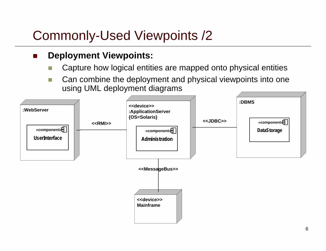
Commonly-Used Viewpoints /2 Deployment Viewpoints:
Capture how logical entities are mapped onto physical entitiesCan combine the deployment and physical viewpoints into one Can combine the deployment and physical viewpoints into one using UML deployment diagrams
<<device>> A li i S:WebServer
:DBMS
:ApplicationServer {OS=Solaris}
:WebServer
<<RMI>> <<JDBC>>
DataStorage«component»
Administration«component»
UserInterface«component»
<<MessageBus>>
<<device>> Mainframe
6
Mainframe

Commonly-Used Viewpoints /3 Concurrency/Process Viewpoints:
Capture how concurrency and threading will be managed in a systemin a system
<<thread>>
HardwareTester<<process>>
Administration<<process>>
Operations +Request H/W Test
<<process>>
Database<<thread>>
Billing+Store Admin Data
+Store Billing Data+Store H/W Data
Behavioral Viewpoints: Capture the expected behavior of (parts of) a system System scenarios using UML collaboration diagrams
7

UML Component Diagram Illustrate dependencies between architectural components at
design time, compilation time and runtime Used to model the system in terms of components andUsed to model the system in terms of components and
dependencies among the components Also called “software wiring diagrams“ They show how the software components are wired together in They show how the software components are wired together in
the overall application
The dependencies (edges in the graph) are shown as dashed lines with arrows from the client component to thedashed lines with arrows from the client component to the supplier component: The lines are often also called connectors
Th t f d d i i l t ti l The types of dependencies are implementation-language specific
Components can also be Source code, linkable libraries, executables
8
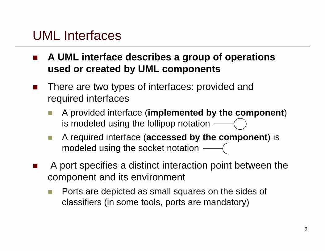
UML Interfaces A UML interface describes a group of operations
used or created by UML components
There are two types of interfaces: provided and required interfaces
A id d i t f (i l t d b th t) A provided interface (implemented by the component) is modeled using the lollipop notation
A required interface (accessed by the component) is q ( y p )modeled using the socket notation
A port specifies a distinct interaction point between the component and its environment Ports are depicted as small squares on the sides of
classifiers (in some tools, ports are mandatory)classifiers (in some tools, ports are mandatory)
9
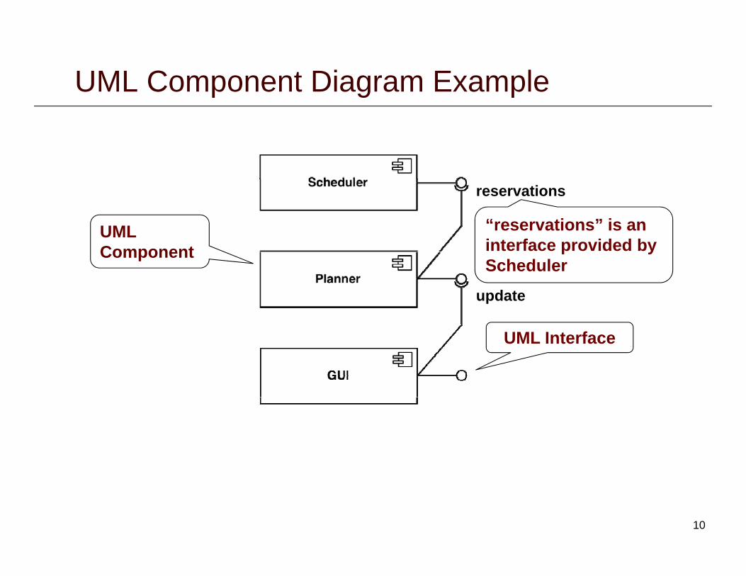
UML Component Diagram Example
reservations
UML Component
“reservations” is an interface provided by
update
Component p yScheduler
UML Interface
10

UML Deployment Diagrams UML deployment diagrams are used for showing
physical and deployment architectural viewpointsUML d l t di l d d i UML deployment diagrams are also used during Subsystem decomposition Concurrency
:PC :Server
Hardware/Software Mapping
A deployment diagram is a graph of nodes and connections (“communication associations”)connections ( communication associations ) Nodes are shown as 3D boxes Connections between nodes are shown as solid lines Nodes may contain components Components are connected through deployment connectors Components may contain objects (indicating that the object is
part of the component)
11

UML Deployment Diagram Example
Dependency (in a node)
UML Node
UML Interface
Dependency (between nodes)
12

ARENA Deployment Diagram
13

Consistency Among Views Views can contain overlapping and related design
decisionsThere is the possibility that the views can thus become There is the possibility that the views can thus become inconsistent with one another
Views are consistent if the design decisions they g ycontain are compatible Views are inconsistent if two views assert design
decisions that cannot simultaneously be truedecisions that cannot simultaneously be true
Inconsistency is usually but not always indicative of problems Temporary inconsistencies are a natural part of
exploratory design Inconsistencies cannot always be fixedy
14

Integrating Multiple Architectural Views Diagrams of different types cover different,
complementary facets of the systemOverlapping aspects require an integration mechanism Overlapping aspects require an integration mechanism needed for compatibility among diagrams
Metamodel Model defining and relating conceptual abstractions in
terms of which other models are defined Defines the structure of the modeling language provides Defines the structure of the modeling language, provides
meta-language for defining it, summarizes main features
Typical approach: Define a common metamodel interrelating all conceptual
abstractions used in each type of diagram Enforce inter-diagram consistency rules based on Enforce inter diagram consistency rules based on
the integrated metamodel15

Model-Driven Software Architecture /1<<metaclass>>
Software Architecture<<metaclass>>
System +has
+described by+includes 1 *<<metaclass>>
Architectural Model<<metaclass>>
Stakeholder +interested in1..*
+described by+includes 1..
<<metaclass>>
View<<metaclass>>
Concern<<metaclass>>
Viewpoint+defines1 *
+composed of 1..*
+conforms to
+selects 1..*+expresses 1..*
1..
16Based on IEEE Std 1471-2000: IEEE Recommended Practice for Architectural Description of Software-Intensive Systems

Model-Driven Software Architecture /2
<<metaclass>><<metaclass>>
Model-driven software architecture creation:
metaclass
Metamodelmetaclass
Viewpoint +represents
+instance of +instance of
1. Identify relevant system stakeholders2. For each stakeholder, determine their
key concerns (e.g., logical structure,
<<metaclass>>
Model<<metaclass>>
View +represents
performance, concurrency)3. Express their concerns as viewpoints
Model the viewpoint elements p(terminology) as metaclasses, and each viewpoint itself as a metamodel
4. Create views that conform to the matching viewpoints Represent each view as a model
that conforms to the corresponding viewpoint/metamodelviewpoint/metamodel
17

Model-Driven Software Architecture /3
<<metaclass>>
Connector<<metaclass>>
Component +target
+source Project the elements of a
metamodel using t t
MM2:
g
<<component>>
WebServerFile
stereotypes: Apply stereotypes to UML
classes and metaclassesMM1:
Get a deeper understanding of the model semantics
<<component>>
JavaFile<<component>>
HTMLFile<<component>>
JSPFile
Narrow the amount of valid models
JavaFile HTMLFile JSPFile
<<JavaFile>><<JavaFile>>
Metaclassesused as
stereotypesM1:
18
<<JavaFile>>
server.java<<JavaFile>>
client.javastereotypes

Types of Requirements Functional requirements
Describe the interactions between the system and its environment, independent from the implementation Example: “An operator must be able to issue a new ticket“
Nonfunctional requirements Nonfunctional requirements Aspects not directly related to functional behavior
Example: “The response time must be less than 1 second”
Constraints Imposed by the client or the environment
E l “Th t t b i l t d Wi d “ Example: “The system must be implemented on Windows“
Also referred to as “pseudo requirements”
19

Functional vs. Nonfunctional Requirements Functional Requirements
Describe user tasks that the system needs to
Nonfunctional Requirements Describe properties of the
system or the domainthe system needs to support
Phrased as actions“Ad ti
system or the domain Phrased as constraints or
negative assertions“All i t h ld b “Advertise a new
league” “Schedule tournament” “Notify an interest
“All user inputs should be acknowledged within 1 second”
“A system crash should Notify an interest group”
A system crash should not result in data loss”.
20

Examples of Nonfunctional Requirements Usability Requirement
“Passengers must be able to buy a ticket for travel without prior registration”
Performance Requirement “The system must support 10 parallel transactions”
Supportability Requirement“ “The operator must be able to add new travel routes without modifications to the existing system.”
21

Quality Attributes in Architectural Design Quality attributes can be used to guide software
architecture design:A hit t l t l di d f ff ifi d t Architectural styles discussed so far offer specific advantages and disadvantages with respect to various quality attributes
For instance, pipes and filters does not support interactive f ( )software and hence (broadly speaking) has limited adaptability
In addition, there are general architectural heuristics that apply to specific quality-driven design goals and can be used as drivers of architectural design
Specific design goals include (see Chapter 12 of Taylor et al textbook for details of these and other goals):textbook for details of these and other goals): Reducing complexity Improving scalability and heterogeneity Improving dependability and fault tolerance
22

Goal: Reduce Complexity /1 IEEE Definition:
Complexity is the degree to which a software system or one of its components has a design or implementation that is difficult to understand and verify
Complexity can also be viewed as: Complexity can also be viewed as: A property that is directly proportional to the size of the
system, number of its constituent elements, their internal structure, and the number of their interdependencies
23

Goal: Reduce Complexity /2 Software components and complexity:
Separate concerns into different components Keep only the functionality inside components Keep only the functionality inside components
Move the interactions into connectors Insulate processing components from changes in data format
(use abstract data types, or specialized data components)
Software connectors and complexity: Keep only interaction facilities inside connectors Separate interaction concerns into different connectorsp
E.g., split communication (streams) from facilitation (delivery, routing) Support connector composition Restrict interactions facilitated by each connector
Architectural configurations and complexity: Eliminate unnecessary dependencies Use hierarchical decomposition Use hierarchical decomposition
24

Goal: Reduce Complexity /3 Linux OS Kernel
Conceptual Architecture: Linux OS Kernel
Concrete Architecture:
File System
File System
Memory Manager
Network Interface Memory
ManagerNetwork Interface
Inter-Process Communications
Process Scheduler Inter-Process
CommunicationsProcess
Scheduler
Initialization Library Initialization Library
25

Goal: Scalability and Heterogeneity /1 Scalability:
The capability of a software system to be adapted to meet new requirements of size and scopemeet new requirements of size and scope
Adaptability: Ability to satisfy new requirements and adjust to new Ability to satisfy new requirements and adjust to new
operating conditions during its lifetime
Heterogeneity: Ability to consist of multiple disparate constituents or
function in multiple disparate computing environments
Portability: Portability: Ability to execute on multiple platforms with minimal
modifications and without significant degradation in functional or non functional characteristicsfunctional or non-functional characteristics
26

Goal: Scalability and Heterogeneity /2 Software components and scalability:
Define each component to have a simple and understandable interface
Distribute the data sources and replicate data when necessaryy
Software connectors and scalability: Give each connector a clearly defined responsibilityy p y Choose the simplest connector suited for the task
Architectural configurations and scalability:g y Place the data sources close to the data consumers Make use of parallel processing capabilities
27
Goal: Dependability /1 Dependability is a collection of system properties that
allows one to rely on a system functioning as required Reliability is the probability that a system will perform its
intended functionality under specified design limits, without failure, over a given time period
Availability is the probability that a system is operational at a particular timeRobustness is a system’s ability to respond adequately Robustness is a system’s ability to respond adequately to unanticipated runtime conditions
Fault-tolerant is a system’s ability to respond gracefully to failures at runtime
28
Goal: Dependability /2 Software components and dependability:
Provide reflection capabilities in components to check status of a component at runtime
Provide suitable exception handling mechanisms and avoid single points of failureg p
Software connectors and dependability: Employ connectors that strictly control component p y y p
dependencies
Architectural configurations and dependability: Provide redundancy of critical functionality and data Implement non-intrusive system health monitoring
29

Food for Thought Read:
Chapter 6 from “Software Architecture: Foundations, Theory, and Practice” Read sections 6.1, 6.2, and 6.3 on architecture modeling
Chapter 12 from “Software Architecture: Foundations, p ,Theory, and Practice” Read detailed explanations of design heuristics discussed in the
lecture notes
30