ctx tractor manual 09
TRANSCRIPT

Operator’s Manual
Garden Tractors
®
Safety Instructions
Page 1
Training1. Read the instructions carefully. Be familiar with controls
and the use of equipment.
2. Never allow children or people unfamiliar with these instructions to operate the mower.
3. Never mow while people, especially children or pets, are nearby.
4. The operator or user is responsible for accidents or hazards occurring to other people or their property.
5. Do not carry passengers.
6. All drivers should seek to obtain professional and practical instruction. In addition the following should be noted:
• Theneedforcareandconcentrationwhenworkingwith this machine.
• Controlofatractorslidingonaslope;controlwillnotbe regained by applying the brake.
• Themainreasonsforlossofcontrolare:
i. Insufficient wheel grip
ii. Driving too fast
iii. Operating on steep slopes (max 15º)
iv. Incorrect load distribution
Preparation1.Checkthatthemachinecomplieswithallapplicable
regulations, including those in force when used on the public highway.
2. When mowing, always wear substantial footwear and long trousers. Do not operate when barefoot or with sandals.
3. Thoroughly inspect the area where the tractor is to be used and remove all stones, sticks, wires and bones or any other foreign objects.
4. WARNING – petrol and diesel are highly flammable:
• Storefuelincontainersspecificallydesignedfor this purpose.
• Re-fueloutdoorsonlyanddonotsmokewhilerefuelling.
• Addfuelbeforestartingtheengine.Neverremovethecap from the fuel tank or add diesel while the engine is running or when engine is hot.
• Iffuelisspilled,donotattempttostarttheenginebutmove the machine away from the area of spillage and avoid creating any source of ignition until petrol or diesel vapours have dissipated.
•Replacethefuelcapsecurely.
5. Replace faulty silencers.
6. Before using, always inspect to see that the blades, bolts and cutter assembly are not worn or damaged.
7.Checktheconditionofthetyresandensurethattheyareinflatedtothecorrectpressures(refertopages25-27).This is particularly important if the machine is to be taken on the public highway.
8.Checkthatthemowerisingoodworkingorder,payingspecial attention to brakes, steering, water and oil.
9.Checkthatalllinkages,connectionsandpivotnutsaresecure and that the wheel nuts are tightened correctly.
20090528
Contents
Safety Instructions Page 1
Operating Instructions Page 2
Controls Page 3 – 8
Powered Grass Collector Page 9 – 10
Using your Tractor Page 11
Cutter decks Page 12
C330 Mini cutter decks Page 13
Routine maintenance Page 14 – 16
Troubleshooting:
Cutting Page 17
Cutter Levelling Page 18 – 19
Grass Collecting Page 20
Tyres & Wheels Page 21
Starting & Running Page 22
Electrics Page 23 – 24
Specifications Page 25 – 27
Personal Service Record Page 28
Certificate of Conformity Page 29

Page 2
Operating Instructions
Safety1. Read the instructions carefully. Be familiar with controls
and the use of equipment.
2. Do not operate the engine in a confined space where dangerous fumes can collect.
3. Mow only in daylight or in very good artificial light.
4. Before starting the engine, disengage blade and attachment drives and make sure handbrake is engaged.
5. Take care on slopes – maximum 15º.
6. Remember, there is no such thing as a ‘safe slope’. Travel on grass slopes requires particular care to guard against overturning:
• Donotstoporstartsuddenlywhengoingupordownhill. • Engagedriveslowly.Alwayskeepthemachineindrive
when travelling up or down a slope. • Machinespeedshouldbekeptlowonslopesandin
tight turns. • Stayalertforhumpsandhollowsandotherhidden
hazards. • Avoidmowingacrossthefaceofaslope.
7. Watch out for traffic when crossing or working near roadways.
8. Stopthebladesrotatingbeforecrossingroadways.
9. When using the machine, never direct discharge or material towards bystanders or allow anyone near the machine while in operation.
10. Never operate the mower with defective guards, shields or without protective safety devices in place and in good working order.
11. Do not change governor settings to increase the speed of the engine. Operating an engine at excessive speed increases the risk of injury.
12. Before leaving the operator’s position:
• Disengagethedrivetothecutterbladesandattachments, then lower the attachments.
• ApplytheParkingBrake. • Stoptheengineandremovetheignitionkey.
13. Always disengage drive to attachments, stop the engine and remove the ignition key before:
• Cleaningblockages. • Checking,cleaningorworkingonthemower. • Refuelling. • RemovingtheGrassCollector.
Also: • Afterstrikingaforeignobjectinspectthemowerfor
damage and make any repairs before restarting the tractor.
• Ifthemachinestartstovibrateabnormally,checkimmediately and call your dealer if necessary.
14. Disengage drive to attachments when transporting or not in use.
15.Reducethethrottlesettingduringenginerun-out.
16. Never work on the mower when the engine is running.
Always:Use good common sense at all times and to ensure this tractor is safe and serviceable fit only original manufacturer’s supplied spares.
• Inspecttheareatobecut,notethepositionofanystumps, drain covers, bumps or depressions and avoid them to prevent damaging the blades.
• Ensurethefueltankisfullbeforeyoustartthemachine. • ONLYusethespecifiedfuelforyourmachine. • Disconnectbothbatteryterminalsbeforeattempting
any work in the engine compartment.
Never: • Leavethetractorunattendedandrunning. • Puthandsnearmovingblades,beltsorthePower
Take-Offpulleywhiletheyarerotating.
PoweredGrassCollector(PGC)
CollectorHeightAdjustmentLever CutterDeck Anti-scalpWheel
PGCTippingLever*
PGCNet
PowerTake-Off(PTO)EngageLever
CuttingHeightAdjustmentLever*
PGCLiftLever*Tractor Drive Pedals
PGCConnectionLever
Page 3
Operating Instructions, Controls
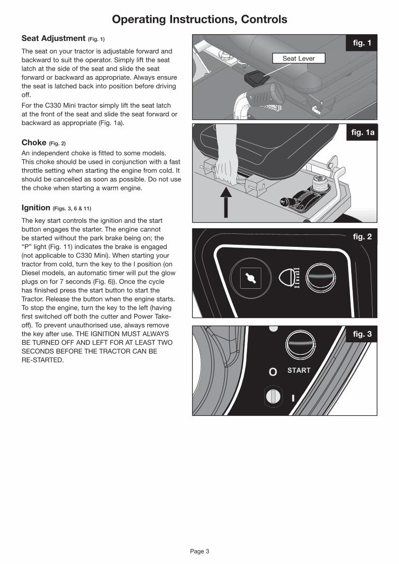
Seat Adjustment (Fig. 1)
The seat on your tractor is adjustable forward and backwardtosuittheoperator.Simplylifttheseatlatch at the side of the seat and slide the seat forward or backward as appropriate. Always ensure the seat is latched back into position before driving off.
FortheC330Minitractorsimplylifttheseatlatchat the front of the seat and slide the seat forward or backward as appropriate (Fig. 1a).
Choke (Fig. 2)
An independent choke is fitted to some models. This choke should be used in conjunction with a fast throttle setting when starting the engine from cold. It should be cancelled as soon as possible. Do not use the choke when starting a warm engine.
Ignition (Figs. 3, 6 & 11)
The key start controls the ignition and the start button engages the starter. The engine cannot bestartedwithouttheparkbrakebeingon;the“P” light (Fig. 11) indicates the brake is engaged (notapplicabletoC330Mini).Whenstartingyourtractor from cold, turn the key to the I position (on Diesel models, an automatic timer will put the glow plugs on for 7 seconds (Fig. 6)). Once the cycle has finished press the start button to start the Tractor. Release the button when the engine starts. To stop the engine, turn the key to the left (having firstswitchedoffboththecutterandPowerTake-off). To prevent unauthorised use, always remove thekeyafteruse.THEIGNITIONMUSTALWAYSBETURNEDOFFANDLEFTFORATLEASTTWOSECONDSBEFORETHETRACTORCANBERE-STARTED.
fig. 1
fig. 2
fig. 3
SeatLever
fig. 1a

RPM Meter fig. 5
fig. 6
Operating Instructions, Controls
Engine Speed Control (Fig. 4)
TheleverispushedupforFAST()anddownforSLOW().Onsomemodelsthechokecontrolisabove the fast setting, a cold engine is started on theChokesetting,awarmoneontheFASTsetting.TheChokesettingshouldbecancelledassoonaspossible. The engine should be operated on the FASTsettingatalltimes.
Please note:D50-LNmodelhasnochoke(Fig. 4a)
RPM Meter (not applicable to C330 Mini) (Fig. 5)
The RPM monitor on the electronic display indicates the engine speed. This feature should be used when the cutter deck is engaged and in conjunction with the forward speed. To ensure complete cutting and collection the engine speed should not be allowed to fall below 2600rpm, the display will flash should this happen. If, when in use, the display does flash indicating that the engine speed has dropped below 2600rpm, there are two options: a) Reduce forward speed b) Raise the cutting height.
fig. 4a
fig. 4
Page 4
Page 5
Operating Instructions, Controls
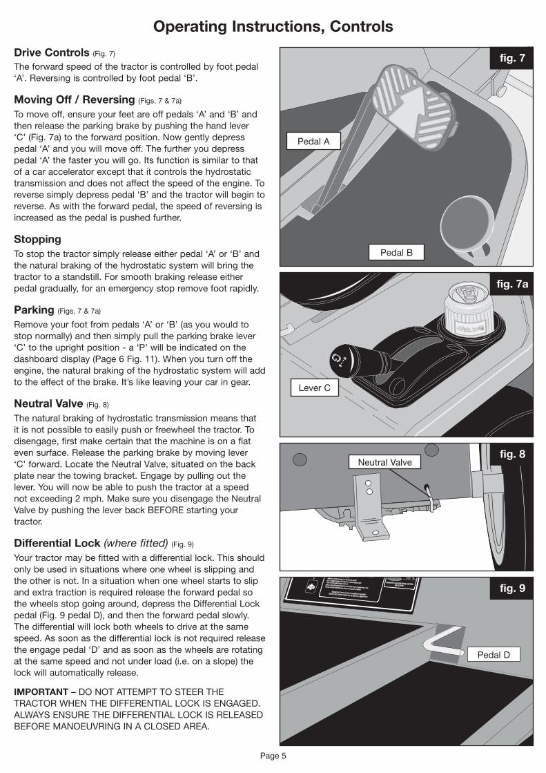
Drive Controls (Fig. 7)
The forward speed of the tractor is controlled by foot pedal ‘A’. Reversing is controlled by foot pedal ‘B’.
Moving Off / Reversing (Figs. 7 & 7a)
To move off, ensure your feet are off pedals ‘A’ and ‘B’ and then release the parking brake by pushing the hand lever ‘C’(Fig.7a)totheforwardposition.Nowgentlydepresspedal ‘A’ and you will move off. The further you depress pedal ‘A’ the faster you will go. Its function is similar to that of a car accelerator except that it controls the hydrostatic transmission and does not affect the speed of the engine. To reverse simply depress pedal ‘B’ and the tractor will begin to reverse. As with the forward pedal, the speed of reversing is increased as the pedal is pushed further.
StoppingTo stop the tractor simply release either pedal ‘A’ or ‘B’ and the natural braking of the hydrostatic system will bring the tractor to a standstill. For smooth braking release either pedal gradually, for an emergency stop remove foot rapidly.
Parking (Figs. 7 & 7a)
Remove your foot from pedals ‘A’ or ‘B’ (as you would to stop normally) and then simply pull the parking brake lever ‘C’totheuprightposition-a‘P’willbeindicatedonthedashboard display (Page 6 Fig. 11). When you turn off the engine, the natural braking of the hydrostatic system will add to the effect of the brake. It’s like leaving your car in gear.
Neutral Valve (Fig. 8)
The natural braking of hydrostatic transmission means that it is not possible to easily push or freewheel the tractor. To disengage, first make certain that the machine is on a flat even surface. Release the parking brake by moving lever ‘C’forward.LocatetheNeutralValve,situatedonthebackplatenearthetowingbracket.Engagebypullingoutthelever.Youwillnowbeabletopushthetractorataspeednot exceeding 2 mph. Make sure you disengage the Neutral ValvebypushingtheleverbackBEFOREstartingyourtractor.
Differential Lock (where fitted) (Fig. 9)
Yourtractormaybefittedwithadifferentiallock.Thisshouldonly be used in situations where one wheel is slipping and the other is not. In a situation when one wheel starts to slip and extra traction is required release the forward pedal so thewheelsstopgoingaround,depresstheDifferentialLockpedal (Fig. 9 pedal D), and then the forward pedal slowly. The differential will lock both wheels to drive at the same speed. As soon as the differential lock is not required release the engage pedal ‘D’ and as soon as the wheels are rotating at the same speed and not under load (i.e. on a slope) the lock will automatically release.
IMPORTANT–DONOTATTEMPTTOSTEERTHETRACTORWHENTHEDIFFERENTIALLOCKISENGAGED.ALWAYSENSURETHEDIFFERENTIALLOCKISRELEASEDBEFOREMANOEUVRINGINACLOSEDAREA.
P
LeverC
Pedal A
Pedal B
Pedal D
NeutralValve
fig. 7
fig. 7a
fig. 8
fig. 9

Page 6
Operating Instructions, Controls
Cutter On/Off Switch (Figs. 10 & 11)
The cutter switch controls the electromagnetic blade clutch. To switch the cutter on, push the switch and then release it, this will engage the cutter deck. To indicatethattheCutterDeckisengaged,theCutterDeckHeightIndicatorwillflash(Fig.11).TostoptheCutterDeck,pushtheswitchagain.AlthoughtheCutterDeckisautomaticallyswitchedoffwhentheengine is stopped or when the operator gets off the seat, it is not good practice to rely on these features, theCutterDeckshouldalwaysbeswitchedOFFas soon as you have finished cutting and certainly BEFOREstoppingtheengineorgettingoffthetractor.TheCutterwillonlyworkwhilsttheoperatoris sat on the seat.
NOTE:TheheadlightswillflashwhilsttheCutterDeck is running if they are not being used. If the headlights are in use they will not flash but function as normal.
Electric Lifts (not applicable to C330 Mini) (Figs. 10 & 11)
Electric deck height adjustment (where fitted) The cutting height is adjusted by turning the rotaryswitchanti-clockwisetolowerthedeckandclockwise to raise the deck (Fig. 10). The height indicator on the electronic display (Fig. 11) shows the deck position (0 – lowest to 9 – highest). To get the best from this refinement use it to continuously adjust cutting height to suit ground and grass conditions. Do not make downward adjustments on the move until you are familiar with the height control, this will avoid “scalping” the lawn.
Manual Deck Lift (where fitted) (Fig. 12)
YourCountaxmaybefittedwithamanualdecklift.To operate, simply push the trigger in until the weight of the deck can be felt and pull back to the desired cuttingheight(numbered1-9).Tolower,holdthetriggerinandpushforward.Exercisecautionwhenoperating lift lever.
Hour Meter (not applicable to C330 Mini) (Fig. 13)
Yourtractorisfittedwithanhourmetertoassistyouin adhering to the recommended service intervals. The hour meter only operates whilst the engine isactuallyrunning.Clockedhourswillshowupon the RPM display prior to starting the engine. Recommended service intervals are shown on page 25.
NOTE: 50 hours of mowing at 5 mph equates to 250 miles of grass cutting!
Low Fuel Warning (not applicable to C330 Mini) (Fig. 14)
When the tractor is low on fuel a warning will appear wheretheRPMdisplayissaying‘FUEL’,thisisawarning to tell you to fill up again as the tractor is about to run out of petrol or diesel.
ElectricDeckLift
Park Brake Indicator CuttingHeightIndicator
fig. 10
fig. 11
fig. 12
fig. 13
fig. 14
CutterOn/Off

Page 7
Operating Instructions, Controls
Auxiliary Lift Switch (where fitted) (Fig. 15)
RaisingtheAuxiliary(GrassCollector)Liftisachievedby pressing a switch (Fig. 15) on the dashboard – UP to raise, DOWN to lower.
Net Empty Switch (where fitted) (Fig. 16)
EmptyingthePoweredGrassCollectorisachievedby pressing a switch (Fig. 16) on the dashboard – UP to open, DOWN to close.
Power Take-Off (C330 Mini and C Series) (Fig. 17)
To engage the PTO drive, the PTO lever is lifted up and out of its locator and then moved to the left and released to find its own height. To disengage the PTO pull the lever up and to the right. Always have this lever in the ‘disengaged’ position when it isnotinuse.DONOTPUTHANDSNEARMOVINGPULLEYSANDBELTS.
Power Take-Off (A Series and D50-LN) (Fig. 17a)
To engage the PTO, push the lever down and to the left and release lever upwards. The PTO lever is pushed down and to the right into its locator to disengage. Always have this lever in the ‘disengaged’ position when it is not in use.
DONOTPUTHANDSNEARMOVINGPULLEYSANDBELTS.
Lights (Fig. 18)
Pressing the rocker switch turns ON the headlights. Turn the headlights OFF by pressing the rocker switch again. The headlights will not operate without the ignition switch turned on.
LightSwitch
fig. 18
fig. 17a
fig. 17
fig. 16fig. 15

fig. 18a
fig. 18b
Electronic Slope Alert (ESA) (not applicable to C330 Mini) (Figure 18a)
Shouldyourtractorbefittedwith4WDitwillhaveESA.Thisissettoanangleof25° at the factory. If this angle is exceeded then the display will flash 25° and a warning siren will sound.
The exceptional traction of 4WD will allow you to cut in very slippery conditions, and it also allows the tractor to ascend very steep slopes. If the slope alarm sounds DO NOT attempt to cut or drive at a greater angle than the one you are on. As all terrains and conditions vary, great care should be maintained when operating the tractor. DO NOT take the tractor into an area where it could become unstable.
On no account should slopes steeper than 25° be driven on.
Battery and Fuel (C330 MIni) (Figure 18b)
TheC330Minihasasimpledashboardarrangement.Thetworedfilteredsquaresshowthecharge(Lefthand) and the fuel level (right hand). When the ignition is turned on the charge light is lit. The only time the charge light goes off is when there is a failure with charging. If this happens you should ring yournearestCountaxdealer.
When the fuel level is running low the fuel warning light will appear. The tractor will need to be refuelled A.S.A.P.
Page 8
Operating Instructions, Controls
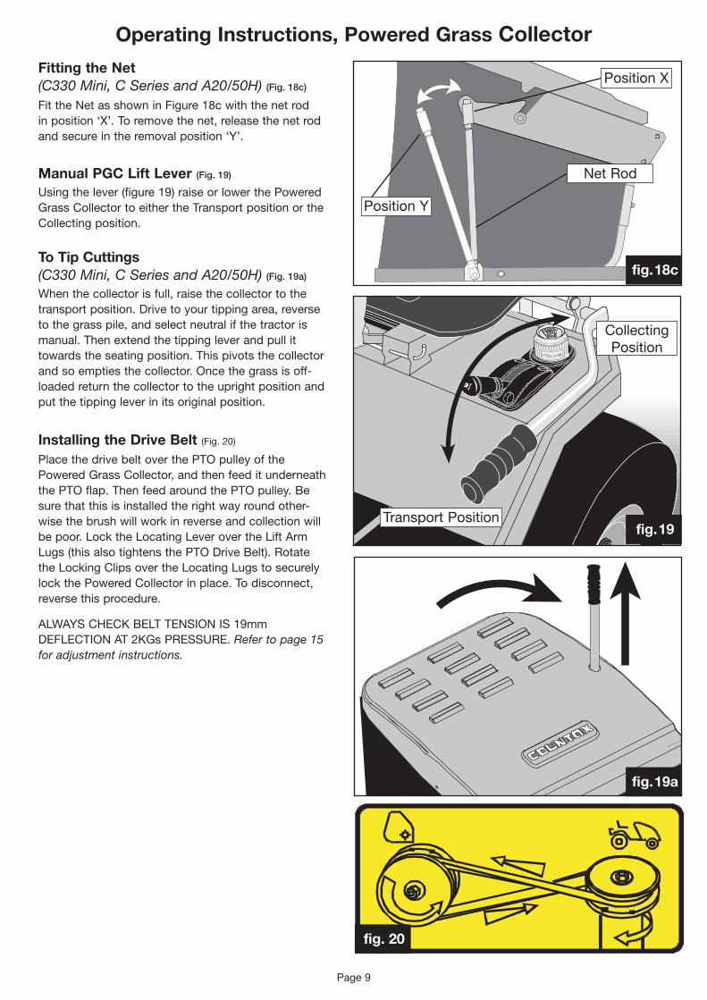
Operating Instructions, Powered Grass CollectorFitting the Net (C330 Mini, C Series and A20/50H) (Fig. 18c)
Fit the Net as shown in Figure 18c with the net rod in position ‘X’. To remove the net, release the net rod andsecureintheremovalposition‘Y’.
Manual PGC Lift Lever (Fig. 19)
Using the lever (figure 19) raise or lower the Powered GrassCollectortoeithertheTransportpositionortheCollectingposition.
To Tip Cuttings (C330 Mini, C Series and A20/50H) (Fig. 19a)
When the collector is full, raise the collector to the transport position. Drive to your tipping area, reverse to the grass pile, and select neutral if the tractor is manual. Then extend the tipping lever and pull it towards the seating position. This pivots the collector andsoemptiesthecollector.Oncethegrassisoff-loaded return the collector to the upright position and put the tipping lever in its original position.
Installing the Drive Belt (Fig. 20)
Place the drive belt over the PTO pulley of the PoweredGrassCollector,andthenfeeditunderneaththe PTO flap. Then feed around the PTO pulley. Be sure that this is installed the right way round other-wise the brush will work in reverse and collection will bepoor.LocktheLocatingLeverovertheLiftArmLugs(thisalsotightensthePTODriveBelt).RotatetheLockingClipsovertheLocatingLugstosecurelylockthePoweredCollectorinplace.Todisconnect,reverse this procedure.
ALWAYSCHECKBELTTENSIONIS19mmDEFLECTIONAT2KGsPRESSURE.Refer to page 15 for adjustment instructions.
Page 9
fig. 20
Net Rod
Position X
PositionY
fig. 18c
Transport Position
CollectingPosition
fig. 19
fig. 19a

Net Assembly
Net Assembly
LocatingLever
Pivot spacer
Net Rod
Net Rod
LockingClip
LockingTube
2ndLockingTube
SecuringPin
SecuringPin
LockingTube
LockingClips
LiftArmLugs
LockingLever
CollectorChannels
fig. 21a
fig. 21
fig. 22
Operating Instructions, Powered Grass Collector
Page 10
fig. 23
Removing and fitting the Net (C Series fitted with Electric Net) (Fig. 21)
When removing the net, we suggest you employ the assistance of another person.
1. PartiallyopenthePGCnet(100mm(4”)).Disconnect the net rod by pulling back on the sprung locking tube and uncoupling it from the pin. The locking tube should then be attached to the securing pin. The process should be repeated on the other side.
2. Disconnect the second locking tube from its pin.
3. With one person standing on each side of the collector net, lift the net off the bag ears.
4. Reverse the above operations for fitting the net.
Removing and fitting the Net (A and D Series fitted with Electric Net) (Fig. 21a)
When removing the net, we suggest you employ the assistance of another person.
1. PartiallyopenthePGCnet(100mm(4”)).Disconnect the net rod by pulling back on the sprung locking tube and uncoupling it from the pin. Repeat on the other side.
2. Undo the net locking clip (both sides), then unhook the levers from the locating pins.
3. DisconnecttheLockingTubeBallJoints.
4. With one person standing on each side of the collector net, slide the net off the locating arms.
5. Reverse the above operations for fitting the net.
PGC Connection (Tractors fitted with Electric Net) (Fig. 22)
ToconnectthePoweredGrassCollector(PGC)tothe tractor, ensure that both are on an even surface withthelockingleversonthecollectorfacingtheLiftArmsonthetractor.LifttheseatandthePTOflapsothat both are resting in the upright position. Move the Collectormanuallytothetractor;lowertheLiftArmsusing the button on the dash console.
AttheendofeachLiftArmyouwillfindaLocatingLug.SlidetheChannelsoneithersideofthePoweredCollectorovertheLugsbutdonotengagetheLocatingLeveryet.EnsurethattheRubberFlapattheopeningofthePGClocatesontopoftheTransmissionGrassDeflector.
Net Empty Plug (where fitted) (Fig. 23)
If fitted, connect the net empty plug to the socket as shown in Fig. 23, to disconnect, reverse this procedure.
ThisplugMUSTBEFITTEDbeforeattemptingtouseyourPoweredGrassCollector.

Page 11
Using your Countax Garden Tractor
Adjusting the sweeper height (Fig. 24)
Use the sweeper height lever to select the position appropriate to the conditions and the height of cut. TOGETTHEBESTSWEEPINGPERFORMANCEANDTOPRESERVETHEBRUSHESSELECTTHEHIGHESTSETTINGTHATWORKS–starthighand adjust down until the brushes start to collect (normally the middle adjustment hole). Do not set the brushes too low – this will lead to scarifying and a very untidy finish as well as shortening brush life.
To tip cuttings (Tractors fitted with Electric Net) (Figs. 15 & 16)
Whenitisfull,raisetheCollectortothetransportposition (Page 7, Fig. 15). Drive to your tipping area, reversetothepile,thendepressthePGCNetEmptySwitch(Page7,Fig.16).
Standard grass collectionWhen cutting the grass and collecting follow these simple steps:
1. Always run the engine at maximum speed.
2.Lowerthesweepertotheworkingposition.REMEMBER:TOGETTHEBESTSWEEPINGPERFORMANCEANDTOPRESERVETHEBRUSHES,SELECTTHEHIGHESTSETTINGTHATWORKS.
3.Engagethesweeperdrive.
4.Engagethecutterdeckdrive.
5.Lowerthedecktothedesiredheightofcut.
6. Drive forward at a speed that does not cause the engine speed to drop. REMEMBER: if the RPM display flashes below 2600rpm, there are two options: a) Reduce forward speed b) Raise the cutting height.
Sometimeswhencuttinglonggrassorapaddock,it may be better to cut the grass and disperse the clippings directly to the ground. Alternatively remove collector net, fit the deflector accessory and spread the cut grass prior to final collection.
fig. 24

Page 12
Cutter decks
Mulch MowingMulching can save time, avoids creating piles of rotting cuttings and feeds your lawn. When Mulch mowing it is necessary to observe certain rules:
1. Reduce the height of the grass by no more than1/3rd its height in each pass. If the grass has grown long make several passes to achieve the cut height you require.
2. Run the engine at maximum speed.
3. Mow often, particularly in spring and early summer.Shortclippingsof25mm(1”)orlessdecompose more quickly.
4. If an unsightly residue of cuttings is being left – increase the cutting height.
6. Varythemowingpatternfromcuttocut.
7. Always keep the underside of the cutting deck clean to ensure good grass flow.
8. Always check that the blades are sharp and in good condition – never attempt to sharpen or replace them yourself.
High Grass Mulch Deck (Fig. 25)
The real alternative when cutting long or paddock grass is the “high grass mulch” deck. When using the high grass mulch deck please ensure the following:
1. When cutting very tall grass set the deck at thehighersettings7-9.
2. Drive forward at a speed that does not cause theenginespeedtodrop.REMEMBERiftheRPM display flashes below 2600rpm, there are two options: a) Reduce forward speed b) Raise the cutting height.
3. Regularly check the cutter deck drive belt tension in accordance with the instructions (Page 15).
Mulching (Fig. 25a)
The Mulching cutter deck has three mulching compartments.Grasscuttingsareliftedandcutseveral times. The small grass particles release nutrients back into the soil for healthy growth.
Belt Arrangement (Figs. 26, 27 & 28)
Fig.26–HighGrassMulcher
Fig.27–StandardMulcher
Fig.28–RearDischargeCutterDeck
Fig. 24fig. 25
fig. 25a
fig. 26
fig. 27
fig. 28

Page 13
C330 Mini – Cutter decks
Mulch Deck (Fig. 28a)
Mulching can save time, avoids creating piles of rotting cuttings and feeds your lawn. When Mulch mowing it is necessary to observe certain rules:
1. Reduce the height of the grass by no more than1/3rd its height in each pass. If the grass has grown long make several passes to achieve the cut height you require.
2. Run the engine at maximum speed.
3. Mow often, particularly in spring and early summer.Shortclippingsof25mm(1”)orlessdecompose more quickly.
4. If an unsightly residue of cuttings is being left – increase the cutting height.
6. Varythemowingpatternfromcuttocut.
7. Always keep the underside of the cutting deck clean to ensure good grass flow.
8. Always check that the blades are sharp and in good condition – never attempt to sharpen or replace them yourself.
Rear Discharge Deck (Fig. 28b)
The rear discharge deck acts similar to the mulch deck but allows the grass trimmings to be discharged out of the back of the deck so it can be easily collected using the sweeper & net. To enable this to work, the deck is set at an angle so the trimmings are thrown into the centre of the tractor.
COMBI Deck (Fig. 28c)
This deck combines the mulch & the rear discharge all in one deck. The user has only to undo a handwheel and remove the back piece of the deck and it can be used as a rear discharge deck. This saves the time of switching decks.
fig. 28a
fig. 28b
fig. 28c

Page 14
Routine Maintenance
Engine MaintenancePlease refer to the engine manufacturer’s handbook enclosed with this manual.
Battery Maintenance (Fig. 29)
The battery fitted to your tractor is a low maintenanceunit.Shouldyourbatteryrequirecharging for any reason the maximum charge rate is 1.5 amps. If your tractor does not start refer to the troubleshooting section in this manual (page 22).
Cutter Deck Maintenance
Removal of cutter deck (figs. 30, 31, 32 & 32a)
TheCutterDeckcanbequicklyremovedforservicing or cleaning, or to give greater clearance when driving or towing over uneven ground.
Follow this sequence:
1. Lowerthecuttingdecktoitslowestposition(SeeControls–Page6).
2. De-tensiontheCutterDriveBeltwiththeleverunder the left running board (Fig. 30).
3. Remove the 3 securing pins from the front of thedeck(Figs.31A,B&C)byundoingtheRueClips(Figs.32&32a)andremovingthem.
4. Remove the 2 securing pins from the back of thedeck(Fig.31–DandE).
5.SlipthecutterdrivebeltofftheEnginePulley.
6. Put steering onto full lock to ease deck out
7. Liftthelinkagethenslidethedeckout
8. If you are going to use the tractor without the deck,removetheSecuringBar*(Fig.31F).
9. Removethefifthwheel–G.
To Clean The Cutter DeckRemove the deck as instructed, stand it on its side andhoseoffaccumulatedcuttings.DONOTSPRAYWATERDIRECTLYONTOBEARINGHOUSINGS.Toprevent a drop in performance it may be necessary to routinely check for this grass build up, particularly at the beginning of the season when the grass is lush and wet. It is best to regularly check and clean theCutterDeckasoftenaspossible,thiscanbedone by either removing the Deck or raising the tractor safely on a ramp.
* PLEASE NOTE: It is not recommended to use the tractor without a deck as this can make it unstable.
The battery in your Countax is very similar to that found in your car. To remove, simply undo the NEGATIVE terminal connection, followed by the positive.
Front of tractor
Unsecured Secured
G
A
F
B
C
E
D
De-Tensioned Tensioned
Connections&Terminals
fig. 29
fig. 30
fig. 31
fig. 32afig. 32

Page 15
Routine Maintenance
Engine to Cutter Drive Belt TensionThecorrecttensionoftheCutterDriveBeltiscritical. If incorrectly set it can lead to engine damage and invalidate the warranty.
To check the tension put the deck in position 5 on the electric lift display.
1. Selectamidwaypositiononthebelt,usingaspringbalance;applya2kg(4-5lbs)pull(Fig.33).
2. Using a ruler or tape, measure the deflection achievedwhichmustbe13mm(1/2”).Ifmore,the belt tension must be increased, if less – decreased.
To correct the tension, follow this procedure:
1. Release the tension on the belt by pulling the Belt tension lever (page 14, Fig 30) forward.
2. TakingCarenottoburnyourselfonahotExhaust,usea17mmlongreachsockettoundo the half nut.
3. Once the half nut is loosened off, use a 19mm Longreachsockettoundothedecktensionadjuster.Turnanti-clockwisetotensionandclockwisetoun-tension.
4. Havingmadetheadjustment,tightenthehalfnutandre-tensionthebeltwiththebelttensionlever-then
5.Re-checkthebelttension.
Transmission Drive BeltThetransmissiondrivebeltisself-tensioning.When the hand brake is released and the drive belt engaged, the belt will retain its tension correctly. Whenthedriveisdis-engagedusingthehandbrakethe park brake engages. This setting is adjustable but should be carried out by your dealer, anyone not familiar with this setting may cause serious damage to the transmission.
Transmission Oil Tank (C Series 4WD models only) (Fig. 36)
This is located in the Tractor rear body and should be approximately half full when the machine is cold. This level will rise when the engine is warm as the oil expands. It should return to the half way point once the machine has cooled down. The oil should not need to be topped up in normal use. If a noticeable drop in the level occurs then your dealer should be contacted.
GROUNDCARE
EnginetoCutter Drive Belt Tension
Belt Tension Rod
fig. 33
fig. 34
fig. 35
Transmission Oil Tank
fig. 36

Page 16
Routine Maintenance
PTO Main Drive Belt
ThePTOdrivebeltisself-tensioningwhenthedriveis engaged. If this belt does require any adjustment itshouldbecarriedoutbyyourdealer;anyonenotfamiliar with this setting may cause serious damage or even injury when using a machine with badly adjusted belts.
Accessory Drive Belt installation
(Figs. 38 & 39)
1. LiftthePTOGuard.
2. Place the drive belt over the PTO pulley of the PoweredGrassCollector.
3. Feed the belt around the PTO pulley clock-wise.
4. LocktheLocatingLeverovertheLiftArmLugs.
5. CheckBeltTension(19mmdeflection2kgspressure).
6. RotatethelockingclipsovertheLocatingLugs.
If the belt tension is incorrect, movement of the sweeperLockingLeversonthethreadedrodcanadjustit.Ensurethelocknutsaresuitablytightenedafter adjustment. Belt tension should be set in the working position.
19mm Deflection@ 2kgs Push or Pull
fig. 37
fig. 38
fig. 39

Page 17
Troubleshooting (Cutting)
Cutter fails to start or cuts out when switched on
CHECK:
4 Are you on the tractor? – Unless you sit on theseat,thesafetyswitchcutsouttheCutterDeck.
4 ThateithertheCutterSwitchortheSafetySwitchontheseatisnotfaulty–ifso,callyour dealer.
4 Isthebatterylow?–TheClutchEngageSwitchwillonlyoperateifthebatteryiswellcharged.
4 TheEngineisrunning.
Uneven cutting
CHECK:
4 That all tyres are inflated to their correct pressures – see Specification pages 25-27
4 That the front axle is pivoting freely.
4 The deck brackets are moving freely and not locking up.
4 That the deck is level from side to side and backtofront(SeeCutterDeckLevelling).
4 That one or more of the cutter blades are not worn or damaged – if this is the case, it is necessary to call your tractor dealer.
Uneven cut (cuts shorter one side than the other)
CHECK:
4 That the tyres are all inflated to the correct pressures(Seeabove).
4 That the front axle is pivoting freely.
4 That the deck brackets are moving freely and not hitching up.
4 That the side deck level adjustment is correct (Page 19).
Cut is uneven or untidy in one or more sectors
CHECK:
4 ThattheCutterDeckislevelledcorrectlyfrontto back (Page 18).
4 That one or more of the blades are not worn or damaged – if so, call your dealer.
The Cutter seems to lose power and the Belt slips and overheats
CHECK:
4 That the Tensioner Rod is correctly applied (Page 14, Fig. 30).
4 ThattheCutterBeltTensioniscorrect(Seepage 15).
4 ThattheCutterDeckisnotcloggedwithwetcuttings.
4 ThattheCutterDrivebeltisnotworn.
We do not recommend that customers attempt to change cutting blades themselves: remember that itisneverworthwhiletohavebladesre-ground.Itischeaperandbettertoreplaceblades–re-grindingis likely to affect the hardening of the blade and its balance.
TheCutterDeckshouldbesetsothatitisparallelto the surface it is cutting with a maximum variation fromsidetoside,orfronttobackof3mm.Checkthis by placing the tractor on a hard level surface and measuring the clearance heights front to back and side to side with a steel ruler or tape, with theCuttersetoneadjustmentupfromitslowestposition.
If the Cutter Deck seems to require levelling, first check these other possible causes:
4 Are the tyres correctly inflated? – If not, rectifyusingthefiguresonpages25-27asareference.
4 AretheCutterDeckHangerBrackets(Page18, Fig. 41) moving freely or are they hitching up.Tocheckthis,lifttheCutterDecktoitshighest position and lift and rock it, watching to ensure that the brackets move freely – if not, clean and lubricate.
4 Is the front axle pivoting freely? – If not, it may require lubrication or adjustment.
4 Is there any impact damage that has bent or distortedtheDeckorSuspensionBrackets(amatter for your dealer)?

Page 18
Troubleshooting (Cutter Levelling)TheCutterDeckshouldbesetsothatitisparallelto the surface it is cutting with a maximum variation from side to side or front to back of 3mm.
Levelling front to backChecktyrepressureiscorrectfirst.Ifnotinflatetyres.
Youneedtwopeopletolevelthedeck–onetoliftthe Deck while the other removes or relocates the adjuster Trunnion.
1. EnsurethattheAnti-ScalpWheelsareallsetto the same height – if not, rectify (Fig. 40).
2. LowertheCutterDecktoapositiononeabovethe lowest setting – check levels with a ruler or tape.
3. Now locate the Front to Back Adjustment Rod to the right rear offside wheel, you will find the Trunnion (Fig. 41) that links the rod to theDeckHangerBracket.BoththeTrunnionand the Rod are threaded and adjustment is achievedbyrotatingtheTrunnionto‘in-effect’lengthen the Rod.
4. To free the Trunnion, use a 17mm spanner or socket to remove the M10 Nyloc nut and washer and push it free.
5. Rotate the Trunnion to advance it up the Rod to pivot the back of the Deck. Rotate it the other way to lift the front. Adjustment is rapid, so try one or two turns first and relocate the Trunnion and secure – then check the effect. Repeatandre-checkifnecessary.
For best results, set the Anti-Scalp Wheels in the middle adjustment holes. If you are experiencing scalping, this can be minimised by setting the wheels in the lowest adjustment holes.
Trunnion
Front to Back Adjustment Rod
DeckHangerBracket
fig. 40
fig. 41
A
B
Page 19
Troubleshooting (Cutter Levelling)
fig. 42
fig. 42a
fig. 42b
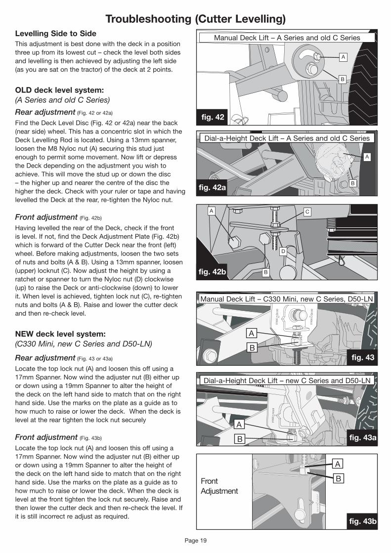
Levelling Side to SideThis adjustment is best done with the deck in a position three up from its lowest cut – check the level both sides and levelling is then achieved by adjusting the left side (as you are sat on the tractor) of the deck at 2 points.
OLD deck level system:(A Series and old C Series)
Rear adjustment (Fig. 42 or 42a)
FindtheDeckLevelDisc(Fig.42or42a)neartheback(near side) wheel. This has a concentric slot in which the DeckLevellingRodislocated.Usinga13mmspanner,loosen the M8 Nyloc nut (A) securing this stud just enough to permit some movement. Now lift or depress the Deck depending on the adjustment you wish to achieve. This will move the stud up or down the disc – the higher up and nearer the centre of the disc the higherthedeck.CheckwithyourrulerortapeandhavinglevelledtheDeckattherear,re-tightentheNylocnut.
Front adjustment (Fig. 42b)
HavinglevelledtherearoftheDeck,checkifthefrontis level. If not, find the Deck Adjustment Plate (Fig. 42b) whichisforwardoftheCutterDecknearthefront(left)wheel. Before making adjustments, loosen the two sets of nuts and bolts (A & B). Using a 13mm spanner, loosen (upper)locknut(C).Nowadjusttheheightbyusingaratchet or spanner to turn the Nyloc nut (D) clockwise (up)toraisetheDeckoranti-clockwise(down)tolowerit.Whenlevelisachieved,tightenlocknut(C),re-tightennuts and bolts (A & B). Raise and lower the cutter deck andthenre-checklevel.
NEW deck level system:(C330 Mini, new C Series and D50-LN)
Rear adjustment (Fig. 43 or 43a)
Locatethetoplocknut(A)andloosenthisoffusinga17mmSpanner.Nowwindtheadjusternut(B)eitherupordownusinga19mmSpannertoaltertheheightofthe deck on the left hand side to match that on the right hand side. Use the marks on the plate as a guide as to how much to raise or lower the deck. When the deck is level at the rear tighten the lock nut securely
Front adjustment (Fig. 43b)
Locatethetoplocknut(A)andloosenthisoffusinga17mmSpanner.Nowwindtheadjusternut(B)eitherupordownusinga19mmSpannertoaltertheheightofthe deck on the left hand side to match that on the right hand side. Use the marks on the plate as a guide as to how much to raise or lower the deck. When the deck is level at the front tighten the lock nut securely. Raise and thenlowerthecutterdeckandthenre-checkthelevel.Ifit is still incorrect re adjust as required.
B
C
D
A
B
A
A
B
A
B
A
B
Dial-a-HeightDeckLift–newCSeriesandD50-LN
Dial-a-HeightDeckLift–ASeriesandoldCSeries
Front Adjustment
ManualDeckLift–ASeriesandoldCSeries
ManualDeckLift–C330Mini,newCSeries,D50-LN
fig. 43
fig. 43a
fig. 43b
Page 20
Troubleshooting (Grass Collecting)
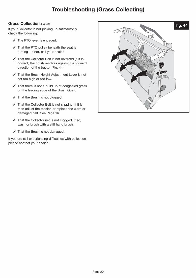
Grass Collection (Fig. 44)
IfyourCollectorisnotpickingupsatisfactorily,check the following:
4 The PTO lever is engaged.
4 That the PTO pulley beneath the seat is turning – if not, call your dealer.
4 ThattheCollectorBeltisnotreversed(ifitiscorrect, the brush revolves against the forward direction of the tractor (Fig. 44).
4 ThattheBrushHeightAdjustmentLeverisnotset too high or too low.
4 That there is not a build up of congealed grass ontheleadingedgeoftheBrushGuard.
4 That the Brush is not clogged.
4 ThattheCollectorBeltisnotslipping,ifitisthen adjust the tension or replace the worn or damagedbelt.SeePage16.
4 ThattheCollectornetisnotclogged.Ifso,wash or brush with a stiff hand brush.
4 That the Brush is not damaged.
If you are still experiencing difficulties with collection please contact your dealer.
fig. 44
Page 21
Troubleshooting (Tyres & Wheels)
Persistent flat tyresLikeallgardenmachinery,themostcommoncauseofpuncturesareTHORNS!Blackthorn,HawthornandRoseare usually at the bottom of the problem and will puncture any tyre not fitted with very expensive guards. There are less expensive ways to overcome this problem and it is advisable to check and avoid these possible causes:
The rim of the wheel has been damaged causing the seal onthetube-lesstyretobebroken.Therearetwosolutions:
4 If the damage is significant it is necessary to order a new wheel from your dealer.
4 IfyouhaveHawthorn,BlackthornorWildRoseinyour garden – this will puncture any tyre. It makes sense to check any area you intend to cut or drive over and to remove any branches.
If your tyres spin or lose grip, check: 4 That all tyres are inflated to their correct pressures
(Seepages25-27).
4 Are you going too fast for the conditions?
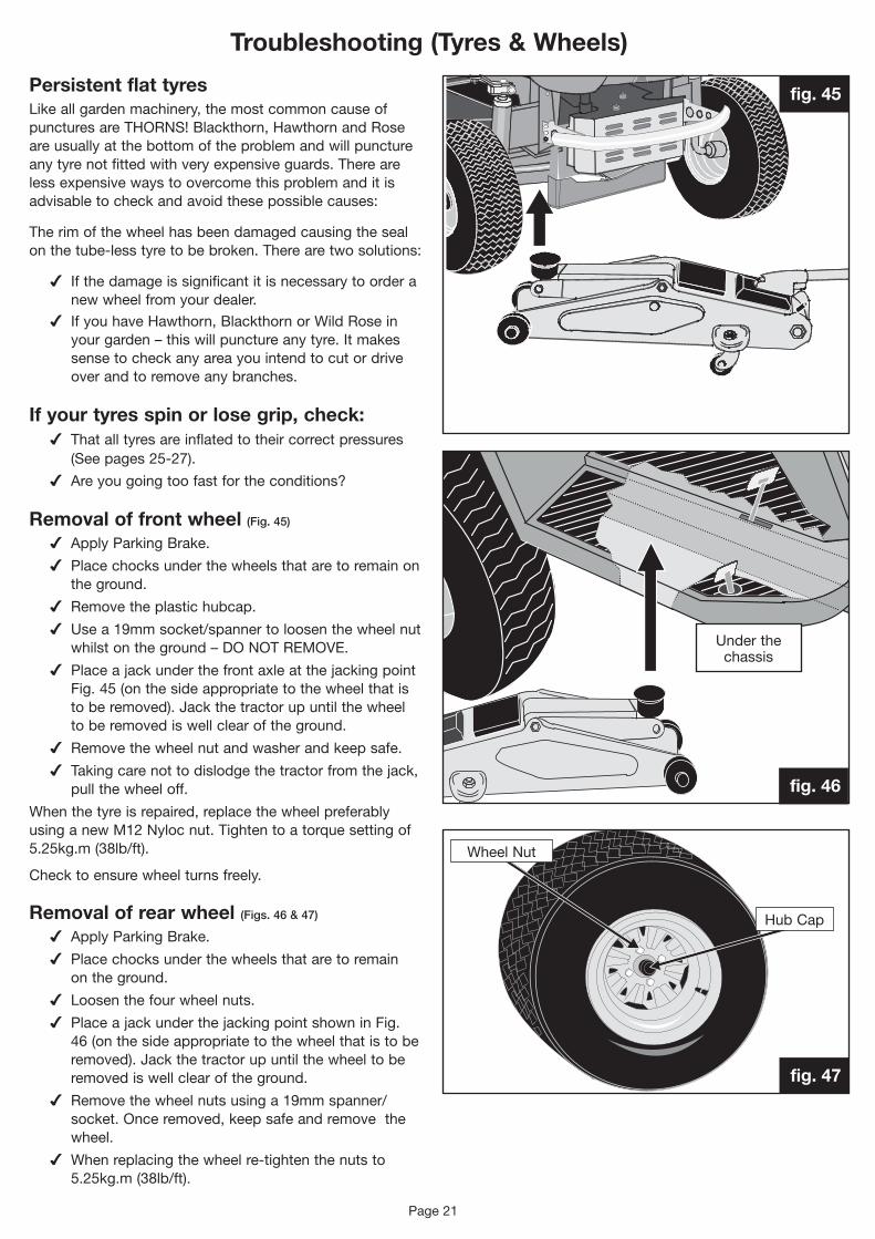
Removal of front wheel (Fig. 45)
4 Apply Parking Brake.
4 Place chocks under the wheels that are to remain on the ground.
4 Remove the plastic hubcap.
4 Usea19mmsocket/spannertoloosenthewheelnutwhilstontheground–DONOTREMOVE.
4 Place a jack under the front axle at the jacking point Fig. 45 (on the side appropriate to the wheel that is toberemoved).Jackthetractorupuntilthewheelto be removed is well clear of the ground.
4 Remove the wheel nut and washer and keep safe.
4 Taking care not to dislodge the tractor from the jack, pull the wheel off.
When the tyre is repaired, replace the wheel preferably using a new M12 Nyloc nut. Tighten to a torque setting of 5.25kg.m(38lb/ft).
Checktoensurewheelturnsfreely.
Removal of rear wheel (Figs. 46 & 47)
4 Apply Parking Brake.
4 Place chocks under the wheels that are to remain on the ground.
4 Loosenthefourwheelnuts.
4 Place a jack under the jacking point shown in Fig. 46 (on the side appropriate to the wheel that is to be removed).Jackthetractorupuntilthewheeltoberemoved is well clear of the ground.
4 Removethewheelnutsusinga19mmspanner/socket. Once removed, keep safe and remove the wheel.
4 Whenreplacingthewheelre-tightenthenutsto5.25kg.m(38lb/ft).
Under the chassis
Wheel Nut
HubCap
fig. 45
fig. 46
fig. 47
Page 22
Troubleshooting (Starting & Running)
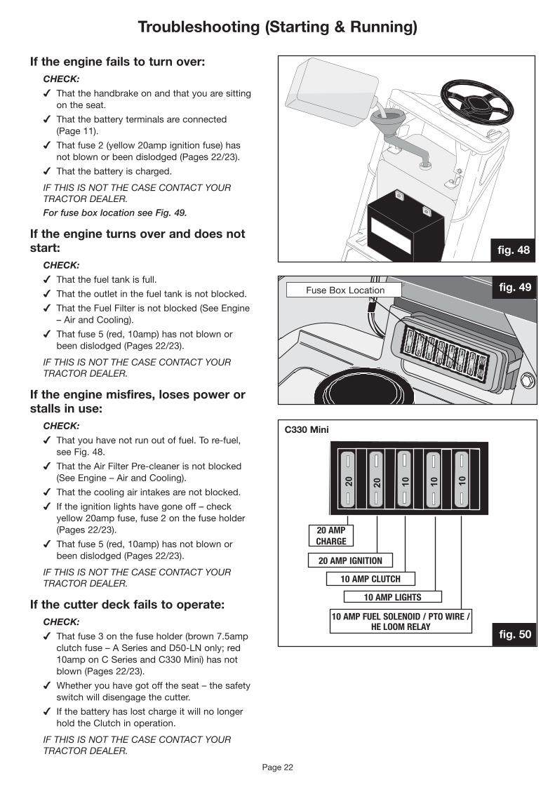
If the engine fails to turn over:CHECK:
4 That the handbrake on and that you are sitting on the seat.
4 That the battery terminals are connected (Page 11).
4 That fuse 2 (yellow 20amp ignition fuse) has notblownorbeendislodged(Pages22/23).
4 That the battery is charged.
IF THIS IS NOT THE CASE CONTACT YOUR TRACTOR DEALER.
For fuse box location see Fig. 49.
If the engine turns over and does not start:
CHECK:
4 That the fuel tank is full.
4 That the outlet in the fuel tank is not blocked.
4 ThattheFuelFilterisnotblocked(SeeEngine–AirandCooling).
4 That fuse 5 (red, 10amp) has not blown or beendislodged(Pages22/23).
IF THIS IS NOT THE CASE CONTACT YOUR TRACTOR DEALER.
If the engine misfires, loses power or stalls in use:
CHECK:
4 Thatyouhavenotrunoutoffuel.Tore-fuel,see Fig. 48.
4 ThattheAirFilterPre-cleanerisnotblocked(SeeEngine–AirandCooling).
4 That the cooling air intakes are not blocked.
4 If the ignition lights have gone off – check yellow 20amp fuse, fuse 2 on the fuse holder (Pages22/23).
4 That fuse 5 (red, 10amp) has not blown or beendislodged(Pages22/23).
IF THIS IS NOT THE CASE CONTACT YOUR TRACTOR DEALER.
If the cutter deck fails to operate:CHECK:
4 That fuse 3 on the fuse holder (brown 7.5amp clutchfuse–ASeriesandD50-LNonly;red10amponCSeriesandC330Mini)hasnotblown(Pages22/23).
4 Whether you have got off the seat – the safety switch will disengage the cutter.
4 If the battery has lost charge it will no longer holdtheClutchinoperation.
IF THIS IS NOT THE CASE CONTACT YOUR TRACTOR DEALER.
fig. 48
FuseBoxLocation
fig. 50
fig. 49
C330 Mini
10 AMP CLUTCH
10 AMP LIGHTS
10 AMP FUEL SOLENOID / PTO WIRE / HE LOOM RELAY
20 AMP CHARGE
20 AMP IGNITION

Page 23
Troubleshooting (Electrical)If the Headlights fail to operate
CHECK:
4 The bulbs.
4 Fuse 4 has not blown. (Red 10amp fuse) (Figs. 50, 50a, 50b). For tractors fitted with electricdial-a-heightandsweeper(Red5ampfuse (Fig. 50c)
IF THIS IS NOT THE CASE CONTACT YOUR TRACTOR DEALER.
If the Electric Deck Lift fails to operate:
CHECK:
4 Turn the tractor off and on again. This will resettheDeckLiftPCBwhichhasanoverloadprotection system built in. If this becomes a regular occurrence with no visible signs of anything overloading the system, eg a branch, thentheDeckLiftSystemwillrequirecheckingby your dealer.
4 Checkfuse6hasnotblown.(Red10ampfuse) (Figs. 50b or 50c).
IF THIS IS NOT THE CASE CONTACT YOUR TRACTOR DEALER.
If the Electric Sweeper Lift fails to operate*
CHECK: 4 Fuse 7 has not blown, (green 30amp fuse)
(Fig. 50c).
IF THIS IS NOT THE CASE CONTACT YOUR TRACTOR DEALER.
If the Electric Sweeper Net Empty fails to operate*
CHECK: 4 Fuse7hasnotblown.(Green30ampfuse)
(Fig. 50c).
4 TheleadfromtheTractortotheSweeperhasnot become disconnected or damaged.
IF THIS IS NOT THE CASE CONTACT YOUR TRACTOR DEALER.
If the ‘Dial-a-height’ stops working and the HE Circuits fails / engine runs poorly or cuts out:
CHECK: 4 Checkfuse5hasnotblown,(red10ampfuse)
(Figs. 50b or 50c).
IF THIS IS NOT THE CASE CONTACT YOUR TRACTOR DEALER.
* PLEASE NOTE: Fuse 6 slot is empty on tractors fittedwithmanualdeckliftandElectricSweeper
20 AMP Charge
20 AMP Ignition
7.5 AMP Clutch
5 AMP Lights
10 AMP PTO Wire, Fuel Solenoid Hold and Fuel Pump
5 AMP Relay Control Feed
30 AMP Relay Feeds
10 AMP Deck Lift
3010 1057.5
20 20 58
fig. 50c
301010101020 20
10101020 20
10101020 20 1020 AMP IGNITION SPARE
SPARE
SPARE
301010101020 20
10101020 20
10101020 20 10
20 AMP CHARGE
Tractors with Dial-a-height and PGC electric lift
Tractors with Dial-a-height
Tractors with manual deck lift
20 AMP CHARGE
fig.50b
fig. 50a
10 AMP CLUTCH
10 AMP LIGHTS
10 AMP FUEL SOLENOID / PTO WIRE / HE LOOM RELAY
10 AMP LIGHTS
10 AMP FUEL SOLENOID / PTO WIRE / HE LOOM RELAY
20 AMP IGNITION
10 AMP CLUTCH
SPARE
10 AMP Deck Lift
SPARE

Page 24
Troubleshooting (Electrical) (not applicable to C330 Mini)
If a C appears in the Park Brake window for more than a couple of minutes: (Fig. 51).
CHECK:
4 This indicates you may have a charging problem.
4 Checkthatmainchargefuse1hasnotblown,(Yellow20ampfuse).(Page23).
IF THIS IS NOT THE CASE CONTACT YOUR TRACTOR DEALER.
If the Tractor Display fails to light up when turned on, or the tractor doesn’t start:
CHECK:
4 Checkfuse2hasnotblown,(yellow20ampfuse) (Page 23).
IF THIS IS NOT THE CASE CONTACT YOUR TRACTOR DEALER.
If ‘OIL’ appears where the RPM Display should be (D50-LN only): (Fig. 52)
CHECK:
4 This indicates a problem with your oil pressure.
4 The tractor will automatically turn itself off after 10 seconds.
CONTACT YOUR DEALER IMMEDIATELY AND DO NOT ATTEMPT TO RESTART YOUR TRACTOR AS SERIOUS DAMAGE MAY BE CAUSED BY RUNNING THE ENGINE WITH LOW OIL PRESSURE.
If ‘HOT’ appears where the RPM Display should be (D50-LN only): (Fig. 53)
CHECK:
4 This indicates a problem with the Water Temperature.
4 The tractor will automatically turn itself off after 10 seconds.
CONTACT YOUR DEALER IMMEDIATELY AND DO NOT ATTEMPT TO RESTART YOUR TRACTOR AS SERIOUS DAMAGE MAY BE CAUSED BY RUNNING THE ENGINE WITH A HIGH WATER TEMPERATURE.
Service Intervals: (Fig. 54)
ThesearepresetintothePCBmemoryandwillflashup‘S’ontheparkbrakedisplaybeforetheserviceisdue. This will be reset by your dealer. The first service for your tractor is after 50 hours of use or yearly, then every 50 hours or yearly. The service light will come on 5 hours before the service is due.
fig. 51
fig. 52
fig. 53
fig. 54

Specifications – C330 Mini and C Series
Page 25
WeightC330Mini 224kgC300-Mulcher 241kgC600-Mulcher 244kgC300M 241kgC300H 241kgC30H 241kgC400H 243kgC600H 244kgC800H 261kgC600-4WD/FW-4WD 264kgC800-4WD 281kgC25-4WD 286kg
WeightC330MiniPGC 49kgCSeriesPGC 59kg
Fuel Tank Capacity7 litres (1.5 gallons)
PGC Capacity255litre(C330Minionly)300 litres
TransmissionTuffTorqK46HydrostaticorPeerlessMST206/536ATransaxleor
Transmission 4WDTuffTorqK574&HFWD
Turning Radius C330Mini142.7cm2WD 128.0cm 4WD 152.0cm
Forward Speeds0-6mph
Tyre PressuresMiniFront:0.7-1.0KGF/cm(10-14psi)Rear: 0.7-1.0KGF/cm(10-14psi)C SeriesFront:0.8-1.1KGF/cm(12-16psi)Rear: 0.7-1.1KGF/cm(10-12psi)
2.70m(C330);2.72m(2WD);2.85m(4WD)
1.73m(C330);1.75m(2WD);1.88m(4WD)
1.10m(C
330);1.12m
Model Engine Displacement Power Torque Bore Stroke
C330 Mini HondaSingleCylinderOHV9.69kW 389cc 9.69kW 13hp 24.2NM 88mm 64mm
C300 Mulcher
HondaTwinCylinderOHC90º V-Twin9.69kW 530cc 9.69kW 13hp 35.9NM 77mm 57mm
C600 Mulcher
HondaTwinCylinderOHC90º V-Twin11.93kW 530cc 11.93kW 16hp 36.5NM 77mm 57mm
C300M Briggs&StrattonSingleCylinderINTEK9.32kW 465cc 9.32kW 12.5hp 24.5NM 87.3mm 66mm
C30H HondaSingleCylinderOHV 9.69kW 530cc 9.69kW 13hp 35.9NM 77mm 57mm
C300H HondaTwinCylinderOHC90º V-Twin9.69kW 530cc 9.69kW 13hp 35.9NM 77mm 57mm
C400H HondaTwinCylinderOHC90º V-Twin10.44kW 530cc 10.44kW 14hp 35.9NM 77mm 57mm
C600H HondaTwinCylinderOHC90º V-Twin11.93kW 530cc 11.93kW 16hp 36.5NM 77mm 57mm
C800H HondaTwinCylinderOHC90º V-Twin13.42kW 614cc 13.42kW 18hp 41.1NM 77mm 66mm
C600-4WD HondaTwinCylinderOHC90º V-Twin11.93kW 530cc 11.93kW 16hp 36.5NM 77mm 57mm
C800-4WD HondaTwinCylinderOHC90º V-Twin13.42kW 614cc 13.42kW 18hp 41.1NM 77mm 66mm
C25-4WD KawasakiTwinCylinder V-Twin18.64kW 675cc 18.64kW 25hp 41.1NM 77mm 66mm
FW-4WD HondaTwinCylinderOHC90º V-Twin11.93kW 530cc 11.93kW 16hp 36.5NM 77mm 57mm
0.86m(C330);0.93m

Page 26
Specifications – A Series
WeightA20/50H 290kg
A20/50HE 290kg
A25/50HE 290kg
A20/50HPGC 59kg
A20/50HEPGC68kg
A25/50HEPGC68kg
Fuel Tank Capacity7 litres (1.5 gallons)
A20/50H PGC Capacity300 litres
A20/50HE PGC Capacity390 litres
A25/50HE PGC Capacity390 litres
TransmissionTuffTorqK62Hydrostatic
Turning Radius99cm
Forward Speeds0-7mph
Tyre PressuresFront: 0.8-1.1KGF/cm(12-16psi)
Rear:0.43-0.7KGF/cm(6-10psi)
A20/50H:2.72m;A20/50HE and A25/50HE: 2.87m
1.84m
1.19m
1m
Model Engine Displacement Power Torque Bore Stroke
A20/50HHondaTwin
CylinderOHV90º V-Twin14.91kW
614cc 14.91kW 20hp 41.1NM 77mm 66mm
A20/50HEHondaTwin
CylinderOHV90º V-Twin14.91kW
614cc 14.91kW 20hp 41.1NM 77mm 66mm
A25/50HEKawasakiTwinCylinderV-Twin
18.64kW675cc 18.64kW 25hp 41.1NM 75.2mm 76mm

Page 27
K18/50andD50LN=308cm
K18/50andD50LN=205cm
Model Engine Displacement Power Torque Bore Stroke
K18/50 Kawasaki Liquidcooled 585cc
13.42kW 18hp) @ 3600rpm
41.5NM @ 2600rpm
74mm 68mm
D50LN Yanmar2V78Diesel 744cc13.42kW 18hp)
@ 3600rpm45NM
@ 2800rpm78mm 78.4mm
K18/50andD50LN131.5cm
Weight Including Cutter Deck (Standard IBS)391kg(includingCutterDeck)
Fuel Tank Capacity7 litres (1.5 gallons)
PGC Capacity390 litres
Forward Speeds0-6.5mph
TransmissionTuffTorqHeavyDutyHydrostaticK66,infinitely variable speed control.
Turning Radius (Internal Rear)104cm (41”)
Tyre PressuresFront:0.8-1.1KGF/cm(12-16psi)Rear: 0.43-0.7KGF/cm(6-10psi)
Specifications – K and D Series

Page 28
Personal Service Record
Service Date: Hours:
Dealer’s Signature:
DEALER STAMPOR NAME & ADDRESS
Service Date: Hours:
Dealer’s Signature:
Second Service (24 months)
DEALER STAMPOR NAME & ADDRESS
Service Date: Hours:
Dealer’s Signature:
Third Service (36 months)
DEALER STAMPOR NAME & ADDRESS
Service Date: Hours:
Dealer’s Signature:
Fourth Service (48 months)
DEALER STAMPOR NAME & ADDRESS
Service Date: Hours:
Dealer’s Signature:
Fifth Service (60 months)
DEALER STAMPOR NAME & ADDRESS
Service Date: Hours:
Dealer’s Signature:
Sixth Service (72 months)
Model
Date of Purchase
Date of Registration
Name of Dealer
SerialNumber
UsethispageasapersonalrecordoftheservicehistoryofyourCountaxgardentractor. AskyourdealertostamptheappropriateboxatthesametimeasyourServiceRecordCard.
4th
5th
6th
1st
2nd
3rd
DEALER STAMPOR NAME & ADDRESS
First Service (12 months)
Page 29
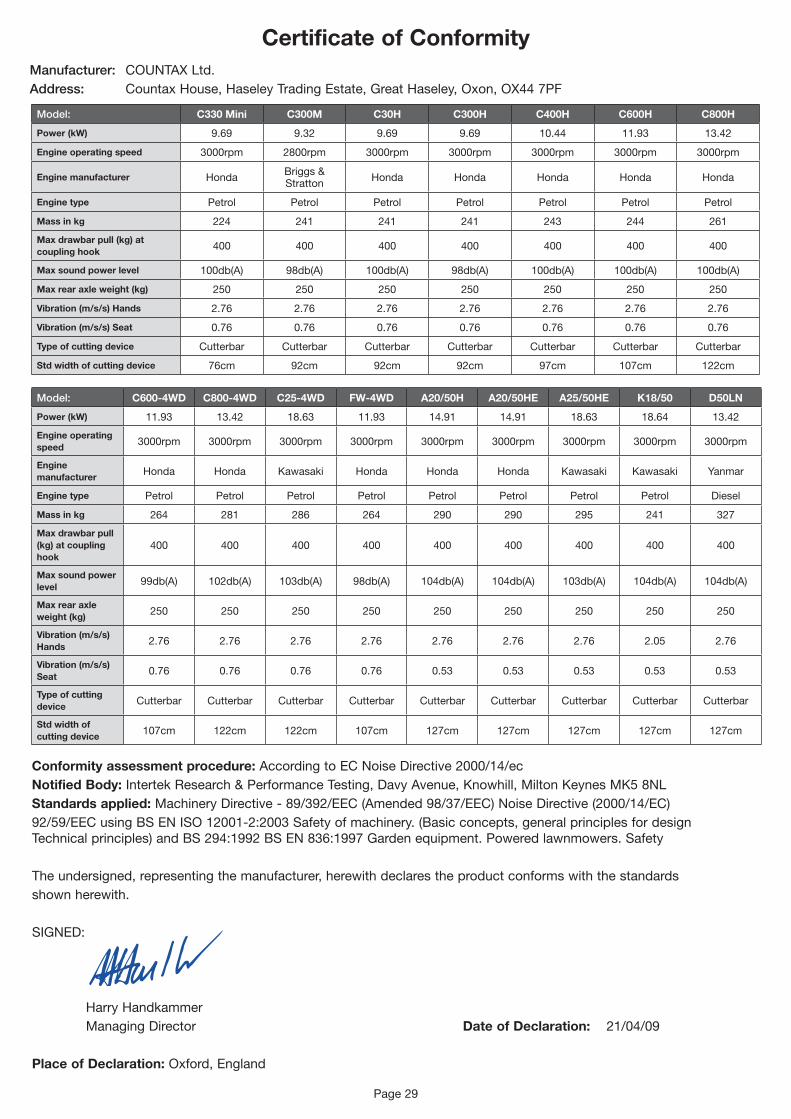
Certificate of ConformityManufacturer: COUNTAXLtd.Address: CountaxHouse,HaseleyTradingEstate,GreatHaseley,Oxon,OX447PF
Conformity assessment procedure:AccordingtoECNoiseDirective2000/14/ecNotified Body:IntertekResearch&PerformanceTesting,DavyAvenue,Knowhill,MiltonKeynesMK58NLStandards applied:MachineryDirective-89/392/EEC(Amended98/37/EEC)NoiseDirective(2000/14/EC)92/59/EECusingBSENISO12001-2:2003Safetyofmachinery.(Basicconcepts,generalprinciplesfordesignTechnicalprinciples)andBS294:1992BSEN836:1997Gardenequipment.Poweredlawnmowers.Safety
The undersigned, representing the manufacturer, herewith declares the product conforms with the standards shown herewith.
SIGNED:
HarryHandkammer Managing Director Date of Declaration: 21/04/09
Place of Declaration:Oxford,England
Model: C330 Mini C300M C30H C300H C400H C600H C800H
Power (kW) 9.69 9.32 9.69 9.69 10.44 11.93 13.42
Engine operating speed 3000rpm 2800rpm 3000rpm 3000rpm 3000rpm 3000rpm 3000rpm
Engine manufacturer Honda Briggs & Stratton Honda Honda Honda Honda Honda
Engine type Petrol Petrol Petrol Petrol Petrol Petrol Petrol
Mass in kg 224 241 241 241 243 244 261
Max drawbar pull (kg) at coupling hook 400 400 400 400 400 400 400
Max sound power level 100db(A) 98db(A) 100db(A) 98db(A) 100db(A) 100db(A) 100db(A)
Max rear axle weight (kg) 250 250 250 250 250 250 250
Vibration (m/s/s) Hands 2.76 2.76 2.76 2.76 2.76 2.76 2.76
Vibration (m/s/s) Seat 0.76 0.76 0.76 0.76 0.76 0.76 0.76
Type of cutting device Cutterbar Cutterbar Cutterbar Cutterbar Cutterbar Cutterbar Cutterbar
Std width of cutting device 76cm 92cm 92cm 92cm 97cm 107cm 122cm
Model: C600-4WD C800-4WD C25-4WD FW-4WD A20/50H A20/50HE A25/50HE K18/50 D50LN
Power (kW) 11.93 13.42 18.63 11.93 14.91 14.91 18.63 18.64 13.42
Engine operating speed 3000rpm 3000rpm 3000rpm 3000rpm 3000rpm 3000rpm 3000rpm 3000rpm 3000rpm
Engine manufacturer Honda Honda Kawasaki Honda Honda Honda Kawasaki Kawasaki Yanmar
Engine type Petrol Petrol Petrol Petrol Petrol Petrol Petrol Petrol Diesel
Mass in kg 264 281 286 264 290 290 295 241 327
Max drawbar pull (kg) at coupling hook
400 400 400 400 400 400 400 400 400
Max sound power level 99db(A) 102db(A) 103db(A) 98db(A) 104db(A) 104db(A) 103db(A) 104db(A) 104db(A)
Max rear axle weight (kg) 250 250 250 250 250 250 250 250 250
Vibration (m/s/s) Hands 2.76 2.76 2.76 2.76 2.76 2.76 2.76 2.05 2.76
Vibration (m/s/s) Seat 0.76 0.76 0.76 0.76 0.53 0.53 0.53 0.53 0.53
Type of cutting device Cutterbar Cutterbar Cutterbar Cutterbar Cutterbar Cutterbar Cutterbar Cutterbar Cutterbar
Std width of cutting device 107cm 122cm 122cm 107cm 127cm 127cm 127cm 127cm 127cm

Notes

CountaxLimited,CountaxHouse,GreatHaseley,OxfordOX447PFTel:(+44)1844278800•Fax:(+44)01844278792