Cummins Inc. - Transfer Switch Operation and …...2 Welcome! PowerHour is designed to help our engineer partners to… • Keep up to date on products, technology, and codes and standards
50
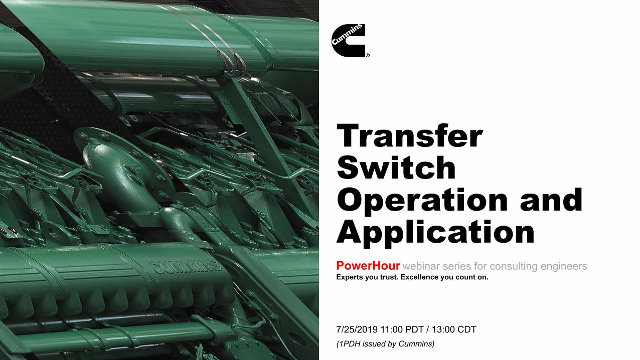
7/25/2019 11:00 PDT / 13:00 CDT (1PDH issued by Cummins) Transfer Switch Operation and Application PowerHour webinar series for consulting engineers Experts you trust. Excellence you count on.
7/25/2019 11:00 PDT / 13:00 CDT(1PDH issued by Cummins)
Transfer Switch Operation and ApplicationPowerHour webinar series for consulting engineersExperts you trust. Excellence you count on.
2
Welcome!PowerHour is designed to help our engineer partners to…• Keep up to date on products, technology, and codes and standards development
• Interact with Cummins experts and gain access to ongoing technical support
• Participate at your convenience, live or on-demand
• Earn Professional Development Hours (PDH)
Technical tips: Audio is available through teleconference, or your computer (don’t
forget to unmute) You are in “listen only” mode throughout the event Use the WebEx Q&A Panel to submit questions, comments, and
feedback throughout the event. We will provide sufficient Q&A time after presentation If you lose audio, get disconnected, or experience a poor connection,
please disconnect and reconnect Report technical issues using the WebEx Q&A Panel, or email
Welcome to PowerHour webinar series, the program designed for our engineering partners like you! - The program will offer concise technical presentations on topics pertaining to on site power systems design and specification. It means to keep you updated on products, technology and codes and standards development, the topic most relevant to the jobs and projects you are working on. - You will be able to interact directly with Cummins presenters throughout the Q&A session at each live webinar, and gain access to ongoing technical support post-events. - The webinars will be recorded and archived. If you miss a webinar, visit our on demand webinar center and replay any topic of your interests. - You can earn 1 Professional Development Hour issued by Cummins upon your completion of the webinar
3
Meet your panelists
Divya MahabalTechnical Specialist-Application EngineeringCummins Inc.
Cummins presenter: Cummins facilitator:
High Resolutio
n Headshot
Tom Bakritzes, Global Sales Training ManagerCummins Inc.
Your local Cummins contacts: Western Canada: Ian Lindquist ([email protected]), Western Canada Region Eastern Canada: Gianluca Ianiro ([email protected]), Eastern Canada Region AZ, ID, NM, NV: Carl Knapp ([email protected]), Rocky Mountain Region CO, MT, ND, UT, WY: Chris Scott ([email protected]), Rocky Mountain Region Northern IL, IA: John Kilinskis ([email protected]), Central Region UP of MI, MN, East ND, WI: Michael Munson ([email protected]), Central Region NE, SD, West MO, KS: Earnest Glaser ([email protected]), Central Region
South IL, East MO: Jeff Yates ([email protected]), Central Region TX, OK, AR, LA, MS, AL, Western TN: Scott Thomas ([email protected]), Gulf Region FL, GA, NC, SC, Eastern TN: Robert Kelly ([email protected]), South Region NY, NJ, CT, PA, MD: Charles Attisani ([email protected]), East Region CA, HI: Brian E Pumphrey ([email protected]), Pacific Region WA, OR, AK: Tom Tomlinson ([email protected]), Pacific Region For other states and territories, email [email protected] or visit
The views and opinions expressed in this course shall not be considered the official position of any regulatory organization and shall not be considered to be, nor be relied upon as, a Formal Interpretation. Participants are encouraged to refer to the entire text of all referenced documents. In addition, when it doubt, reach out to the Authority Having Jurisdiction.
Cummins Confidential
5
Course Objectives
Transfer Switch Operation and ApplicationTransfer switch equipment is available in a variety of types, with a wide array of features. Selecting the appropriate transfer switch for a specific application requires a clear understanding of site needs and application restraints.
After completing this course, participants will be able to: Discuss the basic operation of transfer switches and transition types to aid in the selection
of equipment Describe the operation modes of bypass switches and isolation methods. Identify when it is appropriate to use a 4 pole switch as compared to 3 pole switch
6
What does a transfer switch do?
7
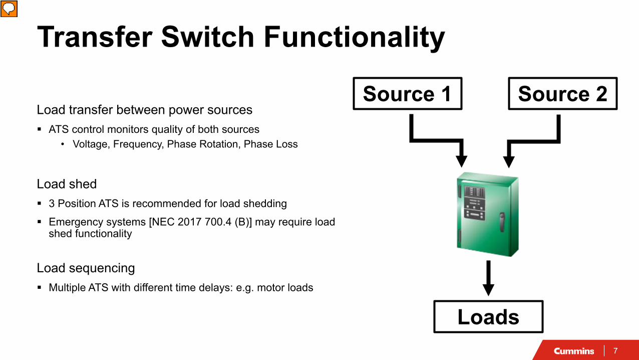
Transfer Switch Functionality
Load transfer between power sources ATS control monitors quality of both sources
• Voltage, Frequency, Phase Rotation, Phase Loss
Load shed 3 Position ATS is recommended for load shedding Emergency systems [NEC 2017 700.4 (B)] may require load
shed functionality
Load sequencing Multiple ATS with different time delays: e.g. motor loads
Source 1 Source 2
Loads
Presenter
Presentation Notes
The ATS monitors voltage and frequency on the primary power source (commonly Utility). It can measure these on one phase or on all three phases. When one of these measurements goes out of an acceptable range, the ATS sends a signal to the generator to start. There is an adjustable time delay on this signal to allow for temporary disturbances in the utility power. Once the ATS senses that the generator is up and running, it transfers load to the generator. When is an ATS needed? NEC driven NEC 517.30 (B)(2) requires one or more transfer switches for each branch of the essential electrical system Essential Electrical System. A system comprised of alternate sources of power and all connected distribution systems and ancillary equipment, designed to ensure continuity of electrical power to designated areas and functions of a health care facility during disruption of normal power sources, and also to minimize disruption within the internal wiring system. NEC 700.5 - Transfer equipment shall be automatic, identified for emergency use, and approved by the authority having jurisdiction. It shall supply only emergency loads. ATS can provide means for Load Shedding Load Sequencing-has been discussed in sizing NEC 700.4 (B) - The alternate power source shall be permitted to supply emergency, legally required standby, and optional standby system loads where the source has adequate capacity or where automatic selective load pickup and load shedding is provided as needed to ensure adequate power Abrupt transient load changes will likely result in larger voltage and frequency disturbances than on Utility. Multiple transfer switches with sequenced transfer time delays allow generator voltage and frequency to stabilize. Digital IO module -Close Motor starting contacts -Multiple transfer switches with different time delays
8
Transfer Switch FunctionalitySource TransferLoad transfer between power sources ATS control monitors quality of both sources
• Voltage, Frequency, Phase Rotation, Phase Loss
Load shed 3 Position ATS is recommended for load shedding Emergency systems [NEC 2017 700.4 (B)] may require load
shed functionality
Load sequencing Multiple ATS with different time delays: e.g. motor loads
Source 1 (Normal)
Source 2 (Emergency)
Loads
Presenter
Presentation Notes
The ATS monitors voltage and frequency on the primary power source (commonly Utility). It can measure these on one phase or on all three phases. When one of these measurements goes out of an acceptable range, the ATS sends a signal to the generator to start. There is an adjustable time delay on this signal to allow for temporary disturbances in the utility power. Once the ATS senses that the generator is up and running, it transfers load to the generator. When is an ATS needed? NEC driven NEC 517.30 (B)(2) requires one or more transfer switches for each branch of the essential electrical system Essential Electrical System. A system comprised of alternate sources of power and all connected distribution systems and ancillary equipment, designed to ensure continuity of electrical power to designated areas and functions of a health care facility during disruption of normal power sources, and also to minimize disruption within the internal wiring system. NEC 700.5 - Transfer equipment shall be automatic, identified for emergency use, and approved by the authority having jurisdiction. It shall supply only emergency loads. ATS can provide means for Load Shedding Load Sequencing-has been discussed in sizing NEC 700.4 (B) - The alternate power source shall be permitted to supply emergency, legally required standby, and optional standby system loads where the source has adequate capacity or where automatic selective load pickup and load shedding is provided as needed to ensure adequate power Abrupt transient load changes will likely result in larger voltage and frequency disturbances than on Utility. Multiple transfer switches with sequenced transfer time delays allow generator voltage and frequency to stabilize. Digital IO module -Close Motor starting contacts -Multiple transfer switches with different time delays
9
Transfer Switch FunctionalityLoad ShedLoad transfer between power sources ATS control monitors quality of both sources
• Voltage, Frequency, Phase Rotation, Phase Loss
Load shed 3 Position ATS is recommended for load shedding Emergency systems [NEC 2017 700.4 (B)] may require load
shed functionality
Load sequencing Multiple ATS with different time delays: e.g. motor loads
Source 1 (Normal)
Source 2 (Emergency)
Loads
Presenter
Presentation Notes
The ATS monitors voltage and frequency on the primary power source (commonly Utility). It can measure these on one phase or on all three phases. When one of these measurements goes out of an acceptable range, the ATS sends a signal to the generator to start. There is an adjustable time delay on this signal to allow for temporary disturbances in the utility power. Once the ATS senses that the generator is up and running, it transfers load to the generator. When is an ATS needed? NEC driven NEC 517.30 (B)(2) requires one or more transfer switches for each branch of the essential electrical system Essential Electrical System. A system comprised of alternate sources of power and all connected distribution systems and ancillary equipment, designed to ensure continuity of electrical power to designated areas and functions of a health care facility during disruption of normal power sources, and also to minimize disruption within the internal wiring system. NEC 700.5 - Transfer equipment shall be automatic, identified for emergency use, and approved by the authority having jurisdiction. It shall supply only emergency loads. ATS can provide means for Load Shedding Load Sequencing-has been discussed in sizing NEC 700.4 (B) - The alternate power source shall be permitted to supply emergency, legally required standby, and optional standby system loads where the source has adequate capacity or where automatic selective load pickup and load shedding is provided as needed to ensure adequate power Abrupt transient load changes will likely result in larger voltage and frequency disturbances than on Utility. Multiple transfer switches with sequenced transfer time delays allow generator voltage and frequency to stabilize. Digital IO module -Close Motor starting contacts -Multiple transfer switches with different time delays
10
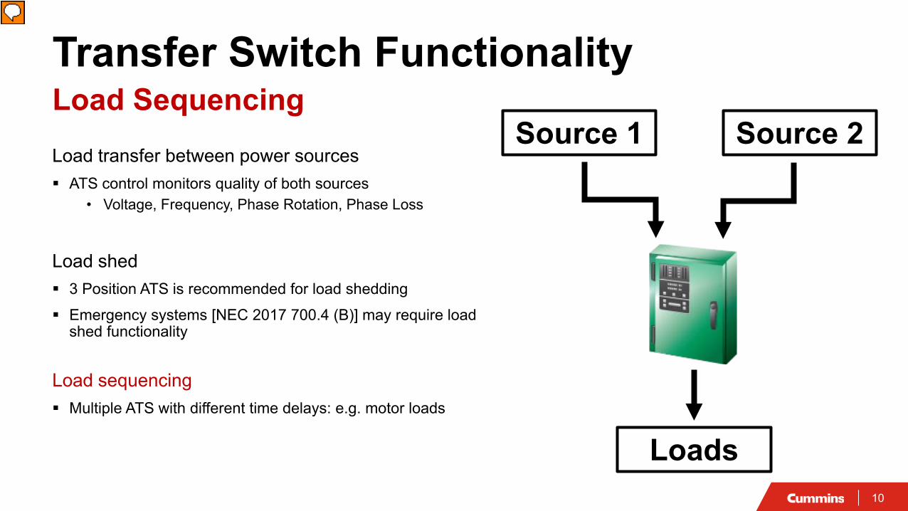
Transfer Switch FunctionalityLoad SequencingLoad transfer between power sources ATS control monitors quality of both sources
• Voltage, Frequency, Phase Rotation, Phase Loss
Load shed 3 Position ATS is recommended for load shedding Emergency systems [NEC 2017 700.4 (B)] may require load
shed functionality
Load sequencing Multiple ATS with different time delays: e.g. motor loads
Source 1 Source 2
Loads
Presenter
Presentation Notes
The ATS monitors voltage and frequency on the primary power source (commonly Utility). It can measure these on one phase or on all three phases. When one of these measurements goes out of an acceptable range, the ATS sends a signal to the generator to start. There is an adjustable time delay on this signal to allow for temporary disturbances in the utility power. Once the ATS senses that the generator is up and running, it transfers load to the generator. When is an ATS needed? NEC driven NEC 517.30 (B)(2) requires one or more transfer switches for each branch of the essential electrical system Essential Electrical System. A system comprised of alternate sources of power and all connected distribution systems and ancillary equipment, designed to ensure continuity of electrical power to designated areas and functions of a health care facility during disruption of normal power sources, and also to minimize disruption within the internal wiring system. NEC 700.5 - Transfer equipment shall be automatic, identified for emergency use, and approved by the authority having jurisdiction. It shall supply only emergency loads. ATS can provide means for Load Shedding Load Sequencing-has been discussed in sizing NEC 700.4 (B) - The alternate power source shall be permitted to supply emergency, legally required standby, and optional standby system loads where the source has adequate capacity or where automatic selective load pickup and load shedding is provided as needed to ensure adequate power Abrupt transient load changes will likely result in larger voltage and frequency disturbances than on Utility. Multiple transfer switches with sequenced transfer time delays allow generator voltage and frequency to stabilize. Digital IO module -Close Motor starting contacts -Multiple transfer switches with different time delays
11
Application Types
Utility to GeneratorFor facilities with a standby power system
and a single utility feed
12
Application Types
Utility to GeneratorFor facilities with a standby power system
and a single utility feed
Utility to UtilityFor use in facilities with redundant feedsbut no standby generator
13
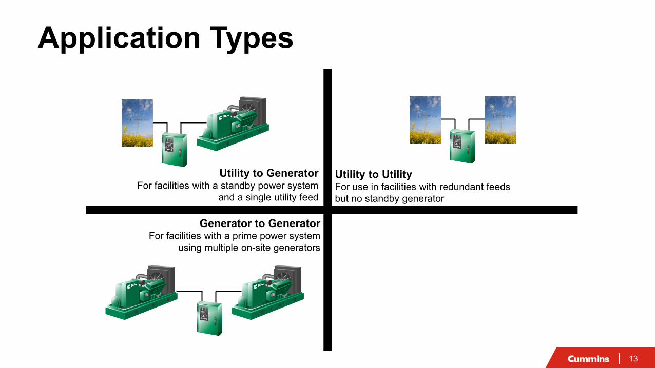
Application Types
Utility to GeneratorFor facilities with a standby power system
and a single utility feed
Utility to UtilityFor use in facilities with redundant feedsbut no standby generator
Generator to GeneratorFor facilities with a prime power system
using multiple on-site generators
14
Application Types
Utility to GeneratorFor facilities with a standby power system
and a single utility feed
Utility to UtilityFor use in facilities with redundant feedsbut no standby generator
Generator to GeneratorFor facilities with a prime power system
using multiple on-site generators
Three-Source SystemTwo generator sets backup a utility service
15
Transition Types
Open Transition (In Phase)Open Transition (Time Delayed / Programmed Transfer)Closed Transition
Presenter
Presentation Notes
There are 2 transition types: Open and Closed. Open: break before make Closed: two sources connected together for 100msec. Open: is divided into in-phase or delayed
16
Open TransitionIn Phase Transfer Break-before-make switching action Power interruption of 3-5 Cycles (50-80 ms) Suitable for resistive and small motor loads
(<20hp)
t
Load Voltage
v
Presenter
Presentation Notes
Here we can see the operating sequence of an open transition transfer switch. Notice that the loads experience a power interruption that lasts 5-10 cycles while both power sources are disconnected. If you have a stored energy load in-phase is not the transition to use
17
Open TransitionIn Phase Transfer
!
Presenter
Presentation Notes
Let us walk through the basic sequence of an open transition transfer switch under a utility failure: Power Interruption of 3-5 cycles which is 50-80ms Power Failure Power fails, time delay to start Start signal issued (hardwire and network) Genset starts, accelerates to rated volts/hz; time delay transfer Open utility source contacts, time delay (if needed), close generator source contacts (4-pole contacts all at the same time)
18
!
Open TransitionRetransfer (In Phase)
Presenter
Presentation Notes
No when the power returns: Power Return ATS control senses return; time delay retransfer Sync check/synchronize command over network (Cummins only) Sync verified; normal source closes 50 ms later, generator source contacts open (control monitors historic speed of operation and adjusts for it) Test/Exercise “What happens if…” Fail to disconnect: trip utility breaker? Generator breaker? Note that software has 2-stage fail to disconnect, fail to disconnect; controller lockout; Fail utility while connected? Utility trip/ats disconnect from utility If all fails, we have started to put reverse power and reverse var functionality in our generator set controls. This is active even when the generator is shut off.
19
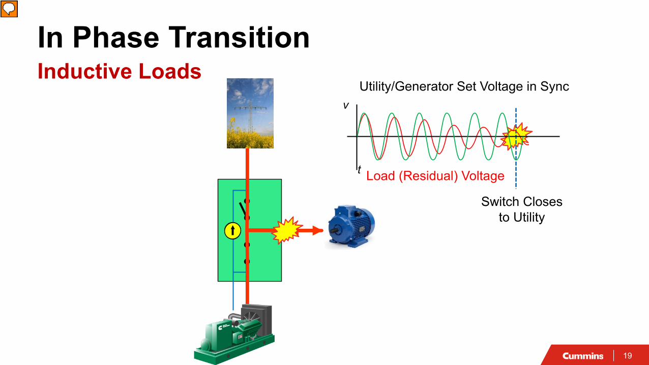
Load (Residual) Voltage
Switch Closes to Utility
In Phase TransitionInductive Loads
Utility/Generator Set Voltage in Sync
t
v
Presenter
Presentation Notes
We just talked about in-phase transfer with that 30-80 ms time delay. There are times when you want to delay for more that 30-80 ms and the primary reason for that is when you have motor loads (inductive loads). A motor is constructed like a generator. It has a rotor and stator Problems with inductive loads Motor acts like a generator after source disconnect Generates voltage due to the stored energy in the windings Voltage phase will keep shifting with respect to source Creates back emf due to rotating field. Phase shifts Closes out of phase Damages load Cause nuisance breaker tripping 1)When the transfer switch determines that the utility power is back on line and stable, the transfer switch control will monitor the voltage on the two sources. 2) When the transfer switch control determines that the two sources are in sync, the transfer switch will begin to transfer the load back to the utility. 3) In the case of an inductive load, we will see how the load generated voltage goes out of phase with the synchronized genset/utility voltage once disconnected from a power source 4) If a standard, in phase transition were used in this case, the switch would close the utility to the out of phase load generated voltage, possibly resulting in damage to the load and distribution equipment IEEE141, the Red Book:��f) Reclosure and transfer switch operations [B26]. Under normal operating conditions,�the self-generated voltage of an ac motor lags the bus voltage by a few electrical�degrees in induction motors and by 25 to 35 electrical degrees in synchronous�motors. The operation of a recloser on the utility power supply or the transfer to an�alternate source will cause the power to be interrupted for a fraction of a second or�longer. When power is removed from a motor, the terminal voltage does not collapse�suddenly, but decays in accordance with the open-circuit machine time constant (time�for self-generated voltage to decay to 37% of rated bus voltage). The load with its�inherent inertia acts as a prime mover that attempts to keep the rotor turning. The frequency�or phase relationship of the motor self-generated voltage no longer follows�the bus voltage by a �xed torque angle, but starts to separate farther from it (out-ofphase in electrical degrees) as the motor decelerates.
20
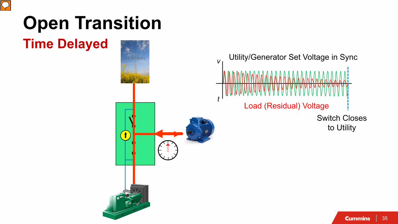
Load (Residual) Voltage
Open TransitionTime Delayed
Utility/Generator Set Voltage in Sync
t
v
Switch Closes to Utility
Presenter
Presentation Notes
(click once to view timed animation) ============================================= Illustrate risk of closing out of phase, see below slide from fly in Show three waveforms: Utility, generator, load When generator connected to load, they are the same When generator disconnected, they change Genset shutdown will not occur until the generator has had a chance to cool down by running without load. Also, some may choose to keep the generator running for several minutes until it has been confirmed that the utility is online and stable. Don’t even talk about shutting generator down.
21
Open TransitionTime Delayed
Load Voltage
Programmed delayt
v
Presenter
Presentation Notes
Here we can see the operating sequence of an programmed transition transfer switch. Notice that the load voltage decays slowly once the inductive loads have been disconnected from a power source. The programmed transition transfer has a delay that allows this load generated voltage to decay to a safe voltage. It is important to understand that the transfer switch does not measure the residual voltage, it only creates a pre-determined pause between switching to allow the residual voltage to decay. NEMA MG1 Suggests 1.5 times Motor Time constant delay to reduce voltage to safe level. NEMA MG1 20.33.1
22
Residual Voltage DecrementSource: IEEE Orange Book
22% of nominal voltage (safe transfer)
Time Delayed TransitionResidual Voltage Decay Voltage decays exponentially
(independent of motor speed) NEMA MG-1 recommends a delay of 1.5
Motor Open Circuit Time Constants• Voltage will be at 22% of nominal
For multiple motors, use the time delay for the largest motor
Spec Note Open transition and delayed transition switches shall be supplied with a 3 position mechanism .The switch control will move to the center off position when there is a load shed signal from Generator set controller or a supervisory controller. The switch will also move to the center off position during delayed transition for a pre programmed amount of time, and aid in residual voltage dissipation
Presenter
Presentation Notes
How long should we wait to let the voltage decay.. The time constant is the time it takes for a system's response to the step function to reach 1 - (1/e) = 63% of its final value. The "open circuit" time constant for a motor is the time it takes for the value of the system (voltage) to reach 37% of the base value (rated bus voltage) when the motor is open circuited. Voltage decays after disconnect. Voltage decay is a function of the open circuit time constant of motor. (time required for volts to decay to 37% of normal) Range is from a few tenths of second, to 1.25 seconds Also capacitive loads should be taken into consideration. Check the datasheet for the capacitive loads. note that this assumes a single motor. In a real circuit you also have other motors, resistive loads, etc….tends to make the voltage decay faster than expected. So, OCTC is a good conservative assumption for volt decay.
23
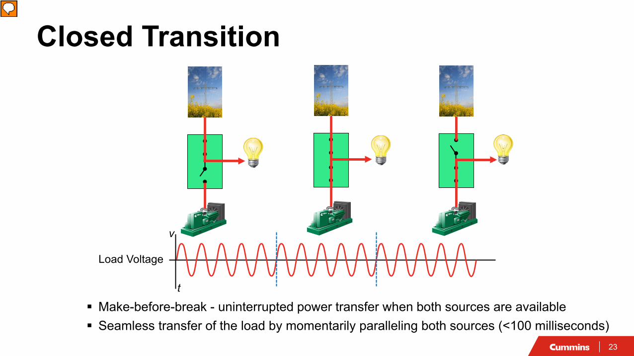
t
Load Voltage
Closed Transition
Make-before-break - uninterrupted power transfer when both sources are available Seamless transfer of the load by momentarily paralleling both sources (<100 milliseconds)
v
Presenter
Presentation Notes
So we talked about open transition and now we will talk about closed transition. Here we can see the operating sequence of a closed transition transfer switch. Notice that the two sources are paralleled for a time not to exceed 100ms during the transition. The result is that the loads experience no power interruption.
24
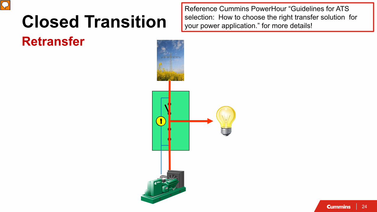
Closed TransitionRetransfer
Reference Cummins PowerHour “Guidelines for ATS selection: How to choose the right transfer solution for your power application.” for more details!
Presenter
Presentation Notes
Here will go over the sequence of operation for a closed transition transfer switch. The utility had failed at some time in the past and we are running on the generator now… 1)When the transfer switch determines that the utility power is back on line and stable, the transfer switch control will monitor the voltage on the two sources. 2) When the transfer switch control determines that the two sources are in sync, the transfer switch will close to the utility so that the generator and the utility are momentarily paralleled. 3) After a maximum of 100ms, the transfer switch will disconnect the loads from the generator. Note that the loads experience no power interruption
25
f2
f1
Synchronizing Synchronization is the mechanism of matching frequency, phase
and voltage of AC power sources• Phase and Frequency: engine governor fuel• Voltage: alternator field excitation
900 270
Ø
v
v
Deg180 360
t10 t2 t3 t4 t
v
t0
Voltage
Phase
Frequency
Generator output Utility output
ECM
AVR
Reference Cummins PowerHour “Features of Generator Set Control Based Paralleling” for more details!
• Wait for sources to drift into permissive window
Sync by slip frequency• Drive sources through permissive window
Active sync• Relies on generator set control to match utility waveform
Presenter
Presentation Notes
So we have been talking about two sources coming together in synch….so how do accomplish that There are three methods 1. Passive sync: freq slightly different-Drift into each other. Simplest method. Waiting for two sources to come in synch. 2. Slip freq: Induce a freq change 3. Active Sync-Adjust Gov and AVR control loops
27
Synchronization MethodsPassive Synchronization (Sync Check)Wait for sources to drift into sync
• Does not drive sources to come into phase
Depends on sources running at slightly different frequency• Sources with same frequency will not drift into sync• If frequency is too different, permissive window might be too short
t
vPermissive Window
Generator set voltageUtility voltage
Presenter
Presentation Notes
Passive synchronizing is the most basic method of synchronizing sources for load transfer. This method is also called “sync check”. In this method, the transfer switch controller monitors the voltage waveforms of both sources and waits for them to drift into a permissive window. It is important to realize that in this method, the transfer switch controller does nothing to drive these sources in phase. It simply monitors and waits for the waveforms to synchronize. Effective passive synchronizing depends on the two sources having slightly different frequencies. If the sources have identical frequencies, they will never drift into sync with each other. If the sources have a large difference in frequency, the time that they are in the permissive window will be too short to transition safely. On thing our control has (a fall back) just in case if you are waiting for eternity. Return to program transition (waiting for 2 minutes) then operate in an open tranisiton.
28
Synchronization MethodsSync by Slip Generator set frequency is set to a slightly different value compared to utility frequency Drive sources through permissive window
t
v Permissive Window
Generator set voltageUtility voltage
Presenter
Presentation Notes
Sync by slip frequency is a slightly more sophisticated method of synchronization. In this method, the transfer switch control induces a frequency change in the generator. This drives the sources through the permissive window for closed transition by ensuring that the waveform of the generator and the utility are slightly out of sync. 1/10 of a Hz is ideal. Run the genset at 0.10Hz faster than the utility
29
Synchronization MethodsActive Sync Actively adjust generator set governor and voltage regulator control loops to match the
utility waveform• Transfer switch sends “sync” command to generator controller• Generator set control adjusts fueling and excitation Generator set voltage
Utility voltage
Spec Note The transfer switch controller shall becapable of providing a synchronization signal to thegenerator set controller when both sources areavailable during a transfer. This signal shall driveactive voltage, frequency and phase matching toenable fast synchronization between sources, holdsynchronization during the transfer process sotransient current spikes are minimized.
Presenter
Presentation Notes
In this method, the generator governor and regulator actively control the generator fueling and excitation to force the generator waveform to match the utility waveform. In a Cummins generator installation, the transfer switch will send a “sync” command to a paralleling generator. The generator governor and regulator will then take over to match the utility waveform.
30
Closed Transition Risks Why do breakers trip during closed transition transfer?
• Current flows between sources caused by a difference in instantaneous voltage between sources at the instant of closure
Voltage Amplitude Difference
Phase Angle Difference
Presenter
Presentation Notes
So what are some of the risks with closed transition transfer?
31
Closed Transition Risks Why do breakers trip during closed transition transfer?
• Current flows between sources caused by a difference in instantaneous voltage between sources at the instant of closure
What causes the difference in voltage?• Phase angle difference between sources
- Use active synchronizing • Difference in RMS voltage between sources
- Use synchronizer with voltage match• Transient condition on one of the sources
- Allow only one switch to transfer at a time
Phase Angle Difference
Voltage Amplitude Difference
Presenter
Presentation Notes
So what are some of the risks with closed transition transfer?
32
Closed TransitionPreventing Extended Paralleling
Shunt trip breaker on normal or emergency source in the event of a failure of ATS to disconnect
• Use Fail to disconnect signal from ATS control or• Use External parallel timer and lockout relay
Function is required by many utilitiesBreaker
Fail to Disconnect
Shunt Trip
Presenter
Presentation Notes
Utility folks get nervous when you parallel with the utility….so the utility main concern is not be paralleled for a period longer than 100ms. Most commonly you trip the utility breaker, but theoretically you can trip either breaker…. So if you are paralleled for more than a 100 ms you need to shunt trip a power source.. Fail to disconnect output from ATS to utility feeder External paralleling timer Picture of Basler paralleling timer relay
33
Concept Check
Which transition types are not suitable for stored energy loads (large motors, MRIs)?
a) Open (In Phase) b) Open (Delayed)c) Closed d) Both b) and c)
34
Concept Check
Which transition types are not suitable for stored energy loads (large motors, MRIs)?
a) Open (In Phase) b) Open (Delayed)c) Closed d) Both b) and c)
35
Load (Residual) Voltage
Open TransitionTime Delayed
Utility/Generator Set Voltage in Sync
t
v
Switch Closes to Utility
Presenter
Presentation Notes
(click once to view timed animation) ============================================= Illustrate risk of closing out of phase, see below slide from fly in Show three waveforms: Utility, generator, load When generator connected to load, they are the same When generator disconnected, they change Genset shutdown will not occur until the generator has had a chance to cool down by running without load. Also, some may choose to keep the generator running for several minutes until it has been confirmed that the utility is online and stable. Don’t even talk about shutting generator down.
36
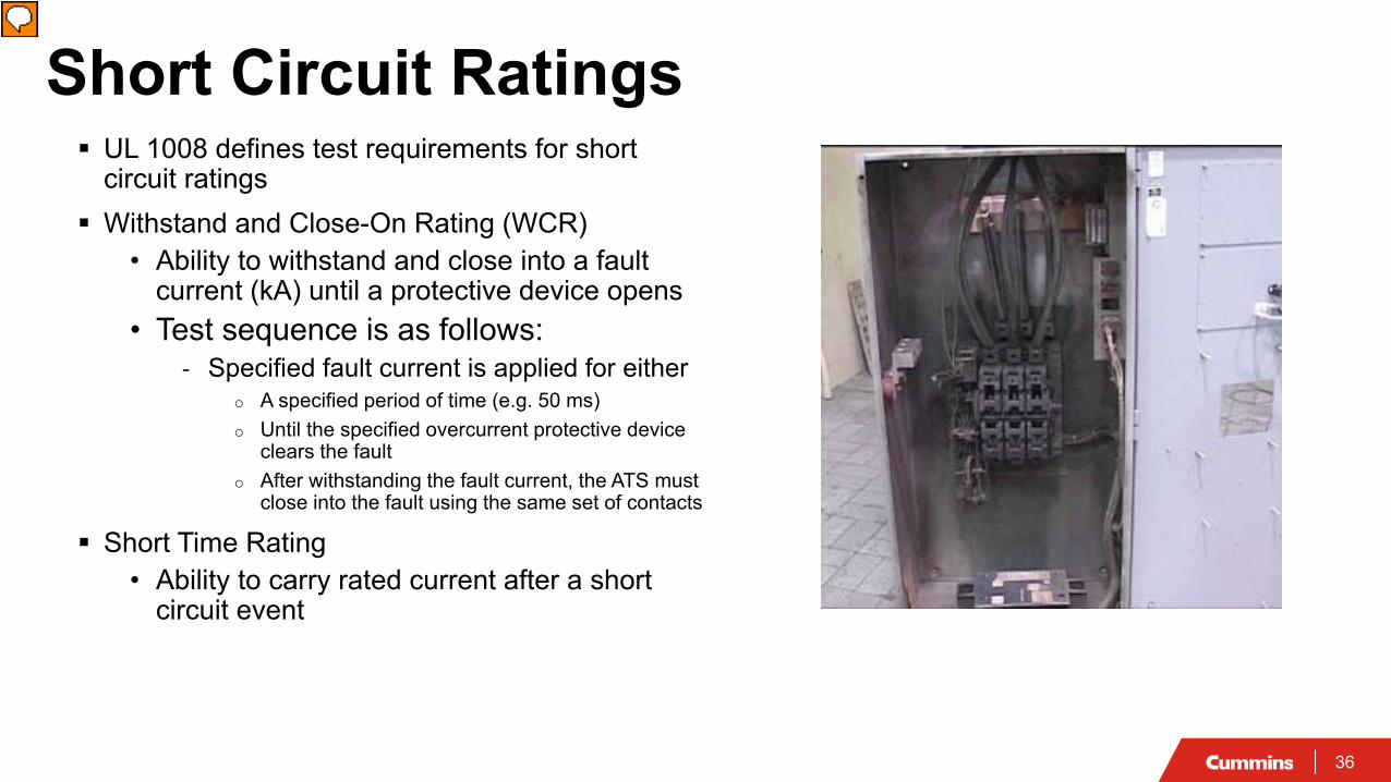
Short Circuit Ratings UL 1008 defines test requirements for short
circuit ratings Withstand and Close-On Rating (WCR)
• Ability to withstand and close into a fault current (kA) until a protective device opens
• Test sequence is as follows:- Specified fault current is applied for either
o A specified period of time (e.g. 50 ms)o Until the specified overcurrent protective device
clears the faulto After withstanding the fault current, the ATS must
close into the fault using the same set of contacts
Short Time Rating• Ability to carry rated current after a short
circuit event
Presenter
Presentation Notes
A transfer switch must withstand and close into a designated level of fault current (kA) until its upstream overcurrent protective device opens, unless an overcurrent protective device is integral to the transfer switch. The WCR is established by test only. The suitability of transfer switch equipment for application in circuits with high available fault current is tested to the requirements of UL 1008.
37
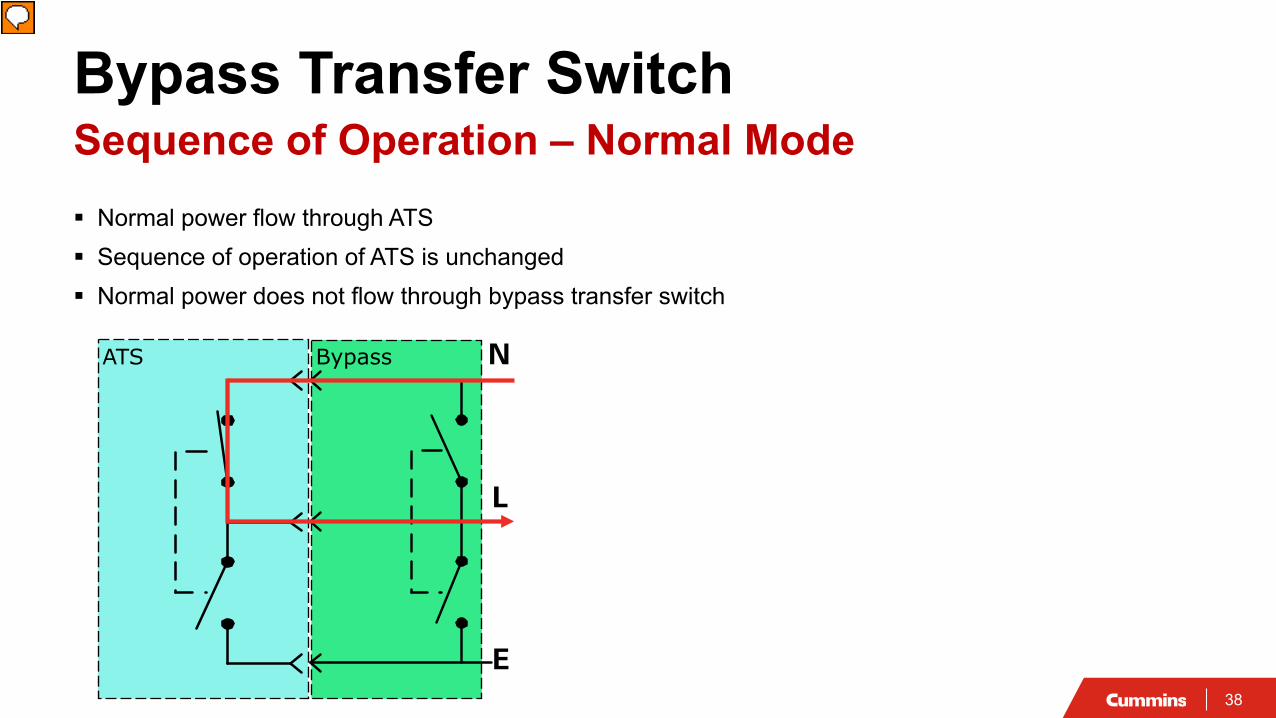
Bypass Transfer Switch Allows service of ATS without disrupting power to critical loads By having two transfer switches, the bypass transfer switch adds redundancy to the system Bypass Isolation: Bypass first and Isolate later (no power interruption to load) Watch out for term “Isolation Bypass”
ATS Bypass
L
E
N
Presenter
Presentation Notes
So how many of you heard of a Bypass switch? A bypass switch is a manual switch and an automatic switch in the same box. They are not connected in parallel under normal conditions Cummins ATS on Drawout Bypass Stationary Interlocks for all positions Source to Source on Each Switch Cross Interlocks
38
Bypass Transfer SwitchSequence of Operation – Normal Mode Normal power flow through ATS Sequence of operation of ATS is unchanged Normal power does not flow through bypass transfer switch
ATS Bypass
L
E
N
Presenter
Presentation Notes
Normal operation, they are not connected together Power do not flow through bypass. This is important, if you have a fault on your load somewhere and 30kA of fault current goes through the ATS and not the bypass. So you can close the bypass and take the ATS out.
39
Bypass Transfer SwitchSequence of Operation – Test Mode Bypass is connected to the same source as the ATS Dead source interlock Bypass to same source does not cause power interruption
ATS Bypass
L
E
N ATS Bypass
L
E
N
Presenter
Presentation Notes
We can test the control and the mechanism. If you want to bypass, connect the bypass contact to the source Dead source interlock
40
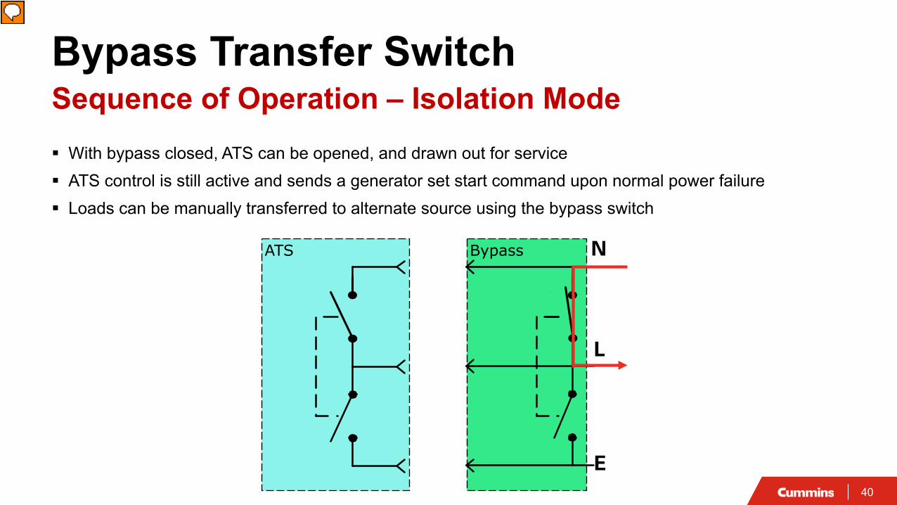
Bypass Transfer SwitchSequence of Operation – Isolation Mode With bypass closed, ATS can be opened, and drawn out for service ATS control is still active and sends a generator set start command upon normal power failure Loads can be manually transferred to alternate source using the bypass switch
ATS Bypass
L
E
N
Presenter
Presentation Notes
In this state we can take the ATS out and check the contacts. It is important to know that the ATS is now manual. If you engage the bypass we recommend the Not in Auto be monitered to show that you no longer have an Automatic switch
41
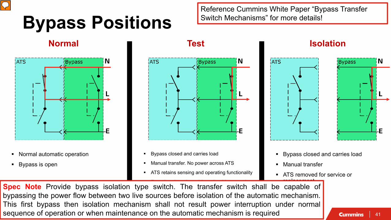
Normal Test Isolation
Bypass Positions
Normal automatic operation
Bypass is open
Bypass closed and carries load
Manual transfer. No power across ATS
ATS retains sensing and operating functionality
Functional testing without load interruption
Bypass closed and carries load
Manual transfer
ATS removed for service or replacement
Spec Note Provide bypass isolation type switch. The transfer switch shall be capable ofbypassing the power flow between two live sources before isolation of the automatic mechanism.This first bypass then isolation mechanism shall not result power interruption under normalsequence of operation or when maintenance on the automatic mechanism is required
Reference Cummins White Paper “Bypass Transfer Switch Mechanisms” for more details!
Presenter
Presentation Notes
There are three positions in the operation of a bypass isolation transfer switch. In the “connected” position, power is flowing through the ATS and the bypass switch is open. This is the normal operating position. In the “test” position, the bypass switch is closed, and the ATS is open. In this position no power flows through the ATS, all power flows through the bypass switch. In this mode, all of the sensing and operating functions of the ATS are still engaged. The function of the transfer switch may be tested in this mode with no interruption of power to the load. In the “isolated” position, the ATS has been completely removed from the bypass isolation switch. “Test” and “Isolated” positions would require a manual transfer to the emergency power source.
42
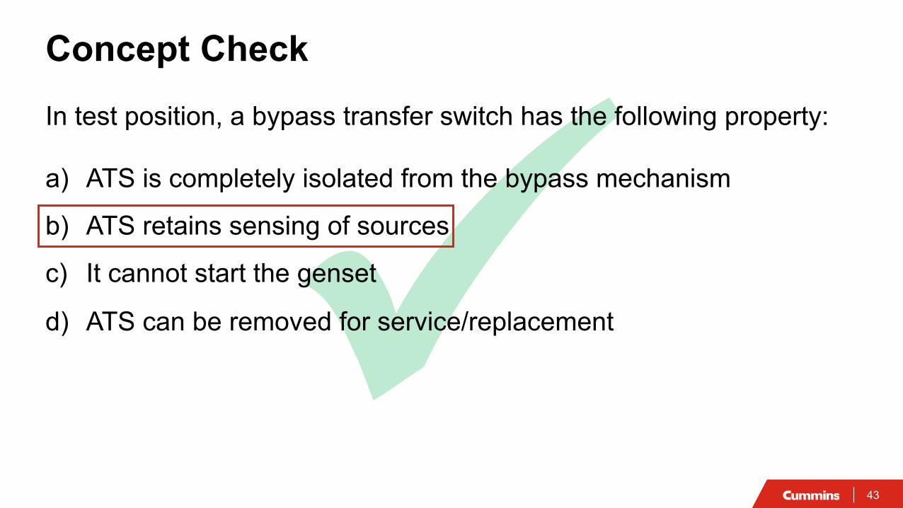
Concept CheckIn test position, a bypass transfer switch has the following property:
a) ATS is completely isolated from the bypass mechanism
b) ATS retains sensing of sources
c) It cannot start the genset
d) ATS can be removed for service/replacement
43
Concept CheckIn test position, a bypass transfer switch has the following property:
a) ATS is completely isolated from the bypass mechanism
b) ATS retains sensing of sources
c) It cannot start the genset
d) ATS can be removed for service/replacement
44
Normal Test Isolation
Bypass Positions
Normal automatic operation
Bypass is open
Bypass closed and carries load
Manual transfer. No power across ATS
ATS retains sensing and operating functionality
Functional testing without load interruption
Bypass closed and carries load
Manual transfer
ATS removed for service or replacement
Spec Note Provide bypass isolation type switch. The transfer switch shall be capable of bypassing the power flow betweentwo live sources before isolation of the automatic mechanism. This first bypass then isolation mechanism shall not resultpower interruption under normal sequence of operation or when maintenance on the automatic mechanism is required
Presenter
Presentation Notes
There are three positions in the operation of a bypass isolation transfer switch. In the “connected” position, power is flowing through the ATS and the bypass switch is open. This is the normal operating position. In the “test” position, the bypass switch is closed, and the ATS is open. In this position no power flows through the ATS, all power flows through the bypass switch. In this mode, all of the sensing and operating functions of the ATS are still engaged. The function of the transfer switch may be tested in this mode with no interruption of power to the load. In the “isolated” position, the ATS has been completely removed from the bypass isolation switch. “Test” and “Isolated” positions would require a manual transfer to the emergency power source.
45
Transfer Switch Selection3 Pole vs 4 PoleUse a 4 pole transfer switch when ground fault sensing is required Most common method is to use GF protection in breaker at the service
disconnect Two rules for proper GF sensing
• There must be only one neutral/ground bond on any neutral bus at one time
• Ground fault sensors must be downstream from the bond
These two rules drive the requirement that 4 pole transfer switches must be used when ground fault sensing is required or may be required in the future.
IEEE Std 446-1995 (Orange Book)7.9.1 "for most emergency and standby power systems with ground-fault systems, switching of the grounded circuit conductor by the transfer switch is the recommended practice."
Presenter
Presentation Notes
You need a 4-pole transfer switch is for when you need to have a ground fault protection.�Discuss the two rules…
46
Course SummaryTransfer Switch Operation and Application Transfer switches
• Provides means of transferring loads between two power sources • Allows shedding of non-critical loads. Requires a 3 position switch.• Allows stepping of loads onto a single generator set.
Transition types• Delayed / Programmed Transition should be used for motor loads. Requires a 3 position switch.• Closed transition transfer switches offer transition without power interruption but introduces risks and costs
Bypass transfer switch allows service of ATS without disrupting power to critical loads. Specify Bypass Isolation switch. 4 Pole transfer switches should be used when ground fault sensing is required
Specify: 3 position mechanism that is required for load shed and delayed transitions. Bypass isolation mechanism for uninterrupted power transfer. 4 pole transfer switch for effective ground fault sensingAvoid specifying: Brand-specific components that can limit design options and increase cost
47
Additional Resources
Cummins White Papers :• Transfer switch set up for reliability and efficiency, part 1, 2 & 3• Considerations for reliable closed transition switches• Bypass transfer switch mechanisms
Cummins On-Demand Webinars :• Functions and Features of Generator Set Control Based
Paralleling
Future Power hours:• Withstand and close on ratings for Transfer switches -
November 2019
48
Q&A
Type your questions, comments, feedback in the WebEx Q&A box. We will get to as many questions as we can
We will publish consolidated FAQ along with presentation and webinar recording on powersuite.cummins.com
Your local Cummins contacts:Western Canada: Ian Lindquist ([email protected]), Western Canada RegionEastern Canada: Gianluca Ianiro ([email protected]), Eastern Canada RegionAZ, ID, NM, NV: Carl Knapp ([email protected]), Rocky Mountain RegionCO, MT, ND, UT, WY: Chris Scott ([email protected]), Rocky Mountain RegionNorthern IL, IA: John Kilinskis ([email protected]), Central RegionUP of MI, MN, East ND, WI: Michael Munson ([email protected]), Central RegionNE, SD, West MO, KS: Earnest Glaser ([email protected]), Central RegionSouth IL, East MO: Jeff Yates ([email protected]), Central RegionTX, OK, AR, LA, MS, AL, Western TN: Scott Thomas ([email protected]), Gulf RegionFL, GA, NC, SC, Eastern TN: Robert Kelly ([email protected]), South RegionNY, NJ, CT, PA, MD: Charles Attisani ([email protected]), East RegionCA, HI: Brian E Pumphrey ([email protected]), Pacific RegionWA, OR, AK: Tom Tomlinson ([email protected]), Pacific RegionFor other states and territories, email [email protected] or visit http://power.cummins.com/sales-service-locator
Presenter
Presentation Notes
Cummins Provides Product Application Engineers experts in all regions in the US and Canada They will be happy to help you with providing technical information, designing and specifying assistance in order to comply with local, regional, state and national regulations. Our Application Engineers provide local in house presentations and expert advice and are backed up directly with our factory team of product and code specialist insuring the best professional network at your disposal Cummins is your partner in professional continuing education through PowerHours, Lunch and Learns and other continuing education program
Watch out for a follow-up email includingA Link to webinar recording and presentationA PDH Certificate
Visit powersuite.cummins.com for PowerHour webinar recording, presentation and FAQ archiveOther Cummins Continuing Education programsSizing and spec development tool
Upcoming PowerHour Webinars:August 22nd – Paralleling Power System Design Considerations and System Level Control
Please contact Mohammed Gulam if you have any questions related to the PowerHour webinar ([email protected])