curreent - bridexbridex.com.au/download/rudolf/rudolf_ct_scan.pdfcurreent tri=insfcfrmer i enhanced...
TRANSCRIPT
CURreENTTRI=INSFcfRMERI Enhanced Ouality with a Touch of Style
Company lntroductionBridex Singapore Pte Ltd is founded in 19/B as amanufacturer of instruments transformer for the Asianmarket. We are the first local electrical switchgearcomponents manufacturer that launches our own Asian
ioentity - RuooLF
Today we aim to become a knowledge-based,technology driven engineering organization, withemphasis on providing solution for electrical distributionand control, in area of instruments, distribution &protection and power quality solution in area of powerquality audit & power quality system and motorcontroller. With our present headquarter in Singaporeand subsidiaries that are located in Aust ralia, Malaysia,
Philippines and Vietnam, we are well equipped toservice both local market and countries in the AsiaPacific,
Product lntroductionRudolf, creating a world class standard in the supplyof current transformer, offers a comprehension range
for both the measuring and protection applications.
Ranges available are:o Encapsulated type;. Tape wound ring type;. Split core encapsulated type;. Class X tape wound ring type;
Designed to meet the highest standards in accordance
to IEC 60044-1 , Rudolf current transformer providesyou with a world-class product manufactured with ourassurance to comply with international standard,
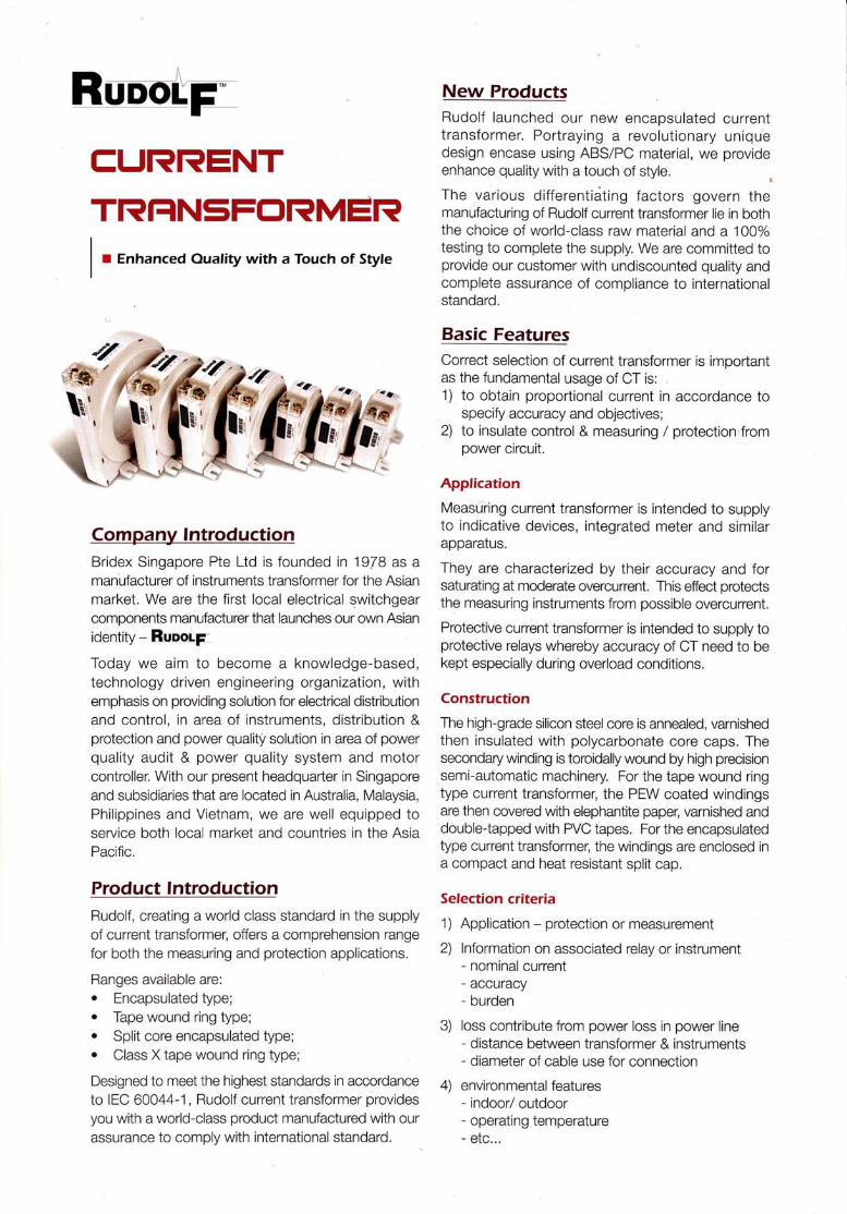
New ProductsRudolf launched our new encapsulated currenttransforrner. Portraying a revolutionary uniquedesign encase using ABS/PC material, we provideenhance quality with a touch of style
The various d ifferentleiting factors govern themanufacturing of Rudolf current transformer lie in boththe choice of world-class raw material and a 100%testing to complete the supply. We are committed toprovide our customer with undiscounted quality andcomplete assurance of compliance to lnternationalstandard.
Basic FeaturesCorrect selection of current transformer is importantas the fundamental usage of CT is:1) to obtain proportional current in accordance
'to
specify accuracy and objectives;2) to insulate control & measuring / protection'from
power circuit.
Application
Measuiring current transformer is intended to supplyto indicative devices, integrated meter and similarapparatus.
They are characterized by their accu racy and forsaturating at moderate overcurrent, This effect protectsthe measuring instruments from possible overcurrent.
Protective current transformer is intended to supply toprotective relays whereby accuracy of CT need to bekept especially during overload conditions.
Construction
The high-grade silicon steel core is annealed, varnishedthen insulated with polycarbonate core caps, Thesecondary winding is toroidally wound by high precisionsemi-automatic machinery. For the tape wound ringtype current transformer, the PEW coated windingsare then covered with elephantite papq varnished anddouble-tapped with PVC tapes. For the encapsulatedtype current transformer, the windings are enclosed in
a compact and heat resistant split cap.
Selection criteria
1) Application - protection or measurement
2) lnformation on associated relay or instrument- nominal current- accuracy- burden
3) loss contribute from power loss in power line- distance between transformer & instruments- diameter of cable use for connection
4) environmental features- indoor/ outdoor- operating temperature- etc...
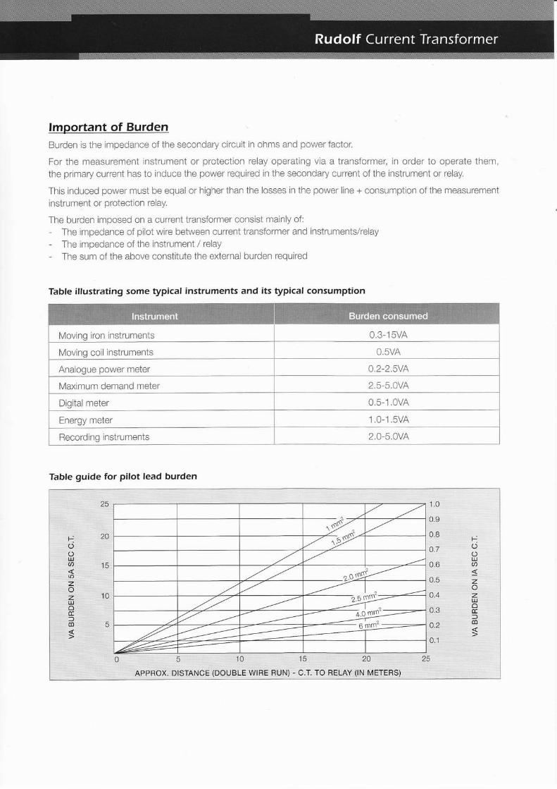
lmportant of BurdenBurden is tne irnpedance cf the secondary circuit in chnrs and ptv;er factor.
For ihe rteasuremgnt instrumeni or pr"otecticn relay cperating vio. a ii'ansii)iiici', r:r cr'..jer t,).):)eraie tireir,the prri-:iary curreni has tc induce ihe power' required in the seccndai'.'' :urrc;'ri cf ihc instrrrrnent or relay.
This inCuced power rnust L:e eqr:al or higher ihan the lcsses rn the pcwer line + consrnrntion o{ the measurement
instrurnent cr protecttcn relali,
The i:urCen imposed cn a current transfcrnrer consist nainly of:
- The impe.iance rf pilot wii'e !:etween current transiormer and instrumentslrelay- The ii'npeCance of the rnstrL;ment / relay
- The sr-im of the airave constiiuie the erternai burCen required
iv4';"'ing irci :r ;sirumeiis U.J :JVI\
i Mcving coii insirurnents
Table guide for pilot lead burden
1.0
0.9
o.7
u_o
0.5
4.4
0.3
4.2
o.1
5 10
APPROX. DISTANCE iDOUBLE WIRE
15 20
RUN) - C.T. TO RELAY (rN METERS)
25
tUOul
zozuJoElm
s
tO
UJa()zozulocc)dl
Table illustrating some typical instruments and its typical consumPtion
lmportant of accuracy & phase angle
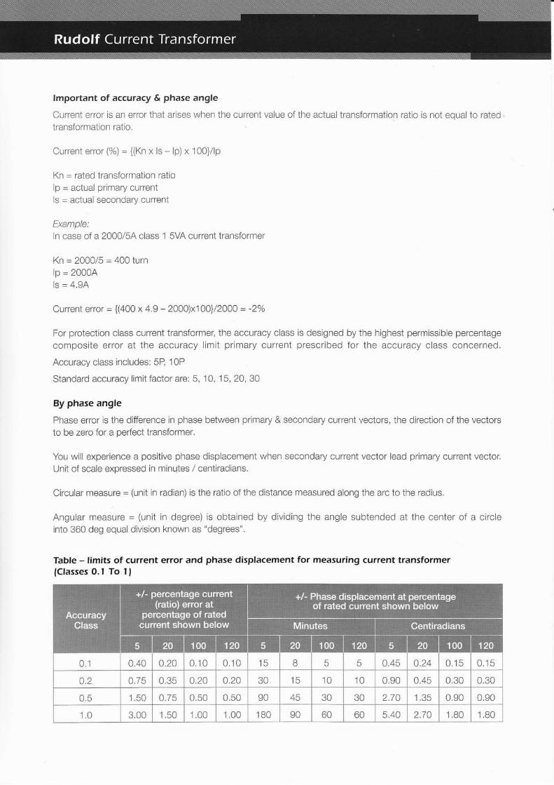
Curreni error is an error that arises when the current value of the actual transformation ratio is not equal to ratedtransformation ratio.
Current error (%) = {(Kn x ls * lp) x 1CO}/lp
Kn = rated transfornraiion ratio
lp = actual primary current
ls = actual secondary curreni
Evzmnla
ln ease of a 2000/5,4 class 1 SVA current transforrner
Kn = 2000/5 = 400 turn
lp = 20C0Als = 4.9A
Current eytot = {(aOO x 4.9 - 2000)x100}/2000 = -2Vo
For protection class current transformer, the accuracy class is designed by the highest permissible percentage
composiie error at the accuracy limit primary current prescribed for the accuracy class concerned.
Accuracy class includes: 5P, 10P
Standard accuracy limit factor are: 5, i0, 15, 20, 30
By phase angle
Phase error is the difference in phase between primary & secondary current vectors, the direction of the vectorsto be zero for a perfect transformer,
You will experience a positive phase displacement when secondary current vector lead primary current vecior.Unit of scale expressed in minutes / centiradians.
Circular measure = (unit in radian) is the ratio of the distance measured along the arc to the radrus.
Angular measure = (unit in degree) is obtained by dividing the angle subtended at the center of a circleinto 360 deg equal division known as "degrees".
Table - limits of cuffent error and phase displacement for measuring current transformer{Classes O.l To I )
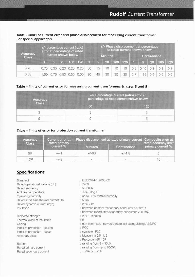
Table - limits of current error and phase displacement for measuring current transformerFor special application
Table - limits of current error for measuring current transformers {classes 3 and 5}
Table - limits of error for protection current transformer
Specifications
StandardRated operational voltage (Un)
Rated {requencyAmbient temperatureOperating humiCity
Rated short time thermal current (ith)
Rated dynamic current (ldyn)
lnsulation
Dielectric strengthThermal class cf insulation
Casinglndex oi proiection - casinglndex of protection - cover
Accuracy class
BurdenRated primary currentRated seccndary curreni
1EC60044-1 2003-0272AV
cJ/cuill-5140 deg Cup to 95% relative hurnidity
2"55 x lthbetween primary iseccnCary conductor >500m0between tcriod core/secondarv conductor >200mf)2kV 1 minutesB
non-flammable, polycarbonaie seli extinguishing ABSIPCtP20
sealable lP20Vleasuring C.5, 1, 3Proteclion 5R 10P
rangingfrom3-30VAranging from up to 60004...15Aor.../1A

Class X Current TransformerClass X current transformer is use in conjunction with high impedance circulating current differential protectionrelay, eg restricted earlh fault relay. As illustrated in 1EC60044-'1, the class X current transformer is needed.
The following illustrates the method to size a class X current transformer.
Step l: calculating knee point voltage VkpVkp = {2 x lft (Rct+Rw)}/ k
Vkp = rgqlr;5ed CT knee point voltagelfl = max transformer through fault in ampere
Rct = OT secondary winding resistance in ohmsRw = loop irnpedance of pilot wire between CT and theK = CT transformation ratio
Step 2: calculate Transformer through fault lftlft = (KVAx 1000)i(1 .732xVx lmpedance)
KVA = transformer rating in kVA
V = transformer secondary voltagelmpedance = transformer impedance
Step 3: How to obtain RctTo measure when CT is produce
Step 4: How to obtain RwThis is ihe resistance of the pilot wire used to connect the Sth class X CT at the transformer star point to the relay
in the LV switchboard. Please obtain this data from the Flectrical contractor or consultant. We provide a table toserve as a general guide on cable resistance.
Example:Transformer CapacityTransformer impedanceVoltage system
Current transformer ratio
Current transformer typeCurrent transformer VkpCurrent transformer Rct
Pilot wire resistance Rw
2s00kvA6"/o
22kV / 415V 3phase 4 wire
4000/5AClass X PRl O
1 BsV1.A2Q (measured)
25 meters using
6.0mm sq cable
=2x25x0.0032= 0..16C)
lft = (kVAx 1000) / (1.732xVxinnpedance)
= (2500 x 1000) / (1 .732 x 415 x 0.06)
= 57,968 round up 58,0004
Vkp ={2x|ft(Rct+Rw)}/k= {2 x 58000 (1 ,02+0,16) } i 800
= 171.1VRudolf Class X CT with knee point voltage of 1B5V is suitable to be use in thls application.

Encapsulated Curent Transformer
Selection Guide
ui
60/54
1 00/54
120/54
3
3
3
5
5
3
3
b
5
r 00/54
1 50/54
20a/54
25A/54
300/54
3
3
3
3
3
5
5
5
5
5
7.5
7.5
7.5
'10
10
10
'10
15
15
15
2A
2A
2A 30
3
3
3
3
5
5
5
5
5
7.5
7.5
7.5
10
-10 15 20
!l
J
3
5
5 7.5 10 15
s)
20a/54
254/54
300/54
400/5A
500/54
60015A
3
3
3
3
3
5
5
5
5
5
5
7.5
7.5
7.5
7.5
7.5
7,5
'10
t0
t0
t0
t0
t0
15
l5
15
t5
15
20
20
20
20
30
30
30
3
3
5
5
5
5
5
5
7.5
7.5
7.5
7.5
7.5
t0
t0
10
t0
t0
15
15
15
.15
20
20
20
30
30
3
3
J
J
3
3
5
5
5
5
5
7.5
7.5
7.5
10
10
10
'15
15
2A
2A 30
lr')
tr
400/5A
500/5A
600/54
800/5A
1 000/54
1200/5A
1 600/54
3
3
3
3
3
3
3
5
5
5
5
5
5
5
7.5
7.5
7.5
7.5
7.5
7.5
7.5
10
10
10
10
10
10
10
15
15
15
15
15
15
15
20
20
20
20
20
20
2C)
30
30
30
30
30
30
3
3
3
3
3
3
3
5
5
5
5
5
5
5
7.5
7.5
7.5
7.5
7.5
7.5
7.5
r0
10
10
10
10
10
IU
15
15
15
15
15
15
t5
20
2A
2A
2A
2A
2A
30
30
30
30
30
3
3
3
3
3
3
3
5
5
5
5
5
5
5
7.5
7.5
7.5
7.5
7.5
7.5
'10
10
10
10
10
10
10
'15
i
t5
t5
t5
t5
2A
2A
2A
2A
2A
30
30
30
30
(sTNN
800/54
1 000/sA
1 200/54
1 600/54
2000/5A
3
3
3
3
3
5
5
5
5
b
7.5
7.5
7.5
7.5
7.5
10
10
10
10
io
15
15
15
15
15
20
20
20
20
20
30
30
30
30
30
3
3
.t
3
5
5
b
5
5
7.5
7.5
7.5
7.5
10
l0
10
10
10
15
'15
t5
t5
t5
2A
2A
2A
2A
2A
30
30
30
30
30
3
3
3
3
5
5
5
5
5
7.5
7.5
7.5
7.5
7.5
10
10
10
10
10
15
t5
15
15
'15
2a
2A
2A
2A
2A
30
30
30
30
30
N\..
[u
1200/54
1 600/54
2000/54
2500/54
3
3
3
3
5
5
5
5
7.5
7.5
7.5
7.5
10
10
10
10
15
15
15
15
20
20
20
20
30
30
30
30
3
3
3
5
5
5
5
7.5
7.5
7.5
t0
10
l0'10
'15
t5
t5
l5
2A
2A
2A
2A
30
30
30
3
J
3
5
5
5
7,5
7.5
7,5
7,5
10
10
10
10
t5'15
t5
l5
2A
2A
2A
2A
30
30
30
s*
r 600/54
2AOO/54
2500/54
3000/5A
3200/5A
3
3
3
J
5
5
5
5
5
7.5
7.5
7.5
7.5
7.5
l0
t0
t0
l0
l0
15
15
15
5
15
20
20
20
20
20
30
30
30
30
30
3
3
3
3
3
5
5
5
5
5
7.5
7.5
7.5
(.5
l0
10
10
l0'10
'15
t5
t5
15
15
2A
2A
2A
2A
2A
30
30
30
30
30
3
3
5
5
5
5
5
7.5
7.5
7.5
7.5
7.5
10
10
'10
10
10
t5
t5
t5
t5'15
2A
2A
2A
2A
2A
30
30
30
30
30
Subjected ta change without priar natice
Dimension Drara4ing
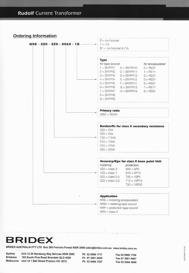
Ordering lnformation
NRE - 3ZO-3ZO-0060-tBB = cw bracket1=/1A81 = cw bracket &/1A
l
# 4=SR./PRz5 = SR/PR56 = SR/PR67 = SR/PR78 = SR/PR89 = SRiPR9
Typqfar tape wound1 = SR/PR]2 = SR/PR23 = SF/PF3
A = SR/PRI O
C = SR/PR1 1
D = SR/PRI 2E = SR/PR] 3F = SR/PRI 4G = SR/PR15H = SR/PR1 6
for encapsulated0 = RE01
l=Htlic _ DEOr
5 = RE51
6 = RE61
/ =nfr/ I
B = REB1
Primary ratio0060 = 60/54
guraen/ns for class X secondary resistance320 = 3VA
5ZO - sVA
725 = 7 .sVA010 = 1OvA
0'15 = 15VA
020 = 20vA
AccutacyfKpv for class X knee point Voltmetering protection320=class3 S05=5P5120 = class 1 S10=5P10025 = class 0.5 T05 = I0P5022 = class O.2 T10 = 10P10
T20 = 10?20
ApplicationNRE = metering encapsulatedNRM = metering tape woundNRP = protection tape woundNRX = class X
Fax 02 9986 1766Fax 07 3881 6467Fax 03 9484 4899
BRIDEXBRIDEX AUSTRALIA Pw LTD Box 260 Frenchs Forest NSW 2086 [email protected] www.bridex.com.au
Sydney Unil1220NarabangWayBetrose NSW2085 ph 0299g6 1711Brisbane 162 South Pine Road Brendale eLD 4500 ph 07 3g81 6450Melbourne Unit 12 1 Bell Street Preston VIC 3072 ph 0394847227
?