current indications - cardioland.orgcardioland.org/echo/grossmans 6th/pdfs/chap11.pdf · contrast...
TRANSCRIPT

11
Coronary Angiography
Donald S. Baim and William Grossman
DSB: Harvard Medical School; Center for Innovative Minimally Invasive Therapy, Brigham and Women's Hospital, Boston, Massachusetts 02115.
WG: University of California, San Francisco, School of Medicine, Division of Cardiology, University of California, San Francisco Medical Center, San Francisco, California 94143
Because of progressive evolution in catheterization technique (including better radiographic imaging equipment and better-tolerated contrast media) coupled with the development of effective treatment options for coronary artery disease (i.e., bypass surgery and angioplasty), diagnostic coronary angiography (also called coronary graphy) has become one of the primary components of cardiac catheterization. It is estimated that more than 1,200,000 coronary angiographic procedures (roughly 400 per 100,000 population) are performed each year in the United States
, with a procedure-related mortality rate of 0.1%. In each procedure, the objective is to examine the entire coronary tree (both native vessels and any surgically constructed bypass grafts), recording details of coronary anatomy that include the individual pattern of arterial distribution, anatomic or functional pathology (atherosclerosis, thrombosis, congenital anomalies, or focal coronary spasm), and the presence of intercoronary and intracoronary collateral connections. Despite gains in noninvasive techniques such as magnetic resonance angiography and fast computed tomography (fast-CT) as tests for coronary artery disease (and limited imaging of the proximal coronary arteries in some patients); the use of intravascular ultrasound (see Chapter 19) and angioscopy to define the status of the local vessel wall and luminal surface; and the use of intracoronary pressure and flow measurement technology to assess physiologic significance (see Chapter 18), selective coronary angiography remains the clinical “gold standard” for evaluating coronary anatomy. By performing a series of intracoronary injections of contrast agents in carefully chosen angulated views using current high-resolution x-ray imaging (see Chapter 2), it is possible to define all portions of the coronary arterial circulation down to vessels as small as 0.3 mm, free of any artifacts caused by vessel overlap or foreshortening. The performance of high-quality coronary angiography, safely defining each and every coronary stenosis in an optimal view, is an important measure of an operator's skill in cardiac catheterization and is the foundation on which the operator's ability to perform successful coronary interventional procedures rests.
arterio
(1) (2)
(3)(4) screening
CURRENT INDICATIONS
There are a variety of indications for coronary angiography, which are summarized comprehensively in the most recent set of American College of Cardiology/American Heart Association (AHA/ACC) guidelines on coronary angiography . These indications continue to evolve as new applications of catheter-based therapy are developed, but they are still best summarized by the principle stated by F. Mason Sones: coronary arteriography is indicated when a problem is encountered whose resolution may be aided by the objective demonstration of the coronary anatomy, provided competent personnel and adequate facilities are available and the potential risks are acceptable to the patient and physician.
(2)
The most frequent indication is the further evaluation of , and in whom anatomic correction by means of coronary artery bypass surgery or transluminal
coronary angioplasty is contemplated. Angiographic evaluation of coronary anatomy in such patients provides the crucial information needed to select the most appropriate treatment strategy-catheter intervention (see Chapters 23 through 25), bypass surgery, or medical therapy. Included in this category are patients with refractory to medical therapy. Recent data suggest that patients with noninvasive evidence of myocardial ischemia also benefit from revascularization and therefore are candidates for coronary angiography . Another target population is comprised of patients with (new onset, progressive, or rest pain). Whereas intensive drug therapy ( -blocker, calcium channel blocker, nitrate, heparin, aspirin, one of the newer blockers of the platelet IIb/IIIa receptor) alone may be tried in patients with unstable angina, almost two thirds of such patients come to angiography within 6 weeks after presentation because of ongoing clinical symptoms or a
patients in whom the diagnosis of coronary atherosclerosis is almost certain
stable angina pectorisasymptomatic
(5)unstable angina
BETA
10/25/00 3:36 PMSECTION IV: ANGIOGRAPHIC TECHNIQUES
Page 1 of 26file:///EPJOBS/Lippincott/BAIM/pdf%20development/htmlbaim%204%2Fpdf/1101_TXT.HTM
positive exercise test . Such patients are candidates for early coronary angiography, particularly if they display indicators (rest pain, electrocardiographic [ECG] abnormalities, heart failure) that place them in the category of Braunwald class II or III unstable angina with high risk of progression to myocardial infarction (MI). In such patients, diagnostic catheterization (with the ability to proceed to coronary intervention during the same procedure, if indicated) should be performed after or concurrent with the initiation of multidrug antianginal therapy. Patients with
may undergo immediate coronary angiography if primary angioplasty is planned or early angiography (hours to days) if they have recurrent spontaneous or exercise-induced angina after thrombolytic therapy . The most recent AHA/ACC guidelines for the management of myocardial infarction extend these indications to potentially include patients with post-MI arrhythmias, congestive heart failure, or an ejection fraction less than 40%; all patients after non–Q wave infarction; and patients in whom ongoing occlusion of the infarct vessel or three-vessel disease is suspected. Coronary angiography is also indicated if clinical evidence of a mechanical defect (ventricular septal defect or papillary muscle rupture) develops in the days after an MI. Routine post-MI coronary angiography in the stable patient without these indications is still advocated by some cardiologists , but its value (compared with the conservative strategy outlined here) has not been established.
(6)
(7)
acute myocardial infarction (8)
(9) (8)
(9)
A second group of indications for coronary angiography concerns patients in whom the. This includes patients with troublesome chest pain syndromes but ambiguous
noninvasive test results, patients with unexplained heart failure or ventricular arrhythmias, survivors of out-of-hospital cardiac arrest , patients with suspected or proven variant angina , and patients with risk factors for coronary artery disease who are being evaluated for major abdominal, thoracic, or vascular surgery . This category also includes patients scheduled for correction of congenital or valvular pathology. Patients with congenital defects such as tetralogy of Fallot frequently have anomalies of coronary distribution that may lead to surgical complications if unrecognized , whereas patients older than 45 years of age with valvular disease may have advanced coronary atherosclerosis without clinical symptoms. Although younger patients with valvular disease are commonly operated on without prior coronary angiograms, given the extraordinary low risk of diagnostic catheterization and the potential benefit of knowing the coronary anatomy, most surgical centers believe it is best to perform a preoperative diagnostic catheterization to identify (and then correct) significant coronary lesions, so as to provide the best and safest outcome during concurrent valve replacement .
presence or absence of coronary artery disease is unclear (2)
(10) (11)(12)
(13)
(14)
Finally, coronary angiography is frequently performed when a patient develops (to detect and treat restenosis; see Chapter 27) (to detect vein graft failure, which
might require catheter intervention or reoperation). Routine follow-up angiography 6 months after catheter intervention is not indicated clinically but may play an important role in the research evaluation of new technologies or drug therapies targeted at reducing restenosis .
recurrent angina after coronary intervention or after bypass surgery
(15)
GENERAL ISSUES
The initial attempts to perform coronary angiography used nonselective injections of contrast medium into the aortic root to simultaneously opacify both left and right coronary arteries, recording the angiographic images on conventional sheet film . To improve contrast delivery into the coronary ostia, some early investigators employed transient circulatory arrest induced by the administration of acetylcholine or by elevation of intrabronchial pressure, followed by occlusion of the ascending aorta by a gas-filled balloon and injection of the contrast bolus. Although nonselective aortic root injection is still used occasionally today to evaluate ostial lesions, anomalous coronary ostia, or coronary bypass grafts, intentional circulatory arrest is no longer practiced, and the nonselective technique has largely been replaced by selective coronary injection using specially designed catheters advanced from either the brachial or the femoral approach.
(16)
In most patients, successful coronary angiography can be performed by either the brachial cutdown or the percutaneous approach (from the femoral, brachial, or radial artery), leaving the choice up to physician and patient. Data from the Society for Cardiac Angiography and Intervention in 1990 show that the percutaneous femoral approach was used in 83% of cases. The brachial approach, either by percutaneous (see Chapter 4) or cutdown (see Chapter 5) entry, may offer a selective advantage in patients with severe peripheral vascular disease or known abdominal aortic aneurysm. In either case, it is important for the catheterization team to meet the patient before the actual procedure to evaluate the best approach to catheterization, to gain an appreciation of the clinical questions that need to be answered by coronary angiography, to uncover any history of adverse reaction to medications or organic iodine compounds, and to explain the procedure in detail.
(17)
10/25/00 3:36 PMSECTION IV: ANGIOGRAPHIC TECHNIQUES
Page 2 of 26file:///EPJOBS/Lippincott/BAIM/pdf%20development/htmlbaim%204%2Fpdf/1101_TXT.HTM
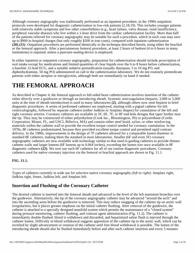
Types of catheters currently in wide use for selective native coronary angiography : Amplatz right, Judkins right, Sones, Judkins left, and Amplatz left.
Although coronary angiography was traditionally performed as an inpatient procedure, in the 1990s outpatient protocols were developed for diagnostic catheterization in low-risk patients (2,18,19). This includes younger patients with relatively stable symptoms and few other comorbidities (e.g., heart failure, valve disease, renal insufficiency, peripheral vascular disease) who live within a 1-hour drive from the cardiac catheterization facility. More than half of the patients referred for coronary angiography may be suitable for such a procedure, which in each case may save up to $900 in hospital charges (but only roughly $200 in true costs), compared with inpatient catheterization
, . Outpatient procedures are performed identically to the technique described herein, using either the brachial or the femoral approach. After a percutaneous femoral procedure, at least 2 hours of bedrest (4 to 6 hours in many institutions) is required, unless a puncture-sealing device is employed.
(20) (21)
In either inpatient or outpatient coronary angiography, preparation for catheterization should include proscription of oral intake except for medications and limited quantities of clear liquids over the 6 to 8 hours before catheterization, a baseline 12-lead ECG, and a suitable sedative premedication (usually diazepam, 5 to 10 mg PO, and diphenhydramine, 50 mg PO) administered on call to the catheterization laboratory. We do not routinely premedicate patients with either atropine or nitroglycerin, although both are immediately on hand if needed.
THE FEMORAL APPROACH
As described in Chapter 4, the femoral approach to left-sided heart catheterization involves insertion of the catheter either directly over a guidewire or through an introducing sheath. Systemic anticoagulation (heparin, 3,000 to 5,000 units at the time of sheath introduction) is used in many laboratories , although others now omit heparin in brief diagnostic procedures. A series of preformed catheters are employed, starting with a pigtail catheter for left ventriculography, followed by separate catheters (either Judkins or Amplatz shapes) for cannulation of the left and right coronary arteries. Coronary catheters are available in 5F, 6F, 7F, or 8F end-hole designs that taper further near the tip. They may be constructed of either polyethylene (Cook Inc., Bloomington, IN) or polyurethane (Cordis Corporation, Miami, FL, and USCI, Billerica, MA) and contain either steel braid, nylon, or other reinforcing materials within the catheter wall to provide the excellent torque control needed for coronary cannulation. In the 1970s, 8F catheters predominated, because they provided excellent torque control and permitted rapid contrast delivery. In the 1980s, improvements in the design of 7F catheters allowed for a comparable lumen diameter in standard 8F catheters, making them the standard in most laboratories. Smaller (6F and even 5F) coronary angiographic catheters are now available with technology similar to that used in guiding catheters to provide thinner catheter walls and larger lumens (6F lumens up to 0.064 inches), exceeding the lumen size once available in 8F diagnostic catheters . We now use such 6F catheters for all of our routine diagnostic procedures. Coronary catheters used for native coronary injection via the femoral or brachial approach are shown in Fig. 11.1.
(2)
(22)
FIG. 11.1.
(left to right)
Insertion and Flushing of the Coronary Catheter
The desired catheter is inserted into the femoral sheath and advanced to the level of the left mainstem bronchus over the guidewire. Alternatively, the tip of the coronary angiography catheter may be advanced “around the arch” and into the ascending aorta before the guidewire is removed. This may reduce snagging of the catheter tip on aortic wall irregularities, but it places greater emphasis on the initial catheter flushing. After removal of the guidewire, the catheter is attached to a specially designed manifold system which permits the maintenance of a “closed system” during pressure monitoring, catheter flushing, and contrast agent administration (Fig. 11.2). The catheter is immediately double-flushed: blood is withdrawn and discarded, and heparinized saline flush is injected through the catheter lumen. Difficulty in blood withdrawal suggests apposition of the catheter tip to the aortic wall, which can be rectified by slight advancement or rotation of the catheter until free blood withdrawal is possible. The lumen of the introducing sheath should also be flushed immediately before and after each catheter insertion and every 5 minutes
10/25/00 3:36 PMSECTION IV: ANGIOGRAPHIC TECHNIQUES
Page 3 of 26file:///EPJOBS/Lippincott/BAIM/pdf%20development/htmlbaim%204%2Fpdf/1101_TXT.HTM
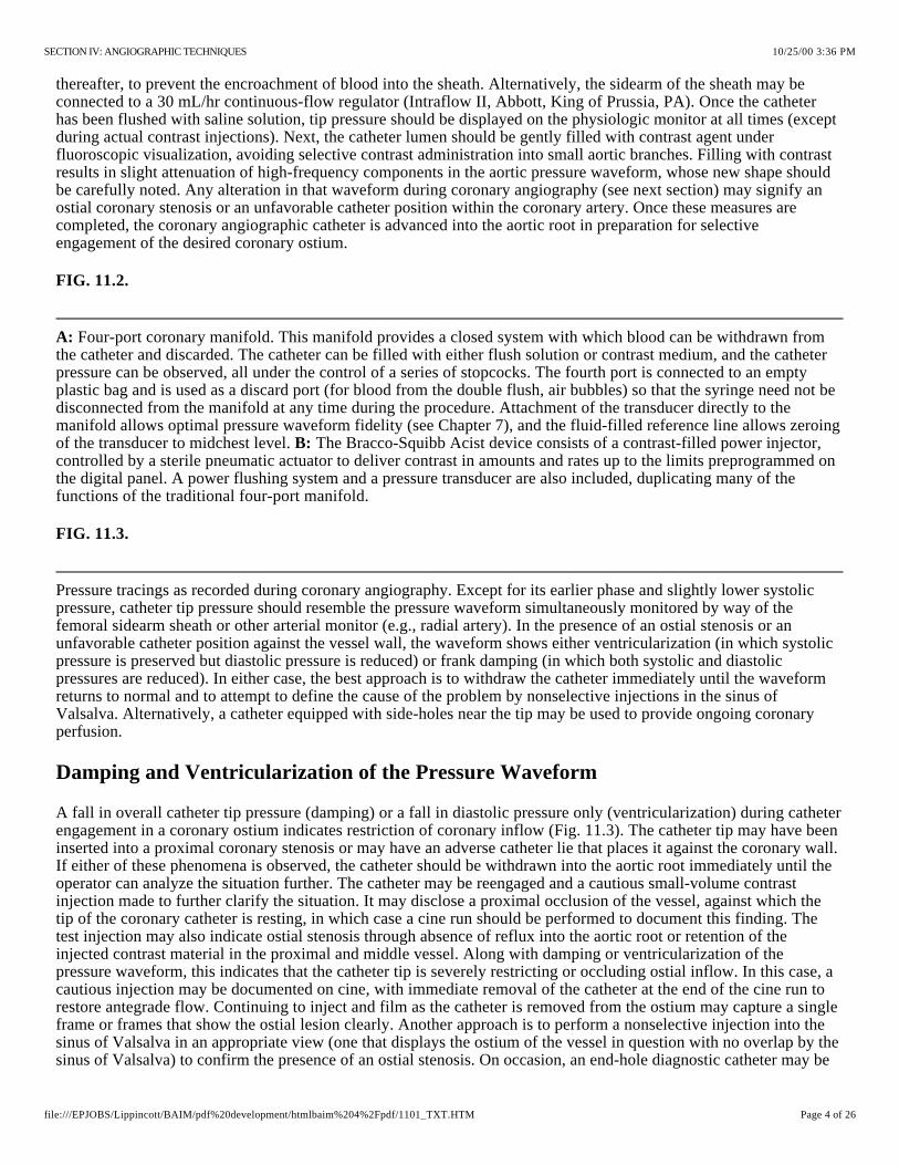
Four-port coronary manifold. This manifold provides a closed system with which blood can be withdrawn from the catheter and discarded. The catheter can be filled with either flush solution or contrast medium, and the catheter pressure can be observed, all under the control of a series of stopcocks. The fourth port is connected to an empty plastic bag and is used as a discard port (for blood from the double flush, air bubbles) so that the syringe need not be disconnected from the manifold at any time during the procedure. Attachment of the transducer directly to the manifold allows optimal pressure waveform fidelity (see Chapter 7), and the fluid-filled reference line allows zeroing of the transducer to midchest level. The Bracco-Squibb Acist device consists of a contrast-filled power injector, controlled by a sterile pneumatic actuator to deliver contrast in amounts and rates up to the limits preprogrammed on the digital panel. A power flushing system and a pressure transducer are also included, duplicating many of the functions of the traditional four-port manifold.
Pressure tracings as recorded during coronary angiography. Except for its earlier phase and slightly lower systolic pressure, catheter tip pressure should resemble the pressure waveform simultaneously monitored by way of the femoral sidearm sheath or other arterial monitor (e.g., radial artery). In the presence of an ostial stenosis or an unfavorable catheter position against the vessel wall, the waveform shows either ventricularization (in which systolic pressure is preserved but diastolic pressure is reduced) or frank damping (in which both systolic and diastolic pressures are reduced). In either case, the best approach is to withdraw the catheter immediately until the waveform returns to normal and to attempt to define the cause of the problem by nonselective injections in the sinus of Valsalva. Alternatively, a catheter equipped with side-holes near the tip may be used to provide ongoing coronary perfusion.
thereafter, to prevent the encroachment of blood into the sheath. Alternatively, the sidearm of the sheath may be connected to a 30 mL/hr continuous-flow regulator (Intraflow II, Abbott, King of Prussia, PA). Once the catheter has been flushed with saline solution, tip pressure should be displayed on the physiologic monitor at all times (except during actual contrast injections). Next, the catheter lumen should be gently filled with contrast agent under fluoroscopic visualization, avoiding selective contrast administration into small aortic branches. Filling with contrast results in slight attenuation of high-frequency components in the aortic pressure waveform, whose new shape should be carefully noted. Any alteration in that waveform during coronary angiography (see next section) may signify an ostial coronary stenosis or an unfavorable catheter position within the coronary artery. Once these measures are completed, the coronary angiographic catheter is advanced into the aortic root in preparation for selective engagement of the desired coronary ostium.
FIG. 11.2.
A:
B:
FIG. 11.3.
Damping and Ventricularization of the Pressure Waveform
A fall in overall catheter tip pressure (damping) or a fall in diastolic pressure only (ventricularization) during catheter engagement in a coronary ostium indicates restriction of coronary inflow (Fig. 11.3). The catheter tip may have been inserted into a proximal coronary stenosis or may have an adverse catheter lie that places it against the coronary wall. If either of these phenomena is observed, the catheter should be withdrawn into the aortic root immediately until the operator can analyze the situation further. The catheter may be reengaged and a cautious small-volume contrast injection made to further clarify the situation. It may disclose a proximal occlusion of the vessel, against which the tip of the coronary catheter is resting, in which case a cine run should be performed to document this finding. The test injection may also indicate ostial stenosis through absence of reflux into the aortic root or retention of the injected contrast material in the proximal and middle vessel. Along with damping or ventricularization of the pressure waveform, this indicates that the catheter tip is severely restricting or occluding ostial inflow. In this case, a cautious injection may be documented on cine, with immediate removal of the catheter at the end of the cine run to restore antegrade flow. Continuing to inject and film as the catheter is removed from the ostium may capture a single frame or frames that show the ostial lesion clearly. Another approach is to perform a nonselective injection into the sinus of Valsalva in an appropriate view (one that displays the ostium of the vessel in question with no overlap by the sinus of Valsalva) to confirm the presence of an ostial stenosis. On occasion, an end-hole diagnostic catheter may be
10/25/00 3:36 PMSECTION IV: ANGIOGRAPHIC TECHNIQUES
Page 4 of 26file:///EPJOBS/Lippincott/BAIM/pdf%20development/htmlbaim%204%2Fpdf/1101_TXT.HTM

Judkins technique for catheterization of the left and right coronary arteries as viewed in the left anterior oblique (LAO) projection. In a patient with a normal-size aortic arch, simple advancement of the JL4 catheter leads to intubation of the left coronary ostium ( , , and ). In a patient with an enlarged aortic root the arm of the JL4 may be too short, causing the catheter tip to point upward or even flip back into its packaged shape . A catheter with an appropriately longer arm (a JL5 or JL6) is required. To catheterize the right coronary ostium, the right Judkins catheter is advanced around the aortic arch with its tip directed leftward, as viewed in the LAO projection, until it reaches a position 2 to 3 cm above the level of the left coronary ostium . Clockwise rotation causes the catheter tip to drop into the aortic root and point anteriorly . Slight further rotation causes the catheter tip to enter the right coronary ostium .
exchanged for an end- and side-hole angioplasty guiding catheter to overcome damping by preserving antegrade flow into the side-holes, through the lumen of the catheter, and into the coronary artery, even though the catheter tip may be obstructing entry of blood into the ostium itself (see Cannulation of the Right Coronary Ostium).
Such a dissection is manifested by tracking of contrast medium down the vessel over the course of the injection and by failure of contrast to clear on fluoroscopy after the injection is terminated. Prompt consideration of repair by catheter-based intervention or bypass surgery should be considered if creation of such a “dye stain” is associated with impeded antegrade coronary flow and signs of myocardial ischemia.
Vigorous injection despite a damped or ventricularized pressure waveform should be avoided, because it predisposes to ventricular fibrillation or dissection of the proximal coronary artery with major ischemic sequelae.
Cannulation of the Left Coronary Ostium
With the Judkins technique it is usually easy to engage the left coronary ostium. As Judkins himself stated, “No points are earned for coronary catheterization-the catheters know where to go if not thwarted by the operator” . If a left Judkins catheter with a 4-cm curve (commonly referred to as a JL4) is simply allowed to remain as it is advanced down into the aortic root, it will engage the left coronary ostium without further manipulation in 80% to 90% of patients (Fig. 11.4). Engagement should take place with the arm of the catheter traversing the ascending aorta at an angle of approximately 45°, the tip of the catheter in a more or less horizontal orientation, and no change in the pressure waveform recorded from the catheter tip.
(23)en face
FIG. 11.4.
A B C (D)(dotted line)
(E)(F)
(G)
In patients with a widened aortic root due to aortic valve disease or long-standing hypertension, the 4-cm left Judkins curve may be too short to allow successful engagement. In such a case, the catheter arm may lie almost horizontally across the aortic root with the tip pointing vertically against the roof of the left main artery, or it may even refold into its packaged shape during advancement into the aortic root (Fig. 11.4 ). In this case, a left Judkins catheter with a larger curve (JL4.5, JL5, or even JL6) curve should be selected. In the long run, changing to a larger catheter under these circumstances may save time compared with persevering in trying to make an unsuitable catheter work. In the occasional patient with a short or narrow aortic root (usually a younger female, particularly if of short stature), even the 4-cm Judkins curve may be too long. When brought down into the aortic root, the catheter arm may lie almost vertically with the tip pointing downward, below the left coronary ostium. The left ostium may still be engaged, by pushing the catheter down into the left sinus of Valsalva for approximately 10 seconds to tighten the angle on the catheter tip and then withdrawing the catheter slowly. Having the patient take a deep breath during this maneuver also helps by pulling the heart into a more vertical position to assist in engagement of the left ostium. The most satisfactory approach, however, is to exchange for a JL3.5 catheter with a shorter curve.
D
On the rare occasions when the left coronary ostium lies “out of plane” (typically high and posterior), limited counterclockwise rotation of the left Judkins catheter in the right anterior oblique (RAO) projection may help orient the catheter's tip posteriorly and facilitate engagement. Too much rotation of this catheter, however, may result in a refolded catheter that requires guidewire reinsertion to straighten. In this case, it may be helpful to step up to the next larger Judkins curve. Alternatively, some operators prefer to switch to a left Amplatz catheter (Fig. 11.1); these are available in progressively larger curves-AL1, AL2, AL3, and AL4. Amplatz catheters are more tolerant of rotational maneuvering and allow easy engagement of left coronary ostia that lie out of the conventional Judkins plane, as well as subselective engagement of the left anterior descending (LAD) and circumflex coronary arteries in
(24)
10/25/00 3:36 PMSECTION IV: ANGIOGRAPHIC TECHNIQUES
Page 5 of 26file:///EPJOBS/Lippincott/BAIM/pdf%20development/htmlbaim%204%2Fpdf/1101_TXT.HTM
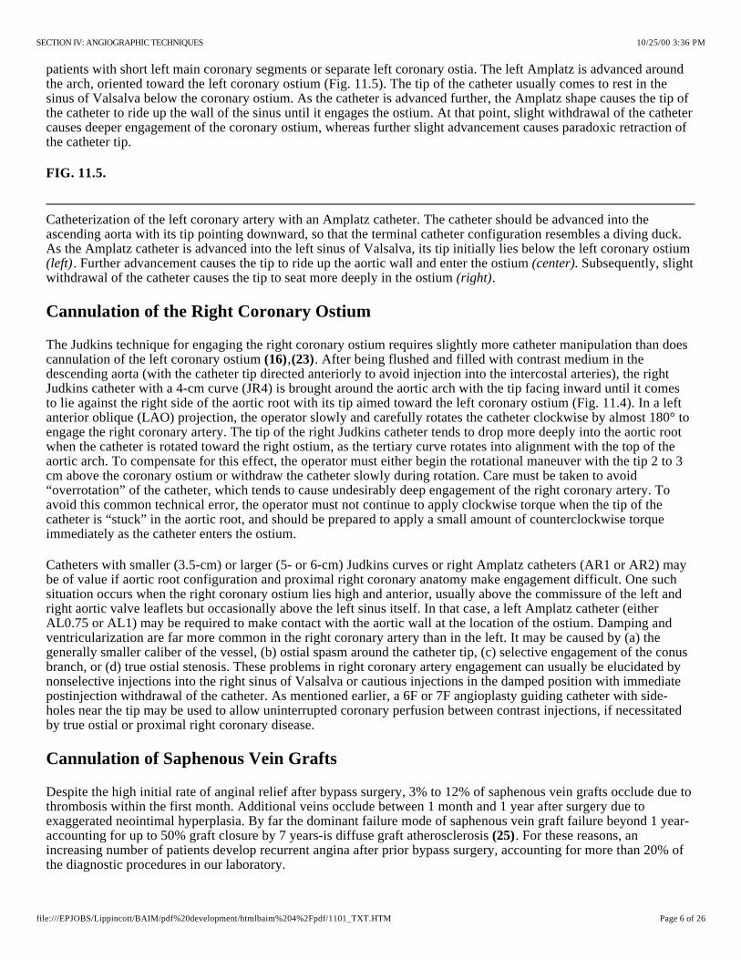
Catheterization of the left coronary artery with an Amplatz catheter. The catheter should be advanced into the ascending aorta with its tip pointing downward, so that the terminal catheter configuration resembles a diving duck. As the Amplatz catheter is advanced into the left sinus of Valsalva, its tip initially lies below the left coronary ostium
. Further advancement causes the tip to ride up the aortic wall and enter the ostium . Subsequently, slight withdrawal of the catheter causes the tip to seat more deeply in the ostium .
patients with short left main coronary segments or separate left coronary ostia. The left Amplatz is advanced around the arch, oriented toward the left coronary ostium (Fig. 11.5). The tip of the catheter usually comes to rest in the sinus of Valsalva below the coronary ostium. As the catheter is advanced further, the Amplatz shape causes the tip of the catheter to ride up the wall of the sinus until it engages the ostium. At that point, slight withdrawal of the catheter causes deeper engagement of the coronary ostium, whereas further slight advancement causes paradoxic retraction of the catheter tip.
FIG. 11.5.
(left) (center)(right)
Cannulation of the Right Coronary Ostium
The Judkins technique for engaging the right coronary ostium requires slightly more catheter manipulation than does cannulation of the left coronary ostium , . After being flushed and filled with contrast medium in the descending aorta (with the catheter tip directed anteriorly to avoid injection into the intercostal arteries), the right Judkins catheter with a 4-cm curve (JR4) is brought around the aortic arch with the tip facing inward until it comes to lie against the right side of the aortic root with its tip aimed toward the left coronary ostium (Fig. 11.4). In a left anterior oblique (LAO) projection, the operator slowly and carefully rotates the catheter clockwise by almost 180° to engage the right coronary artery. The tip of the right Judkins catheter tends to drop more deeply into the aortic root when the catheter is rotated toward the right ostium, as the tertiary curve rotates into alignment with the top of the aortic arch. To compensate for this effect, the operator must either begin the rotational maneuver with the tip 2 to 3 cm above the coronary ostium or withdraw the catheter slowly during rotation. Care must be taken to avoid “overrotation” of the catheter, which tends to cause undesirably deep engagement of the right coronary artery. To avoid this common technical error, the operator must not continue to apply clockwise torque when the tip of the catheter is “stuck” in the aortic root, and should be prepared to apply a small amount of counterclockwise torque immediately as the catheter enters the ostium.
(16) (23)
Catheters with smaller (3.5-cm) or larger (5- or 6-cm) Judkins curves or right Amplatz catheters (AR1 or AR2) may be of value if aortic root configuration and proximal right coronary anatomy make engagement difficult. One such situation occurs when the right coronary ostium lies high and anterior, usually above the commissure of the left and right aortic valve leaflets but occasionally above the left sinus itself. In that case, a left Amplatz catheter (either AL0.75 or AL1) may be required to make contact with the aortic wall at the location of the ostium. Damping and ventricularization are far more common in the right coronary artery than in the left. It may be caused by (a) the generally smaller caliber of the vessel, (b) ostial spasm around the catheter tip, (c) selective engagement of the conus branch, or (d) true ostial stenosis. These problems in right coronary artery engagement can usually be elucidated by nonselective injections into the right sinus of Valsalva or cautious injections in the damped position with immediate postinjection withdrawal of the catheter. As mentioned earlier, a 6F or 7F angioplasty guiding catheter with side-holes near the tip may be used to allow uninterrupted coronary perfusion between contrast injections, if necessitated by true ostial or proximal right coronary disease.
Cannulation of Saphenous Vein Grafts
Despite the high initial rate of anginal relief after bypass surgery, 3% to 12% of saphenous vein grafts occlude due to thrombosis within the first month. Additional veins occlude between 1 month and 1 year after surgery due to exaggerated neointimal hyperplasia. By far the dominant failure mode of saphenous vein graft failure beyond 1 year-accounting for up to 50% graft closure by 7 years-is diffuse graft atherosclerosis . For these reasons, an increasing number of patients develop recurrent angina after prior bypass surgery, accounting for more than 20% of the diagnostic procedures in our laboratory.
(25)
10/25/00 3:36 PMSECTION IV: ANGIOGRAPHIC TECHNIQUES
Page 6 of 26file:///EPJOBS/Lippincott/BAIM/pdf%20development/htmlbaim%204%2Fpdf/1101_TXT.HTM

Catheters used for bypass graft angiography. Although the right Judkins or Amplatz catheters can be used for many anterior takeoff vein grafts, catheters with the following shapes may be useful (left to right): Wexler, multipurpose, hockey-stick shape, and internal mammary.
Sample of saphenous vein graft angiography, showing an occluded graft to the circumflex, filled with thrombus. A drug-infusion catheter (Tracker, Target Therapeutics) was placed
and used to administer urokinase (50,000 IU/hr) overnight. The following morning , the thrombus had been dissolved, revealing the underlying ulcerated culprit lesion. This was treated with a single Palmaz-Schatz coronary stent , reestablishing full patency. Saphenous vein graft with origin localized by ring marker implanted at the time of surgery.
The proximal anastomosis is placed on the right or left anterior aortic surface, several centimeters above the sinuses of Valsalva. Because many surgeons resist the practice of placing radiopaque markers on the proximal graft , the operator usually must rely on the surgeon's operative report or diagram and knowledge of surgical practice in the institution. The operative report should be obtained before elective angiography on any patient with prior bypass surgery, but is absolutely essential for patients who underwent their operation at another medical center (where local preference may include practices such as anastomosis to the right- surface of the aorta; see later discussion). It can be quite frustrating to embark on coronary angiography in such a patient without a detailed graft map or operative note in hand.
(26)
posterior
Most commonly, arise from the left anterior surface of the aorta, with grafts to the LAD coronary artery originating somewhat below grafts to the circumflex system. Some surgeons prefer to route grafts to the circumflex through the transverse sinus behind the heart, in which case the circumflex graft may originate from the posterior surface of the aorta. (or the distal portions of a dominant circumflex) usually originate from the right anterior surface of the aorta, above and somewhat behind the plane of the native right coronary ostium. We usually use the right Judkins (JR4) or Amplatz (AL1) catheter to engage anterior (i.e., left) coronary grafts. Special left coronary bypass, internal mammary, or hockey-stick catheters may be required for left grafts that originate with an upward trajectory (Fig. 11.6). For downward-pointing right coronary artery grafts, we prefer a soft catheter with no primary curve (a multipurpose, Wexler, or JR3.5 short-tip catheter), which provides better alignment with the proximal portion of the graft and therefore better opacification. The Wexler catheter can also be used for grafts originating from the left or posterior surface of the aorta, because its tip remains in contact with the aortic wall. Once the ostium has been selected, the shaft of this catheter may be rotated or the tip may be flexed to bring it into alignment with the proximal graft.
grafts to the left coronary artery
Grafts to the right coronary artery
FIG. 11.6.
If no markers have been provided, the catheter tip should be oriented against the appropriate aortic wall and slowly advanced and then withdrawn until its tip “catches” in a graft ostium. The graft is injected in multiple projections that show its origin, shaft, distal anastomosis, and the native vessels beyond the anastomosis. This process must then be repeated until all graft sites have been identified. Grafts should not be written off as occluded unless a clear “stump” is demonstrated. If the myocardial territory supplied by a graft assumed to be occluded is still contracting and there is no evident native or collateral blood supply to that territory, there must be some “visible means of support,” which may be a missed graft! It may be valuable to perform an aortogram in an appropriate view to try to demonstrate flow in and locate the origin of such a missed graft. The emergence of effective therapies for focal lesions in vein grafts has placed a premium on being able to find and fix such diseased grafts before they occlude (Fig. 11.7; see Chapters 23 through 25).
FIG. 11.7.
A:(upper left, open arrow) (lower left, curved arrow) (upper right)
(lower right) B:
Internal Mammary Cannulation
Based on their superior demonstrated 10-year patency, the left and right internal mammary (also known as internal) arteries have become the conduits of choice. More than 90% of current elective bypass procedures involve thoracic
10/25/00 3:36 PMSECTION IV: ANGIOGRAPHIC TECHNIQUES
Page 7 of 26file:///EPJOBS/Lippincott/BAIM/pdf%20development/htmlbaim%204%2Fpdf/1101_TXT.HTM

Internal mammary angiography. Aortic arch injection shows the left internal mammary artery (LIMA) originating from the left subclavian (LS), just opposite the thyrocervical trunk (tct) and distal to the right vertebral artery (VERT). The right internal mammary artery (RIMA) originates from the right subclavian (RS) just distal to the bifurcation of the right carotid from the brachiocephalic trunk (BT). Schematic diagram shows the corresponding arch vessel origins. Note that the left subclavian artery originates just inside the leftmost edge of the wedge-shaped shadow cast by the upper-mediastinal structures in the left anterior oblique projection. Catheter manipulation in this projection facilitates advancement of a guidewire into the LS (step 1), facilitating selective cannulation of the LIMA during catheter withdrawal and slight counterclockwise rotation (step 2, see text).
Variant in which the internal mammary artery originates in common with the thyrocervical trunk, resulting in poor opacification. An angioplasty guidewire was placed down the internal mammary artery through the 6F diagnostic catheter and used to advance the tip of the diagnostic catheter selectively down the internal mammary artery. From that position, sufficient opacification was obtained to demonstrate occlusion of the distal left anterior descending artery beyond the anastomosis as the cause of the patient's recurrent angina.
Left subclavian artery stenosis in a patient with recurrent angina in the distribution of the otherwise patent left internal mammary artery , treated by placement of Palmaz-Schatz biliary stents .
placement of at least one internal mammary graft. Successful cannulation requires knowledge of the left subclavian and brachiocephalic trunk as well as the right subclavian arteries, as shown in Fig. 11.8 . It is also important to understand some of the common anatomic variants in the internal mammary artery, including more proximal origin in the vertical portion of the subclavian, or origin as a common vessel with the thyrocervical trunk. Although uncommon, these grafts can develop significant lesions, making it important to evaluate such grafts during any postbypass catheterization. In patients with early recurrence of angina (within the first 6 months after surgery), the most common lesion is located at the distal mammary-coronary anastomosis. It is usually caused by local intimal hyperplasia rather than atherosclerosis and responds well to balloon angioplasty (see Chapter 23). Flow-limiting “kinks” may also be present in the midgraft, and ostial lesions at the origin of the internal mammary from the subclavian may also occur. Years after bypass surgery, significant lesions may develop in the native coronary artery beyond the internal mammary touchdown. In addition to establishing the patency of the internal mammary itself, it may also be important to look for large nonligated side branches that may divert flow from the coronary circulation, and whose occlusion (on occasion) may be required for angina relief . It is also important to look for stenoses in the subclavian artery before the takeoff of the internal mammary that may compromise the inflow to the graft and thereby cause myocardial ischemia (Fig. 11.9). Such lesions may require construction of a carotid-to-subclavian graft or catheter intervention (angioplasty, directional atherectomy, or stenting) to restore normal graft flow through the internal mammary artery.
(27)A
(28)
(29)
FIG. 11.8.
A:
B:
Continues
FIG. 11.8.
Continued. C:
FIG. 11.9.
(left panel) (right panel)
Although mammary grafts can be studied easily from the ipsilateral brachial approach, we prefer the femoral approach using a soft-tip preformed internal mammary catheter, which resembles a right Judkins catheter except for a tighter primary curve. This used to be a time-consuming process (up to 20 minutes for some operators), but it has been reduced to less than 3 minutes in our laboratory by adoption of a systematic strategy (Fig. 11.8 ) . In the LAO projection, cannulation of the left internal mammary artery begins by advancement of this catheter into the aortic arch, until it lies just inside the left edge of the wedge-like density formed by the shadow of the upper mediastinum against the lung fields. With 1 to 2 cm of J guidewire protruding from its tip, the mammary catheter is rotated counterclockwise until it falls into the subclavian artery origin. From there, the wire can be advanced well out into the axillary artery. The mammary catheter is then advanced over the wire, into the middle subclavian. The guidewire is then removed, and the catheter is flushed and filled with contrast medium. A low-osmolar contrast agent
B (27)
10/25/00 3:36 PMSECTION IV: ANGIOGRAPHIC TECHNIQUES
Page 8 of 26file:///EPJOBS/Lippincott/BAIM/pdf%20development/htmlbaim%204%2Fpdf/1101_TXT.HTM
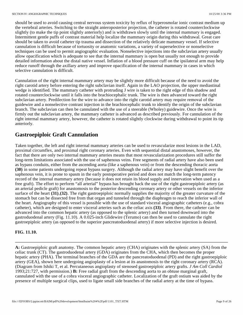
Gastroepiploic graft anatomy. The common hepatic artery (CHA) originates with the splenic artery (SA) from the celiac trunk (CT). The gastroduodenal artery (GDA) originates from the CHA, which then becomes the proper hepatic artery (PHA). The terminal branches of the GDA are the pancreatoduodenal (PD) and the right gastroepiploic artery (GEA), shown here undergoing angioplasty of a lesion at its anastomosis to the right coronary artery (RCA). (Diagram from Ishiki T, et al. Percutaneous angioplasty of stenosed gastroepiploic artery grafts. 1993;21:727, with permission.) Free radial graft from the descending aorta to an obtuse marginal graft, cannulated with the use of a cobra visceral angiographic catheter. Localization of the graft ostium was aided by the presence of multiple surgical clips, used to ligate small side branches of the radial artery at the time of bypass.
should be used to avoid causing central nervous system toxicity by reflux of hyperosmolar ionic contrast medium up the vertebral arteries. Switching to the straight anteroposterior projection, the catheter is rotated counterclockwise slightly (to make the tip point slightly anteriorly) and is withdrawn slowly until the internal mammary is engaged. Intermittent gentle puffs of contrast material help localize the mammary origin during this withdrawal. Great care should be taken to avoid catheter tip trauma and dissection of the relatively delicate mammary vessel. If selective cannulation is difficult because of tortuosity or anatomic variations, a variety of superselective or nonselective techniques can be used to permit angiographic evaluation. Nonselective injections into the subclavian artery usually allow opacification which is adequate to see that the internal mammary is open but usually not enough to provide detailed information about the distal native vessel. Inflation of a blood pressure cuff on the ipsilateral arm may help reduce runoff through the axillary artery and improve opacification of the internal mammary in cases in which selective cannulation is difficult.
Cannulation of the right internal mammary artery may be slightly more difficult because of the need to avoid the right carotid artery before entering the right subclavian itself. Again in the LAO projection, the upper mediastinal wedge is identified. The mammary catheter with protruding J wire is taken to the right edge of this shadow and rotated counterclockwise until it falls into the brachiocephalic trunk. The wire is then advanced toward the right subclavian artery. Predilection for the wire to advance into the right carotid artery may require removal of the guidewire and a nonselective contrast injection in the brachiocephalic trunk to identify the origin of the subclavian branch. The subclavian can then be cannulated with the use of a steerable (Wholey) guidewire. Once the wire is firmly out the subclavian artery, the mammary catheter is advanced as described previously. For cannulation of the right internal mammary artery, however, the catheter is rotated slightly clockwise during withdrawal to point its tip anteriorly.
Gastroepiploic Graft Cannulation
Taken together, the left and right internal mammary arteries can be used to revascularize most lesions in the LAD, proximal circumflex, and proximal right coronary arteries. Even with sequential distal anastomoses, however, the fact that there are only two internal mammary arteries means that most revascularization procedures still suffer the long-term limitations associated with the use of saphenous veins. Free segments of radial artery have also been used as bypass conduits, either from the ascending aorta (like a saphenous vein) or from the descending thoracic aorta
in some patients undergoing repeat bypass surgery. Although the radial artery may have slight benefit over the saphenous vein, it is prone to spasm in the early postoperative period and does not match the long-term patency record of the internal mammary artery (because it does not retain its blood supply and innervation when used as a free graft). The effort to perform “all arterial” bypass has brought back the use of the right gastroepiploic artery (as an arterial pedicle graft) for anastomosis to the posterior descending coronary artery or other vessels on the inferior surface of the heart , . The right gastroepiploic normally supplies the majority of the greater curvature of the stomach but can be dissected free from that organ and tunneled through the diaphragm to reach the inferior wall of the heart. Angiography of this vessel is possible with the use of standard visceral angiographic catheters (e.g., cobra catheter), which are designed to enter visceral arteries such as the celiac axis . From there, the catheter can be advanced into the common hepatic artery (as opposed to the splenic artery) and then turned downward into the gastroduodenal artery (Fig. 11.10). A 0.025-inch Glidewire (Terumo) can then be used to cannulate the right gastroepiploic artery (as opposed to the superior pancreatoduodenal artery) if more selective injection is desired.
(30)
(31) (32)
(33)
FIG. 11.10.
A:
J Am Coll CardiolB:
10/25/00 3:36 PMSECTION IV: ANGIOGRAPHIC TECHNIQUES
Page 9 of 26file:///EPJOBS/Lippincott/BAIM/pdf%20development/htmlbaim%204%2Fpdf/1101_TXT.HTM
Selective catheterization of the left coronary artery using the Sones catheter. The standard approach involves forming a smooth, shallow loop and gradually [inching up] to the ostium from below. If the distal 2 to 3 mm of the catheter
THE BRACHIAL CUTDOWN APPROACH
The technique of performing brachial artery cutdown was the first used for selective coronary angiography, as described in Chapter 5. The original catheter designed by Dr. F. Mason Sones, Jr., was a thin-walled radiopaque woven Dacron catheter with a 2.67-mm (8F) external diameter to its shaft , . The tip is open, and current models also include side-holes that are arranged in opposed pairs within 7 mm of the distal end. The shaft tapers abruptly to 5F external diameter at a point 5 cm from its tip. As Sones stated, this provides a “flexible finger” that may be curved upward into the coronary orifices by pressure of the more rigid shaft against the aortic valve cusps. This enables the Sones catheter to be used for cannulation of both the left and right coronary arteries, as well as entry into the left ventricle for ventriculography. The standard Sones catheter is available in lengths of 80, 100, and 125 cm and in 7F and 8F diameters.
(16) (34)
Some operators use a Sones type of coronary catheter constructed of polyurethane and made by Cordis Corporation. This catheter has the same shape and taper as the woven Dacron catheter and has an end-hole with four side-holes within 7 mm of its tip. This catheter traverses a tortuous subclavian system with much greater facility and smoothness than does the woven Dacron catheter, and its enhanced torque control and reduced friction coefficient permit greater ease in engaging the coronary ostia. It can pass an 0.035-inch guidewire and is an excellent catheter for crossing a stenotic aortic valve. See Fig. 11.1 for a variety of coronary catheters that are also effective from the brachial approach.
When the Sones method is used, catheter-tip pressure should be monitored continuously once the catheter enters the brachial artery. Further passage of the catheter into the subclavian and innominate (brachiocephalic) arteries should be accomplished under both pressure monitoring and fluoroscopic visualization. Occasionally, it may be difficult to pass the catheter from the subclavian artery to the aortic arch, but a simple maneuver by the patient-such as a deep inspiration, shrugging the shoulders, or turning the head to the left-often facilitates passage of the catheter into the ascending aorta. If passage of the catheter from the subclavian artery to the ascending aorta is not accomplished immediately and with complete ease, the operator should stop catheter manipulation and use a soft J-tip 0.035-inch guidewire. Once the catheter is in the ascending aorta, the guidewire is removed and the catheter is aspirated, flushed, and reconnected to the rotating adapter of the manifold, either directly or by a short length of large-bore flexible connecting tubing.
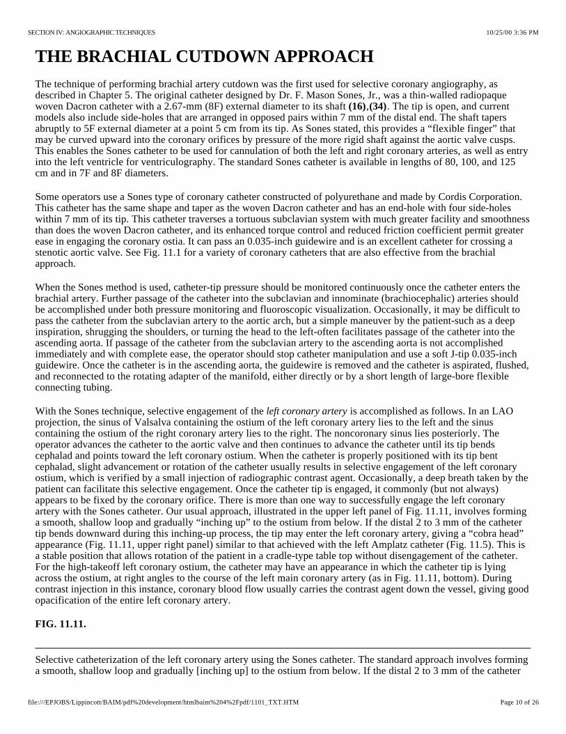
With the Sones technique, selective engagement of the is accomplished as follows. In an LAO projection, the sinus of Valsalva containing the ostium of the left coronary artery lies to the left and the sinus containing the ostium of the right coronary artery lies to the right. The noncoronary sinus lies posteriorly. The operator advances the catheter to the aortic valve and then continues to advance the catheter until its tip bends cephalad and points toward the left coronary ostium. When the catheter is properly positioned with its tip bent cephalad, slight advancement or rotation of the catheter usually results in selective engagement of the left coronary ostium, which is verified by a small injection of radiographic contrast agent. Occasionally, a deep breath taken by the patient can facilitate this selective engagement. Once the catheter tip is engaged, it commonly (but not always) appears to be fixed by the coronary orifice. There is more than one way to successfully engage the left coronary artery with the Sones catheter. Our usual approach, illustrated in the upper left panel of Fig. 11.11, involves forming a smooth, shallow loop and gradually “inching up” to the ostium from below. If the distal 2 to 3 mm of the catheter tip bends downward during this inching-up process, the tip may enter the left coronary artery, giving a “cobra head” appearance (Fig. 11.11, upper right panel) similar to that achieved with the left Amplatz catheter (Fig. 11.5). This is a stable position that allows rotation of the patient in a cradle-type table top without disengagement of the catheter. For the high-takeoff left coronary ostium, the catheter may have an appearance in which the catheter tip is lying across the ostium, at right angles to the course of the left main coronary artery (as in Fig. 11.11, bottom). During contrast injection in this instance, coronary blood flow usually carries the contrast agent down the vessel, giving good opacification of the entire left coronary artery.
left coronary artery
FIG. 11.11.
10/25/00 3:36 PMSECTION IV: ANGIOGRAPHIC TECHNIQUES
Page 10 of 26file:///EPJOBS/Lippincott/BAIM/pdf%20development/htmlbaim%204%2Fpdf/1101_TXT.HTM

tip bends downward during this inching-up process, the tip may enter the left coronary artery, giving a [cobra-head] appearance . When the left coronary ostium originates high in the left sinus of Valsalva ([high-takeoff] left coronary artery), the catheter may have the appearance seen in the bottom panel, where the tip is lying across the ostium, at right angles to the course of the left main coronary artery. During coronary injection in this instance, coronary blood flow usually carries the contrast agent down the vessel, giving good opacification of the entire left coronary artery.
Selective catheterization of the right coronary artery using the Sones catheter. In the shallow left anterior oblique projection, the catheter is curved upward and to the left (1) and clockwise torque is applied. While the operator is gradually applying clockwise torque, a gentle to-and-fro motion of the catheter helps to translate the applied torque to the catheter tip. When the tip starts moving in its clockwise sweep of the anterior wall of the aorta, the operator maintains (but does not increase) a clockwise torque tension on the catheter and simultaneously pulls the catheter back slightly (2), because the right coronary ostium is lower than that of the left coronary artery. At this point the catheter usually makes an abrupt leap into the right coronary ostium (3), at which time the operator must release all torque to prevent the catheter tip from continuing its sweep and passing by the ostium. (See text for details and alternative methods.)
(upper right)
Once the catheter tip has engaged the coronary ostium and no damping of pressure from the catheter tip is observed, cineangiography may be performed with selective injection of radiopaque material in a variety of views, as described later.
Selective engagement of the orifice may be accomplished as illustrated in steps 1 through 3 of Fig. 11.12. In the shallow LAO projection, the catheter is curved up toward the left coronary artery (step 1) and clockwise torque is applied. While the operator is gradually applying clockwise torque, a gentle to-and-fro motion of the catheter (excursions of not more than 5 to 10 mm) helps to translate the applied torque to the catheter tip. When the tip starts moving in its clockwise sweep of the anterior wall of the aorta, the operator maintains (but does not increase) a clockwise torque tension on the catheter and simultaneously pulls the catheter back slightly (step 2, Fig. 11.12), because the right coronary ostium is lower than that of the left coronary artery. At this point, the catheter usually makes an abrupt turn into the right coronary ostium, at which time the operator must release all torque to prevent the catheter tip from continuing its sweep past the ostium. On occasion, the Sones catheter literally leaps into the right coronary artery and 4 to 5 cm down its lumen. If this occurs, the catheter should be gently withdrawn until its tip is stable just within the ostium. Another technique for catheterizing the right coronary artery involves a more direct approach by way of the right coronary cusp. With the catheter in the right sinus, the operator should make a small curve on the tip, directed rightward. A small dose of contrast material in the right sinus of Valsalva allows visualization of the right coronary orifice and facilitates selective engagement. Occasionally, a deep inspiration by the patient accompanied by gentle advancement of the catheter to the right of the aortic root, results in selective engagement of the right coronary artery.
right coronary
FIG. 11.12.
In addition to the Sones catheter, many other catheters may be used for coronary arteriography from the brachial cutdown or percutaneous approach, including the Amplatz , Schoonmaker , Bourassa, Judkins, and other specially designed catheters. Some of these catheters are illustrated in Fig. 11.1. Although the Amplatz catheters were originally devised for use from the percutaneous femoral approach, we have found these catheters highly useful from the brachial approach in cases in which there was difficulty in seating the Sones catheter. Amplatz catheters come in different shapes for the right and left coronary artery and basically incorporate a preformed curvature that is like that of an already-engaged Sones catheter. We have found the AL2 to be adequate for most patients with normal aortic roots, whereas the AL3 may be necessary for a dilated ascending aorta or in large men. Occasionally an AL4 is needed for pronounced aortic dilatation or for a left coronary artery whose ostium originates very high in the left sinus of Valsalva (high-takeoff left coronary artery). The AR1 right coronary catheter is usually adequate for patients with a normal aortic root, whereas the AR2 may be required for patients with an enlarged aortic root or for engagement of saphenous vein bypass grafts. The Amplatz catheters should be introduced through the subclavian artery over a guidewire and (unlike the Sones catheter) cannot be used safely for ventriculography. When working from the left brachial approach, it is also possible to use standard Judkins catheters, since the course of the catheter
(24) (35)
10/25/00 3:36 PMSECTION IV: ANGIOGRAPHIC TECHNIQUES
Page 11 of 26file:///EPJOBS/Lippincott/BAIM/pdf%20development/htmlbaim%204%2Fpdf/1101_TXT.HTM

around the arch emulates its path from the femoral approach in that area. We have not had experience with the Bourassa or Schoonmaker catheters from the brachial approach, but large published series using these catheters from the femoral artery approach suggest that they should also be effective from the brachial approach. Of course, all of these considerations about coronary angiography from the brachial cutdown approach also apply to the percutaneous brachial, axillary, or radial approaches (see Chapter 4).
ADVERSE EFFECTS OF CORONARY ANGIOGRAPHY
Once the coronary vessels have been engaged, selective angiography requires transient but nearly complete replacement of blood flow with a radiopaque contrast agent. A wide variety of iodine-containing agents are currently used for coronary angiography and have already been discussed in greater detail in Chapter 2.
Coronary injection of a high-osmolar contrast agent may have potentially deleterious effects (see Chapters 2 and 3) that include (a) transient (10- to 20-second) hemodynamic depression marked by arterial hypotension and elevation of the left ventricular end-diastolic pressure; (b) ECG effects with T-wave inversion or peaking in the inferior leads (during right and left coronary injection, respectively), sinus slowing or arrest, and prolongation of the PR, QRS, and QT intervals , ; (c) significant arrhythmia (asystole or ventricular tachycardia/fibrillation) ; (d) myocardial ischemia due to interruption of oxygen delivery or inappropriate arteriolar vasodilation (coronary “steal”); (e) allergic reaction ; and (f) cumulative renal toxicity . Some (but not all) of these adverse effects are eliminated by use of a low-osmolar contrast agent, albeit at a modestly increased expense .
(36) (37) (38)
(39) (40)(41)
To recognize, treat, and hopefully prevent these adverse effects, patients undergoing coronary angiography should be monitored continuously in terms of clinical status, surface ECG, and arterial pressure from the catheter tip. In patients with baseline left ventricular dysfunction or marked ischemic instability, we also like to display pulmonary artery pressure continuously on the same scale as the arterial pressure, because this provides the earliest indication of procedural problems or decompensation. A significant rise in pulmonary artery mean or diastolic pressure should prompt temporary suspension of angiography and initiation of treatment (e.g., intravenous furosemide, nitroglycerin, nitroprusside) before frank pulmonary edema develops.
If right-sided heart catheterization is to be performed, the venous sheath provides a ready route for the rapid administration of fluid or medications through its sidearm and allows rapid insertion of a temporary pacing electrode if needed.
We do not, however, endorse the routine prophylactic placement of temporary pacing electrodes in patients undergoing coronary angiography . Most episodes of bradycardia or asystole are brief and are resolved promptly by having the patient give a forceful cough, which elevates central aortic pressure and probably helps wash residual contrast material out of the myocardial capillary bed. True life-threatening bradycardia is very uncommon and can be managed successfully by having the patient cough at 1- to 2-second intervals while a temporary pacing lead is inserted through the indwelling venous sheath and attached to a generator kept at standby at the foot of the catheterization table. Similarly, prophylactic drugs are not given routinely to prevent ventricular tachyarrhythmias, although drugs (e.g., lidocaine, procainamide, atropine, epinephrine), a defibrillator, and airway management equipment are always kept at the ready and can be brought into play within seconds.
(42)
One of the most common adverse effects seen during coronary angiography is the provocation of myocardial ischemia, particularly in patients with unstable angina. In such patients, we commonly do not interrupt any precatheterization heparin infusion (and usually give additional heparin during the catheterization itself) and do not reverse heparin at the completion of the procedure. In very unstable patients, we modify our usual practice of performing the left ventriculogram before coronary angiography (lest an adverse reaction to the ventriculogram compromise the more crucial coronary study). When myocardial ischemia does occur during coronary angiography, the best course of action is to remove the catheter from the coronary ostium and temporarily suspend injections until angina resolves. If this takes more than 30 seconds, we typically administer nitroglycerin (200- g bolus, repeated at 30-second intervals up to a total of 1,000 g) into either the involved coronary artery or the pulmonary artery catheter. If marked arterial hypertension is present and fails to respond to nitroglycerin, we may administer other vasodilators as needed to bring the blood pressure down. In patients with inappropriate tachycardia in the setting of
µµ
10/25/00 3:36 PMSECTION IV: ANGIOGRAPHIC TECHNIQUES
Page 12 of 26file:///EPJOBS/Lippincott/BAIM/pdf%20development/htmlbaim%204%2Fpdf/1101_TXT.HTM

Suggested injection pattern for coronary angiography. To appropriately replace antegrade coronary blood flow with contrast medium throughout the cardiac cycle, the operator should build up the velocity of injection over 1 to 2 seconds until no unopacified blood is seen to enter the ostium and there is reflux of contrast medium into the aorta during systole and diastole. This injection is maintained until the entire coronary artery is filled with contrast medium. If the ostium has not been well seen, a brief extra push should be given to cause adequate reflux into the aortic root, and then the injection is terminated. Prolonged held inspiration with some degree of Valsalva maneuver is sometimes used during Sones angiography to reduce coronary flow and make it much easier to replace blood flow during manual contrast injection.
angina and reasonable systolic left ventricular function, intravenous propranolol (1 mg every minute to a total dose of 0.1 to 0.15 mg/kg) or an infusion of a short-acting -blocking agent (esmolol) is frequently beneficial. Only rarely (in patients with severe three-vessel disease and/or left main coronary artery disease and those whose ischemia is associated with hypotension) is myocardial ischemia severe enough and refractory to this management program to prompt placement of an intraaortic counterpulsation balloon in the contralateral femoral artery before completion of coronary angiography (see Chapter 21). In any patient with prolonged or refractory ischemia during diagnostic coronary angiography, it may be worthwhile to perform limited reexamination of the coronary vessels to determine whether the angiographic procedure has caused a problem (spasm, dissection, thrombosis) that might require immediate treatment with additional vasodilators, balloon angioplasty, thrombolysis, or emergency bypass surgery.
BETA
Severe allergic reactions are uncommon during coronary angiography and are best prevented by 18 to 24 hours of premedication (prednisone, 20 to 40 mg, and cimetidine, 300 mg every 6 hours) and/or use of a nonionic contrast agent in patients with a history of prior allergic reaction to radiographic contrast media . When a severe unexpected reaction does occur, it usually responds promptly to the intravenous administration of epinephrine (0.1 mg = 1 mL of the 1:10,000 solution available on most emergency carts, repeated every 2 minutes until the blood pressure and/or wheezing improves). Larger bolus doses of epinephrine are to be avoided, because they may provoke marked tachycardia, hypertension, and arrhythmia.
(32)(41)
Renal insufficiency may develop after coronary angiography, particularly in patients who are hypovolemic, who receive large volumes of contrast material (more than 3 mL/kg), or who have had prior renal insufficiency, diabetes, or multiple myeloma . In these patients, every effort should be made to give adequate hydration before and after the procedure (see Chapters 2 and 3). Use of low-osmolar contrast agents may be helpful in this situation, but their real benefit remains controversial .
(33)
(41)
INJECTION TECHNIQUE
As mentioned previously, high-quality coronary angiography requires selective injection of radiographic contrast material at an adequate rate and volume to transiently replace the blood contained in the involved vessel with slight but continuous reflux into the aortic root. Too timid an injection allows intermittent entry of non-opaque blood into the coronary artery (producing streaming, which makes interpretation of lesions difficult) and prevents visualization of the coronary ostium and proximal coronary branches. However, too vigorous an injection can cause coronary dissection or excessive myocardial blushing, and too prolonged an injection may contribute to increased myocardial depression or bradycardia.
We train our fellows to adjust the rate and duration of manual contrast injection to match the observed filling pattern of the particular vessel being injected. Injection velocity is built up gradually during the initial 1 second until the injection rate is adequate to completely replace antegrade blood flow into the coronary ostium (Fig. 11.13). The associated rate and volume required to accomplish this goal have been measured and found to average 7 mL at 2.1 mL/sec in the left and 4.8 mL at 1.7 mL/sec in the right coronary artery. In patients with occlusion, much smaller rates and volumes are required, and in patients with left ventricular hypertrophy (e.g., aortic stenosis, hypertrophic myopathy), much larger volumes and higher rates of injection may be required.
(43)
FIG. 11.13.
10/25/00 3:36 PMSECTION IV: ANGIOGRAPHIC TECHNIQUES
Page 13 of 26file:///EPJOBS/Lippincott/BAIM/pdf%20development/htmlbaim%204%2Fpdf/1101_TXT.HTM

Representation of coronary anatomy in relation to the interventricular and atrioventricular valve planes. Coronary branches are as indicated: L Main, left main; LAD, left anterior descending; D, diagonal; S, septal; CX, circumflex; OM, obtuse marginal; RCA, right coronary; CB, conus branch; SN, sinus node; AcM, acute marginal; PD, posterior descending; PL, posterolateral left ventricular.
The numeric coding system and official names of the coronary segments, as used in the Bypass Angioplasty Revascularization Investigation (BARI) study. 1, proximal; 2, middle; 3, distal; 4, posterior descending; 5, posteroatrioventricular; 6, first posterolateral; 7, second posterolateral; 8, third posterolateral; 9, inferior septals; 10, acute marginals. 11, left main; 12, proximal left anterior descending; 13, middle left anterior descending; 14, distal left anterior descending; 15, first diagonal (a, branch of first diagonal); 16, second diagonal; 17, septals (anterior septals); 18, proximal circumflex; 19, middle circumflex; 20, distal circumflex; 21, 22,
The injection is maintained until the entire vessel is opacified. If there is any question as to whether the body of the injection has provided adequate reflux to visualize the coronary ostium, an additional burst of contrast agent (extra reflux) should be given before the injection is terminated. The injection is then terminated abruptly by turning the manifold stopcock back to monitor pressure, although cine filming continues until opacification of distal vessels or late-filling branches is complete. The operator monitors for excessive bradycardia or hypotension, reviews the video playback, and sets the gantry angles for the next injection. To avoid problems, each injection should begin with a completely full (and bubble-free) injection syringe, held with the handle slightly elevated so that any microbubbles will drift up toward the plunger. Recent changes in labeling of contrast agents also suggest that the injection syringe be managed in such a way as to avoid mixtures of blood and contrast material, because such mixtures may promote formation of thrombi (particularly when nonionic contrast agents are used).
Although manual contrast injection is the standard technique in coronary angiography, some operators favor use of a power injector (as used in left ventriculography or aortography) to perform coronary injections . The injector is preset for a rate to match the involved vessel (2 to 3 mL/sec for the right and 3 to 4 mL/sec for the left coronary artery) and is activated by a foot switch for a period sufficient to fill the coronary artery with contrast medium (usually 2 to 3 seconds). This approach allows a single operator to perform injections and move the table and has proved safe in thousands of procedures. A new power injector has been introduced (Acist, Bracco Bristol Myers Squib) (Fig. 11.2) that can perform such power injections under rate control by finger pressure on a sterile control handle, reverting automatically to pressure monitoring when the injection is terminated. This may be of value when a single operator must both perform injections and pan the table during diagnostic coronary angiography.
(44)
ANATOMY, ANGIOGRAPHIC VIEWS, AND QUANTITATION OF STENOSIS
Coronary Anatomy
The coronary angiographer must develop a detailed familiarity with normal coronary arterial anatomy and its common variants. For those just learning coronary anatomy, the main coronary trunks can be considered to lie in one of two orthogonal planes (Fig. 11.14). The anterior descending and posterior descending coronary arteries lie in the plane of the interventricular septum, whereas the right and circumflex coronary trunks lie in the plane of the atrioventricular valves. In the 60° LAO projection, one is looking down the plane of the interventricular septum, with the plane of the atrioventricular (AV) valves seen ; in the 30° RAO projection, one is looking down the plane of the AV valves, with the plane of the interventricular septum seen . The major segments and branches have each been assigned a numeric identification in the Bypass Angioplasty Revascularization Investigation (BARI) modification of the Coronary Artery Surgery Study (CASS) nomenclature (Fig. 11.15).
en faceen face
(45)
FIG. 11.14.
FIG. 11.15.
Right coronary:
Left coronary:
10/25/00 3:36 PMSECTION IV: ANGIOGRAPHIC TECHNIQUES
Page 14 of 26file:///EPJOBS/Lippincott/BAIM/pdf%20development/htmlbaim%204%2Fpdf/1101_TXT.HTM
and 23, first, second, and third obtuse marginals; 23, left atrioventricular; 24, 25, and 26, first, second, and third posterolaterals (in left- or balanced-dominant system); 27, left posterior descending (in left-dominant system); 28, ramus (ramus intermedius); 29, third diagonal. (From The BARI protocol. Protocol for the Bypass Angioplasty Revascularization Investigation. 1991;84:V1, with permission.)Circulation
Right-dominant Circulation
The right coronary artery gives rise to the conus branch (which supplies the right ventricular outflow tract) and one or more acute marginal branches (which supply the free wall of the right ventricle), whether or not the circulation is right-dominant. In the 85% of patients who have a right-dominant coronary artery, it goes on to form the AV nodal artery, the posterior descending, and the posterolateral left ventricular branches which supply the inferior aspect of the left ventricle and interventricular septum (Fig. 11.14). The left main trunk branches after a short (but variable) distance into the LAD and the circumflex coronary arteries. The LAD artery gives rise to septal branches, which curve down into the interventricular septum, as well as diagonal branches, which wrap over the anterolateral free wall of the left ventricle. Some patients have a “twin” LAD system, in which one trunk (frequently intramyocardial) supplies the entire septum and the other trunk runs on the surface of the heart, supplying all the diagonal branches. The circumflex artery courses clockwise in the AV groove (viewed from the apex) as it gives rise to one or more obtuse marginal branches which supply the lateral free wall of the left ventricle, but it does not reach the crux in patients with a right-dominant circulation. In some patients, a large intermedius or ramus medianus branch (neither a diagonal nor a marginal) may originate directly from the left main trunk, bisecting the angle between the LAD and circumflex arteries, to create a trifurcation pattern of the left main coronary artery. Regardless of whether the patient is right- or left-dominant, the sinus node originates as a proximal branch of the right coronary in 60% of patients and as a left atrial branch of the circumflex in the remaining 40% of patients.
Left-dominant Circulation
In 8% of patients, the coronary circulation is left-dominant; that is, the posterolateral left ventricular, posterior descending, and AV nodal arteries are all supplied by the terminal portion of the left circumflex coronary artery. In such patients, the right coronary artery is quite small and supplies only the right atrium and right ventricle. It may be important to visualize, as a potential source of right-to-left collaterals, but the small diameter of a nondominant right coronary artery predisposes it to damping and catheter-induced spasm (see later discussion), which make limited injections advisable.
Balanced-dominant Circulation
In about 7% of hearts, there is a codominant or balanced system, in which the right coronary artery gives rise to the posterior descending artery and then terminates, and the circumflex artery gives rise to all the posterior left ventricular branches and perhaps also to a parallel posterior descending branch that supplies part of the interventricular septum. In some patients, the supply to the inferior wall is further fractionated among a short posterior descending branch of the right coronary (which supplies the inferobase), branches of the distal circumflex (which supply the midinferior wall), and branches of the acute marginal (which extend to supply the inferoapex).
Anatomic Variants
Although these basic concepts describe the general pattern of the coronary circulation, it must be noted that there is considerable patient-to-patient variability in the size and position of the various coronary arterial branches . In 1% to 2% of patients, these coronary anatomic features are sufficiently divergent to qualify as Every operator must be thoroughly familiar with these anatomic anomalies and continually vigilant for their occurrence, lest failure to recognize an anomaly result in an incomplete and therefore inadequate examination. In a review of 126,595 cases from the Cleveland Clinic , the most common of these anomalies was separate ostia of the LAD and left circumflex arteries (0.41%). When this anomaly is present, the catheter usually sits with its tip in the LAD, although there is generally adequate spillover to opacify the circumflex. If not, separate cannulation of the circumflex may be necessary, using the next-larger size left Judkins catheter (e.g., JL5 instead of JL4) or a left Amplatz catheter. A similar situation may exist in the right coronary artery, where the conus branch may have a separate ostium whose separate cannulation may be necessary to demonstrate important collaterals when reflux during the right coronary injection is not adequate to opacify the conus (Fig. 11.16).
(46)coronary anomalies.
(47)
10/25/00 3:36 PMSECTION IV: ANGIOGRAPHIC TECHNIQUES
Page 15 of 26file:///EPJOBS/Lippincott/BAIM/pdf%20development/htmlbaim%204%2Fpdf/1101_TXT.HTM
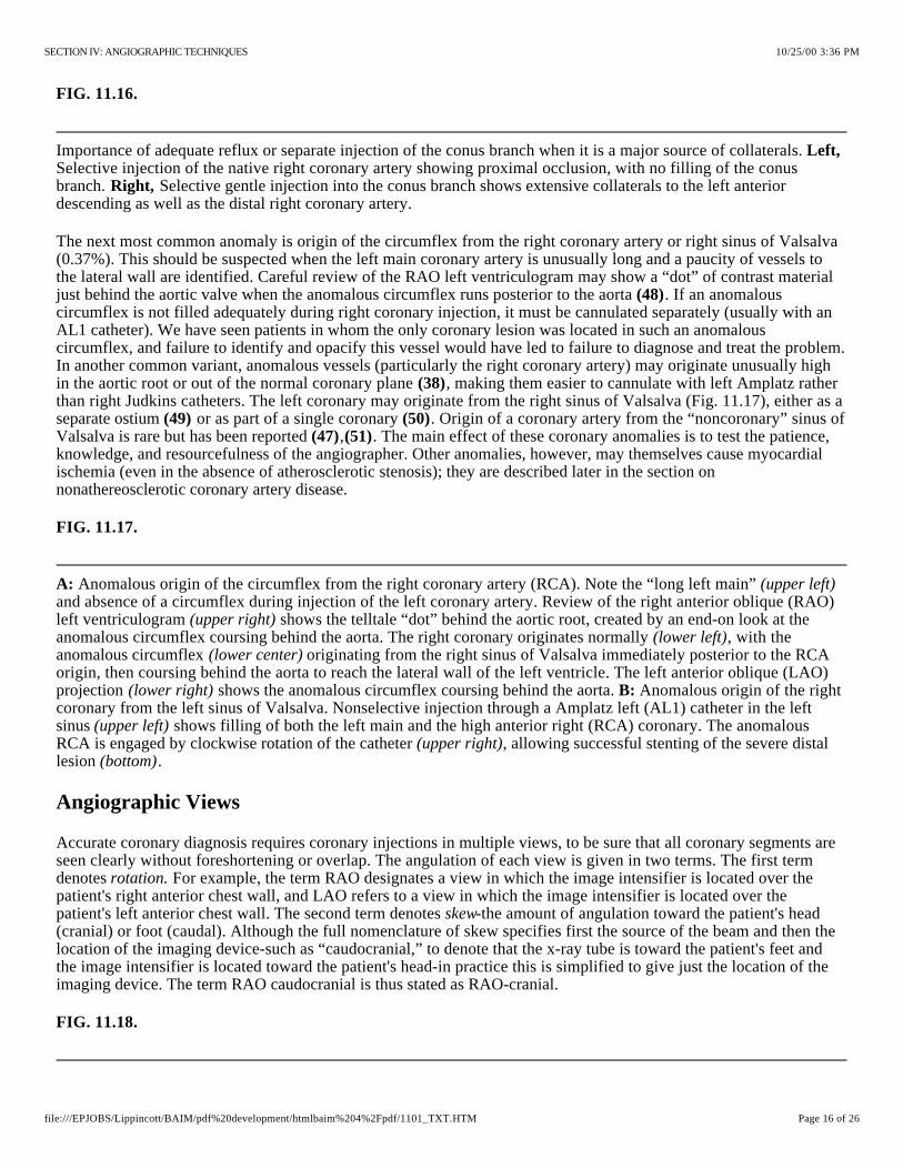
Importance of adequate reflux or separate injection of the conus branch when it is a major source of collaterals. Selective injection of the native right coronary artery showing proximal occlusion, with no filling of the conus branch. Selective gentle injection into the conus branch shows extensive collaterals to the left anterior descending as well as the distal right coronary artery.
Anomalous origin of the circumflex from the right coronary artery (RCA). Note the “long left main” and absence of a circumflex during injection of the left coronary artery. Review of the right anterior oblique (RAO) left ventriculogram shows the telltale “dot” behind the aortic root, created by an end-on look at the anomalous circumflex coursing behind the aorta. The right coronary originates normally , with the anomalous circumflex originating from the right sinus of Valsalva immediately posterior to the RCA origin, then coursing behind the aorta to reach the lateral wall of the left ventricle. The left anterior oblique (LAO) projection shows the anomalous circumflex coursing behind the aorta. Anomalous origin of the right coronary from the left sinus of Valsalva. Nonselective injection through a Amplatz left (AL1) catheter in the left sinus shows filling of both the left main and the high anterior right (RCA) coronary. The anomalous RCA is engaged by clockwise rotation of the catheter , allowing successful stenting of the severe distal lesion .
FIG. 11.16.
Left,
Right,
The next most common anomaly is origin of the circumflex from the right coronary artery or right sinus of Valsalva (0.37%). This should be suspected when the left main coronary artery is unusually long and a paucity of vessels to the lateral wall are identified. Careful review of the RAO left ventriculogram may show a “dot” of contrast material just behind the aortic valve when the anomalous circumflex runs posterior to the aorta . If an anomalous circumflex is not filled adequately during right coronary injection, it must be cannulated separately (usually with an AL1 catheter). We have seen patients in whom the only coronary lesion was located in such an anomalous circumflex, and failure to identify and opacify this vessel would have led to failure to diagnose and treat the problem. In another common variant, anomalous vessels (particularly the right coronary artery) may originate unusually high in the aortic root or out of the normal coronary plane , making them easier to cannulate with left Amplatz rather than right Judkins catheters. The left coronary may originate from the right sinus of Valsalva (Fig. 11.17), either as a separate ostium or as part of a single coronary . Origin of a coronary artery from the “noncoronary” sinus of Valsalva is rare but has been reported , . The main effect of these coronary anomalies is to test the patience, knowledge, and resourcefulness of the angiographer. Other anomalies, however, may themselves cause myocardial ischemia (even in the absence of atherosclerotic stenosis); they are described later in the section on nonathereosclerotic coronary artery disease.
(48)
(38)
(49) (50)(47) (51)
FIG. 11.17.
A: (upper left)
(upper right)(lower left)
(lower center)
(lower right) B:
(upper left)(upper right)
(bottom)
Angiographic Views
Accurate coronary diagnosis requires coronary injections in multiple views, to be sure that all coronary segments are seen clearly without foreshortening or overlap. The angulation of each view is given in two terms. The first term denotes For example, the term RAO designates a view in which the image intensifier is located over the patient's right anterior chest wall, and LAO refers to a view in which the image intensifier is located over the patient's left anterior chest wall. The second term denotes -the amount of angulation toward the patient's head (cranial) or foot (caudal). Although the full nomenclature of skew specifies first the source of the beam and then the location of the imaging device-such as “caudocranial,” to denote that the x-ray tube is toward the patient's feet and the image intensifier is located toward the patient's head-in practice this is simplified to give just the location of the imaging device. The term RAO caudocranial is thus stated as RAO-cranial.
rotation.
skew
FIG. 11.18.
10/25/00 3:36 PMSECTION IV: ANGIOGRAPHIC TECHNIQUES
Page 16 of 26file:///EPJOBS/Lippincott/BAIM/pdf%20development/htmlbaim%204%2Fpdf/1101_TXT.HTM

Geometry of angulated views. Conventional coronary angiography was performed with angulation only in the transverse plane , as demonstrated by the 60° left anterior oblique (LAO) and 30° right anterior oblique (RAO) views. Improved x-ray equipment now permits simultaneous cranial or caudal angulation in the saggital plane. Each view is named according to the location of the image intensifier, rather than by the older nomenclature, which specified the location of both the x-ray tube and intensifier. For example, [cranial] is equivalent to caudocranial.
Demonstration of angiographic projections using the author's coronary model. Left anterior oblique (LAO) and right anterior oblique (RAO) projections are photographed straight (i.e., with no cranial or caudal angulation) and with moderate cranial and moderate caudal angulation (see text for details).
(top)
When cradle systems were used in the 1970s, these views were usually limited to different degrees of left or right anterior obliquity in the transverse plane, including the classic 60° LAO and 30° RAO projections (Fig. 11.14). To allow concurrent cranial angulation of the x-ray beam, cradle systems were modified by propping the patient's shoulders up on a foam wedge (hence the name “sit-up view”) to provide compound LAO-cranial projection. In the 1980s, cradle systems were abandoned in favor of systems in which the x-ray tube and image intensifier are mounted on a parallelogram or on a rigid U-arm supported by a rotating pedestal (see Chapter 2) to allow compound beam angulation in any combination of conventional transverse (LAO, RAO) and skew (cranial, caudal) angulation (Fig. 11.18). Although these views place increased demands on the generator and increase the amount of scattered radiation, there is no doubt that they have improved our ability to define coronary anatomy (52–54).
Not all potential views are necessary in a given patient to constitute an adequate study. Rather, a series of screening views should be used as the foundation of the study, adjusted or supplemented by one or more additional views selected especially to more completely define suspicious areas. This requires the operator to interpret the coronary anatomy as each injection is made, or at least during in-room review from the digital storage system-rather than simply shooting a series of routine views and hoping that the study will prove adequate when reviewed later. Although some laboratories rely on a technician to set up shots and pan the table during coronary angiography, each operator should know how to do this, in order to develop a good understanding of how changes in gantry angulation influence the projected coronary anatomy. One valuable training tool in this respect is a simple wire model of the coronary anatomy which is viewed as it is moved into different angles (Fig. 11.19) . A computer program that simulates the effect of changing angles on the projected coronary anatomy is also available. Although there is no substitution for this type of “hands-on” learning, the discussion below is provided as a rough introduction.
(55)
FIG. 11.19.
Right Anterior Oblique Projections
For historic reasons relating to cradle systems, the screening views used in many laboratories were the straight LAO-RAO angulations. With the availability of more modern gantry systems, it is clear that certain cranial and caudal angulated views offer far better anatomic definition. Therefore, we generally avoid the straight 30° RAO projection of the left coronary artery, because it suffers from overlap and foreshortening of both the LAD and circumflex vessels (Fig. 11.19). Instead, we have made the RAO-caudal projection (0° to 10° RAO and 15° to 20° caudal) our initial view of choice in studying unstable patients, because it provides an excellent view of the left main bifurcation, the proximal LAD artery, and the proximal to middle circumflex artery. The second view we perform is a shallow RAO-cranial projection (0° to 10° RAO and 25° to 40° cranial), which provides a superior view of the middle and distal LAD, with clear visualization of the origins of the septal and diagonal branches. This shallow RAO cranial view is also quite good for examination of the distal right coronary artery or distal circumflex, because it effectively “unstacks” the posterior descending and posterolateral branches and projects them without foreshortening. It seldom, however, provides any useful information about the left main or circumflex coronary artery, because it causes them to be overlapped and foreshortened.
Left Anterior Oblique Projections
The conventional 60° LAO projection is limited by overlap and foreshortening of the left coronary artery, although it is very useful in the evaluation of the proximal and middle right coronary artery. The LAO-cranial view, created by
10/25/00 3:36 PMSECTION IV: ANGIOGRAPHIC TECHNIQUES
Page 17 of 26file:///EPJOBS/Lippincott/BAIM/pdf%20development/htmlbaim%204%2Fpdf/1101_TXT.HTM
the addition of 15° to 30° of cranial angulation, elongates the left main and proximal LAD arteries while projecting the intermedius or first diagonal branch downward off the proximal circumflex. If radiographic penetration in this view is difficult, reducing the LAO angulation to 30° to 40° usually allows the LAD artery to fall into the lucent wedge between the right hemidiaphragm and the spine. Alternatively, performing the cine run during a sustained maximal inspiration usually pulls the diaphragm down and improves x-ray penetration. The LAO-caudal view (40° to 60° LAO and 10° to 20° caudal) projects the left coronary artery upward from the left main in the appearance of a spider, and it usually offers improved visualization of the left main, proximal LAD, and proximal circumflex arteries. It is particularly valuable in patients whose heart has a horizontal lie (i.e., the origin of the left main artery projects at or below the proximal LAD artery in the standard LAO projection). This “spider view” (LAO-caudal) can often be enhanced by filming during maximal expiration, which accentuates a horizontal cardiac position and allows a better look from below, although it stresses the radiographic capacity of most older installations.
Posteroanterior and Left Lateral Projections
The straight posteroanterior (PA, or “0–0”) and left lateral projections tend to be underutilized in the era of complex angulation. Because the left main coronary artery curves from a more leftward to an almost anterior direction along its length, the frequently provides the best view of the left main ostium. On the other hand, the shallow RAO-caudal view frequently provides a better look at the more distal left main artery. The is particularly useful in examining the proximal circumflex and the proximal and distal LAD arteries, particularly when combined with slight (10° to 15°) cranial angulation. This projection also provides the best look at the anastomosis of a left internal mammary graft to the mid-distal LAD, and it offers an excellent look at the midportion of the right coronary artery, free of the excessive motion seen when this portion of the vessel is viewed in the straight RAO projection. The left lateral projection also has the advantage of allowing easy radiographic penetration in most patients when it is performed with both of the patient's hands positioned behind the head, although it generates the highest degree of backscatter to the operator given the proximity of the beam entry point on the patient's right side.
PA projection (sometimes referred to incorrectly as the “AP” projection)
left lateral projection
Over the past several years, operators in our laboratory have adopted a uniform sequence of these views, adjusting the exact angles slightly in each patient as dictated by test puffs of contrast agent. Beginning with the left coronary artery, these views include
1. RAO-caudal to visualize the left main, proximal LAD, and proximal circumflex2. RAO-cranial to visualize the middle and distal LAD without overlap of septal or diagonal branches3. LAO-cranial to visualize the middle and distal LAD in an orthogonal projection4. LAO-caudal to visualize the left main and proximal circumflex.
One or more supplemental views (PA, lateral-cranial, lateral-caudal) may then be taken to clarify any areas of uncertainty. The right coronary catheter is then placed, after which three screening views are obtained:
1. LAO to visualize the proximal right coronary artery2. RAO-cranial to visualize the posterior descending and posterolateral branches3. Lateral to visualize the middle right coronary artery.
Lesion Quantification
To quantify a coronary stenosis accurately, it must be seen in profile, free from artifact related to foreshortening or obfuscation by a crossing vessel. Multiple views are important, because many lesions leave a lumen that is markedly eccentric (elliptic rather than round) . When seen across its major axis, the width of the lumen may appear almost normal; the only clue to the severe degree of narrowing may be marked lucency, caused by thinning of the contrast column. Any such suspicious lesions must be examined in a variety of other projections to reveal their true severity and to distinguish the lucency caused by eccentric stenosis from a similar lucency that may be seen adjacent to an area of denser contrast (caused by tortuosity or overlapping vessels in the absence of any true abnormality at the site) through a perceptual artifact known as the Mach effect .
(56)
(57)
The ability of coronary angiography to quantify the degree of stenosis at different points in the coronary circulation
10/25/00 3:36 PMSECTION IV: ANGIOGRAPHIC TECHNIQUES
Page 18 of 26file:///EPJOBS/Lippincott/BAIM/pdf%20development/htmlbaim%204%2Fpdf/1101_TXT.HTM
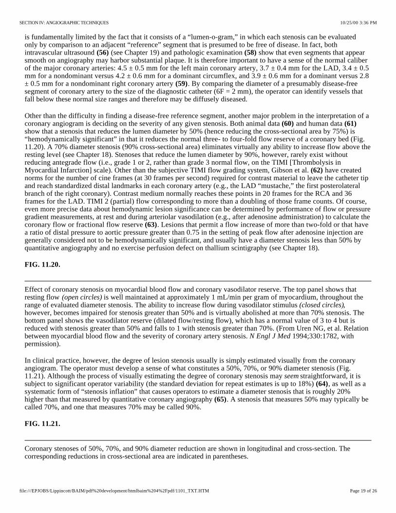
Effect of coronary stenosis on myocardial blood flow and coronary vasodilator reserve. The top panel shows that resting flow is well maintained at approximately 1 mL/min per gram of myocardium, throughout the range of evaluated diameter stenosis. The ability to increase flow during vasodilator stimulus , however, becomes impaired for stenosis greater than 50% and is virtually abolished at more than 70% stenosis. The bottom panel shows the vasodilator reserve (dilated flow/resting flow), which has a normal value of 3 to 4 but is reduced with stenosis greater than 50% and falls to 1 with stenosis greater than 70%. (From Uren NG, et al. Relation between myocardial blood flow and the severity of coronary artery stenosis. 1994;330:1782, with permission).
Coronary stenoses of 50%, 70%, and 90% diameter reduction are shown in longitudinal and cross-section. The corresponding reductions in cross-sectional area are indicated in parentheses.
is fundamentally limited by the fact that it consists of a “lumen-o-gram,” in which each stenosis can be evaluated only by comparison to an adjacent “reference” segment that is presumed to be free of disease. In fact, both intravascular ultrasound (see Chapter 19) and pathologic examination show that even segments that appear smooth on angiography may harbor substantial plaque. It is therefore important to have a sense of the normal caliber of the major coronary arteries: 4.5 ± 0.5 mm for the left main coronary artery, 3.7 ± 0.4 mm for the LAD, 3.4 ± 0.5 mm for a nondominant versus 4.2 ± 0.6 mm for a dominant circumflex, and 3.9 ± 0.6 mm for a dominant versus 2.8 ± 0.5 mm for a nondominant right coronary artery . By comparing the diameter of a presumably disease-free segment of coronary artery to the size of the diagnostic catheter (6F = 2 mm), the operator can identify vessels that fall below these normal size ranges and therefore may be diffusely diseased.
(56) (58)
(59)
Other than the difficulty in finding a disease-free reference segment, another major problem in the interpretation of a coronary angiogram is deciding on the severity of any given stenosis. Both animal data and human data show that a stenosis that reduces the lumen diameter by 50% (hence reducing the cross-sectional area by 75%) is “hemodynamically significant” in that it reduces the normal three- to four-fold flow reserve of a coronary bed (Fig. 11.20). A 70% diameter stenosis (90% cross-sectional area) eliminates virtually any ability to increase flow above the resting level (see Chapter 18). Stenoses that reduce the lumen diameter by 90%, however, rarely exist without reducing antegrade flow (i.e., grade 1 or 2, rather than grade 3 normal flow, on the TIMI [Thrombolysis in Myocardial Infarction] scale). Other than the subjective TIMI flow grading system, Gibson et al. have created norms for the number of cine frames (at 30 frames per second) required for contrast material to leave the catheter tip and reach standardized distal landmarks in each coronary artery (e.g., the LAD “mustache,” the first posterolateral branch of the right coronary). Contrast medium normally reaches these points in 20 frames for the RCA and 36 frames for the LAD. TIMI 2 (partial) flow corresponding to more than a doubling of those frame counts. Of course, even more precise data about hemodynamic lesion significance can be determined by performance of flow or pressure gradient measurements, at rest and during arteriolar vasodilation (e.g., after adenosine administration) to calculate the coronary flow or fractional flow reserve . Lesions that permit a flow increase of more than two-fold or that have a ratio of distal pressure to aortic pressure greater than 0.75 in the setting of peak flow after adenosine injection are generally considered not to be hemodynamically significant, and usually have a diameter stenosis less than 50% by quantitative angiography and no exercise perfusion defect on thallium scintigraphy (see Chapter 18).
(60) (61)
(62)
(63)
FIG. 11.20.
(open circles)(closed circles)
N Engl J Med
In clinical practice, however, the degree of lesion stenosis usually is simply estimated visually from the coronary angiogram. The operator must develop a sense of what constitutes a 50%, 70%, or 90% diameter stenosis (Fig. 11.21). Although the process of visually estimating the degree of coronary stenosis may straightforward, it is subject to significant operator variability (the standard deviation for repeat estimates is up to 18%) , as well as a systematic form of “stenosis inflation” that causes operators to estimate a diameter stenosis that is roughly 20% higher than that measured by quantitative coronary angiography . A stenosis that measures 50% may typically be called 70%, and one that measures 70% may be called 90%.
seem(64)
(65)
FIG. 11.21.
10/25/00 3:36 PMSECTION IV: ANGIOGRAPHIC TECHNIQUES
Page 19 of 26file:///EPJOBS/Lippincott/BAIM/pdf%20development/htmlbaim%204%2Fpdf/1101_TXT.HTM

In a series of 227 patients with single-vessel disease, visual estimates ( , average almost 90%) were consistently higher than either caliper measurements (average approximately 80%) or computer-assisted quantitative angiography by either geometric or densitometric techniques ( , average approximately 70% diameter stenosis). (From Folland ED, Vogel RA, Hartigan P, et al. Relation between coronary artery stenosis assessed by visual, caliper, and computer methods and exercise capacity in patients with single-vessel coronary artery disease.
1994;89:2005, with permission).
Tools are available to resolve this problem. The simplest is to project the coronary image on a wall-mounted viewing screen and to use inexpensive digital calipers (available from machinist supply houses) to measure the relative diameters of the stenotic and reference segments . Percent stenosis then can be calculated as 100 × [1 - (stenosis diameter/reference diameter)] to provide a more accurate estimate. This technique also reduces the standard deviation for diameter stenosis 6% to 8% , . Even greater precision can be obtained by using computer-assisted algorithms to perform automated edge detection on digitally acquired images to measure the coronary lumen with a standard deviation of less than 5% , . The amount of variation in diameter stenosis readings for one study using these different methods concurrently is shown in Fig. 11.22.
(66)
(64) (66)
(67) (68) (69)
FIG. 11.22.
right curve
left curves
Circulation
The good news is that angiographers who have trained their eye in actual stenosis quantification (by using digital calipers or computer-assisted quantitative coronary angiography) can then actually give visual estimates much closer to true measurements . This allows angiographers to be more uniform in their visual estimates and to move away from reporting physiologically impossible findings such as a 95% stenosis with normal distal flow. Until there is a “stenosis reading reform,” so that those of us who call such lesions accurately (e.g., 70%) will not be accused of intervening on mild lesions, there can be no substitute for “seeing the films yourself” before making any clinical decisions!
(70)
It has also become important to evaluate lesion morphology more accurately from the coronary angiogram. Features such as eccentricity, ulceration, and thrombus may be associated with unstable clinical patterns , , and features such as calcification, eccentricity, or thrombus may influence the choice of catheter intervention. Many of these features can be recognized from careful study of high-quality cineangiograms, although angiography is clearly not as sensitive to these features as intravascular ultrasound or angioscopy (for thrombus or dissection) . It may also be difficult to predict the physiologic significance of a coronary lesion from angiography alone, in which case it may need to be supplemented by other techniques such as direct flow or distal pressure measurements . Finally, the absence of lesions that narrow the coronary lumen by more than 50% does not necessarily confer immunity from subsequent coronary events, because it is frequently a less severe stenotic lesion that has a large lipid core and a thin fibrous cap that predisposes to subsequent plaque rupture and the resulting coronary thrombosis . Despite these recognized limitations in quantification and morphology assessment, contrast coronary angiography remains the clinical standard on which lesions are evaluated and decisions are made regarding the need for (and best mode of providing) revascularization in the patient with ischemic heart disease.
(71) (72)
(73) (74)
(63)
(75)
Coronary Collaterals
In reviewing the coronary angiogram, one basic principle is that there should be evident blood supply to all portions of the left ventricle. Previously occluded vessel branches are usually manifested as truncated stumps, but no stump may be evident if there has been a flush occlusion at the origin of the involved vessel. These occluded or severely stenotic vessels are seen frequently to fill late in the injection by antegrade (so-called bridging) collaterals or collaterals that originate from the same (intracoronary) or an adjacent (intercoronary) vessel; this phenomenon is reviewed in an excellent paper by Levin and illustrated in Figs. 11.23 through 11.25. Finally, coronary occlusion may manifest in some patients simply as an angiographically arid area to which there is no evidence of either antegrade or collateral flow and no evident vascular stump. If such an area fails to show regional hypokinesis on the left ventriculogram, however, the operator should search carefully for blood supply by way of anomalous vessels or unopacified collaterals (i.e., a separate origin conus branch that was not opacified during the main right coronary artery injections), because the myocardium cannot continue to function normally with no visible means of support. Functioning collaterals can maintain a coronary wedge pressure that averages almost 40% of mean aortic
(76)
10/25/00 3:36 PMSECTION IV: ANGIOGRAPHIC TECHNIQUES
Page 20 of 26file:///EPJOBS/Lippincott/BAIM/pdf%20development/htmlbaim%204%2Fpdf/1101_TXT.HTM
Ten collateral pathways observed in patients with right coronary (RC) obstruction (total occlusion or greater than 90% stenosis). LAD, left anterior descending; C, circumflex; OM, obtuse marginal; PD, posterior descending; PLV, posterior left ventricular branch; AM, acute marginal branch of right coronary artery; A-V, atrioventricular nodal; LC, left coronary. Numbers in parentheses represent numbers of cases in this series. (From Levin DC. Pathways and functional significance of the coronary collateral circulation. 1974;50:831. By permission of the American Heart Association, Inc.)
Seven collateral pathways observed in patients with left coronary artery obstruction. Abbreviations and format are the same as in Fig. 11.23. (From Levin DC. Pathways and functional significance of the coronary collateral circulation.
1974;50:831. By permission of the American Heart Association, Inc.)
Five collateral pathways observed in patients with circumflex coronary artery obstruction. Abbreviations and format are the same as in Fig. 11.23. (From Levin DC. Pathways and functional significance of the coronary collateral circulation. 1974;50:831. By permission of the American Heart Association, Inc.)
pressure , , thereby maintaining myocardial viability in the collateral-fed distribution. Along with other measures of retained or augmentable wall motion, redistributing defects on perfusion imaging, and positron emission tomographic (PET) evidence of ongoing glucose metabolism, the angiographic presence of collateral flow to an area in the distribution of an occluded coronary artery is one of the strongest evidences of ongoing myocardial viability and an important factor in determining the best revascularization strategy.
(77) (78)
FIG. 11.23.
Circulation
FIG. 11.24.
Circulation
FIG. 11.25.
Circulation
Although it is uncommon, what appears to be a network of collaterals may be the vascular supply to an organized thrombus (in the left ventricle or left atrium) or a cardiac tumor. Those entities should be suspected when filling of an apparent collateral network is seen in the absence of occlusion or severe stenosis of the normal supply to a myocardial territory.
NONATHEROSCLEROTIC CORONARY ARTERY DISEASE
Although atherosclerotic stenosis is by far the most common pathologic process responsible for myocardial ischemia, the angiographer must be aware of a variety of other potential causes . These include certain congenital anomalies of coronary origin (46,80–82), such as an anomalous coronary artery that courses between the aorta and the pulmonary artery, in which flow may be compromised by deformation of the ostium or compression of the proximal vessel, potentially even causing sudden death. Other abnormalities include coronary fistulas (Fig. 11.26), coronary aneurysms , , and muscle bridges (Fig. 11.27) , . , connections mostly from a coronary artery to the right ventricle, right atrium, pulmonary artery, or coronary sinus, are found in roughly 0.1% of patients coming to cardiac catheterization. When they are large (or in the setting of proximal coronary disease), these fistulas may cause chronic volume overload or myocardial ischemia and must be closed, using surgery or newer catheter techniques (e.g., embolization coils, covered stents) . Smaller, asymptomatic fistulas may close spontaneously and can be managed conservatively . are sections of a coronary artery (almost always the LAD) that run under a strip of left ventricular muscle, which compresses the lumen during ventricular systole despite a normal appearance during diastole , . Similar systolic compression of the first septal branch (saw-toothing) is also seen in many patients with hypertrophic cardiomyopathy .
e.g.
(79)
(83) (84) (85) (86) Coronary fistulas
(87)(88) Muscle bridges
(85) (86)(89) When one of these congenital
anomalies is present in a patient with ischemic symptoms in whom catheterization has failed to demonstrate the expected finding of coronary atherosclerosis, the angiographer should be able to recognize it as a potential cause of ischemia and recommend additional functional testing with an eye toward surgical or catheter-assisted repair ( , fistula coil embolization, muscle bridge stent placement).
10/25/00 3:36 PMSECTION IV: ANGIOGRAPHIC TECHNIQUES
Page 21 of 26file:///EPJOBS/Lippincott/BAIM/pdf%20development/htmlbaim%204%2Fpdf/1101_TXT.HTM
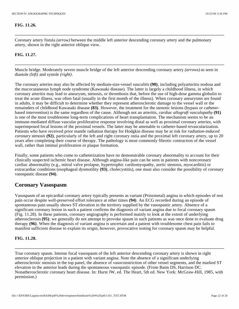
Coronary artery fistula between the middle left anterior descending coronary artery and the pulmonary artery, shown in the right anterior oblique view.
Muscle bridge. Moderately severe muscle bridge of the left anterior descending coronary artery as seen in diastole and systole .
True coronary spasm. Intense focal vasospasm of the left anterior descending coronary artery is shown in right anterior oblique projection in a patient with variant angina. Note the absence of a significant underlying atherosclerotic stenosis in the top panel, the absence of vasoconstriction of other vessel segments, and the marked ST elevation in the anterior leads during the spontaneous vasospastic episode. (From Baim DS, Harrison DC. Nonatherosclerotic coronary heart disease. In: Hurst JW, ed. The Heart, 5th ed. New York: McGraw-Hill, 1985, with permission.)
FIG. 11.26.
(arrow)
FIG. 11.27.
(arrows)(left) (right)
The coronary arteries may also be affected by medium-size-vessel , including polyarteritis nodosa and the mucocutaneous lymph node syndrome (Kawasaki disease). The latter is largely a childhood illness, in which coronary arteritis may lead to aneurysm, stenosis, or thrombosis that, before the use of high-dose gamma globulin to treat the acute illness, was often fatal (usually in the first month of the illness). When coronary aneurysms are found in adults, it may be difficult to determine whether they represent atherosclerotic damage to the vessel wall or the remainders of childhood Kawasaki disease . However, the treatment for the stenotic lesions (bypass or catheter-based intervention) is the same regardless of the cause. Although not an arteritis, is one of the most troublesome long-term complications of heart transplantation. The mechanism seems to be an immune-mediated diffuse vascular proliferative response involving distal as well as proximal coronary arteries, with superimposed focal lesions of the proximal vessels. The latter may be amenable to catheter-based revascularization. Patients who have received prior mantle radiation therapy for Hodgkin disease may be at risk for
, particularly of the left and right coronary ostia and the proximal left coronary artery, up to 20 years after completing their course of therapy. The pathology is most commonly fibrotic contraction of the vessel wall, rather than intimal proliferation or plaque formation.
vasculitis (90)
(83)cardiac allograft vasculopathy (91)
radiation-induced coronary stenosis (92)
Finally, some patients who come to catheterization have no demonstrable coronary abnormality to account for their clinically suspected ischemic heart disease. Although angina-like pain can be seen in patients with noncoronary cardiac abnormality (e.g., mitral valve prolapse, hypertrophic cardiomyopathy, aortic stenosis, myocarditis) or extracardiac conditions (esophageal dysmotility , cholecystitis), one must also consider the possibility of coronary vasospastic disease .
(93)(94)
Coronary Vasospasm
Vasospasm of an epicardial coronary artery typically presents as variant (Prinzmetal) angina in which episodes of rest pain occur despite well-preserved effort tolerance at other times . An ECG recorded during an episode of spontaneous pain usually shows ST elevation in the territory supplied by the vasospastic artery. Absence of a significant coronary lesion in such a patient confirms the diagnosis of variant angina due to focal coronary spasm (Fig. 11.28). In these patients, coronary angiography is performed mainly to look at the extent of underlying atherosclerosis ; we generally do not attempt to provoke spasm in such patients as was once done to evaluate drug therapy . When the diagnosis of variant angina is uncertain and a patient with troublesome chest pain fails to manifest sufficient disease to explain its origin, however, provocative testing for coronary spasm may be helpful.
(94)
(95)(96)
FIG. 11.28.
10/25/00 3:36 PMSECTION IV: ANGIOGRAPHIC TECHNIQUES
Page 22 of 26file:///EPJOBS/Lippincott/BAIM/pdf%20development/htmlbaim%204%2Fpdf/1101_TXT.HTM
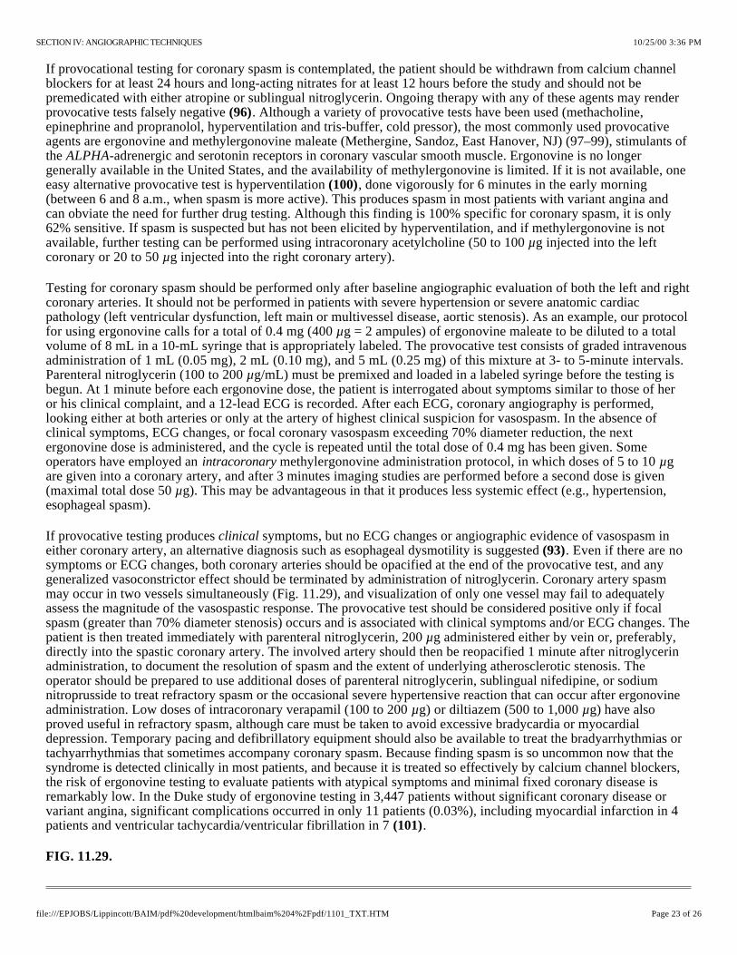
If provocational testing for coronary spasm is contemplated, the patient should be withdrawn from calcium channel blockers for at least 24 hours and long-acting nitrates for at least 12 hours before the study and should not be premedicated with either atropine or sublingual nitroglycerin. Ongoing therapy with any of these agents may render provocative tests falsely negative . Although a variety of provocative tests have been used (methacholine, epinephrine and propranolol, hyperventilation and tris-buffer, cold pressor), the most commonly used provocative agents are ergonovine and methylergonovine maleate (Methergine, Sandoz, East Hanover, NJ) (97–99), stimulants of the -adrenergic and serotonin receptors in coronary vascular smooth muscle. Ergonovine is no longer generally available in the United States, and the availability of methylergonovine is limited. If it is not available, one easy alternative provocative test is hyperventilation , done vigorously for 6 minutes in the early morning (between 6 and 8 a.m., when spasm is more active). This produces spasm in most patients with variant angina and can obviate the need for further drug testing. Although this finding is 100% specific for coronary spasm, it is only 62% sensitive. If spasm is suspected but has not been elicited by hyperventilation, and if methylergonovine is not available, further testing can be performed using intracoronary acetylcholine (50 to 100 g injected into the left coronary or 20 to 50 g injected into the right coronary artery).
(96)
ALPHA
(100)
µµ
Testing for coronary spasm should be performed only after baseline angiographic evaluation of both the left and right coronary arteries. It should not be performed in patients with severe hypertension or severe anatomic cardiac pathology (left ventricular dysfunction, left main or multivessel disease, aortic stenosis). As an example, our protocol for using ergonovine calls for a total of 0.4 mg (400 g = 2 ampules) of ergonovine maleate to be diluted to a total volume of 8 mL in a 10-mL syringe that is appropriately labeled. The provocative test consists of graded intravenous administration of 1 mL (0.05 mg), 2 mL (0.10 mg), and 5 mL (0.25 mg) of this mixture at 3- to 5-minute intervals. Parenteral nitroglycerin (100 to 200 g/mL) must be premixed and loaded in a labeled syringe before the testing is begun. At 1 minute before each ergonovine dose, the patient is interrogated about symptoms similar to those of her or his clinical complaint, and a 12-lead ECG is recorded. After each ECG, coronary angiography is performed, looking either at both arteries or only at the artery of highest clinical suspicion for vasospasm. In the absence of clinical symptoms, ECG changes, or focal coronary vasospasm exceeding 70% diameter reduction, the next ergonovine dose is administered, and the cycle is repeated until the total dose of 0.4 mg has been given. Some operators have employed an methylergonovine administration protocol, in which doses of 5 to 10 g are given into a coronary artery, and after 3 minutes imaging studies are performed before a second dose is given (maximal total dose 50 g). This may be advantageous in that it produces less systemic effect (e.g., hypertension, esophageal spasm).
µ
µ
intracoronary µ
µ
If provocative testing produces symptoms, but no ECG changes or angiographic evidence of vasospasm in either coronary artery, an alternative diagnosis such as esophageal dysmotility is suggested . Even if there are no symptoms or ECG changes, both coronary arteries should be opacified at the end of the provocative test, and any generalized vasoconstrictor effect should be terminated by administration of nitroglycerin. Coronary artery spasm may occur in two vessels simultaneously (Fig. 11.29), and visualization of only one vessel may fail to adequately assess the magnitude of the vasospastic response. The provocative test should be considered positive only if focal spasm (greater than 70% diameter stenosis) occurs and is associated with clinical symptoms and/or ECG changes. The patient is then treated immediately with parenteral nitroglycerin, 200 g administered either by vein or, preferably, directly into the spastic coronary artery. The involved artery should then be reopacified 1 minute after nitroglycerin administration, to document the resolution of spasm and the extent of underlying atherosclerotic stenosis. The operator should be prepared to use additional doses of parenteral nitroglycerin, sublingual nifedipine, or sodium nitroprusside to treat refractory spasm or the occasional severe hypertensive reaction that can occur after ergonovine administration. Low doses of intracoronary verapamil (100 to 200 g) or diltiazem (500 to 1,000 g) have also proved useful in refractory spasm, although care must be taken to avoid excessive bradycardia or myocardial depression. Temporary pacing and defibrillatory equipment should also be available to treat the bradyarrhythmias or tachyarrhythmias that sometimes accompany coronary spasm. Because finding spasm is so uncommon now that the syndrome is detected clinically in most patients, and because it is treated so effectively by calcium channel blockers, the risk of ergonovine testing to evaluate patients with atypical symptoms and minimal fixed coronary disease is remarkably low. In the Duke study of ergonovine testing in 3,447 patients without significant coronary disease or variant angina, significant complications occurred in only 11 patients (0.03%), including myocardial infarction in 4 patients and ventricular tachycardia/ventricular fibrillation in 7 .
clinical(93)
µ
µ µ
(101)
FIG. 11.29.
10/25/00 3:36 PMSECTION IV: ANGIOGRAPHIC TECHNIQUES
Page 23 of 26file:///EPJOBS/Lippincott/BAIM/pdf%20development/htmlbaim%204%2Fpdf/1101_TXT.HTM

This 37-year-old man was admitted with rest pain and ST-segment elevation in the inferior leads. Emergency catheterization was performed for presumed acute myocardial infarction within 30 minutes after presentation
. It disclosed a dominant right coronary artery with only mild disease at a time when pain had resolved after nitrate and heparin therapy. Hyperventilation (30 breaths per minute for 5 minutes) was performed with reduction of the partial pressure of carbon dioxide (PCO2) to 19 mm Hg and elevation of the pH to 7.61, resulting in provocation of occlusive focal spasm of the distal right coronary artery with return of chest pain and ST segment elevation
. Relief of vasospasm and marked general dilation of the right coronary artery were produced by intracoronary administration of trinitroglycerin 200 g and diltiazem 500 g .
Vasomotor changes not representing true coronary spasm. During right coronary catheterization with a Judkins catheter , this patient developed severe catheter-tip spasm. Recatheterization 24 hours later with an Amplatz catheter showed neither catheter-tip spasm nor an atherosclerotic stenosis. After administration of ergonovine 0.4 mg, marked diffuse coronary narrowing was observed , without angina or electrocardiographic changes. After the intracoronary administration of nitroglycerin 200 g , there is marked diffuse vasodilation.
Right coronary artery [pleating] artifact. Baseline injection shows diffuse disease in this tortuous right coronary artery selected for rotational atherectomy. Middle panel shows straightening of the proximal vessel by the stiff [type C] wire, creating three areas of infolding of the vessel wall , as well as the appearance of ostial stenosis
. Immediately on withdrawal of the guidewire, the artery returned to its baseline curvature, and these defects resolved .
(upper left)
(upper right)
µ (lower right) µ (lower right)
Several additional comments about ergonovine are in order. Our group avoids ergonovine testing in patients with severe atherosclerotic stenosis (80% or greater), in whom spasm is not required to explain the clinical symptoms. In these patients, however, we frequently do repeat coronary angiography of the stenotic vessel after the intracoronary administration of 200 mg of nitroglycerin, to exclude the possibility that spontaneous focal vasospasm is contributing to the appearance of severe atherosclerotic stenosis. Second, the operator should be aware that the positivity rate of ergonovine testing depends strongly on which patients are studied; the test is almost always positive in patients with known variant angina (if their disorder is active and medications have been withheld) and is positive in approximately one third of patients with clinically suspected variant angina, but it is positive in fewer than 5% of patients whose symptoms do not suggest variant angina . The Duke group reported an overall positivity rate of 4% in such patients, with two independent predictors of a positive test: mild to moderate disease on the angiogram (spasm often takes place at the point of such disease) and a history of smoking, whose presence increased the positivity rate to 10%. It is also important to distinguish the intense focal spasm seen in patients with variant angina from the normal mild (15% to 20%) diffuse coronary narrowing seen as a pharmacologic response to ergonovine in normal patients . True coronary spasm must also be distinguished from spasm induced by mechanical interventions such as rotational atherectomy (see Chapter 28) or catheter tip spasm (Fig. 11.30). Catheter tip spasm is most common in the right coronary artery, is not associated with clinical symptoms or ECG changes, and does not indicate variant angina . It should be recognized as such, however, and treated by withdrawal of the catheter, administration of nitroglycerin, and nonselective or cautious repeat selective opacification of the involved vessel, to avoid mistaking catheter-tip spasm for an atherosclerotic lesion. Spasm should also be distinguished from a “pleating” artifact that may occur when a curved artery is straightened out by a stiff guidewire (Fig. 11.31), causing folds of the vessel wall to impinge on the lumen. Pleating is refractory to nitroglycerin but resolves immediately when the stiff guidewire is withdrawn .
(99) (101)
(102)
(103)
(104)
FIG. 11.30.
(upper left)(upper right)
(lower left)µ (lower right)
FIG. 11.31.
(left)
(arrows)(curved arrow)
(arrows)
Abnormal Coronary Vasodilator Reserve
Evidence has been accumulating that the population of patients with angina and angiographically normal coronary arteries may contain a subgroup of patients who have myocardial ischemia on the basis of abnormal vasodilator
10/25/00 3:36 PMSECTION IV: ANGIOGRAPHIC TECHNIQUES
Page 24 of 26file:///EPJOBS/Lippincott/BAIM/pdf%20development/htmlbaim%204%2Fpdf/1101_TXT.HTM

reserve. Despite angiographic normality, intravascular ultrasound examination may show normal vessel wall architecture, intimal thickening, or atheromatous plaque . In these patients, coronary blood flow (as described in Chapter 18) may fail to rise normally with pacing tachycardia or exercise, and the coronary vascular resistance is increased abnormally . Also, many of these patients show an abnormal rise in left ventricular end-diastolic pressure after pacing tachycardia and show less lactate consumption than normal subjects in response to pacing tachycardia . A failure of small vessel coronary vasodilation, inappropriate vasoconstriction at the arteriolar level, or functional abnormalities of capillary endothelial cells in releasing endothelium-derived relaxing factor (EDRF) have been postulated to account for these findings. Many patients with so-called syndrome X respond at least partially to treatment with a calcium channel blocker, but other patients show no clear flow or contractile abnormality, so that the primary problem may be simply increased sensitivity to pain .
(84)
(105)
(106)
(11)
MISTAKES IN INTERPRETATION
An inexperienced operator often produces an incomplete or uninterpretable study, especially if poor equipment is used. Such an operator is also likely to misinterpret the angiographic findings, with potentially serious clinical consequences. The following discussion summarizes some of the most common pitfalls that may lead the inexperienced coronary angiographer to mistaken conclusions.
Inadequate Number of Projections
There is no standard number of projections that will always provide complete information. Each major vessel must be viewed in an isolated fashion as it stands apart from other vessels. Usually, the angulated views discussed earlier in this chapter are necessary to visualize clearly the anatomy of the proximal LAD and circumflex arteries.
Inadequate Injection of Contrast Material
The inexperienced operator or assistant has a tendency to hold back on the volume and force of injection into the coronary circulation. This results in inadequate or intermittent, pulsatile opacification of the coronary arterial tree, because contrast flow fails short of peak coronary flow during diastole. There is inadequate mixing of contrast agent and blood, and pockets of nonradiopaque blood in such inadequate injections may even give the appearance of arterial narrowing.
Superselective Injection
It is not uncommon to catheterize the LAD or circumflex coronary artery superselectively, especially when the left main coronary artery is short and its bifurcation is early. To the inexperienced operator, this may give the impression of total occlusion of the nonvisualized vessel (e.g., if only the circumflex artery is opacified, the operator may conclude that the LAD artery is occluded). If adequate filling of the noncannulated vessel cannot be achieved by reflux, selective cannulation of the LAD may be obtained by counterclockwise rotation or use of a Judkins catheter of the next smaller size (e.g., JL3.5), whereas selective cannulation of the circumflex may be obtained by clockwise rotation or use of the next larger size (e.g., JL5). With the right coronary artery, superselective injection may occur if the catheter tip is too far down the vessel, leading to failure to visualize the conus and sinus node arteries. Because these are important sources of collateralization of the left coronary system, important information may be missed (Fig. 11.13). Injection that is adequate to provide a continuous (nonpulsatile) reflux of contrast agent back into the sinus of Valsalva helps the operator to recognize vessels that originate proximally to the catheter tip and thereby avoid the interpretation error of superselective injection.
Selective cannulation of a coronary artery may also fail to detect significant ostial stenosis, particularly if the catheter tip lies beyond the lesion and adequate contrast reflux is not produced. If ostial stenosis is suspected (e.g., if there is partial ventricularization or damping), we have found it helpful to perform a final injection during withdrawal of the catheter from the ostium (Fig. 11.32).
FIG. 11.32.
10/25/00 3:36 PMSECTION IV: ANGIOGRAPHIC TECHNIQUES
Page 25 of 26file:///EPJOBS/Lippincott/BAIM/pdf%20development/htmlbaim%204%2Fpdf/1101_TXT.HTM

Masking of ostial stenosis during superselective cannulation. Ostial stenosis of previously stented vein graft is not apparent with the tip of the catheter well beyond the stenosis . Continued injection during catheter withdrawal causes reflux into the aorta and clearly shows significant ostial stenosis.
(top and middle panels)(bottom panel) (solid arrow)
Catheter-induced Coronary Spasm
Coronary artery spasm may be related to the catheter itself, possibly caused by mechanical irritation and a myogenic reflex (Fig. 11.30). It is seen most commonly when the right coronary artery is engaged selectively, although it may occur rarely in the LAD artery as well. Although catheter-tip spasm can occur with either the brachial or femoral approach, it is probably more common with the right Judkins catheter, especially if the catheter tip enters the right coronary ostium at an angle and produces tenting of the proximal vessel. If coronary narrowing suggests the occurrence of spasm to the operator, sublingual, intravenous, or intracoronary nitroglycerin should be given and the injection repeated.
Congenital Variants of Coronary Origin and Distribution
This topic has been discussed earlier in this chapter, but it bears reemphasis. Variation in origin and distribution of the coronary artery branches may confuse the operator and lead to a mistaken diagnosis of coronary occlusion. For example, a small right coronary artery that terminates in the AV groove well before the crux may be interpreted as an abnormal or occluded artery, whereas it is a normal finding in 7% to 10% of human hearts. Double ostia of the right coronary artery or origin of the circumflex artery from the right coronary artery may be similarly confusing and lead to misdiagnosis.
Myocardial Bridges
As discussed earlier, coronary arteries occasionally dip below the epicardial surface under small strips of myocardium. During systole, the segment of the artery surrounded by myocardium is narrowed and appears as a localized stenosis. These myocardial bridges occur most commonly in the distribution of the LAD artery and its diagonal branches. The key to recognition of these bridges is that the apparent localized stenosis returns to normal during diastole. Studies using the flow wire (see Chapter 18) show clear derangement in phasic flow dynamics in muscle bridge segments, and their normalization by stent placement. Although some severe muscle bridges can therefore cause true myocardial ischemia under certain circumstances, they are seen in at least 5% of normal angiograms obtained in patients with no evidence of ischemia in the LAD territory.
Total Occlusion
If a coronary artery or branch is totally occluded at its origin, it may not be visualized, and the occlusion may be missed. If the occlusion is flush with the parent vessel, no stump will be seen. Such occlusions are recognized primarily by visualization of the distal segment of the occluded vessel by means of collateral channels or by noting the absence of the usual vascularity seen in a particular portion of the heart.
10/25/00 3:36 PMSECTION IV: ANGIOGRAPHIC TECHNIQUES
Page 26 of 26file:///EPJOBS/Lippincott/BAIM/pdf%20development/htmlbaim%204%2Fpdf/1101_TXT.HTM