current limiting stepper driver with drv8871 · the drv8871 bridge chip is capable of much higher...
TRANSCRIPT

Current Limiting Stepper Driver with DRV8871Created by Bill Earl
Last updated on 2018-08-22 03:55:40 PM UTC

23333
6666778
911
Guide Contents
Guide ContentsOverview
A Stepper SmörgåsbordBasic Motor DriversChoppers to the rescue!
Materials2x DRV8871 Breakout BoardsA MicrocontrollerBreadboardHookup Wire or JumpersA Stepper MotorA Power Supply
WiringTesting
© Adafruit Industries https://learn.adafruit.com/current-limiting-stepper-driver-with-drv8871 Page 2 of 12

Overview
A Stepper Smörgåsbord
The Maker movement has created a growing demand for stepper motors to build into projects like 3D printers andCNC machines. The market has responded and now there is a huge variety of reasonably priced stepper motors tochoose from.
But not all motors are created equal. Two identical looking motors may have the same NEMA size designation, yethave completely different electrical specifications. So it is important to choose an appropriate driver for your stepper.At best, a poor match will result in poor performance. At worst, a motor or driver may go up in smoke.
Basic Motor Drivers
The first generation of hobby-level motor controllers like the V1 Motor Shield were almost all based on the ubiquitousL293D chip - a very basic dual H-bridge chip. These bridge chips have no current limiting, so you need to apply Ohm'sLaw to determine a supply voltage that would not exceed the chip's maximum current rating.
Many high-performance steppers have a very low phase resistance so the maximum 'safe' voltage is impossibly low. These motors are simply not compatible with those first-generation hobbyist controllers.
The Adafruit V2 motor shield uses the more modern TB6612B dual bridge chips. These are more efficient and have ahigher current rating. But the TB6612 has no current limiting either, so many high-performance motors are still off-limits for even the V2 shield.
Choppers to the rescue!
Current limiting drivers - also known as "Chopper" drives - are capable of handling a wider range of stepper motor andpower supply combinations. Current limiting was previously only available in expensive industrial controllers. Butthanks largely to the increased demand from Makers, current limiting drivers are now becoming available atreasonable prices
Motor drivers like the DRV8871 allow you to use much higher drive voltages to get best results from these highperformance motors. The higher drive voltage helps to overcome the inductance of the motor windings to producemore torque at the start of a step. But to keep current to a safe level, it 'chops' the current output when it exceeds thepreset limiting level.
© Adafruit Industries https://learn.adafruit.com/current-limiting-stepper-driver-with-drv8871 Page 3 of 12

The DRV8871 bridge chip is capable of much higher supply voltages and currents than an L293D. However, it is only asingle bridge chip. We will need to combine two of them to drive the two phases of a typical stepper motor. In thistutorial, we'll wire up 2 DRV8871 breakout boards to drive a high-torque bipolar stepper motor.
For more information on how a current-limiting "chopper" driver interacts with the motor, please read this guide: Matching the driver to the stepper (https://adafru.it/r2d)
https://adafru.it/r2d
https://adafru.it/r2d
© Adafruit Industries https://learn.adafruit.com/current-limiting-stepper-driver-with-drv8871 Page 4 of 12

© Adafruit Industries https://learn.adafruit.com/current-limiting-stepper-driver-with-drv8871 Page 5 of 12

MaterialsFor this tutorial you will need the following:
2x DRV8871 Breakout BoardsEach DRV8871 breakout board contains a single H-
bridge. Since the stepper motor has 2 sets of windings,
we will need two of them: One DRV8871 for each
winding.
A MicrocontrollerWe are using an Arduino UNO R3. But most Arduino
compatibles will work as well.
BreadboardWe are using a full-size board here. But the circuit
would fit on a half-size breadboard just as well.
© Adafruit Industries https://learn.adafruit.com/current-limiting-stepper-driver-with-drv8871 Page 6 of 12
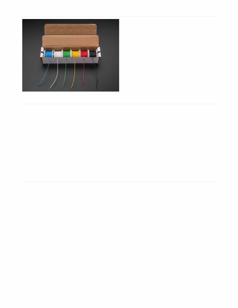
Hookup Wire or Jumpers
A Stepper MotorIn the example circuit, we are using a bipolar stepper
with the following specs:
NEMA 17
Torque: 76 oz-in - 5.47 kg-cm
Step Angle: 1.8
Winding Resistance: 1.8 Ohms/Phase
DC 2 A/Phase
12-24VDC (Recommended)
But this tutorial will work with many NEMA-17 and
NEMA-23 bipolar stepper motors -including the NEMA-
17 motor (http://adafru.it/324) from our store.
Just having current limiting is not enough to protect your motor. You need to make sure that the current limitis set to an appropriate level for your motor. The DRV8871 comes configured to limit the current at 2A. Checkyour motor specifications. If it is rated for less than 2A current, you will need to change the 'RLIM' resistor toreduce the current limit for the DRV8871.
© Adafruit Industries https://learn.adafruit.com/current-limiting-stepper-driver-with-drv8871 Page 7 of 12

A Power SupplyWe are using a 12v/5A supply in our example circuit.
Using our example motor with a 1.8 ohm phase
resistance, this would draw 6.7A per phase and would
quickly burn out a V1 or V2 motor shield.
But the DRV8871 breakout is configured to automatically
limit the current to a maximum of 2A. This is a safe level
for both the motor and the driver.
With some motors, the DRV8871 chips will get quite hot. Sometimes hot enough to trip the thermal shutdowncircuit. Adding heat sinks and/or a fan will help dissipate the extra heat.
© Adafruit Industries https://learn.adafruit.com/current-limiting-stepper-driver-with-drv8871 Page 8 of 12

Wiring
Wiring up the 2 DRV8871s is farly straightforward:
First assemble the DRV8871 breakouts as instructed in this tutorial (https://adafru.it/r2e):
From the Arduino to the DRV8871 Breakouts (we'll call them "A" and "B"), make the following connections:
GND -> (both breakouts)Pin 2 -> IN1 (breakout A)Pin 3 -> IN2 (breakout A)Pin 4 -> IN1 (breakout B)Pin 5 -> IN2 (breakout B)
© Adafruit Industries https://learn.adafruit.com/current-limiting-stepper-driver-with-drv8871 Page 9 of 12

On the motor side:
Connect one pair of motor leads to the MOTOR terminal block on breakout A.Connect the other pair of motor leads to the MOTOR terminal block on breakout B.Connect the power supply ground to the "-" terminal of the POWER terminal block on both breakouts.Connect the power supply positive wire to the "+" terminal of the POWER terminal block on both breakouts.
© Adafruit Industries https://learn.adafruit.com/current-limiting-stepper-driver-with-drv8871 Page 10 of 12

TestingTo test out our current limiting stepper driver, we'll use the standard Arduino Stepper library. This is included with theArduino IDE, so no additional libraries need to be installed.
Copy the code below and upload it to your Arduino.
The motor should start turning back and forth - 1000 steps at a time.
#include <Stepper.h>
// A 200-step motor connected on pins 2-5Stepper stepper(200, 2,3,4,5);
void setup() { // Rotate at 20 rpm: stepper.setSpeed(20);
Serial.begin(9600); Serial.println("Stepper Test!");}
void loop() { // Step forward 1000 steps Serial.println("forward"); stepper.step(1000);
// Step in reverse 1000 steps Serial.println("backward"); stepper.step(-1000);}
© Adafruit Industries https://learn.adafruit.com/current-limiting-stepper-driver-with-drv8871 Page 11 of 12

© Adafruit Industries Last Updated: 2018-08-22 03:55:35 PM UTC Page 12 of 12