current status of the asteroid explorer, hayabusa2
TRANSCRIPT
Current status of the asteroid explorer,
Hayabusa2, leading up to arrival at
asteroid Ryugu in 2018
June 14th, 2018
JAXA Hayabusa2 Project

Today’s Topics
For the Hayabusa2 spacecraft:
・Observation of Ryugu・Optical Navigation (Hybrid navigation using optical and radiometric observations)
・Search for satellites・Schedule
2

Contents
0.Hayabusa2 mission overview1.Current status and project schedule 2.Observation of Ryugu3.Optical navigation 4.Search for satellites5.Mission schedule6.Future plans
3
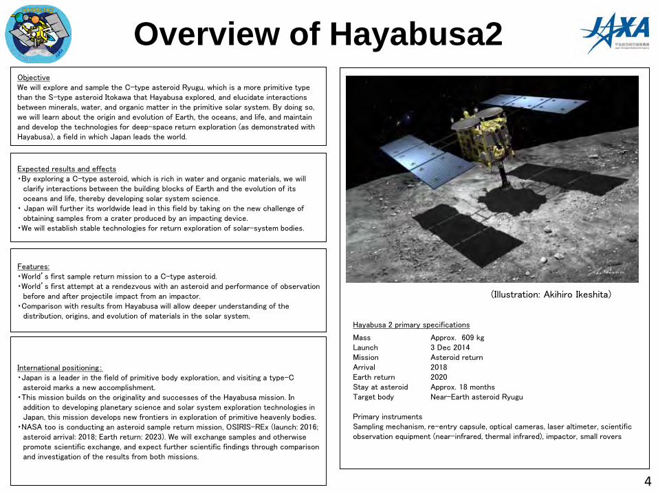
ObjectiveWe will explore and sample the C-type asteroid Ryugu, which is a more primitive type than the S-type asteroid Itokawa that Hayabusa explored, and elucidate interactions between minerals, water, and organic matter in the primitive solar system. By doing so, we will learn about the origin and evolution of Earth, the oceans, and life, and maintain and develop the technologies for deep-space return exploration (as demonstrated with Hayabusa), a field in which Japan leads the world.
Features:・World’s first sample return mission to a C-type asteroid.・World’s first attempt at a rendezvous with an asteroid and performance of observation
before and after projectile impact from an impactor.・Comparison with results from Hayabusa will allow deeper understanding of the
distribution, origins, and evolution of materials in the solar system.
Expected results and effects・By exploring a C-type asteroid, which is rich in water and organic materials, we will
clarify interactions between the building blocks of Earth and the evolution of its oceans and life, thereby developing solar system science.
・ Japan will further its worldwide lead in this field by taking on the new challenge of obtaining samples from a crater produced by an impacting device.
・We will establish stable technologies for return exploration of solar-system bodies.
International positioning:・Japan is a leader in the field of primitive body exploration, and visiting a type-C
asteroid marks a new accomplishment.・This mission builds on the originality and successes of the Hayabusa mission. In
addition to developing planetary science and solar system exploration technologies in Japan, this mission develops new frontiers in exploration of primitive heavenly bodies.
・NASA too is conducting an asteroid sample return mission, OSIRIS-REx (launch: 2016; asteroid arrival: 2018; Earth return: 2023). We will exchange samples and otherwise promote scientific exchange, and expect further scientific findings through comparison and investigation of the results from both missions.
Hayabusa 2 primary specifications
Mass Approx. 609 kgLaunch 3 Dec 2014Mission Asteroid returnArrival 2018Earth return 2020Stay at asteroid Approx. 18 monthsTarget body Near-Earth asteroid Ryugu
Primary instrumentsSampling mechanism, re-entry capsule, optical cameras, laser altimeter, scientific observation equipment (near-infrared, thermal infrared), impactor, small rovers
Overview of Hayabusa2
(Illustration: Akihiro Ikeshita)
4
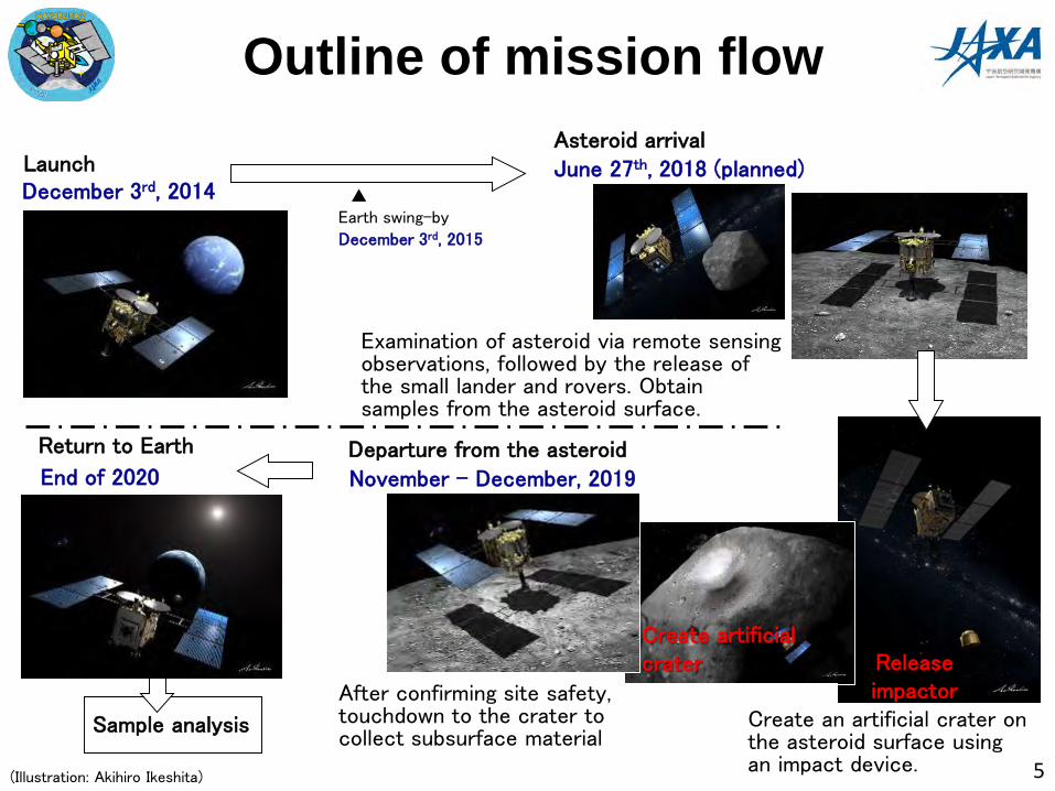
Asteroid arrivalJune 27th, 2018 (planned)
Examination of asteroid via remote sensing observations, followed by the release of the small lander and rovers. Obtain samples from the asteroid surface.
Create an artificial crater on the asteroid surface using an impact device.
Sample analysis
After confirming site safety, touchdown to the crater to collect subsurface material
Departure from the asteroid
November – December, 2019
LaunchDecember 3rd, 2014
Return to Earth
End of 2020
Outline of mission flow
▲Earth swing-by
December 3rd, 2015
5
Release impactor
Create artificial crater
(Illustration: Akihiro Ikeshita)

1. Current status and project schedule
Current status:
– The distance between Ryugu and the spacecraft is about 750km today (June 14)– Today, we will perform a Trajectory Correction Maneuver (TCM03). Approximate
approach speed of Hayabusa2 after TCM03 is 1.7 m/s.– Optical navigation will be used until arriving at Ryugu– We are currently observing the light curve of Ryugu and searching for satellites.– Arrival at Ryugu is scheduled for around June 27.
6
2015 2016 2017 2018 2019 2020
12 3 10 12 4 6 7 12 12
Eventapproach Re-entry
Earth swing-by
Southern hemisphere station operations (CAN/MLG)Oct May
Mar Jun
(Dec 3)
Mar May Nov Apr Jan JunIon engine operations ※
Arrival at Ryugu(Scheduled: June 27)
Departure from Ryugu(Nov~Dec)
Capsule re-entry(Late 2020)
Journey to asteroid Asteroid proximity operations Earth returnswing-by
launch(Dec 3)
EDVEGAInitial operation
Optical navigationMay Jul JanDec
Interim period(Solar conjunction)
TBD TBD TBD TBD
ESA(MLG/WLH)test operations(May 21- 22)
Schedule overview:

1. Observation of Ryugu
■Optical navigation cameras(ONC-T、ONC-W1)
• ONC-T(telescopic)and ONC-W1(wide-angle)are being used to image Ryugu.
• Goals: Optical navigation Satellite search Scientific observations(asteroid light curve)
• At the current time, the size of Ryugu is about 10 pixels on the ONC-T.
■Thermal Infrared Imager(TIR)
• Test observation and scientific observation(light curve)
7

8
Image of Ryugu taken with the ONC-T (Optical Navigation Camera – Telescopic)
Image of Ryugu taken with the ONC-T on June 13, 2018 at approximately 13:50 JST.Field of view is 6.3 degrees x 6.3 degrees and the exposure time is about 178 seconds.
Ground observation team: JAXA, Kyoto University, Japan Spaceguard Association, Seoul National University.ONC team:JAXA, University of Tokyo, Koichi University, Rikkyo University, Nagoya University, Chiba Institute of
Technology, Meiji University, University of Aizu and AIST.
2. Observation of Ryugu
The distance between Ryugu and the spacecraft is about 920km.
Ryugu’s brightness is about -6.6 magnitude.

2. Observation of Ryugu
9
Image of Ryugu taken with the ONC-T (Optical Navigation Camera – Telescopic)
Image of Ryugu taken with the ONC-T on June 13, 2018 at approximately 13:50 JST.Field of view is 6.3 degrees x 6.3 degrees and the exposure time is about 0.09 seconds.
Ground observation team: JAXA, Kyoto University, Japan Spaceguard Association, Seoul National University.ONC team:JAXA, University of Tokyo, Koichi University, Rikkyo University, Nagoya University, Chiba Institute of
Technology, Meiji University, University of Aizu and AIST.
The distance between Ryugu and the spacecraft is about 920km.
Ryugu’s brightness is about -6.6 magnitude.

2. Observation of Ryugu
10
Image of Ryugu taken with the ONC-W1 (Optical Navigation Camera – Wide-angle)
Image of Ryugu taken with the ONC-W1 on June 13, 2018 at approximately 13:00 JST.Field of view is 65 degrees x 65 degrees and the exposure time is about 0.2 seconds.
Ground observation team: JAXA, Kyoto University, Japan Spaceguard Association, Seoul National University.ONC team:JAXA, University of Tokyo, Koichi University, Rikkyo University, Nagoya University, Chiba Institute of
Technology, Meiji University, University of Aizu and AIST.
The distance between Ryugu and the spacecraft is about 920km.
As the measurement of the asteroid position is more accurate when Ryugu is photographed by ONC-T, the ONC-T data is used for optical navigation. Imaging by ONC-W1 is a backup in case imaging with ONC-T failed.

2. Observation of Ryugu
11
Image of Ryugu taken with the TIR(Thermal Infrared Imager)
Image of Ryugu taken with the TIR on June 7, 2018 at approximately 18:45 JST. Field of view on the leftimage is 6 degrees x 6 degrees and the right image is a magnification. The exposure time is about 0.5seconds.TIR team:JAXA, Hokkaido University of Education, Rikkyo University, University of Aizu, Chiba Institute of Technology, AshikagaUniversity, AIST, National Institute for Environmental Studies, Hokkaido Kitami Hokuto High School, University of Tokyo, Max PlanckInstitute, DLR, Stirling University.
The distance between Ryuguand the spacecraft is 2100 km.
2. Observation of Ryugu
12
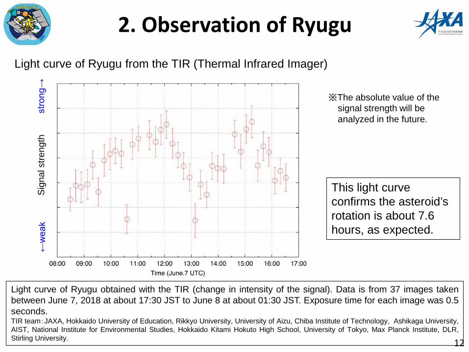
Light curve of Ryugu from the TIR (Thermal Infrared Imager)
This light curve confirms the asteroid’s rotation is about 7.6 hours, as expected.
Light curve of Ryugu obtained with the TIR (change in intensity of the signal). Data is from 37 images takenbetween June 7, 2018 at about 17:30 JST to June 8 at about 01:30 JST. Exposure time for each image was 0.5seconds.TIR team:JAXA, Hokkaido University of Education, Rikkyo University, University of Aizu, Chiba Institute of Technology, Ashikaga University,AIST, National Institute for Environmental Studies, Hokkaido Kitami Hokuto High School, University of Tokyo, Max Planck Institute, DLR,Stirling University.
※The absolute value of the signal strength will be analyzed in the future.
Sign
al s
treng
th←weak
strong→
2. Observations of Ryugu
13
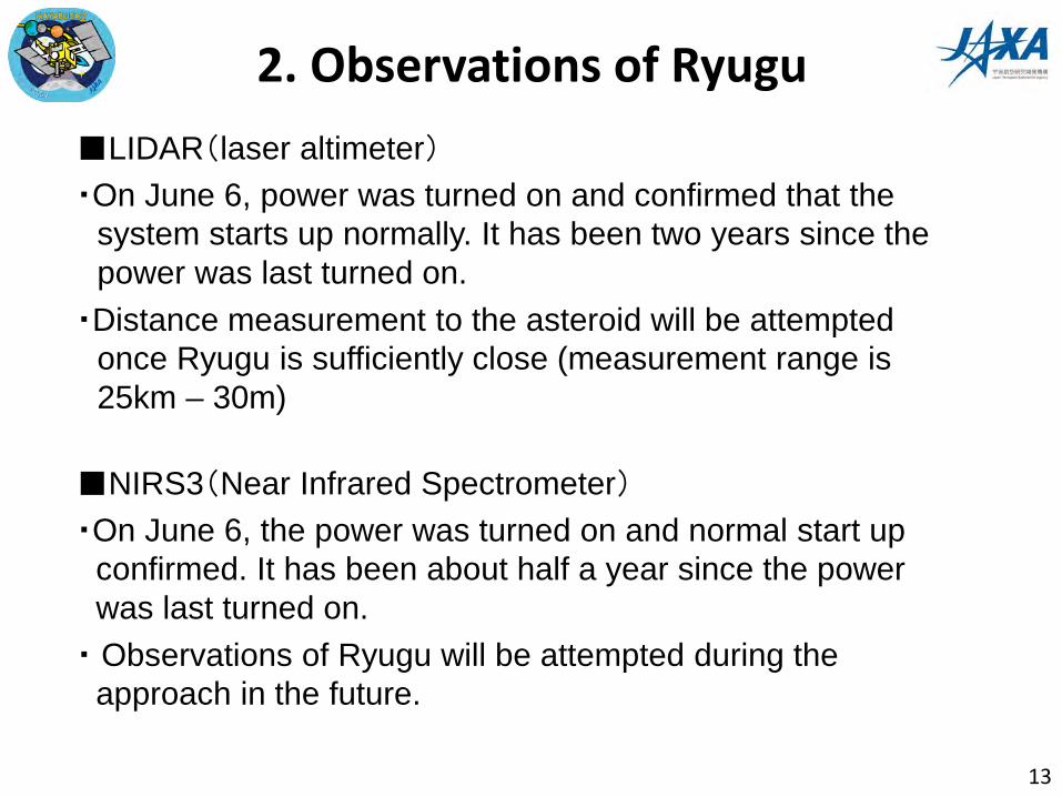
■LIDAR(laser altimeter)・On June 6, power was turned on and confirmed that the
system starts up normally. It has been two years since the power was last turned on.
・Distance measurement to the asteroid will be attempted once Ryugu is sufficiently close (measurement range is 25km – 30m)
■NIRS3(Near Infrared Spectrometer)・On June 6, the power was turned on and normal start up
confirmed. It has been about half a year since the power was last turned on.
・ Observations of Ryugu will be attempted during the approach in the future.

3. Optical Navigation
14
Reasons for Optical Navigation (hybrid navigation using optical and radiometric measurements ):• Necessary technique to arrive at a celestial body 900m in size at a distance 300
million km from Earth.• The errors (uncertainties) for the orbit of spacecraft and asteroid:
• Using Optical Navigation during the approach to the asteroid reduces these errors.
Error in the position estimation
Hayabusa2(At a distance of about 300 million km)
About 300km(Using the conventional RARR)Several km(by DDOR)
Asteroid Ryugu About 220km(as of May 2018)
Note) ・RARR is the abbreviation of “Range and Range Rate”, a conventional method to estimate the trajectory of a spacecraft by measuring the distance to the probe and velocity along the line of sight using radiowavecommunication.
・DDOR is “Delta Differential One-way Range”, a method of accurately estimating the trajectory by receiving radiowaves from the probe at two ground stations simultaneously.
・ The size of the error is 3σ (probability of 99.7%)
Reference:A 900m target at a distance of 300 million km is equivalent to a 6cm target at 20,000 km. In other words, arriving at Ryugu is the same as aiming at a 6cm target in Brazil from Japan!

① Radio NavigationThe measurements of distance, the change in frequency from transmitted & received radiowaves between the Earth and spacecraft (Doppler effect), and DDOR gives the trajectory of the spacecraft relative to the Earth.
② Optical Navigation• By imaging the asteroid from the
spacecraft, we measure the asteroid’s direction from the spacecraft.
• Once we can use LIDAR, the distance can also be measured.
③ Hybrid navigation using optical and radiometric observations By combining ① radio navigation and ② optical navigation, we can accurately calculate all three sides of the triangle in the figure.
Orbit of the spacecraft relative to the Earth (Solar System)
Earth’s orbit around the Sun
3. Optical NavigationBasic Principal
Note: It is common to refer to “hybrid navigation using optical and radiometric observations” as simply “Optical Navigation”. 15

Principals of Optical Navigation • Take an image of the asteroid against background stars.
• Based on the asteroid’s location on this star map, the direction to the asteroid from the spacecraft can be measured.
• By collecting a lot of directional information, the asteroid’s position and velocity with respect to the spacecraft can be calculated.
• Rather than heading straight for the asteroid, adding lateral motion to the spacecraft trajectory allows a “moving stereo view” of the asteroid to give not only the direction, but also the asteroid’s distance.
3. Optical Navigation
16
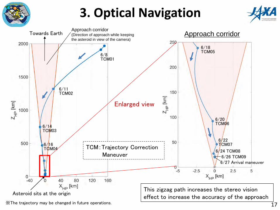
Towards Earth
Asteroid sits at the origin
6/14 TCM03
6/11 TCM02
6/8 TCM01
6/16TCM04
6/18TCM05
6/20TCM06
6/22TCM07
6/24 TCM086/26 TCM09
Approach corridor(Direction of approach while keeping the asteroid in view of the camera)
This zigzag path increases the stereo vision effect to increase the accuracy of the approach
Approach corridor
Enlarged view
6/27 Arrival maneuver
※The trajectory may be changed in future operations.
3. Optical Navigation
TCM:Trajectory Correction Maneuver
17

Japan SpaceguardAssociation
Seoul National University
Kyoto University
JAXA
Navigation team JAXA NEC
Fujitsu
Guidance teamJAXA
Operation teamJAXANEC
Sent to Hayabusa2:•Thruster injection plan
•Asteroid image plan
Received from Hayabusa2:•Thruster injection history•Asteroid image
Calculate the direction to the asteroid from Hayabusa2 using the image of stars and asteroid.
Calculate the trajectory of Hayabusa2 towards Ryugubased on the asteroid direction and radio wave measurements.
Calculate the optimal trajectory to arrive at the asteroid based on the latest Hayabusa2 orbit.
From the latest trajectory plan, send new thruster injection commands and image plan to the spacecraft.
Work loop
Perform this loop once every 24 – 72 hours
3. Optical Navigation
18

3. Optical Navigation
19
Optical Navigation performed using images from the STT(Star Tracker)• Ion engine operation was in progress during May, preventing the Optical Navigation
Camera pointing at Ryugu. Instead, an image of Ryugu was attempted with the Star Tracker, which is usually used to determine the orientation of the spacecraft.
• Ryugu was observed between May 11 – 14 and Optical Navigation was used from measurements of the asteroid’s position.
• As a result, the error (uncertainty) in the position of the asteroid shrank from 220km to about 130km.
• Based on the trajectory estimate obtained form this Optical Navigation, the final ion engine operation was performed.
Ryugu photographed with the Star Tracker. The images were taken starting from the right at approximately 01:00 on May 12, 02:00 on May 13 and 01:00 on May 14 (JST). These are taken from the spacecraft in the direction of Pisces. ("Psc" is an abbreviation of Pisces). The field of view is 9 degrees × 7 degrees. (Ground observation team: JAXA, Kyoto University, Japan Spaceguard Association, Seoul National University.)
3. Optical Navigation
20
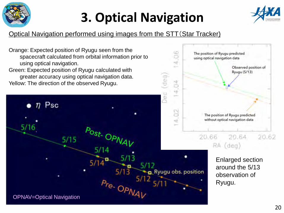
Optical Navigation performed using images from the STT(Star Tracker)
Orange: Expected position of Ryugu seen from the spacecraft calculated from orbital information prior to using optical navigation.
Green: Expected position of Ryugu calculated with greater accuracy using optical navigation data.
Yellow: The direction of the observed Ryugu.
Enlarged section around the 5/13 observation of Ryugu.
OPNAV=Optical Navigation
3. Optical Navigation
21
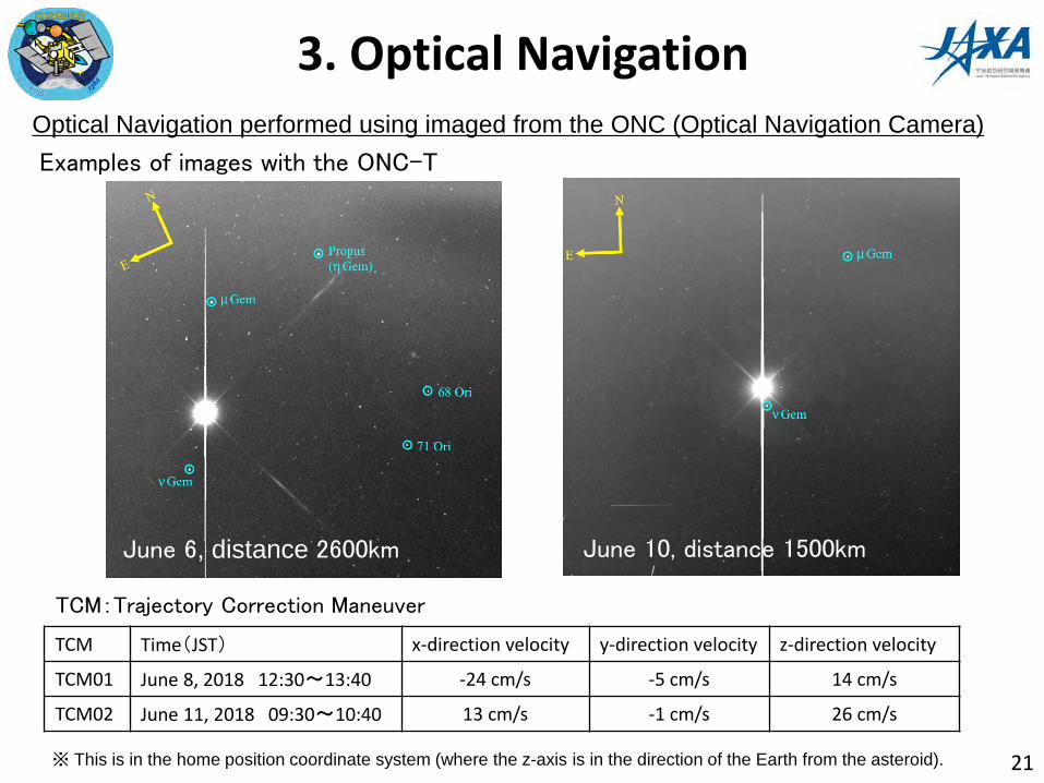
Optical Navigation performed using imaged from the ONC (Optical Navigation Camera)
TCM:Trajectory Correction Maneuver
Examples of images with the ONC-T
June 6, distance 2600km June 10, distance 1500km
TCM Time(JST) x-direction velocity y-direction velocity z-direction velocity
TCM01 June 8, 2018 12:30〜13:40 -24 cm/s -5 cm/s 14 cm/s
TCM02 June 11, 2018 09:30〜10:40 13 cm/s -1 cm/s 26 cm/s
※ This is in the home position coordinate system (where the z-axis is in the direction of the Earth from the asteroid).
3. Optical Navigation
22
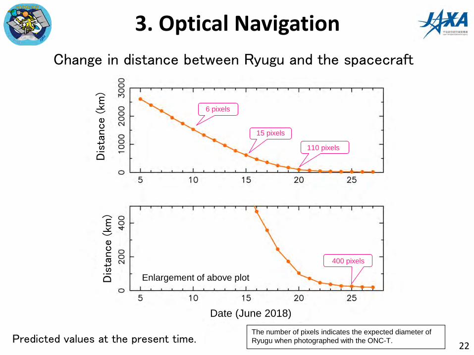
Change in distance between Ryugu and the spacecraft
Predicted values at the present time.
6ピクセル
15ピクセル
110ピクセル
400ピクセル
The number of pixels indicates the expected diameter of Ryugu when photographed with the ONC-T.
Dis
tance (
km)
Dis
tance (
km)
Date (June 2018)
Enlargement of above plot
6 pixels
15 pixels
110 pixels
400 pixels

3. Optical Navigation
23
Change in the relative speed between Ryugu and the spacecraft and the TCM
TCM:Trajectory Correction Maneuver
Rel
ativ
e sp
eed
(cm
/s)
Rel
ativ
e sp
eed
(cm
/s)
Date (June 2018)
Predicted values at the present time.
Enlargement of above plot

3. Optical Navigation
24
Summary figure

(Ryugu image by T. Mueller)
?
?
4. Search for satellites
Reasons for a satellite search• Even the low gravity Ryugu can also have satellite
25
• No matter how small, a collision with a satellite is fatal to the mission. However, if if there are satellites around Ryugu then it would be scientifically a great discovery.
• Ryugu was searched for orbiting objects from a safe distance (on June 7 at 2,100km). From here, satellites smaller than 1m in diameter could be discovered.
Such observations were also performed for Hayabusa [Fuse et al, 2008]
celestial bodies that may orbit Ryugu
Satellites can exist within this range(Hill radius: ~90 km)
We want to approach within the Hill radius

4. Search for satellites
26
Satellite search observation record (June 7)① 08:03 – 08:09② 11:06 – 11:12③ 14:17 – 14:23④ 16:35 – 16:41
*multiple occasions to capture orbital movement.
A small satellite emits only a small amount of light. To capture this, a 178 second exposure it used for observations (30,000 times longer than the normal setting). * Dim stars above magnitude 12 can be seen.
time
Ryugu
Signal overflow from Ryugu
μGem
~200 kmIt is safe to approach the stable orbit radius for a satellite smaller than 50cm (up to 50km). As we approach Ryugu, we will continue to search for smaller satellites. ONC team:JAXA, University of Tokyo, Koichi University, Rikkyo University, Nagoya University, Chiba Institute of Technology, Meiji University, University of Aizu and AIST.Ground observation team: JAXA, Kyoto University, Japan Spaceguard Association, Seoul National University.
No satellites larger than the detection limit (50cm) were seen.

Emphasized brightness
Ryugu
Signal overflow from Ryugu
μGem
4. Search for satellites
27
Satellite search observation record (June 7)① 08:03 – 08:09② 11:06 – 11:12③ 14:17 – 14:23④ 16:35 – 16:41
*multiple occasions to capture orbital movement.
A small satellite emits only a small amount of light. To capture this, a 178 second exposure it used for observations (30,000 times longer than the normal setting). * Dim stars above magnitude 12 can be seen.
It is safe to approach the stable orbit radius for a satellite smaller than 50cm (up to 50km). As we approach Ryugu, we will continue to search for smaller satellites. ONC team:JAXA, University of Tokyo, Koichi University, Rikkyo University, Nagoya University, Chiba Institute of Technology, Meiji University, University of Aizu and AIST.Ground observation team: JAXA, Kyoto University, Japan Spaceguard Association, Seoul National University.
No satellites larger than the detection limit (50cm) were seen.
time
~200 km
4. Search for satellites
28
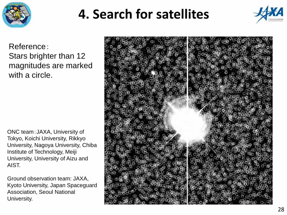
Reference:Stars brighter than 12 magnitudes are marked with a circle.
ONC team:JAXA, University of Tokyo, Koichi University, RikkyoUniversity, Nagoya University, Chiba Institute of Technology, Meiji University, University of Aizu and AIST.
Ground observation team: JAXA, Kyoto University, Japan Spaceguard Association, Seoul National University.

29
5. Mission Schedule
Recent Operations• Continue Optical Navigation • Continue satellite search • Continue scientific observation
• Arrival at Ryugu is scheduled for around June 27 (exact date may vary by a few days, depending on the exact operation situation).
Operation in the asteroid vicinity • The specific schedule will be determined based on observations
between June and August • The current schedule is on the next page.
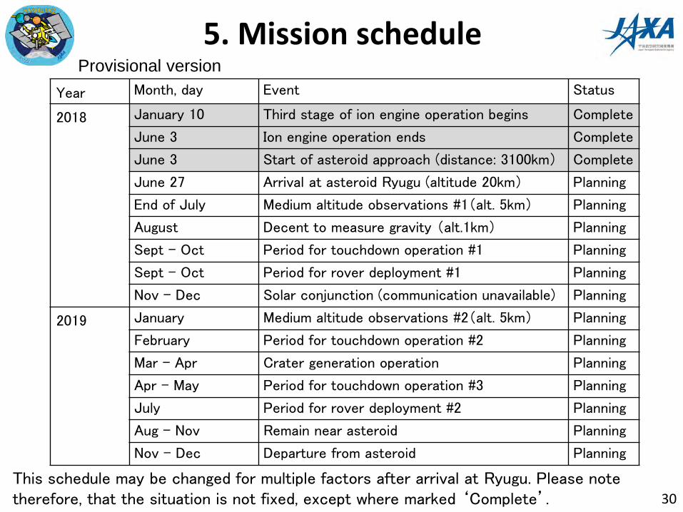
5. Mission scheduleYear Month, day Event Status
2018 January 10 Third stage of ion engine operation begins Complete
June 3 Ion engine operation ends Complete
June 3 Start of asteroid approach (distance: 3100km) Complete
June 27 Arrival at asteroid Ryugu (altitude 20km) Planning
End of July Medium altitude observations #1(alt. 5km) Planning
August Decent to measure gravity (alt.1km) Planning
Sept - Oct Period for touchdown operation #1 Planning
Sept - Oct Period for rover deployment #1 Planning
Nov - Dec Solar conjunction (communication unavailable) Planning
2019 January Medium altitude observations #2(alt. 5km) Planning
February Period for touchdown operation #2 Planning
Mar - Apr Crater generation operation Planning
Apr - May Period for touchdown operation #3 Planning
July Period for rover deployment #2 Planning
Aug - Nov Remain near asteroid Planning
Nov - Dec Departure from asteroid Planning
30This schedule may be changed for multiple factors after arrival at Ryugu. Please note therefore, that the situation is not fixed, except where marked ‘Complete’.
Provisional version

6. Future plans
• Arrival at 20km above Ryugu is scheduled for around June 27. At this time, a press release will be posted and press briefing (@ the Sagamihara campus) will be scheduled.
• We plan to hold regular press briefings after July. (In the next two months, July 19, August 2, August 23 are planned.)
31
Media correspondence & information disclosure:

Reference material
32

X-band mid-gain antenna
X-band high-gain antenna
Ka-band high-gain antenna
Star trackers
Re-entry capsule
Sampler horn
Solar array paddle
Near-infrared spectrometer (NIRS3)
Laser altimeter (LIDAR)
X-band low-gain antenna
Deployable camera (DCAM3)
Optical navigation camera ONC-W2
Primary spacecraft components
Ion engine
Small carry-on impactor (SCI)
MASCOT lander
Minerva-II rovers
RCS thrusters
Thermal infrared camera(TIR)
Optical navigation cameraONC-T, ONC-W1
Target markers × 5
Optical navigation camera, ONC-T
Laser altimeter, LIDAR
Near-infrared spectrometer, NIRS3
Thermal infrared camera, TIR
Scientific observation equipment
II-1A II-1B
Built by DLR and CNES
MASCOT
II-2
II-2: By Tohoku Univ. & the Minerva-II Consortium
II-1: By the JAXA Minerva-II team
Minerva 2
Small lander & rovers
33
Size: 1 ×1. 6×1. 25 m (main body)Solar paddle deployed width 6 m
Mass : 609 kg (incl. fuel)
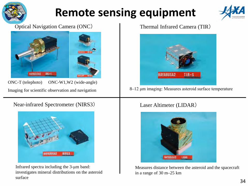
Remote sensing equipment
34
Optical Navigation Camera (ONC) Thermal Infrared Camera (TIR)
ONC-T (telephoto) ONC-W1,W2 (wide-angle)
Imaging for scientific observation and navigation 8–12 μm imaging: Measures asteroid surface temperature
Near-infrared Spectrometer (NIRS3)
Infrared spectra including the 3-μm band: investigates mineral distributions on the asteroid surface
Laser Altimeter (LIDAR)
Measures distance between the asteroid and the spacecraft in a range of 30 m–25 km
W1FoV
TFoV
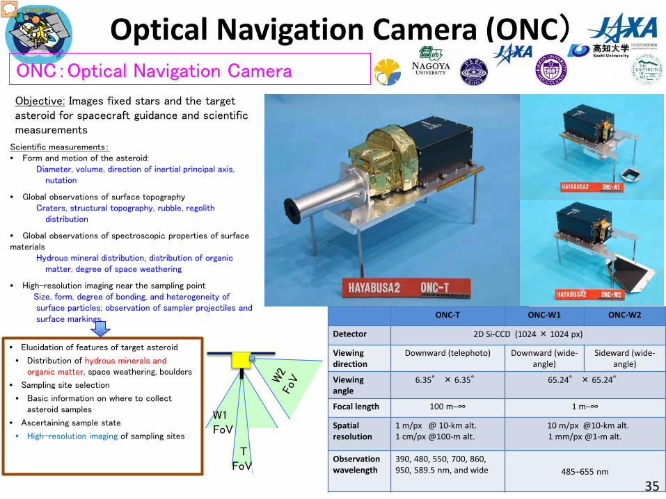
Optical Navigation Camera (ONC)
Scientific measurements:• Form and motion of the asteroid:
Diameter, volume, direction of inertial principal axis, nutation
• Global observations of surface topographyCraters, structural topography, rubble, regolith
distribution
• Global observations of spectroscopic properties of surface materials
Hydrous mineral distribution, distribution of organic matter, degree of space weathering
• High-resolution imaging near the sampling pointSize, form, degree of bonding, and heterogeneity of surface particles; observation of sampler projectiles and surface markings
Objective: Images fixed stars and the target asteroid for spacecraft guidance and scientific measurements
ONC:Optical Navigation Camera
ONC-T ONC-W1 ONC-W2
Detector 2D Si-CCD (1024 × 1024 px)
Viewing direction
Downward (telephoto) Downward (wide-angle)
Sideward (wide-angle)
Viewing angle
6.35° × 6.35° 65.24° × 65.24°
Focal length 100 m–∞ 1 m–∞
Spatial resolution
1 m/px @ 10-km alt.1 cm/px @100-m alt.
10 m/px @10-km alt.1 mm/px @1-m alt.
Observation wavelength
390, 480, 550, 700, 860, 950, 589.5 nm, and wide 485–655 nm
• Elucidation of features of target asteroid
• Distribution of hydrous minerals and organic matter, space weathering, boulders
• Sampling site selection
• Basic information on where to collect asteroid samples
• Ascertaining sample state
• High-resolution imaging of sampling sites
35

Thermal infrared camera (TIR)
TIR=Thermal Infrared Imager
The surface temperature of the asteroid changes over the day, rising in sunlight and decreasing at night.Diurnal change in surface temperature is large in fine soils like sand and highly porous rock, and small in dense rock.We will examine the physical state of the asteroid’s surface by 2D imaging (thermography) of thermal radiation from the asteroid.
100
150
200
250
300
350
400
-180 -135 -90 -45 0 45 90 135 180
Tem
pera
ture
[K]
Longitude [deg]
I=10
I=50
I=100
I=200
I=500
I=1000
I=2000
Tem
p (
K)
Longitude
Night NightDay
Sand Gravel Stone
Temperature changeLarge Small
・ Detector : 2D uncooled bolometer・ Observation wavelength : 8–12 μm・ Observed temperatures : –40 to 150 °C・ Relative accuracy : 0.3 °C・ Dimensions : 328 × 248 (effective)・ Viewing angle : 16°×12°・ Resolution : 20 m (20-km alt.)
5 cm (50-m alt.)
36 36

Laser altimeter (LIDAR)
Laser altimeter engineering model
Long-range Cassegrain telescope
Short-range telescope
Beam expander for illumination
・Pulse-type laser altimeter・ A pulse YAG laser with a 1.064-μm
wavelength is emitted toward the target object, and the altitude is measured by measuring the return time of the laser beam.
・ The LIDAR aboard Hayabusa 2 could perform measurements from 30 m–25 km.
・ LIDAR is a navigation sensor used for approach and landing at a target, and a scientific observation device used to measure shape, gravity, and surface characteristics, and for dust observations.
・ It also has a transponder function that can perform space laser ranging (SLR) experiments with ground LIDAR stations.
LIDAR: Light Detection And Ranging
Scientific objectives• Terrain and gravity field observations of the target
asteroid• Observations of albedo distribution at various
surface points• Observations of dust floating around the asteroid
• Asteroid form, mass, porosity, and deviation• Asteroid surface roughness• Dust floating phenomena(© JAXA) 37

Near-infrared spectrometer (NIRS3)
Infrared absorption of hydroxyl groups and water molecules is
observed in 3-μm band reflection spectra in the near-
infrared region. NIRS3 investigates distributions of hydrous
minerals on the asteroid surface by measuring reflection
spectra in the 3-μm band.
• Observation wavelength range: 1.8–3.2 µm
• Wavelength resolution: 20 nm
• Full field of view: 0.1 deg
• Spatial resolution: 35 m (20-km alt.)
2 m (1-km alt.)
• Detector temperature: –85 to –70 °C
• S/N ratio: 50+ (wavelength 2.6 µm)R
ela
tive
reflecta
nce
Wavelength (µm)
Near-infrared reflection spectra of carbonaceous chondrites
OH H2O
Absorption form and depth vary depending on the type and amount of hydrous mineral
NIRS3: Near-infrared Spectrometer(‘3’ from 3 μm)
(© JAXA) 38

Name : Ryugu
Permanent designation : 162173Provisional designation : 1999 JU3
Discovered : May 1999
Size : Approx. 900 m
Shape : Nearly spherical
Rotation period : approx. 7 h 38 min
Rotation orientation : Ecliptic longitude λ= 310°–340°Ecliptic latitude β= –40°±–15°
Reflectivity : 0.05 (blackish)
Type : C type (assumed to comprise materials containing water and organics)
Orbital radius : Approx. 180,000,000 km
Orbital period : Approx. 1.3 yr
Density and mass : Density is currently unknown, but presumed to be 0.5–4.0 g/cm3
: Mass is approx. 1.7 × 10¹¹ kg –1.4×10¹² kg.
Orbit of Ryugu
Estimated shape
Asteroid Ryugu
(by T. Mueller) 39

(162173) 1999 JU3 (Ryugu) light curve
(from Kim, Choi, Moon et al. A&A 550, L11 (2013))
40
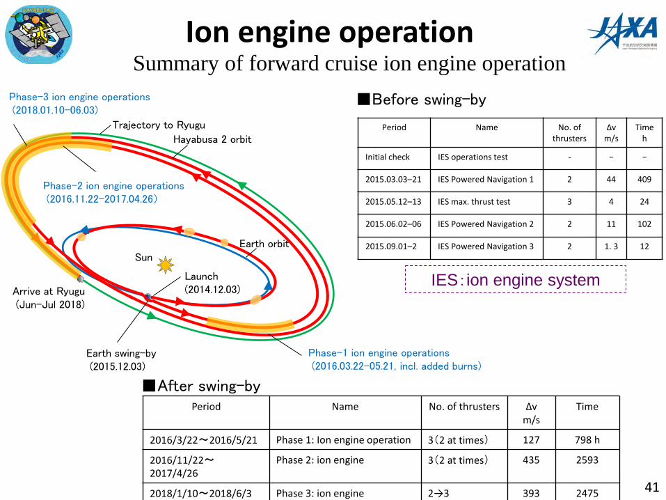
Ion engine operation
■Before swing-by
■After swing-byPeriod Name No. of thrusters Δv
m/sTime
2016/3/22〜2016/5/21 Phase 1: Ion engine operation 3(2 at times) 127 798 h
2016/11/22〜2017/4/26
Phase 2: ion engine 3(2 at times) 435 2593
2018/1/10〜2018/6/3 Phase 3: ion engine 2→3 393 2475 41
Summary of forward cruise ion engine operation
IES:ion engine system
Period Name No. of thrusters
Δvm/s
Timeh
Initial check IES operations test - − −
2015.03.03–21 IES Powered Navigation 1 2 44 409
2015.05.12–13 IES max. thrust test 3 4 24
2015.06.02–06 IES Powered Navigation 2 2 11 102
2015.09.01–2 IES Powered Navigation 3 2 1. 3 12Sun
Launch(2014.12.03)
Earth swing-by(2015.12.03)
Arrive at Ryugu(Jun–Jul 2018)
Trajectory to Ryugu
Hayabusa 2 orbit
Earth orbit
Phase-1 ion engine operations(2016.03.22–05.21, incl. added burns)
Phase-2 ion engine operations(2016.11.22–2017.04.26)
Phase-3 ion engine operations(2018.01.10–06.03)