CVEN 5768 Spring 2019€¦ · ROCK MASS CLASSIFICATION AND GROUND SUPPORT Adapted from Presentation by Dennis J. Lachel, C.E.G., P.G. LACHEL & Associates, Inc. Golden, Colorado “ROCK
101
ROCK MASS CLASSIFICATION AND GROUND SUPPORT Adapted from Presentation by Dennis J. Lachel, C.E.G., P.G. LACHEL & Associates, Inc. Golden, Colorado “ROCK MECHANICS FOR PRACTITIONERS” August 4 – 7, 2003 Boulder, Colorado CVEN 5768 Spring 2019
ldquoROCK MECHANICS FOR PRACTITIONERSrdquoAugust 4 ndash 7 2003Boulder Colorado
CVEN 5768 Spring 2019
Underground Excavations
INITIAL GROUND SUPPORT
STAND-UP TIMEMINUTES HOURS DAYS YEARS
GROUND MODIFICATION
FOREPOLINGBREASTING
STRUCTURAL SUPPORTS
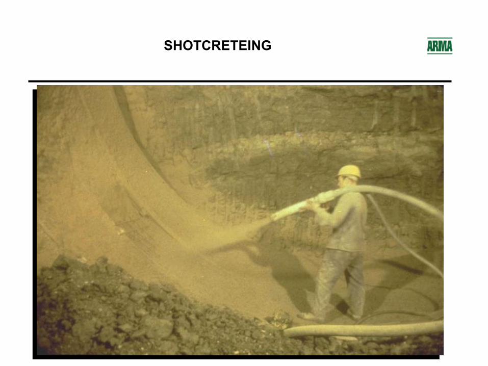
SHOTCRETE
SEGMENTED LINERS
ROCK BOLTS
NO SUPPORT
Sheet1
Sheet2
Sheet3
PRE-EXCAVATION GROUTING
FOREPOLING AND BREASTING
RIBS AND BOARDS
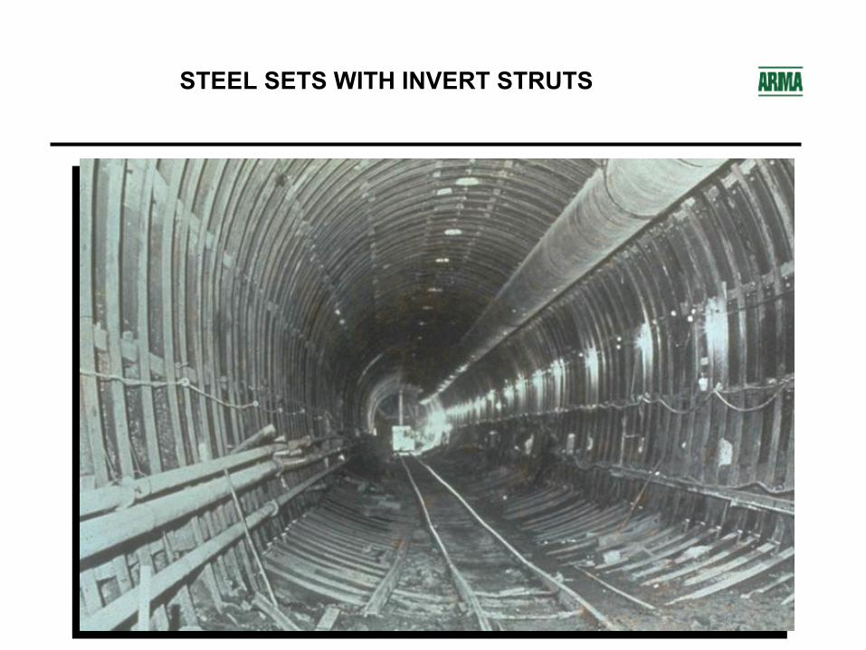
STEEL SETS WITH INVERT STRUTS
SHOTCRETEING
ROBOTIC SHOTCRETE APPLICATION
PRE-CAST CONCRETE SEGMENTS
STEEL LINER PLATE
ROBOTIC ROCK BOLT INSTALLER
ROCK BOLTS STRAPS amp MESH
SMOOTHWALL DRILL AND BLAST
PERMANENT SUPPORT FINAL LINING
bull Precast Concrete Liners ndash A ldquoOne Passrdquo System
bull Rock Bolts and Shotcrete
bull Cast-In-Place Concrete Liners
PRE-CAST CONCRETE SEGMENTS
ROCK BOLTS AND SHOTCRETE AS PERMANENT SUPPORT
CAST-IN-PLACE CONCRETE SUPPORT
METHODS OF EXCAVATION
bull Drill and Blastbull Full facebull Heading and Benchbull Multi-drift Method
bull Tunnel Boring Machines
DRILL AND BLAST TUNNEL
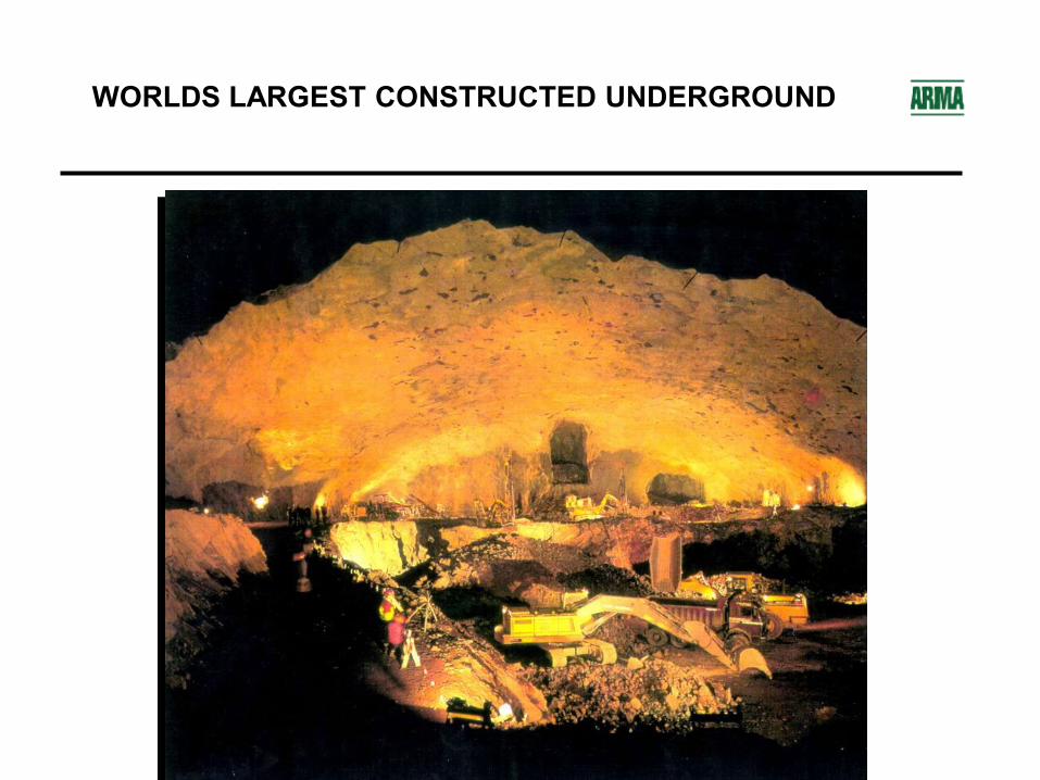
WORLDS LARGEST CONSTRUCTED UNDERGROUND
95 m TBM
TBM TUNNEL IN MASSIVE LIMESTONE
GEOLOGIC CLASSIFICATION
bull Developed by petrographers for classical geologic descriptions
bull Classify rock by modes of origin and mineral content
bull ldquoInterested in mechanical properties not just namesrdquo
bull Does not provide quantitative data for engineering purposes
bull Inform us of potential weaknesses for example- Sheet silicates talc mica chlorite serpentine all alert us to
rocks with low shear strength parallel to direction of imposed loads
- Weak or soluble rocks montmorillonite gypsum shales chalk
CLASSIFICATION OF ROCK MATERIAL BASED ON UNCONFINED COMPRESSIVE STRENGTH
(STAPLEDON AND ISRM)
Term for Uniaxial Compressive Strength
Symbol Strength(MPa)
Extremely Weak
EW 025 ndash 1
Very Weak VW 1 ndash 5
Weak W 5 ndash 25
Medium Strong MS 25 ndash 50
Strong S 50 ndash 100
Very Strong VS 100 ndash 250
Extremely Strong
ES gt250
COMPARISON OF VARIOUS ROCK STRENGTH CLASSIFICATIONS (BIENIAWSKI 1979 IN AFROUZ 1992)
INTACT VERSUS ROCK MASS PROPERTIES
ldquoThe major limitation on intact rock classifications is that they cannot provide quantitative data for engineering design purposes Therefore their main value lies in enabling better identification and communication during discussions of intact rock propertiesrdquo (Bieniawski 1989)
ROCK MASS CLASSIFICATIONS
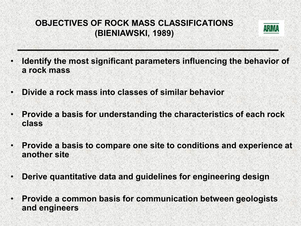
OBJECTIVES OF ROCK MASS CLASSIFICATIONS (BIENIAWSKI 1989)
bull Identify the most significant parameters influencing the behavior of a rock mass
bull Divide a rock mass into classes of similar behavior
bull Provide a basis for understanding the characteristics of each rock class
bull Provide a basis to compare one site to conditions and experience at another site
bull Derive quantitative data and guidelines for engineering design
bull Provide a common basis for communication between geologists and engineers
CLASSIFICATION ATTRIBUTES (BEINIAWSKI 1984)
bull Simple easily remembered and understandable
bull Uses terms and terminology widely accepted by engineers and geologists
bull Includes the most significant properties of the rock mass
bull Based on measurable (and repeatable) field parameters using quick and inexpensive tests
bull Weighs the relative importance of the parameters
bull Provides quantitative data for the design of rock support
ROCK MASS CLASSIFICATIONS
Advantages
bull Improves site investigations by providing a minimum required program
bull A short cut to rock mass properties that are often difficult to assess
bull Only a few basic parameters relating to geometry and mechanical condition of the rock mass are used
bull Provides quantitative information for design
bull Direct guidance for engineering design eg predicting support requirements in tunnels
ROCK MASS CLASSIFICATIONS
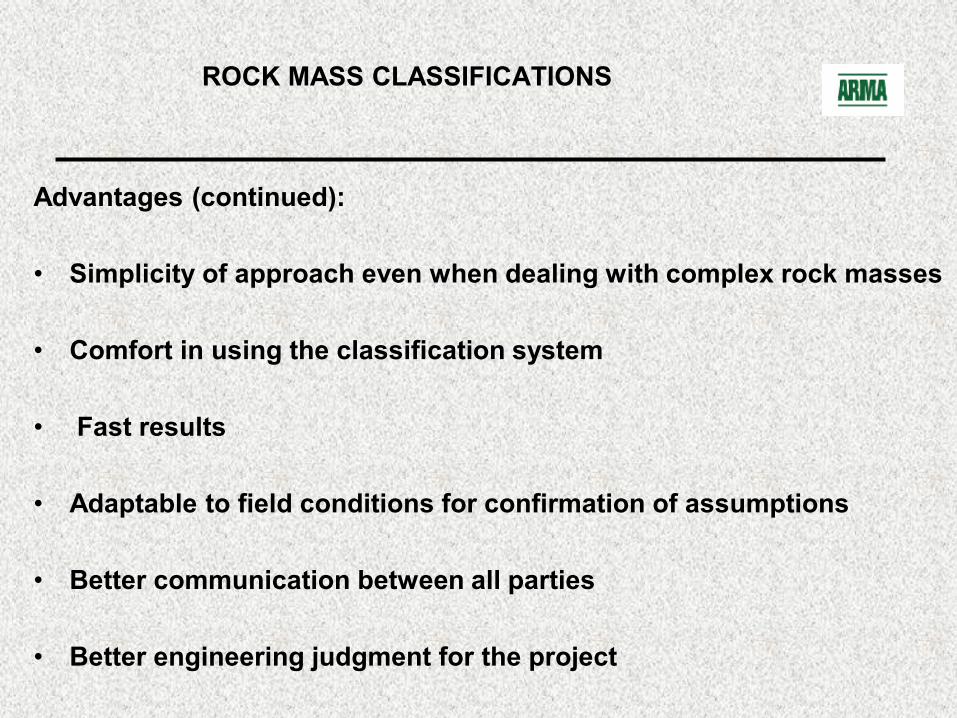
Advantages (continued)
bull Simplicity of approach even when dealing with complex rock masses
bull Comfort in using the classification system
bull Fast results
bull Adaptable to field conditions for confirmation of assumptions
bull Better communication between all parties
bull Better engineering judgment for the project
ROCK MASS CLASSIFICATIONS
Disadvantages
bull Still requires considerable experience for validation
bull Absence of what may be critical parameters for certain projects eg rock cover for pressure tunnels
bull Anisotropy not fully considered
bull False sense of security
ROCK LOAD THEORY
TERZAGHIrsquoS ROCK LOAD CLASSIFICATION
bull ldquoIntroduction to Tunnel Geologyrdquo by Karl Terzaghi in Rock Tunneling with Steel Supports Proctor and White 1946
bull The first practical classification system
bull The ldquoTunnelmanrsquos Rock Mass Classificationrdquo for more than 50 years and still in use
bull The first rational method of evaluating rock loads for designing steel sets
bull Not totally applicable to modern ground support of rock bolts and shotcrete
ROCK LOAD THEORY TERZAGHI (1946)
DEFINITIONS OF ROCK CLASSES OF TERZAGHIrsquoS ROCK LOAD THEORY (SINHA 1989)
Rock Class
Type of Rock Definition
I Hard amp intact Rock is unweathered and contains neither joints nor hair cracks The unconfined compressive strength is equal to or more than 100 MPa
II Hard stratified and schistose
Rock is hard and layered usually widely separated and may or may not have planes of weakness Spalling is quite common
III Massive moderately jointed
Joints are widely spaced and may or may not be cemented Spalling may occur
IV Moderately blocky and seamy
Blocks are about 1m in size Rock may or may not be hard The joints may or may not be healed
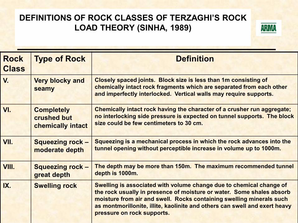
DEFINITIONS OF ROCK CLASSES OF TERZAGHIrsquoS ROCK LOAD THEORY (SINHA 1989)
Rock Class
Type of Rock Definition
V Very blocky and seamy
Closely spaced joints Block size is less than 1m consisting of chemically intact rock fragments which are separated from each other and imperfectly interlocked Vertical walls may require supports
VI Completely crushed but chemically intact
Chemically intact rock having the character of a crusher run aggregate no interlocking side pressure is expected on tunnel supports The block size could be few centimeters to 30 cm
VII Squeezing rock ndashmoderate depth
Squeezing is a mechanical process in which the rock advances into the tunnel opening without perceptible increase in volume up to 1000m
VIII Squeezing rock ndashgreat depth
The depth may be more than 150m The maximum recommended tunnel depth is 1000m
IX Swelling rock Swelling is associated with volume change due to chemical change of the rock usually in presence of moisture or water Some shales absorb moisture from air and swell Rocks containing swelling minerals such as montmorillonite illite kaolinite and others can swell and exert heavy pressure on rock supports
ROCK LOAD IN TUNNELS WITHIN VARIOUS ROCK CLASSES (TERZAGHI 1946)
Rock Class
Rock Condition
Rock Load Factor Hp
Remarks
I Hard and Intact
Zero Light lining required only if spalling or popping occurs
II Hard stratified or schistose
0-05B Light support mainly for protection against spalling
III Massive moderately jointed
0-025B No side pressure
IV Moderately blocky and seamy
025B-035 (B+Ht)
No side pressure
V Very blocky and seamy
(035-110) (B+Ht)
Little or no side pressure
ROCK LOAD IN TUNNELS WITHIN VARIOUS ROCK CLASSES (TERZAGHI 1946)
Rock Class
Rock Condition
Rock Load Factor Hp
Remarks
VI Completely crushed
110 (B+Ht) Considerable side pressure Softening effects of seepage toward bottom of tunnel requires either continuous support for lower ends of ribs or circular ribs
VII Squeezing rock ndashmoderate depth
(110-210) (B+Ht)
Heavy side pressure invert struts required Circular ribs are recommended
VIII Squeezing rock ndashgreat dpth
(210-450) (B+Ht)
-do-
IX Swelling rock
Up to 250 ft irrespective of the value of (B+Ht)
Circular ribs are required In extreme cases use of yielding support recommended
STAND-UP TIME
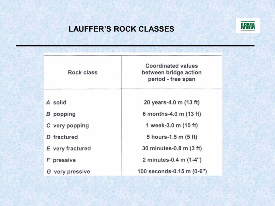
STAND-UP TIME (LAUFFER 1958)
bull Proposed by Lauffer in 1958 based on work by Stini father of the Austrian School of tunneling and rock mechanics
bull Assumed that ground stability is primarily based on structural defects
bull ldquoStand-up Timerdquo is dependent on rock quality and the span of the tunnel
bull Realized that other factors could influence stand-up time egorientation of tunnel axistunnel shapeexcavation methodsupport method
STAND-UP TIME (LAUFFER 1958)
LAUFFERrsquoS ROCK CLASSES
LAUFFERrsquoS DEFINITION OF SPAN
FACTORS INFLUENCING STAND-UP TIME (AFTER LAUFFER 1958 IN BIENIAWSKI 1990)
FACTORS INFLUENCING STAND-UP TIME (AFTER LAUFFER 1958 IN BIENIAWSKI 1990)
ROCK QUALITY DESIGNATION (RQD)
ROCK CORE EVALUATION
ROCK QUALITY DESIGNATION (RQD)
bull Developed by Don U Deere in 1964
bull Significantly expanded by Deere et al in 1967
bull A useful index for determining rock quality from core recovery
bull RQD= Length of ldquosoundrdquo core gt 10 cm (4 in) X 100Total Core Run Length
bull Core measured along centerline
bull NX or NQ size core should be used
RQD MEASUREMENTS
CORRELATION BETWEEN RQD AND ROCK MASS QUALITY (DEERE 1964)
RQD() Rock Quality
lt25 Very poor
25-50 Poor
50-75 Fair
75-90 Good
90-100 Excellent
PROPOSED USE OF RQD FOR ROCK SUPPORT (MERRITT 1972)
GROUND SUPPORT BY RQD FOR 6m TO 12m DIAMETER (DEERE ET AL 1970)
Crown SidesBoring
MachineLight None to
OccasionalNone to
OccasionalRare None to
OccasionalNone None
Drilling amp Blasting
Light None to Occasional
None to Occasional
Rare None to Occasional
None None
Boring Machine Light
Occasional to 15 to 18 m
Occasional to 15 to 18 m
Occasional mesh and straps
Local Application 5 to 75 cm None None
Drilling amp Blasting
Light 15 to 18 m 15 to 18 m Occasional mesh and straps
Local Application 5 to 75 cm
None None
Boring Machine
Light to Medium
15 to 18 m 12 to 18 m Mesh and straps as required
5 to 10 cm None Rock Bolts
Drilling amp Blasting
Light to Medium
12 to 15 m 09 to 15 m Mesh and straps as required
10 cm or more 10 cm or more
Rock Bolts
Shotcrete
Total Thickness (cm)Spacing of Pattern Bolt
Additional Requirements
Additional Supports
Excellent RQD gt 90
Good RQD
75 to 90
Fair RQD 50 to 75
Rock Quality
Construction Method Weight of
Steel SetsSpacing
Steel Sets Rock Bolt
Sheet1
Sheet2
Sheet3
GROUND SUPPORT BY RQD FOR 6m TO 12m DIAMETER (DEERE ET AL 1970)(Cont)
Crown Sides
Boring Machine
Medium Circular
06 to 12 m 09 to 15 m
Anchorage may be hart to obtain
Considerable mesh and straps required
10 to 15 cm 10 to 15 cm
Rockbolt as required (12 to 18 m center to
center)
Drilling amp Blasting
Medium to Heavy circular
02 to 12 m 06 to 12 m as above 15 cm or more 15 cm or
more as above
Boring Machine
Medium to Heavy circular
06 m 06 to 12 m
Anchorage may be impossible 100 mesh and straps
required
15 cm or more on whole section
Medium sets as required
Drilling amp Blasting
Heavy circular
06 m 09 m as above 15 cm or more on whole section
Medium sets as required
Rock Quality
Construction Method
Steel Sets Rock Bolt ShotcreteAdditional SupportsWeight of
Steel SetsSpacing Spacing of
Pattern BoltAdditional
RequirementsTotal Thickness (cm)
Poor RQD 25 to 50
Very Poor RQD lt 25
Very Poor Squeezing
and Swelling
Both methods
15 cm or more on whole section
Heavy sets as required
Very Heavy circular 06 m 06 to 09 m
Anchorage may be impossible 100 mesh and straps
required
Sheet1
Sheet2
Sheet3
LIMITATIONS ON RQD
bull Does not account for the existence thickness and strength characteristics of joint coating or filling material
bull Does not account for joint roughness or interlock
bull Can be significantly influenced by angle of boring
bull ldquoSoundrdquo rock can be very subjective
bull Core may deteriorate between drilling and logging
bull 100 mm core length may be arbitrary for some excavations egNORADIcelandic Power Chamber
bull What RQD really means
ROCK MASS RATING (RMR)
ROCK MASS RATING (RMR)
bull Originally developed by ZT (Dick) Bieniawski in 1973
bull Also called ldquoGeomechanics Classification of Rock Massesrdquo
bull Incorrectly called the ldquoCSIR ratingrdquo or ldquoCSIR Classificationrdquo
bull Currently based on 351 case histories
bull Modified several times ndash must state reference
bull ldquonot the answer to all design problemsrdquo
RMR SYSTEM (GEOMECHANICS CLASSIFICATION)
Based on six geotechnical parameters
bull Uniaxial compressive strength of rockbull Rock quality designation (RQD)bull Spacing of discontinuitiesbull Condition of discontinuitiesbull Groundwater conditionsbull Orientation of discontinuities
STRENGTH OF INTACT ROCK MATERIAL (BIENIAWSKI 1979)
Qualitative Description
Compressive Strength (MPa)
Point Load Strength (MPa)
Rating
Exceptionally strong
gt250 8 15
Very strong 100 ndash 250 4-8 12Strong 50 ndash 100 2-4 7Average 25 ndash 50 1-2 4Weak 10 ndash 25 Use of Uniaxial
DESIGN PARAMETERS amp ENGINEERING PROPERTIES OF ROCK MASS (BIENIAWSKI 1979 amp BIS CODE)
S ParameterProperties Rock Mass Rating (Rock Class)No of Rock Mass
100-81(I) 80-61 (II) 60-41 (III) 40-21 (IV) lt20 (V)
1 Classification of rock mass Very good Good Fair Poor Very poor
2 Average stand-up time 10 years 6 months 1 week 10 hrs 30 min forfor 15 m for 8 m for 5 m for 25 m 1 m spanspan span span span
3 Cohesion of rock mass (MPa) gt04 03-04 02-03 01-02 lt01
4 Angle of internal friction gt45o 35o-45o 25o-35o 15o-25o 15o
GUIDELINES FOR EXCAVATION AND SUPPORT OF ROCK TUNNELS IN ACCORDANCE WITH THE ROCK MASS RATING
SYSTEM (BIENIAWSKI 1989)
Rock Mass Excavation SupportsClass Rock bolts (20 mm Shotcrete Steel sets
dia fully Grouted)
Very good rock Full face 3m advance Generally no support required except for occasional RMR=81-100 spot bolting
Good rock Full face10-15m Locally bolts in crown 50mm in crown NoneRMR=61-80 advance 3m long spaced 25m where required
with occasional wire mesh
Fair rock Heading and bench 15 Systematic bolts 4m long 50-100 mm in NoneRMR=41-60 - 3m advance in heading Spaced 15-2m in crown crown and 30
Commence support and walls with wire mesh mm in sidesafter each blast in crown
Poor rock Top heading and bench Systematic bolts 4-5m 100-200mm in Lt to med ribsRMR21-40 10-15m in heading long spaced 1-15m crown amp 100mm spaced 15m
w WWF on walls as required
Very poor Mult drifts 05-15 m Systematic bolts 5-6m 150-200mm in Med to Hvy ribsRock advance on heading long spaced 1-15m on crown 150mm 075m wRMR lt 20 Shotcrete ASAP crown and walls w on walls 50mm steel lagging
WWF Bolt invert on face Close invert
RMR APPLIED TO STAND-UP TIME (BIENIAWSKI 1989)
Stand-up Time
ROCK MASS RATING AND STAND-UP TIME (BIENIAWSKI 1974)
CORRELATION BETWEEN SPAN ROCK LOAD AND RMR (BIENIAWSKI 1989)
METHOD OF EXCAVATION BASED ON RMR (ABDULLATIF AND CRUDEN 1983)
RMR Value Excavation Method
lt 30 Digging
31 - 60 Ripping
61 ndash 100 Blasting
CORRELATION BETWEEN Ed AND RMR (BIENIAWSKI 1984)
RMR
Ed in
GPa
Q-SYSTEM
Q-SYSTEM OF ROCK MASS CLASSIFICATION
Developed by Nick Barton Lien and Lund 1974
Also known as the Norwegian Geotechnical Institute (NGI) Classification
Originally based on 212 case histories updated to now include more than 1500 case histories
Modified in 1993 by Barton and Grimstad to include ground support systems not available in 1974
ldquoAn engineering system facilitating the design of tunnel supportsrdquo
BASIS OF Q-SYSTEM
A numerical assessment of the rock mass quality based on seven parameters
bull RQDbull Number of joint setsbull Roughness of the most unfavorable joint or discontinuitybull Degree of alteration of filling along the weakest jointbull Water inflowbull Stress conditionbull Equivalent dimension ndash a function of size and purpose of the
excavation
Q-SYSTEM FORMULA
The first six parameters are grouped into three quotients to give the overall rock mass quality Q
Q = (RQD) x (Jr) x (Jw)Jn Ja SRF
WhereRQD = rock quality designation
Jn = joint set numberJr = joint roughness numberJa = joint alteration numberJw = joint water reduction number
SRF = stress reduction factor
JOINT SET NUMBER Jn (BARTON ET AL 1974)
Conditions Jn
A Massive none or few joints 05-10B One joint set 2C One joint set plus random 3D Two joint sets 4E Two joint sets plus random 6F Three joint sets 9G Three joint sets plus random 12H Four or more joint sets random heavily jointed 15
ldquosugar cuberdquo etcH Crushed rock earth like 20
Note(i) For intersections use (30Jn)(ii)For portals use (20Jn)
JOINT ROUGHNESS NUMBER Jr (BARTON ET AL 1974)
ConditionsJr
(a) Rock wall contact and(b) Rock wall contact before 10cm shear
A Discontinuous joint 4B Rough or irregular undulating 3C Smooth undulating 20D Slickensided undulating 15E Rough or irregular planar 15F Smooth planar 10G Slickensided planar 05
(c) No rock wall contact when shearedH Zone containing clay minerals thick enough to prevent 10
rock wall contactI Sandy gravelly or crushed zone thick enough to prevent 10
rock wall contact
RATING DUE TO JOINT WATER (JW)
Approxwater
Classification of joint water Jw pressure(kgcm2)
A Dry excavations or minor inflow 10 lt1
B Medium inflow or pressure 066 1-25
C Large inflow or high pressure with unfilled 05 25-10joints
D Large inflow or high pressure outwash of 033 25-10joint fillings
E Exceptionally high inflow decaying with time 02-01 gt10
F Exceptionally high inflow without noticeable 01-005 gt10decay
JOINT ALTERATION NUMBER Ja(BARTON ET AL 1974)
Conditions Φr jr(degree)
A Tightly healed hard non-softening impermeable filling 075 iequartz or epidote
B Unaltered joint walls surface staining only 25-35 10
C Slightly altered joint walls Non-softening mineral coatings 25-30 20 sandy particles clay-free disintegrated rock etc
D Silty or sandy clay coatings small clay fraction 20-25 30(non-softening)
E Softening or low-friction clay mineral coatings 8-16 40ie kaolinite micachlorite talc gypsum and graphite etc
JOINT ALTERATION NUMBER Ja(BARTON ET AL 1974)
Conditions Φr Ja(degree)
(b) Rock wall contact before 10 cm shearF Sandy particles clay-free disintegrated rock 25-30 40
G Strongly over-consolidated non-softening clay 16-24 60mineral fillings
H Medium or low over-consolidation softening 12-16 80clay mineral fillings
I Swelling clay fillings ie montmorillonite 6-12 8-12
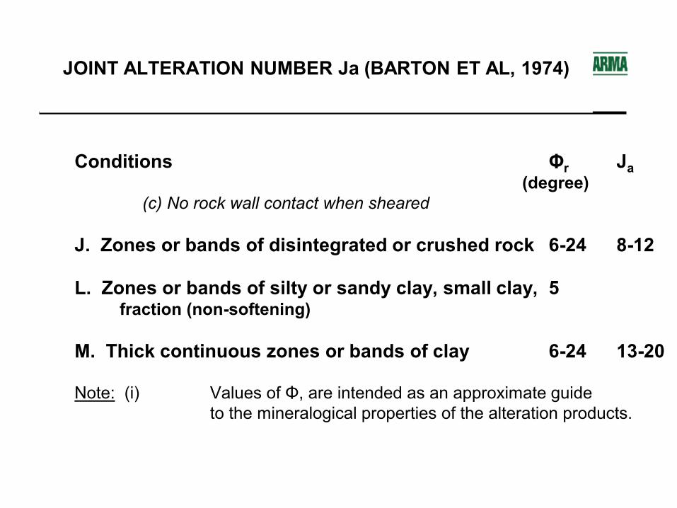
JOINT ALTERATION NUMBER Ja (BARTON ET AL 1974)
Conditions Φr Ja(degree)
(c) No rock wall contact when sheared
J Zones or bands of disintegrated or crushed rock 6-24 8-12
L Zones or bands of silty or sandy clay small clay 5fraction (non-softening)
M Thick continuous zones or bands of clay 6-24 13-20
Note (i) Values of Φ are intended as an approximate guideto the mineralogical properties of the alteration products
STRESS REDUCTION FACTOR SRF (BARTON ET AL 1974 AND GRIMSTAD AND BARTON 1993)
Conditions SRF(a) Weakness zones intersecting excavation which may cause loosening of rockmass when tunnel is excavated
A Multiple occurrences of weakness zones containing clay or 100chemically disintegrated rock
B Single-weakness zones containing clay or chemically 50disintegrated rock (depth lt50 m)
C Single-weakness zones containing clay or chemically 25disintegrated rock (depth gt50m)
D Multiple-shear zones in competent rock (clay-free) 75
E Single shear zones in competent rock (clay-free) (depth lt50m) 50
F Single-shear zones competent rock (clay-free) (depth of gt50m) 25
G Loose open joints heavily jointed or ldquosugar cuberdquo etc 50
STRESS REDUCTION FACTOR SRF (BARTON ET AL 1974 AND GRIMSTAD AND BARTON 1993)
Conditions SRF
(b) Competent rock rock stress problems
H Low stress near surface open joints 25
J Medium stress favorable stress condition 10
K High stress very tight structure 05-20
L Moderate slabbing after gt1 hr in massive rock 5-50
M Slabbing and rock burst after a few minutes massive rock 50-200
N Heavy rock burst and immediate deformations massive rock 200-400
DESCRIPTION OF RANGES IN THE Q-SYSTEM
0001-001 Exceptionally poor001-01 Extremely poor01-1 Very poor
1-4 Poor4-10 Fair
10-40 Good40-100 Very good
100-400 Extremely good400-1000 Exceptionally good
EQUIVALENT DIMENSION De (BARTON ET AL 1974)
Equivalent dimension is defined as follows
De = excavation span diameter or height excavation to support ratio (ESR)
VALUES OF EXCAVATION SUPPORT RATIO ESR (BARTON ET AL 1974)
3 Permanent mine openings water tunnels for hydro power etc
16
4 Storage rooms water treatment plants minor road and railway tunnels etc
13
5 Oil storage caverns power stations major road and railway tunnels civil defense chambers etc
10
6 Underground nuclear power stations railway stations sports and public facilities factories etc
08
Q-SYSTEM GROUND SUPPORT
Empirical Rock Support Design
Q-SYSTEM EXCAVATION SUPPORT CHART (BARTON ET AL 1974)
Exce
ptio
nally
poor
Extre
mely
poor
Very
poo
r
Poor
Fair
Good
Very
goo
d
Extre
mely
Excp
t go
od
100
10
1
010001 001 01 1 4 10 40 100 1000
1234
5678
9
101112
13
14
15
16
1718
19
20
21
22
23
24
25
26
27
28
29
30
31
32
33
34
35
36
37
38
NO SUPPORT REQUIRED
EQUI
VALE
NT D
IMEN
SION
(D )e
good
ROCK MASS OUALITY - Q
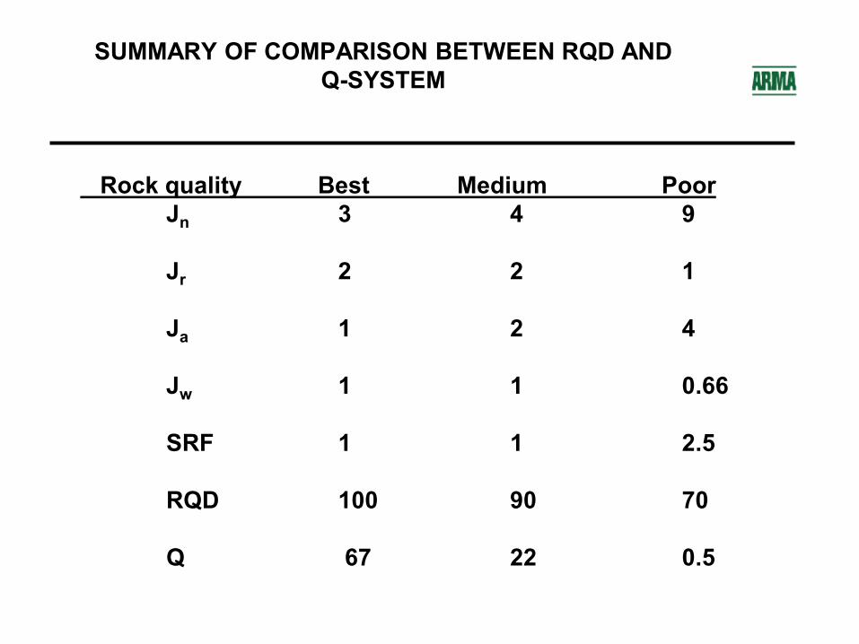
SUMMARY OF COMPARISON BETWEEN RQD AND Q-SYSTEM
Rock quality Best Medium PoorJn 3 4 9
Jr 2 2 1
Ja 1 2 4
Jw 1 1 066
SRF 1 1 25
RQD 100 90 70
Q 67 22 05
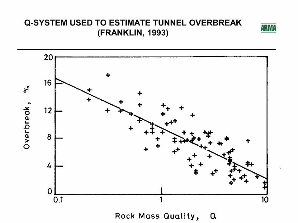
Q-SYSTEM USED TO ESTIMATE TUNNEL OVERBREAK (FRANKLIN 1993)
COMPARISON OF RMR TO Q (SINGH AND GOEL 1999)
RMR AS COMPARED TO Q
Q AND RMR USED TO ESTIMATE MODULUS OF DEFORMATION (BARTON 1993)
RECOMMENDATIONS ON THE USE OF ROCK MASS CLASSIFICATIONS (BIENIAWSKI 1988 LACHEL 2003)
bull Do not use the classification schemes as rigid guidelines or a substitute for sound engineering judgment
bull Consider alternate classifications schemes
bull Classification schemes are not applicable to all situations
bull Classification schemes are based on successfully completed projects and as such are typically conservative
bull Generally RMR and the Q-system appear to give better more consistent results
bull Integrate classification schemes with analytical and observational approaches
RECOMMENDATIONS ON THE USE OF ROCK MASS CLASSIFICATIONS (BIENIAWSKI 1988 LACHEL 2003) cont
bull There is still a great deal of subjectivity is assigning values to the factors
bull Anisotropy and inhomogeneity must always be considered
bull At least two schemes should be applied and it may be possible to develop a site related approach
bull One classification will normally not be applicable to an entire site
bull The results of all analysis must be confirmed during construction
bull A complete record or database of experience with the classification system should be maintained
ROCK MASS CLASSIFICATION AND GROUND SUPPORTAdapted from Presentation by Dennis J Lachel CEG PGLACHEL amp Associates IncGolden Colorado
Underground Excavations
Slide Number 3
INITIAL GROUND SUPPORT
PRE-EXCAVATION GROUTING
FOREPOLING AND BREASTING
RIBS AND BOARDS
STEEL SETS WITH INVERT STRUTS
SHOTCRETEING
ROBOTIC SHOTCRETE APPLICATION
PRE-CAST CONCRETE SEGMENTS
STEEL LINER PLATE
ROBOTIC ROCK BOLT INSTALLER
ROCK BOLTS STRAPS amp MESH
SMOOTHWALL DRILL AND BLAST
PERMANENT SUPPORT FINAL LINING
PRE-CAST CONCRETE SEGMENTS
ROCK BOLTS AND SHOTCRETE AS PERMANENT SUPPORT
CAST-IN-PLACE CONCRETE SUPPORT
METHODS OF EXCAVATION
DRILL AND BLAST TUNNEL
Slide Number 22
WORLDS LARGEST CONSTRUCTED UNDERGROUND
95 m TBM
TBM TUNNEL IN MASSIVE LIMESTONE
GEOLOGIC CLASSIFICATION
CLASSIFICATION OF ROCK MATERIAL BASED ON UNCONFINED COMPRESSIVE STRENGTH(STAPLEDON AND ISRM)
COMPARISON OF VARIOUS ROCK STRENGTH CLASSIFICATIONS (BIENIAWSKI 1979 IN AFROUZ 1992)
INTACT VERSUS ROCK MASS PROPERTIES
Slide Number 30
OBJECTIVES OF ROCK MASS CLASSIFICATIONS (BIENIAWSKI 1989)
CLASSIFICATION ATTRIBUTES (BEINIAWSKI 1984)
ROCK MASS CLASSIFICATIONS
ROCK MASS CLASSIFICATIONS
ROCK MASS CLASSIFICATIONS
Slide Number 36
TERZAGHIrsquoS ROCK LOAD CLASSIFICATION
ROCK LOAD THEORY TERZAGHI (1946)
DEFINITIONS OF ROCK CLASSES OF TERZAGHIrsquoS ROCK LOAD THEORY (SINHA 1989)
DEFINITIONS OF ROCK CLASSES OF TERZAGHIrsquoS ROCK LOAD THEORY (SINHA 1989)
ROCK LOAD IN TUNNELS WITHIN VARIOUS ROCK CLASSES (TERZAGHI 1946)
ROCK LOAD IN TUNNELS WITHIN VARIOUS ROCK CLASSES (TERZAGHI 1946)
Slide Number 43
STAND-UP TIME (LAUFFER 1958)
STAND-UP TIME (LAUFFER 1958)
Slide Number 46
LAUFFERrsquoS DEFINITION OF SPAN
FACTORS INFLUENCING STAND-UP TIME (AFTER LAUFFER 1958 IN BIENIAWSKI 1990)
FACTORS INFLUENCING STAND-UP TIME (AFTER LAUFFER 1958 IN BIENIAWSKI 1990)
Slide Number 50
ROCK CORE EVALUATION
ROCK QUALITY DESIGNATION (RQD)
RQD MEASUREMENTS
CORRELATION BETWEEN RQD AND ROCK MASS QUALITY (DEERE 1964)
PROPOSED USE OF RQD FOR ROCK SUPPORT (MERRITT 1972)
GROUND SUPPORT BY RQD FOR 6m TO 12m DIAMETER (DEERE ET AL 1970)
GROUND SUPPORT BY RQD FOR 6m TO 12m DIAMETER (DEERE ET AL 1970)(Cont)
LIMITATIONS ON RQD
Slide Number 60
ROCK MASS RATING (RMR)
RMR SYSTEM (GEOMECHANICS CLASSIFICATION)
STRENGTH OF INTACT ROCK MATERIAL (BIENIAWSKI 1979)
DRILL CORE QUALITY ndash RQD (BIENIAWSKI 1979)
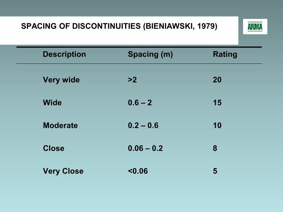
SPACING OF DISCONTINUITIES (BIENIAWSKI 1979)
CONDITION OF DISCONTINUITIES (BIENIAWSKI 1979)
GROUND WATER CONDITION (BIENIAWSKI 1979)
ADJUSTMENT FOR JOINT ORIENTATION (BIENIAWSKI 1979)
ROCK MASS CLASSES DETERMINED FROM TOTAL RATINGS
MEANING OF ROCK MASS CLASSES (BIENIAWSKI 1974)
DESIGN PARAMETERS amp ENGINEERING PROPERTIES OF ROCK MASS (BIENIAWSKI 1979 amp BIS CODE)
GUIDELINES FOR EXCAVATION AND SUPPORT OF ROCK TUNNELS IN ACCORDANCE WITH THE ROCK MASS RATING SYSTEM (BIENIAWSKI 1989)
RMR APPLIED TO STAND-UP TIME (BIENIAWSKI 1989)
ROCK MASS RATING AND STAND-UP TIME (BIENIAWSKI 1974)
CORRELATION BETWEEN SPAN ROCK LOAD AND RMR (BIENIAWSKI 1989)
METHOD OF EXCAVATION BASED ON RMR (ABDULLATIF AND CRUDEN 1983)
CORRELATION BETWEEN Ed AND RMR (BIENIAWSKI 1984)
Slide Number 78
Q-SYSTEM OF ROCK MASS CLASSIFICATION
BASIS OF Q-SYSTEM
Q-SYSTEM FORMULA
JOINT SET NUMBER Jn (BARTON ET AL 1974)
JOINT ROUGHNESS NUMBER Jr (BARTON ET AL 1974)
RATING DUE TO JOINT WATER (JW)
JOINT ALTERATION NUMBER Ja (BARTON ET AL 1974)
JOINT ALTERATION NUMBER Ja(BARTON ET AL 1974)
JOINT ALTERATION NUMBER Ja (BARTON ET AL 1974)
STRESS REDUCTION FACTOR SRF (BARTON ET AL 1974 AND GRIMSTAD AND BARTON 1993)
STRESS REDUCTION FACTOR SRF (BARTON ET AL 1974 AND GRIMSTAD AND BARTON 1993)
DESCRIPTION OF RANGES IN THE Q-SYSTEM
EQUIVALENT DIMENSION De (BARTON ET AL 1974)
Slide Number 92
Q-SYSTEM GROUND SUPPORT
Slide Number 94
Q-SYSTEM EXCAVATION SUPPORT CHART (BARTON ET AL 1974)
SUMMARY OF COMPARISON BETWEEN RQD AND Q-SYSTEM
Q-SYSTEM USED TO ESTIMATE TUNNEL OVERBREAK (FRANKLIN 1993)
COMPARISON OF RMR TO Q (SINGH AND GOEL 1999)
RMR AS COMPARED TO Q
Q AND RMR USED TO ESTIMATE MODULUS OF DEFORMATION (BARTON 1993)
RECOMMENDATIONS ON THE USE OF ROCK MASS CLASSIFICATIONS (BIENIAWSKI 1988 LACHEL 2003)
RECOMMENDATIONS ON THE USE OF ROCK MASS CLASSIFICATIONS (BIENIAWSKI 1988 LACHEL 2003) cont
Rock Quality
Construction Method
Steel Sets
Rock Bolt
Shotcrete
Additional Supports
Weight of Steel Sets
Spacing
Spacing of Pattern Bolt
Additional Requirements
Total Thickness (cm)
Crown
Sides
Poor RQD 25 to 50
Boring Machine
Medium Circular
06 to 12 m
09 to 15 m
Anchorage may be hart to obtain Considerable mesh and straps required
10 to 15 cm
10 to 15 cm
Rockbolt as required (12 to 18 m center to center)
Drilling amp Blasting
Medium to Heavy circular
02 to 12 m
06 to 12 m
as above
15 cm or more
15 cm or more
as above
Very Poor RQD lt 25
Boring Machine
Medium to Heavy circular
06 m
06 to 12 m
Anchorage may be impossible 100 mesh and straps required
15 cm or more on whole section
Medium sets as required
Drilling amp Blasting
Heavy circular
06 m
09 m
as above
15 cm or more on whole section
Medium sets as required
Very Poor Squeezing and Swelling Ground
Both methods
Very Heavy circular
06 m
06 to 09 m
Anchorage may be impossible 100 mesh and straps required
15 cm or more on whole section
Heavy sets as required
Rock Quality
Construction Method
Steel Sets
Rock Bolt
Shotcrete
Additional Supports
Weight of Steel Sets
Spacing
Spacing of Pattern Bolt
Additional Requirements
Total Thickness (cm)
Crown
Sides
Excellent RQD gt 90
Boring Machine
Light
None to Occasional
None to Occasional
Rare
None to Occasional
None
None
Drilling amp Blasting
Light
None to Occasional
None to Occasional
Rare
None to Occasional
None
None
Good RQD 75 to 90
Boring Machine
Light
Occasional to 15 to 18 m
Occasional to 15 to 18 m
Occasional mesh and straps
Local Application 5 to 75 cm
None
None
Drilling amp Blasting
Light
15 to 18 m
15 to 18 m
Occasional mesh and straps
Local Application 5 to 75 cm
None
None
Fair RQD 50 to 75
Boring Machine
Light to Medium
15 to 18 m
12 to 18 m
Mesh and straps as required
5 to 10 cm
None
Rock Bolts
Drilling amp Blasting
Light to Medium
12 to 15 m
09 to 15 m
Mesh and straps as required
10 cm or more
10 cm or more
Rock Bolts
Rock Quality
Construction Method
Steel Sets
Rock Bolt
Shotcrete
Additional Supports
Weight of Steel Sets
Spacing
Spacing of Pattern Bolt
Additional Requirements
Total Thickness (cm)
Crown
Sides
Poor RQD 25 to 50
Boring Machine
Medium Circular
06 to 12 m
09 to 15 m
Anchorage may be hart to obtain Considerable mesh and straps required
10 to 15 cm
10 to 15 cm
Rockbolt as required (12 to 18 m center to center)
Drilling amp Blasting
Medium to Heavy circular
02 to 12 m
06 to 12 m
as above
15 cm or more
15 cm or more
as above
Very Poor RQD lt 25
Boring Machine
Medium to Heavy circular
06 m
06 to 12 m
Anchorage may be impossible 100 mesh and straps required
15 cm or more on whole section
Medium sets as required
Drilling amp Blasting
Heavy circular
06 m
09 m
as above
15 cm or more on whole section
Medium sets as required
Very Poor Squeezing and Swelling Ground
Both methods
Very Heavy circular
06 m
06 to 09 m
Anchorage may be impossible 100 mesh and straps required
15 cm or more on whole section
Heavy sets as required
Rock Quality
Construction Method
Steel Sets
Rock Bolt
Shotcrete
Additional Supports
Weight of Steel Sets
Spacing
Spacing of Pattern Bolt
Additional Requirements
Total Thickness (cm)
Crown
Sides
Excellent RQD gt 90
Boring Machine
Light
None to Occasional
None to Occasional
Rare
None to Occasional
None
None
Drilling amp Blasting
Light
None to Occasional
None to Occasional
Rare
None to Occasional
None
None
Good RQD 75 to 90
Boring Machine
Light
Occasional to 15 to 18 m
Occasional to 15 to 18 m
Occasional mesh and straps
Local Application 5 to 75 cm
None
None
Drilling amp Blasting
Light
15 to 18 m
15 to 18 m
Occasional mesh and straps
Local Application 5 to 75 cm
None
None
Fair RQD 50 to 75
Boring Machine
Light to Medium
15 to 18 m
12 to 18 m
Mesh and straps as required
5 to 10 cm
None
Rock Bolts
Drilling amp Blasting
Light to Medium
12 to 15 m
09 to 15 m
Mesh and straps as required
10 cm or more
10 cm or more
Rock Bolts
STAND-UP TIME
MINUTES
HOURS
DAYS
YEARS
GROUND MODIFICATION
FOREPOLINGBREASTING
STRUCTURAL SUPPORTS
SHOTCRETE
SEGMENTED LINERS
ROCK BOLTS
NO SUPPORT
Underground Excavations
INITIAL GROUND SUPPORT
STAND-UP TIMEMINUTES HOURS DAYS YEARS
GROUND MODIFICATION
FOREPOLINGBREASTING
STRUCTURAL SUPPORTS
SHOTCRETE
SEGMENTED LINERS
ROCK BOLTS
NO SUPPORT
Sheet1
Sheet2
Sheet3
PRE-EXCAVATION GROUTING
FOREPOLING AND BREASTING
RIBS AND BOARDS
STEEL SETS WITH INVERT STRUTS
SHOTCRETEING
ROBOTIC SHOTCRETE APPLICATION
PRE-CAST CONCRETE SEGMENTS
STEEL LINER PLATE
ROBOTIC ROCK BOLT INSTALLER
ROCK BOLTS STRAPS amp MESH
SMOOTHWALL DRILL AND BLAST
PERMANENT SUPPORT FINAL LINING
bull Precast Concrete Liners ndash A ldquoOne Passrdquo System
bull Rock Bolts and Shotcrete
bull Cast-In-Place Concrete Liners
PRE-CAST CONCRETE SEGMENTS
ROCK BOLTS AND SHOTCRETE AS PERMANENT SUPPORT
CAST-IN-PLACE CONCRETE SUPPORT
METHODS OF EXCAVATION
bull Drill and Blastbull Full facebull Heading and Benchbull Multi-drift Method
bull Tunnel Boring Machines
DRILL AND BLAST TUNNEL
WORLDS LARGEST CONSTRUCTED UNDERGROUND
95 m TBM
TBM TUNNEL IN MASSIVE LIMESTONE
GEOLOGIC CLASSIFICATION
bull Developed by petrographers for classical geologic descriptions
bull Classify rock by modes of origin and mineral content
bull ldquoInterested in mechanical properties not just namesrdquo
bull Does not provide quantitative data for engineering purposes
bull Inform us of potential weaknesses for example- Sheet silicates talc mica chlorite serpentine all alert us to
rocks with low shear strength parallel to direction of imposed loads
- Weak or soluble rocks montmorillonite gypsum shales chalk
CLASSIFICATION OF ROCK MATERIAL BASED ON UNCONFINED COMPRESSIVE STRENGTH
(STAPLEDON AND ISRM)
Term for Uniaxial Compressive Strength
Symbol Strength(MPa)
Extremely Weak
EW 025 ndash 1
Very Weak VW 1 ndash 5
Weak W 5 ndash 25
Medium Strong MS 25 ndash 50
Strong S 50 ndash 100
Very Strong VS 100 ndash 250
Extremely Strong
ES gt250
COMPARISON OF VARIOUS ROCK STRENGTH CLASSIFICATIONS (BIENIAWSKI 1979 IN AFROUZ 1992)
INTACT VERSUS ROCK MASS PROPERTIES
ldquoThe major limitation on intact rock classifications is that they cannot provide quantitative data for engineering design purposes Therefore their main value lies in enabling better identification and communication during discussions of intact rock propertiesrdquo (Bieniawski 1989)
ROCK MASS CLASSIFICATIONS
OBJECTIVES OF ROCK MASS CLASSIFICATIONS (BIENIAWSKI 1989)
bull Identify the most significant parameters influencing the behavior of a rock mass
bull Divide a rock mass into classes of similar behavior
bull Provide a basis for understanding the characteristics of each rock class
bull Provide a basis to compare one site to conditions and experience at another site
bull Derive quantitative data and guidelines for engineering design
bull Provide a common basis for communication between geologists and engineers
CLASSIFICATION ATTRIBUTES (BEINIAWSKI 1984)
bull Simple easily remembered and understandable
bull Uses terms and terminology widely accepted by engineers and geologists
bull Includes the most significant properties of the rock mass
bull Based on measurable (and repeatable) field parameters using quick and inexpensive tests
bull Weighs the relative importance of the parameters
bull Provides quantitative data for the design of rock support
ROCK MASS CLASSIFICATIONS
Advantages
bull Improves site investigations by providing a minimum required program
bull A short cut to rock mass properties that are often difficult to assess
bull Only a few basic parameters relating to geometry and mechanical condition of the rock mass are used
bull Provides quantitative information for design
bull Direct guidance for engineering design eg predicting support requirements in tunnels
ROCK MASS CLASSIFICATIONS
Advantages (continued)
bull Simplicity of approach even when dealing with complex rock masses
bull Comfort in using the classification system
bull Fast results
bull Adaptable to field conditions for confirmation of assumptions
bull Better communication between all parties
bull Better engineering judgment for the project
ROCK MASS CLASSIFICATIONS
Disadvantages
bull Still requires considerable experience for validation
bull Absence of what may be critical parameters for certain projects eg rock cover for pressure tunnels
bull Anisotropy not fully considered
bull False sense of security
ROCK LOAD THEORY
TERZAGHIrsquoS ROCK LOAD CLASSIFICATION
bull ldquoIntroduction to Tunnel Geologyrdquo by Karl Terzaghi in Rock Tunneling with Steel Supports Proctor and White 1946
bull The first practical classification system
bull The ldquoTunnelmanrsquos Rock Mass Classificationrdquo for more than 50 years and still in use
bull The first rational method of evaluating rock loads for designing steel sets
bull Not totally applicable to modern ground support of rock bolts and shotcrete
ROCK LOAD THEORY TERZAGHI (1946)
DEFINITIONS OF ROCK CLASSES OF TERZAGHIrsquoS ROCK LOAD THEORY (SINHA 1989)
Rock Class
Type of Rock Definition
I Hard amp intact Rock is unweathered and contains neither joints nor hair cracks The unconfined compressive strength is equal to or more than 100 MPa
II Hard stratified and schistose
Rock is hard and layered usually widely separated and may or may not have planes of weakness Spalling is quite common
III Massive moderately jointed
Joints are widely spaced and may or may not be cemented Spalling may occur
IV Moderately blocky and seamy
Blocks are about 1m in size Rock may or may not be hard The joints may or may not be healed
DEFINITIONS OF ROCK CLASSES OF TERZAGHIrsquoS ROCK LOAD THEORY (SINHA 1989)
Rock Class
Type of Rock Definition
V Very blocky and seamy
Closely spaced joints Block size is less than 1m consisting of chemically intact rock fragments which are separated from each other and imperfectly interlocked Vertical walls may require supports
VI Completely crushed but chemically intact
Chemically intact rock having the character of a crusher run aggregate no interlocking side pressure is expected on tunnel supports The block size could be few centimeters to 30 cm
VII Squeezing rock ndashmoderate depth
Squeezing is a mechanical process in which the rock advances into the tunnel opening without perceptible increase in volume up to 1000m
VIII Squeezing rock ndashgreat depth
The depth may be more than 150m The maximum recommended tunnel depth is 1000m
IX Swelling rock Swelling is associated with volume change due to chemical change of the rock usually in presence of moisture or water Some shales absorb moisture from air and swell Rocks containing swelling minerals such as montmorillonite illite kaolinite and others can swell and exert heavy pressure on rock supports
ROCK LOAD IN TUNNELS WITHIN VARIOUS ROCK CLASSES (TERZAGHI 1946)
Rock Class
Rock Condition
Rock Load Factor Hp
Remarks
I Hard and Intact
Zero Light lining required only if spalling or popping occurs
II Hard stratified or schistose
0-05B Light support mainly for protection against spalling
III Massive moderately jointed
0-025B No side pressure
IV Moderately blocky and seamy
025B-035 (B+Ht)
No side pressure
V Very blocky and seamy
(035-110) (B+Ht)
Little or no side pressure
ROCK LOAD IN TUNNELS WITHIN VARIOUS ROCK CLASSES (TERZAGHI 1946)
Rock Class
Rock Condition
Rock Load Factor Hp
Remarks
VI Completely crushed
110 (B+Ht) Considerable side pressure Softening effects of seepage toward bottom of tunnel requires either continuous support for lower ends of ribs or circular ribs
VII Squeezing rock ndashmoderate depth
(110-210) (B+Ht)
Heavy side pressure invert struts required Circular ribs are recommended
VIII Squeezing rock ndashgreat dpth
(210-450) (B+Ht)
-do-
IX Swelling rock
Up to 250 ft irrespective of the value of (B+Ht)
Circular ribs are required In extreme cases use of yielding support recommended
STAND-UP TIME
STAND-UP TIME (LAUFFER 1958)
bull Proposed by Lauffer in 1958 based on work by Stini father of the Austrian School of tunneling and rock mechanics
bull Assumed that ground stability is primarily based on structural defects
bull ldquoStand-up Timerdquo is dependent on rock quality and the span of the tunnel
bull Realized that other factors could influence stand-up time egorientation of tunnel axistunnel shapeexcavation methodsupport method
STAND-UP TIME (LAUFFER 1958)
LAUFFERrsquoS ROCK CLASSES
LAUFFERrsquoS DEFINITION OF SPAN
FACTORS INFLUENCING STAND-UP TIME (AFTER LAUFFER 1958 IN BIENIAWSKI 1990)
FACTORS INFLUENCING STAND-UP TIME (AFTER LAUFFER 1958 IN BIENIAWSKI 1990)
ROCK QUALITY DESIGNATION (RQD)
ROCK CORE EVALUATION
ROCK QUALITY DESIGNATION (RQD)
bull Developed by Don U Deere in 1964
bull Significantly expanded by Deere et al in 1967
bull A useful index for determining rock quality from core recovery
bull RQD= Length of ldquosoundrdquo core gt 10 cm (4 in) X 100Total Core Run Length
bull Core measured along centerline
bull NX or NQ size core should be used
RQD MEASUREMENTS
CORRELATION BETWEEN RQD AND ROCK MASS QUALITY (DEERE 1964)
RQD() Rock Quality
lt25 Very poor
25-50 Poor
50-75 Fair
75-90 Good
90-100 Excellent
PROPOSED USE OF RQD FOR ROCK SUPPORT (MERRITT 1972)
GROUND SUPPORT BY RQD FOR 6m TO 12m DIAMETER (DEERE ET AL 1970)
Crown SidesBoring
MachineLight None to
OccasionalNone to
OccasionalRare None to
OccasionalNone None
Drilling amp Blasting
Light None to Occasional
None to Occasional
Rare None to Occasional
None None
Boring Machine Light
Occasional to 15 to 18 m
Occasional to 15 to 18 m
Occasional mesh and straps
Local Application 5 to 75 cm None None
Drilling amp Blasting
Light 15 to 18 m 15 to 18 m Occasional mesh and straps
Local Application 5 to 75 cm
None None
Boring Machine
Light to Medium
15 to 18 m 12 to 18 m Mesh and straps as required
5 to 10 cm None Rock Bolts
Drilling amp Blasting
Light to Medium
12 to 15 m 09 to 15 m Mesh and straps as required
10 cm or more 10 cm or more
Rock Bolts
Shotcrete
Total Thickness (cm)Spacing of Pattern Bolt
Additional Requirements
Additional Supports
Excellent RQD gt 90
Good RQD
75 to 90
Fair RQD 50 to 75
Rock Quality
Construction Method Weight of
Steel SetsSpacing
Steel Sets Rock Bolt
Sheet1
Sheet2
Sheet3
GROUND SUPPORT BY RQD FOR 6m TO 12m DIAMETER (DEERE ET AL 1970)(Cont)
Crown Sides
Boring Machine
Medium Circular
06 to 12 m 09 to 15 m
Anchorage may be hart to obtain
Considerable mesh and straps required
10 to 15 cm 10 to 15 cm
Rockbolt as required (12 to 18 m center to
center)
Drilling amp Blasting
Medium to Heavy circular
02 to 12 m 06 to 12 m as above 15 cm or more 15 cm or
more as above
Boring Machine
Medium to Heavy circular
06 m 06 to 12 m
Anchorage may be impossible 100 mesh and straps
required
15 cm or more on whole section
Medium sets as required
Drilling amp Blasting
Heavy circular
06 m 09 m as above 15 cm or more on whole section
Medium sets as required
Rock Quality
Construction Method
Steel Sets Rock Bolt ShotcreteAdditional SupportsWeight of
Steel SetsSpacing Spacing of
Pattern BoltAdditional
RequirementsTotal Thickness (cm)
Poor RQD 25 to 50
Very Poor RQD lt 25
Very Poor Squeezing
and Swelling
Both methods
15 cm or more on whole section
Heavy sets as required
Very Heavy circular 06 m 06 to 09 m
Anchorage may be impossible 100 mesh and straps
required
Sheet1
Sheet2
Sheet3
LIMITATIONS ON RQD
bull Does not account for the existence thickness and strength characteristics of joint coating or filling material
bull Does not account for joint roughness or interlock
bull Can be significantly influenced by angle of boring
bull ldquoSoundrdquo rock can be very subjective
bull Core may deteriorate between drilling and logging
bull 100 mm core length may be arbitrary for some excavations egNORADIcelandic Power Chamber
bull What RQD really means
ROCK MASS RATING (RMR)
ROCK MASS RATING (RMR)
bull Originally developed by ZT (Dick) Bieniawski in 1973
bull Also called ldquoGeomechanics Classification of Rock Massesrdquo
bull Incorrectly called the ldquoCSIR ratingrdquo or ldquoCSIR Classificationrdquo
bull Currently based on 351 case histories
bull Modified several times ndash must state reference
bull ldquonot the answer to all design problemsrdquo
RMR SYSTEM (GEOMECHANICS CLASSIFICATION)
Based on six geotechnical parameters
bull Uniaxial compressive strength of rockbull Rock quality designation (RQD)bull Spacing of discontinuitiesbull Condition of discontinuitiesbull Groundwater conditionsbull Orientation of discontinuities
STRENGTH OF INTACT ROCK MATERIAL (BIENIAWSKI 1979)
Qualitative Description
Compressive Strength (MPa)
Point Load Strength (MPa)
Rating
Exceptionally strong
gt250 8 15
Very strong 100 ndash 250 4-8 12Strong 50 ndash 100 2-4 7Average 25 ndash 50 1-2 4Weak 10 ndash 25 Use of Uniaxial
DESIGN PARAMETERS amp ENGINEERING PROPERTIES OF ROCK MASS (BIENIAWSKI 1979 amp BIS CODE)
S ParameterProperties Rock Mass Rating (Rock Class)No of Rock Mass
100-81(I) 80-61 (II) 60-41 (III) 40-21 (IV) lt20 (V)
1 Classification of rock mass Very good Good Fair Poor Very poor
2 Average stand-up time 10 years 6 months 1 week 10 hrs 30 min forfor 15 m for 8 m for 5 m for 25 m 1 m spanspan span span span
3 Cohesion of rock mass (MPa) gt04 03-04 02-03 01-02 lt01
4 Angle of internal friction gt45o 35o-45o 25o-35o 15o-25o 15o
GUIDELINES FOR EXCAVATION AND SUPPORT OF ROCK TUNNELS IN ACCORDANCE WITH THE ROCK MASS RATING
SYSTEM (BIENIAWSKI 1989)
Rock Mass Excavation SupportsClass Rock bolts (20 mm Shotcrete Steel sets
dia fully Grouted)
Very good rock Full face 3m advance Generally no support required except for occasional RMR=81-100 spot bolting
Good rock Full face10-15m Locally bolts in crown 50mm in crown NoneRMR=61-80 advance 3m long spaced 25m where required
with occasional wire mesh
Fair rock Heading and bench 15 Systematic bolts 4m long 50-100 mm in NoneRMR=41-60 - 3m advance in heading Spaced 15-2m in crown crown and 30
Commence support and walls with wire mesh mm in sidesafter each blast in crown
Poor rock Top heading and bench Systematic bolts 4-5m 100-200mm in Lt to med ribsRMR21-40 10-15m in heading long spaced 1-15m crown amp 100mm spaced 15m
w WWF on walls as required
Very poor Mult drifts 05-15 m Systematic bolts 5-6m 150-200mm in Med to Hvy ribsRock advance on heading long spaced 1-15m on crown 150mm 075m wRMR lt 20 Shotcrete ASAP crown and walls w on walls 50mm steel lagging
WWF Bolt invert on face Close invert
RMR APPLIED TO STAND-UP TIME (BIENIAWSKI 1989)
Stand-up Time
ROCK MASS RATING AND STAND-UP TIME (BIENIAWSKI 1974)
CORRELATION BETWEEN SPAN ROCK LOAD AND RMR (BIENIAWSKI 1989)
METHOD OF EXCAVATION BASED ON RMR (ABDULLATIF AND CRUDEN 1983)
RMR Value Excavation Method
lt 30 Digging
31 - 60 Ripping
61 ndash 100 Blasting
CORRELATION BETWEEN Ed AND RMR (BIENIAWSKI 1984)
RMR
Ed in
GPa
Q-SYSTEM
Q-SYSTEM OF ROCK MASS CLASSIFICATION
Developed by Nick Barton Lien and Lund 1974
Also known as the Norwegian Geotechnical Institute (NGI) Classification
Originally based on 212 case histories updated to now include more than 1500 case histories
Modified in 1993 by Barton and Grimstad to include ground support systems not available in 1974
ldquoAn engineering system facilitating the design of tunnel supportsrdquo
BASIS OF Q-SYSTEM
A numerical assessment of the rock mass quality based on seven parameters
bull RQDbull Number of joint setsbull Roughness of the most unfavorable joint or discontinuitybull Degree of alteration of filling along the weakest jointbull Water inflowbull Stress conditionbull Equivalent dimension ndash a function of size and purpose of the
excavation
Q-SYSTEM FORMULA
The first six parameters are grouped into three quotients to give the overall rock mass quality Q
Q = (RQD) x (Jr) x (Jw)Jn Ja SRF
WhereRQD = rock quality designation
Jn = joint set numberJr = joint roughness numberJa = joint alteration numberJw = joint water reduction number
SRF = stress reduction factor
JOINT SET NUMBER Jn (BARTON ET AL 1974)
Conditions Jn
A Massive none or few joints 05-10B One joint set 2C One joint set plus random 3D Two joint sets 4E Two joint sets plus random 6F Three joint sets 9G Three joint sets plus random 12H Four or more joint sets random heavily jointed 15
ldquosugar cuberdquo etcH Crushed rock earth like 20
Note(i) For intersections use (30Jn)(ii)For portals use (20Jn)
JOINT ROUGHNESS NUMBER Jr (BARTON ET AL 1974)
ConditionsJr
(a) Rock wall contact and(b) Rock wall contact before 10cm shear
A Discontinuous joint 4B Rough or irregular undulating 3C Smooth undulating 20D Slickensided undulating 15E Rough or irregular planar 15F Smooth planar 10G Slickensided planar 05
(c) No rock wall contact when shearedH Zone containing clay minerals thick enough to prevent 10
rock wall contactI Sandy gravelly or crushed zone thick enough to prevent 10
rock wall contact
RATING DUE TO JOINT WATER (JW)
Approxwater
Classification of joint water Jw pressure(kgcm2)
A Dry excavations or minor inflow 10 lt1
B Medium inflow or pressure 066 1-25
C Large inflow or high pressure with unfilled 05 25-10joints
D Large inflow or high pressure outwash of 033 25-10joint fillings
E Exceptionally high inflow decaying with time 02-01 gt10
F Exceptionally high inflow without noticeable 01-005 gt10decay
JOINT ALTERATION NUMBER Ja(BARTON ET AL 1974)
Conditions Φr jr(degree)
A Tightly healed hard non-softening impermeable filling 075 iequartz or epidote
B Unaltered joint walls surface staining only 25-35 10
C Slightly altered joint walls Non-softening mineral coatings 25-30 20 sandy particles clay-free disintegrated rock etc
D Silty or sandy clay coatings small clay fraction 20-25 30(non-softening)
E Softening or low-friction clay mineral coatings 8-16 40ie kaolinite micachlorite talc gypsum and graphite etc
JOINT ALTERATION NUMBER Ja(BARTON ET AL 1974)
Conditions Φr Ja(degree)
(b) Rock wall contact before 10 cm shearF Sandy particles clay-free disintegrated rock 25-30 40
G Strongly over-consolidated non-softening clay 16-24 60mineral fillings
H Medium or low over-consolidation softening 12-16 80clay mineral fillings
I Swelling clay fillings ie montmorillonite 6-12 8-12
JOINT ALTERATION NUMBER Ja (BARTON ET AL 1974)
Conditions Φr Ja(degree)
(c) No rock wall contact when sheared
J Zones or bands of disintegrated or crushed rock 6-24 8-12
L Zones or bands of silty or sandy clay small clay 5fraction (non-softening)
M Thick continuous zones or bands of clay 6-24 13-20
Note (i) Values of Φ are intended as an approximate guideto the mineralogical properties of the alteration products
STRESS REDUCTION FACTOR SRF (BARTON ET AL 1974 AND GRIMSTAD AND BARTON 1993)
Conditions SRF(a) Weakness zones intersecting excavation which may cause loosening of rockmass when tunnel is excavated
A Multiple occurrences of weakness zones containing clay or 100chemically disintegrated rock
B Single-weakness zones containing clay or chemically 50disintegrated rock (depth lt50 m)
C Single-weakness zones containing clay or chemically 25disintegrated rock (depth gt50m)
D Multiple-shear zones in competent rock (clay-free) 75
E Single shear zones in competent rock (clay-free) (depth lt50m) 50
F Single-shear zones competent rock (clay-free) (depth of gt50m) 25
G Loose open joints heavily jointed or ldquosugar cuberdquo etc 50
STRESS REDUCTION FACTOR SRF (BARTON ET AL 1974 AND GRIMSTAD AND BARTON 1993)
Conditions SRF
(b) Competent rock rock stress problems
H Low stress near surface open joints 25
J Medium stress favorable stress condition 10
K High stress very tight structure 05-20
L Moderate slabbing after gt1 hr in massive rock 5-50
M Slabbing and rock burst after a few minutes massive rock 50-200
N Heavy rock burst and immediate deformations massive rock 200-400
DESCRIPTION OF RANGES IN THE Q-SYSTEM
0001-001 Exceptionally poor001-01 Extremely poor01-1 Very poor
1-4 Poor4-10 Fair
10-40 Good40-100 Very good
100-400 Extremely good400-1000 Exceptionally good
EQUIVALENT DIMENSION De (BARTON ET AL 1974)
Equivalent dimension is defined as follows
De = excavation span diameter or height excavation to support ratio (ESR)
VALUES OF EXCAVATION SUPPORT RATIO ESR (BARTON ET AL 1974)
3 Permanent mine openings water tunnels for hydro power etc
16
4 Storage rooms water treatment plants minor road and railway tunnels etc
13
5 Oil storage caverns power stations major road and railway tunnels civil defense chambers etc
10
6 Underground nuclear power stations railway stations sports and public facilities factories etc
08
Q-SYSTEM GROUND SUPPORT
Empirical Rock Support Design
Q-SYSTEM EXCAVATION SUPPORT CHART (BARTON ET AL 1974)
Exce
ptio
nally
poor
Extre
mely
poor
Very
poo
r
Poor
Fair
Good
Very
goo
d
Extre
mely
Excp
t go
od
100
10
1
010001 001 01 1 4 10 40 100 1000
1234
5678
9
101112
13
14
15
16
1718
19
20
21
22
23
24
25
26
27
28
29
30
31
32
33
34
35
36
37
38
NO SUPPORT REQUIRED
EQUI
VALE
NT D
IMEN
SION
(D )e
good
ROCK MASS OUALITY - Q
SUMMARY OF COMPARISON BETWEEN RQD AND Q-SYSTEM
Rock quality Best Medium PoorJn 3 4 9
Jr 2 2 1
Ja 1 2 4
Jw 1 1 066
SRF 1 1 25
RQD 100 90 70
Q 67 22 05
Q-SYSTEM USED TO ESTIMATE TUNNEL OVERBREAK (FRANKLIN 1993)
COMPARISON OF RMR TO Q (SINGH AND GOEL 1999)
RMR AS COMPARED TO Q
Q AND RMR USED TO ESTIMATE MODULUS OF DEFORMATION (BARTON 1993)
RECOMMENDATIONS ON THE USE OF ROCK MASS CLASSIFICATIONS (BIENIAWSKI 1988 LACHEL 2003)
bull Do not use the classification schemes as rigid guidelines or a substitute for sound engineering judgment
bull Consider alternate classifications schemes
bull Classification schemes are not applicable to all situations
bull Classification schemes are based on successfully completed projects and as such are typically conservative
bull Generally RMR and the Q-system appear to give better more consistent results
bull Integrate classification schemes with analytical and observational approaches
RECOMMENDATIONS ON THE USE OF ROCK MASS CLASSIFICATIONS (BIENIAWSKI 1988 LACHEL 2003) cont
bull There is still a great deal of subjectivity is assigning values to the factors
bull Anisotropy and inhomogeneity must always be considered
bull At least two schemes should be applied and it may be possible to develop a site related approach
bull One classification will normally not be applicable to an entire site
bull The results of all analysis must be confirmed during construction
bull A complete record or database of experience with the classification system should be maintained
ROCK MASS CLASSIFICATION AND GROUND SUPPORTAdapted from Presentation by Dennis J Lachel CEG PGLACHEL amp Associates IncGolden Colorado
Underground Excavations
Slide Number 3
INITIAL GROUND SUPPORT
PRE-EXCAVATION GROUTING
FOREPOLING AND BREASTING
RIBS AND BOARDS
STEEL SETS WITH INVERT STRUTS
SHOTCRETEING
ROBOTIC SHOTCRETE APPLICATION
PRE-CAST CONCRETE SEGMENTS
STEEL LINER PLATE
ROBOTIC ROCK BOLT INSTALLER
ROCK BOLTS STRAPS amp MESH
SMOOTHWALL DRILL AND BLAST
PERMANENT SUPPORT FINAL LINING
PRE-CAST CONCRETE SEGMENTS
ROCK BOLTS AND SHOTCRETE AS PERMANENT SUPPORT
CAST-IN-PLACE CONCRETE SUPPORT
METHODS OF EXCAVATION
DRILL AND BLAST TUNNEL
Slide Number 22
WORLDS LARGEST CONSTRUCTED UNDERGROUND
95 m TBM
TBM TUNNEL IN MASSIVE LIMESTONE
GEOLOGIC CLASSIFICATION
CLASSIFICATION OF ROCK MATERIAL BASED ON UNCONFINED COMPRESSIVE STRENGTH(STAPLEDON AND ISRM)
COMPARISON OF VARIOUS ROCK STRENGTH CLASSIFICATIONS (BIENIAWSKI 1979 IN AFROUZ 1992)
INTACT VERSUS ROCK MASS PROPERTIES
Slide Number 30
OBJECTIVES OF ROCK MASS CLASSIFICATIONS (BIENIAWSKI 1989)
CLASSIFICATION ATTRIBUTES (BEINIAWSKI 1984)
ROCK MASS CLASSIFICATIONS
ROCK MASS CLASSIFICATIONS
ROCK MASS CLASSIFICATIONS
Slide Number 36
TERZAGHIrsquoS ROCK LOAD CLASSIFICATION
ROCK LOAD THEORY TERZAGHI (1946)
DEFINITIONS OF ROCK CLASSES OF TERZAGHIrsquoS ROCK LOAD THEORY (SINHA 1989)
DEFINITIONS OF ROCK CLASSES OF TERZAGHIrsquoS ROCK LOAD THEORY (SINHA 1989)
ROCK LOAD IN TUNNELS WITHIN VARIOUS ROCK CLASSES (TERZAGHI 1946)
ROCK LOAD IN TUNNELS WITHIN VARIOUS ROCK CLASSES (TERZAGHI 1946)
Slide Number 43
STAND-UP TIME (LAUFFER 1958)
STAND-UP TIME (LAUFFER 1958)
Slide Number 46
LAUFFERrsquoS DEFINITION OF SPAN
FACTORS INFLUENCING STAND-UP TIME (AFTER LAUFFER 1958 IN BIENIAWSKI 1990)
FACTORS INFLUENCING STAND-UP TIME (AFTER LAUFFER 1958 IN BIENIAWSKI 1990)
Slide Number 50
ROCK CORE EVALUATION
ROCK QUALITY DESIGNATION (RQD)
RQD MEASUREMENTS
CORRELATION BETWEEN RQD AND ROCK MASS QUALITY (DEERE 1964)
PROPOSED USE OF RQD FOR ROCK SUPPORT (MERRITT 1972)
GROUND SUPPORT BY RQD FOR 6m TO 12m DIAMETER (DEERE ET AL 1970)
GROUND SUPPORT BY RQD FOR 6m TO 12m DIAMETER (DEERE ET AL 1970)(Cont)
LIMITATIONS ON RQD
Slide Number 60
ROCK MASS RATING (RMR)
RMR SYSTEM (GEOMECHANICS CLASSIFICATION)
STRENGTH OF INTACT ROCK MATERIAL (BIENIAWSKI 1979)
DRILL CORE QUALITY ndash RQD (BIENIAWSKI 1979)
SPACING OF DISCONTINUITIES (BIENIAWSKI 1979)
CONDITION OF DISCONTINUITIES (BIENIAWSKI 1979)
GROUND WATER CONDITION (BIENIAWSKI 1979)
ADJUSTMENT FOR JOINT ORIENTATION (BIENIAWSKI 1979)
ROCK MASS CLASSES DETERMINED FROM TOTAL RATINGS
MEANING OF ROCK MASS CLASSES (BIENIAWSKI 1974)
DESIGN PARAMETERS amp ENGINEERING PROPERTIES OF ROCK MASS (BIENIAWSKI 1979 amp BIS CODE)
GUIDELINES FOR EXCAVATION AND SUPPORT OF ROCK TUNNELS IN ACCORDANCE WITH THE ROCK MASS RATING SYSTEM (BIENIAWSKI 1989)
RMR APPLIED TO STAND-UP TIME (BIENIAWSKI 1989)
ROCK MASS RATING AND STAND-UP TIME (BIENIAWSKI 1974)
CORRELATION BETWEEN SPAN ROCK LOAD AND RMR (BIENIAWSKI 1989)
METHOD OF EXCAVATION BASED ON RMR (ABDULLATIF AND CRUDEN 1983)
CORRELATION BETWEEN Ed AND RMR (BIENIAWSKI 1984)
Slide Number 78
Q-SYSTEM OF ROCK MASS CLASSIFICATION
BASIS OF Q-SYSTEM
Q-SYSTEM FORMULA
JOINT SET NUMBER Jn (BARTON ET AL 1974)
JOINT ROUGHNESS NUMBER Jr (BARTON ET AL 1974)
RATING DUE TO JOINT WATER (JW)
JOINT ALTERATION NUMBER Ja (BARTON ET AL 1974)
JOINT ALTERATION NUMBER Ja(BARTON ET AL 1974)
JOINT ALTERATION NUMBER Ja (BARTON ET AL 1974)
STRESS REDUCTION FACTOR SRF (BARTON ET AL 1974 AND GRIMSTAD AND BARTON 1993)
STRESS REDUCTION FACTOR SRF (BARTON ET AL 1974 AND GRIMSTAD AND BARTON 1993)
DESCRIPTION OF RANGES IN THE Q-SYSTEM
EQUIVALENT DIMENSION De (BARTON ET AL 1974)
Slide Number 92
Q-SYSTEM GROUND SUPPORT
Slide Number 94
Q-SYSTEM EXCAVATION SUPPORT CHART (BARTON ET AL 1974)
SUMMARY OF COMPARISON BETWEEN RQD AND Q-SYSTEM
Q-SYSTEM USED TO ESTIMATE TUNNEL OVERBREAK (FRANKLIN 1993)
COMPARISON OF RMR TO Q (SINGH AND GOEL 1999)
RMR AS COMPARED TO Q
Q AND RMR USED TO ESTIMATE MODULUS OF DEFORMATION (BARTON 1993)
RECOMMENDATIONS ON THE USE OF ROCK MASS CLASSIFICATIONS (BIENIAWSKI 1988 LACHEL 2003)
RECOMMENDATIONS ON THE USE OF ROCK MASS CLASSIFICATIONS (BIENIAWSKI 1988 LACHEL 2003) cont
Rock Quality
Construction Method
Steel Sets
Rock Bolt
Shotcrete
Additional Supports
Weight of Steel Sets
Spacing
Spacing of Pattern Bolt
Additional Requirements
Total Thickness (cm)
Crown
Sides
Poor RQD 25 to 50
Boring Machine
Medium Circular
06 to 12 m
09 to 15 m
Anchorage may be hart to obtain Considerable mesh and straps required
10 to 15 cm
10 to 15 cm
Rockbolt as required (12 to 18 m center to center)
Drilling amp Blasting
Medium to Heavy circular
02 to 12 m
06 to 12 m
as above
15 cm or more
15 cm or more
as above
Very Poor RQD lt 25
Boring Machine
Medium to Heavy circular
06 m
06 to 12 m
Anchorage may be impossible 100 mesh and straps required
15 cm or more on whole section
Medium sets as required
Drilling amp Blasting
Heavy circular
06 m
09 m
as above
15 cm or more on whole section
Medium sets as required
Very Poor Squeezing and Swelling Ground
Both methods
Very Heavy circular
06 m
06 to 09 m
Anchorage may be impossible 100 mesh and straps required
15 cm or more on whole section
Heavy sets as required
Rock Quality
Construction Method
Steel Sets
Rock Bolt
Shotcrete
Additional Supports
Weight of Steel Sets
Spacing
Spacing of Pattern Bolt
Additional Requirements
Total Thickness (cm)
Crown
Sides
Excellent RQD gt 90
Boring Machine
Light
None to Occasional
None to Occasional
Rare
None to Occasional
None
None
Drilling amp Blasting
Light
None to Occasional
None to Occasional
Rare
None to Occasional
None
None
Good RQD 75 to 90
Boring Machine
Light
Occasional to 15 to 18 m
Occasional to 15 to 18 m
Occasional mesh and straps
Local Application 5 to 75 cm
None
None
Drilling amp Blasting
Light
15 to 18 m
15 to 18 m
Occasional mesh and straps
Local Application 5 to 75 cm
None
None
Fair RQD 50 to 75
Boring Machine
Light to Medium
15 to 18 m
12 to 18 m
Mesh and straps as required
5 to 10 cm
None
Rock Bolts
Drilling amp Blasting
Light to Medium
12 to 15 m
09 to 15 m
Mesh and straps as required
10 cm or more
10 cm or more
Rock Bolts
Rock Quality
Construction Method
Steel Sets
Rock Bolt
Shotcrete
Additional Supports
Weight of Steel Sets
Spacing
Spacing of Pattern Bolt
Additional Requirements
Total Thickness (cm)
Crown
Sides
Poor RQD 25 to 50
Boring Machine
Medium Circular
06 to 12 m
09 to 15 m
Anchorage may be hart to obtain Considerable mesh and straps required
10 to 15 cm
10 to 15 cm
Rockbolt as required (12 to 18 m center to center)
Drilling amp Blasting
Medium to Heavy circular
02 to 12 m
06 to 12 m
as above
15 cm or more
15 cm or more
as above
Very Poor RQD lt 25
Boring Machine
Medium to Heavy circular
06 m
06 to 12 m
Anchorage may be impossible 100 mesh and straps required
15 cm or more on whole section
Medium sets as required
Drilling amp Blasting
Heavy circular
06 m
09 m
as above
15 cm or more on whole section
Medium sets as required
Very Poor Squeezing and Swelling Ground
Both methods
Very Heavy circular
06 m
06 to 09 m
Anchorage may be impossible 100 mesh and straps required
15 cm or more on whole section
Heavy sets as required
Rock Quality
Construction Method
Steel Sets
Rock Bolt
Shotcrete
Additional Supports
Weight of Steel Sets
Spacing
Spacing of Pattern Bolt
Additional Requirements
Total Thickness (cm)
Crown
Sides
Excellent RQD gt 90
Boring Machine
Light
None to Occasional
None to Occasional
Rare
None to Occasional
None
None
Drilling amp Blasting
Light
None to Occasional
None to Occasional
Rare
None to Occasional
None
None
Good RQD 75 to 90
Boring Machine
Light
Occasional to 15 to 18 m
Occasional to 15 to 18 m
Occasional mesh and straps
Local Application 5 to 75 cm
None
None
Drilling amp Blasting
Light
15 to 18 m
15 to 18 m
Occasional mesh and straps
Local Application 5 to 75 cm
None
None
Fair RQD 50 to 75
Boring Machine
Light to Medium
15 to 18 m
12 to 18 m
Mesh and straps as required
5 to 10 cm
None
Rock Bolts
Drilling amp Blasting
Light to Medium
12 to 15 m
09 to 15 m
Mesh and straps as required
10 cm or more
10 cm or more
Rock Bolts
STAND-UP TIME
MINUTES
HOURS
DAYS
YEARS
GROUND MODIFICATION
FOREPOLINGBREASTING
STRUCTURAL SUPPORTS
SHOTCRETE
SEGMENTED LINERS
ROCK BOLTS
NO SUPPORT
INITIAL GROUND SUPPORT
STAND-UP TIMEMINUTES HOURS DAYS YEARS
GROUND MODIFICATION
FOREPOLINGBREASTING
STRUCTURAL SUPPORTS
SHOTCRETE
SEGMENTED LINERS
ROCK BOLTS
NO SUPPORT
Sheet1
Sheet2
Sheet3
PRE-EXCAVATION GROUTING
FOREPOLING AND BREASTING
RIBS AND BOARDS
STEEL SETS WITH INVERT STRUTS
SHOTCRETEING
ROBOTIC SHOTCRETE APPLICATION
PRE-CAST CONCRETE SEGMENTS
STEEL LINER PLATE
ROBOTIC ROCK BOLT INSTALLER
ROCK BOLTS STRAPS amp MESH
SMOOTHWALL DRILL AND BLAST
PERMANENT SUPPORT FINAL LINING
bull Precast Concrete Liners ndash A ldquoOne Passrdquo System
bull Rock Bolts and Shotcrete
bull Cast-In-Place Concrete Liners
PRE-CAST CONCRETE SEGMENTS
ROCK BOLTS AND SHOTCRETE AS PERMANENT SUPPORT
CAST-IN-PLACE CONCRETE SUPPORT
METHODS OF EXCAVATION
bull Drill and Blastbull Full facebull Heading and Benchbull Multi-drift Method
bull Tunnel Boring Machines
DRILL AND BLAST TUNNEL
WORLDS LARGEST CONSTRUCTED UNDERGROUND
95 m TBM
TBM TUNNEL IN MASSIVE LIMESTONE
GEOLOGIC CLASSIFICATION
bull Developed by petrographers for classical geologic descriptions
bull Classify rock by modes of origin and mineral content
bull ldquoInterested in mechanical properties not just namesrdquo
bull Does not provide quantitative data for engineering purposes
bull Inform us of potential weaknesses for example- Sheet silicates talc mica chlorite serpentine all alert us to
rocks with low shear strength parallel to direction of imposed loads
- Weak or soluble rocks montmorillonite gypsum shales chalk
CLASSIFICATION OF ROCK MATERIAL BASED ON UNCONFINED COMPRESSIVE STRENGTH
(STAPLEDON AND ISRM)
Term for Uniaxial Compressive Strength
Symbol Strength(MPa)
Extremely Weak
EW 025 ndash 1
Very Weak VW 1 ndash 5
Weak W 5 ndash 25
Medium Strong MS 25 ndash 50
Strong S 50 ndash 100
Very Strong VS 100 ndash 250
Extremely Strong
ES gt250
COMPARISON OF VARIOUS ROCK STRENGTH CLASSIFICATIONS (BIENIAWSKI 1979 IN AFROUZ 1992)
INTACT VERSUS ROCK MASS PROPERTIES
ldquoThe major limitation on intact rock classifications is that they cannot provide quantitative data for engineering design purposes Therefore their main value lies in enabling better identification and communication during discussions of intact rock propertiesrdquo (Bieniawski 1989)
ROCK MASS CLASSIFICATIONS
OBJECTIVES OF ROCK MASS CLASSIFICATIONS (BIENIAWSKI 1989)
bull Identify the most significant parameters influencing the behavior of a rock mass
bull Divide a rock mass into classes of similar behavior
bull Provide a basis for understanding the characteristics of each rock class
bull Provide a basis to compare one site to conditions and experience at another site
bull Derive quantitative data and guidelines for engineering design
bull Provide a common basis for communication between geologists and engineers
CLASSIFICATION ATTRIBUTES (BEINIAWSKI 1984)
bull Simple easily remembered and understandable
bull Uses terms and terminology widely accepted by engineers and geologists
bull Includes the most significant properties of the rock mass
bull Based on measurable (and repeatable) field parameters using quick and inexpensive tests
bull Weighs the relative importance of the parameters
bull Provides quantitative data for the design of rock support
ROCK MASS CLASSIFICATIONS
Advantages
bull Improves site investigations by providing a minimum required program
bull A short cut to rock mass properties that are often difficult to assess
bull Only a few basic parameters relating to geometry and mechanical condition of the rock mass are used
bull Provides quantitative information for design
bull Direct guidance for engineering design eg predicting support requirements in tunnels
ROCK MASS CLASSIFICATIONS
Advantages (continued)
bull Simplicity of approach even when dealing with complex rock masses
bull Comfort in using the classification system
bull Fast results
bull Adaptable to field conditions for confirmation of assumptions
bull Better communication between all parties
bull Better engineering judgment for the project
ROCK MASS CLASSIFICATIONS
Disadvantages
bull Still requires considerable experience for validation
bull Absence of what may be critical parameters for certain projects eg rock cover for pressure tunnels
bull Anisotropy not fully considered
bull False sense of security
ROCK LOAD THEORY
TERZAGHIrsquoS ROCK LOAD CLASSIFICATION
bull ldquoIntroduction to Tunnel Geologyrdquo by Karl Terzaghi in Rock Tunneling with Steel Supports Proctor and White 1946
bull The first practical classification system
bull The ldquoTunnelmanrsquos Rock Mass Classificationrdquo for more than 50 years and still in use
bull The first rational method of evaluating rock loads for designing steel sets
bull Not totally applicable to modern ground support of rock bolts and shotcrete
ROCK LOAD THEORY TERZAGHI (1946)
DEFINITIONS OF ROCK CLASSES OF TERZAGHIrsquoS ROCK LOAD THEORY (SINHA 1989)
Rock Class
Type of Rock Definition
I Hard amp intact Rock is unweathered and contains neither joints nor hair cracks The unconfined compressive strength is equal to or more than 100 MPa
II Hard stratified and schistose
Rock is hard and layered usually widely separated and may or may not have planes of weakness Spalling is quite common
III Massive moderately jointed
Joints are widely spaced and may or may not be cemented Spalling may occur
IV Moderately blocky and seamy
Blocks are about 1m in size Rock may or may not be hard The joints may or may not be healed
DEFINITIONS OF ROCK CLASSES OF TERZAGHIrsquoS ROCK LOAD THEORY (SINHA 1989)
Rock Class
Type of Rock Definition
V Very blocky and seamy
Closely spaced joints Block size is less than 1m consisting of chemically intact rock fragments which are separated from each other and imperfectly interlocked Vertical walls may require supports
VI Completely crushed but chemically intact
Chemically intact rock having the character of a crusher run aggregate no interlocking side pressure is expected on tunnel supports The block size could be few centimeters to 30 cm
VII Squeezing rock ndashmoderate depth
Squeezing is a mechanical process in which the rock advances into the tunnel opening without perceptible increase in volume up to 1000m
VIII Squeezing rock ndashgreat depth
The depth may be more than 150m The maximum recommended tunnel depth is 1000m
IX Swelling rock Swelling is associated with volume change due to chemical change of the rock usually in presence of moisture or water Some shales absorb moisture from air and swell Rocks containing swelling minerals such as montmorillonite illite kaolinite and others can swell and exert heavy pressure on rock supports
ROCK LOAD IN TUNNELS WITHIN VARIOUS ROCK CLASSES (TERZAGHI 1946)
Rock Class
Rock Condition
Rock Load Factor Hp
Remarks
I Hard and Intact
Zero Light lining required only if spalling or popping occurs
II Hard stratified or schistose
0-05B Light support mainly for protection against spalling
III Massive moderately jointed
0-025B No side pressure
IV Moderately blocky and seamy
025B-035 (B+Ht)
No side pressure
V Very blocky and seamy
(035-110) (B+Ht)
Little or no side pressure
ROCK LOAD IN TUNNELS WITHIN VARIOUS ROCK CLASSES (TERZAGHI 1946)
Rock Class
Rock Condition
Rock Load Factor Hp
Remarks
VI Completely crushed
110 (B+Ht) Considerable side pressure Softening effects of seepage toward bottom of tunnel requires either continuous support for lower ends of ribs or circular ribs
VII Squeezing rock ndashmoderate depth
(110-210) (B+Ht)
Heavy side pressure invert struts required Circular ribs are recommended
VIII Squeezing rock ndashgreat dpth
(210-450) (B+Ht)
-do-
IX Swelling rock
Up to 250 ft irrespective of the value of (B+Ht)
Circular ribs are required In extreme cases use of yielding support recommended
STAND-UP TIME
STAND-UP TIME (LAUFFER 1958)
bull Proposed by Lauffer in 1958 based on work by Stini father of the Austrian School of tunneling and rock mechanics
bull Assumed that ground stability is primarily based on structural defects
bull ldquoStand-up Timerdquo is dependent on rock quality and the span of the tunnel
bull Realized that other factors could influence stand-up time egorientation of tunnel axistunnel shapeexcavation methodsupport method
STAND-UP TIME (LAUFFER 1958)
LAUFFERrsquoS ROCK CLASSES
LAUFFERrsquoS DEFINITION OF SPAN
FACTORS INFLUENCING STAND-UP TIME (AFTER LAUFFER 1958 IN BIENIAWSKI 1990)
FACTORS INFLUENCING STAND-UP TIME (AFTER LAUFFER 1958 IN BIENIAWSKI 1990)
ROCK QUALITY DESIGNATION (RQD)
ROCK CORE EVALUATION
ROCK QUALITY DESIGNATION (RQD)
bull Developed by Don U Deere in 1964
bull Significantly expanded by Deere et al in 1967
bull A useful index for determining rock quality from core recovery
bull RQD= Length of ldquosoundrdquo core gt 10 cm (4 in) X 100Total Core Run Length
bull Core measured along centerline
bull NX or NQ size core should be used
RQD MEASUREMENTS
CORRELATION BETWEEN RQD AND ROCK MASS QUALITY (DEERE 1964)
RQD() Rock Quality
lt25 Very poor
25-50 Poor
50-75 Fair
75-90 Good
90-100 Excellent
PROPOSED USE OF RQD FOR ROCK SUPPORT (MERRITT 1972)
GROUND SUPPORT BY RQD FOR 6m TO 12m DIAMETER (DEERE ET AL 1970)
Crown SidesBoring
MachineLight None to
OccasionalNone to
OccasionalRare None to
OccasionalNone None
Drilling amp Blasting
Light None to Occasional
None to Occasional
Rare None to Occasional
None None
Boring Machine Light
Occasional to 15 to 18 m
Occasional to 15 to 18 m
Occasional mesh and straps
Local Application 5 to 75 cm None None
Drilling amp Blasting
Light 15 to 18 m 15 to 18 m Occasional mesh and straps
Local Application 5 to 75 cm
None None
Boring Machine
Light to Medium
15 to 18 m 12 to 18 m Mesh and straps as required
5 to 10 cm None Rock Bolts
Drilling amp Blasting
Light to Medium
12 to 15 m 09 to 15 m Mesh and straps as required
10 cm or more 10 cm or more
Rock Bolts
Shotcrete
Total Thickness (cm)Spacing of Pattern Bolt
Additional Requirements
Additional Supports
Excellent RQD gt 90
Good RQD
75 to 90
Fair RQD 50 to 75
Rock Quality
Construction Method Weight of
Steel SetsSpacing
Steel Sets Rock Bolt
Sheet1
Sheet2
Sheet3
GROUND SUPPORT BY RQD FOR 6m TO 12m DIAMETER (DEERE ET AL 1970)(Cont)
Crown Sides
Boring Machine
Medium Circular
06 to 12 m 09 to 15 m
Anchorage may be hart to obtain
Considerable mesh and straps required
10 to 15 cm 10 to 15 cm
Rockbolt as required (12 to 18 m center to
center)
Drilling amp Blasting
Medium to Heavy circular
02 to 12 m 06 to 12 m as above 15 cm or more 15 cm or
more as above
Boring Machine
Medium to Heavy circular
06 m 06 to 12 m
Anchorage may be impossible 100 mesh and straps
required
15 cm or more on whole section
Medium sets as required
Drilling amp Blasting
Heavy circular
06 m 09 m as above 15 cm or more on whole section
Medium sets as required
Rock Quality
Construction Method
Steel Sets Rock Bolt ShotcreteAdditional SupportsWeight of
Steel SetsSpacing Spacing of
Pattern BoltAdditional
RequirementsTotal Thickness (cm)
Poor RQD 25 to 50
Very Poor RQD lt 25
Very Poor Squeezing
and Swelling
Both methods
15 cm or more on whole section
Heavy sets as required
Very Heavy circular 06 m 06 to 09 m
Anchorage may be impossible 100 mesh and straps
required
Sheet1
Sheet2
Sheet3
LIMITATIONS ON RQD
bull Does not account for the existence thickness and strength characteristics of joint coating or filling material
bull Does not account for joint roughness or interlock
bull Can be significantly influenced by angle of boring
bull ldquoSoundrdquo rock can be very subjective
bull Core may deteriorate between drilling and logging
bull 100 mm core length may be arbitrary for some excavations egNORADIcelandic Power Chamber
bull What RQD really means
ROCK MASS RATING (RMR)
ROCK MASS RATING (RMR)
bull Originally developed by ZT (Dick) Bieniawski in 1973
bull Also called ldquoGeomechanics Classification of Rock Massesrdquo
bull Incorrectly called the ldquoCSIR ratingrdquo or ldquoCSIR Classificationrdquo
bull Currently based on 351 case histories
bull Modified several times ndash must state reference
bull ldquonot the answer to all design problemsrdquo
RMR SYSTEM (GEOMECHANICS CLASSIFICATION)
Based on six geotechnical parameters
bull Uniaxial compressive strength of rockbull Rock quality designation (RQD)bull Spacing of discontinuitiesbull Condition of discontinuitiesbull Groundwater conditionsbull Orientation of discontinuities
STRENGTH OF INTACT ROCK MATERIAL (BIENIAWSKI 1979)
Qualitative Description
Compressive Strength (MPa)
Point Load Strength (MPa)
Rating
Exceptionally strong
gt250 8 15
Very strong 100 ndash 250 4-8 12Strong 50 ndash 100 2-4 7Average 25 ndash 50 1-2 4Weak 10 ndash 25 Use of Uniaxial
DESIGN PARAMETERS amp ENGINEERING PROPERTIES OF ROCK MASS (BIENIAWSKI 1979 amp BIS CODE)
S ParameterProperties Rock Mass Rating (Rock Class)No of Rock Mass
100-81(I) 80-61 (II) 60-41 (III) 40-21 (IV) lt20 (V)
1 Classification of rock mass Very good Good Fair Poor Very poor
2 Average stand-up time 10 years 6 months 1 week 10 hrs 30 min forfor 15 m for 8 m for 5 m for 25 m 1 m spanspan span span span
3 Cohesion of rock mass (MPa) gt04 03-04 02-03 01-02 lt01
4 Angle of internal friction gt45o 35o-45o 25o-35o 15o-25o 15o
GUIDELINES FOR EXCAVATION AND SUPPORT OF ROCK TUNNELS IN ACCORDANCE WITH THE ROCK MASS RATING
SYSTEM (BIENIAWSKI 1989)
Rock Mass Excavation SupportsClass Rock bolts (20 mm Shotcrete Steel sets
dia fully Grouted)
Very good rock Full face 3m advance Generally no support required except for occasional RMR=81-100 spot bolting
Good rock Full face10-15m Locally bolts in crown 50mm in crown NoneRMR=61-80 advance 3m long spaced 25m where required
with occasional wire mesh
Fair rock Heading and bench 15 Systematic bolts 4m long 50-100 mm in NoneRMR=41-60 - 3m advance in heading Spaced 15-2m in crown crown and 30
Commence support and walls with wire mesh mm in sidesafter each blast in crown
Poor rock Top heading and bench Systematic bolts 4-5m 100-200mm in Lt to med ribsRMR21-40 10-15m in heading long spaced 1-15m crown amp 100mm spaced 15m
w WWF on walls as required
Very poor Mult drifts 05-15 m Systematic bolts 5-6m 150-200mm in Med to Hvy ribsRock advance on heading long spaced 1-15m on crown 150mm 075m wRMR lt 20 Shotcrete ASAP crown and walls w on walls 50mm steel lagging
WWF Bolt invert on face Close invert
RMR APPLIED TO STAND-UP TIME (BIENIAWSKI 1989)
Stand-up Time
ROCK MASS RATING AND STAND-UP TIME (BIENIAWSKI 1974)
CORRELATION BETWEEN SPAN ROCK LOAD AND RMR (BIENIAWSKI 1989)
METHOD OF EXCAVATION BASED ON RMR (ABDULLATIF AND CRUDEN 1983)
RMR Value Excavation Method
lt 30 Digging
31 - 60 Ripping
61 ndash 100 Blasting
CORRELATION BETWEEN Ed AND RMR (BIENIAWSKI 1984)
RMR
Ed in
GPa
Q-SYSTEM
Q-SYSTEM OF ROCK MASS CLASSIFICATION
Developed by Nick Barton Lien and Lund 1974
Also known as the Norwegian Geotechnical Institute (NGI) Classification
Originally based on 212 case histories updated to now include more than 1500 case histories
Modified in 1993 by Barton and Grimstad to include ground support systems not available in 1974
ldquoAn engineering system facilitating the design of tunnel supportsrdquo
BASIS OF Q-SYSTEM
A numerical assessment of the rock mass quality based on seven parameters
bull RQDbull Number of joint setsbull Roughness of the most unfavorable joint or discontinuitybull Degree of alteration of filling along the weakest jointbull Water inflowbull Stress conditionbull Equivalent dimension ndash a function of size and purpose of the
excavation
Q-SYSTEM FORMULA
The first six parameters are grouped into three quotients to give the overall rock mass quality Q
Q = (RQD) x (Jr) x (Jw)Jn Ja SRF
WhereRQD = rock quality designation
Jn = joint set numberJr = joint roughness numberJa = joint alteration numberJw = joint water reduction number
SRF = stress reduction factor
JOINT SET NUMBER Jn (BARTON ET AL 1974)
Conditions Jn
A Massive none or few joints 05-10B One joint set 2C One joint set plus random 3D Two joint sets 4E Two joint sets plus random 6F Three joint sets 9G Three joint sets plus random 12H Four or more joint sets random heavily jointed 15
ldquosugar cuberdquo etcH Crushed rock earth like 20
Note(i) For intersections use (30Jn)(ii)For portals use (20Jn)
JOINT ROUGHNESS NUMBER Jr (BARTON ET AL 1974)
ConditionsJr
(a) Rock wall contact and(b) Rock wall contact before 10cm shear
A Discontinuous joint 4B Rough or irregular undulating 3C Smooth undulating 20D Slickensided undulating 15E Rough or irregular planar 15F Smooth planar 10G Slickensided planar 05
(c) No rock wall contact when shearedH Zone containing clay minerals thick enough to prevent 10
rock wall contactI Sandy gravelly or crushed zone thick enough to prevent 10
rock wall contact
RATING DUE TO JOINT WATER (JW)
Approxwater
Classification of joint water Jw pressure(kgcm2)
A Dry excavations or minor inflow 10 lt1
B Medium inflow or pressure 066 1-25
C Large inflow or high pressure with unfilled 05 25-10joints
D Large inflow or high pressure outwash of 033 25-10joint fillings
E Exceptionally high inflow decaying with time 02-01 gt10
F Exceptionally high inflow without noticeable 01-005 gt10decay
JOINT ALTERATION NUMBER Ja(BARTON ET AL 1974)
Conditions Φr jr(degree)
A Tightly healed hard non-softening impermeable filling 075 iequartz or epidote
B Unaltered joint walls surface staining only 25-35 10
C Slightly altered joint walls Non-softening mineral coatings 25-30 20 sandy particles clay-free disintegrated rock etc
D Silty or sandy clay coatings small clay fraction 20-25 30(non-softening)
E Softening or low-friction clay mineral coatings 8-16 40ie kaolinite micachlorite talc gypsum and graphite etc
JOINT ALTERATION NUMBER Ja(BARTON ET AL 1974)
Conditions Φr Ja(degree)
(b) Rock wall contact before 10 cm shearF Sandy particles clay-free disintegrated rock 25-30 40
G Strongly over-consolidated non-softening clay 16-24 60mineral fillings
H Medium or low over-consolidation softening 12-16 80clay mineral fillings
I Swelling clay fillings ie montmorillonite 6-12 8-12
JOINT ALTERATION NUMBER Ja (BARTON ET AL 1974)
Conditions Φr Ja(degree)
(c) No rock wall contact when sheared
J Zones or bands of disintegrated or crushed rock 6-24 8-12
L Zones or bands of silty or sandy clay small clay 5fraction (non-softening)
M Thick continuous zones or bands of clay 6-24 13-20
Note (i) Values of Φ are intended as an approximate guideto the mineralogical properties of the alteration products
STRESS REDUCTION FACTOR SRF (BARTON ET AL 1974 AND GRIMSTAD AND BARTON 1993)
Conditions SRF(a) Weakness zones intersecting excavation which may cause loosening of rockmass when tunnel is excavated
A Multiple occurrences of weakness zones containing clay or 100chemically disintegrated rock
B Single-weakness zones containing clay or chemically 50disintegrated rock (depth lt50 m)
C Single-weakness zones containing clay or chemically 25disintegrated rock (depth gt50m)
D Multiple-shear zones in competent rock (clay-free) 75
E Single shear zones in competent rock (clay-free) (depth lt50m) 50
F Single-shear zones competent rock (clay-free) (depth of gt50m) 25
G Loose open joints heavily jointed or ldquosugar cuberdquo etc 50
STRESS REDUCTION FACTOR SRF (BARTON ET AL 1974 AND GRIMSTAD AND BARTON 1993)
Conditions SRF
(b) Competent rock rock stress problems
H Low stress near surface open joints 25
J Medium stress favorable stress condition 10
K High stress very tight structure 05-20
L Moderate slabbing after gt1 hr in massive rock 5-50
M Slabbing and rock burst after a few minutes massive rock 50-200
N Heavy rock burst and immediate deformations massive rock 200-400
DESCRIPTION OF RANGES IN THE Q-SYSTEM
0001-001 Exceptionally poor001-01 Extremely poor01-1 Very poor
1-4 Poor4-10 Fair
10-40 Good40-100 Very good
100-400 Extremely good400-1000 Exceptionally good
EQUIVALENT DIMENSION De (BARTON ET AL 1974)
Equivalent dimension is defined as follows
De = excavation span diameter or height excavation to support ratio (ESR)
VALUES OF EXCAVATION SUPPORT RATIO ESR (BARTON ET AL 1974)
3 Permanent mine openings water tunnels for hydro power etc
16
4 Storage rooms water treatment plants minor road and railway tunnels etc
13
5 Oil storage caverns power stations major road and railway tunnels civil defense chambers etc
10
6 Underground nuclear power stations railway stations sports and public facilities factories etc
08
Q-SYSTEM GROUND SUPPORT
Empirical Rock Support Design
Q-SYSTEM EXCAVATION SUPPORT CHART (BARTON ET AL 1974)
Exce
ptio
nally
poor
Extre
mely
poor
Very
poo
r
Poor
Fair
Good
Very
goo
d
Extre
mely
Excp
t go
od
100
10
1
010001 001 01 1 4 10 40 100 1000
1234
5678
9
101112
13
14
15
16
1718
19
20
21
22
23
24
25
26
27
28
29
30
31
32
33
34
35
36
37
38
NO SUPPORT REQUIRED
EQUI
VALE
NT D
IMEN
SION
(D )e
good
ROCK MASS OUALITY - Q
SUMMARY OF COMPARISON BETWEEN RQD AND Q-SYSTEM
Rock quality Best Medium PoorJn 3 4 9
Jr 2 2 1
Ja 1 2 4
Jw 1 1 066
SRF 1 1 25
RQD 100 90 70
Q 67 22 05
Q-SYSTEM USED TO ESTIMATE TUNNEL OVERBREAK (FRANKLIN 1993)
COMPARISON OF RMR TO Q (SINGH AND GOEL 1999)
RMR AS COMPARED TO Q
Q AND RMR USED TO ESTIMATE MODULUS OF DEFORMATION (BARTON 1993)
RECOMMENDATIONS ON THE USE OF ROCK MASS CLASSIFICATIONS (BIENIAWSKI 1988 LACHEL 2003)
bull Do not use the classification schemes as rigid guidelines or a substitute for sound engineering judgment
bull Consider alternate classifications schemes
bull Classification schemes are not applicable to all situations
bull Classification schemes are based on successfully completed projects and as such are typically conservative
bull Generally RMR and the Q-system appear to give better more consistent results
bull Integrate classification schemes with analytical and observational approaches
RECOMMENDATIONS ON THE USE OF ROCK MASS CLASSIFICATIONS (BIENIAWSKI 1988 LACHEL 2003) cont
bull There is still a great deal of subjectivity is assigning values to the factors
bull Anisotropy and inhomogeneity must always be considered
bull At least two schemes should be applied and it may be possible to develop a site related approach
bull One classification will normally not be applicable to an entire site
bull The results of all analysis must be confirmed during construction
bull A complete record or database of experience with the classification system should be maintained
ROCK MASS CLASSIFICATION AND GROUND SUPPORTAdapted from Presentation by Dennis J Lachel CEG PGLACHEL amp Associates IncGolden Colorado
Underground Excavations
Slide Number 3
INITIAL GROUND SUPPORT
PRE-EXCAVATION GROUTING
FOREPOLING AND BREASTING
RIBS AND BOARDS
STEEL SETS WITH INVERT STRUTS
SHOTCRETEING
ROBOTIC SHOTCRETE APPLICATION
PRE-CAST CONCRETE SEGMENTS
STEEL LINER PLATE
ROBOTIC ROCK BOLT INSTALLER
ROCK BOLTS STRAPS amp MESH
SMOOTHWALL DRILL AND BLAST
PERMANENT SUPPORT FINAL LINING
PRE-CAST CONCRETE SEGMENTS
ROCK BOLTS AND SHOTCRETE AS PERMANENT SUPPORT
CAST-IN-PLACE CONCRETE SUPPORT
METHODS OF EXCAVATION
DRILL AND BLAST TUNNEL
Slide Number 22
WORLDS LARGEST CONSTRUCTED UNDERGROUND
95 m TBM
TBM TUNNEL IN MASSIVE LIMESTONE
GEOLOGIC CLASSIFICATION
CLASSIFICATION OF ROCK MATERIAL BASED ON UNCONFINED COMPRESSIVE STRENGTH(STAPLEDON AND ISRM)
COMPARISON OF VARIOUS ROCK STRENGTH CLASSIFICATIONS (BIENIAWSKI 1979 IN AFROUZ 1992)
INTACT VERSUS ROCK MASS PROPERTIES
Slide Number 30
OBJECTIVES OF ROCK MASS CLASSIFICATIONS (BIENIAWSKI 1989)
CLASSIFICATION ATTRIBUTES (BEINIAWSKI 1984)
ROCK MASS CLASSIFICATIONS
ROCK MASS CLASSIFICATIONS
ROCK MASS CLASSIFICATIONS
Slide Number 36
TERZAGHIrsquoS ROCK LOAD CLASSIFICATION
ROCK LOAD THEORY TERZAGHI (1946)
DEFINITIONS OF ROCK CLASSES OF TERZAGHIrsquoS ROCK LOAD THEORY (SINHA 1989)
DEFINITIONS OF ROCK CLASSES OF TERZAGHIrsquoS ROCK LOAD THEORY (SINHA 1989)
ROCK LOAD IN TUNNELS WITHIN VARIOUS ROCK CLASSES (TERZAGHI 1946)
ROCK LOAD IN TUNNELS WITHIN VARIOUS ROCK CLASSES (TERZAGHI 1946)
Slide Number 43
STAND-UP TIME (LAUFFER 1958)
STAND-UP TIME (LAUFFER 1958)
Slide Number 46
LAUFFERrsquoS DEFINITION OF SPAN
FACTORS INFLUENCING STAND-UP TIME (AFTER LAUFFER 1958 IN BIENIAWSKI 1990)
FACTORS INFLUENCING STAND-UP TIME (AFTER LAUFFER 1958 IN BIENIAWSKI 1990)
Slide Number 50
ROCK CORE EVALUATION
ROCK QUALITY DESIGNATION (RQD)
RQD MEASUREMENTS
CORRELATION BETWEEN RQD AND ROCK MASS QUALITY (DEERE 1964)
PROPOSED USE OF RQD FOR ROCK SUPPORT (MERRITT 1972)
GROUND SUPPORT BY RQD FOR 6m TO 12m DIAMETER (DEERE ET AL 1970)
GROUND SUPPORT BY RQD FOR 6m TO 12m DIAMETER (DEERE ET AL 1970)(Cont)
LIMITATIONS ON RQD
Slide Number 60
ROCK MASS RATING (RMR)
RMR SYSTEM (GEOMECHANICS CLASSIFICATION)
STRENGTH OF INTACT ROCK MATERIAL (BIENIAWSKI 1979)
DRILL CORE QUALITY ndash RQD (BIENIAWSKI 1979)
SPACING OF DISCONTINUITIES (BIENIAWSKI 1979)
CONDITION OF DISCONTINUITIES (BIENIAWSKI 1979)
GROUND WATER CONDITION (BIENIAWSKI 1979)
ADJUSTMENT FOR JOINT ORIENTATION (BIENIAWSKI 1979)
ROCK MASS CLASSES DETERMINED FROM TOTAL RATINGS
MEANING OF ROCK MASS CLASSES (BIENIAWSKI 1974)
DESIGN PARAMETERS amp ENGINEERING PROPERTIES OF ROCK MASS (BIENIAWSKI 1979 amp BIS CODE)
GUIDELINES FOR EXCAVATION AND SUPPORT OF ROCK TUNNELS IN ACCORDANCE WITH THE ROCK MASS RATING SYSTEM (BIENIAWSKI 1989)
RMR APPLIED TO STAND-UP TIME (BIENIAWSKI 1989)
ROCK MASS RATING AND STAND-UP TIME (BIENIAWSKI 1974)
CORRELATION BETWEEN SPAN ROCK LOAD AND RMR (BIENIAWSKI 1989)
METHOD OF EXCAVATION BASED ON RMR (ABDULLATIF AND CRUDEN 1983)
CORRELATION BETWEEN Ed AND RMR (BIENIAWSKI 1984)
Slide Number 78
Q-SYSTEM OF ROCK MASS CLASSIFICATION
BASIS OF Q-SYSTEM
Q-SYSTEM FORMULA
JOINT SET NUMBER Jn (BARTON ET AL 1974)
JOINT ROUGHNESS NUMBER Jr (BARTON ET AL 1974)
RATING DUE TO JOINT WATER (JW)
JOINT ALTERATION NUMBER Ja (BARTON ET AL 1974)
JOINT ALTERATION NUMBER Ja(BARTON ET AL 1974)
JOINT ALTERATION NUMBER Ja (BARTON ET AL 1974)
STRESS REDUCTION FACTOR SRF (BARTON ET AL 1974 AND GRIMSTAD AND BARTON 1993)
STRESS REDUCTION FACTOR SRF (BARTON ET AL 1974 AND GRIMSTAD AND BARTON 1993)
DESCRIPTION OF RANGES IN THE Q-SYSTEM
EQUIVALENT DIMENSION De (BARTON ET AL 1974)
Slide Number 92
Q-SYSTEM GROUND SUPPORT
Slide Number 94
Q-SYSTEM EXCAVATION SUPPORT CHART (BARTON ET AL 1974)
SUMMARY OF COMPARISON BETWEEN RQD AND Q-SYSTEM
Q-SYSTEM USED TO ESTIMATE TUNNEL OVERBREAK (FRANKLIN 1993)
COMPARISON OF RMR TO Q (SINGH AND GOEL 1999)
RMR AS COMPARED TO Q
Q AND RMR USED TO ESTIMATE MODULUS OF DEFORMATION (BARTON 1993)
RECOMMENDATIONS ON THE USE OF ROCK MASS CLASSIFICATIONS (BIENIAWSKI 1988 LACHEL 2003)
RECOMMENDATIONS ON THE USE OF ROCK MASS CLASSIFICATIONS (BIENIAWSKI 1988 LACHEL 2003) cont
Rock Quality
Construction Method
Steel Sets
Rock Bolt
Shotcrete
Additional Supports
Weight of Steel Sets
Spacing
Spacing of Pattern Bolt
Additional Requirements
Total Thickness (cm)
Crown
Sides
Poor RQD 25 to 50
Boring Machine
Medium Circular
06 to 12 m
09 to 15 m
Anchorage may be hart to obtain Considerable mesh and straps required
10 to 15 cm
10 to 15 cm
Rockbolt as required (12 to 18 m center to center)
Drilling amp Blasting
Medium to Heavy circular
02 to 12 m
06 to 12 m
as above
15 cm or more
15 cm or more
as above
Very Poor RQD lt 25
Boring Machine
Medium to Heavy circular
06 m
06 to 12 m
Anchorage may be impossible 100 mesh and straps required
15 cm or more on whole section
Medium sets as required
Drilling amp Blasting
Heavy circular
06 m
09 m
as above
15 cm or more on whole section
Medium sets as required
Very Poor Squeezing and Swelling Ground
Both methods
Very Heavy circular
06 m
06 to 09 m
Anchorage may be impossible 100 mesh and straps required
15 cm or more on whole section
Heavy sets as required
Rock Quality
Construction Method
Steel Sets
Rock Bolt
Shotcrete
Additional Supports
Weight of Steel Sets
Spacing
Spacing of Pattern Bolt
Additional Requirements
Total Thickness (cm)
Crown
Sides
Excellent RQD gt 90
Boring Machine
Light
None to Occasional
None to Occasional
Rare
None to Occasional
None
None
Drilling amp Blasting
Light
None to Occasional
None to Occasional
Rare
None to Occasional
None
None
Good RQD 75 to 90
Boring Machine
Light
Occasional to 15 to 18 m
Occasional to 15 to 18 m
Occasional mesh and straps
Local Application 5 to 75 cm
None
None
Drilling amp Blasting
Light
15 to 18 m
15 to 18 m
Occasional mesh and straps
Local Application 5 to 75 cm
None
None
Fair RQD 50 to 75
Boring Machine
Light to Medium
15 to 18 m
12 to 18 m
Mesh and straps as required
5 to 10 cm
None
Rock Bolts
Drilling amp Blasting
Light to Medium
12 to 15 m
09 to 15 m
Mesh and straps as required
10 cm or more
10 cm or more
Rock Bolts
Rock Quality
Construction Method
Steel Sets
Rock Bolt
Shotcrete
Additional Supports
Weight of Steel Sets
Spacing
Spacing of Pattern Bolt
Additional Requirements
Total Thickness (cm)
Crown
Sides
Poor RQD 25 to 50
Boring Machine
Medium Circular
06 to 12 m
09 to 15 m
Anchorage may be hart to obtain Considerable mesh and straps required
10 to 15 cm
10 to 15 cm
Rockbolt as required (12 to 18 m center to center)
Drilling amp Blasting
Medium to Heavy circular
02 to 12 m
06 to 12 m
as above
15 cm or more
15 cm or more
as above
Very Poor RQD lt 25
Boring Machine
Medium to Heavy circular
06 m
06 to 12 m
Anchorage may be impossible 100 mesh and straps required
15 cm or more on whole section
Medium sets as required
Drilling amp Blasting
Heavy circular
06 m
09 m
as above
15 cm or more on whole section
Medium sets as required
Very Poor Squeezing and Swelling Ground
Both methods
Very Heavy circular
06 m
06 to 09 m
Anchorage may be impossible 100 mesh and straps required
15 cm or more on whole section
Heavy sets as required
Rock Quality
Construction Method
Steel Sets
Rock Bolt
Shotcrete
Additional Supports
Weight of Steel Sets
Spacing
Spacing of Pattern Bolt
Additional Requirements
Total Thickness (cm)
Crown
Sides
Excellent RQD gt 90
Boring Machine
Light
None to Occasional
None to Occasional
Rare
None to Occasional
None
None
Drilling amp Blasting
Light
None to Occasional
None to Occasional
Rare
None to Occasional
None
None
Good RQD 75 to 90
Boring Machine
Light
Occasional to 15 to 18 m
Occasional to 15 to 18 m
Occasional mesh and straps
Local Application 5 to 75 cm
None
None
Drilling amp Blasting
Light
15 to 18 m
15 to 18 m
Occasional mesh and straps
Local Application 5 to 75 cm
None
None
Fair RQD 50 to 75
Boring Machine
Light to Medium
15 to 18 m
12 to 18 m
Mesh and straps as required
5 to 10 cm
None
Rock Bolts
Drilling amp Blasting
Light to Medium
12 to 15 m
09 to 15 m
Mesh and straps as required
10 cm or more
10 cm or more
Rock Bolts
STAND-UP TIME
MINUTES
HOURS
DAYS
YEARS
GROUND MODIFICATION
FOREPOLINGBREASTING
STRUCTURAL SUPPORTS
SHOTCRETE
SEGMENTED LINERS
ROCK BOLTS
NO SUPPORT
Sheet1
Sheet2
Sheet3
PRE-EXCAVATION GROUTING
FOREPOLING AND BREASTING
RIBS AND BOARDS
STEEL SETS WITH INVERT STRUTS
SHOTCRETEING
ROBOTIC SHOTCRETE APPLICATION
PRE-CAST CONCRETE SEGMENTS
STEEL LINER PLATE
ROBOTIC ROCK BOLT INSTALLER
ROCK BOLTS STRAPS amp MESH
SMOOTHWALL DRILL AND BLAST
PERMANENT SUPPORT FINAL LINING
bull Precast Concrete Liners ndash A ldquoOne Passrdquo System
bull Rock Bolts and Shotcrete
bull Cast-In-Place Concrete Liners
PRE-CAST CONCRETE SEGMENTS
ROCK BOLTS AND SHOTCRETE AS PERMANENT SUPPORT
CAST-IN-PLACE CONCRETE SUPPORT
METHODS OF EXCAVATION
bull Drill and Blastbull Full facebull Heading and Benchbull Multi-drift Method
bull Tunnel Boring Machines
DRILL AND BLAST TUNNEL
WORLDS LARGEST CONSTRUCTED UNDERGROUND
95 m TBM
TBM TUNNEL IN MASSIVE LIMESTONE
GEOLOGIC CLASSIFICATION
bull Developed by petrographers for classical geologic descriptions
bull Classify rock by modes of origin and mineral content
bull ldquoInterested in mechanical properties not just namesrdquo
bull Does not provide quantitative data for engineering purposes
bull Inform us of potential weaknesses for example- Sheet silicates talc mica chlorite serpentine all alert us to
rocks with low shear strength parallel to direction of imposed loads
- Weak or soluble rocks montmorillonite gypsum shales chalk
CLASSIFICATION OF ROCK MATERIAL BASED ON UNCONFINED COMPRESSIVE STRENGTH
(STAPLEDON AND ISRM)
Term for Uniaxial Compressive Strength
Symbol Strength(MPa)
Extremely Weak
EW 025 ndash 1
Very Weak VW 1 ndash 5
Weak W 5 ndash 25
Medium Strong MS 25 ndash 50
Strong S 50 ndash 100
Very Strong VS 100 ndash 250
Extremely Strong
ES gt250
COMPARISON OF VARIOUS ROCK STRENGTH CLASSIFICATIONS (BIENIAWSKI 1979 IN AFROUZ 1992)
INTACT VERSUS ROCK MASS PROPERTIES
ldquoThe major limitation on intact rock classifications is that they cannot provide quantitative data for engineering design purposes Therefore their main value lies in enabling better identification and communication during discussions of intact rock propertiesrdquo (Bieniawski 1989)
ROCK MASS CLASSIFICATIONS
OBJECTIVES OF ROCK MASS CLASSIFICATIONS (BIENIAWSKI 1989)
bull Identify the most significant parameters influencing the behavior of a rock mass
bull Divide a rock mass into classes of similar behavior
bull Provide a basis for understanding the characteristics of each rock class
bull Provide a basis to compare one site to conditions and experience at another site
bull Derive quantitative data and guidelines for engineering design
bull Provide a common basis for communication between geologists and engineers
CLASSIFICATION ATTRIBUTES (BEINIAWSKI 1984)
bull Simple easily remembered and understandable
bull Uses terms and terminology widely accepted by engineers and geologists
bull Includes the most significant properties of the rock mass
bull Based on measurable (and repeatable) field parameters using quick and inexpensive tests
bull Weighs the relative importance of the parameters
bull Provides quantitative data for the design of rock support
ROCK MASS CLASSIFICATIONS
Advantages
bull Improves site investigations by providing a minimum required program
bull A short cut to rock mass properties that are often difficult to assess
bull Only a few basic parameters relating to geometry and mechanical condition of the rock mass are used
bull Provides quantitative information for design
bull Direct guidance for engineering design eg predicting support requirements in tunnels
ROCK MASS CLASSIFICATIONS
Advantages (continued)
bull Simplicity of approach even when dealing with complex rock masses
bull Comfort in using the classification system
bull Fast results
bull Adaptable to field conditions for confirmation of assumptions
bull Better communication between all parties
bull Better engineering judgment for the project
ROCK MASS CLASSIFICATIONS
Disadvantages
bull Still requires considerable experience for validation
bull Absence of what may be critical parameters for certain projects eg rock cover for pressure tunnels
bull Anisotropy not fully considered
bull False sense of security
ROCK LOAD THEORY
TERZAGHIrsquoS ROCK LOAD CLASSIFICATION
bull ldquoIntroduction to Tunnel Geologyrdquo by Karl Terzaghi in Rock Tunneling with Steel Supports Proctor and White 1946
bull The first practical classification system
bull The ldquoTunnelmanrsquos Rock Mass Classificationrdquo for more than 50 years and still in use
bull The first rational method of evaluating rock loads for designing steel sets
bull Not totally applicable to modern ground support of rock bolts and shotcrete
ROCK LOAD THEORY TERZAGHI (1946)
DEFINITIONS OF ROCK CLASSES OF TERZAGHIrsquoS ROCK LOAD THEORY (SINHA 1989)
Rock Class
Type of Rock Definition
I Hard amp intact Rock is unweathered and contains neither joints nor hair cracks The unconfined compressive strength is equal to or more than 100 MPa
II Hard stratified and schistose
Rock is hard and layered usually widely separated and may or may not have planes of weakness Spalling is quite common
III Massive moderately jointed
Joints are widely spaced and may or may not be cemented Spalling may occur
IV Moderately blocky and seamy
Blocks are about 1m in size Rock may or may not be hard The joints may or may not be healed
DEFINITIONS OF ROCK CLASSES OF TERZAGHIrsquoS ROCK LOAD THEORY (SINHA 1989)
Rock Class
Type of Rock Definition
V Very blocky and seamy
Closely spaced joints Block size is less than 1m consisting of chemically intact rock fragments which are separated from each other and imperfectly interlocked Vertical walls may require supports
VI Completely crushed but chemically intact
Chemically intact rock having the character of a crusher run aggregate no interlocking side pressure is expected on tunnel supports The block size could be few centimeters to 30 cm
VII Squeezing rock ndashmoderate depth
Squeezing is a mechanical process in which the rock advances into the tunnel opening without perceptible increase in volume up to 1000m
VIII Squeezing rock ndashgreat depth
The depth may be more than 150m The maximum recommended tunnel depth is 1000m
IX Swelling rock Swelling is associated with volume change due to chemical change of the rock usually in presence of moisture or water Some shales absorb moisture from air and swell Rocks containing swelling minerals such as montmorillonite illite kaolinite and others can swell and exert heavy pressure on rock supports
ROCK LOAD IN TUNNELS WITHIN VARIOUS ROCK CLASSES (TERZAGHI 1946)
Rock Class
Rock Condition
Rock Load Factor Hp
Remarks
I Hard and Intact
Zero Light lining required only if spalling or popping occurs
II Hard stratified or schistose
0-05B Light support mainly for protection against spalling
III Massive moderately jointed
0-025B No side pressure
IV Moderately blocky and seamy
025B-035 (B+Ht)
No side pressure
V Very blocky and seamy
(035-110) (B+Ht)
Little or no side pressure
ROCK LOAD IN TUNNELS WITHIN VARIOUS ROCK CLASSES (TERZAGHI 1946)
Rock Class
Rock Condition
Rock Load Factor Hp
Remarks
VI Completely crushed
110 (B+Ht) Considerable side pressure Softening effects of seepage toward bottom of tunnel requires either continuous support for lower ends of ribs or circular ribs
VII Squeezing rock ndashmoderate depth
(110-210) (B+Ht)
Heavy side pressure invert struts required Circular ribs are recommended
VIII Squeezing rock ndashgreat dpth
(210-450) (B+Ht)
-do-
IX Swelling rock
Up to 250 ft irrespective of the value of (B+Ht)
Circular ribs are required In extreme cases use of yielding support recommended
STAND-UP TIME
STAND-UP TIME (LAUFFER 1958)
bull Proposed by Lauffer in 1958 based on work by Stini father of the Austrian School of tunneling and rock mechanics
bull Assumed that ground stability is primarily based on structural defects
bull ldquoStand-up Timerdquo is dependent on rock quality and the span of the tunnel
bull Realized that other factors could influence stand-up time egorientation of tunnel axistunnel shapeexcavation methodsupport method
STAND-UP TIME (LAUFFER 1958)
LAUFFERrsquoS ROCK CLASSES
LAUFFERrsquoS DEFINITION OF SPAN
FACTORS INFLUENCING STAND-UP TIME (AFTER LAUFFER 1958 IN BIENIAWSKI 1990)
FACTORS INFLUENCING STAND-UP TIME (AFTER LAUFFER 1958 IN BIENIAWSKI 1990)
ROCK QUALITY DESIGNATION (RQD)
ROCK CORE EVALUATION
ROCK QUALITY DESIGNATION (RQD)
bull Developed by Don U Deere in 1964
bull Significantly expanded by Deere et al in 1967
bull A useful index for determining rock quality from core recovery
bull RQD= Length of ldquosoundrdquo core gt 10 cm (4 in) X 100Total Core Run Length
bull Core measured along centerline
bull NX or NQ size core should be used
RQD MEASUREMENTS
CORRELATION BETWEEN RQD AND ROCK MASS QUALITY (DEERE 1964)
RQD() Rock Quality
lt25 Very poor
25-50 Poor
50-75 Fair
75-90 Good
90-100 Excellent
PROPOSED USE OF RQD FOR ROCK SUPPORT (MERRITT 1972)
GROUND SUPPORT BY RQD FOR 6m TO 12m DIAMETER (DEERE ET AL 1970)
Crown SidesBoring
MachineLight None to
OccasionalNone to
OccasionalRare None to
OccasionalNone None
Drilling amp Blasting
Light None to Occasional
None to Occasional
Rare None to Occasional
None None
Boring Machine Light
Occasional to 15 to 18 m
Occasional to 15 to 18 m
Occasional mesh and straps
Local Application 5 to 75 cm None None
Drilling amp Blasting
Light 15 to 18 m 15 to 18 m Occasional mesh and straps
Local Application 5 to 75 cm
None None
Boring Machine
Light to Medium
15 to 18 m 12 to 18 m Mesh and straps as required
5 to 10 cm None Rock Bolts
Drilling amp Blasting
Light to Medium
12 to 15 m 09 to 15 m Mesh and straps as required
10 cm or more 10 cm or more
Rock Bolts
Shotcrete
Total Thickness (cm)Spacing of Pattern Bolt
Additional Requirements
Additional Supports
Excellent RQD gt 90
Good RQD
75 to 90
Fair RQD 50 to 75
Rock Quality
Construction Method Weight of
Steel SetsSpacing
Steel Sets Rock Bolt
Sheet1
Sheet2
Sheet3
GROUND SUPPORT BY RQD FOR 6m TO 12m DIAMETER (DEERE ET AL 1970)(Cont)
Crown Sides
Boring Machine
Medium Circular
06 to 12 m 09 to 15 m
Anchorage may be hart to obtain
Considerable mesh and straps required
10 to 15 cm 10 to 15 cm
Rockbolt as required (12 to 18 m center to
center)
Drilling amp Blasting
Medium to Heavy circular
02 to 12 m 06 to 12 m as above 15 cm or more 15 cm or
more as above
Boring Machine
Medium to Heavy circular
06 m 06 to 12 m
Anchorage may be impossible 100 mesh and straps
required
15 cm or more on whole section
Medium sets as required
Drilling amp Blasting
Heavy circular
06 m 09 m as above 15 cm or more on whole section
Medium sets as required
Rock Quality
Construction Method
Steel Sets Rock Bolt ShotcreteAdditional SupportsWeight of
Steel SetsSpacing Spacing of
Pattern BoltAdditional
RequirementsTotal Thickness (cm)
Poor RQD 25 to 50
Very Poor RQD lt 25
Very Poor Squeezing
and Swelling
Both methods
15 cm or more on whole section
Heavy sets as required
Very Heavy circular 06 m 06 to 09 m
Anchorage may be impossible 100 mesh and straps
required
Sheet1
Sheet2
Sheet3
LIMITATIONS ON RQD
bull Does not account for the existence thickness and strength characteristics of joint coating or filling material
bull Does not account for joint roughness or interlock
bull Can be significantly influenced by angle of boring
bull ldquoSoundrdquo rock can be very subjective
bull Core may deteriorate between drilling and logging
bull 100 mm core length may be arbitrary for some excavations egNORADIcelandic Power Chamber
bull What RQD really means
ROCK MASS RATING (RMR)
ROCK MASS RATING (RMR)
bull Originally developed by ZT (Dick) Bieniawski in 1973
bull Also called ldquoGeomechanics Classification of Rock Massesrdquo
bull Incorrectly called the ldquoCSIR ratingrdquo or ldquoCSIR Classificationrdquo
bull Currently based on 351 case histories
bull Modified several times ndash must state reference
bull ldquonot the answer to all design problemsrdquo
RMR SYSTEM (GEOMECHANICS CLASSIFICATION)
Based on six geotechnical parameters
bull Uniaxial compressive strength of rockbull Rock quality designation (RQD)bull Spacing of discontinuitiesbull Condition of discontinuitiesbull Groundwater conditionsbull Orientation of discontinuities
STRENGTH OF INTACT ROCK MATERIAL (BIENIAWSKI 1979)
Qualitative Description
Compressive Strength (MPa)
Point Load Strength (MPa)
Rating
Exceptionally strong
gt250 8 15
Very strong 100 ndash 250 4-8 12Strong 50 ndash 100 2-4 7Average 25 ndash 50 1-2 4Weak 10 ndash 25 Use of Uniaxial
DESIGN PARAMETERS amp ENGINEERING PROPERTIES OF ROCK MASS (BIENIAWSKI 1979 amp BIS CODE)
S ParameterProperties Rock Mass Rating (Rock Class)No of Rock Mass
100-81(I) 80-61 (II) 60-41 (III) 40-21 (IV) lt20 (V)
1 Classification of rock mass Very good Good Fair Poor Very poor
2 Average stand-up time 10 years 6 months 1 week 10 hrs 30 min forfor 15 m for 8 m for 5 m for 25 m 1 m spanspan span span span
3 Cohesion of rock mass (MPa) gt04 03-04 02-03 01-02 lt01
4 Angle of internal friction gt45o 35o-45o 25o-35o 15o-25o 15o
GUIDELINES FOR EXCAVATION AND SUPPORT OF ROCK TUNNELS IN ACCORDANCE WITH THE ROCK MASS RATING
SYSTEM (BIENIAWSKI 1989)
Rock Mass Excavation SupportsClass Rock bolts (20 mm Shotcrete Steel sets
dia fully Grouted)
Very good rock Full face 3m advance Generally no support required except for occasional RMR=81-100 spot bolting
Good rock Full face10-15m Locally bolts in crown 50mm in crown NoneRMR=61-80 advance 3m long spaced 25m where required
with occasional wire mesh
Fair rock Heading and bench 15 Systematic bolts 4m long 50-100 mm in NoneRMR=41-60 - 3m advance in heading Spaced 15-2m in crown crown and 30
Commence support and walls with wire mesh mm in sidesafter each blast in crown
Poor rock Top heading and bench Systematic bolts 4-5m 100-200mm in Lt to med ribsRMR21-40 10-15m in heading long spaced 1-15m crown amp 100mm spaced 15m
w WWF on walls as required
Very poor Mult drifts 05-15 m Systematic bolts 5-6m 150-200mm in Med to Hvy ribsRock advance on heading long spaced 1-15m on crown 150mm 075m wRMR lt 20 Shotcrete ASAP crown and walls w on walls 50mm steel lagging
WWF Bolt invert on face Close invert
RMR APPLIED TO STAND-UP TIME (BIENIAWSKI 1989)
Stand-up Time
ROCK MASS RATING AND STAND-UP TIME (BIENIAWSKI 1974)
CORRELATION BETWEEN SPAN ROCK LOAD AND RMR (BIENIAWSKI 1989)
METHOD OF EXCAVATION BASED ON RMR (ABDULLATIF AND CRUDEN 1983)
RMR Value Excavation Method
lt 30 Digging
31 - 60 Ripping
61 ndash 100 Blasting
CORRELATION BETWEEN Ed AND RMR (BIENIAWSKI 1984)
RMR
Ed in
GPa
Q-SYSTEM
Q-SYSTEM OF ROCK MASS CLASSIFICATION
Developed by Nick Barton Lien and Lund 1974
Also known as the Norwegian Geotechnical Institute (NGI) Classification
Originally based on 212 case histories updated to now include more than 1500 case histories
Modified in 1993 by Barton and Grimstad to include ground support systems not available in 1974
ldquoAn engineering system facilitating the design of tunnel supportsrdquo
BASIS OF Q-SYSTEM
A numerical assessment of the rock mass quality based on seven parameters
bull RQDbull Number of joint setsbull Roughness of the most unfavorable joint or discontinuitybull Degree of alteration of filling along the weakest jointbull Water inflowbull Stress conditionbull Equivalent dimension ndash a function of size and purpose of the
excavation
Q-SYSTEM FORMULA
The first six parameters are grouped into three quotients to give the overall rock mass quality Q
Q = (RQD) x (Jr) x (Jw)Jn Ja SRF
WhereRQD = rock quality designation
Jn = joint set numberJr = joint roughness numberJa = joint alteration numberJw = joint water reduction number
SRF = stress reduction factor
JOINT SET NUMBER Jn (BARTON ET AL 1974)
Conditions Jn
A Massive none or few joints 05-10B One joint set 2C One joint set plus random 3D Two joint sets 4E Two joint sets plus random 6F Three joint sets 9G Three joint sets plus random 12H Four or more joint sets random heavily jointed 15
ldquosugar cuberdquo etcH Crushed rock earth like 20
Note(i) For intersections use (30Jn)(ii)For portals use (20Jn)
JOINT ROUGHNESS NUMBER Jr (BARTON ET AL 1974)
ConditionsJr
(a) Rock wall contact and(b) Rock wall contact before 10cm shear
A Discontinuous joint 4B Rough or irregular undulating 3C Smooth undulating 20D Slickensided undulating 15E Rough or irregular planar 15F Smooth planar 10G Slickensided planar 05
(c) No rock wall contact when shearedH Zone containing clay minerals thick enough to prevent 10
rock wall contactI Sandy gravelly or crushed zone thick enough to prevent 10
rock wall contact
RATING DUE TO JOINT WATER (JW)
Approxwater
Classification of joint water Jw pressure(kgcm2)
A Dry excavations or minor inflow 10 lt1
B Medium inflow or pressure 066 1-25
C Large inflow or high pressure with unfilled 05 25-10joints
D Large inflow or high pressure outwash of 033 25-10joint fillings
E Exceptionally high inflow decaying with time 02-01 gt10
F Exceptionally high inflow without noticeable 01-005 gt10decay
JOINT ALTERATION NUMBER Ja(BARTON ET AL 1974)
Conditions Φr jr(degree)
A Tightly healed hard non-softening impermeable filling 075 iequartz or epidote
B Unaltered joint walls surface staining only 25-35 10
C Slightly altered joint walls Non-softening mineral coatings 25-30 20 sandy particles clay-free disintegrated rock etc
D Silty or sandy clay coatings small clay fraction 20-25 30(non-softening)
E Softening or low-friction clay mineral coatings 8-16 40ie kaolinite micachlorite talc gypsum and graphite etc
JOINT ALTERATION NUMBER Ja(BARTON ET AL 1974)
Conditions Φr Ja(degree)
(b) Rock wall contact before 10 cm shearF Sandy particles clay-free disintegrated rock 25-30 40
G Strongly over-consolidated non-softening clay 16-24 60mineral fillings
H Medium or low over-consolidation softening 12-16 80clay mineral fillings
I Swelling clay fillings ie montmorillonite 6-12 8-12
JOINT ALTERATION NUMBER Ja (BARTON ET AL 1974)
Conditions Φr Ja(degree)
(c) No rock wall contact when sheared
J Zones or bands of disintegrated or crushed rock 6-24 8-12
L Zones or bands of silty or sandy clay small clay 5fraction (non-softening)
M Thick continuous zones or bands of clay 6-24 13-20
Note (i) Values of Φ are intended as an approximate guideto the mineralogical properties of the alteration products
STRESS REDUCTION FACTOR SRF (BARTON ET AL 1974 AND GRIMSTAD AND BARTON 1993)
Conditions SRF(a) Weakness zones intersecting excavation which may cause loosening of rockmass when tunnel is excavated
A Multiple occurrences of weakness zones containing clay or 100chemically disintegrated rock
B Single-weakness zones containing clay or chemically 50disintegrated rock (depth lt50 m)
C Single-weakness zones containing clay or chemically 25disintegrated rock (depth gt50m)
D Multiple-shear zones in competent rock (clay-free) 75
E Single shear zones in competent rock (clay-free) (depth lt50m) 50
F Single-shear zones competent rock (clay-free) (depth of gt50m) 25
G Loose open joints heavily jointed or ldquosugar cuberdquo etc 50
STRESS REDUCTION FACTOR SRF (BARTON ET AL 1974 AND GRIMSTAD AND BARTON 1993)
Conditions SRF
(b) Competent rock rock stress problems
H Low stress near surface open joints 25
J Medium stress favorable stress condition 10
K High stress very tight structure 05-20
L Moderate slabbing after gt1 hr in massive rock 5-50
M Slabbing and rock burst after a few minutes massive rock 50-200
N Heavy rock burst and immediate deformations massive rock 200-400
DESCRIPTION OF RANGES IN THE Q-SYSTEM
0001-001 Exceptionally poor001-01 Extremely poor01-1 Very poor
1-4 Poor4-10 Fair
10-40 Good40-100 Very good
100-400 Extremely good400-1000 Exceptionally good
EQUIVALENT DIMENSION De (BARTON ET AL 1974)
Equivalent dimension is defined as follows
De = excavation span diameter or height excavation to support ratio (ESR)
VALUES OF EXCAVATION SUPPORT RATIO ESR (BARTON ET AL 1974)
3 Permanent mine openings water tunnels for hydro power etc
16
4 Storage rooms water treatment plants minor road and railway tunnels etc
13
5 Oil storage caverns power stations major road and railway tunnels civil defense chambers etc
10
6 Underground nuclear power stations railway stations sports and public facilities factories etc
08
Q-SYSTEM GROUND SUPPORT
Empirical Rock Support Design
Q-SYSTEM EXCAVATION SUPPORT CHART (BARTON ET AL 1974)
Exce
ptio
nally
poor
Extre
mely
poor
Very
poo
r
Poor
Fair
Good
Very
goo
d
Extre
mely
Excp
t go
od
100
10
1
010001 001 01 1 4 10 40 100 1000
1234
5678
9
101112
13
14
15
16
1718
19
20
21
22
23
24
25
26
27
28
29
30
31
32
33
34
35
36
37
38
NO SUPPORT REQUIRED
EQUI
VALE
NT D
IMEN
SION
(D )e
good
ROCK MASS OUALITY - Q
SUMMARY OF COMPARISON BETWEEN RQD AND Q-SYSTEM
Rock quality Best Medium PoorJn 3 4 9
Jr 2 2 1
Ja 1 2 4
Jw 1 1 066
SRF 1 1 25
RQD 100 90 70
Q 67 22 05
Q-SYSTEM USED TO ESTIMATE TUNNEL OVERBREAK (FRANKLIN 1993)
COMPARISON OF RMR TO Q (SINGH AND GOEL 1999)
RMR AS COMPARED TO Q
Q AND RMR USED TO ESTIMATE MODULUS OF DEFORMATION (BARTON 1993)
RECOMMENDATIONS ON THE USE OF ROCK MASS CLASSIFICATIONS (BIENIAWSKI 1988 LACHEL 2003)
bull Do not use the classification schemes as rigid guidelines or a substitute for sound engineering judgment
bull Consider alternate classifications schemes
bull Classification schemes are not applicable to all situations
bull Classification schemes are based on successfully completed projects and as such are typically conservative
bull Generally RMR and the Q-system appear to give better more consistent results
bull Integrate classification schemes with analytical and observational approaches
RECOMMENDATIONS ON THE USE OF ROCK MASS CLASSIFICATIONS (BIENIAWSKI 1988 LACHEL 2003) cont
bull There is still a great deal of subjectivity is assigning values to the factors
bull Anisotropy and inhomogeneity must always be considered
bull At least two schemes should be applied and it may be possible to develop a site related approach
bull One classification will normally not be applicable to an entire site
bull The results of all analysis must be confirmed during construction
bull A complete record or database of experience with the classification system should be maintained
ROCK MASS CLASSIFICATION AND GROUND SUPPORTAdapted from Presentation by Dennis J Lachel CEG PGLACHEL amp Associates IncGolden Colorado
Underground Excavations
Slide Number 3
INITIAL GROUND SUPPORT
PRE-EXCAVATION GROUTING
FOREPOLING AND BREASTING
RIBS AND BOARDS
STEEL SETS WITH INVERT STRUTS
SHOTCRETEING
ROBOTIC SHOTCRETE APPLICATION
PRE-CAST CONCRETE SEGMENTS
STEEL LINER PLATE
ROBOTIC ROCK BOLT INSTALLER
ROCK BOLTS STRAPS amp MESH
SMOOTHWALL DRILL AND BLAST
PERMANENT SUPPORT FINAL LINING
PRE-CAST CONCRETE SEGMENTS
ROCK BOLTS AND SHOTCRETE AS PERMANENT SUPPORT
CAST-IN-PLACE CONCRETE SUPPORT
METHODS OF EXCAVATION
DRILL AND BLAST TUNNEL
Slide Number 22
WORLDS LARGEST CONSTRUCTED UNDERGROUND
95 m TBM
TBM TUNNEL IN MASSIVE LIMESTONE
GEOLOGIC CLASSIFICATION
CLASSIFICATION OF ROCK MATERIAL BASED ON UNCONFINED COMPRESSIVE STRENGTH(STAPLEDON AND ISRM)
COMPARISON OF VARIOUS ROCK STRENGTH CLASSIFICATIONS (BIENIAWSKI 1979 IN AFROUZ 1992)
INTACT VERSUS ROCK MASS PROPERTIES
Slide Number 30
OBJECTIVES OF ROCK MASS CLASSIFICATIONS (BIENIAWSKI 1989)
CLASSIFICATION ATTRIBUTES (BEINIAWSKI 1984)
ROCK MASS CLASSIFICATIONS
ROCK MASS CLASSIFICATIONS
ROCK MASS CLASSIFICATIONS
Slide Number 36
TERZAGHIrsquoS ROCK LOAD CLASSIFICATION
ROCK LOAD THEORY TERZAGHI (1946)
DEFINITIONS OF ROCK CLASSES OF TERZAGHIrsquoS ROCK LOAD THEORY (SINHA 1989)
DEFINITIONS OF ROCK CLASSES OF TERZAGHIrsquoS ROCK LOAD THEORY (SINHA 1989)
ROCK LOAD IN TUNNELS WITHIN VARIOUS ROCK CLASSES (TERZAGHI 1946)
ROCK LOAD IN TUNNELS WITHIN VARIOUS ROCK CLASSES (TERZAGHI 1946)
Slide Number 43
STAND-UP TIME (LAUFFER 1958)
STAND-UP TIME (LAUFFER 1958)
Slide Number 46
LAUFFERrsquoS DEFINITION OF SPAN
FACTORS INFLUENCING STAND-UP TIME (AFTER LAUFFER 1958 IN BIENIAWSKI 1990)
FACTORS INFLUENCING STAND-UP TIME (AFTER LAUFFER 1958 IN BIENIAWSKI 1990)
Slide Number 50
ROCK CORE EVALUATION
ROCK QUALITY DESIGNATION (RQD)
RQD MEASUREMENTS
CORRELATION BETWEEN RQD AND ROCK MASS QUALITY (DEERE 1964)
PROPOSED USE OF RQD FOR ROCK SUPPORT (MERRITT 1972)
GROUND SUPPORT BY RQD FOR 6m TO 12m DIAMETER (DEERE ET AL 1970)
GROUND SUPPORT BY RQD FOR 6m TO 12m DIAMETER (DEERE ET AL 1970)(Cont)
LIMITATIONS ON RQD
Slide Number 60
ROCK MASS RATING (RMR)
RMR SYSTEM (GEOMECHANICS CLASSIFICATION)
STRENGTH OF INTACT ROCK MATERIAL (BIENIAWSKI 1979)
DRILL CORE QUALITY ndash RQD (BIENIAWSKI 1979)
SPACING OF DISCONTINUITIES (BIENIAWSKI 1979)
CONDITION OF DISCONTINUITIES (BIENIAWSKI 1979)
GROUND WATER CONDITION (BIENIAWSKI 1979)
ADJUSTMENT FOR JOINT ORIENTATION (BIENIAWSKI 1979)
ROCK MASS CLASSES DETERMINED FROM TOTAL RATINGS
MEANING OF ROCK MASS CLASSES (BIENIAWSKI 1974)
DESIGN PARAMETERS amp ENGINEERING PROPERTIES OF ROCK MASS (BIENIAWSKI 1979 amp BIS CODE)
GUIDELINES FOR EXCAVATION AND SUPPORT OF ROCK TUNNELS IN ACCORDANCE WITH THE ROCK MASS RATING SYSTEM (BIENIAWSKI 1989)
RMR APPLIED TO STAND-UP TIME (BIENIAWSKI 1989)
ROCK MASS RATING AND STAND-UP TIME (BIENIAWSKI 1974)
CORRELATION BETWEEN SPAN ROCK LOAD AND RMR (BIENIAWSKI 1989)
METHOD OF EXCAVATION BASED ON RMR (ABDULLATIF AND CRUDEN 1983)
CORRELATION BETWEEN Ed AND RMR (BIENIAWSKI 1984)
Slide Number 78
Q-SYSTEM OF ROCK MASS CLASSIFICATION
BASIS OF Q-SYSTEM
Q-SYSTEM FORMULA
JOINT SET NUMBER Jn (BARTON ET AL 1974)
JOINT ROUGHNESS NUMBER Jr (BARTON ET AL 1974)
RATING DUE TO JOINT WATER (JW)
JOINT ALTERATION NUMBER Ja (BARTON ET AL 1974)
JOINT ALTERATION NUMBER Ja(BARTON ET AL 1974)
JOINT ALTERATION NUMBER Ja (BARTON ET AL 1974)
STRESS REDUCTION FACTOR SRF (BARTON ET AL 1974 AND GRIMSTAD AND BARTON 1993)
STRESS REDUCTION FACTOR SRF (BARTON ET AL 1974 AND GRIMSTAD AND BARTON 1993)
DESCRIPTION OF RANGES IN THE Q-SYSTEM
EQUIVALENT DIMENSION De (BARTON ET AL 1974)
Slide Number 92
Q-SYSTEM GROUND SUPPORT
Slide Number 94
Q-SYSTEM EXCAVATION SUPPORT CHART (BARTON ET AL 1974)
SUMMARY OF COMPARISON BETWEEN RQD AND Q-SYSTEM
Q-SYSTEM USED TO ESTIMATE TUNNEL OVERBREAK (FRANKLIN 1993)
COMPARISON OF RMR TO Q (SINGH AND GOEL 1999)
RMR AS COMPARED TO Q
Q AND RMR USED TO ESTIMATE MODULUS OF DEFORMATION (BARTON 1993)
RECOMMENDATIONS ON THE USE OF ROCK MASS CLASSIFICATIONS (BIENIAWSKI 1988 LACHEL 2003)
RECOMMENDATIONS ON THE USE OF ROCK MASS CLASSIFICATIONS (BIENIAWSKI 1988 LACHEL 2003) cont
Rock Quality
Construction Method
Steel Sets
Rock Bolt
Shotcrete
Additional Supports
Weight of Steel Sets
Spacing
Spacing of Pattern Bolt
Additional Requirements
Total Thickness (cm)
Crown
Sides
Poor RQD 25 to 50
Boring Machine
Medium Circular
06 to 12 m
09 to 15 m
Anchorage may be hart to obtain Considerable mesh and straps required
10 to 15 cm
10 to 15 cm
Rockbolt as required (12 to 18 m center to center)
Drilling amp Blasting
Medium to Heavy circular
02 to 12 m
06 to 12 m
as above
15 cm or more
15 cm or more
as above
Very Poor RQD lt 25
Boring Machine
Medium to Heavy circular
06 m
06 to 12 m
Anchorage may be impossible 100 mesh and straps required
15 cm or more on whole section
Medium sets as required
Drilling amp Blasting
Heavy circular
06 m
09 m
as above
15 cm or more on whole section
Medium sets as required
Very Poor Squeezing and Swelling Ground
Both methods
Very Heavy circular
06 m
06 to 09 m
Anchorage may be impossible 100 mesh and straps required
15 cm or more on whole section
Heavy sets as required
Rock Quality
Construction Method
Steel Sets
Rock Bolt
Shotcrete
Additional Supports
Weight of Steel Sets
Spacing
Spacing of Pattern Bolt
Additional Requirements
Total Thickness (cm)
Crown
Sides
Excellent RQD gt 90
Boring Machine
Light
None to Occasional
None to Occasional
Rare
None to Occasional
None
None
Drilling amp Blasting
Light
None to Occasional
None to Occasional
Rare
None to Occasional
None
None
Good RQD 75 to 90
Boring Machine
Light
Occasional to 15 to 18 m
Occasional to 15 to 18 m
Occasional mesh and straps
Local Application 5 to 75 cm
None
None
Drilling amp Blasting
Light
15 to 18 m
15 to 18 m
Occasional mesh and straps
Local Application 5 to 75 cm
None
None
Fair RQD 50 to 75
Boring Machine
Light to Medium
15 to 18 m
12 to 18 m
Mesh and straps as required
5 to 10 cm
None
Rock Bolts
Drilling amp Blasting
Light to Medium
12 to 15 m
09 to 15 m
Mesh and straps as required
10 cm or more
10 cm or more
Rock Bolts
Rock Quality
Construction Method
Steel Sets
Rock Bolt
Shotcrete
Additional Supports
Weight of Steel Sets
Spacing
Spacing of Pattern Bolt
Additional Requirements
Total Thickness (cm)
Crown
Sides
Poor RQD 25 to 50
Boring Machine
Medium Circular
06 to 12 m
09 to 15 m
Anchorage may be hart to obtain Considerable mesh and straps required
10 to 15 cm
10 to 15 cm
Rockbolt as required (12 to 18 m center to center)
Drilling amp Blasting
Medium to Heavy circular
02 to 12 m
06 to 12 m
as above
15 cm or more
15 cm or more
as above
Very Poor RQD lt 25
Boring Machine
Medium to Heavy circular
06 m
06 to 12 m
Anchorage may be impossible 100 mesh and straps required
15 cm or more on whole section
Medium sets as required
Drilling amp Blasting
Heavy circular
06 m
09 m
as above
15 cm or more on whole section
Medium sets as required
Very Poor Squeezing and Swelling Ground
Both methods
Very Heavy circular
06 m
06 to 09 m
Anchorage may be impossible 100 mesh and straps required
15 cm or more on whole section
Heavy sets as required
Rock Quality
Construction Method
Steel Sets
Rock Bolt
Shotcrete
Additional Supports
Weight of Steel Sets
Spacing
Spacing of Pattern Bolt
Additional Requirements
Total Thickness (cm)
Crown
Sides
Excellent RQD gt 90
Boring Machine
Light
None to Occasional
None to Occasional
Rare
None to Occasional
None
None
Drilling amp Blasting
Light
None to Occasional
None to Occasional
Rare
None to Occasional
None
None
Good RQD 75 to 90
Boring Machine
Light
Occasional to 15 to 18 m
Occasional to 15 to 18 m
Occasional mesh and straps
Local Application 5 to 75 cm
None
None
Drilling amp Blasting
Light
15 to 18 m
15 to 18 m
Occasional mesh and straps
Local Application 5 to 75 cm
None
None
Fair RQD 50 to 75
Boring Machine
Light to Medium
15 to 18 m
12 to 18 m
Mesh and straps as required
5 to 10 cm
None
Rock Bolts
Drilling amp Blasting
Light to Medium
12 to 15 m
09 to 15 m
Mesh and straps as required
10 cm or more
10 cm or more
Rock Bolts
STAND-UP TIME
MINUTES
HOURS
DAYS
YEARS
GROUND MODIFICATION
FOREPOLINGBREASTING
STRUCTURAL SUPPORTS
SHOTCRETE
SEGMENTED LINERS
ROCK BOLTS
NO SUPPORT
Sheet2
Sheet3
PRE-EXCAVATION GROUTING
FOREPOLING AND BREASTING
RIBS AND BOARDS
STEEL SETS WITH INVERT STRUTS
SHOTCRETEING
ROBOTIC SHOTCRETE APPLICATION
PRE-CAST CONCRETE SEGMENTS
STEEL LINER PLATE
ROBOTIC ROCK BOLT INSTALLER
ROCK BOLTS STRAPS amp MESH
SMOOTHWALL DRILL AND BLAST
PERMANENT SUPPORT FINAL LINING
bull Precast Concrete Liners ndash A ldquoOne Passrdquo System
bull Rock Bolts and Shotcrete
bull Cast-In-Place Concrete Liners
PRE-CAST CONCRETE SEGMENTS
ROCK BOLTS AND SHOTCRETE AS PERMANENT SUPPORT
CAST-IN-PLACE CONCRETE SUPPORT
METHODS OF EXCAVATION
bull Drill and Blastbull Full facebull Heading and Benchbull Multi-drift Method
bull Tunnel Boring Machines
DRILL AND BLAST TUNNEL
WORLDS LARGEST CONSTRUCTED UNDERGROUND
95 m TBM
TBM TUNNEL IN MASSIVE LIMESTONE
GEOLOGIC CLASSIFICATION
bull Developed by petrographers for classical geologic descriptions
bull Classify rock by modes of origin and mineral content
bull ldquoInterested in mechanical properties not just namesrdquo
bull Does not provide quantitative data for engineering purposes
bull Inform us of potential weaknesses for example- Sheet silicates talc mica chlorite serpentine all alert us to
rocks with low shear strength parallel to direction of imposed loads
- Weak or soluble rocks montmorillonite gypsum shales chalk
CLASSIFICATION OF ROCK MATERIAL BASED ON UNCONFINED COMPRESSIVE STRENGTH
(STAPLEDON AND ISRM)
Term for Uniaxial Compressive Strength
Symbol Strength(MPa)
Extremely Weak
EW 025 ndash 1
Very Weak VW 1 ndash 5
Weak W 5 ndash 25
Medium Strong MS 25 ndash 50
Strong S 50 ndash 100
Very Strong VS 100 ndash 250
Extremely Strong
ES gt250
COMPARISON OF VARIOUS ROCK STRENGTH CLASSIFICATIONS (BIENIAWSKI 1979 IN AFROUZ 1992)
INTACT VERSUS ROCK MASS PROPERTIES
ldquoThe major limitation on intact rock classifications is that they cannot provide quantitative data for engineering design purposes Therefore their main value lies in enabling better identification and communication during discussions of intact rock propertiesrdquo (Bieniawski 1989)
ROCK MASS CLASSIFICATIONS
OBJECTIVES OF ROCK MASS CLASSIFICATIONS (BIENIAWSKI 1989)
bull Identify the most significant parameters influencing the behavior of a rock mass
bull Divide a rock mass into classes of similar behavior
bull Provide a basis for understanding the characteristics of each rock class
bull Provide a basis to compare one site to conditions and experience at another site
bull Derive quantitative data and guidelines for engineering design
bull Provide a common basis for communication between geologists and engineers
CLASSIFICATION ATTRIBUTES (BEINIAWSKI 1984)
bull Simple easily remembered and understandable
bull Uses terms and terminology widely accepted by engineers and geologists
bull Includes the most significant properties of the rock mass
bull Based on measurable (and repeatable) field parameters using quick and inexpensive tests
bull Weighs the relative importance of the parameters
bull Provides quantitative data for the design of rock support
ROCK MASS CLASSIFICATIONS
Advantages
bull Improves site investigations by providing a minimum required program
bull A short cut to rock mass properties that are often difficult to assess
bull Only a few basic parameters relating to geometry and mechanical condition of the rock mass are used
bull Provides quantitative information for design
bull Direct guidance for engineering design eg predicting support requirements in tunnels
ROCK MASS CLASSIFICATIONS
Advantages (continued)
bull Simplicity of approach even when dealing with complex rock masses
bull Comfort in using the classification system
bull Fast results
bull Adaptable to field conditions for confirmation of assumptions
bull Better communication between all parties
bull Better engineering judgment for the project
ROCK MASS CLASSIFICATIONS
Disadvantages
bull Still requires considerable experience for validation
bull Absence of what may be critical parameters for certain projects eg rock cover for pressure tunnels
bull Anisotropy not fully considered
bull False sense of security
ROCK LOAD THEORY
TERZAGHIrsquoS ROCK LOAD CLASSIFICATION
bull ldquoIntroduction to Tunnel Geologyrdquo by Karl Terzaghi in Rock Tunneling with Steel Supports Proctor and White 1946
bull The first practical classification system
bull The ldquoTunnelmanrsquos Rock Mass Classificationrdquo for more than 50 years and still in use
bull The first rational method of evaluating rock loads for designing steel sets
bull Not totally applicable to modern ground support of rock bolts and shotcrete
ROCK LOAD THEORY TERZAGHI (1946)
DEFINITIONS OF ROCK CLASSES OF TERZAGHIrsquoS ROCK LOAD THEORY (SINHA 1989)
Rock Class
Type of Rock Definition
I Hard amp intact Rock is unweathered and contains neither joints nor hair cracks The unconfined compressive strength is equal to or more than 100 MPa
II Hard stratified and schistose
Rock is hard and layered usually widely separated and may or may not have planes of weakness Spalling is quite common
III Massive moderately jointed
Joints are widely spaced and may or may not be cemented Spalling may occur
IV Moderately blocky and seamy
Blocks are about 1m in size Rock may or may not be hard The joints may or may not be healed
DEFINITIONS OF ROCK CLASSES OF TERZAGHIrsquoS ROCK LOAD THEORY (SINHA 1989)
Rock Class
Type of Rock Definition
V Very blocky and seamy
Closely spaced joints Block size is less than 1m consisting of chemically intact rock fragments which are separated from each other and imperfectly interlocked Vertical walls may require supports
VI Completely crushed but chemically intact
Chemically intact rock having the character of a crusher run aggregate no interlocking side pressure is expected on tunnel supports The block size could be few centimeters to 30 cm
VII Squeezing rock ndashmoderate depth
Squeezing is a mechanical process in which the rock advances into the tunnel opening without perceptible increase in volume up to 1000m
VIII Squeezing rock ndashgreat depth
The depth may be more than 150m The maximum recommended tunnel depth is 1000m
IX Swelling rock Swelling is associated with volume change due to chemical change of the rock usually in presence of moisture or water Some shales absorb moisture from air and swell Rocks containing swelling minerals such as montmorillonite illite kaolinite and others can swell and exert heavy pressure on rock supports
ROCK LOAD IN TUNNELS WITHIN VARIOUS ROCK CLASSES (TERZAGHI 1946)
Rock Class
Rock Condition
Rock Load Factor Hp
Remarks
I Hard and Intact
Zero Light lining required only if spalling or popping occurs
II Hard stratified or schistose
0-05B Light support mainly for protection against spalling
III Massive moderately jointed
0-025B No side pressure
IV Moderately blocky and seamy
025B-035 (B+Ht)
No side pressure
V Very blocky and seamy
(035-110) (B+Ht)
Little or no side pressure
ROCK LOAD IN TUNNELS WITHIN VARIOUS ROCK CLASSES (TERZAGHI 1946)
Rock Class
Rock Condition
Rock Load Factor Hp
Remarks
VI Completely crushed
110 (B+Ht) Considerable side pressure Softening effects of seepage toward bottom of tunnel requires either continuous support for lower ends of ribs or circular ribs
VII Squeezing rock ndashmoderate depth
(110-210) (B+Ht)
Heavy side pressure invert struts required Circular ribs are recommended
VIII Squeezing rock ndashgreat dpth
(210-450) (B+Ht)
-do-
IX Swelling rock
Up to 250 ft irrespective of the value of (B+Ht)
Circular ribs are required In extreme cases use of yielding support recommended
STAND-UP TIME
STAND-UP TIME (LAUFFER 1958)
bull Proposed by Lauffer in 1958 based on work by Stini father of the Austrian School of tunneling and rock mechanics
bull Assumed that ground stability is primarily based on structural defects
bull ldquoStand-up Timerdquo is dependent on rock quality and the span of the tunnel
bull Realized that other factors could influence stand-up time egorientation of tunnel axistunnel shapeexcavation methodsupport method
STAND-UP TIME (LAUFFER 1958)
LAUFFERrsquoS ROCK CLASSES
LAUFFERrsquoS DEFINITION OF SPAN
FACTORS INFLUENCING STAND-UP TIME (AFTER LAUFFER 1958 IN BIENIAWSKI 1990)
FACTORS INFLUENCING STAND-UP TIME (AFTER LAUFFER 1958 IN BIENIAWSKI 1990)
ROCK QUALITY DESIGNATION (RQD)
ROCK CORE EVALUATION
ROCK QUALITY DESIGNATION (RQD)
bull Developed by Don U Deere in 1964
bull Significantly expanded by Deere et al in 1967
bull A useful index for determining rock quality from core recovery
bull RQD= Length of ldquosoundrdquo core gt 10 cm (4 in) X 100Total Core Run Length
bull Core measured along centerline
bull NX or NQ size core should be used
RQD MEASUREMENTS
CORRELATION BETWEEN RQD AND ROCK MASS QUALITY (DEERE 1964)
RQD() Rock Quality
lt25 Very poor
25-50 Poor
50-75 Fair
75-90 Good
90-100 Excellent
PROPOSED USE OF RQD FOR ROCK SUPPORT (MERRITT 1972)
GROUND SUPPORT BY RQD FOR 6m TO 12m DIAMETER (DEERE ET AL 1970)
Crown SidesBoring
MachineLight None to
OccasionalNone to
OccasionalRare None to
OccasionalNone None
Drilling amp Blasting
Light None to Occasional
None to Occasional
Rare None to Occasional
None None
Boring Machine Light
Occasional to 15 to 18 m
Occasional to 15 to 18 m
Occasional mesh and straps
Local Application 5 to 75 cm None None
Drilling amp Blasting
Light 15 to 18 m 15 to 18 m Occasional mesh and straps
Local Application 5 to 75 cm
None None
Boring Machine
Light to Medium
15 to 18 m 12 to 18 m Mesh and straps as required
5 to 10 cm None Rock Bolts
Drilling amp Blasting
Light to Medium
12 to 15 m 09 to 15 m Mesh and straps as required
10 cm or more 10 cm or more
Rock Bolts
Shotcrete
Total Thickness (cm)Spacing of Pattern Bolt
Additional Requirements
Additional Supports
Excellent RQD gt 90
Good RQD
75 to 90
Fair RQD 50 to 75
Rock Quality
Construction Method Weight of
Steel SetsSpacing
Steel Sets Rock Bolt
Sheet1
Sheet2
Sheet3
GROUND SUPPORT BY RQD FOR 6m TO 12m DIAMETER (DEERE ET AL 1970)(Cont)
Crown Sides
Boring Machine
Medium Circular
06 to 12 m 09 to 15 m
Anchorage may be hart to obtain
Considerable mesh and straps required
10 to 15 cm 10 to 15 cm
Rockbolt as required (12 to 18 m center to
center)
Drilling amp Blasting
Medium to Heavy circular
02 to 12 m 06 to 12 m as above 15 cm or more 15 cm or
more as above
Boring Machine
Medium to Heavy circular
06 m 06 to 12 m
Anchorage may be impossible 100 mesh and straps
required
15 cm or more on whole section
Medium sets as required
Drilling amp Blasting
Heavy circular
06 m 09 m as above 15 cm or more on whole section
Medium sets as required
Rock Quality
Construction Method
Steel Sets Rock Bolt ShotcreteAdditional SupportsWeight of
Steel SetsSpacing Spacing of
Pattern BoltAdditional
RequirementsTotal Thickness (cm)
Poor RQD 25 to 50
Very Poor RQD lt 25
Very Poor Squeezing
and Swelling
Both methods
15 cm or more on whole section
Heavy sets as required
Very Heavy circular 06 m 06 to 09 m
Anchorage may be impossible 100 mesh and straps
required
Sheet1
Sheet2
Sheet3
LIMITATIONS ON RQD
bull Does not account for the existence thickness and strength characteristics of joint coating or filling material
bull Does not account for joint roughness or interlock
bull Can be significantly influenced by angle of boring
bull ldquoSoundrdquo rock can be very subjective
bull Core may deteriorate between drilling and logging
bull 100 mm core length may be arbitrary for some excavations egNORADIcelandic Power Chamber
bull What RQD really means
ROCK MASS RATING (RMR)
ROCK MASS RATING (RMR)
bull Originally developed by ZT (Dick) Bieniawski in 1973
bull Also called ldquoGeomechanics Classification of Rock Massesrdquo
bull Incorrectly called the ldquoCSIR ratingrdquo or ldquoCSIR Classificationrdquo
bull Currently based on 351 case histories
bull Modified several times ndash must state reference
bull ldquonot the answer to all design problemsrdquo
RMR SYSTEM (GEOMECHANICS CLASSIFICATION)
Based on six geotechnical parameters
bull Uniaxial compressive strength of rockbull Rock quality designation (RQD)bull Spacing of discontinuitiesbull Condition of discontinuitiesbull Groundwater conditionsbull Orientation of discontinuities
STRENGTH OF INTACT ROCK MATERIAL (BIENIAWSKI 1979)
Qualitative Description
Compressive Strength (MPa)
Point Load Strength (MPa)
Rating
Exceptionally strong
gt250 8 15
Very strong 100 ndash 250 4-8 12Strong 50 ndash 100 2-4 7Average 25 ndash 50 1-2 4Weak 10 ndash 25 Use of Uniaxial
DESIGN PARAMETERS amp ENGINEERING PROPERTIES OF ROCK MASS (BIENIAWSKI 1979 amp BIS CODE)
S ParameterProperties Rock Mass Rating (Rock Class)No of Rock Mass
100-81(I) 80-61 (II) 60-41 (III) 40-21 (IV) lt20 (V)
1 Classification of rock mass Very good Good Fair Poor Very poor
2 Average stand-up time 10 years 6 months 1 week 10 hrs 30 min forfor 15 m for 8 m for 5 m for 25 m 1 m spanspan span span span
3 Cohesion of rock mass (MPa) gt04 03-04 02-03 01-02 lt01
4 Angle of internal friction gt45o 35o-45o 25o-35o 15o-25o 15o
GUIDELINES FOR EXCAVATION AND SUPPORT OF ROCK TUNNELS IN ACCORDANCE WITH THE ROCK MASS RATING
SYSTEM (BIENIAWSKI 1989)
Rock Mass Excavation SupportsClass Rock bolts (20 mm Shotcrete Steel sets
dia fully Grouted)
Very good rock Full face 3m advance Generally no support required except for occasional RMR=81-100 spot bolting
Good rock Full face10-15m Locally bolts in crown 50mm in crown NoneRMR=61-80 advance 3m long spaced 25m where required
with occasional wire mesh
Fair rock Heading and bench 15 Systematic bolts 4m long 50-100 mm in NoneRMR=41-60 - 3m advance in heading Spaced 15-2m in crown crown and 30
Commence support and walls with wire mesh mm in sidesafter each blast in crown
Poor rock Top heading and bench Systematic bolts 4-5m 100-200mm in Lt to med ribsRMR21-40 10-15m in heading long spaced 1-15m crown amp 100mm spaced 15m
w WWF on walls as required
Very poor Mult drifts 05-15 m Systematic bolts 5-6m 150-200mm in Med to Hvy ribsRock advance on heading long spaced 1-15m on crown 150mm 075m wRMR lt 20 Shotcrete ASAP crown and walls w on walls 50mm steel lagging
WWF Bolt invert on face Close invert
RMR APPLIED TO STAND-UP TIME (BIENIAWSKI 1989)
Stand-up Time
ROCK MASS RATING AND STAND-UP TIME (BIENIAWSKI 1974)
CORRELATION BETWEEN SPAN ROCK LOAD AND RMR (BIENIAWSKI 1989)
METHOD OF EXCAVATION BASED ON RMR (ABDULLATIF AND CRUDEN 1983)
RMR Value Excavation Method
lt 30 Digging
31 - 60 Ripping
61 ndash 100 Blasting
CORRELATION BETWEEN Ed AND RMR (BIENIAWSKI 1984)
RMR
Ed in
GPa
Q-SYSTEM
Q-SYSTEM OF ROCK MASS CLASSIFICATION
Developed by Nick Barton Lien and Lund 1974
Also known as the Norwegian Geotechnical Institute (NGI) Classification
Originally based on 212 case histories updated to now include more than 1500 case histories
Modified in 1993 by Barton and Grimstad to include ground support systems not available in 1974
ldquoAn engineering system facilitating the design of tunnel supportsrdquo
BASIS OF Q-SYSTEM
A numerical assessment of the rock mass quality based on seven parameters
bull RQDbull Number of joint setsbull Roughness of the most unfavorable joint or discontinuitybull Degree of alteration of filling along the weakest jointbull Water inflowbull Stress conditionbull Equivalent dimension ndash a function of size and purpose of the
excavation
Q-SYSTEM FORMULA
The first six parameters are grouped into three quotients to give the overall rock mass quality Q
Q = (RQD) x (Jr) x (Jw)Jn Ja SRF
WhereRQD = rock quality designation
Jn = joint set numberJr = joint roughness numberJa = joint alteration numberJw = joint water reduction number
SRF = stress reduction factor
JOINT SET NUMBER Jn (BARTON ET AL 1974)
Conditions Jn
A Massive none or few joints 05-10B One joint set 2C One joint set plus random 3D Two joint sets 4E Two joint sets plus random 6F Three joint sets 9G Three joint sets plus random 12H Four or more joint sets random heavily jointed 15
ldquosugar cuberdquo etcH Crushed rock earth like 20
Note(i) For intersections use (30Jn)(ii)For portals use (20Jn)
JOINT ROUGHNESS NUMBER Jr (BARTON ET AL 1974)
ConditionsJr
(a) Rock wall contact and(b) Rock wall contact before 10cm shear
A Discontinuous joint 4B Rough or irregular undulating 3C Smooth undulating 20D Slickensided undulating 15E Rough or irregular planar 15F Smooth planar 10G Slickensided planar 05
(c) No rock wall contact when shearedH Zone containing clay minerals thick enough to prevent 10
rock wall contactI Sandy gravelly or crushed zone thick enough to prevent 10
rock wall contact
RATING DUE TO JOINT WATER (JW)
Approxwater
Classification of joint water Jw pressure(kgcm2)
A Dry excavations or minor inflow 10 lt1
B Medium inflow or pressure 066 1-25
C Large inflow or high pressure with unfilled 05 25-10joints
D Large inflow or high pressure outwash of 033 25-10joint fillings
E Exceptionally high inflow decaying with time 02-01 gt10
F Exceptionally high inflow without noticeable 01-005 gt10decay
JOINT ALTERATION NUMBER Ja(BARTON ET AL 1974)
Conditions Φr jr(degree)
A Tightly healed hard non-softening impermeable filling 075 iequartz or epidote
B Unaltered joint walls surface staining only 25-35 10
C Slightly altered joint walls Non-softening mineral coatings 25-30 20 sandy particles clay-free disintegrated rock etc
D Silty or sandy clay coatings small clay fraction 20-25 30(non-softening)
E Softening or low-friction clay mineral coatings 8-16 40ie kaolinite micachlorite talc gypsum and graphite etc
JOINT ALTERATION NUMBER Ja(BARTON ET AL 1974)
Conditions Φr Ja(degree)
(b) Rock wall contact before 10 cm shearF Sandy particles clay-free disintegrated rock 25-30 40
G Strongly over-consolidated non-softening clay 16-24 60mineral fillings
H Medium or low over-consolidation softening 12-16 80clay mineral fillings
I Swelling clay fillings ie montmorillonite 6-12 8-12
JOINT ALTERATION NUMBER Ja (BARTON ET AL 1974)
Conditions Φr Ja(degree)
(c) No rock wall contact when sheared
J Zones or bands of disintegrated or crushed rock 6-24 8-12
L Zones or bands of silty or sandy clay small clay 5fraction (non-softening)
M Thick continuous zones or bands of clay 6-24 13-20
Note (i) Values of Φ are intended as an approximate guideto the mineralogical properties of the alteration products
STRESS REDUCTION FACTOR SRF (BARTON ET AL 1974 AND GRIMSTAD AND BARTON 1993)
Conditions SRF(a) Weakness zones intersecting excavation which may cause loosening of rockmass when tunnel is excavated
A Multiple occurrences of weakness zones containing clay or 100chemically disintegrated rock
B Single-weakness zones containing clay or chemically 50disintegrated rock (depth lt50 m)
C Single-weakness zones containing clay or chemically 25disintegrated rock (depth gt50m)
D Multiple-shear zones in competent rock (clay-free) 75
E Single shear zones in competent rock (clay-free) (depth lt50m) 50
F Single-shear zones competent rock (clay-free) (depth of gt50m) 25
G Loose open joints heavily jointed or ldquosugar cuberdquo etc 50
STRESS REDUCTION FACTOR SRF (BARTON ET AL 1974 AND GRIMSTAD AND BARTON 1993)
Conditions SRF
(b) Competent rock rock stress problems
H Low stress near surface open joints 25
J Medium stress favorable stress condition 10
K High stress very tight structure 05-20
L Moderate slabbing after gt1 hr in massive rock 5-50
M Slabbing and rock burst after a few minutes massive rock 50-200
N Heavy rock burst and immediate deformations massive rock 200-400
DESCRIPTION OF RANGES IN THE Q-SYSTEM
0001-001 Exceptionally poor001-01 Extremely poor01-1 Very poor
1-4 Poor4-10 Fair
10-40 Good40-100 Very good
100-400 Extremely good400-1000 Exceptionally good
EQUIVALENT DIMENSION De (BARTON ET AL 1974)
Equivalent dimension is defined as follows
De = excavation span diameter or height excavation to support ratio (ESR)
VALUES OF EXCAVATION SUPPORT RATIO ESR (BARTON ET AL 1974)
3 Permanent mine openings water tunnels for hydro power etc
16
4 Storage rooms water treatment plants minor road and railway tunnels etc
13
5 Oil storage caverns power stations major road and railway tunnels civil defense chambers etc
10
6 Underground nuclear power stations railway stations sports and public facilities factories etc
08
Q-SYSTEM GROUND SUPPORT
Empirical Rock Support Design
Q-SYSTEM EXCAVATION SUPPORT CHART (BARTON ET AL 1974)
Exce
ptio
nally
poor
Extre
mely
poor
Very
poo
r
Poor
Fair
Good
Very
goo
d
Extre
mely
Excp
t go
od
100
10
1
010001 001 01 1 4 10 40 100 1000
1234
5678
9
101112
13
14
15
16
1718
19
20
21
22
23
24
25
26
27
28
29
30
31
32
33
34
35
36
37
38
NO SUPPORT REQUIRED
EQUI
VALE
NT D
IMEN
SION
(D )e
good
ROCK MASS OUALITY - Q
SUMMARY OF COMPARISON BETWEEN RQD AND Q-SYSTEM
Rock quality Best Medium PoorJn 3 4 9
Jr 2 2 1
Ja 1 2 4
Jw 1 1 066
SRF 1 1 25
RQD 100 90 70
Q 67 22 05
Q-SYSTEM USED TO ESTIMATE TUNNEL OVERBREAK (FRANKLIN 1993)
COMPARISON OF RMR TO Q (SINGH AND GOEL 1999)
RMR AS COMPARED TO Q
Q AND RMR USED TO ESTIMATE MODULUS OF DEFORMATION (BARTON 1993)
RECOMMENDATIONS ON THE USE OF ROCK MASS CLASSIFICATIONS (BIENIAWSKI 1988 LACHEL 2003)
bull Do not use the classification schemes as rigid guidelines or a substitute for sound engineering judgment
bull Consider alternate classifications schemes
bull Classification schemes are not applicable to all situations
bull Classification schemes are based on successfully completed projects and as such are typically conservative
bull Generally RMR and the Q-system appear to give better more consistent results
bull Integrate classification schemes with analytical and observational approaches
RECOMMENDATIONS ON THE USE OF ROCK MASS CLASSIFICATIONS (BIENIAWSKI 1988 LACHEL 2003) cont
bull There is still a great deal of subjectivity is assigning values to the factors
bull Anisotropy and inhomogeneity must always be considered
bull At least two schemes should be applied and it may be possible to develop a site related approach
bull One classification will normally not be applicable to an entire site
bull The results of all analysis must be confirmed during construction
bull A complete record or database of experience with the classification system should be maintained
ROCK MASS CLASSIFICATION AND GROUND SUPPORTAdapted from Presentation by Dennis J Lachel CEG PGLACHEL amp Associates IncGolden Colorado
Underground Excavations
Slide Number 3
INITIAL GROUND SUPPORT
PRE-EXCAVATION GROUTING
FOREPOLING AND BREASTING
RIBS AND BOARDS
STEEL SETS WITH INVERT STRUTS
SHOTCRETEING
ROBOTIC SHOTCRETE APPLICATION
PRE-CAST CONCRETE SEGMENTS
STEEL LINER PLATE
ROBOTIC ROCK BOLT INSTALLER
ROCK BOLTS STRAPS amp MESH
SMOOTHWALL DRILL AND BLAST
PERMANENT SUPPORT FINAL LINING
PRE-CAST CONCRETE SEGMENTS
ROCK BOLTS AND SHOTCRETE AS PERMANENT SUPPORT
CAST-IN-PLACE CONCRETE SUPPORT
METHODS OF EXCAVATION
DRILL AND BLAST TUNNEL
Slide Number 22
WORLDS LARGEST CONSTRUCTED UNDERGROUND
95 m TBM
TBM TUNNEL IN MASSIVE LIMESTONE
GEOLOGIC CLASSIFICATION
CLASSIFICATION OF ROCK MATERIAL BASED ON UNCONFINED COMPRESSIVE STRENGTH(STAPLEDON AND ISRM)
COMPARISON OF VARIOUS ROCK STRENGTH CLASSIFICATIONS (BIENIAWSKI 1979 IN AFROUZ 1992)
INTACT VERSUS ROCK MASS PROPERTIES
Slide Number 30
OBJECTIVES OF ROCK MASS CLASSIFICATIONS (BIENIAWSKI 1989)
CLASSIFICATION ATTRIBUTES (BEINIAWSKI 1984)
ROCK MASS CLASSIFICATIONS
ROCK MASS CLASSIFICATIONS
ROCK MASS CLASSIFICATIONS
Slide Number 36
TERZAGHIrsquoS ROCK LOAD CLASSIFICATION
ROCK LOAD THEORY TERZAGHI (1946)
DEFINITIONS OF ROCK CLASSES OF TERZAGHIrsquoS ROCK LOAD THEORY (SINHA 1989)
DEFINITIONS OF ROCK CLASSES OF TERZAGHIrsquoS ROCK LOAD THEORY (SINHA 1989)
ROCK LOAD IN TUNNELS WITHIN VARIOUS ROCK CLASSES (TERZAGHI 1946)
ROCK LOAD IN TUNNELS WITHIN VARIOUS ROCK CLASSES (TERZAGHI 1946)
Slide Number 43
STAND-UP TIME (LAUFFER 1958)
STAND-UP TIME (LAUFFER 1958)
Slide Number 46
LAUFFERrsquoS DEFINITION OF SPAN
FACTORS INFLUENCING STAND-UP TIME (AFTER LAUFFER 1958 IN BIENIAWSKI 1990)
FACTORS INFLUENCING STAND-UP TIME (AFTER LAUFFER 1958 IN BIENIAWSKI 1990)
Slide Number 50
ROCK CORE EVALUATION
ROCK QUALITY DESIGNATION (RQD)
RQD MEASUREMENTS
CORRELATION BETWEEN RQD AND ROCK MASS QUALITY (DEERE 1964)
PROPOSED USE OF RQD FOR ROCK SUPPORT (MERRITT 1972)
GROUND SUPPORT BY RQD FOR 6m TO 12m DIAMETER (DEERE ET AL 1970)
GROUND SUPPORT BY RQD FOR 6m TO 12m DIAMETER (DEERE ET AL 1970)(Cont)
LIMITATIONS ON RQD
Slide Number 60
ROCK MASS RATING (RMR)
RMR SYSTEM (GEOMECHANICS CLASSIFICATION)
STRENGTH OF INTACT ROCK MATERIAL (BIENIAWSKI 1979)
DRILL CORE QUALITY ndash RQD (BIENIAWSKI 1979)
SPACING OF DISCONTINUITIES (BIENIAWSKI 1979)
CONDITION OF DISCONTINUITIES (BIENIAWSKI 1979)
GROUND WATER CONDITION (BIENIAWSKI 1979)
ADJUSTMENT FOR JOINT ORIENTATION (BIENIAWSKI 1979)
ROCK MASS CLASSES DETERMINED FROM TOTAL RATINGS
MEANING OF ROCK MASS CLASSES (BIENIAWSKI 1974)
DESIGN PARAMETERS amp ENGINEERING PROPERTIES OF ROCK MASS (BIENIAWSKI 1979 amp BIS CODE)
GUIDELINES FOR EXCAVATION AND SUPPORT OF ROCK TUNNELS IN ACCORDANCE WITH THE ROCK MASS RATING SYSTEM (BIENIAWSKI 1989)
RMR APPLIED TO STAND-UP TIME (BIENIAWSKI 1989)
ROCK MASS RATING AND STAND-UP TIME (BIENIAWSKI 1974)
CORRELATION BETWEEN SPAN ROCK LOAD AND RMR (BIENIAWSKI 1989)
METHOD OF EXCAVATION BASED ON RMR (ABDULLATIF AND CRUDEN 1983)
CORRELATION BETWEEN Ed AND RMR (BIENIAWSKI 1984)
Slide Number 78
Q-SYSTEM OF ROCK MASS CLASSIFICATION
BASIS OF Q-SYSTEM
Q-SYSTEM FORMULA
JOINT SET NUMBER Jn (BARTON ET AL 1974)
JOINT ROUGHNESS NUMBER Jr (BARTON ET AL 1974)
RATING DUE TO JOINT WATER (JW)
JOINT ALTERATION NUMBER Ja (BARTON ET AL 1974)
JOINT ALTERATION NUMBER Ja(BARTON ET AL 1974)
JOINT ALTERATION NUMBER Ja (BARTON ET AL 1974)
STRESS REDUCTION FACTOR SRF (BARTON ET AL 1974 AND GRIMSTAD AND BARTON 1993)
STRESS REDUCTION FACTOR SRF (BARTON ET AL 1974 AND GRIMSTAD AND BARTON 1993)
DESCRIPTION OF RANGES IN THE Q-SYSTEM
EQUIVALENT DIMENSION De (BARTON ET AL 1974)
Slide Number 92
Q-SYSTEM GROUND SUPPORT
Slide Number 94
Q-SYSTEM EXCAVATION SUPPORT CHART (BARTON ET AL 1974)
SUMMARY OF COMPARISON BETWEEN RQD AND Q-SYSTEM
Q-SYSTEM USED TO ESTIMATE TUNNEL OVERBREAK (FRANKLIN 1993)
COMPARISON OF RMR TO Q (SINGH AND GOEL 1999)
RMR AS COMPARED TO Q
Q AND RMR USED TO ESTIMATE MODULUS OF DEFORMATION (BARTON 1993)
RECOMMENDATIONS ON THE USE OF ROCK MASS CLASSIFICATIONS (BIENIAWSKI 1988 LACHEL 2003)
RECOMMENDATIONS ON THE USE OF ROCK MASS CLASSIFICATIONS (BIENIAWSKI 1988 LACHEL 2003) cont
Rock Quality
Construction Method
Steel Sets
Rock Bolt
Shotcrete
Additional Supports
Weight of Steel Sets
Spacing
Spacing of Pattern Bolt
Additional Requirements
Total Thickness (cm)
Crown
Sides
Poor RQD 25 to 50
Boring Machine
Medium Circular
06 to 12 m
09 to 15 m
Anchorage may be hart to obtain Considerable mesh and straps required
10 to 15 cm
10 to 15 cm
Rockbolt as required (12 to 18 m center to center)
Drilling amp Blasting
Medium to Heavy circular
02 to 12 m
06 to 12 m
as above
15 cm or more
15 cm or more
as above
Very Poor RQD lt 25
Boring Machine
Medium to Heavy circular
06 m
06 to 12 m
Anchorage may be impossible 100 mesh and straps required
15 cm or more on whole section
Medium sets as required
Drilling amp Blasting
Heavy circular
06 m
09 m
as above
15 cm or more on whole section
Medium sets as required
Very Poor Squeezing and Swelling Ground
Both methods
Very Heavy circular
06 m
06 to 09 m
Anchorage may be impossible 100 mesh and straps required
15 cm or more on whole section
Heavy sets as required
Rock Quality
Construction Method
Steel Sets
Rock Bolt
Shotcrete
Additional Supports
Weight of Steel Sets
Spacing
Spacing of Pattern Bolt
Additional Requirements
Total Thickness (cm)
Crown
Sides
Excellent RQD gt 90
Boring Machine
Light
None to Occasional
None to Occasional
Rare
None to Occasional
None
None
Drilling amp Blasting
Light
None to Occasional
None to Occasional
Rare
None to Occasional
None
None
Good RQD 75 to 90
Boring Machine
Light
Occasional to 15 to 18 m
Occasional to 15 to 18 m
Occasional mesh and straps
Local Application 5 to 75 cm
None
None
Drilling amp Blasting
Light
15 to 18 m
15 to 18 m
Occasional mesh and straps
Local Application 5 to 75 cm
None
None
Fair RQD 50 to 75
Boring Machine
Light to Medium
15 to 18 m
12 to 18 m
Mesh and straps as required
5 to 10 cm
None
Rock Bolts
Drilling amp Blasting
Light to Medium
12 to 15 m
09 to 15 m
Mesh and straps as required
10 cm or more
10 cm or more
Rock Bolts
Rock Quality
Construction Method
Steel Sets
Rock Bolt
Shotcrete
Additional Supports
Weight of Steel Sets
Spacing
Spacing of Pattern Bolt
Additional Requirements
Total Thickness (cm)
Crown
Sides
Poor RQD 25 to 50
Boring Machine
Medium Circular
06 to 12 m
09 to 15 m
Anchorage may be hart to obtain Considerable mesh and straps required
10 to 15 cm
10 to 15 cm
Rockbolt as required (12 to 18 m center to center)
Drilling amp Blasting
Medium to Heavy circular
02 to 12 m
06 to 12 m
as above
15 cm or more
15 cm or more
as above
Very Poor RQD lt 25
Boring Machine
Medium to Heavy circular
06 m
06 to 12 m
Anchorage may be impossible 100 mesh and straps required
15 cm or more on whole section
Medium sets as required
Drilling amp Blasting
Heavy circular
06 m
09 m
as above
15 cm or more on whole section
Medium sets as required
Very Poor Squeezing and Swelling Ground
Both methods
Very Heavy circular
06 m
06 to 09 m
Anchorage may be impossible 100 mesh and straps required
15 cm or more on whole section
Heavy sets as required
Rock Quality
Construction Method
Steel Sets
Rock Bolt
Shotcrete
Additional Supports
Weight of Steel Sets
Spacing
Spacing of Pattern Bolt
Additional Requirements
Total Thickness (cm)
Crown
Sides
Excellent RQD gt 90
Boring Machine
Light
None to Occasional
None to Occasional
Rare
None to Occasional
None
None
Drilling amp Blasting
Light
None to Occasional
None to Occasional
Rare
None to Occasional
None
None
Good RQD 75 to 90
Boring Machine
Light
Occasional to 15 to 18 m
Occasional to 15 to 18 m
Occasional mesh and straps
Local Application 5 to 75 cm
None
None
Drilling amp Blasting
Light
15 to 18 m
15 to 18 m
Occasional mesh and straps
Local Application 5 to 75 cm
None
None
Fair RQD 50 to 75
Boring Machine
Light to Medium
15 to 18 m
12 to 18 m
Mesh and straps as required
5 to 10 cm
None
Rock Bolts
Drilling amp Blasting
Light to Medium
12 to 15 m
09 to 15 m
Mesh and straps as required
10 cm or more
10 cm or more
Rock Bolts
Sheet3
PRE-EXCAVATION GROUTING
FOREPOLING AND BREASTING
RIBS AND BOARDS
STEEL SETS WITH INVERT STRUTS
SHOTCRETEING
ROBOTIC SHOTCRETE APPLICATION
PRE-CAST CONCRETE SEGMENTS
STEEL LINER PLATE
ROBOTIC ROCK BOLT INSTALLER
ROCK BOLTS STRAPS amp MESH
SMOOTHWALL DRILL AND BLAST
PERMANENT SUPPORT FINAL LINING
bull Precast Concrete Liners ndash A ldquoOne Passrdquo System
bull Rock Bolts and Shotcrete
bull Cast-In-Place Concrete Liners
PRE-CAST CONCRETE SEGMENTS
ROCK BOLTS AND SHOTCRETE AS PERMANENT SUPPORT
CAST-IN-PLACE CONCRETE SUPPORT
METHODS OF EXCAVATION
bull Drill and Blastbull Full facebull Heading and Benchbull Multi-drift Method
bull Tunnel Boring Machines
DRILL AND BLAST TUNNEL
WORLDS LARGEST CONSTRUCTED UNDERGROUND
95 m TBM
TBM TUNNEL IN MASSIVE LIMESTONE
GEOLOGIC CLASSIFICATION
bull Developed by petrographers for classical geologic descriptions
bull Classify rock by modes of origin and mineral content
bull ldquoInterested in mechanical properties not just namesrdquo
bull Does not provide quantitative data for engineering purposes
bull Inform us of potential weaknesses for example- Sheet silicates talc mica chlorite serpentine all alert us to
rocks with low shear strength parallel to direction of imposed loads
- Weak or soluble rocks montmorillonite gypsum shales chalk
CLASSIFICATION OF ROCK MATERIAL BASED ON UNCONFINED COMPRESSIVE STRENGTH
(STAPLEDON AND ISRM)
Term for Uniaxial Compressive Strength
Symbol Strength(MPa)
Extremely Weak
EW 025 ndash 1
Very Weak VW 1 ndash 5
Weak W 5 ndash 25
Medium Strong MS 25 ndash 50
Strong S 50 ndash 100
Very Strong VS 100 ndash 250
Extremely Strong
ES gt250
COMPARISON OF VARIOUS ROCK STRENGTH CLASSIFICATIONS (BIENIAWSKI 1979 IN AFROUZ 1992)
INTACT VERSUS ROCK MASS PROPERTIES
ldquoThe major limitation on intact rock classifications is that they cannot provide quantitative data for engineering design purposes Therefore their main value lies in enabling better identification and communication during discussions of intact rock propertiesrdquo (Bieniawski 1989)
ROCK MASS CLASSIFICATIONS
OBJECTIVES OF ROCK MASS CLASSIFICATIONS (BIENIAWSKI 1989)
bull Identify the most significant parameters influencing the behavior of a rock mass
bull Divide a rock mass into classes of similar behavior
bull Provide a basis for understanding the characteristics of each rock class
bull Provide a basis to compare one site to conditions and experience at another site
bull Derive quantitative data and guidelines for engineering design
bull Provide a common basis for communication between geologists and engineers
CLASSIFICATION ATTRIBUTES (BEINIAWSKI 1984)
bull Simple easily remembered and understandable
bull Uses terms and terminology widely accepted by engineers and geologists
bull Includes the most significant properties of the rock mass
bull Based on measurable (and repeatable) field parameters using quick and inexpensive tests
bull Weighs the relative importance of the parameters
bull Provides quantitative data for the design of rock support
ROCK MASS CLASSIFICATIONS
Advantages
bull Improves site investigations by providing a minimum required program
bull A short cut to rock mass properties that are often difficult to assess
bull Only a few basic parameters relating to geometry and mechanical condition of the rock mass are used
bull Provides quantitative information for design
bull Direct guidance for engineering design eg predicting support requirements in tunnels
ROCK MASS CLASSIFICATIONS
Advantages (continued)
bull Simplicity of approach even when dealing with complex rock masses
bull Comfort in using the classification system
bull Fast results
bull Adaptable to field conditions for confirmation of assumptions
bull Better communication between all parties
bull Better engineering judgment for the project
ROCK MASS CLASSIFICATIONS
Disadvantages
bull Still requires considerable experience for validation
bull Absence of what may be critical parameters for certain projects eg rock cover for pressure tunnels
bull Anisotropy not fully considered
bull False sense of security
ROCK LOAD THEORY
TERZAGHIrsquoS ROCK LOAD CLASSIFICATION
bull ldquoIntroduction to Tunnel Geologyrdquo by Karl Terzaghi in Rock Tunneling with Steel Supports Proctor and White 1946
bull The first practical classification system
bull The ldquoTunnelmanrsquos Rock Mass Classificationrdquo for more than 50 years and still in use
bull The first rational method of evaluating rock loads for designing steel sets
bull Not totally applicable to modern ground support of rock bolts and shotcrete
ROCK LOAD THEORY TERZAGHI (1946)
DEFINITIONS OF ROCK CLASSES OF TERZAGHIrsquoS ROCK LOAD THEORY (SINHA 1989)
Rock Class
Type of Rock Definition
I Hard amp intact Rock is unweathered and contains neither joints nor hair cracks The unconfined compressive strength is equal to or more than 100 MPa
II Hard stratified and schistose
Rock is hard and layered usually widely separated and may or may not have planes of weakness Spalling is quite common
III Massive moderately jointed
Joints are widely spaced and may or may not be cemented Spalling may occur
IV Moderately blocky and seamy
Blocks are about 1m in size Rock may or may not be hard The joints may or may not be healed
DEFINITIONS OF ROCK CLASSES OF TERZAGHIrsquoS ROCK LOAD THEORY (SINHA 1989)
Rock Class
Type of Rock Definition
V Very blocky and seamy
Closely spaced joints Block size is less than 1m consisting of chemically intact rock fragments which are separated from each other and imperfectly interlocked Vertical walls may require supports
VI Completely crushed but chemically intact
Chemically intact rock having the character of a crusher run aggregate no interlocking side pressure is expected on tunnel supports The block size could be few centimeters to 30 cm
VII Squeezing rock ndashmoderate depth
Squeezing is a mechanical process in which the rock advances into the tunnel opening without perceptible increase in volume up to 1000m
VIII Squeezing rock ndashgreat depth
The depth may be more than 150m The maximum recommended tunnel depth is 1000m
IX Swelling rock Swelling is associated with volume change due to chemical change of the rock usually in presence of moisture or water Some shales absorb moisture from air and swell Rocks containing swelling minerals such as montmorillonite illite kaolinite and others can swell and exert heavy pressure on rock supports
ROCK LOAD IN TUNNELS WITHIN VARIOUS ROCK CLASSES (TERZAGHI 1946)
Rock Class
Rock Condition
Rock Load Factor Hp
Remarks
I Hard and Intact
Zero Light lining required only if spalling or popping occurs
II Hard stratified or schistose
0-05B Light support mainly for protection against spalling
III Massive moderately jointed
0-025B No side pressure
IV Moderately blocky and seamy
025B-035 (B+Ht)
No side pressure
V Very blocky and seamy
(035-110) (B+Ht)
Little or no side pressure
ROCK LOAD IN TUNNELS WITHIN VARIOUS ROCK CLASSES (TERZAGHI 1946)
Rock Class
Rock Condition
Rock Load Factor Hp
Remarks
VI Completely crushed
110 (B+Ht) Considerable side pressure Softening effects of seepage toward bottom of tunnel requires either continuous support for lower ends of ribs or circular ribs
VII Squeezing rock ndashmoderate depth
(110-210) (B+Ht)
Heavy side pressure invert struts required Circular ribs are recommended
VIII Squeezing rock ndashgreat dpth
(210-450) (B+Ht)
-do-
IX Swelling rock
Up to 250 ft irrespective of the value of (B+Ht)
Circular ribs are required In extreme cases use of yielding support recommended
STAND-UP TIME
STAND-UP TIME (LAUFFER 1958)
bull Proposed by Lauffer in 1958 based on work by Stini father of the Austrian School of tunneling and rock mechanics
bull Assumed that ground stability is primarily based on structural defects
bull ldquoStand-up Timerdquo is dependent on rock quality and the span of the tunnel
bull Realized that other factors could influence stand-up time egorientation of tunnel axistunnel shapeexcavation methodsupport method
STAND-UP TIME (LAUFFER 1958)
LAUFFERrsquoS ROCK CLASSES
LAUFFERrsquoS DEFINITION OF SPAN
FACTORS INFLUENCING STAND-UP TIME (AFTER LAUFFER 1958 IN BIENIAWSKI 1990)
FACTORS INFLUENCING STAND-UP TIME (AFTER LAUFFER 1958 IN BIENIAWSKI 1990)
ROCK QUALITY DESIGNATION (RQD)
ROCK CORE EVALUATION
ROCK QUALITY DESIGNATION (RQD)
bull Developed by Don U Deere in 1964
bull Significantly expanded by Deere et al in 1967
bull A useful index for determining rock quality from core recovery
bull RQD= Length of ldquosoundrdquo core gt 10 cm (4 in) X 100Total Core Run Length
bull Core measured along centerline
bull NX or NQ size core should be used
RQD MEASUREMENTS
CORRELATION BETWEEN RQD AND ROCK MASS QUALITY (DEERE 1964)
RQD() Rock Quality
lt25 Very poor
25-50 Poor
50-75 Fair
75-90 Good
90-100 Excellent
PROPOSED USE OF RQD FOR ROCK SUPPORT (MERRITT 1972)
GROUND SUPPORT BY RQD FOR 6m TO 12m DIAMETER (DEERE ET AL 1970)
Crown SidesBoring
MachineLight None to
OccasionalNone to
OccasionalRare None to
OccasionalNone None
Drilling amp Blasting
Light None to Occasional
None to Occasional
Rare None to Occasional
None None
Boring Machine Light
Occasional to 15 to 18 m
Occasional to 15 to 18 m
Occasional mesh and straps
Local Application 5 to 75 cm None None
Drilling amp Blasting
Light 15 to 18 m 15 to 18 m Occasional mesh and straps
Local Application 5 to 75 cm
None None
Boring Machine
Light to Medium
15 to 18 m 12 to 18 m Mesh and straps as required
5 to 10 cm None Rock Bolts
Drilling amp Blasting
Light to Medium
12 to 15 m 09 to 15 m Mesh and straps as required
10 cm or more 10 cm or more
Rock Bolts
Shotcrete
Total Thickness (cm)Spacing of Pattern Bolt
Additional Requirements
Additional Supports
Excellent RQD gt 90
Good RQD
75 to 90
Fair RQD 50 to 75
Rock Quality
Construction Method Weight of
Steel SetsSpacing
Steel Sets Rock Bolt
Sheet1
Sheet2
Sheet3
GROUND SUPPORT BY RQD FOR 6m TO 12m DIAMETER (DEERE ET AL 1970)(Cont)
Crown Sides
Boring Machine
Medium Circular
06 to 12 m 09 to 15 m
Anchorage may be hart to obtain
Considerable mesh and straps required
10 to 15 cm 10 to 15 cm
Rockbolt as required (12 to 18 m center to
center)
Drilling amp Blasting
Medium to Heavy circular
02 to 12 m 06 to 12 m as above 15 cm or more 15 cm or
more as above
Boring Machine
Medium to Heavy circular
06 m 06 to 12 m
Anchorage may be impossible 100 mesh and straps
required
15 cm or more on whole section
Medium sets as required
Drilling amp Blasting
Heavy circular
06 m 09 m as above 15 cm or more on whole section
Medium sets as required
Rock Quality
Construction Method
Steel Sets Rock Bolt ShotcreteAdditional SupportsWeight of
Steel SetsSpacing Spacing of
Pattern BoltAdditional
RequirementsTotal Thickness (cm)
Poor RQD 25 to 50
Very Poor RQD lt 25
Very Poor Squeezing
and Swelling
Both methods
15 cm or more on whole section
Heavy sets as required
Very Heavy circular 06 m 06 to 09 m
Anchorage may be impossible 100 mesh and straps
required
Sheet1
Sheet2
Sheet3
LIMITATIONS ON RQD
bull Does not account for the existence thickness and strength characteristics of joint coating or filling material
bull Does not account for joint roughness or interlock
bull Can be significantly influenced by angle of boring
bull ldquoSoundrdquo rock can be very subjective
bull Core may deteriorate between drilling and logging
bull 100 mm core length may be arbitrary for some excavations egNORADIcelandic Power Chamber
bull What RQD really means
ROCK MASS RATING (RMR)
ROCK MASS RATING (RMR)
bull Originally developed by ZT (Dick) Bieniawski in 1973
bull Also called ldquoGeomechanics Classification of Rock Massesrdquo
bull Incorrectly called the ldquoCSIR ratingrdquo or ldquoCSIR Classificationrdquo
bull Currently based on 351 case histories
bull Modified several times ndash must state reference
bull ldquonot the answer to all design problemsrdquo
RMR SYSTEM (GEOMECHANICS CLASSIFICATION)
Based on six geotechnical parameters
bull Uniaxial compressive strength of rockbull Rock quality designation (RQD)bull Spacing of discontinuitiesbull Condition of discontinuitiesbull Groundwater conditionsbull Orientation of discontinuities
STRENGTH OF INTACT ROCK MATERIAL (BIENIAWSKI 1979)
Qualitative Description
Compressive Strength (MPa)
Point Load Strength (MPa)
Rating
Exceptionally strong
gt250 8 15
Very strong 100 ndash 250 4-8 12Strong 50 ndash 100 2-4 7Average 25 ndash 50 1-2 4Weak 10 ndash 25 Use of Uniaxial
DESIGN PARAMETERS amp ENGINEERING PROPERTIES OF ROCK MASS (BIENIAWSKI 1979 amp BIS CODE)
S ParameterProperties Rock Mass Rating (Rock Class)No of Rock Mass
100-81(I) 80-61 (II) 60-41 (III) 40-21 (IV) lt20 (V)
1 Classification of rock mass Very good Good Fair Poor Very poor
2 Average stand-up time 10 years 6 months 1 week 10 hrs 30 min forfor 15 m for 8 m for 5 m for 25 m 1 m spanspan span span span
3 Cohesion of rock mass (MPa) gt04 03-04 02-03 01-02 lt01
4 Angle of internal friction gt45o 35o-45o 25o-35o 15o-25o 15o
GUIDELINES FOR EXCAVATION AND SUPPORT OF ROCK TUNNELS IN ACCORDANCE WITH THE ROCK MASS RATING
SYSTEM (BIENIAWSKI 1989)
Rock Mass Excavation SupportsClass Rock bolts (20 mm Shotcrete Steel sets
dia fully Grouted)
Very good rock Full face 3m advance Generally no support required except for occasional RMR=81-100 spot bolting
Good rock Full face10-15m Locally bolts in crown 50mm in crown NoneRMR=61-80 advance 3m long spaced 25m where required
with occasional wire mesh
Fair rock Heading and bench 15 Systematic bolts 4m long 50-100 mm in NoneRMR=41-60 - 3m advance in heading Spaced 15-2m in crown crown and 30
Commence support and walls with wire mesh mm in sidesafter each blast in crown
Poor rock Top heading and bench Systematic bolts 4-5m 100-200mm in Lt to med ribsRMR21-40 10-15m in heading long spaced 1-15m crown amp 100mm spaced 15m
w WWF on walls as required
Very poor Mult drifts 05-15 m Systematic bolts 5-6m 150-200mm in Med to Hvy ribsRock advance on heading long spaced 1-15m on crown 150mm 075m wRMR lt 20 Shotcrete ASAP crown and walls w on walls 50mm steel lagging
WWF Bolt invert on face Close invert
RMR APPLIED TO STAND-UP TIME (BIENIAWSKI 1989)
Stand-up Time
ROCK MASS RATING AND STAND-UP TIME (BIENIAWSKI 1974)
CORRELATION BETWEEN SPAN ROCK LOAD AND RMR (BIENIAWSKI 1989)
METHOD OF EXCAVATION BASED ON RMR (ABDULLATIF AND CRUDEN 1983)
RMR Value Excavation Method
lt 30 Digging
31 - 60 Ripping
61 ndash 100 Blasting
CORRELATION BETWEEN Ed AND RMR (BIENIAWSKI 1984)
RMR
Ed in
GPa
Q-SYSTEM
Q-SYSTEM OF ROCK MASS CLASSIFICATION
Developed by Nick Barton Lien and Lund 1974
Also known as the Norwegian Geotechnical Institute (NGI) Classification
Originally based on 212 case histories updated to now include more than 1500 case histories
Modified in 1993 by Barton and Grimstad to include ground support systems not available in 1974
ldquoAn engineering system facilitating the design of tunnel supportsrdquo
BASIS OF Q-SYSTEM
A numerical assessment of the rock mass quality based on seven parameters
bull RQDbull Number of joint setsbull Roughness of the most unfavorable joint or discontinuitybull Degree of alteration of filling along the weakest jointbull Water inflowbull Stress conditionbull Equivalent dimension ndash a function of size and purpose of the
excavation
Q-SYSTEM FORMULA
The first six parameters are grouped into three quotients to give the overall rock mass quality Q
Q = (RQD) x (Jr) x (Jw)Jn Ja SRF
WhereRQD = rock quality designation
Jn = joint set numberJr = joint roughness numberJa = joint alteration numberJw = joint water reduction number
SRF = stress reduction factor
JOINT SET NUMBER Jn (BARTON ET AL 1974)
Conditions Jn
A Massive none or few joints 05-10B One joint set 2C One joint set plus random 3D Two joint sets 4E Two joint sets plus random 6F Three joint sets 9G Three joint sets plus random 12H Four or more joint sets random heavily jointed 15
ldquosugar cuberdquo etcH Crushed rock earth like 20
Note(i) For intersections use (30Jn)(ii)For portals use (20Jn)
JOINT ROUGHNESS NUMBER Jr (BARTON ET AL 1974)
ConditionsJr
(a) Rock wall contact and(b) Rock wall contact before 10cm shear
A Discontinuous joint 4B Rough or irregular undulating 3C Smooth undulating 20D Slickensided undulating 15E Rough or irregular planar 15F Smooth planar 10G Slickensided planar 05
(c) No rock wall contact when shearedH Zone containing clay minerals thick enough to prevent 10
rock wall contactI Sandy gravelly or crushed zone thick enough to prevent 10
rock wall contact
RATING DUE TO JOINT WATER (JW)
Approxwater
Classification of joint water Jw pressure(kgcm2)
A Dry excavations or minor inflow 10 lt1
B Medium inflow or pressure 066 1-25
C Large inflow or high pressure with unfilled 05 25-10joints
D Large inflow or high pressure outwash of 033 25-10joint fillings
E Exceptionally high inflow decaying with time 02-01 gt10
F Exceptionally high inflow without noticeable 01-005 gt10decay
JOINT ALTERATION NUMBER Ja(BARTON ET AL 1974)
Conditions Φr jr(degree)
A Tightly healed hard non-softening impermeable filling 075 iequartz or epidote
B Unaltered joint walls surface staining only 25-35 10
C Slightly altered joint walls Non-softening mineral coatings 25-30 20 sandy particles clay-free disintegrated rock etc
D Silty or sandy clay coatings small clay fraction 20-25 30(non-softening)
E Softening or low-friction clay mineral coatings 8-16 40ie kaolinite micachlorite talc gypsum and graphite etc
JOINT ALTERATION NUMBER Ja(BARTON ET AL 1974)
Conditions Φr Ja(degree)
(b) Rock wall contact before 10 cm shearF Sandy particles clay-free disintegrated rock 25-30 40
G Strongly over-consolidated non-softening clay 16-24 60mineral fillings
H Medium or low over-consolidation softening 12-16 80clay mineral fillings
I Swelling clay fillings ie montmorillonite 6-12 8-12
JOINT ALTERATION NUMBER Ja (BARTON ET AL 1974)
Conditions Φr Ja(degree)
(c) No rock wall contact when sheared
J Zones or bands of disintegrated or crushed rock 6-24 8-12
L Zones or bands of silty or sandy clay small clay 5fraction (non-softening)
M Thick continuous zones or bands of clay 6-24 13-20
Note (i) Values of Φ are intended as an approximate guideto the mineralogical properties of the alteration products
STRESS REDUCTION FACTOR SRF (BARTON ET AL 1974 AND GRIMSTAD AND BARTON 1993)
Conditions SRF(a) Weakness zones intersecting excavation which may cause loosening of rockmass when tunnel is excavated
A Multiple occurrences of weakness zones containing clay or 100chemically disintegrated rock
B Single-weakness zones containing clay or chemically 50disintegrated rock (depth lt50 m)
C Single-weakness zones containing clay or chemically 25disintegrated rock (depth gt50m)
D Multiple-shear zones in competent rock (clay-free) 75
E Single shear zones in competent rock (clay-free) (depth lt50m) 50
F Single-shear zones competent rock (clay-free) (depth of gt50m) 25
G Loose open joints heavily jointed or ldquosugar cuberdquo etc 50
STRESS REDUCTION FACTOR SRF (BARTON ET AL 1974 AND GRIMSTAD AND BARTON 1993)
Conditions SRF
(b) Competent rock rock stress problems
H Low stress near surface open joints 25
J Medium stress favorable stress condition 10
K High stress very tight structure 05-20
L Moderate slabbing after gt1 hr in massive rock 5-50
M Slabbing and rock burst after a few minutes massive rock 50-200
N Heavy rock burst and immediate deformations massive rock 200-400
DESCRIPTION OF RANGES IN THE Q-SYSTEM
0001-001 Exceptionally poor001-01 Extremely poor01-1 Very poor
1-4 Poor4-10 Fair
10-40 Good40-100 Very good
100-400 Extremely good400-1000 Exceptionally good
EQUIVALENT DIMENSION De (BARTON ET AL 1974)
Equivalent dimension is defined as follows
De = excavation span diameter or height excavation to support ratio (ESR)
VALUES OF EXCAVATION SUPPORT RATIO ESR (BARTON ET AL 1974)
3 Permanent mine openings water tunnels for hydro power etc
16
4 Storage rooms water treatment plants minor road and railway tunnels etc
13
5 Oil storage caverns power stations major road and railway tunnels civil defense chambers etc
10
6 Underground nuclear power stations railway stations sports and public facilities factories etc
08
Q-SYSTEM GROUND SUPPORT
Empirical Rock Support Design
Q-SYSTEM EXCAVATION SUPPORT CHART (BARTON ET AL 1974)
Exce
ptio
nally
poor
Extre
mely
poor
Very
poo
r
Poor
Fair
Good
Very
goo
d
Extre
mely
Excp
t go
od
100
10
1
010001 001 01 1 4 10 40 100 1000
1234
5678
9
101112
13
14
15
16
1718
19
20
21
22
23
24
25
26
27
28
29
30
31
32
33
34
35
36
37
38
NO SUPPORT REQUIRED
EQUI
VALE
NT D
IMEN
SION
(D )e
good
ROCK MASS OUALITY - Q
SUMMARY OF COMPARISON BETWEEN RQD AND Q-SYSTEM
Rock quality Best Medium PoorJn 3 4 9
Jr 2 2 1
Ja 1 2 4
Jw 1 1 066
SRF 1 1 25
RQD 100 90 70
Q 67 22 05
Q-SYSTEM USED TO ESTIMATE TUNNEL OVERBREAK (FRANKLIN 1993)
COMPARISON OF RMR TO Q (SINGH AND GOEL 1999)
RMR AS COMPARED TO Q
Q AND RMR USED TO ESTIMATE MODULUS OF DEFORMATION (BARTON 1993)
RECOMMENDATIONS ON THE USE OF ROCK MASS CLASSIFICATIONS (BIENIAWSKI 1988 LACHEL 2003)
bull Do not use the classification schemes as rigid guidelines or a substitute for sound engineering judgment
bull Consider alternate classifications schemes
bull Classification schemes are not applicable to all situations
bull Classification schemes are based on successfully completed projects and as such are typically conservative
bull Generally RMR and the Q-system appear to give better more consistent results
bull Integrate classification schemes with analytical and observational approaches
RECOMMENDATIONS ON THE USE OF ROCK MASS CLASSIFICATIONS (BIENIAWSKI 1988 LACHEL 2003) cont
bull There is still a great deal of subjectivity is assigning values to the factors
bull Anisotropy and inhomogeneity must always be considered
bull At least two schemes should be applied and it may be possible to develop a site related approach
bull One classification will normally not be applicable to an entire site
bull The results of all analysis must be confirmed during construction
bull A complete record or database of experience with the classification system should be maintained
ROCK MASS CLASSIFICATION AND GROUND SUPPORTAdapted from Presentation by Dennis J Lachel CEG PGLACHEL amp Associates IncGolden Colorado
Underground Excavations
Slide Number 3
INITIAL GROUND SUPPORT
PRE-EXCAVATION GROUTING
FOREPOLING AND BREASTING
RIBS AND BOARDS
STEEL SETS WITH INVERT STRUTS
SHOTCRETEING
ROBOTIC SHOTCRETE APPLICATION
PRE-CAST CONCRETE SEGMENTS
STEEL LINER PLATE
ROBOTIC ROCK BOLT INSTALLER
ROCK BOLTS STRAPS amp MESH
SMOOTHWALL DRILL AND BLAST
PERMANENT SUPPORT FINAL LINING
PRE-CAST CONCRETE SEGMENTS
ROCK BOLTS AND SHOTCRETE AS PERMANENT SUPPORT
CAST-IN-PLACE CONCRETE SUPPORT
METHODS OF EXCAVATION
DRILL AND BLAST TUNNEL
Slide Number 22
WORLDS LARGEST CONSTRUCTED UNDERGROUND
95 m TBM
TBM TUNNEL IN MASSIVE LIMESTONE
GEOLOGIC CLASSIFICATION
CLASSIFICATION OF ROCK MATERIAL BASED ON UNCONFINED COMPRESSIVE STRENGTH(STAPLEDON AND ISRM)
COMPARISON OF VARIOUS ROCK STRENGTH CLASSIFICATIONS (BIENIAWSKI 1979 IN AFROUZ 1992)
INTACT VERSUS ROCK MASS PROPERTIES
Slide Number 30
OBJECTIVES OF ROCK MASS CLASSIFICATIONS (BIENIAWSKI 1989)
CLASSIFICATION ATTRIBUTES (BEINIAWSKI 1984)
ROCK MASS CLASSIFICATIONS
ROCK MASS CLASSIFICATIONS
ROCK MASS CLASSIFICATIONS
Slide Number 36
TERZAGHIrsquoS ROCK LOAD CLASSIFICATION
ROCK LOAD THEORY TERZAGHI (1946)
DEFINITIONS OF ROCK CLASSES OF TERZAGHIrsquoS ROCK LOAD THEORY (SINHA 1989)
DEFINITIONS OF ROCK CLASSES OF TERZAGHIrsquoS ROCK LOAD THEORY (SINHA 1989)
ROCK LOAD IN TUNNELS WITHIN VARIOUS ROCK CLASSES (TERZAGHI 1946)
ROCK LOAD IN TUNNELS WITHIN VARIOUS ROCK CLASSES (TERZAGHI 1946)
Slide Number 43
STAND-UP TIME (LAUFFER 1958)
STAND-UP TIME (LAUFFER 1958)
Slide Number 46
LAUFFERrsquoS DEFINITION OF SPAN
FACTORS INFLUENCING STAND-UP TIME (AFTER LAUFFER 1958 IN BIENIAWSKI 1990)
FACTORS INFLUENCING STAND-UP TIME (AFTER LAUFFER 1958 IN BIENIAWSKI 1990)
Slide Number 50
ROCK CORE EVALUATION
ROCK QUALITY DESIGNATION (RQD)
RQD MEASUREMENTS
CORRELATION BETWEEN RQD AND ROCK MASS QUALITY (DEERE 1964)
PROPOSED USE OF RQD FOR ROCK SUPPORT (MERRITT 1972)
GROUND SUPPORT BY RQD FOR 6m TO 12m DIAMETER (DEERE ET AL 1970)
GROUND SUPPORT BY RQD FOR 6m TO 12m DIAMETER (DEERE ET AL 1970)(Cont)
LIMITATIONS ON RQD
Slide Number 60
ROCK MASS RATING (RMR)
RMR SYSTEM (GEOMECHANICS CLASSIFICATION)
STRENGTH OF INTACT ROCK MATERIAL (BIENIAWSKI 1979)
DRILL CORE QUALITY ndash RQD (BIENIAWSKI 1979)
SPACING OF DISCONTINUITIES (BIENIAWSKI 1979)
CONDITION OF DISCONTINUITIES (BIENIAWSKI 1979)
GROUND WATER CONDITION (BIENIAWSKI 1979)
ADJUSTMENT FOR JOINT ORIENTATION (BIENIAWSKI 1979)
ROCK MASS CLASSES DETERMINED FROM TOTAL RATINGS
MEANING OF ROCK MASS CLASSES (BIENIAWSKI 1974)
DESIGN PARAMETERS amp ENGINEERING PROPERTIES OF ROCK MASS (BIENIAWSKI 1979 amp BIS CODE)
GUIDELINES FOR EXCAVATION AND SUPPORT OF ROCK TUNNELS IN ACCORDANCE WITH THE ROCK MASS RATING SYSTEM (BIENIAWSKI 1989)
RMR APPLIED TO STAND-UP TIME (BIENIAWSKI 1989)
ROCK MASS RATING AND STAND-UP TIME (BIENIAWSKI 1974)
CORRELATION BETWEEN SPAN ROCK LOAD AND RMR (BIENIAWSKI 1989)
METHOD OF EXCAVATION BASED ON RMR (ABDULLATIF AND CRUDEN 1983)
CORRELATION BETWEEN Ed AND RMR (BIENIAWSKI 1984)
Slide Number 78
Q-SYSTEM OF ROCK MASS CLASSIFICATION
BASIS OF Q-SYSTEM
Q-SYSTEM FORMULA
JOINT SET NUMBER Jn (BARTON ET AL 1974)
JOINT ROUGHNESS NUMBER Jr (BARTON ET AL 1974)
RATING DUE TO JOINT WATER (JW)
JOINT ALTERATION NUMBER Ja (BARTON ET AL 1974)
JOINT ALTERATION NUMBER Ja(BARTON ET AL 1974)
JOINT ALTERATION NUMBER Ja (BARTON ET AL 1974)
STRESS REDUCTION FACTOR SRF (BARTON ET AL 1974 AND GRIMSTAD AND BARTON 1993)
STRESS REDUCTION FACTOR SRF (BARTON ET AL 1974 AND GRIMSTAD AND BARTON 1993)
DESCRIPTION OF RANGES IN THE Q-SYSTEM
EQUIVALENT DIMENSION De (BARTON ET AL 1974)
Slide Number 92
Q-SYSTEM GROUND SUPPORT
Slide Number 94
Q-SYSTEM EXCAVATION SUPPORT CHART (BARTON ET AL 1974)
SUMMARY OF COMPARISON BETWEEN RQD AND Q-SYSTEM
Q-SYSTEM USED TO ESTIMATE TUNNEL OVERBREAK (FRANKLIN 1993)
COMPARISON OF RMR TO Q (SINGH AND GOEL 1999)
RMR AS COMPARED TO Q
Q AND RMR USED TO ESTIMATE MODULUS OF DEFORMATION (BARTON 1993)
RECOMMENDATIONS ON THE USE OF ROCK MASS CLASSIFICATIONS (BIENIAWSKI 1988 LACHEL 2003)
RECOMMENDATIONS ON THE USE OF ROCK MASS CLASSIFICATIONS (BIENIAWSKI 1988 LACHEL 2003) cont
Rock Quality
Construction Method
Steel Sets
Rock Bolt
Shotcrete
Additional Supports
Weight of Steel Sets
Spacing
Spacing of Pattern Bolt
Additional Requirements
Total Thickness (cm)
Crown
Sides
Poor RQD 25 to 50
Boring Machine
Medium Circular
06 to 12 m
09 to 15 m
Anchorage may be hart to obtain Considerable mesh and straps required
10 to 15 cm
10 to 15 cm
Rockbolt as required (12 to 18 m center to center)
Drilling amp Blasting
Medium to Heavy circular
02 to 12 m
06 to 12 m
as above
15 cm or more
15 cm or more
as above
Very Poor RQD lt 25
Boring Machine
Medium to Heavy circular
06 m
06 to 12 m
Anchorage may be impossible 100 mesh and straps required
15 cm or more on whole section
Medium sets as required
Drilling amp Blasting
Heavy circular
06 m
09 m
as above
15 cm or more on whole section
Medium sets as required
Very Poor Squeezing and Swelling Ground
Both methods
Very Heavy circular
06 m
06 to 09 m
Anchorage may be impossible 100 mesh and straps required
15 cm or more on whole section
Heavy sets as required
Rock Quality
Construction Method
Steel Sets
Rock Bolt
Shotcrete
Additional Supports
Weight of Steel Sets
Spacing
Spacing of Pattern Bolt
Additional Requirements
Total Thickness (cm)
Crown
Sides
Excellent RQD gt 90
Boring Machine
Light
None to Occasional
None to Occasional
Rare
None to Occasional
None
None
Drilling amp Blasting
Light
None to Occasional
None to Occasional
Rare
None to Occasional
None
None
Good RQD 75 to 90
Boring Machine
Light
Occasional to 15 to 18 m
Occasional to 15 to 18 m
Occasional mesh and straps
Local Application 5 to 75 cm
None
None
Drilling amp Blasting
Light
15 to 18 m
15 to 18 m
Occasional mesh and straps
Local Application 5 to 75 cm
None
None
Fair RQD 50 to 75
Boring Machine
Light to Medium
15 to 18 m
12 to 18 m
Mesh and straps as required
5 to 10 cm
None
Rock Bolts
Drilling amp Blasting
Light to Medium
12 to 15 m
09 to 15 m
Mesh and straps as required
10 cm or more
10 cm or more
Rock Bolts
Rock Quality
Construction Method
Steel Sets
Rock Bolt
Shotcrete
Additional Supports
Weight of Steel Sets
Spacing
Spacing of Pattern Bolt
Additional Requirements
Total Thickness (cm)
Crown
Sides
Poor RQD 25 to 50
Boring Machine
Medium Circular
06 to 12 m
09 to 15 m
Anchorage may be hart to obtain Considerable mesh and straps required
10 to 15 cm
10 to 15 cm
Rockbolt as required (12 to 18 m center to center)
Drilling amp Blasting
Medium to Heavy circular
02 to 12 m
06 to 12 m
as above
15 cm or more
15 cm or more
as above
Very Poor RQD lt 25
Boring Machine
Medium to Heavy circular
06 m
06 to 12 m
Anchorage may be impossible 100 mesh and straps required
15 cm or more on whole section
Medium sets as required
Drilling amp Blasting
Heavy circular
06 m
09 m
as above
15 cm or more on whole section
Medium sets as required
Very Poor Squeezing and Swelling Ground
Both methods
Very Heavy circular
06 m
06 to 09 m
Anchorage may be impossible 100 mesh and straps required
15 cm or more on whole section
Heavy sets as required
Rock Quality
Construction Method
Steel Sets
Rock Bolt
Shotcrete
Additional Supports
Weight of Steel Sets
Spacing
Spacing of Pattern Bolt
Additional Requirements
Total Thickness (cm)
Crown
Sides
Excellent RQD gt 90
Boring Machine
Light
None to Occasional
None to Occasional
Rare
None to Occasional
None
None
Drilling amp Blasting
Light
None to Occasional
None to Occasional
Rare
None to Occasional
None
None
Good RQD 75 to 90
Boring Machine
Light
Occasional to 15 to 18 m
Occasional to 15 to 18 m
Occasional mesh and straps
Local Application 5 to 75 cm
None
None
Drilling amp Blasting
Light
15 to 18 m
15 to 18 m
Occasional mesh and straps
Local Application 5 to 75 cm
None
None
Fair RQD 50 to 75
Boring Machine
Light to Medium
15 to 18 m
12 to 18 m
Mesh and straps as required
5 to 10 cm
None
Rock Bolts
Drilling amp Blasting
Light to Medium
12 to 15 m
09 to 15 m
Mesh and straps as required
10 cm or more
10 cm or more
Rock Bolts
PRE-EXCAVATION GROUTING
FOREPOLING AND BREASTING
RIBS AND BOARDS
STEEL SETS WITH INVERT STRUTS
SHOTCRETEING
ROBOTIC SHOTCRETE APPLICATION
PRE-CAST CONCRETE SEGMENTS
STEEL LINER PLATE
ROBOTIC ROCK BOLT INSTALLER
ROCK BOLTS STRAPS amp MESH
SMOOTHWALL DRILL AND BLAST
PERMANENT SUPPORT FINAL LINING
bull Precast Concrete Liners ndash A ldquoOne Passrdquo System
bull Rock Bolts and Shotcrete
bull Cast-In-Place Concrete Liners
PRE-CAST CONCRETE SEGMENTS
ROCK BOLTS AND SHOTCRETE AS PERMANENT SUPPORT
CAST-IN-PLACE CONCRETE SUPPORT
METHODS OF EXCAVATION
bull Drill and Blastbull Full facebull Heading and Benchbull Multi-drift Method
bull Tunnel Boring Machines
DRILL AND BLAST TUNNEL
WORLDS LARGEST CONSTRUCTED UNDERGROUND
95 m TBM
TBM TUNNEL IN MASSIVE LIMESTONE
GEOLOGIC CLASSIFICATION
bull Developed by petrographers for classical geologic descriptions
bull Classify rock by modes of origin and mineral content
bull ldquoInterested in mechanical properties not just namesrdquo
bull Does not provide quantitative data for engineering purposes
bull Inform us of potential weaknesses for example- Sheet silicates talc mica chlorite serpentine all alert us to
rocks with low shear strength parallel to direction of imposed loads
- Weak or soluble rocks montmorillonite gypsum shales chalk
CLASSIFICATION OF ROCK MATERIAL BASED ON UNCONFINED COMPRESSIVE STRENGTH
(STAPLEDON AND ISRM)
Term for Uniaxial Compressive Strength
Symbol Strength(MPa)
Extremely Weak
EW 025 ndash 1
Very Weak VW 1 ndash 5
Weak W 5 ndash 25
Medium Strong MS 25 ndash 50
Strong S 50 ndash 100
Very Strong VS 100 ndash 250
Extremely Strong
ES gt250
COMPARISON OF VARIOUS ROCK STRENGTH CLASSIFICATIONS (BIENIAWSKI 1979 IN AFROUZ 1992)
INTACT VERSUS ROCK MASS PROPERTIES
ldquoThe major limitation on intact rock classifications is that they cannot provide quantitative data for engineering design purposes Therefore their main value lies in enabling better identification and communication during discussions of intact rock propertiesrdquo (Bieniawski 1989)
ROCK MASS CLASSIFICATIONS
OBJECTIVES OF ROCK MASS CLASSIFICATIONS (BIENIAWSKI 1989)
bull Identify the most significant parameters influencing the behavior of a rock mass
bull Divide a rock mass into classes of similar behavior
bull Provide a basis for understanding the characteristics of each rock class
bull Provide a basis to compare one site to conditions and experience at another site
bull Derive quantitative data and guidelines for engineering design
bull Provide a common basis for communication between geologists and engineers
CLASSIFICATION ATTRIBUTES (BEINIAWSKI 1984)
bull Simple easily remembered and understandable
bull Uses terms and terminology widely accepted by engineers and geologists
bull Includes the most significant properties of the rock mass
bull Based on measurable (and repeatable) field parameters using quick and inexpensive tests
bull Weighs the relative importance of the parameters
bull Provides quantitative data for the design of rock support
ROCK MASS CLASSIFICATIONS
Advantages
bull Improves site investigations by providing a minimum required program
bull A short cut to rock mass properties that are often difficult to assess
bull Only a few basic parameters relating to geometry and mechanical condition of the rock mass are used
bull Provides quantitative information for design
bull Direct guidance for engineering design eg predicting support requirements in tunnels
ROCK MASS CLASSIFICATIONS
Advantages (continued)
bull Simplicity of approach even when dealing with complex rock masses
bull Comfort in using the classification system
bull Fast results
bull Adaptable to field conditions for confirmation of assumptions
bull Better communication between all parties
bull Better engineering judgment for the project
ROCK MASS CLASSIFICATIONS
Disadvantages
bull Still requires considerable experience for validation
bull Absence of what may be critical parameters for certain projects eg rock cover for pressure tunnels
bull Anisotropy not fully considered
bull False sense of security
ROCK LOAD THEORY
TERZAGHIrsquoS ROCK LOAD CLASSIFICATION
bull ldquoIntroduction to Tunnel Geologyrdquo by Karl Terzaghi in Rock Tunneling with Steel Supports Proctor and White 1946
bull The first practical classification system
bull The ldquoTunnelmanrsquos Rock Mass Classificationrdquo for more than 50 years and still in use
bull The first rational method of evaluating rock loads for designing steel sets
bull Not totally applicable to modern ground support of rock bolts and shotcrete
ROCK LOAD THEORY TERZAGHI (1946)
DEFINITIONS OF ROCK CLASSES OF TERZAGHIrsquoS ROCK LOAD THEORY (SINHA 1989)
Rock Class
Type of Rock Definition
I Hard amp intact Rock is unweathered and contains neither joints nor hair cracks The unconfined compressive strength is equal to or more than 100 MPa
II Hard stratified and schistose
Rock is hard and layered usually widely separated and may or may not have planes of weakness Spalling is quite common
III Massive moderately jointed
Joints are widely spaced and may or may not be cemented Spalling may occur
IV Moderately blocky and seamy
Blocks are about 1m in size Rock may or may not be hard The joints may or may not be healed
DEFINITIONS OF ROCK CLASSES OF TERZAGHIrsquoS ROCK LOAD THEORY (SINHA 1989)
Rock Class
Type of Rock Definition
V Very blocky and seamy
Closely spaced joints Block size is less than 1m consisting of chemically intact rock fragments which are separated from each other and imperfectly interlocked Vertical walls may require supports
VI Completely crushed but chemically intact
Chemically intact rock having the character of a crusher run aggregate no interlocking side pressure is expected on tunnel supports The block size could be few centimeters to 30 cm
VII Squeezing rock ndashmoderate depth
Squeezing is a mechanical process in which the rock advances into the tunnel opening without perceptible increase in volume up to 1000m
VIII Squeezing rock ndashgreat depth
The depth may be more than 150m The maximum recommended tunnel depth is 1000m
IX Swelling rock Swelling is associated with volume change due to chemical change of the rock usually in presence of moisture or water Some shales absorb moisture from air and swell Rocks containing swelling minerals such as montmorillonite illite kaolinite and others can swell and exert heavy pressure on rock supports
ROCK LOAD IN TUNNELS WITHIN VARIOUS ROCK CLASSES (TERZAGHI 1946)
Rock Class
Rock Condition
Rock Load Factor Hp
Remarks
I Hard and Intact
Zero Light lining required only if spalling or popping occurs
II Hard stratified or schistose
0-05B Light support mainly for protection against spalling
III Massive moderately jointed
0-025B No side pressure
IV Moderately blocky and seamy
025B-035 (B+Ht)
No side pressure
V Very blocky and seamy
(035-110) (B+Ht)
Little or no side pressure
ROCK LOAD IN TUNNELS WITHIN VARIOUS ROCK CLASSES (TERZAGHI 1946)
Rock Class
Rock Condition
Rock Load Factor Hp
Remarks
VI Completely crushed
110 (B+Ht) Considerable side pressure Softening effects of seepage toward bottom of tunnel requires either continuous support for lower ends of ribs or circular ribs
VII Squeezing rock ndashmoderate depth
(110-210) (B+Ht)
Heavy side pressure invert struts required Circular ribs are recommended
VIII Squeezing rock ndashgreat dpth
(210-450) (B+Ht)
-do-
IX Swelling rock
Up to 250 ft irrespective of the value of (B+Ht)
Circular ribs are required In extreme cases use of yielding support recommended
STAND-UP TIME
STAND-UP TIME (LAUFFER 1958)
bull Proposed by Lauffer in 1958 based on work by Stini father of the Austrian School of tunneling and rock mechanics
bull Assumed that ground stability is primarily based on structural defects
bull ldquoStand-up Timerdquo is dependent on rock quality and the span of the tunnel
bull Realized that other factors could influence stand-up time egorientation of tunnel axistunnel shapeexcavation methodsupport method
STAND-UP TIME (LAUFFER 1958)
LAUFFERrsquoS ROCK CLASSES
LAUFFERrsquoS DEFINITION OF SPAN
FACTORS INFLUENCING STAND-UP TIME (AFTER LAUFFER 1958 IN BIENIAWSKI 1990)
FACTORS INFLUENCING STAND-UP TIME (AFTER LAUFFER 1958 IN BIENIAWSKI 1990)
ROCK QUALITY DESIGNATION (RQD)
ROCK CORE EVALUATION
ROCK QUALITY DESIGNATION (RQD)
bull Developed by Don U Deere in 1964
bull Significantly expanded by Deere et al in 1967
bull A useful index for determining rock quality from core recovery
bull RQD= Length of ldquosoundrdquo core gt 10 cm (4 in) X 100Total Core Run Length
bull Core measured along centerline
bull NX or NQ size core should be used
RQD MEASUREMENTS
CORRELATION BETWEEN RQD AND ROCK MASS QUALITY (DEERE 1964)
RQD() Rock Quality
lt25 Very poor
25-50 Poor
50-75 Fair
75-90 Good
90-100 Excellent
PROPOSED USE OF RQD FOR ROCK SUPPORT (MERRITT 1972)
GROUND SUPPORT BY RQD FOR 6m TO 12m DIAMETER (DEERE ET AL 1970)
Crown SidesBoring
MachineLight None to
OccasionalNone to
OccasionalRare None to
OccasionalNone None
Drilling amp Blasting
Light None to Occasional
None to Occasional
Rare None to Occasional
None None
Boring Machine Light
Occasional to 15 to 18 m
Occasional to 15 to 18 m
Occasional mesh and straps
Local Application 5 to 75 cm None None
Drilling amp Blasting
Light 15 to 18 m 15 to 18 m Occasional mesh and straps
Local Application 5 to 75 cm
None None
Boring Machine
Light to Medium
15 to 18 m 12 to 18 m Mesh and straps as required
5 to 10 cm None Rock Bolts
Drilling amp Blasting
Light to Medium
12 to 15 m 09 to 15 m Mesh and straps as required
10 cm or more 10 cm or more
Rock Bolts
Shotcrete
Total Thickness (cm)Spacing of Pattern Bolt
Additional Requirements
Additional Supports
Excellent RQD gt 90
Good RQD
75 to 90
Fair RQD 50 to 75
Rock Quality
Construction Method Weight of
Steel SetsSpacing
Steel Sets Rock Bolt
Sheet1
Sheet2
Sheet3
GROUND SUPPORT BY RQD FOR 6m TO 12m DIAMETER (DEERE ET AL 1970)(Cont)
Crown Sides
Boring Machine
Medium Circular
06 to 12 m 09 to 15 m
Anchorage may be hart to obtain
Considerable mesh and straps required
10 to 15 cm 10 to 15 cm
Rockbolt as required (12 to 18 m center to
center)
Drilling amp Blasting
Medium to Heavy circular
02 to 12 m 06 to 12 m as above 15 cm or more 15 cm or
more as above
Boring Machine
Medium to Heavy circular
06 m 06 to 12 m
Anchorage may be impossible 100 mesh and straps
required
15 cm or more on whole section
Medium sets as required
Drilling amp Blasting
Heavy circular
06 m 09 m as above 15 cm or more on whole section
Medium sets as required
Rock Quality
Construction Method
Steel Sets Rock Bolt ShotcreteAdditional SupportsWeight of
Steel SetsSpacing Spacing of
Pattern BoltAdditional
RequirementsTotal Thickness (cm)
Poor RQD 25 to 50
Very Poor RQD lt 25
Very Poor Squeezing
and Swelling
Both methods
15 cm or more on whole section
Heavy sets as required
Very Heavy circular 06 m 06 to 09 m
Anchorage may be impossible 100 mesh and straps
required
Sheet1
Sheet2
Sheet3
LIMITATIONS ON RQD
bull Does not account for the existence thickness and strength characteristics of joint coating or filling material
bull Does not account for joint roughness or interlock
bull Can be significantly influenced by angle of boring
bull ldquoSoundrdquo rock can be very subjective
bull Core may deteriorate between drilling and logging
bull 100 mm core length may be arbitrary for some excavations egNORADIcelandic Power Chamber
bull What RQD really means
ROCK MASS RATING (RMR)
ROCK MASS RATING (RMR)
bull Originally developed by ZT (Dick) Bieniawski in 1973
bull Also called ldquoGeomechanics Classification of Rock Massesrdquo
bull Incorrectly called the ldquoCSIR ratingrdquo or ldquoCSIR Classificationrdquo
bull Currently based on 351 case histories
bull Modified several times ndash must state reference
bull ldquonot the answer to all design problemsrdquo
RMR SYSTEM (GEOMECHANICS CLASSIFICATION)
Based on six geotechnical parameters
bull Uniaxial compressive strength of rockbull Rock quality designation (RQD)bull Spacing of discontinuitiesbull Condition of discontinuitiesbull Groundwater conditionsbull Orientation of discontinuities
STRENGTH OF INTACT ROCK MATERIAL (BIENIAWSKI 1979)
Qualitative Description
Compressive Strength (MPa)
Point Load Strength (MPa)
Rating
Exceptionally strong
gt250 8 15
Very strong 100 ndash 250 4-8 12Strong 50 ndash 100 2-4 7Average 25 ndash 50 1-2 4Weak 10 ndash 25 Use of Uniaxial
DESIGN PARAMETERS amp ENGINEERING PROPERTIES OF ROCK MASS (BIENIAWSKI 1979 amp BIS CODE)
S ParameterProperties Rock Mass Rating (Rock Class)No of Rock Mass
100-81(I) 80-61 (II) 60-41 (III) 40-21 (IV) lt20 (V)
1 Classification of rock mass Very good Good Fair Poor Very poor
2 Average stand-up time 10 years 6 months 1 week 10 hrs 30 min forfor 15 m for 8 m for 5 m for 25 m 1 m spanspan span span span
3 Cohesion of rock mass (MPa) gt04 03-04 02-03 01-02 lt01
4 Angle of internal friction gt45o 35o-45o 25o-35o 15o-25o 15o
GUIDELINES FOR EXCAVATION AND SUPPORT OF ROCK TUNNELS IN ACCORDANCE WITH THE ROCK MASS RATING
SYSTEM (BIENIAWSKI 1989)
Rock Mass Excavation SupportsClass Rock bolts (20 mm Shotcrete Steel sets
dia fully Grouted)
Very good rock Full face 3m advance Generally no support required except for occasional RMR=81-100 spot bolting
Good rock Full face10-15m Locally bolts in crown 50mm in crown NoneRMR=61-80 advance 3m long spaced 25m where required
with occasional wire mesh
Fair rock Heading and bench 15 Systematic bolts 4m long 50-100 mm in NoneRMR=41-60 - 3m advance in heading Spaced 15-2m in crown crown and 30
Commence support and walls with wire mesh mm in sidesafter each blast in crown
Poor rock Top heading and bench Systematic bolts 4-5m 100-200mm in Lt to med ribsRMR21-40 10-15m in heading long spaced 1-15m crown amp 100mm spaced 15m
w WWF on walls as required
Very poor Mult drifts 05-15 m Systematic bolts 5-6m 150-200mm in Med to Hvy ribsRock advance on heading long spaced 1-15m on crown 150mm 075m wRMR lt 20 Shotcrete ASAP crown and walls w on walls 50mm steel lagging
WWF Bolt invert on face Close invert
RMR APPLIED TO STAND-UP TIME (BIENIAWSKI 1989)
Stand-up Time
ROCK MASS RATING AND STAND-UP TIME (BIENIAWSKI 1974)
CORRELATION BETWEEN SPAN ROCK LOAD AND RMR (BIENIAWSKI 1989)
METHOD OF EXCAVATION BASED ON RMR (ABDULLATIF AND CRUDEN 1983)
RMR Value Excavation Method
lt 30 Digging
31 - 60 Ripping
61 ndash 100 Blasting
CORRELATION BETWEEN Ed AND RMR (BIENIAWSKI 1984)
RMR
Ed in
GPa
Q-SYSTEM
Q-SYSTEM OF ROCK MASS CLASSIFICATION
Developed by Nick Barton Lien and Lund 1974
Also known as the Norwegian Geotechnical Institute (NGI) Classification
Originally based on 212 case histories updated to now include more than 1500 case histories
Modified in 1993 by Barton and Grimstad to include ground support systems not available in 1974
ldquoAn engineering system facilitating the design of tunnel supportsrdquo
BASIS OF Q-SYSTEM
A numerical assessment of the rock mass quality based on seven parameters
bull RQDbull Number of joint setsbull Roughness of the most unfavorable joint or discontinuitybull Degree of alteration of filling along the weakest jointbull Water inflowbull Stress conditionbull Equivalent dimension ndash a function of size and purpose of the
excavation
Q-SYSTEM FORMULA
The first six parameters are grouped into three quotients to give the overall rock mass quality Q
Q = (RQD) x (Jr) x (Jw)Jn Ja SRF
WhereRQD = rock quality designation
Jn = joint set numberJr = joint roughness numberJa = joint alteration numberJw = joint water reduction number
SRF = stress reduction factor
JOINT SET NUMBER Jn (BARTON ET AL 1974)
Conditions Jn
A Massive none or few joints 05-10B One joint set 2C One joint set plus random 3D Two joint sets 4E Two joint sets plus random 6F Three joint sets 9G Three joint sets plus random 12H Four or more joint sets random heavily jointed 15
ldquosugar cuberdquo etcH Crushed rock earth like 20
Note(i) For intersections use (30Jn)(ii)For portals use (20Jn)
JOINT ROUGHNESS NUMBER Jr (BARTON ET AL 1974)
ConditionsJr
(a) Rock wall contact and(b) Rock wall contact before 10cm shear
A Discontinuous joint 4B Rough or irregular undulating 3C Smooth undulating 20D Slickensided undulating 15E Rough or irregular planar 15F Smooth planar 10G Slickensided planar 05
(c) No rock wall contact when shearedH Zone containing clay minerals thick enough to prevent 10
rock wall contactI Sandy gravelly or crushed zone thick enough to prevent 10
rock wall contact
RATING DUE TO JOINT WATER (JW)
Approxwater
Classification of joint water Jw pressure(kgcm2)
A Dry excavations or minor inflow 10 lt1
B Medium inflow or pressure 066 1-25
C Large inflow or high pressure with unfilled 05 25-10joints
D Large inflow or high pressure outwash of 033 25-10joint fillings
E Exceptionally high inflow decaying with time 02-01 gt10
F Exceptionally high inflow without noticeable 01-005 gt10decay
JOINT ALTERATION NUMBER Ja(BARTON ET AL 1974)
Conditions Φr jr(degree)
A Tightly healed hard non-softening impermeable filling 075 iequartz or epidote
B Unaltered joint walls surface staining only 25-35 10
C Slightly altered joint walls Non-softening mineral coatings 25-30 20 sandy particles clay-free disintegrated rock etc
D Silty or sandy clay coatings small clay fraction 20-25 30(non-softening)
E Softening or low-friction clay mineral coatings 8-16 40ie kaolinite micachlorite talc gypsum and graphite etc
JOINT ALTERATION NUMBER Ja(BARTON ET AL 1974)
Conditions Φr Ja(degree)
(b) Rock wall contact before 10 cm shearF Sandy particles clay-free disintegrated rock 25-30 40
G Strongly over-consolidated non-softening clay 16-24 60mineral fillings
H Medium or low over-consolidation softening 12-16 80clay mineral fillings
I Swelling clay fillings ie montmorillonite 6-12 8-12
JOINT ALTERATION NUMBER Ja (BARTON ET AL 1974)
Conditions Φr Ja(degree)
(c) No rock wall contact when sheared
J Zones or bands of disintegrated or crushed rock 6-24 8-12
L Zones or bands of silty or sandy clay small clay 5fraction (non-softening)
M Thick continuous zones or bands of clay 6-24 13-20
Note (i) Values of Φ are intended as an approximate guideto the mineralogical properties of the alteration products
STRESS REDUCTION FACTOR SRF (BARTON ET AL 1974 AND GRIMSTAD AND BARTON 1993)
Conditions SRF(a) Weakness zones intersecting excavation which may cause loosening of rockmass when tunnel is excavated
A Multiple occurrences of weakness zones containing clay or 100chemically disintegrated rock
B Single-weakness zones containing clay or chemically 50disintegrated rock (depth lt50 m)
C Single-weakness zones containing clay or chemically 25disintegrated rock (depth gt50m)
D Multiple-shear zones in competent rock (clay-free) 75
E Single shear zones in competent rock (clay-free) (depth lt50m) 50
F Single-shear zones competent rock (clay-free) (depth of gt50m) 25
G Loose open joints heavily jointed or ldquosugar cuberdquo etc 50
STRESS REDUCTION FACTOR SRF (BARTON ET AL 1974 AND GRIMSTAD AND BARTON 1993)
Conditions SRF
(b) Competent rock rock stress problems
H Low stress near surface open joints 25
J Medium stress favorable stress condition 10
K High stress very tight structure 05-20
L Moderate slabbing after gt1 hr in massive rock 5-50
M Slabbing and rock burst after a few minutes massive rock 50-200
N Heavy rock burst and immediate deformations massive rock 200-400
DESCRIPTION OF RANGES IN THE Q-SYSTEM
0001-001 Exceptionally poor001-01 Extremely poor01-1 Very poor
1-4 Poor4-10 Fair
10-40 Good40-100 Very good
100-400 Extremely good400-1000 Exceptionally good
EQUIVALENT DIMENSION De (BARTON ET AL 1974)
Equivalent dimension is defined as follows
De = excavation span diameter or height excavation to support ratio (ESR)
VALUES OF EXCAVATION SUPPORT RATIO ESR (BARTON ET AL 1974)
3 Permanent mine openings water tunnels for hydro power etc
16
4 Storage rooms water treatment plants minor road and railway tunnels etc
13
5 Oil storage caverns power stations major road and railway tunnels civil defense chambers etc
10
6 Underground nuclear power stations railway stations sports and public facilities factories etc
08
Q-SYSTEM GROUND SUPPORT
Empirical Rock Support Design
Q-SYSTEM EXCAVATION SUPPORT CHART (BARTON ET AL 1974)
Exce
ptio
nally
poor
Extre
mely
poor
Very
poo
r
Poor
Fair
Good
Very
goo
d
Extre
mely
Excp
t go
od
100
10
1
010001 001 01 1 4 10 40 100 1000
1234
5678
9
101112
13
14
15
16
1718
19
20
21
22
23
24
25
26
27
28
29
30
31
32
33
34
35
36
37
38
NO SUPPORT REQUIRED
EQUI
VALE
NT D
IMEN
SION
(D )e
good
ROCK MASS OUALITY - Q
SUMMARY OF COMPARISON BETWEEN RQD AND Q-SYSTEM
Rock quality Best Medium PoorJn 3 4 9
Jr 2 2 1
Ja 1 2 4
Jw 1 1 066
SRF 1 1 25
RQD 100 90 70
Q 67 22 05
Q-SYSTEM USED TO ESTIMATE TUNNEL OVERBREAK (FRANKLIN 1993)
COMPARISON OF RMR TO Q (SINGH AND GOEL 1999)
RMR AS COMPARED TO Q
Q AND RMR USED TO ESTIMATE MODULUS OF DEFORMATION (BARTON 1993)
RECOMMENDATIONS ON THE USE OF ROCK MASS CLASSIFICATIONS (BIENIAWSKI 1988 LACHEL 2003)
bull Do not use the classification schemes as rigid guidelines or a substitute for sound engineering judgment
bull Consider alternate classifications schemes
bull Classification schemes are not applicable to all situations
bull Classification schemes are based on successfully completed projects and as such are typically conservative
bull Generally RMR and the Q-system appear to give better more consistent results
bull Integrate classification schemes with analytical and observational approaches
RECOMMENDATIONS ON THE USE OF ROCK MASS CLASSIFICATIONS (BIENIAWSKI 1988 LACHEL 2003) cont
bull There is still a great deal of subjectivity is assigning values to the factors
bull Anisotropy and inhomogeneity must always be considered
bull At least two schemes should be applied and it may be possible to develop a site related approach
bull One classification will normally not be applicable to an entire site
bull The results of all analysis must be confirmed during construction
bull A complete record or database of experience with the classification system should be maintained
ROCK MASS CLASSIFICATION AND GROUND SUPPORTAdapted from Presentation by Dennis J Lachel CEG PGLACHEL amp Associates IncGolden Colorado
Underground Excavations
Slide Number 3
INITIAL GROUND SUPPORT
PRE-EXCAVATION GROUTING
FOREPOLING AND BREASTING
RIBS AND BOARDS
STEEL SETS WITH INVERT STRUTS
SHOTCRETEING
ROBOTIC SHOTCRETE APPLICATION
PRE-CAST CONCRETE SEGMENTS
STEEL LINER PLATE
ROBOTIC ROCK BOLT INSTALLER
ROCK BOLTS STRAPS amp MESH
SMOOTHWALL DRILL AND BLAST
PERMANENT SUPPORT FINAL LINING
PRE-CAST CONCRETE SEGMENTS
ROCK BOLTS AND SHOTCRETE AS PERMANENT SUPPORT
CAST-IN-PLACE CONCRETE SUPPORT
METHODS OF EXCAVATION
DRILL AND BLAST TUNNEL
Slide Number 22
WORLDS LARGEST CONSTRUCTED UNDERGROUND
95 m TBM
TBM TUNNEL IN MASSIVE LIMESTONE
GEOLOGIC CLASSIFICATION
CLASSIFICATION OF ROCK MATERIAL BASED ON UNCONFINED COMPRESSIVE STRENGTH(STAPLEDON AND ISRM)
COMPARISON OF VARIOUS ROCK STRENGTH CLASSIFICATIONS (BIENIAWSKI 1979 IN AFROUZ 1992)
INTACT VERSUS ROCK MASS PROPERTIES
Slide Number 30
OBJECTIVES OF ROCK MASS CLASSIFICATIONS (BIENIAWSKI 1989)
CLASSIFICATION ATTRIBUTES (BEINIAWSKI 1984)
ROCK MASS CLASSIFICATIONS
ROCK MASS CLASSIFICATIONS
ROCK MASS CLASSIFICATIONS
Slide Number 36
TERZAGHIrsquoS ROCK LOAD CLASSIFICATION
ROCK LOAD THEORY TERZAGHI (1946)
DEFINITIONS OF ROCK CLASSES OF TERZAGHIrsquoS ROCK LOAD THEORY (SINHA 1989)
DEFINITIONS OF ROCK CLASSES OF TERZAGHIrsquoS ROCK LOAD THEORY (SINHA 1989)
ROCK LOAD IN TUNNELS WITHIN VARIOUS ROCK CLASSES (TERZAGHI 1946)
ROCK LOAD IN TUNNELS WITHIN VARIOUS ROCK CLASSES (TERZAGHI 1946)
Slide Number 43
STAND-UP TIME (LAUFFER 1958)
STAND-UP TIME (LAUFFER 1958)
Slide Number 46
LAUFFERrsquoS DEFINITION OF SPAN
FACTORS INFLUENCING STAND-UP TIME (AFTER LAUFFER 1958 IN BIENIAWSKI 1990)
FACTORS INFLUENCING STAND-UP TIME (AFTER LAUFFER 1958 IN BIENIAWSKI 1990)
Slide Number 50
ROCK CORE EVALUATION
ROCK QUALITY DESIGNATION (RQD)
RQD MEASUREMENTS
CORRELATION BETWEEN RQD AND ROCK MASS QUALITY (DEERE 1964)
PROPOSED USE OF RQD FOR ROCK SUPPORT (MERRITT 1972)
GROUND SUPPORT BY RQD FOR 6m TO 12m DIAMETER (DEERE ET AL 1970)
GROUND SUPPORT BY RQD FOR 6m TO 12m DIAMETER (DEERE ET AL 1970)(Cont)
LIMITATIONS ON RQD
Slide Number 60
ROCK MASS RATING (RMR)
RMR SYSTEM (GEOMECHANICS CLASSIFICATION)
STRENGTH OF INTACT ROCK MATERIAL (BIENIAWSKI 1979)
DRILL CORE QUALITY ndash RQD (BIENIAWSKI 1979)
SPACING OF DISCONTINUITIES (BIENIAWSKI 1979)
CONDITION OF DISCONTINUITIES (BIENIAWSKI 1979)
GROUND WATER CONDITION (BIENIAWSKI 1979)
ADJUSTMENT FOR JOINT ORIENTATION (BIENIAWSKI 1979)
ROCK MASS CLASSES DETERMINED FROM TOTAL RATINGS
MEANING OF ROCK MASS CLASSES (BIENIAWSKI 1974)
DESIGN PARAMETERS amp ENGINEERING PROPERTIES OF ROCK MASS (BIENIAWSKI 1979 amp BIS CODE)
GUIDELINES FOR EXCAVATION AND SUPPORT OF ROCK TUNNELS IN ACCORDANCE WITH THE ROCK MASS RATING SYSTEM (BIENIAWSKI 1989)
RMR APPLIED TO STAND-UP TIME (BIENIAWSKI 1989)
ROCK MASS RATING AND STAND-UP TIME (BIENIAWSKI 1974)
CORRELATION BETWEEN SPAN ROCK LOAD AND RMR (BIENIAWSKI 1989)
METHOD OF EXCAVATION BASED ON RMR (ABDULLATIF AND CRUDEN 1983)
CORRELATION BETWEEN Ed AND RMR (BIENIAWSKI 1984)
Slide Number 78
Q-SYSTEM OF ROCK MASS CLASSIFICATION
BASIS OF Q-SYSTEM
Q-SYSTEM FORMULA
JOINT SET NUMBER Jn (BARTON ET AL 1974)
JOINT ROUGHNESS NUMBER Jr (BARTON ET AL 1974)
RATING DUE TO JOINT WATER (JW)
JOINT ALTERATION NUMBER Ja (BARTON ET AL 1974)
JOINT ALTERATION NUMBER Ja(BARTON ET AL 1974)
JOINT ALTERATION NUMBER Ja (BARTON ET AL 1974)
STRESS REDUCTION FACTOR SRF (BARTON ET AL 1974 AND GRIMSTAD AND BARTON 1993)
STRESS REDUCTION FACTOR SRF (BARTON ET AL 1974 AND GRIMSTAD AND BARTON 1993)
DESCRIPTION OF RANGES IN THE Q-SYSTEM
EQUIVALENT DIMENSION De (BARTON ET AL 1974)
Slide Number 92
Q-SYSTEM GROUND SUPPORT
Slide Number 94
Q-SYSTEM EXCAVATION SUPPORT CHART (BARTON ET AL 1974)
SUMMARY OF COMPARISON BETWEEN RQD AND Q-SYSTEM
Q-SYSTEM USED TO ESTIMATE TUNNEL OVERBREAK (FRANKLIN 1993)
COMPARISON OF RMR TO Q (SINGH AND GOEL 1999)
RMR AS COMPARED TO Q
Q AND RMR USED TO ESTIMATE MODULUS OF DEFORMATION (BARTON 1993)
RECOMMENDATIONS ON THE USE OF ROCK MASS CLASSIFICATIONS (BIENIAWSKI 1988 LACHEL 2003)
RECOMMENDATIONS ON THE USE OF ROCK MASS CLASSIFICATIONS (BIENIAWSKI 1988 LACHEL 2003) cont
Rock Quality
Construction Method
Steel Sets
Rock Bolt
Shotcrete
Additional Supports
Weight of Steel Sets
Spacing
Spacing of Pattern Bolt
Additional Requirements
Total Thickness (cm)
Crown
Sides
Poor RQD 25 to 50
Boring Machine
Medium Circular
06 to 12 m
09 to 15 m
Anchorage may be hart to obtain Considerable mesh and straps required
10 to 15 cm
10 to 15 cm
Rockbolt as required (12 to 18 m center to center)
Drilling amp Blasting
Medium to Heavy circular
02 to 12 m
06 to 12 m
as above
15 cm or more
15 cm or more
as above
Very Poor RQD lt 25
Boring Machine
Medium to Heavy circular
06 m
06 to 12 m
Anchorage may be impossible 100 mesh and straps required
15 cm or more on whole section
Medium sets as required
Drilling amp Blasting
Heavy circular
06 m
09 m
as above
15 cm or more on whole section
Medium sets as required
Very Poor Squeezing and Swelling Ground
Both methods
Very Heavy circular
06 m
06 to 09 m
Anchorage may be impossible 100 mesh and straps required
15 cm or more on whole section
Heavy sets as required
Rock Quality
Construction Method
Steel Sets
Rock Bolt
Shotcrete
Additional Supports
Weight of Steel Sets
Spacing
Spacing of Pattern Bolt
Additional Requirements
Total Thickness (cm)
Crown
Sides
Excellent RQD gt 90
Boring Machine
Light
None to Occasional
None to Occasional
Rare
None to Occasional
None
None
Drilling amp Blasting
Light
None to Occasional
None to Occasional
Rare
None to Occasional
None
None
Good RQD 75 to 90
Boring Machine
Light
Occasional to 15 to 18 m
Occasional to 15 to 18 m
Occasional mesh and straps
Local Application 5 to 75 cm
None
None
Drilling amp Blasting
Light
15 to 18 m
15 to 18 m
Occasional mesh and straps
Local Application 5 to 75 cm
None
None
Fair RQD 50 to 75
Boring Machine
Light to Medium
15 to 18 m
12 to 18 m
Mesh and straps as required
5 to 10 cm
None
Rock Bolts
Drilling amp Blasting
Light to Medium
12 to 15 m
09 to 15 m
Mesh and straps as required
10 cm or more
10 cm or more
Rock Bolts
Rock Quality
Construction Method
Steel Sets
Rock Bolt
Shotcrete
Additional Supports
Weight of Steel Sets
Spacing
Spacing of Pattern Bolt
Additional Requirements
Total Thickness (cm)
Crown
Sides
Poor RQD 25 to 50
Boring Machine
Medium Circular
06 to 12 m
09 to 15 m
Anchorage may be hart to obtain Considerable mesh and straps required
10 to 15 cm
10 to 15 cm
Rockbolt as required (12 to 18 m center to center)
Drilling amp Blasting
Medium to Heavy circular
02 to 12 m
06 to 12 m
as above
15 cm or more
15 cm or more
as above
Very Poor RQD lt 25
Boring Machine
Medium to Heavy circular
06 m
06 to 12 m
Anchorage may be impossible 100 mesh and straps required
15 cm or more on whole section
Medium sets as required
Drilling amp Blasting
Heavy circular
06 m
09 m
as above
15 cm or more on whole section
Medium sets as required
Very Poor Squeezing and Swelling Ground
Both methods
Very Heavy circular
06 m
06 to 09 m
Anchorage may be impossible 100 mesh and straps required
15 cm or more on whole section
Heavy sets as required
Rock Quality
Construction Method
Steel Sets
Rock Bolt
Shotcrete
Additional Supports
Weight of Steel Sets
Spacing
Spacing of Pattern Bolt
Additional Requirements
Total Thickness (cm)
Crown
Sides
Excellent RQD gt 90
Boring Machine
Light
None to Occasional
None to Occasional
Rare
None to Occasional
None
None
Drilling amp Blasting
Light
None to Occasional
None to Occasional
Rare
None to Occasional
None
None
Good RQD 75 to 90
Boring Machine
Light
Occasional to 15 to 18 m
Occasional to 15 to 18 m
Occasional mesh and straps
Local Application 5 to 75 cm
None
None
Drilling amp Blasting
Light
15 to 18 m
15 to 18 m
Occasional mesh and straps
Local Application 5 to 75 cm
None
None
Fair RQD 50 to 75
Boring Machine
Light to Medium
15 to 18 m
12 to 18 m
Mesh and straps as required
5 to 10 cm
None
Rock Bolts
Drilling amp Blasting
Light to Medium
12 to 15 m
09 to 15 m
Mesh and straps as required
10 cm or more
10 cm or more
Rock Bolts
FOREPOLING AND BREASTING
RIBS AND BOARDS
STEEL SETS WITH INVERT STRUTS
SHOTCRETEING
ROBOTIC SHOTCRETE APPLICATION
PRE-CAST CONCRETE SEGMENTS
STEEL LINER PLATE
ROBOTIC ROCK BOLT INSTALLER
ROCK BOLTS STRAPS amp MESH
SMOOTHWALL DRILL AND BLAST
PERMANENT SUPPORT FINAL LINING
bull Precast Concrete Liners ndash A ldquoOne Passrdquo System
bull Rock Bolts and Shotcrete
bull Cast-In-Place Concrete Liners
PRE-CAST CONCRETE SEGMENTS
ROCK BOLTS AND SHOTCRETE AS PERMANENT SUPPORT
CAST-IN-PLACE CONCRETE SUPPORT
METHODS OF EXCAVATION
bull Drill and Blastbull Full facebull Heading and Benchbull Multi-drift Method
bull Tunnel Boring Machines
DRILL AND BLAST TUNNEL
WORLDS LARGEST CONSTRUCTED UNDERGROUND
95 m TBM
TBM TUNNEL IN MASSIVE LIMESTONE
GEOLOGIC CLASSIFICATION
bull Developed by petrographers for classical geologic descriptions
bull Classify rock by modes of origin and mineral content
bull ldquoInterested in mechanical properties not just namesrdquo
bull Does not provide quantitative data for engineering purposes
bull Inform us of potential weaknesses for example- Sheet silicates talc mica chlorite serpentine all alert us to
rocks with low shear strength parallel to direction of imposed loads
- Weak or soluble rocks montmorillonite gypsum shales chalk
CLASSIFICATION OF ROCK MATERIAL BASED ON UNCONFINED COMPRESSIVE STRENGTH
(STAPLEDON AND ISRM)
Term for Uniaxial Compressive Strength
Symbol Strength(MPa)
Extremely Weak
EW 025 ndash 1
Very Weak VW 1 ndash 5
Weak W 5 ndash 25
Medium Strong MS 25 ndash 50
Strong S 50 ndash 100
Very Strong VS 100 ndash 250
Extremely Strong
ES gt250
COMPARISON OF VARIOUS ROCK STRENGTH CLASSIFICATIONS (BIENIAWSKI 1979 IN AFROUZ 1992)
INTACT VERSUS ROCK MASS PROPERTIES
ldquoThe major limitation on intact rock classifications is that they cannot provide quantitative data for engineering design purposes Therefore their main value lies in enabling better identification and communication during discussions of intact rock propertiesrdquo (Bieniawski 1989)
ROCK MASS CLASSIFICATIONS
OBJECTIVES OF ROCK MASS CLASSIFICATIONS (BIENIAWSKI 1989)
bull Identify the most significant parameters influencing the behavior of a rock mass
bull Divide a rock mass into classes of similar behavior
bull Provide a basis for understanding the characteristics of each rock class
bull Provide a basis to compare one site to conditions and experience at another site
bull Derive quantitative data and guidelines for engineering design
bull Provide a common basis for communication between geologists and engineers
CLASSIFICATION ATTRIBUTES (BEINIAWSKI 1984)
bull Simple easily remembered and understandable
bull Uses terms and terminology widely accepted by engineers and geologists
bull Includes the most significant properties of the rock mass
bull Based on measurable (and repeatable) field parameters using quick and inexpensive tests
bull Weighs the relative importance of the parameters
bull Provides quantitative data for the design of rock support
ROCK MASS CLASSIFICATIONS
Advantages
bull Improves site investigations by providing a minimum required program
bull A short cut to rock mass properties that are often difficult to assess
bull Only a few basic parameters relating to geometry and mechanical condition of the rock mass are used
bull Provides quantitative information for design
bull Direct guidance for engineering design eg predicting support requirements in tunnels
ROCK MASS CLASSIFICATIONS
Advantages (continued)
bull Simplicity of approach even when dealing with complex rock masses
bull Comfort in using the classification system
bull Fast results
bull Adaptable to field conditions for confirmation of assumptions
bull Better communication between all parties
bull Better engineering judgment for the project
ROCK MASS CLASSIFICATIONS
Disadvantages
bull Still requires considerable experience for validation
bull Absence of what may be critical parameters for certain projects eg rock cover for pressure tunnels
bull Anisotropy not fully considered
bull False sense of security
ROCK LOAD THEORY
TERZAGHIrsquoS ROCK LOAD CLASSIFICATION
bull ldquoIntroduction to Tunnel Geologyrdquo by Karl Terzaghi in Rock Tunneling with Steel Supports Proctor and White 1946
bull The first practical classification system
bull The ldquoTunnelmanrsquos Rock Mass Classificationrdquo for more than 50 years and still in use
bull The first rational method of evaluating rock loads for designing steel sets
bull Not totally applicable to modern ground support of rock bolts and shotcrete
ROCK LOAD THEORY TERZAGHI (1946)
DEFINITIONS OF ROCK CLASSES OF TERZAGHIrsquoS ROCK LOAD THEORY (SINHA 1989)
Rock Class
Type of Rock Definition
I Hard amp intact Rock is unweathered and contains neither joints nor hair cracks The unconfined compressive strength is equal to or more than 100 MPa
II Hard stratified and schistose
Rock is hard and layered usually widely separated and may or may not have planes of weakness Spalling is quite common
III Massive moderately jointed
Joints are widely spaced and may or may not be cemented Spalling may occur
IV Moderately blocky and seamy
Blocks are about 1m in size Rock may or may not be hard The joints may or may not be healed
DEFINITIONS OF ROCK CLASSES OF TERZAGHIrsquoS ROCK LOAD THEORY (SINHA 1989)
Rock Class
Type of Rock Definition
V Very blocky and seamy
Closely spaced joints Block size is less than 1m consisting of chemically intact rock fragments which are separated from each other and imperfectly interlocked Vertical walls may require supports
VI Completely crushed but chemically intact
Chemically intact rock having the character of a crusher run aggregate no interlocking side pressure is expected on tunnel supports The block size could be few centimeters to 30 cm
VII Squeezing rock ndashmoderate depth
Squeezing is a mechanical process in which the rock advances into the tunnel opening without perceptible increase in volume up to 1000m
VIII Squeezing rock ndashgreat depth
The depth may be more than 150m The maximum recommended tunnel depth is 1000m
IX Swelling rock Swelling is associated with volume change due to chemical change of the rock usually in presence of moisture or water Some shales absorb moisture from air and swell Rocks containing swelling minerals such as montmorillonite illite kaolinite and others can swell and exert heavy pressure on rock supports
ROCK LOAD IN TUNNELS WITHIN VARIOUS ROCK CLASSES (TERZAGHI 1946)
Rock Class
Rock Condition
Rock Load Factor Hp
Remarks
I Hard and Intact
Zero Light lining required only if spalling or popping occurs
II Hard stratified or schistose
0-05B Light support mainly for protection against spalling
III Massive moderately jointed
0-025B No side pressure
IV Moderately blocky and seamy
025B-035 (B+Ht)
No side pressure
V Very blocky and seamy
(035-110) (B+Ht)
Little or no side pressure
ROCK LOAD IN TUNNELS WITHIN VARIOUS ROCK CLASSES (TERZAGHI 1946)
Rock Class
Rock Condition
Rock Load Factor Hp
Remarks
VI Completely crushed
110 (B+Ht) Considerable side pressure Softening effects of seepage toward bottom of tunnel requires either continuous support for lower ends of ribs or circular ribs
VII Squeezing rock ndashmoderate depth
(110-210) (B+Ht)
Heavy side pressure invert struts required Circular ribs are recommended
VIII Squeezing rock ndashgreat dpth
(210-450) (B+Ht)
-do-
IX Swelling rock
Up to 250 ft irrespective of the value of (B+Ht)
Circular ribs are required In extreme cases use of yielding support recommended
STAND-UP TIME
STAND-UP TIME (LAUFFER 1958)
bull Proposed by Lauffer in 1958 based on work by Stini father of the Austrian School of tunneling and rock mechanics
bull Assumed that ground stability is primarily based on structural defects
bull ldquoStand-up Timerdquo is dependent on rock quality and the span of the tunnel
bull Realized that other factors could influence stand-up time egorientation of tunnel axistunnel shapeexcavation methodsupport method
STAND-UP TIME (LAUFFER 1958)
LAUFFERrsquoS ROCK CLASSES
LAUFFERrsquoS DEFINITION OF SPAN
FACTORS INFLUENCING STAND-UP TIME (AFTER LAUFFER 1958 IN BIENIAWSKI 1990)
FACTORS INFLUENCING STAND-UP TIME (AFTER LAUFFER 1958 IN BIENIAWSKI 1990)
ROCK QUALITY DESIGNATION (RQD)
ROCK CORE EVALUATION
ROCK QUALITY DESIGNATION (RQD)
bull Developed by Don U Deere in 1964
bull Significantly expanded by Deere et al in 1967
bull A useful index for determining rock quality from core recovery
bull RQD= Length of ldquosoundrdquo core gt 10 cm (4 in) X 100Total Core Run Length
bull Core measured along centerline
bull NX or NQ size core should be used
RQD MEASUREMENTS
CORRELATION BETWEEN RQD AND ROCK MASS QUALITY (DEERE 1964)
RQD() Rock Quality
lt25 Very poor
25-50 Poor
50-75 Fair
75-90 Good
90-100 Excellent
PROPOSED USE OF RQD FOR ROCK SUPPORT (MERRITT 1972)
GROUND SUPPORT BY RQD FOR 6m TO 12m DIAMETER (DEERE ET AL 1970)
Crown SidesBoring
MachineLight None to
OccasionalNone to
OccasionalRare None to
OccasionalNone None
Drilling amp Blasting
Light None to Occasional
None to Occasional
Rare None to Occasional
None None
Boring Machine Light
Occasional to 15 to 18 m
Occasional to 15 to 18 m
Occasional mesh and straps
Local Application 5 to 75 cm None None
Drilling amp Blasting
Light 15 to 18 m 15 to 18 m Occasional mesh and straps
Local Application 5 to 75 cm
None None
Boring Machine
Light to Medium
15 to 18 m 12 to 18 m Mesh and straps as required
5 to 10 cm None Rock Bolts
Drilling amp Blasting
Light to Medium
12 to 15 m 09 to 15 m Mesh and straps as required
10 cm or more 10 cm or more
Rock Bolts
Shotcrete
Total Thickness (cm)Spacing of Pattern Bolt
Additional Requirements
Additional Supports
Excellent RQD gt 90
Good RQD
75 to 90
Fair RQD 50 to 75
Rock Quality
Construction Method Weight of
Steel SetsSpacing
Steel Sets Rock Bolt
Sheet1
Sheet2
Sheet3
GROUND SUPPORT BY RQD FOR 6m TO 12m DIAMETER (DEERE ET AL 1970)(Cont)
Crown Sides
Boring Machine
Medium Circular
06 to 12 m 09 to 15 m
Anchorage may be hart to obtain
Considerable mesh and straps required
10 to 15 cm 10 to 15 cm
Rockbolt as required (12 to 18 m center to
center)
Drilling amp Blasting
Medium to Heavy circular
02 to 12 m 06 to 12 m as above 15 cm or more 15 cm or
more as above
Boring Machine
Medium to Heavy circular
06 m 06 to 12 m
Anchorage may be impossible 100 mesh and straps
required
15 cm or more on whole section
Medium sets as required
Drilling amp Blasting
Heavy circular
06 m 09 m as above 15 cm or more on whole section
Medium sets as required
Rock Quality
Construction Method
Steel Sets Rock Bolt ShotcreteAdditional SupportsWeight of
Steel SetsSpacing Spacing of
Pattern BoltAdditional
RequirementsTotal Thickness (cm)
Poor RQD 25 to 50
Very Poor RQD lt 25
Very Poor Squeezing
and Swelling
Both methods
15 cm or more on whole section
Heavy sets as required
Very Heavy circular 06 m 06 to 09 m
Anchorage may be impossible 100 mesh and straps
required
Sheet1
Sheet2
Sheet3
LIMITATIONS ON RQD
bull Does not account for the existence thickness and strength characteristics of joint coating or filling material
bull Does not account for joint roughness or interlock
bull Can be significantly influenced by angle of boring
bull ldquoSoundrdquo rock can be very subjective
bull Core may deteriorate between drilling and logging
bull 100 mm core length may be arbitrary for some excavations egNORADIcelandic Power Chamber
bull What RQD really means
ROCK MASS RATING (RMR)
ROCK MASS RATING (RMR)
bull Originally developed by ZT (Dick) Bieniawski in 1973
bull Also called ldquoGeomechanics Classification of Rock Massesrdquo
bull Incorrectly called the ldquoCSIR ratingrdquo or ldquoCSIR Classificationrdquo
bull Currently based on 351 case histories
bull Modified several times ndash must state reference
bull ldquonot the answer to all design problemsrdquo
RMR SYSTEM (GEOMECHANICS CLASSIFICATION)
Based on six geotechnical parameters
bull Uniaxial compressive strength of rockbull Rock quality designation (RQD)bull Spacing of discontinuitiesbull Condition of discontinuitiesbull Groundwater conditionsbull Orientation of discontinuities
STRENGTH OF INTACT ROCK MATERIAL (BIENIAWSKI 1979)
Qualitative Description
Compressive Strength (MPa)
Point Load Strength (MPa)
Rating
Exceptionally strong
gt250 8 15
Very strong 100 ndash 250 4-8 12Strong 50 ndash 100 2-4 7Average 25 ndash 50 1-2 4Weak 10 ndash 25 Use of Uniaxial
DESIGN PARAMETERS amp ENGINEERING PROPERTIES OF ROCK MASS (BIENIAWSKI 1979 amp BIS CODE)
S ParameterProperties Rock Mass Rating (Rock Class)No of Rock Mass
100-81(I) 80-61 (II) 60-41 (III) 40-21 (IV) lt20 (V)
1 Classification of rock mass Very good Good Fair Poor Very poor
2 Average stand-up time 10 years 6 months 1 week 10 hrs 30 min forfor 15 m for 8 m for 5 m for 25 m 1 m spanspan span span span
3 Cohesion of rock mass (MPa) gt04 03-04 02-03 01-02 lt01
4 Angle of internal friction gt45o 35o-45o 25o-35o 15o-25o 15o
GUIDELINES FOR EXCAVATION AND SUPPORT OF ROCK TUNNELS IN ACCORDANCE WITH THE ROCK MASS RATING
SYSTEM (BIENIAWSKI 1989)
Rock Mass Excavation SupportsClass Rock bolts (20 mm Shotcrete Steel sets
dia fully Grouted)
Very good rock Full face 3m advance Generally no support required except for occasional RMR=81-100 spot bolting
Good rock Full face10-15m Locally bolts in crown 50mm in crown NoneRMR=61-80 advance 3m long spaced 25m where required
with occasional wire mesh
Fair rock Heading and bench 15 Systematic bolts 4m long 50-100 mm in NoneRMR=41-60 - 3m advance in heading Spaced 15-2m in crown crown and 30
Commence support and walls with wire mesh mm in sidesafter each blast in crown
Poor rock Top heading and bench Systematic bolts 4-5m 100-200mm in Lt to med ribsRMR21-40 10-15m in heading long spaced 1-15m crown amp 100mm spaced 15m
w WWF on walls as required
Very poor Mult drifts 05-15 m Systematic bolts 5-6m 150-200mm in Med to Hvy ribsRock advance on heading long spaced 1-15m on crown 150mm 075m wRMR lt 20 Shotcrete ASAP crown and walls w on walls 50mm steel lagging
WWF Bolt invert on face Close invert
RMR APPLIED TO STAND-UP TIME (BIENIAWSKI 1989)
Stand-up Time
ROCK MASS RATING AND STAND-UP TIME (BIENIAWSKI 1974)
CORRELATION BETWEEN SPAN ROCK LOAD AND RMR (BIENIAWSKI 1989)
METHOD OF EXCAVATION BASED ON RMR (ABDULLATIF AND CRUDEN 1983)
RMR Value Excavation Method
lt 30 Digging
31 - 60 Ripping
61 ndash 100 Blasting
CORRELATION BETWEEN Ed AND RMR (BIENIAWSKI 1984)
RMR
Ed in
GPa
Q-SYSTEM
Q-SYSTEM OF ROCK MASS CLASSIFICATION
Developed by Nick Barton Lien and Lund 1974
Also known as the Norwegian Geotechnical Institute (NGI) Classification
Originally based on 212 case histories updated to now include more than 1500 case histories
Modified in 1993 by Barton and Grimstad to include ground support systems not available in 1974
ldquoAn engineering system facilitating the design of tunnel supportsrdquo
BASIS OF Q-SYSTEM
A numerical assessment of the rock mass quality based on seven parameters
bull RQDbull Number of joint setsbull Roughness of the most unfavorable joint or discontinuitybull Degree of alteration of filling along the weakest jointbull Water inflowbull Stress conditionbull Equivalent dimension ndash a function of size and purpose of the
excavation
Q-SYSTEM FORMULA
The first six parameters are grouped into three quotients to give the overall rock mass quality Q
Q = (RQD) x (Jr) x (Jw)Jn Ja SRF
WhereRQD = rock quality designation
Jn = joint set numberJr = joint roughness numberJa = joint alteration numberJw = joint water reduction number
SRF = stress reduction factor
JOINT SET NUMBER Jn (BARTON ET AL 1974)
Conditions Jn
A Massive none or few joints 05-10B One joint set 2C One joint set plus random 3D Two joint sets 4E Two joint sets plus random 6F Three joint sets 9G Three joint sets plus random 12H Four or more joint sets random heavily jointed 15
ldquosugar cuberdquo etcH Crushed rock earth like 20
Note(i) For intersections use (30Jn)(ii)For portals use (20Jn)
JOINT ROUGHNESS NUMBER Jr (BARTON ET AL 1974)
ConditionsJr
(a) Rock wall contact and(b) Rock wall contact before 10cm shear
A Discontinuous joint 4B Rough or irregular undulating 3C Smooth undulating 20D Slickensided undulating 15E Rough or irregular planar 15F Smooth planar 10G Slickensided planar 05
(c) No rock wall contact when shearedH Zone containing clay minerals thick enough to prevent 10
rock wall contactI Sandy gravelly or crushed zone thick enough to prevent 10
rock wall contact
RATING DUE TO JOINT WATER (JW)
Approxwater
Classification of joint water Jw pressure(kgcm2)
A Dry excavations or minor inflow 10 lt1
B Medium inflow or pressure 066 1-25
C Large inflow or high pressure with unfilled 05 25-10joints
D Large inflow or high pressure outwash of 033 25-10joint fillings
E Exceptionally high inflow decaying with time 02-01 gt10
F Exceptionally high inflow without noticeable 01-005 gt10decay
JOINT ALTERATION NUMBER Ja(BARTON ET AL 1974)
Conditions Φr jr(degree)
A Tightly healed hard non-softening impermeable filling 075 iequartz or epidote
B Unaltered joint walls surface staining only 25-35 10
C Slightly altered joint walls Non-softening mineral coatings 25-30 20 sandy particles clay-free disintegrated rock etc
D Silty or sandy clay coatings small clay fraction 20-25 30(non-softening)
E Softening or low-friction clay mineral coatings 8-16 40ie kaolinite micachlorite talc gypsum and graphite etc
JOINT ALTERATION NUMBER Ja(BARTON ET AL 1974)
Conditions Φr Ja(degree)
(b) Rock wall contact before 10 cm shearF Sandy particles clay-free disintegrated rock 25-30 40
G Strongly over-consolidated non-softening clay 16-24 60mineral fillings
H Medium or low over-consolidation softening 12-16 80clay mineral fillings
I Swelling clay fillings ie montmorillonite 6-12 8-12
JOINT ALTERATION NUMBER Ja (BARTON ET AL 1974)
Conditions Φr Ja(degree)
(c) No rock wall contact when sheared
J Zones or bands of disintegrated or crushed rock 6-24 8-12
L Zones or bands of silty or sandy clay small clay 5fraction (non-softening)
M Thick continuous zones or bands of clay 6-24 13-20
Note (i) Values of Φ are intended as an approximate guideto the mineralogical properties of the alteration products
STRESS REDUCTION FACTOR SRF (BARTON ET AL 1974 AND GRIMSTAD AND BARTON 1993)
Conditions SRF(a) Weakness zones intersecting excavation which may cause loosening of rockmass when tunnel is excavated
A Multiple occurrences of weakness zones containing clay or 100chemically disintegrated rock
B Single-weakness zones containing clay or chemically 50disintegrated rock (depth lt50 m)
C Single-weakness zones containing clay or chemically 25disintegrated rock (depth gt50m)
D Multiple-shear zones in competent rock (clay-free) 75
E Single shear zones in competent rock (clay-free) (depth lt50m) 50
F Single-shear zones competent rock (clay-free) (depth of gt50m) 25
G Loose open joints heavily jointed or ldquosugar cuberdquo etc 50
STRESS REDUCTION FACTOR SRF (BARTON ET AL 1974 AND GRIMSTAD AND BARTON 1993)
Conditions SRF
(b) Competent rock rock stress problems
H Low stress near surface open joints 25
J Medium stress favorable stress condition 10
K High stress very tight structure 05-20
L Moderate slabbing after gt1 hr in massive rock 5-50
M Slabbing and rock burst after a few minutes massive rock 50-200
N Heavy rock burst and immediate deformations massive rock 200-400
DESCRIPTION OF RANGES IN THE Q-SYSTEM
0001-001 Exceptionally poor001-01 Extremely poor01-1 Very poor
1-4 Poor4-10 Fair
10-40 Good40-100 Very good
100-400 Extremely good400-1000 Exceptionally good
EQUIVALENT DIMENSION De (BARTON ET AL 1974)
Equivalent dimension is defined as follows
De = excavation span diameter or height excavation to support ratio (ESR)
VALUES OF EXCAVATION SUPPORT RATIO ESR (BARTON ET AL 1974)
3 Permanent mine openings water tunnels for hydro power etc
16
4 Storage rooms water treatment plants minor road and railway tunnels etc
13
5 Oil storage caverns power stations major road and railway tunnels civil defense chambers etc
10
6 Underground nuclear power stations railway stations sports and public facilities factories etc
08
Q-SYSTEM GROUND SUPPORT
Empirical Rock Support Design
Q-SYSTEM EXCAVATION SUPPORT CHART (BARTON ET AL 1974)
Exce
ptio
nally
poor
Extre
mely
poor
Very
poo
r
Poor
Fair
Good
Very
goo
d
Extre
mely
Excp
t go
od
100
10
1
010001 001 01 1 4 10 40 100 1000
1234
5678
9
101112
13
14
15
16
1718
19
20
21
22
23
24
25
26
27
28
29
30
31
32
33
34
35
36
37
38
NO SUPPORT REQUIRED
EQUI
VALE
NT D
IMEN
SION
(D )e
good
ROCK MASS OUALITY - Q
SUMMARY OF COMPARISON BETWEEN RQD AND Q-SYSTEM
Rock quality Best Medium PoorJn 3 4 9
Jr 2 2 1
Ja 1 2 4
Jw 1 1 066
SRF 1 1 25
RQD 100 90 70
Q 67 22 05
Q-SYSTEM USED TO ESTIMATE TUNNEL OVERBREAK (FRANKLIN 1993)
COMPARISON OF RMR TO Q (SINGH AND GOEL 1999)
RMR AS COMPARED TO Q
Q AND RMR USED TO ESTIMATE MODULUS OF DEFORMATION (BARTON 1993)
RECOMMENDATIONS ON THE USE OF ROCK MASS CLASSIFICATIONS (BIENIAWSKI 1988 LACHEL 2003)
bull Do not use the classification schemes as rigid guidelines or a substitute for sound engineering judgment
bull Consider alternate classifications schemes
bull Classification schemes are not applicable to all situations
bull Classification schemes are based on successfully completed projects and as such are typically conservative
bull Generally RMR and the Q-system appear to give better more consistent results
bull Integrate classification schemes with analytical and observational approaches
RECOMMENDATIONS ON THE USE OF ROCK MASS CLASSIFICATIONS (BIENIAWSKI 1988 LACHEL 2003) cont
bull There is still a great deal of subjectivity is assigning values to the factors
bull Anisotropy and inhomogeneity must always be considered
bull At least two schemes should be applied and it may be possible to develop a site related approach
bull One classification will normally not be applicable to an entire site
bull The results of all analysis must be confirmed during construction
bull A complete record or database of experience with the classification system should be maintained
ROCK MASS CLASSIFICATION AND GROUND SUPPORTAdapted from Presentation by Dennis J Lachel CEG PGLACHEL amp Associates IncGolden Colorado
Underground Excavations
Slide Number 3
INITIAL GROUND SUPPORT
PRE-EXCAVATION GROUTING
FOREPOLING AND BREASTING
RIBS AND BOARDS
STEEL SETS WITH INVERT STRUTS
SHOTCRETEING
ROBOTIC SHOTCRETE APPLICATION
PRE-CAST CONCRETE SEGMENTS
STEEL LINER PLATE
ROBOTIC ROCK BOLT INSTALLER
ROCK BOLTS STRAPS amp MESH
SMOOTHWALL DRILL AND BLAST
PERMANENT SUPPORT FINAL LINING
PRE-CAST CONCRETE SEGMENTS
ROCK BOLTS AND SHOTCRETE AS PERMANENT SUPPORT
CAST-IN-PLACE CONCRETE SUPPORT
METHODS OF EXCAVATION
DRILL AND BLAST TUNNEL
Slide Number 22
WORLDS LARGEST CONSTRUCTED UNDERGROUND
95 m TBM
TBM TUNNEL IN MASSIVE LIMESTONE
GEOLOGIC CLASSIFICATION
CLASSIFICATION OF ROCK MATERIAL BASED ON UNCONFINED COMPRESSIVE STRENGTH(STAPLEDON AND ISRM)
COMPARISON OF VARIOUS ROCK STRENGTH CLASSIFICATIONS (BIENIAWSKI 1979 IN AFROUZ 1992)
INTACT VERSUS ROCK MASS PROPERTIES
Slide Number 30
OBJECTIVES OF ROCK MASS CLASSIFICATIONS (BIENIAWSKI 1989)
CLASSIFICATION ATTRIBUTES (BEINIAWSKI 1984)
ROCK MASS CLASSIFICATIONS
ROCK MASS CLASSIFICATIONS
ROCK MASS CLASSIFICATIONS
Slide Number 36
TERZAGHIrsquoS ROCK LOAD CLASSIFICATION
ROCK LOAD THEORY TERZAGHI (1946)
DEFINITIONS OF ROCK CLASSES OF TERZAGHIrsquoS ROCK LOAD THEORY (SINHA 1989)
DEFINITIONS OF ROCK CLASSES OF TERZAGHIrsquoS ROCK LOAD THEORY (SINHA 1989)
ROCK LOAD IN TUNNELS WITHIN VARIOUS ROCK CLASSES (TERZAGHI 1946)
ROCK LOAD IN TUNNELS WITHIN VARIOUS ROCK CLASSES (TERZAGHI 1946)
Slide Number 43
STAND-UP TIME (LAUFFER 1958)
STAND-UP TIME (LAUFFER 1958)
Slide Number 46
LAUFFERrsquoS DEFINITION OF SPAN
FACTORS INFLUENCING STAND-UP TIME (AFTER LAUFFER 1958 IN BIENIAWSKI 1990)
FACTORS INFLUENCING STAND-UP TIME (AFTER LAUFFER 1958 IN BIENIAWSKI 1990)
Slide Number 50
ROCK CORE EVALUATION
ROCK QUALITY DESIGNATION (RQD)
RQD MEASUREMENTS
CORRELATION BETWEEN RQD AND ROCK MASS QUALITY (DEERE 1964)
PROPOSED USE OF RQD FOR ROCK SUPPORT (MERRITT 1972)
GROUND SUPPORT BY RQD FOR 6m TO 12m DIAMETER (DEERE ET AL 1970)
GROUND SUPPORT BY RQD FOR 6m TO 12m DIAMETER (DEERE ET AL 1970)(Cont)
LIMITATIONS ON RQD
Slide Number 60
ROCK MASS RATING (RMR)
RMR SYSTEM (GEOMECHANICS CLASSIFICATION)
STRENGTH OF INTACT ROCK MATERIAL (BIENIAWSKI 1979)
DRILL CORE QUALITY ndash RQD (BIENIAWSKI 1979)
SPACING OF DISCONTINUITIES (BIENIAWSKI 1979)
CONDITION OF DISCONTINUITIES (BIENIAWSKI 1979)
GROUND WATER CONDITION (BIENIAWSKI 1979)
ADJUSTMENT FOR JOINT ORIENTATION (BIENIAWSKI 1979)
ROCK MASS CLASSES DETERMINED FROM TOTAL RATINGS
MEANING OF ROCK MASS CLASSES (BIENIAWSKI 1974)
DESIGN PARAMETERS amp ENGINEERING PROPERTIES OF ROCK MASS (BIENIAWSKI 1979 amp BIS CODE)
GUIDELINES FOR EXCAVATION AND SUPPORT OF ROCK TUNNELS IN ACCORDANCE WITH THE ROCK MASS RATING SYSTEM (BIENIAWSKI 1989)
RMR APPLIED TO STAND-UP TIME (BIENIAWSKI 1989)
ROCK MASS RATING AND STAND-UP TIME (BIENIAWSKI 1974)
CORRELATION BETWEEN SPAN ROCK LOAD AND RMR (BIENIAWSKI 1989)
METHOD OF EXCAVATION BASED ON RMR (ABDULLATIF AND CRUDEN 1983)
CORRELATION BETWEEN Ed AND RMR (BIENIAWSKI 1984)
Slide Number 78
Q-SYSTEM OF ROCK MASS CLASSIFICATION
BASIS OF Q-SYSTEM
Q-SYSTEM FORMULA
JOINT SET NUMBER Jn (BARTON ET AL 1974)
JOINT ROUGHNESS NUMBER Jr (BARTON ET AL 1974)
RATING DUE TO JOINT WATER (JW)
JOINT ALTERATION NUMBER Ja (BARTON ET AL 1974)
JOINT ALTERATION NUMBER Ja(BARTON ET AL 1974)
JOINT ALTERATION NUMBER Ja (BARTON ET AL 1974)
STRESS REDUCTION FACTOR SRF (BARTON ET AL 1974 AND GRIMSTAD AND BARTON 1993)
STRESS REDUCTION FACTOR SRF (BARTON ET AL 1974 AND GRIMSTAD AND BARTON 1993)
DESCRIPTION OF RANGES IN THE Q-SYSTEM
EQUIVALENT DIMENSION De (BARTON ET AL 1974)
Slide Number 92
Q-SYSTEM GROUND SUPPORT
Slide Number 94
Q-SYSTEM EXCAVATION SUPPORT CHART (BARTON ET AL 1974)
SUMMARY OF COMPARISON BETWEEN RQD AND Q-SYSTEM
Q-SYSTEM USED TO ESTIMATE TUNNEL OVERBREAK (FRANKLIN 1993)
COMPARISON OF RMR TO Q (SINGH AND GOEL 1999)
RMR AS COMPARED TO Q
Q AND RMR USED TO ESTIMATE MODULUS OF DEFORMATION (BARTON 1993)
RECOMMENDATIONS ON THE USE OF ROCK MASS CLASSIFICATIONS (BIENIAWSKI 1988 LACHEL 2003)
RECOMMENDATIONS ON THE USE OF ROCK MASS CLASSIFICATIONS (BIENIAWSKI 1988 LACHEL 2003) cont
Rock Quality
Construction Method
Steel Sets
Rock Bolt
Shotcrete
Additional Supports
Weight of Steel Sets
Spacing
Spacing of Pattern Bolt
Additional Requirements
Total Thickness (cm)
Crown
Sides
Poor RQD 25 to 50
Boring Machine
Medium Circular
06 to 12 m
09 to 15 m
Anchorage may be hart to obtain Considerable mesh and straps required
10 to 15 cm
10 to 15 cm
Rockbolt as required (12 to 18 m center to center)
Drilling amp Blasting
Medium to Heavy circular
02 to 12 m
06 to 12 m
as above
15 cm or more
15 cm or more
as above
Very Poor RQD lt 25
Boring Machine
Medium to Heavy circular
06 m
06 to 12 m
Anchorage may be impossible 100 mesh and straps required
15 cm or more on whole section
Medium sets as required
Drilling amp Blasting
Heavy circular
06 m
09 m
as above
15 cm or more on whole section
Medium sets as required
Very Poor Squeezing and Swelling Ground
Both methods
Very Heavy circular
06 m
06 to 09 m
Anchorage may be impossible 100 mesh and straps required
15 cm or more on whole section
Heavy sets as required
Rock Quality
Construction Method
Steel Sets
Rock Bolt
Shotcrete
Additional Supports
Weight of Steel Sets
Spacing
Spacing of Pattern Bolt
Additional Requirements
Total Thickness (cm)
Crown
Sides
Excellent RQD gt 90
Boring Machine
Light
None to Occasional
None to Occasional
Rare
None to Occasional
None
None
Drilling amp Blasting
Light
None to Occasional
None to Occasional
Rare
None to Occasional
None
None
Good RQD 75 to 90
Boring Machine
Light
Occasional to 15 to 18 m
Occasional to 15 to 18 m
Occasional mesh and straps
Local Application 5 to 75 cm
None
None
Drilling amp Blasting
Light
15 to 18 m
15 to 18 m
Occasional mesh and straps
Local Application 5 to 75 cm
None
None
Fair RQD 50 to 75
Boring Machine
Light to Medium
15 to 18 m
12 to 18 m
Mesh and straps as required
5 to 10 cm
None
Rock Bolts
Drilling amp Blasting
Light to Medium
12 to 15 m
09 to 15 m
Mesh and straps as required
10 cm or more
10 cm or more
Rock Bolts
Rock Quality
Construction Method
Steel Sets
Rock Bolt
Shotcrete
Additional Supports
Weight of Steel Sets
Spacing
Spacing of Pattern Bolt
Additional Requirements
Total Thickness (cm)
Crown
Sides
Poor RQD 25 to 50
Boring Machine
Medium Circular
06 to 12 m
09 to 15 m
Anchorage may be hart to obtain Considerable mesh and straps required
10 to 15 cm
10 to 15 cm
Rockbolt as required (12 to 18 m center to center)
Drilling amp Blasting
Medium to Heavy circular
02 to 12 m
06 to 12 m
as above
15 cm or more
15 cm or more
as above
Very Poor RQD lt 25
Boring Machine
Medium to Heavy circular
06 m
06 to 12 m
Anchorage may be impossible 100 mesh and straps required
15 cm or more on whole section
Medium sets as required
Drilling amp Blasting
Heavy circular
06 m
09 m
as above
15 cm or more on whole section
Medium sets as required
Very Poor Squeezing and Swelling Ground
Both methods
Very Heavy circular
06 m
06 to 09 m
Anchorage may be impossible 100 mesh and straps required
15 cm or more on whole section
Heavy sets as required
Rock Quality
Construction Method
Steel Sets
Rock Bolt
Shotcrete
Additional Supports
Weight of Steel Sets
Spacing
Spacing of Pattern Bolt
Additional Requirements
Total Thickness (cm)
Crown
Sides
Excellent RQD gt 90
Boring Machine
Light
None to Occasional
None to Occasional
Rare
None to Occasional
None
None
Drilling amp Blasting
Light
None to Occasional
None to Occasional
Rare
None to Occasional
None
None
Good RQD 75 to 90
Boring Machine
Light
Occasional to 15 to 18 m
Occasional to 15 to 18 m
Occasional mesh and straps
Local Application 5 to 75 cm
None
None
Drilling amp Blasting
Light
15 to 18 m
15 to 18 m
Occasional mesh and straps
Local Application 5 to 75 cm
None
None
Fair RQD 50 to 75
Boring Machine
Light to Medium
15 to 18 m
12 to 18 m
Mesh and straps as required
5 to 10 cm
None
Rock Bolts
Drilling amp Blasting
Light to Medium
12 to 15 m
09 to 15 m
Mesh and straps as required
10 cm or more
10 cm or more
Rock Bolts
RIBS AND BOARDS
STEEL SETS WITH INVERT STRUTS
SHOTCRETEING
ROBOTIC SHOTCRETE APPLICATION
PRE-CAST CONCRETE SEGMENTS
STEEL LINER PLATE
ROBOTIC ROCK BOLT INSTALLER
ROCK BOLTS STRAPS amp MESH
SMOOTHWALL DRILL AND BLAST
PERMANENT SUPPORT FINAL LINING
bull Precast Concrete Liners ndash A ldquoOne Passrdquo System
bull Rock Bolts and Shotcrete
bull Cast-In-Place Concrete Liners
PRE-CAST CONCRETE SEGMENTS
ROCK BOLTS AND SHOTCRETE AS PERMANENT SUPPORT
CAST-IN-PLACE CONCRETE SUPPORT
METHODS OF EXCAVATION
bull Drill and Blastbull Full facebull Heading and Benchbull Multi-drift Method
bull Tunnel Boring Machines
DRILL AND BLAST TUNNEL
WORLDS LARGEST CONSTRUCTED UNDERGROUND
95 m TBM
TBM TUNNEL IN MASSIVE LIMESTONE
GEOLOGIC CLASSIFICATION
bull Developed by petrographers for classical geologic descriptions
bull Classify rock by modes of origin and mineral content
bull ldquoInterested in mechanical properties not just namesrdquo
bull Does not provide quantitative data for engineering purposes
bull Inform us of potential weaknesses for example- Sheet silicates talc mica chlorite serpentine all alert us to
rocks with low shear strength parallel to direction of imposed loads
- Weak or soluble rocks montmorillonite gypsum shales chalk
CLASSIFICATION OF ROCK MATERIAL BASED ON UNCONFINED COMPRESSIVE STRENGTH
(STAPLEDON AND ISRM)
Term for Uniaxial Compressive Strength
Symbol Strength(MPa)
Extremely Weak
EW 025 ndash 1
Very Weak VW 1 ndash 5
Weak W 5 ndash 25
Medium Strong MS 25 ndash 50
Strong S 50 ndash 100
Very Strong VS 100 ndash 250
Extremely Strong
ES gt250
COMPARISON OF VARIOUS ROCK STRENGTH CLASSIFICATIONS (BIENIAWSKI 1979 IN AFROUZ 1992)
INTACT VERSUS ROCK MASS PROPERTIES
ldquoThe major limitation on intact rock classifications is that they cannot provide quantitative data for engineering design purposes Therefore their main value lies in enabling better identification and communication during discussions of intact rock propertiesrdquo (Bieniawski 1989)
ROCK MASS CLASSIFICATIONS
OBJECTIVES OF ROCK MASS CLASSIFICATIONS (BIENIAWSKI 1989)
bull Identify the most significant parameters influencing the behavior of a rock mass
bull Divide a rock mass into classes of similar behavior
bull Provide a basis for understanding the characteristics of each rock class
bull Provide a basis to compare one site to conditions and experience at another site
bull Derive quantitative data and guidelines for engineering design
bull Provide a common basis for communication between geologists and engineers
CLASSIFICATION ATTRIBUTES (BEINIAWSKI 1984)
bull Simple easily remembered and understandable
bull Uses terms and terminology widely accepted by engineers and geologists
bull Includes the most significant properties of the rock mass
bull Based on measurable (and repeatable) field parameters using quick and inexpensive tests
bull Weighs the relative importance of the parameters
bull Provides quantitative data for the design of rock support
ROCK MASS CLASSIFICATIONS
Advantages
bull Improves site investigations by providing a minimum required program
bull A short cut to rock mass properties that are often difficult to assess
bull Only a few basic parameters relating to geometry and mechanical condition of the rock mass are used
bull Provides quantitative information for design
bull Direct guidance for engineering design eg predicting support requirements in tunnels
ROCK MASS CLASSIFICATIONS
Advantages (continued)
bull Simplicity of approach even when dealing with complex rock masses
bull Comfort in using the classification system
bull Fast results
bull Adaptable to field conditions for confirmation of assumptions
bull Better communication between all parties
bull Better engineering judgment for the project
ROCK MASS CLASSIFICATIONS
Disadvantages
bull Still requires considerable experience for validation
bull Absence of what may be critical parameters for certain projects eg rock cover for pressure tunnels
bull Anisotropy not fully considered
bull False sense of security
ROCK LOAD THEORY
TERZAGHIrsquoS ROCK LOAD CLASSIFICATION
bull ldquoIntroduction to Tunnel Geologyrdquo by Karl Terzaghi in Rock Tunneling with Steel Supports Proctor and White 1946
bull The first practical classification system
bull The ldquoTunnelmanrsquos Rock Mass Classificationrdquo for more than 50 years and still in use
bull The first rational method of evaluating rock loads for designing steel sets
bull Not totally applicable to modern ground support of rock bolts and shotcrete
ROCK LOAD THEORY TERZAGHI (1946)
DEFINITIONS OF ROCK CLASSES OF TERZAGHIrsquoS ROCK LOAD THEORY (SINHA 1989)
Rock Class
Type of Rock Definition
I Hard amp intact Rock is unweathered and contains neither joints nor hair cracks The unconfined compressive strength is equal to or more than 100 MPa
II Hard stratified and schistose
Rock is hard and layered usually widely separated and may or may not have planes of weakness Spalling is quite common
III Massive moderately jointed
Joints are widely spaced and may or may not be cemented Spalling may occur
IV Moderately blocky and seamy
Blocks are about 1m in size Rock may or may not be hard The joints may or may not be healed
DEFINITIONS OF ROCK CLASSES OF TERZAGHIrsquoS ROCK LOAD THEORY (SINHA 1989)
Rock Class
Type of Rock Definition
V Very blocky and seamy
Closely spaced joints Block size is less than 1m consisting of chemically intact rock fragments which are separated from each other and imperfectly interlocked Vertical walls may require supports
VI Completely crushed but chemically intact
Chemically intact rock having the character of a crusher run aggregate no interlocking side pressure is expected on tunnel supports The block size could be few centimeters to 30 cm
VII Squeezing rock ndashmoderate depth
Squeezing is a mechanical process in which the rock advances into the tunnel opening without perceptible increase in volume up to 1000m
VIII Squeezing rock ndashgreat depth
The depth may be more than 150m The maximum recommended tunnel depth is 1000m
IX Swelling rock Swelling is associated with volume change due to chemical change of the rock usually in presence of moisture or water Some shales absorb moisture from air and swell Rocks containing swelling minerals such as montmorillonite illite kaolinite and others can swell and exert heavy pressure on rock supports
ROCK LOAD IN TUNNELS WITHIN VARIOUS ROCK CLASSES (TERZAGHI 1946)
Rock Class
Rock Condition
Rock Load Factor Hp
Remarks
I Hard and Intact
Zero Light lining required only if spalling or popping occurs
II Hard stratified or schistose
0-05B Light support mainly for protection against spalling
III Massive moderately jointed
0-025B No side pressure
IV Moderately blocky and seamy
025B-035 (B+Ht)
No side pressure
V Very blocky and seamy
(035-110) (B+Ht)
Little or no side pressure
ROCK LOAD IN TUNNELS WITHIN VARIOUS ROCK CLASSES (TERZAGHI 1946)
Rock Class
Rock Condition
Rock Load Factor Hp
Remarks
VI Completely crushed
110 (B+Ht) Considerable side pressure Softening effects of seepage toward bottom of tunnel requires either continuous support for lower ends of ribs or circular ribs
VII Squeezing rock ndashmoderate depth
(110-210) (B+Ht)
Heavy side pressure invert struts required Circular ribs are recommended
VIII Squeezing rock ndashgreat dpth
(210-450) (B+Ht)
-do-
IX Swelling rock
Up to 250 ft irrespective of the value of (B+Ht)
Circular ribs are required In extreme cases use of yielding support recommended
STAND-UP TIME
STAND-UP TIME (LAUFFER 1958)
bull Proposed by Lauffer in 1958 based on work by Stini father of the Austrian School of tunneling and rock mechanics
bull Assumed that ground stability is primarily based on structural defects
bull ldquoStand-up Timerdquo is dependent on rock quality and the span of the tunnel
bull Realized that other factors could influence stand-up time egorientation of tunnel axistunnel shapeexcavation methodsupport method
STAND-UP TIME (LAUFFER 1958)
LAUFFERrsquoS ROCK CLASSES
LAUFFERrsquoS DEFINITION OF SPAN
FACTORS INFLUENCING STAND-UP TIME (AFTER LAUFFER 1958 IN BIENIAWSKI 1990)
FACTORS INFLUENCING STAND-UP TIME (AFTER LAUFFER 1958 IN BIENIAWSKI 1990)
ROCK QUALITY DESIGNATION (RQD)
ROCK CORE EVALUATION
ROCK QUALITY DESIGNATION (RQD)
bull Developed by Don U Deere in 1964
bull Significantly expanded by Deere et al in 1967
bull A useful index for determining rock quality from core recovery
bull RQD= Length of ldquosoundrdquo core gt 10 cm (4 in) X 100Total Core Run Length
bull Core measured along centerline
bull NX or NQ size core should be used
RQD MEASUREMENTS
CORRELATION BETWEEN RQD AND ROCK MASS QUALITY (DEERE 1964)
RQD() Rock Quality
lt25 Very poor
25-50 Poor
50-75 Fair
75-90 Good
90-100 Excellent
PROPOSED USE OF RQD FOR ROCK SUPPORT (MERRITT 1972)
GROUND SUPPORT BY RQD FOR 6m TO 12m DIAMETER (DEERE ET AL 1970)
Crown SidesBoring
MachineLight None to
OccasionalNone to
OccasionalRare None to
OccasionalNone None
Drilling amp Blasting
Light None to Occasional
None to Occasional
Rare None to Occasional
None None
Boring Machine Light
Occasional to 15 to 18 m
Occasional to 15 to 18 m
Occasional mesh and straps
Local Application 5 to 75 cm None None
Drilling amp Blasting
Light 15 to 18 m 15 to 18 m Occasional mesh and straps
Local Application 5 to 75 cm
None None
Boring Machine
Light to Medium
15 to 18 m 12 to 18 m Mesh and straps as required
5 to 10 cm None Rock Bolts
Drilling amp Blasting
Light to Medium
12 to 15 m 09 to 15 m Mesh and straps as required
10 cm or more 10 cm or more
Rock Bolts
Shotcrete
Total Thickness (cm)Spacing of Pattern Bolt
Additional Requirements
Additional Supports
Excellent RQD gt 90
Good RQD
75 to 90
Fair RQD 50 to 75
Rock Quality
Construction Method Weight of
Steel SetsSpacing
Steel Sets Rock Bolt
Sheet1
Sheet2
Sheet3
GROUND SUPPORT BY RQD FOR 6m TO 12m DIAMETER (DEERE ET AL 1970)(Cont)
Crown Sides
Boring Machine
Medium Circular
06 to 12 m 09 to 15 m
Anchorage may be hart to obtain
Considerable mesh and straps required
10 to 15 cm 10 to 15 cm
Rockbolt as required (12 to 18 m center to
center)
Drilling amp Blasting
Medium to Heavy circular
02 to 12 m 06 to 12 m as above 15 cm or more 15 cm or
more as above
Boring Machine
Medium to Heavy circular
06 m 06 to 12 m
Anchorage may be impossible 100 mesh and straps
required
15 cm or more on whole section
Medium sets as required
Drilling amp Blasting
Heavy circular
06 m 09 m as above 15 cm or more on whole section
Medium sets as required
Rock Quality
Construction Method
Steel Sets Rock Bolt ShotcreteAdditional SupportsWeight of
Steel SetsSpacing Spacing of
Pattern BoltAdditional
RequirementsTotal Thickness (cm)
Poor RQD 25 to 50
Very Poor RQD lt 25
Very Poor Squeezing
and Swelling
Both methods
15 cm or more on whole section
Heavy sets as required
Very Heavy circular 06 m 06 to 09 m
Anchorage may be impossible 100 mesh and straps
required
Sheet1
Sheet2
Sheet3
LIMITATIONS ON RQD
bull Does not account for the existence thickness and strength characteristics of joint coating or filling material
bull Does not account for joint roughness or interlock
bull Can be significantly influenced by angle of boring
bull ldquoSoundrdquo rock can be very subjective
bull Core may deteriorate between drilling and logging
bull 100 mm core length may be arbitrary for some excavations egNORADIcelandic Power Chamber
bull What RQD really means
ROCK MASS RATING (RMR)
ROCK MASS RATING (RMR)
bull Originally developed by ZT (Dick) Bieniawski in 1973
bull Also called ldquoGeomechanics Classification of Rock Massesrdquo
bull Incorrectly called the ldquoCSIR ratingrdquo or ldquoCSIR Classificationrdquo
bull Currently based on 351 case histories
bull Modified several times ndash must state reference
bull ldquonot the answer to all design problemsrdquo
RMR SYSTEM (GEOMECHANICS CLASSIFICATION)
Based on six geotechnical parameters
bull Uniaxial compressive strength of rockbull Rock quality designation (RQD)bull Spacing of discontinuitiesbull Condition of discontinuitiesbull Groundwater conditionsbull Orientation of discontinuities
STRENGTH OF INTACT ROCK MATERIAL (BIENIAWSKI 1979)
Qualitative Description
Compressive Strength (MPa)
Point Load Strength (MPa)
Rating
Exceptionally strong
gt250 8 15
Very strong 100 ndash 250 4-8 12Strong 50 ndash 100 2-4 7Average 25 ndash 50 1-2 4Weak 10 ndash 25 Use of Uniaxial
DESIGN PARAMETERS amp ENGINEERING PROPERTIES OF ROCK MASS (BIENIAWSKI 1979 amp BIS CODE)
S ParameterProperties Rock Mass Rating (Rock Class)No of Rock Mass
100-81(I) 80-61 (II) 60-41 (III) 40-21 (IV) lt20 (V)
1 Classification of rock mass Very good Good Fair Poor Very poor
2 Average stand-up time 10 years 6 months 1 week 10 hrs 30 min forfor 15 m for 8 m for 5 m for 25 m 1 m spanspan span span span
3 Cohesion of rock mass (MPa) gt04 03-04 02-03 01-02 lt01
4 Angle of internal friction gt45o 35o-45o 25o-35o 15o-25o 15o
GUIDELINES FOR EXCAVATION AND SUPPORT OF ROCK TUNNELS IN ACCORDANCE WITH THE ROCK MASS RATING
SYSTEM (BIENIAWSKI 1989)
Rock Mass Excavation SupportsClass Rock bolts (20 mm Shotcrete Steel sets
dia fully Grouted)
Very good rock Full face 3m advance Generally no support required except for occasional RMR=81-100 spot bolting
Good rock Full face10-15m Locally bolts in crown 50mm in crown NoneRMR=61-80 advance 3m long spaced 25m where required
with occasional wire mesh
Fair rock Heading and bench 15 Systematic bolts 4m long 50-100 mm in NoneRMR=41-60 - 3m advance in heading Spaced 15-2m in crown crown and 30
Commence support and walls with wire mesh mm in sidesafter each blast in crown
Poor rock Top heading and bench Systematic bolts 4-5m 100-200mm in Lt to med ribsRMR21-40 10-15m in heading long spaced 1-15m crown amp 100mm spaced 15m
w WWF on walls as required
Very poor Mult drifts 05-15 m Systematic bolts 5-6m 150-200mm in Med to Hvy ribsRock advance on heading long spaced 1-15m on crown 150mm 075m wRMR lt 20 Shotcrete ASAP crown and walls w on walls 50mm steel lagging
WWF Bolt invert on face Close invert
RMR APPLIED TO STAND-UP TIME (BIENIAWSKI 1989)
Stand-up Time
ROCK MASS RATING AND STAND-UP TIME (BIENIAWSKI 1974)
CORRELATION BETWEEN SPAN ROCK LOAD AND RMR (BIENIAWSKI 1989)
METHOD OF EXCAVATION BASED ON RMR (ABDULLATIF AND CRUDEN 1983)
RMR Value Excavation Method
lt 30 Digging
31 - 60 Ripping
61 ndash 100 Blasting
CORRELATION BETWEEN Ed AND RMR (BIENIAWSKI 1984)
RMR
Ed in
GPa
Q-SYSTEM
Q-SYSTEM OF ROCK MASS CLASSIFICATION
Developed by Nick Barton Lien and Lund 1974
Also known as the Norwegian Geotechnical Institute (NGI) Classification
Originally based on 212 case histories updated to now include more than 1500 case histories
Modified in 1993 by Barton and Grimstad to include ground support systems not available in 1974
ldquoAn engineering system facilitating the design of tunnel supportsrdquo
BASIS OF Q-SYSTEM
A numerical assessment of the rock mass quality based on seven parameters
bull RQDbull Number of joint setsbull Roughness of the most unfavorable joint or discontinuitybull Degree of alteration of filling along the weakest jointbull Water inflowbull Stress conditionbull Equivalent dimension ndash a function of size and purpose of the
excavation
Q-SYSTEM FORMULA
The first six parameters are grouped into three quotients to give the overall rock mass quality Q
Q = (RQD) x (Jr) x (Jw)Jn Ja SRF
WhereRQD = rock quality designation
Jn = joint set numberJr = joint roughness numberJa = joint alteration numberJw = joint water reduction number
SRF = stress reduction factor
JOINT SET NUMBER Jn (BARTON ET AL 1974)
Conditions Jn
A Massive none or few joints 05-10B One joint set 2C One joint set plus random 3D Two joint sets 4E Two joint sets plus random 6F Three joint sets 9G Three joint sets plus random 12H Four or more joint sets random heavily jointed 15
ldquosugar cuberdquo etcH Crushed rock earth like 20
Note(i) For intersections use (30Jn)(ii)For portals use (20Jn)
JOINT ROUGHNESS NUMBER Jr (BARTON ET AL 1974)
ConditionsJr
(a) Rock wall contact and(b) Rock wall contact before 10cm shear
A Discontinuous joint 4B Rough or irregular undulating 3C Smooth undulating 20D Slickensided undulating 15E Rough or irregular planar 15F Smooth planar 10G Slickensided planar 05
(c) No rock wall contact when shearedH Zone containing clay minerals thick enough to prevent 10
rock wall contactI Sandy gravelly or crushed zone thick enough to prevent 10
rock wall contact
RATING DUE TO JOINT WATER (JW)
Approxwater
Classification of joint water Jw pressure(kgcm2)
A Dry excavations or minor inflow 10 lt1
B Medium inflow or pressure 066 1-25
C Large inflow or high pressure with unfilled 05 25-10joints
D Large inflow or high pressure outwash of 033 25-10joint fillings
E Exceptionally high inflow decaying with time 02-01 gt10
F Exceptionally high inflow without noticeable 01-005 gt10decay
JOINT ALTERATION NUMBER Ja(BARTON ET AL 1974)
Conditions Φr jr(degree)
A Tightly healed hard non-softening impermeable filling 075 iequartz or epidote
B Unaltered joint walls surface staining only 25-35 10
C Slightly altered joint walls Non-softening mineral coatings 25-30 20 sandy particles clay-free disintegrated rock etc
D Silty or sandy clay coatings small clay fraction 20-25 30(non-softening)
E Softening or low-friction clay mineral coatings 8-16 40ie kaolinite micachlorite talc gypsum and graphite etc
JOINT ALTERATION NUMBER Ja(BARTON ET AL 1974)
Conditions Φr Ja(degree)
(b) Rock wall contact before 10 cm shearF Sandy particles clay-free disintegrated rock 25-30 40
G Strongly over-consolidated non-softening clay 16-24 60mineral fillings
H Medium or low over-consolidation softening 12-16 80clay mineral fillings
I Swelling clay fillings ie montmorillonite 6-12 8-12
JOINT ALTERATION NUMBER Ja (BARTON ET AL 1974)
Conditions Φr Ja(degree)
(c) No rock wall contact when sheared
J Zones or bands of disintegrated or crushed rock 6-24 8-12
L Zones or bands of silty or sandy clay small clay 5fraction (non-softening)
M Thick continuous zones or bands of clay 6-24 13-20
Note (i) Values of Φ are intended as an approximate guideto the mineralogical properties of the alteration products
STRESS REDUCTION FACTOR SRF (BARTON ET AL 1974 AND GRIMSTAD AND BARTON 1993)
Conditions SRF(a) Weakness zones intersecting excavation which may cause loosening of rockmass when tunnel is excavated
A Multiple occurrences of weakness zones containing clay or 100chemically disintegrated rock
B Single-weakness zones containing clay or chemically 50disintegrated rock (depth lt50 m)
C Single-weakness zones containing clay or chemically 25disintegrated rock (depth gt50m)
D Multiple-shear zones in competent rock (clay-free) 75
E Single shear zones in competent rock (clay-free) (depth lt50m) 50
F Single-shear zones competent rock (clay-free) (depth of gt50m) 25
G Loose open joints heavily jointed or ldquosugar cuberdquo etc 50
STRESS REDUCTION FACTOR SRF (BARTON ET AL 1974 AND GRIMSTAD AND BARTON 1993)
Conditions SRF
(b) Competent rock rock stress problems
H Low stress near surface open joints 25
J Medium stress favorable stress condition 10
K High stress very tight structure 05-20
L Moderate slabbing after gt1 hr in massive rock 5-50
M Slabbing and rock burst after a few minutes massive rock 50-200
N Heavy rock burst and immediate deformations massive rock 200-400
DESCRIPTION OF RANGES IN THE Q-SYSTEM
0001-001 Exceptionally poor001-01 Extremely poor01-1 Very poor
1-4 Poor4-10 Fair
10-40 Good40-100 Very good
100-400 Extremely good400-1000 Exceptionally good
EQUIVALENT DIMENSION De (BARTON ET AL 1974)
Equivalent dimension is defined as follows
De = excavation span diameter or height excavation to support ratio (ESR)
VALUES OF EXCAVATION SUPPORT RATIO ESR (BARTON ET AL 1974)
3 Permanent mine openings water tunnels for hydro power etc
16
4 Storage rooms water treatment plants minor road and railway tunnels etc
13
5 Oil storage caverns power stations major road and railway tunnels civil defense chambers etc
10
6 Underground nuclear power stations railway stations sports and public facilities factories etc
08
Q-SYSTEM GROUND SUPPORT
Empirical Rock Support Design
Q-SYSTEM EXCAVATION SUPPORT CHART (BARTON ET AL 1974)
Exce
ptio
nally
poor
Extre
mely
poor
Very
poo
r
Poor
Fair
Good
Very
goo
d
Extre
mely
Excp
t go
od
100
10
1
010001 001 01 1 4 10 40 100 1000
1234
5678
9
101112
13
14
15
16
1718
19
20
21
22
23
24
25
26
27
28
29
30
31
32
33
34
35
36
37
38
NO SUPPORT REQUIRED
EQUI
VALE
NT D
IMEN
SION
(D )e
good
ROCK MASS OUALITY - Q
SUMMARY OF COMPARISON BETWEEN RQD AND Q-SYSTEM
Rock quality Best Medium PoorJn 3 4 9
Jr 2 2 1
Ja 1 2 4
Jw 1 1 066
SRF 1 1 25
RQD 100 90 70
Q 67 22 05
Q-SYSTEM USED TO ESTIMATE TUNNEL OVERBREAK (FRANKLIN 1993)
COMPARISON OF RMR TO Q (SINGH AND GOEL 1999)
RMR AS COMPARED TO Q
Q AND RMR USED TO ESTIMATE MODULUS OF DEFORMATION (BARTON 1993)
RECOMMENDATIONS ON THE USE OF ROCK MASS CLASSIFICATIONS (BIENIAWSKI 1988 LACHEL 2003)
bull Do not use the classification schemes as rigid guidelines or a substitute for sound engineering judgment
bull Consider alternate classifications schemes
bull Classification schemes are not applicable to all situations
bull Classification schemes are based on successfully completed projects and as such are typically conservative
bull Generally RMR and the Q-system appear to give better more consistent results
bull Integrate classification schemes with analytical and observational approaches
RECOMMENDATIONS ON THE USE OF ROCK MASS CLASSIFICATIONS (BIENIAWSKI 1988 LACHEL 2003) cont
bull There is still a great deal of subjectivity is assigning values to the factors
bull Anisotropy and inhomogeneity must always be considered
bull At least two schemes should be applied and it may be possible to develop a site related approach
bull One classification will normally not be applicable to an entire site
bull The results of all analysis must be confirmed during construction
bull A complete record or database of experience with the classification system should be maintained
ROCK MASS CLASSIFICATION AND GROUND SUPPORTAdapted from Presentation by Dennis J Lachel CEG PGLACHEL amp Associates IncGolden Colorado
Underground Excavations
Slide Number 3
INITIAL GROUND SUPPORT
PRE-EXCAVATION GROUTING
FOREPOLING AND BREASTING
RIBS AND BOARDS
STEEL SETS WITH INVERT STRUTS
SHOTCRETEING
ROBOTIC SHOTCRETE APPLICATION
PRE-CAST CONCRETE SEGMENTS
STEEL LINER PLATE
ROBOTIC ROCK BOLT INSTALLER
ROCK BOLTS STRAPS amp MESH
SMOOTHWALL DRILL AND BLAST
PERMANENT SUPPORT FINAL LINING
PRE-CAST CONCRETE SEGMENTS
ROCK BOLTS AND SHOTCRETE AS PERMANENT SUPPORT
CAST-IN-PLACE CONCRETE SUPPORT
METHODS OF EXCAVATION
DRILL AND BLAST TUNNEL
Slide Number 22
WORLDS LARGEST CONSTRUCTED UNDERGROUND
95 m TBM
TBM TUNNEL IN MASSIVE LIMESTONE
GEOLOGIC CLASSIFICATION
CLASSIFICATION OF ROCK MATERIAL BASED ON UNCONFINED COMPRESSIVE STRENGTH(STAPLEDON AND ISRM)
COMPARISON OF VARIOUS ROCK STRENGTH CLASSIFICATIONS (BIENIAWSKI 1979 IN AFROUZ 1992)
INTACT VERSUS ROCK MASS PROPERTIES
Slide Number 30
OBJECTIVES OF ROCK MASS CLASSIFICATIONS (BIENIAWSKI 1989)
CLASSIFICATION ATTRIBUTES (BEINIAWSKI 1984)
ROCK MASS CLASSIFICATIONS
ROCK MASS CLASSIFICATIONS
ROCK MASS CLASSIFICATIONS
Slide Number 36
TERZAGHIrsquoS ROCK LOAD CLASSIFICATION
ROCK LOAD THEORY TERZAGHI (1946)
DEFINITIONS OF ROCK CLASSES OF TERZAGHIrsquoS ROCK LOAD THEORY (SINHA 1989)
DEFINITIONS OF ROCK CLASSES OF TERZAGHIrsquoS ROCK LOAD THEORY (SINHA 1989)
ROCK LOAD IN TUNNELS WITHIN VARIOUS ROCK CLASSES (TERZAGHI 1946)
ROCK LOAD IN TUNNELS WITHIN VARIOUS ROCK CLASSES (TERZAGHI 1946)
Slide Number 43
STAND-UP TIME (LAUFFER 1958)
STAND-UP TIME (LAUFFER 1958)
Slide Number 46
LAUFFERrsquoS DEFINITION OF SPAN
FACTORS INFLUENCING STAND-UP TIME (AFTER LAUFFER 1958 IN BIENIAWSKI 1990)
FACTORS INFLUENCING STAND-UP TIME (AFTER LAUFFER 1958 IN BIENIAWSKI 1990)
Slide Number 50
ROCK CORE EVALUATION
ROCK QUALITY DESIGNATION (RQD)
RQD MEASUREMENTS
CORRELATION BETWEEN RQD AND ROCK MASS QUALITY (DEERE 1964)
PROPOSED USE OF RQD FOR ROCK SUPPORT (MERRITT 1972)
GROUND SUPPORT BY RQD FOR 6m TO 12m DIAMETER (DEERE ET AL 1970)
GROUND SUPPORT BY RQD FOR 6m TO 12m DIAMETER (DEERE ET AL 1970)(Cont)
LIMITATIONS ON RQD
Slide Number 60
ROCK MASS RATING (RMR)
RMR SYSTEM (GEOMECHANICS CLASSIFICATION)
STRENGTH OF INTACT ROCK MATERIAL (BIENIAWSKI 1979)
DRILL CORE QUALITY ndash RQD (BIENIAWSKI 1979)
SPACING OF DISCONTINUITIES (BIENIAWSKI 1979)
CONDITION OF DISCONTINUITIES (BIENIAWSKI 1979)
GROUND WATER CONDITION (BIENIAWSKI 1979)
ADJUSTMENT FOR JOINT ORIENTATION (BIENIAWSKI 1979)
ROCK MASS CLASSES DETERMINED FROM TOTAL RATINGS
MEANING OF ROCK MASS CLASSES (BIENIAWSKI 1974)
DESIGN PARAMETERS amp ENGINEERING PROPERTIES OF ROCK MASS (BIENIAWSKI 1979 amp BIS CODE)
GUIDELINES FOR EXCAVATION AND SUPPORT OF ROCK TUNNELS IN ACCORDANCE WITH THE ROCK MASS RATING SYSTEM (BIENIAWSKI 1989)
RMR APPLIED TO STAND-UP TIME (BIENIAWSKI 1989)
ROCK MASS RATING AND STAND-UP TIME (BIENIAWSKI 1974)
CORRELATION BETWEEN SPAN ROCK LOAD AND RMR (BIENIAWSKI 1989)
METHOD OF EXCAVATION BASED ON RMR (ABDULLATIF AND CRUDEN 1983)
CORRELATION BETWEEN Ed AND RMR (BIENIAWSKI 1984)
Slide Number 78
Q-SYSTEM OF ROCK MASS CLASSIFICATION
BASIS OF Q-SYSTEM
Q-SYSTEM FORMULA
JOINT SET NUMBER Jn (BARTON ET AL 1974)
JOINT ROUGHNESS NUMBER Jr (BARTON ET AL 1974)
RATING DUE TO JOINT WATER (JW)
JOINT ALTERATION NUMBER Ja (BARTON ET AL 1974)
JOINT ALTERATION NUMBER Ja(BARTON ET AL 1974)
JOINT ALTERATION NUMBER Ja (BARTON ET AL 1974)
STRESS REDUCTION FACTOR SRF (BARTON ET AL 1974 AND GRIMSTAD AND BARTON 1993)
STRESS REDUCTION FACTOR SRF (BARTON ET AL 1974 AND GRIMSTAD AND BARTON 1993)
DESCRIPTION OF RANGES IN THE Q-SYSTEM
EQUIVALENT DIMENSION De (BARTON ET AL 1974)
Slide Number 92
Q-SYSTEM GROUND SUPPORT
Slide Number 94
Q-SYSTEM EXCAVATION SUPPORT CHART (BARTON ET AL 1974)
SUMMARY OF COMPARISON BETWEEN RQD AND Q-SYSTEM
Q-SYSTEM USED TO ESTIMATE TUNNEL OVERBREAK (FRANKLIN 1993)
COMPARISON OF RMR TO Q (SINGH AND GOEL 1999)
RMR AS COMPARED TO Q
Q AND RMR USED TO ESTIMATE MODULUS OF DEFORMATION (BARTON 1993)
RECOMMENDATIONS ON THE USE OF ROCK MASS CLASSIFICATIONS (BIENIAWSKI 1988 LACHEL 2003)
RECOMMENDATIONS ON THE USE OF ROCK MASS CLASSIFICATIONS (BIENIAWSKI 1988 LACHEL 2003) cont
Rock Quality
Construction Method
Steel Sets
Rock Bolt
Shotcrete
Additional Supports
Weight of Steel Sets
Spacing
Spacing of Pattern Bolt
Additional Requirements
Total Thickness (cm)
Crown
Sides
Poor RQD 25 to 50
Boring Machine
Medium Circular
06 to 12 m
09 to 15 m
Anchorage may be hart to obtain Considerable mesh and straps required
10 to 15 cm
10 to 15 cm
Rockbolt as required (12 to 18 m center to center)
Drilling amp Blasting
Medium to Heavy circular
02 to 12 m
06 to 12 m
as above
15 cm or more
15 cm or more
as above
Very Poor RQD lt 25
Boring Machine
Medium to Heavy circular
06 m
06 to 12 m
Anchorage may be impossible 100 mesh and straps required
15 cm or more on whole section
Medium sets as required
Drilling amp Blasting
Heavy circular
06 m
09 m
as above
15 cm or more on whole section
Medium sets as required
Very Poor Squeezing and Swelling Ground
Both methods
Very Heavy circular
06 m
06 to 09 m
Anchorage may be impossible 100 mesh and straps required
15 cm or more on whole section
Heavy sets as required
Rock Quality
Construction Method
Steel Sets
Rock Bolt
Shotcrete
Additional Supports
Weight of Steel Sets
Spacing
Spacing of Pattern Bolt
Additional Requirements
Total Thickness (cm)
Crown
Sides
Excellent RQD gt 90
Boring Machine
Light
None to Occasional
None to Occasional
Rare
None to Occasional
None
None
Drilling amp Blasting
Light
None to Occasional
None to Occasional
Rare
None to Occasional
None
None
Good RQD 75 to 90
Boring Machine
Light
Occasional to 15 to 18 m
Occasional to 15 to 18 m
Occasional mesh and straps
Local Application 5 to 75 cm
None
None
Drilling amp Blasting
Light
15 to 18 m
15 to 18 m
Occasional mesh and straps
Local Application 5 to 75 cm
None
None
Fair RQD 50 to 75
Boring Machine
Light to Medium
15 to 18 m
12 to 18 m
Mesh and straps as required
5 to 10 cm
None
Rock Bolts
Drilling amp Blasting
Light to Medium
12 to 15 m
09 to 15 m
Mesh and straps as required
10 cm or more
10 cm or more
Rock Bolts
Rock Quality
Construction Method
Steel Sets
Rock Bolt
Shotcrete
Additional Supports
Weight of Steel Sets
Spacing
Spacing of Pattern Bolt
Additional Requirements
Total Thickness (cm)
Crown
Sides
Poor RQD 25 to 50
Boring Machine
Medium Circular
06 to 12 m
09 to 15 m
Anchorage may be hart to obtain Considerable mesh and straps required
10 to 15 cm
10 to 15 cm
Rockbolt as required (12 to 18 m center to center)
Drilling amp Blasting
Medium to Heavy circular
02 to 12 m
06 to 12 m
as above
15 cm or more
15 cm or more
as above
Very Poor RQD lt 25
Boring Machine
Medium to Heavy circular
06 m
06 to 12 m
Anchorage may be impossible 100 mesh and straps required
15 cm or more on whole section
Medium sets as required
Drilling amp Blasting
Heavy circular
06 m
09 m
as above
15 cm or more on whole section
Medium sets as required
Very Poor Squeezing and Swelling Ground
Both methods
Very Heavy circular
06 m
06 to 09 m
Anchorage may be impossible 100 mesh and straps required
15 cm or more on whole section
Heavy sets as required
Rock Quality
Construction Method
Steel Sets
Rock Bolt
Shotcrete
Additional Supports
Weight of Steel Sets
Spacing
Spacing of Pattern Bolt
Additional Requirements
Total Thickness (cm)
Crown
Sides
Excellent RQD gt 90
Boring Machine
Light
None to Occasional
None to Occasional
Rare
None to Occasional
None
None
Drilling amp Blasting
Light
None to Occasional
None to Occasional
Rare
None to Occasional
None
None
Good RQD 75 to 90
Boring Machine
Light
Occasional to 15 to 18 m
Occasional to 15 to 18 m
Occasional mesh and straps
Local Application 5 to 75 cm
None
None
Drilling amp Blasting
Light
15 to 18 m
15 to 18 m
Occasional mesh and straps
Local Application 5 to 75 cm
None
None
Fair RQD 50 to 75
Boring Machine
Light to Medium
15 to 18 m
12 to 18 m
Mesh and straps as required
5 to 10 cm
None
Rock Bolts
Drilling amp Blasting
Light to Medium
12 to 15 m
09 to 15 m
Mesh and straps as required
10 cm or more
10 cm or more
Rock Bolts
STEEL SETS WITH INVERT STRUTS
SHOTCRETEING
ROBOTIC SHOTCRETE APPLICATION
PRE-CAST CONCRETE SEGMENTS
STEEL LINER PLATE
ROBOTIC ROCK BOLT INSTALLER
ROCK BOLTS STRAPS amp MESH
SMOOTHWALL DRILL AND BLAST
PERMANENT SUPPORT FINAL LINING
bull Precast Concrete Liners ndash A ldquoOne Passrdquo System
bull Rock Bolts and Shotcrete
bull Cast-In-Place Concrete Liners
PRE-CAST CONCRETE SEGMENTS
ROCK BOLTS AND SHOTCRETE AS PERMANENT SUPPORT
CAST-IN-PLACE CONCRETE SUPPORT
METHODS OF EXCAVATION
bull Drill and Blastbull Full facebull Heading and Benchbull Multi-drift Method
bull Tunnel Boring Machines
DRILL AND BLAST TUNNEL
WORLDS LARGEST CONSTRUCTED UNDERGROUND
95 m TBM
TBM TUNNEL IN MASSIVE LIMESTONE
GEOLOGIC CLASSIFICATION
bull Developed by petrographers for classical geologic descriptions
bull Classify rock by modes of origin and mineral content
bull ldquoInterested in mechanical properties not just namesrdquo
bull Does not provide quantitative data for engineering purposes
bull Inform us of potential weaknesses for example- Sheet silicates talc mica chlorite serpentine all alert us to
rocks with low shear strength parallel to direction of imposed loads
- Weak or soluble rocks montmorillonite gypsum shales chalk
CLASSIFICATION OF ROCK MATERIAL BASED ON UNCONFINED COMPRESSIVE STRENGTH
(STAPLEDON AND ISRM)
Term for Uniaxial Compressive Strength
Symbol Strength(MPa)
Extremely Weak
EW 025 ndash 1
Very Weak VW 1 ndash 5
Weak W 5 ndash 25
Medium Strong MS 25 ndash 50
Strong S 50 ndash 100
Very Strong VS 100 ndash 250
Extremely Strong
ES gt250
COMPARISON OF VARIOUS ROCK STRENGTH CLASSIFICATIONS (BIENIAWSKI 1979 IN AFROUZ 1992)
INTACT VERSUS ROCK MASS PROPERTIES
ldquoThe major limitation on intact rock classifications is that they cannot provide quantitative data for engineering design purposes Therefore their main value lies in enabling better identification and communication during discussions of intact rock propertiesrdquo (Bieniawski 1989)
ROCK MASS CLASSIFICATIONS
OBJECTIVES OF ROCK MASS CLASSIFICATIONS (BIENIAWSKI 1989)
bull Identify the most significant parameters influencing the behavior of a rock mass
bull Divide a rock mass into classes of similar behavior
bull Provide a basis for understanding the characteristics of each rock class
bull Provide a basis to compare one site to conditions and experience at another site
bull Derive quantitative data and guidelines for engineering design
bull Provide a common basis for communication between geologists and engineers
CLASSIFICATION ATTRIBUTES (BEINIAWSKI 1984)
bull Simple easily remembered and understandable
bull Uses terms and terminology widely accepted by engineers and geologists
bull Includes the most significant properties of the rock mass
bull Based on measurable (and repeatable) field parameters using quick and inexpensive tests
bull Weighs the relative importance of the parameters
bull Provides quantitative data for the design of rock support
ROCK MASS CLASSIFICATIONS
Advantages
bull Improves site investigations by providing a minimum required program
bull A short cut to rock mass properties that are often difficult to assess
bull Only a few basic parameters relating to geometry and mechanical condition of the rock mass are used
bull Provides quantitative information for design
bull Direct guidance for engineering design eg predicting support requirements in tunnels
ROCK MASS CLASSIFICATIONS
Advantages (continued)
bull Simplicity of approach even when dealing with complex rock masses
bull Comfort in using the classification system
bull Fast results
bull Adaptable to field conditions for confirmation of assumptions
bull Better communication between all parties
bull Better engineering judgment for the project
ROCK MASS CLASSIFICATIONS
Disadvantages
bull Still requires considerable experience for validation
bull Absence of what may be critical parameters for certain projects eg rock cover for pressure tunnels
bull Anisotropy not fully considered
bull False sense of security
ROCK LOAD THEORY
TERZAGHIrsquoS ROCK LOAD CLASSIFICATION
bull ldquoIntroduction to Tunnel Geologyrdquo by Karl Terzaghi in Rock Tunneling with Steel Supports Proctor and White 1946
bull The first practical classification system
bull The ldquoTunnelmanrsquos Rock Mass Classificationrdquo for more than 50 years and still in use
bull The first rational method of evaluating rock loads for designing steel sets
bull Not totally applicable to modern ground support of rock bolts and shotcrete
ROCK LOAD THEORY TERZAGHI (1946)
DEFINITIONS OF ROCK CLASSES OF TERZAGHIrsquoS ROCK LOAD THEORY (SINHA 1989)
Rock Class
Type of Rock Definition
I Hard amp intact Rock is unweathered and contains neither joints nor hair cracks The unconfined compressive strength is equal to or more than 100 MPa
II Hard stratified and schistose
Rock is hard and layered usually widely separated and may or may not have planes of weakness Spalling is quite common
III Massive moderately jointed
Joints are widely spaced and may or may not be cemented Spalling may occur
IV Moderately blocky and seamy
Blocks are about 1m in size Rock may or may not be hard The joints may or may not be healed
DEFINITIONS OF ROCK CLASSES OF TERZAGHIrsquoS ROCK LOAD THEORY (SINHA 1989)
Rock Class
Type of Rock Definition
V Very blocky and seamy
Closely spaced joints Block size is less than 1m consisting of chemically intact rock fragments which are separated from each other and imperfectly interlocked Vertical walls may require supports
VI Completely crushed but chemically intact
Chemically intact rock having the character of a crusher run aggregate no interlocking side pressure is expected on tunnel supports The block size could be few centimeters to 30 cm
VII Squeezing rock ndashmoderate depth
Squeezing is a mechanical process in which the rock advances into the tunnel opening without perceptible increase in volume up to 1000m
VIII Squeezing rock ndashgreat depth
The depth may be more than 150m The maximum recommended tunnel depth is 1000m
IX Swelling rock Swelling is associated with volume change due to chemical change of the rock usually in presence of moisture or water Some shales absorb moisture from air and swell Rocks containing swelling minerals such as montmorillonite illite kaolinite and others can swell and exert heavy pressure on rock supports
ROCK LOAD IN TUNNELS WITHIN VARIOUS ROCK CLASSES (TERZAGHI 1946)
Rock Class
Rock Condition
Rock Load Factor Hp
Remarks
I Hard and Intact
Zero Light lining required only if spalling or popping occurs
II Hard stratified or schistose
0-05B Light support mainly for protection against spalling
III Massive moderately jointed
0-025B No side pressure
IV Moderately blocky and seamy
025B-035 (B+Ht)
No side pressure
V Very blocky and seamy
(035-110) (B+Ht)
Little or no side pressure
ROCK LOAD IN TUNNELS WITHIN VARIOUS ROCK CLASSES (TERZAGHI 1946)
Rock Class
Rock Condition
Rock Load Factor Hp
Remarks
VI Completely crushed
110 (B+Ht) Considerable side pressure Softening effects of seepage toward bottom of tunnel requires either continuous support for lower ends of ribs or circular ribs
VII Squeezing rock ndashmoderate depth
(110-210) (B+Ht)
Heavy side pressure invert struts required Circular ribs are recommended
VIII Squeezing rock ndashgreat dpth
(210-450) (B+Ht)
-do-
IX Swelling rock
Up to 250 ft irrespective of the value of (B+Ht)
Circular ribs are required In extreme cases use of yielding support recommended
STAND-UP TIME
STAND-UP TIME (LAUFFER 1958)
bull Proposed by Lauffer in 1958 based on work by Stini father of the Austrian School of tunneling and rock mechanics
bull Assumed that ground stability is primarily based on structural defects
bull ldquoStand-up Timerdquo is dependent on rock quality and the span of the tunnel
bull Realized that other factors could influence stand-up time egorientation of tunnel axistunnel shapeexcavation methodsupport method
STAND-UP TIME (LAUFFER 1958)
LAUFFERrsquoS ROCK CLASSES
LAUFFERrsquoS DEFINITION OF SPAN
FACTORS INFLUENCING STAND-UP TIME (AFTER LAUFFER 1958 IN BIENIAWSKI 1990)
FACTORS INFLUENCING STAND-UP TIME (AFTER LAUFFER 1958 IN BIENIAWSKI 1990)
ROCK QUALITY DESIGNATION (RQD)
ROCK CORE EVALUATION
ROCK QUALITY DESIGNATION (RQD)
bull Developed by Don U Deere in 1964
bull Significantly expanded by Deere et al in 1967
bull A useful index for determining rock quality from core recovery
bull RQD= Length of ldquosoundrdquo core gt 10 cm (4 in) X 100Total Core Run Length
bull Core measured along centerline
bull NX or NQ size core should be used
RQD MEASUREMENTS
CORRELATION BETWEEN RQD AND ROCK MASS QUALITY (DEERE 1964)
RQD() Rock Quality
lt25 Very poor
25-50 Poor
50-75 Fair
75-90 Good
90-100 Excellent
PROPOSED USE OF RQD FOR ROCK SUPPORT (MERRITT 1972)
GROUND SUPPORT BY RQD FOR 6m TO 12m DIAMETER (DEERE ET AL 1970)
Crown SidesBoring
MachineLight None to
OccasionalNone to
OccasionalRare None to
OccasionalNone None
Drilling amp Blasting
Light None to Occasional
None to Occasional
Rare None to Occasional
None None
Boring Machine Light
Occasional to 15 to 18 m
Occasional to 15 to 18 m
Occasional mesh and straps
Local Application 5 to 75 cm None None
Drilling amp Blasting
Light 15 to 18 m 15 to 18 m Occasional mesh and straps
Local Application 5 to 75 cm
None None
Boring Machine
Light to Medium
15 to 18 m 12 to 18 m Mesh and straps as required
5 to 10 cm None Rock Bolts
Drilling amp Blasting
Light to Medium
12 to 15 m 09 to 15 m Mesh and straps as required
10 cm or more 10 cm or more
Rock Bolts
Shotcrete
Total Thickness (cm)Spacing of Pattern Bolt
Additional Requirements
Additional Supports
Excellent RQD gt 90
Good RQD
75 to 90
Fair RQD 50 to 75
Rock Quality
Construction Method Weight of
Steel SetsSpacing
Steel Sets Rock Bolt
Sheet1
Sheet2
Sheet3
GROUND SUPPORT BY RQD FOR 6m TO 12m DIAMETER (DEERE ET AL 1970)(Cont)
Crown Sides
Boring Machine
Medium Circular
06 to 12 m 09 to 15 m
Anchorage may be hart to obtain
Considerable mesh and straps required
10 to 15 cm 10 to 15 cm
Rockbolt as required (12 to 18 m center to
center)
Drilling amp Blasting
Medium to Heavy circular
02 to 12 m 06 to 12 m as above 15 cm or more 15 cm or
more as above
Boring Machine
Medium to Heavy circular
06 m 06 to 12 m
Anchorage may be impossible 100 mesh and straps
required
15 cm or more on whole section
Medium sets as required
Drilling amp Blasting
Heavy circular
06 m 09 m as above 15 cm or more on whole section
Medium sets as required
Rock Quality
Construction Method
Steel Sets Rock Bolt ShotcreteAdditional SupportsWeight of
Steel SetsSpacing Spacing of
Pattern BoltAdditional
RequirementsTotal Thickness (cm)
Poor RQD 25 to 50
Very Poor RQD lt 25
Very Poor Squeezing
and Swelling
Both methods
15 cm or more on whole section
Heavy sets as required
Very Heavy circular 06 m 06 to 09 m
Anchorage may be impossible 100 mesh and straps
required
Sheet1
Sheet2
Sheet3
LIMITATIONS ON RQD
bull Does not account for the existence thickness and strength characteristics of joint coating or filling material
bull Does not account for joint roughness or interlock
bull Can be significantly influenced by angle of boring
bull ldquoSoundrdquo rock can be very subjective
bull Core may deteriorate between drilling and logging
bull 100 mm core length may be arbitrary for some excavations egNORADIcelandic Power Chamber
bull What RQD really means
ROCK MASS RATING (RMR)
ROCK MASS RATING (RMR)
bull Originally developed by ZT (Dick) Bieniawski in 1973
bull Also called ldquoGeomechanics Classification of Rock Massesrdquo
bull Incorrectly called the ldquoCSIR ratingrdquo or ldquoCSIR Classificationrdquo
bull Currently based on 351 case histories
bull Modified several times ndash must state reference
bull ldquonot the answer to all design problemsrdquo
RMR SYSTEM (GEOMECHANICS CLASSIFICATION)
Based on six geotechnical parameters
bull Uniaxial compressive strength of rockbull Rock quality designation (RQD)bull Spacing of discontinuitiesbull Condition of discontinuitiesbull Groundwater conditionsbull Orientation of discontinuities
STRENGTH OF INTACT ROCK MATERIAL (BIENIAWSKI 1979)
Qualitative Description
Compressive Strength (MPa)
Point Load Strength (MPa)
Rating
Exceptionally strong
gt250 8 15
Very strong 100 ndash 250 4-8 12Strong 50 ndash 100 2-4 7Average 25 ndash 50 1-2 4Weak 10 ndash 25 Use of Uniaxial
DESIGN PARAMETERS amp ENGINEERING PROPERTIES OF ROCK MASS (BIENIAWSKI 1979 amp BIS CODE)
S ParameterProperties Rock Mass Rating (Rock Class)No of Rock Mass
100-81(I) 80-61 (II) 60-41 (III) 40-21 (IV) lt20 (V)
1 Classification of rock mass Very good Good Fair Poor Very poor
2 Average stand-up time 10 years 6 months 1 week 10 hrs 30 min forfor 15 m for 8 m for 5 m for 25 m 1 m spanspan span span span
3 Cohesion of rock mass (MPa) gt04 03-04 02-03 01-02 lt01
4 Angle of internal friction gt45o 35o-45o 25o-35o 15o-25o 15o
GUIDELINES FOR EXCAVATION AND SUPPORT OF ROCK TUNNELS IN ACCORDANCE WITH THE ROCK MASS RATING
SYSTEM (BIENIAWSKI 1989)
Rock Mass Excavation SupportsClass Rock bolts (20 mm Shotcrete Steel sets
dia fully Grouted)
Very good rock Full face 3m advance Generally no support required except for occasional RMR=81-100 spot bolting
Good rock Full face10-15m Locally bolts in crown 50mm in crown NoneRMR=61-80 advance 3m long spaced 25m where required
with occasional wire mesh
Fair rock Heading and bench 15 Systematic bolts 4m long 50-100 mm in NoneRMR=41-60 - 3m advance in heading Spaced 15-2m in crown crown and 30
Commence support and walls with wire mesh mm in sidesafter each blast in crown
Poor rock Top heading and bench Systematic bolts 4-5m 100-200mm in Lt to med ribsRMR21-40 10-15m in heading long spaced 1-15m crown amp 100mm spaced 15m
w WWF on walls as required
Very poor Mult drifts 05-15 m Systematic bolts 5-6m 150-200mm in Med to Hvy ribsRock advance on heading long spaced 1-15m on crown 150mm 075m wRMR lt 20 Shotcrete ASAP crown and walls w on walls 50mm steel lagging
WWF Bolt invert on face Close invert
RMR APPLIED TO STAND-UP TIME (BIENIAWSKI 1989)
Stand-up Time
ROCK MASS RATING AND STAND-UP TIME (BIENIAWSKI 1974)
CORRELATION BETWEEN SPAN ROCK LOAD AND RMR (BIENIAWSKI 1989)
METHOD OF EXCAVATION BASED ON RMR (ABDULLATIF AND CRUDEN 1983)
RMR Value Excavation Method
lt 30 Digging
31 - 60 Ripping
61 ndash 100 Blasting
CORRELATION BETWEEN Ed AND RMR (BIENIAWSKI 1984)
RMR
Ed in
GPa
Q-SYSTEM
Q-SYSTEM OF ROCK MASS CLASSIFICATION
Developed by Nick Barton Lien and Lund 1974
Also known as the Norwegian Geotechnical Institute (NGI) Classification
Originally based on 212 case histories updated to now include more than 1500 case histories
Modified in 1993 by Barton and Grimstad to include ground support systems not available in 1974
ldquoAn engineering system facilitating the design of tunnel supportsrdquo
BASIS OF Q-SYSTEM
A numerical assessment of the rock mass quality based on seven parameters
bull RQDbull Number of joint setsbull Roughness of the most unfavorable joint or discontinuitybull Degree of alteration of filling along the weakest jointbull Water inflowbull Stress conditionbull Equivalent dimension ndash a function of size and purpose of the
excavation
Q-SYSTEM FORMULA
The first six parameters are grouped into three quotients to give the overall rock mass quality Q
Q = (RQD) x (Jr) x (Jw)Jn Ja SRF
WhereRQD = rock quality designation
Jn = joint set numberJr = joint roughness numberJa = joint alteration numberJw = joint water reduction number
SRF = stress reduction factor
JOINT SET NUMBER Jn (BARTON ET AL 1974)
Conditions Jn
A Massive none or few joints 05-10B One joint set 2C One joint set plus random 3D Two joint sets 4E Two joint sets plus random 6F Three joint sets 9G Three joint sets plus random 12H Four or more joint sets random heavily jointed 15
ldquosugar cuberdquo etcH Crushed rock earth like 20
Note(i) For intersections use (30Jn)(ii)For portals use (20Jn)
JOINT ROUGHNESS NUMBER Jr (BARTON ET AL 1974)
ConditionsJr
(a) Rock wall contact and(b) Rock wall contact before 10cm shear
A Discontinuous joint 4B Rough or irregular undulating 3C Smooth undulating 20D Slickensided undulating 15E Rough or irregular planar 15F Smooth planar 10G Slickensided planar 05
(c) No rock wall contact when shearedH Zone containing clay minerals thick enough to prevent 10
rock wall contactI Sandy gravelly or crushed zone thick enough to prevent 10
rock wall contact
RATING DUE TO JOINT WATER (JW)
Approxwater
Classification of joint water Jw pressure(kgcm2)
A Dry excavations or minor inflow 10 lt1
B Medium inflow or pressure 066 1-25
C Large inflow or high pressure with unfilled 05 25-10joints
D Large inflow or high pressure outwash of 033 25-10joint fillings
E Exceptionally high inflow decaying with time 02-01 gt10
F Exceptionally high inflow without noticeable 01-005 gt10decay
JOINT ALTERATION NUMBER Ja(BARTON ET AL 1974)
Conditions Φr jr(degree)
A Tightly healed hard non-softening impermeable filling 075 iequartz or epidote
B Unaltered joint walls surface staining only 25-35 10
C Slightly altered joint walls Non-softening mineral coatings 25-30 20 sandy particles clay-free disintegrated rock etc
D Silty or sandy clay coatings small clay fraction 20-25 30(non-softening)
E Softening or low-friction clay mineral coatings 8-16 40ie kaolinite micachlorite talc gypsum and graphite etc
JOINT ALTERATION NUMBER Ja(BARTON ET AL 1974)
Conditions Φr Ja(degree)
(b) Rock wall contact before 10 cm shearF Sandy particles clay-free disintegrated rock 25-30 40
G Strongly over-consolidated non-softening clay 16-24 60mineral fillings
H Medium or low over-consolidation softening 12-16 80clay mineral fillings
I Swelling clay fillings ie montmorillonite 6-12 8-12
JOINT ALTERATION NUMBER Ja (BARTON ET AL 1974)
Conditions Φr Ja(degree)
(c) No rock wall contact when sheared
J Zones or bands of disintegrated or crushed rock 6-24 8-12
L Zones or bands of silty or sandy clay small clay 5fraction (non-softening)
M Thick continuous zones or bands of clay 6-24 13-20
Note (i) Values of Φ are intended as an approximate guideto the mineralogical properties of the alteration products
STRESS REDUCTION FACTOR SRF (BARTON ET AL 1974 AND GRIMSTAD AND BARTON 1993)
Conditions SRF(a) Weakness zones intersecting excavation which may cause loosening of rockmass when tunnel is excavated
A Multiple occurrences of weakness zones containing clay or 100chemically disintegrated rock
B Single-weakness zones containing clay or chemically 50disintegrated rock (depth lt50 m)
C Single-weakness zones containing clay or chemically 25disintegrated rock (depth gt50m)
D Multiple-shear zones in competent rock (clay-free) 75
E Single shear zones in competent rock (clay-free) (depth lt50m) 50
F Single-shear zones competent rock (clay-free) (depth of gt50m) 25
G Loose open joints heavily jointed or ldquosugar cuberdquo etc 50
STRESS REDUCTION FACTOR SRF (BARTON ET AL 1974 AND GRIMSTAD AND BARTON 1993)
Conditions SRF
(b) Competent rock rock stress problems
H Low stress near surface open joints 25
J Medium stress favorable stress condition 10
K High stress very tight structure 05-20
L Moderate slabbing after gt1 hr in massive rock 5-50
M Slabbing and rock burst after a few minutes massive rock 50-200
N Heavy rock burst and immediate deformations massive rock 200-400
DESCRIPTION OF RANGES IN THE Q-SYSTEM
0001-001 Exceptionally poor001-01 Extremely poor01-1 Very poor
1-4 Poor4-10 Fair
10-40 Good40-100 Very good
100-400 Extremely good400-1000 Exceptionally good
EQUIVALENT DIMENSION De (BARTON ET AL 1974)
Equivalent dimension is defined as follows
De = excavation span diameter or height excavation to support ratio (ESR)
VALUES OF EXCAVATION SUPPORT RATIO ESR (BARTON ET AL 1974)
3 Permanent mine openings water tunnels for hydro power etc
16
4 Storage rooms water treatment plants minor road and railway tunnels etc
13
5 Oil storage caverns power stations major road and railway tunnels civil defense chambers etc
10
6 Underground nuclear power stations railway stations sports and public facilities factories etc
08
Q-SYSTEM GROUND SUPPORT
Empirical Rock Support Design
Q-SYSTEM EXCAVATION SUPPORT CHART (BARTON ET AL 1974)
Exce
ptio
nally
poor
Extre
mely
poor
Very
poo
r
Poor
Fair
Good
Very
goo
d
Extre
mely
Excp
t go
od
100
10
1
010001 001 01 1 4 10 40 100 1000
1234
5678
9
101112
13
14
15
16
1718
19
20
21
22
23
24
25
26
27
28
29
30
31
32
33
34
35
36
37
38
NO SUPPORT REQUIRED
EQUI
VALE
NT D
IMEN
SION
(D )e
good
ROCK MASS OUALITY - Q
SUMMARY OF COMPARISON BETWEEN RQD AND Q-SYSTEM
Rock quality Best Medium PoorJn 3 4 9
Jr 2 2 1
Ja 1 2 4
Jw 1 1 066
SRF 1 1 25
RQD 100 90 70
Q 67 22 05
Q-SYSTEM USED TO ESTIMATE TUNNEL OVERBREAK (FRANKLIN 1993)
COMPARISON OF RMR TO Q (SINGH AND GOEL 1999)
RMR AS COMPARED TO Q
Q AND RMR USED TO ESTIMATE MODULUS OF DEFORMATION (BARTON 1993)
RECOMMENDATIONS ON THE USE OF ROCK MASS CLASSIFICATIONS (BIENIAWSKI 1988 LACHEL 2003)
bull Do not use the classification schemes as rigid guidelines or a substitute for sound engineering judgment
bull Consider alternate classifications schemes
bull Classification schemes are not applicable to all situations
bull Classification schemes are based on successfully completed projects and as such are typically conservative
bull Generally RMR and the Q-system appear to give better more consistent results
bull Integrate classification schemes with analytical and observational approaches
RECOMMENDATIONS ON THE USE OF ROCK MASS CLASSIFICATIONS (BIENIAWSKI 1988 LACHEL 2003) cont
bull There is still a great deal of subjectivity is assigning values to the factors
bull Anisotropy and inhomogeneity must always be considered
bull At least two schemes should be applied and it may be possible to develop a site related approach
bull One classification will normally not be applicable to an entire site
bull The results of all analysis must be confirmed during construction
bull A complete record or database of experience with the classification system should be maintained
ROCK MASS CLASSIFICATION AND GROUND SUPPORTAdapted from Presentation by Dennis J Lachel CEG PGLACHEL amp Associates IncGolden Colorado
Underground Excavations
Slide Number 3
INITIAL GROUND SUPPORT
PRE-EXCAVATION GROUTING
FOREPOLING AND BREASTING
RIBS AND BOARDS
STEEL SETS WITH INVERT STRUTS
SHOTCRETEING
ROBOTIC SHOTCRETE APPLICATION
PRE-CAST CONCRETE SEGMENTS
STEEL LINER PLATE
ROBOTIC ROCK BOLT INSTALLER
ROCK BOLTS STRAPS amp MESH
SMOOTHWALL DRILL AND BLAST
PERMANENT SUPPORT FINAL LINING
PRE-CAST CONCRETE SEGMENTS
ROCK BOLTS AND SHOTCRETE AS PERMANENT SUPPORT
CAST-IN-PLACE CONCRETE SUPPORT
METHODS OF EXCAVATION
DRILL AND BLAST TUNNEL
Slide Number 22
WORLDS LARGEST CONSTRUCTED UNDERGROUND
95 m TBM
TBM TUNNEL IN MASSIVE LIMESTONE
GEOLOGIC CLASSIFICATION
CLASSIFICATION OF ROCK MATERIAL BASED ON UNCONFINED COMPRESSIVE STRENGTH(STAPLEDON AND ISRM)
COMPARISON OF VARIOUS ROCK STRENGTH CLASSIFICATIONS (BIENIAWSKI 1979 IN AFROUZ 1992)
INTACT VERSUS ROCK MASS PROPERTIES
Slide Number 30
OBJECTIVES OF ROCK MASS CLASSIFICATIONS (BIENIAWSKI 1989)
CLASSIFICATION ATTRIBUTES (BEINIAWSKI 1984)
ROCK MASS CLASSIFICATIONS
ROCK MASS CLASSIFICATIONS
ROCK MASS CLASSIFICATIONS
Slide Number 36
TERZAGHIrsquoS ROCK LOAD CLASSIFICATION
ROCK LOAD THEORY TERZAGHI (1946)
DEFINITIONS OF ROCK CLASSES OF TERZAGHIrsquoS ROCK LOAD THEORY (SINHA 1989)
DEFINITIONS OF ROCK CLASSES OF TERZAGHIrsquoS ROCK LOAD THEORY (SINHA 1989)
ROCK LOAD IN TUNNELS WITHIN VARIOUS ROCK CLASSES (TERZAGHI 1946)
ROCK LOAD IN TUNNELS WITHIN VARIOUS ROCK CLASSES (TERZAGHI 1946)
Slide Number 43
STAND-UP TIME (LAUFFER 1958)
STAND-UP TIME (LAUFFER 1958)
Slide Number 46
LAUFFERrsquoS DEFINITION OF SPAN
FACTORS INFLUENCING STAND-UP TIME (AFTER LAUFFER 1958 IN BIENIAWSKI 1990)
FACTORS INFLUENCING STAND-UP TIME (AFTER LAUFFER 1958 IN BIENIAWSKI 1990)
Slide Number 50
ROCK CORE EVALUATION
ROCK QUALITY DESIGNATION (RQD)
RQD MEASUREMENTS
CORRELATION BETWEEN RQD AND ROCK MASS QUALITY (DEERE 1964)
PROPOSED USE OF RQD FOR ROCK SUPPORT (MERRITT 1972)
GROUND SUPPORT BY RQD FOR 6m TO 12m DIAMETER (DEERE ET AL 1970)
GROUND SUPPORT BY RQD FOR 6m TO 12m DIAMETER (DEERE ET AL 1970)(Cont)
LIMITATIONS ON RQD
Slide Number 60
ROCK MASS RATING (RMR)
RMR SYSTEM (GEOMECHANICS CLASSIFICATION)
STRENGTH OF INTACT ROCK MATERIAL (BIENIAWSKI 1979)
DRILL CORE QUALITY ndash RQD (BIENIAWSKI 1979)
SPACING OF DISCONTINUITIES (BIENIAWSKI 1979)
CONDITION OF DISCONTINUITIES (BIENIAWSKI 1979)
GROUND WATER CONDITION (BIENIAWSKI 1979)
ADJUSTMENT FOR JOINT ORIENTATION (BIENIAWSKI 1979)
ROCK MASS CLASSES DETERMINED FROM TOTAL RATINGS
MEANING OF ROCK MASS CLASSES (BIENIAWSKI 1974)
DESIGN PARAMETERS amp ENGINEERING PROPERTIES OF ROCK MASS (BIENIAWSKI 1979 amp BIS CODE)
GUIDELINES FOR EXCAVATION AND SUPPORT OF ROCK TUNNELS IN ACCORDANCE WITH THE ROCK MASS RATING SYSTEM (BIENIAWSKI 1989)
RMR APPLIED TO STAND-UP TIME (BIENIAWSKI 1989)
ROCK MASS RATING AND STAND-UP TIME (BIENIAWSKI 1974)
CORRELATION BETWEEN SPAN ROCK LOAD AND RMR (BIENIAWSKI 1989)
METHOD OF EXCAVATION BASED ON RMR (ABDULLATIF AND CRUDEN 1983)
CORRELATION BETWEEN Ed AND RMR (BIENIAWSKI 1984)
Slide Number 78
Q-SYSTEM OF ROCK MASS CLASSIFICATION
BASIS OF Q-SYSTEM
Q-SYSTEM FORMULA
JOINT SET NUMBER Jn (BARTON ET AL 1974)
JOINT ROUGHNESS NUMBER Jr (BARTON ET AL 1974)
RATING DUE TO JOINT WATER (JW)
JOINT ALTERATION NUMBER Ja (BARTON ET AL 1974)
JOINT ALTERATION NUMBER Ja(BARTON ET AL 1974)
JOINT ALTERATION NUMBER Ja (BARTON ET AL 1974)
STRESS REDUCTION FACTOR SRF (BARTON ET AL 1974 AND GRIMSTAD AND BARTON 1993)
STRESS REDUCTION FACTOR SRF (BARTON ET AL 1974 AND GRIMSTAD AND BARTON 1993)
DESCRIPTION OF RANGES IN THE Q-SYSTEM
EQUIVALENT DIMENSION De (BARTON ET AL 1974)
Slide Number 92
Q-SYSTEM GROUND SUPPORT
Slide Number 94
Q-SYSTEM EXCAVATION SUPPORT CHART (BARTON ET AL 1974)
SUMMARY OF COMPARISON BETWEEN RQD AND Q-SYSTEM
Q-SYSTEM USED TO ESTIMATE TUNNEL OVERBREAK (FRANKLIN 1993)
COMPARISON OF RMR TO Q (SINGH AND GOEL 1999)
RMR AS COMPARED TO Q
Q AND RMR USED TO ESTIMATE MODULUS OF DEFORMATION (BARTON 1993)
RECOMMENDATIONS ON THE USE OF ROCK MASS CLASSIFICATIONS (BIENIAWSKI 1988 LACHEL 2003)
RECOMMENDATIONS ON THE USE OF ROCK MASS CLASSIFICATIONS (BIENIAWSKI 1988 LACHEL 2003) cont
Rock Quality
Construction Method
Steel Sets
Rock Bolt
Shotcrete
Additional Supports
Weight of Steel Sets
Spacing
Spacing of Pattern Bolt
Additional Requirements
Total Thickness (cm)
Crown
Sides
Poor RQD 25 to 50
Boring Machine
Medium Circular
06 to 12 m
09 to 15 m
Anchorage may be hart to obtain Considerable mesh and straps required
10 to 15 cm
10 to 15 cm
Rockbolt as required (12 to 18 m center to center)
Drilling amp Blasting
Medium to Heavy circular
02 to 12 m
06 to 12 m
as above
15 cm or more
15 cm or more
as above
Very Poor RQD lt 25
Boring Machine
Medium to Heavy circular
06 m
06 to 12 m
Anchorage may be impossible 100 mesh and straps required
15 cm or more on whole section
Medium sets as required
Drilling amp Blasting
Heavy circular
06 m
09 m
as above
15 cm or more on whole section
Medium sets as required
Very Poor Squeezing and Swelling Ground
Both methods
Very Heavy circular
06 m
06 to 09 m
Anchorage may be impossible 100 mesh and straps required
15 cm or more on whole section
Heavy sets as required
Rock Quality
Construction Method
Steel Sets
Rock Bolt
Shotcrete
Additional Supports
Weight of Steel Sets
Spacing
Spacing of Pattern Bolt
Additional Requirements
Total Thickness (cm)
Crown
Sides
Excellent RQD gt 90
Boring Machine
Light
None to Occasional
None to Occasional
Rare
None to Occasional
None
None
Drilling amp Blasting
Light
None to Occasional
None to Occasional
Rare
None to Occasional
None
None
Good RQD 75 to 90
Boring Machine
Light
Occasional to 15 to 18 m
Occasional to 15 to 18 m
Occasional mesh and straps
Local Application 5 to 75 cm
None
None
Drilling amp Blasting
Light
15 to 18 m
15 to 18 m
Occasional mesh and straps
Local Application 5 to 75 cm
None
None
Fair RQD 50 to 75
Boring Machine
Light to Medium
15 to 18 m
12 to 18 m
Mesh and straps as required
5 to 10 cm
None
Rock Bolts
Drilling amp Blasting
Light to Medium
12 to 15 m
09 to 15 m
Mesh and straps as required
10 cm or more
10 cm or more
Rock Bolts
Rock Quality
Construction Method
Steel Sets
Rock Bolt
Shotcrete
Additional Supports
Weight of Steel Sets
Spacing
Spacing of Pattern Bolt
Additional Requirements
Total Thickness (cm)
Crown
Sides
Poor RQD 25 to 50
Boring Machine
Medium Circular
06 to 12 m
09 to 15 m
Anchorage may be hart to obtain Considerable mesh and straps required
10 to 15 cm
10 to 15 cm
Rockbolt as required (12 to 18 m center to center)
Drilling amp Blasting
Medium to Heavy circular
02 to 12 m
06 to 12 m
as above
15 cm or more
15 cm or more
as above
Very Poor RQD lt 25
Boring Machine
Medium to Heavy circular
06 m
06 to 12 m
Anchorage may be impossible 100 mesh and straps required
15 cm or more on whole section
Medium sets as required
Drilling amp Blasting
Heavy circular
06 m
09 m
as above
15 cm or more on whole section
Medium sets as required
Very Poor Squeezing and Swelling Ground
Both methods
Very Heavy circular
06 m
06 to 09 m
Anchorage may be impossible 100 mesh and straps required
15 cm or more on whole section
Heavy sets as required
Rock Quality
Construction Method
Steel Sets
Rock Bolt
Shotcrete
Additional Supports
Weight of Steel Sets
Spacing
Spacing of Pattern Bolt
Additional Requirements
Total Thickness (cm)
Crown
Sides
Excellent RQD gt 90
Boring Machine
Light
None to Occasional
None to Occasional
Rare
None to Occasional
None
None
Drilling amp Blasting
Light
None to Occasional
None to Occasional
Rare
None to Occasional
None
None
Good RQD 75 to 90
Boring Machine
Light
Occasional to 15 to 18 m
Occasional to 15 to 18 m
Occasional mesh and straps
Local Application 5 to 75 cm
None
None
Drilling amp Blasting
Light
15 to 18 m
15 to 18 m
Occasional mesh and straps
Local Application 5 to 75 cm
None
None
Fair RQD 50 to 75
Boring Machine
Light to Medium
15 to 18 m
12 to 18 m
Mesh and straps as required
5 to 10 cm
None
Rock Bolts
Drilling amp Blasting
Light to Medium
12 to 15 m
09 to 15 m
Mesh and straps as required
10 cm or more
10 cm or more
Rock Bolts
SHOTCRETEING
ROBOTIC SHOTCRETE APPLICATION
PRE-CAST CONCRETE SEGMENTS
STEEL LINER PLATE
ROBOTIC ROCK BOLT INSTALLER
ROCK BOLTS STRAPS amp MESH
SMOOTHWALL DRILL AND BLAST
PERMANENT SUPPORT FINAL LINING
bull Precast Concrete Liners ndash A ldquoOne Passrdquo System
bull Rock Bolts and Shotcrete
bull Cast-In-Place Concrete Liners
PRE-CAST CONCRETE SEGMENTS
ROCK BOLTS AND SHOTCRETE AS PERMANENT SUPPORT
CAST-IN-PLACE CONCRETE SUPPORT
METHODS OF EXCAVATION
bull Drill and Blastbull Full facebull Heading and Benchbull Multi-drift Method
bull Tunnel Boring Machines
DRILL AND BLAST TUNNEL
WORLDS LARGEST CONSTRUCTED UNDERGROUND
95 m TBM
TBM TUNNEL IN MASSIVE LIMESTONE
GEOLOGIC CLASSIFICATION
bull Developed by petrographers for classical geologic descriptions
bull Classify rock by modes of origin and mineral content
bull ldquoInterested in mechanical properties not just namesrdquo
bull Does not provide quantitative data for engineering purposes
bull Inform us of potential weaknesses for example- Sheet silicates talc mica chlorite serpentine all alert us to
rocks with low shear strength parallel to direction of imposed loads
- Weak or soluble rocks montmorillonite gypsum shales chalk
CLASSIFICATION OF ROCK MATERIAL BASED ON UNCONFINED COMPRESSIVE STRENGTH
(STAPLEDON AND ISRM)
Term for Uniaxial Compressive Strength
Symbol Strength(MPa)
Extremely Weak
EW 025 ndash 1
Very Weak VW 1 ndash 5
Weak W 5 ndash 25
Medium Strong MS 25 ndash 50
Strong S 50 ndash 100
Very Strong VS 100 ndash 250
Extremely Strong
ES gt250
COMPARISON OF VARIOUS ROCK STRENGTH CLASSIFICATIONS (BIENIAWSKI 1979 IN AFROUZ 1992)
INTACT VERSUS ROCK MASS PROPERTIES
ldquoThe major limitation on intact rock classifications is that they cannot provide quantitative data for engineering design purposes Therefore their main value lies in enabling better identification and communication during discussions of intact rock propertiesrdquo (Bieniawski 1989)
ROCK MASS CLASSIFICATIONS
OBJECTIVES OF ROCK MASS CLASSIFICATIONS (BIENIAWSKI 1989)
bull Identify the most significant parameters influencing the behavior of a rock mass
bull Divide a rock mass into classes of similar behavior
bull Provide a basis for understanding the characteristics of each rock class
bull Provide a basis to compare one site to conditions and experience at another site
bull Derive quantitative data and guidelines for engineering design
bull Provide a common basis for communication between geologists and engineers
CLASSIFICATION ATTRIBUTES (BEINIAWSKI 1984)
bull Simple easily remembered and understandable
bull Uses terms and terminology widely accepted by engineers and geologists
bull Includes the most significant properties of the rock mass
bull Based on measurable (and repeatable) field parameters using quick and inexpensive tests
bull Weighs the relative importance of the parameters
bull Provides quantitative data for the design of rock support
ROCK MASS CLASSIFICATIONS
Advantages
bull Improves site investigations by providing a minimum required program
bull A short cut to rock mass properties that are often difficult to assess
bull Only a few basic parameters relating to geometry and mechanical condition of the rock mass are used
bull Provides quantitative information for design
bull Direct guidance for engineering design eg predicting support requirements in tunnels
ROCK MASS CLASSIFICATIONS
Advantages (continued)
bull Simplicity of approach even when dealing with complex rock masses
bull Comfort in using the classification system
bull Fast results
bull Adaptable to field conditions for confirmation of assumptions
bull Better communication between all parties
bull Better engineering judgment for the project
ROCK MASS CLASSIFICATIONS
Disadvantages
bull Still requires considerable experience for validation
bull Absence of what may be critical parameters for certain projects eg rock cover for pressure tunnels
bull Anisotropy not fully considered
bull False sense of security
ROCK LOAD THEORY
TERZAGHIrsquoS ROCK LOAD CLASSIFICATION
bull ldquoIntroduction to Tunnel Geologyrdquo by Karl Terzaghi in Rock Tunneling with Steel Supports Proctor and White 1946
bull The first practical classification system
bull The ldquoTunnelmanrsquos Rock Mass Classificationrdquo for more than 50 years and still in use
bull The first rational method of evaluating rock loads for designing steel sets
bull Not totally applicable to modern ground support of rock bolts and shotcrete
ROCK LOAD THEORY TERZAGHI (1946)
DEFINITIONS OF ROCK CLASSES OF TERZAGHIrsquoS ROCK LOAD THEORY (SINHA 1989)
Rock Class
Type of Rock Definition
I Hard amp intact Rock is unweathered and contains neither joints nor hair cracks The unconfined compressive strength is equal to or more than 100 MPa
II Hard stratified and schistose
Rock is hard and layered usually widely separated and may or may not have planes of weakness Spalling is quite common
III Massive moderately jointed
Joints are widely spaced and may or may not be cemented Spalling may occur
IV Moderately blocky and seamy
Blocks are about 1m in size Rock may or may not be hard The joints may or may not be healed
DEFINITIONS OF ROCK CLASSES OF TERZAGHIrsquoS ROCK LOAD THEORY (SINHA 1989)
Rock Class
Type of Rock Definition
V Very blocky and seamy
Closely spaced joints Block size is less than 1m consisting of chemically intact rock fragments which are separated from each other and imperfectly interlocked Vertical walls may require supports
VI Completely crushed but chemically intact
Chemically intact rock having the character of a crusher run aggregate no interlocking side pressure is expected on tunnel supports The block size could be few centimeters to 30 cm
VII Squeezing rock ndashmoderate depth
Squeezing is a mechanical process in which the rock advances into the tunnel opening without perceptible increase in volume up to 1000m
VIII Squeezing rock ndashgreat depth
The depth may be more than 150m The maximum recommended tunnel depth is 1000m
IX Swelling rock Swelling is associated with volume change due to chemical change of the rock usually in presence of moisture or water Some shales absorb moisture from air and swell Rocks containing swelling minerals such as montmorillonite illite kaolinite and others can swell and exert heavy pressure on rock supports
ROCK LOAD IN TUNNELS WITHIN VARIOUS ROCK CLASSES (TERZAGHI 1946)
Rock Class
Rock Condition
Rock Load Factor Hp
Remarks
I Hard and Intact
Zero Light lining required only if spalling or popping occurs
II Hard stratified or schistose
0-05B Light support mainly for protection against spalling
III Massive moderately jointed
0-025B No side pressure
IV Moderately blocky and seamy
025B-035 (B+Ht)
No side pressure
V Very blocky and seamy
(035-110) (B+Ht)
Little or no side pressure
ROCK LOAD IN TUNNELS WITHIN VARIOUS ROCK CLASSES (TERZAGHI 1946)
Rock Class
Rock Condition
Rock Load Factor Hp
Remarks
VI Completely crushed
110 (B+Ht) Considerable side pressure Softening effects of seepage toward bottom of tunnel requires either continuous support for lower ends of ribs or circular ribs
VII Squeezing rock ndashmoderate depth
(110-210) (B+Ht)
Heavy side pressure invert struts required Circular ribs are recommended
VIII Squeezing rock ndashgreat dpth
(210-450) (B+Ht)
-do-
IX Swelling rock
Up to 250 ft irrespective of the value of (B+Ht)
Circular ribs are required In extreme cases use of yielding support recommended
STAND-UP TIME
STAND-UP TIME (LAUFFER 1958)
bull Proposed by Lauffer in 1958 based on work by Stini father of the Austrian School of tunneling and rock mechanics
bull Assumed that ground stability is primarily based on structural defects
bull ldquoStand-up Timerdquo is dependent on rock quality and the span of the tunnel
bull Realized that other factors could influence stand-up time egorientation of tunnel axistunnel shapeexcavation methodsupport method
STAND-UP TIME (LAUFFER 1958)
LAUFFERrsquoS ROCK CLASSES
LAUFFERrsquoS DEFINITION OF SPAN
FACTORS INFLUENCING STAND-UP TIME (AFTER LAUFFER 1958 IN BIENIAWSKI 1990)
FACTORS INFLUENCING STAND-UP TIME (AFTER LAUFFER 1958 IN BIENIAWSKI 1990)
ROCK QUALITY DESIGNATION (RQD)
ROCK CORE EVALUATION
ROCK QUALITY DESIGNATION (RQD)
bull Developed by Don U Deere in 1964
bull Significantly expanded by Deere et al in 1967
bull A useful index for determining rock quality from core recovery
bull RQD= Length of ldquosoundrdquo core gt 10 cm (4 in) X 100Total Core Run Length
bull Core measured along centerline
bull NX or NQ size core should be used
RQD MEASUREMENTS
CORRELATION BETWEEN RQD AND ROCK MASS QUALITY (DEERE 1964)
RQD() Rock Quality
lt25 Very poor
25-50 Poor
50-75 Fair
75-90 Good
90-100 Excellent
PROPOSED USE OF RQD FOR ROCK SUPPORT (MERRITT 1972)
GROUND SUPPORT BY RQD FOR 6m TO 12m DIAMETER (DEERE ET AL 1970)
Crown SidesBoring
MachineLight None to
OccasionalNone to
OccasionalRare None to
OccasionalNone None
Drilling amp Blasting
Light None to Occasional
None to Occasional
Rare None to Occasional
None None
Boring Machine Light
Occasional to 15 to 18 m
Occasional to 15 to 18 m
Occasional mesh and straps
Local Application 5 to 75 cm None None
Drilling amp Blasting
Light 15 to 18 m 15 to 18 m Occasional mesh and straps
Local Application 5 to 75 cm
None None
Boring Machine
Light to Medium
15 to 18 m 12 to 18 m Mesh and straps as required
5 to 10 cm None Rock Bolts
Drilling amp Blasting
Light to Medium
12 to 15 m 09 to 15 m Mesh and straps as required
10 cm or more 10 cm or more
Rock Bolts
Shotcrete
Total Thickness (cm)Spacing of Pattern Bolt
Additional Requirements
Additional Supports
Excellent RQD gt 90
Good RQD
75 to 90
Fair RQD 50 to 75
Rock Quality
Construction Method Weight of
Steel SetsSpacing
Steel Sets Rock Bolt
Sheet1
Sheet2
Sheet3
GROUND SUPPORT BY RQD FOR 6m TO 12m DIAMETER (DEERE ET AL 1970)(Cont)
Crown Sides
Boring Machine
Medium Circular
06 to 12 m 09 to 15 m
Anchorage may be hart to obtain
Considerable mesh and straps required
10 to 15 cm 10 to 15 cm
Rockbolt as required (12 to 18 m center to
center)
Drilling amp Blasting
Medium to Heavy circular
02 to 12 m 06 to 12 m as above 15 cm or more 15 cm or
more as above
Boring Machine
Medium to Heavy circular
06 m 06 to 12 m
Anchorage may be impossible 100 mesh and straps
required
15 cm or more on whole section
Medium sets as required
Drilling amp Blasting
Heavy circular
06 m 09 m as above 15 cm or more on whole section
Medium sets as required
Rock Quality
Construction Method
Steel Sets Rock Bolt ShotcreteAdditional SupportsWeight of
Steel SetsSpacing Spacing of
Pattern BoltAdditional
RequirementsTotal Thickness (cm)
Poor RQD 25 to 50
Very Poor RQD lt 25
Very Poor Squeezing
and Swelling
Both methods
15 cm or more on whole section
Heavy sets as required
Very Heavy circular 06 m 06 to 09 m
Anchorage may be impossible 100 mesh and straps
required
Sheet1
Sheet2
Sheet3
LIMITATIONS ON RQD
bull Does not account for the existence thickness and strength characteristics of joint coating or filling material
bull Does not account for joint roughness or interlock
bull Can be significantly influenced by angle of boring
bull ldquoSoundrdquo rock can be very subjective
bull Core may deteriorate between drilling and logging
bull 100 mm core length may be arbitrary for some excavations egNORADIcelandic Power Chamber
bull What RQD really means
ROCK MASS RATING (RMR)
ROCK MASS RATING (RMR)
bull Originally developed by ZT (Dick) Bieniawski in 1973
bull Also called ldquoGeomechanics Classification of Rock Massesrdquo
bull Incorrectly called the ldquoCSIR ratingrdquo or ldquoCSIR Classificationrdquo
bull Currently based on 351 case histories
bull Modified several times ndash must state reference
bull ldquonot the answer to all design problemsrdquo
RMR SYSTEM (GEOMECHANICS CLASSIFICATION)
Based on six geotechnical parameters
bull Uniaxial compressive strength of rockbull Rock quality designation (RQD)bull Spacing of discontinuitiesbull Condition of discontinuitiesbull Groundwater conditionsbull Orientation of discontinuities
STRENGTH OF INTACT ROCK MATERIAL (BIENIAWSKI 1979)
Qualitative Description
Compressive Strength (MPa)
Point Load Strength (MPa)
Rating
Exceptionally strong
gt250 8 15
Very strong 100 ndash 250 4-8 12Strong 50 ndash 100 2-4 7Average 25 ndash 50 1-2 4Weak 10 ndash 25 Use of Uniaxial
DESIGN PARAMETERS amp ENGINEERING PROPERTIES OF ROCK MASS (BIENIAWSKI 1979 amp BIS CODE)
S ParameterProperties Rock Mass Rating (Rock Class)No of Rock Mass
100-81(I) 80-61 (II) 60-41 (III) 40-21 (IV) lt20 (V)
1 Classification of rock mass Very good Good Fair Poor Very poor
2 Average stand-up time 10 years 6 months 1 week 10 hrs 30 min forfor 15 m for 8 m for 5 m for 25 m 1 m spanspan span span span
3 Cohesion of rock mass (MPa) gt04 03-04 02-03 01-02 lt01
4 Angle of internal friction gt45o 35o-45o 25o-35o 15o-25o 15o
GUIDELINES FOR EXCAVATION AND SUPPORT OF ROCK TUNNELS IN ACCORDANCE WITH THE ROCK MASS RATING
SYSTEM (BIENIAWSKI 1989)
Rock Mass Excavation SupportsClass Rock bolts (20 mm Shotcrete Steel sets
dia fully Grouted)
Very good rock Full face 3m advance Generally no support required except for occasional RMR=81-100 spot bolting
Good rock Full face10-15m Locally bolts in crown 50mm in crown NoneRMR=61-80 advance 3m long spaced 25m where required
with occasional wire mesh
Fair rock Heading and bench 15 Systematic bolts 4m long 50-100 mm in NoneRMR=41-60 - 3m advance in heading Spaced 15-2m in crown crown and 30
Commence support and walls with wire mesh mm in sidesafter each blast in crown
Poor rock Top heading and bench Systematic bolts 4-5m 100-200mm in Lt to med ribsRMR21-40 10-15m in heading long spaced 1-15m crown amp 100mm spaced 15m
w WWF on walls as required
Very poor Mult drifts 05-15 m Systematic bolts 5-6m 150-200mm in Med to Hvy ribsRock advance on heading long spaced 1-15m on crown 150mm 075m wRMR lt 20 Shotcrete ASAP crown and walls w on walls 50mm steel lagging
WWF Bolt invert on face Close invert
RMR APPLIED TO STAND-UP TIME (BIENIAWSKI 1989)
Stand-up Time
ROCK MASS RATING AND STAND-UP TIME (BIENIAWSKI 1974)
CORRELATION BETWEEN SPAN ROCK LOAD AND RMR (BIENIAWSKI 1989)
METHOD OF EXCAVATION BASED ON RMR (ABDULLATIF AND CRUDEN 1983)
RMR Value Excavation Method
lt 30 Digging
31 - 60 Ripping
61 ndash 100 Blasting
CORRELATION BETWEEN Ed AND RMR (BIENIAWSKI 1984)
RMR
Ed in
GPa
Q-SYSTEM
Q-SYSTEM OF ROCK MASS CLASSIFICATION
Developed by Nick Barton Lien and Lund 1974
Also known as the Norwegian Geotechnical Institute (NGI) Classification
Originally based on 212 case histories updated to now include more than 1500 case histories
Modified in 1993 by Barton and Grimstad to include ground support systems not available in 1974
ldquoAn engineering system facilitating the design of tunnel supportsrdquo
BASIS OF Q-SYSTEM
A numerical assessment of the rock mass quality based on seven parameters
bull RQDbull Number of joint setsbull Roughness of the most unfavorable joint or discontinuitybull Degree of alteration of filling along the weakest jointbull Water inflowbull Stress conditionbull Equivalent dimension ndash a function of size and purpose of the
excavation
Q-SYSTEM FORMULA
The first six parameters are grouped into three quotients to give the overall rock mass quality Q
Q = (RQD) x (Jr) x (Jw)Jn Ja SRF
WhereRQD = rock quality designation
Jn = joint set numberJr = joint roughness numberJa = joint alteration numberJw = joint water reduction number
SRF = stress reduction factor
JOINT SET NUMBER Jn (BARTON ET AL 1974)
Conditions Jn
A Massive none or few joints 05-10B One joint set 2C One joint set plus random 3D Two joint sets 4E Two joint sets plus random 6F Three joint sets 9G Three joint sets plus random 12H Four or more joint sets random heavily jointed 15
ldquosugar cuberdquo etcH Crushed rock earth like 20
Note(i) For intersections use (30Jn)(ii)For portals use (20Jn)
JOINT ROUGHNESS NUMBER Jr (BARTON ET AL 1974)
ConditionsJr
(a) Rock wall contact and(b) Rock wall contact before 10cm shear
A Discontinuous joint 4B Rough or irregular undulating 3C Smooth undulating 20D Slickensided undulating 15E Rough or irregular planar 15F Smooth planar 10G Slickensided planar 05
(c) No rock wall contact when shearedH Zone containing clay minerals thick enough to prevent 10
rock wall contactI Sandy gravelly or crushed zone thick enough to prevent 10
rock wall contact
RATING DUE TO JOINT WATER (JW)
Approxwater
Classification of joint water Jw pressure(kgcm2)
A Dry excavations or minor inflow 10 lt1
B Medium inflow or pressure 066 1-25
C Large inflow or high pressure with unfilled 05 25-10joints
D Large inflow or high pressure outwash of 033 25-10joint fillings
E Exceptionally high inflow decaying with time 02-01 gt10
F Exceptionally high inflow without noticeable 01-005 gt10decay
JOINT ALTERATION NUMBER Ja(BARTON ET AL 1974)
Conditions Φr jr(degree)
A Tightly healed hard non-softening impermeable filling 075 iequartz or epidote
B Unaltered joint walls surface staining only 25-35 10
C Slightly altered joint walls Non-softening mineral coatings 25-30 20 sandy particles clay-free disintegrated rock etc
D Silty or sandy clay coatings small clay fraction 20-25 30(non-softening)
E Softening or low-friction clay mineral coatings 8-16 40ie kaolinite micachlorite talc gypsum and graphite etc
JOINT ALTERATION NUMBER Ja(BARTON ET AL 1974)
Conditions Φr Ja(degree)
(b) Rock wall contact before 10 cm shearF Sandy particles clay-free disintegrated rock 25-30 40
G Strongly over-consolidated non-softening clay 16-24 60mineral fillings
H Medium or low over-consolidation softening 12-16 80clay mineral fillings
I Swelling clay fillings ie montmorillonite 6-12 8-12
JOINT ALTERATION NUMBER Ja (BARTON ET AL 1974)
Conditions Φr Ja(degree)
(c) No rock wall contact when sheared
J Zones or bands of disintegrated or crushed rock 6-24 8-12
L Zones or bands of silty or sandy clay small clay 5fraction (non-softening)
M Thick continuous zones or bands of clay 6-24 13-20
Note (i) Values of Φ are intended as an approximate guideto the mineralogical properties of the alteration products
STRESS REDUCTION FACTOR SRF (BARTON ET AL 1974 AND GRIMSTAD AND BARTON 1993)
Conditions SRF(a) Weakness zones intersecting excavation which may cause loosening of rockmass when tunnel is excavated
A Multiple occurrences of weakness zones containing clay or 100chemically disintegrated rock
B Single-weakness zones containing clay or chemically 50disintegrated rock (depth lt50 m)
C Single-weakness zones containing clay or chemically 25disintegrated rock (depth gt50m)
D Multiple-shear zones in competent rock (clay-free) 75
E Single shear zones in competent rock (clay-free) (depth lt50m) 50
F Single-shear zones competent rock (clay-free) (depth of gt50m) 25
G Loose open joints heavily jointed or ldquosugar cuberdquo etc 50
STRESS REDUCTION FACTOR SRF (BARTON ET AL 1974 AND GRIMSTAD AND BARTON 1993)
Conditions SRF
(b) Competent rock rock stress problems
H Low stress near surface open joints 25
J Medium stress favorable stress condition 10
K High stress very tight structure 05-20
L Moderate slabbing after gt1 hr in massive rock 5-50
M Slabbing and rock burst after a few minutes massive rock 50-200
N Heavy rock burst and immediate deformations massive rock 200-400
DESCRIPTION OF RANGES IN THE Q-SYSTEM
0001-001 Exceptionally poor001-01 Extremely poor01-1 Very poor
1-4 Poor4-10 Fair
10-40 Good40-100 Very good
100-400 Extremely good400-1000 Exceptionally good
EQUIVALENT DIMENSION De (BARTON ET AL 1974)
Equivalent dimension is defined as follows
De = excavation span diameter or height excavation to support ratio (ESR)
VALUES OF EXCAVATION SUPPORT RATIO ESR (BARTON ET AL 1974)
3 Permanent mine openings water tunnels for hydro power etc
16
4 Storage rooms water treatment plants minor road and railway tunnels etc
13
5 Oil storage caverns power stations major road and railway tunnels civil defense chambers etc
10
6 Underground nuclear power stations railway stations sports and public facilities factories etc
08
Q-SYSTEM GROUND SUPPORT
Empirical Rock Support Design
Q-SYSTEM EXCAVATION SUPPORT CHART (BARTON ET AL 1974)
Exce
ptio
nally
poor
Extre
mely
poor
Very
poo
r
Poor
Fair
Good
Very
goo
d
Extre
mely
Excp
t go
od
100
10
1
010001 001 01 1 4 10 40 100 1000
1234
5678
9
101112
13
14
15
16
1718
19
20
21
22
23
24
25
26
27
28
29
30
31
32
33
34
35
36
37
38
NO SUPPORT REQUIRED
EQUI
VALE
NT D
IMEN
SION
(D )e
good
ROCK MASS OUALITY - Q
SUMMARY OF COMPARISON BETWEEN RQD AND Q-SYSTEM
Rock quality Best Medium PoorJn 3 4 9
Jr 2 2 1
Ja 1 2 4
Jw 1 1 066
SRF 1 1 25
RQD 100 90 70
Q 67 22 05
Q-SYSTEM USED TO ESTIMATE TUNNEL OVERBREAK (FRANKLIN 1993)
COMPARISON OF RMR TO Q (SINGH AND GOEL 1999)
RMR AS COMPARED TO Q
Q AND RMR USED TO ESTIMATE MODULUS OF DEFORMATION (BARTON 1993)
RECOMMENDATIONS ON THE USE OF ROCK MASS CLASSIFICATIONS (BIENIAWSKI 1988 LACHEL 2003)
bull Do not use the classification schemes as rigid guidelines or a substitute for sound engineering judgment
bull Consider alternate classifications schemes
bull Classification schemes are not applicable to all situations
bull Classification schemes are based on successfully completed projects and as such are typically conservative
bull Generally RMR and the Q-system appear to give better more consistent results
bull Integrate classification schemes with analytical and observational approaches
RECOMMENDATIONS ON THE USE OF ROCK MASS CLASSIFICATIONS (BIENIAWSKI 1988 LACHEL 2003) cont
bull There is still a great deal of subjectivity is assigning values to the factors
bull Anisotropy and inhomogeneity must always be considered
bull At least two schemes should be applied and it may be possible to develop a site related approach
bull One classification will normally not be applicable to an entire site
bull The results of all analysis must be confirmed during construction
bull A complete record or database of experience with the classification system should be maintained
ROCK MASS CLASSIFICATION AND GROUND SUPPORTAdapted from Presentation by Dennis J Lachel CEG PGLACHEL amp Associates IncGolden Colorado
Underground Excavations
Slide Number 3
INITIAL GROUND SUPPORT
PRE-EXCAVATION GROUTING
FOREPOLING AND BREASTING
RIBS AND BOARDS
STEEL SETS WITH INVERT STRUTS
SHOTCRETEING
ROBOTIC SHOTCRETE APPLICATION
PRE-CAST CONCRETE SEGMENTS
STEEL LINER PLATE
ROBOTIC ROCK BOLT INSTALLER
ROCK BOLTS STRAPS amp MESH
SMOOTHWALL DRILL AND BLAST
PERMANENT SUPPORT FINAL LINING
PRE-CAST CONCRETE SEGMENTS
ROCK BOLTS AND SHOTCRETE AS PERMANENT SUPPORT
CAST-IN-PLACE CONCRETE SUPPORT
METHODS OF EXCAVATION
DRILL AND BLAST TUNNEL
Slide Number 22
WORLDS LARGEST CONSTRUCTED UNDERGROUND
95 m TBM
TBM TUNNEL IN MASSIVE LIMESTONE
GEOLOGIC CLASSIFICATION
CLASSIFICATION OF ROCK MATERIAL BASED ON UNCONFINED COMPRESSIVE STRENGTH(STAPLEDON AND ISRM)
COMPARISON OF VARIOUS ROCK STRENGTH CLASSIFICATIONS (BIENIAWSKI 1979 IN AFROUZ 1992)
INTACT VERSUS ROCK MASS PROPERTIES
Slide Number 30
OBJECTIVES OF ROCK MASS CLASSIFICATIONS (BIENIAWSKI 1989)
CLASSIFICATION ATTRIBUTES (BEINIAWSKI 1984)
ROCK MASS CLASSIFICATIONS
ROCK MASS CLASSIFICATIONS
ROCK MASS CLASSIFICATIONS
Slide Number 36
TERZAGHIrsquoS ROCK LOAD CLASSIFICATION
ROCK LOAD THEORY TERZAGHI (1946)
DEFINITIONS OF ROCK CLASSES OF TERZAGHIrsquoS ROCK LOAD THEORY (SINHA 1989)
DEFINITIONS OF ROCK CLASSES OF TERZAGHIrsquoS ROCK LOAD THEORY (SINHA 1989)
ROCK LOAD IN TUNNELS WITHIN VARIOUS ROCK CLASSES (TERZAGHI 1946)
ROCK LOAD IN TUNNELS WITHIN VARIOUS ROCK CLASSES (TERZAGHI 1946)
Slide Number 43
STAND-UP TIME (LAUFFER 1958)
STAND-UP TIME (LAUFFER 1958)
Slide Number 46
LAUFFERrsquoS DEFINITION OF SPAN
FACTORS INFLUENCING STAND-UP TIME (AFTER LAUFFER 1958 IN BIENIAWSKI 1990)
FACTORS INFLUENCING STAND-UP TIME (AFTER LAUFFER 1958 IN BIENIAWSKI 1990)
Slide Number 50
ROCK CORE EVALUATION
ROCK QUALITY DESIGNATION (RQD)
RQD MEASUREMENTS
CORRELATION BETWEEN RQD AND ROCK MASS QUALITY (DEERE 1964)
PROPOSED USE OF RQD FOR ROCK SUPPORT (MERRITT 1972)
GROUND SUPPORT BY RQD FOR 6m TO 12m DIAMETER (DEERE ET AL 1970)
GROUND SUPPORT BY RQD FOR 6m TO 12m DIAMETER (DEERE ET AL 1970)(Cont)
LIMITATIONS ON RQD
Slide Number 60
ROCK MASS RATING (RMR)
RMR SYSTEM (GEOMECHANICS CLASSIFICATION)
STRENGTH OF INTACT ROCK MATERIAL (BIENIAWSKI 1979)
DRILL CORE QUALITY ndash RQD (BIENIAWSKI 1979)
SPACING OF DISCONTINUITIES (BIENIAWSKI 1979)
CONDITION OF DISCONTINUITIES (BIENIAWSKI 1979)
GROUND WATER CONDITION (BIENIAWSKI 1979)
ADJUSTMENT FOR JOINT ORIENTATION (BIENIAWSKI 1979)
ROCK MASS CLASSES DETERMINED FROM TOTAL RATINGS
MEANING OF ROCK MASS CLASSES (BIENIAWSKI 1974)
DESIGN PARAMETERS amp ENGINEERING PROPERTIES OF ROCK MASS (BIENIAWSKI 1979 amp BIS CODE)
GUIDELINES FOR EXCAVATION AND SUPPORT OF ROCK TUNNELS IN ACCORDANCE WITH THE ROCK MASS RATING SYSTEM (BIENIAWSKI 1989)
RMR APPLIED TO STAND-UP TIME (BIENIAWSKI 1989)
ROCK MASS RATING AND STAND-UP TIME (BIENIAWSKI 1974)
CORRELATION BETWEEN SPAN ROCK LOAD AND RMR (BIENIAWSKI 1989)
METHOD OF EXCAVATION BASED ON RMR (ABDULLATIF AND CRUDEN 1983)
CORRELATION BETWEEN Ed AND RMR (BIENIAWSKI 1984)
Slide Number 78
Q-SYSTEM OF ROCK MASS CLASSIFICATION
BASIS OF Q-SYSTEM
Q-SYSTEM FORMULA
JOINT SET NUMBER Jn (BARTON ET AL 1974)
JOINT ROUGHNESS NUMBER Jr (BARTON ET AL 1974)
RATING DUE TO JOINT WATER (JW)
JOINT ALTERATION NUMBER Ja (BARTON ET AL 1974)
JOINT ALTERATION NUMBER Ja(BARTON ET AL 1974)
JOINT ALTERATION NUMBER Ja (BARTON ET AL 1974)
STRESS REDUCTION FACTOR SRF (BARTON ET AL 1974 AND GRIMSTAD AND BARTON 1993)
STRESS REDUCTION FACTOR SRF (BARTON ET AL 1974 AND GRIMSTAD AND BARTON 1993)
DESCRIPTION OF RANGES IN THE Q-SYSTEM
EQUIVALENT DIMENSION De (BARTON ET AL 1974)
Slide Number 92
Q-SYSTEM GROUND SUPPORT
Slide Number 94
Q-SYSTEM EXCAVATION SUPPORT CHART (BARTON ET AL 1974)
SUMMARY OF COMPARISON BETWEEN RQD AND Q-SYSTEM
Q-SYSTEM USED TO ESTIMATE TUNNEL OVERBREAK (FRANKLIN 1993)
COMPARISON OF RMR TO Q (SINGH AND GOEL 1999)
RMR AS COMPARED TO Q
Q AND RMR USED TO ESTIMATE MODULUS OF DEFORMATION (BARTON 1993)
RECOMMENDATIONS ON THE USE OF ROCK MASS CLASSIFICATIONS (BIENIAWSKI 1988 LACHEL 2003)
RECOMMENDATIONS ON THE USE OF ROCK MASS CLASSIFICATIONS (BIENIAWSKI 1988 LACHEL 2003) cont
Rock Quality
Construction Method
Steel Sets
Rock Bolt
Shotcrete
Additional Supports
Weight of Steel Sets
Spacing
Spacing of Pattern Bolt
Additional Requirements
Total Thickness (cm)
Crown
Sides
Poor RQD 25 to 50
Boring Machine
Medium Circular
06 to 12 m
09 to 15 m
Anchorage may be hart to obtain Considerable mesh and straps required
10 to 15 cm
10 to 15 cm
Rockbolt as required (12 to 18 m center to center)
Drilling amp Blasting
Medium to Heavy circular
02 to 12 m
06 to 12 m
as above
15 cm or more
15 cm or more
as above
Very Poor RQD lt 25
Boring Machine
Medium to Heavy circular
06 m
06 to 12 m
Anchorage may be impossible 100 mesh and straps required
15 cm or more on whole section
Medium sets as required
Drilling amp Blasting
Heavy circular
06 m
09 m
as above
15 cm or more on whole section
Medium sets as required
Very Poor Squeezing and Swelling Ground
Both methods
Very Heavy circular
06 m
06 to 09 m
Anchorage may be impossible 100 mesh and straps required
15 cm or more on whole section
Heavy sets as required
Rock Quality
Construction Method
Steel Sets
Rock Bolt
Shotcrete
Additional Supports
Weight of Steel Sets
Spacing
Spacing of Pattern Bolt
Additional Requirements
Total Thickness (cm)
Crown
Sides
Excellent RQD gt 90
Boring Machine
Light
None to Occasional
None to Occasional
Rare
None to Occasional
None
None
Drilling amp Blasting
Light
None to Occasional
None to Occasional
Rare
None to Occasional
None
None
Good RQD 75 to 90
Boring Machine
Light
Occasional to 15 to 18 m
Occasional to 15 to 18 m
Occasional mesh and straps
Local Application 5 to 75 cm
None
None
Drilling amp Blasting
Light
15 to 18 m
15 to 18 m
Occasional mesh and straps
Local Application 5 to 75 cm
None
None
Fair RQD 50 to 75
Boring Machine
Light to Medium
15 to 18 m
12 to 18 m
Mesh and straps as required
5 to 10 cm
None
Rock Bolts
Drilling amp Blasting
Light to Medium
12 to 15 m
09 to 15 m
Mesh and straps as required
10 cm or more
10 cm or more
Rock Bolts
Rock Quality
Construction Method
Steel Sets
Rock Bolt
Shotcrete
Additional Supports
Weight of Steel Sets
Spacing
Spacing of Pattern Bolt
Additional Requirements
Total Thickness (cm)
Crown
Sides
Poor RQD 25 to 50
Boring Machine
Medium Circular
06 to 12 m
09 to 15 m
Anchorage may be hart to obtain Considerable mesh and straps required
10 to 15 cm
10 to 15 cm
Rockbolt as required (12 to 18 m center to center)
Drilling amp Blasting
Medium to Heavy circular
02 to 12 m
06 to 12 m
as above
15 cm or more
15 cm or more
as above
Very Poor RQD lt 25
Boring Machine
Medium to Heavy circular
06 m
06 to 12 m
Anchorage may be impossible 100 mesh and straps required
15 cm or more on whole section
Medium sets as required
Drilling amp Blasting
Heavy circular
06 m
09 m
as above
15 cm or more on whole section
Medium sets as required
Very Poor Squeezing and Swelling Ground
Both methods
Very Heavy circular
06 m
06 to 09 m
Anchorage may be impossible 100 mesh and straps required
15 cm or more on whole section
Heavy sets as required
Rock Quality
Construction Method
Steel Sets
Rock Bolt
Shotcrete
Additional Supports
Weight of Steel Sets
Spacing
Spacing of Pattern Bolt
Additional Requirements
Total Thickness (cm)
Crown
Sides
Excellent RQD gt 90
Boring Machine
Light
None to Occasional
None to Occasional
Rare
None to Occasional
None
None
Drilling amp Blasting
Light
None to Occasional
None to Occasional
Rare
None to Occasional
None
None
Good RQD 75 to 90
Boring Machine
Light
Occasional to 15 to 18 m
Occasional to 15 to 18 m
Occasional mesh and straps
Local Application 5 to 75 cm
None
None
Drilling amp Blasting
Light
15 to 18 m
15 to 18 m
Occasional mesh and straps
Local Application 5 to 75 cm
None
None
Fair RQD 50 to 75
Boring Machine
Light to Medium
15 to 18 m
12 to 18 m
Mesh and straps as required
5 to 10 cm
None
Rock Bolts
Drilling amp Blasting
Light to Medium
12 to 15 m
09 to 15 m
Mesh and straps as required
10 cm or more
10 cm or more
Rock Bolts
ROBOTIC SHOTCRETE APPLICATION
PRE-CAST CONCRETE SEGMENTS
STEEL LINER PLATE
ROBOTIC ROCK BOLT INSTALLER
ROCK BOLTS STRAPS amp MESH
SMOOTHWALL DRILL AND BLAST
PERMANENT SUPPORT FINAL LINING
bull Precast Concrete Liners ndash A ldquoOne Passrdquo System
bull Rock Bolts and Shotcrete
bull Cast-In-Place Concrete Liners
PRE-CAST CONCRETE SEGMENTS
ROCK BOLTS AND SHOTCRETE AS PERMANENT SUPPORT
CAST-IN-PLACE CONCRETE SUPPORT
METHODS OF EXCAVATION
bull Drill and Blastbull Full facebull Heading and Benchbull Multi-drift Method
bull Tunnel Boring Machines
DRILL AND BLAST TUNNEL
WORLDS LARGEST CONSTRUCTED UNDERGROUND
95 m TBM
TBM TUNNEL IN MASSIVE LIMESTONE
GEOLOGIC CLASSIFICATION
bull Developed by petrographers for classical geologic descriptions
bull Classify rock by modes of origin and mineral content
bull ldquoInterested in mechanical properties not just namesrdquo
bull Does not provide quantitative data for engineering purposes
bull Inform us of potential weaknesses for example- Sheet silicates talc mica chlorite serpentine all alert us to
rocks with low shear strength parallel to direction of imposed loads
- Weak or soluble rocks montmorillonite gypsum shales chalk
CLASSIFICATION OF ROCK MATERIAL BASED ON UNCONFINED COMPRESSIVE STRENGTH
(STAPLEDON AND ISRM)
Term for Uniaxial Compressive Strength
Symbol Strength(MPa)
Extremely Weak
EW 025 ndash 1
Very Weak VW 1 ndash 5
Weak W 5 ndash 25
Medium Strong MS 25 ndash 50
Strong S 50 ndash 100
Very Strong VS 100 ndash 250
Extremely Strong
ES gt250
COMPARISON OF VARIOUS ROCK STRENGTH CLASSIFICATIONS (BIENIAWSKI 1979 IN AFROUZ 1992)
INTACT VERSUS ROCK MASS PROPERTIES
ldquoThe major limitation on intact rock classifications is that they cannot provide quantitative data for engineering design purposes Therefore their main value lies in enabling better identification and communication during discussions of intact rock propertiesrdquo (Bieniawski 1989)
ROCK MASS CLASSIFICATIONS
OBJECTIVES OF ROCK MASS CLASSIFICATIONS (BIENIAWSKI 1989)
bull Identify the most significant parameters influencing the behavior of a rock mass
bull Divide a rock mass into classes of similar behavior
bull Provide a basis for understanding the characteristics of each rock class
bull Provide a basis to compare one site to conditions and experience at another site
bull Derive quantitative data and guidelines for engineering design
bull Provide a common basis for communication between geologists and engineers
CLASSIFICATION ATTRIBUTES (BEINIAWSKI 1984)
bull Simple easily remembered and understandable
bull Uses terms and terminology widely accepted by engineers and geologists
bull Includes the most significant properties of the rock mass
bull Based on measurable (and repeatable) field parameters using quick and inexpensive tests
bull Weighs the relative importance of the parameters
bull Provides quantitative data for the design of rock support
ROCK MASS CLASSIFICATIONS
Advantages
bull Improves site investigations by providing a minimum required program
bull A short cut to rock mass properties that are often difficult to assess
bull Only a few basic parameters relating to geometry and mechanical condition of the rock mass are used
bull Provides quantitative information for design
bull Direct guidance for engineering design eg predicting support requirements in tunnels
ROCK MASS CLASSIFICATIONS
Advantages (continued)
bull Simplicity of approach even when dealing with complex rock masses
bull Comfort in using the classification system
bull Fast results
bull Adaptable to field conditions for confirmation of assumptions
bull Better communication between all parties
bull Better engineering judgment for the project
ROCK MASS CLASSIFICATIONS
Disadvantages
bull Still requires considerable experience for validation
bull Absence of what may be critical parameters for certain projects eg rock cover for pressure tunnels
bull Anisotropy not fully considered
bull False sense of security
ROCK LOAD THEORY
TERZAGHIrsquoS ROCK LOAD CLASSIFICATION
bull ldquoIntroduction to Tunnel Geologyrdquo by Karl Terzaghi in Rock Tunneling with Steel Supports Proctor and White 1946
bull The first practical classification system
bull The ldquoTunnelmanrsquos Rock Mass Classificationrdquo for more than 50 years and still in use
bull The first rational method of evaluating rock loads for designing steel sets
bull Not totally applicable to modern ground support of rock bolts and shotcrete
ROCK LOAD THEORY TERZAGHI (1946)
DEFINITIONS OF ROCK CLASSES OF TERZAGHIrsquoS ROCK LOAD THEORY (SINHA 1989)
Rock Class
Type of Rock Definition
I Hard amp intact Rock is unweathered and contains neither joints nor hair cracks The unconfined compressive strength is equal to or more than 100 MPa
II Hard stratified and schistose
Rock is hard and layered usually widely separated and may or may not have planes of weakness Spalling is quite common
III Massive moderately jointed
Joints are widely spaced and may or may not be cemented Spalling may occur
IV Moderately blocky and seamy
Blocks are about 1m in size Rock may or may not be hard The joints may or may not be healed
DEFINITIONS OF ROCK CLASSES OF TERZAGHIrsquoS ROCK LOAD THEORY (SINHA 1989)
Rock Class
Type of Rock Definition
V Very blocky and seamy
Closely spaced joints Block size is less than 1m consisting of chemically intact rock fragments which are separated from each other and imperfectly interlocked Vertical walls may require supports
VI Completely crushed but chemically intact
Chemically intact rock having the character of a crusher run aggregate no interlocking side pressure is expected on tunnel supports The block size could be few centimeters to 30 cm
VII Squeezing rock ndashmoderate depth
Squeezing is a mechanical process in which the rock advances into the tunnel opening without perceptible increase in volume up to 1000m
VIII Squeezing rock ndashgreat depth
The depth may be more than 150m The maximum recommended tunnel depth is 1000m
IX Swelling rock Swelling is associated with volume change due to chemical change of the rock usually in presence of moisture or water Some shales absorb moisture from air and swell Rocks containing swelling minerals such as montmorillonite illite kaolinite and others can swell and exert heavy pressure on rock supports
ROCK LOAD IN TUNNELS WITHIN VARIOUS ROCK CLASSES (TERZAGHI 1946)
Rock Class
Rock Condition
Rock Load Factor Hp
Remarks
I Hard and Intact
Zero Light lining required only if spalling or popping occurs
II Hard stratified or schistose
0-05B Light support mainly for protection against spalling
III Massive moderately jointed
0-025B No side pressure
IV Moderately blocky and seamy
025B-035 (B+Ht)
No side pressure
V Very blocky and seamy
(035-110) (B+Ht)
Little or no side pressure
ROCK LOAD IN TUNNELS WITHIN VARIOUS ROCK CLASSES (TERZAGHI 1946)
Rock Class
Rock Condition
Rock Load Factor Hp
Remarks
VI Completely crushed
110 (B+Ht) Considerable side pressure Softening effects of seepage toward bottom of tunnel requires either continuous support for lower ends of ribs or circular ribs
VII Squeezing rock ndashmoderate depth
(110-210) (B+Ht)
Heavy side pressure invert struts required Circular ribs are recommended
VIII Squeezing rock ndashgreat dpth
(210-450) (B+Ht)
-do-
IX Swelling rock
Up to 250 ft irrespective of the value of (B+Ht)
Circular ribs are required In extreme cases use of yielding support recommended
STAND-UP TIME
STAND-UP TIME (LAUFFER 1958)
bull Proposed by Lauffer in 1958 based on work by Stini father of the Austrian School of tunneling and rock mechanics
bull Assumed that ground stability is primarily based on structural defects
bull ldquoStand-up Timerdquo is dependent on rock quality and the span of the tunnel
bull Realized that other factors could influence stand-up time egorientation of tunnel axistunnel shapeexcavation methodsupport method
STAND-UP TIME (LAUFFER 1958)
LAUFFERrsquoS ROCK CLASSES
LAUFFERrsquoS DEFINITION OF SPAN
FACTORS INFLUENCING STAND-UP TIME (AFTER LAUFFER 1958 IN BIENIAWSKI 1990)
FACTORS INFLUENCING STAND-UP TIME (AFTER LAUFFER 1958 IN BIENIAWSKI 1990)
ROCK QUALITY DESIGNATION (RQD)
ROCK CORE EVALUATION
ROCK QUALITY DESIGNATION (RQD)
bull Developed by Don U Deere in 1964
bull Significantly expanded by Deere et al in 1967
bull A useful index for determining rock quality from core recovery
bull RQD= Length of ldquosoundrdquo core gt 10 cm (4 in) X 100Total Core Run Length
bull Core measured along centerline
bull NX or NQ size core should be used
RQD MEASUREMENTS
CORRELATION BETWEEN RQD AND ROCK MASS QUALITY (DEERE 1964)
RQD() Rock Quality
lt25 Very poor
25-50 Poor
50-75 Fair
75-90 Good
90-100 Excellent
PROPOSED USE OF RQD FOR ROCK SUPPORT (MERRITT 1972)
GROUND SUPPORT BY RQD FOR 6m TO 12m DIAMETER (DEERE ET AL 1970)
Crown SidesBoring
MachineLight None to
OccasionalNone to
OccasionalRare None to
OccasionalNone None
Drilling amp Blasting
Light None to Occasional
None to Occasional
Rare None to Occasional
None None
Boring Machine Light
Occasional to 15 to 18 m
Occasional to 15 to 18 m
Occasional mesh and straps
Local Application 5 to 75 cm None None
Drilling amp Blasting
Light 15 to 18 m 15 to 18 m Occasional mesh and straps
Local Application 5 to 75 cm
None None
Boring Machine
Light to Medium
15 to 18 m 12 to 18 m Mesh and straps as required
5 to 10 cm None Rock Bolts
Drilling amp Blasting
Light to Medium
12 to 15 m 09 to 15 m Mesh and straps as required
10 cm or more 10 cm or more
Rock Bolts
Shotcrete
Total Thickness (cm)Spacing of Pattern Bolt
Additional Requirements
Additional Supports
Excellent RQD gt 90
Good RQD
75 to 90
Fair RQD 50 to 75
Rock Quality
Construction Method Weight of
Steel SetsSpacing
Steel Sets Rock Bolt
Sheet1
Sheet2
Sheet3
GROUND SUPPORT BY RQD FOR 6m TO 12m DIAMETER (DEERE ET AL 1970)(Cont)
Crown Sides
Boring Machine
Medium Circular
06 to 12 m 09 to 15 m
Anchorage may be hart to obtain
Considerable mesh and straps required
10 to 15 cm 10 to 15 cm
Rockbolt as required (12 to 18 m center to
center)
Drilling amp Blasting
Medium to Heavy circular
02 to 12 m 06 to 12 m as above 15 cm or more 15 cm or
more as above
Boring Machine
Medium to Heavy circular
06 m 06 to 12 m
Anchorage may be impossible 100 mesh and straps
required
15 cm or more on whole section
Medium sets as required
Drilling amp Blasting
Heavy circular
06 m 09 m as above 15 cm or more on whole section
Medium sets as required
Rock Quality
Construction Method
Steel Sets Rock Bolt ShotcreteAdditional SupportsWeight of
Steel SetsSpacing Spacing of
Pattern BoltAdditional
RequirementsTotal Thickness (cm)
Poor RQD 25 to 50
Very Poor RQD lt 25
Very Poor Squeezing
and Swelling
Both methods
15 cm or more on whole section
Heavy sets as required
Very Heavy circular 06 m 06 to 09 m
Anchorage may be impossible 100 mesh and straps
required
Sheet1
Sheet2
Sheet3
LIMITATIONS ON RQD
bull Does not account for the existence thickness and strength characteristics of joint coating or filling material
bull Does not account for joint roughness or interlock
bull Can be significantly influenced by angle of boring
bull ldquoSoundrdquo rock can be very subjective
bull Core may deteriorate between drilling and logging
bull 100 mm core length may be arbitrary for some excavations egNORADIcelandic Power Chamber
bull What RQD really means
ROCK MASS RATING (RMR)
ROCK MASS RATING (RMR)
bull Originally developed by ZT (Dick) Bieniawski in 1973
bull Also called ldquoGeomechanics Classification of Rock Massesrdquo
bull Incorrectly called the ldquoCSIR ratingrdquo or ldquoCSIR Classificationrdquo
bull Currently based on 351 case histories
bull Modified several times ndash must state reference
bull ldquonot the answer to all design problemsrdquo
RMR SYSTEM (GEOMECHANICS CLASSIFICATION)
Based on six geotechnical parameters
bull Uniaxial compressive strength of rockbull Rock quality designation (RQD)bull Spacing of discontinuitiesbull Condition of discontinuitiesbull Groundwater conditionsbull Orientation of discontinuities
STRENGTH OF INTACT ROCK MATERIAL (BIENIAWSKI 1979)
Qualitative Description
Compressive Strength (MPa)
Point Load Strength (MPa)
Rating
Exceptionally strong
gt250 8 15
Very strong 100 ndash 250 4-8 12Strong 50 ndash 100 2-4 7Average 25 ndash 50 1-2 4Weak 10 ndash 25 Use of Uniaxial
DESIGN PARAMETERS amp ENGINEERING PROPERTIES OF ROCK MASS (BIENIAWSKI 1979 amp BIS CODE)
S ParameterProperties Rock Mass Rating (Rock Class)No of Rock Mass
100-81(I) 80-61 (II) 60-41 (III) 40-21 (IV) lt20 (V)
1 Classification of rock mass Very good Good Fair Poor Very poor
2 Average stand-up time 10 years 6 months 1 week 10 hrs 30 min forfor 15 m for 8 m for 5 m for 25 m 1 m spanspan span span span
3 Cohesion of rock mass (MPa) gt04 03-04 02-03 01-02 lt01
4 Angle of internal friction gt45o 35o-45o 25o-35o 15o-25o 15o
GUIDELINES FOR EXCAVATION AND SUPPORT OF ROCK TUNNELS IN ACCORDANCE WITH THE ROCK MASS RATING
SYSTEM (BIENIAWSKI 1989)
Rock Mass Excavation SupportsClass Rock bolts (20 mm Shotcrete Steel sets
dia fully Grouted)
Very good rock Full face 3m advance Generally no support required except for occasional RMR=81-100 spot bolting
Good rock Full face10-15m Locally bolts in crown 50mm in crown NoneRMR=61-80 advance 3m long spaced 25m where required
with occasional wire mesh
Fair rock Heading and bench 15 Systematic bolts 4m long 50-100 mm in NoneRMR=41-60 - 3m advance in heading Spaced 15-2m in crown crown and 30
Commence support and walls with wire mesh mm in sidesafter each blast in crown
Poor rock Top heading and bench Systematic bolts 4-5m 100-200mm in Lt to med ribsRMR21-40 10-15m in heading long spaced 1-15m crown amp 100mm spaced 15m
w WWF on walls as required
Very poor Mult drifts 05-15 m Systematic bolts 5-6m 150-200mm in Med to Hvy ribsRock advance on heading long spaced 1-15m on crown 150mm 075m wRMR lt 20 Shotcrete ASAP crown and walls w on walls 50mm steel lagging
WWF Bolt invert on face Close invert
RMR APPLIED TO STAND-UP TIME (BIENIAWSKI 1989)
Stand-up Time
ROCK MASS RATING AND STAND-UP TIME (BIENIAWSKI 1974)
CORRELATION BETWEEN SPAN ROCK LOAD AND RMR (BIENIAWSKI 1989)
METHOD OF EXCAVATION BASED ON RMR (ABDULLATIF AND CRUDEN 1983)
RMR Value Excavation Method
lt 30 Digging
31 - 60 Ripping
61 ndash 100 Blasting
CORRELATION BETWEEN Ed AND RMR (BIENIAWSKI 1984)
RMR
Ed in
GPa
Q-SYSTEM
Q-SYSTEM OF ROCK MASS CLASSIFICATION
Developed by Nick Barton Lien and Lund 1974
Also known as the Norwegian Geotechnical Institute (NGI) Classification
Originally based on 212 case histories updated to now include more than 1500 case histories
Modified in 1993 by Barton and Grimstad to include ground support systems not available in 1974
ldquoAn engineering system facilitating the design of tunnel supportsrdquo
BASIS OF Q-SYSTEM
A numerical assessment of the rock mass quality based on seven parameters
bull RQDbull Number of joint setsbull Roughness of the most unfavorable joint or discontinuitybull Degree of alteration of filling along the weakest jointbull Water inflowbull Stress conditionbull Equivalent dimension ndash a function of size and purpose of the
excavation
Q-SYSTEM FORMULA
The first six parameters are grouped into three quotients to give the overall rock mass quality Q
Q = (RQD) x (Jr) x (Jw)Jn Ja SRF
WhereRQD = rock quality designation
Jn = joint set numberJr = joint roughness numberJa = joint alteration numberJw = joint water reduction number
SRF = stress reduction factor
JOINT SET NUMBER Jn (BARTON ET AL 1974)
Conditions Jn
A Massive none or few joints 05-10B One joint set 2C One joint set plus random 3D Two joint sets 4E Two joint sets plus random 6F Three joint sets 9G Three joint sets plus random 12H Four or more joint sets random heavily jointed 15
ldquosugar cuberdquo etcH Crushed rock earth like 20
Note(i) For intersections use (30Jn)(ii)For portals use (20Jn)
JOINT ROUGHNESS NUMBER Jr (BARTON ET AL 1974)
ConditionsJr
(a) Rock wall contact and(b) Rock wall contact before 10cm shear
A Discontinuous joint 4B Rough or irregular undulating 3C Smooth undulating 20D Slickensided undulating 15E Rough or irregular planar 15F Smooth planar 10G Slickensided planar 05
(c) No rock wall contact when shearedH Zone containing clay minerals thick enough to prevent 10
rock wall contactI Sandy gravelly or crushed zone thick enough to prevent 10
rock wall contact
RATING DUE TO JOINT WATER (JW)
Approxwater
Classification of joint water Jw pressure(kgcm2)
A Dry excavations or minor inflow 10 lt1
B Medium inflow or pressure 066 1-25
C Large inflow or high pressure with unfilled 05 25-10joints
D Large inflow or high pressure outwash of 033 25-10joint fillings
E Exceptionally high inflow decaying with time 02-01 gt10
F Exceptionally high inflow without noticeable 01-005 gt10decay
JOINT ALTERATION NUMBER Ja(BARTON ET AL 1974)
Conditions Φr jr(degree)
A Tightly healed hard non-softening impermeable filling 075 iequartz or epidote
B Unaltered joint walls surface staining only 25-35 10
C Slightly altered joint walls Non-softening mineral coatings 25-30 20 sandy particles clay-free disintegrated rock etc
D Silty or sandy clay coatings small clay fraction 20-25 30(non-softening)
E Softening or low-friction clay mineral coatings 8-16 40ie kaolinite micachlorite talc gypsum and graphite etc
JOINT ALTERATION NUMBER Ja(BARTON ET AL 1974)
Conditions Φr Ja(degree)
(b) Rock wall contact before 10 cm shearF Sandy particles clay-free disintegrated rock 25-30 40
G Strongly over-consolidated non-softening clay 16-24 60mineral fillings
H Medium or low over-consolidation softening 12-16 80clay mineral fillings
I Swelling clay fillings ie montmorillonite 6-12 8-12
JOINT ALTERATION NUMBER Ja (BARTON ET AL 1974)
Conditions Φr Ja(degree)
(c) No rock wall contact when sheared
J Zones or bands of disintegrated or crushed rock 6-24 8-12
L Zones or bands of silty or sandy clay small clay 5fraction (non-softening)
M Thick continuous zones or bands of clay 6-24 13-20
Note (i) Values of Φ are intended as an approximate guideto the mineralogical properties of the alteration products
STRESS REDUCTION FACTOR SRF (BARTON ET AL 1974 AND GRIMSTAD AND BARTON 1993)
Conditions SRF(a) Weakness zones intersecting excavation which may cause loosening of rockmass when tunnel is excavated
A Multiple occurrences of weakness zones containing clay or 100chemically disintegrated rock
B Single-weakness zones containing clay or chemically 50disintegrated rock (depth lt50 m)
C Single-weakness zones containing clay or chemically 25disintegrated rock (depth gt50m)
D Multiple-shear zones in competent rock (clay-free) 75
E Single shear zones in competent rock (clay-free) (depth lt50m) 50
F Single-shear zones competent rock (clay-free) (depth of gt50m) 25
G Loose open joints heavily jointed or ldquosugar cuberdquo etc 50
STRESS REDUCTION FACTOR SRF (BARTON ET AL 1974 AND GRIMSTAD AND BARTON 1993)
Conditions SRF
(b) Competent rock rock stress problems
H Low stress near surface open joints 25
J Medium stress favorable stress condition 10
K High stress very tight structure 05-20
L Moderate slabbing after gt1 hr in massive rock 5-50
M Slabbing and rock burst after a few minutes massive rock 50-200
N Heavy rock burst and immediate deformations massive rock 200-400
DESCRIPTION OF RANGES IN THE Q-SYSTEM
0001-001 Exceptionally poor001-01 Extremely poor01-1 Very poor
1-4 Poor4-10 Fair
10-40 Good40-100 Very good
100-400 Extremely good400-1000 Exceptionally good
EQUIVALENT DIMENSION De (BARTON ET AL 1974)
Equivalent dimension is defined as follows
De = excavation span diameter or height excavation to support ratio (ESR)
VALUES OF EXCAVATION SUPPORT RATIO ESR (BARTON ET AL 1974)
3 Permanent mine openings water tunnels for hydro power etc
16
4 Storage rooms water treatment plants minor road and railway tunnels etc
13
5 Oil storage caverns power stations major road and railway tunnels civil defense chambers etc
10
6 Underground nuclear power stations railway stations sports and public facilities factories etc
08
Q-SYSTEM GROUND SUPPORT
Empirical Rock Support Design
Q-SYSTEM EXCAVATION SUPPORT CHART (BARTON ET AL 1974)
Exce
ptio
nally
poor
Extre
mely
poor
Very
poo
r
Poor
Fair
Good
Very
goo
d
Extre
mely
Excp
t go
od
100
10
1
010001 001 01 1 4 10 40 100 1000
1234
5678
9
101112
13
14
15
16
1718
19
20
21
22
23
24
25
26
27
28
29
30
31
32
33
34
35
36
37
38
NO SUPPORT REQUIRED
EQUI
VALE
NT D
IMEN
SION
(D )e
good
ROCK MASS OUALITY - Q
SUMMARY OF COMPARISON BETWEEN RQD AND Q-SYSTEM
Rock quality Best Medium PoorJn 3 4 9
Jr 2 2 1
Ja 1 2 4
Jw 1 1 066
SRF 1 1 25
RQD 100 90 70
Q 67 22 05
Q-SYSTEM USED TO ESTIMATE TUNNEL OVERBREAK (FRANKLIN 1993)
COMPARISON OF RMR TO Q (SINGH AND GOEL 1999)
RMR AS COMPARED TO Q
Q AND RMR USED TO ESTIMATE MODULUS OF DEFORMATION (BARTON 1993)
RECOMMENDATIONS ON THE USE OF ROCK MASS CLASSIFICATIONS (BIENIAWSKI 1988 LACHEL 2003)
bull Do not use the classification schemes as rigid guidelines or a substitute for sound engineering judgment
bull Consider alternate classifications schemes
bull Classification schemes are not applicable to all situations
bull Classification schemes are based on successfully completed projects and as such are typically conservative
bull Generally RMR and the Q-system appear to give better more consistent results
bull Integrate classification schemes with analytical and observational approaches
RECOMMENDATIONS ON THE USE OF ROCK MASS CLASSIFICATIONS (BIENIAWSKI 1988 LACHEL 2003) cont
bull There is still a great deal of subjectivity is assigning values to the factors
bull Anisotropy and inhomogeneity must always be considered
bull At least two schemes should be applied and it may be possible to develop a site related approach
bull One classification will normally not be applicable to an entire site
bull The results of all analysis must be confirmed during construction
bull A complete record or database of experience with the classification system should be maintained
ROCK MASS CLASSIFICATION AND GROUND SUPPORTAdapted from Presentation by Dennis J Lachel CEG PGLACHEL amp Associates IncGolden Colorado
Underground Excavations
Slide Number 3
INITIAL GROUND SUPPORT
PRE-EXCAVATION GROUTING
FOREPOLING AND BREASTING
RIBS AND BOARDS
STEEL SETS WITH INVERT STRUTS
SHOTCRETEING
ROBOTIC SHOTCRETE APPLICATION
PRE-CAST CONCRETE SEGMENTS
STEEL LINER PLATE
ROBOTIC ROCK BOLT INSTALLER
ROCK BOLTS STRAPS amp MESH
SMOOTHWALL DRILL AND BLAST
PERMANENT SUPPORT FINAL LINING
PRE-CAST CONCRETE SEGMENTS
ROCK BOLTS AND SHOTCRETE AS PERMANENT SUPPORT
CAST-IN-PLACE CONCRETE SUPPORT
METHODS OF EXCAVATION
DRILL AND BLAST TUNNEL
Slide Number 22
WORLDS LARGEST CONSTRUCTED UNDERGROUND
95 m TBM
TBM TUNNEL IN MASSIVE LIMESTONE
GEOLOGIC CLASSIFICATION
CLASSIFICATION OF ROCK MATERIAL BASED ON UNCONFINED COMPRESSIVE STRENGTH(STAPLEDON AND ISRM)
COMPARISON OF VARIOUS ROCK STRENGTH CLASSIFICATIONS (BIENIAWSKI 1979 IN AFROUZ 1992)
INTACT VERSUS ROCK MASS PROPERTIES
Slide Number 30
OBJECTIVES OF ROCK MASS CLASSIFICATIONS (BIENIAWSKI 1989)
CLASSIFICATION ATTRIBUTES (BEINIAWSKI 1984)
ROCK MASS CLASSIFICATIONS
ROCK MASS CLASSIFICATIONS
ROCK MASS CLASSIFICATIONS
Slide Number 36
TERZAGHIrsquoS ROCK LOAD CLASSIFICATION
ROCK LOAD THEORY TERZAGHI (1946)
DEFINITIONS OF ROCK CLASSES OF TERZAGHIrsquoS ROCK LOAD THEORY (SINHA 1989)
DEFINITIONS OF ROCK CLASSES OF TERZAGHIrsquoS ROCK LOAD THEORY (SINHA 1989)
ROCK LOAD IN TUNNELS WITHIN VARIOUS ROCK CLASSES (TERZAGHI 1946)
ROCK LOAD IN TUNNELS WITHIN VARIOUS ROCK CLASSES (TERZAGHI 1946)
Slide Number 43
STAND-UP TIME (LAUFFER 1958)
STAND-UP TIME (LAUFFER 1958)
Slide Number 46
LAUFFERrsquoS DEFINITION OF SPAN
FACTORS INFLUENCING STAND-UP TIME (AFTER LAUFFER 1958 IN BIENIAWSKI 1990)
FACTORS INFLUENCING STAND-UP TIME (AFTER LAUFFER 1958 IN BIENIAWSKI 1990)
Slide Number 50
ROCK CORE EVALUATION
ROCK QUALITY DESIGNATION (RQD)
RQD MEASUREMENTS
CORRELATION BETWEEN RQD AND ROCK MASS QUALITY (DEERE 1964)
PROPOSED USE OF RQD FOR ROCK SUPPORT (MERRITT 1972)
GROUND SUPPORT BY RQD FOR 6m TO 12m DIAMETER (DEERE ET AL 1970)
GROUND SUPPORT BY RQD FOR 6m TO 12m DIAMETER (DEERE ET AL 1970)(Cont)
LIMITATIONS ON RQD
Slide Number 60
ROCK MASS RATING (RMR)
RMR SYSTEM (GEOMECHANICS CLASSIFICATION)
STRENGTH OF INTACT ROCK MATERIAL (BIENIAWSKI 1979)
DRILL CORE QUALITY ndash RQD (BIENIAWSKI 1979)
SPACING OF DISCONTINUITIES (BIENIAWSKI 1979)
CONDITION OF DISCONTINUITIES (BIENIAWSKI 1979)
GROUND WATER CONDITION (BIENIAWSKI 1979)
ADJUSTMENT FOR JOINT ORIENTATION (BIENIAWSKI 1979)
ROCK MASS CLASSES DETERMINED FROM TOTAL RATINGS
MEANING OF ROCK MASS CLASSES (BIENIAWSKI 1974)
DESIGN PARAMETERS amp ENGINEERING PROPERTIES OF ROCK MASS (BIENIAWSKI 1979 amp BIS CODE)
GUIDELINES FOR EXCAVATION AND SUPPORT OF ROCK TUNNELS IN ACCORDANCE WITH THE ROCK MASS RATING SYSTEM (BIENIAWSKI 1989)
RMR APPLIED TO STAND-UP TIME (BIENIAWSKI 1989)
ROCK MASS RATING AND STAND-UP TIME (BIENIAWSKI 1974)
CORRELATION BETWEEN SPAN ROCK LOAD AND RMR (BIENIAWSKI 1989)
METHOD OF EXCAVATION BASED ON RMR (ABDULLATIF AND CRUDEN 1983)
CORRELATION BETWEEN Ed AND RMR (BIENIAWSKI 1984)
Slide Number 78
Q-SYSTEM OF ROCK MASS CLASSIFICATION
BASIS OF Q-SYSTEM
Q-SYSTEM FORMULA
JOINT SET NUMBER Jn (BARTON ET AL 1974)
JOINT ROUGHNESS NUMBER Jr (BARTON ET AL 1974)
RATING DUE TO JOINT WATER (JW)
JOINT ALTERATION NUMBER Ja (BARTON ET AL 1974)
JOINT ALTERATION NUMBER Ja(BARTON ET AL 1974)
JOINT ALTERATION NUMBER Ja (BARTON ET AL 1974)
STRESS REDUCTION FACTOR SRF (BARTON ET AL 1974 AND GRIMSTAD AND BARTON 1993)
STRESS REDUCTION FACTOR SRF (BARTON ET AL 1974 AND GRIMSTAD AND BARTON 1993)
DESCRIPTION OF RANGES IN THE Q-SYSTEM
EQUIVALENT DIMENSION De (BARTON ET AL 1974)
Slide Number 92
Q-SYSTEM GROUND SUPPORT
Slide Number 94
Q-SYSTEM EXCAVATION SUPPORT CHART (BARTON ET AL 1974)
SUMMARY OF COMPARISON BETWEEN RQD AND Q-SYSTEM
Q-SYSTEM USED TO ESTIMATE TUNNEL OVERBREAK (FRANKLIN 1993)
COMPARISON OF RMR TO Q (SINGH AND GOEL 1999)
RMR AS COMPARED TO Q
Q AND RMR USED TO ESTIMATE MODULUS OF DEFORMATION (BARTON 1993)
RECOMMENDATIONS ON THE USE OF ROCK MASS CLASSIFICATIONS (BIENIAWSKI 1988 LACHEL 2003)
RECOMMENDATIONS ON THE USE OF ROCK MASS CLASSIFICATIONS (BIENIAWSKI 1988 LACHEL 2003) cont
Rock Quality
Construction Method
Steel Sets
Rock Bolt
Shotcrete
Additional Supports
Weight of Steel Sets
Spacing
Spacing of Pattern Bolt
Additional Requirements
Total Thickness (cm)
Crown
Sides
Poor RQD 25 to 50
Boring Machine
Medium Circular
06 to 12 m
09 to 15 m
Anchorage may be hart to obtain Considerable mesh and straps required
10 to 15 cm
10 to 15 cm
Rockbolt as required (12 to 18 m center to center)
Drilling amp Blasting
Medium to Heavy circular
02 to 12 m
06 to 12 m
as above
15 cm or more
15 cm or more
as above
Very Poor RQD lt 25
Boring Machine
Medium to Heavy circular
06 m
06 to 12 m
Anchorage may be impossible 100 mesh and straps required
15 cm or more on whole section
Medium sets as required
Drilling amp Blasting
Heavy circular
06 m
09 m
as above
15 cm or more on whole section
Medium sets as required
Very Poor Squeezing and Swelling Ground
Both methods
Very Heavy circular
06 m
06 to 09 m
Anchorage may be impossible 100 mesh and straps required
15 cm or more on whole section
Heavy sets as required
Rock Quality
Construction Method
Steel Sets
Rock Bolt
Shotcrete
Additional Supports
Weight of Steel Sets
Spacing
Spacing of Pattern Bolt
Additional Requirements
Total Thickness (cm)
Crown
Sides
Excellent RQD gt 90
Boring Machine
Light
None to Occasional
None to Occasional
Rare
None to Occasional
None
None
Drilling amp Blasting
Light
None to Occasional
None to Occasional
Rare
None to Occasional
None
None
Good RQD 75 to 90
Boring Machine
Light
Occasional to 15 to 18 m
Occasional to 15 to 18 m
Occasional mesh and straps
Local Application 5 to 75 cm
None
None
Drilling amp Blasting
Light
15 to 18 m
15 to 18 m
Occasional mesh and straps
Local Application 5 to 75 cm
None
None
Fair RQD 50 to 75
Boring Machine
Light to Medium
15 to 18 m
12 to 18 m
Mesh and straps as required
5 to 10 cm
None
Rock Bolts
Drilling amp Blasting
Light to Medium
12 to 15 m
09 to 15 m
Mesh and straps as required
10 cm or more
10 cm or more
Rock Bolts
Rock Quality
Construction Method
Steel Sets
Rock Bolt
Shotcrete
Additional Supports
Weight of Steel Sets
Spacing
Spacing of Pattern Bolt
Additional Requirements
Total Thickness (cm)
Crown
Sides
Poor RQD 25 to 50
Boring Machine
Medium Circular
06 to 12 m
09 to 15 m
Anchorage may be hart to obtain Considerable mesh and straps required
10 to 15 cm
10 to 15 cm
Rockbolt as required (12 to 18 m center to center)
Drilling amp Blasting
Medium to Heavy circular
02 to 12 m
06 to 12 m
as above
15 cm or more
15 cm or more
as above
Very Poor RQD lt 25
Boring Machine
Medium to Heavy circular
06 m
06 to 12 m
Anchorage may be impossible 100 mesh and straps required
15 cm or more on whole section
Medium sets as required
Drilling amp Blasting
Heavy circular
06 m
09 m
as above
15 cm or more on whole section
Medium sets as required
Very Poor Squeezing and Swelling Ground
Both methods
Very Heavy circular
06 m
06 to 09 m
Anchorage may be impossible 100 mesh and straps required
15 cm or more on whole section
Heavy sets as required
Rock Quality
Construction Method
Steel Sets
Rock Bolt
Shotcrete
Additional Supports
Weight of Steel Sets
Spacing
Spacing of Pattern Bolt
Additional Requirements
Total Thickness (cm)
Crown
Sides
Excellent RQD gt 90
Boring Machine
Light
None to Occasional
None to Occasional
Rare
None to Occasional
None
None
Drilling amp Blasting
Light
None to Occasional
None to Occasional
Rare
None to Occasional
None
None
Good RQD 75 to 90
Boring Machine
Light
Occasional to 15 to 18 m
Occasional to 15 to 18 m
Occasional mesh and straps
Local Application 5 to 75 cm
None
None
Drilling amp Blasting
Light
15 to 18 m
15 to 18 m
Occasional mesh and straps
Local Application 5 to 75 cm
None
None
Fair RQD 50 to 75
Boring Machine
Light to Medium
15 to 18 m
12 to 18 m
Mesh and straps as required
5 to 10 cm
None
Rock Bolts
Drilling amp Blasting
Light to Medium
12 to 15 m
09 to 15 m
Mesh and straps as required
10 cm or more
10 cm or more
Rock Bolts
PRE-CAST CONCRETE SEGMENTS
STEEL LINER PLATE
ROBOTIC ROCK BOLT INSTALLER
ROCK BOLTS STRAPS amp MESH
SMOOTHWALL DRILL AND BLAST
PERMANENT SUPPORT FINAL LINING
bull Precast Concrete Liners ndash A ldquoOne Passrdquo System
bull Rock Bolts and Shotcrete
bull Cast-In-Place Concrete Liners
PRE-CAST CONCRETE SEGMENTS
ROCK BOLTS AND SHOTCRETE AS PERMANENT SUPPORT
CAST-IN-PLACE CONCRETE SUPPORT
METHODS OF EXCAVATION
bull Drill and Blastbull Full facebull Heading and Benchbull Multi-drift Method
bull Tunnel Boring Machines
DRILL AND BLAST TUNNEL
WORLDS LARGEST CONSTRUCTED UNDERGROUND
95 m TBM
TBM TUNNEL IN MASSIVE LIMESTONE
GEOLOGIC CLASSIFICATION
bull Developed by petrographers for classical geologic descriptions
bull Classify rock by modes of origin and mineral content
bull ldquoInterested in mechanical properties not just namesrdquo
bull Does not provide quantitative data for engineering purposes
bull Inform us of potential weaknesses for example- Sheet silicates talc mica chlorite serpentine all alert us to
rocks with low shear strength parallel to direction of imposed loads
- Weak or soluble rocks montmorillonite gypsum shales chalk
CLASSIFICATION OF ROCK MATERIAL BASED ON UNCONFINED COMPRESSIVE STRENGTH
(STAPLEDON AND ISRM)
Term for Uniaxial Compressive Strength
Symbol Strength(MPa)
Extremely Weak
EW 025 ndash 1
Very Weak VW 1 ndash 5
Weak W 5 ndash 25
Medium Strong MS 25 ndash 50
Strong S 50 ndash 100
Very Strong VS 100 ndash 250
Extremely Strong
ES gt250
COMPARISON OF VARIOUS ROCK STRENGTH CLASSIFICATIONS (BIENIAWSKI 1979 IN AFROUZ 1992)
INTACT VERSUS ROCK MASS PROPERTIES
ldquoThe major limitation on intact rock classifications is that they cannot provide quantitative data for engineering design purposes Therefore their main value lies in enabling better identification and communication during discussions of intact rock propertiesrdquo (Bieniawski 1989)
ROCK MASS CLASSIFICATIONS
OBJECTIVES OF ROCK MASS CLASSIFICATIONS (BIENIAWSKI 1989)
bull Identify the most significant parameters influencing the behavior of a rock mass
bull Divide a rock mass into classes of similar behavior
bull Provide a basis for understanding the characteristics of each rock class
bull Provide a basis to compare one site to conditions and experience at another site
bull Derive quantitative data and guidelines for engineering design
bull Provide a common basis for communication between geologists and engineers
CLASSIFICATION ATTRIBUTES (BEINIAWSKI 1984)
bull Simple easily remembered and understandable
bull Uses terms and terminology widely accepted by engineers and geologists
bull Includes the most significant properties of the rock mass
bull Based on measurable (and repeatable) field parameters using quick and inexpensive tests
bull Weighs the relative importance of the parameters
bull Provides quantitative data for the design of rock support
ROCK MASS CLASSIFICATIONS
Advantages
bull Improves site investigations by providing a minimum required program
bull A short cut to rock mass properties that are often difficult to assess
bull Only a few basic parameters relating to geometry and mechanical condition of the rock mass are used
bull Provides quantitative information for design
bull Direct guidance for engineering design eg predicting support requirements in tunnels
ROCK MASS CLASSIFICATIONS
Advantages (continued)
bull Simplicity of approach even when dealing with complex rock masses
bull Comfort in using the classification system
bull Fast results
bull Adaptable to field conditions for confirmation of assumptions
bull Better communication between all parties
bull Better engineering judgment for the project
ROCK MASS CLASSIFICATIONS
Disadvantages
bull Still requires considerable experience for validation
bull Absence of what may be critical parameters for certain projects eg rock cover for pressure tunnels
bull Anisotropy not fully considered
bull False sense of security
ROCK LOAD THEORY
TERZAGHIrsquoS ROCK LOAD CLASSIFICATION
bull ldquoIntroduction to Tunnel Geologyrdquo by Karl Terzaghi in Rock Tunneling with Steel Supports Proctor and White 1946
bull The first practical classification system
bull The ldquoTunnelmanrsquos Rock Mass Classificationrdquo for more than 50 years and still in use
bull The first rational method of evaluating rock loads for designing steel sets
bull Not totally applicable to modern ground support of rock bolts and shotcrete
ROCK LOAD THEORY TERZAGHI (1946)
DEFINITIONS OF ROCK CLASSES OF TERZAGHIrsquoS ROCK LOAD THEORY (SINHA 1989)
Rock Class
Type of Rock Definition
I Hard amp intact Rock is unweathered and contains neither joints nor hair cracks The unconfined compressive strength is equal to or more than 100 MPa
II Hard stratified and schistose
Rock is hard and layered usually widely separated and may or may not have planes of weakness Spalling is quite common
III Massive moderately jointed
Joints are widely spaced and may or may not be cemented Spalling may occur
IV Moderately blocky and seamy
Blocks are about 1m in size Rock may or may not be hard The joints may or may not be healed
DEFINITIONS OF ROCK CLASSES OF TERZAGHIrsquoS ROCK LOAD THEORY (SINHA 1989)
Rock Class
Type of Rock Definition
V Very blocky and seamy
Closely spaced joints Block size is less than 1m consisting of chemically intact rock fragments which are separated from each other and imperfectly interlocked Vertical walls may require supports
VI Completely crushed but chemically intact
Chemically intact rock having the character of a crusher run aggregate no interlocking side pressure is expected on tunnel supports The block size could be few centimeters to 30 cm
VII Squeezing rock ndashmoderate depth
Squeezing is a mechanical process in which the rock advances into the tunnel opening without perceptible increase in volume up to 1000m
VIII Squeezing rock ndashgreat depth
The depth may be more than 150m The maximum recommended tunnel depth is 1000m
IX Swelling rock Swelling is associated with volume change due to chemical change of the rock usually in presence of moisture or water Some shales absorb moisture from air and swell Rocks containing swelling minerals such as montmorillonite illite kaolinite and others can swell and exert heavy pressure on rock supports
ROCK LOAD IN TUNNELS WITHIN VARIOUS ROCK CLASSES (TERZAGHI 1946)
Rock Class
Rock Condition
Rock Load Factor Hp
Remarks
I Hard and Intact
Zero Light lining required only if spalling or popping occurs
II Hard stratified or schistose
0-05B Light support mainly for protection against spalling
III Massive moderately jointed
0-025B No side pressure
IV Moderately blocky and seamy
025B-035 (B+Ht)
No side pressure
V Very blocky and seamy
(035-110) (B+Ht)
Little or no side pressure
ROCK LOAD IN TUNNELS WITHIN VARIOUS ROCK CLASSES (TERZAGHI 1946)
Rock Class
Rock Condition
Rock Load Factor Hp
Remarks
VI Completely crushed
110 (B+Ht) Considerable side pressure Softening effects of seepage toward bottom of tunnel requires either continuous support for lower ends of ribs or circular ribs
VII Squeezing rock ndashmoderate depth
(110-210) (B+Ht)
Heavy side pressure invert struts required Circular ribs are recommended
VIII Squeezing rock ndashgreat dpth
(210-450) (B+Ht)
-do-
IX Swelling rock
Up to 250 ft irrespective of the value of (B+Ht)
Circular ribs are required In extreme cases use of yielding support recommended
STAND-UP TIME
STAND-UP TIME (LAUFFER 1958)
bull Proposed by Lauffer in 1958 based on work by Stini father of the Austrian School of tunneling and rock mechanics
bull Assumed that ground stability is primarily based on structural defects
bull ldquoStand-up Timerdquo is dependent on rock quality and the span of the tunnel
bull Realized that other factors could influence stand-up time egorientation of tunnel axistunnel shapeexcavation methodsupport method
STAND-UP TIME (LAUFFER 1958)
LAUFFERrsquoS ROCK CLASSES
LAUFFERrsquoS DEFINITION OF SPAN
FACTORS INFLUENCING STAND-UP TIME (AFTER LAUFFER 1958 IN BIENIAWSKI 1990)
FACTORS INFLUENCING STAND-UP TIME (AFTER LAUFFER 1958 IN BIENIAWSKI 1990)
ROCK QUALITY DESIGNATION (RQD)
ROCK CORE EVALUATION
ROCK QUALITY DESIGNATION (RQD)
bull Developed by Don U Deere in 1964
bull Significantly expanded by Deere et al in 1967
bull A useful index for determining rock quality from core recovery
bull RQD= Length of ldquosoundrdquo core gt 10 cm (4 in) X 100Total Core Run Length
bull Core measured along centerline
bull NX or NQ size core should be used
RQD MEASUREMENTS
CORRELATION BETWEEN RQD AND ROCK MASS QUALITY (DEERE 1964)
RQD() Rock Quality
lt25 Very poor
25-50 Poor
50-75 Fair
75-90 Good
90-100 Excellent
PROPOSED USE OF RQD FOR ROCK SUPPORT (MERRITT 1972)
GROUND SUPPORT BY RQD FOR 6m TO 12m DIAMETER (DEERE ET AL 1970)
Crown SidesBoring
MachineLight None to
OccasionalNone to
OccasionalRare None to
OccasionalNone None
Drilling amp Blasting
Light None to Occasional
None to Occasional
Rare None to Occasional
None None
Boring Machine Light
Occasional to 15 to 18 m
Occasional to 15 to 18 m
Occasional mesh and straps
Local Application 5 to 75 cm None None
Drilling amp Blasting
Light 15 to 18 m 15 to 18 m Occasional mesh and straps
Local Application 5 to 75 cm
None None
Boring Machine
Light to Medium
15 to 18 m 12 to 18 m Mesh and straps as required
5 to 10 cm None Rock Bolts
Drilling amp Blasting
Light to Medium
12 to 15 m 09 to 15 m Mesh and straps as required
10 cm or more 10 cm or more
Rock Bolts
Shotcrete
Total Thickness (cm)Spacing of Pattern Bolt
Additional Requirements
Additional Supports
Excellent RQD gt 90
Good RQD
75 to 90
Fair RQD 50 to 75
Rock Quality
Construction Method Weight of
Steel SetsSpacing
Steel Sets Rock Bolt
Sheet1
Sheet2
Sheet3
GROUND SUPPORT BY RQD FOR 6m TO 12m DIAMETER (DEERE ET AL 1970)(Cont)
Crown Sides
Boring Machine
Medium Circular
06 to 12 m 09 to 15 m
Anchorage may be hart to obtain
Considerable mesh and straps required
10 to 15 cm 10 to 15 cm
Rockbolt as required (12 to 18 m center to
center)
Drilling amp Blasting
Medium to Heavy circular
02 to 12 m 06 to 12 m as above 15 cm or more 15 cm or
more as above
Boring Machine
Medium to Heavy circular
06 m 06 to 12 m
Anchorage may be impossible 100 mesh and straps
required
15 cm or more on whole section
Medium sets as required
Drilling amp Blasting
Heavy circular
06 m 09 m as above 15 cm or more on whole section
Medium sets as required
Rock Quality
Construction Method
Steel Sets Rock Bolt ShotcreteAdditional SupportsWeight of
Steel SetsSpacing Spacing of
Pattern BoltAdditional
RequirementsTotal Thickness (cm)
Poor RQD 25 to 50
Very Poor RQD lt 25
Very Poor Squeezing
and Swelling
Both methods
15 cm or more on whole section
Heavy sets as required
Very Heavy circular 06 m 06 to 09 m
Anchorage may be impossible 100 mesh and straps
required
Sheet1
Sheet2
Sheet3
LIMITATIONS ON RQD
bull Does not account for the existence thickness and strength characteristics of joint coating or filling material
bull Does not account for joint roughness or interlock
bull Can be significantly influenced by angle of boring
bull ldquoSoundrdquo rock can be very subjective
bull Core may deteriorate between drilling and logging
bull 100 mm core length may be arbitrary for some excavations egNORADIcelandic Power Chamber
bull What RQD really means
ROCK MASS RATING (RMR)
ROCK MASS RATING (RMR)
bull Originally developed by ZT (Dick) Bieniawski in 1973
bull Also called ldquoGeomechanics Classification of Rock Massesrdquo
bull Incorrectly called the ldquoCSIR ratingrdquo or ldquoCSIR Classificationrdquo
bull Currently based on 351 case histories
bull Modified several times ndash must state reference
bull ldquonot the answer to all design problemsrdquo
RMR SYSTEM (GEOMECHANICS CLASSIFICATION)
Based on six geotechnical parameters
bull Uniaxial compressive strength of rockbull Rock quality designation (RQD)bull Spacing of discontinuitiesbull Condition of discontinuitiesbull Groundwater conditionsbull Orientation of discontinuities
STRENGTH OF INTACT ROCK MATERIAL (BIENIAWSKI 1979)
Qualitative Description
Compressive Strength (MPa)
Point Load Strength (MPa)
Rating
Exceptionally strong
gt250 8 15
Very strong 100 ndash 250 4-8 12Strong 50 ndash 100 2-4 7Average 25 ndash 50 1-2 4Weak 10 ndash 25 Use of Uniaxial
DESIGN PARAMETERS amp ENGINEERING PROPERTIES OF ROCK MASS (BIENIAWSKI 1979 amp BIS CODE)
S ParameterProperties Rock Mass Rating (Rock Class)No of Rock Mass
100-81(I) 80-61 (II) 60-41 (III) 40-21 (IV) lt20 (V)
1 Classification of rock mass Very good Good Fair Poor Very poor
2 Average stand-up time 10 years 6 months 1 week 10 hrs 30 min forfor 15 m for 8 m for 5 m for 25 m 1 m spanspan span span span
3 Cohesion of rock mass (MPa) gt04 03-04 02-03 01-02 lt01
4 Angle of internal friction gt45o 35o-45o 25o-35o 15o-25o 15o
GUIDELINES FOR EXCAVATION AND SUPPORT OF ROCK TUNNELS IN ACCORDANCE WITH THE ROCK MASS RATING
SYSTEM (BIENIAWSKI 1989)
Rock Mass Excavation SupportsClass Rock bolts (20 mm Shotcrete Steel sets
dia fully Grouted)
Very good rock Full face 3m advance Generally no support required except for occasional RMR=81-100 spot bolting
Good rock Full face10-15m Locally bolts in crown 50mm in crown NoneRMR=61-80 advance 3m long spaced 25m where required
with occasional wire mesh
Fair rock Heading and bench 15 Systematic bolts 4m long 50-100 mm in NoneRMR=41-60 - 3m advance in heading Spaced 15-2m in crown crown and 30
Commence support and walls with wire mesh mm in sidesafter each blast in crown
Poor rock Top heading and bench Systematic bolts 4-5m 100-200mm in Lt to med ribsRMR21-40 10-15m in heading long spaced 1-15m crown amp 100mm spaced 15m
w WWF on walls as required
Very poor Mult drifts 05-15 m Systematic bolts 5-6m 150-200mm in Med to Hvy ribsRock advance on heading long spaced 1-15m on crown 150mm 075m wRMR lt 20 Shotcrete ASAP crown and walls w on walls 50mm steel lagging
WWF Bolt invert on face Close invert
RMR APPLIED TO STAND-UP TIME (BIENIAWSKI 1989)
Stand-up Time
ROCK MASS RATING AND STAND-UP TIME (BIENIAWSKI 1974)
CORRELATION BETWEEN SPAN ROCK LOAD AND RMR (BIENIAWSKI 1989)
METHOD OF EXCAVATION BASED ON RMR (ABDULLATIF AND CRUDEN 1983)
RMR Value Excavation Method
lt 30 Digging
31 - 60 Ripping
61 ndash 100 Blasting
CORRELATION BETWEEN Ed AND RMR (BIENIAWSKI 1984)
RMR
Ed in
GPa
Q-SYSTEM
Q-SYSTEM OF ROCK MASS CLASSIFICATION
Developed by Nick Barton Lien and Lund 1974
Also known as the Norwegian Geotechnical Institute (NGI) Classification
Originally based on 212 case histories updated to now include more than 1500 case histories
Modified in 1993 by Barton and Grimstad to include ground support systems not available in 1974
ldquoAn engineering system facilitating the design of tunnel supportsrdquo
BASIS OF Q-SYSTEM
A numerical assessment of the rock mass quality based on seven parameters
bull RQDbull Number of joint setsbull Roughness of the most unfavorable joint or discontinuitybull Degree of alteration of filling along the weakest jointbull Water inflowbull Stress conditionbull Equivalent dimension ndash a function of size and purpose of the
excavation
Q-SYSTEM FORMULA
The first six parameters are grouped into three quotients to give the overall rock mass quality Q
Q = (RQD) x (Jr) x (Jw)Jn Ja SRF
WhereRQD = rock quality designation
Jn = joint set numberJr = joint roughness numberJa = joint alteration numberJw = joint water reduction number
SRF = stress reduction factor
JOINT SET NUMBER Jn (BARTON ET AL 1974)
Conditions Jn
A Massive none or few joints 05-10B One joint set 2C One joint set plus random 3D Two joint sets 4E Two joint sets plus random 6F Three joint sets 9G Three joint sets plus random 12H Four or more joint sets random heavily jointed 15
ldquosugar cuberdquo etcH Crushed rock earth like 20
Note(i) For intersections use (30Jn)(ii)For portals use (20Jn)
JOINT ROUGHNESS NUMBER Jr (BARTON ET AL 1974)
ConditionsJr
(a) Rock wall contact and(b) Rock wall contact before 10cm shear
A Discontinuous joint 4B Rough or irregular undulating 3C Smooth undulating 20D Slickensided undulating 15E Rough or irregular planar 15F Smooth planar 10G Slickensided planar 05
(c) No rock wall contact when shearedH Zone containing clay minerals thick enough to prevent 10
rock wall contactI Sandy gravelly or crushed zone thick enough to prevent 10
rock wall contact
RATING DUE TO JOINT WATER (JW)
Approxwater
Classification of joint water Jw pressure(kgcm2)
A Dry excavations or minor inflow 10 lt1
B Medium inflow or pressure 066 1-25
C Large inflow or high pressure with unfilled 05 25-10joints
D Large inflow or high pressure outwash of 033 25-10joint fillings
E Exceptionally high inflow decaying with time 02-01 gt10
F Exceptionally high inflow without noticeable 01-005 gt10decay
JOINT ALTERATION NUMBER Ja(BARTON ET AL 1974)
Conditions Φr jr(degree)
A Tightly healed hard non-softening impermeable filling 075 iequartz or epidote
B Unaltered joint walls surface staining only 25-35 10
C Slightly altered joint walls Non-softening mineral coatings 25-30 20 sandy particles clay-free disintegrated rock etc
D Silty or sandy clay coatings small clay fraction 20-25 30(non-softening)
E Softening or low-friction clay mineral coatings 8-16 40ie kaolinite micachlorite talc gypsum and graphite etc
JOINT ALTERATION NUMBER Ja(BARTON ET AL 1974)
Conditions Φr Ja(degree)
(b) Rock wall contact before 10 cm shearF Sandy particles clay-free disintegrated rock 25-30 40
G Strongly over-consolidated non-softening clay 16-24 60mineral fillings
H Medium or low over-consolidation softening 12-16 80clay mineral fillings
I Swelling clay fillings ie montmorillonite 6-12 8-12
JOINT ALTERATION NUMBER Ja (BARTON ET AL 1974)
Conditions Φr Ja(degree)
(c) No rock wall contact when sheared
J Zones or bands of disintegrated or crushed rock 6-24 8-12
L Zones or bands of silty or sandy clay small clay 5fraction (non-softening)
M Thick continuous zones or bands of clay 6-24 13-20
Note (i) Values of Φ are intended as an approximate guideto the mineralogical properties of the alteration products
STRESS REDUCTION FACTOR SRF (BARTON ET AL 1974 AND GRIMSTAD AND BARTON 1993)
Conditions SRF(a) Weakness zones intersecting excavation which may cause loosening of rockmass when tunnel is excavated
A Multiple occurrences of weakness zones containing clay or 100chemically disintegrated rock
B Single-weakness zones containing clay or chemically 50disintegrated rock (depth lt50 m)
C Single-weakness zones containing clay or chemically 25disintegrated rock (depth gt50m)
D Multiple-shear zones in competent rock (clay-free) 75
E Single shear zones in competent rock (clay-free) (depth lt50m) 50
F Single-shear zones competent rock (clay-free) (depth of gt50m) 25
G Loose open joints heavily jointed or ldquosugar cuberdquo etc 50
STRESS REDUCTION FACTOR SRF (BARTON ET AL 1974 AND GRIMSTAD AND BARTON 1993)
Conditions SRF
(b) Competent rock rock stress problems
H Low stress near surface open joints 25
J Medium stress favorable stress condition 10
K High stress very tight structure 05-20
L Moderate slabbing after gt1 hr in massive rock 5-50
M Slabbing and rock burst after a few minutes massive rock 50-200
N Heavy rock burst and immediate deformations massive rock 200-400
DESCRIPTION OF RANGES IN THE Q-SYSTEM
0001-001 Exceptionally poor001-01 Extremely poor01-1 Very poor
1-4 Poor4-10 Fair
10-40 Good40-100 Very good
100-400 Extremely good400-1000 Exceptionally good
EQUIVALENT DIMENSION De (BARTON ET AL 1974)
Equivalent dimension is defined as follows
De = excavation span diameter or height excavation to support ratio (ESR)
VALUES OF EXCAVATION SUPPORT RATIO ESR (BARTON ET AL 1974)
3 Permanent mine openings water tunnels for hydro power etc
16
4 Storage rooms water treatment plants minor road and railway tunnels etc
13
5 Oil storage caverns power stations major road and railway tunnels civil defense chambers etc
10
6 Underground nuclear power stations railway stations sports and public facilities factories etc
08
Q-SYSTEM GROUND SUPPORT
Empirical Rock Support Design
Q-SYSTEM EXCAVATION SUPPORT CHART (BARTON ET AL 1974)
Exce
ptio
nally
poor
Extre
mely
poor
Very
poo
r
Poor
Fair
Good
Very
goo
d
Extre
mely
Excp
t go
od
100
10
1
010001 001 01 1 4 10 40 100 1000
1234
5678
9
101112
13
14
15
16
1718
19
20
21
22
23
24
25
26
27
28
29
30
31
32
33
34
35
36
37
38
NO SUPPORT REQUIRED
EQUI
VALE
NT D
IMEN
SION
(D )e
good
ROCK MASS OUALITY - Q
SUMMARY OF COMPARISON BETWEEN RQD AND Q-SYSTEM
Rock quality Best Medium PoorJn 3 4 9
Jr 2 2 1
Ja 1 2 4
Jw 1 1 066
SRF 1 1 25
RQD 100 90 70
Q 67 22 05
Q-SYSTEM USED TO ESTIMATE TUNNEL OVERBREAK (FRANKLIN 1993)
COMPARISON OF RMR TO Q (SINGH AND GOEL 1999)
RMR AS COMPARED TO Q
Q AND RMR USED TO ESTIMATE MODULUS OF DEFORMATION (BARTON 1993)
RECOMMENDATIONS ON THE USE OF ROCK MASS CLASSIFICATIONS (BIENIAWSKI 1988 LACHEL 2003)
bull Do not use the classification schemes as rigid guidelines or a substitute for sound engineering judgment
bull Consider alternate classifications schemes
bull Classification schemes are not applicable to all situations
bull Classification schemes are based on successfully completed projects and as such are typically conservative
bull Generally RMR and the Q-system appear to give better more consistent results
bull Integrate classification schemes with analytical and observational approaches
RECOMMENDATIONS ON THE USE OF ROCK MASS CLASSIFICATIONS (BIENIAWSKI 1988 LACHEL 2003) cont
bull There is still a great deal of subjectivity is assigning values to the factors
bull Anisotropy and inhomogeneity must always be considered
bull At least two schemes should be applied and it may be possible to develop a site related approach
bull One classification will normally not be applicable to an entire site
bull The results of all analysis must be confirmed during construction
bull A complete record or database of experience with the classification system should be maintained
ROCK MASS CLASSIFICATION AND GROUND SUPPORTAdapted from Presentation by Dennis J Lachel CEG PGLACHEL amp Associates IncGolden Colorado
Underground Excavations
Slide Number 3
INITIAL GROUND SUPPORT
PRE-EXCAVATION GROUTING
FOREPOLING AND BREASTING
RIBS AND BOARDS
STEEL SETS WITH INVERT STRUTS
SHOTCRETEING
ROBOTIC SHOTCRETE APPLICATION
PRE-CAST CONCRETE SEGMENTS
STEEL LINER PLATE
ROBOTIC ROCK BOLT INSTALLER
ROCK BOLTS STRAPS amp MESH
SMOOTHWALL DRILL AND BLAST
PERMANENT SUPPORT FINAL LINING
PRE-CAST CONCRETE SEGMENTS
ROCK BOLTS AND SHOTCRETE AS PERMANENT SUPPORT
CAST-IN-PLACE CONCRETE SUPPORT
METHODS OF EXCAVATION
DRILL AND BLAST TUNNEL
Slide Number 22
WORLDS LARGEST CONSTRUCTED UNDERGROUND
95 m TBM
TBM TUNNEL IN MASSIVE LIMESTONE
GEOLOGIC CLASSIFICATION
CLASSIFICATION OF ROCK MATERIAL BASED ON UNCONFINED COMPRESSIVE STRENGTH(STAPLEDON AND ISRM)
COMPARISON OF VARIOUS ROCK STRENGTH CLASSIFICATIONS (BIENIAWSKI 1979 IN AFROUZ 1992)
INTACT VERSUS ROCK MASS PROPERTIES
Slide Number 30
OBJECTIVES OF ROCK MASS CLASSIFICATIONS (BIENIAWSKI 1989)
CLASSIFICATION ATTRIBUTES (BEINIAWSKI 1984)
ROCK MASS CLASSIFICATIONS
ROCK MASS CLASSIFICATIONS
ROCK MASS CLASSIFICATIONS
Slide Number 36
TERZAGHIrsquoS ROCK LOAD CLASSIFICATION
ROCK LOAD THEORY TERZAGHI (1946)
DEFINITIONS OF ROCK CLASSES OF TERZAGHIrsquoS ROCK LOAD THEORY (SINHA 1989)
DEFINITIONS OF ROCK CLASSES OF TERZAGHIrsquoS ROCK LOAD THEORY (SINHA 1989)
ROCK LOAD IN TUNNELS WITHIN VARIOUS ROCK CLASSES (TERZAGHI 1946)
ROCK LOAD IN TUNNELS WITHIN VARIOUS ROCK CLASSES (TERZAGHI 1946)
Slide Number 43
STAND-UP TIME (LAUFFER 1958)
STAND-UP TIME (LAUFFER 1958)
Slide Number 46
LAUFFERrsquoS DEFINITION OF SPAN
FACTORS INFLUENCING STAND-UP TIME (AFTER LAUFFER 1958 IN BIENIAWSKI 1990)
FACTORS INFLUENCING STAND-UP TIME (AFTER LAUFFER 1958 IN BIENIAWSKI 1990)
Slide Number 50
ROCK CORE EVALUATION
ROCK QUALITY DESIGNATION (RQD)
RQD MEASUREMENTS
CORRELATION BETWEEN RQD AND ROCK MASS QUALITY (DEERE 1964)
PROPOSED USE OF RQD FOR ROCK SUPPORT (MERRITT 1972)
GROUND SUPPORT BY RQD FOR 6m TO 12m DIAMETER (DEERE ET AL 1970)
GROUND SUPPORT BY RQD FOR 6m TO 12m DIAMETER (DEERE ET AL 1970)(Cont)
LIMITATIONS ON RQD
Slide Number 60
ROCK MASS RATING (RMR)
RMR SYSTEM (GEOMECHANICS CLASSIFICATION)
STRENGTH OF INTACT ROCK MATERIAL (BIENIAWSKI 1979)
DRILL CORE QUALITY ndash RQD (BIENIAWSKI 1979)
SPACING OF DISCONTINUITIES (BIENIAWSKI 1979)
CONDITION OF DISCONTINUITIES (BIENIAWSKI 1979)
GROUND WATER CONDITION (BIENIAWSKI 1979)
ADJUSTMENT FOR JOINT ORIENTATION (BIENIAWSKI 1979)
ROCK MASS CLASSES DETERMINED FROM TOTAL RATINGS
MEANING OF ROCK MASS CLASSES (BIENIAWSKI 1974)
DESIGN PARAMETERS amp ENGINEERING PROPERTIES OF ROCK MASS (BIENIAWSKI 1979 amp BIS CODE)
GUIDELINES FOR EXCAVATION AND SUPPORT OF ROCK TUNNELS IN ACCORDANCE WITH THE ROCK MASS RATING SYSTEM (BIENIAWSKI 1989)
RMR APPLIED TO STAND-UP TIME (BIENIAWSKI 1989)
ROCK MASS RATING AND STAND-UP TIME (BIENIAWSKI 1974)
CORRELATION BETWEEN SPAN ROCK LOAD AND RMR (BIENIAWSKI 1989)
METHOD OF EXCAVATION BASED ON RMR (ABDULLATIF AND CRUDEN 1983)
CORRELATION BETWEEN Ed AND RMR (BIENIAWSKI 1984)
Slide Number 78
Q-SYSTEM OF ROCK MASS CLASSIFICATION
BASIS OF Q-SYSTEM
Q-SYSTEM FORMULA
JOINT SET NUMBER Jn (BARTON ET AL 1974)
JOINT ROUGHNESS NUMBER Jr (BARTON ET AL 1974)
RATING DUE TO JOINT WATER (JW)
JOINT ALTERATION NUMBER Ja (BARTON ET AL 1974)
JOINT ALTERATION NUMBER Ja(BARTON ET AL 1974)
JOINT ALTERATION NUMBER Ja (BARTON ET AL 1974)
STRESS REDUCTION FACTOR SRF (BARTON ET AL 1974 AND GRIMSTAD AND BARTON 1993)
STRESS REDUCTION FACTOR SRF (BARTON ET AL 1974 AND GRIMSTAD AND BARTON 1993)
DESCRIPTION OF RANGES IN THE Q-SYSTEM
EQUIVALENT DIMENSION De (BARTON ET AL 1974)
Slide Number 92
Q-SYSTEM GROUND SUPPORT
Slide Number 94
Q-SYSTEM EXCAVATION SUPPORT CHART (BARTON ET AL 1974)
SUMMARY OF COMPARISON BETWEEN RQD AND Q-SYSTEM
Q-SYSTEM USED TO ESTIMATE TUNNEL OVERBREAK (FRANKLIN 1993)
COMPARISON OF RMR TO Q (SINGH AND GOEL 1999)
RMR AS COMPARED TO Q
Q AND RMR USED TO ESTIMATE MODULUS OF DEFORMATION (BARTON 1993)
RECOMMENDATIONS ON THE USE OF ROCK MASS CLASSIFICATIONS (BIENIAWSKI 1988 LACHEL 2003)
RECOMMENDATIONS ON THE USE OF ROCK MASS CLASSIFICATIONS (BIENIAWSKI 1988 LACHEL 2003) cont
Rock Quality
Construction Method
Steel Sets
Rock Bolt
Shotcrete
Additional Supports
Weight of Steel Sets
Spacing
Spacing of Pattern Bolt
Additional Requirements
Total Thickness (cm)
Crown
Sides
Poor RQD 25 to 50
Boring Machine
Medium Circular
06 to 12 m
09 to 15 m
Anchorage may be hart to obtain Considerable mesh and straps required
10 to 15 cm
10 to 15 cm
Rockbolt as required (12 to 18 m center to center)
Drilling amp Blasting
Medium to Heavy circular
02 to 12 m
06 to 12 m
as above
15 cm or more
15 cm or more
as above
Very Poor RQD lt 25
Boring Machine
Medium to Heavy circular
06 m
06 to 12 m
Anchorage may be impossible 100 mesh and straps required
15 cm or more on whole section
Medium sets as required
Drilling amp Blasting
Heavy circular
06 m
09 m
as above
15 cm or more on whole section
Medium sets as required
Very Poor Squeezing and Swelling Ground
Both methods
Very Heavy circular
06 m
06 to 09 m
Anchorage may be impossible 100 mesh and straps required
15 cm or more on whole section
Heavy sets as required
Rock Quality
Construction Method
Steel Sets
Rock Bolt
Shotcrete
Additional Supports
Weight of Steel Sets
Spacing
Spacing of Pattern Bolt
Additional Requirements
Total Thickness (cm)
Crown
Sides
Excellent RQD gt 90
Boring Machine
Light
None to Occasional
None to Occasional
Rare
None to Occasional
None
None
Drilling amp Blasting
Light
None to Occasional
None to Occasional
Rare
None to Occasional
None
None
Good RQD 75 to 90
Boring Machine
Light
Occasional to 15 to 18 m
Occasional to 15 to 18 m
Occasional mesh and straps
Local Application 5 to 75 cm
None
None
Drilling amp Blasting
Light
15 to 18 m
15 to 18 m
Occasional mesh and straps
Local Application 5 to 75 cm
None
None
Fair RQD 50 to 75
Boring Machine
Light to Medium
15 to 18 m
12 to 18 m
Mesh and straps as required
5 to 10 cm
None
Rock Bolts
Drilling amp Blasting
Light to Medium
12 to 15 m
09 to 15 m
Mesh and straps as required
10 cm or more
10 cm or more
Rock Bolts
Rock Quality
Construction Method
Steel Sets
Rock Bolt
Shotcrete
Additional Supports
Weight of Steel Sets
Spacing
Spacing of Pattern Bolt
Additional Requirements
Total Thickness (cm)
Crown
Sides
Poor RQD 25 to 50
Boring Machine
Medium Circular
06 to 12 m
09 to 15 m
Anchorage may be hart to obtain Considerable mesh and straps required
10 to 15 cm
10 to 15 cm
Rockbolt as required (12 to 18 m center to center)
Drilling amp Blasting
Medium to Heavy circular
02 to 12 m
06 to 12 m
as above
15 cm or more
15 cm or more
as above
Very Poor RQD lt 25
Boring Machine
Medium to Heavy circular
06 m
06 to 12 m
Anchorage may be impossible 100 mesh and straps required
15 cm or more on whole section
Medium sets as required
Drilling amp Blasting
Heavy circular
06 m
09 m
as above
15 cm or more on whole section
Medium sets as required
Very Poor Squeezing and Swelling Ground
Both methods
Very Heavy circular
06 m
06 to 09 m
Anchorage may be impossible 100 mesh and straps required
15 cm or more on whole section
Heavy sets as required
Rock Quality
Construction Method
Steel Sets
Rock Bolt
Shotcrete
Additional Supports
Weight of Steel Sets
Spacing
Spacing of Pattern Bolt
Additional Requirements
Total Thickness (cm)
Crown
Sides
Excellent RQD gt 90
Boring Machine
Light
None to Occasional
None to Occasional
Rare
None to Occasional
None
None
Drilling amp Blasting
Light
None to Occasional
None to Occasional
Rare
None to Occasional
None
None
Good RQD 75 to 90
Boring Machine
Light
Occasional to 15 to 18 m
Occasional to 15 to 18 m
Occasional mesh and straps
Local Application 5 to 75 cm
None
None
Drilling amp Blasting
Light
15 to 18 m
15 to 18 m
Occasional mesh and straps
Local Application 5 to 75 cm
None
None
Fair RQD 50 to 75
Boring Machine
Light to Medium
15 to 18 m
12 to 18 m
Mesh and straps as required
5 to 10 cm
None
Rock Bolts
Drilling amp Blasting
Light to Medium
12 to 15 m
09 to 15 m
Mesh and straps as required
10 cm or more
10 cm or more
Rock Bolts
STEEL LINER PLATE
ROBOTIC ROCK BOLT INSTALLER
ROCK BOLTS STRAPS amp MESH
SMOOTHWALL DRILL AND BLAST
PERMANENT SUPPORT FINAL LINING
bull Precast Concrete Liners ndash A ldquoOne Passrdquo System
bull Rock Bolts and Shotcrete
bull Cast-In-Place Concrete Liners
PRE-CAST CONCRETE SEGMENTS
ROCK BOLTS AND SHOTCRETE AS PERMANENT SUPPORT
CAST-IN-PLACE CONCRETE SUPPORT
METHODS OF EXCAVATION
bull Drill and Blastbull Full facebull Heading and Benchbull Multi-drift Method
bull Tunnel Boring Machines
DRILL AND BLAST TUNNEL
WORLDS LARGEST CONSTRUCTED UNDERGROUND
95 m TBM
TBM TUNNEL IN MASSIVE LIMESTONE
GEOLOGIC CLASSIFICATION
bull Developed by petrographers for classical geologic descriptions
bull Classify rock by modes of origin and mineral content
bull ldquoInterested in mechanical properties not just namesrdquo
bull Does not provide quantitative data for engineering purposes
bull Inform us of potential weaknesses for example- Sheet silicates talc mica chlorite serpentine all alert us to
rocks with low shear strength parallel to direction of imposed loads
- Weak or soluble rocks montmorillonite gypsum shales chalk
CLASSIFICATION OF ROCK MATERIAL BASED ON UNCONFINED COMPRESSIVE STRENGTH
(STAPLEDON AND ISRM)
Term for Uniaxial Compressive Strength
Symbol Strength(MPa)
Extremely Weak
EW 025 ndash 1
Very Weak VW 1 ndash 5
Weak W 5 ndash 25
Medium Strong MS 25 ndash 50
Strong S 50 ndash 100
Very Strong VS 100 ndash 250
Extremely Strong
ES gt250
COMPARISON OF VARIOUS ROCK STRENGTH CLASSIFICATIONS (BIENIAWSKI 1979 IN AFROUZ 1992)
INTACT VERSUS ROCK MASS PROPERTIES
ldquoThe major limitation on intact rock classifications is that they cannot provide quantitative data for engineering design purposes Therefore their main value lies in enabling better identification and communication during discussions of intact rock propertiesrdquo (Bieniawski 1989)
ROCK MASS CLASSIFICATIONS
OBJECTIVES OF ROCK MASS CLASSIFICATIONS (BIENIAWSKI 1989)
bull Identify the most significant parameters influencing the behavior of a rock mass
bull Divide a rock mass into classes of similar behavior
bull Provide a basis for understanding the characteristics of each rock class
bull Provide a basis to compare one site to conditions and experience at another site
bull Derive quantitative data and guidelines for engineering design
bull Provide a common basis for communication between geologists and engineers
CLASSIFICATION ATTRIBUTES (BEINIAWSKI 1984)
bull Simple easily remembered and understandable
bull Uses terms and terminology widely accepted by engineers and geologists
bull Includes the most significant properties of the rock mass
bull Based on measurable (and repeatable) field parameters using quick and inexpensive tests
bull Weighs the relative importance of the parameters
bull Provides quantitative data for the design of rock support
ROCK MASS CLASSIFICATIONS
Advantages
bull Improves site investigations by providing a minimum required program
bull A short cut to rock mass properties that are often difficult to assess
bull Only a few basic parameters relating to geometry and mechanical condition of the rock mass are used
bull Provides quantitative information for design
bull Direct guidance for engineering design eg predicting support requirements in tunnels
ROCK MASS CLASSIFICATIONS
Advantages (continued)
bull Simplicity of approach even when dealing with complex rock masses
bull Comfort in using the classification system
bull Fast results
bull Adaptable to field conditions for confirmation of assumptions
bull Better communication between all parties
bull Better engineering judgment for the project
ROCK MASS CLASSIFICATIONS
Disadvantages
bull Still requires considerable experience for validation
bull Absence of what may be critical parameters for certain projects eg rock cover for pressure tunnels
bull Anisotropy not fully considered
bull False sense of security
ROCK LOAD THEORY
TERZAGHIrsquoS ROCK LOAD CLASSIFICATION
bull ldquoIntroduction to Tunnel Geologyrdquo by Karl Terzaghi in Rock Tunneling with Steel Supports Proctor and White 1946
bull The first practical classification system
bull The ldquoTunnelmanrsquos Rock Mass Classificationrdquo for more than 50 years and still in use
bull The first rational method of evaluating rock loads for designing steel sets
bull Not totally applicable to modern ground support of rock bolts and shotcrete
ROCK LOAD THEORY TERZAGHI (1946)
DEFINITIONS OF ROCK CLASSES OF TERZAGHIrsquoS ROCK LOAD THEORY (SINHA 1989)
Rock Class
Type of Rock Definition
I Hard amp intact Rock is unweathered and contains neither joints nor hair cracks The unconfined compressive strength is equal to or more than 100 MPa
II Hard stratified and schistose
Rock is hard and layered usually widely separated and may or may not have planes of weakness Spalling is quite common
III Massive moderately jointed
Joints are widely spaced and may or may not be cemented Spalling may occur
IV Moderately blocky and seamy
Blocks are about 1m in size Rock may or may not be hard The joints may or may not be healed
DEFINITIONS OF ROCK CLASSES OF TERZAGHIrsquoS ROCK LOAD THEORY (SINHA 1989)
Rock Class
Type of Rock Definition
V Very blocky and seamy
Closely spaced joints Block size is less than 1m consisting of chemically intact rock fragments which are separated from each other and imperfectly interlocked Vertical walls may require supports
VI Completely crushed but chemically intact
Chemically intact rock having the character of a crusher run aggregate no interlocking side pressure is expected on tunnel supports The block size could be few centimeters to 30 cm
VII Squeezing rock ndashmoderate depth
Squeezing is a mechanical process in which the rock advances into the tunnel opening without perceptible increase in volume up to 1000m
VIII Squeezing rock ndashgreat depth
The depth may be more than 150m The maximum recommended tunnel depth is 1000m
IX Swelling rock Swelling is associated with volume change due to chemical change of the rock usually in presence of moisture or water Some shales absorb moisture from air and swell Rocks containing swelling minerals such as montmorillonite illite kaolinite and others can swell and exert heavy pressure on rock supports
ROCK LOAD IN TUNNELS WITHIN VARIOUS ROCK CLASSES (TERZAGHI 1946)
Rock Class
Rock Condition
Rock Load Factor Hp
Remarks
I Hard and Intact
Zero Light lining required only if spalling or popping occurs
II Hard stratified or schistose
0-05B Light support mainly for protection against spalling
III Massive moderately jointed
0-025B No side pressure
IV Moderately blocky and seamy
025B-035 (B+Ht)
No side pressure
V Very blocky and seamy
(035-110) (B+Ht)
Little or no side pressure
ROCK LOAD IN TUNNELS WITHIN VARIOUS ROCK CLASSES (TERZAGHI 1946)
Rock Class
Rock Condition
Rock Load Factor Hp
Remarks
VI Completely crushed
110 (B+Ht) Considerable side pressure Softening effects of seepage toward bottom of tunnel requires either continuous support for lower ends of ribs or circular ribs
VII Squeezing rock ndashmoderate depth
(110-210) (B+Ht)
Heavy side pressure invert struts required Circular ribs are recommended
VIII Squeezing rock ndashgreat dpth
(210-450) (B+Ht)
-do-
IX Swelling rock
Up to 250 ft irrespective of the value of (B+Ht)
Circular ribs are required In extreme cases use of yielding support recommended
STAND-UP TIME
STAND-UP TIME (LAUFFER 1958)
bull Proposed by Lauffer in 1958 based on work by Stini father of the Austrian School of tunneling and rock mechanics
bull Assumed that ground stability is primarily based on structural defects
bull ldquoStand-up Timerdquo is dependent on rock quality and the span of the tunnel
bull Realized that other factors could influence stand-up time egorientation of tunnel axistunnel shapeexcavation methodsupport method
STAND-UP TIME (LAUFFER 1958)
LAUFFERrsquoS ROCK CLASSES
LAUFFERrsquoS DEFINITION OF SPAN
FACTORS INFLUENCING STAND-UP TIME (AFTER LAUFFER 1958 IN BIENIAWSKI 1990)
FACTORS INFLUENCING STAND-UP TIME (AFTER LAUFFER 1958 IN BIENIAWSKI 1990)
ROCK QUALITY DESIGNATION (RQD)
ROCK CORE EVALUATION
ROCK QUALITY DESIGNATION (RQD)
bull Developed by Don U Deere in 1964
bull Significantly expanded by Deere et al in 1967
bull A useful index for determining rock quality from core recovery
bull RQD= Length of ldquosoundrdquo core gt 10 cm (4 in) X 100Total Core Run Length
bull Core measured along centerline
bull NX or NQ size core should be used
RQD MEASUREMENTS
CORRELATION BETWEEN RQD AND ROCK MASS QUALITY (DEERE 1964)
RQD() Rock Quality
lt25 Very poor
25-50 Poor
50-75 Fair
75-90 Good
90-100 Excellent
PROPOSED USE OF RQD FOR ROCK SUPPORT (MERRITT 1972)
GROUND SUPPORT BY RQD FOR 6m TO 12m DIAMETER (DEERE ET AL 1970)
Crown SidesBoring
MachineLight None to
OccasionalNone to
OccasionalRare None to
OccasionalNone None
Drilling amp Blasting
Light None to Occasional
None to Occasional
Rare None to Occasional
None None
Boring Machine Light
Occasional to 15 to 18 m
Occasional to 15 to 18 m
Occasional mesh and straps
Local Application 5 to 75 cm None None
Drilling amp Blasting
Light 15 to 18 m 15 to 18 m Occasional mesh and straps
Local Application 5 to 75 cm
None None
Boring Machine
Light to Medium
15 to 18 m 12 to 18 m Mesh and straps as required
5 to 10 cm None Rock Bolts
Drilling amp Blasting
Light to Medium
12 to 15 m 09 to 15 m Mesh and straps as required
10 cm or more 10 cm or more
Rock Bolts
Shotcrete
Total Thickness (cm)Spacing of Pattern Bolt
Additional Requirements
Additional Supports
Excellent RQD gt 90
Good RQD
75 to 90
Fair RQD 50 to 75
Rock Quality
Construction Method Weight of
Steel SetsSpacing
Steel Sets Rock Bolt
Sheet1
Sheet2
Sheet3
GROUND SUPPORT BY RQD FOR 6m TO 12m DIAMETER (DEERE ET AL 1970)(Cont)
Crown Sides
Boring Machine
Medium Circular
06 to 12 m 09 to 15 m
Anchorage may be hart to obtain
Considerable mesh and straps required
10 to 15 cm 10 to 15 cm
Rockbolt as required (12 to 18 m center to
center)
Drilling amp Blasting
Medium to Heavy circular
02 to 12 m 06 to 12 m as above 15 cm or more 15 cm or
more as above
Boring Machine
Medium to Heavy circular
06 m 06 to 12 m
Anchorage may be impossible 100 mesh and straps
required
15 cm or more on whole section
Medium sets as required
Drilling amp Blasting
Heavy circular
06 m 09 m as above 15 cm or more on whole section
Medium sets as required
Rock Quality
Construction Method
Steel Sets Rock Bolt ShotcreteAdditional SupportsWeight of
Steel SetsSpacing Spacing of
Pattern BoltAdditional
RequirementsTotal Thickness (cm)
Poor RQD 25 to 50
Very Poor RQD lt 25
Very Poor Squeezing
and Swelling
Both methods
15 cm or more on whole section
Heavy sets as required
Very Heavy circular 06 m 06 to 09 m
Anchorage may be impossible 100 mesh and straps
required
Sheet1
Sheet2
Sheet3
LIMITATIONS ON RQD
bull Does not account for the existence thickness and strength characteristics of joint coating or filling material
bull Does not account for joint roughness or interlock
bull Can be significantly influenced by angle of boring
bull ldquoSoundrdquo rock can be very subjective
bull Core may deteriorate between drilling and logging
bull 100 mm core length may be arbitrary for some excavations egNORADIcelandic Power Chamber
bull What RQD really means
ROCK MASS RATING (RMR)
ROCK MASS RATING (RMR)
bull Originally developed by ZT (Dick) Bieniawski in 1973
bull Also called ldquoGeomechanics Classification of Rock Massesrdquo
bull Incorrectly called the ldquoCSIR ratingrdquo or ldquoCSIR Classificationrdquo
bull Currently based on 351 case histories
bull Modified several times ndash must state reference
bull ldquonot the answer to all design problemsrdquo
RMR SYSTEM (GEOMECHANICS CLASSIFICATION)
Based on six geotechnical parameters
bull Uniaxial compressive strength of rockbull Rock quality designation (RQD)bull Spacing of discontinuitiesbull Condition of discontinuitiesbull Groundwater conditionsbull Orientation of discontinuities
STRENGTH OF INTACT ROCK MATERIAL (BIENIAWSKI 1979)
Qualitative Description
Compressive Strength (MPa)
Point Load Strength (MPa)
Rating
Exceptionally strong
gt250 8 15
Very strong 100 ndash 250 4-8 12Strong 50 ndash 100 2-4 7Average 25 ndash 50 1-2 4Weak 10 ndash 25 Use of Uniaxial
DESIGN PARAMETERS amp ENGINEERING PROPERTIES OF ROCK MASS (BIENIAWSKI 1979 amp BIS CODE)
S ParameterProperties Rock Mass Rating (Rock Class)No of Rock Mass
100-81(I) 80-61 (II) 60-41 (III) 40-21 (IV) lt20 (V)
1 Classification of rock mass Very good Good Fair Poor Very poor
2 Average stand-up time 10 years 6 months 1 week 10 hrs 30 min forfor 15 m for 8 m for 5 m for 25 m 1 m spanspan span span span
3 Cohesion of rock mass (MPa) gt04 03-04 02-03 01-02 lt01
4 Angle of internal friction gt45o 35o-45o 25o-35o 15o-25o 15o
GUIDELINES FOR EXCAVATION AND SUPPORT OF ROCK TUNNELS IN ACCORDANCE WITH THE ROCK MASS RATING
SYSTEM (BIENIAWSKI 1989)
Rock Mass Excavation SupportsClass Rock bolts (20 mm Shotcrete Steel sets
dia fully Grouted)
Very good rock Full face 3m advance Generally no support required except for occasional RMR=81-100 spot bolting
Good rock Full face10-15m Locally bolts in crown 50mm in crown NoneRMR=61-80 advance 3m long spaced 25m where required
with occasional wire mesh
Fair rock Heading and bench 15 Systematic bolts 4m long 50-100 mm in NoneRMR=41-60 - 3m advance in heading Spaced 15-2m in crown crown and 30
Commence support and walls with wire mesh mm in sidesafter each blast in crown
Poor rock Top heading and bench Systematic bolts 4-5m 100-200mm in Lt to med ribsRMR21-40 10-15m in heading long spaced 1-15m crown amp 100mm spaced 15m
w WWF on walls as required
Very poor Mult drifts 05-15 m Systematic bolts 5-6m 150-200mm in Med to Hvy ribsRock advance on heading long spaced 1-15m on crown 150mm 075m wRMR lt 20 Shotcrete ASAP crown and walls w on walls 50mm steel lagging
WWF Bolt invert on face Close invert
RMR APPLIED TO STAND-UP TIME (BIENIAWSKI 1989)
Stand-up Time
ROCK MASS RATING AND STAND-UP TIME (BIENIAWSKI 1974)
CORRELATION BETWEEN SPAN ROCK LOAD AND RMR (BIENIAWSKI 1989)
METHOD OF EXCAVATION BASED ON RMR (ABDULLATIF AND CRUDEN 1983)
RMR Value Excavation Method
lt 30 Digging
31 - 60 Ripping
61 ndash 100 Blasting
CORRELATION BETWEEN Ed AND RMR (BIENIAWSKI 1984)
RMR
Ed in
GPa
Q-SYSTEM
Q-SYSTEM OF ROCK MASS CLASSIFICATION
Developed by Nick Barton Lien and Lund 1974
Also known as the Norwegian Geotechnical Institute (NGI) Classification
Originally based on 212 case histories updated to now include more than 1500 case histories
Modified in 1993 by Barton and Grimstad to include ground support systems not available in 1974
ldquoAn engineering system facilitating the design of tunnel supportsrdquo
BASIS OF Q-SYSTEM
A numerical assessment of the rock mass quality based on seven parameters
bull RQDbull Number of joint setsbull Roughness of the most unfavorable joint or discontinuitybull Degree of alteration of filling along the weakest jointbull Water inflowbull Stress conditionbull Equivalent dimension ndash a function of size and purpose of the
excavation
Q-SYSTEM FORMULA
The first six parameters are grouped into three quotients to give the overall rock mass quality Q
Q = (RQD) x (Jr) x (Jw)Jn Ja SRF
WhereRQD = rock quality designation
Jn = joint set numberJr = joint roughness numberJa = joint alteration numberJw = joint water reduction number
SRF = stress reduction factor
JOINT SET NUMBER Jn (BARTON ET AL 1974)
Conditions Jn
A Massive none or few joints 05-10B One joint set 2C One joint set plus random 3D Two joint sets 4E Two joint sets plus random 6F Three joint sets 9G Three joint sets plus random 12H Four or more joint sets random heavily jointed 15
ldquosugar cuberdquo etcH Crushed rock earth like 20
Note(i) For intersections use (30Jn)(ii)For portals use (20Jn)
JOINT ROUGHNESS NUMBER Jr (BARTON ET AL 1974)
ConditionsJr
(a) Rock wall contact and(b) Rock wall contact before 10cm shear
A Discontinuous joint 4B Rough or irregular undulating 3C Smooth undulating 20D Slickensided undulating 15E Rough or irregular planar 15F Smooth planar 10G Slickensided planar 05
(c) No rock wall contact when shearedH Zone containing clay minerals thick enough to prevent 10
rock wall contactI Sandy gravelly or crushed zone thick enough to prevent 10
rock wall contact
RATING DUE TO JOINT WATER (JW)
Approxwater
Classification of joint water Jw pressure(kgcm2)
A Dry excavations or minor inflow 10 lt1
B Medium inflow or pressure 066 1-25
C Large inflow or high pressure with unfilled 05 25-10joints
D Large inflow or high pressure outwash of 033 25-10joint fillings
E Exceptionally high inflow decaying with time 02-01 gt10
F Exceptionally high inflow without noticeable 01-005 gt10decay
JOINT ALTERATION NUMBER Ja(BARTON ET AL 1974)
Conditions Φr jr(degree)
A Tightly healed hard non-softening impermeable filling 075 iequartz or epidote
B Unaltered joint walls surface staining only 25-35 10
C Slightly altered joint walls Non-softening mineral coatings 25-30 20 sandy particles clay-free disintegrated rock etc
D Silty or sandy clay coatings small clay fraction 20-25 30(non-softening)
E Softening or low-friction clay mineral coatings 8-16 40ie kaolinite micachlorite talc gypsum and graphite etc
JOINT ALTERATION NUMBER Ja(BARTON ET AL 1974)
Conditions Φr Ja(degree)
(b) Rock wall contact before 10 cm shearF Sandy particles clay-free disintegrated rock 25-30 40
G Strongly over-consolidated non-softening clay 16-24 60mineral fillings
H Medium or low over-consolidation softening 12-16 80clay mineral fillings
I Swelling clay fillings ie montmorillonite 6-12 8-12
JOINT ALTERATION NUMBER Ja (BARTON ET AL 1974)
Conditions Φr Ja(degree)
(c) No rock wall contact when sheared
J Zones or bands of disintegrated or crushed rock 6-24 8-12
L Zones or bands of silty or sandy clay small clay 5fraction (non-softening)
M Thick continuous zones or bands of clay 6-24 13-20
Note (i) Values of Φ are intended as an approximate guideto the mineralogical properties of the alteration products
STRESS REDUCTION FACTOR SRF (BARTON ET AL 1974 AND GRIMSTAD AND BARTON 1993)
Conditions SRF(a) Weakness zones intersecting excavation which may cause loosening of rockmass when tunnel is excavated
A Multiple occurrences of weakness zones containing clay or 100chemically disintegrated rock
B Single-weakness zones containing clay or chemically 50disintegrated rock (depth lt50 m)
C Single-weakness zones containing clay or chemically 25disintegrated rock (depth gt50m)
D Multiple-shear zones in competent rock (clay-free) 75
E Single shear zones in competent rock (clay-free) (depth lt50m) 50
F Single-shear zones competent rock (clay-free) (depth of gt50m) 25
G Loose open joints heavily jointed or ldquosugar cuberdquo etc 50
STRESS REDUCTION FACTOR SRF (BARTON ET AL 1974 AND GRIMSTAD AND BARTON 1993)
Conditions SRF
(b) Competent rock rock stress problems
H Low stress near surface open joints 25
J Medium stress favorable stress condition 10
K High stress very tight structure 05-20
L Moderate slabbing after gt1 hr in massive rock 5-50
M Slabbing and rock burst after a few minutes massive rock 50-200
N Heavy rock burst and immediate deformations massive rock 200-400
DESCRIPTION OF RANGES IN THE Q-SYSTEM
0001-001 Exceptionally poor001-01 Extremely poor01-1 Very poor
1-4 Poor4-10 Fair
10-40 Good40-100 Very good
100-400 Extremely good400-1000 Exceptionally good
EQUIVALENT DIMENSION De (BARTON ET AL 1974)
Equivalent dimension is defined as follows
De = excavation span diameter or height excavation to support ratio (ESR)
VALUES OF EXCAVATION SUPPORT RATIO ESR (BARTON ET AL 1974)
3 Permanent mine openings water tunnels for hydro power etc
16
4 Storage rooms water treatment plants minor road and railway tunnels etc
13
5 Oil storage caverns power stations major road and railway tunnels civil defense chambers etc
10
6 Underground nuclear power stations railway stations sports and public facilities factories etc
08
Q-SYSTEM GROUND SUPPORT
Empirical Rock Support Design
Q-SYSTEM EXCAVATION SUPPORT CHART (BARTON ET AL 1974)
Exce
ptio
nally
poor
Extre
mely
poor
Very
poo
r
Poor
Fair
Good
Very
goo
d
Extre
mely
Excp
t go
od
100
10
1
010001 001 01 1 4 10 40 100 1000
1234
5678
9
101112
13
14
15
16
1718
19
20
21
22
23
24
25
26
27
28
29
30
31
32
33
34
35
36
37
38
NO SUPPORT REQUIRED
EQUI
VALE
NT D
IMEN
SION
(D )e
good
ROCK MASS OUALITY - Q
SUMMARY OF COMPARISON BETWEEN RQD AND Q-SYSTEM
Rock quality Best Medium PoorJn 3 4 9
Jr 2 2 1
Ja 1 2 4
Jw 1 1 066
SRF 1 1 25
RQD 100 90 70
Q 67 22 05
Q-SYSTEM USED TO ESTIMATE TUNNEL OVERBREAK (FRANKLIN 1993)
COMPARISON OF RMR TO Q (SINGH AND GOEL 1999)
RMR AS COMPARED TO Q
Q AND RMR USED TO ESTIMATE MODULUS OF DEFORMATION (BARTON 1993)
RECOMMENDATIONS ON THE USE OF ROCK MASS CLASSIFICATIONS (BIENIAWSKI 1988 LACHEL 2003)
bull Do not use the classification schemes as rigid guidelines or a substitute for sound engineering judgment
bull Consider alternate classifications schemes
bull Classification schemes are not applicable to all situations
bull Classification schemes are based on successfully completed projects and as such are typically conservative
bull Generally RMR and the Q-system appear to give better more consistent results
bull Integrate classification schemes with analytical and observational approaches
RECOMMENDATIONS ON THE USE OF ROCK MASS CLASSIFICATIONS (BIENIAWSKI 1988 LACHEL 2003) cont
bull There is still a great deal of subjectivity is assigning values to the factors
bull Anisotropy and inhomogeneity must always be considered
bull At least two schemes should be applied and it may be possible to develop a site related approach
bull One classification will normally not be applicable to an entire site
bull The results of all analysis must be confirmed during construction
bull A complete record or database of experience with the classification system should be maintained
ROCK MASS CLASSIFICATION AND GROUND SUPPORTAdapted from Presentation by Dennis J Lachel CEG PGLACHEL amp Associates IncGolden Colorado
Underground Excavations
Slide Number 3
INITIAL GROUND SUPPORT
PRE-EXCAVATION GROUTING
FOREPOLING AND BREASTING
RIBS AND BOARDS
STEEL SETS WITH INVERT STRUTS
SHOTCRETEING
ROBOTIC SHOTCRETE APPLICATION
PRE-CAST CONCRETE SEGMENTS
STEEL LINER PLATE
ROBOTIC ROCK BOLT INSTALLER
ROCK BOLTS STRAPS amp MESH
SMOOTHWALL DRILL AND BLAST
PERMANENT SUPPORT FINAL LINING
PRE-CAST CONCRETE SEGMENTS
ROCK BOLTS AND SHOTCRETE AS PERMANENT SUPPORT
CAST-IN-PLACE CONCRETE SUPPORT
METHODS OF EXCAVATION
DRILL AND BLAST TUNNEL
Slide Number 22
WORLDS LARGEST CONSTRUCTED UNDERGROUND
95 m TBM
TBM TUNNEL IN MASSIVE LIMESTONE
GEOLOGIC CLASSIFICATION
CLASSIFICATION OF ROCK MATERIAL BASED ON UNCONFINED COMPRESSIVE STRENGTH(STAPLEDON AND ISRM)
COMPARISON OF VARIOUS ROCK STRENGTH CLASSIFICATIONS (BIENIAWSKI 1979 IN AFROUZ 1992)
INTACT VERSUS ROCK MASS PROPERTIES
Slide Number 30
OBJECTIVES OF ROCK MASS CLASSIFICATIONS (BIENIAWSKI 1989)
CLASSIFICATION ATTRIBUTES (BEINIAWSKI 1984)
ROCK MASS CLASSIFICATIONS
ROCK MASS CLASSIFICATIONS
ROCK MASS CLASSIFICATIONS
Slide Number 36
TERZAGHIrsquoS ROCK LOAD CLASSIFICATION
ROCK LOAD THEORY TERZAGHI (1946)
DEFINITIONS OF ROCK CLASSES OF TERZAGHIrsquoS ROCK LOAD THEORY (SINHA 1989)
DEFINITIONS OF ROCK CLASSES OF TERZAGHIrsquoS ROCK LOAD THEORY (SINHA 1989)
ROCK LOAD IN TUNNELS WITHIN VARIOUS ROCK CLASSES (TERZAGHI 1946)
ROCK LOAD IN TUNNELS WITHIN VARIOUS ROCK CLASSES (TERZAGHI 1946)
Slide Number 43
STAND-UP TIME (LAUFFER 1958)
STAND-UP TIME (LAUFFER 1958)
Slide Number 46
LAUFFERrsquoS DEFINITION OF SPAN
FACTORS INFLUENCING STAND-UP TIME (AFTER LAUFFER 1958 IN BIENIAWSKI 1990)
FACTORS INFLUENCING STAND-UP TIME (AFTER LAUFFER 1958 IN BIENIAWSKI 1990)
Slide Number 50
ROCK CORE EVALUATION
ROCK QUALITY DESIGNATION (RQD)
RQD MEASUREMENTS
CORRELATION BETWEEN RQD AND ROCK MASS QUALITY (DEERE 1964)
PROPOSED USE OF RQD FOR ROCK SUPPORT (MERRITT 1972)
GROUND SUPPORT BY RQD FOR 6m TO 12m DIAMETER (DEERE ET AL 1970)
GROUND SUPPORT BY RQD FOR 6m TO 12m DIAMETER (DEERE ET AL 1970)(Cont)
LIMITATIONS ON RQD
Slide Number 60
ROCK MASS RATING (RMR)
RMR SYSTEM (GEOMECHANICS CLASSIFICATION)
STRENGTH OF INTACT ROCK MATERIAL (BIENIAWSKI 1979)
DRILL CORE QUALITY ndash RQD (BIENIAWSKI 1979)
SPACING OF DISCONTINUITIES (BIENIAWSKI 1979)
CONDITION OF DISCONTINUITIES (BIENIAWSKI 1979)
GROUND WATER CONDITION (BIENIAWSKI 1979)
ADJUSTMENT FOR JOINT ORIENTATION (BIENIAWSKI 1979)
ROCK MASS CLASSES DETERMINED FROM TOTAL RATINGS
MEANING OF ROCK MASS CLASSES (BIENIAWSKI 1974)
DESIGN PARAMETERS amp ENGINEERING PROPERTIES OF ROCK MASS (BIENIAWSKI 1979 amp BIS CODE)
GUIDELINES FOR EXCAVATION AND SUPPORT OF ROCK TUNNELS IN ACCORDANCE WITH THE ROCK MASS RATING SYSTEM (BIENIAWSKI 1989)
RMR APPLIED TO STAND-UP TIME (BIENIAWSKI 1989)
ROCK MASS RATING AND STAND-UP TIME (BIENIAWSKI 1974)
CORRELATION BETWEEN SPAN ROCK LOAD AND RMR (BIENIAWSKI 1989)
METHOD OF EXCAVATION BASED ON RMR (ABDULLATIF AND CRUDEN 1983)
CORRELATION BETWEEN Ed AND RMR (BIENIAWSKI 1984)
Slide Number 78
Q-SYSTEM OF ROCK MASS CLASSIFICATION
BASIS OF Q-SYSTEM
Q-SYSTEM FORMULA
JOINT SET NUMBER Jn (BARTON ET AL 1974)
JOINT ROUGHNESS NUMBER Jr (BARTON ET AL 1974)
RATING DUE TO JOINT WATER (JW)
JOINT ALTERATION NUMBER Ja (BARTON ET AL 1974)
JOINT ALTERATION NUMBER Ja(BARTON ET AL 1974)
JOINT ALTERATION NUMBER Ja (BARTON ET AL 1974)
STRESS REDUCTION FACTOR SRF (BARTON ET AL 1974 AND GRIMSTAD AND BARTON 1993)
STRESS REDUCTION FACTOR SRF (BARTON ET AL 1974 AND GRIMSTAD AND BARTON 1993)
DESCRIPTION OF RANGES IN THE Q-SYSTEM
EQUIVALENT DIMENSION De (BARTON ET AL 1974)
Slide Number 92
Q-SYSTEM GROUND SUPPORT
Slide Number 94
Q-SYSTEM EXCAVATION SUPPORT CHART (BARTON ET AL 1974)
SUMMARY OF COMPARISON BETWEEN RQD AND Q-SYSTEM
Q-SYSTEM USED TO ESTIMATE TUNNEL OVERBREAK (FRANKLIN 1993)
COMPARISON OF RMR TO Q (SINGH AND GOEL 1999)
RMR AS COMPARED TO Q
Q AND RMR USED TO ESTIMATE MODULUS OF DEFORMATION (BARTON 1993)
RECOMMENDATIONS ON THE USE OF ROCK MASS CLASSIFICATIONS (BIENIAWSKI 1988 LACHEL 2003)
RECOMMENDATIONS ON THE USE OF ROCK MASS CLASSIFICATIONS (BIENIAWSKI 1988 LACHEL 2003) cont
Rock Quality
Construction Method
Steel Sets
Rock Bolt
Shotcrete
Additional Supports
Weight of Steel Sets
Spacing
Spacing of Pattern Bolt
Additional Requirements
Total Thickness (cm)
Crown
Sides
Poor RQD 25 to 50
Boring Machine
Medium Circular
06 to 12 m
09 to 15 m
Anchorage may be hart to obtain Considerable mesh and straps required
10 to 15 cm
10 to 15 cm
Rockbolt as required (12 to 18 m center to center)
Drilling amp Blasting
Medium to Heavy circular
02 to 12 m
06 to 12 m
as above
15 cm or more
15 cm or more
as above
Very Poor RQD lt 25
Boring Machine
Medium to Heavy circular
06 m
06 to 12 m
Anchorage may be impossible 100 mesh and straps required
15 cm or more on whole section
Medium sets as required
Drilling amp Blasting
Heavy circular
06 m
09 m
as above
15 cm or more on whole section
Medium sets as required
Very Poor Squeezing and Swelling Ground
Both methods
Very Heavy circular
06 m
06 to 09 m
Anchorage may be impossible 100 mesh and straps required
15 cm or more on whole section
Heavy sets as required
Rock Quality
Construction Method
Steel Sets
Rock Bolt
Shotcrete
Additional Supports
Weight of Steel Sets
Spacing
Spacing of Pattern Bolt
Additional Requirements
Total Thickness (cm)
Crown
Sides
Excellent RQD gt 90
Boring Machine
Light
None to Occasional
None to Occasional
Rare
None to Occasional
None
None
Drilling amp Blasting
Light
None to Occasional
None to Occasional
Rare
None to Occasional
None
None
Good RQD 75 to 90
Boring Machine
Light
Occasional to 15 to 18 m
Occasional to 15 to 18 m
Occasional mesh and straps
Local Application 5 to 75 cm
None
None
Drilling amp Blasting
Light
15 to 18 m
15 to 18 m
Occasional mesh and straps
Local Application 5 to 75 cm
None
None
Fair RQD 50 to 75
Boring Machine
Light to Medium
15 to 18 m
12 to 18 m
Mesh and straps as required
5 to 10 cm
None
Rock Bolts
Drilling amp Blasting
Light to Medium
12 to 15 m
09 to 15 m
Mesh and straps as required
10 cm or more
10 cm or more
Rock Bolts
Rock Quality
Construction Method
Steel Sets
Rock Bolt
Shotcrete
Additional Supports
Weight of Steel Sets
Spacing
Spacing of Pattern Bolt
Additional Requirements
Total Thickness (cm)
Crown
Sides
Poor RQD 25 to 50
Boring Machine
Medium Circular
06 to 12 m
09 to 15 m
Anchorage may be hart to obtain Considerable mesh and straps required
10 to 15 cm
10 to 15 cm
Rockbolt as required (12 to 18 m center to center)
Drilling amp Blasting
Medium to Heavy circular
02 to 12 m
06 to 12 m
as above
15 cm or more
15 cm or more
as above
Very Poor RQD lt 25
Boring Machine
Medium to Heavy circular
06 m
06 to 12 m
Anchorage may be impossible 100 mesh and straps required
15 cm or more on whole section
Medium sets as required
Drilling amp Blasting
Heavy circular
06 m
09 m
as above
15 cm or more on whole section
Medium sets as required
Very Poor Squeezing and Swelling Ground
Both methods
Very Heavy circular
06 m
06 to 09 m
Anchorage may be impossible 100 mesh and straps required
15 cm or more on whole section
Heavy sets as required
Rock Quality
Construction Method
Steel Sets
Rock Bolt
Shotcrete
Additional Supports
Weight of Steel Sets
Spacing
Spacing of Pattern Bolt
Additional Requirements
Total Thickness (cm)
Crown
Sides
Excellent RQD gt 90
Boring Machine
Light
None to Occasional
None to Occasional
Rare
None to Occasional
None
None
Drilling amp Blasting
Light
None to Occasional
None to Occasional
Rare
None to Occasional
None
None
Good RQD 75 to 90
Boring Machine
Light
Occasional to 15 to 18 m
Occasional to 15 to 18 m
Occasional mesh and straps
Local Application 5 to 75 cm
None
None
Drilling amp Blasting
Light
15 to 18 m
15 to 18 m
Occasional mesh and straps
Local Application 5 to 75 cm
None
None
Fair RQD 50 to 75
Boring Machine
Light to Medium
15 to 18 m
12 to 18 m
Mesh and straps as required
5 to 10 cm
None
Rock Bolts
Drilling amp Blasting
Light to Medium
12 to 15 m
09 to 15 m
Mesh and straps as required
10 cm or more
10 cm or more
Rock Bolts
ROBOTIC ROCK BOLT INSTALLER
ROCK BOLTS STRAPS amp MESH
SMOOTHWALL DRILL AND BLAST
PERMANENT SUPPORT FINAL LINING
bull Precast Concrete Liners ndash A ldquoOne Passrdquo System
bull Rock Bolts and Shotcrete
bull Cast-In-Place Concrete Liners
PRE-CAST CONCRETE SEGMENTS
ROCK BOLTS AND SHOTCRETE AS PERMANENT SUPPORT
CAST-IN-PLACE CONCRETE SUPPORT
METHODS OF EXCAVATION
bull Drill and Blastbull Full facebull Heading and Benchbull Multi-drift Method
bull Tunnel Boring Machines
DRILL AND BLAST TUNNEL
WORLDS LARGEST CONSTRUCTED UNDERGROUND
95 m TBM
TBM TUNNEL IN MASSIVE LIMESTONE
GEOLOGIC CLASSIFICATION
bull Developed by petrographers for classical geologic descriptions
bull Classify rock by modes of origin and mineral content
bull ldquoInterested in mechanical properties not just namesrdquo
bull Does not provide quantitative data for engineering purposes
bull Inform us of potential weaknesses for example- Sheet silicates talc mica chlorite serpentine all alert us to
rocks with low shear strength parallel to direction of imposed loads
- Weak or soluble rocks montmorillonite gypsum shales chalk
CLASSIFICATION OF ROCK MATERIAL BASED ON UNCONFINED COMPRESSIVE STRENGTH
(STAPLEDON AND ISRM)
Term for Uniaxial Compressive Strength
Symbol Strength(MPa)
Extremely Weak
EW 025 ndash 1
Very Weak VW 1 ndash 5
Weak W 5 ndash 25
Medium Strong MS 25 ndash 50
Strong S 50 ndash 100
Very Strong VS 100 ndash 250
Extremely Strong
ES gt250
COMPARISON OF VARIOUS ROCK STRENGTH CLASSIFICATIONS (BIENIAWSKI 1979 IN AFROUZ 1992)
INTACT VERSUS ROCK MASS PROPERTIES
ldquoThe major limitation on intact rock classifications is that they cannot provide quantitative data for engineering design purposes Therefore their main value lies in enabling better identification and communication during discussions of intact rock propertiesrdquo (Bieniawski 1989)
ROCK MASS CLASSIFICATIONS
OBJECTIVES OF ROCK MASS CLASSIFICATIONS (BIENIAWSKI 1989)
bull Identify the most significant parameters influencing the behavior of a rock mass
bull Divide a rock mass into classes of similar behavior
bull Provide a basis for understanding the characteristics of each rock class
bull Provide a basis to compare one site to conditions and experience at another site
bull Derive quantitative data and guidelines for engineering design
bull Provide a common basis for communication between geologists and engineers
CLASSIFICATION ATTRIBUTES (BEINIAWSKI 1984)
bull Simple easily remembered and understandable
bull Uses terms and terminology widely accepted by engineers and geologists
bull Includes the most significant properties of the rock mass
bull Based on measurable (and repeatable) field parameters using quick and inexpensive tests
bull Weighs the relative importance of the parameters
bull Provides quantitative data for the design of rock support
ROCK MASS CLASSIFICATIONS
Advantages
bull Improves site investigations by providing a minimum required program
bull A short cut to rock mass properties that are often difficult to assess
bull Only a few basic parameters relating to geometry and mechanical condition of the rock mass are used
bull Provides quantitative information for design
bull Direct guidance for engineering design eg predicting support requirements in tunnels
ROCK MASS CLASSIFICATIONS
Advantages (continued)
bull Simplicity of approach even when dealing with complex rock masses
bull Comfort in using the classification system
bull Fast results
bull Adaptable to field conditions for confirmation of assumptions
bull Better communication between all parties
bull Better engineering judgment for the project
ROCK MASS CLASSIFICATIONS
Disadvantages
bull Still requires considerable experience for validation
bull Absence of what may be critical parameters for certain projects eg rock cover for pressure tunnels
bull Anisotropy not fully considered
bull False sense of security
ROCK LOAD THEORY
TERZAGHIrsquoS ROCK LOAD CLASSIFICATION
bull ldquoIntroduction to Tunnel Geologyrdquo by Karl Terzaghi in Rock Tunneling with Steel Supports Proctor and White 1946
bull The first practical classification system
bull The ldquoTunnelmanrsquos Rock Mass Classificationrdquo for more than 50 years and still in use
bull The first rational method of evaluating rock loads for designing steel sets
bull Not totally applicable to modern ground support of rock bolts and shotcrete
ROCK LOAD THEORY TERZAGHI (1946)
DEFINITIONS OF ROCK CLASSES OF TERZAGHIrsquoS ROCK LOAD THEORY (SINHA 1989)
Rock Class
Type of Rock Definition
I Hard amp intact Rock is unweathered and contains neither joints nor hair cracks The unconfined compressive strength is equal to or more than 100 MPa
II Hard stratified and schistose
Rock is hard and layered usually widely separated and may or may not have planes of weakness Spalling is quite common
III Massive moderately jointed
Joints are widely spaced and may or may not be cemented Spalling may occur
IV Moderately blocky and seamy
Blocks are about 1m in size Rock may or may not be hard The joints may or may not be healed
DEFINITIONS OF ROCK CLASSES OF TERZAGHIrsquoS ROCK LOAD THEORY (SINHA 1989)
Rock Class
Type of Rock Definition
V Very blocky and seamy
Closely spaced joints Block size is less than 1m consisting of chemically intact rock fragments which are separated from each other and imperfectly interlocked Vertical walls may require supports
VI Completely crushed but chemically intact
Chemically intact rock having the character of a crusher run aggregate no interlocking side pressure is expected on tunnel supports The block size could be few centimeters to 30 cm
VII Squeezing rock ndashmoderate depth
Squeezing is a mechanical process in which the rock advances into the tunnel opening without perceptible increase in volume up to 1000m
VIII Squeezing rock ndashgreat depth
The depth may be more than 150m The maximum recommended tunnel depth is 1000m
IX Swelling rock Swelling is associated with volume change due to chemical change of the rock usually in presence of moisture or water Some shales absorb moisture from air and swell Rocks containing swelling minerals such as montmorillonite illite kaolinite and others can swell and exert heavy pressure on rock supports
ROCK LOAD IN TUNNELS WITHIN VARIOUS ROCK CLASSES (TERZAGHI 1946)
Rock Class
Rock Condition
Rock Load Factor Hp
Remarks
I Hard and Intact
Zero Light lining required only if spalling or popping occurs
II Hard stratified or schistose
0-05B Light support mainly for protection against spalling
III Massive moderately jointed
0-025B No side pressure
IV Moderately blocky and seamy
025B-035 (B+Ht)
No side pressure
V Very blocky and seamy
(035-110) (B+Ht)
Little or no side pressure
ROCK LOAD IN TUNNELS WITHIN VARIOUS ROCK CLASSES (TERZAGHI 1946)
Rock Class
Rock Condition
Rock Load Factor Hp
Remarks
VI Completely crushed
110 (B+Ht) Considerable side pressure Softening effects of seepage toward bottom of tunnel requires either continuous support for lower ends of ribs or circular ribs
VII Squeezing rock ndashmoderate depth
(110-210) (B+Ht)
Heavy side pressure invert struts required Circular ribs are recommended
VIII Squeezing rock ndashgreat dpth
(210-450) (B+Ht)
-do-
IX Swelling rock
Up to 250 ft irrespective of the value of (B+Ht)
Circular ribs are required In extreme cases use of yielding support recommended
STAND-UP TIME
STAND-UP TIME (LAUFFER 1958)
bull Proposed by Lauffer in 1958 based on work by Stini father of the Austrian School of tunneling and rock mechanics
bull Assumed that ground stability is primarily based on structural defects
bull ldquoStand-up Timerdquo is dependent on rock quality and the span of the tunnel
bull Realized that other factors could influence stand-up time egorientation of tunnel axistunnel shapeexcavation methodsupport method
STAND-UP TIME (LAUFFER 1958)
LAUFFERrsquoS ROCK CLASSES
LAUFFERrsquoS DEFINITION OF SPAN
FACTORS INFLUENCING STAND-UP TIME (AFTER LAUFFER 1958 IN BIENIAWSKI 1990)
FACTORS INFLUENCING STAND-UP TIME (AFTER LAUFFER 1958 IN BIENIAWSKI 1990)
ROCK QUALITY DESIGNATION (RQD)
ROCK CORE EVALUATION
ROCK QUALITY DESIGNATION (RQD)
bull Developed by Don U Deere in 1964
bull Significantly expanded by Deere et al in 1967
bull A useful index for determining rock quality from core recovery
bull RQD= Length of ldquosoundrdquo core gt 10 cm (4 in) X 100Total Core Run Length
bull Core measured along centerline
bull NX or NQ size core should be used
RQD MEASUREMENTS
CORRELATION BETWEEN RQD AND ROCK MASS QUALITY (DEERE 1964)
RQD() Rock Quality
lt25 Very poor
25-50 Poor
50-75 Fair
75-90 Good
90-100 Excellent
PROPOSED USE OF RQD FOR ROCK SUPPORT (MERRITT 1972)
GROUND SUPPORT BY RQD FOR 6m TO 12m DIAMETER (DEERE ET AL 1970)
Crown SidesBoring
MachineLight None to
OccasionalNone to
OccasionalRare None to
OccasionalNone None
Drilling amp Blasting
Light None to Occasional
None to Occasional
Rare None to Occasional
None None
Boring Machine Light
Occasional to 15 to 18 m
Occasional to 15 to 18 m
Occasional mesh and straps
Local Application 5 to 75 cm None None
Drilling amp Blasting
Light 15 to 18 m 15 to 18 m Occasional mesh and straps
Local Application 5 to 75 cm
None None
Boring Machine
Light to Medium
15 to 18 m 12 to 18 m Mesh and straps as required
5 to 10 cm None Rock Bolts
Drilling amp Blasting
Light to Medium
12 to 15 m 09 to 15 m Mesh and straps as required
10 cm or more 10 cm or more
Rock Bolts
Shotcrete
Total Thickness (cm)Spacing of Pattern Bolt
Additional Requirements
Additional Supports
Excellent RQD gt 90
Good RQD
75 to 90
Fair RQD 50 to 75
Rock Quality
Construction Method Weight of
Steel SetsSpacing
Steel Sets Rock Bolt
Sheet1
Sheet2
Sheet3
GROUND SUPPORT BY RQD FOR 6m TO 12m DIAMETER (DEERE ET AL 1970)(Cont)
Crown Sides
Boring Machine
Medium Circular
06 to 12 m 09 to 15 m
Anchorage may be hart to obtain
Considerable mesh and straps required
10 to 15 cm 10 to 15 cm
Rockbolt as required (12 to 18 m center to
center)
Drilling amp Blasting
Medium to Heavy circular
02 to 12 m 06 to 12 m as above 15 cm or more 15 cm or
more as above
Boring Machine
Medium to Heavy circular
06 m 06 to 12 m
Anchorage may be impossible 100 mesh and straps
required
15 cm or more on whole section
Medium sets as required
Drilling amp Blasting
Heavy circular
06 m 09 m as above 15 cm or more on whole section
Medium sets as required
Rock Quality
Construction Method
Steel Sets Rock Bolt ShotcreteAdditional SupportsWeight of
Steel SetsSpacing Spacing of
Pattern BoltAdditional
RequirementsTotal Thickness (cm)
Poor RQD 25 to 50
Very Poor RQD lt 25
Very Poor Squeezing
and Swelling
Both methods
15 cm or more on whole section
Heavy sets as required
Very Heavy circular 06 m 06 to 09 m
Anchorage may be impossible 100 mesh and straps
required
Sheet1
Sheet2
Sheet3
LIMITATIONS ON RQD
bull Does not account for the existence thickness and strength characteristics of joint coating or filling material
bull Does not account for joint roughness or interlock
bull Can be significantly influenced by angle of boring
bull ldquoSoundrdquo rock can be very subjective
bull Core may deteriorate between drilling and logging
bull 100 mm core length may be arbitrary for some excavations egNORADIcelandic Power Chamber
bull What RQD really means
ROCK MASS RATING (RMR)
ROCK MASS RATING (RMR)
bull Originally developed by ZT (Dick) Bieniawski in 1973
bull Also called ldquoGeomechanics Classification of Rock Massesrdquo
bull Incorrectly called the ldquoCSIR ratingrdquo or ldquoCSIR Classificationrdquo
bull Currently based on 351 case histories
bull Modified several times ndash must state reference
bull ldquonot the answer to all design problemsrdquo
RMR SYSTEM (GEOMECHANICS CLASSIFICATION)
Based on six geotechnical parameters
bull Uniaxial compressive strength of rockbull Rock quality designation (RQD)bull Spacing of discontinuitiesbull Condition of discontinuitiesbull Groundwater conditionsbull Orientation of discontinuities
STRENGTH OF INTACT ROCK MATERIAL (BIENIAWSKI 1979)
Qualitative Description
Compressive Strength (MPa)
Point Load Strength (MPa)
Rating
Exceptionally strong
gt250 8 15
Very strong 100 ndash 250 4-8 12Strong 50 ndash 100 2-4 7Average 25 ndash 50 1-2 4Weak 10 ndash 25 Use of Uniaxial
DESIGN PARAMETERS amp ENGINEERING PROPERTIES OF ROCK MASS (BIENIAWSKI 1979 amp BIS CODE)
S ParameterProperties Rock Mass Rating (Rock Class)No of Rock Mass
100-81(I) 80-61 (II) 60-41 (III) 40-21 (IV) lt20 (V)
1 Classification of rock mass Very good Good Fair Poor Very poor
2 Average stand-up time 10 years 6 months 1 week 10 hrs 30 min forfor 15 m for 8 m for 5 m for 25 m 1 m spanspan span span span
3 Cohesion of rock mass (MPa) gt04 03-04 02-03 01-02 lt01
4 Angle of internal friction gt45o 35o-45o 25o-35o 15o-25o 15o
GUIDELINES FOR EXCAVATION AND SUPPORT OF ROCK TUNNELS IN ACCORDANCE WITH THE ROCK MASS RATING
SYSTEM (BIENIAWSKI 1989)
Rock Mass Excavation SupportsClass Rock bolts (20 mm Shotcrete Steel sets
dia fully Grouted)
Very good rock Full face 3m advance Generally no support required except for occasional RMR=81-100 spot bolting
Good rock Full face10-15m Locally bolts in crown 50mm in crown NoneRMR=61-80 advance 3m long spaced 25m where required
with occasional wire mesh
Fair rock Heading and bench 15 Systematic bolts 4m long 50-100 mm in NoneRMR=41-60 - 3m advance in heading Spaced 15-2m in crown crown and 30
Commence support and walls with wire mesh mm in sidesafter each blast in crown
Poor rock Top heading and bench Systematic bolts 4-5m 100-200mm in Lt to med ribsRMR21-40 10-15m in heading long spaced 1-15m crown amp 100mm spaced 15m
w WWF on walls as required
Very poor Mult drifts 05-15 m Systematic bolts 5-6m 150-200mm in Med to Hvy ribsRock advance on heading long spaced 1-15m on crown 150mm 075m wRMR lt 20 Shotcrete ASAP crown and walls w on walls 50mm steel lagging
WWF Bolt invert on face Close invert
RMR APPLIED TO STAND-UP TIME (BIENIAWSKI 1989)
Stand-up Time
ROCK MASS RATING AND STAND-UP TIME (BIENIAWSKI 1974)
CORRELATION BETWEEN SPAN ROCK LOAD AND RMR (BIENIAWSKI 1989)
METHOD OF EXCAVATION BASED ON RMR (ABDULLATIF AND CRUDEN 1983)
RMR Value Excavation Method
lt 30 Digging
31 - 60 Ripping
61 ndash 100 Blasting
CORRELATION BETWEEN Ed AND RMR (BIENIAWSKI 1984)
RMR
Ed in
GPa
Q-SYSTEM
Q-SYSTEM OF ROCK MASS CLASSIFICATION
Developed by Nick Barton Lien and Lund 1974
Also known as the Norwegian Geotechnical Institute (NGI) Classification
Originally based on 212 case histories updated to now include more than 1500 case histories
Modified in 1993 by Barton and Grimstad to include ground support systems not available in 1974
ldquoAn engineering system facilitating the design of tunnel supportsrdquo
BASIS OF Q-SYSTEM
A numerical assessment of the rock mass quality based on seven parameters
bull RQDbull Number of joint setsbull Roughness of the most unfavorable joint or discontinuitybull Degree of alteration of filling along the weakest jointbull Water inflowbull Stress conditionbull Equivalent dimension ndash a function of size and purpose of the
excavation
Q-SYSTEM FORMULA
The first six parameters are grouped into three quotients to give the overall rock mass quality Q
Q = (RQD) x (Jr) x (Jw)Jn Ja SRF
WhereRQD = rock quality designation
Jn = joint set numberJr = joint roughness numberJa = joint alteration numberJw = joint water reduction number
SRF = stress reduction factor
JOINT SET NUMBER Jn (BARTON ET AL 1974)
Conditions Jn
A Massive none or few joints 05-10B One joint set 2C One joint set plus random 3D Two joint sets 4E Two joint sets plus random 6F Three joint sets 9G Three joint sets plus random 12H Four or more joint sets random heavily jointed 15
ldquosugar cuberdquo etcH Crushed rock earth like 20
Note(i) For intersections use (30Jn)(ii)For portals use (20Jn)
JOINT ROUGHNESS NUMBER Jr (BARTON ET AL 1974)
ConditionsJr
(a) Rock wall contact and(b) Rock wall contact before 10cm shear
A Discontinuous joint 4B Rough or irregular undulating 3C Smooth undulating 20D Slickensided undulating 15E Rough or irregular planar 15F Smooth planar 10G Slickensided planar 05
(c) No rock wall contact when shearedH Zone containing clay minerals thick enough to prevent 10
rock wall contactI Sandy gravelly or crushed zone thick enough to prevent 10
rock wall contact
RATING DUE TO JOINT WATER (JW)
Approxwater
Classification of joint water Jw pressure(kgcm2)
A Dry excavations or minor inflow 10 lt1
B Medium inflow or pressure 066 1-25
C Large inflow or high pressure with unfilled 05 25-10joints
D Large inflow or high pressure outwash of 033 25-10joint fillings
E Exceptionally high inflow decaying with time 02-01 gt10
F Exceptionally high inflow without noticeable 01-005 gt10decay
JOINT ALTERATION NUMBER Ja(BARTON ET AL 1974)
Conditions Φr jr(degree)
A Tightly healed hard non-softening impermeable filling 075 iequartz or epidote
B Unaltered joint walls surface staining only 25-35 10
C Slightly altered joint walls Non-softening mineral coatings 25-30 20 sandy particles clay-free disintegrated rock etc
D Silty or sandy clay coatings small clay fraction 20-25 30(non-softening)
E Softening or low-friction clay mineral coatings 8-16 40ie kaolinite micachlorite talc gypsum and graphite etc
JOINT ALTERATION NUMBER Ja(BARTON ET AL 1974)
Conditions Φr Ja(degree)
(b) Rock wall contact before 10 cm shearF Sandy particles clay-free disintegrated rock 25-30 40
G Strongly over-consolidated non-softening clay 16-24 60mineral fillings
H Medium or low over-consolidation softening 12-16 80clay mineral fillings
I Swelling clay fillings ie montmorillonite 6-12 8-12
JOINT ALTERATION NUMBER Ja (BARTON ET AL 1974)
Conditions Φr Ja(degree)
(c) No rock wall contact when sheared
J Zones or bands of disintegrated or crushed rock 6-24 8-12
L Zones or bands of silty or sandy clay small clay 5fraction (non-softening)
M Thick continuous zones or bands of clay 6-24 13-20
Note (i) Values of Φ are intended as an approximate guideto the mineralogical properties of the alteration products
STRESS REDUCTION FACTOR SRF (BARTON ET AL 1974 AND GRIMSTAD AND BARTON 1993)
Conditions SRF(a) Weakness zones intersecting excavation which may cause loosening of rockmass when tunnel is excavated
A Multiple occurrences of weakness zones containing clay or 100chemically disintegrated rock
B Single-weakness zones containing clay or chemically 50disintegrated rock (depth lt50 m)
C Single-weakness zones containing clay or chemically 25disintegrated rock (depth gt50m)
D Multiple-shear zones in competent rock (clay-free) 75
E Single shear zones in competent rock (clay-free) (depth lt50m) 50
F Single-shear zones competent rock (clay-free) (depth of gt50m) 25
G Loose open joints heavily jointed or ldquosugar cuberdquo etc 50
STRESS REDUCTION FACTOR SRF (BARTON ET AL 1974 AND GRIMSTAD AND BARTON 1993)
Conditions SRF
(b) Competent rock rock stress problems
H Low stress near surface open joints 25
J Medium stress favorable stress condition 10
K High stress very tight structure 05-20
L Moderate slabbing after gt1 hr in massive rock 5-50
M Slabbing and rock burst after a few minutes massive rock 50-200
N Heavy rock burst and immediate deformations massive rock 200-400
DESCRIPTION OF RANGES IN THE Q-SYSTEM
0001-001 Exceptionally poor001-01 Extremely poor01-1 Very poor
1-4 Poor4-10 Fair
10-40 Good40-100 Very good
100-400 Extremely good400-1000 Exceptionally good
EQUIVALENT DIMENSION De (BARTON ET AL 1974)
Equivalent dimension is defined as follows
De = excavation span diameter or height excavation to support ratio (ESR)
VALUES OF EXCAVATION SUPPORT RATIO ESR (BARTON ET AL 1974)
3 Permanent mine openings water tunnels for hydro power etc
16
4 Storage rooms water treatment plants minor road and railway tunnels etc
13
5 Oil storage caverns power stations major road and railway tunnels civil defense chambers etc
10
6 Underground nuclear power stations railway stations sports and public facilities factories etc
08
Q-SYSTEM GROUND SUPPORT
Empirical Rock Support Design
Q-SYSTEM EXCAVATION SUPPORT CHART (BARTON ET AL 1974)
Exce
ptio
nally
poor
Extre
mely
poor
Very
poo
r
Poor
Fair
Good
Very
goo
d
Extre
mely
Excp
t go
od
100
10
1
010001 001 01 1 4 10 40 100 1000
1234
5678
9
101112
13
14
15
16
1718
19
20
21
22
23
24
25
26
27
28
29
30
31
32
33
34
35
36
37
38
NO SUPPORT REQUIRED
EQUI
VALE
NT D
IMEN
SION
(D )e
good
ROCK MASS OUALITY - Q
SUMMARY OF COMPARISON BETWEEN RQD AND Q-SYSTEM
Rock quality Best Medium PoorJn 3 4 9
Jr 2 2 1
Ja 1 2 4
Jw 1 1 066
SRF 1 1 25
RQD 100 90 70
Q 67 22 05
Q-SYSTEM USED TO ESTIMATE TUNNEL OVERBREAK (FRANKLIN 1993)
COMPARISON OF RMR TO Q (SINGH AND GOEL 1999)
RMR AS COMPARED TO Q
Q AND RMR USED TO ESTIMATE MODULUS OF DEFORMATION (BARTON 1993)
RECOMMENDATIONS ON THE USE OF ROCK MASS CLASSIFICATIONS (BIENIAWSKI 1988 LACHEL 2003)
bull Do not use the classification schemes as rigid guidelines or a substitute for sound engineering judgment
bull Consider alternate classifications schemes
bull Classification schemes are not applicable to all situations
bull Classification schemes are based on successfully completed projects and as such are typically conservative
bull Generally RMR and the Q-system appear to give better more consistent results
bull Integrate classification schemes with analytical and observational approaches
RECOMMENDATIONS ON THE USE OF ROCK MASS CLASSIFICATIONS (BIENIAWSKI 1988 LACHEL 2003) cont
bull There is still a great deal of subjectivity is assigning values to the factors
bull Anisotropy and inhomogeneity must always be considered
bull At least two schemes should be applied and it may be possible to develop a site related approach
bull One classification will normally not be applicable to an entire site
bull The results of all analysis must be confirmed during construction
bull A complete record or database of experience with the classification system should be maintained
ROCK MASS CLASSIFICATION AND GROUND SUPPORTAdapted from Presentation by Dennis J Lachel CEG PGLACHEL amp Associates IncGolden Colorado
Underground Excavations
Slide Number 3
INITIAL GROUND SUPPORT
PRE-EXCAVATION GROUTING
FOREPOLING AND BREASTING
RIBS AND BOARDS
STEEL SETS WITH INVERT STRUTS
SHOTCRETEING
ROBOTIC SHOTCRETE APPLICATION
PRE-CAST CONCRETE SEGMENTS
STEEL LINER PLATE
ROBOTIC ROCK BOLT INSTALLER
ROCK BOLTS STRAPS amp MESH
SMOOTHWALL DRILL AND BLAST
PERMANENT SUPPORT FINAL LINING
PRE-CAST CONCRETE SEGMENTS
ROCK BOLTS AND SHOTCRETE AS PERMANENT SUPPORT
CAST-IN-PLACE CONCRETE SUPPORT
METHODS OF EXCAVATION
DRILL AND BLAST TUNNEL
Slide Number 22
WORLDS LARGEST CONSTRUCTED UNDERGROUND
95 m TBM
TBM TUNNEL IN MASSIVE LIMESTONE
GEOLOGIC CLASSIFICATION
CLASSIFICATION OF ROCK MATERIAL BASED ON UNCONFINED COMPRESSIVE STRENGTH(STAPLEDON AND ISRM)
COMPARISON OF VARIOUS ROCK STRENGTH CLASSIFICATIONS (BIENIAWSKI 1979 IN AFROUZ 1992)
INTACT VERSUS ROCK MASS PROPERTIES
Slide Number 30
OBJECTIVES OF ROCK MASS CLASSIFICATIONS (BIENIAWSKI 1989)
CLASSIFICATION ATTRIBUTES (BEINIAWSKI 1984)
ROCK MASS CLASSIFICATIONS
ROCK MASS CLASSIFICATIONS
ROCK MASS CLASSIFICATIONS
Slide Number 36
TERZAGHIrsquoS ROCK LOAD CLASSIFICATION
ROCK LOAD THEORY TERZAGHI (1946)
DEFINITIONS OF ROCK CLASSES OF TERZAGHIrsquoS ROCK LOAD THEORY (SINHA 1989)
DEFINITIONS OF ROCK CLASSES OF TERZAGHIrsquoS ROCK LOAD THEORY (SINHA 1989)
ROCK LOAD IN TUNNELS WITHIN VARIOUS ROCK CLASSES (TERZAGHI 1946)
ROCK LOAD IN TUNNELS WITHIN VARIOUS ROCK CLASSES (TERZAGHI 1946)
Slide Number 43
STAND-UP TIME (LAUFFER 1958)
STAND-UP TIME (LAUFFER 1958)
Slide Number 46
LAUFFERrsquoS DEFINITION OF SPAN
FACTORS INFLUENCING STAND-UP TIME (AFTER LAUFFER 1958 IN BIENIAWSKI 1990)
FACTORS INFLUENCING STAND-UP TIME (AFTER LAUFFER 1958 IN BIENIAWSKI 1990)
Slide Number 50
ROCK CORE EVALUATION
ROCK QUALITY DESIGNATION (RQD)
RQD MEASUREMENTS
CORRELATION BETWEEN RQD AND ROCK MASS QUALITY (DEERE 1964)
PROPOSED USE OF RQD FOR ROCK SUPPORT (MERRITT 1972)
GROUND SUPPORT BY RQD FOR 6m TO 12m DIAMETER (DEERE ET AL 1970)
GROUND SUPPORT BY RQD FOR 6m TO 12m DIAMETER (DEERE ET AL 1970)(Cont)
LIMITATIONS ON RQD
Slide Number 60
ROCK MASS RATING (RMR)
RMR SYSTEM (GEOMECHANICS CLASSIFICATION)
STRENGTH OF INTACT ROCK MATERIAL (BIENIAWSKI 1979)
DRILL CORE QUALITY ndash RQD (BIENIAWSKI 1979)
SPACING OF DISCONTINUITIES (BIENIAWSKI 1979)
CONDITION OF DISCONTINUITIES (BIENIAWSKI 1979)
GROUND WATER CONDITION (BIENIAWSKI 1979)
ADJUSTMENT FOR JOINT ORIENTATION (BIENIAWSKI 1979)
ROCK MASS CLASSES DETERMINED FROM TOTAL RATINGS
MEANING OF ROCK MASS CLASSES (BIENIAWSKI 1974)
DESIGN PARAMETERS amp ENGINEERING PROPERTIES OF ROCK MASS (BIENIAWSKI 1979 amp BIS CODE)
GUIDELINES FOR EXCAVATION AND SUPPORT OF ROCK TUNNELS IN ACCORDANCE WITH THE ROCK MASS RATING SYSTEM (BIENIAWSKI 1989)
RMR APPLIED TO STAND-UP TIME (BIENIAWSKI 1989)
ROCK MASS RATING AND STAND-UP TIME (BIENIAWSKI 1974)
CORRELATION BETWEEN SPAN ROCK LOAD AND RMR (BIENIAWSKI 1989)
METHOD OF EXCAVATION BASED ON RMR (ABDULLATIF AND CRUDEN 1983)
CORRELATION BETWEEN Ed AND RMR (BIENIAWSKI 1984)
Slide Number 78
Q-SYSTEM OF ROCK MASS CLASSIFICATION
BASIS OF Q-SYSTEM
Q-SYSTEM FORMULA
JOINT SET NUMBER Jn (BARTON ET AL 1974)
JOINT ROUGHNESS NUMBER Jr (BARTON ET AL 1974)
RATING DUE TO JOINT WATER (JW)
JOINT ALTERATION NUMBER Ja (BARTON ET AL 1974)
JOINT ALTERATION NUMBER Ja(BARTON ET AL 1974)
JOINT ALTERATION NUMBER Ja (BARTON ET AL 1974)
STRESS REDUCTION FACTOR SRF (BARTON ET AL 1974 AND GRIMSTAD AND BARTON 1993)
STRESS REDUCTION FACTOR SRF (BARTON ET AL 1974 AND GRIMSTAD AND BARTON 1993)
DESCRIPTION OF RANGES IN THE Q-SYSTEM
EQUIVALENT DIMENSION De (BARTON ET AL 1974)
Slide Number 92
Q-SYSTEM GROUND SUPPORT
Slide Number 94
Q-SYSTEM EXCAVATION SUPPORT CHART (BARTON ET AL 1974)
SUMMARY OF COMPARISON BETWEEN RQD AND Q-SYSTEM
Q-SYSTEM USED TO ESTIMATE TUNNEL OVERBREAK (FRANKLIN 1993)
COMPARISON OF RMR TO Q (SINGH AND GOEL 1999)
RMR AS COMPARED TO Q
Q AND RMR USED TO ESTIMATE MODULUS OF DEFORMATION (BARTON 1993)
RECOMMENDATIONS ON THE USE OF ROCK MASS CLASSIFICATIONS (BIENIAWSKI 1988 LACHEL 2003)
RECOMMENDATIONS ON THE USE OF ROCK MASS CLASSIFICATIONS (BIENIAWSKI 1988 LACHEL 2003) cont
Rock Quality
Construction Method
Steel Sets
Rock Bolt
Shotcrete
Additional Supports
Weight of Steel Sets
Spacing
Spacing of Pattern Bolt
Additional Requirements
Total Thickness (cm)
Crown
Sides
Poor RQD 25 to 50
Boring Machine
Medium Circular
06 to 12 m
09 to 15 m
Anchorage may be hart to obtain Considerable mesh and straps required
10 to 15 cm
10 to 15 cm
Rockbolt as required (12 to 18 m center to center)
Drilling amp Blasting
Medium to Heavy circular
02 to 12 m
06 to 12 m
as above
15 cm or more
15 cm or more
as above
Very Poor RQD lt 25
Boring Machine
Medium to Heavy circular
06 m
06 to 12 m
Anchorage may be impossible 100 mesh and straps required
15 cm or more on whole section
Medium sets as required
Drilling amp Blasting
Heavy circular
06 m
09 m
as above
15 cm or more on whole section
Medium sets as required
Very Poor Squeezing and Swelling Ground
Both methods
Very Heavy circular
06 m
06 to 09 m
Anchorage may be impossible 100 mesh and straps required
15 cm or more on whole section
Heavy sets as required
Rock Quality
Construction Method
Steel Sets
Rock Bolt
Shotcrete
Additional Supports
Weight of Steel Sets
Spacing
Spacing of Pattern Bolt
Additional Requirements
Total Thickness (cm)
Crown
Sides
Excellent RQD gt 90
Boring Machine
Light
None to Occasional
None to Occasional
Rare
None to Occasional
None
None
Drilling amp Blasting
Light
None to Occasional
None to Occasional
Rare
None to Occasional
None
None
Good RQD 75 to 90
Boring Machine
Light
Occasional to 15 to 18 m
Occasional to 15 to 18 m
Occasional mesh and straps
Local Application 5 to 75 cm
None
None
Drilling amp Blasting
Light
15 to 18 m
15 to 18 m
Occasional mesh and straps
Local Application 5 to 75 cm
None
None
Fair RQD 50 to 75
Boring Machine
Light to Medium
15 to 18 m
12 to 18 m
Mesh and straps as required
5 to 10 cm
None
Rock Bolts
Drilling amp Blasting
Light to Medium
12 to 15 m
09 to 15 m
Mesh and straps as required
10 cm or more
10 cm or more
Rock Bolts
Rock Quality
Construction Method
Steel Sets
Rock Bolt
Shotcrete
Additional Supports
Weight of Steel Sets
Spacing
Spacing of Pattern Bolt
Additional Requirements
Total Thickness (cm)
Crown
Sides
Poor RQD 25 to 50
Boring Machine
Medium Circular
06 to 12 m
09 to 15 m
Anchorage may be hart to obtain Considerable mesh and straps required
10 to 15 cm
10 to 15 cm
Rockbolt as required (12 to 18 m center to center)
Drilling amp Blasting
Medium to Heavy circular
02 to 12 m
06 to 12 m
as above
15 cm or more
15 cm or more
as above
Very Poor RQD lt 25
Boring Machine
Medium to Heavy circular
06 m
06 to 12 m
Anchorage may be impossible 100 mesh and straps required
15 cm or more on whole section
Medium sets as required
Drilling amp Blasting
Heavy circular
06 m
09 m
as above
15 cm or more on whole section
Medium sets as required
Very Poor Squeezing and Swelling Ground
Both methods
Very Heavy circular
06 m
06 to 09 m
Anchorage may be impossible 100 mesh and straps required
15 cm or more on whole section
Heavy sets as required
Rock Quality
Construction Method
Steel Sets
Rock Bolt
Shotcrete
Additional Supports
Weight of Steel Sets
Spacing
Spacing of Pattern Bolt
Additional Requirements
Total Thickness (cm)
Crown
Sides
Excellent RQD gt 90
Boring Machine
Light
None to Occasional
None to Occasional
Rare
None to Occasional
None
None
Drilling amp Blasting
Light
None to Occasional
None to Occasional
Rare
None to Occasional
None
None
Good RQD 75 to 90
Boring Machine
Light
Occasional to 15 to 18 m
Occasional to 15 to 18 m
Occasional mesh and straps
Local Application 5 to 75 cm
None
None
Drilling amp Blasting
Light
15 to 18 m
15 to 18 m
Occasional mesh and straps
Local Application 5 to 75 cm
None
None
Fair RQD 50 to 75
Boring Machine
Light to Medium
15 to 18 m
12 to 18 m
Mesh and straps as required
5 to 10 cm
None
Rock Bolts
Drilling amp Blasting
Light to Medium
12 to 15 m
09 to 15 m
Mesh and straps as required
10 cm or more
10 cm or more
Rock Bolts
ROCK BOLTS STRAPS amp MESH
SMOOTHWALL DRILL AND BLAST
PERMANENT SUPPORT FINAL LINING
bull Precast Concrete Liners ndash A ldquoOne Passrdquo System
bull Rock Bolts and Shotcrete
bull Cast-In-Place Concrete Liners
PRE-CAST CONCRETE SEGMENTS
ROCK BOLTS AND SHOTCRETE AS PERMANENT SUPPORT
CAST-IN-PLACE CONCRETE SUPPORT
METHODS OF EXCAVATION
bull Drill and Blastbull Full facebull Heading and Benchbull Multi-drift Method
bull Tunnel Boring Machines
DRILL AND BLAST TUNNEL
WORLDS LARGEST CONSTRUCTED UNDERGROUND
95 m TBM
TBM TUNNEL IN MASSIVE LIMESTONE
GEOLOGIC CLASSIFICATION
bull Developed by petrographers for classical geologic descriptions
bull Classify rock by modes of origin and mineral content
bull ldquoInterested in mechanical properties not just namesrdquo
bull Does not provide quantitative data for engineering purposes
bull Inform us of potential weaknesses for example- Sheet silicates talc mica chlorite serpentine all alert us to
rocks with low shear strength parallel to direction of imposed loads
- Weak or soluble rocks montmorillonite gypsum shales chalk
CLASSIFICATION OF ROCK MATERIAL BASED ON UNCONFINED COMPRESSIVE STRENGTH
(STAPLEDON AND ISRM)
Term for Uniaxial Compressive Strength
Symbol Strength(MPa)
Extremely Weak
EW 025 ndash 1
Very Weak VW 1 ndash 5
Weak W 5 ndash 25
Medium Strong MS 25 ndash 50
Strong S 50 ndash 100
Very Strong VS 100 ndash 250
Extremely Strong
ES gt250
COMPARISON OF VARIOUS ROCK STRENGTH CLASSIFICATIONS (BIENIAWSKI 1979 IN AFROUZ 1992)
INTACT VERSUS ROCK MASS PROPERTIES
ldquoThe major limitation on intact rock classifications is that they cannot provide quantitative data for engineering design purposes Therefore their main value lies in enabling better identification and communication during discussions of intact rock propertiesrdquo (Bieniawski 1989)
ROCK MASS CLASSIFICATIONS
OBJECTIVES OF ROCK MASS CLASSIFICATIONS (BIENIAWSKI 1989)
bull Identify the most significant parameters influencing the behavior of a rock mass
bull Divide a rock mass into classes of similar behavior
bull Provide a basis for understanding the characteristics of each rock class
bull Provide a basis to compare one site to conditions and experience at another site
bull Derive quantitative data and guidelines for engineering design
bull Provide a common basis for communication between geologists and engineers
CLASSIFICATION ATTRIBUTES (BEINIAWSKI 1984)
bull Simple easily remembered and understandable
bull Uses terms and terminology widely accepted by engineers and geologists
bull Includes the most significant properties of the rock mass
bull Based on measurable (and repeatable) field parameters using quick and inexpensive tests
bull Weighs the relative importance of the parameters
bull Provides quantitative data for the design of rock support
ROCK MASS CLASSIFICATIONS
Advantages
bull Improves site investigations by providing a minimum required program
bull A short cut to rock mass properties that are often difficult to assess
bull Only a few basic parameters relating to geometry and mechanical condition of the rock mass are used
bull Provides quantitative information for design
bull Direct guidance for engineering design eg predicting support requirements in tunnels
ROCK MASS CLASSIFICATIONS
Advantages (continued)
bull Simplicity of approach even when dealing with complex rock masses
bull Comfort in using the classification system
bull Fast results
bull Adaptable to field conditions for confirmation of assumptions
bull Better communication between all parties
bull Better engineering judgment for the project
ROCK MASS CLASSIFICATIONS
Disadvantages
bull Still requires considerable experience for validation
bull Absence of what may be critical parameters for certain projects eg rock cover for pressure tunnels
bull Anisotropy not fully considered
bull False sense of security
ROCK LOAD THEORY
TERZAGHIrsquoS ROCK LOAD CLASSIFICATION
bull ldquoIntroduction to Tunnel Geologyrdquo by Karl Terzaghi in Rock Tunneling with Steel Supports Proctor and White 1946
bull The first practical classification system
bull The ldquoTunnelmanrsquos Rock Mass Classificationrdquo for more than 50 years and still in use
bull The first rational method of evaluating rock loads for designing steel sets
bull Not totally applicable to modern ground support of rock bolts and shotcrete
ROCK LOAD THEORY TERZAGHI (1946)
DEFINITIONS OF ROCK CLASSES OF TERZAGHIrsquoS ROCK LOAD THEORY (SINHA 1989)
Rock Class
Type of Rock Definition
I Hard amp intact Rock is unweathered and contains neither joints nor hair cracks The unconfined compressive strength is equal to or more than 100 MPa
II Hard stratified and schistose
Rock is hard and layered usually widely separated and may or may not have planes of weakness Spalling is quite common
III Massive moderately jointed
Joints are widely spaced and may or may not be cemented Spalling may occur
IV Moderately blocky and seamy
Blocks are about 1m in size Rock may or may not be hard The joints may or may not be healed
DEFINITIONS OF ROCK CLASSES OF TERZAGHIrsquoS ROCK LOAD THEORY (SINHA 1989)
Rock Class
Type of Rock Definition
V Very blocky and seamy
Closely spaced joints Block size is less than 1m consisting of chemically intact rock fragments which are separated from each other and imperfectly interlocked Vertical walls may require supports
VI Completely crushed but chemically intact
Chemically intact rock having the character of a crusher run aggregate no interlocking side pressure is expected on tunnel supports The block size could be few centimeters to 30 cm
VII Squeezing rock ndashmoderate depth
Squeezing is a mechanical process in which the rock advances into the tunnel opening without perceptible increase in volume up to 1000m
VIII Squeezing rock ndashgreat depth
The depth may be more than 150m The maximum recommended tunnel depth is 1000m
IX Swelling rock Swelling is associated with volume change due to chemical change of the rock usually in presence of moisture or water Some shales absorb moisture from air and swell Rocks containing swelling minerals such as montmorillonite illite kaolinite and others can swell and exert heavy pressure on rock supports
ROCK LOAD IN TUNNELS WITHIN VARIOUS ROCK CLASSES (TERZAGHI 1946)
Rock Class
Rock Condition
Rock Load Factor Hp
Remarks
I Hard and Intact
Zero Light lining required only if spalling or popping occurs
II Hard stratified or schistose
0-05B Light support mainly for protection against spalling
III Massive moderately jointed
0-025B No side pressure
IV Moderately blocky and seamy
025B-035 (B+Ht)
No side pressure
V Very blocky and seamy
(035-110) (B+Ht)
Little or no side pressure
ROCK LOAD IN TUNNELS WITHIN VARIOUS ROCK CLASSES (TERZAGHI 1946)
Rock Class
Rock Condition
Rock Load Factor Hp
Remarks
VI Completely crushed
110 (B+Ht) Considerable side pressure Softening effects of seepage toward bottom of tunnel requires either continuous support for lower ends of ribs or circular ribs
VII Squeezing rock ndashmoderate depth
(110-210) (B+Ht)
Heavy side pressure invert struts required Circular ribs are recommended
VIII Squeezing rock ndashgreat dpth
(210-450) (B+Ht)
-do-
IX Swelling rock
Up to 250 ft irrespective of the value of (B+Ht)
Circular ribs are required In extreme cases use of yielding support recommended
STAND-UP TIME
STAND-UP TIME (LAUFFER 1958)
bull Proposed by Lauffer in 1958 based on work by Stini father of the Austrian School of tunneling and rock mechanics
bull Assumed that ground stability is primarily based on structural defects
bull ldquoStand-up Timerdquo is dependent on rock quality and the span of the tunnel
bull Realized that other factors could influence stand-up time egorientation of tunnel axistunnel shapeexcavation methodsupport method
STAND-UP TIME (LAUFFER 1958)
LAUFFERrsquoS ROCK CLASSES
LAUFFERrsquoS DEFINITION OF SPAN
FACTORS INFLUENCING STAND-UP TIME (AFTER LAUFFER 1958 IN BIENIAWSKI 1990)
FACTORS INFLUENCING STAND-UP TIME (AFTER LAUFFER 1958 IN BIENIAWSKI 1990)
ROCK QUALITY DESIGNATION (RQD)
ROCK CORE EVALUATION
ROCK QUALITY DESIGNATION (RQD)
bull Developed by Don U Deere in 1964
bull Significantly expanded by Deere et al in 1967
bull A useful index for determining rock quality from core recovery
bull RQD= Length of ldquosoundrdquo core gt 10 cm (4 in) X 100Total Core Run Length
bull Core measured along centerline
bull NX or NQ size core should be used
RQD MEASUREMENTS
CORRELATION BETWEEN RQD AND ROCK MASS QUALITY (DEERE 1964)
RQD() Rock Quality
lt25 Very poor
25-50 Poor
50-75 Fair
75-90 Good
90-100 Excellent
PROPOSED USE OF RQD FOR ROCK SUPPORT (MERRITT 1972)
GROUND SUPPORT BY RQD FOR 6m TO 12m DIAMETER (DEERE ET AL 1970)
Crown SidesBoring
MachineLight None to
OccasionalNone to
OccasionalRare None to
OccasionalNone None
Drilling amp Blasting
Light None to Occasional
None to Occasional
Rare None to Occasional
None None
Boring Machine Light
Occasional to 15 to 18 m
Occasional to 15 to 18 m
Occasional mesh and straps
Local Application 5 to 75 cm None None
Drilling amp Blasting
Light 15 to 18 m 15 to 18 m Occasional mesh and straps
Local Application 5 to 75 cm
None None
Boring Machine
Light to Medium
15 to 18 m 12 to 18 m Mesh and straps as required
5 to 10 cm None Rock Bolts
Drilling amp Blasting
Light to Medium
12 to 15 m 09 to 15 m Mesh and straps as required
10 cm or more 10 cm or more
Rock Bolts
Shotcrete
Total Thickness (cm)Spacing of Pattern Bolt
Additional Requirements
Additional Supports
Excellent RQD gt 90
Good RQD
75 to 90
Fair RQD 50 to 75
Rock Quality
Construction Method Weight of
Steel SetsSpacing
Steel Sets Rock Bolt
Sheet1
Sheet2
Sheet3
GROUND SUPPORT BY RQD FOR 6m TO 12m DIAMETER (DEERE ET AL 1970)(Cont)
Crown Sides
Boring Machine
Medium Circular
06 to 12 m 09 to 15 m
Anchorage may be hart to obtain
Considerable mesh and straps required
10 to 15 cm 10 to 15 cm
Rockbolt as required (12 to 18 m center to
center)
Drilling amp Blasting
Medium to Heavy circular
02 to 12 m 06 to 12 m as above 15 cm or more 15 cm or
more as above
Boring Machine
Medium to Heavy circular
06 m 06 to 12 m
Anchorage may be impossible 100 mesh and straps
required
15 cm or more on whole section
Medium sets as required
Drilling amp Blasting
Heavy circular
06 m 09 m as above 15 cm or more on whole section
Medium sets as required
Rock Quality
Construction Method
Steel Sets Rock Bolt ShotcreteAdditional SupportsWeight of
Steel SetsSpacing Spacing of
Pattern BoltAdditional
RequirementsTotal Thickness (cm)
Poor RQD 25 to 50
Very Poor RQD lt 25
Very Poor Squeezing
and Swelling
Both methods
15 cm or more on whole section
Heavy sets as required
Very Heavy circular 06 m 06 to 09 m
Anchorage may be impossible 100 mesh and straps
required
Sheet1
Sheet2
Sheet3
LIMITATIONS ON RQD
bull Does not account for the existence thickness and strength characteristics of joint coating or filling material
bull Does not account for joint roughness or interlock
bull Can be significantly influenced by angle of boring
bull ldquoSoundrdquo rock can be very subjective
bull Core may deteriorate between drilling and logging
bull 100 mm core length may be arbitrary for some excavations egNORADIcelandic Power Chamber
bull What RQD really means
ROCK MASS RATING (RMR)
ROCK MASS RATING (RMR)
bull Originally developed by ZT (Dick) Bieniawski in 1973
bull Also called ldquoGeomechanics Classification of Rock Massesrdquo
bull Incorrectly called the ldquoCSIR ratingrdquo or ldquoCSIR Classificationrdquo
bull Currently based on 351 case histories
bull Modified several times ndash must state reference
bull ldquonot the answer to all design problemsrdquo
RMR SYSTEM (GEOMECHANICS CLASSIFICATION)
Based on six geotechnical parameters
bull Uniaxial compressive strength of rockbull Rock quality designation (RQD)bull Spacing of discontinuitiesbull Condition of discontinuitiesbull Groundwater conditionsbull Orientation of discontinuities
STRENGTH OF INTACT ROCK MATERIAL (BIENIAWSKI 1979)
Qualitative Description
Compressive Strength (MPa)
Point Load Strength (MPa)
Rating
Exceptionally strong
gt250 8 15
Very strong 100 ndash 250 4-8 12Strong 50 ndash 100 2-4 7Average 25 ndash 50 1-2 4Weak 10 ndash 25 Use of Uniaxial
DESIGN PARAMETERS amp ENGINEERING PROPERTIES OF ROCK MASS (BIENIAWSKI 1979 amp BIS CODE)
S ParameterProperties Rock Mass Rating (Rock Class)No of Rock Mass
100-81(I) 80-61 (II) 60-41 (III) 40-21 (IV) lt20 (V)
1 Classification of rock mass Very good Good Fair Poor Very poor
2 Average stand-up time 10 years 6 months 1 week 10 hrs 30 min forfor 15 m for 8 m for 5 m for 25 m 1 m spanspan span span span
3 Cohesion of rock mass (MPa) gt04 03-04 02-03 01-02 lt01
4 Angle of internal friction gt45o 35o-45o 25o-35o 15o-25o 15o
GUIDELINES FOR EXCAVATION AND SUPPORT OF ROCK TUNNELS IN ACCORDANCE WITH THE ROCK MASS RATING
SYSTEM (BIENIAWSKI 1989)
Rock Mass Excavation SupportsClass Rock bolts (20 mm Shotcrete Steel sets
dia fully Grouted)
Very good rock Full face 3m advance Generally no support required except for occasional RMR=81-100 spot bolting
Good rock Full face10-15m Locally bolts in crown 50mm in crown NoneRMR=61-80 advance 3m long spaced 25m where required
with occasional wire mesh
Fair rock Heading and bench 15 Systematic bolts 4m long 50-100 mm in NoneRMR=41-60 - 3m advance in heading Spaced 15-2m in crown crown and 30
Commence support and walls with wire mesh mm in sidesafter each blast in crown
Poor rock Top heading and bench Systematic bolts 4-5m 100-200mm in Lt to med ribsRMR21-40 10-15m in heading long spaced 1-15m crown amp 100mm spaced 15m
w WWF on walls as required
Very poor Mult drifts 05-15 m Systematic bolts 5-6m 150-200mm in Med to Hvy ribsRock advance on heading long spaced 1-15m on crown 150mm 075m wRMR lt 20 Shotcrete ASAP crown and walls w on walls 50mm steel lagging
WWF Bolt invert on face Close invert
RMR APPLIED TO STAND-UP TIME (BIENIAWSKI 1989)
Stand-up Time
ROCK MASS RATING AND STAND-UP TIME (BIENIAWSKI 1974)
CORRELATION BETWEEN SPAN ROCK LOAD AND RMR (BIENIAWSKI 1989)
METHOD OF EXCAVATION BASED ON RMR (ABDULLATIF AND CRUDEN 1983)
RMR Value Excavation Method
lt 30 Digging
31 - 60 Ripping
61 ndash 100 Blasting
CORRELATION BETWEEN Ed AND RMR (BIENIAWSKI 1984)
RMR
Ed in
GPa
Q-SYSTEM
Q-SYSTEM OF ROCK MASS CLASSIFICATION
Developed by Nick Barton Lien and Lund 1974
Also known as the Norwegian Geotechnical Institute (NGI) Classification
Originally based on 212 case histories updated to now include more than 1500 case histories
Modified in 1993 by Barton and Grimstad to include ground support systems not available in 1974
ldquoAn engineering system facilitating the design of tunnel supportsrdquo
BASIS OF Q-SYSTEM
A numerical assessment of the rock mass quality based on seven parameters
bull RQDbull Number of joint setsbull Roughness of the most unfavorable joint or discontinuitybull Degree of alteration of filling along the weakest jointbull Water inflowbull Stress conditionbull Equivalent dimension ndash a function of size and purpose of the
excavation
Q-SYSTEM FORMULA
The first six parameters are grouped into three quotients to give the overall rock mass quality Q
Q = (RQD) x (Jr) x (Jw)Jn Ja SRF
WhereRQD = rock quality designation
Jn = joint set numberJr = joint roughness numberJa = joint alteration numberJw = joint water reduction number
SRF = stress reduction factor
JOINT SET NUMBER Jn (BARTON ET AL 1974)
Conditions Jn
A Massive none or few joints 05-10B One joint set 2C One joint set plus random 3D Two joint sets 4E Two joint sets plus random 6F Three joint sets 9G Three joint sets plus random 12H Four or more joint sets random heavily jointed 15
ldquosugar cuberdquo etcH Crushed rock earth like 20
Note(i) For intersections use (30Jn)(ii)For portals use (20Jn)
JOINT ROUGHNESS NUMBER Jr (BARTON ET AL 1974)
ConditionsJr
(a) Rock wall contact and(b) Rock wall contact before 10cm shear
A Discontinuous joint 4B Rough or irregular undulating 3C Smooth undulating 20D Slickensided undulating 15E Rough or irregular planar 15F Smooth planar 10G Slickensided planar 05
(c) No rock wall contact when shearedH Zone containing clay minerals thick enough to prevent 10
rock wall contactI Sandy gravelly or crushed zone thick enough to prevent 10
rock wall contact
RATING DUE TO JOINT WATER (JW)
Approxwater
Classification of joint water Jw pressure(kgcm2)
A Dry excavations or minor inflow 10 lt1
B Medium inflow or pressure 066 1-25
C Large inflow or high pressure with unfilled 05 25-10joints
D Large inflow or high pressure outwash of 033 25-10joint fillings
E Exceptionally high inflow decaying with time 02-01 gt10
F Exceptionally high inflow without noticeable 01-005 gt10decay
JOINT ALTERATION NUMBER Ja(BARTON ET AL 1974)
Conditions Φr jr(degree)
A Tightly healed hard non-softening impermeable filling 075 iequartz or epidote
B Unaltered joint walls surface staining only 25-35 10
C Slightly altered joint walls Non-softening mineral coatings 25-30 20 sandy particles clay-free disintegrated rock etc
D Silty or sandy clay coatings small clay fraction 20-25 30(non-softening)
E Softening or low-friction clay mineral coatings 8-16 40ie kaolinite micachlorite talc gypsum and graphite etc
JOINT ALTERATION NUMBER Ja(BARTON ET AL 1974)
Conditions Φr Ja(degree)
(b) Rock wall contact before 10 cm shearF Sandy particles clay-free disintegrated rock 25-30 40
G Strongly over-consolidated non-softening clay 16-24 60mineral fillings
H Medium or low over-consolidation softening 12-16 80clay mineral fillings
I Swelling clay fillings ie montmorillonite 6-12 8-12
JOINT ALTERATION NUMBER Ja (BARTON ET AL 1974)
Conditions Φr Ja(degree)
(c) No rock wall contact when sheared
J Zones or bands of disintegrated or crushed rock 6-24 8-12
L Zones or bands of silty or sandy clay small clay 5fraction (non-softening)
M Thick continuous zones or bands of clay 6-24 13-20
Note (i) Values of Φ are intended as an approximate guideto the mineralogical properties of the alteration products
STRESS REDUCTION FACTOR SRF (BARTON ET AL 1974 AND GRIMSTAD AND BARTON 1993)
Conditions SRF(a) Weakness zones intersecting excavation which may cause loosening of rockmass when tunnel is excavated
A Multiple occurrences of weakness zones containing clay or 100chemically disintegrated rock
B Single-weakness zones containing clay or chemically 50disintegrated rock (depth lt50 m)
C Single-weakness zones containing clay or chemically 25disintegrated rock (depth gt50m)
D Multiple-shear zones in competent rock (clay-free) 75
E Single shear zones in competent rock (clay-free) (depth lt50m) 50
F Single-shear zones competent rock (clay-free) (depth of gt50m) 25
G Loose open joints heavily jointed or ldquosugar cuberdquo etc 50
STRESS REDUCTION FACTOR SRF (BARTON ET AL 1974 AND GRIMSTAD AND BARTON 1993)
Conditions SRF
(b) Competent rock rock stress problems
H Low stress near surface open joints 25
J Medium stress favorable stress condition 10
K High stress very tight structure 05-20
L Moderate slabbing after gt1 hr in massive rock 5-50
M Slabbing and rock burst after a few minutes massive rock 50-200
N Heavy rock burst and immediate deformations massive rock 200-400
DESCRIPTION OF RANGES IN THE Q-SYSTEM
0001-001 Exceptionally poor001-01 Extremely poor01-1 Very poor
1-4 Poor4-10 Fair
10-40 Good40-100 Very good
100-400 Extremely good400-1000 Exceptionally good
EQUIVALENT DIMENSION De (BARTON ET AL 1974)
Equivalent dimension is defined as follows
De = excavation span diameter or height excavation to support ratio (ESR)
VALUES OF EXCAVATION SUPPORT RATIO ESR (BARTON ET AL 1974)
3 Permanent mine openings water tunnels for hydro power etc
16
4 Storage rooms water treatment plants minor road and railway tunnels etc
13
5 Oil storage caverns power stations major road and railway tunnels civil defense chambers etc
10
6 Underground nuclear power stations railway stations sports and public facilities factories etc
08
Q-SYSTEM GROUND SUPPORT
Empirical Rock Support Design
Q-SYSTEM EXCAVATION SUPPORT CHART (BARTON ET AL 1974)
Exce
ptio
nally
poor
Extre
mely
poor
Very
poo
r
Poor
Fair
Good
Very
goo
d
Extre
mely
Excp
t go
od
100
10
1
010001 001 01 1 4 10 40 100 1000
1234
5678
9
101112
13
14
15
16
1718
19
20
21
22
23
24
25
26
27
28
29
30
31
32
33
34
35
36
37
38
NO SUPPORT REQUIRED
EQUI
VALE
NT D
IMEN
SION
(D )e
good
ROCK MASS OUALITY - Q
SUMMARY OF COMPARISON BETWEEN RQD AND Q-SYSTEM
Rock quality Best Medium PoorJn 3 4 9
Jr 2 2 1
Ja 1 2 4
Jw 1 1 066
SRF 1 1 25
RQD 100 90 70
Q 67 22 05
Q-SYSTEM USED TO ESTIMATE TUNNEL OVERBREAK (FRANKLIN 1993)
COMPARISON OF RMR TO Q (SINGH AND GOEL 1999)
RMR AS COMPARED TO Q
Q AND RMR USED TO ESTIMATE MODULUS OF DEFORMATION (BARTON 1993)
RECOMMENDATIONS ON THE USE OF ROCK MASS CLASSIFICATIONS (BIENIAWSKI 1988 LACHEL 2003)
bull Do not use the classification schemes as rigid guidelines or a substitute for sound engineering judgment
bull Consider alternate classifications schemes
bull Classification schemes are not applicable to all situations
bull Classification schemes are based on successfully completed projects and as such are typically conservative
bull Generally RMR and the Q-system appear to give better more consistent results
bull Integrate classification schemes with analytical and observational approaches
RECOMMENDATIONS ON THE USE OF ROCK MASS CLASSIFICATIONS (BIENIAWSKI 1988 LACHEL 2003) cont
bull There is still a great deal of subjectivity is assigning values to the factors
bull Anisotropy and inhomogeneity must always be considered
bull At least two schemes should be applied and it may be possible to develop a site related approach
bull One classification will normally not be applicable to an entire site
bull The results of all analysis must be confirmed during construction
bull A complete record or database of experience with the classification system should be maintained
ROCK MASS CLASSIFICATION AND GROUND SUPPORTAdapted from Presentation by Dennis J Lachel CEG PGLACHEL amp Associates IncGolden Colorado
Underground Excavations
Slide Number 3
INITIAL GROUND SUPPORT
PRE-EXCAVATION GROUTING
FOREPOLING AND BREASTING
RIBS AND BOARDS
STEEL SETS WITH INVERT STRUTS
SHOTCRETEING
ROBOTIC SHOTCRETE APPLICATION
PRE-CAST CONCRETE SEGMENTS
STEEL LINER PLATE
ROBOTIC ROCK BOLT INSTALLER
ROCK BOLTS STRAPS amp MESH
SMOOTHWALL DRILL AND BLAST
PERMANENT SUPPORT FINAL LINING
PRE-CAST CONCRETE SEGMENTS
ROCK BOLTS AND SHOTCRETE AS PERMANENT SUPPORT
CAST-IN-PLACE CONCRETE SUPPORT
METHODS OF EXCAVATION
DRILL AND BLAST TUNNEL
Slide Number 22
WORLDS LARGEST CONSTRUCTED UNDERGROUND
95 m TBM
TBM TUNNEL IN MASSIVE LIMESTONE
GEOLOGIC CLASSIFICATION
CLASSIFICATION OF ROCK MATERIAL BASED ON UNCONFINED COMPRESSIVE STRENGTH(STAPLEDON AND ISRM)
COMPARISON OF VARIOUS ROCK STRENGTH CLASSIFICATIONS (BIENIAWSKI 1979 IN AFROUZ 1992)
INTACT VERSUS ROCK MASS PROPERTIES
Slide Number 30
OBJECTIVES OF ROCK MASS CLASSIFICATIONS (BIENIAWSKI 1989)
CLASSIFICATION ATTRIBUTES (BEINIAWSKI 1984)
ROCK MASS CLASSIFICATIONS
ROCK MASS CLASSIFICATIONS
ROCK MASS CLASSIFICATIONS
Slide Number 36
TERZAGHIrsquoS ROCK LOAD CLASSIFICATION
ROCK LOAD THEORY TERZAGHI (1946)
DEFINITIONS OF ROCK CLASSES OF TERZAGHIrsquoS ROCK LOAD THEORY (SINHA 1989)
DEFINITIONS OF ROCK CLASSES OF TERZAGHIrsquoS ROCK LOAD THEORY (SINHA 1989)
ROCK LOAD IN TUNNELS WITHIN VARIOUS ROCK CLASSES (TERZAGHI 1946)
ROCK LOAD IN TUNNELS WITHIN VARIOUS ROCK CLASSES (TERZAGHI 1946)
Slide Number 43
STAND-UP TIME (LAUFFER 1958)
STAND-UP TIME (LAUFFER 1958)
Slide Number 46
LAUFFERrsquoS DEFINITION OF SPAN
FACTORS INFLUENCING STAND-UP TIME (AFTER LAUFFER 1958 IN BIENIAWSKI 1990)
FACTORS INFLUENCING STAND-UP TIME (AFTER LAUFFER 1958 IN BIENIAWSKI 1990)
Slide Number 50
ROCK CORE EVALUATION
ROCK QUALITY DESIGNATION (RQD)
RQD MEASUREMENTS
CORRELATION BETWEEN RQD AND ROCK MASS QUALITY (DEERE 1964)
PROPOSED USE OF RQD FOR ROCK SUPPORT (MERRITT 1972)
GROUND SUPPORT BY RQD FOR 6m TO 12m DIAMETER (DEERE ET AL 1970)
GROUND SUPPORT BY RQD FOR 6m TO 12m DIAMETER (DEERE ET AL 1970)(Cont)
LIMITATIONS ON RQD
Slide Number 60
ROCK MASS RATING (RMR)
RMR SYSTEM (GEOMECHANICS CLASSIFICATION)
STRENGTH OF INTACT ROCK MATERIAL (BIENIAWSKI 1979)
DRILL CORE QUALITY ndash RQD (BIENIAWSKI 1979)
SPACING OF DISCONTINUITIES (BIENIAWSKI 1979)
CONDITION OF DISCONTINUITIES (BIENIAWSKI 1979)
GROUND WATER CONDITION (BIENIAWSKI 1979)
ADJUSTMENT FOR JOINT ORIENTATION (BIENIAWSKI 1979)
ROCK MASS CLASSES DETERMINED FROM TOTAL RATINGS
MEANING OF ROCK MASS CLASSES (BIENIAWSKI 1974)
DESIGN PARAMETERS amp ENGINEERING PROPERTIES OF ROCK MASS (BIENIAWSKI 1979 amp BIS CODE)
GUIDELINES FOR EXCAVATION AND SUPPORT OF ROCK TUNNELS IN ACCORDANCE WITH THE ROCK MASS RATING SYSTEM (BIENIAWSKI 1989)
RMR APPLIED TO STAND-UP TIME (BIENIAWSKI 1989)
ROCK MASS RATING AND STAND-UP TIME (BIENIAWSKI 1974)
CORRELATION BETWEEN SPAN ROCK LOAD AND RMR (BIENIAWSKI 1989)
METHOD OF EXCAVATION BASED ON RMR (ABDULLATIF AND CRUDEN 1983)
CORRELATION BETWEEN Ed AND RMR (BIENIAWSKI 1984)
Slide Number 78
Q-SYSTEM OF ROCK MASS CLASSIFICATION
BASIS OF Q-SYSTEM
Q-SYSTEM FORMULA
JOINT SET NUMBER Jn (BARTON ET AL 1974)
JOINT ROUGHNESS NUMBER Jr (BARTON ET AL 1974)
RATING DUE TO JOINT WATER (JW)
JOINT ALTERATION NUMBER Ja (BARTON ET AL 1974)
JOINT ALTERATION NUMBER Ja(BARTON ET AL 1974)
JOINT ALTERATION NUMBER Ja (BARTON ET AL 1974)
STRESS REDUCTION FACTOR SRF (BARTON ET AL 1974 AND GRIMSTAD AND BARTON 1993)
STRESS REDUCTION FACTOR SRF (BARTON ET AL 1974 AND GRIMSTAD AND BARTON 1993)
DESCRIPTION OF RANGES IN THE Q-SYSTEM
EQUIVALENT DIMENSION De (BARTON ET AL 1974)
Slide Number 92
Q-SYSTEM GROUND SUPPORT
Slide Number 94
Q-SYSTEM EXCAVATION SUPPORT CHART (BARTON ET AL 1974)
SUMMARY OF COMPARISON BETWEEN RQD AND Q-SYSTEM
Q-SYSTEM USED TO ESTIMATE TUNNEL OVERBREAK (FRANKLIN 1993)
COMPARISON OF RMR TO Q (SINGH AND GOEL 1999)
RMR AS COMPARED TO Q
Q AND RMR USED TO ESTIMATE MODULUS OF DEFORMATION (BARTON 1993)
RECOMMENDATIONS ON THE USE OF ROCK MASS CLASSIFICATIONS (BIENIAWSKI 1988 LACHEL 2003)
RECOMMENDATIONS ON THE USE OF ROCK MASS CLASSIFICATIONS (BIENIAWSKI 1988 LACHEL 2003) cont
Rock Quality
Construction Method
Steel Sets
Rock Bolt
Shotcrete
Additional Supports
Weight of Steel Sets
Spacing
Spacing of Pattern Bolt
Additional Requirements
Total Thickness (cm)
Crown
Sides
Poor RQD 25 to 50
Boring Machine
Medium Circular
06 to 12 m
09 to 15 m
Anchorage may be hart to obtain Considerable mesh and straps required
10 to 15 cm
10 to 15 cm
Rockbolt as required (12 to 18 m center to center)
Drilling amp Blasting
Medium to Heavy circular
02 to 12 m
06 to 12 m
as above
15 cm or more
15 cm or more
as above
Very Poor RQD lt 25
Boring Machine
Medium to Heavy circular
06 m
06 to 12 m
Anchorage may be impossible 100 mesh and straps required
15 cm or more on whole section
Medium sets as required
Drilling amp Blasting
Heavy circular
06 m
09 m
as above
15 cm or more on whole section
Medium sets as required
Very Poor Squeezing and Swelling Ground
Both methods
Very Heavy circular
06 m
06 to 09 m
Anchorage may be impossible 100 mesh and straps required
15 cm or more on whole section
Heavy sets as required
Rock Quality
Construction Method
Steel Sets
Rock Bolt
Shotcrete
Additional Supports
Weight of Steel Sets
Spacing
Spacing of Pattern Bolt
Additional Requirements
Total Thickness (cm)
Crown
Sides
Excellent RQD gt 90
Boring Machine
Light
None to Occasional
None to Occasional
Rare
None to Occasional
None
None
Drilling amp Blasting
Light
None to Occasional
None to Occasional
Rare
None to Occasional
None
None
Good RQD 75 to 90
Boring Machine
Light
Occasional to 15 to 18 m
Occasional to 15 to 18 m
Occasional mesh and straps
Local Application 5 to 75 cm
None
None
Drilling amp Blasting
Light
15 to 18 m
15 to 18 m
Occasional mesh and straps
Local Application 5 to 75 cm
None
None
Fair RQD 50 to 75
Boring Machine
Light to Medium
15 to 18 m
12 to 18 m
Mesh and straps as required
5 to 10 cm
None
Rock Bolts
Drilling amp Blasting
Light to Medium
12 to 15 m
09 to 15 m
Mesh and straps as required
10 cm or more
10 cm or more
Rock Bolts
Rock Quality
Construction Method
Steel Sets
Rock Bolt
Shotcrete
Additional Supports
Weight of Steel Sets
Spacing
Spacing of Pattern Bolt
Additional Requirements
Total Thickness (cm)
Crown
Sides
Poor RQD 25 to 50
Boring Machine
Medium Circular
06 to 12 m
09 to 15 m
Anchorage may be hart to obtain Considerable mesh and straps required
10 to 15 cm
10 to 15 cm
Rockbolt as required (12 to 18 m center to center)
Drilling amp Blasting
Medium to Heavy circular
02 to 12 m
06 to 12 m
as above
15 cm or more
15 cm or more
as above
Very Poor RQD lt 25
Boring Machine
Medium to Heavy circular
06 m
06 to 12 m
Anchorage may be impossible 100 mesh and straps required
15 cm or more on whole section
Medium sets as required
Drilling amp Blasting
Heavy circular
06 m
09 m
as above
15 cm or more on whole section
Medium sets as required
Very Poor Squeezing and Swelling Ground
Both methods
Very Heavy circular
06 m
06 to 09 m
Anchorage may be impossible 100 mesh and straps required
15 cm or more on whole section
Heavy sets as required
Rock Quality
Construction Method
Steel Sets
Rock Bolt
Shotcrete
Additional Supports
Weight of Steel Sets
Spacing
Spacing of Pattern Bolt
Additional Requirements
Total Thickness (cm)
Crown
Sides
Excellent RQD gt 90
Boring Machine
Light
None to Occasional
None to Occasional
Rare
None to Occasional
None
None
Drilling amp Blasting
Light
None to Occasional
None to Occasional
Rare
None to Occasional
None
None
Good RQD 75 to 90
Boring Machine
Light
Occasional to 15 to 18 m
Occasional to 15 to 18 m
Occasional mesh and straps
Local Application 5 to 75 cm
None
None
Drilling amp Blasting
Light
15 to 18 m
15 to 18 m
Occasional mesh and straps
Local Application 5 to 75 cm
None
None
Fair RQD 50 to 75
Boring Machine
Light to Medium
15 to 18 m
12 to 18 m
Mesh and straps as required
5 to 10 cm
None
Rock Bolts
Drilling amp Blasting
Light to Medium
12 to 15 m
09 to 15 m
Mesh and straps as required
10 cm or more
10 cm or more
Rock Bolts
SMOOTHWALL DRILL AND BLAST
PERMANENT SUPPORT FINAL LINING
bull Precast Concrete Liners ndash A ldquoOne Passrdquo System
bull Rock Bolts and Shotcrete
bull Cast-In-Place Concrete Liners
PRE-CAST CONCRETE SEGMENTS
ROCK BOLTS AND SHOTCRETE AS PERMANENT SUPPORT
CAST-IN-PLACE CONCRETE SUPPORT
METHODS OF EXCAVATION
bull Drill and Blastbull Full facebull Heading and Benchbull Multi-drift Method
bull Tunnel Boring Machines
DRILL AND BLAST TUNNEL
WORLDS LARGEST CONSTRUCTED UNDERGROUND
95 m TBM
TBM TUNNEL IN MASSIVE LIMESTONE
GEOLOGIC CLASSIFICATION
bull Developed by petrographers for classical geologic descriptions
bull Classify rock by modes of origin and mineral content
bull ldquoInterested in mechanical properties not just namesrdquo
bull Does not provide quantitative data for engineering purposes
bull Inform us of potential weaknesses for example- Sheet silicates talc mica chlorite serpentine all alert us to
rocks with low shear strength parallel to direction of imposed loads
- Weak or soluble rocks montmorillonite gypsum shales chalk
CLASSIFICATION OF ROCK MATERIAL BASED ON UNCONFINED COMPRESSIVE STRENGTH
(STAPLEDON AND ISRM)
Term for Uniaxial Compressive Strength
Symbol Strength(MPa)
Extremely Weak
EW 025 ndash 1
Very Weak VW 1 ndash 5
Weak W 5 ndash 25
Medium Strong MS 25 ndash 50
Strong S 50 ndash 100
Very Strong VS 100 ndash 250
Extremely Strong
ES gt250
COMPARISON OF VARIOUS ROCK STRENGTH CLASSIFICATIONS (BIENIAWSKI 1979 IN AFROUZ 1992)
INTACT VERSUS ROCK MASS PROPERTIES
ldquoThe major limitation on intact rock classifications is that they cannot provide quantitative data for engineering design purposes Therefore their main value lies in enabling better identification and communication during discussions of intact rock propertiesrdquo (Bieniawski 1989)
ROCK MASS CLASSIFICATIONS
OBJECTIVES OF ROCK MASS CLASSIFICATIONS (BIENIAWSKI 1989)
bull Identify the most significant parameters influencing the behavior of a rock mass
bull Divide a rock mass into classes of similar behavior
bull Provide a basis for understanding the characteristics of each rock class
bull Provide a basis to compare one site to conditions and experience at another site
bull Derive quantitative data and guidelines for engineering design
bull Provide a common basis for communication between geologists and engineers
CLASSIFICATION ATTRIBUTES (BEINIAWSKI 1984)
bull Simple easily remembered and understandable
bull Uses terms and terminology widely accepted by engineers and geologists
bull Includes the most significant properties of the rock mass
bull Based on measurable (and repeatable) field parameters using quick and inexpensive tests
bull Weighs the relative importance of the parameters
bull Provides quantitative data for the design of rock support
ROCK MASS CLASSIFICATIONS
Advantages
bull Improves site investigations by providing a minimum required program
bull A short cut to rock mass properties that are often difficult to assess
bull Only a few basic parameters relating to geometry and mechanical condition of the rock mass are used
bull Provides quantitative information for design
bull Direct guidance for engineering design eg predicting support requirements in tunnels
ROCK MASS CLASSIFICATIONS
Advantages (continued)
bull Simplicity of approach even when dealing with complex rock masses
bull Comfort in using the classification system
bull Fast results
bull Adaptable to field conditions for confirmation of assumptions
bull Better communication between all parties
bull Better engineering judgment for the project
ROCK MASS CLASSIFICATIONS
Disadvantages
bull Still requires considerable experience for validation
bull Absence of what may be critical parameters for certain projects eg rock cover for pressure tunnels
bull Anisotropy not fully considered
bull False sense of security
ROCK LOAD THEORY
TERZAGHIrsquoS ROCK LOAD CLASSIFICATION
bull ldquoIntroduction to Tunnel Geologyrdquo by Karl Terzaghi in Rock Tunneling with Steel Supports Proctor and White 1946
bull The first practical classification system
bull The ldquoTunnelmanrsquos Rock Mass Classificationrdquo for more than 50 years and still in use
bull The first rational method of evaluating rock loads for designing steel sets
bull Not totally applicable to modern ground support of rock bolts and shotcrete
ROCK LOAD THEORY TERZAGHI (1946)
DEFINITIONS OF ROCK CLASSES OF TERZAGHIrsquoS ROCK LOAD THEORY (SINHA 1989)
Rock Class
Type of Rock Definition
I Hard amp intact Rock is unweathered and contains neither joints nor hair cracks The unconfined compressive strength is equal to or more than 100 MPa
II Hard stratified and schistose
Rock is hard and layered usually widely separated and may or may not have planes of weakness Spalling is quite common
III Massive moderately jointed
Joints are widely spaced and may or may not be cemented Spalling may occur
IV Moderately blocky and seamy
Blocks are about 1m in size Rock may or may not be hard The joints may or may not be healed
DEFINITIONS OF ROCK CLASSES OF TERZAGHIrsquoS ROCK LOAD THEORY (SINHA 1989)
Rock Class
Type of Rock Definition
V Very blocky and seamy
Closely spaced joints Block size is less than 1m consisting of chemically intact rock fragments which are separated from each other and imperfectly interlocked Vertical walls may require supports
VI Completely crushed but chemically intact
Chemically intact rock having the character of a crusher run aggregate no interlocking side pressure is expected on tunnel supports The block size could be few centimeters to 30 cm
VII Squeezing rock ndashmoderate depth
Squeezing is a mechanical process in which the rock advances into the tunnel opening without perceptible increase in volume up to 1000m
VIII Squeezing rock ndashgreat depth
The depth may be more than 150m The maximum recommended tunnel depth is 1000m
IX Swelling rock Swelling is associated with volume change due to chemical change of the rock usually in presence of moisture or water Some shales absorb moisture from air and swell Rocks containing swelling minerals such as montmorillonite illite kaolinite and others can swell and exert heavy pressure on rock supports
ROCK LOAD IN TUNNELS WITHIN VARIOUS ROCK CLASSES (TERZAGHI 1946)
Rock Class
Rock Condition
Rock Load Factor Hp
Remarks
I Hard and Intact
Zero Light lining required only if spalling or popping occurs
II Hard stratified or schistose
0-05B Light support mainly for protection against spalling
III Massive moderately jointed
0-025B No side pressure
IV Moderately blocky and seamy
025B-035 (B+Ht)
No side pressure
V Very blocky and seamy
(035-110) (B+Ht)
Little or no side pressure
ROCK LOAD IN TUNNELS WITHIN VARIOUS ROCK CLASSES (TERZAGHI 1946)
Rock Class
Rock Condition
Rock Load Factor Hp
Remarks
VI Completely crushed
110 (B+Ht) Considerable side pressure Softening effects of seepage toward bottom of tunnel requires either continuous support for lower ends of ribs or circular ribs
VII Squeezing rock ndashmoderate depth
(110-210) (B+Ht)
Heavy side pressure invert struts required Circular ribs are recommended
VIII Squeezing rock ndashgreat dpth
(210-450) (B+Ht)
-do-
IX Swelling rock
Up to 250 ft irrespective of the value of (B+Ht)
Circular ribs are required In extreme cases use of yielding support recommended
STAND-UP TIME
STAND-UP TIME (LAUFFER 1958)
bull Proposed by Lauffer in 1958 based on work by Stini father of the Austrian School of tunneling and rock mechanics
bull Assumed that ground stability is primarily based on structural defects
bull ldquoStand-up Timerdquo is dependent on rock quality and the span of the tunnel
bull Realized that other factors could influence stand-up time egorientation of tunnel axistunnel shapeexcavation methodsupport method
STAND-UP TIME (LAUFFER 1958)
LAUFFERrsquoS ROCK CLASSES
LAUFFERrsquoS DEFINITION OF SPAN
FACTORS INFLUENCING STAND-UP TIME (AFTER LAUFFER 1958 IN BIENIAWSKI 1990)
FACTORS INFLUENCING STAND-UP TIME (AFTER LAUFFER 1958 IN BIENIAWSKI 1990)
ROCK QUALITY DESIGNATION (RQD)
ROCK CORE EVALUATION
ROCK QUALITY DESIGNATION (RQD)
bull Developed by Don U Deere in 1964
bull Significantly expanded by Deere et al in 1967
bull A useful index for determining rock quality from core recovery
bull RQD= Length of ldquosoundrdquo core gt 10 cm (4 in) X 100Total Core Run Length
bull Core measured along centerline
bull NX or NQ size core should be used
RQD MEASUREMENTS
CORRELATION BETWEEN RQD AND ROCK MASS QUALITY (DEERE 1964)
RQD() Rock Quality
lt25 Very poor
25-50 Poor
50-75 Fair
75-90 Good
90-100 Excellent
PROPOSED USE OF RQD FOR ROCK SUPPORT (MERRITT 1972)
GROUND SUPPORT BY RQD FOR 6m TO 12m DIAMETER (DEERE ET AL 1970)
Crown SidesBoring
MachineLight None to
OccasionalNone to
OccasionalRare None to
OccasionalNone None
Drilling amp Blasting
Light None to Occasional
None to Occasional
Rare None to Occasional
None None
Boring Machine Light
Occasional to 15 to 18 m
Occasional to 15 to 18 m
Occasional mesh and straps
Local Application 5 to 75 cm None None
Drilling amp Blasting
Light 15 to 18 m 15 to 18 m Occasional mesh and straps
Local Application 5 to 75 cm
None None
Boring Machine
Light to Medium
15 to 18 m 12 to 18 m Mesh and straps as required
5 to 10 cm None Rock Bolts
Drilling amp Blasting
Light to Medium
12 to 15 m 09 to 15 m Mesh and straps as required
10 cm or more 10 cm or more
Rock Bolts
Shotcrete
Total Thickness (cm)Spacing of Pattern Bolt
Additional Requirements
Additional Supports
Excellent RQD gt 90
Good RQD
75 to 90
Fair RQD 50 to 75
Rock Quality
Construction Method Weight of
Steel SetsSpacing
Steel Sets Rock Bolt
Sheet1
Sheet2
Sheet3
GROUND SUPPORT BY RQD FOR 6m TO 12m DIAMETER (DEERE ET AL 1970)(Cont)
Crown Sides
Boring Machine
Medium Circular
06 to 12 m 09 to 15 m
Anchorage may be hart to obtain
Considerable mesh and straps required
10 to 15 cm 10 to 15 cm
Rockbolt as required (12 to 18 m center to
center)
Drilling amp Blasting
Medium to Heavy circular
02 to 12 m 06 to 12 m as above 15 cm or more 15 cm or
more as above
Boring Machine
Medium to Heavy circular
06 m 06 to 12 m
Anchorage may be impossible 100 mesh and straps
required
15 cm or more on whole section
Medium sets as required
Drilling amp Blasting
Heavy circular
06 m 09 m as above 15 cm or more on whole section
Medium sets as required
Rock Quality
Construction Method
Steel Sets Rock Bolt ShotcreteAdditional SupportsWeight of
Steel SetsSpacing Spacing of
Pattern BoltAdditional
RequirementsTotal Thickness (cm)
Poor RQD 25 to 50
Very Poor RQD lt 25
Very Poor Squeezing
and Swelling
Both methods
15 cm or more on whole section
Heavy sets as required
Very Heavy circular 06 m 06 to 09 m
Anchorage may be impossible 100 mesh and straps
required
Sheet1
Sheet2
Sheet3
LIMITATIONS ON RQD
bull Does not account for the existence thickness and strength characteristics of joint coating or filling material
bull Does not account for joint roughness or interlock
bull Can be significantly influenced by angle of boring
bull ldquoSoundrdquo rock can be very subjective
bull Core may deteriorate between drilling and logging
bull 100 mm core length may be arbitrary for some excavations egNORADIcelandic Power Chamber
bull What RQD really means
ROCK MASS RATING (RMR)
ROCK MASS RATING (RMR)
bull Originally developed by ZT (Dick) Bieniawski in 1973
bull Also called ldquoGeomechanics Classification of Rock Massesrdquo
bull Incorrectly called the ldquoCSIR ratingrdquo or ldquoCSIR Classificationrdquo
bull Currently based on 351 case histories
bull Modified several times ndash must state reference
bull ldquonot the answer to all design problemsrdquo
RMR SYSTEM (GEOMECHANICS CLASSIFICATION)
Based on six geotechnical parameters
bull Uniaxial compressive strength of rockbull Rock quality designation (RQD)bull Spacing of discontinuitiesbull Condition of discontinuitiesbull Groundwater conditionsbull Orientation of discontinuities
STRENGTH OF INTACT ROCK MATERIAL (BIENIAWSKI 1979)
Qualitative Description
Compressive Strength (MPa)
Point Load Strength (MPa)
Rating
Exceptionally strong
gt250 8 15
Very strong 100 ndash 250 4-8 12Strong 50 ndash 100 2-4 7Average 25 ndash 50 1-2 4Weak 10 ndash 25 Use of Uniaxial
DESIGN PARAMETERS amp ENGINEERING PROPERTIES OF ROCK MASS (BIENIAWSKI 1979 amp BIS CODE)
S ParameterProperties Rock Mass Rating (Rock Class)No of Rock Mass
100-81(I) 80-61 (II) 60-41 (III) 40-21 (IV) lt20 (V)
1 Classification of rock mass Very good Good Fair Poor Very poor
2 Average stand-up time 10 years 6 months 1 week 10 hrs 30 min forfor 15 m for 8 m for 5 m for 25 m 1 m spanspan span span span
3 Cohesion of rock mass (MPa) gt04 03-04 02-03 01-02 lt01
4 Angle of internal friction gt45o 35o-45o 25o-35o 15o-25o 15o
GUIDELINES FOR EXCAVATION AND SUPPORT OF ROCK TUNNELS IN ACCORDANCE WITH THE ROCK MASS RATING
SYSTEM (BIENIAWSKI 1989)
Rock Mass Excavation SupportsClass Rock bolts (20 mm Shotcrete Steel sets
dia fully Grouted)
Very good rock Full face 3m advance Generally no support required except for occasional RMR=81-100 spot bolting
Good rock Full face10-15m Locally bolts in crown 50mm in crown NoneRMR=61-80 advance 3m long spaced 25m where required
with occasional wire mesh
Fair rock Heading and bench 15 Systematic bolts 4m long 50-100 mm in NoneRMR=41-60 - 3m advance in heading Spaced 15-2m in crown crown and 30
Commence support and walls with wire mesh mm in sidesafter each blast in crown
Poor rock Top heading and bench Systematic bolts 4-5m 100-200mm in Lt to med ribsRMR21-40 10-15m in heading long spaced 1-15m crown amp 100mm spaced 15m
w WWF on walls as required
Very poor Mult drifts 05-15 m Systematic bolts 5-6m 150-200mm in Med to Hvy ribsRock advance on heading long spaced 1-15m on crown 150mm 075m wRMR lt 20 Shotcrete ASAP crown and walls w on walls 50mm steel lagging
WWF Bolt invert on face Close invert
RMR APPLIED TO STAND-UP TIME (BIENIAWSKI 1989)
Stand-up Time
ROCK MASS RATING AND STAND-UP TIME (BIENIAWSKI 1974)
CORRELATION BETWEEN SPAN ROCK LOAD AND RMR (BIENIAWSKI 1989)
METHOD OF EXCAVATION BASED ON RMR (ABDULLATIF AND CRUDEN 1983)
RMR Value Excavation Method
lt 30 Digging
31 - 60 Ripping
61 ndash 100 Blasting
CORRELATION BETWEEN Ed AND RMR (BIENIAWSKI 1984)
RMR
Ed in
GPa
Q-SYSTEM
Q-SYSTEM OF ROCK MASS CLASSIFICATION
Developed by Nick Barton Lien and Lund 1974
Also known as the Norwegian Geotechnical Institute (NGI) Classification
Originally based on 212 case histories updated to now include more than 1500 case histories
Modified in 1993 by Barton and Grimstad to include ground support systems not available in 1974
ldquoAn engineering system facilitating the design of tunnel supportsrdquo
BASIS OF Q-SYSTEM
A numerical assessment of the rock mass quality based on seven parameters
bull RQDbull Number of joint setsbull Roughness of the most unfavorable joint or discontinuitybull Degree of alteration of filling along the weakest jointbull Water inflowbull Stress conditionbull Equivalent dimension ndash a function of size and purpose of the
excavation
Q-SYSTEM FORMULA
The first six parameters are grouped into three quotients to give the overall rock mass quality Q
Q = (RQD) x (Jr) x (Jw)Jn Ja SRF
WhereRQD = rock quality designation
Jn = joint set numberJr = joint roughness numberJa = joint alteration numberJw = joint water reduction number
SRF = stress reduction factor
JOINT SET NUMBER Jn (BARTON ET AL 1974)
Conditions Jn
A Massive none or few joints 05-10B One joint set 2C One joint set plus random 3D Two joint sets 4E Two joint sets plus random 6F Three joint sets 9G Three joint sets plus random 12H Four or more joint sets random heavily jointed 15
ldquosugar cuberdquo etcH Crushed rock earth like 20
Note(i) For intersections use (30Jn)(ii)For portals use (20Jn)
JOINT ROUGHNESS NUMBER Jr (BARTON ET AL 1974)
ConditionsJr
(a) Rock wall contact and(b) Rock wall contact before 10cm shear
A Discontinuous joint 4B Rough or irregular undulating 3C Smooth undulating 20D Slickensided undulating 15E Rough or irregular planar 15F Smooth planar 10G Slickensided planar 05
(c) No rock wall contact when shearedH Zone containing clay minerals thick enough to prevent 10
rock wall contactI Sandy gravelly or crushed zone thick enough to prevent 10
rock wall contact
RATING DUE TO JOINT WATER (JW)
Approxwater
Classification of joint water Jw pressure(kgcm2)
A Dry excavations or minor inflow 10 lt1
B Medium inflow or pressure 066 1-25
C Large inflow or high pressure with unfilled 05 25-10joints
D Large inflow or high pressure outwash of 033 25-10joint fillings
E Exceptionally high inflow decaying with time 02-01 gt10
F Exceptionally high inflow without noticeable 01-005 gt10decay
JOINT ALTERATION NUMBER Ja(BARTON ET AL 1974)
Conditions Φr jr(degree)
A Tightly healed hard non-softening impermeable filling 075 iequartz or epidote
B Unaltered joint walls surface staining only 25-35 10
C Slightly altered joint walls Non-softening mineral coatings 25-30 20 sandy particles clay-free disintegrated rock etc
D Silty or sandy clay coatings small clay fraction 20-25 30(non-softening)
E Softening or low-friction clay mineral coatings 8-16 40ie kaolinite micachlorite talc gypsum and graphite etc
JOINT ALTERATION NUMBER Ja(BARTON ET AL 1974)
Conditions Φr Ja(degree)
(b) Rock wall contact before 10 cm shearF Sandy particles clay-free disintegrated rock 25-30 40
G Strongly over-consolidated non-softening clay 16-24 60mineral fillings
H Medium or low over-consolidation softening 12-16 80clay mineral fillings
I Swelling clay fillings ie montmorillonite 6-12 8-12
JOINT ALTERATION NUMBER Ja (BARTON ET AL 1974)
Conditions Φr Ja(degree)
(c) No rock wall contact when sheared
J Zones or bands of disintegrated or crushed rock 6-24 8-12
L Zones or bands of silty or sandy clay small clay 5fraction (non-softening)
M Thick continuous zones or bands of clay 6-24 13-20
Note (i) Values of Φ are intended as an approximate guideto the mineralogical properties of the alteration products
STRESS REDUCTION FACTOR SRF (BARTON ET AL 1974 AND GRIMSTAD AND BARTON 1993)
Conditions SRF(a) Weakness zones intersecting excavation which may cause loosening of rockmass when tunnel is excavated
A Multiple occurrences of weakness zones containing clay or 100chemically disintegrated rock
B Single-weakness zones containing clay or chemically 50disintegrated rock (depth lt50 m)
C Single-weakness zones containing clay or chemically 25disintegrated rock (depth gt50m)
D Multiple-shear zones in competent rock (clay-free) 75
E Single shear zones in competent rock (clay-free) (depth lt50m) 50
F Single-shear zones competent rock (clay-free) (depth of gt50m) 25
G Loose open joints heavily jointed or ldquosugar cuberdquo etc 50
STRESS REDUCTION FACTOR SRF (BARTON ET AL 1974 AND GRIMSTAD AND BARTON 1993)
Conditions SRF
(b) Competent rock rock stress problems
H Low stress near surface open joints 25
J Medium stress favorable stress condition 10
K High stress very tight structure 05-20
L Moderate slabbing after gt1 hr in massive rock 5-50
M Slabbing and rock burst after a few minutes massive rock 50-200
N Heavy rock burst and immediate deformations massive rock 200-400
DESCRIPTION OF RANGES IN THE Q-SYSTEM
0001-001 Exceptionally poor001-01 Extremely poor01-1 Very poor
1-4 Poor4-10 Fair
10-40 Good40-100 Very good
100-400 Extremely good400-1000 Exceptionally good
EQUIVALENT DIMENSION De (BARTON ET AL 1974)
Equivalent dimension is defined as follows
De = excavation span diameter or height excavation to support ratio (ESR)
VALUES OF EXCAVATION SUPPORT RATIO ESR (BARTON ET AL 1974)
3 Permanent mine openings water tunnels for hydro power etc
16
4 Storage rooms water treatment plants minor road and railway tunnels etc
13
5 Oil storage caverns power stations major road and railway tunnels civil defense chambers etc
10
6 Underground nuclear power stations railway stations sports and public facilities factories etc
08
Q-SYSTEM GROUND SUPPORT
Empirical Rock Support Design
Q-SYSTEM EXCAVATION SUPPORT CHART (BARTON ET AL 1974)
Exce
ptio
nally
poor
Extre
mely
poor
Very
poo
r
Poor
Fair
Good
Very
goo
d
Extre
mely
Excp
t go
od
100
10
1
010001 001 01 1 4 10 40 100 1000
1234
5678
9
101112
13
14
15
16
1718
19
20
21
22
23
24
25
26
27
28
29
30
31
32
33
34
35
36
37
38
NO SUPPORT REQUIRED
EQUI
VALE
NT D
IMEN
SION
(D )e
good
ROCK MASS OUALITY - Q
SUMMARY OF COMPARISON BETWEEN RQD AND Q-SYSTEM
Rock quality Best Medium PoorJn 3 4 9
Jr 2 2 1
Ja 1 2 4
Jw 1 1 066
SRF 1 1 25
RQD 100 90 70
Q 67 22 05
Q-SYSTEM USED TO ESTIMATE TUNNEL OVERBREAK (FRANKLIN 1993)
COMPARISON OF RMR TO Q (SINGH AND GOEL 1999)
RMR AS COMPARED TO Q
Q AND RMR USED TO ESTIMATE MODULUS OF DEFORMATION (BARTON 1993)
RECOMMENDATIONS ON THE USE OF ROCK MASS CLASSIFICATIONS (BIENIAWSKI 1988 LACHEL 2003)
bull Do not use the classification schemes as rigid guidelines or a substitute for sound engineering judgment
bull Consider alternate classifications schemes
bull Classification schemes are not applicable to all situations
bull Classification schemes are based on successfully completed projects and as such are typically conservative
bull Generally RMR and the Q-system appear to give better more consistent results
bull Integrate classification schemes with analytical and observational approaches
RECOMMENDATIONS ON THE USE OF ROCK MASS CLASSIFICATIONS (BIENIAWSKI 1988 LACHEL 2003) cont
bull There is still a great deal of subjectivity is assigning values to the factors
bull Anisotropy and inhomogeneity must always be considered
bull At least two schemes should be applied and it may be possible to develop a site related approach
bull One classification will normally not be applicable to an entire site
bull The results of all analysis must be confirmed during construction
bull A complete record or database of experience with the classification system should be maintained
ROCK MASS CLASSIFICATION AND GROUND SUPPORTAdapted from Presentation by Dennis J Lachel CEG PGLACHEL amp Associates IncGolden Colorado
Underground Excavations
Slide Number 3
INITIAL GROUND SUPPORT
PRE-EXCAVATION GROUTING
FOREPOLING AND BREASTING
RIBS AND BOARDS
STEEL SETS WITH INVERT STRUTS
SHOTCRETEING
ROBOTIC SHOTCRETE APPLICATION
PRE-CAST CONCRETE SEGMENTS
STEEL LINER PLATE
ROBOTIC ROCK BOLT INSTALLER
ROCK BOLTS STRAPS amp MESH
SMOOTHWALL DRILL AND BLAST
PERMANENT SUPPORT FINAL LINING
PRE-CAST CONCRETE SEGMENTS
ROCK BOLTS AND SHOTCRETE AS PERMANENT SUPPORT
CAST-IN-PLACE CONCRETE SUPPORT
METHODS OF EXCAVATION
DRILL AND BLAST TUNNEL
Slide Number 22
WORLDS LARGEST CONSTRUCTED UNDERGROUND
95 m TBM
TBM TUNNEL IN MASSIVE LIMESTONE
GEOLOGIC CLASSIFICATION
CLASSIFICATION OF ROCK MATERIAL BASED ON UNCONFINED COMPRESSIVE STRENGTH(STAPLEDON AND ISRM)
COMPARISON OF VARIOUS ROCK STRENGTH CLASSIFICATIONS (BIENIAWSKI 1979 IN AFROUZ 1992)
INTACT VERSUS ROCK MASS PROPERTIES
Slide Number 30
OBJECTIVES OF ROCK MASS CLASSIFICATIONS (BIENIAWSKI 1989)
CLASSIFICATION ATTRIBUTES (BEINIAWSKI 1984)
ROCK MASS CLASSIFICATIONS
ROCK MASS CLASSIFICATIONS
ROCK MASS CLASSIFICATIONS
Slide Number 36
TERZAGHIrsquoS ROCK LOAD CLASSIFICATION
ROCK LOAD THEORY TERZAGHI (1946)
DEFINITIONS OF ROCK CLASSES OF TERZAGHIrsquoS ROCK LOAD THEORY (SINHA 1989)
DEFINITIONS OF ROCK CLASSES OF TERZAGHIrsquoS ROCK LOAD THEORY (SINHA 1989)
ROCK LOAD IN TUNNELS WITHIN VARIOUS ROCK CLASSES (TERZAGHI 1946)
ROCK LOAD IN TUNNELS WITHIN VARIOUS ROCK CLASSES (TERZAGHI 1946)
Slide Number 43
STAND-UP TIME (LAUFFER 1958)
STAND-UP TIME (LAUFFER 1958)
Slide Number 46
LAUFFERrsquoS DEFINITION OF SPAN
FACTORS INFLUENCING STAND-UP TIME (AFTER LAUFFER 1958 IN BIENIAWSKI 1990)
FACTORS INFLUENCING STAND-UP TIME (AFTER LAUFFER 1958 IN BIENIAWSKI 1990)
Slide Number 50
ROCK CORE EVALUATION
ROCK QUALITY DESIGNATION (RQD)
RQD MEASUREMENTS
CORRELATION BETWEEN RQD AND ROCK MASS QUALITY (DEERE 1964)
PROPOSED USE OF RQD FOR ROCK SUPPORT (MERRITT 1972)
GROUND SUPPORT BY RQD FOR 6m TO 12m DIAMETER (DEERE ET AL 1970)
GROUND SUPPORT BY RQD FOR 6m TO 12m DIAMETER (DEERE ET AL 1970)(Cont)
LIMITATIONS ON RQD
Slide Number 60
ROCK MASS RATING (RMR)
RMR SYSTEM (GEOMECHANICS CLASSIFICATION)
STRENGTH OF INTACT ROCK MATERIAL (BIENIAWSKI 1979)
DRILL CORE QUALITY ndash RQD (BIENIAWSKI 1979)
SPACING OF DISCONTINUITIES (BIENIAWSKI 1979)
CONDITION OF DISCONTINUITIES (BIENIAWSKI 1979)
GROUND WATER CONDITION (BIENIAWSKI 1979)
ADJUSTMENT FOR JOINT ORIENTATION (BIENIAWSKI 1979)
ROCK MASS CLASSES DETERMINED FROM TOTAL RATINGS
MEANING OF ROCK MASS CLASSES (BIENIAWSKI 1974)
DESIGN PARAMETERS amp ENGINEERING PROPERTIES OF ROCK MASS (BIENIAWSKI 1979 amp BIS CODE)
GUIDELINES FOR EXCAVATION AND SUPPORT OF ROCK TUNNELS IN ACCORDANCE WITH THE ROCK MASS RATING SYSTEM (BIENIAWSKI 1989)
RMR APPLIED TO STAND-UP TIME (BIENIAWSKI 1989)
ROCK MASS RATING AND STAND-UP TIME (BIENIAWSKI 1974)
CORRELATION BETWEEN SPAN ROCK LOAD AND RMR (BIENIAWSKI 1989)
METHOD OF EXCAVATION BASED ON RMR (ABDULLATIF AND CRUDEN 1983)
CORRELATION BETWEEN Ed AND RMR (BIENIAWSKI 1984)
Slide Number 78
Q-SYSTEM OF ROCK MASS CLASSIFICATION
BASIS OF Q-SYSTEM
Q-SYSTEM FORMULA
JOINT SET NUMBER Jn (BARTON ET AL 1974)
JOINT ROUGHNESS NUMBER Jr (BARTON ET AL 1974)
RATING DUE TO JOINT WATER (JW)
JOINT ALTERATION NUMBER Ja (BARTON ET AL 1974)
JOINT ALTERATION NUMBER Ja(BARTON ET AL 1974)
JOINT ALTERATION NUMBER Ja (BARTON ET AL 1974)
STRESS REDUCTION FACTOR SRF (BARTON ET AL 1974 AND GRIMSTAD AND BARTON 1993)
STRESS REDUCTION FACTOR SRF (BARTON ET AL 1974 AND GRIMSTAD AND BARTON 1993)
DESCRIPTION OF RANGES IN THE Q-SYSTEM
EQUIVALENT DIMENSION De (BARTON ET AL 1974)
Slide Number 92
Q-SYSTEM GROUND SUPPORT
Slide Number 94
Q-SYSTEM EXCAVATION SUPPORT CHART (BARTON ET AL 1974)
SUMMARY OF COMPARISON BETWEEN RQD AND Q-SYSTEM
Q-SYSTEM USED TO ESTIMATE TUNNEL OVERBREAK (FRANKLIN 1993)
COMPARISON OF RMR TO Q (SINGH AND GOEL 1999)
RMR AS COMPARED TO Q
Q AND RMR USED TO ESTIMATE MODULUS OF DEFORMATION (BARTON 1993)
RECOMMENDATIONS ON THE USE OF ROCK MASS CLASSIFICATIONS (BIENIAWSKI 1988 LACHEL 2003)
RECOMMENDATIONS ON THE USE OF ROCK MASS CLASSIFICATIONS (BIENIAWSKI 1988 LACHEL 2003) cont
Rock Quality
Construction Method
Steel Sets
Rock Bolt
Shotcrete
Additional Supports
Weight of Steel Sets
Spacing
Spacing of Pattern Bolt
Additional Requirements
Total Thickness (cm)
Crown
Sides
Poor RQD 25 to 50
Boring Machine
Medium Circular
06 to 12 m
09 to 15 m
Anchorage may be hart to obtain Considerable mesh and straps required
10 to 15 cm
10 to 15 cm
Rockbolt as required (12 to 18 m center to center)
Drilling amp Blasting
Medium to Heavy circular
02 to 12 m
06 to 12 m
as above
15 cm or more
15 cm or more
as above
Very Poor RQD lt 25
Boring Machine
Medium to Heavy circular
06 m
06 to 12 m
Anchorage may be impossible 100 mesh and straps required
15 cm or more on whole section
Medium sets as required
Drilling amp Blasting
Heavy circular
06 m
09 m
as above
15 cm or more on whole section
Medium sets as required
Very Poor Squeezing and Swelling Ground
Both methods
Very Heavy circular
06 m
06 to 09 m
Anchorage may be impossible 100 mesh and straps required
15 cm or more on whole section
Heavy sets as required
Rock Quality
Construction Method
Steel Sets
Rock Bolt
Shotcrete
Additional Supports
Weight of Steel Sets
Spacing
Spacing of Pattern Bolt
Additional Requirements
Total Thickness (cm)
Crown
Sides
Excellent RQD gt 90
Boring Machine
Light
None to Occasional
None to Occasional
Rare
None to Occasional
None
None
Drilling amp Blasting
Light
None to Occasional
None to Occasional
Rare
None to Occasional
None
None
Good RQD 75 to 90
Boring Machine
Light
Occasional to 15 to 18 m
Occasional to 15 to 18 m
Occasional mesh and straps
Local Application 5 to 75 cm
None
None
Drilling amp Blasting
Light
15 to 18 m
15 to 18 m
Occasional mesh and straps
Local Application 5 to 75 cm
None
None
Fair RQD 50 to 75
Boring Machine
Light to Medium
15 to 18 m
12 to 18 m
Mesh and straps as required
5 to 10 cm
None
Rock Bolts
Drilling amp Blasting
Light to Medium
12 to 15 m
09 to 15 m
Mesh and straps as required
10 cm or more
10 cm or more
Rock Bolts
Rock Quality
Construction Method
Steel Sets
Rock Bolt
Shotcrete
Additional Supports
Weight of Steel Sets
Spacing
Spacing of Pattern Bolt
Additional Requirements
Total Thickness (cm)
Crown
Sides
Poor RQD 25 to 50
Boring Machine
Medium Circular
06 to 12 m
09 to 15 m
Anchorage may be hart to obtain Considerable mesh and straps required
10 to 15 cm
10 to 15 cm
Rockbolt as required (12 to 18 m center to center)
Drilling amp Blasting
Medium to Heavy circular
02 to 12 m
06 to 12 m
as above
15 cm or more
15 cm or more
as above
Very Poor RQD lt 25
Boring Machine
Medium to Heavy circular
06 m
06 to 12 m
Anchorage may be impossible 100 mesh and straps required
15 cm or more on whole section
Medium sets as required
Drilling amp Blasting
Heavy circular
06 m
09 m
as above
15 cm or more on whole section
Medium sets as required
Very Poor Squeezing and Swelling Ground
Both methods
Very Heavy circular
06 m
06 to 09 m
Anchorage may be impossible 100 mesh and straps required
15 cm or more on whole section
Heavy sets as required
Rock Quality
Construction Method
Steel Sets
Rock Bolt
Shotcrete
Additional Supports
Weight of Steel Sets
Spacing
Spacing of Pattern Bolt
Additional Requirements
Total Thickness (cm)
Crown
Sides
Excellent RQD gt 90
Boring Machine
Light
None to Occasional
None to Occasional
Rare
None to Occasional
None
None
Drilling amp Blasting
Light
None to Occasional
None to Occasional
Rare
None to Occasional
None
None
Good RQD 75 to 90
Boring Machine
Light
Occasional to 15 to 18 m
Occasional to 15 to 18 m
Occasional mesh and straps
Local Application 5 to 75 cm
None
None
Drilling amp Blasting
Light
15 to 18 m
15 to 18 m
Occasional mesh and straps
Local Application 5 to 75 cm
None
None
Fair RQD 50 to 75
Boring Machine
Light to Medium
15 to 18 m
12 to 18 m
Mesh and straps as required
5 to 10 cm
None
Rock Bolts
Drilling amp Blasting
Light to Medium
12 to 15 m
09 to 15 m
Mesh and straps as required
10 cm or more
10 cm or more
Rock Bolts
PERMANENT SUPPORT FINAL LINING
bull Precast Concrete Liners ndash A ldquoOne Passrdquo System
bull Rock Bolts and Shotcrete
bull Cast-In-Place Concrete Liners
PRE-CAST CONCRETE SEGMENTS
ROCK BOLTS AND SHOTCRETE AS PERMANENT SUPPORT
CAST-IN-PLACE CONCRETE SUPPORT
METHODS OF EXCAVATION
bull Drill and Blastbull Full facebull Heading and Benchbull Multi-drift Method
bull Tunnel Boring Machines
DRILL AND BLAST TUNNEL
WORLDS LARGEST CONSTRUCTED UNDERGROUND
95 m TBM
TBM TUNNEL IN MASSIVE LIMESTONE
GEOLOGIC CLASSIFICATION
bull Developed by petrographers for classical geologic descriptions
bull Classify rock by modes of origin and mineral content
bull ldquoInterested in mechanical properties not just namesrdquo
bull Does not provide quantitative data for engineering purposes
bull Inform us of potential weaknesses for example- Sheet silicates talc mica chlorite serpentine all alert us to
rocks with low shear strength parallel to direction of imposed loads
- Weak or soluble rocks montmorillonite gypsum shales chalk
CLASSIFICATION OF ROCK MATERIAL BASED ON UNCONFINED COMPRESSIVE STRENGTH
(STAPLEDON AND ISRM)
Term for Uniaxial Compressive Strength
Symbol Strength(MPa)
Extremely Weak
EW 025 ndash 1
Very Weak VW 1 ndash 5
Weak W 5 ndash 25
Medium Strong MS 25 ndash 50
Strong S 50 ndash 100
Very Strong VS 100 ndash 250
Extremely Strong
ES gt250
COMPARISON OF VARIOUS ROCK STRENGTH CLASSIFICATIONS (BIENIAWSKI 1979 IN AFROUZ 1992)
INTACT VERSUS ROCK MASS PROPERTIES
ldquoThe major limitation on intact rock classifications is that they cannot provide quantitative data for engineering design purposes Therefore their main value lies in enabling better identification and communication during discussions of intact rock propertiesrdquo (Bieniawski 1989)
ROCK MASS CLASSIFICATIONS
OBJECTIVES OF ROCK MASS CLASSIFICATIONS (BIENIAWSKI 1989)
bull Identify the most significant parameters influencing the behavior of a rock mass
bull Divide a rock mass into classes of similar behavior
bull Provide a basis for understanding the characteristics of each rock class
bull Provide a basis to compare one site to conditions and experience at another site
bull Derive quantitative data and guidelines for engineering design
bull Provide a common basis for communication between geologists and engineers
CLASSIFICATION ATTRIBUTES (BEINIAWSKI 1984)
bull Simple easily remembered and understandable
bull Uses terms and terminology widely accepted by engineers and geologists
bull Includes the most significant properties of the rock mass
bull Based on measurable (and repeatable) field parameters using quick and inexpensive tests
bull Weighs the relative importance of the parameters
bull Provides quantitative data for the design of rock support
ROCK MASS CLASSIFICATIONS
Advantages
bull Improves site investigations by providing a minimum required program
bull A short cut to rock mass properties that are often difficult to assess
bull Only a few basic parameters relating to geometry and mechanical condition of the rock mass are used
bull Provides quantitative information for design
bull Direct guidance for engineering design eg predicting support requirements in tunnels
ROCK MASS CLASSIFICATIONS
Advantages (continued)
bull Simplicity of approach even when dealing with complex rock masses
bull Comfort in using the classification system
bull Fast results
bull Adaptable to field conditions for confirmation of assumptions
bull Better communication between all parties
bull Better engineering judgment for the project
ROCK MASS CLASSIFICATIONS
Disadvantages
bull Still requires considerable experience for validation
bull Absence of what may be critical parameters for certain projects eg rock cover for pressure tunnels
bull Anisotropy not fully considered
bull False sense of security
ROCK LOAD THEORY
TERZAGHIrsquoS ROCK LOAD CLASSIFICATION
bull ldquoIntroduction to Tunnel Geologyrdquo by Karl Terzaghi in Rock Tunneling with Steel Supports Proctor and White 1946
bull The first practical classification system
bull The ldquoTunnelmanrsquos Rock Mass Classificationrdquo for more than 50 years and still in use
bull The first rational method of evaluating rock loads for designing steel sets
bull Not totally applicable to modern ground support of rock bolts and shotcrete
ROCK LOAD THEORY TERZAGHI (1946)
DEFINITIONS OF ROCK CLASSES OF TERZAGHIrsquoS ROCK LOAD THEORY (SINHA 1989)
Rock Class
Type of Rock Definition
I Hard amp intact Rock is unweathered and contains neither joints nor hair cracks The unconfined compressive strength is equal to or more than 100 MPa
II Hard stratified and schistose
Rock is hard and layered usually widely separated and may or may not have planes of weakness Spalling is quite common
III Massive moderately jointed
Joints are widely spaced and may or may not be cemented Spalling may occur
IV Moderately blocky and seamy
Blocks are about 1m in size Rock may or may not be hard The joints may or may not be healed
DEFINITIONS OF ROCK CLASSES OF TERZAGHIrsquoS ROCK LOAD THEORY (SINHA 1989)
Rock Class
Type of Rock Definition
V Very blocky and seamy
Closely spaced joints Block size is less than 1m consisting of chemically intact rock fragments which are separated from each other and imperfectly interlocked Vertical walls may require supports
VI Completely crushed but chemically intact
Chemically intact rock having the character of a crusher run aggregate no interlocking side pressure is expected on tunnel supports The block size could be few centimeters to 30 cm
VII Squeezing rock ndashmoderate depth
Squeezing is a mechanical process in which the rock advances into the tunnel opening without perceptible increase in volume up to 1000m
VIII Squeezing rock ndashgreat depth
The depth may be more than 150m The maximum recommended tunnel depth is 1000m
IX Swelling rock Swelling is associated with volume change due to chemical change of the rock usually in presence of moisture or water Some shales absorb moisture from air and swell Rocks containing swelling minerals such as montmorillonite illite kaolinite and others can swell and exert heavy pressure on rock supports
ROCK LOAD IN TUNNELS WITHIN VARIOUS ROCK CLASSES (TERZAGHI 1946)
Rock Class
Rock Condition
Rock Load Factor Hp
Remarks
I Hard and Intact
Zero Light lining required only if spalling or popping occurs
II Hard stratified or schistose
0-05B Light support mainly for protection against spalling
III Massive moderately jointed
0-025B No side pressure
IV Moderately blocky and seamy
025B-035 (B+Ht)
No side pressure
V Very blocky and seamy
(035-110) (B+Ht)
Little or no side pressure
ROCK LOAD IN TUNNELS WITHIN VARIOUS ROCK CLASSES (TERZAGHI 1946)
Rock Class
Rock Condition
Rock Load Factor Hp
Remarks
VI Completely crushed
110 (B+Ht) Considerable side pressure Softening effects of seepage toward bottom of tunnel requires either continuous support for lower ends of ribs or circular ribs
VII Squeezing rock ndashmoderate depth
(110-210) (B+Ht)
Heavy side pressure invert struts required Circular ribs are recommended
VIII Squeezing rock ndashgreat dpth
(210-450) (B+Ht)
-do-
IX Swelling rock
Up to 250 ft irrespective of the value of (B+Ht)
Circular ribs are required In extreme cases use of yielding support recommended
STAND-UP TIME
STAND-UP TIME (LAUFFER 1958)
bull Proposed by Lauffer in 1958 based on work by Stini father of the Austrian School of tunneling and rock mechanics
bull Assumed that ground stability is primarily based on structural defects
bull ldquoStand-up Timerdquo is dependent on rock quality and the span of the tunnel
bull Realized that other factors could influence stand-up time egorientation of tunnel axistunnel shapeexcavation methodsupport method
STAND-UP TIME (LAUFFER 1958)
LAUFFERrsquoS ROCK CLASSES
LAUFFERrsquoS DEFINITION OF SPAN
FACTORS INFLUENCING STAND-UP TIME (AFTER LAUFFER 1958 IN BIENIAWSKI 1990)
FACTORS INFLUENCING STAND-UP TIME (AFTER LAUFFER 1958 IN BIENIAWSKI 1990)
ROCK QUALITY DESIGNATION (RQD)
ROCK CORE EVALUATION
ROCK QUALITY DESIGNATION (RQD)
bull Developed by Don U Deere in 1964
bull Significantly expanded by Deere et al in 1967
bull A useful index for determining rock quality from core recovery
bull RQD= Length of ldquosoundrdquo core gt 10 cm (4 in) X 100Total Core Run Length
bull Core measured along centerline
bull NX or NQ size core should be used
RQD MEASUREMENTS
CORRELATION BETWEEN RQD AND ROCK MASS QUALITY (DEERE 1964)
RQD() Rock Quality
lt25 Very poor
25-50 Poor
50-75 Fair
75-90 Good
90-100 Excellent
PROPOSED USE OF RQD FOR ROCK SUPPORT (MERRITT 1972)
GROUND SUPPORT BY RQD FOR 6m TO 12m DIAMETER (DEERE ET AL 1970)
Crown SidesBoring
MachineLight None to
OccasionalNone to
OccasionalRare None to
OccasionalNone None
Drilling amp Blasting
Light None to Occasional
None to Occasional
Rare None to Occasional
None None
Boring Machine Light
Occasional to 15 to 18 m
Occasional to 15 to 18 m
Occasional mesh and straps
Local Application 5 to 75 cm None None
Drilling amp Blasting
Light 15 to 18 m 15 to 18 m Occasional mesh and straps
Local Application 5 to 75 cm
None None
Boring Machine
Light to Medium
15 to 18 m 12 to 18 m Mesh and straps as required
5 to 10 cm None Rock Bolts
Drilling amp Blasting
Light to Medium
12 to 15 m 09 to 15 m Mesh and straps as required
10 cm or more 10 cm or more
Rock Bolts
Shotcrete
Total Thickness (cm)Spacing of Pattern Bolt
Additional Requirements
Additional Supports
Excellent RQD gt 90
Good RQD
75 to 90
Fair RQD 50 to 75
Rock Quality
Construction Method Weight of
Steel SetsSpacing
Steel Sets Rock Bolt
Sheet1
Sheet2
Sheet3
GROUND SUPPORT BY RQD FOR 6m TO 12m DIAMETER (DEERE ET AL 1970)(Cont)
Crown Sides
Boring Machine
Medium Circular
06 to 12 m 09 to 15 m
Anchorage may be hart to obtain
Considerable mesh and straps required
10 to 15 cm 10 to 15 cm
Rockbolt as required (12 to 18 m center to
center)
Drilling amp Blasting
Medium to Heavy circular
02 to 12 m 06 to 12 m as above 15 cm or more 15 cm or
more as above
Boring Machine
Medium to Heavy circular
06 m 06 to 12 m
Anchorage may be impossible 100 mesh and straps
required
15 cm or more on whole section
Medium sets as required
Drilling amp Blasting
Heavy circular
06 m 09 m as above 15 cm or more on whole section
Medium sets as required
Rock Quality
Construction Method
Steel Sets Rock Bolt ShotcreteAdditional SupportsWeight of
Steel SetsSpacing Spacing of
Pattern BoltAdditional
RequirementsTotal Thickness (cm)
Poor RQD 25 to 50
Very Poor RQD lt 25
Very Poor Squeezing
and Swelling
Both methods
15 cm or more on whole section
Heavy sets as required
Very Heavy circular 06 m 06 to 09 m
Anchorage may be impossible 100 mesh and straps
required
Sheet1
Sheet2
Sheet3
LIMITATIONS ON RQD
bull Does not account for the existence thickness and strength characteristics of joint coating or filling material
bull Does not account for joint roughness or interlock
bull Can be significantly influenced by angle of boring
bull ldquoSoundrdquo rock can be very subjective
bull Core may deteriorate between drilling and logging
bull 100 mm core length may be arbitrary for some excavations egNORADIcelandic Power Chamber
bull What RQD really means
ROCK MASS RATING (RMR)
ROCK MASS RATING (RMR)
bull Originally developed by ZT (Dick) Bieniawski in 1973
bull Also called ldquoGeomechanics Classification of Rock Massesrdquo
bull Incorrectly called the ldquoCSIR ratingrdquo or ldquoCSIR Classificationrdquo
bull Currently based on 351 case histories
bull Modified several times ndash must state reference
bull ldquonot the answer to all design problemsrdquo
RMR SYSTEM (GEOMECHANICS CLASSIFICATION)
Based on six geotechnical parameters
bull Uniaxial compressive strength of rockbull Rock quality designation (RQD)bull Spacing of discontinuitiesbull Condition of discontinuitiesbull Groundwater conditionsbull Orientation of discontinuities
STRENGTH OF INTACT ROCK MATERIAL (BIENIAWSKI 1979)
Qualitative Description
Compressive Strength (MPa)
Point Load Strength (MPa)
Rating
Exceptionally strong
gt250 8 15
Very strong 100 ndash 250 4-8 12Strong 50 ndash 100 2-4 7Average 25 ndash 50 1-2 4Weak 10 ndash 25 Use of Uniaxial
DESIGN PARAMETERS amp ENGINEERING PROPERTIES OF ROCK MASS (BIENIAWSKI 1979 amp BIS CODE)
S ParameterProperties Rock Mass Rating (Rock Class)No of Rock Mass
100-81(I) 80-61 (II) 60-41 (III) 40-21 (IV) lt20 (V)
1 Classification of rock mass Very good Good Fair Poor Very poor
2 Average stand-up time 10 years 6 months 1 week 10 hrs 30 min forfor 15 m for 8 m for 5 m for 25 m 1 m spanspan span span span
3 Cohesion of rock mass (MPa) gt04 03-04 02-03 01-02 lt01
4 Angle of internal friction gt45o 35o-45o 25o-35o 15o-25o 15o
GUIDELINES FOR EXCAVATION AND SUPPORT OF ROCK TUNNELS IN ACCORDANCE WITH THE ROCK MASS RATING
SYSTEM (BIENIAWSKI 1989)
Rock Mass Excavation SupportsClass Rock bolts (20 mm Shotcrete Steel sets
dia fully Grouted)
Very good rock Full face 3m advance Generally no support required except for occasional RMR=81-100 spot bolting
Good rock Full face10-15m Locally bolts in crown 50mm in crown NoneRMR=61-80 advance 3m long spaced 25m where required
with occasional wire mesh
Fair rock Heading and bench 15 Systematic bolts 4m long 50-100 mm in NoneRMR=41-60 - 3m advance in heading Spaced 15-2m in crown crown and 30
Commence support and walls with wire mesh mm in sidesafter each blast in crown
Poor rock Top heading and bench Systematic bolts 4-5m 100-200mm in Lt to med ribsRMR21-40 10-15m in heading long spaced 1-15m crown amp 100mm spaced 15m
w WWF on walls as required
Very poor Mult drifts 05-15 m Systematic bolts 5-6m 150-200mm in Med to Hvy ribsRock advance on heading long spaced 1-15m on crown 150mm 075m wRMR lt 20 Shotcrete ASAP crown and walls w on walls 50mm steel lagging
WWF Bolt invert on face Close invert
RMR APPLIED TO STAND-UP TIME (BIENIAWSKI 1989)
Stand-up Time
ROCK MASS RATING AND STAND-UP TIME (BIENIAWSKI 1974)
CORRELATION BETWEEN SPAN ROCK LOAD AND RMR (BIENIAWSKI 1989)
METHOD OF EXCAVATION BASED ON RMR (ABDULLATIF AND CRUDEN 1983)
RMR Value Excavation Method
lt 30 Digging
31 - 60 Ripping
61 ndash 100 Blasting
CORRELATION BETWEEN Ed AND RMR (BIENIAWSKI 1984)
RMR
Ed in
GPa
Q-SYSTEM
Q-SYSTEM OF ROCK MASS CLASSIFICATION
Developed by Nick Barton Lien and Lund 1974
Also known as the Norwegian Geotechnical Institute (NGI) Classification
Originally based on 212 case histories updated to now include more than 1500 case histories
Modified in 1993 by Barton and Grimstad to include ground support systems not available in 1974
ldquoAn engineering system facilitating the design of tunnel supportsrdquo
BASIS OF Q-SYSTEM
A numerical assessment of the rock mass quality based on seven parameters
bull RQDbull Number of joint setsbull Roughness of the most unfavorable joint or discontinuitybull Degree of alteration of filling along the weakest jointbull Water inflowbull Stress conditionbull Equivalent dimension ndash a function of size and purpose of the
excavation
Q-SYSTEM FORMULA
The first six parameters are grouped into three quotients to give the overall rock mass quality Q
Q = (RQD) x (Jr) x (Jw)Jn Ja SRF
WhereRQD = rock quality designation
Jn = joint set numberJr = joint roughness numberJa = joint alteration numberJw = joint water reduction number
SRF = stress reduction factor
JOINT SET NUMBER Jn (BARTON ET AL 1974)
Conditions Jn
A Massive none or few joints 05-10B One joint set 2C One joint set plus random 3D Two joint sets 4E Two joint sets plus random 6F Three joint sets 9G Three joint sets plus random 12H Four or more joint sets random heavily jointed 15
ldquosugar cuberdquo etcH Crushed rock earth like 20
Note(i) For intersections use (30Jn)(ii)For portals use (20Jn)
JOINT ROUGHNESS NUMBER Jr (BARTON ET AL 1974)
ConditionsJr
(a) Rock wall contact and(b) Rock wall contact before 10cm shear
A Discontinuous joint 4B Rough or irregular undulating 3C Smooth undulating 20D Slickensided undulating 15E Rough or irregular planar 15F Smooth planar 10G Slickensided planar 05
(c) No rock wall contact when shearedH Zone containing clay minerals thick enough to prevent 10
rock wall contactI Sandy gravelly or crushed zone thick enough to prevent 10
rock wall contact
RATING DUE TO JOINT WATER (JW)
Approxwater
Classification of joint water Jw pressure(kgcm2)
A Dry excavations or minor inflow 10 lt1
B Medium inflow or pressure 066 1-25
C Large inflow or high pressure with unfilled 05 25-10joints
D Large inflow or high pressure outwash of 033 25-10joint fillings
E Exceptionally high inflow decaying with time 02-01 gt10
F Exceptionally high inflow without noticeable 01-005 gt10decay
JOINT ALTERATION NUMBER Ja(BARTON ET AL 1974)
Conditions Φr jr(degree)
A Tightly healed hard non-softening impermeable filling 075 iequartz or epidote
B Unaltered joint walls surface staining only 25-35 10
C Slightly altered joint walls Non-softening mineral coatings 25-30 20 sandy particles clay-free disintegrated rock etc
D Silty or sandy clay coatings small clay fraction 20-25 30(non-softening)
E Softening or low-friction clay mineral coatings 8-16 40ie kaolinite micachlorite talc gypsum and graphite etc
JOINT ALTERATION NUMBER Ja(BARTON ET AL 1974)
Conditions Φr Ja(degree)
(b) Rock wall contact before 10 cm shearF Sandy particles clay-free disintegrated rock 25-30 40
G Strongly over-consolidated non-softening clay 16-24 60mineral fillings
H Medium or low over-consolidation softening 12-16 80clay mineral fillings
I Swelling clay fillings ie montmorillonite 6-12 8-12
JOINT ALTERATION NUMBER Ja (BARTON ET AL 1974)
Conditions Φr Ja(degree)
(c) No rock wall contact when sheared
J Zones or bands of disintegrated or crushed rock 6-24 8-12
L Zones or bands of silty or sandy clay small clay 5fraction (non-softening)
M Thick continuous zones or bands of clay 6-24 13-20
Note (i) Values of Φ are intended as an approximate guideto the mineralogical properties of the alteration products
STRESS REDUCTION FACTOR SRF (BARTON ET AL 1974 AND GRIMSTAD AND BARTON 1993)
Conditions SRF(a) Weakness zones intersecting excavation which may cause loosening of rockmass when tunnel is excavated
A Multiple occurrences of weakness zones containing clay or 100chemically disintegrated rock
B Single-weakness zones containing clay or chemically 50disintegrated rock (depth lt50 m)
C Single-weakness zones containing clay or chemically 25disintegrated rock (depth gt50m)
D Multiple-shear zones in competent rock (clay-free) 75
E Single shear zones in competent rock (clay-free) (depth lt50m) 50
F Single-shear zones competent rock (clay-free) (depth of gt50m) 25
G Loose open joints heavily jointed or ldquosugar cuberdquo etc 50
STRESS REDUCTION FACTOR SRF (BARTON ET AL 1974 AND GRIMSTAD AND BARTON 1993)
Conditions SRF
(b) Competent rock rock stress problems
H Low stress near surface open joints 25
J Medium stress favorable stress condition 10
K High stress very tight structure 05-20
L Moderate slabbing after gt1 hr in massive rock 5-50
M Slabbing and rock burst after a few minutes massive rock 50-200
N Heavy rock burst and immediate deformations massive rock 200-400
DESCRIPTION OF RANGES IN THE Q-SYSTEM
0001-001 Exceptionally poor001-01 Extremely poor01-1 Very poor
1-4 Poor4-10 Fair
10-40 Good40-100 Very good
100-400 Extremely good400-1000 Exceptionally good
EQUIVALENT DIMENSION De (BARTON ET AL 1974)
Equivalent dimension is defined as follows
De = excavation span diameter or height excavation to support ratio (ESR)
VALUES OF EXCAVATION SUPPORT RATIO ESR (BARTON ET AL 1974)
3 Permanent mine openings water tunnels for hydro power etc
16
4 Storage rooms water treatment plants minor road and railway tunnels etc
13
5 Oil storage caverns power stations major road and railway tunnels civil defense chambers etc
10
6 Underground nuclear power stations railway stations sports and public facilities factories etc
08
Q-SYSTEM GROUND SUPPORT
Empirical Rock Support Design
Q-SYSTEM EXCAVATION SUPPORT CHART (BARTON ET AL 1974)
Exce
ptio
nally
poor
Extre
mely
poor
Very
poo
r
Poor
Fair
Good
Very
goo
d
Extre
mely
Excp
t go
od
100
10
1
010001 001 01 1 4 10 40 100 1000
1234
5678
9
101112
13
14
15
16
1718
19
20
21
22
23
24
25
26
27
28
29
30
31
32
33
34
35
36
37
38
NO SUPPORT REQUIRED
EQUI
VALE
NT D
IMEN
SION
(D )e
good
ROCK MASS OUALITY - Q
SUMMARY OF COMPARISON BETWEEN RQD AND Q-SYSTEM
Rock quality Best Medium PoorJn 3 4 9
Jr 2 2 1
Ja 1 2 4
Jw 1 1 066
SRF 1 1 25
RQD 100 90 70
Q 67 22 05
Q-SYSTEM USED TO ESTIMATE TUNNEL OVERBREAK (FRANKLIN 1993)
COMPARISON OF RMR TO Q (SINGH AND GOEL 1999)
RMR AS COMPARED TO Q
Q AND RMR USED TO ESTIMATE MODULUS OF DEFORMATION (BARTON 1993)
RECOMMENDATIONS ON THE USE OF ROCK MASS CLASSIFICATIONS (BIENIAWSKI 1988 LACHEL 2003)
bull Do not use the classification schemes as rigid guidelines or a substitute for sound engineering judgment
bull Consider alternate classifications schemes
bull Classification schemes are not applicable to all situations
bull Classification schemes are based on successfully completed projects and as such are typically conservative
bull Generally RMR and the Q-system appear to give better more consistent results
bull Integrate classification schemes with analytical and observational approaches
RECOMMENDATIONS ON THE USE OF ROCK MASS CLASSIFICATIONS (BIENIAWSKI 1988 LACHEL 2003) cont
bull There is still a great deal of subjectivity is assigning values to the factors
bull Anisotropy and inhomogeneity must always be considered
bull At least two schemes should be applied and it may be possible to develop a site related approach
bull One classification will normally not be applicable to an entire site
bull The results of all analysis must be confirmed during construction
bull A complete record or database of experience with the classification system should be maintained
ROCK MASS CLASSIFICATION AND GROUND SUPPORTAdapted from Presentation by Dennis J Lachel CEG PGLACHEL amp Associates IncGolden Colorado
Underground Excavations
Slide Number 3
INITIAL GROUND SUPPORT
PRE-EXCAVATION GROUTING
FOREPOLING AND BREASTING
RIBS AND BOARDS
STEEL SETS WITH INVERT STRUTS
SHOTCRETEING
ROBOTIC SHOTCRETE APPLICATION
PRE-CAST CONCRETE SEGMENTS
STEEL LINER PLATE
ROBOTIC ROCK BOLT INSTALLER
ROCK BOLTS STRAPS amp MESH
SMOOTHWALL DRILL AND BLAST
PERMANENT SUPPORT FINAL LINING
PRE-CAST CONCRETE SEGMENTS
ROCK BOLTS AND SHOTCRETE AS PERMANENT SUPPORT
CAST-IN-PLACE CONCRETE SUPPORT
METHODS OF EXCAVATION
DRILL AND BLAST TUNNEL
Slide Number 22
WORLDS LARGEST CONSTRUCTED UNDERGROUND
95 m TBM
TBM TUNNEL IN MASSIVE LIMESTONE
GEOLOGIC CLASSIFICATION
CLASSIFICATION OF ROCK MATERIAL BASED ON UNCONFINED COMPRESSIVE STRENGTH(STAPLEDON AND ISRM)
COMPARISON OF VARIOUS ROCK STRENGTH CLASSIFICATIONS (BIENIAWSKI 1979 IN AFROUZ 1992)
INTACT VERSUS ROCK MASS PROPERTIES
Slide Number 30
OBJECTIVES OF ROCK MASS CLASSIFICATIONS (BIENIAWSKI 1989)
CLASSIFICATION ATTRIBUTES (BEINIAWSKI 1984)
ROCK MASS CLASSIFICATIONS
ROCK MASS CLASSIFICATIONS
ROCK MASS CLASSIFICATIONS
Slide Number 36
TERZAGHIrsquoS ROCK LOAD CLASSIFICATION
ROCK LOAD THEORY TERZAGHI (1946)
DEFINITIONS OF ROCK CLASSES OF TERZAGHIrsquoS ROCK LOAD THEORY (SINHA 1989)
DEFINITIONS OF ROCK CLASSES OF TERZAGHIrsquoS ROCK LOAD THEORY (SINHA 1989)
ROCK LOAD IN TUNNELS WITHIN VARIOUS ROCK CLASSES (TERZAGHI 1946)
ROCK LOAD IN TUNNELS WITHIN VARIOUS ROCK CLASSES (TERZAGHI 1946)
Slide Number 43
STAND-UP TIME (LAUFFER 1958)
STAND-UP TIME (LAUFFER 1958)
Slide Number 46
LAUFFERrsquoS DEFINITION OF SPAN
FACTORS INFLUENCING STAND-UP TIME (AFTER LAUFFER 1958 IN BIENIAWSKI 1990)
FACTORS INFLUENCING STAND-UP TIME (AFTER LAUFFER 1958 IN BIENIAWSKI 1990)
Slide Number 50
ROCK CORE EVALUATION
ROCK QUALITY DESIGNATION (RQD)
RQD MEASUREMENTS
CORRELATION BETWEEN RQD AND ROCK MASS QUALITY (DEERE 1964)
PROPOSED USE OF RQD FOR ROCK SUPPORT (MERRITT 1972)
GROUND SUPPORT BY RQD FOR 6m TO 12m DIAMETER (DEERE ET AL 1970)
GROUND SUPPORT BY RQD FOR 6m TO 12m DIAMETER (DEERE ET AL 1970)(Cont)
LIMITATIONS ON RQD
Slide Number 60
ROCK MASS RATING (RMR)
RMR SYSTEM (GEOMECHANICS CLASSIFICATION)
STRENGTH OF INTACT ROCK MATERIAL (BIENIAWSKI 1979)
DRILL CORE QUALITY ndash RQD (BIENIAWSKI 1979)
SPACING OF DISCONTINUITIES (BIENIAWSKI 1979)
CONDITION OF DISCONTINUITIES (BIENIAWSKI 1979)
GROUND WATER CONDITION (BIENIAWSKI 1979)
ADJUSTMENT FOR JOINT ORIENTATION (BIENIAWSKI 1979)
ROCK MASS CLASSES DETERMINED FROM TOTAL RATINGS
MEANING OF ROCK MASS CLASSES (BIENIAWSKI 1974)
DESIGN PARAMETERS amp ENGINEERING PROPERTIES OF ROCK MASS (BIENIAWSKI 1979 amp BIS CODE)
GUIDELINES FOR EXCAVATION AND SUPPORT OF ROCK TUNNELS IN ACCORDANCE WITH THE ROCK MASS RATING SYSTEM (BIENIAWSKI 1989)
RMR APPLIED TO STAND-UP TIME (BIENIAWSKI 1989)
ROCK MASS RATING AND STAND-UP TIME (BIENIAWSKI 1974)
CORRELATION BETWEEN SPAN ROCK LOAD AND RMR (BIENIAWSKI 1989)
METHOD OF EXCAVATION BASED ON RMR (ABDULLATIF AND CRUDEN 1983)
CORRELATION BETWEEN Ed AND RMR (BIENIAWSKI 1984)
Slide Number 78
Q-SYSTEM OF ROCK MASS CLASSIFICATION
BASIS OF Q-SYSTEM
Q-SYSTEM FORMULA
JOINT SET NUMBER Jn (BARTON ET AL 1974)
JOINT ROUGHNESS NUMBER Jr (BARTON ET AL 1974)
RATING DUE TO JOINT WATER (JW)
JOINT ALTERATION NUMBER Ja (BARTON ET AL 1974)
JOINT ALTERATION NUMBER Ja(BARTON ET AL 1974)
JOINT ALTERATION NUMBER Ja (BARTON ET AL 1974)
STRESS REDUCTION FACTOR SRF (BARTON ET AL 1974 AND GRIMSTAD AND BARTON 1993)
STRESS REDUCTION FACTOR SRF (BARTON ET AL 1974 AND GRIMSTAD AND BARTON 1993)
DESCRIPTION OF RANGES IN THE Q-SYSTEM
EQUIVALENT DIMENSION De (BARTON ET AL 1974)
Slide Number 92
Q-SYSTEM GROUND SUPPORT
Slide Number 94
Q-SYSTEM EXCAVATION SUPPORT CHART (BARTON ET AL 1974)
SUMMARY OF COMPARISON BETWEEN RQD AND Q-SYSTEM
Q-SYSTEM USED TO ESTIMATE TUNNEL OVERBREAK (FRANKLIN 1993)
COMPARISON OF RMR TO Q (SINGH AND GOEL 1999)
RMR AS COMPARED TO Q
Q AND RMR USED TO ESTIMATE MODULUS OF DEFORMATION (BARTON 1993)
RECOMMENDATIONS ON THE USE OF ROCK MASS CLASSIFICATIONS (BIENIAWSKI 1988 LACHEL 2003)
RECOMMENDATIONS ON THE USE OF ROCK MASS CLASSIFICATIONS (BIENIAWSKI 1988 LACHEL 2003) cont
Rock Quality
Construction Method
Steel Sets
Rock Bolt
Shotcrete
Additional Supports
Weight of Steel Sets
Spacing
Spacing of Pattern Bolt
Additional Requirements
Total Thickness (cm)
Crown
Sides
Poor RQD 25 to 50
Boring Machine
Medium Circular
06 to 12 m
09 to 15 m
Anchorage may be hart to obtain Considerable mesh and straps required
10 to 15 cm
10 to 15 cm
Rockbolt as required (12 to 18 m center to center)
Drilling amp Blasting
Medium to Heavy circular
02 to 12 m
06 to 12 m
as above
15 cm or more
15 cm or more
as above
Very Poor RQD lt 25
Boring Machine
Medium to Heavy circular
06 m
06 to 12 m
Anchorage may be impossible 100 mesh and straps required
15 cm or more on whole section
Medium sets as required
Drilling amp Blasting
Heavy circular
06 m
09 m
as above
15 cm or more on whole section
Medium sets as required
Very Poor Squeezing and Swelling Ground
Both methods
Very Heavy circular
06 m
06 to 09 m
Anchorage may be impossible 100 mesh and straps required
15 cm or more on whole section
Heavy sets as required
Rock Quality
Construction Method
Steel Sets
Rock Bolt
Shotcrete
Additional Supports
Weight of Steel Sets
Spacing
Spacing of Pattern Bolt
Additional Requirements
Total Thickness (cm)
Crown
Sides
Excellent RQD gt 90
Boring Machine
Light
None to Occasional
None to Occasional
Rare
None to Occasional
None
None
Drilling amp Blasting
Light
None to Occasional
None to Occasional
Rare
None to Occasional
None
None
Good RQD 75 to 90
Boring Machine
Light
Occasional to 15 to 18 m
Occasional to 15 to 18 m
Occasional mesh and straps
Local Application 5 to 75 cm
None
None
Drilling amp Blasting
Light
15 to 18 m
15 to 18 m
Occasional mesh and straps
Local Application 5 to 75 cm
None
None
Fair RQD 50 to 75
Boring Machine
Light to Medium
15 to 18 m
12 to 18 m
Mesh and straps as required
5 to 10 cm
None
Rock Bolts
Drilling amp Blasting
Light to Medium
12 to 15 m
09 to 15 m
Mesh and straps as required
10 cm or more
10 cm or more
Rock Bolts
Rock Quality
Construction Method
Steel Sets
Rock Bolt
Shotcrete
Additional Supports
Weight of Steel Sets
Spacing
Spacing of Pattern Bolt
Additional Requirements
Total Thickness (cm)
Crown
Sides
Poor RQD 25 to 50
Boring Machine
Medium Circular
06 to 12 m
09 to 15 m
Anchorage may be hart to obtain Considerable mesh and straps required
10 to 15 cm
10 to 15 cm
Rockbolt as required (12 to 18 m center to center)
Drilling amp Blasting
Medium to Heavy circular
02 to 12 m
06 to 12 m
as above
15 cm or more
15 cm or more
as above
Very Poor RQD lt 25
Boring Machine
Medium to Heavy circular
06 m
06 to 12 m
Anchorage may be impossible 100 mesh and straps required
15 cm or more on whole section
Medium sets as required
Drilling amp Blasting
Heavy circular
06 m
09 m
as above
15 cm or more on whole section
Medium sets as required
Very Poor Squeezing and Swelling Ground
Both methods
Very Heavy circular
06 m
06 to 09 m
Anchorage may be impossible 100 mesh and straps required
15 cm or more on whole section
Heavy sets as required
Rock Quality
Construction Method
Steel Sets
Rock Bolt
Shotcrete
Additional Supports
Weight of Steel Sets
Spacing
Spacing of Pattern Bolt
Additional Requirements
Total Thickness (cm)
Crown
Sides
Excellent RQD gt 90
Boring Machine
Light
None to Occasional
None to Occasional
Rare
None to Occasional
None
None
Drilling amp Blasting
Light
None to Occasional
None to Occasional
Rare
None to Occasional
None
None
Good RQD 75 to 90
Boring Machine
Light
Occasional to 15 to 18 m
Occasional to 15 to 18 m
Occasional mesh and straps
Local Application 5 to 75 cm
None
None
Drilling amp Blasting
Light
15 to 18 m
15 to 18 m
Occasional mesh and straps
Local Application 5 to 75 cm
None
None
Fair RQD 50 to 75
Boring Machine
Light to Medium
15 to 18 m
12 to 18 m
Mesh and straps as required
5 to 10 cm
None
Rock Bolts
Drilling amp Blasting
Light to Medium
12 to 15 m
09 to 15 m
Mesh and straps as required
10 cm or more
10 cm or more
Rock Bolts
PRE-CAST CONCRETE SEGMENTS
ROCK BOLTS AND SHOTCRETE AS PERMANENT SUPPORT
CAST-IN-PLACE CONCRETE SUPPORT
METHODS OF EXCAVATION
bull Drill and Blastbull Full facebull Heading and Benchbull Multi-drift Method
bull Tunnel Boring Machines
DRILL AND BLAST TUNNEL
WORLDS LARGEST CONSTRUCTED UNDERGROUND
95 m TBM
TBM TUNNEL IN MASSIVE LIMESTONE
GEOLOGIC CLASSIFICATION
bull Developed by petrographers for classical geologic descriptions
bull Classify rock by modes of origin and mineral content
bull ldquoInterested in mechanical properties not just namesrdquo
bull Does not provide quantitative data for engineering purposes
bull Inform us of potential weaknesses for example- Sheet silicates talc mica chlorite serpentine all alert us to
rocks with low shear strength parallel to direction of imposed loads
- Weak or soluble rocks montmorillonite gypsum shales chalk
CLASSIFICATION OF ROCK MATERIAL BASED ON UNCONFINED COMPRESSIVE STRENGTH
(STAPLEDON AND ISRM)
Term for Uniaxial Compressive Strength
Symbol Strength(MPa)
Extremely Weak
EW 025 ndash 1
Very Weak VW 1 ndash 5
Weak W 5 ndash 25
Medium Strong MS 25 ndash 50
Strong S 50 ndash 100
Very Strong VS 100 ndash 250
Extremely Strong
ES gt250
COMPARISON OF VARIOUS ROCK STRENGTH CLASSIFICATIONS (BIENIAWSKI 1979 IN AFROUZ 1992)
INTACT VERSUS ROCK MASS PROPERTIES
ldquoThe major limitation on intact rock classifications is that they cannot provide quantitative data for engineering design purposes Therefore their main value lies in enabling better identification and communication during discussions of intact rock propertiesrdquo (Bieniawski 1989)
ROCK MASS CLASSIFICATIONS
OBJECTIVES OF ROCK MASS CLASSIFICATIONS (BIENIAWSKI 1989)
bull Identify the most significant parameters influencing the behavior of a rock mass
bull Divide a rock mass into classes of similar behavior
bull Provide a basis for understanding the characteristics of each rock class
bull Provide a basis to compare one site to conditions and experience at another site
bull Derive quantitative data and guidelines for engineering design
bull Provide a common basis for communication between geologists and engineers
CLASSIFICATION ATTRIBUTES (BEINIAWSKI 1984)
bull Simple easily remembered and understandable
bull Uses terms and terminology widely accepted by engineers and geologists
bull Includes the most significant properties of the rock mass
bull Based on measurable (and repeatable) field parameters using quick and inexpensive tests
bull Weighs the relative importance of the parameters
bull Provides quantitative data for the design of rock support
ROCK MASS CLASSIFICATIONS
Advantages
bull Improves site investigations by providing a minimum required program
bull A short cut to rock mass properties that are often difficult to assess
bull Only a few basic parameters relating to geometry and mechanical condition of the rock mass are used
bull Provides quantitative information for design
bull Direct guidance for engineering design eg predicting support requirements in tunnels
ROCK MASS CLASSIFICATIONS
Advantages (continued)
bull Simplicity of approach even when dealing with complex rock masses
bull Comfort in using the classification system
bull Fast results
bull Adaptable to field conditions for confirmation of assumptions
bull Better communication between all parties
bull Better engineering judgment for the project
ROCK MASS CLASSIFICATIONS
Disadvantages
bull Still requires considerable experience for validation
bull Absence of what may be critical parameters for certain projects eg rock cover for pressure tunnels
bull Anisotropy not fully considered
bull False sense of security
ROCK LOAD THEORY
TERZAGHIrsquoS ROCK LOAD CLASSIFICATION
bull ldquoIntroduction to Tunnel Geologyrdquo by Karl Terzaghi in Rock Tunneling with Steel Supports Proctor and White 1946
bull The first practical classification system
bull The ldquoTunnelmanrsquos Rock Mass Classificationrdquo for more than 50 years and still in use
bull The first rational method of evaluating rock loads for designing steel sets
bull Not totally applicable to modern ground support of rock bolts and shotcrete
ROCK LOAD THEORY TERZAGHI (1946)
DEFINITIONS OF ROCK CLASSES OF TERZAGHIrsquoS ROCK LOAD THEORY (SINHA 1989)
Rock Class
Type of Rock Definition
I Hard amp intact Rock is unweathered and contains neither joints nor hair cracks The unconfined compressive strength is equal to or more than 100 MPa
II Hard stratified and schistose
Rock is hard and layered usually widely separated and may or may not have planes of weakness Spalling is quite common
III Massive moderately jointed
Joints are widely spaced and may or may not be cemented Spalling may occur
IV Moderately blocky and seamy
Blocks are about 1m in size Rock may or may not be hard The joints may or may not be healed
DEFINITIONS OF ROCK CLASSES OF TERZAGHIrsquoS ROCK LOAD THEORY (SINHA 1989)
Rock Class
Type of Rock Definition
V Very blocky and seamy
Closely spaced joints Block size is less than 1m consisting of chemically intact rock fragments which are separated from each other and imperfectly interlocked Vertical walls may require supports
VI Completely crushed but chemically intact
Chemically intact rock having the character of a crusher run aggregate no interlocking side pressure is expected on tunnel supports The block size could be few centimeters to 30 cm
VII Squeezing rock ndashmoderate depth
Squeezing is a mechanical process in which the rock advances into the tunnel opening without perceptible increase in volume up to 1000m
VIII Squeezing rock ndashgreat depth
The depth may be more than 150m The maximum recommended tunnel depth is 1000m
IX Swelling rock Swelling is associated with volume change due to chemical change of the rock usually in presence of moisture or water Some shales absorb moisture from air and swell Rocks containing swelling minerals such as montmorillonite illite kaolinite and others can swell and exert heavy pressure on rock supports
ROCK LOAD IN TUNNELS WITHIN VARIOUS ROCK CLASSES (TERZAGHI 1946)
Rock Class
Rock Condition
Rock Load Factor Hp
Remarks
I Hard and Intact
Zero Light lining required only if spalling or popping occurs
II Hard stratified or schistose
0-05B Light support mainly for protection against spalling
III Massive moderately jointed
0-025B No side pressure
IV Moderately blocky and seamy
025B-035 (B+Ht)
No side pressure
V Very blocky and seamy
(035-110) (B+Ht)
Little or no side pressure
ROCK LOAD IN TUNNELS WITHIN VARIOUS ROCK CLASSES (TERZAGHI 1946)
Rock Class
Rock Condition
Rock Load Factor Hp
Remarks
VI Completely crushed
110 (B+Ht) Considerable side pressure Softening effects of seepage toward bottom of tunnel requires either continuous support for lower ends of ribs or circular ribs
VII Squeezing rock ndashmoderate depth
(110-210) (B+Ht)
Heavy side pressure invert struts required Circular ribs are recommended
VIII Squeezing rock ndashgreat dpth
(210-450) (B+Ht)
-do-
IX Swelling rock
Up to 250 ft irrespective of the value of (B+Ht)
Circular ribs are required In extreme cases use of yielding support recommended
STAND-UP TIME
STAND-UP TIME (LAUFFER 1958)
bull Proposed by Lauffer in 1958 based on work by Stini father of the Austrian School of tunneling and rock mechanics
bull Assumed that ground stability is primarily based on structural defects
bull ldquoStand-up Timerdquo is dependent on rock quality and the span of the tunnel
bull Realized that other factors could influence stand-up time egorientation of tunnel axistunnel shapeexcavation methodsupport method
STAND-UP TIME (LAUFFER 1958)
LAUFFERrsquoS ROCK CLASSES
LAUFFERrsquoS DEFINITION OF SPAN
FACTORS INFLUENCING STAND-UP TIME (AFTER LAUFFER 1958 IN BIENIAWSKI 1990)
FACTORS INFLUENCING STAND-UP TIME (AFTER LAUFFER 1958 IN BIENIAWSKI 1990)
ROCK QUALITY DESIGNATION (RQD)
ROCK CORE EVALUATION
ROCK QUALITY DESIGNATION (RQD)
bull Developed by Don U Deere in 1964
bull Significantly expanded by Deere et al in 1967
bull A useful index for determining rock quality from core recovery
bull RQD= Length of ldquosoundrdquo core gt 10 cm (4 in) X 100Total Core Run Length
bull Core measured along centerline
bull NX or NQ size core should be used
RQD MEASUREMENTS
CORRELATION BETWEEN RQD AND ROCK MASS QUALITY (DEERE 1964)
RQD() Rock Quality
lt25 Very poor
25-50 Poor
50-75 Fair
75-90 Good
90-100 Excellent
PROPOSED USE OF RQD FOR ROCK SUPPORT (MERRITT 1972)
GROUND SUPPORT BY RQD FOR 6m TO 12m DIAMETER (DEERE ET AL 1970)
Crown SidesBoring
MachineLight None to
OccasionalNone to
OccasionalRare None to
OccasionalNone None
Drilling amp Blasting
Light None to Occasional
None to Occasional
Rare None to Occasional
None None
Boring Machine Light
Occasional to 15 to 18 m
Occasional to 15 to 18 m
Occasional mesh and straps
Local Application 5 to 75 cm None None
Drilling amp Blasting
Light 15 to 18 m 15 to 18 m Occasional mesh and straps
Local Application 5 to 75 cm
None None
Boring Machine
Light to Medium
15 to 18 m 12 to 18 m Mesh and straps as required
5 to 10 cm None Rock Bolts
Drilling amp Blasting
Light to Medium
12 to 15 m 09 to 15 m Mesh and straps as required
10 cm or more 10 cm or more
Rock Bolts
Shotcrete
Total Thickness (cm)Spacing of Pattern Bolt
Additional Requirements
Additional Supports
Excellent RQD gt 90
Good RQD
75 to 90
Fair RQD 50 to 75
Rock Quality
Construction Method Weight of
Steel SetsSpacing
Steel Sets Rock Bolt
Sheet1
Sheet2
Sheet3
GROUND SUPPORT BY RQD FOR 6m TO 12m DIAMETER (DEERE ET AL 1970)(Cont)
Crown Sides
Boring Machine
Medium Circular
06 to 12 m 09 to 15 m
Anchorage may be hart to obtain
Considerable mesh and straps required
10 to 15 cm 10 to 15 cm
Rockbolt as required (12 to 18 m center to
center)
Drilling amp Blasting
Medium to Heavy circular
02 to 12 m 06 to 12 m as above 15 cm or more 15 cm or
more as above
Boring Machine
Medium to Heavy circular
06 m 06 to 12 m
Anchorage may be impossible 100 mesh and straps
required
15 cm or more on whole section
Medium sets as required
Drilling amp Blasting
Heavy circular
06 m 09 m as above 15 cm or more on whole section
Medium sets as required
Rock Quality
Construction Method
Steel Sets Rock Bolt ShotcreteAdditional SupportsWeight of
Steel SetsSpacing Spacing of
Pattern BoltAdditional
RequirementsTotal Thickness (cm)
Poor RQD 25 to 50
Very Poor RQD lt 25
Very Poor Squeezing
and Swelling
Both methods
15 cm or more on whole section
Heavy sets as required
Very Heavy circular 06 m 06 to 09 m
Anchorage may be impossible 100 mesh and straps
required
Sheet1
Sheet2
Sheet3
LIMITATIONS ON RQD
bull Does not account for the existence thickness and strength characteristics of joint coating or filling material
bull Does not account for joint roughness or interlock
bull Can be significantly influenced by angle of boring
bull ldquoSoundrdquo rock can be very subjective
bull Core may deteriorate between drilling and logging
bull 100 mm core length may be arbitrary for some excavations egNORADIcelandic Power Chamber
bull What RQD really means
ROCK MASS RATING (RMR)
ROCK MASS RATING (RMR)
bull Originally developed by ZT (Dick) Bieniawski in 1973
bull Also called ldquoGeomechanics Classification of Rock Massesrdquo
bull Incorrectly called the ldquoCSIR ratingrdquo or ldquoCSIR Classificationrdquo
bull Currently based on 351 case histories
bull Modified several times ndash must state reference
bull ldquonot the answer to all design problemsrdquo
RMR SYSTEM (GEOMECHANICS CLASSIFICATION)
Based on six geotechnical parameters
bull Uniaxial compressive strength of rockbull Rock quality designation (RQD)bull Spacing of discontinuitiesbull Condition of discontinuitiesbull Groundwater conditionsbull Orientation of discontinuities
STRENGTH OF INTACT ROCK MATERIAL (BIENIAWSKI 1979)
Qualitative Description
Compressive Strength (MPa)
Point Load Strength (MPa)
Rating
Exceptionally strong
gt250 8 15
Very strong 100 ndash 250 4-8 12Strong 50 ndash 100 2-4 7Average 25 ndash 50 1-2 4Weak 10 ndash 25 Use of Uniaxial
DESIGN PARAMETERS amp ENGINEERING PROPERTIES OF ROCK MASS (BIENIAWSKI 1979 amp BIS CODE)
S ParameterProperties Rock Mass Rating (Rock Class)No of Rock Mass
100-81(I) 80-61 (II) 60-41 (III) 40-21 (IV) lt20 (V)
1 Classification of rock mass Very good Good Fair Poor Very poor
2 Average stand-up time 10 years 6 months 1 week 10 hrs 30 min forfor 15 m for 8 m for 5 m for 25 m 1 m spanspan span span span
3 Cohesion of rock mass (MPa) gt04 03-04 02-03 01-02 lt01
4 Angle of internal friction gt45o 35o-45o 25o-35o 15o-25o 15o
GUIDELINES FOR EXCAVATION AND SUPPORT OF ROCK TUNNELS IN ACCORDANCE WITH THE ROCK MASS RATING
SYSTEM (BIENIAWSKI 1989)
Rock Mass Excavation SupportsClass Rock bolts (20 mm Shotcrete Steel sets
dia fully Grouted)
Very good rock Full face 3m advance Generally no support required except for occasional RMR=81-100 spot bolting
Good rock Full face10-15m Locally bolts in crown 50mm in crown NoneRMR=61-80 advance 3m long spaced 25m where required
with occasional wire mesh
Fair rock Heading and bench 15 Systematic bolts 4m long 50-100 mm in NoneRMR=41-60 - 3m advance in heading Spaced 15-2m in crown crown and 30
Commence support and walls with wire mesh mm in sidesafter each blast in crown
Poor rock Top heading and bench Systematic bolts 4-5m 100-200mm in Lt to med ribsRMR21-40 10-15m in heading long spaced 1-15m crown amp 100mm spaced 15m
w WWF on walls as required
Very poor Mult drifts 05-15 m Systematic bolts 5-6m 150-200mm in Med to Hvy ribsRock advance on heading long spaced 1-15m on crown 150mm 075m wRMR lt 20 Shotcrete ASAP crown and walls w on walls 50mm steel lagging
WWF Bolt invert on face Close invert
RMR APPLIED TO STAND-UP TIME (BIENIAWSKI 1989)
Stand-up Time
ROCK MASS RATING AND STAND-UP TIME (BIENIAWSKI 1974)
CORRELATION BETWEEN SPAN ROCK LOAD AND RMR (BIENIAWSKI 1989)
METHOD OF EXCAVATION BASED ON RMR (ABDULLATIF AND CRUDEN 1983)
RMR Value Excavation Method
lt 30 Digging
31 - 60 Ripping
61 ndash 100 Blasting
CORRELATION BETWEEN Ed AND RMR (BIENIAWSKI 1984)
RMR
Ed in
GPa
Q-SYSTEM
Q-SYSTEM OF ROCK MASS CLASSIFICATION
Developed by Nick Barton Lien and Lund 1974
Also known as the Norwegian Geotechnical Institute (NGI) Classification
Originally based on 212 case histories updated to now include more than 1500 case histories
Modified in 1993 by Barton and Grimstad to include ground support systems not available in 1974
ldquoAn engineering system facilitating the design of tunnel supportsrdquo
BASIS OF Q-SYSTEM
A numerical assessment of the rock mass quality based on seven parameters
bull RQDbull Number of joint setsbull Roughness of the most unfavorable joint or discontinuitybull Degree of alteration of filling along the weakest jointbull Water inflowbull Stress conditionbull Equivalent dimension ndash a function of size and purpose of the
excavation
Q-SYSTEM FORMULA
The first six parameters are grouped into three quotients to give the overall rock mass quality Q
Q = (RQD) x (Jr) x (Jw)Jn Ja SRF
WhereRQD = rock quality designation
Jn = joint set numberJr = joint roughness numberJa = joint alteration numberJw = joint water reduction number
SRF = stress reduction factor
JOINT SET NUMBER Jn (BARTON ET AL 1974)
Conditions Jn
A Massive none or few joints 05-10B One joint set 2C One joint set plus random 3D Two joint sets 4E Two joint sets plus random 6F Three joint sets 9G Three joint sets plus random 12H Four or more joint sets random heavily jointed 15
ldquosugar cuberdquo etcH Crushed rock earth like 20
Note(i) For intersections use (30Jn)(ii)For portals use (20Jn)
JOINT ROUGHNESS NUMBER Jr (BARTON ET AL 1974)
ConditionsJr
(a) Rock wall contact and(b) Rock wall contact before 10cm shear
A Discontinuous joint 4B Rough or irregular undulating 3C Smooth undulating 20D Slickensided undulating 15E Rough or irregular planar 15F Smooth planar 10G Slickensided planar 05
(c) No rock wall contact when shearedH Zone containing clay minerals thick enough to prevent 10
rock wall contactI Sandy gravelly or crushed zone thick enough to prevent 10
rock wall contact
RATING DUE TO JOINT WATER (JW)
Approxwater
Classification of joint water Jw pressure(kgcm2)
A Dry excavations or minor inflow 10 lt1
B Medium inflow or pressure 066 1-25
C Large inflow or high pressure with unfilled 05 25-10joints
D Large inflow or high pressure outwash of 033 25-10joint fillings
E Exceptionally high inflow decaying with time 02-01 gt10
F Exceptionally high inflow without noticeable 01-005 gt10decay
JOINT ALTERATION NUMBER Ja(BARTON ET AL 1974)
Conditions Φr jr(degree)
A Tightly healed hard non-softening impermeable filling 075 iequartz or epidote
B Unaltered joint walls surface staining only 25-35 10
C Slightly altered joint walls Non-softening mineral coatings 25-30 20 sandy particles clay-free disintegrated rock etc
D Silty or sandy clay coatings small clay fraction 20-25 30(non-softening)
E Softening or low-friction clay mineral coatings 8-16 40ie kaolinite micachlorite talc gypsum and graphite etc
JOINT ALTERATION NUMBER Ja(BARTON ET AL 1974)
Conditions Φr Ja(degree)
(b) Rock wall contact before 10 cm shearF Sandy particles clay-free disintegrated rock 25-30 40
G Strongly over-consolidated non-softening clay 16-24 60mineral fillings
H Medium or low over-consolidation softening 12-16 80clay mineral fillings
I Swelling clay fillings ie montmorillonite 6-12 8-12
JOINT ALTERATION NUMBER Ja (BARTON ET AL 1974)
Conditions Φr Ja(degree)
(c) No rock wall contact when sheared
J Zones or bands of disintegrated or crushed rock 6-24 8-12
L Zones or bands of silty or sandy clay small clay 5fraction (non-softening)
M Thick continuous zones or bands of clay 6-24 13-20
Note (i) Values of Φ are intended as an approximate guideto the mineralogical properties of the alteration products
STRESS REDUCTION FACTOR SRF (BARTON ET AL 1974 AND GRIMSTAD AND BARTON 1993)
Conditions SRF(a) Weakness zones intersecting excavation which may cause loosening of rockmass when tunnel is excavated
A Multiple occurrences of weakness zones containing clay or 100chemically disintegrated rock
B Single-weakness zones containing clay or chemically 50disintegrated rock (depth lt50 m)
C Single-weakness zones containing clay or chemically 25disintegrated rock (depth gt50m)
D Multiple-shear zones in competent rock (clay-free) 75
E Single shear zones in competent rock (clay-free) (depth lt50m) 50
F Single-shear zones competent rock (clay-free) (depth of gt50m) 25
G Loose open joints heavily jointed or ldquosugar cuberdquo etc 50
STRESS REDUCTION FACTOR SRF (BARTON ET AL 1974 AND GRIMSTAD AND BARTON 1993)
Conditions SRF
(b) Competent rock rock stress problems
H Low stress near surface open joints 25
J Medium stress favorable stress condition 10
K High stress very tight structure 05-20
L Moderate slabbing after gt1 hr in massive rock 5-50
M Slabbing and rock burst after a few minutes massive rock 50-200
N Heavy rock burst and immediate deformations massive rock 200-400
DESCRIPTION OF RANGES IN THE Q-SYSTEM
0001-001 Exceptionally poor001-01 Extremely poor01-1 Very poor
1-4 Poor4-10 Fair
10-40 Good40-100 Very good
100-400 Extremely good400-1000 Exceptionally good
EQUIVALENT DIMENSION De (BARTON ET AL 1974)
Equivalent dimension is defined as follows
De = excavation span diameter or height excavation to support ratio (ESR)
VALUES OF EXCAVATION SUPPORT RATIO ESR (BARTON ET AL 1974)
3 Permanent mine openings water tunnels for hydro power etc
16
4 Storage rooms water treatment plants minor road and railway tunnels etc
13
5 Oil storage caverns power stations major road and railway tunnels civil defense chambers etc
10
6 Underground nuclear power stations railway stations sports and public facilities factories etc
08
Q-SYSTEM GROUND SUPPORT
Empirical Rock Support Design
Q-SYSTEM EXCAVATION SUPPORT CHART (BARTON ET AL 1974)
Exce
ptio
nally
poor
Extre
mely
poor
Very
poo
r
Poor
Fair
Good
Very
goo
d
Extre
mely
Excp
t go
od
100
10
1
010001 001 01 1 4 10 40 100 1000
1234
5678
9
101112
13
14
15
16
1718
19
20
21
22
23
24
25
26
27
28
29
30
31
32
33
34
35
36
37
38
NO SUPPORT REQUIRED
EQUI
VALE
NT D
IMEN
SION
(D )e
good
ROCK MASS OUALITY - Q
SUMMARY OF COMPARISON BETWEEN RQD AND Q-SYSTEM
Rock quality Best Medium PoorJn 3 4 9
Jr 2 2 1
Ja 1 2 4
Jw 1 1 066
SRF 1 1 25
RQD 100 90 70
Q 67 22 05
Q-SYSTEM USED TO ESTIMATE TUNNEL OVERBREAK (FRANKLIN 1993)
COMPARISON OF RMR TO Q (SINGH AND GOEL 1999)
RMR AS COMPARED TO Q
Q AND RMR USED TO ESTIMATE MODULUS OF DEFORMATION (BARTON 1993)
RECOMMENDATIONS ON THE USE OF ROCK MASS CLASSIFICATIONS (BIENIAWSKI 1988 LACHEL 2003)
bull Do not use the classification schemes as rigid guidelines or a substitute for sound engineering judgment
bull Consider alternate classifications schemes
bull Classification schemes are not applicable to all situations
bull Classification schemes are based on successfully completed projects and as such are typically conservative
bull Generally RMR and the Q-system appear to give better more consistent results
bull Integrate classification schemes with analytical and observational approaches
RECOMMENDATIONS ON THE USE OF ROCK MASS CLASSIFICATIONS (BIENIAWSKI 1988 LACHEL 2003) cont
bull There is still a great deal of subjectivity is assigning values to the factors
bull Anisotropy and inhomogeneity must always be considered
bull At least two schemes should be applied and it may be possible to develop a site related approach
bull One classification will normally not be applicable to an entire site
bull The results of all analysis must be confirmed during construction
bull A complete record or database of experience with the classification system should be maintained
ROCK MASS CLASSIFICATION AND GROUND SUPPORTAdapted from Presentation by Dennis J Lachel CEG PGLACHEL amp Associates IncGolden Colorado
Underground Excavations
Slide Number 3
INITIAL GROUND SUPPORT
PRE-EXCAVATION GROUTING
FOREPOLING AND BREASTING
RIBS AND BOARDS
STEEL SETS WITH INVERT STRUTS
SHOTCRETEING
ROBOTIC SHOTCRETE APPLICATION
PRE-CAST CONCRETE SEGMENTS
STEEL LINER PLATE
ROBOTIC ROCK BOLT INSTALLER
ROCK BOLTS STRAPS amp MESH
SMOOTHWALL DRILL AND BLAST
PERMANENT SUPPORT FINAL LINING
PRE-CAST CONCRETE SEGMENTS
ROCK BOLTS AND SHOTCRETE AS PERMANENT SUPPORT
CAST-IN-PLACE CONCRETE SUPPORT
METHODS OF EXCAVATION
DRILL AND BLAST TUNNEL
Slide Number 22
WORLDS LARGEST CONSTRUCTED UNDERGROUND
95 m TBM
TBM TUNNEL IN MASSIVE LIMESTONE
GEOLOGIC CLASSIFICATION
CLASSIFICATION OF ROCK MATERIAL BASED ON UNCONFINED COMPRESSIVE STRENGTH(STAPLEDON AND ISRM)
COMPARISON OF VARIOUS ROCK STRENGTH CLASSIFICATIONS (BIENIAWSKI 1979 IN AFROUZ 1992)
INTACT VERSUS ROCK MASS PROPERTIES
Slide Number 30
OBJECTIVES OF ROCK MASS CLASSIFICATIONS (BIENIAWSKI 1989)
CLASSIFICATION ATTRIBUTES (BEINIAWSKI 1984)
ROCK MASS CLASSIFICATIONS
ROCK MASS CLASSIFICATIONS
ROCK MASS CLASSIFICATIONS
Slide Number 36
TERZAGHIrsquoS ROCK LOAD CLASSIFICATION
ROCK LOAD THEORY TERZAGHI (1946)
DEFINITIONS OF ROCK CLASSES OF TERZAGHIrsquoS ROCK LOAD THEORY (SINHA 1989)
DEFINITIONS OF ROCK CLASSES OF TERZAGHIrsquoS ROCK LOAD THEORY (SINHA 1989)
ROCK LOAD IN TUNNELS WITHIN VARIOUS ROCK CLASSES (TERZAGHI 1946)
ROCK LOAD IN TUNNELS WITHIN VARIOUS ROCK CLASSES (TERZAGHI 1946)
Slide Number 43
STAND-UP TIME (LAUFFER 1958)
STAND-UP TIME (LAUFFER 1958)
Slide Number 46
LAUFFERrsquoS DEFINITION OF SPAN
FACTORS INFLUENCING STAND-UP TIME (AFTER LAUFFER 1958 IN BIENIAWSKI 1990)
FACTORS INFLUENCING STAND-UP TIME (AFTER LAUFFER 1958 IN BIENIAWSKI 1990)
Slide Number 50
ROCK CORE EVALUATION
ROCK QUALITY DESIGNATION (RQD)
RQD MEASUREMENTS
CORRELATION BETWEEN RQD AND ROCK MASS QUALITY (DEERE 1964)
PROPOSED USE OF RQD FOR ROCK SUPPORT (MERRITT 1972)
GROUND SUPPORT BY RQD FOR 6m TO 12m DIAMETER (DEERE ET AL 1970)
GROUND SUPPORT BY RQD FOR 6m TO 12m DIAMETER (DEERE ET AL 1970)(Cont)
LIMITATIONS ON RQD
Slide Number 60
ROCK MASS RATING (RMR)
RMR SYSTEM (GEOMECHANICS CLASSIFICATION)
STRENGTH OF INTACT ROCK MATERIAL (BIENIAWSKI 1979)
DRILL CORE QUALITY ndash RQD (BIENIAWSKI 1979)
SPACING OF DISCONTINUITIES (BIENIAWSKI 1979)
CONDITION OF DISCONTINUITIES (BIENIAWSKI 1979)
GROUND WATER CONDITION (BIENIAWSKI 1979)
ADJUSTMENT FOR JOINT ORIENTATION (BIENIAWSKI 1979)
ROCK MASS CLASSES DETERMINED FROM TOTAL RATINGS
MEANING OF ROCK MASS CLASSES (BIENIAWSKI 1974)
DESIGN PARAMETERS amp ENGINEERING PROPERTIES OF ROCK MASS (BIENIAWSKI 1979 amp BIS CODE)
GUIDELINES FOR EXCAVATION AND SUPPORT OF ROCK TUNNELS IN ACCORDANCE WITH THE ROCK MASS RATING SYSTEM (BIENIAWSKI 1989)
RMR APPLIED TO STAND-UP TIME (BIENIAWSKI 1989)
ROCK MASS RATING AND STAND-UP TIME (BIENIAWSKI 1974)
CORRELATION BETWEEN SPAN ROCK LOAD AND RMR (BIENIAWSKI 1989)
METHOD OF EXCAVATION BASED ON RMR (ABDULLATIF AND CRUDEN 1983)
CORRELATION BETWEEN Ed AND RMR (BIENIAWSKI 1984)
Slide Number 78
Q-SYSTEM OF ROCK MASS CLASSIFICATION
BASIS OF Q-SYSTEM
Q-SYSTEM FORMULA
JOINT SET NUMBER Jn (BARTON ET AL 1974)
JOINT ROUGHNESS NUMBER Jr (BARTON ET AL 1974)
RATING DUE TO JOINT WATER (JW)
JOINT ALTERATION NUMBER Ja (BARTON ET AL 1974)
JOINT ALTERATION NUMBER Ja(BARTON ET AL 1974)
JOINT ALTERATION NUMBER Ja (BARTON ET AL 1974)
STRESS REDUCTION FACTOR SRF (BARTON ET AL 1974 AND GRIMSTAD AND BARTON 1993)
STRESS REDUCTION FACTOR SRF (BARTON ET AL 1974 AND GRIMSTAD AND BARTON 1993)
DESCRIPTION OF RANGES IN THE Q-SYSTEM
EQUIVALENT DIMENSION De (BARTON ET AL 1974)
Slide Number 92
Q-SYSTEM GROUND SUPPORT
Slide Number 94
Q-SYSTEM EXCAVATION SUPPORT CHART (BARTON ET AL 1974)
SUMMARY OF COMPARISON BETWEEN RQD AND Q-SYSTEM
Q-SYSTEM USED TO ESTIMATE TUNNEL OVERBREAK (FRANKLIN 1993)
COMPARISON OF RMR TO Q (SINGH AND GOEL 1999)
RMR AS COMPARED TO Q
Q AND RMR USED TO ESTIMATE MODULUS OF DEFORMATION (BARTON 1993)
RECOMMENDATIONS ON THE USE OF ROCK MASS CLASSIFICATIONS (BIENIAWSKI 1988 LACHEL 2003)
RECOMMENDATIONS ON THE USE OF ROCK MASS CLASSIFICATIONS (BIENIAWSKI 1988 LACHEL 2003) cont
Rock Quality
Construction Method
Steel Sets
Rock Bolt
Shotcrete
Additional Supports
Weight of Steel Sets
Spacing
Spacing of Pattern Bolt
Additional Requirements
Total Thickness (cm)
Crown
Sides
Poor RQD 25 to 50
Boring Machine
Medium Circular
06 to 12 m
09 to 15 m
Anchorage may be hart to obtain Considerable mesh and straps required
10 to 15 cm
10 to 15 cm
Rockbolt as required (12 to 18 m center to center)
Drilling amp Blasting
Medium to Heavy circular
02 to 12 m
06 to 12 m
as above
15 cm or more
15 cm or more
as above
Very Poor RQD lt 25
Boring Machine
Medium to Heavy circular
06 m
06 to 12 m
Anchorage may be impossible 100 mesh and straps required
15 cm or more on whole section
Medium sets as required
Drilling amp Blasting
Heavy circular
06 m
09 m
as above
15 cm or more on whole section
Medium sets as required
Very Poor Squeezing and Swelling Ground
Both methods
Very Heavy circular
06 m
06 to 09 m
Anchorage may be impossible 100 mesh and straps required
15 cm or more on whole section
Heavy sets as required
Rock Quality
Construction Method
Steel Sets
Rock Bolt
Shotcrete
Additional Supports
Weight of Steel Sets
Spacing
Spacing of Pattern Bolt
Additional Requirements
Total Thickness (cm)
Crown
Sides
Excellent RQD gt 90
Boring Machine
Light
None to Occasional
None to Occasional
Rare
None to Occasional
None
None
Drilling amp Blasting
Light
None to Occasional
None to Occasional
Rare
None to Occasional
None
None
Good RQD 75 to 90
Boring Machine
Light
Occasional to 15 to 18 m
Occasional to 15 to 18 m
Occasional mesh and straps
Local Application 5 to 75 cm
None
None
Drilling amp Blasting
Light
15 to 18 m
15 to 18 m
Occasional mesh and straps
Local Application 5 to 75 cm
None
None
Fair RQD 50 to 75
Boring Machine
Light to Medium
15 to 18 m
12 to 18 m
Mesh and straps as required
5 to 10 cm
None
Rock Bolts
Drilling amp Blasting
Light to Medium
12 to 15 m
09 to 15 m
Mesh and straps as required
10 cm or more
10 cm or more
Rock Bolts
Rock Quality
Construction Method
Steel Sets
Rock Bolt
Shotcrete
Additional Supports
Weight of Steel Sets
Spacing
Spacing of Pattern Bolt
Additional Requirements
Total Thickness (cm)
Crown
Sides
Poor RQD 25 to 50
Boring Machine
Medium Circular
06 to 12 m
09 to 15 m
Anchorage may be hart to obtain Considerable mesh and straps required
10 to 15 cm
10 to 15 cm
Rockbolt as required (12 to 18 m center to center)
Drilling amp Blasting
Medium to Heavy circular
02 to 12 m
06 to 12 m
as above
15 cm or more
15 cm or more
as above
Very Poor RQD lt 25
Boring Machine
Medium to Heavy circular
06 m
06 to 12 m
Anchorage may be impossible 100 mesh and straps required
15 cm or more on whole section
Medium sets as required
Drilling amp Blasting
Heavy circular
06 m
09 m
as above
15 cm or more on whole section
Medium sets as required
Very Poor Squeezing and Swelling Ground
Both methods
Very Heavy circular
06 m
06 to 09 m
Anchorage may be impossible 100 mesh and straps required
15 cm or more on whole section
Heavy sets as required
Rock Quality
Construction Method
Steel Sets
Rock Bolt
Shotcrete
Additional Supports
Weight of Steel Sets
Spacing
Spacing of Pattern Bolt
Additional Requirements
Total Thickness (cm)
Crown
Sides
Excellent RQD gt 90
Boring Machine
Light
None to Occasional
None to Occasional
Rare
None to Occasional
None
None
Drilling amp Blasting
Light
None to Occasional
None to Occasional
Rare
None to Occasional
None
None
Good RQD 75 to 90
Boring Machine
Light
Occasional to 15 to 18 m
Occasional to 15 to 18 m
Occasional mesh and straps
Local Application 5 to 75 cm
None
None
Drilling amp Blasting
Light
15 to 18 m
15 to 18 m
Occasional mesh and straps
Local Application 5 to 75 cm
None
None
Fair RQD 50 to 75
Boring Machine
Light to Medium
15 to 18 m
12 to 18 m
Mesh and straps as required
5 to 10 cm
None
Rock Bolts
Drilling amp Blasting
Light to Medium
12 to 15 m
09 to 15 m
Mesh and straps as required
10 cm or more
10 cm or more
Rock Bolts
ROCK BOLTS AND SHOTCRETE AS PERMANENT SUPPORT
CAST-IN-PLACE CONCRETE SUPPORT
METHODS OF EXCAVATION
bull Drill and Blastbull Full facebull Heading and Benchbull Multi-drift Method
bull Tunnel Boring Machines
DRILL AND BLAST TUNNEL
WORLDS LARGEST CONSTRUCTED UNDERGROUND
95 m TBM
TBM TUNNEL IN MASSIVE LIMESTONE
GEOLOGIC CLASSIFICATION
bull Developed by petrographers for classical geologic descriptions
bull Classify rock by modes of origin and mineral content
bull ldquoInterested in mechanical properties not just namesrdquo
bull Does not provide quantitative data for engineering purposes
bull Inform us of potential weaknesses for example- Sheet silicates talc mica chlorite serpentine all alert us to
rocks with low shear strength parallel to direction of imposed loads
- Weak or soluble rocks montmorillonite gypsum shales chalk
CLASSIFICATION OF ROCK MATERIAL BASED ON UNCONFINED COMPRESSIVE STRENGTH
(STAPLEDON AND ISRM)
Term for Uniaxial Compressive Strength
Symbol Strength(MPa)
Extremely Weak
EW 025 ndash 1
Very Weak VW 1 ndash 5
Weak W 5 ndash 25
Medium Strong MS 25 ndash 50
Strong S 50 ndash 100
Very Strong VS 100 ndash 250
Extremely Strong
ES gt250
COMPARISON OF VARIOUS ROCK STRENGTH CLASSIFICATIONS (BIENIAWSKI 1979 IN AFROUZ 1992)
INTACT VERSUS ROCK MASS PROPERTIES
ldquoThe major limitation on intact rock classifications is that they cannot provide quantitative data for engineering design purposes Therefore their main value lies in enabling better identification and communication during discussions of intact rock propertiesrdquo (Bieniawski 1989)
ROCK MASS CLASSIFICATIONS
OBJECTIVES OF ROCK MASS CLASSIFICATIONS (BIENIAWSKI 1989)
bull Identify the most significant parameters influencing the behavior of a rock mass
bull Divide a rock mass into classes of similar behavior
bull Provide a basis for understanding the characteristics of each rock class
bull Provide a basis to compare one site to conditions and experience at another site
bull Derive quantitative data and guidelines for engineering design
bull Provide a common basis for communication between geologists and engineers
CLASSIFICATION ATTRIBUTES (BEINIAWSKI 1984)
bull Simple easily remembered and understandable
bull Uses terms and terminology widely accepted by engineers and geologists
bull Includes the most significant properties of the rock mass
bull Based on measurable (and repeatable) field parameters using quick and inexpensive tests
bull Weighs the relative importance of the parameters
bull Provides quantitative data for the design of rock support
ROCK MASS CLASSIFICATIONS
Advantages
bull Improves site investigations by providing a minimum required program
bull A short cut to rock mass properties that are often difficult to assess
bull Only a few basic parameters relating to geometry and mechanical condition of the rock mass are used
bull Provides quantitative information for design
bull Direct guidance for engineering design eg predicting support requirements in tunnels
ROCK MASS CLASSIFICATIONS
Advantages (continued)
bull Simplicity of approach even when dealing with complex rock masses
bull Comfort in using the classification system
bull Fast results
bull Adaptable to field conditions for confirmation of assumptions
bull Better communication between all parties
bull Better engineering judgment for the project
ROCK MASS CLASSIFICATIONS
Disadvantages
bull Still requires considerable experience for validation
bull Absence of what may be critical parameters for certain projects eg rock cover for pressure tunnels
bull Anisotropy not fully considered
bull False sense of security
ROCK LOAD THEORY
TERZAGHIrsquoS ROCK LOAD CLASSIFICATION
bull ldquoIntroduction to Tunnel Geologyrdquo by Karl Terzaghi in Rock Tunneling with Steel Supports Proctor and White 1946
bull The first practical classification system
bull The ldquoTunnelmanrsquos Rock Mass Classificationrdquo for more than 50 years and still in use
bull The first rational method of evaluating rock loads for designing steel sets
bull Not totally applicable to modern ground support of rock bolts and shotcrete
ROCK LOAD THEORY TERZAGHI (1946)
DEFINITIONS OF ROCK CLASSES OF TERZAGHIrsquoS ROCK LOAD THEORY (SINHA 1989)
Rock Class
Type of Rock Definition
I Hard amp intact Rock is unweathered and contains neither joints nor hair cracks The unconfined compressive strength is equal to or more than 100 MPa
II Hard stratified and schistose
Rock is hard and layered usually widely separated and may or may not have planes of weakness Spalling is quite common
III Massive moderately jointed
Joints are widely spaced and may or may not be cemented Spalling may occur
IV Moderately blocky and seamy
Blocks are about 1m in size Rock may or may not be hard The joints may or may not be healed
DEFINITIONS OF ROCK CLASSES OF TERZAGHIrsquoS ROCK LOAD THEORY (SINHA 1989)
Rock Class
Type of Rock Definition
V Very blocky and seamy
Closely spaced joints Block size is less than 1m consisting of chemically intact rock fragments which are separated from each other and imperfectly interlocked Vertical walls may require supports
VI Completely crushed but chemically intact
Chemically intact rock having the character of a crusher run aggregate no interlocking side pressure is expected on tunnel supports The block size could be few centimeters to 30 cm
VII Squeezing rock ndashmoderate depth
Squeezing is a mechanical process in which the rock advances into the tunnel opening without perceptible increase in volume up to 1000m
VIII Squeezing rock ndashgreat depth
The depth may be more than 150m The maximum recommended tunnel depth is 1000m
IX Swelling rock Swelling is associated with volume change due to chemical change of the rock usually in presence of moisture or water Some shales absorb moisture from air and swell Rocks containing swelling minerals such as montmorillonite illite kaolinite and others can swell and exert heavy pressure on rock supports
ROCK LOAD IN TUNNELS WITHIN VARIOUS ROCK CLASSES (TERZAGHI 1946)
Rock Class
Rock Condition
Rock Load Factor Hp
Remarks
I Hard and Intact
Zero Light lining required only if spalling or popping occurs
II Hard stratified or schistose
0-05B Light support mainly for protection against spalling
III Massive moderately jointed
0-025B No side pressure
IV Moderately blocky and seamy
025B-035 (B+Ht)
No side pressure
V Very blocky and seamy
(035-110) (B+Ht)
Little or no side pressure
ROCK LOAD IN TUNNELS WITHIN VARIOUS ROCK CLASSES (TERZAGHI 1946)
Rock Class
Rock Condition
Rock Load Factor Hp
Remarks
VI Completely crushed
110 (B+Ht) Considerable side pressure Softening effects of seepage toward bottom of tunnel requires either continuous support for lower ends of ribs or circular ribs
VII Squeezing rock ndashmoderate depth
(110-210) (B+Ht)
Heavy side pressure invert struts required Circular ribs are recommended
VIII Squeezing rock ndashgreat dpth
(210-450) (B+Ht)
-do-
IX Swelling rock
Up to 250 ft irrespective of the value of (B+Ht)
Circular ribs are required In extreme cases use of yielding support recommended
STAND-UP TIME
STAND-UP TIME (LAUFFER 1958)
bull Proposed by Lauffer in 1958 based on work by Stini father of the Austrian School of tunneling and rock mechanics
bull Assumed that ground stability is primarily based on structural defects
bull ldquoStand-up Timerdquo is dependent on rock quality and the span of the tunnel
bull Realized that other factors could influence stand-up time egorientation of tunnel axistunnel shapeexcavation methodsupport method
STAND-UP TIME (LAUFFER 1958)
LAUFFERrsquoS ROCK CLASSES
LAUFFERrsquoS DEFINITION OF SPAN
FACTORS INFLUENCING STAND-UP TIME (AFTER LAUFFER 1958 IN BIENIAWSKI 1990)
FACTORS INFLUENCING STAND-UP TIME (AFTER LAUFFER 1958 IN BIENIAWSKI 1990)
ROCK QUALITY DESIGNATION (RQD)
ROCK CORE EVALUATION
ROCK QUALITY DESIGNATION (RQD)
bull Developed by Don U Deere in 1964
bull Significantly expanded by Deere et al in 1967
bull A useful index for determining rock quality from core recovery
bull RQD= Length of ldquosoundrdquo core gt 10 cm (4 in) X 100Total Core Run Length
bull Core measured along centerline
bull NX or NQ size core should be used
RQD MEASUREMENTS
CORRELATION BETWEEN RQD AND ROCK MASS QUALITY (DEERE 1964)
RQD() Rock Quality
lt25 Very poor
25-50 Poor
50-75 Fair
75-90 Good
90-100 Excellent
PROPOSED USE OF RQD FOR ROCK SUPPORT (MERRITT 1972)
GROUND SUPPORT BY RQD FOR 6m TO 12m DIAMETER (DEERE ET AL 1970)
Crown SidesBoring
MachineLight None to
OccasionalNone to
OccasionalRare None to
OccasionalNone None
Drilling amp Blasting
Light None to Occasional
None to Occasional
Rare None to Occasional
None None
Boring Machine Light
Occasional to 15 to 18 m
Occasional to 15 to 18 m
Occasional mesh and straps
Local Application 5 to 75 cm None None
Drilling amp Blasting
Light 15 to 18 m 15 to 18 m Occasional mesh and straps
Local Application 5 to 75 cm
None None
Boring Machine
Light to Medium
15 to 18 m 12 to 18 m Mesh and straps as required
5 to 10 cm None Rock Bolts
Drilling amp Blasting
Light to Medium
12 to 15 m 09 to 15 m Mesh and straps as required
10 cm or more 10 cm or more
Rock Bolts
Shotcrete
Total Thickness (cm)Spacing of Pattern Bolt
Additional Requirements
Additional Supports
Excellent RQD gt 90
Good RQD
75 to 90
Fair RQD 50 to 75
Rock Quality
Construction Method Weight of
Steel SetsSpacing
Steel Sets Rock Bolt
Sheet1
Sheet2
Sheet3
GROUND SUPPORT BY RQD FOR 6m TO 12m DIAMETER (DEERE ET AL 1970)(Cont)
Crown Sides
Boring Machine
Medium Circular
06 to 12 m 09 to 15 m
Anchorage may be hart to obtain
Considerable mesh and straps required
10 to 15 cm 10 to 15 cm
Rockbolt as required (12 to 18 m center to
center)
Drilling amp Blasting
Medium to Heavy circular
02 to 12 m 06 to 12 m as above 15 cm or more 15 cm or
more as above
Boring Machine
Medium to Heavy circular
06 m 06 to 12 m
Anchorage may be impossible 100 mesh and straps
required
15 cm or more on whole section
Medium sets as required
Drilling amp Blasting
Heavy circular
06 m 09 m as above 15 cm or more on whole section
Medium sets as required
Rock Quality
Construction Method
Steel Sets Rock Bolt ShotcreteAdditional SupportsWeight of
Steel SetsSpacing Spacing of
Pattern BoltAdditional
RequirementsTotal Thickness (cm)
Poor RQD 25 to 50
Very Poor RQD lt 25
Very Poor Squeezing
and Swelling
Both methods
15 cm or more on whole section
Heavy sets as required
Very Heavy circular 06 m 06 to 09 m
Anchorage may be impossible 100 mesh and straps
required
Sheet1
Sheet2
Sheet3
LIMITATIONS ON RQD
bull Does not account for the existence thickness and strength characteristics of joint coating or filling material
bull Does not account for joint roughness or interlock
bull Can be significantly influenced by angle of boring
bull ldquoSoundrdquo rock can be very subjective
bull Core may deteriorate between drilling and logging
bull 100 mm core length may be arbitrary for some excavations egNORADIcelandic Power Chamber
bull What RQD really means
ROCK MASS RATING (RMR)
ROCK MASS RATING (RMR)
bull Originally developed by ZT (Dick) Bieniawski in 1973
bull Also called ldquoGeomechanics Classification of Rock Massesrdquo
bull Incorrectly called the ldquoCSIR ratingrdquo or ldquoCSIR Classificationrdquo
bull Currently based on 351 case histories
bull Modified several times ndash must state reference
bull ldquonot the answer to all design problemsrdquo
RMR SYSTEM (GEOMECHANICS CLASSIFICATION)
Based on six geotechnical parameters
bull Uniaxial compressive strength of rockbull Rock quality designation (RQD)bull Spacing of discontinuitiesbull Condition of discontinuitiesbull Groundwater conditionsbull Orientation of discontinuities
STRENGTH OF INTACT ROCK MATERIAL (BIENIAWSKI 1979)
Qualitative Description
Compressive Strength (MPa)
Point Load Strength (MPa)
Rating
Exceptionally strong
gt250 8 15
Very strong 100 ndash 250 4-8 12Strong 50 ndash 100 2-4 7Average 25 ndash 50 1-2 4Weak 10 ndash 25 Use of Uniaxial
DESIGN PARAMETERS amp ENGINEERING PROPERTIES OF ROCK MASS (BIENIAWSKI 1979 amp BIS CODE)
S ParameterProperties Rock Mass Rating (Rock Class)No of Rock Mass
100-81(I) 80-61 (II) 60-41 (III) 40-21 (IV) lt20 (V)
1 Classification of rock mass Very good Good Fair Poor Very poor
2 Average stand-up time 10 years 6 months 1 week 10 hrs 30 min forfor 15 m for 8 m for 5 m for 25 m 1 m spanspan span span span
3 Cohesion of rock mass (MPa) gt04 03-04 02-03 01-02 lt01
4 Angle of internal friction gt45o 35o-45o 25o-35o 15o-25o 15o
GUIDELINES FOR EXCAVATION AND SUPPORT OF ROCK TUNNELS IN ACCORDANCE WITH THE ROCK MASS RATING
SYSTEM (BIENIAWSKI 1989)
Rock Mass Excavation SupportsClass Rock bolts (20 mm Shotcrete Steel sets
dia fully Grouted)
Very good rock Full face 3m advance Generally no support required except for occasional RMR=81-100 spot bolting
Good rock Full face10-15m Locally bolts in crown 50mm in crown NoneRMR=61-80 advance 3m long spaced 25m where required
with occasional wire mesh
Fair rock Heading and bench 15 Systematic bolts 4m long 50-100 mm in NoneRMR=41-60 - 3m advance in heading Spaced 15-2m in crown crown and 30
Commence support and walls with wire mesh mm in sidesafter each blast in crown
Poor rock Top heading and bench Systematic bolts 4-5m 100-200mm in Lt to med ribsRMR21-40 10-15m in heading long spaced 1-15m crown amp 100mm spaced 15m
w WWF on walls as required
Very poor Mult drifts 05-15 m Systematic bolts 5-6m 150-200mm in Med to Hvy ribsRock advance on heading long spaced 1-15m on crown 150mm 075m wRMR lt 20 Shotcrete ASAP crown and walls w on walls 50mm steel lagging
WWF Bolt invert on face Close invert
RMR APPLIED TO STAND-UP TIME (BIENIAWSKI 1989)
Stand-up Time
ROCK MASS RATING AND STAND-UP TIME (BIENIAWSKI 1974)
CORRELATION BETWEEN SPAN ROCK LOAD AND RMR (BIENIAWSKI 1989)
METHOD OF EXCAVATION BASED ON RMR (ABDULLATIF AND CRUDEN 1983)
RMR Value Excavation Method
lt 30 Digging
31 - 60 Ripping
61 ndash 100 Blasting
CORRELATION BETWEEN Ed AND RMR (BIENIAWSKI 1984)
RMR
Ed in
GPa
Q-SYSTEM
Q-SYSTEM OF ROCK MASS CLASSIFICATION
Developed by Nick Barton Lien and Lund 1974
Also known as the Norwegian Geotechnical Institute (NGI) Classification
Originally based on 212 case histories updated to now include more than 1500 case histories
Modified in 1993 by Barton and Grimstad to include ground support systems not available in 1974
ldquoAn engineering system facilitating the design of tunnel supportsrdquo
BASIS OF Q-SYSTEM
A numerical assessment of the rock mass quality based on seven parameters
bull RQDbull Number of joint setsbull Roughness of the most unfavorable joint or discontinuitybull Degree of alteration of filling along the weakest jointbull Water inflowbull Stress conditionbull Equivalent dimension ndash a function of size and purpose of the
excavation
Q-SYSTEM FORMULA
The first six parameters are grouped into three quotients to give the overall rock mass quality Q
Q = (RQD) x (Jr) x (Jw)Jn Ja SRF
WhereRQD = rock quality designation
Jn = joint set numberJr = joint roughness numberJa = joint alteration numberJw = joint water reduction number
SRF = stress reduction factor
JOINT SET NUMBER Jn (BARTON ET AL 1974)
Conditions Jn
A Massive none or few joints 05-10B One joint set 2C One joint set plus random 3D Two joint sets 4E Two joint sets plus random 6F Three joint sets 9G Three joint sets plus random 12H Four or more joint sets random heavily jointed 15
ldquosugar cuberdquo etcH Crushed rock earth like 20
Note(i) For intersections use (30Jn)(ii)For portals use (20Jn)
JOINT ROUGHNESS NUMBER Jr (BARTON ET AL 1974)
ConditionsJr
(a) Rock wall contact and(b) Rock wall contact before 10cm shear
A Discontinuous joint 4B Rough or irregular undulating 3C Smooth undulating 20D Slickensided undulating 15E Rough or irregular planar 15F Smooth planar 10G Slickensided planar 05
(c) No rock wall contact when shearedH Zone containing clay minerals thick enough to prevent 10
rock wall contactI Sandy gravelly or crushed zone thick enough to prevent 10
rock wall contact
RATING DUE TO JOINT WATER (JW)
Approxwater
Classification of joint water Jw pressure(kgcm2)
A Dry excavations or minor inflow 10 lt1
B Medium inflow or pressure 066 1-25
C Large inflow or high pressure with unfilled 05 25-10joints
D Large inflow or high pressure outwash of 033 25-10joint fillings
E Exceptionally high inflow decaying with time 02-01 gt10
F Exceptionally high inflow without noticeable 01-005 gt10decay
JOINT ALTERATION NUMBER Ja(BARTON ET AL 1974)
Conditions Φr jr(degree)
A Tightly healed hard non-softening impermeable filling 075 iequartz or epidote
B Unaltered joint walls surface staining only 25-35 10
C Slightly altered joint walls Non-softening mineral coatings 25-30 20 sandy particles clay-free disintegrated rock etc
D Silty or sandy clay coatings small clay fraction 20-25 30(non-softening)
E Softening or low-friction clay mineral coatings 8-16 40ie kaolinite micachlorite talc gypsum and graphite etc
JOINT ALTERATION NUMBER Ja(BARTON ET AL 1974)
Conditions Φr Ja(degree)
(b) Rock wall contact before 10 cm shearF Sandy particles clay-free disintegrated rock 25-30 40
G Strongly over-consolidated non-softening clay 16-24 60mineral fillings
H Medium or low over-consolidation softening 12-16 80clay mineral fillings
I Swelling clay fillings ie montmorillonite 6-12 8-12
JOINT ALTERATION NUMBER Ja (BARTON ET AL 1974)
Conditions Φr Ja(degree)
(c) No rock wall contact when sheared
J Zones or bands of disintegrated or crushed rock 6-24 8-12
L Zones or bands of silty or sandy clay small clay 5fraction (non-softening)
M Thick continuous zones or bands of clay 6-24 13-20
Note (i) Values of Φ are intended as an approximate guideto the mineralogical properties of the alteration products
STRESS REDUCTION FACTOR SRF (BARTON ET AL 1974 AND GRIMSTAD AND BARTON 1993)
Conditions SRF(a) Weakness zones intersecting excavation which may cause loosening of rockmass when tunnel is excavated
A Multiple occurrences of weakness zones containing clay or 100chemically disintegrated rock
B Single-weakness zones containing clay or chemically 50disintegrated rock (depth lt50 m)
C Single-weakness zones containing clay or chemically 25disintegrated rock (depth gt50m)
D Multiple-shear zones in competent rock (clay-free) 75
E Single shear zones in competent rock (clay-free) (depth lt50m) 50
F Single-shear zones competent rock (clay-free) (depth of gt50m) 25
G Loose open joints heavily jointed or ldquosugar cuberdquo etc 50
STRESS REDUCTION FACTOR SRF (BARTON ET AL 1974 AND GRIMSTAD AND BARTON 1993)
Conditions SRF
(b) Competent rock rock stress problems
H Low stress near surface open joints 25
J Medium stress favorable stress condition 10
K High stress very tight structure 05-20
L Moderate slabbing after gt1 hr in massive rock 5-50
M Slabbing and rock burst after a few minutes massive rock 50-200
N Heavy rock burst and immediate deformations massive rock 200-400
DESCRIPTION OF RANGES IN THE Q-SYSTEM
0001-001 Exceptionally poor001-01 Extremely poor01-1 Very poor
1-4 Poor4-10 Fair
10-40 Good40-100 Very good
100-400 Extremely good400-1000 Exceptionally good
EQUIVALENT DIMENSION De (BARTON ET AL 1974)
Equivalent dimension is defined as follows
De = excavation span diameter or height excavation to support ratio (ESR)
VALUES OF EXCAVATION SUPPORT RATIO ESR (BARTON ET AL 1974)
3 Permanent mine openings water tunnels for hydro power etc
16
4 Storage rooms water treatment plants minor road and railway tunnels etc
13
5 Oil storage caverns power stations major road and railway tunnels civil defense chambers etc
10
6 Underground nuclear power stations railway stations sports and public facilities factories etc
08
Q-SYSTEM GROUND SUPPORT
Empirical Rock Support Design
Q-SYSTEM EXCAVATION SUPPORT CHART (BARTON ET AL 1974)
Exce
ptio
nally
poor
Extre
mely
poor
Very
poo
r
Poor
Fair
Good
Very
goo
d
Extre
mely
Excp
t go
od
100
10
1
010001 001 01 1 4 10 40 100 1000
1234
5678
9
101112
13
14
15
16
1718
19
20
21
22
23
24
25
26
27
28
29
30
31
32
33
34
35
36
37
38
NO SUPPORT REQUIRED
EQUI
VALE
NT D
IMEN
SION
(D )e
good
ROCK MASS OUALITY - Q
SUMMARY OF COMPARISON BETWEEN RQD AND Q-SYSTEM
Rock quality Best Medium PoorJn 3 4 9
Jr 2 2 1
Ja 1 2 4
Jw 1 1 066
SRF 1 1 25
RQD 100 90 70
Q 67 22 05
Q-SYSTEM USED TO ESTIMATE TUNNEL OVERBREAK (FRANKLIN 1993)
COMPARISON OF RMR TO Q (SINGH AND GOEL 1999)
RMR AS COMPARED TO Q
Q AND RMR USED TO ESTIMATE MODULUS OF DEFORMATION (BARTON 1993)
RECOMMENDATIONS ON THE USE OF ROCK MASS CLASSIFICATIONS (BIENIAWSKI 1988 LACHEL 2003)
bull Do not use the classification schemes as rigid guidelines or a substitute for sound engineering judgment
bull Consider alternate classifications schemes
bull Classification schemes are not applicable to all situations
bull Classification schemes are based on successfully completed projects and as such are typically conservative
bull Generally RMR and the Q-system appear to give better more consistent results
bull Integrate classification schemes with analytical and observational approaches
RECOMMENDATIONS ON THE USE OF ROCK MASS CLASSIFICATIONS (BIENIAWSKI 1988 LACHEL 2003) cont
bull There is still a great deal of subjectivity is assigning values to the factors
bull Anisotropy and inhomogeneity must always be considered
bull At least two schemes should be applied and it may be possible to develop a site related approach
bull One classification will normally not be applicable to an entire site
bull The results of all analysis must be confirmed during construction
bull A complete record or database of experience with the classification system should be maintained
ROCK MASS CLASSIFICATION AND GROUND SUPPORTAdapted from Presentation by Dennis J Lachel CEG PGLACHEL amp Associates IncGolden Colorado
Underground Excavations
Slide Number 3
INITIAL GROUND SUPPORT
PRE-EXCAVATION GROUTING
FOREPOLING AND BREASTING
RIBS AND BOARDS
STEEL SETS WITH INVERT STRUTS
SHOTCRETEING
ROBOTIC SHOTCRETE APPLICATION
PRE-CAST CONCRETE SEGMENTS
STEEL LINER PLATE
ROBOTIC ROCK BOLT INSTALLER
ROCK BOLTS STRAPS amp MESH
SMOOTHWALL DRILL AND BLAST
PERMANENT SUPPORT FINAL LINING
PRE-CAST CONCRETE SEGMENTS
ROCK BOLTS AND SHOTCRETE AS PERMANENT SUPPORT
CAST-IN-PLACE CONCRETE SUPPORT
METHODS OF EXCAVATION
DRILL AND BLAST TUNNEL
Slide Number 22
WORLDS LARGEST CONSTRUCTED UNDERGROUND
95 m TBM
TBM TUNNEL IN MASSIVE LIMESTONE
GEOLOGIC CLASSIFICATION
CLASSIFICATION OF ROCK MATERIAL BASED ON UNCONFINED COMPRESSIVE STRENGTH(STAPLEDON AND ISRM)
COMPARISON OF VARIOUS ROCK STRENGTH CLASSIFICATIONS (BIENIAWSKI 1979 IN AFROUZ 1992)
INTACT VERSUS ROCK MASS PROPERTIES
Slide Number 30
OBJECTIVES OF ROCK MASS CLASSIFICATIONS (BIENIAWSKI 1989)
CLASSIFICATION ATTRIBUTES (BEINIAWSKI 1984)
ROCK MASS CLASSIFICATIONS
ROCK MASS CLASSIFICATIONS
ROCK MASS CLASSIFICATIONS
Slide Number 36
TERZAGHIrsquoS ROCK LOAD CLASSIFICATION
ROCK LOAD THEORY TERZAGHI (1946)
DEFINITIONS OF ROCK CLASSES OF TERZAGHIrsquoS ROCK LOAD THEORY (SINHA 1989)
DEFINITIONS OF ROCK CLASSES OF TERZAGHIrsquoS ROCK LOAD THEORY (SINHA 1989)
ROCK LOAD IN TUNNELS WITHIN VARIOUS ROCK CLASSES (TERZAGHI 1946)
ROCK LOAD IN TUNNELS WITHIN VARIOUS ROCK CLASSES (TERZAGHI 1946)
Slide Number 43
STAND-UP TIME (LAUFFER 1958)
STAND-UP TIME (LAUFFER 1958)
Slide Number 46
LAUFFERrsquoS DEFINITION OF SPAN
FACTORS INFLUENCING STAND-UP TIME (AFTER LAUFFER 1958 IN BIENIAWSKI 1990)
FACTORS INFLUENCING STAND-UP TIME (AFTER LAUFFER 1958 IN BIENIAWSKI 1990)
Slide Number 50
ROCK CORE EVALUATION
ROCK QUALITY DESIGNATION (RQD)
RQD MEASUREMENTS
CORRELATION BETWEEN RQD AND ROCK MASS QUALITY (DEERE 1964)
PROPOSED USE OF RQD FOR ROCK SUPPORT (MERRITT 1972)
GROUND SUPPORT BY RQD FOR 6m TO 12m DIAMETER (DEERE ET AL 1970)
GROUND SUPPORT BY RQD FOR 6m TO 12m DIAMETER (DEERE ET AL 1970)(Cont)
LIMITATIONS ON RQD
Slide Number 60
ROCK MASS RATING (RMR)
RMR SYSTEM (GEOMECHANICS CLASSIFICATION)
STRENGTH OF INTACT ROCK MATERIAL (BIENIAWSKI 1979)
DRILL CORE QUALITY ndash RQD (BIENIAWSKI 1979)
SPACING OF DISCONTINUITIES (BIENIAWSKI 1979)
CONDITION OF DISCONTINUITIES (BIENIAWSKI 1979)
GROUND WATER CONDITION (BIENIAWSKI 1979)
ADJUSTMENT FOR JOINT ORIENTATION (BIENIAWSKI 1979)
ROCK MASS CLASSES DETERMINED FROM TOTAL RATINGS
MEANING OF ROCK MASS CLASSES (BIENIAWSKI 1974)
DESIGN PARAMETERS amp ENGINEERING PROPERTIES OF ROCK MASS (BIENIAWSKI 1979 amp BIS CODE)
GUIDELINES FOR EXCAVATION AND SUPPORT OF ROCK TUNNELS IN ACCORDANCE WITH THE ROCK MASS RATING SYSTEM (BIENIAWSKI 1989)
RMR APPLIED TO STAND-UP TIME (BIENIAWSKI 1989)
ROCK MASS RATING AND STAND-UP TIME (BIENIAWSKI 1974)
CORRELATION BETWEEN SPAN ROCK LOAD AND RMR (BIENIAWSKI 1989)
METHOD OF EXCAVATION BASED ON RMR (ABDULLATIF AND CRUDEN 1983)
CORRELATION BETWEEN Ed AND RMR (BIENIAWSKI 1984)
Slide Number 78
Q-SYSTEM OF ROCK MASS CLASSIFICATION
BASIS OF Q-SYSTEM
Q-SYSTEM FORMULA
JOINT SET NUMBER Jn (BARTON ET AL 1974)
JOINT ROUGHNESS NUMBER Jr (BARTON ET AL 1974)
RATING DUE TO JOINT WATER (JW)
JOINT ALTERATION NUMBER Ja (BARTON ET AL 1974)
JOINT ALTERATION NUMBER Ja(BARTON ET AL 1974)
JOINT ALTERATION NUMBER Ja (BARTON ET AL 1974)
STRESS REDUCTION FACTOR SRF (BARTON ET AL 1974 AND GRIMSTAD AND BARTON 1993)
STRESS REDUCTION FACTOR SRF (BARTON ET AL 1974 AND GRIMSTAD AND BARTON 1993)
DESCRIPTION OF RANGES IN THE Q-SYSTEM
EQUIVALENT DIMENSION De (BARTON ET AL 1974)
Slide Number 92
Q-SYSTEM GROUND SUPPORT
Slide Number 94
Q-SYSTEM EXCAVATION SUPPORT CHART (BARTON ET AL 1974)
SUMMARY OF COMPARISON BETWEEN RQD AND Q-SYSTEM
Q-SYSTEM USED TO ESTIMATE TUNNEL OVERBREAK (FRANKLIN 1993)
COMPARISON OF RMR TO Q (SINGH AND GOEL 1999)
RMR AS COMPARED TO Q
Q AND RMR USED TO ESTIMATE MODULUS OF DEFORMATION (BARTON 1993)
RECOMMENDATIONS ON THE USE OF ROCK MASS CLASSIFICATIONS (BIENIAWSKI 1988 LACHEL 2003)
RECOMMENDATIONS ON THE USE OF ROCK MASS CLASSIFICATIONS (BIENIAWSKI 1988 LACHEL 2003) cont
Rock Quality
Construction Method
Steel Sets
Rock Bolt
Shotcrete
Additional Supports
Weight of Steel Sets
Spacing
Spacing of Pattern Bolt
Additional Requirements
Total Thickness (cm)
Crown
Sides
Poor RQD 25 to 50
Boring Machine
Medium Circular
06 to 12 m
09 to 15 m
Anchorage may be hart to obtain Considerable mesh and straps required
10 to 15 cm
10 to 15 cm
Rockbolt as required (12 to 18 m center to center)
Drilling amp Blasting
Medium to Heavy circular
02 to 12 m
06 to 12 m
as above
15 cm or more
15 cm or more
as above
Very Poor RQD lt 25
Boring Machine
Medium to Heavy circular
06 m
06 to 12 m
Anchorage may be impossible 100 mesh and straps required
15 cm or more on whole section
Medium sets as required
Drilling amp Blasting
Heavy circular
06 m
09 m
as above
15 cm or more on whole section
Medium sets as required
Very Poor Squeezing and Swelling Ground
Both methods
Very Heavy circular
06 m
06 to 09 m
Anchorage may be impossible 100 mesh and straps required
15 cm or more on whole section
Heavy sets as required
Rock Quality
Construction Method
Steel Sets
Rock Bolt
Shotcrete
Additional Supports
Weight of Steel Sets
Spacing
Spacing of Pattern Bolt
Additional Requirements
Total Thickness (cm)
Crown
Sides
Excellent RQD gt 90
Boring Machine
Light
None to Occasional
None to Occasional
Rare
None to Occasional
None
None
Drilling amp Blasting
Light
None to Occasional
None to Occasional
Rare
None to Occasional
None
None
Good RQD 75 to 90
Boring Machine
Light
Occasional to 15 to 18 m
Occasional to 15 to 18 m
Occasional mesh and straps
Local Application 5 to 75 cm
None
None
Drilling amp Blasting
Light
15 to 18 m
15 to 18 m
Occasional mesh and straps
Local Application 5 to 75 cm
None
None
Fair RQD 50 to 75
Boring Machine
Light to Medium
15 to 18 m
12 to 18 m
Mesh and straps as required
5 to 10 cm
None
Rock Bolts
Drilling amp Blasting
Light to Medium
12 to 15 m
09 to 15 m
Mesh and straps as required
10 cm or more
10 cm or more
Rock Bolts
Rock Quality
Construction Method
Steel Sets
Rock Bolt
Shotcrete
Additional Supports
Weight of Steel Sets
Spacing
Spacing of Pattern Bolt
Additional Requirements
Total Thickness (cm)
Crown
Sides
Poor RQD 25 to 50
Boring Machine
Medium Circular
06 to 12 m
09 to 15 m
Anchorage may be hart to obtain Considerable mesh and straps required
10 to 15 cm
10 to 15 cm
Rockbolt as required (12 to 18 m center to center)
Drilling amp Blasting
Medium to Heavy circular
02 to 12 m
06 to 12 m
as above
15 cm or more
15 cm or more
as above
Very Poor RQD lt 25
Boring Machine
Medium to Heavy circular
06 m
06 to 12 m
Anchorage may be impossible 100 mesh and straps required
15 cm or more on whole section
Medium sets as required
Drilling amp Blasting
Heavy circular
06 m
09 m
as above
15 cm or more on whole section
Medium sets as required
Very Poor Squeezing and Swelling Ground
Both methods
Very Heavy circular
06 m
06 to 09 m
Anchorage may be impossible 100 mesh and straps required
15 cm or more on whole section
Heavy sets as required
Rock Quality
Construction Method
Steel Sets
Rock Bolt
Shotcrete
Additional Supports
Weight of Steel Sets
Spacing
Spacing of Pattern Bolt
Additional Requirements
Total Thickness (cm)
Crown
Sides
Excellent RQD gt 90
Boring Machine
Light
None to Occasional
None to Occasional
Rare
None to Occasional
None
None
Drilling amp Blasting
Light
None to Occasional
None to Occasional
Rare
None to Occasional
None
None
Good RQD 75 to 90
Boring Machine
Light
Occasional to 15 to 18 m
Occasional to 15 to 18 m
Occasional mesh and straps
Local Application 5 to 75 cm
None
None
Drilling amp Blasting
Light
15 to 18 m
15 to 18 m
Occasional mesh and straps
Local Application 5 to 75 cm
None
None
Fair RQD 50 to 75
Boring Machine
Light to Medium
15 to 18 m
12 to 18 m
Mesh and straps as required
5 to 10 cm
None
Rock Bolts
Drilling amp Blasting
Light to Medium
12 to 15 m
09 to 15 m
Mesh and straps as required
10 cm or more
10 cm or more
Rock Bolts
CAST-IN-PLACE CONCRETE SUPPORT
METHODS OF EXCAVATION
bull Drill and Blastbull Full facebull Heading and Benchbull Multi-drift Method
bull Tunnel Boring Machines
DRILL AND BLAST TUNNEL
WORLDS LARGEST CONSTRUCTED UNDERGROUND
95 m TBM
TBM TUNNEL IN MASSIVE LIMESTONE
GEOLOGIC CLASSIFICATION
bull Developed by petrographers for classical geologic descriptions
bull Classify rock by modes of origin and mineral content
bull ldquoInterested in mechanical properties not just namesrdquo
bull Does not provide quantitative data for engineering purposes
bull Inform us of potential weaknesses for example- Sheet silicates talc mica chlorite serpentine all alert us to
rocks with low shear strength parallel to direction of imposed loads
- Weak or soluble rocks montmorillonite gypsum shales chalk
CLASSIFICATION OF ROCK MATERIAL BASED ON UNCONFINED COMPRESSIVE STRENGTH
(STAPLEDON AND ISRM)
Term for Uniaxial Compressive Strength
Symbol Strength(MPa)
Extremely Weak
EW 025 ndash 1
Very Weak VW 1 ndash 5
Weak W 5 ndash 25
Medium Strong MS 25 ndash 50
Strong S 50 ndash 100
Very Strong VS 100 ndash 250
Extremely Strong
ES gt250
COMPARISON OF VARIOUS ROCK STRENGTH CLASSIFICATIONS (BIENIAWSKI 1979 IN AFROUZ 1992)
INTACT VERSUS ROCK MASS PROPERTIES
ldquoThe major limitation on intact rock classifications is that they cannot provide quantitative data for engineering design purposes Therefore their main value lies in enabling better identification and communication during discussions of intact rock propertiesrdquo (Bieniawski 1989)
ROCK MASS CLASSIFICATIONS
OBJECTIVES OF ROCK MASS CLASSIFICATIONS (BIENIAWSKI 1989)
bull Identify the most significant parameters influencing the behavior of a rock mass
bull Divide a rock mass into classes of similar behavior
bull Provide a basis for understanding the characteristics of each rock class
bull Provide a basis to compare one site to conditions and experience at another site
bull Derive quantitative data and guidelines for engineering design
bull Provide a common basis for communication between geologists and engineers
CLASSIFICATION ATTRIBUTES (BEINIAWSKI 1984)
bull Simple easily remembered and understandable
bull Uses terms and terminology widely accepted by engineers and geologists
bull Includes the most significant properties of the rock mass
bull Based on measurable (and repeatable) field parameters using quick and inexpensive tests
bull Weighs the relative importance of the parameters
bull Provides quantitative data for the design of rock support
ROCK MASS CLASSIFICATIONS
Advantages
bull Improves site investigations by providing a minimum required program
bull A short cut to rock mass properties that are often difficult to assess
bull Only a few basic parameters relating to geometry and mechanical condition of the rock mass are used
bull Provides quantitative information for design
bull Direct guidance for engineering design eg predicting support requirements in tunnels
ROCK MASS CLASSIFICATIONS
Advantages (continued)
bull Simplicity of approach even when dealing with complex rock masses
bull Comfort in using the classification system
bull Fast results
bull Adaptable to field conditions for confirmation of assumptions
bull Better communication between all parties
bull Better engineering judgment for the project
ROCK MASS CLASSIFICATIONS
Disadvantages
bull Still requires considerable experience for validation
bull Absence of what may be critical parameters for certain projects eg rock cover for pressure tunnels
bull Anisotropy not fully considered
bull False sense of security
ROCK LOAD THEORY
TERZAGHIrsquoS ROCK LOAD CLASSIFICATION
bull ldquoIntroduction to Tunnel Geologyrdquo by Karl Terzaghi in Rock Tunneling with Steel Supports Proctor and White 1946
bull The first practical classification system
bull The ldquoTunnelmanrsquos Rock Mass Classificationrdquo for more than 50 years and still in use
bull The first rational method of evaluating rock loads for designing steel sets
bull Not totally applicable to modern ground support of rock bolts and shotcrete
ROCK LOAD THEORY TERZAGHI (1946)
DEFINITIONS OF ROCK CLASSES OF TERZAGHIrsquoS ROCK LOAD THEORY (SINHA 1989)
Rock Class
Type of Rock Definition
I Hard amp intact Rock is unweathered and contains neither joints nor hair cracks The unconfined compressive strength is equal to or more than 100 MPa
II Hard stratified and schistose
Rock is hard and layered usually widely separated and may or may not have planes of weakness Spalling is quite common
III Massive moderately jointed
Joints are widely spaced and may or may not be cemented Spalling may occur
IV Moderately blocky and seamy
Blocks are about 1m in size Rock may or may not be hard The joints may or may not be healed
DEFINITIONS OF ROCK CLASSES OF TERZAGHIrsquoS ROCK LOAD THEORY (SINHA 1989)
Rock Class
Type of Rock Definition
V Very blocky and seamy
Closely spaced joints Block size is less than 1m consisting of chemically intact rock fragments which are separated from each other and imperfectly interlocked Vertical walls may require supports
VI Completely crushed but chemically intact
Chemically intact rock having the character of a crusher run aggregate no interlocking side pressure is expected on tunnel supports The block size could be few centimeters to 30 cm
VII Squeezing rock ndashmoderate depth
Squeezing is a mechanical process in which the rock advances into the tunnel opening without perceptible increase in volume up to 1000m
VIII Squeezing rock ndashgreat depth
The depth may be more than 150m The maximum recommended tunnel depth is 1000m
IX Swelling rock Swelling is associated with volume change due to chemical change of the rock usually in presence of moisture or water Some shales absorb moisture from air and swell Rocks containing swelling minerals such as montmorillonite illite kaolinite and others can swell and exert heavy pressure on rock supports
ROCK LOAD IN TUNNELS WITHIN VARIOUS ROCK CLASSES (TERZAGHI 1946)
Rock Class
Rock Condition
Rock Load Factor Hp
Remarks
I Hard and Intact
Zero Light lining required only if spalling or popping occurs
II Hard stratified or schistose
0-05B Light support mainly for protection against spalling
III Massive moderately jointed
0-025B No side pressure
IV Moderately blocky and seamy
025B-035 (B+Ht)
No side pressure
V Very blocky and seamy
(035-110) (B+Ht)
Little or no side pressure
ROCK LOAD IN TUNNELS WITHIN VARIOUS ROCK CLASSES (TERZAGHI 1946)
Rock Class
Rock Condition
Rock Load Factor Hp
Remarks
VI Completely crushed
110 (B+Ht) Considerable side pressure Softening effects of seepage toward bottom of tunnel requires either continuous support for lower ends of ribs or circular ribs
VII Squeezing rock ndashmoderate depth
(110-210) (B+Ht)
Heavy side pressure invert struts required Circular ribs are recommended
VIII Squeezing rock ndashgreat dpth
(210-450) (B+Ht)
-do-
IX Swelling rock
Up to 250 ft irrespective of the value of (B+Ht)
Circular ribs are required In extreme cases use of yielding support recommended
STAND-UP TIME
STAND-UP TIME (LAUFFER 1958)
bull Proposed by Lauffer in 1958 based on work by Stini father of the Austrian School of tunneling and rock mechanics
bull Assumed that ground stability is primarily based on structural defects
bull ldquoStand-up Timerdquo is dependent on rock quality and the span of the tunnel
bull Realized that other factors could influence stand-up time egorientation of tunnel axistunnel shapeexcavation methodsupport method
STAND-UP TIME (LAUFFER 1958)
LAUFFERrsquoS ROCK CLASSES
LAUFFERrsquoS DEFINITION OF SPAN
FACTORS INFLUENCING STAND-UP TIME (AFTER LAUFFER 1958 IN BIENIAWSKI 1990)
FACTORS INFLUENCING STAND-UP TIME (AFTER LAUFFER 1958 IN BIENIAWSKI 1990)
ROCK QUALITY DESIGNATION (RQD)
ROCK CORE EVALUATION
ROCK QUALITY DESIGNATION (RQD)
bull Developed by Don U Deere in 1964
bull Significantly expanded by Deere et al in 1967
bull A useful index for determining rock quality from core recovery
bull RQD= Length of ldquosoundrdquo core gt 10 cm (4 in) X 100Total Core Run Length
bull Core measured along centerline
bull NX or NQ size core should be used
RQD MEASUREMENTS
CORRELATION BETWEEN RQD AND ROCK MASS QUALITY (DEERE 1964)
RQD() Rock Quality
lt25 Very poor
25-50 Poor
50-75 Fair
75-90 Good
90-100 Excellent
PROPOSED USE OF RQD FOR ROCK SUPPORT (MERRITT 1972)
GROUND SUPPORT BY RQD FOR 6m TO 12m DIAMETER (DEERE ET AL 1970)
Crown SidesBoring
MachineLight None to
OccasionalNone to
OccasionalRare None to
OccasionalNone None
Drilling amp Blasting
Light None to Occasional
None to Occasional
Rare None to Occasional
None None
Boring Machine Light
Occasional to 15 to 18 m
Occasional to 15 to 18 m
Occasional mesh and straps
Local Application 5 to 75 cm None None
Drilling amp Blasting
Light 15 to 18 m 15 to 18 m Occasional mesh and straps
Local Application 5 to 75 cm
None None
Boring Machine
Light to Medium
15 to 18 m 12 to 18 m Mesh and straps as required
5 to 10 cm None Rock Bolts
Drilling amp Blasting
Light to Medium
12 to 15 m 09 to 15 m Mesh and straps as required
10 cm or more 10 cm or more
Rock Bolts
Shotcrete
Total Thickness (cm)Spacing of Pattern Bolt
Additional Requirements
Additional Supports
Excellent RQD gt 90
Good RQD
75 to 90
Fair RQD 50 to 75
Rock Quality
Construction Method Weight of
Steel SetsSpacing
Steel Sets Rock Bolt
Sheet1
Sheet2
Sheet3
GROUND SUPPORT BY RQD FOR 6m TO 12m DIAMETER (DEERE ET AL 1970)(Cont)
Crown Sides
Boring Machine
Medium Circular
06 to 12 m 09 to 15 m
Anchorage may be hart to obtain
Considerable mesh and straps required
10 to 15 cm 10 to 15 cm
Rockbolt as required (12 to 18 m center to
center)
Drilling amp Blasting
Medium to Heavy circular
02 to 12 m 06 to 12 m as above 15 cm or more 15 cm or
more as above
Boring Machine
Medium to Heavy circular
06 m 06 to 12 m
Anchorage may be impossible 100 mesh and straps
required
15 cm or more on whole section
Medium sets as required
Drilling amp Blasting
Heavy circular
06 m 09 m as above 15 cm or more on whole section
Medium sets as required
Rock Quality
Construction Method
Steel Sets Rock Bolt ShotcreteAdditional SupportsWeight of
Steel SetsSpacing Spacing of
Pattern BoltAdditional
RequirementsTotal Thickness (cm)
Poor RQD 25 to 50
Very Poor RQD lt 25
Very Poor Squeezing
and Swelling
Both methods
15 cm or more on whole section
Heavy sets as required
Very Heavy circular 06 m 06 to 09 m
Anchorage may be impossible 100 mesh and straps
required
Sheet1
Sheet2
Sheet3
LIMITATIONS ON RQD
bull Does not account for the existence thickness and strength characteristics of joint coating or filling material
bull Does not account for joint roughness or interlock
bull Can be significantly influenced by angle of boring
bull ldquoSoundrdquo rock can be very subjective
bull Core may deteriorate between drilling and logging
bull 100 mm core length may be arbitrary for some excavations egNORADIcelandic Power Chamber
bull What RQD really means
ROCK MASS RATING (RMR)
ROCK MASS RATING (RMR)
bull Originally developed by ZT (Dick) Bieniawski in 1973
bull Also called ldquoGeomechanics Classification of Rock Massesrdquo
bull Incorrectly called the ldquoCSIR ratingrdquo or ldquoCSIR Classificationrdquo
bull Currently based on 351 case histories
bull Modified several times ndash must state reference
bull ldquonot the answer to all design problemsrdquo
RMR SYSTEM (GEOMECHANICS CLASSIFICATION)
Based on six geotechnical parameters
bull Uniaxial compressive strength of rockbull Rock quality designation (RQD)bull Spacing of discontinuitiesbull Condition of discontinuitiesbull Groundwater conditionsbull Orientation of discontinuities
STRENGTH OF INTACT ROCK MATERIAL (BIENIAWSKI 1979)
Qualitative Description
Compressive Strength (MPa)
Point Load Strength (MPa)
Rating
Exceptionally strong
gt250 8 15
Very strong 100 ndash 250 4-8 12Strong 50 ndash 100 2-4 7Average 25 ndash 50 1-2 4Weak 10 ndash 25 Use of Uniaxial
DESIGN PARAMETERS amp ENGINEERING PROPERTIES OF ROCK MASS (BIENIAWSKI 1979 amp BIS CODE)
S ParameterProperties Rock Mass Rating (Rock Class)No of Rock Mass
100-81(I) 80-61 (II) 60-41 (III) 40-21 (IV) lt20 (V)
1 Classification of rock mass Very good Good Fair Poor Very poor
2 Average stand-up time 10 years 6 months 1 week 10 hrs 30 min forfor 15 m for 8 m for 5 m for 25 m 1 m spanspan span span span
3 Cohesion of rock mass (MPa) gt04 03-04 02-03 01-02 lt01
4 Angle of internal friction gt45o 35o-45o 25o-35o 15o-25o 15o
GUIDELINES FOR EXCAVATION AND SUPPORT OF ROCK TUNNELS IN ACCORDANCE WITH THE ROCK MASS RATING
SYSTEM (BIENIAWSKI 1989)
Rock Mass Excavation SupportsClass Rock bolts (20 mm Shotcrete Steel sets
dia fully Grouted)
Very good rock Full face 3m advance Generally no support required except for occasional RMR=81-100 spot bolting
Good rock Full face10-15m Locally bolts in crown 50mm in crown NoneRMR=61-80 advance 3m long spaced 25m where required
with occasional wire mesh
Fair rock Heading and bench 15 Systematic bolts 4m long 50-100 mm in NoneRMR=41-60 - 3m advance in heading Spaced 15-2m in crown crown and 30
Commence support and walls with wire mesh mm in sidesafter each blast in crown
Poor rock Top heading and bench Systematic bolts 4-5m 100-200mm in Lt to med ribsRMR21-40 10-15m in heading long spaced 1-15m crown amp 100mm spaced 15m
w WWF on walls as required
Very poor Mult drifts 05-15 m Systematic bolts 5-6m 150-200mm in Med to Hvy ribsRock advance on heading long spaced 1-15m on crown 150mm 075m wRMR lt 20 Shotcrete ASAP crown and walls w on walls 50mm steel lagging
WWF Bolt invert on face Close invert
RMR APPLIED TO STAND-UP TIME (BIENIAWSKI 1989)
Stand-up Time
ROCK MASS RATING AND STAND-UP TIME (BIENIAWSKI 1974)
CORRELATION BETWEEN SPAN ROCK LOAD AND RMR (BIENIAWSKI 1989)
METHOD OF EXCAVATION BASED ON RMR (ABDULLATIF AND CRUDEN 1983)
RMR Value Excavation Method
lt 30 Digging
31 - 60 Ripping
61 ndash 100 Blasting
CORRELATION BETWEEN Ed AND RMR (BIENIAWSKI 1984)
RMR
Ed in
GPa
Q-SYSTEM
Q-SYSTEM OF ROCK MASS CLASSIFICATION
Developed by Nick Barton Lien and Lund 1974
Also known as the Norwegian Geotechnical Institute (NGI) Classification
Originally based on 212 case histories updated to now include more than 1500 case histories
Modified in 1993 by Barton and Grimstad to include ground support systems not available in 1974
ldquoAn engineering system facilitating the design of tunnel supportsrdquo
BASIS OF Q-SYSTEM
A numerical assessment of the rock mass quality based on seven parameters
bull RQDbull Number of joint setsbull Roughness of the most unfavorable joint or discontinuitybull Degree of alteration of filling along the weakest jointbull Water inflowbull Stress conditionbull Equivalent dimension ndash a function of size and purpose of the
excavation
Q-SYSTEM FORMULA
The first six parameters are grouped into three quotients to give the overall rock mass quality Q
Q = (RQD) x (Jr) x (Jw)Jn Ja SRF
WhereRQD = rock quality designation
Jn = joint set numberJr = joint roughness numberJa = joint alteration numberJw = joint water reduction number
SRF = stress reduction factor
JOINT SET NUMBER Jn (BARTON ET AL 1974)
Conditions Jn
A Massive none or few joints 05-10B One joint set 2C One joint set plus random 3D Two joint sets 4E Two joint sets plus random 6F Three joint sets 9G Three joint sets plus random 12H Four or more joint sets random heavily jointed 15
ldquosugar cuberdquo etcH Crushed rock earth like 20
Note(i) For intersections use (30Jn)(ii)For portals use (20Jn)
JOINT ROUGHNESS NUMBER Jr (BARTON ET AL 1974)
ConditionsJr
(a) Rock wall contact and(b) Rock wall contact before 10cm shear
A Discontinuous joint 4B Rough or irregular undulating 3C Smooth undulating 20D Slickensided undulating 15E Rough or irregular planar 15F Smooth planar 10G Slickensided planar 05
(c) No rock wall contact when shearedH Zone containing clay minerals thick enough to prevent 10
rock wall contactI Sandy gravelly or crushed zone thick enough to prevent 10
rock wall contact
RATING DUE TO JOINT WATER (JW)
Approxwater
Classification of joint water Jw pressure(kgcm2)
A Dry excavations or minor inflow 10 lt1
B Medium inflow or pressure 066 1-25
C Large inflow or high pressure with unfilled 05 25-10joints
D Large inflow or high pressure outwash of 033 25-10joint fillings
E Exceptionally high inflow decaying with time 02-01 gt10
F Exceptionally high inflow without noticeable 01-005 gt10decay
JOINT ALTERATION NUMBER Ja(BARTON ET AL 1974)
Conditions Φr jr(degree)
A Tightly healed hard non-softening impermeable filling 075 iequartz or epidote
B Unaltered joint walls surface staining only 25-35 10
C Slightly altered joint walls Non-softening mineral coatings 25-30 20 sandy particles clay-free disintegrated rock etc
D Silty or sandy clay coatings small clay fraction 20-25 30(non-softening)
E Softening or low-friction clay mineral coatings 8-16 40ie kaolinite micachlorite talc gypsum and graphite etc
JOINT ALTERATION NUMBER Ja(BARTON ET AL 1974)
Conditions Φr Ja(degree)
(b) Rock wall contact before 10 cm shearF Sandy particles clay-free disintegrated rock 25-30 40
G Strongly over-consolidated non-softening clay 16-24 60mineral fillings
H Medium or low over-consolidation softening 12-16 80clay mineral fillings
I Swelling clay fillings ie montmorillonite 6-12 8-12
JOINT ALTERATION NUMBER Ja (BARTON ET AL 1974)
Conditions Φr Ja(degree)
(c) No rock wall contact when sheared
J Zones or bands of disintegrated or crushed rock 6-24 8-12
L Zones or bands of silty or sandy clay small clay 5fraction (non-softening)
M Thick continuous zones or bands of clay 6-24 13-20
Note (i) Values of Φ are intended as an approximate guideto the mineralogical properties of the alteration products
STRESS REDUCTION FACTOR SRF (BARTON ET AL 1974 AND GRIMSTAD AND BARTON 1993)
Conditions SRF(a) Weakness zones intersecting excavation which may cause loosening of rockmass when tunnel is excavated
A Multiple occurrences of weakness zones containing clay or 100chemically disintegrated rock
B Single-weakness zones containing clay or chemically 50disintegrated rock (depth lt50 m)
C Single-weakness zones containing clay or chemically 25disintegrated rock (depth gt50m)
D Multiple-shear zones in competent rock (clay-free) 75
E Single shear zones in competent rock (clay-free) (depth lt50m) 50
F Single-shear zones competent rock (clay-free) (depth of gt50m) 25
G Loose open joints heavily jointed or ldquosugar cuberdquo etc 50
STRESS REDUCTION FACTOR SRF (BARTON ET AL 1974 AND GRIMSTAD AND BARTON 1993)
Conditions SRF
(b) Competent rock rock stress problems
H Low stress near surface open joints 25
J Medium stress favorable stress condition 10
K High stress very tight structure 05-20
L Moderate slabbing after gt1 hr in massive rock 5-50
M Slabbing and rock burst after a few minutes massive rock 50-200
N Heavy rock burst and immediate deformations massive rock 200-400
DESCRIPTION OF RANGES IN THE Q-SYSTEM
0001-001 Exceptionally poor001-01 Extremely poor01-1 Very poor
1-4 Poor4-10 Fair
10-40 Good40-100 Very good
100-400 Extremely good400-1000 Exceptionally good
EQUIVALENT DIMENSION De (BARTON ET AL 1974)
Equivalent dimension is defined as follows
De = excavation span diameter or height excavation to support ratio (ESR)
VALUES OF EXCAVATION SUPPORT RATIO ESR (BARTON ET AL 1974)
3 Permanent mine openings water tunnels for hydro power etc
16
4 Storage rooms water treatment plants minor road and railway tunnels etc
13
5 Oil storage caverns power stations major road and railway tunnels civil defense chambers etc
10
6 Underground nuclear power stations railway stations sports and public facilities factories etc
08
Q-SYSTEM GROUND SUPPORT
Empirical Rock Support Design
Q-SYSTEM EXCAVATION SUPPORT CHART (BARTON ET AL 1974)
Exce
ptio
nally
poor
Extre
mely
poor
Very
poo
r
Poor
Fair
Good
Very
goo
d
Extre
mely
Excp
t go
od
100
10
1
010001 001 01 1 4 10 40 100 1000
1234
5678
9
101112
13
14
15
16
1718
19
20
21
22
23
24
25
26
27
28
29
30
31
32
33
34
35
36
37
38
NO SUPPORT REQUIRED
EQUI
VALE
NT D
IMEN
SION
(D )e
good
ROCK MASS OUALITY - Q
SUMMARY OF COMPARISON BETWEEN RQD AND Q-SYSTEM
Rock quality Best Medium PoorJn 3 4 9
Jr 2 2 1
Ja 1 2 4
Jw 1 1 066
SRF 1 1 25
RQD 100 90 70
Q 67 22 05
Q-SYSTEM USED TO ESTIMATE TUNNEL OVERBREAK (FRANKLIN 1993)
COMPARISON OF RMR TO Q (SINGH AND GOEL 1999)
RMR AS COMPARED TO Q
Q AND RMR USED TO ESTIMATE MODULUS OF DEFORMATION (BARTON 1993)
RECOMMENDATIONS ON THE USE OF ROCK MASS CLASSIFICATIONS (BIENIAWSKI 1988 LACHEL 2003)
bull Do not use the classification schemes as rigid guidelines or a substitute for sound engineering judgment
bull Consider alternate classifications schemes
bull Classification schemes are not applicable to all situations
bull Classification schemes are based on successfully completed projects and as such are typically conservative
bull Generally RMR and the Q-system appear to give better more consistent results
bull Integrate classification schemes with analytical and observational approaches
RECOMMENDATIONS ON THE USE OF ROCK MASS CLASSIFICATIONS (BIENIAWSKI 1988 LACHEL 2003) cont
bull There is still a great deal of subjectivity is assigning values to the factors
bull Anisotropy and inhomogeneity must always be considered
bull At least two schemes should be applied and it may be possible to develop a site related approach
bull One classification will normally not be applicable to an entire site
bull The results of all analysis must be confirmed during construction
bull A complete record or database of experience with the classification system should be maintained
ROCK MASS CLASSIFICATION AND GROUND SUPPORTAdapted from Presentation by Dennis J Lachel CEG PGLACHEL amp Associates IncGolden Colorado
Underground Excavations
Slide Number 3
INITIAL GROUND SUPPORT
PRE-EXCAVATION GROUTING
FOREPOLING AND BREASTING
RIBS AND BOARDS
STEEL SETS WITH INVERT STRUTS
SHOTCRETEING
ROBOTIC SHOTCRETE APPLICATION
PRE-CAST CONCRETE SEGMENTS
STEEL LINER PLATE
ROBOTIC ROCK BOLT INSTALLER
ROCK BOLTS STRAPS amp MESH
SMOOTHWALL DRILL AND BLAST
PERMANENT SUPPORT FINAL LINING
PRE-CAST CONCRETE SEGMENTS
ROCK BOLTS AND SHOTCRETE AS PERMANENT SUPPORT
CAST-IN-PLACE CONCRETE SUPPORT
METHODS OF EXCAVATION
DRILL AND BLAST TUNNEL
Slide Number 22
WORLDS LARGEST CONSTRUCTED UNDERGROUND
95 m TBM
TBM TUNNEL IN MASSIVE LIMESTONE
GEOLOGIC CLASSIFICATION
CLASSIFICATION OF ROCK MATERIAL BASED ON UNCONFINED COMPRESSIVE STRENGTH(STAPLEDON AND ISRM)
COMPARISON OF VARIOUS ROCK STRENGTH CLASSIFICATIONS (BIENIAWSKI 1979 IN AFROUZ 1992)
INTACT VERSUS ROCK MASS PROPERTIES
Slide Number 30
OBJECTIVES OF ROCK MASS CLASSIFICATIONS (BIENIAWSKI 1989)
CLASSIFICATION ATTRIBUTES (BEINIAWSKI 1984)
ROCK MASS CLASSIFICATIONS
ROCK MASS CLASSIFICATIONS
ROCK MASS CLASSIFICATIONS
Slide Number 36
TERZAGHIrsquoS ROCK LOAD CLASSIFICATION
ROCK LOAD THEORY TERZAGHI (1946)
DEFINITIONS OF ROCK CLASSES OF TERZAGHIrsquoS ROCK LOAD THEORY (SINHA 1989)
DEFINITIONS OF ROCK CLASSES OF TERZAGHIrsquoS ROCK LOAD THEORY (SINHA 1989)
ROCK LOAD IN TUNNELS WITHIN VARIOUS ROCK CLASSES (TERZAGHI 1946)
ROCK LOAD IN TUNNELS WITHIN VARIOUS ROCK CLASSES (TERZAGHI 1946)
Slide Number 43
STAND-UP TIME (LAUFFER 1958)
STAND-UP TIME (LAUFFER 1958)
Slide Number 46
LAUFFERrsquoS DEFINITION OF SPAN
FACTORS INFLUENCING STAND-UP TIME (AFTER LAUFFER 1958 IN BIENIAWSKI 1990)
FACTORS INFLUENCING STAND-UP TIME (AFTER LAUFFER 1958 IN BIENIAWSKI 1990)
Slide Number 50
ROCK CORE EVALUATION
ROCK QUALITY DESIGNATION (RQD)
RQD MEASUREMENTS
CORRELATION BETWEEN RQD AND ROCK MASS QUALITY (DEERE 1964)
PROPOSED USE OF RQD FOR ROCK SUPPORT (MERRITT 1972)
GROUND SUPPORT BY RQD FOR 6m TO 12m DIAMETER (DEERE ET AL 1970)
GROUND SUPPORT BY RQD FOR 6m TO 12m DIAMETER (DEERE ET AL 1970)(Cont)
LIMITATIONS ON RQD
Slide Number 60
ROCK MASS RATING (RMR)
RMR SYSTEM (GEOMECHANICS CLASSIFICATION)
STRENGTH OF INTACT ROCK MATERIAL (BIENIAWSKI 1979)
DRILL CORE QUALITY ndash RQD (BIENIAWSKI 1979)
SPACING OF DISCONTINUITIES (BIENIAWSKI 1979)
CONDITION OF DISCONTINUITIES (BIENIAWSKI 1979)
GROUND WATER CONDITION (BIENIAWSKI 1979)
ADJUSTMENT FOR JOINT ORIENTATION (BIENIAWSKI 1979)
ROCK MASS CLASSES DETERMINED FROM TOTAL RATINGS
MEANING OF ROCK MASS CLASSES (BIENIAWSKI 1974)
DESIGN PARAMETERS amp ENGINEERING PROPERTIES OF ROCK MASS (BIENIAWSKI 1979 amp BIS CODE)
GUIDELINES FOR EXCAVATION AND SUPPORT OF ROCK TUNNELS IN ACCORDANCE WITH THE ROCK MASS RATING SYSTEM (BIENIAWSKI 1989)
RMR APPLIED TO STAND-UP TIME (BIENIAWSKI 1989)
ROCK MASS RATING AND STAND-UP TIME (BIENIAWSKI 1974)
CORRELATION BETWEEN SPAN ROCK LOAD AND RMR (BIENIAWSKI 1989)
METHOD OF EXCAVATION BASED ON RMR (ABDULLATIF AND CRUDEN 1983)
CORRELATION BETWEEN Ed AND RMR (BIENIAWSKI 1984)
Slide Number 78
Q-SYSTEM OF ROCK MASS CLASSIFICATION
BASIS OF Q-SYSTEM
Q-SYSTEM FORMULA
JOINT SET NUMBER Jn (BARTON ET AL 1974)
JOINT ROUGHNESS NUMBER Jr (BARTON ET AL 1974)
RATING DUE TO JOINT WATER (JW)
JOINT ALTERATION NUMBER Ja (BARTON ET AL 1974)
JOINT ALTERATION NUMBER Ja(BARTON ET AL 1974)
JOINT ALTERATION NUMBER Ja (BARTON ET AL 1974)
STRESS REDUCTION FACTOR SRF (BARTON ET AL 1974 AND GRIMSTAD AND BARTON 1993)
STRESS REDUCTION FACTOR SRF (BARTON ET AL 1974 AND GRIMSTAD AND BARTON 1993)
DESCRIPTION OF RANGES IN THE Q-SYSTEM
EQUIVALENT DIMENSION De (BARTON ET AL 1974)
Slide Number 92
Q-SYSTEM GROUND SUPPORT
Slide Number 94
Q-SYSTEM EXCAVATION SUPPORT CHART (BARTON ET AL 1974)
SUMMARY OF COMPARISON BETWEEN RQD AND Q-SYSTEM
Q-SYSTEM USED TO ESTIMATE TUNNEL OVERBREAK (FRANKLIN 1993)
COMPARISON OF RMR TO Q (SINGH AND GOEL 1999)
RMR AS COMPARED TO Q
Q AND RMR USED TO ESTIMATE MODULUS OF DEFORMATION (BARTON 1993)
RECOMMENDATIONS ON THE USE OF ROCK MASS CLASSIFICATIONS (BIENIAWSKI 1988 LACHEL 2003)
RECOMMENDATIONS ON THE USE OF ROCK MASS CLASSIFICATIONS (BIENIAWSKI 1988 LACHEL 2003) cont
Rock Quality
Construction Method
Steel Sets
Rock Bolt
Shotcrete
Additional Supports
Weight of Steel Sets
Spacing
Spacing of Pattern Bolt
Additional Requirements
Total Thickness (cm)
Crown
Sides
Poor RQD 25 to 50
Boring Machine
Medium Circular
06 to 12 m
09 to 15 m
Anchorage may be hart to obtain Considerable mesh and straps required
10 to 15 cm
10 to 15 cm
Rockbolt as required (12 to 18 m center to center)
Drilling amp Blasting
Medium to Heavy circular
02 to 12 m
06 to 12 m
as above
15 cm or more
15 cm or more
as above
Very Poor RQD lt 25
Boring Machine
Medium to Heavy circular
06 m
06 to 12 m
Anchorage may be impossible 100 mesh and straps required
15 cm or more on whole section
Medium sets as required
Drilling amp Blasting
Heavy circular
06 m
09 m
as above
15 cm or more on whole section
Medium sets as required
Very Poor Squeezing and Swelling Ground
Both methods
Very Heavy circular
06 m
06 to 09 m
Anchorage may be impossible 100 mesh and straps required
15 cm or more on whole section
Heavy sets as required
Rock Quality
Construction Method
Steel Sets
Rock Bolt
Shotcrete
Additional Supports
Weight of Steel Sets
Spacing
Spacing of Pattern Bolt
Additional Requirements
Total Thickness (cm)
Crown
Sides
Excellent RQD gt 90
Boring Machine
Light
None to Occasional
None to Occasional
Rare
None to Occasional
None
None
Drilling amp Blasting
Light
None to Occasional
None to Occasional
Rare
None to Occasional
None
None
Good RQD 75 to 90
Boring Machine
Light
Occasional to 15 to 18 m
Occasional to 15 to 18 m
Occasional mesh and straps
Local Application 5 to 75 cm
None
None
Drilling amp Blasting
Light
15 to 18 m
15 to 18 m
Occasional mesh and straps
Local Application 5 to 75 cm
None
None
Fair RQD 50 to 75
Boring Machine
Light to Medium
15 to 18 m
12 to 18 m
Mesh and straps as required
5 to 10 cm
None
Rock Bolts
Drilling amp Blasting
Light to Medium
12 to 15 m
09 to 15 m
Mesh and straps as required
10 cm or more
10 cm or more
Rock Bolts
Rock Quality
Construction Method
Steel Sets
Rock Bolt
Shotcrete
Additional Supports
Weight of Steel Sets
Spacing
Spacing of Pattern Bolt
Additional Requirements
Total Thickness (cm)
Crown
Sides
Poor RQD 25 to 50
Boring Machine
Medium Circular
06 to 12 m
09 to 15 m
Anchorage may be hart to obtain Considerable mesh and straps required
10 to 15 cm
10 to 15 cm
Rockbolt as required (12 to 18 m center to center)
Drilling amp Blasting
Medium to Heavy circular
02 to 12 m
06 to 12 m
as above
15 cm or more
15 cm or more
as above
Very Poor RQD lt 25
Boring Machine
Medium to Heavy circular
06 m
06 to 12 m
Anchorage may be impossible 100 mesh and straps required
15 cm or more on whole section
Medium sets as required
Drilling amp Blasting
Heavy circular
06 m
09 m
as above
15 cm or more on whole section
Medium sets as required
Very Poor Squeezing and Swelling Ground
Both methods
Very Heavy circular
06 m
06 to 09 m
Anchorage may be impossible 100 mesh and straps required
15 cm or more on whole section
Heavy sets as required
Rock Quality
Construction Method
Steel Sets
Rock Bolt
Shotcrete
Additional Supports
Weight of Steel Sets
Spacing
Spacing of Pattern Bolt
Additional Requirements
Total Thickness (cm)
Crown
Sides
Excellent RQD gt 90
Boring Machine
Light
None to Occasional
None to Occasional
Rare
None to Occasional
None
None
Drilling amp Blasting
Light
None to Occasional
None to Occasional
Rare
None to Occasional
None
None
Good RQD 75 to 90
Boring Machine
Light
Occasional to 15 to 18 m
Occasional to 15 to 18 m
Occasional mesh and straps
Local Application 5 to 75 cm
None
None
Drilling amp Blasting
Light
15 to 18 m
15 to 18 m
Occasional mesh and straps
Local Application 5 to 75 cm
None
None
Fair RQD 50 to 75
Boring Machine
Light to Medium
15 to 18 m
12 to 18 m
Mesh and straps as required
5 to 10 cm
None
Rock Bolts
Drilling amp Blasting
Light to Medium
12 to 15 m
09 to 15 m
Mesh and straps as required
10 cm or more
10 cm or more
Rock Bolts
METHODS OF EXCAVATION
bull Drill and Blastbull Full facebull Heading and Benchbull Multi-drift Method
bull Tunnel Boring Machines
DRILL AND BLAST TUNNEL
WORLDS LARGEST CONSTRUCTED UNDERGROUND
95 m TBM
TBM TUNNEL IN MASSIVE LIMESTONE
GEOLOGIC CLASSIFICATION
bull Developed by petrographers for classical geologic descriptions
bull Classify rock by modes of origin and mineral content
bull ldquoInterested in mechanical properties not just namesrdquo
bull Does not provide quantitative data for engineering purposes
bull Inform us of potential weaknesses for example- Sheet silicates talc mica chlorite serpentine all alert us to
rocks with low shear strength parallel to direction of imposed loads
- Weak or soluble rocks montmorillonite gypsum shales chalk
CLASSIFICATION OF ROCK MATERIAL BASED ON UNCONFINED COMPRESSIVE STRENGTH
(STAPLEDON AND ISRM)
Term for Uniaxial Compressive Strength
Symbol Strength(MPa)
Extremely Weak
EW 025 ndash 1
Very Weak VW 1 ndash 5
Weak W 5 ndash 25
Medium Strong MS 25 ndash 50
Strong S 50 ndash 100
Very Strong VS 100 ndash 250
Extremely Strong
ES gt250
COMPARISON OF VARIOUS ROCK STRENGTH CLASSIFICATIONS (BIENIAWSKI 1979 IN AFROUZ 1992)
INTACT VERSUS ROCK MASS PROPERTIES
ldquoThe major limitation on intact rock classifications is that they cannot provide quantitative data for engineering design purposes Therefore their main value lies in enabling better identification and communication during discussions of intact rock propertiesrdquo (Bieniawski 1989)
ROCK MASS CLASSIFICATIONS
OBJECTIVES OF ROCK MASS CLASSIFICATIONS (BIENIAWSKI 1989)
bull Identify the most significant parameters influencing the behavior of a rock mass
bull Divide a rock mass into classes of similar behavior
bull Provide a basis for understanding the characteristics of each rock class
bull Provide a basis to compare one site to conditions and experience at another site
bull Derive quantitative data and guidelines for engineering design
bull Provide a common basis for communication between geologists and engineers
CLASSIFICATION ATTRIBUTES (BEINIAWSKI 1984)
bull Simple easily remembered and understandable
bull Uses terms and terminology widely accepted by engineers and geologists
bull Includes the most significant properties of the rock mass
bull Based on measurable (and repeatable) field parameters using quick and inexpensive tests
bull Weighs the relative importance of the parameters
bull Provides quantitative data for the design of rock support
ROCK MASS CLASSIFICATIONS
Advantages
bull Improves site investigations by providing a minimum required program
bull A short cut to rock mass properties that are often difficult to assess
bull Only a few basic parameters relating to geometry and mechanical condition of the rock mass are used
bull Provides quantitative information for design
bull Direct guidance for engineering design eg predicting support requirements in tunnels
ROCK MASS CLASSIFICATIONS
Advantages (continued)
bull Simplicity of approach even when dealing with complex rock masses
bull Comfort in using the classification system
bull Fast results
bull Adaptable to field conditions for confirmation of assumptions
bull Better communication between all parties
bull Better engineering judgment for the project
ROCK MASS CLASSIFICATIONS
Disadvantages
bull Still requires considerable experience for validation
bull Absence of what may be critical parameters for certain projects eg rock cover for pressure tunnels
bull Anisotropy not fully considered
bull False sense of security
ROCK LOAD THEORY
TERZAGHIrsquoS ROCK LOAD CLASSIFICATION
bull ldquoIntroduction to Tunnel Geologyrdquo by Karl Terzaghi in Rock Tunneling with Steel Supports Proctor and White 1946
bull The first practical classification system
bull The ldquoTunnelmanrsquos Rock Mass Classificationrdquo for more than 50 years and still in use
bull The first rational method of evaluating rock loads for designing steel sets
bull Not totally applicable to modern ground support of rock bolts and shotcrete
ROCK LOAD THEORY TERZAGHI (1946)
DEFINITIONS OF ROCK CLASSES OF TERZAGHIrsquoS ROCK LOAD THEORY (SINHA 1989)
Rock Class
Type of Rock Definition
I Hard amp intact Rock is unweathered and contains neither joints nor hair cracks The unconfined compressive strength is equal to or more than 100 MPa
II Hard stratified and schistose
Rock is hard and layered usually widely separated and may or may not have planes of weakness Spalling is quite common
III Massive moderately jointed
Joints are widely spaced and may or may not be cemented Spalling may occur
IV Moderately blocky and seamy
Blocks are about 1m in size Rock may or may not be hard The joints may or may not be healed
DEFINITIONS OF ROCK CLASSES OF TERZAGHIrsquoS ROCK LOAD THEORY (SINHA 1989)
Rock Class
Type of Rock Definition
V Very blocky and seamy
Closely spaced joints Block size is less than 1m consisting of chemically intact rock fragments which are separated from each other and imperfectly interlocked Vertical walls may require supports
VI Completely crushed but chemically intact
Chemically intact rock having the character of a crusher run aggregate no interlocking side pressure is expected on tunnel supports The block size could be few centimeters to 30 cm
VII Squeezing rock ndashmoderate depth
Squeezing is a mechanical process in which the rock advances into the tunnel opening without perceptible increase in volume up to 1000m
VIII Squeezing rock ndashgreat depth
The depth may be more than 150m The maximum recommended tunnel depth is 1000m
IX Swelling rock Swelling is associated with volume change due to chemical change of the rock usually in presence of moisture or water Some shales absorb moisture from air and swell Rocks containing swelling minerals such as montmorillonite illite kaolinite and others can swell and exert heavy pressure on rock supports
ROCK LOAD IN TUNNELS WITHIN VARIOUS ROCK CLASSES (TERZAGHI 1946)
Rock Class
Rock Condition
Rock Load Factor Hp
Remarks
I Hard and Intact
Zero Light lining required only if spalling or popping occurs
II Hard stratified or schistose
0-05B Light support mainly for protection against spalling
III Massive moderately jointed
0-025B No side pressure
IV Moderately blocky and seamy
025B-035 (B+Ht)
No side pressure
V Very blocky and seamy
(035-110) (B+Ht)
Little or no side pressure
ROCK LOAD IN TUNNELS WITHIN VARIOUS ROCK CLASSES (TERZAGHI 1946)
Rock Class
Rock Condition
Rock Load Factor Hp
Remarks
VI Completely crushed
110 (B+Ht) Considerable side pressure Softening effects of seepage toward bottom of tunnel requires either continuous support for lower ends of ribs or circular ribs
VII Squeezing rock ndashmoderate depth
(110-210) (B+Ht)
Heavy side pressure invert struts required Circular ribs are recommended
VIII Squeezing rock ndashgreat dpth
(210-450) (B+Ht)
-do-
IX Swelling rock
Up to 250 ft irrespective of the value of (B+Ht)
Circular ribs are required In extreme cases use of yielding support recommended
STAND-UP TIME
STAND-UP TIME (LAUFFER 1958)
bull Proposed by Lauffer in 1958 based on work by Stini father of the Austrian School of tunneling and rock mechanics
bull Assumed that ground stability is primarily based on structural defects
bull ldquoStand-up Timerdquo is dependent on rock quality and the span of the tunnel
bull Realized that other factors could influence stand-up time egorientation of tunnel axistunnel shapeexcavation methodsupport method
STAND-UP TIME (LAUFFER 1958)
LAUFFERrsquoS ROCK CLASSES
LAUFFERrsquoS DEFINITION OF SPAN
FACTORS INFLUENCING STAND-UP TIME (AFTER LAUFFER 1958 IN BIENIAWSKI 1990)
FACTORS INFLUENCING STAND-UP TIME (AFTER LAUFFER 1958 IN BIENIAWSKI 1990)
ROCK QUALITY DESIGNATION (RQD)
ROCK CORE EVALUATION
ROCK QUALITY DESIGNATION (RQD)
bull Developed by Don U Deere in 1964
bull Significantly expanded by Deere et al in 1967
bull A useful index for determining rock quality from core recovery
bull RQD= Length of ldquosoundrdquo core gt 10 cm (4 in) X 100Total Core Run Length
bull Core measured along centerline
bull NX or NQ size core should be used
RQD MEASUREMENTS
CORRELATION BETWEEN RQD AND ROCK MASS QUALITY (DEERE 1964)
RQD() Rock Quality
lt25 Very poor
25-50 Poor
50-75 Fair
75-90 Good
90-100 Excellent
PROPOSED USE OF RQD FOR ROCK SUPPORT (MERRITT 1972)
GROUND SUPPORT BY RQD FOR 6m TO 12m DIAMETER (DEERE ET AL 1970)
Crown SidesBoring
MachineLight None to
OccasionalNone to
OccasionalRare None to
OccasionalNone None
Drilling amp Blasting
Light None to Occasional
None to Occasional
Rare None to Occasional
None None
Boring Machine Light
Occasional to 15 to 18 m
Occasional to 15 to 18 m
Occasional mesh and straps
Local Application 5 to 75 cm None None
Drilling amp Blasting
Light 15 to 18 m 15 to 18 m Occasional mesh and straps
Local Application 5 to 75 cm
None None
Boring Machine
Light to Medium
15 to 18 m 12 to 18 m Mesh and straps as required
5 to 10 cm None Rock Bolts
Drilling amp Blasting
Light to Medium
12 to 15 m 09 to 15 m Mesh and straps as required
10 cm or more 10 cm or more
Rock Bolts
Shotcrete
Total Thickness (cm)Spacing of Pattern Bolt
Additional Requirements
Additional Supports
Excellent RQD gt 90
Good RQD
75 to 90
Fair RQD 50 to 75
Rock Quality
Construction Method Weight of
Steel SetsSpacing
Steel Sets Rock Bolt
Sheet1
Sheet2
Sheet3
GROUND SUPPORT BY RQD FOR 6m TO 12m DIAMETER (DEERE ET AL 1970)(Cont)
Crown Sides
Boring Machine
Medium Circular
06 to 12 m 09 to 15 m
Anchorage may be hart to obtain
Considerable mesh and straps required
10 to 15 cm 10 to 15 cm
Rockbolt as required (12 to 18 m center to
center)
Drilling amp Blasting
Medium to Heavy circular
02 to 12 m 06 to 12 m as above 15 cm or more 15 cm or
more as above
Boring Machine
Medium to Heavy circular
06 m 06 to 12 m
Anchorage may be impossible 100 mesh and straps
required
15 cm or more on whole section
Medium sets as required
Drilling amp Blasting
Heavy circular
06 m 09 m as above 15 cm or more on whole section
Medium sets as required
Rock Quality
Construction Method
Steel Sets Rock Bolt ShotcreteAdditional SupportsWeight of
Steel SetsSpacing Spacing of
Pattern BoltAdditional
RequirementsTotal Thickness (cm)
Poor RQD 25 to 50
Very Poor RQD lt 25
Very Poor Squeezing
and Swelling
Both methods
15 cm or more on whole section
Heavy sets as required
Very Heavy circular 06 m 06 to 09 m
Anchorage may be impossible 100 mesh and straps
required
Sheet1
Sheet2
Sheet3
LIMITATIONS ON RQD
bull Does not account for the existence thickness and strength characteristics of joint coating or filling material
bull Does not account for joint roughness or interlock
bull Can be significantly influenced by angle of boring
bull ldquoSoundrdquo rock can be very subjective
bull Core may deteriorate between drilling and logging
bull 100 mm core length may be arbitrary for some excavations egNORADIcelandic Power Chamber
bull What RQD really means
ROCK MASS RATING (RMR)
ROCK MASS RATING (RMR)
bull Originally developed by ZT (Dick) Bieniawski in 1973
bull Also called ldquoGeomechanics Classification of Rock Massesrdquo
bull Incorrectly called the ldquoCSIR ratingrdquo or ldquoCSIR Classificationrdquo
bull Currently based on 351 case histories
bull Modified several times ndash must state reference
bull ldquonot the answer to all design problemsrdquo
RMR SYSTEM (GEOMECHANICS CLASSIFICATION)
Based on six geotechnical parameters
bull Uniaxial compressive strength of rockbull Rock quality designation (RQD)bull Spacing of discontinuitiesbull Condition of discontinuitiesbull Groundwater conditionsbull Orientation of discontinuities
STRENGTH OF INTACT ROCK MATERIAL (BIENIAWSKI 1979)
Qualitative Description
Compressive Strength (MPa)
Point Load Strength (MPa)
Rating
Exceptionally strong
gt250 8 15
Very strong 100 ndash 250 4-8 12Strong 50 ndash 100 2-4 7Average 25 ndash 50 1-2 4Weak 10 ndash 25 Use of Uniaxial
DESIGN PARAMETERS amp ENGINEERING PROPERTIES OF ROCK MASS (BIENIAWSKI 1979 amp BIS CODE)
S ParameterProperties Rock Mass Rating (Rock Class)No of Rock Mass
100-81(I) 80-61 (II) 60-41 (III) 40-21 (IV) lt20 (V)
1 Classification of rock mass Very good Good Fair Poor Very poor
2 Average stand-up time 10 years 6 months 1 week 10 hrs 30 min forfor 15 m for 8 m for 5 m for 25 m 1 m spanspan span span span
3 Cohesion of rock mass (MPa) gt04 03-04 02-03 01-02 lt01
4 Angle of internal friction gt45o 35o-45o 25o-35o 15o-25o 15o
GUIDELINES FOR EXCAVATION AND SUPPORT OF ROCK TUNNELS IN ACCORDANCE WITH THE ROCK MASS RATING
SYSTEM (BIENIAWSKI 1989)
Rock Mass Excavation SupportsClass Rock bolts (20 mm Shotcrete Steel sets
dia fully Grouted)
Very good rock Full face 3m advance Generally no support required except for occasional RMR=81-100 spot bolting
Good rock Full face10-15m Locally bolts in crown 50mm in crown NoneRMR=61-80 advance 3m long spaced 25m where required
with occasional wire mesh
Fair rock Heading and bench 15 Systematic bolts 4m long 50-100 mm in NoneRMR=41-60 - 3m advance in heading Spaced 15-2m in crown crown and 30
Commence support and walls with wire mesh mm in sidesafter each blast in crown
Poor rock Top heading and bench Systematic bolts 4-5m 100-200mm in Lt to med ribsRMR21-40 10-15m in heading long spaced 1-15m crown amp 100mm spaced 15m
w WWF on walls as required
Very poor Mult drifts 05-15 m Systematic bolts 5-6m 150-200mm in Med to Hvy ribsRock advance on heading long spaced 1-15m on crown 150mm 075m wRMR lt 20 Shotcrete ASAP crown and walls w on walls 50mm steel lagging
WWF Bolt invert on face Close invert
RMR APPLIED TO STAND-UP TIME (BIENIAWSKI 1989)
Stand-up Time
ROCK MASS RATING AND STAND-UP TIME (BIENIAWSKI 1974)
CORRELATION BETWEEN SPAN ROCK LOAD AND RMR (BIENIAWSKI 1989)
METHOD OF EXCAVATION BASED ON RMR (ABDULLATIF AND CRUDEN 1983)
RMR Value Excavation Method
lt 30 Digging
31 - 60 Ripping
61 ndash 100 Blasting
CORRELATION BETWEEN Ed AND RMR (BIENIAWSKI 1984)
RMR
Ed in
GPa
Q-SYSTEM
Q-SYSTEM OF ROCK MASS CLASSIFICATION
Developed by Nick Barton Lien and Lund 1974
Also known as the Norwegian Geotechnical Institute (NGI) Classification
Originally based on 212 case histories updated to now include more than 1500 case histories
Modified in 1993 by Barton and Grimstad to include ground support systems not available in 1974
ldquoAn engineering system facilitating the design of tunnel supportsrdquo
BASIS OF Q-SYSTEM
A numerical assessment of the rock mass quality based on seven parameters
bull RQDbull Number of joint setsbull Roughness of the most unfavorable joint or discontinuitybull Degree of alteration of filling along the weakest jointbull Water inflowbull Stress conditionbull Equivalent dimension ndash a function of size and purpose of the
excavation
Q-SYSTEM FORMULA
The first six parameters are grouped into three quotients to give the overall rock mass quality Q
Q = (RQD) x (Jr) x (Jw)Jn Ja SRF
WhereRQD = rock quality designation
Jn = joint set numberJr = joint roughness numberJa = joint alteration numberJw = joint water reduction number
SRF = stress reduction factor
JOINT SET NUMBER Jn (BARTON ET AL 1974)
Conditions Jn
A Massive none or few joints 05-10B One joint set 2C One joint set plus random 3D Two joint sets 4E Two joint sets plus random 6F Three joint sets 9G Three joint sets plus random 12H Four or more joint sets random heavily jointed 15
ldquosugar cuberdquo etcH Crushed rock earth like 20
Note(i) For intersections use (30Jn)(ii)For portals use (20Jn)
JOINT ROUGHNESS NUMBER Jr (BARTON ET AL 1974)
ConditionsJr
(a) Rock wall contact and(b) Rock wall contact before 10cm shear
A Discontinuous joint 4B Rough or irregular undulating 3C Smooth undulating 20D Slickensided undulating 15E Rough or irregular planar 15F Smooth planar 10G Slickensided planar 05
(c) No rock wall contact when shearedH Zone containing clay minerals thick enough to prevent 10
rock wall contactI Sandy gravelly or crushed zone thick enough to prevent 10
rock wall contact
RATING DUE TO JOINT WATER (JW)
Approxwater
Classification of joint water Jw pressure(kgcm2)
A Dry excavations or minor inflow 10 lt1
B Medium inflow or pressure 066 1-25
C Large inflow or high pressure with unfilled 05 25-10joints
D Large inflow or high pressure outwash of 033 25-10joint fillings
E Exceptionally high inflow decaying with time 02-01 gt10
F Exceptionally high inflow without noticeable 01-005 gt10decay
JOINT ALTERATION NUMBER Ja(BARTON ET AL 1974)
Conditions Φr jr(degree)
A Tightly healed hard non-softening impermeable filling 075 iequartz or epidote
B Unaltered joint walls surface staining only 25-35 10
C Slightly altered joint walls Non-softening mineral coatings 25-30 20 sandy particles clay-free disintegrated rock etc
D Silty or sandy clay coatings small clay fraction 20-25 30(non-softening)
E Softening or low-friction clay mineral coatings 8-16 40ie kaolinite micachlorite talc gypsum and graphite etc
JOINT ALTERATION NUMBER Ja(BARTON ET AL 1974)
Conditions Φr Ja(degree)
(b) Rock wall contact before 10 cm shearF Sandy particles clay-free disintegrated rock 25-30 40
G Strongly over-consolidated non-softening clay 16-24 60mineral fillings
H Medium or low over-consolidation softening 12-16 80clay mineral fillings
I Swelling clay fillings ie montmorillonite 6-12 8-12
JOINT ALTERATION NUMBER Ja (BARTON ET AL 1974)
Conditions Φr Ja(degree)
(c) No rock wall contact when sheared
J Zones or bands of disintegrated or crushed rock 6-24 8-12
L Zones or bands of silty or sandy clay small clay 5fraction (non-softening)
M Thick continuous zones or bands of clay 6-24 13-20
Note (i) Values of Φ are intended as an approximate guideto the mineralogical properties of the alteration products
STRESS REDUCTION FACTOR SRF (BARTON ET AL 1974 AND GRIMSTAD AND BARTON 1993)
Conditions SRF(a) Weakness zones intersecting excavation which may cause loosening of rockmass when tunnel is excavated
A Multiple occurrences of weakness zones containing clay or 100chemically disintegrated rock
B Single-weakness zones containing clay or chemically 50disintegrated rock (depth lt50 m)
C Single-weakness zones containing clay or chemically 25disintegrated rock (depth gt50m)
D Multiple-shear zones in competent rock (clay-free) 75
E Single shear zones in competent rock (clay-free) (depth lt50m) 50
F Single-shear zones competent rock (clay-free) (depth of gt50m) 25
G Loose open joints heavily jointed or ldquosugar cuberdquo etc 50
STRESS REDUCTION FACTOR SRF (BARTON ET AL 1974 AND GRIMSTAD AND BARTON 1993)
Conditions SRF
(b) Competent rock rock stress problems
H Low stress near surface open joints 25
J Medium stress favorable stress condition 10
K High stress very tight structure 05-20
L Moderate slabbing after gt1 hr in massive rock 5-50
M Slabbing and rock burst after a few minutes massive rock 50-200
N Heavy rock burst and immediate deformations massive rock 200-400
DESCRIPTION OF RANGES IN THE Q-SYSTEM
0001-001 Exceptionally poor001-01 Extremely poor01-1 Very poor
1-4 Poor4-10 Fair
10-40 Good40-100 Very good
100-400 Extremely good400-1000 Exceptionally good
EQUIVALENT DIMENSION De (BARTON ET AL 1974)
Equivalent dimension is defined as follows
De = excavation span diameter or height excavation to support ratio (ESR)
VALUES OF EXCAVATION SUPPORT RATIO ESR (BARTON ET AL 1974)
3 Permanent mine openings water tunnels for hydro power etc
16
4 Storage rooms water treatment plants minor road and railway tunnels etc
13
5 Oil storage caverns power stations major road and railway tunnels civil defense chambers etc
10
6 Underground nuclear power stations railway stations sports and public facilities factories etc
08
Q-SYSTEM GROUND SUPPORT
Empirical Rock Support Design
Q-SYSTEM EXCAVATION SUPPORT CHART (BARTON ET AL 1974)
Exce
ptio
nally
poor
Extre
mely
poor
Very
poo
r
Poor
Fair
Good
Very
goo
d
Extre
mely
Excp
t go
od
100
10
1
010001 001 01 1 4 10 40 100 1000
1234
5678
9
101112
13
14
15
16
1718
19
20
21
22
23
24
25
26
27
28
29
30
31
32
33
34
35
36
37
38
NO SUPPORT REQUIRED
EQUI
VALE
NT D
IMEN
SION
(D )e
good
ROCK MASS OUALITY - Q
SUMMARY OF COMPARISON BETWEEN RQD AND Q-SYSTEM
Rock quality Best Medium PoorJn 3 4 9
Jr 2 2 1
Ja 1 2 4
Jw 1 1 066
SRF 1 1 25
RQD 100 90 70
Q 67 22 05
Q-SYSTEM USED TO ESTIMATE TUNNEL OVERBREAK (FRANKLIN 1993)
COMPARISON OF RMR TO Q (SINGH AND GOEL 1999)
RMR AS COMPARED TO Q
Q AND RMR USED TO ESTIMATE MODULUS OF DEFORMATION (BARTON 1993)
RECOMMENDATIONS ON THE USE OF ROCK MASS CLASSIFICATIONS (BIENIAWSKI 1988 LACHEL 2003)
bull Do not use the classification schemes as rigid guidelines or a substitute for sound engineering judgment
bull Consider alternate classifications schemes
bull Classification schemes are not applicable to all situations
bull Classification schemes are based on successfully completed projects and as such are typically conservative
bull Generally RMR and the Q-system appear to give better more consistent results
bull Integrate classification schemes with analytical and observational approaches
RECOMMENDATIONS ON THE USE OF ROCK MASS CLASSIFICATIONS (BIENIAWSKI 1988 LACHEL 2003) cont
bull There is still a great deal of subjectivity is assigning values to the factors
bull Anisotropy and inhomogeneity must always be considered
bull At least two schemes should be applied and it may be possible to develop a site related approach
bull One classification will normally not be applicable to an entire site
bull The results of all analysis must be confirmed during construction
bull A complete record or database of experience with the classification system should be maintained
ROCK MASS CLASSIFICATION AND GROUND SUPPORTAdapted from Presentation by Dennis J Lachel CEG PGLACHEL amp Associates IncGolden Colorado
Underground Excavations
Slide Number 3
INITIAL GROUND SUPPORT
PRE-EXCAVATION GROUTING
FOREPOLING AND BREASTING
RIBS AND BOARDS
STEEL SETS WITH INVERT STRUTS
SHOTCRETEING
ROBOTIC SHOTCRETE APPLICATION
PRE-CAST CONCRETE SEGMENTS
STEEL LINER PLATE
ROBOTIC ROCK BOLT INSTALLER
ROCK BOLTS STRAPS amp MESH
SMOOTHWALL DRILL AND BLAST
PERMANENT SUPPORT FINAL LINING
PRE-CAST CONCRETE SEGMENTS
ROCK BOLTS AND SHOTCRETE AS PERMANENT SUPPORT
CAST-IN-PLACE CONCRETE SUPPORT
METHODS OF EXCAVATION
DRILL AND BLAST TUNNEL
Slide Number 22
WORLDS LARGEST CONSTRUCTED UNDERGROUND
95 m TBM
TBM TUNNEL IN MASSIVE LIMESTONE
GEOLOGIC CLASSIFICATION
CLASSIFICATION OF ROCK MATERIAL BASED ON UNCONFINED COMPRESSIVE STRENGTH(STAPLEDON AND ISRM)
COMPARISON OF VARIOUS ROCK STRENGTH CLASSIFICATIONS (BIENIAWSKI 1979 IN AFROUZ 1992)
INTACT VERSUS ROCK MASS PROPERTIES
Slide Number 30
OBJECTIVES OF ROCK MASS CLASSIFICATIONS (BIENIAWSKI 1989)
CLASSIFICATION ATTRIBUTES (BEINIAWSKI 1984)
ROCK MASS CLASSIFICATIONS
ROCK MASS CLASSIFICATIONS
ROCK MASS CLASSIFICATIONS
Slide Number 36
TERZAGHIrsquoS ROCK LOAD CLASSIFICATION
ROCK LOAD THEORY TERZAGHI (1946)
DEFINITIONS OF ROCK CLASSES OF TERZAGHIrsquoS ROCK LOAD THEORY (SINHA 1989)
DEFINITIONS OF ROCK CLASSES OF TERZAGHIrsquoS ROCK LOAD THEORY (SINHA 1989)
ROCK LOAD IN TUNNELS WITHIN VARIOUS ROCK CLASSES (TERZAGHI 1946)
ROCK LOAD IN TUNNELS WITHIN VARIOUS ROCK CLASSES (TERZAGHI 1946)
Slide Number 43
STAND-UP TIME (LAUFFER 1958)
STAND-UP TIME (LAUFFER 1958)
Slide Number 46
LAUFFERrsquoS DEFINITION OF SPAN
FACTORS INFLUENCING STAND-UP TIME (AFTER LAUFFER 1958 IN BIENIAWSKI 1990)
FACTORS INFLUENCING STAND-UP TIME (AFTER LAUFFER 1958 IN BIENIAWSKI 1990)
Slide Number 50
ROCK CORE EVALUATION
ROCK QUALITY DESIGNATION (RQD)
RQD MEASUREMENTS
CORRELATION BETWEEN RQD AND ROCK MASS QUALITY (DEERE 1964)
PROPOSED USE OF RQD FOR ROCK SUPPORT (MERRITT 1972)
GROUND SUPPORT BY RQD FOR 6m TO 12m DIAMETER (DEERE ET AL 1970)
GROUND SUPPORT BY RQD FOR 6m TO 12m DIAMETER (DEERE ET AL 1970)(Cont)
LIMITATIONS ON RQD
Slide Number 60
ROCK MASS RATING (RMR)
RMR SYSTEM (GEOMECHANICS CLASSIFICATION)
STRENGTH OF INTACT ROCK MATERIAL (BIENIAWSKI 1979)
DRILL CORE QUALITY ndash RQD (BIENIAWSKI 1979)
SPACING OF DISCONTINUITIES (BIENIAWSKI 1979)
CONDITION OF DISCONTINUITIES (BIENIAWSKI 1979)
GROUND WATER CONDITION (BIENIAWSKI 1979)
ADJUSTMENT FOR JOINT ORIENTATION (BIENIAWSKI 1979)
ROCK MASS CLASSES DETERMINED FROM TOTAL RATINGS
MEANING OF ROCK MASS CLASSES (BIENIAWSKI 1974)
DESIGN PARAMETERS amp ENGINEERING PROPERTIES OF ROCK MASS (BIENIAWSKI 1979 amp BIS CODE)
GUIDELINES FOR EXCAVATION AND SUPPORT OF ROCK TUNNELS IN ACCORDANCE WITH THE ROCK MASS RATING SYSTEM (BIENIAWSKI 1989)
RMR APPLIED TO STAND-UP TIME (BIENIAWSKI 1989)
ROCK MASS RATING AND STAND-UP TIME (BIENIAWSKI 1974)
CORRELATION BETWEEN SPAN ROCK LOAD AND RMR (BIENIAWSKI 1989)
METHOD OF EXCAVATION BASED ON RMR (ABDULLATIF AND CRUDEN 1983)
CORRELATION BETWEEN Ed AND RMR (BIENIAWSKI 1984)
Slide Number 78
Q-SYSTEM OF ROCK MASS CLASSIFICATION
BASIS OF Q-SYSTEM
Q-SYSTEM FORMULA
JOINT SET NUMBER Jn (BARTON ET AL 1974)
JOINT ROUGHNESS NUMBER Jr (BARTON ET AL 1974)
RATING DUE TO JOINT WATER (JW)
JOINT ALTERATION NUMBER Ja (BARTON ET AL 1974)
JOINT ALTERATION NUMBER Ja(BARTON ET AL 1974)
JOINT ALTERATION NUMBER Ja (BARTON ET AL 1974)
STRESS REDUCTION FACTOR SRF (BARTON ET AL 1974 AND GRIMSTAD AND BARTON 1993)
STRESS REDUCTION FACTOR SRF (BARTON ET AL 1974 AND GRIMSTAD AND BARTON 1993)
DESCRIPTION OF RANGES IN THE Q-SYSTEM
EQUIVALENT DIMENSION De (BARTON ET AL 1974)
Slide Number 92
Q-SYSTEM GROUND SUPPORT
Slide Number 94
Q-SYSTEM EXCAVATION SUPPORT CHART (BARTON ET AL 1974)
SUMMARY OF COMPARISON BETWEEN RQD AND Q-SYSTEM
Q-SYSTEM USED TO ESTIMATE TUNNEL OVERBREAK (FRANKLIN 1993)
COMPARISON OF RMR TO Q (SINGH AND GOEL 1999)
RMR AS COMPARED TO Q
Q AND RMR USED TO ESTIMATE MODULUS OF DEFORMATION (BARTON 1993)
RECOMMENDATIONS ON THE USE OF ROCK MASS CLASSIFICATIONS (BIENIAWSKI 1988 LACHEL 2003)
RECOMMENDATIONS ON THE USE OF ROCK MASS CLASSIFICATIONS (BIENIAWSKI 1988 LACHEL 2003) cont
Rock Quality
Construction Method
Steel Sets
Rock Bolt
Shotcrete
Additional Supports
Weight of Steel Sets
Spacing
Spacing of Pattern Bolt
Additional Requirements
Total Thickness (cm)
Crown
Sides
Poor RQD 25 to 50
Boring Machine
Medium Circular
06 to 12 m
09 to 15 m
Anchorage may be hart to obtain Considerable mesh and straps required
10 to 15 cm
10 to 15 cm
Rockbolt as required (12 to 18 m center to center)
Drilling amp Blasting
Medium to Heavy circular
02 to 12 m
06 to 12 m
as above
15 cm or more
15 cm or more
as above
Very Poor RQD lt 25
Boring Machine
Medium to Heavy circular
06 m
06 to 12 m
Anchorage may be impossible 100 mesh and straps required
15 cm or more on whole section
Medium sets as required
Drilling amp Blasting
Heavy circular
06 m
09 m
as above
15 cm or more on whole section
Medium sets as required
Very Poor Squeezing and Swelling Ground
Both methods
Very Heavy circular
06 m
06 to 09 m
Anchorage may be impossible 100 mesh and straps required
15 cm or more on whole section
Heavy sets as required
Rock Quality
Construction Method
Steel Sets
Rock Bolt
Shotcrete
Additional Supports
Weight of Steel Sets
Spacing
Spacing of Pattern Bolt
Additional Requirements
Total Thickness (cm)
Crown
Sides
Excellent RQD gt 90
Boring Machine
Light
None to Occasional
None to Occasional
Rare
None to Occasional
None
None
Drilling amp Blasting
Light
None to Occasional
None to Occasional
Rare
None to Occasional
None
None
Good RQD 75 to 90
Boring Machine
Light
Occasional to 15 to 18 m
Occasional to 15 to 18 m
Occasional mesh and straps
Local Application 5 to 75 cm
None
None
Drilling amp Blasting
Light
15 to 18 m
15 to 18 m
Occasional mesh and straps
Local Application 5 to 75 cm
None
None
Fair RQD 50 to 75
Boring Machine
Light to Medium
15 to 18 m
12 to 18 m
Mesh and straps as required
5 to 10 cm
None
Rock Bolts
Drilling amp Blasting
Light to Medium
12 to 15 m
09 to 15 m
Mesh and straps as required
10 cm or more
10 cm or more
Rock Bolts
Rock Quality
Construction Method
Steel Sets
Rock Bolt
Shotcrete
Additional Supports
Weight of Steel Sets
Spacing
Spacing of Pattern Bolt
Additional Requirements
Total Thickness (cm)
Crown
Sides
Poor RQD 25 to 50
Boring Machine
Medium Circular
06 to 12 m
09 to 15 m
Anchorage may be hart to obtain Considerable mesh and straps required
10 to 15 cm
10 to 15 cm
Rockbolt as required (12 to 18 m center to center)
Drilling amp Blasting
Medium to Heavy circular
02 to 12 m
06 to 12 m
as above
15 cm or more
15 cm or more
as above
Very Poor RQD lt 25
Boring Machine
Medium to Heavy circular
06 m
06 to 12 m
Anchorage may be impossible 100 mesh and straps required
15 cm or more on whole section
Medium sets as required
Drilling amp Blasting
Heavy circular
06 m
09 m
as above
15 cm or more on whole section
Medium sets as required
Very Poor Squeezing and Swelling Ground
Both methods
Very Heavy circular
06 m
06 to 09 m
Anchorage may be impossible 100 mesh and straps required
15 cm or more on whole section
Heavy sets as required
Rock Quality
Construction Method
Steel Sets
Rock Bolt
Shotcrete
Additional Supports
Weight of Steel Sets
Spacing
Spacing of Pattern Bolt
Additional Requirements
Total Thickness (cm)
Crown
Sides
Excellent RQD gt 90
Boring Machine
Light
None to Occasional
None to Occasional
Rare
None to Occasional
None
None
Drilling amp Blasting
Light
None to Occasional
None to Occasional
Rare
None to Occasional
None
None
Good RQD 75 to 90
Boring Machine
Light
Occasional to 15 to 18 m
Occasional to 15 to 18 m
Occasional mesh and straps
Local Application 5 to 75 cm
None
None
Drilling amp Blasting
Light
15 to 18 m
15 to 18 m
Occasional mesh and straps
Local Application 5 to 75 cm
None
None
Fair RQD 50 to 75
Boring Machine
Light to Medium
15 to 18 m
12 to 18 m
Mesh and straps as required
5 to 10 cm
None
Rock Bolts
Drilling amp Blasting
Light to Medium
12 to 15 m
09 to 15 m
Mesh and straps as required
10 cm or more
10 cm or more
Rock Bolts
DRILL AND BLAST TUNNEL
WORLDS LARGEST CONSTRUCTED UNDERGROUND
95 m TBM
TBM TUNNEL IN MASSIVE LIMESTONE
GEOLOGIC CLASSIFICATION
bull Developed by petrographers for classical geologic descriptions
bull Classify rock by modes of origin and mineral content
bull ldquoInterested in mechanical properties not just namesrdquo
bull Does not provide quantitative data for engineering purposes
bull Inform us of potential weaknesses for example- Sheet silicates talc mica chlorite serpentine all alert us to
rocks with low shear strength parallel to direction of imposed loads
- Weak or soluble rocks montmorillonite gypsum shales chalk
CLASSIFICATION OF ROCK MATERIAL BASED ON UNCONFINED COMPRESSIVE STRENGTH
(STAPLEDON AND ISRM)
Term for Uniaxial Compressive Strength
Symbol Strength(MPa)
Extremely Weak
EW 025 ndash 1
Very Weak VW 1 ndash 5
Weak W 5 ndash 25
Medium Strong MS 25 ndash 50
Strong S 50 ndash 100
Very Strong VS 100 ndash 250
Extremely Strong
ES gt250
COMPARISON OF VARIOUS ROCK STRENGTH CLASSIFICATIONS (BIENIAWSKI 1979 IN AFROUZ 1992)
INTACT VERSUS ROCK MASS PROPERTIES
ldquoThe major limitation on intact rock classifications is that they cannot provide quantitative data for engineering design purposes Therefore their main value lies in enabling better identification and communication during discussions of intact rock propertiesrdquo (Bieniawski 1989)
ROCK MASS CLASSIFICATIONS
OBJECTIVES OF ROCK MASS CLASSIFICATIONS (BIENIAWSKI 1989)
bull Identify the most significant parameters influencing the behavior of a rock mass
bull Divide a rock mass into classes of similar behavior
bull Provide a basis for understanding the characteristics of each rock class
bull Provide a basis to compare one site to conditions and experience at another site
bull Derive quantitative data and guidelines for engineering design
bull Provide a common basis for communication between geologists and engineers
CLASSIFICATION ATTRIBUTES (BEINIAWSKI 1984)
bull Simple easily remembered and understandable
bull Uses terms and terminology widely accepted by engineers and geologists
bull Includes the most significant properties of the rock mass
bull Based on measurable (and repeatable) field parameters using quick and inexpensive tests
bull Weighs the relative importance of the parameters
bull Provides quantitative data for the design of rock support
ROCK MASS CLASSIFICATIONS
Advantages
bull Improves site investigations by providing a minimum required program
bull A short cut to rock mass properties that are often difficult to assess
bull Only a few basic parameters relating to geometry and mechanical condition of the rock mass are used
bull Provides quantitative information for design
bull Direct guidance for engineering design eg predicting support requirements in tunnels
ROCK MASS CLASSIFICATIONS
Advantages (continued)
bull Simplicity of approach even when dealing with complex rock masses
bull Comfort in using the classification system
bull Fast results
bull Adaptable to field conditions for confirmation of assumptions
bull Better communication between all parties
bull Better engineering judgment for the project
ROCK MASS CLASSIFICATIONS
Disadvantages
bull Still requires considerable experience for validation
bull Absence of what may be critical parameters for certain projects eg rock cover for pressure tunnels
bull Anisotropy not fully considered
bull False sense of security
ROCK LOAD THEORY
TERZAGHIrsquoS ROCK LOAD CLASSIFICATION
bull ldquoIntroduction to Tunnel Geologyrdquo by Karl Terzaghi in Rock Tunneling with Steel Supports Proctor and White 1946
bull The first practical classification system
bull The ldquoTunnelmanrsquos Rock Mass Classificationrdquo for more than 50 years and still in use
bull The first rational method of evaluating rock loads for designing steel sets
bull Not totally applicable to modern ground support of rock bolts and shotcrete
ROCK LOAD THEORY TERZAGHI (1946)
DEFINITIONS OF ROCK CLASSES OF TERZAGHIrsquoS ROCK LOAD THEORY (SINHA 1989)
Rock Class
Type of Rock Definition
I Hard amp intact Rock is unweathered and contains neither joints nor hair cracks The unconfined compressive strength is equal to or more than 100 MPa
II Hard stratified and schistose
Rock is hard and layered usually widely separated and may or may not have planes of weakness Spalling is quite common
III Massive moderately jointed
Joints are widely spaced and may or may not be cemented Spalling may occur
IV Moderately blocky and seamy
Blocks are about 1m in size Rock may or may not be hard The joints may or may not be healed
DEFINITIONS OF ROCK CLASSES OF TERZAGHIrsquoS ROCK LOAD THEORY (SINHA 1989)
Rock Class
Type of Rock Definition
V Very blocky and seamy
Closely spaced joints Block size is less than 1m consisting of chemically intact rock fragments which are separated from each other and imperfectly interlocked Vertical walls may require supports
VI Completely crushed but chemically intact
Chemically intact rock having the character of a crusher run aggregate no interlocking side pressure is expected on tunnel supports The block size could be few centimeters to 30 cm
VII Squeezing rock ndashmoderate depth
Squeezing is a mechanical process in which the rock advances into the tunnel opening without perceptible increase in volume up to 1000m
VIII Squeezing rock ndashgreat depth
The depth may be more than 150m The maximum recommended tunnel depth is 1000m
IX Swelling rock Swelling is associated with volume change due to chemical change of the rock usually in presence of moisture or water Some shales absorb moisture from air and swell Rocks containing swelling minerals such as montmorillonite illite kaolinite and others can swell and exert heavy pressure on rock supports
ROCK LOAD IN TUNNELS WITHIN VARIOUS ROCK CLASSES (TERZAGHI 1946)
Rock Class
Rock Condition
Rock Load Factor Hp
Remarks
I Hard and Intact
Zero Light lining required only if spalling or popping occurs
II Hard stratified or schistose
0-05B Light support mainly for protection against spalling
III Massive moderately jointed
0-025B No side pressure
IV Moderately blocky and seamy
025B-035 (B+Ht)
No side pressure
V Very blocky and seamy
(035-110) (B+Ht)
Little or no side pressure
ROCK LOAD IN TUNNELS WITHIN VARIOUS ROCK CLASSES (TERZAGHI 1946)
Rock Class
Rock Condition
Rock Load Factor Hp
Remarks
VI Completely crushed
110 (B+Ht) Considerable side pressure Softening effects of seepage toward bottom of tunnel requires either continuous support for lower ends of ribs or circular ribs
VII Squeezing rock ndashmoderate depth
(110-210) (B+Ht)
Heavy side pressure invert struts required Circular ribs are recommended
VIII Squeezing rock ndashgreat dpth
(210-450) (B+Ht)
-do-
IX Swelling rock
Up to 250 ft irrespective of the value of (B+Ht)
Circular ribs are required In extreme cases use of yielding support recommended
STAND-UP TIME
STAND-UP TIME (LAUFFER 1958)
bull Proposed by Lauffer in 1958 based on work by Stini father of the Austrian School of tunneling and rock mechanics
bull Assumed that ground stability is primarily based on structural defects
bull ldquoStand-up Timerdquo is dependent on rock quality and the span of the tunnel
bull Realized that other factors could influence stand-up time egorientation of tunnel axistunnel shapeexcavation methodsupport method
STAND-UP TIME (LAUFFER 1958)
LAUFFERrsquoS ROCK CLASSES
LAUFFERrsquoS DEFINITION OF SPAN
FACTORS INFLUENCING STAND-UP TIME (AFTER LAUFFER 1958 IN BIENIAWSKI 1990)
FACTORS INFLUENCING STAND-UP TIME (AFTER LAUFFER 1958 IN BIENIAWSKI 1990)
ROCK QUALITY DESIGNATION (RQD)
ROCK CORE EVALUATION
ROCK QUALITY DESIGNATION (RQD)
bull Developed by Don U Deere in 1964
bull Significantly expanded by Deere et al in 1967
bull A useful index for determining rock quality from core recovery
bull RQD= Length of ldquosoundrdquo core gt 10 cm (4 in) X 100Total Core Run Length
bull Core measured along centerline
bull NX or NQ size core should be used
RQD MEASUREMENTS
CORRELATION BETWEEN RQD AND ROCK MASS QUALITY (DEERE 1964)
RQD() Rock Quality
lt25 Very poor
25-50 Poor
50-75 Fair
75-90 Good
90-100 Excellent
PROPOSED USE OF RQD FOR ROCK SUPPORT (MERRITT 1972)
GROUND SUPPORT BY RQD FOR 6m TO 12m DIAMETER (DEERE ET AL 1970)
Crown SidesBoring
MachineLight None to
OccasionalNone to
OccasionalRare None to
OccasionalNone None
Drilling amp Blasting
Light None to Occasional
None to Occasional
Rare None to Occasional
None None
Boring Machine Light
Occasional to 15 to 18 m
Occasional to 15 to 18 m
Occasional mesh and straps
Local Application 5 to 75 cm None None
Drilling amp Blasting
Light 15 to 18 m 15 to 18 m Occasional mesh and straps
Local Application 5 to 75 cm
None None
Boring Machine
Light to Medium
15 to 18 m 12 to 18 m Mesh and straps as required
5 to 10 cm None Rock Bolts
Drilling amp Blasting
Light to Medium
12 to 15 m 09 to 15 m Mesh and straps as required
10 cm or more 10 cm or more
Rock Bolts
Shotcrete
Total Thickness (cm)Spacing of Pattern Bolt
Additional Requirements
Additional Supports
Excellent RQD gt 90
Good RQD
75 to 90
Fair RQD 50 to 75
Rock Quality
Construction Method Weight of
Steel SetsSpacing
Steel Sets Rock Bolt
Sheet1
Sheet2
Sheet3
GROUND SUPPORT BY RQD FOR 6m TO 12m DIAMETER (DEERE ET AL 1970)(Cont)
Crown Sides
Boring Machine
Medium Circular
06 to 12 m 09 to 15 m
Anchorage may be hart to obtain
Considerable mesh and straps required
10 to 15 cm 10 to 15 cm
Rockbolt as required (12 to 18 m center to
center)
Drilling amp Blasting
Medium to Heavy circular
02 to 12 m 06 to 12 m as above 15 cm or more 15 cm or
more as above
Boring Machine
Medium to Heavy circular
06 m 06 to 12 m
Anchorage may be impossible 100 mesh and straps
required
15 cm or more on whole section
Medium sets as required
Drilling amp Blasting
Heavy circular
06 m 09 m as above 15 cm or more on whole section
Medium sets as required
Rock Quality
Construction Method
Steel Sets Rock Bolt ShotcreteAdditional SupportsWeight of
Steel SetsSpacing Spacing of
Pattern BoltAdditional
RequirementsTotal Thickness (cm)
Poor RQD 25 to 50
Very Poor RQD lt 25
Very Poor Squeezing
and Swelling
Both methods
15 cm or more on whole section
Heavy sets as required
Very Heavy circular 06 m 06 to 09 m
Anchorage may be impossible 100 mesh and straps
required
Sheet1
Sheet2
Sheet3
LIMITATIONS ON RQD
bull Does not account for the existence thickness and strength characteristics of joint coating or filling material
bull Does not account for joint roughness or interlock
bull Can be significantly influenced by angle of boring
bull ldquoSoundrdquo rock can be very subjective
bull Core may deteriorate between drilling and logging
bull 100 mm core length may be arbitrary for some excavations egNORADIcelandic Power Chamber
bull What RQD really means
ROCK MASS RATING (RMR)
ROCK MASS RATING (RMR)
bull Originally developed by ZT (Dick) Bieniawski in 1973
bull Also called ldquoGeomechanics Classification of Rock Massesrdquo
bull Incorrectly called the ldquoCSIR ratingrdquo or ldquoCSIR Classificationrdquo
bull Currently based on 351 case histories
bull Modified several times ndash must state reference
bull ldquonot the answer to all design problemsrdquo
RMR SYSTEM (GEOMECHANICS CLASSIFICATION)
Based on six geotechnical parameters
bull Uniaxial compressive strength of rockbull Rock quality designation (RQD)bull Spacing of discontinuitiesbull Condition of discontinuitiesbull Groundwater conditionsbull Orientation of discontinuities
STRENGTH OF INTACT ROCK MATERIAL (BIENIAWSKI 1979)
Qualitative Description
Compressive Strength (MPa)
Point Load Strength (MPa)
Rating
Exceptionally strong
gt250 8 15
Very strong 100 ndash 250 4-8 12Strong 50 ndash 100 2-4 7Average 25 ndash 50 1-2 4Weak 10 ndash 25 Use of Uniaxial
DESIGN PARAMETERS amp ENGINEERING PROPERTIES OF ROCK MASS (BIENIAWSKI 1979 amp BIS CODE)
S ParameterProperties Rock Mass Rating (Rock Class)No of Rock Mass
100-81(I) 80-61 (II) 60-41 (III) 40-21 (IV) lt20 (V)
1 Classification of rock mass Very good Good Fair Poor Very poor
2 Average stand-up time 10 years 6 months 1 week 10 hrs 30 min forfor 15 m for 8 m for 5 m for 25 m 1 m spanspan span span span
3 Cohesion of rock mass (MPa) gt04 03-04 02-03 01-02 lt01
4 Angle of internal friction gt45o 35o-45o 25o-35o 15o-25o 15o
GUIDELINES FOR EXCAVATION AND SUPPORT OF ROCK TUNNELS IN ACCORDANCE WITH THE ROCK MASS RATING
SYSTEM (BIENIAWSKI 1989)
Rock Mass Excavation SupportsClass Rock bolts (20 mm Shotcrete Steel sets
dia fully Grouted)
Very good rock Full face 3m advance Generally no support required except for occasional RMR=81-100 spot bolting
Good rock Full face10-15m Locally bolts in crown 50mm in crown NoneRMR=61-80 advance 3m long spaced 25m where required
with occasional wire mesh
Fair rock Heading and bench 15 Systematic bolts 4m long 50-100 mm in NoneRMR=41-60 - 3m advance in heading Spaced 15-2m in crown crown and 30
Commence support and walls with wire mesh mm in sidesafter each blast in crown
Poor rock Top heading and bench Systematic bolts 4-5m 100-200mm in Lt to med ribsRMR21-40 10-15m in heading long spaced 1-15m crown amp 100mm spaced 15m
w WWF on walls as required
Very poor Mult drifts 05-15 m Systematic bolts 5-6m 150-200mm in Med to Hvy ribsRock advance on heading long spaced 1-15m on crown 150mm 075m wRMR lt 20 Shotcrete ASAP crown and walls w on walls 50mm steel lagging
WWF Bolt invert on face Close invert
RMR APPLIED TO STAND-UP TIME (BIENIAWSKI 1989)
Stand-up Time
ROCK MASS RATING AND STAND-UP TIME (BIENIAWSKI 1974)
CORRELATION BETWEEN SPAN ROCK LOAD AND RMR (BIENIAWSKI 1989)
METHOD OF EXCAVATION BASED ON RMR (ABDULLATIF AND CRUDEN 1983)
RMR Value Excavation Method
lt 30 Digging
31 - 60 Ripping
61 ndash 100 Blasting
CORRELATION BETWEEN Ed AND RMR (BIENIAWSKI 1984)
RMR
Ed in
GPa
Q-SYSTEM
Q-SYSTEM OF ROCK MASS CLASSIFICATION
Developed by Nick Barton Lien and Lund 1974
Also known as the Norwegian Geotechnical Institute (NGI) Classification
Originally based on 212 case histories updated to now include more than 1500 case histories
Modified in 1993 by Barton and Grimstad to include ground support systems not available in 1974
ldquoAn engineering system facilitating the design of tunnel supportsrdquo
BASIS OF Q-SYSTEM
A numerical assessment of the rock mass quality based on seven parameters
bull RQDbull Number of joint setsbull Roughness of the most unfavorable joint or discontinuitybull Degree of alteration of filling along the weakest jointbull Water inflowbull Stress conditionbull Equivalent dimension ndash a function of size and purpose of the
excavation
Q-SYSTEM FORMULA
The first six parameters are grouped into three quotients to give the overall rock mass quality Q
Q = (RQD) x (Jr) x (Jw)Jn Ja SRF
WhereRQD = rock quality designation
Jn = joint set numberJr = joint roughness numberJa = joint alteration numberJw = joint water reduction number
SRF = stress reduction factor
JOINT SET NUMBER Jn (BARTON ET AL 1974)
Conditions Jn
A Massive none or few joints 05-10B One joint set 2C One joint set plus random 3D Two joint sets 4E Two joint sets plus random 6F Three joint sets 9G Three joint sets plus random 12H Four or more joint sets random heavily jointed 15
ldquosugar cuberdquo etcH Crushed rock earth like 20
Note(i) For intersections use (30Jn)(ii)For portals use (20Jn)
JOINT ROUGHNESS NUMBER Jr (BARTON ET AL 1974)
ConditionsJr
(a) Rock wall contact and(b) Rock wall contact before 10cm shear
A Discontinuous joint 4B Rough or irregular undulating 3C Smooth undulating 20D Slickensided undulating 15E Rough or irregular planar 15F Smooth planar 10G Slickensided planar 05
(c) No rock wall contact when shearedH Zone containing clay minerals thick enough to prevent 10
rock wall contactI Sandy gravelly or crushed zone thick enough to prevent 10
rock wall contact
RATING DUE TO JOINT WATER (JW)
Approxwater
Classification of joint water Jw pressure(kgcm2)
A Dry excavations or minor inflow 10 lt1
B Medium inflow or pressure 066 1-25
C Large inflow or high pressure with unfilled 05 25-10joints
D Large inflow or high pressure outwash of 033 25-10joint fillings
E Exceptionally high inflow decaying with time 02-01 gt10
F Exceptionally high inflow without noticeable 01-005 gt10decay
JOINT ALTERATION NUMBER Ja(BARTON ET AL 1974)
Conditions Φr jr(degree)
A Tightly healed hard non-softening impermeable filling 075 iequartz or epidote
B Unaltered joint walls surface staining only 25-35 10
C Slightly altered joint walls Non-softening mineral coatings 25-30 20 sandy particles clay-free disintegrated rock etc
D Silty or sandy clay coatings small clay fraction 20-25 30(non-softening)
E Softening or low-friction clay mineral coatings 8-16 40ie kaolinite micachlorite talc gypsum and graphite etc
JOINT ALTERATION NUMBER Ja(BARTON ET AL 1974)
Conditions Φr Ja(degree)
(b) Rock wall contact before 10 cm shearF Sandy particles clay-free disintegrated rock 25-30 40
G Strongly over-consolidated non-softening clay 16-24 60mineral fillings
H Medium or low over-consolidation softening 12-16 80clay mineral fillings
I Swelling clay fillings ie montmorillonite 6-12 8-12
JOINT ALTERATION NUMBER Ja (BARTON ET AL 1974)
Conditions Φr Ja(degree)
(c) No rock wall contact when sheared
J Zones or bands of disintegrated or crushed rock 6-24 8-12
L Zones or bands of silty or sandy clay small clay 5fraction (non-softening)
M Thick continuous zones or bands of clay 6-24 13-20
Note (i) Values of Φ are intended as an approximate guideto the mineralogical properties of the alteration products
STRESS REDUCTION FACTOR SRF (BARTON ET AL 1974 AND GRIMSTAD AND BARTON 1993)
Conditions SRF(a) Weakness zones intersecting excavation which may cause loosening of rockmass when tunnel is excavated
A Multiple occurrences of weakness zones containing clay or 100chemically disintegrated rock
B Single-weakness zones containing clay or chemically 50disintegrated rock (depth lt50 m)
C Single-weakness zones containing clay or chemically 25disintegrated rock (depth gt50m)
D Multiple-shear zones in competent rock (clay-free) 75
E Single shear zones in competent rock (clay-free) (depth lt50m) 50
F Single-shear zones competent rock (clay-free) (depth of gt50m) 25
G Loose open joints heavily jointed or ldquosugar cuberdquo etc 50
STRESS REDUCTION FACTOR SRF (BARTON ET AL 1974 AND GRIMSTAD AND BARTON 1993)
Conditions SRF
(b) Competent rock rock stress problems
H Low stress near surface open joints 25
J Medium stress favorable stress condition 10
K High stress very tight structure 05-20
L Moderate slabbing after gt1 hr in massive rock 5-50
M Slabbing and rock burst after a few minutes massive rock 50-200
N Heavy rock burst and immediate deformations massive rock 200-400
DESCRIPTION OF RANGES IN THE Q-SYSTEM
0001-001 Exceptionally poor001-01 Extremely poor01-1 Very poor
1-4 Poor4-10 Fair
10-40 Good40-100 Very good
100-400 Extremely good400-1000 Exceptionally good
EQUIVALENT DIMENSION De (BARTON ET AL 1974)
Equivalent dimension is defined as follows
De = excavation span diameter or height excavation to support ratio (ESR)
VALUES OF EXCAVATION SUPPORT RATIO ESR (BARTON ET AL 1974)
3 Permanent mine openings water tunnels for hydro power etc
16
4 Storage rooms water treatment plants minor road and railway tunnels etc
13
5 Oil storage caverns power stations major road and railway tunnels civil defense chambers etc
10
6 Underground nuclear power stations railway stations sports and public facilities factories etc
08
Q-SYSTEM GROUND SUPPORT
Empirical Rock Support Design
Q-SYSTEM EXCAVATION SUPPORT CHART (BARTON ET AL 1974)
Exce
ptio
nally
poor
Extre
mely
poor
Very
poo
r
Poor
Fair
Good
Very
goo
d
Extre
mely
Excp
t go
od
100
10
1
010001 001 01 1 4 10 40 100 1000
1234
5678
9
101112
13
14
15
16
1718
19
20
21
22
23
24
25
26
27
28
29
30
31
32
33
34
35
36
37
38
NO SUPPORT REQUIRED
EQUI
VALE
NT D
IMEN
SION
(D )e
good
ROCK MASS OUALITY - Q
SUMMARY OF COMPARISON BETWEEN RQD AND Q-SYSTEM
Rock quality Best Medium PoorJn 3 4 9
Jr 2 2 1
Ja 1 2 4
Jw 1 1 066
SRF 1 1 25
RQD 100 90 70
Q 67 22 05
Q-SYSTEM USED TO ESTIMATE TUNNEL OVERBREAK (FRANKLIN 1993)
COMPARISON OF RMR TO Q (SINGH AND GOEL 1999)
RMR AS COMPARED TO Q
Q AND RMR USED TO ESTIMATE MODULUS OF DEFORMATION (BARTON 1993)
RECOMMENDATIONS ON THE USE OF ROCK MASS CLASSIFICATIONS (BIENIAWSKI 1988 LACHEL 2003)
bull Do not use the classification schemes as rigid guidelines or a substitute for sound engineering judgment
bull Consider alternate classifications schemes
bull Classification schemes are not applicable to all situations
bull Classification schemes are based on successfully completed projects and as such are typically conservative
bull Generally RMR and the Q-system appear to give better more consistent results
bull Integrate classification schemes with analytical and observational approaches
RECOMMENDATIONS ON THE USE OF ROCK MASS CLASSIFICATIONS (BIENIAWSKI 1988 LACHEL 2003) cont
bull There is still a great deal of subjectivity is assigning values to the factors
bull Anisotropy and inhomogeneity must always be considered
bull At least two schemes should be applied and it may be possible to develop a site related approach
bull One classification will normally not be applicable to an entire site
bull The results of all analysis must be confirmed during construction
bull A complete record or database of experience with the classification system should be maintained
ROCK MASS CLASSIFICATION AND GROUND SUPPORTAdapted from Presentation by Dennis J Lachel CEG PGLACHEL amp Associates IncGolden Colorado
Underground Excavations
Slide Number 3
INITIAL GROUND SUPPORT
PRE-EXCAVATION GROUTING
FOREPOLING AND BREASTING
RIBS AND BOARDS
STEEL SETS WITH INVERT STRUTS
SHOTCRETEING
ROBOTIC SHOTCRETE APPLICATION
PRE-CAST CONCRETE SEGMENTS
STEEL LINER PLATE
ROBOTIC ROCK BOLT INSTALLER
ROCK BOLTS STRAPS amp MESH
SMOOTHWALL DRILL AND BLAST
PERMANENT SUPPORT FINAL LINING
PRE-CAST CONCRETE SEGMENTS
ROCK BOLTS AND SHOTCRETE AS PERMANENT SUPPORT
CAST-IN-PLACE CONCRETE SUPPORT
METHODS OF EXCAVATION
DRILL AND BLAST TUNNEL
Slide Number 22
WORLDS LARGEST CONSTRUCTED UNDERGROUND
95 m TBM
TBM TUNNEL IN MASSIVE LIMESTONE
GEOLOGIC CLASSIFICATION
CLASSIFICATION OF ROCK MATERIAL BASED ON UNCONFINED COMPRESSIVE STRENGTH(STAPLEDON AND ISRM)
COMPARISON OF VARIOUS ROCK STRENGTH CLASSIFICATIONS (BIENIAWSKI 1979 IN AFROUZ 1992)
INTACT VERSUS ROCK MASS PROPERTIES
Slide Number 30
OBJECTIVES OF ROCK MASS CLASSIFICATIONS (BIENIAWSKI 1989)
CLASSIFICATION ATTRIBUTES (BEINIAWSKI 1984)
ROCK MASS CLASSIFICATIONS
ROCK MASS CLASSIFICATIONS
ROCK MASS CLASSIFICATIONS
Slide Number 36
TERZAGHIrsquoS ROCK LOAD CLASSIFICATION
ROCK LOAD THEORY TERZAGHI (1946)
DEFINITIONS OF ROCK CLASSES OF TERZAGHIrsquoS ROCK LOAD THEORY (SINHA 1989)
DEFINITIONS OF ROCK CLASSES OF TERZAGHIrsquoS ROCK LOAD THEORY (SINHA 1989)
ROCK LOAD IN TUNNELS WITHIN VARIOUS ROCK CLASSES (TERZAGHI 1946)
ROCK LOAD IN TUNNELS WITHIN VARIOUS ROCK CLASSES (TERZAGHI 1946)
Slide Number 43
STAND-UP TIME (LAUFFER 1958)
STAND-UP TIME (LAUFFER 1958)
Slide Number 46
LAUFFERrsquoS DEFINITION OF SPAN
FACTORS INFLUENCING STAND-UP TIME (AFTER LAUFFER 1958 IN BIENIAWSKI 1990)
FACTORS INFLUENCING STAND-UP TIME (AFTER LAUFFER 1958 IN BIENIAWSKI 1990)
Slide Number 50
ROCK CORE EVALUATION
ROCK QUALITY DESIGNATION (RQD)
RQD MEASUREMENTS
CORRELATION BETWEEN RQD AND ROCK MASS QUALITY (DEERE 1964)
PROPOSED USE OF RQD FOR ROCK SUPPORT (MERRITT 1972)
GROUND SUPPORT BY RQD FOR 6m TO 12m DIAMETER (DEERE ET AL 1970)
GROUND SUPPORT BY RQD FOR 6m TO 12m DIAMETER (DEERE ET AL 1970)(Cont)
LIMITATIONS ON RQD
Slide Number 60
ROCK MASS RATING (RMR)
RMR SYSTEM (GEOMECHANICS CLASSIFICATION)
STRENGTH OF INTACT ROCK MATERIAL (BIENIAWSKI 1979)
DRILL CORE QUALITY ndash RQD (BIENIAWSKI 1979)
SPACING OF DISCONTINUITIES (BIENIAWSKI 1979)
CONDITION OF DISCONTINUITIES (BIENIAWSKI 1979)
GROUND WATER CONDITION (BIENIAWSKI 1979)
ADJUSTMENT FOR JOINT ORIENTATION (BIENIAWSKI 1979)
ROCK MASS CLASSES DETERMINED FROM TOTAL RATINGS
MEANING OF ROCK MASS CLASSES (BIENIAWSKI 1974)
DESIGN PARAMETERS amp ENGINEERING PROPERTIES OF ROCK MASS (BIENIAWSKI 1979 amp BIS CODE)
GUIDELINES FOR EXCAVATION AND SUPPORT OF ROCK TUNNELS IN ACCORDANCE WITH THE ROCK MASS RATING SYSTEM (BIENIAWSKI 1989)
RMR APPLIED TO STAND-UP TIME (BIENIAWSKI 1989)
ROCK MASS RATING AND STAND-UP TIME (BIENIAWSKI 1974)
CORRELATION BETWEEN SPAN ROCK LOAD AND RMR (BIENIAWSKI 1989)
METHOD OF EXCAVATION BASED ON RMR (ABDULLATIF AND CRUDEN 1983)
CORRELATION BETWEEN Ed AND RMR (BIENIAWSKI 1984)
Slide Number 78
Q-SYSTEM OF ROCK MASS CLASSIFICATION
BASIS OF Q-SYSTEM
Q-SYSTEM FORMULA
JOINT SET NUMBER Jn (BARTON ET AL 1974)
JOINT ROUGHNESS NUMBER Jr (BARTON ET AL 1974)
RATING DUE TO JOINT WATER (JW)
JOINT ALTERATION NUMBER Ja (BARTON ET AL 1974)
JOINT ALTERATION NUMBER Ja(BARTON ET AL 1974)
JOINT ALTERATION NUMBER Ja (BARTON ET AL 1974)
STRESS REDUCTION FACTOR SRF (BARTON ET AL 1974 AND GRIMSTAD AND BARTON 1993)
STRESS REDUCTION FACTOR SRF (BARTON ET AL 1974 AND GRIMSTAD AND BARTON 1993)
DESCRIPTION OF RANGES IN THE Q-SYSTEM
EQUIVALENT DIMENSION De (BARTON ET AL 1974)
Slide Number 92
Q-SYSTEM GROUND SUPPORT
Slide Number 94
Q-SYSTEM EXCAVATION SUPPORT CHART (BARTON ET AL 1974)
SUMMARY OF COMPARISON BETWEEN RQD AND Q-SYSTEM
Q-SYSTEM USED TO ESTIMATE TUNNEL OVERBREAK (FRANKLIN 1993)
COMPARISON OF RMR TO Q (SINGH AND GOEL 1999)
RMR AS COMPARED TO Q
Q AND RMR USED TO ESTIMATE MODULUS OF DEFORMATION (BARTON 1993)
RECOMMENDATIONS ON THE USE OF ROCK MASS CLASSIFICATIONS (BIENIAWSKI 1988 LACHEL 2003)
RECOMMENDATIONS ON THE USE OF ROCK MASS CLASSIFICATIONS (BIENIAWSKI 1988 LACHEL 2003) cont
Rock Quality
Construction Method
Steel Sets
Rock Bolt
Shotcrete
Additional Supports
Weight of Steel Sets
Spacing
Spacing of Pattern Bolt
Additional Requirements
Total Thickness (cm)
Crown
Sides
Poor RQD 25 to 50
Boring Machine
Medium Circular
06 to 12 m
09 to 15 m
Anchorage may be hart to obtain Considerable mesh and straps required
10 to 15 cm
10 to 15 cm
Rockbolt as required (12 to 18 m center to center)
Drilling amp Blasting
Medium to Heavy circular
02 to 12 m
06 to 12 m
as above
15 cm or more
15 cm or more
as above
Very Poor RQD lt 25
Boring Machine
Medium to Heavy circular
06 m
06 to 12 m
Anchorage may be impossible 100 mesh and straps required
15 cm or more on whole section
Medium sets as required
Drilling amp Blasting
Heavy circular
06 m
09 m
as above
15 cm or more on whole section
Medium sets as required
Very Poor Squeezing and Swelling Ground
Both methods
Very Heavy circular
06 m
06 to 09 m
Anchorage may be impossible 100 mesh and straps required
15 cm or more on whole section
Heavy sets as required
Rock Quality
Construction Method
Steel Sets
Rock Bolt
Shotcrete
Additional Supports
Weight of Steel Sets
Spacing
Spacing of Pattern Bolt
Additional Requirements
Total Thickness (cm)
Crown
Sides
Excellent RQD gt 90
Boring Machine
Light
None to Occasional
None to Occasional
Rare
None to Occasional
None
None
Drilling amp Blasting
Light
None to Occasional
None to Occasional
Rare
None to Occasional
None
None
Good RQD 75 to 90
Boring Machine
Light
Occasional to 15 to 18 m
Occasional to 15 to 18 m
Occasional mesh and straps
Local Application 5 to 75 cm
None
None
Drilling amp Blasting
Light
15 to 18 m
15 to 18 m
Occasional mesh and straps
Local Application 5 to 75 cm
None
None
Fair RQD 50 to 75
Boring Machine
Light to Medium
15 to 18 m
12 to 18 m
Mesh and straps as required
5 to 10 cm
None
Rock Bolts
Drilling amp Blasting
Light to Medium
12 to 15 m
09 to 15 m
Mesh and straps as required
10 cm or more
10 cm or more
Rock Bolts
Rock Quality
Construction Method
Steel Sets
Rock Bolt
Shotcrete
Additional Supports
Weight of Steel Sets
Spacing
Spacing of Pattern Bolt
Additional Requirements
Total Thickness (cm)
Crown
Sides
Poor RQD 25 to 50
Boring Machine
Medium Circular
06 to 12 m
09 to 15 m
Anchorage may be hart to obtain Considerable mesh and straps required
10 to 15 cm
10 to 15 cm
Rockbolt as required (12 to 18 m center to center)
Drilling amp Blasting
Medium to Heavy circular
02 to 12 m
06 to 12 m
as above
15 cm or more
15 cm or more
as above
Very Poor RQD lt 25
Boring Machine
Medium to Heavy circular
06 m
06 to 12 m
Anchorage may be impossible 100 mesh and straps required
15 cm or more on whole section
Medium sets as required
Drilling amp Blasting
Heavy circular
06 m
09 m
as above
15 cm or more on whole section
Medium sets as required
Very Poor Squeezing and Swelling Ground
Both methods
Very Heavy circular
06 m
06 to 09 m
Anchorage may be impossible 100 mesh and straps required
15 cm or more on whole section
Heavy sets as required
Rock Quality
Construction Method
Steel Sets
Rock Bolt
Shotcrete
Additional Supports
Weight of Steel Sets
Spacing
Spacing of Pattern Bolt
Additional Requirements
Total Thickness (cm)
Crown
Sides
Excellent RQD gt 90
Boring Machine
Light
None to Occasional
None to Occasional
Rare
None to Occasional
None
None
Drilling amp Blasting
Light
None to Occasional
None to Occasional
Rare
None to Occasional
None
None
Good RQD 75 to 90
Boring Machine
Light
Occasional to 15 to 18 m
Occasional to 15 to 18 m
Occasional mesh and straps
Local Application 5 to 75 cm
None
None
Drilling amp Blasting
Light
15 to 18 m
15 to 18 m
Occasional mesh and straps
Local Application 5 to 75 cm
None
None
Fair RQD 50 to 75
Boring Machine
Light to Medium
15 to 18 m
12 to 18 m
Mesh and straps as required
5 to 10 cm
None
Rock Bolts
Drilling amp Blasting
Light to Medium
12 to 15 m
09 to 15 m
Mesh and straps as required
10 cm or more
10 cm or more
Rock Bolts
WORLDS LARGEST CONSTRUCTED UNDERGROUND
95 m TBM
TBM TUNNEL IN MASSIVE LIMESTONE
GEOLOGIC CLASSIFICATION
bull Developed by petrographers for classical geologic descriptions
bull Classify rock by modes of origin and mineral content
bull ldquoInterested in mechanical properties not just namesrdquo
bull Does not provide quantitative data for engineering purposes
bull Inform us of potential weaknesses for example- Sheet silicates talc mica chlorite serpentine all alert us to
rocks with low shear strength parallel to direction of imposed loads
- Weak or soluble rocks montmorillonite gypsum shales chalk
CLASSIFICATION OF ROCK MATERIAL BASED ON UNCONFINED COMPRESSIVE STRENGTH
(STAPLEDON AND ISRM)
Term for Uniaxial Compressive Strength
Symbol Strength(MPa)
Extremely Weak
EW 025 ndash 1
Very Weak VW 1 ndash 5
Weak W 5 ndash 25
Medium Strong MS 25 ndash 50
Strong S 50 ndash 100
Very Strong VS 100 ndash 250
Extremely Strong
ES gt250
COMPARISON OF VARIOUS ROCK STRENGTH CLASSIFICATIONS (BIENIAWSKI 1979 IN AFROUZ 1992)
INTACT VERSUS ROCK MASS PROPERTIES
ldquoThe major limitation on intact rock classifications is that they cannot provide quantitative data for engineering design purposes Therefore their main value lies in enabling better identification and communication during discussions of intact rock propertiesrdquo (Bieniawski 1989)
ROCK MASS CLASSIFICATIONS
OBJECTIVES OF ROCK MASS CLASSIFICATIONS (BIENIAWSKI 1989)
bull Identify the most significant parameters influencing the behavior of a rock mass
bull Divide a rock mass into classes of similar behavior
bull Provide a basis for understanding the characteristics of each rock class
bull Provide a basis to compare one site to conditions and experience at another site
bull Derive quantitative data and guidelines for engineering design
bull Provide a common basis for communication between geologists and engineers
CLASSIFICATION ATTRIBUTES (BEINIAWSKI 1984)
bull Simple easily remembered and understandable
bull Uses terms and terminology widely accepted by engineers and geologists
bull Includes the most significant properties of the rock mass
bull Based on measurable (and repeatable) field parameters using quick and inexpensive tests
bull Weighs the relative importance of the parameters
bull Provides quantitative data for the design of rock support
ROCK MASS CLASSIFICATIONS
Advantages
bull Improves site investigations by providing a minimum required program
bull A short cut to rock mass properties that are often difficult to assess
bull Only a few basic parameters relating to geometry and mechanical condition of the rock mass are used
bull Provides quantitative information for design
bull Direct guidance for engineering design eg predicting support requirements in tunnels
ROCK MASS CLASSIFICATIONS
Advantages (continued)
bull Simplicity of approach even when dealing with complex rock masses
bull Comfort in using the classification system
bull Fast results
bull Adaptable to field conditions for confirmation of assumptions
bull Better communication between all parties
bull Better engineering judgment for the project
ROCK MASS CLASSIFICATIONS
Disadvantages
bull Still requires considerable experience for validation
bull Absence of what may be critical parameters for certain projects eg rock cover for pressure tunnels
bull Anisotropy not fully considered
bull False sense of security
ROCK LOAD THEORY
TERZAGHIrsquoS ROCK LOAD CLASSIFICATION
bull ldquoIntroduction to Tunnel Geologyrdquo by Karl Terzaghi in Rock Tunneling with Steel Supports Proctor and White 1946
bull The first practical classification system
bull The ldquoTunnelmanrsquos Rock Mass Classificationrdquo for more than 50 years and still in use
bull The first rational method of evaluating rock loads for designing steel sets
bull Not totally applicable to modern ground support of rock bolts and shotcrete
ROCK LOAD THEORY TERZAGHI (1946)
DEFINITIONS OF ROCK CLASSES OF TERZAGHIrsquoS ROCK LOAD THEORY (SINHA 1989)
Rock Class
Type of Rock Definition
I Hard amp intact Rock is unweathered and contains neither joints nor hair cracks The unconfined compressive strength is equal to or more than 100 MPa
II Hard stratified and schistose
Rock is hard and layered usually widely separated and may or may not have planes of weakness Spalling is quite common
III Massive moderately jointed
Joints are widely spaced and may or may not be cemented Spalling may occur
IV Moderately blocky and seamy
Blocks are about 1m in size Rock may or may not be hard The joints may or may not be healed
DEFINITIONS OF ROCK CLASSES OF TERZAGHIrsquoS ROCK LOAD THEORY (SINHA 1989)
Rock Class
Type of Rock Definition
V Very blocky and seamy
Closely spaced joints Block size is less than 1m consisting of chemically intact rock fragments which are separated from each other and imperfectly interlocked Vertical walls may require supports
VI Completely crushed but chemically intact
Chemically intact rock having the character of a crusher run aggregate no interlocking side pressure is expected on tunnel supports The block size could be few centimeters to 30 cm
VII Squeezing rock ndashmoderate depth
Squeezing is a mechanical process in which the rock advances into the tunnel opening without perceptible increase in volume up to 1000m
VIII Squeezing rock ndashgreat depth
The depth may be more than 150m The maximum recommended tunnel depth is 1000m
IX Swelling rock Swelling is associated with volume change due to chemical change of the rock usually in presence of moisture or water Some shales absorb moisture from air and swell Rocks containing swelling minerals such as montmorillonite illite kaolinite and others can swell and exert heavy pressure on rock supports
ROCK LOAD IN TUNNELS WITHIN VARIOUS ROCK CLASSES (TERZAGHI 1946)
Rock Class
Rock Condition
Rock Load Factor Hp
Remarks
I Hard and Intact
Zero Light lining required only if spalling or popping occurs
II Hard stratified or schistose
0-05B Light support mainly for protection against spalling
III Massive moderately jointed
0-025B No side pressure
IV Moderately blocky and seamy
025B-035 (B+Ht)
No side pressure
V Very blocky and seamy
(035-110) (B+Ht)
Little or no side pressure
ROCK LOAD IN TUNNELS WITHIN VARIOUS ROCK CLASSES (TERZAGHI 1946)
Rock Class
Rock Condition
Rock Load Factor Hp
Remarks
VI Completely crushed
110 (B+Ht) Considerable side pressure Softening effects of seepage toward bottom of tunnel requires either continuous support for lower ends of ribs or circular ribs
VII Squeezing rock ndashmoderate depth
(110-210) (B+Ht)
Heavy side pressure invert struts required Circular ribs are recommended
VIII Squeezing rock ndashgreat dpth
(210-450) (B+Ht)
-do-
IX Swelling rock
Up to 250 ft irrespective of the value of (B+Ht)
Circular ribs are required In extreme cases use of yielding support recommended
STAND-UP TIME
STAND-UP TIME (LAUFFER 1958)
bull Proposed by Lauffer in 1958 based on work by Stini father of the Austrian School of tunneling and rock mechanics
bull Assumed that ground stability is primarily based on structural defects
bull ldquoStand-up Timerdquo is dependent on rock quality and the span of the tunnel
bull Realized that other factors could influence stand-up time egorientation of tunnel axistunnel shapeexcavation methodsupport method
STAND-UP TIME (LAUFFER 1958)
LAUFFERrsquoS ROCK CLASSES
LAUFFERrsquoS DEFINITION OF SPAN
FACTORS INFLUENCING STAND-UP TIME (AFTER LAUFFER 1958 IN BIENIAWSKI 1990)
FACTORS INFLUENCING STAND-UP TIME (AFTER LAUFFER 1958 IN BIENIAWSKI 1990)
ROCK QUALITY DESIGNATION (RQD)
ROCK CORE EVALUATION
ROCK QUALITY DESIGNATION (RQD)
bull Developed by Don U Deere in 1964
bull Significantly expanded by Deere et al in 1967
bull A useful index for determining rock quality from core recovery
bull RQD= Length of ldquosoundrdquo core gt 10 cm (4 in) X 100Total Core Run Length
bull Core measured along centerline
bull NX or NQ size core should be used
RQD MEASUREMENTS
CORRELATION BETWEEN RQD AND ROCK MASS QUALITY (DEERE 1964)
RQD() Rock Quality
lt25 Very poor
25-50 Poor
50-75 Fair
75-90 Good
90-100 Excellent
PROPOSED USE OF RQD FOR ROCK SUPPORT (MERRITT 1972)
GROUND SUPPORT BY RQD FOR 6m TO 12m DIAMETER (DEERE ET AL 1970)
Crown SidesBoring
MachineLight None to
OccasionalNone to
OccasionalRare None to
OccasionalNone None
Drilling amp Blasting
Light None to Occasional
None to Occasional
Rare None to Occasional
None None
Boring Machine Light
Occasional to 15 to 18 m
Occasional to 15 to 18 m
Occasional mesh and straps
Local Application 5 to 75 cm None None
Drilling amp Blasting
Light 15 to 18 m 15 to 18 m Occasional mesh and straps
Local Application 5 to 75 cm
None None
Boring Machine
Light to Medium
15 to 18 m 12 to 18 m Mesh and straps as required
5 to 10 cm None Rock Bolts
Drilling amp Blasting
Light to Medium
12 to 15 m 09 to 15 m Mesh and straps as required
10 cm or more 10 cm or more
Rock Bolts
Shotcrete
Total Thickness (cm)Spacing of Pattern Bolt
Additional Requirements
Additional Supports
Excellent RQD gt 90
Good RQD
75 to 90
Fair RQD 50 to 75
Rock Quality
Construction Method Weight of
Steel SetsSpacing
Steel Sets Rock Bolt
Sheet1
Sheet2
Sheet3
GROUND SUPPORT BY RQD FOR 6m TO 12m DIAMETER (DEERE ET AL 1970)(Cont)
Crown Sides
Boring Machine
Medium Circular
06 to 12 m 09 to 15 m
Anchorage may be hart to obtain
Considerable mesh and straps required
10 to 15 cm 10 to 15 cm
Rockbolt as required (12 to 18 m center to
center)
Drilling amp Blasting
Medium to Heavy circular
02 to 12 m 06 to 12 m as above 15 cm or more 15 cm or
more as above
Boring Machine
Medium to Heavy circular
06 m 06 to 12 m
Anchorage may be impossible 100 mesh and straps
required
15 cm or more on whole section
Medium sets as required
Drilling amp Blasting
Heavy circular
06 m 09 m as above 15 cm or more on whole section
Medium sets as required
Rock Quality
Construction Method
Steel Sets Rock Bolt ShotcreteAdditional SupportsWeight of
Steel SetsSpacing Spacing of
Pattern BoltAdditional
RequirementsTotal Thickness (cm)
Poor RQD 25 to 50
Very Poor RQD lt 25
Very Poor Squeezing
and Swelling
Both methods
15 cm or more on whole section
Heavy sets as required
Very Heavy circular 06 m 06 to 09 m
Anchorage may be impossible 100 mesh and straps
required
Sheet1
Sheet2
Sheet3
LIMITATIONS ON RQD
bull Does not account for the existence thickness and strength characteristics of joint coating or filling material
bull Does not account for joint roughness or interlock
bull Can be significantly influenced by angle of boring
bull ldquoSoundrdquo rock can be very subjective
bull Core may deteriorate between drilling and logging
bull 100 mm core length may be arbitrary for some excavations egNORADIcelandic Power Chamber
bull What RQD really means
ROCK MASS RATING (RMR)
ROCK MASS RATING (RMR)
bull Originally developed by ZT (Dick) Bieniawski in 1973
bull Also called ldquoGeomechanics Classification of Rock Massesrdquo
bull Incorrectly called the ldquoCSIR ratingrdquo or ldquoCSIR Classificationrdquo
bull Currently based on 351 case histories
bull Modified several times ndash must state reference
bull ldquonot the answer to all design problemsrdquo
RMR SYSTEM (GEOMECHANICS CLASSIFICATION)
Based on six geotechnical parameters
bull Uniaxial compressive strength of rockbull Rock quality designation (RQD)bull Spacing of discontinuitiesbull Condition of discontinuitiesbull Groundwater conditionsbull Orientation of discontinuities
STRENGTH OF INTACT ROCK MATERIAL (BIENIAWSKI 1979)
Qualitative Description
Compressive Strength (MPa)
Point Load Strength (MPa)
Rating
Exceptionally strong
gt250 8 15
Very strong 100 ndash 250 4-8 12Strong 50 ndash 100 2-4 7Average 25 ndash 50 1-2 4Weak 10 ndash 25 Use of Uniaxial
DESIGN PARAMETERS amp ENGINEERING PROPERTIES OF ROCK MASS (BIENIAWSKI 1979 amp BIS CODE)
S ParameterProperties Rock Mass Rating (Rock Class)No of Rock Mass
100-81(I) 80-61 (II) 60-41 (III) 40-21 (IV) lt20 (V)
1 Classification of rock mass Very good Good Fair Poor Very poor
2 Average stand-up time 10 years 6 months 1 week 10 hrs 30 min forfor 15 m for 8 m for 5 m for 25 m 1 m spanspan span span span
3 Cohesion of rock mass (MPa) gt04 03-04 02-03 01-02 lt01
4 Angle of internal friction gt45o 35o-45o 25o-35o 15o-25o 15o
GUIDELINES FOR EXCAVATION AND SUPPORT OF ROCK TUNNELS IN ACCORDANCE WITH THE ROCK MASS RATING
SYSTEM (BIENIAWSKI 1989)
Rock Mass Excavation SupportsClass Rock bolts (20 mm Shotcrete Steel sets
dia fully Grouted)
Very good rock Full face 3m advance Generally no support required except for occasional RMR=81-100 spot bolting
Good rock Full face10-15m Locally bolts in crown 50mm in crown NoneRMR=61-80 advance 3m long spaced 25m where required
with occasional wire mesh
Fair rock Heading and bench 15 Systematic bolts 4m long 50-100 mm in NoneRMR=41-60 - 3m advance in heading Spaced 15-2m in crown crown and 30
Commence support and walls with wire mesh mm in sidesafter each blast in crown
Poor rock Top heading and bench Systematic bolts 4-5m 100-200mm in Lt to med ribsRMR21-40 10-15m in heading long spaced 1-15m crown amp 100mm spaced 15m
w WWF on walls as required
Very poor Mult drifts 05-15 m Systematic bolts 5-6m 150-200mm in Med to Hvy ribsRock advance on heading long spaced 1-15m on crown 150mm 075m wRMR lt 20 Shotcrete ASAP crown and walls w on walls 50mm steel lagging
WWF Bolt invert on face Close invert
RMR APPLIED TO STAND-UP TIME (BIENIAWSKI 1989)
Stand-up Time
ROCK MASS RATING AND STAND-UP TIME (BIENIAWSKI 1974)
CORRELATION BETWEEN SPAN ROCK LOAD AND RMR (BIENIAWSKI 1989)
METHOD OF EXCAVATION BASED ON RMR (ABDULLATIF AND CRUDEN 1983)
RMR Value Excavation Method
lt 30 Digging
31 - 60 Ripping
61 ndash 100 Blasting
CORRELATION BETWEEN Ed AND RMR (BIENIAWSKI 1984)
RMR
Ed in
GPa
Q-SYSTEM
Q-SYSTEM OF ROCK MASS CLASSIFICATION
Developed by Nick Barton Lien and Lund 1974
Also known as the Norwegian Geotechnical Institute (NGI) Classification
Originally based on 212 case histories updated to now include more than 1500 case histories
Modified in 1993 by Barton and Grimstad to include ground support systems not available in 1974
ldquoAn engineering system facilitating the design of tunnel supportsrdquo
BASIS OF Q-SYSTEM
A numerical assessment of the rock mass quality based on seven parameters
bull RQDbull Number of joint setsbull Roughness of the most unfavorable joint or discontinuitybull Degree of alteration of filling along the weakest jointbull Water inflowbull Stress conditionbull Equivalent dimension ndash a function of size and purpose of the
excavation
Q-SYSTEM FORMULA
The first six parameters are grouped into three quotients to give the overall rock mass quality Q
Q = (RQD) x (Jr) x (Jw)Jn Ja SRF
WhereRQD = rock quality designation
Jn = joint set numberJr = joint roughness numberJa = joint alteration numberJw = joint water reduction number
SRF = stress reduction factor
JOINT SET NUMBER Jn (BARTON ET AL 1974)
Conditions Jn
A Massive none or few joints 05-10B One joint set 2C One joint set plus random 3D Two joint sets 4E Two joint sets plus random 6F Three joint sets 9G Three joint sets plus random 12H Four or more joint sets random heavily jointed 15
ldquosugar cuberdquo etcH Crushed rock earth like 20
Note(i) For intersections use (30Jn)(ii)For portals use (20Jn)
JOINT ROUGHNESS NUMBER Jr (BARTON ET AL 1974)
ConditionsJr
(a) Rock wall contact and(b) Rock wall contact before 10cm shear
A Discontinuous joint 4B Rough or irregular undulating 3C Smooth undulating 20D Slickensided undulating 15E Rough or irregular planar 15F Smooth planar 10G Slickensided planar 05
(c) No rock wall contact when shearedH Zone containing clay minerals thick enough to prevent 10
rock wall contactI Sandy gravelly or crushed zone thick enough to prevent 10
rock wall contact
RATING DUE TO JOINT WATER (JW)
Approxwater
Classification of joint water Jw pressure(kgcm2)
A Dry excavations or minor inflow 10 lt1
B Medium inflow or pressure 066 1-25
C Large inflow or high pressure with unfilled 05 25-10joints
D Large inflow or high pressure outwash of 033 25-10joint fillings
E Exceptionally high inflow decaying with time 02-01 gt10
F Exceptionally high inflow without noticeable 01-005 gt10decay
JOINT ALTERATION NUMBER Ja(BARTON ET AL 1974)
Conditions Φr jr(degree)
A Tightly healed hard non-softening impermeable filling 075 iequartz or epidote
B Unaltered joint walls surface staining only 25-35 10
C Slightly altered joint walls Non-softening mineral coatings 25-30 20 sandy particles clay-free disintegrated rock etc
D Silty or sandy clay coatings small clay fraction 20-25 30(non-softening)
E Softening or low-friction clay mineral coatings 8-16 40ie kaolinite micachlorite talc gypsum and graphite etc
JOINT ALTERATION NUMBER Ja(BARTON ET AL 1974)
Conditions Φr Ja(degree)
(b) Rock wall contact before 10 cm shearF Sandy particles clay-free disintegrated rock 25-30 40
G Strongly over-consolidated non-softening clay 16-24 60mineral fillings
H Medium or low over-consolidation softening 12-16 80clay mineral fillings
I Swelling clay fillings ie montmorillonite 6-12 8-12
JOINT ALTERATION NUMBER Ja (BARTON ET AL 1974)
Conditions Φr Ja(degree)
(c) No rock wall contact when sheared
J Zones or bands of disintegrated or crushed rock 6-24 8-12
L Zones or bands of silty or sandy clay small clay 5fraction (non-softening)
M Thick continuous zones or bands of clay 6-24 13-20
Note (i) Values of Φ are intended as an approximate guideto the mineralogical properties of the alteration products
STRESS REDUCTION FACTOR SRF (BARTON ET AL 1974 AND GRIMSTAD AND BARTON 1993)
Conditions SRF(a) Weakness zones intersecting excavation which may cause loosening of rockmass when tunnel is excavated
A Multiple occurrences of weakness zones containing clay or 100chemically disintegrated rock
B Single-weakness zones containing clay or chemically 50disintegrated rock (depth lt50 m)
C Single-weakness zones containing clay or chemically 25disintegrated rock (depth gt50m)
D Multiple-shear zones in competent rock (clay-free) 75
E Single shear zones in competent rock (clay-free) (depth lt50m) 50
F Single-shear zones competent rock (clay-free) (depth of gt50m) 25
G Loose open joints heavily jointed or ldquosugar cuberdquo etc 50
STRESS REDUCTION FACTOR SRF (BARTON ET AL 1974 AND GRIMSTAD AND BARTON 1993)
Conditions SRF
(b) Competent rock rock stress problems
H Low stress near surface open joints 25
J Medium stress favorable stress condition 10
K High stress very tight structure 05-20
L Moderate slabbing after gt1 hr in massive rock 5-50
M Slabbing and rock burst after a few minutes massive rock 50-200
N Heavy rock burst and immediate deformations massive rock 200-400
DESCRIPTION OF RANGES IN THE Q-SYSTEM
0001-001 Exceptionally poor001-01 Extremely poor01-1 Very poor
1-4 Poor4-10 Fair
10-40 Good40-100 Very good
100-400 Extremely good400-1000 Exceptionally good
EQUIVALENT DIMENSION De (BARTON ET AL 1974)
Equivalent dimension is defined as follows
De = excavation span diameter or height excavation to support ratio (ESR)
VALUES OF EXCAVATION SUPPORT RATIO ESR (BARTON ET AL 1974)
3 Permanent mine openings water tunnels for hydro power etc
16
4 Storage rooms water treatment plants minor road and railway tunnels etc
13
5 Oil storage caverns power stations major road and railway tunnels civil defense chambers etc
10
6 Underground nuclear power stations railway stations sports and public facilities factories etc
08
Q-SYSTEM GROUND SUPPORT
Empirical Rock Support Design
Q-SYSTEM EXCAVATION SUPPORT CHART (BARTON ET AL 1974)
Exce
ptio
nally
poor
Extre
mely
poor
Very
poo
r
Poor
Fair
Good
Very
goo
d
Extre
mely
Excp
t go
od
100
10
1
010001 001 01 1 4 10 40 100 1000
1234
5678
9
101112
13
14
15
16
1718
19
20
21
22
23
24
25
26
27
28
29
30
31
32
33
34
35
36
37
38
NO SUPPORT REQUIRED
EQUI
VALE
NT D
IMEN
SION
(D )e
good
ROCK MASS OUALITY - Q
SUMMARY OF COMPARISON BETWEEN RQD AND Q-SYSTEM
Rock quality Best Medium PoorJn 3 4 9
Jr 2 2 1
Ja 1 2 4
Jw 1 1 066
SRF 1 1 25
RQD 100 90 70
Q 67 22 05
Q-SYSTEM USED TO ESTIMATE TUNNEL OVERBREAK (FRANKLIN 1993)
COMPARISON OF RMR TO Q (SINGH AND GOEL 1999)
RMR AS COMPARED TO Q
Q AND RMR USED TO ESTIMATE MODULUS OF DEFORMATION (BARTON 1993)
RECOMMENDATIONS ON THE USE OF ROCK MASS CLASSIFICATIONS (BIENIAWSKI 1988 LACHEL 2003)
bull Do not use the classification schemes as rigid guidelines or a substitute for sound engineering judgment
bull Consider alternate classifications schemes
bull Classification schemes are not applicable to all situations
bull Classification schemes are based on successfully completed projects and as such are typically conservative
bull Generally RMR and the Q-system appear to give better more consistent results
bull Integrate classification schemes with analytical and observational approaches
RECOMMENDATIONS ON THE USE OF ROCK MASS CLASSIFICATIONS (BIENIAWSKI 1988 LACHEL 2003) cont
bull There is still a great deal of subjectivity is assigning values to the factors
bull Anisotropy and inhomogeneity must always be considered
bull At least two schemes should be applied and it may be possible to develop a site related approach
bull One classification will normally not be applicable to an entire site
bull The results of all analysis must be confirmed during construction
bull A complete record or database of experience with the classification system should be maintained
ROCK MASS CLASSIFICATION AND GROUND SUPPORTAdapted from Presentation by Dennis J Lachel CEG PGLACHEL amp Associates IncGolden Colorado
Underground Excavations
Slide Number 3
INITIAL GROUND SUPPORT
PRE-EXCAVATION GROUTING
FOREPOLING AND BREASTING
RIBS AND BOARDS
STEEL SETS WITH INVERT STRUTS
SHOTCRETEING
ROBOTIC SHOTCRETE APPLICATION
PRE-CAST CONCRETE SEGMENTS
STEEL LINER PLATE
ROBOTIC ROCK BOLT INSTALLER
ROCK BOLTS STRAPS amp MESH
SMOOTHWALL DRILL AND BLAST
PERMANENT SUPPORT FINAL LINING
PRE-CAST CONCRETE SEGMENTS
ROCK BOLTS AND SHOTCRETE AS PERMANENT SUPPORT
CAST-IN-PLACE CONCRETE SUPPORT
METHODS OF EXCAVATION
DRILL AND BLAST TUNNEL
Slide Number 22
WORLDS LARGEST CONSTRUCTED UNDERGROUND
95 m TBM
TBM TUNNEL IN MASSIVE LIMESTONE
GEOLOGIC CLASSIFICATION
CLASSIFICATION OF ROCK MATERIAL BASED ON UNCONFINED COMPRESSIVE STRENGTH(STAPLEDON AND ISRM)
COMPARISON OF VARIOUS ROCK STRENGTH CLASSIFICATIONS (BIENIAWSKI 1979 IN AFROUZ 1992)
INTACT VERSUS ROCK MASS PROPERTIES
Slide Number 30
OBJECTIVES OF ROCK MASS CLASSIFICATIONS (BIENIAWSKI 1989)
CLASSIFICATION ATTRIBUTES (BEINIAWSKI 1984)
ROCK MASS CLASSIFICATIONS
ROCK MASS CLASSIFICATIONS
ROCK MASS CLASSIFICATIONS
Slide Number 36
TERZAGHIrsquoS ROCK LOAD CLASSIFICATION
ROCK LOAD THEORY TERZAGHI (1946)
DEFINITIONS OF ROCK CLASSES OF TERZAGHIrsquoS ROCK LOAD THEORY (SINHA 1989)
DEFINITIONS OF ROCK CLASSES OF TERZAGHIrsquoS ROCK LOAD THEORY (SINHA 1989)
ROCK LOAD IN TUNNELS WITHIN VARIOUS ROCK CLASSES (TERZAGHI 1946)
ROCK LOAD IN TUNNELS WITHIN VARIOUS ROCK CLASSES (TERZAGHI 1946)
Slide Number 43
STAND-UP TIME (LAUFFER 1958)
STAND-UP TIME (LAUFFER 1958)
Slide Number 46
LAUFFERrsquoS DEFINITION OF SPAN
FACTORS INFLUENCING STAND-UP TIME (AFTER LAUFFER 1958 IN BIENIAWSKI 1990)
FACTORS INFLUENCING STAND-UP TIME (AFTER LAUFFER 1958 IN BIENIAWSKI 1990)
Slide Number 50
ROCK CORE EVALUATION
ROCK QUALITY DESIGNATION (RQD)
RQD MEASUREMENTS
CORRELATION BETWEEN RQD AND ROCK MASS QUALITY (DEERE 1964)
PROPOSED USE OF RQD FOR ROCK SUPPORT (MERRITT 1972)
GROUND SUPPORT BY RQD FOR 6m TO 12m DIAMETER (DEERE ET AL 1970)
GROUND SUPPORT BY RQD FOR 6m TO 12m DIAMETER (DEERE ET AL 1970)(Cont)
LIMITATIONS ON RQD
Slide Number 60
ROCK MASS RATING (RMR)
RMR SYSTEM (GEOMECHANICS CLASSIFICATION)
STRENGTH OF INTACT ROCK MATERIAL (BIENIAWSKI 1979)
DRILL CORE QUALITY ndash RQD (BIENIAWSKI 1979)
SPACING OF DISCONTINUITIES (BIENIAWSKI 1979)
CONDITION OF DISCONTINUITIES (BIENIAWSKI 1979)
GROUND WATER CONDITION (BIENIAWSKI 1979)
ADJUSTMENT FOR JOINT ORIENTATION (BIENIAWSKI 1979)
ROCK MASS CLASSES DETERMINED FROM TOTAL RATINGS
MEANING OF ROCK MASS CLASSES (BIENIAWSKI 1974)
DESIGN PARAMETERS amp ENGINEERING PROPERTIES OF ROCK MASS (BIENIAWSKI 1979 amp BIS CODE)
GUIDELINES FOR EXCAVATION AND SUPPORT OF ROCK TUNNELS IN ACCORDANCE WITH THE ROCK MASS RATING SYSTEM (BIENIAWSKI 1989)
RMR APPLIED TO STAND-UP TIME (BIENIAWSKI 1989)
ROCK MASS RATING AND STAND-UP TIME (BIENIAWSKI 1974)
CORRELATION BETWEEN SPAN ROCK LOAD AND RMR (BIENIAWSKI 1989)
METHOD OF EXCAVATION BASED ON RMR (ABDULLATIF AND CRUDEN 1983)
CORRELATION BETWEEN Ed AND RMR (BIENIAWSKI 1984)
Slide Number 78
Q-SYSTEM OF ROCK MASS CLASSIFICATION
BASIS OF Q-SYSTEM
Q-SYSTEM FORMULA
JOINT SET NUMBER Jn (BARTON ET AL 1974)
JOINT ROUGHNESS NUMBER Jr (BARTON ET AL 1974)
RATING DUE TO JOINT WATER (JW)
JOINT ALTERATION NUMBER Ja (BARTON ET AL 1974)
JOINT ALTERATION NUMBER Ja(BARTON ET AL 1974)
JOINT ALTERATION NUMBER Ja (BARTON ET AL 1974)
STRESS REDUCTION FACTOR SRF (BARTON ET AL 1974 AND GRIMSTAD AND BARTON 1993)
STRESS REDUCTION FACTOR SRF (BARTON ET AL 1974 AND GRIMSTAD AND BARTON 1993)
DESCRIPTION OF RANGES IN THE Q-SYSTEM
EQUIVALENT DIMENSION De (BARTON ET AL 1974)
Slide Number 92
Q-SYSTEM GROUND SUPPORT
Slide Number 94
Q-SYSTEM EXCAVATION SUPPORT CHART (BARTON ET AL 1974)
SUMMARY OF COMPARISON BETWEEN RQD AND Q-SYSTEM
Q-SYSTEM USED TO ESTIMATE TUNNEL OVERBREAK (FRANKLIN 1993)
COMPARISON OF RMR TO Q (SINGH AND GOEL 1999)
RMR AS COMPARED TO Q
Q AND RMR USED TO ESTIMATE MODULUS OF DEFORMATION (BARTON 1993)
RECOMMENDATIONS ON THE USE OF ROCK MASS CLASSIFICATIONS (BIENIAWSKI 1988 LACHEL 2003)
RECOMMENDATIONS ON THE USE OF ROCK MASS CLASSIFICATIONS (BIENIAWSKI 1988 LACHEL 2003) cont
Rock Quality
Construction Method
Steel Sets
Rock Bolt
Shotcrete
Additional Supports
Weight of Steel Sets
Spacing
Spacing of Pattern Bolt
Additional Requirements
Total Thickness (cm)
Crown
Sides
Poor RQD 25 to 50
Boring Machine
Medium Circular
06 to 12 m
09 to 15 m
Anchorage may be hart to obtain Considerable mesh and straps required
10 to 15 cm
10 to 15 cm
Rockbolt as required (12 to 18 m center to center)
Drilling amp Blasting
Medium to Heavy circular
02 to 12 m
06 to 12 m
as above
15 cm or more
15 cm or more
as above
Very Poor RQD lt 25
Boring Machine
Medium to Heavy circular
06 m
06 to 12 m
Anchorage may be impossible 100 mesh and straps required
15 cm or more on whole section
Medium sets as required
Drilling amp Blasting
Heavy circular
06 m
09 m
as above
15 cm or more on whole section
Medium sets as required
Very Poor Squeezing and Swelling Ground
Both methods
Very Heavy circular
06 m
06 to 09 m
Anchorage may be impossible 100 mesh and straps required
15 cm or more on whole section
Heavy sets as required
Rock Quality
Construction Method
Steel Sets
Rock Bolt
Shotcrete
Additional Supports
Weight of Steel Sets
Spacing
Spacing of Pattern Bolt
Additional Requirements
Total Thickness (cm)
Crown
Sides
Excellent RQD gt 90
Boring Machine
Light
None to Occasional
None to Occasional
Rare
None to Occasional
None
None
Drilling amp Blasting
Light
None to Occasional
None to Occasional
Rare
None to Occasional
None
None
Good RQD 75 to 90
Boring Machine
Light
Occasional to 15 to 18 m
Occasional to 15 to 18 m
Occasional mesh and straps
Local Application 5 to 75 cm
None
None
Drilling amp Blasting
Light
15 to 18 m
15 to 18 m
Occasional mesh and straps
Local Application 5 to 75 cm
None
None
Fair RQD 50 to 75
Boring Machine
Light to Medium
15 to 18 m
12 to 18 m
Mesh and straps as required
5 to 10 cm
None
Rock Bolts
Drilling amp Blasting
Light to Medium
12 to 15 m
09 to 15 m
Mesh and straps as required
10 cm or more
10 cm or more
Rock Bolts
Rock Quality
Construction Method
Steel Sets
Rock Bolt
Shotcrete
Additional Supports
Weight of Steel Sets
Spacing
Spacing of Pattern Bolt
Additional Requirements
Total Thickness (cm)
Crown
Sides
Poor RQD 25 to 50
Boring Machine
Medium Circular
06 to 12 m
09 to 15 m
Anchorage may be hart to obtain Considerable mesh and straps required
10 to 15 cm
10 to 15 cm
Rockbolt as required (12 to 18 m center to center)
Drilling amp Blasting
Medium to Heavy circular
02 to 12 m
06 to 12 m
as above
15 cm or more
15 cm or more
as above
Very Poor RQD lt 25
Boring Machine
Medium to Heavy circular
06 m
06 to 12 m
Anchorage may be impossible 100 mesh and straps required
15 cm or more on whole section
Medium sets as required
Drilling amp Blasting
Heavy circular
06 m
09 m
as above
15 cm or more on whole section
Medium sets as required
Very Poor Squeezing and Swelling Ground
Both methods
Very Heavy circular
06 m
06 to 09 m
Anchorage may be impossible 100 mesh and straps required
15 cm or more on whole section
Heavy sets as required
Rock Quality
Construction Method
Steel Sets
Rock Bolt
Shotcrete
Additional Supports
Weight of Steel Sets
Spacing
Spacing of Pattern Bolt
Additional Requirements
Total Thickness (cm)
Crown
Sides
Excellent RQD gt 90
Boring Machine
Light
None to Occasional
None to Occasional
Rare
None to Occasional
None
None
Drilling amp Blasting
Light
None to Occasional
None to Occasional
Rare
None to Occasional
None
None
Good RQD 75 to 90
Boring Machine
Light
Occasional to 15 to 18 m
Occasional to 15 to 18 m
Occasional mesh and straps
Local Application 5 to 75 cm
None
None
Drilling amp Blasting
Light
15 to 18 m
15 to 18 m
Occasional mesh and straps
Local Application 5 to 75 cm
None
None
Fair RQD 50 to 75
Boring Machine
Light to Medium
15 to 18 m
12 to 18 m
Mesh and straps as required
5 to 10 cm
None
Rock Bolts
Drilling amp Blasting
Light to Medium
12 to 15 m
09 to 15 m
Mesh and straps as required
10 cm or more
10 cm or more
Rock Bolts
95 m TBM
TBM TUNNEL IN MASSIVE LIMESTONE
GEOLOGIC CLASSIFICATION
bull Developed by petrographers for classical geologic descriptions
bull Classify rock by modes of origin and mineral content
bull ldquoInterested in mechanical properties not just namesrdquo
bull Does not provide quantitative data for engineering purposes
bull Inform us of potential weaknesses for example- Sheet silicates talc mica chlorite serpentine all alert us to
rocks with low shear strength parallel to direction of imposed loads
- Weak or soluble rocks montmorillonite gypsum shales chalk
CLASSIFICATION OF ROCK MATERIAL BASED ON UNCONFINED COMPRESSIVE STRENGTH
(STAPLEDON AND ISRM)
Term for Uniaxial Compressive Strength
Symbol Strength(MPa)
Extremely Weak
EW 025 ndash 1
Very Weak VW 1 ndash 5
Weak W 5 ndash 25
Medium Strong MS 25 ndash 50
Strong S 50 ndash 100
Very Strong VS 100 ndash 250
Extremely Strong
ES gt250
COMPARISON OF VARIOUS ROCK STRENGTH CLASSIFICATIONS (BIENIAWSKI 1979 IN AFROUZ 1992)
INTACT VERSUS ROCK MASS PROPERTIES
ldquoThe major limitation on intact rock classifications is that they cannot provide quantitative data for engineering design purposes Therefore their main value lies in enabling better identification and communication during discussions of intact rock propertiesrdquo (Bieniawski 1989)
ROCK MASS CLASSIFICATIONS
OBJECTIVES OF ROCK MASS CLASSIFICATIONS (BIENIAWSKI 1989)
bull Identify the most significant parameters influencing the behavior of a rock mass
bull Divide a rock mass into classes of similar behavior
bull Provide a basis for understanding the characteristics of each rock class
bull Provide a basis to compare one site to conditions and experience at another site
bull Derive quantitative data and guidelines for engineering design
bull Provide a common basis for communication between geologists and engineers
CLASSIFICATION ATTRIBUTES (BEINIAWSKI 1984)
bull Simple easily remembered and understandable
bull Uses terms and terminology widely accepted by engineers and geologists
bull Includes the most significant properties of the rock mass
bull Based on measurable (and repeatable) field parameters using quick and inexpensive tests
bull Weighs the relative importance of the parameters
bull Provides quantitative data for the design of rock support
ROCK MASS CLASSIFICATIONS
Advantages
bull Improves site investigations by providing a minimum required program
bull A short cut to rock mass properties that are often difficult to assess
bull Only a few basic parameters relating to geometry and mechanical condition of the rock mass are used
bull Provides quantitative information for design
bull Direct guidance for engineering design eg predicting support requirements in tunnels
ROCK MASS CLASSIFICATIONS
Advantages (continued)
bull Simplicity of approach even when dealing with complex rock masses
bull Comfort in using the classification system
bull Fast results
bull Adaptable to field conditions for confirmation of assumptions
bull Better communication between all parties
bull Better engineering judgment for the project
ROCK MASS CLASSIFICATIONS
Disadvantages
bull Still requires considerable experience for validation
bull Absence of what may be critical parameters for certain projects eg rock cover for pressure tunnels
bull Anisotropy not fully considered
bull False sense of security
ROCK LOAD THEORY
TERZAGHIrsquoS ROCK LOAD CLASSIFICATION
bull ldquoIntroduction to Tunnel Geologyrdquo by Karl Terzaghi in Rock Tunneling with Steel Supports Proctor and White 1946
bull The first practical classification system
bull The ldquoTunnelmanrsquos Rock Mass Classificationrdquo for more than 50 years and still in use
bull The first rational method of evaluating rock loads for designing steel sets
bull Not totally applicable to modern ground support of rock bolts and shotcrete
ROCK LOAD THEORY TERZAGHI (1946)
DEFINITIONS OF ROCK CLASSES OF TERZAGHIrsquoS ROCK LOAD THEORY (SINHA 1989)
Rock Class
Type of Rock Definition
I Hard amp intact Rock is unweathered and contains neither joints nor hair cracks The unconfined compressive strength is equal to or more than 100 MPa
II Hard stratified and schistose
Rock is hard and layered usually widely separated and may or may not have planes of weakness Spalling is quite common
III Massive moderately jointed
Joints are widely spaced and may or may not be cemented Spalling may occur
IV Moderately blocky and seamy
Blocks are about 1m in size Rock may or may not be hard The joints may or may not be healed
DEFINITIONS OF ROCK CLASSES OF TERZAGHIrsquoS ROCK LOAD THEORY (SINHA 1989)
Rock Class
Type of Rock Definition
V Very blocky and seamy
Closely spaced joints Block size is less than 1m consisting of chemically intact rock fragments which are separated from each other and imperfectly interlocked Vertical walls may require supports
VI Completely crushed but chemically intact
Chemically intact rock having the character of a crusher run aggregate no interlocking side pressure is expected on tunnel supports The block size could be few centimeters to 30 cm
VII Squeezing rock ndashmoderate depth
Squeezing is a mechanical process in which the rock advances into the tunnel opening without perceptible increase in volume up to 1000m
VIII Squeezing rock ndashgreat depth
The depth may be more than 150m The maximum recommended tunnel depth is 1000m
IX Swelling rock Swelling is associated with volume change due to chemical change of the rock usually in presence of moisture or water Some shales absorb moisture from air and swell Rocks containing swelling minerals such as montmorillonite illite kaolinite and others can swell and exert heavy pressure on rock supports
ROCK LOAD IN TUNNELS WITHIN VARIOUS ROCK CLASSES (TERZAGHI 1946)
Rock Class
Rock Condition
Rock Load Factor Hp
Remarks
I Hard and Intact
Zero Light lining required only if spalling or popping occurs
II Hard stratified or schistose
0-05B Light support mainly for protection against spalling
III Massive moderately jointed
0-025B No side pressure
IV Moderately blocky and seamy
025B-035 (B+Ht)
No side pressure
V Very blocky and seamy
(035-110) (B+Ht)
Little or no side pressure
ROCK LOAD IN TUNNELS WITHIN VARIOUS ROCK CLASSES (TERZAGHI 1946)
Rock Class
Rock Condition
Rock Load Factor Hp
Remarks
VI Completely crushed
110 (B+Ht) Considerable side pressure Softening effects of seepage toward bottom of tunnel requires either continuous support for lower ends of ribs or circular ribs
VII Squeezing rock ndashmoderate depth
(110-210) (B+Ht)
Heavy side pressure invert struts required Circular ribs are recommended
VIII Squeezing rock ndashgreat dpth
(210-450) (B+Ht)
-do-
IX Swelling rock
Up to 250 ft irrespective of the value of (B+Ht)
Circular ribs are required In extreme cases use of yielding support recommended
STAND-UP TIME
STAND-UP TIME (LAUFFER 1958)
bull Proposed by Lauffer in 1958 based on work by Stini father of the Austrian School of tunneling and rock mechanics
bull Assumed that ground stability is primarily based on structural defects
bull ldquoStand-up Timerdquo is dependent on rock quality and the span of the tunnel
bull Realized that other factors could influence stand-up time egorientation of tunnel axistunnel shapeexcavation methodsupport method
STAND-UP TIME (LAUFFER 1958)
LAUFFERrsquoS ROCK CLASSES
LAUFFERrsquoS DEFINITION OF SPAN
FACTORS INFLUENCING STAND-UP TIME (AFTER LAUFFER 1958 IN BIENIAWSKI 1990)
FACTORS INFLUENCING STAND-UP TIME (AFTER LAUFFER 1958 IN BIENIAWSKI 1990)
ROCK QUALITY DESIGNATION (RQD)
ROCK CORE EVALUATION
ROCK QUALITY DESIGNATION (RQD)
bull Developed by Don U Deere in 1964
bull Significantly expanded by Deere et al in 1967
bull A useful index for determining rock quality from core recovery
bull RQD= Length of ldquosoundrdquo core gt 10 cm (4 in) X 100Total Core Run Length
bull Core measured along centerline
bull NX or NQ size core should be used
RQD MEASUREMENTS
CORRELATION BETWEEN RQD AND ROCK MASS QUALITY (DEERE 1964)
RQD() Rock Quality
lt25 Very poor
25-50 Poor
50-75 Fair
75-90 Good
90-100 Excellent
PROPOSED USE OF RQD FOR ROCK SUPPORT (MERRITT 1972)
GROUND SUPPORT BY RQD FOR 6m TO 12m DIAMETER (DEERE ET AL 1970)
Crown SidesBoring
MachineLight None to
OccasionalNone to
OccasionalRare None to
OccasionalNone None
Drilling amp Blasting
Light None to Occasional
None to Occasional
Rare None to Occasional
None None
Boring Machine Light
Occasional to 15 to 18 m
Occasional to 15 to 18 m
Occasional mesh and straps
Local Application 5 to 75 cm None None
Drilling amp Blasting
Light 15 to 18 m 15 to 18 m Occasional mesh and straps
Local Application 5 to 75 cm
None None
Boring Machine
Light to Medium
15 to 18 m 12 to 18 m Mesh and straps as required
5 to 10 cm None Rock Bolts
Drilling amp Blasting
Light to Medium
12 to 15 m 09 to 15 m Mesh and straps as required
10 cm or more 10 cm or more
Rock Bolts
Shotcrete
Total Thickness (cm)Spacing of Pattern Bolt
Additional Requirements
Additional Supports
Excellent RQD gt 90
Good RQD
75 to 90
Fair RQD 50 to 75
Rock Quality
Construction Method Weight of
Steel SetsSpacing
Steel Sets Rock Bolt
Sheet1
Sheet2
Sheet3
GROUND SUPPORT BY RQD FOR 6m TO 12m DIAMETER (DEERE ET AL 1970)(Cont)
Crown Sides
Boring Machine
Medium Circular
06 to 12 m 09 to 15 m
Anchorage may be hart to obtain
Considerable mesh and straps required
10 to 15 cm 10 to 15 cm
Rockbolt as required (12 to 18 m center to
center)
Drilling amp Blasting
Medium to Heavy circular
02 to 12 m 06 to 12 m as above 15 cm or more 15 cm or
more as above
Boring Machine
Medium to Heavy circular
06 m 06 to 12 m
Anchorage may be impossible 100 mesh and straps
required
15 cm or more on whole section
Medium sets as required
Drilling amp Blasting
Heavy circular
06 m 09 m as above 15 cm or more on whole section
Medium sets as required
Rock Quality
Construction Method
Steel Sets Rock Bolt ShotcreteAdditional SupportsWeight of
Steel SetsSpacing Spacing of
Pattern BoltAdditional
RequirementsTotal Thickness (cm)
Poor RQD 25 to 50
Very Poor RQD lt 25
Very Poor Squeezing
and Swelling
Both methods
15 cm or more on whole section
Heavy sets as required
Very Heavy circular 06 m 06 to 09 m
Anchorage may be impossible 100 mesh and straps
required
Sheet1
Sheet2
Sheet3
LIMITATIONS ON RQD
bull Does not account for the existence thickness and strength characteristics of joint coating or filling material
bull Does not account for joint roughness or interlock
bull Can be significantly influenced by angle of boring
bull ldquoSoundrdquo rock can be very subjective
bull Core may deteriorate between drilling and logging
bull 100 mm core length may be arbitrary for some excavations egNORADIcelandic Power Chamber
bull What RQD really means
ROCK MASS RATING (RMR)
ROCK MASS RATING (RMR)
bull Originally developed by ZT (Dick) Bieniawski in 1973
bull Also called ldquoGeomechanics Classification of Rock Massesrdquo
bull Incorrectly called the ldquoCSIR ratingrdquo or ldquoCSIR Classificationrdquo
bull Currently based on 351 case histories
bull Modified several times ndash must state reference
bull ldquonot the answer to all design problemsrdquo
RMR SYSTEM (GEOMECHANICS CLASSIFICATION)
Based on six geotechnical parameters
bull Uniaxial compressive strength of rockbull Rock quality designation (RQD)bull Spacing of discontinuitiesbull Condition of discontinuitiesbull Groundwater conditionsbull Orientation of discontinuities
STRENGTH OF INTACT ROCK MATERIAL (BIENIAWSKI 1979)
Qualitative Description
Compressive Strength (MPa)
Point Load Strength (MPa)
Rating
Exceptionally strong
gt250 8 15
Very strong 100 ndash 250 4-8 12Strong 50 ndash 100 2-4 7Average 25 ndash 50 1-2 4Weak 10 ndash 25 Use of Uniaxial
DESIGN PARAMETERS amp ENGINEERING PROPERTIES OF ROCK MASS (BIENIAWSKI 1979 amp BIS CODE)
S ParameterProperties Rock Mass Rating (Rock Class)No of Rock Mass
100-81(I) 80-61 (II) 60-41 (III) 40-21 (IV) lt20 (V)
1 Classification of rock mass Very good Good Fair Poor Very poor
2 Average stand-up time 10 years 6 months 1 week 10 hrs 30 min forfor 15 m for 8 m for 5 m for 25 m 1 m spanspan span span span
3 Cohesion of rock mass (MPa) gt04 03-04 02-03 01-02 lt01
4 Angle of internal friction gt45o 35o-45o 25o-35o 15o-25o 15o
GUIDELINES FOR EXCAVATION AND SUPPORT OF ROCK TUNNELS IN ACCORDANCE WITH THE ROCK MASS RATING
SYSTEM (BIENIAWSKI 1989)
Rock Mass Excavation SupportsClass Rock bolts (20 mm Shotcrete Steel sets
dia fully Grouted)
Very good rock Full face 3m advance Generally no support required except for occasional RMR=81-100 spot bolting
Good rock Full face10-15m Locally bolts in crown 50mm in crown NoneRMR=61-80 advance 3m long spaced 25m where required
with occasional wire mesh
Fair rock Heading and bench 15 Systematic bolts 4m long 50-100 mm in NoneRMR=41-60 - 3m advance in heading Spaced 15-2m in crown crown and 30
Commence support and walls with wire mesh mm in sidesafter each blast in crown
Poor rock Top heading and bench Systematic bolts 4-5m 100-200mm in Lt to med ribsRMR21-40 10-15m in heading long spaced 1-15m crown amp 100mm spaced 15m
w WWF on walls as required
Very poor Mult drifts 05-15 m Systematic bolts 5-6m 150-200mm in Med to Hvy ribsRock advance on heading long spaced 1-15m on crown 150mm 075m wRMR lt 20 Shotcrete ASAP crown and walls w on walls 50mm steel lagging
WWF Bolt invert on face Close invert
RMR APPLIED TO STAND-UP TIME (BIENIAWSKI 1989)
Stand-up Time
ROCK MASS RATING AND STAND-UP TIME (BIENIAWSKI 1974)
CORRELATION BETWEEN SPAN ROCK LOAD AND RMR (BIENIAWSKI 1989)
METHOD OF EXCAVATION BASED ON RMR (ABDULLATIF AND CRUDEN 1983)
RMR Value Excavation Method
lt 30 Digging
31 - 60 Ripping
61 ndash 100 Blasting
CORRELATION BETWEEN Ed AND RMR (BIENIAWSKI 1984)
RMR
Ed in
GPa
Q-SYSTEM
Q-SYSTEM OF ROCK MASS CLASSIFICATION
Developed by Nick Barton Lien and Lund 1974
Also known as the Norwegian Geotechnical Institute (NGI) Classification
Originally based on 212 case histories updated to now include more than 1500 case histories
Modified in 1993 by Barton and Grimstad to include ground support systems not available in 1974
ldquoAn engineering system facilitating the design of tunnel supportsrdquo
BASIS OF Q-SYSTEM
A numerical assessment of the rock mass quality based on seven parameters
bull RQDbull Number of joint setsbull Roughness of the most unfavorable joint or discontinuitybull Degree of alteration of filling along the weakest jointbull Water inflowbull Stress conditionbull Equivalent dimension ndash a function of size and purpose of the
excavation
Q-SYSTEM FORMULA
The first six parameters are grouped into three quotients to give the overall rock mass quality Q
Q = (RQD) x (Jr) x (Jw)Jn Ja SRF
WhereRQD = rock quality designation
Jn = joint set numberJr = joint roughness numberJa = joint alteration numberJw = joint water reduction number
SRF = stress reduction factor
JOINT SET NUMBER Jn (BARTON ET AL 1974)
Conditions Jn
A Massive none or few joints 05-10B One joint set 2C One joint set plus random 3D Two joint sets 4E Two joint sets plus random 6F Three joint sets 9G Three joint sets plus random 12H Four or more joint sets random heavily jointed 15
ldquosugar cuberdquo etcH Crushed rock earth like 20
Note(i) For intersections use (30Jn)(ii)For portals use (20Jn)
JOINT ROUGHNESS NUMBER Jr (BARTON ET AL 1974)
ConditionsJr
(a) Rock wall contact and(b) Rock wall contact before 10cm shear
A Discontinuous joint 4B Rough or irregular undulating 3C Smooth undulating 20D Slickensided undulating 15E Rough or irregular planar 15F Smooth planar 10G Slickensided planar 05
(c) No rock wall contact when shearedH Zone containing clay minerals thick enough to prevent 10
rock wall contactI Sandy gravelly or crushed zone thick enough to prevent 10
rock wall contact
RATING DUE TO JOINT WATER (JW)
Approxwater
Classification of joint water Jw pressure(kgcm2)
A Dry excavations or minor inflow 10 lt1
B Medium inflow or pressure 066 1-25
C Large inflow or high pressure with unfilled 05 25-10joints
D Large inflow or high pressure outwash of 033 25-10joint fillings
E Exceptionally high inflow decaying with time 02-01 gt10
F Exceptionally high inflow without noticeable 01-005 gt10decay
JOINT ALTERATION NUMBER Ja(BARTON ET AL 1974)
Conditions Φr jr(degree)
A Tightly healed hard non-softening impermeable filling 075 iequartz or epidote
B Unaltered joint walls surface staining only 25-35 10
C Slightly altered joint walls Non-softening mineral coatings 25-30 20 sandy particles clay-free disintegrated rock etc
D Silty or sandy clay coatings small clay fraction 20-25 30(non-softening)
E Softening or low-friction clay mineral coatings 8-16 40ie kaolinite micachlorite talc gypsum and graphite etc
JOINT ALTERATION NUMBER Ja(BARTON ET AL 1974)
Conditions Φr Ja(degree)
(b) Rock wall contact before 10 cm shearF Sandy particles clay-free disintegrated rock 25-30 40
G Strongly over-consolidated non-softening clay 16-24 60mineral fillings
H Medium or low over-consolidation softening 12-16 80clay mineral fillings
I Swelling clay fillings ie montmorillonite 6-12 8-12
JOINT ALTERATION NUMBER Ja (BARTON ET AL 1974)
Conditions Φr Ja(degree)
(c) No rock wall contact when sheared
J Zones or bands of disintegrated or crushed rock 6-24 8-12
L Zones or bands of silty or sandy clay small clay 5fraction (non-softening)
M Thick continuous zones or bands of clay 6-24 13-20
Note (i) Values of Φ are intended as an approximate guideto the mineralogical properties of the alteration products
STRESS REDUCTION FACTOR SRF (BARTON ET AL 1974 AND GRIMSTAD AND BARTON 1993)
Conditions SRF(a) Weakness zones intersecting excavation which may cause loosening of rockmass when tunnel is excavated
A Multiple occurrences of weakness zones containing clay or 100chemically disintegrated rock
B Single-weakness zones containing clay or chemically 50disintegrated rock (depth lt50 m)
C Single-weakness zones containing clay or chemically 25disintegrated rock (depth gt50m)
D Multiple-shear zones in competent rock (clay-free) 75
E Single shear zones in competent rock (clay-free) (depth lt50m) 50
F Single-shear zones competent rock (clay-free) (depth of gt50m) 25
G Loose open joints heavily jointed or ldquosugar cuberdquo etc 50
STRESS REDUCTION FACTOR SRF (BARTON ET AL 1974 AND GRIMSTAD AND BARTON 1993)
Conditions SRF
(b) Competent rock rock stress problems
H Low stress near surface open joints 25
J Medium stress favorable stress condition 10
K High stress very tight structure 05-20
L Moderate slabbing after gt1 hr in massive rock 5-50
M Slabbing and rock burst after a few minutes massive rock 50-200
N Heavy rock burst and immediate deformations massive rock 200-400
DESCRIPTION OF RANGES IN THE Q-SYSTEM
0001-001 Exceptionally poor001-01 Extremely poor01-1 Very poor
1-4 Poor4-10 Fair
10-40 Good40-100 Very good
100-400 Extremely good400-1000 Exceptionally good
EQUIVALENT DIMENSION De (BARTON ET AL 1974)
Equivalent dimension is defined as follows
De = excavation span diameter or height excavation to support ratio (ESR)
VALUES OF EXCAVATION SUPPORT RATIO ESR (BARTON ET AL 1974)
3 Permanent mine openings water tunnels for hydro power etc
16
4 Storage rooms water treatment plants minor road and railway tunnels etc
13
5 Oil storage caverns power stations major road and railway tunnels civil defense chambers etc
10
6 Underground nuclear power stations railway stations sports and public facilities factories etc
08
Q-SYSTEM GROUND SUPPORT
Empirical Rock Support Design
Q-SYSTEM EXCAVATION SUPPORT CHART (BARTON ET AL 1974)
Exce
ptio
nally
poor
Extre
mely
poor
Very
poo
r
Poor
Fair
Good
Very
goo
d
Extre
mely
Excp
t go
od
100
10
1
010001 001 01 1 4 10 40 100 1000
1234
5678
9
101112
13
14
15
16
1718
19
20
21
22
23
24
25
26
27
28
29
30
31
32
33
34
35
36
37
38
NO SUPPORT REQUIRED
EQUI
VALE
NT D
IMEN
SION
(D )e
good
ROCK MASS OUALITY - Q
SUMMARY OF COMPARISON BETWEEN RQD AND Q-SYSTEM
Rock quality Best Medium PoorJn 3 4 9
Jr 2 2 1
Ja 1 2 4
Jw 1 1 066
SRF 1 1 25
RQD 100 90 70
Q 67 22 05
Q-SYSTEM USED TO ESTIMATE TUNNEL OVERBREAK (FRANKLIN 1993)
COMPARISON OF RMR TO Q (SINGH AND GOEL 1999)
RMR AS COMPARED TO Q
Q AND RMR USED TO ESTIMATE MODULUS OF DEFORMATION (BARTON 1993)
RECOMMENDATIONS ON THE USE OF ROCK MASS CLASSIFICATIONS (BIENIAWSKI 1988 LACHEL 2003)
bull Do not use the classification schemes as rigid guidelines or a substitute for sound engineering judgment
bull Consider alternate classifications schemes
bull Classification schemes are not applicable to all situations
bull Classification schemes are based on successfully completed projects and as such are typically conservative
bull Generally RMR and the Q-system appear to give better more consistent results
bull Integrate classification schemes with analytical and observational approaches
RECOMMENDATIONS ON THE USE OF ROCK MASS CLASSIFICATIONS (BIENIAWSKI 1988 LACHEL 2003) cont
bull There is still a great deal of subjectivity is assigning values to the factors
bull Anisotropy and inhomogeneity must always be considered
bull At least two schemes should be applied and it may be possible to develop a site related approach
bull One classification will normally not be applicable to an entire site
bull The results of all analysis must be confirmed during construction
bull A complete record or database of experience with the classification system should be maintained
ROCK MASS CLASSIFICATION AND GROUND SUPPORTAdapted from Presentation by Dennis J Lachel CEG PGLACHEL amp Associates IncGolden Colorado
Underground Excavations
Slide Number 3
INITIAL GROUND SUPPORT
PRE-EXCAVATION GROUTING
FOREPOLING AND BREASTING
RIBS AND BOARDS
STEEL SETS WITH INVERT STRUTS
SHOTCRETEING
ROBOTIC SHOTCRETE APPLICATION
PRE-CAST CONCRETE SEGMENTS
STEEL LINER PLATE
ROBOTIC ROCK BOLT INSTALLER
ROCK BOLTS STRAPS amp MESH
SMOOTHWALL DRILL AND BLAST
PERMANENT SUPPORT FINAL LINING
PRE-CAST CONCRETE SEGMENTS
ROCK BOLTS AND SHOTCRETE AS PERMANENT SUPPORT
CAST-IN-PLACE CONCRETE SUPPORT
METHODS OF EXCAVATION
DRILL AND BLAST TUNNEL
Slide Number 22
WORLDS LARGEST CONSTRUCTED UNDERGROUND
95 m TBM
TBM TUNNEL IN MASSIVE LIMESTONE
GEOLOGIC CLASSIFICATION
CLASSIFICATION OF ROCK MATERIAL BASED ON UNCONFINED COMPRESSIVE STRENGTH(STAPLEDON AND ISRM)
COMPARISON OF VARIOUS ROCK STRENGTH CLASSIFICATIONS (BIENIAWSKI 1979 IN AFROUZ 1992)
INTACT VERSUS ROCK MASS PROPERTIES
Slide Number 30
OBJECTIVES OF ROCK MASS CLASSIFICATIONS (BIENIAWSKI 1989)
CLASSIFICATION ATTRIBUTES (BEINIAWSKI 1984)
ROCK MASS CLASSIFICATIONS
ROCK MASS CLASSIFICATIONS
ROCK MASS CLASSIFICATIONS
Slide Number 36
TERZAGHIrsquoS ROCK LOAD CLASSIFICATION
ROCK LOAD THEORY TERZAGHI (1946)
DEFINITIONS OF ROCK CLASSES OF TERZAGHIrsquoS ROCK LOAD THEORY (SINHA 1989)
DEFINITIONS OF ROCK CLASSES OF TERZAGHIrsquoS ROCK LOAD THEORY (SINHA 1989)
ROCK LOAD IN TUNNELS WITHIN VARIOUS ROCK CLASSES (TERZAGHI 1946)
ROCK LOAD IN TUNNELS WITHIN VARIOUS ROCK CLASSES (TERZAGHI 1946)
Slide Number 43
STAND-UP TIME (LAUFFER 1958)
STAND-UP TIME (LAUFFER 1958)
Slide Number 46
LAUFFERrsquoS DEFINITION OF SPAN
FACTORS INFLUENCING STAND-UP TIME (AFTER LAUFFER 1958 IN BIENIAWSKI 1990)
FACTORS INFLUENCING STAND-UP TIME (AFTER LAUFFER 1958 IN BIENIAWSKI 1990)
Slide Number 50
ROCK CORE EVALUATION
ROCK QUALITY DESIGNATION (RQD)
RQD MEASUREMENTS
CORRELATION BETWEEN RQD AND ROCK MASS QUALITY (DEERE 1964)
PROPOSED USE OF RQD FOR ROCK SUPPORT (MERRITT 1972)
GROUND SUPPORT BY RQD FOR 6m TO 12m DIAMETER (DEERE ET AL 1970)
GROUND SUPPORT BY RQD FOR 6m TO 12m DIAMETER (DEERE ET AL 1970)(Cont)
LIMITATIONS ON RQD
Slide Number 60
ROCK MASS RATING (RMR)
RMR SYSTEM (GEOMECHANICS CLASSIFICATION)
STRENGTH OF INTACT ROCK MATERIAL (BIENIAWSKI 1979)
DRILL CORE QUALITY ndash RQD (BIENIAWSKI 1979)
SPACING OF DISCONTINUITIES (BIENIAWSKI 1979)
CONDITION OF DISCONTINUITIES (BIENIAWSKI 1979)
GROUND WATER CONDITION (BIENIAWSKI 1979)
ADJUSTMENT FOR JOINT ORIENTATION (BIENIAWSKI 1979)
ROCK MASS CLASSES DETERMINED FROM TOTAL RATINGS
MEANING OF ROCK MASS CLASSES (BIENIAWSKI 1974)
DESIGN PARAMETERS amp ENGINEERING PROPERTIES OF ROCK MASS (BIENIAWSKI 1979 amp BIS CODE)
GUIDELINES FOR EXCAVATION AND SUPPORT OF ROCK TUNNELS IN ACCORDANCE WITH THE ROCK MASS RATING SYSTEM (BIENIAWSKI 1989)
RMR APPLIED TO STAND-UP TIME (BIENIAWSKI 1989)
ROCK MASS RATING AND STAND-UP TIME (BIENIAWSKI 1974)
CORRELATION BETWEEN SPAN ROCK LOAD AND RMR (BIENIAWSKI 1989)
METHOD OF EXCAVATION BASED ON RMR (ABDULLATIF AND CRUDEN 1983)
CORRELATION BETWEEN Ed AND RMR (BIENIAWSKI 1984)
Slide Number 78
Q-SYSTEM OF ROCK MASS CLASSIFICATION
BASIS OF Q-SYSTEM
Q-SYSTEM FORMULA
JOINT SET NUMBER Jn (BARTON ET AL 1974)
JOINT ROUGHNESS NUMBER Jr (BARTON ET AL 1974)
RATING DUE TO JOINT WATER (JW)
JOINT ALTERATION NUMBER Ja (BARTON ET AL 1974)
JOINT ALTERATION NUMBER Ja(BARTON ET AL 1974)
JOINT ALTERATION NUMBER Ja (BARTON ET AL 1974)
STRESS REDUCTION FACTOR SRF (BARTON ET AL 1974 AND GRIMSTAD AND BARTON 1993)
STRESS REDUCTION FACTOR SRF (BARTON ET AL 1974 AND GRIMSTAD AND BARTON 1993)
DESCRIPTION OF RANGES IN THE Q-SYSTEM
EQUIVALENT DIMENSION De (BARTON ET AL 1974)
Slide Number 92
Q-SYSTEM GROUND SUPPORT
Slide Number 94
Q-SYSTEM EXCAVATION SUPPORT CHART (BARTON ET AL 1974)
SUMMARY OF COMPARISON BETWEEN RQD AND Q-SYSTEM
Q-SYSTEM USED TO ESTIMATE TUNNEL OVERBREAK (FRANKLIN 1993)
COMPARISON OF RMR TO Q (SINGH AND GOEL 1999)
RMR AS COMPARED TO Q
Q AND RMR USED TO ESTIMATE MODULUS OF DEFORMATION (BARTON 1993)
RECOMMENDATIONS ON THE USE OF ROCK MASS CLASSIFICATIONS (BIENIAWSKI 1988 LACHEL 2003)
RECOMMENDATIONS ON THE USE OF ROCK MASS CLASSIFICATIONS (BIENIAWSKI 1988 LACHEL 2003) cont
Rock Quality
Construction Method
Steel Sets
Rock Bolt
Shotcrete
Additional Supports
Weight of Steel Sets
Spacing
Spacing of Pattern Bolt
Additional Requirements
Total Thickness (cm)
Crown
Sides
Poor RQD 25 to 50
Boring Machine
Medium Circular
06 to 12 m
09 to 15 m
Anchorage may be hart to obtain Considerable mesh and straps required
10 to 15 cm
10 to 15 cm
Rockbolt as required (12 to 18 m center to center)
Drilling amp Blasting
Medium to Heavy circular
02 to 12 m
06 to 12 m
as above
15 cm or more
15 cm or more
as above
Very Poor RQD lt 25
Boring Machine
Medium to Heavy circular
06 m
06 to 12 m
Anchorage may be impossible 100 mesh and straps required
15 cm or more on whole section
Medium sets as required
Drilling amp Blasting
Heavy circular
06 m
09 m
as above
15 cm or more on whole section
Medium sets as required
Very Poor Squeezing and Swelling Ground
Both methods
Very Heavy circular
06 m
06 to 09 m
Anchorage may be impossible 100 mesh and straps required
15 cm or more on whole section
Heavy sets as required
Rock Quality
Construction Method
Steel Sets
Rock Bolt
Shotcrete
Additional Supports
Weight of Steel Sets
Spacing
Spacing of Pattern Bolt
Additional Requirements
Total Thickness (cm)
Crown
Sides
Excellent RQD gt 90
Boring Machine
Light
None to Occasional
None to Occasional
Rare
None to Occasional
None
None
Drilling amp Blasting
Light
None to Occasional
None to Occasional
Rare
None to Occasional
None
None
Good RQD 75 to 90
Boring Machine
Light
Occasional to 15 to 18 m
Occasional to 15 to 18 m
Occasional mesh and straps
Local Application 5 to 75 cm
None
None
Drilling amp Blasting
Light
15 to 18 m
15 to 18 m
Occasional mesh and straps
Local Application 5 to 75 cm
None
None
Fair RQD 50 to 75
Boring Machine
Light to Medium
15 to 18 m
12 to 18 m
Mesh and straps as required
5 to 10 cm
None
Rock Bolts
Drilling amp Blasting
Light to Medium
12 to 15 m
09 to 15 m
Mesh and straps as required
10 cm or more
10 cm or more
Rock Bolts
Rock Quality
Construction Method
Steel Sets
Rock Bolt
Shotcrete
Additional Supports
Weight of Steel Sets
Spacing
Spacing of Pattern Bolt
Additional Requirements
Total Thickness (cm)
Crown
Sides
Poor RQD 25 to 50
Boring Machine
Medium Circular
06 to 12 m
09 to 15 m
Anchorage may be hart to obtain Considerable mesh and straps required
10 to 15 cm
10 to 15 cm
Rockbolt as required (12 to 18 m center to center)
Drilling amp Blasting
Medium to Heavy circular
02 to 12 m
06 to 12 m
as above
15 cm or more
15 cm or more
as above
Very Poor RQD lt 25
Boring Machine
Medium to Heavy circular
06 m
06 to 12 m
Anchorage may be impossible 100 mesh and straps required
15 cm or more on whole section
Medium sets as required
Drilling amp Blasting
Heavy circular
06 m
09 m
as above
15 cm or more on whole section
Medium sets as required
Very Poor Squeezing and Swelling Ground
Both methods
Very Heavy circular
06 m
06 to 09 m
Anchorage may be impossible 100 mesh and straps required
15 cm or more on whole section
Heavy sets as required
Rock Quality
Construction Method
Steel Sets
Rock Bolt
Shotcrete
Additional Supports
Weight of Steel Sets
Spacing
Spacing of Pattern Bolt
Additional Requirements
Total Thickness (cm)
Crown
Sides
Excellent RQD gt 90
Boring Machine
Light
None to Occasional
None to Occasional
Rare
None to Occasional
None
None
Drilling amp Blasting
Light
None to Occasional
None to Occasional
Rare
None to Occasional
None
None
Good RQD 75 to 90
Boring Machine
Light
Occasional to 15 to 18 m
Occasional to 15 to 18 m
Occasional mesh and straps
Local Application 5 to 75 cm
None
None
Drilling amp Blasting
Light
15 to 18 m
15 to 18 m
Occasional mesh and straps
Local Application 5 to 75 cm
None
None
Fair RQD 50 to 75
Boring Machine
Light to Medium
15 to 18 m
12 to 18 m
Mesh and straps as required
5 to 10 cm
None
Rock Bolts
Drilling amp Blasting
Light to Medium
12 to 15 m
09 to 15 m
Mesh and straps as required
10 cm or more
10 cm or more
Rock Bolts
TBM TUNNEL IN MASSIVE LIMESTONE
GEOLOGIC CLASSIFICATION
bull Developed by petrographers for classical geologic descriptions
bull Classify rock by modes of origin and mineral content
bull ldquoInterested in mechanical properties not just namesrdquo
bull Does not provide quantitative data for engineering purposes
bull Inform us of potential weaknesses for example- Sheet silicates talc mica chlorite serpentine all alert us to
rocks with low shear strength parallel to direction of imposed loads
- Weak or soluble rocks montmorillonite gypsum shales chalk
CLASSIFICATION OF ROCK MATERIAL BASED ON UNCONFINED COMPRESSIVE STRENGTH
(STAPLEDON AND ISRM)
Term for Uniaxial Compressive Strength
Symbol Strength(MPa)
Extremely Weak
EW 025 ndash 1
Very Weak VW 1 ndash 5
Weak W 5 ndash 25
Medium Strong MS 25 ndash 50
Strong S 50 ndash 100
Very Strong VS 100 ndash 250
Extremely Strong
ES gt250
COMPARISON OF VARIOUS ROCK STRENGTH CLASSIFICATIONS (BIENIAWSKI 1979 IN AFROUZ 1992)
INTACT VERSUS ROCK MASS PROPERTIES
ldquoThe major limitation on intact rock classifications is that they cannot provide quantitative data for engineering design purposes Therefore their main value lies in enabling better identification and communication during discussions of intact rock propertiesrdquo (Bieniawski 1989)
ROCK MASS CLASSIFICATIONS
OBJECTIVES OF ROCK MASS CLASSIFICATIONS (BIENIAWSKI 1989)
bull Identify the most significant parameters influencing the behavior of a rock mass
bull Divide a rock mass into classes of similar behavior
bull Provide a basis for understanding the characteristics of each rock class
bull Provide a basis to compare one site to conditions and experience at another site
bull Derive quantitative data and guidelines for engineering design
bull Provide a common basis for communication between geologists and engineers
CLASSIFICATION ATTRIBUTES (BEINIAWSKI 1984)
bull Simple easily remembered and understandable
bull Uses terms and terminology widely accepted by engineers and geologists
bull Includes the most significant properties of the rock mass
bull Based on measurable (and repeatable) field parameters using quick and inexpensive tests
bull Weighs the relative importance of the parameters
bull Provides quantitative data for the design of rock support
ROCK MASS CLASSIFICATIONS
Advantages
bull Improves site investigations by providing a minimum required program
bull A short cut to rock mass properties that are often difficult to assess
bull Only a few basic parameters relating to geometry and mechanical condition of the rock mass are used
bull Provides quantitative information for design
bull Direct guidance for engineering design eg predicting support requirements in tunnels
ROCK MASS CLASSIFICATIONS
Advantages (continued)
bull Simplicity of approach even when dealing with complex rock masses
bull Comfort in using the classification system
bull Fast results
bull Adaptable to field conditions for confirmation of assumptions
bull Better communication between all parties
bull Better engineering judgment for the project
ROCK MASS CLASSIFICATIONS
Disadvantages
bull Still requires considerable experience for validation
bull Absence of what may be critical parameters for certain projects eg rock cover for pressure tunnels
bull Anisotropy not fully considered
bull False sense of security
ROCK LOAD THEORY
TERZAGHIrsquoS ROCK LOAD CLASSIFICATION
bull ldquoIntroduction to Tunnel Geologyrdquo by Karl Terzaghi in Rock Tunneling with Steel Supports Proctor and White 1946
bull The first practical classification system
bull The ldquoTunnelmanrsquos Rock Mass Classificationrdquo for more than 50 years and still in use
bull The first rational method of evaluating rock loads for designing steel sets
bull Not totally applicable to modern ground support of rock bolts and shotcrete
ROCK LOAD THEORY TERZAGHI (1946)
DEFINITIONS OF ROCK CLASSES OF TERZAGHIrsquoS ROCK LOAD THEORY (SINHA 1989)
Rock Class
Type of Rock Definition
I Hard amp intact Rock is unweathered and contains neither joints nor hair cracks The unconfined compressive strength is equal to or more than 100 MPa
II Hard stratified and schistose
Rock is hard and layered usually widely separated and may or may not have planes of weakness Spalling is quite common
III Massive moderately jointed
Joints are widely spaced and may or may not be cemented Spalling may occur
IV Moderately blocky and seamy
Blocks are about 1m in size Rock may or may not be hard The joints may or may not be healed
DEFINITIONS OF ROCK CLASSES OF TERZAGHIrsquoS ROCK LOAD THEORY (SINHA 1989)
Rock Class
Type of Rock Definition
V Very blocky and seamy
Closely spaced joints Block size is less than 1m consisting of chemically intact rock fragments which are separated from each other and imperfectly interlocked Vertical walls may require supports
VI Completely crushed but chemically intact
Chemically intact rock having the character of a crusher run aggregate no interlocking side pressure is expected on tunnel supports The block size could be few centimeters to 30 cm
VII Squeezing rock ndashmoderate depth
Squeezing is a mechanical process in which the rock advances into the tunnel opening without perceptible increase in volume up to 1000m
VIII Squeezing rock ndashgreat depth
The depth may be more than 150m The maximum recommended tunnel depth is 1000m
IX Swelling rock Swelling is associated with volume change due to chemical change of the rock usually in presence of moisture or water Some shales absorb moisture from air and swell Rocks containing swelling minerals such as montmorillonite illite kaolinite and others can swell and exert heavy pressure on rock supports
ROCK LOAD IN TUNNELS WITHIN VARIOUS ROCK CLASSES (TERZAGHI 1946)
Rock Class
Rock Condition
Rock Load Factor Hp
Remarks
I Hard and Intact
Zero Light lining required only if spalling or popping occurs
II Hard stratified or schistose
0-05B Light support mainly for protection against spalling
III Massive moderately jointed
0-025B No side pressure
IV Moderately blocky and seamy
025B-035 (B+Ht)
No side pressure
V Very blocky and seamy
(035-110) (B+Ht)
Little or no side pressure
ROCK LOAD IN TUNNELS WITHIN VARIOUS ROCK CLASSES (TERZAGHI 1946)
Rock Class
Rock Condition
Rock Load Factor Hp
Remarks
VI Completely crushed
110 (B+Ht) Considerable side pressure Softening effects of seepage toward bottom of tunnel requires either continuous support for lower ends of ribs or circular ribs
VII Squeezing rock ndashmoderate depth
(110-210) (B+Ht)
Heavy side pressure invert struts required Circular ribs are recommended
VIII Squeezing rock ndashgreat dpth
(210-450) (B+Ht)
-do-
IX Swelling rock
Up to 250 ft irrespective of the value of (B+Ht)
Circular ribs are required In extreme cases use of yielding support recommended
STAND-UP TIME
STAND-UP TIME (LAUFFER 1958)
bull Proposed by Lauffer in 1958 based on work by Stini father of the Austrian School of tunneling and rock mechanics
bull Assumed that ground stability is primarily based on structural defects
bull ldquoStand-up Timerdquo is dependent on rock quality and the span of the tunnel
bull Realized that other factors could influence stand-up time egorientation of tunnel axistunnel shapeexcavation methodsupport method
STAND-UP TIME (LAUFFER 1958)
LAUFFERrsquoS ROCK CLASSES
LAUFFERrsquoS DEFINITION OF SPAN
FACTORS INFLUENCING STAND-UP TIME (AFTER LAUFFER 1958 IN BIENIAWSKI 1990)
FACTORS INFLUENCING STAND-UP TIME (AFTER LAUFFER 1958 IN BIENIAWSKI 1990)
ROCK QUALITY DESIGNATION (RQD)
ROCK CORE EVALUATION
ROCK QUALITY DESIGNATION (RQD)
bull Developed by Don U Deere in 1964
bull Significantly expanded by Deere et al in 1967
bull A useful index for determining rock quality from core recovery
bull RQD= Length of ldquosoundrdquo core gt 10 cm (4 in) X 100Total Core Run Length
bull Core measured along centerline
bull NX or NQ size core should be used
RQD MEASUREMENTS
CORRELATION BETWEEN RQD AND ROCK MASS QUALITY (DEERE 1964)
RQD() Rock Quality
lt25 Very poor
25-50 Poor
50-75 Fair
75-90 Good
90-100 Excellent
PROPOSED USE OF RQD FOR ROCK SUPPORT (MERRITT 1972)
GROUND SUPPORT BY RQD FOR 6m TO 12m DIAMETER (DEERE ET AL 1970)
Crown SidesBoring
MachineLight None to
OccasionalNone to
OccasionalRare None to
OccasionalNone None
Drilling amp Blasting
Light None to Occasional
None to Occasional
Rare None to Occasional
None None
Boring Machine Light
Occasional to 15 to 18 m
Occasional to 15 to 18 m
Occasional mesh and straps
Local Application 5 to 75 cm None None
Drilling amp Blasting
Light 15 to 18 m 15 to 18 m Occasional mesh and straps
Local Application 5 to 75 cm
None None
Boring Machine
Light to Medium
15 to 18 m 12 to 18 m Mesh and straps as required
5 to 10 cm None Rock Bolts
Drilling amp Blasting
Light to Medium
12 to 15 m 09 to 15 m Mesh and straps as required
10 cm or more 10 cm or more
Rock Bolts
Shotcrete
Total Thickness (cm)Spacing of Pattern Bolt
Additional Requirements
Additional Supports
Excellent RQD gt 90
Good RQD
75 to 90
Fair RQD 50 to 75
Rock Quality
Construction Method Weight of
Steel SetsSpacing
Steel Sets Rock Bolt
Sheet1
Sheet2
Sheet3
GROUND SUPPORT BY RQD FOR 6m TO 12m DIAMETER (DEERE ET AL 1970)(Cont)
Crown Sides
Boring Machine
Medium Circular
06 to 12 m 09 to 15 m
Anchorage may be hart to obtain
Considerable mesh and straps required
10 to 15 cm 10 to 15 cm
Rockbolt as required (12 to 18 m center to
center)
Drilling amp Blasting
Medium to Heavy circular
02 to 12 m 06 to 12 m as above 15 cm or more 15 cm or
more as above
Boring Machine
Medium to Heavy circular
06 m 06 to 12 m
Anchorage may be impossible 100 mesh and straps
required
15 cm or more on whole section
Medium sets as required
Drilling amp Blasting
Heavy circular
06 m 09 m as above 15 cm or more on whole section
Medium sets as required
Rock Quality
Construction Method
Steel Sets Rock Bolt ShotcreteAdditional SupportsWeight of
Steel SetsSpacing Spacing of
Pattern BoltAdditional
RequirementsTotal Thickness (cm)
Poor RQD 25 to 50
Very Poor RQD lt 25
Very Poor Squeezing
and Swelling
Both methods
15 cm or more on whole section
Heavy sets as required
Very Heavy circular 06 m 06 to 09 m
Anchorage may be impossible 100 mesh and straps
required
Sheet1
Sheet2
Sheet3
LIMITATIONS ON RQD
bull Does not account for the existence thickness and strength characteristics of joint coating or filling material
bull Does not account for joint roughness or interlock
bull Can be significantly influenced by angle of boring
bull ldquoSoundrdquo rock can be very subjective
bull Core may deteriorate between drilling and logging
bull 100 mm core length may be arbitrary for some excavations egNORADIcelandic Power Chamber
bull What RQD really means
ROCK MASS RATING (RMR)
ROCK MASS RATING (RMR)
bull Originally developed by ZT (Dick) Bieniawski in 1973
bull Also called ldquoGeomechanics Classification of Rock Massesrdquo
bull Incorrectly called the ldquoCSIR ratingrdquo or ldquoCSIR Classificationrdquo
bull Currently based on 351 case histories
bull Modified several times ndash must state reference
bull ldquonot the answer to all design problemsrdquo
RMR SYSTEM (GEOMECHANICS CLASSIFICATION)
Based on six geotechnical parameters
bull Uniaxial compressive strength of rockbull Rock quality designation (RQD)bull Spacing of discontinuitiesbull Condition of discontinuitiesbull Groundwater conditionsbull Orientation of discontinuities
STRENGTH OF INTACT ROCK MATERIAL (BIENIAWSKI 1979)
Qualitative Description
Compressive Strength (MPa)
Point Load Strength (MPa)
Rating
Exceptionally strong
gt250 8 15
Very strong 100 ndash 250 4-8 12Strong 50 ndash 100 2-4 7Average 25 ndash 50 1-2 4Weak 10 ndash 25 Use of Uniaxial
DESIGN PARAMETERS amp ENGINEERING PROPERTIES OF ROCK MASS (BIENIAWSKI 1979 amp BIS CODE)
S ParameterProperties Rock Mass Rating (Rock Class)No of Rock Mass
100-81(I) 80-61 (II) 60-41 (III) 40-21 (IV) lt20 (V)
1 Classification of rock mass Very good Good Fair Poor Very poor
2 Average stand-up time 10 years 6 months 1 week 10 hrs 30 min forfor 15 m for 8 m for 5 m for 25 m 1 m spanspan span span span
3 Cohesion of rock mass (MPa) gt04 03-04 02-03 01-02 lt01
4 Angle of internal friction gt45o 35o-45o 25o-35o 15o-25o 15o
GUIDELINES FOR EXCAVATION AND SUPPORT OF ROCK TUNNELS IN ACCORDANCE WITH THE ROCK MASS RATING
SYSTEM (BIENIAWSKI 1989)
Rock Mass Excavation SupportsClass Rock bolts (20 mm Shotcrete Steel sets
dia fully Grouted)
Very good rock Full face 3m advance Generally no support required except for occasional RMR=81-100 spot bolting
Good rock Full face10-15m Locally bolts in crown 50mm in crown NoneRMR=61-80 advance 3m long spaced 25m where required
with occasional wire mesh
Fair rock Heading and bench 15 Systematic bolts 4m long 50-100 mm in NoneRMR=41-60 - 3m advance in heading Spaced 15-2m in crown crown and 30
Commence support and walls with wire mesh mm in sidesafter each blast in crown
Poor rock Top heading and bench Systematic bolts 4-5m 100-200mm in Lt to med ribsRMR21-40 10-15m in heading long spaced 1-15m crown amp 100mm spaced 15m
w WWF on walls as required
Very poor Mult drifts 05-15 m Systematic bolts 5-6m 150-200mm in Med to Hvy ribsRock advance on heading long spaced 1-15m on crown 150mm 075m wRMR lt 20 Shotcrete ASAP crown and walls w on walls 50mm steel lagging
WWF Bolt invert on face Close invert
RMR APPLIED TO STAND-UP TIME (BIENIAWSKI 1989)
Stand-up Time
ROCK MASS RATING AND STAND-UP TIME (BIENIAWSKI 1974)
CORRELATION BETWEEN SPAN ROCK LOAD AND RMR (BIENIAWSKI 1989)
METHOD OF EXCAVATION BASED ON RMR (ABDULLATIF AND CRUDEN 1983)
RMR Value Excavation Method
lt 30 Digging
31 - 60 Ripping
61 ndash 100 Blasting
CORRELATION BETWEEN Ed AND RMR (BIENIAWSKI 1984)
RMR
Ed in
GPa
Q-SYSTEM
Q-SYSTEM OF ROCK MASS CLASSIFICATION
Developed by Nick Barton Lien and Lund 1974
Also known as the Norwegian Geotechnical Institute (NGI) Classification
Originally based on 212 case histories updated to now include more than 1500 case histories
Modified in 1993 by Barton and Grimstad to include ground support systems not available in 1974
ldquoAn engineering system facilitating the design of tunnel supportsrdquo
BASIS OF Q-SYSTEM
A numerical assessment of the rock mass quality based on seven parameters
bull RQDbull Number of joint setsbull Roughness of the most unfavorable joint or discontinuitybull Degree of alteration of filling along the weakest jointbull Water inflowbull Stress conditionbull Equivalent dimension ndash a function of size and purpose of the
excavation
Q-SYSTEM FORMULA
The first six parameters are grouped into three quotients to give the overall rock mass quality Q
Q = (RQD) x (Jr) x (Jw)Jn Ja SRF
WhereRQD = rock quality designation
Jn = joint set numberJr = joint roughness numberJa = joint alteration numberJw = joint water reduction number
SRF = stress reduction factor
JOINT SET NUMBER Jn (BARTON ET AL 1974)
Conditions Jn
A Massive none or few joints 05-10B One joint set 2C One joint set plus random 3D Two joint sets 4E Two joint sets plus random 6F Three joint sets 9G Three joint sets plus random 12H Four or more joint sets random heavily jointed 15
ldquosugar cuberdquo etcH Crushed rock earth like 20
Note(i) For intersections use (30Jn)(ii)For portals use (20Jn)
JOINT ROUGHNESS NUMBER Jr (BARTON ET AL 1974)
ConditionsJr
(a) Rock wall contact and(b) Rock wall contact before 10cm shear
A Discontinuous joint 4B Rough or irregular undulating 3C Smooth undulating 20D Slickensided undulating 15E Rough or irregular planar 15F Smooth planar 10G Slickensided planar 05
(c) No rock wall contact when shearedH Zone containing clay minerals thick enough to prevent 10
rock wall contactI Sandy gravelly or crushed zone thick enough to prevent 10
rock wall contact
RATING DUE TO JOINT WATER (JW)
Approxwater
Classification of joint water Jw pressure(kgcm2)
A Dry excavations or minor inflow 10 lt1
B Medium inflow or pressure 066 1-25
C Large inflow or high pressure with unfilled 05 25-10joints
D Large inflow or high pressure outwash of 033 25-10joint fillings
E Exceptionally high inflow decaying with time 02-01 gt10
F Exceptionally high inflow without noticeable 01-005 gt10decay
JOINT ALTERATION NUMBER Ja(BARTON ET AL 1974)
Conditions Φr jr(degree)
A Tightly healed hard non-softening impermeable filling 075 iequartz or epidote
B Unaltered joint walls surface staining only 25-35 10
C Slightly altered joint walls Non-softening mineral coatings 25-30 20 sandy particles clay-free disintegrated rock etc
D Silty or sandy clay coatings small clay fraction 20-25 30(non-softening)
E Softening or low-friction clay mineral coatings 8-16 40ie kaolinite micachlorite talc gypsum and graphite etc
JOINT ALTERATION NUMBER Ja(BARTON ET AL 1974)
Conditions Φr Ja(degree)
(b) Rock wall contact before 10 cm shearF Sandy particles clay-free disintegrated rock 25-30 40
G Strongly over-consolidated non-softening clay 16-24 60mineral fillings
H Medium or low over-consolidation softening 12-16 80clay mineral fillings
I Swelling clay fillings ie montmorillonite 6-12 8-12
JOINT ALTERATION NUMBER Ja (BARTON ET AL 1974)
Conditions Φr Ja(degree)
(c) No rock wall contact when sheared
J Zones or bands of disintegrated or crushed rock 6-24 8-12
L Zones or bands of silty or sandy clay small clay 5fraction (non-softening)
M Thick continuous zones or bands of clay 6-24 13-20
Note (i) Values of Φ are intended as an approximate guideto the mineralogical properties of the alteration products
STRESS REDUCTION FACTOR SRF (BARTON ET AL 1974 AND GRIMSTAD AND BARTON 1993)
Conditions SRF(a) Weakness zones intersecting excavation which may cause loosening of rockmass when tunnel is excavated
A Multiple occurrences of weakness zones containing clay or 100chemically disintegrated rock
B Single-weakness zones containing clay or chemically 50disintegrated rock (depth lt50 m)
C Single-weakness zones containing clay or chemically 25disintegrated rock (depth gt50m)
D Multiple-shear zones in competent rock (clay-free) 75
E Single shear zones in competent rock (clay-free) (depth lt50m) 50
F Single-shear zones competent rock (clay-free) (depth of gt50m) 25
G Loose open joints heavily jointed or ldquosugar cuberdquo etc 50
STRESS REDUCTION FACTOR SRF (BARTON ET AL 1974 AND GRIMSTAD AND BARTON 1993)
Conditions SRF
(b) Competent rock rock stress problems
H Low stress near surface open joints 25
J Medium stress favorable stress condition 10
K High stress very tight structure 05-20
L Moderate slabbing after gt1 hr in massive rock 5-50
M Slabbing and rock burst after a few minutes massive rock 50-200
N Heavy rock burst and immediate deformations massive rock 200-400
DESCRIPTION OF RANGES IN THE Q-SYSTEM
0001-001 Exceptionally poor001-01 Extremely poor01-1 Very poor
1-4 Poor4-10 Fair
10-40 Good40-100 Very good
100-400 Extremely good400-1000 Exceptionally good
EQUIVALENT DIMENSION De (BARTON ET AL 1974)
Equivalent dimension is defined as follows
De = excavation span diameter or height excavation to support ratio (ESR)
VALUES OF EXCAVATION SUPPORT RATIO ESR (BARTON ET AL 1974)
3 Permanent mine openings water tunnels for hydro power etc
16
4 Storage rooms water treatment plants minor road and railway tunnels etc
13
5 Oil storage caverns power stations major road and railway tunnels civil defense chambers etc
10
6 Underground nuclear power stations railway stations sports and public facilities factories etc
08
Q-SYSTEM GROUND SUPPORT
Empirical Rock Support Design
Q-SYSTEM EXCAVATION SUPPORT CHART (BARTON ET AL 1974)
Exce
ptio
nally
poor
Extre
mely
poor
Very
poo
r
Poor
Fair
Good
Very
goo
d
Extre
mely
Excp
t go
od
100
10
1
010001 001 01 1 4 10 40 100 1000
1234
5678
9
101112
13
14
15
16
1718
19
20
21
22
23
24
25
26
27
28
29
30
31
32
33
34
35
36
37
38
NO SUPPORT REQUIRED
EQUI
VALE
NT D
IMEN
SION
(D )e
good
ROCK MASS OUALITY - Q
SUMMARY OF COMPARISON BETWEEN RQD AND Q-SYSTEM
Rock quality Best Medium PoorJn 3 4 9
Jr 2 2 1
Ja 1 2 4
Jw 1 1 066
SRF 1 1 25
RQD 100 90 70
Q 67 22 05
Q-SYSTEM USED TO ESTIMATE TUNNEL OVERBREAK (FRANKLIN 1993)
COMPARISON OF RMR TO Q (SINGH AND GOEL 1999)
RMR AS COMPARED TO Q
Q AND RMR USED TO ESTIMATE MODULUS OF DEFORMATION (BARTON 1993)
RECOMMENDATIONS ON THE USE OF ROCK MASS CLASSIFICATIONS (BIENIAWSKI 1988 LACHEL 2003)
bull Do not use the classification schemes as rigid guidelines or a substitute for sound engineering judgment
bull Consider alternate classifications schemes
bull Classification schemes are not applicable to all situations
bull Classification schemes are based on successfully completed projects and as such are typically conservative
bull Generally RMR and the Q-system appear to give better more consistent results
bull Integrate classification schemes with analytical and observational approaches
RECOMMENDATIONS ON THE USE OF ROCK MASS CLASSIFICATIONS (BIENIAWSKI 1988 LACHEL 2003) cont
bull There is still a great deal of subjectivity is assigning values to the factors
bull Anisotropy and inhomogeneity must always be considered
bull At least two schemes should be applied and it may be possible to develop a site related approach
bull One classification will normally not be applicable to an entire site
bull The results of all analysis must be confirmed during construction
bull A complete record or database of experience with the classification system should be maintained
ROCK MASS CLASSIFICATION AND GROUND SUPPORTAdapted from Presentation by Dennis J Lachel CEG PGLACHEL amp Associates IncGolden Colorado
Underground Excavations
Slide Number 3
INITIAL GROUND SUPPORT
PRE-EXCAVATION GROUTING
FOREPOLING AND BREASTING
RIBS AND BOARDS
STEEL SETS WITH INVERT STRUTS
SHOTCRETEING
ROBOTIC SHOTCRETE APPLICATION
PRE-CAST CONCRETE SEGMENTS
STEEL LINER PLATE
ROBOTIC ROCK BOLT INSTALLER
ROCK BOLTS STRAPS amp MESH
SMOOTHWALL DRILL AND BLAST
PERMANENT SUPPORT FINAL LINING
PRE-CAST CONCRETE SEGMENTS
ROCK BOLTS AND SHOTCRETE AS PERMANENT SUPPORT
CAST-IN-PLACE CONCRETE SUPPORT
METHODS OF EXCAVATION
DRILL AND BLAST TUNNEL
Slide Number 22
WORLDS LARGEST CONSTRUCTED UNDERGROUND
95 m TBM
TBM TUNNEL IN MASSIVE LIMESTONE
GEOLOGIC CLASSIFICATION
CLASSIFICATION OF ROCK MATERIAL BASED ON UNCONFINED COMPRESSIVE STRENGTH(STAPLEDON AND ISRM)
COMPARISON OF VARIOUS ROCK STRENGTH CLASSIFICATIONS (BIENIAWSKI 1979 IN AFROUZ 1992)
INTACT VERSUS ROCK MASS PROPERTIES
Slide Number 30
OBJECTIVES OF ROCK MASS CLASSIFICATIONS (BIENIAWSKI 1989)
CLASSIFICATION ATTRIBUTES (BEINIAWSKI 1984)
ROCK MASS CLASSIFICATIONS
ROCK MASS CLASSIFICATIONS
ROCK MASS CLASSIFICATIONS
Slide Number 36
TERZAGHIrsquoS ROCK LOAD CLASSIFICATION
ROCK LOAD THEORY TERZAGHI (1946)
DEFINITIONS OF ROCK CLASSES OF TERZAGHIrsquoS ROCK LOAD THEORY (SINHA 1989)
DEFINITIONS OF ROCK CLASSES OF TERZAGHIrsquoS ROCK LOAD THEORY (SINHA 1989)
ROCK LOAD IN TUNNELS WITHIN VARIOUS ROCK CLASSES (TERZAGHI 1946)
ROCK LOAD IN TUNNELS WITHIN VARIOUS ROCK CLASSES (TERZAGHI 1946)
Slide Number 43
STAND-UP TIME (LAUFFER 1958)
STAND-UP TIME (LAUFFER 1958)
Slide Number 46
LAUFFERrsquoS DEFINITION OF SPAN
FACTORS INFLUENCING STAND-UP TIME (AFTER LAUFFER 1958 IN BIENIAWSKI 1990)
FACTORS INFLUENCING STAND-UP TIME (AFTER LAUFFER 1958 IN BIENIAWSKI 1990)
Slide Number 50
ROCK CORE EVALUATION
ROCK QUALITY DESIGNATION (RQD)
RQD MEASUREMENTS
CORRELATION BETWEEN RQD AND ROCK MASS QUALITY (DEERE 1964)
PROPOSED USE OF RQD FOR ROCK SUPPORT (MERRITT 1972)
GROUND SUPPORT BY RQD FOR 6m TO 12m DIAMETER (DEERE ET AL 1970)
GROUND SUPPORT BY RQD FOR 6m TO 12m DIAMETER (DEERE ET AL 1970)(Cont)
LIMITATIONS ON RQD
Slide Number 60
ROCK MASS RATING (RMR)
RMR SYSTEM (GEOMECHANICS CLASSIFICATION)
STRENGTH OF INTACT ROCK MATERIAL (BIENIAWSKI 1979)
DRILL CORE QUALITY ndash RQD (BIENIAWSKI 1979)
SPACING OF DISCONTINUITIES (BIENIAWSKI 1979)
CONDITION OF DISCONTINUITIES (BIENIAWSKI 1979)
GROUND WATER CONDITION (BIENIAWSKI 1979)
ADJUSTMENT FOR JOINT ORIENTATION (BIENIAWSKI 1979)
ROCK MASS CLASSES DETERMINED FROM TOTAL RATINGS
MEANING OF ROCK MASS CLASSES (BIENIAWSKI 1974)
DESIGN PARAMETERS amp ENGINEERING PROPERTIES OF ROCK MASS (BIENIAWSKI 1979 amp BIS CODE)
GUIDELINES FOR EXCAVATION AND SUPPORT OF ROCK TUNNELS IN ACCORDANCE WITH THE ROCK MASS RATING SYSTEM (BIENIAWSKI 1989)
RMR APPLIED TO STAND-UP TIME (BIENIAWSKI 1989)
ROCK MASS RATING AND STAND-UP TIME (BIENIAWSKI 1974)
CORRELATION BETWEEN SPAN ROCK LOAD AND RMR (BIENIAWSKI 1989)
METHOD OF EXCAVATION BASED ON RMR (ABDULLATIF AND CRUDEN 1983)
CORRELATION BETWEEN Ed AND RMR (BIENIAWSKI 1984)
Slide Number 78
Q-SYSTEM OF ROCK MASS CLASSIFICATION
BASIS OF Q-SYSTEM
Q-SYSTEM FORMULA
JOINT SET NUMBER Jn (BARTON ET AL 1974)
JOINT ROUGHNESS NUMBER Jr (BARTON ET AL 1974)
RATING DUE TO JOINT WATER (JW)
JOINT ALTERATION NUMBER Ja (BARTON ET AL 1974)
JOINT ALTERATION NUMBER Ja(BARTON ET AL 1974)
JOINT ALTERATION NUMBER Ja (BARTON ET AL 1974)
STRESS REDUCTION FACTOR SRF (BARTON ET AL 1974 AND GRIMSTAD AND BARTON 1993)
STRESS REDUCTION FACTOR SRF (BARTON ET AL 1974 AND GRIMSTAD AND BARTON 1993)
DESCRIPTION OF RANGES IN THE Q-SYSTEM
EQUIVALENT DIMENSION De (BARTON ET AL 1974)
Slide Number 92
Q-SYSTEM GROUND SUPPORT
Slide Number 94
Q-SYSTEM EXCAVATION SUPPORT CHART (BARTON ET AL 1974)
SUMMARY OF COMPARISON BETWEEN RQD AND Q-SYSTEM
Q-SYSTEM USED TO ESTIMATE TUNNEL OVERBREAK (FRANKLIN 1993)
COMPARISON OF RMR TO Q (SINGH AND GOEL 1999)
RMR AS COMPARED TO Q
Q AND RMR USED TO ESTIMATE MODULUS OF DEFORMATION (BARTON 1993)
RECOMMENDATIONS ON THE USE OF ROCK MASS CLASSIFICATIONS (BIENIAWSKI 1988 LACHEL 2003)
RECOMMENDATIONS ON THE USE OF ROCK MASS CLASSIFICATIONS (BIENIAWSKI 1988 LACHEL 2003) cont
Rock Quality
Construction Method
Steel Sets
Rock Bolt
Shotcrete
Additional Supports
Weight of Steel Sets
Spacing
Spacing of Pattern Bolt
Additional Requirements
Total Thickness (cm)
Crown
Sides
Poor RQD 25 to 50
Boring Machine
Medium Circular
06 to 12 m
09 to 15 m
Anchorage may be hart to obtain Considerable mesh and straps required
10 to 15 cm
10 to 15 cm
Rockbolt as required (12 to 18 m center to center)
Drilling amp Blasting
Medium to Heavy circular
02 to 12 m
06 to 12 m
as above
15 cm or more
15 cm or more
as above
Very Poor RQD lt 25
Boring Machine
Medium to Heavy circular
06 m
06 to 12 m
Anchorage may be impossible 100 mesh and straps required
15 cm or more on whole section
Medium sets as required
Drilling amp Blasting
Heavy circular
06 m
09 m
as above
15 cm or more on whole section
Medium sets as required
Very Poor Squeezing and Swelling Ground
Both methods
Very Heavy circular
06 m
06 to 09 m
Anchorage may be impossible 100 mesh and straps required
15 cm or more on whole section
Heavy sets as required
Rock Quality
Construction Method
Steel Sets
Rock Bolt
Shotcrete
Additional Supports
Weight of Steel Sets
Spacing
Spacing of Pattern Bolt
Additional Requirements
Total Thickness (cm)
Crown
Sides
Excellent RQD gt 90
Boring Machine
Light
None to Occasional
None to Occasional
Rare
None to Occasional
None
None
Drilling amp Blasting
Light
None to Occasional
None to Occasional
Rare
None to Occasional
None
None
Good RQD 75 to 90
Boring Machine
Light
Occasional to 15 to 18 m
Occasional to 15 to 18 m
Occasional mesh and straps
Local Application 5 to 75 cm
None
None
Drilling amp Blasting
Light
15 to 18 m
15 to 18 m
Occasional mesh and straps
Local Application 5 to 75 cm
None
None
Fair RQD 50 to 75
Boring Machine
Light to Medium
15 to 18 m
12 to 18 m
Mesh and straps as required
5 to 10 cm
None
Rock Bolts
Drilling amp Blasting
Light to Medium
12 to 15 m
09 to 15 m
Mesh and straps as required
10 cm or more
10 cm or more
Rock Bolts
Rock Quality
Construction Method
Steel Sets
Rock Bolt
Shotcrete
Additional Supports
Weight of Steel Sets
Spacing
Spacing of Pattern Bolt
Additional Requirements
Total Thickness (cm)
Crown
Sides
Poor RQD 25 to 50
Boring Machine
Medium Circular
06 to 12 m
09 to 15 m
Anchorage may be hart to obtain Considerable mesh and straps required
10 to 15 cm
10 to 15 cm
Rockbolt as required (12 to 18 m center to center)
Drilling amp Blasting
Medium to Heavy circular
02 to 12 m
06 to 12 m
as above
15 cm or more
15 cm or more
as above
Very Poor RQD lt 25
Boring Machine
Medium to Heavy circular
06 m
06 to 12 m
Anchorage may be impossible 100 mesh and straps required
15 cm or more on whole section
Medium sets as required
Drilling amp Blasting
Heavy circular
06 m
09 m
as above
15 cm or more on whole section
Medium sets as required
Very Poor Squeezing and Swelling Ground
Both methods
Very Heavy circular
06 m
06 to 09 m
Anchorage may be impossible 100 mesh and straps required
15 cm or more on whole section
Heavy sets as required
Rock Quality
Construction Method
Steel Sets
Rock Bolt
Shotcrete
Additional Supports
Weight of Steel Sets
Spacing
Spacing of Pattern Bolt
Additional Requirements
Total Thickness (cm)
Crown
Sides
Excellent RQD gt 90
Boring Machine
Light
None to Occasional
None to Occasional
Rare
None to Occasional
None
None
Drilling amp Blasting
Light
None to Occasional
None to Occasional
Rare
None to Occasional
None
None
Good RQD 75 to 90
Boring Machine
Light
Occasional to 15 to 18 m
Occasional to 15 to 18 m
Occasional mesh and straps
Local Application 5 to 75 cm
None
None
Drilling amp Blasting
Light
15 to 18 m
15 to 18 m
Occasional mesh and straps
Local Application 5 to 75 cm
None
None
Fair RQD 50 to 75
Boring Machine
Light to Medium
15 to 18 m
12 to 18 m
Mesh and straps as required
5 to 10 cm
None
Rock Bolts
Drilling amp Blasting
Light to Medium
12 to 15 m
09 to 15 m
Mesh and straps as required
10 cm or more
10 cm or more
Rock Bolts
GEOLOGIC CLASSIFICATION
bull Developed by petrographers for classical geologic descriptions
bull Classify rock by modes of origin and mineral content
bull ldquoInterested in mechanical properties not just namesrdquo
bull Does not provide quantitative data for engineering purposes
bull Inform us of potential weaknesses for example- Sheet silicates talc mica chlorite serpentine all alert us to
rocks with low shear strength parallel to direction of imposed loads
- Weak or soluble rocks montmorillonite gypsum shales chalk
CLASSIFICATION OF ROCK MATERIAL BASED ON UNCONFINED COMPRESSIVE STRENGTH
(STAPLEDON AND ISRM)
Term for Uniaxial Compressive Strength
Symbol Strength(MPa)
Extremely Weak
EW 025 ndash 1
Very Weak VW 1 ndash 5
Weak W 5 ndash 25
Medium Strong MS 25 ndash 50
Strong S 50 ndash 100
Very Strong VS 100 ndash 250
Extremely Strong
ES gt250
COMPARISON OF VARIOUS ROCK STRENGTH CLASSIFICATIONS (BIENIAWSKI 1979 IN AFROUZ 1992)
INTACT VERSUS ROCK MASS PROPERTIES
ldquoThe major limitation on intact rock classifications is that they cannot provide quantitative data for engineering design purposes Therefore their main value lies in enabling better identification and communication during discussions of intact rock propertiesrdquo (Bieniawski 1989)
ROCK MASS CLASSIFICATIONS
OBJECTIVES OF ROCK MASS CLASSIFICATIONS (BIENIAWSKI 1989)
bull Identify the most significant parameters influencing the behavior of a rock mass
bull Divide a rock mass into classes of similar behavior
bull Provide a basis for understanding the characteristics of each rock class
bull Provide a basis to compare one site to conditions and experience at another site
bull Derive quantitative data and guidelines for engineering design
bull Provide a common basis for communication between geologists and engineers
CLASSIFICATION ATTRIBUTES (BEINIAWSKI 1984)
bull Simple easily remembered and understandable
bull Uses terms and terminology widely accepted by engineers and geologists
bull Includes the most significant properties of the rock mass
bull Based on measurable (and repeatable) field parameters using quick and inexpensive tests
bull Weighs the relative importance of the parameters
bull Provides quantitative data for the design of rock support
ROCK MASS CLASSIFICATIONS
Advantages
bull Improves site investigations by providing a minimum required program
bull A short cut to rock mass properties that are often difficult to assess
bull Only a few basic parameters relating to geometry and mechanical condition of the rock mass are used
bull Provides quantitative information for design
bull Direct guidance for engineering design eg predicting support requirements in tunnels
ROCK MASS CLASSIFICATIONS
Advantages (continued)
bull Simplicity of approach even when dealing with complex rock masses
bull Comfort in using the classification system
bull Fast results
bull Adaptable to field conditions for confirmation of assumptions
bull Better communication between all parties
bull Better engineering judgment for the project
ROCK MASS CLASSIFICATIONS
Disadvantages
bull Still requires considerable experience for validation
bull Absence of what may be critical parameters for certain projects eg rock cover for pressure tunnels
bull Anisotropy not fully considered
bull False sense of security
ROCK LOAD THEORY
TERZAGHIrsquoS ROCK LOAD CLASSIFICATION
bull ldquoIntroduction to Tunnel Geologyrdquo by Karl Terzaghi in Rock Tunneling with Steel Supports Proctor and White 1946
bull The first practical classification system
bull The ldquoTunnelmanrsquos Rock Mass Classificationrdquo for more than 50 years and still in use
bull The first rational method of evaluating rock loads for designing steel sets
bull Not totally applicable to modern ground support of rock bolts and shotcrete
ROCK LOAD THEORY TERZAGHI (1946)
DEFINITIONS OF ROCK CLASSES OF TERZAGHIrsquoS ROCK LOAD THEORY (SINHA 1989)
Rock Class
Type of Rock Definition
I Hard amp intact Rock is unweathered and contains neither joints nor hair cracks The unconfined compressive strength is equal to or more than 100 MPa
II Hard stratified and schistose
Rock is hard and layered usually widely separated and may or may not have planes of weakness Spalling is quite common
III Massive moderately jointed
Joints are widely spaced and may or may not be cemented Spalling may occur
IV Moderately blocky and seamy
Blocks are about 1m in size Rock may or may not be hard The joints may or may not be healed
DEFINITIONS OF ROCK CLASSES OF TERZAGHIrsquoS ROCK LOAD THEORY (SINHA 1989)
Rock Class
Type of Rock Definition
V Very blocky and seamy
Closely spaced joints Block size is less than 1m consisting of chemically intact rock fragments which are separated from each other and imperfectly interlocked Vertical walls may require supports
VI Completely crushed but chemically intact
Chemically intact rock having the character of a crusher run aggregate no interlocking side pressure is expected on tunnel supports The block size could be few centimeters to 30 cm
VII Squeezing rock ndashmoderate depth
Squeezing is a mechanical process in which the rock advances into the tunnel opening without perceptible increase in volume up to 1000m
VIII Squeezing rock ndashgreat depth
The depth may be more than 150m The maximum recommended tunnel depth is 1000m
IX Swelling rock Swelling is associated with volume change due to chemical change of the rock usually in presence of moisture or water Some shales absorb moisture from air and swell Rocks containing swelling minerals such as montmorillonite illite kaolinite and others can swell and exert heavy pressure on rock supports
ROCK LOAD IN TUNNELS WITHIN VARIOUS ROCK CLASSES (TERZAGHI 1946)
Rock Class
Rock Condition
Rock Load Factor Hp
Remarks
I Hard and Intact
Zero Light lining required only if spalling or popping occurs
II Hard stratified or schistose
0-05B Light support mainly for protection against spalling
III Massive moderately jointed
0-025B No side pressure
IV Moderately blocky and seamy
025B-035 (B+Ht)
No side pressure
V Very blocky and seamy
(035-110) (B+Ht)
Little or no side pressure
ROCK LOAD IN TUNNELS WITHIN VARIOUS ROCK CLASSES (TERZAGHI 1946)
Rock Class
Rock Condition
Rock Load Factor Hp
Remarks
VI Completely crushed
110 (B+Ht) Considerable side pressure Softening effects of seepage toward bottom of tunnel requires either continuous support for lower ends of ribs or circular ribs
VII Squeezing rock ndashmoderate depth
(110-210) (B+Ht)
Heavy side pressure invert struts required Circular ribs are recommended
VIII Squeezing rock ndashgreat dpth
(210-450) (B+Ht)
-do-
IX Swelling rock
Up to 250 ft irrespective of the value of (B+Ht)
Circular ribs are required In extreme cases use of yielding support recommended
STAND-UP TIME
STAND-UP TIME (LAUFFER 1958)
bull Proposed by Lauffer in 1958 based on work by Stini father of the Austrian School of tunneling and rock mechanics
bull Assumed that ground stability is primarily based on structural defects
bull ldquoStand-up Timerdquo is dependent on rock quality and the span of the tunnel
bull Realized that other factors could influence stand-up time egorientation of tunnel axistunnel shapeexcavation methodsupport method
STAND-UP TIME (LAUFFER 1958)
LAUFFERrsquoS ROCK CLASSES
LAUFFERrsquoS DEFINITION OF SPAN
FACTORS INFLUENCING STAND-UP TIME (AFTER LAUFFER 1958 IN BIENIAWSKI 1990)
FACTORS INFLUENCING STAND-UP TIME (AFTER LAUFFER 1958 IN BIENIAWSKI 1990)
ROCK QUALITY DESIGNATION (RQD)
ROCK CORE EVALUATION
ROCK QUALITY DESIGNATION (RQD)
bull Developed by Don U Deere in 1964
bull Significantly expanded by Deere et al in 1967
bull A useful index for determining rock quality from core recovery
bull RQD= Length of ldquosoundrdquo core gt 10 cm (4 in) X 100Total Core Run Length
bull Core measured along centerline
bull NX or NQ size core should be used
RQD MEASUREMENTS
CORRELATION BETWEEN RQD AND ROCK MASS QUALITY (DEERE 1964)
RQD() Rock Quality
lt25 Very poor
25-50 Poor
50-75 Fair
75-90 Good
90-100 Excellent
PROPOSED USE OF RQD FOR ROCK SUPPORT (MERRITT 1972)
GROUND SUPPORT BY RQD FOR 6m TO 12m DIAMETER (DEERE ET AL 1970)
Crown SidesBoring
MachineLight None to
OccasionalNone to
OccasionalRare None to
OccasionalNone None
Drilling amp Blasting
Light None to Occasional
None to Occasional
Rare None to Occasional
None None
Boring Machine Light
Occasional to 15 to 18 m
Occasional to 15 to 18 m
Occasional mesh and straps
Local Application 5 to 75 cm None None
Drilling amp Blasting
Light 15 to 18 m 15 to 18 m Occasional mesh and straps
Local Application 5 to 75 cm
None None
Boring Machine
Light to Medium
15 to 18 m 12 to 18 m Mesh and straps as required
5 to 10 cm None Rock Bolts
Drilling amp Blasting
Light to Medium
12 to 15 m 09 to 15 m Mesh and straps as required
10 cm or more 10 cm or more
Rock Bolts
Shotcrete
Total Thickness (cm)Spacing of Pattern Bolt
Additional Requirements
Additional Supports
Excellent RQD gt 90
Good RQD
75 to 90
Fair RQD 50 to 75
Rock Quality
Construction Method Weight of
Steel SetsSpacing
Steel Sets Rock Bolt
Sheet1
Sheet2
Sheet3
GROUND SUPPORT BY RQD FOR 6m TO 12m DIAMETER (DEERE ET AL 1970)(Cont)
Crown Sides
Boring Machine
Medium Circular
06 to 12 m 09 to 15 m
Anchorage may be hart to obtain
Considerable mesh and straps required
10 to 15 cm 10 to 15 cm
Rockbolt as required (12 to 18 m center to
center)
Drilling amp Blasting
Medium to Heavy circular
02 to 12 m 06 to 12 m as above 15 cm or more 15 cm or
more as above
Boring Machine
Medium to Heavy circular
06 m 06 to 12 m
Anchorage may be impossible 100 mesh and straps
required
15 cm or more on whole section
Medium sets as required
Drilling amp Blasting
Heavy circular
06 m 09 m as above 15 cm or more on whole section
Medium sets as required
Rock Quality
Construction Method
Steel Sets Rock Bolt ShotcreteAdditional SupportsWeight of
Steel SetsSpacing Spacing of
Pattern BoltAdditional
RequirementsTotal Thickness (cm)
Poor RQD 25 to 50
Very Poor RQD lt 25
Very Poor Squeezing
and Swelling
Both methods
15 cm or more on whole section
Heavy sets as required
Very Heavy circular 06 m 06 to 09 m
Anchorage may be impossible 100 mesh and straps
required
Sheet1
Sheet2
Sheet3
LIMITATIONS ON RQD
bull Does not account for the existence thickness and strength characteristics of joint coating or filling material
bull Does not account for joint roughness or interlock
bull Can be significantly influenced by angle of boring
bull ldquoSoundrdquo rock can be very subjective
bull Core may deteriorate between drilling and logging
bull 100 mm core length may be arbitrary for some excavations egNORADIcelandic Power Chamber
bull What RQD really means
ROCK MASS RATING (RMR)
ROCK MASS RATING (RMR)
bull Originally developed by ZT (Dick) Bieniawski in 1973
bull Also called ldquoGeomechanics Classification of Rock Massesrdquo
bull Incorrectly called the ldquoCSIR ratingrdquo or ldquoCSIR Classificationrdquo
bull Currently based on 351 case histories
bull Modified several times ndash must state reference
bull ldquonot the answer to all design problemsrdquo
RMR SYSTEM (GEOMECHANICS CLASSIFICATION)
Based on six geotechnical parameters
bull Uniaxial compressive strength of rockbull Rock quality designation (RQD)bull Spacing of discontinuitiesbull Condition of discontinuitiesbull Groundwater conditionsbull Orientation of discontinuities
STRENGTH OF INTACT ROCK MATERIAL (BIENIAWSKI 1979)
Qualitative Description
Compressive Strength (MPa)
Point Load Strength (MPa)
Rating
Exceptionally strong
gt250 8 15
Very strong 100 ndash 250 4-8 12Strong 50 ndash 100 2-4 7Average 25 ndash 50 1-2 4Weak 10 ndash 25 Use of Uniaxial
DESIGN PARAMETERS amp ENGINEERING PROPERTIES OF ROCK MASS (BIENIAWSKI 1979 amp BIS CODE)
S ParameterProperties Rock Mass Rating (Rock Class)No of Rock Mass
100-81(I) 80-61 (II) 60-41 (III) 40-21 (IV) lt20 (V)
1 Classification of rock mass Very good Good Fair Poor Very poor
2 Average stand-up time 10 years 6 months 1 week 10 hrs 30 min forfor 15 m for 8 m for 5 m for 25 m 1 m spanspan span span span
3 Cohesion of rock mass (MPa) gt04 03-04 02-03 01-02 lt01
4 Angle of internal friction gt45o 35o-45o 25o-35o 15o-25o 15o
GUIDELINES FOR EXCAVATION AND SUPPORT OF ROCK TUNNELS IN ACCORDANCE WITH THE ROCK MASS RATING
SYSTEM (BIENIAWSKI 1989)
Rock Mass Excavation SupportsClass Rock bolts (20 mm Shotcrete Steel sets
dia fully Grouted)
Very good rock Full face 3m advance Generally no support required except for occasional RMR=81-100 spot bolting
Good rock Full face10-15m Locally bolts in crown 50mm in crown NoneRMR=61-80 advance 3m long spaced 25m where required
with occasional wire mesh
Fair rock Heading and bench 15 Systematic bolts 4m long 50-100 mm in NoneRMR=41-60 - 3m advance in heading Spaced 15-2m in crown crown and 30
Commence support and walls with wire mesh mm in sidesafter each blast in crown
Poor rock Top heading and bench Systematic bolts 4-5m 100-200mm in Lt to med ribsRMR21-40 10-15m in heading long spaced 1-15m crown amp 100mm spaced 15m
w WWF on walls as required
Very poor Mult drifts 05-15 m Systematic bolts 5-6m 150-200mm in Med to Hvy ribsRock advance on heading long spaced 1-15m on crown 150mm 075m wRMR lt 20 Shotcrete ASAP crown and walls w on walls 50mm steel lagging
WWF Bolt invert on face Close invert
RMR APPLIED TO STAND-UP TIME (BIENIAWSKI 1989)
Stand-up Time
ROCK MASS RATING AND STAND-UP TIME (BIENIAWSKI 1974)
CORRELATION BETWEEN SPAN ROCK LOAD AND RMR (BIENIAWSKI 1989)
METHOD OF EXCAVATION BASED ON RMR (ABDULLATIF AND CRUDEN 1983)
RMR Value Excavation Method
lt 30 Digging
31 - 60 Ripping
61 ndash 100 Blasting
CORRELATION BETWEEN Ed AND RMR (BIENIAWSKI 1984)
RMR
Ed in
GPa
Q-SYSTEM
Q-SYSTEM OF ROCK MASS CLASSIFICATION
Developed by Nick Barton Lien and Lund 1974
Also known as the Norwegian Geotechnical Institute (NGI) Classification
Originally based on 212 case histories updated to now include more than 1500 case histories
Modified in 1993 by Barton and Grimstad to include ground support systems not available in 1974
ldquoAn engineering system facilitating the design of tunnel supportsrdquo
BASIS OF Q-SYSTEM
A numerical assessment of the rock mass quality based on seven parameters
bull RQDbull Number of joint setsbull Roughness of the most unfavorable joint or discontinuitybull Degree of alteration of filling along the weakest jointbull Water inflowbull Stress conditionbull Equivalent dimension ndash a function of size and purpose of the
excavation
Q-SYSTEM FORMULA
The first six parameters are grouped into three quotients to give the overall rock mass quality Q
Q = (RQD) x (Jr) x (Jw)Jn Ja SRF
WhereRQD = rock quality designation
Jn = joint set numberJr = joint roughness numberJa = joint alteration numberJw = joint water reduction number
SRF = stress reduction factor
JOINT SET NUMBER Jn (BARTON ET AL 1974)
Conditions Jn
A Massive none or few joints 05-10B One joint set 2C One joint set plus random 3D Two joint sets 4E Two joint sets plus random 6F Three joint sets 9G Three joint sets plus random 12H Four or more joint sets random heavily jointed 15
ldquosugar cuberdquo etcH Crushed rock earth like 20
Note(i) For intersections use (30Jn)(ii)For portals use (20Jn)
JOINT ROUGHNESS NUMBER Jr (BARTON ET AL 1974)
ConditionsJr
(a) Rock wall contact and(b) Rock wall contact before 10cm shear
A Discontinuous joint 4B Rough or irregular undulating 3C Smooth undulating 20D Slickensided undulating 15E Rough or irregular planar 15F Smooth planar 10G Slickensided planar 05
(c) No rock wall contact when shearedH Zone containing clay minerals thick enough to prevent 10
rock wall contactI Sandy gravelly or crushed zone thick enough to prevent 10
rock wall contact
RATING DUE TO JOINT WATER (JW)
Approxwater
Classification of joint water Jw pressure(kgcm2)
A Dry excavations or minor inflow 10 lt1
B Medium inflow or pressure 066 1-25
C Large inflow or high pressure with unfilled 05 25-10joints
D Large inflow or high pressure outwash of 033 25-10joint fillings
E Exceptionally high inflow decaying with time 02-01 gt10
F Exceptionally high inflow without noticeable 01-005 gt10decay
JOINT ALTERATION NUMBER Ja(BARTON ET AL 1974)
Conditions Φr jr(degree)
A Tightly healed hard non-softening impermeable filling 075 iequartz or epidote
B Unaltered joint walls surface staining only 25-35 10
C Slightly altered joint walls Non-softening mineral coatings 25-30 20 sandy particles clay-free disintegrated rock etc
D Silty or sandy clay coatings small clay fraction 20-25 30(non-softening)
E Softening or low-friction clay mineral coatings 8-16 40ie kaolinite micachlorite talc gypsum and graphite etc
JOINT ALTERATION NUMBER Ja(BARTON ET AL 1974)
Conditions Φr Ja(degree)
(b) Rock wall contact before 10 cm shearF Sandy particles clay-free disintegrated rock 25-30 40
G Strongly over-consolidated non-softening clay 16-24 60mineral fillings
H Medium or low over-consolidation softening 12-16 80clay mineral fillings
I Swelling clay fillings ie montmorillonite 6-12 8-12
JOINT ALTERATION NUMBER Ja (BARTON ET AL 1974)
Conditions Φr Ja(degree)
(c) No rock wall contact when sheared
J Zones or bands of disintegrated or crushed rock 6-24 8-12
L Zones or bands of silty or sandy clay small clay 5fraction (non-softening)
M Thick continuous zones or bands of clay 6-24 13-20
Note (i) Values of Φ are intended as an approximate guideto the mineralogical properties of the alteration products
STRESS REDUCTION FACTOR SRF (BARTON ET AL 1974 AND GRIMSTAD AND BARTON 1993)
Conditions SRF(a) Weakness zones intersecting excavation which may cause loosening of rockmass when tunnel is excavated
A Multiple occurrences of weakness zones containing clay or 100chemically disintegrated rock
B Single-weakness zones containing clay or chemically 50disintegrated rock (depth lt50 m)
C Single-weakness zones containing clay or chemically 25disintegrated rock (depth gt50m)
D Multiple-shear zones in competent rock (clay-free) 75
E Single shear zones in competent rock (clay-free) (depth lt50m) 50
F Single-shear zones competent rock (clay-free) (depth of gt50m) 25
G Loose open joints heavily jointed or ldquosugar cuberdquo etc 50
STRESS REDUCTION FACTOR SRF (BARTON ET AL 1974 AND GRIMSTAD AND BARTON 1993)
Conditions SRF
(b) Competent rock rock stress problems
H Low stress near surface open joints 25
J Medium stress favorable stress condition 10
K High stress very tight structure 05-20
L Moderate slabbing after gt1 hr in massive rock 5-50
M Slabbing and rock burst after a few minutes massive rock 50-200
N Heavy rock burst and immediate deformations massive rock 200-400
DESCRIPTION OF RANGES IN THE Q-SYSTEM
0001-001 Exceptionally poor001-01 Extremely poor01-1 Very poor
1-4 Poor4-10 Fair
10-40 Good40-100 Very good
100-400 Extremely good400-1000 Exceptionally good
EQUIVALENT DIMENSION De (BARTON ET AL 1974)
Equivalent dimension is defined as follows
De = excavation span diameter or height excavation to support ratio (ESR)
VALUES OF EXCAVATION SUPPORT RATIO ESR (BARTON ET AL 1974)
3 Permanent mine openings water tunnels for hydro power etc
16
4 Storage rooms water treatment plants minor road and railway tunnels etc
13
5 Oil storage caverns power stations major road and railway tunnels civil defense chambers etc
10
6 Underground nuclear power stations railway stations sports and public facilities factories etc
08
Q-SYSTEM GROUND SUPPORT
Empirical Rock Support Design
Q-SYSTEM EXCAVATION SUPPORT CHART (BARTON ET AL 1974)
Exce
ptio
nally
poor
Extre
mely
poor
Very
poo
r
Poor
Fair
Good
Very
goo
d
Extre
mely
Excp
t go
od
100
10
1
010001 001 01 1 4 10 40 100 1000
1234
5678
9
101112
13
14
15
16
1718
19
20
21
22
23
24
25
26
27
28
29
30
31
32
33
34
35
36
37
38
NO SUPPORT REQUIRED
EQUI
VALE
NT D
IMEN
SION
(D )e
good
ROCK MASS OUALITY - Q
SUMMARY OF COMPARISON BETWEEN RQD AND Q-SYSTEM
Rock quality Best Medium PoorJn 3 4 9
Jr 2 2 1
Ja 1 2 4
Jw 1 1 066
SRF 1 1 25
RQD 100 90 70
Q 67 22 05
Q-SYSTEM USED TO ESTIMATE TUNNEL OVERBREAK (FRANKLIN 1993)
COMPARISON OF RMR TO Q (SINGH AND GOEL 1999)
RMR AS COMPARED TO Q
Q AND RMR USED TO ESTIMATE MODULUS OF DEFORMATION (BARTON 1993)
RECOMMENDATIONS ON THE USE OF ROCK MASS CLASSIFICATIONS (BIENIAWSKI 1988 LACHEL 2003)
bull Do not use the classification schemes as rigid guidelines or a substitute for sound engineering judgment
bull Consider alternate classifications schemes
bull Classification schemes are not applicable to all situations
bull Classification schemes are based on successfully completed projects and as such are typically conservative
bull Generally RMR and the Q-system appear to give better more consistent results
bull Integrate classification schemes with analytical and observational approaches
RECOMMENDATIONS ON THE USE OF ROCK MASS CLASSIFICATIONS (BIENIAWSKI 1988 LACHEL 2003) cont
bull There is still a great deal of subjectivity is assigning values to the factors
bull Anisotropy and inhomogeneity must always be considered
bull At least two schemes should be applied and it may be possible to develop a site related approach
bull One classification will normally not be applicable to an entire site
bull The results of all analysis must be confirmed during construction
bull A complete record or database of experience with the classification system should be maintained
ROCK MASS CLASSIFICATION AND GROUND SUPPORTAdapted from Presentation by Dennis J Lachel CEG PGLACHEL amp Associates IncGolden Colorado
Underground Excavations
Slide Number 3
INITIAL GROUND SUPPORT
PRE-EXCAVATION GROUTING
FOREPOLING AND BREASTING
RIBS AND BOARDS
STEEL SETS WITH INVERT STRUTS
SHOTCRETEING
ROBOTIC SHOTCRETE APPLICATION
PRE-CAST CONCRETE SEGMENTS
STEEL LINER PLATE
ROBOTIC ROCK BOLT INSTALLER
ROCK BOLTS STRAPS amp MESH
SMOOTHWALL DRILL AND BLAST
PERMANENT SUPPORT FINAL LINING
PRE-CAST CONCRETE SEGMENTS
ROCK BOLTS AND SHOTCRETE AS PERMANENT SUPPORT
CAST-IN-PLACE CONCRETE SUPPORT
METHODS OF EXCAVATION
DRILL AND BLAST TUNNEL
Slide Number 22
WORLDS LARGEST CONSTRUCTED UNDERGROUND
95 m TBM
TBM TUNNEL IN MASSIVE LIMESTONE
GEOLOGIC CLASSIFICATION
CLASSIFICATION OF ROCK MATERIAL BASED ON UNCONFINED COMPRESSIVE STRENGTH(STAPLEDON AND ISRM)
COMPARISON OF VARIOUS ROCK STRENGTH CLASSIFICATIONS (BIENIAWSKI 1979 IN AFROUZ 1992)
INTACT VERSUS ROCK MASS PROPERTIES
Slide Number 30
OBJECTIVES OF ROCK MASS CLASSIFICATIONS (BIENIAWSKI 1989)
CLASSIFICATION ATTRIBUTES (BEINIAWSKI 1984)
ROCK MASS CLASSIFICATIONS
ROCK MASS CLASSIFICATIONS
ROCK MASS CLASSIFICATIONS
Slide Number 36
TERZAGHIrsquoS ROCK LOAD CLASSIFICATION
ROCK LOAD THEORY TERZAGHI (1946)
DEFINITIONS OF ROCK CLASSES OF TERZAGHIrsquoS ROCK LOAD THEORY (SINHA 1989)
DEFINITIONS OF ROCK CLASSES OF TERZAGHIrsquoS ROCK LOAD THEORY (SINHA 1989)
ROCK LOAD IN TUNNELS WITHIN VARIOUS ROCK CLASSES (TERZAGHI 1946)
ROCK LOAD IN TUNNELS WITHIN VARIOUS ROCK CLASSES (TERZAGHI 1946)
Slide Number 43
STAND-UP TIME (LAUFFER 1958)
STAND-UP TIME (LAUFFER 1958)
Slide Number 46
LAUFFERrsquoS DEFINITION OF SPAN
FACTORS INFLUENCING STAND-UP TIME (AFTER LAUFFER 1958 IN BIENIAWSKI 1990)
FACTORS INFLUENCING STAND-UP TIME (AFTER LAUFFER 1958 IN BIENIAWSKI 1990)
Slide Number 50
ROCK CORE EVALUATION
ROCK QUALITY DESIGNATION (RQD)
RQD MEASUREMENTS
CORRELATION BETWEEN RQD AND ROCK MASS QUALITY (DEERE 1964)
PROPOSED USE OF RQD FOR ROCK SUPPORT (MERRITT 1972)
GROUND SUPPORT BY RQD FOR 6m TO 12m DIAMETER (DEERE ET AL 1970)
GROUND SUPPORT BY RQD FOR 6m TO 12m DIAMETER (DEERE ET AL 1970)(Cont)
LIMITATIONS ON RQD
Slide Number 60
ROCK MASS RATING (RMR)
RMR SYSTEM (GEOMECHANICS CLASSIFICATION)
STRENGTH OF INTACT ROCK MATERIAL (BIENIAWSKI 1979)
DRILL CORE QUALITY ndash RQD (BIENIAWSKI 1979)
SPACING OF DISCONTINUITIES (BIENIAWSKI 1979)
CONDITION OF DISCONTINUITIES (BIENIAWSKI 1979)
GROUND WATER CONDITION (BIENIAWSKI 1979)
ADJUSTMENT FOR JOINT ORIENTATION (BIENIAWSKI 1979)
ROCK MASS CLASSES DETERMINED FROM TOTAL RATINGS
MEANING OF ROCK MASS CLASSES (BIENIAWSKI 1974)
DESIGN PARAMETERS amp ENGINEERING PROPERTIES OF ROCK MASS (BIENIAWSKI 1979 amp BIS CODE)
GUIDELINES FOR EXCAVATION AND SUPPORT OF ROCK TUNNELS IN ACCORDANCE WITH THE ROCK MASS RATING SYSTEM (BIENIAWSKI 1989)
RMR APPLIED TO STAND-UP TIME (BIENIAWSKI 1989)
ROCK MASS RATING AND STAND-UP TIME (BIENIAWSKI 1974)
CORRELATION BETWEEN SPAN ROCK LOAD AND RMR (BIENIAWSKI 1989)
METHOD OF EXCAVATION BASED ON RMR (ABDULLATIF AND CRUDEN 1983)
CORRELATION BETWEEN Ed AND RMR (BIENIAWSKI 1984)
Slide Number 78
Q-SYSTEM OF ROCK MASS CLASSIFICATION
BASIS OF Q-SYSTEM
Q-SYSTEM FORMULA
JOINT SET NUMBER Jn (BARTON ET AL 1974)
JOINT ROUGHNESS NUMBER Jr (BARTON ET AL 1974)
RATING DUE TO JOINT WATER (JW)
JOINT ALTERATION NUMBER Ja (BARTON ET AL 1974)
JOINT ALTERATION NUMBER Ja(BARTON ET AL 1974)
JOINT ALTERATION NUMBER Ja (BARTON ET AL 1974)
STRESS REDUCTION FACTOR SRF (BARTON ET AL 1974 AND GRIMSTAD AND BARTON 1993)
STRESS REDUCTION FACTOR SRF (BARTON ET AL 1974 AND GRIMSTAD AND BARTON 1993)
DESCRIPTION OF RANGES IN THE Q-SYSTEM
EQUIVALENT DIMENSION De (BARTON ET AL 1974)
Slide Number 92
Q-SYSTEM GROUND SUPPORT
Slide Number 94
Q-SYSTEM EXCAVATION SUPPORT CHART (BARTON ET AL 1974)
SUMMARY OF COMPARISON BETWEEN RQD AND Q-SYSTEM
Q-SYSTEM USED TO ESTIMATE TUNNEL OVERBREAK (FRANKLIN 1993)
COMPARISON OF RMR TO Q (SINGH AND GOEL 1999)
RMR AS COMPARED TO Q
Q AND RMR USED TO ESTIMATE MODULUS OF DEFORMATION (BARTON 1993)
RECOMMENDATIONS ON THE USE OF ROCK MASS CLASSIFICATIONS (BIENIAWSKI 1988 LACHEL 2003)
RECOMMENDATIONS ON THE USE OF ROCK MASS CLASSIFICATIONS (BIENIAWSKI 1988 LACHEL 2003) cont
Rock Quality
Construction Method
Steel Sets
Rock Bolt
Shotcrete
Additional Supports
Weight of Steel Sets
Spacing
Spacing of Pattern Bolt
Additional Requirements
Total Thickness (cm)
Crown
Sides
Poor RQD 25 to 50
Boring Machine
Medium Circular
06 to 12 m
09 to 15 m
Anchorage may be hart to obtain Considerable mesh and straps required
10 to 15 cm
10 to 15 cm
Rockbolt as required (12 to 18 m center to center)
Drilling amp Blasting
Medium to Heavy circular
02 to 12 m
06 to 12 m
as above
15 cm or more
15 cm or more
as above
Very Poor RQD lt 25
Boring Machine
Medium to Heavy circular
06 m
06 to 12 m
Anchorage may be impossible 100 mesh and straps required
15 cm or more on whole section
Medium sets as required
Drilling amp Blasting
Heavy circular
06 m
09 m
as above
15 cm or more on whole section
Medium sets as required
Very Poor Squeezing and Swelling Ground
Both methods
Very Heavy circular
06 m
06 to 09 m
Anchorage may be impossible 100 mesh and straps required
15 cm or more on whole section
Heavy sets as required
Rock Quality
Construction Method
Steel Sets
Rock Bolt
Shotcrete
Additional Supports
Weight of Steel Sets
Spacing
Spacing of Pattern Bolt
Additional Requirements
Total Thickness (cm)
Crown
Sides
Excellent RQD gt 90
Boring Machine
Light
None to Occasional
None to Occasional
Rare
None to Occasional
None
None
Drilling amp Blasting
Light
None to Occasional
None to Occasional
Rare
None to Occasional
None
None
Good RQD 75 to 90
Boring Machine
Light
Occasional to 15 to 18 m
Occasional to 15 to 18 m
Occasional mesh and straps
Local Application 5 to 75 cm
None
None
Drilling amp Blasting
Light
15 to 18 m
15 to 18 m
Occasional mesh and straps
Local Application 5 to 75 cm
None
None
Fair RQD 50 to 75
Boring Machine
Light to Medium
15 to 18 m
12 to 18 m
Mesh and straps as required
5 to 10 cm
None
Rock Bolts
Drilling amp Blasting
Light to Medium
12 to 15 m
09 to 15 m
Mesh and straps as required
10 cm or more
10 cm or more
Rock Bolts
Rock Quality
Construction Method
Steel Sets
Rock Bolt
Shotcrete
Additional Supports
Weight of Steel Sets
Spacing
Spacing of Pattern Bolt
Additional Requirements
Total Thickness (cm)
Crown
Sides
Poor RQD 25 to 50
Boring Machine
Medium Circular
06 to 12 m
09 to 15 m
Anchorage may be hart to obtain Considerable mesh and straps required
10 to 15 cm
10 to 15 cm
Rockbolt as required (12 to 18 m center to center)
Drilling amp Blasting
Medium to Heavy circular
02 to 12 m
06 to 12 m
as above
15 cm or more
15 cm or more
as above
Very Poor RQD lt 25
Boring Machine
Medium to Heavy circular
06 m
06 to 12 m
Anchorage may be impossible 100 mesh and straps required
15 cm or more on whole section
Medium sets as required
Drilling amp Blasting
Heavy circular
06 m
09 m
as above
15 cm or more on whole section
Medium sets as required
Very Poor Squeezing and Swelling Ground
Both methods
Very Heavy circular
06 m
06 to 09 m
Anchorage may be impossible 100 mesh and straps required
15 cm or more on whole section
Heavy sets as required
Rock Quality
Construction Method
Steel Sets
Rock Bolt
Shotcrete
Additional Supports
Weight of Steel Sets
Spacing
Spacing of Pattern Bolt
Additional Requirements
Total Thickness (cm)
Crown
Sides
Excellent RQD gt 90
Boring Machine
Light
None to Occasional
None to Occasional
Rare
None to Occasional
None
None
Drilling amp Blasting
Light
None to Occasional
None to Occasional
Rare
None to Occasional
None
None
Good RQD 75 to 90
Boring Machine
Light
Occasional to 15 to 18 m
Occasional to 15 to 18 m
Occasional mesh and straps
Local Application 5 to 75 cm
None
None
Drilling amp Blasting
Light
15 to 18 m
15 to 18 m
Occasional mesh and straps
Local Application 5 to 75 cm
None
None
Fair RQD 50 to 75
Boring Machine
Light to Medium
15 to 18 m
12 to 18 m
Mesh and straps as required
5 to 10 cm
None
Rock Bolts
Drilling amp Blasting
Light to Medium
12 to 15 m
09 to 15 m
Mesh and straps as required
10 cm or more
10 cm or more
Rock Bolts
COMPARISON OF VARIOUS ROCK STRENGTH CLASSIFICATIONS (BIENIAWSKI 1979 IN AFROUZ 1992)
INTACT VERSUS ROCK MASS PROPERTIES
ldquoThe major limitation on intact rock classifications is that they cannot provide quantitative data for engineering design purposes Therefore their main value lies in enabling better identification and communication during discussions of intact rock propertiesrdquo (Bieniawski 1989)
ROCK MASS CLASSIFICATIONS
OBJECTIVES OF ROCK MASS CLASSIFICATIONS (BIENIAWSKI 1989)
bull Identify the most significant parameters influencing the behavior of a rock mass
bull Divide a rock mass into classes of similar behavior
bull Provide a basis for understanding the characteristics of each rock class
bull Provide a basis to compare one site to conditions and experience at another site
bull Derive quantitative data and guidelines for engineering design
bull Provide a common basis for communication between geologists and engineers
CLASSIFICATION ATTRIBUTES (BEINIAWSKI 1984)
bull Simple easily remembered and understandable
bull Uses terms and terminology widely accepted by engineers and geologists
bull Includes the most significant properties of the rock mass
bull Based on measurable (and repeatable) field parameters using quick and inexpensive tests
bull Weighs the relative importance of the parameters
bull Provides quantitative data for the design of rock support
ROCK MASS CLASSIFICATIONS
Advantages
bull Improves site investigations by providing a minimum required program
bull A short cut to rock mass properties that are often difficult to assess
bull Only a few basic parameters relating to geometry and mechanical condition of the rock mass are used
bull Provides quantitative information for design
bull Direct guidance for engineering design eg predicting support requirements in tunnels
ROCK MASS CLASSIFICATIONS
Advantages (continued)
bull Simplicity of approach even when dealing with complex rock masses
bull Comfort in using the classification system
bull Fast results
bull Adaptable to field conditions for confirmation of assumptions
bull Better communication between all parties
bull Better engineering judgment for the project
ROCK MASS CLASSIFICATIONS
Disadvantages
bull Still requires considerable experience for validation
bull Absence of what may be critical parameters for certain projects eg rock cover for pressure tunnels
bull Anisotropy not fully considered
bull False sense of security
ROCK LOAD THEORY
TERZAGHIrsquoS ROCK LOAD CLASSIFICATION
bull ldquoIntroduction to Tunnel Geologyrdquo by Karl Terzaghi in Rock Tunneling with Steel Supports Proctor and White 1946
bull The first practical classification system
bull The ldquoTunnelmanrsquos Rock Mass Classificationrdquo for more than 50 years and still in use
bull The first rational method of evaluating rock loads for designing steel sets
bull Not totally applicable to modern ground support of rock bolts and shotcrete
ROCK LOAD THEORY TERZAGHI (1946)
DEFINITIONS OF ROCK CLASSES OF TERZAGHIrsquoS ROCK LOAD THEORY (SINHA 1989)
Rock Class
Type of Rock Definition
I Hard amp intact Rock is unweathered and contains neither joints nor hair cracks The unconfined compressive strength is equal to or more than 100 MPa
II Hard stratified and schistose
Rock is hard and layered usually widely separated and may or may not have planes of weakness Spalling is quite common
III Massive moderately jointed
Joints are widely spaced and may or may not be cemented Spalling may occur
IV Moderately blocky and seamy
Blocks are about 1m in size Rock may or may not be hard The joints may or may not be healed
DEFINITIONS OF ROCK CLASSES OF TERZAGHIrsquoS ROCK LOAD THEORY (SINHA 1989)
Rock Class
Type of Rock Definition
V Very blocky and seamy
Closely spaced joints Block size is less than 1m consisting of chemically intact rock fragments which are separated from each other and imperfectly interlocked Vertical walls may require supports
VI Completely crushed but chemically intact
Chemically intact rock having the character of a crusher run aggregate no interlocking side pressure is expected on tunnel supports The block size could be few centimeters to 30 cm
VII Squeezing rock ndashmoderate depth
Squeezing is a mechanical process in which the rock advances into the tunnel opening without perceptible increase in volume up to 1000m
VIII Squeezing rock ndashgreat depth
The depth may be more than 150m The maximum recommended tunnel depth is 1000m
IX Swelling rock Swelling is associated with volume change due to chemical change of the rock usually in presence of moisture or water Some shales absorb moisture from air and swell Rocks containing swelling minerals such as montmorillonite illite kaolinite and others can swell and exert heavy pressure on rock supports
ROCK LOAD IN TUNNELS WITHIN VARIOUS ROCK CLASSES (TERZAGHI 1946)
Rock Class
Rock Condition
Rock Load Factor Hp
Remarks
I Hard and Intact
Zero Light lining required only if spalling or popping occurs
II Hard stratified or schistose
0-05B Light support mainly for protection against spalling
III Massive moderately jointed
0-025B No side pressure
IV Moderately blocky and seamy
025B-035 (B+Ht)
No side pressure
V Very blocky and seamy
(035-110) (B+Ht)
Little or no side pressure
ROCK LOAD IN TUNNELS WITHIN VARIOUS ROCK CLASSES (TERZAGHI 1946)
Rock Class
Rock Condition
Rock Load Factor Hp
Remarks
VI Completely crushed
110 (B+Ht) Considerable side pressure Softening effects of seepage toward bottom of tunnel requires either continuous support for lower ends of ribs or circular ribs
VII Squeezing rock ndashmoderate depth
(110-210) (B+Ht)
Heavy side pressure invert struts required Circular ribs are recommended
VIII Squeezing rock ndashgreat dpth
(210-450) (B+Ht)
-do-
IX Swelling rock
Up to 250 ft irrespective of the value of (B+Ht)
Circular ribs are required In extreme cases use of yielding support recommended
STAND-UP TIME
STAND-UP TIME (LAUFFER 1958)
bull Proposed by Lauffer in 1958 based on work by Stini father of the Austrian School of tunneling and rock mechanics
bull Assumed that ground stability is primarily based on structural defects
bull ldquoStand-up Timerdquo is dependent on rock quality and the span of the tunnel
bull Realized that other factors could influence stand-up time egorientation of tunnel axistunnel shapeexcavation methodsupport method
STAND-UP TIME (LAUFFER 1958)
LAUFFERrsquoS ROCK CLASSES
LAUFFERrsquoS DEFINITION OF SPAN
FACTORS INFLUENCING STAND-UP TIME (AFTER LAUFFER 1958 IN BIENIAWSKI 1990)
FACTORS INFLUENCING STAND-UP TIME (AFTER LAUFFER 1958 IN BIENIAWSKI 1990)
ROCK QUALITY DESIGNATION (RQD)
ROCK CORE EVALUATION
ROCK QUALITY DESIGNATION (RQD)
bull Developed by Don U Deere in 1964
bull Significantly expanded by Deere et al in 1967
bull A useful index for determining rock quality from core recovery
bull RQD= Length of ldquosoundrdquo core gt 10 cm (4 in) X 100Total Core Run Length
bull Core measured along centerline
bull NX or NQ size core should be used
RQD MEASUREMENTS
CORRELATION BETWEEN RQD AND ROCK MASS QUALITY (DEERE 1964)
RQD() Rock Quality
lt25 Very poor
25-50 Poor
50-75 Fair
75-90 Good
90-100 Excellent
PROPOSED USE OF RQD FOR ROCK SUPPORT (MERRITT 1972)
GROUND SUPPORT BY RQD FOR 6m TO 12m DIAMETER (DEERE ET AL 1970)
Crown SidesBoring
MachineLight None to
OccasionalNone to
OccasionalRare None to
OccasionalNone None
Drilling amp Blasting
Light None to Occasional
None to Occasional
Rare None to Occasional
None None
Boring Machine Light
Occasional to 15 to 18 m
Occasional to 15 to 18 m
Occasional mesh and straps
Local Application 5 to 75 cm None None
Drilling amp Blasting
Light 15 to 18 m 15 to 18 m Occasional mesh and straps
Local Application 5 to 75 cm
None None
Boring Machine
Light to Medium
15 to 18 m 12 to 18 m Mesh and straps as required
5 to 10 cm None Rock Bolts
Drilling amp Blasting
Light to Medium
12 to 15 m 09 to 15 m Mesh and straps as required
10 cm or more 10 cm or more
Rock Bolts
Shotcrete
Total Thickness (cm)Spacing of Pattern Bolt
Additional Requirements
Additional Supports
Excellent RQD gt 90
Good RQD
75 to 90
Fair RQD 50 to 75
Rock Quality
Construction Method Weight of
Steel SetsSpacing
Steel Sets Rock Bolt
Sheet1
Sheet2
Sheet3
GROUND SUPPORT BY RQD FOR 6m TO 12m DIAMETER (DEERE ET AL 1970)(Cont)
Crown Sides
Boring Machine
Medium Circular
06 to 12 m 09 to 15 m
Anchorage may be hart to obtain
Considerable mesh and straps required
10 to 15 cm 10 to 15 cm
Rockbolt as required (12 to 18 m center to
center)
Drilling amp Blasting
Medium to Heavy circular
02 to 12 m 06 to 12 m as above 15 cm or more 15 cm or
more as above
Boring Machine
Medium to Heavy circular
06 m 06 to 12 m
Anchorage may be impossible 100 mesh and straps
required
15 cm or more on whole section
Medium sets as required
Drilling amp Blasting
Heavy circular
06 m 09 m as above 15 cm or more on whole section
Medium sets as required
Rock Quality
Construction Method
Steel Sets Rock Bolt ShotcreteAdditional SupportsWeight of
Steel SetsSpacing Spacing of
Pattern BoltAdditional
RequirementsTotal Thickness (cm)
Poor RQD 25 to 50
Very Poor RQD lt 25
Very Poor Squeezing
and Swelling
Both methods
15 cm or more on whole section
Heavy sets as required
Very Heavy circular 06 m 06 to 09 m
Anchorage may be impossible 100 mesh and straps
required
Sheet1
Sheet2
Sheet3
LIMITATIONS ON RQD
bull Does not account for the existence thickness and strength characteristics of joint coating or filling material
bull Does not account for joint roughness or interlock
bull Can be significantly influenced by angle of boring
bull ldquoSoundrdquo rock can be very subjective
bull Core may deteriorate between drilling and logging
bull 100 mm core length may be arbitrary for some excavations egNORADIcelandic Power Chamber
bull What RQD really means
ROCK MASS RATING (RMR)
ROCK MASS RATING (RMR)
bull Originally developed by ZT (Dick) Bieniawski in 1973
bull Also called ldquoGeomechanics Classification of Rock Massesrdquo
bull Incorrectly called the ldquoCSIR ratingrdquo or ldquoCSIR Classificationrdquo
bull Currently based on 351 case histories
bull Modified several times ndash must state reference
bull ldquonot the answer to all design problemsrdquo
RMR SYSTEM (GEOMECHANICS CLASSIFICATION)
Based on six geotechnical parameters
bull Uniaxial compressive strength of rockbull Rock quality designation (RQD)bull Spacing of discontinuitiesbull Condition of discontinuitiesbull Groundwater conditionsbull Orientation of discontinuities
STRENGTH OF INTACT ROCK MATERIAL (BIENIAWSKI 1979)
Qualitative Description
Compressive Strength (MPa)
Point Load Strength (MPa)
Rating
Exceptionally strong
gt250 8 15
Very strong 100 ndash 250 4-8 12Strong 50 ndash 100 2-4 7Average 25 ndash 50 1-2 4Weak 10 ndash 25 Use of Uniaxial
DESIGN PARAMETERS amp ENGINEERING PROPERTIES OF ROCK MASS (BIENIAWSKI 1979 amp BIS CODE)
S ParameterProperties Rock Mass Rating (Rock Class)No of Rock Mass
100-81(I) 80-61 (II) 60-41 (III) 40-21 (IV) lt20 (V)
1 Classification of rock mass Very good Good Fair Poor Very poor
2 Average stand-up time 10 years 6 months 1 week 10 hrs 30 min forfor 15 m for 8 m for 5 m for 25 m 1 m spanspan span span span
3 Cohesion of rock mass (MPa) gt04 03-04 02-03 01-02 lt01
4 Angle of internal friction gt45o 35o-45o 25o-35o 15o-25o 15o
GUIDELINES FOR EXCAVATION AND SUPPORT OF ROCK TUNNELS IN ACCORDANCE WITH THE ROCK MASS RATING
SYSTEM (BIENIAWSKI 1989)
Rock Mass Excavation SupportsClass Rock bolts (20 mm Shotcrete Steel sets
dia fully Grouted)
Very good rock Full face 3m advance Generally no support required except for occasional RMR=81-100 spot bolting
Good rock Full face10-15m Locally bolts in crown 50mm in crown NoneRMR=61-80 advance 3m long spaced 25m where required
with occasional wire mesh
Fair rock Heading and bench 15 Systematic bolts 4m long 50-100 mm in NoneRMR=41-60 - 3m advance in heading Spaced 15-2m in crown crown and 30
Commence support and walls with wire mesh mm in sidesafter each blast in crown
Poor rock Top heading and bench Systematic bolts 4-5m 100-200mm in Lt to med ribsRMR21-40 10-15m in heading long spaced 1-15m crown amp 100mm spaced 15m
w WWF on walls as required
Very poor Mult drifts 05-15 m Systematic bolts 5-6m 150-200mm in Med to Hvy ribsRock advance on heading long spaced 1-15m on crown 150mm 075m wRMR lt 20 Shotcrete ASAP crown and walls w on walls 50mm steel lagging
WWF Bolt invert on face Close invert
RMR APPLIED TO STAND-UP TIME (BIENIAWSKI 1989)
Stand-up Time
ROCK MASS RATING AND STAND-UP TIME (BIENIAWSKI 1974)
CORRELATION BETWEEN SPAN ROCK LOAD AND RMR (BIENIAWSKI 1989)
METHOD OF EXCAVATION BASED ON RMR (ABDULLATIF AND CRUDEN 1983)
RMR Value Excavation Method
lt 30 Digging
31 - 60 Ripping
61 ndash 100 Blasting
CORRELATION BETWEEN Ed AND RMR (BIENIAWSKI 1984)
RMR
Ed in
GPa
Q-SYSTEM
Q-SYSTEM OF ROCK MASS CLASSIFICATION
Developed by Nick Barton Lien and Lund 1974
Also known as the Norwegian Geotechnical Institute (NGI) Classification
Originally based on 212 case histories updated to now include more than 1500 case histories
Modified in 1993 by Barton and Grimstad to include ground support systems not available in 1974
ldquoAn engineering system facilitating the design of tunnel supportsrdquo
BASIS OF Q-SYSTEM
A numerical assessment of the rock mass quality based on seven parameters
bull RQDbull Number of joint setsbull Roughness of the most unfavorable joint or discontinuitybull Degree of alteration of filling along the weakest jointbull Water inflowbull Stress conditionbull Equivalent dimension ndash a function of size and purpose of the
excavation
Q-SYSTEM FORMULA
The first six parameters are grouped into three quotients to give the overall rock mass quality Q
Q = (RQD) x (Jr) x (Jw)Jn Ja SRF
WhereRQD = rock quality designation
Jn = joint set numberJr = joint roughness numberJa = joint alteration numberJw = joint water reduction number
SRF = stress reduction factor
JOINT SET NUMBER Jn (BARTON ET AL 1974)
Conditions Jn
A Massive none or few joints 05-10B One joint set 2C One joint set plus random 3D Two joint sets 4E Two joint sets plus random 6F Three joint sets 9G Three joint sets plus random 12H Four or more joint sets random heavily jointed 15
ldquosugar cuberdquo etcH Crushed rock earth like 20
Note(i) For intersections use (30Jn)(ii)For portals use (20Jn)
JOINT ROUGHNESS NUMBER Jr (BARTON ET AL 1974)
ConditionsJr
(a) Rock wall contact and(b) Rock wall contact before 10cm shear
A Discontinuous joint 4B Rough or irregular undulating 3C Smooth undulating 20D Slickensided undulating 15E Rough or irregular planar 15F Smooth planar 10G Slickensided planar 05
(c) No rock wall contact when shearedH Zone containing clay minerals thick enough to prevent 10
rock wall contactI Sandy gravelly or crushed zone thick enough to prevent 10
rock wall contact
RATING DUE TO JOINT WATER (JW)
Approxwater
Classification of joint water Jw pressure(kgcm2)
A Dry excavations or minor inflow 10 lt1
B Medium inflow or pressure 066 1-25
C Large inflow or high pressure with unfilled 05 25-10joints
D Large inflow or high pressure outwash of 033 25-10joint fillings
E Exceptionally high inflow decaying with time 02-01 gt10
F Exceptionally high inflow without noticeable 01-005 gt10decay
JOINT ALTERATION NUMBER Ja(BARTON ET AL 1974)
Conditions Φr jr(degree)
A Tightly healed hard non-softening impermeable filling 075 iequartz or epidote
B Unaltered joint walls surface staining only 25-35 10
C Slightly altered joint walls Non-softening mineral coatings 25-30 20 sandy particles clay-free disintegrated rock etc
D Silty or sandy clay coatings small clay fraction 20-25 30(non-softening)
E Softening or low-friction clay mineral coatings 8-16 40ie kaolinite micachlorite talc gypsum and graphite etc
JOINT ALTERATION NUMBER Ja(BARTON ET AL 1974)
Conditions Φr Ja(degree)
(b) Rock wall contact before 10 cm shearF Sandy particles clay-free disintegrated rock 25-30 40
G Strongly over-consolidated non-softening clay 16-24 60mineral fillings
H Medium or low over-consolidation softening 12-16 80clay mineral fillings
I Swelling clay fillings ie montmorillonite 6-12 8-12
JOINT ALTERATION NUMBER Ja (BARTON ET AL 1974)
Conditions Φr Ja(degree)
(c) No rock wall contact when sheared
J Zones or bands of disintegrated or crushed rock 6-24 8-12
L Zones or bands of silty or sandy clay small clay 5fraction (non-softening)
M Thick continuous zones or bands of clay 6-24 13-20
Note (i) Values of Φ are intended as an approximate guideto the mineralogical properties of the alteration products
STRESS REDUCTION FACTOR SRF (BARTON ET AL 1974 AND GRIMSTAD AND BARTON 1993)
Conditions SRF(a) Weakness zones intersecting excavation which may cause loosening of rockmass when tunnel is excavated
A Multiple occurrences of weakness zones containing clay or 100chemically disintegrated rock
B Single-weakness zones containing clay or chemically 50disintegrated rock (depth lt50 m)
C Single-weakness zones containing clay or chemically 25disintegrated rock (depth gt50m)
D Multiple-shear zones in competent rock (clay-free) 75
E Single shear zones in competent rock (clay-free) (depth lt50m) 50
F Single-shear zones competent rock (clay-free) (depth of gt50m) 25
G Loose open joints heavily jointed or ldquosugar cuberdquo etc 50
STRESS REDUCTION FACTOR SRF (BARTON ET AL 1974 AND GRIMSTAD AND BARTON 1993)
Conditions SRF
(b) Competent rock rock stress problems
H Low stress near surface open joints 25
J Medium stress favorable stress condition 10
K High stress very tight structure 05-20
L Moderate slabbing after gt1 hr in massive rock 5-50
M Slabbing and rock burst after a few minutes massive rock 50-200
N Heavy rock burst and immediate deformations massive rock 200-400
DESCRIPTION OF RANGES IN THE Q-SYSTEM
0001-001 Exceptionally poor001-01 Extremely poor01-1 Very poor
1-4 Poor4-10 Fair
10-40 Good40-100 Very good
100-400 Extremely good400-1000 Exceptionally good
EQUIVALENT DIMENSION De (BARTON ET AL 1974)
Equivalent dimension is defined as follows
De = excavation span diameter or height excavation to support ratio (ESR)
VALUES OF EXCAVATION SUPPORT RATIO ESR (BARTON ET AL 1974)
3 Permanent mine openings water tunnels for hydro power etc
16
4 Storage rooms water treatment plants minor road and railway tunnels etc
13
5 Oil storage caverns power stations major road and railway tunnels civil defense chambers etc
10
6 Underground nuclear power stations railway stations sports and public facilities factories etc
08
Q-SYSTEM GROUND SUPPORT
Empirical Rock Support Design
Q-SYSTEM EXCAVATION SUPPORT CHART (BARTON ET AL 1974)
Exce
ptio
nally
poor
Extre
mely
poor
Very
poo
r
Poor
Fair
Good
Very
goo
d
Extre
mely
Excp
t go
od
100
10
1
010001 001 01 1 4 10 40 100 1000
1234
5678
9
101112
13
14
15
16
1718
19
20
21
22
23
24
25
26
27
28
29
30
31
32
33
34
35
36
37
38
NO SUPPORT REQUIRED
EQUI
VALE
NT D
IMEN
SION
(D )e
good
ROCK MASS OUALITY - Q
SUMMARY OF COMPARISON BETWEEN RQD AND Q-SYSTEM
Rock quality Best Medium PoorJn 3 4 9
Jr 2 2 1
Ja 1 2 4
Jw 1 1 066
SRF 1 1 25
RQD 100 90 70
Q 67 22 05
Q-SYSTEM USED TO ESTIMATE TUNNEL OVERBREAK (FRANKLIN 1993)
COMPARISON OF RMR TO Q (SINGH AND GOEL 1999)
RMR AS COMPARED TO Q
Q AND RMR USED TO ESTIMATE MODULUS OF DEFORMATION (BARTON 1993)
RECOMMENDATIONS ON THE USE OF ROCK MASS CLASSIFICATIONS (BIENIAWSKI 1988 LACHEL 2003)
bull Do not use the classification schemes as rigid guidelines or a substitute for sound engineering judgment
bull Consider alternate classifications schemes
bull Classification schemes are not applicable to all situations
bull Classification schemes are based on successfully completed projects and as such are typically conservative
bull Generally RMR and the Q-system appear to give better more consistent results
bull Integrate classification schemes with analytical and observational approaches
RECOMMENDATIONS ON THE USE OF ROCK MASS CLASSIFICATIONS (BIENIAWSKI 1988 LACHEL 2003) cont
bull There is still a great deal of subjectivity is assigning values to the factors
bull Anisotropy and inhomogeneity must always be considered
bull At least two schemes should be applied and it may be possible to develop a site related approach
bull One classification will normally not be applicable to an entire site
bull The results of all analysis must be confirmed during construction
bull A complete record or database of experience with the classification system should be maintained
ROCK MASS CLASSIFICATION AND GROUND SUPPORTAdapted from Presentation by Dennis J Lachel CEG PGLACHEL amp Associates IncGolden Colorado
Underground Excavations
Slide Number 3
INITIAL GROUND SUPPORT
PRE-EXCAVATION GROUTING
FOREPOLING AND BREASTING
RIBS AND BOARDS
STEEL SETS WITH INVERT STRUTS
SHOTCRETEING
ROBOTIC SHOTCRETE APPLICATION
PRE-CAST CONCRETE SEGMENTS
STEEL LINER PLATE
ROBOTIC ROCK BOLT INSTALLER
ROCK BOLTS STRAPS amp MESH
SMOOTHWALL DRILL AND BLAST
PERMANENT SUPPORT FINAL LINING
PRE-CAST CONCRETE SEGMENTS
ROCK BOLTS AND SHOTCRETE AS PERMANENT SUPPORT
CAST-IN-PLACE CONCRETE SUPPORT
METHODS OF EXCAVATION
DRILL AND BLAST TUNNEL
Slide Number 22
WORLDS LARGEST CONSTRUCTED UNDERGROUND
95 m TBM
TBM TUNNEL IN MASSIVE LIMESTONE
GEOLOGIC CLASSIFICATION
CLASSIFICATION OF ROCK MATERIAL BASED ON UNCONFINED COMPRESSIVE STRENGTH(STAPLEDON AND ISRM)
COMPARISON OF VARIOUS ROCK STRENGTH CLASSIFICATIONS (BIENIAWSKI 1979 IN AFROUZ 1992)
INTACT VERSUS ROCK MASS PROPERTIES
Slide Number 30
OBJECTIVES OF ROCK MASS CLASSIFICATIONS (BIENIAWSKI 1989)
CLASSIFICATION ATTRIBUTES (BEINIAWSKI 1984)
ROCK MASS CLASSIFICATIONS
ROCK MASS CLASSIFICATIONS
ROCK MASS CLASSIFICATIONS
Slide Number 36
TERZAGHIrsquoS ROCK LOAD CLASSIFICATION
ROCK LOAD THEORY TERZAGHI (1946)
DEFINITIONS OF ROCK CLASSES OF TERZAGHIrsquoS ROCK LOAD THEORY (SINHA 1989)
DEFINITIONS OF ROCK CLASSES OF TERZAGHIrsquoS ROCK LOAD THEORY (SINHA 1989)
ROCK LOAD IN TUNNELS WITHIN VARIOUS ROCK CLASSES (TERZAGHI 1946)
ROCK LOAD IN TUNNELS WITHIN VARIOUS ROCK CLASSES (TERZAGHI 1946)
Slide Number 43
STAND-UP TIME (LAUFFER 1958)
STAND-UP TIME (LAUFFER 1958)
Slide Number 46
LAUFFERrsquoS DEFINITION OF SPAN
FACTORS INFLUENCING STAND-UP TIME (AFTER LAUFFER 1958 IN BIENIAWSKI 1990)
FACTORS INFLUENCING STAND-UP TIME (AFTER LAUFFER 1958 IN BIENIAWSKI 1990)
Slide Number 50
ROCK CORE EVALUATION
ROCK QUALITY DESIGNATION (RQD)
RQD MEASUREMENTS
CORRELATION BETWEEN RQD AND ROCK MASS QUALITY (DEERE 1964)
PROPOSED USE OF RQD FOR ROCK SUPPORT (MERRITT 1972)
GROUND SUPPORT BY RQD FOR 6m TO 12m DIAMETER (DEERE ET AL 1970)
GROUND SUPPORT BY RQD FOR 6m TO 12m DIAMETER (DEERE ET AL 1970)(Cont)
LIMITATIONS ON RQD
Slide Number 60
ROCK MASS RATING (RMR)
RMR SYSTEM (GEOMECHANICS CLASSIFICATION)
STRENGTH OF INTACT ROCK MATERIAL (BIENIAWSKI 1979)
DRILL CORE QUALITY ndash RQD (BIENIAWSKI 1979)
SPACING OF DISCONTINUITIES (BIENIAWSKI 1979)
CONDITION OF DISCONTINUITIES (BIENIAWSKI 1979)
GROUND WATER CONDITION (BIENIAWSKI 1979)
ADJUSTMENT FOR JOINT ORIENTATION (BIENIAWSKI 1979)
ROCK MASS CLASSES DETERMINED FROM TOTAL RATINGS
MEANING OF ROCK MASS CLASSES (BIENIAWSKI 1974)
DESIGN PARAMETERS amp ENGINEERING PROPERTIES OF ROCK MASS (BIENIAWSKI 1979 amp BIS CODE)
GUIDELINES FOR EXCAVATION AND SUPPORT OF ROCK TUNNELS IN ACCORDANCE WITH THE ROCK MASS RATING SYSTEM (BIENIAWSKI 1989)
RMR APPLIED TO STAND-UP TIME (BIENIAWSKI 1989)
ROCK MASS RATING AND STAND-UP TIME (BIENIAWSKI 1974)
CORRELATION BETWEEN SPAN ROCK LOAD AND RMR (BIENIAWSKI 1989)
METHOD OF EXCAVATION BASED ON RMR (ABDULLATIF AND CRUDEN 1983)
CORRELATION BETWEEN Ed AND RMR (BIENIAWSKI 1984)
Slide Number 78
Q-SYSTEM OF ROCK MASS CLASSIFICATION
BASIS OF Q-SYSTEM
Q-SYSTEM FORMULA
JOINT SET NUMBER Jn (BARTON ET AL 1974)
JOINT ROUGHNESS NUMBER Jr (BARTON ET AL 1974)
RATING DUE TO JOINT WATER (JW)
JOINT ALTERATION NUMBER Ja (BARTON ET AL 1974)
JOINT ALTERATION NUMBER Ja(BARTON ET AL 1974)
JOINT ALTERATION NUMBER Ja (BARTON ET AL 1974)
STRESS REDUCTION FACTOR SRF (BARTON ET AL 1974 AND GRIMSTAD AND BARTON 1993)
STRESS REDUCTION FACTOR SRF (BARTON ET AL 1974 AND GRIMSTAD AND BARTON 1993)
DESCRIPTION OF RANGES IN THE Q-SYSTEM
EQUIVALENT DIMENSION De (BARTON ET AL 1974)
Slide Number 92
Q-SYSTEM GROUND SUPPORT
Slide Number 94
Q-SYSTEM EXCAVATION SUPPORT CHART (BARTON ET AL 1974)
SUMMARY OF COMPARISON BETWEEN RQD AND Q-SYSTEM
Q-SYSTEM USED TO ESTIMATE TUNNEL OVERBREAK (FRANKLIN 1993)
COMPARISON OF RMR TO Q (SINGH AND GOEL 1999)
RMR AS COMPARED TO Q
Q AND RMR USED TO ESTIMATE MODULUS OF DEFORMATION (BARTON 1993)
RECOMMENDATIONS ON THE USE OF ROCK MASS CLASSIFICATIONS (BIENIAWSKI 1988 LACHEL 2003)
RECOMMENDATIONS ON THE USE OF ROCK MASS CLASSIFICATIONS (BIENIAWSKI 1988 LACHEL 2003) cont
Rock Quality
Construction Method
Steel Sets
Rock Bolt
Shotcrete
Additional Supports
Weight of Steel Sets
Spacing
Spacing of Pattern Bolt
Additional Requirements
Total Thickness (cm)
Crown
Sides
Poor RQD 25 to 50
Boring Machine
Medium Circular
06 to 12 m
09 to 15 m
Anchorage may be hart to obtain Considerable mesh and straps required
10 to 15 cm
10 to 15 cm
Rockbolt as required (12 to 18 m center to center)
Drilling amp Blasting
Medium to Heavy circular
02 to 12 m
06 to 12 m
as above
15 cm or more
15 cm or more
as above
Very Poor RQD lt 25
Boring Machine
Medium to Heavy circular
06 m
06 to 12 m
Anchorage may be impossible 100 mesh and straps required
15 cm or more on whole section
Medium sets as required
Drilling amp Blasting
Heavy circular
06 m
09 m
as above
15 cm or more on whole section
Medium sets as required
Very Poor Squeezing and Swelling Ground
Both methods
Very Heavy circular
06 m
06 to 09 m
Anchorage may be impossible 100 mesh and straps required
15 cm or more on whole section
Heavy sets as required
Rock Quality
Construction Method
Steel Sets
Rock Bolt
Shotcrete
Additional Supports
Weight of Steel Sets
Spacing
Spacing of Pattern Bolt
Additional Requirements
Total Thickness (cm)
Crown
Sides
Excellent RQD gt 90
Boring Machine
Light
None to Occasional
None to Occasional
Rare
None to Occasional
None
None
Drilling amp Blasting
Light
None to Occasional
None to Occasional
Rare
None to Occasional
None
None
Good RQD 75 to 90
Boring Machine
Light
Occasional to 15 to 18 m
Occasional to 15 to 18 m
Occasional mesh and straps
Local Application 5 to 75 cm
None
None
Drilling amp Blasting
Light
15 to 18 m
15 to 18 m
Occasional mesh and straps
Local Application 5 to 75 cm
None
None
Fair RQD 50 to 75
Boring Machine
Light to Medium
15 to 18 m
12 to 18 m
Mesh and straps as required
5 to 10 cm
None
Rock Bolts
Drilling amp Blasting
Light to Medium
12 to 15 m
09 to 15 m
Mesh and straps as required
10 cm or more
10 cm or more
Rock Bolts
Rock Quality
Construction Method
Steel Sets
Rock Bolt
Shotcrete
Additional Supports
Weight of Steel Sets
Spacing
Spacing of Pattern Bolt
Additional Requirements
Total Thickness (cm)
Crown
Sides
Poor RQD 25 to 50
Boring Machine
Medium Circular
06 to 12 m
09 to 15 m
Anchorage may be hart to obtain Considerable mesh and straps required
10 to 15 cm
10 to 15 cm
Rockbolt as required (12 to 18 m center to center)
Drilling amp Blasting
Medium to Heavy circular
02 to 12 m
06 to 12 m
as above
15 cm or more
15 cm or more
as above
Very Poor RQD lt 25
Boring Machine
Medium to Heavy circular
06 m
06 to 12 m
Anchorage may be impossible 100 mesh and straps required
15 cm or more on whole section
Medium sets as required
Drilling amp Blasting
Heavy circular
06 m
09 m
as above
15 cm or more on whole section
Medium sets as required
Very Poor Squeezing and Swelling Ground
Both methods
Very Heavy circular
06 m
06 to 09 m
Anchorage may be impossible 100 mesh and straps required
15 cm or more on whole section
Heavy sets as required
Rock Quality
Construction Method
Steel Sets
Rock Bolt
Shotcrete
Additional Supports
Weight of Steel Sets
Spacing
Spacing of Pattern Bolt
Additional Requirements
Total Thickness (cm)
Crown
Sides
Excellent RQD gt 90
Boring Machine
Light
None to Occasional
None to Occasional
Rare
None to Occasional
None
None
Drilling amp Blasting
Light
None to Occasional
None to Occasional
Rare
None to Occasional
None
None
Good RQD 75 to 90
Boring Machine
Light
Occasional to 15 to 18 m
Occasional to 15 to 18 m
Occasional mesh and straps
Local Application 5 to 75 cm
None
None
Drilling amp Blasting
Light
15 to 18 m
15 to 18 m
Occasional mesh and straps
Local Application 5 to 75 cm
None
None
Fair RQD 50 to 75
Boring Machine
Light to Medium
15 to 18 m
12 to 18 m
Mesh and straps as required
5 to 10 cm
None
Rock Bolts
Drilling amp Blasting
Light to Medium
12 to 15 m
09 to 15 m
Mesh and straps as required
10 cm or more
10 cm or more
Rock Bolts
INTACT VERSUS ROCK MASS PROPERTIES
ldquoThe major limitation on intact rock classifications is that they cannot provide quantitative data for engineering design purposes Therefore their main value lies in enabling better identification and communication during discussions of intact rock propertiesrdquo (Bieniawski 1989)
ROCK MASS CLASSIFICATIONS
OBJECTIVES OF ROCK MASS CLASSIFICATIONS (BIENIAWSKI 1989)
bull Identify the most significant parameters influencing the behavior of a rock mass
bull Divide a rock mass into classes of similar behavior
bull Provide a basis for understanding the characteristics of each rock class
bull Provide a basis to compare one site to conditions and experience at another site
bull Derive quantitative data and guidelines for engineering design
bull Provide a common basis for communication between geologists and engineers
CLASSIFICATION ATTRIBUTES (BEINIAWSKI 1984)
bull Simple easily remembered and understandable
bull Uses terms and terminology widely accepted by engineers and geologists
bull Includes the most significant properties of the rock mass
bull Based on measurable (and repeatable) field parameters using quick and inexpensive tests
bull Weighs the relative importance of the parameters
bull Provides quantitative data for the design of rock support
ROCK MASS CLASSIFICATIONS
Advantages
bull Improves site investigations by providing a minimum required program
bull A short cut to rock mass properties that are often difficult to assess
bull Only a few basic parameters relating to geometry and mechanical condition of the rock mass are used
bull Provides quantitative information for design
bull Direct guidance for engineering design eg predicting support requirements in tunnels
ROCK MASS CLASSIFICATIONS
Advantages (continued)
bull Simplicity of approach even when dealing with complex rock masses
bull Comfort in using the classification system
bull Fast results
bull Adaptable to field conditions for confirmation of assumptions
bull Better communication between all parties
bull Better engineering judgment for the project
ROCK MASS CLASSIFICATIONS
Disadvantages
bull Still requires considerable experience for validation
bull Absence of what may be critical parameters for certain projects eg rock cover for pressure tunnels
bull Anisotropy not fully considered
bull False sense of security
ROCK LOAD THEORY
TERZAGHIrsquoS ROCK LOAD CLASSIFICATION
bull ldquoIntroduction to Tunnel Geologyrdquo by Karl Terzaghi in Rock Tunneling with Steel Supports Proctor and White 1946
bull The first practical classification system
bull The ldquoTunnelmanrsquos Rock Mass Classificationrdquo for more than 50 years and still in use
bull The first rational method of evaluating rock loads for designing steel sets
bull Not totally applicable to modern ground support of rock bolts and shotcrete
ROCK LOAD THEORY TERZAGHI (1946)
DEFINITIONS OF ROCK CLASSES OF TERZAGHIrsquoS ROCK LOAD THEORY (SINHA 1989)
Rock Class
Type of Rock Definition
I Hard amp intact Rock is unweathered and contains neither joints nor hair cracks The unconfined compressive strength is equal to or more than 100 MPa
II Hard stratified and schistose
Rock is hard and layered usually widely separated and may or may not have planes of weakness Spalling is quite common
III Massive moderately jointed
Joints are widely spaced and may or may not be cemented Spalling may occur
IV Moderately blocky and seamy
Blocks are about 1m in size Rock may or may not be hard The joints may or may not be healed
DEFINITIONS OF ROCK CLASSES OF TERZAGHIrsquoS ROCK LOAD THEORY (SINHA 1989)
Rock Class
Type of Rock Definition
V Very blocky and seamy
Closely spaced joints Block size is less than 1m consisting of chemically intact rock fragments which are separated from each other and imperfectly interlocked Vertical walls may require supports
VI Completely crushed but chemically intact
Chemically intact rock having the character of a crusher run aggregate no interlocking side pressure is expected on tunnel supports The block size could be few centimeters to 30 cm
VII Squeezing rock ndashmoderate depth
Squeezing is a mechanical process in which the rock advances into the tunnel opening without perceptible increase in volume up to 1000m
VIII Squeezing rock ndashgreat depth
The depth may be more than 150m The maximum recommended tunnel depth is 1000m
IX Swelling rock Swelling is associated with volume change due to chemical change of the rock usually in presence of moisture or water Some shales absorb moisture from air and swell Rocks containing swelling minerals such as montmorillonite illite kaolinite and others can swell and exert heavy pressure on rock supports
ROCK LOAD IN TUNNELS WITHIN VARIOUS ROCK CLASSES (TERZAGHI 1946)
Rock Class
Rock Condition
Rock Load Factor Hp
Remarks
I Hard and Intact
Zero Light lining required only if spalling or popping occurs
II Hard stratified or schistose
0-05B Light support mainly for protection against spalling
III Massive moderately jointed
0-025B No side pressure
IV Moderately blocky and seamy
025B-035 (B+Ht)
No side pressure
V Very blocky and seamy
(035-110) (B+Ht)
Little or no side pressure
ROCK LOAD IN TUNNELS WITHIN VARIOUS ROCK CLASSES (TERZAGHI 1946)
Rock Class
Rock Condition
Rock Load Factor Hp
Remarks
VI Completely crushed
110 (B+Ht) Considerable side pressure Softening effects of seepage toward bottom of tunnel requires either continuous support for lower ends of ribs or circular ribs
VII Squeezing rock ndashmoderate depth
(110-210) (B+Ht)
Heavy side pressure invert struts required Circular ribs are recommended
VIII Squeezing rock ndashgreat dpth
(210-450) (B+Ht)
-do-
IX Swelling rock
Up to 250 ft irrespective of the value of (B+Ht)
Circular ribs are required In extreme cases use of yielding support recommended
STAND-UP TIME
STAND-UP TIME (LAUFFER 1958)
bull Proposed by Lauffer in 1958 based on work by Stini father of the Austrian School of tunneling and rock mechanics
bull Assumed that ground stability is primarily based on structural defects
bull ldquoStand-up Timerdquo is dependent on rock quality and the span of the tunnel
bull Realized that other factors could influence stand-up time egorientation of tunnel axistunnel shapeexcavation methodsupport method
STAND-UP TIME (LAUFFER 1958)
LAUFFERrsquoS ROCK CLASSES
LAUFFERrsquoS DEFINITION OF SPAN
FACTORS INFLUENCING STAND-UP TIME (AFTER LAUFFER 1958 IN BIENIAWSKI 1990)
FACTORS INFLUENCING STAND-UP TIME (AFTER LAUFFER 1958 IN BIENIAWSKI 1990)
ROCK QUALITY DESIGNATION (RQD)
ROCK CORE EVALUATION
ROCK QUALITY DESIGNATION (RQD)
bull Developed by Don U Deere in 1964
bull Significantly expanded by Deere et al in 1967
bull A useful index for determining rock quality from core recovery
bull RQD= Length of ldquosoundrdquo core gt 10 cm (4 in) X 100Total Core Run Length
bull Core measured along centerline
bull NX or NQ size core should be used
RQD MEASUREMENTS
CORRELATION BETWEEN RQD AND ROCK MASS QUALITY (DEERE 1964)
RQD() Rock Quality
lt25 Very poor
25-50 Poor
50-75 Fair
75-90 Good
90-100 Excellent
PROPOSED USE OF RQD FOR ROCK SUPPORT (MERRITT 1972)
GROUND SUPPORT BY RQD FOR 6m TO 12m DIAMETER (DEERE ET AL 1970)
Crown SidesBoring
MachineLight None to
OccasionalNone to
OccasionalRare None to
OccasionalNone None
Drilling amp Blasting
Light None to Occasional
None to Occasional
Rare None to Occasional
None None
Boring Machine Light
Occasional to 15 to 18 m
Occasional to 15 to 18 m
Occasional mesh and straps
Local Application 5 to 75 cm None None
Drilling amp Blasting
Light 15 to 18 m 15 to 18 m Occasional mesh and straps
Local Application 5 to 75 cm
None None
Boring Machine
Light to Medium
15 to 18 m 12 to 18 m Mesh and straps as required
5 to 10 cm None Rock Bolts
Drilling amp Blasting
Light to Medium
12 to 15 m 09 to 15 m Mesh and straps as required
10 cm or more 10 cm or more
Rock Bolts
Shotcrete
Total Thickness (cm)Spacing of Pattern Bolt
Additional Requirements
Additional Supports
Excellent RQD gt 90
Good RQD
75 to 90
Fair RQD 50 to 75
Rock Quality
Construction Method Weight of
Steel SetsSpacing
Steel Sets Rock Bolt
Sheet1
Sheet2
Sheet3
GROUND SUPPORT BY RQD FOR 6m TO 12m DIAMETER (DEERE ET AL 1970)(Cont)
Crown Sides
Boring Machine
Medium Circular
06 to 12 m 09 to 15 m
Anchorage may be hart to obtain
Considerable mesh and straps required
10 to 15 cm 10 to 15 cm
Rockbolt as required (12 to 18 m center to
center)
Drilling amp Blasting
Medium to Heavy circular
02 to 12 m 06 to 12 m as above 15 cm or more 15 cm or
more as above
Boring Machine
Medium to Heavy circular
06 m 06 to 12 m
Anchorage may be impossible 100 mesh and straps
required
15 cm or more on whole section
Medium sets as required
Drilling amp Blasting
Heavy circular
06 m 09 m as above 15 cm or more on whole section
Medium sets as required
Rock Quality
Construction Method
Steel Sets Rock Bolt ShotcreteAdditional SupportsWeight of
Steel SetsSpacing Spacing of
Pattern BoltAdditional
RequirementsTotal Thickness (cm)
Poor RQD 25 to 50
Very Poor RQD lt 25
Very Poor Squeezing
and Swelling
Both methods
15 cm or more on whole section
Heavy sets as required
Very Heavy circular 06 m 06 to 09 m
Anchorage may be impossible 100 mesh and straps
required
Sheet1
Sheet2
Sheet3
LIMITATIONS ON RQD
bull Does not account for the existence thickness and strength characteristics of joint coating or filling material
bull Does not account for joint roughness or interlock
bull Can be significantly influenced by angle of boring
bull ldquoSoundrdquo rock can be very subjective
bull Core may deteriorate between drilling and logging
bull 100 mm core length may be arbitrary for some excavations egNORADIcelandic Power Chamber
bull What RQD really means
ROCK MASS RATING (RMR)
ROCK MASS RATING (RMR)
bull Originally developed by ZT (Dick) Bieniawski in 1973
bull Also called ldquoGeomechanics Classification of Rock Massesrdquo
bull Incorrectly called the ldquoCSIR ratingrdquo or ldquoCSIR Classificationrdquo
bull Currently based on 351 case histories
bull Modified several times ndash must state reference
bull ldquonot the answer to all design problemsrdquo
RMR SYSTEM (GEOMECHANICS CLASSIFICATION)
Based on six geotechnical parameters
bull Uniaxial compressive strength of rockbull Rock quality designation (RQD)bull Spacing of discontinuitiesbull Condition of discontinuitiesbull Groundwater conditionsbull Orientation of discontinuities
STRENGTH OF INTACT ROCK MATERIAL (BIENIAWSKI 1979)
Qualitative Description
Compressive Strength (MPa)
Point Load Strength (MPa)
Rating
Exceptionally strong
gt250 8 15
Very strong 100 ndash 250 4-8 12Strong 50 ndash 100 2-4 7Average 25 ndash 50 1-2 4Weak 10 ndash 25 Use of Uniaxial
DESIGN PARAMETERS amp ENGINEERING PROPERTIES OF ROCK MASS (BIENIAWSKI 1979 amp BIS CODE)
S ParameterProperties Rock Mass Rating (Rock Class)No of Rock Mass
100-81(I) 80-61 (II) 60-41 (III) 40-21 (IV) lt20 (V)
1 Classification of rock mass Very good Good Fair Poor Very poor
2 Average stand-up time 10 years 6 months 1 week 10 hrs 30 min forfor 15 m for 8 m for 5 m for 25 m 1 m spanspan span span span
3 Cohesion of rock mass (MPa) gt04 03-04 02-03 01-02 lt01
4 Angle of internal friction gt45o 35o-45o 25o-35o 15o-25o 15o
GUIDELINES FOR EXCAVATION AND SUPPORT OF ROCK TUNNELS IN ACCORDANCE WITH THE ROCK MASS RATING
SYSTEM (BIENIAWSKI 1989)
Rock Mass Excavation SupportsClass Rock bolts (20 mm Shotcrete Steel sets
dia fully Grouted)
Very good rock Full face 3m advance Generally no support required except for occasional RMR=81-100 spot bolting
Good rock Full face10-15m Locally bolts in crown 50mm in crown NoneRMR=61-80 advance 3m long spaced 25m where required
with occasional wire mesh
Fair rock Heading and bench 15 Systematic bolts 4m long 50-100 mm in NoneRMR=41-60 - 3m advance in heading Spaced 15-2m in crown crown and 30
Commence support and walls with wire mesh mm in sidesafter each blast in crown
Poor rock Top heading and bench Systematic bolts 4-5m 100-200mm in Lt to med ribsRMR21-40 10-15m in heading long spaced 1-15m crown amp 100mm spaced 15m
w WWF on walls as required
Very poor Mult drifts 05-15 m Systematic bolts 5-6m 150-200mm in Med to Hvy ribsRock advance on heading long spaced 1-15m on crown 150mm 075m wRMR lt 20 Shotcrete ASAP crown and walls w on walls 50mm steel lagging
WWF Bolt invert on face Close invert
RMR APPLIED TO STAND-UP TIME (BIENIAWSKI 1989)
Stand-up Time
ROCK MASS RATING AND STAND-UP TIME (BIENIAWSKI 1974)
CORRELATION BETWEEN SPAN ROCK LOAD AND RMR (BIENIAWSKI 1989)
METHOD OF EXCAVATION BASED ON RMR (ABDULLATIF AND CRUDEN 1983)
RMR Value Excavation Method
lt 30 Digging
31 - 60 Ripping
61 ndash 100 Blasting
CORRELATION BETWEEN Ed AND RMR (BIENIAWSKI 1984)
RMR
Ed in
GPa
Q-SYSTEM
Q-SYSTEM OF ROCK MASS CLASSIFICATION
Developed by Nick Barton Lien and Lund 1974
Also known as the Norwegian Geotechnical Institute (NGI) Classification
Originally based on 212 case histories updated to now include more than 1500 case histories
Modified in 1993 by Barton and Grimstad to include ground support systems not available in 1974
ldquoAn engineering system facilitating the design of tunnel supportsrdquo
BASIS OF Q-SYSTEM
A numerical assessment of the rock mass quality based on seven parameters
bull RQDbull Number of joint setsbull Roughness of the most unfavorable joint or discontinuitybull Degree of alteration of filling along the weakest jointbull Water inflowbull Stress conditionbull Equivalent dimension ndash a function of size and purpose of the
excavation
Q-SYSTEM FORMULA
The first six parameters are grouped into three quotients to give the overall rock mass quality Q
Q = (RQD) x (Jr) x (Jw)Jn Ja SRF
WhereRQD = rock quality designation
Jn = joint set numberJr = joint roughness numberJa = joint alteration numberJw = joint water reduction number
SRF = stress reduction factor
JOINT SET NUMBER Jn (BARTON ET AL 1974)
Conditions Jn
A Massive none or few joints 05-10B One joint set 2C One joint set plus random 3D Two joint sets 4E Two joint sets plus random 6F Three joint sets 9G Three joint sets plus random 12H Four or more joint sets random heavily jointed 15
ldquosugar cuberdquo etcH Crushed rock earth like 20
Note(i) For intersections use (30Jn)(ii)For portals use (20Jn)
JOINT ROUGHNESS NUMBER Jr (BARTON ET AL 1974)
ConditionsJr
(a) Rock wall contact and(b) Rock wall contact before 10cm shear
A Discontinuous joint 4B Rough or irregular undulating 3C Smooth undulating 20D Slickensided undulating 15E Rough or irregular planar 15F Smooth planar 10G Slickensided planar 05
(c) No rock wall contact when shearedH Zone containing clay minerals thick enough to prevent 10
rock wall contactI Sandy gravelly or crushed zone thick enough to prevent 10
rock wall contact
RATING DUE TO JOINT WATER (JW)
Approxwater
Classification of joint water Jw pressure(kgcm2)
A Dry excavations or minor inflow 10 lt1
B Medium inflow or pressure 066 1-25
C Large inflow or high pressure with unfilled 05 25-10joints
D Large inflow or high pressure outwash of 033 25-10joint fillings
E Exceptionally high inflow decaying with time 02-01 gt10
F Exceptionally high inflow without noticeable 01-005 gt10decay
JOINT ALTERATION NUMBER Ja(BARTON ET AL 1974)
Conditions Φr jr(degree)
A Tightly healed hard non-softening impermeable filling 075 iequartz or epidote
B Unaltered joint walls surface staining only 25-35 10
C Slightly altered joint walls Non-softening mineral coatings 25-30 20 sandy particles clay-free disintegrated rock etc
D Silty or sandy clay coatings small clay fraction 20-25 30(non-softening)
E Softening or low-friction clay mineral coatings 8-16 40ie kaolinite micachlorite talc gypsum and graphite etc
JOINT ALTERATION NUMBER Ja(BARTON ET AL 1974)
Conditions Φr Ja(degree)
(b) Rock wall contact before 10 cm shearF Sandy particles clay-free disintegrated rock 25-30 40
G Strongly over-consolidated non-softening clay 16-24 60mineral fillings
H Medium or low over-consolidation softening 12-16 80clay mineral fillings
I Swelling clay fillings ie montmorillonite 6-12 8-12
JOINT ALTERATION NUMBER Ja (BARTON ET AL 1974)
Conditions Φr Ja(degree)
(c) No rock wall contact when sheared
J Zones or bands of disintegrated or crushed rock 6-24 8-12
L Zones or bands of silty or sandy clay small clay 5fraction (non-softening)
M Thick continuous zones or bands of clay 6-24 13-20
Note (i) Values of Φ are intended as an approximate guideto the mineralogical properties of the alteration products
STRESS REDUCTION FACTOR SRF (BARTON ET AL 1974 AND GRIMSTAD AND BARTON 1993)
Conditions SRF(a) Weakness zones intersecting excavation which may cause loosening of rockmass when tunnel is excavated
A Multiple occurrences of weakness zones containing clay or 100chemically disintegrated rock
B Single-weakness zones containing clay or chemically 50disintegrated rock (depth lt50 m)
C Single-weakness zones containing clay or chemically 25disintegrated rock (depth gt50m)
D Multiple-shear zones in competent rock (clay-free) 75
E Single shear zones in competent rock (clay-free) (depth lt50m) 50
F Single-shear zones competent rock (clay-free) (depth of gt50m) 25
G Loose open joints heavily jointed or ldquosugar cuberdquo etc 50
STRESS REDUCTION FACTOR SRF (BARTON ET AL 1974 AND GRIMSTAD AND BARTON 1993)
Conditions SRF
(b) Competent rock rock stress problems
H Low stress near surface open joints 25
J Medium stress favorable stress condition 10
K High stress very tight structure 05-20
L Moderate slabbing after gt1 hr in massive rock 5-50
M Slabbing and rock burst after a few minutes massive rock 50-200
N Heavy rock burst and immediate deformations massive rock 200-400
DESCRIPTION OF RANGES IN THE Q-SYSTEM
0001-001 Exceptionally poor001-01 Extremely poor01-1 Very poor
1-4 Poor4-10 Fair
10-40 Good40-100 Very good
100-400 Extremely good400-1000 Exceptionally good
EQUIVALENT DIMENSION De (BARTON ET AL 1974)
Equivalent dimension is defined as follows
De = excavation span diameter or height excavation to support ratio (ESR)
VALUES OF EXCAVATION SUPPORT RATIO ESR (BARTON ET AL 1974)
3 Permanent mine openings water tunnels for hydro power etc
16
4 Storage rooms water treatment plants minor road and railway tunnels etc
13
5 Oil storage caverns power stations major road and railway tunnels civil defense chambers etc
10
6 Underground nuclear power stations railway stations sports and public facilities factories etc
08
Q-SYSTEM GROUND SUPPORT
Empirical Rock Support Design
Q-SYSTEM EXCAVATION SUPPORT CHART (BARTON ET AL 1974)
Exce
ptio
nally
poor
Extre
mely
poor
Very
poo
r
Poor
Fair
Good
Very
goo
d
Extre
mely
Excp
t go
od
100
10
1
010001 001 01 1 4 10 40 100 1000
1234
5678
9
101112
13
14
15
16
1718
19
20
21
22
23
24
25
26
27
28
29
30
31
32
33
34
35
36
37
38
NO SUPPORT REQUIRED
EQUI
VALE
NT D
IMEN
SION
(D )e
good
ROCK MASS OUALITY - Q
SUMMARY OF COMPARISON BETWEEN RQD AND Q-SYSTEM
Rock quality Best Medium PoorJn 3 4 9
Jr 2 2 1
Ja 1 2 4
Jw 1 1 066
SRF 1 1 25
RQD 100 90 70
Q 67 22 05
Q-SYSTEM USED TO ESTIMATE TUNNEL OVERBREAK (FRANKLIN 1993)
COMPARISON OF RMR TO Q (SINGH AND GOEL 1999)
RMR AS COMPARED TO Q
Q AND RMR USED TO ESTIMATE MODULUS OF DEFORMATION (BARTON 1993)
RECOMMENDATIONS ON THE USE OF ROCK MASS CLASSIFICATIONS (BIENIAWSKI 1988 LACHEL 2003)
bull Do not use the classification schemes as rigid guidelines or a substitute for sound engineering judgment
bull Consider alternate classifications schemes
bull Classification schemes are not applicable to all situations
bull Classification schemes are based on successfully completed projects and as such are typically conservative
bull Generally RMR and the Q-system appear to give better more consistent results
bull Integrate classification schemes with analytical and observational approaches
RECOMMENDATIONS ON THE USE OF ROCK MASS CLASSIFICATIONS (BIENIAWSKI 1988 LACHEL 2003) cont
bull There is still a great deal of subjectivity is assigning values to the factors
bull Anisotropy and inhomogeneity must always be considered
bull At least two schemes should be applied and it may be possible to develop a site related approach
bull One classification will normally not be applicable to an entire site
bull The results of all analysis must be confirmed during construction
bull A complete record or database of experience with the classification system should be maintained
ROCK MASS CLASSIFICATION AND GROUND SUPPORTAdapted from Presentation by Dennis J Lachel CEG PGLACHEL amp Associates IncGolden Colorado
Underground Excavations
Slide Number 3
INITIAL GROUND SUPPORT
PRE-EXCAVATION GROUTING
FOREPOLING AND BREASTING
RIBS AND BOARDS
STEEL SETS WITH INVERT STRUTS
SHOTCRETEING
ROBOTIC SHOTCRETE APPLICATION
PRE-CAST CONCRETE SEGMENTS
STEEL LINER PLATE
ROBOTIC ROCK BOLT INSTALLER
ROCK BOLTS STRAPS amp MESH
SMOOTHWALL DRILL AND BLAST
PERMANENT SUPPORT FINAL LINING
PRE-CAST CONCRETE SEGMENTS
ROCK BOLTS AND SHOTCRETE AS PERMANENT SUPPORT
CAST-IN-PLACE CONCRETE SUPPORT
METHODS OF EXCAVATION
DRILL AND BLAST TUNNEL
Slide Number 22
WORLDS LARGEST CONSTRUCTED UNDERGROUND
95 m TBM
TBM TUNNEL IN MASSIVE LIMESTONE
GEOLOGIC CLASSIFICATION
CLASSIFICATION OF ROCK MATERIAL BASED ON UNCONFINED COMPRESSIVE STRENGTH(STAPLEDON AND ISRM)
COMPARISON OF VARIOUS ROCK STRENGTH CLASSIFICATIONS (BIENIAWSKI 1979 IN AFROUZ 1992)
INTACT VERSUS ROCK MASS PROPERTIES
Slide Number 30
OBJECTIVES OF ROCK MASS CLASSIFICATIONS (BIENIAWSKI 1989)
CLASSIFICATION ATTRIBUTES (BEINIAWSKI 1984)
ROCK MASS CLASSIFICATIONS
ROCK MASS CLASSIFICATIONS
ROCK MASS CLASSIFICATIONS
Slide Number 36
TERZAGHIrsquoS ROCK LOAD CLASSIFICATION
ROCK LOAD THEORY TERZAGHI (1946)
DEFINITIONS OF ROCK CLASSES OF TERZAGHIrsquoS ROCK LOAD THEORY (SINHA 1989)
DEFINITIONS OF ROCK CLASSES OF TERZAGHIrsquoS ROCK LOAD THEORY (SINHA 1989)
ROCK LOAD IN TUNNELS WITHIN VARIOUS ROCK CLASSES (TERZAGHI 1946)
ROCK LOAD IN TUNNELS WITHIN VARIOUS ROCK CLASSES (TERZAGHI 1946)
Slide Number 43
STAND-UP TIME (LAUFFER 1958)
STAND-UP TIME (LAUFFER 1958)
Slide Number 46
LAUFFERrsquoS DEFINITION OF SPAN
FACTORS INFLUENCING STAND-UP TIME (AFTER LAUFFER 1958 IN BIENIAWSKI 1990)
FACTORS INFLUENCING STAND-UP TIME (AFTER LAUFFER 1958 IN BIENIAWSKI 1990)
Slide Number 50
ROCK CORE EVALUATION
ROCK QUALITY DESIGNATION (RQD)
RQD MEASUREMENTS
CORRELATION BETWEEN RQD AND ROCK MASS QUALITY (DEERE 1964)
PROPOSED USE OF RQD FOR ROCK SUPPORT (MERRITT 1972)
GROUND SUPPORT BY RQD FOR 6m TO 12m DIAMETER (DEERE ET AL 1970)
GROUND SUPPORT BY RQD FOR 6m TO 12m DIAMETER (DEERE ET AL 1970)(Cont)
LIMITATIONS ON RQD
Slide Number 60
ROCK MASS RATING (RMR)
RMR SYSTEM (GEOMECHANICS CLASSIFICATION)
STRENGTH OF INTACT ROCK MATERIAL (BIENIAWSKI 1979)
DRILL CORE QUALITY ndash RQD (BIENIAWSKI 1979)
SPACING OF DISCONTINUITIES (BIENIAWSKI 1979)
CONDITION OF DISCONTINUITIES (BIENIAWSKI 1979)
GROUND WATER CONDITION (BIENIAWSKI 1979)
ADJUSTMENT FOR JOINT ORIENTATION (BIENIAWSKI 1979)
ROCK MASS CLASSES DETERMINED FROM TOTAL RATINGS
MEANING OF ROCK MASS CLASSES (BIENIAWSKI 1974)
DESIGN PARAMETERS amp ENGINEERING PROPERTIES OF ROCK MASS (BIENIAWSKI 1979 amp BIS CODE)
GUIDELINES FOR EXCAVATION AND SUPPORT OF ROCK TUNNELS IN ACCORDANCE WITH THE ROCK MASS RATING SYSTEM (BIENIAWSKI 1989)
RMR APPLIED TO STAND-UP TIME (BIENIAWSKI 1989)
ROCK MASS RATING AND STAND-UP TIME (BIENIAWSKI 1974)
CORRELATION BETWEEN SPAN ROCK LOAD AND RMR (BIENIAWSKI 1989)
METHOD OF EXCAVATION BASED ON RMR (ABDULLATIF AND CRUDEN 1983)
CORRELATION BETWEEN Ed AND RMR (BIENIAWSKI 1984)
Slide Number 78
Q-SYSTEM OF ROCK MASS CLASSIFICATION
BASIS OF Q-SYSTEM
Q-SYSTEM FORMULA
JOINT SET NUMBER Jn (BARTON ET AL 1974)
JOINT ROUGHNESS NUMBER Jr (BARTON ET AL 1974)
RATING DUE TO JOINT WATER (JW)
JOINT ALTERATION NUMBER Ja (BARTON ET AL 1974)
JOINT ALTERATION NUMBER Ja(BARTON ET AL 1974)
JOINT ALTERATION NUMBER Ja (BARTON ET AL 1974)
STRESS REDUCTION FACTOR SRF (BARTON ET AL 1974 AND GRIMSTAD AND BARTON 1993)
STRESS REDUCTION FACTOR SRF (BARTON ET AL 1974 AND GRIMSTAD AND BARTON 1993)
DESCRIPTION OF RANGES IN THE Q-SYSTEM
EQUIVALENT DIMENSION De (BARTON ET AL 1974)
Slide Number 92
Q-SYSTEM GROUND SUPPORT
Slide Number 94
Q-SYSTEM EXCAVATION SUPPORT CHART (BARTON ET AL 1974)
SUMMARY OF COMPARISON BETWEEN RQD AND Q-SYSTEM
Q-SYSTEM USED TO ESTIMATE TUNNEL OVERBREAK (FRANKLIN 1993)
COMPARISON OF RMR TO Q (SINGH AND GOEL 1999)
RMR AS COMPARED TO Q
Q AND RMR USED TO ESTIMATE MODULUS OF DEFORMATION (BARTON 1993)
RECOMMENDATIONS ON THE USE OF ROCK MASS CLASSIFICATIONS (BIENIAWSKI 1988 LACHEL 2003)
RECOMMENDATIONS ON THE USE OF ROCK MASS CLASSIFICATIONS (BIENIAWSKI 1988 LACHEL 2003) cont
Rock Quality
Construction Method
Steel Sets
Rock Bolt
Shotcrete
Additional Supports
Weight of Steel Sets
Spacing
Spacing of Pattern Bolt
Additional Requirements
Total Thickness (cm)
Crown
Sides
Poor RQD 25 to 50
Boring Machine
Medium Circular
06 to 12 m
09 to 15 m
Anchorage may be hart to obtain Considerable mesh and straps required
10 to 15 cm
10 to 15 cm
Rockbolt as required (12 to 18 m center to center)
Drilling amp Blasting
Medium to Heavy circular
02 to 12 m
06 to 12 m
as above
15 cm or more
15 cm or more
as above
Very Poor RQD lt 25
Boring Machine
Medium to Heavy circular
06 m
06 to 12 m
Anchorage may be impossible 100 mesh and straps required
15 cm or more on whole section
Medium sets as required
Drilling amp Blasting
Heavy circular
06 m
09 m
as above
15 cm or more on whole section
Medium sets as required
Very Poor Squeezing and Swelling Ground
Both methods
Very Heavy circular
06 m
06 to 09 m
Anchorage may be impossible 100 mesh and straps required
15 cm or more on whole section
Heavy sets as required
Rock Quality
Construction Method
Steel Sets
Rock Bolt
Shotcrete
Additional Supports
Weight of Steel Sets
Spacing
Spacing of Pattern Bolt
Additional Requirements
Total Thickness (cm)
Crown
Sides
Excellent RQD gt 90
Boring Machine
Light
None to Occasional
None to Occasional
Rare
None to Occasional
None
None
Drilling amp Blasting
Light
None to Occasional
None to Occasional
Rare
None to Occasional
None
None
Good RQD 75 to 90
Boring Machine
Light
Occasional to 15 to 18 m
Occasional to 15 to 18 m
Occasional mesh and straps
Local Application 5 to 75 cm
None
None
Drilling amp Blasting
Light
15 to 18 m
15 to 18 m
Occasional mesh and straps
Local Application 5 to 75 cm
None
None
Fair RQD 50 to 75
Boring Machine
Light to Medium
15 to 18 m
12 to 18 m
Mesh and straps as required
5 to 10 cm
None
Rock Bolts
Drilling amp Blasting
Light to Medium
12 to 15 m
09 to 15 m
Mesh and straps as required
10 cm or more
10 cm or more
Rock Bolts
Rock Quality
Construction Method
Steel Sets
Rock Bolt
Shotcrete
Additional Supports
Weight of Steel Sets
Spacing
Spacing of Pattern Bolt
Additional Requirements
Total Thickness (cm)
Crown
Sides
Poor RQD 25 to 50
Boring Machine
Medium Circular
06 to 12 m
09 to 15 m
Anchorage may be hart to obtain Considerable mesh and straps required
10 to 15 cm
10 to 15 cm
Rockbolt as required (12 to 18 m center to center)
Drilling amp Blasting
Medium to Heavy circular
02 to 12 m
06 to 12 m
as above
15 cm or more
15 cm or more
as above
Very Poor RQD lt 25
Boring Machine
Medium to Heavy circular
06 m
06 to 12 m
Anchorage may be impossible 100 mesh and straps required
15 cm or more on whole section
Medium sets as required
Drilling amp Blasting
Heavy circular
06 m
09 m
as above
15 cm or more on whole section
Medium sets as required
Very Poor Squeezing and Swelling Ground
Both methods
Very Heavy circular
06 m
06 to 09 m
Anchorage may be impossible 100 mesh and straps required
15 cm or more on whole section
Heavy sets as required
Rock Quality
Construction Method
Steel Sets
Rock Bolt
Shotcrete
Additional Supports
Weight of Steel Sets
Spacing
Spacing of Pattern Bolt
Additional Requirements
Total Thickness (cm)
Crown
Sides
Excellent RQD gt 90
Boring Machine
Light
None to Occasional
None to Occasional
Rare
None to Occasional
None
None
Drilling amp Blasting
Light
None to Occasional
None to Occasional
Rare
None to Occasional
None
None
Good RQD 75 to 90
Boring Machine
Light
Occasional to 15 to 18 m
Occasional to 15 to 18 m
Occasional mesh and straps
Local Application 5 to 75 cm
None
None
Drilling amp Blasting
Light
15 to 18 m
15 to 18 m
Occasional mesh and straps
Local Application 5 to 75 cm
None
None
Fair RQD 50 to 75
Boring Machine
Light to Medium
15 to 18 m
12 to 18 m
Mesh and straps as required
5 to 10 cm
None
Rock Bolts
Drilling amp Blasting
Light to Medium
12 to 15 m
09 to 15 m
Mesh and straps as required
10 cm or more
10 cm or more
Rock Bolts
ROCK MASS CLASSIFICATIONS
OBJECTIVES OF ROCK MASS CLASSIFICATIONS (BIENIAWSKI 1989)
bull Identify the most significant parameters influencing the behavior of a rock mass
bull Divide a rock mass into classes of similar behavior
bull Provide a basis for understanding the characteristics of each rock class
bull Provide a basis to compare one site to conditions and experience at another site
bull Derive quantitative data and guidelines for engineering design
bull Provide a common basis for communication between geologists and engineers
CLASSIFICATION ATTRIBUTES (BEINIAWSKI 1984)
bull Simple easily remembered and understandable
bull Uses terms and terminology widely accepted by engineers and geologists
bull Includes the most significant properties of the rock mass
bull Based on measurable (and repeatable) field parameters using quick and inexpensive tests
bull Weighs the relative importance of the parameters
bull Provides quantitative data for the design of rock support
ROCK MASS CLASSIFICATIONS
Advantages
bull Improves site investigations by providing a minimum required program
bull A short cut to rock mass properties that are often difficult to assess
bull Only a few basic parameters relating to geometry and mechanical condition of the rock mass are used
bull Provides quantitative information for design
bull Direct guidance for engineering design eg predicting support requirements in tunnels
ROCK MASS CLASSIFICATIONS
Advantages (continued)
bull Simplicity of approach even when dealing with complex rock masses
bull Comfort in using the classification system
bull Fast results
bull Adaptable to field conditions for confirmation of assumptions
bull Better communication between all parties
bull Better engineering judgment for the project
ROCK MASS CLASSIFICATIONS
Disadvantages
bull Still requires considerable experience for validation
bull Absence of what may be critical parameters for certain projects eg rock cover for pressure tunnels
bull Anisotropy not fully considered
bull False sense of security
ROCK LOAD THEORY
TERZAGHIrsquoS ROCK LOAD CLASSIFICATION
bull ldquoIntroduction to Tunnel Geologyrdquo by Karl Terzaghi in Rock Tunneling with Steel Supports Proctor and White 1946
bull The first practical classification system
bull The ldquoTunnelmanrsquos Rock Mass Classificationrdquo for more than 50 years and still in use
bull The first rational method of evaluating rock loads for designing steel sets
bull Not totally applicable to modern ground support of rock bolts and shotcrete
ROCK LOAD THEORY TERZAGHI (1946)
DEFINITIONS OF ROCK CLASSES OF TERZAGHIrsquoS ROCK LOAD THEORY (SINHA 1989)
Rock Class
Type of Rock Definition
I Hard amp intact Rock is unweathered and contains neither joints nor hair cracks The unconfined compressive strength is equal to or more than 100 MPa
II Hard stratified and schistose
Rock is hard and layered usually widely separated and may or may not have planes of weakness Spalling is quite common
III Massive moderately jointed
Joints are widely spaced and may or may not be cemented Spalling may occur
IV Moderately blocky and seamy
Blocks are about 1m in size Rock may or may not be hard The joints may or may not be healed
DEFINITIONS OF ROCK CLASSES OF TERZAGHIrsquoS ROCK LOAD THEORY (SINHA 1989)
Rock Class
Type of Rock Definition
V Very blocky and seamy
Closely spaced joints Block size is less than 1m consisting of chemically intact rock fragments which are separated from each other and imperfectly interlocked Vertical walls may require supports
VI Completely crushed but chemically intact
Chemically intact rock having the character of a crusher run aggregate no interlocking side pressure is expected on tunnel supports The block size could be few centimeters to 30 cm
VII Squeezing rock ndashmoderate depth
Squeezing is a mechanical process in which the rock advances into the tunnel opening without perceptible increase in volume up to 1000m
VIII Squeezing rock ndashgreat depth
The depth may be more than 150m The maximum recommended tunnel depth is 1000m
IX Swelling rock Swelling is associated with volume change due to chemical change of the rock usually in presence of moisture or water Some shales absorb moisture from air and swell Rocks containing swelling minerals such as montmorillonite illite kaolinite and others can swell and exert heavy pressure on rock supports
ROCK LOAD IN TUNNELS WITHIN VARIOUS ROCK CLASSES (TERZAGHI 1946)
Rock Class
Rock Condition
Rock Load Factor Hp
Remarks
I Hard and Intact
Zero Light lining required only if spalling or popping occurs
II Hard stratified or schistose
0-05B Light support mainly for protection against spalling
III Massive moderately jointed
0-025B No side pressure
IV Moderately blocky and seamy
025B-035 (B+Ht)
No side pressure
V Very blocky and seamy
(035-110) (B+Ht)
Little or no side pressure
ROCK LOAD IN TUNNELS WITHIN VARIOUS ROCK CLASSES (TERZAGHI 1946)
Rock Class
Rock Condition
Rock Load Factor Hp
Remarks
VI Completely crushed
110 (B+Ht) Considerable side pressure Softening effects of seepage toward bottom of tunnel requires either continuous support for lower ends of ribs or circular ribs
VII Squeezing rock ndashmoderate depth
(110-210) (B+Ht)
Heavy side pressure invert struts required Circular ribs are recommended
VIII Squeezing rock ndashgreat dpth
(210-450) (B+Ht)
-do-
IX Swelling rock
Up to 250 ft irrespective of the value of (B+Ht)
Circular ribs are required In extreme cases use of yielding support recommended
STAND-UP TIME
STAND-UP TIME (LAUFFER 1958)
bull Proposed by Lauffer in 1958 based on work by Stini father of the Austrian School of tunneling and rock mechanics
bull Assumed that ground stability is primarily based on structural defects
bull ldquoStand-up Timerdquo is dependent on rock quality and the span of the tunnel
bull Realized that other factors could influence stand-up time egorientation of tunnel axistunnel shapeexcavation methodsupport method
STAND-UP TIME (LAUFFER 1958)
LAUFFERrsquoS ROCK CLASSES
LAUFFERrsquoS DEFINITION OF SPAN
FACTORS INFLUENCING STAND-UP TIME (AFTER LAUFFER 1958 IN BIENIAWSKI 1990)
FACTORS INFLUENCING STAND-UP TIME (AFTER LAUFFER 1958 IN BIENIAWSKI 1990)
ROCK QUALITY DESIGNATION (RQD)
ROCK CORE EVALUATION
ROCK QUALITY DESIGNATION (RQD)
bull Developed by Don U Deere in 1964
bull Significantly expanded by Deere et al in 1967
bull A useful index for determining rock quality from core recovery
bull RQD= Length of ldquosoundrdquo core gt 10 cm (4 in) X 100Total Core Run Length
bull Core measured along centerline
bull NX or NQ size core should be used
RQD MEASUREMENTS
CORRELATION BETWEEN RQD AND ROCK MASS QUALITY (DEERE 1964)
RQD() Rock Quality
lt25 Very poor
25-50 Poor
50-75 Fair
75-90 Good
90-100 Excellent
PROPOSED USE OF RQD FOR ROCK SUPPORT (MERRITT 1972)
GROUND SUPPORT BY RQD FOR 6m TO 12m DIAMETER (DEERE ET AL 1970)
Crown SidesBoring
MachineLight None to
OccasionalNone to
OccasionalRare None to
OccasionalNone None
Drilling amp Blasting
Light None to Occasional
None to Occasional
Rare None to Occasional
None None
Boring Machine Light
Occasional to 15 to 18 m
Occasional to 15 to 18 m
Occasional mesh and straps
Local Application 5 to 75 cm None None
Drilling amp Blasting
Light 15 to 18 m 15 to 18 m Occasional mesh and straps
Local Application 5 to 75 cm
None None
Boring Machine
Light to Medium
15 to 18 m 12 to 18 m Mesh and straps as required
5 to 10 cm None Rock Bolts
Drilling amp Blasting
Light to Medium
12 to 15 m 09 to 15 m Mesh and straps as required
10 cm or more 10 cm or more
Rock Bolts
Shotcrete
Total Thickness (cm)Spacing of Pattern Bolt
Additional Requirements
Additional Supports
Excellent RQD gt 90
Good RQD
75 to 90
Fair RQD 50 to 75
Rock Quality
Construction Method Weight of
Steel SetsSpacing
Steel Sets Rock Bolt
Sheet1
Sheet2
Sheet3
GROUND SUPPORT BY RQD FOR 6m TO 12m DIAMETER (DEERE ET AL 1970)(Cont)
Crown Sides
Boring Machine
Medium Circular
06 to 12 m 09 to 15 m
Anchorage may be hart to obtain
Considerable mesh and straps required
10 to 15 cm 10 to 15 cm
Rockbolt as required (12 to 18 m center to
center)
Drilling amp Blasting
Medium to Heavy circular
02 to 12 m 06 to 12 m as above 15 cm or more 15 cm or
more as above
Boring Machine
Medium to Heavy circular
06 m 06 to 12 m
Anchorage may be impossible 100 mesh and straps
required
15 cm or more on whole section
Medium sets as required
Drilling amp Blasting
Heavy circular
06 m 09 m as above 15 cm or more on whole section
Medium sets as required
Rock Quality
Construction Method
Steel Sets Rock Bolt ShotcreteAdditional SupportsWeight of
Steel SetsSpacing Spacing of
Pattern BoltAdditional
RequirementsTotal Thickness (cm)
Poor RQD 25 to 50
Very Poor RQD lt 25
Very Poor Squeezing
and Swelling
Both methods
15 cm or more on whole section
Heavy sets as required
Very Heavy circular 06 m 06 to 09 m
Anchorage may be impossible 100 mesh and straps
required
Sheet1
Sheet2
Sheet3
LIMITATIONS ON RQD
bull Does not account for the existence thickness and strength characteristics of joint coating or filling material
bull Does not account for joint roughness or interlock
bull Can be significantly influenced by angle of boring
bull ldquoSoundrdquo rock can be very subjective
bull Core may deteriorate between drilling and logging
bull 100 mm core length may be arbitrary for some excavations egNORADIcelandic Power Chamber
bull What RQD really means
ROCK MASS RATING (RMR)
ROCK MASS RATING (RMR)
bull Originally developed by ZT (Dick) Bieniawski in 1973
bull Also called ldquoGeomechanics Classification of Rock Massesrdquo
bull Incorrectly called the ldquoCSIR ratingrdquo or ldquoCSIR Classificationrdquo
bull Currently based on 351 case histories
bull Modified several times ndash must state reference
bull ldquonot the answer to all design problemsrdquo
RMR SYSTEM (GEOMECHANICS CLASSIFICATION)
Based on six geotechnical parameters
bull Uniaxial compressive strength of rockbull Rock quality designation (RQD)bull Spacing of discontinuitiesbull Condition of discontinuitiesbull Groundwater conditionsbull Orientation of discontinuities
STRENGTH OF INTACT ROCK MATERIAL (BIENIAWSKI 1979)
Qualitative Description
Compressive Strength (MPa)
Point Load Strength (MPa)
Rating
Exceptionally strong
gt250 8 15
Very strong 100 ndash 250 4-8 12Strong 50 ndash 100 2-4 7Average 25 ndash 50 1-2 4Weak 10 ndash 25 Use of Uniaxial
DESIGN PARAMETERS amp ENGINEERING PROPERTIES OF ROCK MASS (BIENIAWSKI 1979 amp BIS CODE)
S ParameterProperties Rock Mass Rating (Rock Class)No of Rock Mass
100-81(I) 80-61 (II) 60-41 (III) 40-21 (IV) lt20 (V)
1 Classification of rock mass Very good Good Fair Poor Very poor
2 Average stand-up time 10 years 6 months 1 week 10 hrs 30 min forfor 15 m for 8 m for 5 m for 25 m 1 m spanspan span span span
3 Cohesion of rock mass (MPa) gt04 03-04 02-03 01-02 lt01
4 Angle of internal friction gt45o 35o-45o 25o-35o 15o-25o 15o
GUIDELINES FOR EXCAVATION AND SUPPORT OF ROCK TUNNELS IN ACCORDANCE WITH THE ROCK MASS RATING
SYSTEM (BIENIAWSKI 1989)
Rock Mass Excavation SupportsClass Rock bolts (20 mm Shotcrete Steel sets
dia fully Grouted)
Very good rock Full face 3m advance Generally no support required except for occasional RMR=81-100 spot bolting
Good rock Full face10-15m Locally bolts in crown 50mm in crown NoneRMR=61-80 advance 3m long spaced 25m where required
with occasional wire mesh
Fair rock Heading and bench 15 Systematic bolts 4m long 50-100 mm in NoneRMR=41-60 - 3m advance in heading Spaced 15-2m in crown crown and 30
Commence support and walls with wire mesh mm in sidesafter each blast in crown
Poor rock Top heading and bench Systematic bolts 4-5m 100-200mm in Lt to med ribsRMR21-40 10-15m in heading long spaced 1-15m crown amp 100mm spaced 15m
w WWF on walls as required
Very poor Mult drifts 05-15 m Systematic bolts 5-6m 150-200mm in Med to Hvy ribsRock advance on heading long spaced 1-15m on crown 150mm 075m wRMR lt 20 Shotcrete ASAP crown and walls w on walls 50mm steel lagging
WWF Bolt invert on face Close invert
RMR APPLIED TO STAND-UP TIME (BIENIAWSKI 1989)
Stand-up Time
ROCK MASS RATING AND STAND-UP TIME (BIENIAWSKI 1974)
CORRELATION BETWEEN SPAN ROCK LOAD AND RMR (BIENIAWSKI 1989)
METHOD OF EXCAVATION BASED ON RMR (ABDULLATIF AND CRUDEN 1983)
RMR Value Excavation Method
lt 30 Digging
31 - 60 Ripping
61 ndash 100 Blasting
CORRELATION BETWEEN Ed AND RMR (BIENIAWSKI 1984)
RMR
Ed in
GPa
Q-SYSTEM
Q-SYSTEM OF ROCK MASS CLASSIFICATION
Developed by Nick Barton Lien and Lund 1974
Also known as the Norwegian Geotechnical Institute (NGI) Classification
Originally based on 212 case histories updated to now include more than 1500 case histories
Modified in 1993 by Barton and Grimstad to include ground support systems not available in 1974
ldquoAn engineering system facilitating the design of tunnel supportsrdquo
BASIS OF Q-SYSTEM
A numerical assessment of the rock mass quality based on seven parameters
bull RQDbull Number of joint setsbull Roughness of the most unfavorable joint or discontinuitybull Degree of alteration of filling along the weakest jointbull Water inflowbull Stress conditionbull Equivalent dimension ndash a function of size and purpose of the
excavation
Q-SYSTEM FORMULA
The first six parameters are grouped into three quotients to give the overall rock mass quality Q
Q = (RQD) x (Jr) x (Jw)Jn Ja SRF
WhereRQD = rock quality designation
Jn = joint set numberJr = joint roughness numberJa = joint alteration numberJw = joint water reduction number
SRF = stress reduction factor
JOINT SET NUMBER Jn (BARTON ET AL 1974)
Conditions Jn
A Massive none or few joints 05-10B One joint set 2C One joint set plus random 3D Two joint sets 4E Two joint sets plus random 6F Three joint sets 9G Three joint sets plus random 12H Four or more joint sets random heavily jointed 15
ldquosugar cuberdquo etcH Crushed rock earth like 20
Note(i) For intersections use (30Jn)(ii)For portals use (20Jn)
JOINT ROUGHNESS NUMBER Jr (BARTON ET AL 1974)
ConditionsJr
(a) Rock wall contact and(b) Rock wall contact before 10cm shear
A Discontinuous joint 4B Rough or irregular undulating 3C Smooth undulating 20D Slickensided undulating 15E Rough or irregular planar 15F Smooth planar 10G Slickensided planar 05
(c) No rock wall contact when shearedH Zone containing clay minerals thick enough to prevent 10
rock wall contactI Sandy gravelly or crushed zone thick enough to prevent 10
rock wall contact
RATING DUE TO JOINT WATER (JW)
Approxwater
Classification of joint water Jw pressure(kgcm2)
A Dry excavations or minor inflow 10 lt1
B Medium inflow or pressure 066 1-25
C Large inflow or high pressure with unfilled 05 25-10joints
D Large inflow or high pressure outwash of 033 25-10joint fillings
E Exceptionally high inflow decaying with time 02-01 gt10
F Exceptionally high inflow without noticeable 01-005 gt10decay
JOINT ALTERATION NUMBER Ja(BARTON ET AL 1974)
Conditions Φr jr(degree)
A Tightly healed hard non-softening impermeable filling 075 iequartz or epidote
B Unaltered joint walls surface staining only 25-35 10
C Slightly altered joint walls Non-softening mineral coatings 25-30 20 sandy particles clay-free disintegrated rock etc
D Silty or sandy clay coatings small clay fraction 20-25 30(non-softening)
E Softening or low-friction clay mineral coatings 8-16 40ie kaolinite micachlorite talc gypsum and graphite etc
JOINT ALTERATION NUMBER Ja(BARTON ET AL 1974)
Conditions Φr Ja(degree)
(b) Rock wall contact before 10 cm shearF Sandy particles clay-free disintegrated rock 25-30 40
G Strongly over-consolidated non-softening clay 16-24 60mineral fillings
H Medium or low over-consolidation softening 12-16 80clay mineral fillings
I Swelling clay fillings ie montmorillonite 6-12 8-12
JOINT ALTERATION NUMBER Ja (BARTON ET AL 1974)
Conditions Φr Ja(degree)
(c) No rock wall contact when sheared
J Zones or bands of disintegrated or crushed rock 6-24 8-12
L Zones or bands of silty or sandy clay small clay 5fraction (non-softening)
M Thick continuous zones or bands of clay 6-24 13-20
Note (i) Values of Φ are intended as an approximate guideto the mineralogical properties of the alteration products
STRESS REDUCTION FACTOR SRF (BARTON ET AL 1974 AND GRIMSTAD AND BARTON 1993)
Conditions SRF(a) Weakness zones intersecting excavation which may cause loosening of rockmass when tunnel is excavated
A Multiple occurrences of weakness zones containing clay or 100chemically disintegrated rock
B Single-weakness zones containing clay or chemically 50disintegrated rock (depth lt50 m)
C Single-weakness zones containing clay or chemically 25disintegrated rock (depth gt50m)
D Multiple-shear zones in competent rock (clay-free) 75
E Single shear zones in competent rock (clay-free) (depth lt50m) 50
F Single-shear zones competent rock (clay-free) (depth of gt50m) 25
G Loose open joints heavily jointed or ldquosugar cuberdquo etc 50
STRESS REDUCTION FACTOR SRF (BARTON ET AL 1974 AND GRIMSTAD AND BARTON 1993)
Conditions SRF
(b) Competent rock rock stress problems
H Low stress near surface open joints 25
J Medium stress favorable stress condition 10
K High stress very tight structure 05-20
L Moderate slabbing after gt1 hr in massive rock 5-50
M Slabbing and rock burst after a few minutes massive rock 50-200
N Heavy rock burst and immediate deformations massive rock 200-400
DESCRIPTION OF RANGES IN THE Q-SYSTEM
0001-001 Exceptionally poor001-01 Extremely poor01-1 Very poor
1-4 Poor4-10 Fair
10-40 Good40-100 Very good
100-400 Extremely good400-1000 Exceptionally good
EQUIVALENT DIMENSION De (BARTON ET AL 1974)
Equivalent dimension is defined as follows
De = excavation span diameter or height excavation to support ratio (ESR)
VALUES OF EXCAVATION SUPPORT RATIO ESR (BARTON ET AL 1974)
3 Permanent mine openings water tunnels for hydro power etc
16
4 Storage rooms water treatment plants minor road and railway tunnels etc
13
5 Oil storage caverns power stations major road and railway tunnels civil defense chambers etc
10
6 Underground nuclear power stations railway stations sports and public facilities factories etc
08
Q-SYSTEM GROUND SUPPORT
Empirical Rock Support Design
Q-SYSTEM EXCAVATION SUPPORT CHART (BARTON ET AL 1974)
Exce
ptio
nally
poor
Extre
mely
poor
Very
poo
r
Poor
Fair
Good
Very
goo
d
Extre
mely
Excp
t go
od
100
10
1
010001 001 01 1 4 10 40 100 1000
1234
5678
9
101112
13
14
15
16
1718
19
20
21
22
23
24
25
26
27
28
29
30
31
32
33
34
35
36
37
38
NO SUPPORT REQUIRED
EQUI
VALE
NT D
IMEN
SION
(D )e
good
ROCK MASS OUALITY - Q
SUMMARY OF COMPARISON BETWEEN RQD AND Q-SYSTEM
Rock quality Best Medium PoorJn 3 4 9
Jr 2 2 1
Ja 1 2 4
Jw 1 1 066
SRF 1 1 25
RQD 100 90 70
Q 67 22 05
Q-SYSTEM USED TO ESTIMATE TUNNEL OVERBREAK (FRANKLIN 1993)
COMPARISON OF RMR TO Q (SINGH AND GOEL 1999)
RMR AS COMPARED TO Q
Q AND RMR USED TO ESTIMATE MODULUS OF DEFORMATION (BARTON 1993)
RECOMMENDATIONS ON THE USE OF ROCK MASS CLASSIFICATIONS (BIENIAWSKI 1988 LACHEL 2003)
bull Do not use the classification schemes as rigid guidelines or a substitute for sound engineering judgment
bull Consider alternate classifications schemes
bull Classification schemes are not applicable to all situations
bull Classification schemes are based on successfully completed projects and as such are typically conservative
bull Generally RMR and the Q-system appear to give better more consistent results
bull Integrate classification schemes with analytical and observational approaches
RECOMMENDATIONS ON THE USE OF ROCK MASS CLASSIFICATIONS (BIENIAWSKI 1988 LACHEL 2003) cont
bull There is still a great deal of subjectivity is assigning values to the factors
bull Anisotropy and inhomogeneity must always be considered
bull At least two schemes should be applied and it may be possible to develop a site related approach
bull One classification will normally not be applicable to an entire site
bull The results of all analysis must be confirmed during construction
bull A complete record or database of experience with the classification system should be maintained
ROCK MASS CLASSIFICATION AND GROUND SUPPORTAdapted from Presentation by Dennis J Lachel CEG PGLACHEL amp Associates IncGolden Colorado
Underground Excavations
Slide Number 3
INITIAL GROUND SUPPORT
PRE-EXCAVATION GROUTING
FOREPOLING AND BREASTING
RIBS AND BOARDS
STEEL SETS WITH INVERT STRUTS
SHOTCRETEING
ROBOTIC SHOTCRETE APPLICATION
PRE-CAST CONCRETE SEGMENTS
STEEL LINER PLATE
ROBOTIC ROCK BOLT INSTALLER
ROCK BOLTS STRAPS amp MESH
SMOOTHWALL DRILL AND BLAST
PERMANENT SUPPORT FINAL LINING
PRE-CAST CONCRETE SEGMENTS
ROCK BOLTS AND SHOTCRETE AS PERMANENT SUPPORT
CAST-IN-PLACE CONCRETE SUPPORT
METHODS OF EXCAVATION
DRILL AND BLAST TUNNEL
Slide Number 22
WORLDS LARGEST CONSTRUCTED UNDERGROUND
95 m TBM
TBM TUNNEL IN MASSIVE LIMESTONE
GEOLOGIC CLASSIFICATION
CLASSIFICATION OF ROCK MATERIAL BASED ON UNCONFINED COMPRESSIVE STRENGTH(STAPLEDON AND ISRM)
COMPARISON OF VARIOUS ROCK STRENGTH CLASSIFICATIONS (BIENIAWSKI 1979 IN AFROUZ 1992)
INTACT VERSUS ROCK MASS PROPERTIES
Slide Number 30
OBJECTIVES OF ROCK MASS CLASSIFICATIONS (BIENIAWSKI 1989)
CLASSIFICATION ATTRIBUTES (BEINIAWSKI 1984)
ROCK MASS CLASSIFICATIONS
ROCK MASS CLASSIFICATIONS
ROCK MASS CLASSIFICATIONS
Slide Number 36
TERZAGHIrsquoS ROCK LOAD CLASSIFICATION
ROCK LOAD THEORY TERZAGHI (1946)
DEFINITIONS OF ROCK CLASSES OF TERZAGHIrsquoS ROCK LOAD THEORY (SINHA 1989)
DEFINITIONS OF ROCK CLASSES OF TERZAGHIrsquoS ROCK LOAD THEORY (SINHA 1989)
ROCK LOAD IN TUNNELS WITHIN VARIOUS ROCK CLASSES (TERZAGHI 1946)
ROCK LOAD IN TUNNELS WITHIN VARIOUS ROCK CLASSES (TERZAGHI 1946)
Slide Number 43
STAND-UP TIME (LAUFFER 1958)
STAND-UP TIME (LAUFFER 1958)
Slide Number 46
LAUFFERrsquoS DEFINITION OF SPAN
FACTORS INFLUENCING STAND-UP TIME (AFTER LAUFFER 1958 IN BIENIAWSKI 1990)
FACTORS INFLUENCING STAND-UP TIME (AFTER LAUFFER 1958 IN BIENIAWSKI 1990)
Slide Number 50
ROCK CORE EVALUATION
ROCK QUALITY DESIGNATION (RQD)
RQD MEASUREMENTS
CORRELATION BETWEEN RQD AND ROCK MASS QUALITY (DEERE 1964)
PROPOSED USE OF RQD FOR ROCK SUPPORT (MERRITT 1972)
GROUND SUPPORT BY RQD FOR 6m TO 12m DIAMETER (DEERE ET AL 1970)
GROUND SUPPORT BY RQD FOR 6m TO 12m DIAMETER (DEERE ET AL 1970)(Cont)
LIMITATIONS ON RQD
Slide Number 60
ROCK MASS RATING (RMR)
RMR SYSTEM (GEOMECHANICS CLASSIFICATION)
STRENGTH OF INTACT ROCK MATERIAL (BIENIAWSKI 1979)
DRILL CORE QUALITY ndash RQD (BIENIAWSKI 1979)
SPACING OF DISCONTINUITIES (BIENIAWSKI 1979)
CONDITION OF DISCONTINUITIES (BIENIAWSKI 1979)
GROUND WATER CONDITION (BIENIAWSKI 1979)
ADJUSTMENT FOR JOINT ORIENTATION (BIENIAWSKI 1979)
ROCK MASS CLASSES DETERMINED FROM TOTAL RATINGS
MEANING OF ROCK MASS CLASSES (BIENIAWSKI 1974)
DESIGN PARAMETERS amp ENGINEERING PROPERTIES OF ROCK MASS (BIENIAWSKI 1979 amp BIS CODE)
GUIDELINES FOR EXCAVATION AND SUPPORT OF ROCK TUNNELS IN ACCORDANCE WITH THE ROCK MASS RATING SYSTEM (BIENIAWSKI 1989)
RMR APPLIED TO STAND-UP TIME (BIENIAWSKI 1989)
ROCK MASS RATING AND STAND-UP TIME (BIENIAWSKI 1974)
CORRELATION BETWEEN SPAN ROCK LOAD AND RMR (BIENIAWSKI 1989)
METHOD OF EXCAVATION BASED ON RMR (ABDULLATIF AND CRUDEN 1983)
CORRELATION BETWEEN Ed AND RMR (BIENIAWSKI 1984)
Slide Number 78
Q-SYSTEM OF ROCK MASS CLASSIFICATION
BASIS OF Q-SYSTEM
Q-SYSTEM FORMULA
JOINT SET NUMBER Jn (BARTON ET AL 1974)
JOINT ROUGHNESS NUMBER Jr (BARTON ET AL 1974)
RATING DUE TO JOINT WATER (JW)
JOINT ALTERATION NUMBER Ja (BARTON ET AL 1974)
JOINT ALTERATION NUMBER Ja(BARTON ET AL 1974)
JOINT ALTERATION NUMBER Ja (BARTON ET AL 1974)
STRESS REDUCTION FACTOR SRF (BARTON ET AL 1974 AND GRIMSTAD AND BARTON 1993)
STRESS REDUCTION FACTOR SRF (BARTON ET AL 1974 AND GRIMSTAD AND BARTON 1993)
DESCRIPTION OF RANGES IN THE Q-SYSTEM
EQUIVALENT DIMENSION De (BARTON ET AL 1974)
Slide Number 92
Q-SYSTEM GROUND SUPPORT
Slide Number 94
Q-SYSTEM EXCAVATION SUPPORT CHART (BARTON ET AL 1974)
SUMMARY OF COMPARISON BETWEEN RQD AND Q-SYSTEM
Q-SYSTEM USED TO ESTIMATE TUNNEL OVERBREAK (FRANKLIN 1993)
COMPARISON OF RMR TO Q (SINGH AND GOEL 1999)
RMR AS COMPARED TO Q
Q AND RMR USED TO ESTIMATE MODULUS OF DEFORMATION (BARTON 1993)
RECOMMENDATIONS ON THE USE OF ROCK MASS CLASSIFICATIONS (BIENIAWSKI 1988 LACHEL 2003)
RECOMMENDATIONS ON THE USE OF ROCK MASS CLASSIFICATIONS (BIENIAWSKI 1988 LACHEL 2003) cont
Rock Quality
Construction Method
Steel Sets
Rock Bolt
Shotcrete
Additional Supports
Weight of Steel Sets
Spacing
Spacing of Pattern Bolt
Additional Requirements
Total Thickness (cm)
Crown
Sides
Poor RQD 25 to 50
Boring Machine
Medium Circular
06 to 12 m
09 to 15 m
Anchorage may be hart to obtain Considerable mesh and straps required
10 to 15 cm
10 to 15 cm
Rockbolt as required (12 to 18 m center to center)
Drilling amp Blasting
Medium to Heavy circular
02 to 12 m
06 to 12 m
as above
15 cm or more
15 cm or more
as above
Very Poor RQD lt 25
Boring Machine
Medium to Heavy circular
06 m
06 to 12 m
Anchorage may be impossible 100 mesh and straps required
15 cm or more on whole section
Medium sets as required
Drilling amp Blasting
Heavy circular
06 m
09 m
as above
15 cm or more on whole section
Medium sets as required
Very Poor Squeezing and Swelling Ground
Both methods
Very Heavy circular
06 m
06 to 09 m
Anchorage may be impossible 100 mesh and straps required
15 cm or more on whole section
Heavy sets as required
Rock Quality
Construction Method
Steel Sets
Rock Bolt
Shotcrete
Additional Supports
Weight of Steel Sets
Spacing
Spacing of Pattern Bolt
Additional Requirements
Total Thickness (cm)
Crown
Sides
Excellent RQD gt 90
Boring Machine
Light
None to Occasional
None to Occasional
Rare
None to Occasional
None
None
Drilling amp Blasting
Light
None to Occasional
None to Occasional
Rare
None to Occasional
None
None
Good RQD 75 to 90
Boring Machine
Light
Occasional to 15 to 18 m
Occasional to 15 to 18 m
Occasional mesh and straps
Local Application 5 to 75 cm
None
None
Drilling amp Blasting
Light
15 to 18 m
15 to 18 m
Occasional mesh and straps
Local Application 5 to 75 cm
None
None
Fair RQD 50 to 75
Boring Machine
Light to Medium
15 to 18 m
12 to 18 m
Mesh and straps as required
5 to 10 cm
None
Rock Bolts
Drilling amp Blasting
Light to Medium
12 to 15 m
09 to 15 m
Mesh and straps as required
10 cm or more
10 cm or more
Rock Bolts
Rock Quality
Construction Method
Steel Sets
Rock Bolt
Shotcrete
Additional Supports
Weight of Steel Sets
Spacing
Spacing of Pattern Bolt
Additional Requirements
Total Thickness (cm)
Crown
Sides
Poor RQD 25 to 50
Boring Machine
Medium Circular
06 to 12 m
09 to 15 m
Anchorage may be hart to obtain Considerable mesh and straps required
10 to 15 cm
10 to 15 cm
Rockbolt as required (12 to 18 m center to center)
Drilling amp Blasting
Medium to Heavy circular
02 to 12 m
06 to 12 m
as above
15 cm or more
15 cm or more
as above
Very Poor RQD lt 25
Boring Machine
Medium to Heavy circular
06 m
06 to 12 m
Anchorage may be impossible 100 mesh and straps required
15 cm or more on whole section
Medium sets as required
Drilling amp Blasting
Heavy circular
06 m
09 m
as above
15 cm or more on whole section
Medium sets as required
Very Poor Squeezing and Swelling Ground
Both methods
Very Heavy circular
06 m
06 to 09 m
Anchorage may be impossible 100 mesh and straps required
15 cm or more on whole section
Heavy sets as required
Rock Quality
Construction Method
Steel Sets
Rock Bolt
Shotcrete
Additional Supports
Weight of Steel Sets
Spacing
Spacing of Pattern Bolt
Additional Requirements
Total Thickness (cm)
Crown
Sides
Excellent RQD gt 90
Boring Machine
Light
None to Occasional
None to Occasional
Rare
None to Occasional
None
None
Drilling amp Blasting
Light
None to Occasional
None to Occasional
Rare
None to Occasional
None
None
Good RQD 75 to 90
Boring Machine
Light
Occasional to 15 to 18 m
Occasional to 15 to 18 m
Occasional mesh and straps
Local Application 5 to 75 cm
None
None
Drilling amp Blasting
Light
15 to 18 m
15 to 18 m
Occasional mesh and straps
Local Application 5 to 75 cm
None
None
Fair RQD 50 to 75
Boring Machine
Light to Medium
15 to 18 m
12 to 18 m
Mesh and straps as required
5 to 10 cm
None
Rock Bolts
Drilling amp Blasting
Light to Medium
12 to 15 m
09 to 15 m
Mesh and straps as required
10 cm or more
10 cm or more
Rock Bolts
OBJECTIVES OF ROCK MASS CLASSIFICATIONS (BIENIAWSKI 1989)
bull Identify the most significant parameters influencing the behavior of a rock mass
bull Divide a rock mass into classes of similar behavior
bull Provide a basis for understanding the characteristics of each rock class
bull Provide a basis to compare one site to conditions and experience at another site
bull Derive quantitative data and guidelines for engineering design
bull Provide a common basis for communication between geologists and engineers
CLASSIFICATION ATTRIBUTES (BEINIAWSKI 1984)
bull Simple easily remembered and understandable
bull Uses terms and terminology widely accepted by engineers and geologists
bull Includes the most significant properties of the rock mass
bull Based on measurable (and repeatable) field parameters using quick and inexpensive tests
bull Weighs the relative importance of the parameters
bull Provides quantitative data for the design of rock support
ROCK MASS CLASSIFICATIONS
Advantages
bull Improves site investigations by providing a minimum required program
bull A short cut to rock mass properties that are often difficult to assess
bull Only a few basic parameters relating to geometry and mechanical condition of the rock mass are used
bull Provides quantitative information for design
bull Direct guidance for engineering design eg predicting support requirements in tunnels
ROCK MASS CLASSIFICATIONS
Advantages (continued)
bull Simplicity of approach even when dealing with complex rock masses
bull Comfort in using the classification system
bull Fast results
bull Adaptable to field conditions for confirmation of assumptions
bull Better communication between all parties
bull Better engineering judgment for the project
ROCK MASS CLASSIFICATIONS
Disadvantages
bull Still requires considerable experience for validation
bull Absence of what may be critical parameters for certain projects eg rock cover for pressure tunnels
bull Anisotropy not fully considered
bull False sense of security
ROCK LOAD THEORY
TERZAGHIrsquoS ROCK LOAD CLASSIFICATION
bull ldquoIntroduction to Tunnel Geologyrdquo by Karl Terzaghi in Rock Tunneling with Steel Supports Proctor and White 1946
bull The first practical classification system
bull The ldquoTunnelmanrsquos Rock Mass Classificationrdquo for more than 50 years and still in use
bull The first rational method of evaluating rock loads for designing steel sets
bull Not totally applicable to modern ground support of rock bolts and shotcrete
ROCK LOAD THEORY TERZAGHI (1946)
DEFINITIONS OF ROCK CLASSES OF TERZAGHIrsquoS ROCK LOAD THEORY (SINHA 1989)
Rock Class
Type of Rock Definition
I Hard amp intact Rock is unweathered and contains neither joints nor hair cracks The unconfined compressive strength is equal to or more than 100 MPa
II Hard stratified and schistose
Rock is hard and layered usually widely separated and may or may not have planes of weakness Spalling is quite common
III Massive moderately jointed
Joints are widely spaced and may or may not be cemented Spalling may occur
IV Moderately blocky and seamy
Blocks are about 1m in size Rock may or may not be hard The joints may or may not be healed
DEFINITIONS OF ROCK CLASSES OF TERZAGHIrsquoS ROCK LOAD THEORY (SINHA 1989)
Rock Class
Type of Rock Definition
V Very blocky and seamy
Closely spaced joints Block size is less than 1m consisting of chemically intact rock fragments which are separated from each other and imperfectly interlocked Vertical walls may require supports
VI Completely crushed but chemically intact
Chemically intact rock having the character of a crusher run aggregate no interlocking side pressure is expected on tunnel supports The block size could be few centimeters to 30 cm
VII Squeezing rock ndashmoderate depth
Squeezing is a mechanical process in which the rock advances into the tunnel opening without perceptible increase in volume up to 1000m
VIII Squeezing rock ndashgreat depth
The depth may be more than 150m The maximum recommended tunnel depth is 1000m
IX Swelling rock Swelling is associated with volume change due to chemical change of the rock usually in presence of moisture or water Some shales absorb moisture from air and swell Rocks containing swelling minerals such as montmorillonite illite kaolinite and others can swell and exert heavy pressure on rock supports
ROCK LOAD IN TUNNELS WITHIN VARIOUS ROCK CLASSES (TERZAGHI 1946)
Rock Class
Rock Condition
Rock Load Factor Hp
Remarks
I Hard and Intact
Zero Light lining required only if spalling or popping occurs
II Hard stratified or schistose
0-05B Light support mainly for protection against spalling
III Massive moderately jointed
0-025B No side pressure
IV Moderately blocky and seamy
025B-035 (B+Ht)
No side pressure
V Very blocky and seamy
(035-110) (B+Ht)
Little or no side pressure
ROCK LOAD IN TUNNELS WITHIN VARIOUS ROCK CLASSES (TERZAGHI 1946)
Rock Class
Rock Condition
Rock Load Factor Hp
Remarks
VI Completely crushed
110 (B+Ht) Considerable side pressure Softening effects of seepage toward bottom of tunnel requires either continuous support for lower ends of ribs or circular ribs
VII Squeezing rock ndashmoderate depth
(110-210) (B+Ht)
Heavy side pressure invert struts required Circular ribs are recommended
VIII Squeezing rock ndashgreat dpth
(210-450) (B+Ht)
-do-
IX Swelling rock
Up to 250 ft irrespective of the value of (B+Ht)
Circular ribs are required In extreme cases use of yielding support recommended
STAND-UP TIME
STAND-UP TIME (LAUFFER 1958)
bull Proposed by Lauffer in 1958 based on work by Stini father of the Austrian School of tunneling and rock mechanics
bull Assumed that ground stability is primarily based on structural defects
bull ldquoStand-up Timerdquo is dependent on rock quality and the span of the tunnel
bull Realized that other factors could influence stand-up time egorientation of tunnel axistunnel shapeexcavation methodsupport method
STAND-UP TIME (LAUFFER 1958)
LAUFFERrsquoS ROCK CLASSES
LAUFFERrsquoS DEFINITION OF SPAN
FACTORS INFLUENCING STAND-UP TIME (AFTER LAUFFER 1958 IN BIENIAWSKI 1990)
FACTORS INFLUENCING STAND-UP TIME (AFTER LAUFFER 1958 IN BIENIAWSKI 1990)
ROCK QUALITY DESIGNATION (RQD)
ROCK CORE EVALUATION
ROCK QUALITY DESIGNATION (RQD)
bull Developed by Don U Deere in 1964
bull Significantly expanded by Deere et al in 1967
bull A useful index for determining rock quality from core recovery
bull RQD= Length of ldquosoundrdquo core gt 10 cm (4 in) X 100Total Core Run Length
bull Core measured along centerline
bull NX or NQ size core should be used
RQD MEASUREMENTS
CORRELATION BETWEEN RQD AND ROCK MASS QUALITY (DEERE 1964)
RQD() Rock Quality
lt25 Very poor
25-50 Poor
50-75 Fair
75-90 Good
90-100 Excellent
PROPOSED USE OF RQD FOR ROCK SUPPORT (MERRITT 1972)
GROUND SUPPORT BY RQD FOR 6m TO 12m DIAMETER (DEERE ET AL 1970)
Crown SidesBoring
MachineLight None to
OccasionalNone to
OccasionalRare None to
OccasionalNone None
Drilling amp Blasting
Light None to Occasional
None to Occasional
Rare None to Occasional
None None
Boring Machine Light
Occasional to 15 to 18 m
Occasional to 15 to 18 m
Occasional mesh and straps
Local Application 5 to 75 cm None None
Drilling amp Blasting
Light 15 to 18 m 15 to 18 m Occasional mesh and straps
Local Application 5 to 75 cm
None None
Boring Machine
Light to Medium
15 to 18 m 12 to 18 m Mesh and straps as required
5 to 10 cm None Rock Bolts
Drilling amp Blasting
Light to Medium
12 to 15 m 09 to 15 m Mesh and straps as required
10 cm or more 10 cm or more
Rock Bolts
Shotcrete
Total Thickness (cm)Spacing of Pattern Bolt
Additional Requirements
Additional Supports
Excellent RQD gt 90
Good RQD
75 to 90
Fair RQD 50 to 75
Rock Quality
Construction Method Weight of
Steel SetsSpacing
Steel Sets Rock Bolt
Sheet1
Sheet2
Sheet3
GROUND SUPPORT BY RQD FOR 6m TO 12m DIAMETER (DEERE ET AL 1970)(Cont)
Crown Sides
Boring Machine
Medium Circular
06 to 12 m 09 to 15 m
Anchorage may be hart to obtain
Considerable mesh and straps required
10 to 15 cm 10 to 15 cm
Rockbolt as required (12 to 18 m center to
center)
Drilling amp Blasting
Medium to Heavy circular
02 to 12 m 06 to 12 m as above 15 cm or more 15 cm or
more as above
Boring Machine
Medium to Heavy circular
06 m 06 to 12 m
Anchorage may be impossible 100 mesh and straps
required
15 cm or more on whole section
Medium sets as required
Drilling amp Blasting
Heavy circular
06 m 09 m as above 15 cm or more on whole section
Medium sets as required
Rock Quality
Construction Method
Steel Sets Rock Bolt ShotcreteAdditional SupportsWeight of
Steel SetsSpacing Spacing of
Pattern BoltAdditional
RequirementsTotal Thickness (cm)
Poor RQD 25 to 50
Very Poor RQD lt 25
Very Poor Squeezing
and Swelling
Both methods
15 cm or more on whole section
Heavy sets as required
Very Heavy circular 06 m 06 to 09 m
Anchorage may be impossible 100 mesh and straps
required
Sheet1
Sheet2
Sheet3
LIMITATIONS ON RQD
bull Does not account for the existence thickness and strength characteristics of joint coating or filling material
bull Does not account for joint roughness or interlock
bull Can be significantly influenced by angle of boring
bull ldquoSoundrdquo rock can be very subjective
bull Core may deteriorate between drilling and logging
bull 100 mm core length may be arbitrary for some excavations egNORADIcelandic Power Chamber
bull What RQD really means
ROCK MASS RATING (RMR)
ROCK MASS RATING (RMR)
bull Originally developed by ZT (Dick) Bieniawski in 1973
bull Also called ldquoGeomechanics Classification of Rock Massesrdquo
bull Incorrectly called the ldquoCSIR ratingrdquo or ldquoCSIR Classificationrdquo
bull Currently based on 351 case histories
bull Modified several times ndash must state reference
bull ldquonot the answer to all design problemsrdquo
RMR SYSTEM (GEOMECHANICS CLASSIFICATION)
Based on six geotechnical parameters
bull Uniaxial compressive strength of rockbull Rock quality designation (RQD)bull Spacing of discontinuitiesbull Condition of discontinuitiesbull Groundwater conditionsbull Orientation of discontinuities
STRENGTH OF INTACT ROCK MATERIAL (BIENIAWSKI 1979)
Qualitative Description
Compressive Strength (MPa)
Point Load Strength (MPa)
Rating
Exceptionally strong
gt250 8 15
Very strong 100 ndash 250 4-8 12Strong 50 ndash 100 2-4 7Average 25 ndash 50 1-2 4Weak 10 ndash 25 Use of Uniaxial
DESIGN PARAMETERS amp ENGINEERING PROPERTIES OF ROCK MASS (BIENIAWSKI 1979 amp BIS CODE)
S ParameterProperties Rock Mass Rating (Rock Class)No of Rock Mass
100-81(I) 80-61 (II) 60-41 (III) 40-21 (IV) lt20 (V)
1 Classification of rock mass Very good Good Fair Poor Very poor
2 Average stand-up time 10 years 6 months 1 week 10 hrs 30 min forfor 15 m for 8 m for 5 m for 25 m 1 m spanspan span span span
3 Cohesion of rock mass (MPa) gt04 03-04 02-03 01-02 lt01
4 Angle of internal friction gt45o 35o-45o 25o-35o 15o-25o 15o
GUIDELINES FOR EXCAVATION AND SUPPORT OF ROCK TUNNELS IN ACCORDANCE WITH THE ROCK MASS RATING
SYSTEM (BIENIAWSKI 1989)
Rock Mass Excavation SupportsClass Rock bolts (20 mm Shotcrete Steel sets
dia fully Grouted)
Very good rock Full face 3m advance Generally no support required except for occasional RMR=81-100 spot bolting
Good rock Full face10-15m Locally bolts in crown 50mm in crown NoneRMR=61-80 advance 3m long spaced 25m where required
with occasional wire mesh
Fair rock Heading and bench 15 Systematic bolts 4m long 50-100 mm in NoneRMR=41-60 - 3m advance in heading Spaced 15-2m in crown crown and 30
Commence support and walls with wire mesh mm in sidesafter each blast in crown
Poor rock Top heading and bench Systematic bolts 4-5m 100-200mm in Lt to med ribsRMR21-40 10-15m in heading long spaced 1-15m crown amp 100mm spaced 15m
w WWF on walls as required
Very poor Mult drifts 05-15 m Systematic bolts 5-6m 150-200mm in Med to Hvy ribsRock advance on heading long spaced 1-15m on crown 150mm 075m wRMR lt 20 Shotcrete ASAP crown and walls w on walls 50mm steel lagging
WWF Bolt invert on face Close invert
RMR APPLIED TO STAND-UP TIME (BIENIAWSKI 1989)
Stand-up Time
ROCK MASS RATING AND STAND-UP TIME (BIENIAWSKI 1974)
CORRELATION BETWEEN SPAN ROCK LOAD AND RMR (BIENIAWSKI 1989)
METHOD OF EXCAVATION BASED ON RMR (ABDULLATIF AND CRUDEN 1983)
RMR Value Excavation Method
lt 30 Digging
31 - 60 Ripping
61 ndash 100 Blasting
CORRELATION BETWEEN Ed AND RMR (BIENIAWSKI 1984)
RMR
Ed in
GPa
Q-SYSTEM
Q-SYSTEM OF ROCK MASS CLASSIFICATION
Developed by Nick Barton Lien and Lund 1974
Also known as the Norwegian Geotechnical Institute (NGI) Classification
Originally based on 212 case histories updated to now include more than 1500 case histories
Modified in 1993 by Barton and Grimstad to include ground support systems not available in 1974
ldquoAn engineering system facilitating the design of tunnel supportsrdquo
BASIS OF Q-SYSTEM
A numerical assessment of the rock mass quality based on seven parameters
bull RQDbull Number of joint setsbull Roughness of the most unfavorable joint or discontinuitybull Degree of alteration of filling along the weakest jointbull Water inflowbull Stress conditionbull Equivalent dimension ndash a function of size and purpose of the
excavation
Q-SYSTEM FORMULA
The first six parameters are grouped into three quotients to give the overall rock mass quality Q
Q = (RQD) x (Jr) x (Jw)Jn Ja SRF
WhereRQD = rock quality designation
Jn = joint set numberJr = joint roughness numberJa = joint alteration numberJw = joint water reduction number
SRF = stress reduction factor
JOINT SET NUMBER Jn (BARTON ET AL 1974)
Conditions Jn
A Massive none or few joints 05-10B One joint set 2C One joint set plus random 3D Two joint sets 4E Two joint sets plus random 6F Three joint sets 9G Three joint sets plus random 12H Four or more joint sets random heavily jointed 15
ldquosugar cuberdquo etcH Crushed rock earth like 20
Note(i) For intersections use (30Jn)(ii)For portals use (20Jn)
JOINT ROUGHNESS NUMBER Jr (BARTON ET AL 1974)
ConditionsJr
(a) Rock wall contact and(b) Rock wall contact before 10cm shear
A Discontinuous joint 4B Rough or irregular undulating 3C Smooth undulating 20D Slickensided undulating 15E Rough or irregular planar 15F Smooth planar 10G Slickensided planar 05
(c) No rock wall contact when shearedH Zone containing clay minerals thick enough to prevent 10
rock wall contactI Sandy gravelly or crushed zone thick enough to prevent 10
rock wall contact
RATING DUE TO JOINT WATER (JW)
Approxwater
Classification of joint water Jw pressure(kgcm2)
A Dry excavations or minor inflow 10 lt1
B Medium inflow or pressure 066 1-25
C Large inflow or high pressure with unfilled 05 25-10joints
D Large inflow or high pressure outwash of 033 25-10joint fillings
E Exceptionally high inflow decaying with time 02-01 gt10
F Exceptionally high inflow without noticeable 01-005 gt10decay
JOINT ALTERATION NUMBER Ja(BARTON ET AL 1974)
Conditions Φr jr(degree)
A Tightly healed hard non-softening impermeable filling 075 iequartz or epidote
B Unaltered joint walls surface staining only 25-35 10
C Slightly altered joint walls Non-softening mineral coatings 25-30 20 sandy particles clay-free disintegrated rock etc
D Silty or sandy clay coatings small clay fraction 20-25 30(non-softening)
E Softening or low-friction clay mineral coatings 8-16 40ie kaolinite micachlorite talc gypsum and graphite etc
JOINT ALTERATION NUMBER Ja(BARTON ET AL 1974)
Conditions Φr Ja(degree)
(b) Rock wall contact before 10 cm shearF Sandy particles clay-free disintegrated rock 25-30 40
G Strongly over-consolidated non-softening clay 16-24 60mineral fillings
H Medium or low over-consolidation softening 12-16 80clay mineral fillings
I Swelling clay fillings ie montmorillonite 6-12 8-12
JOINT ALTERATION NUMBER Ja (BARTON ET AL 1974)
Conditions Φr Ja(degree)
(c) No rock wall contact when sheared
J Zones or bands of disintegrated or crushed rock 6-24 8-12
L Zones or bands of silty or sandy clay small clay 5fraction (non-softening)
M Thick continuous zones or bands of clay 6-24 13-20
Note (i) Values of Φ are intended as an approximate guideto the mineralogical properties of the alteration products
STRESS REDUCTION FACTOR SRF (BARTON ET AL 1974 AND GRIMSTAD AND BARTON 1993)
Conditions SRF(a) Weakness zones intersecting excavation which may cause loosening of rockmass when tunnel is excavated
A Multiple occurrences of weakness zones containing clay or 100chemically disintegrated rock
B Single-weakness zones containing clay or chemically 50disintegrated rock (depth lt50 m)
C Single-weakness zones containing clay or chemically 25disintegrated rock (depth gt50m)
D Multiple-shear zones in competent rock (clay-free) 75
E Single shear zones in competent rock (clay-free) (depth lt50m) 50
F Single-shear zones competent rock (clay-free) (depth of gt50m) 25
G Loose open joints heavily jointed or ldquosugar cuberdquo etc 50
STRESS REDUCTION FACTOR SRF (BARTON ET AL 1974 AND GRIMSTAD AND BARTON 1993)
Conditions SRF
(b) Competent rock rock stress problems
H Low stress near surface open joints 25
J Medium stress favorable stress condition 10
K High stress very tight structure 05-20
L Moderate slabbing after gt1 hr in massive rock 5-50
M Slabbing and rock burst after a few minutes massive rock 50-200
N Heavy rock burst and immediate deformations massive rock 200-400
DESCRIPTION OF RANGES IN THE Q-SYSTEM
0001-001 Exceptionally poor001-01 Extremely poor01-1 Very poor
1-4 Poor4-10 Fair
10-40 Good40-100 Very good
100-400 Extremely good400-1000 Exceptionally good
EQUIVALENT DIMENSION De (BARTON ET AL 1974)
Equivalent dimension is defined as follows
De = excavation span diameter or height excavation to support ratio (ESR)
VALUES OF EXCAVATION SUPPORT RATIO ESR (BARTON ET AL 1974)
3 Permanent mine openings water tunnels for hydro power etc
16
4 Storage rooms water treatment plants minor road and railway tunnels etc
13
5 Oil storage caverns power stations major road and railway tunnels civil defense chambers etc
10
6 Underground nuclear power stations railway stations sports and public facilities factories etc
08
Q-SYSTEM GROUND SUPPORT
Empirical Rock Support Design
Q-SYSTEM EXCAVATION SUPPORT CHART (BARTON ET AL 1974)
Exce
ptio
nally
poor
Extre
mely
poor
Very
poo
r
Poor
Fair
Good
Very
goo
d
Extre
mely
Excp
t go
od
100
10
1
010001 001 01 1 4 10 40 100 1000
1234
5678
9
101112
13
14
15
16
1718
19
20
21
22
23
24
25
26
27
28
29
30
31
32
33
34
35
36
37
38
NO SUPPORT REQUIRED
EQUI
VALE
NT D
IMEN
SION
(D )e
good
ROCK MASS OUALITY - Q
SUMMARY OF COMPARISON BETWEEN RQD AND Q-SYSTEM
Rock quality Best Medium PoorJn 3 4 9
Jr 2 2 1
Ja 1 2 4
Jw 1 1 066
SRF 1 1 25
RQD 100 90 70
Q 67 22 05
Q-SYSTEM USED TO ESTIMATE TUNNEL OVERBREAK (FRANKLIN 1993)
COMPARISON OF RMR TO Q (SINGH AND GOEL 1999)
RMR AS COMPARED TO Q
Q AND RMR USED TO ESTIMATE MODULUS OF DEFORMATION (BARTON 1993)
RECOMMENDATIONS ON THE USE OF ROCK MASS CLASSIFICATIONS (BIENIAWSKI 1988 LACHEL 2003)
bull Do not use the classification schemes as rigid guidelines or a substitute for sound engineering judgment
bull Consider alternate classifications schemes
bull Classification schemes are not applicable to all situations
bull Classification schemes are based on successfully completed projects and as such are typically conservative
bull Generally RMR and the Q-system appear to give better more consistent results
bull Integrate classification schemes with analytical and observational approaches
RECOMMENDATIONS ON THE USE OF ROCK MASS CLASSIFICATIONS (BIENIAWSKI 1988 LACHEL 2003) cont
bull There is still a great deal of subjectivity is assigning values to the factors
bull Anisotropy and inhomogeneity must always be considered
bull At least two schemes should be applied and it may be possible to develop a site related approach
bull One classification will normally not be applicable to an entire site
bull The results of all analysis must be confirmed during construction
bull A complete record or database of experience with the classification system should be maintained
ROCK MASS CLASSIFICATION AND GROUND SUPPORTAdapted from Presentation by Dennis J Lachel CEG PGLACHEL amp Associates IncGolden Colorado
Underground Excavations
Slide Number 3
INITIAL GROUND SUPPORT
PRE-EXCAVATION GROUTING
FOREPOLING AND BREASTING
RIBS AND BOARDS
STEEL SETS WITH INVERT STRUTS
SHOTCRETEING
ROBOTIC SHOTCRETE APPLICATION
PRE-CAST CONCRETE SEGMENTS
STEEL LINER PLATE
ROBOTIC ROCK BOLT INSTALLER
ROCK BOLTS STRAPS amp MESH
SMOOTHWALL DRILL AND BLAST
PERMANENT SUPPORT FINAL LINING
PRE-CAST CONCRETE SEGMENTS
ROCK BOLTS AND SHOTCRETE AS PERMANENT SUPPORT
CAST-IN-PLACE CONCRETE SUPPORT
METHODS OF EXCAVATION
DRILL AND BLAST TUNNEL
Slide Number 22
WORLDS LARGEST CONSTRUCTED UNDERGROUND
95 m TBM
TBM TUNNEL IN MASSIVE LIMESTONE
GEOLOGIC CLASSIFICATION
CLASSIFICATION OF ROCK MATERIAL BASED ON UNCONFINED COMPRESSIVE STRENGTH(STAPLEDON AND ISRM)
COMPARISON OF VARIOUS ROCK STRENGTH CLASSIFICATIONS (BIENIAWSKI 1979 IN AFROUZ 1992)
INTACT VERSUS ROCK MASS PROPERTIES
Slide Number 30
OBJECTIVES OF ROCK MASS CLASSIFICATIONS (BIENIAWSKI 1989)
CLASSIFICATION ATTRIBUTES (BEINIAWSKI 1984)
ROCK MASS CLASSIFICATIONS
ROCK MASS CLASSIFICATIONS
ROCK MASS CLASSIFICATIONS
Slide Number 36
TERZAGHIrsquoS ROCK LOAD CLASSIFICATION
ROCK LOAD THEORY TERZAGHI (1946)
DEFINITIONS OF ROCK CLASSES OF TERZAGHIrsquoS ROCK LOAD THEORY (SINHA 1989)
DEFINITIONS OF ROCK CLASSES OF TERZAGHIrsquoS ROCK LOAD THEORY (SINHA 1989)
ROCK LOAD IN TUNNELS WITHIN VARIOUS ROCK CLASSES (TERZAGHI 1946)
ROCK LOAD IN TUNNELS WITHIN VARIOUS ROCK CLASSES (TERZAGHI 1946)
Slide Number 43
STAND-UP TIME (LAUFFER 1958)
STAND-UP TIME (LAUFFER 1958)
Slide Number 46
LAUFFERrsquoS DEFINITION OF SPAN
FACTORS INFLUENCING STAND-UP TIME (AFTER LAUFFER 1958 IN BIENIAWSKI 1990)
FACTORS INFLUENCING STAND-UP TIME (AFTER LAUFFER 1958 IN BIENIAWSKI 1990)
Slide Number 50
ROCK CORE EVALUATION
ROCK QUALITY DESIGNATION (RQD)
RQD MEASUREMENTS
CORRELATION BETWEEN RQD AND ROCK MASS QUALITY (DEERE 1964)
PROPOSED USE OF RQD FOR ROCK SUPPORT (MERRITT 1972)
GROUND SUPPORT BY RQD FOR 6m TO 12m DIAMETER (DEERE ET AL 1970)
GROUND SUPPORT BY RQD FOR 6m TO 12m DIAMETER (DEERE ET AL 1970)(Cont)
LIMITATIONS ON RQD
Slide Number 60
ROCK MASS RATING (RMR)
RMR SYSTEM (GEOMECHANICS CLASSIFICATION)
STRENGTH OF INTACT ROCK MATERIAL (BIENIAWSKI 1979)
DRILL CORE QUALITY ndash RQD (BIENIAWSKI 1979)
SPACING OF DISCONTINUITIES (BIENIAWSKI 1979)
CONDITION OF DISCONTINUITIES (BIENIAWSKI 1979)
GROUND WATER CONDITION (BIENIAWSKI 1979)
ADJUSTMENT FOR JOINT ORIENTATION (BIENIAWSKI 1979)
ROCK MASS CLASSES DETERMINED FROM TOTAL RATINGS
MEANING OF ROCK MASS CLASSES (BIENIAWSKI 1974)
DESIGN PARAMETERS amp ENGINEERING PROPERTIES OF ROCK MASS (BIENIAWSKI 1979 amp BIS CODE)
GUIDELINES FOR EXCAVATION AND SUPPORT OF ROCK TUNNELS IN ACCORDANCE WITH THE ROCK MASS RATING SYSTEM (BIENIAWSKI 1989)
RMR APPLIED TO STAND-UP TIME (BIENIAWSKI 1989)
ROCK MASS RATING AND STAND-UP TIME (BIENIAWSKI 1974)
CORRELATION BETWEEN SPAN ROCK LOAD AND RMR (BIENIAWSKI 1989)
METHOD OF EXCAVATION BASED ON RMR (ABDULLATIF AND CRUDEN 1983)
CORRELATION BETWEEN Ed AND RMR (BIENIAWSKI 1984)
Slide Number 78
Q-SYSTEM OF ROCK MASS CLASSIFICATION
BASIS OF Q-SYSTEM
Q-SYSTEM FORMULA
JOINT SET NUMBER Jn (BARTON ET AL 1974)
JOINT ROUGHNESS NUMBER Jr (BARTON ET AL 1974)
RATING DUE TO JOINT WATER (JW)
JOINT ALTERATION NUMBER Ja (BARTON ET AL 1974)
JOINT ALTERATION NUMBER Ja(BARTON ET AL 1974)
JOINT ALTERATION NUMBER Ja (BARTON ET AL 1974)
STRESS REDUCTION FACTOR SRF (BARTON ET AL 1974 AND GRIMSTAD AND BARTON 1993)
STRESS REDUCTION FACTOR SRF (BARTON ET AL 1974 AND GRIMSTAD AND BARTON 1993)
DESCRIPTION OF RANGES IN THE Q-SYSTEM
EQUIVALENT DIMENSION De (BARTON ET AL 1974)
Slide Number 92
Q-SYSTEM GROUND SUPPORT
Slide Number 94
Q-SYSTEM EXCAVATION SUPPORT CHART (BARTON ET AL 1974)
SUMMARY OF COMPARISON BETWEEN RQD AND Q-SYSTEM
Q-SYSTEM USED TO ESTIMATE TUNNEL OVERBREAK (FRANKLIN 1993)
COMPARISON OF RMR TO Q (SINGH AND GOEL 1999)
RMR AS COMPARED TO Q
Q AND RMR USED TO ESTIMATE MODULUS OF DEFORMATION (BARTON 1993)
RECOMMENDATIONS ON THE USE OF ROCK MASS CLASSIFICATIONS (BIENIAWSKI 1988 LACHEL 2003)
RECOMMENDATIONS ON THE USE OF ROCK MASS CLASSIFICATIONS (BIENIAWSKI 1988 LACHEL 2003) cont
Rock Quality
Construction Method
Steel Sets
Rock Bolt
Shotcrete
Additional Supports
Weight of Steel Sets
Spacing
Spacing of Pattern Bolt
Additional Requirements
Total Thickness (cm)
Crown
Sides
Poor RQD 25 to 50
Boring Machine
Medium Circular
06 to 12 m
09 to 15 m
Anchorage may be hart to obtain Considerable mesh and straps required
10 to 15 cm
10 to 15 cm
Rockbolt as required (12 to 18 m center to center)
Drilling amp Blasting
Medium to Heavy circular
02 to 12 m
06 to 12 m
as above
15 cm or more
15 cm or more
as above
Very Poor RQD lt 25
Boring Machine
Medium to Heavy circular
06 m
06 to 12 m
Anchorage may be impossible 100 mesh and straps required
15 cm or more on whole section
Medium sets as required
Drilling amp Blasting
Heavy circular
06 m
09 m
as above
15 cm or more on whole section
Medium sets as required
Very Poor Squeezing and Swelling Ground
Both methods
Very Heavy circular
06 m
06 to 09 m
Anchorage may be impossible 100 mesh and straps required
15 cm or more on whole section
Heavy sets as required
Rock Quality
Construction Method
Steel Sets
Rock Bolt
Shotcrete
Additional Supports
Weight of Steel Sets
Spacing
Spacing of Pattern Bolt
Additional Requirements
Total Thickness (cm)
Crown
Sides
Excellent RQD gt 90
Boring Machine
Light
None to Occasional
None to Occasional
Rare
None to Occasional
None
None
Drilling amp Blasting
Light
None to Occasional
None to Occasional
Rare
None to Occasional
None
None
Good RQD 75 to 90
Boring Machine
Light
Occasional to 15 to 18 m
Occasional to 15 to 18 m
Occasional mesh and straps
Local Application 5 to 75 cm
None
None
Drilling amp Blasting
Light
15 to 18 m
15 to 18 m
Occasional mesh and straps
Local Application 5 to 75 cm
None
None
Fair RQD 50 to 75
Boring Machine
Light to Medium
15 to 18 m
12 to 18 m
Mesh and straps as required
5 to 10 cm
None
Rock Bolts
Drilling amp Blasting
Light to Medium
12 to 15 m
09 to 15 m
Mesh and straps as required
10 cm or more
10 cm or more
Rock Bolts
Rock Quality
Construction Method
Steel Sets
Rock Bolt
Shotcrete
Additional Supports
Weight of Steel Sets
Spacing
Spacing of Pattern Bolt
Additional Requirements
Total Thickness (cm)
Crown
Sides
Poor RQD 25 to 50
Boring Machine
Medium Circular
06 to 12 m
09 to 15 m
Anchorage may be hart to obtain Considerable mesh and straps required
10 to 15 cm
10 to 15 cm
Rockbolt as required (12 to 18 m center to center)
Drilling amp Blasting
Medium to Heavy circular
02 to 12 m
06 to 12 m
as above
15 cm or more
15 cm or more
as above
Very Poor RQD lt 25
Boring Machine
Medium to Heavy circular
06 m
06 to 12 m
Anchorage may be impossible 100 mesh and straps required
15 cm or more on whole section
Medium sets as required
Drilling amp Blasting
Heavy circular
06 m
09 m
as above
15 cm or more on whole section
Medium sets as required
Very Poor Squeezing and Swelling Ground
Both methods
Very Heavy circular
06 m
06 to 09 m
Anchorage may be impossible 100 mesh and straps required
15 cm or more on whole section
Heavy sets as required
Rock Quality
Construction Method
Steel Sets
Rock Bolt
Shotcrete
Additional Supports
Weight of Steel Sets
Spacing
Spacing of Pattern Bolt
Additional Requirements
Total Thickness (cm)
Crown
Sides
Excellent RQD gt 90
Boring Machine
Light
None to Occasional
None to Occasional
Rare
None to Occasional
None
None
Drilling amp Blasting
Light
None to Occasional
None to Occasional
Rare
None to Occasional
None
None
Good RQD 75 to 90
Boring Machine
Light
Occasional to 15 to 18 m
Occasional to 15 to 18 m
Occasional mesh and straps
Local Application 5 to 75 cm
None
None
Drilling amp Blasting
Light
15 to 18 m
15 to 18 m
Occasional mesh and straps
Local Application 5 to 75 cm
None
None
Fair RQD 50 to 75
Boring Machine
Light to Medium
15 to 18 m
12 to 18 m
Mesh and straps as required
5 to 10 cm
None
Rock Bolts
Drilling amp Blasting
Light to Medium
12 to 15 m
09 to 15 m
Mesh and straps as required
10 cm or more
10 cm or more
Rock Bolts
CLASSIFICATION ATTRIBUTES (BEINIAWSKI 1984)
bull Simple easily remembered and understandable
bull Uses terms and terminology widely accepted by engineers and geologists
bull Includes the most significant properties of the rock mass
bull Based on measurable (and repeatable) field parameters using quick and inexpensive tests
bull Weighs the relative importance of the parameters
bull Provides quantitative data for the design of rock support
ROCK MASS CLASSIFICATIONS
Advantages
bull Improves site investigations by providing a minimum required program
bull A short cut to rock mass properties that are often difficult to assess
bull Only a few basic parameters relating to geometry and mechanical condition of the rock mass are used
bull Provides quantitative information for design
bull Direct guidance for engineering design eg predicting support requirements in tunnels
ROCK MASS CLASSIFICATIONS
Advantages (continued)
bull Simplicity of approach even when dealing with complex rock masses
bull Comfort in using the classification system
bull Fast results
bull Adaptable to field conditions for confirmation of assumptions
bull Better communication between all parties
bull Better engineering judgment for the project
ROCK MASS CLASSIFICATIONS
Disadvantages
bull Still requires considerable experience for validation
bull Absence of what may be critical parameters for certain projects eg rock cover for pressure tunnels
bull Anisotropy not fully considered
bull False sense of security
ROCK LOAD THEORY
TERZAGHIrsquoS ROCK LOAD CLASSIFICATION
bull ldquoIntroduction to Tunnel Geologyrdquo by Karl Terzaghi in Rock Tunneling with Steel Supports Proctor and White 1946
bull The first practical classification system
bull The ldquoTunnelmanrsquos Rock Mass Classificationrdquo for more than 50 years and still in use
bull The first rational method of evaluating rock loads for designing steel sets
bull Not totally applicable to modern ground support of rock bolts and shotcrete
ROCK LOAD THEORY TERZAGHI (1946)
DEFINITIONS OF ROCK CLASSES OF TERZAGHIrsquoS ROCK LOAD THEORY (SINHA 1989)
Rock Class
Type of Rock Definition
I Hard amp intact Rock is unweathered and contains neither joints nor hair cracks The unconfined compressive strength is equal to or more than 100 MPa
II Hard stratified and schistose
Rock is hard and layered usually widely separated and may or may not have planes of weakness Spalling is quite common
III Massive moderately jointed
Joints are widely spaced and may or may not be cemented Spalling may occur
IV Moderately blocky and seamy
Blocks are about 1m in size Rock may or may not be hard The joints may or may not be healed
DEFINITIONS OF ROCK CLASSES OF TERZAGHIrsquoS ROCK LOAD THEORY (SINHA 1989)
Rock Class
Type of Rock Definition
V Very blocky and seamy
Closely spaced joints Block size is less than 1m consisting of chemically intact rock fragments which are separated from each other and imperfectly interlocked Vertical walls may require supports
VI Completely crushed but chemically intact
Chemically intact rock having the character of a crusher run aggregate no interlocking side pressure is expected on tunnel supports The block size could be few centimeters to 30 cm
VII Squeezing rock ndashmoderate depth
Squeezing is a mechanical process in which the rock advances into the tunnel opening without perceptible increase in volume up to 1000m
VIII Squeezing rock ndashgreat depth
The depth may be more than 150m The maximum recommended tunnel depth is 1000m
IX Swelling rock Swelling is associated with volume change due to chemical change of the rock usually in presence of moisture or water Some shales absorb moisture from air and swell Rocks containing swelling minerals such as montmorillonite illite kaolinite and others can swell and exert heavy pressure on rock supports
ROCK LOAD IN TUNNELS WITHIN VARIOUS ROCK CLASSES (TERZAGHI 1946)
Rock Class
Rock Condition
Rock Load Factor Hp
Remarks
I Hard and Intact
Zero Light lining required only if spalling or popping occurs
II Hard stratified or schistose
0-05B Light support mainly for protection against spalling
III Massive moderately jointed
0-025B No side pressure
IV Moderately blocky and seamy
025B-035 (B+Ht)
No side pressure
V Very blocky and seamy
(035-110) (B+Ht)
Little or no side pressure
ROCK LOAD IN TUNNELS WITHIN VARIOUS ROCK CLASSES (TERZAGHI 1946)
Rock Class
Rock Condition
Rock Load Factor Hp
Remarks
VI Completely crushed
110 (B+Ht) Considerable side pressure Softening effects of seepage toward bottom of tunnel requires either continuous support for lower ends of ribs or circular ribs
VII Squeezing rock ndashmoderate depth
(110-210) (B+Ht)
Heavy side pressure invert struts required Circular ribs are recommended
VIII Squeezing rock ndashgreat dpth
(210-450) (B+Ht)
-do-
IX Swelling rock
Up to 250 ft irrespective of the value of (B+Ht)
Circular ribs are required In extreme cases use of yielding support recommended
STAND-UP TIME
STAND-UP TIME (LAUFFER 1958)
bull Proposed by Lauffer in 1958 based on work by Stini father of the Austrian School of tunneling and rock mechanics
bull Assumed that ground stability is primarily based on structural defects
bull ldquoStand-up Timerdquo is dependent on rock quality and the span of the tunnel
bull Realized that other factors could influence stand-up time egorientation of tunnel axistunnel shapeexcavation methodsupport method
STAND-UP TIME (LAUFFER 1958)
LAUFFERrsquoS ROCK CLASSES
LAUFFERrsquoS DEFINITION OF SPAN
FACTORS INFLUENCING STAND-UP TIME (AFTER LAUFFER 1958 IN BIENIAWSKI 1990)
FACTORS INFLUENCING STAND-UP TIME (AFTER LAUFFER 1958 IN BIENIAWSKI 1990)
ROCK QUALITY DESIGNATION (RQD)
ROCK CORE EVALUATION
ROCK QUALITY DESIGNATION (RQD)
bull Developed by Don U Deere in 1964
bull Significantly expanded by Deere et al in 1967
bull A useful index for determining rock quality from core recovery
bull RQD= Length of ldquosoundrdquo core gt 10 cm (4 in) X 100Total Core Run Length
bull Core measured along centerline
bull NX or NQ size core should be used
RQD MEASUREMENTS
CORRELATION BETWEEN RQD AND ROCK MASS QUALITY (DEERE 1964)
RQD() Rock Quality
lt25 Very poor
25-50 Poor
50-75 Fair
75-90 Good
90-100 Excellent
PROPOSED USE OF RQD FOR ROCK SUPPORT (MERRITT 1972)
GROUND SUPPORT BY RQD FOR 6m TO 12m DIAMETER (DEERE ET AL 1970)
Crown SidesBoring
MachineLight None to
OccasionalNone to
OccasionalRare None to
OccasionalNone None
Drilling amp Blasting
Light None to Occasional
None to Occasional
Rare None to Occasional
None None
Boring Machine Light
Occasional to 15 to 18 m
Occasional to 15 to 18 m
Occasional mesh and straps
Local Application 5 to 75 cm None None
Drilling amp Blasting
Light 15 to 18 m 15 to 18 m Occasional mesh and straps
Local Application 5 to 75 cm
None None
Boring Machine
Light to Medium
15 to 18 m 12 to 18 m Mesh and straps as required
5 to 10 cm None Rock Bolts
Drilling amp Blasting
Light to Medium
12 to 15 m 09 to 15 m Mesh and straps as required
10 cm or more 10 cm or more
Rock Bolts
Shotcrete
Total Thickness (cm)Spacing of Pattern Bolt
Additional Requirements
Additional Supports
Excellent RQD gt 90
Good RQD
75 to 90
Fair RQD 50 to 75
Rock Quality
Construction Method Weight of
Steel SetsSpacing
Steel Sets Rock Bolt
Sheet1
Sheet2
Sheet3
GROUND SUPPORT BY RQD FOR 6m TO 12m DIAMETER (DEERE ET AL 1970)(Cont)
Crown Sides
Boring Machine
Medium Circular
06 to 12 m 09 to 15 m
Anchorage may be hart to obtain
Considerable mesh and straps required
10 to 15 cm 10 to 15 cm
Rockbolt as required (12 to 18 m center to
center)
Drilling amp Blasting
Medium to Heavy circular
02 to 12 m 06 to 12 m as above 15 cm or more 15 cm or
more as above
Boring Machine
Medium to Heavy circular
06 m 06 to 12 m
Anchorage may be impossible 100 mesh and straps
required
15 cm or more on whole section
Medium sets as required
Drilling amp Blasting
Heavy circular
06 m 09 m as above 15 cm or more on whole section
Medium sets as required
Rock Quality
Construction Method
Steel Sets Rock Bolt ShotcreteAdditional SupportsWeight of
Steel SetsSpacing Spacing of
Pattern BoltAdditional
RequirementsTotal Thickness (cm)
Poor RQD 25 to 50
Very Poor RQD lt 25
Very Poor Squeezing
and Swelling
Both methods
15 cm or more on whole section
Heavy sets as required
Very Heavy circular 06 m 06 to 09 m
Anchorage may be impossible 100 mesh and straps
required
Sheet1
Sheet2
Sheet3
LIMITATIONS ON RQD
bull Does not account for the existence thickness and strength characteristics of joint coating or filling material
bull Does not account for joint roughness or interlock
bull Can be significantly influenced by angle of boring
bull ldquoSoundrdquo rock can be very subjective
bull Core may deteriorate between drilling and logging
bull 100 mm core length may be arbitrary for some excavations egNORADIcelandic Power Chamber
bull What RQD really means
ROCK MASS RATING (RMR)
ROCK MASS RATING (RMR)
bull Originally developed by ZT (Dick) Bieniawski in 1973
bull Also called ldquoGeomechanics Classification of Rock Massesrdquo
bull Incorrectly called the ldquoCSIR ratingrdquo or ldquoCSIR Classificationrdquo
bull Currently based on 351 case histories
bull Modified several times ndash must state reference
bull ldquonot the answer to all design problemsrdquo
RMR SYSTEM (GEOMECHANICS CLASSIFICATION)
Based on six geotechnical parameters
bull Uniaxial compressive strength of rockbull Rock quality designation (RQD)bull Spacing of discontinuitiesbull Condition of discontinuitiesbull Groundwater conditionsbull Orientation of discontinuities
STRENGTH OF INTACT ROCK MATERIAL (BIENIAWSKI 1979)
Qualitative Description
Compressive Strength (MPa)
Point Load Strength (MPa)
Rating
Exceptionally strong
gt250 8 15
Very strong 100 ndash 250 4-8 12Strong 50 ndash 100 2-4 7Average 25 ndash 50 1-2 4Weak 10 ndash 25 Use of Uniaxial
DESIGN PARAMETERS amp ENGINEERING PROPERTIES OF ROCK MASS (BIENIAWSKI 1979 amp BIS CODE)
S ParameterProperties Rock Mass Rating (Rock Class)No of Rock Mass
100-81(I) 80-61 (II) 60-41 (III) 40-21 (IV) lt20 (V)
1 Classification of rock mass Very good Good Fair Poor Very poor
2 Average stand-up time 10 years 6 months 1 week 10 hrs 30 min forfor 15 m for 8 m for 5 m for 25 m 1 m spanspan span span span
3 Cohesion of rock mass (MPa) gt04 03-04 02-03 01-02 lt01
4 Angle of internal friction gt45o 35o-45o 25o-35o 15o-25o 15o
GUIDELINES FOR EXCAVATION AND SUPPORT OF ROCK TUNNELS IN ACCORDANCE WITH THE ROCK MASS RATING
SYSTEM (BIENIAWSKI 1989)
Rock Mass Excavation SupportsClass Rock bolts (20 mm Shotcrete Steel sets
dia fully Grouted)
Very good rock Full face 3m advance Generally no support required except for occasional RMR=81-100 spot bolting
Good rock Full face10-15m Locally bolts in crown 50mm in crown NoneRMR=61-80 advance 3m long spaced 25m where required
with occasional wire mesh
Fair rock Heading and bench 15 Systematic bolts 4m long 50-100 mm in NoneRMR=41-60 - 3m advance in heading Spaced 15-2m in crown crown and 30
Commence support and walls with wire mesh mm in sidesafter each blast in crown
Poor rock Top heading and bench Systematic bolts 4-5m 100-200mm in Lt to med ribsRMR21-40 10-15m in heading long spaced 1-15m crown amp 100mm spaced 15m
w WWF on walls as required
Very poor Mult drifts 05-15 m Systematic bolts 5-6m 150-200mm in Med to Hvy ribsRock advance on heading long spaced 1-15m on crown 150mm 075m wRMR lt 20 Shotcrete ASAP crown and walls w on walls 50mm steel lagging
WWF Bolt invert on face Close invert
RMR APPLIED TO STAND-UP TIME (BIENIAWSKI 1989)
Stand-up Time
ROCK MASS RATING AND STAND-UP TIME (BIENIAWSKI 1974)
CORRELATION BETWEEN SPAN ROCK LOAD AND RMR (BIENIAWSKI 1989)
METHOD OF EXCAVATION BASED ON RMR (ABDULLATIF AND CRUDEN 1983)
RMR Value Excavation Method
lt 30 Digging
31 - 60 Ripping
61 ndash 100 Blasting
CORRELATION BETWEEN Ed AND RMR (BIENIAWSKI 1984)
RMR
Ed in
GPa
Q-SYSTEM
Q-SYSTEM OF ROCK MASS CLASSIFICATION
Developed by Nick Barton Lien and Lund 1974
Also known as the Norwegian Geotechnical Institute (NGI) Classification
Originally based on 212 case histories updated to now include more than 1500 case histories
Modified in 1993 by Barton and Grimstad to include ground support systems not available in 1974
ldquoAn engineering system facilitating the design of tunnel supportsrdquo
BASIS OF Q-SYSTEM
A numerical assessment of the rock mass quality based on seven parameters
bull RQDbull Number of joint setsbull Roughness of the most unfavorable joint or discontinuitybull Degree of alteration of filling along the weakest jointbull Water inflowbull Stress conditionbull Equivalent dimension ndash a function of size and purpose of the
excavation
Q-SYSTEM FORMULA
The first six parameters are grouped into three quotients to give the overall rock mass quality Q
Q = (RQD) x (Jr) x (Jw)Jn Ja SRF
WhereRQD = rock quality designation
Jn = joint set numberJr = joint roughness numberJa = joint alteration numberJw = joint water reduction number
SRF = stress reduction factor
JOINT SET NUMBER Jn (BARTON ET AL 1974)
Conditions Jn
A Massive none or few joints 05-10B One joint set 2C One joint set plus random 3D Two joint sets 4E Two joint sets plus random 6F Three joint sets 9G Three joint sets plus random 12H Four or more joint sets random heavily jointed 15
ldquosugar cuberdquo etcH Crushed rock earth like 20
Note(i) For intersections use (30Jn)(ii)For portals use (20Jn)
JOINT ROUGHNESS NUMBER Jr (BARTON ET AL 1974)
ConditionsJr
(a) Rock wall contact and(b) Rock wall contact before 10cm shear
A Discontinuous joint 4B Rough or irregular undulating 3C Smooth undulating 20D Slickensided undulating 15E Rough or irregular planar 15F Smooth planar 10G Slickensided planar 05
(c) No rock wall contact when shearedH Zone containing clay minerals thick enough to prevent 10
rock wall contactI Sandy gravelly or crushed zone thick enough to prevent 10
rock wall contact
RATING DUE TO JOINT WATER (JW)
Approxwater
Classification of joint water Jw pressure(kgcm2)
A Dry excavations or minor inflow 10 lt1
B Medium inflow or pressure 066 1-25
C Large inflow or high pressure with unfilled 05 25-10joints
D Large inflow or high pressure outwash of 033 25-10joint fillings
E Exceptionally high inflow decaying with time 02-01 gt10
F Exceptionally high inflow without noticeable 01-005 gt10decay
JOINT ALTERATION NUMBER Ja(BARTON ET AL 1974)
Conditions Φr jr(degree)
A Tightly healed hard non-softening impermeable filling 075 iequartz or epidote
B Unaltered joint walls surface staining only 25-35 10
C Slightly altered joint walls Non-softening mineral coatings 25-30 20 sandy particles clay-free disintegrated rock etc
D Silty or sandy clay coatings small clay fraction 20-25 30(non-softening)
E Softening or low-friction clay mineral coatings 8-16 40ie kaolinite micachlorite talc gypsum and graphite etc
JOINT ALTERATION NUMBER Ja(BARTON ET AL 1974)
Conditions Φr Ja(degree)
(b) Rock wall contact before 10 cm shearF Sandy particles clay-free disintegrated rock 25-30 40
G Strongly over-consolidated non-softening clay 16-24 60mineral fillings
H Medium or low over-consolidation softening 12-16 80clay mineral fillings
I Swelling clay fillings ie montmorillonite 6-12 8-12
JOINT ALTERATION NUMBER Ja (BARTON ET AL 1974)
Conditions Φr Ja(degree)
(c) No rock wall contact when sheared
J Zones or bands of disintegrated or crushed rock 6-24 8-12
L Zones or bands of silty or sandy clay small clay 5fraction (non-softening)
M Thick continuous zones or bands of clay 6-24 13-20
Note (i) Values of Φ are intended as an approximate guideto the mineralogical properties of the alteration products
STRESS REDUCTION FACTOR SRF (BARTON ET AL 1974 AND GRIMSTAD AND BARTON 1993)
Conditions SRF(a) Weakness zones intersecting excavation which may cause loosening of rockmass when tunnel is excavated
A Multiple occurrences of weakness zones containing clay or 100chemically disintegrated rock
B Single-weakness zones containing clay or chemically 50disintegrated rock (depth lt50 m)
C Single-weakness zones containing clay or chemically 25disintegrated rock (depth gt50m)
D Multiple-shear zones in competent rock (clay-free) 75
E Single shear zones in competent rock (clay-free) (depth lt50m) 50
F Single-shear zones competent rock (clay-free) (depth of gt50m) 25
G Loose open joints heavily jointed or ldquosugar cuberdquo etc 50
STRESS REDUCTION FACTOR SRF (BARTON ET AL 1974 AND GRIMSTAD AND BARTON 1993)
Conditions SRF
(b) Competent rock rock stress problems
H Low stress near surface open joints 25
J Medium stress favorable stress condition 10
K High stress very tight structure 05-20
L Moderate slabbing after gt1 hr in massive rock 5-50
M Slabbing and rock burst after a few minutes massive rock 50-200
N Heavy rock burst and immediate deformations massive rock 200-400
DESCRIPTION OF RANGES IN THE Q-SYSTEM
0001-001 Exceptionally poor001-01 Extremely poor01-1 Very poor
1-4 Poor4-10 Fair
10-40 Good40-100 Very good
100-400 Extremely good400-1000 Exceptionally good
EQUIVALENT DIMENSION De (BARTON ET AL 1974)
Equivalent dimension is defined as follows
De = excavation span diameter or height excavation to support ratio (ESR)
VALUES OF EXCAVATION SUPPORT RATIO ESR (BARTON ET AL 1974)
3 Permanent mine openings water tunnels for hydro power etc
16
4 Storage rooms water treatment plants minor road and railway tunnels etc
13
5 Oil storage caverns power stations major road and railway tunnels civil defense chambers etc
10
6 Underground nuclear power stations railway stations sports and public facilities factories etc
08
Q-SYSTEM GROUND SUPPORT
Empirical Rock Support Design
Q-SYSTEM EXCAVATION SUPPORT CHART (BARTON ET AL 1974)
Exce
ptio
nally
poor
Extre
mely
poor
Very
poo
r
Poor
Fair
Good
Very
goo
d
Extre
mely
Excp
t go
od
100
10
1
010001 001 01 1 4 10 40 100 1000
1234
5678
9
101112
13
14
15
16
1718
19
20
21
22
23
24
25
26
27
28
29
30
31
32
33
34
35
36
37
38
NO SUPPORT REQUIRED
EQUI
VALE
NT D
IMEN
SION
(D )e
good
ROCK MASS OUALITY - Q
SUMMARY OF COMPARISON BETWEEN RQD AND Q-SYSTEM
Rock quality Best Medium PoorJn 3 4 9
Jr 2 2 1
Ja 1 2 4
Jw 1 1 066
SRF 1 1 25
RQD 100 90 70
Q 67 22 05
Q-SYSTEM USED TO ESTIMATE TUNNEL OVERBREAK (FRANKLIN 1993)
COMPARISON OF RMR TO Q (SINGH AND GOEL 1999)
RMR AS COMPARED TO Q
Q AND RMR USED TO ESTIMATE MODULUS OF DEFORMATION (BARTON 1993)
RECOMMENDATIONS ON THE USE OF ROCK MASS CLASSIFICATIONS (BIENIAWSKI 1988 LACHEL 2003)
bull Do not use the classification schemes as rigid guidelines or a substitute for sound engineering judgment
bull Consider alternate classifications schemes
bull Classification schemes are not applicable to all situations
bull Classification schemes are based on successfully completed projects and as such are typically conservative
bull Generally RMR and the Q-system appear to give better more consistent results
bull Integrate classification schemes with analytical and observational approaches
RECOMMENDATIONS ON THE USE OF ROCK MASS CLASSIFICATIONS (BIENIAWSKI 1988 LACHEL 2003) cont
bull There is still a great deal of subjectivity is assigning values to the factors
bull Anisotropy and inhomogeneity must always be considered
bull At least two schemes should be applied and it may be possible to develop a site related approach
bull One classification will normally not be applicable to an entire site
bull The results of all analysis must be confirmed during construction
bull A complete record or database of experience with the classification system should be maintained
ROCK MASS CLASSIFICATION AND GROUND SUPPORTAdapted from Presentation by Dennis J Lachel CEG PGLACHEL amp Associates IncGolden Colorado
Underground Excavations
Slide Number 3
INITIAL GROUND SUPPORT
PRE-EXCAVATION GROUTING
FOREPOLING AND BREASTING
RIBS AND BOARDS
STEEL SETS WITH INVERT STRUTS
SHOTCRETEING
ROBOTIC SHOTCRETE APPLICATION
PRE-CAST CONCRETE SEGMENTS
STEEL LINER PLATE
ROBOTIC ROCK BOLT INSTALLER
ROCK BOLTS STRAPS amp MESH
SMOOTHWALL DRILL AND BLAST
PERMANENT SUPPORT FINAL LINING
PRE-CAST CONCRETE SEGMENTS
ROCK BOLTS AND SHOTCRETE AS PERMANENT SUPPORT
CAST-IN-PLACE CONCRETE SUPPORT
METHODS OF EXCAVATION
DRILL AND BLAST TUNNEL
Slide Number 22
WORLDS LARGEST CONSTRUCTED UNDERGROUND
95 m TBM
TBM TUNNEL IN MASSIVE LIMESTONE
GEOLOGIC CLASSIFICATION
CLASSIFICATION OF ROCK MATERIAL BASED ON UNCONFINED COMPRESSIVE STRENGTH(STAPLEDON AND ISRM)
COMPARISON OF VARIOUS ROCK STRENGTH CLASSIFICATIONS (BIENIAWSKI 1979 IN AFROUZ 1992)
INTACT VERSUS ROCK MASS PROPERTIES
Slide Number 30
OBJECTIVES OF ROCK MASS CLASSIFICATIONS (BIENIAWSKI 1989)
CLASSIFICATION ATTRIBUTES (BEINIAWSKI 1984)
ROCK MASS CLASSIFICATIONS
ROCK MASS CLASSIFICATIONS
ROCK MASS CLASSIFICATIONS
Slide Number 36
TERZAGHIrsquoS ROCK LOAD CLASSIFICATION
ROCK LOAD THEORY TERZAGHI (1946)
DEFINITIONS OF ROCK CLASSES OF TERZAGHIrsquoS ROCK LOAD THEORY (SINHA 1989)
DEFINITIONS OF ROCK CLASSES OF TERZAGHIrsquoS ROCK LOAD THEORY (SINHA 1989)
ROCK LOAD IN TUNNELS WITHIN VARIOUS ROCK CLASSES (TERZAGHI 1946)
ROCK LOAD IN TUNNELS WITHIN VARIOUS ROCK CLASSES (TERZAGHI 1946)
Slide Number 43
STAND-UP TIME (LAUFFER 1958)
STAND-UP TIME (LAUFFER 1958)
Slide Number 46
LAUFFERrsquoS DEFINITION OF SPAN
FACTORS INFLUENCING STAND-UP TIME (AFTER LAUFFER 1958 IN BIENIAWSKI 1990)
FACTORS INFLUENCING STAND-UP TIME (AFTER LAUFFER 1958 IN BIENIAWSKI 1990)
Slide Number 50
ROCK CORE EVALUATION
ROCK QUALITY DESIGNATION (RQD)
RQD MEASUREMENTS
CORRELATION BETWEEN RQD AND ROCK MASS QUALITY (DEERE 1964)
PROPOSED USE OF RQD FOR ROCK SUPPORT (MERRITT 1972)
GROUND SUPPORT BY RQD FOR 6m TO 12m DIAMETER (DEERE ET AL 1970)
GROUND SUPPORT BY RQD FOR 6m TO 12m DIAMETER (DEERE ET AL 1970)(Cont)
LIMITATIONS ON RQD
Slide Number 60
ROCK MASS RATING (RMR)
RMR SYSTEM (GEOMECHANICS CLASSIFICATION)
STRENGTH OF INTACT ROCK MATERIAL (BIENIAWSKI 1979)
DRILL CORE QUALITY ndash RQD (BIENIAWSKI 1979)
SPACING OF DISCONTINUITIES (BIENIAWSKI 1979)
CONDITION OF DISCONTINUITIES (BIENIAWSKI 1979)
GROUND WATER CONDITION (BIENIAWSKI 1979)
ADJUSTMENT FOR JOINT ORIENTATION (BIENIAWSKI 1979)
ROCK MASS CLASSES DETERMINED FROM TOTAL RATINGS
MEANING OF ROCK MASS CLASSES (BIENIAWSKI 1974)
DESIGN PARAMETERS amp ENGINEERING PROPERTIES OF ROCK MASS (BIENIAWSKI 1979 amp BIS CODE)
GUIDELINES FOR EXCAVATION AND SUPPORT OF ROCK TUNNELS IN ACCORDANCE WITH THE ROCK MASS RATING SYSTEM (BIENIAWSKI 1989)
RMR APPLIED TO STAND-UP TIME (BIENIAWSKI 1989)
ROCK MASS RATING AND STAND-UP TIME (BIENIAWSKI 1974)
CORRELATION BETWEEN SPAN ROCK LOAD AND RMR (BIENIAWSKI 1989)
METHOD OF EXCAVATION BASED ON RMR (ABDULLATIF AND CRUDEN 1983)
CORRELATION BETWEEN Ed AND RMR (BIENIAWSKI 1984)
Slide Number 78
Q-SYSTEM OF ROCK MASS CLASSIFICATION
BASIS OF Q-SYSTEM
Q-SYSTEM FORMULA
JOINT SET NUMBER Jn (BARTON ET AL 1974)
JOINT ROUGHNESS NUMBER Jr (BARTON ET AL 1974)
RATING DUE TO JOINT WATER (JW)
JOINT ALTERATION NUMBER Ja (BARTON ET AL 1974)
JOINT ALTERATION NUMBER Ja(BARTON ET AL 1974)
JOINT ALTERATION NUMBER Ja (BARTON ET AL 1974)
STRESS REDUCTION FACTOR SRF (BARTON ET AL 1974 AND GRIMSTAD AND BARTON 1993)
STRESS REDUCTION FACTOR SRF (BARTON ET AL 1974 AND GRIMSTAD AND BARTON 1993)
DESCRIPTION OF RANGES IN THE Q-SYSTEM
EQUIVALENT DIMENSION De (BARTON ET AL 1974)
Slide Number 92
Q-SYSTEM GROUND SUPPORT
Slide Number 94
Q-SYSTEM EXCAVATION SUPPORT CHART (BARTON ET AL 1974)
SUMMARY OF COMPARISON BETWEEN RQD AND Q-SYSTEM
Q-SYSTEM USED TO ESTIMATE TUNNEL OVERBREAK (FRANKLIN 1993)
COMPARISON OF RMR TO Q (SINGH AND GOEL 1999)
RMR AS COMPARED TO Q
Q AND RMR USED TO ESTIMATE MODULUS OF DEFORMATION (BARTON 1993)
RECOMMENDATIONS ON THE USE OF ROCK MASS CLASSIFICATIONS (BIENIAWSKI 1988 LACHEL 2003)
RECOMMENDATIONS ON THE USE OF ROCK MASS CLASSIFICATIONS (BIENIAWSKI 1988 LACHEL 2003) cont
Rock Quality
Construction Method
Steel Sets
Rock Bolt
Shotcrete
Additional Supports
Weight of Steel Sets
Spacing
Spacing of Pattern Bolt
Additional Requirements
Total Thickness (cm)
Crown
Sides
Poor RQD 25 to 50
Boring Machine
Medium Circular
06 to 12 m
09 to 15 m
Anchorage may be hart to obtain Considerable mesh and straps required
10 to 15 cm
10 to 15 cm
Rockbolt as required (12 to 18 m center to center)
Drilling amp Blasting
Medium to Heavy circular
02 to 12 m
06 to 12 m
as above
15 cm or more
15 cm or more
as above
Very Poor RQD lt 25
Boring Machine
Medium to Heavy circular
06 m
06 to 12 m
Anchorage may be impossible 100 mesh and straps required
15 cm or more on whole section
Medium sets as required
Drilling amp Blasting
Heavy circular
06 m
09 m
as above
15 cm or more on whole section
Medium sets as required
Very Poor Squeezing and Swelling Ground
Both methods
Very Heavy circular
06 m
06 to 09 m
Anchorage may be impossible 100 mesh and straps required
15 cm or more on whole section
Heavy sets as required
Rock Quality
Construction Method
Steel Sets
Rock Bolt
Shotcrete
Additional Supports
Weight of Steel Sets
Spacing
Spacing of Pattern Bolt
Additional Requirements
Total Thickness (cm)
Crown
Sides
Excellent RQD gt 90
Boring Machine
Light
None to Occasional
None to Occasional
Rare
None to Occasional
None
None
Drilling amp Blasting
Light
None to Occasional
None to Occasional
Rare
None to Occasional
None
None
Good RQD 75 to 90
Boring Machine
Light
Occasional to 15 to 18 m
Occasional to 15 to 18 m
Occasional mesh and straps
Local Application 5 to 75 cm
None
None
Drilling amp Blasting
Light
15 to 18 m
15 to 18 m
Occasional mesh and straps
Local Application 5 to 75 cm
None
None
Fair RQD 50 to 75
Boring Machine
Light to Medium
15 to 18 m
12 to 18 m
Mesh and straps as required
5 to 10 cm
None
Rock Bolts
Drilling amp Blasting
Light to Medium
12 to 15 m
09 to 15 m
Mesh and straps as required
10 cm or more
10 cm or more
Rock Bolts
Rock Quality
Construction Method
Steel Sets
Rock Bolt
Shotcrete
Additional Supports
Weight of Steel Sets
Spacing
Spacing of Pattern Bolt
Additional Requirements
Total Thickness (cm)
Crown
Sides
Poor RQD 25 to 50
Boring Machine
Medium Circular
06 to 12 m
09 to 15 m
Anchorage may be hart to obtain Considerable mesh and straps required
10 to 15 cm
10 to 15 cm
Rockbolt as required (12 to 18 m center to center)
Drilling amp Blasting
Medium to Heavy circular
02 to 12 m
06 to 12 m
as above
15 cm or more
15 cm or more
as above
Very Poor RQD lt 25
Boring Machine
Medium to Heavy circular
06 m
06 to 12 m
Anchorage may be impossible 100 mesh and straps required
15 cm or more on whole section
Medium sets as required
Drilling amp Blasting
Heavy circular
06 m
09 m
as above
15 cm or more on whole section
Medium sets as required
Very Poor Squeezing and Swelling Ground
Both methods
Very Heavy circular
06 m
06 to 09 m
Anchorage may be impossible 100 mesh and straps required
15 cm or more on whole section
Heavy sets as required
Rock Quality
Construction Method
Steel Sets
Rock Bolt
Shotcrete
Additional Supports
Weight of Steel Sets
Spacing
Spacing of Pattern Bolt
Additional Requirements
Total Thickness (cm)
Crown
Sides
Excellent RQD gt 90
Boring Machine
Light
None to Occasional
None to Occasional
Rare
None to Occasional
None
None
Drilling amp Blasting
Light
None to Occasional
None to Occasional
Rare
None to Occasional
None
None
Good RQD 75 to 90
Boring Machine
Light
Occasional to 15 to 18 m
Occasional to 15 to 18 m
Occasional mesh and straps
Local Application 5 to 75 cm
None
None
Drilling amp Blasting
Light
15 to 18 m
15 to 18 m
Occasional mesh and straps
Local Application 5 to 75 cm
None
None
Fair RQD 50 to 75
Boring Machine
Light to Medium
15 to 18 m
12 to 18 m
Mesh and straps as required
5 to 10 cm
None
Rock Bolts
Drilling amp Blasting
Light to Medium
12 to 15 m
09 to 15 m
Mesh and straps as required
10 cm or more
10 cm or more
Rock Bolts
ROCK MASS CLASSIFICATIONS
Disadvantages
bull Still requires considerable experience for validation
bull Absence of what may be critical parameters for certain projects eg rock cover for pressure tunnels
bull Anisotropy not fully considered
bull False sense of security
ROCK LOAD THEORY
TERZAGHIrsquoS ROCK LOAD CLASSIFICATION
bull ldquoIntroduction to Tunnel Geologyrdquo by Karl Terzaghi in Rock Tunneling with Steel Supports Proctor and White 1946
bull The first practical classification system
bull The ldquoTunnelmanrsquos Rock Mass Classificationrdquo for more than 50 years and still in use
bull The first rational method of evaluating rock loads for designing steel sets
bull Not totally applicable to modern ground support of rock bolts and shotcrete
ROCK LOAD THEORY TERZAGHI (1946)
DEFINITIONS OF ROCK CLASSES OF TERZAGHIrsquoS ROCK LOAD THEORY (SINHA 1989)
Rock Class
Type of Rock Definition
I Hard amp intact Rock is unweathered and contains neither joints nor hair cracks The unconfined compressive strength is equal to or more than 100 MPa
II Hard stratified and schistose
Rock is hard and layered usually widely separated and may or may not have planes of weakness Spalling is quite common
III Massive moderately jointed
Joints are widely spaced and may or may not be cemented Spalling may occur
IV Moderately blocky and seamy
Blocks are about 1m in size Rock may or may not be hard The joints may or may not be healed
DEFINITIONS OF ROCK CLASSES OF TERZAGHIrsquoS ROCK LOAD THEORY (SINHA 1989)
Rock Class
Type of Rock Definition
V Very blocky and seamy
Closely spaced joints Block size is less than 1m consisting of chemically intact rock fragments which are separated from each other and imperfectly interlocked Vertical walls may require supports
VI Completely crushed but chemically intact
Chemically intact rock having the character of a crusher run aggregate no interlocking side pressure is expected on tunnel supports The block size could be few centimeters to 30 cm
VII Squeezing rock ndashmoderate depth
Squeezing is a mechanical process in which the rock advances into the tunnel opening without perceptible increase in volume up to 1000m
VIII Squeezing rock ndashgreat depth
The depth may be more than 150m The maximum recommended tunnel depth is 1000m
IX Swelling rock Swelling is associated with volume change due to chemical change of the rock usually in presence of moisture or water Some shales absorb moisture from air and swell Rocks containing swelling minerals such as montmorillonite illite kaolinite and others can swell and exert heavy pressure on rock supports
ROCK LOAD IN TUNNELS WITHIN VARIOUS ROCK CLASSES (TERZAGHI 1946)
Rock Class
Rock Condition
Rock Load Factor Hp
Remarks
I Hard and Intact
Zero Light lining required only if spalling or popping occurs
II Hard stratified or schistose
0-05B Light support mainly for protection against spalling
III Massive moderately jointed
0-025B No side pressure
IV Moderately blocky and seamy
025B-035 (B+Ht)
No side pressure
V Very blocky and seamy
(035-110) (B+Ht)
Little or no side pressure
ROCK LOAD IN TUNNELS WITHIN VARIOUS ROCK CLASSES (TERZAGHI 1946)
Rock Class
Rock Condition
Rock Load Factor Hp
Remarks
VI Completely crushed
110 (B+Ht) Considerable side pressure Softening effects of seepage toward bottom of tunnel requires either continuous support for lower ends of ribs or circular ribs
VII Squeezing rock ndashmoderate depth
(110-210) (B+Ht)
Heavy side pressure invert struts required Circular ribs are recommended
VIII Squeezing rock ndashgreat dpth
(210-450) (B+Ht)
-do-
IX Swelling rock
Up to 250 ft irrespective of the value of (B+Ht)
Circular ribs are required In extreme cases use of yielding support recommended
STAND-UP TIME
STAND-UP TIME (LAUFFER 1958)
bull Proposed by Lauffer in 1958 based on work by Stini father of the Austrian School of tunneling and rock mechanics
bull Assumed that ground stability is primarily based on structural defects
bull ldquoStand-up Timerdquo is dependent on rock quality and the span of the tunnel
bull Realized that other factors could influence stand-up time egorientation of tunnel axistunnel shapeexcavation methodsupport method
STAND-UP TIME (LAUFFER 1958)
LAUFFERrsquoS ROCK CLASSES
LAUFFERrsquoS DEFINITION OF SPAN
FACTORS INFLUENCING STAND-UP TIME (AFTER LAUFFER 1958 IN BIENIAWSKI 1990)
FACTORS INFLUENCING STAND-UP TIME (AFTER LAUFFER 1958 IN BIENIAWSKI 1990)
ROCK QUALITY DESIGNATION (RQD)
ROCK CORE EVALUATION
ROCK QUALITY DESIGNATION (RQD)
bull Developed by Don U Deere in 1964
bull Significantly expanded by Deere et al in 1967
bull A useful index for determining rock quality from core recovery
bull RQD= Length of ldquosoundrdquo core gt 10 cm (4 in) X 100Total Core Run Length
bull Core measured along centerline
bull NX or NQ size core should be used
RQD MEASUREMENTS
CORRELATION BETWEEN RQD AND ROCK MASS QUALITY (DEERE 1964)
RQD() Rock Quality
lt25 Very poor
25-50 Poor
50-75 Fair
75-90 Good
90-100 Excellent
PROPOSED USE OF RQD FOR ROCK SUPPORT (MERRITT 1972)
GROUND SUPPORT BY RQD FOR 6m TO 12m DIAMETER (DEERE ET AL 1970)
Crown SidesBoring
MachineLight None to
OccasionalNone to
OccasionalRare None to
OccasionalNone None
Drilling amp Blasting
Light None to Occasional
None to Occasional
Rare None to Occasional
None None
Boring Machine Light
Occasional to 15 to 18 m
Occasional to 15 to 18 m
Occasional mesh and straps
Local Application 5 to 75 cm None None
Drilling amp Blasting
Light 15 to 18 m 15 to 18 m Occasional mesh and straps
Local Application 5 to 75 cm
None None
Boring Machine
Light to Medium
15 to 18 m 12 to 18 m Mesh and straps as required
5 to 10 cm None Rock Bolts
Drilling amp Blasting
Light to Medium
12 to 15 m 09 to 15 m Mesh and straps as required
10 cm or more 10 cm or more
Rock Bolts
Shotcrete
Total Thickness (cm)Spacing of Pattern Bolt
Additional Requirements
Additional Supports
Excellent RQD gt 90
Good RQD
75 to 90
Fair RQD 50 to 75
Rock Quality
Construction Method Weight of
Steel SetsSpacing
Steel Sets Rock Bolt
Sheet1
Sheet2
Sheet3
GROUND SUPPORT BY RQD FOR 6m TO 12m DIAMETER (DEERE ET AL 1970)(Cont)
Crown Sides
Boring Machine
Medium Circular
06 to 12 m 09 to 15 m
Anchorage may be hart to obtain
Considerable mesh and straps required
10 to 15 cm 10 to 15 cm
Rockbolt as required (12 to 18 m center to
center)
Drilling amp Blasting
Medium to Heavy circular
02 to 12 m 06 to 12 m as above 15 cm or more 15 cm or
more as above
Boring Machine
Medium to Heavy circular
06 m 06 to 12 m
Anchorage may be impossible 100 mesh and straps
required
15 cm or more on whole section
Medium sets as required
Drilling amp Blasting
Heavy circular
06 m 09 m as above 15 cm or more on whole section
Medium sets as required
Rock Quality
Construction Method
Steel Sets Rock Bolt ShotcreteAdditional SupportsWeight of
Steel SetsSpacing Spacing of
Pattern BoltAdditional
RequirementsTotal Thickness (cm)
Poor RQD 25 to 50
Very Poor RQD lt 25
Very Poor Squeezing
and Swelling
Both methods
15 cm or more on whole section
Heavy sets as required
Very Heavy circular 06 m 06 to 09 m
Anchorage may be impossible 100 mesh and straps
required
Sheet1
Sheet2
Sheet3
LIMITATIONS ON RQD
bull Does not account for the existence thickness and strength characteristics of joint coating or filling material
bull Does not account for joint roughness or interlock
bull Can be significantly influenced by angle of boring
bull ldquoSoundrdquo rock can be very subjective
bull Core may deteriorate between drilling and logging
bull 100 mm core length may be arbitrary for some excavations egNORADIcelandic Power Chamber
bull What RQD really means
ROCK MASS RATING (RMR)
ROCK MASS RATING (RMR)
bull Originally developed by ZT (Dick) Bieniawski in 1973
bull Also called ldquoGeomechanics Classification of Rock Massesrdquo
bull Incorrectly called the ldquoCSIR ratingrdquo or ldquoCSIR Classificationrdquo
bull Currently based on 351 case histories
bull Modified several times ndash must state reference
bull ldquonot the answer to all design problemsrdquo
RMR SYSTEM (GEOMECHANICS CLASSIFICATION)
Based on six geotechnical parameters
bull Uniaxial compressive strength of rockbull Rock quality designation (RQD)bull Spacing of discontinuitiesbull Condition of discontinuitiesbull Groundwater conditionsbull Orientation of discontinuities
STRENGTH OF INTACT ROCK MATERIAL (BIENIAWSKI 1979)
Qualitative Description
Compressive Strength (MPa)
Point Load Strength (MPa)
Rating
Exceptionally strong
gt250 8 15
Very strong 100 ndash 250 4-8 12Strong 50 ndash 100 2-4 7Average 25 ndash 50 1-2 4Weak 10 ndash 25 Use of Uniaxial
DESIGN PARAMETERS amp ENGINEERING PROPERTIES OF ROCK MASS (BIENIAWSKI 1979 amp BIS CODE)
S ParameterProperties Rock Mass Rating (Rock Class)No of Rock Mass
100-81(I) 80-61 (II) 60-41 (III) 40-21 (IV) lt20 (V)
1 Classification of rock mass Very good Good Fair Poor Very poor
2 Average stand-up time 10 years 6 months 1 week 10 hrs 30 min forfor 15 m for 8 m for 5 m for 25 m 1 m spanspan span span span
3 Cohesion of rock mass (MPa) gt04 03-04 02-03 01-02 lt01
4 Angle of internal friction gt45o 35o-45o 25o-35o 15o-25o 15o
GUIDELINES FOR EXCAVATION AND SUPPORT OF ROCK TUNNELS IN ACCORDANCE WITH THE ROCK MASS RATING
SYSTEM (BIENIAWSKI 1989)
Rock Mass Excavation SupportsClass Rock bolts (20 mm Shotcrete Steel sets
dia fully Grouted)
Very good rock Full face 3m advance Generally no support required except for occasional RMR=81-100 spot bolting
Good rock Full face10-15m Locally bolts in crown 50mm in crown NoneRMR=61-80 advance 3m long spaced 25m where required
with occasional wire mesh
Fair rock Heading and bench 15 Systematic bolts 4m long 50-100 mm in NoneRMR=41-60 - 3m advance in heading Spaced 15-2m in crown crown and 30
Commence support and walls with wire mesh mm in sidesafter each blast in crown
Poor rock Top heading and bench Systematic bolts 4-5m 100-200mm in Lt to med ribsRMR21-40 10-15m in heading long spaced 1-15m crown amp 100mm spaced 15m
w WWF on walls as required
Very poor Mult drifts 05-15 m Systematic bolts 5-6m 150-200mm in Med to Hvy ribsRock advance on heading long spaced 1-15m on crown 150mm 075m wRMR lt 20 Shotcrete ASAP crown and walls w on walls 50mm steel lagging
WWF Bolt invert on face Close invert
RMR APPLIED TO STAND-UP TIME (BIENIAWSKI 1989)
Stand-up Time
ROCK MASS RATING AND STAND-UP TIME (BIENIAWSKI 1974)
CORRELATION BETWEEN SPAN ROCK LOAD AND RMR (BIENIAWSKI 1989)
METHOD OF EXCAVATION BASED ON RMR (ABDULLATIF AND CRUDEN 1983)
RMR Value Excavation Method
lt 30 Digging
31 - 60 Ripping
61 ndash 100 Blasting
CORRELATION BETWEEN Ed AND RMR (BIENIAWSKI 1984)
RMR
Ed in
GPa
Q-SYSTEM
Q-SYSTEM OF ROCK MASS CLASSIFICATION
Developed by Nick Barton Lien and Lund 1974
Also known as the Norwegian Geotechnical Institute (NGI) Classification
Originally based on 212 case histories updated to now include more than 1500 case histories
Modified in 1993 by Barton and Grimstad to include ground support systems not available in 1974
ldquoAn engineering system facilitating the design of tunnel supportsrdquo
BASIS OF Q-SYSTEM
A numerical assessment of the rock mass quality based on seven parameters
bull RQDbull Number of joint setsbull Roughness of the most unfavorable joint or discontinuitybull Degree of alteration of filling along the weakest jointbull Water inflowbull Stress conditionbull Equivalent dimension ndash a function of size and purpose of the
excavation
Q-SYSTEM FORMULA
The first six parameters are grouped into three quotients to give the overall rock mass quality Q
Q = (RQD) x (Jr) x (Jw)Jn Ja SRF
WhereRQD = rock quality designation
Jn = joint set numberJr = joint roughness numberJa = joint alteration numberJw = joint water reduction number
SRF = stress reduction factor
JOINT SET NUMBER Jn (BARTON ET AL 1974)
Conditions Jn
A Massive none or few joints 05-10B One joint set 2C One joint set plus random 3D Two joint sets 4E Two joint sets plus random 6F Three joint sets 9G Three joint sets plus random 12H Four or more joint sets random heavily jointed 15
ldquosugar cuberdquo etcH Crushed rock earth like 20
Note(i) For intersections use (30Jn)(ii)For portals use (20Jn)
JOINT ROUGHNESS NUMBER Jr (BARTON ET AL 1974)
ConditionsJr
(a) Rock wall contact and(b) Rock wall contact before 10cm shear
A Discontinuous joint 4B Rough or irregular undulating 3C Smooth undulating 20D Slickensided undulating 15E Rough or irregular planar 15F Smooth planar 10G Slickensided planar 05
(c) No rock wall contact when shearedH Zone containing clay minerals thick enough to prevent 10
rock wall contactI Sandy gravelly or crushed zone thick enough to prevent 10
rock wall contact
RATING DUE TO JOINT WATER (JW)
Approxwater
Classification of joint water Jw pressure(kgcm2)
A Dry excavations or minor inflow 10 lt1
B Medium inflow or pressure 066 1-25
C Large inflow or high pressure with unfilled 05 25-10joints
D Large inflow or high pressure outwash of 033 25-10joint fillings
E Exceptionally high inflow decaying with time 02-01 gt10
F Exceptionally high inflow without noticeable 01-005 gt10decay
JOINT ALTERATION NUMBER Ja(BARTON ET AL 1974)
Conditions Φr jr(degree)
A Tightly healed hard non-softening impermeable filling 075 iequartz or epidote
B Unaltered joint walls surface staining only 25-35 10
C Slightly altered joint walls Non-softening mineral coatings 25-30 20 sandy particles clay-free disintegrated rock etc
D Silty or sandy clay coatings small clay fraction 20-25 30(non-softening)
E Softening or low-friction clay mineral coatings 8-16 40ie kaolinite micachlorite talc gypsum and graphite etc
JOINT ALTERATION NUMBER Ja(BARTON ET AL 1974)
Conditions Φr Ja(degree)
(b) Rock wall contact before 10 cm shearF Sandy particles clay-free disintegrated rock 25-30 40
G Strongly over-consolidated non-softening clay 16-24 60mineral fillings
H Medium or low over-consolidation softening 12-16 80clay mineral fillings
I Swelling clay fillings ie montmorillonite 6-12 8-12
JOINT ALTERATION NUMBER Ja (BARTON ET AL 1974)
Conditions Φr Ja(degree)
(c) No rock wall contact when sheared
J Zones or bands of disintegrated or crushed rock 6-24 8-12
L Zones or bands of silty or sandy clay small clay 5fraction (non-softening)
M Thick continuous zones or bands of clay 6-24 13-20
Note (i) Values of Φ are intended as an approximate guideto the mineralogical properties of the alteration products
STRESS REDUCTION FACTOR SRF (BARTON ET AL 1974 AND GRIMSTAD AND BARTON 1993)
Conditions SRF(a) Weakness zones intersecting excavation which may cause loosening of rockmass when tunnel is excavated
A Multiple occurrences of weakness zones containing clay or 100chemically disintegrated rock
B Single-weakness zones containing clay or chemically 50disintegrated rock (depth lt50 m)
C Single-weakness zones containing clay or chemically 25disintegrated rock (depth gt50m)
D Multiple-shear zones in competent rock (clay-free) 75
E Single shear zones in competent rock (clay-free) (depth lt50m) 50
F Single-shear zones competent rock (clay-free) (depth of gt50m) 25
G Loose open joints heavily jointed or ldquosugar cuberdquo etc 50
STRESS REDUCTION FACTOR SRF (BARTON ET AL 1974 AND GRIMSTAD AND BARTON 1993)
Conditions SRF
(b) Competent rock rock stress problems
H Low stress near surface open joints 25
J Medium stress favorable stress condition 10
K High stress very tight structure 05-20
L Moderate slabbing after gt1 hr in massive rock 5-50
M Slabbing and rock burst after a few minutes massive rock 50-200
N Heavy rock burst and immediate deformations massive rock 200-400
DESCRIPTION OF RANGES IN THE Q-SYSTEM
0001-001 Exceptionally poor001-01 Extremely poor01-1 Very poor
1-4 Poor4-10 Fair
10-40 Good40-100 Very good
100-400 Extremely good400-1000 Exceptionally good
EQUIVALENT DIMENSION De (BARTON ET AL 1974)
Equivalent dimension is defined as follows
De = excavation span diameter or height excavation to support ratio (ESR)
VALUES OF EXCAVATION SUPPORT RATIO ESR (BARTON ET AL 1974)
3 Permanent mine openings water tunnels for hydro power etc
16
4 Storage rooms water treatment plants minor road and railway tunnels etc
13
5 Oil storage caverns power stations major road and railway tunnels civil defense chambers etc
10
6 Underground nuclear power stations railway stations sports and public facilities factories etc
08
Q-SYSTEM GROUND SUPPORT
Empirical Rock Support Design
Q-SYSTEM EXCAVATION SUPPORT CHART (BARTON ET AL 1974)
Exce
ptio
nally
poor
Extre
mely
poor
Very
poo
r
Poor
Fair
Good
Very
goo
d
Extre
mely
Excp
t go
od
100
10
1
010001 001 01 1 4 10 40 100 1000
1234
5678
9
101112
13
14
15
16
1718
19
20
21
22
23
24
25
26
27
28
29
30
31
32
33
34
35
36
37
38
NO SUPPORT REQUIRED
EQUI
VALE
NT D
IMEN
SION
(D )e
good
ROCK MASS OUALITY - Q
SUMMARY OF COMPARISON BETWEEN RQD AND Q-SYSTEM
Rock quality Best Medium PoorJn 3 4 9
Jr 2 2 1
Ja 1 2 4
Jw 1 1 066
SRF 1 1 25
RQD 100 90 70
Q 67 22 05
Q-SYSTEM USED TO ESTIMATE TUNNEL OVERBREAK (FRANKLIN 1993)
COMPARISON OF RMR TO Q (SINGH AND GOEL 1999)
RMR AS COMPARED TO Q
Q AND RMR USED TO ESTIMATE MODULUS OF DEFORMATION (BARTON 1993)
RECOMMENDATIONS ON THE USE OF ROCK MASS CLASSIFICATIONS (BIENIAWSKI 1988 LACHEL 2003)
bull Do not use the classification schemes as rigid guidelines or a substitute for sound engineering judgment
bull Consider alternate classifications schemes
bull Classification schemes are not applicable to all situations
bull Classification schemes are based on successfully completed projects and as such are typically conservative
bull Generally RMR and the Q-system appear to give better more consistent results
bull Integrate classification schemes with analytical and observational approaches
RECOMMENDATIONS ON THE USE OF ROCK MASS CLASSIFICATIONS (BIENIAWSKI 1988 LACHEL 2003) cont
bull There is still a great deal of subjectivity is assigning values to the factors
bull Anisotropy and inhomogeneity must always be considered
bull At least two schemes should be applied and it may be possible to develop a site related approach
bull One classification will normally not be applicable to an entire site
bull The results of all analysis must be confirmed during construction
bull A complete record or database of experience with the classification system should be maintained
ROCK MASS CLASSIFICATION AND GROUND SUPPORTAdapted from Presentation by Dennis J Lachel CEG PGLACHEL amp Associates IncGolden Colorado
Underground Excavations
Slide Number 3
INITIAL GROUND SUPPORT
PRE-EXCAVATION GROUTING
FOREPOLING AND BREASTING
RIBS AND BOARDS
STEEL SETS WITH INVERT STRUTS
SHOTCRETEING
ROBOTIC SHOTCRETE APPLICATION
PRE-CAST CONCRETE SEGMENTS
STEEL LINER PLATE
ROBOTIC ROCK BOLT INSTALLER
ROCK BOLTS STRAPS amp MESH
SMOOTHWALL DRILL AND BLAST
PERMANENT SUPPORT FINAL LINING
PRE-CAST CONCRETE SEGMENTS
ROCK BOLTS AND SHOTCRETE AS PERMANENT SUPPORT
CAST-IN-PLACE CONCRETE SUPPORT
METHODS OF EXCAVATION
DRILL AND BLAST TUNNEL
Slide Number 22
WORLDS LARGEST CONSTRUCTED UNDERGROUND
95 m TBM
TBM TUNNEL IN MASSIVE LIMESTONE
GEOLOGIC CLASSIFICATION
CLASSIFICATION OF ROCK MATERIAL BASED ON UNCONFINED COMPRESSIVE STRENGTH(STAPLEDON AND ISRM)
COMPARISON OF VARIOUS ROCK STRENGTH CLASSIFICATIONS (BIENIAWSKI 1979 IN AFROUZ 1992)
INTACT VERSUS ROCK MASS PROPERTIES
Slide Number 30
OBJECTIVES OF ROCK MASS CLASSIFICATIONS (BIENIAWSKI 1989)
CLASSIFICATION ATTRIBUTES (BEINIAWSKI 1984)
ROCK MASS CLASSIFICATIONS
ROCK MASS CLASSIFICATIONS
ROCK MASS CLASSIFICATIONS
Slide Number 36
TERZAGHIrsquoS ROCK LOAD CLASSIFICATION
ROCK LOAD THEORY TERZAGHI (1946)
DEFINITIONS OF ROCK CLASSES OF TERZAGHIrsquoS ROCK LOAD THEORY (SINHA 1989)
DEFINITIONS OF ROCK CLASSES OF TERZAGHIrsquoS ROCK LOAD THEORY (SINHA 1989)
ROCK LOAD IN TUNNELS WITHIN VARIOUS ROCK CLASSES (TERZAGHI 1946)
ROCK LOAD IN TUNNELS WITHIN VARIOUS ROCK CLASSES (TERZAGHI 1946)
Slide Number 43
STAND-UP TIME (LAUFFER 1958)
STAND-UP TIME (LAUFFER 1958)
Slide Number 46
LAUFFERrsquoS DEFINITION OF SPAN
FACTORS INFLUENCING STAND-UP TIME (AFTER LAUFFER 1958 IN BIENIAWSKI 1990)
FACTORS INFLUENCING STAND-UP TIME (AFTER LAUFFER 1958 IN BIENIAWSKI 1990)
Slide Number 50
ROCK CORE EVALUATION
ROCK QUALITY DESIGNATION (RQD)
RQD MEASUREMENTS
CORRELATION BETWEEN RQD AND ROCK MASS QUALITY (DEERE 1964)
PROPOSED USE OF RQD FOR ROCK SUPPORT (MERRITT 1972)
GROUND SUPPORT BY RQD FOR 6m TO 12m DIAMETER (DEERE ET AL 1970)
GROUND SUPPORT BY RQD FOR 6m TO 12m DIAMETER (DEERE ET AL 1970)(Cont)
LIMITATIONS ON RQD
Slide Number 60
ROCK MASS RATING (RMR)
RMR SYSTEM (GEOMECHANICS CLASSIFICATION)
STRENGTH OF INTACT ROCK MATERIAL (BIENIAWSKI 1979)
DRILL CORE QUALITY ndash RQD (BIENIAWSKI 1979)
SPACING OF DISCONTINUITIES (BIENIAWSKI 1979)
CONDITION OF DISCONTINUITIES (BIENIAWSKI 1979)
GROUND WATER CONDITION (BIENIAWSKI 1979)
ADJUSTMENT FOR JOINT ORIENTATION (BIENIAWSKI 1979)
ROCK MASS CLASSES DETERMINED FROM TOTAL RATINGS
MEANING OF ROCK MASS CLASSES (BIENIAWSKI 1974)
DESIGN PARAMETERS amp ENGINEERING PROPERTIES OF ROCK MASS (BIENIAWSKI 1979 amp BIS CODE)
GUIDELINES FOR EXCAVATION AND SUPPORT OF ROCK TUNNELS IN ACCORDANCE WITH THE ROCK MASS RATING SYSTEM (BIENIAWSKI 1989)
RMR APPLIED TO STAND-UP TIME (BIENIAWSKI 1989)
ROCK MASS RATING AND STAND-UP TIME (BIENIAWSKI 1974)
CORRELATION BETWEEN SPAN ROCK LOAD AND RMR (BIENIAWSKI 1989)
METHOD OF EXCAVATION BASED ON RMR (ABDULLATIF AND CRUDEN 1983)
CORRELATION BETWEEN Ed AND RMR (BIENIAWSKI 1984)
Slide Number 78
Q-SYSTEM OF ROCK MASS CLASSIFICATION
BASIS OF Q-SYSTEM
Q-SYSTEM FORMULA
JOINT SET NUMBER Jn (BARTON ET AL 1974)
JOINT ROUGHNESS NUMBER Jr (BARTON ET AL 1974)
RATING DUE TO JOINT WATER (JW)
JOINT ALTERATION NUMBER Ja (BARTON ET AL 1974)
JOINT ALTERATION NUMBER Ja(BARTON ET AL 1974)
JOINT ALTERATION NUMBER Ja (BARTON ET AL 1974)
STRESS REDUCTION FACTOR SRF (BARTON ET AL 1974 AND GRIMSTAD AND BARTON 1993)
STRESS REDUCTION FACTOR SRF (BARTON ET AL 1974 AND GRIMSTAD AND BARTON 1993)
DESCRIPTION OF RANGES IN THE Q-SYSTEM
EQUIVALENT DIMENSION De (BARTON ET AL 1974)
Slide Number 92
Q-SYSTEM GROUND SUPPORT
Slide Number 94
Q-SYSTEM EXCAVATION SUPPORT CHART (BARTON ET AL 1974)
SUMMARY OF COMPARISON BETWEEN RQD AND Q-SYSTEM
Q-SYSTEM USED TO ESTIMATE TUNNEL OVERBREAK (FRANKLIN 1993)
COMPARISON OF RMR TO Q (SINGH AND GOEL 1999)
RMR AS COMPARED TO Q
Q AND RMR USED TO ESTIMATE MODULUS OF DEFORMATION (BARTON 1993)
RECOMMENDATIONS ON THE USE OF ROCK MASS CLASSIFICATIONS (BIENIAWSKI 1988 LACHEL 2003)
RECOMMENDATIONS ON THE USE OF ROCK MASS CLASSIFICATIONS (BIENIAWSKI 1988 LACHEL 2003) cont
Rock Quality
Construction Method
Steel Sets
Rock Bolt
Shotcrete
Additional Supports
Weight of Steel Sets
Spacing
Spacing of Pattern Bolt
Additional Requirements
Total Thickness (cm)
Crown
Sides
Poor RQD 25 to 50
Boring Machine
Medium Circular
06 to 12 m
09 to 15 m
Anchorage may be hart to obtain Considerable mesh and straps required
10 to 15 cm
10 to 15 cm
Rockbolt as required (12 to 18 m center to center)
Drilling amp Blasting
Medium to Heavy circular
02 to 12 m
06 to 12 m
as above
15 cm or more
15 cm or more
as above
Very Poor RQD lt 25
Boring Machine
Medium to Heavy circular
06 m
06 to 12 m
Anchorage may be impossible 100 mesh and straps required
15 cm or more on whole section
Medium sets as required
Drilling amp Blasting
Heavy circular
06 m
09 m
as above
15 cm or more on whole section
Medium sets as required
Very Poor Squeezing and Swelling Ground
Both methods
Very Heavy circular
06 m
06 to 09 m
Anchorage may be impossible 100 mesh and straps required
15 cm or more on whole section
Heavy sets as required
Rock Quality
Construction Method
Steel Sets
Rock Bolt
Shotcrete
Additional Supports
Weight of Steel Sets
Spacing
Spacing of Pattern Bolt
Additional Requirements
Total Thickness (cm)
Crown
Sides
Excellent RQD gt 90
Boring Machine
Light
None to Occasional
None to Occasional
Rare
None to Occasional
None
None
Drilling amp Blasting
Light
None to Occasional
None to Occasional
Rare
None to Occasional
None
None
Good RQD 75 to 90
Boring Machine
Light
Occasional to 15 to 18 m
Occasional to 15 to 18 m
Occasional mesh and straps
Local Application 5 to 75 cm
None
None
Drilling amp Blasting
Light
15 to 18 m
15 to 18 m
Occasional mesh and straps
Local Application 5 to 75 cm
None
None
Fair RQD 50 to 75
Boring Machine
Light to Medium
15 to 18 m
12 to 18 m
Mesh and straps as required
5 to 10 cm
None
Rock Bolts
Drilling amp Blasting
Light to Medium
12 to 15 m
09 to 15 m
Mesh and straps as required
10 cm or more
10 cm or more
Rock Bolts
Rock Quality
Construction Method
Steel Sets
Rock Bolt
Shotcrete
Additional Supports
Weight of Steel Sets
Spacing
Spacing of Pattern Bolt
Additional Requirements
Total Thickness (cm)
Crown
Sides
Poor RQD 25 to 50
Boring Machine
Medium Circular
06 to 12 m
09 to 15 m
Anchorage may be hart to obtain Considerable mesh and straps required
10 to 15 cm
10 to 15 cm
Rockbolt as required (12 to 18 m center to center)
Drilling amp Blasting
Medium to Heavy circular
02 to 12 m
06 to 12 m
as above
15 cm or more
15 cm or more
as above
Very Poor RQD lt 25
Boring Machine
Medium to Heavy circular
06 m
06 to 12 m
Anchorage may be impossible 100 mesh and straps required
15 cm or more on whole section
Medium sets as required
Drilling amp Blasting
Heavy circular
06 m
09 m
as above
15 cm or more on whole section
Medium sets as required
Very Poor Squeezing and Swelling Ground
Both methods
Very Heavy circular
06 m
06 to 09 m
Anchorage may be impossible 100 mesh and straps required
15 cm or more on whole section
Heavy sets as required
Rock Quality
Construction Method
Steel Sets
Rock Bolt
Shotcrete
Additional Supports
Weight of Steel Sets
Spacing
Spacing of Pattern Bolt
Additional Requirements
Total Thickness (cm)
Crown
Sides
Excellent RQD gt 90
Boring Machine
Light
None to Occasional
None to Occasional
Rare
None to Occasional
None
None
Drilling amp Blasting
Light
None to Occasional
None to Occasional
Rare
None to Occasional
None
None
Good RQD 75 to 90
Boring Machine
Light
Occasional to 15 to 18 m
Occasional to 15 to 18 m
Occasional mesh and straps
Local Application 5 to 75 cm
None
None
Drilling amp Blasting
Light
15 to 18 m
15 to 18 m
Occasional mesh and straps
Local Application 5 to 75 cm
None
None
Fair RQD 50 to 75
Boring Machine
Light to Medium
15 to 18 m
12 to 18 m
Mesh and straps as required
5 to 10 cm
None
Rock Bolts
Drilling amp Blasting
Light to Medium
12 to 15 m
09 to 15 m
Mesh and straps as required
10 cm or more
10 cm or more
Rock Bolts
TERZAGHIrsquoS ROCK LOAD CLASSIFICATION
bull ldquoIntroduction to Tunnel Geologyrdquo by Karl Terzaghi in Rock Tunneling with Steel Supports Proctor and White 1946
bull The first practical classification system
bull The ldquoTunnelmanrsquos Rock Mass Classificationrdquo for more than 50 years and still in use
bull The first rational method of evaluating rock loads for designing steel sets
bull Not totally applicable to modern ground support of rock bolts and shotcrete
ROCK LOAD THEORY TERZAGHI (1946)
DEFINITIONS OF ROCK CLASSES OF TERZAGHIrsquoS ROCK LOAD THEORY (SINHA 1989)
Rock Class
Type of Rock Definition
I Hard amp intact Rock is unweathered and contains neither joints nor hair cracks The unconfined compressive strength is equal to or more than 100 MPa
II Hard stratified and schistose
Rock is hard and layered usually widely separated and may or may not have planes of weakness Spalling is quite common
III Massive moderately jointed
Joints are widely spaced and may or may not be cemented Spalling may occur
IV Moderately blocky and seamy
Blocks are about 1m in size Rock may or may not be hard The joints may or may not be healed
DEFINITIONS OF ROCK CLASSES OF TERZAGHIrsquoS ROCK LOAD THEORY (SINHA 1989)
Rock Class
Type of Rock Definition
V Very blocky and seamy
Closely spaced joints Block size is less than 1m consisting of chemically intact rock fragments which are separated from each other and imperfectly interlocked Vertical walls may require supports
VI Completely crushed but chemically intact
Chemically intact rock having the character of a crusher run aggregate no interlocking side pressure is expected on tunnel supports The block size could be few centimeters to 30 cm
VII Squeezing rock ndashmoderate depth
Squeezing is a mechanical process in which the rock advances into the tunnel opening without perceptible increase in volume up to 1000m
VIII Squeezing rock ndashgreat depth
The depth may be more than 150m The maximum recommended tunnel depth is 1000m
IX Swelling rock Swelling is associated with volume change due to chemical change of the rock usually in presence of moisture or water Some shales absorb moisture from air and swell Rocks containing swelling minerals such as montmorillonite illite kaolinite and others can swell and exert heavy pressure on rock supports
ROCK LOAD IN TUNNELS WITHIN VARIOUS ROCK CLASSES (TERZAGHI 1946)
Rock Class
Rock Condition
Rock Load Factor Hp
Remarks
I Hard and Intact
Zero Light lining required only if spalling or popping occurs
II Hard stratified or schistose
0-05B Light support mainly for protection against spalling
III Massive moderately jointed
0-025B No side pressure
IV Moderately blocky and seamy
025B-035 (B+Ht)
No side pressure
V Very blocky and seamy
(035-110) (B+Ht)
Little or no side pressure
ROCK LOAD IN TUNNELS WITHIN VARIOUS ROCK CLASSES (TERZAGHI 1946)
Rock Class
Rock Condition
Rock Load Factor Hp
Remarks
VI Completely crushed
110 (B+Ht) Considerable side pressure Softening effects of seepage toward bottom of tunnel requires either continuous support for lower ends of ribs or circular ribs
VII Squeezing rock ndashmoderate depth
(110-210) (B+Ht)
Heavy side pressure invert struts required Circular ribs are recommended
VIII Squeezing rock ndashgreat dpth
(210-450) (B+Ht)
-do-
IX Swelling rock
Up to 250 ft irrespective of the value of (B+Ht)
Circular ribs are required In extreme cases use of yielding support recommended
STAND-UP TIME
STAND-UP TIME (LAUFFER 1958)
bull Proposed by Lauffer in 1958 based on work by Stini father of the Austrian School of tunneling and rock mechanics
bull Assumed that ground stability is primarily based on structural defects
bull ldquoStand-up Timerdquo is dependent on rock quality and the span of the tunnel
bull Realized that other factors could influence stand-up time egorientation of tunnel axistunnel shapeexcavation methodsupport method
STAND-UP TIME (LAUFFER 1958)
LAUFFERrsquoS ROCK CLASSES
LAUFFERrsquoS DEFINITION OF SPAN
FACTORS INFLUENCING STAND-UP TIME (AFTER LAUFFER 1958 IN BIENIAWSKI 1990)
FACTORS INFLUENCING STAND-UP TIME (AFTER LAUFFER 1958 IN BIENIAWSKI 1990)
ROCK QUALITY DESIGNATION (RQD)
ROCK CORE EVALUATION
ROCK QUALITY DESIGNATION (RQD)
bull Developed by Don U Deere in 1964
bull Significantly expanded by Deere et al in 1967
bull A useful index for determining rock quality from core recovery
bull RQD= Length of ldquosoundrdquo core gt 10 cm (4 in) X 100Total Core Run Length
bull Core measured along centerline
bull NX or NQ size core should be used
RQD MEASUREMENTS
CORRELATION BETWEEN RQD AND ROCK MASS QUALITY (DEERE 1964)
RQD() Rock Quality
lt25 Very poor
25-50 Poor
50-75 Fair
75-90 Good
90-100 Excellent
PROPOSED USE OF RQD FOR ROCK SUPPORT (MERRITT 1972)
GROUND SUPPORT BY RQD FOR 6m TO 12m DIAMETER (DEERE ET AL 1970)
Crown SidesBoring
MachineLight None to
OccasionalNone to
OccasionalRare None to
OccasionalNone None
Drilling amp Blasting
Light None to Occasional
None to Occasional
Rare None to Occasional
None None
Boring Machine Light
Occasional to 15 to 18 m
Occasional to 15 to 18 m
Occasional mesh and straps
Local Application 5 to 75 cm None None
Drilling amp Blasting
Light 15 to 18 m 15 to 18 m Occasional mesh and straps
Local Application 5 to 75 cm
None None
Boring Machine
Light to Medium
15 to 18 m 12 to 18 m Mesh and straps as required
5 to 10 cm None Rock Bolts
Drilling amp Blasting
Light to Medium
12 to 15 m 09 to 15 m Mesh and straps as required
10 cm or more 10 cm or more
Rock Bolts
Shotcrete
Total Thickness (cm)Spacing of Pattern Bolt
Additional Requirements
Additional Supports
Excellent RQD gt 90
Good RQD
75 to 90
Fair RQD 50 to 75
Rock Quality
Construction Method Weight of
Steel SetsSpacing
Steel Sets Rock Bolt
Sheet1
Sheet2
Sheet3
GROUND SUPPORT BY RQD FOR 6m TO 12m DIAMETER (DEERE ET AL 1970)(Cont)
Crown Sides
Boring Machine
Medium Circular
06 to 12 m 09 to 15 m
Anchorage may be hart to obtain
Considerable mesh and straps required
10 to 15 cm 10 to 15 cm
Rockbolt as required (12 to 18 m center to
center)
Drilling amp Blasting
Medium to Heavy circular
02 to 12 m 06 to 12 m as above 15 cm or more 15 cm or
more as above
Boring Machine
Medium to Heavy circular
06 m 06 to 12 m
Anchorage may be impossible 100 mesh and straps
required
15 cm or more on whole section
Medium sets as required
Drilling amp Blasting
Heavy circular
06 m 09 m as above 15 cm or more on whole section
Medium sets as required
Rock Quality
Construction Method
Steel Sets Rock Bolt ShotcreteAdditional SupportsWeight of
Steel SetsSpacing Spacing of
Pattern BoltAdditional
RequirementsTotal Thickness (cm)
Poor RQD 25 to 50
Very Poor RQD lt 25
Very Poor Squeezing
and Swelling
Both methods
15 cm or more on whole section
Heavy sets as required
Very Heavy circular 06 m 06 to 09 m
Anchorage may be impossible 100 mesh and straps
required
Sheet1
Sheet2
Sheet3
LIMITATIONS ON RQD
bull Does not account for the existence thickness and strength characteristics of joint coating or filling material
bull Does not account for joint roughness or interlock
bull Can be significantly influenced by angle of boring
bull ldquoSoundrdquo rock can be very subjective
bull Core may deteriorate between drilling and logging
bull 100 mm core length may be arbitrary for some excavations egNORADIcelandic Power Chamber
bull What RQD really means
ROCK MASS RATING (RMR)
ROCK MASS RATING (RMR)
bull Originally developed by ZT (Dick) Bieniawski in 1973
bull Also called ldquoGeomechanics Classification of Rock Massesrdquo
bull Incorrectly called the ldquoCSIR ratingrdquo or ldquoCSIR Classificationrdquo
bull Currently based on 351 case histories
bull Modified several times ndash must state reference
bull ldquonot the answer to all design problemsrdquo
RMR SYSTEM (GEOMECHANICS CLASSIFICATION)
Based on six geotechnical parameters
bull Uniaxial compressive strength of rockbull Rock quality designation (RQD)bull Spacing of discontinuitiesbull Condition of discontinuitiesbull Groundwater conditionsbull Orientation of discontinuities
STRENGTH OF INTACT ROCK MATERIAL (BIENIAWSKI 1979)
Qualitative Description
Compressive Strength (MPa)
Point Load Strength (MPa)
Rating
Exceptionally strong
gt250 8 15
Very strong 100 ndash 250 4-8 12Strong 50 ndash 100 2-4 7Average 25 ndash 50 1-2 4Weak 10 ndash 25 Use of Uniaxial
DESIGN PARAMETERS amp ENGINEERING PROPERTIES OF ROCK MASS (BIENIAWSKI 1979 amp BIS CODE)
S ParameterProperties Rock Mass Rating (Rock Class)No of Rock Mass
100-81(I) 80-61 (II) 60-41 (III) 40-21 (IV) lt20 (V)
1 Classification of rock mass Very good Good Fair Poor Very poor
2 Average stand-up time 10 years 6 months 1 week 10 hrs 30 min forfor 15 m for 8 m for 5 m for 25 m 1 m spanspan span span span
3 Cohesion of rock mass (MPa) gt04 03-04 02-03 01-02 lt01
4 Angle of internal friction gt45o 35o-45o 25o-35o 15o-25o 15o
GUIDELINES FOR EXCAVATION AND SUPPORT OF ROCK TUNNELS IN ACCORDANCE WITH THE ROCK MASS RATING
SYSTEM (BIENIAWSKI 1989)
Rock Mass Excavation SupportsClass Rock bolts (20 mm Shotcrete Steel sets
dia fully Grouted)
Very good rock Full face 3m advance Generally no support required except for occasional RMR=81-100 spot bolting
Good rock Full face10-15m Locally bolts in crown 50mm in crown NoneRMR=61-80 advance 3m long spaced 25m where required
with occasional wire mesh
Fair rock Heading and bench 15 Systematic bolts 4m long 50-100 mm in NoneRMR=41-60 - 3m advance in heading Spaced 15-2m in crown crown and 30
Commence support and walls with wire mesh mm in sidesafter each blast in crown
Poor rock Top heading and bench Systematic bolts 4-5m 100-200mm in Lt to med ribsRMR21-40 10-15m in heading long spaced 1-15m crown amp 100mm spaced 15m
w WWF on walls as required
Very poor Mult drifts 05-15 m Systematic bolts 5-6m 150-200mm in Med to Hvy ribsRock advance on heading long spaced 1-15m on crown 150mm 075m wRMR lt 20 Shotcrete ASAP crown and walls w on walls 50mm steel lagging
WWF Bolt invert on face Close invert
RMR APPLIED TO STAND-UP TIME (BIENIAWSKI 1989)
Stand-up Time
ROCK MASS RATING AND STAND-UP TIME (BIENIAWSKI 1974)
CORRELATION BETWEEN SPAN ROCK LOAD AND RMR (BIENIAWSKI 1989)
METHOD OF EXCAVATION BASED ON RMR (ABDULLATIF AND CRUDEN 1983)
RMR Value Excavation Method
lt 30 Digging
31 - 60 Ripping
61 ndash 100 Blasting
CORRELATION BETWEEN Ed AND RMR (BIENIAWSKI 1984)
RMR
Ed in
GPa
Q-SYSTEM
Q-SYSTEM OF ROCK MASS CLASSIFICATION
Developed by Nick Barton Lien and Lund 1974
Also known as the Norwegian Geotechnical Institute (NGI) Classification
Originally based on 212 case histories updated to now include more than 1500 case histories
Modified in 1993 by Barton and Grimstad to include ground support systems not available in 1974
ldquoAn engineering system facilitating the design of tunnel supportsrdquo
BASIS OF Q-SYSTEM
A numerical assessment of the rock mass quality based on seven parameters
bull RQDbull Number of joint setsbull Roughness of the most unfavorable joint or discontinuitybull Degree of alteration of filling along the weakest jointbull Water inflowbull Stress conditionbull Equivalent dimension ndash a function of size and purpose of the
excavation
Q-SYSTEM FORMULA
The first six parameters are grouped into three quotients to give the overall rock mass quality Q
Q = (RQD) x (Jr) x (Jw)Jn Ja SRF
WhereRQD = rock quality designation
Jn = joint set numberJr = joint roughness numberJa = joint alteration numberJw = joint water reduction number
SRF = stress reduction factor
JOINT SET NUMBER Jn (BARTON ET AL 1974)
Conditions Jn
A Massive none or few joints 05-10B One joint set 2C One joint set plus random 3D Two joint sets 4E Two joint sets plus random 6F Three joint sets 9G Three joint sets plus random 12H Four or more joint sets random heavily jointed 15
ldquosugar cuberdquo etcH Crushed rock earth like 20
Note(i) For intersections use (30Jn)(ii)For portals use (20Jn)
JOINT ROUGHNESS NUMBER Jr (BARTON ET AL 1974)
ConditionsJr
(a) Rock wall contact and(b) Rock wall contact before 10cm shear
A Discontinuous joint 4B Rough or irregular undulating 3C Smooth undulating 20D Slickensided undulating 15E Rough or irregular planar 15F Smooth planar 10G Slickensided planar 05
(c) No rock wall contact when shearedH Zone containing clay minerals thick enough to prevent 10
rock wall contactI Sandy gravelly or crushed zone thick enough to prevent 10
rock wall contact
RATING DUE TO JOINT WATER (JW)
Approxwater
Classification of joint water Jw pressure(kgcm2)
A Dry excavations or minor inflow 10 lt1
B Medium inflow or pressure 066 1-25
C Large inflow or high pressure with unfilled 05 25-10joints
D Large inflow or high pressure outwash of 033 25-10joint fillings
E Exceptionally high inflow decaying with time 02-01 gt10
F Exceptionally high inflow without noticeable 01-005 gt10decay
JOINT ALTERATION NUMBER Ja(BARTON ET AL 1974)
Conditions Φr jr(degree)
A Tightly healed hard non-softening impermeable filling 075 iequartz or epidote
B Unaltered joint walls surface staining only 25-35 10
C Slightly altered joint walls Non-softening mineral coatings 25-30 20 sandy particles clay-free disintegrated rock etc
D Silty or sandy clay coatings small clay fraction 20-25 30(non-softening)
E Softening or low-friction clay mineral coatings 8-16 40ie kaolinite micachlorite talc gypsum and graphite etc
JOINT ALTERATION NUMBER Ja(BARTON ET AL 1974)
Conditions Φr Ja(degree)
(b) Rock wall contact before 10 cm shearF Sandy particles clay-free disintegrated rock 25-30 40
G Strongly over-consolidated non-softening clay 16-24 60mineral fillings
H Medium or low over-consolidation softening 12-16 80clay mineral fillings
I Swelling clay fillings ie montmorillonite 6-12 8-12
JOINT ALTERATION NUMBER Ja (BARTON ET AL 1974)
Conditions Φr Ja(degree)
(c) No rock wall contact when sheared
J Zones or bands of disintegrated or crushed rock 6-24 8-12
L Zones or bands of silty or sandy clay small clay 5fraction (non-softening)
M Thick continuous zones or bands of clay 6-24 13-20
Note (i) Values of Φ are intended as an approximate guideto the mineralogical properties of the alteration products
STRESS REDUCTION FACTOR SRF (BARTON ET AL 1974 AND GRIMSTAD AND BARTON 1993)
Conditions SRF(a) Weakness zones intersecting excavation which may cause loosening of rockmass when tunnel is excavated
A Multiple occurrences of weakness zones containing clay or 100chemically disintegrated rock
B Single-weakness zones containing clay or chemically 50disintegrated rock (depth lt50 m)
C Single-weakness zones containing clay or chemically 25disintegrated rock (depth gt50m)
D Multiple-shear zones in competent rock (clay-free) 75
E Single shear zones in competent rock (clay-free) (depth lt50m) 50
F Single-shear zones competent rock (clay-free) (depth of gt50m) 25
G Loose open joints heavily jointed or ldquosugar cuberdquo etc 50
STRESS REDUCTION FACTOR SRF (BARTON ET AL 1974 AND GRIMSTAD AND BARTON 1993)
Conditions SRF
(b) Competent rock rock stress problems
H Low stress near surface open joints 25
J Medium stress favorable stress condition 10
K High stress very tight structure 05-20
L Moderate slabbing after gt1 hr in massive rock 5-50
M Slabbing and rock burst after a few minutes massive rock 50-200
N Heavy rock burst and immediate deformations massive rock 200-400
DESCRIPTION OF RANGES IN THE Q-SYSTEM
0001-001 Exceptionally poor001-01 Extremely poor01-1 Very poor
1-4 Poor4-10 Fair
10-40 Good40-100 Very good
100-400 Extremely good400-1000 Exceptionally good
EQUIVALENT DIMENSION De (BARTON ET AL 1974)
Equivalent dimension is defined as follows
De = excavation span diameter or height excavation to support ratio (ESR)
VALUES OF EXCAVATION SUPPORT RATIO ESR (BARTON ET AL 1974)
3 Permanent mine openings water tunnels for hydro power etc
16
4 Storage rooms water treatment plants minor road and railway tunnels etc
13
5 Oil storage caverns power stations major road and railway tunnels civil defense chambers etc
10
6 Underground nuclear power stations railway stations sports and public facilities factories etc
08
Q-SYSTEM GROUND SUPPORT
Empirical Rock Support Design
Q-SYSTEM EXCAVATION SUPPORT CHART (BARTON ET AL 1974)
Exce
ptio
nally
poor
Extre
mely
poor
Very
poo
r
Poor
Fair
Good
Very
goo
d
Extre
mely
Excp
t go
od
100
10
1
010001 001 01 1 4 10 40 100 1000
1234
5678
9
101112
13
14
15
16
1718
19
20
21
22
23
24
25
26
27
28
29
30
31
32
33
34
35
36
37
38
NO SUPPORT REQUIRED
EQUI
VALE
NT D
IMEN
SION
(D )e
good
ROCK MASS OUALITY - Q
SUMMARY OF COMPARISON BETWEEN RQD AND Q-SYSTEM
Rock quality Best Medium PoorJn 3 4 9
Jr 2 2 1
Ja 1 2 4
Jw 1 1 066
SRF 1 1 25
RQD 100 90 70
Q 67 22 05
Q-SYSTEM USED TO ESTIMATE TUNNEL OVERBREAK (FRANKLIN 1993)
COMPARISON OF RMR TO Q (SINGH AND GOEL 1999)
RMR AS COMPARED TO Q
Q AND RMR USED TO ESTIMATE MODULUS OF DEFORMATION (BARTON 1993)
RECOMMENDATIONS ON THE USE OF ROCK MASS CLASSIFICATIONS (BIENIAWSKI 1988 LACHEL 2003)
bull Do not use the classification schemes as rigid guidelines or a substitute for sound engineering judgment
bull Consider alternate classifications schemes
bull Classification schemes are not applicable to all situations
bull Classification schemes are based on successfully completed projects and as such are typically conservative
bull Generally RMR and the Q-system appear to give better more consistent results
bull Integrate classification schemes with analytical and observational approaches
RECOMMENDATIONS ON THE USE OF ROCK MASS CLASSIFICATIONS (BIENIAWSKI 1988 LACHEL 2003) cont
bull There is still a great deal of subjectivity is assigning values to the factors
bull Anisotropy and inhomogeneity must always be considered
bull At least two schemes should be applied and it may be possible to develop a site related approach
bull One classification will normally not be applicable to an entire site
bull The results of all analysis must be confirmed during construction
bull A complete record or database of experience with the classification system should be maintained
ROCK MASS CLASSIFICATION AND GROUND SUPPORTAdapted from Presentation by Dennis J Lachel CEG PGLACHEL amp Associates IncGolden Colorado
Underground Excavations
Slide Number 3
INITIAL GROUND SUPPORT
PRE-EXCAVATION GROUTING
FOREPOLING AND BREASTING
RIBS AND BOARDS
STEEL SETS WITH INVERT STRUTS
SHOTCRETEING
ROBOTIC SHOTCRETE APPLICATION
PRE-CAST CONCRETE SEGMENTS
STEEL LINER PLATE
ROBOTIC ROCK BOLT INSTALLER
ROCK BOLTS STRAPS amp MESH
SMOOTHWALL DRILL AND BLAST
PERMANENT SUPPORT FINAL LINING
PRE-CAST CONCRETE SEGMENTS
ROCK BOLTS AND SHOTCRETE AS PERMANENT SUPPORT
CAST-IN-PLACE CONCRETE SUPPORT
METHODS OF EXCAVATION
DRILL AND BLAST TUNNEL
Slide Number 22
WORLDS LARGEST CONSTRUCTED UNDERGROUND
95 m TBM
TBM TUNNEL IN MASSIVE LIMESTONE
GEOLOGIC CLASSIFICATION
CLASSIFICATION OF ROCK MATERIAL BASED ON UNCONFINED COMPRESSIVE STRENGTH(STAPLEDON AND ISRM)
COMPARISON OF VARIOUS ROCK STRENGTH CLASSIFICATIONS (BIENIAWSKI 1979 IN AFROUZ 1992)
INTACT VERSUS ROCK MASS PROPERTIES
Slide Number 30
OBJECTIVES OF ROCK MASS CLASSIFICATIONS (BIENIAWSKI 1989)
CLASSIFICATION ATTRIBUTES (BEINIAWSKI 1984)
ROCK MASS CLASSIFICATIONS
ROCK MASS CLASSIFICATIONS
ROCK MASS CLASSIFICATIONS
Slide Number 36
TERZAGHIrsquoS ROCK LOAD CLASSIFICATION
ROCK LOAD THEORY TERZAGHI (1946)
DEFINITIONS OF ROCK CLASSES OF TERZAGHIrsquoS ROCK LOAD THEORY (SINHA 1989)
DEFINITIONS OF ROCK CLASSES OF TERZAGHIrsquoS ROCK LOAD THEORY (SINHA 1989)
ROCK LOAD IN TUNNELS WITHIN VARIOUS ROCK CLASSES (TERZAGHI 1946)
ROCK LOAD IN TUNNELS WITHIN VARIOUS ROCK CLASSES (TERZAGHI 1946)
Slide Number 43
STAND-UP TIME (LAUFFER 1958)
STAND-UP TIME (LAUFFER 1958)
Slide Number 46
LAUFFERrsquoS DEFINITION OF SPAN
FACTORS INFLUENCING STAND-UP TIME (AFTER LAUFFER 1958 IN BIENIAWSKI 1990)
FACTORS INFLUENCING STAND-UP TIME (AFTER LAUFFER 1958 IN BIENIAWSKI 1990)
Slide Number 50
ROCK CORE EVALUATION
ROCK QUALITY DESIGNATION (RQD)
RQD MEASUREMENTS
CORRELATION BETWEEN RQD AND ROCK MASS QUALITY (DEERE 1964)
PROPOSED USE OF RQD FOR ROCK SUPPORT (MERRITT 1972)
GROUND SUPPORT BY RQD FOR 6m TO 12m DIAMETER (DEERE ET AL 1970)
GROUND SUPPORT BY RQD FOR 6m TO 12m DIAMETER (DEERE ET AL 1970)(Cont)
LIMITATIONS ON RQD
Slide Number 60
ROCK MASS RATING (RMR)
RMR SYSTEM (GEOMECHANICS CLASSIFICATION)
STRENGTH OF INTACT ROCK MATERIAL (BIENIAWSKI 1979)
DRILL CORE QUALITY ndash RQD (BIENIAWSKI 1979)
SPACING OF DISCONTINUITIES (BIENIAWSKI 1979)
CONDITION OF DISCONTINUITIES (BIENIAWSKI 1979)
GROUND WATER CONDITION (BIENIAWSKI 1979)
ADJUSTMENT FOR JOINT ORIENTATION (BIENIAWSKI 1979)
ROCK MASS CLASSES DETERMINED FROM TOTAL RATINGS
MEANING OF ROCK MASS CLASSES (BIENIAWSKI 1974)
DESIGN PARAMETERS amp ENGINEERING PROPERTIES OF ROCK MASS (BIENIAWSKI 1979 amp BIS CODE)
GUIDELINES FOR EXCAVATION AND SUPPORT OF ROCK TUNNELS IN ACCORDANCE WITH THE ROCK MASS RATING SYSTEM (BIENIAWSKI 1989)
RMR APPLIED TO STAND-UP TIME (BIENIAWSKI 1989)
ROCK MASS RATING AND STAND-UP TIME (BIENIAWSKI 1974)
CORRELATION BETWEEN SPAN ROCK LOAD AND RMR (BIENIAWSKI 1989)
METHOD OF EXCAVATION BASED ON RMR (ABDULLATIF AND CRUDEN 1983)
CORRELATION BETWEEN Ed AND RMR (BIENIAWSKI 1984)
Slide Number 78
Q-SYSTEM OF ROCK MASS CLASSIFICATION
BASIS OF Q-SYSTEM
Q-SYSTEM FORMULA
JOINT SET NUMBER Jn (BARTON ET AL 1974)
JOINT ROUGHNESS NUMBER Jr (BARTON ET AL 1974)
RATING DUE TO JOINT WATER (JW)
JOINT ALTERATION NUMBER Ja (BARTON ET AL 1974)
JOINT ALTERATION NUMBER Ja(BARTON ET AL 1974)
JOINT ALTERATION NUMBER Ja (BARTON ET AL 1974)
STRESS REDUCTION FACTOR SRF (BARTON ET AL 1974 AND GRIMSTAD AND BARTON 1993)
STRESS REDUCTION FACTOR SRF (BARTON ET AL 1974 AND GRIMSTAD AND BARTON 1993)
DESCRIPTION OF RANGES IN THE Q-SYSTEM
EQUIVALENT DIMENSION De (BARTON ET AL 1974)
Slide Number 92
Q-SYSTEM GROUND SUPPORT
Slide Number 94
Q-SYSTEM EXCAVATION SUPPORT CHART (BARTON ET AL 1974)
SUMMARY OF COMPARISON BETWEEN RQD AND Q-SYSTEM
Q-SYSTEM USED TO ESTIMATE TUNNEL OVERBREAK (FRANKLIN 1993)
COMPARISON OF RMR TO Q (SINGH AND GOEL 1999)
RMR AS COMPARED TO Q
Q AND RMR USED TO ESTIMATE MODULUS OF DEFORMATION (BARTON 1993)
RECOMMENDATIONS ON THE USE OF ROCK MASS CLASSIFICATIONS (BIENIAWSKI 1988 LACHEL 2003)
RECOMMENDATIONS ON THE USE OF ROCK MASS CLASSIFICATIONS (BIENIAWSKI 1988 LACHEL 2003) cont
Rock Quality
Construction Method
Steel Sets
Rock Bolt
Shotcrete
Additional Supports
Weight of Steel Sets
Spacing
Spacing of Pattern Bolt
Additional Requirements
Total Thickness (cm)
Crown
Sides
Poor RQD 25 to 50
Boring Machine
Medium Circular
06 to 12 m
09 to 15 m
Anchorage may be hart to obtain Considerable mesh and straps required
10 to 15 cm
10 to 15 cm
Rockbolt as required (12 to 18 m center to center)
Drilling amp Blasting
Medium to Heavy circular
02 to 12 m
06 to 12 m
as above
15 cm or more
15 cm or more
as above
Very Poor RQD lt 25
Boring Machine
Medium to Heavy circular
06 m
06 to 12 m
Anchorage may be impossible 100 mesh and straps required
15 cm or more on whole section
Medium sets as required
Drilling amp Blasting
Heavy circular
06 m
09 m
as above
15 cm or more on whole section
Medium sets as required
Very Poor Squeezing and Swelling Ground
Both methods
Very Heavy circular
06 m
06 to 09 m
Anchorage may be impossible 100 mesh and straps required
15 cm or more on whole section
Heavy sets as required
Rock Quality
Construction Method
Steel Sets
Rock Bolt
Shotcrete
Additional Supports
Weight of Steel Sets
Spacing
Spacing of Pattern Bolt
Additional Requirements
Total Thickness (cm)
Crown
Sides
Excellent RQD gt 90
Boring Machine
Light
None to Occasional
None to Occasional
Rare
None to Occasional
None
None
Drilling amp Blasting
Light
None to Occasional
None to Occasional
Rare
None to Occasional
None
None
Good RQD 75 to 90
Boring Machine
Light
Occasional to 15 to 18 m
Occasional to 15 to 18 m
Occasional mesh and straps
Local Application 5 to 75 cm
None
None
Drilling amp Blasting
Light
15 to 18 m
15 to 18 m
Occasional mesh and straps
Local Application 5 to 75 cm
None
None
Fair RQD 50 to 75
Boring Machine
Light to Medium
15 to 18 m
12 to 18 m
Mesh and straps as required
5 to 10 cm
None
Rock Bolts
Drilling amp Blasting
Light to Medium
12 to 15 m
09 to 15 m
Mesh and straps as required
10 cm or more
10 cm or more
Rock Bolts
Rock Quality
Construction Method
Steel Sets
Rock Bolt
Shotcrete
Additional Supports
Weight of Steel Sets
Spacing
Spacing of Pattern Bolt
Additional Requirements
Total Thickness (cm)
Crown
Sides
Poor RQD 25 to 50
Boring Machine
Medium Circular
06 to 12 m
09 to 15 m
Anchorage may be hart to obtain Considerable mesh and straps required
10 to 15 cm
10 to 15 cm
Rockbolt as required (12 to 18 m center to center)
Drilling amp Blasting
Medium to Heavy circular
02 to 12 m
06 to 12 m
as above
15 cm or more
15 cm or more
as above
Very Poor RQD lt 25
Boring Machine
Medium to Heavy circular
06 m
06 to 12 m
Anchorage may be impossible 100 mesh and straps required
15 cm or more on whole section
Medium sets as required
Drilling amp Blasting
Heavy circular
06 m
09 m
as above
15 cm or more on whole section
Medium sets as required
Very Poor Squeezing and Swelling Ground
Both methods
Very Heavy circular
06 m
06 to 09 m
Anchorage may be impossible 100 mesh and straps required
15 cm or more on whole section
Heavy sets as required
Rock Quality
Construction Method
Steel Sets
Rock Bolt
Shotcrete
Additional Supports
Weight of Steel Sets
Spacing
Spacing of Pattern Bolt
Additional Requirements
Total Thickness (cm)
Crown
Sides
Excellent RQD gt 90
Boring Machine
Light
None to Occasional
None to Occasional
Rare
None to Occasional
None
None
Drilling amp Blasting
Light
None to Occasional
None to Occasional
Rare
None to Occasional
None
None
Good RQD 75 to 90
Boring Machine
Light
Occasional to 15 to 18 m
Occasional to 15 to 18 m
Occasional mesh and straps
Local Application 5 to 75 cm
None
None
Drilling amp Blasting
Light
15 to 18 m
15 to 18 m
Occasional mesh and straps
Local Application 5 to 75 cm
None
None
Fair RQD 50 to 75
Boring Machine
Light to Medium
15 to 18 m
12 to 18 m
Mesh and straps as required
5 to 10 cm
None
Rock Bolts
Drilling amp Blasting
Light to Medium
12 to 15 m
09 to 15 m
Mesh and straps as required
10 cm or more
10 cm or more
Rock Bolts
ROCK LOAD THEORY TERZAGHI (1946)
DEFINITIONS OF ROCK CLASSES OF TERZAGHIrsquoS ROCK LOAD THEORY (SINHA 1989)
Rock Class
Type of Rock Definition
I Hard amp intact Rock is unweathered and contains neither joints nor hair cracks The unconfined compressive strength is equal to or more than 100 MPa
II Hard stratified and schistose
Rock is hard and layered usually widely separated and may or may not have planes of weakness Spalling is quite common
III Massive moderately jointed
Joints are widely spaced and may or may not be cemented Spalling may occur
IV Moderately blocky and seamy
Blocks are about 1m in size Rock may or may not be hard The joints may or may not be healed
DEFINITIONS OF ROCK CLASSES OF TERZAGHIrsquoS ROCK LOAD THEORY (SINHA 1989)
Rock Class
Type of Rock Definition
V Very blocky and seamy
Closely spaced joints Block size is less than 1m consisting of chemically intact rock fragments which are separated from each other and imperfectly interlocked Vertical walls may require supports
VI Completely crushed but chemically intact
Chemically intact rock having the character of a crusher run aggregate no interlocking side pressure is expected on tunnel supports The block size could be few centimeters to 30 cm
VII Squeezing rock ndashmoderate depth
Squeezing is a mechanical process in which the rock advances into the tunnel opening without perceptible increase in volume up to 1000m
VIII Squeezing rock ndashgreat depth
The depth may be more than 150m The maximum recommended tunnel depth is 1000m
IX Swelling rock Swelling is associated with volume change due to chemical change of the rock usually in presence of moisture or water Some shales absorb moisture from air and swell Rocks containing swelling minerals such as montmorillonite illite kaolinite and others can swell and exert heavy pressure on rock supports
ROCK LOAD IN TUNNELS WITHIN VARIOUS ROCK CLASSES (TERZAGHI 1946)
Rock Class
Rock Condition
Rock Load Factor Hp
Remarks
I Hard and Intact
Zero Light lining required only if spalling or popping occurs
II Hard stratified or schistose
0-05B Light support mainly for protection against spalling
III Massive moderately jointed
0-025B No side pressure
IV Moderately blocky and seamy
025B-035 (B+Ht)
No side pressure
V Very blocky and seamy
(035-110) (B+Ht)
Little or no side pressure
ROCK LOAD IN TUNNELS WITHIN VARIOUS ROCK CLASSES (TERZAGHI 1946)
Rock Class
Rock Condition
Rock Load Factor Hp
Remarks
VI Completely crushed
110 (B+Ht) Considerable side pressure Softening effects of seepage toward bottom of tunnel requires either continuous support for lower ends of ribs or circular ribs
VII Squeezing rock ndashmoderate depth
(110-210) (B+Ht)
Heavy side pressure invert struts required Circular ribs are recommended
VIII Squeezing rock ndashgreat dpth
(210-450) (B+Ht)
-do-
IX Swelling rock
Up to 250 ft irrespective of the value of (B+Ht)
Circular ribs are required In extreme cases use of yielding support recommended
STAND-UP TIME
STAND-UP TIME (LAUFFER 1958)
bull Proposed by Lauffer in 1958 based on work by Stini father of the Austrian School of tunneling and rock mechanics
bull Assumed that ground stability is primarily based on structural defects
bull ldquoStand-up Timerdquo is dependent on rock quality and the span of the tunnel
bull Realized that other factors could influence stand-up time egorientation of tunnel axistunnel shapeexcavation methodsupport method
STAND-UP TIME (LAUFFER 1958)
LAUFFERrsquoS ROCK CLASSES
LAUFFERrsquoS DEFINITION OF SPAN
FACTORS INFLUENCING STAND-UP TIME (AFTER LAUFFER 1958 IN BIENIAWSKI 1990)
FACTORS INFLUENCING STAND-UP TIME (AFTER LAUFFER 1958 IN BIENIAWSKI 1990)
ROCK QUALITY DESIGNATION (RQD)
ROCK CORE EVALUATION
ROCK QUALITY DESIGNATION (RQD)
bull Developed by Don U Deere in 1964
bull Significantly expanded by Deere et al in 1967
bull A useful index for determining rock quality from core recovery
bull RQD= Length of ldquosoundrdquo core gt 10 cm (4 in) X 100Total Core Run Length
bull Core measured along centerline
bull NX or NQ size core should be used
RQD MEASUREMENTS
CORRELATION BETWEEN RQD AND ROCK MASS QUALITY (DEERE 1964)
RQD() Rock Quality
lt25 Very poor
25-50 Poor
50-75 Fair
75-90 Good
90-100 Excellent
PROPOSED USE OF RQD FOR ROCK SUPPORT (MERRITT 1972)
GROUND SUPPORT BY RQD FOR 6m TO 12m DIAMETER (DEERE ET AL 1970)
Crown SidesBoring
MachineLight None to
OccasionalNone to
OccasionalRare None to
OccasionalNone None
Drilling amp Blasting
Light None to Occasional
None to Occasional
Rare None to Occasional
None None
Boring Machine Light
Occasional to 15 to 18 m
Occasional to 15 to 18 m
Occasional mesh and straps
Local Application 5 to 75 cm None None
Drilling amp Blasting
Light 15 to 18 m 15 to 18 m Occasional mesh and straps
Local Application 5 to 75 cm
None None
Boring Machine
Light to Medium
15 to 18 m 12 to 18 m Mesh and straps as required
5 to 10 cm None Rock Bolts
Drilling amp Blasting
Light to Medium
12 to 15 m 09 to 15 m Mesh and straps as required
10 cm or more 10 cm or more
Rock Bolts
Shotcrete
Total Thickness (cm)Spacing of Pattern Bolt
Additional Requirements
Additional Supports
Excellent RQD gt 90
Good RQD
75 to 90
Fair RQD 50 to 75
Rock Quality
Construction Method Weight of
Steel SetsSpacing
Steel Sets Rock Bolt
Sheet1
Sheet2
Sheet3
GROUND SUPPORT BY RQD FOR 6m TO 12m DIAMETER (DEERE ET AL 1970)(Cont)
Crown Sides
Boring Machine
Medium Circular
06 to 12 m 09 to 15 m
Anchorage may be hart to obtain
Considerable mesh and straps required
10 to 15 cm 10 to 15 cm
Rockbolt as required (12 to 18 m center to
center)
Drilling amp Blasting
Medium to Heavy circular
02 to 12 m 06 to 12 m as above 15 cm or more 15 cm or
more as above
Boring Machine
Medium to Heavy circular
06 m 06 to 12 m
Anchorage may be impossible 100 mesh and straps
required
15 cm or more on whole section
Medium sets as required
Drilling amp Blasting
Heavy circular
06 m 09 m as above 15 cm or more on whole section
Medium sets as required
Rock Quality
Construction Method
Steel Sets Rock Bolt ShotcreteAdditional SupportsWeight of
Steel SetsSpacing Spacing of
Pattern BoltAdditional
RequirementsTotal Thickness (cm)
Poor RQD 25 to 50
Very Poor RQD lt 25
Very Poor Squeezing
and Swelling
Both methods
15 cm or more on whole section
Heavy sets as required
Very Heavy circular 06 m 06 to 09 m
Anchorage may be impossible 100 mesh and straps
required
Sheet1
Sheet2
Sheet3
LIMITATIONS ON RQD
bull Does not account for the existence thickness and strength characteristics of joint coating or filling material
bull Does not account for joint roughness or interlock
bull Can be significantly influenced by angle of boring
bull ldquoSoundrdquo rock can be very subjective
bull Core may deteriorate between drilling and logging
bull 100 mm core length may be arbitrary for some excavations egNORADIcelandic Power Chamber
bull What RQD really means
ROCK MASS RATING (RMR)
ROCK MASS RATING (RMR)
bull Originally developed by ZT (Dick) Bieniawski in 1973
bull Also called ldquoGeomechanics Classification of Rock Massesrdquo
bull Incorrectly called the ldquoCSIR ratingrdquo or ldquoCSIR Classificationrdquo
bull Currently based on 351 case histories
bull Modified several times ndash must state reference
bull ldquonot the answer to all design problemsrdquo
RMR SYSTEM (GEOMECHANICS CLASSIFICATION)
Based on six geotechnical parameters
bull Uniaxial compressive strength of rockbull Rock quality designation (RQD)bull Spacing of discontinuitiesbull Condition of discontinuitiesbull Groundwater conditionsbull Orientation of discontinuities
STRENGTH OF INTACT ROCK MATERIAL (BIENIAWSKI 1979)
Qualitative Description
Compressive Strength (MPa)
Point Load Strength (MPa)
Rating
Exceptionally strong
gt250 8 15
Very strong 100 ndash 250 4-8 12Strong 50 ndash 100 2-4 7Average 25 ndash 50 1-2 4Weak 10 ndash 25 Use of Uniaxial
DESIGN PARAMETERS amp ENGINEERING PROPERTIES OF ROCK MASS (BIENIAWSKI 1979 amp BIS CODE)
S ParameterProperties Rock Mass Rating (Rock Class)No of Rock Mass
100-81(I) 80-61 (II) 60-41 (III) 40-21 (IV) lt20 (V)
1 Classification of rock mass Very good Good Fair Poor Very poor
2 Average stand-up time 10 years 6 months 1 week 10 hrs 30 min forfor 15 m for 8 m for 5 m for 25 m 1 m spanspan span span span
3 Cohesion of rock mass (MPa) gt04 03-04 02-03 01-02 lt01
4 Angle of internal friction gt45o 35o-45o 25o-35o 15o-25o 15o
GUIDELINES FOR EXCAVATION AND SUPPORT OF ROCK TUNNELS IN ACCORDANCE WITH THE ROCK MASS RATING
SYSTEM (BIENIAWSKI 1989)
Rock Mass Excavation SupportsClass Rock bolts (20 mm Shotcrete Steel sets
dia fully Grouted)
Very good rock Full face 3m advance Generally no support required except for occasional RMR=81-100 spot bolting
Good rock Full face10-15m Locally bolts in crown 50mm in crown NoneRMR=61-80 advance 3m long spaced 25m where required
with occasional wire mesh
Fair rock Heading and bench 15 Systematic bolts 4m long 50-100 mm in NoneRMR=41-60 - 3m advance in heading Spaced 15-2m in crown crown and 30
Commence support and walls with wire mesh mm in sidesafter each blast in crown
Poor rock Top heading and bench Systematic bolts 4-5m 100-200mm in Lt to med ribsRMR21-40 10-15m in heading long spaced 1-15m crown amp 100mm spaced 15m
w WWF on walls as required
Very poor Mult drifts 05-15 m Systematic bolts 5-6m 150-200mm in Med to Hvy ribsRock advance on heading long spaced 1-15m on crown 150mm 075m wRMR lt 20 Shotcrete ASAP crown and walls w on walls 50mm steel lagging
WWF Bolt invert on face Close invert
RMR APPLIED TO STAND-UP TIME (BIENIAWSKI 1989)
Stand-up Time
ROCK MASS RATING AND STAND-UP TIME (BIENIAWSKI 1974)
CORRELATION BETWEEN SPAN ROCK LOAD AND RMR (BIENIAWSKI 1989)
METHOD OF EXCAVATION BASED ON RMR (ABDULLATIF AND CRUDEN 1983)
RMR Value Excavation Method
lt 30 Digging
31 - 60 Ripping
61 ndash 100 Blasting
CORRELATION BETWEEN Ed AND RMR (BIENIAWSKI 1984)
RMR
Ed in
GPa
Q-SYSTEM
Q-SYSTEM OF ROCK MASS CLASSIFICATION
Developed by Nick Barton Lien and Lund 1974
Also known as the Norwegian Geotechnical Institute (NGI) Classification
Originally based on 212 case histories updated to now include more than 1500 case histories
Modified in 1993 by Barton and Grimstad to include ground support systems not available in 1974
ldquoAn engineering system facilitating the design of tunnel supportsrdquo
BASIS OF Q-SYSTEM
A numerical assessment of the rock mass quality based on seven parameters
bull RQDbull Number of joint setsbull Roughness of the most unfavorable joint or discontinuitybull Degree of alteration of filling along the weakest jointbull Water inflowbull Stress conditionbull Equivalent dimension ndash a function of size and purpose of the
excavation
Q-SYSTEM FORMULA
The first six parameters are grouped into three quotients to give the overall rock mass quality Q
Q = (RQD) x (Jr) x (Jw)Jn Ja SRF
WhereRQD = rock quality designation
Jn = joint set numberJr = joint roughness numberJa = joint alteration numberJw = joint water reduction number
SRF = stress reduction factor
JOINT SET NUMBER Jn (BARTON ET AL 1974)
Conditions Jn
A Massive none or few joints 05-10B One joint set 2C One joint set plus random 3D Two joint sets 4E Two joint sets plus random 6F Three joint sets 9G Three joint sets plus random 12H Four or more joint sets random heavily jointed 15
ldquosugar cuberdquo etcH Crushed rock earth like 20
Note(i) For intersections use (30Jn)(ii)For portals use (20Jn)
JOINT ROUGHNESS NUMBER Jr (BARTON ET AL 1974)
ConditionsJr
(a) Rock wall contact and(b) Rock wall contact before 10cm shear
A Discontinuous joint 4B Rough or irregular undulating 3C Smooth undulating 20D Slickensided undulating 15E Rough or irregular planar 15F Smooth planar 10G Slickensided planar 05
(c) No rock wall contact when shearedH Zone containing clay minerals thick enough to prevent 10
rock wall contactI Sandy gravelly or crushed zone thick enough to prevent 10
rock wall contact
RATING DUE TO JOINT WATER (JW)
Approxwater
Classification of joint water Jw pressure(kgcm2)
A Dry excavations or minor inflow 10 lt1
B Medium inflow or pressure 066 1-25
C Large inflow or high pressure with unfilled 05 25-10joints
D Large inflow or high pressure outwash of 033 25-10joint fillings
E Exceptionally high inflow decaying with time 02-01 gt10
F Exceptionally high inflow without noticeable 01-005 gt10decay
JOINT ALTERATION NUMBER Ja(BARTON ET AL 1974)
Conditions Φr jr(degree)
A Tightly healed hard non-softening impermeable filling 075 iequartz or epidote
B Unaltered joint walls surface staining only 25-35 10
C Slightly altered joint walls Non-softening mineral coatings 25-30 20 sandy particles clay-free disintegrated rock etc
D Silty or sandy clay coatings small clay fraction 20-25 30(non-softening)
E Softening or low-friction clay mineral coatings 8-16 40ie kaolinite micachlorite talc gypsum and graphite etc
JOINT ALTERATION NUMBER Ja(BARTON ET AL 1974)
Conditions Φr Ja(degree)
(b) Rock wall contact before 10 cm shearF Sandy particles clay-free disintegrated rock 25-30 40
G Strongly over-consolidated non-softening clay 16-24 60mineral fillings
H Medium or low over-consolidation softening 12-16 80clay mineral fillings
I Swelling clay fillings ie montmorillonite 6-12 8-12
JOINT ALTERATION NUMBER Ja (BARTON ET AL 1974)
Conditions Φr Ja(degree)
(c) No rock wall contact when sheared
J Zones or bands of disintegrated or crushed rock 6-24 8-12
L Zones or bands of silty or sandy clay small clay 5fraction (non-softening)
M Thick continuous zones or bands of clay 6-24 13-20
Note (i) Values of Φ are intended as an approximate guideto the mineralogical properties of the alteration products
STRESS REDUCTION FACTOR SRF (BARTON ET AL 1974 AND GRIMSTAD AND BARTON 1993)
Conditions SRF(a) Weakness zones intersecting excavation which may cause loosening of rockmass when tunnel is excavated
A Multiple occurrences of weakness zones containing clay or 100chemically disintegrated rock
B Single-weakness zones containing clay or chemically 50disintegrated rock (depth lt50 m)
C Single-weakness zones containing clay or chemically 25disintegrated rock (depth gt50m)
D Multiple-shear zones in competent rock (clay-free) 75
E Single shear zones in competent rock (clay-free) (depth lt50m) 50
F Single-shear zones competent rock (clay-free) (depth of gt50m) 25
G Loose open joints heavily jointed or ldquosugar cuberdquo etc 50
STRESS REDUCTION FACTOR SRF (BARTON ET AL 1974 AND GRIMSTAD AND BARTON 1993)
Conditions SRF
(b) Competent rock rock stress problems
H Low stress near surface open joints 25
J Medium stress favorable stress condition 10
K High stress very tight structure 05-20
L Moderate slabbing after gt1 hr in massive rock 5-50
M Slabbing and rock burst after a few minutes massive rock 50-200
N Heavy rock burst and immediate deformations massive rock 200-400
DESCRIPTION OF RANGES IN THE Q-SYSTEM
0001-001 Exceptionally poor001-01 Extremely poor01-1 Very poor
1-4 Poor4-10 Fair
10-40 Good40-100 Very good
100-400 Extremely good400-1000 Exceptionally good
EQUIVALENT DIMENSION De (BARTON ET AL 1974)
Equivalent dimension is defined as follows
De = excavation span diameter or height excavation to support ratio (ESR)
VALUES OF EXCAVATION SUPPORT RATIO ESR (BARTON ET AL 1974)
3 Permanent mine openings water tunnels for hydro power etc
16
4 Storage rooms water treatment plants minor road and railway tunnels etc
13
5 Oil storage caverns power stations major road and railway tunnels civil defense chambers etc
10
6 Underground nuclear power stations railway stations sports and public facilities factories etc
08
Q-SYSTEM GROUND SUPPORT
Empirical Rock Support Design
Q-SYSTEM EXCAVATION SUPPORT CHART (BARTON ET AL 1974)
Exce
ptio
nally
poor
Extre
mely
poor
Very
poo
r
Poor
Fair
Good
Very
goo
d
Extre
mely
Excp
t go
od
100
10
1
010001 001 01 1 4 10 40 100 1000
1234
5678
9
101112
13
14
15
16
1718
19
20
21
22
23
24
25
26
27
28
29
30
31
32
33
34
35
36
37
38
NO SUPPORT REQUIRED
EQUI
VALE
NT D
IMEN
SION
(D )e
good
ROCK MASS OUALITY - Q
SUMMARY OF COMPARISON BETWEEN RQD AND Q-SYSTEM
Rock quality Best Medium PoorJn 3 4 9
Jr 2 2 1
Ja 1 2 4
Jw 1 1 066
SRF 1 1 25
RQD 100 90 70
Q 67 22 05
Q-SYSTEM USED TO ESTIMATE TUNNEL OVERBREAK (FRANKLIN 1993)
COMPARISON OF RMR TO Q (SINGH AND GOEL 1999)
RMR AS COMPARED TO Q
Q AND RMR USED TO ESTIMATE MODULUS OF DEFORMATION (BARTON 1993)
RECOMMENDATIONS ON THE USE OF ROCK MASS CLASSIFICATIONS (BIENIAWSKI 1988 LACHEL 2003)
bull Do not use the classification schemes as rigid guidelines or a substitute for sound engineering judgment
bull Consider alternate classifications schemes
bull Classification schemes are not applicable to all situations
bull Classification schemes are based on successfully completed projects and as such are typically conservative
bull Generally RMR and the Q-system appear to give better more consistent results
bull Integrate classification schemes with analytical and observational approaches
RECOMMENDATIONS ON THE USE OF ROCK MASS CLASSIFICATIONS (BIENIAWSKI 1988 LACHEL 2003) cont
bull There is still a great deal of subjectivity is assigning values to the factors
bull Anisotropy and inhomogeneity must always be considered
bull At least two schemes should be applied and it may be possible to develop a site related approach
bull One classification will normally not be applicable to an entire site
bull The results of all analysis must be confirmed during construction
bull A complete record or database of experience with the classification system should be maintained
ROCK MASS CLASSIFICATION AND GROUND SUPPORTAdapted from Presentation by Dennis J Lachel CEG PGLACHEL amp Associates IncGolden Colorado
Underground Excavations
Slide Number 3
INITIAL GROUND SUPPORT
PRE-EXCAVATION GROUTING
FOREPOLING AND BREASTING
RIBS AND BOARDS
STEEL SETS WITH INVERT STRUTS
SHOTCRETEING
ROBOTIC SHOTCRETE APPLICATION
PRE-CAST CONCRETE SEGMENTS
STEEL LINER PLATE
ROBOTIC ROCK BOLT INSTALLER
ROCK BOLTS STRAPS amp MESH
SMOOTHWALL DRILL AND BLAST
PERMANENT SUPPORT FINAL LINING
PRE-CAST CONCRETE SEGMENTS
ROCK BOLTS AND SHOTCRETE AS PERMANENT SUPPORT
CAST-IN-PLACE CONCRETE SUPPORT
METHODS OF EXCAVATION
DRILL AND BLAST TUNNEL
Slide Number 22
WORLDS LARGEST CONSTRUCTED UNDERGROUND
95 m TBM
TBM TUNNEL IN MASSIVE LIMESTONE
GEOLOGIC CLASSIFICATION
CLASSIFICATION OF ROCK MATERIAL BASED ON UNCONFINED COMPRESSIVE STRENGTH(STAPLEDON AND ISRM)
COMPARISON OF VARIOUS ROCK STRENGTH CLASSIFICATIONS (BIENIAWSKI 1979 IN AFROUZ 1992)
INTACT VERSUS ROCK MASS PROPERTIES
Slide Number 30
OBJECTIVES OF ROCK MASS CLASSIFICATIONS (BIENIAWSKI 1989)
CLASSIFICATION ATTRIBUTES (BEINIAWSKI 1984)
ROCK MASS CLASSIFICATIONS
ROCK MASS CLASSIFICATIONS
ROCK MASS CLASSIFICATIONS
Slide Number 36
TERZAGHIrsquoS ROCK LOAD CLASSIFICATION
ROCK LOAD THEORY TERZAGHI (1946)
DEFINITIONS OF ROCK CLASSES OF TERZAGHIrsquoS ROCK LOAD THEORY (SINHA 1989)
DEFINITIONS OF ROCK CLASSES OF TERZAGHIrsquoS ROCK LOAD THEORY (SINHA 1989)
ROCK LOAD IN TUNNELS WITHIN VARIOUS ROCK CLASSES (TERZAGHI 1946)
ROCK LOAD IN TUNNELS WITHIN VARIOUS ROCK CLASSES (TERZAGHI 1946)
Slide Number 43
STAND-UP TIME (LAUFFER 1958)
STAND-UP TIME (LAUFFER 1958)
Slide Number 46
LAUFFERrsquoS DEFINITION OF SPAN
FACTORS INFLUENCING STAND-UP TIME (AFTER LAUFFER 1958 IN BIENIAWSKI 1990)
FACTORS INFLUENCING STAND-UP TIME (AFTER LAUFFER 1958 IN BIENIAWSKI 1990)
Slide Number 50
ROCK CORE EVALUATION
ROCK QUALITY DESIGNATION (RQD)
RQD MEASUREMENTS
CORRELATION BETWEEN RQD AND ROCK MASS QUALITY (DEERE 1964)
PROPOSED USE OF RQD FOR ROCK SUPPORT (MERRITT 1972)
GROUND SUPPORT BY RQD FOR 6m TO 12m DIAMETER (DEERE ET AL 1970)
GROUND SUPPORT BY RQD FOR 6m TO 12m DIAMETER (DEERE ET AL 1970)(Cont)
LIMITATIONS ON RQD
Slide Number 60
ROCK MASS RATING (RMR)
RMR SYSTEM (GEOMECHANICS CLASSIFICATION)
STRENGTH OF INTACT ROCK MATERIAL (BIENIAWSKI 1979)
DRILL CORE QUALITY ndash RQD (BIENIAWSKI 1979)
SPACING OF DISCONTINUITIES (BIENIAWSKI 1979)
CONDITION OF DISCONTINUITIES (BIENIAWSKI 1979)
GROUND WATER CONDITION (BIENIAWSKI 1979)
ADJUSTMENT FOR JOINT ORIENTATION (BIENIAWSKI 1979)
ROCK MASS CLASSES DETERMINED FROM TOTAL RATINGS
MEANING OF ROCK MASS CLASSES (BIENIAWSKI 1974)
DESIGN PARAMETERS amp ENGINEERING PROPERTIES OF ROCK MASS (BIENIAWSKI 1979 amp BIS CODE)
GUIDELINES FOR EXCAVATION AND SUPPORT OF ROCK TUNNELS IN ACCORDANCE WITH THE ROCK MASS RATING SYSTEM (BIENIAWSKI 1989)
RMR APPLIED TO STAND-UP TIME (BIENIAWSKI 1989)
ROCK MASS RATING AND STAND-UP TIME (BIENIAWSKI 1974)
CORRELATION BETWEEN SPAN ROCK LOAD AND RMR (BIENIAWSKI 1989)
METHOD OF EXCAVATION BASED ON RMR (ABDULLATIF AND CRUDEN 1983)
CORRELATION BETWEEN Ed AND RMR (BIENIAWSKI 1984)
Slide Number 78
Q-SYSTEM OF ROCK MASS CLASSIFICATION
BASIS OF Q-SYSTEM
Q-SYSTEM FORMULA
JOINT SET NUMBER Jn (BARTON ET AL 1974)
JOINT ROUGHNESS NUMBER Jr (BARTON ET AL 1974)
RATING DUE TO JOINT WATER (JW)
JOINT ALTERATION NUMBER Ja (BARTON ET AL 1974)
JOINT ALTERATION NUMBER Ja(BARTON ET AL 1974)
JOINT ALTERATION NUMBER Ja (BARTON ET AL 1974)
STRESS REDUCTION FACTOR SRF (BARTON ET AL 1974 AND GRIMSTAD AND BARTON 1993)
STRESS REDUCTION FACTOR SRF (BARTON ET AL 1974 AND GRIMSTAD AND BARTON 1993)
DESCRIPTION OF RANGES IN THE Q-SYSTEM
EQUIVALENT DIMENSION De (BARTON ET AL 1974)
Slide Number 92
Q-SYSTEM GROUND SUPPORT
Slide Number 94
Q-SYSTEM EXCAVATION SUPPORT CHART (BARTON ET AL 1974)
SUMMARY OF COMPARISON BETWEEN RQD AND Q-SYSTEM
Q-SYSTEM USED TO ESTIMATE TUNNEL OVERBREAK (FRANKLIN 1993)
COMPARISON OF RMR TO Q (SINGH AND GOEL 1999)
RMR AS COMPARED TO Q
Q AND RMR USED TO ESTIMATE MODULUS OF DEFORMATION (BARTON 1993)
RECOMMENDATIONS ON THE USE OF ROCK MASS CLASSIFICATIONS (BIENIAWSKI 1988 LACHEL 2003)
RECOMMENDATIONS ON THE USE OF ROCK MASS CLASSIFICATIONS (BIENIAWSKI 1988 LACHEL 2003) cont
Rock Quality
Construction Method
Steel Sets
Rock Bolt
Shotcrete
Additional Supports
Weight of Steel Sets
Spacing
Spacing of Pattern Bolt
Additional Requirements
Total Thickness (cm)
Crown
Sides
Poor RQD 25 to 50
Boring Machine
Medium Circular
06 to 12 m
09 to 15 m
Anchorage may be hart to obtain Considerable mesh and straps required
10 to 15 cm
10 to 15 cm
Rockbolt as required (12 to 18 m center to center)
Drilling amp Blasting
Medium to Heavy circular
02 to 12 m
06 to 12 m
as above
15 cm or more
15 cm or more
as above
Very Poor RQD lt 25
Boring Machine
Medium to Heavy circular
06 m
06 to 12 m
Anchorage may be impossible 100 mesh and straps required
15 cm or more on whole section
Medium sets as required
Drilling amp Blasting
Heavy circular
06 m
09 m
as above
15 cm or more on whole section
Medium sets as required
Very Poor Squeezing and Swelling Ground
Both methods
Very Heavy circular
06 m
06 to 09 m
Anchorage may be impossible 100 mesh and straps required
15 cm or more on whole section
Heavy sets as required
Rock Quality
Construction Method
Steel Sets
Rock Bolt
Shotcrete
Additional Supports
Weight of Steel Sets
Spacing
Spacing of Pattern Bolt
Additional Requirements
Total Thickness (cm)
Crown
Sides
Excellent RQD gt 90
Boring Machine
Light
None to Occasional
None to Occasional
Rare
None to Occasional
None
None
Drilling amp Blasting
Light
None to Occasional
None to Occasional
Rare
None to Occasional
None
None
Good RQD 75 to 90
Boring Machine
Light
Occasional to 15 to 18 m
Occasional to 15 to 18 m
Occasional mesh and straps
Local Application 5 to 75 cm
None
None
Drilling amp Blasting
Light
15 to 18 m
15 to 18 m
Occasional mesh and straps
Local Application 5 to 75 cm
None
None
Fair RQD 50 to 75
Boring Machine
Light to Medium
15 to 18 m
12 to 18 m
Mesh and straps as required
5 to 10 cm
None
Rock Bolts
Drilling amp Blasting
Light to Medium
12 to 15 m
09 to 15 m
Mesh and straps as required
10 cm or more
10 cm or more
Rock Bolts
Rock Quality
Construction Method
Steel Sets
Rock Bolt
Shotcrete
Additional Supports
Weight of Steel Sets
Spacing
Spacing of Pattern Bolt
Additional Requirements
Total Thickness (cm)
Crown
Sides
Poor RQD 25 to 50
Boring Machine
Medium Circular
06 to 12 m
09 to 15 m
Anchorage may be hart to obtain Considerable mesh and straps required
10 to 15 cm
10 to 15 cm
Rockbolt as required (12 to 18 m center to center)
Drilling amp Blasting
Medium to Heavy circular
02 to 12 m
06 to 12 m
as above
15 cm or more
15 cm or more
as above
Very Poor RQD lt 25
Boring Machine
Medium to Heavy circular
06 m
06 to 12 m
Anchorage may be impossible 100 mesh and straps required
15 cm or more on whole section
Medium sets as required
Drilling amp Blasting
Heavy circular
06 m
09 m
as above
15 cm or more on whole section
Medium sets as required
Very Poor Squeezing and Swelling Ground
Both methods
Very Heavy circular
06 m
06 to 09 m
Anchorage may be impossible 100 mesh and straps required
15 cm or more on whole section
Heavy sets as required
Rock Quality
Construction Method
Steel Sets
Rock Bolt
Shotcrete
Additional Supports
Weight of Steel Sets
Spacing
Spacing of Pattern Bolt
Additional Requirements
Total Thickness (cm)
Crown
Sides
Excellent RQD gt 90
Boring Machine
Light
None to Occasional
None to Occasional
Rare
None to Occasional
None
None
Drilling amp Blasting
Light
None to Occasional
None to Occasional
Rare
None to Occasional
None
None
Good RQD 75 to 90
Boring Machine
Light
Occasional to 15 to 18 m
Occasional to 15 to 18 m
Occasional mesh and straps
Local Application 5 to 75 cm
None
None
Drilling amp Blasting
Light
15 to 18 m
15 to 18 m
Occasional mesh and straps
Local Application 5 to 75 cm
None
None
Fair RQD 50 to 75
Boring Machine
Light to Medium
15 to 18 m
12 to 18 m
Mesh and straps as required
5 to 10 cm
None
Rock Bolts
Drilling amp Blasting
Light to Medium
12 to 15 m
09 to 15 m
Mesh and straps as required
10 cm or more
10 cm or more
Rock Bolts
DEFINITIONS OF ROCK CLASSES OF TERZAGHIrsquoS ROCK LOAD THEORY (SINHA 1989)
Rock Class
Type of Rock Definition
V Very blocky and seamy
Closely spaced joints Block size is less than 1m consisting of chemically intact rock fragments which are separated from each other and imperfectly interlocked Vertical walls may require supports
VI Completely crushed but chemically intact
Chemically intact rock having the character of a crusher run aggregate no interlocking side pressure is expected on tunnel supports The block size could be few centimeters to 30 cm
VII Squeezing rock ndashmoderate depth
Squeezing is a mechanical process in which the rock advances into the tunnel opening without perceptible increase in volume up to 1000m
VIII Squeezing rock ndashgreat depth
The depth may be more than 150m The maximum recommended tunnel depth is 1000m
IX Swelling rock Swelling is associated with volume change due to chemical change of the rock usually in presence of moisture or water Some shales absorb moisture from air and swell Rocks containing swelling minerals such as montmorillonite illite kaolinite and others can swell and exert heavy pressure on rock supports
ROCK LOAD IN TUNNELS WITHIN VARIOUS ROCK CLASSES (TERZAGHI 1946)
Rock Class
Rock Condition
Rock Load Factor Hp
Remarks
I Hard and Intact
Zero Light lining required only if spalling or popping occurs
II Hard stratified or schistose
0-05B Light support mainly for protection against spalling
III Massive moderately jointed
0-025B No side pressure
IV Moderately blocky and seamy
025B-035 (B+Ht)
No side pressure
V Very blocky and seamy
(035-110) (B+Ht)
Little or no side pressure
ROCK LOAD IN TUNNELS WITHIN VARIOUS ROCK CLASSES (TERZAGHI 1946)
Rock Class
Rock Condition
Rock Load Factor Hp
Remarks
VI Completely crushed
110 (B+Ht) Considerable side pressure Softening effects of seepage toward bottom of tunnel requires either continuous support for lower ends of ribs or circular ribs
VII Squeezing rock ndashmoderate depth
(110-210) (B+Ht)
Heavy side pressure invert struts required Circular ribs are recommended
VIII Squeezing rock ndashgreat dpth
(210-450) (B+Ht)
-do-
IX Swelling rock
Up to 250 ft irrespective of the value of (B+Ht)
Circular ribs are required In extreme cases use of yielding support recommended
STAND-UP TIME
STAND-UP TIME (LAUFFER 1958)
bull Proposed by Lauffer in 1958 based on work by Stini father of the Austrian School of tunneling and rock mechanics
bull Assumed that ground stability is primarily based on structural defects
bull ldquoStand-up Timerdquo is dependent on rock quality and the span of the tunnel
bull Realized that other factors could influence stand-up time egorientation of tunnel axistunnel shapeexcavation methodsupport method
STAND-UP TIME (LAUFFER 1958)
LAUFFERrsquoS ROCK CLASSES
LAUFFERrsquoS DEFINITION OF SPAN
FACTORS INFLUENCING STAND-UP TIME (AFTER LAUFFER 1958 IN BIENIAWSKI 1990)
FACTORS INFLUENCING STAND-UP TIME (AFTER LAUFFER 1958 IN BIENIAWSKI 1990)
ROCK QUALITY DESIGNATION (RQD)
ROCK CORE EVALUATION
ROCK QUALITY DESIGNATION (RQD)
bull Developed by Don U Deere in 1964
bull Significantly expanded by Deere et al in 1967
bull A useful index for determining rock quality from core recovery
bull RQD= Length of ldquosoundrdquo core gt 10 cm (4 in) X 100Total Core Run Length
bull Core measured along centerline
bull NX or NQ size core should be used
RQD MEASUREMENTS
CORRELATION BETWEEN RQD AND ROCK MASS QUALITY (DEERE 1964)
RQD() Rock Quality
lt25 Very poor
25-50 Poor
50-75 Fair
75-90 Good
90-100 Excellent
PROPOSED USE OF RQD FOR ROCK SUPPORT (MERRITT 1972)
GROUND SUPPORT BY RQD FOR 6m TO 12m DIAMETER (DEERE ET AL 1970)
Crown SidesBoring
MachineLight None to
OccasionalNone to
OccasionalRare None to
OccasionalNone None
Drilling amp Blasting
Light None to Occasional
None to Occasional
Rare None to Occasional
None None
Boring Machine Light
Occasional to 15 to 18 m
Occasional to 15 to 18 m
Occasional mesh and straps
Local Application 5 to 75 cm None None
Drilling amp Blasting
Light 15 to 18 m 15 to 18 m Occasional mesh and straps
Local Application 5 to 75 cm
None None
Boring Machine
Light to Medium
15 to 18 m 12 to 18 m Mesh and straps as required
5 to 10 cm None Rock Bolts
Drilling amp Blasting
Light to Medium
12 to 15 m 09 to 15 m Mesh and straps as required
10 cm or more 10 cm or more
Rock Bolts
Shotcrete
Total Thickness (cm)Spacing of Pattern Bolt
Additional Requirements
Additional Supports
Excellent RQD gt 90
Good RQD
75 to 90
Fair RQD 50 to 75
Rock Quality
Construction Method Weight of
Steel SetsSpacing
Steel Sets Rock Bolt
Sheet1
Sheet2
Sheet3
GROUND SUPPORT BY RQD FOR 6m TO 12m DIAMETER (DEERE ET AL 1970)(Cont)
Crown Sides
Boring Machine
Medium Circular
06 to 12 m 09 to 15 m
Anchorage may be hart to obtain
Considerable mesh and straps required
10 to 15 cm 10 to 15 cm
Rockbolt as required (12 to 18 m center to
center)
Drilling amp Blasting
Medium to Heavy circular
02 to 12 m 06 to 12 m as above 15 cm or more 15 cm or
more as above
Boring Machine
Medium to Heavy circular
06 m 06 to 12 m
Anchorage may be impossible 100 mesh and straps
required
15 cm or more on whole section
Medium sets as required
Drilling amp Blasting
Heavy circular
06 m 09 m as above 15 cm or more on whole section
Medium sets as required
Rock Quality
Construction Method
Steel Sets Rock Bolt ShotcreteAdditional SupportsWeight of
Steel SetsSpacing Spacing of
Pattern BoltAdditional
RequirementsTotal Thickness (cm)
Poor RQD 25 to 50
Very Poor RQD lt 25
Very Poor Squeezing
and Swelling
Both methods
15 cm or more on whole section
Heavy sets as required
Very Heavy circular 06 m 06 to 09 m
Anchorage may be impossible 100 mesh and straps
required
Sheet1
Sheet2
Sheet3
LIMITATIONS ON RQD
bull Does not account for the existence thickness and strength characteristics of joint coating or filling material
bull Does not account for joint roughness or interlock
bull Can be significantly influenced by angle of boring
bull ldquoSoundrdquo rock can be very subjective
bull Core may deteriorate between drilling and logging
bull 100 mm core length may be arbitrary for some excavations egNORADIcelandic Power Chamber
bull What RQD really means
ROCK MASS RATING (RMR)
ROCK MASS RATING (RMR)
bull Originally developed by ZT (Dick) Bieniawski in 1973
bull Also called ldquoGeomechanics Classification of Rock Massesrdquo
bull Incorrectly called the ldquoCSIR ratingrdquo or ldquoCSIR Classificationrdquo
bull Currently based on 351 case histories
bull Modified several times ndash must state reference
bull ldquonot the answer to all design problemsrdquo
RMR SYSTEM (GEOMECHANICS CLASSIFICATION)
Based on six geotechnical parameters
bull Uniaxial compressive strength of rockbull Rock quality designation (RQD)bull Spacing of discontinuitiesbull Condition of discontinuitiesbull Groundwater conditionsbull Orientation of discontinuities
STRENGTH OF INTACT ROCK MATERIAL (BIENIAWSKI 1979)
Qualitative Description
Compressive Strength (MPa)
Point Load Strength (MPa)
Rating
Exceptionally strong
gt250 8 15
Very strong 100 ndash 250 4-8 12Strong 50 ndash 100 2-4 7Average 25 ndash 50 1-2 4Weak 10 ndash 25 Use of Uniaxial
DESIGN PARAMETERS amp ENGINEERING PROPERTIES OF ROCK MASS (BIENIAWSKI 1979 amp BIS CODE)
S ParameterProperties Rock Mass Rating (Rock Class)No of Rock Mass
100-81(I) 80-61 (II) 60-41 (III) 40-21 (IV) lt20 (V)
1 Classification of rock mass Very good Good Fair Poor Very poor
2 Average stand-up time 10 years 6 months 1 week 10 hrs 30 min forfor 15 m for 8 m for 5 m for 25 m 1 m spanspan span span span
3 Cohesion of rock mass (MPa) gt04 03-04 02-03 01-02 lt01
4 Angle of internal friction gt45o 35o-45o 25o-35o 15o-25o 15o
GUIDELINES FOR EXCAVATION AND SUPPORT OF ROCK TUNNELS IN ACCORDANCE WITH THE ROCK MASS RATING
SYSTEM (BIENIAWSKI 1989)
Rock Mass Excavation SupportsClass Rock bolts (20 mm Shotcrete Steel sets
dia fully Grouted)
Very good rock Full face 3m advance Generally no support required except for occasional RMR=81-100 spot bolting
Good rock Full face10-15m Locally bolts in crown 50mm in crown NoneRMR=61-80 advance 3m long spaced 25m where required
with occasional wire mesh
Fair rock Heading and bench 15 Systematic bolts 4m long 50-100 mm in NoneRMR=41-60 - 3m advance in heading Spaced 15-2m in crown crown and 30
Commence support and walls with wire mesh mm in sidesafter each blast in crown
Poor rock Top heading and bench Systematic bolts 4-5m 100-200mm in Lt to med ribsRMR21-40 10-15m in heading long spaced 1-15m crown amp 100mm spaced 15m
w WWF on walls as required
Very poor Mult drifts 05-15 m Systematic bolts 5-6m 150-200mm in Med to Hvy ribsRock advance on heading long spaced 1-15m on crown 150mm 075m wRMR lt 20 Shotcrete ASAP crown and walls w on walls 50mm steel lagging
WWF Bolt invert on face Close invert
RMR APPLIED TO STAND-UP TIME (BIENIAWSKI 1989)
Stand-up Time
ROCK MASS RATING AND STAND-UP TIME (BIENIAWSKI 1974)
CORRELATION BETWEEN SPAN ROCK LOAD AND RMR (BIENIAWSKI 1989)
METHOD OF EXCAVATION BASED ON RMR (ABDULLATIF AND CRUDEN 1983)
RMR Value Excavation Method
lt 30 Digging
31 - 60 Ripping
61 ndash 100 Blasting
CORRELATION BETWEEN Ed AND RMR (BIENIAWSKI 1984)
RMR
Ed in
GPa
Q-SYSTEM
Q-SYSTEM OF ROCK MASS CLASSIFICATION
Developed by Nick Barton Lien and Lund 1974
Also known as the Norwegian Geotechnical Institute (NGI) Classification
Originally based on 212 case histories updated to now include more than 1500 case histories
Modified in 1993 by Barton and Grimstad to include ground support systems not available in 1974
ldquoAn engineering system facilitating the design of tunnel supportsrdquo
BASIS OF Q-SYSTEM
A numerical assessment of the rock mass quality based on seven parameters
bull RQDbull Number of joint setsbull Roughness of the most unfavorable joint or discontinuitybull Degree of alteration of filling along the weakest jointbull Water inflowbull Stress conditionbull Equivalent dimension ndash a function of size and purpose of the
excavation
Q-SYSTEM FORMULA
The first six parameters are grouped into three quotients to give the overall rock mass quality Q
Q = (RQD) x (Jr) x (Jw)Jn Ja SRF
WhereRQD = rock quality designation
Jn = joint set numberJr = joint roughness numberJa = joint alteration numberJw = joint water reduction number
SRF = stress reduction factor
JOINT SET NUMBER Jn (BARTON ET AL 1974)
Conditions Jn
A Massive none or few joints 05-10B One joint set 2C One joint set plus random 3D Two joint sets 4E Two joint sets plus random 6F Three joint sets 9G Three joint sets plus random 12H Four or more joint sets random heavily jointed 15
ldquosugar cuberdquo etcH Crushed rock earth like 20
Note(i) For intersections use (30Jn)(ii)For portals use (20Jn)
JOINT ROUGHNESS NUMBER Jr (BARTON ET AL 1974)
ConditionsJr
(a) Rock wall contact and(b) Rock wall contact before 10cm shear
A Discontinuous joint 4B Rough or irregular undulating 3C Smooth undulating 20D Slickensided undulating 15E Rough or irregular planar 15F Smooth planar 10G Slickensided planar 05
(c) No rock wall contact when shearedH Zone containing clay minerals thick enough to prevent 10
rock wall contactI Sandy gravelly or crushed zone thick enough to prevent 10
rock wall contact
RATING DUE TO JOINT WATER (JW)
Approxwater
Classification of joint water Jw pressure(kgcm2)
A Dry excavations or minor inflow 10 lt1
B Medium inflow or pressure 066 1-25
C Large inflow or high pressure with unfilled 05 25-10joints
D Large inflow or high pressure outwash of 033 25-10joint fillings
E Exceptionally high inflow decaying with time 02-01 gt10
F Exceptionally high inflow without noticeable 01-005 gt10decay
JOINT ALTERATION NUMBER Ja(BARTON ET AL 1974)
Conditions Φr jr(degree)
A Tightly healed hard non-softening impermeable filling 075 iequartz or epidote
B Unaltered joint walls surface staining only 25-35 10
C Slightly altered joint walls Non-softening mineral coatings 25-30 20 sandy particles clay-free disintegrated rock etc
D Silty or sandy clay coatings small clay fraction 20-25 30(non-softening)
E Softening or low-friction clay mineral coatings 8-16 40ie kaolinite micachlorite talc gypsum and graphite etc
JOINT ALTERATION NUMBER Ja(BARTON ET AL 1974)
Conditions Φr Ja(degree)
(b) Rock wall contact before 10 cm shearF Sandy particles clay-free disintegrated rock 25-30 40
G Strongly over-consolidated non-softening clay 16-24 60mineral fillings
H Medium or low over-consolidation softening 12-16 80clay mineral fillings
I Swelling clay fillings ie montmorillonite 6-12 8-12
JOINT ALTERATION NUMBER Ja (BARTON ET AL 1974)
Conditions Φr Ja(degree)
(c) No rock wall contact when sheared
J Zones or bands of disintegrated or crushed rock 6-24 8-12
L Zones or bands of silty or sandy clay small clay 5fraction (non-softening)
M Thick continuous zones or bands of clay 6-24 13-20
Note (i) Values of Φ are intended as an approximate guideto the mineralogical properties of the alteration products
STRESS REDUCTION FACTOR SRF (BARTON ET AL 1974 AND GRIMSTAD AND BARTON 1993)
Conditions SRF(a) Weakness zones intersecting excavation which may cause loosening of rockmass when tunnel is excavated
A Multiple occurrences of weakness zones containing clay or 100chemically disintegrated rock
B Single-weakness zones containing clay or chemically 50disintegrated rock (depth lt50 m)
C Single-weakness zones containing clay or chemically 25disintegrated rock (depth gt50m)
D Multiple-shear zones in competent rock (clay-free) 75
E Single shear zones in competent rock (clay-free) (depth lt50m) 50
F Single-shear zones competent rock (clay-free) (depth of gt50m) 25
G Loose open joints heavily jointed or ldquosugar cuberdquo etc 50
STRESS REDUCTION FACTOR SRF (BARTON ET AL 1974 AND GRIMSTAD AND BARTON 1993)
Conditions SRF
(b) Competent rock rock stress problems
H Low stress near surface open joints 25
J Medium stress favorable stress condition 10
K High stress very tight structure 05-20
L Moderate slabbing after gt1 hr in massive rock 5-50
M Slabbing and rock burst after a few minutes massive rock 50-200
N Heavy rock burst and immediate deformations massive rock 200-400
DESCRIPTION OF RANGES IN THE Q-SYSTEM
0001-001 Exceptionally poor001-01 Extremely poor01-1 Very poor
1-4 Poor4-10 Fair
10-40 Good40-100 Very good
100-400 Extremely good400-1000 Exceptionally good
EQUIVALENT DIMENSION De (BARTON ET AL 1974)
Equivalent dimension is defined as follows
De = excavation span diameter or height excavation to support ratio (ESR)
VALUES OF EXCAVATION SUPPORT RATIO ESR (BARTON ET AL 1974)
3 Permanent mine openings water tunnels for hydro power etc
16
4 Storage rooms water treatment plants minor road and railway tunnels etc
13
5 Oil storage caverns power stations major road and railway tunnels civil defense chambers etc
10
6 Underground nuclear power stations railway stations sports and public facilities factories etc
08
Q-SYSTEM GROUND SUPPORT
Empirical Rock Support Design
Q-SYSTEM EXCAVATION SUPPORT CHART (BARTON ET AL 1974)
Exce
ptio
nally
poor
Extre
mely
poor
Very
poo
r
Poor
Fair
Good
Very
goo
d
Extre
mely
Excp
t go
od
100
10
1
010001 001 01 1 4 10 40 100 1000
1234
5678
9
101112
13
14
15
16
1718
19
20
21
22
23
24
25
26
27
28
29
30
31
32
33
34
35
36
37
38
NO SUPPORT REQUIRED
EQUI
VALE
NT D
IMEN
SION
(D )e
good
ROCK MASS OUALITY - Q
SUMMARY OF COMPARISON BETWEEN RQD AND Q-SYSTEM
Rock quality Best Medium PoorJn 3 4 9
Jr 2 2 1
Ja 1 2 4
Jw 1 1 066
SRF 1 1 25
RQD 100 90 70
Q 67 22 05
Q-SYSTEM USED TO ESTIMATE TUNNEL OVERBREAK (FRANKLIN 1993)
COMPARISON OF RMR TO Q (SINGH AND GOEL 1999)
RMR AS COMPARED TO Q
Q AND RMR USED TO ESTIMATE MODULUS OF DEFORMATION (BARTON 1993)
RECOMMENDATIONS ON THE USE OF ROCK MASS CLASSIFICATIONS (BIENIAWSKI 1988 LACHEL 2003)
bull Do not use the classification schemes as rigid guidelines or a substitute for sound engineering judgment
bull Consider alternate classifications schemes
bull Classification schemes are not applicable to all situations
bull Classification schemes are based on successfully completed projects and as such are typically conservative
bull Generally RMR and the Q-system appear to give better more consistent results
bull Integrate classification schemes with analytical and observational approaches
RECOMMENDATIONS ON THE USE OF ROCK MASS CLASSIFICATIONS (BIENIAWSKI 1988 LACHEL 2003) cont
bull There is still a great deal of subjectivity is assigning values to the factors
bull Anisotropy and inhomogeneity must always be considered
bull At least two schemes should be applied and it may be possible to develop a site related approach
bull One classification will normally not be applicable to an entire site
bull The results of all analysis must be confirmed during construction
bull A complete record or database of experience with the classification system should be maintained
ROCK MASS CLASSIFICATION AND GROUND SUPPORTAdapted from Presentation by Dennis J Lachel CEG PGLACHEL amp Associates IncGolden Colorado
Underground Excavations
Slide Number 3
INITIAL GROUND SUPPORT
PRE-EXCAVATION GROUTING
FOREPOLING AND BREASTING
RIBS AND BOARDS
STEEL SETS WITH INVERT STRUTS
SHOTCRETEING
ROBOTIC SHOTCRETE APPLICATION
PRE-CAST CONCRETE SEGMENTS
STEEL LINER PLATE
ROBOTIC ROCK BOLT INSTALLER
ROCK BOLTS STRAPS amp MESH
SMOOTHWALL DRILL AND BLAST
PERMANENT SUPPORT FINAL LINING
PRE-CAST CONCRETE SEGMENTS
ROCK BOLTS AND SHOTCRETE AS PERMANENT SUPPORT
CAST-IN-PLACE CONCRETE SUPPORT
METHODS OF EXCAVATION
DRILL AND BLAST TUNNEL
Slide Number 22
WORLDS LARGEST CONSTRUCTED UNDERGROUND
95 m TBM
TBM TUNNEL IN MASSIVE LIMESTONE
GEOLOGIC CLASSIFICATION
CLASSIFICATION OF ROCK MATERIAL BASED ON UNCONFINED COMPRESSIVE STRENGTH(STAPLEDON AND ISRM)
COMPARISON OF VARIOUS ROCK STRENGTH CLASSIFICATIONS (BIENIAWSKI 1979 IN AFROUZ 1992)
INTACT VERSUS ROCK MASS PROPERTIES
Slide Number 30
OBJECTIVES OF ROCK MASS CLASSIFICATIONS (BIENIAWSKI 1989)
CLASSIFICATION ATTRIBUTES (BEINIAWSKI 1984)
ROCK MASS CLASSIFICATIONS
ROCK MASS CLASSIFICATIONS
ROCK MASS CLASSIFICATIONS
Slide Number 36
TERZAGHIrsquoS ROCK LOAD CLASSIFICATION
ROCK LOAD THEORY TERZAGHI (1946)
DEFINITIONS OF ROCK CLASSES OF TERZAGHIrsquoS ROCK LOAD THEORY (SINHA 1989)
DEFINITIONS OF ROCK CLASSES OF TERZAGHIrsquoS ROCK LOAD THEORY (SINHA 1989)
ROCK LOAD IN TUNNELS WITHIN VARIOUS ROCK CLASSES (TERZAGHI 1946)
ROCK LOAD IN TUNNELS WITHIN VARIOUS ROCK CLASSES (TERZAGHI 1946)
Slide Number 43
STAND-UP TIME (LAUFFER 1958)
STAND-UP TIME (LAUFFER 1958)
Slide Number 46
LAUFFERrsquoS DEFINITION OF SPAN
FACTORS INFLUENCING STAND-UP TIME (AFTER LAUFFER 1958 IN BIENIAWSKI 1990)
FACTORS INFLUENCING STAND-UP TIME (AFTER LAUFFER 1958 IN BIENIAWSKI 1990)
Slide Number 50
ROCK CORE EVALUATION
ROCK QUALITY DESIGNATION (RQD)
RQD MEASUREMENTS
CORRELATION BETWEEN RQD AND ROCK MASS QUALITY (DEERE 1964)
PROPOSED USE OF RQD FOR ROCK SUPPORT (MERRITT 1972)
GROUND SUPPORT BY RQD FOR 6m TO 12m DIAMETER (DEERE ET AL 1970)
GROUND SUPPORT BY RQD FOR 6m TO 12m DIAMETER (DEERE ET AL 1970)(Cont)
LIMITATIONS ON RQD
Slide Number 60
ROCK MASS RATING (RMR)
RMR SYSTEM (GEOMECHANICS CLASSIFICATION)
STRENGTH OF INTACT ROCK MATERIAL (BIENIAWSKI 1979)
DRILL CORE QUALITY ndash RQD (BIENIAWSKI 1979)
SPACING OF DISCONTINUITIES (BIENIAWSKI 1979)
CONDITION OF DISCONTINUITIES (BIENIAWSKI 1979)
GROUND WATER CONDITION (BIENIAWSKI 1979)
ADJUSTMENT FOR JOINT ORIENTATION (BIENIAWSKI 1979)
ROCK MASS CLASSES DETERMINED FROM TOTAL RATINGS
MEANING OF ROCK MASS CLASSES (BIENIAWSKI 1974)
DESIGN PARAMETERS amp ENGINEERING PROPERTIES OF ROCK MASS (BIENIAWSKI 1979 amp BIS CODE)
GUIDELINES FOR EXCAVATION AND SUPPORT OF ROCK TUNNELS IN ACCORDANCE WITH THE ROCK MASS RATING SYSTEM (BIENIAWSKI 1989)
RMR APPLIED TO STAND-UP TIME (BIENIAWSKI 1989)
ROCK MASS RATING AND STAND-UP TIME (BIENIAWSKI 1974)
CORRELATION BETWEEN SPAN ROCK LOAD AND RMR (BIENIAWSKI 1989)
METHOD OF EXCAVATION BASED ON RMR (ABDULLATIF AND CRUDEN 1983)
CORRELATION BETWEEN Ed AND RMR (BIENIAWSKI 1984)
Slide Number 78
Q-SYSTEM OF ROCK MASS CLASSIFICATION
BASIS OF Q-SYSTEM
Q-SYSTEM FORMULA
JOINT SET NUMBER Jn (BARTON ET AL 1974)
JOINT ROUGHNESS NUMBER Jr (BARTON ET AL 1974)
RATING DUE TO JOINT WATER (JW)
JOINT ALTERATION NUMBER Ja (BARTON ET AL 1974)
JOINT ALTERATION NUMBER Ja(BARTON ET AL 1974)
JOINT ALTERATION NUMBER Ja (BARTON ET AL 1974)
STRESS REDUCTION FACTOR SRF (BARTON ET AL 1974 AND GRIMSTAD AND BARTON 1993)
STRESS REDUCTION FACTOR SRF (BARTON ET AL 1974 AND GRIMSTAD AND BARTON 1993)
DESCRIPTION OF RANGES IN THE Q-SYSTEM
EQUIVALENT DIMENSION De (BARTON ET AL 1974)
Slide Number 92
Q-SYSTEM GROUND SUPPORT
Slide Number 94
Q-SYSTEM EXCAVATION SUPPORT CHART (BARTON ET AL 1974)
SUMMARY OF COMPARISON BETWEEN RQD AND Q-SYSTEM
Q-SYSTEM USED TO ESTIMATE TUNNEL OVERBREAK (FRANKLIN 1993)
COMPARISON OF RMR TO Q (SINGH AND GOEL 1999)
RMR AS COMPARED TO Q
Q AND RMR USED TO ESTIMATE MODULUS OF DEFORMATION (BARTON 1993)
RECOMMENDATIONS ON THE USE OF ROCK MASS CLASSIFICATIONS (BIENIAWSKI 1988 LACHEL 2003)
RECOMMENDATIONS ON THE USE OF ROCK MASS CLASSIFICATIONS (BIENIAWSKI 1988 LACHEL 2003) cont
Rock Quality
Construction Method
Steel Sets
Rock Bolt
Shotcrete
Additional Supports
Weight of Steel Sets
Spacing
Spacing of Pattern Bolt
Additional Requirements
Total Thickness (cm)
Crown
Sides
Poor RQD 25 to 50
Boring Machine
Medium Circular
06 to 12 m
09 to 15 m
Anchorage may be hart to obtain Considerable mesh and straps required
10 to 15 cm
10 to 15 cm
Rockbolt as required (12 to 18 m center to center)
Drilling amp Blasting
Medium to Heavy circular
02 to 12 m
06 to 12 m
as above
15 cm or more
15 cm or more
as above
Very Poor RQD lt 25
Boring Machine
Medium to Heavy circular
06 m
06 to 12 m
Anchorage may be impossible 100 mesh and straps required
15 cm or more on whole section
Medium sets as required
Drilling amp Blasting
Heavy circular
06 m
09 m
as above
15 cm or more on whole section
Medium sets as required
Very Poor Squeezing and Swelling Ground
Both methods
Very Heavy circular
06 m
06 to 09 m
Anchorage may be impossible 100 mesh and straps required
15 cm or more on whole section
Heavy sets as required
Rock Quality
Construction Method
Steel Sets
Rock Bolt
Shotcrete
Additional Supports
Weight of Steel Sets
Spacing
Spacing of Pattern Bolt
Additional Requirements
Total Thickness (cm)
Crown
Sides
Excellent RQD gt 90
Boring Machine
Light
None to Occasional
None to Occasional
Rare
None to Occasional
None
None
Drilling amp Blasting
Light
None to Occasional
None to Occasional
Rare
None to Occasional
None
None
Good RQD 75 to 90
Boring Machine
Light
Occasional to 15 to 18 m
Occasional to 15 to 18 m
Occasional mesh and straps
Local Application 5 to 75 cm
None
None
Drilling amp Blasting
Light
15 to 18 m
15 to 18 m
Occasional mesh and straps
Local Application 5 to 75 cm
None
None
Fair RQD 50 to 75
Boring Machine
Light to Medium
15 to 18 m
12 to 18 m
Mesh and straps as required
5 to 10 cm
None
Rock Bolts
Drilling amp Blasting
Light to Medium
12 to 15 m
09 to 15 m
Mesh and straps as required
10 cm or more
10 cm or more
Rock Bolts
Rock Quality
Construction Method
Steel Sets
Rock Bolt
Shotcrete
Additional Supports
Weight of Steel Sets
Spacing
Spacing of Pattern Bolt
Additional Requirements
Total Thickness (cm)
Crown
Sides
Poor RQD 25 to 50
Boring Machine
Medium Circular
06 to 12 m
09 to 15 m
Anchorage may be hart to obtain Considerable mesh and straps required
10 to 15 cm
10 to 15 cm
Rockbolt as required (12 to 18 m center to center)
Drilling amp Blasting
Medium to Heavy circular
02 to 12 m
06 to 12 m
as above
15 cm or more
15 cm or more
as above
Very Poor RQD lt 25
Boring Machine
Medium to Heavy circular
06 m
06 to 12 m
Anchorage may be impossible 100 mesh and straps required
15 cm or more on whole section
Medium sets as required
Drilling amp Blasting
Heavy circular
06 m
09 m
as above
15 cm or more on whole section
Medium sets as required
Very Poor Squeezing and Swelling Ground
Both methods
Very Heavy circular
06 m
06 to 09 m
Anchorage may be impossible 100 mesh and straps required
15 cm or more on whole section
Heavy sets as required
Rock Quality
Construction Method
Steel Sets
Rock Bolt
Shotcrete
Additional Supports
Weight of Steel Sets
Spacing
Spacing of Pattern Bolt
Additional Requirements
Total Thickness (cm)
Crown
Sides
Excellent RQD gt 90
Boring Machine
Light
None to Occasional
None to Occasional
Rare
None to Occasional
None
None
Drilling amp Blasting
Light
None to Occasional
None to Occasional
Rare
None to Occasional
None
None
Good RQD 75 to 90
Boring Machine
Light
Occasional to 15 to 18 m
Occasional to 15 to 18 m
Occasional mesh and straps
Local Application 5 to 75 cm
None
None
Drilling amp Blasting
Light
15 to 18 m
15 to 18 m
Occasional mesh and straps
Local Application 5 to 75 cm
None
None
Fair RQD 50 to 75
Boring Machine
Light to Medium
15 to 18 m
12 to 18 m
Mesh and straps as required
5 to 10 cm
None
Rock Bolts
Drilling amp Blasting
Light to Medium
12 to 15 m
09 to 15 m
Mesh and straps as required
10 cm or more
10 cm or more
Rock Bolts
ROCK LOAD IN TUNNELS WITHIN VARIOUS ROCK CLASSES (TERZAGHI 1946)
Rock Class
Rock Condition
Rock Load Factor Hp
Remarks
VI Completely crushed
110 (B+Ht) Considerable side pressure Softening effects of seepage toward bottom of tunnel requires either continuous support for lower ends of ribs or circular ribs
VII Squeezing rock ndashmoderate depth
(110-210) (B+Ht)
Heavy side pressure invert struts required Circular ribs are recommended
VIII Squeezing rock ndashgreat dpth
(210-450) (B+Ht)
-do-
IX Swelling rock
Up to 250 ft irrespective of the value of (B+Ht)
Circular ribs are required In extreme cases use of yielding support recommended
STAND-UP TIME
STAND-UP TIME (LAUFFER 1958)
bull Proposed by Lauffer in 1958 based on work by Stini father of the Austrian School of tunneling and rock mechanics
bull Assumed that ground stability is primarily based on structural defects
bull ldquoStand-up Timerdquo is dependent on rock quality and the span of the tunnel
bull Realized that other factors could influence stand-up time egorientation of tunnel axistunnel shapeexcavation methodsupport method
STAND-UP TIME (LAUFFER 1958)
LAUFFERrsquoS ROCK CLASSES
LAUFFERrsquoS DEFINITION OF SPAN
FACTORS INFLUENCING STAND-UP TIME (AFTER LAUFFER 1958 IN BIENIAWSKI 1990)
FACTORS INFLUENCING STAND-UP TIME (AFTER LAUFFER 1958 IN BIENIAWSKI 1990)
ROCK QUALITY DESIGNATION (RQD)
ROCK CORE EVALUATION
ROCK QUALITY DESIGNATION (RQD)
bull Developed by Don U Deere in 1964
bull Significantly expanded by Deere et al in 1967
bull A useful index for determining rock quality from core recovery
bull RQD= Length of ldquosoundrdquo core gt 10 cm (4 in) X 100Total Core Run Length
bull Core measured along centerline
bull NX or NQ size core should be used
RQD MEASUREMENTS
CORRELATION BETWEEN RQD AND ROCK MASS QUALITY (DEERE 1964)
RQD() Rock Quality
lt25 Very poor
25-50 Poor
50-75 Fair
75-90 Good
90-100 Excellent
PROPOSED USE OF RQD FOR ROCK SUPPORT (MERRITT 1972)
GROUND SUPPORT BY RQD FOR 6m TO 12m DIAMETER (DEERE ET AL 1970)
Crown SidesBoring
MachineLight None to
OccasionalNone to
OccasionalRare None to
OccasionalNone None
Drilling amp Blasting
Light None to Occasional
None to Occasional
Rare None to Occasional
None None
Boring Machine Light
Occasional to 15 to 18 m
Occasional to 15 to 18 m
Occasional mesh and straps
Local Application 5 to 75 cm None None
Drilling amp Blasting
Light 15 to 18 m 15 to 18 m Occasional mesh and straps
Local Application 5 to 75 cm
None None
Boring Machine
Light to Medium
15 to 18 m 12 to 18 m Mesh and straps as required
5 to 10 cm None Rock Bolts
Drilling amp Blasting
Light to Medium
12 to 15 m 09 to 15 m Mesh and straps as required
10 cm or more 10 cm or more
Rock Bolts
Shotcrete
Total Thickness (cm)Spacing of Pattern Bolt
Additional Requirements
Additional Supports
Excellent RQD gt 90
Good RQD
75 to 90
Fair RQD 50 to 75
Rock Quality
Construction Method Weight of
Steel SetsSpacing
Steel Sets Rock Bolt
Sheet1
Sheet2
Sheet3
GROUND SUPPORT BY RQD FOR 6m TO 12m DIAMETER (DEERE ET AL 1970)(Cont)
Crown Sides
Boring Machine
Medium Circular
06 to 12 m 09 to 15 m
Anchorage may be hart to obtain
Considerable mesh and straps required
10 to 15 cm 10 to 15 cm
Rockbolt as required (12 to 18 m center to
center)
Drilling amp Blasting
Medium to Heavy circular
02 to 12 m 06 to 12 m as above 15 cm or more 15 cm or
more as above
Boring Machine
Medium to Heavy circular
06 m 06 to 12 m
Anchorage may be impossible 100 mesh and straps
required
15 cm or more on whole section
Medium sets as required
Drilling amp Blasting
Heavy circular
06 m 09 m as above 15 cm or more on whole section
Medium sets as required
Rock Quality
Construction Method
Steel Sets Rock Bolt ShotcreteAdditional SupportsWeight of
Steel SetsSpacing Spacing of
Pattern BoltAdditional
RequirementsTotal Thickness (cm)
Poor RQD 25 to 50
Very Poor RQD lt 25
Very Poor Squeezing
and Swelling
Both methods
15 cm or more on whole section
Heavy sets as required
Very Heavy circular 06 m 06 to 09 m
Anchorage may be impossible 100 mesh and straps
required
Sheet1
Sheet2
Sheet3
LIMITATIONS ON RQD
bull Does not account for the existence thickness and strength characteristics of joint coating or filling material
bull Does not account for joint roughness or interlock
bull Can be significantly influenced by angle of boring
bull ldquoSoundrdquo rock can be very subjective
bull Core may deteriorate between drilling and logging
bull 100 mm core length may be arbitrary for some excavations egNORADIcelandic Power Chamber
bull What RQD really means
ROCK MASS RATING (RMR)
ROCK MASS RATING (RMR)
bull Originally developed by ZT (Dick) Bieniawski in 1973
bull Also called ldquoGeomechanics Classification of Rock Massesrdquo
bull Incorrectly called the ldquoCSIR ratingrdquo or ldquoCSIR Classificationrdquo
bull Currently based on 351 case histories
bull Modified several times ndash must state reference
bull ldquonot the answer to all design problemsrdquo
RMR SYSTEM (GEOMECHANICS CLASSIFICATION)
Based on six geotechnical parameters
bull Uniaxial compressive strength of rockbull Rock quality designation (RQD)bull Spacing of discontinuitiesbull Condition of discontinuitiesbull Groundwater conditionsbull Orientation of discontinuities
STRENGTH OF INTACT ROCK MATERIAL (BIENIAWSKI 1979)
Qualitative Description
Compressive Strength (MPa)
Point Load Strength (MPa)
Rating
Exceptionally strong
gt250 8 15
Very strong 100 ndash 250 4-8 12Strong 50 ndash 100 2-4 7Average 25 ndash 50 1-2 4Weak 10 ndash 25 Use of Uniaxial
DESIGN PARAMETERS amp ENGINEERING PROPERTIES OF ROCK MASS (BIENIAWSKI 1979 amp BIS CODE)
S ParameterProperties Rock Mass Rating (Rock Class)No of Rock Mass
100-81(I) 80-61 (II) 60-41 (III) 40-21 (IV) lt20 (V)
1 Classification of rock mass Very good Good Fair Poor Very poor
2 Average stand-up time 10 years 6 months 1 week 10 hrs 30 min forfor 15 m for 8 m for 5 m for 25 m 1 m spanspan span span span
3 Cohesion of rock mass (MPa) gt04 03-04 02-03 01-02 lt01
4 Angle of internal friction gt45o 35o-45o 25o-35o 15o-25o 15o
GUIDELINES FOR EXCAVATION AND SUPPORT OF ROCK TUNNELS IN ACCORDANCE WITH THE ROCK MASS RATING
SYSTEM (BIENIAWSKI 1989)
Rock Mass Excavation SupportsClass Rock bolts (20 mm Shotcrete Steel sets
dia fully Grouted)
Very good rock Full face 3m advance Generally no support required except for occasional RMR=81-100 spot bolting
Good rock Full face10-15m Locally bolts in crown 50mm in crown NoneRMR=61-80 advance 3m long spaced 25m where required
with occasional wire mesh
Fair rock Heading and bench 15 Systematic bolts 4m long 50-100 mm in NoneRMR=41-60 - 3m advance in heading Spaced 15-2m in crown crown and 30
Commence support and walls with wire mesh mm in sidesafter each blast in crown
Poor rock Top heading and bench Systematic bolts 4-5m 100-200mm in Lt to med ribsRMR21-40 10-15m in heading long spaced 1-15m crown amp 100mm spaced 15m
w WWF on walls as required
Very poor Mult drifts 05-15 m Systematic bolts 5-6m 150-200mm in Med to Hvy ribsRock advance on heading long spaced 1-15m on crown 150mm 075m wRMR lt 20 Shotcrete ASAP crown and walls w on walls 50mm steel lagging
WWF Bolt invert on face Close invert
RMR APPLIED TO STAND-UP TIME (BIENIAWSKI 1989)
Stand-up Time
ROCK MASS RATING AND STAND-UP TIME (BIENIAWSKI 1974)
CORRELATION BETWEEN SPAN ROCK LOAD AND RMR (BIENIAWSKI 1989)
METHOD OF EXCAVATION BASED ON RMR (ABDULLATIF AND CRUDEN 1983)
RMR Value Excavation Method
lt 30 Digging
31 - 60 Ripping
61 ndash 100 Blasting
CORRELATION BETWEEN Ed AND RMR (BIENIAWSKI 1984)
RMR
Ed in
GPa
Q-SYSTEM
Q-SYSTEM OF ROCK MASS CLASSIFICATION
Developed by Nick Barton Lien and Lund 1974
Also known as the Norwegian Geotechnical Institute (NGI) Classification
Originally based on 212 case histories updated to now include more than 1500 case histories
Modified in 1993 by Barton and Grimstad to include ground support systems not available in 1974
ldquoAn engineering system facilitating the design of tunnel supportsrdquo
BASIS OF Q-SYSTEM
A numerical assessment of the rock mass quality based on seven parameters
bull RQDbull Number of joint setsbull Roughness of the most unfavorable joint or discontinuitybull Degree of alteration of filling along the weakest jointbull Water inflowbull Stress conditionbull Equivalent dimension ndash a function of size and purpose of the
excavation
Q-SYSTEM FORMULA
The first six parameters are grouped into three quotients to give the overall rock mass quality Q
Q = (RQD) x (Jr) x (Jw)Jn Ja SRF
WhereRQD = rock quality designation
Jn = joint set numberJr = joint roughness numberJa = joint alteration numberJw = joint water reduction number
SRF = stress reduction factor
JOINT SET NUMBER Jn (BARTON ET AL 1974)
Conditions Jn
A Massive none or few joints 05-10B One joint set 2C One joint set plus random 3D Two joint sets 4E Two joint sets plus random 6F Three joint sets 9G Three joint sets plus random 12H Four or more joint sets random heavily jointed 15
ldquosugar cuberdquo etcH Crushed rock earth like 20
Note(i) For intersections use (30Jn)(ii)For portals use (20Jn)
JOINT ROUGHNESS NUMBER Jr (BARTON ET AL 1974)
ConditionsJr
(a) Rock wall contact and(b) Rock wall contact before 10cm shear
A Discontinuous joint 4B Rough or irregular undulating 3C Smooth undulating 20D Slickensided undulating 15E Rough or irregular planar 15F Smooth planar 10G Slickensided planar 05
(c) No rock wall contact when shearedH Zone containing clay minerals thick enough to prevent 10
rock wall contactI Sandy gravelly or crushed zone thick enough to prevent 10
rock wall contact
RATING DUE TO JOINT WATER (JW)
Approxwater
Classification of joint water Jw pressure(kgcm2)
A Dry excavations or minor inflow 10 lt1
B Medium inflow or pressure 066 1-25
C Large inflow or high pressure with unfilled 05 25-10joints
D Large inflow or high pressure outwash of 033 25-10joint fillings
E Exceptionally high inflow decaying with time 02-01 gt10
F Exceptionally high inflow without noticeable 01-005 gt10decay
JOINT ALTERATION NUMBER Ja(BARTON ET AL 1974)
Conditions Φr jr(degree)
A Tightly healed hard non-softening impermeable filling 075 iequartz or epidote
B Unaltered joint walls surface staining only 25-35 10
C Slightly altered joint walls Non-softening mineral coatings 25-30 20 sandy particles clay-free disintegrated rock etc
D Silty or sandy clay coatings small clay fraction 20-25 30(non-softening)
E Softening or low-friction clay mineral coatings 8-16 40ie kaolinite micachlorite talc gypsum and graphite etc
JOINT ALTERATION NUMBER Ja(BARTON ET AL 1974)
Conditions Φr Ja(degree)
(b) Rock wall contact before 10 cm shearF Sandy particles clay-free disintegrated rock 25-30 40
G Strongly over-consolidated non-softening clay 16-24 60mineral fillings
H Medium or low over-consolidation softening 12-16 80clay mineral fillings
I Swelling clay fillings ie montmorillonite 6-12 8-12
JOINT ALTERATION NUMBER Ja (BARTON ET AL 1974)
Conditions Φr Ja(degree)
(c) No rock wall contact when sheared
J Zones or bands of disintegrated or crushed rock 6-24 8-12
L Zones or bands of silty or sandy clay small clay 5fraction (non-softening)
M Thick continuous zones or bands of clay 6-24 13-20
Note (i) Values of Φ are intended as an approximate guideto the mineralogical properties of the alteration products
STRESS REDUCTION FACTOR SRF (BARTON ET AL 1974 AND GRIMSTAD AND BARTON 1993)
Conditions SRF(a) Weakness zones intersecting excavation which may cause loosening of rockmass when tunnel is excavated
A Multiple occurrences of weakness zones containing clay or 100chemically disintegrated rock
B Single-weakness zones containing clay or chemically 50disintegrated rock (depth lt50 m)
C Single-weakness zones containing clay or chemically 25disintegrated rock (depth gt50m)
D Multiple-shear zones in competent rock (clay-free) 75
E Single shear zones in competent rock (clay-free) (depth lt50m) 50
F Single-shear zones competent rock (clay-free) (depth of gt50m) 25
G Loose open joints heavily jointed or ldquosugar cuberdquo etc 50
STRESS REDUCTION FACTOR SRF (BARTON ET AL 1974 AND GRIMSTAD AND BARTON 1993)
Conditions SRF
(b) Competent rock rock stress problems
H Low stress near surface open joints 25
J Medium stress favorable stress condition 10
K High stress very tight structure 05-20
L Moderate slabbing after gt1 hr in massive rock 5-50
M Slabbing and rock burst after a few minutes massive rock 50-200
N Heavy rock burst and immediate deformations massive rock 200-400
DESCRIPTION OF RANGES IN THE Q-SYSTEM
0001-001 Exceptionally poor001-01 Extremely poor01-1 Very poor
1-4 Poor4-10 Fair
10-40 Good40-100 Very good
100-400 Extremely good400-1000 Exceptionally good
EQUIVALENT DIMENSION De (BARTON ET AL 1974)
Equivalent dimension is defined as follows
De = excavation span diameter or height excavation to support ratio (ESR)
VALUES OF EXCAVATION SUPPORT RATIO ESR (BARTON ET AL 1974)
3 Permanent mine openings water tunnels for hydro power etc
16
4 Storage rooms water treatment plants minor road and railway tunnels etc
13
5 Oil storage caverns power stations major road and railway tunnels civil defense chambers etc
10
6 Underground nuclear power stations railway stations sports and public facilities factories etc
08
Q-SYSTEM GROUND SUPPORT
Empirical Rock Support Design
Q-SYSTEM EXCAVATION SUPPORT CHART (BARTON ET AL 1974)
Exce
ptio
nally
poor
Extre
mely
poor
Very
poo
r
Poor
Fair
Good
Very
goo
d
Extre
mely
Excp
t go
od
100
10
1
010001 001 01 1 4 10 40 100 1000
1234
5678
9
101112
13
14
15
16
1718
19
20
21
22
23
24
25
26
27
28
29
30
31
32
33
34
35
36
37
38
NO SUPPORT REQUIRED
EQUI
VALE
NT D
IMEN
SION
(D )e
good
ROCK MASS OUALITY - Q
SUMMARY OF COMPARISON BETWEEN RQD AND Q-SYSTEM
Rock quality Best Medium PoorJn 3 4 9
Jr 2 2 1
Ja 1 2 4
Jw 1 1 066
SRF 1 1 25
RQD 100 90 70
Q 67 22 05
Q-SYSTEM USED TO ESTIMATE TUNNEL OVERBREAK (FRANKLIN 1993)
COMPARISON OF RMR TO Q (SINGH AND GOEL 1999)
RMR AS COMPARED TO Q
Q AND RMR USED TO ESTIMATE MODULUS OF DEFORMATION (BARTON 1993)
RECOMMENDATIONS ON THE USE OF ROCK MASS CLASSIFICATIONS (BIENIAWSKI 1988 LACHEL 2003)
bull Do not use the classification schemes as rigid guidelines or a substitute for sound engineering judgment
bull Consider alternate classifications schemes
bull Classification schemes are not applicable to all situations
bull Classification schemes are based on successfully completed projects and as such are typically conservative
bull Generally RMR and the Q-system appear to give better more consistent results
bull Integrate classification schemes with analytical and observational approaches
RECOMMENDATIONS ON THE USE OF ROCK MASS CLASSIFICATIONS (BIENIAWSKI 1988 LACHEL 2003) cont
bull There is still a great deal of subjectivity is assigning values to the factors
bull Anisotropy and inhomogeneity must always be considered
bull At least two schemes should be applied and it may be possible to develop a site related approach
bull One classification will normally not be applicable to an entire site
bull The results of all analysis must be confirmed during construction
bull A complete record or database of experience with the classification system should be maintained
ROCK MASS CLASSIFICATION AND GROUND SUPPORTAdapted from Presentation by Dennis J Lachel CEG PGLACHEL amp Associates IncGolden Colorado
Underground Excavations
Slide Number 3
INITIAL GROUND SUPPORT
PRE-EXCAVATION GROUTING
FOREPOLING AND BREASTING
RIBS AND BOARDS
STEEL SETS WITH INVERT STRUTS
SHOTCRETEING
ROBOTIC SHOTCRETE APPLICATION
PRE-CAST CONCRETE SEGMENTS
STEEL LINER PLATE
ROBOTIC ROCK BOLT INSTALLER
ROCK BOLTS STRAPS amp MESH
SMOOTHWALL DRILL AND BLAST
PERMANENT SUPPORT FINAL LINING
PRE-CAST CONCRETE SEGMENTS
ROCK BOLTS AND SHOTCRETE AS PERMANENT SUPPORT
CAST-IN-PLACE CONCRETE SUPPORT
METHODS OF EXCAVATION
DRILL AND BLAST TUNNEL
Slide Number 22
WORLDS LARGEST CONSTRUCTED UNDERGROUND
95 m TBM
TBM TUNNEL IN MASSIVE LIMESTONE
GEOLOGIC CLASSIFICATION
CLASSIFICATION OF ROCK MATERIAL BASED ON UNCONFINED COMPRESSIVE STRENGTH(STAPLEDON AND ISRM)
COMPARISON OF VARIOUS ROCK STRENGTH CLASSIFICATIONS (BIENIAWSKI 1979 IN AFROUZ 1992)
INTACT VERSUS ROCK MASS PROPERTIES
Slide Number 30
OBJECTIVES OF ROCK MASS CLASSIFICATIONS (BIENIAWSKI 1989)
CLASSIFICATION ATTRIBUTES (BEINIAWSKI 1984)
ROCK MASS CLASSIFICATIONS
ROCK MASS CLASSIFICATIONS
ROCK MASS CLASSIFICATIONS
Slide Number 36
TERZAGHIrsquoS ROCK LOAD CLASSIFICATION
ROCK LOAD THEORY TERZAGHI (1946)
DEFINITIONS OF ROCK CLASSES OF TERZAGHIrsquoS ROCK LOAD THEORY (SINHA 1989)
DEFINITIONS OF ROCK CLASSES OF TERZAGHIrsquoS ROCK LOAD THEORY (SINHA 1989)
ROCK LOAD IN TUNNELS WITHIN VARIOUS ROCK CLASSES (TERZAGHI 1946)
ROCK LOAD IN TUNNELS WITHIN VARIOUS ROCK CLASSES (TERZAGHI 1946)
Slide Number 43
STAND-UP TIME (LAUFFER 1958)
STAND-UP TIME (LAUFFER 1958)
Slide Number 46
LAUFFERrsquoS DEFINITION OF SPAN
FACTORS INFLUENCING STAND-UP TIME (AFTER LAUFFER 1958 IN BIENIAWSKI 1990)
FACTORS INFLUENCING STAND-UP TIME (AFTER LAUFFER 1958 IN BIENIAWSKI 1990)
Slide Number 50
ROCK CORE EVALUATION
ROCK QUALITY DESIGNATION (RQD)
RQD MEASUREMENTS
CORRELATION BETWEEN RQD AND ROCK MASS QUALITY (DEERE 1964)
PROPOSED USE OF RQD FOR ROCK SUPPORT (MERRITT 1972)
GROUND SUPPORT BY RQD FOR 6m TO 12m DIAMETER (DEERE ET AL 1970)
GROUND SUPPORT BY RQD FOR 6m TO 12m DIAMETER (DEERE ET AL 1970)(Cont)
LIMITATIONS ON RQD
Slide Number 60
ROCK MASS RATING (RMR)
RMR SYSTEM (GEOMECHANICS CLASSIFICATION)
STRENGTH OF INTACT ROCK MATERIAL (BIENIAWSKI 1979)
DRILL CORE QUALITY ndash RQD (BIENIAWSKI 1979)
SPACING OF DISCONTINUITIES (BIENIAWSKI 1979)
CONDITION OF DISCONTINUITIES (BIENIAWSKI 1979)
GROUND WATER CONDITION (BIENIAWSKI 1979)
ADJUSTMENT FOR JOINT ORIENTATION (BIENIAWSKI 1979)
ROCK MASS CLASSES DETERMINED FROM TOTAL RATINGS
MEANING OF ROCK MASS CLASSES (BIENIAWSKI 1974)
DESIGN PARAMETERS amp ENGINEERING PROPERTIES OF ROCK MASS (BIENIAWSKI 1979 amp BIS CODE)
GUIDELINES FOR EXCAVATION AND SUPPORT OF ROCK TUNNELS IN ACCORDANCE WITH THE ROCK MASS RATING SYSTEM (BIENIAWSKI 1989)
RMR APPLIED TO STAND-UP TIME (BIENIAWSKI 1989)
ROCK MASS RATING AND STAND-UP TIME (BIENIAWSKI 1974)
CORRELATION BETWEEN SPAN ROCK LOAD AND RMR (BIENIAWSKI 1989)
METHOD OF EXCAVATION BASED ON RMR (ABDULLATIF AND CRUDEN 1983)
CORRELATION BETWEEN Ed AND RMR (BIENIAWSKI 1984)
Slide Number 78
Q-SYSTEM OF ROCK MASS CLASSIFICATION
BASIS OF Q-SYSTEM
Q-SYSTEM FORMULA
JOINT SET NUMBER Jn (BARTON ET AL 1974)
JOINT ROUGHNESS NUMBER Jr (BARTON ET AL 1974)
RATING DUE TO JOINT WATER (JW)
JOINT ALTERATION NUMBER Ja (BARTON ET AL 1974)
JOINT ALTERATION NUMBER Ja(BARTON ET AL 1974)
JOINT ALTERATION NUMBER Ja (BARTON ET AL 1974)
STRESS REDUCTION FACTOR SRF (BARTON ET AL 1974 AND GRIMSTAD AND BARTON 1993)
STRESS REDUCTION FACTOR SRF (BARTON ET AL 1974 AND GRIMSTAD AND BARTON 1993)
DESCRIPTION OF RANGES IN THE Q-SYSTEM
EQUIVALENT DIMENSION De (BARTON ET AL 1974)
Slide Number 92
Q-SYSTEM GROUND SUPPORT
Slide Number 94
Q-SYSTEM EXCAVATION SUPPORT CHART (BARTON ET AL 1974)
SUMMARY OF COMPARISON BETWEEN RQD AND Q-SYSTEM
Q-SYSTEM USED TO ESTIMATE TUNNEL OVERBREAK (FRANKLIN 1993)
COMPARISON OF RMR TO Q (SINGH AND GOEL 1999)
RMR AS COMPARED TO Q
Q AND RMR USED TO ESTIMATE MODULUS OF DEFORMATION (BARTON 1993)
RECOMMENDATIONS ON THE USE OF ROCK MASS CLASSIFICATIONS (BIENIAWSKI 1988 LACHEL 2003)
RECOMMENDATIONS ON THE USE OF ROCK MASS CLASSIFICATIONS (BIENIAWSKI 1988 LACHEL 2003) cont
Rock Quality
Construction Method
Steel Sets
Rock Bolt
Shotcrete
Additional Supports
Weight of Steel Sets
Spacing
Spacing of Pattern Bolt
Additional Requirements
Total Thickness (cm)
Crown
Sides
Poor RQD 25 to 50
Boring Machine
Medium Circular
06 to 12 m
09 to 15 m
Anchorage may be hart to obtain Considerable mesh and straps required
10 to 15 cm
10 to 15 cm
Rockbolt as required (12 to 18 m center to center)
Drilling amp Blasting
Medium to Heavy circular
02 to 12 m
06 to 12 m
as above
15 cm or more
15 cm or more
as above
Very Poor RQD lt 25
Boring Machine
Medium to Heavy circular
06 m
06 to 12 m
Anchorage may be impossible 100 mesh and straps required
15 cm or more on whole section
Medium sets as required
Drilling amp Blasting
Heavy circular
06 m
09 m
as above
15 cm or more on whole section
Medium sets as required
Very Poor Squeezing and Swelling Ground
Both methods
Very Heavy circular
06 m
06 to 09 m
Anchorage may be impossible 100 mesh and straps required
15 cm or more on whole section
Heavy sets as required
Rock Quality
Construction Method
Steel Sets
Rock Bolt
Shotcrete
Additional Supports
Weight of Steel Sets
Spacing
Spacing of Pattern Bolt
Additional Requirements
Total Thickness (cm)
Crown
Sides
Excellent RQD gt 90
Boring Machine
Light
None to Occasional
None to Occasional
Rare
None to Occasional
None
None
Drilling amp Blasting
Light
None to Occasional
None to Occasional
Rare
None to Occasional
None
None
Good RQD 75 to 90
Boring Machine
Light
Occasional to 15 to 18 m
Occasional to 15 to 18 m
Occasional mesh and straps
Local Application 5 to 75 cm
None
None
Drilling amp Blasting
Light
15 to 18 m
15 to 18 m
Occasional mesh and straps
Local Application 5 to 75 cm
None
None
Fair RQD 50 to 75
Boring Machine
Light to Medium
15 to 18 m
12 to 18 m
Mesh and straps as required
5 to 10 cm
None
Rock Bolts
Drilling amp Blasting
Light to Medium
12 to 15 m
09 to 15 m
Mesh and straps as required
10 cm or more
10 cm or more
Rock Bolts
Rock Quality
Construction Method
Steel Sets
Rock Bolt
Shotcrete
Additional Supports
Weight of Steel Sets
Spacing
Spacing of Pattern Bolt
Additional Requirements
Total Thickness (cm)
Crown
Sides
Poor RQD 25 to 50
Boring Machine
Medium Circular
06 to 12 m
09 to 15 m
Anchorage may be hart to obtain Considerable mesh and straps required
10 to 15 cm
10 to 15 cm
Rockbolt as required (12 to 18 m center to center)
Drilling amp Blasting
Medium to Heavy circular
02 to 12 m
06 to 12 m
as above
15 cm or more
15 cm or more
as above
Very Poor RQD lt 25
Boring Machine
Medium to Heavy circular
06 m
06 to 12 m
Anchorage may be impossible 100 mesh and straps required
15 cm or more on whole section
Medium sets as required
Drilling amp Blasting
Heavy circular
06 m
09 m
as above
15 cm or more on whole section
Medium sets as required
Very Poor Squeezing and Swelling Ground
Both methods
Very Heavy circular
06 m
06 to 09 m
Anchorage may be impossible 100 mesh and straps required
15 cm or more on whole section
Heavy sets as required
Rock Quality
Construction Method
Steel Sets
Rock Bolt
Shotcrete
Additional Supports
Weight of Steel Sets
Spacing
Spacing of Pattern Bolt
Additional Requirements
Total Thickness (cm)
Crown
Sides
Excellent RQD gt 90
Boring Machine
Light
None to Occasional
None to Occasional
Rare
None to Occasional
None
None
Drilling amp Blasting
Light
None to Occasional
None to Occasional
Rare
None to Occasional
None
None
Good RQD 75 to 90
Boring Machine
Light
Occasional to 15 to 18 m
Occasional to 15 to 18 m
Occasional mesh and straps
Local Application 5 to 75 cm
None
None
Drilling amp Blasting
Light
15 to 18 m
15 to 18 m
Occasional mesh and straps
Local Application 5 to 75 cm
None
None
Fair RQD 50 to 75
Boring Machine
Light to Medium
15 to 18 m
12 to 18 m
Mesh and straps as required
5 to 10 cm
None
Rock Bolts
Drilling amp Blasting
Light to Medium
12 to 15 m
09 to 15 m
Mesh and straps as required
10 cm or more
10 cm or more
Rock Bolts
STAND-UP TIME (LAUFFER 1958)
LAUFFERrsquoS ROCK CLASSES
LAUFFERrsquoS DEFINITION OF SPAN
FACTORS INFLUENCING STAND-UP TIME (AFTER LAUFFER 1958 IN BIENIAWSKI 1990)
FACTORS INFLUENCING STAND-UP TIME (AFTER LAUFFER 1958 IN BIENIAWSKI 1990)
ROCK QUALITY DESIGNATION (RQD)
ROCK CORE EVALUATION
ROCK QUALITY DESIGNATION (RQD)
bull Developed by Don U Deere in 1964
bull Significantly expanded by Deere et al in 1967
bull A useful index for determining rock quality from core recovery
bull RQD= Length of ldquosoundrdquo core gt 10 cm (4 in) X 100Total Core Run Length
bull Core measured along centerline
bull NX or NQ size core should be used
RQD MEASUREMENTS
CORRELATION BETWEEN RQD AND ROCK MASS QUALITY (DEERE 1964)
RQD() Rock Quality
lt25 Very poor
25-50 Poor
50-75 Fair
75-90 Good
90-100 Excellent
PROPOSED USE OF RQD FOR ROCK SUPPORT (MERRITT 1972)
GROUND SUPPORT BY RQD FOR 6m TO 12m DIAMETER (DEERE ET AL 1970)
Crown SidesBoring
MachineLight None to
OccasionalNone to
OccasionalRare None to
OccasionalNone None
Drilling amp Blasting
Light None to Occasional
None to Occasional
Rare None to Occasional
None None
Boring Machine Light
Occasional to 15 to 18 m
Occasional to 15 to 18 m
Occasional mesh and straps
Local Application 5 to 75 cm None None
Drilling amp Blasting
Light 15 to 18 m 15 to 18 m Occasional mesh and straps
Local Application 5 to 75 cm
None None
Boring Machine
Light to Medium
15 to 18 m 12 to 18 m Mesh and straps as required
5 to 10 cm None Rock Bolts
Drilling amp Blasting
Light to Medium
12 to 15 m 09 to 15 m Mesh and straps as required
10 cm or more 10 cm or more
Rock Bolts
Shotcrete
Total Thickness (cm)Spacing of Pattern Bolt
Additional Requirements
Additional Supports
Excellent RQD gt 90
Good RQD
75 to 90
Fair RQD 50 to 75
Rock Quality
Construction Method Weight of
Steel SetsSpacing
Steel Sets Rock Bolt
Sheet1
Sheet2
Sheet3
GROUND SUPPORT BY RQD FOR 6m TO 12m DIAMETER (DEERE ET AL 1970)(Cont)
Crown Sides
Boring Machine
Medium Circular
06 to 12 m 09 to 15 m
Anchorage may be hart to obtain
Considerable mesh and straps required
10 to 15 cm 10 to 15 cm
Rockbolt as required (12 to 18 m center to
center)
Drilling amp Blasting
Medium to Heavy circular
02 to 12 m 06 to 12 m as above 15 cm or more 15 cm or
more as above
Boring Machine
Medium to Heavy circular
06 m 06 to 12 m
Anchorage may be impossible 100 mesh and straps
required
15 cm or more on whole section
Medium sets as required
Drilling amp Blasting
Heavy circular
06 m 09 m as above 15 cm or more on whole section
Medium sets as required
Rock Quality
Construction Method
Steel Sets Rock Bolt ShotcreteAdditional SupportsWeight of
Steel SetsSpacing Spacing of
Pattern BoltAdditional
RequirementsTotal Thickness (cm)
Poor RQD 25 to 50
Very Poor RQD lt 25
Very Poor Squeezing
and Swelling
Both methods
15 cm or more on whole section
Heavy sets as required
Very Heavy circular 06 m 06 to 09 m
Anchorage may be impossible 100 mesh and straps
required
Sheet1
Sheet2
Sheet3
LIMITATIONS ON RQD
bull Does not account for the existence thickness and strength characteristics of joint coating or filling material
bull Does not account for joint roughness or interlock
bull Can be significantly influenced by angle of boring
bull ldquoSoundrdquo rock can be very subjective
bull Core may deteriorate between drilling and logging
bull 100 mm core length may be arbitrary for some excavations egNORADIcelandic Power Chamber
bull What RQD really means
ROCK MASS RATING (RMR)
ROCK MASS RATING (RMR)
bull Originally developed by ZT (Dick) Bieniawski in 1973
bull Also called ldquoGeomechanics Classification of Rock Massesrdquo
bull Incorrectly called the ldquoCSIR ratingrdquo or ldquoCSIR Classificationrdquo
bull Currently based on 351 case histories
bull Modified several times ndash must state reference
bull ldquonot the answer to all design problemsrdquo
RMR SYSTEM (GEOMECHANICS CLASSIFICATION)
Based on six geotechnical parameters
bull Uniaxial compressive strength of rockbull Rock quality designation (RQD)bull Spacing of discontinuitiesbull Condition of discontinuitiesbull Groundwater conditionsbull Orientation of discontinuities
STRENGTH OF INTACT ROCK MATERIAL (BIENIAWSKI 1979)
Qualitative Description
Compressive Strength (MPa)
Point Load Strength (MPa)
Rating
Exceptionally strong
gt250 8 15
Very strong 100 ndash 250 4-8 12Strong 50 ndash 100 2-4 7Average 25 ndash 50 1-2 4Weak 10 ndash 25 Use of Uniaxial
DESIGN PARAMETERS amp ENGINEERING PROPERTIES OF ROCK MASS (BIENIAWSKI 1979 amp BIS CODE)
S ParameterProperties Rock Mass Rating (Rock Class)No of Rock Mass
100-81(I) 80-61 (II) 60-41 (III) 40-21 (IV) lt20 (V)
1 Classification of rock mass Very good Good Fair Poor Very poor
2 Average stand-up time 10 years 6 months 1 week 10 hrs 30 min forfor 15 m for 8 m for 5 m for 25 m 1 m spanspan span span span
3 Cohesion of rock mass (MPa) gt04 03-04 02-03 01-02 lt01
4 Angle of internal friction gt45o 35o-45o 25o-35o 15o-25o 15o
GUIDELINES FOR EXCAVATION AND SUPPORT OF ROCK TUNNELS IN ACCORDANCE WITH THE ROCK MASS RATING
SYSTEM (BIENIAWSKI 1989)
Rock Mass Excavation SupportsClass Rock bolts (20 mm Shotcrete Steel sets
dia fully Grouted)
Very good rock Full face 3m advance Generally no support required except for occasional RMR=81-100 spot bolting
Good rock Full face10-15m Locally bolts in crown 50mm in crown NoneRMR=61-80 advance 3m long spaced 25m where required
with occasional wire mesh
Fair rock Heading and bench 15 Systematic bolts 4m long 50-100 mm in NoneRMR=41-60 - 3m advance in heading Spaced 15-2m in crown crown and 30
Commence support and walls with wire mesh mm in sidesafter each blast in crown
Poor rock Top heading and bench Systematic bolts 4-5m 100-200mm in Lt to med ribsRMR21-40 10-15m in heading long spaced 1-15m crown amp 100mm spaced 15m
w WWF on walls as required
Very poor Mult drifts 05-15 m Systematic bolts 5-6m 150-200mm in Med to Hvy ribsRock advance on heading long spaced 1-15m on crown 150mm 075m wRMR lt 20 Shotcrete ASAP crown and walls w on walls 50mm steel lagging
WWF Bolt invert on face Close invert
RMR APPLIED TO STAND-UP TIME (BIENIAWSKI 1989)
Stand-up Time
ROCK MASS RATING AND STAND-UP TIME (BIENIAWSKI 1974)
CORRELATION BETWEEN SPAN ROCK LOAD AND RMR (BIENIAWSKI 1989)
METHOD OF EXCAVATION BASED ON RMR (ABDULLATIF AND CRUDEN 1983)
RMR Value Excavation Method
lt 30 Digging
31 - 60 Ripping
61 ndash 100 Blasting
CORRELATION BETWEEN Ed AND RMR (BIENIAWSKI 1984)
RMR
Ed in
GPa
Q-SYSTEM
Q-SYSTEM OF ROCK MASS CLASSIFICATION
Developed by Nick Barton Lien and Lund 1974
Also known as the Norwegian Geotechnical Institute (NGI) Classification
Originally based on 212 case histories updated to now include more than 1500 case histories
Modified in 1993 by Barton and Grimstad to include ground support systems not available in 1974
ldquoAn engineering system facilitating the design of tunnel supportsrdquo
BASIS OF Q-SYSTEM
A numerical assessment of the rock mass quality based on seven parameters
bull RQDbull Number of joint setsbull Roughness of the most unfavorable joint or discontinuitybull Degree of alteration of filling along the weakest jointbull Water inflowbull Stress conditionbull Equivalent dimension ndash a function of size and purpose of the
excavation
Q-SYSTEM FORMULA
The first six parameters are grouped into three quotients to give the overall rock mass quality Q
Q = (RQD) x (Jr) x (Jw)Jn Ja SRF
WhereRQD = rock quality designation
Jn = joint set numberJr = joint roughness numberJa = joint alteration numberJw = joint water reduction number
SRF = stress reduction factor
JOINT SET NUMBER Jn (BARTON ET AL 1974)
Conditions Jn
A Massive none or few joints 05-10B One joint set 2C One joint set plus random 3D Two joint sets 4E Two joint sets plus random 6F Three joint sets 9G Three joint sets plus random 12H Four or more joint sets random heavily jointed 15
ldquosugar cuberdquo etcH Crushed rock earth like 20
Note(i) For intersections use (30Jn)(ii)For portals use (20Jn)
JOINT ROUGHNESS NUMBER Jr (BARTON ET AL 1974)
ConditionsJr
(a) Rock wall contact and(b) Rock wall contact before 10cm shear
A Discontinuous joint 4B Rough or irregular undulating 3C Smooth undulating 20D Slickensided undulating 15E Rough or irregular planar 15F Smooth planar 10G Slickensided planar 05
(c) No rock wall contact when shearedH Zone containing clay minerals thick enough to prevent 10
rock wall contactI Sandy gravelly or crushed zone thick enough to prevent 10
rock wall contact
RATING DUE TO JOINT WATER (JW)
Approxwater
Classification of joint water Jw pressure(kgcm2)
A Dry excavations or minor inflow 10 lt1
B Medium inflow or pressure 066 1-25
C Large inflow or high pressure with unfilled 05 25-10joints
D Large inflow or high pressure outwash of 033 25-10joint fillings
E Exceptionally high inflow decaying with time 02-01 gt10
F Exceptionally high inflow without noticeable 01-005 gt10decay
JOINT ALTERATION NUMBER Ja(BARTON ET AL 1974)
Conditions Φr jr(degree)
A Tightly healed hard non-softening impermeable filling 075 iequartz or epidote
B Unaltered joint walls surface staining only 25-35 10
C Slightly altered joint walls Non-softening mineral coatings 25-30 20 sandy particles clay-free disintegrated rock etc
D Silty or sandy clay coatings small clay fraction 20-25 30(non-softening)
E Softening or low-friction clay mineral coatings 8-16 40ie kaolinite micachlorite talc gypsum and graphite etc
JOINT ALTERATION NUMBER Ja(BARTON ET AL 1974)
Conditions Φr Ja(degree)
(b) Rock wall contact before 10 cm shearF Sandy particles clay-free disintegrated rock 25-30 40
G Strongly over-consolidated non-softening clay 16-24 60mineral fillings
H Medium or low over-consolidation softening 12-16 80clay mineral fillings
I Swelling clay fillings ie montmorillonite 6-12 8-12
JOINT ALTERATION NUMBER Ja (BARTON ET AL 1974)
Conditions Φr Ja(degree)
(c) No rock wall contact when sheared
J Zones or bands of disintegrated or crushed rock 6-24 8-12
L Zones or bands of silty or sandy clay small clay 5fraction (non-softening)
M Thick continuous zones or bands of clay 6-24 13-20
Note (i) Values of Φ are intended as an approximate guideto the mineralogical properties of the alteration products
STRESS REDUCTION FACTOR SRF (BARTON ET AL 1974 AND GRIMSTAD AND BARTON 1993)
Conditions SRF(a) Weakness zones intersecting excavation which may cause loosening of rockmass when tunnel is excavated
A Multiple occurrences of weakness zones containing clay or 100chemically disintegrated rock
B Single-weakness zones containing clay or chemically 50disintegrated rock (depth lt50 m)
C Single-weakness zones containing clay or chemically 25disintegrated rock (depth gt50m)
D Multiple-shear zones in competent rock (clay-free) 75
E Single shear zones in competent rock (clay-free) (depth lt50m) 50
F Single-shear zones competent rock (clay-free) (depth of gt50m) 25
G Loose open joints heavily jointed or ldquosugar cuberdquo etc 50
STRESS REDUCTION FACTOR SRF (BARTON ET AL 1974 AND GRIMSTAD AND BARTON 1993)
Conditions SRF
(b) Competent rock rock stress problems
H Low stress near surface open joints 25
J Medium stress favorable stress condition 10
K High stress very tight structure 05-20
L Moderate slabbing after gt1 hr in massive rock 5-50
M Slabbing and rock burst after a few minutes massive rock 50-200
N Heavy rock burst and immediate deformations massive rock 200-400
DESCRIPTION OF RANGES IN THE Q-SYSTEM
0001-001 Exceptionally poor001-01 Extremely poor01-1 Very poor
1-4 Poor4-10 Fair
10-40 Good40-100 Very good
100-400 Extremely good400-1000 Exceptionally good
EQUIVALENT DIMENSION De (BARTON ET AL 1974)
Equivalent dimension is defined as follows
De = excavation span diameter or height excavation to support ratio (ESR)
VALUES OF EXCAVATION SUPPORT RATIO ESR (BARTON ET AL 1974)
3 Permanent mine openings water tunnels for hydro power etc
16
4 Storage rooms water treatment plants minor road and railway tunnels etc
13
5 Oil storage caverns power stations major road and railway tunnels civil defense chambers etc
10
6 Underground nuclear power stations railway stations sports and public facilities factories etc
08
Q-SYSTEM GROUND SUPPORT
Empirical Rock Support Design
Q-SYSTEM EXCAVATION SUPPORT CHART (BARTON ET AL 1974)
Exce
ptio
nally
poor
Extre
mely
poor
Very
poo
r
Poor
Fair
Good
Very
goo
d
Extre
mely
Excp
t go
od
100
10
1
010001 001 01 1 4 10 40 100 1000
1234
5678
9
101112
13
14
15
16
1718
19
20
21
22
23
24
25
26
27
28
29
30
31
32
33
34
35
36
37
38
NO SUPPORT REQUIRED
EQUI
VALE
NT D
IMEN
SION
(D )e
good
ROCK MASS OUALITY - Q
SUMMARY OF COMPARISON BETWEEN RQD AND Q-SYSTEM
Rock quality Best Medium PoorJn 3 4 9
Jr 2 2 1
Ja 1 2 4
Jw 1 1 066
SRF 1 1 25
RQD 100 90 70
Q 67 22 05
Q-SYSTEM USED TO ESTIMATE TUNNEL OVERBREAK (FRANKLIN 1993)
COMPARISON OF RMR TO Q (SINGH AND GOEL 1999)
RMR AS COMPARED TO Q
Q AND RMR USED TO ESTIMATE MODULUS OF DEFORMATION (BARTON 1993)
RECOMMENDATIONS ON THE USE OF ROCK MASS CLASSIFICATIONS (BIENIAWSKI 1988 LACHEL 2003)
bull Do not use the classification schemes as rigid guidelines or a substitute for sound engineering judgment
bull Consider alternate classifications schemes
bull Classification schemes are not applicable to all situations
bull Classification schemes are based on successfully completed projects and as such are typically conservative
bull Generally RMR and the Q-system appear to give better more consistent results
bull Integrate classification schemes with analytical and observational approaches
RECOMMENDATIONS ON THE USE OF ROCK MASS CLASSIFICATIONS (BIENIAWSKI 1988 LACHEL 2003) cont
bull There is still a great deal of subjectivity is assigning values to the factors
bull Anisotropy and inhomogeneity must always be considered
bull At least two schemes should be applied and it may be possible to develop a site related approach
bull One classification will normally not be applicable to an entire site
bull The results of all analysis must be confirmed during construction
bull A complete record or database of experience with the classification system should be maintained
ROCK MASS CLASSIFICATION AND GROUND SUPPORTAdapted from Presentation by Dennis J Lachel CEG PGLACHEL amp Associates IncGolden Colorado
Underground Excavations
Slide Number 3
INITIAL GROUND SUPPORT
PRE-EXCAVATION GROUTING
FOREPOLING AND BREASTING
RIBS AND BOARDS
STEEL SETS WITH INVERT STRUTS
SHOTCRETEING
ROBOTIC SHOTCRETE APPLICATION
PRE-CAST CONCRETE SEGMENTS
STEEL LINER PLATE
ROBOTIC ROCK BOLT INSTALLER
ROCK BOLTS STRAPS amp MESH
SMOOTHWALL DRILL AND BLAST
PERMANENT SUPPORT FINAL LINING
PRE-CAST CONCRETE SEGMENTS
ROCK BOLTS AND SHOTCRETE AS PERMANENT SUPPORT
CAST-IN-PLACE CONCRETE SUPPORT
METHODS OF EXCAVATION
DRILL AND BLAST TUNNEL
Slide Number 22
WORLDS LARGEST CONSTRUCTED UNDERGROUND
95 m TBM
TBM TUNNEL IN MASSIVE LIMESTONE
GEOLOGIC CLASSIFICATION
CLASSIFICATION OF ROCK MATERIAL BASED ON UNCONFINED COMPRESSIVE STRENGTH(STAPLEDON AND ISRM)
COMPARISON OF VARIOUS ROCK STRENGTH CLASSIFICATIONS (BIENIAWSKI 1979 IN AFROUZ 1992)
INTACT VERSUS ROCK MASS PROPERTIES
Slide Number 30
OBJECTIVES OF ROCK MASS CLASSIFICATIONS (BIENIAWSKI 1989)
CLASSIFICATION ATTRIBUTES (BEINIAWSKI 1984)
ROCK MASS CLASSIFICATIONS
ROCK MASS CLASSIFICATIONS
ROCK MASS CLASSIFICATIONS
Slide Number 36
TERZAGHIrsquoS ROCK LOAD CLASSIFICATION
ROCK LOAD THEORY TERZAGHI (1946)
DEFINITIONS OF ROCK CLASSES OF TERZAGHIrsquoS ROCK LOAD THEORY (SINHA 1989)
DEFINITIONS OF ROCK CLASSES OF TERZAGHIrsquoS ROCK LOAD THEORY (SINHA 1989)
ROCK LOAD IN TUNNELS WITHIN VARIOUS ROCK CLASSES (TERZAGHI 1946)
ROCK LOAD IN TUNNELS WITHIN VARIOUS ROCK CLASSES (TERZAGHI 1946)
Slide Number 43
STAND-UP TIME (LAUFFER 1958)
STAND-UP TIME (LAUFFER 1958)
Slide Number 46
LAUFFERrsquoS DEFINITION OF SPAN
FACTORS INFLUENCING STAND-UP TIME (AFTER LAUFFER 1958 IN BIENIAWSKI 1990)
FACTORS INFLUENCING STAND-UP TIME (AFTER LAUFFER 1958 IN BIENIAWSKI 1990)
Slide Number 50
ROCK CORE EVALUATION
ROCK QUALITY DESIGNATION (RQD)
RQD MEASUREMENTS
CORRELATION BETWEEN RQD AND ROCK MASS QUALITY (DEERE 1964)
PROPOSED USE OF RQD FOR ROCK SUPPORT (MERRITT 1972)
GROUND SUPPORT BY RQD FOR 6m TO 12m DIAMETER (DEERE ET AL 1970)
GROUND SUPPORT BY RQD FOR 6m TO 12m DIAMETER (DEERE ET AL 1970)(Cont)
LIMITATIONS ON RQD
Slide Number 60
ROCK MASS RATING (RMR)
RMR SYSTEM (GEOMECHANICS CLASSIFICATION)
STRENGTH OF INTACT ROCK MATERIAL (BIENIAWSKI 1979)
DRILL CORE QUALITY ndash RQD (BIENIAWSKI 1979)
SPACING OF DISCONTINUITIES (BIENIAWSKI 1979)
CONDITION OF DISCONTINUITIES (BIENIAWSKI 1979)
GROUND WATER CONDITION (BIENIAWSKI 1979)
ADJUSTMENT FOR JOINT ORIENTATION (BIENIAWSKI 1979)
ROCK MASS CLASSES DETERMINED FROM TOTAL RATINGS
MEANING OF ROCK MASS CLASSES (BIENIAWSKI 1974)
DESIGN PARAMETERS amp ENGINEERING PROPERTIES OF ROCK MASS (BIENIAWSKI 1979 amp BIS CODE)
GUIDELINES FOR EXCAVATION AND SUPPORT OF ROCK TUNNELS IN ACCORDANCE WITH THE ROCK MASS RATING SYSTEM (BIENIAWSKI 1989)
RMR APPLIED TO STAND-UP TIME (BIENIAWSKI 1989)
ROCK MASS RATING AND STAND-UP TIME (BIENIAWSKI 1974)
CORRELATION BETWEEN SPAN ROCK LOAD AND RMR (BIENIAWSKI 1989)
METHOD OF EXCAVATION BASED ON RMR (ABDULLATIF AND CRUDEN 1983)
CORRELATION BETWEEN Ed AND RMR (BIENIAWSKI 1984)
Slide Number 78
Q-SYSTEM OF ROCK MASS CLASSIFICATION
BASIS OF Q-SYSTEM
Q-SYSTEM FORMULA
JOINT SET NUMBER Jn (BARTON ET AL 1974)
JOINT ROUGHNESS NUMBER Jr (BARTON ET AL 1974)
RATING DUE TO JOINT WATER (JW)
JOINT ALTERATION NUMBER Ja (BARTON ET AL 1974)
JOINT ALTERATION NUMBER Ja(BARTON ET AL 1974)
JOINT ALTERATION NUMBER Ja (BARTON ET AL 1974)
STRESS REDUCTION FACTOR SRF (BARTON ET AL 1974 AND GRIMSTAD AND BARTON 1993)
STRESS REDUCTION FACTOR SRF (BARTON ET AL 1974 AND GRIMSTAD AND BARTON 1993)
DESCRIPTION OF RANGES IN THE Q-SYSTEM
EQUIVALENT DIMENSION De (BARTON ET AL 1974)
Slide Number 92
Q-SYSTEM GROUND SUPPORT
Slide Number 94
Q-SYSTEM EXCAVATION SUPPORT CHART (BARTON ET AL 1974)
SUMMARY OF COMPARISON BETWEEN RQD AND Q-SYSTEM
Q-SYSTEM USED TO ESTIMATE TUNNEL OVERBREAK (FRANKLIN 1993)
COMPARISON OF RMR TO Q (SINGH AND GOEL 1999)
RMR AS COMPARED TO Q
Q AND RMR USED TO ESTIMATE MODULUS OF DEFORMATION (BARTON 1993)
RECOMMENDATIONS ON THE USE OF ROCK MASS CLASSIFICATIONS (BIENIAWSKI 1988 LACHEL 2003)
RECOMMENDATIONS ON THE USE OF ROCK MASS CLASSIFICATIONS (BIENIAWSKI 1988 LACHEL 2003) cont
Rock Quality
Construction Method
Steel Sets
Rock Bolt
Shotcrete
Additional Supports
Weight of Steel Sets
Spacing
Spacing of Pattern Bolt
Additional Requirements
Total Thickness (cm)
Crown
Sides
Poor RQD 25 to 50
Boring Machine
Medium Circular
06 to 12 m
09 to 15 m
Anchorage may be hart to obtain Considerable mesh and straps required
10 to 15 cm
10 to 15 cm
Rockbolt as required (12 to 18 m center to center)
Drilling amp Blasting
Medium to Heavy circular
02 to 12 m
06 to 12 m
as above
15 cm or more
15 cm or more
as above
Very Poor RQD lt 25
Boring Machine
Medium to Heavy circular
06 m
06 to 12 m
Anchorage may be impossible 100 mesh and straps required
15 cm or more on whole section
Medium sets as required
Drilling amp Blasting
Heavy circular
06 m
09 m
as above
15 cm or more on whole section
Medium sets as required
Very Poor Squeezing and Swelling Ground
Both methods
Very Heavy circular
06 m
06 to 09 m
Anchorage may be impossible 100 mesh and straps required
15 cm or more on whole section
Heavy sets as required
Rock Quality
Construction Method
Steel Sets
Rock Bolt
Shotcrete
Additional Supports
Weight of Steel Sets
Spacing
Spacing of Pattern Bolt
Additional Requirements
Total Thickness (cm)
Crown
Sides
Excellent RQD gt 90
Boring Machine
Light
None to Occasional
None to Occasional
Rare
None to Occasional
None
None
Drilling amp Blasting
Light
None to Occasional
None to Occasional
Rare
None to Occasional
None
None
Good RQD 75 to 90
Boring Machine
Light
Occasional to 15 to 18 m
Occasional to 15 to 18 m
Occasional mesh and straps
Local Application 5 to 75 cm
None
None
Drilling amp Blasting
Light
15 to 18 m
15 to 18 m
Occasional mesh and straps
Local Application 5 to 75 cm
None
None
Fair RQD 50 to 75
Boring Machine
Light to Medium
15 to 18 m
12 to 18 m
Mesh and straps as required
5 to 10 cm
None
Rock Bolts
Drilling amp Blasting
Light to Medium
12 to 15 m
09 to 15 m
Mesh and straps as required
10 cm or more
10 cm or more
Rock Bolts
Rock Quality
Construction Method
Steel Sets
Rock Bolt
Shotcrete
Additional Supports
Weight of Steel Sets
Spacing
Spacing of Pattern Bolt
Additional Requirements
Total Thickness (cm)
Crown
Sides
Poor RQD 25 to 50
Boring Machine
Medium Circular
06 to 12 m
09 to 15 m
Anchorage may be hart to obtain Considerable mesh and straps required
10 to 15 cm
10 to 15 cm
Rockbolt as required (12 to 18 m center to center)
Drilling amp Blasting
Medium to Heavy circular
02 to 12 m
06 to 12 m
as above
15 cm or more
15 cm or more
as above
Very Poor RQD lt 25
Boring Machine
Medium to Heavy circular
06 m
06 to 12 m
Anchorage may be impossible 100 mesh and straps required
15 cm or more on whole section
Medium sets as required
Drilling amp Blasting
Heavy circular
06 m
09 m
as above
15 cm or more on whole section
Medium sets as required
Very Poor Squeezing and Swelling Ground
Both methods
Very Heavy circular
06 m
06 to 09 m
Anchorage may be impossible 100 mesh and straps required
15 cm or more on whole section
Heavy sets as required
Rock Quality
Construction Method
Steel Sets
Rock Bolt
Shotcrete
Additional Supports
Weight of Steel Sets
Spacing
Spacing of Pattern Bolt
Additional Requirements
Total Thickness (cm)
Crown
Sides
Excellent RQD gt 90
Boring Machine
Light
None to Occasional
None to Occasional
Rare
None to Occasional
None
None
Drilling amp Blasting
Light
None to Occasional
None to Occasional
Rare
None to Occasional
None
None
Good RQD 75 to 90
Boring Machine
Light
Occasional to 15 to 18 m
Occasional to 15 to 18 m
Occasional mesh and straps
Local Application 5 to 75 cm
None
None
Drilling amp Blasting
Light
15 to 18 m
15 to 18 m
Occasional mesh and straps
Local Application 5 to 75 cm
None
None
Fair RQD 50 to 75
Boring Machine
Light to Medium
15 to 18 m
12 to 18 m
Mesh and straps as required
5 to 10 cm
None
Rock Bolts
Drilling amp Blasting
Light to Medium
12 to 15 m
09 to 15 m
Mesh and straps as required
10 cm or more
10 cm or more
Rock Bolts
LAUFFERrsquoS DEFINITION OF SPAN
FACTORS INFLUENCING STAND-UP TIME (AFTER LAUFFER 1958 IN BIENIAWSKI 1990)
FACTORS INFLUENCING STAND-UP TIME (AFTER LAUFFER 1958 IN BIENIAWSKI 1990)
ROCK QUALITY DESIGNATION (RQD)
ROCK CORE EVALUATION
ROCK QUALITY DESIGNATION (RQD)
bull Developed by Don U Deere in 1964
bull Significantly expanded by Deere et al in 1967
bull A useful index for determining rock quality from core recovery
bull RQD= Length of ldquosoundrdquo core gt 10 cm (4 in) X 100Total Core Run Length
bull Core measured along centerline
bull NX or NQ size core should be used
RQD MEASUREMENTS
CORRELATION BETWEEN RQD AND ROCK MASS QUALITY (DEERE 1964)
RQD() Rock Quality
lt25 Very poor
25-50 Poor
50-75 Fair
75-90 Good
90-100 Excellent
PROPOSED USE OF RQD FOR ROCK SUPPORT (MERRITT 1972)
GROUND SUPPORT BY RQD FOR 6m TO 12m DIAMETER (DEERE ET AL 1970)
Crown SidesBoring
MachineLight None to
OccasionalNone to
OccasionalRare None to
OccasionalNone None
Drilling amp Blasting
Light None to Occasional
None to Occasional
Rare None to Occasional
None None
Boring Machine Light
Occasional to 15 to 18 m
Occasional to 15 to 18 m
Occasional mesh and straps
Local Application 5 to 75 cm None None
Drilling amp Blasting
Light 15 to 18 m 15 to 18 m Occasional mesh and straps
Local Application 5 to 75 cm
None None
Boring Machine
Light to Medium
15 to 18 m 12 to 18 m Mesh and straps as required
5 to 10 cm None Rock Bolts
Drilling amp Blasting
Light to Medium
12 to 15 m 09 to 15 m Mesh and straps as required
10 cm or more 10 cm or more
Rock Bolts
Shotcrete
Total Thickness (cm)Spacing of Pattern Bolt
Additional Requirements
Additional Supports
Excellent RQD gt 90
Good RQD
75 to 90
Fair RQD 50 to 75
Rock Quality
Construction Method Weight of
Steel SetsSpacing
Steel Sets Rock Bolt
Sheet1
Sheet2
Sheet3
GROUND SUPPORT BY RQD FOR 6m TO 12m DIAMETER (DEERE ET AL 1970)(Cont)
Crown Sides
Boring Machine
Medium Circular
06 to 12 m 09 to 15 m
Anchorage may be hart to obtain
Considerable mesh and straps required
10 to 15 cm 10 to 15 cm
Rockbolt as required (12 to 18 m center to
center)
Drilling amp Blasting
Medium to Heavy circular
02 to 12 m 06 to 12 m as above 15 cm or more 15 cm or
more as above
Boring Machine
Medium to Heavy circular
06 m 06 to 12 m
Anchorage may be impossible 100 mesh and straps
required
15 cm or more on whole section
Medium sets as required
Drilling amp Blasting
Heavy circular
06 m 09 m as above 15 cm or more on whole section
Medium sets as required
Rock Quality
Construction Method
Steel Sets Rock Bolt ShotcreteAdditional SupportsWeight of
Steel SetsSpacing Spacing of
Pattern BoltAdditional
RequirementsTotal Thickness (cm)
Poor RQD 25 to 50
Very Poor RQD lt 25
Very Poor Squeezing
and Swelling
Both methods
15 cm or more on whole section
Heavy sets as required
Very Heavy circular 06 m 06 to 09 m
Anchorage may be impossible 100 mesh and straps
required
Sheet1
Sheet2
Sheet3
LIMITATIONS ON RQD
bull Does not account for the existence thickness and strength characteristics of joint coating or filling material
bull Does not account for joint roughness or interlock
bull Can be significantly influenced by angle of boring
bull ldquoSoundrdquo rock can be very subjective
bull Core may deteriorate between drilling and logging
bull 100 mm core length may be arbitrary for some excavations egNORADIcelandic Power Chamber
bull What RQD really means
ROCK MASS RATING (RMR)
ROCK MASS RATING (RMR)
bull Originally developed by ZT (Dick) Bieniawski in 1973
bull Also called ldquoGeomechanics Classification of Rock Massesrdquo
bull Incorrectly called the ldquoCSIR ratingrdquo or ldquoCSIR Classificationrdquo
bull Currently based on 351 case histories
bull Modified several times ndash must state reference
bull ldquonot the answer to all design problemsrdquo
RMR SYSTEM (GEOMECHANICS CLASSIFICATION)
Based on six geotechnical parameters
bull Uniaxial compressive strength of rockbull Rock quality designation (RQD)bull Spacing of discontinuitiesbull Condition of discontinuitiesbull Groundwater conditionsbull Orientation of discontinuities
STRENGTH OF INTACT ROCK MATERIAL (BIENIAWSKI 1979)
Qualitative Description
Compressive Strength (MPa)
Point Load Strength (MPa)
Rating
Exceptionally strong
gt250 8 15
Very strong 100 ndash 250 4-8 12Strong 50 ndash 100 2-4 7Average 25 ndash 50 1-2 4Weak 10 ndash 25 Use of Uniaxial
DESIGN PARAMETERS amp ENGINEERING PROPERTIES OF ROCK MASS (BIENIAWSKI 1979 amp BIS CODE)
S ParameterProperties Rock Mass Rating (Rock Class)No of Rock Mass
100-81(I) 80-61 (II) 60-41 (III) 40-21 (IV) lt20 (V)
1 Classification of rock mass Very good Good Fair Poor Very poor
2 Average stand-up time 10 years 6 months 1 week 10 hrs 30 min forfor 15 m for 8 m for 5 m for 25 m 1 m spanspan span span span
3 Cohesion of rock mass (MPa) gt04 03-04 02-03 01-02 lt01
4 Angle of internal friction gt45o 35o-45o 25o-35o 15o-25o 15o
GUIDELINES FOR EXCAVATION AND SUPPORT OF ROCK TUNNELS IN ACCORDANCE WITH THE ROCK MASS RATING
SYSTEM (BIENIAWSKI 1989)
Rock Mass Excavation SupportsClass Rock bolts (20 mm Shotcrete Steel sets
dia fully Grouted)
Very good rock Full face 3m advance Generally no support required except for occasional RMR=81-100 spot bolting
Good rock Full face10-15m Locally bolts in crown 50mm in crown NoneRMR=61-80 advance 3m long spaced 25m where required
with occasional wire mesh
Fair rock Heading and bench 15 Systematic bolts 4m long 50-100 mm in NoneRMR=41-60 - 3m advance in heading Spaced 15-2m in crown crown and 30
Commence support and walls with wire mesh mm in sidesafter each blast in crown
Poor rock Top heading and bench Systematic bolts 4-5m 100-200mm in Lt to med ribsRMR21-40 10-15m in heading long spaced 1-15m crown amp 100mm spaced 15m
w WWF on walls as required
Very poor Mult drifts 05-15 m Systematic bolts 5-6m 150-200mm in Med to Hvy ribsRock advance on heading long spaced 1-15m on crown 150mm 075m wRMR lt 20 Shotcrete ASAP crown and walls w on walls 50mm steel lagging
WWF Bolt invert on face Close invert
RMR APPLIED TO STAND-UP TIME (BIENIAWSKI 1989)
Stand-up Time
ROCK MASS RATING AND STAND-UP TIME (BIENIAWSKI 1974)
CORRELATION BETWEEN SPAN ROCK LOAD AND RMR (BIENIAWSKI 1989)
METHOD OF EXCAVATION BASED ON RMR (ABDULLATIF AND CRUDEN 1983)
RMR Value Excavation Method
lt 30 Digging
31 - 60 Ripping
61 ndash 100 Blasting
CORRELATION BETWEEN Ed AND RMR (BIENIAWSKI 1984)
RMR
Ed in
GPa
Q-SYSTEM
Q-SYSTEM OF ROCK MASS CLASSIFICATION
Developed by Nick Barton Lien and Lund 1974
Also known as the Norwegian Geotechnical Institute (NGI) Classification
Originally based on 212 case histories updated to now include more than 1500 case histories
Modified in 1993 by Barton and Grimstad to include ground support systems not available in 1974
ldquoAn engineering system facilitating the design of tunnel supportsrdquo
BASIS OF Q-SYSTEM
A numerical assessment of the rock mass quality based on seven parameters
bull RQDbull Number of joint setsbull Roughness of the most unfavorable joint or discontinuitybull Degree of alteration of filling along the weakest jointbull Water inflowbull Stress conditionbull Equivalent dimension ndash a function of size and purpose of the
excavation
Q-SYSTEM FORMULA
The first six parameters are grouped into three quotients to give the overall rock mass quality Q
Q = (RQD) x (Jr) x (Jw)Jn Ja SRF
WhereRQD = rock quality designation
Jn = joint set numberJr = joint roughness numberJa = joint alteration numberJw = joint water reduction number
SRF = stress reduction factor
JOINT SET NUMBER Jn (BARTON ET AL 1974)
Conditions Jn
A Massive none or few joints 05-10B One joint set 2C One joint set plus random 3D Two joint sets 4E Two joint sets plus random 6F Three joint sets 9G Three joint sets plus random 12H Four or more joint sets random heavily jointed 15
ldquosugar cuberdquo etcH Crushed rock earth like 20
Note(i) For intersections use (30Jn)(ii)For portals use (20Jn)
JOINT ROUGHNESS NUMBER Jr (BARTON ET AL 1974)
ConditionsJr
(a) Rock wall contact and(b) Rock wall contact before 10cm shear
A Discontinuous joint 4B Rough or irregular undulating 3C Smooth undulating 20D Slickensided undulating 15E Rough or irregular planar 15F Smooth planar 10G Slickensided planar 05
(c) No rock wall contact when shearedH Zone containing clay minerals thick enough to prevent 10
rock wall contactI Sandy gravelly or crushed zone thick enough to prevent 10
rock wall contact
RATING DUE TO JOINT WATER (JW)
Approxwater
Classification of joint water Jw pressure(kgcm2)
A Dry excavations or minor inflow 10 lt1
B Medium inflow or pressure 066 1-25
C Large inflow or high pressure with unfilled 05 25-10joints
D Large inflow or high pressure outwash of 033 25-10joint fillings
E Exceptionally high inflow decaying with time 02-01 gt10
F Exceptionally high inflow without noticeable 01-005 gt10decay
JOINT ALTERATION NUMBER Ja(BARTON ET AL 1974)
Conditions Φr jr(degree)
A Tightly healed hard non-softening impermeable filling 075 iequartz or epidote
B Unaltered joint walls surface staining only 25-35 10
C Slightly altered joint walls Non-softening mineral coatings 25-30 20 sandy particles clay-free disintegrated rock etc
D Silty or sandy clay coatings small clay fraction 20-25 30(non-softening)
E Softening or low-friction clay mineral coatings 8-16 40ie kaolinite micachlorite talc gypsum and graphite etc
JOINT ALTERATION NUMBER Ja(BARTON ET AL 1974)
Conditions Φr Ja(degree)
(b) Rock wall contact before 10 cm shearF Sandy particles clay-free disintegrated rock 25-30 40
G Strongly over-consolidated non-softening clay 16-24 60mineral fillings
H Medium or low over-consolidation softening 12-16 80clay mineral fillings
I Swelling clay fillings ie montmorillonite 6-12 8-12
JOINT ALTERATION NUMBER Ja (BARTON ET AL 1974)
Conditions Φr Ja(degree)
(c) No rock wall contact when sheared
J Zones or bands of disintegrated or crushed rock 6-24 8-12
L Zones or bands of silty or sandy clay small clay 5fraction (non-softening)
M Thick continuous zones or bands of clay 6-24 13-20
Note (i) Values of Φ are intended as an approximate guideto the mineralogical properties of the alteration products
STRESS REDUCTION FACTOR SRF (BARTON ET AL 1974 AND GRIMSTAD AND BARTON 1993)
Conditions SRF(a) Weakness zones intersecting excavation which may cause loosening of rockmass when tunnel is excavated
A Multiple occurrences of weakness zones containing clay or 100chemically disintegrated rock
B Single-weakness zones containing clay or chemically 50disintegrated rock (depth lt50 m)
C Single-weakness zones containing clay or chemically 25disintegrated rock (depth gt50m)
D Multiple-shear zones in competent rock (clay-free) 75
E Single shear zones in competent rock (clay-free) (depth lt50m) 50
F Single-shear zones competent rock (clay-free) (depth of gt50m) 25
G Loose open joints heavily jointed or ldquosugar cuberdquo etc 50
STRESS REDUCTION FACTOR SRF (BARTON ET AL 1974 AND GRIMSTAD AND BARTON 1993)
Conditions SRF
(b) Competent rock rock stress problems
H Low stress near surface open joints 25
J Medium stress favorable stress condition 10
K High stress very tight structure 05-20
L Moderate slabbing after gt1 hr in massive rock 5-50
M Slabbing and rock burst after a few minutes massive rock 50-200
N Heavy rock burst and immediate deformations massive rock 200-400
DESCRIPTION OF RANGES IN THE Q-SYSTEM
0001-001 Exceptionally poor001-01 Extremely poor01-1 Very poor
1-4 Poor4-10 Fair
10-40 Good40-100 Very good
100-400 Extremely good400-1000 Exceptionally good
EQUIVALENT DIMENSION De (BARTON ET AL 1974)
Equivalent dimension is defined as follows
De = excavation span diameter or height excavation to support ratio (ESR)
VALUES OF EXCAVATION SUPPORT RATIO ESR (BARTON ET AL 1974)
3 Permanent mine openings water tunnels for hydro power etc
16
4 Storage rooms water treatment plants minor road and railway tunnels etc
13
5 Oil storage caverns power stations major road and railway tunnels civil defense chambers etc
10
6 Underground nuclear power stations railway stations sports and public facilities factories etc
08
Q-SYSTEM GROUND SUPPORT
Empirical Rock Support Design
Q-SYSTEM EXCAVATION SUPPORT CHART (BARTON ET AL 1974)
Exce
ptio
nally
poor
Extre
mely
poor
Very
poo
r
Poor
Fair
Good
Very
goo
d
Extre
mely
Excp
t go
od
100
10
1
010001 001 01 1 4 10 40 100 1000
1234
5678
9
101112
13
14
15
16
1718
19
20
21
22
23
24
25
26
27
28
29
30
31
32
33
34
35
36
37
38
NO SUPPORT REQUIRED
EQUI
VALE
NT D
IMEN
SION
(D )e
good
ROCK MASS OUALITY - Q
SUMMARY OF COMPARISON BETWEEN RQD AND Q-SYSTEM
Rock quality Best Medium PoorJn 3 4 9
Jr 2 2 1
Ja 1 2 4
Jw 1 1 066
SRF 1 1 25
RQD 100 90 70
Q 67 22 05
Q-SYSTEM USED TO ESTIMATE TUNNEL OVERBREAK (FRANKLIN 1993)
COMPARISON OF RMR TO Q (SINGH AND GOEL 1999)
RMR AS COMPARED TO Q
Q AND RMR USED TO ESTIMATE MODULUS OF DEFORMATION (BARTON 1993)
RECOMMENDATIONS ON THE USE OF ROCK MASS CLASSIFICATIONS (BIENIAWSKI 1988 LACHEL 2003)
bull Do not use the classification schemes as rigid guidelines or a substitute for sound engineering judgment
bull Consider alternate classifications schemes
bull Classification schemes are not applicable to all situations
bull Classification schemes are based on successfully completed projects and as such are typically conservative
bull Generally RMR and the Q-system appear to give better more consistent results
bull Integrate classification schemes with analytical and observational approaches
RECOMMENDATIONS ON THE USE OF ROCK MASS CLASSIFICATIONS (BIENIAWSKI 1988 LACHEL 2003) cont
bull There is still a great deal of subjectivity is assigning values to the factors
bull Anisotropy and inhomogeneity must always be considered
bull At least two schemes should be applied and it may be possible to develop a site related approach
bull One classification will normally not be applicable to an entire site
bull The results of all analysis must be confirmed during construction
bull A complete record or database of experience with the classification system should be maintained
ROCK MASS CLASSIFICATION AND GROUND SUPPORTAdapted from Presentation by Dennis J Lachel CEG PGLACHEL amp Associates IncGolden Colorado
Underground Excavations
Slide Number 3
INITIAL GROUND SUPPORT
PRE-EXCAVATION GROUTING
FOREPOLING AND BREASTING
RIBS AND BOARDS
STEEL SETS WITH INVERT STRUTS
SHOTCRETEING
ROBOTIC SHOTCRETE APPLICATION
PRE-CAST CONCRETE SEGMENTS
STEEL LINER PLATE
ROBOTIC ROCK BOLT INSTALLER
ROCK BOLTS STRAPS amp MESH
SMOOTHWALL DRILL AND BLAST
PERMANENT SUPPORT FINAL LINING
PRE-CAST CONCRETE SEGMENTS
ROCK BOLTS AND SHOTCRETE AS PERMANENT SUPPORT
CAST-IN-PLACE CONCRETE SUPPORT
METHODS OF EXCAVATION
DRILL AND BLAST TUNNEL
Slide Number 22
WORLDS LARGEST CONSTRUCTED UNDERGROUND
95 m TBM
TBM TUNNEL IN MASSIVE LIMESTONE
GEOLOGIC CLASSIFICATION
CLASSIFICATION OF ROCK MATERIAL BASED ON UNCONFINED COMPRESSIVE STRENGTH(STAPLEDON AND ISRM)
COMPARISON OF VARIOUS ROCK STRENGTH CLASSIFICATIONS (BIENIAWSKI 1979 IN AFROUZ 1992)
INTACT VERSUS ROCK MASS PROPERTIES
Slide Number 30
OBJECTIVES OF ROCK MASS CLASSIFICATIONS (BIENIAWSKI 1989)
CLASSIFICATION ATTRIBUTES (BEINIAWSKI 1984)
ROCK MASS CLASSIFICATIONS
ROCK MASS CLASSIFICATIONS
ROCK MASS CLASSIFICATIONS
Slide Number 36
TERZAGHIrsquoS ROCK LOAD CLASSIFICATION
ROCK LOAD THEORY TERZAGHI (1946)
DEFINITIONS OF ROCK CLASSES OF TERZAGHIrsquoS ROCK LOAD THEORY (SINHA 1989)
DEFINITIONS OF ROCK CLASSES OF TERZAGHIrsquoS ROCK LOAD THEORY (SINHA 1989)
ROCK LOAD IN TUNNELS WITHIN VARIOUS ROCK CLASSES (TERZAGHI 1946)
ROCK LOAD IN TUNNELS WITHIN VARIOUS ROCK CLASSES (TERZAGHI 1946)
Slide Number 43
STAND-UP TIME (LAUFFER 1958)
STAND-UP TIME (LAUFFER 1958)
Slide Number 46
LAUFFERrsquoS DEFINITION OF SPAN
FACTORS INFLUENCING STAND-UP TIME (AFTER LAUFFER 1958 IN BIENIAWSKI 1990)
FACTORS INFLUENCING STAND-UP TIME (AFTER LAUFFER 1958 IN BIENIAWSKI 1990)
Slide Number 50
ROCK CORE EVALUATION
ROCK QUALITY DESIGNATION (RQD)
RQD MEASUREMENTS
CORRELATION BETWEEN RQD AND ROCK MASS QUALITY (DEERE 1964)
PROPOSED USE OF RQD FOR ROCK SUPPORT (MERRITT 1972)
GROUND SUPPORT BY RQD FOR 6m TO 12m DIAMETER (DEERE ET AL 1970)
GROUND SUPPORT BY RQD FOR 6m TO 12m DIAMETER (DEERE ET AL 1970)(Cont)
LIMITATIONS ON RQD
Slide Number 60
ROCK MASS RATING (RMR)
RMR SYSTEM (GEOMECHANICS CLASSIFICATION)
STRENGTH OF INTACT ROCK MATERIAL (BIENIAWSKI 1979)
DRILL CORE QUALITY ndash RQD (BIENIAWSKI 1979)
SPACING OF DISCONTINUITIES (BIENIAWSKI 1979)
CONDITION OF DISCONTINUITIES (BIENIAWSKI 1979)
GROUND WATER CONDITION (BIENIAWSKI 1979)
ADJUSTMENT FOR JOINT ORIENTATION (BIENIAWSKI 1979)
ROCK MASS CLASSES DETERMINED FROM TOTAL RATINGS
MEANING OF ROCK MASS CLASSES (BIENIAWSKI 1974)
DESIGN PARAMETERS amp ENGINEERING PROPERTIES OF ROCK MASS (BIENIAWSKI 1979 amp BIS CODE)
GUIDELINES FOR EXCAVATION AND SUPPORT OF ROCK TUNNELS IN ACCORDANCE WITH THE ROCK MASS RATING SYSTEM (BIENIAWSKI 1989)
RMR APPLIED TO STAND-UP TIME (BIENIAWSKI 1989)
ROCK MASS RATING AND STAND-UP TIME (BIENIAWSKI 1974)
CORRELATION BETWEEN SPAN ROCK LOAD AND RMR (BIENIAWSKI 1989)
METHOD OF EXCAVATION BASED ON RMR (ABDULLATIF AND CRUDEN 1983)
CORRELATION BETWEEN Ed AND RMR (BIENIAWSKI 1984)
Slide Number 78
Q-SYSTEM OF ROCK MASS CLASSIFICATION
BASIS OF Q-SYSTEM
Q-SYSTEM FORMULA
JOINT SET NUMBER Jn (BARTON ET AL 1974)
JOINT ROUGHNESS NUMBER Jr (BARTON ET AL 1974)
RATING DUE TO JOINT WATER (JW)
JOINT ALTERATION NUMBER Ja (BARTON ET AL 1974)
JOINT ALTERATION NUMBER Ja(BARTON ET AL 1974)
JOINT ALTERATION NUMBER Ja (BARTON ET AL 1974)
STRESS REDUCTION FACTOR SRF (BARTON ET AL 1974 AND GRIMSTAD AND BARTON 1993)
STRESS REDUCTION FACTOR SRF (BARTON ET AL 1974 AND GRIMSTAD AND BARTON 1993)
DESCRIPTION OF RANGES IN THE Q-SYSTEM
EQUIVALENT DIMENSION De (BARTON ET AL 1974)
Slide Number 92
Q-SYSTEM GROUND SUPPORT
Slide Number 94
Q-SYSTEM EXCAVATION SUPPORT CHART (BARTON ET AL 1974)
SUMMARY OF COMPARISON BETWEEN RQD AND Q-SYSTEM
Q-SYSTEM USED TO ESTIMATE TUNNEL OVERBREAK (FRANKLIN 1993)
COMPARISON OF RMR TO Q (SINGH AND GOEL 1999)
RMR AS COMPARED TO Q
Q AND RMR USED TO ESTIMATE MODULUS OF DEFORMATION (BARTON 1993)
RECOMMENDATIONS ON THE USE OF ROCK MASS CLASSIFICATIONS (BIENIAWSKI 1988 LACHEL 2003)
RECOMMENDATIONS ON THE USE OF ROCK MASS CLASSIFICATIONS (BIENIAWSKI 1988 LACHEL 2003) cont
Rock Quality
Construction Method
Steel Sets
Rock Bolt
Shotcrete
Additional Supports
Weight of Steel Sets
Spacing
Spacing of Pattern Bolt
Additional Requirements
Total Thickness (cm)
Crown
Sides
Poor RQD 25 to 50
Boring Machine
Medium Circular
06 to 12 m
09 to 15 m
Anchorage may be hart to obtain Considerable mesh and straps required
10 to 15 cm
10 to 15 cm
Rockbolt as required (12 to 18 m center to center)
Drilling amp Blasting
Medium to Heavy circular
02 to 12 m
06 to 12 m
as above
15 cm or more
15 cm or more
as above
Very Poor RQD lt 25
Boring Machine
Medium to Heavy circular
06 m
06 to 12 m
Anchorage may be impossible 100 mesh and straps required
15 cm or more on whole section
Medium sets as required
Drilling amp Blasting
Heavy circular
06 m
09 m
as above
15 cm or more on whole section
Medium sets as required
Very Poor Squeezing and Swelling Ground
Both methods
Very Heavy circular
06 m
06 to 09 m
Anchorage may be impossible 100 mesh and straps required
15 cm or more on whole section
Heavy sets as required
Rock Quality
Construction Method
Steel Sets
Rock Bolt
Shotcrete
Additional Supports
Weight of Steel Sets
Spacing
Spacing of Pattern Bolt
Additional Requirements
Total Thickness (cm)
Crown
Sides
Excellent RQD gt 90
Boring Machine
Light
None to Occasional
None to Occasional
Rare
None to Occasional
None
None
Drilling amp Blasting
Light
None to Occasional
None to Occasional
Rare
None to Occasional
None
None
Good RQD 75 to 90
Boring Machine
Light
Occasional to 15 to 18 m
Occasional to 15 to 18 m
Occasional mesh and straps
Local Application 5 to 75 cm
None
None
Drilling amp Blasting
Light
15 to 18 m
15 to 18 m
Occasional mesh and straps
Local Application 5 to 75 cm
None
None
Fair RQD 50 to 75
Boring Machine
Light to Medium
15 to 18 m
12 to 18 m
Mesh and straps as required
5 to 10 cm
None
Rock Bolts
Drilling amp Blasting
Light to Medium
12 to 15 m
09 to 15 m
Mesh and straps as required
10 cm or more
10 cm or more
Rock Bolts
Rock Quality
Construction Method
Steel Sets
Rock Bolt
Shotcrete
Additional Supports
Weight of Steel Sets
Spacing
Spacing of Pattern Bolt
Additional Requirements
Total Thickness (cm)
Crown
Sides
Poor RQD 25 to 50
Boring Machine
Medium Circular
06 to 12 m
09 to 15 m
Anchorage may be hart to obtain Considerable mesh and straps required
10 to 15 cm
10 to 15 cm
Rockbolt as required (12 to 18 m center to center)
Drilling amp Blasting
Medium to Heavy circular
02 to 12 m
06 to 12 m
as above
15 cm or more
15 cm or more
as above
Very Poor RQD lt 25
Boring Machine
Medium to Heavy circular
06 m
06 to 12 m
Anchorage may be impossible 100 mesh and straps required
15 cm or more on whole section
Medium sets as required
Drilling amp Blasting
Heavy circular
06 m
09 m
as above
15 cm or more on whole section
Medium sets as required
Very Poor Squeezing and Swelling Ground
Both methods
Very Heavy circular
06 m
06 to 09 m
Anchorage may be impossible 100 mesh and straps required
15 cm or more on whole section
Heavy sets as required
Rock Quality
Construction Method
Steel Sets
Rock Bolt
Shotcrete
Additional Supports
Weight of Steel Sets
Spacing
Spacing of Pattern Bolt
Additional Requirements
Total Thickness (cm)
Crown
Sides
Excellent RQD gt 90
Boring Machine
Light
None to Occasional
None to Occasional
Rare
None to Occasional
None
None
Drilling amp Blasting
Light
None to Occasional
None to Occasional
Rare
None to Occasional
None
None
Good RQD 75 to 90
Boring Machine
Light
Occasional to 15 to 18 m
Occasional to 15 to 18 m
Occasional mesh and straps
Local Application 5 to 75 cm
None
None
Drilling amp Blasting
Light
15 to 18 m
15 to 18 m
Occasional mesh and straps
Local Application 5 to 75 cm
None
None
Fair RQD 50 to 75
Boring Machine
Light to Medium
15 to 18 m
12 to 18 m
Mesh and straps as required
5 to 10 cm
None
Rock Bolts
Drilling amp Blasting
Light to Medium
12 to 15 m
09 to 15 m
Mesh and straps as required
10 cm or more
10 cm or more
Rock Bolts
FACTORS INFLUENCING STAND-UP TIME (AFTER LAUFFER 1958 IN BIENIAWSKI 1990)
FACTORS INFLUENCING STAND-UP TIME (AFTER LAUFFER 1958 IN BIENIAWSKI 1990)
ROCK QUALITY DESIGNATION (RQD)
ROCK CORE EVALUATION
ROCK QUALITY DESIGNATION (RQD)
bull Developed by Don U Deere in 1964
bull Significantly expanded by Deere et al in 1967
bull A useful index for determining rock quality from core recovery
bull RQD= Length of ldquosoundrdquo core gt 10 cm (4 in) X 100Total Core Run Length
bull Core measured along centerline
bull NX or NQ size core should be used
RQD MEASUREMENTS
CORRELATION BETWEEN RQD AND ROCK MASS QUALITY (DEERE 1964)
RQD() Rock Quality
lt25 Very poor
25-50 Poor
50-75 Fair
75-90 Good
90-100 Excellent
PROPOSED USE OF RQD FOR ROCK SUPPORT (MERRITT 1972)
GROUND SUPPORT BY RQD FOR 6m TO 12m DIAMETER (DEERE ET AL 1970)
Crown SidesBoring
MachineLight None to
OccasionalNone to
OccasionalRare None to
OccasionalNone None
Drilling amp Blasting
Light None to Occasional
None to Occasional
Rare None to Occasional
None None
Boring Machine Light
Occasional to 15 to 18 m
Occasional to 15 to 18 m
Occasional mesh and straps
Local Application 5 to 75 cm None None
Drilling amp Blasting
Light 15 to 18 m 15 to 18 m Occasional mesh and straps
Local Application 5 to 75 cm
None None
Boring Machine
Light to Medium
15 to 18 m 12 to 18 m Mesh and straps as required
5 to 10 cm None Rock Bolts
Drilling amp Blasting
Light to Medium
12 to 15 m 09 to 15 m Mesh and straps as required
10 cm or more 10 cm or more
Rock Bolts
Shotcrete
Total Thickness (cm)Spacing of Pattern Bolt
Additional Requirements
Additional Supports
Excellent RQD gt 90
Good RQD
75 to 90
Fair RQD 50 to 75
Rock Quality
Construction Method Weight of
Steel SetsSpacing
Steel Sets Rock Bolt
Sheet1
Sheet2
Sheet3
GROUND SUPPORT BY RQD FOR 6m TO 12m DIAMETER (DEERE ET AL 1970)(Cont)
Crown Sides
Boring Machine
Medium Circular
06 to 12 m 09 to 15 m
Anchorage may be hart to obtain
Considerable mesh and straps required
10 to 15 cm 10 to 15 cm
Rockbolt as required (12 to 18 m center to
center)
Drilling amp Blasting
Medium to Heavy circular
02 to 12 m 06 to 12 m as above 15 cm or more 15 cm or
more as above
Boring Machine
Medium to Heavy circular
06 m 06 to 12 m
Anchorage may be impossible 100 mesh and straps
required
15 cm or more on whole section
Medium sets as required
Drilling amp Blasting
Heavy circular
06 m 09 m as above 15 cm or more on whole section
Medium sets as required
Rock Quality
Construction Method
Steel Sets Rock Bolt ShotcreteAdditional SupportsWeight of
Steel SetsSpacing Spacing of
Pattern BoltAdditional
RequirementsTotal Thickness (cm)
Poor RQD 25 to 50
Very Poor RQD lt 25
Very Poor Squeezing
and Swelling
Both methods
15 cm or more on whole section
Heavy sets as required
Very Heavy circular 06 m 06 to 09 m
Anchorage may be impossible 100 mesh and straps
required
Sheet1
Sheet2
Sheet3
LIMITATIONS ON RQD
bull Does not account for the existence thickness and strength characteristics of joint coating or filling material
bull Does not account for joint roughness or interlock
bull Can be significantly influenced by angle of boring
bull ldquoSoundrdquo rock can be very subjective
bull Core may deteriorate between drilling and logging
bull 100 mm core length may be arbitrary for some excavations egNORADIcelandic Power Chamber
bull What RQD really means
ROCK MASS RATING (RMR)
ROCK MASS RATING (RMR)
bull Originally developed by ZT (Dick) Bieniawski in 1973
bull Also called ldquoGeomechanics Classification of Rock Massesrdquo
bull Incorrectly called the ldquoCSIR ratingrdquo or ldquoCSIR Classificationrdquo
bull Currently based on 351 case histories
bull Modified several times ndash must state reference
bull ldquonot the answer to all design problemsrdquo
RMR SYSTEM (GEOMECHANICS CLASSIFICATION)
Based on six geotechnical parameters
bull Uniaxial compressive strength of rockbull Rock quality designation (RQD)bull Spacing of discontinuitiesbull Condition of discontinuitiesbull Groundwater conditionsbull Orientation of discontinuities
STRENGTH OF INTACT ROCK MATERIAL (BIENIAWSKI 1979)
Qualitative Description
Compressive Strength (MPa)
Point Load Strength (MPa)
Rating
Exceptionally strong
gt250 8 15
Very strong 100 ndash 250 4-8 12Strong 50 ndash 100 2-4 7Average 25 ndash 50 1-2 4Weak 10 ndash 25 Use of Uniaxial
DESIGN PARAMETERS amp ENGINEERING PROPERTIES OF ROCK MASS (BIENIAWSKI 1979 amp BIS CODE)
S ParameterProperties Rock Mass Rating (Rock Class)No of Rock Mass
100-81(I) 80-61 (II) 60-41 (III) 40-21 (IV) lt20 (V)
1 Classification of rock mass Very good Good Fair Poor Very poor
2 Average stand-up time 10 years 6 months 1 week 10 hrs 30 min forfor 15 m for 8 m for 5 m for 25 m 1 m spanspan span span span
3 Cohesion of rock mass (MPa) gt04 03-04 02-03 01-02 lt01
4 Angle of internal friction gt45o 35o-45o 25o-35o 15o-25o 15o
GUIDELINES FOR EXCAVATION AND SUPPORT OF ROCK TUNNELS IN ACCORDANCE WITH THE ROCK MASS RATING
SYSTEM (BIENIAWSKI 1989)
Rock Mass Excavation SupportsClass Rock bolts (20 mm Shotcrete Steel sets
dia fully Grouted)
Very good rock Full face 3m advance Generally no support required except for occasional RMR=81-100 spot bolting
Good rock Full face10-15m Locally bolts in crown 50mm in crown NoneRMR=61-80 advance 3m long spaced 25m where required
with occasional wire mesh
Fair rock Heading and bench 15 Systematic bolts 4m long 50-100 mm in NoneRMR=41-60 - 3m advance in heading Spaced 15-2m in crown crown and 30
Commence support and walls with wire mesh mm in sidesafter each blast in crown
Poor rock Top heading and bench Systematic bolts 4-5m 100-200mm in Lt to med ribsRMR21-40 10-15m in heading long spaced 1-15m crown amp 100mm spaced 15m
w WWF on walls as required
Very poor Mult drifts 05-15 m Systematic bolts 5-6m 150-200mm in Med to Hvy ribsRock advance on heading long spaced 1-15m on crown 150mm 075m wRMR lt 20 Shotcrete ASAP crown and walls w on walls 50mm steel lagging
WWF Bolt invert on face Close invert
RMR APPLIED TO STAND-UP TIME (BIENIAWSKI 1989)
Stand-up Time
ROCK MASS RATING AND STAND-UP TIME (BIENIAWSKI 1974)
CORRELATION BETWEEN SPAN ROCK LOAD AND RMR (BIENIAWSKI 1989)
METHOD OF EXCAVATION BASED ON RMR (ABDULLATIF AND CRUDEN 1983)
RMR Value Excavation Method
lt 30 Digging
31 - 60 Ripping
61 ndash 100 Blasting
CORRELATION BETWEEN Ed AND RMR (BIENIAWSKI 1984)
RMR
Ed in
GPa
Q-SYSTEM
Q-SYSTEM OF ROCK MASS CLASSIFICATION
Developed by Nick Barton Lien and Lund 1974
Also known as the Norwegian Geotechnical Institute (NGI) Classification
Originally based on 212 case histories updated to now include more than 1500 case histories
Modified in 1993 by Barton and Grimstad to include ground support systems not available in 1974
ldquoAn engineering system facilitating the design of tunnel supportsrdquo
BASIS OF Q-SYSTEM
A numerical assessment of the rock mass quality based on seven parameters
bull RQDbull Number of joint setsbull Roughness of the most unfavorable joint or discontinuitybull Degree of alteration of filling along the weakest jointbull Water inflowbull Stress conditionbull Equivalent dimension ndash a function of size and purpose of the
excavation
Q-SYSTEM FORMULA
The first six parameters are grouped into three quotients to give the overall rock mass quality Q
Q = (RQD) x (Jr) x (Jw)Jn Ja SRF
WhereRQD = rock quality designation
Jn = joint set numberJr = joint roughness numberJa = joint alteration numberJw = joint water reduction number
SRF = stress reduction factor
JOINT SET NUMBER Jn (BARTON ET AL 1974)
Conditions Jn
A Massive none or few joints 05-10B One joint set 2C One joint set plus random 3D Two joint sets 4E Two joint sets plus random 6F Three joint sets 9G Three joint sets plus random 12H Four or more joint sets random heavily jointed 15
ldquosugar cuberdquo etcH Crushed rock earth like 20
Note(i) For intersections use (30Jn)(ii)For portals use (20Jn)
JOINT ROUGHNESS NUMBER Jr (BARTON ET AL 1974)
ConditionsJr
(a) Rock wall contact and(b) Rock wall contact before 10cm shear
A Discontinuous joint 4B Rough or irregular undulating 3C Smooth undulating 20D Slickensided undulating 15E Rough or irregular planar 15F Smooth planar 10G Slickensided planar 05
(c) No rock wall contact when shearedH Zone containing clay minerals thick enough to prevent 10
rock wall contactI Sandy gravelly or crushed zone thick enough to prevent 10
rock wall contact
RATING DUE TO JOINT WATER (JW)
Approxwater
Classification of joint water Jw pressure(kgcm2)
A Dry excavations or minor inflow 10 lt1
B Medium inflow or pressure 066 1-25
C Large inflow or high pressure with unfilled 05 25-10joints
D Large inflow or high pressure outwash of 033 25-10joint fillings
E Exceptionally high inflow decaying with time 02-01 gt10
F Exceptionally high inflow without noticeable 01-005 gt10decay
JOINT ALTERATION NUMBER Ja(BARTON ET AL 1974)
Conditions Φr jr(degree)
A Tightly healed hard non-softening impermeable filling 075 iequartz or epidote
B Unaltered joint walls surface staining only 25-35 10
C Slightly altered joint walls Non-softening mineral coatings 25-30 20 sandy particles clay-free disintegrated rock etc
D Silty or sandy clay coatings small clay fraction 20-25 30(non-softening)
E Softening or low-friction clay mineral coatings 8-16 40ie kaolinite micachlorite talc gypsum and graphite etc
JOINT ALTERATION NUMBER Ja(BARTON ET AL 1974)
Conditions Φr Ja(degree)
(b) Rock wall contact before 10 cm shearF Sandy particles clay-free disintegrated rock 25-30 40
G Strongly over-consolidated non-softening clay 16-24 60mineral fillings
H Medium or low over-consolidation softening 12-16 80clay mineral fillings
I Swelling clay fillings ie montmorillonite 6-12 8-12
JOINT ALTERATION NUMBER Ja (BARTON ET AL 1974)
Conditions Φr Ja(degree)
(c) No rock wall contact when sheared
J Zones or bands of disintegrated or crushed rock 6-24 8-12
L Zones or bands of silty or sandy clay small clay 5fraction (non-softening)
M Thick continuous zones or bands of clay 6-24 13-20
Note (i) Values of Φ are intended as an approximate guideto the mineralogical properties of the alteration products
STRESS REDUCTION FACTOR SRF (BARTON ET AL 1974 AND GRIMSTAD AND BARTON 1993)
Conditions SRF(a) Weakness zones intersecting excavation which may cause loosening of rockmass when tunnel is excavated
A Multiple occurrences of weakness zones containing clay or 100chemically disintegrated rock
B Single-weakness zones containing clay or chemically 50disintegrated rock (depth lt50 m)
C Single-weakness zones containing clay or chemically 25disintegrated rock (depth gt50m)
D Multiple-shear zones in competent rock (clay-free) 75
E Single shear zones in competent rock (clay-free) (depth lt50m) 50
F Single-shear zones competent rock (clay-free) (depth of gt50m) 25
G Loose open joints heavily jointed or ldquosugar cuberdquo etc 50
STRESS REDUCTION FACTOR SRF (BARTON ET AL 1974 AND GRIMSTAD AND BARTON 1993)
Conditions SRF
(b) Competent rock rock stress problems
H Low stress near surface open joints 25
J Medium stress favorable stress condition 10
K High stress very tight structure 05-20
L Moderate slabbing after gt1 hr in massive rock 5-50
M Slabbing and rock burst after a few minutes massive rock 50-200
N Heavy rock burst and immediate deformations massive rock 200-400
DESCRIPTION OF RANGES IN THE Q-SYSTEM
0001-001 Exceptionally poor001-01 Extremely poor01-1 Very poor
1-4 Poor4-10 Fair
10-40 Good40-100 Very good
100-400 Extremely good400-1000 Exceptionally good
EQUIVALENT DIMENSION De (BARTON ET AL 1974)
Equivalent dimension is defined as follows
De = excavation span diameter or height excavation to support ratio (ESR)
VALUES OF EXCAVATION SUPPORT RATIO ESR (BARTON ET AL 1974)
3 Permanent mine openings water tunnels for hydro power etc
16
4 Storage rooms water treatment plants minor road and railway tunnels etc
13
5 Oil storage caverns power stations major road and railway tunnels civil defense chambers etc
10
6 Underground nuclear power stations railway stations sports and public facilities factories etc
08
Q-SYSTEM GROUND SUPPORT
Empirical Rock Support Design
Q-SYSTEM EXCAVATION SUPPORT CHART (BARTON ET AL 1974)
Exce
ptio
nally
poor
Extre
mely
poor
Very
poo
r
Poor
Fair
Good
Very
goo
d
Extre
mely
Excp
t go
od
100
10
1
010001 001 01 1 4 10 40 100 1000
1234
5678
9
101112
13
14
15
16
1718
19
20
21
22
23
24
25
26
27
28
29
30
31
32
33
34
35
36
37
38
NO SUPPORT REQUIRED
EQUI
VALE
NT D
IMEN
SION
(D )e
good
ROCK MASS OUALITY - Q
SUMMARY OF COMPARISON BETWEEN RQD AND Q-SYSTEM
Rock quality Best Medium PoorJn 3 4 9
Jr 2 2 1
Ja 1 2 4
Jw 1 1 066
SRF 1 1 25
RQD 100 90 70
Q 67 22 05
Q-SYSTEM USED TO ESTIMATE TUNNEL OVERBREAK (FRANKLIN 1993)
COMPARISON OF RMR TO Q (SINGH AND GOEL 1999)
RMR AS COMPARED TO Q
Q AND RMR USED TO ESTIMATE MODULUS OF DEFORMATION (BARTON 1993)
RECOMMENDATIONS ON THE USE OF ROCK MASS CLASSIFICATIONS (BIENIAWSKI 1988 LACHEL 2003)
bull Do not use the classification schemes as rigid guidelines or a substitute for sound engineering judgment
bull Consider alternate classifications schemes
bull Classification schemes are not applicable to all situations
bull Classification schemes are based on successfully completed projects and as such are typically conservative
bull Generally RMR and the Q-system appear to give better more consistent results
bull Integrate classification schemes with analytical and observational approaches
RECOMMENDATIONS ON THE USE OF ROCK MASS CLASSIFICATIONS (BIENIAWSKI 1988 LACHEL 2003) cont
bull There is still a great deal of subjectivity is assigning values to the factors
bull Anisotropy and inhomogeneity must always be considered
bull At least two schemes should be applied and it may be possible to develop a site related approach
bull One classification will normally not be applicable to an entire site
bull The results of all analysis must be confirmed during construction
bull A complete record or database of experience with the classification system should be maintained
ROCK MASS CLASSIFICATION AND GROUND SUPPORTAdapted from Presentation by Dennis J Lachel CEG PGLACHEL amp Associates IncGolden Colorado
Underground Excavations
Slide Number 3
INITIAL GROUND SUPPORT
PRE-EXCAVATION GROUTING
FOREPOLING AND BREASTING
RIBS AND BOARDS
STEEL SETS WITH INVERT STRUTS
SHOTCRETEING
ROBOTIC SHOTCRETE APPLICATION
PRE-CAST CONCRETE SEGMENTS
STEEL LINER PLATE
ROBOTIC ROCK BOLT INSTALLER
ROCK BOLTS STRAPS amp MESH
SMOOTHWALL DRILL AND BLAST
PERMANENT SUPPORT FINAL LINING
PRE-CAST CONCRETE SEGMENTS
ROCK BOLTS AND SHOTCRETE AS PERMANENT SUPPORT
CAST-IN-PLACE CONCRETE SUPPORT
METHODS OF EXCAVATION
DRILL AND BLAST TUNNEL
Slide Number 22
WORLDS LARGEST CONSTRUCTED UNDERGROUND
95 m TBM
TBM TUNNEL IN MASSIVE LIMESTONE
GEOLOGIC CLASSIFICATION
CLASSIFICATION OF ROCK MATERIAL BASED ON UNCONFINED COMPRESSIVE STRENGTH(STAPLEDON AND ISRM)
COMPARISON OF VARIOUS ROCK STRENGTH CLASSIFICATIONS (BIENIAWSKI 1979 IN AFROUZ 1992)
INTACT VERSUS ROCK MASS PROPERTIES
Slide Number 30
OBJECTIVES OF ROCK MASS CLASSIFICATIONS (BIENIAWSKI 1989)
CLASSIFICATION ATTRIBUTES (BEINIAWSKI 1984)
ROCK MASS CLASSIFICATIONS
ROCK MASS CLASSIFICATIONS
ROCK MASS CLASSIFICATIONS
Slide Number 36
TERZAGHIrsquoS ROCK LOAD CLASSIFICATION
ROCK LOAD THEORY TERZAGHI (1946)
DEFINITIONS OF ROCK CLASSES OF TERZAGHIrsquoS ROCK LOAD THEORY (SINHA 1989)
DEFINITIONS OF ROCK CLASSES OF TERZAGHIrsquoS ROCK LOAD THEORY (SINHA 1989)
ROCK LOAD IN TUNNELS WITHIN VARIOUS ROCK CLASSES (TERZAGHI 1946)
ROCK LOAD IN TUNNELS WITHIN VARIOUS ROCK CLASSES (TERZAGHI 1946)
Slide Number 43
STAND-UP TIME (LAUFFER 1958)
STAND-UP TIME (LAUFFER 1958)
Slide Number 46
LAUFFERrsquoS DEFINITION OF SPAN
FACTORS INFLUENCING STAND-UP TIME (AFTER LAUFFER 1958 IN BIENIAWSKI 1990)
FACTORS INFLUENCING STAND-UP TIME (AFTER LAUFFER 1958 IN BIENIAWSKI 1990)
Slide Number 50
ROCK CORE EVALUATION
ROCK QUALITY DESIGNATION (RQD)
RQD MEASUREMENTS
CORRELATION BETWEEN RQD AND ROCK MASS QUALITY (DEERE 1964)
PROPOSED USE OF RQD FOR ROCK SUPPORT (MERRITT 1972)
GROUND SUPPORT BY RQD FOR 6m TO 12m DIAMETER (DEERE ET AL 1970)
GROUND SUPPORT BY RQD FOR 6m TO 12m DIAMETER (DEERE ET AL 1970)(Cont)
LIMITATIONS ON RQD
Slide Number 60
ROCK MASS RATING (RMR)
RMR SYSTEM (GEOMECHANICS CLASSIFICATION)
STRENGTH OF INTACT ROCK MATERIAL (BIENIAWSKI 1979)
DRILL CORE QUALITY ndash RQD (BIENIAWSKI 1979)
SPACING OF DISCONTINUITIES (BIENIAWSKI 1979)
CONDITION OF DISCONTINUITIES (BIENIAWSKI 1979)
GROUND WATER CONDITION (BIENIAWSKI 1979)
ADJUSTMENT FOR JOINT ORIENTATION (BIENIAWSKI 1979)
ROCK MASS CLASSES DETERMINED FROM TOTAL RATINGS
MEANING OF ROCK MASS CLASSES (BIENIAWSKI 1974)
DESIGN PARAMETERS amp ENGINEERING PROPERTIES OF ROCK MASS (BIENIAWSKI 1979 amp BIS CODE)
GUIDELINES FOR EXCAVATION AND SUPPORT OF ROCK TUNNELS IN ACCORDANCE WITH THE ROCK MASS RATING SYSTEM (BIENIAWSKI 1989)
RMR APPLIED TO STAND-UP TIME (BIENIAWSKI 1989)
ROCK MASS RATING AND STAND-UP TIME (BIENIAWSKI 1974)
CORRELATION BETWEEN SPAN ROCK LOAD AND RMR (BIENIAWSKI 1989)
METHOD OF EXCAVATION BASED ON RMR (ABDULLATIF AND CRUDEN 1983)
CORRELATION BETWEEN Ed AND RMR (BIENIAWSKI 1984)
Slide Number 78
Q-SYSTEM OF ROCK MASS CLASSIFICATION
BASIS OF Q-SYSTEM
Q-SYSTEM FORMULA
JOINT SET NUMBER Jn (BARTON ET AL 1974)
JOINT ROUGHNESS NUMBER Jr (BARTON ET AL 1974)
RATING DUE TO JOINT WATER (JW)
JOINT ALTERATION NUMBER Ja (BARTON ET AL 1974)
JOINT ALTERATION NUMBER Ja(BARTON ET AL 1974)
JOINT ALTERATION NUMBER Ja (BARTON ET AL 1974)
STRESS REDUCTION FACTOR SRF (BARTON ET AL 1974 AND GRIMSTAD AND BARTON 1993)
STRESS REDUCTION FACTOR SRF (BARTON ET AL 1974 AND GRIMSTAD AND BARTON 1993)
DESCRIPTION OF RANGES IN THE Q-SYSTEM
EQUIVALENT DIMENSION De (BARTON ET AL 1974)
Slide Number 92
Q-SYSTEM GROUND SUPPORT
Slide Number 94
Q-SYSTEM EXCAVATION SUPPORT CHART (BARTON ET AL 1974)
SUMMARY OF COMPARISON BETWEEN RQD AND Q-SYSTEM
Q-SYSTEM USED TO ESTIMATE TUNNEL OVERBREAK (FRANKLIN 1993)
COMPARISON OF RMR TO Q (SINGH AND GOEL 1999)
RMR AS COMPARED TO Q
Q AND RMR USED TO ESTIMATE MODULUS OF DEFORMATION (BARTON 1993)
RECOMMENDATIONS ON THE USE OF ROCK MASS CLASSIFICATIONS (BIENIAWSKI 1988 LACHEL 2003)
RECOMMENDATIONS ON THE USE OF ROCK MASS CLASSIFICATIONS (BIENIAWSKI 1988 LACHEL 2003) cont
Rock Quality
Construction Method
Steel Sets
Rock Bolt
Shotcrete
Additional Supports
Weight of Steel Sets
Spacing
Spacing of Pattern Bolt
Additional Requirements
Total Thickness (cm)
Crown
Sides
Poor RQD 25 to 50
Boring Machine
Medium Circular
06 to 12 m
09 to 15 m
Anchorage may be hart to obtain Considerable mesh and straps required
10 to 15 cm
10 to 15 cm
Rockbolt as required (12 to 18 m center to center)
Drilling amp Blasting
Medium to Heavy circular
02 to 12 m
06 to 12 m
as above
15 cm or more
15 cm or more
as above
Very Poor RQD lt 25
Boring Machine
Medium to Heavy circular
06 m
06 to 12 m
Anchorage may be impossible 100 mesh and straps required
15 cm or more on whole section
Medium sets as required
Drilling amp Blasting
Heavy circular
06 m
09 m
as above
15 cm or more on whole section
Medium sets as required
Very Poor Squeezing and Swelling Ground
Both methods
Very Heavy circular
06 m
06 to 09 m
Anchorage may be impossible 100 mesh and straps required
15 cm or more on whole section
Heavy sets as required
Rock Quality
Construction Method
Steel Sets
Rock Bolt
Shotcrete
Additional Supports
Weight of Steel Sets
Spacing
Spacing of Pattern Bolt
Additional Requirements
Total Thickness (cm)
Crown
Sides
Excellent RQD gt 90
Boring Machine
Light
None to Occasional
None to Occasional
Rare
None to Occasional
None
None
Drilling amp Blasting
Light
None to Occasional
None to Occasional
Rare
None to Occasional
None
None
Good RQD 75 to 90
Boring Machine
Light
Occasional to 15 to 18 m
Occasional to 15 to 18 m
Occasional mesh and straps
Local Application 5 to 75 cm
None
None
Drilling amp Blasting
Light
15 to 18 m
15 to 18 m
Occasional mesh and straps
Local Application 5 to 75 cm
None
None
Fair RQD 50 to 75
Boring Machine
Light to Medium
15 to 18 m
12 to 18 m
Mesh and straps as required
5 to 10 cm
None
Rock Bolts
Drilling amp Blasting
Light to Medium
12 to 15 m
09 to 15 m
Mesh and straps as required
10 cm or more
10 cm or more
Rock Bolts
Rock Quality
Construction Method
Steel Sets
Rock Bolt
Shotcrete
Additional Supports
Weight of Steel Sets
Spacing
Spacing of Pattern Bolt
Additional Requirements
Total Thickness (cm)
Crown
Sides
Poor RQD 25 to 50
Boring Machine
Medium Circular
06 to 12 m
09 to 15 m
Anchorage may be hart to obtain Considerable mesh and straps required
10 to 15 cm
10 to 15 cm
Rockbolt as required (12 to 18 m center to center)
Drilling amp Blasting
Medium to Heavy circular
02 to 12 m
06 to 12 m
as above
15 cm or more
15 cm or more
as above
Very Poor RQD lt 25
Boring Machine
Medium to Heavy circular
06 m
06 to 12 m
Anchorage may be impossible 100 mesh and straps required
15 cm or more on whole section
Medium sets as required
Drilling amp Blasting
Heavy circular
06 m
09 m
as above
15 cm or more on whole section
Medium sets as required
Very Poor Squeezing and Swelling Ground
Both methods
Very Heavy circular
06 m
06 to 09 m
Anchorage may be impossible 100 mesh and straps required
15 cm or more on whole section
Heavy sets as required
Rock Quality
Construction Method
Steel Sets
Rock Bolt
Shotcrete
Additional Supports
Weight of Steel Sets
Spacing
Spacing of Pattern Bolt
Additional Requirements
Total Thickness (cm)
Crown
Sides
Excellent RQD gt 90
Boring Machine
Light
None to Occasional
None to Occasional
Rare
None to Occasional
None
None
Drilling amp Blasting
Light
None to Occasional
None to Occasional
Rare
None to Occasional
None
None
Good RQD 75 to 90
Boring Machine
Light
Occasional to 15 to 18 m
Occasional to 15 to 18 m
Occasional mesh and straps
Local Application 5 to 75 cm
None
None
Drilling amp Blasting
Light
15 to 18 m
15 to 18 m
Occasional mesh and straps
Local Application 5 to 75 cm
None
None
Fair RQD 50 to 75
Boring Machine
Light to Medium
15 to 18 m
12 to 18 m
Mesh and straps as required
5 to 10 cm
None
Rock Bolts
Drilling amp Blasting
Light to Medium
12 to 15 m
09 to 15 m
Mesh and straps as required
10 cm or more
10 cm or more
Rock Bolts
FACTORS INFLUENCING STAND-UP TIME (AFTER LAUFFER 1958 IN BIENIAWSKI 1990)
ROCK QUALITY DESIGNATION (RQD)
ROCK CORE EVALUATION
ROCK QUALITY DESIGNATION (RQD)
bull Developed by Don U Deere in 1964
bull Significantly expanded by Deere et al in 1967
bull A useful index for determining rock quality from core recovery
bull RQD= Length of ldquosoundrdquo core gt 10 cm (4 in) X 100Total Core Run Length
bull Core measured along centerline
bull NX or NQ size core should be used
RQD MEASUREMENTS
CORRELATION BETWEEN RQD AND ROCK MASS QUALITY (DEERE 1964)
RQD() Rock Quality
lt25 Very poor
25-50 Poor
50-75 Fair
75-90 Good
90-100 Excellent
PROPOSED USE OF RQD FOR ROCK SUPPORT (MERRITT 1972)
GROUND SUPPORT BY RQD FOR 6m TO 12m DIAMETER (DEERE ET AL 1970)
Crown SidesBoring
MachineLight None to
OccasionalNone to
OccasionalRare None to
OccasionalNone None
Drilling amp Blasting
Light None to Occasional
None to Occasional
Rare None to Occasional
None None
Boring Machine Light
Occasional to 15 to 18 m
Occasional to 15 to 18 m
Occasional mesh and straps
Local Application 5 to 75 cm None None
Drilling amp Blasting
Light 15 to 18 m 15 to 18 m Occasional mesh and straps
Local Application 5 to 75 cm
None None
Boring Machine
Light to Medium
15 to 18 m 12 to 18 m Mesh and straps as required
5 to 10 cm None Rock Bolts
Drilling amp Blasting
Light to Medium
12 to 15 m 09 to 15 m Mesh and straps as required
10 cm or more 10 cm or more
Rock Bolts
Shotcrete
Total Thickness (cm)Spacing of Pattern Bolt
Additional Requirements
Additional Supports
Excellent RQD gt 90
Good RQD
75 to 90
Fair RQD 50 to 75
Rock Quality
Construction Method Weight of
Steel SetsSpacing
Steel Sets Rock Bolt
Sheet1
Sheet2
Sheet3
GROUND SUPPORT BY RQD FOR 6m TO 12m DIAMETER (DEERE ET AL 1970)(Cont)
Crown Sides
Boring Machine
Medium Circular
06 to 12 m 09 to 15 m
Anchorage may be hart to obtain
Considerable mesh and straps required
10 to 15 cm 10 to 15 cm
Rockbolt as required (12 to 18 m center to
center)
Drilling amp Blasting
Medium to Heavy circular
02 to 12 m 06 to 12 m as above 15 cm or more 15 cm or
more as above
Boring Machine
Medium to Heavy circular
06 m 06 to 12 m
Anchorage may be impossible 100 mesh and straps
required
15 cm or more on whole section
Medium sets as required
Drilling amp Blasting
Heavy circular
06 m 09 m as above 15 cm or more on whole section
Medium sets as required
Rock Quality
Construction Method
Steel Sets Rock Bolt ShotcreteAdditional SupportsWeight of
Steel SetsSpacing Spacing of
Pattern BoltAdditional
RequirementsTotal Thickness (cm)
Poor RQD 25 to 50
Very Poor RQD lt 25
Very Poor Squeezing
and Swelling
Both methods
15 cm or more on whole section
Heavy sets as required
Very Heavy circular 06 m 06 to 09 m
Anchorage may be impossible 100 mesh and straps
required
Sheet1
Sheet2
Sheet3
LIMITATIONS ON RQD
bull Does not account for the existence thickness and strength characteristics of joint coating or filling material
bull Does not account for joint roughness or interlock
bull Can be significantly influenced by angle of boring
bull ldquoSoundrdquo rock can be very subjective
bull Core may deteriorate between drilling and logging
bull 100 mm core length may be arbitrary for some excavations egNORADIcelandic Power Chamber
bull What RQD really means
ROCK MASS RATING (RMR)
ROCK MASS RATING (RMR)
bull Originally developed by ZT (Dick) Bieniawski in 1973
bull Also called ldquoGeomechanics Classification of Rock Massesrdquo
bull Incorrectly called the ldquoCSIR ratingrdquo or ldquoCSIR Classificationrdquo
bull Currently based on 351 case histories
bull Modified several times ndash must state reference
bull ldquonot the answer to all design problemsrdquo
RMR SYSTEM (GEOMECHANICS CLASSIFICATION)
Based on six geotechnical parameters
bull Uniaxial compressive strength of rockbull Rock quality designation (RQD)bull Spacing of discontinuitiesbull Condition of discontinuitiesbull Groundwater conditionsbull Orientation of discontinuities
STRENGTH OF INTACT ROCK MATERIAL (BIENIAWSKI 1979)
Qualitative Description
Compressive Strength (MPa)
Point Load Strength (MPa)
Rating
Exceptionally strong
gt250 8 15
Very strong 100 ndash 250 4-8 12Strong 50 ndash 100 2-4 7Average 25 ndash 50 1-2 4Weak 10 ndash 25 Use of Uniaxial
DESIGN PARAMETERS amp ENGINEERING PROPERTIES OF ROCK MASS (BIENIAWSKI 1979 amp BIS CODE)
S ParameterProperties Rock Mass Rating (Rock Class)No of Rock Mass
100-81(I) 80-61 (II) 60-41 (III) 40-21 (IV) lt20 (V)
1 Classification of rock mass Very good Good Fair Poor Very poor
2 Average stand-up time 10 years 6 months 1 week 10 hrs 30 min forfor 15 m for 8 m for 5 m for 25 m 1 m spanspan span span span
3 Cohesion of rock mass (MPa) gt04 03-04 02-03 01-02 lt01
4 Angle of internal friction gt45o 35o-45o 25o-35o 15o-25o 15o
GUIDELINES FOR EXCAVATION AND SUPPORT OF ROCK TUNNELS IN ACCORDANCE WITH THE ROCK MASS RATING
SYSTEM (BIENIAWSKI 1989)
Rock Mass Excavation SupportsClass Rock bolts (20 mm Shotcrete Steel sets
dia fully Grouted)
Very good rock Full face 3m advance Generally no support required except for occasional RMR=81-100 spot bolting
Good rock Full face10-15m Locally bolts in crown 50mm in crown NoneRMR=61-80 advance 3m long spaced 25m where required
with occasional wire mesh
Fair rock Heading and bench 15 Systematic bolts 4m long 50-100 mm in NoneRMR=41-60 - 3m advance in heading Spaced 15-2m in crown crown and 30
Commence support and walls with wire mesh mm in sidesafter each blast in crown
Poor rock Top heading and bench Systematic bolts 4-5m 100-200mm in Lt to med ribsRMR21-40 10-15m in heading long spaced 1-15m crown amp 100mm spaced 15m
w WWF on walls as required
Very poor Mult drifts 05-15 m Systematic bolts 5-6m 150-200mm in Med to Hvy ribsRock advance on heading long spaced 1-15m on crown 150mm 075m wRMR lt 20 Shotcrete ASAP crown and walls w on walls 50mm steel lagging
WWF Bolt invert on face Close invert
RMR APPLIED TO STAND-UP TIME (BIENIAWSKI 1989)
Stand-up Time
ROCK MASS RATING AND STAND-UP TIME (BIENIAWSKI 1974)
CORRELATION BETWEEN SPAN ROCK LOAD AND RMR (BIENIAWSKI 1989)
METHOD OF EXCAVATION BASED ON RMR (ABDULLATIF AND CRUDEN 1983)
RMR Value Excavation Method
lt 30 Digging
31 - 60 Ripping
61 ndash 100 Blasting
CORRELATION BETWEEN Ed AND RMR (BIENIAWSKI 1984)
RMR
Ed in
GPa
Q-SYSTEM
Q-SYSTEM OF ROCK MASS CLASSIFICATION
Developed by Nick Barton Lien and Lund 1974
Also known as the Norwegian Geotechnical Institute (NGI) Classification
Originally based on 212 case histories updated to now include more than 1500 case histories
Modified in 1993 by Barton and Grimstad to include ground support systems not available in 1974
ldquoAn engineering system facilitating the design of tunnel supportsrdquo
BASIS OF Q-SYSTEM
A numerical assessment of the rock mass quality based on seven parameters
bull RQDbull Number of joint setsbull Roughness of the most unfavorable joint or discontinuitybull Degree of alteration of filling along the weakest jointbull Water inflowbull Stress conditionbull Equivalent dimension ndash a function of size and purpose of the
excavation
Q-SYSTEM FORMULA
The first six parameters are grouped into three quotients to give the overall rock mass quality Q
Q = (RQD) x (Jr) x (Jw)Jn Ja SRF
WhereRQD = rock quality designation
Jn = joint set numberJr = joint roughness numberJa = joint alteration numberJw = joint water reduction number
SRF = stress reduction factor
JOINT SET NUMBER Jn (BARTON ET AL 1974)
Conditions Jn
A Massive none or few joints 05-10B One joint set 2C One joint set plus random 3D Two joint sets 4E Two joint sets plus random 6F Three joint sets 9G Three joint sets plus random 12H Four or more joint sets random heavily jointed 15
ldquosugar cuberdquo etcH Crushed rock earth like 20
Note(i) For intersections use (30Jn)(ii)For portals use (20Jn)
JOINT ROUGHNESS NUMBER Jr (BARTON ET AL 1974)
ConditionsJr
(a) Rock wall contact and(b) Rock wall contact before 10cm shear
A Discontinuous joint 4B Rough or irregular undulating 3C Smooth undulating 20D Slickensided undulating 15E Rough or irregular planar 15F Smooth planar 10G Slickensided planar 05
(c) No rock wall contact when shearedH Zone containing clay minerals thick enough to prevent 10
rock wall contactI Sandy gravelly or crushed zone thick enough to prevent 10
rock wall contact
RATING DUE TO JOINT WATER (JW)
Approxwater
Classification of joint water Jw pressure(kgcm2)
A Dry excavations or minor inflow 10 lt1
B Medium inflow or pressure 066 1-25
C Large inflow or high pressure with unfilled 05 25-10joints
D Large inflow or high pressure outwash of 033 25-10joint fillings
E Exceptionally high inflow decaying with time 02-01 gt10
F Exceptionally high inflow without noticeable 01-005 gt10decay
JOINT ALTERATION NUMBER Ja(BARTON ET AL 1974)
Conditions Φr jr(degree)
A Tightly healed hard non-softening impermeable filling 075 iequartz or epidote
B Unaltered joint walls surface staining only 25-35 10
C Slightly altered joint walls Non-softening mineral coatings 25-30 20 sandy particles clay-free disintegrated rock etc
D Silty or sandy clay coatings small clay fraction 20-25 30(non-softening)
E Softening or low-friction clay mineral coatings 8-16 40ie kaolinite micachlorite talc gypsum and graphite etc
JOINT ALTERATION NUMBER Ja(BARTON ET AL 1974)
Conditions Φr Ja(degree)
(b) Rock wall contact before 10 cm shearF Sandy particles clay-free disintegrated rock 25-30 40
G Strongly over-consolidated non-softening clay 16-24 60mineral fillings
H Medium or low over-consolidation softening 12-16 80clay mineral fillings
I Swelling clay fillings ie montmorillonite 6-12 8-12
JOINT ALTERATION NUMBER Ja (BARTON ET AL 1974)
Conditions Φr Ja(degree)
(c) No rock wall contact when sheared
J Zones or bands of disintegrated or crushed rock 6-24 8-12
L Zones or bands of silty or sandy clay small clay 5fraction (non-softening)
M Thick continuous zones or bands of clay 6-24 13-20
Note (i) Values of Φ are intended as an approximate guideto the mineralogical properties of the alteration products
STRESS REDUCTION FACTOR SRF (BARTON ET AL 1974 AND GRIMSTAD AND BARTON 1993)
Conditions SRF(a) Weakness zones intersecting excavation which may cause loosening of rockmass when tunnel is excavated
A Multiple occurrences of weakness zones containing clay or 100chemically disintegrated rock
B Single-weakness zones containing clay or chemically 50disintegrated rock (depth lt50 m)
C Single-weakness zones containing clay or chemically 25disintegrated rock (depth gt50m)
D Multiple-shear zones in competent rock (clay-free) 75
E Single shear zones in competent rock (clay-free) (depth lt50m) 50
F Single-shear zones competent rock (clay-free) (depth of gt50m) 25
G Loose open joints heavily jointed or ldquosugar cuberdquo etc 50
STRESS REDUCTION FACTOR SRF (BARTON ET AL 1974 AND GRIMSTAD AND BARTON 1993)
Conditions SRF
(b) Competent rock rock stress problems
H Low stress near surface open joints 25
J Medium stress favorable stress condition 10
K High stress very tight structure 05-20
L Moderate slabbing after gt1 hr in massive rock 5-50
M Slabbing and rock burst after a few minutes massive rock 50-200
N Heavy rock burst and immediate deformations massive rock 200-400
DESCRIPTION OF RANGES IN THE Q-SYSTEM
0001-001 Exceptionally poor001-01 Extremely poor01-1 Very poor
1-4 Poor4-10 Fair
10-40 Good40-100 Very good
100-400 Extremely good400-1000 Exceptionally good
EQUIVALENT DIMENSION De (BARTON ET AL 1974)
Equivalent dimension is defined as follows
De = excavation span diameter or height excavation to support ratio (ESR)
VALUES OF EXCAVATION SUPPORT RATIO ESR (BARTON ET AL 1974)
3 Permanent mine openings water tunnels for hydro power etc
16
4 Storage rooms water treatment plants minor road and railway tunnels etc
13
5 Oil storage caverns power stations major road and railway tunnels civil defense chambers etc
10
6 Underground nuclear power stations railway stations sports and public facilities factories etc
08
Q-SYSTEM GROUND SUPPORT
Empirical Rock Support Design
Q-SYSTEM EXCAVATION SUPPORT CHART (BARTON ET AL 1974)
Exce
ptio
nally
poor
Extre
mely
poor
Very
poo
r
Poor
Fair
Good
Very
goo
d
Extre
mely
Excp
t go
od
100
10
1
010001 001 01 1 4 10 40 100 1000
1234
5678
9
101112
13
14
15
16
1718
19
20
21
22
23
24
25
26
27
28
29
30
31
32
33
34
35
36
37
38
NO SUPPORT REQUIRED
EQUI
VALE
NT D
IMEN
SION
(D )e
good
ROCK MASS OUALITY - Q
SUMMARY OF COMPARISON BETWEEN RQD AND Q-SYSTEM
Rock quality Best Medium PoorJn 3 4 9
Jr 2 2 1
Ja 1 2 4
Jw 1 1 066
SRF 1 1 25
RQD 100 90 70
Q 67 22 05
Q-SYSTEM USED TO ESTIMATE TUNNEL OVERBREAK (FRANKLIN 1993)
COMPARISON OF RMR TO Q (SINGH AND GOEL 1999)
RMR AS COMPARED TO Q
Q AND RMR USED TO ESTIMATE MODULUS OF DEFORMATION (BARTON 1993)
RECOMMENDATIONS ON THE USE OF ROCK MASS CLASSIFICATIONS (BIENIAWSKI 1988 LACHEL 2003)
bull Do not use the classification schemes as rigid guidelines or a substitute for sound engineering judgment
bull Consider alternate classifications schemes
bull Classification schemes are not applicable to all situations
bull Classification schemes are based on successfully completed projects and as such are typically conservative
bull Generally RMR and the Q-system appear to give better more consistent results
bull Integrate classification schemes with analytical and observational approaches
RECOMMENDATIONS ON THE USE OF ROCK MASS CLASSIFICATIONS (BIENIAWSKI 1988 LACHEL 2003) cont
bull There is still a great deal of subjectivity is assigning values to the factors
bull Anisotropy and inhomogeneity must always be considered
bull At least two schemes should be applied and it may be possible to develop a site related approach
bull One classification will normally not be applicable to an entire site
bull The results of all analysis must be confirmed during construction
bull A complete record or database of experience with the classification system should be maintained
ROCK MASS CLASSIFICATION AND GROUND SUPPORTAdapted from Presentation by Dennis J Lachel CEG PGLACHEL amp Associates IncGolden Colorado
Underground Excavations
Slide Number 3
INITIAL GROUND SUPPORT
PRE-EXCAVATION GROUTING
FOREPOLING AND BREASTING
RIBS AND BOARDS
STEEL SETS WITH INVERT STRUTS
SHOTCRETEING
ROBOTIC SHOTCRETE APPLICATION
PRE-CAST CONCRETE SEGMENTS
STEEL LINER PLATE
ROBOTIC ROCK BOLT INSTALLER
ROCK BOLTS STRAPS amp MESH
SMOOTHWALL DRILL AND BLAST
PERMANENT SUPPORT FINAL LINING
PRE-CAST CONCRETE SEGMENTS
ROCK BOLTS AND SHOTCRETE AS PERMANENT SUPPORT
CAST-IN-PLACE CONCRETE SUPPORT
METHODS OF EXCAVATION
DRILL AND BLAST TUNNEL
Slide Number 22
WORLDS LARGEST CONSTRUCTED UNDERGROUND
95 m TBM
TBM TUNNEL IN MASSIVE LIMESTONE
GEOLOGIC CLASSIFICATION
CLASSIFICATION OF ROCK MATERIAL BASED ON UNCONFINED COMPRESSIVE STRENGTH(STAPLEDON AND ISRM)
COMPARISON OF VARIOUS ROCK STRENGTH CLASSIFICATIONS (BIENIAWSKI 1979 IN AFROUZ 1992)
INTACT VERSUS ROCK MASS PROPERTIES
Slide Number 30
OBJECTIVES OF ROCK MASS CLASSIFICATIONS (BIENIAWSKI 1989)
CLASSIFICATION ATTRIBUTES (BEINIAWSKI 1984)
ROCK MASS CLASSIFICATIONS
ROCK MASS CLASSIFICATIONS
ROCK MASS CLASSIFICATIONS
Slide Number 36
TERZAGHIrsquoS ROCK LOAD CLASSIFICATION
ROCK LOAD THEORY TERZAGHI (1946)
DEFINITIONS OF ROCK CLASSES OF TERZAGHIrsquoS ROCK LOAD THEORY (SINHA 1989)
DEFINITIONS OF ROCK CLASSES OF TERZAGHIrsquoS ROCK LOAD THEORY (SINHA 1989)
ROCK LOAD IN TUNNELS WITHIN VARIOUS ROCK CLASSES (TERZAGHI 1946)
ROCK LOAD IN TUNNELS WITHIN VARIOUS ROCK CLASSES (TERZAGHI 1946)
Slide Number 43
STAND-UP TIME (LAUFFER 1958)
STAND-UP TIME (LAUFFER 1958)
Slide Number 46
LAUFFERrsquoS DEFINITION OF SPAN
FACTORS INFLUENCING STAND-UP TIME (AFTER LAUFFER 1958 IN BIENIAWSKI 1990)
FACTORS INFLUENCING STAND-UP TIME (AFTER LAUFFER 1958 IN BIENIAWSKI 1990)
Slide Number 50
ROCK CORE EVALUATION
ROCK QUALITY DESIGNATION (RQD)
RQD MEASUREMENTS
CORRELATION BETWEEN RQD AND ROCK MASS QUALITY (DEERE 1964)
PROPOSED USE OF RQD FOR ROCK SUPPORT (MERRITT 1972)
GROUND SUPPORT BY RQD FOR 6m TO 12m DIAMETER (DEERE ET AL 1970)
GROUND SUPPORT BY RQD FOR 6m TO 12m DIAMETER (DEERE ET AL 1970)(Cont)
LIMITATIONS ON RQD
Slide Number 60
ROCK MASS RATING (RMR)
RMR SYSTEM (GEOMECHANICS CLASSIFICATION)
STRENGTH OF INTACT ROCK MATERIAL (BIENIAWSKI 1979)
DRILL CORE QUALITY ndash RQD (BIENIAWSKI 1979)
SPACING OF DISCONTINUITIES (BIENIAWSKI 1979)
CONDITION OF DISCONTINUITIES (BIENIAWSKI 1979)
GROUND WATER CONDITION (BIENIAWSKI 1979)
ADJUSTMENT FOR JOINT ORIENTATION (BIENIAWSKI 1979)
ROCK MASS CLASSES DETERMINED FROM TOTAL RATINGS
MEANING OF ROCK MASS CLASSES (BIENIAWSKI 1974)
DESIGN PARAMETERS amp ENGINEERING PROPERTIES OF ROCK MASS (BIENIAWSKI 1979 amp BIS CODE)
GUIDELINES FOR EXCAVATION AND SUPPORT OF ROCK TUNNELS IN ACCORDANCE WITH THE ROCK MASS RATING SYSTEM (BIENIAWSKI 1989)
RMR APPLIED TO STAND-UP TIME (BIENIAWSKI 1989)
ROCK MASS RATING AND STAND-UP TIME (BIENIAWSKI 1974)
CORRELATION BETWEEN SPAN ROCK LOAD AND RMR (BIENIAWSKI 1989)
METHOD OF EXCAVATION BASED ON RMR (ABDULLATIF AND CRUDEN 1983)
CORRELATION BETWEEN Ed AND RMR (BIENIAWSKI 1984)
Slide Number 78
Q-SYSTEM OF ROCK MASS CLASSIFICATION
BASIS OF Q-SYSTEM
Q-SYSTEM FORMULA
JOINT SET NUMBER Jn (BARTON ET AL 1974)
JOINT ROUGHNESS NUMBER Jr (BARTON ET AL 1974)
RATING DUE TO JOINT WATER (JW)
JOINT ALTERATION NUMBER Ja (BARTON ET AL 1974)
JOINT ALTERATION NUMBER Ja(BARTON ET AL 1974)
JOINT ALTERATION NUMBER Ja (BARTON ET AL 1974)
STRESS REDUCTION FACTOR SRF (BARTON ET AL 1974 AND GRIMSTAD AND BARTON 1993)
STRESS REDUCTION FACTOR SRF (BARTON ET AL 1974 AND GRIMSTAD AND BARTON 1993)
DESCRIPTION OF RANGES IN THE Q-SYSTEM
EQUIVALENT DIMENSION De (BARTON ET AL 1974)
Slide Number 92
Q-SYSTEM GROUND SUPPORT
Slide Number 94
Q-SYSTEM EXCAVATION SUPPORT CHART (BARTON ET AL 1974)
SUMMARY OF COMPARISON BETWEEN RQD AND Q-SYSTEM
Q-SYSTEM USED TO ESTIMATE TUNNEL OVERBREAK (FRANKLIN 1993)
COMPARISON OF RMR TO Q (SINGH AND GOEL 1999)
RMR AS COMPARED TO Q
Q AND RMR USED TO ESTIMATE MODULUS OF DEFORMATION (BARTON 1993)
RECOMMENDATIONS ON THE USE OF ROCK MASS CLASSIFICATIONS (BIENIAWSKI 1988 LACHEL 2003)
RECOMMENDATIONS ON THE USE OF ROCK MASS CLASSIFICATIONS (BIENIAWSKI 1988 LACHEL 2003) cont
Rock Quality
Construction Method
Steel Sets
Rock Bolt
Shotcrete
Additional Supports
Weight of Steel Sets
Spacing
Spacing of Pattern Bolt
Additional Requirements
Total Thickness (cm)
Crown
Sides
Poor RQD 25 to 50
Boring Machine
Medium Circular
06 to 12 m
09 to 15 m
Anchorage may be hart to obtain Considerable mesh and straps required
10 to 15 cm
10 to 15 cm
Rockbolt as required (12 to 18 m center to center)
Drilling amp Blasting
Medium to Heavy circular
02 to 12 m
06 to 12 m
as above
15 cm or more
15 cm or more
as above
Very Poor RQD lt 25
Boring Machine
Medium to Heavy circular
06 m
06 to 12 m
Anchorage may be impossible 100 mesh and straps required
15 cm or more on whole section
Medium sets as required
Drilling amp Blasting
Heavy circular
06 m
09 m
as above
15 cm or more on whole section
Medium sets as required
Very Poor Squeezing and Swelling Ground
Both methods
Very Heavy circular
06 m
06 to 09 m
Anchorage may be impossible 100 mesh and straps required
15 cm or more on whole section
Heavy sets as required
Rock Quality
Construction Method
Steel Sets
Rock Bolt
Shotcrete
Additional Supports
Weight of Steel Sets
Spacing
Spacing of Pattern Bolt
Additional Requirements
Total Thickness (cm)
Crown
Sides
Excellent RQD gt 90
Boring Machine
Light
None to Occasional
None to Occasional
Rare
None to Occasional
None
None
Drilling amp Blasting
Light
None to Occasional
None to Occasional
Rare
None to Occasional
None
None
Good RQD 75 to 90
Boring Machine
Light
Occasional to 15 to 18 m
Occasional to 15 to 18 m
Occasional mesh and straps
Local Application 5 to 75 cm
None
None
Drilling amp Blasting
Light
15 to 18 m
15 to 18 m
Occasional mesh and straps
Local Application 5 to 75 cm
None
None
Fair RQD 50 to 75
Boring Machine
Light to Medium
15 to 18 m
12 to 18 m
Mesh and straps as required
5 to 10 cm
None
Rock Bolts
Drilling amp Blasting
Light to Medium
12 to 15 m
09 to 15 m
Mesh and straps as required
10 cm or more
10 cm or more
Rock Bolts
Rock Quality
Construction Method
Steel Sets
Rock Bolt
Shotcrete
Additional Supports
Weight of Steel Sets
Spacing
Spacing of Pattern Bolt
Additional Requirements
Total Thickness (cm)
Crown
Sides
Poor RQD 25 to 50
Boring Machine
Medium Circular
06 to 12 m
09 to 15 m
Anchorage may be hart to obtain Considerable mesh and straps required
10 to 15 cm
10 to 15 cm
Rockbolt as required (12 to 18 m center to center)
Drilling amp Blasting
Medium to Heavy circular
02 to 12 m
06 to 12 m
as above
15 cm or more
15 cm or more
as above
Very Poor RQD lt 25
Boring Machine
Medium to Heavy circular
06 m
06 to 12 m
Anchorage may be impossible 100 mesh and straps required
15 cm or more on whole section
Medium sets as required
Drilling amp Blasting
Heavy circular
06 m
09 m
as above
15 cm or more on whole section
Medium sets as required
Very Poor Squeezing and Swelling Ground
Both methods
Very Heavy circular
06 m
06 to 09 m
Anchorage may be impossible 100 mesh and straps required
15 cm or more on whole section
Heavy sets as required
Rock Quality
Construction Method
Steel Sets
Rock Bolt
Shotcrete
Additional Supports
Weight of Steel Sets
Spacing
Spacing of Pattern Bolt
Additional Requirements
Total Thickness (cm)
Crown
Sides
Excellent RQD gt 90
Boring Machine
Light
None to Occasional
None to Occasional
Rare
None to Occasional
None
None
Drilling amp Blasting
Light
None to Occasional
None to Occasional
Rare
None to Occasional
None
None
Good RQD 75 to 90
Boring Machine
Light
Occasional to 15 to 18 m
Occasional to 15 to 18 m
Occasional mesh and straps
Local Application 5 to 75 cm
None
None
Drilling amp Blasting
Light
15 to 18 m
15 to 18 m
Occasional mesh and straps
Local Application 5 to 75 cm
None
None
Fair RQD 50 to 75
Boring Machine
Light to Medium
15 to 18 m
12 to 18 m
Mesh and straps as required
5 to 10 cm
None
Rock Bolts
Drilling amp Blasting
Light to Medium
12 to 15 m
09 to 15 m
Mesh and straps as required
10 cm or more
10 cm or more
Rock Bolts
ROCK QUALITY DESIGNATION (RQD)
ROCK CORE EVALUATION
ROCK QUALITY DESIGNATION (RQD)
bull Developed by Don U Deere in 1964
bull Significantly expanded by Deere et al in 1967
bull A useful index for determining rock quality from core recovery
bull RQD= Length of ldquosoundrdquo core gt 10 cm (4 in) X 100Total Core Run Length
bull Core measured along centerline
bull NX or NQ size core should be used
RQD MEASUREMENTS
CORRELATION BETWEEN RQD AND ROCK MASS QUALITY (DEERE 1964)
RQD() Rock Quality
lt25 Very poor
25-50 Poor
50-75 Fair
75-90 Good
90-100 Excellent
PROPOSED USE OF RQD FOR ROCK SUPPORT (MERRITT 1972)
GROUND SUPPORT BY RQD FOR 6m TO 12m DIAMETER (DEERE ET AL 1970)
Crown SidesBoring
MachineLight None to
OccasionalNone to
OccasionalRare None to
OccasionalNone None
Drilling amp Blasting
Light None to Occasional
None to Occasional
Rare None to Occasional
None None
Boring Machine Light
Occasional to 15 to 18 m
Occasional to 15 to 18 m
Occasional mesh and straps
Local Application 5 to 75 cm None None
Drilling amp Blasting
Light 15 to 18 m 15 to 18 m Occasional mesh and straps
Local Application 5 to 75 cm
None None
Boring Machine
Light to Medium
15 to 18 m 12 to 18 m Mesh and straps as required
5 to 10 cm None Rock Bolts
Drilling amp Blasting
Light to Medium
12 to 15 m 09 to 15 m Mesh and straps as required
10 cm or more 10 cm or more
Rock Bolts
Shotcrete
Total Thickness (cm)Spacing of Pattern Bolt
Additional Requirements
Additional Supports
Excellent RQD gt 90
Good RQD
75 to 90
Fair RQD 50 to 75
Rock Quality
Construction Method Weight of
Steel SetsSpacing
Steel Sets Rock Bolt
Sheet1
Sheet2
Sheet3
GROUND SUPPORT BY RQD FOR 6m TO 12m DIAMETER (DEERE ET AL 1970)(Cont)
Crown Sides
Boring Machine
Medium Circular
06 to 12 m 09 to 15 m
Anchorage may be hart to obtain
Considerable mesh and straps required
10 to 15 cm 10 to 15 cm
Rockbolt as required (12 to 18 m center to
center)
Drilling amp Blasting
Medium to Heavy circular
02 to 12 m 06 to 12 m as above 15 cm or more 15 cm or
more as above
Boring Machine
Medium to Heavy circular
06 m 06 to 12 m
Anchorage may be impossible 100 mesh and straps
required
15 cm or more on whole section
Medium sets as required
Drilling amp Blasting
Heavy circular
06 m 09 m as above 15 cm or more on whole section
Medium sets as required
Rock Quality
Construction Method
Steel Sets Rock Bolt ShotcreteAdditional SupportsWeight of
Steel SetsSpacing Spacing of
Pattern BoltAdditional
RequirementsTotal Thickness (cm)
Poor RQD 25 to 50
Very Poor RQD lt 25
Very Poor Squeezing
and Swelling
Both methods
15 cm or more on whole section
Heavy sets as required
Very Heavy circular 06 m 06 to 09 m
Anchorage may be impossible 100 mesh and straps
required
Sheet1
Sheet2
Sheet3
LIMITATIONS ON RQD
bull Does not account for the existence thickness and strength characteristics of joint coating or filling material
bull Does not account for joint roughness or interlock
bull Can be significantly influenced by angle of boring
bull ldquoSoundrdquo rock can be very subjective
bull Core may deteriorate between drilling and logging
bull 100 mm core length may be arbitrary for some excavations egNORADIcelandic Power Chamber
bull What RQD really means
ROCK MASS RATING (RMR)
ROCK MASS RATING (RMR)
bull Originally developed by ZT (Dick) Bieniawski in 1973
bull Also called ldquoGeomechanics Classification of Rock Massesrdquo
bull Incorrectly called the ldquoCSIR ratingrdquo or ldquoCSIR Classificationrdquo
bull Currently based on 351 case histories
bull Modified several times ndash must state reference
bull ldquonot the answer to all design problemsrdquo
RMR SYSTEM (GEOMECHANICS CLASSIFICATION)
Based on six geotechnical parameters
bull Uniaxial compressive strength of rockbull Rock quality designation (RQD)bull Spacing of discontinuitiesbull Condition of discontinuitiesbull Groundwater conditionsbull Orientation of discontinuities
STRENGTH OF INTACT ROCK MATERIAL (BIENIAWSKI 1979)
Qualitative Description
Compressive Strength (MPa)
Point Load Strength (MPa)
Rating
Exceptionally strong
gt250 8 15
Very strong 100 ndash 250 4-8 12Strong 50 ndash 100 2-4 7Average 25 ndash 50 1-2 4Weak 10 ndash 25 Use of Uniaxial
DESIGN PARAMETERS amp ENGINEERING PROPERTIES OF ROCK MASS (BIENIAWSKI 1979 amp BIS CODE)
S ParameterProperties Rock Mass Rating (Rock Class)No of Rock Mass
100-81(I) 80-61 (II) 60-41 (III) 40-21 (IV) lt20 (V)
1 Classification of rock mass Very good Good Fair Poor Very poor
2 Average stand-up time 10 years 6 months 1 week 10 hrs 30 min forfor 15 m for 8 m for 5 m for 25 m 1 m spanspan span span span
3 Cohesion of rock mass (MPa) gt04 03-04 02-03 01-02 lt01
4 Angle of internal friction gt45o 35o-45o 25o-35o 15o-25o 15o
GUIDELINES FOR EXCAVATION AND SUPPORT OF ROCK TUNNELS IN ACCORDANCE WITH THE ROCK MASS RATING
SYSTEM (BIENIAWSKI 1989)
Rock Mass Excavation SupportsClass Rock bolts (20 mm Shotcrete Steel sets
dia fully Grouted)
Very good rock Full face 3m advance Generally no support required except for occasional RMR=81-100 spot bolting
Good rock Full face10-15m Locally bolts in crown 50mm in crown NoneRMR=61-80 advance 3m long spaced 25m where required
with occasional wire mesh
Fair rock Heading and bench 15 Systematic bolts 4m long 50-100 mm in NoneRMR=41-60 - 3m advance in heading Spaced 15-2m in crown crown and 30
Commence support and walls with wire mesh mm in sidesafter each blast in crown
Poor rock Top heading and bench Systematic bolts 4-5m 100-200mm in Lt to med ribsRMR21-40 10-15m in heading long spaced 1-15m crown amp 100mm spaced 15m
w WWF on walls as required
Very poor Mult drifts 05-15 m Systematic bolts 5-6m 150-200mm in Med to Hvy ribsRock advance on heading long spaced 1-15m on crown 150mm 075m wRMR lt 20 Shotcrete ASAP crown and walls w on walls 50mm steel lagging
WWF Bolt invert on face Close invert
RMR APPLIED TO STAND-UP TIME (BIENIAWSKI 1989)
Stand-up Time
ROCK MASS RATING AND STAND-UP TIME (BIENIAWSKI 1974)
CORRELATION BETWEEN SPAN ROCK LOAD AND RMR (BIENIAWSKI 1989)
METHOD OF EXCAVATION BASED ON RMR (ABDULLATIF AND CRUDEN 1983)
RMR Value Excavation Method
lt 30 Digging
31 - 60 Ripping
61 ndash 100 Blasting
CORRELATION BETWEEN Ed AND RMR (BIENIAWSKI 1984)
RMR
Ed in
GPa
Q-SYSTEM
Q-SYSTEM OF ROCK MASS CLASSIFICATION
Developed by Nick Barton Lien and Lund 1974
Also known as the Norwegian Geotechnical Institute (NGI) Classification
Originally based on 212 case histories updated to now include more than 1500 case histories
Modified in 1993 by Barton and Grimstad to include ground support systems not available in 1974
ldquoAn engineering system facilitating the design of tunnel supportsrdquo
BASIS OF Q-SYSTEM
A numerical assessment of the rock mass quality based on seven parameters
bull RQDbull Number of joint setsbull Roughness of the most unfavorable joint or discontinuitybull Degree of alteration of filling along the weakest jointbull Water inflowbull Stress conditionbull Equivalent dimension ndash a function of size and purpose of the
excavation
Q-SYSTEM FORMULA
The first six parameters are grouped into three quotients to give the overall rock mass quality Q
Q = (RQD) x (Jr) x (Jw)Jn Ja SRF
WhereRQD = rock quality designation
Jn = joint set numberJr = joint roughness numberJa = joint alteration numberJw = joint water reduction number
SRF = stress reduction factor
JOINT SET NUMBER Jn (BARTON ET AL 1974)
Conditions Jn
A Massive none or few joints 05-10B One joint set 2C One joint set plus random 3D Two joint sets 4E Two joint sets plus random 6F Three joint sets 9G Three joint sets plus random 12H Four or more joint sets random heavily jointed 15
ldquosugar cuberdquo etcH Crushed rock earth like 20
Note(i) For intersections use (30Jn)(ii)For portals use (20Jn)
JOINT ROUGHNESS NUMBER Jr (BARTON ET AL 1974)
ConditionsJr
(a) Rock wall contact and(b) Rock wall contact before 10cm shear
A Discontinuous joint 4B Rough or irregular undulating 3C Smooth undulating 20D Slickensided undulating 15E Rough or irregular planar 15F Smooth planar 10G Slickensided planar 05
(c) No rock wall contact when shearedH Zone containing clay minerals thick enough to prevent 10
rock wall contactI Sandy gravelly or crushed zone thick enough to prevent 10
rock wall contact
RATING DUE TO JOINT WATER (JW)
Approxwater
Classification of joint water Jw pressure(kgcm2)
A Dry excavations or minor inflow 10 lt1
B Medium inflow or pressure 066 1-25
C Large inflow or high pressure with unfilled 05 25-10joints
D Large inflow or high pressure outwash of 033 25-10joint fillings
E Exceptionally high inflow decaying with time 02-01 gt10
F Exceptionally high inflow without noticeable 01-005 gt10decay
JOINT ALTERATION NUMBER Ja(BARTON ET AL 1974)
Conditions Φr jr(degree)
A Tightly healed hard non-softening impermeable filling 075 iequartz or epidote
B Unaltered joint walls surface staining only 25-35 10
C Slightly altered joint walls Non-softening mineral coatings 25-30 20 sandy particles clay-free disintegrated rock etc
D Silty or sandy clay coatings small clay fraction 20-25 30(non-softening)
E Softening or low-friction clay mineral coatings 8-16 40ie kaolinite micachlorite talc gypsum and graphite etc
JOINT ALTERATION NUMBER Ja(BARTON ET AL 1974)
Conditions Φr Ja(degree)
(b) Rock wall contact before 10 cm shearF Sandy particles clay-free disintegrated rock 25-30 40
G Strongly over-consolidated non-softening clay 16-24 60mineral fillings
H Medium or low over-consolidation softening 12-16 80clay mineral fillings
I Swelling clay fillings ie montmorillonite 6-12 8-12
JOINT ALTERATION NUMBER Ja (BARTON ET AL 1974)
Conditions Φr Ja(degree)
(c) No rock wall contact when sheared
J Zones or bands of disintegrated or crushed rock 6-24 8-12
L Zones or bands of silty or sandy clay small clay 5fraction (non-softening)
M Thick continuous zones or bands of clay 6-24 13-20
Note (i) Values of Φ are intended as an approximate guideto the mineralogical properties of the alteration products
STRESS REDUCTION FACTOR SRF (BARTON ET AL 1974 AND GRIMSTAD AND BARTON 1993)
Conditions SRF(a) Weakness zones intersecting excavation which may cause loosening of rockmass when tunnel is excavated
A Multiple occurrences of weakness zones containing clay or 100chemically disintegrated rock
B Single-weakness zones containing clay or chemically 50disintegrated rock (depth lt50 m)
C Single-weakness zones containing clay or chemically 25disintegrated rock (depth gt50m)
D Multiple-shear zones in competent rock (clay-free) 75
E Single shear zones in competent rock (clay-free) (depth lt50m) 50
F Single-shear zones competent rock (clay-free) (depth of gt50m) 25
G Loose open joints heavily jointed or ldquosugar cuberdquo etc 50
STRESS REDUCTION FACTOR SRF (BARTON ET AL 1974 AND GRIMSTAD AND BARTON 1993)
Conditions SRF
(b) Competent rock rock stress problems
H Low stress near surface open joints 25
J Medium stress favorable stress condition 10
K High stress very tight structure 05-20
L Moderate slabbing after gt1 hr in massive rock 5-50
M Slabbing and rock burst after a few minutes massive rock 50-200
N Heavy rock burst and immediate deformations massive rock 200-400
DESCRIPTION OF RANGES IN THE Q-SYSTEM
0001-001 Exceptionally poor001-01 Extremely poor01-1 Very poor
1-4 Poor4-10 Fair
10-40 Good40-100 Very good
100-400 Extremely good400-1000 Exceptionally good
EQUIVALENT DIMENSION De (BARTON ET AL 1974)
Equivalent dimension is defined as follows
De = excavation span diameter or height excavation to support ratio (ESR)
VALUES OF EXCAVATION SUPPORT RATIO ESR (BARTON ET AL 1974)
3 Permanent mine openings water tunnels for hydro power etc
16
4 Storage rooms water treatment plants minor road and railway tunnels etc
13
5 Oil storage caverns power stations major road and railway tunnels civil defense chambers etc
10
6 Underground nuclear power stations railway stations sports and public facilities factories etc
08
Q-SYSTEM GROUND SUPPORT
Empirical Rock Support Design
Q-SYSTEM EXCAVATION SUPPORT CHART (BARTON ET AL 1974)
Exce
ptio
nally
poor
Extre
mely
poor
Very
poo
r
Poor
Fair
Good
Very
goo
d
Extre
mely
Excp
t go
od
100
10
1
010001 001 01 1 4 10 40 100 1000
1234
5678
9
101112
13
14
15
16
1718
19
20
21
22
23
24
25
26
27
28
29
30
31
32
33
34
35
36
37
38
NO SUPPORT REQUIRED
EQUI
VALE
NT D
IMEN
SION
(D )e
good
ROCK MASS OUALITY - Q
SUMMARY OF COMPARISON BETWEEN RQD AND Q-SYSTEM
Rock quality Best Medium PoorJn 3 4 9
Jr 2 2 1
Ja 1 2 4
Jw 1 1 066
SRF 1 1 25
RQD 100 90 70
Q 67 22 05
Q-SYSTEM USED TO ESTIMATE TUNNEL OVERBREAK (FRANKLIN 1993)
COMPARISON OF RMR TO Q (SINGH AND GOEL 1999)
RMR AS COMPARED TO Q
Q AND RMR USED TO ESTIMATE MODULUS OF DEFORMATION (BARTON 1993)
RECOMMENDATIONS ON THE USE OF ROCK MASS CLASSIFICATIONS (BIENIAWSKI 1988 LACHEL 2003)
bull Do not use the classification schemes as rigid guidelines or a substitute for sound engineering judgment
bull Consider alternate classifications schemes
bull Classification schemes are not applicable to all situations
bull Classification schemes are based on successfully completed projects and as such are typically conservative
bull Generally RMR and the Q-system appear to give better more consistent results
bull Integrate classification schemes with analytical and observational approaches
RECOMMENDATIONS ON THE USE OF ROCK MASS CLASSIFICATIONS (BIENIAWSKI 1988 LACHEL 2003) cont
bull There is still a great deal of subjectivity is assigning values to the factors
bull Anisotropy and inhomogeneity must always be considered
bull At least two schemes should be applied and it may be possible to develop a site related approach
bull One classification will normally not be applicable to an entire site
bull The results of all analysis must be confirmed during construction
bull A complete record or database of experience with the classification system should be maintained
ROCK MASS CLASSIFICATION AND GROUND SUPPORTAdapted from Presentation by Dennis J Lachel CEG PGLACHEL amp Associates IncGolden Colorado
Underground Excavations
Slide Number 3
INITIAL GROUND SUPPORT
PRE-EXCAVATION GROUTING
FOREPOLING AND BREASTING
RIBS AND BOARDS
STEEL SETS WITH INVERT STRUTS
SHOTCRETEING
ROBOTIC SHOTCRETE APPLICATION
PRE-CAST CONCRETE SEGMENTS
STEEL LINER PLATE
ROBOTIC ROCK BOLT INSTALLER
ROCK BOLTS STRAPS amp MESH
SMOOTHWALL DRILL AND BLAST
PERMANENT SUPPORT FINAL LINING
PRE-CAST CONCRETE SEGMENTS
ROCK BOLTS AND SHOTCRETE AS PERMANENT SUPPORT
CAST-IN-PLACE CONCRETE SUPPORT
METHODS OF EXCAVATION
DRILL AND BLAST TUNNEL
Slide Number 22
WORLDS LARGEST CONSTRUCTED UNDERGROUND
95 m TBM
TBM TUNNEL IN MASSIVE LIMESTONE
GEOLOGIC CLASSIFICATION
CLASSIFICATION OF ROCK MATERIAL BASED ON UNCONFINED COMPRESSIVE STRENGTH(STAPLEDON AND ISRM)
COMPARISON OF VARIOUS ROCK STRENGTH CLASSIFICATIONS (BIENIAWSKI 1979 IN AFROUZ 1992)
INTACT VERSUS ROCK MASS PROPERTIES
Slide Number 30
OBJECTIVES OF ROCK MASS CLASSIFICATIONS (BIENIAWSKI 1989)
CLASSIFICATION ATTRIBUTES (BEINIAWSKI 1984)
ROCK MASS CLASSIFICATIONS
ROCK MASS CLASSIFICATIONS
ROCK MASS CLASSIFICATIONS
Slide Number 36
TERZAGHIrsquoS ROCK LOAD CLASSIFICATION
ROCK LOAD THEORY TERZAGHI (1946)
DEFINITIONS OF ROCK CLASSES OF TERZAGHIrsquoS ROCK LOAD THEORY (SINHA 1989)
DEFINITIONS OF ROCK CLASSES OF TERZAGHIrsquoS ROCK LOAD THEORY (SINHA 1989)
ROCK LOAD IN TUNNELS WITHIN VARIOUS ROCK CLASSES (TERZAGHI 1946)
ROCK LOAD IN TUNNELS WITHIN VARIOUS ROCK CLASSES (TERZAGHI 1946)
Slide Number 43
STAND-UP TIME (LAUFFER 1958)
STAND-UP TIME (LAUFFER 1958)
Slide Number 46
LAUFFERrsquoS DEFINITION OF SPAN
FACTORS INFLUENCING STAND-UP TIME (AFTER LAUFFER 1958 IN BIENIAWSKI 1990)
FACTORS INFLUENCING STAND-UP TIME (AFTER LAUFFER 1958 IN BIENIAWSKI 1990)
Slide Number 50
ROCK CORE EVALUATION
ROCK QUALITY DESIGNATION (RQD)
RQD MEASUREMENTS
CORRELATION BETWEEN RQD AND ROCK MASS QUALITY (DEERE 1964)
PROPOSED USE OF RQD FOR ROCK SUPPORT (MERRITT 1972)
GROUND SUPPORT BY RQD FOR 6m TO 12m DIAMETER (DEERE ET AL 1970)
GROUND SUPPORT BY RQD FOR 6m TO 12m DIAMETER (DEERE ET AL 1970)(Cont)
LIMITATIONS ON RQD
Slide Number 60
ROCK MASS RATING (RMR)
RMR SYSTEM (GEOMECHANICS CLASSIFICATION)
STRENGTH OF INTACT ROCK MATERIAL (BIENIAWSKI 1979)
DRILL CORE QUALITY ndash RQD (BIENIAWSKI 1979)
SPACING OF DISCONTINUITIES (BIENIAWSKI 1979)
CONDITION OF DISCONTINUITIES (BIENIAWSKI 1979)
GROUND WATER CONDITION (BIENIAWSKI 1979)
ADJUSTMENT FOR JOINT ORIENTATION (BIENIAWSKI 1979)
ROCK MASS CLASSES DETERMINED FROM TOTAL RATINGS
MEANING OF ROCK MASS CLASSES (BIENIAWSKI 1974)
DESIGN PARAMETERS amp ENGINEERING PROPERTIES OF ROCK MASS (BIENIAWSKI 1979 amp BIS CODE)
GUIDELINES FOR EXCAVATION AND SUPPORT OF ROCK TUNNELS IN ACCORDANCE WITH THE ROCK MASS RATING SYSTEM (BIENIAWSKI 1989)
RMR APPLIED TO STAND-UP TIME (BIENIAWSKI 1989)
ROCK MASS RATING AND STAND-UP TIME (BIENIAWSKI 1974)
CORRELATION BETWEEN SPAN ROCK LOAD AND RMR (BIENIAWSKI 1989)
METHOD OF EXCAVATION BASED ON RMR (ABDULLATIF AND CRUDEN 1983)
CORRELATION BETWEEN Ed AND RMR (BIENIAWSKI 1984)
Slide Number 78
Q-SYSTEM OF ROCK MASS CLASSIFICATION
BASIS OF Q-SYSTEM
Q-SYSTEM FORMULA
JOINT SET NUMBER Jn (BARTON ET AL 1974)
JOINT ROUGHNESS NUMBER Jr (BARTON ET AL 1974)
RATING DUE TO JOINT WATER (JW)
JOINT ALTERATION NUMBER Ja (BARTON ET AL 1974)
JOINT ALTERATION NUMBER Ja(BARTON ET AL 1974)
JOINT ALTERATION NUMBER Ja (BARTON ET AL 1974)
STRESS REDUCTION FACTOR SRF (BARTON ET AL 1974 AND GRIMSTAD AND BARTON 1993)
STRESS REDUCTION FACTOR SRF (BARTON ET AL 1974 AND GRIMSTAD AND BARTON 1993)
DESCRIPTION OF RANGES IN THE Q-SYSTEM
EQUIVALENT DIMENSION De (BARTON ET AL 1974)
Slide Number 92
Q-SYSTEM GROUND SUPPORT
Slide Number 94
Q-SYSTEM EXCAVATION SUPPORT CHART (BARTON ET AL 1974)
SUMMARY OF COMPARISON BETWEEN RQD AND Q-SYSTEM
Q-SYSTEM USED TO ESTIMATE TUNNEL OVERBREAK (FRANKLIN 1993)
COMPARISON OF RMR TO Q (SINGH AND GOEL 1999)
RMR AS COMPARED TO Q
Q AND RMR USED TO ESTIMATE MODULUS OF DEFORMATION (BARTON 1993)
RECOMMENDATIONS ON THE USE OF ROCK MASS CLASSIFICATIONS (BIENIAWSKI 1988 LACHEL 2003)
RECOMMENDATIONS ON THE USE OF ROCK MASS CLASSIFICATIONS (BIENIAWSKI 1988 LACHEL 2003) cont
Rock Quality
Construction Method
Steel Sets
Rock Bolt
Shotcrete
Additional Supports
Weight of Steel Sets
Spacing
Spacing of Pattern Bolt
Additional Requirements
Total Thickness (cm)
Crown
Sides
Poor RQD 25 to 50
Boring Machine
Medium Circular
06 to 12 m
09 to 15 m
Anchorage may be hart to obtain Considerable mesh and straps required
10 to 15 cm
10 to 15 cm
Rockbolt as required (12 to 18 m center to center)
Drilling amp Blasting
Medium to Heavy circular
02 to 12 m
06 to 12 m
as above
15 cm or more
15 cm or more
as above
Very Poor RQD lt 25
Boring Machine
Medium to Heavy circular
06 m
06 to 12 m
Anchorage may be impossible 100 mesh and straps required
15 cm or more on whole section
Medium sets as required
Drilling amp Blasting
Heavy circular
06 m
09 m
as above
15 cm or more on whole section
Medium sets as required
Very Poor Squeezing and Swelling Ground
Both methods
Very Heavy circular
06 m
06 to 09 m
Anchorage may be impossible 100 mesh and straps required
15 cm or more on whole section
Heavy sets as required
Rock Quality
Construction Method
Steel Sets
Rock Bolt
Shotcrete
Additional Supports
Weight of Steel Sets
Spacing
Spacing of Pattern Bolt
Additional Requirements
Total Thickness (cm)
Crown
Sides
Excellent RQD gt 90
Boring Machine
Light
None to Occasional
None to Occasional
Rare
None to Occasional
None
None
Drilling amp Blasting
Light
None to Occasional
None to Occasional
Rare
None to Occasional
None
None
Good RQD 75 to 90
Boring Machine
Light
Occasional to 15 to 18 m
Occasional to 15 to 18 m
Occasional mesh and straps
Local Application 5 to 75 cm
None
None
Drilling amp Blasting
Light
15 to 18 m
15 to 18 m
Occasional mesh and straps
Local Application 5 to 75 cm
None
None
Fair RQD 50 to 75
Boring Machine
Light to Medium
15 to 18 m
12 to 18 m
Mesh and straps as required
5 to 10 cm
None
Rock Bolts
Drilling amp Blasting
Light to Medium
12 to 15 m
09 to 15 m
Mesh and straps as required
10 cm or more
10 cm or more
Rock Bolts
Rock Quality
Construction Method
Steel Sets
Rock Bolt
Shotcrete
Additional Supports
Weight of Steel Sets
Spacing
Spacing of Pattern Bolt
Additional Requirements
Total Thickness (cm)
Crown
Sides
Poor RQD 25 to 50
Boring Machine
Medium Circular
06 to 12 m
09 to 15 m
Anchorage may be hart to obtain Considerable mesh and straps required
10 to 15 cm
10 to 15 cm
Rockbolt as required (12 to 18 m center to center)
Drilling amp Blasting
Medium to Heavy circular
02 to 12 m
06 to 12 m
as above
15 cm or more
15 cm or more
as above
Very Poor RQD lt 25
Boring Machine
Medium to Heavy circular
06 m
06 to 12 m
Anchorage may be impossible 100 mesh and straps required
15 cm or more on whole section
Medium sets as required
Drilling amp Blasting
Heavy circular
06 m
09 m
as above
15 cm or more on whole section
Medium sets as required
Very Poor Squeezing and Swelling Ground
Both methods
Very Heavy circular
06 m
06 to 09 m
Anchorage may be impossible 100 mesh and straps required
15 cm or more on whole section
Heavy sets as required
Rock Quality
Construction Method
Steel Sets
Rock Bolt
Shotcrete
Additional Supports
Weight of Steel Sets
Spacing
Spacing of Pattern Bolt
Additional Requirements
Total Thickness (cm)
Crown
Sides
Excellent RQD gt 90
Boring Machine
Light
None to Occasional
None to Occasional
Rare
None to Occasional
None
None
Drilling amp Blasting
Light
None to Occasional
None to Occasional
Rare
None to Occasional
None
None
Good RQD 75 to 90
Boring Machine
Light
Occasional to 15 to 18 m
Occasional to 15 to 18 m
Occasional mesh and straps
Local Application 5 to 75 cm
None
None
Drilling amp Blasting
Light
15 to 18 m
15 to 18 m
Occasional mesh and straps
Local Application 5 to 75 cm
None
None
Fair RQD 50 to 75
Boring Machine
Light to Medium
15 to 18 m
12 to 18 m
Mesh and straps as required
5 to 10 cm
None
Rock Bolts
Drilling amp Blasting
Light to Medium
12 to 15 m
09 to 15 m
Mesh and straps as required
10 cm or more
10 cm or more
Rock Bolts
ROCK CORE EVALUATION
ROCK QUALITY DESIGNATION (RQD)
bull Developed by Don U Deere in 1964
bull Significantly expanded by Deere et al in 1967
bull A useful index for determining rock quality from core recovery
bull RQD= Length of ldquosoundrdquo core gt 10 cm (4 in) X 100Total Core Run Length
bull Core measured along centerline
bull NX or NQ size core should be used
RQD MEASUREMENTS
CORRELATION BETWEEN RQD AND ROCK MASS QUALITY (DEERE 1964)
RQD() Rock Quality
lt25 Very poor
25-50 Poor
50-75 Fair
75-90 Good
90-100 Excellent
PROPOSED USE OF RQD FOR ROCK SUPPORT (MERRITT 1972)
GROUND SUPPORT BY RQD FOR 6m TO 12m DIAMETER (DEERE ET AL 1970)
Crown SidesBoring
MachineLight None to
OccasionalNone to
OccasionalRare None to
OccasionalNone None
Drilling amp Blasting
Light None to Occasional
None to Occasional
Rare None to Occasional
None None
Boring Machine Light
Occasional to 15 to 18 m
Occasional to 15 to 18 m
Occasional mesh and straps
Local Application 5 to 75 cm None None
Drilling amp Blasting
Light 15 to 18 m 15 to 18 m Occasional mesh and straps
Local Application 5 to 75 cm
None None
Boring Machine
Light to Medium
15 to 18 m 12 to 18 m Mesh and straps as required
5 to 10 cm None Rock Bolts
Drilling amp Blasting
Light to Medium
12 to 15 m 09 to 15 m Mesh and straps as required
10 cm or more 10 cm or more
Rock Bolts
Shotcrete
Total Thickness (cm)Spacing of Pattern Bolt
Additional Requirements
Additional Supports
Excellent RQD gt 90
Good RQD
75 to 90
Fair RQD 50 to 75
Rock Quality
Construction Method Weight of
Steel SetsSpacing
Steel Sets Rock Bolt
Sheet1
Sheet2
Sheet3
GROUND SUPPORT BY RQD FOR 6m TO 12m DIAMETER (DEERE ET AL 1970)(Cont)
Crown Sides
Boring Machine
Medium Circular
06 to 12 m 09 to 15 m
Anchorage may be hart to obtain
Considerable mesh and straps required
10 to 15 cm 10 to 15 cm
Rockbolt as required (12 to 18 m center to
center)
Drilling amp Blasting
Medium to Heavy circular
02 to 12 m 06 to 12 m as above 15 cm or more 15 cm or
more as above
Boring Machine
Medium to Heavy circular
06 m 06 to 12 m
Anchorage may be impossible 100 mesh and straps
required
15 cm or more on whole section
Medium sets as required
Drilling amp Blasting
Heavy circular
06 m 09 m as above 15 cm or more on whole section
Medium sets as required
Rock Quality
Construction Method
Steel Sets Rock Bolt ShotcreteAdditional SupportsWeight of
Steel SetsSpacing Spacing of
Pattern BoltAdditional
RequirementsTotal Thickness (cm)
Poor RQD 25 to 50
Very Poor RQD lt 25
Very Poor Squeezing
and Swelling
Both methods
15 cm or more on whole section
Heavy sets as required
Very Heavy circular 06 m 06 to 09 m
Anchorage may be impossible 100 mesh and straps
required
Sheet1
Sheet2
Sheet3
LIMITATIONS ON RQD
bull Does not account for the existence thickness and strength characteristics of joint coating or filling material
bull Does not account for joint roughness or interlock
bull Can be significantly influenced by angle of boring
bull ldquoSoundrdquo rock can be very subjective
bull Core may deteriorate between drilling and logging
bull 100 mm core length may be arbitrary for some excavations egNORADIcelandic Power Chamber
bull What RQD really means
ROCK MASS RATING (RMR)
ROCK MASS RATING (RMR)
bull Originally developed by ZT (Dick) Bieniawski in 1973
bull Also called ldquoGeomechanics Classification of Rock Massesrdquo
bull Incorrectly called the ldquoCSIR ratingrdquo or ldquoCSIR Classificationrdquo
bull Currently based on 351 case histories
bull Modified several times ndash must state reference
bull ldquonot the answer to all design problemsrdquo
RMR SYSTEM (GEOMECHANICS CLASSIFICATION)
Based on six geotechnical parameters
bull Uniaxial compressive strength of rockbull Rock quality designation (RQD)bull Spacing of discontinuitiesbull Condition of discontinuitiesbull Groundwater conditionsbull Orientation of discontinuities
STRENGTH OF INTACT ROCK MATERIAL (BIENIAWSKI 1979)
Qualitative Description
Compressive Strength (MPa)
Point Load Strength (MPa)
Rating
Exceptionally strong
gt250 8 15
Very strong 100 ndash 250 4-8 12Strong 50 ndash 100 2-4 7Average 25 ndash 50 1-2 4Weak 10 ndash 25 Use of Uniaxial
DESIGN PARAMETERS amp ENGINEERING PROPERTIES OF ROCK MASS (BIENIAWSKI 1979 amp BIS CODE)
S ParameterProperties Rock Mass Rating (Rock Class)No of Rock Mass
100-81(I) 80-61 (II) 60-41 (III) 40-21 (IV) lt20 (V)
1 Classification of rock mass Very good Good Fair Poor Very poor
2 Average stand-up time 10 years 6 months 1 week 10 hrs 30 min forfor 15 m for 8 m for 5 m for 25 m 1 m spanspan span span span
3 Cohesion of rock mass (MPa) gt04 03-04 02-03 01-02 lt01
4 Angle of internal friction gt45o 35o-45o 25o-35o 15o-25o 15o
GUIDELINES FOR EXCAVATION AND SUPPORT OF ROCK TUNNELS IN ACCORDANCE WITH THE ROCK MASS RATING
SYSTEM (BIENIAWSKI 1989)
Rock Mass Excavation SupportsClass Rock bolts (20 mm Shotcrete Steel sets
dia fully Grouted)
Very good rock Full face 3m advance Generally no support required except for occasional RMR=81-100 spot bolting
Good rock Full face10-15m Locally bolts in crown 50mm in crown NoneRMR=61-80 advance 3m long spaced 25m where required
with occasional wire mesh
Fair rock Heading and bench 15 Systematic bolts 4m long 50-100 mm in NoneRMR=41-60 - 3m advance in heading Spaced 15-2m in crown crown and 30
Commence support and walls with wire mesh mm in sidesafter each blast in crown
Poor rock Top heading and bench Systematic bolts 4-5m 100-200mm in Lt to med ribsRMR21-40 10-15m in heading long spaced 1-15m crown amp 100mm spaced 15m
w WWF on walls as required
Very poor Mult drifts 05-15 m Systematic bolts 5-6m 150-200mm in Med to Hvy ribsRock advance on heading long spaced 1-15m on crown 150mm 075m wRMR lt 20 Shotcrete ASAP crown and walls w on walls 50mm steel lagging
WWF Bolt invert on face Close invert
RMR APPLIED TO STAND-UP TIME (BIENIAWSKI 1989)
Stand-up Time
ROCK MASS RATING AND STAND-UP TIME (BIENIAWSKI 1974)
CORRELATION BETWEEN SPAN ROCK LOAD AND RMR (BIENIAWSKI 1989)
METHOD OF EXCAVATION BASED ON RMR (ABDULLATIF AND CRUDEN 1983)
RMR Value Excavation Method
lt 30 Digging
31 - 60 Ripping
61 ndash 100 Blasting
CORRELATION BETWEEN Ed AND RMR (BIENIAWSKI 1984)
RMR
Ed in
GPa
Q-SYSTEM
Q-SYSTEM OF ROCK MASS CLASSIFICATION
Developed by Nick Barton Lien and Lund 1974
Also known as the Norwegian Geotechnical Institute (NGI) Classification
Originally based on 212 case histories updated to now include more than 1500 case histories
Modified in 1993 by Barton and Grimstad to include ground support systems not available in 1974
ldquoAn engineering system facilitating the design of tunnel supportsrdquo
BASIS OF Q-SYSTEM
A numerical assessment of the rock mass quality based on seven parameters
bull RQDbull Number of joint setsbull Roughness of the most unfavorable joint or discontinuitybull Degree of alteration of filling along the weakest jointbull Water inflowbull Stress conditionbull Equivalent dimension ndash a function of size and purpose of the
excavation
Q-SYSTEM FORMULA
The first six parameters are grouped into three quotients to give the overall rock mass quality Q
Q = (RQD) x (Jr) x (Jw)Jn Ja SRF
WhereRQD = rock quality designation
Jn = joint set numberJr = joint roughness numberJa = joint alteration numberJw = joint water reduction number
SRF = stress reduction factor
JOINT SET NUMBER Jn (BARTON ET AL 1974)
Conditions Jn
A Massive none or few joints 05-10B One joint set 2C One joint set plus random 3D Two joint sets 4E Two joint sets plus random 6F Three joint sets 9G Three joint sets plus random 12H Four or more joint sets random heavily jointed 15
ldquosugar cuberdquo etcH Crushed rock earth like 20
Note(i) For intersections use (30Jn)(ii)For portals use (20Jn)
JOINT ROUGHNESS NUMBER Jr (BARTON ET AL 1974)
ConditionsJr
(a) Rock wall contact and(b) Rock wall contact before 10cm shear
A Discontinuous joint 4B Rough or irregular undulating 3C Smooth undulating 20D Slickensided undulating 15E Rough or irregular planar 15F Smooth planar 10G Slickensided planar 05
(c) No rock wall contact when shearedH Zone containing clay minerals thick enough to prevent 10
rock wall contactI Sandy gravelly or crushed zone thick enough to prevent 10
rock wall contact
RATING DUE TO JOINT WATER (JW)
Approxwater
Classification of joint water Jw pressure(kgcm2)
A Dry excavations or minor inflow 10 lt1
B Medium inflow or pressure 066 1-25
C Large inflow or high pressure with unfilled 05 25-10joints
D Large inflow or high pressure outwash of 033 25-10joint fillings
E Exceptionally high inflow decaying with time 02-01 gt10
F Exceptionally high inflow without noticeable 01-005 gt10decay
JOINT ALTERATION NUMBER Ja(BARTON ET AL 1974)
Conditions Φr jr(degree)
A Tightly healed hard non-softening impermeable filling 075 iequartz or epidote
B Unaltered joint walls surface staining only 25-35 10
C Slightly altered joint walls Non-softening mineral coatings 25-30 20 sandy particles clay-free disintegrated rock etc
D Silty or sandy clay coatings small clay fraction 20-25 30(non-softening)
E Softening or low-friction clay mineral coatings 8-16 40ie kaolinite micachlorite talc gypsum and graphite etc
JOINT ALTERATION NUMBER Ja(BARTON ET AL 1974)
Conditions Φr Ja(degree)
(b) Rock wall contact before 10 cm shearF Sandy particles clay-free disintegrated rock 25-30 40
G Strongly over-consolidated non-softening clay 16-24 60mineral fillings
H Medium or low over-consolidation softening 12-16 80clay mineral fillings
I Swelling clay fillings ie montmorillonite 6-12 8-12
JOINT ALTERATION NUMBER Ja (BARTON ET AL 1974)
Conditions Φr Ja(degree)
(c) No rock wall contact when sheared
J Zones or bands of disintegrated or crushed rock 6-24 8-12
L Zones or bands of silty or sandy clay small clay 5fraction (non-softening)
M Thick continuous zones or bands of clay 6-24 13-20
Note (i) Values of Φ are intended as an approximate guideto the mineralogical properties of the alteration products
STRESS REDUCTION FACTOR SRF (BARTON ET AL 1974 AND GRIMSTAD AND BARTON 1993)
Conditions SRF(a) Weakness zones intersecting excavation which may cause loosening of rockmass when tunnel is excavated
A Multiple occurrences of weakness zones containing clay or 100chemically disintegrated rock
B Single-weakness zones containing clay or chemically 50disintegrated rock (depth lt50 m)
C Single-weakness zones containing clay or chemically 25disintegrated rock (depth gt50m)
D Multiple-shear zones in competent rock (clay-free) 75
E Single shear zones in competent rock (clay-free) (depth lt50m) 50
F Single-shear zones competent rock (clay-free) (depth of gt50m) 25
G Loose open joints heavily jointed or ldquosugar cuberdquo etc 50
STRESS REDUCTION FACTOR SRF (BARTON ET AL 1974 AND GRIMSTAD AND BARTON 1993)
Conditions SRF
(b) Competent rock rock stress problems
H Low stress near surface open joints 25
J Medium stress favorable stress condition 10
K High stress very tight structure 05-20
L Moderate slabbing after gt1 hr in massive rock 5-50
M Slabbing and rock burst after a few minutes massive rock 50-200
N Heavy rock burst and immediate deformations massive rock 200-400
DESCRIPTION OF RANGES IN THE Q-SYSTEM
0001-001 Exceptionally poor001-01 Extremely poor01-1 Very poor
1-4 Poor4-10 Fair
10-40 Good40-100 Very good
100-400 Extremely good400-1000 Exceptionally good
EQUIVALENT DIMENSION De (BARTON ET AL 1974)
Equivalent dimension is defined as follows
De = excavation span diameter or height excavation to support ratio (ESR)
VALUES OF EXCAVATION SUPPORT RATIO ESR (BARTON ET AL 1974)
3 Permanent mine openings water tunnels for hydro power etc
16
4 Storage rooms water treatment plants minor road and railway tunnels etc
13
5 Oil storage caverns power stations major road and railway tunnels civil defense chambers etc
10
6 Underground nuclear power stations railway stations sports and public facilities factories etc
08
Q-SYSTEM GROUND SUPPORT
Empirical Rock Support Design
Q-SYSTEM EXCAVATION SUPPORT CHART (BARTON ET AL 1974)
Exce
ptio
nally
poor
Extre
mely
poor
Very
poo
r
Poor
Fair
Good
Very
goo
d
Extre
mely
Excp
t go
od
100
10
1
010001 001 01 1 4 10 40 100 1000
1234
5678
9
101112
13
14
15
16
1718
19
20
21
22
23
24
25
26
27
28
29
30
31
32
33
34
35
36
37
38
NO SUPPORT REQUIRED
EQUI
VALE
NT D
IMEN
SION
(D )e
good
ROCK MASS OUALITY - Q
SUMMARY OF COMPARISON BETWEEN RQD AND Q-SYSTEM
Rock quality Best Medium PoorJn 3 4 9
Jr 2 2 1
Ja 1 2 4
Jw 1 1 066
SRF 1 1 25
RQD 100 90 70
Q 67 22 05
Q-SYSTEM USED TO ESTIMATE TUNNEL OVERBREAK (FRANKLIN 1993)
COMPARISON OF RMR TO Q (SINGH AND GOEL 1999)
RMR AS COMPARED TO Q
Q AND RMR USED TO ESTIMATE MODULUS OF DEFORMATION (BARTON 1993)
RECOMMENDATIONS ON THE USE OF ROCK MASS CLASSIFICATIONS (BIENIAWSKI 1988 LACHEL 2003)
bull Do not use the classification schemes as rigid guidelines or a substitute for sound engineering judgment
bull Consider alternate classifications schemes
bull Classification schemes are not applicable to all situations
bull Classification schemes are based on successfully completed projects and as such are typically conservative
bull Generally RMR and the Q-system appear to give better more consistent results
bull Integrate classification schemes with analytical and observational approaches
RECOMMENDATIONS ON THE USE OF ROCK MASS CLASSIFICATIONS (BIENIAWSKI 1988 LACHEL 2003) cont
bull There is still a great deal of subjectivity is assigning values to the factors
bull Anisotropy and inhomogeneity must always be considered
bull At least two schemes should be applied and it may be possible to develop a site related approach
bull One classification will normally not be applicable to an entire site
bull The results of all analysis must be confirmed during construction
bull A complete record or database of experience with the classification system should be maintained
ROCK MASS CLASSIFICATION AND GROUND SUPPORTAdapted from Presentation by Dennis J Lachel CEG PGLACHEL amp Associates IncGolden Colorado
Underground Excavations
Slide Number 3
INITIAL GROUND SUPPORT
PRE-EXCAVATION GROUTING
FOREPOLING AND BREASTING
RIBS AND BOARDS
STEEL SETS WITH INVERT STRUTS
SHOTCRETEING
ROBOTIC SHOTCRETE APPLICATION
PRE-CAST CONCRETE SEGMENTS
STEEL LINER PLATE
ROBOTIC ROCK BOLT INSTALLER
ROCK BOLTS STRAPS amp MESH
SMOOTHWALL DRILL AND BLAST
PERMANENT SUPPORT FINAL LINING
PRE-CAST CONCRETE SEGMENTS
ROCK BOLTS AND SHOTCRETE AS PERMANENT SUPPORT
CAST-IN-PLACE CONCRETE SUPPORT
METHODS OF EXCAVATION
DRILL AND BLAST TUNNEL
Slide Number 22
WORLDS LARGEST CONSTRUCTED UNDERGROUND
95 m TBM
TBM TUNNEL IN MASSIVE LIMESTONE
GEOLOGIC CLASSIFICATION
CLASSIFICATION OF ROCK MATERIAL BASED ON UNCONFINED COMPRESSIVE STRENGTH(STAPLEDON AND ISRM)
COMPARISON OF VARIOUS ROCK STRENGTH CLASSIFICATIONS (BIENIAWSKI 1979 IN AFROUZ 1992)
INTACT VERSUS ROCK MASS PROPERTIES
Slide Number 30
OBJECTIVES OF ROCK MASS CLASSIFICATIONS (BIENIAWSKI 1989)
CLASSIFICATION ATTRIBUTES (BEINIAWSKI 1984)
ROCK MASS CLASSIFICATIONS
ROCK MASS CLASSIFICATIONS
ROCK MASS CLASSIFICATIONS
Slide Number 36
TERZAGHIrsquoS ROCK LOAD CLASSIFICATION
ROCK LOAD THEORY TERZAGHI (1946)
DEFINITIONS OF ROCK CLASSES OF TERZAGHIrsquoS ROCK LOAD THEORY (SINHA 1989)
DEFINITIONS OF ROCK CLASSES OF TERZAGHIrsquoS ROCK LOAD THEORY (SINHA 1989)
ROCK LOAD IN TUNNELS WITHIN VARIOUS ROCK CLASSES (TERZAGHI 1946)
ROCK LOAD IN TUNNELS WITHIN VARIOUS ROCK CLASSES (TERZAGHI 1946)
Slide Number 43
STAND-UP TIME (LAUFFER 1958)
STAND-UP TIME (LAUFFER 1958)
Slide Number 46
LAUFFERrsquoS DEFINITION OF SPAN
FACTORS INFLUENCING STAND-UP TIME (AFTER LAUFFER 1958 IN BIENIAWSKI 1990)
FACTORS INFLUENCING STAND-UP TIME (AFTER LAUFFER 1958 IN BIENIAWSKI 1990)
Slide Number 50
ROCK CORE EVALUATION
ROCK QUALITY DESIGNATION (RQD)
RQD MEASUREMENTS
CORRELATION BETWEEN RQD AND ROCK MASS QUALITY (DEERE 1964)
PROPOSED USE OF RQD FOR ROCK SUPPORT (MERRITT 1972)
GROUND SUPPORT BY RQD FOR 6m TO 12m DIAMETER (DEERE ET AL 1970)
GROUND SUPPORT BY RQD FOR 6m TO 12m DIAMETER (DEERE ET AL 1970)(Cont)
LIMITATIONS ON RQD
Slide Number 60
ROCK MASS RATING (RMR)
RMR SYSTEM (GEOMECHANICS CLASSIFICATION)
STRENGTH OF INTACT ROCK MATERIAL (BIENIAWSKI 1979)
DRILL CORE QUALITY ndash RQD (BIENIAWSKI 1979)
SPACING OF DISCONTINUITIES (BIENIAWSKI 1979)
CONDITION OF DISCONTINUITIES (BIENIAWSKI 1979)
GROUND WATER CONDITION (BIENIAWSKI 1979)
ADJUSTMENT FOR JOINT ORIENTATION (BIENIAWSKI 1979)
ROCK MASS CLASSES DETERMINED FROM TOTAL RATINGS
MEANING OF ROCK MASS CLASSES (BIENIAWSKI 1974)
DESIGN PARAMETERS amp ENGINEERING PROPERTIES OF ROCK MASS (BIENIAWSKI 1979 amp BIS CODE)
GUIDELINES FOR EXCAVATION AND SUPPORT OF ROCK TUNNELS IN ACCORDANCE WITH THE ROCK MASS RATING SYSTEM (BIENIAWSKI 1989)
RMR APPLIED TO STAND-UP TIME (BIENIAWSKI 1989)
ROCK MASS RATING AND STAND-UP TIME (BIENIAWSKI 1974)
CORRELATION BETWEEN SPAN ROCK LOAD AND RMR (BIENIAWSKI 1989)
METHOD OF EXCAVATION BASED ON RMR (ABDULLATIF AND CRUDEN 1983)
CORRELATION BETWEEN Ed AND RMR (BIENIAWSKI 1984)
Slide Number 78
Q-SYSTEM OF ROCK MASS CLASSIFICATION
BASIS OF Q-SYSTEM
Q-SYSTEM FORMULA
JOINT SET NUMBER Jn (BARTON ET AL 1974)
JOINT ROUGHNESS NUMBER Jr (BARTON ET AL 1974)
RATING DUE TO JOINT WATER (JW)
JOINT ALTERATION NUMBER Ja (BARTON ET AL 1974)
JOINT ALTERATION NUMBER Ja(BARTON ET AL 1974)
JOINT ALTERATION NUMBER Ja (BARTON ET AL 1974)
STRESS REDUCTION FACTOR SRF (BARTON ET AL 1974 AND GRIMSTAD AND BARTON 1993)
STRESS REDUCTION FACTOR SRF (BARTON ET AL 1974 AND GRIMSTAD AND BARTON 1993)
DESCRIPTION OF RANGES IN THE Q-SYSTEM
EQUIVALENT DIMENSION De (BARTON ET AL 1974)
Slide Number 92
Q-SYSTEM GROUND SUPPORT
Slide Number 94
Q-SYSTEM EXCAVATION SUPPORT CHART (BARTON ET AL 1974)
SUMMARY OF COMPARISON BETWEEN RQD AND Q-SYSTEM
Q-SYSTEM USED TO ESTIMATE TUNNEL OVERBREAK (FRANKLIN 1993)
COMPARISON OF RMR TO Q (SINGH AND GOEL 1999)
RMR AS COMPARED TO Q
Q AND RMR USED TO ESTIMATE MODULUS OF DEFORMATION (BARTON 1993)
RECOMMENDATIONS ON THE USE OF ROCK MASS CLASSIFICATIONS (BIENIAWSKI 1988 LACHEL 2003)
RECOMMENDATIONS ON THE USE OF ROCK MASS CLASSIFICATIONS (BIENIAWSKI 1988 LACHEL 2003) cont
Rock Quality
Construction Method
Steel Sets
Rock Bolt
Shotcrete
Additional Supports
Weight of Steel Sets
Spacing
Spacing of Pattern Bolt
Additional Requirements
Total Thickness (cm)
Crown
Sides
Poor RQD 25 to 50
Boring Machine
Medium Circular
06 to 12 m
09 to 15 m
Anchorage may be hart to obtain Considerable mesh and straps required
10 to 15 cm
10 to 15 cm
Rockbolt as required (12 to 18 m center to center)
Drilling amp Blasting
Medium to Heavy circular
02 to 12 m
06 to 12 m
as above
15 cm or more
15 cm or more
as above
Very Poor RQD lt 25
Boring Machine
Medium to Heavy circular
06 m
06 to 12 m
Anchorage may be impossible 100 mesh and straps required
15 cm or more on whole section
Medium sets as required
Drilling amp Blasting
Heavy circular
06 m
09 m
as above
15 cm or more on whole section
Medium sets as required
Very Poor Squeezing and Swelling Ground
Both methods
Very Heavy circular
06 m
06 to 09 m
Anchorage may be impossible 100 mesh and straps required
15 cm or more on whole section
Heavy sets as required
Rock Quality
Construction Method
Steel Sets
Rock Bolt
Shotcrete
Additional Supports
Weight of Steel Sets
Spacing
Spacing of Pattern Bolt
Additional Requirements
Total Thickness (cm)
Crown
Sides
Excellent RQD gt 90
Boring Machine
Light
None to Occasional
None to Occasional
Rare
None to Occasional
None
None
Drilling amp Blasting
Light
None to Occasional
None to Occasional
Rare
None to Occasional
None
None
Good RQD 75 to 90
Boring Machine
Light
Occasional to 15 to 18 m
Occasional to 15 to 18 m
Occasional mesh and straps
Local Application 5 to 75 cm
None
None
Drilling amp Blasting
Light
15 to 18 m
15 to 18 m
Occasional mesh and straps
Local Application 5 to 75 cm
None
None
Fair RQD 50 to 75
Boring Machine
Light to Medium
15 to 18 m
12 to 18 m
Mesh and straps as required
5 to 10 cm
None
Rock Bolts
Drilling amp Blasting
Light to Medium
12 to 15 m
09 to 15 m
Mesh and straps as required
10 cm or more
10 cm or more
Rock Bolts
Rock Quality
Construction Method
Steel Sets
Rock Bolt
Shotcrete
Additional Supports
Weight of Steel Sets
Spacing
Spacing of Pattern Bolt
Additional Requirements
Total Thickness (cm)
Crown
Sides
Poor RQD 25 to 50
Boring Machine
Medium Circular
06 to 12 m
09 to 15 m
Anchorage may be hart to obtain Considerable mesh and straps required
10 to 15 cm
10 to 15 cm
Rockbolt as required (12 to 18 m center to center)
Drilling amp Blasting
Medium to Heavy circular
02 to 12 m
06 to 12 m
as above
15 cm or more
15 cm or more
as above
Very Poor RQD lt 25
Boring Machine
Medium to Heavy circular
06 m
06 to 12 m
Anchorage may be impossible 100 mesh and straps required
15 cm or more on whole section
Medium sets as required
Drilling amp Blasting
Heavy circular
06 m
09 m
as above
15 cm or more on whole section
Medium sets as required
Very Poor Squeezing and Swelling Ground
Both methods
Very Heavy circular
06 m
06 to 09 m
Anchorage may be impossible 100 mesh and straps required
15 cm or more on whole section
Heavy sets as required
Rock Quality
Construction Method
Steel Sets
Rock Bolt
Shotcrete
Additional Supports
Weight of Steel Sets
Spacing
Spacing of Pattern Bolt
Additional Requirements
Total Thickness (cm)
Crown
Sides
Excellent RQD gt 90
Boring Machine
Light
None to Occasional
None to Occasional
Rare
None to Occasional
None
None
Drilling amp Blasting
Light
None to Occasional
None to Occasional
Rare
None to Occasional
None
None
Good RQD 75 to 90
Boring Machine
Light
Occasional to 15 to 18 m
Occasional to 15 to 18 m
Occasional mesh and straps
Local Application 5 to 75 cm
None
None
Drilling amp Blasting
Light
15 to 18 m
15 to 18 m
Occasional mesh and straps
Local Application 5 to 75 cm
None
None
Fair RQD 50 to 75
Boring Machine
Light to Medium
15 to 18 m
12 to 18 m
Mesh and straps as required
5 to 10 cm
None
Rock Bolts
Drilling amp Blasting
Light to Medium
12 to 15 m
09 to 15 m
Mesh and straps as required
10 cm or more
10 cm or more
Rock Bolts
ROCK QUALITY DESIGNATION (RQD)
bull Developed by Don U Deere in 1964
bull Significantly expanded by Deere et al in 1967
bull A useful index for determining rock quality from core recovery
bull RQD= Length of ldquosoundrdquo core gt 10 cm (4 in) X 100Total Core Run Length
bull Core measured along centerline
bull NX or NQ size core should be used
RQD MEASUREMENTS
CORRELATION BETWEEN RQD AND ROCK MASS QUALITY (DEERE 1964)
RQD() Rock Quality
lt25 Very poor
25-50 Poor
50-75 Fair
75-90 Good
90-100 Excellent
PROPOSED USE OF RQD FOR ROCK SUPPORT (MERRITT 1972)
GROUND SUPPORT BY RQD FOR 6m TO 12m DIAMETER (DEERE ET AL 1970)
Crown SidesBoring
MachineLight None to
OccasionalNone to
OccasionalRare None to
OccasionalNone None
Drilling amp Blasting
Light None to Occasional
None to Occasional
Rare None to Occasional
None None
Boring Machine Light
Occasional to 15 to 18 m
Occasional to 15 to 18 m
Occasional mesh and straps
Local Application 5 to 75 cm None None
Drilling amp Blasting
Light 15 to 18 m 15 to 18 m Occasional mesh and straps
Local Application 5 to 75 cm
None None
Boring Machine
Light to Medium
15 to 18 m 12 to 18 m Mesh and straps as required
5 to 10 cm None Rock Bolts
Drilling amp Blasting
Light to Medium
12 to 15 m 09 to 15 m Mesh and straps as required
10 cm or more 10 cm or more
Rock Bolts
Shotcrete
Total Thickness (cm)Spacing of Pattern Bolt
Additional Requirements
Additional Supports
Excellent RQD gt 90
Good RQD
75 to 90
Fair RQD 50 to 75
Rock Quality
Construction Method Weight of
Steel SetsSpacing
Steel Sets Rock Bolt
Sheet1
Sheet2
Sheet3
GROUND SUPPORT BY RQD FOR 6m TO 12m DIAMETER (DEERE ET AL 1970)(Cont)
Crown Sides
Boring Machine
Medium Circular
06 to 12 m 09 to 15 m
Anchorage may be hart to obtain
Considerable mesh and straps required
10 to 15 cm 10 to 15 cm
Rockbolt as required (12 to 18 m center to
center)
Drilling amp Blasting
Medium to Heavy circular
02 to 12 m 06 to 12 m as above 15 cm or more 15 cm or
more as above
Boring Machine
Medium to Heavy circular
06 m 06 to 12 m
Anchorage may be impossible 100 mesh and straps
required
15 cm or more on whole section
Medium sets as required
Drilling amp Blasting
Heavy circular
06 m 09 m as above 15 cm or more on whole section
Medium sets as required
Rock Quality
Construction Method
Steel Sets Rock Bolt ShotcreteAdditional SupportsWeight of
Steel SetsSpacing Spacing of
Pattern BoltAdditional
RequirementsTotal Thickness (cm)
Poor RQD 25 to 50
Very Poor RQD lt 25
Very Poor Squeezing
and Swelling
Both methods
15 cm or more on whole section
Heavy sets as required
Very Heavy circular 06 m 06 to 09 m
Anchorage may be impossible 100 mesh and straps
required
Sheet1
Sheet2
Sheet3
LIMITATIONS ON RQD
bull Does not account for the existence thickness and strength characteristics of joint coating or filling material
bull Does not account for joint roughness or interlock
bull Can be significantly influenced by angle of boring
bull ldquoSoundrdquo rock can be very subjective
bull Core may deteriorate between drilling and logging
bull 100 mm core length may be arbitrary for some excavations egNORADIcelandic Power Chamber
bull What RQD really means
ROCK MASS RATING (RMR)
ROCK MASS RATING (RMR)
bull Originally developed by ZT (Dick) Bieniawski in 1973
bull Also called ldquoGeomechanics Classification of Rock Massesrdquo
bull Incorrectly called the ldquoCSIR ratingrdquo or ldquoCSIR Classificationrdquo
bull Currently based on 351 case histories
bull Modified several times ndash must state reference
bull ldquonot the answer to all design problemsrdquo
RMR SYSTEM (GEOMECHANICS CLASSIFICATION)
Based on six geotechnical parameters
bull Uniaxial compressive strength of rockbull Rock quality designation (RQD)bull Spacing of discontinuitiesbull Condition of discontinuitiesbull Groundwater conditionsbull Orientation of discontinuities
STRENGTH OF INTACT ROCK MATERIAL (BIENIAWSKI 1979)
Qualitative Description
Compressive Strength (MPa)
Point Load Strength (MPa)
Rating
Exceptionally strong
gt250 8 15
Very strong 100 ndash 250 4-8 12Strong 50 ndash 100 2-4 7Average 25 ndash 50 1-2 4Weak 10 ndash 25 Use of Uniaxial
DESIGN PARAMETERS amp ENGINEERING PROPERTIES OF ROCK MASS (BIENIAWSKI 1979 amp BIS CODE)
S ParameterProperties Rock Mass Rating (Rock Class)No of Rock Mass
100-81(I) 80-61 (II) 60-41 (III) 40-21 (IV) lt20 (V)
1 Classification of rock mass Very good Good Fair Poor Very poor
2 Average stand-up time 10 years 6 months 1 week 10 hrs 30 min forfor 15 m for 8 m for 5 m for 25 m 1 m spanspan span span span
3 Cohesion of rock mass (MPa) gt04 03-04 02-03 01-02 lt01
4 Angle of internal friction gt45o 35o-45o 25o-35o 15o-25o 15o
GUIDELINES FOR EXCAVATION AND SUPPORT OF ROCK TUNNELS IN ACCORDANCE WITH THE ROCK MASS RATING
SYSTEM (BIENIAWSKI 1989)
Rock Mass Excavation SupportsClass Rock bolts (20 mm Shotcrete Steel sets
dia fully Grouted)
Very good rock Full face 3m advance Generally no support required except for occasional RMR=81-100 spot bolting
Good rock Full face10-15m Locally bolts in crown 50mm in crown NoneRMR=61-80 advance 3m long spaced 25m where required
with occasional wire mesh
Fair rock Heading and bench 15 Systematic bolts 4m long 50-100 mm in NoneRMR=41-60 - 3m advance in heading Spaced 15-2m in crown crown and 30
Commence support and walls with wire mesh mm in sidesafter each blast in crown
Poor rock Top heading and bench Systematic bolts 4-5m 100-200mm in Lt to med ribsRMR21-40 10-15m in heading long spaced 1-15m crown amp 100mm spaced 15m
w WWF on walls as required
Very poor Mult drifts 05-15 m Systematic bolts 5-6m 150-200mm in Med to Hvy ribsRock advance on heading long spaced 1-15m on crown 150mm 075m wRMR lt 20 Shotcrete ASAP crown and walls w on walls 50mm steel lagging
WWF Bolt invert on face Close invert
RMR APPLIED TO STAND-UP TIME (BIENIAWSKI 1989)
Stand-up Time
ROCK MASS RATING AND STAND-UP TIME (BIENIAWSKI 1974)
CORRELATION BETWEEN SPAN ROCK LOAD AND RMR (BIENIAWSKI 1989)
METHOD OF EXCAVATION BASED ON RMR (ABDULLATIF AND CRUDEN 1983)
RMR Value Excavation Method
lt 30 Digging
31 - 60 Ripping
61 ndash 100 Blasting
CORRELATION BETWEEN Ed AND RMR (BIENIAWSKI 1984)
RMR
Ed in
GPa
Q-SYSTEM
Q-SYSTEM OF ROCK MASS CLASSIFICATION
Developed by Nick Barton Lien and Lund 1974
Also known as the Norwegian Geotechnical Institute (NGI) Classification
Originally based on 212 case histories updated to now include more than 1500 case histories
Modified in 1993 by Barton and Grimstad to include ground support systems not available in 1974
ldquoAn engineering system facilitating the design of tunnel supportsrdquo
BASIS OF Q-SYSTEM
A numerical assessment of the rock mass quality based on seven parameters
bull RQDbull Number of joint setsbull Roughness of the most unfavorable joint or discontinuitybull Degree of alteration of filling along the weakest jointbull Water inflowbull Stress conditionbull Equivalent dimension ndash a function of size and purpose of the
excavation
Q-SYSTEM FORMULA
The first six parameters are grouped into three quotients to give the overall rock mass quality Q
Q = (RQD) x (Jr) x (Jw)Jn Ja SRF
WhereRQD = rock quality designation
Jn = joint set numberJr = joint roughness numberJa = joint alteration numberJw = joint water reduction number
SRF = stress reduction factor
JOINT SET NUMBER Jn (BARTON ET AL 1974)
Conditions Jn
A Massive none or few joints 05-10B One joint set 2C One joint set plus random 3D Two joint sets 4E Two joint sets plus random 6F Three joint sets 9G Three joint sets plus random 12H Four or more joint sets random heavily jointed 15
ldquosugar cuberdquo etcH Crushed rock earth like 20
Note(i) For intersections use (30Jn)(ii)For portals use (20Jn)
JOINT ROUGHNESS NUMBER Jr (BARTON ET AL 1974)
ConditionsJr
(a) Rock wall contact and(b) Rock wall contact before 10cm shear
A Discontinuous joint 4B Rough or irregular undulating 3C Smooth undulating 20D Slickensided undulating 15E Rough or irregular planar 15F Smooth planar 10G Slickensided planar 05
(c) No rock wall contact when shearedH Zone containing clay minerals thick enough to prevent 10
rock wall contactI Sandy gravelly or crushed zone thick enough to prevent 10
rock wall contact
RATING DUE TO JOINT WATER (JW)
Approxwater
Classification of joint water Jw pressure(kgcm2)
A Dry excavations or minor inflow 10 lt1
B Medium inflow or pressure 066 1-25
C Large inflow or high pressure with unfilled 05 25-10joints
D Large inflow or high pressure outwash of 033 25-10joint fillings
E Exceptionally high inflow decaying with time 02-01 gt10
F Exceptionally high inflow without noticeable 01-005 gt10decay
JOINT ALTERATION NUMBER Ja(BARTON ET AL 1974)
Conditions Φr jr(degree)
A Tightly healed hard non-softening impermeable filling 075 iequartz or epidote
B Unaltered joint walls surface staining only 25-35 10
C Slightly altered joint walls Non-softening mineral coatings 25-30 20 sandy particles clay-free disintegrated rock etc
D Silty or sandy clay coatings small clay fraction 20-25 30(non-softening)
E Softening or low-friction clay mineral coatings 8-16 40ie kaolinite micachlorite talc gypsum and graphite etc
JOINT ALTERATION NUMBER Ja(BARTON ET AL 1974)
Conditions Φr Ja(degree)
(b) Rock wall contact before 10 cm shearF Sandy particles clay-free disintegrated rock 25-30 40
G Strongly over-consolidated non-softening clay 16-24 60mineral fillings
H Medium or low over-consolidation softening 12-16 80clay mineral fillings
I Swelling clay fillings ie montmorillonite 6-12 8-12
JOINT ALTERATION NUMBER Ja (BARTON ET AL 1974)
Conditions Φr Ja(degree)
(c) No rock wall contact when sheared
J Zones or bands of disintegrated or crushed rock 6-24 8-12
L Zones or bands of silty or sandy clay small clay 5fraction (non-softening)
M Thick continuous zones or bands of clay 6-24 13-20
Note (i) Values of Φ are intended as an approximate guideto the mineralogical properties of the alteration products
STRESS REDUCTION FACTOR SRF (BARTON ET AL 1974 AND GRIMSTAD AND BARTON 1993)
Conditions SRF(a) Weakness zones intersecting excavation which may cause loosening of rockmass when tunnel is excavated
A Multiple occurrences of weakness zones containing clay or 100chemically disintegrated rock
B Single-weakness zones containing clay or chemically 50disintegrated rock (depth lt50 m)
C Single-weakness zones containing clay or chemically 25disintegrated rock (depth gt50m)
D Multiple-shear zones in competent rock (clay-free) 75
E Single shear zones in competent rock (clay-free) (depth lt50m) 50
F Single-shear zones competent rock (clay-free) (depth of gt50m) 25
G Loose open joints heavily jointed or ldquosugar cuberdquo etc 50
STRESS REDUCTION FACTOR SRF (BARTON ET AL 1974 AND GRIMSTAD AND BARTON 1993)
Conditions SRF
(b) Competent rock rock stress problems
H Low stress near surface open joints 25
J Medium stress favorable stress condition 10
K High stress very tight structure 05-20
L Moderate slabbing after gt1 hr in massive rock 5-50
M Slabbing and rock burst after a few minutes massive rock 50-200
N Heavy rock burst and immediate deformations massive rock 200-400
DESCRIPTION OF RANGES IN THE Q-SYSTEM
0001-001 Exceptionally poor001-01 Extremely poor01-1 Very poor
1-4 Poor4-10 Fair
10-40 Good40-100 Very good
100-400 Extremely good400-1000 Exceptionally good
EQUIVALENT DIMENSION De (BARTON ET AL 1974)
Equivalent dimension is defined as follows
De = excavation span diameter or height excavation to support ratio (ESR)
VALUES OF EXCAVATION SUPPORT RATIO ESR (BARTON ET AL 1974)
3 Permanent mine openings water tunnels for hydro power etc
16
4 Storage rooms water treatment plants minor road and railway tunnels etc
13
5 Oil storage caverns power stations major road and railway tunnels civil defense chambers etc
10
6 Underground nuclear power stations railway stations sports and public facilities factories etc
08
Q-SYSTEM GROUND SUPPORT
Empirical Rock Support Design
Q-SYSTEM EXCAVATION SUPPORT CHART (BARTON ET AL 1974)
Exce
ptio
nally
poor
Extre
mely
poor
Very
poo
r
Poor
Fair
Good
Very
goo
d
Extre
mely
Excp
t go
od
100
10
1
010001 001 01 1 4 10 40 100 1000
1234
5678
9
101112
13
14
15
16
1718
19
20
21
22
23
24
25
26
27
28
29
30
31
32
33
34
35
36
37
38
NO SUPPORT REQUIRED
EQUI
VALE
NT D
IMEN
SION
(D )e
good
ROCK MASS OUALITY - Q
SUMMARY OF COMPARISON BETWEEN RQD AND Q-SYSTEM
Rock quality Best Medium PoorJn 3 4 9
Jr 2 2 1
Ja 1 2 4
Jw 1 1 066
SRF 1 1 25
RQD 100 90 70
Q 67 22 05
Q-SYSTEM USED TO ESTIMATE TUNNEL OVERBREAK (FRANKLIN 1993)
COMPARISON OF RMR TO Q (SINGH AND GOEL 1999)
RMR AS COMPARED TO Q
Q AND RMR USED TO ESTIMATE MODULUS OF DEFORMATION (BARTON 1993)
RECOMMENDATIONS ON THE USE OF ROCK MASS CLASSIFICATIONS (BIENIAWSKI 1988 LACHEL 2003)
bull Do not use the classification schemes as rigid guidelines or a substitute for sound engineering judgment
bull Consider alternate classifications schemes
bull Classification schemes are not applicable to all situations
bull Classification schemes are based on successfully completed projects and as such are typically conservative
bull Generally RMR and the Q-system appear to give better more consistent results
bull Integrate classification schemes with analytical and observational approaches
RECOMMENDATIONS ON THE USE OF ROCK MASS CLASSIFICATIONS (BIENIAWSKI 1988 LACHEL 2003) cont
bull There is still a great deal of subjectivity is assigning values to the factors
bull Anisotropy and inhomogeneity must always be considered
bull At least two schemes should be applied and it may be possible to develop a site related approach
bull One classification will normally not be applicable to an entire site
bull The results of all analysis must be confirmed during construction
bull A complete record or database of experience with the classification system should be maintained
ROCK MASS CLASSIFICATION AND GROUND SUPPORTAdapted from Presentation by Dennis J Lachel CEG PGLACHEL amp Associates IncGolden Colorado
Underground Excavations
Slide Number 3
INITIAL GROUND SUPPORT
PRE-EXCAVATION GROUTING
FOREPOLING AND BREASTING
RIBS AND BOARDS
STEEL SETS WITH INVERT STRUTS
SHOTCRETEING
ROBOTIC SHOTCRETE APPLICATION
PRE-CAST CONCRETE SEGMENTS
STEEL LINER PLATE
ROBOTIC ROCK BOLT INSTALLER
ROCK BOLTS STRAPS amp MESH
SMOOTHWALL DRILL AND BLAST
PERMANENT SUPPORT FINAL LINING
PRE-CAST CONCRETE SEGMENTS
ROCK BOLTS AND SHOTCRETE AS PERMANENT SUPPORT
CAST-IN-PLACE CONCRETE SUPPORT
METHODS OF EXCAVATION
DRILL AND BLAST TUNNEL
Slide Number 22
WORLDS LARGEST CONSTRUCTED UNDERGROUND
95 m TBM
TBM TUNNEL IN MASSIVE LIMESTONE
GEOLOGIC CLASSIFICATION
CLASSIFICATION OF ROCK MATERIAL BASED ON UNCONFINED COMPRESSIVE STRENGTH(STAPLEDON AND ISRM)
COMPARISON OF VARIOUS ROCK STRENGTH CLASSIFICATIONS (BIENIAWSKI 1979 IN AFROUZ 1992)
INTACT VERSUS ROCK MASS PROPERTIES
Slide Number 30
OBJECTIVES OF ROCK MASS CLASSIFICATIONS (BIENIAWSKI 1989)
CLASSIFICATION ATTRIBUTES (BEINIAWSKI 1984)
ROCK MASS CLASSIFICATIONS
ROCK MASS CLASSIFICATIONS
ROCK MASS CLASSIFICATIONS
Slide Number 36
TERZAGHIrsquoS ROCK LOAD CLASSIFICATION
ROCK LOAD THEORY TERZAGHI (1946)
DEFINITIONS OF ROCK CLASSES OF TERZAGHIrsquoS ROCK LOAD THEORY (SINHA 1989)
DEFINITIONS OF ROCK CLASSES OF TERZAGHIrsquoS ROCK LOAD THEORY (SINHA 1989)
ROCK LOAD IN TUNNELS WITHIN VARIOUS ROCK CLASSES (TERZAGHI 1946)
ROCK LOAD IN TUNNELS WITHIN VARIOUS ROCK CLASSES (TERZAGHI 1946)
Slide Number 43
STAND-UP TIME (LAUFFER 1958)
STAND-UP TIME (LAUFFER 1958)
Slide Number 46
LAUFFERrsquoS DEFINITION OF SPAN
FACTORS INFLUENCING STAND-UP TIME (AFTER LAUFFER 1958 IN BIENIAWSKI 1990)
FACTORS INFLUENCING STAND-UP TIME (AFTER LAUFFER 1958 IN BIENIAWSKI 1990)
Slide Number 50
ROCK CORE EVALUATION
ROCK QUALITY DESIGNATION (RQD)
RQD MEASUREMENTS
CORRELATION BETWEEN RQD AND ROCK MASS QUALITY (DEERE 1964)
PROPOSED USE OF RQD FOR ROCK SUPPORT (MERRITT 1972)
GROUND SUPPORT BY RQD FOR 6m TO 12m DIAMETER (DEERE ET AL 1970)
GROUND SUPPORT BY RQD FOR 6m TO 12m DIAMETER (DEERE ET AL 1970)(Cont)
LIMITATIONS ON RQD
Slide Number 60
ROCK MASS RATING (RMR)
RMR SYSTEM (GEOMECHANICS CLASSIFICATION)
STRENGTH OF INTACT ROCK MATERIAL (BIENIAWSKI 1979)
DRILL CORE QUALITY ndash RQD (BIENIAWSKI 1979)
SPACING OF DISCONTINUITIES (BIENIAWSKI 1979)
CONDITION OF DISCONTINUITIES (BIENIAWSKI 1979)
GROUND WATER CONDITION (BIENIAWSKI 1979)
ADJUSTMENT FOR JOINT ORIENTATION (BIENIAWSKI 1979)
ROCK MASS CLASSES DETERMINED FROM TOTAL RATINGS
MEANING OF ROCK MASS CLASSES (BIENIAWSKI 1974)
DESIGN PARAMETERS amp ENGINEERING PROPERTIES OF ROCK MASS (BIENIAWSKI 1979 amp BIS CODE)
GUIDELINES FOR EXCAVATION AND SUPPORT OF ROCK TUNNELS IN ACCORDANCE WITH THE ROCK MASS RATING SYSTEM (BIENIAWSKI 1989)
RMR APPLIED TO STAND-UP TIME (BIENIAWSKI 1989)
ROCK MASS RATING AND STAND-UP TIME (BIENIAWSKI 1974)
CORRELATION BETWEEN SPAN ROCK LOAD AND RMR (BIENIAWSKI 1989)
METHOD OF EXCAVATION BASED ON RMR (ABDULLATIF AND CRUDEN 1983)
CORRELATION BETWEEN Ed AND RMR (BIENIAWSKI 1984)
Slide Number 78
Q-SYSTEM OF ROCK MASS CLASSIFICATION
BASIS OF Q-SYSTEM
Q-SYSTEM FORMULA
JOINT SET NUMBER Jn (BARTON ET AL 1974)
JOINT ROUGHNESS NUMBER Jr (BARTON ET AL 1974)
RATING DUE TO JOINT WATER (JW)
JOINT ALTERATION NUMBER Ja (BARTON ET AL 1974)
JOINT ALTERATION NUMBER Ja(BARTON ET AL 1974)
JOINT ALTERATION NUMBER Ja (BARTON ET AL 1974)
STRESS REDUCTION FACTOR SRF (BARTON ET AL 1974 AND GRIMSTAD AND BARTON 1993)
STRESS REDUCTION FACTOR SRF (BARTON ET AL 1974 AND GRIMSTAD AND BARTON 1993)
DESCRIPTION OF RANGES IN THE Q-SYSTEM
EQUIVALENT DIMENSION De (BARTON ET AL 1974)
Slide Number 92
Q-SYSTEM GROUND SUPPORT
Slide Number 94
Q-SYSTEM EXCAVATION SUPPORT CHART (BARTON ET AL 1974)
SUMMARY OF COMPARISON BETWEEN RQD AND Q-SYSTEM
Q-SYSTEM USED TO ESTIMATE TUNNEL OVERBREAK (FRANKLIN 1993)
COMPARISON OF RMR TO Q (SINGH AND GOEL 1999)
RMR AS COMPARED TO Q
Q AND RMR USED TO ESTIMATE MODULUS OF DEFORMATION (BARTON 1993)
RECOMMENDATIONS ON THE USE OF ROCK MASS CLASSIFICATIONS (BIENIAWSKI 1988 LACHEL 2003)
RECOMMENDATIONS ON THE USE OF ROCK MASS CLASSIFICATIONS (BIENIAWSKI 1988 LACHEL 2003) cont
Rock Quality
Construction Method
Steel Sets
Rock Bolt
Shotcrete
Additional Supports
Weight of Steel Sets
Spacing
Spacing of Pattern Bolt
Additional Requirements
Total Thickness (cm)
Crown
Sides
Poor RQD 25 to 50
Boring Machine
Medium Circular
06 to 12 m
09 to 15 m
Anchorage may be hart to obtain Considerable mesh and straps required
10 to 15 cm
10 to 15 cm
Rockbolt as required (12 to 18 m center to center)
Drilling amp Blasting
Medium to Heavy circular
02 to 12 m
06 to 12 m
as above
15 cm or more
15 cm or more
as above
Very Poor RQD lt 25
Boring Machine
Medium to Heavy circular
06 m
06 to 12 m
Anchorage may be impossible 100 mesh and straps required
15 cm or more on whole section
Medium sets as required
Drilling amp Blasting
Heavy circular
06 m
09 m
as above
15 cm or more on whole section
Medium sets as required
Very Poor Squeezing and Swelling Ground
Both methods
Very Heavy circular
06 m
06 to 09 m
Anchorage may be impossible 100 mesh and straps required
15 cm or more on whole section
Heavy sets as required
Rock Quality
Construction Method
Steel Sets
Rock Bolt
Shotcrete
Additional Supports
Weight of Steel Sets
Spacing
Spacing of Pattern Bolt
Additional Requirements
Total Thickness (cm)
Crown
Sides
Excellent RQD gt 90
Boring Machine
Light
None to Occasional
None to Occasional
Rare
None to Occasional
None
None
Drilling amp Blasting
Light
None to Occasional
None to Occasional
Rare
None to Occasional
None
None
Good RQD 75 to 90
Boring Machine
Light
Occasional to 15 to 18 m
Occasional to 15 to 18 m
Occasional mesh and straps
Local Application 5 to 75 cm
None
None
Drilling amp Blasting
Light
15 to 18 m
15 to 18 m
Occasional mesh and straps
Local Application 5 to 75 cm
None
None
Fair RQD 50 to 75
Boring Machine
Light to Medium
15 to 18 m
12 to 18 m
Mesh and straps as required
5 to 10 cm
None
Rock Bolts
Drilling amp Blasting
Light to Medium
12 to 15 m
09 to 15 m
Mesh and straps as required
10 cm or more
10 cm or more
Rock Bolts
Rock Quality
Construction Method
Steel Sets
Rock Bolt
Shotcrete
Additional Supports
Weight of Steel Sets
Spacing
Spacing of Pattern Bolt
Additional Requirements
Total Thickness (cm)
Crown
Sides
Poor RQD 25 to 50
Boring Machine
Medium Circular
06 to 12 m
09 to 15 m
Anchorage may be hart to obtain Considerable mesh and straps required
10 to 15 cm
10 to 15 cm
Rockbolt as required (12 to 18 m center to center)
Drilling amp Blasting
Medium to Heavy circular
02 to 12 m
06 to 12 m
as above
15 cm or more
15 cm or more
as above
Very Poor RQD lt 25
Boring Machine
Medium to Heavy circular
06 m
06 to 12 m
Anchorage may be impossible 100 mesh and straps required
15 cm or more on whole section
Medium sets as required
Drilling amp Blasting
Heavy circular
06 m
09 m
as above
15 cm or more on whole section
Medium sets as required
Very Poor Squeezing and Swelling Ground
Both methods
Very Heavy circular
06 m
06 to 09 m
Anchorage may be impossible 100 mesh and straps required
15 cm or more on whole section
Heavy sets as required
Rock Quality
Construction Method
Steel Sets
Rock Bolt
Shotcrete
Additional Supports
Weight of Steel Sets
Spacing
Spacing of Pattern Bolt
Additional Requirements
Total Thickness (cm)
Crown
Sides
Excellent RQD gt 90
Boring Machine
Light
None to Occasional
None to Occasional
Rare
None to Occasional
None
None
Drilling amp Blasting
Light
None to Occasional
None to Occasional
Rare
None to Occasional
None
None
Good RQD 75 to 90
Boring Machine
Light
Occasional to 15 to 18 m
Occasional to 15 to 18 m
Occasional mesh and straps
Local Application 5 to 75 cm
None
None
Drilling amp Blasting
Light
15 to 18 m
15 to 18 m
Occasional mesh and straps
Local Application 5 to 75 cm
None
None
Fair RQD 50 to 75
Boring Machine
Light to Medium
15 to 18 m
12 to 18 m
Mesh and straps as required
5 to 10 cm
None
Rock Bolts
Drilling amp Blasting
Light to Medium
12 to 15 m
09 to 15 m
Mesh and straps as required
10 cm or more
10 cm or more
Rock Bolts
RQD MEASUREMENTS
CORRELATION BETWEEN RQD AND ROCK MASS QUALITY (DEERE 1964)
RQD() Rock Quality
lt25 Very poor
25-50 Poor
50-75 Fair
75-90 Good
90-100 Excellent
PROPOSED USE OF RQD FOR ROCK SUPPORT (MERRITT 1972)
GROUND SUPPORT BY RQD FOR 6m TO 12m DIAMETER (DEERE ET AL 1970)
Crown SidesBoring
MachineLight None to
OccasionalNone to
OccasionalRare None to
OccasionalNone None
Drilling amp Blasting
Light None to Occasional
None to Occasional
Rare None to Occasional
None None
Boring Machine Light
Occasional to 15 to 18 m
Occasional to 15 to 18 m
Occasional mesh and straps
Local Application 5 to 75 cm None None
Drilling amp Blasting
Light 15 to 18 m 15 to 18 m Occasional mesh and straps
Local Application 5 to 75 cm
None None
Boring Machine
Light to Medium
15 to 18 m 12 to 18 m Mesh and straps as required
5 to 10 cm None Rock Bolts
Drilling amp Blasting
Light to Medium
12 to 15 m 09 to 15 m Mesh and straps as required
10 cm or more 10 cm or more
Rock Bolts
Shotcrete
Total Thickness (cm)Spacing of Pattern Bolt
Additional Requirements
Additional Supports
Excellent RQD gt 90
Good RQD
75 to 90
Fair RQD 50 to 75
Rock Quality
Construction Method Weight of
Steel SetsSpacing
Steel Sets Rock Bolt
Sheet1
Sheet2
Sheet3
GROUND SUPPORT BY RQD FOR 6m TO 12m DIAMETER (DEERE ET AL 1970)(Cont)
Crown Sides
Boring Machine
Medium Circular
06 to 12 m 09 to 15 m
Anchorage may be hart to obtain
Considerable mesh and straps required
10 to 15 cm 10 to 15 cm
Rockbolt as required (12 to 18 m center to
center)
Drilling amp Blasting
Medium to Heavy circular
02 to 12 m 06 to 12 m as above 15 cm or more 15 cm or
more as above
Boring Machine
Medium to Heavy circular
06 m 06 to 12 m
Anchorage may be impossible 100 mesh and straps
required
15 cm or more on whole section
Medium sets as required
Drilling amp Blasting
Heavy circular
06 m 09 m as above 15 cm or more on whole section
Medium sets as required
Rock Quality
Construction Method
Steel Sets Rock Bolt ShotcreteAdditional SupportsWeight of
Steel SetsSpacing Spacing of
Pattern BoltAdditional
RequirementsTotal Thickness (cm)
Poor RQD 25 to 50
Very Poor RQD lt 25
Very Poor Squeezing
and Swelling
Both methods
15 cm or more on whole section
Heavy sets as required
Very Heavy circular 06 m 06 to 09 m
Anchorage may be impossible 100 mesh and straps
required
Sheet1
Sheet2
Sheet3
LIMITATIONS ON RQD
bull Does not account for the existence thickness and strength characteristics of joint coating or filling material
bull Does not account for joint roughness or interlock
bull Can be significantly influenced by angle of boring
bull ldquoSoundrdquo rock can be very subjective
bull Core may deteriorate between drilling and logging
bull 100 mm core length may be arbitrary for some excavations egNORADIcelandic Power Chamber
bull What RQD really means
ROCK MASS RATING (RMR)
ROCK MASS RATING (RMR)
bull Originally developed by ZT (Dick) Bieniawski in 1973
bull Also called ldquoGeomechanics Classification of Rock Massesrdquo
bull Incorrectly called the ldquoCSIR ratingrdquo or ldquoCSIR Classificationrdquo
bull Currently based on 351 case histories
bull Modified several times ndash must state reference
bull ldquonot the answer to all design problemsrdquo
RMR SYSTEM (GEOMECHANICS CLASSIFICATION)
Based on six geotechnical parameters
bull Uniaxial compressive strength of rockbull Rock quality designation (RQD)bull Spacing of discontinuitiesbull Condition of discontinuitiesbull Groundwater conditionsbull Orientation of discontinuities
STRENGTH OF INTACT ROCK MATERIAL (BIENIAWSKI 1979)
Qualitative Description
Compressive Strength (MPa)
Point Load Strength (MPa)
Rating
Exceptionally strong
gt250 8 15
Very strong 100 ndash 250 4-8 12Strong 50 ndash 100 2-4 7Average 25 ndash 50 1-2 4Weak 10 ndash 25 Use of Uniaxial
DESIGN PARAMETERS amp ENGINEERING PROPERTIES OF ROCK MASS (BIENIAWSKI 1979 amp BIS CODE)
S ParameterProperties Rock Mass Rating (Rock Class)No of Rock Mass
100-81(I) 80-61 (II) 60-41 (III) 40-21 (IV) lt20 (V)
1 Classification of rock mass Very good Good Fair Poor Very poor
2 Average stand-up time 10 years 6 months 1 week 10 hrs 30 min forfor 15 m for 8 m for 5 m for 25 m 1 m spanspan span span span
3 Cohesion of rock mass (MPa) gt04 03-04 02-03 01-02 lt01
4 Angle of internal friction gt45o 35o-45o 25o-35o 15o-25o 15o
GUIDELINES FOR EXCAVATION AND SUPPORT OF ROCK TUNNELS IN ACCORDANCE WITH THE ROCK MASS RATING
SYSTEM (BIENIAWSKI 1989)
Rock Mass Excavation SupportsClass Rock bolts (20 mm Shotcrete Steel sets
dia fully Grouted)
Very good rock Full face 3m advance Generally no support required except for occasional RMR=81-100 spot bolting
Good rock Full face10-15m Locally bolts in crown 50mm in crown NoneRMR=61-80 advance 3m long spaced 25m where required
with occasional wire mesh
Fair rock Heading and bench 15 Systematic bolts 4m long 50-100 mm in NoneRMR=41-60 - 3m advance in heading Spaced 15-2m in crown crown and 30
Commence support and walls with wire mesh mm in sidesafter each blast in crown
Poor rock Top heading and bench Systematic bolts 4-5m 100-200mm in Lt to med ribsRMR21-40 10-15m in heading long spaced 1-15m crown amp 100mm spaced 15m
w WWF on walls as required
Very poor Mult drifts 05-15 m Systematic bolts 5-6m 150-200mm in Med to Hvy ribsRock advance on heading long spaced 1-15m on crown 150mm 075m wRMR lt 20 Shotcrete ASAP crown and walls w on walls 50mm steel lagging
WWF Bolt invert on face Close invert
RMR APPLIED TO STAND-UP TIME (BIENIAWSKI 1989)
Stand-up Time
ROCK MASS RATING AND STAND-UP TIME (BIENIAWSKI 1974)
CORRELATION BETWEEN SPAN ROCK LOAD AND RMR (BIENIAWSKI 1989)
METHOD OF EXCAVATION BASED ON RMR (ABDULLATIF AND CRUDEN 1983)
RMR Value Excavation Method
lt 30 Digging
31 - 60 Ripping
61 ndash 100 Blasting
CORRELATION BETWEEN Ed AND RMR (BIENIAWSKI 1984)
RMR
Ed in
GPa
Q-SYSTEM
Q-SYSTEM OF ROCK MASS CLASSIFICATION
Developed by Nick Barton Lien and Lund 1974
Also known as the Norwegian Geotechnical Institute (NGI) Classification
Originally based on 212 case histories updated to now include more than 1500 case histories
Modified in 1993 by Barton and Grimstad to include ground support systems not available in 1974
ldquoAn engineering system facilitating the design of tunnel supportsrdquo
BASIS OF Q-SYSTEM
A numerical assessment of the rock mass quality based on seven parameters
bull RQDbull Number of joint setsbull Roughness of the most unfavorable joint or discontinuitybull Degree of alteration of filling along the weakest jointbull Water inflowbull Stress conditionbull Equivalent dimension ndash a function of size and purpose of the
excavation
Q-SYSTEM FORMULA
The first six parameters are grouped into three quotients to give the overall rock mass quality Q
Q = (RQD) x (Jr) x (Jw)Jn Ja SRF
WhereRQD = rock quality designation
Jn = joint set numberJr = joint roughness numberJa = joint alteration numberJw = joint water reduction number
SRF = stress reduction factor
JOINT SET NUMBER Jn (BARTON ET AL 1974)
Conditions Jn
A Massive none or few joints 05-10B One joint set 2C One joint set plus random 3D Two joint sets 4E Two joint sets plus random 6F Three joint sets 9G Three joint sets plus random 12H Four or more joint sets random heavily jointed 15
ldquosugar cuberdquo etcH Crushed rock earth like 20
Note(i) For intersections use (30Jn)(ii)For portals use (20Jn)
JOINT ROUGHNESS NUMBER Jr (BARTON ET AL 1974)
ConditionsJr
(a) Rock wall contact and(b) Rock wall contact before 10cm shear
A Discontinuous joint 4B Rough or irregular undulating 3C Smooth undulating 20D Slickensided undulating 15E Rough or irregular planar 15F Smooth planar 10G Slickensided planar 05
(c) No rock wall contact when shearedH Zone containing clay minerals thick enough to prevent 10
rock wall contactI Sandy gravelly or crushed zone thick enough to prevent 10
rock wall contact
RATING DUE TO JOINT WATER (JW)
Approxwater
Classification of joint water Jw pressure(kgcm2)
A Dry excavations or minor inflow 10 lt1
B Medium inflow or pressure 066 1-25
C Large inflow or high pressure with unfilled 05 25-10joints
D Large inflow or high pressure outwash of 033 25-10joint fillings
E Exceptionally high inflow decaying with time 02-01 gt10
F Exceptionally high inflow without noticeable 01-005 gt10decay
JOINT ALTERATION NUMBER Ja(BARTON ET AL 1974)
Conditions Φr jr(degree)
A Tightly healed hard non-softening impermeable filling 075 iequartz or epidote
B Unaltered joint walls surface staining only 25-35 10
C Slightly altered joint walls Non-softening mineral coatings 25-30 20 sandy particles clay-free disintegrated rock etc
D Silty or sandy clay coatings small clay fraction 20-25 30(non-softening)
E Softening or low-friction clay mineral coatings 8-16 40ie kaolinite micachlorite talc gypsum and graphite etc
JOINT ALTERATION NUMBER Ja(BARTON ET AL 1974)
Conditions Φr Ja(degree)
(b) Rock wall contact before 10 cm shearF Sandy particles clay-free disintegrated rock 25-30 40
G Strongly over-consolidated non-softening clay 16-24 60mineral fillings
H Medium or low over-consolidation softening 12-16 80clay mineral fillings
I Swelling clay fillings ie montmorillonite 6-12 8-12
JOINT ALTERATION NUMBER Ja (BARTON ET AL 1974)
Conditions Φr Ja(degree)
(c) No rock wall contact when sheared
J Zones or bands of disintegrated or crushed rock 6-24 8-12
L Zones or bands of silty or sandy clay small clay 5fraction (non-softening)
M Thick continuous zones or bands of clay 6-24 13-20
Note (i) Values of Φ are intended as an approximate guideto the mineralogical properties of the alteration products
STRESS REDUCTION FACTOR SRF (BARTON ET AL 1974 AND GRIMSTAD AND BARTON 1993)
Conditions SRF(a) Weakness zones intersecting excavation which may cause loosening of rockmass when tunnel is excavated
A Multiple occurrences of weakness zones containing clay or 100chemically disintegrated rock
B Single-weakness zones containing clay or chemically 50disintegrated rock (depth lt50 m)
C Single-weakness zones containing clay or chemically 25disintegrated rock (depth gt50m)
D Multiple-shear zones in competent rock (clay-free) 75
E Single shear zones in competent rock (clay-free) (depth lt50m) 50
F Single-shear zones competent rock (clay-free) (depth of gt50m) 25
G Loose open joints heavily jointed or ldquosugar cuberdquo etc 50
STRESS REDUCTION FACTOR SRF (BARTON ET AL 1974 AND GRIMSTAD AND BARTON 1993)
Conditions SRF
(b) Competent rock rock stress problems
H Low stress near surface open joints 25
J Medium stress favorable stress condition 10
K High stress very tight structure 05-20
L Moderate slabbing after gt1 hr in massive rock 5-50
M Slabbing and rock burst after a few minutes massive rock 50-200
N Heavy rock burst and immediate deformations massive rock 200-400
DESCRIPTION OF RANGES IN THE Q-SYSTEM
0001-001 Exceptionally poor001-01 Extremely poor01-1 Very poor
1-4 Poor4-10 Fair
10-40 Good40-100 Very good
100-400 Extremely good400-1000 Exceptionally good
EQUIVALENT DIMENSION De (BARTON ET AL 1974)
Equivalent dimension is defined as follows
De = excavation span diameter or height excavation to support ratio (ESR)
VALUES OF EXCAVATION SUPPORT RATIO ESR (BARTON ET AL 1974)
3 Permanent mine openings water tunnels for hydro power etc
16
4 Storage rooms water treatment plants minor road and railway tunnels etc
13
5 Oil storage caverns power stations major road and railway tunnels civil defense chambers etc
10
6 Underground nuclear power stations railway stations sports and public facilities factories etc
08
Q-SYSTEM GROUND SUPPORT
Empirical Rock Support Design
Q-SYSTEM EXCAVATION SUPPORT CHART (BARTON ET AL 1974)
Exce
ptio
nally
poor
Extre
mely
poor
Very
poo
r
Poor
Fair
Good
Very
goo
d
Extre
mely
Excp
t go
od
100
10
1
010001 001 01 1 4 10 40 100 1000
1234
5678
9
101112
13
14
15
16
1718
19
20
21
22
23
24
25
26
27
28
29
30
31
32
33
34
35
36
37
38
NO SUPPORT REQUIRED
EQUI
VALE
NT D
IMEN
SION
(D )e
good
ROCK MASS OUALITY - Q
SUMMARY OF COMPARISON BETWEEN RQD AND Q-SYSTEM
Rock quality Best Medium PoorJn 3 4 9
Jr 2 2 1
Ja 1 2 4
Jw 1 1 066
SRF 1 1 25
RQD 100 90 70
Q 67 22 05
Q-SYSTEM USED TO ESTIMATE TUNNEL OVERBREAK (FRANKLIN 1993)
COMPARISON OF RMR TO Q (SINGH AND GOEL 1999)
RMR AS COMPARED TO Q
Q AND RMR USED TO ESTIMATE MODULUS OF DEFORMATION (BARTON 1993)
RECOMMENDATIONS ON THE USE OF ROCK MASS CLASSIFICATIONS (BIENIAWSKI 1988 LACHEL 2003)
bull Do not use the classification schemes as rigid guidelines or a substitute for sound engineering judgment
bull Consider alternate classifications schemes
bull Classification schemes are not applicable to all situations
bull Classification schemes are based on successfully completed projects and as such are typically conservative
bull Generally RMR and the Q-system appear to give better more consistent results
bull Integrate classification schemes with analytical and observational approaches
RECOMMENDATIONS ON THE USE OF ROCK MASS CLASSIFICATIONS (BIENIAWSKI 1988 LACHEL 2003) cont
bull There is still a great deal of subjectivity is assigning values to the factors
bull Anisotropy and inhomogeneity must always be considered
bull At least two schemes should be applied and it may be possible to develop a site related approach
bull One classification will normally not be applicable to an entire site
bull The results of all analysis must be confirmed during construction
bull A complete record or database of experience with the classification system should be maintained
ROCK MASS CLASSIFICATION AND GROUND SUPPORTAdapted from Presentation by Dennis J Lachel CEG PGLACHEL amp Associates IncGolden Colorado
Underground Excavations
Slide Number 3
INITIAL GROUND SUPPORT
PRE-EXCAVATION GROUTING
FOREPOLING AND BREASTING
RIBS AND BOARDS
STEEL SETS WITH INVERT STRUTS
SHOTCRETEING
ROBOTIC SHOTCRETE APPLICATION
PRE-CAST CONCRETE SEGMENTS
STEEL LINER PLATE
ROBOTIC ROCK BOLT INSTALLER
ROCK BOLTS STRAPS amp MESH
SMOOTHWALL DRILL AND BLAST
PERMANENT SUPPORT FINAL LINING
PRE-CAST CONCRETE SEGMENTS
ROCK BOLTS AND SHOTCRETE AS PERMANENT SUPPORT
CAST-IN-PLACE CONCRETE SUPPORT
METHODS OF EXCAVATION
DRILL AND BLAST TUNNEL
Slide Number 22
WORLDS LARGEST CONSTRUCTED UNDERGROUND
95 m TBM
TBM TUNNEL IN MASSIVE LIMESTONE
GEOLOGIC CLASSIFICATION
CLASSIFICATION OF ROCK MATERIAL BASED ON UNCONFINED COMPRESSIVE STRENGTH(STAPLEDON AND ISRM)
COMPARISON OF VARIOUS ROCK STRENGTH CLASSIFICATIONS (BIENIAWSKI 1979 IN AFROUZ 1992)
INTACT VERSUS ROCK MASS PROPERTIES
Slide Number 30
OBJECTIVES OF ROCK MASS CLASSIFICATIONS (BIENIAWSKI 1989)
CLASSIFICATION ATTRIBUTES (BEINIAWSKI 1984)
ROCK MASS CLASSIFICATIONS
ROCK MASS CLASSIFICATIONS
ROCK MASS CLASSIFICATIONS
Slide Number 36
TERZAGHIrsquoS ROCK LOAD CLASSIFICATION
ROCK LOAD THEORY TERZAGHI (1946)
DEFINITIONS OF ROCK CLASSES OF TERZAGHIrsquoS ROCK LOAD THEORY (SINHA 1989)
DEFINITIONS OF ROCK CLASSES OF TERZAGHIrsquoS ROCK LOAD THEORY (SINHA 1989)
ROCK LOAD IN TUNNELS WITHIN VARIOUS ROCK CLASSES (TERZAGHI 1946)
ROCK LOAD IN TUNNELS WITHIN VARIOUS ROCK CLASSES (TERZAGHI 1946)
Slide Number 43
STAND-UP TIME (LAUFFER 1958)
STAND-UP TIME (LAUFFER 1958)
Slide Number 46
LAUFFERrsquoS DEFINITION OF SPAN
FACTORS INFLUENCING STAND-UP TIME (AFTER LAUFFER 1958 IN BIENIAWSKI 1990)
FACTORS INFLUENCING STAND-UP TIME (AFTER LAUFFER 1958 IN BIENIAWSKI 1990)
Slide Number 50
ROCK CORE EVALUATION
ROCK QUALITY DESIGNATION (RQD)
RQD MEASUREMENTS
CORRELATION BETWEEN RQD AND ROCK MASS QUALITY (DEERE 1964)
PROPOSED USE OF RQD FOR ROCK SUPPORT (MERRITT 1972)
GROUND SUPPORT BY RQD FOR 6m TO 12m DIAMETER (DEERE ET AL 1970)
GROUND SUPPORT BY RQD FOR 6m TO 12m DIAMETER (DEERE ET AL 1970)(Cont)
LIMITATIONS ON RQD
Slide Number 60
ROCK MASS RATING (RMR)
RMR SYSTEM (GEOMECHANICS CLASSIFICATION)
STRENGTH OF INTACT ROCK MATERIAL (BIENIAWSKI 1979)
DRILL CORE QUALITY ndash RQD (BIENIAWSKI 1979)
SPACING OF DISCONTINUITIES (BIENIAWSKI 1979)
CONDITION OF DISCONTINUITIES (BIENIAWSKI 1979)
GROUND WATER CONDITION (BIENIAWSKI 1979)
ADJUSTMENT FOR JOINT ORIENTATION (BIENIAWSKI 1979)
ROCK MASS CLASSES DETERMINED FROM TOTAL RATINGS
MEANING OF ROCK MASS CLASSES (BIENIAWSKI 1974)
DESIGN PARAMETERS amp ENGINEERING PROPERTIES OF ROCK MASS (BIENIAWSKI 1979 amp BIS CODE)
GUIDELINES FOR EXCAVATION AND SUPPORT OF ROCK TUNNELS IN ACCORDANCE WITH THE ROCK MASS RATING SYSTEM (BIENIAWSKI 1989)
RMR APPLIED TO STAND-UP TIME (BIENIAWSKI 1989)
ROCK MASS RATING AND STAND-UP TIME (BIENIAWSKI 1974)
CORRELATION BETWEEN SPAN ROCK LOAD AND RMR (BIENIAWSKI 1989)
METHOD OF EXCAVATION BASED ON RMR (ABDULLATIF AND CRUDEN 1983)
CORRELATION BETWEEN Ed AND RMR (BIENIAWSKI 1984)
Slide Number 78
Q-SYSTEM OF ROCK MASS CLASSIFICATION
BASIS OF Q-SYSTEM
Q-SYSTEM FORMULA
JOINT SET NUMBER Jn (BARTON ET AL 1974)
JOINT ROUGHNESS NUMBER Jr (BARTON ET AL 1974)
RATING DUE TO JOINT WATER (JW)
JOINT ALTERATION NUMBER Ja (BARTON ET AL 1974)
JOINT ALTERATION NUMBER Ja(BARTON ET AL 1974)
JOINT ALTERATION NUMBER Ja (BARTON ET AL 1974)
STRESS REDUCTION FACTOR SRF (BARTON ET AL 1974 AND GRIMSTAD AND BARTON 1993)
STRESS REDUCTION FACTOR SRF (BARTON ET AL 1974 AND GRIMSTAD AND BARTON 1993)
DESCRIPTION OF RANGES IN THE Q-SYSTEM
EQUIVALENT DIMENSION De (BARTON ET AL 1974)
Slide Number 92
Q-SYSTEM GROUND SUPPORT
Slide Number 94
Q-SYSTEM EXCAVATION SUPPORT CHART (BARTON ET AL 1974)
SUMMARY OF COMPARISON BETWEEN RQD AND Q-SYSTEM
Q-SYSTEM USED TO ESTIMATE TUNNEL OVERBREAK (FRANKLIN 1993)
COMPARISON OF RMR TO Q (SINGH AND GOEL 1999)
RMR AS COMPARED TO Q
Q AND RMR USED TO ESTIMATE MODULUS OF DEFORMATION (BARTON 1993)
RECOMMENDATIONS ON THE USE OF ROCK MASS CLASSIFICATIONS (BIENIAWSKI 1988 LACHEL 2003)
RECOMMENDATIONS ON THE USE OF ROCK MASS CLASSIFICATIONS (BIENIAWSKI 1988 LACHEL 2003) cont
Rock Quality
Construction Method
Steel Sets
Rock Bolt
Shotcrete
Additional Supports
Weight of Steel Sets
Spacing
Spacing of Pattern Bolt
Additional Requirements
Total Thickness (cm)
Crown
Sides
Poor RQD 25 to 50
Boring Machine
Medium Circular
06 to 12 m
09 to 15 m
Anchorage may be hart to obtain Considerable mesh and straps required
10 to 15 cm
10 to 15 cm
Rockbolt as required (12 to 18 m center to center)
Drilling amp Blasting
Medium to Heavy circular
02 to 12 m
06 to 12 m
as above
15 cm or more
15 cm or more
as above
Very Poor RQD lt 25
Boring Machine
Medium to Heavy circular
06 m
06 to 12 m
Anchorage may be impossible 100 mesh and straps required
15 cm or more on whole section
Medium sets as required
Drilling amp Blasting
Heavy circular
06 m
09 m
as above
15 cm or more on whole section
Medium sets as required
Very Poor Squeezing and Swelling Ground
Both methods
Very Heavy circular
06 m
06 to 09 m
Anchorage may be impossible 100 mesh and straps required
15 cm or more on whole section
Heavy sets as required
Rock Quality
Construction Method
Steel Sets
Rock Bolt
Shotcrete
Additional Supports
Weight of Steel Sets
Spacing
Spacing of Pattern Bolt
Additional Requirements
Total Thickness (cm)
Crown
Sides
Excellent RQD gt 90
Boring Machine
Light
None to Occasional
None to Occasional
Rare
None to Occasional
None
None
Drilling amp Blasting
Light
None to Occasional
None to Occasional
Rare
None to Occasional
None
None
Good RQD 75 to 90
Boring Machine
Light
Occasional to 15 to 18 m
Occasional to 15 to 18 m
Occasional mesh and straps
Local Application 5 to 75 cm
None
None
Drilling amp Blasting
Light
15 to 18 m
15 to 18 m
Occasional mesh and straps
Local Application 5 to 75 cm
None
None
Fair RQD 50 to 75
Boring Machine
Light to Medium
15 to 18 m
12 to 18 m
Mesh and straps as required
5 to 10 cm
None
Rock Bolts
Drilling amp Blasting
Light to Medium
12 to 15 m
09 to 15 m
Mesh and straps as required
10 cm or more
10 cm or more
Rock Bolts
Rock Quality
Construction Method
Steel Sets
Rock Bolt
Shotcrete
Additional Supports
Weight of Steel Sets
Spacing
Spacing of Pattern Bolt
Additional Requirements
Total Thickness (cm)
Crown
Sides
Poor RQD 25 to 50
Boring Machine
Medium Circular
06 to 12 m
09 to 15 m
Anchorage may be hart to obtain Considerable mesh and straps required
10 to 15 cm
10 to 15 cm
Rockbolt as required (12 to 18 m center to center)
Drilling amp Blasting
Medium to Heavy circular
02 to 12 m
06 to 12 m
as above
15 cm or more
15 cm or more
as above
Very Poor RQD lt 25
Boring Machine
Medium to Heavy circular
06 m
06 to 12 m
Anchorage may be impossible 100 mesh and straps required
15 cm or more on whole section
Medium sets as required
Drilling amp Blasting
Heavy circular
06 m
09 m
as above
15 cm or more on whole section
Medium sets as required
Very Poor Squeezing and Swelling Ground
Both methods
Very Heavy circular
06 m
06 to 09 m
Anchorage may be impossible 100 mesh and straps required
15 cm or more on whole section
Heavy sets as required
Rock Quality
Construction Method
Steel Sets
Rock Bolt
Shotcrete
Additional Supports
Weight of Steel Sets
Spacing
Spacing of Pattern Bolt
Additional Requirements
Total Thickness (cm)
Crown
Sides
Excellent RQD gt 90
Boring Machine
Light
None to Occasional
None to Occasional
Rare
None to Occasional
None
None
Drilling amp Blasting
Light
None to Occasional
None to Occasional
Rare
None to Occasional
None
None
Good RQD 75 to 90
Boring Machine
Light
Occasional to 15 to 18 m
Occasional to 15 to 18 m
Occasional mesh and straps
Local Application 5 to 75 cm
None
None
Drilling amp Blasting
Light
15 to 18 m
15 to 18 m
Occasional mesh and straps
Local Application 5 to 75 cm
None
None
Fair RQD 50 to 75
Boring Machine
Light to Medium
15 to 18 m
12 to 18 m
Mesh and straps as required
5 to 10 cm
None
Rock Bolts
Drilling amp Blasting
Light to Medium
12 to 15 m
09 to 15 m
Mesh and straps as required
10 cm or more
10 cm or more
Rock Bolts
CORRELATION BETWEEN RQD AND ROCK MASS QUALITY (DEERE 1964)
RQD() Rock Quality
lt25 Very poor
25-50 Poor
50-75 Fair
75-90 Good
90-100 Excellent
PROPOSED USE OF RQD FOR ROCK SUPPORT (MERRITT 1972)
GROUND SUPPORT BY RQD FOR 6m TO 12m DIAMETER (DEERE ET AL 1970)
Crown SidesBoring
MachineLight None to
OccasionalNone to
OccasionalRare None to
OccasionalNone None
Drilling amp Blasting
Light None to Occasional
None to Occasional
Rare None to Occasional
None None
Boring Machine Light
Occasional to 15 to 18 m
Occasional to 15 to 18 m
Occasional mesh and straps
Local Application 5 to 75 cm None None
Drilling amp Blasting
Light 15 to 18 m 15 to 18 m Occasional mesh and straps
Local Application 5 to 75 cm
None None
Boring Machine
Light to Medium
15 to 18 m 12 to 18 m Mesh and straps as required
5 to 10 cm None Rock Bolts
Drilling amp Blasting
Light to Medium
12 to 15 m 09 to 15 m Mesh and straps as required
10 cm or more 10 cm or more
Rock Bolts
Shotcrete
Total Thickness (cm)Spacing of Pattern Bolt
Additional Requirements
Additional Supports
Excellent RQD gt 90
Good RQD
75 to 90
Fair RQD 50 to 75
Rock Quality
Construction Method Weight of
Steel SetsSpacing
Steel Sets Rock Bolt
Sheet1
Sheet2
Sheet3
GROUND SUPPORT BY RQD FOR 6m TO 12m DIAMETER (DEERE ET AL 1970)(Cont)
Crown Sides
Boring Machine
Medium Circular
06 to 12 m 09 to 15 m
Anchorage may be hart to obtain
Considerable mesh and straps required
10 to 15 cm 10 to 15 cm
Rockbolt as required (12 to 18 m center to
center)
Drilling amp Blasting
Medium to Heavy circular
02 to 12 m 06 to 12 m as above 15 cm or more 15 cm or
more as above
Boring Machine
Medium to Heavy circular
06 m 06 to 12 m
Anchorage may be impossible 100 mesh and straps
required
15 cm or more on whole section
Medium sets as required
Drilling amp Blasting
Heavy circular
06 m 09 m as above 15 cm or more on whole section
Medium sets as required
Rock Quality
Construction Method
Steel Sets Rock Bolt ShotcreteAdditional SupportsWeight of
Steel SetsSpacing Spacing of
Pattern BoltAdditional
RequirementsTotal Thickness (cm)
Poor RQD 25 to 50
Very Poor RQD lt 25
Very Poor Squeezing
and Swelling
Both methods
15 cm or more on whole section
Heavy sets as required
Very Heavy circular 06 m 06 to 09 m
Anchorage may be impossible 100 mesh and straps
required
Sheet1
Sheet2
Sheet3
LIMITATIONS ON RQD
bull Does not account for the existence thickness and strength characteristics of joint coating or filling material
bull Does not account for joint roughness or interlock
bull Can be significantly influenced by angle of boring
bull ldquoSoundrdquo rock can be very subjective
bull Core may deteriorate between drilling and logging
bull 100 mm core length may be arbitrary for some excavations egNORADIcelandic Power Chamber
bull What RQD really means
ROCK MASS RATING (RMR)
ROCK MASS RATING (RMR)
bull Originally developed by ZT (Dick) Bieniawski in 1973
bull Also called ldquoGeomechanics Classification of Rock Massesrdquo
bull Incorrectly called the ldquoCSIR ratingrdquo or ldquoCSIR Classificationrdquo
bull Currently based on 351 case histories
bull Modified several times ndash must state reference
bull ldquonot the answer to all design problemsrdquo
RMR SYSTEM (GEOMECHANICS CLASSIFICATION)
Based on six geotechnical parameters
bull Uniaxial compressive strength of rockbull Rock quality designation (RQD)bull Spacing of discontinuitiesbull Condition of discontinuitiesbull Groundwater conditionsbull Orientation of discontinuities
STRENGTH OF INTACT ROCK MATERIAL (BIENIAWSKI 1979)
Qualitative Description
Compressive Strength (MPa)
Point Load Strength (MPa)
Rating
Exceptionally strong
gt250 8 15
Very strong 100 ndash 250 4-8 12Strong 50 ndash 100 2-4 7Average 25 ndash 50 1-2 4Weak 10 ndash 25 Use of Uniaxial
DESIGN PARAMETERS amp ENGINEERING PROPERTIES OF ROCK MASS (BIENIAWSKI 1979 amp BIS CODE)
S ParameterProperties Rock Mass Rating (Rock Class)No of Rock Mass
100-81(I) 80-61 (II) 60-41 (III) 40-21 (IV) lt20 (V)
1 Classification of rock mass Very good Good Fair Poor Very poor
2 Average stand-up time 10 years 6 months 1 week 10 hrs 30 min forfor 15 m for 8 m for 5 m for 25 m 1 m spanspan span span span
3 Cohesion of rock mass (MPa) gt04 03-04 02-03 01-02 lt01
4 Angle of internal friction gt45o 35o-45o 25o-35o 15o-25o 15o
GUIDELINES FOR EXCAVATION AND SUPPORT OF ROCK TUNNELS IN ACCORDANCE WITH THE ROCK MASS RATING
SYSTEM (BIENIAWSKI 1989)
Rock Mass Excavation SupportsClass Rock bolts (20 mm Shotcrete Steel sets
dia fully Grouted)
Very good rock Full face 3m advance Generally no support required except for occasional RMR=81-100 spot bolting
Good rock Full face10-15m Locally bolts in crown 50mm in crown NoneRMR=61-80 advance 3m long spaced 25m where required
with occasional wire mesh
Fair rock Heading and bench 15 Systematic bolts 4m long 50-100 mm in NoneRMR=41-60 - 3m advance in heading Spaced 15-2m in crown crown and 30
Commence support and walls with wire mesh mm in sidesafter each blast in crown
Poor rock Top heading and bench Systematic bolts 4-5m 100-200mm in Lt to med ribsRMR21-40 10-15m in heading long spaced 1-15m crown amp 100mm spaced 15m
w WWF on walls as required
Very poor Mult drifts 05-15 m Systematic bolts 5-6m 150-200mm in Med to Hvy ribsRock advance on heading long spaced 1-15m on crown 150mm 075m wRMR lt 20 Shotcrete ASAP crown and walls w on walls 50mm steel lagging
WWF Bolt invert on face Close invert
RMR APPLIED TO STAND-UP TIME (BIENIAWSKI 1989)
Stand-up Time
ROCK MASS RATING AND STAND-UP TIME (BIENIAWSKI 1974)
CORRELATION BETWEEN SPAN ROCK LOAD AND RMR (BIENIAWSKI 1989)
METHOD OF EXCAVATION BASED ON RMR (ABDULLATIF AND CRUDEN 1983)
RMR Value Excavation Method
lt 30 Digging
31 - 60 Ripping
61 ndash 100 Blasting
CORRELATION BETWEEN Ed AND RMR (BIENIAWSKI 1984)
RMR
Ed in
GPa
Q-SYSTEM
Q-SYSTEM OF ROCK MASS CLASSIFICATION
Developed by Nick Barton Lien and Lund 1974
Also known as the Norwegian Geotechnical Institute (NGI) Classification
Originally based on 212 case histories updated to now include more than 1500 case histories
Modified in 1993 by Barton and Grimstad to include ground support systems not available in 1974
ldquoAn engineering system facilitating the design of tunnel supportsrdquo
BASIS OF Q-SYSTEM
A numerical assessment of the rock mass quality based on seven parameters
bull RQDbull Number of joint setsbull Roughness of the most unfavorable joint or discontinuitybull Degree of alteration of filling along the weakest jointbull Water inflowbull Stress conditionbull Equivalent dimension ndash a function of size and purpose of the
excavation
Q-SYSTEM FORMULA
The first six parameters are grouped into three quotients to give the overall rock mass quality Q
Q = (RQD) x (Jr) x (Jw)Jn Ja SRF
WhereRQD = rock quality designation
Jn = joint set numberJr = joint roughness numberJa = joint alteration numberJw = joint water reduction number
SRF = stress reduction factor
JOINT SET NUMBER Jn (BARTON ET AL 1974)
Conditions Jn
A Massive none or few joints 05-10B One joint set 2C One joint set plus random 3D Two joint sets 4E Two joint sets plus random 6F Three joint sets 9G Three joint sets plus random 12H Four or more joint sets random heavily jointed 15
ldquosugar cuberdquo etcH Crushed rock earth like 20
Note(i) For intersections use (30Jn)(ii)For portals use (20Jn)
JOINT ROUGHNESS NUMBER Jr (BARTON ET AL 1974)
ConditionsJr
(a) Rock wall contact and(b) Rock wall contact before 10cm shear
A Discontinuous joint 4B Rough or irregular undulating 3C Smooth undulating 20D Slickensided undulating 15E Rough or irregular planar 15F Smooth planar 10G Slickensided planar 05
(c) No rock wall contact when shearedH Zone containing clay minerals thick enough to prevent 10
rock wall contactI Sandy gravelly or crushed zone thick enough to prevent 10
rock wall contact
RATING DUE TO JOINT WATER (JW)
Approxwater
Classification of joint water Jw pressure(kgcm2)
A Dry excavations or minor inflow 10 lt1
B Medium inflow or pressure 066 1-25
C Large inflow or high pressure with unfilled 05 25-10joints
D Large inflow or high pressure outwash of 033 25-10joint fillings
E Exceptionally high inflow decaying with time 02-01 gt10
F Exceptionally high inflow without noticeable 01-005 gt10decay
JOINT ALTERATION NUMBER Ja(BARTON ET AL 1974)
Conditions Φr jr(degree)
A Tightly healed hard non-softening impermeable filling 075 iequartz or epidote
B Unaltered joint walls surface staining only 25-35 10
C Slightly altered joint walls Non-softening mineral coatings 25-30 20 sandy particles clay-free disintegrated rock etc
D Silty or sandy clay coatings small clay fraction 20-25 30(non-softening)
E Softening or low-friction clay mineral coatings 8-16 40ie kaolinite micachlorite talc gypsum and graphite etc
JOINT ALTERATION NUMBER Ja(BARTON ET AL 1974)
Conditions Φr Ja(degree)
(b) Rock wall contact before 10 cm shearF Sandy particles clay-free disintegrated rock 25-30 40
G Strongly over-consolidated non-softening clay 16-24 60mineral fillings
H Medium or low over-consolidation softening 12-16 80clay mineral fillings
I Swelling clay fillings ie montmorillonite 6-12 8-12
JOINT ALTERATION NUMBER Ja (BARTON ET AL 1974)
Conditions Φr Ja(degree)
(c) No rock wall contact when sheared
J Zones or bands of disintegrated or crushed rock 6-24 8-12
L Zones or bands of silty or sandy clay small clay 5fraction (non-softening)
M Thick continuous zones or bands of clay 6-24 13-20
Note (i) Values of Φ are intended as an approximate guideto the mineralogical properties of the alteration products
STRESS REDUCTION FACTOR SRF (BARTON ET AL 1974 AND GRIMSTAD AND BARTON 1993)
Conditions SRF(a) Weakness zones intersecting excavation which may cause loosening of rockmass when tunnel is excavated
A Multiple occurrences of weakness zones containing clay or 100chemically disintegrated rock
B Single-weakness zones containing clay or chemically 50disintegrated rock (depth lt50 m)
C Single-weakness zones containing clay or chemically 25disintegrated rock (depth gt50m)
D Multiple-shear zones in competent rock (clay-free) 75
E Single shear zones in competent rock (clay-free) (depth lt50m) 50
F Single-shear zones competent rock (clay-free) (depth of gt50m) 25
G Loose open joints heavily jointed or ldquosugar cuberdquo etc 50
STRESS REDUCTION FACTOR SRF (BARTON ET AL 1974 AND GRIMSTAD AND BARTON 1993)
Conditions SRF
(b) Competent rock rock stress problems
H Low stress near surface open joints 25
J Medium stress favorable stress condition 10
K High stress very tight structure 05-20
L Moderate slabbing after gt1 hr in massive rock 5-50
M Slabbing and rock burst after a few minutes massive rock 50-200
N Heavy rock burst and immediate deformations massive rock 200-400
DESCRIPTION OF RANGES IN THE Q-SYSTEM
0001-001 Exceptionally poor001-01 Extremely poor01-1 Very poor
1-4 Poor4-10 Fair
10-40 Good40-100 Very good
100-400 Extremely good400-1000 Exceptionally good
EQUIVALENT DIMENSION De (BARTON ET AL 1974)
Equivalent dimension is defined as follows
De = excavation span diameter or height excavation to support ratio (ESR)
VALUES OF EXCAVATION SUPPORT RATIO ESR (BARTON ET AL 1974)
3 Permanent mine openings water tunnels for hydro power etc
16
4 Storage rooms water treatment plants minor road and railway tunnels etc
13
5 Oil storage caverns power stations major road and railway tunnels civil defense chambers etc
10
6 Underground nuclear power stations railway stations sports and public facilities factories etc
08
Q-SYSTEM GROUND SUPPORT
Empirical Rock Support Design
Q-SYSTEM EXCAVATION SUPPORT CHART (BARTON ET AL 1974)
Exce
ptio
nally
poor
Extre
mely
poor
Very
poo
r
Poor
Fair
Good
Very
goo
d
Extre
mely
Excp
t go
od
100
10
1
010001 001 01 1 4 10 40 100 1000
1234
5678
9
101112
13
14
15
16
1718
19
20
21
22
23
24
25
26
27
28
29
30
31
32
33
34
35
36
37
38
NO SUPPORT REQUIRED
EQUI
VALE
NT D
IMEN
SION
(D )e
good
ROCK MASS OUALITY - Q
SUMMARY OF COMPARISON BETWEEN RQD AND Q-SYSTEM
Rock quality Best Medium PoorJn 3 4 9
Jr 2 2 1
Ja 1 2 4
Jw 1 1 066
SRF 1 1 25
RQD 100 90 70
Q 67 22 05
Q-SYSTEM USED TO ESTIMATE TUNNEL OVERBREAK (FRANKLIN 1993)
COMPARISON OF RMR TO Q (SINGH AND GOEL 1999)
RMR AS COMPARED TO Q
Q AND RMR USED TO ESTIMATE MODULUS OF DEFORMATION (BARTON 1993)
RECOMMENDATIONS ON THE USE OF ROCK MASS CLASSIFICATIONS (BIENIAWSKI 1988 LACHEL 2003)
bull Do not use the classification schemes as rigid guidelines or a substitute for sound engineering judgment
bull Consider alternate classifications schemes
bull Classification schemes are not applicable to all situations
bull Classification schemes are based on successfully completed projects and as such are typically conservative
bull Generally RMR and the Q-system appear to give better more consistent results
bull Integrate classification schemes with analytical and observational approaches
RECOMMENDATIONS ON THE USE OF ROCK MASS CLASSIFICATIONS (BIENIAWSKI 1988 LACHEL 2003) cont
bull There is still a great deal of subjectivity is assigning values to the factors
bull Anisotropy and inhomogeneity must always be considered
bull At least two schemes should be applied and it may be possible to develop a site related approach
bull One classification will normally not be applicable to an entire site
bull The results of all analysis must be confirmed during construction
bull A complete record or database of experience with the classification system should be maintained
ROCK MASS CLASSIFICATION AND GROUND SUPPORTAdapted from Presentation by Dennis J Lachel CEG PGLACHEL amp Associates IncGolden Colorado
Underground Excavations
Slide Number 3
INITIAL GROUND SUPPORT
PRE-EXCAVATION GROUTING
FOREPOLING AND BREASTING
RIBS AND BOARDS
STEEL SETS WITH INVERT STRUTS
SHOTCRETEING
ROBOTIC SHOTCRETE APPLICATION
PRE-CAST CONCRETE SEGMENTS
STEEL LINER PLATE
ROBOTIC ROCK BOLT INSTALLER
ROCK BOLTS STRAPS amp MESH
SMOOTHWALL DRILL AND BLAST
PERMANENT SUPPORT FINAL LINING
PRE-CAST CONCRETE SEGMENTS
ROCK BOLTS AND SHOTCRETE AS PERMANENT SUPPORT
CAST-IN-PLACE CONCRETE SUPPORT
METHODS OF EXCAVATION
DRILL AND BLAST TUNNEL
Slide Number 22
WORLDS LARGEST CONSTRUCTED UNDERGROUND
95 m TBM
TBM TUNNEL IN MASSIVE LIMESTONE
GEOLOGIC CLASSIFICATION
CLASSIFICATION OF ROCK MATERIAL BASED ON UNCONFINED COMPRESSIVE STRENGTH(STAPLEDON AND ISRM)
COMPARISON OF VARIOUS ROCK STRENGTH CLASSIFICATIONS (BIENIAWSKI 1979 IN AFROUZ 1992)
INTACT VERSUS ROCK MASS PROPERTIES
Slide Number 30
OBJECTIVES OF ROCK MASS CLASSIFICATIONS (BIENIAWSKI 1989)
CLASSIFICATION ATTRIBUTES (BEINIAWSKI 1984)
ROCK MASS CLASSIFICATIONS
ROCK MASS CLASSIFICATIONS
ROCK MASS CLASSIFICATIONS
Slide Number 36
TERZAGHIrsquoS ROCK LOAD CLASSIFICATION
ROCK LOAD THEORY TERZAGHI (1946)
DEFINITIONS OF ROCK CLASSES OF TERZAGHIrsquoS ROCK LOAD THEORY (SINHA 1989)
DEFINITIONS OF ROCK CLASSES OF TERZAGHIrsquoS ROCK LOAD THEORY (SINHA 1989)
ROCK LOAD IN TUNNELS WITHIN VARIOUS ROCK CLASSES (TERZAGHI 1946)
ROCK LOAD IN TUNNELS WITHIN VARIOUS ROCK CLASSES (TERZAGHI 1946)
Slide Number 43
STAND-UP TIME (LAUFFER 1958)
STAND-UP TIME (LAUFFER 1958)
Slide Number 46
LAUFFERrsquoS DEFINITION OF SPAN
FACTORS INFLUENCING STAND-UP TIME (AFTER LAUFFER 1958 IN BIENIAWSKI 1990)
FACTORS INFLUENCING STAND-UP TIME (AFTER LAUFFER 1958 IN BIENIAWSKI 1990)
Slide Number 50
ROCK CORE EVALUATION
ROCK QUALITY DESIGNATION (RQD)
RQD MEASUREMENTS
CORRELATION BETWEEN RQD AND ROCK MASS QUALITY (DEERE 1964)
PROPOSED USE OF RQD FOR ROCK SUPPORT (MERRITT 1972)
GROUND SUPPORT BY RQD FOR 6m TO 12m DIAMETER (DEERE ET AL 1970)
GROUND SUPPORT BY RQD FOR 6m TO 12m DIAMETER (DEERE ET AL 1970)(Cont)
LIMITATIONS ON RQD
Slide Number 60
ROCK MASS RATING (RMR)
RMR SYSTEM (GEOMECHANICS CLASSIFICATION)
STRENGTH OF INTACT ROCK MATERIAL (BIENIAWSKI 1979)
DRILL CORE QUALITY ndash RQD (BIENIAWSKI 1979)
SPACING OF DISCONTINUITIES (BIENIAWSKI 1979)
CONDITION OF DISCONTINUITIES (BIENIAWSKI 1979)
GROUND WATER CONDITION (BIENIAWSKI 1979)
ADJUSTMENT FOR JOINT ORIENTATION (BIENIAWSKI 1979)
ROCK MASS CLASSES DETERMINED FROM TOTAL RATINGS
MEANING OF ROCK MASS CLASSES (BIENIAWSKI 1974)
DESIGN PARAMETERS amp ENGINEERING PROPERTIES OF ROCK MASS (BIENIAWSKI 1979 amp BIS CODE)
GUIDELINES FOR EXCAVATION AND SUPPORT OF ROCK TUNNELS IN ACCORDANCE WITH THE ROCK MASS RATING SYSTEM (BIENIAWSKI 1989)
RMR APPLIED TO STAND-UP TIME (BIENIAWSKI 1989)
ROCK MASS RATING AND STAND-UP TIME (BIENIAWSKI 1974)
CORRELATION BETWEEN SPAN ROCK LOAD AND RMR (BIENIAWSKI 1989)
METHOD OF EXCAVATION BASED ON RMR (ABDULLATIF AND CRUDEN 1983)
CORRELATION BETWEEN Ed AND RMR (BIENIAWSKI 1984)
Slide Number 78
Q-SYSTEM OF ROCK MASS CLASSIFICATION
BASIS OF Q-SYSTEM
Q-SYSTEM FORMULA
JOINT SET NUMBER Jn (BARTON ET AL 1974)
JOINT ROUGHNESS NUMBER Jr (BARTON ET AL 1974)
RATING DUE TO JOINT WATER (JW)
JOINT ALTERATION NUMBER Ja (BARTON ET AL 1974)
JOINT ALTERATION NUMBER Ja(BARTON ET AL 1974)
JOINT ALTERATION NUMBER Ja (BARTON ET AL 1974)
STRESS REDUCTION FACTOR SRF (BARTON ET AL 1974 AND GRIMSTAD AND BARTON 1993)
STRESS REDUCTION FACTOR SRF (BARTON ET AL 1974 AND GRIMSTAD AND BARTON 1993)
DESCRIPTION OF RANGES IN THE Q-SYSTEM
EQUIVALENT DIMENSION De (BARTON ET AL 1974)
Slide Number 92
Q-SYSTEM GROUND SUPPORT
Slide Number 94
Q-SYSTEM EXCAVATION SUPPORT CHART (BARTON ET AL 1974)
SUMMARY OF COMPARISON BETWEEN RQD AND Q-SYSTEM
Q-SYSTEM USED TO ESTIMATE TUNNEL OVERBREAK (FRANKLIN 1993)
COMPARISON OF RMR TO Q (SINGH AND GOEL 1999)
RMR AS COMPARED TO Q
Q AND RMR USED TO ESTIMATE MODULUS OF DEFORMATION (BARTON 1993)
RECOMMENDATIONS ON THE USE OF ROCK MASS CLASSIFICATIONS (BIENIAWSKI 1988 LACHEL 2003)
RECOMMENDATIONS ON THE USE OF ROCK MASS CLASSIFICATIONS (BIENIAWSKI 1988 LACHEL 2003) cont
Rock Quality
Construction Method
Steel Sets
Rock Bolt
Shotcrete
Additional Supports
Weight of Steel Sets
Spacing
Spacing of Pattern Bolt
Additional Requirements
Total Thickness (cm)
Crown
Sides
Poor RQD 25 to 50
Boring Machine
Medium Circular
06 to 12 m
09 to 15 m
Anchorage may be hart to obtain Considerable mesh and straps required
10 to 15 cm
10 to 15 cm
Rockbolt as required (12 to 18 m center to center)
Drilling amp Blasting
Medium to Heavy circular
02 to 12 m
06 to 12 m
as above
15 cm or more
15 cm or more
as above
Very Poor RQD lt 25
Boring Machine
Medium to Heavy circular
06 m
06 to 12 m
Anchorage may be impossible 100 mesh and straps required
15 cm or more on whole section
Medium sets as required
Drilling amp Blasting
Heavy circular
06 m
09 m
as above
15 cm or more on whole section
Medium sets as required
Very Poor Squeezing and Swelling Ground
Both methods
Very Heavy circular
06 m
06 to 09 m
Anchorage may be impossible 100 mesh and straps required
15 cm or more on whole section
Heavy sets as required
Rock Quality
Construction Method
Steel Sets
Rock Bolt
Shotcrete
Additional Supports
Weight of Steel Sets
Spacing
Spacing of Pattern Bolt
Additional Requirements
Total Thickness (cm)
Crown
Sides
Excellent RQD gt 90
Boring Machine
Light
None to Occasional
None to Occasional
Rare
None to Occasional
None
None
Drilling amp Blasting
Light
None to Occasional
None to Occasional
Rare
None to Occasional
None
None
Good RQD 75 to 90
Boring Machine
Light
Occasional to 15 to 18 m
Occasional to 15 to 18 m
Occasional mesh and straps
Local Application 5 to 75 cm
None
None
Drilling amp Blasting
Light
15 to 18 m
15 to 18 m
Occasional mesh and straps
Local Application 5 to 75 cm
None
None
Fair RQD 50 to 75
Boring Machine
Light to Medium
15 to 18 m
12 to 18 m
Mesh and straps as required
5 to 10 cm
None
Rock Bolts
Drilling amp Blasting
Light to Medium
12 to 15 m
09 to 15 m
Mesh and straps as required
10 cm or more
10 cm or more
Rock Bolts
Rock Quality
Construction Method
Steel Sets
Rock Bolt
Shotcrete
Additional Supports
Weight of Steel Sets
Spacing
Spacing of Pattern Bolt
Additional Requirements
Total Thickness (cm)
Crown
Sides
Poor RQD 25 to 50
Boring Machine
Medium Circular
06 to 12 m
09 to 15 m
Anchorage may be hart to obtain Considerable mesh and straps required
10 to 15 cm
10 to 15 cm
Rockbolt as required (12 to 18 m center to center)
Drilling amp Blasting
Medium to Heavy circular
02 to 12 m
06 to 12 m
as above
15 cm or more
15 cm or more
as above
Very Poor RQD lt 25
Boring Machine
Medium to Heavy circular
06 m
06 to 12 m
Anchorage may be impossible 100 mesh and straps required
15 cm or more on whole section
Medium sets as required
Drilling amp Blasting
Heavy circular
06 m
09 m
as above
15 cm or more on whole section
Medium sets as required
Very Poor Squeezing and Swelling Ground
Both methods
Very Heavy circular
06 m
06 to 09 m
Anchorage may be impossible 100 mesh and straps required
15 cm or more on whole section
Heavy sets as required
Rock Quality
Construction Method
Steel Sets
Rock Bolt
Shotcrete
Additional Supports
Weight of Steel Sets
Spacing
Spacing of Pattern Bolt
Additional Requirements
Total Thickness (cm)
Crown
Sides
Excellent RQD gt 90
Boring Machine
Light
None to Occasional
None to Occasional
Rare
None to Occasional
None
None
Drilling amp Blasting
Light
None to Occasional
None to Occasional
Rare
None to Occasional
None
None
Good RQD 75 to 90
Boring Machine
Light
Occasional to 15 to 18 m
Occasional to 15 to 18 m
Occasional mesh and straps
Local Application 5 to 75 cm
None
None
Drilling amp Blasting
Light
15 to 18 m
15 to 18 m
Occasional mesh and straps
Local Application 5 to 75 cm
None
None
Fair RQD 50 to 75
Boring Machine
Light to Medium
15 to 18 m
12 to 18 m
Mesh and straps as required
5 to 10 cm
None
Rock Bolts
Drilling amp Blasting
Light to Medium
12 to 15 m
09 to 15 m
Mesh and straps as required
10 cm or more
10 cm or more
Rock Bolts
PROPOSED USE OF RQD FOR ROCK SUPPORT (MERRITT 1972)
GROUND SUPPORT BY RQD FOR 6m TO 12m DIAMETER (DEERE ET AL 1970)
Crown SidesBoring
MachineLight None to
OccasionalNone to
OccasionalRare None to
OccasionalNone None
Drilling amp Blasting
Light None to Occasional
None to Occasional
Rare None to Occasional
None None
Boring Machine Light
Occasional to 15 to 18 m
Occasional to 15 to 18 m
Occasional mesh and straps
Local Application 5 to 75 cm None None
Drilling amp Blasting
Light 15 to 18 m 15 to 18 m Occasional mesh and straps
Local Application 5 to 75 cm
None None
Boring Machine
Light to Medium
15 to 18 m 12 to 18 m Mesh and straps as required
5 to 10 cm None Rock Bolts
Drilling amp Blasting
Light to Medium
12 to 15 m 09 to 15 m Mesh and straps as required
10 cm or more 10 cm or more
Rock Bolts
Shotcrete
Total Thickness (cm)Spacing of Pattern Bolt
Additional Requirements
Additional Supports
Excellent RQD gt 90
Good RQD
75 to 90
Fair RQD 50 to 75
Rock Quality
Construction Method Weight of
Steel SetsSpacing
Steel Sets Rock Bolt
Sheet1
Sheet2
Sheet3
GROUND SUPPORT BY RQD FOR 6m TO 12m DIAMETER (DEERE ET AL 1970)(Cont)
Crown Sides
Boring Machine
Medium Circular
06 to 12 m 09 to 15 m
Anchorage may be hart to obtain
Considerable mesh and straps required
10 to 15 cm 10 to 15 cm
Rockbolt as required (12 to 18 m center to
center)
Drilling amp Blasting
Medium to Heavy circular
02 to 12 m 06 to 12 m as above 15 cm or more 15 cm or
more as above
Boring Machine
Medium to Heavy circular
06 m 06 to 12 m
Anchorage may be impossible 100 mesh and straps
required
15 cm or more on whole section
Medium sets as required
Drilling amp Blasting
Heavy circular
06 m 09 m as above 15 cm or more on whole section
Medium sets as required
Rock Quality
Construction Method
Steel Sets Rock Bolt ShotcreteAdditional SupportsWeight of
Steel SetsSpacing Spacing of
Pattern BoltAdditional
RequirementsTotal Thickness (cm)
Poor RQD 25 to 50
Very Poor RQD lt 25
Very Poor Squeezing
and Swelling
Both methods
15 cm or more on whole section
Heavy sets as required
Very Heavy circular 06 m 06 to 09 m
Anchorage may be impossible 100 mesh and straps
required
Sheet1
Sheet2
Sheet3
LIMITATIONS ON RQD
bull Does not account for the existence thickness and strength characteristics of joint coating or filling material
bull Does not account for joint roughness or interlock
bull Can be significantly influenced by angle of boring
bull ldquoSoundrdquo rock can be very subjective
bull Core may deteriorate between drilling and logging
bull 100 mm core length may be arbitrary for some excavations egNORADIcelandic Power Chamber
bull What RQD really means
ROCK MASS RATING (RMR)
ROCK MASS RATING (RMR)
bull Originally developed by ZT (Dick) Bieniawski in 1973
bull Also called ldquoGeomechanics Classification of Rock Massesrdquo
bull Incorrectly called the ldquoCSIR ratingrdquo or ldquoCSIR Classificationrdquo
bull Currently based on 351 case histories
bull Modified several times ndash must state reference
bull ldquonot the answer to all design problemsrdquo
RMR SYSTEM (GEOMECHANICS CLASSIFICATION)
Based on six geotechnical parameters
bull Uniaxial compressive strength of rockbull Rock quality designation (RQD)bull Spacing of discontinuitiesbull Condition of discontinuitiesbull Groundwater conditionsbull Orientation of discontinuities
STRENGTH OF INTACT ROCK MATERIAL (BIENIAWSKI 1979)
Qualitative Description
Compressive Strength (MPa)
Point Load Strength (MPa)
Rating
Exceptionally strong
gt250 8 15
Very strong 100 ndash 250 4-8 12Strong 50 ndash 100 2-4 7Average 25 ndash 50 1-2 4Weak 10 ndash 25 Use of Uniaxial
DESIGN PARAMETERS amp ENGINEERING PROPERTIES OF ROCK MASS (BIENIAWSKI 1979 amp BIS CODE)
S ParameterProperties Rock Mass Rating (Rock Class)No of Rock Mass
100-81(I) 80-61 (II) 60-41 (III) 40-21 (IV) lt20 (V)
1 Classification of rock mass Very good Good Fair Poor Very poor
2 Average stand-up time 10 years 6 months 1 week 10 hrs 30 min forfor 15 m for 8 m for 5 m for 25 m 1 m spanspan span span span
3 Cohesion of rock mass (MPa) gt04 03-04 02-03 01-02 lt01
4 Angle of internal friction gt45o 35o-45o 25o-35o 15o-25o 15o
GUIDELINES FOR EXCAVATION AND SUPPORT OF ROCK TUNNELS IN ACCORDANCE WITH THE ROCK MASS RATING
SYSTEM (BIENIAWSKI 1989)
Rock Mass Excavation SupportsClass Rock bolts (20 mm Shotcrete Steel sets
dia fully Grouted)
Very good rock Full face 3m advance Generally no support required except for occasional RMR=81-100 spot bolting
Good rock Full face10-15m Locally bolts in crown 50mm in crown NoneRMR=61-80 advance 3m long spaced 25m where required
with occasional wire mesh
Fair rock Heading and bench 15 Systematic bolts 4m long 50-100 mm in NoneRMR=41-60 - 3m advance in heading Spaced 15-2m in crown crown and 30
Commence support and walls with wire mesh mm in sidesafter each blast in crown
Poor rock Top heading and bench Systematic bolts 4-5m 100-200mm in Lt to med ribsRMR21-40 10-15m in heading long spaced 1-15m crown amp 100mm spaced 15m
w WWF on walls as required
Very poor Mult drifts 05-15 m Systematic bolts 5-6m 150-200mm in Med to Hvy ribsRock advance on heading long spaced 1-15m on crown 150mm 075m wRMR lt 20 Shotcrete ASAP crown and walls w on walls 50mm steel lagging
WWF Bolt invert on face Close invert
RMR APPLIED TO STAND-UP TIME (BIENIAWSKI 1989)
Stand-up Time
ROCK MASS RATING AND STAND-UP TIME (BIENIAWSKI 1974)
CORRELATION BETWEEN SPAN ROCK LOAD AND RMR (BIENIAWSKI 1989)
METHOD OF EXCAVATION BASED ON RMR (ABDULLATIF AND CRUDEN 1983)
RMR Value Excavation Method
lt 30 Digging
31 - 60 Ripping
61 ndash 100 Blasting
CORRELATION BETWEEN Ed AND RMR (BIENIAWSKI 1984)
RMR
Ed in
GPa
Q-SYSTEM
Q-SYSTEM OF ROCK MASS CLASSIFICATION
Developed by Nick Barton Lien and Lund 1974
Also known as the Norwegian Geotechnical Institute (NGI) Classification
Originally based on 212 case histories updated to now include more than 1500 case histories
Modified in 1993 by Barton and Grimstad to include ground support systems not available in 1974
ldquoAn engineering system facilitating the design of tunnel supportsrdquo
BASIS OF Q-SYSTEM
A numerical assessment of the rock mass quality based on seven parameters
bull RQDbull Number of joint setsbull Roughness of the most unfavorable joint or discontinuitybull Degree of alteration of filling along the weakest jointbull Water inflowbull Stress conditionbull Equivalent dimension ndash a function of size and purpose of the
excavation
Q-SYSTEM FORMULA
The first six parameters are grouped into three quotients to give the overall rock mass quality Q
Q = (RQD) x (Jr) x (Jw)Jn Ja SRF
WhereRQD = rock quality designation
Jn = joint set numberJr = joint roughness numberJa = joint alteration numberJw = joint water reduction number
SRF = stress reduction factor
JOINT SET NUMBER Jn (BARTON ET AL 1974)
Conditions Jn
A Massive none or few joints 05-10B One joint set 2C One joint set plus random 3D Two joint sets 4E Two joint sets plus random 6F Three joint sets 9G Three joint sets plus random 12H Four or more joint sets random heavily jointed 15
ldquosugar cuberdquo etcH Crushed rock earth like 20
Note(i) For intersections use (30Jn)(ii)For portals use (20Jn)
JOINT ROUGHNESS NUMBER Jr (BARTON ET AL 1974)
ConditionsJr
(a) Rock wall contact and(b) Rock wall contact before 10cm shear
A Discontinuous joint 4B Rough or irregular undulating 3C Smooth undulating 20D Slickensided undulating 15E Rough or irregular planar 15F Smooth planar 10G Slickensided planar 05
(c) No rock wall contact when shearedH Zone containing clay minerals thick enough to prevent 10
rock wall contactI Sandy gravelly or crushed zone thick enough to prevent 10
rock wall contact
RATING DUE TO JOINT WATER (JW)
Approxwater
Classification of joint water Jw pressure(kgcm2)
A Dry excavations or minor inflow 10 lt1
B Medium inflow or pressure 066 1-25
C Large inflow or high pressure with unfilled 05 25-10joints
D Large inflow or high pressure outwash of 033 25-10joint fillings
E Exceptionally high inflow decaying with time 02-01 gt10
F Exceptionally high inflow without noticeable 01-005 gt10decay
JOINT ALTERATION NUMBER Ja(BARTON ET AL 1974)
Conditions Φr jr(degree)
A Tightly healed hard non-softening impermeable filling 075 iequartz or epidote
B Unaltered joint walls surface staining only 25-35 10
C Slightly altered joint walls Non-softening mineral coatings 25-30 20 sandy particles clay-free disintegrated rock etc
D Silty or sandy clay coatings small clay fraction 20-25 30(non-softening)
E Softening or low-friction clay mineral coatings 8-16 40ie kaolinite micachlorite talc gypsum and graphite etc
JOINT ALTERATION NUMBER Ja(BARTON ET AL 1974)
Conditions Φr Ja(degree)
(b) Rock wall contact before 10 cm shearF Sandy particles clay-free disintegrated rock 25-30 40
G Strongly over-consolidated non-softening clay 16-24 60mineral fillings
H Medium or low over-consolidation softening 12-16 80clay mineral fillings
I Swelling clay fillings ie montmorillonite 6-12 8-12
JOINT ALTERATION NUMBER Ja (BARTON ET AL 1974)
Conditions Φr Ja(degree)
(c) No rock wall contact when sheared
J Zones or bands of disintegrated or crushed rock 6-24 8-12
L Zones or bands of silty or sandy clay small clay 5fraction (non-softening)
M Thick continuous zones or bands of clay 6-24 13-20
Note (i) Values of Φ are intended as an approximate guideto the mineralogical properties of the alteration products
STRESS REDUCTION FACTOR SRF (BARTON ET AL 1974 AND GRIMSTAD AND BARTON 1993)
Conditions SRF(a) Weakness zones intersecting excavation which may cause loosening of rockmass when tunnel is excavated
A Multiple occurrences of weakness zones containing clay or 100chemically disintegrated rock
B Single-weakness zones containing clay or chemically 50disintegrated rock (depth lt50 m)
C Single-weakness zones containing clay or chemically 25disintegrated rock (depth gt50m)
D Multiple-shear zones in competent rock (clay-free) 75
E Single shear zones in competent rock (clay-free) (depth lt50m) 50
F Single-shear zones competent rock (clay-free) (depth of gt50m) 25
G Loose open joints heavily jointed or ldquosugar cuberdquo etc 50
STRESS REDUCTION FACTOR SRF (BARTON ET AL 1974 AND GRIMSTAD AND BARTON 1993)
Conditions SRF
(b) Competent rock rock stress problems
H Low stress near surface open joints 25
J Medium stress favorable stress condition 10
K High stress very tight structure 05-20
L Moderate slabbing after gt1 hr in massive rock 5-50
M Slabbing and rock burst after a few minutes massive rock 50-200
N Heavy rock burst and immediate deformations massive rock 200-400
DESCRIPTION OF RANGES IN THE Q-SYSTEM
0001-001 Exceptionally poor001-01 Extremely poor01-1 Very poor
1-4 Poor4-10 Fair
10-40 Good40-100 Very good
100-400 Extremely good400-1000 Exceptionally good
EQUIVALENT DIMENSION De (BARTON ET AL 1974)
Equivalent dimension is defined as follows
De = excavation span diameter or height excavation to support ratio (ESR)
VALUES OF EXCAVATION SUPPORT RATIO ESR (BARTON ET AL 1974)
3 Permanent mine openings water tunnels for hydro power etc
16
4 Storage rooms water treatment plants minor road and railway tunnels etc
13
5 Oil storage caverns power stations major road and railway tunnels civil defense chambers etc
10
6 Underground nuclear power stations railway stations sports and public facilities factories etc
08
Q-SYSTEM GROUND SUPPORT
Empirical Rock Support Design
Q-SYSTEM EXCAVATION SUPPORT CHART (BARTON ET AL 1974)
Exce
ptio
nally
poor
Extre
mely
poor
Very
poo
r
Poor
Fair
Good
Very
goo
d
Extre
mely
Excp
t go
od
100
10
1
010001 001 01 1 4 10 40 100 1000
1234
5678
9
101112
13
14
15
16
1718
19
20
21
22
23
24
25
26
27
28
29
30
31
32
33
34
35
36
37
38
NO SUPPORT REQUIRED
EQUI
VALE
NT D
IMEN
SION
(D )e
good
ROCK MASS OUALITY - Q
SUMMARY OF COMPARISON BETWEEN RQD AND Q-SYSTEM
Rock quality Best Medium PoorJn 3 4 9
Jr 2 2 1
Ja 1 2 4
Jw 1 1 066
SRF 1 1 25
RQD 100 90 70
Q 67 22 05
Q-SYSTEM USED TO ESTIMATE TUNNEL OVERBREAK (FRANKLIN 1993)
COMPARISON OF RMR TO Q (SINGH AND GOEL 1999)
RMR AS COMPARED TO Q
Q AND RMR USED TO ESTIMATE MODULUS OF DEFORMATION (BARTON 1993)
RECOMMENDATIONS ON THE USE OF ROCK MASS CLASSIFICATIONS (BIENIAWSKI 1988 LACHEL 2003)
bull Do not use the classification schemes as rigid guidelines or a substitute for sound engineering judgment
bull Consider alternate classifications schemes
bull Classification schemes are not applicable to all situations
bull Classification schemes are based on successfully completed projects and as such are typically conservative
bull Generally RMR and the Q-system appear to give better more consistent results
bull Integrate classification schemes with analytical and observational approaches
RECOMMENDATIONS ON THE USE OF ROCK MASS CLASSIFICATIONS (BIENIAWSKI 1988 LACHEL 2003) cont
bull There is still a great deal of subjectivity is assigning values to the factors
bull Anisotropy and inhomogeneity must always be considered
bull At least two schemes should be applied and it may be possible to develop a site related approach
bull One classification will normally not be applicable to an entire site
bull The results of all analysis must be confirmed during construction
bull A complete record or database of experience with the classification system should be maintained
ROCK MASS CLASSIFICATION AND GROUND SUPPORTAdapted from Presentation by Dennis J Lachel CEG PGLACHEL amp Associates IncGolden Colorado
Underground Excavations
Slide Number 3
INITIAL GROUND SUPPORT
PRE-EXCAVATION GROUTING
FOREPOLING AND BREASTING
RIBS AND BOARDS
STEEL SETS WITH INVERT STRUTS
SHOTCRETEING
ROBOTIC SHOTCRETE APPLICATION
PRE-CAST CONCRETE SEGMENTS
STEEL LINER PLATE
ROBOTIC ROCK BOLT INSTALLER
ROCK BOLTS STRAPS amp MESH
SMOOTHWALL DRILL AND BLAST
PERMANENT SUPPORT FINAL LINING
PRE-CAST CONCRETE SEGMENTS
ROCK BOLTS AND SHOTCRETE AS PERMANENT SUPPORT
CAST-IN-PLACE CONCRETE SUPPORT
METHODS OF EXCAVATION
DRILL AND BLAST TUNNEL
Slide Number 22
WORLDS LARGEST CONSTRUCTED UNDERGROUND
95 m TBM
TBM TUNNEL IN MASSIVE LIMESTONE
GEOLOGIC CLASSIFICATION
CLASSIFICATION OF ROCK MATERIAL BASED ON UNCONFINED COMPRESSIVE STRENGTH(STAPLEDON AND ISRM)
COMPARISON OF VARIOUS ROCK STRENGTH CLASSIFICATIONS (BIENIAWSKI 1979 IN AFROUZ 1992)
INTACT VERSUS ROCK MASS PROPERTIES
Slide Number 30
OBJECTIVES OF ROCK MASS CLASSIFICATIONS (BIENIAWSKI 1989)
CLASSIFICATION ATTRIBUTES (BEINIAWSKI 1984)
ROCK MASS CLASSIFICATIONS
ROCK MASS CLASSIFICATIONS
ROCK MASS CLASSIFICATIONS
Slide Number 36
TERZAGHIrsquoS ROCK LOAD CLASSIFICATION
ROCK LOAD THEORY TERZAGHI (1946)
DEFINITIONS OF ROCK CLASSES OF TERZAGHIrsquoS ROCK LOAD THEORY (SINHA 1989)
DEFINITIONS OF ROCK CLASSES OF TERZAGHIrsquoS ROCK LOAD THEORY (SINHA 1989)
ROCK LOAD IN TUNNELS WITHIN VARIOUS ROCK CLASSES (TERZAGHI 1946)
ROCK LOAD IN TUNNELS WITHIN VARIOUS ROCK CLASSES (TERZAGHI 1946)
Slide Number 43
STAND-UP TIME (LAUFFER 1958)
STAND-UP TIME (LAUFFER 1958)
Slide Number 46
LAUFFERrsquoS DEFINITION OF SPAN
FACTORS INFLUENCING STAND-UP TIME (AFTER LAUFFER 1958 IN BIENIAWSKI 1990)
FACTORS INFLUENCING STAND-UP TIME (AFTER LAUFFER 1958 IN BIENIAWSKI 1990)
Slide Number 50
ROCK CORE EVALUATION
ROCK QUALITY DESIGNATION (RQD)
RQD MEASUREMENTS
CORRELATION BETWEEN RQD AND ROCK MASS QUALITY (DEERE 1964)
PROPOSED USE OF RQD FOR ROCK SUPPORT (MERRITT 1972)
GROUND SUPPORT BY RQD FOR 6m TO 12m DIAMETER (DEERE ET AL 1970)
GROUND SUPPORT BY RQD FOR 6m TO 12m DIAMETER (DEERE ET AL 1970)(Cont)
LIMITATIONS ON RQD
Slide Number 60
ROCK MASS RATING (RMR)
RMR SYSTEM (GEOMECHANICS CLASSIFICATION)
STRENGTH OF INTACT ROCK MATERIAL (BIENIAWSKI 1979)
DRILL CORE QUALITY ndash RQD (BIENIAWSKI 1979)
SPACING OF DISCONTINUITIES (BIENIAWSKI 1979)
CONDITION OF DISCONTINUITIES (BIENIAWSKI 1979)
GROUND WATER CONDITION (BIENIAWSKI 1979)
ADJUSTMENT FOR JOINT ORIENTATION (BIENIAWSKI 1979)
ROCK MASS CLASSES DETERMINED FROM TOTAL RATINGS
MEANING OF ROCK MASS CLASSES (BIENIAWSKI 1974)
DESIGN PARAMETERS amp ENGINEERING PROPERTIES OF ROCK MASS (BIENIAWSKI 1979 amp BIS CODE)
GUIDELINES FOR EXCAVATION AND SUPPORT OF ROCK TUNNELS IN ACCORDANCE WITH THE ROCK MASS RATING SYSTEM (BIENIAWSKI 1989)
RMR APPLIED TO STAND-UP TIME (BIENIAWSKI 1989)
ROCK MASS RATING AND STAND-UP TIME (BIENIAWSKI 1974)
CORRELATION BETWEEN SPAN ROCK LOAD AND RMR (BIENIAWSKI 1989)
METHOD OF EXCAVATION BASED ON RMR (ABDULLATIF AND CRUDEN 1983)
CORRELATION BETWEEN Ed AND RMR (BIENIAWSKI 1984)
Slide Number 78
Q-SYSTEM OF ROCK MASS CLASSIFICATION
BASIS OF Q-SYSTEM
Q-SYSTEM FORMULA
JOINT SET NUMBER Jn (BARTON ET AL 1974)
JOINT ROUGHNESS NUMBER Jr (BARTON ET AL 1974)
RATING DUE TO JOINT WATER (JW)
JOINT ALTERATION NUMBER Ja (BARTON ET AL 1974)
JOINT ALTERATION NUMBER Ja(BARTON ET AL 1974)
JOINT ALTERATION NUMBER Ja (BARTON ET AL 1974)
STRESS REDUCTION FACTOR SRF (BARTON ET AL 1974 AND GRIMSTAD AND BARTON 1993)
STRESS REDUCTION FACTOR SRF (BARTON ET AL 1974 AND GRIMSTAD AND BARTON 1993)
DESCRIPTION OF RANGES IN THE Q-SYSTEM
EQUIVALENT DIMENSION De (BARTON ET AL 1974)
Slide Number 92
Q-SYSTEM GROUND SUPPORT
Slide Number 94
Q-SYSTEM EXCAVATION SUPPORT CHART (BARTON ET AL 1974)
SUMMARY OF COMPARISON BETWEEN RQD AND Q-SYSTEM
Q-SYSTEM USED TO ESTIMATE TUNNEL OVERBREAK (FRANKLIN 1993)
COMPARISON OF RMR TO Q (SINGH AND GOEL 1999)
RMR AS COMPARED TO Q
Q AND RMR USED TO ESTIMATE MODULUS OF DEFORMATION (BARTON 1993)
RECOMMENDATIONS ON THE USE OF ROCK MASS CLASSIFICATIONS (BIENIAWSKI 1988 LACHEL 2003)
RECOMMENDATIONS ON THE USE OF ROCK MASS CLASSIFICATIONS (BIENIAWSKI 1988 LACHEL 2003) cont
Rock Quality
Construction Method
Steel Sets
Rock Bolt
Shotcrete
Additional Supports
Weight of Steel Sets
Spacing
Spacing of Pattern Bolt
Additional Requirements
Total Thickness (cm)
Crown
Sides
Poor RQD 25 to 50
Boring Machine
Medium Circular
06 to 12 m
09 to 15 m
Anchorage may be hart to obtain Considerable mesh and straps required
10 to 15 cm
10 to 15 cm
Rockbolt as required (12 to 18 m center to center)
Drilling amp Blasting
Medium to Heavy circular
02 to 12 m
06 to 12 m
as above
15 cm or more
15 cm or more
as above
Very Poor RQD lt 25
Boring Machine
Medium to Heavy circular
06 m
06 to 12 m
Anchorage may be impossible 100 mesh and straps required
15 cm or more on whole section
Medium sets as required
Drilling amp Blasting
Heavy circular
06 m
09 m
as above
15 cm or more on whole section
Medium sets as required
Very Poor Squeezing and Swelling Ground
Both methods
Very Heavy circular
06 m
06 to 09 m
Anchorage may be impossible 100 mesh and straps required
15 cm or more on whole section
Heavy sets as required
Rock Quality
Construction Method
Steel Sets
Rock Bolt
Shotcrete
Additional Supports
Weight of Steel Sets
Spacing
Spacing of Pattern Bolt
Additional Requirements
Total Thickness (cm)
Crown
Sides
Excellent RQD gt 90
Boring Machine
Light
None to Occasional
None to Occasional
Rare
None to Occasional
None
None
Drilling amp Blasting
Light
None to Occasional
None to Occasional
Rare
None to Occasional
None
None
Good RQD 75 to 90
Boring Machine
Light
Occasional to 15 to 18 m
Occasional to 15 to 18 m
Occasional mesh and straps
Local Application 5 to 75 cm
None
None
Drilling amp Blasting
Light
15 to 18 m
15 to 18 m
Occasional mesh and straps
Local Application 5 to 75 cm
None
None
Fair RQD 50 to 75
Boring Machine
Light to Medium
15 to 18 m
12 to 18 m
Mesh and straps as required
5 to 10 cm
None
Rock Bolts
Drilling amp Blasting
Light to Medium
12 to 15 m
09 to 15 m
Mesh and straps as required
10 cm or more
10 cm or more
Rock Bolts
Rock Quality
Construction Method
Steel Sets
Rock Bolt
Shotcrete
Additional Supports
Weight of Steel Sets
Spacing
Spacing of Pattern Bolt
Additional Requirements
Total Thickness (cm)
Crown
Sides
Poor RQD 25 to 50
Boring Machine
Medium Circular
06 to 12 m
09 to 15 m
Anchorage may be hart to obtain Considerable mesh and straps required
10 to 15 cm
10 to 15 cm
Rockbolt as required (12 to 18 m center to center)
Drilling amp Blasting
Medium to Heavy circular
02 to 12 m
06 to 12 m
as above
15 cm or more
15 cm or more
as above
Very Poor RQD lt 25
Boring Machine
Medium to Heavy circular
06 m
06 to 12 m
Anchorage may be impossible 100 mesh and straps required
15 cm or more on whole section
Medium sets as required
Drilling amp Blasting
Heavy circular
06 m
09 m
as above
15 cm or more on whole section
Medium sets as required
Very Poor Squeezing and Swelling Ground
Both methods
Very Heavy circular
06 m
06 to 09 m
Anchorage may be impossible 100 mesh and straps required
15 cm or more on whole section
Heavy sets as required
Rock Quality
Construction Method
Steel Sets
Rock Bolt
Shotcrete
Additional Supports
Weight of Steel Sets
Spacing
Spacing of Pattern Bolt
Additional Requirements
Total Thickness (cm)
Crown
Sides
Excellent RQD gt 90
Boring Machine
Light
None to Occasional
None to Occasional
Rare
None to Occasional
None
None
Drilling amp Blasting
Light
None to Occasional
None to Occasional
Rare
None to Occasional
None
None
Good RQD 75 to 90
Boring Machine
Light
Occasional to 15 to 18 m
Occasional to 15 to 18 m
Occasional mesh and straps
Local Application 5 to 75 cm
None
None
Drilling amp Blasting
Light
15 to 18 m
15 to 18 m
Occasional mesh and straps
Local Application 5 to 75 cm
None
None
Fair RQD 50 to 75
Boring Machine
Light to Medium
15 to 18 m
12 to 18 m
Mesh and straps as required
5 to 10 cm
None
Rock Bolts
Drilling amp Blasting
Light to Medium
12 to 15 m
09 to 15 m
Mesh and straps as required
10 cm or more
10 cm or more
Rock Bolts
GROUND SUPPORT BY RQD FOR 6m TO 12m DIAMETER (DEERE ET AL 1970)
Crown SidesBoring
MachineLight None to
OccasionalNone to
OccasionalRare None to
OccasionalNone None
Drilling amp Blasting
Light None to Occasional
None to Occasional
Rare None to Occasional
None None
Boring Machine Light
Occasional to 15 to 18 m
Occasional to 15 to 18 m
Occasional mesh and straps
Local Application 5 to 75 cm None None
Drilling amp Blasting
Light 15 to 18 m 15 to 18 m Occasional mesh and straps
Local Application 5 to 75 cm
None None
Boring Machine
Light to Medium
15 to 18 m 12 to 18 m Mesh and straps as required
5 to 10 cm None Rock Bolts
Drilling amp Blasting
Light to Medium
12 to 15 m 09 to 15 m Mesh and straps as required
10 cm or more 10 cm or more
Rock Bolts
Shotcrete
Total Thickness (cm)Spacing of Pattern Bolt
Additional Requirements
Additional Supports
Excellent RQD gt 90
Good RQD
75 to 90
Fair RQD 50 to 75
Rock Quality
Construction Method Weight of
Steel SetsSpacing
Steel Sets Rock Bolt
Sheet1
Sheet2
Sheet3
GROUND SUPPORT BY RQD FOR 6m TO 12m DIAMETER (DEERE ET AL 1970)(Cont)
Crown Sides
Boring Machine
Medium Circular
06 to 12 m 09 to 15 m
Anchorage may be hart to obtain
Considerable mesh and straps required
10 to 15 cm 10 to 15 cm
Rockbolt as required (12 to 18 m center to
center)
Drilling amp Blasting
Medium to Heavy circular
02 to 12 m 06 to 12 m as above 15 cm or more 15 cm or
more as above
Boring Machine
Medium to Heavy circular
06 m 06 to 12 m
Anchorage may be impossible 100 mesh and straps
required
15 cm or more on whole section
Medium sets as required
Drilling amp Blasting
Heavy circular
06 m 09 m as above 15 cm or more on whole section
Medium sets as required
Rock Quality
Construction Method
Steel Sets Rock Bolt ShotcreteAdditional SupportsWeight of
Steel SetsSpacing Spacing of
Pattern BoltAdditional
RequirementsTotal Thickness (cm)
Poor RQD 25 to 50
Very Poor RQD lt 25
Very Poor Squeezing
and Swelling
Both methods
15 cm or more on whole section
Heavy sets as required
Very Heavy circular 06 m 06 to 09 m
Anchorage may be impossible 100 mesh and straps
required
Sheet1
Sheet2
Sheet3
LIMITATIONS ON RQD
bull Does not account for the existence thickness and strength characteristics of joint coating or filling material
bull Does not account for joint roughness or interlock
bull Can be significantly influenced by angle of boring
bull ldquoSoundrdquo rock can be very subjective
bull Core may deteriorate between drilling and logging
bull 100 mm core length may be arbitrary for some excavations egNORADIcelandic Power Chamber
bull What RQD really means
ROCK MASS RATING (RMR)
ROCK MASS RATING (RMR)
bull Originally developed by ZT (Dick) Bieniawski in 1973
bull Also called ldquoGeomechanics Classification of Rock Massesrdquo
bull Incorrectly called the ldquoCSIR ratingrdquo or ldquoCSIR Classificationrdquo
bull Currently based on 351 case histories
bull Modified several times ndash must state reference
bull ldquonot the answer to all design problemsrdquo
RMR SYSTEM (GEOMECHANICS CLASSIFICATION)
Based on six geotechnical parameters
bull Uniaxial compressive strength of rockbull Rock quality designation (RQD)bull Spacing of discontinuitiesbull Condition of discontinuitiesbull Groundwater conditionsbull Orientation of discontinuities
STRENGTH OF INTACT ROCK MATERIAL (BIENIAWSKI 1979)
Qualitative Description
Compressive Strength (MPa)
Point Load Strength (MPa)
Rating
Exceptionally strong
gt250 8 15
Very strong 100 ndash 250 4-8 12Strong 50 ndash 100 2-4 7Average 25 ndash 50 1-2 4Weak 10 ndash 25 Use of Uniaxial
DESIGN PARAMETERS amp ENGINEERING PROPERTIES OF ROCK MASS (BIENIAWSKI 1979 amp BIS CODE)
S ParameterProperties Rock Mass Rating (Rock Class)No of Rock Mass
100-81(I) 80-61 (II) 60-41 (III) 40-21 (IV) lt20 (V)
1 Classification of rock mass Very good Good Fair Poor Very poor
2 Average stand-up time 10 years 6 months 1 week 10 hrs 30 min forfor 15 m for 8 m for 5 m for 25 m 1 m spanspan span span span
3 Cohesion of rock mass (MPa) gt04 03-04 02-03 01-02 lt01
4 Angle of internal friction gt45o 35o-45o 25o-35o 15o-25o 15o
GUIDELINES FOR EXCAVATION AND SUPPORT OF ROCK TUNNELS IN ACCORDANCE WITH THE ROCK MASS RATING
SYSTEM (BIENIAWSKI 1989)
Rock Mass Excavation SupportsClass Rock bolts (20 mm Shotcrete Steel sets
dia fully Grouted)
Very good rock Full face 3m advance Generally no support required except for occasional RMR=81-100 spot bolting
Good rock Full face10-15m Locally bolts in crown 50mm in crown NoneRMR=61-80 advance 3m long spaced 25m where required
with occasional wire mesh
Fair rock Heading and bench 15 Systematic bolts 4m long 50-100 mm in NoneRMR=41-60 - 3m advance in heading Spaced 15-2m in crown crown and 30
Commence support and walls with wire mesh mm in sidesafter each blast in crown
Poor rock Top heading and bench Systematic bolts 4-5m 100-200mm in Lt to med ribsRMR21-40 10-15m in heading long spaced 1-15m crown amp 100mm spaced 15m
w WWF on walls as required
Very poor Mult drifts 05-15 m Systematic bolts 5-6m 150-200mm in Med to Hvy ribsRock advance on heading long spaced 1-15m on crown 150mm 075m wRMR lt 20 Shotcrete ASAP crown and walls w on walls 50mm steel lagging
WWF Bolt invert on face Close invert
RMR APPLIED TO STAND-UP TIME (BIENIAWSKI 1989)
Stand-up Time
ROCK MASS RATING AND STAND-UP TIME (BIENIAWSKI 1974)
CORRELATION BETWEEN SPAN ROCK LOAD AND RMR (BIENIAWSKI 1989)
METHOD OF EXCAVATION BASED ON RMR (ABDULLATIF AND CRUDEN 1983)
RMR Value Excavation Method
lt 30 Digging
31 - 60 Ripping
61 ndash 100 Blasting
CORRELATION BETWEEN Ed AND RMR (BIENIAWSKI 1984)
RMR
Ed in
GPa
Q-SYSTEM
Q-SYSTEM OF ROCK MASS CLASSIFICATION
Developed by Nick Barton Lien and Lund 1974
Also known as the Norwegian Geotechnical Institute (NGI) Classification
Originally based on 212 case histories updated to now include more than 1500 case histories
Modified in 1993 by Barton and Grimstad to include ground support systems not available in 1974
ldquoAn engineering system facilitating the design of tunnel supportsrdquo
BASIS OF Q-SYSTEM
A numerical assessment of the rock mass quality based on seven parameters
bull RQDbull Number of joint setsbull Roughness of the most unfavorable joint or discontinuitybull Degree of alteration of filling along the weakest jointbull Water inflowbull Stress conditionbull Equivalent dimension ndash a function of size and purpose of the
excavation
Q-SYSTEM FORMULA
The first six parameters are grouped into three quotients to give the overall rock mass quality Q
Q = (RQD) x (Jr) x (Jw)Jn Ja SRF
WhereRQD = rock quality designation
Jn = joint set numberJr = joint roughness numberJa = joint alteration numberJw = joint water reduction number
SRF = stress reduction factor
JOINT SET NUMBER Jn (BARTON ET AL 1974)
Conditions Jn
A Massive none or few joints 05-10B One joint set 2C One joint set plus random 3D Two joint sets 4E Two joint sets plus random 6F Three joint sets 9G Three joint sets plus random 12H Four or more joint sets random heavily jointed 15
ldquosugar cuberdquo etcH Crushed rock earth like 20
Note(i) For intersections use (30Jn)(ii)For portals use (20Jn)
JOINT ROUGHNESS NUMBER Jr (BARTON ET AL 1974)
ConditionsJr
(a) Rock wall contact and(b) Rock wall contact before 10cm shear
A Discontinuous joint 4B Rough or irregular undulating 3C Smooth undulating 20D Slickensided undulating 15E Rough or irregular planar 15F Smooth planar 10G Slickensided planar 05
(c) No rock wall contact when shearedH Zone containing clay minerals thick enough to prevent 10
rock wall contactI Sandy gravelly or crushed zone thick enough to prevent 10
rock wall contact
RATING DUE TO JOINT WATER (JW)
Approxwater
Classification of joint water Jw pressure(kgcm2)
A Dry excavations or minor inflow 10 lt1
B Medium inflow or pressure 066 1-25
C Large inflow or high pressure with unfilled 05 25-10joints
D Large inflow or high pressure outwash of 033 25-10joint fillings
E Exceptionally high inflow decaying with time 02-01 gt10
F Exceptionally high inflow without noticeable 01-005 gt10decay
JOINT ALTERATION NUMBER Ja(BARTON ET AL 1974)
Conditions Φr jr(degree)
A Tightly healed hard non-softening impermeable filling 075 iequartz or epidote
B Unaltered joint walls surface staining only 25-35 10
C Slightly altered joint walls Non-softening mineral coatings 25-30 20 sandy particles clay-free disintegrated rock etc
D Silty or sandy clay coatings small clay fraction 20-25 30(non-softening)
E Softening or low-friction clay mineral coatings 8-16 40ie kaolinite micachlorite talc gypsum and graphite etc
JOINT ALTERATION NUMBER Ja(BARTON ET AL 1974)
Conditions Φr Ja(degree)
(b) Rock wall contact before 10 cm shearF Sandy particles clay-free disintegrated rock 25-30 40
G Strongly over-consolidated non-softening clay 16-24 60mineral fillings
H Medium or low over-consolidation softening 12-16 80clay mineral fillings
I Swelling clay fillings ie montmorillonite 6-12 8-12
JOINT ALTERATION NUMBER Ja (BARTON ET AL 1974)
Conditions Φr Ja(degree)
(c) No rock wall contact when sheared
J Zones or bands of disintegrated or crushed rock 6-24 8-12
L Zones or bands of silty or sandy clay small clay 5fraction (non-softening)
M Thick continuous zones or bands of clay 6-24 13-20
Note (i) Values of Φ are intended as an approximate guideto the mineralogical properties of the alteration products
STRESS REDUCTION FACTOR SRF (BARTON ET AL 1974 AND GRIMSTAD AND BARTON 1993)
Conditions SRF(a) Weakness zones intersecting excavation which may cause loosening of rockmass when tunnel is excavated
A Multiple occurrences of weakness zones containing clay or 100chemically disintegrated rock
B Single-weakness zones containing clay or chemically 50disintegrated rock (depth lt50 m)
C Single-weakness zones containing clay or chemically 25disintegrated rock (depth gt50m)
D Multiple-shear zones in competent rock (clay-free) 75
E Single shear zones in competent rock (clay-free) (depth lt50m) 50
F Single-shear zones competent rock (clay-free) (depth of gt50m) 25
G Loose open joints heavily jointed or ldquosugar cuberdquo etc 50
STRESS REDUCTION FACTOR SRF (BARTON ET AL 1974 AND GRIMSTAD AND BARTON 1993)
Conditions SRF
(b) Competent rock rock stress problems
H Low stress near surface open joints 25
J Medium stress favorable stress condition 10
K High stress very tight structure 05-20
L Moderate slabbing after gt1 hr in massive rock 5-50
M Slabbing and rock burst after a few minutes massive rock 50-200
N Heavy rock burst and immediate deformations massive rock 200-400
DESCRIPTION OF RANGES IN THE Q-SYSTEM
0001-001 Exceptionally poor001-01 Extremely poor01-1 Very poor
1-4 Poor4-10 Fair
10-40 Good40-100 Very good
100-400 Extremely good400-1000 Exceptionally good
EQUIVALENT DIMENSION De (BARTON ET AL 1974)
Equivalent dimension is defined as follows
De = excavation span diameter or height excavation to support ratio (ESR)
VALUES OF EXCAVATION SUPPORT RATIO ESR (BARTON ET AL 1974)
3 Permanent mine openings water tunnels for hydro power etc
16
4 Storage rooms water treatment plants minor road and railway tunnels etc
13
5 Oil storage caverns power stations major road and railway tunnels civil defense chambers etc
10
6 Underground nuclear power stations railway stations sports and public facilities factories etc
08
Q-SYSTEM GROUND SUPPORT
Empirical Rock Support Design
Q-SYSTEM EXCAVATION SUPPORT CHART (BARTON ET AL 1974)
Exce
ptio
nally
poor
Extre
mely
poor
Very
poo
r
Poor
Fair
Good
Very
goo
d
Extre
mely
Excp
t go
od
100
10
1
010001 001 01 1 4 10 40 100 1000
1234
5678
9
101112
13
14
15
16
1718
19
20
21
22
23
24
25
26
27
28
29
30
31
32
33
34
35
36
37
38
NO SUPPORT REQUIRED
EQUI
VALE
NT D
IMEN
SION
(D )e
good
ROCK MASS OUALITY - Q
SUMMARY OF COMPARISON BETWEEN RQD AND Q-SYSTEM
Rock quality Best Medium PoorJn 3 4 9
Jr 2 2 1
Ja 1 2 4
Jw 1 1 066
SRF 1 1 25
RQD 100 90 70
Q 67 22 05
Q-SYSTEM USED TO ESTIMATE TUNNEL OVERBREAK (FRANKLIN 1993)
COMPARISON OF RMR TO Q (SINGH AND GOEL 1999)
RMR AS COMPARED TO Q
Q AND RMR USED TO ESTIMATE MODULUS OF DEFORMATION (BARTON 1993)
RECOMMENDATIONS ON THE USE OF ROCK MASS CLASSIFICATIONS (BIENIAWSKI 1988 LACHEL 2003)
bull Do not use the classification schemes as rigid guidelines or a substitute for sound engineering judgment
bull Consider alternate classifications schemes
bull Classification schemes are not applicable to all situations
bull Classification schemes are based on successfully completed projects and as such are typically conservative
bull Generally RMR and the Q-system appear to give better more consistent results
bull Integrate classification schemes with analytical and observational approaches
RECOMMENDATIONS ON THE USE OF ROCK MASS CLASSIFICATIONS (BIENIAWSKI 1988 LACHEL 2003) cont
bull There is still a great deal of subjectivity is assigning values to the factors
bull Anisotropy and inhomogeneity must always be considered
bull At least two schemes should be applied and it may be possible to develop a site related approach
bull One classification will normally not be applicable to an entire site
bull The results of all analysis must be confirmed during construction
bull A complete record or database of experience with the classification system should be maintained
ROCK MASS CLASSIFICATION AND GROUND SUPPORTAdapted from Presentation by Dennis J Lachel CEG PGLACHEL amp Associates IncGolden Colorado
Underground Excavations
Slide Number 3
INITIAL GROUND SUPPORT
PRE-EXCAVATION GROUTING
FOREPOLING AND BREASTING
RIBS AND BOARDS
STEEL SETS WITH INVERT STRUTS
SHOTCRETEING
ROBOTIC SHOTCRETE APPLICATION
PRE-CAST CONCRETE SEGMENTS
STEEL LINER PLATE
ROBOTIC ROCK BOLT INSTALLER
ROCK BOLTS STRAPS amp MESH
SMOOTHWALL DRILL AND BLAST
PERMANENT SUPPORT FINAL LINING
PRE-CAST CONCRETE SEGMENTS
ROCK BOLTS AND SHOTCRETE AS PERMANENT SUPPORT
CAST-IN-PLACE CONCRETE SUPPORT
METHODS OF EXCAVATION
DRILL AND BLAST TUNNEL
Slide Number 22
WORLDS LARGEST CONSTRUCTED UNDERGROUND
95 m TBM
TBM TUNNEL IN MASSIVE LIMESTONE
GEOLOGIC CLASSIFICATION
CLASSIFICATION OF ROCK MATERIAL BASED ON UNCONFINED COMPRESSIVE STRENGTH(STAPLEDON AND ISRM)
COMPARISON OF VARIOUS ROCK STRENGTH CLASSIFICATIONS (BIENIAWSKI 1979 IN AFROUZ 1992)
INTACT VERSUS ROCK MASS PROPERTIES
Slide Number 30
OBJECTIVES OF ROCK MASS CLASSIFICATIONS (BIENIAWSKI 1989)
CLASSIFICATION ATTRIBUTES (BEINIAWSKI 1984)
ROCK MASS CLASSIFICATIONS
ROCK MASS CLASSIFICATIONS
ROCK MASS CLASSIFICATIONS
Slide Number 36
TERZAGHIrsquoS ROCK LOAD CLASSIFICATION
ROCK LOAD THEORY TERZAGHI (1946)
DEFINITIONS OF ROCK CLASSES OF TERZAGHIrsquoS ROCK LOAD THEORY (SINHA 1989)
DEFINITIONS OF ROCK CLASSES OF TERZAGHIrsquoS ROCK LOAD THEORY (SINHA 1989)
ROCK LOAD IN TUNNELS WITHIN VARIOUS ROCK CLASSES (TERZAGHI 1946)
ROCK LOAD IN TUNNELS WITHIN VARIOUS ROCK CLASSES (TERZAGHI 1946)
Slide Number 43
STAND-UP TIME (LAUFFER 1958)
STAND-UP TIME (LAUFFER 1958)
Slide Number 46
LAUFFERrsquoS DEFINITION OF SPAN
FACTORS INFLUENCING STAND-UP TIME (AFTER LAUFFER 1958 IN BIENIAWSKI 1990)
FACTORS INFLUENCING STAND-UP TIME (AFTER LAUFFER 1958 IN BIENIAWSKI 1990)
Slide Number 50
ROCK CORE EVALUATION
ROCK QUALITY DESIGNATION (RQD)
RQD MEASUREMENTS
CORRELATION BETWEEN RQD AND ROCK MASS QUALITY (DEERE 1964)
PROPOSED USE OF RQD FOR ROCK SUPPORT (MERRITT 1972)
GROUND SUPPORT BY RQD FOR 6m TO 12m DIAMETER (DEERE ET AL 1970)
GROUND SUPPORT BY RQD FOR 6m TO 12m DIAMETER (DEERE ET AL 1970)(Cont)
LIMITATIONS ON RQD
Slide Number 60
ROCK MASS RATING (RMR)
RMR SYSTEM (GEOMECHANICS CLASSIFICATION)
STRENGTH OF INTACT ROCK MATERIAL (BIENIAWSKI 1979)
DRILL CORE QUALITY ndash RQD (BIENIAWSKI 1979)
SPACING OF DISCONTINUITIES (BIENIAWSKI 1979)
CONDITION OF DISCONTINUITIES (BIENIAWSKI 1979)
GROUND WATER CONDITION (BIENIAWSKI 1979)
ADJUSTMENT FOR JOINT ORIENTATION (BIENIAWSKI 1979)
ROCK MASS CLASSES DETERMINED FROM TOTAL RATINGS
MEANING OF ROCK MASS CLASSES (BIENIAWSKI 1974)
DESIGN PARAMETERS amp ENGINEERING PROPERTIES OF ROCK MASS (BIENIAWSKI 1979 amp BIS CODE)
GUIDELINES FOR EXCAVATION AND SUPPORT OF ROCK TUNNELS IN ACCORDANCE WITH THE ROCK MASS RATING SYSTEM (BIENIAWSKI 1989)
RMR APPLIED TO STAND-UP TIME (BIENIAWSKI 1989)
ROCK MASS RATING AND STAND-UP TIME (BIENIAWSKI 1974)
CORRELATION BETWEEN SPAN ROCK LOAD AND RMR (BIENIAWSKI 1989)
METHOD OF EXCAVATION BASED ON RMR (ABDULLATIF AND CRUDEN 1983)
CORRELATION BETWEEN Ed AND RMR (BIENIAWSKI 1984)
Slide Number 78
Q-SYSTEM OF ROCK MASS CLASSIFICATION
BASIS OF Q-SYSTEM
Q-SYSTEM FORMULA
JOINT SET NUMBER Jn (BARTON ET AL 1974)
JOINT ROUGHNESS NUMBER Jr (BARTON ET AL 1974)
RATING DUE TO JOINT WATER (JW)
JOINT ALTERATION NUMBER Ja (BARTON ET AL 1974)
JOINT ALTERATION NUMBER Ja(BARTON ET AL 1974)
JOINT ALTERATION NUMBER Ja (BARTON ET AL 1974)
STRESS REDUCTION FACTOR SRF (BARTON ET AL 1974 AND GRIMSTAD AND BARTON 1993)
STRESS REDUCTION FACTOR SRF (BARTON ET AL 1974 AND GRIMSTAD AND BARTON 1993)
DESCRIPTION OF RANGES IN THE Q-SYSTEM
EQUIVALENT DIMENSION De (BARTON ET AL 1974)
Slide Number 92
Q-SYSTEM GROUND SUPPORT
Slide Number 94
Q-SYSTEM EXCAVATION SUPPORT CHART (BARTON ET AL 1974)
SUMMARY OF COMPARISON BETWEEN RQD AND Q-SYSTEM
Q-SYSTEM USED TO ESTIMATE TUNNEL OVERBREAK (FRANKLIN 1993)
COMPARISON OF RMR TO Q (SINGH AND GOEL 1999)
RMR AS COMPARED TO Q
Q AND RMR USED TO ESTIMATE MODULUS OF DEFORMATION (BARTON 1993)
RECOMMENDATIONS ON THE USE OF ROCK MASS CLASSIFICATIONS (BIENIAWSKI 1988 LACHEL 2003)
RECOMMENDATIONS ON THE USE OF ROCK MASS CLASSIFICATIONS (BIENIAWSKI 1988 LACHEL 2003) cont
Rock Quality
Construction Method
Steel Sets
Rock Bolt
Shotcrete
Additional Supports
Weight of Steel Sets
Spacing
Spacing of Pattern Bolt
Additional Requirements
Total Thickness (cm)
Crown
Sides
Poor RQD 25 to 50
Boring Machine
Medium Circular
06 to 12 m
09 to 15 m
Anchorage may be hart to obtain Considerable mesh and straps required
10 to 15 cm
10 to 15 cm
Rockbolt as required (12 to 18 m center to center)
Drilling amp Blasting
Medium to Heavy circular
02 to 12 m
06 to 12 m
as above
15 cm or more
15 cm or more
as above
Very Poor RQD lt 25
Boring Machine
Medium to Heavy circular
06 m
06 to 12 m
Anchorage may be impossible 100 mesh and straps required
15 cm or more on whole section
Medium sets as required
Drilling amp Blasting
Heavy circular
06 m
09 m
as above
15 cm or more on whole section
Medium sets as required
Very Poor Squeezing and Swelling Ground
Both methods
Very Heavy circular
06 m
06 to 09 m
Anchorage may be impossible 100 mesh and straps required
15 cm or more on whole section
Heavy sets as required
Rock Quality
Construction Method
Steel Sets
Rock Bolt
Shotcrete
Additional Supports
Weight of Steel Sets
Spacing
Spacing of Pattern Bolt
Additional Requirements
Total Thickness (cm)
Crown
Sides
Excellent RQD gt 90
Boring Machine
Light
None to Occasional
None to Occasional
Rare
None to Occasional
None
None
Drilling amp Blasting
Light
None to Occasional
None to Occasional
Rare
None to Occasional
None
None
Good RQD 75 to 90
Boring Machine
Light
Occasional to 15 to 18 m
Occasional to 15 to 18 m
Occasional mesh and straps
Local Application 5 to 75 cm
None
None
Drilling amp Blasting
Light
15 to 18 m
15 to 18 m
Occasional mesh and straps
Local Application 5 to 75 cm
None
None
Fair RQD 50 to 75
Boring Machine
Light to Medium
15 to 18 m
12 to 18 m
Mesh and straps as required
5 to 10 cm
None
Rock Bolts
Drilling amp Blasting
Light to Medium
12 to 15 m
09 to 15 m
Mesh and straps as required
10 cm or more
10 cm or more
Rock Bolts
Rock Quality
Construction Method
Steel Sets
Rock Bolt
Shotcrete
Additional Supports
Weight of Steel Sets
Spacing
Spacing of Pattern Bolt
Additional Requirements
Total Thickness (cm)
Crown
Sides
Poor RQD 25 to 50
Boring Machine
Medium Circular
06 to 12 m
09 to 15 m
Anchorage may be hart to obtain Considerable mesh and straps required
10 to 15 cm
10 to 15 cm
Rockbolt as required (12 to 18 m center to center)
Drilling amp Blasting
Medium to Heavy circular
02 to 12 m
06 to 12 m
as above
15 cm or more
15 cm or more
as above
Very Poor RQD lt 25
Boring Machine
Medium to Heavy circular
06 m
06 to 12 m
Anchorage may be impossible 100 mesh and straps required
15 cm or more on whole section
Medium sets as required
Drilling amp Blasting
Heavy circular
06 m
09 m
as above
15 cm or more on whole section
Medium sets as required
Very Poor Squeezing and Swelling Ground
Both methods
Very Heavy circular
06 m
06 to 09 m
Anchorage may be impossible 100 mesh and straps required
15 cm or more on whole section
Heavy sets as required
Rock Quality
Construction Method
Steel Sets
Rock Bolt
Shotcrete
Additional Supports
Weight of Steel Sets
Spacing
Spacing of Pattern Bolt
Additional Requirements
Total Thickness (cm)
Crown
Sides
Excellent RQD gt 90
Boring Machine
Light
None to Occasional
None to Occasional
Rare
None to Occasional
None
None
Drilling amp Blasting
Light
None to Occasional
None to Occasional
Rare
None to Occasional
None
None
Good RQD 75 to 90
Boring Machine
Light
Occasional to 15 to 18 m
Occasional to 15 to 18 m
Occasional mesh and straps
Local Application 5 to 75 cm
None
None
Drilling amp Blasting
Light
15 to 18 m
15 to 18 m
Occasional mesh and straps
Local Application 5 to 75 cm
None
None
Fair RQD 50 to 75
Boring Machine
Light to Medium
15 to 18 m
12 to 18 m
Mesh and straps as required
5 to 10 cm
None
Rock Bolts
Drilling amp Blasting
Light to Medium
12 to 15 m
09 to 15 m
Mesh and straps as required
10 cm or more
10 cm or more
Rock Bolts
Sheet1
Sheet2
Sheet3
GROUND SUPPORT BY RQD FOR 6m TO 12m DIAMETER (DEERE ET AL 1970)(Cont)
Crown Sides
Boring Machine
Medium Circular
06 to 12 m 09 to 15 m
Anchorage may be hart to obtain
Considerable mesh and straps required
10 to 15 cm 10 to 15 cm
Rockbolt as required (12 to 18 m center to
center)
Drilling amp Blasting
Medium to Heavy circular
02 to 12 m 06 to 12 m as above 15 cm or more 15 cm or
more as above
Boring Machine
Medium to Heavy circular
06 m 06 to 12 m
Anchorage may be impossible 100 mesh and straps
required
15 cm or more on whole section
Medium sets as required
Drilling amp Blasting
Heavy circular
06 m 09 m as above 15 cm or more on whole section
Medium sets as required
Rock Quality
Construction Method
Steel Sets Rock Bolt ShotcreteAdditional SupportsWeight of
Steel SetsSpacing Spacing of
Pattern BoltAdditional
RequirementsTotal Thickness (cm)
Poor RQD 25 to 50
Very Poor RQD lt 25
Very Poor Squeezing
and Swelling
Both methods
15 cm or more on whole section
Heavy sets as required
Very Heavy circular 06 m 06 to 09 m
Anchorage may be impossible 100 mesh and straps
required
Sheet1
Sheet2
Sheet3
LIMITATIONS ON RQD
bull Does not account for the existence thickness and strength characteristics of joint coating or filling material
bull Does not account for joint roughness or interlock
bull Can be significantly influenced by angle of boring
bull ldquoSoundrdquo rock can be very subjective
bull Core may deteriorate between drilling and logging
bull 100 mm core length may be arbitrary for some excavations egNORADIcelandic Power Chamber
bull What RQD really means
ROCK MASS RATING (RMR)
ROCK MASS RATING (RMR)
bull Originally developed by ZT (Dick) Bieniawski in 1973
bull Also called ldquoGeomechanics Classification of Rock Massesrdquo
bull Incorrectly called the ldquoCSIR ratingrdquo or ldquoCSIR Classificationrdquo
bull Currently based on 351 case histories
bull Modified several times ndash must state reference
bull ldquonot the answer to all design problemsrdquo
RMR SYSTEM (GEOMECHANICS CLASSIFICATION)
Based on six geotechnical parameters
bull Uniaxial compressive strength of rockbull Rock quality designation (RQD)bull Spacing of discontinuitiesbull Condition of discontinuitiesbull Groundwater conditionsbull Orientation of discontinuities
STRENGTH OF INTACT ROCK MATERIAL (BIENIAWSKI 1979)
Qualitative Description
Compressive Strength (MPa)
Point Load Strength (MPa)
Rating
Exceptionally strong
gt250 8 15
Very strong 100 ndash 250 4-8 12Strong 50 ndash 100 2-4 7Average 25 ndash 50 1-2 4Weak 10 ndash 25 Use of Uniaxial
DESIGN PARAMETERS amp ENGINEERING PROPERTIES OF ROCK MASS (BIENIAWSKI 1979 amp BIS CODE)
S ParameterProperties Rock Mass Rating (Rock Class)No of Rock Mass
100-81(I) 80-61 (II) 60-41 (III) 40-21 (IV) lt20 (V)
1 Classification of rock mass Very good Good Fair Poor Very poor
2 Average stand-up time 10 years 6 months 1 week 10 hrs 30 min forfor 15 m for 8 m for 5 m for 25 m 1 m spanspan span span span
3 Cohesion of rock mass (MPa) gt04 03-04 02-03 01-02 lt01
4 Angle of internal friction gt45o 35o-45o 25o-35o 15o-25o 15o
GUIDELINES FOR EXCAVATION AND SUPPORT OF ROCK TUNNELS IN ACCORDANCE WITH THE ROCK MASS RATING
SYSTEM (BIENIAWSKI 1989)
Rock Mass Excavation SupportsClass Rock bolts (20 mm Shotcrete Steel sets
dia fully Grouted)
Very good rock Full face 3m advance Generally no support required except for occasional RMR=81-100 spot bolting
Good rock Full face10-15m Locally bolts in crown 50mm in crown NoneRMR=61-80 advance 3m long spaced 25m where required
with occasional wire mesh
Fair rock Heading and bench 15 Systematic bolts 4m long 50-100 mm in NoneRMR=41-60 - 3m advance in heading Spaced 15-2m in crown crown and 30
Commence support and walls with wire mesh mm in sidesafter each blast in crown
Poor rock Top heading and bench Systematic bolts 4-5m 100-200mm in Lt to med ribsRMR21-40 10-15m in heading long spaced 1-15m crown amp 100mm spaced 15m
w WWF on walls as required
Very poor Mult drifts 05-15 m Systematic bolts 5-6m 150-200mm in Med to Hvy ribsRock advance on heading long spaced 1-15m on crown 150mm 075m wRMR lt 20 Shotcrete ASAP crown and walls w on walls 50mm steel lagging
WWF Bolt invert on face Close invert
RMR APPLIED TO STAND-UP TIME (BIENIAWSKI 1989)
Stand-up Time
ROCK MASS RATING AND STAND-UP TIME (BIENIAWSKI 1974)
CORRELATION BETWEEN SPAN ROCK LOAD AND RMR (BIENIAWSKI 1989)
METHOD OF EXCAVATION BASED ON RMR (ABDULLATIF AND CRUDEN 1983)
RMR Value Excavation Method
lt 30 Digging
31 - 60 Ripping
61 ndash 100 Blasting
CORRELATION BETWEEN Ed AND RMR (BIENIAWSKI 1984)
RMR
Ed in
GPa
Q-SYSTEM
Q-SYSTEM OF ROCK MASS CLASSIFICATION
Developed by Nick Barton Lien and Lund 1974
Also known as the Norwegian Geotechnical Institute (NGI) Classification
Originally based on 212 case histories updated to now include more than 1500 case histories
Modified in 1993 by Barton and Grimstad to include ground support systems not available in 1974
ldquoAn engineering system facilitating the design of tunnel supportsrdquo
BASIS OF Q-SYSTEM
A numerical assessment of the rock mass quality based on seven parameters
bull RQDbull Number of joint setsbull Roughness of the most unfavorable joint or discontinuitybull Degree of alteration of filling along the weakest jointbull Water inflowbull Stress conditionbull Equivalent dimension ndash a function of size and purpose of the
excavation
Q-SYSTEM FORMULA
The first six parameters are grouped into three quotients to give the overall rock mass quality Q
Q = (RQD) x (Jr) x (Jw)Jn Ja SRF
WhereRQD = rock quality designation
Jn = joint set numberJr = joint roughness numberJa = joint alteration numberJw = joint water reduction number
SRF = stress reduction factor
JOINT SET NUMBER Jn (BARTON ET AL 1974)
Conditions Jn
A Massive none or few joints 05-10B One joint set 2C One joint set plus random 3D Two joint sets 4E Two joint sets plus random 6F Three joint sets 9G Three joint sets plus random 12H Four or more joint sets random heavily jointed 15
ldquosugar cuberdquo etcH Crushed rock earth like 20
Note(i) For intersections use (30Jn)(ii)For portals use (20Jn)
JOINT ROUGHNESS NUMBER Jr (BARTON ET AL 1974)
ConditionsJr
(a) Rock wall contact and(b) Rock wall contact before 10cm shear
A Discontinuous joint 4B Rough or irregular undulating 3C Smooth undulating 20D Slickensided undulating 15E Rough or irregular planar 15F Smooth planar 10G Slickensided planar 05
(c) No rock wall contact when shearedH Zone containing clay minerals thick enough to prevent 10
rock wall contactI Sandy gravelly or crushed zone thick enough to prevent 10
rock wall contact
RATING DUE TO JOINT WATER (JW)
Approxwater
Classification of joint water Jw pressure(kgcm2)
A Dry excavations or minor inflow 10 lt1
B Medium inflow or pressure 066 1-25
C Large inflow or high pressure with unfilled 05 25-10joints
D Large inflow or high pressure outwash of 033 25-10joint fillings
E Exceptionally high inflow decaying with time 02-01 gt10
F Exceptionally high inflow without noticeable 01-005 gt10decay
JOINT ALTERATION NUMBER Ja(BARTON ET AL 1974)
Conditions Φr jr(degree)
A Tightly healed hard non-softening impermeable filling 075 iequartz or epidote
B Unaltered joint walls surface staining only 25-35 10
C Slightly altered joint walls Non-softening mineral coatings 25-30 20 sandy particles clay-free disintegrated rock etc
D Silty or sandy clay coatings small clay fraction 20-25 30(non-softening)
E Softening or low-friction clay mineral coatings 8-16 40ie kaolinite micachlorite talc gypsum and graphite etc
JOINT ALTERATION NUMBER Ja(BARTON ET AL 1974)
Conditions Φr Ja(degree)
(b) Rock wall contact before 10 cm shearF Sandy particles clay-free disintegrated rock 25-30 40
G Strongly over-consolidated non-softening clay 16-24 60mineral fillings
H Medium or low over-consolidation softening 12-16 80clay mineral fillings
I Swelling clay fillings ie montmorillonite 6-12 8-12
JOINT ALTERATION NUMBER Ja (BARTON ET AL 1974)
Conditions Φr Ja(degree)
(c) No rock wall contact when sheared
J Zones or bands of disintegrated or crushed rock 6-24 8-12
L Zones or bands of silty or sandy clay small clay 5fraction (non-softening)
M Thick continuous zones or bands of clay 6-24 13-20
Note (i) Values of Φ are intended as an approximate guideto the mineralogical properties of the alteration products
STRESS REDUCTION FACTOR SRF (BARTON ET AL 1974 AND GRIMSTAD AND BARTON 1993)
Conditions SRF(a) Weakness zones intersecting excavation which may cause loosening of rockmass when tunnel is excavated
A Multiple occurrences of weakness zones containing clay or 100chemically disintegrated rock
B Single-weakness zones containing clay or chemically 50disintegrated rock (depth lt50 m)
C Single-weakness zones containing clay or chemically 25disintegrated rock (depth gt50m)
D Multiple-shear zones in competent rock (clay-free) 75
E Single shear zones in competent rock (clay-free) (depth lt50m) 50
F Single-shear zones competent rock (clay-free) (depth of gt50m) 25
G Loose open joints heavily jointed or ldquosugar cuberdquo etc 50
STRESS REDUCTION FACTOR SRF (BARTON ET AL 1974 AND GRIMSTAD AND BARTON 1993)
Conditions SRF
(b) Competent rock rock stress problems
H Low stress near surface open joints 25
J Medium stress favorable stress condition 10
K High stress very tight structure 05-20
L Moderate slabbing after gt1 hr in massive rock 5-50
M Slabbing and rock burst after a few minutes massive rock 50-200
N Heavy rock burst and immediate deformations massive rock 200-400
DESCRIPTION OF RANGES IN THE Q-SYSTEM
0001-001 Exceptionally poor001-01 Extremely poor01-1 Very poor
1-4 Poor4-10 Fair
10-40 Good40-100 Very good
100-400 Extremely good400-1000 Exceptionally good
EQUIVALENT DIMENSION De (BARTON ET AL 1974)
Equivalent dimension is defined as follows
De = excavation span diameter or height excavation to support ratio (ESR)
VALUES OF EXCAVATION SUPPORT RATIO ESR (BARTON ET AL 1974)
3 Permanent mine openings water tunnels for hydro power etc
16
4 Storage rooms water treatment plants minor road and railway tunnels etc
13
5 Oil storage caverns power stations major road and railway tunnels civil defense chambers etc
10
6 Underground nuclear power stations railway stations sports and public facilities factories etc
08
Q-SYSTEM GROUND SUPPORT
Empirical Rock Support Design
Q-SYSTEM EXCAVATION SUPPORT CHART (BARTON ET AL 1974)
Exce
ptio
nally
poor
Extre
mely
poor
Very
poo
r
Poor
Fair
Good
Very
goo
d
Extre
mely
Excp
t go
od
100
10
1
010001 001 01 1 4 10 40 100 1000
1234
5678
9
101112
13
14
15
16
1718
19
20
21
22
23
24
25
26
27
28
29
30
31
32
33
34
35
36
37
38
NO SUPPORT REQUIRED
EQUI
VALE
NT D
IMEN
SION
(D )e
good
ROCK MASS OUALITY - Q
SUMMARY OF COMPARISON BETWEEN RQD AND Q-SYSTEM
Rock quality Best Medium PoorJn 3 4 9
Jr 2 2 1
Ja 1 2 4
Jw 1 1 066
SRF 1 1 25
RQD 100 90 70
Q 67 22 05
Q-SYSTEM USED TO ESTIMATE TUNNEL OVERBREAK (FRANKLIN 1993)
COMPARISON OF RMR TO Q (SINGH AND GOEL 1999)
RMR AS COMPARED TO Q
Q AND RMR USED TO ESTIMATE MODULUS OF DEFORMATION (BARTON 1993)
RECOMMENDATIONS ON THE USE OF ROCK MASS CLASSIFICATIONS (BIENIAWSKI 1988 LACHEL 2003)
bull Do not use the classification schemes as rigid guidelines or a substitute for sound engineering judgment
bull Consider alternate classifications schemes
bull Classification schemes are not applicable to all situations
bull Classification schemes are based on successfully completed projects and as such are typically conservative
bull Generally RMR and the Q-system appear to give better more consistent results
bull Integrate classification schemes with analytical and observational approaches
RECOMMENDATIONS ON THE USE OF ROCK MASS CLASSIFICATIONS (BIENIAWSKI 1988 LACHEL 2003) cont
bull There is still a great deal of subjectivity is assigning values to the factors
bull Anisotropy and inhomogeneity must always be considered
bull At least two schemes should be applied and it may be possible to develop a site related approach
bull One classification will normally not be applicable to an entire site
bull The results of all analysis must be confirmed during construction
bull A complete record or database of experience with the classification system should be maintained
ROCK MASS CLASSIFICATION AND GROUND SUPPORTAdapted from Presentation by Dennis J Lachel CEG PGLACHEL amp Associates IncGolden Colorado
Underground Excavations
Slide Number 3
INITIAL GROUND SUPPORT
PRE-EXCAVATION GROUTING
FOREPOLING AND BREASTING
RIBS AND BOARDS
STEEL SETS WITH INVERT STRUTS
SHOTCRETEING
ROBOTIC SHOTCRETE APPLICATION
PRE-CAST CONCRETE SEGMENTS
STEEL LINER PLATE
ROBOTIC ROCK BOLT INSTALLER
ROCK BOLTS STRAPS amp MESH
SMOOTHWALL DRILL AND BLAST
PERMANENT SUPPORT FINAL LINING
PRE-CAST CONCRETE SEGMENTS
ROCK BOLTS AND SHOTCRETE AS PERMANENT SUPPORT
CAST-IN-PLACE CONCRETE SUPPORT
METHODS OF EXCAVATION
DRILL AND BLAST TUNNEL
Slide Number 22
WORLDS LARGEST CONSTRUCTED UNDERGROUND
95 m TBM
TBM TUNNEL IN MASSIVE LIMESTONE
GEOLOGIC CLASSIFICATION
CLASSIFICATION OF ROCK MATERIAL BASED ON UNCONFINED COMPRESSIVE STRENGTH(STAPLEDON AND ISRM)
COMPARISON OF VARIOUS ROCK STRENGTH CLASSIFICATIONS (BIENIAWSKI 1979 IN AFROUZ 1992)
INTACT VERSUS ROCK MASS PROPERTIES
Slide Number 30
OBJECTIVES OF ROCK MASS CLASSIFICATIONS (BIENIAWSKI 1989)
CLASSIFICATION ATTRIBUTES (BEINIAWSKI 1984)
ROCK MASS CLASSIFICATIONS
ROCK MASS CLASSIFICATIONS
ROCK MASS CLASSIFICATIONS
Slide Number 36
TERZAGHIrsquoS ROCK LOAD CLASSIFICATION
ROCK LOAD THEORY TERZAGHI (1946)
DEFINITIONS OF ROCK CLASSES OF TERZAGHIrsquoS ROCK LOAD THEORY (SINHA 1989)
DEFINITIONS OF ROCK CLASSES OF TERZAGHIrsquoS ROCK LOAD THEORY (SINHA 1989)
ROCK LOAD IN TUNNELS WITHIN VARIOUS ROCK CLASSES (TERZAGHI 1946)
ROCK LOAD IN TUNNELS WITHIN VARIOUS ROCK CLASSES (TERZAGHI 1946)
Slide Number 43
STAND-UP TIME (LAUFFER 1958)
STAND-UP TIME (LAUFFER 1958)
Slide Number 46
LAUFFERrsquoS DEFINITION OF SPAN
FACTORS INFLUENCING STAND-UP TIME (AFTER LAUFFER 1958 IN BIENIAWSKI 1990)
FACTORS INFLUENCING STAND-UP TIME (AFTER LAUFFER 1958 IN BIENIAWSKI 1990)
Slide Number 50
ROCK CORE EVALUATION
ROCK QUALITY DESIGNATION (RQD)
RQD MEASUREMENTS
CORRELATION BETWEEN RQD AND ROCK MASS QUALITY (DEERE 1964)
PROPOSED USE OF RQD FOR ROCK SUPPORT (MERRITT 1972)
GROUND SUPPORT BY RQD FOR 6m TO 12m DIAMETER (DEERE ET AL 1970)
GROUND SUPPORT BY RQD FOR 6m TO 12m DIAMETER (DEERE ET AL 1970)(Cont)
LIMITATIONS ON RQD
Slide Number 60
ROCK MASS RATING (RMR)
RMR SYSTEM (GEOMECHANICS CLASSIFICATION)
STRENGTH OF INTACT ROCK MATERIAL (BIENIAWSKI 1979)
DRILL CORE QUALITY ndash RQD (BIENIAWSKI 1979)
SPACING OF DISCONTINUITIES (BIENIAWSKI 1979)
CONDITION OF DISCONTINUITIES (BIENIAWSKI 1979)
GROUND WATER CONDITION (BIENIAWSKI 1979)
ADJUSTMENT FOR JOINT ORIENTATION (BIENIAWSKI 1979)
ROCK MASS CLASSES DETERMINED FROM TOTAL RATINGS
MEANING OF ROCK MASS CLASSES (BIENIAWSKI 1974)
DESIGN PARAMETERS amp ENGINEERING PROPERTIES OF ROCK MASS (BIENIAWSKI 1979 amp BIS CODE)
GUIDELINES FOR EXCAVATION AND SUPPORT OF ROCK TUNNELS IN ACCORDANCE WITH THE ROCK MASS RATING SYSTEM (BIENIAWSKI 1989)
RMR APPLIED TO STAND-UP TIME (BIENIAWSKI 1989)
ROCK MASS RATING AND STAND-UP TIME (BIENIAWSKI 1974)
CORRELATION BETWEEN SPAN ROCK LOAD AND RMR (BIENIAWSKI 1989)
METHOD OF EXCAVATION BASED ON RMR (ABDULLATIF AND CRUDEN 1983)
CORRELATION BETWEEN Ed AND RMR (BIENIAWSKI 1984)
Slide Number 78
Q-SYSTEM OF ROCK MASS CLASSIFICATION
BASIS OF Q-SYSTEM
Q-SYSTEM FORMULA
JOINT SET NUMBER Jn (BARTON ET AL 1974)
JOINT ROUGHNESS NUMBER Jr (BARTON ET AL 1974)
RATING DUE TO JOINT WATER (JW)
JOINT ALTERATION NUMBER Ja (BARTON ET AL 1974)
JOINT ALTERATION NUMBER Ja(BARTON ET AL 1974)
JOINT ALTERATION NUMBER Ja (BARTON ET AL 1974)
STRESS REDUCTION FACTOR SRF (BARTON ET AL 1974 AND GRIMSTAD AND BARTON 1993)
STRESS REDUCTION FACTOR SRF (BARTON ET AL 1974 AND GRIMSTAD AND BARTON 1993)
DESCRIPTION OF RANGES IN THE Q-SYSTEM
EQUIVALENT DIMENSION De (BARTON ET AL 1974)
Slide Number 92
Q-SYSTEM GROUND SUPPORT
Slide Number 94
Q-SYSTEM EXCAVATION SUPPORT CHART (BARTON ET AL 1974)
SUMMARY OF COMPARISON BETWEEN RQD AND Q-SYSTEM
Q-SYSTEM USED TO ESTIMATE TUNNEL OVERBREAK (FRANKLIN 1993)
COMPARISON OF RMR TO Q (SINGH AND GOEL 1999)
RMR AS COMPARED TO Q
Q AND RMR USED TO ESTIMATE MODULUS OF DEFORMATION (BARTON 1993)
RECOMMENDATIONS ON THE USE OF ROCK MASS CLASSIFICATIONS (BIENIAWSKI 1988 LACHEL 2003)
RECOMMENDATIONS ON THE USE OF ROCK MASS CLASSIFICATIONS (BIENIAWSKI 1988 LACHEL 2003) cont
Rock Quality
Construction Method
Steel Sets
Rock Bolt
Shotcrete
Additional Supports
Weight of Steel Sets
Spacing
Spacing of Pattern Bolt
Additional Requirements
Total Thickness (cm)
Crown
Sides
Poor RQD 25 to 50
Boring Machine
Medium Circular
06 to 12 m
09 to 15 m
Anchorage may be hart to obtain Considerable mesh and straps required
10 to 15 cm
10 to 15 cm
Rockbolt as required (12 to 18 m center to center)
Drilling amp Blasting
Medium to Heavy circular
02 to 12 m
06 to 12 m
as above
15 cm or more
15 cm or more
as above
Very Poor RQD lt 25
Boring Machine
Medium to Heavy circular
06 m
06 to 12 m
Anchorage may be impossible 100 mesh and straps required
15 cm or more on whole section
Medium sets as required
Drilling amp Blasting
Heavy circular
06 m
09 m
as above
15 cm or more on whole section
Medium sets as required
Very Poor Squeezing and Swelling Ground
Both methods
Very Heavy circular
06 m
06 to 09 m
Anchorage may be impossible 100 mesh and straps required
15 cm or more on whole section
Heavy sets as required
Rock Quality
Construction Method
Steel Sets
Rock Bolt
Shotcrete
Additional Supports
Weight of Steel Sets
Spacing
Spacing of Pattern Bolt
Additional Requirements
Total Thickness (cm)
Crown
Sides
Excellent RQD gt 90
Boring Machine
Light
None to Occasional
None to Occasional
Rare
None to Occasional
None
None
Drilling amp Blasting
Light
None to Occasional
None to Occasional
Rare
None to Occasional
None
None
Good RQD 75 to 90
Boring Machine
Light
Occasional to 15 to 18 m
Occasional to 15 to 18 m
Occasional mesh and straps
Local Application 5 to 75 cm
None
None
Drilling amp Blasting
Light
15 to 18 m
15 to 18 m
Occasional mesh and straps
Local Application 5 to 75 cm
None
None
Fair RQD 50 to 75
Boring Machine
Light to Medium
15 to 18 m
12 to 18 m
Mesh and straps as required
5 to 10 cm
None
Rock Bolts
Drilling amp Blasting
Light to Medium
12 to 15 m
09 to 15 m
Mesh and straps as required
10 cm or more
10 cm or more
Rock Bolts
Rock Quality
Construction Method
Steel Sets
Rock Bolt
Shotcrete
Additional Supports
Weight of Steel Sets
Spacing
Spacing of Pattern Bolt
Additional Requirements
Total Thickness (cm)
Crown
Sides
Poor RQD 25 to 50
Boring Machine
Medium Circular
06 to 12 m
09 to 15 m
Anchorage may be hart to obtain Considerable mesh and straps required
10 to 15 cm
10 to 15 cm
Rockbolt as required (12 to 18 m center to center)
Drilling amp Blasting
Medium to Heavy circular
02 to 12 m
06 to 12 m
as above
15 cm or more
15 cm or more
as above
Very Poor RQD lt 25
Boring Machine
Medium to Heavy circular
06 m
06 to 12 m
Anchorage may be impossible 100 mesh and straps required
15 cm or more on whole section
Medium sets as required
Drilling amp Blasting
Heavy circular
06 m
09 m
as above
15 cm or more on whole section
Medium sets as required
Very Poor Squeezing and Swelling Ground
Both methods
Very Heavy circular
06 m
06 to 09 m
Anchorage may be impossible 100 mesh and straps required
15 cm or more on whole section
Heavy sets as required
Rock Quality
Construction Method
Steel Sets
Rock Bolt
Shotcrete
Additional Supports
Weight of Steel Sets
Spacing
Spacing of Pattern Bolt
Additional Requirements
Total Thickness (cm)
Crown
Sides
Excellent RQD gt 90
Boring Machine
Light
None to Occasional
None to Occasional
Rare
None to Occasional
None
None
Drilling amp Blasting
Light
None to Occasional
None to Occasional
Rare
None to Occasional
None
None
Good RQD 75 to 90
Boring Machine
Light
Occasional to 15 to 18 m
Occasional to 15 to 18 m
Occasional mesh and straps
Local Application 5 to 75 cm
None
None
Drilling amp Blasting
Light
15 to 18 m
15 to 18 m
Occasional mesh and straps
Local Application 5 to 75 cm
None
None
Fair RQD 50 to 75
Boring Machine
Light to Medium
15 to 18 m
12 to 18 m
Mesh and straps as required
5 to 10 cm
None
Rock Bolts
Drilling amp Blasting
Light to Medium
12 to 15 m
09 to 15 m
Mesh and straps as required
10 cm or more
10 cm or more
Rock Bolts
Sheet2
Sheet3
GROUND SUPPORT BY RQD FOR 6m TO 12m DIAMETER (DEERE ET AL 1970)(Cont)
Crown Sides
Boring Machine
Medium Circular
06 to 12 m 09 to 15 m
Anchorage may be hart to obtain
Considerable mesh and straps required
10 to 15 cm 10 to 15 cm
Rockbolt as required (12 to 18 m center to
center)
Drilling amp Blasting
Medium to Heavy circular
02 to 12 m 06 to 12 m as above 15 cm or more 15 cm or
more as above
Boring Machine
Medium to Heavy circular
06 m 06 to 12 m
Anchorage may be impossible 100 mesh and straps
required
15 cm or more on whole section
Medium sets as required
Drilling amp Blasting
Heavy circular
06 m 09 m as above 15 cm or more on whole section
Medium sets as required
Rock Quality
Construction Method
Steel Sets Rock Bolt ShotcreteAdditional SupportsWeight of
Steel SetsSpacing Spacing of
Pattern BoltAdditional
RequirementsTotal Thickness (cm)
Poor RQD 25 to 50
Very Poor RQD lt 25
Very Poor Squeezing
and Swelling
Both methods
15 cm or more on whole section
Heavy sets as required
Very Heavy circular 06 m 06 to 09 m
Anchorage may be impossible 100 mesh and straps
required
Sheet1
Sheet2
Sheet3
LIMITATIONS ON RQD
bull Does not account for the existence thickness and strength characteristics of joint coating or filling material
bull Does not account for joint roughness or interlock
bull Can be significantly influenced by angle of boring
bull ldquoSoundrdquo rock can be very subjective
bull Core may deteriorate between drilling and logging
bull 100 mm core length may be arbitrary for some excavations egNORADIcelandic Power Chamber
bull What RQD really means
ROCK MASS RATING (RMR)
ROCK MASS RATING (RMR)
bull Originally developed by ZT (Dick) Bieniawski in 1973
bull Also called ldquoGeomechanics Classification of Rock Massesrdquo
bull Incorrectly called the ldquoCSIR ratingrdquo or ldquoCSIR Classificationrdquo
bull Currently based on 351 case histories
bull Modified several times ndash must state reference
bull ldquonot the answer to all design problemsrdquo
RMR SYSTEM (GEOMECHANICS CLASSIFICATION)
Based on six geotechnical parameters
bull Uniaxial compressive strength of rockbull Rock quality designation (RQD)bull Spacing of discontinuitiesbull Condition of discontinuitiesbull Groundwater conditionsbull Orientation of discontinuities
STRENGTH OF INTACT ROCK MATERIAL (BIENIAWSKI 1979)
Qualitative Description
Compressive Strength (MPa)
Point Load Strength (MPa)
Rating
Exceptionally strong
gt250 8 15
Very strong 100 ndash 250 4-8 12Strong 50 ndash 100 2-4 7Average 25 ndash 50 1-2 4Weak 10 ndash 25 Use of Uniaxial
DESIGN PARAMETERS amp ENGINEERING PROPERTIES OF ROCK MASS (BIENIAWSKI 1979 amp BIS CODE)
S ParameterProperties Rock Mass Rating (Rock Class)No of Rock Mass
100-81(I) 80-61 (II) 60-41 (III) 40-21 (IV) lt20 (V)
1 Classification of rock mass Very good Good Fair Poor Very poor
2 Average stand-up time 10 years 6 months 1 week 10 hrs 30 min forfor 15 m for 8 m for 5 m for 25 m 1 m spanspan span span span
3 Cohesion of rock mass (MPa) gt04 03-04 02-03 01-02 lt01
4 Angle of internal friction gt45o 35o-45o 25o-35o 15o-25o 15o
GUIDELINES FOR EXCAVATION AND SUPPORT OF ROCK TUNNELS IN ACCORDANCE WITH THE ROCK MASS RATING
SYSTEM (BIENIAWSKI 1989)
Rock Mass Excavation SupportsClass Rock bolts (20 mm Shotcrete Steel sets
dia fully Grouted)
Very good rock Full face 3m advance Generally no support required except for occasional RMR=81-100 spot bolting
Good rock Full face10-15m Locally bolts in crown 50mm in crown NoneRMR=61-80 advance 3m long spaced 25m where required
with occasional wire mesh
Fair rock Heading and bench 15 Systematic bolts 4m long 50-100 mm in NoneRMR=41-60 - 3m advance in heading Spaced 15-2m in crown crown and 30
Commence support and walls with wire mesh mm in sidesafter each blast in crown
Poor rock Top heading and bench Systematic bolts 4-5m 100-200mm in Lt to med ribsRMR21-40 10-15m in heading long spaced 1-15m crown amp 100mm spaced 15m
w WWF on walls as required
Very poor Mult drifts 05-15 m Systematic bolts 5-6m 150-200mm in Med to Hvy ribsRock advance on heading long spaced 1-15m on crown 150mm 075m wRMR lt 20 Shotcrete ASAP crown and walls w on walls 50mm steel lagging
WWF Bolt invert on face Close invert
RMR APPLIED TO STAND-UP TIME (BIENIAWSKI 1989)
Stand-up Time
ROCK MASS RATING AND STAND-UP TIME (BIENIAWSKI 1974)
CORRELATION BETWEEN SPAN ROCK LOAD AND RMR (BIENIAWSKI 1989)
METHOD OF EXCAVATION BASED ON RMR (ABDULLATIF AND CRUDEN 1983)
RMR Value Excavation Method
lt 30 Digging
31 - 60 Ripping
61 ndash 100 Blasting
CORRELATION BETWEEN Ed AND RMR (BIENIAWSKI 1984)
RMR
Ed in
GPa
Q-SYSTEM
Q-SYSTEM OF ROCK MASS CLASSIFICATION
Developed by Nick Barton Lien and Lund 1974
Also known as the Norwegian Geotechnical Institute (NGI) Classification
Originally based on 212 case histories updated to now include more than 1500 case histories
Modified in 1993 by Barton and Grimstad to include ground support systems not available in 1974
ldquoAn engineering system facilitating the design of tunnel supportsrdquo
BASIS OF Q-SYSTEM
A numerical assessment of the rock mass quality based on seven parameters
bull RQDbull Number of joint setsbull Roughness of the most unfavorable joint or discontinuitybull Degree of alteration of filling along the weakest jointbull Water inflowbull Stress conditionbull Equivalent dimension ndash a function of size and purpose of the
excavation
Q-SYSTEM FORMULA
The first six parameters are grouped into three quotients to give the overall rock mass quality Q
Q = (RQD) x (Jr) x (Jw)Jn Ja SRF
WhereRQD = rock quality designation
Jn = joint set numberJr = joint roughness numberJa = joint alteration numberJw = joint water reduction number
SRF = stress reduction factor
JOINT SET NUMBER Jn (BARTON ET AL 1974)
Conditions Jn
A Massive none or few joints 05-10B One joint set 2C One joint set plus random 3D Two joint sets 4E Two joint sets plus random 6F Three joint sets 9G Three joint sets plus random 12H Four or more joint sets random heavily jointed 15
ldquosugar cuberdquo etcH Crushed rock earth like 20
Note(i) For intersections use (30Jn)(ii)For portals use (20Jn)
JOINT ROUGHNESS NUMBER Jr (BARTON ET AL 1974)
ConditionsJr
(a) Rock wall contact and(b) Rock wall contact before 10cm shear
A Discontinuous joint 4B Rough or irregular undulating 3C Smooth undulating 20D Slickensided undulating 15E Rough or irregular planar 15F Smooth planar 10G Slickensided planar 05
(c) No rock wall contact when shearedH Zone containing clay minerals thick enough to prevent 10
rock wall contactI Sandy gravelly or crushed zone thick enough to prevent 10
rock wall contact
RATING DUE TO JOINT WATER (JW)
Approxwater
Classification of joint water Jw pressure(kgcm2)
A Dry excavations or minor inflow 10 lt1
B Medium inflow or pressure 066 1-25
C Large inflow or high pressure with unfilled 05 25-10joints
D Large inflow or high pressure outwash of 033 25-10joint fillings
E Exceptionally high inflow decaying with time 02-01 gt10
F Exceptionally high inflow without noticeable 01-005 gt10decay
JOINT ALTERATION NUMBER Ja(BARTON ET AL 1974)
Conditions Φr jr(degree)
A Tightly healed hard non-softening impermeable filling 075 iequartz or epidote
B Unaltered joint walls surface staining only 25-35 10
C Slightly altered joint walls Non-softening mineral coatings 25-30 20 sandy particles clay-free disintegrated rock etc
D Silty or sandy clay coatings small clay fraction 20-25 30(non-softening)
E Softening or low-friction clay mineral coatings 8-16 40ie kaolinite micachlorite talc gypsum and graphite etc
JOINT ALTERATION NUMBER Ja(BARTON ET AL 1974)
Conditions Φr Ja(degree)
(b) Rock wall contact before 10 cm shearF Sandy particles clay-free disintegrated rock 25-30 40
G Strongly over-consolidated non-softening clay 16-24 60mineral fillings
H Medium or low over-consolidation softening 12-16 80clay mineral fillings
I Swelling clay fillings ie montmorillonite 6-12 8-12
JOINT ALTERATION NUMBER Ja (BARTON ET AL 1974)
Conditions Φr Ja(degree)
(c) No rock wall contact when sheared
J Zones or bands of disintegrated or crushed rock 6-24 8-12
L Zones or bands of silty or sandy clay small clay 5fraction (non-softening)
M Thick continuous zones or bands of clay 6-24 13-20
Note (i) Values of Φ are intended as an approximate guideto the mineralogical properties of the alteration products
STRESS REDUCTION FACTOR SRF (BARTON ET AL 1974 AND GRIMSTAD AND BARTON 1993)
Conditions SRF(a) Weakness zones intersecting excavation which may cause loosening of rockmass when tunnel is excavated
A Multiple occurrences of weakness zones containing clay or 100chemically disintegrated rock
B Single-weakness zones containing clay or chemically 50disintegrated rock (depth lt50 m)
C Single-weakness zones containing clay or chemically 25disintegrated rock (depth gt50m)
D Multiple-shear zones in competent rock (clay-free) 75
E Single shear zones in competent rock (clay-free) (depth lt50m) 50
F Single-shear zones competent rock (clay-free) (depth of gt50m) 25
G Loose open joints heavily jointed or ldquosugar cuberdquo etc 50
STRESS REDUCTION FACTOR SRF (BARTON ET AL 1974 AND GRIMSTAD AND BARTON 1993)
Conditions SRF
(b) Competent rock rock stress problems
H Low stress near surface open joints 25
J Medium stress favorable stress condition 10
K High stress very tight structure 05-20
L Moderate slabbing after gt1 hr in massive rock 5-50
M Slabbing and rock burst after a few minutes massive rock 50-200
N Heavy rock burst and immediate deformations massive rock 200-400
DESCRIPTION OF RANGES IN THE Q-SYSTEM
0001-001 Exceptionally poor001-01 Extremely poor01-1 Very poor
1-4 Poor4-10 Fair
10-40 Good40-100 Very good
100-400 Extremely good400-1000 Exceptionally good
EQUIVALENT DIMENSION De (BARTON ET AL 1974)
Equivalent dimension is defined as follows
De = excavation span diameter or height excavation to support ratio (ESR)
VALUES OF EXCAVATION SUPPORT RATIO ESR (BARTON ET AL 1974)
3 Permanent mine openings water tunnels for hydro power etc
16
4 Storage rooms water treatment plants minor road and railway tunnels etc
13
5 Oil storage caverns power stations major road and railway tunnels civil defense chambers etc
10
6 Underground nuclear power stations railway stations sports and public facilities factories etc
08
Q-SYSTEM GROUND SUPPORT
Empirical Rock Support Design
Q-SYSTEM EXCAVATION SUPPORT CHART (BARTON ET AL 1974)
Exce
ptio
nally
poor
Extre
mely
poor
Very
poo
r
Poor
Fair
Good
Very
goo
d
Extre
mely
Excp
t go
od
100
10
1
010001 001 01 1 4 10 40 100 1000
1234
5678
9
101112
13
14
15
16
1718
19
20
21
22
23
24
25
26
27
28
29
30
31
32
33
34
35
36
37
38
NO SUPPORT REQUIRED
EQUI
VALE
NT D
IMEN
SION
(D )e
good
ROCK MASS OUALITY - Q
SUMMARY OF COMPARISON BETWEEN RQD AND Q-SYSTEM
Rock quality Best Medium PoorJn 3 4 9
Jr 2 2 1
Ja 1 2 4
Jw 1 1 066
SRF 1 1 25
RQD 100 90 70
Q 67 22 05
Q-SYSTEM USED TO ESTIMATE TUNNEL OVERBREAK (FRANKLIN 1993)
COMPARISON OF RMR TO Q (SINGH AND GOEL 1999)
RMR AS COMPARED TO Q
Q AND RMR USED TO ESTIMATE MODULUS OF DEFORMATION (BARTON 1993)
RECOMMENDATIONS ON THE USE OF ROCK MASS CLASSIFICATIONS (BIENIAWSKI 1988 LACHEL 2003)
bull Do not use the classification schemes as rigid guidelines or a substitute for sound engineering judgment
bull Consider alternate classifications schemes
bull Classification schemes are not applicable to all situations
bull Classification schemes are based on successfully completed projects and as such are typically conservative
bull Generally RMR and the Q-system appear to give better more consistent results
bull Integrate classification schemes with analytical and observational approaches
RECOMMENDATIONS ON THE USE OF ROCK MASS CLASSIFICATIONS (BIENIAWSKI 1988 LACHEL 2003) cont
bull There is still a great deal of subjectivity is assigning values to the factors
bull Anisotropy and inhomogeneity must always be considered
bull At least two schemes should be applied and it may be possible to develop a site related approach
bull One classification will normally not be applicable to an entire site
bull The results of all analysis must be confirmed during construction
bull A complete record or database of experience with the classification system should be maintained
ROCK MASS CLASSIFICATION AND GROUND SUPPORTAdapted from Presentation by Dennis J Lachel CEG PGLACHEL amp Associates IncGolden Colorado
Underground Excavations
Slide Number 3
INITIAL GROUND SUPPORT
PRE-EXCAVATION GROUTING
FOREPOLING AND BREASTING
RIBS AND BOARDS
STEEL SETS WITH INVERT STRUTS
SHOTCRETEING
ROBOTIC SHOTCRETE APPLICATION
PRE-CAST CONCRETE SEGMENTS
STEEL LINER PLATE
ROBOTIC ROCK BOLT INSTALLER
ROCK BOLTS STRAPS amp MESH
SMOOTHWALL DRILL AND BLAST
PERMANENT SUPPORT FINAL LINING
PRE-CAST CONCRETE SEGMENTS
ROCK BOLTS AND SHOTCRETE AS PERMANENT SUPPORT
CAST-IN-PLACE CONCRETE SUPPORT
METHODS OF EXCAVATION
DRILL AND BLAST TUNNEL
Slide Number 22
WORLDS LARGEST CONSTRUCTED UNDERGROUND
95 m TBM
TBM TUNNEL IN MASSIVE LIMESTONE
GEOLOGIC CLASSIFICATION
CLASSIFICATION OF ROCK MATERIAL BASED ON UNCONFINED COMPRESSIVE STRENGTH(STAPLEDON AND ISRM)
COMPARISON OF VARIOUS ROCK STRENGTH CLASSIFICATIONS (BIENIAWSKI 1979 IN AFROUZ 1992)
INTACT VERSUS ROCK MASS PROPERTIES
Slide Number 30
OBJECTIVES OF ROCK MASS CLASSIFICATIONS (BIENIAWSKI 1989)
CLASSIFICATION ATTRIBUTES (BEINIAWSKI 1984)
ROCK MASS CLASSIFICATIONS
ROCK MASS CLASSIFICATIONS
ROCK MASS CLASSIFICATIONS
Slide Number 36
TERZAGHIrsquoS ROCK LOAD CLASSIFICATION
ROCK LOAD THEORY TERZAGHI (1946)
DEFINITIONS OF ROCK CLASSES OF TERZAGHIrsquoS ROCK LOAD THEORY (SINHA 1989)
DEFINITIONS OF ROCK CLASSES OF TERZAGHIrsquoS ROCK LOAD THEORY (SINHA 1989)
ROCK LOAD IN TUNNELS WITHIN VARIOUS ROCK CLASSES (TERZAGHI 1946)
ROCK LOAD IN TUNNELS WITHIN VARIOUS ROCK CLASSES (TERZAGHI 1946)
Slide Number 43
STAND-UP TIME (LAUFFER 1958)
STAND-UP TIME (LAUFFER 1958)
Slide Number 46
LAUFFERrsquoS DEFINITION OF SPAN
FACTORS INFLUENCING STAND-UP TIME (AFTER LAUFFER 1958 IN BIENIAWSKI 1990)
FACTORS INFLUENCING STAND-UP TIME (AFTER LAUFFER 1958 IN BIENIAWSKI 1990)
Slide Number 50
ROCK CORE EVALUATION
ROCK QUALITY DESIGNATION (RQD)
RQD MEASUREMENTS
CORRELATION BETWEEN RQD AND ROCK MASS QUALITY (DEERE 1964)
PROPOSED USE OF RQD FOR ROCK SUPPORT (MERRITT 1972)
GROUND SUPPORT BY RQD FOR 6m TO 12m DIAMETER (DEERE ET AL 1970)
GROUND SUPPORT BY RQD FOR 6m TO 12m DIAMETER (DEERE ET AL 1970)(Cont)
LIMITATIONS ON RQD
Slide Number 60
ROCK MASS RATING (RMR)
RMR SYSTEM (GEOMECHANICS CLASSIFICATION)
STRENGTH OF INTACT ROCK MATERIAL (BIENIAWSKI 1979)
DRILL CORE QUALITY ndash RQD (BIENIAWSKI 1979)
SPACING OF DISCONTINUITIES (BIENIAWSKI 1979)
CONDITION OF DISCONTINUITIES (BIENIAWSKI 1979)
GROUND WATER CONDITION (BIENIAWSKI 1979)
ADJUSTMENT FOR JOINT ORIENTATION (BIENIAWSKI 1979)
ROCK MASS CLASSES DETERMINED FROM TOTAL RATINGS
MEANING OF ROCK MASS CLASSES (BIENIAWSKI 1974)
DESIGN PARAMETERS amp ENGINEERING PROPERTIES OF ROCK MASS (BIENIAWSKI 1979 amp BIS CODE)
GUIDELINES FOR EXCAVATION AND SUPPORT OF ROCK TUNNELS IN ACCORDANCE WITH THE ROCK MASS RATING SYSTEM (BIENIAWSKI 1989)
RMR APPLIED TO STAND-UP TIME (BIENIAWSKI 1989)
ROCK MASS RATING AND STAND-UP TIME (BIENIAWSKI 1974)
CORRELATION BETWEEN SPAN ROCK LOAD AND RMR (BIENIAWSKI 1989)
METHOD OF EXCAVATION BASED ON RMR (ABDULLATIF AND CRUDEN 1983)
CORRELATION BETWEEN Ed AND RMR (BIENIAWSKI 1984)
Slide Number 78
Q-SYSTEM OF ROCK MASS CLASSIFICATION
BASIS OF Q-SYSTEM
Q-SYSTEM FORMULA
JOINT SET NUMBER Jn (BARTON ET AL 1974)
JOINT ROUGHNESS NUMBER Jr (BARTON ET AL 1974)
RATING DUE TO JOINT WATER (JW)
JOINT ALTERATION NUMBER Ja (BARTON ET AL 1974)
JOINT ALTERATION NUMBER Ja(BARTON ET AL 1974)
JOINT ALTERATION NUMBER Ja (BARTON ET AL 1974)
STRESS REDUCTION FACTOR SRF (BARTON ET AL 1974 AND GRIMSTAD AND BARTON 1993)
STRESS REDUCTION FACTOR SRF (BARTON ET AL 1974 AND GRIMSTAD AND BARTON 1993)
DESCRIPTION OF RANGES IN THE Q-SYSTEM
EQUIVALENT DIMENSION De (BARTON ET AL 1974)
Slide Number 92
Q-SYSTEM GROUND SUPPORT
Slide Number 94
Q-SYSTEM EXCAVATION SUPPORT CHART (BARTON ET AL 1974)
SUMMARY OF COMPARISON BETWEEN RQD AND Q-SYSTEM
Q-SYSTEM USED TO ESTIMATE TUNNEL OVERBREAK (FRANKLIN 1993)
COMPARISON OF RMR TO Q (SINGH AND GOEL 1999)
RMR AS COMPARED TO Q
Q AND RMR USED TO ESTIMATE MODULUS OF DEFORMATION (BARTON 1993)
RECOMMENDATIONS ON THE USE OF ROCK MASS CLASSIFICATIONS (BIENIAWSKI 1988 LACHEL 2003)
RECOMMENDATIONS ON THE USE OF ROCK MASS CLASSIFICATIONS (BIENIAWSKI 1988 LACHEL 2003) cont
Rock Quality
Construction Method
Steel Sets
Rock Bolt
Shotcrete
Additional Supports
Weight of Steel Sets
Spacing
Spacing of Pattern Bolt
Additional Requirements
Total Thickness (cm)
Crown
Sides
Poor RQD 25 to 50
Boring Machine
Medium Circular
06 to 12 m
09 to 15 m
Anchorage may be hart to obtain Considerable mesh and straps required
10 to 15 cm
10 to 15 cm
Rockbolt as required (12 to 18 m center to center)
Drilling amp Blasting
Medium to Heavy circular
02 to 12 m
06 to 12 m
as above
15 cm or more
15 cm or more
as above
Very Poor RQD lt 25
Boring Machine
Medium to Heavy circular
06 m
06 to 12 m
Anchorage may be impossible 100 mesh and straps required
15 cm or more on whole section
Medium sets as required
Drilling amp Blasting
Heavy circular
06 m
09 m
as above
15 cm or more on whole section
Medium sets as required
Very Poor Squeezing and Swelling Ground
Both methods
Very Heavy circular
06 m
06 to 09 m
Anchorage may be impossible 100 mesh and straps required
15 cm or more on whole section
Heavy sets as required
Rock Quality
Construction Method
Steel Sets
Rock Bolt
Shotcrete
Additional Supports
Weight of Steel Sets
Spacing
Spacing of Pattern Bolt
Additional Requirements
Total Thickness (cm)
Crown
Sides
Excellent RQD gt 90
Boring Machine
Light
None to Occasional
None to Occasional
Rare
None to Occasional
None
None
Drilling amp Blasting
Light
None to Occasional
None to Occasional
Rare
None to Occasional
None
None
Good RQD 75 to 90
Boring Machine
Light
Occasional to 15 to 18 m
Occasional to 15 to 18 m
Occasional mesh and straps
Local Application 5 to 75 cm
None
None
Drilling amp Blasting
Light
15 to 18 m
15 to 18 m
Occasional mesh and straps
Local Application 5 to 75 cm
None
None
Fair RQD 50 to 75
Boring Machine
Light to Medium
15 to 18 m
12 to 18 m
Mesh and straps as required
5 to 10 cm
None
Rock Bolts
Drilling amp Blasting
Light to Medium
12 to 15 m
09 to 15 m
Mesh and straps as required
10 cm or more
10 cm or more
Rock Bolts
Rock Quality
Construction Method
Steel Sets
Rock Bolt
Shotcrete
Additional Supports
Weight of Steel Sets
Spacing
Spacing of Pattern Bolt
Additional Requirements
Total Thickness (cm)
Crown
Sides
Poor RQD 25 to 50
Boring Machine
Medium Circular
06 to 12 m
09 to 15 m
Anchorage may be hart to obtain Considerable mesh and straps required
10 to 15 cm
10 to 15 cm
Rockbolt as required (12 to 18 m center to center)
Drilling amp Blasting
Medium to Heavy circular
02 to 12 m
06 to 12 m
as above
15 cm or more
15 cm or more
as above
Very Poor RQD lt 25
Boring Machine
Medium to Heavy circular
06 m
06 to 12 m
Anchorage may be impossible 100 mesh and straps required
15 cm or more on whole section
Medium sets as required
Drilling amp Blasting
Heavy circular
06 m
09 m
as above
15 cm or more on whole section
Medium sets as required
Very Poor Squeezing and Swelling Ground
Both methods
Very Heavy circular
06 m
06 to 09 m
Anchorage may be impossible 100 mesh and straps required
15 cm or more on whole section
Heavy sets as required
Sheet3
GROUND SUPPORT BY RQD FOR 6m TO 12m DIAMETER (DEERE ET AL 1970)(Cont)
Crown Sides
Boring Machine
Medium Circular
06 to 12 m 09 to 15 m
Anchorage may be hart to obtain
Considerable mesh and straps required
10 to 15 cm 10 to 15 cm
Rockbolt as required (12 to 18 m center to
center)
Drilling amp Blasting
Medium to Heavy circular
02 to 12 m 06 to 12 m as above 15 cm or more 15 cm or
more as above
Boring Machine
Medium to Heavy circular
06 m 06 to 12 m
Anchorage may be impossible 100 mesh and straps
required
15 cm or more on whole section
Medium sets as required
Drilling amp Blasting
Heavy circular
06 m 09 m as above 15 cm or more on whole section
Medium sets as required
Rock Quality
Construction Method
Steel Sets Rock Bolt ShotcreteAdditional SupportsWeight of
Steel SetsSpacing Spacing of
Pattern BoltAdditional
RequirementsTotal Thickness (cm)
Poor RQD 25 to 50
Very Poor RQD lt 25
Very Poor Squeezing
and Swelling
Both methods
15 cm or more on whole section
Heavy sets as required
Very Heavy circular 06 m 06 to 09 m
Anchorage may be impossible 100 mesh and straps
required
Sheet1
Sheet2
Sheet3
LIMITATIONS ON RQD
bull Does not account for the existence thickness and strength characteristics of joint coating or filling material
bull Does not account for joint roughness or interlock
bull Can be significantly influenced by angle of boring
bull ldquoSoundrdquo rock can be very subjective
bull Core may deteriorate between drilling and logging
bull 100 mm core length may be arbitrary for some excavations egNORADIcelandic Power Chamber
bull What RQD really means
ROCK MASS RATING (RMR)
ROCK MASS RATING (RMR)
bull Originally developed by ZT (Dick) Bieniawski in 1973
bull Also called ldquoGeomechanics Classification of Rock Massesrdquo
bull Incorrectly called the ldquoCSIR ratingrdquo or ldquoCSIR Classificationrdquo
bull Currently based on 351 case histories
bull Modified several times ndash must state reference
bull ldquonot the answer to all design problemsrdquo
RMR SYSTEM (GEOMECHANICS CLASSIFICATION)
Based on six geotechnical parameters
bull Uniaxial compressive strength of rockbull Rock quality designation (RQD)bull Spacing of discontinuitiesbull Condition of discontinuitiesbull Groundwater conditionsbull Orientation of discontinuities
STRENGTH OF INTACT ROCK MATERIAL (BIENIAWSKI 1979)
Qualitative Description
Compressive Strength (MPa)
Point Load Strength (MPa)
Rating
Exceptionally strong
gt250 8 15
Very strong 100 ndash 250 4-8 12Strong 50 ndash 100 2-4 7Average 25 ndash 50 1-2 4Weak 10 ndash 25 Use of Uniaxial
DESIGN PARAMETERS amp ENGINEERING PROPERTIES OF ROCK MASS (BIENIAWSKI 1979 amp BIS CODE)
S ParameterProperties Rock Mass Rating (Rock Class)No of Rock Mass
100-81(I) 80-61 (II) 60-41 (III) 40-21 (IV) lt20 (V)
1 Classification of rock mass Very good Good Fair Poor Very poor
2 Average stand-up time 10 years 6 months 1 week 10 hrs 30 min forfor 15 m for 8 m for 5 m for 25 m 1 m spanspan span span span
3 Cohesion of rock mass (MPa) gt04 03-04 02-03 01-02 lt01
4 Angle of internal friction gt45o 35o-45o 25o-35o 15o-25o 15o
GUIDELINES FOR EXCAVATION AND SUPPORT OF ROCK TUNNELS IN ACCORDANCE WITH THE ROCK MASS RATING
SYSTEM (BIENIAWSKI 1989)
Rock Mass Excavation SupportsClass Rock bolts (20 mm Shotcrete Steel sets
dia fully Grouted)
Very good rock Full face 3m advance Generally no support required except for occasional RMR=81-100 spot bolting
Good rock Full face10-15m Locally bolts in crown 50mm in crown NoneRMR=61-80 advance 3m long spaced 25m where required
with occasional wire mesh
Fair rock Heading and bench 15 Systematic bolts 4m long 50-100 mm in NoneRMR=41-60 - 3m advance in heading Spaced 15-2m in crown crown and 30
Commence support and walls with wire mesh mm in sidesafter each blast in crown
Poor rock Top heading and bench Systematic bolts 4-5m 100-200mm in Lt to med ribsRMR21-40 10-15m in heading long spaced 1-15m crown amp 100mm spaced 15m
w WWF on walls as required
Very poor Mult drifts 05-15 m Systematic bolts 5-6m 150-200mm in Med to Hvy ribsRock advance on heading long spaced 1-15m on crown 150mm 075m wRMR lt 20 Shotcrete ASAP crown and walls w on walls 50mm steel lagging
WWF Bolt invert on face Close invert
RMR APPLIED TO STAND-UP TIME (BIENIAWSKI 1989)
Stand-up Time
ROCK MASS RATING AND STAND-UP TIME (BIENIAWSKI 1974)
CORRELATION BETWEEN SPAN ROCK LOAD AND RMR (BIENIAWSKI 1989)
METHOD OF EXCAVATION BASED ON RMR (ABDULLATIF AND CRUDEN 1983)
RMR Value Excavation Method
lt 30 Digging
31 - 60 Ripping
61 ndash 100 Blasting
CORRELATION BETWEEN Ed AND RMR (BIENIAWSKI 1984)
RMR
Ed in
GPa
Q-SYSTEM
Q-SYSTEM OF ROCK MASS CLASSIFICATION
Developed by Nick Barton Lien and Lund 1974
Also known as the Norwegian Geotechnical Institute (NGI) Classification
Originally based on 212 case histories updated to now include more than 1500 case histories
Modified in 1993 by Barton and Grimstad to include ground support systems not available in 1974
ldquoAn engineering system facilitating the design of tunnel supportsrdquo
BASIS OF Q-SYSTEM
A numerical assessment of the rock mass quality based on seven parameters
bull RQDbull Number of joint setsbull Roughness of the most unfavorable joint or discontinuitybull Degree of alteration of filling along the weakest jointbull Water inflowbull Stress conditionbull Equivalent dimension ndash a function of size and purpose of the
excavation
Q-SYSTEM FORMULA
The first six parameters are grouped into three quotients to give the overall rock mass quality Q
Q = (RQD) x (Jr) x (Jw)Jn Ja SRF
WhereRQD = rock quality designation
Jn = joint set numberJr = joint roughness numberJa = joint alteration numberJw = joint water reduction number
SRF = stress reduction factor
JOINT SET NUMBER Jn (BARTON ET AL 1974)
Conditions Jn
A Massive none or few joints 05-10B One joint set 2C One joint set plus random 3D Two joint sets 4E Two joint sets plus random 6F Three joint sets 9G Three joint sets plus random 12H Four or more joint sets random heavily jointed 15
ldquosugar cuberdquo etcH Crushed rock earth like 20
Note(i) For intersections use (30Jn)(ii)For portals use (20Jn)
JOINT ROUGHNESS NUMBER Jr (BARTON ET AL 1974)
ConditionsJr
(a) Rock wall contact and(b) Rock wall contact before 10cm shear
A Discontinuous joint 4B Rough or irregular undulating 3C Smooth undulating 20D Slickensided undulating 15E Rough or irregular planar 15F Smooth planar 10G Slickensided planar 05
(c) No rock wall contact when shearedH Zone containing clay minerals thick enough to prevent 10
rock wall contactI Sandy gravelly or crushed zone thick enough to prevent 10
rock wall contact
RATING DUE TO JOINT WATER (JW)
Approxwater
Classification of joint water Jw pressure(kgcm2)
A Dry excavations or minor inflow 10 lt1
B Medium inflow or pressure 066 1-25
C Large inflow or high pressure with unfilled 05 25-10joints
D Large inflow or high pressure outwash of 033 25-10joint fillings
E Exceptionally high inflow decaying with time 02-01 gt10
F Exceptionally high inflow without noticeable 01-005 gt10decay
JOINT ALTERATION NUMBER Ja(BARTON ET AL 1974)
Conditions Φr jr(degree)
A Tightly healed hard non-softening impermeable filling 075 iequartz or epidote
B Unaltered joint walls surface staining only 25-35 10
C Slightly altered joint walls Non-softening mineral coatings 25-30 20 sandy particles clay-free disintegrated rock etc
D Silty or sandy clay coatings small clay fraction 20-25 30(non-softening)
E Softening or low-friction clay mineral coatings 8-16 40ie kaolinite micachlorite talc gypsum and graphite etc
JOINT ALTERATION NUMBER Ja(BARTON ET AL 1974)
Conditions Φr Ja(degree)
(b) Rock wall contact before 10 cm shearF Sandy particles clay-free disintegrated rock 25-30 40
G Strongly over-consolidated non-softening clay 16-24 60mineral fillings
H Medium or low over-consolidation softening 12-16 80clay mineral fillings
I Swelling clay fillings ie montmorillonite 6-12 8-12
JOINT ALTERATION NUMBER Ja (BARTON ET AL 1974)
Conditions Φr Ja(degree)
(c) No rock wall contact when sheared
J Zones or bands of disintegrated or crushed rock 6-24 8-12
L Zones or bands of silty or sandy clay small clay 5fraction (non-softening)
M Thick continuous zones or bands of clay 6-24 13-20
Note (i) Values of Φ are intended as an approximate guideto the mineralogical properties of the alteration products
STRESS REDUCTION FACTOR SRF (BARTON ET AL 1974 AND GRIMSTAD AND BARTON 1993)
Conditions SRF(a) Weakness zones intersecting excavation which may cause loosening of rockmass when tunnel is excavated
A Multiple occurrences of weakness zones containing clay or 100chemically disintegrated rock
B Single-weakness zones containing clay or chemically 50disintegrated rock (depth lt50 m)
C Single-weakness zones containing clay or chemically 25disintegrated rock (depth gt50m)
D Multiple-shear zones in competent rock (clay-free) 75
E Single shear zones in competent rock (clay-free) (depth lt50m) 50
F Single-shear zones competent rock (clay-free) (depth of gt50m) 25
G Loose open joints heavily jointed or ldquosugar cuberdquo etc 50
STRESS REDUCTION FACTOR SRF (BARTON ET AL 1974 AND GRIMSTAD AND BARTON 1993)
Conditions SRF
(b) Competent rock rock stress problems
H Low stress near surface open joints 25
J Medium stress favorable stress condition 10
K High stress very tight structure 05-20
L Moderate slabbing after gt1 hr in massive rock 5-50
M Slabbing and rock burst after a few minutes massive rock 50-200
N Heavy rock burst and immediate deformations massive rock 200-400
DESCRIPTION OF RANGES IN THE Q-SYSTEM
0001-001 Exceptionally poor001-01 Extremely poor01-1 Very poor
1-4 Poor4-10 Fair
10-40 Good40-100 Very good
100-400 Extremely good400-1000 Exceptionally good
EQUIVALENT DIMENSION De (BARTON ET AL 1974)
Equivalent dimension is defined as follows
De = excavation span diameter or height excavation to support ratio (ESR)
VALUES OF EXCAVATION SUPPORT RATIO ESR (BARTON ET AL 1974)
3 Permanent mine openings water tunnels for hydro power etc
16
4 Storage rooms water treatment plants minor road and railway tunnels etc
13
5 Oil storage caverns power stations major road and railway tunnels civil defense chambers etc
10
6 Underground nuclear power stations railway stations sports and public facilities factories etc
08
Q-SYSTEM GROUND SUPPORT
Empirical Rock Support Design
Q-SYSTEM EXCAVATION SUPPORT CHART (BARTON ET AL 1974)
Exce
ptio
nally
poor
Extre
mely
poor
Very
poo
r
Poor
Fair
Good
Very
goo
d
Extre
mely
Excp
t go
od
100
10
1
010001 001 01 1 4 10 40 100 1000
1234
5678
9
101112
13
14
15
16
1718
19
20
21
22
23
24
25
26
27
28
29
30
31
32
33
34
35
36
37
38
NO SUPPORT REQUIRED
EQUI
VALE
NT D
IMEN
SION
(D )e
good
ROCK MASS OUALITY - Q
SUMMARY OF COMPARISON BETWEEN RQD AND Q-SYSTEM
Rock quality Best Medium PoorJn 3 4 9
Jr 2 2 1
Ja 1 2 4
Jw 1 1 066
SRF 1 1 25
RQD 100 90 70
Q 67 22 05
Q-SYSTEM USED TO ESTIMATE TUNNEL OVERBREAK (FRANKLIN 1993)
COMPARISON OF RMR TO Q (SINGH AND GOEL 1999)
RMR AS COMPARED TO Q
Q AND RMR USED TO ESTIMATE MODULUS OF DEFORMATION (BARTON 1993)
RECOMMENDATIONS ON THE USE OF ROCK MASS CLASSIFICATIONS (BIENIAWSKI 1988 LACHEL 2003)
bull Do not use the classification schemes as rigid guidelines or a substitute for sound engineering judgment
bull Consider alternate classifications schemes
bull Classification schemes are not applicable to all situations
bull Classification schemes are based on successfully completed projects and as such are typically conservative
bull Generally RMR and the Q-system appear to give better more consistent results
bull Integrate classification schemes with analytical and observational approaches
RECOMMENDATIONS ON THE USE OF ROCK MASS CLASSIFICATIONS (BIENIAWSKI 1988 LACHEL 2003) cont
bull There is still a great deal of subjectivity is assigning values to the factors
bull Anisotropy and inhomogeneity must always be considered
bull At least two schemes should be applied and it may be possible to develop a site related approach
bull One classification will normally not be applicable to an entire site
bull The results of all analysis must be confirmed during construction
bull A complete record or database of experience with the classification system should be maintained
ROCK MASS CLASSIFICATION AND GROUND SUPPORTAdapted from Presentation by Dennis J Lachel CEG PGLACHEL amp Associates IncGolden Colorado
Underground Excavations
Slide Number 3
INITIAL GROUND SUPPORT
PRE-EXCAVATION GROUTING
FOREPOLING AND BREASTING
RIBS AND BOARDS
STEEL SETS WITH INVERT STRUTS
SHOTCRETEING
ROBOTIC SHOTCRETE APPLICATION
PRE-CAST CONCRETE SEGMENTS
STEEL LINER PLATE
ROBOTIC ROCK BOLT INSTALLER
ROCK BOLTS STRAPS amp MESH
SMOOTHWALL DRILL AND BLAST
PERMANENT SUPPORT FINAL LINING
PRE-CAST CONCRETE SEGMENTS
ROCK BOLTS AND SHOTCRETE AS PERMANENT SUPPORT
CAST-IN-PLACE CONCRETE SUPPORT
METHODS OF EXCAVATION
DRILL AND BLAST TUNNEL
Slide Number 22
WORLDS LARGEST CONSTRUCTED UNDERGROUND
95 m TBM
TBM TUNNEL IN MASSIVE LIMESTONE
GEOLOGIC CLASSIFICATION
CLASSIFICATION OF ROCK MATERIAL BASED ON UNCONFINED COMPRESSIVE STRENGTH(STAPLEDON AND ISRM)
COMPARISON OF VARIOUS ROCK STRENGTH CLASSIFICATIONS (BIENIAWSKI 1979 IN AFROUZ 1992)
INTACT VERSUS ROCK MASS PROPERTIES
Slide Number 30
OBJECTIVES OF ROCK MASS CLASSIFICATIONS (BIENIAWSKI 1989)
CLASSIFICATION ATTRIBUTES (BEINIAWSKI 1984)
ROCK MASS CLASSIFICATIONS
ROCK MASS CLASSIFICATIONS
ROCK MASS CLASSIFICATIONS
Slide Number 36
TERZAGHIrsquoS ROCK LOAD CLASSIFICATION
ROCK LOAD THEORY TERZAGHI (1946)
DEFINITIONS OF ROCK CLASSES OF TERZAGHIrsquoS ROCK LOAD THEORY (SINHA 1989)
DEFINITIONS OF ROCK CLASSES OF TERZAGHIrsquoS ROCK LOAD THEORY (SINHA 1989)
ROCK LOAD IN TUNNELS WITHIN VARIOUS ROCK CLASSES (TERZAGHI 1946)
ROCK LOAD IN TUNNELS WITHIN VARIOUS ROCK CLASSES (TERZAGHI 1946)
Slide Number 43
STAND-UP TIME (LAUFFER 1958)
STAND-UP TIME (LAUFFER 1958)
Slide Number 46
LAUFFERrsquoS DEFINITION OF SPAN
FACTORS INFLUENCING STAND-UP TIME (AFTER LAUFFER 1958 IN BIENIAWSKI 1990)
FACTORS INFLUENCING STAND-UP TIME (AFTER LAUFFER 1958 IN BIENIAWSKI 1990)
Slide Number 50
ROCK CORE EVALUATION
ROCK QUALITY DESIGNATION (RQD)
RQD MEASUREMENTS
CORRELATION BETWEEN RQD AND ROCK MASS QUALITY (DEERE 1964)
PROPOSED USE OF RQD FOR ROCK SUPPORT (MERRITT 1972)
GROUND SUPPORT BY RQD FOR 6m TO 12m DIAMETER (DEERE ET AL 1970)
GROUND SUPPORT BY RQD FOR 6m TO 12m DIAMETER (DEERE ET AL 1970)(Cont)
LIMITATIONS ON RQD
Slide Number 60
ROCK MASS RATING (RMR)
RMR SYSTEM (GEOMECHANICS CLASSIFICATION)
STRENGTH OF INTACT ROCK MATERIAL (BIENIAWSKI 1979)
DRILL CORE QUALITY ndash RQD (BIENIAWSKI 1979)
SPACING OF DISCONTINUITIES (BIENIAWSKI 1979)
CONDITION OF DISCONTINUITIES (BIENIAWSKI 1979)
GROUND WATER CONDITION (BIENIAWSKI 1979)
ADJUSTMENT FOR JOINT ORIENTATION (BIENIAWSKI 1979)
ROCK MASS CLASSES DETERMINED FROM TOTAL RATINGS
MEANING OF ROCK MASS CLASSES (BIENIAWSKI 1974)
DESIGN PARAMETERS amp ENGINEERING PROPERTIES OF ROCK MASS (BIENIAWSKI 1979 amp BIS CODE)
GUIDELINES FOR EXCAVATION AND SUPPORT OF ROCK TUNNELS IN ACCORDANCE WITH THE ROCK MASS RATING SYSTEM (BIENIAWSKI 1989)
RMR APPLIED TO STAND-UP TIME (BIENIAWSKI 1989)
ROCK MASS RATING AND STAND-UP TIME (BIENIAWSKI 1974)
CORRELATION BETWEEN SPAN ROCK LOAD AND RMR (BIENIAWSKI 1989)
METHOD OF EXCAVATION BASED ON RMR (ABDULLATIF AND CRUDEN 1983)
CORRELATION BETWEEN Ed AND RMR (BIENIAWSKI 1984)
Slide Number 78
Q-SYSTEM OF ROCK MASS CLASSIFICATION
BASIS OF Q-SYSTEM
Q-SYSTEM FORMULA
JOINT SET NUMBER Jn (BARTON ET AL 1974)
JOINT ROUGHNESS NUMBER Jr (BARTON ET AL 1974)
RATING DUE TO JOINT WATER (JW)
JOINT ALTERATION NUMBER Ja (BARTON ET AL 1974)
JOINT ALTERATION NUMBER Ja(BARTON ET AL 1974)
JOINT ALTERATION NUMBER Ja (BARTON ET AL 1974)
STRESS REDUCTION FACTOR SRF (BARTON ET AL 1974 AND GRIMSTAD AND BARTON 1993)
STRESS REDUCTION FACTOR SRF (BARTON ET AL 1974 AND GRIMSTAD AND BARTON 1993)
DESCRIPTION OF RANGES IN THE Q-SYSTEM
EQUIVALENT DIMENSION De (BARTON ET AL 1974)
Slide Number 92
Q-SYSTEM GROUND SUPPORT
Slide Number 94
Q-SYSTEM EXCAVATION SUPPORT CHART (BARTON ET AL 1974)
SUMMARY OF COMPARISON BETWEEN RQD AND Q-SYSTEM
Q-SYSTEM USED TO ESTIMATE TUNNEL OVERBREAK (FRANKLIN 1993)
COMPARISON OF RMR TO Q (SINGH AND GOEL 1999)
RMR AS COMPARED TO Q
Q AND RMR USED TO ESTIMATE MODULUS OF DEFORMATION (BARTON 1993)
RECOMMENDATIONS ON THE USE OF ROCK MASS CLASSIFICATIONS (BIENIAWSKI 1988 LACHEL 2003)
RECOMMENDATIONS ON THE USE OF ROCK MASS CLASSIFICATIONS (BIENIAWSKI 1988 LACHEL 2003) cont
Rock Quality
Construction Method
Steel Sets
Rock Bolt
Shotcrete
Additional Supports
Weight of Steel Sets
Spacing
Spacing of Pattern Bolt
Additional Requirements
Total Thickness (cm)
Crown
Sides
Poor RQD 25 to 50
Boring Machine
Medium Circular
06 to 12 m
09 to 15 m
Anchorage may be hart to obtain Considerable mesh and straps required
10 to 15 cm
10 to 15 cm
Rockbolt as required (12 to 18 m center to center)
Drilling amp Blasting
Medium to Heavy circular
02 to 12 m
06 to 12 m
as above
15 cm or more
15 cm or more
as above
Very Poor RQD lt 25
Boring Machine
Medium to Heavy circular
06 m
06 to 12 m
Anchorage may be impossible 100 mesh and straps required
15 cm or more on whole section
Medium sets as required
Drilling amp Blasting
Heavy circular
06 m
09 m
as above
15 cm or more on whole section
Medium sets as required
Very Poor Squeezing and Swelling Ground
Both methods
Very Heavy circular
06 m
06 to 09 m
Anchorage may be impossible 100 mesh and straps required
15 cm or more on whole section
Heavy sets as required
Rock Quality
Construction Method
Steel Sets
Rock Bolt
Shotcrete
Additional Supports
Weight of Steel Sets
Spacing
Spacing of Pattern Bolt
Additional Requirements
Total Thickness (cm)
Crown
Sides
Excellent RQD gt 90
Boring Machine
Light
None to Occasional
None to Occasional
Rare
None to Occasional
None
None
Drilling amp Blasting
Light
None to Occasional
None to Occasional
Rare
None to Occasional
None
None
Good RQD 75 to 90
Boring Machine
Light
Occasional to 15 to 18 m
Occasional to 15 to 18 m
Occasional mesh and straps
Local Application 5 to 75 cm
None
None
Drilling amp Blasting
Light
15 to 18 m
15 to 18 m
Occasional mesh and straps
Local Application 5 to 75 cm
None
None
Fair RQD 50 to 75
Boring Machine
Light to Medium
15 to 18 m
12 to 18 m
Mesh and straps as required
5 to 10 cm
None
Rock Bolts
Drilling amp Blasting
Light to Medium
12 to 15 m
09 to 15 m
Mesh and straps as required
10 cm or more
10 cm or more
Rock Bolts
GROUND SUPPORT BY RQD FOR 6m TO 12m DIAMETER (DEERE ET AL 1970)(Cont)
Crown Sides
Boring Machine
Medium Circular
06 to 12 m 09 to 15 m
Anchorage may be hart to obtain
Considerable mesh and straps required
10 to 15 cm 10 to 15 cm
Rockbolt as required (12 to 18 m center to
center)
Drilling amp Blasting
Medium to Heavy circular
02 to 12 m 06 to 12 m as above 15 cm or more 15 cm or
more as above
Boring Machine
Medium to Heavy circular
06 m 06 to 12 m
Anchorage may be impossible 100 mesh and straps
required
15 cm or more on whole section
Medium sets as required
Drilling amp Blasting
Heavy circular
06 m 09 m as above 15 cm or more on whole section
Medium sets as required
Rock Quality
Construction Method
Steel Sets Rock Bolt ShotcreteAdditional SupportsWeight of
Steel SetsSpacing Spacing of
Pattern BoltAdditional
RequirementsTotal Thickness (cm)
Poor RQD 25 to 50
Very Poor RQD lt 25
Very Poor Squeezing
and Swelling
Both methods
15 cm or more on whole section
Heavy sets as required
Very Heavy circular 06 m 06 to 09 m
Anchorage may be impossible 100 mesh and straps
required
Sheet1
Sheet2
Sheet3
LIMITATIONS ON RQD
bull Does not account for the existence thickness and strength characteristics of joint coating or filling material
bull Does not account for joint roughness or interlock
bull Can be significantly influenced by angle of boring
bull ldquoSoundrdquo rock can be very subjective
bull Core may deteriorate between drilling and logging
bull 100 mm core length may be arbitrary for some excavations egNORADIcelandic Power Chamber
bull What RQD really means
ROCK MASS RATING (RMR)
ROCK MASS RATING (RMR)
bull Originally developed by ZT (Dick) Bieniawski in 1973
bull Also called ldquoGeomechanics Classification of Rock Massesrdquo
bull Incorrectly called the ldquoCSIR ratingrdquo or ldquoCSIR Classificationrdquo
bull Currently based on 351 case histories
bull Modified several times ndash must state reference
bull ldquonot the answer to all design problemsrdquo
RMR SYSTEM (GEOMECHANICS CLASSIFICATION)
Based on six geotechnical parameters
bull Uniaxial compressive strength of rockbull Rock quality designation (RQD)bull Spacing of discontinuitiesbull Condition of discontinuitiesbull Groundwater conditionsbull Orientation of discontinuities
STRENGTH OF INTACT ROCK MATERIAL (BIENIAWSKI 1979)
Qualitative Description
Compressive Strength (MPa)
Point Load Strength (MPa)
Rating
Exceptionally strong
gt250 8 15
Very strong 100 ndash 250 4-8 12Strong 50 ndash 100 2-4 7Average 25 ndash 50 1-2 4Weak 10 ndash 25 Use of Uniaxial
DESIGN PARAMETERS amp ENGINEERING PROPERTIES OF ROCK MASS (BIENIAWSKI 1979 amp BIS CODE)
S ParameterProperties Rock Mass Rating (Rock Class)No of Rock Mass
100-81(I) 80-61 (II) 60-41 (III) 40-21 (IV) lt20 (V)
1 Classification of rock mass Very good Good Fair Poor Very poor
2 Average stand-up time 10 years 6 months 1 week 10 hrs 30 min forfor 15 m for 8 m for 5 m for 25 m 1 m spanspan span span span
3 Cohesion of rock mass (MPa) gt04 03-04 02-03 01-02 lt01
4 Angle of internal friction gt45o 35o-45o 25o-35o 15o-25o 15o
GUIDELINES FOR EXCAVATION AND SUPPORT OF ROCK TUNNELS IN ACCORDANCE WITH THE ROCK MASS RATING
SYSTEM (BIENIAWSKI 1989)
Rock Mass Excavation SupportsClass Rock bolts (20 mm Shotcrete Steel sets
dia fully Grouted)
Very good rock Full face 3m advance Generally no support required except for occasional RMR=81-100 spot bolting
Good rock Full face10-15m Locally bolts in crown 50mm in crown NoneRMR=61-80 advance 3m long spaced 25m where required
with occasional wire mesh
Fair rock Heading and bench 15 Systematic bolts 4m long 50-100 mm in NoneRMR=41-60 - 3m advance in heading Spaced 15-2m in crown crown and 30
Commence support and walls with wire mesh mm in sidesafter each blast in crown
Poor rock Top heading and bench Systematic bolts 4-5m 100-200mm in Lt to med ribsRMR21-40 10-15m in heading long spaced 1-15m crown amp 100mm spaced 15m
w WWF on walls as required
Very poor Mult drifts 05-15 m Systematic bolts 5-6m 150-200mm in Med to Hvy ribsRock advance on heading long spaced 1-15m on crown 150mm 075m wRMR lt 20 Shotcrete ASAP crown and walls w on walls 50mm steel lagging
WWF Bolt invert on face Close invert
RMR APPLIED TO STAND-UP TIME (BIENIAWSKI 1989)
Stand-up Time
ROCK MASS RATING AND STAND-UP TIME (BIENIAWSKI 1974)
CORRELATION BETWEEN SPAN ROCK LOAD AND RMR (BIENIAWSKI 1989)
METHOD OF EXCAVATION BASED ON RMR (ABDULLATIF AND CRUDEN 1983)
RMR Value Excavation Method
lt 30 Digging
31 - 60 Ripping
61 ndash 100 Blasting
CORRELATION BETWEEN Ed AND RMR (BIENIAWSKI 1984)
RMR
Ed in
GPa
Q-SYSTEM
Q-SYSTEM OF ROCK MASS CLASSIFICATION
Developed by Nick Barton Lien and Lund 1974
Also known as the Norwegian Geotechnical Institute (NGI) Classification
Originally based on 212 case histories updated to now include more than 1500 case histories
Modified in 1993 by Barton and Grimstad to include ground support systems not available in 1974
ldquoAn engineering system facilitating the design of tunnel supportsrdquo
BASIS OF Q-SYSTEM
A numerical assessment of the rock mass quality based on seven parameters
bull RQDbull Number of joint setsbull Roughness of the most unfavorable joint or discontinuitybull Degree of alteration of filling along the weakest jointbull Water inflowbull Stress conditionbull Equivalent dimension ndash a function of size and purpose of the
excavation
Q-SYSTEM FORMULA
The first six parameters are grouped into three quotients to give the overall rock mass quality Q
Q = (RQD) x (Jr) x (Jw)Jn Ja SRF
WhereRQD = rock quality designation
Jn = joint set numberJr = joint roughness numberJa = joint alteration numberJw = joint water reduction number
SRF = stress reduction factor
JOINT SET NUMBER Jn (BARTON ET AL 1974)
Conditions Jn
A Massive none or few joints 05-10B One joint set 2C One joint set plus random 3D Two joint sets 4E Two joint sets plus random 6F Three joint sets 9G Three joint sets plus random 12H Four or more joint sets random heavily jointed 15
ldquosugar cuberdquo etcH Crushed rock earth like 20
Note(i) For intersections use (30Jn)(ii)For portals use (20Jn)
JOINT ROUGHNESS NUMBER Jr (BARTON ET AL 1974)
ConditionsJr
(a) Rock wall contact and(b) Rock wall contact before 10cm shear
A Discontinuous joint 4B Rough or irregular undulating 3C Smooth undulating 20D Slickensided undulating 15E Rough or irregular planar 15F Smooth planar 10G Slickensided planar 05
(c) No rock wall contact when shearedH Zone containing clay minerals thick enough to prevent 10
rock wall contactI Sandy gravelly or crushed zone thick enough to prevent 10
rock wall contact
RATING DUE TO JOINT WATER (JW)
Approxwater
Classification of joint water Jw pressure(kgcm2)
A Dry excavations or minor inflow 10 lt1
B Medium inflow or pressure 066 1-25
C Large inflow or high pressure with unfilled 05 25-10joints
D Large inflow or high pressure outwash of 033 25-10joint fillings
E Exceptionally high inflow decaying with time 02-01 gt10
F Exceptionally high inflow without noticeable 01-005 gt10decay
JOINT ALTERATION NUMBER Ja(BARTON ET AL 1974)
Conditions Φr jr(degree)
A Tightly healed hard non-softening impermeable filling 075 iequartz or epidote
B Unaltered joint walls surface staining only 25-35 10
C Slightly altered joint walls Non-softening mineral coatings 25-30 20 sandy particles clay-free disintegrated rock etc
D Silty or sandy clay coatings small clay fraction 20-25 30(non-softening)
E Softening or low-friction clay mineral coatings 8-16 40ie kaolinite micachlorite talc gypsum and graphite etc
JOINT ALTERATION NUMBER Ja(BARTON ET AL 1974)
Conditions Φr Ja(degree)
(b) Rock wall contact before 10 cm shearF Sandy particles clay-free disintegrated rock 25-30 40
G Strongly over-consolidated non-softening clay 16-24 60mineral fillings
H Medium or low over-consolidation softening 12-16 80clay mineral fillings
I Swelling clay fillings ie montmorillonite 6-12 8-12
JOINT ALTERATION NUMBER Ja (BARTON ET AL 1974)
Conditions Φr Ja(degree)
(c) No rock wall contact when sheared
J Zones or bands of disintegrated or crushed rock 6-24 8-12
L Zones or bands of silty or sandy clay small clay 5fraction (non-softening)
M Thick continuous zones or bands of clay 6-24 13-20
Note (i) Values of Φ are intended as an approximate guideto the mineralogical properties of the alteration products
STRESS REDUCTION FACTOR SRF (BARTON ET AL 1974 AND GRIMSTAD AND BARTON 1993)
Conditions SRF(a) Weakness zones intersecting excavation which may cause loosening of rockmass when tunnel is excavated
A Multiple occurrences of weakness zones containing clay or 100chemically disintegrated rock
B Single-weakness zones containing clay or chemically 50disintegrated rock (depth lt50 m)
C Single-weakness zones containing clay or chemically 25disintegrated rock (depth gt50m)
D Multiple-shear zones in competent rock (clay-free) 75
E Single shear zones in competent rock (clay-free) (depth lt50m) 50
F Single-shear zones competent rock (clay-free) (depth of gt50m) 25
G Loose open joints heavily jointed or ldquosugar cuberdquo etc 50
STRESS REDUCTION FACTOR SRF (BARTON ET AL 1974 AND GRIMSTAD AND BARTON 1993)
Conditions SRF
(b) Competent rock rock stress problems
H Low stress near surface open joints 25
J Medium stress favorable stress condition 10
K High stress very tight structure 05-20
L Moderate slabbing after gt1 hr in massive rock 5-50
M Slabbing and rock burst after a few minutes massive rock 50-200
N Heavy rock burst and immediate deformations massive rock 200-400
DESCRIPTION OF RANGES IN THE Q-SYSTEM
0001-001 Exceptionally poor001-01 Extremely poor01-1 Very poor
1-4 Poor4-10 Fair
10-40 Good40-100 Very good
100-400 Extremely good400-1000 Exceptionally good
EQUIVALENT DIMENSION De (BARTON ET AL 1974)
Equivalent dimension is defined as follows
De = excavation span diameter or height excavation to support ratio (ESR)
VALUES OF EXCAVATION SUPPORT RATIO ESR (BARTON ET AL 1974)
3 Permanent mine openings water tunnels for hydro power etc
16
4 Storage rooms water treatment plants minor road and railway tunnels etc
13
5 Oil storage caverns power stations major road and railway tunnels civil defense chambers etc
10
6 Underground nuclear power stations railway stations sports and public facilities factories etc
08
Q-SYSTEM GROUND SUPPORT
Empirical Rock Support Design
Q-SYSTEM EXCAVATION SUPPORT CHART (BARTON ET AL 1974)
Exce
ptio
nally
poor
Extre
mely
poor
Very
poo
r
Poor
Fair
Good
Very
goo
d
Extre
mely
Excp
t go
od
100
10
1
010001 001 01 1 4 10 40 100 1000
1234
5678
9
101112
13
14
15
16
1718
19
20
21
22
23
24
25
26
27
28
29
30
31
32
33
34
35
36
37
38
NO SUPPORT REQUIRED
EQUI
VALE
NT D
IMEN
SION
(D )e
good
ROCK MASS OUALITY - Q
SUMMARY OF COMPARISON BETWEEN RQD AND Q-SYSTEM
Rock quality Best Medium PoorJn 3 4 9
Jr 2 2 1
Ja 1 2 4
Jw 1 1 066
SRF 1 1 25
RQD 100 90 70
Q 67 22 05
Q-SYSTEM USED TO ESTIMATE TUNNEL OVERBREAK (FRANKLIN 1993)
COMPARISON OF RMR TO Q (SINGH AND GOEL 1999)
RMR AS COMPARED TO Q
Q AND RMR USED TO ESTIMATE MODULUS OF DEFORMATION (BARTON 1993)
RECOMMENDATIONS ON THE USE OF ROCK MASS CLASSIFICATIONS (BIENIAWSKI 1988 LACHEL 2003)
bull Do not use the classification schemes as rigid guidelines or a substitute for sound engineering judgment
bull Consider alternate classifications schemes
bull Classification schemes are not applicable to all situations
bull Classification schemes are based on successfully completed projects and as such are typically conservative
bull Generally RMR and the Q-system appear to give better more consistent results
bull Integrate classification schemes with analytical and observational approaches
RECOMMENDATIONS ON THE USE OF ROCK MASS CLASSIFICATIONS (BIENIAWSKI 1988 LACHEL 2003) cont
bull There is still a great deal of subjectivity is assigning values to the factors
bull Anisotropy and inhomogeneity must always be considered
bull At least two schemes should be applied and it may be possible to develop a site related approach
bull One classification will normally not be applicable to an entire site
bull The results of all analysis must be confirmed during construction
bull A complete record or database of experience with the classification system should be maintained
ROCK MASS CLASSIFICATION AND GROUND SUPPORTAdapted from Presentation by Dennis J Lachel CEG PGLACHEL amp Associates IncGolden Colorado
Underground Excavations
Slide Number 3
INITIAL GROUND SUPPORT
PRE-EXCAVATION GROUTING
FOREPOLING AND BREASTING
RIBS AND BOARDS
STEEL SETS WITH INVERT STRUTS
SHOTCRETEING
ROBOTIC SHOTCRETE APPLICATION
PRE-CAST CONCRETE SEGMENTS
STEEL LINER PLATE
ROBOTIC ROCK BOLT INSTALLER
ROCK BOLTS STRAPS amp MESH
SMOOTHWALL DRILL AND BLAST
PERMANENT SUPPORT FINAL LINING
PRE-CAST CONCRETE SEGMENTS
ROCK BOLTS AND SHOTCRETE AS PERMANENT SUPPORT
CAST-IN-PLACE CONCRETE SUPPORT
METHODS OF EXCAVATION
DRILL AND BLAST TUNNEL
Slide Number 22
WORLDS LARGEST CONSTRUCTED UNDERGROUND
95 m TBM
TBM TUNNEL IN MASSIVE LIMESTONE
GEOLOGIC CLASSIFICATION
CLASSIFICATION OF ROCK MATERIAL BASED ON UNCONFINED COMPRESSIVE STRENGTH(STAPLEDON AND ISRM)
COMPARISON OF VARIOUS ROCK STRENGTH CLASSIFICATIONS (BIENIAWSKI 1979 IN AFROUZ 1992)
INTACT VERSUS ROCK MASS PROPERTIES
Slide Number 30
OBJECTIVES OF ROCK MASS CLASSIFICATIONS (BIENIAWSKI 1989)
CLASSIFICATION ATTRIBUTES (BEINIAWSKI 1984)
ROCK MASS CLASSIFICATIONS
ROCK MASS CLASSIFICATIONS
ROCK MASS CLASSIFICATIONS
Slide Number 36
TERZAGHIrsquoS ROCK LOAD CLASSIFICATION
ROCK LOAD THEORY TERZAGHI (1946)
DEFINITIONS OF ROCK CLASSES OF TERZAGHIrsquoS ROCK LOAD THEORY (SINHA 1989)
DEFINITIONS OF ROCK CLASSES OF TERZAGHIrsquoS ROCK LOAD THEORY (SINHA 1989)
ROCK LOAD IN TUNNELS WITHIN VARIOUS ROCK CLASSES (TERZAGHI 1946)
ROCK LOAD IN TUNNELS WITHIN VARIOUS ROCK CLASSES (TERZAGHI 1946)
Slide Number 43
STAND-UP TIME (LAUFFER 1958)
STAND-UP TIME (LAUFFER 1958)
Slide Number 46
LAUFFERrsquoS DEFINITION OF SPAN
FACTORS INFLUENCING STAND-UP TIME (AFTER LAUFFER 1958 IN BIENIAWSKI 1990)
FACTORS INFLUENCING STAND-UP TIME (AFTER LAUFFER 1958 IN BIENIAWSKI 1990)
Slide Number 50
ROCK CORE EVALUATION
ROCK QUALITY DESIGNATION (RQD)
RQD MEASUREMENTS
CORRELATION BETWEEN RQD AND ROCK MASS QUALITY (DEERE 1964)
PROPOSED USE OF RQD FOR ROCK SUPPORT (MERRITT 1972)
GROUND SUPPORT BY RQD FOR 6m TO 12m DIAMETER (DEERE ET AL 1970)
GROUND SUPPORT BY RQD FOR 6m TO 12m DIAMETER (DEERE ET AL 1970)(Cont)
LIMITATIONS ON RQD
Slide Number 60
ROCK MASS RATING (RMR)
RMR SYSTEM (GEOMECHANICS CLASSIFICATION)
STRENGTH OF INTACT ROCK MATERIAL (BIENIAWSKI 1979)
DRILL CORE QUALITY ndash RQD (BIENIAWSKI 1979)
SPACING OF DISCONTINUITIES (BIENIAWSKI 1979)
CONDITION OF DISCONTINUITIES (BIENIAWSKI 1979)
GROUND WATER CONDITION (BIENIAWSKI 1979)
ADJUSTMENT FOR JOINT ORIENTATION (BIENIAWSKI 1979)
ROCK MASS CLASSES DETERMINED FROM TOTAL RATINGS
MEANING OF ROCK MASS CLASSES (BIENIAWSKI 1974)
DESIGN PARAMETERS amp ENGINEERING PROPERTIES OF ROCK MASS (BIENIAWSKI 1979 amp BIS CODE)
GUIDELINES FOR EXCAVATION AND SUPPORT OF ROCK TUNNELS IN ACCORDANCE WITH THE ROCK MASS RATING SYSTEM (BIENIAWSKI 1989)
RMR APPLIED TO STAND-UP TIME (BIENIAWSKI 1989)
ROCK MASS RATING AND STAND-UP TIME (BIENIAWSKI 1974)
CORRELATION BETWEEN SPAN ROCK LOAD AND RMR (BIENIAWSKI 1989)
METHOD OF EXCAVATION BASED ON RMR (ABDULLATIF AND CRUDEN 1983)
CORRELATION BETWEEN Ed AND RMR (BIENIAWSKI 1984)
Slide Number 78
Q-SYSTEM OF ROCK MASS CLASSIFICATION
BASIS OF Q-SYSTEM
Q-SYSTEM FORMULA
JOINT SET NUMBER Jn (BARTON ET AL 1974)
JOINT ROUGHNESS NUMBER Jr (BARTON ET AL 1974)
RATING DUE TO JOINT WATER (JW)
JOINT ALTERATION NUMBER Ja (BARTON ET AL 1974)
JOINT ALTERATION NUMBER Ja(BARTON ET AL 1974)
JOINT ALTERATION NUMBER Ja (BARTON ET AL 1974)
STRESS REDUCTION FACTOR SRF (BARTON ET AL 1974 AND GRIMSTAD AND BARTON 1993)
STRESS REDUCTION FACTOR SRF (BARTON ET AL 1974 AND GRIMSTAD AND BARTON 1993)
DESCRIPTION OF RANGES IN THE Q-SYSTEM
EQUIVALENT DIMENSION De (BARTON ET AL 1974)
Slide Number 92
Q-SYSTEM GROUND SUPPORT
Slide Number 94
Q-SYSTEM EXCAVATION SUPPORT CHART (BARTON ET AL 1974)
SUMMARY OF COMPARISON BETWEEN RQD AND Q-SYSTEM
Q-SYSTEM USED TO ESTIMATE TUNNEL OVERBREAK (FRANKLIN 1993)
COMPARISON OF RMR TO Q (SINGH AND GOEL 1999)
RMR AS COMPARED TO Q
Q AND RMR USED TO ESTIMATE MODULUS OF DEFORMATION (BARTON 1993)
RECOMMENDATIONS ON THE USE OF ROCK MASS CLASSIFICATIONS (BIENIAWSKI 1988 LACHEL 2003)
RECOMMENDATIONS ON THE USE OF ROCK MASS CLASSIFICATIONS (BIENIAWSKI 1988 LACHEL 2003) cont
Rock Quality
Construction Method
Steel Sets
Rock Bolt
Shotcrete
Additional Supports
Weight of Steel Sets
Spacing
Spacing of Pattern Bolt
Additional Requirements
Total Thickness (cm)
Crown
Sides
Poor RQD 25 to 50
Boring Machine
Medium Circular
06 to 12 m
09 to 15 m
Anchorage may be hart to obtain Considerable mesh and straps required
10 to 15 cm
10 to 15 cm
Rockbolt as required (12 to 18 m center to center)
Drilling amp Blasting
Medium to Heavy circular
02 to 12 m
06 to 12 m
as above
15 cm or more
15 cm or more
as above
Very Poor RQD lt 25
Boring Machine
Medium to Heavy circular
06 m
06 to 12 m
Anchorage may be impossible 100 mesh and straps required
15 cm or more on whole section
Medium sets as required
Drilling amp Blasting
Heavy circular
06 m
09 m
as above
15 cm or more on whole section
Medium sets as required
Very Poor Squeezing and Swelling Ground
Both methods
Very Heavy circular
06 m
06 to 09 m
Anchorage may be impossible 100 mesh and straps required
15 cm or more on whole section
Heavy sets as required
Rock Quality
Construction Method
Steel Sets
Rock Bolt
Shotcrete
Additional Supports
Weight of Steel Sets
Spacing
Spacing of Pattern Bolt
Additional Requirements
Total Thickness (cm)
Crown
Sides
Excellent RQD gt 90
Boring Machine
Light
None to Occasional
None to Occasional
Rare
None to Occasional
None
None
Drilling amp Blasting
Light
None to Occasional
None to Occasional
Rare
None to Occasional
None
None
Good RQD 75 to 90
Boring Machine
Light
Occasional to 15 to 18 m
Occasional to 15 to 18 m
Occasional mesh and straps
Local Application 5 to 75 cm
None
None
Drilling amp Blasting
Light
15 to 18 m
15 to 18 m
Occasional mesh and straps
Local Application 5 to 75 cm
None
None
Fair RQD 50 to 75
Boring Machine
Light to Medium
15 to 18 m
12 to 18 m
Mesh and straps as required
5 to 10 cm
None
Rock Bolts
Drilling amp Blasting
Light to Medium
12 to 15 m
09 to 15 m
Mesh and straps as required
10 cm or more
10 cm or more
Rock Bolts
Sheet2
Sheet3
LIMITATIONS ON RQD
bull Does not account for the existence thickness and strength characteristics of joint coating or filling material
bull Does not account for joint roughness or interlock
bull Can be significantly influenced by angle of boring
bull ldquoSoundrdquo rock can be very subjective
bull Core may deteriorate between drilling and logging
bull 100 mm core length may be arbitrary for some excavations egNORADIcelandic Power Chamber
bull What RQD really means
ROCK MASS RATING (RMR)
ROCK MASS RATING (RMR)
bull Originally developed by ZT (Dick) Bieniawski in 1973
bull Also called ldquoGeomechanics Classification of Rock Massesrdquo
bull Incorrectly called the ldquoCSIR ratingrdquo or ldquoCSIR Classificationrdquo
bull Currently based on 351 case histories
bull Modified several times ndash must state reference
bull ldquonot the answer to all design problemsrdquo
RMR SYSTEM (GEOMECHANICS CLASSIFICATION)
Based on six geotechnical parameters
bull Uniaxial compressive strength of rockbull Rock quality designation (RQD)bull Spacing of discontinuitiesbull Condition of discontinuitiesbull Groundwater conditionsbull Orientation of discontinuities
STRENGTH OF INTACT ROCK MATERIAL (BIENIAWSKI 1979)
Qualitative Description
Compressive Strength (MPa)
Point Load Strength (MPa)
Rating
Exceptionally strong
gt250 8 15
Very strong 100 ndash 250 4-8 12Strong 50 ndash 100 2-4 7Average 25 ndash 50 1-2 4Weak 10 ndash 25 Use of Uniaxial
DESIGN PARAMETERS amp ENGINEERING PROPERTIES OF ROCK MASS (BIENIAWSKI 1979 amp BIS CODE)
S ParameterProperties Rock Mass Rating (Rock Class)No of Rock Mass
100-81(I) 80-61 (II) 60-41 (III) 40-21 (IV) lt20 (V)
1 Classification of rock mass Very good Good Fair Poor Very poor
2 Average stand-up time 10 years 6 months 1 week 10 hrs 30 min forfor 15 m for 8 m for 5 m for 25 m 1 m spanspan span span span
3 Cohesion of rock mass (MPa) gt04 03-04 02-03 01-02 lt01
4 Angle of internal friction gt45o 35o-45o 25o-35o 15o-25o 15o
GUIDELINES FOR EXCAVATION AND SUPPORT OF ROCK TUNNELS IN ACCORDANCE WITH THE ROCK MASS RATING
SYSTEM (BIENIAWSKI 1989)
Rock Mass Excavation SupportsClass Rock bolts (20 mm Shotcrete Steel sets
dia fully Grouted)
Very good rock Full face 3m advance Generally no support required except for occasional RMR=81-100 spot bolting
Good rock Full face10-15m Locally bolts in crown 50mm in crown NoneRMR=61-80 advance 3m long spaced 25m where required
with occasional wire mesh
Fair rock Heading and bench 15 Systematic bolts 4m long 50-100 mm in NoneRMR=41-60 - 3m advance in heading Spaced 15-2m in crown crown and 30
Commence support and walls with wire mesh mm in sidesafter each blast in crown
Poor rock Top heading and bench Systematic bolts 4-5m 100-200mm in Lt to med ribsRMR21-40 10-15m in heading long spaced 1-15m crown amp 100mm spaced 15m
w WWF on walls as required
Very poor Mult drifts 05-15 m Systematic bolts 5-6m 150-200mm in Med to Hvy ribsRock advance on heading long spaced 1-15m on crown 150mm 075m wRMR lt 20 Shotcrete ASAP crown and walls w on walls 50mm steel lagging
WWF Bolt invert on face Close invert
RMR APPLIED TO STAND-UP TIME (BIENIAWSKI 1989)
Stand-up Time
ROCK MASS RATING AND STAND-UP TIME (BIENIAWSKI 1974)
CORRELATION BETWEEN SPAN ROCK LOAD AND RMR (BIENIAWSKI 1989)
METHOD OF EXCAVATION BASED ON RMR (ABDULLATIF AND CRUDEN 1983)
RMR Value Excavation Method
lt 30 Digging
31 - 60 Ripping
61 ndash 100 Blasting
CORRELATION BETWEEN Ed AND RMR (BIENIAWSKI 1984)
RMR
Ed in
GPa
Q-SYSTEM
Q-SYSTEM OF ROCK MASS CLASSIFICATION
Developed by Nick Barton Lien and Lund 1974
Also known as the Norwegian Geotechnical Institute (NGI) Classification
Originally based on 212 case histories updated to now include more than 1500 case histories
Modified in 1993 by Barton and Grimstad to include ground support systems not available in 1974
ldquoAn engineering system facilitating the design of tunnel supportsrdquo
BASIS OF Q-SYSTEM
A numerical assessment of the rock mass quality based on seven parameters
bull RQDbull Number of joint setsbull Roughness of the most unfavorable joint or discontinuitybull Degree of alteration of filling along the weakest jointbull Water inflowbull Stress conditionbull Equivalent dimension ndash a function of size and purpose of the
excavation
Q-SYSTEM FORMULA
The first six parameters are grouped into three quotients to give the overall rock mass quality Q
Q = (RQD) x (Jr) x (Jw)Jn Ja SRF
WhereRQD = rock quality designation
Jn = joint set numberJr = joint roughness numberJa = joint alteration numberJw = joint water reduction number
SRF = stress reduction factor
JOINT SET NUMBER Jn (BARTON ET AL 1974)
Conditions Jn
A Massive none or few joints 05-10B One joint set 2C One joint set plus random 3D Two joint sets 4E Two joint sets plus random 6F Three joint sets 9G Three joint sets plus random 12H Four or more joint sets random heavily jointed 15
ldquosugar cuberdquo etcH Crushed rock earth like 20
Note(i) For intersections use (30Jn)(ii)For portals use (20Jn)
JOINT ROUGHNESS NUMBER Jr (BARTON ET AL 1974)
ConditionsJr
(a) Rock wall contact and(b) Rock wall contact before 10cm shear
A Discontinuous joint 4B Rough or irregular undulating 3C Smooth undulating 20D Slickensided undulating 15E Rough or irregular planar 15F Smooth planar 10G Slickensided planar 05
(c) No rock wall contact when shearedH Zone containing clay minerals thick enough to prevent 10
rock wall contactI Sandy gravelly or crushed zone thick enough to prevent 10
rock wall contact
RATING DUE TO JOINT WATER (JW)
Approxwater
Classification of joint water Jw pressure(kgcm2)
A Dry excavations or minor inflow 10 lt1
B Medium inflow or pressure 066 1-25
C Large inflow or high pressure with unfilled 05 25-10joints
D Large inflow or high pressure outwash of 033 25-10joint fillings
E Exceptionally high inflow decaying with time 02-01 gt10
F Exceptionally high inflow without noticeable 01-005 gt10decay
JOINT ALTERATION NUMBER Ja(BARTON ET AL 1974)
Conditions Φr jr(degree)
A Tightly healed hard non-softening impermeable filling 075 iequartz or epidote
B Unaltered joint walls surface staining only 25-35 10
C Slightly altered joint walls Non-softening mineral coatings 25-30 20 sandy particles clay-free disintegrated rock etc
D Silty or sandy clay coatings small clay fraction 20-25 30(non-softening)
E Softening or low-friction clay mineral coatings 8-16 40ie kaolinite micachlorite talc gypsum and graphite etc
JOINT ALTERATION NUMBER Ja(BARTON ET AL 1974)
Conditions Φr Ja(degree)
(b) Rock wall contact before 10 cm shearF Sandy particles clay-free disintegrated rock 25-30 40
G Strongly over-consolidated non-softening clay 16-24 60mineral fillings
H Medium or low over-consolidation softening 12-16 80clay mineral fillings
I Swelling clay fillings ie montmorillonite 6-12 8-12
JOINT ALTERATION NUMBER Ja (BARTON ET AL 1974)
Conditions Φr Ja(degree)
(c) No rock wall contact when sheared
J Zones or bands of disintegrated or crushed rock 6-24 8-12
L Zones or bands of silty or sandy clay small clay 5fraction (non-softening)
M Thick continuous zones or bands of clay 6-24 13-20
Note (i) Values of Φ are intended as an approximate guideto the mineralogical properties of the alteration products
STRESS REDUCTION FACTOR SRF (BARTON ET AL 1974 AND GRIMSTAD AND BARTON 1993)
Conditions SRF(a) Weakness zones intersecting excavation which may cause loosening of rockmass when tunnel is excavated
A Multiple occurrences of weakness zones containing clay or 100chemically disintegrated rock
B Single-weakness zones containing clay or chemically 50disintegrated rock (depth lt50 m)
C Single-weakness zones containing clay or chemically 25disintegrated rock (depth gt50m)
D Multiple-shear zones in competent rock (clay-free) 75
E Single shear zones in competent rock (clay-free) (depth lt50m) 50
F Single-shear zones competent rock (clay-free) (depth of gt50m) 25
G Loose open joints heavily jointed or ldquosugar cuberdquo etc 50
STRESS REDUCTION FACTOR SRF (BARTON ET AL 1974 AND GRIMSTAD AND BARTON 1993)
Conditions SRF
(b) Competent rock rock stress problems
H Low stress near surface open joints 25
J Medium stress favorable stress condition 10
K High stress very tight structure 05-20
L Moderate slabbing after gt1 hr in massive rock 5-50
M Slabbing and rock burst after a few minutes massive rock 50-200
N Heavy rock burst and immediate deformations massive rock 200-400
DESCRIPTION OF RANGES IN THE Q-SYSTEM
0001-001 Exceptionally poor001-01 Extremely poor01-1 Very poor
1-4 Poor4-10 Fair
10-40 Good40-100 Very good
100-400 Extremely good400-1000 Exceptionally good
EQUIVALENT DIMENSION De (BARTON ET AL 1974)
Equivalent dimension is defined as follows
De = excavation span diameter or height excavation to support ratio (ESR)
VALUES OF EXCAVATION SUPPORT RATIO ESR (BARTON ET AL 1974)
3 Permanent mine openings water tunnels for hydro power etc
16
4 Storage rooms water treatment plants minor road and railway tunnels etc
13
5 Oil storage caverns power stations major road and railway tunnels civil defense chambers etc
10
6 Underground nuclear power stations railway stations sports and public facilities factories etc
08
Q-SYSTEM GROUND SUPPORT
Empirical Rock Support Design
Q-SYSTEM EXCAVATION SUPPORT CHART (BARTON ET AL 1974)
Exce
ptio
nally
poor
Extre
mely
poor
Very
poo
r
Poor
Fair
Good
Very
goo
d
Extre
mely
Excp
t go
od
100
10
1
010001 001 01 1 4 10 40 100 1000
1234
5678
9
101112
13
14
15
16
1718
19
20
21
22
23
24
25
26
27
28
29
30
31
32
33
34
35
36
37
38
NO SUPPORT REQUIRED
EQUI
VALE
NT D
IMEN
SION
(D )e
good
ROCK MASS OUALITY - Q
SUMMARY OF COMPARISON BETWEEN RQD AND Q-SYSTEM
Rock quality Best Medium PoorJn 3 4 9
Jr 2 2 1
Ja 1 2 4
Jw 1 1 066
SRF 1 1 25
RQD 100 90 70
Q 67 22 05
Q-SYSTEM USED TO ESTIMATE TUNNEL OVERBREAK (FRANKLIN 1993)
COMPARISON OF RMR TO Q (SINGH AND GOEL 1999)
RMR AS COMPARED TO Q
Q AND RMR USED TO ESTIMATE MODULUS OF DEFORMATION (BARTON 1993)
RECOMMENDATIONS ON THE USE OF ROCK MASS CLASSIFICATIONS (BIENIAWSKI 1988 LACHEL 2003)
bull Do not use the classification schemes as rigid guidelines or a substitute for sound engineering judgment
bull Consider alternate classifications schemes
bull Classification schemes are not applicable to all situations
bull Classification schemes are based on successfully completed projects and as such are typically conservative
bull Generally RMR and the Q-system appear to give better more consistent results
bull Integrate classification schemes with analytical and observational approaches
RECOMMENDATIONS ON THE USE OF ROCK MASS CLASSIFICATIONS (BIENIAWSKI 1988 LACHEL 2003) cont
bull There is still a great deal of subjectivity is assigning values to the factors
bull Anisotropy and inhomogeneity must always be considered
bull At least two schemes should be applied and it may be possible to develop a site related approach
bull One classification will normally not be applicable to an entire site
bull The results of all analysis must be confirmed during construction
bull A complete record or database of experience with the classification system should be maintained
ROCK MASS CLASSIFICATION AND GROUND SUPPORTAdapted from Presentation by Dennis J Lachel CEG PGLACHEL amp Associates IncGolden Colorado
Underground Excavations
Slide Number 3
INITIAL GROUND SUPPORT
PRE-EXCAVATION GROUTING
FOREPOLING AND BREASTING
RIBS AND BOARDS
STEEL SETS WITH INVERT STRUTS
SHOTCRETEING
ROBOTIC SHOTCRETE APPLICATION
PRE-CAST CONCRETE SEGMENTS
STEEL LINER PLATE
ROBOTIC ROCK BOLT INSTALLER
ROCK BOLTS STRAPS amp MESH
SMOOTHWALL DRILL AND BLAST
PERMANENT SUPPORT FINAL LINING
PRE-CAST CONCRETE SEGMENTS
ROCK BOLTS AND SHOTCRETE AS PERMANENT SUPPORT
CAST-IN-PLACE CONCRETE SUPPORT
METHODS OF EXCAVATION
DRILL AND BLAST TUNNEL
Slide Number 22
WORLDS LARGEST CONSTRUCTED UNDERGROUND
95 m TBM
TBM TUNNEL IN MASSIVE LIMESTONE
GEOLOGIC CLASSIFICATION
CLASSIFICATION OF ROCK MATERIAL BASED ON UNCONFINED COMPRESSIVE STRENGTH(STAPLEDON AND ISRM)
COMPARISON OF VARIOUS ROCK STRENGTH CLASSIFICATIONS (BIENIAWSKI 1979 IN AFROUZ 1992)
INTACT VERSUS ROCK MASS PROPERTIES
Slide Number 30
OBJECTIVES OF ROCK MASS CLASSIFICATIONS (BIENIAWSKI 1989)
CLASSIFICATION ATTRIBUTES (BEINIAWSKI 1984)
ROCK MASS CLASSIFICATIONS
ROCK MASS CLASSIFICATIONS
ROCK MASS CLASSIFICATIONS
Slide Number 36
TERZAGHIrsquoS ROCK LOAD CLASSIFICATION
ROCK LOAD THEORY TERZAGHI (1946)
DEFINITIONS OF ROCK CLASSES OF TERZAGHIrsquoS ROCK LOAD THEORY (SINHA 1989)
DEFINITIONS OF ROCK CLASSES OF TERZAGHIrsquoS ROCK LOAD THEORY (SINHA 1989)
ROCK LOAD IN TUNNELS WITHIN VARIOUS ROCK CLASSES (TERZAGHI 1946)
ROCK LOAD IN TUNNELS WITHIN VARIOUS ROCK CLASSES (TERZAGHI 1946)
Slide Number 43
STAND-UP TIME (LAUFFER 1958)
STAND-UP TIME (LAUFFER 1958)
Slide Number 46
LAUFFERrsquoS DEFINITION OF SPAN
FACTORS INFLUENCING STAND-UP TIME (AFTER LAUFFER 1958 IN BIENIAWSKI 1990)
FACTORS INFLUENCING STAND-UP TIME (AFTER LAUFFER 1958 IN BIENIAWSKI 1990)
Slide Number 50
ROCK CORE EVALUATION
ROCK QUALITY DESIGNATION (RQD)
RQD MEASUREMENTS
CORRELATION BETWEEN RQD AND ROCK MASS QUALITY (DEERE 1964)
PROPOSED USE OF RQD FOR ROCK SUPPORT (MERRITT 1972)
GROUND SUPPORT BY RQD FOR 6m TO 12m DIAMETER (DEERE ET AL 1970)
GROUND SUPPORT BY RQD FOR 6m TO 12m DIAMETER (DEERE ET AL 1970)(Cont)
LIMITATIONS ON RQD
Slide Number 60
ROCK MASS RATING (RMR)
RMR SYSTEM (GEOMECHANICS CLASSIFICATION)
STRENGTH OF INTACT ROCK MATERIAL (BIENIAWSKI 1979)
DRILL CORE QUALITY ndash RQD (BIENIAWSKI 1979)
SPACING OF DISCONTINUITIES (BIENIAWSKI 1979)
CONDITION OF DISCONTINUITIES (BIENIAWSKI 1979)
GROUND WATER CONDITION (BIENIAWSKI 1979)
ADJUSTMENT FOR JOINT ORIENTATION (BIENIAWSKI 1979)
ROCK MASS CLASSES DETERMINED FROM TOTAL RATINGS
MEANING OF ROCK MASS CLASSES (BIENIAWSKI 1974)
DESIGN PARAMETERS amp ENGINEERING PROPERTIES OF ROCK MASS (BIENIAWSKI 1979 amp BIS CODE)
GUIDELINES FOR EXCAVATION AND SUPPORT OF ROCK TUNNELS IN ACCORDANCE WITH THE ROCK MASS RATING SYSTEM (BIENIAWSKI 1989)
RMR APPLIED TO STAND-UP TIME (BIENIAWSKI 1989)
ROCK MASS RATING AND STAND-UP TIME (BIENIAWSKI 1974)
CORRELATION BETWEEN SPAN ROCK LOAD AND RMR (BIENIAWSKI 1989)
METHOD OF EXCAVATION BASED ON RMR (ABDULLATIF AND CRUDEN 1983)
CORRELATION BETWEEN Ed AND RMR (BIENIAWSKI 1984)
Slide Number 78
Q-SYSTEM OF ROCK MASS CLASSIFICATION
BASIS OF Q-SYSTEM
Q-SYSTEM FORMULA
JOINT SET NUMBER Jn (BARTON ET AL 1974)
JOINT ROUGHNESS NUMBER Jr (BARTON ET AL 1974)
RATING DUE TO JOINT WATER (JW)
JOINT ALTERATION NUMBER Ja (BARTON ET AL 1974)
JOINT ALTERATION NUMBER Ja(BARTON ET AL 1974)
JOINT ALTERATION NUMBER Ja (BARTON ET AL 1974)
STRESS REDUCTION FACTOR SRF (BARTON ET AL 1974 AND GRIMSTAD AND BARTON 1993)
STRESS REDUCTION FACTOR SRF (BARTON ET AL 1974 AND GRIMSTAD AND BARTON 1993)
DESCRIPTION OF RANGES IN THE Q-SYSTEM
EQUIVALENT DIMENSION De (BARTON ET AL 1974)
Slide Number 92
Q-SYSTEM GROUND SUPPORT
Slide Number 94
Q-SYSTEM EXCAVATION SUPPORT CHART (BARTON ET AL 1974)
SUMMARY OF COMPARISON BETWEEN RQD AND Q-SYSTEM
Q-SYSTEM USED TO ESTIMATE TUNNEL OVERBREAK (FRANKLIN 1993)
COMPARISON OF RMR TO Q (SINGH AND GOEL 1999)
RMR AS COMPARED TO Q
Q AND RMR USED TO ESTIMATE MODULUS OF DEFORMATION (BARTON 1993)
RECOMMENDATIONS ON THE USE OF ROCK MASS CLASSIFICATIONS (BIENIAWSKI 1988 LACHEL 2003)
RECOMMENDATIONS ON THE USE OF ROCK MASS CLASSIFICATIONS (BIENIAWSKI 1988 LACHEL 2003) cont
Rock Quality
Construction Method
Steel Sets
Rock Bolt
Shotcrete
Additional Supports
Weight of Steel Sets
Spacing
Spacing of Pattern Bolt
Additional Requirements
Total Thickness (cm)
Crown
Sides
Poor RQD 25 to 50
Boring Machine
Medium Circular
06 to 12 m
09 to 15 m
Anchorage may be hart to obtain Considerable mesh and straps required
10 to 15 cm
10 to 15 cm
Rockbolt as required (12 to 18 m center to center)
Drilling amp Blasting
Medium to Heavy circular
02 to 12 m
06 to 12 m
as above
15 cm or more
15 cm or more
as above
Very Poor RQD lt 25
Boring Machine
Medium to Heavy circular
06 m
06 to 12 m
Anchorage may be impossible 100 mesh and straps required
15 cm or more on whole section
Medium sets as required
Drilling amp Blasting
Heavy circular
06 m
09 m
as above
15 cm or more on whole section
Medium sets as required
Very Poor Squeezing and Swelling Ground
Both methods
Very Heavy circular
06 m
06 to 09 m
Anchorage may be impossible 100 mesh and straps required
15 cm or more on whole section
Heavy sets as required
Sheet3
LIMITATIONS ON RQD
bull Does not account for the existence thickness and strength characteristics of joint coating or filling material
bull Does not account for joint roughness or interlock
bull Can be significantly influenced by angle of boring
bull ldquoSoundrdquo rock can be very subjective
bull Core may deteriorate between drilling and logging
bull 100 mm core length may be arbitrary for some excavations egNORADIcelandic Power Chamber
bull What RQD really means
ROCK MASS RATING (RMR)
ROCK MASS RATING (RMR)
bull Originally developed by ZT (Dick) Bieniawski in 1973
bull Also called ldquoGeomechanics Classification of Rock Massesrdquo
bull Incorrectly called the ldquoCSIR ratingrdquo or ldquoCSIR Classificationrdquo
bull Currently based on 351 case histories
bull Modified several times ndash must state reference
bull ldquonot the answer to all design problemsrdquo
RMR SYSTEM (GEOMECHANICS CLASSIFICATION)
Based on six geotechnical parameters
bull Uniaxial compressive strength of rockbull Rock quality designation (RQD)bull Spacing of discontinuitiesbull Condition of discontinuitiesbull Groundwater conditionsbull Orientation of discontinuities
STRENGTH OF INTACT ROCK MATERIAL (BIENIAWSKI 1979)
Qualitative Description
Compressive Strength (MPa)
Point Load Strength (MPa)
Rating
Exceptionally strong
gt250 8 15
Very strong 100 ndash 250 4-8 12Strong 50 ndash 100 2-4 7Average 25 ndash 50 1-2 4Weak 10 ndash 25 Use of Uniaxial
DESIGN PARAMETERS amp ENGINEERING PROPERTIES OF ROCK MASS (BIENIAWSKI 1979 amp BIS CODE)
S ParameterProperties Rock Mass Rating (Rock Class)No of Rock Mass
100-81(I) 80-61 (II) 60-41 (III) 40-21 (IV) lt20 (V)
1 Classification of rock mass Very good Good Fair Poor Very poor
2 Average stand-up time 10 years 6 months 1 week 10 hrs 30 min forfor 15 m for 8 m for 5 m for 25 m 1 m spanspan span span span
3 Cohesion of rock mass (MPa) gt04 03-04 02-03 01-02 lt01
4 Angle of internal friction gt45o 35o-45o 25o-35o 15o-25o 15o
GUIDELINES FOR EXCAVATION AND SUPPORT OF ROCK TUNNELS IN ACCORDANCE WITH THE ROCK MASS RATING
SYSTEM (BIENIAWSKI 1989)
Rock Mass Excavation SupportsClass Rock bolts (20 mm Shotcrete Steel sets
dia fully Grouted)
Very good rock Full face 3m advance Generally no support required except for occasional RMR=81-100 spot bolting
Good rock Full face10-15m Locally bolts in crown 50mm in crown NoneRMR=61-80 advance 3m long spaced 25m where required
with occasional wire mesh
Fair rock Heading and bench 15 Systematic bolts 4m long 50-100 mm in NoneRMR=41-60 - 3m advance in heading Spaced 15-2m in crown crown and 30
Commence support and walls with wire mesh mm in sidesafter each blast in crown
Poor rock Top heading and bench Systematic bolts 4-5m 100-200mm in Lt to med ribsRMR21-40 10-15m in heading long spaced 1-15m crown amp 100mm spaced 15m
w WWF on walls as required
Very poor Mult drifts 05-15 m Systematic bolts 5-6m 150-200mm in Med to Hvy ribsRock advance on heading long spaced 1-15m on crown 150mm 075m wRMR lt 20 Shotcrete ASAP crown and walls w on walls 50mm steel lagging
WWF Bolt invert on face Close invert
RMR APPLIED TO STAND-UP TIME (BIENIAWSKI 1989)
Stand-up Time
ROCK MASS RATING AND STAND-UP TIME (BIENIAWSKI 1974)
CORRELATION BETWEEN SPAN ROCK LOAD AND RMR (BIENIAWSKI 1989)
METHOD OF EXCAVATION BASED ON RMR (ABDULLATIF AND CRUDEN 1983)
RMR Value Excavation Method
lt 30 Digging
31 - 60 Ripping
61 ndash 100 Blasting
CORRELATION BETWEEN Ed AND RMR (BIENIAWSKI 1984)
RMR
Ed in
GPa
Q-SYSTEM
Q-SYSTEM OF ROCK MASS CLASSIFICATION
Developed by Nick Barton Lien and Lund 1974
Also known as the Norwegian Geotechnical Institute (NGI) Classification
Originally based on 212 case histories updated to now include more than 1500 case histories
Modified in 1993 by Barton and Grimstad to include ground support systems not available in 1974
ldquoAn engineering system facilitating the design of tunnel supportsrdquo
BASIS OF Q-SYSTEM
A numerical assessment of the rock mass quality based on seven parameters
bull RQDbull Number of joint setsbull Roughness of the most unfavorable joint or discontinuitybull Degree of alteration of filling along the weakest jointbull Water inflowbull Stress conditionbull Equivalent dimension ndash a function of size and purpose of the
excavation
Q-SYSTEM FORMULA
The first six parameters are grouped into three quotients to give the overall rock mass quality Q
Q = (RQD) x (Jr) x (Jw)Jn Ja SRF
WhereRQD = rock quality designation
Jn = joint set numberJr = joint roughness numberJa = joint alteration numberJw = joint water reduction number
SRF = stress reduction factor
JOINT SET NUMBER Jn (BARTON ET AL 1974)
Conditions Jn
A Massive none or few joints 05-10B One joint set 2C One joint set plus random 3D Two joint sets 4E Two joint sets plus random 6F Three joint sets 9G Three joint sets plus random 12H Four or more joint sets random heavily jointed 15
ldquosugar cuberdquo etcH Crushed rock earth like 20
Note(i) For intersections use (30Jn)(ii)For portals use (20Jn)
JOINT ROUGHNESS NUMBER Jr (BARTON ET AL 1974)
ConditionsJr
(a) Rock wall contact and(b) Rock wall contact before 10cm shear
A Discontinuous joint 4B Rough or irregular undulating 3C Smooth undulating 20D Slickensided undulating 15E Rough or irregular planar 15F Smooth planar 10G Slickensided planar 05
(c) No rock wall contact when shearedH Zone containing clay minerals thick enough to prevent 10
rock wall contactI Sandy gravelly or crushed zone thick enough to prevent 10
rock wall contact
RATING DUE TO JOINT WATER (JW)
Approxwater
Classification of joint water Jw pressure(kgcm2)
A Dry excavations or minor inflow 10 lt1
B Medium inflow or pressure 066 1-25
C Large inflow or high pressure with unfilled 05 25-10joints
D Large inflow or high pressure outwash of 033 25-10joint fillings
E Exceptionally high inflow decaying with time 02-01 gt10
F Exceptionally high inflow without noticeable 01-005 gt10decay
JOINT ALTERATION NUMBER Ja(BARTON ET AL 1974)
Conditions Φr jr(degree)
A Tightly healed hard non-softening impermeable filling 075 iequartz or epidote
B Unaltered joint walls surface staining only 25-35 10
C Slightly altered joint walls Non-softening mineral coatings 25-30 20 sandy particles clay-free disintegrated rock etc
D Silty or sandy clay coatings small clay fraction 20-25 30(non-softening)
E Softening or low-friction clay mineral coatings 8-16 40ie kaolinite micachlorite talc gypsum and graphite etc
JOINT ALTERATION NUMBER Ja(BARTON ET AL 1974)
Conditions Φr Ja(degree)
(b) Rock wall contact before 10 cm shearF Sandy particles clay-free disintegrated rock 25-30 40
G Strongly over-consolidated non-softening clay 16-24 60mineral fillings
H Medium or low over-consolidation softening 12-16 80clay mineral fillings
I Swelling clay fillings ie montmorillonite 6-12 8-12
JOINT ALTERATION NUMBER Ja (BARTON ET AL 1974)
Conditions Φr Ja(degree)
(c) No rock wall contact when sheared
J Zones or bands of disintegrated or crushed rock 6-24 8-12
L Zones or bands of silty or sandy clay small clay 5fraction (non-softening)
M Thick continuous zones or bands of clay 6-24 13-20
Note (i) Values of Φ are intended as an approximate guideto the mineralogical properties of the alteration products
STRESS REDUCTION FACTOR SRF (BARTON ET AL 1974 AND GRIMSTAD AND BARTON 1993)
Conditions SRF(a) Weakness zones intersecting excavation which may cause loosening of rockmass when tunnel is excavated
A Multiple occurrences of weakness zones containing clay or 100chemically disintegrated rock
B Single-weakness zones containing clay or chemically 50disintegrated rock (depth lt50 m)
C Single-weakness zones containing clay or chemically 25disintegrated rock (depth gt50m)
D Multiple-shear zones in competent rock (clay-free) 75
E Single shear zones in competent rock (clay-free) (depth lt50m) 50
F Single-shear zones competent rock (clay-free) (depth of gt50m) 25
G Loose open joints heavily jointed or ldquosugar cuberdquo etc 50
STRESS REDUCTION FACTOR SRF (BARTON ET AL 1974 AND GRIMSTAD AND BARTON 1993)
Conditions SRF
(b) Competent rock rock stress problems
H Low stress near surface open joints 25
J Medium stress favorable stress condition 10
K High stress very tight structure 05-20
L Moderate slabbing after gt1 hr in massive rock 5-50
M Slabbing and rock burst after a few minutes massive rock 50-200
N Heavy rock burst and immediate deformations massive rock 200-400
DESCRIPTION OF RANGES IN THE Q-SYSTEM
0001-001 Exceptionally poor001-01 Extremely poor01-1 Very poor
1-4 Poor4-10 Fair
10-40 Good40-100 Very good
100-400 Extremely good400-1000 Exceptionally good
EQUIVALENT DIMENSION De (BARTON ET AL 1974)
Equivalent dimension is defined as follows
De = excavation span diameter or height excavation to support ratio (ESR)
VALUES OF EXCAVATION SUPPORT RATIO ESR (BARTON ET AL 1974)
3 Permanent mine openings water tunnels for hydro power etc
16
4 Storage rooms water treatment plants minor road and railway tunnels etc
13
5 Oil storage caverns power stations major road and railway tunnels civil defense chambers etc
10
6 Underground nuclear power stations railway stations sports and public facilities factories etc
08
Q-SYSTEM GROUND SUPPORT
Empirical Rock Support Design
Q-SYSTEM EXCAVATION SUPPORT CHART (BARTON ET AL 1974)
Exce
ptio
nally
poor
Extre
mely
poor
Very
poo
r
Poor
Fair
Good
Very
goo
d
Extre
mely
Excp
t go
od
100
10
1
010001 001 01 1 4 10 40 100 1000
1234
5678
9
101112
13
14
15
16
1718
19
20
21
22
23
24
25
26
27
28
29
30
31
32
33
34
35
36
37
38
NO SUPPORT REQUIRED
EQUI
VALE
NT D
IMEN
SION
(D )e
good
ROCK MASS OUALITY - Q
SUMMARY OF COMPARISON BETWEEN RQD AND Q-SYSTEM
Rock quality Best Medium PoorJn 3 4 9
Jr 2 2 1
Ja 1 2 4
Jw 1 1 066
SRF 1 1 25
RQD 100 90 70
Q 67 22 05
Q-SYSTEM USED TO ESTIMATE TUNNEL OVERBREAK (FRANKLIN 1993)
COMPARISON OF RMR TO Q (SINGH AND GOEL 1999)
RMR AS COMPARED TO Q
Q AND RMR USED TO ESTIMATE MODULUS OF DEFORMATION (BARTON 1993)
RECOMMENDATIONS ON THE USE OF ROCK MASS CLASSIFICATIONS (BIENIAWSKI 1988 LACHEL 2003)
bull Do not use the classification schemes as rigid guidelines or a substitute for sound engineering judgment
bull Consider alternate classifications schemes
bull Classification schemes are not applicable to all situations
bull Classification schemes are based on successfully completed projects and as such are typically conservative
bull Generally RMR and the Q-system appear to give better more consistent results
bull Integrate classification schemes with analytical and observational approaches
RECOMMENDATIONS ON THE USE OF ROCK MASS CLASSIFICATIONS (BIENIAWSKI 1988 LACHEL 2003) cont
bull There is still a great deal of subjectivity is assigning values to the factors
bull Anisotropy and inhomogeneity must always be considered
bull At least two schemes should be applied and it may be possible to develop a site related approach
bull One classification will normally not be applicable to an entire site
bull The results of all analysis must be confirmed during construction
bull A complete record or database of experience with the classification system should be maintained
ROCK MASS CLASSIFICATION AND GROUND SUPPORTAdapted from Presentation by Dennis J Lachel CEG PGLACHEL amp Associates IncGolden Colorado
Underground Excavations
Slide Number 3
INITIAL GROUND SUPPORT
PRE-EXCAVATION GROUTING
FOREPOLING AND BREASTING
RIBS AND BOARDS
STEEL SETS WITH INVERT STRUTS
SHOTCRETEING
ROBOTIC SHOTCRETE APPLICATION
PRE-CAST CONCRETE SEGMENTS
STEEL LINER PLATE
ROBOTIC ROCK BOLT INSTALLER
ROCK BOLTS STRAPS amp MESH
SMOOTHWALL DRILL AND BLAST
PERMANENT SUPPORT FINAL LINING
PRE-CAST CONCRETE SEGMENTS
ROCK BOLTS AND SHOTCRETE AS PERMANENT SUPPORT
CAST-IN-PLACE CONCRETE SUPPORT
METHODS OF EXCAVATION
DRILL AND BLAST TUNNEL
Slide Number 22
WORLDS LARGEST CONSTRUCTED UNDERGROUND
95 m TBM
TBM TUNNEL IN MASSIVE LIMESTONE
GEOLOGIC CLASSIFICATION
CLASSIFICATION OF ROCK MATERIAL BASED ON UNCONFINED COMPRESSIVE STRENGTH(STAPLEDON AND ISRM)
COMPARISON OF VARIOUS ROCK STRENGTH CLASSIFICATIONS (BIENIAWSKI 1979 IN AFROUZ 1992)
INTACT VERSUS ROCK MASS PROPERTIES
Slide Number 30
OBJECTIVES OF ROCK MASS CLASSIFICATIONS (BIENIAWSKI 1989)
CLASSIFICATION ATTRIBUTES (BEINIAWSKI 1984)
ROCK MASS CLASSIFICATIONS
ROCK MASS CLASSIFICATIONS
ROCK MASS CLASSIFICATIONS
Slide Number 36
TERZAGHIrsquoS ROCK LOAD CLASSIFICATION
ROCK LOAD THEORY TERZAGHI (1946)
DEFINITIONS OF ROCK CLASSES OF TERZAGHIrsquoS ROCK LOAD THEORY (SINHA 1989)
DEFINITIONS OF ROCK CLASSES OF TERZAGHIrsquoS ROCK LOAD THEORY (SINHA 1989)
ROCK LOAD IN TUNNELS WITHIN VARIOUS ROCK CLASSES (TERZAGHI 1946)
ROCK LOAD IN TUNNELS WITHIN VARIOUS ROCK CLASSES (TERZAGHI 1946)
Slide Number 43
STAND-UP TIME (LAUFFER 1958)
STAND-UP TIME (LAUFFER 1958)
Slide Number 46
LAUFFERrsquoS DEFINITION OF SPAN
FACTORS INFLUENCING STAND-UP TIME (AFTER LAUFFER 1958 IN BIENIAWSKI 1990)
FACTORS INFLUENCING STAND-UP TIME (AFTER LAUFFER 1958 IN BIENIAWSKI 1990)
Slide Number 50
ROCK CORE EVALUATION
ROCK QUALITY DESIGNATION (RQD)
RQD MEASUREMENTS
CORRELATION BETWEEN RQD AND ROCK MASS QUALITY (DEERE 1964)
PROPOSED USE OF RQD FOR ROCK SUPPORT (MERRITT 1972)
GROUND SUPPORT BY RQD FOR 6m TO 12m DIAMETER (DEERE ET AL 1970)
GROUND SUPPORT BY RQD FOR 6m TO 12m DIAMETER (DEERE ET AL 1970)(Cont)
LIMITATIONS ON RQD
Slide Number 60
ROCK MASS RATING (RMR)
RMR SYSTEM (GEOMECHANICS CLASSIFICATION)
STRENGTH OF INTACT ROCK MATERIAL (BIENIAWSKI 1979)
DRILL CORE QUALITY ndash RQD (BIENIAWSKI 1979)
SPACING OF DISCONTINUITIES (BIENIAWSKI 1979)
CONDITION OF DISCONTINUITIES (BIENIAWSKI 1979)
GROUND WATER CONDITION (BIENIAWSKI 1979)
ADJUSTMENT FOR JOINT ORIENTATION (BIENIAWSKI 1979)
ROCK MASS CLASSES DETERMINED FROM TOTAL RATINGS
MEANING OF ROCK MASS CLASSES (BIENIAWSKI 1974)
DESIGN PARAMETERS amp ENGINEERING PROPERTIES OF ROCK MASS (BIENIAWSKI 1979 amp BIS CODE)
GUIDELINES FOR EXCAVATION AND SUPPORT OF ROCK TUNNELS IN ACCORDANCE WITH THE ROCK MASS RATING SYSTEM (BIENIAWSKI 1989)
RMR APPLIED TO STAND-UP TIME (BIENIAWSKI 1989)
ROCK MASS RATING AND STAND-UP TIME (BIENIAWSKI 1974)
CORRELATION BETWEEN SPAN ROCK LOAD AND RMR (BIENIAWSKI 1989)
METHOD OF EXCAVATION BASED ON RMR (ABDULLATIF AND CRUDEN 1983)
CORRELATION BETWEEN Ed AND RMR (BIENIAWSKI 1984)
Slide Number 78
Q-SYSTEM OF ROCK MASS CLASSIFICATION
BASIS OF Q-SYSTEM
Q-SYSTEM FORMULA
JOINT SET NUMBER Jn (BARTON ET AL 1974)
JOINT ROUGHNESS NUMBER Jr (BARTON ET AL 1974)
RATING DUE TO JOINT WATER (JW)
JOINT ALTERATION NUMBER Ja (BARTON ET AL 1974)
JOINT ALTERATION NUMBER Ja(BARTON ET AL 1974)
JOINT ALTERATION NUMBER Ja (BARTON ET AL 1974)
STRESS REDUCTION FACTOR SRF (BARTON ET AL 1974 AND GRIMSTAD AND BARTON 1993)
STRESS REDUCTION FACTOR SRF (BARTON ET AL 1974 AND GRIMSTAD AND BARTON 1993)
DESCRIPTION OF RANGES IN THE Q-SYSTEM
EQUIVALENT DIMENSION De (BARTON ET AL 1974)
Slide Number 92
Q-SYSTEM GROUND SUPPORT
Slide Number 94
Q-SYSTEM EXCAVATION SUPPORT CHART (BARTON ET AL 1974)
SUMMARY OF COMPARISON BETWEEN RQD AND Q-SYSTEM
Q-SYSTEM USED TO ESTIMATE TUNNEL OVERBREAK (FRANKLIN 1993)
COMPARISON OF RMR TO Q (SINGH AND GOEL 1999)
RMR AS COMPARED TO Q
Q AND RMR USED TO ESTIMATE MODULUS OF DEFORMATION (BARTON 1993)
RECOMMENDATIONS ON THE USE OF ROCK MASS CLASSIFICATIONS (BIENIAWSKI 1988 LACHEL 2003)
RECOMMENDATIONS ON THE USE OF ROCK MASS CLASSIFICATIONS (BIENIAWSKI 1988 LACHEL 2003) cont
LIMITATIONS ON RQD
bull Does not account for the existence thickness and strength characteristics of joint coating or filling material
bull Does not account for joint roughness or interlock
bull Can be significantly influenced by angle of boring
bull ldquoSoundrdquo rock can be very subjective
bull Core may deteriorate between drilling and logging
bull 100 mm core length may be arbitrary for some excavations egNORADIcelandic Power Chamber
bull What RQD really means
ROCK MASS RATING (RMR)
ROCK MASS RATING (RMR)
bull Originally developed by ZT (Dick) Bieniawski in 1973
bull Also called ldquoGeomechanics Classification of Rock Massesrdquo
bull Incorrectly called the ldquoCSIR ratingrdquo or ldquoCSIR Classificationrdquo
bull Currently based on 351 case histories
bull Modified several times ndash must state reference
bull ldquonot the answer to all design problemsrdquo
RMR SYSTEM (GEOMECHANICS CLASSIFICATION)
Based on six geotechnical parameters
bull Uniaxial compressive strength of rockbull Rock quality designation (RQD)bull Spacing of discontinuitiesbull Condition of discontinuitiesbull Groundwater conditionsbull Orientation of discontinuities
STRENGTH OF INTACT ROCK MATERIAL (BIENIAWSKI 1979)
Qualitative Description
Compressive Strength (MPa)
Point Load Strength (MPa)
Rating
Exceptionally strong
gt250 8 15
Very strong 100 ndash 250 4-8 12Strong 50 ndash 100 2-4 7Average 25 ndash 50 1-2 4Weak 10 ndash 25 Use of Uniaxial
DESIGN PARAMETERS amp ENGINEERING PROPERTIES OF ROCK MASS (BIENIAWSKI 1979 amp BIS CODE)
S ParameterProperties Rock Mass Rating (Rock Class)No of Rock Mass
100-81(I) 80-61 (II) 60-41 (III) 40-21 (IV) lt20 (V)
1 Classification of rock mass Very good Good Fair Poor Very poor
2 Average stand-up time 10 years 6 months 1 week 10 hrs 30 min forfor 15 m for 8 m for 5 m for 25 m 1 m spanspan span span span
3 Cohesion of rock mass (MPa) gt04 03-04 02-03 01-02 lt01
4 Angle of internal friction gt45o 35o-45o 25o-35o 15o-25o 15o
GUIDELINES FOR EXCAVATION AND SUPPORT OF ROCK TUNNELS IN ACCORDANCE WITH THE ROCK MASS RATING
SYSTEM (BIENIAWSKI 1989)
Rock Mass Excavation SupportsClass Rock bolts (20 mm Shotcrete Steel sets
dia fully Grouted)
Very good rock Full face 3m advance Generally no support required except for occasional RMR=81-100 spot bolting
Good rock Full face10-15m Locally bolts in crown 50mm in crown NoneRMR=61-80 advance 3m long spaced 25m where required
with occasional wire mesh
Fair rock Heading and bench 15 Systematic bolts 4m long 50-100 mm in NoneRMR=41-60 - 3m advance in heading Spaced 15-2m in crown crown and 30
Commence support and walls with wire mesh mm in sidesafter each blast in crown
Poor rock Top heading and bench Systematic bolts 4-5m 100-200mm in Lt to med ribsRMR21-40 10-15m in heading long spaced 1-15m crown amp 100mm spaced 15m
w WWF on walls as required
Very poor Mult drifts 05-15 m Systematic bolts 5-6m 150-200mm in Med to Hvy ribsRock advance on heading long spaced 1-15m on crown 150mm 075m wRMR lt 20 Shotcrete ASAP crown and walls w on walls 50mm steel lagging
WWF Bolt invert on face Close invert
RMR APPLIED TO STAND-UP TIME (BIENIAWSKI 1989)
Stand-up Time
ROCK MASS RATING AND STAND-UP TIME (BIENIAWSKI 1974)
CORRELATION BETWEEN SPAN ROCK LOAD AND RMR (BIENIAWSKI 1989)
METHOD OF EXCAVATION BASED ON RMR (ABDULLATIF AND CRUDEN 1983)
RMR Value Excavation Method
lt 30 Digging
31 - 60 Ripping
61 ndash 100 Blasting
CORRELATION BETWEEN Ed AND RMR (BIENIAWSKI 1984)
RMR
Ed in
GPa
Q-SYSTEM
Q-SYSTEM OF ROCK MASS CLASSIFICATION
Developed by Nick Barton Lien and Lund 1974
Also known as the Norwegian Geotechnical Institute (NGI) Classification
Originally based on 212 case histories updated to now include more than 1500 case histories
Modified in 1993 by Barton and Grimstad to include ground support systems not available in 1974
ldquoAn engineering system facilitating the design of tunnel supportsrdquo
BASIS OF Q-SYSTEM
A numerical assessment of the rock mass quality based on seven parameters
bull RQDbull Number of joint setsbull Roughness of the most unfavorable joint or discontinuitybull Degree of alteration of filling along the weakest jointbull Water inflowbull Stress conditionbull Equivalent dimension ndash a function of size and purpose of the
excavation
Q-SYSTEM FORMULA
The first six parameters are grouped into three quotients to give the overall rock mass quality Q
Q = (RQD) x (Jr) x (Jw)Jn Ja SRF
WhereRQD = rock quality designation
Jn = joint set numberJr = joint roughness numberJa = joint alteration numberJw = joint water reduction number
SRF = stress reduction factor
JOINT SET NUMBER Jn (BARTON ET AL 1974)
Conditions Jn
A Massive none or few joints 05-10B One joint set 2C One joint set plus random 3D Two joint sets 4E Two joint sets plus random 6F Three joint sets 9G Three joint sets plus random 12H Four or more joint sets random heavily jointed 15
ldquosugar cuberdquo etcH Crushed rock earth like 20
Note(i) For intersections use (30Jn)(ii)For portals use (20Jn)
JOINT ROUGHNESS NUMBER Jr (BARTON ET AL 1974)
ConditionsJr
(a) Rock wall contact and(b) Rock wall contact before 10cm shear
A Discontinuous joint 4B Rough or irregular undulating 3C Smooth undulating 20D Slickensided undulating 15E Rough or irregular planar 15F Smooth planar 10G Slickensided planar 05
(c) No rock wall contact when shearedH Zone containing clay minerals thick enough to prevent 10
rock wall contactI Sandy gravelly or crushed zone thick enough to prevent 10
rock wall contact
RATING DUE TO JOINT WATER (JW)
Approxwater
Classification of joint water Jw pressure(kgcm2)
A Dry excavations or minor inflow 10 lt1
B Medium inflow or pressure 066 1-25
C Large inflow or high pressure with unfilled 05 25-10joints
D Large inflow or high pressure outwash of 033 25-10joint fillings
E Exceptionally high inflow decaying with time 02-01 gt10
F Exceptionally high inflow without noticeable 01-005 gt10decay
JOINT ALTERATION NUMBER Ja(BARTON ET AL 1974)
Conditions Φr jr(degree)
A Tightly healed hard non-softening impermeable filling 075 iequartz or epidote
B Unaltered joint walls surface staining only 25-35 10
C Slightly altered joint walls Non-softening mineral coatings 25-30 20 sandy particles clay-free disintegrated rock etc
D Silty or sandy clay coatings small clay fraction 20-25 30(non-softening)
E Softening or low-friction clay mineral coatings 8-16 40ie kaolinite micachlorite talc gypsum and graphite etc
JOINT ALTERATION NUMBER Ja(BARTON ET AL 1974)
Conditions Φr Ja(degree)
(b) Rock wall contact before 10 cm shearF Sandy particles clay-free disintegrated rock 25-30 40
G Strongly over-consolidated non-softening clay 16-24 60mineral fillings
H Medium or low over-consolidation softening 12-16 80clay mineral fillings
I Swelling clay fillings ie montmorillonite 6-12 8-12
JOINT ALTERATION NUMBER Ja (BARTON ET AL 1974)
Conditions Φr Ja(degree)
(c) No rock wall contact when sheared
J Zones or bands of disintegrated or crushed rock 6-24 8-12
L Zones or bands of silty or sandy clay small clay 5fraction (non-softening)
M Thick continuous zones or bands of clay 6-24 13-20
Note (i) Values of Φ are intended as an approximate guideto the mineralogical properties of the alteration products
STRESS REDUCTION FACTOR SRF (BARTON ET AL 1974 AND GRIMSTAD AND BARTON 1993)
Conditions SRF(a) Weakness zones intersecting excavation which may cause loosening of rockmass when tunnel is excavated
A Multiple occurrences of weakness zones containing clay or 100chemically disintegrated rock
B Single-weakness zones containing clay or chemically 50disintegrated rock (depth lt50 m)
C Single-weakness zones containing clay or chemically 25disintegrated rock (depth gt50m)
D Multiple-shear zones in competent rock (clay-free) 75
E Single shear zones in competent rock (clay-free) (depth lt50m) 50
F Single-shear zones competent rock (clay-free) (depth of gt50m) 25
G Loose open joints heavily jointed or ldquosugar cuberdquo etc 50
STRESS REDUCTION FACTOR SRF (BARTON ET AL 1974 AND GRIMSTAD AND BARTON 1993)
Conditions SRF
(b) Competent rock rock stress problems
H Low stress near surface open joints 25
J Medium stress favorable stress condition 10
K High stress very tight structure 05-20
L Moderate slabbing after gt1 hr in massive rock 5-50
M Slabbing and rock burst after a few minutes massive rock 50-200
N Heavy rock burst and immediate deformations massive rock 200-400
DESCRIPTION OF RANGES IN THE Q-SYSTEM
0001-001 Exceptionally poor001-01 Extremely poor01-1 Very poor
1-4 Poor4-10 Fair
10-40 Good40-100 Very good
100-400 Extremely good400-1000 Exceptionally good
EQUIVALENT DIMENSION De (BARTON ET AL 1974)
Equivalent dimension is defined as follows
De = excavation span diameter or height excavation to support ratio (ESR)
VALUES OF EXCAVATION SUPPORT RATIO ESR (BARTON ET AL 1974)
3 Permanent mine openings water tunnels for hydro power etc
16
4 Storage rooms water treatment plants minor road and railway tunnels etc
13
5 Oil storage caverns power stations major road and railway tunnels civil defense chambers etc
10
6 Underground nuclear power stations railway stations sports and public facilities factories etc
08
Q-SYSTEM GROUND SUPPORT
Empirical Rock Support Design
Q-SYSTEM EXCAVATION SUPPORT CHART (BARTON ET AL 1974)
Exce
ptio
nally
poor
Extre
mely
poor
Very
poo
r
Poor
Fair
Good
Very
goo
d
Extre
mely
Excp
t go
od
100
10
1
010001 001 01 1 4 10 40 100 1000
1234
5678
9
101112
13
14
15
16
1718
19
20
21
22
23
24
25
26
27
28
29
30
31
32
33
34
35
36
37
38
NO SUPPORT REQUIRED
EQUI
VALE
NT D
IMEN
SION
(D )e
good
ROCK MASS OUALITY - Q
SUMMARY OF COMPARISON BETWEEN RQD AND Q-SYSTEM
Rock quality Best Medium PoorJn 3 4 9
Jr 2 2 1
Ja 1 2 4
Jw 1 1 066
SRF 1 1 25
RQD 100 90 70
Q 67 22 05
Q-SYSTEM USED TO ESTIMATE TUNNEL OVERBREAK (FRANKLIN 1993)
COMPARISON OF RMR TO Q (SINGH AND GOEL 1999)
RMR AS COMPARED TO Q
Q AND RMR USED TO ESTIMATE MODULUS OF DEFORMATION (BARTON 1993)
RECOMMENDATIONS ON THE USE OF ROCK MASS CLASSIFICATIONS (BIENIAWSKI 1988 LACHEL 2003)
bull Do not use the classification schemes as rigid guidelines or a substitute for sound engineering judgment
bull Consider alternate classifications schemes
bull Classification schemes are not applicable to all situations
bull Classification schemes are based on successfully completed projects and as such are typically conservative
bull Generally RMR and the Q-system appear to give better more consistent results
bull Integrate classification schemes with analytical and observational approaches
RECOMMENDATIONS ON THE USE OF ROCK MASS CLASSIFICATIONS (BIENIAWSKI 1988 LACHEL 2003) cont
bull There is still a great deal of subjectivity is assigning values to the factors
bull Anisotropy and inhomogeneity must always be considered
bull At least two schemes should be applied and it may be possible to develop a site related approach
bull One classification will normally not be applicable to an entire site
bull The results of all analysis must be confirmed during construction
bull A complete record or database of experience with the classification system should be maintained
ROCK MASS CLASSIFICATION AND GROUND SUPPORTAdapted from Presentation by Dennis J Lachel CEG PGLACHEL amp Associates IncGolden Colorado
Underground Excavations
Slide Number 3
INITIAL GROUND SUPPORT
PRE-EXCAVATION GROUTING
FOREPOLING AND BREASTING
RIBS AND BOARDS
STEEL SETS WITH INVERT STRUTS
SHOTCRETEING
ROBOTIC SHOTCRETE APPLICATION
PRE-CAST CONCRETE SEGMENTS
STEEL LINER PLATE
ROBOTIC ROCK BOLT INSTALLER
ROCK BOLTS STRAPS amp MESH
SMOOTHWALL DRILL AND BLAST
PERMANENT SUPPORT FINAL LINING
PRE-CAST CONCRETE SEGMENTS
ROCK BOLTS AND SHOTCRETE AS PERMANENT SUPPORT
CAST-IN-PLACE CONCRETE SUPPORT
METHODS OF EXCAVATION
DRILL AND BLAST TUNNEL
Slide Number 22
WORLDS LARGEST CONSTRUCTED UNDERGROUND
95 m TBM
TBM TUNNEL IN MASSIVE LIMESTONE
GEOLOGIC CLASSIFICATION
CLASSIFICATION OF ROCK MATERIAL BASED ON UNCONFINED COMPRESSIVE STRENGTH(STAPLEDON AND ISRM)
COMPARISON OF VARIOUS ROCK STRENGTH CLASSIFICATIONS (BIENIAWSKI 1979 IN AFROUZ 1992)
INTACT VERSUS ROCK MASS PROPERTIES
Slide Number 30
OBJECTIVES OF ROCK MASS CLASSIFICATIONS (BIENIAWSKI 1989)
CLASSIFICATION ATTRIBUTES (BEINIAWSKI 1984)
ROCK MASS CLASSIFICATIONS
ROCK MASS CLASSIFICATIONS
ROCK MASS CLASSIFICATIONS
Slide Number 36
TERZAGHIrsquoS ROCK LOAD CLASSIFICATION
ROCK LOAD THEORY TERZAGHI (1946)
DEFINITIONS OF ROCK CLASSES OF TERZAGHIrsquoS ROCK LOAD THEORY (SINHA 1989)
DEFINITIONS OF ROCK CLASSES OF TERZAGHIrsquoS ROCK LOAD THEORY (SINHA 1989)
ROCK LOAD IN TUNNELS WITHIN VARIOUS ROCK CLASSES (TERZAGHI 1946)
ROCK LOAD IN TUNNELS WITHIN VARIOUS ROCK CLASSES (TERZAGHI 1946)
Slide Number 43
STAND-UP TIME (LAUFFER 1958)
STAND-UP TIME (LAUFFER 1958)
Slide Number 46
LAUFFERrsquoS DEFINITION OF SPAN
FACTORS INFLUENCING STAND-UP TIME (AFTER LAUFFER 1958 IN BIENIAWSKI 1990)
FACTORS INFLUENCING STAND-UP TIME (AFTER LAUFFER 1958 IN BIENIAWSKI 1990)
Slide Number 50
ROCK CORE EVALUATION
ROCK QUALITY DESIGNATION (RQD)
RQD MEASUREMENTS
CORRELATION BETWEEN RQD AND ROCK MASS QUALITY (DEERE 1964)
PROPOSED USE OF RQD FOR ROCK SUPPORT (MERRITT 1972)
GROUND SUPPORT BY RQD FOR 6m TO 12m DIAMETER (DEERE ET AL 1970)
GROUND SUPPORT BY RQD FOR 6m TO 12m DIAMETER (DEERE ET AL 1970)(Cont)
LIMITATIONS ON RQD
Slide Number 60
ROCK MASS RATING (RMR)
RMR SYSTEM (GEOMECHANICS CLASSIFICATION)
STRENGTH OF INTACT ROCK MATERIAL (BIENIAWSKI 1979)
DRILL CORE QUALITY ndash RQD (BIENIAWSKI 1979)
SPACING OF DISCONTINUITIES (BIENIAWSKI 1979)
CONDITION OF DISCONTINUITIES (BIENIAWSKI 1979)
GROUND WATER CONDITION (BIENIAWSKI 1979)
ADJUSTMENT FOR JOINT ORIENTATION (BIENIAWSKI 1979)
ROCK MASS CLASSES DETERMINED FROM TOTAL RATINGS
MEANING OF ROCK MASS CLASSES (BIENIAWSKI 1974)
DESIGN PARAMETERS amp ENGINEERING PROPERTIES OF ROCK MASS (BIENIAWSKI 1979 amp BIS CODE)
GUIDELINES FOR EXCAVATION AND SUPPORT OF ROCK TUNNELS IN ACCORDANCE WITH THE ROCK MASS RATING SYSTEM (BIENIAWSKI 1989)
RMR APPLIED TO STAND-UP TIME (BIENIAWSKI 1989)
ROCK MASS RATING AND STAND-UP TIME (BIENIAWSKI 1974)
CORRELATION BETWEEN SPAN ROCK LOAD AND RMR (BIENIAWSKI 1989)
METHOD OF EXCAVATION BASED ON RMR (ABDULLATIF AND CRUDEN 1983)
CORRELATION BETWEEN Ed AND RMR (BIENIAWSKI 1984)
Slide Number 78
Q-SYSTEM OF ROCK MASS CLASSIFICATION
BASIS OF Q-SYSTEM
Q-SYSTEM FORMULA
JOINT SET NUMBER Jn (BARTON ET AL 1974)
JOINT ROUGHNESS NUMBER Jr (BARTON ET AL 1974)
RATING DUE TO JOINT WATER (JW)
JOINT ALTERATION NUMBER Ja (BARTON ET AL 1974)
JOINT ALTERATION NUMBER Ja(BARTON ET AL 1974)
JOINT ALTERATION NUMBER Ja (BARTON ET AL 1974)
STRESS REDUCTION FACTOR SRF (BARTON ET AL 1974 AND GRIMSTAD AND BARTON 1993)
STRESS REDUCTION FACTOR SRF (BARTON ET AL 1974 AND GRIMSTAD AND BARTON 1993)
DESCRIPTION OF RANGES IN THE Q-SYSTEM
EQUIVALENT DIMENSION De (BARTON ET AL 1974)
Slide Number 92
Q-SYSTEM GROUND SUPPORT
Slide Number 94
Q-SYSTEM EXCAVATION SUPPORT CHART (BARTON ET AL 1974)
SUMMARY OF COMPARISON BETWEEN RQD AND Q-SYSTEM
Q-SYSTEM USED TO ESTIMATE TUNNEL OVERBREAK (FRANKLIN 1993)
COMPARISON OF RMR TO Q (SINGH AND GOEL 1999)
RMR AS COMPARED TO Q
Q AND RMR USED TO ESTIMATE MODULUS OF DEFORMATION (BARTON 1993)
RECOMMENDATIONS ON THE USE OF ROCK MASS CLASSIFICATIONS (BIENIAWSKI 1988 LACHEL 2003)
RECOMMENDATIONS ON THE USE OF ROCK MASS CLASSIFICATIONS (BIENIAWSKI 1988 LACHEL 2003) cont
ROCK MASS RATING (RMR)
ROCK MASS RATING (RMR)
bull Originally developed by ZT (Dick) Bieniawski in 1973
bull Also called ldquoGeomechanics Classification of Rock Massesrdquo
bull Incorrectly called the ldquoCSIR ratingrdquo or ldquoCSIR Classificationrdquo
bull Currently based on 351 case histories
bull Modified several times ndash must state reference
bull ldquonot the answer to all design problemsrdquo
RMR SYSTEM (GEOMECHANICS CLASSIFICATION)
Based on six geotechnical parameters
bull Uniaxial compressive strength of rockbull Rock quality designation (RQD)bull Spacing of discontinuitiesbull Condition of discontinuitiesbull Groundwater conditionsbull Orientation of discontinuities
STRENGTH OF INTACT ROCK MATERIAL (BIENIAWSKI 1979)
Qualitative Description
Compressive Strength (MPa)
Point Load Strength (MPa)
Rating
Exceptionally strong
gt250 8 15
Very strong 100 ndash 250 4-8 12Strong 50 ndash 100 2-4 7Average 25 ndash 50 1-2 4Weak 10 ndash 25 Use of Uniaxial
DESIGN PARAMETERS amp ENGINEERING PROPERTIES OF ROCK MASS (BIENIAWSKI 1979 amp BIS CODE)
S ParameterProperties Rock Mass Rating (Rock Class)No of Rock Mass
100-81(I) 80-61 (II) 60-41 (III) 40-21 (IV) lt20 (V)
1 Classification of rock mass Very good Good Fair Poor Very poor
2 Average stand-up time 10 years 6 months 1 week 10 hrs 30 min forfor 15 m for 8 m for 5 m for 25 m 1 m spanspan span span span
3 Cohesion of rock mass (MPa) gt04 03-04 02-03 01-02 lt01
4 Angle of internal friction gt45o 35o-45o 25o-35o 15o-25o 15o
GUIDELINES FOR EXCAVATION AND SUPPORT OF ROCK TUNNELS IN ACCORDANCE WITH THE ROCK MASS RATING
SYSTEM (BIENIAWSKI 1989)
Rock Mass Excavation SupportsClass Rock bolts (20 mm Shotcrete Steel sets
dia fully Grouted)
Very good rock Full face 3m advance Generally no support required except for occasional RMR=81-100 spot bolting
Good rock Full face10-15m Locally bolts in crown 50mm in crown NoneRMR=61-80 advance 3m long spaced 25m where required
with occasional wire mesh
Fair rock Heading and bench 15 Systematic bolts 4m long 50-100 mm in NoneRMR=41-60 - 3m advance in heading Spaced 15-2m in crown crown and 30
Commence support and walls with wire mesh mm in sidesafter each blast in crown
Poor rock Top heading and bench Systematic bolts 4-5m 100-200mm in Lt to med ribsRMR21-40 10-15m in heading long spaced 1-15m crown amp 100mm spaced 15m
w WWF on walls as required
Very poor Mult drifts 05-15 m Systematic bolts 5-6m 150-200mm in Med to Hvy ribsRock advance on heading long spaced 1-15m on crown 150mm 075m wRMR lt 20 Shotcrete ASAP crown and walls w on walls 50mm steel lagging
WWF Bolt invert on face Close invert
RMR APPLIED TO STAND-UP TIME (BIENIAWSKI 1989)
Stand-up Time
ROCK MASS RATING AND STAND-UP TIME (BIENIAWSKI 1974)
CORRELATION BETWEEN SPAN ROCK LOAD AND RMR (BIENIAWSKI 1989)
METHOD OF EXCAVATION BASED ON RMR (ABDULLATIF AND CRUDEN 1983)
RMR Value Excavation Method
lt 30 Digging
31 - 60 Ripping
61 ndash 100 Blasting
CORRELATION BETWEEN Ed AND RMR (BIENIAWSKI 1984)
RMR
Ed in
GPa
Q-SYSTEM
Q-SYSTEM OF ROCK MASS CLASSIFICATION
Developed by Nick Barton Lien and Lund 1974
Also known as the Norwegian Geotechnical Institute (NGI) Classification
Originally based on 212 case histories updated to now include more than 1500 case histories
Modified in 1993 by Barton and Grimstad to include ground support systems not available in 1974
ldquoAn engineering system facilitating the design of tunnel supportsrdquo
BASIS OF Q-SYSTEM
A numerical assessment of the rock mass quality based on seven parameters
bull RQDbull Number of joint setsbull Roughness of the most unfavorable joint or discontinuitybull Degree of alteration of filling along the weakest jointbull Water inflowbull Stress conditionbull Equivalent dimension ndash a function of size and purpose of the
excavation
Q-SYSTEM FORMULA
The first six parameters are grouped into three quotients to give the overall rock mass quality Q
Q = (RQD) x (Jr) x (Jw)Jn Ja SRF
WhereRQD = rock quality designation
Jn = joint set numberJr = joint roughness numberJa = joint alteration numberJw = joint water reduction number
SRF = stress reduction factor
JOINT SET NUMBER Jn (BARTON ET AL 1974)
Conditions Jn
A Massive none or few joints 05-10B One joint set 2C One joint set plus random 3D Two joint sets 4E Two joint sets plus random 6F Three joint sets 9G Three joint sets plus random 12H Four or more joint sets random heavily jointed 15
ldquosugar cuberdquo etcH Crushed rock earth like 20
Note(i) For intersections use (30Jn)(ii)For portals use (20Jn)
JOINT ROUGHNESS NUMBER Jr (BARTON ET AL 1974)
ConditionsJr
(a) Rock wall contact and(b) Rock wall contact before 10cm shear
A Discontinuous joint 4B Rough or irregular undulating 3C Smooth undulating 20D Slickensided undulating 15E Rough or irregular planar 15F Smooth planar 10G Slickensided planar 05
(c) No rock wall contact when shearedH Zone containing clay minerals thick enough to prevent 10
rock wall contactI Sandy gravelly or crushed zone thick enough to prevent 10
rock wall contact
RATING DUE TO JOINT WATER (JW)
Approxwater
Classification of joint water Jw pressure(kgcm2)
A Dry excavations or minor inflow 10 lt1
B Medium inflow or pressure 066 1-25
C Large inflow or high pressure with unfilled 05 25-10joints
D Large inflow or high pressure outwash of 033 25-10joint fillings
E Exceptionally high inflow decaying with time 02-01 gt10
F Exceptionally high inflow without noticeable 01-005 gt10decay
JOINT ALTERATION NUMBER Ja(BARTON ET AL 1974)
Conditions Φr jr(degree)
A Tightly healed hard non-softening impermeable filling 075 iequartz or epidote
B Unaltered joint walls surface staining only 25-35 10
C Slightly altered joint walls Non-softening mineral coatings 25-30 20 sandy particles clay-free disintegrated rock etc
D Silty or sandy clay coatings small clay fraction 20-25 30(non-softening)
E Softening or low-friction clay mineral coatings 8-16 40ie kaolinite micachlorite talc gypsum and graphite etc
JOINT ALTERATION NUMBER Ja(BARTON ET AL 1974)
Conditions Φr Ja(degree)
(b) Rock wall contact before 10 cm shearF Sandy particles clay-free disintegrated rock 25-30 40
G Strongly over-consolidated non-softening clay 16-24 60mineral fillings
H Medium or low over-consolidation softening 12-16 80clay mineral fillings
I Swelling clay fillings ie montmorillonite 6-12 8-12
JOINT ALTERATION NUMBER Ja (BARTON ET AL 1974)
Conditions Φr Ja(degree)
(c) No rock wall contact when sheared
J Zones or bands of disintegrated or crushed rock 6-24 8-12
L Zones or bands of silty or sandy clay small clay 5fraction (non-softening)
M Thick continuous zones or bands of clay 6-24 13-20
Note (i) Values of Φ are intended as an approximate guideto the mineralogical properties of the alteration products
STRESS REDUCTION FACTOR SRF (BARTON ET AL 1974 AND GRIMSTAD AND BARTON 1993)
Conditions SRF(a) Weakness zones intersecting excavation which may cause loosening of rockmass when tunnel is excavated
A Multiple occurrences of weakness zones containing clay or 100chemically disintegrated rock
B Single-weakness zones containing clay or chemically 50disintegrated rock (depth lt50 m)
C Single-weakness zones containing clay or chemically 25disintegrated rock (depth gt50m)
D Multiple-shear zones in competent rock (clay-free) 75
E Single shear zones in competent rock (clay-free) (depth lt50m) 50
F Single-shear zones competent rock (clay-free) (depth of gt50m) 25
G Loose open joints heavily jointed or ldquosugar cuberdquo etc 50
STRESS REDUCTION FACTOR SRF (BARTON ET AL 1974 AND GRIMSTAD AND BARTON 1993)
Conditions SRF
(b) Competent rock rock stress problems
H Low stress near surface open joints 25
J Medium stress favorable stress condition 10
K High stress very tight structure 05-20
L Moderate slabbing after gt1 hr in massive rock 5-50
M Slabbing and rock burst after a few minutes massive rock 50-200
N Heavy rock burst and immediate deformations massive rock 200-400
DESCRIPTION OF RANGES IN THE Q-SYSTEM
0001-001 Exceptionally poor001-01 Extremely poor01-1 Very poor
1-4 Poor4-10 Fair
10-40 Good40-100 Very good
100-400 Extremely good400-1000 Exceptionally good
EQUIVALENT DIMENSION De (BARTON ET AL 1974)
Equivalent dimension is defined as follows
De = excavation span diameter or height excavation to support ratio (ESR)
VALUES OF EXCAVATION SUPPORT RATIO ESR (BARTON ET AL 1974)
3 Permanent mine openings water tunnels for hydro power etc
16
4 Storage rooms water treatment plants minor road and railway tunnels etc
13
5 Oil storage caverns power stations major road and railway tunnels civil defense chambers etc
10
6 Underground nuclear power stations railway stations sports and public facilities factories etc
08
Q-SYSTEM GROUND SUPPORT
Empirical Rock Support Design
Q-SYSTEM EXCAVATION SUPPORT CHART (BARTON ET AL 1974)
Exce
ptio
nally
poor
Extre
mely
poor
Very
poo
r
Poor
Fair
Good
Very
goo
d
Extre
mely
Excp
t go
od
100
10
1
010001 001 01 1 4 10 40 100 1000
1234
5678
9
101112
13
14
15
16
1718
19
20
21
22
23
24
25
26
27
28
29
30
31
32
33
34
35
36
37
38
NO SUPPORT REQUIRED
EQUI
VALE
NT D
IMEN
SION
(D )e
good
ROCK MASS OUALITY - Q
SUMMARY OF COMPARISON BETWEEN RQD AND Q-SYSTEM
Rock quality Best Medium PoorJn 3 4 9
Jr 2 2 1
Ja 1 2 4
Jw 1 1 066
SRF 1 1 25
RQD 100 90 70
Q 67 22 05
Q-SYSTEM USED TO ESTIMATE TUNNEL OVERBREAK (FRANKLIN 1993)
COMPARISON OF RMR TO Q (SINGH AND GOEL 1999)
RMR AS COMPARED TO Q
Q AND RMR USED TO ESTIMATE MODULUS OF DEFORMATION (BARTON 1993)
RECOMMENDATIONS ON THE USE OF ROCK MASS CLASSIFICATIONS (BIENIAWSKI 1988 LACHEL 2003)
bull Do not use the classification schemes as rigid guidelines or a substitute for sound engineering judgment
bull Consider alternate classifications schemes
bull Classification schemes are not applicable to all situations
bull Classification schemes are based on successfully completed projects and as such are typically conservative
bull Generally RMR and the Q-system appear to give better more consistent results
bull Integrate classification schemes with analytical and observational approaches
RECOMMENDATIONS ON THE USE OF ROCK MASS CLASSIFICATIONS (BIENIAWSKI 1988 LACHEL 2003) cont
bull There is still a great deal of subjectivity is assigning values to the factors
bull Anisotropy and inhomogeneity must always be considered
bull At least two schemes should be applied and it may be possible to develop a site related approach
bull One classification will normally not be applicable to an entire site
bull The results of all analysis must be confirmed during construction
bull A complete record or database of experience with the classification system should be maintained
ROCK MASS CLASSIFICATION AND GROUND SUPPORTAdapted from Presentation by Dennis J Lachel CEG PGLACHEL amp Associates IncGolden Colorado
Underground Excavations
Slide Number 3
INITIAL GROUND SUPPORT
PRE-EXCAVATION GROUTING
FOREPOLING AND BREASTING
RIBS AND BOARDS
STEEL SETS WITH INVERT STRUTS
SHOTCRETEING
ROBOTIC SHOTCRETE APPLICATION
PRE-CAST CONCRETE SEGMENTS
STEEL LINER PLATE
ROBOTIC ROCK BOLT INSTALLER
ROCK BOLTS STRAPS amp MESH
SMOOTHWALL DRILL AND BLAST
PERMANENT SUPPORT FINAL LINING
PRE-CAST CONCRETE SEGMENTS
ROCK BOLTS AND SHOTCRETE AS PERMANENT SUPPORT
CAST-IN-PLACE CONCRETE SUPPORT
METHODS OF EXCAVATION
DRILL AND BLAST TUNNEL
Slide Number 22
WORLDS LARGEST CONSTRUCTED UNDERGROUND
95 m TBM
TBM TUNNEL IN MASSIVE LIMESTONE
GEOLOGIC CLASSIFICATION
CLASSIFICATION OF ROCK MATERIAL BASED ON UNCONFINED COMPRESSIVE STRENGTH(STAPLEDON AND ISRM)
COMPARISON OF VARIOUS ROCK STRENGTH CLASSIFICATIONS (BIENIAWSKI 1979 IN AFROUZ 1992)
INTACT VERSUS ROCK MASS PROPERTIES
Slide Number 30
OBJECTIVES OF ROCK MASS CLASSIFICATIONS (BIENIAWSKI 1989)
CLASSIFICATION ATTRIBUTES (BEINIAWSKI 1984)
ROCK MASS CLASSIFICATIONS
ROCK MASS CLASSIFICATIONS
ROCK MASS CLASSIFICATIONS
Slide Number 36
TERZAGHIrsquoS ROCK LOAD CLASSIFICATION
ROCK LOAD THEORY TERZAGHI (1946)
DEFINITIONS OF ROCK CLASSES OF TERZAGHIrsquoS ROCK LOAD THEORY (SINHA 1989)
DEFINITIONS OF ROCK CLASSES OF TERZAGHIrsquoS ROCK LOAD THEORY (SINHA 1989)
ROCK LOAD IN TUNNELS WITHIN VARIOUS ROCK CLASSES (TERZAGHI 1946)
ROCK LOAD IN TUNNELS WITHIN VARIOUS ROCK CLASSES (TERZAGHI 1946)
Slide Number 43
STAND-UP TIME (LAUFFER 1958)
STAND-UP TIME (LAUFFER 1958)
Slide Number 46
LAUFFERrsquoS DEFINITION OF SPAN
FACTORS INFLUENCING STAND-UP TIME (AFTER LAUFFER 1958 IN BIENIAWSKI 1990)
FACTORS INFLUENCING STAND-UP TIME (AFTER LAUFFER 1958 IN BIENIAWSKI 1990)
Slide Number 50
ROCK CORE EVALUATION
ROCK QUALITY DESIGNATION (RQD)
RQD MEASUREMENTS
CORRELATION BETWEEN RQD AND ROCK MASS QUALITY (DEERE 1964)
PROPOSED USE OF RQD FOR ROCK SUPPORT (MERRITT 1972)
GROUND SUPPORT BY RQD FOR 6m TO 12m DIAMETER (DEERE ET AL 1970)
GROUND SUPPORT BY RQD FOR 6m TO 12m DIAMETER (DEERE ET AL 1970)(Cont)
LIMITATIONS ON RQD
Slide Number 60
ROCK MASS RATING (RMR)
RMR SYSTEM (GEOMECHANICS CLASSIFICATION)
STRENGTH OF INTACT ROCK MATERIAL (BIENIAWSKI 1979)
DRILL CORE QUALITY ndash RQD (BIENIAWSKI 1979)
SPACING OF DISCONTINUITIES (BIENIAWSKI 1979)
CONDITION OF DISCONTINUITIES (BIENIAWSKI 1979)
GROUND WATER CONDITION (BIENIAWSKI 1979)
ADJUSTMENT FOR JOINT ORIENTATION (BIENIAWSKI 1979)
ROCK MASS CLASSES DETERMINED FROM TOTAL RATINGS
MEANING OF ROCK MASS CLASSES (BIENIAWSKI 1974)
DESIGN PARAMETERS amp ENGINEERING PROPERTIES OF ROCK MASS (BIENIAWSKI 1979 amp BIS CODE)
GUIDELINES FOR EXCAVATION AND SUPPORT OF ROCK TUNNELS IN ACCORDANCE WITH THE ROCK MASS RATING SYSTEM (BIENIAWSKI 1989)
RMR APPLIED TO STAND-UP TIME (BIENIAWSKI 1989)
ROCK MASS RATING AND STAND-UP TIME (BIENIAWSKI 1974)
CORRELATION BETWEEN SPAN ROCK LOAD AND RMR (BIENIAWSKI 1989)
METHOD OF EXCAVATION BASED ON RMR (ABDULLATIF AND CRUDEN 1983)
CORRELATION BETWEEN Ed AND RMR (BIENIAWSKI 1984)
Slide Number 78
Q-SYSTEM OF ROCK MASS CLASSIFICATION
BASIS OF Q-SYSTEM
Q-SYSTEM FORMULA
JOINT SET NUMBER Jn (BARTON ET AL 1974)
JOINT ROUGHNESS NUMBER Jr (BARTON ET AL 1974)
RATING DUE TO JOINT WATER (JW)
JOINT ALTERATION NUMBER Ja (BARTON ET AL 1974)
JOINT ALTERATION NUMBER Ja(BARTON ET AL 1974)
JOINT ALTERATION NUMBER Ja (BARTON ET AL 1974)
STRESS REDUCTION FACTOR SRF (BARTON ET AL 1974 AND GRIMSTAD AND BARTON 1993)
STRESS REDUCTION FACTOR SRF (BARTON ET AL 1974 AND GRIMSTAD AND BARTON 1993)
DESCRIPTION OF RANGES IN THE Q-SYSTEM
EQUIVALENT DIMENSION De (BARTON ET AL 1974)
Slide Number 92
Q-SYSTEM GROUND SUPPORT
Slide Number 94
Q-SYSTEM EXCAVATION SUPPORT CHART (BARTON ET AL 1974)
SUMMARY OF COMPARISON BETWEEN RQD AND Q-SYSTEM
Q-SYSTEM USED TO ESTIMATE TUNNEL OVERBREAK (FRANKLIN 1993)
COMPARISON OF RMR TO Q (SINGH AND GOEL 1999)
RMR AS COMPARED TO Q
Q AND RMR USED TO ESTIMATE MODULUS OF DEFORMATION (BARTON 1993)
RECOMMENDATIONS ON THE USE OF ROCK MASS CLASSIFICATIONS (BIENIAWSKI 1988 LACHEL 2003)
RECOMMENDATIONS ON THE USE OF ROCK MASS CLASSIFICATIONS (BIENIAWSKI 1988 LACHEL 2003) cont
ROCK MASS RATING (RMR)
bull Originally developed by ZT (Dick) Bieniawski in 1973
bull Also called ldquoGeomechanics Classification of Rock Massesrdquo
bull Incorrectly called the ldquoCSIR ratingrdquo or ldquoCSIR Classificationrdquo
bull Currently based on 351 case histories
bull Modified several times ndash must state reference
bull ldquonot the answer to all design problemsrdquo
RMR SYSTEM (GEOMECHANICS CLASSIFICATION)
Based on six geotechnical parameters
bull Uniaxial compressive strength of rockbull Rock quality designation (RQD)bull Spacing of discontinuitiesbull Condition of discontinuitiesbull Groundwater conditionsbull Orientation of discontinuities
STRENGTH OF INTACT ROCK MATERIAL (BIENIAWSKI 1979)
Qualitative Description
Compressive Strength (MPa)
Point Load Strength (MPa)
Rating
Exceptionally strong
gt250 8 15
Very strong 100 ndash 250 4-8 12Strong 50 ndash 100 2-4 7Average 25 ndash 50 1-2 4Weak 10 ndash 25 Use of Uniaxial
DESIGN PARAMETERS amp ENGINEERING PROPERTIES OF ROCK MASS (BIENIAWSKI 1979 amp BIS CODE)
S ParameterProperties Rock Mass Rating (Rock Class)No of Rock Mass
100-81(I) 80-61 (II) 60-41 (III) 40-21 (IV) lt20 (V)
1 Classification of rock mass Very good Good Fair Poor Very poor
2 Average stand-up time 10 years 6 months 1 week 10 hrs 30 min forfor 15 m for 8 m for 5 m for 25 m 1 m spanspan span span span
3 Cohesion of rock mass (MPa) gt04 03-04 02-03 01-02 lt01
4 Angle of internal friction gt45o 35o-45o 25o-35o 15o-25o 15o
GUIDELINES FOR EXCAVATION AND SUPPORT OF ROCK TUNNELS IN ACCORDANCE WITH THE ROCK MASS RATING
SYSTEM (BIENIAWSKI 1989)
Rock Mass Excavation SupportsClass Rock bolts (20 mm Shotcrete Steel sets
dia fully Grouted)
Very good rock Full face 3m advance Generally no support required except for occasional RMR=81-100 spot bolting
Good rock Full face10-15m Locally bolts in crown 50mm in crown NoneRMR=61-80 advance 3m long spaced 25m where required
with occasional wire mesh
Fair rock Heading and bench 15 Systematic bolts 4m long 50-100 mm in NoneRMR=41-60 - 3m advance in heading Spaced 15-2m in crown crown and 30
Commence support and walls with wire mesh mm in sidesafter each blast in crown
Poor rock Top heading and bench Systematic bolts 4-5m 100-200mm in Lt to med ribsRMR21-40 10-15m in heading long spaced 1-15m crown amp 100mm spaced 15m
w WWF on walls as required
Very poor Mult drifts 05-15 m Systematic bolts 5-6m 150-200mm in Med to Hvy ribsRock advance on heading long spaced 1-15m on crown 150mm 075m wRMR lt 20 Shotcrete ASAP crown and walls w on walls 50mm steel lagging
WWF Bolt invert on face Close invert
RMR APPLIED TO STAND-UP TIME (BIENIAWSKI 1989)
Stand-up Time
ROCK MASS RATING AND STAND-UP TIME (BIENIAWSKI 1974)
CORRELATION BETWEEN SPAN ROCK LOAD AND RMR (BIENIAWSKI 1989)
METHOD OF EXCAVATION BASED ON RMR (ABDULLATIF AND CRUDEN 1983)
RMR Value Excavation Method
lt 30 Digging
31 - 60 Ripping
61 ndash 100 Blasting
CORRELATION BETWEEN Ed AND RMR (BIENIAWSKI 1984)
RMR
Ed in
GPa
Q-SYSTEM
Q-SYSTEM OF ROCK MASS CLASSIFICATION
Developed by Nick Barton Lien and Lund 1974
Also known as the Norwegian Geotechnical Institute (NGI) Classification
Originally based on 212 case histories updated to now include more than 1500 case histories
Modified in 1993 by Barton and Grimstad to include ground support systems not available in 1974
ldquoAn engineering system facilitating the design of tunnel supportsrdquo
BASIS OF Q-SYSTEM
A numerical assessment of the rock mass quality based on seven parameters
bull RQDbull Number of joint setsbull Roughness of the most unfavorable joint or discontinuitybull Degree of alteration of filling along the weakest jointbull Water inflowbull Stress conditionbull Equivalent dimension ndash a function of size and purpose of the
excavation
Q-SYSTEM FORMULA
The first six parameters are grouped into three quotients to give the overall rock mass quality Q
Q = (RQD) x (Jr) x (Jw)Jn Ja SRF
WhereRQD = rock quality designation
Jn = joint set numberJr = joint roughness numberJa = joint alteration numberJw = joint water reduction number
SRF = stress reduction factor
JOINT SET NUMBER Jn (BARTON ET AL 1974)
Conditions Jn
A Massive none or few joints 05-10B One joint set 2C One joint set plus random 3D Two joint sets 4E Two joint sets plus random 6F Three joint sets 9G Three joint sets plus random 12H Four or more joint sets random heavily jointed 15
ldquosugar cuberdquo etcH Crushed rock earth like 20
Note(i) For intersections use (30Jn)(ii)For portals use (20Jn)
JOINT ROUGHNESS NUMBER Jr (BARTON ET AL 1974)
ConditionsJr
(a) Rock wall contact and(b) Rock wall contact before 10cm shear
A Discontinuous joint 4B Rough or irregular undulating 3C Smooth undulating 20D Slickensided undulating 15E Rough or irregular planar 15F Smooth planar 10G Slickensided planar 05
(c) No rock wall contact when shearedH Zone containing clay minerals thick enough to prevent 10
rock wall contactI Sandy gravelly or crushed zone thick enough to prevent 10
rock wall contact
RATING DUE TO JOINT WATER (JW)
Approxwater
Classification of joint water Jw pressure(kgcm2)
A Dry excavations or minor inflow 10 lt1
B Medium inflow or pressure 066 1-25
C Large inflow or high pressure with unfilled 05 25-10joints
D Large inflow or high pressure outwash of 033 25-10joint fillings
E Exceptionally high inflow decaying with time 02-01 gt10
F Exceptionally high inflow without noticeable 01-005 gt10decay
JOINT ALTERATION NUMBER Ja(BARTON ET AL 1974)
Conditions Φr jr(degree)
A Tightly healed hard non-softening impermeable filling 075 iequartz or epidote
B Unaltered joint walls surface staining only 25-35 10
C Slightly altered joint walls Non-softening mineral coatings 25-30 20 sandy particles clay-free disintegrated rock etc
D Silty or sandy clay coatings small clay fraction 20-25 30(non-softening)
E Softening or low-friction clay mineral coatings 8-16 40ie kaolinite micachlorite talc gypsum and graphite etc
JOINT ALTERATION NUMBER Ja(BARTON ET AL 1974)
Conditions Φr Ja(degree)
(b) Rock wall contact before 10 cm shearF Sandy particles clay-free disintegrated rock 25-30 40
G Strongly over-consolidated non-softening clay 16-24 60mineral fillings
H Medium or low over-consolidation softening 12-16 80clay mineral fillings
I Swelling clay fillings ie montmorillonite 6-12 8-12
JOINT ALTERATION NUMBER Ja (BARTON ET AL 1974)
Conditions Φr Ja(degree)
(c) No rock wall contact when sheared
J Zones or bands of disintegrated or crushed rock 6-24 8-12
L Zones or bands of silty or sandy clay small clay 5fraction (non-softening)
M Thick continuous zones or bands of clay 6-24 13-20
Note (i) Values of Φ are intended as an approximate guideto the mineralogical properties of the alteration products
STRESS REDUCTION FACTOR SRF (BARTON ET AL 1974 AND GRIMSTAD AND BARTON 1993)
Conditions SRF(a) Weakness zones intersecting excavation which may cause loosening of rockmass when tunnel is excavated
A Multiple occurrences of weakness zones containing clay or 100chemically disintegrated rock
B Single-weakness zones containing clay or chemically 50disintegrated rock (depth lt50 m)
C Single-weakness zones containing clay or chemically 25disintegrated rock (depth gt50m)
D Multiple-shear zones in competent rock (clay-free) 75
E Single shear zones in competent rock (clay-free) (depth lt50m) 50
F Single-shear zones competent rock (clay-free) (depth of gt50m) 25
G Loose open joints heavily jointed or ldquosugar cuberdquo etc 50
STRESS REDUCTION FACTOR SRF (BARTON ET AL 1974 AND GRIMSTAD AND BARTON 1993)
Conditions SRF
(b) Competent rock rock stress problems
H Low stress near surface open joints 25
J Medium stress favorable stress condition 10
K High stress very tight structure 05-20
L Moderate slabbing after gt1 hr in massive rock 5-50
M Slabbing and rock burst after a few minutes massive rock 50-200
N Heavy rock burst and immediate deformations massive rock 200-400
DESCRIPTION OF RANGES IN THE Q-SYSTEM
0001-001 Exceptionally poor001-01 Extremely poor01-1 Very poor
1-4 Poor4-10 Fair
10-40 Good40-100 Very good
100-400 Extremely good400-1000 Exceptionally good
EQUIVALENT DIMENSION De (BARTON ET AL 1974)
Equivalent dimension is defined as follows
De = excavation span diameter or height excavation to support ratio (ESR)
VALUES OF EXCAVATION SUPPORT RATIO ESR (BARTON ET AL 1974)
3 Permanent mine openings water tunnels for hydro power etc
16
4 Storage rooms water treatment plants minor road and railway tunnels etc
13
5 Oil storage caverns power stations major road and railway tunnels civil defense chambers etc
10
6 Underground nuclear power stations railway stations sports and public facilities factories etc
08
Q-SYSTEM GROUND SUPPORT
Empirical Rock Support Design
Q-SYSTEM EXCAVATION SUPPORT CHART (BARTON ET AL 1974)
Exce
ptio
nally
poor
Extre
mely
poor
Very
poo
r
Poor
Fair
Good
Very
goo
d
Extre
mely
Excp
t go
od
100
10
1
010001 001 01 1 4 10 40 100 1000
1234
5678
9
101112
13
14
15
16
1718
19
20
21
22
23
24
25
26
27
28
29
30
31
32
33
34
35
36
37
38
NO SUPPORT REQUIRED
EQUI
VALE
NT D
IMEN
SION
(D )e
good
ROCK MASS OUALITY - Q
SUMMARY OF COMPARISON BETWEEN RQD AND Q-SYSTEM
Rock quality Best Medium PoorJn 3 4 9
Jr 2 2 1
Ja 1 2 4
Jw 1 1 066
SRF 1 1 25
RQD 100 90 70
Q 67 22 05
Q-SYSTEM USED TO ESTIMATE TUNNEL OVERBREAK (FRANKLIN 1993)
COMPARISON OF RMR TO Q (SINGH AND GOEL 1999)
RMR AS COMPARED TO Q
Q AND RMR USED TO ESTIMATE MODULUS OF DEFORMATION (BARTON 1993)
RECOMMENDATIONS ON THE USE OF ROCK MASS CLASSIFICATIONS (BIENIAWSKI 1988 LACHEL 2003)
bull Do not use the classification schemes as rigid guidelines or a substitute for sound engineering judgment
bull Consider alternate classifications schemes
bull Classification schemes are not applicable to all situations
bull Classification schemes are based on successfully completed projects and as such are typically conservative
bull Generally RMR and the Q-system appear to give better more consistent results
bull Integrate classification schemes with analytical and observational approaches
RECOMMENDATIONS ON THE USE OF ROCK MASS CLASSIFICATIONS (BIENIAWSKI 1988 LACHEL 2003) cont
bull There is still a great deal of subjectivity is assigning values to the factors
bull Anisotropy and inhomogeneity must always be considered
bull At least two schemes should be applied and it may be possible to develop a site related approach
bull One classification will normally not be applicable to an entire site
bull The results of all analysis must be confirmed during construction
bull A complete record or database of experience with the classification system should be maintained
ROCK MASS CLASSIFICATION AND GROUND SUPPORTAdapted from Presentation by Dennis J Lachel CEG PGLACHEL amp Associates IncGolden Colorado
Underground Excavations
Slide Number 3
INITIAL GROUND SUPPORT
PRE-EXCAVATION GROUTING
FOREPOLING AND BREASTING
RIBS AND BOARDS
STEEL SETS WITH INVERT STRUTS
SHOTCRETEING
ROBOTIC SHOTCRETE APPLICATION
PRE-CAST CONCRETE SEGMENTS
STEEL LINER PLATE
ROBOTIC ROCK BOLT INSTALLER
ROCK BOLTS STRAPS amp MESH
SMOOTHWALL DRILL AND BLAST
PERMANENT SUPPORT FINAL LINING
PRE-CAST CONCRETE SEGMENTS
ROCK BOLTS AND SHOTCRETE AS PERMANENT SUPPORT
CAST-IN-PLACE CONCRETE SUPPORT
METHODS OF EXCAVATION
DRILL AND BLAST TUNNEL
Slide Number 22
WORLDS LARGEST CONSTRUCTED UNDERGROUND
95 m TBM
TBM TUNNEL IN MASSIVE LIMESTONE
GEOLOGIC CLASSIFICATION
CLASSIFICATION OF ROCK MATERIAL BASED ON UNCONFINED COMPRESSIVE STRENGTH(STAPLEDON AND ISRM)
COMPARISON OF VARIOUS ROCK STRENGTH CLASSIFICATIONS (BIENIAWSKI 1979 IN AFROUZ 1992)
INTACT VERSUS ROCK MASS PROPERTIES
Slide Number 30
OBJECTIVES OF ROCK MASS CLASSIFICATIONS (BIENIAWSKI 1989)
CLASSIFICATION ATTRIBUTES (BEINIAWSKI 1984)
ROCK MASS CLASSIFICATIONS
ROCK MASS CLASSIFICATIONS
ROCK MASS CLASSIFICATIONS
Slide Number 36
TERZAGHIrsquoS ROCK LOAD CLASSIFICATION
ROCK LOAD THEORY TERZAGHI (1946)
DEFINITIONS OF ROCK CLASSES OF TERZAGHIrsquoS ROCK LOAD THEORY (SINHA 1989)
DEFINITIONS OF ROCK CLASSES OF TERZAGHIrsquoS ROCK LOAD THEORY (SINHA 1989)
ROCK LOAD IN TUNNELS WITHIN VARIOUS ROCK CLASSES (TERZAGHI 1946)
ROCK LOAD IN TUNNELS WITHIN VARIOUS ROCK CLASSES (TERZAGHI 1946)
Slide Number 43
STAND-UP TIME (LAUFFER 1958)
STAND-UP TIME (LAUFFER 1958)
Slide Number 46
LAUFFERrsquoS DEFINITION OF SPAN
FACTORS INFLUENCING STAND-UP TIME (AFTER LAUFFER 1958 IN BIENIAWSKI 1990)
FACTORS INFLUENCING STAND-UP TIME (AFTER LAUFFER 1958 IN BIENIAWSKI 1990)
Slide Number 50
ROCK CORE EVALUATION
ROCK QUALITY DESIGNATION (RQD)
RQD MEASUREMENTS
CORRELATION BETWEEN RQD AND ROCK MASS QUALITY (DEERE 1964)
PROPOSED USE OF RQD FOR ROCK SUPPORT (MERRITT 1972)
GROUND SUPPORT BY RQD FOR 6m TO 12m DIAMETER (DEERE ET AL 1970)
GROUND SUPPORT BY RQD FOR 6m TO 12m DIAMETER (DEERE ET AL 1970)(Cont)
LIMITATIONS ON RQD
Slide Number 60
ROCK MASS RATING (RMR)
RMR SYSTEM (GEOMECHANICS CLASSIFICATION)
STRENGTH OF INTACT ROCK MATERIAL (BIENIAWSKI 1979)
DRILL CORE QUALITY ndash RQD (BIENIAWSKI 1979)
SPACING OF DISCONTINUITIES (BIENIAWSKI 1979)
CONDITION OF DISCONTINUITIES (BIENIAWSKI 1979)
GROUND WATER CONDITION (BIENIAWSKI 1979)
ADJUSTMENT FOR JOINT ORIENTATION (BIENIAWSKI 1979)
ROCK MASS CLASSES DETERMINED FROM TOTAL RATINGS
MEANING OF ROCK MASS CLASSES (BIENIAWSKI 1974)
DESIGN PARAMETERS amp ENGINEERING PROPERTIES OF ROCK MASS (BIENIAWSKI 1979 amp BIS CODE)
GUIDELINES FOR EXCAVATION AND SUPPORT OF ROCK TUNNELS IN ACCORDANCE WITH THE ROCK MASS RATING SYSTEM (BIENIAWSKI 1989)
RMR APPLIED TO STAND-UP TIME (BIENIAWSKI 1989)
ROCK MASS RATING AND STAND-UP TIME (BIENIAWSKI 1974)
CORRELATION BETWEEN SPAN ROCK LOAD AND RMR (BIENIAWSKI 1989)
METHOD OF EXCAVATION BASED ON RMR (ABDULLATIF AND CRUDEN 1983)
CORRELATION BETWEEN Ed AND RMR (BIENIAWSKI 1984)
Slide Number 78
Q-SYSTEM OF ROCK MASS CLASSIFICATION
BASIS OF Q-SYSTEM
Q-SYSTEM FORMULA
JOINT SET NUMBER Jn (BARTON ET AL 1974)
JOINT ROUGHNESS NUMBER Jr (BARTON ET AL 1974)
RATING DUE TO JOINT WATER (JW)
JOINT ALTERATION NUMBER Ja (BARTON ET AL 1974)
JOINT ALTERATION NUMBER Ja(BARTON ET AL 1974)
JOINT ALTERATION NUMBER Ja (BARTON ET AL 1974)
STRESS REDUCTION FACTOR SRF (BARTON ET AL 1974 AND GRIMSTAD AND BARTON 1993)
STRESS REDUCTION FACTOR SRF (BARTON ET AL 1974 AND GRIMSTAD AND BARTON 1993)
DESCRIPTION OF RANGES IN THE Q-SYSTEM
EQUIVALENT DIMENSION De (BARTON ET AL 1974)
Slide Number 92
Q-SYSTEM GROUND SUPPORT
Slide Number 94
Q-SYSTEM EXCAVATION SUPPORT CHART (BARTON ET AL 1974)
SUMMARY OF COMPARISON BETWEEN RQD AND Q-SYSTEM
Q-SYSTEM USED TO ESTIMATE TUNNEL OVERBREAK (FRANKLIN 1993)
COMPARISON OF RMR TO Q (SINGH AND GOEL 1999)
RMR AS COMPARED TO Q
Q AND RMR USED TO ESTIMATE MODULUS OF DEFORMATION (BARTON 1993)
RECOMMENDATIONS ON THE USE OF ROCK MASS CLASSIFICATIONS (BIENIAWSKI 1988 LACHEL 2003)
RECOMMENDATIONS ON THE USE OF ROCK MASS CLASSIFICATIONS (BIENIAWSKI 1988 LACHEL 2003) cont
RMR SYSTEM (GEOMECHANICS CLASSIFICATION)
Based on six geotechnical parameters
bull Uniaxial compressive strength of rockbull Rock quality designation (RQD)bull Spacing of discontinuitiesbull Condition of discontinuitiesbull Groundwater conditionsbull Orientation of discontinuities
STRENGTH OF INTACT ROCK MATERIAL (BIENIAWSKI 1979)
Qualitative Description
Compressive Strength (MPa)
Point Load Strength (MPa)
Rating
Exceptionally strong
gt250 8 15
Very strong 100 ndash 250 4-8 12Strong 50 ndash 100 2-4 7Average 25 ndash 50 1-2 4Weak 10 ndash 25 Use of Uniaxial
DESIGN PARAMETERS amp ENGINEERING PROPERTIES OF ROCK MASS (BIENIAWSKI 1979 amp BIS CODE)
S ParameterProperties Rock Mass Rating (Rock Class)No of Rock Mass
100-81(I) 80-61 (II) 60-41 (III) 40-21 (IV) lt20 (V)
1 Classification of rock mass Very good Good Fair Poor Very poor
2 Average stand-up time 10 years 6 months 1 week 10 hrs 30 min forfor 15 m for 8 m for 5 m for 25 m 1 m spanspan span span span
3 Cohesion of rock mass (MPa) gt04 03-04 02-03 01-02 lt01
4 Angle of internal friction gt45o 35o-45o 25o-35o 15o-25o 15o
GUIDELINES FOR EXCAVATION AND SUPPORT OF ROCK TUNNELS IN ACCORDANCE WITH THE ROCK MASS RATING
SYSTEM (BIENIAWSKI 1989)
Rock Mass Excavation SupportsClass Rock bolts (20 mm Shotcrete Steel sets
dia fully Grouted)
Very good rock Full face 3m advance Generally no support required except for occasional RMR=81-100 spot bolting
Good rock Full face10-15m Locally bolts in crown 50mm in crown NoneRMR=61-80 advance 3m long spaced 25m where required
with occasional wire mesh
Fair rock Heading and bench 15 Systematic bolts 4m long 50-100 mm in NoneRMR=41-60 - 3m advance in heading Spaced 15-2m in crown crown and 30
Commence support and walls with wire mesh mm in sidesafter each blast in crown
Poor rock Top heading and bench Systematic bolts 4-5m 100-200mm in Lt to med ribsRMR21-40 10-15m in heading long spaced 1-15m crown amp 100mm spaced 15m
w WWF on walls as required
Very poor Mult drifts 05-15 m Systematic bolts 5-6m 150-200mm in Med to Hvy ribsRock advance on heading long spaced 1-15m on crown 150mm 075m wRMR lt 20 Shotcrete ASAP crown and walls w on walls 50mm steel lagging
WWF Bolt invert on face Close invert
RMR APPLIED TO STAND-UP TIME (BIENIAWSKI 1989)
Stand-up Time
ROCK MASS RATING AND STAND-UP TIME (BIENIAWSKI 1974)
CORRELATION BETWEEN SPAN ROCK LOAD AND RMR (BIENIAWSKI 1989)
METHOD OF EXCAVATION BASED ON RMR (ABDULLATIF AND CRUDEN 1983)
RMR Value Excavation Method
lt 30 Digging
31 - 60 Ripping
61 ndash 100 Blasting
CORRELATION BETWEEN Ed AND RMR (BIENIAWSKI 1984)
RMR
Ed in
GPa
Q-SYSTEM
Q-SYSTEM OF ROCK MASS CLASSIFICATION
Developed by Nick Barton Lien and Lund 1974
Also known as the Norwegian Geotechnical Institute (NGI) Classification
Originally based on 212 case histories updated to now include more than 1500 case histories
Modified in 1993 by Barton and Grimstad to include ground support systems not available in 1974
ldquoAn engineering system facilitating the design of tunnel supportsrdquo
BASIS OF Q-SYSTEM
A numerical assessment of the rock mass quality based on seven parameters
bull RQDbull Number of joint setsbull Roughness of the most unfavorable joint or discontinuitybull Degree of alteration of filling along the weakest jointbull Water inflowbull Stress conditionbull Equivalent dimension ndash a function of size and purpose of the
excavation
Q-SYSTEM FORMULA
The first six parameters are grouped into three quotients to give the overall rock mass quality Q
Q = (RQD) x (Jr) x (Jw)Jn Ja SRF
WhereRQD = rock quality designation
Jn = joint set numberJr = joint roughness numberJa = joint alteration numberJw = joint water reduction number
SRF = stress reduction factor
JOINT SET NUMBER Jn (BARTON ET AL 1974)
Conditions Jn
A Massive none or few joints 05-10B One joint set 2C One joint set plus random 3D Two joint sets 4E Two joint sets plus random 6F Three joint sets 9G Three joint sets plus random 12H Four or more joint sets random heavily jointed 15
ldquosugar cuberdquo etcH Crushed rock earth like 20
Note(i) For intersections use (30Jn)(ii)For portals use (20Jn)
JOINT ROUGHNESS NUMBER Jr (BARTON ET AL 1974)
ConditionsJr
(a) Rock wall contact and(b) Rock wall contact before 10cm shear
A Discontinuous joint 4B Rough or irregular undulating 3C Smooth undulating 20D Slickensided undulating 15E Rough or irregular planar 15F Smooth planar 10G Slickensided planar 05
(c) No rock wall contact when shearedH Zone containing clay minerals thick enough to prevent 10
rock wall contactI Sandy gravelly or crushed zone thick enough to prevent 10
rock wall contact
RATING DUE TO JOINT WATER (JW)
Approxwater
Classification of joint water Jw pressure(kgcm2)
A Dry excavations or minor inflow 10 lt1
B Medium inflow or pressure 066 1-25
C Large inflow or high pressure with unfilled 05 25-10joints
D Large inflow or high pressure outwash of 033 25-10joint fillings
E Exceptionally high inflow decaying with time 02-01 gt10
F Exceptionally high inflow without noticeable 01-005 gt10decay
JOINT ALTERATION NUMBER Ja(BARTON ET AL 1974)
Conditions Φr jr(degree)
A Tightly healed hard non-softening impermeable filling 075 iequartz or epidote
B Unaltered joint walls surface staining only 25-35 10
C Slightly altered joint walls Non-softening mineral coatings 25-30 20 sandy particles clay-free disintegrated rock etc
D Silty or sandy clay coatings small clay fraction 20-25 30(non-softening)
E Softening or low-friction clay mineral coatings 8-16 40ie kaolinite micachlorite talc gypsum and graphite etc
JOINT ALTERATION NUMBER Ja(BARTON ET AL 1974)
Conditions Φr Ja(degree)
(b) Rock wall contact before 10 cm shearF Sandy particles clay-free disintegrated rock 25-30 40
G Strongly over-consolidated non-softening clay 16-24 60mineral fillings
H Medium or low over-consolidation softening 12-16 80clay mineral fillings
I Swelling clay fillings ie montmorillonite 6-12 8-12
JOINT ALTERATION NUMBER Ja (BARTON ET AL 1974)
Conditions Φr Ja(degree)
(c) No rock wall contact when sheared
J Zones or bands of disintegrated or crushed rock 6-24 8-12
L Zones or bands of silty or sandy clay small clay 5fraction (non-softening)
M Thick continuous zones or bands of clay 6-24 13-20
Note (i) Values of Φ are intended as an approximate guideto the mineralogical properties of the alteration products
STRESS REDUCTION FACTOR SRF (BARTON ET AL 1974 AND GRIMSTAD AND BARTON 1993)
Conditions SRF(a) Weakness zones intersecting excavation which may cause loosening of rockmass when tunnel is excavated
A Multiple occurrences of weakness zones containing clay or 100chemically disintegrated rock
B Single-weakness zones containing clay or chemically 50disintegrated rock (depth lt50 m)
C Single-weakness zones containing clay or chemically 25disintegrated rock (depth gt50m)
D Multiple-shear zones in competent rock (clay-free) 75
E Single shear zones in competent rock (clay-free) (depth lt50m) 50
F Single-shear zones competent rock (clay-free) (depth of gt50m) 25
G Loose open joints heavily jointed or ldquosugar cuberdquo etc 50
STRESS REDUCTION FACTOR SRF (BARTON ET AL 1974 AND GRIMSTAD AND BARTON 1993)
Conditions SRF
(b) Competent rock rock stress problems
H Low stress near surface open joints 25
J Medium stress favorable stress condition 10
K High stress very tight structure 05-20
L Moderate slabbing after gt1 hr in massive rock 5-50
M Slabbing and rock burst after a few minutes massive rock 50-200
N Heavy rock burst and immediate deformations massive rock 200-400
DESCRIPTION OF RANGES IN THE Q-SYSTEM
0001-001 Exceptionally poor001-01 Extremely poor01-1 Very poor
1-4 Poor4-10 Fair
10-40 Good40-100 Very good
100-400 Extremely good400-1000 Exceptionally good
EQUIVALENT DIMENSION De (BARTON ET AL 1974)
Equivalent dimension is defined as follows
De = excavation span diameter or height excavation to support ratio (ESR)
VALUES OF EXCAVATION SUPPORT RATIO ESR (BARTON ET AL 1974)
3 Permanent mine openings water tunnels for hydro power etc
16
4 Storage rooms water treatment plants minor road and railway tunnels etc
13
5 Oil storage caverns power stations major road and railway tunnels civil defense chambers etc
10
6 Underground nuclear power stations railway stations sports and public facilities factories etc
08
Q-SYSTEM GROUND SUPPORT
Empirical Rock Support Design
Q-SYSTEM EXCAVATION SUPPORT CHART (BARTON ET AL 1974)
Exce
ptio
nally
poor
Extre
mely
poor
Very
poo
r
Poor
Fair
Good
Very
goo
d
Extre
mely
Excp
t go
od
100
10
1
010001 001 01 1 4 10 40 100 1000
1234
5678
9
101112
13
14
15
16
1718
19
20
21
22
23
24
25
26
27
28
29
30
31
32
33
34
35
36
37
38
NO SUPPORT REQUIRED
EQUI
VALE
NT D
IMEN
SION
(D )e
good
ROCK MASS OUALITY - Q
SUMMARY OF COMPARISON BETWEEN RQD AND Q-SYSTEM
Rock quality Best Medium PoorJn 3 4 9
Jr 2 2 1
Ja 1 2 4
Jw 1 1 066
SRF 1 1 25
RQD 100 90 70
Q 67 22 05
Q-SYSTEM USED TO ESTIMATE TUNNEL OVERBREAK (FRANKLIN 1993)
COMPARISON OF RMR TO Q (SINGH AND GOEL 1999)
RMR AS COMPARED TO Q
Q AND RMR USED TO ESTIMATE MODULUS OF DEFORMATION (BARTON 1993)
RECOMMENDATIONS ON THE USE OF ROCK MASS CLASSIFICATIONS (BIENIAWSKI 1988 LACHEL 2003)
bull Do not use the classification schemes as rigid guidelines or a substitute for sound engineering judgment
bull Consider alternate classifications schemes
bull Classification schemes are not applicable to all situations
bull Classification schemes are based on successfully completed projects and as such are typically conservative
bull Generally RMR and the Q-system appear to give better more consistent results
bull Integrate classification schemes with analytical and observational approaches
RECOMMENDATIONS ON THE USE OF ROCK MASS CLASSIFICATIONS (BIENIAWSKI 1988 LACHEL 2003) cont
bull There is still a great deal of subjectivity is assigning values to the factors
bull Anisotropy and inhomogeneity must always be considered
bull At least two schemes should be applied and it may be possible to develop a site related approach
bull One classification will normally not be applicable to an entire site
bull The results of all analysis must be confirmed during construction
bull A complete record or database of experience with the classification system should be maintained
ROCK MASS CLASSIFICATION AND GROUND SUPPORTAdapted from Presentation by Dennis J Lachel CEG PGLACHEL amp Associates IncGolden Colorado
Underground Excavations
Slide Number 3
INITIAL GROUND SUPPORT
PRE-EXCAVATION GROUTING
FOREPOLING AND BREASTING
RIBS AND BOARDS
STEEL SETS WITH INVERT STRUTS
SHOTCRETEING
ROBOTIC SHOTCRETE APPLICATION
PRE-CAST CONCRETE SEGMENTS
STEEL LINER PLATE
ROBOTIC ROCK BOLT INSTALLER
ROCK BOLTS STRAPS amp MESH
SMOOTHWALL DRILL AND BLAST
PERMANENT SUPPORT FINAL LINING
PRE-CAST CONCRETE SEGMENTS
ROCK BOLTS AND SHOTCRETE AS PERMANENT SUPPORT
CAST-IN-PLACE CONCRETE SUPPORT
METHODS OF EXCAVATION
DRILL AND BLAST TUNNEL
Slide Number 22
WORLDS LARGEST CONSTRUCTED UNDERGROUND
95 m TBM
TBM TUNNEL IN MASSIVE LIMESTONE
GEOLOGIC CLASSIFICATION
CLASSIFICATION OF ROCK MATERIAL BASED ON UNCONFINED COMPRESSIVE STRENGTH(STAPLEDON AND ISRM)
COMPARISON OF VARIOUS ROCK STRENGTH CLASSIFICATIONS (BIENIAWSKI 1979 IN AFROUZ 1992)
INTACT VERSUS ROCK MASS PROPERTIES
Slide Number 30
OBJECTIVES OF ROCK MASS CLASSIFICATIONS (BIENIAWSKI 1989)
CLASSIFICATION ATTRIBUTES (BEINIAWSKI 1984)
ROCK MASS CLASSIFICATIONS
ROCK MASS CLASSIFICATIONS
ROCK MASS CLASSIFICATIONS
Slide Number 36
TERZAGHIrsquoS ROCK LOAD CLASSIFICATION
ROCK LOAD THEORY TERZAGHI (1946)
DEFINITIONS OF ROCK CLASSES OF TERZAGHIrsquoS ROCK LOAD THEORY (SINHA 1989)
DEFINITIONS OF ROCK CLASSES OF TERZAGHIrsquoS ROCK LOAD THEORY (SINHA 1989)
ROCK LOAD IN TUNNELS WITHIN VARIOUS ROCK CLASSES (TERZAGHI 1946)
ROCK LOAD IN TUNNELS WITHIN VARIOUS ROCK CLASSES (TERZAGHI 1946)
Slide Number 43
STAND-UP TIME (LAUFFER 1958)
STAND-UP TIME (LAUFFER 1958)
Slide Number 46
LAUFFERrsquoS DEFINITION OF SPAN
FACTORS INFLUENCING STAND-UP TIME (AFTER LAUFFER 1958 IN BIENIAWSKI 1990)
FACTORS INFLUENCING STAND-UP TIME (AFTER LAUFFER 1958 IN BIENIAWSKI 1990)
Slide Number 50
ROCK CORE EVALUATION
ROCK QUALITY DESIGNATION (RQD)
RQD MEASUREMENTS
CORRELATION BETWEEN RQD AND ROCK MASS QUALITY (DEERE 1964)
PROPOSED USE OF RQD FOR ROCK SUPPORT (MERRITT 1972)
GROUND SUPPORT BY RQD FOR 6m TO 12m DIAMETER (DEERE ET AL 1970)
GROUND SUPPORT BY RQD FOR 6m TO 12m DIAMETER (DEERE ET AL 1970)(Cont)
LIMITATIONS ON RQD
Slide Number 60
ROCK MASS RATING (RMR)
RMR SYSTEM (GEOMECHANICS CLASSIFICATION)
STRENGTH OF INTACT ROCK MATERIAL (BIENIAWSKI 1979)
DRILL CORE QUALITY ndash RQD (BIENIAWSKI 1979)
SPACING OF DISCONTINUITIES (BIENIAWSKI 1979)
CONDITION OF DISCONTINUITIES (BIENIAWSKI 1979)
GROUND WATER CONDITION (BIENIAWSKI 1979)
ADJUSTMENT FOR JOINT ORIENTATION (BIENIAWSKI 1979)
ROCK MASS CLASSES DETERMINED FROM TOTAL RATINGS
MEANING OF ROCK MASS CLASSES (BIENIAWSKI 1974)
DESIGN PARAMETERS amp ENGINEERING PROPERTIES OF ROCK MASS (BIENIAWSKI 1979 amp BIS CODE)
GUIDELINES FOR EXCAVATION AND SUPPORT OF ROCK TUNNELS IN ACCORDANCE WITH THE ROCK MASS RATING SYSTEM (BIENIAWSKI 1989)
RMR APPLIED TO STAND-UP TIME (BIENIAWSKI 1989)
ROCK MASS RATING AND STAND-UP TIME (BIENIAWSKI 1974)
CORRELATION BETWEEN SPAN ROCK LOAD AND RMR (BIENIAWSKI 1989)
METHOD OF EXCAVATION BASED ON RMR (ABDULLATIF AND CRUDEN 1983)
CORRELATION BETWEEN Ed AND RMR (BIENIAWSKI 1984)
Slide Number 78
Q-SYSTEM OF ROCK MASS CLASSIFICATION
BASIS OF Q-SYSTEM
Q-SYSTEM FORMULA
JOINT SET NUMBER Jn (BARTON ET AL 1974)
JOINT ROUGHNESS NUMBER Jr (BARTON ET AL 1974)
RATING DUE TO JOINT WATER (JW)
JOINT ALTERATION NUMBER Ja (BARTON ET AL 1974)
JOINT ALTERATION NUMBER Ja(BARTON ET AL 1974)
JOINT ALTERATION NUMBER Ja (BARTON ET AL 1974)
STRESS REDUCTION FACTOR SRF (BARTON ET AL 1974 AND GRIMSTAD AND BARTON 1993)
STRESS REDUCTION FACTOR SRF (BARTON ET AL 1974 AND GRIMSTAD AND BARTON 1993)
DESCRIPTION OF RANGES IN THE Q-SYSTEM
EQUIVALENT DIMENSION De (BARTON ET AL 1974)
Slide Number 92
Q-SYSTEM GROUND SUPPORT
Slide Number 94
Q-SYSTEM EXCAVATION SUPPORT CHART (BARTON ET AL 1974)
SUMMARY OF COMPARISON BETWEEN RQD AND Q-SYSTEM
Q-SYSTEM USED TO ESTIMATE TUNNEL OVERBREAK (FRANKLIN 1993)
COMPARISON OF RMR TO Q (SINGH AND GOEL 1999)
RMR AS COMPARED TO Q
Q AND RMR USED TO ESTIMATE MODULUS OF DEFORMATION (BARTON 1993)
RECOMMENDATIONS ON THE USE OF ROCK MASS CLASSIFICATIONS (BIENIAWSKI 1988 LACHEL 2003)
RECOMMENDATIONS ON THE USE OF ROCK MASS CLASSIFICATIONS (BIENIAWSKI 1988 LACHEL 2003) cont
DESIGN PARAMETERS amp ENGINEERING PROPERTIES OF ROCK MASS (BIENIAWSKI 1979 amp BIS CODE)
S ParameterProperties Rock Mass Rating (Rock Class)No of Rock Mass
100-81(I) 80-61 (II) 60-41 (III) 40-21 (IV) lt20 (V)
1 Classification of rock mass Very good Good Fair Poor Very poor
2 Average stand-up time 10 years 6 months 1 week 10 hrs 30 min forfor 15 m for 8 m for 5 m for 25 m 1 m spanspan span span span
3 Cohesion of rock mass (MPa) gt04 03-04 02-03 01-02 lt01
4 Angle of internal friction gt45o 35o-45o 25o-35o 15o-25o 15o
GUIDELINES FOR EXCAVATION AND SUPPORT OF ROCK TUNNELS IN ACCORDANCE WITH THE ROCK MASS RATING
SYSTEM (BIENIAWSKI 1989)
Rock Mass Excavation SupportsClass Rock bolts (20 mm Shotcrete Steel sets
dia fully Grouted)
Very good rock Full face 3m advance Generally no support required except for occasional RMR=81-100 spot bolting
Good rock Full face10-15m Locally bolts in crown 50mm in crown NoneRMR=61-80 advance 3m long spaced 25m where required
with occasional wire mesh
Fair rock Heading and bench 15 Systematic bolts 4m long 50-100 mm in NoneRMR=41-60 - 3m advance in heading Spaced 15-2m in crown crown and 30
Commence support and walls with wire mesh mm in sidesafter each blast in crown
Poor rock Top heading and bench Systematic bolts 4-5m 100-200mm in Lt to med ribsRMR21-40 10-15m in heading long spaced 1-15m crown amp 100mm spaced 15m
w WWF on walls as required
Very poor Mult drifts 05-15 m Systematic bolts 5-6m 150-200mm in Med to Hvy ribsRock advance on heading long spaced 1-15m on crown 150mm 075m wRMR lt 20 Shotcrete ASAP crown and walls w on walls 50mm steel lagging
WWF Bolt invert on face Close invert
RMR APPLIED TO STAND-UP TIME (BIENIAWSKI 1989)
Stand-up Time
ROCK MASS RATING AND STAND-UP TIME (BIENIAWSKI 1974)
CORRELATION BETWEEN SPAN ROCK LOAD AND RMR (BIENIAWSKI 1989)
METHOD OF EXCAVATION BASED ON RMR (ABDULLATIF AND CRUDEN 1983)
RMR Value Excavation Method
lt 30 Digging
31 - 60 Ripping
61 ndash 100 Blasting
CORRELATION BETWEEN Ed AND RMR (BIENIAWSKI 1984)
RMR
Ed in
GPa
Q-SYSTEM
Q-SYSTEM OF ROCK MASS CLASSIFICATION
Developed by Nick Barton Lien and Lund 1974
Also known as the Norwegian Geotechnical Institute (NGI) Classification
Originally based on 212 case histories updated to now include more than 1500 case histories
Modified in 1993 by Barton and Grimstad to include ground support systems not available in 1974
ldquoAn engineering system facilitating the design of tunnel supportsrdquo
BASIS OF Q-SYSTEM
A numerical assessment of the rock mass quality based on seven parameters
bull RQDbull Number of joint setsbull Roughness of the most unfavorable joint or discontinuitybull Degree of alteration of filling along the weakest jointbull Water inflowbull Stress conditionbull Equivalent dimension ndash a function of size and purpose of the
excavation
Q-SYSTEM FORMULA
The first six parameters are grouped into three quotients to give the overall rock mass quality Q
Q = (RQD) x (Jr) x (Jw)Jn Ja SRF
WhereRQD = rock quality designation
Jn = joint set numberJr = joint roughness numberJa = joint alteration numberJw = joint water reduction number
SRF = stress reduction factor
JOINT SET NUMBER Jn (BARTON ET AL 1974)
Conditions Jn
A Massive none or few joints 05-10B One joint set 2C One joint set plus random 3D Two joint sets 4E Two joint sets plus random 6F Three joint sets 9G Three joint sets plus random 12H Four or more joint sets random heavily jointed 15
ldquosugar cuberdquo etcH Crushed rock earth like 20
Note(i) For intersections use (30Jn)(ii)For portals use (20Jn)
JOINT ROUGHNESS NUMBER Jr (BARTON ET AL 1974)
ConditionsJr
(a) Rock wall contact and(b) Rock wall contact before 10cm shear
A Discontinuous joint 4B Rough or irregular undulating 3C Smooth undulating 20D Slickensided undulating 15E Rough or irregular planar 15F Smooth planar 10G Slickensided planar 05
(c) No rock wall contact when shearedH Zone containing clay minerals thick enough to prevent 10
rock wall contactI Sandy gravelly or crushed zone thick enough to prevent 10
rock wall contact
RATING DUE TO JOINT WATER (JW)
Approxwater
Classification of joint water Jw pressure(kgcm2)
A Dry excavations or minor inflow 10 lt1
B Medium inflow or pressure 066 1-25
C Large inflow or high pressure with unfilled 05 25-10joints
D Large inflow or high pressure outwash of 033 25-10joint fillings
E Exceptionally high inflow decaying with time 02-01 gt10
F Exceptionally high inflow without noticeable 01-005 gt10decay
JOINT ALTERATION NUMBER Ja(BARTON ET AL 1974)
Conditions Φr jr(degree)
A Tightly healed hard non-softening impermeable filling 075 iequartz or epidote
B Unaltered joint walls surface staining only 25-35 10
C Slightly altered joint walls Non-softening mineral coatings 25-30 20 sandy particles clay-free disintegrated rock etc
D Silty or sandy clay coatings small clay fraction 20-25 30(non-softening)
E Softening or low-friction clay mineral coatings 8-16 40ie kaolinite micachlorite talc gypsum and graphite etc
JOINT ALTERATION NUMBER Ja(BARTON ET AL 1974)
Conditions Φr Ja(degree)
(b) Rock wall contact before 10 cm shearF Sandy particles clay-free disintegrated rock 25-30 40
G Strongly over-consolidated non-softening clay 16-24 60mineral fillings
H Medium or low over-consolidation softening 12-16 80clay mineral fillings
I Swelling clay fillings ie montmorillonite 6-12 8-12
JOINT ALTERATION NUMBER Ja (BARTON ET AL 1974)
Conditions Φr Ja(degree)
(c) No rock wall contact when sheared
J Zones or bands of disintegrated or crushed rock 6-24 8-12
L Zones or bands of silty or sandy clay small clay 5fraction (non-softening)
M Thick continuous zones or bands of clay 6-24 13-20
Note (i) Values of Φ are intended as an approximate guideto the mineralogical properties of the alteration products
STRESS REDUCTION FACTOR SRF (BARTON ET AL 1974 AND GRIMSTAD AND BARTON 1993)
Conditions SRF(a) Weakness zones intersecting excavation which may cause loosening of rockmass when tunnel is excavated
A Multiple occurrences of weakness zones containing clay or 100chemically disintegrated rock
B Single-weakness zones containing clay or chemically 50disintegrated rock (depth lt50 m)
C Single-weakness zones containing clay or chemically 25disintegrated rock (depth gt50m)
D Multiple-shear zones in competent rock (clay-free) 75
E Single shear zones in competent rock (clay-free) (depth lt50m) 50
F Single-shear zones competent rock (clay-free) (depth of gt50m) 25
G Loose open joints heavily jointed or ldquosugar cuberdquo etc 50
STRESS REDUCTION FACTOR SRF (BARTON ET AL 1974 AND GRIMSTAD AND BARTON 1993)
Conditions SRF
(b) Competent rock rock stress problems
H Low stress near surface open joints 25
J Medium stress favorable stress condition 10
K High stress very tight structure 05-20
L Moderate slabbing after gt1 hr in massive rock 5-50
M Slabbing and rock burst after a few minutes massive rock 50-200
N Heavy rock burst and immediate deformations massive rock 200-400
DESCRIPTION OF RANGES IN THE Q-SYSTEM
0001-001 Exceptionally poor001-01 Extremely poor01-1 Very poor
1-4 Poor4-10 Fair
10-40 Good40-100 Very good
100-400 Extremely good400-1000 Exceptionally good
EQUIVALENT DIMENSION De (BARTON ET AL 1974)
Equivalent dimension is defined as follows
De = excavation span diameter or height excavation to support ratio (ESR)
VALUES OF EXCAVATION SUPPORT RATIO ESR (BARTON ET AL 1974)
3 Permanent mine openings water tunnels for hydro power etc
16
4 Storage rooms water treatment plants minor road and railway tunnels etc
13
5 Oil storage caverns power stations major road and railway tunnels civil defense chambers etc
10
6 Underground nuclear power stations railway stations sports and public facilities factories etc
08
Q-SYSTEM GROUND SUPPORT
Empirical Rock Support Design
Q-SYSTEM EXCAVATION SUPPORT CHART (BARTON ET AL 1974)
Exce
ptio
nally
poor
Extre
mely
poor
Very
poo
r
Poor
Fair
Good
Very
goo
d
Extre
mely
Excp
t go
od
100
10
1
010001 001 01 1 4 10 40 100 1000
1234
5678
9
101112
13
14
15
16
1718
19
20
21
22
23
24
25
26
27
28
29
30
31
32
33
34
35
36
37
38
NO SUPPORT REQUIRED
EQUI
VALE
NT D
IMEN
SION
(D )e
good
ROCK MASS OUALITY - Q
SUMMARY OF COMPARISON BETWEEN RQD AND Q-SYSTEM
Rock quality Best Medium PoorJn 3 4 9
Jr 2 2 1
Ja 1 2 4
Jw 1 1 066
SRF 1 1 25
RQD 100 90 70
Q 67 22 05
Q-SYSTEM USED TO ESTIMATE TUNNEL OVERBREAK (FRANKLIN 1993)
COMPARISON OF RMR TO Q (SINGH AND GOEL 1999)
RMR AS COMPARED TO Q
Q AND RMR USED TO ESTIMATE MODULUS OF DEFORMATION (BARTON 1993)
RECOMMENDATIONS ON THE USE OF ROCK MASS CLASSIFICATIONS (BIENIAWSKI 1988 LACHEL 2003)
bull Do not use the classification schemes as rigid guidelines or a substitute for sound engineering judgment
bull Consider alternate classifications schemes
bull Classification schemes are not applicable to all situations
bull Classification schemes are based on successfully completed projects and as such are typically conservative
bull Generally RMR and the Q-system appear to give better more consistent results
bull Integrate classification schemes with analytical and observational approaches
RECOMMENDATIONS ON THE USE OF ROCK MASS CLASSIFICATIONS (BIENIAWSKI 1988 LACHEL 2003) cont
bull There is still a great deal of subjectivity is assigning values to the factors
bull Anisotropy and inhomogeneity must always be considered
bull At least two schemes should be applied and it may be possible to develop a site related approach
bull One classification will normally not be applicable to an entire site
bull The results of all analysis must be confirmed during construction
bull A complete record or database of experience with the classification system should be maintained
ROCK MASS CLASSIFICATION AND GROUND SUPPORTAdapted from Presentation by Dennis J Lachel CEG PGLACHEL amp Associates IncGolden Colorado
Underground Excavations
Slide Number 3
INITIAL GROUND SUPPORT
PRE-EXCAVATION GROUTING
FOREPOLING AND BREASTING
RIBS AND BOARDS
STEEL SETS WITH INVERT STRUTS
SHOTCRETEING
ROBOTIC SHOTCRETE APPLICATION
PRE-CAST CONCRETE SEGMENTS
STEEL LINER PLATE
ROBOTIC ROCK BOLT INSTALLER
ROCK BOLTS STRAPS amp MESH
SMOOTHWALL DRILL AND BLAST
PERMANENT SUPPORT FINAL LINING
PRE-CAST CONCRETE SEGMENTS
ROCK BOLTS AND SHOTCRETE AS PERMANENT SUPPORT
CAST-IN-PLACE CONCRETE SUPPORT
METHODS OF EXCAVATION
DRILL AND BLAST TUNNEL
Slide Number 22
WORLDS LARGEST CONSTRUCTED UNDERGROUND
95 m TBM
TBM TUNNEL IN MASSIVE LIMESTONE
GEOLOGIC CLASSIFICATION
CLASSIFICATION OF ROCK MATERIAL BASED ON UNCONFINED COMPRESSIVE STRENGTH(STAPLEDON AND ISRM)
COMPARISON OF VARIOUS ROCK STRENGTH CLASSIFICATIONS (BIENIAWSKI 1979 IN AFROUZ 1992)
INTACT VERSUS ROCK MASS PROPERTIES
Slide Number 30
OBJECTIVES OF ROCK MASS CLASSIFICATIONS (BIENIAWSKI 1989)
CLASSIFICATION ATTRIBUTES (BEINIAWSKI 1984)
ROCK MASS CLASSIFICATIONS
ROCK MASS CLASSIFICATIONS
ROCK MASS CLASSIFICATIONS
Slide Number 36
TERZAGHIrsquoS ROCK LOAD CLASSIFICATION
ROCK LOAD THEORY TERZAGHI (1946)
DEFINITIONS OF ROCK CLASSES OF TERZAGHIrsquoS ROCK LOAD THEORY (SINHA 1989)
DEFINITIONS OF ROCK CLASSES OF TERZAGHIrsquoS ROCK LOAD THEORY (SINHA 1989)
ROCK LOAD IN TUNNELS WITHIN VARIOUS ROCK CLASSES (TERZAGHI 1946)
ROCK LOAD IN TUNNELS WITHIN VARIOUS ROCK CLASSES (TERZAGHI 1946)
Slide Number 43
STAND-UP TIME (LAUFFER 1958)
STAND-UP TIME (LAUFFER 1958)
Slide Number 46
LAUFFERrsquoS DEFINITION OF SPAN
FACTORS INFLUENCING STAND-UP TIME (AFTER LAUFFER 1958 IN BIENIAWSKI 1990)
FACTORS INFLUENCING STAND-UP TIME (AFTER LAUFFER 1958 IN BIENIAWSKI 1990)
Slide Number 50
ROCK CORE EVALUATION
ROCK QUALITY DESIGNATION (RQD)
RQD MEASUREMENTS
CORRELATION BETWEEN RQD AND ROCK MASS QUALITY (DEERE 1964)
PROPOSED USE OF RQD FOR ROCK SUPPORT (MERRITT 1972)
GROUND SUPPORT BY RQD FOR 6m TO 12m DIAMETER (DEERE ET AL 1970)
GROUND SUPPORT BY RQD FOR 6m TO 12m DIAMETER (DEERE ET AL 1970)(Cont)
LIMITATIONS ON RQD
Slide Number 60
ROCK MASS RATING (RMR)
RMR SYSTEM (GEOMECHANICS CLASSIFICATION)
STRENGTH OF INTACT ROCK MATERIAL (BIENIAWSKI 1979)
DRILL CORE QUALITY ndash RQD (BIENIAWSKI 1979)
SPACING OF DISCONTINUITIES (BIENIAWSKI 1979)
CONDITION OF DISCONTINUITIES (BIENIAWSKI 1979)
GROUND WATER CONDITION (BIENIAWSKI 1979)
ADJUSTMENT FOR JOINT ORIENTATION (BIENIAWSKI 1979)
ROCK MASS CLASSES DETERMINED FROM TOTAL RATINGS
MEANING OF ROCK MASS CLASSES (BIENIAWSKI 1974)
DESIGN PARAMETERS amp ENGINEERING PROPERTIES OF ROCK MASS (BIENIAWSKI 1979 amp BIS CODE)
GUIDELINES FOR EXCAVATION AND SUPPORT OF ROCK TUNNELS IN ACCORDANCE WITH THE ROCK MASS RATING SYSTEM (BIENIAWSKI 1989)
RMR APPLIED TO STAND-UP TIME (BIENIAWSKI 1989)
ROCK MASS RATING AND STAND-UP TIME (BIENIAWSKI 1974)
CORRELATION BETWEEN SPAN ROCK LOAD AND RMR (BIENIAWSKI 1989)
METHOD OF EXCAVATION BASED ON RMR (ABDULLATIF AND CRUDEN 1983)
CORRELATION BETWEEN Ed AND RMR (BIENIAWSKI 1984)
Slide Number 78
Q-SYSTEM OF ROCK MASS CLASSIFICATION
BASIS OF Q-SYSTEM
Q-SYSTEM FORMULA
JOINT SET NUMBER Jn (BARTON ET AL 1974)
JOINT ROUGHNESS NUMBER Jr (BARTON ET AL 1974)
RATING DUE TO JOINT WATER (JW)
JOINT ALTERATION NUMBER Ja (BARTON ET AL 1974)
JOINT ALTERATION NUMBER Ja(BARTON ET AL 1974)
JOINT ALTERATION NUMBER Ja (BARTON ET AL 1974)
STRESS REDUCTION FACTOR SRF (BARTON ET AL 1974 AND GRIMSTAD AND BARTON 1993)
STRESS REDUCTION FACTOR SRF (BARTON ET AL 1974 AND GRIMSTAD AND BARTON 1993)
DESCRIPTION OF RANGES IN THE Q-SYSTEM
EQUIVALENT DIMENSION De (BARTON ET AL 1974)
Slide Number 92
Q-SYSTEM GROUND SUPPORT
Slide Number 94
Q-SYSTEM EXCAVATION SUPPORT CHART (BARTON ET AL 1974)
SUMMARY OF COMPARISON BETWEEN RQD AND Q-SYSTEM
Q-SYSTEM USED TO ESTIMATE TUNNEL OVERBREAK (FRANKLIN 1993)
COMPARISON OF RMR TO Q (SINGH AND GOEL 1999)
RMR AS COMPARED TO Q
Q AND RMR USED TO ESTIMATE MODULUS OF DEFORMATION (BARTON 1993)
RECOMMENDATIONS ON THE USE OF ROCK MASS CLASSIFICATIONS (BIENIAWSKI 1988 LACHEL 2003)
RECOMMENDATIONS ON THE USE OF ROCK MASS CLASSIFICATIONS (BIENIAWSKI 1988 LACHEL 2003) cont
RMR APPLIED TO STAND-UP TIME (BIENIAWSKI 1989)
Stand-up Time
ROCK MASS RATING AND STAND-UP TIME (BIENIAWSKI 1974)
CORRELATION BETWEEN SPAN ROCK LOAD AND RMR (BIENIAWSKI 1989)
METHOD OF EXCAVATION BASED ON RMR (ABDULLATIF AND CRUDEN 1983)
RMR Value Excavation Method
lt 30 Digging
31 - 60 Ripping
61 ndash 100 Blasting
CORRELATION BETWEEN Ed AND RMR (BIENIAWSKI 1984)
RMR
Ed in
GPa
Q-SYSTEM
Q-SYSTEM OF ROCK MASS CLASSIFICATION
Developed by Nick Barton Lien and Lund 1974
Also known as the Norwegian Geotechnical Institute (NGI) Classification
Originally based on 212 case histories updated to now include more than 1500 case histories
Modified in 1993 by Barton and Grimstad to include ground support systems not available in 1974
ldquoAn engineering system facilitating the design of tunnel supportsrdquo
BASIS OF Q-SYSTEM
A numerical assessment of the rock mass quality based on seven parameters
bull RQDbull Number of joint setsbull Roughness of the most unfavorable joint or discontinuitybull Degree of alteration of filling along the weakest jointbull Water inflowbull Stress conditionbull Equivalent dimension ndash a function of size and purpose of the
excavation
Q-SYSTEM FORMULA
The first six parameters are grouped into three quotients to give the overall rock mass quality Q
Q = (RQD) x (Jr) x (Jw)Jn Ja SRF
WhereRQD = rock quality designation
Jn = joint set numberJr = joint roughness numberJa = joint alteration numberJw = joint water reduction number
SRF = stress reduction factor
JOINT SET NUMBER Jn (BARTON ET AL 1974)
Conditions Jn
A Massive none or few joints 05-10B One joint set 2C One joint set plus random 3D Two joint sets 4E Two joint sets plus random 6F Three joint sets 9G Three joint sets plus random 12H Four or more joint sets random heavily jointed 15
ldquosugar cuberdquo etcH Crushed rock earth like 20
Note(i) For intersections use (30Jn)(ii)For portals use (20Jn)
JOINT ROUGHNESS NUMBER Jr (BARTON ET AL 1974)
ConditionsJr
(a) Rock wall contact and(b) Rock wall contact before 10cm shear
A Discontinuous joint 4B Rough or irregular undulating 3C Smooth undulating 20D Slickensided undulating 15E Rough or irregular planar 15F Smooth planar 10G Slickensided planar 05
(c) No rock wall contact when shearedH Zone containing clay minerals thick enough to prevent 10
rock wall contactI Sandy gravelly or crushed zone thick enough to prevent 10
rock wall contact
RATING DUE TO JOINT WATER (JW)
Approxwater
Classification of joint water Jw pressure(kgcm2)
A Dry excavations or minor inflow 10 lt1
B Medium inflow or pressure 066 1-25
C Large inflow or high pressure with unfilled 05 25-10joints
D Large inflow or high pressure outwash of 033 25-10joint fillings
E Exceptionally high inflow decaying with time 02-01 gt10
F Exceptionally high inflow without noticeable 01-005 gt10decay
JOINT ALTERATION NUMBER Ja(BARTON ET AL 1974)
Conditions Φr jr(degree)
A Tightly healed hard non-softening impermeable filling 075 iequartz or epidote
B Unaltered joint walls surface staining only 25-35 10
C Slightly altered joint walls Non-softening mineral coatings 25-30 20 sandy particles clay-free disintegrated rock etc
D Silty or sandy clay coatings small clay fraction 20-25 30(non-softening)
E Softening or low-friction clay mineral coatings 8-16 40ie kaolinite micachlorite talc gypsum and graphite etc
JOINT ALTERATION NUMBER Ja(BARTON ET AL 1974)
Conditions Φr Ja(degree)
(b) Rock wall contact before 10 cm shearF Sandy particles clay-free disintegrated rock 25-30 40
G Strongly over-consolidated non-softening clay 16-24 60mineral fillings
H Medium or low over-consolidation softening 12-16 80clay mineral fillings
I Swelling clay fillings ie montmorillonite 6-12 8-12
JOINT ALTERATION NUMBER Ja (BARTON ET AL 1974)
Conditions Φr Ja(degree)
(c) No rock wall contact when sheared
J Zones or bands of disintegrated or crushed rock 6-24 8-12
L Zones or bands of silty or sandy clay small clay 5fraction (non-softening)
M Thick continuous zones or bands of clay 6-24 13-20
Note (i) Values of Φ are intended as an approximate guideto the mineralogical properties of the alteration products
STRESS REDUCTION FACTOR SRF (BARTON ET AL 1974 AND GRIMSTAD AND BARTON 1993)
Conditions SRF(a) Weakness zones intersecting excavation which may cause loosening of rockmass when tunnel is excavated
A Multiple occurrences of weakness zones containing clay or 100chemically disintegrated rock
B Single-weakness zones containing clay or chemically 50disintegrated rock (depth lt50 m)
C Single-weakness zones containing clay or chemically 25disintegrated rock (depth gt50m)
D Multiple-shear zones in competent rock (clay-free) 75
E Single shear zones in competent rock (clay-free) (depth lt50m) 50
F Single-shear zones competent rock (clay-free) (depth of gt50m) 25
G Loose open joints heavily jointed or ldquosugar cuberdquo etc 50
STRESS REDUCTION FACTOR SRF (BARTON ET AL 1974 AND GRIMSTAD AND BARTON 1993)
Conditions SRF
(b) Competent rock rock stress problems
H Low stress near surface open joints 25
J Medium stress favorable stress condition 10
K High stress very tight structure 05-20
L Moderate slabbing after gt1 hr in massive rock 5-50
M Slabbing and rock burst after a few minutes massive rock 50-200
N Heavy rock burst and immediate deformations massive rock 200-400
DESCRIPTION OF RANGES IN THE Q-SYSTEM
0001-001 Exceptionally poor001-01 Extremely poor01-1 Very poor
1-4 Poor4-10 Fair
10-40 Good40-100 Very good
100-400 Extremely good400-1000 Exceptionally good
EQUIVALENT DIMENSION De (BARTON ET AL 1974)
Equivalent dimension is defined as follows
De = excavation span diameter or height excavation to support ratio (ESR)
VALUES OF EXCAVATION SUPPORT RATIO ESR (BARTON ET AL 1974)
3 Permanent mine openings water tunnels for hydro power etc
16
4 Storage rooms water treatment plants minor road and railway tunnels etc
13
5 Oil storage caverns power stations major road and railway tunnels civil defense chambers etc
10
6 Underground nuclear power stations railway stations sports and public facilities factories etc
08
Q-SYSTEM GROUND SUPPORT
Empirical Rock Support Design
Q-SYSTEM EXCAVATION SUPPORT CHART (BARTON ET AL 1974)
Exce
ptio
nally
poor
Extre
mely
poor
Very
poo
r
Poor
Fair
Good
Very
goo
d
Extre
mely
Excp
t go
od
100
10
1
010001 001 01 1 4 10 40 100 1000
1234
5678
9
101112
13
14
15
16
1718
19
20
21
22
23
24
25
26
27
28
29
30
31
32
33
34
35
36
37
38
NO SUPPORT REQUIRED
EQUI
VALE
NT D
IMEN
SION
(D )e
good
ROCK MASS OUALITY - Q
SUMMARY OF COMPARISON BETWEEN RQD AND Q-SYSTEM
Rock quality Best Medium PoorJn 3 4 9
Jr 2 2 1
Ja 1 2 4
Jw 1 1 066
SRF 1 1 25
RQD 100 90 70
Q 67 22 05
Q-SYSTEM USED TO ESTIMATE TUNNEL OVERBREAK (FRANKLIN 1993)
COMPARISON OF RMR TO Q (SINGH AND GOEL 1999)
RMR AS COMPARED TO Q
Q AND RMR USED TO ESTIMATE MODULUS OF DEFORMATION (BARTON 1993)
RECOMMENDATIONS ON THE USE OF ROCK MASS CLASSIFICATIONS (BIENIAWSKI 1988 LACHEL 2003)
bull Do not use the classification schemes as rigid guidelines or a substitute for sound engineering judgment
bull Consider alternate classifications schemes
bull Classification schemes are not applicable to all situations
bull Classification schemes are based on successfully completed projects and as such are typically conservative
bull Generally RMR and the Q-system appear to give better more consistent results
bull Integrate classification schemes with analytical and observational approaches
RECOMMENDATIONS ON THE USE OF ROCK MASS CLASSIFICATIONS (BIENIAWSKI 1988 LACHEL 2003) cont
bull There is still a great deal of subjectivity is assigning values to the factors
bull Anisotropy and inhomogeneity must always be considered
bull At least two schemes should be applied and it may be possible to develop a site related approach
bull One classification will normally not be applicable to an entire site
bull The results of all analysis must be confirmed during construction
bull A complete record or database of experience with the classification system should be maintained
ROCK MASS CLASSIFICATION AND GROUND SUPPORTAdapted from Presentation by Dennis J Lachel CEG PGLACHEL amp Associates IncGolden Colorado
Underground Excavations
Slide Number 3
INITIAL GROUND SUPPORT
PRE-EXCAVATION GROUTING
FOREPOLING AND BREASTING
RIBS AND BOARDS
STEEL SETS WITH INVERT STRUTS
SHOTCRETEING
ROBOTIC SHOTCRETE APPLICATION
PRE-CAST CONCRETE SEGMENTS
STEEL LINER PLATE
ROBOTIC ROCK BOLT INSTALLER
ROCK BOLTS STRAPS amp MESH
SMOOTHWALL DRILL AND BLAST
PERMANENT SUPPORT FINAL LINING
PRE-CAST CONCRETE SEGMENTS
ROCK BOLTS AND SHOTCRETE AS PERMANENT SUPPORT
CAST-IN-PLACE CONCRETE SUPPORT
METHODS OF EXCAVATION
DRILL AND BLAST TUNNEL
Slide Number 22
WORLDS LARGEST CONSTRUCTED UNDERGROUND
95 m TBM
TBM TUNNEL IN MASSIVE LIMESTONE
GEOLOGIC CLASSIFICATION
CLASSIFICATION OF ROCK MATERIAL BASED ON UNCONFINED COMPRESSIVE STRENGTH(STAPLEDON AND ISRM)
COMPARISON OF VARIOUS ROCK STRENGTH CLASSIFICATIONS (BIENIAWSKI 1979 IN AFROUZ 1992)
INTACT VERSUS ROCK MASS PROPERTIES
Slide Number 30
OBJECTIVES OF ROCK MASS CLASSIFICATIONS (BIENIAWSKI 1989)
CLASSIFICATION ATTRIBUTES (BEINIAWSKI 1984)
ROCK MASS CLASSIFICATIONS
ROCK MASS CLASSIFICATIONS
ROCK MASS CLASSIFICATIONS
Slide Number 36
TERZAGHIrsquoS ROCK LOAD CLASSIFICATION
ROCK LOAD THEORY TERZAGHI (1946)
DEFINITIONS OF ROCK CLASSES OF TERZAGHIrsquoS ROCK LOAD THEORY (SINHA 1989)
DEFINITIONS OF ROCK CLASSES OF TERZAGHIrsquoS ROCK LOAD THEORY (SINHA 1989)
ROCK LOAD IN TUNNELS WITHIN VARIOUS ROCK CLASSES (TERZAGHI 1946)
ROCK LOAD IN TUNNELS WITHIN VARIOUS ROCK CLASSES (TERZAGHI 1946)
Slide Number 43
STAND-UP TIME (LAUFFER 1958)
STAND-UP TIME (LAUFFER 1958)
Slide Number 46
LAUFFERrsquoS DEFINITION OF SPAN
FACTORS INFLUENCING STAND-UP TIME (AFTER LAUFFER 1958 IN BIENIAWSKI 1990)
FACTORS INFLUENCING STAND-UP TIME (AFTER LAUFFER 1958 IN BIENIAWSKI 1990)
Slide Number 50
ROCK CORE EVALUATION
ROCK QUALITY DESIGNATION (RQD)
RQD MEASUREMENTS
CORRELATION BETWEEN RQD AND ROCK MASS QUALITY (DEERE 1964)
PROPOSED USE OF RQD FOR ROCK SUPPORT (MERRITT 1972)
GROUND SUPPORT BY RQD FOR 6m TO 12m DIAMETER (DEERE ET AL 1970)
GROUND SUPPORT BY RQD FOR 6m TO 12m DIAMETER (DEERE ET AL 1970)(Cont)
LIMITATIONS ON RQD
Slide Number 60
ROCK MASS RATING (RMR)
RMR SYSTEM (GEOMECHANICS CLASSIFICATION)
STRENGTH OF INTACT ROCK MATERIAL (BIENIAWSKI 1979)
DRILL CORE QUALITY ndash RQD (BIENIAWSKI 1979)
SPACING OF DISCONTINUITIES (BIENIAWSKI 1979)
CONDITION OF DISCONTINUITIES (BIENIAWSKI 1979)
GROUND WATER CONDITION (BIENIAWSKI 1979)
ADJUSTMENT FOR JOINT ORIENTATION (BIENIAWSKI 1979)
ROCK MASS CLASSES DETERMINED FROM TOTAL RATINGS
MEANING OF ROCK MASS CLASSES (BIENIAWSKI 1974)
DESIGN PARAMETERS amp ENGINEERING PROPERTIES OF ROCK MASS (BIENIAWSKI 1979 amp BIS CODE)
GUIDELINES FOR EXCAVATION AND SUPPORT OF ROCK TUNNELS IN ACCORDANCE WITH THE ROCK MASS RATING SYSTEM (BIENIAWSKI 1989)
RMR APPLIED TO STAND-UP TIME (BIENIAWSKI 1989)
ROCK MASS RATING AND STAND-UP TIME (BIENIAWSKI 1974)
CORRELATION BETWEEN SPAN ROCK LOAD AND RMR (BIENIAWSKI 1989)
METHOD OF EXCAVATION BASED ON RMR (ABDULLATIF AND CRUDEN 1983)
CORRELATION BETWEEN Ed AND RMR (BIENIAWSKI 1984)
Slide Number 78
Q-SYSTEM OF ROCK MASS CLASSIFICATION
BASIS OF Q-SYSTEM
Q-SYSTEM FORMULA
JOINT SET NUMBER Jn (BARTON ET AL 1974)
JOINT ROUGHNESS NUMBER Jr (BARTON ET AL 1974)
RATING DUE TO JOINT WATER (JW)
JOINT ALTERATION NUMBER Ja (BARTON ET AL 1974)
JOINT ALTERATION NUMBER Ja(BARTON ET AL 1974)
JOINT ALTERATION NUMBER Ja (BARTON ET AL 1974)
STRESS REDUCTION FACTOR SRF (BARTON ET AL 1974 AND GRIMSTAD AND BARTON 1993)
STRESS REDUCTION FACTOR SRF (BARTON ET AL 1974 AND GRIMSTAD AND BARTON 1993)
DESCRIPTION OF RANGES IN THE Q-SYSTEM
EQUIVALENT DIMENSION De (BARTON ET AL 1974)
Slide Number 92
Q-SYSTEM GROUND SUPPORT
Slide Number 94
Q-SYSTEM EXCAVATION SUPPORT CHART (BARTON ET AL 1974)
SUMMARY OF COMPARISON BETWEEN RQD AND Q-SYSTEM
Q-SYSTEM USED TO ESTIMATE TUNNEL OVERBREAK (FRANKLIN 1993)
COMPARISON OF RMR TO Q (SINGH AND GOEL 1999)
RMR AS COMPARED TO Q
Q AND RMR USED TO ESTIMATE MODULUS OF DEFORMATION (BARTON 1993)
RECOMMENDATIONS ON THE USE OF ROCK MASS CLASSIFICATIONS (BIENIAWSKI 1988 LACHEL 2003)
RECOMMENDATIONS ON THE USE OF ROCK MASS CLASSIFICATIONS (BIENIAWSKI 1988 LACHEL 2003) cont
ROCK MASS RATING AND STAND-UP TIME (BIENIAWSKI 1974)
CORRELATION BETWEEN SPAN ROCK LOAD AND RMR (BIENIAWSKI 1989)
METHOD OF EXCAVATION BASED ON RMR (ABDULLATIF AND CRUDEN 1983)
RMR Value Excavation Method
lt 30 Digging
31 - 60 Ripping
61 ndash 100 Blasting
CORRELATION BETWEEN Ed AND RMR (BIENIAWSKI 1984)
RMR
Ed in
GPa
Q-SYSTEM
Q-SYSTEM OF ROCK MASS CLASSIFICATION
Developed by Nick Barton Lien and Lund 1974
Also known as the Norwegian Geotechnical Institute (NGI) Classification
Originally based on 212 case histories updated to now include more than 1500 case histories
Modified in 1993 by Barton and Grimstad to include ground support systems not available in 1974
ldquoAn engineering system facilitating the design of tunnel supportsrdquo
BASIS OF Q-SYSTEM
A numerical assessment of the rock mass quality based on seven parameters
bull RQDbull Number of joint setsbull Roughness of the most unfavorable joint or discontinuitybull Degree of alteration of filling along the weakest jointbull Water inflowbull Stress conditionbull Equivalent dimension ndash a function of size and purpose of the
excavation
Q-SYSTEM FORMULA
The first six parameters are grouped into three quotients to give the overall rock mass quality Q
Q = (RQD) x (Jr) x (Jw)Jn Ja SRF
WhereRQD = rock quality designation
Jn = joint set numberJr = joint roughness numberJa = joint alteration numberJw = joint water reduction number
SRF = stress reduction factor
JOINT SET NUMBER Jn (BARTON ET AL 1974)
Conditions Jn
A Massive none or few joints 05-10B One joint set 2C One joint set plus random 3D Two joint sets 4E Two joint sets plus random 6F Three joint sets 9G Three joint sets plus random 12H Four or more joint sets random heavily jointed 15
ldquosugar cuberdquo etcH Crushed rock earth like 20
Note(i) For intersections use (30Jn)(ii)For portals use (20Jn)
JOINT ROUGHNESS NUMBER Jr (BARTON ET AL 1974)
ConditionsJr
(a) Rock wall contact and(b) Rock wall contact before 10cm shear
A Discontinuous joint 4B Rough or irregular undulating 3C Smooth undulating 20D Slickensided undulating 15E Rough or irregular planar 15F Smooth planar 10G Slickensided planar 05
(c) No rock wall contact when shearedH Zone containing clay minerals thick enough to prevent 10
rock wall contactI Sandy gravelly or crushed zone thick enough to prevent 10
rock wall contact
RATING DUE TO JOINT WATER (JW)
Approxwater
Classification of joint water Jw pressure(kgcm2)
A Dry excavations or minor inflow 10 lt1
B Medium inflow or pressure 066 1-25
C Large inflow or high pressure with unfilled 05 25-10joints
D Large inflow or high pressure outwash of 033 25-10joint fillings
E Exceptionally high inflow decaying with time 02-01 gt10
F Exceptionally high inflow without noticeable 01-005 gt10decay
JOINT ALTERATION NUMBER Ja(BARTON ET AL 1974)
Conditions Φr jr(degree)
A Tightly healed hard non-softening impermeable filling 075 iequartz or epidote
B Unaltered joint walls surface staining only 25-35 10
C Slightly altered joint walls Non-softening mineral coatings 25-30 20 sandy particles clay-free disintegrated rock etc
D Silty or sandy clay coatings small clay fraction 20-25 30(non-softening)
E Softening or low-friction clay mineral coatings 8-16 40ie kaolinite micachlorite talc gypsum and graphite etc
JOINT ALTERATION NUMBER Ja(BARTON ET AL 1974)
Conditions Φr Ja(degree)
(b) Rock wall contact before 10 cm shearF Sandy particles clay-free disintegrated rock 25-30 40
G Strongly over-consolidated non-softening clay 16-24 60mineral fillings
H Medium or low over-consolidation softening 12-16 80clay mineral fillings
I Swelling clay fillings ie montmorillonite 6-12 8-12
JOINT ALTERATION NUMBER Ja (BARTON ET AL 1974)
Conditions Φr Ja(degree)
(c) No rock wall contact when sheared
J Zones or bands of disintegrated or crushed rock 6-24 8-12
L Zones or bands of silty or sandy clay small clay 5fraction (non-softening)
M Thick continuous zones or bands of clay 6-24 13-20
Note (i) Values of Φ are intended as an approximate guideto the mineralogical properties of the alteration products
STRESS REDUCTION FACTOR SRF (BARTON ET AL 1974 AND GRIMSTAD AND BARTON 1993)
Conditions SRF(a) Weakness zones intersecting excavation which may cause loosening of rockmass when tunnel is excavated
A Multiple occurrences of weakness zones containing clay or 100chemically disintegrated rock
B Single-weakness zones containing clay or chemically 50disintegrated rock (depth lt50 m)
C Single-weakness zones containing clay or chemically 25disintegrated rock (depth gt50m)
D Multiple-shear zones in competent rock (clay-free) 75
E Single shear zones in competent rock (clay-free) (depth lt50m) 50
F Single-shear zones competent rock (clay-free) (depth of gt50m) 25
G Loose open joints heavily jointed or ldquosugar cuberdquo etc 50
STRESS REDUCTION FACTOR SRF (BARTON ET AL 1974 AND GRIMSTAD AND BARTON 1993)
Conditions SRF
(b) Competent rock rock stress problems
H Low stress near surface open joints 25
J Medium stress favorable stress condition 10
K High stress very tight structure 05-20
L Moderate slabbing after gt1 hr in massive rock 5-50
M Slabbing and rock burst after a few minutes massive rock 50-200
N Heavy rock burst and immediate deformations massive rock 200-400
DESCRIPTION OF RANGES IN THE Q-SYSTEM
0001-001 Exceptionally poor001-01 Extremely poor01-1 Very poor
1-4 Poor4-10 Fair
10-40 Good40-100 Very good
100-400 Extremely good400-1000 Exceptionally good
EQUIVALENT DIMENSION De (BARTON ET AL 1974)
Equivalent dimension is defined as follows
De = excavation span diameter or height excavation to support ratio (ESR)
VALUES OF EXCAVATION SUPPORT RATIO ESR (BARTON ET AL 1974)
3 Permanent mine openings water tunnels for hydro power etc
16
4 Storage rooms water treatment plants minor road and railway tunnels etc
13
5 Oil storage caverns power stations major road and railway tunnels civil defense chambers etc
10
6 Underground nuclear power stations railway stations sports and public facilities factories etc
08
Q-SYSTEM GROUND SUPPORT
Empirical Rock Support Design
Q-SYSTEM EXCAVATION SUPPORT CHART (BARTON ET AL 1974)
Exce
ptio
nally
poor
Extre
mely
poor
Very
poo
r
Poor
Fair
Good
Very
goo
d
Extre
mely
Excp
t go
od
100
10
1
010001 001 01 1 4 10 40 100 1000
1234
5678
9
101112
13
14
15
16
1718
19
20
21
22
23
24
25
26
27
28
29
30
31
32
33
34
35
36
37
38
NO SUPPORT REQUIRED
EQUI
VALE
NT D
IMEN
SION
(D )e
good
ROCK MASS OUALITY - Q
SUMMARY OF COMPARISON BETWEEN RQD AND Q-SYSTEM
Rock quality Best Medium PoorJn 3 4 9
Jr 2 2 1
Ja 1 2 4
Jw 1 1 066
SRF 1 1 25
RQD 100 90 70
Q 67 22 05
Q-SYSTEM USED TO ESTIMATE TUNNEL OVERBREAK (FRANKLIN 1993)
COMPARISON OF RMR TO Q (SINGH AND GOEL 1999)
RMR AS COMPARED TO Q
Q AND RMR USED TO ESTIMATE MODULUS OF DEFORMATION (BARTON 1993)
RECOMMENDATIONS ON THE USE OF ROCK MASS CLASSIFICATIONS (BIENIAWSKI 1988 LACHEL 2003)
bull Do not use the classification schemes as rigid guidelines or a substitute for sound engineering judgment
bull Consider alternate classifications schemes
bull Classification schemes are not applicable to all situations
bull Classification schemes are based on successfully completed projects and as such are typically conservative
bull Generally RMR and the Q-system appear to give better more consistent results
bull Integrate classification schemes with analytical and observational approaches
RECOMMENDATIONS ON THE USE OF ROCK MASS CLASSIFICATIONS (BIENIAWSKI 1988 LACHEL 2003) cont
bull There is still a great deal of subjectivity is assigning values to the factors
bull Anisotropy and inhomogeneity must always be considered
bull At least two schemes should be applied and it may be possible to develop a site related approach
bull One classification will normally not be applicable to an entire site
bull The results of all analysis must be confirmed during construction
bull A complete record or database of experience with the classification system should be maintained
ROCK MASS CLASSIFICATION AND GROUND SUPPORTAdapted from Presentation by Dennis J Lachel CEG PGLACHEL amp Associates IncGolden Colorado
Underground Excavations
Slide Number 3
INITIAL GROUND SUPPORT
PRE-EXCAVATION GROUTING
FOREPOLING AND BREASTING
RIBS AND BOARDS
STEEL SETS WITH INVERT STRUTS
SHOTCRETEING
ROBOTIC SHOTCRETE APPLICATION
PRE-CAST CONCRETE SEGMENTS
STEEL LINER PLATE
ROBOTIC ROCK BOLT INSTALLER
ROCK BOLTS STRAPS amp MESH
SMOOTHWALL DRILL AND BLAST
PERMANENT SUPPORT FINAL LINING
PRE-CAST CONCRETE SEGMENTS
ROCK BOLTS AND SHOTCRETE AS PERMANENT SUPPORT
CAST-IN-PLACE CONCRETE SUPPORT
METHODS OF EXCAVATION
DRILL AND BLAST TUNNEL
Slide Number 22
WORLDS LARGEST CONSTRUCTED UNDERGROUND
95 m TBM
TBM TUNNEL IN MASSIVE LIMESTONE
GEOLOGIC CLASSIFICATION
CLASSIFICATION OF ROCK MATERIAL BASED ON UNCONFINED COMPRESSIVE STRENGTH(STAPLEDON AND ISRM)
COMPARISON OF VARIOUS ROCK STRENGTH CLASSIFICATIONS (BIENIAWSKI 1979 IN AFROUZ 1992)
INTACT VERSUS ROCK MASS PROPERTIES
Slide Number 30
OBJECTIVES OF ROCK MASS CLASSIFICATIONS (BIENIAWSKI 1989)
CLASSIFICATION ATTRIBUTES (BEINIAWSKI 1984)
ROCK MASS CLASSIFICATIONS
ROCK MASS CLASSIFICATIONS
ROCK MASS CLASSIFICATIONS
Slide Number 36
TERZAGHIrsquoS ROCK LOAD CLASSIFICATION
ROCK LOAD THEORY TERZAGHI (1946)
DEFINITIONS OF ROCK CLASSES OF TERZAGHIrsquoS ROCK LOAD THEORY (SINHA 1989)
DEFINITIONS OF ROCK CLASSES OF TERZAGHIrsquoS ROCK LOAD THEORY (SINHA 1989)
ROCK LOAD IN TUNNELS WITHIN VARIOUS ROCK CLASSES (TERZAGHI 1946)
ROCK LOAD IN TUNNELS WITHIN VARIOUS ROCK CLASSES (TERZAGHI 1946)
Slide Number 43
STAND-UP TIME (LAUFFER 1958)
STAND-UP TIME (LAUFFER 1958)
Slide Number 46
LAUFFERrsquoS DEFINITION OF SPAN
FACTORS INFLUENCING STAND-UP TIME (AFTER LAUFFER 1958 IN BIENIAWSKI 1990)
FACTORS INFLUENCING STAND-UP TIME (AFTER LAUFFER 1958 IN BIENIAWSKI 1990)
Slide Number 50
ROCK CORE EVALUATION
ROCK QUALITY DESIGNATION (RQD)
RQD MEASUREMENTS
CORRELATION BETWEEN RQD AND ROCK MASS QUALITY (DEERE 1964)
PROPOSED USE OF RQD FOR ROCK SUPPORT (MERRITT 1972)
GROUND SUPPORT BY RQD FOR 6m TO 12m DIAMETER (DEERE ET AL 1970)
GROUND SUPPORT BY RQD FOR 6m TO 12m DIAMETER (DEERE ET AL 1970)(Cont)
LIMITATIONS ON RQD
Slide Number 60
ROCK MASS RATING (RMR)
RMR SYSTEM (GEOMECHANICS CLASSIFICATION)
STRENGTH OF INTACT ROCK MATERIAL (BIENIAWSKI 1979)
DRILL CORE QUALITY ndash RQD (BIENIAWSKI 1979)
SPACING OF DISCONTINUITIES (BIENIAWSKI 1979)
CONDITION OF DISCONTINUITIES (BIENIAWSKI 1979)
GROUND WATER CONDITION (BIENIAWSKI 1979)
ADJUSTMENT FOR JOINT ORIENTATION (BIENIAWSKI 1979)
ROCK MASS CLASSES DETERMINED FROM TOTAL RATINGS
MEANING OF ROCK MASS CLASSES (BIENIAWSKI 1974)
DESIGN PARAMETERS amp ENGINEERING PROPERTIES OF ROCK MASS (BIENIAWSKI 1979 amp BIS CODE)
GUIDELINES FOR EXCAVATION AND SUPPORT OF ROCK TUNNELS IN ACCORDANCE WITH THE ROCK MASS RATING SYSTEM (BIENIAWSKI 1989)
RMR APPLIED TO STAND-UP TIME (BIENIAWSKI 1989)
ROCK MASS RATING AND STAND-UP TIME (BIENIAWSKI 1974)
CORRELATION BETWEEN SPAN ROCK LOAD AND RMR (BIENIAWSKI 1989)
METHOD OF EXCAVATION BASED ON RMR (ABDULLATIF AND CRUDEN 1983)
CORRELATION BETWEEN Ed AND RMR (BIENIAWSKI 1984)
Slide Number 78
Q-SYSTEM OF ROCK MASS CLASSIFICATION
BASIS OF Q-SYSTEM
Q-SYSTEM FORMULA
JOINT SET NUMBER Jn (BARTON ET AL 1974)
JOINT ROUGHNESS NUMBER Jr (BARTON ET AL 1974)
RATING DUE TO JOINT WATER (JW)
JOINT ALTERATION NUMBER Ja (BARTON ET AL 1974)
JOINT ALTERATION NUMBER Ja(BARTON ET AL 1974)
JOINT ALTERATION NUMBER Ja (BARTON ET AL 1974)
STRESS REDUCTION FACTOR SRF (BARTON ET AL 1974 AND GRIMSTAD AND BARTON 1993)
STRESS REDUCTION FACTOR SRF (BARTON ET AL 1974 AND GRIMSTAD AND BARTON 1993)
DESCRIPTION OF RANGES IN THE Q-SYSTEM
EQUIVALENT DIMENSION De (BARTON ET AL 1974)
Slide Number 92
Q-SYSTEM GROUND SUPPORT
Slide Number 94
Q-SYSTEM EXCAVATION SUPPORT CHART (BARTON ET AL 1974)
SUMMARY OF COMPARISON BETWEEN RQD AND Q-SYSTEM
Q-SYSTEM USED TO ESTIMATE TUNNEL OVERBREAK (FRANKLIN 1993)
COMPARISON OF RMR TO Q (SINGH AND GOEL 1999)
RMR AS COMPARED TO Q
Q AND RMR USED TO ESTIMATE MODULUS OF DEFORMATION (BARTON 1993)
RECOMMENDATIONS ON THE USE OF ROCK MASS CLASSIFICATIONS (BIENIAWSKI 1988 LACHEL 2003)
RECOMMENDATIONS ON THE USE OF ROCK MASS CLASSIFICATIONS (BIENIAWSKI 1988 LACHEL 2003) cont
CORRELATION BETWEEN SPAN ROCK LOAD AND RMR (BIENIAWSKI 1989)
METHOD OF EXCAVATION BASED ON RMR (ABDULLATIF AND CRUDEN 1983)
RMR Value Excavation Method
lt 30 Digging
31 - 60 Ripping
61 ndash 100 Blasting
CORRELATION BETWEEN Ed AND RMR (BIENIAWSKI 1984)
RMR
Ed in
GPa
Q-SYSTEM
Q-SYSTEM OF ROCK MASS CLASSIFICATION
Developed by Nick Barton Lien and Lund 1974
Also known as the Norwegian Geotechnical Institute (NGI) Classification
Originally based on 212 case histories updated to now include more than 1500 case histories
Modified in 1993 by Barton and Grimstad to include ground support systems not available in 1974
ldquoAn engineering system facilitating the design of tunnel supportsrdquo
BASIS OF Q-SYSTEM
A numerical assessment of the rock mass quality based on seven parameters
bull RQDbull Number of joint setsbull Roughness of the most unfavorable joint or discontinuitybull Degree of alteration of filling along the weakest jointbull Water inflowbull Stress conditionbull Equivalent dimension ndash a function of size and purpose of the
excavation
Q-SYSTEM FORMULA
The first six parameters are grouped into three quotients to give the overall rock mass quality Q
Q = (RQD) x (Jr) x (Jw)Jn Ja SRF
WhereRQD = rock quality designation
Jn = joint set numberJr = joint roughness numberJa = joint alteration numberJw = joint water reduction number
SRF = stress reduction factor
JOINT SET NUMBER Jn (BARTON ET AL 1974)
Conditions Jn
A Massive none or few joints 05-10B One joint set 2C One joint set plus random 3D Two joint sets 4E Two joint sets plus random 6F Three joint sets 9G Three joint sets plus random 12H Four or more joint sets random heavily jointed 15
ldquosugar cuberdquo etcH Crushed rock earth like 20
Note(i) For intersections use (30Jn)(ii)For portals use (20Jn)
JOINT ROUGHNESS NUMBER Jr (BARTON ET AL 1974)
ConditionsJr
(a) Rock wall contact and(b) Rock wall contact before 10cm shear
A Discontinuous joint 4B Rough or irregular undulating 3C Smooth undulating 20D Slickensided undulating 15E Rough or irregular planar 15F Smooth planar 10G Slickensided planar 05
(c) No rock wall contact when shearedH Zone containing clay minerals thick enough to prevent 10
rock wall contactI Sandy gravelly or crushed zone thick enough to prevent 10
rock wall contact
RATING DUE TO JOINT WATER (JW)
Approxwater
Classification of joint water Jw pressure(kgcm2)
A Dry excavations or minor inflow 10 lt1
B Medium inflow or pressure 066 1-25
C Large inflow or high pressure with unfilled 05 25-10joints
D Large inflow or high pressure outwash of 033 25-10joint fillings
E Exceptionally high inflow decaying with time 02-01 gt10
F Exceptionally high inflow without noticeable 01-005 gt10decay
JOINT ALTERATION NUMBER Ja(BARTON ET AL 1974)
Conditions Φr jr(degree)
A Tightly healed hard non-softening impermeable filling 075 iequartz or epidote
B Unaltered joint walls surface staining only 25-35 10
C Slightly altered joint walls Non-softening mineral coatings 25-30 20 sandy particles clay-free disintegrated rock etc
D Silty or sandy clay coatings small clay fraction 20-25 30(non-softening)
E Softening or low-friction clay mineral coatings 8-16 40ie kaolinite micachlorite talc gypsum and graphite etc
JOINT ALTERATION NUMBER Ja(BARTON ET AL 1974)
Conditions Φr Ja(degree)
(b) Rock wall contact before 10 cm shearF Sandy particles clay-free disintegrated rock 25-30 40
G Strongly over-consolidated non-softening clay 16-24 60mineral fillings
H Medium or low over-consolidation softening 12-16 80clay mineral fillings
I Swelling clay fillings ie montmorillonite 6-12 8-12
JOINT ALTERATION NUMBER Ja (BARTON ET AL 1974)
Conditions Φr Ja(degree)
(c) No rock wall contact when sheared
J Zones or bands of disintegrated or crushed rock 6-24 8-12
L Zones or bands of silty or sandy clay small clay 5fraction (non-softening)
M Thick continuous zones or bands of clay 6-24 13-20
Note (i) Values of Φ are intended as an approximate guideto the mineralogical properties of the alteration products
STRESS REDUCTION FACTOR SRF (BARTON ET AL 1974 AND GRIMSTAD AND BARTON 1993)
Conditions SRF(a) Weakness zones intersecting excavation which may cause loosening of rockmass when tunnel is excavated
A Multiple occurrences of weakness zones containing clay or 100chemically disintegrated rock
B Single-weakness zones containing clay or chemically 50disintegrated rock (depth lt50 m)
C Single-weakness zones containing clay or chemically 25disintegrated rock (depth gt50m)
D Multiple-shear zones in competent rock (clay-free) 75
E Single shear zones in competent rock (clay-free) (depth lt50m) 50
F Single-shear zones competent rock (clay-free) (depth of gt50m) 25
G Loose open joints heavily jointed or ldquosugar cuberdquo etc 50
STRESS REDUCTION FACTOR SRF (BARTON ET AL 1974 AND GRIMSTAD AND BARTON 1993)
Conditions SRF
(b) Competent rock rock stress problems
H Low stress near surface open joints 25
J Medium stress favorable stress condition 10
K High stress very tight structure 05-20
L Moderate slabbing after gt1 hr in massive rock 5-50
M Slabbing and rock burst after a few minutes massive rock 50-200
N Heavy rock burst and immediate deformations massive rock 200-400
DESCRIPTION OF RANGES IN THE Q-SYSTEM
0001-001 Exceptionally poor001-01 Extremely poor01-1 Very poor
1-4 Poor4-10 Fair
10-40 Good40-100 Very good
100-400 Extremely good400-1000 Exceptionally good
EQUIVALENT DIMENSION De (BARTON ET AL 1974)
Equivalent dimension is defined as follows
De = excavation span diameter or height excavation to support ratio (ESR)
VALUES OF EXCAVATION SUPPORT RATIO ESR (BARTON ET AL 1974)
3 Permanent mine openings water tunnels for hydro power etc
16
4 Storage rooms water treatment plants minor road and railway tunnels etc
13
5 Oil storage caverns power stations major road and railway tunnels civil defense chambers etc
10
6 Underground nuclear power stations railway stations sports and public facilities factories etc
08
Q-SYSTEM GROUND SUPPORT
Empirical Rock Support Design
Q-SYSTEM EXCAVATION SUPPORT CHART (BARTON ET AL 1974)
Exce
ptio
nally
poor
Extre
mely
poor
Very
poo
r
Poor
Fair
Good
Very
goo
d
Extre
mely
Excp
t go
od
100
10
1
010001 001 01 1 4 10 40 100 1000
1234
5678
9
101112
13
14
15
16
1718
19
20
21
22
23
24
25
26
27
28
29
30
31
32
33
34
35
36
37
38
NO SUPPORT REQUIRED
EQUI
VALE
NT D
IMEN
SION
(D )e
good
ROCK MASS OUALITY - Q
SUMMARY OF COMPARISON BETWEEN RQD AND Q-SYSTEM
Rock quality Best Medium PoorJn 3 4 9
Jr 2 2 1
Ja 1 2 4
Jw 1 1 066
SRF 1 1 25
RQD 100 90 70
Q 67 22 05
Q-SYSTEM USED TO ESTIMATE TUNNEL OVERBREAK (FRANKLIN 1993)
COMPARISON OF RMR TO Q (SINGH AND GOEL 1999)
RMR AS COMPARED TO Q
Q AND RMR USED TO ESTIMATE MODULUS OF DEFORMATION (BARTON 1993)
RECOMMENDATIONS ON THE USE OF ROCK MASS CLASSIFICATIONS (BIENIAWSKI 1988 LACHEL 2003)
bull Do not use the classification schemes as rigid guidelines or a substitute for sound engineering judgment
bull Consider alternate classifications schemes
bull Classification schemes are not applicable to all situations
bull Classification schemes are based on successfully completed projects and as such are typically conservative
bull Generally RMR and the Q-system appear to give better more consistent results
bull Integrate classification schemes with analytical and observational approaches
RECOMMENDATIONS ON THE USE OF ROCK MASS CLASSIFICATIONS (BIENIAWSKI 1988 LACHEL 2003) cont
bull There is still a great deal of subjectivity is assigning values to the factors
bull Anisotropy and inhomogeneity must always be considered
bull At least two schemes should be applied and it may be possible to develop a site related approach
bull One classification will normally not be applicable to an entire site
bull The results of all analysis must be confirmed during construction
bull A complete record or database of experience with the classification system should be maintained
ROCK MASS CLASSIFICATION AND GROUND SUPPORTAdapted from Presentation by Dennis J Lachel CEG PGLACHEL amp Associates IncGolden Colorado
Underground Excavations
Slide Number 3
INITIAL GROUND SUPPORT
PRE-EXCAVATION GROUTING
FOREPOLING AND BREASTING
RIBS AND BOARDS
STEEL SETS WITH INVERT STRUTS
SHOTCRETEING
ROBOTIC SHOTCRETE APPLICATION
PRE-CAST CONCRETE SEGMENTS
STEEL LINER PLATE
ROBOTIC ROCK BOLT INSTALLER
ROCK BOLTS STRAPS amp MESH
SMOOTHWALL DRILL AND BLAST
PERMANENT SUPPORT FINAL LINING
PRE-CAST CONCRETE SEGMENTS
ROCK BOLTS AND SHOTCRETE AS PERMANENT SUPPORT
CAST-IN-PLACE CONCRETE SUPPORT
METHODS OF EXCAVATION
DRILL AND BLAST TUNNEL
Slide Number 22
WORLDS LARGEST CONSTRUCTED UNDERGROUND
95 m TBM
TBM TUNNEL IN MASSIVE LIMESTONE
GEOLOGIC CLASSIFICATION
CLASSIFICATION OF ROCK MATERIAL BASED ON UNCONFINED COMPRESSIVE STRENGTH(STAPLEDON AND ISRM)
COMPARISON OF VARIOUS ROCK STRENGTH CLASSIFICATIONS (BIENIAWSKI 1979 IN AFROUZ 1992)
INTACT VERSUS ROCK MASS PROPERTIES
Slide Number 30
OBJECTIVES OF ROCK MASS CLASSIFICATIONS (BIENIAWSKI 1989)
CLASSIFICATION ATTRIBUTES (BEINIAWSKI 1984)
ROCK MASS CLASSIFICATIONS
ROCK MASS CLASSIFICATIONS
ROCK MASS CLASSIFICATIONS
Slide Number 36
TERZAGHIrsquoS ROCK LOAD CLASSIFICATION
ROCK LOAD THEORY TERZAGHI (1946)
DEFINITIONS OF ROCK CLASSES OF TERZAGHIrsquoS ROCK LOAD THEORY (SINHA 1989)
DEFINITIONS OF ROCK CLASSES OF TERZAGHIrsquoS ROCK LOAD THEORY (SINHA 1989)
ROCK LOAD IN TUNNELS WITHIN VARIOUS ROCK CLASSES (TERZAGHI 1946)
ROCK LOAD IN TUNNELS WITHIN VARIOUS ROCK CLASSES (TERZAGHI 1946)
Slide Number 43
STAND-UP TIME (LAUFFER 1958)
STAND-UP TIME (LAUFFER 1958)
Slide Number 46
LAUFFERrsquoS DEFINITION OF SPAN
FACTORS INFLUENCING STAND-UP TIME (AFTER LAUFFER 1958 IN BIENIAWSKI 1990)
FACTORS INFLUENCING STAND-UP TIME (AFTER LAUFFER 1958 IN BIENIAWSKI 1990)
Slide Number 50
ROCK CORE EVALUATION
ROCK QUALITY DESIGNATION (RQD)
RQD MEASUREMENTS
CORRELATION BETWEEN RQD AND ROCK MASS QUALITY (DEERE 1964)
PROPOSED USE OF RQD FOR ROCK SUPPORT (MERRITT 1972)
GROUND SUPPORT BY RQD FOR 6m TO 12m DIAMETER (DEERE ET AL 1970)
GROUND SUPPORT BY RQD FOR 6m TO 12m DIAMETER (DEERE ET AL 1970)(Cont)
LIMITATIONS ON RQD
Slide Number 60
ROCK MASS RATING (RMR)
RMR SYSTEM (GEOMECHANICS CLASSIFICATION)
STRENGTH OF INTACT ROCK MATERIAL (BIENIAWSKI 1979)
DRILL CORE QUALITY ndash RQD (BIENIAWSKI 1979)
SPACING OF DISCONTINUITIES (BIENIAWSKI 1979)
CONDITION OF DISCONTINUITIES (BIENIAWSKI 1979)
GROUND WATER CONDITION (BIENIAWSKI 1979)
ADJUSTMENT FOR JOINT ORIENTATION (BIENIAWSKI 1979)
ROCK MASS CLASSES DETERMINED FROM TOTAL RATINGS
MEANING OF ROCK MASS CLASSES (BIENIAWSKI 1974)
DESIGN PARAMETERS amp ENGINEERING PROPERTIES OF ROCK MASS (BIENIAWSKI 1979 amp BIS CODE)
GUIDELINES FOR EXCAVATION AND SUPPORT OF ROCK TUNNELS IN ACCORDANCE WITH THE ROCK MASS RATING SYSTEM (BIENIAWSKI 1989)
RMR APPLIED TO STAND-UP TIME (BIENIAWSKI 1989)
ROCK MASS RATING AND STAND-UP TIME (BIENIAWSKI 1974)
CORRELATION BETWEEN SPAN ROCK LOAD AND RMR (BIENIAWSKI 1989)
METHOD OF EXCAVATION BASED ON RMR (ABDULLATIF AND CRUDEN 1983)
CORRELATION BETWEEN Ed AND RMR (BIENIAWSKI 1984)
Slide Number 78
Q-SYSTEM OF ROCK MASS CLASSIFICATION
BASIS OF Q-SYSTEM
Q-SYSTEM FORMULA
JOINT SET NUMBER Jn (BARTON ET AL 1974)
JOINT ROUGHNESS NUMBER Jr (BARTON ET AL 1974)
RATING DUE TO JOINT WATER (JW)
JOINT ALTERATION NUMBER Ja (BARTON ET AL 1974)
JOINT ALTERATION NUMBER Ja(BARTON ET AL 1974)
JOINT ALTERATION NUMBER Ja (BARTON ET AL 1974)
STRESS REDUCTION FACTOR SRF (BARTON ET AL 1974 AND GRIMSTAD AND BARTON 1993)
STRESS REDUCTION FACTOR SRF (BARTON ET AL 1974 AND GRIMSTAD AND BARTON 1993)
DESCRIPTION OF RANGES IN THE Q-SYSTEM
EQUIVALENT DIMENSION De (BARTON ET AL 1974)
Slide Number 92
Q-SYSTEM GROUND SUPPORT
Slide Number 94
Q-SYSTEM EXCAVATION SUPPORT CHART (BARTON ET AL 1974)
SUMMARY OF COMPARISON BETWEEN RQD AND Q-SYSTEM
Q-SYSTEM USED TO ESTIMATE TUNNEL OVERBREAK (FRANKLIN 1993)
COMPARISON OF RMR TO Q (SINGH AND GOEL 1999)
RMR AS COMPARED TO Q
Q AND RMR USED TO ESTIMATE MODULUS OF DEFORMATION (BARTON 1993)
RECOMMENDATIONS ON THE USE OF ROCK MASS CLASSIFICATIONS (BIENIAWSKI 1988 LACHEL 2003)
RECOMMENDATIONS ON THE USE OF ROCK MASS CLASSIFICATIONS (BIENIAWSKI 1988 LACHEL 2003) cont
METHOD OF EXCAVATION BASED ON RMR (ABDULLATIF AND CRUDEN 1983)
RMR Value Excavation Method
lt 30 Digging
31 - 60 Ripping
61 ndash 100 Blasting
CORRELATION BETWEEN Ed AND RMR (BIENIAWSKI 1984)
RMR
Ed in
GPa
Q-SYSTEM
Q-SYSTEM OF ROCK MASS CLASSIFICATION
Developed by Nick Barton Lien and Lund 1974
Also known as the Norwegian Geotechnical Institute (NGI) Classification
Originally based on 212 case histories updated to now include more than 1500 case histories
Modified in 1993 by Barton and Grimstad to include ground support systems not available in 1974
ldquoAn engineering system facilitating the design of tunnel supportsrdquo
BASIS OF Q-SYSTEM
A numerical assessment of the rock mass quality based on seven parameters
bull RQDbull Number of joint setsbull Roughness of the most unfavorable joint or discontinuitybull Degree of alteration of filling along the weakest jointbull Water inflowbull Stress conditionbull Equivalent dimension ndash a function of size and purpose of the
excavation
Q-SYSTEM FORMULA
The first six parameters are grouped into three quotients to give the overall rock mass quality Q
Q = (RQD) x (Jr) x (Jw)Jn Ja SRF
WhereRQD = rock quality designation
Jn = joint set numberJr = joint roughness numberJa = joint alteration numberJw = joint water reduction number
SRF = stress reduction factor
JOINT SET NUMBER Jn (BARTON ET AL 1974)
Conditions Jn
A Massive none or few joints 05-10B One joint set 2C One joint set plus random 3D Two joint sets 4E Two joint sets plus random 6F Three joint sets 9G Three joint sets plus random 12H Four or more joint sets random heavily jointed 15
ldquosugar cuberdquo etcH Crushed rock earth like 20
Note(i) For intersections use (30Jn)(ii)For portals use (20Jn)
JOINT ROUGHNESS NUMBER Jr (BARTON ET AL 1974)
ConditionsJr
(a) Rock wall contact and(b) Rock wall contact before 10cm shear
A Discontinuous joint 4B Rough or irregular undulating 3C Smooth undulating 20D Slickensided undulating 15E Rough or irregular planar 15F Smooth planar 10G Slickensided planar 05
(c) No rock wall contact when shearedH Zone containing clay minerals thick enough to prevent 10
rock wall contactI Sandy gravelly or crushed zone thick enough to prevent 10
rock wall contact
RATING DUE TO JOINT WATER (JW)
Approxwater
Classification of joint water Jw pressure(kgcm2)
A Dry excavations or minor inflow 10 lt1
B Medium inflow or pressure 066 1-25
C Large inflow or high pressure with unfilled 05 25-10joints
D Large inflow or high pressure outwash of 033 25-10joint fillings
E Exceptionally high inflow decaying with time 02-01 gt10
F Exceptionally high inflow without noticeable 01-005 gt10decay
JOINT ALTERATION NUMBER Ja(BARTON ET AL 1974)
Conditions Φr jr(degree)
A Tightly healed hard non-softening impermeable filling 075 iequartz or epidote
B Unaltered joint walls surface staining only 25-35 10
C Slightly altered joint walls Non-softening mineral coatings 25-30 20 sandy particles clay-free disintegrated rock etc
D Silty or sandy clay coatings small clay fraction 20-25 30(non-softening)
E Softening or low-friction clay mineral coatings 8-16 40ie kaolinite micachlorite talc gypsum and graphite etc
JOINT ALTERATION NUMBER Ja(BARTON ET AL 1974)
Conditions Φr Ja(degree)
(b) Rock wall contact before 10 cm shearF Sandy particles clay-free disintegrated rock 25-30 40
G Strongly over-consolidated non-softening clay 16-24 60mineral fillings
H Medium or low over-consolidation softening 12-16 80clay mineral fillings
I Swelling clay fillings ie montmorillonite 6-12 8-12
JOINT ALTERATION NUMBER Ja (BARTON ET AL 1974)
Conditions Φr Ja(degree)
(c) No rock wall contact when sheared
J Zones or bands of disintegrated or crushed rock 6-24 8-12
L Zones or bands of silty or sandy clay small clay 5fraction (non-softening)
M Thick continuous zones or bands of clay 6-24 13-20
Note (i) Values of Φ are intended as an approximate guideto the mineralogical properties of the alteration products
STRESS REDUCTION FACTOR SRF (BARTON ET AL 1974 AND GRIMSTAD AND BARTON 1993)
Conditions SRF(a) Weakness zones intersecting excavation which may cause loosening of rockmass when tunnel is excavated
A Multiple occurrences of weakness zones containing clay or 100chemically disintegrated rock
B Single-weakness zones containing clay or chemically 50disintegrated rock (depth lt50 m)
C Single-weakness zones containing clay or chemically 25disintegrated rock (depth gt50m)
D Multiple-shear zones in competent rock (clay-free) 75
E Single shear zones in competent rock (clay-free) (depth lt50m) 50
F Single-shear zones competent rock (clay-free) (depth of gt50m) 25
G Loose open joints heavily jointed or ldquosugar cuberdquo etc 50
STRESS REDUCTION FACTOR SRF (BARTON ET AL 1974 AND GRIMSTAD AND BARTON 1993)
Conditions SRF
(b) Competent rock rock stress problems
H Low stress near surface open joints 25
J Medium stress favorable stress condition 10
K High stress very tight structure 05-20
L Moderate slabbing after gt1 hr in massive rock 5-50
M Slabbing and rock burst after a few minutes massive rock 50-200
N Heavy rock burst and immediate deformations massive rock 200-400
DESCRIPTION OF RANGES IN THE Q-SYSTEM
0001-001 Exceptionally poor001-01 Extremely poor01-1 Very poor
1-4 Poor4-10 Fair
10-40 Good40-100 Very good
100-400 Extremely good400-1000 Exceptionally good
EQUIVALENT DIMENSION De (BARTON ET AL 1974)
Equivalent dimension is defined as follows
De = excavation span diameter or height excavation to support ratio (ESR)
VALUES OF EXCAVATION SUPPORT RATIO ESR (BARTON ET AL 1974)
3 Permanent mine openings water tunnels for hydro power etc
16
4 Storage rooms water treatment plants minor road and railway tunnels etc
13
5 Oil storage caverns power stations major road and railway tunnels civil defense chambers etc
10
6 Underground nuclear power stations railway stations sports and public facilities factories etc
08
Q-SYSTEM GROUND SUPPORT
Empirical Rock Support Design
Q-SYSTEM EXCAVATION SUPPORT CHART (BARTON ET AL 1974)
Exce
ptio
nally
poor
Extre
mely
poor
Very
poo
r
Poor
Fair
Good
Very
goo
d
Extre
mely
Excp
t go
od
100
10
1
010001 001 01 1 4 10 40 100 1000
1234
5678
9
101112
13
14
15
16
1718
19
20
21
22
23
24
25
26
27
28
29
30
31
32
33
34
35
36
37
38
NO SUPPORT REQUIRED
EQUI
VALE
NT D
IMEN
SION
(D )e
good
ROCK MASS OUALITY - Q
SUMMARY OF COMPARISON BETWEEN RQD AND Q-SYSTEM
Rock quality Best Medium PoorJn 3 4 9
Jr 2 2 1
Ja 1 2 4
Jw 1 1 066
SRF 1 1 25
RQD 100 90 70
Q 67 22 05
Q-SYSTEM USED TO ESTIMATE TUNNEL OVERBREAK (FRANKLIN 1993)
COMPARISON OF RMR TO Q (SINGH AND GOEL 1999)
RMR AS COMPARED TO Q
Q AND RMR USED TO ESTIMATE MODULUS OF DEFORMATION (BARTON 1993)
RECOMMENDATIONS ON THE USE OF ROCK MASS CLASSIFICATIONS (BIENIAWSKI 1988 LACHEL 2003)
bull Do not use the classification schemes as rigid guidelines or a substitute for sound engineering judgment
bull Consider alternate classifications schemes
bull Classification schemes are not applicable to all situations
bull Classification schemes are based on successfully completed projects and as such are typically conservative
bull Generally RMR and the Q-system appear to give better more consistent results
bull Integrate classification schemes with analytical and observational approaches
RECOMMENDATIONS ON THE USE OF ROCK MASS CLASSIFICATIONS (BIENIAWSKI 1988 LACHEL 2003) cont
bull There is still a great deal of subjectivity is assigning values to the factors
bull Anisotropy and inhomogeneity must always be considered
bull At least two schemes should be applied and it may be possible to develop a site related approach
bull One classification will normally not be applicable to an entire site
bull The results of all analysis must be confirmed during construction
bull A complete record or database of experience with the classification system should be maintained
ROCK MASS CLASSIFICATION AND GROUND SUPPORTAdapted from Presentation by Dennis J Lachel CEG PGLACHEL amp Associates IncGolden Colorado
Underground Excavations
Slide Number 3
INITIAL GROUND SUPPORT
PRE-EXCAVATION GROUTING
FOREPOLING AND BREASTING
RIBS AND BOARDS
STEEL SETS WITH INVERT STRUTS
SHOTCRETEING
ROBOTIC SHOTCRETE APPLICATION
PRE-CAST CONCRETE SEGMENTS
STEEL LINER PLATE
ROBOTIC ROCK BOLT INSTALLER
ROCK BOLTS STRAPS amp MESH
SMOOTHWALL DRILL AND BLAST
PERMANENT SUPPORT FINAL LINING
PRE-CAST CONCRETE SEGMENTS
ROCK BOLTS AND SHOTCRETE AS PERMANENT SUPPORT
CAST-IN-PLACE CONCRETE SUPPORT
METHODS OF EXCAVATION
DRILL AND BLAST TUNNEL
Slide Number 22
WORLDS LARGEST CONSTRUCTED UNDERGROUND
95 m TBM
TBM TUNNEL IN MASSIVE LIMESTONE
GEOLOGIC CLASSIFICATION
CLASSIFICATION OF ROCK MATERIAL BASED ON UNCONFINED COMPRESSIVE STRENGTH(STAPLEDON AND ISRM)
COMPARISON OF VARIOUS ROCK STRENGTH CLASSIFICATIONS (BIENIAWSKI 1979 IN AFROUZ 1992)
INTACT VERSUS ROCK MASS PROPERTIES
Slide Number 30
OBJECTIVES OF ROCK MASS CLASSIFICATIONS (BIENIAWSKI 1989)
CLASSIFICATION ATTRIBUTES (BEINIAWSKI 1984)
ROCK MASS CLASSIFICATIONS
ROCK MASS CLASSIFICATIONS
ROCK MASS CLASSIFICATIONS
Slide Number 36
TERZAGHIrsquoS ROCK LOAD CLASSIFICATION
ROCK LOAD THEORY TERZAGHI (1946)
DEFINITIONS OF ROCK CLASSES OF TERZAGHIrsquoS ROCK LOAD THEORY (SINHA 1989)
DEFINITIONS OF ROCK CLASSES OF TERZAGHIrsquoS ROCK LOAD THEORY (SINHA 1989)
ROCK LOAD IN TUNNELS WITHIN VARIOUS ROCK CLASSES (TERZAGHI 1946)
ROCK LOAD IN TUNNELS WITHIN VARIOUS ROCK CLASSES (TERZAGHI 1946)
Slide Number 43
STAND-UP TIME (LAUFFER 1958)
STAND-UP TIME (LAUFFER 1958)
Slide Number 46
LAUFFERrsquoS DEFINITION OF SPAN
FACTORS INFLUENCING STAND-UP TIME (AFTER LAUFFER 1958 IN BIENIAWSKI 1990)
FACTORS INFLUENCING STAND-UP TIME (AFTER LAUFFER 1958 IN BIENIAWSKI 1990)
Slide Number 50
ROCK CORE EVALUATION
ROCK QUALITY DESIGNATION (RQD)
RQD MEASUREMENTS
CORRELATION BETWEEN RQD AND ROCK MASS QUALITY (DEERE 1964)
PROPOSED USE OF RQD FOR ROCK SUPPORT (MERRITT 1972)
GROUND SUPPORT BY RQD FOR 6m TO 12m DIAMETER (DEERE ET AL 1970)
GROUND SUPPORT BY RQD FOR 6m TO 12m DIAMETER (DEERE ET AL 1970)(Cont)
LIMITATIONS ON RQD
Slide Number 60
ROCK MASS RATING (RMR)
RMR SYSTEM (GEOMECHANICS CLASSIFICATION)
STRENGTH OF INTACT ROCK MATERIAL (BIENIAWSKI 1979)
DRILL CORE QUALITY ndash RQD (BIENIAWSKI 1979)
SPACING OF DISCONTINUITIES (BIENIAWSKI 1979)
CONDITION OF DISCONTINUITIES (BIENIAWSKI 1979)
GROUND WATER CONDITION (BIENIAWSKI 1979)
ADJUSTMENT FOR JOINT ORIENTATION (BIENIAWSKI 1979)
ROCK MASS CLASSES DETERMINED FROM TOTAL RATINGS
MEANING OF ROCK MASS CLASSES (BIENIAWSKI 1974)
DESIGN PARAMETERS amp ENGINEERING PROPERTIES OF ROCK MASS (BIENIAWSKI 1979 amp BIS CODE)
GUIDELINES FOR EXCAVATION AND SUPPORT OF ROCK TUNNELS IN ACCORDANCE WITH THE ROCK MASS RATING SYSTEM (BIENIAWSKI 1989)
RMR APPLIED TO STAND-UP TIME (BIENIAWSKI 1989)
ROCK MASS RATING AND STAND-UP TIME (BIENIAWSKI 1974)
CORRELATION BETWEEN SPAN ROCK LOAD AND RMR (BIENIAWSKI 1989)
METHOD OF EXCAVATION BASED ON RMR (ABDULLATIF AND CRUDEN 1983)
CORRELATION BETWEEN Ed AND RMR (BIENIAWSKI 1984)
Slide Number 78
Q-SYSTEM OF ROCK MASS CLASSIFICATION
BASIS OF Q-SYSTEM
Q-SYSTEM FORMULA
JOINT SET NUMBER Jn (BARTON ET AL 1974)
JOINT ROUGHNESS NUMBER Jr (BARTON ET AL 1974)
RATING DUE TO JOINT WATER (JW)
JOINT ALTERATION NUMBER Ja (BARTON ET AL 1974)
JOINT ALTERATION NUMBER Ja(BARTON ET AL 1974)
JOINT ALTERATION NUMBER Ja (BARTON ET AL 1974)
STRESS REDUCTION FACTOR SRF (BARTON ET AL 1974 AND GRIMSTAD AND BARTON 1993)
STRESS REDUCTION FACTOR SRF (BARTON ET AL 1974 AND GRIMSTAD AND BARTON 1993)
DESCRIPTION OF RANGES IN THE Q-SYSTEM
EQUIVALENT DIMENSION De (BARTON ET AL 1974)
Slide Number 92
Q-SYSTEM GROUND SUPPORT
Slide Number 94
Q-SYSTEM EXCAVATION SUPPORT CHART (BARTON ET AL 1974)
SUMMARY OF COMPARISON BETWEEN RQD AND Q-SYSTEM
Q-SYSTEM USED TO ESTIMATE TUNNEL OVERBREAK (FRANKLIN 1993)
COMPARISON OF RMR TO Q (SINGH AND GOEL 1999)
RMR AS COMPARED TO Q
Q AND RMR USED TO ESTIMATE MODULUS OF DEFORMATION (BARTON 1993)
RECOMMENDATIONS ON THE USE OF ROCK MASS CLASSIFICATIONS (BIENIAWSKI 1988 LACHEL 2003)
RECOMMENDATIONS ON THE USE OF ROCK MASS CLASSIFICATIONS (BIENIAWSKI 1988 LACHEL 2003) cont
CORRELATION BETWEEN Ed AND RMR (BIENIAWSKI 1984)
RMR
Ed in
GPa
Q-SYSTEM
Q-SYSTEM OF ROCK MASS CLASSIFICATION
Developed by Nick Barton Lien and Lund 1974
Also known as the Norwegian Geotechnical Institute (NGI) Classification
Originally based on 212 case histories updated to now include more than 1500 case histories
Modified in 1993 by Barton and Grimstad to include ground support systems not available in 1974
ldquoAn engineering system facilitating the design of tunnel supportsrdquo
BASIS OF Q-SYSTEM
A numerical assessment of the rock mass quality based on seven parameters
bull RQDbull Number of joint setsbull Roughness of the most unfavorable joint or discontinuitybull Degree of alteration of filling along the weakest jointbull Water inflowbull Stress conditionbull Equivalent dimension ndash a function of size and purpose of the
excavation
Q-SYSTEM FORMULA
The first six parameters are grouped into three quotients to give the overall rock mass quality Q
Q = (RQD) x (Jr) x (Jw)Jn Ja SRF
WhereRQD = rock quality designation
Jn = joint set numberJr = joint roughness numberJa = joint alteration numberJw = joint water reduction number
SRF = stress reduction factor
JOINT SET NUMBER Jn (BARTON ET AL 1974)
Conditions Jn
A Massive none or few joints 05-10B One joint set 2C One joint set plus random 3D Two joint sets 4E Two joint sets plus random 6F Three joint sets 9G Three joint sets plus random 12H Four or more joint sets random heavily jointed 15
ldquosugar cuberdquo etcH Crushed rock earth like 20
Note(i) For intersections use (30Jn)(ii)For portals use (20Jn)
JOINT ROUGHNESS NUMBER Jr (BARTON ET AL 1974)
ConditionsJr
(a) Rock wall contact and(b) Rock wall contact before 10cm shear
A Discontinuous joint 4B Rough or irregular undulating 3C Smooth undulating 20D Slickensided undulating 15E Rough or irregular planar 15F Smooth planar 10G Slickensided planar 05
(c) No rock wall contact when shearedH Zone containing clay minerals thick enough to prevent 10
rock wall contactI Sandy gravelly or crushed zone thick enough to prevent 10
rock wall contact
RATING DUE TO JOINT WATER (JW)
Approxwater
Classification of joint water Jw pressure(kgcm2)
A Dry excavations or minor inflow 10 lt1
B Medium inflow or pressure 066 1-25
C Large inflow or high pressure with unfilled 05 25-10joints
D Large inflow or high pressure outwash of 033 25-10joint fillings
E Exceptionally high inflow decaying with time 02-01 gt10
F Exceptionally high inflow without noticeable 01-005 gt10decay
JOINT ALTERATION NUMBER Ja(BARTON ET AL 1974)
Conditions Φr jr(degree)
A Tightly healed hard non-softening impermeable filling 075 iequartz or epidote
B Unaltered joint walls surface staining only 25-35 10
C Slightly altered joint walls Non-softening mineral coatings 25-30 20 sandy particles clay-free disintegrated rock etc
D Silty or sandy clay coatings small clay fraction 20-25 30(non-softening)
E Softening or low-friction clay mineral coatings 8-16 40ie kaolinite micachlorite talc gypsum and graphite etc
JOINT ALTERATION NUMBER Ja(BARTON ET AL 1974)
Conditions Φr Ja(degree)
(b) Rock wall contact before 10 cm shearF Sandy particles clay-free disintegrated rock 25-30 40
G Strongly over-consolidated non-softening clay 16-24 60mineral fillings
H Medium or low over-consolidation softening 12-16 80clay mineral fillings
I Swelling clay fillings ie montmorillonite 6-12 8-12
JOINT ALTERATION NUMBER Ja (BARTON ET AL 1974)
Conditions Φr Ja(degree)
(c) No rock wall contact when sheared
J Zones or bands of disintegrated or crushed rock 6-24 8-12
L Zones or bands of silty or sandy clay small clay 5fraction (non-softening)
M Thick continuous zones or bands of clay 6-24 13-20
Note (i) Values of Φ are intended as an approximate guideto the mineralogical properties of the alteration products
STRESS REDUCTION FACTOR SRF (BARTON ET AL 1974 AND GRIMSTAD AND BARTON 1993)
Conditions SRF(a) Weakness zones intersecting excavation which may cause loosening of rockmass when tunnel is excavated
A Multiple occurrences of weakness zones containing clay or 100chemically disintegrated rock
B Single-weakness zones containing clay or chemically 50disintegrated rock (depth lt50 m)
C Single-weakness zones containing clay or chemically 25disintegrated rock (depth gt50m)
D Multiple-shear zones in competent rock (clay-free) 75
E Single shear zones in competent rock (clay-free) (depth lt50m) 50
F Single-shear zones competent rock (clay-free) (depth of gt50m) 25
G Loose open joints heavily jointed or ldquosugar cuberdquo etc 50
STRESS REDUCTION FACTOR SRF (BARTON ET AL 1974 AND GRIMSTAD AND BARTON 1993)
Conditions SRF
(b) Competent rock rock stress problems
H Low stress near surface open joints 25
J Medium stress favorable stress condition 10
K High stress very tight structure 05-20
L Moderate slabbing after gt1 hr in massive rock 5-50
M Slabbing and rock burst after a few minutes massive rock 50-200
N Heavy rock burst and immediate deformations massive rock 200-400
DESCRIPTION OF RANGES IN THE Q-SYSTEM
0001-001 Exceptionally poor001-01 Extremely poor01-1 Very poor
1-4 Poor4-10 Fair
10-40 Good40-100 Very good
100-400 Extremely good400-1000 Exceptionally good
EQUIVALENT DIMENSION De (BARTON ET AL 1974)
Equivalent dimension is defined as follows
De = excavation span diameter or height excavation to support ratio (ESR)
VALUES OF EXCAVATION SUPPORT RATIO ESR (BARTON ET AL 1974)
3 Permanent mine openings water tunnels for hydro power etc
16
4 Storage rooms water treatment plants minor road and railway tunnels etc
13
5 Oil storage caverns power stations major road and railway tunnels civil defense chambers etc
10
6 Underground nuclear power stations railway stations sports and public facilities factories etc
08
Q-SYSTEM GROUND SUPPORT
Empirical Rock Support Design
Q-SYSTEM EXCAVATION SUPPORT CHART (BARTON ET AL 1974)
Exce
ptio
nally
poor
Extre
mely
poor
Very
poo
r
Poor
Fair
Good
Very
goo
d
Extre
mely
Excp
t go
od
100
10
1
010001 001 01 1 4 10 40 100 1000
1234
5678
9
101112
13
14
15
16
1718
19
20
21
22
23
24
25
26
27
28
29
30
31
32
33
34
35
36
37
38
NO SUPPORT REQUIRED
EQUI
VALE
NT D
IMEN
SION
(D )e
good
ROCK MASS OUALITY - Q
SUMMARY OF COMPARISON BETWEEN RQD AND Q-SYSTEM
Rock quality Best Medium PoorJn 3 4 9
Jr 2 2 1
Ja 1 2 4
Jw 1 1 066
SRF 1 1 25
RQD 100 90 70
Q 67 22 05
Q-SYSTEM USED TO ESTIMATE TUNNEL OVERBREAK (FRANKLIN 1993)
COMPARISON OF RMR TO Q (SINGH AND GOEL 1999)
RMR AS COMPARED TO Q
Q AND RMR USED TO ESTIMATE MODULUS OF DEFORMATION (BARTON 1993)
RECOMMENDATIONS ON THE USE OF ROCK MASS CLASSIFICATIONS (BIENIAWSKI 1988 LACHEL 2003)
bull Do not use the classification schemes as rigid guidelines or a substitute for sound engineering judgment
bull Consider alternate classifications schemes
bull Classification schemes are not applicable to all situations
bull Classification schemes are based on successfully completed projects and as such are typically conservative
bull Generally RMR and the Q-system appear to give better more consistent results
bull Integrate classification schemes with analytical and observational approaches
RECOMMENDATIONS ON THE USE OF ROCK MASS CLASSIFICATIONS (BIENIAWSKI 1988 LACHEL 2003) cont
bull There is still a great deal of subjectivity is assigning values to the factors
bull Anisotropy and inhomogeneity must always be considered
bull At least two schemes should be applied and it may be possible to develop a site related approach
bull One classification will normally not be applicable to an entire site
bull The results of all analysis must be confirmed during construction
bull A complete record or database of experience with the classification system should be maintained
ROCK MASS CLASSIFICATION AND GROUND SUPPORTAdapted from Presentation by Dennis J Lachel CEG PGLACHEL amp Associates IncGolden Colorado
Underground Excavations
Slide Number 3
INITIAL GROUND SUPPORT
PRE-EXCAVATION GROUTING
FOREPOLING AND BREASTING
RIBS AND BOARDS
STEEL SETS WITH INVERT STRUTS
SHOTCRETEING
ROBOTIC SHOTCRETE APPLICATION
PRE-CAST CONCRETE SEGMENTS
STEEL LINER PLATE
ROBOTIC ROCK BOLT INSTALLER
ROCK BOLTS STRAPS amp MESH
SMOOTHWALL DRILL AND BLAST
PERMANENT SUPPORT FINAL LINING
PRE-CAST CONCRETE SEGMENTS
ROCK BOLTS AND SHOTCRETE AS PERMANENT SUPPORT
CAST-IN-PLACE CONCRETE SUPPORT
METHODS OF EXCAVATION
DRILL AND BLAST TUNNEL
Slide Number 22
WORLDS LARGEST CONSTRUCTED UNDERGROUND
95 m TBM
TBM TUNNEL IN MASSIVE LIMESTONE
GEOLOGIC CLASSIFICATION
CLASSIFICATION OF ROCK MATERIAL BASED ON UNCONFINED COMPRESSIVE STRENGTH(STAPLEDON AND ISRM)
COMPARISON OF VARIOUS ROCK STRENGTH CLASSIFICATIONS (BIENIAWSKI 1979 IN AFROUZ 1992)
INTACT VERSUS ROCK MASS PROPERTIES
Slide Number 30
OBJECTIVES OF ROCK MASS CLASSIFICATIONS (BIENIAWSKI 1989)
CLASSIFICATION ATTRIBUTES (BEINIAWSKI 1984)
ROCK MASS CLASSIFICATIONS
ROCK MASS CLASSIFICATIONS
ROCK MASS CLASSIFICATIONS
Slide Number 36
TERZAGHIrsquoS ROCK LOAD CLASSIFICATION
ROCK LOAD THEORY TERZAGHI (1946)
DEFINITIONS OF ROCK CLASSES OF TERZAGHIrsquoS ROCK LOAD THEORY (SINHA 1989)
DEFINITIONS OF ROCK CLASSES OF TERZAGHIrsquoS ROCK LOAD THEORY (SINHA 1989)
ROCK LOAD IN TUNNELS WITHIN VARIOUS ROCK CLASSES (TERZAGHI 1946)
ROCK LOAD IN TUNNELS WITHIN VARIOUS ROCK CLASSES (TERZAGHI 1946)
Slide Number 43
STAND-UP TIME (LAUFFER 1958)
STAND-UP TIME (LAUFFER 1958)
Slide Number 46
LAUFFERrsquoS DEFINITION OF SPAN
FACTORS INFLUENCING STAND-UP TIME (AFTER LAUFFER 1958 IN BIENIAWSKI 1990)
FACTORS INFLUENCING STAND-UP TIME (AFTER LAUFFER 1958 IN BIENIAWSKI 1990)
Slide Number 50
ROCK CORE EVALUATION
ROCK QUALITY DESIGNATION (RQD)
RQD MEASUREMENTS
CORRELATION BETWEEN RQD AND ROCK MASS QUALITY (DEERE 1964)
PROPOSED USE OF RQD FOR ROCK SUPPORT (MERRITT 1972)
GROUND SUPPORT BY RQD FOR 6m TO 12m DIAMETER (DEERE ET AL 1970)
GROUND SUPPORT BY RQD FOR 6m TO 12m DIAMETER (DEERE ET AL 1970)(Cont)
LIMITATIONS ON RQD
Slide Number 60
ROCK MASS RATING (RMR)
RMR SYSTEM (GEOMECHANICS CLASSIFICATION)
STRENGTH OF INTACT ROCK MATERIAL (BIENIAWSKI 1979)
DRILL CORE QUALITY ndash RQD (BIENIAWSKI 1979)
SPACING OF DISCONTINUITIES (BIENIAWSKI 1979)
CONDITION OF DISCONTINUITIES (BIENIAWSKI 1979)
GROUND WATER CONDITION (BIENIAWSKI 1979)
ADJUSTMENT FOR JOINT ORIENTATION (BIENIAWSKI 1979)
ROCK MASS CLASSES DETERMINED FROM TOTAL RATINGS
MEANING OF ROCK MASS CLASSES (BIENIAWSKI 1974)
DESIGN PARAMETERS amp ENGINEERING PROPERTIES OF ROCK MASS (BIENIAWSKI 1979 amp BIS CODE)
GUIDELINES FOR EXCAVATION AND SUPPORT OF ROCK TUNNELS IN ACCORDANCE WITH THE ROCK MASS RATING SYSTEM (BIENIAWSKI 1989)
RMR APPLIED TO STAND-UP TIME (BIENIAWSKI 1989)
ROCK MASS RATING AND STAND-UP TIME (BIENIAWSKI 1974)
CORRELATION BETWEEN SPAN ROCK LOAD AND RMR (BIENIAWSKI 1989)
METHOD OF EXCAVATION BASED ON RMR (ABDULLATIF AND CRUDEN 1983)
CORRELATION BETWEEN Ed AND RMR (BIENIAWSKI 1984)
Slide Number 78
Q-SYSTEM OF ROCK MASS CLASSIFICATION
BASIS OF Q-SYSTEM
Q-SYSTEM FORMULA
JOINT SET NUMBER Jn (BARTON ET AL 1974)
JOINT ROUGHNESS NUMBER Jr (BARTON ET AL 1974)
RATING DUE TO JOINT WATER (JW)
JOINT ALTERATION NUMBER Ja (BARTON ET AL 1974)
JOINT ALTERATION NUMBER Ja(BARTON ET AL 1974)
JOINT ALTERATION NUMBER Ja (BARTON ET AL 1974)
STRESS REDUCTION FACTOR SRF (BARTON ET AL 1974 AND GRIMSTAD AND BARTON 1993)
STRESS REDUCTION FACTOR SRF (BARTON ET AL 1974 AND GRIMSTAD AND BARTON 1993)
DESCRIPTION OF RANGES IN THE Q-SYSTEM
EQUIVALENT DIMENSION De (BARTON ET AL 1974)
Slide Number 92
Q-SYSTEM GROUND SUPPORT
Slide Number 94
Q-SYSTEM EXCAVATION SUPPORT CHART (BARTON ET AL 1974)
SUMMARY OF COMPARISON BETWEEN RQD AND Q-SYSTEM
Q-SYSTEM USED TO ESTIMATE TUNNEL OVERBREAK (FRANKLIN 1993)
COMPARISON OF RMR TO Q (SINGH AND GOEL 1999)
RMR AS COMPARED TO Q
Q AND RMR USED TO ESTIMATE MODULUS OF DEFORMATION (BARTON 1993)
RECOMMENDATIONS ON THE USE OF ROCK MASS CLASSIFICATIONS (BIENIAWSKI 1988 LACHEL 2003)
RECOMMENDATIONS ON THE USE OF ROCK MASS CLASSIFICATIONS (BIENIAWSKI 1988 LACHEL 2003) cont
Q-SYSTEM OF ROCK MASS CLASSIFICATION
Developed by Nick Barton Lien and Lund 1974
Also known as the Norwegian Geotechnical Institute (NGI) Classification
Originally based on 212 case histories updated to now include more than 1500 case histories
Modified in 1993 by Barton and Grimstad to include ground support systems not available in 1974
ldquoAn engineering system facilitating the design of tunnel supportsrdquo
BASIS OF Q-SYSTEM
A numerical assessment of the rock mass quality based on seven parameters
bull RQDbull Number of joint setsbull Roughness of the most unfavorable joint or discontinuitybull Degree of alteration of filling along the weakest jointbull Water inflowbull Stress conditionbull Equivalent dimension ndash a function of size and purpose of the
excavation
Q-SYSTEM FORMULA
The first six parameters are grouped into three quotients to give the overall rock mass quality Q
Q = (RQD) x (Jr) x (Jw)Jn Ja SRF
WhereRQD = rock quality designation
Jn = joint set numberJr = joint roughness numberJa = joint alteration numberJw = joint water reduction number
SRF = stress reduction factor
JOINT SET NUMBER Jn (BARTON ET AL 1974)
Conditions Jn
A Massive none or few joints 05-10B One joint set 2C One joint set plus random 3D Two joint sets 4E Two joint sets plus random 6F Three joint sets 9G Three joint sets plus random 12H Four or more joint sets random heavily jointed 15
ldquosugar cuberdquo etcH Crushed rock earth like 20
Note(i) For intersections use (30Jn)(ii)For portals use (20Jn)
JOINT ROUGHNESS NUMBER Jr (BARTON ET AL 1974)
ConditionsJr
(a) Rock wall contact and(b) Rock wall contact before 10cm shear
A Discontinuous joint 4B Rough or irregular undulating 3C Smooth undulating 20D Slickensided undulating 15E Rough or irregular planar 15F Smooth planar 10G Slickensided planar 05
(c) No rock wall contact when shearedH Zone containing clay minerals thick enough to prevent 10
rock wall contactI Sandy gravelly or crushed zone thick enough to prevent 10
rock wall contact
RATING DUE TO JOINT WATER (JW)
Approxwater
Classification of joint water Jw pressure(kgcm2)
A Dry excavations or minor inflow 10 lt1
B Medium inflow or pressure 066 1-25
C Large inflow or high pressure with unfilled 05 25-10joints
D Large inflow or high pressure outwash of 033 25-10joint fillings
E Exceptionally high inflow decaying with time 02-01 gt10
F Exceptionally high inflow without noticeable 01-005 gt10decay
JOINT ALTERATION NUMBER Ja(BARTON ET AL 1974)
Conditions Φr jr(degree)
A Tightly healed hard non-softening impermeable filling 075 iequartz or epidote
B Unaltered joint walls surface staining only 25-35 10
C Slightly altered joint walls Non-softening mineral coatings 25-30 20 sandy particles clay-free disintegrated rock etc
D Silty or sandy clay coatings small clay fraction 20-25 30(non-softening)
E Softening or low-friction clay mineral coatings 8-16 40ie kaolinite micachlorite talc gypsum and graphite etc
JOINT ALTERATION NUMBER Ja(BARTON ET AL 1974)
Conditions Φr Ja(degree)
(b) Rock wall contact before 10 cm shearF Sandy particles clay-free disintegrated rock 25-30 40
G Strongly over-consolidated non-softening clay 16-24 60mineral fillings
H Medium or low over-consolidation softening 12-16 80clay mineral fillings
I Swelling clay fillings ie montmorillonite 6-12 8-12
JOINT ALTERATION NUMBER Ja (BARTON ET AL 1974)
Conditions Φr Ja(degree)
(c) No rock wall contact when sheared
J Zones or bands of disintegrated or crushed rock 6-24 8-12
L Zones or bands of silty or sandy clay small clay 5fraction (non-softening)
M Thick continuous zones or bands of clay 6-24 13-20
Note (i) Values of Φ are intended as an approximate guideto the mineralogical properties of the alteration products
STRESS REDUCTION FACTOR SRF (BARTON ET AL 1974 AND GRIMSTAD AND BARTON 1993)
Conditions SRF(a) Weakness zones intersecting excavation which may cause loosening of rockmass when tunnel is excavated
A Multiple occurrences of weakness zones containing clay or 100chemically disintegrated rock
B Single-weakness zones containing clay or chemically 50disintegrated rock (depth lt50 m)
C Single-weakness zones containing clay or chemically 25disintegrated rock (depth gt50m)
D Multiple-shear zones in competent rock (clay-free) 75
E Single shear zones in competent rock (clay-free) (depth lt50m) 50
F Single-shear zones competent rock (clay-free) (depth of gt50m) 25
G Loose open joints heavily jointed or ldquosugar cuberdquo etc 50
STRESS REDUCTION FACTOR SRF (BARTON ET AL 1974 AND GRIMSTAD AND BARTON 1993)
Conditions SRF
(b) Competent rock rock stress problems
H Low stress near surface open joints 25
J Medium stress favorable stress condition 10
K High stress very tight structure 05-20
L Moderate slabbing after gt1 hr in massive rock 5-50
M Slabbing and rock burst after a few minutes massive rock 50-200
N Heavy rock burst and immediate deformations massive rock 200-400
DESCRIPTION OF RANGES IN THE Q-SYSTEM
0001-001 Exceptionally poor001-01 Extremely poor01-1 Very poor
1-4 Poor4-10 Fair
10-40 Good40-100 Very good
100-400 Extremely good400-1000 Exceptionally good
EQUIVALENT DIMENSION De (BARTON ET AL 1974)
Equivalent dimension is defined as follows
De = excavation span diameter or height excavation to support ratio (ESR)
VALUES OF EXCAVATION SUPPORT RATIO ESR (BARTON ET AL 1974)
3 Permanent mine openings water tunnels for hydro power etc
16
4 Storage rooms water treatment plants minor road and railway tunnels etc
13
5 Oil storage caverns power stations major road and railway tunnels civil defense chambers etc
10
6 Underground nuclear power stations railway stations sports and public facilities factories etc
08
Q-SYSTEM GROUND SUPPORT
Empirical Rock Support Design
Q-SYSTEM EXCAVATION SUPPORT CHART (BARTON ET AL 1974)
Exce
ptio
nally
poor
Extre
mely
poor
Very
poo
r
Poor
Fair
Good
Very
goo
d
Extre
mely
Excp
t go
od
100
10
1
010001 001 01 1 4 10 40 100 1000
1234
5678
9
101112
13
14
15
16
1718
19
20
21
22
23
24
25
26
27
28
29
30
31
32
33
34
35
36
37
38
NO SUPPORT REQUIRED
EQUI
VALE
NT D
IMEN
SION
(D )e
good
ROCK MASS OUALITY - Q
SUMMARY OF COMPARISON BETWEEN RQD AND Q-SYSTEM
Rock quality Best Medium PoorJn 3 4 9
Jr 2 2 1
Ja 1 2 4
Jw 1 1 066
SRF 1 1 25
RQD 100 90 70
Q 67 22 05
Q-SYSTEM USED TO ESTIMATE TUNNEL OVERBREAK (FRANKLIN 1993)
COMPARISON OF RMR TO Q (SINGH AND GOEL 1999)
RMR AS COMPARED TO Q
Q AND RMR USED TO ESTIMATE MODULUS OF DEFORMATION (BARTON 1993)
RECOMMENDATIONS ON THE USE OF ROCK MASS CLASSIFICATIONS (BIENIAWSKI 1988 LACHEL 2003)
bull Do not use the classification schemes as rigid guidelines or a substitute for sound engineering judgment
bull Consider alternate classifications schemes
bull Classification schemes are not applicable to all situations
bull Classification schemes are based on successfully completed projects and as such are typically conservative
bull Generally RMR and the Q-system appear to give better more consistent results
bull Integrate classification schemes with analytical and observational approaches
RECOMMENDATIONS ON THE USE OF ROCK MASS CLASSIFICATIONS (BIENIAWSKI 1988 LACHEL 2003) cont
bull There is still a great deal of subjectivity is assigning values to the factors
bull Anisotropy and inhomogeneity must always be considered
bull At least two schemes should be applied and it may be possible to develop a site related approach
bull One classification will normally not be applicable to an entire site
bull The results of all analysis must be confirmed during construction
bull A complete record or database of experience with the classification system should be maintained
ROCK MASS CLASSIFICATION AND GROUND SUPPORTAdapted from Presentation by Dennis J Lachel CEG PGLACHEL amp Associates IncGolden Colorado
Underground Excavations
Slide Number 3
INITIAL GROUND SUPPORT
PRE-EXCAVATION GROUTING
FOREPOLING AND BREASTING
RIBS AND BOARDS
STEEL SETS WITH INVERT STRUTS
SHOTCRETEING
ROBOTIC SHOTCRETE APPLICATION
PRE-CAST CONCRETE SEGMENTS
STEEL LINER PLATE
ROBOTIC ROCK BOLT INSTALLER
ROCK BOLTS STRAPS amp MESH
SMOOTHWALL DRILL AND BLAST
PERMANENT SUPPORT FINAL LINING
PRE-CAST CONCRETE SEGMENTS
ROCK BOLTS AND SHOTCRETE AS PERMANENT SUPPORT
CAST-IN-PLACE CONCRETE SUPPORT
METHODS OF EXCAVATION
DRILL AND BLAST TUNNEL
Slide Number 22
WORLDS LARGEST CONSTRUCTED UNDERGROUND
95 m TBM
TBM TUNNEL IN MASSIVE LIMESTONE
GEOLOGIC CLASSIFICATION
CLASSIFICATION OF ROCK MATERIAL BASED ON UNCONFINED COMPRESSIVE STRENGTH(STAPLEDON AND ISRM)
COMPARISON OF VARIOUS ROCK STRENGTH CLASSIFICATIONS (BIENIAWSKI 1979 IN AFROUZ 1992)
INTACT VERSUS ROCK MASS PROPERTIES
Slide Number 30
OBJECTIVES OF ROCK MASS CLASSIFICATIONS (BIENIAWSKI 1989)
CLASSIFICATION ATTRIBUTES (BEINIAWSKI 1984)
ROCK MASS CLASSIFICATIONS
ROCK MASS CLASSIFICATIONS
ROCK MASS CLASSIFICATIONS
Slide Number 36
TERZAGHIrsquoS ROCK LOAD CLASSIFICATION
ROCK LOAD THEORY TERZAGHI (1946)
DEFINITIONS OF ROCK CLASSES OF TERZAGHIrsquoS ROCK LOAD THEORY (SINHA 1989)
DEFINITIONS OF ROCK CLASSES OF TERZAGHIrsquoS ROCK LOAD THEORY (SINHA 1989)
ROCK LOAD IN TUNNELS WITHIN VARIOUS ROCK CLASSES (TERZAGHI 1946)
ROCK LOAD IN TUNNELS WITHIN VARIOUS ROCK CLASSES (TERZAGHI 1946)
Slide Number 43
STAND-UP TIME (LAUFFER 1958)
STAND-UP TIME (LAUFFER 1958)
Slide Number 46
LAUFFERrsquoS DEFINITION OF SPAN
FACTORS INFLUENCING STAND-UP TIME (AFTER LAUFFER 1958 IN BIENIAWSKI 1990)
FACTORS INFLUENCING STAND-UP TIME (AFTER LAUFFER 1958 IN BIENIAWSKI 1990)
Slide Number 50
ROCK CORE EVALUATION
ROCK QUALITY DESIGNATION (RQD)
RQD MEASUREMENTS
CORRELATION BETWEEN RQD AND ROCK MASS QUALITY (DEERE 1964)
PROPOSED USE OF RQD FOR ROCK SUPPORT (MERRITT 1972)
GROUND SUPPORT BY RQD FOR 6m TO 12m DIAMETER (DEERE ET AL 1970)
GROUND SUPPORT BY RQD FOR 6m TO 12m DIAMETER (DEERE ET AL 1970)(Cont)
LIMITATIONS ON RQD
Slide Number 60
ROCK MASS RATING (RMR)
RMR SYSTEM (GEOMECHANICS CLASSIFICATION)
STRENGTH OF INTACT ROCK MATERIAL (BIENIAWSKI 1979)
DRILL CORE QUALITY ndash RQD (BIENIAWSKI 1979)
SPACING OF DISCONTINUITIES (BIENIAWSKI 1979)
CONDITION OF DISCONTINUITIES (BIENIAWSKI 1979)
GROUND WATER CONDITION (BIENIAWSKI 1979)
ADJUSTMENT FOR JOINT ORIENTATION (BIENIAWSKI 1979)
ROCK MASS CLASSES DETERMINED FROM TOTAL RATINGS
MEANING OF ROCK MASS CLASSES (BIENIAWSKI 1974)
DESIGN PARAMETERS amp ENGINEERING PROPERTIES OF ROCK MASS (BIENIAWSKI 1979 amp BIS CODE)
GUIDELINES FOR EXCAVATION AND SUPPORT OF ROCK TUNNELS IN ACCORDANCE WITH THE ROCK MASS RATING SYSTEM (BIENIAWSKI 1989)
RMR APPLIED TO STAND-UP TIME (BIENIAWSKI 1989)
ROCK MASS RATING AND STAND-UP TIME (BIENIAWSKI 1974)
CORRELATION BETWEEN SPAN ROCK LOAD AND RMR (BIENIAWSKI 1989)
METHOD OF EXCAVATION BASED ON RMR (ABDULLATIF AND CRUDEN 1983)
CORRELATION BETWEEN Ed AND RMR (BIENIAWSKI 1984)
Slide Number 78
Q-SYSTEM OF ROCK MASS CLASSIFICATION
BASIS OF Q-SYSTEM
Q-SYSTEM FORMULA
JOINT SET NUMBER Jn (BARTON ET AL 1974)
JOINT ROUGHNESS NUMBER Jr (BARTON ET AL 1974)
RATING DUE TO JOINT WATER (JW)
JOINT ALTERATION NUMBER Ja (BARTON ET AL 1974)
JOINT ALTERATION NUMBER Ja(BARTON ET AL 1974)
JOINT ALTERATION NUMBER Ja (BARTON ET AL 1974)
STRESS REDUCTION FACTOR SRF (BARTON ET AL 1974 AND GRIMSTAD AND BARTON 1993)
STRESS REDUCTION FACTOR SRF (BARTON ET AL 1974 AND GRIMSTAD AND BARTON 1993)
DESCRIPTION OF RANGES IN THE Q-SYSTEM
EQUIVALENT DIMENSION De (BARTON ET AL 1974)
Slide Number 92
Q-SYSTEM GROUND SUPPORT
Slide Number 94
Q-SYSTEM EXCAVATION SUPPORT CHART (BARTON ET AL 1974)
SUMMARY OF COMPARISON BETWEEN RQD AND Q-SYSTEM
Q-SYSTEM USED TO ESTIMATE TUNNEL OVERBREAK (FRANKLIN 1993)
COMPARISON OF RMR TO Q (SINGH AND GOEL 1999)
RMR AS COMPARED TO Q
Q AND RMR USED TO ESTIMATE MODULUS OF DEFORMATION (BARTON 1993)
RECOMMENDATIONS ON THE USE OF ROCK MASS CLASSIFICATIONS (BIENIAWSKI 1988 LACHEL 2003)
RECOMMENDATIONS ON THE USE OF ROCK MASS CLASSIFICATIONS (BIENIAWSKI 1988 LACHEL 2003) cont
BASIS OF Q-SYSTEM
A numerical assessment of the rock mass quality based on seven parameters
bull RQDbull Number of joint setsbull Roughness of the most unfavorable joint or discontinuitybull Degree of alteration of filling along the weakest jointbull Water inflowbull Stress conditionbull Equivalent dimension ndash a function of size and purpose of the
excavation
Q-SYSTEM FORMULA
The first six parameters are grouped into three quotients to give the overall rock mass quality Q
Q = (RQD) x (Jr) x (Jw)Jn Ja SRF
WhereRQD = rock quality designation
Jn = joint set numberJr = joint roughness numberJa = joint alteration numberJw = joint water reduction number
SRF = stress reduction factor
JOINT SET NUMBER Jn (BARTON ET AL 1974)
Conditions Jn
A Massive none or few joints 05-10B One joint set 2C One joint set plus random 3D Two joint sets 4E Two joint sets plus random 6F Three joint sets 9G Three joint sets plus random 12H Four or more joint sets random heavily jointed 15
ldquosugar cuberdquo etcH Crushed rock earth like 20
Note(i) For intersections use (30Jn)(ii)For portals use (20Jn)
JOINT ROUGHNESS NUMBER Jr (BARTON ET AL 1974)
ConditionsJr
(a) Rock wall contact and(b) Rock wall contact before 10cm shear
A Discontinuous joint 4B Rough or irregular undulating 3C Smooth undulating 20D Slickensided undulating 15E Rough or irregular planar 15F Smooth planar 10G Slickensided planar 05
(c) No rock wall contact when shearedH Zone containing clay minerals thick enough to prevent 10
rock wall contactI Sandy gravelly or crushed zone thick enough to prevent 10
rock wall contact
RATING DUE TO JOINT WATER (JW)
Approxwater
Classification of joint water Jw pressure(kgcm2)
A Dry excavations or minor inflow 10 lt1
B Medium inflow or pressure 066 1-25
C Large inflow or high pressure with unfilled 05 25-10joints
D Large inflow or high pressure outwash of 033 25-10joint fillings
E Exceptionally high inflow decaying with time 02-01 gt10
F Exceptionally high inflow without noticeable 01-005 gt10decay
JOINT ALTERATION NUMBER Ja(BARTON ET AL 1974)
Conditions Φr jr(degree)
A Tightly healed hard non-softening impermeable filling 075 iequartz or epidote
B Unaltered joint walls surface staining only 25-35 10
C Slightly altered joint walls Non-softening mineral coatings 25-30 20 sandy particles clay-free disintegrated rock etc
D Silty or sandy clay coatings small clay fraction 20-25 30(non-softening)
E Softening or low-friction clay mineral coatings 8-16 40ie kaolinite micachlorite talc gypsum and graphite etc
JOINT ALTERATION NUMBER Ja(BARTON ET AL 1974)
Conditions Φr Ja(degree)
(b) Rock wall contact before 10 cm shearF Sandy particles clay-free disintegrated rock 25-30 40
G Strongly over-consolidated non-softening clay 16-24 60mineral fillings
H Medium or low over-consolidation softening 12-16 80clay mineral fillings
I Swelling clay fillings ie montmorillonite 6-12 8-12
JOINT ALTERATION NUMBER Ja (BARTON ET AL 1974)
Conditions Φr Ja(degree)
(c) No rock wall contact when sheared
J Zones or bands of disintegrated or crushed rock 6-24 8-12
L Zones or bands of silty or sandy clay small clay 5fraction (non-softening)
M Thick continuous zones or bands of clay 6-24 13-20
Note (i) Values of Φ are intended as an approximate guideto the mineralogical properties of the alteration products
STRESS REDUCTION FACTOR SRF (BARTON ET AL 1974 AND GRIMSTAD AND BARTON 1993)
Conditions SRF(a) Weakness zones intersecting excavation which may cause loosening of rockmass when tunnel is excavated
A Multiple occurrences of weakness zones containing clay or 100chemically disintegrated rock
B Single-weakness zones containing clay or chemically 50disintegrated rock (depth lt50 m)
C Single-weakness zones containing clay or chemically 25disintegrated rock (depth gt50m)
D Multiple-shear zones in competent rock (clay-free) 75
E Single shear zones in competent rock (clay-free) (depth lt50m) 50
F Single-shear zones competent rock (clay-free) (depth of gt50m) 25
G Loose open joints heavily jointed or ldquosugar cuberdquo etc 50
STRESS REDUCTION FACTOR SRF (BARTON ET AL 1974 AND GRIMSTAD AND BARTON 1993)
Conditions SRF
(b) Competent rock rock stress problems
H Low stress near surface open joints 25
J Medium stress favorable stress condition 10
K High stress very tight structure 05-20
L Moderate slabbing after gt1 hr in massive rock 5-50
M Slabbing and rock burst after a few minutes massive rock 50-200
N Heavy rock burst and immediate deformations massive rock 200-400
DESCRIPTION OF RANGES IN THE Q-SYSTEM
0001-001 Exceptionally poor001-01 Extremely poor01-1 Very poor
1-4 Poor4-10 Fair
10-40 Good40-100 Very good
100-400 Extremely good400-1000 Exceptionally good
EQUIVALENT DIMENSION De (BARTON ET AL 1974)
Equivalent dimension is defined as follows
De = excavation span diameter or height excavation to support ratio (ESR)
VALUES OF EXCAVATION SUPPORT RATIO ESR (BARTON ET AL 1974)
3 Permanent mine openings water tunnels for hydro power etc
16
4 Storage rooms water treatment plants minor road and railway tunnels etc
13
5 Oil storage caverns power stations major road and railway tunnels civil defense chambers etc
10
6 Underground nuclear power stations railway stations sports and public facilities factories etc
08
Q-SYSTEM GROUND SUPPORT
Empirical Rock Support Design
Q-SYSTEM EXCAVATION SUPPORT CHART (BARTON ET AL 1974)
Exce
ptio
nally
poor
Extre
mely
poor
Very
poo
r
Poor
Fair
Good
Very
goo
d
Extre
mely
Excp
t go
od
100
10
1
010001 001 01 1 4 10 40 100 1000
1234
5678
9
101112
13
14
15
16
1718
19
20
21
22
23
24
25
26
27
28
29
30
31
32
33
34
35
36
37
38
NO SUPPORT REQUIRED
EQUI
VALE
NT D
IMEN
SION
(D )e
good
ROCK MASS OUALITY - Q
SUMMARY OF COMPARISON BETWEEN RQD AND Q-SYSTEM
Rock quality Best Medium PoorJn 3 4 9
Jr 2 2 1
Ja 1 2 4
Jw 1 1 066
SRF 1 1 25
RQD 100 90 70
Q 67 22 05
Q-SYSTEM USED TO ESTIMATE TUNNEL OVERBREAK (FRANKLIN 1993)
COMPARISON OF RMR TO Q (SINGH AND GOEL 1999)
RMR AS COMPARED TO Q
Q AND RMR USED TO ESTIMATE MODULUS OF DEFORMATION (BARTON 1993)
RECOMMENDATIONS ON THE USE OF ROCK MASS CLASSIFICATIONS (BIENIAWSKI 1988 LACHEL 2003)
bull Do not use the classification schemes as rigid guidelines or a substitute for sound engineering judgment
bull Consider alternate classifications schemes
bull Classification schemes are not applicable to all situations
bull Classification schemes are based on successfully completed projects and as such are typically conservative
bull Generally RMR and the Q-system appear to give better more consistent results
bull Integrate classification schemes with analytical and observational approaches
RECOMMENDATIONS ON THE USE OF ROCK MASS CLASSIFICATIONS (BIENIAWSKI 1988 LACHEL 2003) cont
bull There is still a great deal of subjectivity is assigning values to the factors
bull Anisotropy and inhomogeneity must always be considered
bull At least two schemes should be applied and it may be possible to develop a site related approach
bull One classification will normally not be applicable to an entire site
bull The results of all analysis must be confirmed during construction
bull A complete record or database of experience with the classification system should be maintained
ROCK MASS CLASSIFICATION AND GROUND SUPPORTAdapted from Presentation by Dennis J Lachel CEG PGLACHEL amp Associates IncGolden Colorado
Underground Excavations
Slide Number 3
INITIAL GROUND SUPPORT
PRE-EXCAVATION GROUTING
FOREPOLING AND BREASTING
RIBS AND BOARDS
STEEL SETS WITH INVERT STRUTS
SHOTCRETEING
ROBOTIC SHOTCRETE APPLICATION
PRE-CAST CONCRETE SEGMENTS
STEEL LINER PLATE
ROBOTIC ROCK BOLT INSTALLER
ROCK BOLTS STRAPS amp MESH
SMOOTHWALL DRILL AND BLAST
PERMANENT SUPPORT FINAL LINING
PRE-CAST CONCRETE SEGMENTS
ROCK BOLTS AND SHOTCRETE AS PERMANENT SUPPORT
CAST-IN-PLACE CONCRETE SUPPORT
METHODS OF EXCAVATION
DRILL AND BLAST TUNNEL
Slide Number 22
WORLDS LARGEST CONSTRUCTED UNDERGROUND
95 m TBM
TBM TUNNEL IN MASSIVE LIMESTONE
GEOLOGIC CLASSIFICATION
CLASSIFICATION OF ROCK MATERIAL BASED ON UNCONFINED COMPRESSIVE STRENGTH(STAPLEDON AND ISRM)
COMPARISON OF VARIOUS ROCK STRENGTH CLASSIFICATIONS (BIENIAWSKI 1979 IN AFROUZ 1992)
INTACT VERSUS ROCK MASS PROPERTIES
Slide Number 30
OBJECTIVES OF ROCK MASS CLASSIFICATIONS (BIENIAWSKI 1989)
CLASSIFICATION ATTRIBUTES (BEINIAWSKI 1984)
ROCK MASS CLASSIFICATIONS
ROCK MASS CLASSIFICATIONS
ROCK MASS CLASSIFICATIONS
Slide Number 36
TERZAGHIrsquoS ROCK LOAD CLASSIFICATION
ROCK LOAD THEORY TERZAGHI (1946)
DEFINITIONS OF ROCK CLASSES OF TERZAGHIrsquoS ROCK LOAD THEORY (SINHA 1989)
DEFINITIONS OF ROCK CLASSES OF TERZAGHIrsquoS ROCK LOAD THEORY (SINHA 1989)
ROCK LOAD IN TUNNELS WITHIN VARIOUS ROCK CLASSES (TERZAGHI 1946)
ROCK LOAD IN TUNNELS WITHIN VARIOUS ROCK CLASSES (TERZAGHI 1946)
Slide Number 43
STAND-UP TIME (LAUFFER 1958)
STAND-UP TIME (LAUFFER 1958)
Slide Number 46
LAUFFERrsquoS DEFINITION OF SPAN
FACTORS INFLUENCING STAND-UP TIME (AFTER LAUFFER 1958 IN BIENIAWSKI 1990)
FACTORS INFLUENCING STAND-UP TIME (AFTER LAUFFER 1958 IN BIENIAWSKI 1990)
Slide Number 50
ROCK CORE EVALUATION
ROCK QUALITY DESIGNATION (RQD)
RQD MEASUREMENTS
CORRELATION BETWEEN RQD AND ROCK MASS QUALITY (DEERE 1964)
PROPOSED USE OF RQD FOR ROCK SUPPORT (MERRITT 1972)
GROUND SUPPORT BY RQD FOR 6m TO 12m DIAMETER (DEERE ET AL 1970)
GROUND SUPPORT BY RQD FOR 6m TO 12m DIAMETER (DEERE ET AL 1970)(Cont)
LIMITATIONS ON RQD
Slide Number 60
ROCK MASS RATING (RMR)
RMR SYSTEM (GEOMECHANICS CLASSIFICATION)
STRENGTH OF INTACT ROCK MATERIAL (BIENIAWSKI 1979)
DRILL CORE QUALITY ndash RQD (BIENIAWSKI 1979)
SPACING OF DISCONTINUITIES (BIENIAWSKI 1979)
CONDITION OF DISCONTINUITIES (BIENIAWSKI 1979)
GROUND WATER CONDITION (BIENIAWSKI 1979)
ADJUSTMENT FOR JOINT ORIENTATION (BIENIAWSKI 1979)
ROCK MASS CLASSES DETERMINED FROM TOTAL RATINGS
MEANING OF ROCK MASS CLASSES (BIENIAWSKI 1974)
DESIGN PARAMETERS amp ENGINEERING PROPERTIES OF ROCK MASS (BIENIAWSKI 1979 amp BIS CODE)
GUIDELINES FOR EXCAVATION AND SUPPORT OF ROCK TUNNELS IN ACCORDANCE WITH THE ROCK MASS RATING SYSTEM (BIENIAWSKI 1989)
RMR APPLIED TO STAND-UP TIME (BIENIAWSKI 1989)
ROCK MASS RATING AND STAND-UP TIME (BIENIAWSKI 1974)
CORRELATION BETWEEN SPAN ROCK LOAD AND RMR (BIENIAWSKI 1989)
METHOD OF EXCAVATION BASED ON RMR (ABDULLATIF AND CRUDEN 1983)
CORRELATION BETWEEN Ed AND RMR (BIENIAWSKI 1984)
Slide Number 78
Q-SYSTEM OF ROCK MASS CLASSIFICATION
BASIS OF Q-SYSTEM
Q-SYSTEM FORMULA
JOINT SET NUMBER Jn (BARTON ET AL 1974)
JOINT ROUGHNESS NUMBER Jr (BARTON ET AL 1974)
RATING DUE TO JOINT WATER (JW)
JOINT ALTERATION NUMBER Ja (BARTON ET AL 1974)
JOINT ALTERATION NUMBER Ja(BARTON ET AL 1974)
JOINT ALTERATION NUMBER Ja (BARTON ET AL 1974)
STRESS REDUCTION FACTOR SRF (BARTON ET AL 1974 AND GRIMSTAD AND BARTON 1993)
STRESS REDUCTION FACTOR SRF (BARTON ET AL 1974 AND GRIMSTAD AND BARTON 1993)
DESCRIPTION OF RANGES IN THE Q-SYSTEM
EQUIVALENT DIMENSION De (BARTON ET AL 1974)
Slide Number 92
Q-SYSTEM GROUND SUPPORT
Slide Number 94
Q-SYSTEM EXCAVATION SUPPORT CHART (BARTON ET AL 1974)
SUMMARY OF COMPARISON BETWEEN RQD AND Q-SYSTEM
Q-SYSTEM USED TO ESTIMATE TUNNEL OVERBREAK (FRANKLIN 1993)
COMPARISON OF RMR TO Q (SINGH AND GOEL 1999)
RMR AS COMPARED TO Q
Q AND RMR USED TO ESTIMATE MODULUS OF DEFORMATION (BARTON 1993)
RECOMMENDATIONS ON THE USE OF ROCK MASS CLASSIFICATIONS (BIENIAWSKI 1988 LACHEL 2003)
RECOMMENDATIONS ON THE USE OF ROCK MASS CLASSIFICATIONS (BIENIAWSKI 1988 LACHEL 2003) cont
Q-SYSTEM FORMULA
The first six parameters are grouped into three quotients to give the overall rock mass quality Q
Q = (RQD) x (Jr) x (Jw)Jn Ja SRF
WhereRQD = rock quality designation
Jn = joint set numberJr = joint roughness numberJa = joint alteration numberJw = joint water reduction number
SRF = stress reduction factor
JOINT SET NUMBER Jn (BARTON ET AL 1974)
Conditions Jn
A Massive none or few joints 05-10B One joint set 2C One joint set plus random 3D Two joint sets 4E Two joint sets plus random 6F Three joint sets 9G Three joint sets plus random 12H Four or more joint sets random heavily jointed 15
ldquosugar cuberdquo etcH Crushed rock earth like 20
Note(i) For intersections use (30Jn)(ii)For portals use (20Jn)
JOINT ROUGHNESS NUMBER Jr (BARTON ET AL 1974)
ConditionsJr
(a) Rock wall contact and(b) Rock wall contact before 10cm shear
A Discontinuous joint 4B Rough or irregular undulating 3C Smooth undulating 20D Slickensided undulating 15E Rough or irregular planar 15F Smooth planar 10G Slickensided planar 05
(c) No rock wall contact when shearedH Zone containing clay minerals thick enough to prevent 10
rock wall contactI Sandy gravelly or crushed zone thick enough to prevent 10
rock wall contact
RATING DUE TO JOINT WATER (JW)
Approxwater
Classification of joint water Jw pressure(kgcm2)
A Dry excavations or minor inflow 10 lt1
B Medium inflow or pressure 066 1-25
C Large inflow or high pressure with unfilled 05 25-10joints
D Large inflow or high pressure outwash of 033 25-10joint fillings
E Exceptionally high inflow decaying with time 02-01 gt10
F Exceptionally high inflow without noticeable 01-005 gt10decay
JOINT ALTERATION NUMBER Ja(BARTON ET AL 1974)
Conditions Φr jr(degree)
A Tightly healed hard non-softening impermeable filling 075 iequartz or epidote
B Unaltered joint walls surface staining only 25-35 10
C Slightly altered joint walls Non-softening mineral coatings 25-30 20 sandy particles clay-free disintegrated rock etc
D Silty or sandy clay coatings small clay fraction 20-25 30(non-softening)
E Softening or low-friction clay mineral coatings 8-16 40ie kaolinite micachlorite talc gypsum and graphite etc
JOINT ALTERATION NUMBER Ja(BARTON ET AL 1974)
Conditions Φr Ja(degree)
(b) Rock wall contact before 10 cm shearF Sandy particles clay-free disintegrated rock 25-30 40
G Strongly over-consolidated non-softening clay 16-24 60mineral fillings
H Medium or low over-consolidation softening 12-16 80clay mineral fillings
I Swelling clay fillings ie montmorillonite 6-12 8-12
JOINT ALTERATION NUMBER Ja (BARTON ET AL 1974)
Conditions Φr Ja(degree)
(c) No rock wall contact when sheared
J Zones or bands of disintegrated or crushed rock 6-24 8-12
L Zones or bands of silty or sandy clay small clay 5fraction (non-softening)
M Thick continuous zones or bands of clay 6-24 13-20
Note (i) Values of Φ are intended as an approximate guideto the mineralogical properties of the alteration products
STRESS REDUCTION FACTOR SRF (BARTON ET AL 1974 AND GRIMSTAD AND BARTON 1993)
Conditions SRF(a) Weakness zones intersecting excavation which may cause loosening of rockmass when tunnel is excavated
A Multiple occurrences of weakness zones containing clay or 100chemically disintegrated rock
B Single-weakness zones containing clay or chemically 50disintegrated rock (depth lt50 m)
C Single-weakness zones containing clay or chemically 25disintegrated rock (depth gt50m)
D Multiple-shear zones in competent rock (clay-free) 75
E Single shear zones in competent rock (clay-free) (depth lt50m) 50
F Single-shear zones competent rock (clay-free) (depth of gt50m) 25
G Loose open joints heavily jointed or ldquosugar cuberdquo etc 50
STRESS REDUCTION FACTOR SRF (BARTON ET AL 1974 AND GRIMSTAD AND BARTON 1993)
Conditions SRF
(b) Competent rock rock stress problems
H Low stress near surface open joints 25
J Medium stress favorable stress condition 10
K High stress very tight structure 05-20
L Moderate slabbing after gt1 hr in massive rock 5-50
M Slabbing and rock burst after a few minutes massive rock 50-200
N Heavy rock burst and immediate deformations massive rock 200-400
DESCRIPTION OF RANGES IN THE Q-SYSTEM
0001-001 Exceptionally poor001-01 Extremely poor01-1 Very poor
1-4 Poor4-10 Fair
10-40 Good40-100 Very good
100-400 Extremely good400-1000 Exceptionally good
EQUIVALENT DIMENSION De (BARTON ET AL 1974)
Equivalent dimension is defined as follows
De = excavation span diameter or height excavation to support ratio (ESR)
VALUES OF EXCAVATION SUPPORT RATIO ESR (BARTON ET AL 1974)
3 Permanent mine openings water tunnels for hydro power etc
16
4 Storage rooms water treatment plants minor road and railway tunnels etc
13
5 Oil storage caverns power stations major road and railway tunnels civil defense chambers etc
10
6 Underground nuclear power stations railway stations sports and public facilities factories etc
08
Q-SYSTEM GROUND SUPPORT
Empirical Rock Support Design
Q-SYSTEM EXCAVATION SUPPORT CHART (BARTON ET AL 1974)
Exce
ptio
nally
poor
Extre
mely
poor
Very
poo
r
Poor
Fair
Good
Very
goo
d
Extre
mely
Excp
t go
od
100
10
1
010001 001 01 1 4 10 40 100 1000
1234
5678
9
101112
13
14
15
16
1718
19
20
21
22
23
24
25
26
27
28
29
30
31
32
33
34
35
36
37
38
NO SUPPORT REQUIRED
EQUI
VALE
NT D
IMEN
SION
(D )e
good
ROCK MASS OUALITY - Q
SUMMARY OF COMPARISON BETWEEN RQD AND Q-SYSTEM
Rock quality Best Medium PoorJn 3 4 9
Jr 2 2 1
Ja 1 2 4
Jw 1 1 066
SRF 1 1 25
RQD 100 90 70
Q 67 22 05
Q-SYSTEM USED TO ESTIMATE TUNNEL OVERBREAK (FRANKLIN 1993)
COMPARISON OF RMR TO Q (SINGH AND GOEL 1999)
RMR AS COMPARED TO Q
Q AND RMR USED TO ESTIMATE MODULUS OF DEFORMATION (BARTON 1993)
RECOMMENDATIONS ON THE USE OF ROCK MASS CLASSIFICATIONS (BIENIAWSKI 1988 LACHEL 2003)
bull Do not use the classification schemes as rigid guidelines or a substitute for sound engineering judgment
bull Consider alternate classifications schemes
bull Classification schemes are not applicable to all situations
bull Classification schemes are based on successfully completed projects and as such are typically conservative
bull Generally RMR and the Q-system appear to give better more consistent results
bull Integrate classification schemes with analytical and observational approaches
RECOMMENDATIONS ON THE USE OF ROCK MASS CLASSIFICATIONS (BIENIAWSKI 1988 LACHEL 2003) cont
bull There is still a great deal of subjectivity is assigning values to the factors
bull Anisotropy and inhomogeneity must always be considered
bull At least two schemes should be applied and it may be possible to develop a site related approach
bull One classification will normally not be applicable to an entire site
bull The results of all analysis must be confirmed during construction
bull A complete record or database of experience with the classification system should be maintained
ROCK MASS CLASSIFICATION AND GROUND SUPPORTAdapted from Presentation by Dennis J Lachel CEG PGLACHEL amp Associates IncGolden Colorado
Underground Excavations
Slide Number 3
INITIAL GROUND SUPPORT
PRE-EXCAVATION GROUTING
FOREPOLING AND BREASTING
RIBS AND BOARDS
STEEL SETS WITH INVERT STRUTS
SHOTCRETEING
ROBOTIC SHOTCRETE APPLICATION
PRE-CAST CONCRETE SEGMENTS
STEEL LINER PLATE
ROBOTIC ROCK BOLT INSTALLER
ROCK BOLTS STRAPS amp MESH
SMOOTHWALL DRILL AND BLAST
PERMANENT SUPPORT FINAL LINING
PRE-CAST CONCRETE SEGMENTS
ROCK BOLTS AND SHOTCRETE AS PERMANENT SUPPORT
CAST-IN-PLACE CONCRETE SUPPORT
METHODS OF EXCAVATION
DRILL AND BLAST TUNNEL
Slide Number 22
WORLDS LARGEST CONSTRUCTED UNDERGROUND
95 m TBM
TBM TUNNEL IN MASSIVE LIMESTONE
GEOLOGIC CLASSIFICATION
CLASSIFICATION OF ROCK MATERIAL BASED ON UNCONFINED COMPRESSIVE STRENGTH(STAPLEDON AND ISRM)
COMPARISON OF VARIOUS ROCK STRENGTH CLASSIFICATIONS (BIENIAWSKI 1979 IN AFROUZ 1992)
INTACT VERSUS ROCK MASS PROPERTIES
Slide Number 30
OBJECTIVES OF ROCK MASS CLASSIFICATIONS (BIENIAWSKI 1989)
CLASSIFICATION ATTRIBUTES (BEINIAWSKI 1984)
ROCK MASS CLASSIFICATIONS
ROCK MASS CLASSIFICATIONS
ROCK MASS CLASSIFICATIONS
Slide Number 36
TERZAGHIrsquoS ROCK LOAD CLASSIFICATION
ROCK LOAD THEORY TERZAGHI (1946)
DEFINITIONS OF ROCK CLASSES OF TERZAGHIrsquoS ROCK LOAD THEORY (SINHA 1989)
DEFINITIONS OF ROCK CLASSES OF TERZAGHIrsquoS ROCK LOAD THEORY (SINHA 1989)
ROCK LOAD IN TUNNELS WITHIN VARIOUS ROCK CLASSES (TERZAGHI 1946)
ROCK LOAD IN TUNNELS WITHIN VARIOUS ROCK CLASSES (TERZAGHI 1946)
Slide Number 43
STAND-UP TIME (LAUFFER 1958)
STAND-UP TIME (LAUFFER 1958)
Slide Number 46
LAUFFERrsquoS DEFINITION OF SPAN
FACTORS INFLUENCING STAND-UP TIME (AFTER LAUFFER 1958 IN BIENIAWSKI 1990)
FACTORS INFLUENCING STAND-UP TIME (AFTER LAUFFER 1958 IN BIENIAWSKI 1990)
Slide Number 50
ROCK CORE EVALUATION
ROCK QUALITY DESIGNATION (RQD)
RQD MEASUREMENTS
CORRELATION BETWEEN RQD AND ROCK MASS QUALITY (DEERE 1964)
PROPOSED USE OF RQD FOR ROCK SUPPORT (MERRITT 1972)
GROUND SUPPORT BY RQD FOR 6m TO 12m DIAMETER (DEERE ET AL 1970)
GROUND SUPPORT BY RQD FOR 6m TO 12m DIAMETER (DEERE ET AL 1970)(Cont)
LIMITATIONS ON RQD
Slide Number 60
ROCK MASS RATING (RMR)
RMR SYSTEM (GEOMECHANICS CLASSIFICATION)
STRENGTH OF INTACT ROCK MATERIAL (BIENIAWSKI 1979)
DRILL CORE QUALITY ndash RQD (BIENIAWSKI 1979)
SPACING OF DISCONTINUITIES (BIENIAWSKI 1979)
CONDITION OF DISCONTINUITIES (BIENIAWSKI 1979)
GROUND WATER CONDITION (BIENIAWSKI 1979)
ADJUSTMENT FOR JOINT ORIENTATION (BIENIAWSKI 1979)
ROCK MASS CLASSES DETERMINED FROM TOTAL RATINGS
MEANING OF ROCK MASS CLASSES (BIENIAWSKI 1974)
DESIGN PARAMETERS amp ENGINEERING PROPERTIES OF ROCK MASS (BIENIAWSKI 1979 amp BIS CODE)
GUIDELINES FOR EXCAVATION AND SUPPORT OF ROCK TUNNELS IN ACCORDANCE WITH THE ROCK MASS RATING SYSTEM (BIENIAWSKI 1989)
RMR APPLIED TO STAND-UP TIME (BIENIAWSKI 1989)
ROCK MASS RATING AND STAND-UP TIME (BIENIAWSKI 1974)
CORRELATION BETWEEN SPAN ROCK LOAD AND RMR (BIENIAWSKI 1989)
METHOD OF EXCAVATION BASED ON RMR (ABDULLATIF AND CRUDEN 1983)
CORRELATION BETWEEN Ed AND RMR (BIENIAWSKI 1984)
Slide Number 78
Q-SYSTEM OF ROCK MASS CLASSIFICATION
BASIS OF Q-SYSTEM
Q-SYSTEM FORMULA
JOINT SET NUMBER Jn (BARTON ET AL 1974)
JOINT ROUGHNESS NUMBER Jr (BARTON ET AL 1974)
RATING DUE TO JOINT WATER (JW)
JOINT ALTERATION NUMBER Ja (BARTON ET AL 1974)
JOINT ALTERATION NUMBER Ja(BARTON ET AL 1974)
JOINT ALTERATION NUMBER Ja (BARTON ET AL 1974)
STRESS REDUCTION FACTOR SRF (BARTON ET AL 1974 AND GRIMSTAD AND BARTON 1993)
STRESS REDUCTION FACTOR SRF (BARTON ET AL 1974 AND GRIMSTAD AND BARTON 1993)
DESCRIPTION OF RANGES IN THE Q-SYSTEM
EQUIVALENT DIMENSION De (BARTON ET AL 1974)
Slide Number 92
Q-SYSTEM GROUND SUPPORT
Slide Number 94
Q-SYSTEM EXCAVATION SUPPORT CHART (BARTON ET AL 1974)
SUMMARY OF COMPARISON BETWEEN RQD AND Q-SYSTEM
Q-SYSTEM USED TO ESTIMATE TUNNEL OVERBREAK (FRANKLIN 1993)
COMPARISON OF RMR TO Q (SINGH AND GOEL 1999)
RMR AS COMPARED TO Q
Q AND RMR USED TO ESTIMATE MODULUS OF DEFORMATION (BARTON 1993)
RECOMMENDATIONS ON THE USE OF ROCK MASS CLASSIFICATIONS (BIENIAWSKI 1988 LACHEL 2003)
RECOMMENDATIONS ON THE USE OF ROCK MASS CLASSIFICATIONS (BIENIAWSKI 1988 LACHEL 2003) cont
JOINT SET NUMBER Jn (BARTON ET AL 1974)
Conditions Jn
A Massive none or few joints 05-10B One joint set 2C One joint set plus random 3D Two joint sets 4E Two joint sets plus random 6F Three joint sets 9G Three joint sets plus random 12H Four or more joint sets random heavily jointed 15
ldquosugar cuberdquo etcH Crushed rock earth like 20
Note(i) For intersections use (30Jn)(ii)For portals use (20Jn)
JOINT ROUGHNESS NUMBER Jr (BARTON ET AL 1974)
ConditionsJr
(a) Rock wall contact and(b) Rock wall contact before 10cm shear
A Discontinuous joint 4B Rough or irregular undulating 3C Smooth undulating 20D Slickensided undulating 15E Rough or irregular planar 15F Smooth planar 10G Slickensided planar 05
(c) No rock wall contact when shearedH Zone containing clay minerals thick enough to prevent 10
rock wall contactI Sandy gravelly or crushed zone thick enough to prevent 10
rock wall contact
RATING DUE TO JOINT WATER (JW)
Approxwater
Classification of joint water Jw pressure(kgcm2)
A Dry excavations or minor inflow 10 lt1
B Medium inflow or pressure 066 1-25
C Large inflow or high pressure with unfilled 05 25-10joints
D Large inflow or high pressure outwash of 033 25-10joint fillings
E Exceptionally high inflow decaying with time 02-01 gt10
F Exceptionally high inflow without noticeable 01-005 gt10decay
JOINT ALTERATION NUMBER Ja(BARTON ET AL 1974)
Conditions Φr jr(degree)
A Tightly healed hard non-softening impermeable filling 075 iequartz or epidote
B Unaltered joint walls surface staining only 25-35 10
C Slightly altered joint walls Non-softening mineral coatings 25-30 20 sandy particles clay-free disintegrated rock etc
D Silty or sandy clay coatings small clay fraction 20-25 30(non-softening)
E Softening or low-friction clay mineral coatings 8-16 40ie kaolinite micachlorite talc gypsum and graphite etc
JOINT ALTERATION NUMBER Ja(BARTON ET AL 1974)
Conditions Φr Ja(degree)
(b) Rock wall contact before 10 cm shearF Sandy particles clay-free disintegrated rock 25-30 40
G Strongly over-consolidated non-softening clay 16-24 60mineral fillings
H Medium or low over-consolidation softening 12-16 80clay mineral fillings
I Swelling clay fillings ie montmorillonite 6-12 8-12
JOINT ALTERATION NUMBER Ja (BARTON ET AL 1974)
Conditions Φr Ja(degree)
(c) No rock wall contact when sheared
J Zones or bands of disintegrated or crushed rock 6-24 8-12
L Zones or bands of silty or sandy clay small clay 5fraction (non-softening)
M Thick continuous zones or bands of clay 6-24 13-20
Note (i) Values of Φ are intended as an approximate guideto the mineralogical properties of the alteration products
STRESS REDUCTION FACTOR SRF (BARTON ET AL 1974 AND GRIMSTAD AND BARTON 1993)
Conditions SRF(a) Weakness zones intersecting excavation which may cause loosening of rockmass when tunnel is excavated
A Multiple occurrences of weakness zones containing clay or 100chemically disintegrated rock
B Single-weakness zones containing clay or chemically 50disintegrated rock (depth lt50 m)
C Single-weakness zones containing clay or chemically 25disintegrated rock (depth gt50m)
D Multiple-shear zones in competent rock (clay-free) 75
E Single shear zones in competent rock (clay-free) (depth lt50m) 50
F Single-shear zones competent rock (clay-free) (depth of gt50m) 25
G Loose open joints heavily jointed or ldquosugar cuberdquo etc 50
STRESS REDUCTION FACTOR SRF (BARTON ET AL 1974 AND GRIMSTAD AND BARTON 1993)
Conditions SRF
(b) Competent rock rock stress problems
H Low stress near surface open joints 25
J Medium stress favorable stress condition 10
K High stress very tight structure 05-20
L Moderate slabbing after gt1 hr in massive rock 5-50
M Slabbing and rock burst after a few minutes massive rock 50-200
N Heavy rock burst and immediate deformations massive rock 200-400
DESCRIPTION OF RANGES IN THE Q-SYSTEM
0001-001 Exceptionally poor001-01 Extremely poor01-1 Very poor
1-4 Poor4-10 Fair
10-40 Good40-100 Very good
100-400 Extremely good400-1000 Exceptionally good
EQUIVALENT DIMENSION De (BARTON ET AL 1974)
Equivalent dimension is defined as follows
De = excavation span diameter or height excavation to support ratio (ESR)
VALUES OF EXCAVATION SUPPORT RATIO ESR (BARTON ET AL 1974)