d3.5: smartsdk iot and data management enablers v2 · d3.5: smartsdk iot and data management...
TRANSCRIPT

Grant Agreement No.: 723174 Call: H2020-ICT-2016-2017 Topic: ICT-38-2016 - MEXICO: Collaboration on ICT Type of action: RIA
D3.5: SmartSDK IoT and Data
Management Enablers v2 Revision: v.2.1
Work package WP 3 Task Task 3.1 & Task 3.2 Due date 29/05/2018 Submission date 29/05/2018 Deliverable lead INFOTEC Version 2.0 Authors Hugo Estrada (INFOTEC), Yolanda Raquel Baca Gómez
(INFOTEC), Tomas Aliaga (MARTEL), Germán Molina (HOPU), Miguel González (ITESM), Nestor Velasco Bermeo (ITESM), Alicia Martínez (CENIDET), Antonio Macías (CICESE), Blanca Haidee Onofre Ramírez (CENIDET).
Reviewers Federico Facca (MARTEL)
Abstract This deliverable provides an overview of the current status of the components developed for Internet of Things and Data Management.
Keywords FIWARE, Data Management, IoT Service Enablement

D3.5: SmartSDK IoT and Data Management Enablers (V2)
© SmartSDK Consortium 2016-2018 Page 2 of 72
Document Revision History
Version Date Description of change List of contributor(s)
V1.0 26/04/2018 Table of Contents and initial version.
V2.0 09/06/2018 Updated by Tomás, Cenidet, Infotec and Hopu.
Hugo Estrada (INFOTEC), Yolanda Raquel Baca Gómez (INFOTEC), Tomas Aliaga (MARTEL), Germán Molina (HOPU), Alicia Martínez (CENIDET), Blanca Haidee Onofre Ramírez (CENIDET).
V2.1 18/06/2018 Last updates by ITESM Nestor Velasco Bermeo (ITESM)
Disclaimer The information, documentation and figures available in this deliverable, is written by the SmartSDK (A FIWARE-based Software Development Kit for Smart Applications for the needs of Europe and Mexico) – project consortium under EC grant agreement 723174 and does not necessarily reflect the views of the European Commission. The European Commission is not liable for any use that may be made of the information contained herein.
Copyright notice
© 2016 - 2018 SmartSDK Consortium
Project co-funded by the European Commission in the H2020 Programme
Nature of the deliverable: R Dissemination Level
PU Public, fully open, e.g. web ✓ CI Classified, information as referred to in Commission Decision 2001/844/EC CO Confidential to SmartSDK project and Commission Services
* R: Document, report (excluding the periodic and final reports)
DEM: Demonstrator, pilot, prototype, plan designs
DEC: Websites, patents filing, press & media actions, videos, etc.
OTHER: Software, technical diagram, etc.

D3.5: SmartSDK IoT and Data Management Enablers (V2)
© SmartSDK Consortium 2016-2018 Page 3 of 72
EXECUTIVE SUMMARY
SmartSDK is the FIWARE’s “cookbook” for developing smart applications in the Smart City, Smart Healthcare, and Smart Security domains. It refines, combines, and develops new FIWARE Generic Enablers (GEs) and FIWARE Data Models into a set of well codified and ready to use solutions. This is very important to facilitate the take up of FIWARE by new developers and its transition from proof of concepts environment to productions ones. As part of the compromises, SmartSDK initiative aims of developing new components for Internet of Thing (IoT) and Data Management to be used in a variety of scenarios, for example: smart cities, smart health and smart security. These components enable the developers to facilitate the use of physical devices, manage and capture context data, and share it through FIWARE Cloud platform. This chapter presents the advances in the components developed for Internet of Things and Data Management tasks. The document presents two new hardware components developed for Internet of Things: (I) Cloudino component represents a new component that extends the capabilities of the Arduino platform to manage the connection of IoT devices with FIWARE. (II) Smart Sport component introduces a new generation of IoT that enables the interaction with the environment and the users, it is a device that allows users easily interact each other (e.g., suggestions, mailbox, and co-creation) and / or to obtain additional information from any point of interest (e.g., tourism, infotainment). Moreover, in context of the Data Management module of FIWARE, this document presents three components that are being developed in the project to improve current components to manage context data produced by sensors and software applications. The first one will be used to retrieve NGSI historical data with the underlying power of modern time-series oriented databases. The second will brings a layer of encryption on top of sensible NGSI attributes, thus, data can be safely transferred to the Context Broker. The third component consists on a NGSI library which is a new component that enables developers to use mobile devices (e.g., smartphones) as context data producers by sharing information related to alerts, such as the event, location and severity of the event.
D3.5: SmartSDK IoT and Data Management Enablers (V2)
© SmartSDK Consortium 2016-2018 Page 4 of 72
TABLE OF CONTENTS
LIST OF FIGURES .................................................................................................................. 7
LIST OF TABLES .................................................................................................................... 9 ABBREVIATIONS ................................................................................................................. 10
1 INTRODUCTION .................................................................................................... 11 1.1 STRUCTURE OF THE DELIVERABLE .............................................................. 11
1.2 AUDIENCE ............................................................................................................... 11 2 FIWARE REFERENCE ARCHITECTURE FOR IOT AND DATA MANAGEMENT .................................................................................................................... 12 2.1 INTERNET OF THINGS ENABLEMENT SERVICES ...................................... 12
2.2 DATA/CONTEXT MANAGEMENT SERVICES ................................................ 13 3 INTERNET OF THINGS ENABLEMENT SERVICES ...................................... 14
3.1 INTRODUCTION AND COMMON CHARACTERISTICS .............................. 14 3.1.1 FIWARE REFERENCE ARCHITECTURE OVERVIEW ................................. 15
3.2 SMART SPOT .......................................................................................................... 17 3.2.1 ARCHITECTURE .................................................................................................... 17
3.2.2 INTERACTION WITH USERS BY URL ............................................................. 21 3.2.3 CONNECTION WITH CLOUD SERVERS .......................................................... 21
3.2.4 STATUS AND ROADMAP ..................................................................................... 22 3.3 CLOUDINO .............................................................................................................. 27
3.3.1 ARCHITECTURE .................................................................................................... 27 3.3.2 CONNECTION CLOUDINO TO FIWARE .......................................................... 29
3.3.3 DIRECT CONNECTION TO FIWARE ................................................................ 29 3.3.4 CONNECTION THROUGH AND MQTT IOT AGENT .................................... 31
3.3.5 CONNECTION THROUGH CLOUDINO CLOUD SERVICE .......................... 31 3.3.5.1 REQUIREMENTS ................................................................................................... 32 3.3.5.2 HOW TO ADD AIR QUALITY SENSORS .......................................................... 33
3.3.5.3 HOW TO INSTALL AND CONFIGURE IT ........................................................ 34 3.3.5.4 CONNECT A CLOUDINO WIFI CONNECTOR TO CLOUDINO.IO PORTAL .................................................................................................................................. 36 3.3.5.5 VERIFY THE CONNECTION BETWEEN CLOUDINO WIFI CONNECTOR AND CLOUDINO.IO ............................................................................................................. 38 3.3.5.6 DEFINE YOUR APPLICATION’S LOGIC THROUGH THE DEVELOPMENT TOOLS .................................................................................................... 39 3.3.5.7 CLOUDINO AS IOT AGENT ................................................................................. 44

D3.5: SmartSDK IoT and Data Management Enablers (V2)
© SmartSDK Consortium 2016-2018 Page 5 of 72
3.3.6 STATUS AND ROADMAP ..................................................................................... 47
3.4 PROXIMITHINGS SERVER ................................................................................. 48 3.4.1 ARCHITECTURE .................................................................................................... 48
3.4.2 ENABLING OCB NOTIFICATIONS TO PROXIMITHINGS .......................... 50 3.4.3 USING PROXEMICS INTERACTION INFO FROM PROXIMITHINGS ...... 51
3.4.4 ROADMAP AND STATUS ..................................................................................... 51 3.5 ROADMAP OF INTERNET OF THINGS ENABLEMENT SERVICES ......... 53
3.5.1 DATA STORAGE MODULE FOR NGSI ............................................................. 53 3.5.2 AUTOMATIC CONNECTION MODULE FOR NGSI ....................................... 53
3.5.3 ENERGY SAVING CONFIGURATION MODULE FOR NGSI ........................ 54 4 DATA CONTEXT MANAGEMENT SERVICES ................................................ 55
4.1 INTRODUCTION .................................................................................................... 55 4.2 TIME SERIES FOR NGSI ...................................................................................... 56
4.2.1 INTRODUCTION .................................................................................................... 56 4.2.2 ARCHITECTURE .................................................................................................... 56
4.2.3 STATUS ..................................................................................................................... 57 4.2.4 ROADMAP ............................................................................................................... 59
4.3 NGSI ENCRYPTION LAYER ................................................................................ 60 4.3.1 ARCHITECTURE .................................................................................................... 60
4.3.2 STATUS AND ROADMAP ..................................................................................... 62 4.3.2.1 USING THE GRAPHICAL USER INTERFACE ................................................. 62
4.3.2.2 ENCRYPTION USING THE RESTFUL API CALLS ......................................... 63 4.3.2.3 NGSI-AE LAYER ARCHITECTURE ................................................................... 64
4.4 SDK LIBRARY FOR NGSI .................................................................................... 65 4.4.1 ARCHITECTURE .................................................................................................... 65
4.4.2 STATUS AND ROADMAP ..................................................................................... 66 CONCLUSION ....................................................................................................................... 68
REFERENCES ........................................................................................................................ 69 APPENDIX A – TIME-SERIES FOR NGSI INITIAL STUDY ........................................ 70

D3.5: SmartSDK IoT and Data Management Enablers (V2)
© SmartSDK Consortium 2016-2018 Page 6 of 72

D3.5: SmartSDK IoT and Data Management Enablers (V2)
© SmartSDK Consortium 2016-2018 Page 7 of 72
LIST OF FIGURES
Figure 1: IoT Backend Device Management Architecture ................................................. 12Figure 2: Data / Context Management Architecture ........................................................... 13Figure 3: An FIWARE context-aware, IoT-based and data intensive application. Derived from a presentation by Juan Jose Hierro, FIWARE Chief Architect. ................ 15Figure 4: Extended architecture with the Smart Spot and Cloudino connector components to FIWARE IoT & Context Management Architecture ................................ 16Figure 5: Architecture of Open & Agile Smart Cities Solutions ........................................ 17Figure 6: Smart Spot Hardware Architecture ..................................................................... 19Figure 7: Smart Spot Cloud Connection Architecture ........................................................ 21Figure 8: Multi entity IoT Agent for Smart Spot ................................................................. 22Figure 9: ESP32 ....................................................................................................................... 24Figure 10: Smart-SDK Hopu Expansion Board .................................................................. 25Figure 11: Smart-SDK Hopu Expansion Board connectors schema ................................. 25Figure 12: Gas Sensor Integration Board ............................................................................. 26Figure 13: Components of Cloudino ..................................................................................... 28Figure 14: Cloudino configuration screen for the direct connection to FIWARE ........... 29Figure 15: Cloudino configuration screen for connection to FIWARE using MQTT Agent ........................................................................................................................................ 31Figure 16: Cloudino configuration screen for connection to FIWARE using Cloudino Cloud Service ........................................................................................................................... 32Figure 17: Air monitoring unit diagram ............................................................................... 33Figure 18: Cloudino.io Portal ................................................................................................ 34Figure 19: Cloudino.io User’s Main page ............................................................................. 34Figure 20: Cloudino WiFi Connector ................................................................................... 35Figure 21: Cloudino WiFi Connector device registered ...................................................... 35Figure 22: General Information of the Cloudino WiFi Connector device ........................ 35Figure 23: WiFi Network generated by the Cloudino WiFi Connector ............................ 36Figure 24: Cloudino WiFi Connector Panel on 192.168.4.1 ................................................ 36Figure 25: Cloudino Cloud Configuration ........................................................................... 37Figure 26: WiFi Configuration Section ................................................................................. 37Figure 27: Cloudino device online and ready to be used ..................................................... 38Figure 28: Add Sketcher option in the Arduino menu ........................................................ 39Figure 29: Define the name of the sketcher .......................................................................... 39Figure 30: Sketcher area: compile, save and delete the code .............................................. 40Figure 31: Example of a sketch compiled successfully ........................................................ 41Figure 32: Upload Sketch section from the selected device ................................................ 42Figure 33: Selecting a sketch for the device .......................................................................... 42Figure 34: Upload process of the sketch inside the Cloudino WiFi Connector ................ 43Figure 35: Real time measurements from the Air Quality Monitoring unit ..................... 43Figure 36: Creating a link with the FIWARE Platform ..................................................... 44Figure 37: Configuration panel of the FIWARE OCB Link and entity definition ........... 45Figure 38: Data of air quality monitoring unit in the FIWARE OCB ............................... 47Figure 39: GSM connection diagram .................................................................................... 47Figure 40: GSM activation on the Cloudino Cloud Configuration .................................... 48Figure 41: five proxemics dimensions of ubicomp as defined by Greenberg et al. ........... 48Figure 42: Architectural overview of the ProximiThings framework ............................... 49

D3.5: SmartSDK IoT and Data Management Enablers (V2)
© SmartSDK Consortium 2016-2018 Page 8 of 72
Figure 43: Architecture overview of NGSI TSDB Component .......................................... 57Figure 44: Overview of TSDB API version 0.1 .................................................................... 58Figure 45: Geocoding feature exemplification (before and after) ...................................... 59Figure 46: Simplified Architecture overview of the NGSI module. ................................... 60Figure 47: Catalogue of data models. .................................................................................... 61Figure 48: Example of data models subcategories ............................................................... 61Figure 49: Example of selection of attribute to be encrypted. In this case, the attribute location will be encrypted in the NGSI frame. ..................................................................... 62Figure 50: Example of an encrypted NGSI data model ...................................................... 63Figure 51: Example of an API RESTful call to encryption an NGSI data model ............ 64Figure 52: General Architecture of the NGSI-AE module ................................................. 65Figure 53: Architecture of current NGSI Library ............................................................... 66Figure 54: Insert times (in seconds) for 1 and N=1000 updates ......................................... 71Figure 55: Querying times (in seconds) for all the defined metrics ................................... 71Figure 56: Aggregation (mean) times (in seconds) for attributes of 1 and N=1000 entities................................................................................................................................................... 72

D3.5: SmartSDK IoT and Data Management Enablers (V2)
© SmartSDK Consortium 2016-2018 Page 9 of 72
LIST OF TABLES
Table 1: Smart Spot Specification Datasheet ....................................................................... 19Table 2: correspondence between connector and gas sensor .............................................. 27Table 3: The RESTful API provided by ProximiThings ..................................................... 50Table 4: Tested database versions ......................................................................................... 72

D3.5: SmartSDK IoT and Data Management Enablers (V2)
© SmartSDK Consortium 2016-2018 Page 10 of 72
ABBREVIATIONS
BLE Bluetooth Low Energy
CKAN Comprehensive Knowledge Archive Network
DNS Domain Name System
GEs Generic Enablers
GSM Global System for Mobile
GPS Global Positioning System
IoT Internet of Things
I2ND Interface to Networks and Devices
LwM2M Lightweight M2M
SensorML Sensor Model Language
OCB Orion Context Broker
OGC Open Geospatial Consortium
OASC Open & Agile Smart Cities
OMA Open Mobile Alliance
MAC Media Access Control
MQTT Message Queue Telemetry Transport
POI Point of Interest
SDK Software Development Kit

D3.5: SmartSDK IoT and Data Management Enablers (V2)
© SmartSDK Consortium 2016-2018 Page 11 of 72
1 INTRODUCTION
This section presents the status of the components developed for Internet of Things and Data Management. As stated before, new hardware components are being developed to manage the integration of physical devices in smart applications and services. The following sections describe the three main components under development in the project: The Cloudino that represents a new IoT component that extends the capabilities of the Arduino platform to manage the connection of devices to IoT and to send the data to the FIWARE Cloud. The Smart Spot represents the new generation of IoT components that interact with the environment and with the users. The ProximiThings Server can be integrated on IoT systems with FIWARE Platform to add proxemics interaction between objects and people.
New software components are being developed to manage the data. The NGSI library is a new software component that enable developers to use smartphones as context data producers, such as alerts or the location of the system users. The Data Series component allows the analysis of context data coming from system applications. The NGSI Encryption Layer will provide developers the tools and strategies to secure and protect the data related to the applications they create. In addition, it will help to handle sensitive information shared among different applications.
1.1 Structure of the deliverable
The deliverable is structured as follow:
➔ Section 2 presents the current FIWARE Reference Architecture for IoT and Data Management services.
➔ Section 3 presents the contributions of the SmartSDK project related to the architectures described in Section 2 about Internet of Things Enablement services. Three of them are strictly related to the use of the Context Broker. The Smart Spot, Cloudino and ProximiThings are presented in this section.
➔ Section 4 presents the contributions of the Smart SDK project related to the architectures described in Section 2 about Data Management services. These include: NGSI Timeseries, a complementary element in Cosmos which provides an updated version of Comet STH, leveraging on the power of modern time-series databases; an NGSI Encryption Layer, that supports the selecting encryption and decryption of NGSI data, and a SDK Library for NGSI to connect several kinds of smartphones to Orion Context Broker via a NGSI RESTful interface with the objective of sending context data for mobile contexts.
➔ Section 5 summarizes the contributions presented in this deliverable in the context of SmartSDK.
1.2 Audience
This deliverable is mainly intended for:
➔ Developers and Operators interested into deploy FIWARE Smart applications in a production context.
➔ Developers and Data experts interested into adopting FIWARE Data Models or contributing to the initiative.

D3.5: SmartSDK IoT and Data Management Enablers (V2)
© SmartSDK Consortium 2016-2018 Page 12 of 72
2 FIWARE REFERENCE ARCHITECTURE FOR IOT AND DATA MANAGEMENT
This section shortly summarizes the current FIWARE architecture for the Internet of Things Enablement and the Data Management services.
2.1 Internet of Things Enablement services
FIWARE offers an original ecosystem that allow things to become available, searchable, accessible, and usable context resources. To achieve that, FIWARE provides an IoT Backend Device Management (IDAS) that is normally the central enabler at the IoT backend for most common scenarios. This enabler allows IoT devices/gateways to connect to FIWARE-based ecosystems. IDAS IoT Agents translate IoT-specific protocols into the NGSI context information protocol that is the FIWARE standard data exchange model. The IoT Backend Device architecture is shown in Figure 1.
Figure 1: IoT Backend Device Management Architecture
The main components of the previous architecture are: ➔ IoT Agent: The IoT Agents are the software modules handling South IoT Specific protocols and
North OMA NGSI interaction. The minimum configuration of a Backend Device Management GE in a FIWARE ecosystem includes at least one IoT Agent.
➔ IoT Manager: The IoT Agent Manager is an optional module that will interface with all the IoT Agents installed in a datacenter throughout their Administration/Configuration API. This will enable a single point to launch, configure, operate and monitor all IoT-Agents in a FIWARE Ecosystem. It provides IoT Integrators with the ability of transforming devices specific Data Models into the Data Models defined at the NGSI level by different verticals (Smartcities, SmartAgrifood, Smartports, etc.).
➔ IoT Edge Management: The IoT Edge Manager is an optional module that will interface with IoT end-nodes, IoT Gateways and IoT network APIs throughout their IoT Edge API in order to operate and monitor the IoT Edge infrastructure that means connectivity, gateways and devices.
SmartSDK proposes two new IoT components that can be applied in the project scenarios, smart cities, smart security and smart health. ➔ Smart Spot, which is the infrastructure for the definition of a Smart POI (Point of Interest). Smart
POIs are areas of interest, consisting of a set of Smart Spots (the specific point of connection) that broadcast a URL and create a physical space of information where everyone can interact through mobile devices. Smart POIs connect physical objects / places with the smartphone to

D3.5: SmartSDK IoT and Data Management Enablers (V2)
© SmartSDK Consortium 2016-2018 Page 13 of 72
offer an interactive experience. ➔ Cloudino, an IoT component that facilitates the connection of microcontroller devices to the
Cloud. It is a modular and wireless implementation that integrate a new network layer for microcontroller solutions that need to connect to the Cloud.
2.2 Data/Context Management services
The Data/Context Management Chapter1, depicted in Figure 1, contains the most relevant components to build the data storage and processing part of the Smart services. The interconnection of these components is implemented through FIWARE’s standardized interface NGSIv2 [9]. Application developers, depending on their needs, can select to adopt any given subset of those components in their applications.
Figure 2: Data / Context Management Architecture
The core components of the Data/Context Management Chapter include:
➔ Context Broker - Orion, the central element of the Data Context Management architecture, allows both data producers and consumers to exchange data in different ways such as get/put and publish/subscribe services.
➔ Big Data Analysis - Cosmos, the solution for the analysis of NGSI data sets, made of different tools including the Short Time Historical data storage (STH Comet) and the integration with different datastores (relational databases, big data filesystems, etc.) through the adaptation capabilities provided by Cygnus.
➔ Stream Oriented - Kurento, an NGSI integrated multimedia server. ➔ CKAN - a repository for Open Data sets. ➔ Complex Event Processing (CEP) - Proton, an event-processing tool that identify patterns over
NGSI data and generate response over identified patterns. In Section 3, we explain the contributions of the SmartSDK project related to the Data Management Section. Two of them are strictly related to the use of the Context Broker, one by facilitating the interaction with mobile devices and the other by adding a layer to provide privacy over Orion Context Broker shared data. The third contribution is a complementary element in Cosmos which shares the same goal as the Comet STH; but which leverages on the power of modern time-series databases.
1 https://catalogue.fiware.org/chapter/datacontext-management

D3.5: SmartSDK IoT and Data Management Enablers (V2)
© SmartSDK Consortium 2016-2018 Page 14 of 72
3 INTERNET OF THINGS ENABLEMENT SERVICES
3.1 Introduction and common characteristics
The Internet of Things (IoT) has been defined as a global infrastructure for the information society, enabling advanced services by interconnecting (physical and virtual) things based on existing and evolving interoperable information and communication technologies [2]. The IoT allows objects to be sensed or controlled remotely across existing network infrastructure [3], creating opportunities for more direct integration of the physical world into computer-based systems, and resulting in improved efficiency, accuracy and economic benefit in addition to reduced human intervention [4]. According to [5][6] the main components of IoT concept are:
➔ Things: physical and virtual things (cars, person, system...) ➔ Sensors: sense the physical environment (GPS, speed, gases, RFID...) ➔ Actuators: affect the physical environment (stability controller, fluid controller, AC motors...) ➔ Communication platform: type of middleware used to connect IoT components (objects, people,
services, etc.) to IoT (FIWARE, OpenIoT, Murano, ThingSpeak…). ➔ Network: IoT components are tied together by networks, using various wireless and wireline
technologies, standards, and protocols to provide pervasive connectivity (Bluetooth, WIFI, Satellite...)
➔ Services: that processes the data obtained from sensors (Data analytics, store data, access to devices...).
In all these components, the relevance of software and hardware is crucial. A physical thing may be represented as a virtual thing (mappings of attributes and values). This thing can be associated a set of sensors for monitoring features (such as temperature, velocity, heart rate). The sensors may be communicated with other devices through a network (such as local or WIFI network) to send data, data storage and data processing. Moreover, currently exists a set of platforms for IoT that provides features as device management, charging and accounting, generic enable capabilities and so on.
FIWARE is a platform that provides a set of generic enablers that ease the development of Smart Applications in multiple vertical sectors. Specifically, FIWARE provides a component to connect IoT devices / gateways to FIWARE-based ecosystems called IDAS IoT Agent.
An IoT Agent is a component that translates IoT-specific protocols into the NGSI context information protocol that is the FIWARE standard data exchange model. The advantages of using an IoT Agent is that devices will be represented in a FIWARE platform as NGSI entities in a Context Broker. This means that a user / device / system can query or subscribe to changes of device parameters status by querying or subscribing to the corresponding NGSI entity attributes at the Context Broker.
Additionally, an IoT agent may trigger commands to actuation devices just by updating specific command-related attributes in their NGSI entities representation at the Context Broker. This way, all developers’ interactions with devices are handled at a Context Broker, providing a homogeneous API and interface as for all other non-IoT data in a FIWARE ecosystem.
In this way, the use of an IoT agent provides a backend asset that can collect and store events from physical devices with or without the presence of intermediate gateways. It is also capable of forwarding commands to bidirectional devices (actuators). When the IoT Agent sends data to the Context Broker, it allows us to manage all the whole lifecycle of context information including updates, queries, registrations and subscriptions. In this way, the management of data from sensors through IoT Agents and then to Context Broker is crucial to receive a notification (heat alert, suspicious activities or fall or patient). All these features have achieved that IoT Agent is used in different scenarios: tourism, agrifood, health and so on.

D3.5: SmartSDK IoT and Data Management Enablers (V2)
© SmartSDK Consortium 2016-2018 Page 15 of 72
Currently, the IoT Agent component has been deployed in the Smart SDK project. The component is deployed in the Cloudino Connector and the Smart Spot devices. Both devices allow to obtain data from gas sensors, temperature, relative humidity and location and the devices could be used in concrete applications in scenarios of the SmartSDK project: smart city, smart health and smart security.
For instance, in the smart city scenario the objective is to build an application with focus on supporting the citizen mobility in high-polluted cities, like Mexico City, with the aim of improving the life quality of citizens and fostering environmental friendly behaviours by citizens. The application aims to help the final user to determine the best route to follow to reach a destination, considering the user profile (such as health conditions), and the user preferences, such as transport type. To carry out this, this scenario will use the Smart Spot and Cloudino to obtain data from weather condition, pollution, and traffic jam.
The aim of smart security scenario is to develop applications to support the security guard to detect and prevent risk situations. The Smart Spot and Cloudino can be used as mobile sensor to detect risk situations involving cars inside a university campus.
3.1.1 FIWARE Reference Architecture overview
FIWARE provides a set of generic enablers that ease the development of Smart Applications in multiple vertical sectors. The generic enablers are clustered according the FIWARE chapters: Cloud Hosting, Data/Context Management, Internet of Things (IoT) Services Enablement, Applications/Services Ecosystem and Delivery Framework, Security, Interface to Networks and Devices (I2ND) and Advanced Middleware and Web-based User Interface. Each chapter describes a set of high-level descriptions of the APIs that each FIWARE Generic Enabler (GE) exposes to application developers or it uses to connect to another FIWARE GEs.
FIWARE provides a Reference Architecture to associate the different chapters of FIWARE. The Architecture can be instantiated into a concrete architecture by means of selecting and integrating products implementing the corresponding FIWARE GEs (i.e., products which are compliant with the corresponding FIWARE GE Open Specifications). In this section, the reference architecture for FIWARE context-aware, IoT-based and data intensive application have been analysed and extended. This architecture is shown in Figure 3.
Figure 3: An FIWARE context-aware, IoT-based and data intensive application. Derived from a
presentation by Juan Jose Hierro, FIWARE Chief Architect.

D3.5: SmartSDK IoT and Data Management Enablers (V2)
© SmartSDK Consortium 2016-2018 Page 16 of 72
Data coming from remote sensors are collected through the IoT Backend Device Management GE for sensors not offering a NGSI interface, whereas are sent directly to the Orion Context Broker for sensors already NGSI enabled. From Orion Context Broker data can be dispatched to other tools for elaboration, processing and analysis (Complex Event Processing GE or Big Data Analysis GE). Moreover, through the Context Broker data can be exported to CKAN GE, which is an enabler for open data management. Client applications or dashboards query the data in order to provide to the user a visual representation.
As part of the objectives of Smart SDK project is the development of Enablers to support the realization of IoT-based Smart Applications, then two enablers are being developed: Smart Spot and Cloudino Connector. The final objective is each enabler will be a FIWARE IoT Ready. These enablers have extended the Reference Architecture of FIWARE.
The extension is in two main ways. Firstly, the Smart Spot will be a pioneer component in FIWARE IoT Ready, this is because the Smart Spot will implant the hierarchy concept inside the FIWARE components. Secondly, the Cloudino Connector is a component that can connect to the FIWARE Context Broker without an IoT-Agent, using the simple Cloudino configuration Web Interface. The new components have extended the Architecture reference by FIWARE.
Then, these new IoT components have extended the FIWARE Architecture reference. In this extended architecture, the data coming from Smart Spot (for instance gases, temperature, humidity, location) are collected through the IoT Backend Device Management GE for sensors not offering a NGSI interface. On the other hand, the Cloudino connector has a special connection to send data directly to Orion Context Broker, using a NGSI interface. From Orion Context Broker data can be dispatched to other tools for elaboration, processing and analysis (Complex Event Processing GE or Big Data Analysis GE). Moreover, through the Context Broker open data can be exported to CKAN GE. Client applications or dashboards query the data to provide to the user a visual representation. This extended architecture is shown in Figure 4.
Figure 4: Extended architecture with the Smart Spot and Cloudino connector components to FIWARE IoT &
Context Management Architecture

D3.5: SmartSDK IoT and Data Management Enablers (V2)
© SmartSDK Consortium 2016-2018 Page 17 of 72
3.2 Smart Spot
A Smart Spot provides the ability of create an area of interaction with citizens and visitors. Thereby, People can connect with online content, discover webs from the physical places and the different digital services linked to the Smart point of interaction (Smart POI), such as booking, payment, participation, real time monitoring, etc.
➔ Physical Web technology links physical spaces with Digital Services through Web technology. Interact through your smartphone/tablet without any App required.
➔ Smart Spot makes use of Bluetooth Low Energy and WiFi technologies to send “push” messages to any Smartphone.
➔ Fully integrated with FIWARE and oneM2M. Creates Open and Agile Smart Cities.
3.2.1 Architecture
The platform and management of the Smart Spot is based entirely on FIWARE and open standards such as OMA LwM2M, Physical Web, OMA NGSI and other technologies based on Open standards that guarantee the system is not locked into proprietary or unique vendor solutions. Figure 5 presents the architecture of the open and agile platform for Smart Cities solutions.
Figure 5: Architecture of Open & Agile Smart Cities Solutions
The Platform is responsible for interacting, obtaining and integrating data from different environments or data sources with which it must interact. In particular, the following functionalities are offered:
➔ IoT sensors / actuators: This component interacts with entities such as devices (sensors and actuators) or smartphones, integrating the diversity of formats, protocols or technologies that can

D3.5: SmartSDK IoT and Data Management Enablers (V2)
© SmartSDK Consortium 2016-2018 Page 18 of 72
be found in a Smart City. In details, the protocol will preferably be OMA LwM2M, OMA NGSI, MQTT and also SensorML of OGC (Open Geospatial Consortium), and that constitutes a model of description of the resources in general, being these devices or other systems. The IoT Devices Integration component has as fundamental responsibility to interact and integrate all those devices belonging to urban services of the city such as: environmental sensors, parking sensors, measures reported by traffic control elements, beacons etc. In addition to supporting the protocols, advanced support for semantic integration is offered that allows integration of the measurements sent by the different heterogeneous systems and offers a common integration via semantics (such as the OMA NGSI data models).
➔ Integrations aligned with the OMA NGSI standard and the FIWARE / OASC specifications: The platform is oriented to the implementation of scenarios with control and support of interactivity, such as reaction to events, alarms, etc. based on a modular architecture for context management (according to OMA NGSI) that manage the relevant information and maintain the state for any type of defined entity. This architecture plays a strategic role in the face of interoperability and integration, since it guarantees the horizontality of the information so that any data of the platform can be consulted through a subscription process based on open standards. This ensures the availability of updated data on the actual state of the ecosystems integrated into the platform. In addition, this component will receive all the data from the various sources and implement the publication/subscription mechanisms that make it possible to circulate information between the producers and the consumers of the same.
The communication between the different actors that interact in the management of contexts is done through a RESTful OMA NGSI interface. Inspired by the standard OMA NGSI specification, which defines an interface capable of handling any type of data, including metadata. At the same way support and integration with other existing platforms is also supported.
➔ Interaction with the citizen (Physical Web) via personal/mobile devices: One of the advantages of the proposed architecture in relation to other solutions in the market is its orientation towards promoting citizen participation, co-creation and interaction through mobile services. That is why architecture integrates beacons that offer a direct way of interacting with the user, promoting places, offering information and above all collecting the opinions/ideas of citizens.
The following image represents the Smart Spot Hardware Architecture.

D3.5: SmartSDK IoT and Data Management Enablers (V2)
© SmartSDK Consortium 2016-2018 Page 19 of 72
Figure 6: Smart Spot Hardware Architecture
Table 1: Smart Spot Specification Datasheet
Enclosure Outdoor protection IP55 (Resistant to water and dust)
Radio Interfaces
2 x 802.11 b/g/n/e/i (802.11n @ 2.4 GHz up to 150 Mbit/s) – STA-AP/Sniffer 1 x Bluetooth Low Energy Beacon (Eddystone / Physical Web)
1 x M2M Connectivity (Cellular GPRS) - SIM card
MCU Core / Clock Speed Tensilica Xtensa dual-core 32-bit LX6 / 240MHz
Internal Memory 16 MB
Cellular Quad-band 850/900/1800/1900MHz (GPRS - Class 12 modem) Hardware accelerated
encryption AES / SHA2 / Elliptical Curve Cryptography / RSA-4096
External Interfaces
I2C Probe and ADC (GPIO) interface for external sensors
- Temperature and humidity Probe. - Environmental monitoring Probe. - Noise/acoustic Probe.
Dimensions 80mm x 80mm x 36mm (IP55 encapsulation)
Temperature Range -20 oC to 80 oC operating temperature
SIM Card Slot Nano SIM Card Connection -12,3mm x 8,8mm (4FF) Power Supply 5V (USB compatible)
Battery Charger Li-ion battery charger
Internal Battery Connection JST 1.0 Connector (1200mAh Li-ion internal battery)
Energy Harvesting Solar Panel + 10000mAh external battery (IP65 protection)

D3.5: SmartSDK IoT and Data Management Enablers (V2)
© SmartSDK Consortium 2016-2018 Page 20 of 72
Bluetooth Low Energy Co-Processor Texas Instrument CC2541
Wi-Fi Co-Processor Espressif ESP8266
Cellular GPRS Co-Processor Simcom SIM868
GPS Outdoor Location GPS L1 C/A code - 22 tracking/66 acquisition channels
Antennas
External Antenna WiFi 802.11 b/g/n/e/i (STA-AP) Internal PCB Antenna WiFi 802.11 b/ g/n/e/i (Sniffer - Crowd Monitoring - SmartPhone Detection) External Antenna GSM/GPRS (Cellular)
External Antenna Bluetooth Low Energy
Software Full Stack
IPv4 / IPv6 Connectivity – Internet of Things
RESTFul (HTTP / CoAP) – Web of Things
OMA LwM2M Device Management (Firmware Upgrade Over the Air) FIWARE NGSI Data Models / ETSI CIM (POI + Device + Extensions)

D3.5: SmartSDK IoT and Data Management Enablers (V2)
© SmartSDK Consortium 2016-2018 Page 21 of 72
3.2.2 Interaction with users by URL
Smart POIs (Smart Point of Interaction) are strategic smart areas of interest (POI) where can be accessed digital content geolocated at a specific physical point of interest. This is thanks to a set of Smart Spots (the specific point of connection that use similar beacon technology) that send a URL and create a physical space of information where everyone approaching can collaborate through a smartphone, tablet and with another smart device. Therefore, Smart POIs connect physical objects or places with the smartphone to offer an interactive and multimedia experience. This technology allows to directly open a responsive Web App that contains information designed to answer a specific topic, including text, videos, images and any multimedia material. The devices work by proximity (20 meters) both outdoors and indoors. Smart POIs have a multitude of possibilities for the tourism industry, such ailing the information gaps existing in the cities, and connecting the consumer with services and products related to the sector, proximity marketing, geographic targeting, and content broadcasting.
3.2.3 Connection with Cloud servers
The diagram of the Figure 7 represent the current mode for connecting a Smart Spot that represent a multi entity model to the Orion Context Broker.
Figure 7: Smart Spot Cloud Connection Architecture
1. The Smart Spot connect to the bootstrap server, this bootstrap server creates the configuration needed in the Smart Spot for connecting with the desired servers.
2. As the IoT Agent does not support multi entity, The Smart Spot has to connect with different IoT Agent.
3. Each IoT Agent manage a different NGSI entity on the Orion Context Broker. 4. The user can read and change the Smart Spot measurement and status through the Orion Context
Broker. The Method has many disadvantages, the device has to maintain several connections increasing the power and data consumed. Several IoT Agents have to be maintained. The Smart Spot configuration has to be written in different services.
For that reasons we have proposed an alternative (Figure 8), this alternative consist in a multi entity IoT Agent, this enabler will resolve all the precious problem, some of them critical for an IoT device like the Data and Power Saving and the single service configuration.

D3.5: SmartSDK IoT and Data Management Enablers (V2)
© SmartSDK Consortium 2016-2018 Page 22 of 72
Figure 8: Multi entity IoT Agent for Smart Spot
The Smart Spot connect with the bootstrap server, this bootstrap server create the configuration need in the Smart Spot for connecting with the desired servers, in this case only one multi entity IoT Agent.
1. The Smart Spot connect with the multi entity IoT Agent. 2. The IoT Agent manage all the different NGSI entities on the Orion Context Broker. 3. The user can read and change the Smart Spot measurement and status through the Orion Context
Broker.
This alternative way for connection the IoT devices is introduced in the Hopu roadmap.
3.2.4 Status and Roadmap
The following features have been implemented in the period covered by this report:
➔ IoT Agent Fixes: For the correct behavior of the device, some corrections were made in this FIWARE enabler, this correction were about the way of manage the LwM2M protocol and they were merged in the master branch by the repository manager.
➔ BLE Physical Web capability in Smart Spots: The device is able to broadcast the desired URL via Bluetooth using the google protocol eddystone URL and giving to the device de capability of send physical webs to the users.
➔ Device URL Manager: This service provide to the user the capability of admin the URL broadcasted by the devices seamless, it also provide some statistics like the number of interactions. Now days this service is used by an API REST but we are working in a user interface to facilitate the user's interactions. This tool is used for manage the physical web URL of any device by software. A smartphone will detect an eddystone URL advertisement with a fixed device URL that point to the Device URL Manager, then the Device URL Manager will redirect the request to the real URL.
*shortened mac: is a normal mac without the two dots
Create Device: Method: POST URL: /api/v1/devices URL Params: None Data Params: application/json Body: { "mac": "001122334455",

D3.5: SmartSDK IoT and Data Management Enablers (V2)
© SmartSDK Consortium 2016-2018 Page 23 of 72
"external_url": "https://google.es/" } Successful Response: Code: 201 (Created) Content: { "mac": "001122334455", "external_url": "https://google.es/" } Error Response: Code: 400 (Bad Request) Content: { "bad_field_name": [error causes] }
Show Device Data: Method: GET URL: /api/v1/devices/:shortened_mac URL Params: shortened_mac=[String] Data Params: None Success Response: Code: 200 (Ok) Content: { "mac": "001122334455", "external_url": "https://google.es/" } Error Response: Code: 404 (Not Found) Content: { "detail": "Device Not Found" }
Update Device Data: Method: PUT URL: /api/v1/devices/:shortened_mac URL Params: shortened_mac=[String] Data Params: application/json Body: { "mac": "001122334455", "external_url": "https://google.es/" } Success Response: Code: 200 (Ok) Content: { "mac": "001122334455", "external_url": "https://google.es/" } Error Response: Code: 404 (Not Found)

D3.5: SmartSDK IoT and Data Management Enablers (V2)
© SmartSDK Consortium 2016-2018 Page 24 of 72
Content: { "detail": "Device Not Found" }
➔ GSM Module: Thanks to this module, the Smart Spot has the capability of sending data using a
micro sim with data. This module also has manage features like connection handle disconnections, use the cheaper connection available, reconnect if is possible and improve the power saving. This module also provide to the Smart Spot the capability of by localized via GPS, this feature is interesting when we are trying to improve mobile entities.
➔ Smart Spot Data Model: For the correct integration of the Smart Spot in the FIWARE ecosystem, we have been working in a NGSI data models approved and certificated by FIWARE Community. https://github.com/Fiware/dataModels/tree/master/PointOfInteraction
➔ Connectivity Manager: In order to always use the best option to make communication with the server based on availability and cost of it, a module has been developed that will make an intelligent management of it.
➔ Sensor integration: For this project will be integrated several sensors, likes temperature, humidity, air quality and accelerometer, some of this sensors have to be defined in the OMA protocol and conveniently parsed to NGSI entities.
➔ Smart Spot Starter Kit: In order to cover a wider scope of the project the device has been split in two differents version, one open hardware that allows user to experiment and develop new solutions on the ecosystem and other proprietary version that thanks to a process of previous calibration that thanks to an automatic learning system allows a greater precision and durability of the system.
The most important features of the Smart Spor Starter Kit are described in more detail below.
o Open hardware: In order to offer a simple and intuitive way to interact with the smart cities we have developed an Open Source and Open Hardware solution called Smart Spot Starter Kit, this device not only has development purposes but is a perfect candidate for educational use. All the infrastructure needed to deploy, use and manage the device in based on Open Software project mostly FIWARE.
The Smart Sport Started Kit hardware architecture is mainly composed by two components:
1. ESP32-DevKitC: This is a very well know device used for IoT developers with a big community supporting it.
Figure 9: ESP32
For easy use of this device, HOPU has developed a firmware that provide to the device the following capabilities:
○ Physical Web

D3.5: SmartSDK IoT and Data Management Enablers (V2)
© SmartSDK Consortium 2016-2018 Page 25 of 72
○ Crowd Monitoring ○ LwM2M client ○ Integration with I2C sensors ○ GPIO driver
2. Smart-SDK Hopu Expansion Board: The smart spot starter kit solution takes
advantage of an expansion board integration made by HOPU (Figure 10). The expansion board is completely plug and play. You just need an ESP32 DevKitC to unlock all the possibilities that the Smart Spot starter kit brings, such as measuring temperature, humidity, pressure, luminosity and acceleration or enabling new features by using its I2C or ADC connectors.
Figure 10: Smart-SDK Hopu Expansion Board
The Expansion board is completely plug and play. If you previously flashed the ESP32 correctly you will only have to plug it matching the pins with the ones in the board, as the picture below. This is a detailed list of the expansion board components:
Figure 11: Smart-SDK Hopu Expansion Board connectors schema
○ Bme280: This well-known sensor from Bosch measures humidity with ±3% accuracy, barometric pressure with ±1 hPa absolute accuracy, and temperature with ±1.0°C accuracy. It can be used either with SPI or I2C.
○ Mpu6050: this sensor contains a MEMS accelerometer and a MEMS gyro in a single chip. It is very accurate, as it contains 16-bits analog to digital conversion hardware for each channel. Therefor it captures the x, y, and z channel at the same time. The sensor uses the I2C-bus

D3.5: SmartSDK IoT and Data Management Enablers (V2)
© SmartSDK Consortium 2016-2018 Page 26 of 72
interface.
○ Opt3001: is a sensor that measures the intensity of visible light. The spectral response of the sensor tightly matches the photopic response of the human eye and includes significant infrared rejection.
○ WS2812: is an intelligent control LED light source that the control circuit and RGB chip are integrated in a package of 5050 components. It internally includes digital port latch and reshaping amplification drive circuit. Each color has a different meaning, representing the current status of the Smart Spot:
■ Purple: Starting software. ■ Blue: Attaching to global connectivity. ■ Orange: Bootstrapping. Connecting to LwM2M servers. ■ Green: Device fully functional.
○ GPIO Led: is just simply a Led controlled by a GPIO pin of the ESP32. You can manage and switch it on/off from the dashboard.
➔ Gas Sensor Integration Board.
The idea is to provide users a easy and open hardware way to connect the Smart Spot Starter Kit with the gas sensors. Between the available gases, we selected the most important to quantify the air quality (gases required by the OMS), the most interesting depending of the use cases but also interesting gases to carry out corrections in measures:
- NO2: Nitrogen dioxide (instance 0). - O3: Ozone (instance 1). - CO: Carbon monoxide (instance 2). - SO2: Sulfur dioxide (instance 3).
Figure 12: Gas Sensor Integration Board
In order to carry out the connection between the Expansion board and the Smart Spot Air Quality Expansion Board users only have to plug the I2C cable to one of the two I2C Smart Spot Connectors. Regarding I2C Gas connectors, the every port must match its gas (Table 2):
Port Gas
J3 NO2

D3.5: SmartSDK IoT and Data Management Enablers (V2)
© SmartSDK Consortium 2016-2018 Page 27 of 72
J4 O3
J5 CO
J6 SO2
J7 Work in Progress
J8 Work in Progress
Table 2: correspondence between connector and gas sensor The Smart Spot LwM2M Client offers both a proprietary OMA LwM2M object called “SmartSpot Gas Concentration” created specifically to provide information related to interesting variables of the gas sensors, and on the other hand the standard IPSO Alliance Concentration Object.
Roadmap for the Smart Spot will follow the next steps:
➔ LwM2M IoT Agent: hopu has a large background working with lwM2M devices, for that reason and the imperative need to have and agent that handle this protocol hopu has started the development of a LwM2M IoTAgent based on Open software projects like Leshan provided by eclipse.
➔ LwM2M IoT Agent High Availability: In order to provide to the smart cities tools that can satisfy their requirements, HOPU will develop a service that allow connect a huge number of lwM2M clients to the IoTAgent, this service will be based on the solution proposed by Leshan to provide high availability but it will try to improve their solution.
3.3 Cloudino
Cloudino is a full stack IoT platform that provides all necessary components to transform the existing microcontroller’s solutions (Atmel AVR, Microchip PIC, etc.) to the IoT world.
Cloudino was designed thinking in three main characteristics to take to reality the vision of the Internet of Things: small size, easy to use and low cost hardware, and with these characteristics, the Cloudino allows to everyone the possibility to incorporate IoT technologies in their projects without any technical or economical limitations.
3.3.1 Architecture
The Cloudino proposes to add a new IoT Chip that works like a configurable Network Layer between the existent hardware solutions (Microcontrollers, Sensors or Actuators) and the Cloud Services, for a simple and fast start to IoT World. The platform consists of three main components, which can work together or independently.

D3.5: SmartSDK IoT and Data Management Enablers (V2)
© SmartSDK Consortium 2016-2018 Page 28 of 72
Figure 13: Components of Cloudino
The first component is the Cloudino API, which has a specific implementation for different microcontroller solutions (Arduino, Intel Edison, PICs, etc.), the function of the API is to isolate the microcontroller code to the specific IoT protocol, this mean that the programmers can use the same code for send data to a MQTT Server or to an Orion Context Broker or to the Cloudino Server without doing any change to the source code, only configuring the specific protocol in the networking layer.
Another of the main components is the Cloudino WiFi Connector, which is a little, inexpensive and powerful IoT Chip, that has preprogrammed the most common IoT protocols like a MQTT or the NGSI for the Orion Context Broker, that allows everyone to start sending information to the Cloud without any additional programming effort. The Cloudino WiFi Connector can be seen as an IoT Router that can be configured using a simple web browser.
Another important characteristic of the Cloudino WiFi Connector is that can working in parallel with Arduino and can be used as an Arduino Cloud Programmer.
The Cloudino WiFi Connector can be used as an additional microcontroller dedicated to the network layer, working in parallel with actual microcontroller solutions like Arduino. Also can be used as a standalone device for directly communicate the real-life objects to the internet.
The Cloudino WiFi Connector has 10 digital GPIOs and one analog GPIO, that we can use for connect sensors and actuator directly to the chip and can be programmed using and JavaScript Engine that is working inside the chip.
The Cloudino WiFi Connector can be configured to connect to any cloud service, however in order to get the best out of the solution, the
platform contains the Cloudino Server, which includes all the components needed to manage devices from anywhere in the world.
The use of the Cloudino Server is optional; however, it has many advantages over existing services, such as Devices, Rules and User Contexts Manages, and Stream Data Storage.
The Cloudino Server includes also web IDE that allows devices to be programmed and debugged via Cloud and it includes an easy "Blocks programming interface" for non-experimented programmers.

D3.5: SmartSDK IoT and Data Management Enablers (V2)
© SmartSDK Consortium 2016-2018 Page 29 of 72
3.3.2 Connection Cloudino to FIWARE
Cloudino WiFi Connector can be integrated with FIWARE above-described FIWARE IoT ecosystems using different mechanisms:
➔ Direct Connection. ➔ Connection via MQTT IoT-Agent. ➔ Connection via Cloudino.io cloud service.
The simple’s way to integrate Cloudino to FIWARE is the Direct Connection; this is configuring the Cloudino WiFi Connector to send direct data to the OCB without any IoT Agent. This configuration is very convenient if the solution only contain sensors that periodically reports the status to the server and where do not require any feedback from the server side.
If the solution require feedback from the server side, the Connection via MQTT IoT Agent could be used. This option is very convenient considering that you have the opportunity to send and receive messages more efficiently; however, another component is required to be configured and maintained.
Perhaps the best way to connect the Cloudino to FIWARE is to use the Service of Cloudino Server, because Cloudino acts such as an IoT Agent, which not only allows the sending and reception in real time of messages, but also allows the administration of the devices, the possibility to create rules of communication between the devices and besides having a development environment that allows the programming of the devices via cloud.
3.3.3 Direct connection to FIWARE
Cloudino WIFI Connector can connect to the FIWARE Context Broker without an IoT-Agent, using the simple Cloudino Configuration Web Interface.
The Cloudino Connector starts an WiFi Access Point that lets you connect to the configuration web interface at: http://192.168.4.1
To use a direct connection to FIWARE Context Broker, the option of Orion Context Broker inside the Server Configuration need to be selected by the developer, and the following fields need to be configured: The DNS and the Port of the OCB Server, the URL, User and Password for get the authentication token (https://orion.lab.fiware.org/token, only in case that the OCB Server needs it), and the entity definition template used for create the initial entities.
Figure 14: Cloudino configuration screen for the direct connection to FIWARE

D3.5: SmartSDK IoT and Data Management Enablers (V2)
© SmartSDK Consortium 2016-2018 Page 30 of 72
Once configured the protocol to be used to send data to the cloud, the next step is to configure the WiFi network to be used by the device to connect to the internet, this can be done selecting the WiFi Configuration Option on the menu.
Once the Cloudino WiFi Connector is configured to access the internet, the next step is to program the specific logic to perform the functions of collection and sending data to the cloud, for which there are two possibilities:
Firstly, it is to use the Cloudino WiFi Connector as a WiFi Bridge between an Arduino and the Cloud, connecting the Sensors and Actuators to the Arduino and programming in the Arduino the specific logic to send data to the cloud through the Cloudino WiFi Connector.
Example of Arduino Code to Post Temperature and Humidity
#include <Cloudino.h> #include <dht11.h> #define DHT11PIN 8 Cloudino cdino; //Cloudino Library dht11 DHT11; //DHT11 Library void getSensor() { int chk = DHT11.read(DHT11PIN); cdino.post("temperature",String((float)DHT11.temperature,2)); cdino.post("humidity",String((float)DHT11.humidity,2)); cdino.print("Timer done!"); //Send to console } void setup() { cdino.setInterval(10000,getSensor); //Timer every 10 seconds cdino.begin(); } void loop() { cdino.loop(); }
Secondly, it is to use the Cloudino WiFi Connector to directly connect the sensors and actuators to the device and programming in it the specific logic for collecting and sending data to the cloud using the JavaScript interpreter integrated in the Cloudino WiFi Connector.
Example of CloudinoJS to Post Temperature and Humidity
//import Cloudino, Timer and DHT11 require("Cloudino"); require("Timer"); require("DHT11"); //Create timer every second 5s(5000ms) setInterval(function(){ //Read DHT11 on GPIO 14 var sens=DHT11.read(14); //Post temperature an humidity data to defined Server Cloudino.post("temperature",sens.temperature); Cloudino.post("humidity",sens.humidity); },5000);
Example of request to FIWARE Context Broker
curl orion.lab.fiware.org:1026/v2/entities/MyHouse -X GET -s -S \ --header 'Accept: application/json'\ --header "X-Auth-Token: $AUTH_TOKEN" | python -mjson.tool

D3.5: SmartSDK IoT and Data Management Enablers (V2)
© SmartSDK Consortium 2016-2018 Page 31 of 72
3.3.4 Connection through and MQTT IoT Agent
Cloudino WiFi Connector can connect to the FIWARE using MQTT IoT-Agent, using the simple Cloudino Configuration Web Interface.
The Cloudino WiFi Connector starts an access point that lets you connect to the configuration web interface at: http://192.168.4.1
To use a MQTT Protocol to connect to FIWARE Context Broker, the option of MQTT Server inside the Server Configuration need to be selected by the developer, and the following fields need to be configured: The active field need to be true, the DNS, Port, User and Password of the MQTT IoT Agent need to be specify.
Finally, it is necessary to define the routes of publication and subscription for filtering messages, based on these routes the device will send and receive messages or properties that would be part of the entity stored in the Orion Context Broker. However, the end configuration to connect to the Orion Context Broker will have to be defined on the side of the MQTT Agent.
Figure 15: Cloudino configuration screen for connection to FIWARE using MQTT Agent
Once configured the protocol to be used to send data to the cloud, the next step is to configure the WiFi network and program the specific logic to perform the functions of collection and sending data to the cloud, for do this you can follow the steps described in the section of Direct Connection to FIWARE
3.3.5 Connection through Cloudino Cloud Service
Cloudino Connector can connect to the FIWARE using Cloudino Cloud Service, using the simple Cloudino Configuration Web Interface.
The Cloudino Wifi Connector starts an access point that lets you connect to the configuration web interface at: http://192.168.4.1
To use the Cloudino WiFi Connector to connect to FIWARE Context Broker through Cloudino Server, the option of Cloudino Server inside the Server Configuration need to be selected by the developer, and the following fields need to be configured: The active field need to be true, the DNS, Port and Auth Token need to be specify.

D3.5: SmartSDK IoT and Data Management Enablers (V2)
© SmartSDK Consortium 2016-2018 Page 32 of 72
Figure 16: Cloudino configuration screen for connection to FIWARE using Cloudino Cloud Service
The Authentication Token can be obtained by registering on the cloudino.io platform and creating a device to link to the Cloudino WiFi Connector.
Once configured the protocol to be used to send data to the cloud, the next step is to configure the WiFi network and program the specific logic to perform the functions of collection and sending data to the cloud, for do this you can follow the steps described in the section of Direct Connection to FIWARE
The Connection through Cloudino Cloud Service, will be explained by using an example. This example could help you to create an air quality sensor unit using Cloudino and Arduino, in order to remotely monitor sensors and send data to the FIWARE Platform.
3.3.5.1 Requirements
While using with Arduino, the Cloudino WiFi Connector works as another processor in parallel dedicated only to the network layer including the IoT protocols, leaving the Arduino dedicated to connectivity with sensors and actuators and allowing reprogramming Arduino via WiFi or Cloud.
In this manner, we can connect any sensor compatible with Arduino and process our data through the Cloudino and FIWARE platforms. For the purpose of this guide we will use the following components to develop our air quality sensor unit:
➔ Cloudino WiFi Connector ➔ Arduino UNO
➔ PPD42NS. PM10 Sensor
➔ DHT11. Temperature / Humidity Sensor
➔ MQ-131. Ozone Sensor.
➔ Grove Multichannel. Gas Sensor (NO2, CO).

D3.5: SmartSDK IoT and Data Management Enablers (V2)
© SmartSDK Consortium 2016-2018 Page 33 of 72
The Cloudino can be acquired directly by contacting the developer [email protected], [email protected] or you can even build your own Cloudino device by using a ESP8266 and following the instructions from the Cloudino documentation.
3.3.5.2 How to add air quality sensors
The Figure 17 shows the schematic model for an air quality unit where the Arduino UNO Board connects 4 sensors that measures: temperature, humidity, CO, Ozone, NO2 and dust (PM10) along the CWC which allows us to automatically sense air quality measurements and share the information to the cloud using cloudino.io portal.
Figure 17: Air monitoring unit diagram
The proposed schematic is intended for guidance/educational purposes and its components are easy to find; however, it can be integrated any additional electronic components to the Arduino board to create more complex systems and post the measurements to both Cloudino and FIWARE platforms.

D3.5: SmartSDK IoT and Data Management Enablers (V2)
© SmartSDK Consortium 2016-2018 Page 34 of 72
3.3.5.3 How to install and configure it
In order to use the Cloudino Platform, it is necessary to access the cloudino.io portal which includes the tools that allows us to connect any device to IoT. The Figure 18 shows the Cloudino.io interface.
Figure 18: Cloudino.io Portal
Firstly it is necessary to create an account and login to the platform, where it can be find a configuration section to manage Cloudino devices, clouding rules and FIWARE Orion Context Broker (OCB) connections as well as a main Getting Started guide. The Figure 19 shows the Cloudino User’s Interface.
Figure 19: Cloudino.io User’s Main page

D3.5: SmartSDK IoT and Data Management Enablers (V2)
© SmartSDK Consortium 2016-2018 Page 35 of 72
In order to connect the air quality sensor unit to the Cloudino platform, the Cloudino WiFi Connector needs to be set up in the portal. The Cloudino WiFi Connector is the hardware with Cloudino technology that allows to connect any device to IoT. The Figure 20 shows an image of the Cloudino WiFi Connector.
Figure 20: Cloudino WiFi Connector
In the the left side panel in the user’s main page, there is the "Add Device" option. Then, a name, description and hardware type configuration must be introduced. In this case, an Arduino UNO will be used for developing the air quality sensor unit. As it can be seen on Figure 21, the proper Arduino type must be selected on the list. Click on the "Submit" button and the device will be created. It can be registered as many devices as are needed.
Figure 21: Cloudino WiFi Connector device registered
After of the creation of the device, several sections will be shown in order to configure, control and program the devices as it can be seen on Figure 22. The General View shows the device's id, authentication token (Auth Token), name, description, type and security level (public or private). This information will be used later to associate our Cloudino WiFi Connector to the device created in the portal.
Figure 22: General Information of the Cloudino WiFi Connector device

D3.5: SmartSDK IoT and Data Management Enablers (V2)
© SmartSDK Consortium 2016-2018 Page 36 of 72
3.3.5.4 Connect a Cloudino WiFi Connector to Cloudino.io Portal
Once the device is created in the portal, it is necessary to associate the Cloud WiFi Connector to it by attaching the Auth Token generated in the previous step. In this way, the air quality unit will be connected to the Cloudino platform.
To perform this action, connect the Cloudino WiFi Connector to a power source (5 volts). It will create a WiFi Network on which we need to connect to access the CloudinoWiFi Connector configuration panel. The WiFi network's SSID is the serial number of the Cloudino WiFi Connector device and is created without any password. For instance, Figure 23 highlights Cloudino_FAAE37 network that is used to configure the particular Cloudino WiFi Connector.
Figure 23: WiFi Network generated by the Cloudino WiFi Connector
As soon as the WiFi connection is made, a configuration panel shows up. In case it doesn't happen, you can access to the panel using a web browser with the 192.168.4.1 IP address. Figure 24 shows the main configuration Web page for a Cloudino WiFi Connector.
Figure 24: Cloudino WiFi Connector Panel on 192.168.4.1

D3.5: SmartSDK IoT and Data Management Enablers (V2)
© SmartSDK Consortium 2016-2018 Page 37 of 72
The association is done by accessing "Cloudino Cloud Configuration" found at Server Configuration / Cloudino Server submenu. We need to copy/paste the Auth Token generated from the Cloudino Platform into the "Auth Token" field and switch the "Active" field to True, then click "Save" button as seen at Figure 25.
Figure 25: Cloudino Cloud Configuration
Lastly, the Cloudino WiFi Connector needs to be configured to access Internet over a WiFi network to be able to send data to the Cloudino Platform. Go to the WiFi Configuration menu, scan your available WiFi networks and connect to your chosen one. You can verify that the connection is correct when the "Status" changes to CONNECTED (Figure 26).
Figure 26: WiFi Configuration Section

D3.5: SmartSDK IoT and Data Management Enablers (V2)
© SmartSDK Consortium 2016-2018 Page 38 of 72
3.3.5.5 Verify the connection between Cloudino WiFi Connector and Cloudino.io
To verify the Cloudino WiFi Connector is connected to the Cloudino Platform you need to login again to the Cloudino Platform and go to "Devices" menu. If the connection is working properly you will see a green "online" legend aside your device created previously (See Figure 27). Be aware to properly disconnect your computer from the Cloudino WiFi Connector WiFi and connect to an internet WiFi network. At this point your Cloudino/Arduino air quality sensor unit is ready to be programmed and controlled by means of the cloudino.io tools.
Figure 27: Cloudino device online and ready to be used

D3.5: SmartSDK IoT and Data Management Enablers (V2)
© SmartSDK Consortium 2016-2018 Page 39 of 72
3.3.5.6 Define your application’s logic through the development tools
Once a Cloudino WiFi Connector is registered in cloudino.io, we can proceed to program it along with the associated hardware "Arduino UNO" and sensors shown in Figure 13. to define the behaviour of the IoT air quality monitoring application.
At first, we need to create a sketch –project- which has the same context and meaning of the Arduino technology. You must select the "Arduino" section from the dropdown menu indicated with </> icon and go to "Sketchers", where you can create or edit projects to be used on Arduino boards with the Cloudino technology. Select the "Add Sketcher" option as seen on Figure 28.
Figure 28: Add Sketcher option in the Arduino menu
Then, you must enter a name for the Sketch (a program used to control an Arduino board), and press the "Submit" button, it will display a Sketcher area as shown in Figure 29 and Figure 30.
Figure 29: Define the name of the sketcher

D3.5: SmartSDK IoT and Data Management Enablers (V2)
© SmartSDK Consortium 2016-2018 Page 40 of 72
In Sketcher area, see Figure 30, you can write the code to control Arduino, Cloudino WiFi Connector and sensors for remote monitoring of your air quality unit. The code syntax is based on the Cloudino API (Application Programming Interface) which is a variant from Arduino, making it easier to be adopted by former and new arduino users. A broad description of the Cloudino API can be found at https://github.com/Cloudino/Cloudino-Doc.
Figure 30: Sketcher area: compile, save and delete the code
Below we can see the arduino code to be used in the development of our air quality monitoring unit. It sends the raw values captured from the sensors showed in the diagram from Figure 17 to the Cloudino platform using a post method.
#include <Cloudino.h>
#include <dht11.h>
#define DHT11PIN 7
Cloudino cdino;
dht11 DHT11;
const int analogPinO3 = A0;
const int analogPinCO = A3;
const int analogPinNO2 = A4;
void setup(){
cdino.setInterval(10000,getSensors);
cdino.begin();
}
void getSensors(){
int chk = DHT11.read(DHT11PIN);
cdino.post("temperature",String((float)DHT11.temperature,2));

D3.5: SmartSDK IoT and Data Management Enablers (V2)
© SmartSDK Consortium 2016-2018 Page 41 of 72
cdino.post("relativeHumidity",String((float)DHT11.humidity,2));
cdino.post("O3",String(analogRead(analogPinO3)));
cdino.post("CO",String(analogRead(analogPinCO)));
cdino.post("NO2",String(analogRead(analogPinNO2)));
cdino.post("PM10",String(digitalRead(8)));
}
void loop(){
cdino.loop();
}
The previous code captures the raw data from sensors except the DHT11 which makes use of its own library to calculate the correct temperature and relative humidity. To properly represent the measurements from many sensors, additional libraries might be needed.
Once the code for the sketch has been written, it must be saved and compiled to verify that it is consistent with the Cloudino API, this process is performed by clicking the "Compile" button as shown in Figure 31. The blue box (Console) shows the compilation status, here you can be aware of any compilation errors and success. To solve any compilation problems you should consult the Cloudino API on the Cloudino website.
Figure 31: Example of a sketch compiled successfully
Now, the created sketch must be loaded to the actual device. This is done by using the "Upload Sketch" section within the selected device that is going to be configured (See Figure 32).

D3.5: SmartSDK IoT and Data Management Enablers (V2)
© SmartSDK Consortium 2016-2018 Page 42 of 72
Figure 32: Upload Sketch section from the selected device
A list of sketches developed by the user and samples is shown. We need to select the recently created sketch named "AirQualityMonitorUnit_sketch" and press the "Upload Sketcher" button in order to flash the compiled code in the CWC memory and the Arduino board to perform the developed functionality. The application logic is stored after flashing concludes successfully Figure 33 and Figure 34show the process described above.
Figure 33: Selecting a sketch for the device

D3.5: SmartSDK IoT and Data Management Enablers (V2)
© SmartSDK Consortium 2016-2018 Page 43 of 72
Figure 34: Upload process of the sketch inside the Cloudino WiFi Connector
At this point, the functionality of the system according to the Figure 17 is working. While the monitoring station is powered and connected to internet it will be able to send measurements to the cloudino.io server; with that said, data can be observed and used remotely. The developed code periodically sends the values reported by the sensors each second and displays them in the "Messages" section of the cloudino.io platform, as shown in Figure 35. The console is updated in real time indefinitely while Cloudino is operating.
Figure 35: Real time measurements from the Air Quality Monitoring unit

D3.5: SmartSDK IoT and Data Management Enablers (V2)
© SmartSDK Consortium 2016-2018 Page 44 of 72
3.3.5.7 Cloudino as IoT Agent
The Cloudino itself operates as an IoT Agent able to work with FIWARE. Its Cloudino Platform lets us connect to the FIWARE Orion Context Broker following a simple series of steps.
To share the data of your developed air quality station in Cloudino with the FIWARE platform, you must first enter the "FIWARE OCB" menu and select the "Add Entity" option; this section helps you to define a link with the FIWARE platform. As shown on Figure 36, it is necessary to define a name for the link, a description and select a device (Cloudino WiFi Connector) to be associated with the platform. In this manner, the data collected by Cloudino can be shared with the FIWARE platform.
Figure 36: Creating a link with the FIWARE Platform
Once a link has been created, a configuration panel is displayed where you can activate/deactivate the link, define the entity (data set) which will be shared in the FIWARE platform as well as the OCB server address that will be used to send the data and, when appropriate, the authentication data required to connect to the server. Figure 37 shows the definition of the entity "AirQualityMonitorUnit:Entity" that includes all the data obtained from the previously developed air quality monitoring unit.

D3.5: SmartSDK IoT and Data Management Enablers (V2)
© SmartSDK Consortium 2016-2018 Page 45 of 72
Figure 37: Configuration panel of the FIWARE OCB Link and entity definition
The following JSON code describes the entity “AirQualityMonitorUnit:Entity” created in the previous step (Figure 37):
{
"id": "AirQualityMonitorUnit:Entity",
"type": "AirQualityObserved",
"address": {
"type": "StructuredValue",
"value": {
"addressCountry": "MX",
"addressLocality": "Ciudad de México",
"streetAddress": "San Fernando"
}
},
"dataSource": {
"type": "text",
"value": "Cloudino"
},
"dateObserved": {
"type": "DateTime",
"value": "2018-02-01T17:00:00-05:00"
},
"location": {
"value": {

D3.5: SmartSDK IoT and Data Management Enablers (V2)
© SmartSDK Consortium 2016-2018 Page 46 of 72
"type": "Point",
"coordinates": [-99.163309, 19.291001]
},
"type": "geo:json"
},
"temperature": {
"type": "text",
"value": "12.2"
},
"relativeHumidity": {
"type": "text",
"value": "0.54"
},
"O3": {
"type": "number",
"value": "1.6"
},
"CO": {
"type": "number",
"value": "1.7"
},
"NO2": {
"type": "number",
"value": "1.9"
},
"PM10": {
"type": "number",
"value": "3.5"
}
}
It is important to notice that the names of the variables used in cloudino must be equal to the names defined in the attributes of the FIWARE entity model.
After configuring the link, you must switch the "Active" option to "ON" and define the entity (previous JSON code) to be shared with FIWARE, then click the "Submit" button. It will automatically start to submit the data from the air quality monitoring unit to the FIWARE OCB.
To verify the operation, we can access the associated OCB server defined in the previous figure, i.e. http://207.249.127.132:1026/v2 without any authentication. In this way, Figure 34 shows how the data defined in the entity and associated with the Cloudino is displayed and updated in real time on the FIWARE OCB server.

D3.5: SmartSDK IoT and Data Management Enablers (V2)
© SmartSDK Consortium 2016-2018 Page 47 of 72
Figure 38: Data of air quality monitoring unit in the FIWARE OCB
As can be seen on Figure 38, the data of the air quality monitoring unit can be accessed with the following REST call: http://207.249.127.132:1026/v2/entities/AirQualityMonitorUnit:Entity,
where we can see the real time information of the air quality monitoring sensors controlled through the Cloudino platform. The information can now be used by any kind of IoT application.
Further details to developed your IoT applications with Cloudino and integrate with the FIWARE platform can be found here: https://github.com/Cloudino/Cloudino-Doc
3.3.6 Status and Roadmap
Currently the development of the Cloudino is ongoing; however, it is already in a fully functional stage. The main development efforts are focused on the one hand in the development of new devices for the platform with other mechanisms of data transmission, such as:
➔ Cloudino GSM Connector The Cloudino GSM Connector can be configured only with the Cloudino protocol. So, the connection to FIWARE should be configured through the Cloudino Server.
The Figure 39 shows the diagram of how to connect the Cloudino with the GSM board.
Figure 39: GSM connection diagram
Once the GSM board is properly connected, it is only necessary to enable the GSM option, through Cloudino Server. The options Active and GSM Active in the Cloudino Cloud Configuration must be True, like in the Figure 40.

D3.5: SmartSDK IoT and Data Management Enablers (V2)
© SmartSDK Consortium 2016-2018 Page 48 of 72
Figure 40: GSM activation on the Cloudino Cloud Configuration
These components are still under development with limited scope, due to the restrictions of the medium of communication with very low bandwidth:
➔ Cloudino Lora Connector ➔ Cloudino SigFox Connector
On the other hand, the development of Cloudino Server is continued to make it not only an IoT Solution Development Platform, but also a Data Broker that implements the main existing protocols used in the IoT.
The current working prototype of Cloudino can be found at https://github.com/Cloudino
3.4 ProximiThings Server
ProximiThings is a FIWARE-enabled framework for the incorporation of proxemic interaction capabilities in IoT systems. The five dimensions of proxemics for ubicomp defined by Greenberg et al. (see Figure 41) constitute the basis for building proxemic interactions. These five dimensions are distance, orientation, location, movement and identification. These dimensions can be measured by different approaches, and using different types of devices. For instance, the distance between a person and an (smart) object could be measured by a Kinect placed alongside the object, but it could also be measured with a small board having an ultrasonic sensor. In both cases, although the particular device may vary, the principle is the same and consists of measuring the round trip time of the infrared signal. We are using Orion Context Broker as a Context Consumer to get sensor information for further conversion into interaction information.
Figure 41: five proxemics dimensions of ubicomp as defined by Greenberg et al.
3.4.1 Architecture
Given the limitations in processing, connectivity and synchronization on the part of the IoT devices, we

D3.5: SmartSDK IoT and Data Management Enablers (V2)
© SmartSDK Consortium 2016-2018 Page 49 of 72
propose the implementation of a cloud service to overcome such limitations. For this, we are using Orion Context Broker, which allows the storage of context information; it has a RESTful API based on JSON for the CRUD methods of entities and context information. Orion also has methods to notify about updates about context information, using Webhooks with HTTP for this purpose. ProximiThings obtain information from entities through HTTP notification from Orion Context Broker.
ProximiThings Server will store the proxemics dimensions information for further conversion into interaction information. For efficient communication between the Orion Context Broker and IoT devices, we will use IoT Agents (GE) that support the MQTT protocol. This component maps information received by devices in plain text format to an appropriate JSON format to perform context information updates in the Orion Context Broker.
The FIWARE platform does not have any component or GE to allow processing proxemics related information, so this is the main reason why the ProximiThings Server is developed. ProximiThings uses the notification service of the Orion Context Broker to receive updates from the devices concerning the proxemic dimensions; also, through the RESTful API it updates context parameters in the entities.
Information about proxemics dimensions is received in continuous units and is in turn converted into discrete units, turning the Orion Context Broker into a Proxemics Provider. This discrete information is made available to other systems (Proxemics Consumers) through a RESTful API. There are three components or modules in ProximiThings Server: Proxemics Data Conversor, User Interaction Rules and Proxemics Actions.
Figure 42: Architectural overview of the ProximiThings framework
Proxemics data conversor is a module of the ProximiThings which allows proxemics data received in continuous units to be converted into discrete units. It is also the module directly connected to the Orion Context Broker to receive updates concerning the measurements of proxemic dimensions. The Orion Context Broker manages context data from the entities received by the devices, and this data can be obtained in several ways. For instance, distance can be measured with IR or optical sensors; identity may be obtained using any type of link, including RFID, NFC, Bluetooth or IR; motion can be detected with a simple IR sensor or with a more complex computer vision system that tracks objects. Therefore, ProximiThings is flexible, as it is not tied to any particular set of sensing devices to generate proxemics information.
User interaction rules is a module intended for developers to set interaction rules based on the discretized proxemic dimensions, in order to trigger actions or commands define in the Proxemics Actions module. Each command may have multiple interaction rules, and these rules are a subset of possible values that a proxemic dimension could have. For instance, if we wish to show information on a display to a specific person, the rules shown in Table 3 should be set.
Proxemics actions. When a user-defined proxemic interaction rule is met, a command stored in this module is executed. There can be two types of command: 1) a message to be transmitted via MQTT to IoT devices or 2) an HTTP callback (webhook) including the command and values of the proxemic

D3.5: SmartSDK IoT and Data Management Enablers (V2)
© SmartSDK Consortium 2016-2018 Page 50 of 72
dimensions of the entities. Each IoT device supports different functions and the MQTT message should specify the function and the data needed for executing that function. Some of the functions executed by ProximiThings in the devices are the transmission of codes via IR, and the interruption of electrical flow.
The HTTP callback allow the incorporation of other cloud services, such as IFTT, so ProximiThings can then be linked to services such as Facebook, Twitter, Dropbox, etc. Another important element of ProximiThings is its RESTful API, which allows developers to incorporate proxemics capabilities into their IoT systems. This API has support for CRUD operation in interaction rules (User Interaction Rules), actions to be executed (Proxemics Actions), as well as for user profiles and to consult information from any entity of a IoT environment. This is performed as a REST service which responds in a JSON format. This way, developers can have a REST client to update or consult information, but also create their own interfaces to show relevant information.
Method PATH Description
GET /config/rules Show prox. interaction rules being monitored for execution of command
POST /config/rules Create a new proxemic interaction rule
POST /config/rules/{RuleID} Updates a proxemic interaction rule
DELETE /config/rules/{RuleID} Deletes a proxemic interaction rule
GET /config/actions Show actions and commands to be executed
POST /config/actions Create a new action
POST /config/actions/{ActionID}
Updates an action or command to be executed in a device
DELETE /config/actions/{ActionID}
Deletes an action or command to be executed in a device
GET /dev/{EntityID} Show proxemic information of an entity by providing its ID
POST /dev Creates a new device in the server and in the FIWARE platform
Table 3: The RESTful API provided by ProximiThings
3.4.2 Enabling OCB notifications to ProximiThings
In order to integrate ProximiThings to OCB, we need to create a subscription on OCB to send proxemics dimension data to ProximiThings every time that devices update measurements.
Example to create a notification on OCB to send data to ProximiThings

D3.5: SmartSDK IoT and Data Management Enablers (V2)
© SmartSDK Consortium 2016-2018 Page 51 of 72
3.4.3 Using proxemics interaction info from ProximiThings
After ProximiThings detects an interaction, using proxemics dimensions measurements comparing with proxemics rules. If these rules are equal to proxemics dimensions measurements, then ProximiThings executes one of these:
1. MQTT messages to devices
2. Webhooks
MQTT Message to device: We can provide a message to a device to change its configuration or some functionality. For example, a user is near and in front of her computer (inside the personal proxemic zone). We can send a message to her computer to unlock or turn on the computer.
WebHooks: We can execute an URL via HTTP to callback another webservice or RESTful API.
3.4.4 Roadmap and Status
The current working prototype of ProximiThings (not a stable version) can be found at https://github.com/faxterol/ProximiThings-Server
In the period of this report, we made the architecture of ProximiThings and we made an evaluation of components from FIWARE Platform to use on ProximiThings.
ProximiThings is developed in three big steps:
➔ API REST for create, update, read and delete (CRUD operations) Rules Interactions and Actions. ➔ Engine for receive data from OCB and convert sensor data measurements on discrete
information. ➔ A service to execute HTTP callbacks and send data through MQTT.

D3.5: SmartSDK IoT and Data Management Enablers (V2)
© SmartSDK Consortium 2016-2018 Page 52 of 72
Now, we are working on the first step and we will publish the code on the repository of GitHub. Some resources from API REST of ProximiThings has been implemented. For example:
Example of add a RuleInteraction on ProximiThings API REST
curl -X POST \ http://127.0.0.1:6253/config/rules \ -H 'accept: application/json' \ -H 'cache-control: no-cache' \ -H 'content-type: application/json' \ -H 'postman-token: bb257ce2-dc0c-c9c0-24a3-03c33be9961b' \ -d '{ "name" : "Water save on sink", "description": "Interaction rules for save water on sink when Prof. Smith is not using it.", "entities" : [ { "entity_id" : "ProfSmith", "proxemics_rules" : { "zone" : "PERSONAL|INTIMATE", "orientation" : "FRONT_OF:SinkKitchen", "movement" : "*", "interaction_phase" : "DIRECT", "location" : "ProfSmithKitchen" } }, { "entity_id":"SinkKitchen", "proxemics_rules" : { "zone" : "PERSONAL|INTIMATE", "orientation" : "FRONT_OF:ProfSmith", "movement" : "IDLE", "interaction_phase" : "DIRECT", "location" : "ProfSmithKitchen" } } ], "commands_rules_apply" : [ { "entity_id" : "SinkKitchen", "command" : "locker_faucet_open" } ], "commands_rules_not_apply" : [ { "entity_id" : "SinkKitchen", "command" : "locker_faucet_closed" } ] }'
Example of add a Proxemics Action on ProximiThings API REST
curl -X POST \ http://127.0.0.1/%7D:6253%7D/config/actions \ -H 'accept: application/json' \ -H 'cache-control: no-cache' \ -H 'content-type: application/json' \ -H 'postman-token: 93c9e03a-dab3-5990-9df7-4e9d902771d1' \ -d '{ "identifier" : "locker_faucet_open", "entity_id" : "SinkKitchen", "name" : "Open water flow of faucet", "description": "This command open water flow on faucet to save water when Prof. Smith is in the kitchen.", "type_action" : "mqtt_msg", "action" : { "publish_message" : "{'\''water_flow'\'':'\''on'\''}" } }'

D3.5: SmartSDK IoT and Data Management Enablers (V2)
© SmartSDK Consortium 2016-2018 Page 53 of 72
The next 6 months, we will have developed the three big steps so next to made an evaluation of ProximiThings on some IoT environments.
3.5 Roadmap of Internet of Things Enablement Services
This section presents the Roadmap and the next steps to follow inside the IoT Backend Device Management Architecture Chapter. The components presented in the section are under development and will be completed in second phase of the project.
3.5.1 Data Storage module for NGSI
The objective of this component is to allow the IoT devices to store data context when the device does not have access to some internet connection to send the data online. In this context, this is a software component that will allow developers to configure a specific sensor (which contain a hardware component to save information in internal or external memory) to enable the store of information when the device is disconnected. Due that, this component is really close to hardware configuration of the sensor; in this project, we will provide the component only for Smart Spot and Cloudino technologies.
It is possible to configure a SD Card component in the circuit by using Arduino or Cloudino stand alone. The Cloudino could be programmed to save the data measured by the sensors in a SD Card; if there is no connection to internet. And when the connection get established again, the data saved in the SD Card can be sent to an application or to another device.
Also, if there is no SD Card component, Cloudino can be configured to save the data in the internal memory, until the connection to internet get established, and then, the data can be sent to an application or to another device.
The user can choose one or both options, depending the application or the criticality of the data. The next code is an example of how to save data in memory, and then send it to an application. require("Cloudino.post"); require("setInterval"); require("BME280"); require("HTTP.sendFile"); require("File"); setInterval(function(){ var topic="BME280"; var content=""+BME280.read(); if(File.exists(topic)) { if(HTTP.sendFile(topic,"http://cloudino.io/api/post2Srv/[Authentication Token]/"+topic)) { File.remove(topic); } } if(!Cloudino.post(topic,content)) { File.write(topic,content+"\n",true); } },600000); //send data every 10 minutes
3.5.2 Automatic connection module for NGSI
The objective of this component is create a module to enable the automatic upload of gathered data when the hardware component detects an internet connection. One of the possible scenarios we can find in practice is that mobile sensor could be located in placed without any internet connection. In this scenario, it is necessary to configure the device to enable the automatic connection when an internet connection is available. Due that, this component is really close to hardware configuration of the sensor, in this

D3.5: SmartSDK IoT and Data Management Enablers (V2)
© SmartSDK Consortium 2016-2018 Page 54 of 72
project, we will provide the component only for Smart Spot and Cloudino technologies.
In case the connection is lost, Cloudino is configured to reconnect itself to the networks already known. Regarding to the Smart Spot, a module that always chooses the cheaper connection switching between WiFi and GPRS when they are available, has been developed.
3.5.3 Energy saving configuration module for NGSI
The objective of this component is configure the electronic device to save energy according with the rules defined in the configuration. Each scenario has different option to indicate the conditions when a device needs to save energy, so a configuration module need to be defined. Due that, this component is really close to hardware configuration of the sensor, in this project, we will provide the component only for Smart Spot and Cloudino technologies.
Cloudino can be configured to shutdown the WiFi connection, while is not necessary to send data. For example, if the data is sent every hour, the WiFi connection can be down all the time, and turn on when the data should be sent. This configuration allows saving a lot of energy. The average consumption of the device with active WiFi is around 80 mA and inactive close to 14 mA. The next code is an example of how to configure the Cloudino to shutdown and turn on the WiFi. require("Cloudino"); require("Timer"); require("BME280"); require("WiFi"); require("delay"); setInterval(function(){ WiFi.sleepWake(); delay(1000); //wait for network connection Cloudino.post("BME280",BME280.read()); WiFi.sleepBegin(); },600000); //send data every 10 minutes The Smart Spot have improved the power consumption of the device, but the low power functionalities are still in the road map.

D3.5: SmartSDK IoT and Data Management Enablers (V2)
© SmartSDK Consortium 2016-2018 Page 55 of 72
4 DATA CONTEXT MANAGEMENT SERVICES
4.1 Introduction
During the last decades, societies have been producing tremendous amount of digitalized data, generated by different kind of devices in all sort of domains. This massive amount of generated data paired with the continuously increasing computing capabilities have enabled what are called the Big Data economies. Moreover, the use of standardized APIs in this Data processing will boost the development of service-oriented business, which can complement each other building on top of these APIs.
Aware of this reality, FIWARE defines what is known as the Data Management Chapter, a group of Generic Enablers (GE) aimed at facilitating the processing and analysis of context data, all of them harmonized using the NGSI standard. The services defined in this Chapter are a natural complement to those already defined in section 2, whose purpose was restricted to the on-field sensing and data generation. The context data services on the other hand enable high performance data processing using different open source technologies. The computing requirements of these services are much higher than the one data-generator devices are able to provide, and hence the need to deploy them on a different infrastructure, typically in a cloud environment such as FIWARE Lab. This technical difference draws the line between the two mentioned FIWARE Chapters.
As defined in the official reference documentation [8], the services of the Data Management Chapter enable users to:
➔ Generate, subscribe for being notified about and query for context information coming from different sources.
➔ Model changes in context as events that can be processed to detect complex situations that will lead to generation of actions or the generation of new context information (therefore, leading to changes in context also treatable as events).
➔ Processing large amounts of context information in an aggregated way, using Big Data Map&Reduce techniques, in order to generate new knowledge, and to interact with the store to support off the self-bundles of data, algorithms and infrastructure. Use context data and social networks data to perform analysis.
➔ Process data streams (particularly, multimedia video streams) coming from different sources in order to generate new data streams as well as context information that can be further exploited.
➔ Manage some context information, such as location information, presence, user or terminal profile, etc., in a standard way.
➔ Manage and publish open data, in particular as context data in real time. ➔ Use existing data and media to enrich applications.
The services are offered by different projects, known as Generic Enablers, and are in dynamic growth and constantly evolving. Consequently, there is always room for enhancements and introduction of complementary features to these components. In particular, the SmartSDK plans three tasks aimed to enhance the services of the FIWARE Data/Context Management Chapter by developing a new prototype to give historical data retrieval of context data in the new NGSI v2; a way to encrypt sensitive data being sent to the Context Brokers and a library to perform NGSI operations natively from mobile devices. These tasks are presented in more details in the following subsections.

D3.5: SmartSDK IoT and Data Management Enablers (V2)
© SmartSDK Consortium 2016-2018 Page 56 of 72
4.2 Time Series for NGSI
4.2.1 Introduction
The main goal of this activity is to develop a software component that would allow efficient management (i.e., persistence and retrieval) of historical data generated by NGSI notification sources such as Orion Context Broker.
The reader might realise about similarities with the already existent Generic Enabler called Comet. In fact, Comet was developed to attend this goal, but in a time where the industry of timeseries databases was in its early development stages and therefore it had to make some technical design compromises in order to have some of the features the backend technologies were not providing at that time. In concrete, Comet was designed on top of MongoDB, which is a modern technology for databases but known to be not ideal for time series datasets. Comet attends its goals in the sense that it allows users to keep historical track of attribute values; whereas Orion is only able to store the latest. However, its responses are still not fully oriented to time-based indexes and it lacks advanced features of modern time series databases such as complex aggregations, adaptive resolution and ease of horizontal scalability.
The industry has seen significant progress in the timeseries databases solutions in the last five years. Many projects of this kind emerged and some were open-sourced after a certain maturity was reached. Examples include Graphite, InfluxDB and CrateDB, but the list goes on. With this task, we wanted to review these technologies and construct a component that would allow us to use NGSI queries leveraging on their features.
It is worth noting that the implementation approach described in this section has been presented to the FIWARE TSC and ideas has been exchanged with the core developers of Comet, in order to gather insight and try to make the most out of this task.
The overall development of this task is tracked in the project’s issue tracker (JIRA) issue named SMAR-82; https://jira.fiware.org/browse/SMAR-82.
4.2.2 Architecture
QuantumLeap can be seen as a context data consumer of NGSI notifications, which interprets the notifications and is able to respond to queries asking for historical data in different ways. The overall architecture is composed of the subcomponents show in Figure 43.

D3.5: SmartSDK IoT and Data Management Enablers (V2)
© SmartSDK Consortium 2016-2018 Page 57 of 72
Figure 43: Architecture overview of NGSI TSDB Component
As it can be seen in Figure 43, the QuantumLeap component is composed of three main submodules; the API endpoints, the reporter and the translator. As metioned earlier, this component is designed to complement Orion Context Broker. This way, based on NGSI subscriptions, data insertion will typically come from Orion in the form of NGSI notifications (see ‘3’ in Figure 43) and users will directly interact with QuantumLeap for querying and deleting records (see ‘4’ in Figure 43).
In alignment with modern good practices, the API was defined using Swagger 2.0, and contains the definition of endpoints to store, query and delete historical records of NGSIv2 entities. Some of these endpoints are extensions of the official NGSI API, others are proposed new alternatives.
The notifications parser is responsible for validating the received notifications (data input) and making complementary adjustments. It adds possible missing pieces of metadata and eventually performs all the common preprocessing steps to be done before the entity is actually translated into a specific backend storage.
Finally, the translator submodule is responsible for adapting NGSIv2 data into specific instructions for a particular database cluster where data will be stored. Since different database technologies are using different type systems and protocols for querying, this Translator should be easily replaceable.
A visualization layer using state-of-the-art tools like Grafana can be built either on top of the exposed NGSI API or directly on top of the underlying database by reusing some of the existing Grafana plugins.
4.2.3 Status
The previous version of this report explained how the development of this component started with a state-of-the-art (SOTA) analysis of the available databases with support for timeseries datasets. Details of the initial study can be found in the Appendix A. Special interest was given to those solutions who easily support dynamic scaling and dockerized environment, since these criteria align well with the

D3.5: SmartSDK IoT and Data Management Enablers (V2)
© SmartSDK Consortium 2016-2018 Page 58 of 72
vision of dockerized solutions SmartSDK presents in deliverable D3.1. In addition, aligned with the FIWARE vision of openness, only open source databases were considered.
By the end of the period covered by this report, QuantumLeap has gained several new features in addition to those reported in the previous version of this deliverable. We will briefly present each bellow.
Having elected CrateDB as the timeseries database on which to build the initial implementation, the next step was to craft the definition of the REST API that would enable interaction with historical NSGI records. Considering its ease of use, availability of complementary tools and its strong community acceptance, it was decided to develop the specification using SWAGGER. Figure 44 below presents an overview of the defined methods in the first version of the API (0.1). Users of QuantumLeap can refer to this live API documentation both in the official documentation and as a service live in each deployment of QuantumLeap (under the /ui endpoint).
Figure 44: Overview of TSDB API version 0.1
Another important implemented feature is the support for multi-tenancy, and it was implemented like Orion Context Broker does, leveraging on the use of FIWARE HTTP headers. This way, when REST clients try to get data from QuantumLeap, unless they provide the correct Fiware-Service and Fiware-ServicePath headers, they will not get the data back. The use of the Fiware-Service and Fiware-ServicePaths is properly documented in the official documentation at (http://fiware-orion.readthedocs.io/en/master/user/multitenancy/index.html)
Since the beginning, we have kept an eye on ways to simplify the usage of the component for new users. From a discussion originated during the project review meeting, we decided that the initial configuration flow could be improved if clients could create the subscriptions directly talking to QuantumLeap. This way, users get alleviated from the details of creating NGSI Orion Subscriptions, avoiding the risk of forgetting optional parameters of relevant importance for QuantumLeap such as “dateModified”. Thus, we implemented the “/subscribe” endpoint in QuantumLeap API.

D3.5: SmartSDK IoT and Data Management Enablers (V2)
© SmartSDK Consortium 2016-2018 Page 59 of 72
The Geocoding feature attempts to harmonise the storage of geo-data attributes in NGSI Entities. This is because some entities work with postal addresses, others with cartographic coordinates. If all entities had cartographic indexes in the backend, this would enable geo-queries across entities without users having to worry about preprocessing their entities with geocoding processes. The feature leverages on the availability of the Open Street Map API, and the functionality is quite simple. If this feature is enabled, whenever QuantumLeap receives a notification of an Entity with an attribute called “address” containing data in the form of a postal address (e.g “Acolman 22, Ciudad de Mexico, Mexico”) it adds an attribute called “location” containing a geo:json value. Depending on the number of elements of the address, the shape of the generated geo:json. For example, if the address was complete, the generated geo:json type will be a point. If the address contained only the street name, the generated shape will be a street line representation. Finally, if only the name of the city (or country) were given, the shape will be the corresponding polygon representing the boundaries of the city (or country). Figure 45 exemplifies this feature, as you can see, the entity (right) has gained a ‘location’ attribute.
Figure 45: Geocoding feature exemplification (before and after)
Finally, to wrap up the main functions of a timeseries database, we developed two API endpoints to let users delete historical records. These endpoints let users delete records of either one or multiple entities of the same type. Moreover, users can filter the deletion range by date, and specify for example an action like “delete all records of sensor123 between January 1st 2017 and December 31st 2018”.
Complementing all of these features, we have updated the documentation for users and developers, which is still available at http://quantumleap.readthedocs.io/en/latest/.
4.2.4 Roadmap
By the end of the covered period of this report, most of the originally planned features for QuantumLeap

D3.5: SmartSDK IoT and Data Management Enablers (V2)
© SmartSDK Consortium 2016-2018 Page 60 of 72
were successfully implemented. Moreover, even though some of the implemented features were not foreseen in the original planning, the usage of this component in the applications exposed the need for features like geocoding and deletion API endpoints.
For the last months of this project, the pending tasks to be worked on for this component are the following.
● Refactoring of code to accommodate for an easier maintenance of code ● Simplify configuration of specific database settings such as number of replicas, etc. ● Final update of documentation to reflect latest changes in both installation and usage
instructions.
4.3 NGSI Encryption Layer
As more sensitive data are shared and stored in different repositories, (particularly within the Orion Context Broker for any FIWARE based application), there is a need to encrypt such data when specific attributes are related to sensitive information. One drawback of encrypting data, is that it can be selectively shared only at a coarse-grained level (i.e., giving another party your private key). This is an opportunity to allow, in a selective way, the protection of specific sensitive data using an encryption key and maintaining the visibility of the rest of the attributes.
In this way, the main goal of this activity is to develop a software component allowing NGSI data encryption on the related attributes in a partial or a total manner.
This fine-grained sharing of NGSI attribute encryption (NGSI-AE) could be seen as a collection of ciphered attributes, tied to a private key that will set the foundations for access to the structures that control which user/entity is allowed to decrypt user’s data.
In this NGSI-AE, a user’s key and cipher-texts are labeled with sets of descriptive attributes and a particular key can decrypt a particular ciphertext only if there is a match between the attributes of the cipher-text and the user’s key.
4.3.1 Architecture
The proposed software component to be developed is an attribute based on encryption oriented for the NGSI specification. The overall architecture is composed of the subcomponents shown in Figure 46.
Figure 46: Simplified Architecture overview of the NGSI module.
The GUI selector (as shown in Figure 48: Example of data models) presents a catalogue of the available data models that will provide any developer the possibility to work on any FIWARE validated data model. The Figure 48 presents an example of subcategories that a data model might have.

D3.5: SmartSDK IoT and Data Management Enablers (V2)
© SmartSDK Consortium 2016-2018 Page 61 of 72
Figure 47: Catalogue of data models.
Figure 48: Example of data models subcategories
The encryption mask is related to the data model, previously selected by the user, and establishes what attributes must be encrypted. The user configures the encryption of these attributes using the GUI selector by means of a panel. The Key Generator / Use produces the encryption key, once the data model and the encryption mask were configured. The NGSI-AE with its Encryption / Decryption capabilities oversees the use of an encryption key for the attribute encryption for the selected data model.
Figure 49 shows an example in which the alerts’ data model will use a mask in which the location will be encrypted.

D3.5: SmartSDK IoT and Data Management Enablers (V2)
© SmartSDK Consortium 2016-2018 Page 62 of 72
Figure 49: Example of selection of attribute to be encrypted. In this case, the attribute location will be
encrypted in the NGSI frame.
4.3.2 Status and Roadmap
The encryption module’s main goal is to provide both developers and users protection to sensitive data without it being tied to the data model used. For the former, this module will operate in two different ways:
1. Using the graphical user interface and
2. By performing RESTful calls with the provided API.
4.3.2.1 Using the graphical user interface
Once the user has selected the data model and the corresponding subcategory the encryption interface is shown. The available options are:
➔ Encryption methods available
o Galois/Counter Mode (GCM)
o Authenticated-Encryption with Associated-Data (AEAD)
➔ Attribute. Each corresponding attribute is listed and can be modified
➔ Encrypt checkbox. The user can select whether the attribute is encrypted or not
➔ Encrypted. Represents the encrypted value of the corresponding attribute
➔ Generate JSON button.
The dataset to be encrypted can be filled in the encryption interface. The value of each attribute that's been filled in will be encrypted automatically when the user selects the corresponding checkbox. Once all desired the attributes are filled and the encryption option selected will generate the corresponding JSON by selecting the provided button. (The Decrypt option works in a reverse order as the one

D3.5: SmartSDK IoT and Data Management Enablers (V2)
© SmartSDK Consortium 2016-2018 Page 63 of 72
described here). It's worth pointing out that the key must be properly kept since it will be used to decrypt and get the original data. An example of an encrypted NGSI data model is shown in Figure 50.
Figure 50: Example of an encrypted NGSI data model
4.3.2.2 Encryption using the RESTful API calls
In order to use the RESTful API the POST method, with the following attributes, must be used to request the encryption or decryption process
For the encryption process the user/developer has to submit a JSON with the following structure:
➔ Model: data model to decrypt
➔ Attributes: JSON with the attributes to be decrypted. The JSON constraints are the following:
➔ Attribute enumeration begins in number one
➔ Encryption chromosome: String associated to the number of attributes present in the JSON file where a one represents encryption, zero otherwise
➔ JSON size must be equal to the number of attributes of the model
➔ Key: corresponding associated encryption key.

D3.5: SmartSDK IoT and Data Management Enablers (V2)
© SmartSDK Consortium 2016-2018 Page 64 of 72
Figure 51: Example of an API RESTful call to encryption an NGSI data model
For the decryption process the structure is the same with the only consideration that the Encryption chromosome is inverse to the encryption process.
4.3.2.3 NGSI-AE Layer Architecture
Finally, the module is built on top of NodeJS and Angular Universal. NodeJS is an open-source and cross-platform framework used to develop I/O intensive web applications (video streaming, etc.). Angular Universal, on the other hand, runs everywhere (client, server, raps, etc.) This feature is called server side rendering and has the following advantages:
➔ Best SEO (Search Engine Optimization): Server-side pre-rendering allows any search engine to find your site.
➔ Instant loading. Progressive web apps provide a native-app-like experience with instant page loading (due to the service worker and its caching capabilities), push notifications, offline support, etc.
In the Figure 52 the general architecture diagram of the encryption layer, is presented.

D3.5: SmartSDK IoT and Data Management Enablers (V2)
© SmartSDK Consortium 2016-2018 Page 65 of 72
Figure 52: General Architecture of the NGSI-AE module
4.4 SDK Library for NGSI
The NGSI library for JavaScript is a software tool with the aim of transforming JSON entities to NGSI data models, which can be manipulated or operated by the FIWARE Orion Context Broker. The library can be use in the development of mobile applications with frameworks that use JavaScript as a language to develop of Android or IOS native applications, such as React Native o Native Script. This library can be also implemented in web applications through RESTFul web services, with the NodeJS execution environment.
The NGSI library is a client of the Orion Context Broker that implement functionalities for the analysis of the JSON objects to determine the match with a data model, and also, functionalities to transform JSON objects to a NGSI v2 entities.
Currently, several libraries have been developed with a similar functionality. The main difference is the split of this library in two modules npm. In this approach, the user can use the library as a unique entity, but also both modules can be used in an independent manner. The library is fully functional and it is currently used in the Smart Security scenario.
4.4.1 Architecture
The architecture of the NGSI library is composed by two modules npm: ngsi-parser and ocb-sender. These modules can be imported in only one JavaScript project. Figure 53 shows the modules ngsi-parser and ocb-sender of the architecture of the library.

D3.5: SmartSDK IoT and Data Management Enablers (V2)
© SmartSDK Consortium 2016-2018 Page 66 of 72
Figure 53: Architecture of current NGSI Library
Ngsi-parser module
The ngsi-parser module has the objective of analyzing and converting the syntax of a non-structured JSON object or attribute to transform it in a NGSI entity context. Additionally, this module provides the functionality to verify if the entity fulfills with the standard specification of a FIWARE data model. The library verifies if the original JSON structure match with the corresponding FIWARE data model. These data model can be located in the repository “dataModels” of the account Github of the SmartSDK proyect. The ngsi-parser contains three basic elements to perform the analysis of the JSON objects: a) the JSON Parser includes the function needed for the analysis and transformation of a non structured JSON object to one that fulfill with the NGSI standard. b) the Queries Parser is the responsible element to interpret JSON objects to produce context queries to obtain specific data from the Orion Context Broker, and finally, c) the Data JSON Schema Analyzer is the responsible to determine if a JSON object fulfill or not fulfill with a data models and also it generates the list of errors in the match between the JSON schema and the data models.
Ocb-sender module
The module ocb-sender has the main objective of manipulating the context information of NGSI context entities and/or FIWARE data models, in order to send this information to one instance of the Orion Context Broker.
The ocb-senser module is composed by four elements: first three elements are used to encapsulate the functionalities of the client of the Orion Context Broker: a) the Entities Functions implements the functions to manipulate the entities of the Orion Context Broker, b) the Queries Functions considers the functions for personalized queries to the Orion Context Broker, b) Subscriptions Functions implement the functions to manipulate the subscriptions of the Orion Context Broker, d) the HTTP-Client is the responsible for the connection of the Orion Context Broker, this component is also used for the ngsi-parser to obtain JSON schemas for a repository.
4.4.2 Status and Roadmap
The development of this component has been broken in following tasks.
➔ Analysis of non-structured JSON entities to convert these in NGSI entities. ➔ Analysis of JSON entity attributes to convert these in attributes in NGSI formats. ➔ Analysis of attributes value to transform these in attributes in NGSI format.

D3.5: SmartSDK IoT and Data Management Enablers (V2)
© SmartSDK Consortium 2016-2018 Page 67 of 72
➔ Definition of the attributes to define queries to the Orion Context Broker ➔ Configurable definition to the Orion Context Broker specifying the IP address of the FIWARE
instance. ➔ Implementation of CRUD operations for the management of NGSI entities. ➔ Implementations of CRUD operations for the management of NGSI subscriptions. ➔ Implementation of personalized queries to the Orion Context Broker.
➔ Implementation of geospatial context queries.

D3.5: SmartSDK IoT and Data Management Enablers (V2)
© SmartSDK Consortium 2016-2018 Page 68 of 72
CONCLUSION
This document presents the current status of the Internet of Things Enablement and Data / Context Management services developed in SmartSDK. The components developed in this chapter are orthogonal to application domains; therefore, these can be reused in the project scenarios: smart cities, smart health and smart security.
Hardware and software components are the main contributions of this chapter that represent an progress in current FIWARE components to manage the context data produced by sensors and software applications and also, it represents an advance for the FIWARE components that permit the connection of electronic devices to the FIWARE Cloud.

D3.5: SmartSDK IoT and Data Management Enablers (V2)
© SmartSDK Consortium 2016-2018 Page 69 of 72
REFERENCES
[1] SmartSDK Consortium. Description of Action. July 2016. SmartSDK project is co-funded by the EU's Horizon2020 programme under agreement number 723174 - ©2016 EC and by CONACYT agreement 737373.
[2] Overview of the Internet of things (2012, June 6). Retrieved 2017, May from http://www.itu.int/ITU-T/recommendations/rec.aspx?rec=y.2060
[3] Internet of Things: Science fiction or Business fact? (2014). Retrieved 2017, May from https://hbr.org/resources/pdfs/comm/verizon/18980_HBR_Verizon_IoT_Nov_14.pdf
[4] Internet of Things - Converging technologies for Smart Environment and Integrated Ecosystems (2013). Retrieved 2017, May from http://www.internet-of-things-research.eu/pdf/Converging_Technologies_for_Smart_Environments_and_Integrated_Ecosystems_IERC_Book_Open_Access_2013.pdf
[5] What Makes Up the Internet of Things? (2015, Marc 6). Retrieved 2017, May from https://www.computer.org/web/sensing-iot/content?g=53926943&type=article&urlTitle=what-are-the-components-of-iot-
[6] From the Internet of Computers to the Internet of Things. Retrieved 2017, May from http://www.vs.inf.ethz.ch/publ/papers/Internet-of-things.pdf
[7] Physical Web overview and official website https://google.github.io/physical-web/ [8] FIWARE Data/Context Management. Retrieved 2017, May from
https://forge.fiware.org/plugins/mediawiki/wiki/fiware/index.php/FI-WARE_Data/Context_Management
[9] FIWARE-NGSI v2 Specification. Retrieved 2017, May from http://telefonicaid.github.io/fiware-orion/api/v2/stable/
[10] InfluxDB Version 1.2 Documentation. Retrieved 2017, May from https://docs.influxdata.com/influxdb/v1.2/
[11] WHAT IS CRATEDB? Retrieved 2017, May from https://crate.io/overview/ [12] RethinkDB. Retrieved 2017, May from https://www.rethinkdb.com/ [13] RIAK TS. Retrieved 2017, May from http://basho.com/products/riak-ts/ [14] Documentation for OpenTSDB 2.3. Retrieved 2017, May from
http://opentsdb.net/docs/build/html/index.html [15] ngsi-timeseries-api. Retrieved 2017, May from https://github.com/smartsdk/ngsi-timeseries-
api/tree/benchmark

D3.5: SmartSDK IoT and Data Management Enablers (V2)
© SmartSDK Consortium 2016-2018 Page 70 of 72
APPENDIX A – TIME-SERIES FOR NGSI INITIAL STUDY
A.1 Introduction This appendix complements section 4.2 by giving more details on the first tasks of the “Time Series for NGSI”. In concrete, the first steps of this epic consisted on investigating the state-of-the-art in different modern databases used for timeseries data. Timeseries data refers to datasets which are always indexed by time, or in other words, measurements of some type that happened at certain different points in time. As mentioned earlier, the selected candidates for the testing were InfluxDB, CrateDB and RethinkDB [10], [11], [12]. Other solutions unfortunately not explored in the testing due to time constraints, but definitely worth considering in a future opportunity are Riak-ts [13] and TSDB [14].
Complementing this SOTA, a coding testbed has been developed to try the different alternatives. The goals of the testbed are twofold. On the one hand, it helps validate the translation of the basic NGSI data types to the specifics of each database solution. Correctness checks are required due to the presence of data types conversions, which are common in the storage process. On the other hand, the testbed allows us to define a set of isolated and automated tests to basic database operations so that comparable metrics can be extracted out of their execution.
A.2 The procedure The syntaxes and protocols used to manipulate data differs from one database solution to the other. Thus, to have an harmonized testbed, we decided to test the solutions using their Python3 client drivers. Python was chosen not only because it was one of the few languages in which drivers were available for all the tested databases; but also because of its benefits for fast prototyping and flexibility for changes. Also, for a fair comparison, only officially supported drivers were considered.
The source code and work in progress of this epic is being kept in the SmartSDK’s github repository called ngsi-timeseries-api [15]. In all the cases, the databases are run locally, each having one table on a single instance on its own Docker container. This helped keep complexity low at this stage of testing, particularly because the scalability of each solution is different and to be evaluated at a later point, as explained in the roadmap of section 4.2.
The following actions were measured for each candidate database. In parenthesis, the reference codename for the figures):
➔ An insert of a single NGSI notification, i.e all attributes of 1 entity. (Insert 1) ➔ An insert of 1000 NGSI notifications, i.e a batch of 1000 updates. (Insert N)2 ➔ A query for 1 attribute of 1 entity (Query 1A1E) ➔ A query for all attributes of 1 entity (Query NA1E) ➔ A query for 1 attribute of all entities (Query 1ANE) ➔ A query for all attributes of all entities (Query NANE) ➔ An aggregation (average) of 1 attribute for one entity ➔ An aggregation (average) of 1 attribute for all entities
One measure the benchmark did not include and might be worth taking into account when testing more complex deployments is the time of data availability. This means, the time it takes for a piece of data to be retrievable by a query after it was inserted. Due to internal implementation details such as caching or replication, this is not always immediate.
2 Note, after this point, the number of total updates is raised to 100000 (100 entities, 1000 updates each).
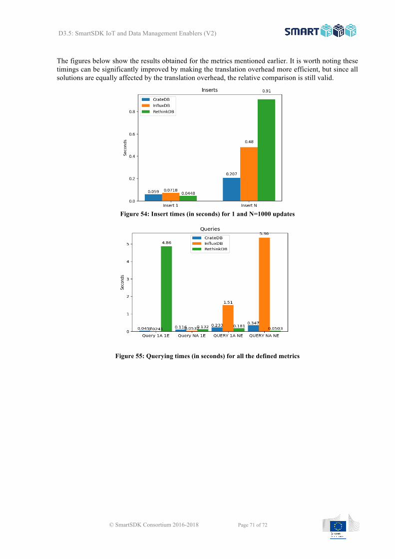
D3.5: SmartSDK IoT and Data Management Enablers (V2)
© SmartSDK Consortium 2016-2018 Page 71 of 72
The figures below show the results obtained for the metrics mentioned earlier. It is worth noting these timings can be significantly improved by making the translation overhead more efficient, but since all solutions are equally affected by the translation overhead, the relative comparison is still valid.
Figure 54: Insert times (in seconds) for 1 and N=1000 updates
Figure 55: Querying times (in seconds) for all the defined metrics

D3.5: SmartSDK IoT and Data Management Enablers (V2)
© SmartSDK Consortium 2016-2018 Page 72 of 72
Figure 56: Aggregation (mean) times (in seconds) for attributes of 1 and N=1000 entities
The benchmark was executed on a MacbookPro (early 2015) with a 2.7 GHz Intel Core i5 processor and 8 GB 1867 MHz DDR3 RAM running macOS Sierra v10.12.4 (16E195). The following table shows the database versions used in the comparison, which was, in all cases, the latest available at that time.
InfluxDB CrateDB RethinkDB
Version 1.2.2 1.0.5 2.3.5
Official Docker Image
61a53f6a13f2 ae465cbdc754 c5ed876750b4
Table 4: Tested database versions
A.3 Conclusions The main findings extracted from the analysis of both the obtained metrics and the implementation experience with each database can be summarized as follows.
The first observation is regarding the lack of support from InfluxDB to having either geodata storage or multiple columns for storing datetimes. Even though it proved to have good insert and query times for single attributes, this lack of support for geodata and extra datetime columns ended up being a showstopper. Moreover, it is clear from Error! Reference source not found. that InfluxDB is not well at responding to queries of the type: Give me all attributes of Entity X. This is because its index is “measurements” centric, which are equivalent to NGSI’s attributes. Hence, it works better with queries like: give me all temperatures for Entities X.
RethinkDB on the other hand does support geodata attributes, although not as good as CrateDB does RethinkDB on the other hand does support geodata attributes, although not as good as CrateDB does [15]. For example, ReQL geometry objects are not pure GeoJSON objects so further conversions are required, and not all geometry types are supported.