daniel t. kettler compensation for beating heart...
TRANSCRIPT

Shelten G. YuenDaniel T. KettlerPaul M. NovotnyRichard D. PlowesRobert D. Howe�School of Engineering and Applied Sciences,Harvard University,Cambridge, MA 02138,[email protected]
Robotic MotionCompensation forBeating HeartIntracardiac Surgery
Abstract
3D ultrasound imaging has enabled minimally invasive, beating heartintracardiac procedures. However, rapid heart motion poses a seriouschallenge to the surgeon that is compounded by significant time de-lays and noise in 3D ultrasound. This paper investigates the conceptof using a one-degree-of-freedom motion compensation system to syn-chronize with tissue motions that may be approximated by 1D motionmodels. We characterize the motion of the mitral valve annulus andshow that it is well approximated by a 1D model. The subsequent de-velopment of a motion compensation instrument (MCI) is described,as well as an extended Kalman filter (EKF) that compensates forsystem delays. The benefits and robustness of motion compensationare tested in user trials under a series of non-ideal tracking condi-tions. Results indicate that the MCI provides an approximately 50%increase in dexterity and 50% decrease in force when compared witha solid tool, but is sensitive to time delays. We demonstrate that theuse of the EKF for delay compensation restores performance, even insituations of high heart rate variability. The resulting system is testedin an in vitro 3D ultrasound-guided servoing task, yielding accuratetracking (1.15 mm root mean square) in the presence of noisy, time-delayed 3D ultrasound measurements.
KEY WORDS—medical robotics, motion compensation, ul-trasound.
The International Journal of Robotics ResearchVol. 00, No. 00, Xxxxxxxx 2009, pp. 000–000DOI: 10.1177/0278364909104065c� The Author(s), 2009. Reprints and permissions:http://www.sagepub.co.uk/journalsPermissions.nav
1. Introduction
Real-time 3D ultrasound (3DUS) imaging has enabled newsurgical procedures within the beating heart that are not pos-sible with current endoscopic technology (Cannon et al. 2003�Suematsu et al. 2005). These procedures eliminate the need forcardiopulmonary bypass and its attendant side effects, such asincreased stroke risk, decline in cognitive performance, delayof neural development in children, and damage to the majorvessels (Zeitlhofer et al. 1993� Bellinger et al. 1999� Murkinet al. 1999). Beating heart procedures also make the real-time evaluation of structural modifications possible while theheart continues to function. The benefits of such proceduresare clear� however, the rapid motion of the heart poses seri-ous challenges to the surgeon. This is especially true of proce-dures involving intracardiac structures such as the mitral valve,which recoils rapidly with every heartbeat. In order to realizethe potential of minimally invasive beating heart mitral valveprocedures, the difficulty of manipulating tissues undergoingfast motion must be addressed.
One appealing approach to the beating heart repair of in-tracardiac structures is robotic assistance to the surgeon. Inthis setting, the surgeon uses a handheld robotic instrumentthat tracks the fast motion of the heart so that the operation isperformed on an effectively stopped heart (i.e. as if the heartwere not beating). This is similar to previously proposed mo-tion compensation systems in which the surgeon could inter-act with the heart on a supported moving platform (Trejos etal. 1999) or teleoperate on a “virtually” stopped heart (Naka-mura et al. 2001� Ortmaier et al. 2005� Ginhoux et al. 2006�Bebek and Cavusoglu 2007). This approach should be distin-guished from the recent clinical application of commercial sur-
� Also with the Harvard-MIT Division of Health Sciences and Technology,Cambridge, MA 02139, USA.
1
The International Journal of Robotics Research OnlineFirst, published on May 19, 2009 as doi:10.1177/0278364909104065
2 THE INTERNATIONAL JOURNAL OF ROBOTICS RESEARCH / Xxxxxxxx 2009
gical robots in performing minimally invasive mitral valve re-pair, with a stopped heart and cardiopulmonary bypass (Re-ichenspurner et al. 2005�Woo et al. 2006). Prior work on beat-ing heart motion compensation has largely focused on the de-velopment of robust tracking controllers intended for multi-degree-of-freedom (DOF) robot manipulators and extracardiacprocedures. However, implementing a full six-DOF robot forintracardiac applications has a number of challenges, includingthe development of a manipulator with sufficient mechanicalbandwidth, creating a wrist that can operate in the restrictedworkspace within the beating heart, and ensuring safety for acomplex manipulator system. These requirements are far be-yond the capabilities of current commercial surgical robots.
Another major consideration for beating intracardiac pro-cedures is guidance inside of the heart, which requires imag-ing tissue through blood in real-time. Currently, 3DUS is theonly technology that has these capabilities: endoscopic sys-tems are obscured by blood, and computed tomography andmagnetic resonance imaging are not yet able to image at thespeeds necessary for beating heart surgery. 3DUS also easesthe difficulties in spatial perception experienced with tradi-tional 2D ultrasound (Cannon et al. 2003). However, for allof its advantages, the acquisition and processing of 3DUSvolumes introduces a substantial time delay, during whichtime the annulus can recoil over the majority of its trajec-tory (Novotny 2007). Servoing a robot with these measure-ments directly would result in large errors that could damagethe valve and nearby structures.
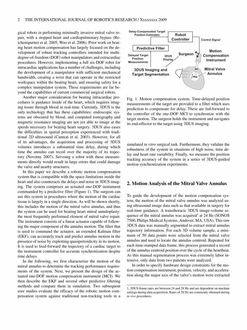
In this paper we describe a robotic motion compensationsystem that is compatible with the space limitations inside theheart and also counteracts the delays and noise in 3DUS imag-ing. The system comprises an actuated one-DOF instrumentcommanded by a predictive filter (Figure 1). The surgeon canuse this system in procedures where the motion of the cardiactissue is largely in a single direction. As will be shown shortly,this includes the motion of the mitral valve annulus, and thusthe system can be used for beating heart mitral annuloplasty:the most frequently performed element of mitral valve repair.The instrument consists of a linear actuator capable of follow-ing the major component of the annulus motion. The filter thatis used to command the actuator, an extended Kalman filter(EKF), can accurately track and predict annulus motion in thepresence of noise by exploiting quasiperioidicity in its motion.It is used to feed-forward the trajectory of a cardiac target tothe instrument controller for accurate synchronization despitetime delays.
In the following, we first characterize the motion of themitral annulus to determine the tracking performance require-ments of the system. Next, we present the design of the ac-tuated one-DOF motion compensation instrument (MCI). Wethen describe the EKF and several other predictive filteringmethods and compare them in simulation. Two subsequentuser studies evaluate the efficacy of the robotic motion com-pensation system against traditional non-tracking tools in a
Fig. 1. Motion compensation system. Time-delayed positionmeasurements of the target are provided to a filter which usesprediction to compensate for delay. These are fed-forward tothe controller of the one-DOF MCI to synchronize with thetarget motion. The surgeon holds the instrument and navigatesits end-effector to the target using 3DUS imaging.
simulated in vitro surgical task. Furthermore, they validate therobustness of the system in situations of high noise, time de-lay and heart rate variability. Finally, we measure the positiontracking accuracy of the system in a series of 3DUS-guidedmotion synchronization experiments.
2. Motion Analysis of the Mitral Valve Annulus
To guide the development of the motion compensation sys-tem, the motion of the mitral valve annulus was analyzed us-ing ultrasound image data such as that available in surgery forreal-time guidance. A transthoracic 3DUS image-volume se-quence of the mitral annulus was acquired1 at 24 Hz (SONOS7500, Philips Medical Systems, Andover, MA, USA). This raw3DUS data was manually segmented to extract mitral annulustrajectory information. For each 3D volume sample, a mini-mum of 50 data points were selected from the mitral valveannulus and used to locate the annulus centroid. Repeated foreach time-stamped data frame, this process generated a recordof the annulus centroid position over the cycle of the heartbeat.As this manual segmentation process was extremely labor in-tensive, only data from two patients were analyzed.
In order to specify hardware design constraints for the mo-tion compensation instrument, position, velocity, and accelera-tion along the major axis of the valve’s motion were extracted
1. 3DUS frame rates are between 24 and 28 Hz and are dependent on machinesettings during data acquisition. Rates of 28 Hz are commonly obtained duringin vivo procedures.

Yuen, Kettler, Novotny, Plowes, and Howe / Robotic Motion Compensation for Beating Heart Intracardiac Surgery 3
Fig. 2. Orthogonal views of 3DUS tracking data centroid posi-tions plotted in principal component axes. The axes are scaledin millimeters. Note the dominance of motion in the first com-ponent.
from these data. Using singular value decomposition (SVD),a line was fit to each data set. The relative sizes of the singu-lar value associated with each orthonormal basis vector gen-erated by SVD (i.e. 21.75, 5.49, 2.97) suggest that the valve’smotion is strongly constrained to a principal axis (Figure 2).Furthermore, working with sheep, Gorman et al. (1996) gen-erated tracking data which indicates that rotational movementsaround this primary axis are also negligible. Subsequent analy-sis presented here will therefore focus on the component ofmotion along this primary axis.
Velocity and acceleration were estimated by consideringthe relative motion between 3DUS data samples. This methodprovided mitral valve velocity and acceleration maxima of ap-proximately 210 mm s�1 and approximately 3.8 m s�2, respec-tively, with a total travel of approximately 20 mm at a heart rateof 76 beats per minute (bpm). While only two subjects wereanalyzed in this fashion, work by Kamigaki and Goldschlager(1972) on the mitral valve leaflets reports similar velocity andamplitude results.
The major frequency components of motion were also re-viewed using spectral decomposition (Figure 3). This analy-sis indicates major motion components at 1.3, 2.6, and 5.2 Hzwith further components of decreasing amplitude at higher fre-quencies. This is consistent with the findings of Nakamuraet al. (2001) which show dominant frequency components of1.5 and 3.0 Hz in the motion of porcine epicardium. Gin-houx et al. (2006) found the same major frequency compo-nents in the motion of porcine epicardium. This paper alsonoted higher-frequency transients that it deemed significantand concluded that a 25 Hz sampling rate would be insufficientto track the motion of the epicardium with high precision (Gin-houx et al. 2006). Bebek and Cavusoglu (2007) found similarfrequency components, but concluded that the motion couldbe adequately characterized using lower sampling frequencies,i.e. 26 Hz.
Fig. 3. 3DUS tracking data spectral decomposition. Motionamplitudes decrease quickly with increasing frequency.
Fig. 4. Diagram of proposed surgical procedure. The anchordriver approaches along the valve’s axis, which corresponds tothe valve’s major component of motion.
3. Motion Compensation Instrument Design
The MCI developed here is an actuated handheld or robot-mounted minimally invasive tool to aid surgeons in workingon the moving mitral valve. Rather than attempting to correctfor motion components in all three dimensions, the objectivewas to develop a device that could compensate for the ma-jor component of motion and allow surgeons and passive tis-sue compliance to counter the slow or relatively minor mo-tions along the remaining two axes. The surgical procedurethat we are developing for this purpose is a modification of aminimally invasive beating heart procedure for the repair of

4 THE INTERNATIONAL JOURNAL OF ROBOTICS RESEARCH / Xxxxxxxx 2009
Fig. 5. MCI design and prototype. A, MCI actuation package. The MCI may be mounted by its base (at the upper left of theimage) to a robot or handle. The surgical anchor driver is mounted on the linear slide carriage. B, MCI hardware prototype.
atrial–septal defects (Vasilyev et al. 2006). In the new pro-cedure, the instrument will be inserted through the left atrialappendage and controlled by a pursestring suture. A customannuloplastry ring will be inserted through an adjacent inci-sion and positioned over the mitral annulus (Figure 4). Theactuated instrument will be tipped with a modified 14 gaugeneedle (OD � 0�083 in) that will deploy anchors to “staple”the annuloplasty ring to the annulus (Wagner et al. 2006). Thesurgeon will then maneuver the ring and anchor driver to theappropriate locations over the annulus and repeatedly fire theanchor driver to attach the ring and reshape the annulus.
The selection of the mechanical mechanism to follow thelinear motion component of the mitral valve annulus wasguided by the clinical 3DUS trajectory analysis from Sec-tion 2. The high velocity and acceleration requirements leadto a linear motor-based design which benefits from low fric-tion and low moving mass (Figure 5). This design format alsoproduces a surgical tool similar in design and function to typ-ical endoscopic tools, supported by a port and maneuvered byhand. Consequently, the MCI will be intuitive to operate fortrained endoscopic surgeons.
The MCI uses a voice coil motor (NCC20-18-020-1X,H2W Technologies, Inc., Valencia, CA, USA) and a high lin-earity potentiometer (P3 America, San Diego, CA, USA) forposition sensing. These components are mounted on a lin-ear ball-bearing stage (BX4-3, Tusk Direct, Inc., Bethel, CT,USA). The MCI prototype has a 5.4 cm range of motion and ispowered by a linear power amplifier (BTA-28V-6A, PrecisionMicroDynamics, Victoria, BC, Canada). PID servo control isimplemented in a 1 kHz servo loop on a personal computerunder Windows XP. The MCI is interfaced to this computerthrough a data acquisition card (PCI-60-40E, National Instru-ments, Corp., Austin, TX, USA).
The resulting system has the characteristics required totrack the mitral valve. The MCI has demonstrated velocitiesand accelerations as high as approximately 290 mm s�1 and
Fig. 6. Frequency response of the MCI. The system is over-damped and has a �3 dB point of 20.6 Hz.
approximately 17.5 m s�2, respectively. Controller gains werehand tuned to achieve good stiffness and response. To avoidpotentially dangerous overshoot and instability, the system isoverdamped. The tool has a static stiffness of 0.23 N mm�1
and a friction force less than 0.009 N. The system’s frequencyresponse is similarly adequate for the tracking task (Figure 6).The system has a �3 dB point of 20.6 Hz and roll-off rate of40 dB per decade. The potentiometer on the MCI is capable ofmeasuring position with a root mean square error (RMSE) ofless than 0.01 mm. The system is capable of maintaining sta-tionary at a commanded position with a RMSE of 0.009 mm.
The tracking abilities of the MCI were demonstrated bycommanding the system to follow the motion of a mitral valveat 60 bpm (Figure 7). Mitral motion was determined from

Yuen, Kettler, Novotny, Plowes, and Howe / Robotic Motion Compensation for Beating Heart Intracardiac Surgery 5
Fig. 7. The MCI tracking a simulated mitral valve trajectory.The MCI motion profile closely mimics that of the target withan approximately 14 ms delay.
the 3DUS data above (Figure 2). The MCI reliably replicatedthe motion profile of the valve with an effective delay of14 ms.
4. Time Delay Compensation
The time delay that is intrinsic to 3DUS makes direct servoingof the MCI from this signal potentially dangerous. A previouscharacterization of the acquisition, transmission, and computa-tion times for 3DUS estimated delays of approximately 70 ms,a sufficient amount of time for the mitral valve annulus to tra-verse the majority of its path (Novotny 2007). For the purposesof illustration, an example of the error for MCI tracking a mi-tral valve target with a 75 ms measurement delay is shown inFigure 8. The rapid recoil of the valve associated with ven-tricular relaxation (100–200 ms in Figure 8) results in a large(approximately 14 mm) tracking error that would cause the in-strument to pierce and damage the tissue target.
4.1. Predictive Filters
To avoid this outcome, we exploit the near periodicity of themitral valve trajectory to predict its path and hence compensatefor time delay. However, such predictions must be made in thepresence of measurement noise and a potentially variable heartrate. Here we describe and evaluate several predictive filteringmethods that can be employed for delay compensation in thissetting: an autoregressive (AR) filter, a fading memory ARfilter, and an EKF with a quasiperiodic motion model. The ARfilter has previously been applied by Nakamura et al. (2001) ina spectral analysis of heart motion for motion compensation incoronary artery bypass graft (CABG) procedures. In principle,this method is equivalent to the adaptive harmonic filter bank
used by Ginhoux et al. (2006) for CABG and has its atten-dant assumption of a fixed heart rate. The fading memory ARfilter overcomes this limitation despite using the same modelby exponentially discounting the measurements supplied to thefilter, thereby allowing it to adjust to more recent informa-tion. This approach has been used for motion synchronizationin CABG by Franke et al. (2007). In contrast, the EKF per-mits variations to heart rate by directly accounting for it in atime-varying Fourier series model. A similar model was em-ployed by Riviere et al. (1998) in the weighted Fourier linearcombiner (WFLC) estimator for CABG� however, unlike theEKF, this method does not explicitly model noise. Ortmaier etal. (2005) has evaluated other non-linear prediction techniquesfor CABG such as artificial neural networks and an estimatorbased on Takens theorem.
4.1.1. AR Model with Least Squares Estimator
Fixed-rate mitral valve motion can be modeled as an n-orderAR model
y[k] �n�
i�1
�i y[k � i]� (1)
where �i , i � �1� � � � � n�, are the model coefficients and y[k]is the target position at time sample k. Note that rather thanexplicitly assuming periodicity in the target motion, this modelpredicates that the kth position can be expressed as a linearcombination of the previous n positions.
In order to predict the target position, the model coefficientsand order must be estimated. The first can be achieved in real-time using the recursive covariance method estimator. Denot-ing z[k] � y[k]��[k] as the noise-corrupted position measure-ment at time sample k with �[k] � �0� � 2
R
�, this estimator
is expressed compactly in matrix form as
�[k] � [z[k � n � 1]� � � � � z[k � 1]] �
�[k] � �[k � 1]��[k]T�[k]� (2)
�[k] � �[k � 1]��[k]�1�[k]T
� �z[k]�� �[k � 1]
�� (3)
with initial conditions �[0] � 0 and �[0] � 0. An appropri-ate AR model order was determined using the Akaike infor-mation criteria on the mitral valve annulus trajectory in Fig-ure 2, yielding n � 30. Predicted target locations, y[k], can beobtained through evaluation of (1). In addition, the target tra-jectory can be interpolated from its inherent measurement rate(i.e. 28 Hz, a typical 3DUS frame rate) to the higher controlrate of the robot using the Whittaker–Shannon interpolationformula.

6 THE INTERNATIONAL JOURNAL OF ROBOTICS RESEARCH / Xxxxxxxx 2009
Fig. 8. MCI tracking of a mitral valve target with 75 ms measurement delay. A, MCI and target positions. B, Tracking error. Notethat the additional 14 ms response time of the MCI yields an effective delay of 89 ms. Maximum and RMS tracking errors are14.49 and 4.60 mm, respectively.
4.1.2. AR Model with Fading Memory Estimator
Imperfect periodicity can cause the AR model coefficients tochange over time. In this situation, it can be useful to pref-erentially weight recent measurements over those in the past:otherwise the filter becomes progressively less responsive tonew data and (3) does not update � because �[k]�1�T � 0as k � . Exponential weighting of previous measurementsin the iterative least squares estimator is achieved through asimple modification of (2):
�[k] � f�[k � 1]��[k]T�[k]�
where 0 � f � 1 is the so-called fading factor. Choosingf � 1 recovers the estimator of Section 4.1.1 while choosingf � 0 increases the speed by which previous measurementsare discounted. To distinguish between the two estimators, weterm the former the AR filter and the latter the fading AR filterfor the remainder of this section. As can be imagined, reducingthe contribution of previous measurements ( f � 1) can bedesirable if the trajectory evolves through time, although doingso incurs increased estimation error when the trajectory is nottime varying.
4.1.3. Time-varying Fourier Series Model with EKF
The spectral analysis of mitral valve annulus motion from Sec-tion 2 suggests that its motion may be approximated by a lim-ited number of harmonics. Consider a perfectly periodic mo-tion model obtained by an m-order Fourier series with a con-stant offset
y�t� � c �m�
i�1
ri sin�it � i �� (4)
where y�t� is the position in ultrasound coordinates, is theheart rate, c is the constant offset, and ri and i are the har-monic amplitudes and phases, respectively. Accurate modelingof quasiperiodicity requires a more flexible model in which theheart rate and signal morphology can evolve over time. Usingthe parametrization of Parker and Anderson (1990), the trajec-tory can be expressed as the following time-varying Fourierseries
y�t� � c�t��m�
i�1
ri �t� sin � i �t�, (5)
where � i �t� � i� t
0 ��� d� � i�t� and all other parametersare the time-varying equivalents to those in (4).
Defining the state vector ��t� � [c�t�� ri�t�� �t�� � i �t�]T,
i � �1� � � � �m� and assuming that c�t�� ri �t�� �t�, and i �t�evolve through a random walk, the state space model for thissystem is
��t � t� � � � t���t�� ��t�z�t� � h���t��� ��t�,
where
� � t� �
������������������
�m�1 0
1
t 1
0 2 t 0 1
���� � �
m t 1
�
�
Yuen, Kettler, Novotny, Plowes, and Howe / Robotic Motion Compensation for Beating Heart Intracardiac Surgery 7
h���t�� � y�t� from (5), ��t� � �0� � 2R
�is zero mean
Gaussian measurement noise, and ��t� � �0��� is the ran-dom step of the states assumed to be drawn from a zero meanmultivariate normal distribution with covariance matrix�.
Prediction with this model requires estimation of the 2m�2parameters in ��t�� a non-linear estimation problem owingto the measurement function, h���t��. We employ the EKF,a non-linear filtering method that approximates the Kalmanfilter through linearization about the current state estimate��t � t�. The EKF can be computed in real-time using the re-cursion
� �t � t � t� � �� �t � t�� T ��
S � � 2R ��� �t � t � t��T
� � � �t � t � t��T S�1
��t � t � t � t� � � ��t � t����z�t � t�� h�� ��t � t���
� �t � t � t � t� � �� ����� �t � t � t�,
where
�T ���h
��
�T ��t� t�t��� ��t�t�
�
������������������������������
1
sin �1�t � t � t�
���
sin �m�t � t � t�
0
r1�t � t � t� cos �1�t � t � t�
���
rm�t � t � t� cos �m�t � t � t�
�
,
and ��� � E� ���� ����T �denotes the state estimate covari-
ance, whose initialization is described later in this section.Note that the time dependencies for � , , S, and � havebeen dropped for notational convenience. The EKF as pre-sented here is a slight variant on that first introduced by Parkerand Anderson (1990).
To initialize this filter, we first assume that y�t� has constantfundamental frequency yielding N noisy measurements overthe interval t � [0� N t]. Observation of Figure 3 indicatesthat the dominant frequency peak is the fundamental frequency
of the signal (i.e. heart rate). We apply a fast Fourier transform(FFT) to the data sequence with a Hamming window to obtainthe power spectrum. The maximum frequency peak within areasonable human heart rate range (0.5 to 2.5 Hz) is used toinitialize the estimate of 0 � �t � N t�.
Assuming 0 to be correct, the problem can be rewritten asa linear estimation problem to obtain the harmonic amplitudesand coefficients. Equation (4) is equivalently reparametrizedas
y�t� � c0 �m�
i�1
�ai sin�i 0t�� bi cos�i 0t�
�. (6)
Collecting the measurements z�t�, 0 � t � N t we have�� � �0 � �, where �� � [z�0�� z� t�� � � � � z�N t�]T,�0 � [c0� a1� � � � � am� b1� � � � � bm]T, � is a vector of measure-ment noise, and
�T �
�������������������������
1 1 � � � 1
sin� 00� sin� 0 t� � � � sin� 0 N t�
������
���
sin�m 00� sin�m 0 t� � � � sin�m 0 N t�
cos� 00� cos� 0 t� � � � cos� 0 N t�
������
���
cos�m 00� cos�m 0 t� � � � cos�m 0 N t�
�
,
to which the least squares estimate is obtained as ��0 �� T ��1 T ��. ��T �T � is then initialized with the valuesc�T � � c0, �T � � 0, ri �T � � � a2
i � b2i ��1�2, and
� i �T � � arctan� bi � ai �. The state estimate covariance is set to �T �T � � diag[� 2
R�N� � 21� �
21�2
2� � � � � � 21�m2� � 2
� 0�02 rad2�� � � � 0�02 rad2]. The relationship between the amplitude uncer-tainties is chosen to reflect the decreasing harmonic strengthseen in Figure 3, while the phase uncertainties follow thoseused in (Parker and Anderson 1990). Parameters � 2
1 and � 2
are determined through experimentation. Last we assume thatthe process noise covariance � is diagonal with all values setto 10�4 except for q, the entry corresponding to �t�.
4.2. Simulation Studies
Three simulation studies were conducted to evaluate the ca-pabilities of the EKF, AR filter, and fading AR filter to theprimary sources of random error in the system: measurementnoise and heart rate variability. For illustrative purposes, thefilters were also compared with the WFLC estimator (Riviereet al. 1998) and a simpler method of using the previous cardiac

8 THE INTERNATIONAL JOURNAL OF ROBOTICS RESEARCH / Xxxxxxxx 2009
Fig. 9. RMS prediction error results for parametric simulation studies. A, Error for varying measurement noise� B, error for stepheart rate changes.
cycle trajectory for the prediction of the next. A more sophis-ticated version of the latter method, called the last cycle here,was used successfully in a beating heart tracking system (Be-bek and Cavusoglu 2007).
In the first simulation, we subjected the predictors to vary-ing levels of measurement noise on a fixed-rate trajectory (60bpm). The mitral annulus trajectory of Figure 2 was reinterpo-lated to 28 Hz and corrupted by additive zero-mean Gaussiannoise with standard deviation 0�3 � � R � 3 mm. Each predic-tor was then given 30 sec of data to initialize and performancewas judged for the following 10 sec on 1-sample ahead predic-tions.
The RMSEs for each predictor averaged across 100 MonteCarlo trials are shown in Figure 9A. The EKF, WFLC, AR,and fading AR filtering methods clearly give higher-accuracypredictions than the inherent uncertainty of the measurements,with the EKF doing the best. As expected, the last cyclemethod had error statistics equal to � R since it attempts nosmoothing. It should be noted that the fading AR filter wastuned with f � 0�985 in order to achieve errors that are ap-proximately equal to � R . This setting represents the lowestreasonable value for the fading AR filter since a lower valuewould give performance below the last cycle method. The EKFwas run with m � 8 harmonics, N � 280 initialization points(10 seconds), � 2
1 � 2 mm2, � 2 � 0�11 �rad/s�2 (roughly twice
the frequency resolution of the FFT), and q � 10�3 �rad/s�2.The WFLC was initialized in the same manner as the EKF, runwith m � 8 harmonics, and experimentally set with its adap-tive gain parameters �0 � 7 � 10�6 and �1 � 0�03 for bestperformance in this and subsequent simulations.
In a second parametric simulation study, we gauged thetolerance of each predictor to a sudden change in heart rate.A trajectory was assembled by piecing together 30 secondsof heart motion at 60 bpm and 10 seconds of motion at�60 � HR� bpm. The second portion of the trajectory was
generated by compression/dilation of the target trajectory inFigure 2 to obtain the desired heart rate. Like before, the com-posite trajectory was reinterpolated to 28 Hz and corruptedwith � R � 1�30 mm noise� the measured uncertainty of the3DUS annulus estimates (Novotny 2007). The last 10 sec-onds were used to evaluate performance. A reasonable rangeof �10 bpm � HR � 10 bpm was determined from clinicalRR data (Figure 10), which is discussed later.
Figure 9B shows the mean RMSEs for each predictor across100 Monte Carlo trials. The EKF provided better predictionsthan the other four methods. It was also the only method thatyielded sub-� R error for the majority of heart rate changes.The WFLC had similar accuracies to the EKF at small HRbut showed slow convergence to the new heart rate for HR �4 bpm. As expected, the accuracy of the AR filter also ap-proached that of the EKF for small HR and quickly degradedas HR increased. Exponential weighting of the measure-ments allowed the filter to adjust to changes in the trajectory, asdemonstrated by the fading AR filter’s superior performanceover the AR filter for large HR. However, this adaptabilitydecreased accuracy when the trajectory did not change sig-nificantly. Finally, the last cycle method showed performancecomparable to the fading AR filter. For this simulation all filterparameters were chosen to be the same as in the previous sim-ulation, with the exception of q � 5 � 10�3 (rad/s)2 and� 2 � 1 (rad/s)2 for the EKF.
Finally, to investigate the performance of each predictor tothe more realistic case of a continuously changing heart rate,we modulated the period of the annulus trajectory with clini-cally obtained cardiac cycle records. Annotated ECG recordsfor five human subjects were selected from the MIT–BIH Nor-mal Sinus Rhythm Database (Goldberger et al. 2000) and com-posite mitral valve trajectories were generated in a mannersimilar to the previous simulation study. Noise-corrupted mea-surements were generated as before, with � R � 1�30 mm.

Yuen, Kettler, Novotny, Plowes, and Howe / Robotic Motion Compensation for Beating Heart Intracardiac Surgery 9
Fig. 10. Heart rate statistics on five human subjects. A, Distribution of beat-to-beat variation� B, subject-specific mean � onestandard deviation� C, heart rate data for subject 1.
Fig. 11. Comparison of prediction error results on clinical data using last cycle, WFLC, AR filter, fading AR filter, and EKF:A, RMSE� B, maximum absolute error.
Summary statistics for each subject are presented in Fig-ure 10B and an example of the beat-to-beat heart rate for sub-ject number 1 is shown in Figure 10C.
Results from this study indicate that the EKF is more suitedto tracking and prediction in this application than the other
four methods because it adjusts to rapid changes in heart ratethrough explicit modeling of quasiperiodicity (Figure 11). In-terestingly, the AR filter showed moderately better perfor-mance than the fading AR filter. The reason for this is thatthe AR filter locked on to an “average” trajectory for each

10 THE INTERNATIONAL JOURNAL OF ROBOTICS RESEARCH / Xxxxxxxx 2009
subject while the fading AR filter continuously readjusted tomore recent noisy data. Ultimately, deviations from the “aver-age” motion were less than the measurement noise. The lastcycle method performed worse for similar reasons: persistentvariations in heart rate and measurement noise degraded theaccuracy of the previous cycle as a predictor for the next. Theslow convergence of the WFLC to changing heart rates causedit to have severely degraded performance.
5. Performance Evaluation in a Surgical Task
In order to quantify the amount of assistance that motion com-pensation provides to operators working on a moving target,we conducted two studies of user performance with the MCIin an in vitro setting. These studies additionally provide insighton how sensitive performance is to potential shortcomings ofa 3DUS-guided system. Specifically, user study 1 determinedthe extent to which user performance is dependent on time de-lay and random positional error. These error types are of inter-est because both positional precision errors and computationaldelays develop while generating 3DUS tracking data in real-time. User study 2 investigated user performance with EKFdelay compensation on targets with both fixed and variableheart rates. Subjects performed a drawing task on a movingtarget using the MCI under different tracking conditions. A to-tal of 18 test subjects (14 male and 4 female, aged 22 to 36� 8subjects for user study 1 and 10 subjects for user study 2) vol-untarily participated following informed consent under a pro-tocol approved by the University Institutional Review Board.
5.1. Experimental Setup
The tests were run on a setup which emulates the intendedsurgical environment. To simulate the moving mitral valve, atarget platform was mounted on a cam-driven device that repli-cates the 1D motion of the mitral annulus centroid as measuredfrom the 3DUS tracking data. During trials, a paper targetwas affixed to this platform to record the subject’s drawing. A0.5 cm hard foam rubber pad between the target paper and tar-get platform provided a small measure of compliance. In com-bination with the pen used in the trials, the pad had a stiffnessof 4.5 N mm�1. For the purposes of this experiment, the camwas used to simulate a heart rate of 60 bpm. Opposite the targetplatform, the MCI was mounted in a gimbal allowing both an-gular motion and translation towards and away from the target(Figure 12). A rod was mounted on the MCI with a ballpointpen affixed to one end and a force sensor incorporated alongits length. The force sensor had a stiffness of 10 N mm�1. Inplace of the 3DUS-based tracking and controls algorithms thatwould be used in surgery, target position was directly mea-sured at 1 kHz by a contact arm with a potentiometer attachedto the target platform. This sensing method provided the robust
Fig. 12. User trial setup. The bold arrow indicates the cyclicalmotion of the simulated valve target. The tool shaft has freerotational and sliding motion at the fixed support point.
tracking data necessary to evaluate the efficacy of MCI mitralvalve tracking and the performance of predictive filtering al-gorithms.
5.2. User Task
Subjects were instructed to draw a circle on the moving targetplatform. The circle must be drawn between two concentrictarget circles with 2.29 and 2.92 cm diameters. Subjects startedat the top of the circle and proceeded in the clockwise direc-tion. If the pen bounced off the target surface or outside the tar-get circles, the subject was instructed to continue drawing fromthe clockwise-most mark they made between the target circles.Subjects could only draw around the circle once. They couldnot go back to draw in gaps they originally missed. To pre-vent subjects from spending an inordinate amount of time onthe task, a 25-second time limit was set. All subjects finishedevery trial before the time expired.
Both dexterity and force metrics were used to evaluate sub-ject performance. In all trials, the quality of each circle drawnwas characterized by digitally scanning the target and com-puting the drawn line’s “angular surround” value. This valueindicates what percentage of 360 discrete 1� arc segments theuser’s line covered between the two concentric target circles.This metric reflects positioning accuracy both in the plane ofthe target and in tracking the motion of the target perpendicularto this plane. If the user-drawn line strayed from the concentrictarget circles, it did not contribute to the angular surround met-ric and resulted in a lower score. Similarly, if the user and MCIwere unable to track the motion of the target, the pen tendedto bounce off of the target surface, producing widely spacedmarks and a low angular surround score.
The axial force applied by the subject to the target was alsorecorded for 4 of the 8 test subjects in user study 1 and 9 of

Yuen, Kettler, Novotny, Plowes, and Howe / Robotic Motion Compensation for Beating Heart Intracardiac Surgery 11
the 10 subjects in user study 2. In all 18 cases, subjects wereinformed of both evaluation metrics. They were instructed thattheir foremost objective was to draw continuous circles con-forming to the angular surround metric and only secondly touse the minimum amount of force necessary.
This task was selected to emulate the motion requirementsof placing a surgical anchor. In order to apply the surgical an-chors developed for this procedure, the tip of the anchor driver,consisting of 14 gauge hypodermic tubing, must be accuratelylocated and pressed against the target surface with a force of atleast 1.5 N (Wagner et al. 2006). This contact must be main-tained for several seconds as the surgeon inserts the anchor,tests whether it is deployed properly, and then releases the an-chor. This process requires a combination of accuracy and pro-longed contact with the surface. At the same time, forces mustbe minimized so as not to cause damage to the valve.
5.3. User Study 1: Tracking with Time Delay and PositionalError
Subjects of this study completed the task under eight differenttracking conditions. In the “solid” condition, the motion of theMCI was rigidly locked in order to simulate a traditional, solidendoscopic tool. For the “baseline” MCI tracking condition,the current position of the target (RMSE � 0�015 mm) wassent to the MCI as a position command. This baseline con-dition resulted in a 14 ms delay. The remaining six trackingconditions were divided into two groups of three conditionscorresponding to differing levels of the considered error.
Random positional error was simulated by the superposi-tion of a time-varying error value with the cam position com-mand used in the baseline tracking state. A new positional er-ror was calculated at 8 Hz. These errors were uniformly dis-tributed random values ([�1� 1]), multiplied by an amplitudefactor of 0.35, 0.70, or 1.05 mm.
Delay error was implemented by recording the cam track-ing position and holding it for a specified period before send-ing this position to the MCI as a motion command. For this setof trials, the three levels of added delay used were 25, 35, and45 ms. Including the MCI lag time of 14 ms, the effective delaysettings were 39, 49, and 59 ms. This range of times was cho-sen as representative of the imaging and transmission delaysassociated with real-time 3DUS-guided procedures (Novotnyet al. 2007).
5.4. User Study 2: Delay-compensated Tracking with HeartRate Variation and Measurement Noise
To test the EKF under conditions similar to those seen in3DUS-guided procedures, the 1 kHz measurements of targetposition were downsampled to 28 Hz and corrupted by additiveGaussian noise ~� �0� 1�302 mm
�(Novotny 2007). The target
was commanded to beat at 60 bpm or with a variable rate thathad additive Gaussian beat-to-beat fluctuations � �0� � 2
HR
�.
Finally, a time delay of 39, 59, or 89 ms was injected into themeasurements to simulate the delays encountered with 3DUS.Note that the 89 ms delay exceeds the delays used in userstudy 1 to also account for the additional computational delaysfrom instrument and target segmentation in 3DUS (Novotny2007).
Overall, the subjects of this study performed the task un-der 10 tracking conditions, all with varying amounts of timedelay. Three tracking conditions evaluated user performancewith EKF delay compensation against 39, 59, and 89 ms time-delayed, noise-corrupted measurements on a 60 bpm target.For comparison, three tracking conditions were conducted onthe same set of delays but without delay compensation andwithout measurement noise.
The remaining four tracking conditions evaluated user per-formance with EKF delay compensation on a variable heartrate target. Measurements were delayed by 89 ms and noise-corrupted. The four levels of beat-to-beat variation were cho-sen as �HR � �1�0� 2�0� 3�0� 4�0� bpm. These values span thoseobserved in the clinical RR data from Section 4.2. An illustra-tive example of this tracking condition with �HR � 4�0 bpmand the subsequent behavior of the EKF and the MCI is shownin Figure 13.
5.5. Testing Protocol
Each subject test consisted of a practice period followed by thetrials corresponding to the tracking conditions of their study.Practice was intended to familiarize the test subject with theMCI and the evaluation task in order to bring subjects to a uni-form level of ability and to limit learning effects during trials.Practice was divided into three one-minute segments duringwhich the subject was free to experiment with using the MCIto draw on a target paper. During the first minute of training,the target was stationary and the tool was set in the solid con-dition. The second minute of training involved a moving tar-get and a solid tool. In the third and final minute, the targetwas moving and the MCI was in the baseline tracking condi-tion. Following the completion of training, each test subjectran through the trials corresponding to the tracking conditionsof their study. The order in which these conditions were ad-ministered was varied between trials using a balanced Latinsquare to minimize the effects of between-trial carry-over andlearning on collected data.
The means of collected angular surround error metricwere compared for statistically significant differences usingthe SPSS statistical analysis software package (Version 14.0,SPSS Inc., Chicago, IL, USA). These comparisons were madeusing t-tests and analysis of variance (ANOVA) with a leastsignificant difference (LSD) post hoc test. In all cases, sig-nificance corresponds to p � 0�05.

12 THE INTERNATIONAL JOURNAL OF ROBOTICS RESEARCH / Xxxxxxxx 2009
Fig. 13. Variable heart rate tracking condition (�HR � 4�0). A, Noise-corrupted, time-delayed measurements and the resultingEKF predictions� B, MCI position and the true position of the target.
Fig. 14. Targets with median angular surround scores under solid (A), baseline (B), and 59 ms time-delayed (C) tracking condi-tions. The baseline circle is the most continuous and round. While the solid target has more continuous lines than the time-delayedtarget, it also has heavy dots and dimpling indicative of high forces.
5.6. User Study 1 Results
The results of this study indicate that the MCI can provide sig-nificant assistance while operating on a moving target. Fig-ure 14 shows typical target results. Mean angular surroundmetric scores (Figure 15) for the baseline tracking condition(81�9� 4�5% (mean � standard error)) were over 50% greaterthan for the solid condition (53�8 � 5�0%), with clear statis-tical significance (t �14� � 0�1987, p � 0�0009). Similarly,axial force data indicates that subjects applied less than 50%as much force and spent less time at elevated forces under thebaseline MCI tracking condition. Aggregating the data fromall four subjects (Figure 16), the 90th percentile for force sam-ples using the solid tool (17.5 N) is roughly double the 90thpercentile for the baseline tracking condition (8.5 N).
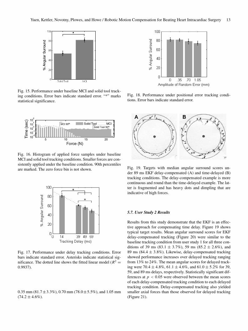
A comparison of mean angular surround metric scores re-lated to the amount of delay error (Figure 17) demonstrates de-creases in performance ranging from 67% to 33% with increas-ing delay ( f �3� 28� � 16�005, p � 0�001). Statistically sig-nificant differences were indicated between the baseline con-dition and tracking with delays of 39 ms (61�2� 1�5%), 49 ms(56�0 � 3�7%), and 59 ms (48�8 � 3�8%). A significant dif-ference also exists between the means of the 39 and 59 mstracking conditions (p � 0�02). Trend analysis indicates thatthe data is well fit by a linear model (p � 0�001).
An analysis of mean angular surround metric scores relatedto positional error did not demonstrate significant differencesunder ANOVA analysis ( f �3� 28� � 0�638, p � 0�597). Asseen in Figure 18, the mean score under the baseline conditiondiffered very little from those with error amplitude factors of
Yuen, Kettler, Novotny, Plowes, and Howe / Robotic Motion Compensation for Beating Heart Intracardiac Surgery 13
Fig. 15. Performance under baseline MCI and solid tool track-ing conditions. Error bars indicate standard error. “*” marksstatistical significance.
Fig. 16. Histogram of applied force samples under baselineMCI and solid tool tracking conditions. Smaller forces are con-sistently applied under the baseline condition. 90th percentilesare marked. The zero force bin is not shown.
Fig. 17. Performance under delay tracking conditions. Errorbars indicate standard error. Asterisks indicate statistical sig-nificance. The dotted line shows the fitted linear model (R2 �0�9937).
0.35 mm (81�7�3�3%), 0.70 mm (78�0�5�5%), and 1.05 mm(74�2� 4�6%).
Fig. 18. Performance under positional error tracking condi-tions. Error bars indicate standard error.
Fig. 19. Targets with median angular surround scores un-der 89 ms EKF delay-compensated (A) and time-delayed (B)tracking conditions. The delay-compensated example is morecontinuous and round than the time-delayed example. The lat-ter is fragmented and has heavy dots and dimpling that areindicative of high forces.
5.7. User Study 2 Results
Results from this study demonstrate that the EKF is an effec-tive approach for compensating time delay. Figure 19 showstypical target results. Mean angular surround scores for EKFdelay-compensated tracking (Figure 20) were similar to thebaseline tracking condition from user study 1 for all three con-ditions of 39 ms (83�1 � 3�7%), 59 ms (85�2 � 2�6%), and89 ms (84�4 � 3�8%). Likewise, delay-compensated trackingshowed performance increases over delayed tracking rangingfrom 13% to 24%. The mean angular scores for delayed track-ing were 70�4� 4�8%, 61�1� 4�6%, and 61�0� 5�2% for 39,59, and 89 ms delays, respectively. Statistically significant dif-ferences at p � 0�05 were observed between the mean scoresof each delay-compensated tracking condition to each delayedtracking condition. Delay-compensated tracking also yieldedsmaller axial forces than those observed for delayed tracking(Figure 21).

14 THE INTERNATIONAL JOURNAL OF ROBOTICS RESEARCH / Xxxxxxxx 2009
Fig. 20. Performance with EKF delay compensation and with-out. Error bars indicate standard error. Asterisks indicate sta-tistical significance.
Fig. 21. Force application with and without delay compensa-tion for delays of (A) 39 ms, (B) 59 ms, and (C) 89 ms. Smallerforces are consistently applied under the delay-compensatedtracking conditions. The zero force bin is not shown.
An analysis of mean angular surround metric scores relatedto heart rate variability did not demonstrate significant differ-ences under ANOVA analysis ( f �3� 36� � 0�705, p � 0�555).As seen in Figure 22, the performance against a fixed-rate tar-get was comparable to that against a variable rate target with�HR equal to 1�0 bpm (85�9� 2�6%), 2�0 bpm (84�1� 2�9%),3�0 bpm (80�5� 3�6%), and 4�0 bpm (81�5� 2�5%).
Fig. 22. Performance under variable heart rate tracking condi-tions. Error bars indicate standard error.
6. System Accuracy Under 3D UltrasoundGuidance
Water tank experiments were conducted to measure the mo-tion synchronization accuracy of the system under 3DUS guid-ance. To do these, a real-time 3DUS target segmentation algo-rithm was first incorporated into the system to provide posi-tion measurements to the EKF. The target was set to be an�-shaped fiducial that can be easily mounted to an annulo-plasty ring (Figure 23B). This fiducial was specifically cho-sen because detecting two intersecting lines is suited for anexisting real-time 3DUS segmentation algorithm based on themodified Radon transform (Novotny 2007). This algorithm isknown to provide target position measurements with 1.30 mmRMS accuracy under in vitro conditions. Because higher noisemay be present in vivo, we also tested this system in two othernoise conditions in which large Gaussian terms � �0� � �,� � �2�0� 3�0� mm were added to the segmented target po-sitions. This yielded three noise conditions with overall RMSaccuracies of � R � �1�30� 3�30� 4�30� mm. We anticipate invivo noise levels to be less than 3.5 mm RMS.
6.1. Experimental Setup
The target and instrument were imaged by a real-time 3DUSprobe in a water tank at 28 Hz (Figure 23A). Data wasstreamed from the ultrasound machine (SONOS 7500, PhilipsMedical, Andover, MA) to a computer over an ethernetconnection. The stream was captured by the computer andpassed to a graphics processing unit (8800GTS, nVidia Corp,Santa Clara, CA) where the volumes were automaticallysegmented using the modified Radon transform segmenta-tion algorithm (Novotny 2007) to obtain target position mea-surements. The measurements were corrupted with additiveGaussian noise (depending on the noise condition), then

Yuen, Kettler, Novotny, Plowes, and Howe / Robotic Motion Compensation for Beating Heart Intracardiac Surgery 15
Fig. 23. (A) Setup for motion synchronization experiments and (B) X-shaped fiducial target.
passed to a third thread for EKF processing. This returned pre-dicted target positions 82 ms in the future (68 ms from imagingand segmentation, 14 ms from instrument lag time) and weresent to the 1 kHz PID control loop for the robot.
Five motion synchronization trials were conducted pernoise condition. The target simulated mitral valve motion at60 bpm with the cam-driven mechanism described in Sec-tion 5.1. MCI position and true target position were measuredat 1 kHz with potentiometers and stored for offline process-ing. Target measurements and EKF predictions were acquiredat the 3DUS sampling rate (28 Hz) and stored as well. Ac-curacy evaluation was performed on the 20 s of tracking datafollowing 20 s of EKF initialization.
6.2. Results
Results from this experiment demonstrate that the motioncompensation system is robust to the noise levels present in3DUS imaging. Typical data and results for each noise condi-tion are shown in Figure 24 and overall performance is sum-marized in Figure 25. Mean RMS accuracies for EKF predic-tions were 1�01 � 0�02, 1�08 � 0�03, and 1�22 � 0�05 mmfor � R � �1�30� 3�30� 4�30� mm (respectively) and showedstatistically significant reductions in measurement error (p �0�0001 for each case). Mean MCI synchronization errors were1�15 � 0�04, 1�23 � 0�06, and 1�28 � 0�10 mm RMS for thethree noise conditions. The mean RMSE added to the systemfrom the MCI following the prescribed EKF trajectory was0�14�0�01 mm and this difference was statistically significant(p � 0�002). The RMS noise accuracy for the �-tracking al-gorithm observed across all 15 trials was 1�30 � 0�01 mm, inagreement with previous reports (Novotny 2007).
7. Discussion
User trials demonstrate that the motion compensation systemdescribed here is an effective aid for surgical tasks on beatingmitral valve targets. Motion synchronization allowed users tooperate with both increased dexterity and reduced forces. Inuser study 1, the angular surround scores indicative of dexter-ity increased by approximately 50% between the solid tool andbaseline tracking conditions while the 90th percentile for forcedecreased by a similar ratio. These performance gains weremaintained when increasing levels of positional error were in-serted into the system, but disappeared when uncompensatedtime delays were added to the tracking data.
The strong dependence of user performance on delay em-phasizes that precise timing is essential for successful motioncompensation. Left uncompensated, tracking delays producedserious errors during the rapid recoil of the target associatedwith the relaxation of the left ventricle. During this motion thevalve moves towards the operator, nearly covering its entire18 mm range of motion. Owing to the delay, the MCI con-tinued to servo towards the oncoming target and abruptly col-lided with it. Qualitatively, while subjects did not always no-tice added positional error, they universally correctly identifiedand expressed dismay over tracking delay.
The introduction of a predictive EKF into the system ef-fectively removed the performance decrease associated withtracking delays. The angular surround scores for delay-compensated tracking conditions exceeded their respective de-layed tracking conditions by 13% to 24%, depending on thedegree of delay. The forces applied in the delay-compensatedconditions also decreased relative to the delayed conditions,although to a lesser extent than seen between baseline track-ing and the solid tool. The delay-compensated scores of userstudy 2 marginally exceeded the baseline scores of user study 1by an amount that is consistent with the removal of the MCI’s14 ms lag time (as predicted by the linear model from user

16 THE INTERNATIONAL JOURNAL OF ROBOTICS RESEARCH / Xxxxxxxx 2009
Fig. 24. Examples of data, filtering, and motion tracking results. Left column shows measurements from 3DUS target seg-mentation and EKF predicted target trajectories for each noise condition: (A) � R � 1�30 mm� (C) � R � 3�30 mm� and(E) � R � 4�30 mm. Corresponding MCI and true target trajectories for each noise condition are shown in the right column:(B) � R � 1�30 mm� (D) � R � 3�30 mm� (F) � R � 4�30 mm.
Fig. 25. EKF prediction performance and MCI tracking per-formance over three increasing noise conditions. Error bars in-dicate standard error.
study 1). However, caution must be taken when making a di-rect comparison of the angular surround scores between userstudies 1 and 2 because of differing amounts of in-trial training(8 trials in user study 1 and 10 trials in user study 2). It is rea-sonable to conclude that EKF delay compensation restored theMCI tracking performance to at least baseline tracking condi-
tions in cases of delay. Moreover, the performance increasesobserved for delay-compensated tracking showed no degrada-tion across the range of time delays expected for 3DUS-guidedprocedures.
Surprisingly, the levels of random positional error exploredin the user studies had a negligible effect on the benefitsof MCI tracking. No statistically significant differences werefound between user performance under all three positional er-ror conditions and the baseline condition. This result suggeststhat if the timing with the valve’s sudden recoil is maintained,the value of the MCI’s tracking is robust in the face of posi-tional errors as high as�1 mm. This may be attributed, in part,to compliance in the system: in the MCI’s mechanism and inthe foam pad on the target platform, which introduce compli-ance similar in nature to that in the heart. An in vivo character-ization of MCI performance is necessary to determine whethercompliance acts in the same way to assist operation on the mi-tral valve annulus.
Heart rate variations in the target motion also providedno significant degradation in user performance over the clin-ically obtained beat-to-beat statistics (Figure 10). This is notsurprising given that the EKF estimates did not degrade onthese levels of heart rate variation. In some respects, track-ing a variable rate target was another approach to injecting

Yuen, Kettler, Novotny, Plowes, and Howe / Robotic Motion Compensation for Beating Heart Intracardiac Surgery 17
positional error into the system since the filter remained inphase with the target (see, for instance, Figure 13). We antici-pate that extremely large beat-to-beat variations will cause theEKF to break synchronization with the target as the lineariza-tion of the measurement function, h���t��, becomes inappro-priate. Should more aggressive heart rate variations be encoun-tered in future in vivo experiments, there are several potentialroutes for improvement. First, heart rate variability could bereduced through drug treatment and/or electrical pacing of theheart. Second, following Bebek and Cavusoglu (2007), ECGinformation could be used to obtain direct measurements ofheart rate. This could reduce the effect of the non-linearityin h���t�� since, as mentioned before, perfect knowledge of�t� turns this into a linear estimation problem (6). Note thatthe EKF, a non-linear filtering approach, would still be usefulwith these measurements because they are sampled at discreteintervals but �t� is continuous.
The efficacy of this motion compensation system is basedon the assumption that the motion which must be tracked ismodeled well by a 1D approximation. Previous research onaugmenting surgical procedures with robotic tracking havefocused on coronary artery bypass grafting, requiring a 3Dmodel of surface motion (Nakamura et al. 2001� Ortmaier etal. 2005� Ginhoux et al. 2006� Bebek and Cavusoglu 2007).The characterization of the mitral valve annulus motion aboveshows that the fast motion of the mitral valve is primarily alongone axis� however, we also observe approximately 2 mm ofoff-axis motion (Figure 2). Our preliminary tests suggest thatthe passive compliance of the mitral valve annulus and the sur-geon’s hand will assist with these minor off-axis deviations. Inaddition, in vivo conditions will present slow out-of-axis mo-tions owing to the respiration of the subject. Fortunately, sur-geons already overcome this in current heart procedures, eitherby manually compensating for the slow motion or momentar-ily stopping the controlled ventilation to the patient.
In this work, particular emphasis has been placed on predic-tive filtering to mitigate the dominant sources of tracking er-ror in the system: 3DUS delay and noise. Using this approachwith the MCI in a 3DUS-guided servoing task, we achievedsynchronization accuracies of less than 1.3 mm RMS in thepresence of large measurement noise (1.3–4.3 mm RMS) and82 ms of system delay. This is a significant improvement overthe approximately 4.6 mm RMSEs that would be incurred ina time-delayed but otherwise noiseless tracking system. Al-though errors in the current system are low, there is potentialfor further lowering error through a more sophisticated con-troller. Repetitive control methods are well suited for quasi-periodic servoing tasks (Hara et al. 1988� Chew and Tomizuka1990�Kempf et al. 1993�Horowitz 1993) and model predictivecontrol has shown promising results in external beating hearttracking (Ginhoux et al. 2006� Bebek and Cavusoglu 2007).These techniques may reduce the 0.14 mm tracking error thatis attributable to the PID controller used in the current sys-tem.
Acknowledgements
This work is supported by the US National Institutes of Healthunder grant NIH R01 HL073647-01. The authors wouldlike to thank the test subjects who graciously donated theirtime to this study, and Nikolay Vasilyev, Pedro J. del Nido,Mahdi Tavakoli, Peter Hammer, and Petr Jordan for many in-sightful medical and technical conversations.
References
Bebek, O. and Cavusoglu, M. (2007). Intelligent control al-gorithms for robotic assisted beating heart surgery. IEEETransactions on Robotics, 23(3): 468–480.
Bellinger, D., Wypij, D., Kuban, K., Rappaport, L., Hickey,P., Wernovsky, G., Jonas, R. and Newburger, J. (1999). De-velopmental and neurological status of children at 4 yearsof age after heart surgery with hypothermic circulatory ar-rest or low-flow cardiopulmonary bypass. Circulation, 100:526–532.
Cannon, J., Stoll, J., Salgo, I., Knowles, H., Howe, R., Dupont,P., Marx, G. and del Nido, P. (2003). Real-time three-dimensional ultrasound for guiding surgical tasks. Com-puter Aided Surgery, 8(2): 82–90.
Chew, K. K. and Tomizuka, M. (1990). Digital control ofrepetitive errors in disk drive systems. IEEE Control Sys-tems Magazine, 10(1): 16–20.
Franke, T., Bebek, O., and Cavusoglu, C. (2007). Improvedprediction of heart motion using an adaptive filter for ro-bot assisted beating heart surgery. Proceedings of IEEE In-telligent Robots and Systems (IROS ’07), San Diego, CA,pp. 509–515.
Ginhoux, R., Gangloff, J., de Mathelin, M., Soler, L., Sanchez,M. A. and Marescaux, J. (2006). Active filtering of physi-ological motion in robotized surgery using predictive con-trol. IEEE Transactions on Robotics, 21(1): 27–79.
Goldberger, A., Amaral, L., Glass, L., Hausdorff, J., Ivanov,P., Mark, R., Mietus, J., Moody, G., Peng, C.-K. and Stan-ley, H. (2000). PhysioBank, PhysioToolkit, and PhysioNet:components of a new research resource for complex physi-ologic signals. Circulation, 101(23): e215–e220.
Gorman, J., III, et al. (1996). Dynamic three-dimensionalimaging of the mitral valve and left ventricle by rapid so-nomicrometry array localization. Journal of Thoracic andCardiovascular Surgery, 112(3): 712–726.
Hara, S., Yamamoto, Y., Omata, T. and Nakano, M. (1988).Repetitive control system: a new type servo system for pe-riodic exogenous signals. IEEE Transactions on AutomaticControl, 33(7): 659–668.
Horowitz, R. (1993). Learning control of robot manipulators.Journal of Dynamic Systems, Measurement, and Control,115(2B): 402–411.

18 THE INTERNATIONAL JOURNAL OF ROBOTICS RESEARCH / Xxxxxxxx 2009
Kamigaki, M. and Goldschlager, N. (1972). Echocardio-graphic analysis of mitral valve motion in atrial septal de-fect. American Journal of Cardiology, 30: 343–348.
Kempf, C., Messner, W. C., Tomizuka, M. and Horowitz, R.(1993). Comparison of four discrete-time repetitive controlalgorithms. IEEE Control Systems Magazine, 13(6): 48–54.
Murkin, J., Boyd, W., Ganapathy, S., Adams, S. and Peterson,R. (1999). Beating heart surgery: why expect less centralnervous system morbidity? Annals of Thoracic Surgery, 68:1498–1501.
Nakamura, Y., Kishi, K. and Kawakami, H. (2001). Heartbeatsynchronization for robotic cardiac surgery. Proceedings ofIEEE International Conference on Robotics and Automa-tion (ICRA’01), pp. 2014–2019.
Novotny, P. (2007). Real-time processing of three dimensionalultrasound for intracardiac surgery. PhD Thesis, HarvardUniversity.
Novotny, P., Stoll, J., Vasilyev, N., del Nido, P., Zickler, T.,Dupont, P. and Howe, R. (2007). GPU based real-time in-strument tracking with three-dimensional ultrasound. Med-ical Image Analysis, 11: 458–464.
Ortmaier, T., Groger, M., Boehm, D., Falk, V. and Hirzinger,G. (2005). Motion estimation in beating heart surgery. IEEETransactions on Biomedical Engineering, 52(10): 1729–1740.
Parker, P. and Anderson, B. (1990). Frequency tracking of non-sinusoidal periodic signals in noise. Signal Processing, 20:127–152.
Reichenspurner, H., Detter, C., Deuse, T., Boehm, D., Treede,H. and Reichart, B. (2005). Video and robotic-assisted min-imally invasive mitral valve surgery: a comparison of theport-access and transthoracic clamp techniques. Annals ofThoracic Surgery, 79(2): 485–490.
Riviere, C., Rader, R. and Thakor, N. (1998). Adaptive can-celling of physiological tremor for improved precision inmicrosurgery. IEEE Transactions on Biomedical Engineer-ing, 45(7): 839–846.
Suematsu, Y., Martinez, J., Wolf, B., Marx, G., Stoll, J.,DuPont, P., Howe, R., Triedman, J. and del Nido, P. (2005).Three-dimensional echo-guided beating heart surgery with-out cardiopulmonary bypass: atrial septal defect closure ina swine model. Journal of Thoracic and CardiovascularSurgery, 130: 1348–1357.
Trejos, A., Salcudean, S., Sassani, F. and Lichtenstein, S.(1999). On the feasibility of a moving support for surgeryon the beating heart. Medical Image Computing andComputer-Assisted Intervention (MICCAI’99), pp. 1088–1097.
Vasilyev, N., Martinez, J., Freudenthal, F., Suematsu, Y., Marx,G. and del Nido, P. (2006). Three-dimensional echo andvideocardioscopy-guided atrial septal defect closure. An-nals of Thoracic Surgery, 82(4): 1322–1326.
Wagner, C., Perrin, D., Vasilyev, N., del Nido, P. and Howe, R.(2006). Force feedback in a three-dimensional ultrasound-guided surgical task. Proceedings of 14th Symposium onHaptic Interfaces for Virtual Environments and Teleoper-ator Systems. IEEE Computer Society Press, Washington,DC, pp. 43–48.
Woo, Y., Rodriguez, E., Atluri, P., and Chitwood, W., Jr(2006). Minimally invasive, robotic, and off-pump mitralvalve surgery. Seminars in Thoracic and CardiovascularSurgery, 18(2): 139–147.
Zeitlhofer, J., Asenbaum, S., Spiss, C., Wimmer, A., Mayr, N.,Wolner, E. and Deecke, L. (1993). Central nervous systemfunction after cardiopulmonary bypass. European HeartJournal, 14: 885–890.