darmstadt university of technology
TRANSCRIPT
Darmstadt University of Technology
Department of Computer ScienceTelecooperation
Prof. Dr. Max Muhlhauser
Diploma Thesis
MICON: A Music Stand forInteractive Conducting
Advisors: Prof. Dr. Max MuhlhauserProf. Dr. Jan Borchers
Aristotelis Hadjakos
May 2006

i
Contents
Ehrenwortliche Erklarung v
Abstract vii
Zusammenfassung ix
Acknowledgements xi
1 Introduction 1
1.1 Motivation . . . . . . . . . . . . . . . . . . . . . . . . . . . . . 1
1.2 Overview . . . . . . . . . . . . . . . . . . . . . . . . . . . . . . 2
1.3 Proposed System . . . . . . . . . . . . . . . . . . . . . . . . . 3
2 Related Work 5
2.1 Electronic Music Stands . . . . . . . . . . . . . . . . . . . . . 5
2.1.1 MOODS . . . . . . . . . . . . . . . . . . . . . . . . . . 5
2.1.2 muse . . . . . . . . . . . . . . . . . . . . . . . . . . . . 6
2.1.3 eStand . . . . . . . . . . . . . . . . . . . . . . . . . . . 6
2.2 Interactive Conducting Systems . . . . . . . . . . . . . . . . . 7
ii Contents
2.2.1 The Radio-Baton . . . . . . . . . . . . . . . . . . . . . 7
2.2.2 The MIDI Baton . . . . . . . . . . . . . . . . . . . . . . 8
2.2.3 Computer Music System which Follows a HumanConductor . . . . . . . . . . . . . . . . . . . . . . . . . 8
2.2.4 Light Baton . . . . . . . . . . . . . . . . . . . . . . . . 9
2.2.5 Conductor Follower . . . . . . . . . . . . . . . . . . . 9
2.2.6 The Digital Baton . . . . . . . . . . . . . . . . . . . . . 9
2.2.7 The Conductor’s Jacket . . . . . . . . . . . . . . . . . 9
2.2.8 Multi-Modal Conducting Simulator . . . . . . . . . . 11
2.2.9 Virtual Conducting Practice Environment . . . . . . . 11
2.2.10 Interactive Virtual Ensemble . . . . . . . . . . . . . . 12
2.2.11 DIVA’s Virtual Orchestra . . . . . . . . . . . . . . . . 12
2.2.12 Conducting Gesture Recognition, Analysis and Per-formance System . . . . . . . . . . . . . . . . . . . . . 13
2.2.13 Personal Orchestra and WorldBeat . . . . . . . . . . . 13
WorldBeat . . . . . . . . . . . . . . . . . . . . . . . . . 13
Virtual Conductor . . . . . . . . . . . . . . . . . . . . 13
You’re the Conductor . . . . . . . . . . . . . . . . . . 14
Maestro . . . . . . . . . . . . . . . . . . . . . . . . . . 15
3 Requirements 17
3.1 Design Goals . . . . . . . . . . . . . . . . . . . . . . . . . . . . 17
3.2 Design Philosophy . . . . . . . . . . . . . . . . . . . . . . . . 18
3.2.1 Design Patterns . . . . . . . . . . . . . . . . . . . . . . 18
Contents iii
3.2.2 Design Patterns in Personal Orchestra . . . . . . . . . 22
3.2.3 Design Principles . . . . . . . . . . . . . . . . . . . . . 24
4 Design of the MICON 27
4.1 Functional Design . . . . . . . . . . . . . . . . . . . . . . . . . 27
4.1.1 Piano Roll . . . . . . . . . . . . . . . . . . . . . . . . . 27
4.1.2 Pulse Notation . . . . . . . . . . . . . . . . . . . . . . 30
4.1.3 Combining Piano Roll and Pulse Notation . . . . . . 31
4.1.4 Score . . . . . . . . . . . . . . . . . . . . . . . . . . . . 32
4.1.5 Combining Score and Pulse Notation . . . . . . . . . 35
4.2 Aesthetic Design . . . . . . . . . . . . . . . . . . . . . . . . . 37
4.2.1 Score . . . . . . . . . . . . . . . . . . . . . . . . . . . . 37
4.2.2 Piano Roll . . . . . . . . . . . . . . . . . . . . . . . . . 42
4.2.3 Pulse . . . . . . . . . . . . . . . . . . . . . . . . . . . . 43
4.2.4 MICON Display Options . . . . . . . . . . . . . . . . 45
4.3 Integrating MICON and Maestro . . . . . . . . . . . . . . . . 48
5 Content Creation 51
5.1 Score Information Model . . . . . . . . . . . . . . . . . . . . . 52
5.2 ScoreMarker . . . . . . . . . . . . . . . . . . . . . . . . . . . . 54
5.2.1 Creating the ScoreInfo file . . . . . . . . . . . . . . . . 54
5.3 Creating the MIDI file . . . . . . . . . . . . . . . . . . . . . . 55
5.4 Creating the Beats file . . . . . . . . . . . . . . . . . . . . . . . 57
iv Contents
6 Implementation 59
6.1 MICON . . . . . . . . . . . . . . . . . . . . . . . . . . . . . . . 60
6.1.1 File Formats . . . . . . . . . . . . . . . . . . . . . . . . 60
Beats File . . . . . . . . . . . . . . . . . . . . . . . . . . 60
ScoreInfo File . . . . . . . . . . . . . . . . . . . . . . . 61
6.1.2 Communication . . . . . . . . . . . . . . . . . . . . . . 63
6.1.3 Assembling the Representations . . . . . . . . . . . . 63
Score . . . . . . . . . . . . . . . . . . . . . . . . . . . . 64
Pulse . . . . . . . . . . . . . . . . . . . . . . . . . . . . 67
Piano Roll . . . . . . . . . . . . . . . . . . . . . . . . . 68
6.1.4 Score Rendering . . . . . . . . . . . . . . . . . . . . . 69
6.1.5 System Architecture . . . . . . . . . . . . . . . . . . . 72
7 Evaluation 75
7.1 Testing the MICON with Experts . . . . . . . . . . . . . . . . 75
7.1.1 Effects on the Final MICON Version . . . . . . . . . . 77
7.2 Presentation at the Hessische Rundfunk . . . . . . . . . . . . 78
8 Summary 81
A ScoreMarker—A Tutorial 83
B Screenshots 91
Bibliography 109

v
Ehrenwortliche Erklarung
Hiermit versichere ich, die vorliegende Diplomarbeit ohne Hilfe Dritterund nur mit den angegebenen Quellen und Hilfsmitteln angefertigt zu ha-ben. Alle Stellen, die aus den Quellen entnommen wurden, sind als sol-che kenntlich gemacht worden. Diese Arbeit hat in gleicher oder ahnlicherForm noch keiner Prufungsbehorde vorgelegen.
Darmstadt, den 13. Juli 2006

vii
Abstract
The MICON is an electronic music stand extending Maestro, the latest in aseries of interactive conducting exhibits that use real orchestral audio andvideo recordings. The MICON uses OpenGL-based rendering to displayand animate score pages with a high degree of realism. It offers three dif-ferent score display formats to match the user’s level of expertise. An ani-mated visual cueing system helps users with their conducting. The MICONhas been evaluated with music students and has been presented at variousevents, including an one-day exhibition at the Hessischer Rundfunk, a ra-dio and television broadcaster.

ix
Zusammenfassung
Der MICON ist ein elektronischer Notenstander fur Maestro, dem neue-sten einer Reihe von Dirigierexponaten basierend auf echten Video- undAudioaufnahmen. Er nutzt OpenGL fur die realistische Darstellung undAnimation der Partitur und bietet verschiedene Darstellungsformen desmusikalischen Materials fur Benutzer mit verschiedener musikalischer Vor-bildung an. Der Benutzer wird durch animierte visuelle Zeichen beim Di-rigieren unterstutzt. Der MICON wurde mit Musikstudenten getestet undbei verschiedenen Anlassen gezeigt, darunter auch eine Prasentation beimHessischen Rundfunk anlasslich eines Tages der offenen Tur.

xi
Acknowledgements
It has been a big pleasure to create this work and to see people enjoy theexhibit—I have to thank: I thank Prof. Dr. Max Muhlhauser for making itpossible and for his encouragement. I thank Prof. Dr. Jan Borchers for hissupport and his advice. Thank you Henning Kiel and Eric Lee for yourfriendliness, the interesting discussions and for your help getting MICONand Maestro to talk to each other. Thank you Gerhard Austaller for yourfriendly help and for the beautiful installation of the system in the me-dia room. Special thanks go to my parents Birgit and Kyriakos not onlyfor their support during my studies and to my brother Stephanos. Specialthanks go to my wife Won-Kyoung.

1
Chapter 1
Introduction
Some people enjoy to conduct while hearing music on their CD-players.They are involved in the musical process but have no active influence.
This is where Personal Orchestra comes in.
With Personal Orchestra, the user can control some aspects of a real record-ing: The user can control tempo, volume and can put emphasis on an in-strument group. Within boundaries, given by the recording and the limitsof the system, the user can change the expression of the music and becomea more active part of the performance. Personal Orchestra is an interactiveexhibit. Different versions are currently being presented at the HOUSE OFMUSIC in Vienna, at the CHILDREN’S MUSEUM in Boston and at the BETTYBRINN CHILDREN’S MUSEUM in Milwaukee.
This thesis deals with the design of an electronic music stand for PersonalOrchestra: the MICON (Music stand for Interactive CONducting). A paperabout the MICON will be published in NIME 2006 (Borchers, Hadjakos andMuhlhauser [2006]).
1.1 Motivation
The music stand for Personal Orchestra was created in order to enrich theexperience with the notational aspect of music. Furthermore, it should givethe user visual feedback about his actions and support the user while con-ducting. A real conductor, normally, has the score before him while con-
2 1 Introduction
ducting the orchestra. So a music stand for Personal Orchestra, being partof the interaction, would create a more realistic atmosphere.
1.2 Overview
This introduction concludes with the presentation of the proposed system.Chapter 2 presents already existing electronic music stands and gives anoverview of recent Personal Orchestra systems and other interactive con-ducting systems. The requirements for the design of MICON are given inchapter 3. The design considerations and the resulting decisions can befound in chapter 4. Chapter 5 deals with the content creation process forMICON. Chapter 6 gives an overview of the inner workings of the MICON.Chapter 7 evaluates the MICON. Screenshots of the MICON can be foundin appendix B.
1.3 Proposed System 3
1.3 Proposed System
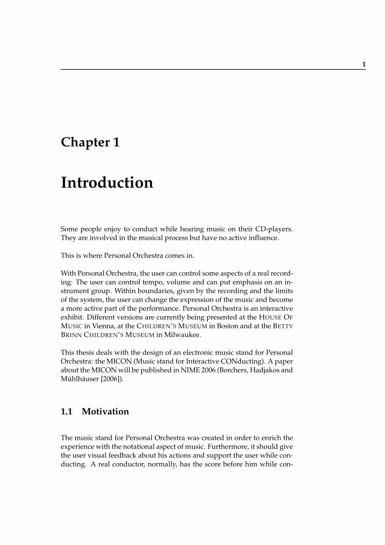
The proposed system (figure 1.1) consists of two parts: Maestro andMICON. Maestro analyzes the conducting and modifies the tempo of themusic with a time-stretching algorithm. The video of the playing orches-tra is also time-modified to fit the tempo. The MICON renders and ani-mates the musical score. Maestro informs MICON over a communicationmedium about the current position, and the MICON renders the appropri-ate section of the score.
Maestro is a modification of the already existing Personal Orchestra sys-tem. Maestro was developed by the Media Computing Group at RWTHAachen.
Maestro MICONcommunication
infraredlight
position,emphasis
infraredsensorx/y position
Figure 1.1: The proposed system

5
Chapter 2
Related Work
2.1 Electronic Music Stands
2.1.1 MOODS
MOODS (Music Object Oriented Distributed System) is a synchronous real-time cooperative editor for music scores, i.e. each performed change is im-mediately made visible to all users. MOODS was created by Bellini et al.[2002]. It is intended to be used by the musicians of an orchestra duringrehearsal.
MOODS consists of three different types of lecterns: DLIOO (distributedlectern interactive object-oriented), MASE (main score editor) and MASAE(main score auxiliary editor). DLIOOs are single part lecterns for the in-strumentalists and are used for editing and visualizing. The MASE is usedby the conductor in order to view and modify the main score. MASAEis a general manager and music editor to be used by the archivist. Thearchivist can make modifications on the main score during rehearsal andscore revision. The system allows not only multiple DLIOOs but also mul-tiple MASEs and MASAEs.
Editing in MOODS is based on different permissions for the archivist, theconductor, the concertmaster and the instrumentalist. MOODS supportssemi-automatic page-turning. The rate of music execution is initially set onthe basis of a metronomic indication in terms of beats per minutes. Thistrend can be adjusted by the operator of the MASAE. The score on theDLIOO is separated horizontally. Below the separator is the score that is
6 2 Related Work
currently being played. Above the separator the next page is being shown.As the music advances, the separator moves downwards. The score on theMASE and the MASAE is separated vertically. The right half shows thecurrent score, and the left half shows the beginning of the next page.
MOODS assumes a constant tempo for a piece; tempo variations have to beadjusted manually by a human operator during the performance making itunsuitable for our purposes.
2.1.2 muse
muse is a digital music stand for musicians in a symphony orchestra(Graefe et al. [1996]). It consists mainly of a portable display and a match-ing stand. It has an integrated metronome with auditive and visual feed-back. It has a pitch-generating tuner. It allows on-screen annotation andhas intrasymphonic communication capabilities. The pages are turned ei-ther automatically or manually.
muse is powered by battery. There is wireless communication betweenthe music librarian’s computer and the muses. This communication is en-crypted to prevent copyright violation. Every muse has an attached mi-crophone. The microphone is needed for the tuner and for automatic pageturning; the sound of the instruments is compared against the score, andthe pages are turned in the appropriate moment.
muse was presented to the musicians of the Pittsburgh Symphony Orches-tra.
muse it does not highlight the current score position, and its page-turningrequires per-instrument microphones making it unsuitable for our pur-poses.
2.1.3 eStand
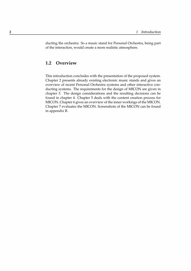
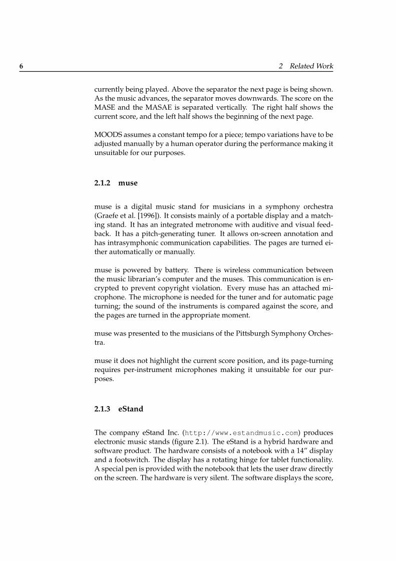
The company eStand Inc. (http://www.estandmusic.com) produceselectronic music stands (figure 2.1). The eStand is a hybrid hardware andsoftware product. The hardware consists of a notebook with a 14” displayand a footswitch. The display has a rotating hinge for tablet functionality.A special pen is provided with the notebook that lets the user draw directlyon the screen. The hardware is very silent. The software displays the score,
2.2 Interactive Conducting Systems 7
Figure 2.1: The eStand
which has to be downloaded from the Internet or created with note-settingsoftware. The musician can turn pages with the footswitch. The musiciancan annotate the score with the provided pen. The eStand has a built-inmetronome and tuning. It also includes music library management. For en-sembles and orchestras, eStand offers networking capabilities: Scores canbe sent to each other, and annotations and comments can be shared.
eStand does not highlight the current position in the score and does notadvance the score automatically making it unsuitable for our purposes.
2.2 Interactive Conducting Systems
2.2.1 The Radio-Baton
The Radio-Baton (Boie et al. [1989], Boulanger and Mathews [1997]) is acontroller for live computer performances. It is a MIDI instrument de-signed to work with MIDI synthesizers and MIDI-based sequencing andprogramming software.
The Radio-Baton system can determine the 3D position of the batons,which are equipped with small radio antennas. A sensor board is equippedwith five receiving antennas. The closer the baton comes to an antenna, thehigher is the intensity of the signal. This effect is used to determine thepositions of the batons.
The Radio-Baton can send trigger signals when the baton hits an imagi-nary plane. Besides sending trigger and position signals to a listening com-
8 2 Related Work
puter, the Radio-Baton processor can also run other programs. In Conduc-tor Mode, the Radio-Baton plays a previously loaded MIDI score accordingto the performer’s conducting gestures by sending MIDI messages to anattached synthesizer.
2.2.2 The MIDI Baton
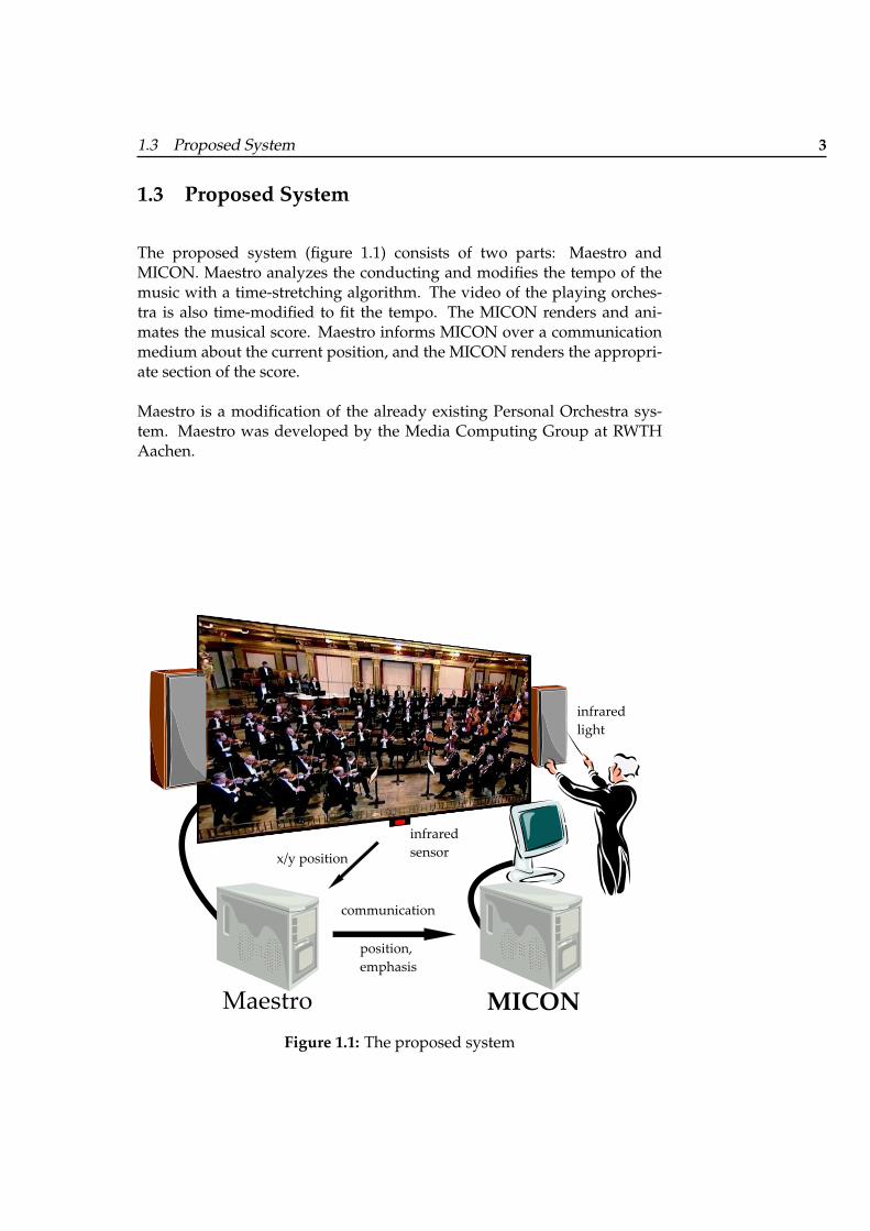
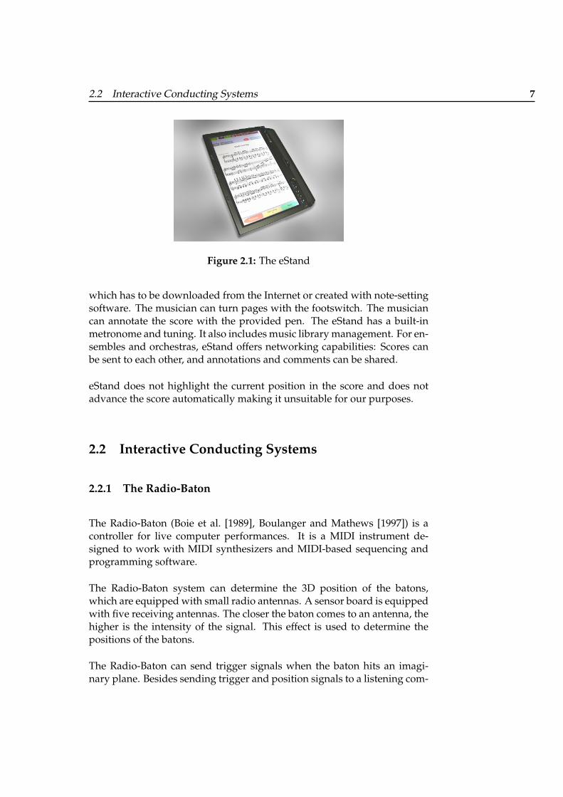
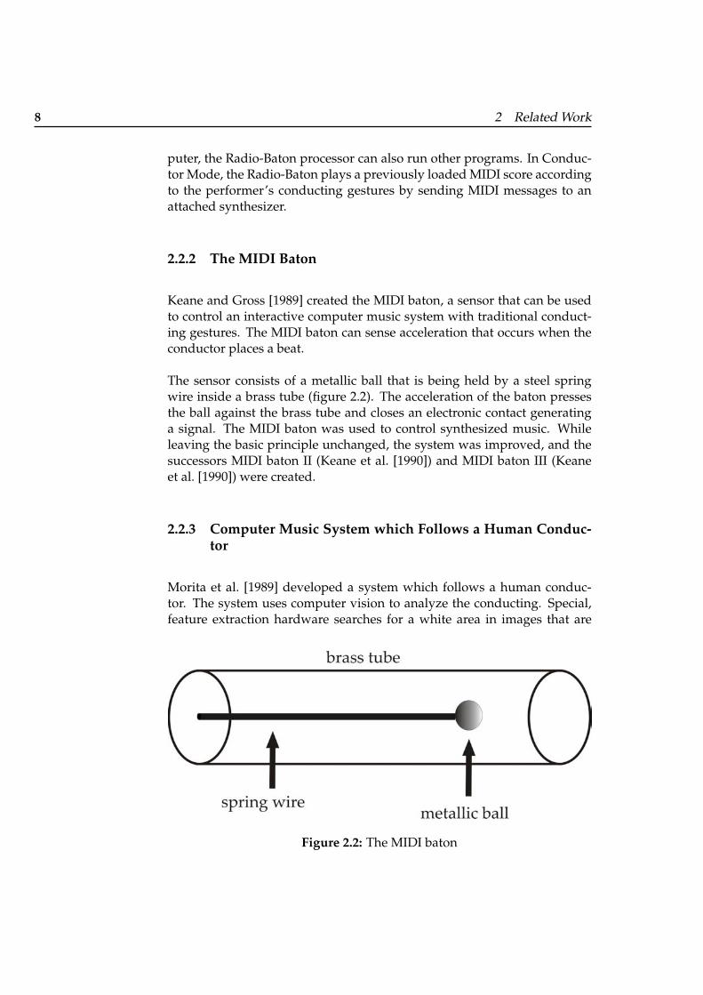
Keane and Gross [1989] created the MIDI baton, a sensor that can be usedto control an interactive computer music system with traditional conduct-ing gestures. The MIDI baton can sense acceleration that occurs when theconductor places a beat.
The sensor consists of a metallic ball that is being held by a steel springwire inside a brass tube (figure 2.2). The acceleration of the baton pressesthe ball against the brass tube and closes an electronic contact generatinga signal. The MIDI baton was used to control synthesized music. Whileleaving the basic principle unchanged, the system was improved, and thesuccessors MIDI baton II (Keane et al. [1990]) and MIDI baton III (Keaneet al. [1990]) were created.
2.2.3 Computer Music System which Follows a Human Conduc-tor
Morita et al. [1989] developed a system which follows a human conduc-tor. The system uses computer vision to analyze the conducting. Special,feature extraction hardware searches for a white area in images that are
Figure 2.2: The MIDI baton
2.2 Interactive Conducting Systems 9
provided by a CCD camera. The tip of the conductor’s baton has a whitemarking attached to it, or the conductor alternatively wears white glovesand conducts without baton. The gesture is a analyzed, and tempo andvolume are derived.
2.2.4 Light Baton
Bertini and Carosi [1992] created the light baton. The system can derivebeat time, beat order and amplitude from traditional conducting gestures.The system also recognizes end of movement and absence of the baton. Thedata is used to control a computer-generated musical performance. The ba-ton they use has a light source attached on the tip. A CCD camera providesthe computer with images of the conducting area, which are examined tofind the position of the baton and to analyze the gesture.
2.2.5 Conductor Follower
The Conductor Follower (Lee et al. [1992], Brecht and Garnett [1995]) usesa Mattel Power Glove and a Buchla Lightning baton for input and createssynthesized MIDI music. The emphasis of the project lies in beat time pre-diction.
2.2.6 The Digital Baton
The Digital Baton was created by Marrin and Paradiso [1997]. It consists ofan infrared LED on the baton’s tip, piezo-resistive strips for finger and palmpressure and three orthogonally placed accelerometers. The position of thebaton is determined by an infrared sensor. The sensor produces horizontaland vertical positioning information; the intensity of the infrared light is arough measure for distance.
2.2.7 The Conductor’s Jacket
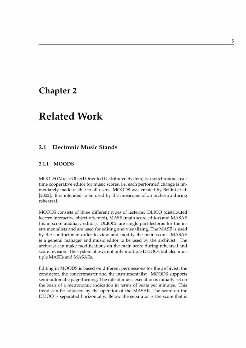
Marrin and Picard [1998] created the Conductor’s Jacket, an array of sen-sors that are built into normal clothing. The sensors are used to collect and
10 2 Related Work
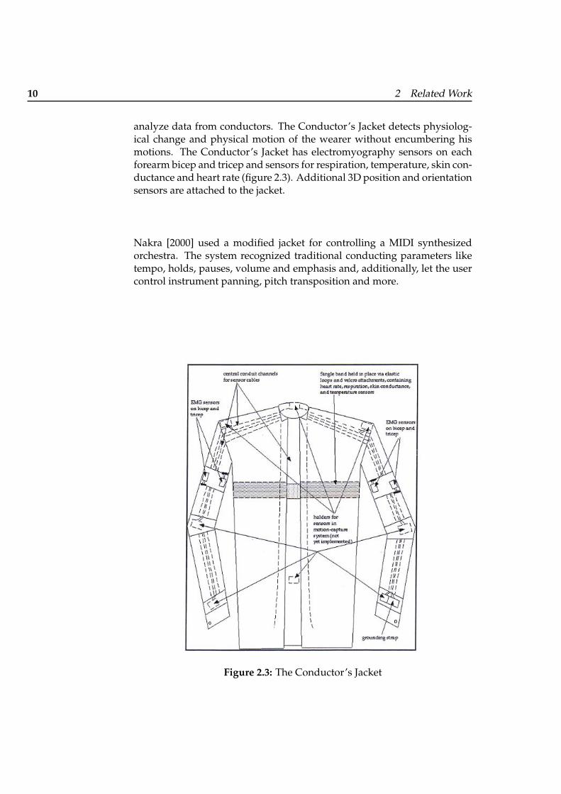
analyze data from conductors. The Conductor’s Jacket detects physiolog-ical change and physical motion of the wearer without encumbering hismotions. The Conductor’s Jacket has electromyography sensors on eachforearm bicep and tricep and sensors for respiration, temperature, skin con-ductance and heart rate (figure 2.3). Additional 3D position and orientationsensors are attached to the jacket.
Nakra [2000] used a modified jacket for controlling a MIDI synthesizedorchestra. The system recognized traditional conducting parameters liketempo, holds, pauses, volume and emphasis and, additionally, let the usercontrol instrument panning, pitch transposition and more.
Figure 2.3: The Conductor’s Jacket
2.2 Interactive Conducting Systems 11
2.2.8 Multi-Modal Conducting Simulator
Usa and Mochida [1998] created the Multi-Modal Conducting Simulator,which uses input from different sources to control a synthetic MIDI orches-tra. The system recognizes beginning and end of a piece, cue for a playerwith the eyes, beat timing and beat number in the measure, some aspects ofarticulation, and breathing. Acceleration, breathing and eye-tracking sen-sors provide the system with user input.
2.2.9 Virtual Conducting Practice Environment
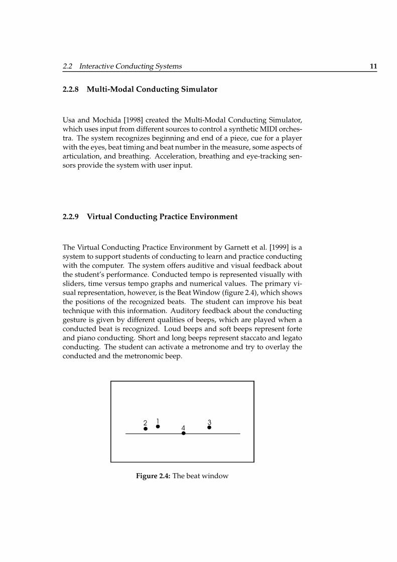
The Virtual Conducting Practice Environment by Garnett et al. [1999] is asystem to support students of conducting to learn and practice conductingwith the computer. The system offers auditive and visual feedback aboutthe student’s performance. Conducted tempo is represented visually withsliders, time versus tempo graphs and numerical values. The primary vi-sual representation, however, is the Beat Window (figure 2.4), which showsthe positions of the recognized beats. The student can improve his beattechnique with this information. Auditory feedback about the conductinggesture is given by different qualities of beeps, which are played when aconducted beat is recognized. Loud beeps and soft beeps represent forteand piano conducting. Short and long beeps represent staccato and legatoconducting. The student can activate a metronome and try to overlay theconducted and the metronomic beep.
Figure 2.4: The beat window
12 2 Related Work
2.2.10 Interactive Virtual Ensemble
Garnett et al. [2001] use a wireless MotionStar tracker by Ascension Tech-nologies to recognize standard conducting gestures. This sensor gives 3Dposition and orientation, which is in particular important to recognize theorientation of the conductor’s left hand to convey dynamics and for givingcues. The Virtual Ensemble creates MIDI output.
2.2.11 DIVA’s Virtual Orchestra
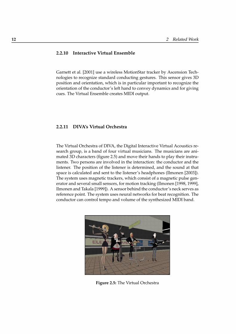
The Virtual Orchestra of DIVA, the Digital Interactive Virtual Acoustics re-search group, is a band of four virtual musicians. The musicians are ani-mated 3D characters (figure 2.5) and move their hands to play their instru-ments. Two persons are involved in the interaction: the conductor and thelistener. The position of the listener is determined, and the sound at thatspace is calculated and sent to the listener’s headphones (Ilmonen [2003]).The system uses magnetic trackers, which consist of a magnetic pulse gen-erator and several small sensors, for motion tracking (Ilmonen [1998, 1999],Ilmonen and Takala [1999]). A sensor behind the conductor’s neck serves asreference point. The system uses neural networks for beat recognition. Theconductor can control tempo and volume of the synthesized MIDI band.
Figure 2.5: The Virtual Orchestra
2.2 Interactive Conducting Systems 13
2.2.12 Conducting Gesture Recognition, Analysis and Perfor-mance System
The Conducting Gesture Recognition, Analysis and Performance Systemby Kolesnik [2004] uses the input of two cameras giving a front and sideview of the conductor, who wears a colored glove for automatic featureextraction. The system analyzes the movement of the right hand for beatplacement and the left, for expressive information. The system features areal audio/video recording.
2.2.13 Personal Orchestra and WorldBeat
WorldBeat
Borchers [1997] created the WordBeat system. The system features differ-ent modules that lets even persons unexperienced in music and computersgenerate pleasing music. One of the modules lets the user conduct a syn-thesizer allowing to control tempo and volume. The system uses a mod-ified version of the gesture recognition algorithm developed by Lee et al.[1992]. The system evaluates the vertical movement of a Buchla Lightningelectronic baton to determine beat placement and evaluates the size of thegesture to determine volume.
Virtual Conductor
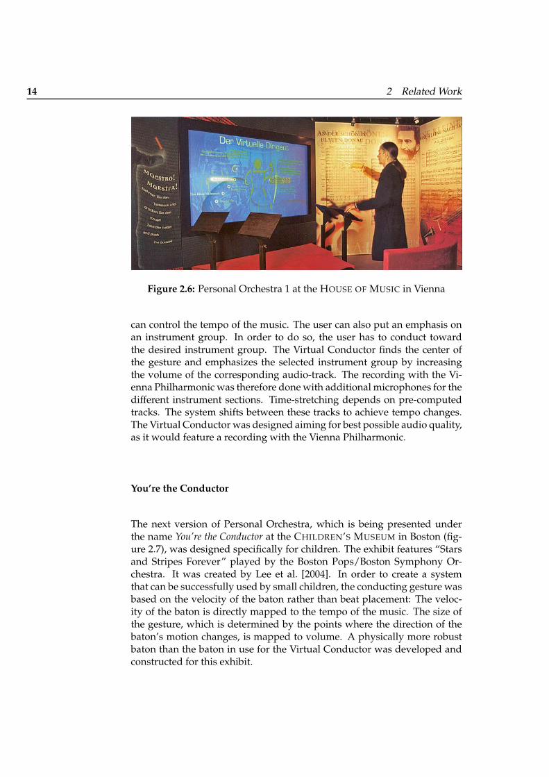
Samminger [2002], Borchers et al. [2002, 2004] created the first version ofPersonal Orchestra, which is being exhibited under the name “Virtual Con-ductor” at the HOUSE OF MUSIC in Vienna (figure 2.6). This is the firstmultimedia system to conduct a realistic electronic orchestra. The user canconduct an audio and video recording of the famous Vienna Philharmonic.
The input device for Virtual Conductor is an electronic baton. An infraredlight shines inside the translucent baton. The baton’s position light is de-tected by a sensor, and position data is sent to the computer where it is an-alyzed. Virtual Conductor interprets the user input as a simple single-handup-down gesture. Volume is controlled by the size of the user’s conduct-ing gesture. A beat is marked by the change of the baton’s motion fromdownwards to upwards. By placing the beats densely or sparsely the user
14 2 Related Work
Figure 2.6: Personal Orchestra 1 at the HOUSE OF MUSIC in Vienna
can control the tempo of the music. The user can also put an emphasis onan instrument group. In order to do so, the user has to conduct towardthe desired instrument group. The Virtual Conductor finds the center ofthe gesture and emphasizes the selected instrument group by increasingthe volume of the corresponding audio-track. The recording with the Vi-enna Philharmonic was therefore done with additional microphones for thedifferent instrument sections. Time-stretching depends on pre-computedtracks. The system shifts between these tracks to achieve tempo changes.The Virtual Conductor was designed aiming for best possible audio quality,as it would feature a recording with the Vienna Philharmonic.
You’re the Conductor
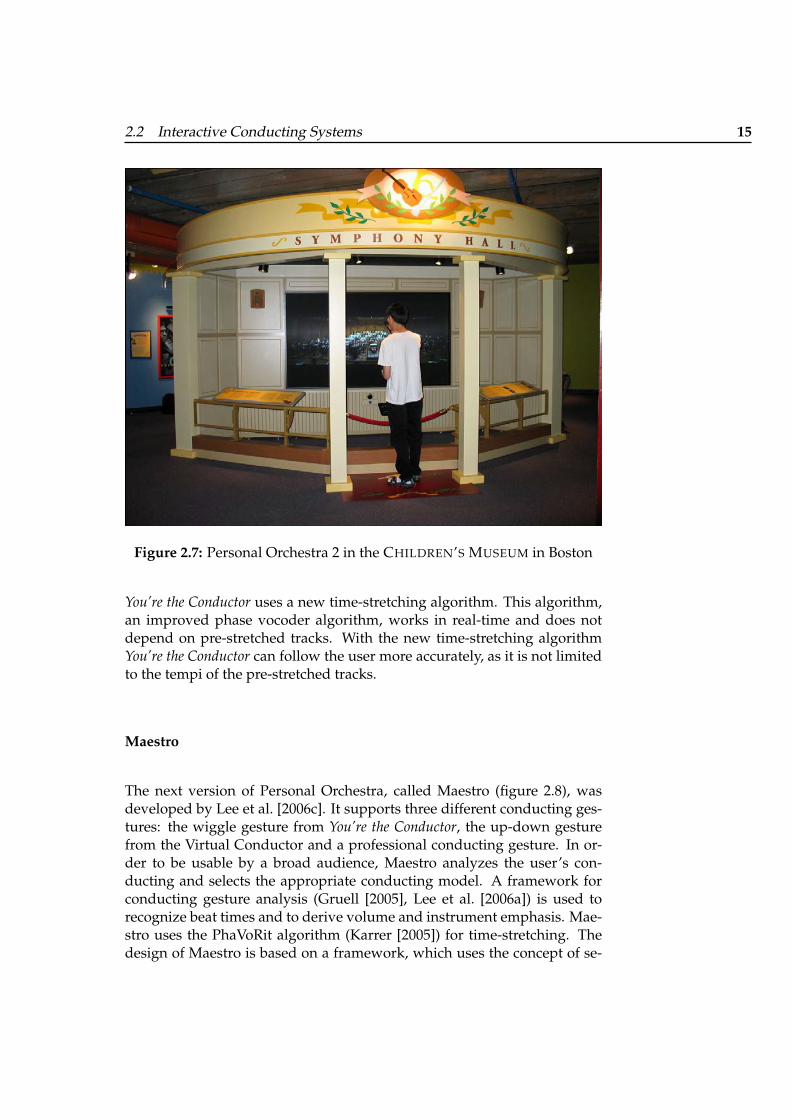
The next version of Personal Orchestra, which is being presented underthe name You’re the Conductor at the CHILDREN’S MUSEUM in Boston (fig-ure 2.7), was designed specifically for children. The exhibit features “Starsand Stripes Forever” played by the Boston Pops/Boston Symphony Or-chestra. It was created by Lee et al. [2004]. In order to create a systemthat can be successfully used by small children, the conducting gesture wasbased on the velocity of the baton rather than beat placement: The veloc-ity of the baton is directly mapped to the tempo of the music. The size ofthe gesture, which is determined by the points where the direction of thebaton’s motion changes, is mapped to volume. A physically more robustbaton than the baton in use for the Virtual Conductor was developed andconstructed for this exhibit.
2.2 Interactive Conducting Systems 15
Figure 2.7: Personal Orchestra 2 in the CHILDREN’S MUSEUM in Boston
You’re the Conductor uses a new time-stretching algorithm. This algorithm,an improved phase vocoder algorithm, works in real-time and does notdepend on pre-stretched tracks. With the new time-stretching algorithmYou’re the Conductor can follow the user more accurately, as it is not limitedto the tempi of the pre-stretched tracks.
Maestro
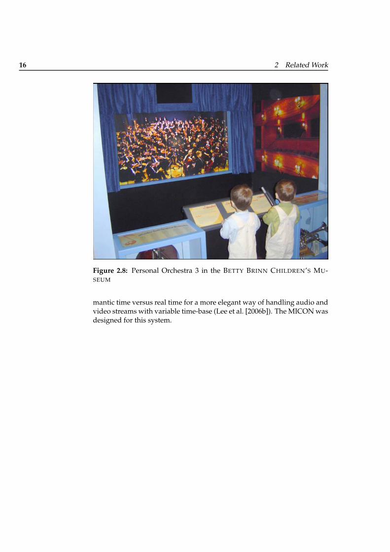
The next version of Personal Orchestra, called Maestro (figure 2.8), wasdeveloped by Lee et al. [2006c]. It supports three different conducting ges-tures: the wiggle gesture from You’re the Conductor, the up-down gesturefrom the Virtual Conductor and a professional conducting gesture. In or-der to be usable by a broad audience, Maestro analyzes the user’s con-ducting and selects the appropriate conducting model. A framework forconducting gesture analysis (Gruell [2005], Lee et al. [2006a]) is used torecognize beat times and to derive volume and instrument emphasis. Mae-stro uses the PhaVoRit algorithm (Karrer [2005]) for time-stretching. Thedesign of Maestro is based on a framework, which uses the concept of se-
16 2 Related Work
Figure 2.8: Personal Orchestra 3 in the BETTY BRINN CHILDREN’S MU-SEUM
mantic time versus real time for a more elegant way of handling audio andvideo streams with variable time-base (Lee et al. [2006b]). The MICON wasdesigned for this system.
17
Chapter 3
Requirements
3.1 Design Goals
The functional goals of the MICON were:
• to display the musical score to Maestro visitors while they are con-ducting and
• to indicate the current position in the score and to automatically ad-vance the pages following the music to help visitors with their con-ducting.
The key constraints in creating the MICON were:
Production quality. Since the Maestro system features professional or-chestras, its look and feel has to fulfill high standards to be acceptedby the museum and orchestra in question. The MICON has to lookand behave as professional as the rest of the exhibit, which requiresexcellent visual quality of the score display and fluid, non-distractinginteraction with it.
Visitor profile. Typical visitors using the system would be one-time userswith a short dwelling time. The system has to provide for thisthrough a particularly simple, self-explanatory and obvious interfacethat requires little or no interaction apart from the conducting itself.
18 3 Requirements
Musical knowledge. Some visitors might be amateur or even professionalconductors, but most would have no prior experience in conducting.The MICON has to provide these beginners with alternatives to thecomplexity of a full orchestral score document. Hopefully, by inter-acting with the system visitors would learn a little more about con-ducting and experience some of its challenges and rewards.
Design philosophy. Being a part of the interactive conducting exhibit Per-sonal Orchestra, the MICON has to fit with the design philosophy ofPersonal Orchestra.
Listener architecture. The MICON has to extend the Maestro system. Tominimize dependencies between these two co-evolving projects, theircommunication interface has to be kept as narrow as possible, withthe MICON essentially listening to the timing information that wasalready being generated by the Maestro gesture recognition engine.
Screen geometry. The MICON has to be adaptable to different screen sizesand geometries so that it can be run on a small display for a presen-tation as well as on a big display in a full installation of the exhibit.
3.2 Design Philosophy
3.2.1 Design Patterns
Borchers [2001] presents a set of patterns for interactive exhibits. A selec-tion of these patterns, which apply to the Personal Orchestra system, aredescribed here.
ATTRACT-ENGAGE-DELIVER*: An interactive exhibit is used by visitors fortheir entertainment. They have no actual need to use the interactive exhibit.Usually, an interactive exhibit has a message for the user or wants to teachsomething. The duration of the interaction has to be limited so that theexhibit can be used by many persons over the day. When the message hasbeen delivered, the interaction should be ended. Otherwise, users will stopthe interaction when they get bored or because they cannot figure out howto properly end the interaction.
The interaction should take place in three phases: First, the users have tobe attracted. Then within the interaction, the message of the exhibit has tobe delivered. After the message has been delivered, the interaction should
3.2 Design Philosophy 19
be ended in a positive way so that the length of the interaction correspondsto the desired throughput of the exhibit. References: ATTRACTION SPACE.
ATTRACTION SPACE*: In a museum many exhibits compete for the visi-tor’s attention. In order to deliver a message to the user, an exhibit has toattract the user first. An exhibit should not disturb other near-by standingexhibits. When the exhibit is not been used, the first thing a passing-byvisitor sees is its appearance in the idle-state. The exhibit in idle-state canattract the user with visual and auditory clues. Visual signals are only per-ceived when the user looks into the right direction. Auditory signals areomni-directional. They are also more intrusive and stronger. Strong visualclues (big displays, animation) can be perceived in the visual periphery ofthe user.
An attraction space has to be defined around the exhibit. This space shouldbe as large as possible, yet it should not penetrate the other exhibits’ at-traction spaces. An exhibit should not frequently violate the border of itsattraction space. To achieve this, static stimuli can be used: The appearanceof the exhibit should be attractive by its own. Excessive animation and thefrequent use of undirected stimuli should be avoided as they violate theother exhibits’ attraction spaces. References: INNOVATIVE APPEARANCE,SIMPLE IMPRESSION, DOMAIN-APPROPRIATE-DEVICES.
COOPERATIVE EXPERIENCE**: Often people visit exhibitions in groups.However, most interactive exhibits can only be used by a single persona time. When used by more then one person, the interaction of the humanswith each other becomes the main part of the experience. There are, ofcourse, many situations where the control has to stay with a single person.Apart from cooperative use, an interactive exhibit should allow bystandersto watch what is going on. This allows to increase the number of personsthat can at least passively experience the exhibit. While watching, a by-stander learns about the system and can gain form this knowledge whenusing the exhibit himself. If a cooperative experience is not planned, thevisitors will create it themselves.
Two people should be able to use an interactive exhibit at the same time. Atleast five bystanders should be able to watch or listen while another personuses the exhibit. References: EASY HANDOVER, IMMERSIVE DISPLAY.
EASY HANDOVER*: Most interactive exhibits assume that each user beginsthe interaction form the very beginning. However, it often happens thata visitor leaves the controls to another person during the interaction. Thenew user takes over the control in the middle of the interaction and doespossibly not know the interaction history. When the new user takes over,
20 3 Requirements
he has already gained some knowledge by watching his predecessor. Thiscan compensate for missed explanations.
Knowledge of the interaction history that a new user needs to perform suc-cessfully should be as little as possible. A simple means to return to theinitial state should be given. Critical parameters, like language settings,should be accessible at every step of the interaction. References: LAN-GUAGE INDEPENDENCE.
LANGUAGE INDEPENDENCE: Museums and exhibition centers often haveinternational visitors, who might not speak the local tongue. Most interac-tive exhibits show text messages to the user. It does not suffice to provide alanguage selection at the beginning of the interaction. The language selec-tion has to be accessible at every step of the interaction because a new usermight take over the control in the middle of a previous interaction.
At every step of interaction the language selection should be accessible.This can be done in a multilingual or pictorial way. References: none.
SIMPLE IMPRESSION*: Interactive exhibits often have complex messagesand present new technology to the visitors of an exhibition. Typically thevisitors are first-time and one-time users. Therefore, the users have to learnto use the system very quickly.
The user interface of an interactive exhibit should be simple. This simplic-ity should be represented in the overall appearance of the exhibit. Refer-ences: INVISIBLE HARDWARE, INCREMENTAL REVEALING.
INCREMENTAL REVEALING**: Systems that look complex do not seem tobe inviting. If an exhibit does not have enough interaction possibilities, itcan quickly become boring.
Initially the exhibit should present a simple overview of the exhibits func-tions. When the user becomes active showing interest in a specific part,more information should be revealed about it, and the user is given newchoices. References: FLAT AND NARROW TREE.
FLAT AND NARROW TREE*: Many interactive exhibits contain a set of dif-ferent pages. The user navigates through these pages. Large hierarchiesand unordered networks can confuse the user.
A tree-like hierarchy should be used for navigation. There should be nomore than seven items to choose from at every step. The tree should be nomore that five levels deep. References: none.
3.2 Design Philosophy 21
DOMAIN-APPROPRIATE DEVICES*: Although interactive exhibits deal witha wide range of different domains, they use mostly standard computer in-put and output devices. Most interactive exhibits use metaphors from theapplication domain, yet they use standard keyboard and mouse for inputand a monitor for output. The metaphors remain virtual. Of course, build-ing innovative input and output hardware is more expensive, but often it isnot even attempted to estimate the extra cost and its payoff. Psychologicalresearch suggests that users are more successful when using I/O-devicesfrom the application domain.
Input and output devices that resemble real-world objects should be pre-ferred over standard periphery. Whenever the user receives informationor has to input something, it should be considered if standard hardwareshould really be used, or if special, domain-appropriate, hardware canserve as periphery for the exhibit. References: INNOVATIVE APPEARANCE,INVISIBLE HARDWARE, ONE INPUT DEVICE.
INNOVATIVE APPEARANCE*: Standard hardware is usually not consideredto be exciting.
Input and output hardware that looks differently form standard hardwareshould be preferred, as it might rage the curiosity of visitors. The usage ofinnovative I/O-devices offers new ways of interaction to the users. Refer-ences: INVISIBLE HARDWARE, ONE INPUT DEVICE.
IMMERSIVE DISPLAY*: Exhibits are usually visited by groups of people.When people interact with the exhibit, they want to immerse themselvesinto the world of the exhibit. Large displays enable bystanders to watchwhat is going on, while another person uses the system.
A single exhibit with a large screen (minimum 1.5 m) should be preferredover several similar exhibits with smaller displays. The user should notbe shielded from the other visitors: Head-mounted displays do not letbystanders take place in the interaction. The viewing distance should beroughly equal to the width of the screen. References: INVISIBLE HARD-WARE.
INVISIBLE HARDWARE*: Modern interactive exhibits often use advancedand expensive technology. If the technology is visible, users might bedriven away by it. The display of the technology can overshadow the realcontents of the exhibit.
The computer hardware used in an exhibit should be hidden. Ideally, onlyrelevant devices, devices the user interacts with, should be visible. These
22 3 Requirements
devices should create an image, which is adequate to the application do-main. References: ONE INPUT DEVICE.
ONE INPUT DEVICE*: Many interactive exhibits use a variety of input de-vices. Some exhibits recognize gestures without any physical input device.But exhibits are used by people without prior knowledge about it. Manyinput devices might cause them to feel confused. No input device at allmight make them feel uneasy.
All input should be mapped to one input device. References: DOMAIN-APPROPRIATE DEVICES.
3.2.2 Design Patterns in Personal Orchestra
The interaction with Personal Orchestra is divided into three phases(ATTRACT-ENGAGE-DELIVER): The user’s attention is drawn to the exhibitby auditive and visual clues. The interaction takes place, and the musicalmessage is delivered. When the user finishes the piece, applause marks theend of the interaction. The user can leave the exhibit or, alternatively, startover from the beginning. The pieces are roughly three minutes long. De-pending on the tempo the user conducts, the interaction takes between 1.5and 6 minutes.
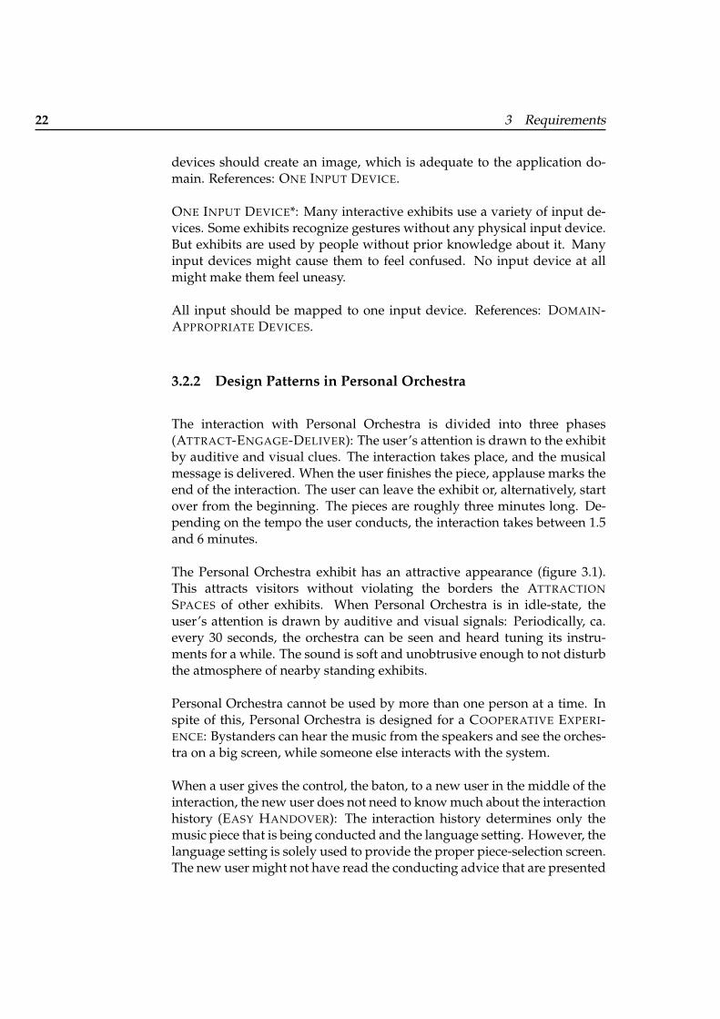
The Personal Orchestra exhibit has an attractive appearance (figure 3.1).This attracts visitors without violating the borders the ATTRACTIONSPACES of other exhibits. When Personal Orchestra is in idle-state, theuser’s attention is drawn by auditive and visual signals: Periodically, ca.every 30 seconds, the orchestra can be seen and heard tuning its instru-ments for a while. The sound is soft and unobtrusive enough to not disturbthe atmosphere of nearby standing exhibits.
Personal Orchestra cannot be used by more than one person at a time. Inspite of this, Personal Orchestra is designed for a COOPERATIVE EXPERI-ENCE: Bystanders can hear the music from the speakers and see the orches-tra on a big screen, while someone else interacts with the system.
When a user gives the control, the baton, to a new user in the middle of theinteraction, the new user does not need to know much about the interactionhistory (EASY HANDOVER): The interaction history determines only themusic piece that is being conducted and the language setting. However, thelanguage setting is solely used to provide the proper piece-selection screen.The new user might not have read the conducting advice that are presented
3.2 Design Philosophy 23
Figure 3.1: Personal Orchestra 1 exhibit
in the beginning. He will, however, have watched the predecessor andhave learned how to interact from this source. If the new user does notconduct, the system returns to the idle-state after a while.
In order to ensure LANGUAGE INDEPENDENCE, the user chooses his lan-guage. This is done in the very first step of the interaction. A multilinguallanguage selection is presented at the beginning of the interaction.
Personal Orchestra gives a SIMPLE IMPRESSION. The entities the user dealswith are the baton, the music from the loudspeakers and the video of theorchestra on the screen.
The user selects the preferred language. Then he selects a music piece froma list of four items, and the conducting begins. The selection has the struc-ture of a FLAT AND NARROW TREE.
The input device for Personal Orchestra is an electronic baton, resemblinga real conductor’s baton. The electronic baton is a DOMAIN APPROPRIATEDEVICE. The baton also provides Personal Orchestra with an INNOVATIVEAPPEARANCE.
The exhibit uses a large screen for visual output. This allows the user to get
24 3 Requirements
immersed into the situation of standing before a large orchestra (IMMER-SIVE DISPLAY).
In the Personal Orchestra exhibit much of the computer hardware is hid-den. INVISIBLE HARDWARE lets the real contents of the exhibit—musicshine. Users can be driven away if complicating looking and advancedhardware is shown.
In Personal Orchestra every interaction is mapped to ONE INPUT DEVICE:the electronic baton. The baton is not only used for conducting but also forselecting language and piece in the beginning of the interaction by pointingtoward the desired item and pushing a button on the baton.
3.2.3 Design Principles
Norman [2002] provides design principles to aid designers to create goodproducts.
Human action has to phases: execution and evaluation. After an action isexecuted, the results are evaluated and compared to the desired outcome:the goal. Action execution can be divided into smaller steps. The goal, avery high-level description (e.g. get more light), has to be transformed intoa specific intention (put on the lamp or, alternatively, use a candle). Theintention is then transformed into a series of planned actions, which arethen performed and change the state of the world. Evaluation can also bedivided into smaller steps. The physical world is perceived, and a men-tal model of the world state is built: the interpretation. The interpreta-tion is evaluated, and the goals are modified (or may remain unchanged ifthe action was unsuccessful). The seven stages of human action are: per-ception, interpretation, evaluation, goals, intention, action sequence, exe-cution. In many tasks problems arise when mapping mental intention tophysical states and physical states to interpretations.
Two gulfs separate mental sates from physical states: The gulf of executionis a measure of the difficulty for the user to map his intention to possible ac-tions on a device. The gulf of evaluation is a measure of the difficulty to in-terpret and evaluate the physical state of the device. Design should supportthe user at every stage of action: The design should make clear what can beachieved with the device (goal level) and show the possible actions (inten-tion level). It should support the user to determine the mapping betweenintention and physical plan (action sequence level), and the device shouldbe physically operated with ease (execution level). The design should en-
3.2 Design Philosophy 25
able the user to determine the state of the device (perception level), helpthe user to interpret the perception (interpretation level) and support theuser to tell if the device is in the desired state (evaluation level). These re-quirements can be accomplished by using principles of good design: goodconceptual models, good mappings visibility and feedback.
A good conceptual model allows the user to predict the effects of his ac-tions. A conceptual model is a representation of a device in the mind of aperson. It is a representation of the relationships of actions and outcomes.A wrong or inadequate conceptual model can lead to difficulties in usingthe device. Therefore, the designer is obliged to provide the user with agood conceptual model. First the designer has to create a good conceptu-alization of the device: an easy to learn conceptualization that describesthe device sufficiently. This model, the design model, has to be communi-cated to the user. A very important communication medium is the deviceitself. Manuals are often ignored by users. The user develops his mentalmodel, the user model, mainly by interacting with the device. Therefore,the system image of a device is critical: It has to lead the user to a goodunderstanding of the device.
A mapping is the relationship between actions on the device and effects inthe world. A natural mapping takes advantage of analogies and culturalconventions. In a spatial analogy, e.g., the layout of the control elementscould resemble the physical or functional structure of the device. Othernatural mappings take advantage of principles of human perception. Anatural mapping leads the user immediately to understanding the device.Natural mappings can easily be learned by users. Arbitrary mappings,however, are difficult to learn and to use.
The relevant parts of a device should be visible. The user should be able toeasily distinguish important parts from other parts like decorative items.Aesthetic considerations should not affect this visibility principle: An im-portant part should not be left out for a better appearance of the device.Feedback gives the user information about the effects of his actions. It givesevery action an immediate effect. Especially visible feedback, in form of awell-designed display, can improve the usability of a device significantly.Without feedback the user will wonder whether his actions have been exe-cuted. The user might then repeat his actions without need, possibly harm-ing the result. The user might conclude that the device does not react andrestart his interaction unnecessarily.
When a person uses a new device, a big number of possible actions mightcause problems. The number of possible actions can be reduced by con-straints. There are different types of constraints: physical, semantic, cul-
26 3 Requirements
tural and logical constraints. Physical constraints depend on properties ofthe physical world. A big peg, e.g., does not fit to a small hole. Physicalconstraints are recognized by users without special training. If a physicalconstraint can easily been seen, the number of possible actions is immedi-ately reduced: The user will not make obviously impossible actions. Se-mantical constraints rely on the meaning of the situation and on the user’sknowledge. Cultural constraints rely upon cultural conventions. Logicalconstraints rely on logics and analogy.
The affordance of an object gives the user a strong hint what actions can bedone: A button affords (“is for”) pushing; a knob affords turning. Evenmaterials have affordances: Glass, e.g., affords looking through it (andalso breaking it). With affordances, the user can know what to do with-out the need of labels, instructions or pictures. Simple things should beself-explanatory.
A task should be simple to perform by the user. If a task is unnecessarycomplex, the task should be changed. Technology can aid to simplify thetask. In order to simplify a task, a designer has several alternatives: Thetask can be left unchanged, and the designer provides the user with mentalaids to remember what actions to do. Alternatively, the designer coulduse technology to make a hidden part visible. This improves the feedbackfrom the device and helps the user to gain better control on the device: Adiagram on a computer screen could, e.g., help the user. To simplify a tasksome of it could be automated, or the task could be changed completelywith the aid of technology.
27
Chapter 4
Design of the MICON
4.1 Functional Design
The MICON features four different musical representations:
• piano roll,
• pulse notation,
• full orchestral score and
• piano extract score.
The piano roll and the score representations provide visualizations of themusical material, enhancing the Maestro experience with the notational as-pect of music. The pulse notation was designed to support the user withhis conducting: It visualizes the, previously inaccessible, metrical structureof the music.
4.1.1 Piano Roll
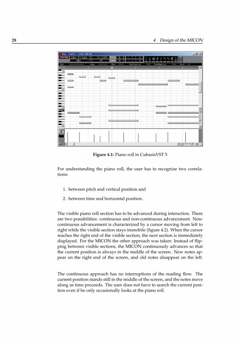
The piano roll represents notes as boxes of uniform height. Box widthdefines the length of a note, the vertical position defines pitch, and thehorizontal position defines onset time. Music software such as MIDI se-quencers often uses piano roll (figure 4.1) so that some users of the MICONmay already be familiar with this representation.
28 4 Design of the MICON
Figure 4.1: Piano roll in CubasisVST 5
For understanding the piano roll, the user has to recognize two correla-tions:
1. between pitch and vertical position and
2. between time and horizontal position.
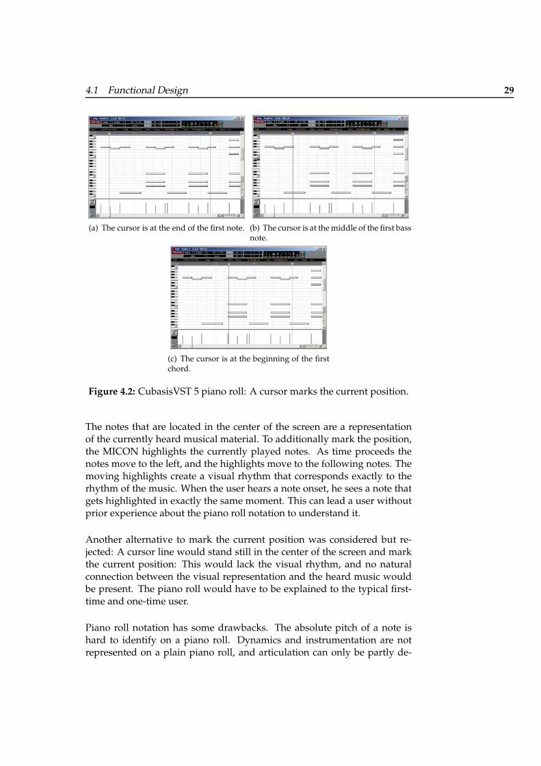
The visible piano roll section has to be advanced during interaction. Thereare two possibilities: continuous and non-continuous advancement. Non-continuous advancement is characterized by a cursor moving from left toright while the visible section stays immobile (figure 4.2). When the cursorreaches the right end of the visible section, the next section is immediatelydisplayed. For the MICON the other approach was taken: Instead of flip-ping between visible sections, the MICON continuously advances so thatthe current position is always in the middle of the screen. New notes ap-pear on the right end of the screen, and old notes disappear on the left.
The continuous approach has no interruptions of the reading flow. Thecurrent position stands still in the middle of the screen, and the notes movealong as time proceeds. The user does not have to search the current posi-tion even if he only occasionally looks at the piano roll.
4.1 Functional Design 29
(a) The cursor is at the end of the first note. (b) The cursor is at the middle of the first bassnote.
(c) The cursor is at the beginning of the firstchord.
Figure 4.2: CubasisVST 5 piano roll: A cursor marks the current position.
The notes that are located in the center of the screen are a representationof the currently heard musical material. To additionally mark the position,the MICON highlights the currently played notes. As time proceeds thenotes move to the left, and the highlights move to the following notes. Themoving highlights create a visual rhythm that corresponds exactly to therhythm of the music. When the user hears a note onset, he sees a note thatgets highlighted in exactly the same moment. This can lead a user withoutprior experience about the piano roll notation to understand it.
Another alternative to mark the current position was considered but re-jected: A cursor line would stand still in the center of the screen and markthe current position: This would lack the visual rhythm, and no naturalconnection between the visual representation and the heard music wouldbe present. The piano roll would have to be explained to the typical first-time and one-time user.
Piano roll notation has some drawbacks. The absolute pitch of a note ishard to identify on a piano roll. Dynamics and instrumentation are notrepresented on a plain piano roll, and articulation can only be partly de-
30 4 Design of the MICON
rived by examining the length of the notes. The most problematic propertyof the piano roll notation in context of an interactive conducting system,however, is the lack of representing high-level rhythmical structures likemeter. The pulse notation supplements the piano roll with a representationof a high-level rhythmical structure.
4.1.2 Pulse Notation
The pulse notation was created to support the Personal Orchestra user withhis conducting. The deviation of the conducted beat from the beat in themusic is essential for controlling the tempo of Maestro. Conducting beforethe beat increases, conducting after the beat decreases the tempo. However,in a piece with a lot of rubato, the timing of the beats is hard to predictincreasing difficulty. The pulse notation visualizes the beat of the musicand helps the user to coordinate his conducting gesture with the beat.
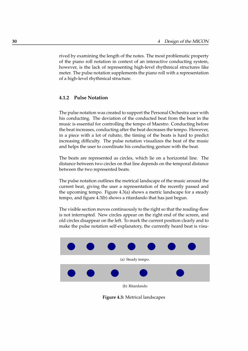
The beats are represented as circles, which lie on a horizontal line. Thedistance between two circles on that line depends on the temporal distancebetween the two represented beats.
The pulse notation outlines the metrical landscape of the music around thecurrent beat, giving the user a representation of the recently passed andthe upcoming tempo. Figure 4.3(a) shows a metric landscape for a steadytempo, and figure 4.3(b) shows a ritardando that has just begun.
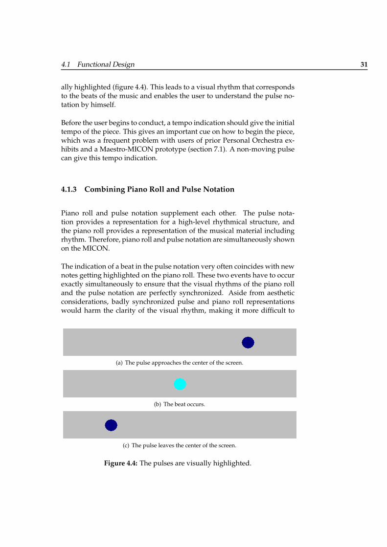
The visible section moves continuously to the right so that the reading-flowis not interrupted. New circles appear on the right end of the screen, andold circles disappear on the left. To mark the current position clearly and tomake the pulse notation self-explanatory, the currently heard beat is visu-
(a) Steady tempo.
(b) Ritardando
Figure 4.3: Metrical landscapes
4.1 Functional Design 31
ally highlighted (figure 4.4). This leads to a visual rhythm that correspondsto the beats of the music and enables the user to understand the pulse no-tation by himself.
Before the user begins to conduct, a tempo indication should give the initialtempo of the piece. This gives an important cue on how to begin the piece,which was a frequent problem with users of prior Personal Orchestra ex-hibits and a Maestro-MICON prototype (section 7.1). A non-moving pulsecan give this tempo indication.
4.1.3 Combining Piano Roll and Pulse Notation
Piano roll and pulse notation supplement each other. The pulse nota-tion provides a representation for a high-level rhythmical structure, andthe piano roll provides a representation of the musical material includingrhythm. Therefore, piano roll and pulse notation are simultaneously shownon the MICON.
The indication of a beat in the pulse notation very often coincides with newnotes getting highlighted on the piano roll. These two events have to occurexactly simultaneously to ensure that the visual rhythms of the piano rolland the pulse notation are perfectly synchronized. Aside from aestheticconsiderations, badly synchronized pulse and piano roll representationswould harm the clarity of the visual rhythm, making it more difficult to
(a) The pulse approaches the center of the screen.
(b) The beat occurs.
(c) The pulse leaves the center of the screen.
Figure 4.4: The pulses are visually highlighted.
32 4 Design of the MICON
understand the representations. The content creation for the piano roll andthe pulse notation is interwined and provides the desired synchronicity(section 5.4).
4.1.4 Score
The piano roll and the pulse notation do not require a background of formalmusical training. However, as music exhibit Personal Orchestra attracts theattention of people with interest and knowledge about music. The MICONshould offer visualizations that enable musically educated users to profitfrom their abilities. To this end the score representations were included.
Aside form offering more or easier accessible information about pitch, ar-ticulation, dynamics, instrumentation, etc., a score representation is easierto read than a piano roll for users with good music-reading skills. Theyrecognize bigger structures like chords, scales, etc., which enables them toread the score fluently.
MICON advances the score automatically. Several strategies were consid-ered:
• The score is presented like a book. When the cursor reaches the endof the right page, the next two pages become visible.
• When the music reaches the end of the left double-page, the rightpage moves to the left, and the new page is displayed on the right.
• The entire score is represented without line breaks, and the line con-tinuously moves while music plays.
The last two choices allow the user to read the score in advance at everymoment. In spite of this, it was decided to use the book metaphor in orderto keep the representation as simple as possible and to not introduce an-other, musically unimportant, item (SIMPLE IMPRESSION Borchers [2001]).
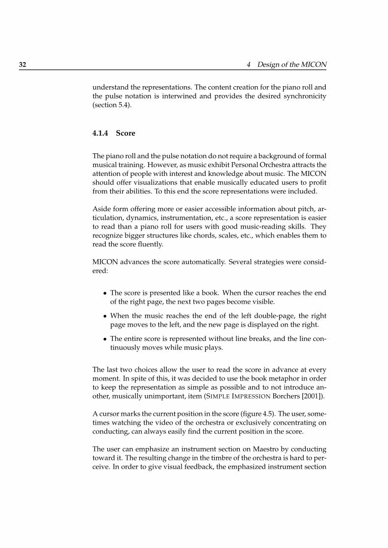
A cursor marks the current position in the score (figure 4.5). The user, some-times watching the video of the orchestra or exclusively concentrating onconducting, can always easily find the current position in the score.
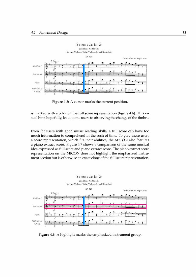
The user can emphasize an instrument section on Maestro by conductingtoward it. The resulting change in the timbre of the orchestra is hard to per-ceive. In order to give visual feedback, the emphasized instrument section
4.1 Functional Design 33
Figure 4.5: A cursor marks the current position.
is marked with a color on the full score representation (figure 4.6). This vi-sual hint, hopefully, leads some users to observing the change of the timbre.
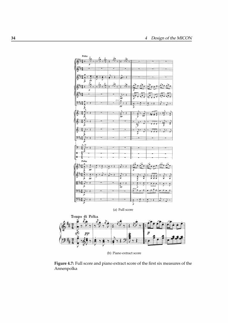
Even for users with good music reading skills, a full score can have toomuch information to comprehend in the rush of time. To give these usersa score representation, which fits their abilities, the MICON also featuresa piano extract score. Figure 4.7 shows a comparison of the same musicalidea expressed as full score and piano extract score. The piano extract scorerepresentation on the MICON does not highlight the emphasized instru-ment section but is otherwise an exact clone of the full score representation.
Figure 4.6: A highlight marks the emphasized instrument group.
34 4 Design of the MICON
(a) Full score
(b) Piano extract score
Figure 4.7: Full score and piano extract score of the first six measures of theAnnenpolka
4.1 Functional Design 35
4.1.5 Combining Score and Pulse Notation
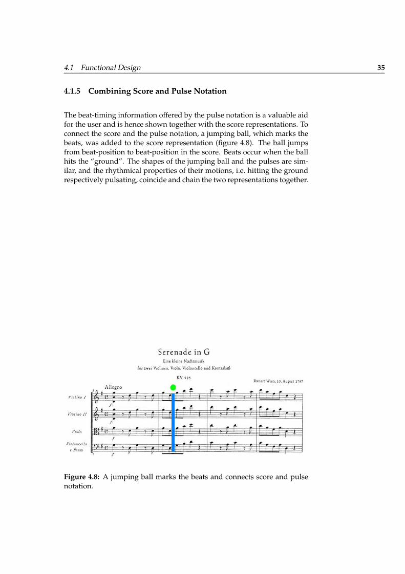
The beat-timing information offered by the pulse notation is a valuable aidfor the user and is hence shown together with the score representations. Toconnect the score and the pulse notation, a jumping ball, which marks thebeats, was added to the score representation (figure 4.8). The ball jumpsfrom beat-position to beat-position in the score. Beats occur when the ballhits the “ground”. The shapes of the jumping ball and the pulses are sim-ilar, and the rhythmical properties of their motions, i.e. hitting the groundrespectively pulsating, coincide and chain the two representations together.
Figure 4.8: A jumping ball marks the beats and connects score and pulsenotation.

4.2 Aesthetic Design 37
4.2 Aesthetic Design
4.2.1 Score
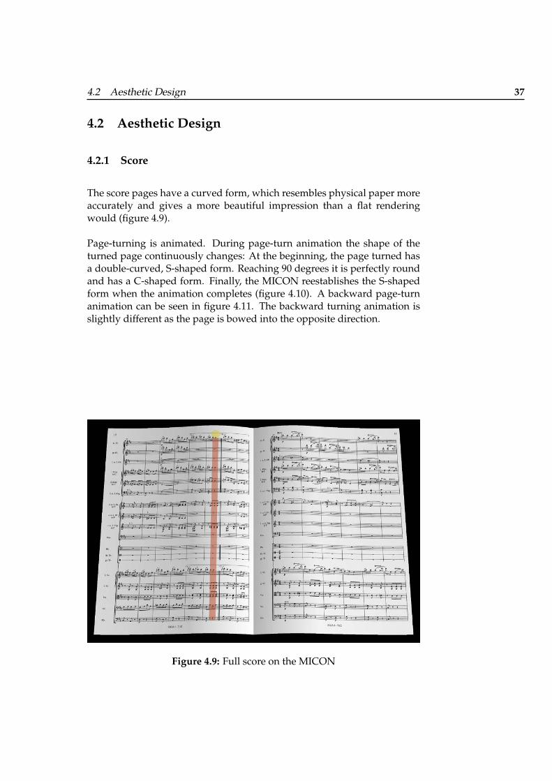
The score pages have a curved form, which resembles physical paper moreaccurately and gives a more beautiful impression than a flat renderingwould (figure 4.9).
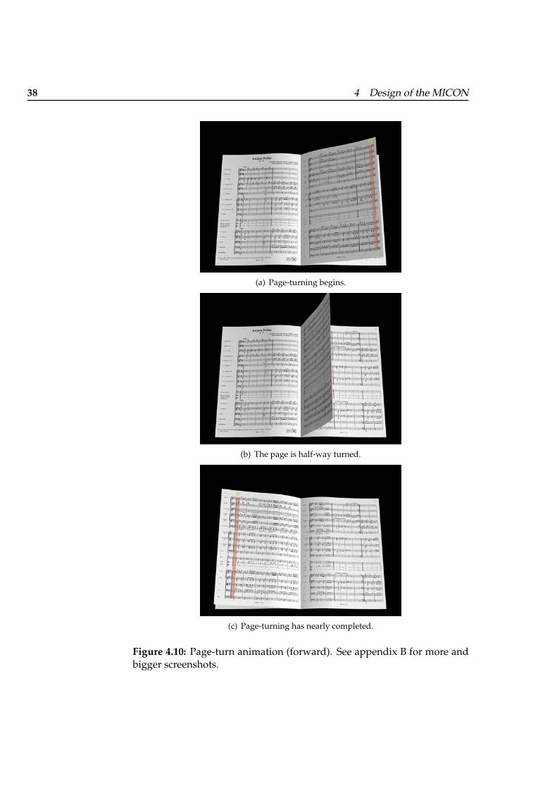
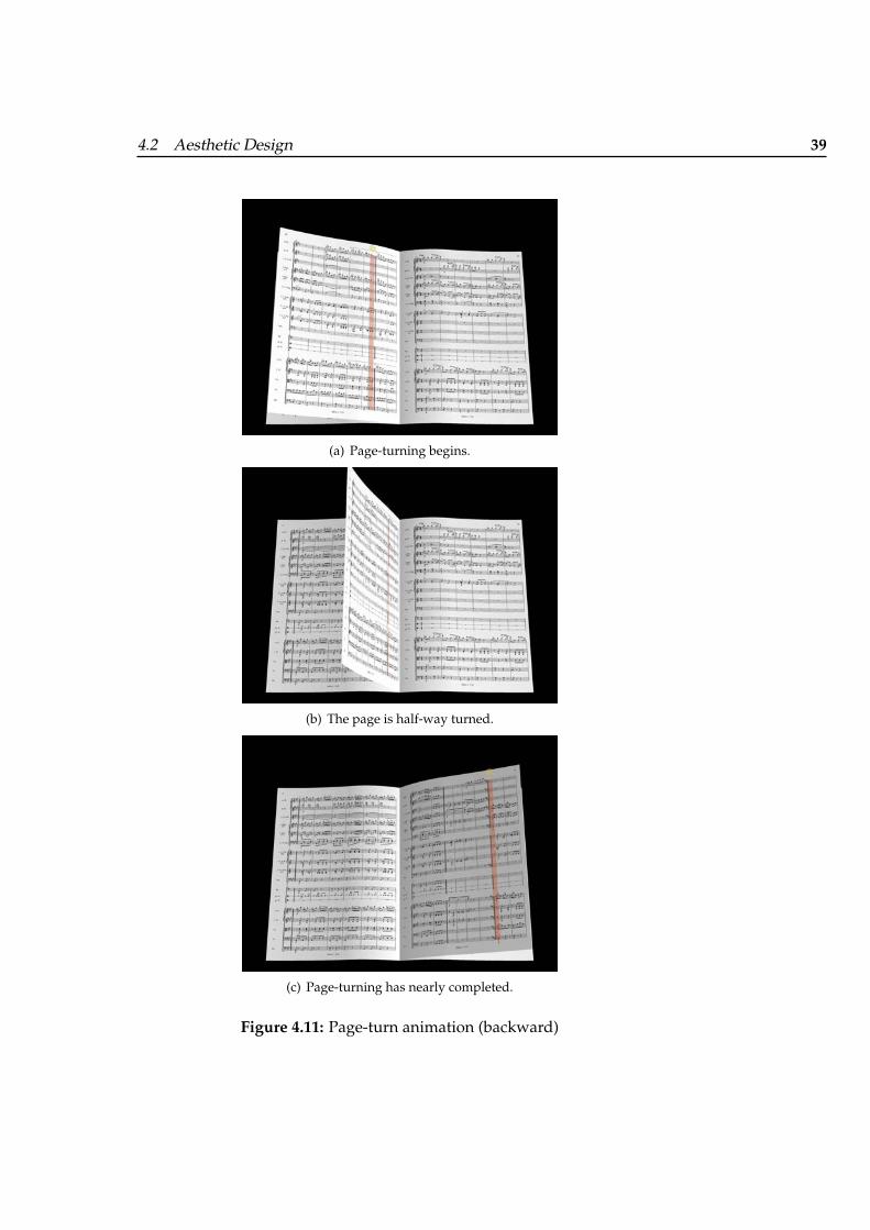
Page-turning is animated. During page-turn animation the shape of theturned page continuously changes: At the beginning, the page turned hasa double-curved, S-shaped form. Reaching 90 degrees it is perfectly roundand has a C-shaped form. Finally, the MICON reestablishes the S-shapedform when the animation completes (figure 4.10). A backward page-turnanimation can be seen in figure 4.11. The backward turning animation isslightly different as the page is bowed into the opposite direction.
Figure 4.9: Full score on the MICON
38 4 Design of the MICON
(a) Page-turning begins.
(b) The page is half-way turned.
(c) Page-turning has nearly completed.
Figure 4.10: Page-turn animation (forward). See appendix B for more andbigger screenshots.
4.2 Aesthetic Design 39
(a) Page-turning begins.
(b) The page is half-way turned.
(c) Page-turning has nearly completed.
Figure 4.11: Page-turn animation (backward)
40 4 Design of the MICON
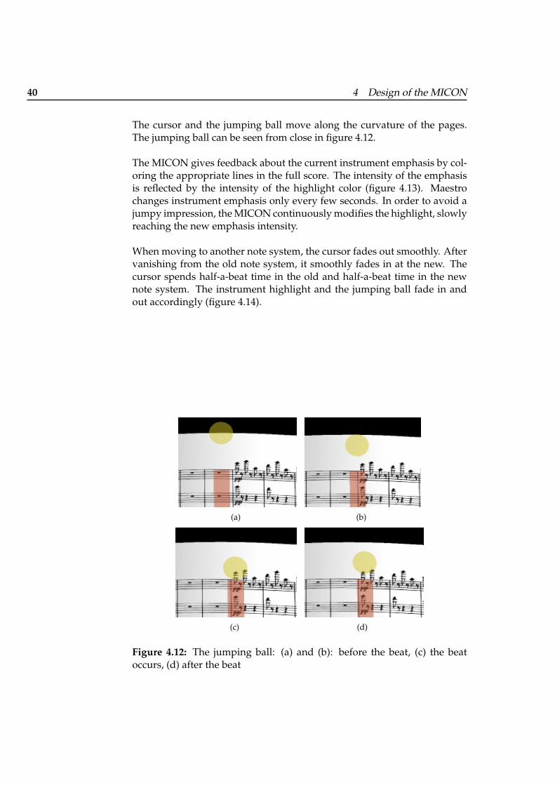
The cursor and the jumping ball move along the curvature of the pages.The jumping ball can be seen from close in figure 4.12.
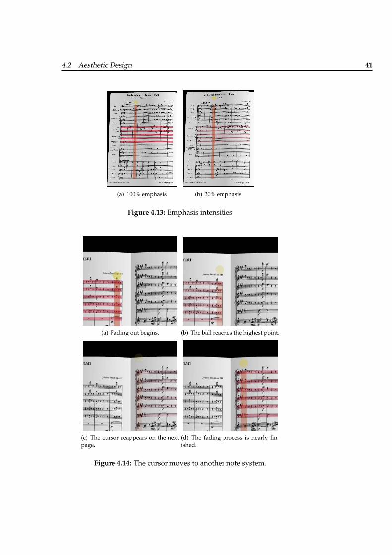
The MICON gives feedback about the current instrument emphasis by col-oring the appropriate lines in the full score. The intensity of the emphasisis reflected by the intensity of the highlight color (figure 4.13). Maestrochanges instrument emphasis only every few seconds. In order to avoid ajumpy impression, the MICON continuously modifies the highlight, slowlyreaching the new emphasis intensity.
When moving to another note system, the cursor fades out smoothly. Aftervanishing from the old note system, it smoothly fades in at the new. Thecursor spends half-a-beat time in the old and half-a-beat time in the newnote system. The instrument highlight and the jumping ball fade in andout accordingly (figure 4.14).
(a) (b)
(c) (d)
Figure 4.12: The jumping ball: (a) and (b): before the beat, (c) the beatoccurs, (d) after the beat
4.2 Aesthetic Design 41
(a) 100% emphasis (b) 30% emphasis
Figure 4.13: Emphasis intensities
(a) Fading out begins. (b) The ball reaches the highest point.
(c) The cursor reappears on the nextpage.
(d) The fading process is nearly fin-ished.
Figure 4.14: The cursor moves to another note system.
42 4 Design of the MICON
4.2.2 Piano Roll
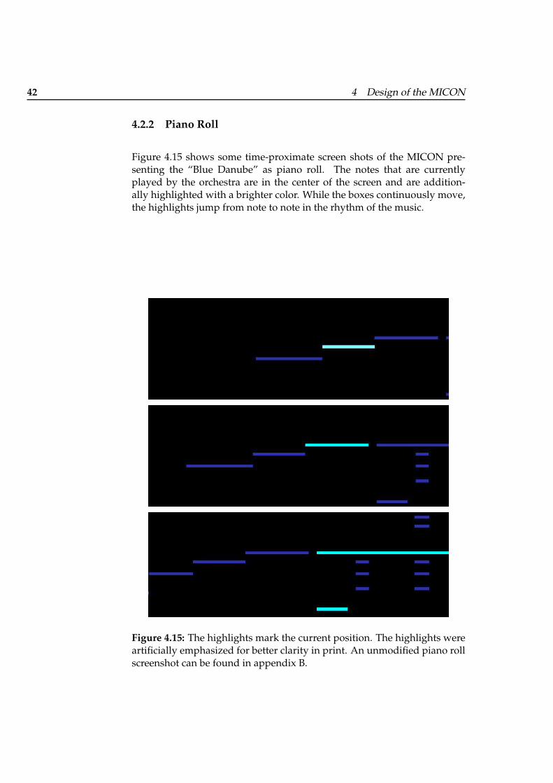
Figure 4.15 shows some time-proximate screen shots of the MICON pre-senting the “Blue Danube” as piano roll. The notes that are currentlyplayed by the orchestra are in the center of the screen and are addition-ally highlighted with a brighter color. While the boxes continuously move,the highlights jump from note to note in the rhythm of the music.
Figure 4.15: The highlights mark the current position. The highlights wereartificially emphasized for better clarity in print. An unmodified piano rollscreenshot can be found in appendix B.
4.2 Aesthetic Design 43
4.2.3 Pulse
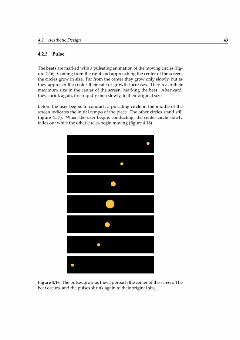
The beats are marked with a pulsating animation of the moving circles (fig-ure 4.16). Coming from the right and approaching the center of the screen,the circles grow in size. Far from the center they grow only slowly, but asthey approach the center their rate of growth increases. They reach theirmaximum size in the center of the screen, marking the beat. Afterward,they shrink again, first rapidly then slowly, to their original size.
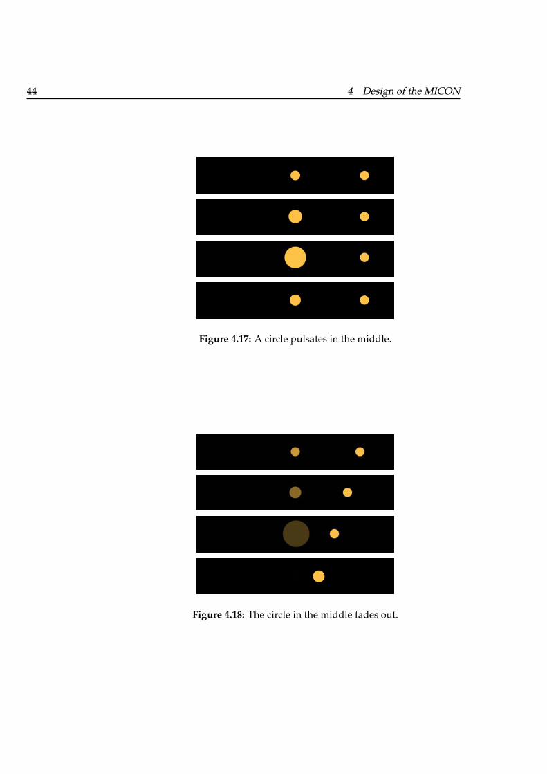
Before the user begins to conduct, a pulsating circle in the middle of thescreen indicates the initial tempo of the piece. The other circles stand still(figure 4.17). When the user begins conducting, the center circle slowlyfades out while the other circles begin moving (figure 4.18).
Figure 4.16: The pulses grow as they approach the center of the screen. Thebeat occurs, and the pulses shrink again to their original size.
44 4 Design of the MICON
Figure 4.17: A circle pulsates in the middle.
Figure 4.18: The circle in the middle fades out.
4.2 Aesthetic Design 45
4.2.4 MICON Display Options
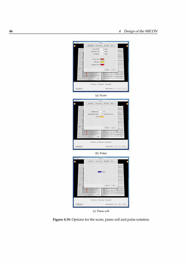
Several properties of the representations are configurable (figure 4.19) andcan be altered to fit well with the design of the exhibit installation.
For the full score and the piano extract score,
• the color of the cursor, of the emphasis highlight and of the jumpingball and
• the thickness of the cursor and the size of the jumping ball can be set.
The options are handled for the full score and the piano part score sepa-rately. Thus it is possible, for example, to have different cursor and jumpingball sizes for these two representations.
For the pulse notation,
• the color of the circles,
• the size of the circles,
• the magnification factor and
• the point in time when magnification begins can be set.
For the piano roll, the color of the boxes can be set.
The MICON allows to place the representations in a virtual 3D space andchange their orientation and scale their size freely. This flexibility allows tochange the layout of the MICON screen, enabling to save space on a smalldisplay while placing the representation more orderly on a large display(figure 4.20).
46 4 Design of the MICON
(a) Score
(b) Pulse
(c) Piano roll
Figure 4.19: Options for the score, piano roll and pulse notation
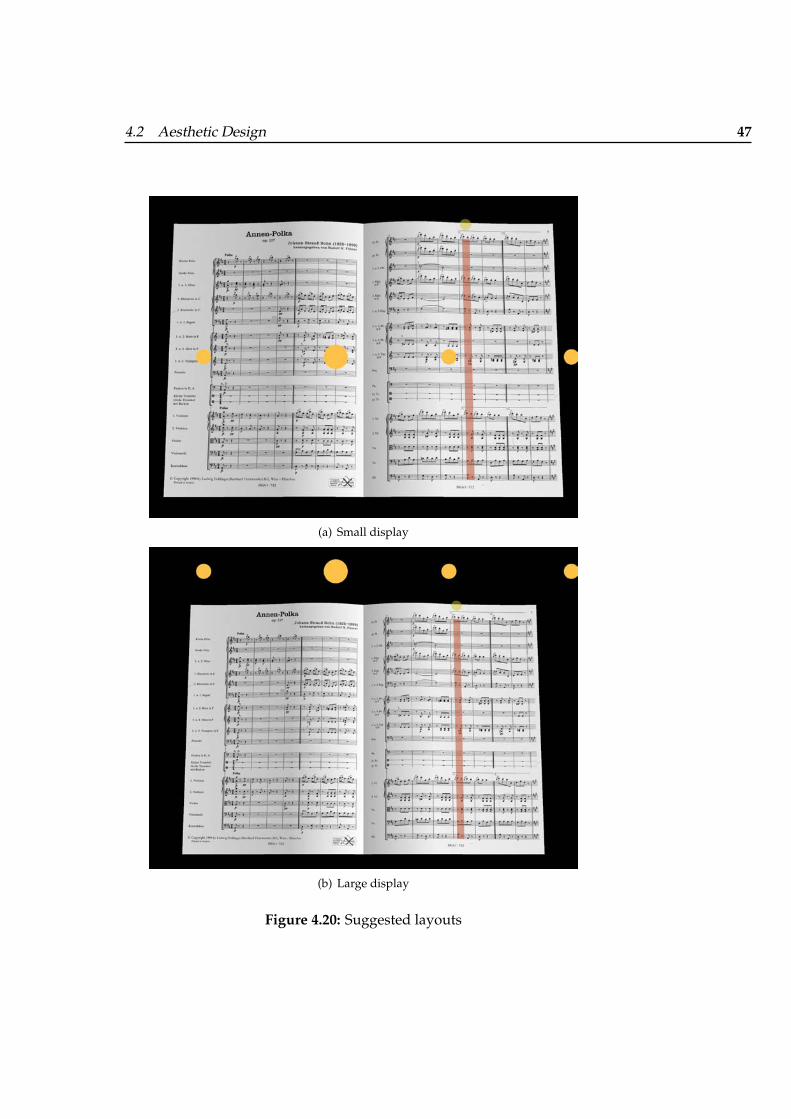
4.2 Aesthetic Design 47
(a) Small display
(b) Large display
Figure 4.20: Suggested layouts
48 4 Design of the MICON
4.3 Integrating MICON and Maestro
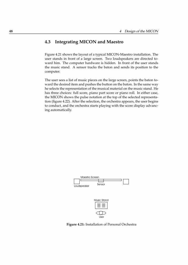
Figure 4.21 shows the layout of a typical MICON-Maestro installation. Theuser stands in front of a large screen. Two loudspeakers are directed to-ward him. The computer hardware is hidden. In front of the user standsthe music stand. A sensor tracks the baton and sends its position to thecomputer.
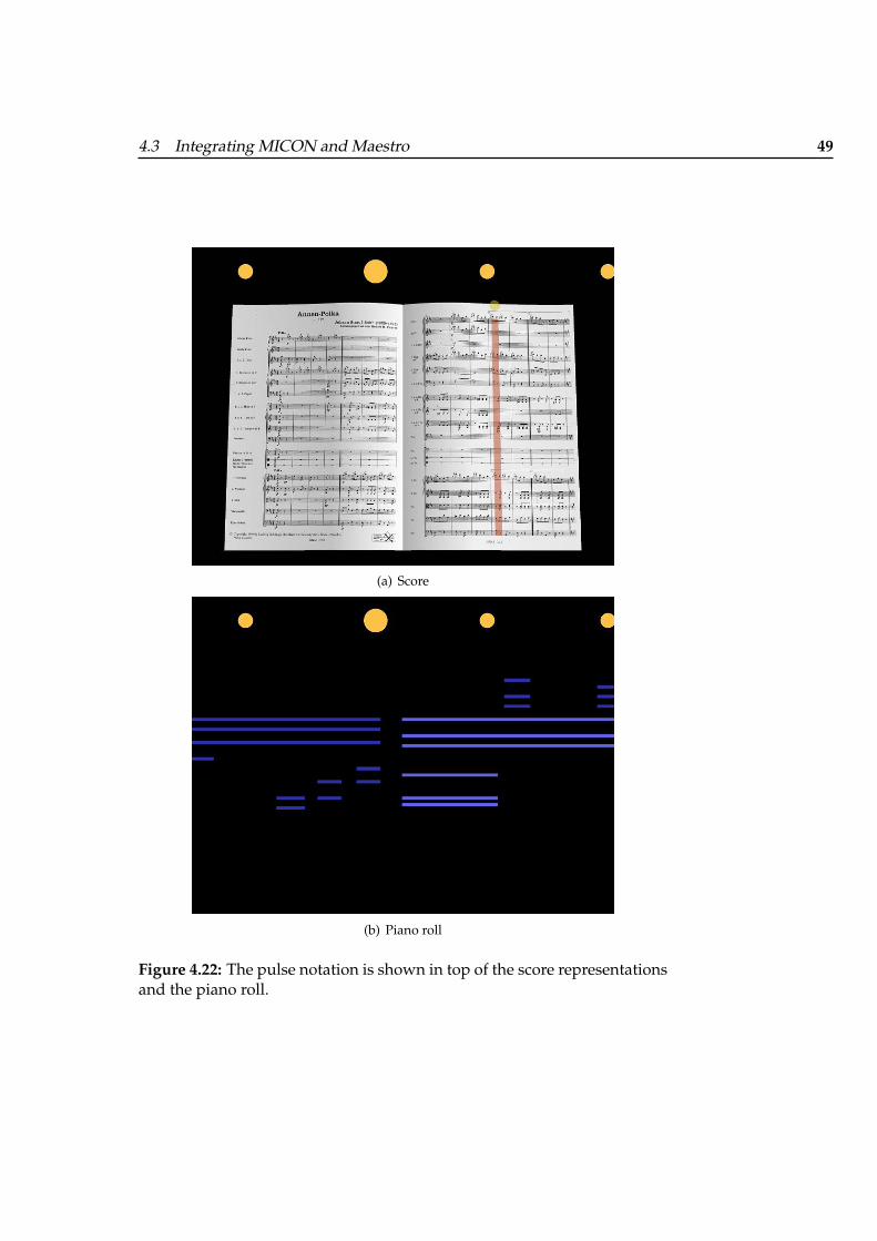
The user sees a list of music pieces on the large screen, points the baton to-ward the desired item and pushes the button on the baton. In the same wayhe selects the representation of the musical material on the music stand. Hehas three choices: full score, piano part score or piano roll. In either case,the MICON shows the pulse notation at the top of the selected representa-tion (figure 4.22). After the selection, the orchestra appears, the user beginsto conduct, and the orchestra starts playing with the score display advanc-ing automatically.
SensorMaestro Screen
UserMusic Stand
Loudspeaker
Figure 4.21: Installation of Personal Orchestra
4.3 Integrating MICON and Maestro 49
(a) Score
(b) Piano roll
Figure 4.22: The pulse notation is shown in top of the score representationsand the piano roll.

51
Chapter 5
Content Creation
For a new music piece, Maestro needs:
• a synchronized audio and video recording of the piece and
• timing information about the beats in the recording provided by aBeats file.
For a new music, piece MICON needs:
• scans of the full score and the piano extract score,
• information about the score provided by ScoreInfo files,
• timing information about the beats in the recording provided by aBeats file and
• a piano roll representation given by a MIDI file that is synchronizedwith the audio recording.
Adding a new music piece to Personal Orchestra 4 requires various manualprocessing steps. Figure 5.1 shows the suggested workflow for that task.The beat concept is of central importance. It determines the variables inthe creation of the ScoreInfo file and the Beats file. The beat concept is theregular pulse of the piece, the base unit that the user conducts. The baseunit given by the composer is a good choice (e.g., a quarter note in a 4/4measure). Sometimes, however, a larger base unit is easier to conduct withthe quite heavy electronic baton. The MICON and the Maestro have to

52 5 Content Creation
BeatConcept
Maestro MICONscanscore
JPEGScoreMarkerScoreInfofile
recordAudioVideo
MIDIfileMIDI recording
BeatsfileMidi2Beats
Figure 5.1: Workflow for adding a new piece to the Personal Orchestrasystem
be based on the same beat concept; otherwise, the pulse notation wouldbe pointless. This is best achieved by using the same file for both parts.Because of the combination of the pulse notation with the piano roll, theMIDI file and the Beats file have to be perfectly synchronized. Therefore,the Beats file is derived from the MIDI file and is then given to Maestro.
5.1 Score Information Model
As far as the MICON is concerned, a score is made of three structures:
5.1 Score Information Model 53
• note systems,
• beats and
• staffs.
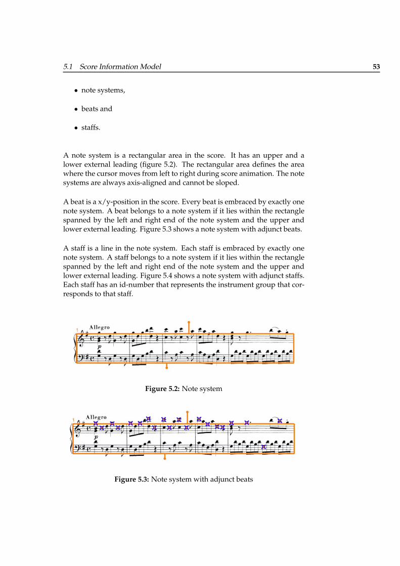
A note system is a rectangular area in the score. It has an upper and alower external leading (figure 5.2). The rectangular area defines the areawhere the cursor moves from left to right during score animation. The notesystems are always axis-aligned and cannot be sloped.
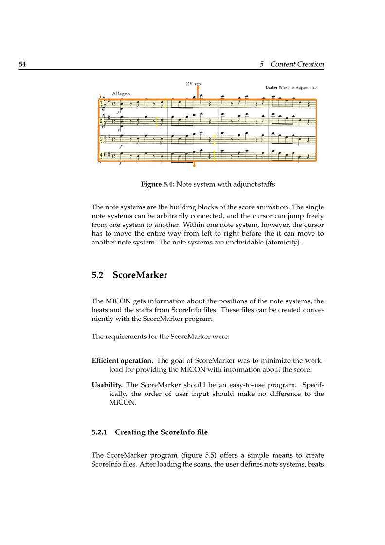
A beat is a x/y-position in the score. Every beat is embraced by exactly onenote system. A beat belongs to a note system if it lies within the rectanglespanned by the left and right end of the note system and the upper andlower external leading. Figure 5.3 shows a note system with adjunct beats.
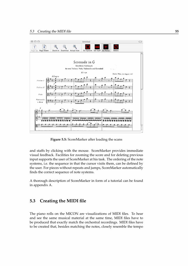
A staff is a line in the note system. Each staff is embraced by exactly onenote system. A staff belongs to a note system if it lies within the rectanglespanned by the left and right end of the note system and the upper andlower external leading. Figure 5.4 shows a note system with adjunct staffs.Each staff has an id-number that represents the instrument group that cor-responds to that staff.
Figure 5.2: Note system
Figure 5.3: Note system with adjunct beats
54 5 Content Creation
Figure 5.4: Note system with adjunct staffs
The note systems are the building blocks of the score animation. The singlenote systems can be arbitrarily connected, and the cursor can jump freelyfrom one system to another. Within one note system, however, the cursorhas to move the entire way from left to right before the it can move toanother note system. The note systems are undividable (atomicity).
5.2 ScoreMarker
The MICON gets information about the positions of the note systems, thebeats and the staffs from ScoreInfo files. These files can be created conve-niently with the ScoreMarker program.
The requirements for the ScoreMarker were:
Efficient operation. The goal of ScoreMarker was to minimize the work-load for providing the MICON with information about the score.
Usability. The ScoreMarker should be an easy-to-use program. Specif-ically, the order of user input should make no difference to theMICON.
5.2.1 Creating the ScoreInfo file
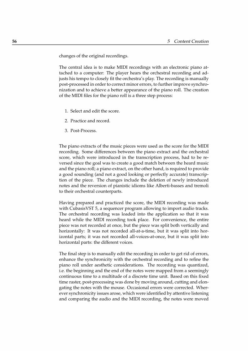
The ScoreMarker program (figure 5.5) offers a simple means to createScoreInfo files. After loading the scans, the user defines note systems, beats
5.3 Creating the MIDI file 55
Figure 5.5: ScoreMarker after loading the scans
and staffs by clicking with the mouse. ScoreMarker provides immediatevisual feedback. Facilities for zooming the score and for deleting previousinput supports the user of ScoreMarker at his task. The ordering of the notesystems, i.e. the sequence in that the cursor visits them, can be defined bythe user. For pieces without repeats and jumps, ScoreMarker automaticallyfinds the correct sequence of note systems.
A thorough description of ScoreMarker in form of a tutorial can be foundin appendix A.
5.3 Creating the MIDI file
The piano rolls on the MICON are visualizations of MIDI files. To hearand see the same musical material at the same time, MIDI files have tobe produced that exactly match the orchestral recordings. MIDI files haveto be created that, besides matching the notes, closely resemble the tempo
56 5 Content Creation
changes of the original recordings.
The central idea is to make MIDI recordings with an electronic piano at-tached to a computer: The player hears the orchestral recording and ad-justs his tempo to closely fit the orchestra’s play. The recording is manuallypost-processed in order to correct minor errors, to further improve synchro-nization and to achieve a better appearance of the piano roll. The creationof the MIDI files for the piano roll is a three step process:
1. Select and edit the score.
2. Practice and record.
3. Post-Process.
The piano extracts of the music pieces were used as the score for the MIDIrecording. Some differences between the piano extract and the orchestralscore, which were introduced in the transcription process, had to be re-versed since the goal was to create a good match between the heard musicand the piano roll; a piano extract, on the other hand, is required to providea good sounding (and not a good looking or perfectly accurate) transcrip-tion of the piece. The changes include the deletion of newly introducednotes and the reversion of pianistic idioms like Alberti-basses and tremolito their orchestral counterparts.
Having prepared and practiced the score, the MIDI recording was madewith CubasisVST 5, a sequencer program allowing to import audio tracks.The orchestral recording was loaded into the application so that it washeard while the MIDI recording took place. For convenience, the entirepiece was not recorded at once, but the piece was split both vertically andhorizontally: It was not recorded all-at-a-time, but it was split into hor-izontal parts; it was not recorded all-voices-at-once, but it was split intohorizontal parts: the different voices.
The final step is to manually edit the recording in order to get rid of errors,enhance the synchronicity with the orchestral recording and to refine thepiano roll under aesthetic considerations. The recording was quantized,i.e. the beginning and the end of the notes were mapped from a seeminglycontinuous time to a multitude of a discrete time unit. Based on this fixedtime raster, post-processing was done by moving around, cutting and elon-gating the notes with the mouse. Occasional errors were corrected. Wher-ever synchronicity issues arose, which were identified by attentive listeningand comparing the audio and the MIDI recording, the notes were moved
5.4 Creating the Beats file 57
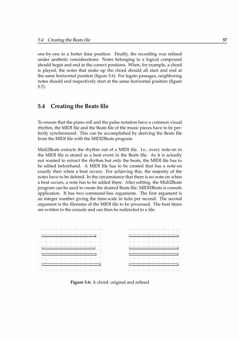
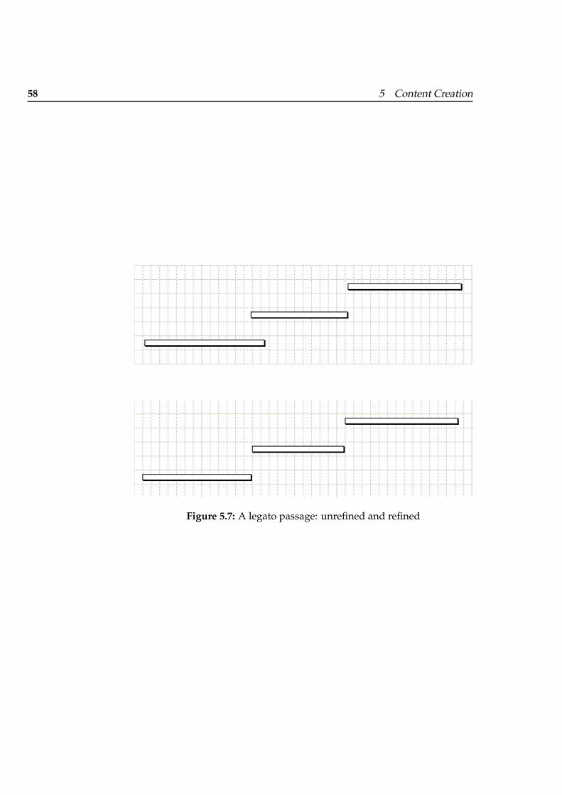
one-by-one to a better time position. Finally, the recording was refinedunder aesthetic considerations: Notes belonging to a logical compoundshould begin and end in the correct positions. When, for example, a chordis played, the notes that make up the chord should all start and end atthe same horizontal position (figure 5.6). For legato passages, neighboringnotes should end respectively start at the same horizontal position (figure5.7).
5.4 Creating the Beats file
To ensure that the piano roll and the pulse notation have a common visualrhythm, the MIDI file and the Beats file of the music pieces have to be per-fectly synchronized. This can be accomplished by deriving the Beats filefrom the MIDI file with the MIDI2Beats program.
Midi2Beats extracts the rhythm out of a MIDI file. I.e., every note-on inthe MIDI file is stored as a beat event in the Beats file. As it is actuallynot wanted to extract the rhythm but only the beats, the MIDI file has tobe edited beforehand. A MIDI file has to be created that has a note-onexactly then when a beat occurs. For achieving this, the majority of thenotes have to be deleted. In the circumstance that there is no note-on whena beat occurs, a note has to be added there. After editing, the Midi2Beatsprogram can be used to create the desired Beats file. MIDI2Beats is consoleapplication. It has two command-line arguments. The first argument isan integer number giving the time-scale in ticks per second. The secondargument is the filename of the MIDI file to be processed. The beat timesare written to the console and can then be redirected to a file.
Figure 5.6: A chord: original and refined
58 5 Content Creation
Figure 5.7: A legato passage: unrefined and refined
59
Chapter 6
Implementation
Three programs were developed:
• MICON,
• ScoreMarker and
• Midi2Beats.
ScoreMarker was the first program to be written. ScoreMarker consists oftwo parts: a back-end, implemented in C++, and a front-end, implementedin Obj-C using the Obj-C Cocoa framework. The back-end reads and writesScoreInfo files while the front-end handles the user interface.
Second, the MICON was written. The MICON consists of four parts: file-I/O, communication, assembling and rendering. The file-I/O part consistsof a ScoreInfo file facility, which was reused from the back-end of Score-Marker, and additional facilities to read Beats and MIDI files. The file-I/Opart was written in C++. The rendering part of the MICON uses OpenGL.The rest was written in Obj-C using the Cocoa framework.
The last program to be written was the Midi2Beats converter. It was neededbecause the Beats files that were produced for the Maestro system were notsufficiently synchronous with the MIDI files used for the piano roll. Theimplementation of MIDI2Beats reused the MIDI-facility from the MICON.
60 6 Implementation
6.1 MICON
During conducting Maestro continuously informs the MICON about thecurrent position of the music. The position is expressed in seconds sincebeginning of the piece. Using this temporal information, the MICON as-sembles the representations and renders them.
This section follows the way of a time-packet. This section describes howthe time-packet is communicated between the Maestro and the MICON,and how the MICON uses this information to assemble the representa-tions. Then, the rendering process will be presented. However, at start-up MICON first loads and parses Beats files and ScoreInfo files. So, thisexploration starts there.
6.1.1 File Formats
MICON uses JPEG and MIDI files for displaying the score and piano roll.MICON uses two non-standard file-formats, Beats files and ScoreInfo files,that are explained in this section.
Beats File
A Beats file contains a representation for the beats of a music piece. A Beatsfile is separated into a header and a body. The header defines the time-scaleand gives the duration of the piece. The time-scale is defined in terms ofticks per second. The beat times are contained in the body of the Beats file.They are given according to the time scale. Here is an excerpt from a Beatsfile:
1 ###########################2 ## BeatTapper BeatFile ##3 ###########################45 # Timescale in ticks per second6 [scale]7 60089 # Duration of the movie in ticks
10 [duration]
6.1 MICON 61
11 1298751213 # Beattimes measured in ticks14 [beats]15 75516 151117 226618 302119 380820 466621 ...
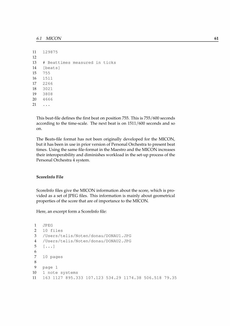
This beat-file defines the first beat on position 755. This is 755/600 secondsaccording to the time-scale. The next beat is on 1511/600 seconds and soon.
The Beats-file format has not been originally developed for the MICON,but it has been in use in prior version of Personal Orchestra to present beattimes. Using the same file-format in the Maestro and the MICON increasestheir interoperability and diminishes workload in the set-up process of thePersonal Orchestra 4 system.
ScoreInfo File
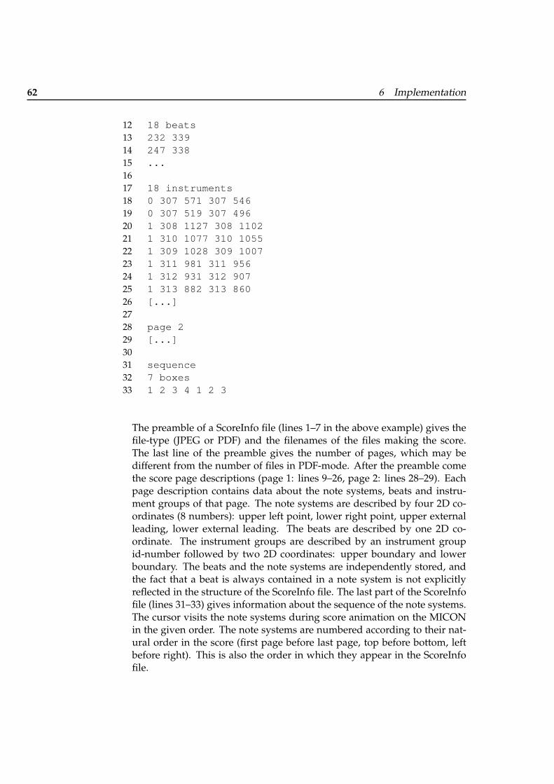
ScoreInfo files give the MICON information about the score, which is pro-vided as a set of JPEG files. This information is mainly about geometricalproperties of the score that are of importance to the MICON.
Here, an excerpt form a ScoreInfo file:
1 JPEG2 10 files3 /Users/telis/Noten/donau/DONAU1.JPG4 /Users/telis/Noten/donau/DONAU2.JPG5 [...]67 10 pages89 page 1
10 1 note systems11 163 1127 895.333 107.123 534.29 1174.38 506.518 79.35
62 6 Implementation
12 18 beats13 232 33914 247 33815 ...1617 18 instruments18 0 307 571 307 54619 0 307 519 307 49620 1 308 1127 308 110221 1 310 1077 310 105522 1 309 1028 309 100723 1 311 981 311 95624 1 312 931 312 90725 1 313 882 313 86026 [...]2728 page 229 [...]3031 sequence32 7 boxes33 1 2 3 4 1 2 3
The preamble of a ScoreInfo file (lines 1–7 in the above example) gives thefile-type (JPEG or PDF) and the filenames of the files making the score.The last line of the preamble gives the number of pages, which may bedifferent from the number of files in PDF-mode. After the preamble comethe score page descriptions (page 1: lines 9–26, page 2: lines 28–29). Eachpage description contains data about the note systems, beats and instru-ment groups of that page. The note systems are described by four 2D co-ordinates (8 numbers): upper left point, lower right point, upper externalleading, lower external leading. The beats are described by one 2D co-ordinate. The instrument groups are described by an instrument groupid-number followed by two 2D coordinates: upper boundary and lowerboundary. The beats and the note systems are independently stored, andthe fact that a beat is always contained in a note system is not explicitlyreflected in the structure of the ScoreInfo file. The last part of the ScoreInfofile (lines 31–33) gives information about the sequence of the note systems.The cursor visits the note systems during score animation on the MICONin the given order. The note systems are numbered according to their nat-ural order in the score (first page before last page, top before bottom, leftbefore right). This is also the order in which they appear in the ScoreInfofile.
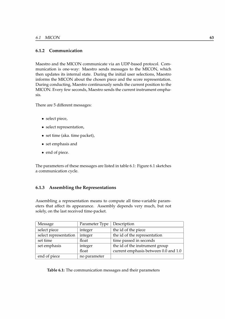
6.1 MICON 63
6.1.2 Communication
Maestro and the MICON communicate via an UDP-based protocol. Com-munication is one-way: Maestro sends messages to the MICON, whichthen updates its internal state. During the initial user selections, Maestroinforms the MICON about the chosen piece and the score representation.During conducting, Maestro continuously sends the current position to theMICON. Every few seconds, Maestro sends the current instrument empha-sis.
There are 5 different messages:
• select piece,
• select representation,
• set time (aka. time packet),
• set emphasis and
• end of piece.
The parameters of these messages are listed in table 6.1: Figure 6.1 sketchesa communication cycle.
6.1.3 Assembling the Representations
Assembling a representation means to compute all time-variable param-eters that affect its appearance. Assembly depends very much, but notsolely, on the last received time-packet.
Message Parameter Type Descriptionselect piece integer the id of the pieceselect representation integer the id of the representationset time float time passed in secondsset emphasis integer the id of the instrument group
float current emphasis between 0.0 and 1.0end of piece no parameter
Table 6.1: The communication messages and their parameters
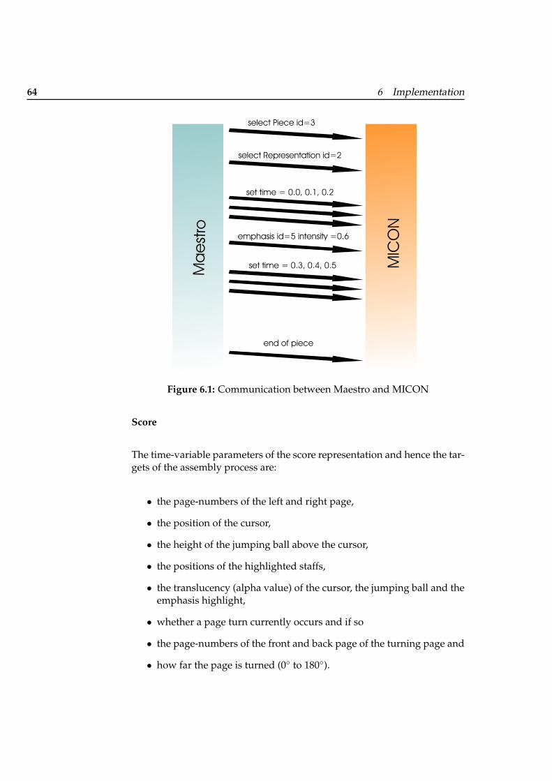
64 6 Implementation
select Representation id=2select Piece id=3
set time = 0.0, 0.1, 0.2emphasis id=5 intensity =0.6
set time = 0.3, 0.4, 0.5
end of piece
Mestaro MICON
Figure 6.1: Communication between Maestro and MICON
Score
The time-variable parameters of the score representation and hence the tar-gets of the assembly process are:
• the page-numbers of the left and right page,
• the position of the cursor,
• the height of the jumping ball above the cursor,
• the positions of the highlighted staffs,
• the translucency (alpha value) of the cursor, the jumping ball and theemphasis highlight,
• whether a page turn currently occurs and if so
• the page-numbers of the front and back page of the turning page and
• how far the page is turned (0◦ to 180◦).
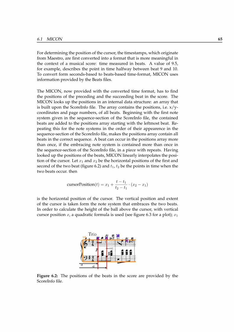
6.1 MICON 65
For determining the position of the cursor, the timestamps, which originatefrom Maestro, are first converted into a format that is more meaningful inthe context of a musical score: time measured in beats. A value of 9.5,for example, describes the point in time halfway between beat 9 and 10.To convert form seconds-based to beats-based time-format, MICON usesinformation provided by the Beats files.
The MICON, now provided with the converted time format, has to findthe positions of the preceding and the succeeding beat in the score. TheMICON looks up the positions in an internal data structure: an array thatis built upon the ScoreInfo file. The array contains the positions, i.e. x/y-coordinates and page numbers, of all beats. Beginning with the first notesystem given in the sequence-section of the ScoreInfo file, the containedbeats are added to the positions array starting with the leftmost beat. Re-peating this for the note systems in the order of their appearence in thesequence-section of the ScoreInfo file, makes the positions array contain allbeats in the correct sequence. A beat can occur in the positions array morethan once, if the embracing note system is contained more than once inthe sequence-section of the ScoreInfo file, in a piece with repeats. Havinglooked up the positions of the beats, MICON linearly interpolates the posi-tion of the cursor. Let x1 and x2 be the horizontal positions of the first andsecond of the two beat (figure 6.2) and t1, t2 be the points in time when thetwo beats occur. then
cursorPosition(t) = x1 +t− t1t2 − t1
· (x2 − x1)
is the horizontal position of the cursor. The vertical position and extentof the cursor is taken form the note system that embraces the two beats.In order to calculate the height of the ball above the cursor, with verticalcursor position x, a quadratic formula is used (see figure 6.3 for a plot); x1
Figure 6.2: The positions of the beats in the score are provided by theScoreInfo file.
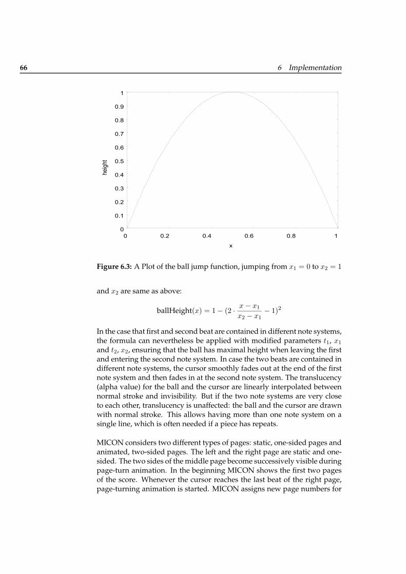
66 6 Implementation
0
0.1
0.2
0.3
0.4
0.5
0.6
0.7
0.8
0.9
1
0 0.2 0.4 0.6 0.8 1
heig
ht
x
Figure 6.3: A Plot of the ball jump function, jumping from x1 = 0 to x2 = 1
and x2 are same as above:
ballHeight(x) = 1− (2 · x− x1
x2 − x1− 1)2
In the case that first and second beat are contained in different note systems,the formula can nevertheless be applied with modified parameters t1, x1
and t2, x2, ensuring that the ball has maximal height when leaving the firstand entering the second note system. In case the two beats are contained indifferent note systems, the cursor smoothly fades out at the end of the firstnote system and then fades in at the second note system. The translucency(alpha value) for the ball and the cursor are linearly interpolated betweennormal stroke and invisibility. But if the two note systems are very closeto each other, translucency is unaffected: the ball and the cursor are drawnwith normal stroke. This allows having more than one note system on asingle line, which is often needed if a piece has repeats.
MICON considers two different types of pages: static, one-sided pages andanimated, two-sided pages. The left and the right page are static and one-sided. The two sides of the middle page become successively visible duringpage-turn animation. In the beginning MICON shows the first two pagesof the score. Whenever the cursor reaches the last beat of the right page,page-turning animation is started. MICON assigns new page numbers for
6.1 MICON 67
the static right page and the two sides of the animated middle page. Lettreal start be the point in real-world time when the page-turn starts, and lettreal be the current point in time (seconds); let tbeat before and tbeat after be thebeat times as given by the Beats file and tMaestro the value of the last time-packet the MICON has received from Maestro in converted time-format.According to this formula the middle page is turned between 0◦ and 180◦:
pageTurn(treal, tMaestro) = 180 ·(
treal − treal start1.5sec
+tMaestro − tbeat before
tbeat after
)
If the music does not proceed, page turning is nevertheless completed in1.5 seconds (1.5-seconds-limit). If the user conducts and music proceeds,the new page is reached slightly ahead of time. When page-turning is com-pleted, the MICON assigns new page numbers to the static left and rightpages and the middle page vanishes.
Pulse
The time-variable parameters of the score representation and hence the tar-gets of the assembly process are:
• the vertical positions of the pulses and
• the size of the pulses.
The positions of the pulses are determined by extracting the beat times fromthe beats file and translating these absolute positions along the x-axis toreflect the point in time given by the last time-packet.
The pulses move along form right to left with constant speed and gain sizeas they approach the center of the screen. The desired maximal magnifica-tion m is configurable; so is the distance dcenter between the center and thepoint when the magnification begins. Let distance be the current distancebetween the pulse and the center of the screen. The size of the pulse is thengiven by:
magnification(distance) =a
b + distance
wherea =
dcenter · mm− 1
b =dcenter
m− 1
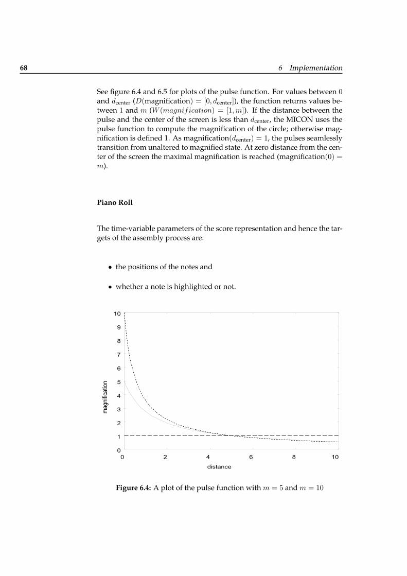
68 6 Implementation
See figure 6.4 and 6.5 for plots of the pulse function. For values between 0and dcenter (D(magnification) = [0, dcenter]), the function returns values be-tween 1 and m (W (magnification) = [1,m]). If the distance between thepulse and the center of the screen is less than dcenter, the MICON uses thepulse function to compute the magnification of the circle; otherwise mag-nification is defined 1. As magnification(dcenter) = 1, the pulses seamlesslytransition from unaltered to magnified state. At zero distance from the cen-ter of the screen the maximal magnification is reached (magnification(0) =m).
Piano Roll
The time-variable parameters of the score representation and hence the tar-gets of the assembly process are:
• the positions of the notes and
• whether a note is highlighted or not.
0
1
2
3
4
5
6
7
8
9
10
0 2 4 6 8 10
magnifi
catio
n
distance
Figure 6.4: A plot of the pulse function with m = 5 and m = 10
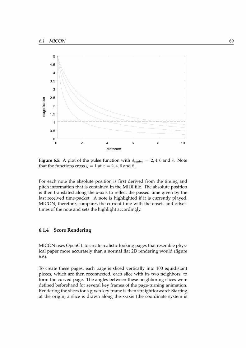
6.1 MICON 69
0
0.5
1
1.5
2
2.5
3
3.5
4
4.5
5
0 2 4 6 8 10
magnifi
catio
n
distance
Figure 6.5: A plot of the pulse function with dcenter = 2, 4, 6 and 8. Notethat the functions cross y = 1 at x = 2, 4, 6 and 8.
For each note the absolute position is first derived from the timing andpitch information that is contained in the MIDI file. The absolute positionis then translated along the x-axis to reflect the passed time given by thelast received time-packet. A note is highlighted if it is currently played.MICON, therefore, compares the current time with the onset- and offset-times of the note and sets the highlight accordingly.
6.1.4 Score Rendering
MICON uses OpenGL to create realistic looking pages that resemble phys-ical paper more accurately than a normal flat 2D rendering would (figure6.6).
To create these pages, each page is sliced vertically into 100 equidistantpieces, which are then reconnected, each slice with its two neighbors, toform the curved page. The angles between these neighboring slices weredefined beforehand for several key frames of the page-turning animation.Rendering the slices for a given key frame is then straightforward: Startingat the origin, a slice is drawn along the x-axis (the coordinate system is
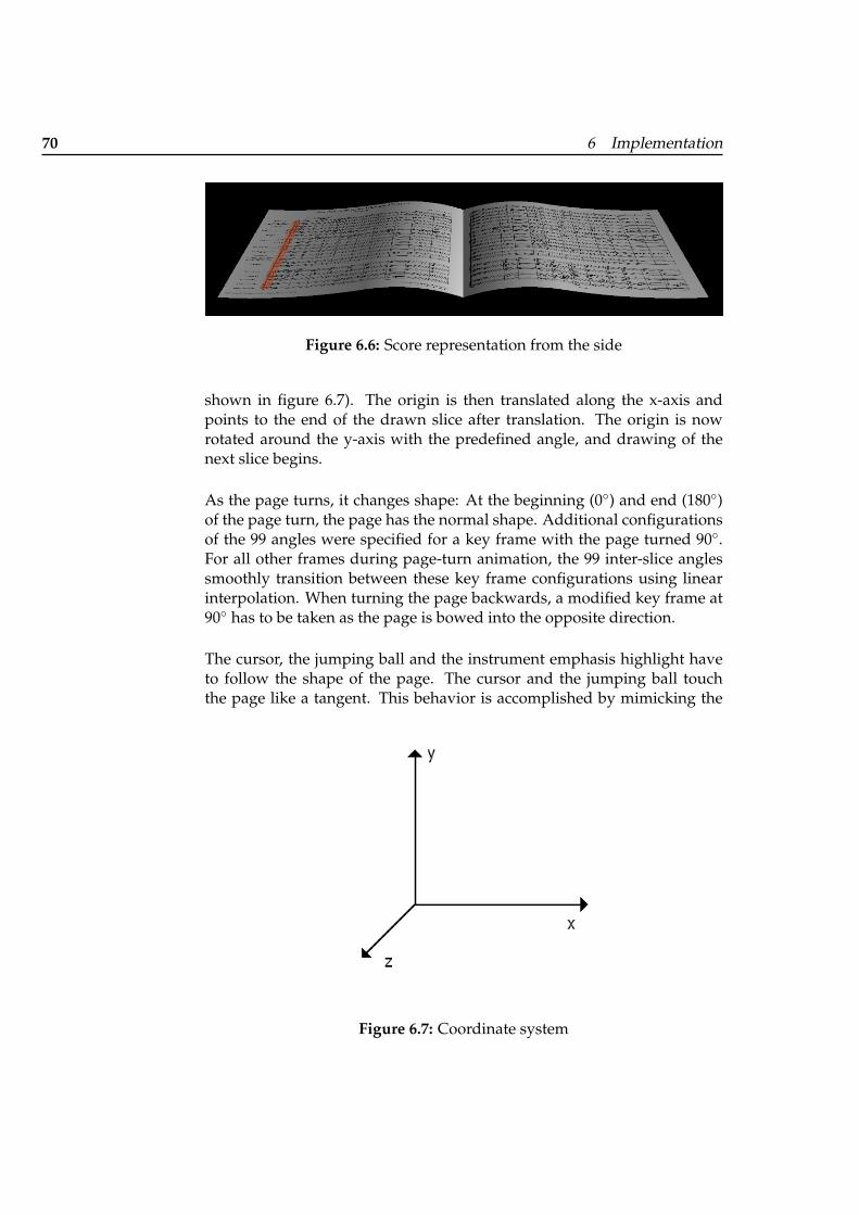
70 6 Implementation
Figure 6.6: Score representation from the side
shown in figure 6.7). The origin is then translated along the x-axis andpoints to the end of the drawn slice after translation. The origin is nowrotated around the y-axis with the predefined angle, and drawing of thenext slice begins.
As the page turns, it changes shape: At the beginning (0◦) and end (180◦)of the page turn, the page has the normal shape. Additional configurationsof the 99 angles were specified for a key frame with the page turned 90◦.For all other frames during page-turn animation, the 99 inter-slice anglessmoothly transition between these key frame configurations using linearinterpolation. When turning the page backwards, a modified key frame at90◦ has to be taken as the page is bowed into the opposite direction.
The cursor, the jumping ball and the instrument emphasis highlight haveto follow the shape of the page. The cursor and the jumping ball touchthe page like a tangent. This behavior is accomplished by mimicking the
Figure 6.7: Coordinate system
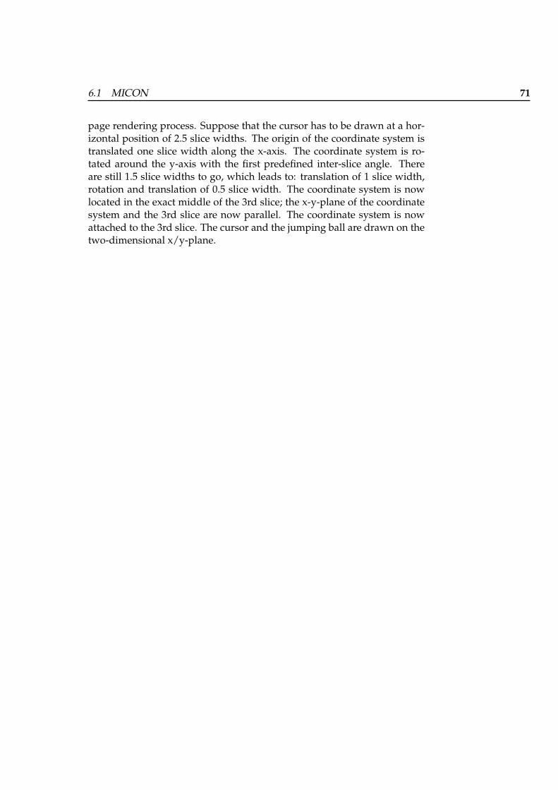
6.1 MICON 71
page rendering process. Suppose that the cursor has to be drawn at a hor-izontal position of 2.5 slice widths. The origin of the coordinate system istranslated one slice width along the x-axis. The coordinate system is ro-tated around the y-axis with the first predefined inter-slice angle. Thereare still 1.5 slice widths to go, which leads to: translation of 1 slice width,rotation and translation of 0.5 slice width. The coordinate system is nowlocated in the exact middle of the 3rd slice; the x-y-plane of the coordinatesystem and the 3rd slice are now parallel. The coordinate system is nowattached to the 3rd slice. The cursor and the jumping ball are drawn on thetwo-dimensional x/y-plane.
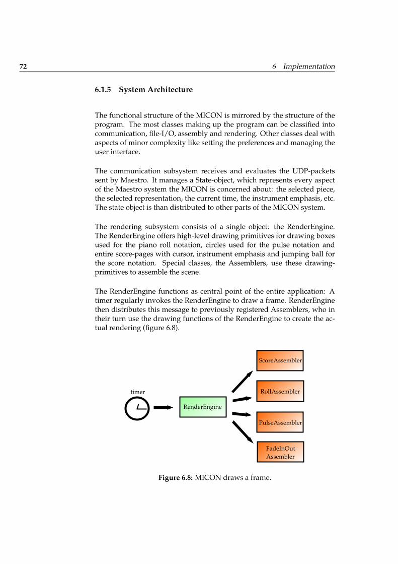
72 6 Implementation
6.1.5 System Architecture
The functional structure of the MICON is mirrored by the structure of theprogram. The most classes making up the program can be classified intocommunication, file-I/O, assembly and rendering. Other classes deal withaspects of minor complexity like setting the preferences and managing theuser interface.
The communication subsystem receives and evaluates the UDP-packetssent by Maestro. It manages a State-object, which represents every aspectof the Maestro system the MICON is concerned about: the selected piece,the selected representation, the current time, the instrument emphasis, etc.The state object is than distributed to other parts of the MICON system.
The rendering subsystem consists of a single object: the RenderEngine.The RenderEngine offers high-level drawing primitives for drawing boxesused for the piano roll notation, circles used for the pulse notation andentire score-pages with cursor, instrument emphasis and jumping ball forthe score notation. Special classes, the Assemblers, use these drawing-primitives to assemble the scene.
The RenderEngine functions as central point of the entire application: Atimer regularly invokes the RenderEngine to draw a frame. RenderEnginethen distributes this message to previously registered Assemblers, who intheir turn use the drawing functions of the RenderEngine to create the ac-tual rendering (figure 6.8).
RenderEngine
ScoreAssemblerRollAssembler
PulseAssemblerFadeInOutAssembler
timer
Figure 6.8: MICON draws a frame.
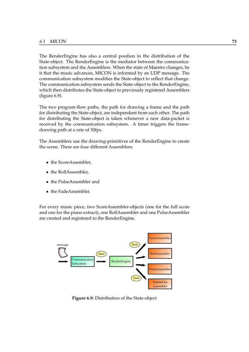
6.1 MICON 73
The RenderEngine has also a central position in the distribution of theState-object. The RenderEngine is the mediator between the communica-tion subsystem and the Assemblers. When the state of Maestro changes, beit that the music advances, MICON is informed by an UDP message. Thecommunication subsystem modifies the State-object to reflect that change.The communication subsystem sends the State-object to the RenderEngine,which then distributes the State-object to previously registered Assemblers(figure 6.9).
The two program-flow paths, the path for drawing a frame and the pathfor distributing the State-object, are independent from each other. The pathfor distributing the State-object is taken whenever a new data-packet isreceived by the communication subsystem. A timer triggers the frame-drawing path at a rate of 30fps.
The Assemblers use the drawing-primitives of the RenderEngine to createthe scene. There are four different Assemblers:
• the ScoreAssembler,
• the RollAssembler,
• the PulseAssembler and
• the FadeAssembler.
For every music piece, two ScoreAssembler-objects (one for the full scoreand one for the piano extract), one RollAssembler and one PulseAssemblerare created and registered to the RenderEngine.
RenderEngine
ScoreAssemblerRollAssembler
PulseAssemblerFadeInOutAssembler
CommunicationSubsystemState
State
State
message
Figure 6.9: Distribution of the State-object
74 6 Implementation
The FadeAssembler is responsible for smoothly fading in or out the rep-resentations when the piece begins or ends. The FadeAssembler does notuse drawing functions provided by the RenderEngine but issues OpenGL-commands directly. FadeAssembler generates the fading effect by drawinga black rectangle with changing transparency.
75
Chapter 7
Evaluation
7.1 Testing the MICON with Experts
The Personal Orchestra system was presented in the “Hochschule furMusik und Darstellende Kunst” in Frankfurt to music students. Ten stu-dents participated in the test. They were:
• four pianists,
• one composer,
• four other instrumentalists (violinist, cellist, flutist, guitarist).
The students had different experience in conducting: Six of them hadlearned conducting in a course at the Hochschule or other institutes. Two ofthem had practical conducting experience (brass orchestra, church choir).Two students had no experience, neither theoretical nor practical, of con-ducting.
For each student the test took 30 minutes. The student conducted thesystem at least two times: once with the combined full score and pulsenotation, once with the combined piano-roll and pulse notation. If therewas still time, the student would conduct a third time with the piano-partscore on the note stand. The “Blue Danube” was at that time this the onlypiece available on the MICON prototype. After each run, a discussion withthe student took place. The discussion had three focus points: checkingwhether the representation were understood, getting feedback about the
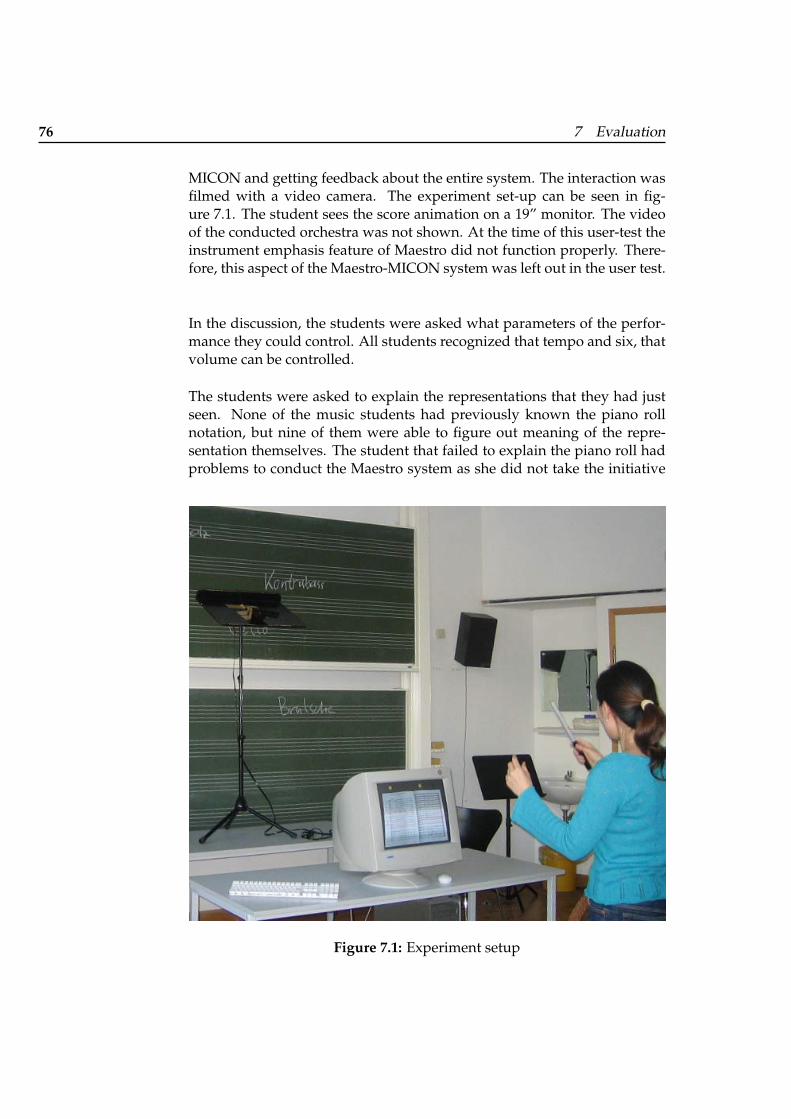
76 7 Evaluation
MICON and getting feedback about the entire system. The interaction wasfilmed with a video camera. The experiment set-up can be seen in fig-ure 7.1. The student sees the score animation on a 19” monitor. The videoof the conducted orchestra was not shown. At the time of this user-test theinstrument emphasis feature of Maestro did not function properly. There-fore, this aspect of the Maestro-MICON system was left out in the user test.
In the discussion, the students were asked what parameters of the perfor-mance they could control. All students recognized that tempo and six, thatvolume can be controlled.
The students were asked to explain the representations that they had justseen. None of the music students had previously known the piano rollnotation, but nine of them were able to figure out meaning of the repre-sentation themselves. The student that failed to explain the piano roll hadproblems to conduct the Maestro system as she did not take the initiative
Figure 7.1: Experiment setup
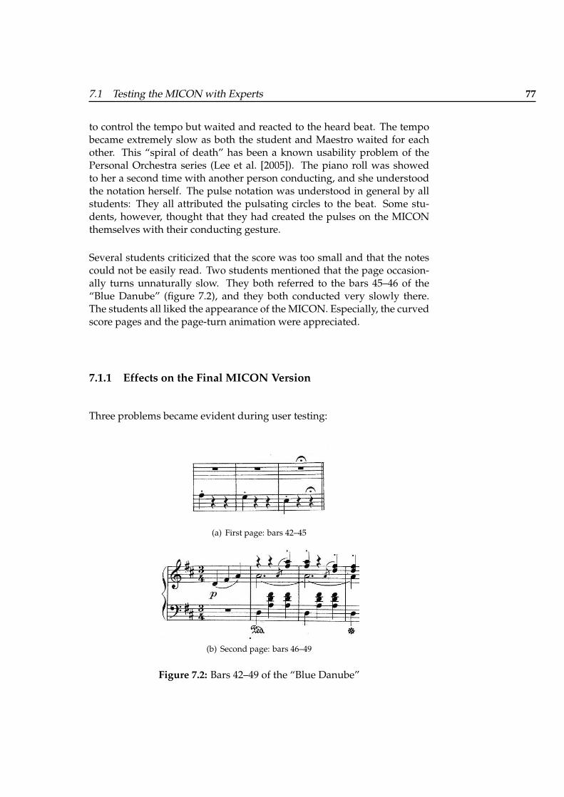
7.1 Testing the MICON with Experts 77
to control the tempo but waited and reacted to the heard beat. The tempobecame extremely slow as both the student and Maestro waited for eachother. This “spiral of death” has been a known usability problem of thePersonal Orchestra series (Lee et al. [2005]). The piano roll was showedto her a second time with another person conducting, and she understoodthe notation herself. The pulse notation was understood in general by allstudents: They all attributed the pulsating circles to the beat. Some stu-dents, however, thought that they had created the pulses on the MICONthemselves with their conducting gesture.
Several students criticized that the score was too small and that the notescould not be easily read. Two students mentioned that the page occasion-ally turns unnaturally slow. They both referred to the bars 45–46 of the“Blue Danube” (figure 7.2), and they both conducted very slowly there.The students all liked the appearance of the MICON. Especially, the curvedscore pages and the page-turn animation were appreciated.
7.1.1 Effects on the Final MICON Version
Three problems became evident during user testing:
(a) First page: bars 42–45
(b) Second page: bars 46–49
Figure 7.2: Bars 42–49 of the “Blue Danube”
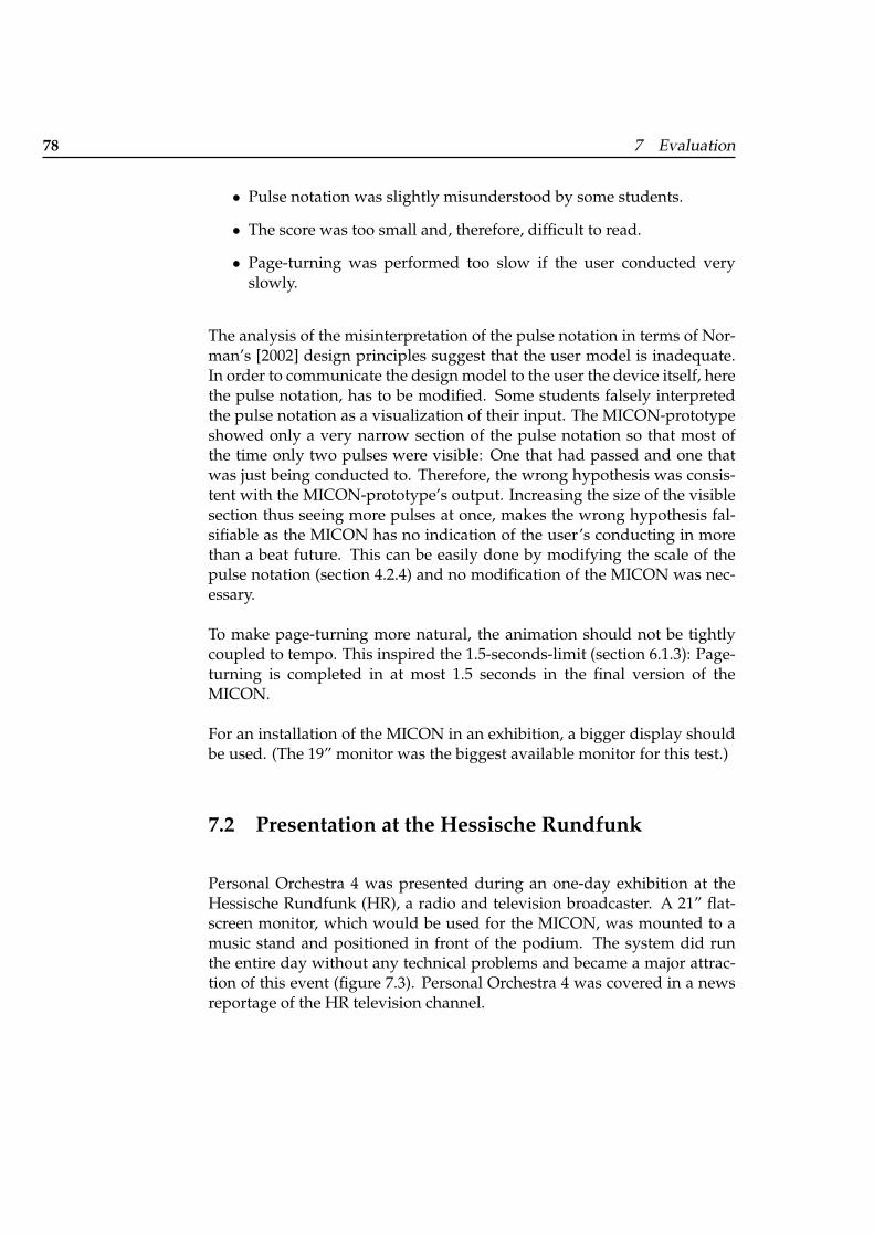
78 7 Evaluation
• Pulse notation was slightly misunderstood by some students.
• The score was too small and, therefore, difficult to read.
• Page-turning was performed too slow if the user conducted veryslowly.
The analysis of the misinterpretation of the pulse notation in terms of Nor-man’s [2002] design principles suggest that the user model is inadequate.In order to communicate the design model to the user the device itself, herethe pulse notation, has to be modified. Some students falsely interpretedthe pulse notation as a visualization of their input. The MICON-prototypeshowed only a very narrow section of the pulse notation so that most ofthe time only two pulses were visible: One that had passed and one thatwas just being conducted to. Therefore, the wrong hypothesis was consis-tent with the MICON-prototype’s output. Increasing the size of the visiblesection thus seeing more pulses at once, makes the wrong hypothesis fal-sifiable as the MICON has no indication of the user’s conducting in morethan a beat future. This can be easily done by modifying the scale of thepulse notation (section 4.2.4) and no modification of the MICON was nec-essary.
To make page-turning more natural, the animation should not be tightlycoupled to tempo. This inspired the 1.5-seconds-limit (section 6.1.3): Page-turning is completed in at most 1.5 seconds in the final version of theMICON.
For an installation of the MICON in an exhibition, a bigger display shouldbe used. (The 19” monitor was the biggest available monitor for this test.)
7.2 Presentation at the Hessische Rundfunk
Personal Orchestra 4 was presented during an one-day exhibition at theHessische Rundfunk (HR), a radio and television broadcaster. A 21” flat-screen monitor, which would be used for the MICON, was mounted to amusic stand and positioned in front of the podium. The system did runthe entire day without any technical problems and became a major attrac-tion of this event (figure 7.3). Personal Orchestra 4 was covered in a newsreportage of the HR television channel.
7.2 Presentation at the Hessische Rundfunk 79
Figure 7.3: Personal Orchestra 4 at the HR

81
Chapter 8
Summary
The MICON is a music stand for the interactive conducting exhibit Mae-stro. The MICON displays musical material in various formats: full score,piano extract score, piano roll and pulse notation. This enables a broadpublic to use the MICON, while still allowing expert music score readersto benefit from their abilities.
The pulse notation is a visualization of the metrical structure of the mu-sic. An animated pulsation marks the beat and creates a visual rhythm thatcorresponds to the heard beat, enabling an unexperienced user to under-stand the notation without further explanation. The pulse notation aids theuser in his conducting by providing information about the beat times inadvance.
The piano roll, a common representation in MIDI editing software, doesnot require music reading skills. The currently played notes, which arerepresented by moving boxes, are highlighted. This creates a visual rhythmthat corresponds to the heard rhythm, enabling an unexperienced user tounderstand the notation without further explanation.
The full score and the piano extract score are intended for user with musicreading abilities. The current position is marked in the score. In the fullscore representation the current instrument emphasis is visualized by col-oring the relevant sections of the score. The MICON renders its output viaOpenGL and features natural-looking curved pages and realistic-lookingpage-turning.
The MICON was presented to music students and their feedback was in-corporated into the final MICON version.

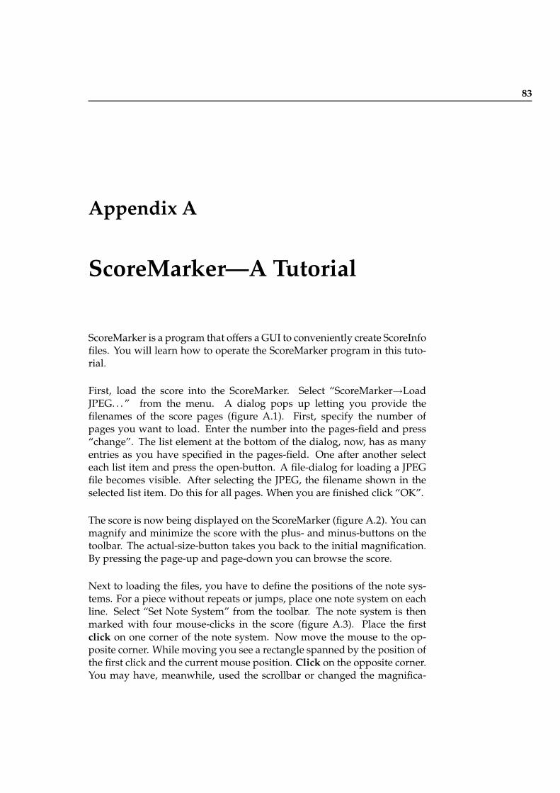
83
Appendix A
ScoreMarker—A Tutorial
ScoreMarker is a program that offers a GUI to conveniently create ScoreInfofiles. You will learn how to operate the ScoreMarker program in this tuto-rial.
First, load the score into the ScoreMarker. Select “ScoreMarker→LoadJPEG. . . ” from the menu. A dialog pops up letting you provide thefilenames of the score pages (figure A.1). First, specify the number ofpages you want to load. Enter the number into the pages-field and press“change”. The list element at the bottom of the dialog, now, has as manyentries as you have specified in the pages-field. One after another selecteach list item and press the open-button. A file-dialog for loading a JPEGfile becomes visible. After selecting the JPEG, the filename shown in theselected list item. Do this for all pages. When you are finished click “OK”.
The score is now being displayed on the ScoreMarker (figure A.2). You canmagnify and minimize the score with the plus- and minus-buttons on thetoolbar. The actual-size-button takes you back to the initial magnification.By pressing the page-up and page-down you can browse the score.
Next to loading the files, you have to define the positions of the note sys-tems. For a piece without repeats or jumps, place one note system on eachline. Select “Set Note System” from the toolbar. The note system is thenmarked with four mouse-clicks in the score (figure A.3). Place the firstclick on one corner of the note system. Now move the mouse to the op-posite corner. While moving you see a rectangle spanned by the position ofthe first click and the current mouse position. Click on the opposite corner.You may have, meanwhile, used the scrollbar or changed the magnifica-
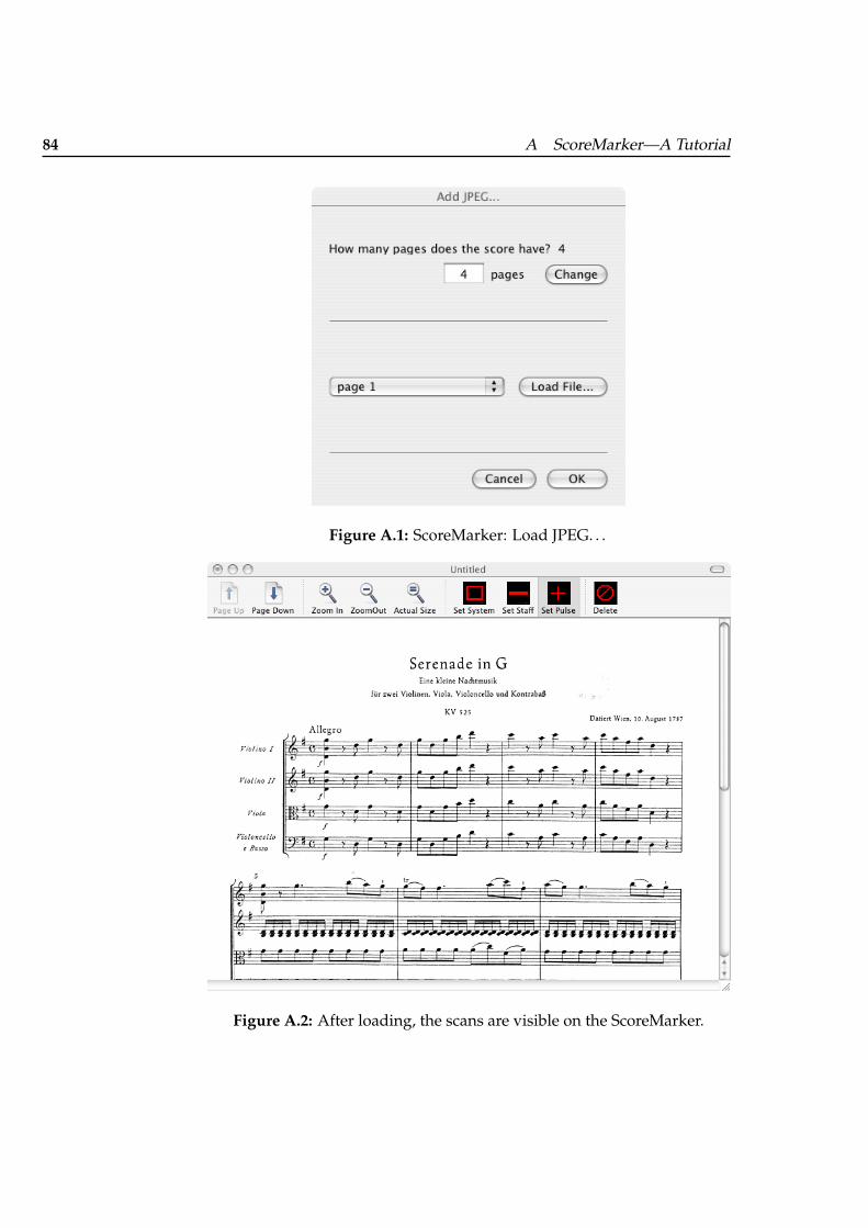
84 A ScoreMarker—A Tutorial
Figure A.1: ScoreMarker: Load JPEG. . .
Figure A.2: After loading, the scans are visible on the ScoreMarker.
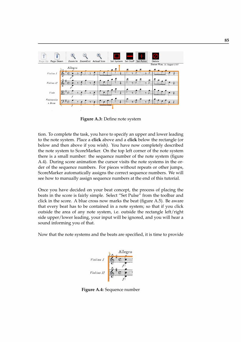
85
Figure A.3: Define note system
tion. To complete the task, you have to specify an upper and lower leadingto the note system. Place a click above and a click below the rectangle (orbelow and then above if you wish). You have now completely describedthe note system to ScoreMarker. On the top left corner of the note systemthere is a small number: the sequence number of the note system (figureA.4). During score animation the cursor visits the note systems in the or-der of the sequence numbers. For pieces without repeats or other jumps,ScoreMarker automatically assigns the correct sequence numbers. We willsee how to manually assign sequence numbers at the end of this tutorial.
Once you have decided on your beat concept, the process of placing thebeats in the score is fairly simple. Select “Set Pulse” from the toolbar andclick in the score. A blue cross now marks the beat (figure A.5). Be awarethat every beat has to be contained in a note system; so that if you clickoutside the area of any note system, i.e. outside the rectangle left/rightside upper/lower leading, your input will be ignored, and you will hear asound informing you of that.
Now that the note systems and the beats are specified, it is time to provide
Figure A.4: Sequence number
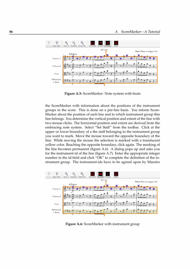
86 A ScoreMarker—A Tutorial
Figure A.5: ScoreMarker: Note system with beats
the ScoreMarker with information about the positions of the instrumentgroups in the score. This is done on a per-line basis. You inform Score-Marker about the position of each line and to which instrument group thisline belongs. You determine the vertical position and extent of the line withtwo mouse clicks. The horizontal position and extent are derived from theembracing note system. Select “Set Staff” from the toolbar. Click at theupper or lower boundary of a the staff belonging to the instrument groupyou want to mark. Move the mouse toward the opposite boundary of theline. While moving the mouse the selection is marked with a translucentyellow color. Reaching the opposite boundary, click again. The marking ofthe line becomes permanent (figure A.6). A dialog pops up and asks youfor the instrument-id of the line (figure A.7). Enter the appropriate integernumber in the id-field and click “OK” to complete the definition of the in-strument group. The instrument-ids have to be agreed upon by Maestro
Figure A.6: ScoreMarker with instrument group
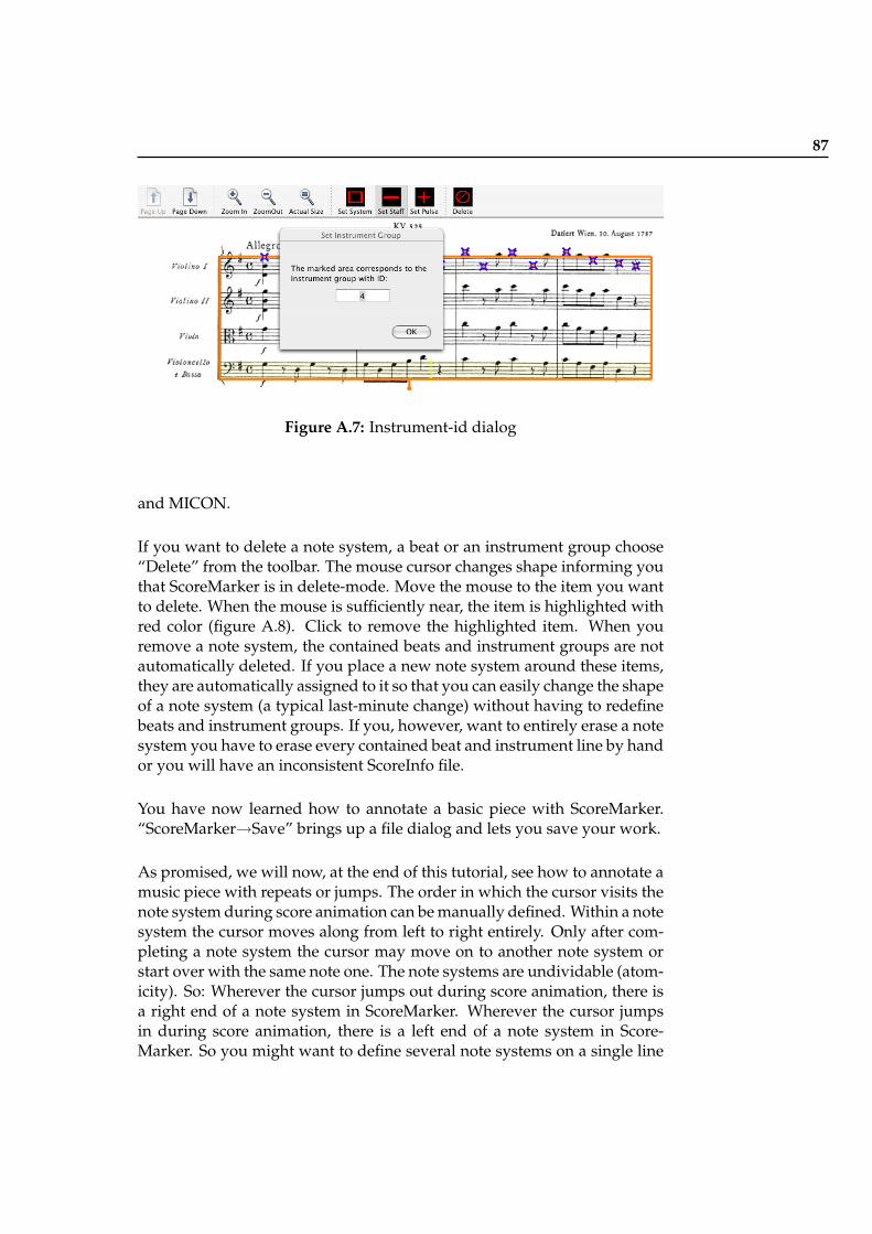
87
Figure A.7: Instrument-id dialog
and MICON.
If you want to delete a note system, a beat or an instrument group choose“Delete” from the toolbar. The mouse cursor changes shape informing youthat ScoreMarker is in delete-mode. Move the mouse to the item you wantto delete. When the mouse is sufficiently near, the item is highlighted withred color (figure A.8). Click to remove the highlighted item. When youremove a note system, the contained beats and instrument groups are notautomatically deleted. If you place a new note system around these items,they are automatically assigned to it so that you can easily change the shapeof a note system (a typical last-minute change) without having to redefinebeats and instrument groups. If you, however, want to entirely erase a notesystem you have to erase every contained beat and instrument line by handor you will have an inconsistent ScoreInfo file.
You have now learned how to annotate a basic piece with ScoreMarker.“ScoreMarker→Save” brings up a file dialog and lets you save your work.
As promised, we will now, at the end of this tutorial, see how to annotate amusic piece with repeats or jumps. The order in which the cursor visits thenote system during score animation can be manually defined. Within a notesystem the cursor moves along from left to right entirely. Only after com-pleting a note system the cursor may move on to another note system orstart over with the same note one. The note systems are undividable (atom-icity). So: Wherever the cursor jumps out during score animation, there isa right end of a note system in ScoreMarker. Wherever the cursor jumpsin during score animation, there is a left end of a note system in Score-Marker. So you might want to define several note systems on a single line
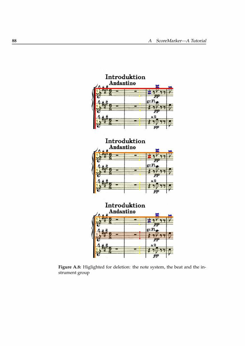
88 A ScoreMarker—A Tutorial
Figure A.8: Higlighted for deletion: the note system, the beat and the in-strument group
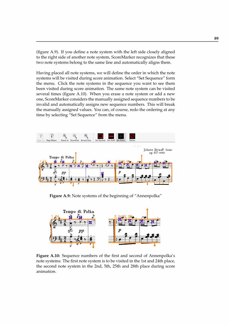
89
(figure A.9). If you define a note system with the left side closely alignedto the right side of another note system, ScoreMarker recognizes that thesetwo note systems belong to the same line and automatically aligns them.
Having placed all note systems, we will define the order in which the notesystems will be visited during score animation. Select “Set Sequence” formthe menu. Click the note systems in the sequence you want to see thembeen visited during score animation. The same note system can be visitedseveral times (figure A.10). When you erase a note system or add a newone, ScoreMarker considers the manually assigned sequence numbers to beinvalid and automatically assigns new sequence numbers. This will breakthe manually assigned values. You can, of course, redo the ordering at anytime by selecting “Set Sequence” from the menu.
Figure A.9: Note systems of the beginning of “Annenpolka”
Figure A.10: Sequence numbers of the first and second of Annenpolka’snote systems: The first note system is to be visited in the 1st and 24th place,the second note system in the 2nd, 5th, 25th and 28th place during scoreanimation.

91
Appendix B
Screenshots
92 B Screenshots
93
94 B Screenshots
95
96 B Screenshots
97
98 B Screenshots
99
100 B Screenshots
101
102 B Screenshots
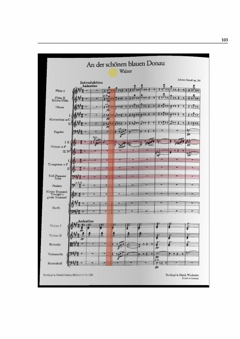
103
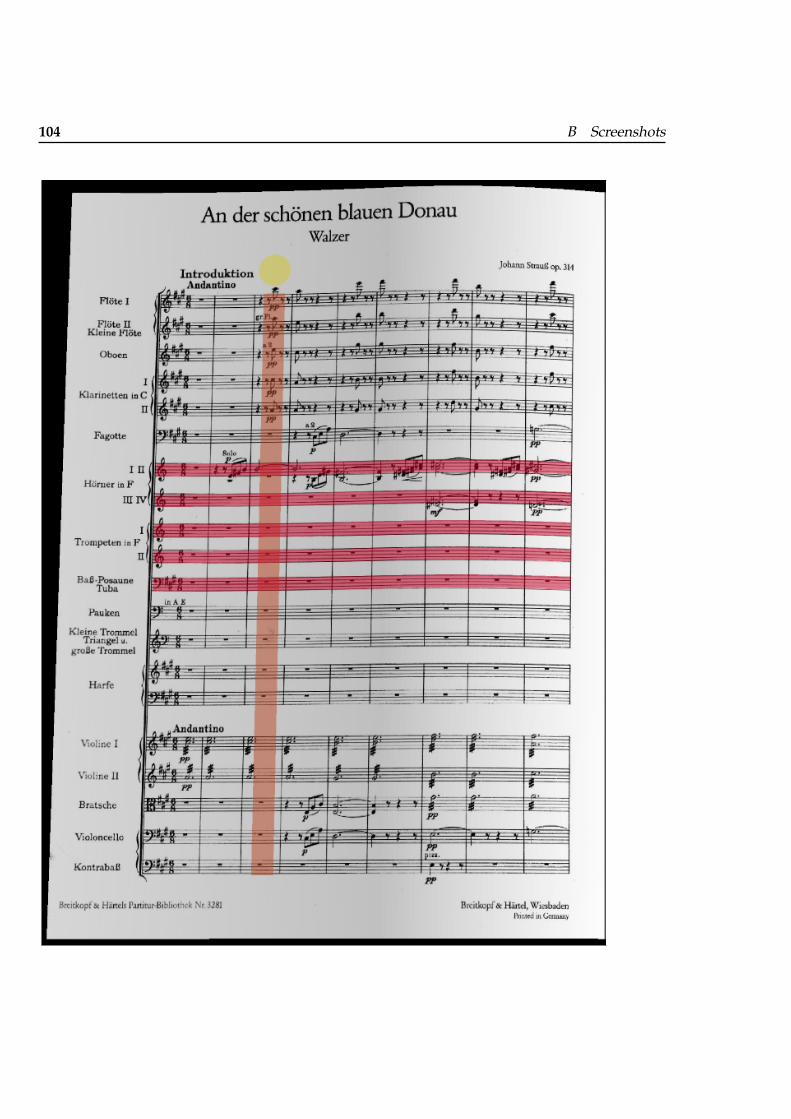
104 B Screenshots
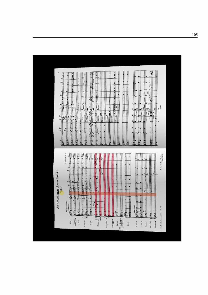
105
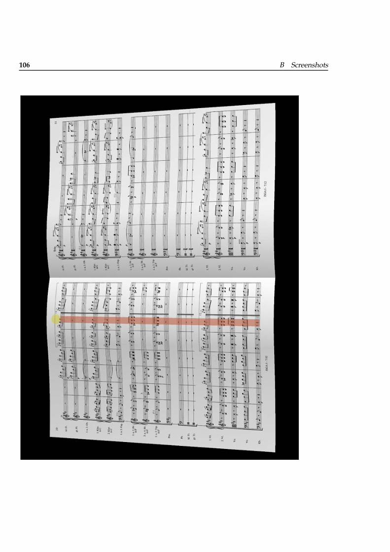
106 B Screenshots
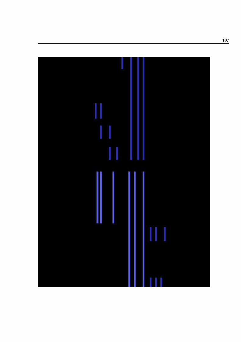
107

109
Bibliography
P. Bellini, P. Nesi, and M. B. Spinu. Cooperative visual manipulation ofmusic notation. ACM Transactions on Computer-Human Interaction, 9(3):194–237, 2002.
Graziano Bertini and Paolo Carosi. Light baton: A system for conductingcomputer music performance. In Proceedings of the International ComputerMusic Conference. International Computer Music Association, 1992.
Bob Boie, Max Mathews, and Andy Schloss. The radio drum as a synthe-sizer controller. In Proceedings of the International Computer Music Confer-ence, pages 42–45. International Computer Music Association, 1989.
Jan Borchers. Worldbeat: Designing a baton-based interface for an inter-active music exhibit. In Proceedings of the ACM CHI International Confer-ence on Human Factors in Computing Systems, pages 131–138. ACM, March1997.
Jan Borchers. A Pattern Approach to Interaction Design. John Wiley & Sons,Baffins Lane, Chichester, West Sussex, PO19 1UD, England, March 2001.
Jan Borchers, Eric Lee, Wolfgang Samminger, and Max Muhlhauser. Per-sonal orchestra: A real-time audio/video system for interactive conduct-ing. ACM Multimedia Systems Journal Special Issue on Multimedia SoftwareEngineering, 9(5):458–465, March 2004.
Jan Borchers, Aristotelis Hadjakos, and Max Muhlhauser. Micon: A musicstand for interactive conducting. In NIME 2006 International Conferenceon New Interfaces for Musical Expression, Paris, France, June 2006.
Jan O. Borchers, Wolfgang Samminger, and Max Muhlhauser. Engineeringa realistic real-time conducting system for the audio/video rendering ofa real orchestra. In IEEE MSE 2002 Fourth International Symposium onMultimedia Software Engineering, December 2002.
110 Bibliography
Richard Boulanger and Max Mathews. The 1997 mathews radio-baton andimprovisation modes. In Proceedings of the International Computer Mu-sic Conference, pages 395–398. International Computer Music Association,1997.
Bennett Brecht and Guy E. Garnett. Conductor follower. In Proceedings ofthe International Computer Music Conference, pages 185–186. InternationalComputer Music Association, 1995.
Guy E. Garnett, Fernando Malvar-Ruiz, and Fred Stoltzfus. Virtual con-ducting practice environment. In Proceedings of the International ComputerMusic Conference, pages 371–374. International Computer Music Associ-ation, 1999.
Guy E. Garnett, Mangesh Jonnalagadda, Ivan Elezovic, Timothy Johnson,and Kevin Small. Technological advances for conducting a virtual en-semble. In Proceedings of the International Computer Music Conference,pages 167–169. International Computer Music Association, 2001.
Christopher Graefe, Derek Wahila, Justin Maguire, and Orya Dasna. muse:a digital music stand for symphony musicians. ACM interactions, 3(3):26–35, 1996.
Ingo Gruell. conga: A conducting gesture analysis framework. Master’sthesis, University of Ulm, Ulm, Germany, April 2005.
Tommi Ilmonen. Tracking conductor of an orchestra using artificial neu-ral networks. Master’s thesis, Helsinki University of Technology, Esboo,Finland, April 1999.
Tommi Ilmonen. Tracking conductor of an orchestra using artificial neuralnetworks. In STeP’98, Human and Artificial Information Processing. FinnishConference on Artificial Intelligence, 1998.
Tommi Ilmonen. Diva - digital interactive virtual acoustics. http://www.tml.tkk.fi/Research/DIVA/, March 2003.
Tommi Ilmonen and Tapio Takala. Conductor following with artificial neu-ral networks. In Proceedings of the International Computer Music Conference.International Computer Music Association, 1999.
Thorsten Karrer. Phavorit: A phase vocoder for real-time interactive time-stretching. Master’s thesis, RWTH Aachen University, Aachen, Germany,November 2005.
David Keane and Peter Gross. The midi baton. In Proceedings of the Interna-tional Computer Music Conference, pages 151–154. International ComputerMusic Association, 1989.
Bibliography 111
David Keane, G. Smecca, and Kevin Wood. The midi baton ii. In Pro-ceedings of the International Computer Music Conference. International Com-puter Music Association, 1990.
Paul Kolesnik. Conducting gesture recognition, analysis and performancesystem. Master’s thesis, Mc Gill University, Montreal, June 2004.
Eric Lee, Teresa Marrin Nakra, and Jan Borchers. You’re the conductor: Arealistic interactive conducting system for children. In NIME 2004 Inter-national Conference on New Interfaces for Musical Expression, pages 68–73,Hamamatsu, Japan, June 2004.
Eric Lee, Marius Wolf, and Jan Borchers. Improving orchestral conductingsystems in public spaces: Examining the temporal characteristics andconceptual models of conducting gestures. In Proceedings of the CHI 2005Conference on Human Factors in Computing Systems, pages 731–740, Port-land, Oregon, USA, April 2005. ACM.
Eric Lee, Ingo Grull, Henning Kiel, and Jan Borchers. conga: A frameworkfor adaptive conducting gesture analysis. In Proceedings of the New Inter-faces for Musical Expression, 2006a.
Eric Lee, Thorsten Karrer, and Jan Borchers. Toward a framework for in-teractive systems to conduct digital audio and video streams. ComputerMusic Journal, 30(1):21–36, Spring 2006b. The video for this article ap-pears in the Computer Music Journal Sound and Video Anthology 29(4),2005.
Eric Lee, Henning Kiel, Saskia Dedenbach, Ingo Gruell, Thorsten Karrer,Marius Wolf, and Jan Borchers. isymphony: An adaptive interactiveorchestral conducting system for conducting digital audio and videostreams. In Extended Abstracts of CHI 2006 Conference on Human Factorsin Computing Systems, Montreal, Canada, April 2006c. ACM Press.
Michael Lee, Guy Garnett, and David Wessel. An adaptive conductor fol-lower. In Proceedings of the International Computer Music Conference, pages454–455. International Computer Music Association, 1992.
Teresa Marrin and Joseph Paradiso. The digital baton: a versatile perfor-mance instrument. In Proceedings of the International Computer Music Con-ference, pages 313–316. International Computer Music Association, 1997.
Teresa Marrin and Rosalind Picard. The conductor’s jacket: A device forrecording expressive musical gestures. In Proceedings of the InternationalComputer Music Conference, pages 215–219. International Computer Mu-sic Association, 1998.
112 Bibliography
H. Morita, S. Ohteru, and S. Hashimoto. Computer music system whichfollows a human conductor. In Proceedings of the International ComputerMusic Conference. International Computer Music Association, 1989.
Teresa Marrin Nakra. Inside the Conductor’s Jacket: Analysis, Interpretationand Musical Synthesis of Expressive Gesture. PhD thesis, MassachusettsInstitute of Technology, February 2000.
Donald A. Norman. The Design of Everyday Things. Basic Books, 2002.
Wolfgang F. Samminger. Personal orchestra: Interaktive steuerung syn-chroner audio- und videostrome. Master’s thesis, Johannes Kepler Uni-versitat Linz, Linz, Germany, September 2002.
Satoshi Usa and Yasunori Mochida. A multi-modal conducting simulator.In Proceedings of the International Computer Music Conference, pages 25–32.International Computer Music Association, 1998.