das multi-protokoll digitalsystem für motorola, selectrix ... · das multi-protokoll digitalsystem...
TRANSCRIPT

Das Multi-Protokoll Digitalsystemfür Motorola, Selectrix und DCC
Handbuch
English
Edition

Authors: Dr.-Ing. T. Vaupel, M. BergerTranslation: Prof. A. Scorzoni, S. Chiti-Batelli
© Uhlenbrock Elektronik GmbH, Germany2nd edition, July 1999
All rights reserved,including translation rights
Order number 685e

Intellibox
3
ContentsBuilding elements and connections 5
A quick start 6
1. The Intellibox connectors1.1 Definition of the Intellibox connectors 91.2 Connecting the clamp plugs 91.3 Connecting transformer, track and programming tracks 101.4 Connecting a DCC Booster 121.5 Connecting a Marklin Booster 121.6 Connecting a LocoNet Booster 131.7 Connecting the s88 feedback modules 131.8 Connecting the Lokmaus 141.9 Connecting a computer 151.10 Connecting LocoNet devices 151.11 Connecting Marklin devices 16
2. Compatible locomotive decoders 18
3. Technical Data 19
4. Display, keyboard and menus4.1 The display 204.2 Key functions 204.3 The menus 22
5. The basic settings menu5.1 Menu structure 235.2 Menu �User interface� 245.3 Menu �Language� 265.4 Menu �Loco data format� 275.5 Menu �Accessory (decoder) setting� 285.6 Menu �Display� 305.7 Menu �Scale� 305.8 Menu �Programming Track� 315.9 Menu �Interface� 325.10 Menu �s88 configuration� 335.11 Menu �Lokmaus address� 345.12 Menu �Special Options� 355.13 Menu �Software version� 365.14 Menu �Loco at power-up� 36
5.15 Menu �Reset� 37

Intellibox
4
6. The control panel6.1 Building elements 386.2 The locomotive addresses 406.3 The speed knob (throttle) 416.4 Lights and extended functions 426.5 Changing the data format of a locomotive decoder 436.6 Locomotive virtual addresses 456.7 Consisting 476.8 Controlling function decoders 49
7. Keyboard mode7.1 Selecting the Keyboard mode 507.2 Keyboard control 507.3 Configuring switching timings 517.4 Selection of the Keyboard address 527.5 �Table� Keyboard mode 53
8. s88 monitor mode8.1 Operation 548.2 Selecting the s88 mode 548.3 Monitorring another s88 status 558.4 �Zooming� on a contact 55
9. Programming mode9.1 Programming track 569.2 Selecting the programming mode 569.3 Structure of the programming menu 569.4 Programming Uhlenbrock decoders 579.5 Programming DCC decoders 599.6 Programming Selectrix decoders 649.7 Searching a decoder�s address 65
10. The PC interface 66
11. Error messages 67
12. Software updates 68
Appendix 69
All used trade marks are registered trade-marks of their respective companies.
Intellibox
5
9 91
3
2
56 7
84
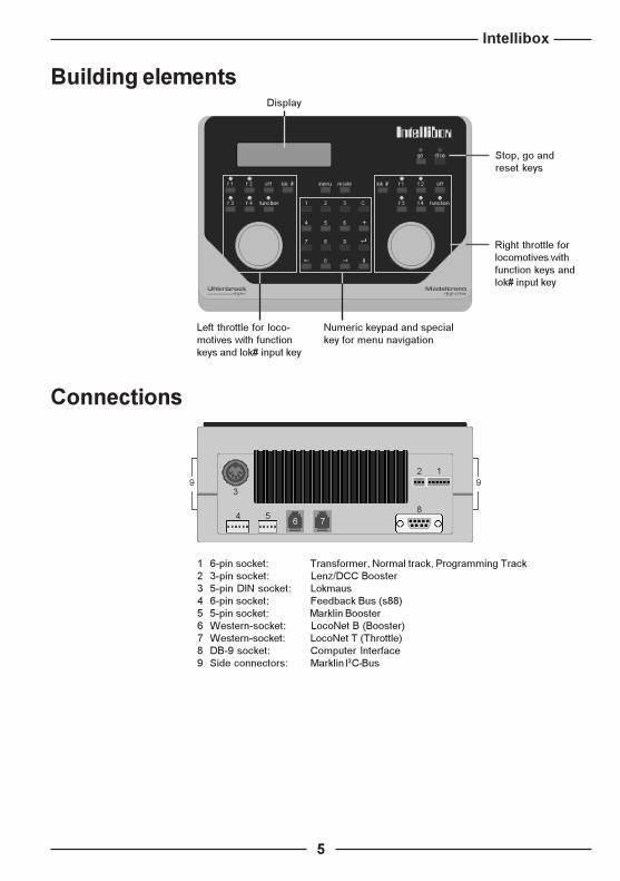
Connections
1 6-pin socket: Transformer, Normal track, Programming Track2 3-pin socket: Lenz/DCC Booster3 5-pin DIN socket: Lokmaus4 6-pin socket: Feedback Bus (s88)5 5-pin socket: Marklin Booster6 Western-socket: LocoNet B (Booster)7 Western-socket: LocoNet T (Throttle)8 DB-9 socket: Computer Interface9 Side connectors: Marklin I2C-Bus
Building elements
Right throttle forlocomotives withfunction keys andlok# input key
Stop, go andreset keys
Display
Left throttle for loco-motives with functionkeys and lok# input key
Numeric keypad and specialkey for menu navigation

Intellibox
6
A quick startIMPORTANT! Please note that this quick start section should only be used to
test the Intellibox. It is absolutly necessary to read the whole manualin order to understand and use all Intellibox features.
Connecting the plug
You need a transformer with 16 V AC output voltage and a minimumoutput power of 52 VA. Use wires with max. diameter 1.1 mm(cross sectional area = 1 mm2, 18AWG). The 16 V AC voltage fromthe transformer and the two poles of the track are connected to theclamps of plug #1 on the backside of the Intellibox.
If you are using the Marklin Digital System (Motorola or AC-format)please make the following connections to plug #1.
� The middle rail to clamp 3 (red Marklin cable)� The two rails (body of the track) to clamp 4 (brown Marklin cable)� The AC voltage to clamps 5 and 6
If you are using a DCC/NMRA formatplease make the following connections to plug #1.
� One out of two rails to clamp 3 (red Marklin cable)� The other rail to clamp 4 (brown Marklin cable)� The AC voltage to clamps 5 and 6
Automatic set-up at power on
Should you keep a key pressed during the Intellibox power on, youwill force the Intellibox to perform special actions:
[1]...[8]selects and stores in the flash-ROM the corresponding language.
Possible languages and their code numbers are:German (default factory setting, key #1), English (2), French (3),Italian (4), Dutch (5), Swedish (6), Spanish (7), Portuguese (8).
[mode]test mode (keypad, LCD display, LED�s and rotary encoders)
[+]restores LCD contrast and backlight to their default values.
[C]allows you to define and interactively store the LCD display contrast.Use the [!] key to decrease and the ["] key to increase the contrastvoltage. Store with [8].
How to handlethe plugs

Intellibox
7
Connecting the Intellibox
CAUTION! Before your now connect plug #1 to the Intellibox, please verify carefullythat the wires from the transformer have not been swapped withthose from the track, or that short-circuits did not occur among thevarious wires of the connector!! A short-circuit between the transformerand the track could destroy the output stage of the Intellibox!
As soon as the plug has been inserted in socket #1 of the Intellibox(the transformer must be connected to the AC main line), the displaystarts showing the initialization procedure. After about 5 secondsthe green LED turns on.
If you observe a blinking red LED, a short circuit occurred on thetrack. Remove it and press the [go] key.
Select the data format
If you are using the Marklin Digital System and most of your deco-ders for locos, turnouts and switching devices conform to theMotorola data format you can use the factory default of the Intellibox.
If most of your decoders for locos, turnouts and switching devicesconform to the DCC/NMRA data format, please do the following steps:
After switching on the Intellibox, press [menu] and then [mode],then press the [$] key until you reach the text �Loco data fmt�. Pressthe ["] key. Now you can scroll all available formats using the [$]key. Choose, e.g., the DCC 14 format by pressing the [8] key.
After switching on the Intellibox, press [menu] and then [mode],then press the [$] key until you read �Loco data fmt�. Press the ["]key. Now you can scroll all available formats using the [$] key.Choose, e.g., the DCC 14 format by pressing the [8] key. This causesthe default format to be defined as DCC/NMRA with 14 operatinglevels (or speeds). With the [menu] key you will leave the menu.
Similarly, in order to define the default format for solenoid devices,press [menu]-[mode], then press the [$] key until you reach the text�Access.Setting�. Press the ["] key: you read �General type�. Pressthe ["] key again. You can now scroll between the two availableformats (Motorola and DCC) using the [$] key. Select the DCC for-mat and confirm by pressing the [8] key. This causes the defaultformat for solenoid devices to be defined as DCC/NMRA. With the[menu] key you will leave the menu.
First steps with the Intellibox
How to switch the layout on after a "stop"� Press the [go] button.
How to introduce a loco address� Press the [lok#] key on the right or left control section.� Use the numerical keyboard to input the loco address.� Conclude the input sequence by using the [8]-key.

Intellibox
8
How to steer a loco� Turn the speed knob clockwise to increase thespeed of the loco.� Turn the speed knob counterclockwise todecrease the speed.
How to reverse the direction of the loco� Press the speed knob, then the loco is stopped.
The next time it will start in the opposite direction.
How to control the light of the loco� The [function] key switches the light on.� The [off] key switches the light off.
How to control the extended functions� Press one of the keys: [f1] - [f4]
How to control a turnoutThe keyboard (numerical keyboard) in the middle of the Intelliboxfrontpanel is used to control the turnouts. The eight pairs of keys ofthis keyboard control the eight outputs of turnout decoders withaddresses 1 to 8. The positions of the turnouts are shown in themiddle of the LCD display.
The Programming TrackFor the time being, please do not connect and use the Programmingtrack. Its connections and use are extensively explained in theremaining part of the manual.
Definition of the digital format of single locomotives� Press [lok#] on the left or right cab� Introduce the locomotive address on the numeric keypad� Press the [menu] key� Choose the locomotive format using the [$] key� Confirm by pressing the [8] key
Intellibox
9
1.2 Connecting the clamp plugs
To connect the transformer, the nor-mal track and the programmingtrack as well as the Lenz booster,two clamp plugs are supplied withthe Intellibox. Use a work bench orsimilar surface, when conntectingthe cables to the clamps.
The designations of the clamps areshown in Figure 1.21.
Figure 1.21Designations of the
clamps in connector #1
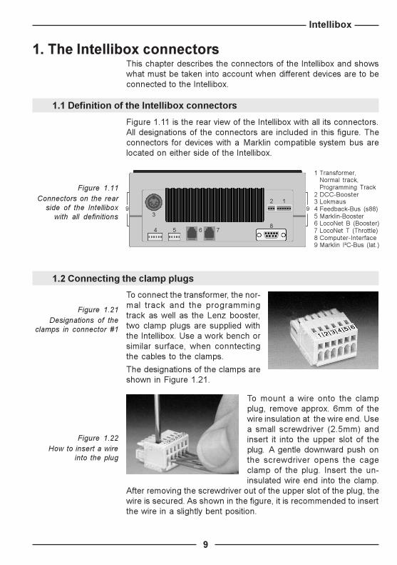
1. The Intellibox connectorsThis chapter describes the connectors of the Intellibox and showswhat must be taken into account when different devices are to beconnected to the Intellibox.
1.1 Definition of the Intellibox connectors
Figure 1.11 is the rear view of the Intellibox with all its connectors.All designations of the connectors are included in this figure. Theconnectors for devices with a Marklin compatible system bus arelocated on either side of the Intellibox.
9 91
3
2
58
4 6 7
Figure 1.11 Connectors on the rear
side of the Intelliboxwith all definitions
Figure 1.22How to insert a wire
into the plug
To mount a wire onto the clampplug, remove approx. 6mm of thewire insulation at the wire end. Usea small screwdriver (2.5mm) andinsert it into the upper slot of theplug. A gentle downward push onthe screwdriver opens the cageclamp of the plug. Insert the un-insulated wire end into the clamp.
After removing the screwdriver out of the upper slot of the plug, thewire is secured. As shown in the figure, it is recommended to insertthe wire in a slightly bent position.
1 Transformer,Normal track,Programming Track
2 DCC-Booster3 Lokmaus4 Feedback-Bus (s88)5 Marklin-Booster6 LocoNet B (Booster)7 LocoNet T (Throttle)8 Computer-Interface9 Marklin I²C-Bus (lat.)

Intellibox
10
1 Programming track (brown)2 Programming track (red)3 Digital voltage to the track (Marklin red)4 Digital voltage to the track (Marklin brown-digital ground)5 Ground 16 V AC froml Transformer (Marklin brown)6 16 V AC from Transformer (Marklin yellow)
The transformerIn order to obtain a troublefree operaton of the Intellibox please usea transformer of min. 52 VA output power. The maximum output ACr.m.s. voltage from the transformer should not exceed 18V.
The transformer must be connected to clamps 5 and 6 (brown andyellow, respectively).
CAUTION! Please verify carefully that the wires from the transformer have notbeen swapped with those from the track, or that short-circuits didnot occur among the various wires of the connector!! A short-circuitbetween the transformer and the track could destroy the outputstage of the Intellibox!
The trackThe track must be connected to clamps 3 and 4 of plug #1.For 2-rails tracks, follow this example:
For 3-rails tracks, clamp 4 is the ground potential of the digitalvoltage and corresponds to the brown wire of a Marklin digital sys-tem (external rails). Clamp 3 corresponds to the red wire and mustbe connected to the central rail.
Figure 1.32Connections to a
2-rails track
Figure 1.33Connections to a
3-rails track
1.3 Connecting transformer, track and programming track
The 6-pins plug #1 is used to connect the transformer, the trackand the programming track.
Figure 1.31Connections of the 6-poles connector

Intellibox
11
The programming trackThe programming track (PT) is a special track for programmingand reading out the configuration variables of loco decoders.
VERY IMPORTANT Both rails of the PT must be isolated from the normal track. Thismust also be true for 3-rails Marklin tracks, where the two lateralrails must also be isolated! With �M� tracks this is a really difficulttask (insulation of the ballast)! During programming, the isolationgaps must not be crossed or bridged by locomotives or boogies,being this prejudicial to a good electrical insulation.
The PT is connected to clamp 1 (brown) and 2 (red) of plug #1.
Use the basic settings of the Intellibox (section 5.8) to choose howthe Intellibox handles the PT. You can choose either "only program-ming track" or "automatic". The latter means that you can use partof your normal layout track (but insulated on both rails). The ad-vantage in this case is that you can drive a loco into the PT, enter theprogramming mode, change and read configuration variables andfinally steer the loco out of the PT. The changeover between PT andnormal track is done by a relais in the Intellibox.
CAUTION! In case of a short-circuit between the normal track and the pro-gramming track the Intellibox will display an error message.
A short circuit also occurs when the two terminals of the Program-ming Track are erroneously swapped.
HINT It is preferable that a newly installed decoder is first connected tothe PT (a low-current, low-energy track) instead of the normal track,in order to check for the correctness of the installation. In fact, incase of wrong connections, it is less likely to produce a damageon the decoder. For this reason we suggest installers of decodersto choose the option "only programming track" in the basic settingsof the Intellibox.
Figure 1.34Connections of the
Programming Track

Intellibox
12
Figure 1.51Appearance of
the flat cable
1.5 Connecting a Marklin Booster
Connector #5 is designed for Marklin Boosters (6017 and 6015)and all Marklin-Motorola compatible Boosters.
The flat cable delivered with the Marklin Booster must be tied atconnector #5 of the Intellibox, running upwards. On the Boosterside (see also the operating manual of the Booster) this cablemust run downwards from the model Marklin 6015 and upwardsfrom the model Marklin 6017, as shown in Figure 1.51.
HINT The SO #901 has to be changed to a value of 3, in order to controlDCC locomotives on layout sections supplied through a MarklinBooster 6015 or 6017.
1.4 Connecting a DCC booster
In principle, all optoisolated DCC Booster can be connected toplug #2. DCC Boosters are not able to output a Selectrix signal.
Lenz BoosterThese Boosters can directly be connected to the Intellibox. Thesignal lines C and D and the short signal line E must be connectedto the 3 pole clamp plug as shown in the picture.
Marklin- and Arnold Digital= BoosterMarklin Digital= Boosters (6016) and Arnold Digital= Boosters(86015) are optoisolated. Therefore they can be connected toconnector #2, but only using the Uhlenbrock adapter #693.
Other DCC boostersOnly optoisolated DCC Boosters can be connected to the Intellibox!
Usually, DCC boosters have only two wires. These wires shouldbe connected to plug #2, clamps 1 and 2 of the Intellibox.
CAUTION! These boosters are not able to transmit a short-circuit signal tothe Intellibox. But they are usually protected by their own short-circuit protection.
1 C = Signal +2 D = Signal -3 E = Short-circuit signal line
Figure 1.41Front view of the3-pin connector 1 2 3
Intellibox
13
1.6 Connecting a LocoNet Booster
LocoNet Boosters (optoisolated only!) must be connected to connec-tor #6 on the rear of the Intellibox using a 6-poles Western cable.
CAUTION! These boosters are not able to transmit a short-circuit signal tothe Intellibox. But they are usually protected by their own short-circuit protection.
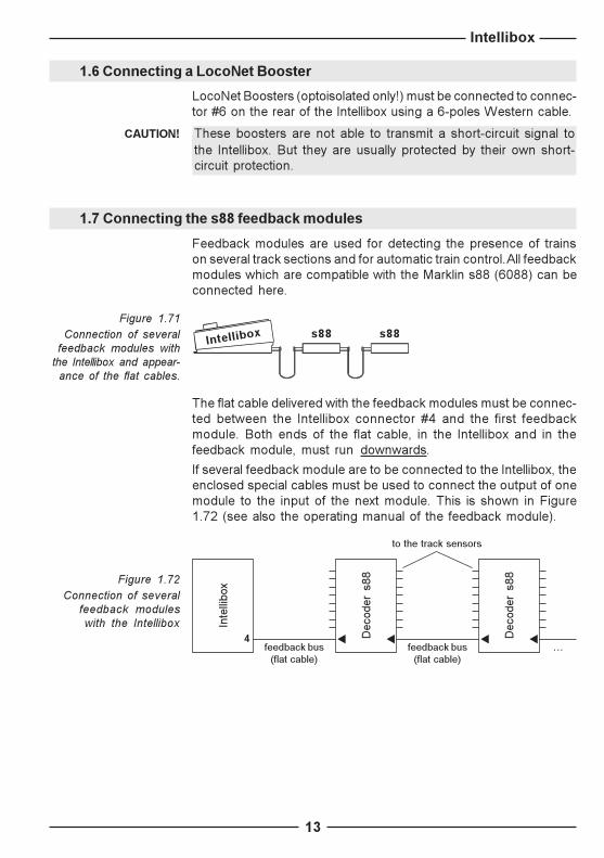
1.7 Connecting the s88 feedback modules
Feedback modules are used for detecting the presence of trainson several track sections and for automatic train control. All feedbackmodules which are compatible with the Marklin s88 (6088) can beconnected here.
The flat cable delivered with the feedback modules must be connec-ted between the Intellibox connector #4 and the first feedbackmodule. Both ends of the flat cable, in the Intellibox and in thefeedback module, must run downwards.
If several feedback module are to be connected to the Intellibox, theenclosed special cables must be used to connect the output of onemodule to the input of the next module. This is shown in Figure1.72 (see also the operating manual of the feedback module).
Figure 1.71Connection of several
feedback modules withthe Intellibox and appear-
ance of the flat cables.
s88 s88Intellibox
Figure 1.72 Connection of several
feedback moduleswith the Intellibox
feedback bus(flat cable)
...r
feedback bus(flat cable)
to the track sensors
r rDec
oder
s88
r rDec
oder
s88
4
Inte
llibo
x

Intellibox
14
1.8 Connecting the Lokmaus
Both Roco and LGB Lokmaus can be used. They must be connectedto connector #3 of the Intellibox.
Eight different locos can be controlled with one Lokmaus. The lococan be selected using the 8-positions slider of the Lokmaus. Up toeight Lokmaus could be used at the same time with the Intellibox.
With the factory setting of the Intellibox the positions 1-8 of selectionswitch correspond to the loco addresses 1-8.
The assignment of loco addresses to the position of the selectionswitch can easily be changed using the basic settings menu of theIntellibox (see also section 5.11).
Connecting more than one LokmausSeveral Lokmaus could be connected to the Intellibox using a Y-shaped cable (ROCO 10755).
Take into account when using a Lokmaus:� Due to the Lokmaus characteristics, the Power on/off button can
only be pressed once every 5 seconds.
� The light and the horn button can only be pressed every second.
� The light button of the Lokmaus corresponds to the [functon]/[off]buttons of the Intellibox.
� The horn button corresponds to the [f1] button of the Intellibox.
� Should several Lokmaus try to control the same loco using thesame position of the selection switch, then only the "first" one willactually control that loco indicated by the red LED.
CAUTION! Only Lokmaus compatible devices could be plugged into thisconnector. Do not plug any XBUS device in it!
Figure 1.81Connection of
several Lokmaus s
ss
s
ss
Lokmaus 1
Lokmaus 2
usw.
Y-Adapter
Y-Adapter
sIntellibox
Intellibox
15
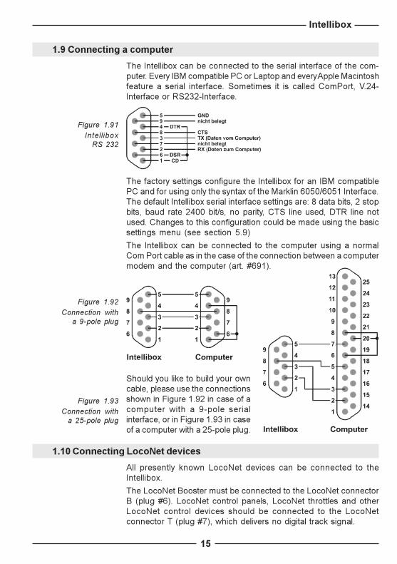
1.9 Connecting a computer
The Intellibox can be connected to the serial interface of the com-puter. Every IBM compatible PC or Laptop and every Apple Macintoshfeature a serial interface. Sometimes it is called ComPort, V.24-Interface or RS232-Interface.
The factory settings configure the Intellibox for an IBM compatiblePC and for using only the syntax of the Marklin 6050/6051 Interface.The default Intellibox serial interface settings are: 8 data bits, 2 stopbits, baud rate 2400 bit/s, no parity, CTS line used, DTR line notused. Changes to this configuration could be made using the basicsettings menu (see section 5.9)
The Intellibox can be connected to the computer using a normalCom Port cable as in the case of the connection between a computermodem and the computer (art. #691).
Should you like to build your owncable, please use the connectionsshown in Figure 1.92 in case of acomputer with a 9-pole serialinterface, or in Figure 1.93 in caseof a computer with a 25-pole plug.
Figure 1.93Connection with
a 25-pole plug
Figure 1.92Connection with
a 9-pole plug
1.10 Connecting LocoNet devices
All presently known LocoNet devices can be connected to theIntellibox.
The LocoNet Booster must be connected to the LocoNet connectorB (plug #6). LocoNet control panels, LocoNet throttles and otherLocoNet control devices should be connected to the LocoNetconnector T (plug #7), which delivers no digital track signal.
Figure 1.91Intel l ibox
RS 232
Intellibox
16
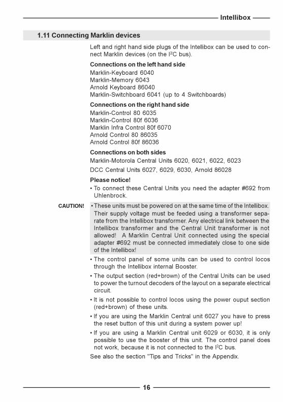
1.11 Connecting Marklin devices
Left and right hand side plugs of the Intellibox can be used to con-nect Marklin devices (on the I2C bus).
Connections on the left hand sideMarklin-Keyboard 6040Marklin-Memory 6043Arnold Keyboard 86040Marklin-Switchboard 6041 (up to 4 Switchboards)
Connections on the right hand sideMarklin-Control 80 6035Marklin-Control 80f 6036Marklin Infra Control 80f 6070Arnold Control 80 86035Arnold Control 80f 86036
Connections on both sidesMarklin-Motorola Central Units 6020, 6021, 6022, 6023
DCC Central Units 6027, 6029, 6030, Arnold 86028
Please notice!� To connect these Central Units you need the adapter #692 from
Uhlenbrock.
CAUTION! �These units must be powered on at the same time of the Intellibox.Their supply voltage must be feeded using a transformer sepa-rate from the Intellibox transformer. Any electrical link between theIntellibox transformer and the Central Unit transformer is notallowed! A Marklin Central Unit connected using the specialadapter #692 must be connected immediately close to one sideof the Intellibox!
� The control panel of some units can be used to control locosthrough the Intellibox internal Booster.
� The output section (red+brown) of the Central Units can be usedto power the turnout decoders of the layout on a separate electricalcircuit.
� It is not possible to control locos using the power ouput section(red+brown) of these units.
� If you are using the Marklin Central unit 6027 you have to pressthe reset button of this unit during a system power up!
� If you are using a Marklin Central unit 6029 or 6030, it is onlypossible to use the booster of this unit. The control panel doesnot work, because it is not connected to the I2C bus.
See also the section "Tips and Tricks" in the Appendix.
Intellibox
17
Available addresses in C80, C80f and Infra-Control 80f unitsWhen you plug a Control 80 on the right side of the Intellibox, you areobviously allowed to control the locomotive addresses from 1 to 80.
However, in the case of a Control 80f (or an Infra-Control 80f), themaximum number of locomotives depends on the combination ofthe units you are using:
from 1 to 99 Intellibox and C80ffrom 1 to 80 Intellibox, C80f and Central Unit - Motorola format
(6020, 6021, 6022, 6023)from 1 to 99 Intellibox, C80f and Central Unit - DCC format
(6027, 6029, 6030, 86028)

Intellibox
18
2. Compatible locomotive decodersThe Intellibox features an independent control of digital decoderswith different data formats.
Loco decodersOld Motorola format(ZyTX, ZyMOS, Blaupunkt, LDE, 701.13 Marklin chips)New Motorola format, Gauge-1 formatDCC format, all loco decoders compliant to the NMRA standardSelectrix, the Trix digital system
Function decodersOld Motorola formatNew Motorola format, Gauge-1 formatDCC format, all function decoders compliant to the NMRA standardSelectrix, only decoders with standard functions f0 and f1
Solenoid devices-Accessory decoders-Motorola formatMarklin (6083, 6084)Modeltreno 66001Viessmann (5211, 5213)
Solenoid devices-Accessory decoders-DCC formatArnold K87N 86078Lenz LS100/110/120DCC decoders conforming to the NMRA standard
See also the section "compatible decoders" in the Appendix.
Intellibox
19
3. Technical DataMaximum supply voltage18 V AC
Maximum current load3 A to the rails1 A to the I2C Bus0,2 A to LocoNet B output0,5 A to LocoNet T output
Maximum number of feedback moduless88 or s88 compatible modules - addr. 1-31additional modules, connection through the LocoNet - addr. 32-128The Intellibox can control up to 2048 feedback contacts.
Maximum number of loco addressesMotorola format, available with the Marklin Digital system - addr. 1-80Motorola format, available with Uhlenbrock decoders - addr. 1-255DCC format - addr. 1-9999Selectrix format - addr. 0-111
Maximum number of solenoid device decoder adressesMotorola format - addr. 1-320DCC format - addr. 1-2040
Maximum number of connected Boosters15 Marklin Boosters15 DCC Boosters
Dimensions180 x 136 x 80 mm

Intellibox
20
4.2 Key functions
[go], [stop], [stop]+[go]Switch the digital voltage on (go) and off (stop).
A system reset is performed when [stop]+[go] are pressed at thesame time for about 2.5 seconds.
[f1] [f2] [f3] [f4]Toggle the loco extended functions.
Together with the [lok#] key it toggles the f5 to f8 functions of DCCdecoders (see section 6.4).
[function] [off]Switch the direction-dependent function on and off.
[lok #]Starts the input of a loco address.
If you are controlling a locomotive, by pressing [lok#] and [menu] insequence you enter the data-format menu.
Together with the [f5]-[f8] keys, toggles the f5 to f8 functions of DCCdecoders (see section 6.4).
See also the function of the [C] key.
[menu]Start/end of a context menu (followed by the [mode] key).
Just after the introduction of a locomotive address you are allowedto define its digital format.
4. Display, keyboard and menus
4.1 The display
The user interface is implemented into a backlighted LCD display.The display is divided in three parts and is designed in order to givethe user a quick and clear view of the available commands.
At both sides the display shows the rele-vant loco decoder format, the address,the speed level and the driving direction.
In the middle part the display showsinformation on the presently activemode; f. i. the current position of the so-lenoid devices in "keyboard mode".
The text for menu-driven decoder-programming is shown on the wholescreen.

Intellibox
21
[mode]Toggles among the Intellibox control panel modes: keyboard, s88monitor and programming mode.
In some edit fields (Register and CV programming mode andSpecial Options), pressing [mode] while the cursor is blinking on avalue (not the number!) shows the current value in hexadecimalformat (with a leading "$"). Pressing [mode] again (or performingany editing action) causes the value to be shown back again indecimal format.
[0] - [9]Decimal digits
[!] ["]One menu level (or one column) to the left or to the right
[$]Decrements a value by one or goes one menu entry downwards
[+]Increments a value by one or goes one menu entry upwardsBuilds a consistAdds a loco to a consist control
[8]Confirmation key (enter)
[C]Deletes the last entry from the keyboardDeletes a consistIf pressed into an empty field:- shows the default value of the Special Options- shows the last programmed value in the menusIf you are controlling a Lok, by pressing [lok#], then [C] and finally[lok#] once again, you will put that knob back in the "no controlledLok" condition and you will also prepare that very lok you were incontrol of for "takeover" by a LocoNet simple throttle like the DigitraxBT-2, Fremo and Uhlenbrock FRED, etc. In LocoNet terms this iscalled "dispatching a Lok".
Figura 4.2The buttons of the
central block

Intellibox
22
4.3.3 Inputs
Numeric values can be entered using the numeric key pad. Theinput position is shown by a blinking character in the display.
The [C] button clears the last entered digit.
If you want to run "horizontally" among the different levels, use the[!] and the ["] buttons to step between the columns.
The [8] button confirms the last input or selects a parameter.
4.3 The menus
4.3.1 Structure and navigation
["] One menu level (or one col-umn) to the right
[!] One menu level (or one col-umn) to the left
[$] One menu entry downwards(from top to bottom)
[+] One menu entry upwards(from bottom to top)
[menu] ends a context menuand returns to the normalIntellibox control mode.
HINT During navigation in the menus the display shows the relevantmessages instead of the status of locomotives and turnouts. Allcontrol functions for locomotives are still active: knobs for speedand direction change, function keys [f1]-[f4], [function]-[off] keys.Therefore, during navigation you are still able to control the lastselected locomotives.
Level 1 Level 2 Level 3
Entry 1 Entry 1 Entry 1
Entry 2
Entry 2 Entry 1
Entry 2
Entry 2 Entry 1 Entry 1
Entry 2
Entry 2 Entry 1
Entry 2
Figure 4.3The structure of the
menus of the Intellibox
4.3.2 Special characters of the display
Should a level include further menu levels, then the first characterin the second row of the display will be a ">".
Should the entry be a parameter value, which could be activated orchanged, then the first character in the display will be a "=".
All active entries are indicated with a "�" at the end of the line.

Intellibox
23
5. The basic setting menuThe basic settings of the Intellibox can be changed using this user-friendly menu. All setting will permanently be saved in the non-volatile memory of the Intellibox.
Press the [menu] and the [mode] buttons one after the other inorder to enter the basic settings menu.
5.1 Menu structure
Default value is marked by a star (�).
= AC style knob *= DC style knob
= Percentage= Absolute *> User Interface
> Loco data format
> Accessory Setting
= Address and Format
= Min. and Max.
> Display
= Setting with [+] and [V]
> Scale
> Programming Track
= DCC= Motorola *
> Language
= Setting with [+] and [V]
= Deutsch *
= Francais= Italiano= Nederlands= Svenska= Espanol= Portugues
= English
> Speed knobs
> Loc speed display
> General type
> Single type
> Switch times
> Backlight
> Contrast
= Motorola, neu *= Motorola, alt= DCC 14= DCC 27= DCC 28= DCC 28 DAC= DCC 128= DCC 128 DAC= Selectrix
= Virtual Address= special Config,
= Voltage H0 *
= Voltage N
= Automatic *
= Prog. Track only

Intellibox
24
= automatic, plus speed
> Interface
> s88-Settings
> Lokmaus-Addr. = Enter loco address for position 1-8
> Special Options = Enter the special option
> Software Version
> Loco Start Mode
> Reset
= No old status *= automatic, speed = 0
= Software version and serial number are shown
= Number of modules connected
> Configuration
> Loco data format
> Accessory setting
= no *= yes
= no *= yes
= no *= yes
> Bit per second
> Syntax
> Computer
= 19200 bit/s
= 2400 bit/s *= 4800 bit/s= 9600 bit/s
= 6050 and IB-Syntax= IB-Syntax only= 6050-Syntax only *
= none
= PC *= Mac
5.2 Menu "User interface"
5.2.1 Loco speed display
The speed of the loco can be displayed in two different ways.
Absolute Speed (default factory setting)The speed level will directly be displayed using the current operatinglevel. According to the choosen data format the display will shownumbers in the range 0-14, 0-27, 0-28, 0-31 or 0-127.
Percentage of maximum speedThe speed level will be displayed in percentage of the maximumspeed independently of the current data format.
How to set loco speed display� Press the [menu] key� Press the [mode] key� Scroll with the [$] key until you read �User Interface�� Enter the menu with the ["] key� Scroll with the [$] key until you read �Loc speed display�

Intellibox
25
� Enter the menu with the ["] key� Scroll with the [$] key until you reach your desired entry� Select this setting by pressing the [8] key� Go back to the main display with the [menu] key
5.2.2 Speed knobs
Here you can choose the style of the speed knob. An AC style knobor a DC style knob could be chosen.
The default factory setting is the "AC style knob".
The AC style knobThe AC Style mode works like an old-fashioned three rail ACcontroller.
Using the AC style, the speed will always be increased while turningthe knob clockwise and will be decreased while turning the knobcounterclockwise. If the max. speed or the speed zero is reached,
a further turn of the knob in the same direction hasno effect. The max. speed or the speed zero willbe maintained.
A slight push on to the speed knob will reverse thedirection of the loco.
Pushing the speed knob during driving will stopthe loco first (emergency stop). Then the direction will be changed.Depening on the decoder format, some locos stop immediately(Marklin, DCC) while other locos stop using their current decele-ration rate (Selectrix).
DC style knobThe DC Style mode works like a DC speed control device for DCtwo rail systems.
Using the DC style, turning clockwise the speed knob starting froma zero speed level will increase the speed of the loco in forwarddirection. Turning the speed knob counterclockwise will decreasethe speed until the zero speed level is reached. A further turn of the
knob will reverse the direction of the loco and willincrease the speed in reverse direction. If the max.speed level is reached, further turns of the knob inthe same direction will not cause any change. On theother hand, when speed zero is reached, you will beallowed to change direction to the locomotive only
after about half a second. Only after this pause is a further knobrotation accepted. This feature prevents unwanted direction changes.
A slight push on to the speed knob will stop the loco. Depending onthe decoder format some locos will stop immediately by a locodependent emergency stop (DCC) while other locos will stop usingtheir current deceleration rate (Marklin Motorola, Selectrix).
Figure 5.22How a
DC style knobworks
Figure 5.21How an
AC style knob works

Intellibox
26
How to change the style of the speed knob� Press the [menu] key� Press the [mode] key� Scroll with the [$] key until you read �User Interface�� Enter the menu with the ["] key� Scroll with the [$] key until you read �Speed knobs�� Enter the menu with the ["] key� Scroll with the [$] key until you reach your desired entry� Select this setting by pressing the [8] key� Go back to the main display with the [menu] key
5.3 Menu "Language"
Here you can choose the language of the displayed text.
Possible languages and their code numbers are:
German (key #1), English (2), French (3), Italian (4), Dutch (5),Swedish (6), Spanish (7), Portuguese (8).
The default factory setting is "German".
How to change the language of the display� Press the [menu] key� Press the [mode] key� Scroll with the [$] key until you read �Language�� Enter the menu with the ["] key� Scroll with the [$] key until you reach your desired entry� Select this setting by pressing the [8] key� Go back to the main display with the [menu] key
HINT It is also possible to change the default language by switching theIntellibox on while pressing one key from 1 to 8 (see the previoustable). For example, by pressing the �2� key you will set the defaultlanguage to �English�.

Intellibox
27
5.4 Menu "Loco data format"
Here you can choose the default loco data format. This format willautomatically be used when new decoder addresses are intro-duced, if no other format is explicitly defined.
This menu should be used to define the data format which will benormally used.
The default factory setting is the new Motorola format.
Possible formats are:
Motorola - oldOld Motorola data formatLoco decoder without additional functionsOld-fashioned function decoders will be controlled by [f1] - [f4](e.g. Marklin coach with automatic waiter or digital crane)
Motorola - newAlso called Gauge-I-Format, including the extended functions f1-f4.
DCC 14-27-28-128DCC format using 14, 27, 28 or 128 operating levels
DCC 28-128 DACDCC format with 28 and 128 operating levels with decoder assistedconsisting (DAC)
SelectrixTrix selectrix with 31 operating levels
How to change the loco data format� Press the [menu] key� Press the [mode] key� Scroll with the [$] key until you read "Loco data format"� Enter the menu with the ["] key� Scroll with the [$] key until you reach your desired entry� Select this setting by pressing the [8] key� Go back to the main display with the [menu] key
HINT The digital format of each locomotive can be modified independentlyof all other locomotives. Detailed instructions are given in section 6.5.

Intellibox
28
5.5 Menu "Accessory (decoder) setting"
Solenoid device decoders from Marklin, Viessmann and Modeltrenoare compatible with the Motorola format. Their addresses aredefined using suitable microswitches (DIP switches) that can befound inside each unit. Each decoder is characterized by a uniqueaddress. In the Appendix you can find a table showing themicroswitch position for each address.
On the contrary, DCC/NMRA-compliant solenoid device decodershave no microswitches and can be programmed using the Pro-gramming track - or directly on the �main track�.
5.5.1 General type
The general data format used for most of your accessory decoders.After defining a general type you can define the type of each sole-noid device decoder following the instructions of section 5.5.2.
Possible choices are:
Motorola (default factory setting)Accessory decoders using the Motorola data format:Uhlenbrock, Modeltreno, Viessmann, Marklin
DCCAccessory decoders using the DCC data format:Roco, Arnold, LGB, Lenz, Marklin=, Digitrax, etc.
How to change the accessory (decoder) setting� Press the [menu] key� Press the [mode] key� Scroll with the [$] key until you read �Accessory (decoder) setting�� Enter the menu with the ["] key� Scroll with the [$] key until you read �General type�� Enter the menu with the ["] key� Scroll with the [$] key until you reach your desired entry� Select this setting by pressing the [8] key� Go back to the main display with the [menu] key
5.5.2 Single type
Independently of the general data format for accessory decoders,you can choose an individual data format for each accessory de-coder address.
How to change the setting for a single type� Press the [menu] key� Press the [mode] key� Scroll with the [$] key until you read �Accessory setting�� Enter the menu with the ["] key� Scroll with the [$] key until you read �Single type�� Enter the menu with the ["] key

Intellibox
29
� The address of a decoder which should get an individual dataformat must be entered in the first input column after "Addr".
� The ["] key can be used to jump to the right input column.� Scroll with the [$] key to the desired data format:
"Mot." for Motorola (Marklin) or "DCC"� Select this setting by pressing the [8] key� Go back to the main display with the [menu] key
5.5.3 Switching time
The switching pulse triggered by the pressure on a keyboard buttonusually lasts until the button is released.
Here the minimum and maximum switching times of the accessorydecoders can be changed.
The default factory setting is minimum 100 ms (0.1 seconds) andmaximum 5000 ms (5 seconds).
You can introduce values between 50 and 9999.
How to change the switching time� Press the [menu] key� Press the [mode] key� Scroll with the [$] key until you read �Accessory setting�� Enter the menu with the ["] key� Scroll with the [$] key until you read �Switch time�� Enter the menu with the ["] key� In the 1st column you can set the minimum switching time. This is
the min. duration of the voltage pulse for switching an accessorydecoder, even in the case of either avery short manual actuation or a com-puter command. The input value willbe rounded to the nearest 50 ms.
Should you input a �zero� value, the switching pulse will be issuedonly until the key is pressed.
� The ["] key can be used to jump to the right input column.� In the 2nd column you can set the maximum switching time.
Correspondingly, the max. switching time defines the max. durationof the voltage pulse for switching an accessory decoder, evenwhen no command will reach the Intellibox to switch the accessorydecoder off. The input value will be rounded to the nearest 50 ms.Should you input a �zero� value, the switching pulse will always beissued until the key is pressed.
� Go back to the main display with the [menu] key
HINT These settings are common to all solenoid device decoders.

Intellibox
30
5.7 Menu "Scale"
By setting the scale the output voltage of the built-in Booster will beadjusted.
H0 scaleThe output voltage will not be controlled to a fixed maximum level. Itcould reach a max. level of 21 V peak voltage if the input AC voltageis 16 V.
N scaleThe output voltage is clamped to a peak voltage of 18 V.
The factory default is the �H0� setting for H0 and all bigger gauges.
How to change the voltage of the built-in booster� Press the [menu] key� Press the [mode] key� Scroll with the [$] key until you read �Scale�� Enter the menu with the ["] key� Scroll with the [$] key until you reach your desired entry� Select this setting by pressing the [8] key� Go back to the main display with the [menu] key
5.6 Menu "Display"
The Display menu could be used to adjust the brightness and thecontrast of the LCD.
How to change brightness and contrast of the LCD� Press the [menu] key� Press the [mode] key� Scroll with the [$] key until you read �Display�� Enter the menu with the ["] key� Scroll with the [$] key until you reach your desired entry� The adjustment can be done using the [$] and the [+] keys� Select this setting by pressing the [8] key� Go back to the main display with the [menu] key
HINT If you leave the menu without using the [8] key, the old settings willbe restored.
IMPORTANT If the display is unreadable because of a wrong setting of thebrightness and/or contrast, you could recall the default factorysettings by switching the main power on while pressing down the[+] key at the same time.

Intellibox
31
5.8 Menu "Progr. Track"
The Intellibox features an internal relais, connected in such a waythat an existing track of a layout (Programming Track) can be usedeither as a �real� Programming Track or as a �normal� track.
Here you can choose whether the programming track connectorwill output the programming voltage only, or if it will automaticallybe switched between the normal track voltage and the programmingvoltage.
Programming Track onlyThe programming track output is never connected to the normaldigital voltage. The connector outputs a voltage (the programmingvoltage) only during read and write operations.
AutomaticThe programming track connector will automatically be switchedfrom the normal track voltage to the programming voltage whenentering the programming mode.
CAUTION! Both rails of the programming track must be electrically isolatedfrom the normal track. It is not allowed to bridge the isolation pointswith a bogie of a car or a loco.
The default factory setting is "automatic".
How to change the style of the speed knob� Press the [menu] key� Press the [mode] key� Scroll with the [$] key until you read �Prg. Track�� Enter the menu with the ["] key� Scroll with the [$] key until you reach your desired entry� Select this setting by pressing the [8] key� Go back to the main display with the [menu] key
HINT An easy test of the Programming Track can be accomplished byreading the configuration variables of a newly purchased decoder(e.g. DCC/NMRA: reading CV1 in �bite mode� should give CV1=3).
HINT If you have just installed a decoder, in order to check the electricalconnections it is advisable to test it first on the Programming track(a low-current, low-energy track) instead of the normal track.
Due to this reason, we strongly suggest installers of decoders tochoose the option �Prg. Track only� in the configuration menu ofthe Intellibox.

Intellibox
32
5.9 Menu �Interface�
You can change the settings of the serial interface of the Intellibox.
5.9.1 Speed
The transmission rate of the serial computer interface depends onthe software in use.
Possible choices are 2400, 4800, 9600, 19200 bit/s
Factory default is 2400 bit/s.
5.9.2 Syntax
You can change the serial interface protocol used by the Intellibox.
The Intellibox can be controlled with the serial protocol of the Mark-lin 6050/6051 Interface (see Appendix). The Intellibox will alsorecognize an extended serial protocol (�P50X�) fully compatibilewith the 6050/6051 syntax (updated documentation will be availablein the Uhlenbrock and Modeltreno homepages).
Possible choices are:
6050 (syntax) onlyOnly the syntax of the 6050/6051 interfaces is used.
Intellibox (syntax) onlyOnly the syntax of the Intellibox is used.
6050 and IntelliboxBoth syntaxes (P50 and P50X), are used simultaneously. TheIntellibox automatically recognizes the syntax of the commands itreceives.
Factory default is "6050 and Intellibox".
5.9.3 Computer
This option lets you choose the type of computer interface.
PC (factory default)IBM-compatible Personal Computer.
For the technically minded: if the �CTS� (clear to send) line of theRS232 interface is high, connector 8 CTS pin outputs +12 V, allowingthe computer to transfer data to the Intellibox.
MacApple Macintosh Computer.
For the technically minded: if the �CTS� (clear to send) line of theRS232 interface is high, connector 8 CTS pin outputs -12 V,allowinging the computer to transfer data to the Intellibox.
NoneNo computer.

Intellibox
33
How to change the settings of the Intellibox interface� Press the [menu] key� Press the [mode] key� Scroll with the [$] key until you read �Interface�� Enter the menu with the ["] key� Scroll with the [$] key until you reach your desired entry� Enter the menu with the ["] key� Scroll with the [$] key until you reach your desired option� Select this setting by pressing the [8] key� Go back to the main display with the [menu] key�.
5.10 Menu �s88 configuration�
In other digital systems, s88 feedback modules are read only bycomputer command. The Intellibox, instead, continuously readsand memorizes the s88 modules, in order to maintain an updatedstatus of the layout�s sensors. The computer can also query theIntellibox about the occurrence and type of changes in the feedbackbus signals. In order to optimize the feedback bus operation, theIntellibox must be aware of the number of s88 modules connectedto it.
How to make the "s88" entry� Press the [menu] key� Press the [mode] key� Scroll with the [$] key until you read �s88 settings�� Enter the menu with the ["] key
� In this entry you should input the number of s88 modulesconnected to the feedback bus.
� Go back to the main display with the [menu] key
You may connect at the most 31 s88 modules to the Intellibox.

Intellibox
34
5.11 Menu �Lokmaus address�
You can connect up to 8 Lokmauses in the 5-pin DIN connector #3,by means of �Y� adapters.
The Lokmaus has an eight position slider for locomotive selection.Each of the eight positions can be assigned to a specific locoaddress. The assignments are common to all Lokmauses: in thismanner, you can control maximum 8 locomotives, even if you have8 Lokmauses.
How to change the style of the speed knob� Press the [menu] key� Press the [mode] key� Scroll with the [$] key until you read �Lokmaus-Addr.�� Enter the menu with the ["] key
� Use the column after �Pos� to input the desired slider position oruse the [$] and [+] keys to review the available positions (1-8).
� The ["] key can be used to jump to the right input column.� Input the locomotive address (1 to 9999) to be assigned to this
slider position.� Save the settings by pressing the [8] key� Go back to the main display with the [menu] key
Factory defaults assign positions 1-8 to loco addresses 1-8.

Intellibox
35
5.12 Menu �Special Options�
The Intellibox features a number of special options which affect itsoperating mode. The effect of any given special option depends ofthe installed Intellibox software version. You can choose the spe-cial option by means of its code number.
How to set a special option� Press the [menu] key� Press the [mode] key� Scroll with the [$] key until you read �Special Option�� Enter the menu with the ["] key
� Use the column after �No� to input the special option code number.In case of error, you can cancel the last digit with the [C] key.
� The ["] key can be used to jump to the right input column.� Input the special option value in the right field.
In case of error, you can cancel the last digit with the [C] key. If youpress [C] after erasing the last remaining digit, the special optiondefault value will be displayed.
� Pressing the [8] key confirms the entry.A "�" in the display shows, that the special option is activated.
� Go back to the main display with the [menu] key
HINT The Appendix lists some of the special options. This listing isintentionally incomplete since the modification of certain specialoptions by non-experts can compromise the correct operation ofthe Intellibox. Special options in coming software versions will bedescribed in documents to be made available in our Internet sites.
HINT Hexadecimal displayIn the special options menu, by pressing the [mode] key when thecursor is standing on the value of a special option, it is possible todisplay its value in hexadecimal format. However, it is not possibleto modify this value directly in hexadecimal format; it is just a diffe-rent display mode. By pressing [mode] again, the normal (decimal)display will be restored.

Intellibox
36
5.14 Menu �Loco at power-up�
The status of your layout is stored when you switch off the Intellibox.When you next switch it on, the Intellibox allows you to recall thelatest locomotive settings. In this menu, you can specify the Intelliboxbehaviour at power-up.
no memory (factory default)The speed, direction, consisting and auxiliary function settings ofthe different locomotives are not recalled at power-up.
automatic, speed = 0The direction, consisting and auxiliary function settings of the diffe-rent locomotives are recalled, but speed is set to zero for all thelocomotives present in the layout at power-up.
automatic + speedThe speed, direction, consisting and auxiliary function settings ofthe different locomotives are recalled. If you choose this option, theIntellibox will ask you for confirmation prior to powering-up all thelocomotives in the layout.
How to change the loco start mode� Press the [menu] key� Press the [mode] key� Scroll with the [$] key until you read �Loco start mode�� Enter the menu with the ["] key� Scroll with the [$] key until you reach your desired entry� Select this setting by pressing the [8] key� Go back to the main display with the [menu] key
5.13 Menu �Software Version�
In this menu you can read the Intellibox serial number and thesoftware version number.
How to display the version numbers� Press the [menu] key� Press the [mode] key� Scroll with the [$] key until you read �Software Version�� Enter the menu with the ["] key
� In the upper line you can read the Intellibox software versionnumber.
� In the line below you can read the Intellibox serial number.� Go back to the main display with the [menu] key
Intellibox
37
5.15 Menu �Reset�
This menu allows you to reset the Intellibox to factory defaults.
ConfigurationAll changes in the basic settings menu will be deleted.Factory settings of the special options will be restored.
The setting for the selected language does not change.
Loco data formatAll entrys for single locomotive decoders that were made in themenu �Loco data format� (section 6.5) will be deleted. The corre-sponding addresses will receive the default loco data format(section 5.4).
Accessory (decoder) settingAll entrys for single accessory decoders that were made in themenu �Single type� (section 5.5.2) will be deleted. The correspon-ding addresses will receive the default data format for accessorydecoders (section 5.5.1).
How to make a reset� Press the [mode] key� Press the [menu] key� Scroll with the [$] key until you read �Reset�� Enter the menu with the ["] key� Scroll with the [$] key until you reach your desired entry� Press the ["] key� Scroll with the [$] key until you read "yes"� Select this setting by pressing the [8] key� Go back to the main display with the [menu] key
Table 5.15Intellibox factory
defaults after reset
Speed display Absolute
Speed knobs AC-style
Loco data format Motorola new (prevailing type)Accessories dataformat Motorola (prevailing type))
Scale Voltage H0
Programming track Automatic
Speed (interface) 2400 bit/s
Syntax 6050-Syntax
Computer PC
Lokmaus-addresse Addr. 1-8 for Pos.1-8
Special options Back to default values

Intellibox
38
6. The control panelLocomotives can be addressed and controlled by means of thecontrol panel. The Intellibox has two independent control panels,located left and right of the numeric keypad.
You can assign a specific data format (protocol) to each locomotiveaddress controlled by the Intellibox. The Intellibox can control, simul-taneously and independently, locomotive decoders conforming todifferent protocols.
Use of the control panel is possible even when the Intellibox is inprogramming mode or when configuring the unit.
6.1 Building elements
The [stop] keyUse the [stop] key to switch the digital voltage off in the normaltrack. The display will show �STOP�. Pressing this key will act onboth control panels.
The [go] keyUse the [go] key to switch the digital voltage on in the normal track.Pressing this key will act on both control panels.
HINT You can reset the Intellibox by pressing both the [go] and [stop]keys for about two seconds.
The displayThe backlighted liquid crystal display continuously shows thedetailed status of the currently controlled locomotives: the address,the protocol (data format), the operating level and the direction oftravel are shown in the left and right sections of the display.
Direction
Digital format
Operating level (speed)
Address
Figure 6.1Front view ofthe Intellibox

Intellibox
39
In each control panel you will find the following elements:
The [f1] [f2] [f3] [f4] keysThese keys control the locomotive�s extended functions, e.g. lights,sounds, smoke generator.
If you press [lok#] followed by one of the [f1] - [f4] keys, you will beable to switch the f5 - f8 extended functions of DCC decoders (seesection 6.4).
The [function] and [off] keysThese two keys switch the locomotive lights on/off.
The [lok#] keyStarts the input of a locomotive address.
After completing the locomotive address input, you can change thedecoder protocol. Press [menu] and select the appropriate dataformat (protocol).
If you press [lok#] followed by one of the [f1] - [f4] keys, you will beable to switch the f5 - f8 extended functions of DCC decoders (seesection 6.4).
The speed knob (throttle)Use the knob to change a locomotive speed and direction of travel.Suppose that you have chosen with the [lok#] key a previously con-trolled locomotive. Given the fact that the knob can rotate freely, theIntellibox automatically reads from its memory the previous operat-ing level of the locomotive, and takes control from that level.
Even if you are in the process of changing an Intellibox parameter(in configuration mode), you can still control a locomotive with aspeed knob: the ongoing configuration can proceed without prob-lems.

Intellibox
40
6.2 The locomotive addresses
Each locomotive in a digital system can be controlled by means ofan �address�, a combination of digits that uniquely identifies thelocomotive�s decoder.
Each decoder has its own address. An address should identifyone, and only one, locomotive.
Normally, a locomotive decoder is controlled by only one of the twocontrol panels. However, it is possible to control the same decoderwith both throttles.
6.2.1 Selecting a locomotive address
In order to control a locomotive with the Intellibox you must selectits address.
To select a locomotive address, first press [lok#]. The display willshow a blinking cursor in one of the address fields, prompting youto input a value.
There are two methods to do it:
Address selection using the numeric keypad� You have just pressed [lok#] (right?)� Input the digits that form the whole address with the numeric
keypad� Terminate address input:
- pressing the [8] key,- pressing any other key in the control panel:
[function] [off] [f1] [f2] [f3] [f4] [lok#],- turning the knob (throttle),- pressing the knob to induce a change of direction.
HINT Use the [C] key to erase wrong entries, one digit at a time. If youcancel the whole address, a further press of the [C] key will recallthe previous address.
Address selection using the throttle� You have just pressed [lok#] (right?)� Turn the knob to change the address, clockwise to increase the
value, counterclockwise to decrease it.� Terminate adress input:
- pressing the [8] key,- pressing any other key in the control panel:
[function] [off] [f1] [f2] [f3] [f4] [lok#],- pressing the knob to induce a change of direction.
HINT Should you try to take control of a locomotive which is alreadysteered by another knob, the Intellibox will show the message"Loco used by another controller!" After this message you areallowed to control the relevant locomotive using both manualcontrollers (the external and the internal ones).

Intellibox
41
6.2.2 Recalling from memory a stored address
The Intellibox stores in its memory the address of the last locomotivecontrolled by each of the control panels.
It is possible to recall this address:
� Press [lok#]� Press [$]The last valid address is displayed and is ready to be used.
6.2.3 Releasing a locomotive address
To release the control of a locomotive address (the released loco-motive can now be taken over by a manual controller without selec-tion keypad, e.g. FRED by Uhlenbrock or BT-2 by Digitrax), use thefollowing procedure:
Single locomotive� Press [lok#]� Cancel the whole address with the [C] key� Press [lok#].
Consist� Press [lok#].� Press any number key (0-9)� Cancel the whole address with the [C] key� Press [lok#].
6.3 The speed knob (throttle)
Use the knob to change a locomotive speed and direction of travel.Suppose that you have chosen with the [lok#] key a previouslycontrolled locomotive. Given the fact that the knob can rotate freely,the Intellibox automatically reads from its memory the previousoperating level of the locomotive, and takes control from that level.
The throttle has two different operating modes:
� AC style� DC style
Please refer to section 5.2.2 for a detailed description of theseoperating modes.
Factory default: AC style. You can change this setting in theconfiguration menu (section 5.2.2)

Intellibox
42
6.4 Lights and extended functions
The [function] key and the extended function keys [f1] - [f4] controlthe lights and the locomotive decoder extended function outputs.
[function]Switches on the direction-dependent auxiliary function (usually thelocomotive lights).
[off]Switches off the direction-dependent auxiliary function.
If you press the [off] key, the auxiliary function switches on briefly,even if it was not previously switched on with the [function] key.
Extended functions Press one of the [f1] - [f4] keys to control the relevant extendedfunction.
Each key press toggles the relevant decoder output from �off� to�on�, and viceversa.
Additional functionsThe [lok#] key used in combination with the [f1] - [f4] keys, controlsthe f5, f6, f7, f8 functions of 8-function decoders. The [lok#] key mustbe pressed before (not simultaneously with) the [f1] - [f4] keys.
The following key combinations are valid:
- [lok#] and [f1] control function f5- [lok#] and [f2] control function f6- [lok#] and [f3] control function f7- [lok#] and [f4] control function f8.
During the control of an extended function the display will show itsstatus (1=on, 0=off).
HINT The function status is displayed for about 2 seconds. During thisperiod, you can change the status of another function without firsthaving to press [lok#].

Intellibox
43
6.5 Changing the data format of a locomotive decoder
The Intellibox is able to control simultaneously decoders with diffe-rent digital data formats (protocols) in the same layout.
It is possible to transmit a different data format for each individuallocomotive address. In this case it is necessary to define the protocolfor each locomotive.
Section 5.4 describes how to configure the Intellibox default protocol.
6.5.1 Data formats (protocols)
The following data formats (protocols) are available:
Motorola - oldOld Motorola format with 14 operating levelsLocomotive decoders without extended functionsControl of earlier function decoders with the [f1] - [f4] keys
Motorola - newNew Marklin-Motorola protocol, also known as Gauge-1 format,with 14 operating levels (speeds) and the extended functions f 1- f4.
DCC 14/27/28/128DCC protocol with 14/27/28/128 operating levels
DCC 28/128 DACDCC protocol with 28/128 operating levels and �decoder assistedconsisting� (DAC)
SelectrixTrix Selectrix protocol with 31 operating levels
Special configurationThis menu entry allows one to modify some special settings foreach particular decoder. This could be requested in case of a wrong(maybe crazy) behaviour of the decoder when using the defaultsettings. A list of these special configurations will be available forsome decoders on the Internet. In particular cases, or in case ofproblems, refer to the available Hotline in order to understand whichspecial configuration should be modified.
Locomotive virtual addressesA virtual address is not a data format or protocol!
You can control a locomotive using a �virtual� address, differentfrom the real one.
The Intellibox can use 4-digit virtual addresses. Therefore, it ispossible to address a locomotive using its �class�, e.g. 444, even ifthe decoder is limited to 80 addresses.
Please refer to section 6.6 for a detailed description.

Intellibox
44
6.5.2 Symbols used to display different data formats
The decoder�s data format is displayed on the left of the locomotiveaddress.
The following symbols are defined:
Motorola - old = m without direction arrowMotorola - new = m with direction arrowDCC, all formats = dSelectrix = sVirtual address = �Consist = + (see section 6.7)
6.5.3 Procedure
Please use the following procedure to assign or modify the dataformat of a single decoder address:
How to assign a data format to a single decoder address� Press the [lok#] key and enter an address (if you didn't do before)� Press the [8] key� Press the [lok#] key� After pressing [menu], the display will show the currently assigned
format marked with a "�" at the end of the line.� Use the [$] or [+] keys to scroll through the different formats.
CAUTION! Please do the next three steps only if you have selected "spec.Configuration".
� Use the first position of the cursor to input the codenumber of thedesired configuration (here a "1").
� Use the ["] key to jump to the right input column.� Input the value of the desired configuration (here a "0").
� Press the [8] key to accept the displayed format.The selected format will be marked with a "�" character.
� Go back to the main display with the [menu] key.

Intellibox
45
6.6 Locomotive virtual addresses
6.6.1 Introduction
Railway modellers would rather designate a locomotive by its classnumber, than by some random (and sometimes meaningless) num-ber. In most cases this is not possible because of the narrow rangeof (possible) decoder addresses. For instance, an E444 locomo-tive equipped with a DCC decoder with 99 addresses, cannot nor-mally be controlled with the number 444.
With the Intellibox you can use virtual addressing, i.e. addresseswhich are not real decoder addresses.
HINT You can assign a virtual address to each �real� locomotive address,providing that the address is not already used by another decoder.It is not possible to assign a virtual address to another virtual ad-dress. The available range for virtual addresses is 1-9999.
Example: a class 636 locomotive is equipped with a DCC decoderwith 99 addresses. The Intellibox could control the locomotive withits normal address, e.g. 10.
You can now assign a virtual address 636 to the real addressnumber 10. Your locomotive can now be controlled with both ad-dresses (10 and 636).
Virtual addresses can be recalled from the Intellibox control panels(IB-Control, Intellibox) and can also be stored in the Lokmausassociation table. Unfortunately, it is not possible to use them withMarklin units connected to the I2C-Bus.
The locomotives associated with a virtual address can, however,be controlled using their �normal� address, also using Marklin units(Control 80 or 80f).
Virtual addresses are stored in the Intellibox. If you decide that youwill no longer use a particular virtual address, you can erase it fromthe Intellibox memory.
The selected virtual address can be used to control the locomotivejust like any real address and can even be used in consisting.
6.6.2 Virtual address assignment
If an address is already displayed, press the [lok#] key and then the[menu] key. This sequence displays the data format and virtualaddress configuration menu.
If the Intellibox is in address input mode, you can press the [menu]key to change the format of the displayed address.
Press [$] or [+] to page through the different options until �Virt.Addr.:�is displayed. The cursor is positioned in the right column, whereyou can input the virtual address. Possible values are comprisedbetween 1 and 9999.

Intellibox
46
6.6.3 Displaying a virtual address
If you are controlling a virtual address, pressing [lok#] followed by[menu] will display the address assignment, e.g.:
6.6.4 Deleting a virtual address
To delete a virtual address, recall the locomotive by pressing the[lok#] key and using its real address, enter the data format menuby pressing [menu], input a value of zero in the �Virt. Addr.:� andconfirm the entry with [8]. Alternatively, you can delete the addressby pressing the [C] key.
After inputting the virtual address, press the [8] to store its value.Pressing the [menu] key will take you back to the normal display.
A virtual address is marked with a "�" at the left of the address field.

Intellibox
47
6.7 Consisting
The Intellibox is able to control several locomotives with a singlethrottle. This is called �consisting�. A consist can be composed of amaximum of 4 locomotives. Each locomotive can be introduced ina consist using either its �normal� address or its virtual address.The Intellibox can control a maximum of eight consists.
6.7.1 Setting up a consist
You can create a consist by adding up to three additional locomo-tives to a �base� locomotive.
Suppose that, in normal control mode, you are controlling the loco-motive chosen as the base for the consist. Now, press the [lok#]key, followed by the [+] key. The consisting menu is displayed:
With the numeric keypad, input the address of the locomotive toadd to the base locomotive.
If you want to add a further locomotive, press again the [+] key andinput another address. In this case the display will show:
The �consisting� sequence is terminated with the [8] key. TheIntellibox display returns to the normal control panel and the con-sist can be controlled with the base locomotive address.
If you press [8] without inputting any number or after cancelling theentry with the [C] key, no locomotive will be added to the consist.
By pressing the [menu] instead of [8] you go back to the locomotivecontrol mode.
When controlling a consist, the symbol which is normally reservedto the decoder type is substituted by a �+� . On its right side you willfind the base locomotive address. In the final version of the Intelliboxsoftware, the speed of the consist will be displayed as a percent-age of the maximum speed.
6.7.2 Consist behaviour
After having created a consist, you can control all the locomotivesusing the base locomotive address. If you try to recall the addressof a �consisted� locomotive, the display will show �MUL� in the speed

Intellibox
48
field and the direction field of the locomotive will show a �-� symbol.Moreover, you will not be able to change the locomotive speed.
However, it is possible to change the direction of travel of this locomo-tive, provided the consist is stopped (speed = 0), independently of thedirection of the other locomotives of the consist.
REMARK This feature allows one to correct, if necessary, the direction oftravel of a locomotive which has just been added to the consist,without the need to remove the locomotive from the consist.
If the consist includes locomotives with different numbers of oper-ating levels, the Intellibox will operate the consist using the numberof operating levels of the base locomotive.
If, for instance, the consist has a base locomotive with only 14 ope-rating levels and another locomotive with 128 operating levels, theIntellibox will only use 14 operating levels to control both decoders.
HINT To correctly use a consist, all locomotives should have the samemaximum and minimum �real� speeds.
The maximum and minimum operating levels can be configured inthe decoder itself. Please refer to each decoder�s operating manual.
6.7.3 Releasing a consist
You can release a consist (relative to the base locomotive) eithercompletely or by unfastening one locomotive at a time.
Recall the base locomotive on the control panel. Press the [lok#]key to remove single locomotives or the whole consist. Then, press[C]. The display will show:Pressing the [8] key will release the whole consist. Otherwise, use
the [+] or [$] keys to browse the list oflocomotives in the consist. When thelocomotive to remove is highlighted,press [8].Just after the Intellibox will go back tothe standard control panel. The [menu]key will return the Intellibox to the nor-mal control panel.
REMARK While you can add locomotives to a consist through their virtualaddress, only the real address is shown while removing singlelocomotives from a consist.
6.7.4 Storing a consist
Consists can be stored in the Intellibox non-volatile memory. To doso, you must modify the base parameter �Locomotive at start-up�,as described in section 5.14.
Intellibox
49
6.8 Controlling function decoders
Function decoders are used to control models with special electricor electronic features.
From a technical standpoint, there is no difference between thedata format (protocol) of a locomotive decoder and a functiondecoder. You can configure the protocol for these decoders asdescribed in section 6.5 for locomotive decoders.
REMARK Function decoders can be controlled with the [f1] - [f4] keys.
You can control functions f5 - f8 of DCC decoders with the [f1] - [f4]keys preceded by the [lok#] key.
The [f1] - [f4] keys are able to control function decoders conformingto the old Motorola protocol (e.g. Marklin digital crane or dancingcar), but only if the relevant addresses are configured for this (old)protocol.
While a full compatibility exists between the old and new Motorolaprotocols regarding speed control, this property does not hold truefor functions.

Intellibox
50
7. Keyboard modeIn a digital control system, turnouts and signals are controlled bymeans of special decoders, identified by individual addresses.
The Intellibox is able to control electromagnetic devices and acces-sories that conform to two different protocols: Motorola and DCC.Decoders of each format can be controlled simultaneously. As isthe case for locomtive decoders, the user can configure a prevailing(general) type of accessory decoder.
Marklin, Viessmann and Modeltreno accessory decoders conformto the Motorola protocol. Their addresses are defined by DIP swit-ches located inside each unit. Each decoder has its own address,which differentiates it from all others. In the Appendix you will find atable listing the addresses and the corresponding DIP switchsettings.
Decoders conforming to the DCC/NMRA standard, instead, haveno DIP switches and are programmed with the programming track.
The protocol for these decoders (Motorola, DCC) can be individuallyset in the system�s configuration menu (see also section 5.5)
7.1 Selecting the Keyboard mode
The Intellibox has several operating modes. Three are currentlyavailable: Keyboard, s88 monitor and programming.
The Intellibox toggles among its operating modes each time the[mode] key is pressed. The layout of the display is updated accor-dingly.
To select the �Keyboard� mode, press the [mode] key until �Keyboard�is displayed.
7.2 Keyboard control
In �Keyboard� mode, the numeric keypad is used to control electro-magnetic (solenoid) devices (turnouts, signals, relays). At power-up, you can control, without any additional configuration, the first 8devices.
Switching is accomplished with the red and green keys. The displaywill show �R� or �G� when you press, respectively, a red or a greenkey. Additionally, the sequencial address of the controlled device isalso displayed.
Figura 7.2The keypad
(in Keyboard mode)and the numbering
of key pairs

Intellibox
51
Normally, the display will show the current status of the Keyboard:
If the last key to be pressed was a red one, its rectangular markerwill be in the �up� position (see figure, positions 1, 7, 8 of the avail-able 8, 4 in each line). If, however, the last key to be pressed was agreen one, its marker will be in the �down� position.
7.3 Configuring switching timing
In solenoid device decoders, especially of the Marklin/Motorola type,the switching pulse, started with a key press, is usually terminatedwith the release of the initiating key.
To obviate the occurrence of too short (which wouldn�t be able toswitch the solenoid), or too long (which could destroy the solenoid)pulses, you can configure the decoder�s maximum and minimumswithching times. This procedure takes place in the Intellibox�ssystem configuration menu. Please refer to section 5.5.3.
The factory defaults are 100 ms (0.1 second), minimum duration,and 5000 ms (5 seconds), maximum duration.
REMARK DCC decoders might not be affected by these settings. Many ofthem have configuration variables that define their own switchingtiming (output duration, waveform, etc.).
Intellibox
52
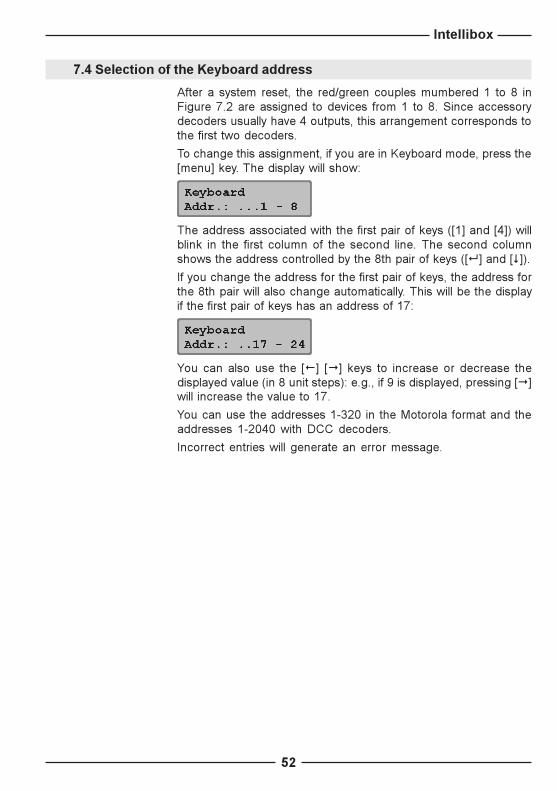
7.4 Selection of the Keyboard address
After a system reset, the red/green couples mumbered 1 to 8 inFigure 7.2 are assigned to devices from 1 to 8. Since accessorydecoders usually have 4 outputs, this arrangement corresponds tothe first two decoders.
To change this assignment, if you are in Keyboard mode, press the[menu] key. The display will show:
The address associated with the first pair of keys ([1] and [4]) willblink in the first column of the second line. The second columnshows the address controlled by the 8th pair of keys ([8] and [$]).If you change the address for the first pair of keys, the address forthe 8th pair will also change automatically. This will be the displayif the first pair of keys has an address of 17:
You can also use the [!] ["] keys to increase or decrease thedisplayed value (in 8 unit steps): e.g., if 9 is displayed, pressing ["]will increase the value to 17.
You can use the addresses 1-320 in the Motorola format and theaddresses 1-2040 with DCC decoders.
Incorrect entries will generate an error message.

Intellibox
53
7.5 �Table� Keyboard mode
We already know that, when in the Keyboard mode, by pressing the[menu] key it is possible to specify the address of the first solenoiddevice controlled by the first pair of keys ([1] and [4]), thus automa-tically assigning the following key pairs to the following solenoiddevices.
However, it is also possible to assign a particular solenoid deviceto a particular key pair. This is the so-called �Table� Keyboard mode.In order to switch this mode on, just select "0" (zero) as the addressassociated to the first key pair. When doing this, the display willconfirm the activation of the �Table� mode with the followingindication:
It is now possible, through the configuration menu (submenu�Special Options�) to assign a specific solenoid device address toa particular key pair. In order to accomplish this task, please refer tothe description of special option #810 in the Appendix.

Intellibox
54
8. s88 monitor modeIf you control your layout with a computer, your software will probablyneed some sort of feedback signaling in order to be �aware� oftrack occupation and, thus, be able to automatically switch turnoutsand signals.
This can be accomplished using s88 modules, which can �see� asection of track and �understand� if it is �free� or �occupied�, trans-mitting this data to the Intellibox. The computer software reads thisinformation through the serial interface and issues its commandsaccordingly.
You can connect the Intellibox to a maximum of 31 s88 moduleswith 16 feedback contacts each and to further LocoNet feedbackmodules (addresses 32 to 128). The 31 x 16 = 496 s88 contactswill be superimposed to the first 496 LocoNet contacts. You canhave a maximum of 128 x 16 = 2048 inputs.
8.1 Operation
In s88 mode, the display will show the status of the s88 modules.
Unlike other digital systems, the Intellibox continuously reads allthe s88 modules connected to the feedback bus and stores theirstatus information. This way, a computer connected through theserial interface to the Intellibox is not obliged to continuously monitorthe s88 modules. In the Intellibox memory there is a one bit �flag�which registers the occurrence of changes in the s88 status. Thecomputer can only be requested to monitor this flag.
To maximize the reading speed of the s88 modules connected tothe feedback bus, the Intellibox must know how many s88 modulesare connected to it. This value must be inputted in the systemconfiguration menu (refer to section 5.10).
8.2 Selecting the s88 mode
The Intellibox has several operating modes. Three are currentlyavailable: Keyboard, s88 monitor and programming.
The Intellibox toggles among its operating modes each time the[mode] key is pressed. The layout of the display is updated accor-dingly.
To select the �s88� mode, press the [mode] key until �s88� is dis-played.
A filled rectangle indicates a closed contact, while an open circledenotes a �free� contact.

Intellibox
55
8.3 Monitoring another s88 status
After a system reset, the s88 mode will display the status of the firsts88 module. To monitor the status of another s88, you must changethe module�s address.
Pressing [menu] will display:
Change the module�s address with the numeric keypad.Terminate with [8].
8.4 �Zooming� on a contact
Pressing one of the sixteen keys in the numeric keypad, in s88mode, lets you �zoom� on that particular contact: its status is shownwith a �0� or a �1�.
Please note that there is no relation between the contact numberand the keypad legend.
Figure 8.4Correspondence
between key positionsand contact numbers of
the feedback modules

Intellibox
56
9. Programming modeYou can program Uhlenbrock, Selectrix and DCC decoders withthe Intellibox.
9.1 Programming track
Programming is carried out in a special track, called �programmingtrack�, which can be a section of normal track, electrically isolatedfrom the rest of the layout, or a side track, available in most layouts.
CAUTION! Both rails of the programming track must be electrically isolatedfrom the rest of the layout. In the case of Marklin track, not only thethird (central) rail must be isolated, but also the two outer railsmust be disconnected from the rest of the layout.
The programming track is connected to pins 1 and 2 of connector #1for the Intellibox.
The configuration menu �Progr. Track� (section 5.8) lets you choosehow the Intellibox handles the programming track. The default modeis �automatic�. In this mode, the programming track supply voltageautomatically changes from the normal digital voltage (in normalcontrol mode) to the programming voltage (when the Intelliboxenters the programming mode). If you use the programming tracksolely for this purpose you should, instead, choose the �Prg. trackonly� option.
9.2 Selecting the programming mode
The Intellibox has several operating modes. Three are currentlyavailable: Keyboard, s88 monitor and programming.
The Intellibox toggles among its operating modes each time the[mode] key is pressed. The layout of the display is updated accor-dingly.
To select the �Programming� mode, press the [mode] key until �Pro-gramming� is displayed.
9.3 Structure of the programming menu
The following menus are available:
> long addresses> Main line prog.> Paged prog.> CV prog. (bit)> CV prog. (byte)> Register-Prog.> DCC
> Selectrix
> Addr. search
> Uhlenbrock
> all decoders
> 750/770
> 760> Reset
> 755/756
> Motorola> DCC

Intellibox
57
9.4 Programming Uhlenbrock decoders
The �Uhlenbrock� menu lets you program the various Uhlenbrockdecoders.
CAUTION! Before initiating the programming procedure, you must enter theold (current) decoder address.
Please key in, one by one, the parameters that you want to configure(terminating with [8]). Parameters that you leave blank will not bechanged during the decoder�s programming procedure.
HINT The meaning of each parameter is explained in the decoder�smanual (Uhlenbrock #685). In the moment it is available only inGerman language.
Pressing the [8] key in the line labelled �Programming� initiatesthe programming sequence and transmits all the parameters tothe decoder.
Pressing the [menu] key exits the menu, without programming thedecoder.
9.4.1 DGL750/770 menu
This menu lets you program DGL750, DGL751 and DAL770decoders. Valid parameters and respective values are:
old Address 1-255new Address 1-255min Speed 1-63 (1-30)max Speed 1-63 (40-63)Deceleration 1-79 (1-30)Acceleration 1-79 (1-30)2nd Address 1-255Analog/Digital 1/2Programming
Bracketed values assure a correct behaviour of the decoder.
Intellibox
58
9.4.3 DGF 760 menu
This menu lets you program DGF760 decoders.Valid parameters and relevant values are:
old Address 1-255new Address 1-255Mode 1-4PWM-Frequency 1 or 2Voltage output 1 1-8Voltage output 2 1-8Flash rate1 1-79Flash rate2 1-79Flash assgn1 0-31Flash assgn2 0-31Programming
9.4.2 DGR755/756 menu
This menu lets you program DGR755 and DGF756 decoders.Valid parameters and respective values are:
old Address 1-255new Address 1-255Speed Table 1-4 (see info)min Speed 0-254 (2-50)max Speed 0-254 (120-254)Deceleration 1-79 (1-30)Acceleration 1-79 (1-30)2nd Address 1-2553rd Address 1-255Analog/Digital 1/2Spc. Option 0-63Programming
Bracketed values assure a correct behaviour of the decoder
INFO Speed table
1 = normal driving mode with load-independent speed2 = slow driving mode (by means of the f3 function key) with load-
independent speed
9.4.4 Reset menu
This menu allows a user to reset all Uhlenbrock decoders to thefactory default conditions. This can be accomplished by simply:� Introduce the locomotive address� With the [$] key choose the menu �Reset�� Start the reset procedure with the [8] key
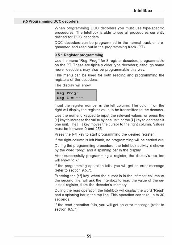
Intellibox
59
9.5 Programming DCC decoders
When programming DCC decoders you must use type-specificprocedures. The Intellibox is able to use all procedures currentlydefined for DCC decoders.
DCC decoders can be programmed in the normal track or pro-grammed and read out in the programming track (PT).
9.5.1 Register programming
Use the menu �Reg.-Prog.� for 8-register decoders, programmableon the PT. These are tipically older type decoders; although somenewer decoders may also be programmable this way.
This menu can be used for both reading and programming theregisters of the decoders.
The display will show:
Input the register number in the left column. The column on theright will display the register value to be transmitted to the decoder.
Use the numeric keypad to input the relevant values, or press the[+] key to increase the value by one unit, or the [$] key to decrease itone unit. The ["] key moves the cursor to the right column. Valuesmust be between 0 and 255.
Press the [8] key to start programming the desired register.
If the right column is left blank, no programming will be carried out.
During the programming procedure, the Intellibox activity is shownby the word �prog� and a spinning bar in the display.
After successfully programming a register, the display�s top linewill show �o.k.�.
If the programming operation fails, you will get an error message(refer to section 9.5.7).
Pressing the [8] key, when the cursor is in the leftmost column ofthe second line, will ask the Intellibox to read the value of the se-lected register, from the decoder�s memory.
During the read operation the Intellibox will display the word �Read�and a spinning bar in the top line. This operation can take up to 30seconds.
If the read operation fails, you will get an error message (refer tosection 9.5.7).

Intellibox
60
9.5.2 CV programming (byte)
Use the �CV Prog (byte)� menu to program DCC decoders with1024 configuration variables (CV) on the PT.
This type of programming is also known as �direct programming�.It is the fastest and most usual method to program a DCC decoder,taking a maximum of 5 seconds.
The programming menu will show the following display:
Input the number of the desired CV (1-1024) in the left-hand columnand its value (0-255) in the right-hand column.
Programming and reading procedures, follow what has been de-scribed in section 9.5.1 about register programming. In this section,please take special notice of the highlighted paragraphs.
REMARK A read error can be generated when you try to access a write-onlyregister. On the other hand, sometimes, read or write errors canbe caused by faulty electrical contacts between the locomotiveand the tracks. In this case you should correct the problem andmove the Intellibox cursor with the [!] key to the left-hand column.Press [8] again to re-read the same register.
After successfully reading a register, the display�s top line will show�o.k.�. You can now change, should you like to do so, the register�svalue, as described before.
CAUTION! Register no. 1 contains the decoder address. If you are program-ming older decoders, never use values greater than maximumallowed value for that decoder. This maximum allowed value(usually 99) should be mentioned in the decoder manual.

Intellibox
61
9.5.3 CV programming (bit)
Use the �CV Prog (bit)� menu to program DCC decoders with 1024configuration variables (CV) on the PT. With this programmingmethod, you can easily read or write single bits in a CV. This isreally useful when each bit in a configuration variable has a specialmeaning, usually controlling different decoder options.
The programming menu will show the following display:
The menu has three columns. The leftmost is used to input the CVnumber (1-1024), the central one to input the desired bit number(0-7) and the right-hand column to input the bit value (0-1).
CAUTION! Bits are numbered 0 to 7. Some decoder�s manuals (e.g. Lenz) usenumbers from 1 to 8. Don�t forget to convert these values beforeusing this menu!
Programming and reading procedures, follow what has beendescribed in section 9.5.1 about register programming, with theexception that the reading procedure is initiated by pressing the [8]key when the cursor is in the central column.
If the decoder cannot accept direct programming, the display willshow an error message. You will not be able to change the desiredbit through this menu: you will have to use the �CV Prog (byte)�menu (refer also to the Appendix).
HINT Some decoders use decimal values for the configuration variablebits. A table is given in the Appendix, with all possible bit-byteconversions. The following table could also help the user in theconversion among different standards of different companies.
Bit no. (Intellibox) 0 1 2 3 4 5 6 7
Bit no. (Lenz) 1 2 3 4 5 6 7 8
Decimal value 1 2 4 8 16 32 64 128

Intellibox
62
9.5.4 Paged programming
Use the �Paged Prog.� menu to program DCC decoders with 1024configuration variables (CV) on the PT.
The programming menu will show the following display:
Input the number of the desired CV (1-1024) in the left-hand columnand its value (0-255) in the right-hand column.
Programming and reading procedures, follow what has been de-scribed in section 9.5.1 about register programming. In this section,please take special notice of the highlighted paragraphs.
9.5.5 Programming on the main track
Use the �Main line Prg.� menu to program decoders on the maintrack. This programming mode is useful to change a decoder�sconfiguration variables �on the fly�.
This method uses the CV programming procedure. However, it isnot possible to read the decoder�s CVs.
REMARK Depending on the decoder�s model, programming on the main trackmight fail if the locomotive is not stationary on the track (speed =/ zero).
Initially the programming menu will show:
You should input now the decoder�s address. After confirming theaddress with the [8] key, the display will change to:
Input the number of the desired CV (1-1024) in the left-hand columnand its value (0-255) in the right-hand column.
The remaining programming and reading procedures, follow whathas been described in section 9.5.1 about register programming.In this section, please take special notice of the highlighted para-graphs.
CAUTION! It is not possible to carry out �programming on the main track�when the locomotive is on the programming track!

Intellibox
63
9.5.6 Programming long addresses
This menu provides a simple method to program �long� (14 bit)addresses (DCC addresses greater than 127).
Long addresses are stored in two CVs of the decoder (CV 17 andCV 18). To enable the use of long addresses, bit 5 of CV 29 shouldbe set to 1.
In principle, you should be able to carry out this type of program-ming using the normal CV direct programming procedure (refer tosections 9.5.2 and 9.5.3). If, instead, you choose to use the �pro-gramming long addresses� menu, the Intellibox will automaticallycompute the correct CV values and write to or read from all thenecessary CV.
The �long addresses� menu includes the two sub-menus �read�and �program�.
Use the �read� sub-menu to read and display long addresses. Theread procedure is initiated by pressing the [8] key.
CAUTION! Take note that even during a read operation, bit 5 of CV 29 is set to 1!From that moment on, it will no longer be possible to control thelocomotive with its CV 1 �short� address, unless you reset bit 5 ofCV 29 to zero.
Use the �program� sub-menu for programming addresses greaterthan 127. The programming operation is initiated by pressing the[8] key.
HINT The long addresses programming procedure changes the de-coder�s CV 17, 18 and 29. After programming a long address, the�short� address in CV 1 and the consisting address in CV 19 areno longer available. If you want to use these addresses again, youmust set bit 5 of CV 29 to zero.

Intellibox
64
9.5.7 DCC programming error messages
If the programming operation of a DCC decoder fails, the top line ofthe display will show one of the following error messages:
� errorThe read or write operations of a register or a CV has failed.
� no locNo locomotive is present in the programming track (PT), or thelocomotive has a defective electrical contact with the PT.
� shortShort-circuit in the programming track.
� dangerElectrical contact (non admissible!) between the PT and the maintrack.
� no pagThe decoder doesn�t accept paged programming.
� in use!The PT is being used by another device (e.g. by the PC throughthe serial interface).
9.6 Programming Selectrix decoders
Use this menu to program Selectrix decoders.The menu has the following options:
Address 0-111Max. speed 1-7Acc./Decel. 0-7Puls duration 1-4Stop zones 1-2Programming
Upon entering the menu, all the variables of the decoder presenton the PT are read and the address is displayed. You can reviewthe other values using the [+] and [$] keys.
Input the values for the registers you want to change with the numerickeypad. Once all the changes are made, select �programming� andinitiate the process by pressing [8].
HINT If you forget to enter even one of the 5 requested values, theprogramming procedure will fail.
CAUTION! If the programmimg procedure generates an error message, re-peat it, after turning (rotating) the locomotive on the PT 180°.
A zero value of the maximum speed sets some Selectrix decodersto conventional operation (read the decoder manual in order tounderstand how the decoder works). The conventional operationof Selectrix decoders is not handled by the Intellibox.

Intellibox
65
9.7 Searching a decoder�s address
The search menu can scan for the address of a decoder that cannotbe electrically read or whose address is set with DIP switches.
The search algorithm can be used with Motorola and DCC decoders.
To use this menu, follow this procedure:
� press the [mode] key until �Mode Programming� is displayed� press the [menu] key� with the [$] key page through the menus until �Address search� is
displayed� Choose this option with ["]� Choose between Motorola and DCC with the [$] key� Begin the search with [8]� Return to the normal control panel by pressing the [menu] key
REMARK This operation can take a long time to complete, because thesearch process sequentially reads all the decoder�s addresses!
Intellibox
66
10. The PC interfaceThe Intellibox�s PC interface is connected to the PC�s serial inter-face with a standard modem cable, available as art. #691.
With a maximum speed of 19200 baud, the Intellibox serial interfaceis 8 times faster than the Marklin Interface. Moreover, it has an I/Obuffer that further increases its throughput.
InstallationDepending on the software, it may be necessary to configure theserial interface (refer to section 5.9).
An application that uses the new communications protocol (P50X)adopted in the Intellibox, doesn�t need to be user-configured. Every-thing is done automatically.
The default settings of the serial interface are as follows:
Speed: 2400, 4800, 9600 or 19200Start bits: 1Stop bits: 2Data bits: 8Parity: noneHandshake: hardware, RTS-CTS
Compatibility and protocolsThe Intellibox serial protocol is completely compatible with the se-rial protocol of the Marklin 6050 and 6051 Interfaces. The Intelliboxcan be used with any train control software designed for the MarklinInterface.
In addition to the Marklin syntax, the Intellibox uses several advancedcommands that either replace Marklin commands or can be usedsimultaneously. This can be defined in a configuration menu in theIntellibox system parameters (section 5.9.2).
HINT The Intellibox serial protocol is described in a file, available throughdownload from our Internet sites.

Intellibox
67
11. Error messagesIn case of error during normal Intellibox operation, its power supplyis immediately interrupted, the red LED above the [stop] key startsblinking and the display shows an error message.
Short-circuit on the main track.
Short-circuit on a section controlled by a Booster.
Short-circuit on the CID lines booster or LocoNet outputs.
Short-circuit on the DCC booster output (connector #2 pin 1 and 2)or on the LocoNet B output between (connector #6 pin 1 and 6).
Short-circuit between main track and PT, DCC booster or LocoNetoutputs.
Short-circuit on the Lokmaus bus.
Overheating: If you continuously use the Intellibox at its maximumrated output, its heat sink could become too hot. In this case, aninternal thermal protection circuit is activated and the Intellibox isshut down to avoid permanent damage to its electronic circuitry.
HINT As soon as the error has been corrected and/or the temperaturedecreases, you can power your layout again by pressing the [go] key.

Intellibox
68
12. Software updatesThe Intellibox system software can be updated to a newer version,by downloading the new software from the computer, through theserial interface. This procedure doesn�t require any physical inter-vention on the Intellibox.
Hardware requirements
You need to power the Intellibox with a transformer. You will alsoneed a serial cable to connect the Intellibox to a Personal Computer.
There is no need to open up the Intellibox!
Software requirements
Contact your local retailer to obtain a diskette with the softwareupdate, or download it from our Internet sites.
How to update the software
� Connect the serial cable between the Intellibox and a PC serial(COM) port.
� Switch off the Intellibox for about 10 seconds. Switch it back onand wait for the completion of the initialization procedure.
� Run the application �ibupdate.exe� on your PC and follow the on-screen instructions.
Checking the software version
With the �Software vers.� menu in the system�s parameters, youcan check the software version of your Intellibox.
� Press the [menu] key� Press the [mode] key� Press the [$] key until �Software vers.� is displayed� Enter this menu by pressing ["]
� The top line displays the system�s software version number, whilethe bottom line shows the Intellibox serial number.
� Press the [menu] key to return to the main screen.

Intellibox
69
Appendix
Compatible devices 70
Compatible decoders 72
Some Special Options of the Intellibox 73
List of the standard serial commands
(6050 syntax) 76
Converting bits to bytes 77
Coding table for solenoid devices 79
Troubleshooting general problems 80
Troubleshooting decoder problems 82
Tips and Tricks 84

Intellibox
70
Compatible devicesThis section lists the successfully tested devices
Marklin I2C Bus
Marklin I2C Bus, left sideMarklin Keyboard 6040Marklin Memory 6043Arnold Keyboard 86040Marklin Switchboard 6041 (up to 4 Switchboards)
Marklin I2C Bus, right sideMarklin Control 80 6035Marklin Control 80f 6036Marklin Infra Control 80f 6070Arnold Control 80 86035Arnold Control 80f 86036
Marklin I2C Bus, both sides, using the adapter #692Marklin Central Units 6020, 6021, 6022, 6023, 6027, 6029, 6030.
REMARK If you are using the Marklin Central Unit 6027 you have to press thereset button of this unit during a system power up.If you are using a Marklin Central Control 6029 or 6030 as a Booster,it is not possible to use their control panels, since they are notconnected to I2C bus.
INFO Important differences exist among different production series ofthe same type of Marklin Digital Central Unit. Nevertheless, wetried to make the Intellibox as compatible as possible to most ofthese series and versions. However, we cannot exclude theoccurrence of troubles in a limited number of cases.
Lokmaus connector
CAUTION! Do not connect any X-Bus device here!
ROCO Lokmaus 10750LGB Lokmaus 55010
Feedback bus
Marklin s88 6088Modeltreno s88 66002Viessmann s88 5217
Marklin Booster connector
Uhlenbrock Booster 656; output format: Motorola, DCC, Selectrix.
Modeltreno Booster 66007 (Marklin and DCC compatibility mode).
Marklin Booster 6017 and 6015; output format: Motorola.In order to control DCC locomotives it might be necessary to modifythe Special Option #901 from 1 to 3 (see section 5.12).

Intellibox
71
DCC Booster connector
Lenz Booster LV100Lenz Booster LV101Marklin Booster 6016 with Adapter (#693)Arnold Booster 86015 with Adapter (#693)
HINT Most of DCC Boosters are able to supply the Motorola format. Inorder to accomplish this task with Boosters 6016 and 86015, itcould be necessary to modify their electronic circuit.
LocoNet connector
Uhlenbrock manual controller IB-Control (#654)Uhlenbrock hand-held controller FRED (#660)Digitrax hand held throttles DT100, DT100IR, BT2
HINT The Selectrix format can be supplied only with the Intellibox andthe Uhlenbrock Booster 656.

Intellibox
72
Compatible decodersTurnout and accessory decoders
Motorola formatUhlenbrock solenoid and accessory decoders 762, 765, 766Modeltreno solenoid device decoder 66001Viessmann solenoid device decoder 5211Viessmann relay decoder 5213Marklin K83 (6083)Marklin K84 (6084)
DCC formatUhlenbrock solenoid and accessory decoders 762, 765, 766Arnold K87N (86078)Lenz LS100/110/120DCC compatible decoders from other manufacturers
List of tested decoders
The following decoders have been tested with the Intellibox. Theycan be controlled by the Intellibox without any known problem. Thecompatibility of non-listed decoders is not guaranteed (unlessNMRA standard compliant).
� Uhlenbrock and Modeltreno Decoders
� Marklin Decoders, e.g. 6603 (Delta), 6080, 6081, 6090, 6090xnew, 6095, special decoders for some locos.
HINT Marklin decoders 6080, 6090 and Delta featuring chips with serialnumbers less than 701.17 (also LME or Zymos) should be definedas conforming to the old Motorola format.
� Old Marklin Digital= Decoder (c82)
� Old and new Lenz decoders, e.g. LE030, LE040, LE075, LE103,LE103XF, LE104, LE110, LE130, LE131, LE135, LE062XF, LE105XF
� LE100 in DCC format onlyShows problems in the multiprotocol environment.
� Several Digitrax decoders
� New Arnold decoders (81200, 81210)It is recommended to switch off the automatic detection of theMotorola protocol (CV 49, bit 4=1).
� Selectrix decoders (66830, 66832), only using the Intellibox.Other Boosters (Marklin or DCC) cannot be used.
� Wangrow and North Coast Engineering decoders
� XR1 decoder (Motorola compatible)
� Roco decoders (Lenz)
� ZIMO MX61N decoder

Intellibox
73
Some Special Options of the IntelliboxThe Intellibox uses up to 1000 Special Options (SO), numberedfrom 0 to 999. These are modifiable by the user only through theIntellibox menus, not by a PC. However, the PC can read the valueof all SO's.
Each SO controls a particular aspect of the Intellibox configuration.Only some of these SO's are documented along with their �mea-ning�. These would be those SO's which would make sense beingable to modify. Please do NOT change the value of other SO's asthis could interfere or even impede correct Intellibox operation.
A maximum and a minimum value are internally associated witheach SO. The Intellibox does not allow selecting a value outsidethat range.
SO #20 factory default = 1Whether (1) or not (0) P50 commands to an already �busy� locomo-tive are allowed (�busy� = already controlled by another (non-PC)device).
SO #21 factory default = 0Whether (1) or not (0) to discard P50 turnout commands issuedwhile the Intellibox is in Power Off.
SO #25 factory default = 1Whether (1) or not (0) to always send a DCC signal - eventually aDCC idle signal (if there is no DCC Lok in the refresh cycle).
HINT If you have no DCC locomotives, in order to increase the Intelliboxtransmission rate to the tracks please write �0� to this SO.
SO #27 factory default = 20 = no �purging�
1 -240 = Time in minutes between the last command delivered toa loco and the time when the commands for that loco are purgedfrom the refresh cycle.
SO #28 factory default = 0Defines the �purging condition�
= 0 locomotive speed = 0= 1 locomotive speed =/ 0
SO #812 factory default = 1Default s88 module number to be shown when activating the s88mode after turning on the Intellibox. Possible values are 1-128.
HINT The s88 module # 32-128 only correspond to LocoNet sensors.

Intellibox
74
SO #861-868 factory default = 1You can select what extended function (F1 - F4) is controlled throughthe "F1" Lokmaus key (i.e. the right function key of the Lokmaus).Furthermore, you can also tell the Intellibox, whether the function isto be toggled at each key press, or if the function is to be turned ononly as long as the Lokmaus key is kept pressed (�pulsed� or�push-button� behaviour). The following table shows the associationbetween the special options and the Lokmaus number:
Special option number 861 862 863 864 865 866 867 868
Lokmaus number 1 2 3 4 5 6 7 8
The value of each of these SO must be within 1 to 8. One wouldchoose a value from 1 to 4 in order to specify which function tochange (toggle), while you would choose a value from 5 to 8 (i.e. +4with respect to the previous case) in order to specify which functionto "push button" on. This concept is explained in the following table:
"Toggled" extended function F1 F2 F3 F4 - - - -
"Pulsed" extended function - - - - F1 F2 F3 F4
Special option value 1 2 3 4 5 6 7 8
For example: the default for all these SO's is 1. This implies that,upon each new closure of the Lokmaus "F1" key, the F1 functionstatus is toggled. Setting one of these SO's, let's say SO #864, tothe value 3 would imply that, upon each new closure of the Lok-maus #4 "F1" key, the F3 function status is toggled. Setting that verySO to the value 5 would imply that, upon pressing the Lokmaus #4"F1" key, the F1 function is turned on - and that this very function isturned off as soon as the Lokmaus "F1" key is released.
The following table could be used in order to register the chosenvalues of the Special Options 861-868.
Special option value 861 862 863 864 865 866 867 868
Default value 1 1 1 1 1 1 1 1
User’s value

Intellibox
75
SO #901 factory default = 1This SO has to be changed to a value of 3, in order to control DCClocomotives on layout sections supplied through a Marklin Booster6015 or 6017. Factory default = 1 means no DCC signal output.
SO #907 factory default = 1�Idle� format on the main track at Intellibox startup:
1 = Motorola4 = DCC5 = mixed Motorola and DCC
The following table could be used in order to register the chosenvalues.
Special option number
User’s values
SO #871-878 min = 0, max = 255In the �Table Keyboard mode� (see Special Option 810), each turnoutcontrol key-pair is associated to a user-defineable turnout address.The first turnout address is taken from the value of SO #871 decre-mented by 1, the second from SO #872 (-1), the 3rd from SO #873(-1), the 4th from SO #874 (-1), the 5th from SO #875 (-1), the 6thfrom SO #876 (-1), the 7th from SO #877 (-1) and the 8th turnoutaddress is taken from SO #878 (-1).
For example: setting SO #871 to the value 10 would allow you tocontrol the turnout address 11 through the [1] and [4] key-pair (ofcourse: only if this special "Table Keyboard mode" has beenactivated with SO #810=0).
The following table could be used in order to register the chosenvalues of the Special Options 871-878.
Special option number 871 872 873 874 875 876 877 878
Key pair 1 2 3 4 5 6 7 8
Default addresses 10 20 30 40 50 60 70 80
User’s values

Intellibox
76
List of the standard serial commands (6050 syntax)By means of the standard �P50� or �6050-type� binary commandsthe Intellibox is able to communicate with any program written forthe Marklin 6050/6051 interfaces. In the following table you will findthe decimal values of the available P50 commands.
Locomotive and solenoid device commands are composed of twobytes, with the exception of the emergency stop command. The firstbyte defines the type of command, while the second byte representsthe decoder address. Using these commands you are allowed tocontrol locomotives with an address range 0 to 255 (standard P50range is 1-80). All other commands are composed of just one byte.
The only commands implying a reply from the interface are thosedealing with feedback modules.
Command byte Address byte Function
97 - Emergency stop, same as [stop] key
96 - End of emergency stop, same as [go] key
1-14 1-80 (0-255)* Locomotives: operating levels 1-14 and "function light" off
15 1-80 (0-255)* Locomotives: direction change and "function light" off
17-30 1-80 (0-255)* Locomotives: operating levels 1-14 and "function light" on
31 1-80 (0-255)* Locomotives: direction change and "function light" on
64-79 1-80 (0-255)* Locomotives: toggle extended functions f1, f2, f3, f4Command byte = 64+1*f1+2*f2+4*f3+8*f4fx = 0 " Extended function fx offfx = 1 " Extended function fx on
33 0-255 Solenoid devices: green (straight)34 0-255 Solenoid devices: red32 - Solenoid devices: switch off the last addressed decoder
Zuordnung der Adressbytes:1-4 = outputs #1-4 of the first solenoid device decoder5-8 = outputs #1-4 of the second solenoid device decoder.....
255 = third output of the last (64.) solenoid device decoder
128 - Feedback modules: read without reset
129-159 - Feedback modules: read n s88 modules till the indicated module
129 " reads only the first feedback module
159 " reads all 31 feedback modules
The Interface replies with 2 bytes per module, showing the status of the inputs from 1-16
192 - Feedback modules: read with reset ("reset-mode" = default)
193-223 - Feedback modules: read a single s88 module193 " reads the first feedback module223 " reads the last feedback module (#31)The Interface replies with 2 bytes per module, showing the status of the inputs from 1-16
HINT A manual on the extended serial protocol (called P50X) of the Intelli-box is available on diskette (ask your local dealer) or at our Internetsites.

Intellibox
77
Converting bits to bytesSome DCC decoders do not accept the �bit-wise� programmingmode. When programming a single bit of a configuration variable itcould be necessary to convert the 8 bits of a CV to a complete byte.
The following table could be used for this purpose. In the table thelabel �CV adresse� represents the decimal value corresponding tothe 8 bit sequence.
CVAddress
Bit0
Bit1
Bit2
Bit3
Bit4
Bit5
Bit6
Bit7
0 0 0 0 0 0 0 0 0
1 1 0 0 0 0 0 0 0
2 0 1 0 0 0 0 0 0
3 1 1 0 0 0 0 0 0
4 0 0 1 0 0 0 0 0
5 1 0 1 0 0 0 0 0
6 0 1 1 0 0 0 0 0
7 1 1 1 0 0 0 0 0
8 0 0 0 1 0 0 0 0
9 1 0 0 1 0 0 0 0
10 0 1 0 1 0 0 0 0
11 1 1 0 1 0 0 0 0
12 0 0 1 1 0 0 0 0
13 1 0 1 1 0 0 0 0
14 0 1 1 1 0 0 0 0
15 1 1 1 1 0 0 0 0
16 0 0 0 0 1 0 0 0
17 1 0 0 0 1 0 0 0
18 0 1 0 0 1 0 0 0
19 1 1 0 0 1 0 0 0
20 0 0 1 0 1 0 0 0
21 1 0 1 0 1 0 0 0
22 0 1 1 0 1 0 0 0
23 1 1 1 0 1 0 0 0
24 0 0 0 1 1 0 0 0
25 1 0 0 1 1 0 0 0
26 0 1 0 1 1 0 0 0
27 1 1 0 1 1 0 0 0
28 0 0 1 1 1 0 0 0
29 1 0 1 1 1 0 0 0
30 0 1 1 1 1 0 0 0
31 1 1 1 1 1 0 0 0
32 0 0 0 0 0 1 0 0
33 1 0 0 0 0 1 0 0
34 0 1 0 0 0 1 0 0
CVAddress
Bit0
Bit1
Bit2
Bit3
Bit4
Bit5
Bit6
Bit7
35 1 1 0 0 0 1 0 0
36 0 0 1 0 0 1 0 0
37 1 0 1 0 0 1 0 0
38 0 1 1 0 0 1 0 0
39 1 1 1 0 0 1 0 0
40 0 0 0 1 0 1 0 0
41 1 0 0 1 0 1 0 0
42 0 1 0 1 0 1 0 0
43 1 1 0 1 0 1 0 0
44 0 0 1 1 0 1 0 0
45 1 0 1 1 0 1 0 0
46 0 1 1 1 0 1 0 0
47 1 1 1 1 0 1 0 0
48 0 0 0 0 1 1 0 0
49 1 0 0 0 1 1 0 0
50 0 1 0 0 1 1 0 0
51 1 1 0 0 1 1 0 0
52 0 0 1 0 1 1 0 0
53 1 0 1 0 1 1 0 0
54 0 1 1 0 1 1 0 0
55 1 1 1 0 1 1 0 0
56 0 0 0 1 1 1 0 0
57 1 0 0 1 1 1 0 0
58 0 1 0 1 1 1 0 0
59 1 1 0 1 1 1 0 0
60 0 0 1 1 1 1 0 0
61 1 0 1 1 1 1 0 0
62 0 1 1 1 1 1 0 0
63 1 1 1 1 1 1 0 0
64 0 0 0 0 0 0 1 0
65 1 0 0 0 0 0 1 0
66 0 1 0 0 0 0 1 0
67 1 1 0 0 0 0 1 0
68 0 0 1 0 0 0 1 0
69 1 0 1 0 0 0 1 0
CVAddress
Bit0
Bit1
Bit2
Bit3
Bit4
Bit5
Bit6
Bit7
70 0 1 1 0 0 0 1 0
71 1 1 1 0 0 0 1 0
72 0 0 0 1 0 0 1 0
73 1 0 0 1 0 0 1 0
74 0 1 0 1 0 0 1 0
75 1 1 0 1 0 0 1 0
76 0 0 1 1 0 0 1 0
77 1 0 1 1 0 0 1 0
78 0 1 1 1 0 0 1 0
79 1 1 1 1 0 0 1 0
80 0 0 0 0 1 0 1 0
81 1 0 0 0 1 0 1 0
82 0 1 0 0 1 0 1 0
83 1 1 0 0 1 0 1 0
84 0 0 1 0 1 0 1 0
85 1 0 1 0 1 0 1 0
86 0 1 1 0 1 0 1 0
87 1 1 1 0 1 0 1 0
88 0 0 0 1 1 0 1 0
89 1 0 0 1 1 0 1 0
90 0 1 0 1 1 0 1 0
91 1 1 0 1 1 0 1 0
92 0 0 1 1 1 0 1 0
93 1 0 1 1 1 0 1 0
94 0 1 1 1 1 0 1 0
95 1 1 1 1 1 0 1 0
96 0 0 0 0 0 1 1 0
97 1 0 0 0 0 1 1 0
98 0 1 0 0 0 1 1 0
99 1 1 0 0 0 1 1 0
100 0 0 1 0 0 1 1 0
101 1 0 1 0 0 1 1 0
102 0 1 1 0 0 1 1 0
103 1 1 1 0 0 1 1 0
104 0 0 0 1 0 1 1 0
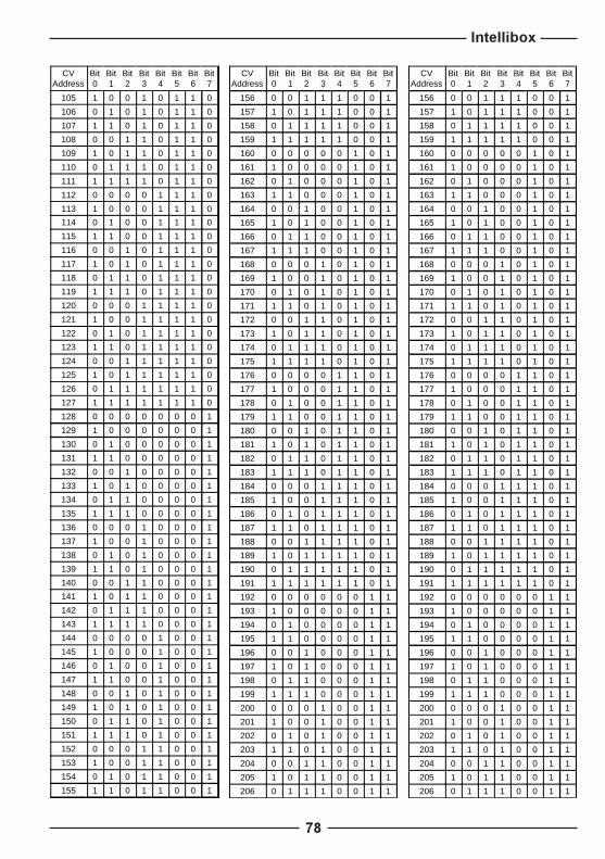
Intellibox
78
CVAddress
Bit0
Bit1
Bit2
Bit3
Bit4
Bit5
Bit6
Bit7
105 1 0 0 1 0 1 1 0
106 0 1 0 1 0 1 1 0
107 1 1 0 1 0 1 1 0
108 0 0 1 1 0 1 1 0
109 1 0 1 1 0 1 1 0
110 0 1 1 1 0 1 1 0
111 1 1 1 1 0 1 1 0
112 0 0 0 0 1 1 1 0
113 1 0 0 0 1 1 1 0
114 0 1 0 0 1 1 1 0
115 1 1 0 0 1 1 1 0
116 0 0 1 0 1 1 1 0
117 1 0 1 0 1 1 1 0
118 0 1 1 0 1 1 1 0
119 1 1 1 0 1 1 1 0
120 0 0 0 1 1 1 1 0
121 1 0 0 1 1 1 1 0
122 0 1 0 1 1 1 1 0
123 1 1 0 1 1 1 1 0
124 0 0 1 1 1 1 1 0
125 1 0 1 1 1 1 1 0
126 0 1 1 1 1 1 1 0
127 1 1 1 1 1 1 1 0
128 0 0 0 0 0 0 0 1
129 1 0 0 0 0 0 0 1
130 0 1 0 0 0 0 0 1
131 1 1 0 0 0 0 0 1
132 0 0 1 0 0 0 0 1
133 1 0 1 0 0 0 0 1
134 0 1 1 0 0 0 0 1
135 1 1 1 0 0 0 0 1
136 0 0 0 1 0 0 0 1
137 1 0 0 1 0 0 0 1
138 0 1 0 1 0 0 0 1
139 1 1 0 1 0 0 0 1
140 0 0 1 1 0 0 0 1
141 1 0 1 1 0 0 0 1
142 0 1 1 1 0 0 0 1
143 1 1 1 1 0 0 0 1
144 0 0 0 0 1 0 0 1
145 1 0 0 0 1 0 0 1
146 0 1 0 0 1 0 0 1
147 1 1 0 0 1 0 0 1
148 0 0 1 0 1 0 0 1
149 1 0 1 0 1 0 0 1
150 0 1 1 0 1 0 0 1
151 1 1 1 0 1 0 0 1
152 0 0 0 1 1 0 0 1
153 1 0 0 1 1 0 0 1
154 0 1 0 1 1 0 0 1
155 1 1 0 1 1 0 0 1
CVAddress
Bit0
Bit1
Bit2
Bit3
Bit4
Bit5
Bit6
Bit7
156 0 0 1 1 1 0 0 1
157 1 0 1 1 1 0 0 1
158 0 1 1 1 1 0 0 1
159 1 1 1 1 1 0 0 1
160 0 0 0 0 0 1 0 1
161 1 0 0 0 0 1 0 1
162 0 1 0 0 0 1 0 1
163 1 1 0 0 0 1 0 1
164 0 0 1 0 0 1 0 1
165 1 0 1 0 0 1 0 1
166 0 1 1 0 0 1 0 1
167 1 1 1 0 0 1 0 1
168 0 0 0 1 0 1 0 1
169 1 0 0 1 0 1 0 1
170 0 1 0 1 0 1 0 1
171 1 1 0 1 0 1 0 1
172 0 0 1 1 0 1 0 1
173 1 0 1 1 0 1 0 1
174 0 1 1 1 0 1 0 1
175 1 1 1 1 0 1 0 1
176 0 0 0 0 1 1 0 1
177 1 0 0 0 1 1 0 1
178 0 1 0 0 1 1 0 1
179 1 1 0 0 1 1 0 1
180 0 0 1 0 1 1 0 1
181 1 0 1 0 1 1 0 1
182 0 1 1 0 1 1 0 1
183 1 1 1 0 1 1 0 1
184 0 0 0 1 1 1 0 1
185 1 0 0 1 1 1 0 1
186 0 1 0 1 1 1 0 1
187 1 1 0 1 1 1 0 1
188 0 0 1 1 1 1 0 1
189 1 0 1 1 1 1 0 1
190 0 1 1 1 1 1 0 1
191 1 1 1 1 1 1 0 1
192 0 0 0 0 0 0 1 1
193 1 0 0 0 0 0 1 1
194 0 1 0 0 0 0 1 1
195 1 1 0 0 0 0 1 1
196 0 0 1 0 0 0 1 1
197 1 0 1 0 0 0 1 1
198 0 1 1 0 0 0 1 1
199 1 1 1 0 0 0 1 1
200 0 0 0 1 0 0 1 1
201 1 0 0 1 0 0 1 1
202 0 1 0 1 0 0 1 1
203 1 1 0 1 0 0 1 1
204 0 0 1 1 0 0 1 1
205 1 0 1 1 0 0 1 1
206 0 1 1 1 0 0 1 1

Intellibox
79
Coding table for solenoid devicesThe address of decoders conforming to the Motorola format (fromthe companies Marklin, Viessmann and Modeltreno) is definedusing 8 microswitches. Since every decoder controls 4 solenoiddevices, the decoder address is different from the solenoid deviceaddress.
The following table shows the position of the 8 microswitches ofthese decoders. The correlation with solenoid device addressesand Marklin Keyboard is also included.
Keyboardnumber
Keyboardkeys
Sol. dev.addr.
1 1..4 1-4 - 2 3 - 5 - 7 -
1 5..8 5-8 - - 3 - 5 - 7 -
1 9..12 9-12 1 - - 4 5 - 7 -
1 13..16 13-16 - 2 - 4 5 - 7 -
2 1..4 17-20 - - - 4 5 - 7 -
2 5..8 21-24 1 - - - 5 - 7 -
2 9..12 25-28 - 2 - - 5 - 7 -
2 13..16 29-32 - - - - 5 - 7 -
3 1..4 33-36 1 - 3 - - 6 7 -
3 5..8 37-40 - 2 3 - - 6 7 -
3 9..12 41-44 - - 3 - - 6 7 -
3 13..16 45-48 1 - - 4 - 6 7 -
4 1..4 49-52 - 2 - 4 - 6 7 -
4 5..8 53-56 - - - 4 - 6 7 -
4 9..12 57-60 1 - - - - 6 7 -
4 13..16 61-64 - 2 - - - 6 7 -
5 1..4 65-68 - - - - - 6 7 -
5 5..8 69-72 1 - 3 - - - 7 -
5 9..12 73-76 - 2 3 - - - 7 -
5 13..16 77-80 - - 3 - - - 7 -
6 1..4 81-84 1 - - 4 - - 7 -
6 5..8 85-88 - 2 - 4 - - 7 -
6 9..12 89-92 - - - 4 - - 7 -
6 13..16 93-96 1 - - - - - 7 -
7 1..4 97-100 - 2 - - - - 7 -
7 5..8 101-104 - - - - - - 7 -
7 9..12 105-108 1 - 3 - 5 - - 8
7 13..16 109-112 - 2 3 - 5 - - 8
8 1..4 113-116 - - 3 - 5 - - 8
8 5..8 117-120 1 - - 4 5 - - 8
8 9..12 121-124 - 2 - 4 5 - - 8
8 13..16 125-128 - - - 4 5 - - 8
9 1..4 129-132 1 - - - 5 - - 8
9 5..8 133-136 - 2 - - 5 - - 8
9 9..12 137-140 - - - - 5 - - 8
9 13..16 141-144 1 - 3 - - 6 - 8
10 1..4 145-148 - 2 3 - - 6 - 8
10 5..8 149-152 - - 3 - - 6 - 8
10 9..12 153-156 1 - - 4 - 6 - 8
10 13..16 157-160 - 2 - 4 - 6 - 8
Keyboardnumber
Keyboardkeys
Sol. dev.addr.
11 1..4 161-164 - - - 4 - 6 - 8
11 5..8 165-168 1 - - - - 6 - 8
11 9..12 169-172 - 2 - - - 6 - 8
11 13..16 173-176 - - - - - 6 - 8
12 1..4 177-180 1 - 3 - - - - 8
12 5..8 181-184 - 2 3 - - - - 8
12 9..12 185-188 - - 3 - - - - 8
12 13..16 189-192 1 - - 4 - - - 8
13 1..4 193-196 - 2 - 4 - - - 8
13 5..8 197-200 - - - 4 - - - 8
13 9..12 201-204 1 - - - - - - 8
13 13..16 205-208 - 2 - - - - - 8
14 1..4 209-212 - - - - - - - 8
14 5..8 213-216 1 - 3 - 5 - - -
14 9..12 217-220 - 2 3 - 5 - - -
14 13..16 221-224 - - 3 - 5 - - -
15 1..4 225-228 1 - - 4 5 - - -
15 5..8 229-232 - 2 - 4 5 - - -
15 9..12 233-236 - - - 4 5 - - -
15 13..16 237-240 1 - - - 5 - - -
16 1..4 241-244 - 2 - - 5 - - -
16 5..8 245-248 - - - - 5 - - -
16 9..12 249-252 1 - 3 - - 6 - -
16 13..16 253-256 - 2 3 - - 6 - -
- - 257-260 - - 3 - - 6 - -
- - 261-264 1 - - 4 - 6 - -
- - 265-268 - 2 - 4 - 6 - -
- - 269-272 - - - 4 - 6 - -
- - 273-276 1 - - - - 6 - -
- - 277-280 - 2 - - - 6 - -
- - 281-284 - - - - - 6 - -
- - 285-288 1 - 3 - - - - -
- - 289-292 - 2 3 - - - - -
- - 293-296 - - 3 - - - - -
- - 297-300 1 - - 4 - - - -
- - 301-304 - 2 - 4 - - - -
- - 305-308 - - - 4 - - - -
- - 309-312 1 - - - - - - -
- - 313-316 - 2 - - - - - -
- - 317-320 1 - 3 - 5 - 7 -
DecoderMicroswitches ON
DecoderMicroswitches ON

Intellibox
80
Troubleshooting general problemsIn this section you can find the solution to most of the commonproblems found when playing with the Intellibox.
The Intellibox does not switch on
If the Intellibox does not switch on (the liquid crystal display staysoff) the AC voltage could be missing. Maybe the plug of thetransformer is not correctly connected in its socket.
Check the connections between the transformer and the Intellibox.Connect the plug in the wall-socket.
The Intellibox does not �speak� English
Switch off the Intellibox. After some seconds switch the Intellibox onagain keeping the �2� key pressed.
The red LED (�stop�) of the Intellibox keeps blinking
A short-circuit occurred on the rails or a thermal overload occurredin the electronic circuits of the Intellibox, or a short-circuit occurredbetween the normal rails and the programming track.
Eliminate the short-circuit and wait for the cooling of the electroniccircuits. The liquid crystal display usually helps in finding out theproblem.
The red LED (�stop�) of the Intellibox keeps blinking
Overload of the output amplifier (Booster) of the Intellibox, due to aneccessive number of users (locomotives, lamps, etc.) connectedat the same time.
Subdivide the layout in more than one part and feed them usingmore than one Booster (and proper transformers).
The green LED (Go) lights up, but the locomotives do not run
If the Intellibox switches on, the green LED (Go) lights up, but thelocomotives do not run and the solenoid devices do not switch,then probably the connection between the output amplifier of theIntellibox and the rails is interrupted. As an alternative, the connectionbetween the Intellibox and the relevant Booster or between theBooster and the track is interrupted.
Check and correct the connections. In case of use of an externalBooster, check the status of the power-on indications (LED) on theBooster.

Intellibox
81
The Lokmaus does not workIf the Lokmaus does not work (e.g. the round central push-button isnot working), then probably the 5 pole plug of the Lokmaus or of theLokmaus adapter is not correctly connected in its socket.
Check the connection of the plug or of the adapter.
You are not able to control a locomotive using the LokmausIf the red LED of the Lokmaus remains inactive even after trying tocontrol a locomotive, then it is likely that the locomotive is undercontrol of another hand-held controller or of a computer.
Select a different locomotive address on the second hand-heldcontroller or on the computer program.
The locomotive does not workAfter introducing the address of a locomotive on the Intellibox controlpanel, the locomotive does not work. It is likely that you defined thewrong locomotive type. Please verify first what is the currentlocomotive format:
� Press [lok#] on the relevant control panel (left or right hand side)� Input the locomotive address on the numerical keypad� Confirm by pressing [8] key� Press a second time the [lok#] key� Press the [menu] key� Now the locomotive digital format is shown on the display� Should the digital format be wrong, browse all available formats
using the [$] key, until you find the right one� Confirm by pressing [8] key� Go back to the normal display by pressing [menu]
And now please test again your locomotive.
The solenoid devices are OK but the locomotives do not runYou are using the Intellibox in conjunction with a Marklin control unit(6020, 6021, 6022, 6023, 6027, 6029, 6030, which could be usedas a booster for solenoid devices). You are able to control the sole-noid devices but the locomotives do not run. You probably connectedthe track to the output plugs of the Marklin unit instead of the outputplug of the Intellibox.
Disconnect the rails from the Marklin unit and connect them to theoutput of the Intellibox or of a booster directly connected to the Intellibox.
The display of a Marklin Control connected to the Intellibox blinksAfter introducing a locomotive address in a Marklin Control 80 (6035)or 80f (6036) the display blinks. The locomotive is probably undercontrol of another manual controller or of a computer.
Marklin Control 80 (6035): It is not possible to gain control thelocomotive until it is released by the other controller.
Marklin Control 80f (6036): Introduce again the locomotive addressor introduce a different address.

Intellibox
82
Troubleshooting decoder problemsIn this section you can find solutions to the most common decoderproblems.
Problems controlling the lights in DCC decoders - 1
If the locomotive lights no longer respond to the [function] key, inmost likelihood the decoder is configured for 28 operating levelswhile the Intellibox only foresees for that locomotive address 14/27speed levels. To solve this situation, change (in the Intellibox) theconfiguration of the relevant decoder address to 28 operating levels.
Remember that NMRA standards impose the following specifica-tions for CV #29:
14 operating levels -> CV#29 Bit 1 = 027 operating levels -> CV#29 Bit 1 = 028 operating levels -> CV#29 Bit 1 = 1
128 operating levels -> CV#29 Bit 1 = 1
DCC decoder problems with the Motorola protocol
Some Motorola and DCC decoders may exhibit an abnormal be-haviour in layouts operating in a mixed mode.
While Marklin decoders behave normally in the presence of a DCCsignal, the opposite is not always true for many DCC decoders inpresence of a Motorola signal (notwithstanding NMRA compliance!).These decoders erroneously interpret the Motorola protocol as ananalog feed and start �jittering� or moving at an unpredictable speed.
In this eventuality, you should switch off the decoder�s analog signalautomatic recognition feature. Please refer to the decoder�s instruc-tion manual to determine which CV should be modified.
In latest generation decoders, bit #2 of CV #29 should be set tozero, although this might not be true for all DCC decoders.
Old and new Marklin function decoders
The Panorama car and the Marklin Digital remote control rotarycrane (7051+7652), are controlled with the old Motorola protocol,using f1-f4 functions. They are not able to operate with the newMarklin-Motorola protocol.
On the opposite, new Marklin locomotives (with smoke, soundeffects, etc), new Marklin decoders (60901, etc.) and Uhlenbrockdecoders (755, 756, 760 in operating mode 1-3) operate only in thenew protocol, and ignore the f1-f4 function signals of the old protocol.

Intellibox
83
Controlling the Marklin TEE train 3471
The address of this model should be configured for the old Motorolaprotocol.
Non-compatibility of Roco locomotive decoder 829162
It has been noted that, as soon as a Selectrix Locomotive is in therefresh cycle, this decoder starts "jittering� (micro-jumping).
Controlling the Roco crane wagon (Digital DCC)
The address of the Roco digital crane wagon (40110 or 46800)should be configured for DCC - 14 operating levels. The cranewagon uses one locomotive address.
The different functions are operated with the [function], [off] and [f1]keys and turning the corresponding knob.
REMARK The decoder address cannot be read on the programming track.Should you program a different address, you will get an errormessage, even if the programming procedure was successful.
Problems controlling the lights in DCC decoders - 2
If the lights of a locomotive equiped with a DCC/NMRA decoder areswitched on with even operating levels, switched off with odd oper-ating levels and do not respond to the [function] key, in most likeli-hood the decoder is configured for 14/27 operating levels while theIntellibox foresees for that locomotive address 28 speed levels. Tosolve this situation, change (in the Intellibox) the configuration ofthe relevant decoder address to 14 or 27 operating levels or re-configure the decoder (if possible) for 28 operating levels.
Remember that NMRA standards impose the following specifica-tions for CV #29:
14 operating levels -> CV#29 Bit 1 = 027 operating levels -> CV#29 Bit 1 = 028 operating levels -> CV#29 Bit 1 = 1
128 operating levels -> CV#29 Bit 1 = 1

Intellibox
84
Tips and Tricks
Controlling the Marklin Digital rotary crane
The address of the digital rotary crane must be configured for theold Motorola protocol. The crane�s functions, like turning the caband raising/lowering the boom, are controlled with the [f1] and [f2]keys and the speed knob. The working lights and the magnet areswitched on with the [function] key and switched off with the [off] key.
HINT If, in multiprotocol operation, the crane should not respond correctly,try changing its address.
Emergency stop button in the Lenz Booster output
If you connect the Intelliboxground (connector #1, pin #5)with the Lenz Booster short-c i rcu i t s igna l l ing l ine �E� ,(connector #2, pin #3) with amomentary switch, the Intelli-box will shut off power to thetrack and to all connected Boosters.
You can have a number of �emergency stop� buttons, connected inparallel, spread along your layout.
Track ground connectionconnector #1, pin #5
Lenz BoosterShort-circuit �E� input,connector #2, pin #3
...
Controlling the Marklin Digital turntable
The turntable can be retrofitted with a specific decoder (7687)compatible with the Motorola protocol. The different functionsrespond to the solenoid devices addresses 225 to 240.
Add Key Function
225redgreen
Ends programmingProgramming / Input
226redgreen
Cancels programmingRotates 180°
227redgreen
Next segment clockwiseNext segm.counterclockwise
228redgreen
Rotation clockwiseRotation counterclockwise
229redgreen
Rotates to segment #1Rotates to segment #2
230redgreen
Rotates to segment #3Rotates to segment #4
231redgreen
Rotates to segment #5Rotates to segment #6
232redgreen
Rotates to segment #7Rotates to segment #8
Add Key Function
233redgreen
Rotates to segment #9Rotates to segment #10
234redgreen
Rotates to segment #11Rotates to segment #12
235redgreen
Rotates to segment #13Rotates to segment #14
236redgreen
Rotates to segment #15Rotates to segment #16
237redgreen
Rotates to segment #17Rotates to segment #18
238redgreen
Rotates to segment #19Rotates to segment #20
239redgreen
Rotates to segment #21Rotates to segment #22
240redgreen
Rotates to segment #23Rotates to segment #24

Intellibox
85
Accessories
650 Intellibox
685 Manual with demo program of the Intellibox
691 Serial interface cable for PC�s
692 Control Unit adapter
693 Marklin Digital= Booster (6016) adapter
694 Spare connectors (3 and 6 poles)
750 DGL decoder for DC motors
751 DGL with universal NEM-NMRA plug
755 DGR decoder with load-independent regulation
756 DGF decoderfor Faulhaber motors
760 Function decoderDFU
770 DAL decoder for universal motors (Marklin)
775 DSU digital swapper for pickup shoes
785 Decoder manual
1006 Book: Digital Command Control by Rutger Friberg
1606 LocoNet cable, 6m with 2 plugs
1622 LocoNet coupler, with 2 sockets
Latest news at www.uhlenbrock.de or www.modeltreno.it.
Email your questions to [email protected]