data acquisition software - ic master shop · data acquisition software model : ... am-4210 dt-2269...
TRANSCRIPT

DATA ACQUISITION SOFTWAREModel : SW-U811-WIN
Your purchase of this DATA ACQUISITION SOFTWAREmarks a step forward for you into the field of precisionmeasurement. Please read the following instructionscarefully and always keep this manual within easy reach.
OPERATION MANUAL
TABLE OF CONTENTS
1. INTRODUCTION.......................................................... 1
2. GENERAL SPECIFICATION........................................... 2
3. INSTALL AND STAR THE PROGRAM.............................. 33-1 INSTALLATION...................................................... 33-2 START THE PROGRAM........................................... 43-3 Cooperate with the right interface cable.................. 4
4. USING SW-U811-WIN.................................................. 54-1 SYSTEM SETUP..................................................... 54-2 CREATE NEW DATA FILE....................................... 54-3 ANGULAR DISPLAY................................................ 64-4 TEXT DISPLAY....................................................... 84-5 SYSTEM MONITOR................................................ 84-6 DATA QUERY........................................................ 8
5. INTERFACE CABLES ( optional )................................... 10

1. INTRODUCTION
The SW-U811-WIN is a powerful WINDOWS programsoftware which enables full line RS232 serial instruments to be with data logging function.
Three kinds of different displays provide you choicedepends on your favorite. Maximum 16 channelsmonitoring at the same time let you can get a completedata information. High, Low warming to monitor anyunusually situation. Sample rate setting from 2 to 3600seconds to satisfy your different demands.
.xxx.mdb data file can be retrieved by EXCEL, ACESS..,and other kinds of database software. Data analyzeand demonstrate easily.
1

2. GENERAL SPECIFICATIONS
System Computer with following operating system :Requirement Win 98
Win 2000XPVISTA
Monitor : VGA, EGA monitorCommon Port Select COM 1 to COM 16.Function Data recorder, text display, analog display, chart
display, high/low limit, data query, text report,chart report.
Data Record Auto or ManualSample Rate 2 to 3,600 seconds.Data Save Data file : XXX.mdb.
* Automatic save to disk.Data file : XXX.txt.* When execute the " Print data " function, will generate the xxx.text file.
Accessories CD disk................................ 1 PC.Included Operation manual................. 1 PC.
2

Optional RS232 cable, Model : UPCB-01Accessory Direct RS232 cable be used to connect the meter
to the computer ( COM port ).RS232 cable, Model : UPCB-02Isolated RS232 cable be used to connect themeter to the computer ( COM port ).USB cable, Model : USB-01USB interface cable be used to connect the meterto the computer ( USB port ).RS232 cable, Model : UPCB-04* UPCB-04 is the double D9 RS232 cable.* Available for FG-5000A-232, FG-20KG-232.
3. INSTALL AND START THE PROGRAM
3-1 InstallationBefore installation, please remove the previousversion data acquisition software.1. Start your windows.2. Insert the CD-ROM disc into your CD-ROM driver. 3. In Windows 98, xp, VISTA click Run from the Start menu.4. Assume your CD-ROM driver is D:.
Run "D:\setup.exe" and click OK to start install
3

3-2 Star the programOnce you finish the installation, click the " Lutron811 " from the program file to start the program.
3-3 Cooperate with the right interface cableBefore you start the program, please identify and make sure to use the right interface cable ( optional )
USB-01UPCB-01UPCB-02UPCB-04
that connect the meter and between the computer. Thecable information, please refer to page 10.
4

4. USING SW-U811-WIN4-1 System setup
After run the program & the computer will show the Fig. 1.1. Chose System setup from the Setup menu in the top-left
corner and you will see a dialog box as Fig. 22. Enter a value in the " System Scan Rate " grid to determine
the sampling time.3. Enter a value in the " Max Record Data " grid to determine
computer's max. recording number.4. Click the arrow of " Common Port " to chose which port you
are connecting.5. Click the arrow of " Text Display Type " to determine how
many displays will show in the Text display screen. 6. Click the arrow of " Angular Display Type " to determine
how many displays will show in the Angular display screen. 7 Click the up-down arrow of " Chart Display Chan. " to select
which channel will show in the Chart display screen. 8 To determine the meter with how many display.9 Click " Save " to save your above setting then click " Exit " to
close this dialog box.
4-2 Create New Data FileChose " Create New Data File " from the " Setup menu ( Fig. 3 )
1. Enter a file name in the Data File Name grid.2. Click on " Create " then click on " Exit " to close this dialog.
5

4-3 Angular DisplayWe recommend you start from the " Angular Display " for serialsetting, and following instructions are based on the meter with 2channels.1. Select " Angular Display " from the commander line of
measurement system dialog box ( Fig. 1 ), and you will see theAngular Display dialog box with four sheet.The initial screen 2 Angular Display depending on yourselection of " System Setup " dialog box, Channel No.Please refer to the highlight blue number at thetop-left corner of the angular panel.
2. Select " Page Setup " ( Fig-4 ) sheet for the proper rangesetting of the angular panel and charts.
3. Select the up-down arrow of " Channel No " to determinewhich channel that you want to adjust.
4. Enter a number of the " Min Value " and the " Max Value "grid to determine the range of the angular panel.
5. Enter a number of the " Large Tick Delta " and " Small TickDelta " grid to determine the graduation of the angular panel.
6. Enter a number of " Label Delta " grid to determine thenumerical graduation of the angular panel.
7. Enter a number of " High Warning " and " Low Warning "grid to set the tolerable range.
8. Input a integer in " Decimal " grid to determine how manynumbers behind the decimal point.
6

9. The number of the "Scale" grid must be an integer, and thescale value will time your meter's reading value. For instancescale is 10 and the meter's reading value is 65.4. The readingvalue on the screen value would be 654.
10To judge the unit of your measurement, please click thegrid in front of " Unit Auto Sense ".
11Press " Save " button to save the setting.Press Save button every time to make newsetting value work.
12Change to sheet " Angular Display " ( Fig-5 ) you can findthe angular panel and inspect whether the setting is OK.
Panel Description
* Timer icon : Show the measuring time.* Counter icon : Show how many data recorded.* Scan Rate indicator : Show the sampling time.* Run / Pause button : If it shows Run that means data record automatically. If it shows Pause that means data record stopping. * Alarm Sound : check grid for sound warning.* Save Data button : No matter the data record situation is Run or Pause, every time you press the button would record data one once.* Chart Display button : Change to Chart Display screen* Text Display button : Change to Text Display screen
7

4-4 Text Display 1. Page setup sheet ( Fig-6 ).
Select the group that is suitable your measurement, and selecta channel for each display,Change to "2 channel Display" sheet, you can see the settingresult.
2. Channel Display sheet ( Fig-7 )The light blue grid shows the unit selected.The Light orange grid shows the channel selected..
4-5 System Monitor ( Chart Display Fig-8 ) 1. Enter a number into the " Y-Max " and " Y-Min " grid to set
the Y-axis max. and min. value.2. Press the button " Set Y-Axis Min_Max " every time to make
the new setting value work
4-6 Data QuerySelect the Data Query from the " Report " menu in the Measurement system dialog box. ( See Fig. 1 ) to entry the " DataQuery 16 " Data program. ( See Fig. 9 )
* Before make the data query, it should select thechannel no. of Database ( Chan. 1 to Chan. 16 )and the sampling date at first, refer to Fig. 9, page 20.
* If user intend to have period data analysis, please checkthe grid in front of the " Add Time condition ". Key in the time in the " Start Time " and " END Time " grid.
8

1) Click the " Data Query " button, and each data would be listed in the data list icon.
2) Click the " Show chart " button to show the data recorded withchart display.
3) Click the " Print Chart " and " print Data " button to print the detail of data recorded.
4) Click the " Clear Chart " button to clear the chart display.5) * Enter the chart's header and in the " Header " grid.
* Enter the chart's footer and in the " Footer " grid.* Enter numbers in " Y-Max " and " Y-Min " to set the Y-axsis.* Enter numbers in " Y-Grid " and " X-Grid " to divide the chart with vertical line and horizontal line and the numbers you entered is the interval of two line.
6) Click on " Setup " button to display it on the chart.7) Click Setup button every time when the setting value has been
changed to make a new setting value work.8) Click "Exit" to close the program.
9
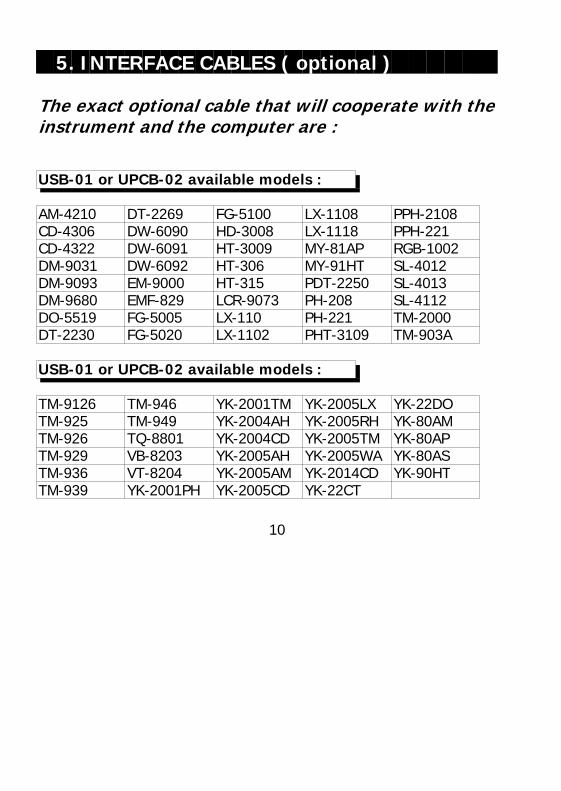
5. INTERFACE CABLES ( optional )
The exact optional cable that will cooperate with theinstrument and the computer are :
USB-01 or UPCB-02 available models :
AM-4210 DT-2269 FG-5100 LX-1108 PPH-2108CD-4306 DW-6090 HD-3008 LX-1118 PPH-221CD-4322 DW-6091 HT-3009 MY-81AP RGB-1002DM-9031 DW-6092 HT-306 MY-91HT SL-4012DM-9093 EM-9000 HT-315 PDT-2250 SL-4013DM-9680 EMF-829 LCR-9073 PH-208 SL-4112DO-5519 FG-5005 LX-110 PH-221 TM-2000DT-2230 FG-5020 LX-1102 PHT-3109 TM-903A
USB-01 or UPCB-02 available models :
TM-9126 TM-946 YK-2001TM YK-2005LX YK-22DOTM-925 TM-949 YK-2004AH YK-2005RH YK-80AMTM-926 TQ-8801 YK-2004CD YK-2005TM YK-80APTM-929 VB-8203 YK-2005AH YK-2005WA YK-80ASTM-936 VT-8204 YK-2005AM YK-2014CD YK-90HTTM-939 YK-2001PH YK-2005CD YK-22CT
10
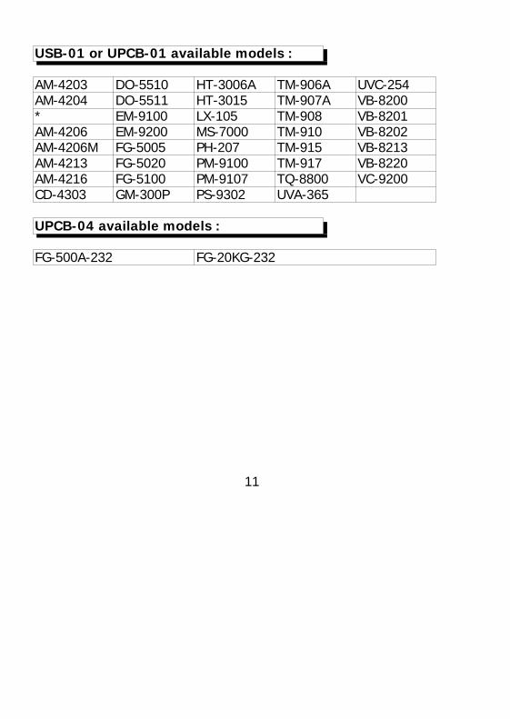
USB-01 or UPCB-01 available models :
AM-4203 DO-5510 HT-3006A TM-906A UVC-254AM-4204 DO-5511 HT-3015 TM-907A VB-8200* EM-9100 LX-105 TM-908 VB-8201AM-4206 EM-9200 MS-7000 TM-910 VB-8202AM-4206M FG-5005 PH-207 TM-915 VB-8213AM-4213 FG-5020 PM-9100 TM-917 VB-8220AM-4216 FG-5100 PM-9107 TQ-8800 VC-9200CD-4303 GM-300P PS-9302 UVA-365
UPCB-04 available models :
FG-500A-232 FG-20KG-232
11
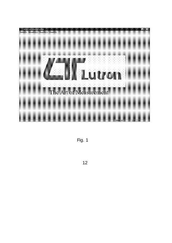
Fig. 1
12

Fig. 2
13

Fig. 3
14
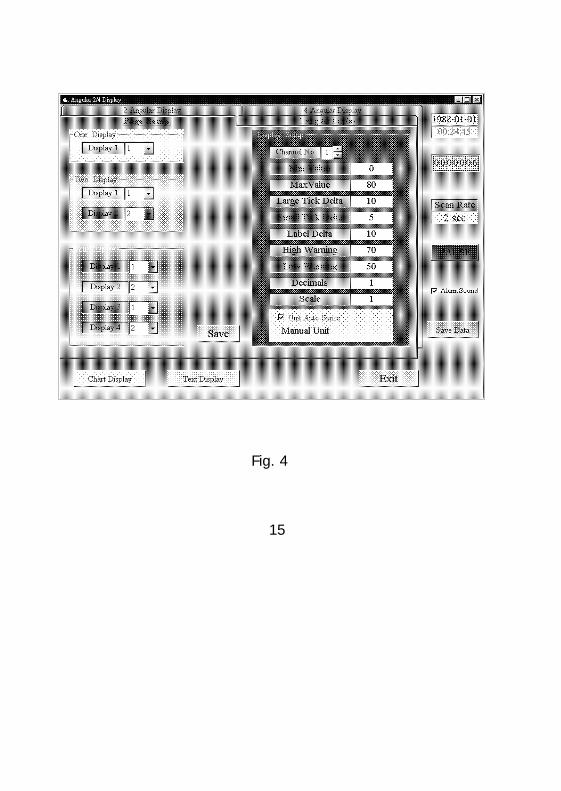
Fig. 4
15
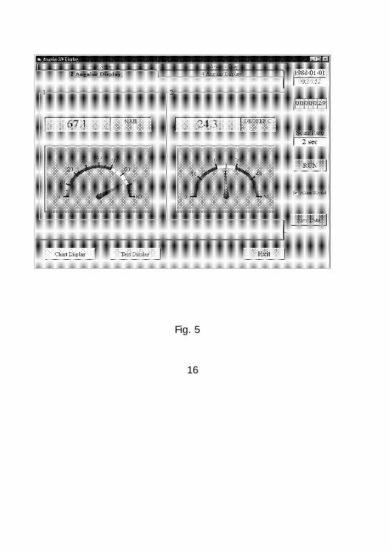
Fig. 5
16

Fig. 6
17

Fig. 7
18

Fig. 8
19

select forst select first
Fig. 9
20 0907-SWU811