data networking guidelines
TRANSCRIPT

Succession Communication Server for Enterprise 1000X21 Release 2.0
Data Networking Guidelines
Document Number: 553-3023-103Document Release: Standard 1.00Date: November 2002
Year Publish FCC TM
Copyright © 2002 Nortel NetworksAll Rights Reserved
Printed in Canada
Information is subject to change without notice. Nortel Networks reserves the right to make changes in design or components as progress in engineering and manufacturing may warrant. This equipment has been tested and found to comply with the limits for a Class A digital device pursuant to Part 15 of the FCC rules, and the radio interference regulations of Industry Canada. These limits are designed to provide reasonable protection against harmful interference when the equipment is operated in a commercial environment. This equipment generates, uses and can radiate radio frequency energy, and if not installed and used in accordance with the instruction manual, may cause harmful interference to radio communications. Operation of this equipment in a residential area is likely to cause harmful interference in which case the user will be required to correct the interference at their own expense.
SL-1, Meridian 1, and Succession are trademarks of Nortel Networks.
Title page


Page 3 of 190
Data Networking Guidelines
4
Revision history November 2002
Standard 1.00. This document is issued to support Succession Communication Server for Enterprise 1000, Release 2.0.

Page 4 of 190
553-3023-103 Standard 1.00 November 2002

Page 5 of 190
Data Networking Guidelines
8
Contents
Contents . . . . . . . . . . . . . . . . . . . . . . . . . . . . . . . . . . 5
About this document . . . . . . . . . . . . . . . . . . . . . . . 9Applicable systems . . . . . . . . . . . . . . . . . . . . . . . . . . . . . . . . . . . . . . . . 9
Intended audience . . . . . . . . . . . . . . . . . . . . . . . . . . . . . . . . . . . . . . . . . 9
Overview . . . . . . . . . . . . . . . . . . . . . . . . . . . . . . . . . 11Contents .. . . . . . . . . . . . . . . . . . . . . . . . . . . . . . . . . . . . . . . . . . . . . . . . 11
Introduction . . . . . . . . . . . . . . . . . . . . . . . . . . . . . . . . . . . . . . . . . . . . . . 11
The importance of QoS . . . . . . . . . . . . . . . . . . . . . . . . . . . . . . . . . . . . . 12
QoS and network convergence . . . . . . . . . . . . . . . . . . . . . . . . . . . . . . . 14
QoS versus bandwidth .. . . . . . . . . . . . . . . . . . . . . . . . . . . . . . . . . . . . . 15
Network performance dimensions affecting QoE . . . . . . . . . . . . . . . . . 16
Achieving satisfactory voice quality . . . . . . . . . . . . . . . . . . . . . . . . . . . 22
System recommendations . . . . . . . . . . . . . . . . . . . 23Contents .. . . . . . . . . . . . . . . . . . . . . . . . . . . . . . . . . . . . . . . . . . . . . . . . 23
Reference list . . . . . . . . . . . . . . . . . . . . . . . . . . . . . . . . . . . . . . . . . . . . . 24
Core networking . . . . . . . . . . . . . . . . . . . . . . . . . . . . . . . . . . . . . . . . . . 24
Sample system layout . . . . . . . . . . . . . . . . . . . . . . . . . . . . . . . . . . . . . . 35
VoIP QoS parameters . . . . . . . . . . . . . . . . . . . . . . . . . . . . . . . . . . . . . . 43
Designing networks for good QoE . . . . . . . . . . . . 59Contents .. . . . . . . . . . . . . . . . . . . . . . . . . . . . . . . . . . . . . . . . . . . . . . . . 59

Page 6 of 190
553-3023-103 Standard 1.00 November 2002
Introduction .. . . . . . . . . . . . . . . . . . . . . . . . . . . . . . . . . . . . . . . . . . . . . 60
The Succession CSE 1000 network . . . . . . . . . . . . . . . . . . . . . . . . . . . 61
Bandwidth considerations . . . . . . . . . . . . . . . . . . . . . . . . . . . . . . . . . . . 67
Survivability . . . . . . . . . . . . . . . . . . . . . . . . . . . . . . . . . . . . . . . . . . . . . 75
The QoS process . . . . . . . . . . . . . . . . . . . . . . . . . . . . . . . . . . . . . . . . . . 75
Layer 2 (Ethernet) QoS . . . . . . . . . . . . . . . . . . . . . . . . . . . . . . . . . . . . . 79
Layer 3 QoS . . . . . . . . . . . . . . . . . . . . . . . . . . . . . . . . . . . . . . . . . . . . . 86
Layer 4 (TCP/IP) classification . . . . . . . . . . . . . . . . . . . . . . . . . . . . . . 94
VoIP network assessment . . . . . . . . . . . . . . . . . . . 97Contents . . . . . . . . . . . . . . . . . . . . . . . . . . . . . . . . . . . . . . . . . . . . . . . . 97
Network assessment phases . . . . . . . . . . . . . . . . . . . . . . . . . . . . . . . . . 97
Physical and logical network diagrams . . . . . . . . . . . . . . . . . . . . . . . . 101
Link speeds and types . . . . . . . . . . . . . . . . . . . . . . . . . . . . . . . . . . . . . . 102
Link utilization assessment . . . . . . . . . . . . . . . . . . . . . . . . . . . . . . . . . . 106
Protocols in use . . . . . . . . . . . . . . . . . . . . . . . . . . . . . . . . . . . . . . . . . . . 110
Routing protocols . . . . . . . . . . . . . . . . . . . . . . . . . . . . . . . . . . . . . . . . . 111
Traffic flows in the network . . . . . . . . . . . . . . . . . . . . . . . . . . . . . . . . . 112
Calculating voice quality . . . . . . . . . . . . . . . . . . . . . . . . . . . . . . . . . . . 112
Tools . . . . . . . . . . . . . . . . . . . . . . . . . . . . . . . . . . . . . . . . . . . . . . . . . . . 116
Operating the VoIP network . . . . . . . . . . . . . . . . . 119Contents . . . . . . . . . . . . . . . . . . . . . . . . . . . . . . . . . . . . . . . . . . . . . . . . 119
Reference list . . . . . . . . . . . . . . . . . . . . . . . . . . . . . . . . . . . . . . . . . . . . 119
OTM . . . . . . . . . . . . . . . . . . . . . . . . . . . . . . . . . . . . . . . . . . . . . . . . . . . 120
Element Management . . . . . . . . . . . . . . . . . . . . . . . . . . . . . . . . . . . . . . 120
SNMP Network Management .. . . . . . . . . . . . . . . . . . . . . . . . . . . . . . . 124
Policy Management . . . . . . . . . . . . . . . . . . . . . . . . . . . . . . . . . . . . . . . 125

Page 7 of 190
Data Networking Guidelines
Appendix A: Configuring the BPS / Baystack 450 . . . . . . . . . . . . . . . . . . . . . . . . . 127Contents .. . . . . . . . . . . . . . . . . . . . . . . . . . . . . . . . . . . . . . . . . . . . . . . . 127
Creating Telephony VLANs on the Business Policy Switch . . . . . . . . 128
QoS configuration for the BPS/Baystack 450 . . . . . . . . . . . . . . . . . . . . 150
Baystack 450 802.1p user priority configuration . . . . . . . . . . . . . . . . . 157
Appendix B: Configuring QoS on the Passport 8600 . . . . . . . . . . . . . . . . . . . . . . . . . . . . . 159Contents .. . . . . . . . . . . . . . . . . . . . . . . . . . . . . . . . . . . . . . . . . . . . . . . . 159
DiffServ core network with BPS 2000 . . . . . . . . . . . . . . . . . . . . . . . . . 159
DiffServ core network with Baystack 450 . . . . . . . . . . . . . . . . . . . . . . 162
QoS on the Passport 8600 . . . . . . . . . . . . . . . . . . . . . . . . . . . . . . . . . . . 163
Layer 3 QoS mechanisms . . . . . . . . . . . . . . . . . . . . . . . . . . . . . . . . . . . 168
Appendix C: Optivity Policy Services . . . . . . . . . . 173Contents .. . . . . . . . . . . . . . . . . . . . . . . . . . . . . . . . . . . . . . . . . . . . . . . . 173
Policies . . . . . . . . . . . . . . . . . . . . . . . . . . . . . . . . . . . . . . . . . . . . . . . . . 173
List of terms . . . . . . . . . . . . . . . . . . . . . . . . . . . . . . . 179
Page 8 of 190
553-3023-103 Standard 1.00 November 2002

Page 9 of 190
Data Networking Guidelines
10
About this documentThis document is a global document. Contact your system supplier or your Nortel Networks representative to verify that the hardware and software described are supported in your area.
Applicable systemsThis document applies to Succession Communication Server for Enterprise (CSE) 1000 systems.
Intended audienceThis document is intended for network deployment personnel responsible for ensuring that the data network has been properly provisioned to support IP Telephony services using Succession CSE 1000 systems.
This document assumes that the reader understands general data networking technology and has a fundamental understanding of IP networking technologies and protocols.

Page 10 of 190 About this document
553-3023-103 Standard 1.00 November 2002

Page 11 of 190
Data Networking Guidelines
22
Overview
ContentsThis section contains information on the following topics:
Introduction . . . . . . . . . . . . . . . . . . . . . . . . . . . . . . . . . . . . . . . . . . . . . . 11
The importance of QoS . . . . . . . . . . . . . . . . . . . . . . . . . . . . . . . . . . . . . 12Application requirements . . . . . . . . . . . . . . . . . . . . . . . . . . . . . . . . . 14
QoS and network convergence . . . . . . . . . . . . . . . . . . . . . . . . . . . . . . . 14
QoS versus bandwidth. . . . . . . . . . . . . . . . . . . . . . . . . . . . . . . . . . . . . . 15
Network performance dimensions affecting QoE. . . . . . . . . . . . . . . . . 16Network availability . . . . . . . . . . . . . . . . . . . . . . . . . . . . . . . . . . . . . 16Bandwidth. . . . . . . . . . . . . . . . . . . . . . . . . . . . . . . . . . . . . . . . . . . . . 17Delay. . . . . . . . . . . . . . . . . . . . . . . . . . . . . . . . . . . . . . . . . . . . . . . . . 18Jitter . . . . . . . . . . . . . . . . . . . . . . . . . . . . . . . . . . . . . . . . . . . . . . . . . 19Loss. . . . . . . . . . . . . . . . . . . . . . . . . . . . . . . . . . . . . . . . . . . . . . . . . . 20
Achieving satisfactory voice quality . . . . . . . . . . . . . . . . . . . . . . . . . . . 22
IntroductionData networks were originally designed and deployed to provide best-effort services. Applications such as IP Telephony require the data network to provide special treatment for the telephony packets to ensure that the application works properly.

Page 12 of 190 Overview
553-3023-103 Standard 1.00 November 2002
The primary applications used with IP Telephony are interactive voice, voice mail, facsimile, and voice-band data (modem). Quality of Service (QoS) is the mechanisms and protocols used on the network to obtain reliable quality. Quality of Experience (QoE), also known as the service quality, is the term used to describe the overall performance quality that the network provides the user or application.
QoS refers to packet tagging mechanisms and network architecture decisions at the packet layer to expedite packet forwarding and delivery. Networks carrying both telephony and data traffic usually require QoS mechanisms to ensure that the telephony applications achieve acceptable service quality. QoS must be applied uniformly across the network to ensure consistent, timely delivery of telephony packets.
End-to-end QoS is required for IP Telephony applications to achieve reliable QoE and is achieved by ensuring that the different parts of the network apply consistent treatment to the telephony packets.
The importance of QoSNetworks now carry many different types of traffic. Each traffic type has unique requirements for the following elements:
• bandwidth
• delay
• jitter
• availability
Internet Protocol (IP) is a connectionless protocol. This means that IP packets do not take a specific path across the network. In a best-effort network, this can result in unpredictable QoE. A best-effort network has no specified parameters. It does not guarantee how fast data is transmitted over a network, and has no assurances that the data will even be delivered at all.

Overview Page 13 of 190
Data Networking Guidelines
The IP protocol was originally designed to reliably send a packet to its destination. Little consideration was given to the length of time it took to get there. Today, IP networks transport data from many different application types. Many of these applications require low latency. Latency is the length of time needed for information to travel through a network. High latency can significantly affect the end-user quality; in some cases, the application does not function at all.
Voice applications
Voice applications originated on Public Switched Telephone Networks (PSTNs) and used circuit switching in the form of Time Division Multiplexing (TDM).
TDM has been engineered with very specific, pre-determined behaviors in order to support real-time voice conversations. On a TDM network, voice traffic experiences a low, fixed amount of delay, with essentially no loss. Voice applications over IP networks must restrict delay and data loss to maintain acceptable user quality.
If a voice application is sent over a best-effort IP network, the following can occur:
• Voice packets experience variable, unpredictable amounts of delay.
• Voice packets are dropped when the network is congested.
• Voice packets can re-ordered by the network if the packets arrive out of sequence.
QoS techniques can be applied to properly-engineered networks to support Voice over Internet Protocol (VoIP) with acceptable, consistent, and predictable voice quality.

Page 14 of 190 Overview
553-3023-103 Standard 1.00 November 2002
Application requirements
Table 1 lists the various QoS performance parameters required by some common applications. If these parameters are mixed over a common-use IP network and QoS technologies are not used, the traffic can experience unpredictable behavior.
QoS and network convergenceIn the last several years, there has been a move towards network convergence. Network convergence is the transport of all services over the same network structure. Previously, there were separate, dedicated networks for different types of applications, such as voice, video, and data. Today, many of these applications are being merged into a single network to reduce operating costs and increase ease of operation.
A traditional enterprise may have the following network types:
• private TDM-based voice network
• IP network to the Internet
Table 1Common application performance parameters
Application
Relative bandwidth
demand
Sensitivity to
Delay Jitter Loss
VoIP Low High High High
Video Conferencing High High High Med
Streaming Video on Demand High Med Med Med
Streaming Audio Low Med Med Med
Web browsing(eBusiness)
Med Med Low High
E-mail Low Low Low High
File Transfer Med Low Low High

Overview Page 15 of 190
Data Networking Guidelines
• Integrated Services Digital Network (ISDN) for videoconferencing
• SNA network (an IBM computer network architecture)
• multi-protocol network, including such varied protocol types as IPX and AppleTalk
Many enterprises look to converged networks to achieve cost and operational efficiency. A converged network mixes different types of traffic, each with different requirements. This creates difficulties that must be addressed.
When different types of applications had dedicated networks, QoS technology played a smaller role. Dedicated network traffic was similar in behavior, and the networks were fine-tuned to achieve an application’s required behavior.
For example, the expectation for interactive voice is low packet loss, and a minimal, fixed amount of delay. Data is sent in a steady stream, with samples transmitted at fixed time intervals. Such performance is obtained on a circuit-switched network. A best-effort data network has varying amounts of packet loss, and variable delay usually caused by network congestion. A packet-based data network usually is the opposite of what is needed by a voice application.
Implementing QoS mechanisms helps to address this issue.
QoS versus bandwidthBandwidth is the measure of the amount of information that can be transmitted over a medium in a specific amount of time.
One approach to engineering says that QoS is not needed; increasing bandwidth provides enough QoS for all applications. This theory also states that implementing QoS is complicated; adding bandwidth is easy. However, it is necessary to look at the QoS problem to determine if adding bandwidth will solve the problem.
If all networks had sufficient bandwidth available so that network congestion never occurred, QoS technology would not be needed.

Page 16 of 190 Overview
553-3023-103 Standard 1.00 November 2002
High-bandwidth connections are not available throughout the entire network. This is especially true for access networks, where the usual amount of bandwidth available is only several hundred kbps. Telephony traffic must be treated consistently end-to-end to achieve a prescribed QoE performance level. Bandwidth differences in a network become potential congestion points. This can degrade perceived quality, even though the long-haul network offers excellent packet-forwarding performance.
Network performance dimensions affecting QoESeveral QoS parameters can be measured and monitored to determine if desired service levels are provided and obtained. These parameters consist of the following:
• network availability
• bandwidth
• delay
• jitter
• loss
These QoS parameters and mechanisms affect the application’s or end-user’s QoE.
Network availability
Network availability has the most significant effect on QoE. If the network is unavailable, even for brief periods of time, the user or application can achieve unpredictable or undesirable performance levels.
Network availability is dependent on the availability of a survivable, redundant network. A redundant network should include the following elements to ensure survivability:
• redundant devices such as
— interfaces
— processor cards
— power supplies in routers and switches
Overview Page 17 of 190
Data Networking Guidelines
• resilient networking protocols
• multiple physical connections, such as copper or fiber
• backup power sources
Bandwidth
Bandwidth is also a significant parameter that affects QoS. There are two types of bandwidth:
• Available Bandwidth
• Guaranteed Bandwidth
Available Bandwidth
Many network operators oversubscribe the bandwidth on their network to maximize the return on their network infrastructure or leased bandwidth.
Oversubscribing bandwidth means that the bandwidth a user subscribes to is not always available. All users compete for Available Bandwidth. The amount of bandwidth available to a user depends on the amount of traffic from other network users at any given time.
Guaranteed Bandwidth
Some network operators offer a service that guarantees a minimum bandwidth and burst bandwidth in the Service Level Agreement (SLA). This service is more expensive than the Available Bandwidth service. The network operator must ensure that the Guaranteed Bandwidth subscribers get preferential treatment (QoS bandwidth guarantee) over the Available Bandwidth subscribers.
This can be accomplished in several ways. Sometimes, the network operator separates the subscribers by different physical or logical networks, such as Virtual Local Area Networks (VLANs) or Virtual Circuits.
Page 18 of 190 Overview
553-3023-103 Standard 1.00 November 2002
In other cases, the Guaranteed Bandwidth traffic shares the same infrastructure as the Available Bandwidth traffic. This is often seen where network connections are expensive, or where the bandwidth is leased from other service providers. When both types of subscribers share the same infrastructure, the network must be able to prioritize the Guaranteed Bandwidth traffic over the Available Bandwidth traffic. This ensures that when network traffic is heavy, the Guaranteed Bandwidth subscriber’s SLA is met.
Queueing
Over-engineering network bandwidth does not necessarily solve voice quality problems, as IP network traffic is inherently bursty in nature. At any time, a burst of packets can enter a switch. If the number of packets received in that instant is greater than the capacity of the transmitting port’s queue, then packets are lost. This situation is particularly serious on slow connections.
If a queue is busy (though not necessarily full), voice packet traffic can back up and jitter can occur, if voice packets are not prioritized. Network QoS mechanisms are based on assigning different priorities to multiple queues. A voice queue is assigned a higher priority. If a specific queue is assigned only to voice traffic, then there is less chance that voice packets will be discarded because the queue is too full. Network delay is reduced, as voice packets are transmitted first. This minimizes delay, jitter, and loss. Perceived voice quality is greatly improved.
Delay
Delay is defined as the amount of time required for an application’s data to reach its intended destination. Delay causes significant QoE issues with voice and video applications. Other applications, such as Fax transmissions, simply time-out and fail with excessive delay.
Some applications can compensate for specified amounts of delay, but once that amount is exceeded, the QoS is compromised. VoIP and gateways also provide delay compensation by using local buffering.
Delay can be fixed or variable. Variable delay is also known as jitter.

Overview Page 19 of 190
Data Networking Guidelines
Some causes contributions to fixed (baseline) delay are as follows:
• Application-based delay, such as:
— voice Codec processing
— IP packet creation time required by the TCP/IP software stack
• Serialization delay — Delay of the voice packet at each hop of the physical network. Depends on link speed (a fixed, constant value for each link).
• Propagation delay — The delay caused by the finite speed at which electronic signals can travel through a transmission medium.
Jitter
Jitter is the variation in the amount of time it takes for consecutive packets to travel from the sender to the receiver. There is a fixed baseline delay for packet flow (the absolute fastest time for a voice packet to pass through the network), and a variation as well. The variation in the delay is jitter. Jitter is also known as variable delay.
The primary cause of jitter (variable delay) is contention (vying for network access), also known as queueing delay. Variable delays are affected by the amount of network traffic.
Jitter has a pronounced effect on real-time, delay-sensitive applications, such as video and voice. These applications need to receive packets at a fairly constant rate, with a fixed delay between consecutive packets. If the arrival rate varies, the jitter affects the application’s performance. Minimal jitter might be acceptable, but if jitter increases, the application could become unusable.
Some settings on devices such as VoIP gateways and Internet Telephones can compensate for a finite (specified) amount of jitter.
If an adaptive jitter buffer is used, delay is kept to a minimum during periods of low jitter. The adaptive buffer can adjust to higher levels of jitter, within a limited range, during periods of higher traffic volume. (If the network becomes congested, jitter and packet loss can become undefined, and real-time interactive applications can become unusable.)

Page 20 of 190 Overview
553-3023-103 Standard 1.00 November 2002
Voice applications require the voice packets to be fed to the decoder at a constant rate. If the next voice packet does not arrive in time to take its turn to be decoded, the packet is considered lost. Packet Loss Concealment (PLC) attempts to smooth over the lost voice packet. PLC replays the previous voice packet until the next voice packet arrives. A PLC algorithm can repair losses of 40-60 ms. Longer gaps in the signal must be muted. If jitter is high, whole groups of packets can be late or lost, and the output can often contain muted segments.
All networks have some jitter. This is due to the differences in delay created by each network node, as packets are queued. If jitter is contained within specified limits, QoS can be maintained.
Loss
Loss is defined as the number of packets lost during transmission. It is usually measured as a percentage of the total packets exchanged.
Physical medium loss
Loss can occur due to errors created by the physical medium used to transmit the data.
Most landline connections have very low loss, measured in Bit Error Rate (BER). Wireless connections, such as satellite, mobile, or fixed wireless networks, have a high BER. The BER can vary due to the following:
• radio frequency interference
• cell handoff during roaming calls
• weather conditions, such as fog and rain
• physical obstacles such as trees, buildings, and mountains
Wireless technology usually transmits redundant information, since packets are often dropped during transmission due to the physical medium.
Congestion loss
Congestion loss is made up of true loss (buffer overflow at router queues) and late packets. Loss also occurs when congested network nodes drop packets. The majority of packet loss is caused by congestion.

Overview Page 21 of 190
Data Networking Guidelines
VoIP uses User Datagram Protocol (UDP). UDP is a connectionless protocol which, unlike TCP, cannot retransmit lost packets. A packet is sent from the source to the destination with no means to determine if that packet was received or not.
If a network becomes congested to the point that packets are lost, voice quality is degraded. Traffic is discarded if the transmit queue of an uplink has less bandwidth available than the total amount of bandwidth trying to use that link. This situation is also known as a “bottle neck”.
Congestion can lead to packet loss. Mechanisms to avoid network congestion can be used. One such mechanism is called Random Early Discard (RED). RED deliberately drops packets once the network traffic reaches a specified threshold. The dropped packets cause TCP to reduce its window size and send fewer packets, thus reducing network traffic.
Note: RED provides congestion control only for applications or protocols that have the TCP-like ability to reduce network traffic.
UDP packets dropped in a network cannot be re-transmitted. Flow rates are not adjusted by devices that communicate through UDP.
Without discard priorities, it would be necessary to separate packets into different queues in a network node to provide different levels of service. This is expensive to implement, as only a limited number of hardware queues (usually eight or fewer) are available on networking devices. Though some devices have software-based queues, their increased use reduces network node performance.
With discard priorities, although packets are placed in the same queue, they are divided into virtual sub-queues, determined by their assigned discard priority. For example, if a product supports three discard priorities, then the product’s queue provides three sub-queues, and therefore, three QoS levels.

Page 22 of 190 Overview
553-3023-103 Standard 1.00 November 2002
Achieving satisfactory voice qualityA satisfactory level of perceived voice quality is achieved through the following:
• a properly-engineered network
• good network equipment
• adequate bandwidth for peak usage
• use of QoS mechanisms
If these elements are not present, VoIP performance suffers.
This document provides recommendations for implementing QoS mechanisms on a network that is using Succession CSE 1000.
WARNINGConfigure the ports on Layer 2 or Layer 3 switching equipment as Auto-negotiate.
If one side is manually configured, and the other side is configured as Auto-negotiate, the following situation occurs.
The Auto-negotiate side sets itself to the manually configured side’s speed, but always sets itself to Half-duplex transmission. If the manually-configured side is Full-duplex transmission, then a mismatch occurs, and voice quality is unsatisfactory.

Page 23 of 190
Data Networking Guidelines
58
System recommendations
ContentsThis section contains information on the following topics:
Reference list . . . . . . . . . . . . . . . . . . . . . . . . . . . . . . . . . . . . . . . . . . . . . 24
Core networking . . . . . . . . . . . . . . . . . . . . . . . . . . . . . . . . . . . . . . . . . . 24Introduction . . . . . . . . . . . . . . . . . . . . . . . . . . . . . . . . . . . . . . . . . . . 24ELAN . . . . . . . . . . . . . . . . . . . . . . . . . . . . . . . . . . . . . . . . . . . . . . . . 26TLAN . . . . . . . . . . . . . . . . . . . . . . . . . . . . . . . . . . . . . . . . . . . . . . . . 27Security. . . . . . . . . . . . . . . . . . . . . . . . . . . . . . . . . . . . . . . . . . . . . . . 29Redundant network architecture. . . . . . . . . . . . . . . . . . . . . . . . . . . . 29Succession Call Server to remote Media Gateway requirements. . . 38
VoIP QoS parameters . . . . . . . . . . . . . . . . . . . . . . . . . . . . . . . . . . . . . . 43Network availability . . . . . . . . . . . . . . . . . . . . . . . . . . . . . . . . . . . . . 44Bandwidth. . . . . . . . . . . . . . . . . . . . . . . . . . . . . . . . . . . . . . . . . . . . . 44Packet loss . . . . . . . . . . . . . . . . . . . . . . . . . . . . . . . . . . . . . . . . . . . . 51Delay. . . . . . . . . . . . . . . . . . . . . . . . . . . . . . . . . . . . . . . . . . . . . . . . . 52Jitter . . . . . . . . . . . . . . . . . . . . . . . . . . . . . . . . . . . . . . . . . . . . . . . . . 56

Page 24 of 190 System recommendations
553-3023-103 Standard 1.00 November 2002
Reference listThe following are the references in this section:
• Installing and Configuring Optivity Telephony Manager (553-3001-230)
• Software Input/Output: Maintenance (553-3001-511)
• IP Peer Networking (553-3023-220)
Core networking
Introduction
This chapter describes the requirements for creating and maintaining a robust, redundant Succession Communication Server for Enterprise (CSE) 1000 network.
The Succession CSE 1000 requires several separate sub-networks to operate, as follows:
• ELAN
• TLAN
• CLAN (customer’s enterprise IP network)
Figure 1 on page 25 illustrates the logical elements of basic system connectivity in a Succession CSE 1000 network.

System recommendations Page 25 of 190
Data Networking Guidelines
Figure 1Succession CSE 1000 logical connectivity
Note: Every device, with the exception of the Call Server, has an ELAN and a TLAN connection. The Call Server has a single ELAN connection and up to four Call Server-to-Media Gateway connections. The Succession System Controller (SSC) in the Media Gateway has a single Call Server-to-Media Gateway connection and an ELAN connection.
The Call Server/Media Gateway LAN connects the Call Server to each Media Gateway Succession System Controller (SSC). See Figure 1. In many cases, the Call Server/Media Gateway LAN is implemented using point-to point cabling (crossover cable) and non-routable IP addresses, but it can also operate through a Layer 2 switch.
The ELAN carries management and signaling data. The ELAN connects the Call Server, Media Gateway SSCs, Signaling Server(s), and Voice Gateway Media Card(s). The ELAN is not usually routed, but in special cases, such as remote access, limited access can be implemented.
Signaling Server
Media Gateway
Media Card
SSC
OTM Server
Call Server
Call Pilot Server
Call Server –- Media Gateway Connections
Media Gateway
Media Card
SSC
• Logical server connectivity.
Call PilotCLAN connection
TLAN ELAN

Page 26 of 190 System recommendations
553-3023-103 Standard 1.00 November 2002
The TLAN primarily carries VoIP traffic. It connects the Signaling Server and Voice Gateway Media Card(s) within a single Succession CSE 1000 node. The CLAN (customer’s enterprise IP network) connection from applications such as CallPilot can also be connected to the TLAN.
The management workstation is usually on the ELAN in order to achieve the highest degree of system security. The ELAN can be an isolated or non-routable subnet. If a single management workstation is required to manage multiple Succession CSE 1000 systems, The management workstation can be deployed on the TLAN or elsewhere on the enterprise network. Remote access to the ELAN should be restricted to the management workstation only.
ELAN
The ELAN is an isolated 10BaseT management LAN required for management traffic and signaling traffic between the Call Server, the Signaling Server, and the Succession System Controllers (SSCs) and Succession Media Cards in the Media Gateways. All core signaling is done over the ELAN.
The Media Gateway ELAN connections include the Media Gateway SSC ELAN connection and the Succession Media Cards ELAN connection. Other cards could also require ELAN connections.
All ELAN connections must be in an isolated broadcast domain. Connect all ELAN connections to an isolated ELAN or a Virtual LAN (VLAN). This reduces the risk of network outage due to broadcast storms.
For maximum redundancy, connect the following to a backup Layer 2 switch:
• the Media Gateway designated as the alternate Call Server
• the redundant Signaling Server
For more information on survivability, see “Redundant network architecture” on page 29.

System recommendations Page 27 of 190
Data Networking Guidelines
Connect the ELAN from other applications, such as CallPilot and Symposium Call Center, to the Succession CSE 1000 ELAN.
TLAN
The TLAN is a 100baseT full-duplex LAN that connects all Succession Media Cards and Signaling Servers within an IP Telephony node. An IP Telephony node is defined as a logical grouping of Succession Media Cards and Signaling Servers.
A single IP telephony node on the TLAN cannot be a member of more than one subnet/VLAN. However, a VLAN can have more that one IP Telephony node as a member.
Call Server to Media Gateway connections can also be made on the TLAN.
Recommendation
Nortel Networks recommends that the Optivity Telephony Manager (OTM) server/Element Management workstation be deployed on the ELAN when managing a single system. Refer to Installing and Configuring Optivity Telephony Manager (553-3001-230) for information on connecting the OTM server to the ELAN.
Recommendation
Nortel Networks recommends that the TLAN carry only Succession CSE 1000-specific traffic and be separated from customer traffic by a Layer 3 switch. Deploy the Internet Telephones on the client side of the CLAN (the enterprise IP customer’s IP network).
Recommendation
Nortel Networks recommends using a point-to-point cross-over cable to connect the Call Server to the Media Gateway.

Page 28 of 190 System recommendations
553-3023-103 Standard 1.00 November 2002
For reliable performance and maximum security, isolate the TLAN from other LANs in the network.
The TLAN can share a subnet/VLAN with other Nortel Networks applications’ Customer LAN (CLAN) connections, such as CallPilot and Symposium, to simplify core network implementation. Nortel Networks recommends that this subnet still be isolated.
Port prioritization is recommended for all TLAN connections. For detailed information on port prioritization, see the chapter “Designing networks for good QoE” on page 59.
Recommendation
Nortel Networks recommends that the TLAN is a separate subnet on the network.
WARNINGThe ELAN and TLAN must be connected to Layer 2 switches. Shared-media hubs are not supported, as they cause the Succession CSE 1000 system to become unreliable, and cause unpredictable voice quality.
WARNINGConfigure the ports on Layer 2 or Layer 3 switching equipment as Auto-negotiate.
If one side is manually configured, and the other side is configured as Auto-negotiate, the following situation occurs.
The Auto-negotiate side sets itself to the manually configured side’s speed, but always sets itself to Half-duplex transmission. If the manually-configured side is Full-duplex transmission, then a mismatch occurs, and voice quality is unsatisfactory.
System recommendations Page 29 of 190
Data Networking Guidelines
Security
To maximize security, configure the network as follows:
• The ELAN should be on a physically separate LAN. Restrict LAN access from the Layer 3 switch or router.
• Isolate the TLAN from the other LANs in the network. Restrict TLAN access to Internet Telephones.
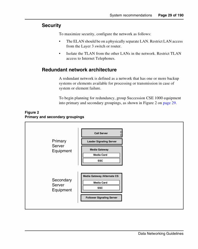
Redundant network architecture
A redundant network is defined as a network that has one or more backup systems or elements available for processing or transmission in case of system or element failure.
To begin planning for redundancy, group Succession CSE 1000 equipment into primary and secondary groupings, as shown in Figure 2 on page 29.
Figure 2Primary and secondary groupings
PrimaryServerEquipment
SecondaryServerEquipment
Leader Signaling Server
Call Server
Media Gateway
Media Card
SSC
Media Gateway /Alternate CS
Media Card
SSC
Follower Signaling Server

Page 30 of 190 System recommendations
553-3023-103 Standard 1.00 November 2002
To provide a redundant core network, follow these recommendations:
• Connect ELAN and TLAN connections for the primary core components (Call Server, Leader Signaling Server, and Media Gateway) to the primary Layer 2 switch.
• Connect ELAN and TLAN connections for the secondary core components (Alternate Call Server, Follower (secondary) Signaling Server, and Media Gateway) to the secondary Layer 2 switch.
• Provide backup power for all essential components and networking devices.
• Use data equipment that supports port-based Virtual LANs (VLANs) and prioritization (IEEE 802.1Q standard).
• Install load-sharing connections, or install backup connections, using Open Shortest Path First (OSPF) (recommended) protocol or Spanning Tree Protocol (STP), to multiple Layer 3 switches.
Note: Spanning Tree Protocol (STP) convergence can cause Layer 2 switch ports to be disabled for up to 60 seconds. This can affect the entire Succession CSE 1000 system. In some cases, STP needs to be disabled on the switch ports directly connecting the Succession CSE 1000 system.
• If using a high availability, chassis-based system (for example, Passport 8100), then designate one card as the primary Layer 2 switch and another card as the secondary Layer 2 switch. Then group the ELAN and the TLAN with port-based VLANs.
Note: Use of a single highly-available Nortel Networks Passport 8600 switch can provide a “five nines” Succession CSE 1000 network.
Figures 3 through 6 illustrate a network architecture that divides the core components into primary and secondary groups. Each group is connected to its own Layer 2 switch. Both the ELAN and TLAN connections are made to the group’s respective Layer 2 switch. VLANs can be used to reduce the number of switches required to obtain a redundant core network.

System recommendations Page 31 of 190
Data Networking Guidelines
Figure 3 on page 31 and Figure 4 on page 32 provide an example of a redundant core network which does not utilize VLANs on the Layer 2 switch infrastructure.
Figure 3Redundant core network – no VLAN on Layer 2 switch infrastructure
CAUTIONThe primary and secondary TLAN must be on the same subnet and in the same broadcast domain.
The primary and secondary ELAN must be on the same subnet and in the same broadcast domain.
Primary TLAN Switch
Secondary TLAN Switch
Primary ELAN Switch
Secondary ELAN Switch
u1 102 3 4 5 6 7 8 9 11 12
u1 102 3 4 5 6 7 8 9 11 12
1 102 3 4 5 6 7 8 9 11 12
1 102 3 4 5 6 7 8 9 11 12

Page 32 of 190 System recommendations
553-3023-103 Standard 1.00 November 2002
Figure 4Redundant core network – no VLAN on Layer 2 switch infrastructure detailed core system connections
Figure 5 shows Layer 2 switch port provisioning when utilizing VLANs in the core Succession CSE 1000 system.
Primary ELAN Switch
Media Gateway /Alternate CS
Media Card
SSC
Follower Signaling Server
Leader Signaling Server
Call Server
Media Gateway
Media Card
SSC
Primary TLAN Switch
Secondary TLAN Switch
Secondary ELAN SwitchCall Pilot Server
OTM Server
ELAN
C-LAN
TLAN
TLAN
ELAN
ELAN
ELAN
TLAN
ELAN
1 102 3 4 5 6 7 8 9 11 12
1 102 3 4 5 6 7 8 9 11 12ELAN
1 102 3 4 5 6 7 8 9 11 12
TLAN
ELAN
ELAN
ELAN
1 102 3 4 5 6 7 8 9 11 12
u
u
PrimaryServerEquipment
SecondaryServerEquipment

System recommendations Page 33 of 190
Data Networking Guidelines
Figure 5Redundant core network – Layer 2 switch port provisioning when using VLANs in the core system
Figure 6 shows detailed core system connections in a redundant core Succession CSE 1000 system utilizing VLANs.
Legend (Untagged port-based Virtual LAN Assignments):E represents ELAN Port Based Virtual LANT represents TLAN Port Based Virtual LANU represents an up-link port to another network switch
Ports 1 through 6 on each Layer 2 switch are members of the ELAN Virtual LAN.Ports 7 through 11 on each Layer 2 switch are members of the TLAN Virtual LAN.
Ideally, the Layer 2 switches are connected with a stack cascade connection.
Using a cross-over cable to connect the switches requires the use of another switch port, which must also be a tagged member of all VLANs.
PrimaryLayer 2 switch
SecondaryLayer 2 switch
T T T T TT E EEE E
1 102 3 4 5 6 7 8 9 11 12
u
T T T T TT E EEE E
1 102 3 4 5 6 7 8 9 11 12
u

Page 34 of 190 System recommendations
553-3023-103 Standard 1.00 November 2002
Figure 6Redundant core network – Layer 2 switch infrastructure detailed core system connections utilizing VLANs
Media Gateway /Alternate CS
Media Card
SSC
Follower Signaling Server
Leader Signaling Server
Call Server
Media Gateway
Media Card
SSC
PrimaryLayer 2 switch
Secondary Layer 2 switch
Call Pilot Server
OTM Server
ELAN
C-LAN
TLAN
TLAN
ELAN
ELAN
ELAN
TLAN
ELAN
ELAN
TLAN
ELAN
ELAN
ELAN
T T T T TT E EEE E
1 102 3 4 5 6 7 8 9 11 12
u
T T T T TT E EEE E
1 102 3 4 5 6 7 8 9 11 12
u
StackCascadeConnection
Important: The primary and secondary TLAN must bein the same subnet and broadcast domain.
The primary and secondary ELAN must bein the same subnet and broadcast domain.
PrimaryServerequipment
SecondaryServerequipment
System recommendations Page 35 of 190
Data Networking Guidelines
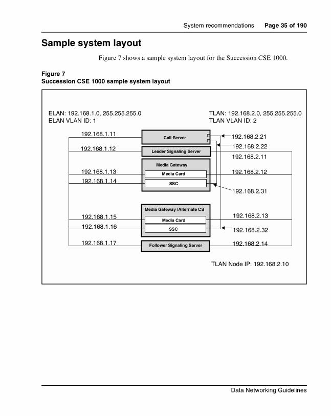
Sample system layoutFigure 7 shows a sample system layout for the Succession CSE 1000.
Figure 7Succession CSE 1000 sample system layout
ELAN: 192.168.1.0, 255.255.255.0ELAN VLAN ID: 1
192.168.1.11
192.168.1.12
192.168.1.13
192.168.1.14
192.168.1.16
192.168.1.15
192.168.1.17
TLAN: 192.168.2.0, 255.255.255.0TLAN VLAN ID: 2
192.168.2.21
192.168.2.11
192.168.2.12
192.168.2.31
192.168.2.32
192.168.2.13
192.168.2.14
TLAN Node IP: 192.168.2.10
Leader Signaling Server
Call Server
Media Gateway
Media Card
SSC
Media Gateway /Alternate CS
Media Card
SSC
Follower Signaling Server
192.168.2.22

Page 36 of 190 System recommendations
553-3023-103 Standard 1.00 November 2002
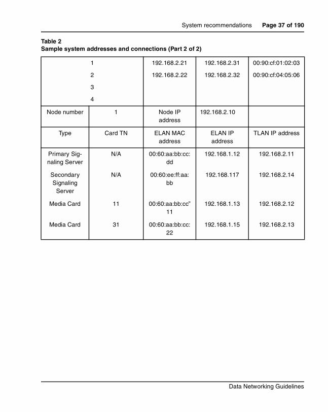
Table 2 defines the addresses and connections.
Table 2Sample system addresses and connections (Part 1 of 2)
Primary Gatekeeper IP
192.168.2.11 Secondary Gatekeeper IP
192.168.2.14
Failsafe Gatekeeper IP ____________
SNMP NMS address
<ip address>
System description
Succession CSE 1000 core server network example
ELAN VLAN ID
1 TLAN VLAN ID 2
ELAN subnet 192.168.1.0 TLAN subnet 192.168.2.0
ELAN mask 255.255.255.0 TLAN mask 255.255.255.0
ELAN Gateway router
192.168.1.1 TLAN router 192.168.2.1
Call Server ELAN IP
192.168.1.11
Media Gateway #1 ELAN IP
192.168.1.14 Media Gateway #3 ELAN IP
N/A
Media Gateway #2 ELAN IP
192.168.1.16 Media Gateway #4 ELAN IP
N/A
Call Server to Media Gateway connection number
Call Server IP D/B (IPM) IP
address
Media Gateway IP D/B (IPR) IP
address
Media Gateway IP D/B (IPR) MAC address
System recommendations Page 37 of 190
Data Networking Guidelines
1
2
3
4
192.168.2.21
192.168.2.22
192.168.2.31
192.168.2.32
00:90:cf:01:02:03
00:90:cf:04:05:06
Node number 1 Node IP address
192.168.2.10
Type Card TN ELAN MAC address
ELAN IP address
TLAN IP address
Primary Sig-naling Server
N/A 00:60:aa:bb:cc:dd
192.168.1.12 192.168.2.11
Secondary Signaling
Server
N/A 00:60:ee:ff:aa:bb
192.168.117 192.168.2.14
Media Card 11 00:60:aa:bb:cc”11
192.168.1.13 192.168.2.12
Media Card 31 00:60:aa:bb:cc:22
192.168.1.15 192.168.2.13
Table 2Sample system addresses and connections (Part 2 of 2)

Page 38 of 190 System recommendations
553-3023-103 Standard 1.00 November 2002
Succession Call Server to remote Media Gateway requirements
The Call Server-to-Media Gateway connection exists on a segment of the TLAN. The connection links the Call Server IP daughterboards to the Media Gateways SSC daughterboards. This segment is logically separate from the TLAN that connects the Succession Media Cards and the Signaling Servers, although both TLANs can exist on the same LAN segment.
The Call Server-to-Media Gateway connections have strict requirements, due to the packetization format used over the links. Each packet contains data from multiple users. This format is efficient, though no echo cancellation is possible. To avoid echo, network delay must be very low.
Succession Call Server to Media Gateway connection requirements
For excellent voice quality, the following requirements apply to the 100BaseTx connection between the Call Server and the Media Gateway SSCs:
• 100BaseT Layer 2 (or Layer 3) switch that supports full-duplex connection. Software-based routers are not supported in Call Server-to-Media Gateway connections.
Note: The ports on Layer 2 (or Layer 3) switching equipment must be set to auto-negotiate ENABLED.
WARNINGConfigure the ports on Layer 2 or Layer 3 switching equipment as Auto-negotiate.
If one side is manually configured, and the other side is configured as Auto-negotiate, the following situation occurs.
The Auto-negotiate side sets itself to the manually configured side’s speed, but always sets itself to Half-duplex transmission. If the manually-configured side is Full-duplex transmission, then a mismatch occurs, and voice quality is unsatisfactory.

System recommendations Page 39 of 190
Data Networking Guidelines
• packet loss < 0.5% (0% loss recommended)
• 100 Mbps full-duplex link (minimum)
— bandwidth usage on an idle system is negligible
— peak bandwidth under high voice traffic conditions (Internet Telephone to trunk calls) – 21 Mbps
• network delay – Round Trip Delay (RTD) with PDV jitter buffer set to maximum: < 5 msec
• network delay – Round Trip Delay (RTD) with PDV jitter buffer set to minimum: < 12 msec
• support of Port Priority Queuing (recommended, but not required)
• support of VLAN configuration (recommended, but not required)
Bandwidth planning
The Succession CSE 1000 system is designed for non-blocking transmission between the Call Server and the Media Gateways. The throughput of the network must be guaranteed.
Under high traffic conditions, a peak bandwidth of 10Mbps is used for voice traffic that requires Media Gateway services, such as trunk services. See Table 3.
Note: A minimum 100 Mbps full-duplex link is required.
If there is no traffic flow, there are negligible bandwidth requirements. Only active channels use bandwidth.

Page 40 of 190 System recommendations
553-3023-103 Standard 1.00 November 2002
Monitoring network behavior QoS
Behavioral characteristics of the network are dependent on factors like Round Trip Delay (RTD), Packet Delay Variation (PDV) jitter buffers, queuing delay in the intermediate nodes, packet loss and available bandwidth. The service level of each IP link is measured and maintained on the Call Server for the system.
If using cross-over cables to connect to the Call Server and Media Gateway, verify the active link.
Information on latency and packet loss is collected from the hardware and processed.
Based on system-configured thresholds, the level of service is compiled and reported with the PRT QOS <cab#> command in LD 117. See Software Input/Output: Maintenance (553-3001-511).
Table 3Bandwidth Consumption/100BaseTx
Number of active conversations
Voicebandwidth (Mbps)
Signaling bandwidth (Mbps)
Total bandwidth (Mbps)
o 0 0.11 0.11
16 5.25 0.5 5.75
32 6.27 0.5 6.77
64 8.32 0.5 8.82
128 12.4 0.5 12.9
256 20.6 0.5 21.1
Note: For voice traffic that requires Media Gateway services.

System recommendations Page 41 of 190
Data Networking Guidelines
Data Network Ratings (Excellent, Good, Fair, Poor) along with the actual parameter values for network delay are displayed in Table 4.
The values in Table 4 assume that there is no echo cancellation mechanism and no particular mechanism for recovering lost packets.
Call Server to Media Gateway connection Packet Delay Variation jitter buffer
The Call Server to Media Gateway connection Packet Delay Variation (PDV) jitter buffer ensures a constant voice playback rate, even when there is variation in the voice packet arrival rate. The PDV jitter buffer is also used to re-sequence out-of-order voice packets, and is integral to the IP-based clock recovery scheme.
The PDV jitter buffer delay is adjustable and should be as short as possible. The minimum and maximum values for excellent voice quality are given in Table 4 on page 41.
Insufficient jitter buffer delay causes a degradation in voice in the form of clicks or pops during a voice call. Insufficient delay is indicated when the QoS monitor reports buffer underflows.
Table 4Campus data network voice quality measurements
Voice QoS Rating
Network Round Trip Delay
(PDV Max 7.8 ms)
Network Round Trip Delay
(PDV Min 0.5 ms)Network Packet
Loss
Excellent <5 ms <12 ms <0.5%
Good 5 – 25 ms 12 – 32 ms 0.5 – 1%
Fair 25 – 45 ms 32 – 52 ms 1 – 1.5 ms
Poor >45 ms >52 ms >1.5%

Page 42 of 190 System recommendations
553-3023-103 Standard 1.00 November 2002
If this happens, increase the size of the PDV buffer. Increase the PDV buffer as little as possible to keep the round trip delay as short as possible. The goal is to operate with as small a buffer as possible. When increasing the buffer delay, increment in 0.5 msec steps until the QoS monitor no longer reports buffer underflows.
Note: Where the IP network interfaces with a TDM network which might use analog loop, or other 2-wire devices, echo cancellers must be installed at the network interface.
The command PRT PDV <cab#> in LD 117 displays both the current size of the PDV buffer and the number of PDV underflows.
In addition, a warning message is printed when a parameter threshold (or combination of thresholds) is reached. These thresholds are not user configured.
In LD 117, the command CHG PDV <port#> <delay> is used to set Packet Delay Variation (PDV buffer size) on a per link basis. The <delay> parameter can accept values from 0.5 ms to 8 ms. This value should be initially tested at default settings. Increase the <delay> parameter value by 0.5 ms increments if an unacceptable level of voice quality is experienced (“pops and clicks”). Decrease this value if echo is experienced. The goal is to operate with the smallest jitter buffer possible.
The PDV jitter buffer size for each IP connection is configured at the Call Server and is automatically downloaded to the Media Gateways.
CAUTIONExcessive delay causes a degradation in voice quality in the form of additional echo.

System recommendations Page 43 of 190
Data Networking Guidelines
VoIP QoS parametersVoIP Desktop Clients on a QoS-managed IP network are usually separate from the core system’s ELAN and TLAN. The IP network carries a variety of media, including voice, video, and data. The IP network may or may not be logically separated into voice and data VLANs. In either case, QoS management plays an important role in providing satisfactory VoIP performance.
To create a VoIP-grade network, certain QoS standards for various basic network elements must be met. These basic elements include:
• network availability
• bandwidth
• packet loss
• delay
• jitter
These QoS parameters apply to any IP network carrying VoIP traffic, including TLANs, LANs, campus-wide networks, and WANs.

Page 44 of 190 System recommendations
553-3023-103 Standard 1.00 November 2002
G.711 CodecG.711 is the recommended Codec.
G.729AB CodecThe G.729 uses less bandwidth than the G.711. If minimizing bandwidth demand is a priority, and the customer is willing to accept lesser voice quality, a G.729AB Codec can be used.
Extreme care must be taken in the network design if using the G.729AB Codec. The G.729 AB Codec has the same requirements as the G.711 Codec.
Network availability
See “Network availability” on page 16.
Bandwidth
Bandwidth management zones
Bandwidth management zones divide Internet Telephones and Succession Media Cards into logical groupings (zones) to determine Codec selection and aid in bandwidth management. Zones are configured after the QoS-managed IP network has been designed.
Recommendation
To achieve excellent voice quality, Nortel Networks recommends using G.711 Codec with the following configuration:
• end-to end delay less than 150 ms one way(network delay + packetization delay + jitter buffer delay <150). See “Call Server to Media Gateway connection Packet Delay Variation jitter buffer” on page 41.
• packet loss less than 0.5% (approaching 0%)
• maximum jitter buffer setting for Internet Telephone as low as possible (maximum 100 ms)

System recommendations Page 45 of 190
Data Networking Guidelines
Zone configuration specifies how much bandwidth is available for inter-zone and intra-zone calls. The configuration also specifies whether to use the Best Bandwidth (BB) Codec or Best Quality (BQ) Codec for that type of call.
Two Codecs can be configured in the Call Server:
• one for BQ – G.711
• one for BB – G.729AB
Each Codec has specific parameters that must be configured, such as packetization delay and voice activity detect. These parameters are configured on the Signaling Server, using Element Management. For further information, see “Element Management” on page 120.
For remote users such as telecommuters, it can be convenient to allocate zones for users with similar connection speeds. In that case, set both the inter-zone and intra-zone Codec to BB.
As calls are made, the Succession CSE 1000 software chooses a Codec to be used for the call, based on the zone configuration. The software also tracks bandwidth usage within each zone and between zones. When making an inter-zone call, the lowest bandwidth Codec between the zones is always chosen.
Inter-zone and intra-zone bandwidth availability is calculated dynamically by the Call Server on a per-call basis. A call is blocked if there is not enough available bandwidth.
Recommendation
Nortel Networks recommends the following:
• Use BQ Codec for intra-zone calls.
• Use BB Codec for inter-zone calls.

Page 46 of 190 System recommendations
553-3023-103 Standard 1.00 November 2002
Virtual trunk routes also allow configuration of a zone. Calls are terminated on a virtual trunk. Virtual trunks and Internet Telephones are not in the same zone. Zones allocated to virtual trunk routes are primarily used for intra-system Codec selection. Bandwidth is already managed within the Internet Telephone zone.
Figure 8 on page 46 shows an example of bandwidth management zones.
Figure 8Bandwidth management zone example
For more information on zone configuration, see IP Peer Networking (553-3023-220).

System recommendations Page 47 of 190
Data Networking Guidelines
Calculating bandwidth usage
To determine bandwidth usage for each desktop client, determine the following details:
• packetization rate
• Voice Activity Detector (VAD) – on or off
• Codec
• link type
• half- or full-duplex link
Ask a Nortel Networks representative for the VoIP bandwidth calculator spreadsheet. Use these parameters and the bandwidth calculator to determine the bandwidth requirement for each client.
WARNINGConfigure the ports on Layer 2 or Layer 3 switching equipment as Auto-negotiate.
If one side is manually configured, and the other side is configured as Auto-negotiate, the following situation occurs.
The Auto-negotiate side sets itself to the manually configured side’s speed, but always sets itself to half-duplex transmission. If the manually-configured side is full-duplex transmission, then a mismatch occurs, and voice quality is unsatisfactory.

Page 48 of 190 System recommendations
553-3023-103 Standard 1.00 November 2002
Calculating bandwidth zone parameters
The Call Admission Control (CAC) algorithm of Succession CSE 1000 is not aware of the data network topology over which the call will made. CAC, therefore, does not know if a call will be traversing a WAN link, and if so, what type of WAN link. Bandwidth demand is specific to the type of link, and CAC does not know the details of the call path. Therefore, a consistent mechanism is required for the system administrator to control the number of calls within a bandwidth zone (Intrazone) and between bandwidth zones (Interzone). Full-duplex Ethernet bandwidth demand is used for this purpose in this example, as seen in Table 5.
Table 5Bandwidth estimates used by Succession CSE 1000 CAC (Part 1 of 2)
Codec
Packetiz-ation rate
(ms)
Voice payload (octets) VAD
Peak bandwidth
(kbps)
Average bandwidth
(kbps) Overhead VAD
G.711 10 80 Off 116800 116800 66 1
G.711 20 160 Off 90400 90400 66 1
G.711 30 240 Off 81600 81600 66 1
G.711 10 80 On 116800 70080 66 0.6
G.711 20 160 On 90400 54240 66 0.6
G.711 30 240 On 81600 48960 66 0.6
G.729A 10 10 Off 60800 60800 66 1
G.729A 20 20 Off 34400 34400 66 1
G.729A 30 30 Off 25600 25600 66 1
G.729A 40 40 Off 21200 21200 66 1
G.729A 50 50 Off 18560 18560 66 1
G.729AB 10 10 On 60800 36480 66 0.6
G.729AB 20 20 On 34400 20640 66 0.6
G.729AB 30 30 On 25600 15360 66 0.6

System recommendations Page 49 of 190
Data Networking Guidelines
Determining interzone and intrazone bandwidth values
In the following example, it is assumed that voice traffic engineering, capacity planning, and bandwidth demand per link have all been calculated, and the maximum number of calls allowed in each bandwidth zone, and between zones has been determined. In this example, 125 calls within the zone, and 8 calls between zones, are assumed.
To determine intrazone bandwidth, follow the steps in Procedure 1 on page 50.
G.729AB 40 40 On 21200 12720 66 0.6
G.729AB 50 50 On 18560 11136 66 0.6
Note: The bandwidth estimates assume a full-duplex connection. For half-duplex connections such as half-duplex Ethernet, the bandwidth estimates much be doubled.
The overhead is assumed to be for Ethernet connections and is comprised of the following:Ethernet preamble = 8 bytesEthernet header = 14 bytesIP header = 20 bytesUDP header = 8 bytesRTP header = 12 bytesEthernet checksum = 4 bytesTotal Payload encapsulation = 66 bytes. The Interframe Gap is not included in these calculations.
Different transport types will have slightly different bandwidth requirements.
The average bandwidth is reduced from the peak bandwidth by the use of Silence Suppression (VAD). The reduction due to VAD is assumed to be 40%.
Table 5Bandwidth estimates used by Succession CSE 1000 CAC (Part 2 of 2)
Codec
Packetiz-ation rate
(ms)
Voice payload (octets) VAD
Peak bandwidth
(kbps)
Average bandwidth
(kbps) Overhead VAD

Page 50 of 190 System recommendations
553-3023-103 Standard 1.00 November 2002
Procedure 1Determining intrazone bandwidth
1 For each bandwidth zone, determine the maximum number of simultaneous calls to be allowed within the zone.
2 Choose the bandwidth per call value from Table 5 on page 48, based on the Codec and options configured for Best Quality (BQ).
For example, if G.711, 20 ms, VAD Off is selected for BQ, intrazone calls will account for 90,400 bps of use.
3 Convert bandwidth per call from bps to kbps by dividing by 1000. In this example, 90,400 bps/1000 = 90.4 kbps.
4 Calculate the intrazone bandwidth setting by multiplying the BQ bandwidth per call value (as calculated in kbps in Step 3) by the maximum number of calls to be allowed within the zone. Round up to the next whole number, if necessary.
In this example, if the maximum number of intrazone calls is 125, then 90.4 kbps/call * 125 calls = 11,300kbps. CAC will then allow up to 125 calls in the zone. Use this value for intrazone bandwidth when defining the zone.
End of Procedure
To determine interzone bandwidth, follow the steps in Procedure 2.
Procedure 2Determining interzone bandwidth
1 For each bandwidth zone, determine the maximum number of calls to be allowed between zones.
2 Choose the bandwidth per call value from Table 5 on page 48, based on the Codec and options configured for Best Bandwidth (BB).
For example, if G.729AB, 30 ms, VAD On is selected for BB, intrazone calls will account for 20,640 bps of use.
3 Convert bandwidth per call from bps to kbps by dividing by 1000. In this example, 20,640 bps/1000 = 20.64 kbps.

System recommendations Page 51 of 190
Data Networking Guidelines
4 Calculate the interzone bandwidth setting by multiplying the BB bandwidth per call value (as calculated in kbps in Step 3) by the maximum number of calls to be allowed between zones. Round up the value to the next whole number, if necessary.
In this example, if the maximum number of interzone calls is 8, then 20.64 kbps/call * 8 calls = 165.12 kbps. Round 165.12 kbps to 166 kbps. CAC will then allow up to 8 calls between zones. Use this value for interzone bandwidth when defining the zone.
End of Procedure
Packet loss
IP networks divide voice, fax, and data into small packets of information. Each packet has a header that identifies where the packet is going and contains information on how to reassemble the packet when it arrives at its destination. Packets travel independently, often by different routes to their destination. Packets can be lost due to dead-end routes, or due to a router dropping packets when links are congested.
Individual packets that are delayed much more than the baseline delay (variable delay) are referred to as jitter. Excess jitter causes packet loss which can result in choppy or unintelligible speech.
Packet loss occurs in the following situations:
• during network congestion
• mis-configured LAN settings
• mis-configured clock settings
• bit errors in the network.
Packet Loss Concealment (PLC) is used to minimize the noticeable effects of packet loss.
Recommendation
To achieve maximum voice quality, Nortel Networks recommends that packet loss = 0%.

Page 52 of 190 System recommendations
553-3023-103 Standard 1.00 November 2002
Packet Loss Concealment
The term Codec stands for coder/decoder. A Codec executes a compression algorithm (a specialized computer program) that reduces the number of bytes required to encode digital data. This reduces packet size and bandwidth requirements. As well, smaller packets are less likely to be lost.
Codecs designed for packet networks, such as G.729, have built-in Packet Loss Concealment (PLC). PLC minimizes the impact of lost packets on an audio signal, by mixing in synthesized speech derived from previous packets.
When a speech Codec operates in normal mode, a receiver decodes packets and sends the output to an audio port. A PLC algorithm saves a copy of the recent audio output, which is used to create a signal to replace the missing speech if lost data is encountered. How this information is used depends on the PLC algorithm. Some simple algorithms smooth over gaps in the signal to remove clicks. Other algorithms replay an earlier packet to fill in the gap. More sophisticated algorithms tweak the replacement signal to make it sound more natural. The best algorithms can repair a 20-40 ms gap with little audible distortion. The PLC operates constantly, generating speech to replace the next packet in the event it is lost. The use of a PLC adds a small fixed delay to the call’s baseline delay.
PLC is necessary to achieve acceptable IP speech quality.
Delay
In VoIP, end-to-end delay on a call is the total time elapsed from speaking into an transmitter at one end to hearing the reconstructed sound on a receiver at the other end. Delay has a significant impact on the quality of a voice call. Most listeners can detect delay greater than 100 milliseconds (ms). Delay becomes annoying at the following levels:
• for G.711 Codec, 250 ms
• for G.729AB Codec, 150 ms
Figure 9 shows the mechanisms that cause delay, and the technologies to counter the delay.

System recommendations Page 53 of 190
Data Networking Guidelines
Figure 9Sources of packet delay
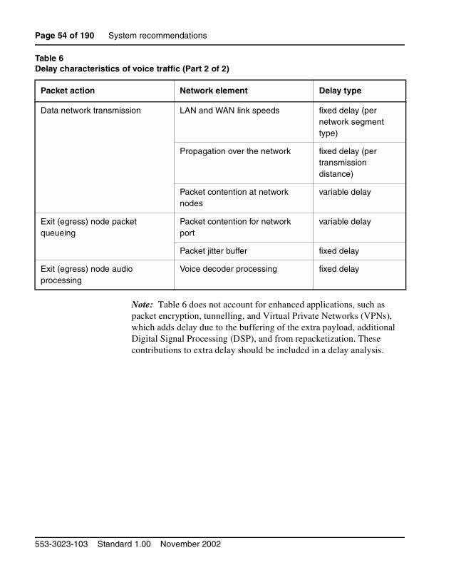
Table 6 lists the network elements where delay occurs, and the characteristics of that delay.
Table 6Delay characteristics of voice traffic (Part 1 of 2)
Packet action Network element Delay type
Entrance (ingress) node audio processing
Voice Codec algorithmic processing
fixed delay
Voice payload packetization fixed delay
Entrance (ingress) node packet queueing
Packet contention for network port
variable delay
Page 54 of 190 System recommendations
553-3023-103 Standard 1.00 November 2002
Note: Table 6 does not account for enhanced applications, such as packet encryption, tunnelling, and Virtual Private Networks (VPNs), which adds delay due to the buffering of the extra payload, additional Digital Signal Processing (DSP), and from repacketization. These contributions to extra delay should be included in a delay analysis.
Data network transmission LAN and WAN link speeds fixed delay (per network segment type)
Propagation over the network fixed delay (per transmission distance)
Packet contention at network nodes
variable delay
Exit (egress) node packet queueing
Packet contention for network port
variable delay
Packet jitter buffer fixed delay
Exit (egress) node audio processing
Voice decoder processing fixed delay
Table 6Delay characteristics of voice traffic (Part 2 of 2)
Packet action Network element Delay type

System recommendations Page 55 of 190
Data Networking Guidelines
Effects of delay on voice quality
Figure 10 shows the effects of delay on voice quality.
Figure 10Effects of delay on voice quality using a G.711 Codec

Page 56 of 190 System recommendations
553-3023-103 Standard 1.00 November 2002
Jitter
In VoIP, jitter is the total amount of variable delay encountered during the end-to-end processing of voice packets. See “Jitter” on page 19 for more information.
Jitter buffers are used on the receive-side of a call to smooth out small variations in the packet time-of arrival. This allows the data to be unpacked and sent to the decoder as a constant stream. Since all buffering increases end-to-end delay, the jitter buffer length (duration) must be kept to a minimum. If a network has been engineered to have minimal jitter, the jitter buffer can be very small.
The following contribute to the total variation in delay:
• packet contention during node queueing
• network conditions such as routing and transmission queueing
• router and switch (statistical multiplexer) performance under a load
• link speed
• voice and data packet size
• exit (egress) queue buffer size
Queueing delay occurs at the exit port of every device on the network.
Call Admission Control (CAC) performs packet admission and blocking functions. Voice packets are admitted to the network when the network can adequately support them. The packets are denied admission when the network cannot support them as defined in the Service Level Agreement.
When voice and data packets share a low-speed WAN connection (< 1Mbps), the larger data packets introduce queuing delay to the smaller voice packets waiting to be queued out onto the WAN connection. Therefore, the smaller voice packets do not arrive at the same fixed time interval as they are transmitted from their source. The arrival time of the voice packets varies because of interjected data packets of varying sizes that introduces a varying amount of jitter (queuing delay).

System recommendations Page 57 of 190
Data Networking Guidelines
Jitter buffers
When voice and data packets share a high-speed connection (> 1Mbps), the variable queuing delay (jitter) introduced by the WAN connection becomes insignificant.The jitter in high-speed networks is affected by the buffer size of a router and the load/congestion in the router. Jitter buffers are designed to smooth out irregular packet arrival. This is done by collecting the arriving packets, and holding them in a buffer long enough to allow the slowest packets to arrive. The packets are then played in the correct sequence. Jitter buffers solve the late and lost packet problem, but add more delay to the total amount of end-to-end delay.
VoIP jitter buffer configuration
Configure the jitter buffer in whole-number multiples of the frame size (expressed in milliseconds). For example, 30 ms frames should have a minimum jitter buffer of 60 ms, regardless of Codec used. The Voice Gateway application on the Media Card automatically adjusts any user-configured jitter buffer values upward to the next whole number multiple to meet this requirement. For example, a network is using a 20 ms G.711 frame size. The OTM default jitter buffer value is 50 ms. The Voice Gateway Media Card increases the jitter buffer value to 60 ms (adjusted upward from 50 ms to a multiple of the 20 ms frame size = 60 ms).
A jitter buffer must be configured for each Codec.
Internet Telephone firmware must be configured for jitter buffers. However, instead of specifying the jitter buffer size in msec, it is configured with the number of frames to be held in the jitter buffer, such as 1, 2, or 3.
Recommendation
To achieve maximum voice quality, Nortel Networks recommends that Internet Telephone firmware be configured with a jitter buffer size of 3; however, a well-engineered network can function with a jitter buffer size of 2, which increases perceived voice quality.
Page 58 of 190 System recommendations
553-3023-103 Standard 1.00 November 2002

Page 59 of 190
Data Networking Guidelines
96
Designing networks for good QoE
ContentsThis section contains information on the following topics:
Introduction . . . . . . . . . . . . . . . . . . . . . . . . . . . . . . . . . . . . . . . . . . . . . . 60
The Succession CSE 1000 network . . . . . . . . . . . . . . . . . . . . . . . . . . . 61QoS problem locations . . . . . . . . . . . . . . . . . . . . . . . . . . . . . . . . . . . 65
Bandwidth considerations . . . . . . . . . . . . . . . . . . . . . . . . . . . . . . . . . . . 67Campus networks . . . . . . . . . . . . . . . . . . . . . . . . . . . . . . . . . . . . . . . 67WAN connections . . . . . . . . . . . . . . . . . . . . . . . . . . . . . . . . . . . . . . 67
Survivability . . . . . . . . . . . . . . . . . . . . . . . . . . . . . . . . . . . . . . . . . . . . . 75
The QoS process . . . . . . . . . . . . . . . . . . . . . . . . . . . . . . . . . . . . . . . . . . 75Classification . . . . . . . . . . . . . . . . . . . . . . . . . . . . . . . . . . . . . . . . . . 76Marking . . . . . . . . . . . . . . . . . . . . . . . . . . . . . . . . . . . . . . . . . . . . . . 77Queuing . . . . . . . . . . . . . . . . . . . . . . . . . . . . . . . . . . . . . . . . . . . . . . 77
Layer 2 (Ethernet) QoS . . . . . . . . . . . . . . . . . . . . . . . . . . . . . . . . . . . . . 79MAC address . . . . . . . . . . . . . . . . . . . . . . . . . . . . . . . . . . . . . . . . . . 79IEEE 802.1Q. . . . . . . . . . . . . . . . . . . . . . . . . . . . . . . . . . . . . . . . . . . 79Port prioritization . . . . . . . . . . . . . . . . . . . . . . . . . . . . . . . . . . . . . . . 84
Layer 3 QoS . . . . . . . . . . . . . . . . . . . . . . . . . . . . . . . . . . . . . . . . . . . . . 86DiffServ for VoIP . . . . . . . . . . . . . . . . . . . . . . . . . . . . . . . . . . . . . . . 87Trust configuration . . . . . . . . . . . . . . . . . . . . . . . . . . . . . . . . . . . . . . 88Voice signaling and media DSCPs. . . . . . . . . . . . . . . . . . . . . . . . . . 89Setting DSCP values. . . . . . . . . . . . . . . . . . . . . . . . . . . . . . . . . . . . . 89
Layer 4 (TCP/IP) classification. . . . . . . . . . . . . . . . . . . . . . . . . . . . . . . 94Policy management . . . . . . . . . . . . . . . . . . . . . . . . . . . . . . . . . . . . . 95

Page 60 of 190 Designing networks for good QoE
553-3023-103 Standard 1.00 November 2002
IntroductionThis chapter describes the mechanisms to design a QoS-managed VoIP network that provides satisfactory voice quality.
An IP network must be properly engineered and provisioned to achieve high voice quality performance. The network administrator should implement QoS policies network-wide so voice packets receive consistent and proper treatment as they travel the network.
IP networks that treat all packets in the same manner are called “best-effort networks”. In a best-effort network, traffic can experience different amounts of delay, jitter, and loss at any given time. This can produce the following problems:
• speech breakup
• speech clipping
• pops and clicks
• echo
A best-effort network does not guarantee that bandwidth is available at any given time.
Most QoS mechanisms employed today cannot to ensure bandwidth is available at all times, but will maintain consistent, acceptable levels of loss, delay, and jitter, even under heavy traffic loads.
See “Succession Call Server to remote Media Gateway requirements” on page 38 for detailed information on QoS requirements for this part of the system, as these connections are extensions of the system bus.
Apply QoS mechanisms to the following VoIP media and signaling paths:
• Succession CSE 1000 TLAN connections
• VoIP traffic between Internet Telephones
• VoIP traffic between Internet Telephones and Succession Media Cards on the TLAN

Designing networks for good QoE Page 61 of 190
Data Networking Guidelines
The Succession CSE 1000 networkThe Succession Communication Server for Enterprise (CSE) 1000 is a VoIP server particularly suited for typical campus network designs. The core server components are seen as a single logical server, because only a single IP address is visible to the Internet Telephones.
In most cases, The Succession CSE 1000 is connected logically to the server layer, as the server layer is engineered for high availability and security.
The large amount of bandwidth available at the server level, though not required by the Succession Call Server, also helps to ensure satisfactory VoIP QoS.
QoS mechanisms are recommended at all layers to ensure that all voice traffic obtains a level of service greater than the level of service for the best-effort data traffic.
Physical connectivity, VLANs, and subnets for the Succession CSE 1000 core server components are configured at the server layer, following existing server layer design and conforming to the Succession CSE 1000 core server configuration requirements.
If campus-distributed Media Gateways are used, they are connected at the distribution layer. The core IP network can be configured with multiple VLANs and subnets to meet the Succession CSE 1000 core server configuration requirements.
The following are planned based on the access and distribution layers’ configuration:
• VLANs
• subnets
• QoS mechanisms for the Internet Telephones such as DiffServ and 802.1Q

Page 62 of 190 Designing networks for good QoE
553-3023-103 Standard 1.00 November 2002
Typical network topology
Figure 11 on page 62 provides a reference model for a campus network.
Figure 11Campus network reference model
The following figures provide examples of logical connection diagrams for small, medium, and large campus networks. Other network designs can also be used. The actual design that is implemented depends on many factors, including physical locations, size, and scalability.

Designing networks for good QoE Page 63 of 190
Data Networking Guidelines
Figure 12 is an example of a small campus network design.
Figure 12Small campus network example

Page 64 of 190 Designing networks for good QoE
553-3023-103 Standard 1.00 November 2002
Figure 13 is an example of a mid-size campus network design.
Figure 13Mid-size campus network example

Designing networks for good QoE Page 65 of 190
Data Networking Guidelines
Figure 14 is an example of a large campus network design.
Figure 14Large campus network example
QoS problem locations
Figure 15 on page 66 identifies typical network congestion areas.
Voice traffic competes for the use of limited bandwidth on the uplinks. These uplinks are shown in Figure 15.
Congestion at these points causes the majority of all packet loss, delay, and jitter that is incurred. Using QoS mechanisms alleviates this congestion by using multiple queues with different priorities.

Page 66 of 190 Designing networks for good QoE
553-3023-103 Standard 1.00 November 2002
Figure 15Potential uplink problem areas
Designing networks for good QoE Page 67 of 190
Data Networking Guidelines
Bandwidth considerationsThis section discusses the impact of bandwidth availability on QoS over different types of network connections. Transmission of VoIP traffic over low-speed connections requires special consideration, in order to ensure acceptable levels of delay, jitter, and loss.
Campus networks
In most cases, campus Ethernet networks require less sophisticated QoS mechanisms than low-bandwidth WAN connections, because the available bandwidth is much greater. This results in significantly lower queuing and network delay. However, network congestion on an Ethernet network (even for short periods of time) and bursty TCP-based Internet traffic can cause significant voice quality problems if QoS is not applied.
QoS mechanisms, such as 802.1Q, VLANs, and Layer 2 Port prioritization (802.1p), can be used for VoIP traffic over Ethernet networks. If the Layer 2 (Ethernet) switches also support Layer 3 (IP) capabilities, then QoS mechanisms such as DiffServ and/or IP Address prioritization can also be used. For example, the Business Policy Switch (BPS) is a Layer 2 switch that can recognize, filter, monitor, and re-mark 802.1p and DiffServ markings, based on implemented policy.
WAN connections
There are many items to consider when using routers with low-bandwidth WANs and low bandwidth access network connections such as T1, xDSL, or Packet Cable. This section specifically discusses WAN connections, but the techniques and recommendations described also apply to low-bandwidth access network connections.
WARNINGThe ELAN and TLAN must be connected to Layer 2 switches. Shared-media hubs are not supported, as they cause the Succession CSE 1000 system to become unreliable, and cause unpredictable voice quality.

Page 68 of 190 Designing networks for good QoE
553-3023-103 Standard 1.00 November 2002
Per call bandwidth demand
VoIP bandwidth is dependent on the following:
• type of Codec used
• if Voice Activity Detection (VAD) is used. VAD is also known as Silence Suppression.
• packetization rate (voice sample size)
• IP/UDP/RTP encapsulations
• if RTP Header Compression is used
• Layer 2 (link layer) protocol overhead for the specific link the voice traffic is traversing
Though G.711 is the preferred Codec for excellent voice quality, it could be desirable to compress the voice signals when using VoIP over a low-bandwidth connection. However, due to the lower voice quality of the compressed Codecs and the issue of multiple transcodings on a call, great care must be taken in designing the network to minimize (and avoid, if possible) multiple tandem hops involving voice compression. There are several possible choices for voice compression, such as G.729, G.723, and G.726. Of these, the ITU G.729 Codec provides the lowest bandwidth and highest voice quality. G.729 compresses the voice call from 64kbps down to 8kbps. This 8kbps is the “raw voice” payload, and must be encapsulated into other protocols before it becomes VoIP and is transported over an IP network.
The protocol to transport the IP packet could be Point-to-Point Protocol (PPP), Frame Relay or ATM. The additional overhead added by these protocols increases bandwidth required for VoIP calls. For a G.729 call (no VAD), with a 20 ms packetization rate (50 packets/second) at the IP layer, the bandwidth demand is 24 kbps. The actual bandwidth demand varies by link, due to the specific overhead associated with each type of link.
Voice compression is not required (and is undesirable) over high bandwidth Ethernet connections. By comparison, the uncompressed voice is encoded using the ITU G.711 Codec, and results in 64 kbps of “raw voice” payload. When the packetization rate (voice sample) is 20 ms (50 packets per second) and IP encapsulation is added to create a VoIP packet, 80 kbps of total bandwidth is generated at the IP layer. The bandwidth demand at the IP layer

Designing networks for good QoE Page 69 of 190
Data Networking Guidelines
is constant throughout the network. Depending on the link protocol used and the options invoked, the link protocol adds the following to each VoIP packet:
• 5 to 6 octets (FR)
• 7 to 8 octets (PPP)
• 18/22-26/30-38/42 octets (802.3 LAN – with or without 802.1Q/p 8-octet preamble and 12-octet interframe gap)
The extra octets create an additional overhead of 2 kbps (5-octet FR) to 16.8 kbps (42-octet 802.3 LAN) for each VoIP call.
Note: ATM has its own overhead requirements. Due to the fixed cell size of 53 octets, the additional overhead varies widely, depending on the Codec and packetization rate used.
Bandwidth example
One of the main attractions of VoIP is the ability to use an existing WAN data network to save on inter-office toll calls. However, offices often connect over low-bandwidth WAN connections, so special considerations must be made when adding VoIP over a bandwidth-limited connection.
When VoIP calls are active, routers configured with QoS (which prioritizes voice traffic over data traffic) reduce the data traffic throughput by the amount of bandwidth being used for the VoIP call. This reduces the data traffic throughput to, perhaps, an unacceptable level. Adding VoIP to the existing WAN data network might require an increase in the WAN bandwidth.
Example: A company has 2 sites connected by a leased-line WAN connection (PPP) operating at 128 kbps. Due to the potential use of 20% of link capacity for “zero-bit stuffing”, a safe assumption of this link’s capacity is 102 kbps. For design purposes, assume a maximum utilization of 70% (in this example, 90 kbps).

Page 70 of 190 Designing networks for good QoE
553-3023-103 Standard 1.00 November 2002
This bandwidth has been sufficient for the current data requirements. The company believes that it only needs 70-80 kbps most of the time, with occasional traffic peaks up to the full capacity. The company wants to support up to 4 simultaneous voice calls over the IP WAN network between the sites. If all 4 calls were simultaneously active, this would require 108.8 kbps (using a G.729 Codec, 20 ms voice sample, and PPP overhead/frame) of the available 90 kbps of the 128 kbps link. This requirement exceeds the carrying capacity of the link and completely starves that data traffic. The solution is to upgrade the WAN connection bandwidth. A 256 kbps link is the minimum speed to provide 109 kbps for four G.729 VoIP calls, 80 kbps for data, and 20% availability for zero-bit stuffing.
Delay / Latency
The overall “delay budget” for a voice call from the time one party speaks, to the time the voice is heard by the listener, should not be longer than 150 ms for good quality voice over landline connections, although 250 ms is often tolerated for G.711 calls if there is no packet loss. (The amount of delay is often longer, but unavoidable, for satellite and other types of wireless connections).
Recommendation
Nortel Networks recommends that G.711 Codec be used over high-bandwidth connections and used any time that call quality is the top priority. In call quality is the top priority, sufficient bandwidth must be provided for the VoIP application. The Best Quality (BQ) Codec is usually chosen and configured as G.711 within the zone configuration (intrazone).
Use G.729 Codec to compress voice traffic over low-bandwidth connections when bandwidth considerations take precedence over call quality. The Best Bandwidth (BB) Codec is usually chosen and set to G.729A or G.729AB between zones (interzone).
Codec details are then configured on the Succession Signaling Server through OTM or Element Management.

Designing networks for good QoE Page 71 of 190
Data Networking Guidelines
Studies show that as the 150 ms delay budget is exceeded, users perceive the delay as resulting in poorer voice quality, especially for the compressed Codecs. Every time a VoIP packet passes through a device or network connection, delay is introduced. A significant amount of delay is introduced over low-bandwidth connections.
Reducing delay and jitter through packet fragmentation
To minimize voice delay and jitter in mixed voice/data IP networks, fragment large packets before they traverse limited-bandwidth (<1 b Mbps) connections. There are several different protocols that can be used to fragment packets.
For Frame Relay connections, the FRF.12 standard can be used for fragmenting packets. ATM provides fragmentation since all packets are fragmented into 53-byte ATM cells. Both of these fragmentation techniques are acceptable.
Two types of fragmentation are more universal and not limited to a specific link-layer technology, such as ATM or Frame Relay. These methods are PPP fragmentation and IP fragmentation.
Consult the router’s documentation for information on configuring PPP and IP fragmentation.
Layer 2 fragmentation (ATM, FRF.12, PPP) is preferred over Layer 3 fragmentation, as Layer 2 fragmentation universally affects all higher layer protocols. Layer 3 fragmentation is less desirable for two reasons:
1 Layer 3 fragmentation applies only to the specific protocol being used. For example, Internet Protocol’s (IP) MTU (Maximum Transmission Unit, in bytes) affects only IP traffic. It has no effect on IPX, AppleTalk, or other protocols.
2 Some applications do not function because they set the “Do not Fragment” bit. This prevents the application’s packets from being transmitted.

Page 72 of 190 Designing networks for good QoE
553-3023-103 Standard 1.00 November 2002
PPP fragmentation and interleaving
Many routers support PPP fragmentation. PPP fragmentation splits large packets into multiple smaller packets and encapsulates them into PPP frames before they are queued and transmitted. PPP fragmentation enables higher-priority VoIP packets to be transmitted ahead of the lower-priority data packets fragments that have already been queued. The voice packets and data fragments are interleaved so the maximum delay a voice packet will experience is one fragment time (ideally <=10 ms), rather than one large packet time.
For example, a voice (small) packet enters a router, followed by a large data packet, which is followed by a second voice packet. The first voice packet is transmitted as the first frame on the link. Next, the first data fragment is transmitted, followed by the second voice packet, then the second data fragment. If no more packets enter the router for a time, then the remaining data fragments will continue to be transmitted until the entire data packet has been sent.
IP fragmentation
All routers support IP fragmentation. IP fragmentation configures all IP packets to a size determined by the MTU (Maximum Transmission Unit). Most routers use a default maximum packet size of 1500 bytes (the largest packet allowed on Ethernet LANs), which can take a considerable amount of time to transmit over a low-bandwidth connection.
CAUTIONWhen determining the fragment size for a packet, ensure that the fragment size is not smaller than the voice packet. Fragment only the larger data packets, not the voice packets.

Designing networks for good QoE Page 73 of 190
Data Networking Guidelines
For example, over a 64 kbps link, a 1500 byte data packet takes 188 ms to transmit. If the WAN connection is Frame Relay (FR), this same queuing delay is added again when the packet is queued at the far-end FR switch on the other side of the connection. To achieve high voice quality, the desirable end-to-end delay for a voice packet is less than 150 ms. In this example, the data packet uses up almost the entire delay budget for the voice traffic before the first voice packet is ever transmitted. Jitter of 188 ms is created, which greatly exceeds the normal jitter buffer settings of 2 to 3 voice sample sizes (40 – 90 ms). This results in at least one packet, and usually many packets, arriving too late to be used.
Over bandwidth-limited connections (<1 Mbps), if Layer 2 (ATM, FRF.12, or PPP) fragmentation is not used, the router must be configured to transmit smaller packets by adjusting the MTU size for the IP packets. Ideally, the MTU size is adjusted to achieve an optimum delay of 10 ms or less over the different connection speeds. Therefore, a higher bandwidth connection will have a larger MTU size than a lower bandwidth connection.
Note: When IP fragmentation is used, the packets remain fragmented from source to destination. This can result in reduced data performance since the larger data packets are fragmented into multiple, smaller fragments that use more bandwidth than the unfragmented packet.
Recommendation
Nortel Networks recommends PPP as the preferred method for packet fragmentation. Use IP fragmentation only if the router does not support a DLL fragmentation protocol, such as PPP or FRF.12.

Page 74 of 190 Designing networks for good QoE
553-3023-103 Standard 1.00 November 2002
Table 7 provides the recommended maximum MTU sizes for different connection speeds when using IP fragmentation. These choices result in a maximum delay of 8 ms.
Note: These values also apply to Layer 2 fragmentation techniques.
Link utilization for VoIP traffic
Over low-bandwidth connections, the amount of VoIP traffic should be limited to a percentage of the bandwidth of the connection. This is done to minimize the maximum queuing delay that the VoIP traffic experiences over low-bandwidth connections.
Table 7Recommended MTU sizes for various connection speeds
Connection Rate (in kbps)
56 64 128 256 512
Maximum MTU size (in bytes) 56 64 128 256 512
Recommendation
Nortel Networks recommends PPP as the preferred method for packet fragmentation. Use IP fragmentation only if the router does not support a Layer 2 fragmentation protocol, such as PPP or FRF.12.
Recommendation
Nortel Networks recommends the following:
• For low-bandwidth (<1 Mbps) connections, up to 50% of the available bandwidth can be used for the combined data and voice traffic.
• For connections > 1Mbps, up to 70-80% of the available bandwidth can be used for the combined data and voice traffic.

Designing networks for good QoE Page 75 of 190
Data Networking Guidelines
Packet reordering
In some cases, there can be multiple paths for a VoIP packet to take when traveling from its source to its destination. If all VoIP packets do not take the same path, then packets can arrive out of order. This can cause voice quality issues, even though packet reordering often has little or no adverse affect on data traffic quality, due to the design of the data protocols.
For example, if two locations are connected using two Frame Relay Permanent Virtual Circuits (PVCs), it is necessary to ensure that all voice traffic for a specific call travels on the same PVC. The routers can be configured to direct voice packets from the same source/destination IP address to traverse the same PVC. Another approach is to configure the router to send all voice traffic over only one PVC.
SurvivabilityNetwork availability has the most significant effect on QoS. If the network is unavailable, even for brief periods of time, the user or application can achieve unpredictable or undesirable performance levels.
It is necessary to engineer a survivable network to provide guaranteed network availability. See “Network availability” on page 16 for survivability requirements.
The QoS processPacket handling on a QoS-enabled network consists of three stages:
1 classification
2 marking
3 queueing (forwarding)
To implement QoS on an IP network, all packets entering the IP network must be classified and marked. The packets are then placed into transmission queues of a certain priority.

Page 76 of 190 Designing networks for good QoE
553-3023-103 Standard 1.00 November 2002
Packets in high priority queues are transmitted before packets in best-effort lower priority queues. This means that VoIP packets no longer have to compete with best-effort data packets for IP network resources. Typical QoS implementations protect call quality by minimizing loss, delay, and jitter. Bandwidth cannot be assured without the use of some type of reservation protocol, such as Resource Reservation Protocol (RSVP).
Classification
The Signaling Server TLAN, the Succession Media Card TLAN, and the Internet Telephones can classify and mark their VoIP packets. The Signaling Server TLAN classifies its packets as signaling packets. The Media Card TLAN classifies its packets as voice or signaling packets. Internet Telephones classify their packets as voice or signaling packets.
Note: To classify Signaling Server and Succession Media Card packets at Layer 2 (802.1p) and/or Layer 3 (DiffServ), implement QoS mechanisms on the Signaling Server and Succession Media Card TLAN and the Layer 2 switch ports to which they are attached. Internet Telephones with firmware 1.3x or later can classify voice and signaling packets at Layer 2 (802.1p) and/or Layer 3 (DiffServ).
Classification can be implemented on Layer 2 or Layer 3 switches. Consult the switch’s documentation for information on configuring classification.
Policy management also provides other methods of classifying and marking packets, based on identifiers such as the originating IP address of the packet. For more information on Policy Management, see “Policy Management” on page 125.
Packets can also be pre-marked with default 802.1p and DSCP values. The Layer 2/Layer 3/Policy switches can be configured to trust that the packets have been marked correctly.

Designing networks for good QoE Page 77 of 190
Data Networking Guidelines
Marking
Nortel Networks Internet Telephones, upon power-up, contact the Telephony Proxy Server (TPS) that controls them. The TPS then instructs the Internet Telephones to mark all packets with a default, yet configurable (through Element Management) DiffServ Code Point (DSCP) and/or 802.1Q/p tag.
Queuing
Packet prioritization and schedulers
All Internet Telephone packets must be given a priority higher than the priority of non-voice packets to minimize delay and jitter (delay variation), which adversely affect voice quality.
Note: All voice packets must be placed in the highest priority queue using a strict-priority scheduler, or a scheduler that can be configured to behave as a strict-priority scheduler. Some switches only permit network-controlled traffic in the highest priority queue, leaving the second highest priority queue for the remaining user traffic.
Packet schedulers for voice
Most Layer 2 switches use a strict-priority scheduler. A strict-priority scheduler schedules all packets in a higher-priority queue before servicing any packets in a lower priority queue.
Some Layer 3 switches and routers support priority and weighted schedulers. Voice packets must be placed in a queue that uses a strict-priority scheduler, or in a queue that uses a weighted scheduler configured to behave like a strict-priority scheduler.
Recommendation
Nortel Networks recommends that voice traffic be placed in a queue separate from other traffic types. However, if there are few queues available in the Layer 2 or Layer 3 switch, then voice traffic could be combined with other high-priority network-controlled traffic. Because the queuing delay is small for Ethernet interfaces, this should have very little impact on voice quality.

Page 78 of 190 Designing networks for good QoE
553-3023-103 Standard 1.00 November 2002
The Passport 8600 uses a weighted scheduler, with its highest priority user queue configured by default to behave like a strict-priority scheduler. The queue is configured with all PTOs (Packet Transmit Opportunities) enabled. This is equivalent to a 100% weight (highest priority). This queue is where the voice packets with DSCPs marked with ‘EF' and 'CS5' are placed by default, when QoS is enabled on an interface.
The Business Policy Switch (BPS) places the voice packets in the highest priority queue using a strict-priority scheduler in its 4-queue system, when QoS is enabled on an interface.
Note: Other vendors often refer to “priority queueing” when describing their techniques for strict-priority scheduling.
VoIP packet scheduling
It is important that all VoIP packets be queued in a router or switch using a strict priority scheduler. This ensures that VoIP packets receive priority treatment over all other packets. Priority treatment is required to minimize voice traffic delay, and more importantly, minimize the delay variation (jitter) introduced to the voice traffic. Because a strict priority scheduler can “starve” the servicing of all other traffic queues, it is necessary to set a threshold to limit the maximum amount of bandwidth that the VoIP traffic can consume. This threshold is also called “rate limiting”.
Other “weighted” schedulers such as Weighted Round Robin (WRR) or Weighted Fair Queuing (WFQ) are not recommended. If the router or switch does not support a priority scheduler and only supports a weighted scheduler, then the queue weight for VoIP traffic should be configured to 100%. If a 100% weight cannot be configured due to some product limitation, then consider replacing the product, because it can cause unpredictable voice quality.
Recommendation
Nortel Networks recommends that a strict priority be used for VoIP.

Designing networks for good QoE Page 79 of 190
Data Networking Guidelines
Layer 2 (Ethernet) QoSAt Layer 2, Internet Telephone packets can be classified by the following fields in the Ethernet header:
• source/destination MAC address
• 802.1
— VLAN ID
— 802.1p user priority bits
MAC address
All MAC addresses are unique and cannot be changed.
Packets can be classified by the MAC address. Packets from a Nortel Networks Internet Telephone can be recognized because Nortel Networks Internet Telephones each have a unique set of MAC addresses. When the Layer 2 switch recognizes the Internet Telephone packet’s MAC address, it marks the packets with the appropriate 802.1p value. Then the Layer 2 switch places the packets in the correct switch queue. The correct queue is determined by the QoS policy implemented by the network administrator.
IEEE 802.1Q
The IEEE 802.1Q standard extends the Ethernet frame format by adding four additional bytes to the Ethernet packet header. See Figure 16 on page 80.
The 802.1Q extensions contain two important fields – the 802.1p field and the VLAN ID field. Table on page 80 lists the 802.1Q field names and their definitions.

Page 80 of 190 Designing networks for good QoE
553-3023-103 Standard 1.00 November 2002
Figure 16Ethernet 802.1Q extensions
Table 8IEEE 802.1Q field definitions
802.1Q field Description
Tag protocol identifier Always set to 8100h for Ethernet frames (802.3 tag format).
3-bit priority field (802.1p) Value from 0-7 representing user priority levels (7 is the highest)
Canonical field Always set to 0 (zero).
12-bit 802.1Q VLAN ID VLAN identification number

Designing networks for good QoE Page 81 of 190
Data Networking Guidelines
VLAN ID
A VLAN is used to logically group network devices into a single broadcast domain. Each VLAN has its own IP subnet. This ensures that devices on separate VLANs cannot communicate with each other unless their traffic is routed. The routing enables traffic separation and isolation by creating separate broadcast domains.
VLANs are a popular method of providing QoS, using a Layer 2 (Ethernet) switching structure.
Note: The routers must be compatible. Routers must support VLANs on their physical ports.
VLANs have obvious advantages when applied to voice traffic on an IP network. VLANs enable packets with similar QoS requirements to be grouped together to receive the same QoS treatment.
Note: When routing into a specific VLAN, configure the router interface to tag the incoming Layer 2 Ethernet frames with the correct VLAN ID and priority.
VLANs provide a useful way to separate and prioritize the IP telephony packets for Layer 2 switches. A telephony VLAN can be created so that all IP telephony devices are members. This enables the Layer 2 switch to prioritize all telephony traffic so that it all receives consistent QoS treatment.
Note: A VLAN can only provide QoS on Layer 2 switches that support the 802.1Q (VLAN) standard. Once the packets leave the Layer 2 switch, and encounter routers or WAN switches, DiffServe should be used to provide end-to-end QoS. Nortel Networks Internet Telephones also mark the DSCP, so when voice packets encounter routers, the routers can be configured to prioritize the packets based on their DSCP value.
The i2002/i2004 Internet Telephones support IEEE 802.1Q in firmware release 1.3x. The default Ethernet Class of Service (CoS) is 0.
The i2004 Internet Telephone firmware tags the ethernet frames with both the telephone’s VLAN ID and the 802.1p priority specified in Element Management. The recommended 802.1p priority is 6.

Page 82 of 190 Designing networks for good QoE
553-3023-103 Standard 1.00 November 2002
The i2050 SoftPhone client support of IEEE 802.1Q priority depends on the underlying operating system and hardware.
802.1p user priority bits
The 802.1p field provides three bits that are used to provide eight Classes of Service (CoS). 802.1p-capable L2/L3 switches use these CLS to prioritize packets, and place them in different queues. This provides service differentiation.
802.1p configuration
The 802.1p priority bits are configured in Element Management.
Configure the following:
• 802.1pqEnabled = {0 = disabled, 1 = enabled}
• 802.1p = {Internet Telephone priority = 0 to 7}
See Figure 17 on page 83.

Designing networks for good QoE Page 83 of 190
Data Networking Guidelines
Figure 17Priority bit configuration in Element Management

Page 84 of 190 Designing networks for good QoE
553-3023-103 Standard 1.00 November 2002
Port prioritization
A Layer 2 switch port can be configured to prioritize all packets entering it. This could be done in cases where Internet Telephones connect to a Layer 2 switch port that is not shared with other devices.
3-port switch port prioritization
The i2004 Internet Telephone has an optional external 3-port Layer 2 switch module that is inserted into the bottom of the phone. See Figure 18 on page 85.
The i2002 Internet Telephone has a built-in 3-port switch. The internal port is used by the 2002 Internet Telephone. The two external ports provide connection to the network and another device (such as a PC).
The 3-port Layer 2 switch enables a PC and an Internet Telephone to share a single Ethernet connection. All packets entering the port connected to the Internet Telephone are given a higher priority than packets entering the port connected to the PC. This ensures that all voice packets are sent ahead of any data packets. This has little effect on the data packets because the Internet Telephone packets are small and use little bandwidth.
Note: When using the optional external 3-port switch module, the Internet Telephone must be plugged into the correct port for the voice packets to receive proper treatment. See Figure 18 on page 85.

Designing networks for good QoE Page 85 of 190
Data Networking Guidelines
Figure 183-port switch
This approach has limitations. For example, if a network user unintentionally (or intentionally) connects a PC to the Internet Telephone Ethernet port, they can unfavorably take advantage of network resources. This situation can be prevented by ensuring that all packets entering the port are also prioritized through MAC or VLAN ID classification to determine that they are from an Internet Telephone.
Recommendation
For stationary IP telephony devices such as VoIP gateways, use port prioritization on the Ethernet switch port that connects to the device.
PC portInternet Telephone port
Networkconnection
Power to Internet Telephone
Power fromoutlet

Page 86 of 190 Designing networks for good QoE
553-3023-103 Standard 1.00 November 2002
Layer 3 QoSDiffServ is the recommended Succession CSE 1000 Layer 3 QoS mechanism. Newer Layer 3 IP devices (routers and Layer 3 switches) can classify Internet Telephone packets by using the following fields in the IP packet header:
• source/destination IP address
• DSCP (the 6 Most Significant Bits (MSB) in the 8-bit ToS Field)
IP address classification
A Nortel Networks Internet Telephone obtains its IP address in one of two ways:
• DHCP is used to automatically obtain the IP address
• the IP address is permanently assigned through the keypad
To make it easier to prioritize packets by IP addresses, a pool of IP addresses can be set aside exclusively for Internet Telephones. The Layer 3 switch/router can then prioritize the packets based on this range of IP addresses. It marks the voice packets from those designated IP addresses with the recommended DSCP.
This method does not differentiate between voice media and signaling packets. Only a single DSCP is used for both. However, if additional filters are applied to sort the different packet types, the voice media and signaling packets can be marked with different DSCPs.

Designing networks for good QoE Page 87 of 190
Data Networking Guidelines
DiffServ for VoIP
DiffServe-based QoS at Layer 3 provides end-to-end QoS. By using DSCP, DiffServ enables service assignment to network traffic on a per-hop basis.
Figure 19 shows the architecture of DiffServ-based QoS.
Figure 19DiffServe-based QoS architecture
The DiffServ Code Point (DSCP) is a 6-bit value contained in the second byte of the IPv4 header. See Figure 20 on page 88. The DSCP determines the DiffServ Per Hop Behavior (PHB) treatment that the router/Layer 3 switch provides to the IP packets.
The DSCP is contained in the 8-bit DiffServ Field (DS Field) which was formerly known as the Type of Service (ToS) Field. Some routers use the older ToS terminology instead of the newer DiffServ terminology. However, in either case, the six most significant bits in this field are the DSCP value. See Figure 20.

Page 88 of 190 Designing networks for good QoE
553-3023-103 Standard 1.00 November 2002
Figure 20IPv4 header showing DSCP location
Note: The 8-bit value, rather than the 6-bit value, is seen if using a network analyzer to look at the DiffServe byte.
Trust configuration
DiffServ edge routers and switch interfaces can be configured to trust or distrust any previously-marked DSCP or 802.1p-tagged packets. Voice packets entering 'untrusted' interfaces are re-marked to a DSCP/802.1p value of 0 (best effort), unless filters are set up to classify the packets and mark them with the DSCP or 802.1p value specified by the network administrator. If the router and switch interfaces are configured as 'trusted' interfaces, then the packets are not re-marked and the pre-marked voice packets are prioritized based on their DSCP and 802.1p values.
A router can use the DSCP to queue pre-marked Internet Telephone packets if they have arrived from a trusted source.
Designing networks for good QoE Page 89 of 190
Data Networking Guidelines
For example, a Layer 3 switch can have Ethernet ports assigned just to Internet Telephones. These ports can be configured to trust that the Internet Telephones have marked the packets correctly.
Voice signaling and media DSCPs
Over a high bandwidth, low latency Ethernet LAN connection, voice media packets and signaling packets can be placed in the same queue in the Layer 2 or Layer 3 switch. In this case, differentiation between voice media packets and voice signaling packets is not necessary.
However, when the voice packets use a low-bandwidth (less than 1Mbps) connection, considerable queuing delay can occur. This queuing delay, when coupled with the arrival of different-sized voice packets (signaling and media), creates an unacceptable amount of voice jitter. This jitter results in poor voice quality.
To minimize voice jitter over low bandwidth connections, the voice media packets and voice signaling packets must be separated into different queues. By marking the voice media packets and voice signaling packets with a different DSCP, the packets can be classified and separated into different queues by the router connected to the low-bandwidth connection.
Note: It is important to categorize signaling packets so that they are not discarded by the network. The Internet Telephone contains a watchdog timer that resets the Internet Telephone if signaling packets are not seen within a certain amount of time. Lost signaling packets can cause the Internet Telephones to reset.
Setting DSCP values
If a best-effort network is currently in place, and VoIP is being added, the simplest approach is to create the network QoS with only three priority levels:
1 VoIP voice media traffic
2 VoIP signaling traffic
3 best-effort IP data traffic

Page 90 of 190 Designing networks for good QoE
553-3023-103 Standard 1.00 November 2002
Routers connected to low-bandwidth interfaces must separate voice media packets and voice signaling packets. This is necessary to minimize jitter that was introduced by the signaling packets to the voice media packets. This jitter occurs if the packets are placed in the same queue instead of being separated.
IP packets are prioritized based on the DSCP in the distribution layer, core layer and WAN.
DiffServ is supported on the Signaling Server, Succession Media Cards, and the i2002/i2004 Internet Telephones.
Table 9 shows the recommended DiffServ traffic classes for various applications.
Note: If using Sniffer, the values in a sniffer capture are 8-bit values. The EF DSCP can appear as 184 decimal. The CS5 DSCP can appear as 160 decimal.
The Nortel Networks standard DSCP for signaling is decimal 40.
The Nortel Networks standard DSCP for voice is decimal 46, based on six bits of an 8-bit field. Two bits are unused.
The DSCP is programmed through Element Management.
For an example of Layer 3 QoS configuration, see Appendix B on page 159.
Table 9Recommended DiffServ classes
Traffic type DiffServ classDSCP
(binary)DSCP
(decimal)
Voice media ExpeditedForwarding
101110 46
Voice signaling Class Selector 5
101000 40
Data traffic default 000000 0

Designing networks for good QoE Page 91 of 190
Data Networking Guidelines
Mapping DSCP to 802.1Q
Some switches such as the Passport 8600 and Business Policy Switch can map the DSCP to and from an 802.1p tag. See Figure 21 on page 91. This extends the IP QoS to Layer 2 QoS for the downstream L2 switches which are not IP-aware. The Passport 8600 has a mapping table for DSCP to 802.1p. The Passport 8600 can map packets marked with ‘EF’ and 'CS5' DSCPs to 802.1p user priority ‘110’. The downstream Layer 2 switch should be configured to place this 802.1p tag of ‘110’ into its highest priority queue.
If a network administrator has configured a different 802.1p tag for the Internet Telephone’s packets, then packets tagged with this value should be placed in the highest priority queue of the Layer 2 switch. The network administrator must also ensure consistency in mapping the 'EF' and 'CS5' marked packets to this 802.1p tag.
Figure 21Mapping DSCP to 802.1p

Page 92 of 190 Designing networks for good QoE
553-3023-103 Standard 1.00 November 2002
Example
Using OTM, a network administrator can configure the i2004 Internet Telephones controlled by a Voice Gateway Media Card to mark the voice media packets with the ‘EF’ DSCP, and the voice signaling packets with the 'CS5' DSCP. The Passport 8600 routing switch trusts the pre-marked packets entering ports configured as 'core ports'. The Passport 8600 places these packets into the highest priority queue by default. Its scheduler for this queue has been pre-configured with a Packet Transmit Opportunity (PTO) or queue weight of 100%. This configuration provides the necessary behavior required for Internet Telephone packets to achieve the required QoS.
Voice Gateway Media Card OTM configuration
Adhering to Nortel Networks standards, the DSCP bits for VoIP control packets are set to ‘CS5’, decimal value of 40. The voice packets are set to the Expedited Forwarding decimal value of 46. By default, the Passport 8600 and BPS place the voice and control packets into the same queue.
For slower links (<1Mbps), the control and voice packets marked with different DSCP values should be separated into different queues; otherwise, the voice packets experience significant queuing delays. Figure 22 shows the DSCP configuration through OTM.

Designing networks for good QoE Page 93 of 190
Data Networking Guidelines
Figure 22Voice Gateway Media Card DSCP configuration through OTM
Figure 23 on page 94 shows the DCSP configuration through Element Management.

Page 94 of 190 Designing networks for good QoE
553-3023-103 Standard 1.00 November 2002
Figure 23Voice Gateway Media Card DSCP configuration through Element Management
Layer 4 (TCP/IP) classificationAll Layer 4 IP devices can classify Internet Telephone packets by using the following fields in the packet header:
• source/destination TCP/UDP port number
• protocol ID

Designing networks for good QoE Page 95 of 190
Data Networking Guidelines
Port number classification
UDP port numbers used by Internet Telephone voice packets are dynamically assigned. This makes it difficult to classify packets by port number. However, if a specific range of port numbers is assigned to Internet Telephones, then the router recognizes that the packet has come from a port number assigned to Internet Telephones, and prioritizes the packet as a voice packet.
There is a disadvantage to using this method of prioritization. Another application could use the same port number range, its packets be mistaken for voice packets, and the packets assigned an incorrect QoS behavior and prioritization.
Protocol ID classification
The Realtime Transport Protocol (RTP) is used by many multimedia applications such as real-time fax and video, as well as voice. Prioritizing packets according to the protocol used, therefore, cannot be used to accurately prioritize the voice packets.
Policy management
Prioritization of CSE 1000 traffic can also be implemented through policy management. Nortel Networks supports this option through Optivity Policy Services software. See “Policy Management” on page 125 and “Policies” on page 173.
Optivity Policy Services
Optivity Policy Services (OPS) is network-management software that enables the network administrator to prioritize and manage different types of network traffic. OPS 2.0 is designed to manage policies on the BPS and Business Communications Server (BCM). To manage BayRS, Accelar, and Passport devices, OPS 1.1.1 needs to be installed.
See “Optivity Policy Services” on page 173. for configuration examples.

Page 96 of 190 Designing networks for good QoE
553-3023-103 Standard 1.00 November 2002

Page 97 of 190
Data Networking Guidelines
118
VoIP network assessment
ContentsThis section contains information on the following topics:
Network assessment phases . . . . . . . . . . . . . . . . . . . . . . . . . . . . . . . . . 97
Physical and logical network diagrams . . . . . . . . . . . . . . . . . . . . . . . . . 101
Link speeds and types . . . . . . . . . . . . . . . . . . . . . . . . . . . . . . . . . . . . . . 102
Link utilization assessment . . . . . . . . . . . . . . . . . . . . . . . . . . . . . . . . . . 106
Protocols in use . . . . . . . . . . . . . . . . . . . . . . . . . . . . . . . . . . . . . . . . . . . 110
Routing protocols . . . . . . . . . . . . . . . . . . . . . . . . . . . . . . . . . . . . . . . . . 111
Traffic flows in the network . . . . . . . . . . . . . . . . . . . . . . . . . . . . . . . . . 112
Calculating voice quality. . . . . . . . . . . . . . . . . . . . . . . . . . . . . . . . . . . . 112
Tools . . . . . . . . . . . . . . . . . . . . . . . . . . . . . . . . . . . . . . . . . . . . . . . . . . . 116
Network assessment phasesThere are phases of assessment used to determine if the network can support VoIP with a consistent Quality of Service (QoS).
1 It is felt that the network is VoIP ready.
2 Perform a readiness audit:
a Answer the network assessment questions below.
b Utilize the existing Network Management System (NMS) to collect Simple Network Management Protocol (SNMP) and Remote Monitoring (RMON) statistics.

Page 98 of 190 VoIP network assessment
553-3023-103 Standard 1.00 November 2002
c Utilize simple auditing tools. See “Tools” on page 116.
d Utilize passive monitoring tools such as sniffer applications or active traffic-generating and monitoring tools such as NetIQ Chariot. See “Tools” on page 116.
3 Nortel Networks Professional Services can be engaged to perform a true audit of the customers network.
Network assessment questions
Several important questions must be answered in order to begin a network assessment. These questions are not a replacement for a comprehensive network audit; an overview of some basic tools to evaluate an IP network is included in this document. See “Tools” on page 116.
1 Is a physical network diagram available for the data and voice network?
— Is a logical diagram for both networks available? The logical diagram can be provided by the SNMP Network Management System (NMS).
2 What types of links are in use? PPP, FR, ATM?
— What link speeds are in use on the LAN/WAN?
— What is the current delay and packet loss?
3 What is the current utilization of those links?
— What are the peak delays on the WAN links?
4 What LAN/WAN platforms are currently installed?
— Do the currently installed platforms support some form of QoS?
5 What protocols are in use?
— What routing protocols are in use?
6 What is the current flow of data and voice traffic?
— Is a Call Detail Record (CDR) available?

VoIP network assessment Page 99 of 190
Data Networking Guidelines
7 What is the expected voice quality?
— What MOS score and (or) R Value is expected?
Logical assessment flow chart
Figure 24 on page 100 is a logical view of what steps are necessary to assess a network for VoIP readiness.

Page 100 of 190 VoIP network assessment
553-3023-103 Standard 1.00 November 2002
Figure 24Network assessment flow chart

VoIP network assessment Page 101 of 190
Data Networking Guidelines
Physical and logical network diagrams To ascertain VoIP readiness, diagrams of both the data and voice infrastructure (physical and logical) are required. These diagrams are valuable when determining the platforms deployed in the network as well as the logical design such as the IP addressing architecture, link speeds and connectivity.
Note: Network diagrams are typically created using SNMP Network Management Systems (NMS). NMS provides graphical views from physical connections between LANs and WANs to the logical connections of a VLAN.
From a voice perspective, the numbering plan and Call Detail Record (CDR) help determine calling patterns in a multi-site environment.
Knowledge of routing of circuit-switched trunking facilities helps when determining utilization and bandwidth requirements for a VoIP deployment.
See Table 10 for figures that show bandwidth usage for given Codec types and packet sample times. Refer to “Calculating bandwidth usage” on page 47 for more information on calculating bandwidth.
Table 10VoIP transmission characteristics for uni-directional continuous media stream (Part 1 of 2)
Codec type
Payload sizeIP
packetEthernet
bandwidthPPP
bandwidthFrame Relay bandwidth
ms bytes bytes Kbps Kbps Kbps
G.711 (64 kb/s)
10 80 120 116.8 97.6 103.2
20 160 200 90.4 80.8 83.6
30 240 280 81.6 75.2 77.1
G.729(8 kb/s)
10 10 50 60.8 41.6 47.2
20 20 60 34.4 24.8 27.6
30 30 70 25.6 19.2 21.1

Page 102 of 190 VoIP network assessment
553-3023-103 Standard 1.00 November 2002
Link speeds and typesLink speeds in a WAN environment are usually low compared to a LAN. When considering VoIP in a WAN environment, link speeds are an important consideration, as speeds under 1 mb are subject VoIP to serialization delay. This can impair deployment. When smaller VoIP packets travel over an network that typically has packet sizes up to 1500 bytes, these larger packets introduce variable delay (jitter) in the network. This impacts voice quality.
To address QoS on a WAN, implement the following:
• protocol prioritization
• traffic shaping (for Frame Relay)
• Diffserve
• the MTU (Maximum Transmit Unit) size of IP packets transported over the WAN. Larger packet sizes incur higher serialization delays and introduce jitter into the VoIP stream.
Other vendor devices also have several mechanisms available.
G.723.1(6.3 kb/s)
30 24 64 24 17.6 19.5
G.723.1(5.3 kb/s)
30 20 60 22.9 16.5 18.4
Note: Shaded areas indicate payload sizes for transmission.The other values listed indicate payload sizes that can be received.
Table 10VoIP transmission characteristics for uni-directional continuous media stream (Part 2 of 2)
Codec type
Payload sizeIP
packetEthernet
bandwidthPPP
bandwidthFrame Relay bandwidth
ms bytes bytes Kbps Kbps Kbps

VoIP network assessment Page 103 of 190
Data Networking Guidelines
If the link speed and packet size are considered, the serialization delay introduced can be predicted. See Table 11.
Table 11Serialization delay characteristics (in ms) for different packet sizes and link speeds
Serialization delay characteristics (in ms) for different link speeds
Link speed
in Kbps
Packet size
40 bytes
80 bytes
88 bytes
136 bytes
184 bytes
232 bytes
280 bytes
520bytes
1Kbyte
1.48 Kbytes
56 5.7 11.4 12.5 19.4 26. 33.1 40.0 74.2 146.2 211.4
64 5.0 10.0 11.0 17.0 23.0 29.0 35.0 65.0 128.0 185.0
128 2.5 5.0 5.5 8.5 11.5 14.5 17.5 32.5 64.0 92.5
256 1.2 2.5 2.7 4.2 5.7 7.2 8.7 16.2 32.0 46.2
384 0.8 1.6 1.8 2.8 3.8 4.8 5.8 10.8 21.3 30.8
1000 0.3 0.6 0.7 1.0 1.4 1.8 2.2 4.1 8.1 11.8
1540 0.2 0.4 0.4 0.7 0.9 1.2 1.4 2.7 5.3 7.6
2048 0.1 0.3 0.5 0.71 0.9 1.09 2.0 4.0 4.0 5.7
10000 0.03 0.06 0.07 0.1 0.1 0.18 0.2 0.4 0.8 1.1
100000 0.003 0.006 0.007 0.01 0.015 0.019 0.022 0.04 0.08 0.1
150000 0.002 0.004 0.005 0.007 0.01 0.012 0.013 0.028 0.05 0.079
Recommendation
Nortel Networks recommends beginning with an MTU size of 232 bytes for links under 1 Mb, adjusting upwards as needed.
Some applications do not perform well with an adjusted MTU, so caution must be used when utilizing MTU.

Page 104 of 190 VoIP network assessment
553-3023-103 Standard 1.00 November 2002
Link types
A typical campus network can have 100 mb of bandwidth going to the desk, with multi-Gigabit riser links. Since bandwidth is plentiful, peak link utilization is the most important issue. If link utilization is averaged, it may not be accurate. A minimum of Layer 2 switching is required, with no shared media.
PPP links
PPP links give the network operator the most control for QoS. PPP links are direct point-to-point links. They provide dedicated bandwidth. A meshed topology is more expensive with PPP links, but PPP links have great flexibility about where they terminate, once the network is in place.
WARNINGThe ELAN and TLAN must be connected to Layer 2 switches. Shared-media hubs are not supported, as they cause the Succession CSE 1000 system to become unreliable, and cause unpredictable voice quality.
WARNINGConfigure the ports on Layer 2 or Layer 3 switching equipment as Auto-negotiate.
If one side is manually configured, and the other side is configured as Auto-negotiate, the following situation occurs.
The Auto-negotiate side sets itself to the manually configured side’s speed, but always sets itself to half-duplex transmission. If the manually-configured side is full-duplex transmission, then a mismatch occurs, and voice quality is unsatisfactory.

VoIP network assessment Page 105 of 190
Data Networking Guidelines
Frame Relay
Frame Relay networks provide more flexibility when the requirements include a full meshed topology. They have a lower overall cost, with respect to meshed designs.
Frame Relay networks are based on a shared-access model, where Data Link Connection Identifier (DLCI) numbers are used to define Permanent Virtual Circuits (PVCs) in the network.
QoS in a Frame Relay network is achieved by specifying a Committed Information Rate (CIR) and using separate PVC's. CIR is the level of data traffic (in bits) that the carrier agrees to handle, averaged over a period of time.
The CIR on the voice traffic PVC must be set for the total peak traffic, because any traffic that exceeds the CIR is marked Discard Eligible (DE) and can be dropped by the carrier. This is not an acceptable condition for VoIP traffic, as real-time data carrying packetized voice cannot be re-transmitted.
It is important to understand the design of the carrier network, how much traffic is currently being transported, and if any type of Service Level Agreement (SLA), other than CIR, is offered.
The WAN-access platform in the network can help ensure that VoIP traffic does not exceed the CIR on the PVC. Protocol prioritization, traffic shaping and IP fragmentation (MTU) can insure that the VoIP traffic is transmitted first and does not exceed the CIR on the PVC.
ATM
ATM transport can provide a Constant Bit Rate (CBR) service, dedicating a channel with a fixed bandwidth based on the application’s needs.
Using ATM as a transport for VoIP adds overhead associated with ATM. A G.711 20 ms voice payload, when the associated TCP, UDP, and RTP header information is added, can become a 200-byte frame.

Page 106 of 190 VoIP network assessment
553-3023-103 Standard 1.00 November 2002
Using ATM for transport requires the frame to be segmented to fit into multiple cells. This adds an additional 10-15% of overhead. The G.729 significantly reduces the frame size to 60 bytes, so Codec selection is crucial for the WAN.
Link utilization assessment Assessment of link utilization is the key to supporting VoIP over WAN links. There are several methods of gathering statistical information on a WAN link. Tools such as an existing network management system should have the ability to poll routers through SNMP and collect the statistics over a period of time on utilization of a given WAN link.
Other methods of assessment include the use of imbedded Remote Monitoring (RMON) and external RMON probes installed for the purpose of gathering statistical information that includes link utilization.
Recommendation
Nortel Networks recommends that G.711 Codec be used over high-bandwidth connections and used any time that call quality is the top priority. In call quality is the top priority, sufficient bandwidth must be provided for the VoIP application. The Best Quality (BQ) Codec is usually chosen and configured as G.711 within the zone configuration (intrazone).
Use G.729 Codec to compress voice traffic over low-bandwidth connections when bandwidth considerations take precedence over call quality. The Best Bandwidth (BB) Codec is usually chosen and set to G.729A or G.729AB between zones (interzone).
Codec details are then configured on the Succession Signaling Server through OTM or Element Management.

VoIP network assessment Page 107 of 190
Data Networking Guidelines
It is necessary to identify if the link is 1.0 mbps or 1.5 mbps.
Assess peak delay and packet loss
Consistent voice quality is dependent on several factors, such as peak delay times over a given link, and packet loss.
Peak delay can be measured with simple auditing tools. It is best to perform a long-term analysis and have a larger sample of the delay and packet loss on the network. See “Tools” on page 116.
Recommendation
Nortel Networks recommends that G.711 Codec be used over high-bandwidth connections and used any time that call quality is the top priority. In call quality is the top priority, sufficient bandwidth must be provided for the VoIP application. The Best Quality (BQ) Codec is usually chosen and configured as G.711 within the zone configuration (intrazone).
Use G.729 Codec to compress voice traffic over low-bandwidth connections when bandwidth considerations take precedence over call quality. The Best Bandwidth (BB) Codec is usually chosen and set to G.729A or G.729AB between zones (interzone).
Codec details are then configured on the Succession Signaling Server through OTM or Element Management.
Recommendation
For compression Codecs, Nortel Networks recommends that total end-to end delay should not exceed 150 ms with no packet loss.
For G.711 Codecs, Nortel Networks recommends that total end-to end delay should not exceed 250 ms with no packet loss.

Page 108 of 190 VoIP network assessment
553-3023-103 Standard 1.00 November 2002
LAN and WAN platforms
After determining the network topology, the next step is to evaluate the LAN and WAN platforms installed in the network.
If shared media is on the LAN, install Layer 2 switching as a minimum requirement. If there is a Layer 2 switched edge with a Layer 3 core, it is necessary to assess the network’s bandwidth.
Campus scenario
Many networks are designed with high bandwidth edge switches, with multi-gigabit Ethernet connections to a switched Layer 3 IP network. These types of networks only require a few simple tests, using an active monitoring tool that can determine delay and packet loss on the network.
Riser access links and Layer 3 capacity are critical areas. If the desktop switching platform provides 24 connections at 100Mb and has only four 100Mb links, a significant bottleneck can occur at the riser. Serialization and queuing delays can become an issue that requires the application of QoS mechanisms such as 802.1 Q/P and/or DiffServ.
Note: Another approach is migrating 100Mb riser links to Gigabit Ethernet.
WAN scenario
It is challenging to guarantee consistent application performance on a WAN. There are many different scenarios, each presenting unique challenges.
For example, in a Frame Relay environment, a typical design could have many low-speed links, terminating at branch locations with a single high-speed link into a hub location. See Figure 25 on page 109.
WARNINGThe ELAN and TLAN must be connected to Layer 2 switches. Shared-media hubs are not supported, as they cause the Succession CSE 1000 system to become unreliable, and cause unpredictable voice quality.

VoIP network assessment Page 109 of 190
Data Networking Guidelines
Figure 25Many links terminating at a high-speed link into a hub (big pipe into little pipe)
In this example, the remote site with a low speed link can be overrun by traffic from the central site that has a larger bandwidth connection.
Solution A:Routers can alleviate this problem with the following:
• traffic shaping
• priority queuing
• Forward Explicit Congestion Notification (FECN)
• Backwards Explicit Congestion Notification (BECN))
Other vendors’ devices also have several options for these types of situations.
Supported QoS
To insure consistent voice quality, some form of QoS must be supported on the platforms that transport VoIP. There are several ways to provide QoS, including the following:
• bandwidth
• packet classification
• DiffServ
• IP fragmentation

Page 110 of 190 VoIP network assessment
553-3023-103 Standard 1.00 November 2002
• traffic shaping
• the use of the platforms queuing mechanisms
High bandwidth
In this example, a LAN/Campus network’s elements consist of the following:
• 100Mb bandwidth to the desktop
• high performance closet switching
• devices such as the Business Policy Switch (BPS) connected to the core network
• multi-gigabit riser connections
• devices such as the Passport 8600 in the core
This network has only minimal requirements for QoS. These types of devices can take advantage of DiffServ from end to end, if necessary.
If VoIP traffic travels on the WAN, high bandwidth can be achieved with networks connected through high speed point-to-point DS3 links or through ATM/SONET services of OC-3 and higher. All-optical networks with gigabit Ethernet also provide high-bandwidth transport.
Protocols in useWhen assessing the network for VoIP readiness, observe the distribution of protocols in the network – specifically, on the WAN. Tools available for this task include Network Management Systems (NMS), which can poll devices through SNMP and/or RMON probes and analyze the results.
Mixing protocols
Even with Maximum Transmission Unit (MTU) implemented, if there are protocols in use other than IP, those protocols can maintain larger frame sizes. This can introduce additional delay to the VoIP traffic.

VoIP network assessment Page 111 of 190
Data Networking Guidelines
It is important to be aware that certain applications running over IP can set the frames with the “may fragment” bit to 1, which prevents fragmentation. As part of the overall assessment process, the network analysis on the LAN can determine if any applications have this bit setting.
Security and QoS
The following security features must be considered:
• Firewalls.
• Network Address Translation (NAT). See “NAT” on page 186.
• Secure VPN Virtual Private Network (VPN) access through IPSec encryption. See “IPSec” on page 185.
Routers might use NAT and IPSec for remote network users who connect to the network through the public internet, using IPSec encryption. A firewall connection might also be in place. The network designer must consider the security policy in force and see if the ports required for VoIP can go through the firewall.
Routing protocols
WAN protocols
Routing protocols in the WAN can be very important when considering how VoIP calls will be routed and how quickly fail-over occurs. When planning a VoIP network, be aware of what situations trigger a routing table update with respect to the routing protocol. This helps when predicting what path a VoIP flow might take during a failure in the network.
Convergence
Convergence is the point where all internetworking devices have a common understanding of the routing topology. The time it takes a network to re-converge after a link failure must be considered, as the process might take several minutes, depending on the network size and routing protocol in use.

Page 112 of 190 VoIP network assessment
553-3023-103 Standard 1.00 November 2002
LAN protocols
Routing protocols in the LAN must also be considered when implementing VoIP.
Traffic flows in the networkIdentify traffic flows in the network by utilizing an existing NMS (Network Management System) or using another passive tool, such as a packet sniffer. Those tools identify protocol distribution in the network and traffic flow between devices. RMON probes and devices with imbedded RMON capability can also help the network designer determine where traffic flows occur.
Assess traffic flows over a period of time (a week or longer depending on the complexity of the network). Observe the peak times of day, week, and month to determine where the highest utilization exists.
Once traffic flows are identified, determine bandwidth requirements, using tools such as the VoIP bandwidth calculator. Ask your Nortel Networks representative for the VoIP bandwidth calculator spreadsheet. For more information, see “VoIP Bandwidth Demand Calculator” on page 117.
Call Detail Record
Obtain a Call Detail Record (CDR) to help ascertain where the VoIP traffic flows are in the network. The CDR assists in determining which route VoIP flows will ultimately use in the network. The peak values for time of day and day of week/month must be considered to ensure consistent voice quality.
Calculating voice qualityVoice quality is the most subjective test of success in a VoIP deployment. Once network measurements are obtained, calculations based on the TIA/EIA G.107 E-Model can be used to predict the obtainable quality over a given link. The E-Model is used because traditional models such as Mean Opinion Score (MOS) are not as accurate when applied to VoIP networks as they assume the network is circuit-switched.

VoIP network assessment Page 113 of 190
Data Networking Guidelines
Mean Opinion Score, R rating, and the E-Model
Once the expected voice quality has been determined, expected voice quality can be mapped to a MOS. Use the MOS score to calculate the R-value derived from the ITU G.107 E-Model.
MOS
The MOS is the most widely known voice quality metric. It is a subjective score, obtained from a test panel of listeners. MOS scores range from 0 (Unacceptable) to 5 (Excellent). The desired range for VoIP networks is 3.5 – 4.2.
R-value
The output of an E-model calculation is a scale called an R-value. It is derived from delays and equipment impairment factors. Once an R-value is obtained, it can be mapped to an estimated MOS.
R-value = 100 – the sum of the impairments. An R-value under 50 is considered unacceptable. An R-value greater than 94.5 is considered unobtainable in narrowband telephony.
E-Model
Note: The E-Model is a well-established transmission-quality model (ITU G.107). It is a transmission-planning calculation. The E-Model provides an objective method of assessing the mouth-to-ear transmission quality of a telephone connection as perceived by the listener, but is not intended to predict absolute user satisfaction. It represents specific impairments and their interactions in calculating performance.The output is called the R-value (also known as the Rating Factor).
Recommendation
Nortel Networks recommends the minimum quality is an R-value of 70. See Table 12 on page 114 for definitions of the R-values.

Page 114 of 190 VoIP network assessment
553-3023-103 Standard 1.00 November 2002
The results are calculated using the Impairment Factor method. The Impairment Factor is calculated by combining impairment values along the speech path, such as loss, distortion echo, delay, and noise. See Table 13 on page 114, Table 14 on page 115 and Table 15 on page 115.
Voice quality estimates for the network are made based on the expected Codec, packet loss, delay, and jitter.
Table 12R-value mapped to MOS
R-value MOS User satisfaction
90 4.5 Very satisfied
80 4 Satisfied
70 3.5 Some dissatisfied
60 3 Many dissatisfied
50 2.5 Nearly all dissatisfied
0 1 Not recommended
Table 13Impairment factors of Codecs
Codec Impairment (msec frames)
G.711 0
G.729A/AB 11 – 20 or 30
G.729A/AB 16 – 40 or 50

VoIP network assessment Page 115 of 190
Data Networking Guidelines
Table 14Impairment factors due to network delay
Network delay* (msecs) Impairment
0 - 49 0
50 - 99 5
100 -149 10
150 - 199 15
200 - 249 20
250 - 299 25
* Network delay is the average one-way network delay plus jitter.
Table 15Impairment factors due to packet loss
Packet loss (%) Impairment
0 0
1 4
2 8
4 15
8 25

Page 116 of 190 VoIP network assessment
553-3023-103 Standard 1.00 November 2002
Tools
Pre-Sales Network Assessment Tools
The Network Assessment tools provide a mechanism to measure anticipated voice quality in a VoIP network. These tools objectively calculate potential voice QoS by generating synthetic network traffic that is almost identical to real VoIP traffic. Only the voice path is simulated, not the signaling path. The tools allow for flexible configuration of such items as Codec selection, jitter buffer size, fixed delay, and voice activity detection.
The basic architecture for these tools is as follows:
• a single console application where the test scripts are created, initiated and the metrics are analyzed
• a series of endpoint applications (at least two) that generate and receive synthetic traffic as prescribed by the console
• impairment statistics (such as jitter, packet loss, and delay) that are reported back to the console application in either real-time or batch-mode
• custom reports which can be generated based on generated statistics
Because of the dynamic nature of data networks, it is important to note that a network assessment's results give accurate measurements for a specific moment in time. The results do not necessarily reflect the network's everyday performance.
Recommendation
Nortel Networks recommends that a network be designed to accommodate a larger VoIP deployment than will be installed, and that network administrators monitor the network’s data traffic on a regular basis.
VoIP network assessment Page 117 of 190
Data Networking Guidelines
QoS Monitoring & Reporting Tools
These tools monitor and report on the post-installation day-to-day activities of maintaining an acceptable QoS level for the VoIP network. Passive tools are used to monitor and report on real-time VoIP traffic metrics gathered from network devices that already collect and gather RMON information.
To adequately assess the data network on an on-going basis, other more intrusive tools are used to generate synthetic VoIP traffic. The more intrusive tools are similar to those used to perform pre-sales network assessments.
Nortel Networks recommends using a mechanism to provide notification of QoS policy breaches through e-mail, alarm or page. The ability of these tools to generate timely reports on QoS for network analysis is also important.
Available Tools
For more detailed information regarding specific QoS assessment, monitoring and reporting tools available, please contact your Nortel Networks Sales representative.
VoIP Bandwidth Demand Calculator
The VoIP Bandwidth Calculator is an Excel-based tool that quickly determines the bandwidth requirements for a given link.
The VoIP Bandwidth Calculator uses the following variables:
• number of trunks
• packetization interval
• Codec (G.711, G.729, and G.723)
• link type (Frame Relay, PPP, ATM, Ethernet)
• link speed

Page 118 of 190 VoIP network assessment
553-3023-103 Standard 1.00 November 2002

Page 119 of 190
Data Networking Guidelines
126
Operating the VoIP network
ContentsThis section contains information on the following topics:
Reference list . . . . . . . . . . . . . . . . . . . . . . . . . . . . . . . . . . . . . . . . . . . . . 119
OTM . . . . . . . . . . . . . . . . . . . . . . . . . . . . . . . . . . . . . . . . . . . . . . . . . . . 120
Element Management . . . . . . . . . . . . . . . . . . . . . . . . . . . . . . . . . . . . . . 120
SNMP Network Management . . . . . . . . . . . . . . . . . . . . . . . . . . . . . . . . 124
Policy Management. . . . . . . . . . . . . . . . . . . . . . . . . . . . . . . . . . . . . . . . 125
Reference listThe following are the references in this section:
• Installing and Configuring OTM (553-3001-280)
• Using Optivity Telephony Manager (553-3001-330)
• Using Optivity Telephony Manager Telemanagement Applications (553-3001-331)
• Element Management (553-3023-222)

Page 120 of 190 Operating the VoIP network
553-3023-103 Standard 1.00 November 2002
OTMOptivity Telephony Manager (OTM) is an integrated suite of system management tools. Compatible with a standard PC, it provides a single point of access and control for Succession Communication Server for Enterprise (CSE) 1000 and Meridian 1 system management. Use OTM to configure, control, and manage the Succession CSE 1000 or Meridian 1 system.
OTM uses IP technology to target the following:
• single point of connectivity to the Succession CSE 1000 or Meridian 1 system, and related devices
• data collection for traffic and billing records
• collection, processing, distribution, and notification of alarms and events
• data propagation
• performance measurement tools (Traffic Analysis package, and Real Time Conferencing Protocol (RTCP) statistics from the Terminal Proxy Server (TPS) and Succession Media Cards)
• web-based management applications, including security
OTM can be integrated with the suite of Optivity management tools to provide comprehensive management of the voice and data network.
Element ManagementSuccession CSE 1000 Release 2 introduces Element Management. Element Management is a web server, with a user interface that provides an alternative to overlays and command lines. Element Management simplifies system management in areas such as the following:
• Gatekeeper services
• IP services
• IP Peer Networking configuration
• Software, firmware, and patch downloads
The Element Management user interface is shown in Figure 26 on page 121.

Operating the VoIP network Page 121 of 190
Data Networking Guidelines
Figure 26Element Management user interface main menu
Element Management organizes system parameters into logical groups. Single web pages provide access to information previously accessed through multiple overlays. Parameter and acronym descriptions help reduce configuration errors. Parameter value selection is simplified through use of the following:
• pre-selected default values
• drop-down lists of choices
• range values indications
• Yes/No check boxes

Page 122 of 190 Operating the VoIP network
553-3023-103 Standard 1.00 November 2002
The following tasks can be performed using Element Management:
• System Status – helps the user perform maintenance for IP Telephony, and Succession Call Server components such as the following:
— D-channel
— MSDL
— TMDI
— digital trunk
— clock controller
— network and peripherals
— trunk diagnostics
• Configuration – the following can be configured:
— customer data, trunks, and routes(traditionally done in LDs 14, 15, and 16)
— D-channel and Common Equipment(traditionally done in LD 17)
— Digital Trunk Interface(traditionally done in LD 73)
— IP Telephony
— Flexible Code Restriction
— Digit Conversion
— Zones
• Network Numbering Plan
— Gatekeeper configuration
— configuration of all ESN data blocks for the Succession Call Server
• Software Upgrade – can upgrade the following:
— IP Telephony loadware
— IP Telephony firmware
— File Upload

Operating the VoIP network Page 123 of 190
Data Networking Guidelines
— IP Telephony software downloads
— IP Telephony firmware downloads
• Patching – patches for the following can be downloaded, activated and deactivated:
— Call Server
— Media Gateway
— IP Telephony
• System Utility – includes the following:
— Backup/Restore (of databases)
— Date and Time
• Administration
— System Information
— Password
• Support
— Help
— Contact Nortel Networks
— Release Notes
• Logout
For more information on using Element Management, refer to Element Management (553-3023-222).

Page 124 of 190 Operating the VoIP network
553-3023-103 Standard 1.00 November 2002
SNMP Network ManagementSNMP-based Network Management Systems (NMS) provides a useful way of monitoring a real time network from end to end. This is important for networks using VoIP. User complaints of slow downloads is no longer enough to diagnose problems. NMS ensures that problems on a network running real time traffic are solved quickly to maintain high-quality service.
SNMP NMS software can be configured to perform the following actions:
• map the network
• monitor network operation
• collect SNMP trap alarms
• notify the network operators of problems
The Succession CSE 1000 can be integrated into an NMS to provide an integrated view of the converged voice and data network. Problems can be isolated much more quickly when looking at the entire network.
SNMP Agent support is provided in OTM Release 1.1 and later. This integrates OTM with existing NMS software, which allows alarms collected from Succession CSE 1000 devices to be forwarded to the NMS.
OTM and Network Management System
OTM can be combined with Optivity Network Management System (Optivity NMS), Release 9.01 and later. This provides an integrated data, voice, and video network, as part of the Nortel Networks Unified Networking system. The result is integrated LAN, WAN, and voice network management.
Optivity NMS is an enterprise-level network management solution providing fault, performance, configuration, and security management for Nortel Networks internetworking devices. Optivity NMS enables network administrators to monitor and manage the network through a single view, and access any Optivity NMS server in the network from one client installation. It provides system-level management, instead of managing one device at a time. Optivity NMS provides graphical views from physical connections between the LANs and WANs to the logical connections of a VLAN.

Operating the VoIP network Page 125 of 190
Data Networking Guidelines
OTM server activity can be monitored through Optivity NMS.
OTM Alarm Manager receives Simple Network Management Protocol (SNMP) traps from managed Succession CSE 1000 elements. Through Alarm Notification, OTM sends filtered traps to Optivity NMS.
For detailed information on integrating OTM with Optivity NMS, see Installing and Configuring OTM (553-3001-280).
Policy ManagementPolicy Management simplifies network QoS configuration by managing network QoS policies from a central location.
Details such as Layer 2, Layer 3, Layer 4, and trust configurations can be implemented for the entire network from a central location. A variety of policy managers are usually available from the network equipment vendor.
The Common Open Policy Services (COPS) protocol is used to transmit standard policies to the network devices.
For more details on Nortel Networks Optivity Policy Services, refer to Appendix A on page 127, or contact your Nortel Networks representative.

Page 126 of 190 Operating the VoIP network
553-3023-103 Standard 1.00 November 2002

Page 127 of 190
Data Networking Guidelines
158
Appendix A: Configuring the BPS / Baystack 450
ContentsThis section contains information on the following topics:
Creating Telephony VLANs on the Business Policy Switch . . . . . . . . 128Business Policy Switch/ BayStack 450 configuration . . . . . . . . . . . 128Definitions . . . . . . . . . . . . . . . . . . . . . . . . . . . . . . . . . . . . . . . . . . . . 128BPS VLAN. . . . . . . . . . . . . . . . . . . . . . . . . . . . . . . . . . . . . . . . . . . . 129Tagging after packets exit the BPS . . . . . . . . . . . . . . . . . . . . . . . . . 130VLAN configuration using the BPS Web Interface . . . . . . . . . . . . . 131
QoS configuration for the BPS/Baystack 450. . . . . . . . . . . . . . . . . . . . 150The BPS interface group assignment . . . . . . . . . . . . . . . . . . . . . . . . 153The BPS User Priority queue Assignment Table . . . . . . . . . . . . . . . 154The BPS DSCP queue assignment . . . . . . . . . . . . . . . . . . . . . . . . . . 154The BPS Priority Mapping Table . . . . . . . . . . . . . . . . . . . . . . . . . . . 155
Baystack 450 802.1p user priority configuration . . . . . . . . . . . . . . . . . 157

Page 128 of 190 Appendix A: Configuring the BPS / Baystack 450
553-3023-103 Standard 1.00 November 2002
Creating Telephony VLANs on the Business Policy SwitchThe following sections describe an example of configuring voice and data VLANs on a single port of a Layer 2 switch.
Business Policy Switch/ BayStack 450 configuration
Detailed Business Policy Switch (BPS)/Baystack 450 configuration information is provided in the following sections. The Web-based graphical screen shots are exclusively for the BPS with V1.2 firmware. The text-based screen shots from the terminal interface apply to both the BPS and the BayStack 450.
Definitions
Table 16 provides the definitions for common Ethernet VLAN terms and terms used by the Nortel Networks Business Policy Switch 2000.
Table 16VLAN terms and definitions (Part 1 of 2)
Term Definition
Port VLAN Identifier (PVID)
Associates a port to a VLAN. The default is 0. Incoming untagged frames are sent to this VLAN 0.
Tagged frame 32-bit field (VLAN tag) in the Ethernet frame header that identifies the frame to a VLAN.
Untagged frame The extra 32-bit VLAN tag is not included in this Ethernet frame.
Tagged Member A port that is a member of the same VLAN community that adds a VLAN tag to Ethernet frames that exit the port.
Untagged Member
A port that is a member of a VLAN community that removes the VLAN tag from Ethernet frames that exit the port.
Registered packet
A tagged Ethernet frame's VLAN ID that matches the receiving port’s VLAN membership.

Appendix A: Configuring the BPS / Baystack 450 Page 129 of 190
Data Networking Guidelines
BPS VLAN
The scenario
An i2004 Internet Telephone is connected to ports 3, 7, and 14 on the BPS. The CSE 1000 is connected to port 10. The i2004 Internet Telephone tags its packets with VLAN ID 50. The Succession Media Card in the CSE 1000 cannot tag its packets nor does it understand tagged packets. Therefore, the VLAN tag must be removed prior to packets arriving at the CSE 1000. The 3-port switch is used with each of the Internet Telephones. A PC is connected to each Internet Telephone through the telephone's 3-port switch.
Figure 27 on page 130 shows the VLAN assignments on the BPS switch.
Unregistered packet
A tagged Ethernet frame's VLAN ID that does not match the receiving port’s VLAN membership.
Multi-Link Trunk (MLT)
A single virtual high-bandwidth connection that uses up to 4 Ethernet ports. Can connect to another Ethernet switch or server.
Table 16VLAN terms and definitions (Part 2 of 2)
Term Definition

Page 130 of 190 Appendix A: Configuring the BPS / Baystack 450
553-3023-103 Standard 1.00 November 2002
Figure 27VLAN assignment on BPS
The global configuration for the BPS is as follows:
• No port filtering
• VLAN ID 50 for Internet Telephone packets (Telephony VLAN)
• VLAN ID 60 and 70 for data packets
Tagging after packets exit the BPS
The uplink (Port 1 in Figure 28) on the BPS must be configured both as a tagged trunk, and as a tagged member of all VLANs whose members are on other switches in the network. As the packets exit onto the uplink, they are tagged with their associated VLAN tag.

Appendix A: Configuring the BPS / Baystack 450 Page 131 of 190
Data Networking Guidelines
The packets exiting the ports of their respective devices (PC or Internet Telephone) have their 802.1Q VLAN tags removed since the ports are configured as “untagged members”. See Figure 28.
Figure 28VLAN tagging after packets have travelled through the BPS
VLAN configuration using the BPS Web Interface
The following sections describe how to configure the VLAN using the BPS Web interfaces.

Page 132 of 190 Appendix A: Configuring the BPS / Baystack 450
553-3023-103 Standard 1.00 November 2002
Creating multiple port-based VLANs
To create multiple port-based VLANs, perform the steps in the following procedure.
Procedure 3Creating multiple port-based VLANs
1 From the main VLAN menu shown in Figure 29, choose Application > VLAN > VLAN Configuration
Figure 29BPS VLAN main menu
2 In the VLAN Creation drop-down menu, select Port for VLAN Type. Click the Create VLAN button below the drop-down menu. This creates a port-based VLAN. See Figure 30 on page 133.

Appendix A: Configuring the BPS / Baystack 450 Page 133 of 190
Data Networking Guidelines
Figure 30BPS VLAN configuration menu
3 On the VLAN – Port Based Setting page, enter the VLAN ID and VLAN Name; for example, 50 for VLAN ID and Telephony VLAN for VLAN Name. See Figure 31 on page 134.

Page 134 of 190 Appendix A: Configuring the BPS / Baystack 450
553-3023-103 Standard 1.00 November 2002
Figure 31BPS VLAN port configuration menu
4 Click the Submit button.
End of Procedure
VLAN naming
The VLAN name provides an easy way to remember the usage of the VLAN. In this example, “Telephony VLAN” is the name for VLAN 50 which is used for IP Telephony.
Repeat steps 2 through 4 of Procedure 3 on page 132 to configure VLANs 60 and 70. In this example, VLANs 60 and 70 use the VLAN names “PC VLAN 60" and “PC VLAN 70". These names make it easy to remember that these VLANs are used for PCs, and that 60 and 70 are the VLAN IDs.
Once all of the VLANs are created, the VLAN Configuration VLAN table appears, as seen in Figure 32 on page 135.

Appendix A: Configuring the BPS / Baystack 450 Page 135 of 190
Data Networking Guidelines
Figure 32Completed VLAN configuration VLAN table
VLAN port membership assignment
This section describes how to configure different ports on the switch to become a member of a particular VLAN. This means that traffic marked with a particular VLAN ID can travel through those ports that are members of this VLAN ID.
Procedure 4Assigning membership to VLAN ports
1 In the VLAN Configuration VLAN Table menu (see Figure 32 on page 135), click the Action button (in the Action column – far left) for VLAN 50.
2 In the VLAN Configuration: Port Based window that appears, (see Figure 33 on page 136), check the box under all ports that belong in this VLAN. In this case, all 24 ports on the switch are members of VLAN ID 50, the Telephony VLAN. All telephony packets marked with VLAN ID 50 can now access the marked ports.

Page 136 of 190 Appendix A: Configuring the BPS / Baystack 450
553-3023-103 Standard 1.00 November 2002
Figure 33VLAN 50 port membership configuration menu
3 When the ports are selected, click on the Submit button.
4 Repeat steps 1 through 3 for the remaining VLANs (60 and 70). Refer to Figure 34 on page 136 and Figure 35 on page 137 for the final VLAN configuration for VLAN 60 and 70. In this example, VLAN 60 packets have membership only in ports 1-12. VLAN 70 packets have membership only in ports 1 and 13-24.
Figure 34 shows ports 1-12 configured with port membership in VLAN 60.
Figure 34VLAN 60 port membership configuration menu
In Figure 35 on page 137, ports 1 and 13–24 are configured to have port membership in VLAN 70.

Appendix A: Configuring the BPS / Baystack 450 Page 137 of 190
Data Networking Guidelines
Figure 35VLAN 70 port membership configuration menu
End of Procedure
Note: All VLAN IDs must have membership to port 1 which is the uplink connection. Any VLAN IDs that are not members of the uplink (port 1), will be blocked from the uplink, and only local connectivity to other port members on the switch will be available.
Configuring PVIDs
This section describes how to configure additional capabilities for the VLAN. In this example, the PVIDs and Link Type for each port are configured.
Procedure 5Configuring the PVID and Link Type for each port
1 From the main VLAN configuration menu, choose Port Configuration. See Figure 29 on page 132.
2 Within the Port Configuration menu (refer to Figure 36 on page 138), configure PVID 60 for ports 2–9, 11 and 12. Configure PVID 70 for ports 13–24.
3 In this same menu, configure port 10 with PVID 50. This is the port to which the CSE 1000 system is connected. Set Port Priority to 6. This is the 802.1p user priority used to tag all traffic entering that port from the CSE 1000 system. Nortel Networks has designated 802.1p user priority 6 for IP telephony traffic.

Page 138 of 190 Appendix A: Configuring the BPS / Baystack 450
553-3023-103 Standard 1.00 November 2002
4 In the Port Configuration menu (see Figure 36 on page 138), in the Tagging column, select Tagged in the drop-down box to configure Port 1 as the “Tagged Trunk” link type.
5 When completed, click on the Submit button.
Note: The tagged trunk uplink must be a member of every VLAN that uses the uplink.
End of Procedure
Figure 36BPS VLAN port membership menu

Appendix A: Configuring the BPS / Baystack 450 Page 139 of 190
Data Networking Guidelines
Interface trust configuration
After the VLANs are configured, it is necessary to configure the Telephony VLAN ports to trust the packet QoS markings. This prioritizes the packets appropriately on the BPS. The i2002 and i2004 Internet Telephone pre-mark their packets with the Expedited Forwarding (EF) DSCP and 802.1p user priority 6.
Once the BPS is configured to trust pre-marked telephony packets, it places the pre-marked telephony packets in its highest priority queue, Queue 1. This ensures that the telephony packets achieve low latency, even during network congestion.
Procedure 6Configuring trust relationships
1 In the main menu (see Figure 37 on page 140), select the following:Application > QoS > QoS Advanced > Devices > Interface Config.

Page 140 of 190 Appendix A: Configuring the BPS / Baystack 450
553-3023-103 Standard 1.00 November 2002
Figure 37BPS main menu – QoS advanced
2 The Interface Configuration screen displays, as seen in Figure 38 on page 141. On this screen, go to the Interface Group Creation box and enter Telephony as the Role Combination.
3 In the drop-down box, select Trusted as the Interface Class.

Appendix A: Configuring the BPS / Baystack 450 Page 141 of 190
Data Networking Guidelines
Figure 38BPS interface configuration
The Telephony Role Combination described in Step 2 is used to configure all telephony ports as trusted interfaces. This means that the BPS trusts the DSCP and 802.1p packet values. The BPS also maps the pre-marked packets to one of the four BPS queues, based on the internal default mapping tables of DSCP to queue. BPS retains the DSCP and 802.1p markings of the packets as they exit the switch.
The Interface Group Table is now updated to include the new Telephony Role Combination. See Figure 39 on page 142.

Page 142 of 190 Appendix A: Configuring the BPS / Baystack 450
553-3023-103 Standard 1.00 November 2002
Figure 39Updated BPS interface Group Table
4 In the Interface Group Table, click the Action button for the Telephony Role Combination. This opens a new window where the ports to be configured as trusted interfaces are selected.
5 Select all 24 ports (see Figure 40 on page 143) since Internet Telephones can be connected to any of the 24 ports. The port membership for the Telephony Role Combination must correspond to the port membership for VLAN 50, the Telephony VLAN.

Appendix A: Configuring the BPS / Baystack 450 Page 143 of 190
Data Networking Guidelines
Figure 40Telephony Role Combination port membership
End of Procedure
The QoS policies for the telephony traffic are complete. This example is a simple QoS policy, where all pre-marked packets (assumed to be from the telephony devices) are received on trusted interfaces, and prioritized based on their QoS markings. More sophisticated QoS policies may be implemented through the Rules sub-menus, for example, IP Classification or Layer 2 Classification. Actions, Meters and Policies can be added to provide additional filtering, if necessary.
VLAN configuration using the terminal interface
The following sections describe the VLAN configuration process using the terminal interface. The configuration screens are essentially the same for both the BPS and the BayStack 450.
Creating multiple port-based VLANs
Follow the steps in Procedure 7 to create multiple port-based VLANs.
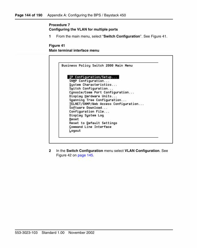
Page 144 of 190 Appendix A: Configuring the BPS / Baystack 450
553-3023-103 Standard 1.00 November 2002
Procedure 7Configuring the VLAN for multiple ports
1 From the main menu, select “Switch Configuration”. See Figure 41.
Figure 41Main terminal interface menu
2 In the Switch Configuration menu select VLAN Configuration. See Figure 42 on page 145.
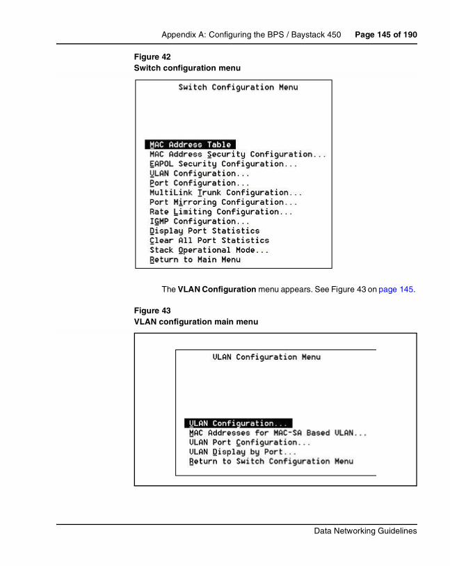
Appendix A: Configuring the BPS / Baystack 450 Page 145 of 190
Data Networking Guidelines
Figure 42Switch configuration menu
The VLAN Configuration menu appears. See Figure 43 on page 145.
Figure 43VLAN configuration main menu

Page 146 of 190 Appendix A: Configuring the BPS / Baystack 450
553-3023-103 Standard 1.00 November 2002
3 Select VLAN Port Configuration. See Figure 44 on page 146. In the Tagging field, select Tagged Trunk. This is the uplink port.
Figure 44VLAN port configuration menu
4 From the VLAN Configuration menu (Figure 43 on page 145), select the VLAN Configuration option. In the VLAN Configuration screen (see Figure 45), enter the required VLAN ID (in this example, 50) in the Create VLAN field.
5 In the Port Membership fields, select the port member type by using the space bar and then the Enter key to select the value. See Figure 45. The Port Membership type can consist of the following:
• '–' (not a member),
• 'U' (an untagged port member) or
• 'T' (tagged port member)
6 In the VLAN State field, select Active. See Figure 45 on page 147.

Appendix A: Configuring the BPS / Baystack 450 Page 147 of 190
Data Networking Guidelines
Figure 45VLAN configuration menu – VID 50
7 Repeat steps 5, 6, and 7 for the remaining VLANs to be configured (VID 60 and 70). See Figure 46 and Figure 47 on page 148.
Figure 46VLAN configuration menu – VID 60
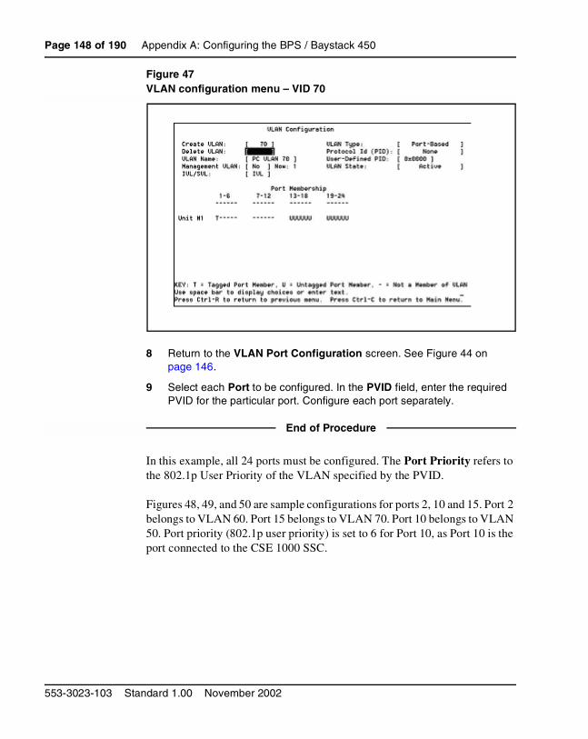
Page 148 of 190 Appendix A: Configuring the BPS / Baystack 450
553-3023-103 Standard 1.00 November 2002
Figure 47VLAN configuration menu – VID 70
8 Return to the VLAN Port Configuration screen. See Figure 44 on page 146.
9 Select each Port to be configured. In the PVID field, enter the required PVID for the particular port. Configure each port separately.
End of Procedure
In this example, all 24 ports must be configured. The Port Priority refers to the 802.1p User Priority of the VLAN specified by the PVID.
Figures 48, 49, and 50 are sample configurations for ports 2, 10 and 15. Port 2 belongs to VLAN 60. Port 15 belongs to VLAN 70. Port 10 belongs to VLAN 50. Port priority (802.1p user priority) is set to 6 for Port 10, as Port 10 is the port connected to the CSE 1000 SSC.

Appendix A: Configuring the BPS / Baystack 450 Page 149 of 190
Data Networking Guidelines
Figure 48Configuration for VLAN ID 60, port 2
Figure 49Configuration for VLAN ID 50, port 10

Page 150 of 190 Appendix A: Configuring the BPS / Baystack 450
553-3023-103 Standard 1.00 November 2002
Figure 50Configuration for VLAN ID 70, port 15
End of Procedure
QoS configuration for the BPS/Baystack 450
QoS functionality on the BPS
QoS activity on the BPS takes place in several stages. The first stage involves using a method to identify the traffic, such as traffic filters.
After identifying the class of traffic, actions can be configured to drop, mark or pass the network traffic. Dropping the traffic involves preventing the information from passing through the device. Marking the traffic changes the flow identifier values such as the DSCP or 802.1p user priority bits. Marking the traffic affects the behavior of the network traffic downstream. The BPS can also allow the traffic to pass unaltered.
All traffic that passes through the switch is placed in hardware queues for outbound ports. A single packet is not spread among multiple queues.
Appendix A: Configuring the BPS / Baystack 450 Page 151 of 190
Data Networking Guidelines
Each interface can have two or more queues associated with it. Multiple queues that are related by their schedule for servicing, can be associated as a queue set. On the BPS there are two scheduling methods, Priority Queues (PQ) and Weighted Round-Robin (WRR).
Figure 51 on page 152 shows an example of an Interface Queue Table. Under the Set ID column, Set ID 1 and Set ID 2 refer to Queue Set 1 and Queue Set 2.
Queue Set 1 has the following parameters:
• General Discipline (scheduling)
— Priority Queueing + Weighted Fair Queueing (Weighted Round-Robin)
• Highest priority queue
— Queue ID 1
• Weighted Round-Robin queues
— Queue ID 2 (50% bandwidth)
— Queue ID 3 (30% bandwidth)
— Queue ID 4 (20% bandwidth)
Note: All packets in the highest priority queue, Queue ID 1, are serviced before the packets in any other queues. When Queue ID 1 is empty, the packets in queues 2, 3, and 4 are serviced in a Round-Robin method. In this example, it is possible for packets in queues 2, 3, and 4 to starve (never be serviced), if Queue ID 1 is continuously busy.
Queue Set 2 has the following parameters:
• General Discipline (scheduling)
— Priority Queueing)
• Highest priority queue
— Queue ID 1
• Lowest priority queue
— Queue ID 2

Page 152 of 190 Appendix A: Configuring the BPS / Baystack 450
553-3023-103 Standard 1.00 November 2002
Note: In this example, all packets in Queue ID 1 are serviced before the packets in Queue ID 2.
Figure 51Interface Queue Table

Appendix A: Configuring the BPS / Baystack 450 Page 153 of 190
Data Networking Guidelines
The BPS interface group assignment
QoS configuration on the BPS consists of assigning each of the Internet Telephone Ethernet ports to a ‘Trusted’ Interface Group. See Figure 52 on page 153.
Figure 52QoS interface group port assignment
The remaining desktop PC Ethernet ports are assigned to the default untrusted role. A trusted port keeps the DSCP and 802.1p bits intact. Untrusted ports have the DSCP and 802.1p values reset. VoIP traffic coming out of the i2050 software Internet Telephone is prioritized by applying policies using Optivity Policy Services (OPS) 2.0. See Appendix C on page 173 for more information.
The BPS with Media Dependant Adapter (MDA) uplinks must have its ports set to trusted roles as well, to ensure that the QoS services are passed on.
Another method of deploying QoS in the BPS is to set all the ports to ‘trusted’. This implementation is simple to deploy. However, it is necessary that the traffic coming out of the PC Ethernet ports and Internet Telephone ports is not abused. Setting desktop PC connections to a trusted role on the BPS allows applications such as the i2050 software Internet Telephone to prioritize voice traffic. It is possible that a user could configure a PC to mark DiffServ code points so that their network traffic gets prioritized. This requires a high level of expertise, but the possibility of abuse exists. Therefore, this method of deployment is not the recommended method.
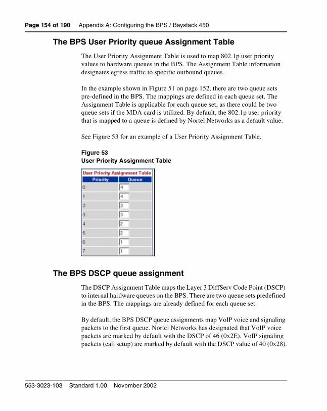
Page 154 of 190 Appendix A: Configuring the BPS / Baystack 450
553-3023-103 Standard 1.00 November 2002
The BPS User Priority queue Assignment Table
The User Priority Assignment Table is used to map 802.1p user priority values to hardware queues in the BPS. The Assignment Table information designates egress traffic to specific outbound queues.
In the example shown in Figure 51 on page 152, there are two queue sets pre-defined in the BPS. The mappings are defined in each queue set. The Assignment Table is applicable for each queue set, as there could be two queue sets if the MDA card is utilized. By default, the 802.1p user priority that is mapped to a queue is defined by Nortel Networks as a default value.
See Figure 53 for an example of a User Priority Assignment Table.
Figure 53User Priority Assignment Table
The BPS DSCP queue assignment
The DSCP Assignment Table maps the Layer 3 DiffServ Code Point (DSCP) to internal hardware queues on the BPS. There are two queue sets predefined in the BPS. The mappings are already defined for each queue set.
By default, the BPS DSCP queue assignments map VoIP voice and signaling packets to the first queue. Nortel Networks has designated that VoIP voice packets are marked by default with the DSCP of 46 (0x2E). VoIP signaling packets (call setup) are marked by default with the DSCP value of 40 (0x28).

Appendix A: Configuring the BPS / Baystack 450 Page 155 of 190
Data Networking Guidelines
Figure 54 shows an example of a DSCP Assignment Table.
Figure 54DSCP Assignment Table
The BPS Priority Mapping Table
The Priority Mapping Table maps 802.1 user priority values to DSCP values. These values do not need to be changed as Nortel Networks defines them by default.
Figure 55 shows an example of a Priority Mapping Table.

Page 156 of 190 Appendix A: Configuring the BPS / Baystack 450
553-3023-103 Standard 1.00 November 2002
Figure 55Priority Mapping Table
Figure 56 on page 157 is an example of the BPS DSCP Mapping Table.

Appendix A: Configuring the BPS / Baystack 450 Page 157 of 190
Data Networking Guidelines
Figure 56DSCP Mapping Table
Baystack 450 802.1p user priority configurationThe BayStack 450 switch is a Layer 2-aware device. The BayStack 450 cannot prioritize packets based on the DSCP set in the IP packet header. Instead, Layer 2 802.1p user priority bits are used to differentiate packets.
To support prioritization of 802.1p user priorities on the Baystack 450, it is necessary to configure the Traffic Class Configuration under the Switch Configuration -> VLAN Configuration menu option.

Page 158 of 190 Appendix A: Configuring the BPS / Baystack 450
553-3023-103 Standard 1.00 November 2002
Nortel Networks has defined a default value of ‘110’ (User Priority 6) for 802.1p marking. To implement VoIP using QoS on the BayStack 450, the user priority value of 6 should be assigned a high traffic class. See Figure 57 on page 158.
In the end, the configuration enables the prioritization of Ethernet packets on the upstream and downstream.
Figure 57Traffic class configuration on the Baystack 450

Page 159 of 190
Data Networking Guidelines
172
Appendix B: Configuring QoS on the Passport 8600
ContentsThis section contains information on the following topics:
DiffServ core network with BPS 2000 . . . . . . . . . . . . . . . . . . . . . . . . . 159
DiffServ core network with Baystack 450 . . . . . . . . . . . . . . . . . . . . . . 162
QoS on the Passport 8600 . . . . . . . . . . . . . . . . . . . . . . . . . . . . . . . . . . . 163
Layer 3 QoS mechanisms . . . . . . . . . . . . . . . . . . . . . . . . . . . . . . . . . . . 168
DiffServ core network with BPS 2000The Business Policy Switch (BPS) 2000 supports the ability to classify and mark traffic based on DiffServ and 802.1p values. The BPS 2000 can serve as the DiffServ edge device that performs mapping and network classification. Uplink ports from the BPS 2000 to the Passport 8600 can be set to ‘trusted’ core ports as the network traffic is assumed to be valid. Figure 58 on page 160 shows an example of a DiffServ core network with the BPS 2000 and the Passport 8600 switches.

Page 160 of 190 Appendix B: Configuring QoS on the Passport 8600
553-3023-103 Standard 1.00 November 2002
Figure 58DiffServ core network with BPS 2000
The easiest way to configure this port is to use Device Manager. Enter the edit mode on the appropriate port and set the following options:
• Check the DiffServEnable checkbox.
• Set the DiffServType to core.

Appendix B: Configuring QoS on the Passport 8600 Page 161 of 190
Data Networking Guidelines
Figure 59Configuring a port using Device Manager
To configure a port using a telnet session, enter config mode for the appropriate port interface:
/config/ethernet/<interface>/<port number>#
Ensure the following values are set:
• enable-diffserv: true
• access-diffserv: false
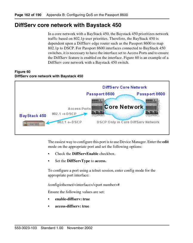
Page 162 of 190 Appendix B: Configuring QoS on the Passport 8600
553-3023-103 Standard 1.00 November 2002
DiffServ core network with Baystack 450In a core network with a BayStack 450, the Baystack 450 prioritizes network traffic based on 802.1p user priorities. Therefore, the BayStack 450 is dependent upon a DiffServ edge router such as the Passport 8600 to map 802.1p to DSCP. For Passport 8600 interfaces connected to BayStack 450 switches, it is necessary to have the interface set to Access Ports and to ensure the DiffServ feature is enabled on the interface. Figure 60 is an example of a DiffServ core network with a Baystack 450 switch.
Figure 60DiffServ core network with Baystack 450
The easiest way to configure this port is to use Device Manager. Enter the edit mode on the appropriate port and set the following options:
• Check the DiffServEnable checkbox.
• Set the DiffServType to access.
To configure a port using a telnet session, enter config mode for the appropriate port interface:
/config/ethernet/<interface>/<port number>#
Ensure the following values are set:
• enable-diffserv: true
• access-diffserv: true

Appendix B: Configuring QoS on the Passport 8600 Page 163 of 190
Data Networking Guidelines
Note: A traffic filter must be created to ensure proper mapping from 802.1p to DiffServ for this access port.
QoS on the Passport 8600The Passport 8600 switch provides a hardware-based Quality of Service (QoS). The hardware on the routing switch enables it to classify 802.1p- and DiffServ Code Point (DSCP)-marked packets. The Passport 8600 has eight output queues per port into which packets are placed. The eight queues on the Passport 8600 are serviced according to a guaranteed Weight Round Robin (WRR) routine. See Table 17.
Passport 8600 port QoS configuration
The Passport 8600 ports are configured for the core DiffServ type. To enable QoS on the ports of the Passport 8600, the DiffServEnable check box must be selected. Set the DiffServType to core. See Figure 61 on page 164.
Table 17WWR on the Passport 8600
IP service class DSCP
Packet transmission opportunity Percentage weight
Network 7 2 6%
Premium 6 32 100%
Platform 5 10 31%
Gold 4 8 25%
Silver 3 6 18%
Bronze 2 4 12%
Standard 1 2 6%
User-defined 0 0 0%

Page 164 of 190 Appendix B: Configuring QoS on the Passport 8600
553-3023-103 Standard 1.00 November 2002
Figure 61Passport 8600 port configuration
The DSCP marking and 802.1p bits are forwarded and routed unaffected, if the ports are configured for the core DiffServ type. Untagged and bridged packets are placed into QoS queues based on DSCP-to-QoS mappings. Untagged and routed packets are placed into QoS queues based on DSCP-to-QoS mappings. Figure 62 on page 165 shows the Passport 8600 QoS mappings.

Appendix B: Configuring QoS on the Passport 8600 Page 165 of 190
Data Networking Guidelines
Figure 62Passport 8600 Qos mappings
Internet Telephones do not support 802.1p user priority markings. The importance of 802.1p priorities comes into play when using Layer 2 switches that do not view information at an IP level.
Nortel Networks has defined that the Internet Telephones mark the 802.1p priority with a value of ‘110’, a decimal value of 6 (0.6). By default, the Internet Telephone 802.1p priority is mapped to QoS level 6. It is not necessary to changes these values.
DSCP queue assignment tables show the mapping of Layer 3 DSCP to internal hardware queues on the BPS 2000. The default settings of the Passport 8600 DSCP to QoS assignments already map VoIP voice and control packets to QoS level 6. Nortel Networks standards have defined that VoIP voice packets are to be marked with DSCP values of 46 (0x2E) and VoIP signaling packets (call setup) are to be marked with DSCP values of 40 (0x28). See Figures 63, 64, 65, and 66 on the following pages.
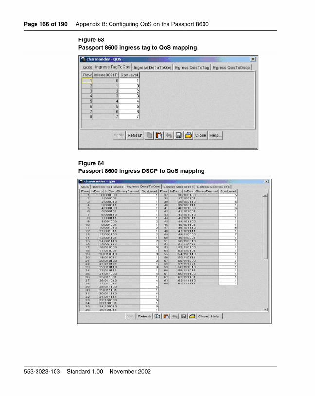
Page 166 of 190 Appendix B: Configuring QoS on the Passport 8600
553-3023-103 Standard 1.00 November 2002
Figure 63Passport 8600 ingress tag to QoS mapping
Figure 64Passport 8600 ingress DSCP to QoS mapping

Appendix B: Configuring QoS on the Passport 8600 Page 167 of 190
Data Networking Guidelines
Figure 65Passport 8600 egress QoS to tag mapping
Figure 66Passport 8600 egress QoS to DSCP mapping

Page 168 of 190 Appendix B: Configuring QoS on the Passport 8600
553-3023-103 Standard 1.00 November 2002
Layer 3 QoS mechanismsQoS services are engineered at a Layer 3 level using DiffServ for end-to-end QoS. End-to-end QoS means providing QoS services in both directions from the IP Line card to the Internet Telephones. DiffServ is a Layer 3 QoS service, that enables the prioritization of IP traffic.
There are 6 bits in the second byte of the IPv4 header, referred to as the DiffServ Code Point (DSCP). They are used to identify the priority of the IP packet on a per-hop basis. Figure 67 on page 168 is an example of DiffServe-based QoS architecture.
Figure 67DiffServe-based QoS architecture
Examples of Layer 3 configuration
In these examples, the network consists of Passport 8600 and BPS 2000 devices. The ITGL cards and the Internet Telephones have been configured to Nortel Networks standards for DSCP. VoIP traffic for voice stream has the Expedited Forwarding (EF) DSCP value of decimal 46 (binary 101110). Voice signaling packets have the Class Selector 5 (CS5) DSCP value of decimal 40 (binary 101000).

Appendix B: Configuring QoS on the Passport 8600 Page 169 of 190
Data Networking Guidelines
Nortel Networks Service Classes (NNSC) provides standardized behaviors for marking IP telephony packets. This ensures that VoIP traffic gets mapped to premium queues on Nortel Networks devices.
The standardized default QoS behaviors of Nortel Networks routers/switches enables the prioritization of voice packets. Passport 8600 and BPS 2000 are L2/L3 QoS-aware devices. These devices are capable of prioritizing traffic based on DSCP and 802.1p. The interfaces on the Passport 8600 and BPS 2000 can be configured to choose to distrust or trust 802.1p and DSCP marked traffic.
The BPS 2000 and Passport 8600 places DSCP marked IP packets into the same priority queue. By default, trusted (core) ports on the Passport 8600 and BPS 2000 place DSCP marked traffic into the Premium queue. The Passport 8600 and BPS 2000 are essentially plug-and-play, providing QoS services based on DSCP. The VoIP traffic that is marked with QoS bits will be re-marked to DSCP and 802.1p values of 0 when entering untrusted ports.
Recommended network architecture
The following sections describe the recommended network architecture for the LAN.
Pure BPS 2000 and Passport 8600 environment
The recommended network architecture in the LAN environment consists consists primarily of Passport 8600 devices and Business Policy Switch 2000 to offer end-to-end DiffServ. The main advantage to this solution is that there is minimal engineering to implement QoS. This implementation requires minimal network management once the network infrastructure is put into place. This simple solution decreases the cost of training employees for network management.
The BPS 2000 and Passport 8600 have been selected as the fundamental network elements as the QoS features are simple to configure and QoS mapping behaviors are configured by default. The pure BPS 2000 and Passport 8600 network architecture functions strictly on DSCP propagating the network. See Figure 68 on page 170.

Page 170 of 190 Appendix B: Configuring QoS on the Passport 8600
553-3023-103 Standard 1.00 November 2002
Figure 68Pure BPS 2000 and Passport 8600 environment
BPS 2000 / BayStack 450 and Passport 8600 environment
In addition to the recommended network architecture consisting of only Business Policy Switch 2000 and Passport 8600 devices, the BayStack 450 can be configured to offer DiffServ capabilities.
By replacing the base unit with a Business Policy Switch 2000, traffic entering the 10/100 Mbps interfaces of the BayStack 450 can be classified and queued. Essentially, the traffic is propagated through the stack up to the BPS 2000, which serves as the uplink on the BPS 2000. The BPS 2000 then acts as the QoS device that performs the queuing, based on the DSCP markings on the IP traffic. See Figure 69 on page 171.
This implementation reduces the cost of replacing all the units in a BayStack 450 stack with Business Policy Switch 2000. In BayStack 450 stacks where the redundancy is offered using VRRP, multiple BayStack 450 switches must be replaced to offer DiffServ QoS and redundancy at the same time.
To ensure that no network traffic abuse occurs, the cascade ports should be set to ‘untrusted’ roles and the appropriate policies are set using Optivity Policy Services 2.0. See “Optivity Policy Services” on page 95.

Appendix B: Configuring QoS on the Passport 8600 Page 171 of 190
Data Networking Guidelines
Figure 69BPS 2000/Baystack 450 and Passport 8600 environment
Note: There is no prioritization of packets between individual BayStack 450 switches in the stack.

Page 172 of 190 Appendix B: Configuring QoS on the Passport 8600
553-3023-103 Standard 1.00 November 2002

Page 173 of 190
Data Networking Guidelines
178
Appendix C: Optivity Policy Services
ContentsThis section contains information on the following topics:
Policies . . . . . . . . . . . . . . . . . . . . . . . . . . . . . . . . . . . . . . . . . . . . . . . . . 173Creating policies for Internet telephones on untrusted ports . . . . . . 176
PoliciesA policy is defined as a traffic rule that is implemented based on the following:
• traffic classification
• scheduling
• traffic governing (actions)
Optivity Policy Services (OPS) 2.0 uses policies to govern the flow of traffic travelling through a BPS 2000 and Business Communications Server (BCS). The OPS traffic conditions allow the network administrator to specify the type of network traffic a policy acts upon.
Traffic classification can be determined based on the following:
• VLAN ID
• user priority value
• DSCP value
• protocol type

Page 174 of 190 Appendix C: Optivity Policy Services
553-3023-103 Standard 1.00 November 2002
• IP addresses
• port number
OPS network-management software uses actions to control network traffic by controlling packet flow, by denying packets, or by policing packet flow. Scheduling is used to determine the time and dates a policy are effective. In the event that conflicting policies are put in place, the numeric priority level of the policy is used to determine which policy is selected.
Figure 70 on page 174 and Figure 71 on page 175 show the OPS Management Console.
Figure 70OPS Management Console

Appendix C: Optivity Policy Services Page 175 of 190
Data Networking Guidelines
Figure 71OPS Management Console – expanded view
To put a policy into effect, it must be applied to a role. A role serves as a identifier that clusters together interfaces with similar functions. Roles can be created as ‘trusted’ or ‘untrusted’ using the BPS 2000 web GUI interface.

Page 176 of 190 Appendix C: Optivity Policy Services
553-3023-103 Standard 1.00 November 2002
Creating policies for Internet telephones on untrusted ports
IP traffic conditions
It is necessary to first define the IP traffic conditions that specify what VoIP traffic is coming out of the i2050 software client. There are two types of traffic:
• voice packets
• control packets
A new IP traffic condition is created for the VoIP voice packets to be filtered, based on UDP protocol network traffic and Inbound DiffServ Value marked as 46. Another new IP traffic condition is created for the VoIP data packets to be filtered, based on TCP protocol and Inbound DiffServ Value marked as 40. See Figure 72 on page 176 and Figure 73 on page 177.
Figure 72New IP traffic condition – voice packets

Appendix C: Optivity Policy Services Page 177 of 190
Data Networking Guidelines
Figure 73New IP traffic condition – control packets
Optivity Policy Services 2.0 already has predefined schedules and actions that can be used. In this example, a policy for marking i2050 VoIP traffic can be created with the following parameters:
• IP Traffic Condition: VoIP Voice Packets and VoIP Control Packets (as created in “IP traffic conditions” on page 176)
• Schedules: Always On (predefined schedule)
• Actions: mark traffic Premium (predefined action)
See Figure 74 on page 178.

Page 178 of 190 Appendix C: Optivity Policy Services
553-3023-103 Standard 1.00 November 2002
Figure 74Mark voice traffic
Page 179 of 190
Data Networking Guidelines
190
List of terms
Algorithm A formula or set of steps for solving a particular problem. To be an algorithm, a set of rules must be unambiguous and have a clear stopping point. Algorithms can be expressed in any language, from natural languages like English or French to programming languages like FORTRAN.
We use algorithms every day. For example, a recipe for baking a cake is an algorithm. Most programs, with the exception of some artificial intelligence applications, consist of algorithms. Inventing elegant algorithms – algorithms that are simple and require the fewest steps possible – is one of the principal challenges in programming.
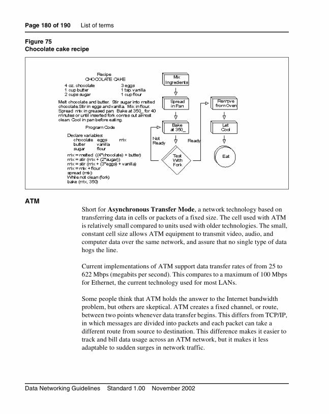
Page 180 of 190 List of terms
Data Networking Guidelines Standard 1.00 November 2002
Figure 75Chocolate cake recipe
ATM Short for Asynchronous Transfer Mode, a network technology based on transferring data in cells or packets of a fixed size. The cell used with ATM is relatively small compared to units used with older technologies. The small, constant cell size allows ATM equipment to transmit video, audio, and computer data over the same network, and assure that no single type of data hogs the line.
Current implementations of ATM support data transfer rates of from 25 to 622 Mbps (megabits per second). This compares to a maximum of 100 Mbps for Ethernet, the current technology used for most LANs.
Some people think that ATM holds the answer to the Internet bandwidth problem, but others are skeptical. ATM creates a fixed channel, or route, between two points whenever data transfer begins. This differs from TCP/IP, in which messages are divided into packets and each packet can take a different route from source to destination. This difference makes it easier to track and bill data usage across an ATM network, but it makes it less adaptable to sudden surges in network traffic.

List of terms Page 181 of 190
Data Networking Guidelines
When purchasing ATM service, you generally have a choice of four different types of service:
• Constant Bit Rate (CBR) specifies a fixed bit rate so that data is sent at a constant rate. This is analogous to a leased line.
• Variable Bit Rate (VBR) provides a specified throughput capacity but data is not sent evenly. This is a popular choice for voice and videoconferencing data.
Unspecified Bit Rate (UBR) does not guarantee any throughput levels. This is used for applications, such as file transfer, that can tolerate delays.
Available Bit Rate (ABR) provides a guaranteed minimum capacity but allows data to be bursted at higher capacities when the network is free.
CBRConstant Bit Rate. See ATM on page 180.
CIRCommitted Information Rate. A Frame relay term. CIR is the level of data traffic in bits that a carrier agrees to handle – not at all times, but averaged over a period of time.
Client The client part of a client-server architecture. Typically, a client is an application that runs on a personal computer or workstation and relies on a server to perform some operations. For example, an e-mail client is an application that enables you to send and receive e-mail.
COPS-PRCommon Open Policy Service (COPS) is an IETF standard (RFC 2748). It provides a standard protocol for exchange of policy information between network servers, and network clients such as routers and switches. COPS-PR (COPS Usage for Policy Provisioning) is a provisioning layer designed to facilitate the implementation of new policies, as defined by Policy Information Bases (PIBs).

Page 182 of 190 List of terms
Data Networking Guidelines Standard 1.00 November 2002
Network administrators can quickly deploy new services and configurations across a network, using the COPS-PR layer, to dynamically update network devices with new policies. It provides the necessary services to propagate DiffServ policy information across the network.
DiffServDifferentiated Services. DiffServ specifies, on a per-packet basis, how IP traffic is handled. The handling is specified based on the packet’s DiffServ Code Point (DSCP). A method for adding quality of service (QoS) to IP networks from the IETF, DiffServ is the preferred Layer 3 QoS mechanism for Succession CSE.
Operating at Layer 3 only, Diffserv uses the IP Type Of Service (TOS) field as the Diffserv byte (DS byte).
DiffServ domainA network segment that is DiffServ-aware.
DiffServ edgeWhere the DiffServ domain begins. Defined in the DiffServ Architecture RFC 2475.
DiffServ Edge NodeThe first Layer 3-aware device that a packet encounters.
DSCPDiffServ Code Point. Six bits in an IP packet header that specify how a packet is to be handled on an IP network.
DSP Digital Signal Processing, which refers to manipulating analog information, such as sound or photographs that has been converted into a digital form. DSP also implies the use of a data compression technique.
When used as a noun, DSP stands for Digital Signal Processor, a special type of coprocessor designed for performing the mathematics involved in DSP. Most DSPs are programmable, which means that they can be used for manipulating different types of information, including sound, images, and video.

List of terms Page 183 of 190
Data Networking Guidelines
Full-duplexTransmission in both directions at the same time can occur on the bandwidth. The full bandwidth of the link is available in either direction.
Gateway In networking, a combination of hardware and software that links two different types of networks. Gateways between e-mail systems, for example, allow users on different e-mail systems to exchange messages.
H.323 A standard approved by the International Telecommunication Union (ITU) that defines how audiovisual conferencing data is transmitted across networks. In theory, H.323 should enable users to participate in the same conference even though they are using different videoconferencing applications. Although most videoconferencing vendors have announced that their products will conform to H.323, it's too early to say whether such adherence will actually result in interoperability.
Half-DuplexPackets are transmitted in only one direction at a time. The send and receive bandwidth is shared. Packet collisions can occur on Half Duplex links.
IEEE 802 standards IEEE
Institute of Electrical and Electronics Engineers, pronounced I-triple-E. Founded in 1884 as the AIEE, the IEEE was formed in 1963 when AIEE merged with IRE. IEEE is an organization composed of engineers, scientists, and students. The IEEE is best known for developing standards for the computer and electronics industry. In particular, the IEEE 802 standards for local-area networks are widely followed.
802 standardsA set of network standards developed by the IEEE. They include:
• IEEE 802.1: Standards related to network management.

Page 184 of 190 List of terms
Data Networking Guidelines Standard 1.00 November 2002
• IEEE 802.2: General standard for the data link layer in the OSI Reference Model. The IEEE divides this layer into two sublayers -- the logical link control (LLC) layer and the media access control (MAC) layer. The MAC layer varies for different network types and is defined by standards IEEE 802.3 through IEEE 802.5.
• IEEE 802.3: Defines the MAC layer for bus networks that use CSMA/CD. This is the basis of the Ethernet standard.
• IEEE 802.4: Defines the MAC layer for bus networks that use a token-passing mechanism (token bus networks).
• IEEE 802.5: Defines the MAC layer for token-ring networks.
• IEEE 802.6: Standard for Metropolitan Area Networks (MANs).
IEEE 802.1: network management Refers to the broad subject of managing computer networks. There exists a wide variety of software and hardware products that help network system administrators manage a network. Network management covers a wide area, including:
• Security: Ensuring that the network is protected from unauthorized users.
• Performance: Eliminating bottlenecks in the network.
• Reliability: Making sure the network is available to users and responding to hardware and software malfunctions.
IEEE 802.1p
The Class of Service bits within an IEEE 802.1Q VLAN tag.
IEEE 802.1Q
The IEEE specification referring to Virtual Local Area Networks (VLANs). It includes “Class of Service” and VLAN ID.
IEEE 802.2: MAC Layer The Media Access Control Layer is one of two sublayers that make up the Data Link Layer of the OSI model. The MAC layer is responsible for moving data packets to and from one Network Interface Card (NIC) to another across a shared channel.

List of terms Page 185 of 190
Data Networking Guidelines
See a breakdown of the seven OSI layers in the Quick Reference section of Webopedia.
The MAC sublayer uses MAC protocols to ensure that signals sent from different stations across the same channel don't collide.
Different protocols are used for different shared networks, such as Ethernet, Token Ring, and Token Bus.
IP Abbreviation of Internet Protocol, pronounced as two separate letters. IP specifies the format of packets, also called datagrams, and the addressing scheme. Most networks combine IP with a higher-level protocol called Transport Control Protocol (TCP), which establishes a virtual connection between a destination and a source.
IP by itself is something like the postal system. It allows you to address a package and drop it in the system, but there's no direct link between you and the recipient. TCP/IP, on the other hand, establishes a connection between two hosts so that they can send messages back and forth for a period of time.
The current version of IP is IPv4. A new version, called IPv6 or IPng, is under development.
IPSecA group of IP security measures. It defines privacy, integrity, authentication, security key management, and tunnelling methods. A secure version of IP, IPSec enables a secure VPN over the Internet, providing optional authentication and encryption at the packet level.
Layer 2 switchingPackets are forwarded based on the destination’s MAC address. The switch automatically determines which switch port must be used to send the packet, based on the destination’s MAC address. The MAC address location was determined from incoming packets from that MAC address received on that port.

Page 186 of 190 List of terms
Data Networking Guidelines Standard 1.00 November 2002
Layer 3 switchingPacket traffic is grouped based on source and destination addresses. The first packet in a flow is routed by a software-based algorithm. Subsequent packets with the same source and destination addresses are switched based on the destination’s MAC address (hardware mechanism). This is similar to multi-layer routing and routers with hardware assist.
MIBManagement Information Base. A database of network performance information that is stored on a Network Agent. It contains characteristics and parameters about network devices such as NICs, hubs, switches, and routers. This information is accessed by software like SNMP.
MIDMessage Identifier.
MUAMail User Agent. The mail program used by an end-user computer to create and read e-mail messages.
NATNetwork Address Translation. It is defined as an internet standard that lets a LAN use both internal and external IP addresses. This protects an internal IP address from being accessed from outside. NAT translates the internal IP addresses to unique IP addresses before sending out packets. NAT is practical when only a few users in a domain need to communicate outside of the domain at the same time.
Object IdentifierAlso known as OID. An object is identified as a numeric value that represents some aspect of a managed device. An Object Identifier (OID) is a sequence of numbers, separated by periods, which uniquely defines the object within an MIB.
OIDSee Object Identifier.
PolicyA set of rules defining how certain network traffic should be treated. The rules consist of classification, marking, and queueing specifications.

List of terms Page 187 of 190
Data Networking Guidelines
Proxy Server A server that sits between a client application, such as a Web browser, and a real server. It intercepts all requests to the real server to see if it can fulfill the requests itself. If not, it forwards the request to the real server.
Proxy servers have two main purposes:
• Improve Performance: Proxy servers can dramatically improve performance for groups of users. This is because it saves the results of all requests for a certain amount of time. Consider the case where both user X and user Y access the World Wide Web through a proxy server. First user X requests a certain Web page, which we'll call Page 1. Sometime later, user Y requests the same page. Instead of forwarding the request to the Web server where Page 1 resides, which can be a time-consuming operation, the proxy server simply returns the Page 1 that it already fetched for user X. Since the proxy server is often on the same network as the user, this is a much faster operation. Real proxy servers support hundreds or thousands of users. The major online services such as Compuserve and America Online, for example, employ an array of proxy servers.
• Filter Requests: Proxy servers can also be used to filter requests. For example, a company might use a proxy server to prevent its employees from accessing a specific set of Web sites.
PSTN Short for Public Switched Telephone Network, which refers to the international telephone system based on copper wires carrying analog voice data. This is in contrast to newer telephone networks base on digital technologies, such as ISDN and FDDI.
Telephone service carried by the PSTN is often called plain old telephone service (POTS).
PVCPermanent Virtual Circuit. All transmitted data between two points follows a pre-determined path.

Page 188 of 190 List of terms
Data Networking Guidelines Standard 1.00 November 2002
QoS Quality of Service. A networking term that specifies a guaranteed throughput level. One of the biggest advantages of ATM over competing technologies such as Frame Relay and Fast Ethernet, is that it supports QoS levels. This allows ATM providers to guarantee to their customers that end-to-end latency will not exceed a specified level.
RMONRemote Monitoring specification. It is a set of SNMP-based MIBs (Management Information Bases) that define the monitoring, instrumenting, and diagnosis of LANS. It occurs at OSI Layer 2 (DLL). RMON-2 monitors above Layer 2, and can see across segments and through routers. See “SNMP” on page 189.
routingThe process of selecting the correct path for packets transmitted between IP networks by using software-based algorithms. Each packet is processed by the algorithm to determine its destination.
RTPRealtime Transport Protocol. An IETF standard that supports transport of realtime data, like voice and video, over packet switched networks. It does not provide QoS control.
Server A computer or device on a network that manages network resources. For example, a file server is a computer and storage device dedicated to storing files. Any user on the network can store files on the server. A print server is a computer that manages one or more printers, and a network server is a computer that manages network traffic. A database server is a computer system that processes database queries.
Servers are often dedicated, meaning that they perform no other tasks besides their server tasks. On multiprocessing operating systems, however, a single computer can execute several programs at once. A server in this case could refer to the program that is managing resources rather than the entire computer.

List of terms Page 189 of 190
Data Networking Guidelines
Shared-media hubA central connecting device in a network that joins communications lines together in a star configuration. Packets received on a shared-media hub are transmitted out of all other ports on the hub. This means all links must be half-duplex.
SNMP Simple Network Management Protocol. A set of protocols for managing complex networks. The first versions of SNMP were developed in the early 1980s. SNMP works by sending messages, called Protocol Data Units (PDUs), to different parts of a network. SNMP-compliant devices, called agents, store data about themselves in Management Information Bases (MIBs) and return this data to the SNMP requesters.
SNMP 1 reports only whether a device is functioning properly. The industry has attempted to define a new set of protocols called SNMP 2 that would provide additional information, but the standardization efforts have not been successful. Instead, network managers have turned to a related technology called RMON that provides more detailed information about network usage.
SubnetSubnetwork. A segment of an IP network. Packets must be routed in and out of a subnet.
TDM Time Division Multiplexing, a type of multiplexing that combines data streams by assigning each stream a different time slot in a set. TDM repeatedly transmits a fixed sequence of time slots over a single transmission channel.
Within T-Carrier systems, such as T-1 and T-3, TDM combines Pulse Code Modulated (PCM) streams created for each conversation or data stream.
UDPUser Datagram Protocol. Part of the TCP/IP protocol suite. It allows for the exchange of datagrams without acknowledgement or guarantee of delivery. UDP is at Layer 4 of the OSI model.

Page 190 of 190 List of terms
Data Networking Guidelines Standard 1.00 November 2002
VLANVirtual LAN. A logical grouping of network devices, located on different physical LAN segments, into a single domain. This allows the devices to interwork as though they were on the same segment.
WANWide Area Network. A computer network that spans a relatively large geographical area. Typically, a WAN consists of two or more local-area networks (LANs).
Computers connected to a wide-area network are often connected through public networks, such as the telephone system. They can also be connected through leased lines or satellites. The largest WAN in existence is the Internet.

TM
Family Product Manual Contacts Copyright FCC notice Trademarks Document number Product release Document release Date Publish
Succession Communication Server for Enterprise 1000
Data Networking Guidelines
Copyright © 2002 Nortel NetworksAll Rights ReservedInformation is subject to change without notice. Nortel Networks reserves the right to make changes in design or components as progress in engineering and manufacturing may warrant. This equipment has been tested and found to comply with the limits for a Class A digital device pursuant to Part 15 of the FCC rules, and the radio interference regulations of Industry Canada. These limits are designed to provide reasonable protection against harmful interference when the equipment is operated in a commercial environment. This equipment generates, uses and can radiate radio frequency energy, and if not installed and used in accordance with the instruction manual, may cause harmful interference to radio communications. Operation of this equipment in a residential area is likely to cause harmful interference in which case the user will be required to correct the interference at their own expense.SL-1, Meridian 1, and Succession are trademarks of Nortel Networks.Publication number: 553-3023-103Document release: Standard 1.00Date: November 2002Printed in Canada