data paths and control logic · building up toward project - mastermind autumn 2014 cse390c - ix...
TRANSCRIPT

Data paths and control logic
! Building larger digital systems " Include data, not just control inputs
! An example ! Building up toward project - MasterMind
Autumn 2014 CSE390C - IX - Data Paths and Control Logic 1

Data-path and control
! Digital hardware systems = data-path + control " datapath: registers, counters, combinational functional units (e.g.,
ALU), communication (e.g., busses) " control: FSM generating sequences of control signals that
instructs datapath what to do next
Autumn 2014 CSE390C - IX - Data Paths and Control Logic 2
"puppet"
"puppeteer who pulls the strings" control
data-path
status info and inputs
control signal
outputs state

Digital combinational lock
! Door combination lock: " punch in 3 values in sequence and the door opens; if there is an
error the lock must be reset; once the door opens the lock must be reset
" inputs: sequence of input values, reset " outputs: door open/close " memory: must remember combination or always have it available
" open questions: how do you set the internal combination? ! stored in registers (how loaded?) ! hardwired via switches set by user
Autumn 2014 CSE390C - IX - Data Paths and Control Logic 3

Autumn 2014 CSE390C - IX - Data Paths and Control Logic 4
Implementation in software
integer combination_lock ( ) { integer v1, v2, v3;
integer error = 0; static integer c[3] = 3, 4, 2;
while (!new_value( ));
v1 = read_value( ); if (v1 != c[1]) then error = 1;
while (!new_value( ));
v2 = read_value( ); if (v2 != c[2]) then error = 1;
while (!new_value( ));
v3 = read_value( ); if (v2 != c[3]) then error = 1;
if (error == 1) then return(0); else return (1);
}

Determining details of the specification
! How many bits per input value? ! How many values in sequence? ! How do we know a new input value is entered? ! What are the states and state transitions of the system?
Autumn 2014 CSE390C - IX - Data Paths and Control Logic 5
reset value
open/closed
new
clock

Digital combination lock state diagram
! States: 5 states " represent point in execution of machine " each state has outputs
! Transitions: 6 from state to state, 5 self transitions, 1 global " changes of state occur when clock says its ok " based on value of inputs
! Inputs: reset, new, results of comparisons ! Output: open/closed
Autumn 2014 CSE390C - IX - Data Paths and Control Logic 6
closed closed closed C1==value
& new C2==value
& new C3==value
& new
C1!=value & new C2!=value
& new C3!=value
& new
closed
reset
not new not new not new
S1 S2 S3 OPEN
ERR
open

Data-path and control structure
! Data-path " storage registers for combination values " multiplexer " comparator
! Control " finite-state machine controller " control for data-path (which value to compare)
Autumn 2014 CSE390C - IX - Data Paths and Control Logic 7
reset
open/closed
new C1 C2 C3
comparator value equal
multiplexer controller
mux control
clock 4
4 4 4
4
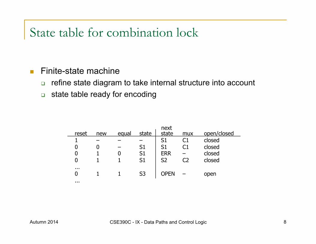
State table for combination lock
! Finite-state machine " refine state diagram to take internal structure into account " state table ready for encoding
Autumn 2014 CSE390C - IX - Data Paths and Control Logic 8
reset new equal state state mux open/closed 1 – – – S1 C1 closed 0 0 – S1 S1 C1 closed 0 1 0 S1 ERR – closed 0 1 1 S1 S2 C2 closed ... 0 1 1 S3 OPEN – open ...
next

Encodings for combination lock
! Encode state table " state can be: S1, S2, S3, OPEN, or ERR
! needs at least 3 bits to encode: 000, 001, 010, 011, 100 ! and as many as 5: 00001, 00010, 00100, 01000, 10000 ! choose 4 bits: 0001, 0010, 0100, 1000, 0000
" output mux can be: C1, C2, or C3 ! needs 2 to 3 bits to encode ! choose 3 bits: 001, 010, 100
" output open/closed can be: open or closed ! needs 1 or 2 bits to encode ! choose 1 bit: 1, 0
Autumn 2014 CSE390C - IX - Data Paths and Control Logic 9
reset new equal state state mux open/closed 1 – – – 0001 001 0 0 0 – 0001 0001 001 0 0 1 0 0001 0000 – 0 0 1 1 0001 0010 010 0 ... 0 1 1 0100 1000 – 1 ...
next
mux is identical to last 3 bits of state open/closed is identical to first bit of state therefore, we do not even need to implement FFs to hold state, just use outputs
reset
open/closed
new
equal
controller
mux control
clock
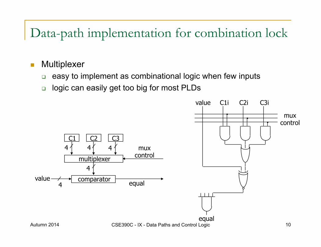
Data-path implementation for combination lock
! Multiplexer " easy to implement as combinational logic when few inputs " logic can easily get too big for most PLDs
Autumn 2014 CSE390C - IX - Data Paths and Control Logic 10
C1 C2 C3
comparator equal
multiplexer
mux control
4
4 4 4
4 value
C1i C2i C3i
mux control
value
equal

Digital combination lock (new data-path)
! Decrease number of inputs ! Remove 3 code digits as inputs
" use code registers " make them loadable from value " need 3 load signal inputs (net gain in input ( 4 * 3 ) – 3 = 9)
! could be done with 2 signals and decoder (ld1, ld2, ld3, hold)
Autumn 2014 CSE390C - IX - Data Paths and Control Logic 11
C1 C2 C3
comparator value equal
multiplexer
mux control
4
4 4 4
4
ld1 ld2 ld3

Sequential logic case studies summary
! FSM design " understanding the problem " generating state diagram " communicating state machines " implementation using PLDs
! Case studies in lecture and lab " understand I/O behavior " draw diagrams " enumerate states for the "goal" " expand with error conditions " reuse states whenever possible
Autumn 2014 CSE390C - IX - Data Paths and Control Logic 12

Lab 8 – final project
! Much more work than labs 1-7 ! You have from Nov 19 at 2:30 to Dec 8 at 2:30 – 19 days ! You will likely need all 19 of them, so start early
! For CSE390C, everyone will do the “MasterMind” (option 2) " No other options will be accepted
Autumn 2014 CSE390C - IX - Data Paths and Control Logic 13

MasterMind game
! How-to-play video may be helpful " http://www.theboardgamefamily.com/2011/03/become-a-mastermind/
! Basic idea " Set a secret pattern of colored pegs " Player guesses pattern " Report on guesses
! Number of correct color in correct position ! Number of correct color in incorrect position
" Keep guessing until secret pattern is found or number of guesses allowed is exhausted
Autumn 2014 CSE390C - IX - Data Paths and Control Logic 14

First steps
! How many colors (4) and positions (4)? " 2 bits to represent each
! Secret code of 4 colors " 2 bits each – 8 bits in all
! use switches on board
! Guess " 2 bits each – 8 bits in all
! use switches on board
! Report " Number of guesses so far
! use a hex display (max number of guesses?) " Number of correct colors and correct position
! hex display (0-4) " Number of correct colors in incorrect position
! hex display (0-4) " Win
! hex display or LED
Autumn 2014 CSE390C - IX - Data Paths and Control Logic 15
Example: secret code: 00 01 01 10 guess: 01 10 01 11
result: 1 exact, 2 colors-only

Second steps
! Reset " Start with entering a secret code through switches
! Need a way to signal a new guess " Switch (same switch as for secret code?)
! Register to hold secret code " Increment counter if exact color and position " FSM to step through a comparison " Four comparisons of 2-bits each
! Increment other counter if color and wrong position " Also coordinated by control FSM " Multiple scans? " What if two colors are the same in secret code?
Autumn 2014 CSE390C - IX - Data Paths and Control Logic 16

Color matching
! Position 1 compared to each other " If color is the same, increment exact counter " If different, do not increment color-match-only counter " Go through all 4 positions
! Match color of secret’s position 1 " Compare to other 3 positions " If match, “mark” secret position 1 as matched " If not, then don’t “mark” " Go through all four positions " Count “marks” as the value for the color-match-only counter
! How do we “mark” the four values?
Autumn 2014 CSE390C - IX - Data Paths and Control Logic 17

Basic data path structure
Autumn 2014 CSE390C - IX - Data Paths and Control Logic 18
4:1 2-bit mux 4:1 2-bit mux
8
2 2
2-bit comparator
Code for secret
or guess
Load secret Load guess
Select guess part
Select secret part
Match
Plus two counters for keeping track of number of matches for report

Control finite state machine
! Wait for secret code entry or guess entry " Load appropriate register
! Once guess is entered, sequence through a set of comparisons " For color match in same position – count these " For color match in incorrect position – count these " The hard part is making sure not to double count
! How to do this? ! What do you need to keep track of? ! Need another register (memory) to keep track?
" What about a separate state machine for each position? ! They could all access the data in parallel (with their own muxes)
! Report result of counters to two hex displays (counter values) ! Go back to await next guess Autumn 2014 CSE390C - IX - Data Paths and Control Logic 19