data summary - ministerio de fomento · 2019-09-01 · report in-031/2012 1 all times in this...
TRANSCRIPT
REPORT IN-031/2012
1 All times in this report are local. To obtain UTC, subtract 2 hours from local time.
LOCATION
Date and time Saturday, 11 August 2012; 19:47 h1
Site Almeria Airport (Spain)
FLIGHT DATA
Operation General aviation – Private
Phase of flight Landing
REPORT
Date of approval 27 January 2014
CREW
Pilot in command
Age 49 years old
Licence PPL(A)
Total flight hours 663 h
Flight hours on the type 250 h
AIRCRAFT
Registration D-EEDM
Type and model CESSNA 177RG
Operator Private
Engines
Type and model LYCOMING IO-360-A1B6D
Number 1
INJURIES Fatal Serious Minor/None
Crew 1
Passengers 3
Third persons
DAMAGE
Aircraft Minor
Third parties N/A
DATA SUMMARY
209
Report IN-031/2012
1. FACTUAL INFORMATION
1.1. History of the flight
Summary of the incident
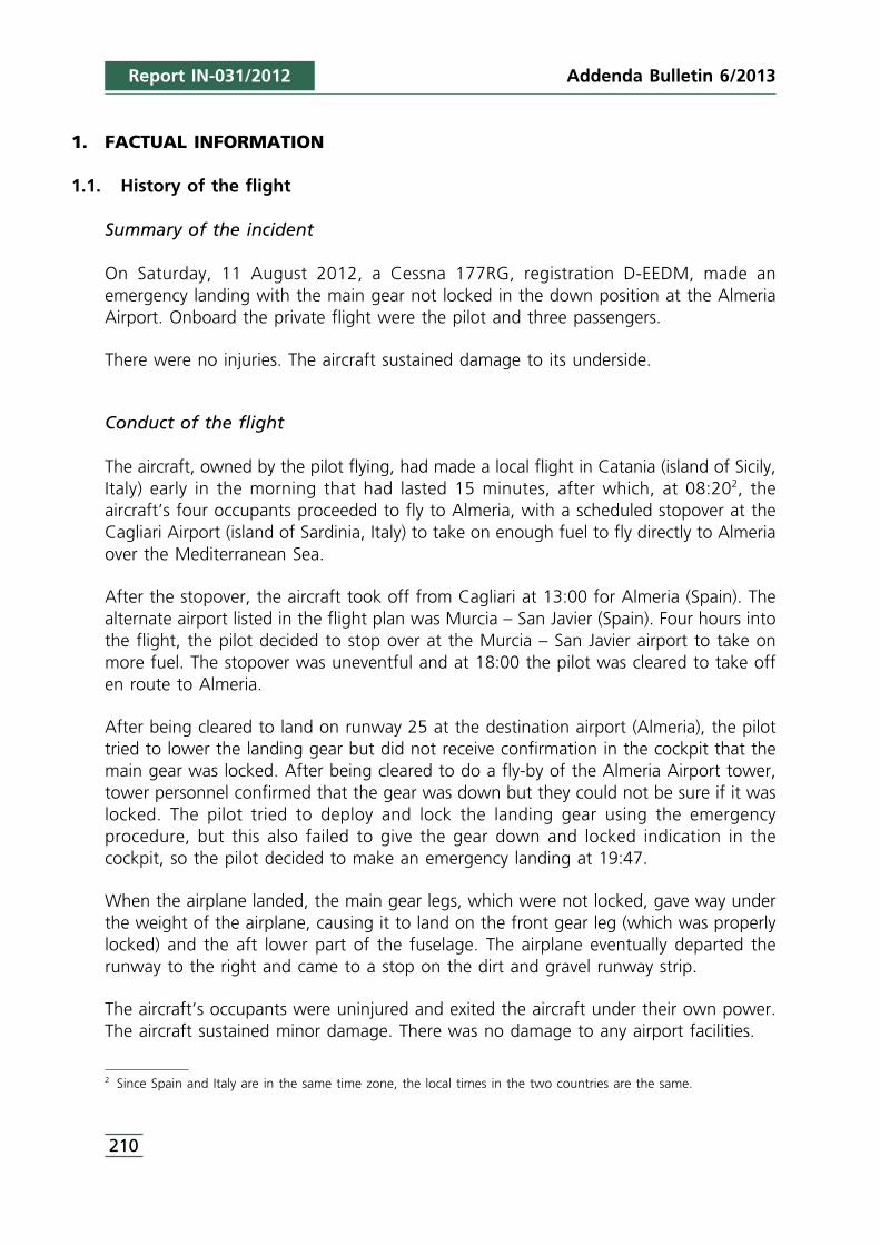
On Saturday, 11 August 2012, a Cessna 177RG, registration D-EEDM, made anemergency landing with the main gear not locked in the down position at the AlmeriaAirport. Onboard the private flight were the pilot and three passengers.
There were no injuries. The aircraft sustained damage to its underside.
Conduct of the flight
The aircraft, owned by the pilot flying, had made a local flight in Catania (island of Sicily,Italy) early in the morning that had lasted 15 minutes, after which, at 08:202, theaircraft’s four occupants proceeded to fly to Almeria, with a scheduled stopover at theCagliari Airport (island of Sardinia, Italy) to take on enough fuel to fly directly to Almeriaover the Mediterranean Sea.
After the stopover, the aircraft took off from Cagliari at 13:00 for Almeria (Spain). Thealternate airport listed in the flight plan was Murcia – San Javier (Spain). Four hours intothe flight, the pilot decided to stop over at the Murcia – San Javier airport to take onmore fuel. The stopover was uneventful and at 18:00 the pilot was cleared to take offen route to Almeria.
After being cleared to land on runway 25 at the destination airport (Almeria), the pilottried to lower the landing gear but did not receive confirmation in the cockpit that themain gear was locked. After being cleared to do a fly-by of the Almeria Airport tower,tower personnel confirmed that the gear was down but they could not be sure if it waslocked. The pilot tried to deploy and lock the landing gear using the emergencyprocedure, but this also failed to give the gear down and locked indication in thecockpit, so the pilot decided to make an emergency landing at 19:47.
When the airplane landed, the main gear legs, which were not locked, gave way underthe weight of the airplane, causing it to land on the front gear leg (which was properlylocked) and the aft lower part of the fuselage. The airplane eventually departed therunway to the right and came to a stop on the dirt and gravel runway strip.
The aircraft’s occupants were uninjured and exited the aircraft under their own power.The aircraft sustained minor damage. There was no damage to any airport facilities.
210
Addenda Bulletin 6/2013
2 Since Spain and Italy are in the same time zone, the local times in the two countries are the same.

Addenda Bulletin 6/2013 Report IN-031/2012
Figure 1. Aircraft on runway strip after emergency landing
1.2. Damage to aircraft
The aircraft exhibited damage to the:
• Bottom surface of the horizontal stabilizer.• Lower aft part of the fuselage.
1.3. Personnel information
The aircraft’s pilot, an Italian national, had a private pilot license (PPL(A)) for the aircrafttype. It had been issued by the Italian aviation authority and was valid and in force until22/07/2013. He also had a valid class 2 medical certificate that expired on 15/03/2013.
The pilot had a total of 663 flight hours, of which 250 had been on the type.
The aircraft belonged to the pilot, who was its usual pilot.
1.4. Aircraft information
Manufacturer: Cessna
Model: 177RG (Cardinal)
Serial number: 177RG1054
Year of manufacture: 1976
211

Addenda Bulletin 6/2013
212
Maximum weight: 1,220 kg
Maximum capacity: 4 people
Engine: • Number: 1• Manufacturer: Lycoming• Model: IO-360-A1B6D• Serial number: L-16301-51A
Propeller: • Manufacturer: McCauley• Model: C3D36C415/82NGA-8• Serial number: 061256
The aircraft was registered in Germany’s Aircraft Registration Registry in November2008.
Its airworthiness certificate was issued by the German authority in September 2005, andrevised by the Italian authority in June 2012, which renewed the certificate until 8 June2013.
The last time the aircraft’s weight and balance were certified was on 24/05/2011, withthe aircraft equipped as per the flight manual, with no fuel and with engine oil. A studyof the aircraft’s weight and balance reveals that its operation during the incident flightwas within limits at all times.
The most recent maintenance activities3 had been:
Date Total flight hours Inspection
25/05/2010 3,795:05 h 50-h, 100-h and 200-h/annual
11/12/2010 3,843:25 h 50-h
25/05/2011 3,857:15 h 50-h, 100-h and 200-h/annual
09/06/2012 3,901:25 h 50-h, 100-h, 200-h/annual and airworthiness
No abnormalities were detected in the documentation of the scheduled maintenance,which was verified to have been carried out in keeping with the Maintenance Program.
1.5. Meteorological information
According to the weather information supplied by the Meteorological Office at theAlmeria Airport (part of Spain’s National Weather Agency), the conditions at the timeof the incident were:
Report IN-031/2012
3 These activities were carried out at the Max Aviation srl. maintenance center, an EASA-approved organization withnumber IT.145.0295.
213
• Visibility: in excess of 10 km.• Wind: variable between calm and 3 kt, shifting between 140° (southeast) and 220°
(southwest).• Temperature: 26 °C.
1.6. Aerodrome information
The Almeria Airport is located 9 km west of the city. Its reference point is at an elevationof 21 m (70 ft).
It has one 3,200-m long by 45-m wide asphalt runway in a 07/25 orientation. There isone 23-m wide taxiway that connects the apron to the runway thresholds.
1.7. Survival aspects
The pilot carried out the emergency landing maneuver at the minimum speed possibleso as to cushion the impact with the runway. Also, during the final approach phase,once he was committed to landing, he stopped the engine, shut off the fuel valve andunlatched the doors.
During the landing, after the main landing gear collapsed, the aircraft skidded along therunway on its lower aft fuselage and horizontal stabilizer before departing the runwayand coming to a stop between the runway and the taxiway. The passengercompartment was not compromised and there was no fire. All four occupants onboardwere uninjured and exited the aircraft without any problem.
1.8. Tests and research
1.8.1. Pilot’s statement
The pilot flying was interviewed and stated that upon arriving at the Almeria Airport,he contacted the control tower to request clearance to land. He was cleared to land onrunway 25, at which time he lowered the landing gear lever. The mechanism soundednormal, but the green light4 on the control panel did not turn on. From the pilot’s seaton this aircraft the left main gear wheel is visible, and its position indicated that it wasnot locked. He could not see the nose wheel.
He went around and asked the tower for permission to do a fly-by at low speed sotower personnel could report the condition of the landing gear. The tower informedhim that the gear was down but maybe not locked.
Report IN-031/2012Addenda Bulletin 6/2013
4 This aircraft has a single green light to indicate when the gear is fully extended and locked.

Report IN-031/2012
He then decided to continue flying an additional 25 or 30 minutes to burn off fuel andtry to recycle the gear. He had the aircraft manufacturer’s Pilot’s Operating Handbook5
onboard and he performed the Landing gear fails to extend procedure from Section 3of the Emergency Procedures in an attempt to lower and lock the landing gearmanually.
He then asked the tower to once again check the condition of the gear, the responsebeing the same as the first time. The pilot thus decided to make an emergency landingassuming the main gear was not locked in the down position and not knowing thecondition of the nose gear.
He tried to make the landing as smooth and as slow as possible. On final approach,once he was committed to landing, he stopped the engine, closed the fuel shut-offvalves and unlatched the doors.
When the unlocked main gear wheels touched down, they were unable to support anyweight and the aircraft settled on the lower aft part of the fuselage. The front leg waslocked and withstood its corresponding portion of the aircraft’s weight.
The aircraft skidded on the runway and departed it to the right. When it came to astop, the four people onboard exited the aircraft under their own power. All wereuninjured.
As the aircraft was being lifted from the strip using a crane and slings, the main gearfell under its own weight into an almost locked position. The pilot himself pulled oneof the legs and both locked, so it was decided to lower the aircraft to the ground (withthe gear supporting its weight normally) and tow it to a parking stand on the apron.
1.8.2. Field investigation
The examination of the aircraft wreckage revealed that:
• The hydraulic fluid level was correct and there were no leaks.• The hydraulic pump showed no signs of having failed.• The aircraft’s frame was almost completely intact, with the external damage limited
to the underside of the horizontal stabilizer and the aft center section of the fuselage.
In order to access the mechanical assembly that raises and lowers the main gear whenactuated by a hydraulic piston, the seats and the floor plates were removed from thecabin.
214
Addenda Bulletin 6/2013
5 Pilot´s Operating Handbook, Cessna model 177RG (Cardinal). 1976.

Addenda Bulletin 6/2013 Report IN-031/2012
It was noted that the assembly seemed to be in good overall condition and was properlygreased.
The actuator rod end, however, was broken.
The function of this piece is to transmit the force generated by the hydraulic piston toan arm that transforms the rod’s translational motion into the motion of the piniongear, which raises and lowers the main landing gear.
The hydraulic piston was actuated, it worked properly in both directions, but since therewas no mechanical continuity at the rod end, it was impossible to transfer forces to therest of the system.
Figure 2 shows the components mentioned above and their relative positions. For amore detailed explanation of the system’s operation as a whole, see Section 1.9.2Operation of the main landing gear extension and retraction system.
Figure 2. Main landing gear extension/retraction system
1.8.3. Analysis of the broken part
The part of the actuator rod end that was loose in the hydraulic piston (henceforthreferred to as “rod end”) was sent to the Materials Testing Laboratory of the
215
Report IN-031/2012
Universidad Politécnica de Madrid’s Department of Aeronautical Engineering for ananalysis of the fracture.
The summary provided below is taken from the report issued by the laboratory.Appendix I, at the end of this report, provides more detailed information on themetallurgical analysis of the fracture surfaces.
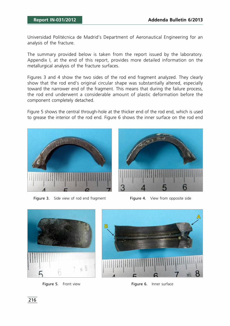
Figures 3 and 4 show the two sides of the rod end fragment analyzed. They clearlyshow that the rod end’s original circular shape was substantially altered, especiallytoward the narrower end of the fragment. This means that during the failure process,the rod end underwent a considerable amount of plastic deformation before thecomponent completely detached.
Figure 5 shows the central through-hole at the thicker end of the rod end, which is usedto grease the interior of the rod end. Figure 6 shows the inner surface on the rod end
Figure 3. Side view of rod end fragment Figure 4. View from opposite side
Figure 5. Front view Figure 6. Inner surface
216
Addenda Bulletin 6/2013
Addenda Bulletin 6/2013 Report IN-031/2012
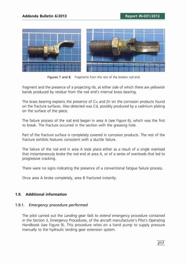
Figures 7 and 8. Fragments from the rest of the broken rod end
fragment and the presence of a projecting rib, at either side of which there are yellowishbands produced by residue from the rod end’s internal brass bearing.
The brass bearing explains the presence of Cu and Zn on the corrosion products foundon the fracture surfaces. Also detected was Cd, possibly produced by a cadmium platingon the surface of the piece.
The failure process of the rod end began in area A (see Figure 6), which was the firstto break. The fracture occurred in the section with the greasing hole.
Part of the fracture surface is completely covered in corrosion products. The rest of thefracture exhibits features consistent with a ductile failure.
The failure of the rod end in area A took place either as a result of a single overloadthat instantaneously broke the rod end at area A, or of a series of overloads that led toprogressive cracking.
There were no signs indicating the presence of a conventional fatigue failure process.
Once area A broke completely, area B fractured instantly.
1.9. Additional information
1.9.1. Emergency procedure performed
The pilot carried out the Landing gear fails to extend emergency procedure containedin the Section 3, Emergency Procedures, of the aircraft manufacturer’s Pilot’s OperatingHandbook (see Figure 9). This procedure relies on a hand pump to supply pressuremanually to the hydraulic landing gear extension system.
217

Report IN-031/2012
Figure 9. Emergency procedure used
1.9.2. Operation of the main landing gear extension and retraction system6
Each of the two main landing gear ends in a pinion gear (located at the end oppositethe wheel).
When the stem on the hydraulic piston extends or retracts, the actuator rod endtransmits this motion to a hinged arm located at one end of a fixed shaft, which makesit rotate. Since the arm is attached to the two sector gears where the ends of the maingear legs mesh, when the arm moves, this motion is transmitted to the main gear legssimultaneously.
If the hydraulic piston loses pressure, the aircraft is equipped with an emergency hand pump that can be used to build up pressure in the system. If the piston stembreaks, however, no motion can be transmitted to the sector gears, meaning the mainlanding gear cannot be extended or retracted. In the absence of hydraulic pressure inthe piston, the gear can be allowed to fall by gravity, but this is not sufficient to lockit in place.
Figures 10 and 11 show an exploded view of the main landing gear extension andretraction system components contained in Figure 2.
As a result of the simultaneous movement of both main landing gear legs in this typeof aircraft (interlocked with the sector gears), the legs cannot be locked independentlythrough the application of inertial forces in high-g turns.
218
Addenda Bulletin 6/2013
6 The nose gear leg extends and retracts by means of a hydraulic actuator independent from that for the main gear,though both are commanded from the cockpit using a single control.

Addenda Bulletin 6/2013 Report IN-031/2012
Figures 10 and 11. Close-ups of the main landing gear extension/retraction system
1.9.3. Information on the broken part
The rod end hinges with the arm to transmit to it the motion of the main gear actuatorrod end.
Internally the rod end has a bearing to reduce friction. The rod end also has a centralthrough-hole that can be used to inject lubricant, which is distributed internally by a ribthat protrudes from the inner central part of the rod end.
On 6 August 1979, Cessna, the aircraft manufacturer, issued Service Information Letter(SIL) SE79-37 specifically concerning this component. The SIL was applicable to theincident aircraft since its serial number, 177RG1054, was listed among the SIL’saddressees7. This SIL was subsequently revised on 15 December 1980 (attached asAppendix II).
This SIL recommended replacing the existing rod end (which was the one installed onthe incident aircraft with P/N S2049-6FG) with another without a greasing hole andwithout an internal brass bearing prior to (or at the latest during) the aircraft’s nextannual inspection. The new rod end (with P/N S2426-6) had a higher strength and aninternal Teflon bearing to minimize friction with the shaft on the sector arm.
Compliance with the contents of SIL SE79-37 was recommended, not obligatory.
FAA Advisory Circular 43-16A8 reveals that Cessna issued a second revision to SIL SE79-37 in which the new recommended rod end now had P/N S3469-1, very similar to P/NS2426-6, but that also had to be inspected prior to leaving the manufacturing center.
219
7 Serial numbers of affected aircraft: 177RG0001 to 177RG1366 and F177RG0001 to F177RG0177.8 Alert number 271, february 2001.
Addenda Bulletin 6/2013
220
The aforementioned Advisory Circular also indicated that if the rod end installed hadP/N S2426-6, it was not necessary to replace it but it did have to be carefully checkedduring annual inspections.
1.9.4. History of similar failures
An incident of almost identical characteristics took place in the United Kingdom9 on 5September 2003 involving a Cessna F177RG Cardinal, registration G-BFIV and S/NF177RG0161.
In this incident, the pilot was unable to get the landing gear to lower and lock downand had to make an emergency landing. Neither of aircraft’s occupants was injured.
The cause of the improper operation of the main landing gear of aircraft G-BFIV wasthe fracture of the same rod end (the one originally installed on the aircraft, with thethrough-hole and the internal brass bearing) as the one involved in this report. Thenature of the fracture of the rod end on G-BFIV was practically identical to thatdetermined for the broken rod end on D-EEDM by the Universidad Politécnica deMadrid’s School of Aeronautical Engineering.
In addition, according to data published in 2001 by the FAA’s Aircraft CertificationOffice in Wichita, Kansas, a total of 13 Service Difficulty Reports (SDR) were reportedfrom 1979 to 1998 involving problems with rod end P/N S2049-6FG, and fiveaccident/incidents were analyzed from 1979 to 1989 in which the rod end P/N S2426-6 had broken.
From 1977 to 2001, 30 SDRs reported the fracture of rod end P/N S2049-6FG. From1978 to 1987, the FAA recorded 10 accidents/incidents involving the fracture of rod endP/N S2049-6FG. No problems were reported, however, with the rod end P/N 3469-1.
The FAA issued one safety recommendation (FAA Safety Recommendation 00.284),which recommended replacing rod end P/N S2049-6FG with P/N S3469-1 as soon aspossible.
2. ANALYSIS
2.1. General considerations
The pilot of the aircraft had the necessary licenses, valid and in force, to make the flightand the aircraft had been maintained in accordance with the manufacturer’smaintenance manual and was properly licensed and certified.
Report IN-031/2012
9 The United Kingdom’s accident investigation commission issued the relevant report (AAIB Bulletin N° 4/2004, Ref:EW/G2003/09/06).

221
The aircraft’s weight and balance during the incident flight were likewise within limitsat all times.
The weather conditions were suitable for the approach and landing.
2.2. Failure of main landing gear to extend and lock down
The failure of the rod end made it impossible for the main landing gear to extend andlock down. This was not the case with the nose gear, which has a separate actuator.
With the main gear actuator rod end broken, it was impossible to transmit themovement of the hydraulic piston to the rest of the mechanical system used to extendand retract the main landing system.
Thus, even though the hydraulic piston worked properly and extended and retracted theinternal rod, the arm was not receiving any force to be transmitted to the pinionsresponsible for moving the main landing gear since the mechanical connection wascompletely decoupled.
2.3. Alternate maneuver
Even though the noise heard in the cockpit was the usual one for when the hydraulicsystem that extends or retracts the landing gear actuates, the pilot tried to pumppressure into the system manually by following the proper emergency procedure. Butthe result continued to be the lack of a green light indicating the gear was down andlocked.
In light of the situation, and since inertial forces in turns are insufficient to fully extend(and lock) the main landing gear on this type of airplane, the pilot made the rightdecision and burned off fuel before making an emergency landing at the lowest speedpossible in anticipation of having (at least) the main landing gear collapse when ittouched down on the runway.
2.4. Broken part
The part fractured instantaneously and with no prior warning that it was workingimproperly. In fact, the incident landing was the fourth that day, with the aircraft’slanding gear having worked perfectly on the three previous landings made hoursearlier.
Report IN-031/2012Addenda Bulletin 6/2013
Report IN-031/2012
The original design of the rod end with the greasing through-hole had previously beenresponsible for nearly identical failures. In fact, SE79-37, dated August 1979 andmodified in December 1980, recommended that this part be replaced with another withthe same operational characteristics but without the through-hole and with a higherstrength.
The rod end installed on the aircraft bore the original design and had not been replacedas recommended in either SE79-37 or in FAA Safety Recommendation 00.284.
3. CONCLUSIONS
3.1. Findings
• The four flights made by the aircraft on the day of the incident were uneventful untilthe pilot started the landing approach for the last flight into the Almeria Airport.
• The aircraft’s pilot had a valid and in force flight license and medical certificate.• The aircraft was properly licensed and certified for the operation.• An analysis of the aircraft’s weight and balance revealed that the incident flight
operated within these limits at all times.• No abnormalities were detected in the scheduled maintenance documentation, which
showed that the Maintenance Program had been complied with.• The approach and landing were made under suitable weather conditions.• The field investigation of the aircraft revealed that the landing gear extension and
retraction system was in good condition except for the presence of a failed rod endin the mechanical assembly that extends and retracts the main landing gear.
• This failure of the rod end happened instantaneously in flight without prior warningof any malfunction.
• The failure of the rod end interrupts the mechanical continuity of the main landinggear extension and retraction system, rendering it inoperative.
• The fractured rod end had been the subject of a service letter (SIL SE79-37) issued bythe aircraft manufacturer in 1979 that recommended it be replaced with a strongerpart without the greasing hole.
• The rod end installed in the aircraft was of the original design. It had not beenreplaced as recommended in SIL SE79-37.
• There are records indicating that the failure of the rod end in question has occurredon other occasions on aircraft of the same type where the original rod end had notbeen replaced, as recommended in SIL SE79-37 and in FAA Safety Recommendation00.284.
• There is no emergency procedure for extending and locking down both main landinggear legs in flight on this type of aircraft following a failure of the rod end.
• The pilot made the emergency landing after taking the proper precautions.• The aircraft’s passenger compartment retained its integrity and its occupants were
able to exit the aircraft under their own power and without sustaining any injuries.
222
Addenda Bulletin 6/2013
Addenda Bulletin 6/2013 Report IN-031/2012
3.2. Causes
The incident was caused by the instantaneous fracture in flight of the main gearactuator rod end, which interrupted the mechanical continuity in the main gearextension and retraction mechanism, thereby rendering it inoperative by failing totransmit the motion of the hydraulic piston to the rest of the system.
Contributing to this incident is the fact that the rod end that was installed on theaircraft was of the original design and had not been replaced with a stronger partwithout a greasing hole, as per the recommendation in Cessna’s SIL SE-79-37.
4. RECOMMENDATIONS
REC 07/14. It is recommended that the FAA require the replacement of the rod endwith the original design by the one recommended in Cessna ServiceInformation Letter SE79-37.
223


Addenda Bulletin 6/2013 Report IN-031/2012
225
APPENDICES


APPENDIX IAnalysis of the fracture surfaces
227
Report IN-031/2012Addenda Bulletin 6/2013

Addenda Bulletin 6/2013
228
So as to determine the microfractographic features associated with the fracture process,the two fracture surfaces located at either end of the fragment, labeled as A and B inFigure 6, were analyzed using a scanning electron microscope and an X-raymicroanalyzer.
Fracture A
Figure 12 shows a full image of this fracture, which extends to both sides of the centralthrough-hole. At low magnifications there are two regions with a different appearance.These regions are separated as shown by the dashed line.
There is an area near the outer surface of the rod end at either end of the hole withan apparent uniform and non-directional roughness. The rest of the fracture surface, incontrast, exhibits a high directionality along the plane of the rod end and parallel to thethrough-hole.
Various areas from both fracture regions and on either side of the through hole,numbered in Figure 12, were selected for determination of their microfractographicfeatures.
At high magnifications, area 1, near the hole and very close to the rod end’s outersurface, shows a microrelief that cannot be associated with any specific fracturemechanism, but rather with the presence of corrosion products on the surface thatprevent a proper observation of the original fracture relief in this area.
Figure 12. General view of fracture A
Report IN-031/2012
Addenda Bulletin 6/2013 Report IN-031/2012
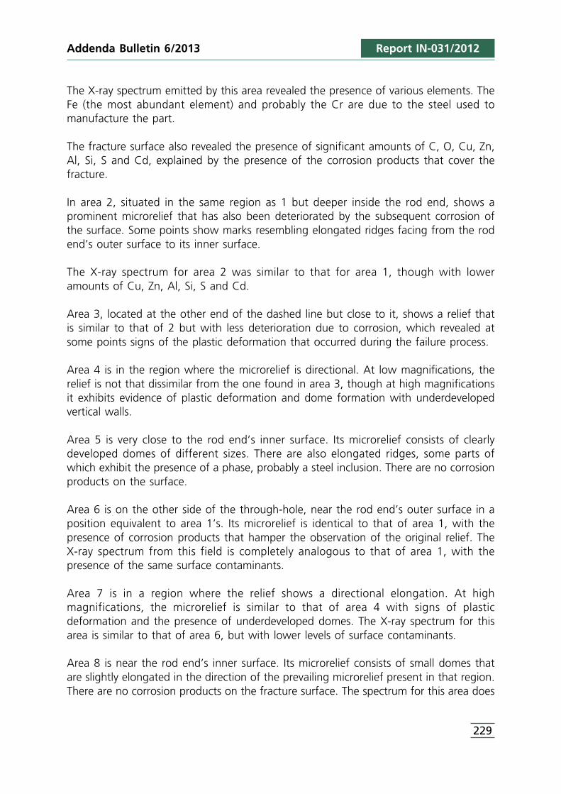
The X-ray spectrum emitted by this area revealed the presence of various elements. TheFe (the most abundant element) and probably the Cr are due to the steel used tomanufacture the part.
The fracture surface also revealed the presence of significant amounts of C, O, Cu, Zn,Al, Si, S and Cd, explained by the presence of the corrosion products that cover thefracture.
In area 2, situated in the same region as 1 but deeper inside the rod end, shows aprominent microrelief that has also been deteriorated by the subsequent corrosion ofthe surface. Some points show marks resembling elongated ridges facing from the rodend’s outer surface to its inner surface.
The X-ray spectrum for area 2 was similar to that for area 1, though with loweramounts of Cu, Zn, Al, Si, S and Cd.
Area 3, located at the other end of the dashed line but close to it, shows a relief thatis similar to that of 2 but with less deterioration due to corrosion, which revealed atsome points signs of the plastic deformation that occurred during the failure process.
Area 4 is in the region where the microrelief is directional. At low magnifications, therelief is not that dissimilar from the one found in area 3, though at high magnificationsit exhibits evidence of plastic deformation and dome formation with underdevelopedvertical walls.
Area 5 is very close to the rod end’s inner surface. Its microrelief consists of clearlydeveloped domes of different sizes. There are also elongated ridges, some parts ofwhich exhibit the presence of a phase, probably a steel inclusion. There are no corrosionproducts on the surface.
Area 6 is on the other side of the through-hole, near the rod end’s outer surface in aposition equivalent to area 1’s. Its microrelief is identical to that of area 1, with thepresence of corrosion products that hamper the observation of the original relief. TheX-ray spectrum from this field is completely analogous to that of area 1, with thepresence of the same surface contaminants.
Area 7 is in a region where the relief shows a directional elongation. At highmagnifications, the microrelief is similar to that of area 4 with signs of plasticdeformation and the presence of underdeveloped domes. The X-ray spectrum for thisarea is similar to that of area 6, but with lower levels of surface contaminants.
Area 8 is near the rod end’s inner surface. Its microrelief consists of small domes thatare slightly elongated in the direction of the prevailing microrelief present in that region.There are no corrosion products on the fracture surface. The spectrum for this area does
229
Report IN-031/2012
not indicate the presence of unexpected elements, which is consistent with the absenceof corrosion products.
Fracture B
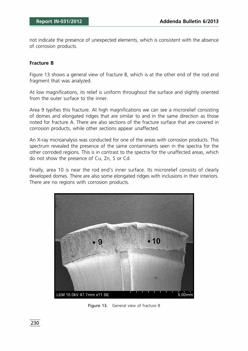
Figure 13 shows a general view of fracture B, which is at the other end of the rod endfragment that was analyzed.
At low magnifications, its relief is uniform throughout the surface and slightly orientedfrom the outer surface to the inner.
Area 9 typifies this fracture. At high magnifications we can see a microrelief consistingof domes and elongated ridges that are similar to and in the same direction as thosenoted for fracture A. There are also sections of the fracture surface that are covered incorrosion products, while other sections appear unaffected.
An X-ray microanalysis was conducted for one of the areas with corrosion products. Thisspectrum revealed the presence of the same contaminants seen in the spectra for theother corroded regions. This is in contrast to the spectra for the unaffected areas, whichdo not show the presence of Cu, Zn, S or Cd.
Finally, area 10 is near the rod end’s inner surface. Its microrelief consists of clearlydeveloped domes. There are also some elongated ridges with inclusions in their interiors.There are no regions with corrosion products.
Figure 13. General view of fracture B
230
Addenda Bulletin 6/2013

Addenda Bulletin 6/2013 Report IN-031/2012
The X-ray spectrum of this area did, however, reveal the presence of small quantities ofsurface contaminants (Cu, Na, Al, Si, S, Cl and Cd).
Fracture growth
The rod end fragment analyzed exhibits significant plastic deformation. This resulted inthe inner surface losing the circular shape it must have had originally.
This deformation is much more pronounced in the thinnest area of the fragment, nextto fracture B (see Figure 6).
This indicates that fracture A was the first area to break. The fracture in this area washelped by the presence of the through-hole present there.
Once fracture A occurred, the force exerted on the rod end at that moment resulted ina significant plastic deformation that caused the rod end to open and then to fracturealong area B.
Fracture A most likely started on the outer surface of the rod end at either side of thethrough-hole. Since the microrelief of the fracture could not be observed in these areasgiven that it was covered in corrosion products, it was not possible to accuratelydetermine the fracture mechanism at work in this area.
As the fracture progressed toward the inner surface of the rod end, the appearance ofthe relief at low magnifications undergoes a change as it takes on a certaindirectionality.
In the central part of fracture A, on either side of the through-hole, we start to see signsof plastic deformation and the presence of underdeveloped domes, both featurestypically associated with instantaneous fracture processes of a ductile nature. Thesurface contamination in these central areas is much lower than that on the outersurface of the rod end.
Near the inner surface of the rod end the microrelief reveals the abundant presence ofdomes with no surface deterioration or significant amounts of contaminants.
The presence of a fracture area near the outer surface of the rod end and on both sidesof the through-hole, along with a microrelief different from that found in the rest ofthe fracture, as well as the fact that this entire area is completely covered in corrosionproducts, could indicate that this area fractured before the rest of the rod end.
In the central part of fracture A, however, in the region with the more directional relief,the microrelief does not appear very different from that of the region discussed above.It also exhibits surface corrosion, though to a lesser extent.
231

Report IN-031/2012
Near the rod end’s inner surface the fracture surface is populated by domes, indicatinga ductile failure that occurred instantaneously.
The ridge-shaped reliefs that appear in various areas of fracture A could be associatedwith the presence of elongated inclusions in the steel used to manufacture the part.
This might indicate the development of a classical fatigue crack on the outer surface ofthe rod end and on either side of the through-hole. The subsequent corrosion of thefracture surface in this area prevents seeing the microfractographic features, and thuscategorically confirming or denying the initial presence of a classic fatigue process.
There is, however, one radical difference in the relief of this potential fatigue area andthe central fracture area and its directional relief. This potential fatigue area also featuresthe presence of ridge-shaped reliefs, which typically suggests a failure process enhancedby the presence of inclusions, something that is more likely is the fracture process resultsfrom an overload than if the growth is driven by fatigue.
As a result, and without being able to rule out the presence of a conventional fatiguefailure, it seems more likely that the fracture of the outer surface of the rod end wascaused by an overload.
The complete fracture of area A of the rod end could have occurred due to a singlestatic overload, which originated the entire fracture surface all at once, or due to theapplication of successive overloads, which would have made the crack grow in stagesuntil the eventual fracture, which could be regarded as a fatigue process with a verylow number of cycles.
The presence of areas fully covered in corrosion products (next to the rod end’s outersurface) and of areas practically free from corrosion (next to the inner surface) couldconfirm the hypothesis that the fracture progressed in several stages, with the first areasto crack corroding more.
The fracture of area B clearly corresponds to a single instantaneous fracture process ofa ductile nature that occurred after the fracture of area A. This fracture surface was thelast to form, and it also exhibits regions that underwent a corrosive attack very similarto that seen in fracture A.
As a result, the possibility remains that all of the corrosion on the surface area wasproduced after a full and instantaneous fracture of area A, followed by area B, withsome areas being more corroded than others for unknown reasons.
232
Addenda Bulletin 6/2013

Addenda Bulletin 6/2013 Report IN-031/2012
233
APPENDIX II

Report IN-031/2012
234
Addenda Bulletin 6/2013
Addenda Bulletin 6/2013 Report IN-031/2012
235
