date of issue: 10/30/93 revision: m, 07/17clemcoindustries.com/images/pdfs/07763m.pdf · electronic...
TRANSCRIPT

Do not use this equipment until you have READ this MANUAL and YOU UNDERSTAND its contents. *
These WARNINGS are included for the health and safety of the operator and those in the immediate vicinity.
*If you are using a Clemco Distributor Maintenance and Parts Guide, refer to the orange warnings insert preceding the Index before continuing with the enclosed instructions.
Electronic files include a Preface containing the same important information as the orange cover.
WARNING
FLAT-TRAK® RECOVERY FLOOR O. M. 07763
DATE OF ISSUE: 10/30/93
REVISION: M, 07/17
© 2017 CLEMCO INDUSTRIES CORP. One Cable Car Dr.
Washington, MO 63090 Phone (636) 239-4300
Fax (800) 726-7559 Email: [email protected]
www.clemcoindustries.com

PREFACE
[ I ]
• Employers are responsible for identifying all job site hazards, educating and training all persons who will operate and
maintain these products, and ensuring that all blast operators and their assistants understand the warnings and information contained in these instructions relating to safe and proper operation and maintenance of this equipment.
• Serious injury or death can result from failure to comply with all Occupational Safety and Health Administration (OSHA)regulations and all manufacturer’s instructions.
• This equipment is not intended for use in any area considered hazardous per National Electric Code NFPA 70 2011, Article 500.
• Read this document and follow all instructions before using this equipment.
OSHA regulations relating to abrasive blasting are contained in the Code of Federal Regulations, Title 29 (29 CFR 1910 General Industry; 1915 Maritime; 1926 Construction). The most pertinent include: 1910.94 Ventilation, 1910.95 Occupational Noise Exposure, 1910.132 Personal Protective Equipment, 1910.133 Eye and Face Protection, 1910.134 Respiratory Protection, 1910.135 Head Protection, 1910.244 (b) Remote Controls. Consult www.osha.gov for complete information.
NOTICE TO PURCHASERS AND USERS OF OUR PRODUCTS AND THIS INFORMATIONAL MATERIAL
Clemco proudly provides products for the abrasive blast industry and is confident that industry professionals will use their knowledge and expertise for the safe and efficient use of these products.
The products described in this material, and the information relating to these products, are intended for knowledgeable, experienced users.
No representation is intended or made as to: the suitability of the products described here for any purpose or application, or to the efficiency, production rate, or useful life of these products. All estimates regarding production rates or finishes are the responsibility of the user and must be derived solely from the user’s experience and expertise, not from information contained in this material.
It is possible that the products described in this material may be combined with other products by the user for purposes determined solely by the user. No representations are intended or made as to the suitability of or engineering balance of or compliance with regulations or standard practice of any such combination of products or components the user may employ.
Abrasive blast equipment is only one component of an abrasive blasting job. Other products, such as air compressors, air filters and receivers, abrasives, scaffolding, hydraulic work platforms or booms, equipment for lighting, painting, ventilating, dehumidifying, parts handling, or specialized respirators or other equipment, even if offered by Clemco, may have been manufactured or supplied by others. The information Clemco provides is intended to support the products Clemco manufactures. Users must contact each manufacturer and supplier of products used in the blast job for warnings, information, training, and instruction relating to the proper and safe use of their equipment.
GENERAL INSTRUCTIONS
This material describes some, but not all, of the major requirements for safe and productive use of blast machines, remote controls, respirator systems, and related accessories. All equipment and accessories must be installed, tested, operated and maintained only by trained, knowledgeable, experienced users.
The blast operator and all workers in the vicinity must be properly protected from all job site hazards including those hazards generated by blasting.
Work environments involving abrasive blasting present numerous hazards. Hazards relate to the blast process from many sources that include, but are not limited to, dust generated by blasting or from material present on the surface being blasted. The hazards from toxic materials may include, but are not limited to, silica, cyanide, arsenic, or other toxins in the abrasives or in the coatings, such as lead or heavy metals. Other hazards from toxins include, but are not limited to, fumes from coating application, carbon monoxide from engine exhaust, contaminated water, chemicals or asbestos. In addition, physical hazards that may be present include, but are not limited to, uneven work surfaces, poor visibility, excessive noise, and electricity. Employers must identify all job site hazards and protect workers in accordance with OSHA regulations.
Never modify Clemco equipment or components or substitute parts from other manufacturers for any Clemco components or parts. Any unauthorized modification or substitution of supplied-air respirator parts violates OSHA regulations and voids the NIOSH approval.
IMPORTANT
Contact Clemco for free booklets: Blast Off 2 – Guide to Safe, Productive, and Efficient Abrasive
Blasting, and Abrasive Blasting Safety Practices – Guide to Safe
Abrasive Blasting.
Clemco Industries Corp. One Cable Car Drive Washington MO 63090
Tel: 636 239-4300 — Fax: 800 726-7559
Email: [email protected]
Website: www.clemcoindustries.com
PREFACE
[ II ]
OPERATIONAL INSTRUCTIONS
OPERATOR SAFETY EQUIPMENT
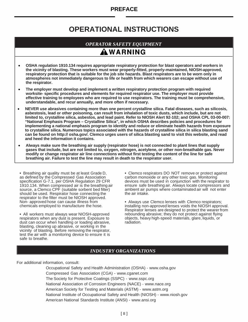
OSHA regulation 1910.134 requires appropriate respiratory protection for blast operators and workers in the vicinity of blasting. These workers must wear properly-fitted, properly-maintained, NIOSH-approved, respiratory protection that is suitable for the job site hazards. Blast respirators are to be worn only in atmospheres not immediately dangerous to life or health from which wearers can escape without use of the respirator.
The employer must develop and implement a written respiratory protection program with required worksite- specific procedures and elements for required respirator use. The employer must provide effective training to employees who are required to use respirators. The training must be comprehensive, understandable, and recur annually, and more often if necessary.
NEVER use abrasives containing more than one percent crystalline silica. Fatal diseases, such as silicosis, asbestosis, lead or other poisoning, can result from inhalation of toxic dusts, which include, but are not limited to, crystalline silica, asbestos, and lead paint. Refer to NIOSH Alert 92-102; and OSHA CPL 03-00-007: “National Emphasis Program – Crystalline Silica”, in which OSHA describes policies and procedures for implementing a national emphasis program to identify and reduce or eliminate health hazards from exposure to crystalline silica. Numerous topics associated with the hazards of crystalline silica in silica blasting sand can be found on http:// osha.gov/. Clemco urges users of silica blasting sand to visit this website, and read and heed the information it contains.
Always make sure the breathing air supply (respirator hose) is not connected to plant lines that supply gases that include, but are not limited to, oxygen, nitrogen, acetylene, or other non-breathable gas. Never modify or change respirator air line connections without first testing the content of the line for safe breathing air. Failure to test the line may result in death to the respirator user.
• Breathing air quality must be at least Grade D, as defined by the Compressed Gas Association specification G-7.1, per OSHA Regulation 29 CFR 1910.134. When compressed air is the breathing air source, a Clemco CPF (suitable sorbent bed filter) should be used. Respirator hose connecting the respirator to the filter must be NIOSH approved. Non- approved hose can cause illness from chemicals employed to manufacture the hose.
• All workers must always wear NIOSH-approved respirators when any dust is present. Exposure to dust can occur when handling or loading abrasive, blasting, cleaning up abrasive, or working in the vicinity of blasting. Before removing the respirator, test the air with a monitoring device to ensure it is safe to breathe.
• Clemco respirators DO NOT remove or protect against carbon monoxide or any other toxic gas. Monitoring devices must be used in conjunction with the respirator to ensure safe breathing air. Always locate compressors and ambient air pumps where contaminated air will not enter the air intake.
• Always use Clemco lenses with Clemco respirators; installing non-approved lenses voids the NIOSH approval. Respirator lenses are designed to protect the wearer from rebounding abrasive; they do not protect against flying objects, heavy high-speed materials, glare, liquids, or radiation.
INDUSTRY ORGANIZATIONS
For additional information, consult: Occupational Safety and Health Administration (OSHA) - www.osha.gov Compressed Gas Association (CGA) - www.cganet.com The Society for Protective Coatings (SSPC) - www.sspc.org National Association of Corrosion Engineers (NACE) - www.nace.org American Society for Testing and Materials (ASTM) - www.astm.org National Institute of Occupational Safety and Health (NIOSH) - www.niosh.gov American National Standards Institute (ANSI) - www.ansi.org
PREFACE
[ III ]
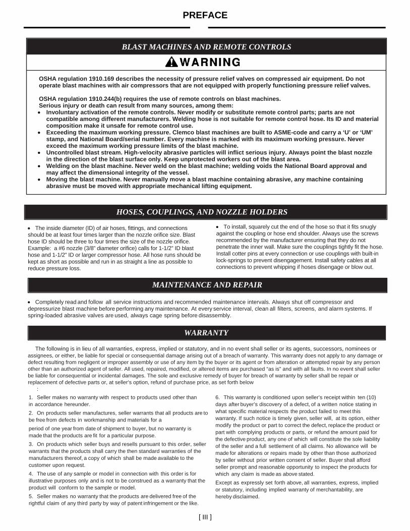
BLAST MACHINES AND REMOTE CONTROLS
OSHA regulation 1910.169 describes the necessity of pressure relief valves on compressed air equipment. Do not operate blast machines with air compressors that are not equipped with properly functioning pressure relief valves. OSHA regulation 1910.244(b) requires the use of remote controls on blast machines. Serious injury or death can result from many sources, among them: Involuntary activation of the remote controls. Never modify or substitute remote control parts; parts are not
compatible among different manufacturers. Welding hose is not suitable for remote control hose. Its ID and material composition make it unsafe for remote control use.
Exceeding the maximum working pressure. Clemco blast machines are built to ASME-code and carry a ‘U’ or ‘UM’ stamp, and National Board/serial number. Every machine is marked with its maximum working pressure. Never exceed the maximum working pressure limits of the blast machine.
Uncontrolled blast stream. High-velocity abrasive particles will inflict serious injury. Always point the blast nozzle in the direction of the blast surface only. Keep unprotected workers out of the blast area.
Welding on the blast machine. Never weld on the blast machine; welding voids the National Board approval and may affect the dimensional integrity of the vessel.
Moving the blast machine. Never manually move a blast machine containing abrasive, any machine containing abrasive must be moved with appropriate mechanical lifting equipment.
HOSES, COUPLINGS, AND NOZZLE HOLDERS The inside diameter (ID) of air hoses, fittings, and connections should be at least four times larger than the nozzle orifice size. Blast hose ID should be three to four times the size of the nozzle orifice. Example: a #6 nozzle (3/8” diameter orifice) calls for 1-1/2” ID blast hose and 1-1/2” ID or larger compressor hose. All hose runs should be kept as short as possible and run in as straight a line as possible to reduce pressure loss.
To install, squarely cut the end of the hose so that it fits snugly against the coupling or hose end shoulder. Always use the screws recommended by the manufacturer ensuring that they do not penetrate the inner wall. Make sure the couplings tightly fit the hose. Install cotter pins at every connection or use couplings with built-in lock-springs to prevent disengagement. Install safety cables at all connections to prevent whipping if hoses disengage or blow out.
MAINTENANCE AND REPAIR
Completely read and follow all service instructions and recommended maintenance intervals. Always shut off compressor and depressurize blast machine before performing any maintenance. At every service interval, clean all filters, screens, and alarm systems. If spring-loaded abrasive valves are used, always cage spring before disassembly.
WARRANTY
The following is in lieu of all warranties, express, implied or statutory, and in no event shall seller or its agents, successors, nominees or assignees, or either, be liable for special or consequential damage arising out of a breach of warranty. This warranty does not apply to any damage or defect resulting from negligent or improper assembly or use of any item by the buyer or its agent or from alteration or attempted repair by any person other than an authorized agent of seller. All used, repaired, modified, or altered items are purchased “as is” and with all faults. In no event shall seller be liable for consequential or incidental damages. The sole and exclusive remedy of buyer for breach of warranty by seller shall be repair or replacement of defective parts or, at seller’s option, refund of purchase price, as set forth below
:
1. Seller makes no warranty with respect to products used other than in accordance hereunder.
2. On products seller manufactures, seller warrants that all products are to be free from defects in workmanship and materials for a
period of one year from date of shipment to buyer, but no warranty is made that the products are fit for a particular purpose.
3. On products which seller buys and resells pursuant to this order, seller warrants that the products shall carry the then standard warranties of the manufacturers thereof, a copy of which shall be made available to the customer upon request.
4. The use of any sample or model in connection with this order is for illustrative purposes only and is not to be construed as a warranty that the product will conform to the sample or model.
5. Seller makes no warranty that the products are delivered free of the rightful claim of any third party by way of patent infringement or the like.
6. This warranty is conditioned upon seller’s receipt within ten (10) days after buyer’s discovery of a defect, of a written notice stating in what specific material respects the product failed to meet this warranty. If such notice is timely given, seller will, at its option, either modify the product or part to correct the defect, replace the product or part with complying products or parts, or refund the amount paid for the defective product, any one of which will constitute the sole liability of the seller and a full settlement of all claims. No allowance will be made for alterations or repairs made by other than those authorized by seller without prior written consent of seller. Buyer shall afford seller prompt and reasonable opportunity to inspect the products for which any claim is made as above stated.
Except as expressly set forth above, all warranties, express, implied or statutory, including implied warranty of merchantability, are hereby disclaimed.
PREFACE
[ IV ]
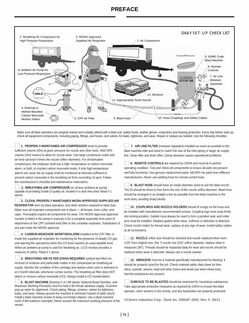
DAILY SET ‐UP CHECK LIST
Make sure all blast operators are properly trained and suitably attired with a blast suit, safety boots, leather gloves, respiratory and hearing protection. Every day before start up, check all equipment components, including piping, fittings, and hoses, and valves, for leaks, tightness, and wear. Repair or replace as needed. Use the following checklist.
1. PROPERLY-MAINTAINED AIR COMPRESSOR sized to provide
sufficient volume (cfm) at given pressure for nozzle and other tools. ADD 50% volume (cfm) reserve to allow for nozzle wear. Use large compressor outlet and air hose (at least 4 times the nozzle orifice diameter). For oil-lubricated compressors, the employer shall use a high- temperature or carbon monoxide alarm, or both, to monitor carbon monoxide levels. If only high-temperature alarms are used, the air supply shall be monitored at intervals sufficient to prevent carbon monoxide in the breathing air from exceeding 10 ppm. Follow the manufacturer’s checklist and maintenance instructions.
2. BREATHING-AIR COMPRESSOR (or oil-less ambient air pump) capable of providing Grade D quality air, located in a dust free area. Read # 1 above.
3. CLEAN, PROPERLY-MAINTAINED NIOSH-APPROVED SUPPLIED-AIR RESPIRATOR worn by blast operators, and other workers exposed to blast dust. Make sure all respirator components are in place — all lenses, inner collar, and cape. Thoroughly inspect all components for wear. The NIOSH approval (approval number is listed in the owner’s manual) is for a complete assembly from point of attachment on the CPF (sorbent bed) filter to the complete respirator. Substitution of any part voids the NIOSH approval.
4. CARBON MONOXIDE MONITOR/ALARM installed at the CPF filter or inside the supplied-air respirator for monitoring for the presence of deadly CO gas and warning the operator(s) when the CO level reaches an unacceptable level. When an ambient air pump is used for breathing air, a CO monitor provides a measure of safety. Read # 1 above.
5. BREATHING-AIR FILTER (OSHA-REQUIRED sorbent bed filter) for removal of moisture and particulate matter in the compressed air breathing-air supply. Monitor the condition of the cartridge and replace when odor is detected or at 3 month intervals, whichever comes sooner. The breathing air filter does NOT detect or remove carbon monoxide (CO). Always install a CO monitor/alarm.
6. BLAST MACHINE (bearing U or UM stamp, National Board Number, and Maximum Working Pressure) sized to hold a 30-minute abrasive supply. Examine pop-up valve for alignment. Check piping, fittings, screens, valves for tightness, leaks, and wear. Always ground the machine to eliminate hazard of static shock. Install a blast machine screen to keep out foreign objects. Use a blast machine cover if left outdoors overnight. Never exceed the maximum working pressure of the vessel.
7. AIR LINE FILTER (moisture separator) installed as close as possible to the
blast machine inlet and sized to match the size of the inlet piping or larger air supply
line. Clean filter and drain often. Damp abrasive causes operational problems.
8. REMOTE CONTROLS are required by OSHA and must be in perfect
operating condition. Test and check all components to ensure all parts are present
and fully functional. Use genuine replacement parts. NEVER mix parts from different
manufacturers. Never use welding hose for remote control hose.
9. BLAST HOSE should have an inside diameter sized to suit the blast nozzle.
The ID should be three to four times the size of the nozzle orifice diameter. Blast hose
should be arranged in as straight a line as possible from the blast machine to the
work area, avoiding sharp bends.
10. COUPLINGS AND NOZZLE HOLDERS should fit snugly on the hose and
be installed with manufacturer recommended screws. Coupling lugs must snap firmly
into locking position. Gasket must always be used to form a positive seal, and cotter
pins must be installed. Replace gasket when wear, softness or distortion is detected.
Check nozzle holder for thread wear; replace at any sign of wear. Install safety cables
at all connections.
11. NOZZLE orifice size should be checked and nozzle replaced when worn
1/16” from original size. (No. 5 nozzle has 5/16” orifice diameter; replace when it
measures 3/8”). Threads should be inspected daily for wear and nozzle should be
replaced when wear is detected. Always use a nozzle washer.
12. ABRASIVE must be a material specifically manufactured for blasting. It
should be properly sized for the job. Check material safety data sheet for free-
silica, cyanide, arsenic, lead and other toxins and avoid use when these toxic,
harmful substances are present.
SURFACE TO BE BLASTED should be examined for hazardous substances.
Take appropriate protective measures as required by OSHA to ensure the blast
operator, other workers in the vicinity, and any bystanders are properly protected.
©Clemco Industries Corp., Stock No. 20954P, 0692 Rev. F, 06/12
1. Air Compressor
7. Air Line Moisture Separator
5. CPF Air Filter
6. ASME Code Blast Machine
8. Remote Controls
9. Blast Hose 10. Hose Couplings and Safety Cables
11. Appropriately Sized Nozzle
12. Abrasive
4. External or Helmet Mounted Carbon Monoxide Monitor /Alarm
2. Breathing Air Compressor for High Pressure Respirators
3. NIOSH Approved Supplied-Air Respirator
or Ambient Air Pump for Low Pressure Respirators

FLAT-TRAK® RECOVERY FLOOR Page 1
© 2017 CLEMCO INDUSTRIES CORP. www.clemcoindustries.com Manual No. 07763, Rev M
1.0 INTRODUCTION 1.1 Scope 1.1.1 This manual covers the installation, operation, maintenance, and replacement parts for Clemco’s Flat-Trak® Recovery Floor. Assembly drawings supplied with this manual apply to the specific floor and accessories provided. Use the manual and the drawings for sizing, arrangement, and other specific information about the recovery floor supplied. 1.1.2 This manual contains important safety information. All operators and personnel involved with the abrasive blast process must read and understand the contents of these instructions, including the orange cover. It is equally important that the operator is trained and qualified to safely operate the blast machine and remote controls and all other equipment used with the blast machine. To ensure safe blasting, before operating, read the manuals for all devices used in conjunction with this recovery floor. 1.1.3 All personnel involved with the abrasive blasting process must be made aware of the hazards associated with abrasive blasting. The Clemco booklet Abrasive Blasting Safety Practices is included with every blast machine; it contains important safety information about abrasive blasting that may not be included in equipment operation manuals. The booklet is available in both English and Spanish; to request copies, email [email protected]. 1.2 Safety Alerts
1.2.1 Clemco uses safety alert signal words, based on ANSI Z535.4-2011, to alert the user of a potentially hazardous situation that may be encountered while operating this equipment. ANSI's definitions of the signal words are as follows:
This is the safety alert symbol. It is used to alert you to potential physical injury hazards. Obey all safety messages that follow this symbol to avoid possible injury or death.
NOTICE Notice indicates information that is considered important, but not hazard-related, if not avoided, could result in property damage.
CAUTION Caution indicates a hazardous situation that, if not avoided, could result in minor or moderate injury.
WARNING Warning indicates a hazardous situation that, if not avoided, could result in death or serious injury.
DANGER Danger indicates a hazardous situation that, if not avoided, will result in death or serious injury.
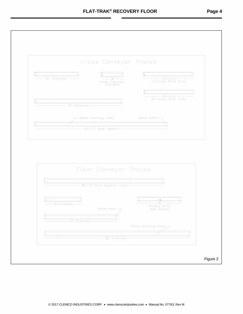
1.3 General Description 1.3.1 The Flat-Trak® recovery floor comprise of three to ten modular floor conveyor sections, and one modular cross conveyor. See Figure 1 for a typical sample arrangement. In operation, the floor conveyor sections feed abrasive to the cross conveyor. The cross conveyor moves abrasive to the bucket elevator, or customer’s equipment modified to interface with the Flat-Trak®. 1.3.2 Floor conveyor sections: Floor sections are 36 inches or 24 inches wide from center to center (other widths are available by special order). These section widths enable floors to be widened in 24-inch and 36-inch increments, from a standard minimum width of 9 feet (three, 36-inch sections) to a maximum width of 30 feet (ten sections). Floor sections consist of an 8-foot drive segment (where the cylinder mounts), and when the floor is longer than 10 feet, one or more extension segments. Floor extension segments are 30-inches, 60-inches, or 120-inches long. They bolt together in any combination to form a maximum length of 30 feet. Two floor conveyor floors can be mounted on each side of a cross conveyor section (forming a center cross conveyor), for a total maximum length of 60 feet. 1.3.3 Cross conveyor section: The cross conveyor section is 18-inches wide. It consists of a 109-1/2 inch base segment and 40-13/16 inch drive segment. If the recovery floor is wider than 9 feet, use one or more cross conveyor extensions. Cross conveyor extensions are 36 inches, and 72 inches long (24-inch extensions are available by special order). They bolt together in any combination to form a maximum length of 30 feet.

FLAT-TRAK® RECOVERY FLOOR Page 2
© 2017 CLEMCO INDUSTRIES CORP. www.clemcoindustries.com Manual No. 07763, Rev M
Figure 1
FLAT-TRAK® RECOVERY FLOOR Page 3
© 2017 CLEMCO INDUSTRIES CORP. www.clemcoindustries.com Manual No. 07763, Rev M
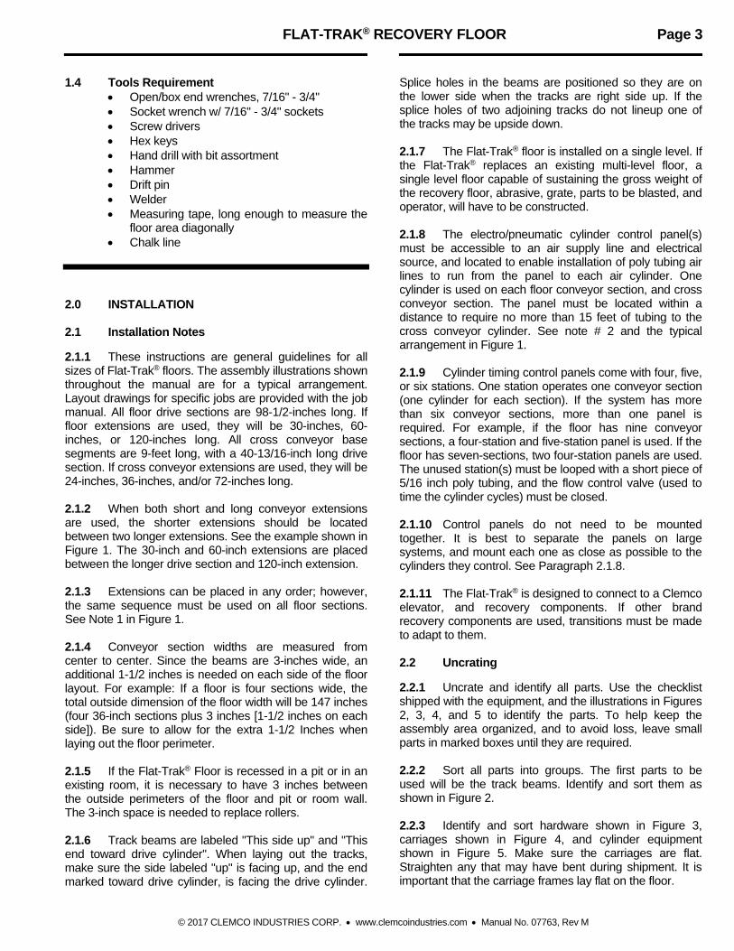
1.4 Tools Requirement Open/box end wrenches, 7/16" - 3/4" Socket wrench w/ 7/16" - 3/4" sockets Screw drivers Hex keys Hand drill with bit assortment Hammer Drift pin Welder Measuring tape, long enough to measure the
floor area diagonally Chalk line
2.0 INSTALLATION 2.1 Installation Notes 2.1.1 These instructions are general guidelines for all sizes of Flat-Trak® floors. The assembly illustrations shown throughout the manual are for a typical arrangement. Layout drawings for specific jobs are provided with the job manual. All floor drive sections are 98-1/2-inches long. If floor extensions are used, they will be 30-inches, 60-inches, or 120-inches long. All cross conveyor base segments are 9-feet long, with a 40-13/16-inch long drive section. If cross conveyor extensions are used, they will be 24-inches, 36-inches, and/or 72-inches long. 2.1.2 When both short and long conveyor extensions are used, the shorter extensions should be located between two longer extensions. See the example shown in Figure 1. The 30-inch and 60-inch extensions are placed between the longer drive section and 120-inch extension. 2.1.3 Extensions can be placed in any order; however, the same sequence must be used on all floor sections. See Note 1 in Figure 1. 2.1.4 Conveyor section widths are measured from center to center. Since the beams are 3-inches wide, an additional 1-1/2 inches is needed on each side of the floor layout. For example: If a floor is four sections wide, the total outside dimension of the floor width will be 147 inches (four 36-inch sections plus 3 inches [1-1/2 inches on each side]). Be sure to allow for the extra 1-1/2 Inches when laying out the floor perimeter. 2.1.5 If the Flat-Trak® Floor is recessed in a pit or in an existing room, it is necessary to have 3 inches between the outside perimeters of the floor and pit or room wall. The 3-inch space is needed to replace rollers. 2.1.6 Track beams are labeled "This side up" and "This end toward drive cylinder". When laying out the tracks, make sure the side labeled "up" is facing up, and the end marked toward drive cylinder, is facing the drive cylinder.
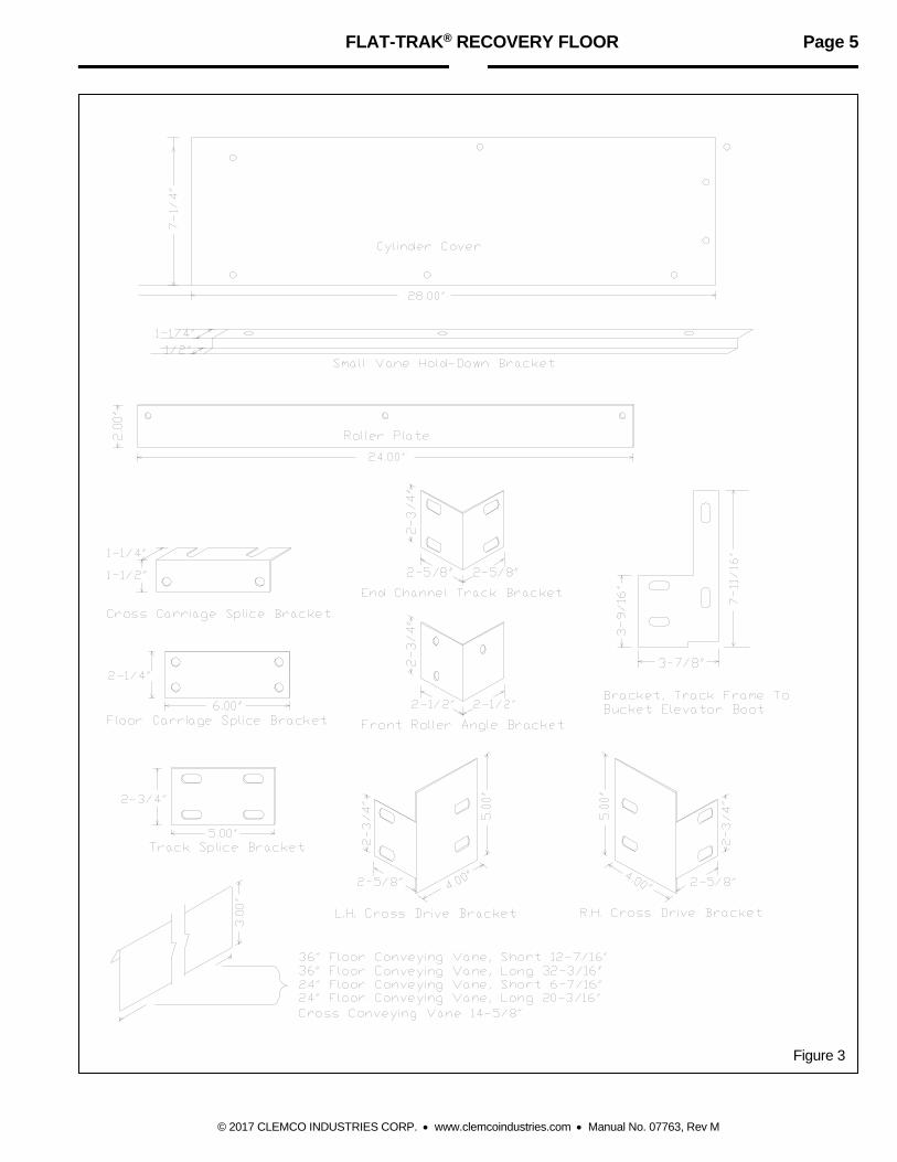
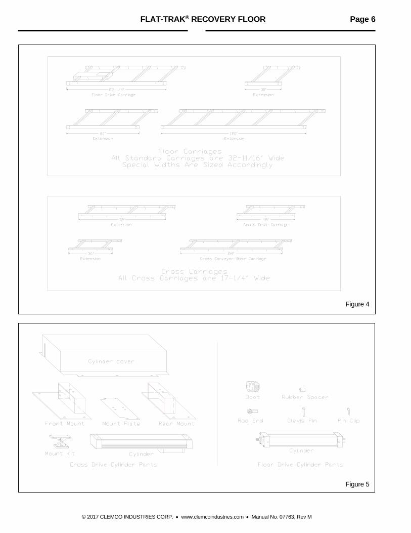
Splice holes in the beams are positioned so they are on the lower side when the tracks are right side up. If the splice holes of two adjoining tracks do not lineup one of the tracks may be upside down. 2.1.7 The Flat-Trak® floor is installed on a single level. If the Flat-Trak® replaces an existing multi-level floor, a single level floor capable of sustaining the gross weight of the recovery floor, abrasive, grate, parts to be blasted, and operator, will have to be constructed. 2.1.8 The electro/pneumatic cylinder control panel(s) must be accessible to an air supply line and electrical source, and located to enable installation of poly tubing air lines to run from the panel to each air cylinder. One cylinder is used on each floor conveyor section, and cross conveyor section. The panel must be located within a distance to require no more than 15 feet of tubing to the cross conveyor cylinder. See note # 2 and the typical arrangement in Figure 1. 2.1.9 Cylinder timing control panels come with four, five, or six stations. One station operates one conveyor section (one cylinder for each section). If the system has more than six conveyor sections, more than one panel is required. For example, if the floor has nine conveyor sections, a four-station and five-station panel is used. If the floor has seven-sections, two four-station panels are used. The unused station(s) must be looped with a short piece of 5/16 inch poly tubing, and the flow control valve (used to time the cylinder cycles) must be closed. 2.1.10 Control panels do not need to be mounted together. It is best to separate the panels on large systems, and mount each one as close as possible to the cylinders they control. See Paragraph 2.1.8. 2.1.11 The Flat-Trak® is designed to connect to a Clemco elevator, and recovery components. If other brand recovery components are used, transitions must be made to adapt to them. 2.2 Uncrating 2.2.1 Uncrate and identify all parts. Use the checklist shipped with the equipment, and the illustrations in Figures 2, 3, 4, and 5 to identify the parts. To help keep the assembly area organized, and to avoid loss, leave small parts in marked boxes until they are required. 2.2.2 Sort all parts into groups. The first parts to be used will be the track beams. Identify and sort them as shown in Figure 2. 2.2.3 Identify and sort hardware shown in Figure 3, carriages shown in Figure 4, and cylinder equipment shown in Figure 5. Make sure the carriages are flat. Straighten any that may have bent during shipment. It is important that the carriage frames lay flat on the floor.
FLAT-TRAK® RECOVERY FLOOR Page 4
© 2017 CLEMCO INDUSTRIES CORP. www.clemcoindustries.com Manual No. 07763, Rev M
Figure 2
FLAT-TRAK® RECOVERY FLOOR Page 5
© 2017 CLEMCO INDUSTRIES CORP. www.clemcoindustries.com Manual No. 07763, Rev M
Figure 3
FLAT-TRAK® RECOVERY FLOOR Page 6
© 2017 CLEMCO INDUSTRIES CORP. www.clemcoindustries.com Manual No. 07763, Rev M
Figure 4
Figure 5

FLAT-TRAK® RECOVERY FLOOR Page 7
© 2017 CLEMCO INDUSTRIES CORP. www.clemcoindustries.com Manual No. 07763, Rev M
2.3 Layout 2.3.1 Layout notes
2.3.1.1 The typical layout used in Figure 1 is used in all floor illustrations in this manual. It is only a sample floor layout. Since the Flat-Trak® is modular in design; the floor supplied may vary in size. 2.3.1.2 Center feed cross conveyor floors do not have a cross conveyor track. Carriages ride on rollers mounted on front roller angle brackets that attach to the ends of the floor tracks. The two halves of the recovery floor must be
squared with the cross-conveyor drive-segment and the 18-inch cross end beam as shown in Figure 6. Use the same procedures as described in this text for both sides of a center feed floor. 2.3.1.3 Use the typical layout in Figure 1 to determine the final position for the elevator, blast machine, cylinder control panels, starter control panel, blast room doors, etc. Make sure space is available for all accessories, and that the floor cross conveyor drive section ends at the elevator inlet.
Figure 6
FLAT-TRAK® RECOVERY FLOOR Page 8
© 2017 CLEMCO INDUSTRIES CORP. www.clemcoindustries.com Manual No. 07763, Rev M
Figure 7

FLAT-TRAK® RECOVERY FLOOR Page 9
© 2017 CLEMCO INDUSTRIES CORP. www.clemcoindustries.com Manual No. 07763, Rev M
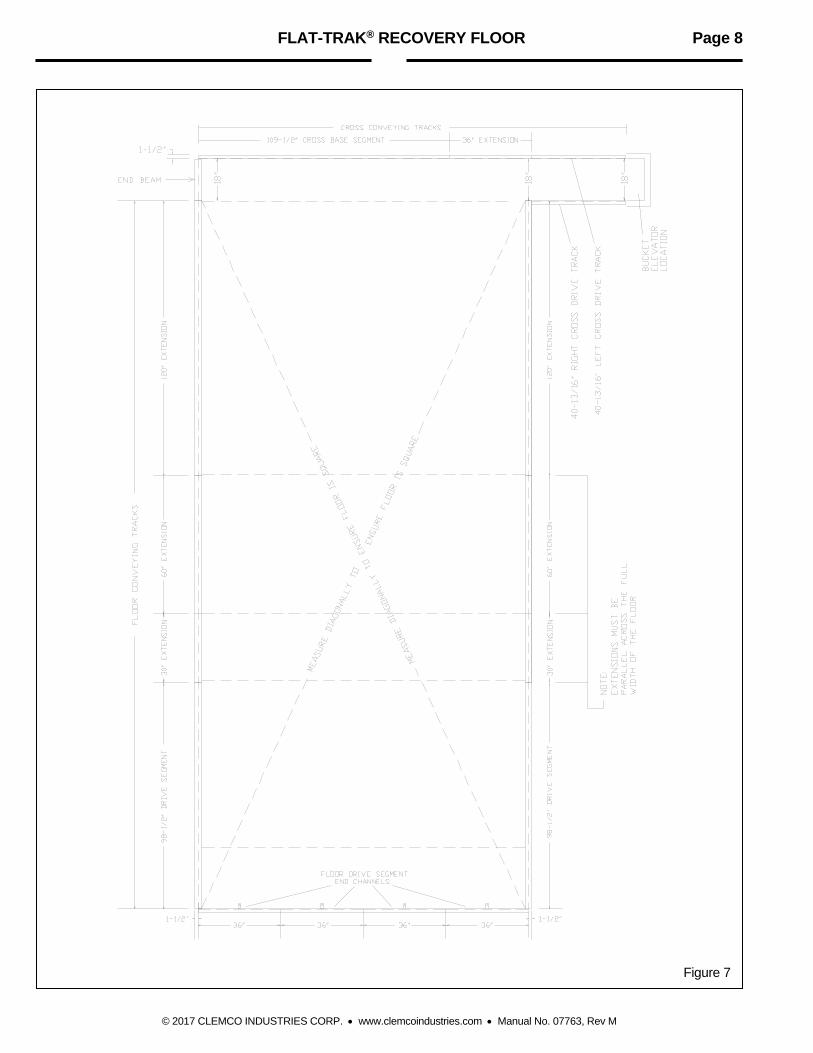
2.4 Perimeter Tracks, Ref. Figure 7 2.4.1 Run chalk lines around the perimeter of the floor. Make sure the perimeter is square. Recheck the final location for the elevator, cross conveyor and floor conveyor sections. Be sure to allow 1-1/2-inches around the perimeter. If the floor is mounted in a pit or existing room, allow 3-inches for service. See Sections 2.1.4 and 2.1.5. 2.4.2 Place the cross conveyor tracks (C channels) as shown in Figure 7. Beginning at the elevator location, place the left and right hand cross drive tracks, cross extensions (if used), and the cross conveyor base segment. The flat side of the cross conveyor tracks must face the inside of the floor recovery area. 2.4.3 Bolt the cross conveyor tracks together, using fasteners and track splice brackets shown in Figure 8.
Cross Track to Cross Track
Figure 8 2.4.4 Lay the 18-inch cross conveyor end beam at the end of the cross-conveyor base-segment track. Use an end-channel splice-bracket, and loosely bolt the end beam to the track as shown in Figure 9. 2.4.5 Place the floor conveyor tracks along both sides of the perimeter. Note: The tracks are labeled "This side up" and "This end toward drive cylinder". Make sure each track is placed accordingly.
Cross Base Segment to Cross End Beam
Figure 9 2.4.6 Splice the perimeter track adjacent to the 18-inch cross conveyor end beam to the beam, using a track splice bracket and fasteners shown in Figure 10.
Floor Track to Floor Track
Figure 10 2.4.7 Splice all the perimeter tracks together using the track splice brackets and fasteners as shown in Figure 10. NOTE: The splice can go on either side of the I-beam track. 2.4.8 Place the drive-segment end-channels in position as shown in Figure 7. The cylinder mounting tabs must face the floor area and be on the lower side when the channels are right side up. 2.4.9 Position a drive segment track at the end of each drive end channel.

FLAT-TRAK® RECOVERY FLOOR Page 10
© 2017 CLEMCO INDUSTRIES CORP. www.clemcoindustries.com Manual No. 07763, Rev M
2.4.10 Connect the drive segment tracks to the drive end channels, using end channel brackets as shown in Figure 11. Inside tracks will have two brackets as shown, while perimeter tracks will have only one. NOTE: The bracket bolts for the end channels must face away from the floor area as shown.
Floor Conveying Drive Segment to Floor End Channel
Figure 11 2.4.11 Make sure the cross conveyor tracks are straight and aligned with the chalk line. Anchor them as noted on the assembly drawings, just enough to keep them from moving, while squaring the rest of the perimeter tracks. 2.4.12 Square the perimeter tracks. Make sure that the sides are parallel. Check diagonally to make sure the perimeter is square, by measuring from the points shown in Figure 7. 2.4.13 Anchor the perimeter tracks as noted on the assembly drawings, just enough to hold them in place. 2.5 Inside Tracks 2.5.1 Position all the inside tracks on the floor. The track extensions for each section must be positioned in the same order and parallel to the perimeter track extensions. See note in Figure 7. 2.5.2 Splice the inside tracks together using the splice brackets and fasteners as shown is Figure 10. NOTE: The splice can go on either side of the I beam track.
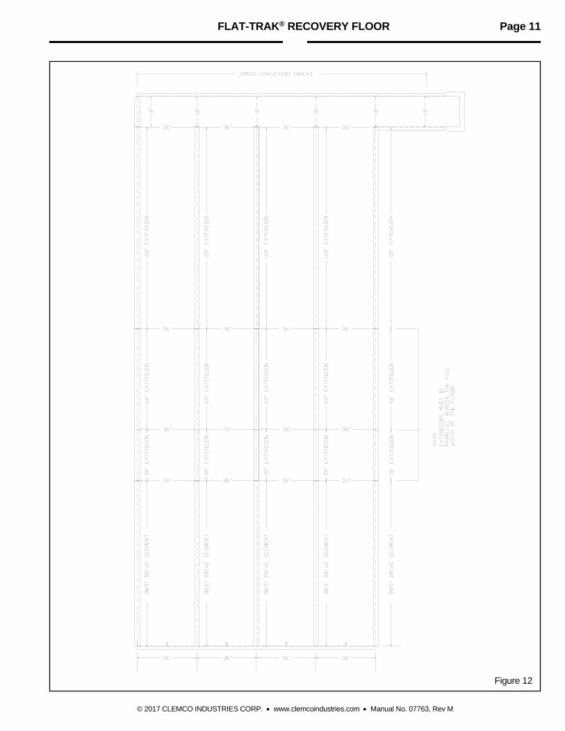
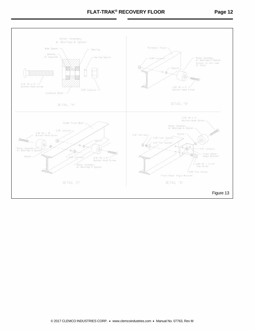
2.5.3 Make sure the measurement from the inside of the cross-conveyor track-channel to the front of each floor track beam is 18-inches as shown in Figure 12. 2.5.4 Make sure each section is square and parallel, per the illustrations in Figures 7 and 12. The 36-inch dimension between the floor track rails is measured from center to center. 2.5.5 As each channel is checked, Anchor them as noted on the assembly drawings, just enough to prevent movement during the remainder of the assembly. 2.6 Rollers Note: The roller assemblies shown in detail "A" of Figure 13 are factory assembled. If they are taken apart, they must be reassembled as shown. When attaching the roller assemblies to the tracks, the button head screw must be inserted into the side with the recessed bearing. The flush side faces the track, with a spacer between the bearing and track. 2.6.1 Attach roller assemblies to the inside of the perimeter tracks as shown in Figure 13 detail "B". Two rollers are required on each drive section, including the cross drive, and on 72-inch, and 120-inch extensions. One roller is required on each 30-inch, 36-inch, and 60-inch extension. 2.6.2 Attach roller assemblies hand tight to both sides of the inside tracks as shown in Figure 13 detail C". Four rollers are required on each drive section, and 120-inch extension. Two rollers are required on each 30-inch, and 60-inch extension. When rollers are in place on the inside beams, one will be slightly offset from the other. It is not necessary to mount rollers in each segment directly opposite one another, but roller mounting should be done uniformly. Aligning the rollers may mean moving some of the perimeter rollers. 2.6.3 Attach the front roller angle brackets to the inside tracks as shown in Figure 13 detail "D". 2.6.4 Attach rollers to the angle brackets. 2.6.5 Recheck the location of the rollers to make sure they are in-line, and on the same elevation. 2.6.6 Tighten all the roller assemblies and check each one to ensure that it turns freely.
FLAT-TRAK® RECOVERY FLOOR Page 11
© 2017 CLEMCO INDUSTRIES CORP. www.clemcoindustries.com Manual No. 07763, Rev M
Figure 12
FLAT-TRAK® RECOVERY FLOOR Page 12
© 2017 CLEMCO INDUSTRIES CORP. www.clemcoindustries.com Manual No. 07763, Rev M
Figure 13

FLAT-TRAK® RECOVERY FLOOR Page 13
© 2015 CLEMCO INDUSTRIES CORP. www.clemcoindustries.com Manual No. 07763, Rev L
2.7 Carriages 2.7.1 Carriage Assembly Notes 2.7.1.1 All carriages except the cross conveyor "drive" carriage are installed inside the room. The cross drive carriage is different from floor drive carriages, because the cross drive cylinder is mounted on top of the carriage rather than within the carriage, inside the cylinder compartment as with the floor drive. 2.7.1.2 Complete one entire conveyor section of carriages before starting the next. Doing so will train the assembler, and identify any procedural problems. 2.7.1.3 Floor carriages must be laid in the tracks with the vane guides sloping toward the cross conveyor as shown in Figure 15. Vane guides on cross conveyor tracks slope toward the elevator as shown in Figure 20. 2.7.2 Floor Carriage Assembly
Refer to Floor Drive and Floor Extension Drawings
2.7.2.1 Lay the carriages inside the corresponding size track. For example, a 30-inch carriage lays in a 30-inch extension. The drive carriage, identified by the cylinder compartment (frame weldment in the back), lays in the drive track. 2.7.2.2 Make sure all the carriages lay flat on the floor. If any are bent, they must be straightened. 2.7.2.3 Install only the front vane on each carriage section as shown in Figure 14. If the front vane is not put in before the carriages are spliced together, it will be necessary to remove some of the splice bolts to install them. The vane slides in from the back and rests on the guide. 2.7.2.4 Bolt both sides of the floor carriages together using splice brackets and 3/8" fasteners as shown in Figure 15. Splice brackets mount on the outside of the carriages. 2.7.2.5 Use 1/4" fasteners to bolt the roller plate onto the carriage over each roller as shown in Figure 16. The edge of the roller plate should extend over the roller. 2.7.2.6 When all roller plates are installed and the fasteners are tight, the carriage should be off the floor, and should slide freely. If it does not, determine the reason, and correct it. 2.7.2.7 Install the remainder of the vanes. The vanes slide in from the back and rest on the sloping guides.
Figure 14
Figure 15
Figure 16 2.7.2.8 After all the vanes are installed, check movement of the carriages by sliding them forward and backward. Make sure they move freely, rest flat on the rollers, and that none of the vanes bind or drag.
FLAT-TRAK® RECOVERY FLOOR Page 14
© 2017 CLEMCO INDUSTRIES CORP. www.clemcoindustries.com Manual No. 07763, Rev M
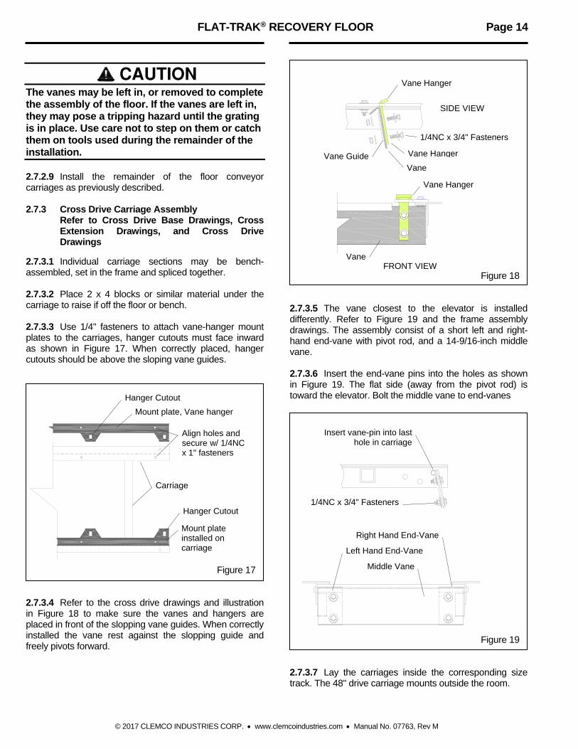
CAUTION The vanes may be left in, or removed to complete the assembly of the floor. If the vanes are left in, they may pose a tripping hazard until the grating is in place. Use care not to step on them or catch them on tools used during the remainder of the installation. 2.7.2.9 Install the remainder of the floor conveyor carriages as previously described. 2.7.3 Cross Drive Carriage Assembly
Refer to Cross Drive Base Drawings, Cross Extension Drawings, and Cross Drive Drawings
2.7.3.1 Individual carriage sections may be bench-assembled, set in the frame and spliced together. 2.7.3.2 Place 2 x 4 blocks or similar material under the carriage to raise if off the floor or bench. 2.7.3.3 Use 1/4" fasteners to attach vane-hanger mount plates to the carriages, hanger cutouts must face inward as shown in Figure 17. When correctly placed, hanger cutouts should be above the sloping vane guides.
Figure 17 2.7.3.4 Refer to the cross drive drawings and illustration in Figure 18 to make sure the vanes and hangers are placed in front of the slopping vane guides. When correctly installed the vane rest against the slopping guide and freely pivots forward.
Figure 18 2.7.3.5 The vane closest to the elevator is installed differently. Refer to Figure 19 and the frame assembly drawings. The assembly consist of a short left and right-hand end-vane with pivot rod, and a 14-9/16-inch middle vane. 2.7.3.6 Insert the end-vane pins into the holes as shown in Figure 19. The flat side (away from the pivot rod) is toward the elevator. Bolt the middle vane to end-vanes
Figure 19 2.7.3.7 Lay the carriages inside the corresponding size track. The 48" drive carriage mounts outside the room.
Mount plate, Vane hanger
Carriage
Mount plate installed on carriage
Align holes and secure w/ 1/4NC x 1" fasteners
Hanger Cutout
Hanger Cutout
Insert vane-pin into last hole in carriage
Right Hand End-Vane
Left Hand End-Vane
Middle Vane
1/4NC x 3/4" Fasteners
Vane Hanger
Vane Hanger
Vane
Vane
Vane Hanger Vane Guide
1/4NC x 3/4" Fasteners
FRONT VIEW
SIDE VIEW
FLAT-TRAK® RECOVERY FLOOR Page 15
© 2017 CLEMCO INDUSTRIES CORP. www.clemcoindustries.com Manual No. 07763, Rev M
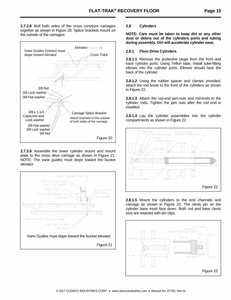
2.7.3.8 Bolt both sides of the cross conveyor carriages together as shown in Figure 20. Splice brackets mount on the outside of the carriages.
Figure 20 2.7.3.9 Assemble the lower cylinder mount and mount plate to the cross drive carriage as shown in Figure 21. NOTE: The vane guides must slope toward the bucket elevator
Vane Guides must slope toward the bucket elevator
Figure 21
2.8 Cylinders NOTE: Care must be taken to keep dirt or any other dust or debris out of the cylinders ports and tubing during assembly. Dirt will accelerate cylinder wear. 2.8.1 Floor Drive Cylinders 2.8.1.1 Remove the protective plugs from the front and back cylinder ports. Using Teflon tape, install tube-fitting elbows into the cylinder ports. Elbows should face the back of the cylinder. 2.8.1.2 Using the rubber spacer and clamps provided, attach the rod boots to the front of the cylinders as shown in Figure 22. 2.8.1.3 Attach the rod-end jam-nuts and rod-ends to the cylinder rods. Tighten the jam nuts after the rod end is installed. 2.8.1.4 Lay the cylinder assemblies into the cylinder compartments as shown in Figure 22.
Figure 22 2.8.1.5 Mount the cylinders to the end channels and carriage as shown in Figure 23. The clevis pin on the cylinder base must face down. Both rod and base clevis pins are retained with pin clips.
Figure 23
Cross Track Vane Guides (Vanes) must slope toward elevator
Elevator
Carriage Splice Bracket
Attach brackets to the outside of both sides of the carriage.
3/8 x 1-1/4 Capscrew and
Lock washer
3/8 Lock washer 3/8 Flat washer
3/8 Nut
3/8 Flat washer 3/8 Lock washer
3/8 Nut
FLAT-TRAK® RECOVERY FLOOR Page 16
© 2017 CLEMCO INDUSTRIES CORP. www.clemcoindustries.com Manual No. 07763, Rev M
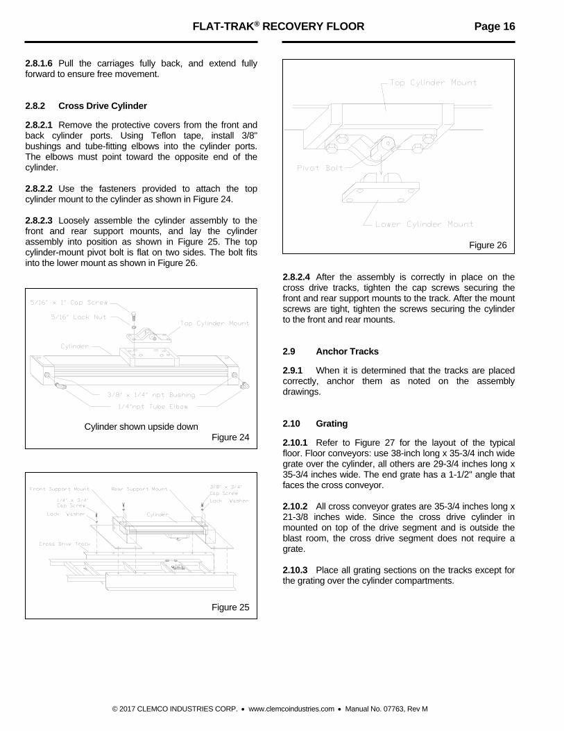
2.8.1.6 Pull the carriages fully back, and extend fully forward to ensure free movement. 2.8.2 Cross Drive Cylinder 2.8.2.1 Remove the protective covers from the front and back cylinder ports. Using Teflon tape, install 3/8" bushings and tube-fitting elbows into the cylinder ports. The elbows must point toward the opposite end of the cylinder. 2.8.2.2 Use the fasteners provided to attach the top cylinder mount to the cylinder as shown in Figure 24. 2.8.2.3 Loosely assemble the cylinder assembly to the front and rear support mounts, and lay the cylinder assembly into position as shown in Figure 25. The top cylinder-mount pivot bolt is flat on two sides. The bolt fits into the lower mount as shown in Figure 26.
Cylinder shown upside down Figure 24
Figure 25
Figure 26 2.8.2.4 After the assembly is correctly in place on the cross drive tracks, tighten the cap screws securing the front and rear support mounts to the track. After the mount screws are tight, tighten the screws securing the cylinder to the front and rear mounts. 2.9 Anchor Tracks 2.9.1 When it is determined that the tracks are placed correctly, anchor them as noted on the assembly drawings. 2.10 Grating 2.10.1 Refer to Figure 27 for the layout of the typical floor. Floor conveyors: use 38-inch long x 35-3/4 inch wide grate over the cylinder, all others are 29-3/4 inches long x 35-3/4 inches wide. The end grate has a 1-1/2" angle that faces the cross conveyor. 2.10.2 All cross conveyor grates are 35-3/4 inches long x 21-3/8 inches wide. Since the cross drive cylinder in mounted on top of the drive segment and is outside the blast room, the cross drive segment does not require a grate. 2.10.3 Place all grating sections on the tracks except for the grating over the cylinder compartments.

FLAT-TRAK® RECOVERY FLOOR Page 17
© 2017 CLEMCO INDUSTRIES CORP. www.clemcoindustries.com Manual No. 07763, Rev M
Figure 27

FLAT-TRAK® RECOVERY FLOOR Page 18
© 2017 CLEMCO INDUSTRIES CORP. www.clemcoindustries.com Manual No. 07763, Rev M
2.11 Cylinder Control Timing Panel Refer to control panel installation notes in Paragraphs 2.18, 2.1.9, and 2.1.10. 2.11.1 Mount the cylinder control panel(s) at its permanent location. The panel must be located within a distance to require no more than 15-feet of tubing to the cross conveyor cylinder. The ideal location is outside the blast room on the wall closest to the cross conveyor cylinder. If the panel is to be mounted on the wall, the Flat-Trak® floor should be completed before the blast room is erected. 2.11.2 Electrical Connections 2.11.2.1 Refer to the wiring diagram stowed inside the control panel or the wiring diagram provided with the project manual and connect electrical power to the cylinder control panel(s). 2.11.3 Pneumatic Connection 2.11.3.1 Install an air supply line to the 1/2-inch pressure regulator/filter inlet located on the right side of each panel. The line must be large enough to handle 7 cfm at 100 psi per cylinder. NOTE: The air line must have a shut-off valve installed at the source to enable lockout and tagout for service. 2.12 Control Tubing 2.12.1 Floor Conveyor Tubing 2.12.1.1 Run 5/16 inch OD poly air tubing from each of the panel outlet ports, through the end channel tubing access holes, to a corresponding cylinder as follows. 2.12.1.2 Tubing from the panel outlet ports marked "A" connects to the front (rod end) of the cylinders. Tubing from the ports marked "B" connects to the back (end cap) of the cylinders.
CAUTION Care must be taken to keep dust or debris out of the tubing during assembly, as it will accelerate wear, or jam the cylinders, panel solenoids, and pressure switches. 2.12.1.3 Tubing is connected to the elbow fittings on the panel and cylinders, by inserting the tubing ends into the fittings and pushing them until they bottom-out. Release tubing by pushing in on the plastic collar while pulling out on the tubing. 2.12.1.4 Use nylon ties to band the tubing to the cylinder bodies. Band the tubing at any other place where the
tubing is loose (especially around moving parts) to prevent it from being snagged or cut. 2.12.1.5 The tubing should be run neatly, and as close to walls or supports as possible. Band tubing lines together with nylon ties.
NOTICE If it is necessary to drill through steel to run the poly tubing, use rubber grommets in the drill holes to protect the tubing from sharp metal edges. 2.12.2 Cross Conveyor Tubing 2.12.2.1 Run tubing to the cross conveyor cylinder through the hole in the front cylinder mount. 2.12.2.2 Connect the tubing to the rear cylinder port tube-fitting straight on. Make a loop in the front-port tubing and connect it to the front-port tube fitting. 2.13 Initial Test 2.13.1 Read the warning below and apply air to the cylinder control panel(s)
WARNING Clear the Flat-Trak® floor area of objects and personnel before applying air or electrical power to the cylinder control panels. When air is first applied to the control panel, the floor carriages will retract to the far back position. This will happen even if electrical power is not hooked up. Failure to clear the floor area could result in injury, or equipment damage. 2.13.2 Adjust panel pressure per Section 4.1. 2.13.3 Adjust cylinder cycle time per Section 4.2. 2.13.4 Observe the movement of the floor carriages. Make sure they move freely, rest flat on the rollers, and none of the vanes are binding or dragging. 2.13.5 Install the cylinder-compartment cover plates, and vane hold-down brackets. Hold-down brackets must be positioned on top of the cover. 2.13.6 Place the remainder of the grating on the tracks. 2.13.7 Install the cross-conveyor cylinder cover.

FLAT-TRAK® RECOVERY FLOOR Page 19
© 2017 CLEMCO INDUSTRIES CORP. www.clemcoindustries.com Manual No. 07763, Rev M
2.14 Bucket Elevator Refer to the bucket elevator manual for elevator assembly. 2.14.1 Attach the bucket elevator or elevator boot section to the cross conveyor using track frame to elevator boot brackets as shown in Figure 3.
WARNING Whether the elevator is attached as a unit, or built on site, it must be adequately supported to prevent toppling during assembly. Failure to support the elevator could result in serious injury or death. Supports must remain until the elevator is permanently secured. 2.15 Starter Controls 2.15.1 Electric controls are critical to the operation of the blast cleaning facility. If a Clemco control panel was purchased with the recovery system the electrical components will be interlocked to prevent an over-load in the system. The electrical interlocks for a complete Clemco blast facility are wired in series as follows: 1. Abrasive Cleaner 2. Bucket Elevator 3. Flat-Trak® Floor 2.15.2 If the system has not been supplied with a control panel, the components should be wired to insure start-up sequence as specified above, and shutdown in reverse order. Doing so will prevent overloading any component. 2.15.3 In addition to the above, separate switches are required for the dust collector and the blast room lights.
3.0 ABRASIVE 3.1 Selection of abrasive can play a significant part in both the productivity and maintenance of the blast facility. Most blast rooms use metallic abrasive such as steel or iron grit, which are favored because of their low break down rate. Mineral abrasive in general is not recommended in Flat-Trak® blast rooms due to the rapid breakdown rate. Clemco recommends against the use of silica sand.
3.2 The "working mix" of the abrasive is important to the blasting operation. When first charging the system, the abrasive mesh size should be the size which will produce the desired production rate for the type of material being removed from the part, as well as the proper etch for the coating to be applied. As the abrasive breaks down it becomes a smaller mesh size. To compensate for this, an abrasive mesh size larger than the original charge size is
added as abrasive replenishment is required. This working mix will then average out to produce the required etch and production rate. Establishment of this working mix is largely by trial and error as it is dependent on the breakdown rate of the abrasive used and the nature of the surface being blasted and the desired results. 3.3 Loading Abrasive
3.3.1 When initially charging the system with abrasive, calculate the storage capacity of each component. Fill the system below the capacity, and check each component as the volume is reached. A Clemco 6 cubic foot blast machine holds roughly 1500 lbs. of steel or iron grit or 600 lbs. of non-metallic abrasive. A Clemco abrasive cleaner holds 10 cubic feet (2500 lbs. of metallic or 1000 lbs. of non-metallic abrasive that has the density of slag or aluminum oxide). The recovery system should not be filled with more than a total of 10 cubic feet (2500 lbs. of metallic abrasive). This will fill a Clemco 6-cubic-foot blast machine and Clemco abrasive cleaner, to about 12 inches above the bottom of the abrasive cleaner, or half way up the access door. That provides 6 cubic feet in the machine and 4 cubic feet in the abrasive cleaner. Adding more may overfill the system causes abrasive blockage and /or carryover of good abrasive into the exhaust ducting or dust collector.
NOTICE During blasting, the pop-up valve (blast machine filling-port) is sealed, so abrasive will not enter the blast machine. As abrasive is recovered, the level in the abrasive cleaner will rise. By the time the blast machine is empty, the abrasive cleaner will be nearly filled to its full capacity of 10 cubic feet.
NEVER add new abrasive unless all recoverable abrasive has been retrieved into the blast machine and abrasive cleaner. Doing so will overfill the cleaner. 3.3.2 A portion of the abrasive will remain in non-recoverable areas between the vanes and floor, and grating bars over the tracks. This filler abrasive should be compensated for only after running the system for a couple of days. Do not increase the initial charge, as it could overload the system. 3.3.3 The system is charged by uniformly pouring abrasive through the grating, over the floor conveyor sections as the system is operating. Observe the movement of the vanes during operation to ensure that they pivot freely as the carriage moves forward and backward. The vanes should move abrasive over the
FLAT-TRAK® RECOVERY FLOOR Page 20
© 2017 CLEMCO INDUSTRIES CORP. www.clemcoindustries.com Manual No. 07763, Rev M
entire floor area, feeding toward the cross conveyor section and elevator.
NOTICE Never attempt to charge the system unless all recovery components are operating. Overfilling, blockage, and possible damage will occur requiring extensive cleaning out. 3.3.4 Add abrasive while the system is operating by pouring through the grating onto the conveyor sections. Frequency and amount of abrasive replenishment depends on the breakdown rate of the abrasive.
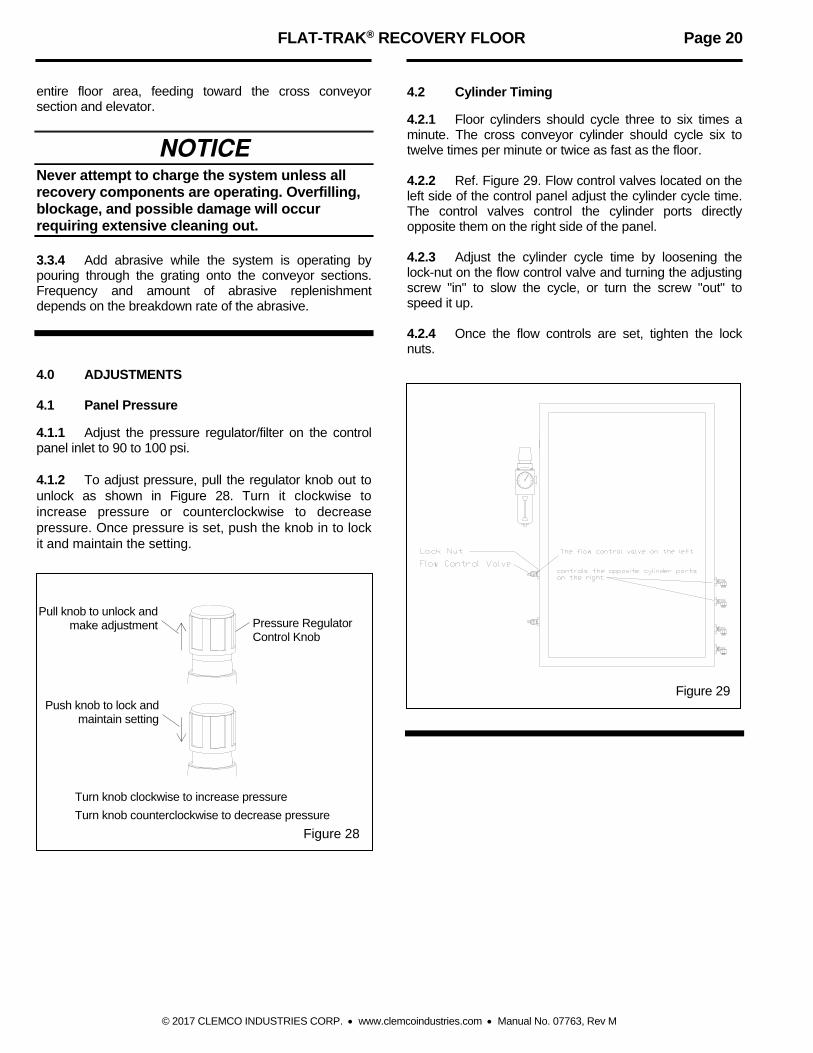
4.0 ADJUSTMENTS 4.1 Panel Pressure 4.1.1 Adjust the pressure regulator/filter on the control panel inlet to 90 to 100 psi. 4.1.2 To adjust pressure, pull the regulator knob out to unlock as shown in Figure 28. Turn it clockwise to increase pressure or counterclockwise to decrease pressure. Once pressure is set, push the knob in to lock it and maintain the setting.
Figure 28
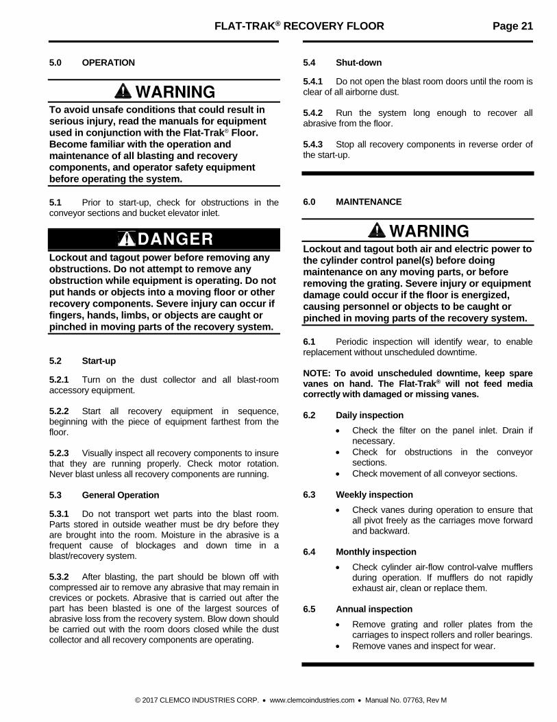
4.2 Cylinder Timing 4.2.1 Floor cylinders should cycle three to six times a minute. The cross conveyor cylinder should cycle six to twelve times per minute or twice as fast as the floor. 4.2.2 Ref. Figure 29. Flow control valves located on the left side of the control panel adjust the cylinder cycle time. The control valves control the cylinder ports directly opposite them on the right side of the panel. 4.2.3 Adjust the cylinder cycle time by loosening the lock-nut on the flow control valve and turning the adjusting screw "in" to slow the cycle, or turn the screw "out" to speed it up. 4.2.4 Once the flow controls are set, tighten the lock nuts.
Figure 29
Turn knob clockwise to increase pressure
Turn knob counterclockwise to decrease pressure
Pressure Regulator Control Knob
Pull knob to unlock and make adjustment
Push knob to lock and maintain setting
FLAT-TRAK® RECOVERY FLOOR Page 21
© 2017 CLEMCO INDUSTRIES CORP. www.clemcoindustries.com Manual No. 07763, Rev M
5.0 OPERATION
WARNING To avoid unsafe conditions that could result in serious injury, read the manuals for equipment used in conjunction with the Flat-Trak® Floor. Become familiar with the operation and maintenance of all blasting and recovery components, and operator safety equipment before operating the system. 5.1 Prior to start-up, check for obstructions in the conveyor sections and bucket elevator inlet.
DANGER Lockout and tagout power before removing any obstructions. Do not attempt to remove any obstruction while equipment is operating. Do not put hands or objects into a moving floor or other recovery components. Severe injury can occur if fingers, hands, limbs, or objects are caught or pinched in moving parts of the recovery system. 5.2 Start-up 5.2.1 Turn on the dust collector and all blast-room accessory equipment. 5.2.2 Start all recovery equipment in sequence, beginning with the piece of equipment farthest from the floor. 5.2.3 Visually inspect all recovery components to insure that they are running properly. Check motor rotation. Never blast unless all recovery components are running. 5.3 General Operation 5.3.1 Do not transport wet parts into the blast room. Parts stored in outside weather must be dry before they are brought into the room. Moisture in the abrasive is a frequent cause of blockages and down time in a blast/recovery system. 5.3.2 After blasting, the part should be blown off with compressed air to remove any abrasive that may remain in crevices or pockets. Abrasive that is carried out after the part has been blasted is one of the largest sources of abrasive loss from the recovery system. Blow down should be carried out with the room doors closed while the dust collector and all recovery components are operating.
5.4 Shut-down 5.4.1 Do not open the blast room doors until the room is clear of all airborne dust. 5.4.2 Run the system long enough to recover all abrasive from the floor. 5.4.3 Stop all recovery components in reverse order of the start-up.
6.0 MAINTENANCE
WARNING Lockout and tagout both air and electric power to the cylinder control panel(s) before doing maintenance on any moving parts, or before removing the grating. Severe injury or equipment damage could occur if the floor is energized, causing personnel or objects to be caught or pinched in moving parts of the recovery system. 6.1 Periodic inspection will identify wear, to enable replacement without unscheduled downtime. NOTE: To avoid unscheduled downtime, keep spare vanes on hand. The Flat-Trak® will not feed media correctly with damaged or missing vanes. 6.2 Daily inspection
Check the filter on the panel inlet. Drain if necessary.
Check for obstructions in the conveyor sections.
Check movement of all conveyor sections. 6.3 Weekly inspection
Check vanes during operation to ensure that all pivot freely as the carriages move forward and backward.
6.4 Monthly inspection
Check cylinder air-flow control-valve mufflers during operation. If mufflers do not rapidly exhaust air, clean or replace them.
6.5 Annual inspection
Remove grating and roller plates from the carriages to inspect rollers and roller bearings.
Remove vanes and inspect for wear.

FLAT-TRAK® RECOVERY FLOOR Page 22
© 2017 CLEMCO INDUSTRIES CORP. www.clemcoindustries.com Manual No. 07763, Rev M
7.0 REPLACEMENT PARTS 7.1 Floor Conveyor, Figure 30
Item Description Stock No.
1. Track beam, floor drive ................................. 20750 2. Extension, track beam 30" floor extension ..................................... 20751 60" floor extension ..................................... 20752 120" floor extension .................................. 20753 3. End channel, 36" .......................................... 20823 4 Carriage, Drive, floor ................................................. 20813 30" extension carriage .............................. 20814 60" extension carriage .............................. 20815 120" extension carriage ............................ 20816 5. Vane, (each) Long floor, 32-3/16" ................................... 20791 Short floor, 12-7/16" .................................. 20790 6. Roller plate .................................................... 20765 7. Cover, cylinder .............................................. 20786 8. Cylinder, floor drive (cylinder only) ............... 21437 9. Cylinder assembly includes Items 8, 10, 11, and 22 .............. 20433 10. Jam nut, 1/2-NF ............................................ 20855 11. Rod end ......................................................... 20844 12. Clevis pin ....................................................... 20842 13. Clip, clevis pin ............................................... 20843
14. Adaptor, elbow, 1/4" NPT x 5/16" tube ........ 20845 15. Tubing, 5/16" OD, specify length required in feet ................... 20856 16. Roller assembly ............................................ 20830 17. Bracket, end channel to track ...................... 20761 18. Tie, nylon ....................................................... 12140 19. Splice bracket, floor carriage ........................ 20762 20. Splice bracket, track ..................................... 20760 21. Angle bracket, front roller ............................. 20764 22. Boot replacement kit includes boot, items 23, 24, and 25 ......... 20413 23. Clamp, 2-1/4" ................................................ 12750 24. Clamp, 3/4" ................................................... 12756 25. Spacer, rubber boot ...................................... 20411 26. Cap screw, 3/8-NC x 1-1/4" ......................... 03253 27. Washer, 3/8" lock .......................................... 03318 28. Washer, 3/8" flat ........................................... 03317 29. Nut, 3/8-NC hex ............................................ 03311 30. Cap screw, 1/4-NC x 3/4" ............................. 03052 31. Washer, 1/4" lock .......................................... 03117 32. Washer, 1/4" flat ........................................... 03116 33. Hold-down, for short vanes .......................... 22033 (-) Service kit, cylinder (item 8), includes:
24889 rod bushing seal kit and 24890 piston seal kit ................................. 24861
(-) Service kit, rod bushing ................................ 24889 (-) Service kit, piston seal .................................. 24890 (-) Grating ........................ refer to Page 17, Figure 27
Figure 30
3
6 1
4
2
8, 9
4 4
5 5
5
5
6
7
11
10
13
12
14 15
16
16
16 6 17
17
18
19
20
21
16
22
23 24
25
26, 27, 28, 29 30, 31, 32
26, 27, 28, 29
33
5

FLAT-TRAK® RECOVERY FLOOR Page 23
© 2017 CLEMCO INDUSTRIES CORP. www.clemcoindustries.com Manual No. 07763, Rev M
7.2 Cross Conveyor, Figure 31
Item Description Stock No.
1. Track, base segment ..................................... 22003 2. Track extension, 36" cross extension .................................... 22035 72" cross extension .................................... 22034 3. Track, left hand cross drive ........................... 22004 4. Track, right hand cross drive ........................ 22005 5. End beam ...................................................... 22002 6. Carriage frame base segment ............................................ 22022 drive segment ............................................. 22023 36" extension, cross conveyor .................. 20811 72" extension, cross conveyor .................. 20812 7. Vane, standard 14-1/2" (each) ...................... 25224 8. Hanger, vane mount tab ................................ 25223 9. Cylinder, cross drive ...................................... 28722 10. Mounting kit, cross drive cylinder ................. 22047 11. Mount, cylinder front ...................................... 22024 12. Mount, cylinder rear ....................................... 22025 13. Plate, cylinder-mount .................................... 22014 14. Bushing, 3/8" x 1/4" NPT brass .................... 03528 15. Adaptor, elbow, 1/4" NPT x 5/16" tube ......... 20845 16. Tubing, 5/16" OD, specify length required in feet ................... 20856 17. Roller assembly ............................................. 20830 18. Bracket, 90o, end channel to track ................ 20761
19. Splice bracket, cross carriage, angle ........... 20763 20. Splice bracket, track, straight ....................... 20760 21. Bracket, angled front roller ............................ 20764 22. Bracket, drive track for right extension ...................................... 20793 for left extension ......................................... 20794 23. Bracket, track frame to elevator boot ........... 20795 24. Cap screw, 1/4-NC x 3/4" ............................. 03052 25. Washer, 1/4" lock .......................................... 03117 26. Cap screw, 3/8-NC x 3/4" ............................. 03251 27. Cap screw, 3/8-NC x 1-1/4" .......................... 03253 28. Washer, 3/8" lock .......................................... 03318 29. Washer, 3/8" flat ............................................ 03317 30. Nut, 3/8-NC hex ............................................. 03311 31. Cap screw, 5/16-NC x 1" .............................. 03152 32. Nut, 5/16-NC hex .......................................... 03211 33. Washer, 5/16 lock ........................................ 03217 34. Washer, 5/16" flat .......................................... 03216 35. End-vane w/pin, left, away from floor ........... 25229 36. End-vane w/pin, right, toward floor ............... 25230 37. Vane, middle 14-9/16" .................................. 25225 38. Cover, cylinder .............................................. 22026 `39. Plate, vane hanger mount Base segment ............................................ 25228 drive segment ............................................ 25235 36" extension, cross conveyor .................. 25222 72" extension, cross conveyor .................. 25233 (-) *Service kit for Item 9, cross drive cylinder .. 28723 (-) Grating ....................... refer to Page 17, Figure 27
Figure 31
Previous item 9 cylinder, stock no. 22046 used prior to 2016 is discontinued.
When discontinued cylinder 22046 needs to be replaced, replace with current item 9 cylinder, stock number 28722 *28723 service kit is compatible with current 28722 cylinder, and discontinued 22046 cylinder.
Viewed from elevator
5
1 3
2
4
6 6 6
7 14, 15
14, 1516 17
17 21
18 20
20
27, 28, 29, 30
27, 28, 29, 30
22
27, 28, 29, 30 36 3537
7
8
7
Side view of vanes and mounting (hanger) tabs
8
19 7 8
3939
39
39
39
9
10
38 11 12
13
19 23
31, 32, 33, 34
26, 28
24, 25
23
9

FLAT-TRAK® RECOVERY FLOOR Page 24
© 2017 CLEMCO INDUSTRIES CORP. www.clemcoindustries.com Manual No. 07763, Rev M
7.3 Cylinder Control Panel, Figure 32
Item Description Stock No.
1. Solenoid, 1/4", 4 way .................................... 20857 2. Relay ............................................................. 12046 3. Pressure switch ............................................ 20849 4. Socket, 8 pin ................................................. 12164 5. Tubing, 5/32" nylon (specify feet required in feet) .................... 20838 6. Filter/Regulator, 1/2" ..................................... 05530 7. Fitting, 1/2" female bulkhead ........................ 20858 8. Bushing 1/2" X 1/4" NPT .............................. 01801 9. Adaptor, elbow, 1/4" male NPT x 3/8" tube ........................ 11685 10. Tubing, 3/8" Poly (specify length required in feet) ................ 12478
11. Manifold, six outlet ........................................ 20851 12. Blanking nut (used on 4 & 5 station panels only) .......... 20852 13. Fitting, 1/4" female bulkhead ....................... 05605 14. Flow control valve ......................................... 20850 15. Tee, 1/4" NPT brass male ............................ 20847 16. Elbow, 1/4" NPT x 5/16" tube ...................... 20845 17. Connector, straight, 1/4" NPT x 5/16" tube ............................... 20846 18. Wye connector, 1/4" NPT x 5/16" tube ........ 20848 19. Tubing 5/16" nylon (specify length required in feet) ................ 20856 20. Connector, straight, 1/4" x 5/32" tube .......... 20839 21. Label, cylinder connections .......................... 20742 22. Bushing, 3/8 x 1/4-NPT ................................ 01800 23. O-ring, 11/16" OD ......................................... 08976 24. Screw, mounting, solenoid to manifold ....... 29236
Figure 32
21 24
23
Wire Raceway
Terminal Strip
1
2 4
3
5
6
8
7
9
13
10
14 18 19
10 9
22
17
19
17
20
15 13
16
16
12
11
17