date signature of officer making correction · radio receiver bc-348·(*) terminal box dynamotor...
TRANSCRIPT
ANjMRC-35A
INSTRUCTION BOOK
for
RADIO SET CENTRAL
AN/MRC-35A
Project 54741
----- -- - ----- ------------
REPAIR DIVISION
MARINE CORPS SUPPLY CENTER
ALBANY, GA.
U.S. MARINE CORPS
15 February 1957
- . --�---------- -- - -- ----� -�---�
FI.ONT MATTEI
OIANGE NO.
t-
t--
--
Correction Page
RECORD OF CORRECTIONS MADE
DATE SIGNATURE OF OFFICER MAKING CORRECTION
---·------
---
-
� --- ------- -- ------------------
lll
ARTIFICIAL RESPIRATION FRONT MATTER
ARTIFICIAL RESPIRATION
IV
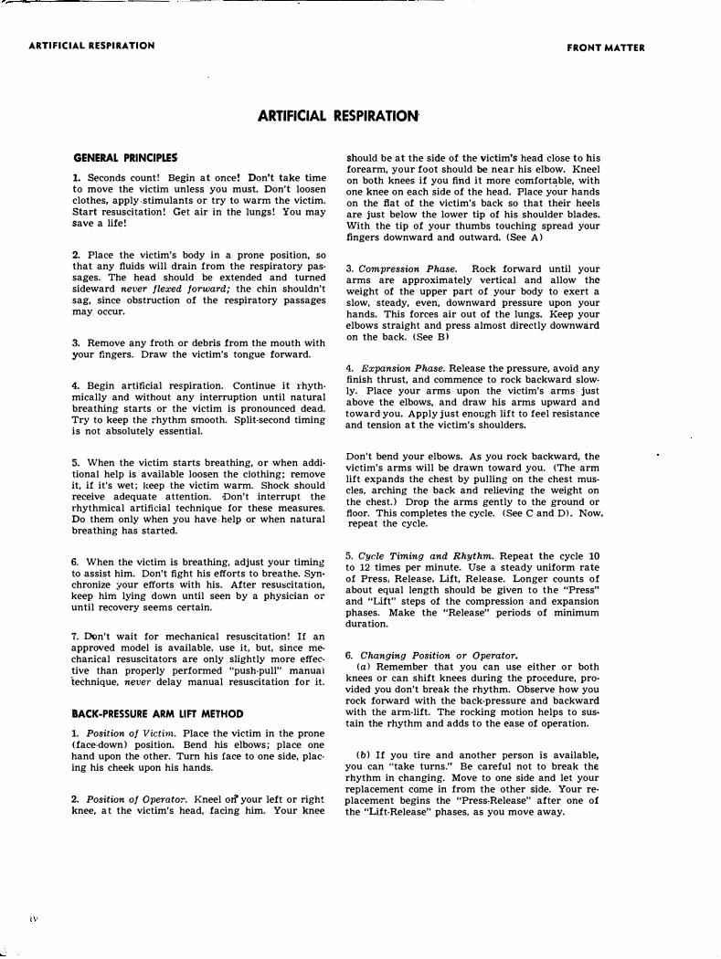
GENERAL PRINCIPLES
1. Seconds count! Begin at once! Don't take time to move the victim unless you must. Don't loosen clothes, apply -stimulants or try to warm the victim. Start resuscitation! Get air in the lungs! You may save a life!
2. Place the victim's body in a prone position, so that any fluids will drain from the respiratory pas· sages. The head should be extended and turned sideward never flexed forward; the chin shouldn't sag, since obstruction of the respiratory passages may occur.
3. Remove any froth or debris from the mouth with your fingers. Draw the victim's tongue forward.
4. Begin arti-ficial respiration. Continue it rhyth· mically and without any interruption until natural breathing starts or the victim is pronounced dead. Try to keep the rhythm smooth. Split-second timing is not absolutely essential.
5. When the victim starts breathing, or when addi· tiona! help is available loosen the clothing; remove it, if it's wet; keep the victim warm. Shock should receive adequate attention. Don't interrupt the rhythmical artificial technique for these measures. Do them only when you have help or when natural breathing has started.
6. When the victim is breathing, adjust your timing to assist him. Don't fight his efforts to breathe. Synchronize your efforts with his. After resuscitation, keep him lying down until seen by a physician or until recovery seems certain.
7. [)()n't wait for mechanical resuscitation! If an approved model is available, use it, but, since mechanical resuscitators are only slightly more effective than properly performed "push-pull" manuai technique, never delay manual resuscitation for it.
BACK-PRESSURE ARM LIFT METHOD
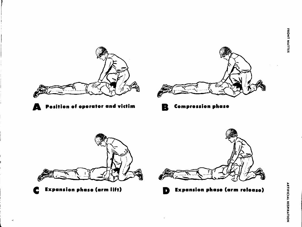
1. Position of Victim. Place the victim in the prone (face-down) position. Bend his elbows; place one hand upon the other. Turn his face to one side, placing his cheek upon his hands.
2. Position of Operator. Kneel orl' your left or right knee, at the victim's head, facing him. Your knee
should be at the side of the victim's head close to his forearm, your foot should be near his elbow. Kneel on both knees if you find it more comfortable, with one knee on each side of the head. Place your hands on the flat of the victim's back so that their heels are just below the lower tip of his shoulder blades. With the tip of your thumbs touching spread your fingers downward and outward. <See A)
3. Compression Phase. Rock forward until your arms are approximately vertical and allow the weight of the upper part of your body to exert a slow, steady, even, downward pressure upon your hands. This forces air out of the lungs. Keep your elbows straight and press almost directly downward on the back. <See B>
4. Expansion Phase. Release the pressure, avoid any finish thrust, and commence to rock backward slowly. Place your arms upon the victim's arms just above the elbows, and draw his arms upward and toward you. Apply just enough lift to feel resistance and tension at the victim's shoulders.
Don't bend your elbows. As you rock backward, the victim's arms will be drawn toward you. <The arm lift expands the chest by pulling on the chest muscles, arching the back and relieving the weight on the chest.) Drop the arms gently to the ground or floor. This completes the cycle. (See C and D). Now. repeat the cycle.
5. Cycle Timing and Rhythm. Repeat the cycle 10
to 12 times per minute. Use a steady uniform rate of Press, Release, Lift, Release. Longer counts of about equal length should be given to the "Press" and "Lift" steps of the compression and expansion phases. Make the "Release" periods of minimum duration.
6. Changing Position or Operator. (a) Remember that you can use either or both
knees or can shift knees during the procedure, provided you don't break the rhythm. Observe how you rock forward with the back-pressure and backward with the arm-lift. The rocking motion helps to sustain the rhythm and adds to the ease of operation.
(b) If you tire and another person is available, you can "take turns." Be careful not to break the rhythm in changing. Move to one side and let your replacement come in from the other side. Your replacement begins the "Press-Release" after one of the "Lift-Release" phases, as you move away.
--
FR
ON
T M
AT
TE
R
•
•
•
..
..
•
0
-•
•
•
..
&
E
0
u
II
E
-..
v
-•
..
•
•
..
0
..
•
..
•
&
0
,...
0
•
0
-..
-•
0
..
c
--
--
-��
--
--
--
-·-
-�
---
AR
TI
FI
CI
AL
RE
SP
IR
AT
IO
N
�
•
•
•
•
-•
..
E
..
•
�
•
•
•
..
&
•
0
-•
•
•
&
M
Ill
A
�
..
,...
--E
..
•
�
•
•
•
..
&
•
0
-•
•
•
&
M
Ill
u
v
r I
WARNING HIGH VOLTAGE
\'!
WARNING
HIGH VOLTAGE
is used in the operation of
this equipment
DEATH ON CONTACT
may result if operating personnel
fail to observe safety precautions
Be careful not to contact high-voltage connections when working on or near this equipment. Do not touch the antenna when the transmitter is being keyed. Do not add gasoline to the fuel tank unless all equipment is turned off.
EXTREMELY DANGEROUS POTENTIALS
exist in the following units:
RADIO TRANSMIITER T-47/ART-13
RADIO RECEIVER BC-348·(*)
TERMINAL BOX
DYNAMOTOR UNIT DY-12/ART-13
RECEIVER-TRANSMITTER RT-178/ ARC-27
FRONT MATTER
FRONT MATTER
DESTRUCTION OF
ABANDONED MATERIAL IN THE COMBAT ZONE
In case it should become necessary to prevent the capture of this
equipment, and when ordered to do so, DESTROY IT SO THAT
NO PART OF IT CAN BE SALVAGED, RECOGNIZED, OR
USED BY THE ENEMY. BURN ALL PAPERS AND BOOKS.
Means:
1. Explosives, when provided.
2. Hammers, axes, sledges, machetes, or whatever heavy object is readily available.
3. Burning by means of incendiaries such as gasoline, oil, paper or wood.
4. Grenades and shots from available firearms.
5. Burying all debris, where possible and when time permits.
6. Throwing overboard or disposing of in streams or other bodies of water.
Procedure:
l. Obliterate all nameplates and identifying marks. 2. Smash all receiving and transmitting equipment. 3. Smash keyer, controls, UHF antenna and RF Coil. 4. Chop cables and smash all connectors. 5. Smash generator, regulator and fan belts. 6. Smash all components of the antennas. 7. Burn as much of the equipment as time permits. 8. Bury or scatter all debris.
ABANDONED MATERIAL
Vll
FRONT MATTER ANjMRC-35A
TABLE OF CONTENTS
CONTENTS
Page
Record of Corrections Made ___________________ iii Artificial Respiration -------------------------- iv High Voltage Warning ------------------------ vi Destruction of Abandoned Material ______________ vii
SECTION I-GENERAL INFORMATION Paragraph
1-1. Equipment Illustrations ----------------- 1-1 a. Radio Set Control C-2198/MRC-35A ____ 1-1 b. Field Strength Meter __________________ 1-1
1-2. Functional Description ----------------- 1-1 a. Uses --------------------------------- 1-1 b. Major Components ____________________ 1-1
1-3. Equipment Modifications ________________ 1-2 a. Radio Transmitter T-47 I ART-13 _________ 1-2 b. Keyer KY-132/U ---------------------- 1-2 c. Radio Receiver BC-348-(*) ______________ 1-2 d. Installation Kit MK-327 /MRC-35A ______ 1-2
(I) CY-2017 /MRC-35A ________________ 1-2 (2) CY-2018/MRC-35A ________________ 1-2 (3) CY-2019/MRC-35A ________________ 1-2
e. Antenna Shunt Capacitor CU-24/ ART-13_ 1-2 f. Truck M38AI ________________________ 1-2
1-4. Quick Reference Data __________________ 1-2 a. Instruction books and Technical
Manuals Supplied _____________________ 1-2 b. Electrical Characteristics of AN I
MRC-35A Components ______________ __ 1-3 1-5. Equipment Lists ----------------------- 1-3
a. Equipment Not Supplied _______________ 1-3 b. Equipment Components and Accessories
Supplied ----------------------------- 1-3 c. Spare parts supplied ____________________ 1-5
1-6. Equipment Similarities __________________ 1-6 a. Dynamotor Unit ----------------------- 1-6 b. Radio Receiver BC-348-("') _____________ 1-6 c. Special Notice ------------------------- 1-6
SECTION 2-INSTALLATION
2-1. Unpacking and Handling _______________ 2-1 2-2. Site Selection ------------------------- 2-1 2-3. Power Requirements and Distribution _____ 2-1 2-4. Installation Layout --------------------- 2-1
a. UHF Antenna ------------------------ 2-1 b. T-47 I ART-13 and BC-348-(*) Antenna __ 2-1
2-5. Installation Pointers -------------------- 2-1 a. Typical Antenna Installations ___________ 2-1
(I) Long wire antenna _________________ 2-1 (2) Antenna Assembly AS-390/SRC _____ 2-1
b. Ground Rod and Counterpoise __________ 2-3 c. Control Group AN /GRA-6 _____________ 2-3 d. Interconnecting Diagram _______________ 2-4
Page
Paragraph 2-6. Inspection and Adjustments _____________ 2-4
a. Detailed Procedure -------------------- 2-4 b. RF Output Indications _________________ 2-4
SECTION 3-0PERATOR'S SECTION
3-1. Functional Operation ------------------- 3-1 3-2. Preparation for Use -------------------- 3-1
a. Antennas Used With Radio Trans-mitter T-47 I ART-13 ___________________ 3-1 (I) Low frequencies ------------------- 3-1 (2) Medium and high frequencies _______ 3-1 (3) Connections ----------------------- 3-1
b. Antenna Used With Receiver-Transmitter RT-178/ ARC-27 ____________ 3-1
c. RF Indication ------------------------- 3-1
3-3. Operating Procedures ___________________ 3-1 a. Description of Controls Radio Set Con-
trol C-2198/MRC-35A _________________ 3-1 b. Sequence of Operation _________________ 3-2
(I) LF, MF, HF equipment _____________ 3:2 (2) UHF equipment ___________________ 3-2 (3) Volume controls ___________________ 3-2 (4) Keyer KY-132/U __________________ 3-2
c. Netting of Radio Transmitter T-47 / ART-13 With Radio Receiver BC-348-(*)_ 3-2
d. Frequency Adjustment of Radio Transmitter T-47 / ART-13 from Calibration Chart -------------------------------- 3-4
e. Precautions --------------------------- 3-4 (I) RF Coil use _______________________ 3-4 (2) Modulation when using Antenna
Loading Coil CU-25/ ART-13 ________ 3-4 (3) Emission switch ------------------- 3-4 ( 4) Frequency range of Antenna Loading
Coil CU-25/ ART-13 _______________ 3-4 (5) Frequency Range with the whip
antenna -------------------------- 3-4 (6) Operation with Top Bows stowed ___ 3-4 (7) Generator flushing ----------------- 3-4 (8) Non-standard fan belts _____________ 3-4 (9) Slow blow fuse -------------------- 3-4
3-4. Operating Procedures for Radio Set AN/ ARC-27 --------------------------- 3-4
a. Functions of the Equipment _____________ 3-4 b. Functions of the Controls ____________ ____ 3-4 c. Sequence of Operation _________________ 3-6 d. Reception ---------------------------- 3-6 e. Transmission --------------------------- 3-6 f. Operation on Guard Frequency __________ 3-6 g. Transmission on Guard Frequency _______ 3-6 h. Tone Operation ----------------------- 3-6 i. Stopping the Equipment ________________ 3-6
FRONT MATTER! AN/MRC-35A
TABLE OF CONTENTS
CONTENTS
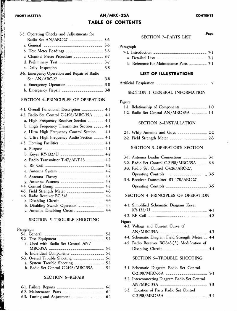
3-5. Operating Checks and Adjustments for
Radio Set AN I ARC-27 ----------------- 3-6
a. General ------------------------------ 3-6
b. Test Meter Readings ------------------- 3-6
c. Channel Preset Procedure _______________ 3-7
d. Preliminary Test ---------------------- 3-7
e. Daily Inspection ---------------------- 3-8
3-6. Emergency Operation and Repair of Radio
Set AN/ ARC-27 ______________________ 3-8
a. Emergency Operation ------------------ 3-8
b. Emergency Repair --------------------- 3-8
SECTION 4-PRINCIPLES OF OPERATION
4-1. Overall Functional Description ___________ 4-l
4-2. ,Radio Set Control C-2198/MRC-35A _____ 4-l
a. High Frequency Receiver Section ________ 4-l
b. High Frequency Transmitter Section _____ 4-l
c. Ultra High Frequency Control Section ___ 4-l
d. Ultra High Frequency Audio Section _____ 4-l
4-3. Homing Facilities ______________________ 4-l
a. Purpose ------------------------------ 4-l
b. Keyer KY-132/U ______________________ 4-2
c. Radio Transmitter T-47 / ART-13 _________ 4-2
d. RF Coil ------------------------------ 4-2
e. Antenna System ----------------------- 4-2
f. Antenna Theory ----------------------- 4-3 g. Antenna Patterns ---------------------- 4-3
4-4. Control Group ------------------------- 4-3 4-5. Field Strength Meter ------------------- 4-3 4-6. Radio Receiver BC-348 ------------------ 4-4
a. Disabling Circuit ---------------------- 4-4 b. Disabling Switch Operation _____________ 4-4 c. Antenna Disabling Circuit ______________ 4-4
SECTION 5-TROUBLE SHOOTING
Paragraph 5-l. General ------------------------------ 5-l 5-2. Test Equipment ----------------------- 5-l
a. Used with Radio Set Central AN/ MRC-35A ---------------------------- 5-l
b. Individual Components ----------------- 5-I 5-3. Overall Trouble Shooting ---------------- 5-l
a. System Trouble Shooting --------------- 5-l b. Radio Set Control C-2198/MRC-35A _____ 5-l
SECTION 6-REPAIR
6-l. Failure Reports ------------------------ 6-l 6-2. Maintenance Parts --------------------- 6-1 6-3. Tuning and Adjustment ----------------- 6-1
Page SECTION 7-PARTS LIST
Paragraph
7-l. Introduction --------------------------- 7-1
a. Detailed Lists ------------------------- 7-1
b. Reference for Maintenance Parts --------- 7-l
LIST OF ILLUSTRATIONS
Artificial Respiration -------------------------- v
SECTION I-GENERAL INFORMATION
Figure 1-l. Relationship of Components _____________ 1-0
1-2. Radio Set Central AN/MRC-35A ________ 1-l
SECTION 2-INSTALLATION
2-1. Whip Antenna and Guys _______________ 2-2
2-2. Field Strength Meter ___________________ 2-3
SECTION 3-0PERATOR'S SECTION
3-1. Antenna Leadin Connections ____________ 3-1
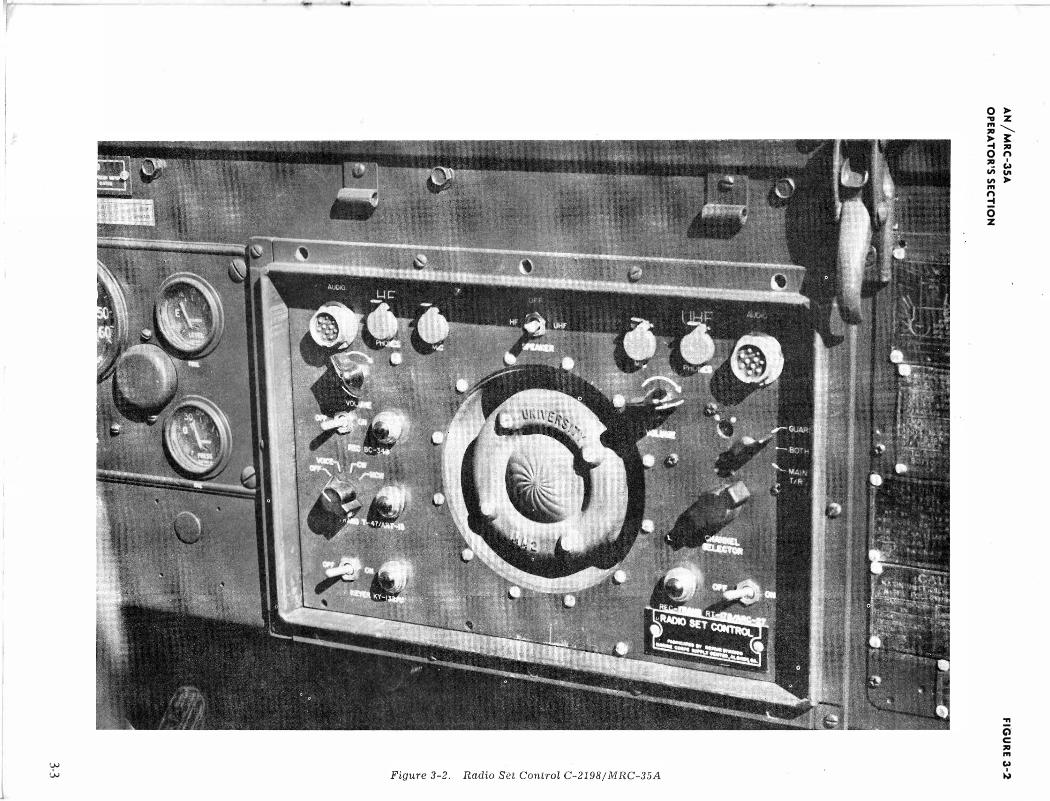
3-2. Radio Set Control C-2198/MRC-35A _____ 3-3
3-3. Radio Set Control C-626/ ARC-27,
Operating Controls --------------------- 3-5
3-4. Receiver-Transmitter RT-178/ ARC-27,
Operating Controls --------------------- 3-5
SECTION 4-PRINCIPLES OF OPERATION
4-1. Simplified Schematic Diagram Keyer KY-132/U ---------------------------- 4-1
4-2. RF Coil 4-2
Figure 4-3. Voltage and Current Curve of
AN/MRC-35A ------------------------ 4-3
4-4. Schematic Diagram Field Strength Meter __ 4-4
4-5. Radio Receiver BC-348-("') Modification of
Disabling Circuit ---------------------- 4-4
SECTION 5-TROUBLE SHOOTING
5-l. Schematic Diagram Radio Set Control
C-2198/MRC-35A --------------------- 5-1
5-2. Interconnecting Diagram Radio Set Central
AN /MRC-35A ------------------------ 5-3
5-3. Location of Parts Radio Set Control
C-2198/MRC-35A --------------------- 5-4
FRONT MATTER AN/MRC-35A
TABLE OF CONTENTS
CONTENTS
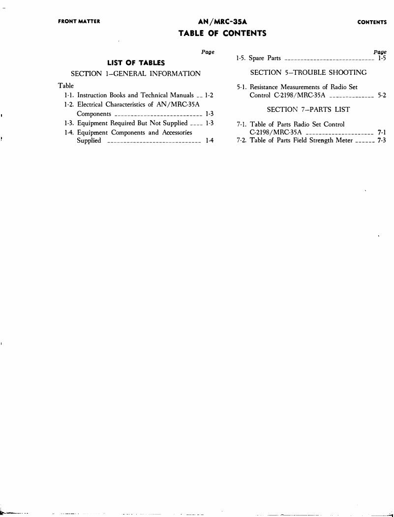
LIST OF TABLES
SECTION I-GENERAL INFORMATION
Table
Page
1-l. Instruction Books and Technical Manuals __ l-2
1-2. Electrical Characteristics of AN/MRC-35A
Components --------------------------- 1-3
1-3. Equipment Required But Not Supplied ____ 1-3
1-4. Equipment Components and Accessories Supplied ----------------------------- 1-4
Pqge 1-5. Spare Parts ---------------------------- 1-5
SECTION 5-TROUBLE SHOOTING
5-l. Resistance Measurements of Radio Set Control C-2198/MRC-35A ______________ 5-2
SECTION 7-PARTS LIST
7-l. Table of Parts Radio Set Control C-2198/MRC-35A --------------------- 7-1
7-2. Table of Parts Field Strength Meter ______ 7-3
6
p.t\tet\;; -:,\, "\s-49. �4
• -:,'}.., -:,'2>,
t>-"f co\\
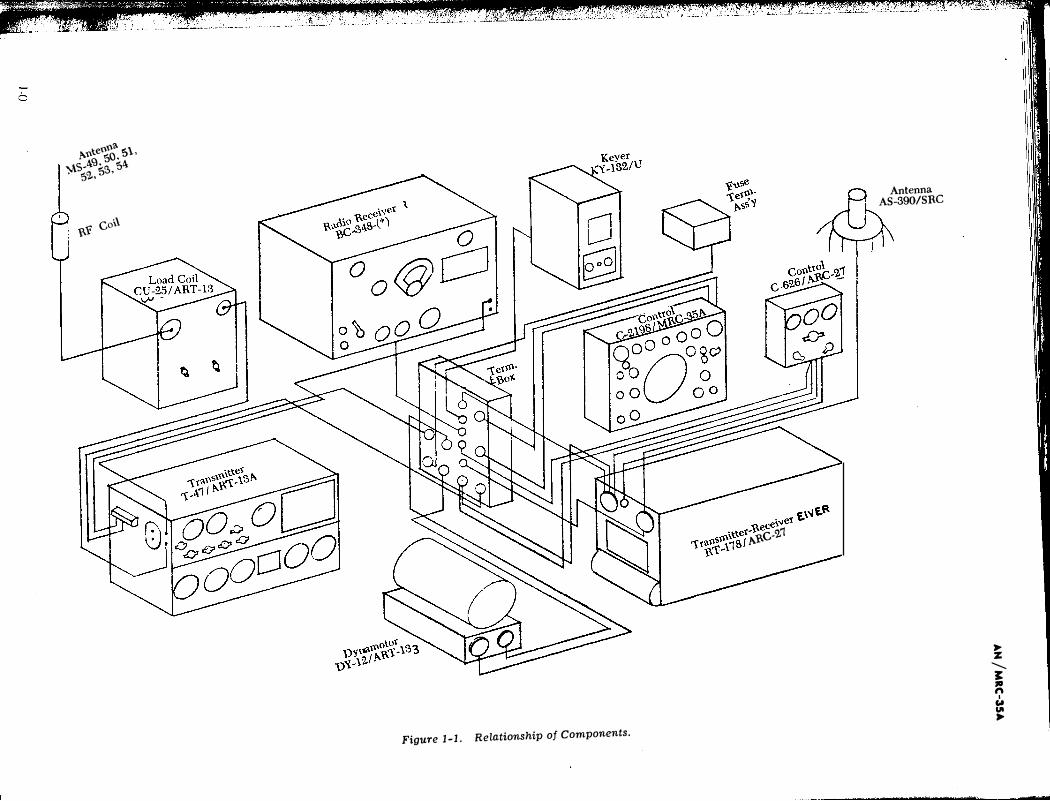
Figure 1-1. Relationship of Components.
.::. """"et f.\-.lf.�
\ttet-•'e._-
1't���1SI p.t>-C-'2.1
Antenna AS-390/SRC
,.. z:
......... 1: , n
I Col "'
,..
AN jMRC-35A SECTION 1 PARAGRAPH
1-1 GENERAL INFO·RMATION
GENERAL INFORMATION
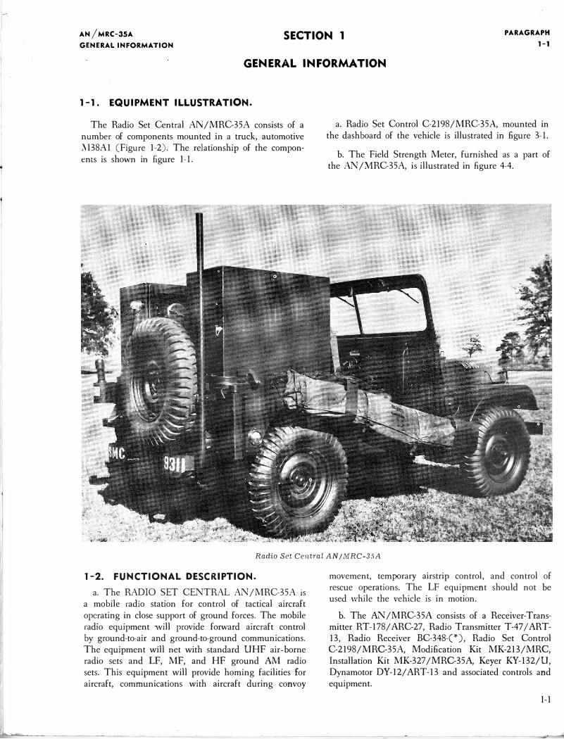
1-1. EQUIPMENT ILLUSTRATION.
The Radio Set Central AN/MRC-35A consists of a number of components mounted in a truck, automotive ;\'l38A1 (Figure 1-2). The relationship of the components is shown in £gure 1-l.
a. Radio Set Control C-2198/MRC-35A, mounted in the dashboard of the vehicle is illustrated in figure 3-l.
b. The Field Strength Meter, furnished as a part of the AN /MRC-35A, is illustrated in figure 4-4.
Radio Set Centra! AN I MRC-3SA
1-2. FUNCTIONAL DES.CRIPTION.
a. The RADIO SET CENTRAL AN/MRC-35A is a mobile radio station for control of tactical aircraft operating in close support of ground forces. The mobile radio equipment will provide forward aircraft control by ground-to-air and ground-to-ground communications. The equipment will net with standard UHF air- borne radio sets and LF, MF, and HF ground AM radio sets. This equipment will provide homing facilities for aircraft, communications with aircraft during convoy
movement, temporary airstrip control, and control of rescue operations. The LF equipment should not be used while the vehicle is in motion.
b. The AN/MRC-35A consists of a Receiver-Transmitter RT-178/ARC-27, Radio Transmitter T-47 I ART-13, Radio Receiver BC-348-(*), Radio Set Control C-2198/MRC-35A, Modification Kit MK-213/MRC, Installation Kit MK-327 /MRC-35A, Keyer KY-132/U, Dynamotor DY-12/ ART-13 and associated controls and equipment.
1-1
�-----'------ ---·-
I PARAGRAPH
1-3
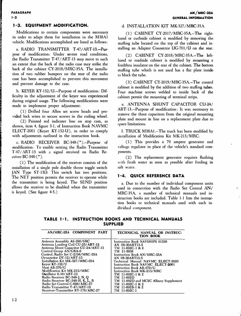
1-3. EQUIPMENT MODIFICATION.
Modifications to certain components were necessary in order to adapt them for installation in the M38A1 vehicle. Modifications accomplished are listed as follows:
a. RADIO TRANSMITTER T-47 I ART-B.-Purpose of modification: Under severe road conditions, the Radio Transmitter T-47 I ART-13 may move to such an extent that the back of the radio case may strike the back of the cabinet CY-20181MRC-35A. The installation of two rubber bumpers on the rear of the radio case has been accomplished to prevent this movement and prevent damage to the case.
b. KEYER KY-132/U.-Purpose of modification: Difficulty in the adjustment of the keyer was experienced during original usage. The following modifications were made to implement proper adjustment:
( 1) Drilled four Allen set screw heads and provided lock wires to secure screws in the coding wheel.
(2) Painted red indicater line on stop cam, as shown, item 4, figure 3-1, of Instruction Book NAVMC ELECT-2001 (Keyer KY-132-U), in order to comply with adjustments outlined in the instruction book.
c. RADIO RECEIVER BC-348-(*).-Purpose of modification: To enable netting the Radio Transmitter T-47 /ART-13 with a signal received on Radio Receiver BC-348-(*).
(l) The modification of the receiver consists of the installation of a single pole double throw toggle switch JAN Type ST-130. This switch has two positions. The NET position permits the receiver to operate while the transmitter is being keyed. The SEND position allows the receiver to be disabled when the transmitter is keyed. (See figure 4-5.)
AM /MRC-35A
GENERAL INFORMATION
d. INSTALLATION KIT .MK-327 ll\1RC-35A.
(l) CABINET CY-2017 /MRC-35A-The righthand or curbside cabinet is modified by removing the stuffing tube located on the top of the cabinet and installing an Adapter Connector UG-701/U on the rear.
(2) CABINET CY-2018/MRC-35A.-The lefthand or roadside cabinet is modified by mounting a feedthru insulator on the rear of the cabinet. The bottom stuffing tube which is not used has a Rat plate inside to block the tube.
(3) CABINET CY-2019/MRC-35A.-The control cabinet is modified by the addition of two stuffing tubes. Four machine screws welded to inside back of the cabinet permit the mounting of terminal strips.
e. ANTENNA SHUNT CAPACITOR CU-24/ ART-B.-Purpose of modification: It was necessary to remove the three capacitors from the original mounting plate and mount in line on a replacement plate due to space limitations.
f. TRUCK M38Al.-The truck has been modified by installation of Modification Kit .l\iK-213/MRC.
( 1) This provides a 70 ampere generator and Yoltagc regulator in place of the vehicle's standard components.
(2) The replacement generator requires Rushing with fresh water as soon as possible after fording in salt water.
1-4. QUICK REFEREtNCE DAT.A
a. Due to the number of individual component units used ·in connection with the Radio Set Central AN I
MRC-35A, a number of technical manuals and instruction books arc included. Table 1-1 lists the instruction books or technical manuals used with each individual component.
TABLE 1-1. INSTRUCTIO·N BOOKS .AND TECHNICAL MANUALS
SUPPLIED
1-2
AN/MRC-35A COMPONENT PART
Antenna Assembly AS-390/SRC Antenna Loading Coil CU-25/ ART-13 Antenna Shunt Capacitor CU-24/ ART -13 Control Group AN/GRA-6 Control, Radio Set C-2198/MRC-35A Oynamotor DY-12/ART-13 Installation Kit MK-327/MRC-35A Keyer KY-132/U :-.last AB-370/G Modification Kit MK-213/MRC Oscillator 0-16/ ART-13 Hadio Receiver BC-348-J, N, Q Radio Receiver BC-348-H, K, L, R Hadio Set Control C-626/ ARC-27 Radio Transmitter T-47/ART-13 Receiver-Transmitter RT -178/ ARC-27
TECHNICAL MANUAL OR INSTRUCTION BOOK
Instruction Book NAVSHIPS 91338 AN 08-30ART13-5 TM ll-692C-l & 2 TM 11-5038 Instruction Book AN I MRC-35A AN 08-30ART13-5 Technical Manual NAVMC ELECT-2020 Instruction Book NAVMC ELECT-2001 Instruction Book AB-370/G Instruction Book MK-213/MRC TM ll-692C-l & 2 TM ll-692D TM 11-692D and MCSC Albany Supplement TM ll-692C-1 & 2 TM ll-692B-1 & 2 TM ll-692C-1
••
..
AN/MRC-3SA
GENERAL INFORMATION
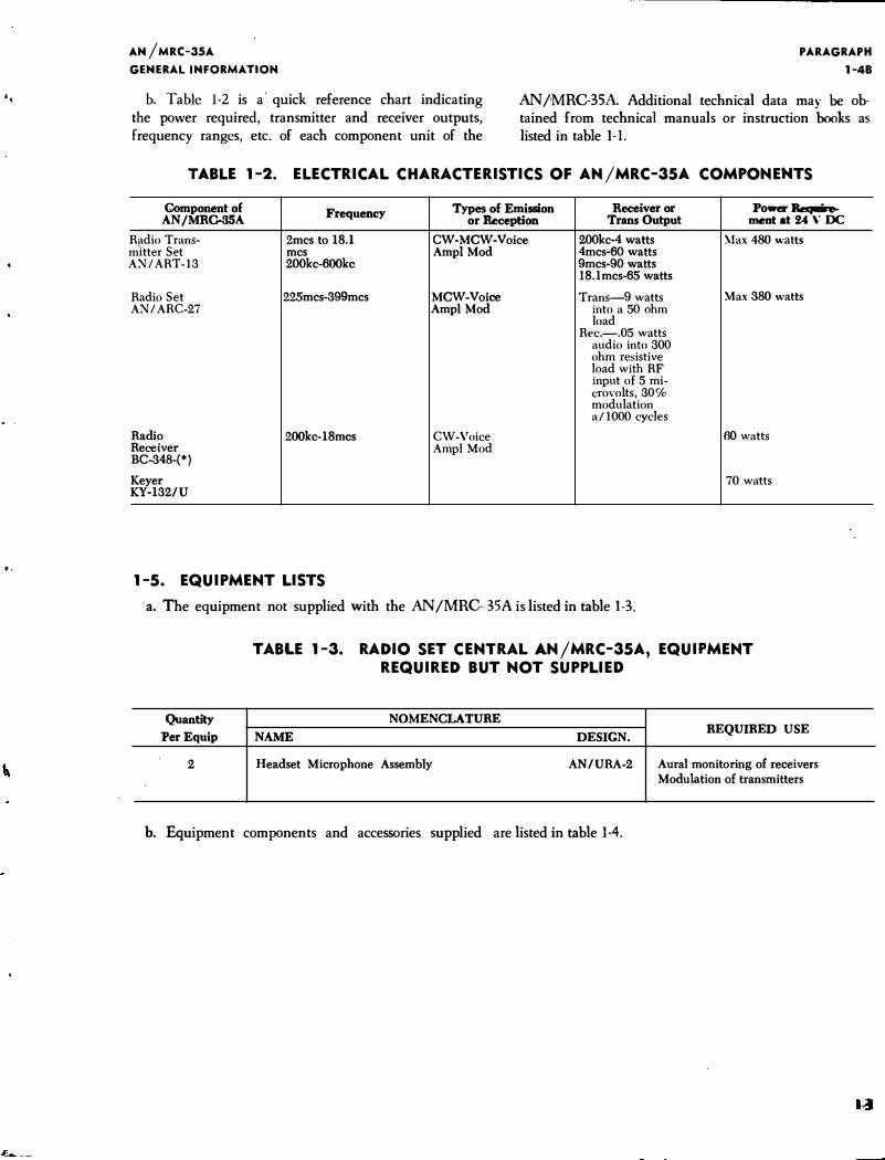
b. Table 1-2 is a· quick reference chart indicating the power required, transmitter and receiver outputs, frequency ranges, etc. of each component unit of the
PARAGRAPH
1-48
AN/MRC-35A Additional technical data may be obtained from technical manuals or instruction books as listed in table 1-l.
TABLE 1-2. ELECTRICAL CHARACTERISTICS OF AN/MRC-35A COMPONENTS
Component of Frequency Types of Emission Recei'l(er or Powrr Reqaire-AN/MRG-35A or Reception Trans Output ment at 24 Y DC
Radio Trans- 2mcs to 18.1 CW-MCW-Voice 200kc-4 watts \lax 480 watts mltter Set mcs Ampl Mod 4mcs-60 watts AN/ ART-13 200kc-600kc 9mcs-90 watts
18.lmcs-65 watts
Radio Set 225mcs-399mcs MCW-Voice Trans-9 watts Max 380 watts AN/ ARC-27 Amp! Mod into a 50 ohm
load Rec.-.05 watts
audio into 300 ohm resistive load with RF input of 5 mi-crovolts, 30% modulation a/ 1000 cycles
Radio 200kc-18mcs CW-Voice 60 watts Receiver Amp! Mod BC-348-(*)
Keyer 70 watts KY-132/U
1-5. EQUIPMENT LISTS
a. The equipment not supplied with the AN/MRC- 35A is listed in table 1-3.
Quantity
Per Equip
2
TABLE 1-3. RADIO SET CENTRAL .A.N/MRC-35A, EQUIPMENT REQUIRED BUT NOT SUPPLIED
NOMENCLATURE
NAME DESIGN. REQUIRED USE
Headset Microphone Assembly AN/URA-2 Aural monitoring of receivers Modulation of transmitters
b. Equipment components and accessories supplied are listed in table 1-4.
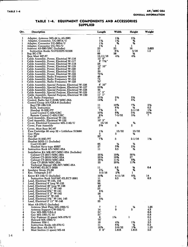
TABLE 1-4 AM /MRC-35A
GENERAL IMFORMAT10M
TABLE 1-4 •. EQUIPMENT COMPONENTS AND ACCESSORIES SUPPLIED
Qty. Description Length Width Height Weight
1 Adapter, Antenna (MS-44 to AS-390) 7 H2 2% 1 Adapter, Connector, UG-567A/U 111'4 114 % 1 Adapter, Connector UG-565A/U 11f.! % %
1 Adapter, Connector UG-701/U 11f.! 1 1 1 Antenna AS-390/ SRC (Includes) 23 23 16 3.625 2 Instruction Books NAV SHIPS 91338 11 81f.! 3/16 1.3 1 Bag BG-176 66 36 lh 1 Base Mast MP-57 12 -11/16 41f.! 4% 1 Cable Assembly, Power, Electrical W-116 12' 9"
1 Cable Assembly, Power, Electrical W-117 8' 7%" 1 Cable Assembly, Power, Electrical W-118 28 1 Cable Assembly, Power, Electrical W-119 12' 10" 1 Cable Assembly, Power, Electrical W-120 47 1 Cable Assembly, Power, Electrical W-121 39 1 Cable Assembly, Power, Electrical W-122 79¥4 1 Cable Assembly, Radio Frequency W-123 48 1 Cable Assembly, Radio Frequency W-124 74
1 Cable Assembly, Radio Frequency W-125 70' 1 Cable Assembly, Special Purpose, Electrical W-126 8' 10" 1 Cable Assembly, Special Purpose, Electrical W-127 23% 1 Cable Assembly, Special Purpose, Electrical W-128 44 1 Cable Assembly, Special Purpose, Electrical W-129 11' 3" 1 Cable Assembly, Special Purpose, Electrical W-130 11' 1" 1 Coil, Radio Frequency 131f.! 21f.! 21f.! 1 Control, Radio Set C-2198/MRC-35A 14% 9 4¥4 1 Control Group AN/GRA-6 (Includes) 1 Bag CW-189/GR 11 10% 7% 2% 2 Book, Instruction 11 81f.! lfs 0.5 1 Handset H-33E/PT 7'1/s 3 2 -1/16 1% 1 Local Control C-434/GRC 10lfs 8% 31f.! 10% 1 Remote Control C-433/GRC 8¥4 7 -3/32 31f.! 7 1 Cord Assembly, Electrical W-131 37 1 Cord Assembly, Electrical W-132 10' 3" l Cover, Electrical Connector MX-1142/U 13/16 % %
1 Cover, Fuse Assembly 5lfs 3 2 1 Cover, Mast Base BG-67 1 Fuse Cartridge 60 amp 32 v Littlefuse 513060 11f.! 13/32 13/32 1 Guy Plate 3 3 lfs 3 Guy 20' 20' 1 Handset H-33E/PT 7Ys 3 2 -1/16 1% 2 Headset MHS-11 (Includes) 1 Cord CD-307 65 If.! If.! 1 Headset N al type 49507 27 5% 21f.! 2 Instruction Boo AN/MRC-35A 11 8.5 14 1 Installation Kit MK-327 /MRC-35A (Includes) 1 Cabinet CY-2017/MRC-SSA 3514 19% 301f.! 1 Cabinet CY-2018/MRC-35A 35¥4 19% 27 1 Cabinet CY-2019/MRC-SSA 161h 111f.! 5% 1 Case CY-2016/MRC-35A 35 2014 11% 2 Technical Manual MK-327 /MRC-35A
NA VMC-ELECT -2020 11 8.5 % 0.4 4 Insulator Strain IN -86 4¥4 % % 1 Key, Telegraph J-37 5 -3/16 2% 1 1 Keyer KY-132/U (Includes) 10% 4 -11/16 81!4 14 2 Instruction Book NAVMC-ELECT-2001 11 8.5 If.! 0.5 2 Lead, Electrical W-133 , 134 35 1 Lead, Electrical8'long W-135 96 1 Lead, Electrical40' long W-136 40' 1 Lead, Electrical2' 1" W-140 25 1 Lead, Electrical6lh" W-141 61h 1 Lead, Electrical3' 2" W-142 38 1 Lead, Electrical9" W-143 9 2 Lead, Electrical3lh" W-144 , 145 31f.! 1 Lead, Electrical2' 11" W-146 35 1 Mast AB-370/G (Includes) 1 Antenna Mast Plate MX-1592/G 7 7 ¥4 1.25 1 Antenna Support CW-332/G 14 9 5 4.5 4 Guy MX-382/GRA-4 31' 0.8 4 Guy MX-1591/G 31' 31' 0.8 6 Guy Fastener (2 spare) MX-379/U 6 1¥4 1 0.2 1 Halyard MX-1593/U 75' 1.5 1 Hammer HM-1 16 41f.! 11f.! 2.5 2 Instruction Books AB-370/G 11 8% lfs 0.2 1 Mast Base AB-154/U 18% 2 -9/32 1% 1.25 5 Mast Section (1 spare) MS-44 5' 6" 1.615 1.615 3.0
1-4
''-··}
AN /MRC-35A TABLE 1-4
GENERAL INFO,RMATION
Qty. Deseription Length Width Height Weight
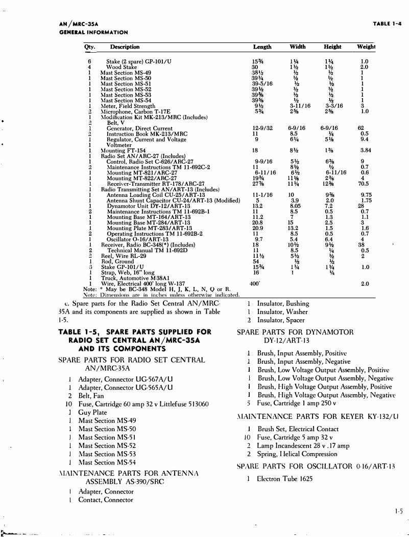
6 Stake (2 spare) GP-101/U 153/4 Il/4 Jl/4 1.0 4 Wood Stake 30 1% 1% 2.0 1 Mast Section MS-49 :38�':! % % 1 1 Mast Section MS-50 39¥4 Ifz % 1 1 .Mast Section l\-IS-51 39-5/16 % % 1 1 Mast Section MS-52 39% % lh 1 1 Mast Section MS-53 39o/s · lh lh 1 1 �1ast Section MS-54 39o/s lh % 1 1 Meter, Field Strength 9% 3-11/16 3-3/16 3 2 �1icrophone, Carbon T-17E .5% 2o/s 2o/s 1.0 1 �lodification Kit MK-213/MRC (Includes) 2 Belt, V
Generator, Direct Current 12-9/32 6-9/16 6-9/16 62 2. lnstmctiou Book MK-213/MRC 11 8.5 lf4 0.5 1 Hegulator, Current and Voltage 9 6% 5 lfs 9.4 1 Voltmeter 1 �1ounting FT-154 18 8% 13fs 3.84 1 Hadio Set AN I ARC-27 (Includes) 1 Control, Hadio Set C-626/ AHC-27 9-9/16 5% 63fs 9 2. Maintenance Instructions TM 11-692C-2 11 8% lh 0.7 1 Mounting MT-821/ ARC-27 6-11/16 6% 6-11/16 0.6 1 Mounting MT -822/ AHC-27 19% lllfs 23fs 4 l Receiver-Transmitter RT -178/ AHC-27 27'¥s 11¥4 12o/s 70.5 1 Hadio Transmitting Set AN/ART-13 (Includes) 1 Antenna Loading Coil CU-25/ ART -13 11-1/16 10 9o/s 9.75 1 Antenna Shunt Capacitor CU-24/ART-13 (Modified) 5 3.9 2.0 1.75 1 Dynamotor Unit DY-12/ART-13 2 Maintenance Instructions TM ll-692B-l 1 Mounting Base MT-164/ ART-13 1 Mounting Base MT-284/ART-13 1 Mounting Plate MT-283/ ART-13 2 Operating Instructions TM 11-692B-2 1 Oscillator 0-16/ ART-13 1 Receiver, Radio BC-348(*) (Includes) 2 Technical Manual TM ll-692D 2 Reel, Wire RL-29 1 Rod, Ground 3 Stake GP-101/U 1 Strap, Web, 16" long 1 Truck, Automotive M 38A1 1 Wire, Electrical 400' long W-137
Note: * May be BC-348 Model H, J, K, L, N, Q or H.
13.2 11 11.2 20.8 20.9 11 9.7
18 11 !Ph 54 15% 16
400'
8.05 7.2 28 8.5 0.5 0.7 7 1.3 1.1
15 2.5 3 13.2 1.5 1.6
8.5 0.5 0.7 5.4 6.4 4
10% 9% 38 8.5 % 0.5 5% lfz 2
lh lfz 1% llf4 1.0 1 lf4
2.0
:'1/ote: Dimensions are in inches unless otherwise indicated.
c. Spare parts for the Radio Set Central AN/MRC-35A and its components are supplied as shown in Table 1-5.
TABLE 1-5, SPARE PARTS SUPPLIED FOR RADIO SET CENTRAL AN/MRC-35A
AND ITS COMPONENTS
SPARE PARTS FOR RADIO SET CENTRAL AN/MRC-35A
I Adapter, Connector UG-567A/U 1 Adapter, Connector UG-565A/U 2 Belt, Fan
10 Fuse, Cartridge 60 amp 32 v Littlefuse 513060 Guy Plate Mast Section MS-49 Mast Section MS-50 Mast Section MS-51 Mast Section MS-52 Mast Section MS-53 Mast Section MS-54
.\IAINTENANCE PARTS FOR ANTENNA ASSEMBLY AS-390/SRC
Adapter, Connector Contact, Connector
Insulator, Bushing Insulator, Washer
2 Insulator, Spacer
SPARE PARTS FOR DYNAMOTOR DY-12/ ART-13
Brush, Input Assembly, Positive Brush, Input Assembly, Negative Brush, Low Voltage Output Assembly, Positive Brush, Low Voltage Output Assembly, Negative Brush, High Voltage Output Assembly, Positive Brush, High Voltage Output Assembly, Negative
5 Fuse, Cartridge I amp 250 v
.\IAINTENANCE PARTS FOR KEYER KY-132/U
Brush Set, Electrical Contact I 0 Fuse, Cartridge 5 amp 32 v
2 Lamp Incandescent 28 v .17 amp 2 Spring, I lelical Compression
SPAHE PARTS FOR OSCILLATOR 0-16/ART-13
Electron Tube 1625
1-5
PARAGRAPH 1-5
SPARE PARTS FOR RADIO RECEIVER BC-348 MODELS J, N, AND Q
Brush and Spring, Low Voltage Output, Positive Brush and Spring, Low Voltage Output, Negative
2 Brush and Spring, High Voltage Output Electron Tube 6K6GT Electron Tube 6SA7 Electron Tube 6SJ7
2 Electron Tube 6SK7 Electron Tube 6SR7 Electron Tube 991
5 Fuse, Cartridge 5 amp 32 v
1 Lamp, Incandescent LM-27
SPARE PARTS FOR RADIO RECEIVER MODELS H, K, L, AND R
Brush and Spring, Low Voltage Output, Positive 1 Brush and Spring, Low Voltage Output, Negative 2 Brush and Spring, High Voltage Output
Electron Tube 6B8 Electron Tube 6C5 Electron Tube 6F7 Electron Tube 6}7
1 Electron Tube 6K6GT 2 Electron Tube 6K7
Electron Tube 991 5 Fuse, Cartridge 5 amp 32 v 1 Lamp, Incandescent LM-27
SPARE PARTS FOR RADIO TRANSMITTER
1-6
T-47 I ART-13
Electron Tube 6V6 Electron Tube l2SA7 Electron Tube l2SJ7 Electron Tube l2SL7GT Electron Tube 811 Electron Tube 813 Electron Tube 837 Electron Tube 1625 Lamp, Incandescent LM-38
AN /MRC-35A
GENERAL INFORMATION
SPARE PARTS FOR RECEIVER-TRANSMITTER RT-1781 ARC-27
3 Electron Tube 6}4 4 Electron Tube 6AG5 4 Electron Tube l2AT7 4 Electron Tube 6BA615749 2 Electron Tube 6AL5W 15726 I Electron Tube 6AQ5 I 6005 I Electron Tube 2C43 1 Electron Tube 2C39A 1 Electron Tube 829B
Electron Tube 6AK5W 15654 Brush set, Continental E Co, Electrolux or Winco (Includes)
6 Brushes
SPART PARTS FOR RADIO SET CONTROL C-2198IMRC-35A
2 Lamp, Incandescent, LM-38
1-6. EQUIPMENT SIMILARITIES
Various models of equipment have been used to fabricate the Radio Set Central ANIMRC-35A as follows:
a. DYNAMOTOR UNIT.-Models DY-111 ART-13, DY-121 ART-13 and DY-17 I ART-13 are mechanically and electrically interchangeable. (See TM 11-692B-2)
b. RADIO RECEIVER BC-348-(*).-Models BC-348-J, N and Q are mechanically and electrically interchangeable. Models BC-348-H, K, L and R are mechanically and electrically interchangeable. All models listed are mechanically and electrically interchangeable. There is considerable difference in the internal wiring and parts used between the two groups of receivers including the electron tube complement which is completely different, but this does not affect the external \\iring or mounting of the receiver. For details of the wiring and parts differences, see TM 11-692D and attached supplement provided with those equipments containing the BC-348-R.
c. SPECIAL NOTICE.-The receiver models throughout this book when mentioned collectively are indicated hy an asterisk as follows: Radio Receiver BC-348-(*).
•
•
I -·
AN/MRC-35A INSTALLATION
SECTION 2 PARAGRAPH 2-1
INSTALI..ATION
2-1. UNPACKING AND HANDLING.
No unusual precautions are necessary in unpacking the equipment. It is suggested that the fan belts supplied as a maintenance part be retained in the spare parts cabinet CY-2016/MRC-35A. The fan belts are unusual as they are not standard and may be difficult to replace .
2-2. SITE SELECTION.
For efficient operation of Radio Set Central AN I MRC-35A, the best available site should be chosen. Where possible, choose a flat, well-drained, elevated location for the installation of the radio set. Signals from the AN/MRC-35A have a greater range if the antenna is high and clear of hills, buildings, cliffs, densely wooded areas, and other obstructions. Depressions, valleys and other low places are poor locations for radio reception and transmission because the surrounding high terrain absorbs RF energy. Weak or otherwise undesirable signals may be expected if the radio set is operated under or close to steel bridges, underpasses, power lines, buildings or power units. Normally, transmission over water is better than over land. In locating the antenna, avoid obstructions which are about two or three degrees above the horizontal plane of the antenna in the direction of desired transmiSsiOn. This is approximately 200 to 300 feet at a distance of one mile from the antenna.
2-3. POWER REQUIREMENTS AND DISTRIBUTION.
The vehicle generator of the AN/MRC-35A is replaced by a heavy duty generator that is capable of producing up to 70 amps of current. No auxiliary generator sets are required.
2-4. INSTALLATION LAYOUT.
The Radio Set Central AN/MRC-35A is supplied to the using activity with all interconnecting cables installed.
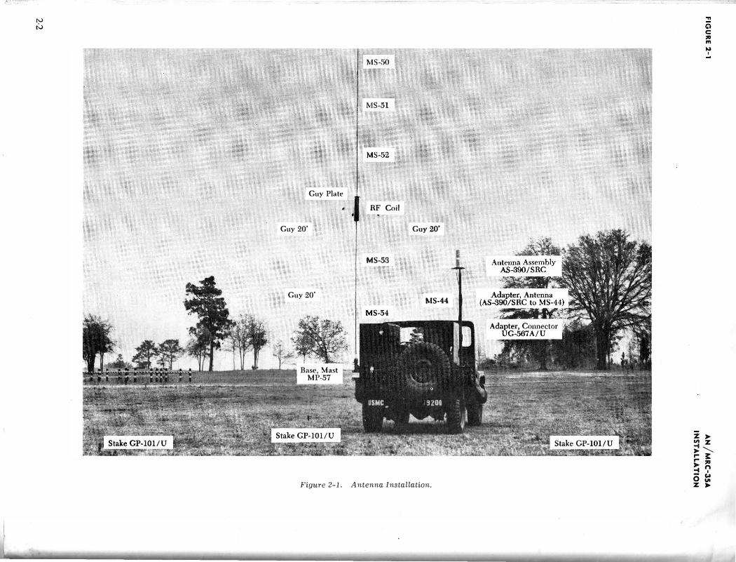
a. Operation of the Receiver-Transmitter RT-178/ ARC-27 requires installation of Antenna Assembly AS-390/SRC with Mast AB-370/G and Mast Adapter (MS-44 to AS-390/SRC). The complete mast is not always used in the operation of the AN/ ARC-27. Its usc is dependent upon the terrain and the line of sight path requirement for proper transmission and reception. If height is a requirement, the complete mast can be used. (See Instruction Book for Mast AB-370/G.) If height is not a requirement, one or two sections of the mast, as necessary, may be utilized and mounted on
the vehicle mast bracket. (See figure 2--1.)
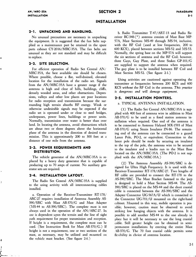
b. Radio Transmitter T-47 /ART-13 and Radio Receiver BC-348-(*) antenna consists of Mast Base MP-57 A, Mast Sections MS-49 through MS-54, inclusive, with the RF Coil (used at low frequencies, 200 to 600 KCS), placed between sections MS-52 and MS-53. Normally, the spring base on the MP-57 A will support the six sections of antenna and the RF Coil; however, three Guys, Guy Plate, and three Stakes GP-101/G are supplied to support the antenna when required. The guy plate is to be installed between RF Coil and Mast Section MS-52. (See figure 2-1.)
Using activities are cautioned against operating the transmitter at frequencies between 200 KCS and 600 KCS without the RF Coil in the antenna. This practice is dangerous and will damage equipment.
2-5 . . INSTALLATION POINTERS.
a. TYPICAL ANTENNA INSTALLATION.
(I) The Radio Set Central AN/MRC-35A is supplied with 400 feet of antenna wire in addition to Mast AB-370/G to be used as a fixed station antenna ·installation when required. One end of the antenna is to be connected to Antenna Halyard MX-1593 of Mast AB-370/G using Strain Insulator IN-86. The remaining end of the antenna can be connected to a guyed Lance Pole, P0-2, or equivalent. Connection to the lance pole should be made by securing an insulator to the top of the pole, the antenna wire to be secured to the insulator and a leadin run to the Mast Base located on the AN/MRC-35A. (The P0-2 is not supplied with the AN/MRC-35A.)
(2) The Antenna Assembly AS-390/SRC is designed for Ultra High Frequency. It is used with the Receiver-Transmitter RT-178/ ARC-27. Two lengths of RF cable arc provided to connect the RT-178 to the AS-390/SRC. The Mast Bracket fastened to the jeep is designed to hold a Mast Section MS-44. The AS-390/SRC is placed on the MS-44 and the short coaxial cable is connected between the AS-390/SRC and the Adapter Connector UG-567 A/U which is connected to the Connector UG-701/U mounted on the right-hand cabinet. Mounted in this way, mobile operation is possible; however, caution must be observed to avoid striking low hanging objects with the antenna. It is possible to add another MS-44 to the one already in place but it will be necessary to use the long coaxial cable. Still greater height can be obtained in semipermanent installations by erecting the entire Mast AB-370/G. The 70 foot coaxial cable permits some flexibility in choice of antenna location.
2-1
N
N
Guy Plate
RF Coil
Guy 20' Guy20'
MS-53
Guy 20' MS-44
Figure 2-1. Antenna Installation.
... () c: :1:1 m
� I
z ). In z -t'-.... � � .... ;JlJ ,.. n -t I - Col 0 "' z ,..
•
AN jMRC-35A
INSTALLATION
b. GROUND ROD AND COUNTERPOISE.
,\fter the whip antenna and Antenna Assembly AS-390/SRC are installed, (see figure 2-1) it is advisable to install the ground rod which is provided with the AN /:\1HC-35A. The ground rod should be driven into the ground approximately four feet and be connected to the AN /MRC-35A vehicle chassis utilizing the 10 feet of braid supplied. For permanent installations, a counterpoise system can be fabricated using field telephone wire or similar items. The counteqJoise should
consist of a minimum of eight radials approximately
PARAGRAPH
2-SB
the length of one quarter wave at the lowest frequency to be utilized in transmissions. The center of the counterpoise system to be connected to the vehicle chassis of the AN/MRC-35A.
c. Control Group AN /GRA-6 is supplied as part of the AN /MR:C-35A for purposes of controlling the equipment components from a remote position. Two Audio Rcceptablcs, J-801 and J-802 are located on Radio Set Control C-2198/MRC-35A. These audio receptacles are used to receive the plugs of Local Control C-434/ GRC which is a part of the control group.
Figure 2-2. Field Strength Meter.
2-3
PARAGRAPH
2-SD
d. An interconnecting diagram for ·Radio Set Central AN /l\1RC-35A is shown in figure 5-2. Designation of cables and interconnecting data is shown to aid m
trouble shooting equipment.
2-6. INSPECTION AND ADJUSTMENTS.
a. Section 3 outlines detailed procedures for the operation of equipment components. Table 1-1 of section one shows the technical manuals and instruction books that apply to each component of the AN /MRC 35A. Detailed information on adjustments required for each component may be obtained from the technical manuals or instruction books.
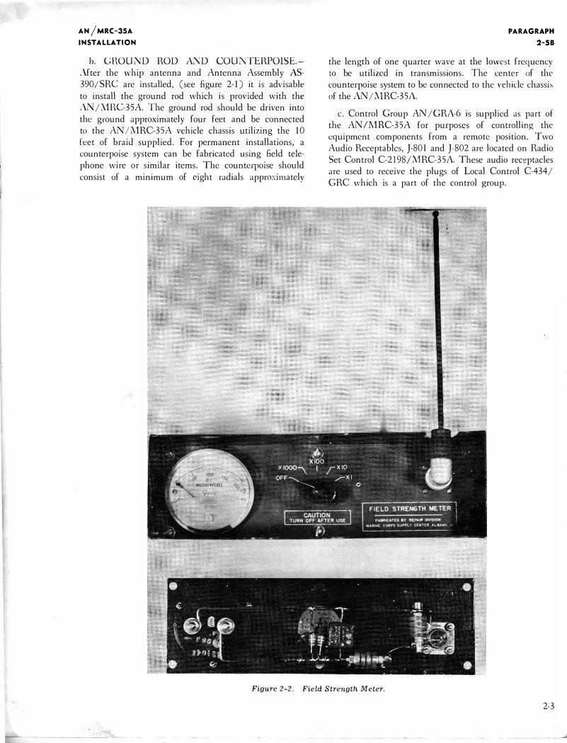
b. Radio frequency output indications of the T-47 I
ART-13 and the RT-178/ ARC-27 transmitters may be obtained by utilization of the field strength meter supplied with the AN/MRC-35A. (See figure 2-2.) The
2-4
AN/MRC-35A
INSTALLATION
field strength meter should be placed at some convenient location on the AN/MRC-35A vehicle body. With the meter antenna extended and the meter multiplier knob turned to X1000, transmitter should be keyed. A relative field strength indication will appear on the panel meter. If no indication appears, tum multiplier knob to the next lowest multiplier position (XlOO), etc. until a field strength indication is received. Always turn field strength meter to the OFF position at the termination of each test. After using the meter to tune one transmitter and it is intended that a second one be tuned, it is necessary to turn �he meter switch to the OFF position to prevent any damage to the meter should the second transmitter have a higher field strength.
CAUTION
Always turn field strength meter to OFF position at the termination of each test.
i:i, ' l.i.
PARAGRAPH
3-3A
CHANNEL SELECTOR Selects the channel of the RT-178/ARC-27
GUARD, BOTH, Guard-Transmit and receive MAIN T /R on the guard freq.
Both-Receive on the guard frequency and transmit and receive on the preset channel
Main T I R-Transmit and receive on the preset channels.
OFF ON REC-TRANS Turns the RT-178/ARC-27 on RT-178/ARC-27 and off
b. SEQUENCE OF OPERATION.
(1) LF, MF, HF equipment. Before using, see TM ll-692D and TM II-692B-2 to set Radio Transmitter T-47 I ART-13 and Radio Receiver BC-348-(*) on the desired frequency. The receiver is turned on for presetting on frequency by the use of Rec BC-348 ON-OFF switch of the radio set control. Mter the transmitter is set to the desired frequency, the LOCALRE:\10TE switch is placed in the REMOTE position. Do not operate the transmitter at frequencies below 600 Kc without installing the RF Coil in whip antenna beween l\1ast Sections MS-52 and MS-53.
(2) UHF equipment. Before using, see paragraph 3-4 to preset the Receiver-Transmitter RT-1781 ARC-27 to guard channel and the 18 preset channels. After all channels are preset, the LOCAL-REMOTE switch is placed in the REMOTE position and the TONEVOICE switch is placed in the VOICE position for voice operation and TONE for MCW operation.
(3) Volume controls for both receivers are attenuators in the line between the receiver and the sneaker on the Radio Set Control C-21981MRC-35A. The C\V, l\1C\V, VOICE controls on the Radio Reccin.'r BC-348( * ) arc set for the desired operation.
( 4) Keycr KY-l32IU
(a) Keyer KY-1321U coding wheel is set up on the assigned code by following the procedure shown in the instruction book on the keyer. (See instruction book NAVMC ELECT-2001.)
(b) The Radio Transmitter T-47 I ART-13 is first set up for operation on CW as described in TM II-692B-2 and turned to REMOTE operation.
(c) When the transmitter has been properly set up and control has changed over to the Radio Set Control by placing the LOCAL-REMOTE switch of the transmitter in the REMOTE position, the Radio Set Control S-801 (OFF-VOICE-CW-MCW) is placed in the CW position. The keyer is turned on when it is desired to transmit the code signal.
(d) To cease transmitting, it is important that the keyer be turned off first.
3-2
AN /MRC-35A
OPERA TOR'S SECTION
c. NETTING OF RADIO TRANSMITTER T-47 I ART-13 WITH RECEIVER BC-348-("').
(I) Tune receiver to frequency of station with which it is intended to net.
(2) Turn on the CW OSCILLATOR in the receiver and adjust to zero-beat with the stations carrier.
(3) Place NET-SEND function switch on the receiver to NET position.
(4) Place CALIBRATE-TUNE-OPERATE function switch to TUNE on the transmitter.
(5) Observe frequency setting on the receiver and adjust the transmitter oscillator frequency coarse and fine controls to the same approximate frequency observed on receiver.
(6) Place transmitter function switch to VOICE position. Key the transmitter and adjust the OSCILLATOR FINE frequency control to the exact netting frequency as indicated by a zero beat with the receiver frequency setting.
(7) Tune antenna circuit of the transmitter, place CALIBRATE-TUNE-OPERATE function switch in OPERATE position. Place PHONE-CW-MCW function switch to desired type of emission. Place NETSEND function switch on the receiver to SEND position for automatic muting when the transmitter is keyed.
d. FREQUENCY ADJUSTMENT OF RADIO TRANSMITTER T-47 I ART-13 FROM CALIBRATION CHART.
(I) Place NET-SEND function switch on the receiver to SEND position.
(2) Locate C. F. I. calibration check point on calibration chart nearest the listing of the desired frequency. (Sec chart in TM ll-692B-2.) Set coarse and line oscilbtor controls of the transmitter.
(3) Place CALIBR ATE - TUNE-O PERATE switch to CALIBRATE position. Adjust the fine oscillator frequency to exact C. F. I. check frequency as indicated by zero-beat with the C. F. I. crystal frequency. 1\djust the fine oscillator corrector to correspond with the calibration check point listing from the calibration chart.
( 4) Adjust the fine oscillator frequency control to the numerical listing of the calibration book for the desired operating frequency.
(5) Place the CALIBRATE - TUNE - OPERATE function switch to TUNE position and tunc the antenna circuits.
(6) Place the CALIBRATE- TUNE - OPERATE function switch to OPERATE, and the PHONE-CWl\1CW function switch to the type of emission desired.
c. PRECAUTIONS.-There are certain precautions
AN
jM
RC
-3
5A
OP
ER
AT
OR
'S S
EC
TI
O'N
FI
GU
RE
3-
2
3-3
PARAGRAPH
3-3E
that must be observed with the usc of this equipment.
(I) The RF Coil is only used on the low frequency range and should never be used when the vehicle is moving because of the possibility of damaging the coil either by excessive whipping of the antenna or by striking low hanging objects.
CAUTION
Do not operate the Radio Transmitter T-47 I !\RT-13 at low frequencies without the RF Coil installed.
CAUTION
Remove the RF Coil before moving the vehicle.
(2) The Antenna Loading Coil CU-251 ART-13 is not designed to withstand the high voltage generated with modulation under conditions of fixed wire antennas on voice and MCW operation. It is permissible to place the transmitter function switch on VOICE for netting purposes without modulation.
CAUTION
Do not amplitude modulate the Radio Transmitter T-47 I ART-13 on frequencies below 600 Kcs.
(3) The emission switch should not be operated when the transmitter is keyed either by pressing the key, the microphone switch, or by turning on the keyer KY-1321U. Failure to observe this precaution mav cause arcing at contacts of relays.
CAUTION
Do not operate emission switch when the Radio Transmitter T-47 I ART-13 is keyed.
(4) The Antenna Loading Coil CU-25Ii\RT-13 is only used in the frequency range (200 to 600 Kc). The 1\ntcnna Shunt Capacitor CU-241 ART-13 will probably only have to he used at the high frequency range or when a long wire antenna is used.
(5) The Radio Transmitter T-47 I AH.T-13 cannot be tuned to a frequency lower than 250 Kcs when only the whip antenna is installed.
(6) The top bows when secured in the transport condition are close to the rear antenna standoff insulator and leadin. There is danger of arcing unless the hows arc moved.
3-4
CAUTION
AH /MRC-35A
OPERATOR'S SECTION
Do not operate the Radio Transmitter T-4 7/ ART-13 while the top bows are in the transport condition.
(7) The ANIMRC-35A has been equipped with :\lodification Kit MK-2131l\1RC which consists of a 70 ampere generator with necessary regulator. This heavy duty generator and regulator replaces the standard components originally supplied with the model M38A1 vehicle. The generator has an open bell housing and should be immediately washed out with fresh water if it is immersed in salt water at any time.
CAUTION
Flush generator with fresh water as soon as possible after fording in salt water.
(8) The fan belts used with the vehicle are not a part of the Modification Kit MK-2131�1RC and are not a standard item. Care must be taken to keep the spare fan belts with the equipment at all times.
CAUTION
Keep spare non-standard fan belts with the vehicle at all times.
(9) The fuse in the Fuse Terminal Assembly is a
slow blow 60 ampere, 32 volt fuse and may not always be readily available. For this reason 10 spare fuses arc furnished with this equipment.
3-4. OPERATING PROCEDURES FOR RADIO SET AN/ ARC-27.
a. FUNCTIONS OF THE EQUIPMENT.-With Hadio Set AN I ARC-27 the operator may hold two way radio telephone communication on any one of 1750 frequencies between 225.0 and 399.9 me. Any eighteen of these frequncies may be preset for remote selection. Constant monitoring of a guard frequency is provided. The transmitter may he tone modulated at 1020 cycles per second if desired.
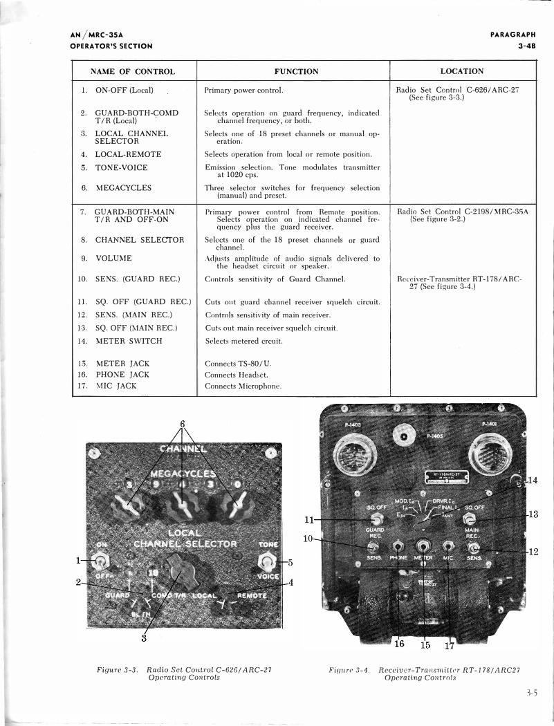
b. FUNCTIONS OF THE CONTHOLS.-A list of the controls, their function, and their location follows: (Sec figures 3-2 to 3-4 incl.)
AN jMRC-35A
OPERATOR'S SECTIO'N
NAME OF CONTROL
l. ON-OFF (Local)
2. GUARD-BOTH-COMD T/R (Local)
3. LOCAL CHANNEL SELECTOR
4. LOCAL-REMOTE
5. TONE-VOICE
6. MEGACYCLES
7. GUARD-BOTH-MAIN T/R AND OFF-ON
8. CHA NEL SELECTOR
9. VOLUME
10. SENS. (GUARD REC.)
11. SQ. OFF (GUARD REC.)
1:2. SE�S. NAIN REC.)
13. SQ. OFF (MAIN REC.)
14. METER SWITCH
1.5. �'IETER JACK
16. PHONE JACK
17. �1IC JACK
FUNCTION
Primary power control.
Selects operation on guard frequency, indicated channel frequency, or both.
Selects one of 18 preset channels or manual operation.
Selects operation from local or remote position.
Emission selection. Tone modulates transmitter at 1020 cps.
Three selector switches for frequency selection (manual) and preset.
Primary power control from Remote position. Selects operation on indicated channel frequency plus the guard receiver.
Selects one of the 18 preset channels or guard channel.
Adjusts amplitude of audio signals delivered to the headset circuit or speaker.
Controls sensitivity of Guard Channel.
Cuts out guard channel receiver squelch circuit.
Controls sensitivity of main receiver.
Cuts out main receiver squelch circuit.
Selects metered crcuit.
Connects TS-80/U.
Connects Headset.
Connects Microphone.
LOCATION
PARAGRAPH
3-48
Radio Set Control C-626/ ARC-2i (See figure 3-3.)
Radio Set Control C-2198/ .\1RC-35A (See figure 3-2.)
Receiver-Transmitter RT -178/ ARC-27 (See figure 3-4.)
Figure 3-3. Radio Set Control C-626/ ARC-27 Operating Controls
Fiuure 3-4. Receiver-Transmitter RT-178/ARC27 Operating Controls
3-5
PAI\AGRAPH
3-4C
c. SEQUENCE OF OPERATION.-Plug a microphone and headset into the appropriate jacks on the Radio Set Control C-2198/MRC-35A. The VOLUME control on the radio set control may be used to adjust the headphone level. (See Figure 3-2.)
d. RECEPTION.
(1) Operate the LOCAL-REMOTE (4) switch to the REMOTE position.
(2) Operate TONE-VOICE (5) switch to the VOICE position.
(3) Operate the GUARD-BOTH-MAIN T /R switch (on C-2198/MRC-35A) to T /R position and OFF-ON switch to ON.
( 4) Allow at least one minute for the equipment to warm up. At the end of this time, signals above the squelch level will be heard. The SENS. (13) control on the main receiver should be set to the point where only signals of the desired strength will operate the squelch. If the SENS. control on the main receiver is set too high, the set noise will itself operate the squelch, in which case a "hiss," characteristic of thermal noise, will be heard in the headset.
(5) Turn the GUARD-BOTH-.\IAli\' T /R switch to the BOTH position. Reception is now possible on
both the main and guard channel frequencies.
(6) Turn the CHANNEL switch to the desired 'preset channel. Reception and transmission will now be on this frequency.
c. TRANSMISSION .-After the equipment has been operated as above for reception, it is also ready for transmission. This is accomplished simply by pressing the microphone push-button switch. The microphone should be held in a vertical position and just touching the lips. Talk in a loud and clear voice. Do not shout into the microphone. Intelligibility of the received signals will be improved if care is taken in proper articulation of each word. Release the microphone button at the end of each transmission. This is necessary to hear incoming signals, and also reduces the load on the dynamotor.
f. OPERATION ON GUARD FREQUENCY.(See figure 3-2.) A completely separate guard channel receiver is provided in the equipment to monitor the guard frequency continuously while operating on the
3-6
AN/MRC-35A OPERATOR'S SECTION
main channel frequency. This is accomplished by placing the GUARD-BOTH-MAIN T /R switch on the BOTH position. In the MAIN T /R position, the main channel is on but the separate guard receiver is turned off. Both receivers are off during any transmission period, but sidetones will be heard in the headset.
g. To transmit on the guard frequency, the GUARDBOTH-MAIN T /R switch is placed in the GUARD position. This actually turns the separate guard receiver off but tunes the main transmitting and receiving equipment to the guard frequency.
h. TONE OPERATION.-Tone or modulated continuous wave operation can be accomplished on any of the operating frequencies, including the guard frequency, by placing the TONE-VOICE (3) switch in the TONE position. This automatically turns the transmitter on so that it is not necessary to hold the microphone button. The resulting tone modulation is at approximately 1020 cycles per second. It may be used as an emergency signal or to aid direction finder equipment.
i. STOPPING THE EQUIPMENT-To turn the equipment off, simply place the OFF-ON switch in the OFF position. However, it is desirable that the TONE-VOICE (5) switch be checked to see that it is in the VOICE position. This will avoid starting the equipment in the transmit position the next time it is turned on.
3-5. OPERATING CHECKS AND ADJUSTMENTS FOR RADIO SET .AN/ ARC-27.
a. GENERAL-Certain operating checks are necessary and must be made by the operator prior to or durin� actual operation in order to insure optimum
utility of Radio Set ,\:'\1 ,-\RC-27. Careful observance of these procedures will greatly reduce the chances of equipment failure in service, since any deviation from normal operation may be quickly reported to maintenance personnel if correction of the defect is beyond the scope of the operator.
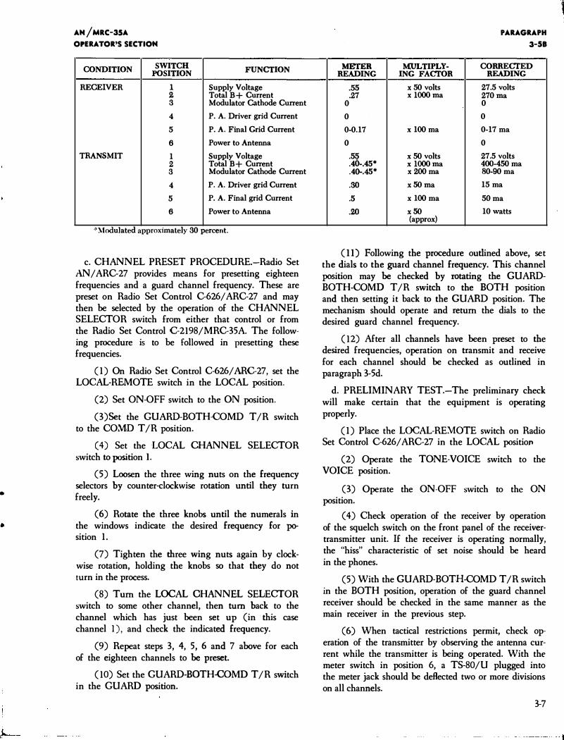
b. TEST METER READINGS.-A very good indication of how the equipment is operating may be gained by observing the indications of a TS-80/U Test Meter or equivalent plugged into the front panel of ReceiverTransmitter RT-178/ ARC-27. Typical meter readings for normal operation of Radio Set AN I ARC-27 are indicated below.
•
AM /MRC-35A
OPERATOR'S SECTION
CONDITION SWITCH POSITION
RECEIVER 1 2 3
4
5
6
TRANSMIT 1 2 3
4
5
6
FUNCTION
Supply Voltage Total B+ Current Modulator Cathode Current
P. A. Driver grid Current
P. A. Final Grid Current
Power to Antenna
Supply Voltage Total B+ Current Modulator Cathode Current
P. A. Driver grid Current
P. A. Final grid Current
Power to Antenna
*.\lodulated approximately 30 percent.
c. CHANNEL PRESET PROCEDURE.-Radio Set AN/ ARC-27 provides means for presetting eighteen frequencies and a guard channel frequency. These are preset on Radio Set Control C-626/ ARC-27 and may then be selected by the operation of the CHANNEL SELECTOR switch from either that control or from the Radio Set Control C-2198/MRC-35A. The following procedure is to be followed in presetting these frequencies.
(l) On Radio Set Control C-626/ ARC-27, set the LOCAL-REMOTE switch in the LOCAL position.
(2) Set ON-OFF switch to the ON position.
(3)Set the GUARD-BOTH-COMD T /R switch to the COMD T /R position.
(4) Set the LOCAL CHANNEL SELECTOR switch to position l.
(5) Loosen the three wing nuts on the frequency selectors by counter-clockwise rotation until they turn freely.
(6) Rotate the three knobs until the numerals in the windows indicate the desired frequency for position l.
(7) Tighten the three wing nuts again by clockwise rotation, holding the knobs so that they do not turn in the process.
(8) Turn the LOCAL CHANNEL SELECTOR switch to some other channel, then tum back to the channel which has just been set up (in this case channel 1), and check the indicated frequency.
(9) Repeat steps 3, 4, 5, 6 and 7 above for each of the eighteen channels to be preset.
(10) Set the GUARD·BOTH-COMD T /R switch in the GUARD position.
METER MULTIPLY-READING lNG FACTOR
.55 x 50 volts
.27 x lOOOma 0
0
0-0.17 x 100 rna
0
.55 x 50 volts
.40-.45* x lOOOma
.40-.45* x 200 rna
.30 x50ma
.5 x 100 rna
.20 x50 (approx)
PARAGRAPH
3-SB
CORRECTED READING
27.5 volts 270ma 0
0
0-17 rna
0
27.5 volts 400-450 rna 80-90 rna
15 rna
50 rna
10 watts
( 11) Following the procedure outlined above, set the dials to the guard channel frequency. This channel position may be checked by rotating the GUARDBOTH-COMO T /R switch to the BOTH position and then setting it back to the GUARD position. The mechanism should operate and return the dials to the desired guard channel frequency.
(12) After all channels have been preset to the desired frequencies, operation on transmit and receive for each channel should be checked as outlined in paragraph 3-5d.
d. PRELIMINARY TEST.-The preliminary check will make certain that the equipment is operating properly.
(l) Place the LOCAL-REMOTE switch on Radio Set Control C-626/ ARC-27 in the LOCAL position
(2) Operate the TONE-VOICE switch to the VOICE position.
(3) Operate the ON-OFF switch to the ON position.
( 4) Check operation of the receiver by operation of the squelch switch on the front panel of the receivertransmitter unit. If the receiver is operating normally, the "hiss" characteristic of set noise should be heard in the phones.
(5) With the GUARD-BOTH-COMD T /R switch in the BOTH position, operation of the guard channel receiver should be checked in the same manner as the main receiver in the previous step.
(6) When tactical restrictions permit, check operation of the transmitter by observing the antenna current while the transmitter is being operated. With the meter switch in position 6, a TS-80/U plugged into the meter jack should be deflected two or more divisions on all channels.
3-7
J q li ji I
il :I
;r I
·f
il II I" ij'· !
iJ !
I
l I I '..,_
PARAGRAPH
3-SD
(7) Operation of the transmitter should also operate the sidetone which will be heard in the headphones.
(8) Repeat the above checks on each of the preset frequencies if time permits. This may be accomplished by making the checks·at each of the eighteen positions of the CHANNEL SELECTOR switch.
NOTE
All checks should be made with the vehicle engine running since the transmitter power output will vary with battery voltage.
(9) When tactical restrictions and time permit, check of the complete system should be made by establishing two-way communication with an airplane or another ground station.
( 10) Make checks similar to above by operation from the remote position.
e. DAILY INSPECTION. - The following tests should be made by the operator every 24 hours.
( 1) Check all connectors to the units of the equipment to make certain the locking rings are tight.
(2) Check the wing-nuts on Radio Set Control C-626/ ARC-27 to be sure the preset frequencies are not disturbed.
(3) Check the headphone and microphone cords for possible damage.
( 4) Check for loose nuts and screws on the units themselves as well as in the mounting facilities.
(5) Check the screws around the edge of the front castings of the receiver transmitter unit to make certain that the air seal of the case is maintained.
( 6) Check air pressure in the transmitter-receiver case, using a pressure gauge. It should be no more than one to two pounds at · sea level.
3-8
AN /MRC-35A
OPERATOR'S SECTION
3-6, EMERGE:NCY OPERATION AND REPAIR OF RADIO SET AN/ ARC-27.
a. EMERGENCY OPERATION.-While vehicle is in motion, if the transmitter and receiver should fail to operate, there are actually only a few procedures which will allow a continuation of communication. These are enumerated below.
(l) Switch the CHANNEL SELECTOR to a
different frequency, and return it immediately to the desired channel. If an obstruction has caused the defective operation of one of the relays, this will often correct the difficulty.
(2) Try operation at a different frequency. A crystal failure will not affect all frequencies.
(3) In the event the trouble has occurred between the remote unit, Radio Set Control C-2198/MRC-35A and the local control, Radio Set Control C-626/ ARC-27, the equipment may be operated using the CHANNEL selector on Radio Set Control C-626/ ARC-27.
( 4) If the equipment will not channel to the desired frequency, turn the LOCAL CHANNEL SELECTOR s·witch to the manual position and set up the desired frequency by manually operating the three selector switches.
(5) If the decade frequency selectors will not send the selector switches to any position unlock the three thumb screws, and manually adjust the three selector switches to the desired positions.
(6) If the phones or microphone are defective, use the phones or microphone from another position.
b. EMERGENCY REPAIR-In case of equipment failure, check all cable terminating plugs to be sure they are tight. If all power to the unit has failed, check the fuse in the supply line from the primary source. If a cable has been visibly damaged to the extent that wires have been broken, it may be repaired by splicing the wires back together, matching color codes. Be sure to tape the exposed wires to avoid shorting.
•
L____
AN/MRC-35A SECTION 4 PARAGRAPH 4-1 PRINCIPLES OF OPERATION
PRINCIPLES OF OPERATION
4-1. OVERALL FUNCTIONAL DESCRIPTION. The equipments used to make up the Radio Set
Central ANjMRC-35A may be set up and operated from the local position as described in their respective technical manuals. They may be operated from the remote position by the use of the Radio Set Control mounted in the vehicle dash. The Control Group ,\N/GH.A.-6 may be used to provide remote operation of the equipment up to a maximum distance of 2 miles.
4-2. RADIO SET CONTROL C-21 98/ MRC-3SA.
a. HIGH FH.EQUENCY RECEIVER SECTION.This portion of the radio set control has a standard Audio Receptacle J-802 which can receive the plug of Handset H-33E/PT or Local Control C-434/GRC and an Audio Jack J-806 (see figure 5-I) which can receive the plug of the Headset Extension Cord. The volume control consists of attenuators which are so arranged that the input and output impedance will be 300 ohms at all times. Power to the H.adio H.eceiver BC-348(*) is controlled by switch S-806. In an emergency, S-806 may be bypassed by closing the switch in the Terminal Box located in the Cabinet CY-2017 jMRC-35A. (See figure 5-2.)
b. HIGH FREQUENCY TRANSMITTER SECTION.-This portion of the radio set control permits
the operator to turn the power to the Radio Transmitter T-47 j ART-13 on and off and also control the type of emission. (See figure 5-l.) Microphone Jack J-804 may be used with the Microphone T-17£ or Audio Receptacle J-802 may be used with H-33E/PT.
c. ULTRA HIGH FR E Q U E N C Y CO NTRO L SECTION .-Switch S-803 (see figure 5-1) permits remote selection of one of 18 preset channels. Switch S-807 controls power to the set. S-802 and S-803 permit selection of any of 18 preset channels and/or guard channel.
d. ULTRA HIGH FREQUENCY AUDIO SECTION.-(See figure 5-l.) Microphone Jack J-803 and Headphone Jack J-805 or Audio Receptacle J-801 may be used with appropriate accessories or Local Control C-434/GRC. The volume control consists of attenuators which are so arranged that the input and output impedance will be 300 ohms at all times.
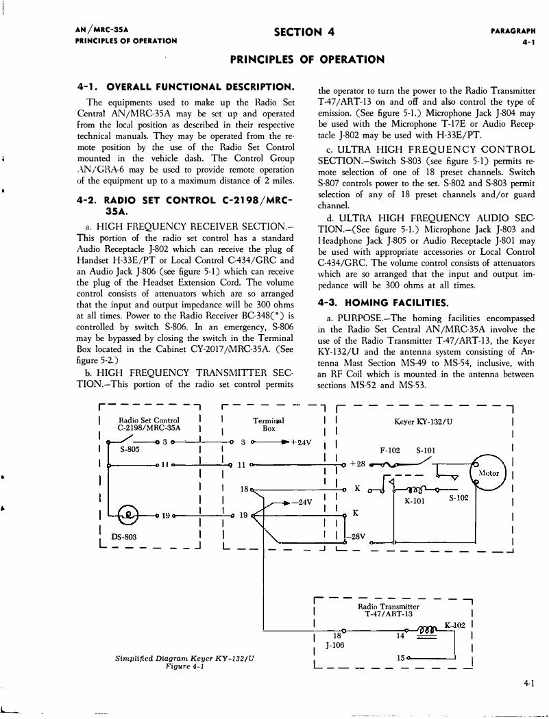
4-3. HOMING FACILITIES. a. PURPOSE.-The homing facilities encompassed
in the Radio Set Central ANjMRC-35A involve the use of the Radio Transmitter T-47/ART-13, the Keyer KY-132/U and the antenna system consisting of Antenna Mast Section MS-49 to MS-54, inclusive, with an RF Coil which is mounted in the antenna between sections MS-52 and MS-53.
r------ -, r- - - - -l r
- -- -- ---,
I Radio Set Control I Tenninnl C-2198/MRC-35A I
---o 3 0 0 3 0
S-805 I
llct lq
ll
I
I 18
I
19o I
0 19
L �S-803
-
I I
- -- J L --
Simplified Diagram Keyer KY -132/U Figure 4-1
Box
•+24V
-24V
- -
I I Keyer KY-132/U I I I I
I F-102 S-101 I
+28 � I
I K I
K-101 I K
I I
-28V I _.J L_ - - - - - -- - - _ _J
r - - - - - - --,
Radio Transmitter I T-47/ART-13 I I I
I 18 14 I
I J-106 I
L __
15 I -- - - - -
4-1
PARAGRAPH 4-38
b. KEYER KY-132;U.-The Keyer coding wheel is set up on the assigned code by following the procedure shown in the instruction book on the keyer. (NAVMC ELECT-2001) The keyer can transmit a maximum of two letters at a code speed of 6 to lO words per minute. Between cycles, a 30 to 40 second signal is transmitted. Operation of the keyer is normally controlled by S-805 on the Radio Set Control C-21981MRC-35A; however, the kcyer can be controlled locally by closing S-1 0 \ only. In either case, both switches must be on before the keycr will operate. (See figure 4-l.) The Radio Transmitter T-47 I ART-13 is first set up for operation on CW as described in TM 11-692B and turned to remote operation. When the transmitter has been properly set up and control has been changed over to the radio set control by placing the LOCAL REMOTE switch of the transmitter in the REMOTE position, the radio set control OFF, VOICE, CW, MCW switch (S-801) is placed in the CW or MCW position. In CW position, greater range may be realized; however, MCW is preferred. Mode of operation should be in accordance with operations plans or standard operating procedure of the using organization. The keyer is turned on when it is desired to send out the coded signal. To cease transmitting, it is important that the keyer be turned off first. Otherwise, the emission selector switch which is used to turn the transmitter off would be changed while the transmitter is being keyed which may result in damage to switches and relays.
c. RADIO TRANS:\1ITTER T-471ART-13.-This equipment was originally designed to operate with a
AN/MRC-35A PRINCIPLES OF OPERATION
trailing \\'lTC antenna of approximately 200 feet. Installation of the T-47 I ART-13 in a M38A1 jeep and utilizing an antenna of approximately 19h feet (Mast Sections MS-49 through 54 incl) presented a problem inasmuch as the antenna was very short electrically, presenting excessive capacity, at the homing frequencies (approximately 200-500 KCS). In order to transmit properly at the homing frequencies, it was necessary to design an RF Coil to cancel out the large amount of capacitive reactance in the short whip antenna.
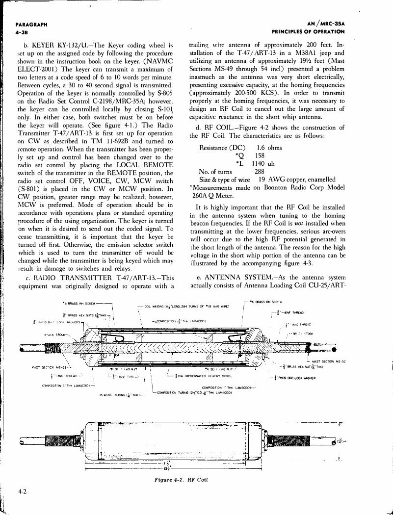
d. RF COIL-Figure 4-2 shows the construction of the RF Coil. The characteristics are as follows:
Resistance (DC) *Q *L
No. of turns Size & type of wire
*l\1easurements made 260A Q Meter.
1.6 ohms 158
1140 uh 288
19 AWG copper, enamelled on Boonton Radio Corp Model
It is highly important that the RF Coil be installed in the antenna system when tuning to the homing beacon frequencies. If the RF Coil is not installed when transmitting at the lower frequencies, serious arc-overs will occur due to the high RF potential generated in the short length of the antenna. The reason for the high voltage in the short whip portion of the antenna can be illustrated by the accompanying figure 4-3.
e. ANTENNA SYSTEM.-As the antenna system actually consists of Antenna Loading Coil CU-25 I ART-
.,6 BRASS RH SCREW -COIL Wf�OING (I I�"LONG,284 TURNS OF •19 AWG WIRE)
r•6 BRASS RH SCRFW
4-2
i" BRASS HEX NUTS (�THK)----:r I
·f P>-fC·S Br-- ' L0Cf N.C.SHERS 1
\
f-13NC THREAD--'. !__ i "- 16rJf TrlRt- .:..:-
C')MP?SITI')N ( :"THK LAMACOID) ___:
\
PLASTIC TUBING (i" THK.)-
,I :----l' -16NF THREAD
�COMPCSITIOIJ l �" Trl" LAMACOID)
I SEI F I KG
\ '---- � DIA. IMPREGNATED HICKCRY DOWEL
l COMPOSITION (I" THK L.AMACOID)COMPOSITION TUBING (2�"Q.D.,�"THK LAMACOIDl
Figure 4-2. RF Coil
-f" -13f>.IC THREA�
MAST SECTION MS-52 -i"8R.:.SS HEX NUT(�"THK)
- f" PH0S 81<0 I.OCK WASHER
L
•
AN/MRC-35A PRINCIPLES OF OPERATION
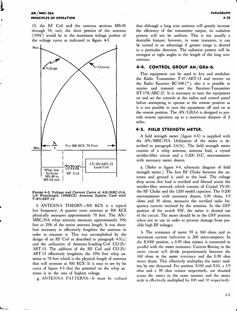
13, the RF Coil and the antenna sections MS-49 through 54, incl, the short portion of the antenna ( 191h') would be in the maximum voltage portion of the voltage curve as indicated in figure 4-3.
Max.
Min. For 300 KCS. 78 Feet
4----------�-------------+----
Whip Ant. Sections RF Coil
MS-49 to MS-54 incl.
CU-25/ART-13 Load Coil
FIGURE 4-3. Voltage and Current Curve of AN/MRC-35A, 1/4 Wavelength (300KCS) Antenna System Used with T-47 I ART-13.
f. ANTENNA THEORY.-300 KCS is a typical low frequency. A quarter wave antenna at 300 KCS physically measures approximately 78 feet. The AN I MRC-35A whip antenna measures approximately 19Y2 feet or 25% of the entire antenna length. It was therefore necessary to effectively lengthen the antenna in order to resonate it. This was accomplished by the design of an RF Coil as described in paragraph 4-3(c) and the utilization of Antenna Loading Coil CU-251 ART-13. The addition of the RF Coil and CU-251 ART-13 effectively lengthens the 19Y2 foot whip antenna to 78 feet which is the physical length of antenna that will resonate at 300 KCS. It is easy to see by he curve of figure 4-3 that the potential on the whip an tenna is in the area of highest voltage.
g. ANTENNA PATTERNS.-lt must be realized
PARAGRAPH 4-3E
that although a long wire antenna will greatly increase the efficiency of the transmitter output, its radiation pattern will not be uniform. This is not usually a desirable feature; however, in some instances, it can be turned to an advantage if greater range is desired in a particular direction. The radiation pattern will be strongest at right angles to the length of the long wire antenna.
4-4. CONTROL GROUP AN/GRA-6.
This equipment can be used to key and modulate the Radio Transmitter T-47 I ART-13 and receive on the Radio Receiver BC-348-(*); also it is possible to receive and transmit over the Receiver-Transmitter RT-1781 ARC-27. It is necessary to turn the equipment on and set the controls at the radios and control panel before attempting to operate at the remote position as it is not possible to turn the equipment off and on at the remote position. The AN IGRA-6 is designed to provide remote operation up to a maximum distance of 2
miles.
4-5. FIELD STRENGTH METER.
A field strength meter (figure 4-4) is supplied with the ANIMRC-35A. Utilization of the meter is described in paragraph 2-6(b). The field strength meter consists of a whip antenna, antenna load, a crystal rectifier-filter circuit and a 0-200 D.C. microammeter with necessary meter shunts.
a. (Refer to figure 4-4, schematic diagram of field strength meter.) The first RF Choke between the antenna and ground is used as the load. The voltage drop across this load is rectified and filtered across the rectifier-filter network which consists of Crystal IN-69, the RF Choke and the 1200 mmfd capacitor. The 0-200 microammeter with necessary shunts, 0.39 ohms, 3.9 ohms and 39 ohms, measures the rectified radio frequency current received by the antenna. In the OFF position of the switch SW, the meter is shorted out of the circuit. The meter should be in the OFF position when not in use in order to prevent damage from possihle high RF voltages.
b. The resistance of meter l\1 is 360 ohms and its
maximum current indication is 200 micro-amperes. In the XIOOO position, a 0.39 ohm resistor is connected in parallel with the meter resistance. Current Rowing in the meter circuit will divide proportionately between the :)60 ohms in the meter resistance and the 0.39 ohm meter shunt. This effectively multiplies the meter reading by one thousand. For position XIOO and XIO, a 3.9
ohm and a 39 ohm resistor respectively, are shunted across the meter in the same manner and the meter scale is effectiYely multiplied hy 100 and 10 respccti\"cly.
4-3
l I
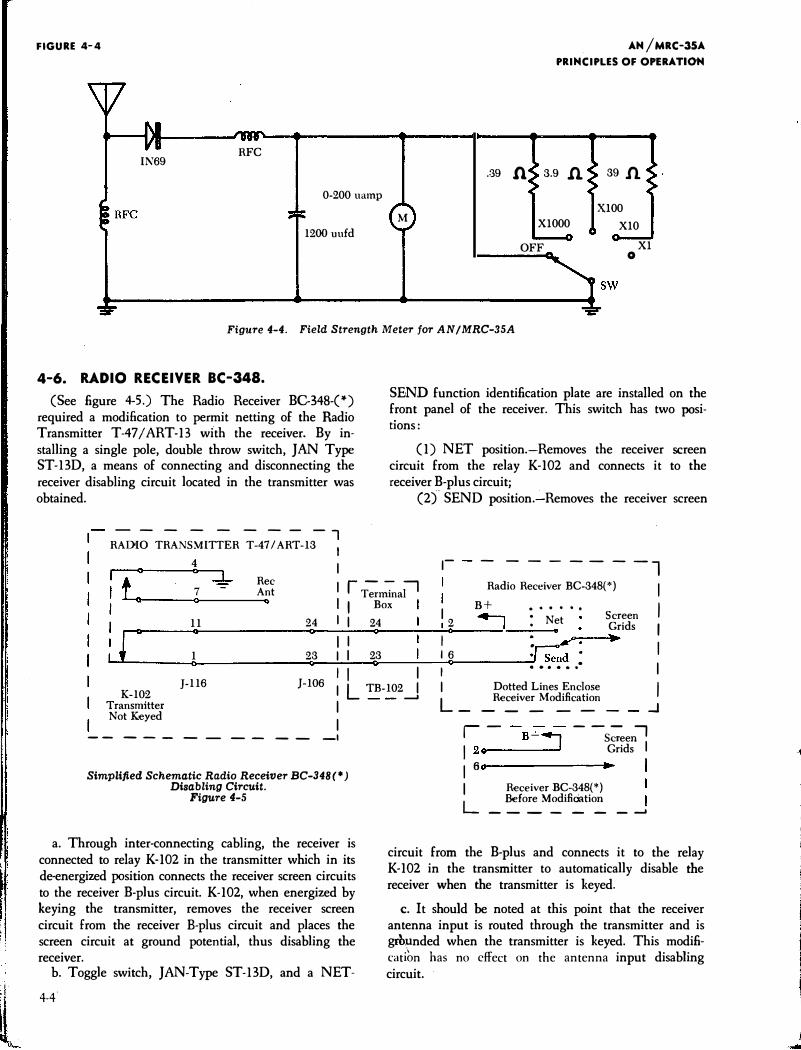
FIGURE 4-4
RFC IN69
0-200 uamp
M 1200 uufd
AN/MRC-35A PRINCIPLES OF OPERATION
.39 n 3.9 .n
XlOOO
OFF
39 1l
XlOO XlO
Xl 0
Figure 4-4. Field Strength Meter for AN I MRC-35A
4-6. RADIO RECEIVER BC-348. (See figure 4-5.) The Radio Receiver BG348-(*)
required a modification to permit netting of the Radio Transmitter T-47 / ART-13 with the receiver. By installing a single pole, double throw switch, JAN Type ST-BD, a means of connecting and disconnecting the receiver disabling circuit located in the transmitter was obtained.
- -- - - -- - - l RADIO TRANSMITTER T-47 I ART-13 I
SEND function identification plate are installed on the front panel of the receiver. This switch has two positions:
(1) NET position.-Removes the receiver screen circuit from the relay K-102 and connects it to the receiver B-plus circuit;
(2)SEND position.-Removes the receiver screen
---- --
-4 0 0 :L
7 Rec Ant
I �r--:�
Terminal
,- -l Radio Receiver BC-348(*) I l 0 .. Box B+ . . . . .. I I I
11
r 0
1 0
24 0
23 0
I I 24 Q
I I I I 23
0
12 I o ..., I 16
0
. Net . : �. ·r5:d :
Screen Grids I •
I
J-116 J-106 K-102
I I I I L TB-102 _j
I I L_
...... I Dotted Lines Enclose I Receiver Modification Transmitter
Not Keyed I I
--------- -- -1
Simplified Schematic Radio Receiver BC-348(*) Disabling Circuit.
Figure 4-5
a. Through inter-connecting cabling, the receiver is connected to relay K-102 in the transmitter which in its de-energized position connects the receiver screen circuits to the receiver B-plus circuit. K-102, when energized by keying the transmitter, removes the receiver screen circuit from the receiver B-plus circuit and places the screen circuit at ground potential, thus disabling the receiver.
b. Toggle switch, JAN-Type ST-BD, and a NET-
4-4
- - - - - -
r-
-B + � - -S;eenll I 2o - Grids
I a I Receiver BC-348(*)
Before Modifiootion L _______ __,
..J
circuit from the B-plus and connects it to the relay K-102 in the transmitter to automatically disable the receiver when the transmitter is keyed.
c. It should be noted at this point that the receiver antenna input is routed through the transmitter and is grbunded when the transmitter is keyed. This modificati.on has no effect on the antenna input disabling circuit.
•
•
AN/ MRC-35A TROUBLE SHOOTING
SECTION 5 PARAGRAPH 5-1
TROUBLE SHOOTING
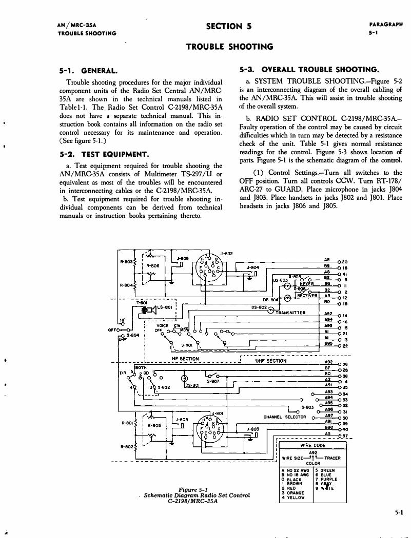
S-1. GENERAL.
Trouble shooting procedures for the major individual component units of the Radio Set Central AN/MRC-35A are shown in the technical manuals listed in
Table 1-l. The Radio Set Control C-2198/MRC-35A does not have a separate technical manual. This instruction book contains all information on the radio set control necessary for its maintenance and operation. (See figure 5-l.)
S-2. TEST EQUIPMENT.
a. Test equipment required for trouble shooting the AN /MRC-35A consists of Multimeter TS-297 /U or equivalent as most of the troubles will be encountered in interconnecting cables or the C-2198/MRG35A.
b. Test equipment required for trouble shooting individual components can be derived from technical manuals or instruction books pertaining thereto.
R-803
R-804
S-3. OVERALL TROUBLE SHOOTING.
a. SYSTEM TROUBLE SHOOTING.-Figure 5-2 is an interconnecting diagram of the overall cabling of
the AN /MRC-35A. This will assist in trouble shooting of the overall system.
b. RADIO SET CONTROL C-2198/MRC-35A.Faulty operation of the control may be caused by circuit difficulties which in turn may be detected by a resistance check of the unit. Table 5-1 gives normal resistance readings for the control. Figure 5-3 shows location of parts. Figure 5-1 is the schematic diagram of the control.
(1) Control Settings.-Turn all switches to the OFF position. Turn all controls CCW. Turn RT-178/ ARC-27 to GUARD. Place microphone in jacks }804 and }803. Place handsets in jacks }802 and }801. Place headsets in jacks }806 and }805.
r---------------------��-C20 r-------------��-CI8
��+J��--�--0 II 2
�������-c12 .-----�------------�����------��-cl9
DS-802
4
R·801
R-802
r-------------------�����--����14 r------------------------------4�A9�4� 16
.---�----------------------��A�93�15 �r---------------------4-�A�I--Q21 r-----------------��A�I --Q I3
�������==�c==:=:=:=:=::J�A=�� u
0 A93 034 �33 A95
S-803 �32 �31
CHANNEL SELECTOR 0 A97 0 30 A91 39 r-------------�B�9�0�40
A:! r--- - - - --- - - --- _3!-I
:�----�W�IR�E�C�O�DE�--� I A92
---- - ':_:-:_:-:_:-::_:-:_:-:_�--=-=-=--=-=--=-=--=-:-::-_--:_:--____________________________ _J __ J WIRE SIZE.....Jf L-TRACER COLOR
Figure 5-l Schematic Diagram Radio Set Control
C-2198/MRC-35A
A NO 22 AWG B NO 18 AWG 0 BLACK I BROWN 2 RED 3 ORANGE 4 YELLOW
:; GREEN 6 BLUE 7 PU RPLE 8 G�Y 9 W�TE
5-1
- �
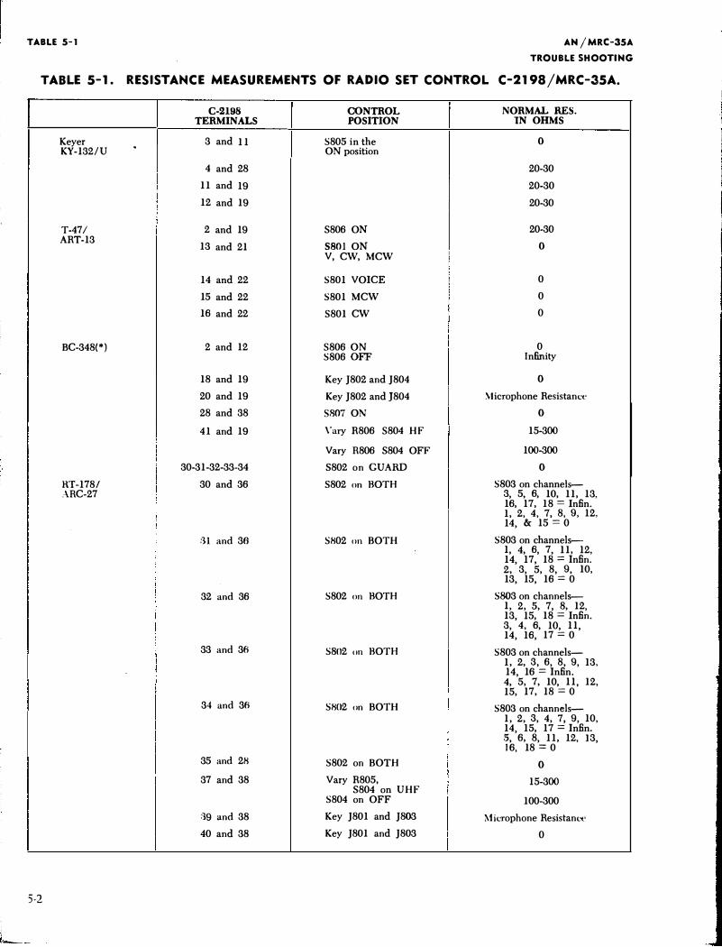
TABLE 5-1 AN I MRC-35A
TROUBLE SHOOTING
TABLE S-1. RESISTANCE MEASUREMENTS OF RADIO SET CONTROL C-2198/MRC-35A.
C-2198 CONTROL NORMAL RES. TERMINALS POSITION IN OHMS
Keyer 3 and 11 S805 in the 0 KY-132/U
. ON position
4 and 28 20-30
11 and 19 20-30
12 and 19 20-30
T-47/ 2 and 19 S806 ON 20-30 ART-13
13 and 21 S801 ON 0 V, CW, MCW
14 and 22 S801 VOICE 0
15 and 22 S801 MCW 0
16 and 22 5801 CW 0
BC-348(*) 2 and 12 5806 ON 0 S806 OFF Infinity
18 and 19 Key ]802 and ]804 0
20 and 19 Key ]802 and ]804 Microphone Resistance
28 and 38 5807 ON 0
41 and 19 \'ary R806 5804 HF 15-300
Vary R806 S804 OFF 100-300
30-31-32-33-34 S802 on GUARD 0
RT-178/ 30 and 36 5802 on BOTH S803 on channels--:\RC-27 3, 5, 6, 10, 11, 13,
16, 17, 18 = lnfin. 1, 2, 4, 7, 8, 9, 12, 14, & 15 = 0
:)1 and 36 SH02 on BOTH S803 on channels--1, 4, 6, 7, 11, 12, 14, 17, 18 = Infin. 2, 3, 5, 8, 9, 10, 13, 15, 16 = 0
32 and 36 S802 on BOTH S803 on channels--1, 2, 5, 7, 8, 12, 13, 15, 18 = lnfin. 3, 4, 6, 10, 11, 14, 16, 17 = 0
33 and 36 S802 on BOTH S803 on channels--1, 2, 3, 6, 8, 9, 13, 14, 16 = Infin. 4, 5, 7, 10, 11, 12, 15, 17, 18 = 0
34 and 36 SH02 on BOTH S803 on channels-1, 2, 3, 4, 7, 9, 10, 14, 15, 17 = Infin . . 5, 6, 8, 11, 12, 13, 16, 18 = 0
35 and 2H S802 on BOTH 0
37 and 38 Vary R805, 15-300 S804 on UHF
S804 on OFF 100-300
:39 and 38 Key ]801 and ]803 Microphone ResistanL�'
40 and 38 Key ]801 and ]803 0
5-2
L__
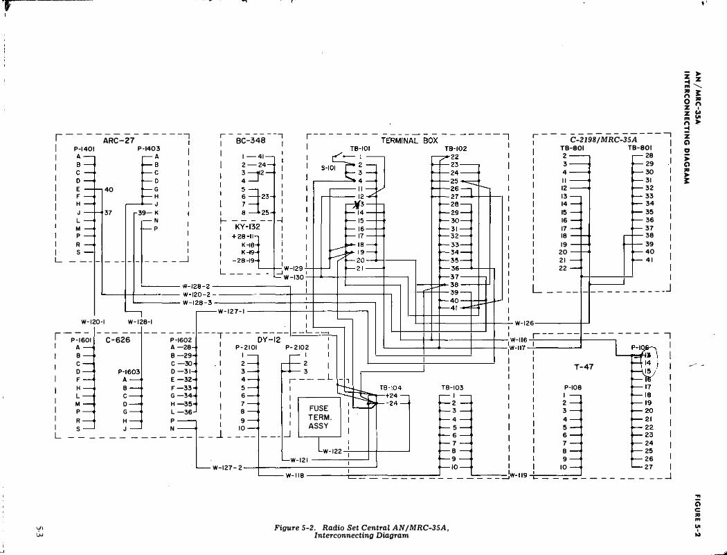
'f r
VI w
--. �
I-- - - ARC-Z7- -----, r-------1 BC-348 1 I
I r--------- -----,
C-2198/MRC-35A 1 P-1401 P-1403
�3 E! E F H J L M p R s
40
37
G H J
39- K N p
I 1-41
2-24
!:::::f 5 =t 6 :::::123
� -.�_,,,-�,��
TB-801 TB-801 I 2 28 I 3 29
4 30
II 3 1
12 32
13 33
14 34
15 35
16 36
17 37
18 38
L ___ l_l __ _ i _ i _ i ____ _j
I I I I
I
·1W-129
_J
19
20
2 1
22
39
40
4 1
w -130 �___...--+-+-----+-----, '-----+-+------ :������� I I I I I
L ____ I_L _________ J ,__ ____ W-128-3
I I I
W-127-1 ------t--'---1-----t-----, W-120-1 W- 128-1
I ·-
P�6-;I c-626 -4--- ;-�o-;--- -T---- -ov-=-12:._1 __ :__ -� A -28 I
P-2 1 0 1 P-2102 I
CD....!--+1 -t-1 r----.· W-126 I�- -- -- - - - --, 1 I II 1
r--- --. I I I ' 1 I I :::1
1
1�--'-----' I A I B B-29 I I I
I I I I L
c D F H L
B c
c -30 . I 2 2 1 D -3 1 I 3 3
E-32 4 , -- _L F -33
I 5 I TB-103 G -34 I 6 I I
M � D � H -35 I 7 I FUSE 2
P G L -36 B I 3
R H P I
9 TERM. 4
I 7
W-122 : B
I I I I
T-47 P- 108
I 2
3
4
5
6
7
B 9
s _ __ _' ___ _ "_ __ 1--l_ �
o-- ___ � ASSY : · W-121 9
. W-127-2 : - _ _ - -____ �0_=--1 Jw-1!9 �:_r----_-_--' ___ _ 1 0
Figure 5-2. Radio Set Central AN/MRC-35A, Interconnecting Diagram
24
25
2 6
27 _____ _j
*'
z,.. .... z '" "----� � 0 :ICI z ':' z c.» '" Ul
g � z (j) � ,.. (j) :ICI ,.. �
_,.,./ -
... a c :ICI '" Ul
I !.)
.. -.....Iii
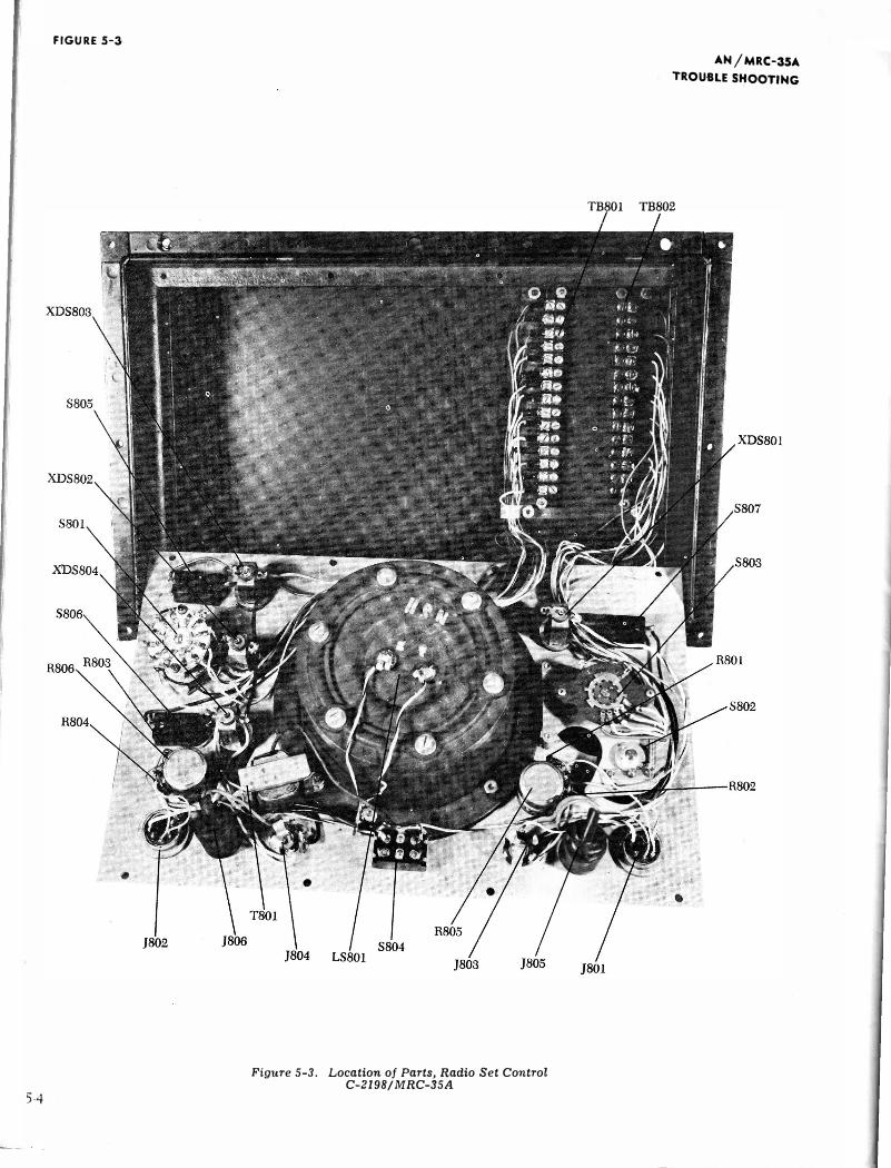
FIGURE 5-3
54
Figure 5-3. Location of Parts, Radio Set Control C-2198/ MRC-35A
AN/MRC-35A TROUBLE SHOOTING
TB801 TB802
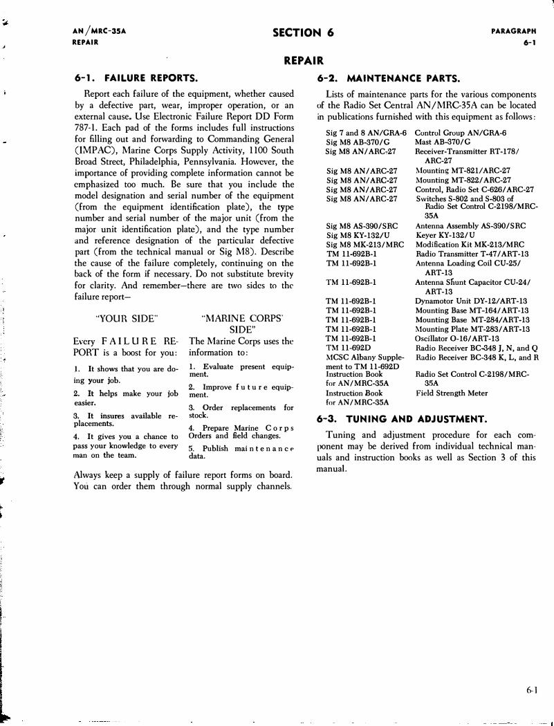
AN jMRC-35A
REPAIR
SECTION 6 PARAGRAPH
6-1
REPAIR
6-1. FAILURE REPORTS.
Report each failure of the equipment, whether caused by a defective part, wear, improper operation, or an external cause. Use Electronic Failure Report DD Form 787-1. Each pad of the forms includes full instructions for filling out and forwarding to Commanding General (IMPAC), Marine Corps Supply Activity, llOO South Broad Street, Philadelphia, Pennsylvania. However, the importance of providing complete information cannot be emphasized too much. Be sure that you include the model designation and serial number of the equipment (from the equipment identification plate), the type number and serial number of the major unit (from the major unit identification plate), and the type number and reference designation of the particular defective part (from the technical manual or Sig M8). Describe the cause of the failure completely, continuing on the back of the form if necessary. Do not substitute brevity for clarity. And remember-there are two sides to the failure report-
''YOUR SIDE"
Every F A I L U R E REPORT is a boost for you:
1. It shows that you are do
ing your job.
2. It helps make your job easier.
3. It insures available replacements.
4. It gives you a chance to pass your knowledge to every man on the team.
"MARINE CORPS' SIDE"
The Marine Corps uses the information to:
1. Evaluate present equipment.
2. Improve f u t u r e equipment.
3. Order repla<.-ements for stock.
4. Prepare Marine C o r p s Orders and field changes.
5. Publish mai n t e n a n c e
data.
Always keep a supply of failure report forms on board. You can order them through normal supply channels.
6-2. MAINTENANCE PARTS.
Lists of maintenance parts for the various components of the Radio Set Central AN/MRC-35A can be located in publications furnished with this equipment as follows:
Sig 7 and 8 AN/GRA-6 Control Group AN/GRA-6 Sig M8 AB-370IG Mast AB-3701G Sig M8 ANIARC�27 Receiver-Transmitter RT-1781
Sig M8 AN I ARC-27 Sig M8 AN I ARC-27 Sig M8 ANI ARC-27 Sig M8 ANI ARC-27
Sig M8 AS-390ISRC Sig M8 KY-132/U Sig M8 MK-213/MRC TM 11-692B-l TM ll-692B-l
TM ll-692B-l
TM ll-692B-1 TM ll-692B-l TM ll-692B-l TM ll-692B-1 TM ll-692B-1 H.-I ll-692D MCSC Albany Supplement to TM ll-692D Instruction Book for AN/MRC-35A
Instruction Book for AN/MRC-35A
ARC-27 �lounting MT -821/ ARC-27 Mounting MT -8221 ARC-27 Control, Radio Set C-6261 ARC-27 Switches S-802 and S-803 of
Radio Set Control C-2198/MRC-35A
Antenna Assembly AS-3901SRC Keyer KY-1321U Modification Kit MK-213/MRC Radio Transmitter T-47 I ART-13 Antenna Loading Coil CU-251
ART-13 Antenna Sfiunt Capacitor CU-24/
ART-13 Dynamotor Unit DY-12/ ART-13 Mounting Base MT-164/ART-13 Mounting Base MT-284/ART-13 �.founting Plate MT-2831 ART-13 Oscillator 0-161 ART-13 Radio Receiver BC-348 J, N, and Q Radio Receiver BC-348 K, L, and R
Radio Set Control C-2198/MRC-3.'5A
Field Strength Meter
6-3. TUNING AND ADJUSTMENT.
Tuning and adjustment procedure for each component may be derived from individual technical manuals and instruction books as well as Section 3 of this manual.
6-1
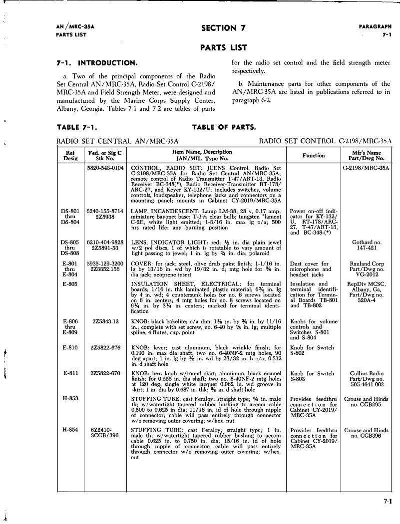
AN /MRC-35A
PARTS LIST SECTION 7
PARTS LIST
PARAGRAPH
7-1
7-1. INTRODUCTION.
a. Two of the principal components of the Radio Set Central AN/MRC-35A, Radio Set Control C-2198/ MRC-35A and Field Strength Meter, were designed and manufactured by the Marine Corps Supply Center, Albany, Georgia. Tables 7-l and 7-2 are tables of parts
for the radio set control and the field strength meter respective! y.
b. Maintenance parts for other components of the AN/.\1RC-35A are listed in publications referred to in paragraph 6-2.
TABLE 7-1. TABLE OF PARTS.
RADIO SET CENTRAL AN/MRC-35A RADIO SET CONTROL C-2198/MRC-35:\
Ref Desig
Fed. or Sig C Stk No.
5820-543-0104
DS-801 6240-155-8714 thru 2Z5938
DS-804
DS-805 6210-404-9828 thru 2Z5891-53
DS-808
Item Name, Description JAN/MIL Type No.
CO:'IITROL, RADIO SET: JCENS Control, Hadio Set C-2198/MRC-35A for Radio Set Central ANIMRC-35A; remote control of Radio Transmitter T-47 I ART-13, Radio Receiver BC-348(*), Radio Receiver-Transmitter RT-178/ ARC-27, and Keyer KY-132IU; includes switches, volume controls, loudspeaker, telephone jacks and connectors on a mounting panel; mounts in Cabinet CY-20191MRC-35A
LAMP, INCANDESCENT: Lamp LM-38; 28 v, 0.17 amp; miniature bayonet base; T-31!4 clear bulb; tungsten •lament C-2E, white light emitted; 1-3/16 in. max lg ola; 500 hrs rated life; any burning position
LENS, INDICATOR LIGHT: red; lh in. dia plain jewel wl2 pol discs, 1 of which is rotatable to vary amount of light passing to jewel; 1 in. lg by % in. dia; polaroid
E-801 thru
E-804
5935-129-3200
I COVER: for jack; steel, olive drab paint finish; 1-1/16 in.
2Z3352.156 lg by 13116 in. wd by 19132 in. d; mtg hole for % in. dia jack; neoprene insert
E-805
E-806 thru
E-809
E-810
E-811
H-853
H-854
2Z5843.12
2Z5822-676
2Z5822-670
6Z2410-3CGBI396
I:'IISULATION SHEET, ELECTRICAL: for terminal boards; 1/16 in. thk laminated plastic material; 6% in. lg by 4 in. wd; 4 countersunk holes for no. 6 screws located on 6 in. centers; 4 mtg holes for no. 8 screws located on 61/4 in. by 31f4 in. centers; marked for terminal identification
KNOB: black bakelite; ol a dim. 11fs in. by o/4 in. by 11/16 in.; complete with set screw, no. 6-40 by 1fs in. lg; multiple spline, 4 flutes, cup. point
K:'IIOB: lever; cast aluminum, black wrinkle finish; for 0.190 in. max dia shaft; two no. 6-40NF-2 mtg holes, 90 deg apart; 1 in. lg by 1h in. wd by 23132 in. h o/a; 0.312 in. d shaft hole
KNOB: hex. knob wlround skirt; aluminum, black enamel finish; for 0.255 in. dia shaft; two no. 6-40NF -2 mtg holes at 120 deg; single white lacquer 0.062 in. wd groove in skirt; 1 in. dia by 0.687 in. thk; 5/s in. d shaft hole
STUFFING TUBE: cast Feraloy; straight type; o/4 in. male th; wlwatertight tapered rubber bushing to accom cable 0.500 to 0.625 in dia; 11/16 in. id of hole through nipple of connector; cable will pass entirely through connector w/o removing outer covering; wlhex. nut
STUFFING TUBE: cast Feraloy; straight type; 1 in. male th; wlwatertight tapered rubber bushing to accom cable 0.625 in. to 0.750 in. dia; 15/16 in. id of hole through nipple of connector; cable will pass entirely through connector w I o removing outer covering; w /hex. nut
Function
Power on-off indicator for KY-1321 U, RT-1781 ARC-27, T-47/ART-13, and BC-348-(*)
Dust cover for microphone and headset jacks
Insulation and terminal identification for Terminal Boards TB-801 and TB-802
Knobs for volume controls and Switches S-801 and S-804
Knob for Switch S-802
Mfr's Name Part/Dwg No.
C-21981MRC-35A
Gothard no. 147-421
Rauland Corp PartiDwg no.
VG-2012
RepDiv MCSC, Albany, Ga,
Part/Dwg no. 320A-4
Knob for Switch Collins Radio S-803 Part/Dwg no.
505 4641002
Provides feedthru Crouse and Hinds conn e c t i o n for no. CGB295 Cabinet CY-2019/ MRC-35A
Provides feedthru Crouse and Hinds conn e c t i o n for no. CGB396 Cabinet CY-2019/ MRC-35A
7-1
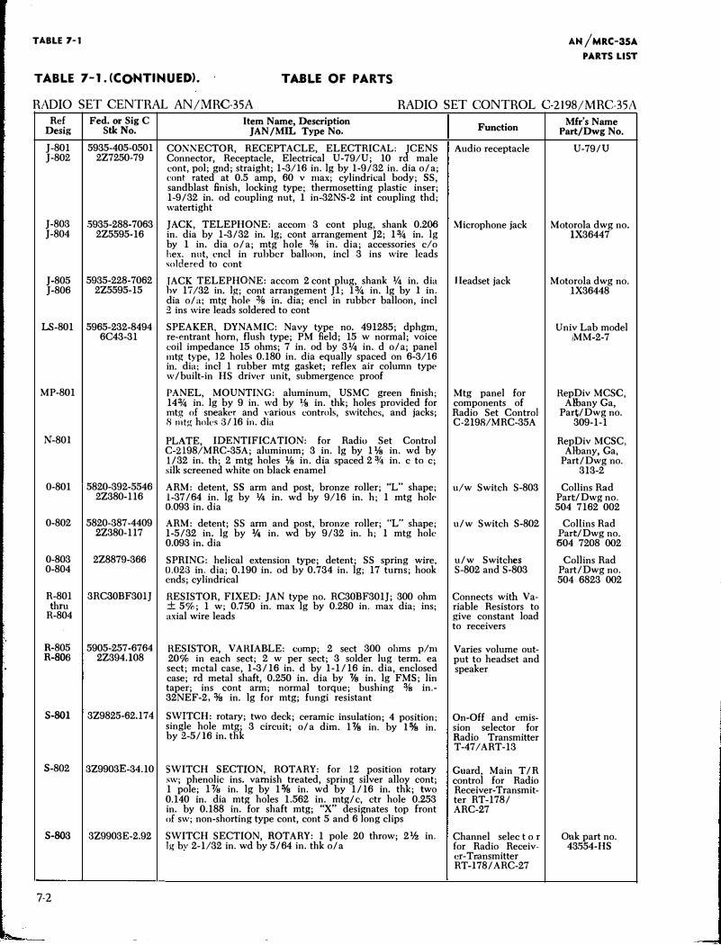
TABLE 7-1
TABLE 7-1. CCO,NTINUED). TABLE OF PARTS
AN /MRC-35A
PARTS LIST
RADIO SET CENTRAL AN/MRC-35A RADIO SET CONTROL C-2198/MRC-35A
Ref Desig
J-801 J-802
J-803 J-804
J-805 J-806
Fed. or Sig C Stk No.
5935-405-0501 2Z7250-79
.5935-288-7063 2Z5595-16
5935-228-7062 2Z5595-15
Item Name, Description JAN /MIL Type No.
CONNECTOR, RECEPTACLE, ELECTRICAL: J
CENS Connector, Receptacle, Electrical U-79/U; 10 r male cont, pol; gnd; straight; 1-3/I6 in. lg by 1-9/32 in. dia o/a; cont rated at 0.5 amp, 60 v max; cylindrical body; SS, sandblast finish, locking type; thermosetting plastic inser; 1-9/32 in. od coupling nut, 1 in-32NS-2 int coupling thd; watertight
JACK, TELEPHONE: accom 3 cant plug, shank 0.206 in. dia by 1-3/32 in. lg; cant arrangement J2; 1% in. lg by 1 in. dia o/a; mtg hole 3fs in. dia; accessories c/o hex. nut, end in rubber balloon, incl 3 ins wire leads soldered to cont
JACK TELEPHONE: accom 2 cant plug, shank % in. dia hv 17/32 in. lg; cont arrangement JI; 1% in. lg by I in. dia o/a; mtg hole :1,8 in. dia; encl in rubber balloon, incl 2 ins wire leads soldered to cant
Function
Audio receptacle
�Hcrophone jack
Headset jack
LS-801 5965-232-8494 SPEAKER, DYNAMIC: Navy type no. 491285; dphgm,
MP-801
N-80I
0-801
0-802
0-803 0-804
R-80I thru
R-804
R-805 R-806
S-801
S-802
S-803
7-2
6C43-31 re-entrant hom, flush type; PM field; 15 w normal; voice coil impedance 15 ohms; 7 in. od by 3% in. d o/a; panel mtg type, 12 holes 0.180 in. dia equally spaced on 6-3/I6 in. dia; inc! I rubber mtg gasket; reflex air column type w/built-in HS driver unit, submergence proof
PANEL, MOUNTING: aluminum, USMC green finish; 14% in. lg by 9 in. wd by % in. thk; holes provided for mtg of sneaker and various controls, switches, and jacks; 8 mtg holes 3/ 16 in. dia
PLATE, IDENTIFICATION: for Radio Set Control C-2198/MRC-35A; aluminum; 3 in. lg by 11fs in. wd by l/32 in. th; 2 mtg holes 1fs in. dia spaced 2 3f4 in. c to c; silk screened white on black enamel
Mtg panel for components of Radio Set Control C-2198/MRC-35A
5820-392-5546 ARM: detent, SS arm and post, bronze roller; "L" shape; u/w Switch S-803 2Z380-116 1-37/64 in. lg by ¥4 in. wd by 9/16 in. h; 1 mtg hok
0.093 in. dia
5820-387-4409 ARM: detent; SS arm and post, bronze roller; "L" shape; u/w Switch S-802 2Z380-117 1-5/32 in. lg by V4 in. wd by 9/32 in. h; 1 mtg hole
0.093 in. dia
2Z8879-366 SPRING: helical extension type; detent; SS spring wire, u/w Switches 0.023 in. dia; 0.190 in. od by 0.734 in. lg; 17 tums; hook S-802 and S-803
3RC30BF30IJ
5905-257-6764 2Z394.108
ends; cylindrical
RESISTOR, FIXED: JAN type no. RC30BF301J; 300 ohm ± 5%; 1 w; 0.7.'50 in. max lg by 0.280 in. max dia; ins; axial wire leads
HESISTOR, VAHIABLE: comp; 2 sect 300 ohms p/m 20% in each sect; 2 w per sect; 3 solder lug term. ea sect; metal case, I-3/16 in. d by 1-1/16 in. dia, enclosed case; rd metal shaft, 0.250 in. dia by % in. lg FMS; lin taper; ins cant arm; normal torque; bushing 3fs in.-32NEF-2,% in. lg for mtg; fungi resistant
3Z9825-62.174 SWITCH: rotary; two deck; ceramic insulation; 4 position; single hole mtg; 3 circuit; o/ a dim. 1% in. by I o/s in. by 2-5/ I6 in. thk
3Z9903E-34.10 SWITCH SECTION, ROTARY: for 12 position rotary sw; phenolic ins. varnish treated, spring silver alloy cant; 1 pole; B's in. lg by 1 o/s in. wd by 1/16 in. thk; two 0.140 in. dia mtg holes 1.562 in. mtg/c, ctr hole 0.253 in. by 0.188 in. for shaft mtg; "X" designates top front of sw; non-shorting type cont, cont 5 and 6 long clips
3Z9903E-2.92 SWITCH SECTION, ROTARY: 1 pole 20 throw; 21h in. lg by 2-1/32 in. wd by 5/64 in. thk o/a
Connects with Variable Resistors to give constant load to receivers
Varies volume output to headset and speaker
On-Off and emission selector for Radio Transmitter T-47/ART-13
Guard, Main T /R control for Radio Receiver-Transmitter RT-178/ ARC-27
Channel selec t o r for Radio Receiver-T11ansmitter RT-I78/ ARC-27
Mfr's Name Part/Dwg No.
U-79/U
Motorola dwg no. 1X36447
Motorola dwg no. 1X36448
Univ Lab model iMM-2-7
HepDiv MCSC, Albany Ga,
Part/ Dwg no. 309-1-1
RepDiv MCSC, Albany, Ga,
Part/Dwg no. 313-2
Collins Rad Part/Dwg no. 504 7162 002
Collins Rad Part/Dwg no. 504 7208 002
Collins Rad Part/ Dwg no. 504 6823 002
Onk part no. 43.'554-HS
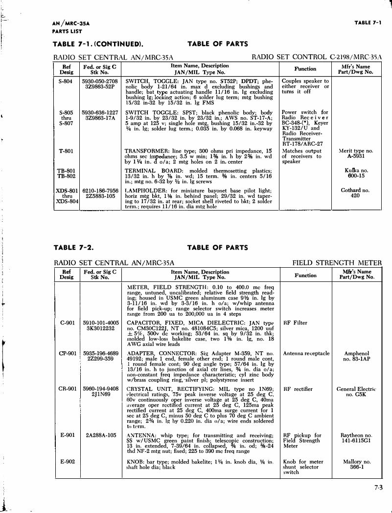
I
'1-
r 1
i
l
AH /MRC-35A
PARTS LIST
TABLE 7-1. (CONTINUED). TABLE OF PARTS
··l TABLE 7-1
RADIO SET CENTRAL AN/MRC-35A RADIO SET CONTROL C-2198/MRC-35;\
Ref Desig
S-804
S-805 thru
S-807
T-801
TB-801 TB-802
Fed. or Sig C Stk No.
5930-050-2708 3Z9863-52P
Item Name, Description JAN /MIL Type No.
SWITCH, TOGGLE: JAN type no. ST52P; DPDT; phenolic body 1-21/64 in. max d excluding bushings and handle; bat type actuating handle 11/16 in. lg excluding bushing lg; locking action; 6 solder lug term; mtg bushing 15/32 in-32 by 15/32 in. lg FMS
5930-636-1227 SWITCH TOGGLE: SPST; black phenolic body; body 3Z9863-17A 1-9/32 in. by 23/32 in. by 23/32 in.; AWS no. ST-17-A;
5 amp at 125 v; single hole mtg, bushing 15/32 in.-32 by % in. lg; solder lug term.; 0.035 in. by 0.068 in. keyway
TRANSFORMER: line type; 300 ohms pri impedance, 15 ohms sec impedance; 3.5 w min; 1 o/s in. h by 2o/s in. wd by 1¥4 in. d o/ a; 2 mtg holes on 2 in. center
TERMINAL BOARD: molded thermosetting plastics; 13/32 in. h by 7fs in. wd; 15 term. % in. centers 5/16 in.; mtg no. 6-32 by 1;2 in. lg screws
XDS-801 6210-186-7956 LAMPHOLDER: for miniature bayonet base pilot light; horiz mtg bkt, 1 lfs in. behind panel; 29/32 in. wd tapering to 17/32 in. at rear; socket shell riveted to bkt; 2 solder term.; requires 11/16 in. dia mtg hole
thru 2Z5883-105 XDS-804
TABLE 7-2. TABLE OF PARTS
Function
Couples speaker to either receiver or turns it off
Power switch for Radio Rec e i v e r BC-348-("'), Keyer KY-132/U and Radio ReceiverTransmitter RT-178/ ARC-27 Matches output of receivers to speaker
Mfr's Name Part/Dwg No.
.Merit type no. A-5931
Kulka no. 600-15
Gothard no. 420
RADIO SET CENTRAL AN/MRG35A FIELD STRENGTH METER
Ref Fed. or Sig C Desig Stk No.
Item Name, Description JAN /MIL Type No .
.\IETER, FIELD STRENGTH: 0.10 to 400.0 me freq range, untuned, uncalibrated; relative field strength reading; housed in USMC green aluminum case 91h in. lg by 3-11/16 in. wd by 3-3/16 in. h o/a; w/whip antenna for field pick-up; range selector switch increases meter range from 200 ua to 200,000 ua in 4 steps
Function
C-901 5910-101-4005 CAPACITOR, FIXED, MICA DIELECTRIC: JAN type HF Filter 3K3012232 no. CM30C122J, NT no. 481084C5; silver mica, 1200 uuf
± 5%, 500v de working; 53/64 in. sq by 9/32 in. thk; molded low-loss bakelite case, two I ¥s in. lg, no. 18 A WG axial wire leads
CP-901 5935-196-4689 ADAPTER, CONNECTOR: Sig Adapter M-359, NT no. Antenna receptacle 2Z299-359 49192; male 1 end, female other end; 1 round male cont,
1 round female cont; 90 deg angle type; 57/64 in. lg by 13/16 in. h to junction of axial ctr lines, 3f4 in. dia o/ a; non-constant freq impedance characteristic; cyl zinc body w/brass coupling ring, ·silver pi; polystyrene insert
CR-901 5960-194-9408 2JlN69
CRYSTAL UNIT, RECTIFYING: MIL type no 1N69; dectrical ratings, 75v peak inverse voltage at 25 deg C, GOv continuously oper inverse voltage at 25 deg C, 40ma
HF rectifier
E-901 2A288A-105
E-902
average oper rectified current at 25 deg C, 125ma peak rectified current at 2.'5 dcg C, 400ma surge current for 1 sec at 2.'5 deg C, minus 50 deg C to plus 70 deg C ambient range; 2% in. )g by 0.220 in. dia o/a; wire ends soldered to tPrm.
A;\/TENNA: whip type; for transmitting and re<.-eiving; SS w/USMC green paint finish; telescopic construction; 13 in. extended, 7-39/64 in. collapsed, o/4 in. od; %-24 thd NF -2 mtg nut; fixed; 225 to 390 me freq range
RF /ickup for Fie! Strength Meter
KNOB: bar type; molded bakelite; 1% in. knob dia, 1f4 in. Knob for meter shaft hole dia; black shunt selector
switch
Mfr's Name Part/Dwg No.
Amphenol no. 83-IAP
General Electrk no. G5K
Raytheon no. 141-6115Gl
Mallory no. 366-1
7-3
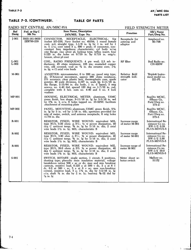
TABLE 7-2
TABLE 7-2. (CONTINUED). TABLE OF PARTS
AN /MRC-35A
PARTS LIST
RADIO SET CENTRAL AN/MRC-35A FIELD STRENGTH METER Ref
Desig
J-901
L-901 L-902
M-901
MP-901
MP-902
R-901
R-902
R-903
S-901
7-4
Fed. or Sig C Stk No.
5935-161-9639 2Z8799-239
Item Name, Description
JAN/MIL Type No.
CONNECTOR, RECEPTACLE, ELECTRICAL: Sig Socket S0-239, Navy Socket no. 49194; 1 round female cont; pol; straight type, 1-1/6 in. lg by 1 in. wd by 1 in. h o/a; cont rated 5 a, 500 v peak; rf connector, nonconstant freq impedance characteristic; cyl body w/sq mtg flange; zinc silver pi, locking type; teflon insert; four 0.125 in. dia holes on 0.719 in. by 0.719 in. mtg/c; bronze, silver pi cont
COIL, RADIO FREQUENCY: 4 pie wnd; 2.5 mh inductance, 45 ohms resistance, 125 rna; enameled copper wire, silk covered; wnd on % in. dia ceramic core; 11h in. lg; w/2 axial wire leads
A,\1METER: microammeter, 0 to 200 ua; panel mtg type; de, D'Arsonval movement, approx 360 ohms resistance, 2% accuracy; clear plastic lens, thermoplastic case, spade pointer, 40 scale divisions, 2.197 in. scale lg; 2-11/16 in. dia flange, 2-13/64 in. dia body, 1 in. d barrel; 3 mtg screws, no. 4-40 thd, spaced 120 deg on 1-7/32 in. rad, complete with 3 hex. nuts no. 4-40 and 3 no. 4 lock washers
HOUSING, ELECTRICAL METER: aluminum, USMC green finish, box shape; 9-11/16 in. lg by 3-3/16 in. wd by 3% in. h o/a; 6 holes tapped no. 10-32NC facilitate attachment of mounting plate
PANEL, MOUNTING: aluminum, USMC green finish; 91h in. lg by 3 in. wd by 1/16 in. thk; apertures provided for mtg of meter, switch, and antenna receptacle; 6 mtg holes 11/64 in. dia
Function
Receptacle for antenna and adaptor
RF filter
Relative field strength indicator
RESISTOR, FIXED, WIRE WOUND: equivalent MIL Increase range type RU3; 0.39 ohms ± 5%; % w power dissipation, 40 of meter M-901 deg C ambient temp; % in. lg by 3/16 in. dia; 2 axial wire leads 1% in. lg; MIL characteristic B
RESISTOR, FIXED, WIRE WOUND: equivalent MIL Increase range type RU3; 3.90 ohm ± 5%; lfz w power dissipation, 40 of meter M-901 dcg C ambient temp; % in. lg by 3/16 in. dia; 2 axial wire leads 1% in. lg; MIL characteristic B
RESISTOR, FIXED, WIRE WOUND: equivalent MIL Increase range of type RU3; 39.0 ohms ± 5% lfz w power dissipation, 40 meter M-901 deg C ambient temp; % in. lg by 3/16 in. dia; 2 axial wire leads 1lfz in. lg; MIL characteristic B
SWITCH, ROTARY: single section, 1 circuit, 5 positions, Meter shunt se-shorting type; phenolic resin insulation material; voltage lector switch breakdown rating .'500 v ac or de; max and min breaking eurrents, resistive load, 0.125 a at 300 v de, 3 a at 6 v
clc, 0.2 at 300 ,. ac, 5 a at 6 v ac; max non-breaking current, resistive load, 5 a; 1% in. dia by 3-3/16 in. lg o/ a; shaft % in. dia hy 2 in. lg; hushing %-32 thd by % in.lg
Mfr's Name Part/Dwg No.
Amphenol no. 83-798
Bud Radio no .
CH-920W
Tlriplett Instrument model no.
221-PL
RepDiv MCSC, Albany Ga,
Part/Dwg no. 375-2'
RepDiv MCSC, Albany, Ga,
Part/Dwg no. 375-3
International Resistance Co no. BW-1/2 0.39
PLUS-MINUS-5
International Resistance Co no. BW-1/2 3.90
PLUS-MINUS-5
International Resistance Co no. BW-1/2 39.0
PLUS-MINUS-5
Mallory no. 3115J
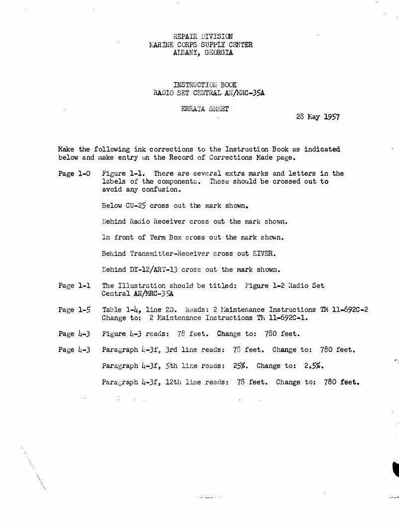
REPAIR DIVISICN 1-'IARINE CORPS SUPPLY CENTER
AlBANY, GEORGIA
INSTRUCTIOlj BOOK RADIO SET CE:NTHAL AN/NH.C-35A
ERRA'l'A SHEET . 28 Nay 1957
Make the fol lowing ink corrections to the Instruction Book as indicated below a nd make· entry on the Record of Cor.t•ections Nade page.
Page 1-0 Figure 1-1. There are several extra marks and letters in the labels of the component::;. These should be crossed out to avoid any confusion.
Below CU-25 cross out the mark shown.
Behind Radio Heceiver cross out the mark shot·m.
In front of Term Box cross out the mark show n.
Behind Transmitter-Receiver cross out ElVER.
Behind DY-12/��T-13 cross out the mark shown.
Page 1-1 The Illustration should be titled: Figure 1-2 Radio Set Central Al�J}mc-35A
Page 1-5 Table 1-4, line 20. Reads: 2 Naintenance Instructions TI•l 11..692C-2 Change to: 2 }laintenance Instructions T¥1 ll-692C-l.
Page 4 ... 3 Figure L1-3 reads: 78 feet. Change to: 780 feet.
Page �-3 Paragraph L-3f� Jrd line reads: 78 feet . Change to: 780 feet.
Paragraph 4-3f, 5th line reads: 25%. Chang e to: 2.5%.
Para;:.;raph 4-3f, 12th line reads: 78 feet. Change to: 780 feet.