day 1 qod: what is the standard system of wire sizes in the united states? awg, american wire gauge...
TRANSCRIPT

Day 1QOD: What is the standard system of wire sizes in the United States?
AWG, American Wire Gauge
Agenda:1. QOD & Measurements2. Module 26109-11: Conductors & Cables3. Activity – Cables4. Review
Learning Target:1. Students will accurately select proper conductors for an application.
Conductors and Cables
Learning Targets:
• Students will demonstrate the knowledge of National Electric Code (NEC) related to conductors.
• Students will accurately select proper conductors for a specified application.
• Students will demonstrate the proper installation of selected conductors.

Introduction
• Electricians must be able to – select and install wire and/or cable appropriate
for the job– Pull wire or cable through conduit runs in order
to terminate
Conductors and Insulation
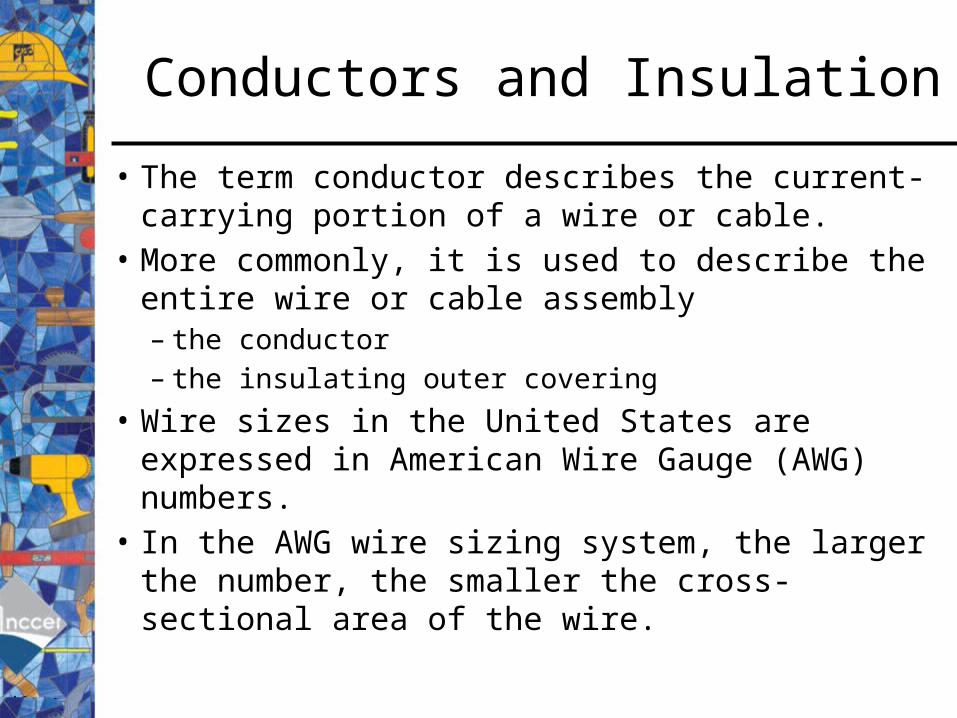
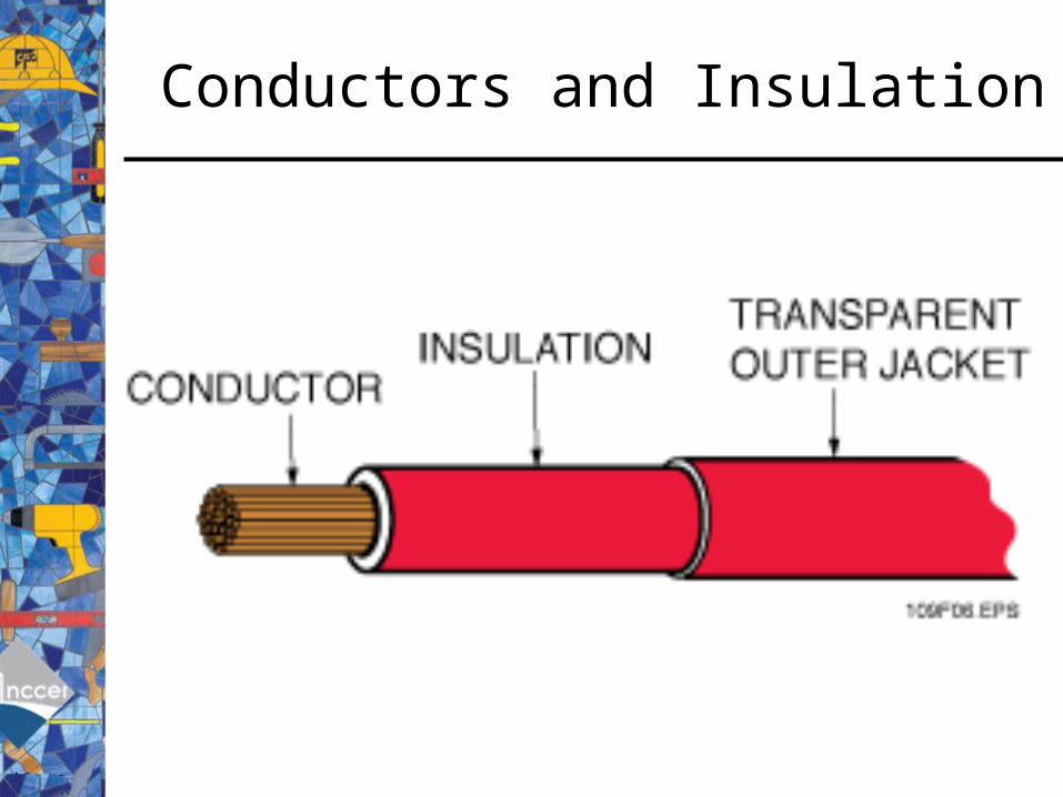
• The term conductor describes the current-carrying portion of a wire or cable.
• More commonly, it is used to describe the entire wire or cable assembly– the conductor– the insulating outer covering
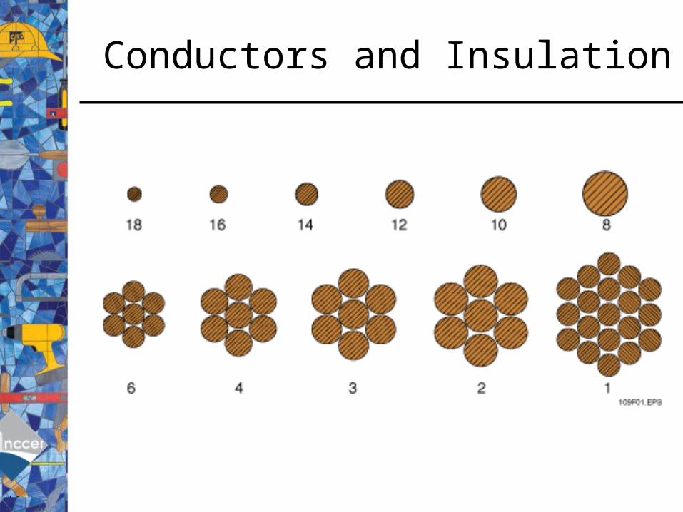
• Wire sizes in the United States are expressed in American Wire Gauge (AWG) numbers.
• In the AWG wire sizing system, the larger the number, the smaller the cross-sectional area of the wire.
Conductors and Insulation
Conductors and Insulation
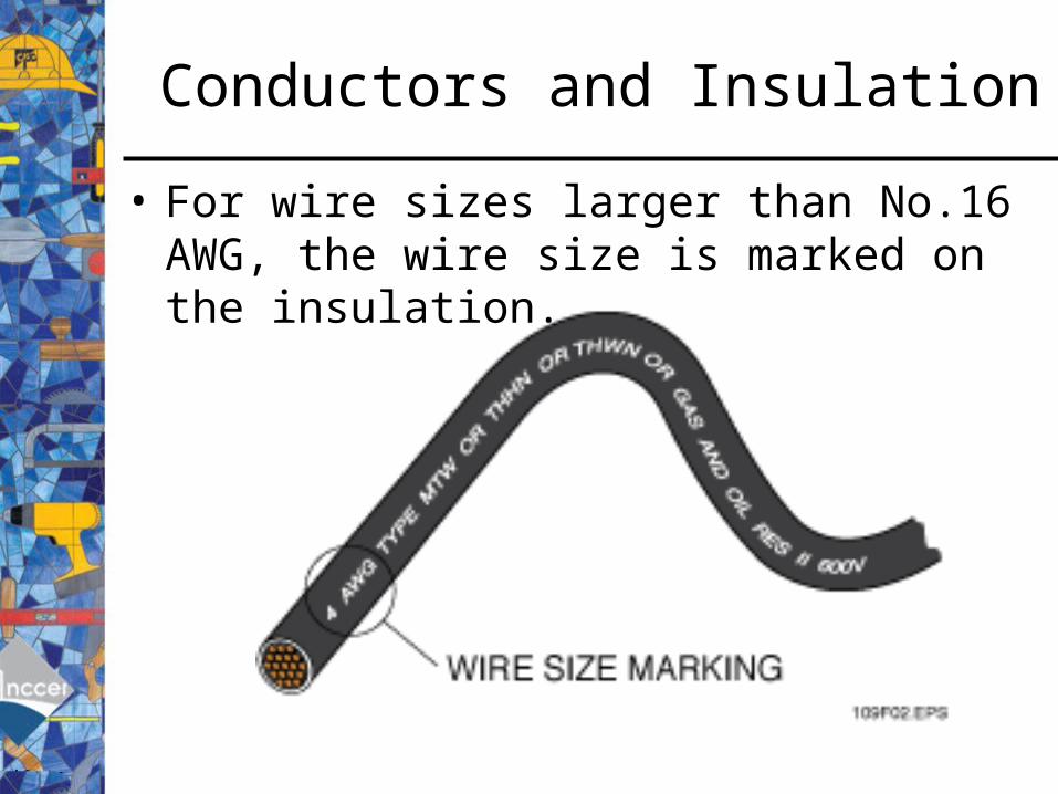
• For wire sizes larger than No.16 AWG, the wire size is marked on the insulation.
Conductors and Insulation
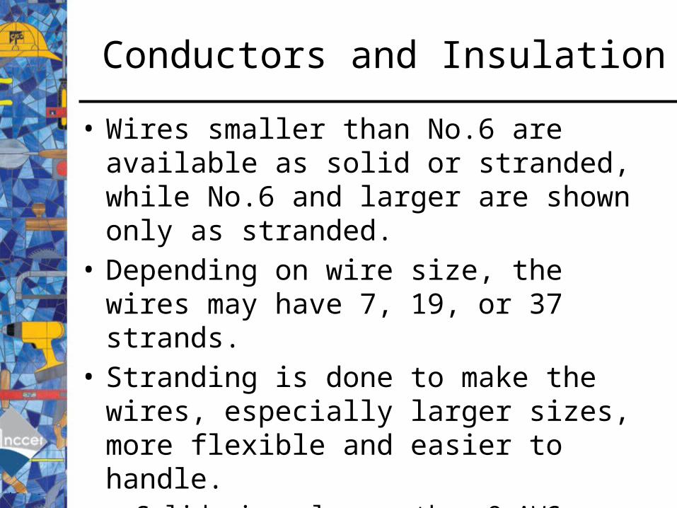
• Wires smaller than No.6 are available as solid or stranded, while No.6 and larger are shown only as stranded.
• Depending on wire size, the wires may have 7, 19, or 37 strands.
• Stranding is done to make the wires, especially larger sizes, more flexible and easier to handle.– Solid wires larger than 8 AWG should not be
terminated in pull boxes or disconnect switches.

Conductors and Insulation
Conductors and Insulation
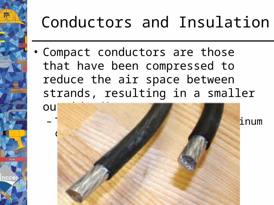
• Compact conductors are those that have been compressed to reduce the air space between strands, resulting in a smaller outside diameter.– This is commonly done with aluminum conductors.
Conductors and Insulation
• Using circular mils to express the cross-sectional area of a wire is a much easier way to express the wire size than using square inches.
• Ampacity is the current in amperes a conductor can carry continuously under the conditions of use without exceeding its temperature rating.
• The NEC® ampacity tables allow electricians to determine the ampacity of all types of conductors, with different insulating materials and in different operating conditions.
• Copper is the most common conductor because of its excellent conductivity, ease of use, and relatively low cost.
• All current-carrying conductors, including the grounded conductor, must be insulated when used in buildings or after the first over-current protective device.

Conductors and Insulation
• The value of any material used to manufacture wire is determined by its conductivity, cost, availability, and workability. – Conductivity describes the ease with which a material can carry
electric current. For example, the conductivity of aluminum is two-thirds that of copper.
– Cost of conductive material varies widely. • For example, platinum, a very good conductor, is much more expensive
than copper, another very good conductor.
– Conductive materials such as copper and aluminum are widely available, which makes them an affordable choice for conductors.
– Aluminum conductors are lighter and more flexible. or workable, than copper conductors, but that advantage is reduced because aluminum wire terminations require special materials and treatments

Conductors and Insulation
• Thermoplastic is a popular and effective insulation material in use today. Polyethylene (PE) is used for insulation of control and communications wiring.
• Thermoset insulating material such as RHW, maintain their form when heated.
• Insulation applied to building wire is coded using letters to indicate the type of insulation and its environmental rating. – For example, the letter W indicates that the
insulation is rated for use in a wet, outdoor location.

Conductors and Insulation
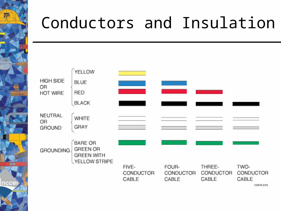
• A color code is used to help identify wires by the color of the insulation to make it easier to install and connect the wires.– For example, three- conductor cable has one
white or gray, one black, one red, and a grounding wire. Four-conductor cable has the same as three plus a fourth blue wire.
• The grounding conductor may be bare, green, or green with a yellow stripe.
Conductors and Insulation
Conductors and Insulation
• Ungrounded conductors are not normally color-coded; however certain power distribution arrangements require orange color-coding for the phase conductor that has the higher voltage to ground.
• Conductor selection is often based on the temperature rating of the wire, with conductor ampacities based on the ambient temperature plus the heat produced by current in the wire.
• In general, conductors with a higher temperature rating are able to handle higher current in higher ambient conditions.
• Fixture wire, used for the interior wiring of fixtures, is available in sizes from No.18 to No.10 AWG.
Conductors and Insulation
Day 2QOD: What increases the flexibility of a wire?
Stranding
Agenda:1. QOD & Measurements2. Module 26109-11: Conductors & Cables3. Activity – Cables4. Review
Learning Target:1. Students will accurately select conductors for a specified application.
2. Students will demonstrate the proper installation of selected conductors.
Conductors and Insulation
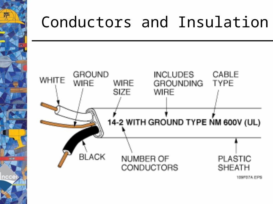
• Cables consist of two or more insulated wires and possibly a grounding wire, covered by a non-metallic or metallic sheath.
• All cables are marked to show important properties, including – wire size– number of conductors– cable type– voltage rating
Conductors and Insulation

Conductors and Insulation
• Non-metallic-sheathed cable such as Type NM and Type NMC is widely used for branch circuits and feeders in residential and commercial systems.
Conductors and Insulation
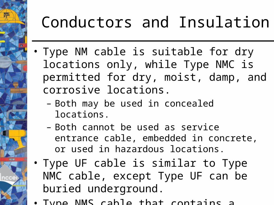
• Type NM cable is suitable for dry locations only, while Type NMC is permitted for dry, moist, damp, and corrosive locations. – Both may be used in concealed locations.– Both cannot be used as service entrance cable, embedded
in concrete, or used in hazardous locations.
• Type UF cable is similar to Type NMC cable, except Type UF can be buried underground.
• Type NMS cable that contains a factory assembly of power, communications, and signaling conductors enclosed within a moisture-resistant, flame-retardant sheath.

Conductors and Insulation
• Type MV (medium voltage) cable can be buried, installed in wet and dry locations, and is suitable for voltages ranging from 2,001 to 35,000 volts.
Conductors and Insulation
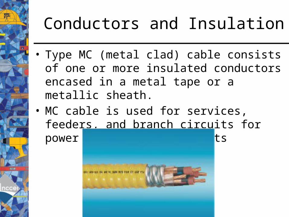
• Type MC (metal clad) cable consists of one or more insulated conductors encased in a metal tape or a metallic sheath.
• MC cable is used for services, feeders, and branch circuits for power and lighting circuits
Conductors and Insulation
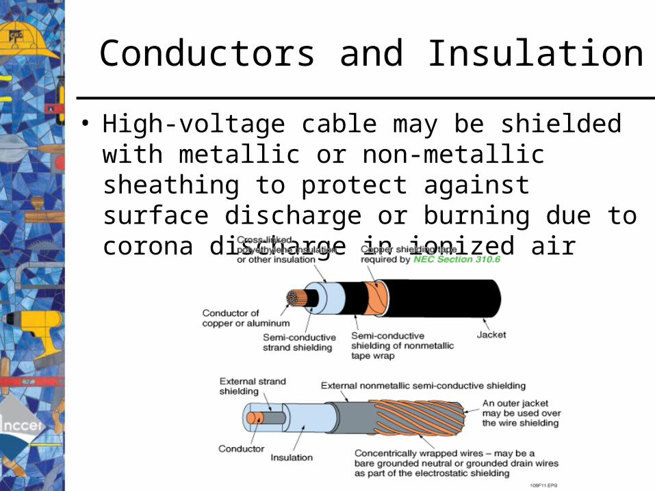
• High-voltage cable may be shielded with metallic or non-metallic sheathing to protect against surface discharge or burning due to corona discharge in ionized air
Conductors and Insulation
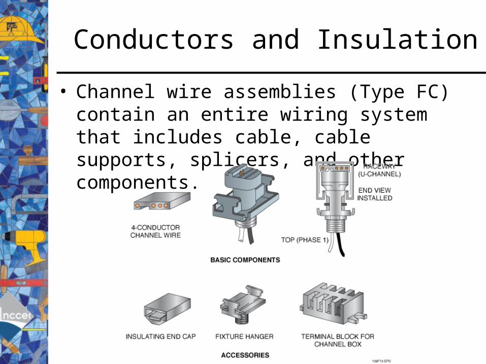
• Channel wire assemblies (Type FC) contain an entire wiring system that includes cable, cable supports, splicers, and other components.
Conductors and Insulation
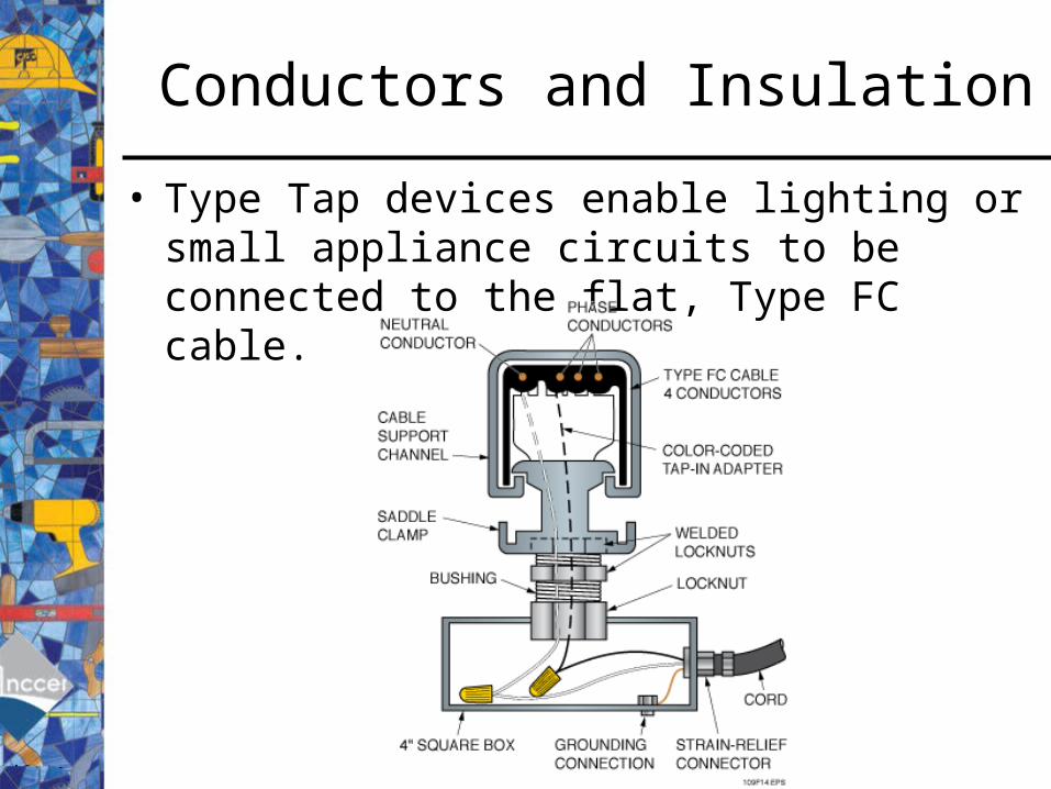
• Type Tap devices enable lighting or small appliance circuits to be connected to the flat, Type FC cable.

Conductors and Insulation
• Type FCC flat conductor cable contains an entire branch wiring system and is designed for installation under carpeting to supply floor outlets in commercial applications

Conductors and Insulation
• Type TC cable may be used in cable trays and raceways or may be buried.
Conductors and Insulation
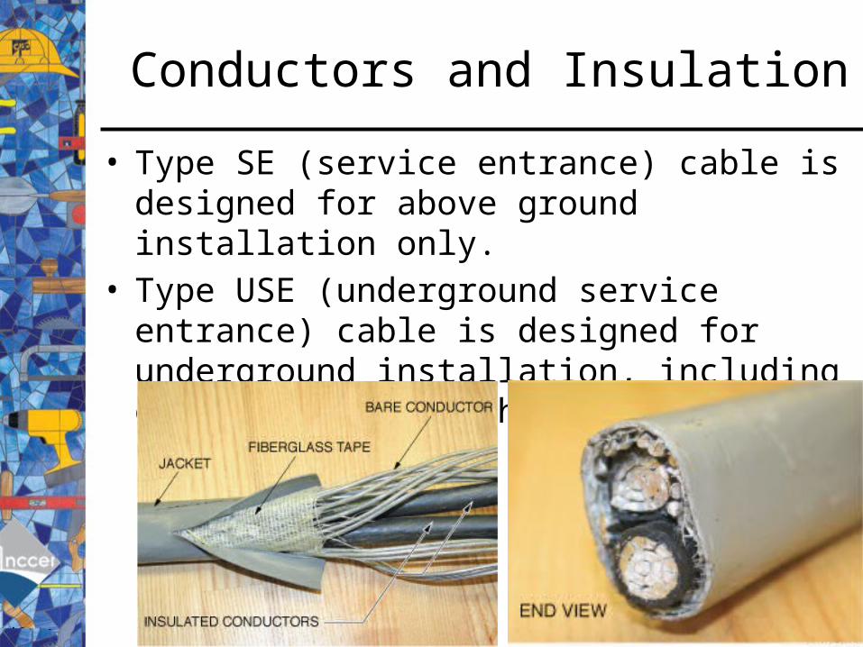
• Type SE (service entrance) cable is designed for above ground installation only.
• Type USE (underground service entrance) cable is designed for underground installation, including direct burial in the earth.
Conductors and Insulation
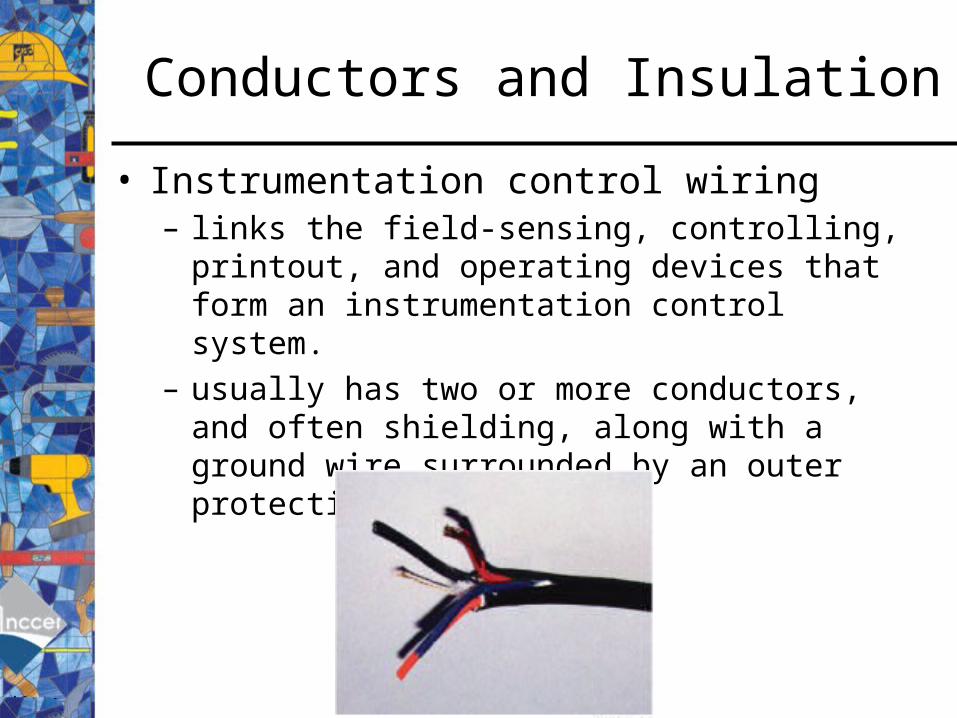
• Instrumentation control wiring – links the field-sensing, controlling, printout, and
operating devices that form an instrumentation control system.
– usually has two or more conductors, and often shielding, along with a ground wire surrounded by an outer protective jacket.

Conductors and Insulation
• Shields are often provided on instrumentation control wiring to prevent stray electrical interference from affecting signals being carried by the control wiring.
Conductors and Insulation
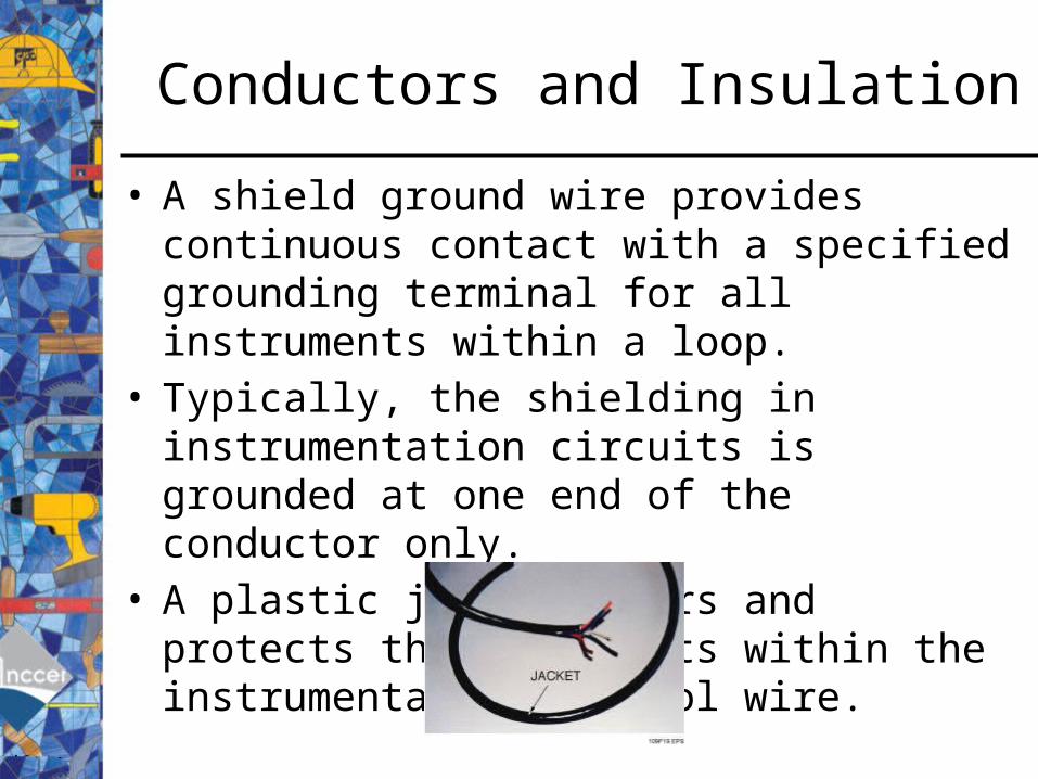
• A shield ground wire provides continuous contact with a specified grounding terminal for all instruments within a loop.
• Typically, the shielding in instrumentation circuits is grounded at one end of the conductor only.
• A plastic jacket covers and protects the components within the instrumentation control wire.

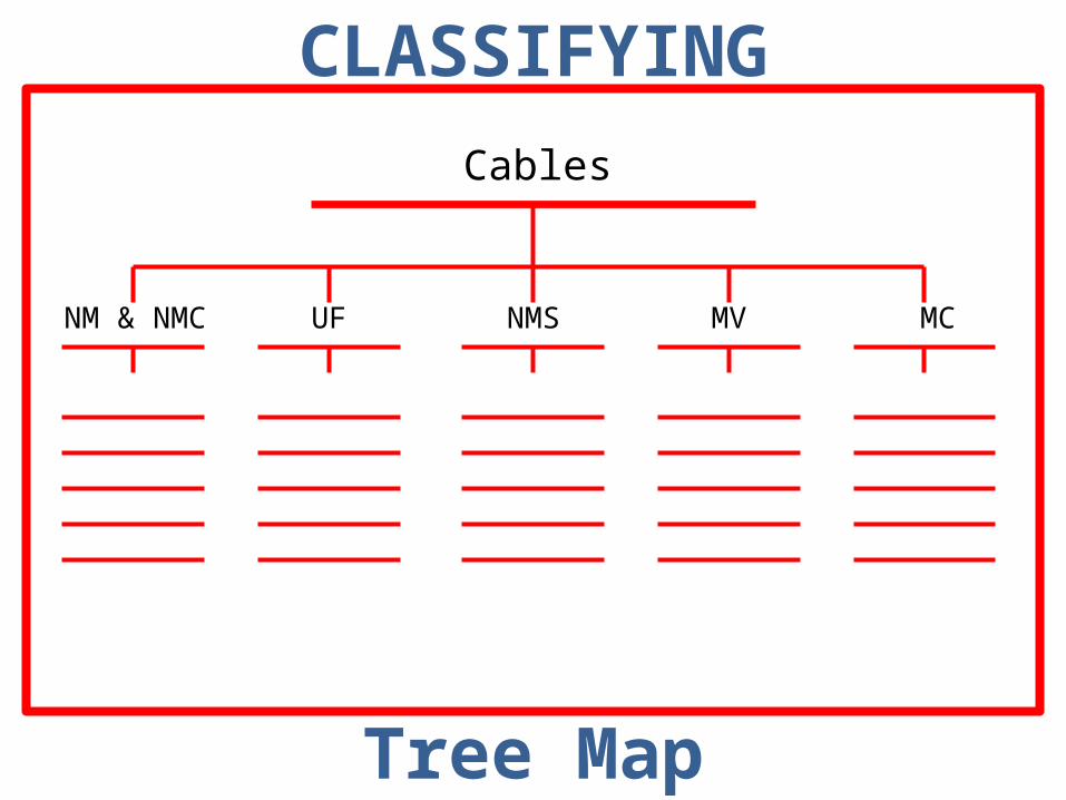
Activity:Electrical Cables
Objective: List important facts about electrical cables found in the book.
Individual Task: Prepare a Tree Map to classify facts about electrical cables discussed in class. Be prepared to present your work to the class. (Module 26109-11 / pp.7-14)
CLASSIFYING
Tree Map
Cables
NM & NMC UF NMS MV MC
Day 3QOD: Where can type UF cable be used?
Underground and direct burial applications
Agenda:1. QOD & Measurements2. Module 26109-11: Conductors & Cables3. Activity – Wire Pulling4. Review
Learning Target:1. Students will accurately select conductors for a specified application.
2. Students will demonstrate the proper installation of selected conductors.
3. Students will demonstrate the knowledge of National Electric Code
(NEC) related to conductors.

Conductors and Insulation
• Conductors can be installed in conduit by pulling them through using fish tape, pull line, and pulling equipment.
• Fish tapes, made of nylon or flexible steel, are available in lengths up to 200 feet and are equipped with a hook or loop to attach conductors.

Conductors and Insulation
• The tape is fed through the conduit between the points through which the wire is to be pulled.
Conductors and Insulation
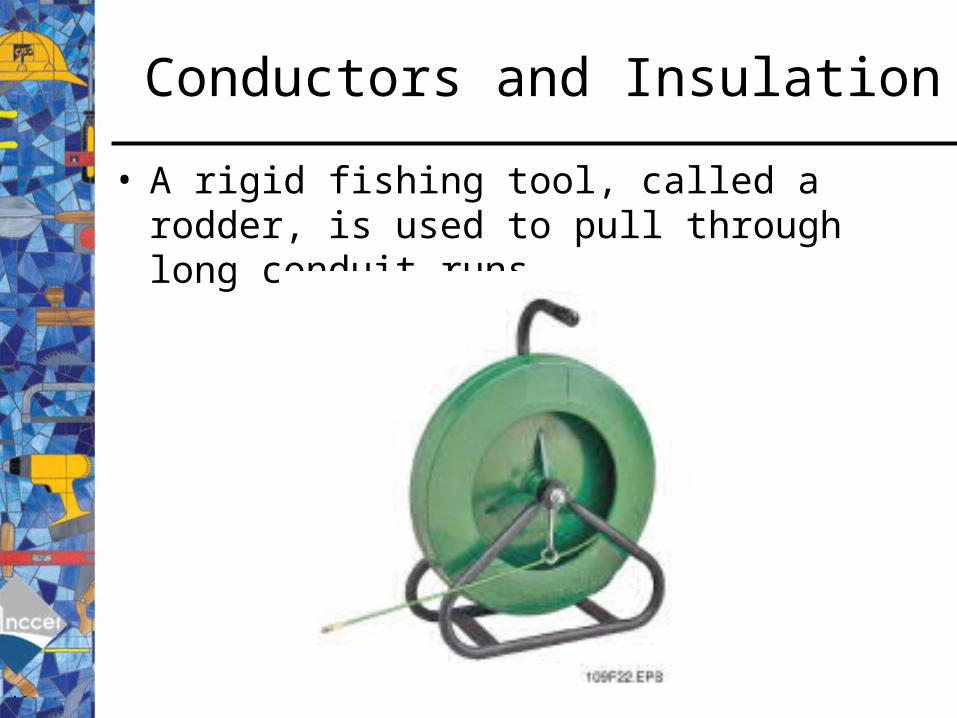
• A rigid fishing tool, called a rodder, is used to pull through long conduit runs.

Conductors and Insulation
• String lines can be attached to a piston-like plug called a mouse and drawn through the conduit with vacuum power.
Conductors and Insulation
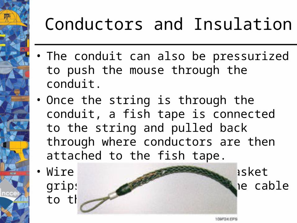
• The conduit can also be pressurized to push the mouse through the conduit.
• Once the string is through the conduit, a fish tape is connected to the string and pulled back through where conductors are then attached to the fish tape.
• Wire grips, also known as basket grips, are used to attach the cable to the fish tape.
Conductors and Insulation
• If it is determined that the conductors will be difficult to pull with a fish tape, a nylon pull line should be used instead.
• Pulling equipment is available to help electricians pull conductors through conduit.

Conductors and Insulation
• Manually operated pullers are used on smaller jobs where hand pulling is not possible or practical.
• Several attachments are available for power pullers to increase their versatility.

Conductors and Insulation
• Electrically driven pullers are useful when the friction caused by long runs and several conduit bends must be overcome.
• Several attachments are available for power pullers to increase their versatility.

Conductors and Insulation
• It is important to keep the conductors straight and parallel, and free from kinks, bends, and crossovers during the pull.
• To overcome the friction in long conduit runs, use a specially formulated wire lubricant to make pulling easier. Apply lubricant to the wires and the conduit.
• Once the conductors have been pulled, ensure that there is enough length of conductor to allow for bends, splices and terminations.
• The NEC® specifies a minimum of 6 inches for connections made to wiring devices or for splices.

Day 4QOD: What color is typically used for the fourth conductor of a power cable?
Blue
Agenda:1. QOD & Measurements2. Module 26109-11: Conductors & Cables3. Review for Test – Introduction to Electrical Circuits
Review Questions – p. 22Trade Term Quiz – pp. 23-24Supplemental Exercises – pp. 25-26
4. Review
Learning Target:1. Students will accurately select conductors for a specified application.
2. Students will demonstrate the proper installation of selected conductors.
3. Students will demonstrate the knowledge of National Electric Code
(NEC) related to conductors.
Day 5QOD: What type of conductor cable is flat?
FCC
Agenda:1. QOD & Measurements2. Module 26109-11: Conductors & Cables3. Review for Test – Introduction to Electrical Circuits
Review Questions – p. 22Trade Term Quiz – pp. 23-24Supplemental Exercises – pp. 25-26
4. Review
Learning Target:1. Students will accurately select conductors for a specified application.
2. Students will demonstrate the proper installation of selected conductors.
3. Students will demonstrate the knowledge of National Electric Code
(NEC) related to conductors.
Day 6QOD: What is true of shielding in instrumentation circuits?
It is grounded at one end only
Agenda:1. QOD & Measurements2. Module 26109-11: Conductors & Cables3. Test4. Review
Learning Target:1. Students will accurately select conductors for a specified application.
2. Students will demonstrate the proper installation of selected conductors.
3. Students will demonstrate the knowledge of National Electric Code
(NEC) related to conductors.