dcbf-125 dccf-150
TRANSCRIPT
Manufactured by:ECR International Inc.
2201 Dwyer Avenue, Utica, NY 13501Tel. 800 253 7900
www.ecrinternational.com
DCBF-125 DCCF-150
CONDENSING GAS FIRED BOILER
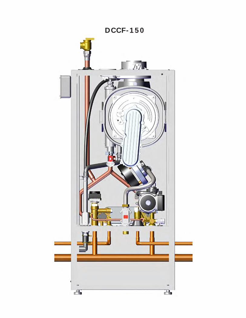
DCCF-150
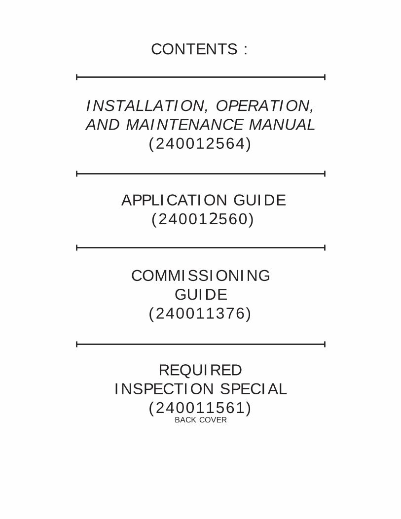
CONTENTS :
INSTALLATION, OPERATION,AND MAINTENANCE MANUAL
(240012564)
APPLICATION GUIDE (240012560)
COMMISSIONINGGUIDE
(240011376)
REQUIREDINSPECTION SPECIAL
(240011561)BACK COVER
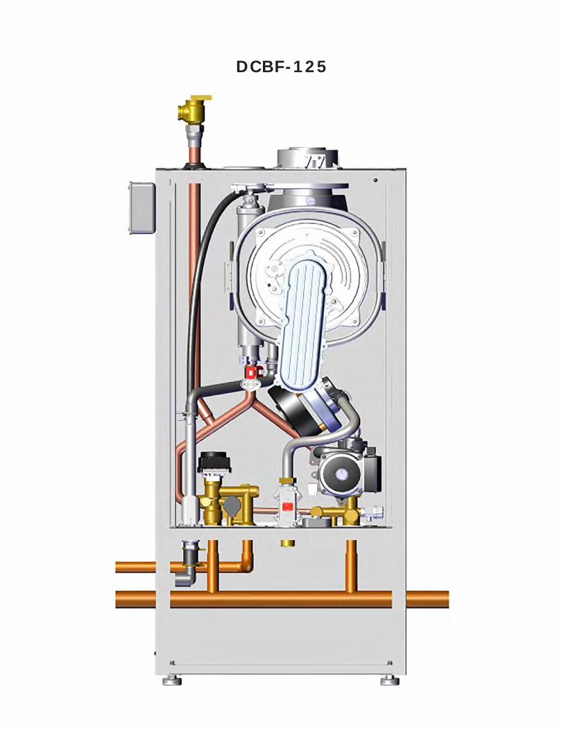
DCBF-125
CONDENSING GAS FIRED
INSTALLATION, OPERATION & MAINTENANCE MANUAL
Models DCBF-125, DCCF-150
Manufactured by: ECR International Inc.
2201 Dwyer Avenue, Utica, NY 13501 Tel. 800 253 7900
www.ecrinternational.com PN 240012564 REV. A [05/15/2019]
2
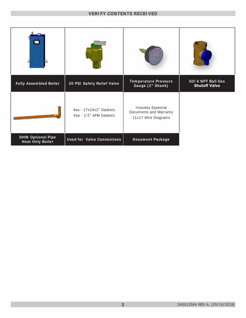
Fully Assembled Boiler 30 PSI Safety Relief Valve Temperature Pressure Gauge (2" Shank)
G3/4 NPT Ball Gas Shutoff Valve
4ea - 17x24x2" Gaskets4ea - 1/2" AFM Gaskets
Includes Essential Documents and Warranty
11x17 Wire Diagrams
DHW Optional Pipe Heat Only Boiler Used for Valve Connections Document Package
VERIFY CONTENTS RECEIVED
240012564 REV A, [05/15/2019]
3
Verify contents received ................................................2Table of contents ...........................................................3Physical Data.................................................................41 - Important Information .............................................62 - Introduction .............................................................73 - Component Listing ...................................................84 - Locating Boiler .......................................................105 - Combustion Air And Vent Piping .............................12
5.1 General .................................................................125.2 Removal of Existing Boiler From Common Vent System .................................................................................125.3 Definitions .............................................................135.4 Approved Venting Materials ....................................145.5 Vent Termination ....................................................145.6 Coaxial Venting Instructions ....................................155.7 Coaxial Vent Screw Placement ................................155.8 Twin Pipe Systems ..................................................175.9 Securing Twin Pipe Polypropylene Venting .............. 185.10 (3" /80 mm Only) Flexible Vent System ............. 215.11 Condensate Piping ................................................23
6 - Hydronic Piping ......................................................246.1 General .................................................................246.2 Special Conditions ..................................................246.3 Safety Relief Valve and Air Vent ...............................256.4 Trim Piping ............................................................256.5 System Piping ........................................................256.6 External Optional Low Water Cut Off ........................276.7 Central Heating System ..........................................296.8 Domestic Hot Water Mode .......................................296.9 Frost Protection Mode .............................................296.10 Pump Protection ...................................................29
7 - Gas Supply Piping ..................................................307.1 General .................................................................307.2 Leak Check Gas Piping ............................................317.3 Gas Orifice ...........................................................31
8 - Electrical Connections ............................................328.1 General .................................................................328.2 Install Room Thermostat .........................................328.3 Electrical Connections .............................................328.4 Access To Connection Block .....................................338.5 Main Supply Connection ..........................................338.6 Install Room Thermostat .........................................348.7 Optional Electrical Connections .................................348.8 Indirect Storage Tank ..............................................35
9 - Start Up Procedure .................................................369.1 Central Heating System Connections - Heat Only..... 369.2 Central Heating System Connections - Combi.......... 369.3 System Start Up.....................................................379.4 Fill Condensate Trap with Water ...............................379.5 Control Panel .........................................................389.6 Prior to Commissioning ..........................................399.7 Commissioning For The First Time: ...........................399.8 Automatic Calibration Function .................................399.9 Manual Calibration Function: ....................................409.10 De-Aeration Function ............................................409.11 Commission Set Up (Gas) - Changing The Type Of ....... Gas ............................................................................40
9.12 Chimney Sweep Function (CO2 Adjust) ................ 419.13 Combustion Adjustment Function (CO2%) ............ 419.14 Check Firing Rate .................................................419.15 Description Of Parameters: Factory Settings ......... 429.16 Adjusting Maximum Heating Power .........................44
10 - Operating instructions .........................................4510.1 Testing For Gas Leaks And Purging The Gas Supply 4510.2 Boiler Operation ...................................................4510.3 Central Heating Mode ............................................4510.4 Domestic Hot Water Mode .....................................4510.5 Frost Protection ....................................................4510.6 Pump ..................................................................4510.7 Low Water Pressure Sensor (Internal) ................ 45
11 - General Maintenance and Cleaning.......................4611.1 Beginning of Each Heating Season ..........................4611.2 Maintenance And Routine Servicing .........................4711.3 Component Replacement And Cleaning ................ 4711.4 Draining the Boiler ................................................4811.5 Draining the Heating Circuit ...................................4811.6 Hydraulic Unit (DHW) ............................................4911.7 Cleaning The Cold Water Filter ...............................4911.8 Final Commissioning .............................................4911.9 Final Assembly .....................................................4911.10 User Information ................................................5011.11 Safety Flue Thermostat - DO NOT disable this safety device. .......................................................................5011.12 Flue Pressure Switch- DO NOT disable this safety device. .......................................................................5011.13 Replacement Parts ..............................................50
12 - Ratings And Capacities .........................................5112.1 Ratings and Capacity ............................................5112.2 Domestic Hot Water Specifications ..........................5112.3 High Altitude Ratings and Capacity .........................5112.4 High Altitude Chart ...............................................51
13 - Trouble Shooting ..................................................5213.1 Error Messages And Resetting The Boiler .............. 5213.2 Anomalies Table for the Installer - Use this table to report the anomaly values. ...........................................54
14 - Glossary ...............................................................55Appendix A - Wiring Diagrams .....................................57Appendix A - Wiring Diagrams .....................................58
TABLE OF CONTENTS
240012564 REV A, [05/15/2019]
4
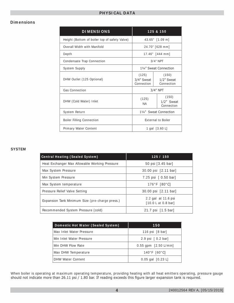
Dimensions
Central Heating (Sealed System) 125 / 150
Heat Exchanger Max Allowable Working Pressure 50 psi [3.45 bar]
Max System Pressure 30.00 psi [2.11 bar]
Min System Pressure 7.25 psi [ 0.50 bar]
Max System temperature 176°F [80°C]
Pressure Relief Valve Setting 30.00 psi [2.11 bar]
Expansion Tank Minimum Size (pre-charge press.) 2.2 gal at 11.6 psi [10.0 L at 0.8 bar]
Recommended System Pressure (cold) 21.7 psi [1.5 bar]
Domestic Hot Water (Sealed System) 150Max Inlet Water Pressure 116 psi [8 bar]
Min Inlet Water Pressure 2.9 psi [ 0.2 bar]
Min DHW Flow Rate 0.55 gpm [2.50 L/min]
Max DHW Temperature 140°F [60°C]
DHW Water Content 0.05 gal [0.23 L]
SYSTEM
When boiler is operating at maximum operating temperature, providing heating with all heat emitters operating, pressure gauge should not indicate more than 26.11 psi / 1.80 bar. If reading exceeds this figure larger expansion tank is required.
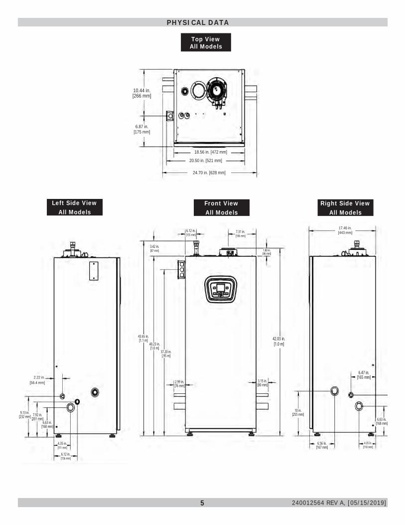
PHYSICAL DATA
DIMENSIONS 125 & 150
Height (Bottom of boiler top of safety Valve) 43.65" [1.09 m]
Overall Width with Manifold 24.70" [628 mm]
Depth 17.46" [444 mm]
Condensate Trap Connection 3/4" NPT
System Supply 11/4” Sweat Connection
DHW Outlet (125 Optional)(125)
3/4” Sweat Connection
(150) 1/2” Sweat Connection
Gas Connection 3/4” NPT
DHW (Cold Water) Inlet(125) NA
(150) 1/2” Sweat Connection
System Return 11/4” Sweat Connection
Boiler Filling Connection External to Boiler
Primary Water Content 1 gal [3.60 L]
240012564 REV A, [05/15/2019]
5
PHYSICAL DATA
240012564 REV A, [05/15/2019]
Top View All Models
Front ViewAll Models
Right Side ViewAll Models
Left Side ViewAll Models
10.44 in.[266 mm]
6.87 in.[175 mm]
18.56 in. [472 mm]
20.50 in. [521 mm]
24.70 in. [628 mm]
2.22 in.[56.4 mm]
9.13 in.[232 mm] 7.92 in.
[201 mm]6.63 in.
[168 mm]
4.35 in.[111 mm]
6.12 in.[156 mm]
6.12 in.[155 mm]
7.31 in.[186 mm]
3.42 in.[87 mm] 1.80 in.
[46 mm]
43.65 in.[1.1 m]
40.23 in.[1.0 m]
37.20 in.[.95 m]
2.99 in.[76 mm]
3.15 in.[80 mm]
10 in.[255 mm]
6.56 in.[167 mm]
4.35 in.[110 mm]
6.63 in.[168 mm]
6.47 in.[165 mm]
42.03 in.[1.0 m]
17.46 in.[443 mm]
6
CAUTIONIndicates a hazardous situation which, if not avoided, could result in minor or moderate injury.
!
WARNINGIndicates a hazardous situation which, if not avoided, could result in death or serious injury.
!
DANGERIndicates a hazardous situation which, if not avoided, WILL result in death or serious injury.
!
This is the safety alert symbol. Symbol alerts you to potential personal injury hazards. Obey all safety messages following this symbol to avoid possible injury or death.
Become familiar with symbols identifying potential hazards.
Boiler installation shall be completed by qualified agency. See glossary for additional information.
1. Safety Information
WARNINGDo not tamper with or use this boiler for any purpose other than its intended use. Failure to follow these instructions could result in death or serious injury. Use only manufacturer recommended parts and accessories.
!
CAUTIONLaceration, burn hazard. Metal edges and parts may have sharp edges and/or may be hot. Use appropriate personal protection equipment to include safety glasses and gloves when installing or servicing this boiler. Failure to follow these instructions could result in minor or moderate injury.
!
NOTICEUsed to address practices not related to personal injury.
WARNINGFire, explosion, asphyxiation and electrical shock hazard. Improper installation could result in death or serious injury. Read this manual and understand all requirements before beginning installation.
!
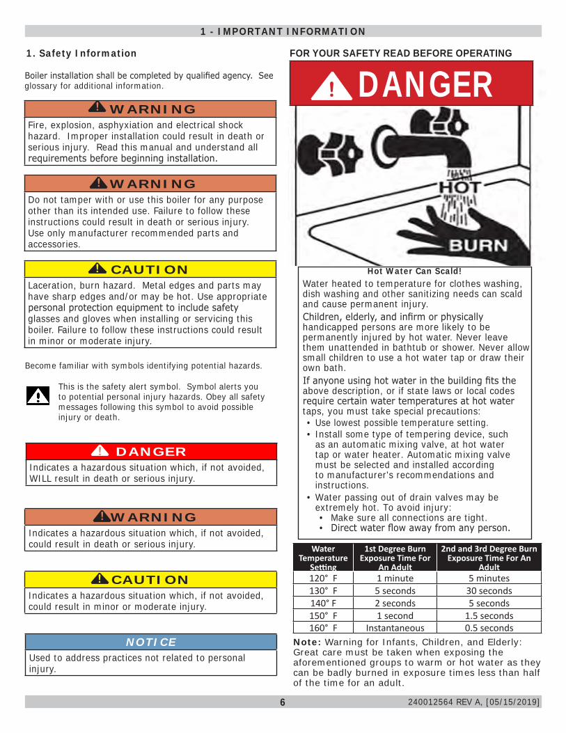
FOR YOUR SAFETY READ BEFORE OPERATING
Hot Water Can Scald!Water heated to temperature for clothes washing, dish washing and other sanitizing needs can scald and cause permanent injury.Children, elderly, and infirm or physically handicapped persons are more likely to be permanently injured by hot water. Never leave them unattended in bathtub or shower. Never allow small children to use a hot water tap or draw their own bath.If anyone using hot water in the building fits the above description, or if state laws or local codes require certain water temperatures at hot water taps, you must take special precautions:• Use lowest possible temperature setting.• Install some type of tempering device, such
as an automatic mixing valve, at hot water tap or water heater. Automatic mixing valve must be selected and installed according to manufacturer's recommendations and instructions.
• Water passing out of drain valves may be extremely hot. To avoid injury:• Make sure all connections are tight.• Direct water flow away from any person.
DANGER!
Water Temperature
Setting
1st Degree Burn Exposure Time For
An Adult
2nd and 3rd Degree Burn Exposure Time For An
Adult120° F 1 minute 5 minutes130° F 5 seconds 30 seconds140° F 2 seconds 5 seconds150° F 1 second 1.5 seconds160° F Instantaneous 0.5 seconds
Note: Warning for Infants, Children, and Elderly: Great care must be taken when exposing the aforementioned groups to warm or hot water as they can be badly burned in exposure times less than half of the time for an adult.
1 - IMPORTANT INFORMATION
240012564 REV A, [05/15/2019]
7
Check our website frequently for updates: www.ecrinternational.com
Information and specifications outlined in this manual in effect at thetime of printing of this manual. ECR International reserves the right to
discontinue, change specifications or system design at any time without notice and without incurring any obligation, whatsoever.
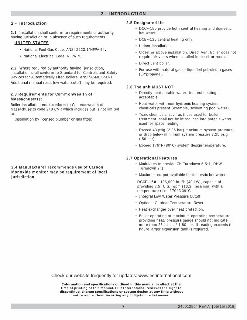
2.5 Designated Use• DCCF-150 provide both central heating and domestic
hot water. • DCBF-125 central heating only.• Indoor installation.• Closet or alcove installation. Direct Vent Boiler does not
require air vents when installed in closet or room.• Direct vent boiler.• For use with natural gas or liquefied petroleum gases
(LP/propane).
2.6 The unit MUST NOT:• Directly heat potable water. Indirect heating is
acceptable.• Heat water with non-hydronic heating system
chemicals present (example, swimming pool water).• Toxic chemicals, such as those used for boiler
treatment, shall not be introduced into potable water used for space heating.
• Exceed 43 psig (2.96 bar) maximum system pressure, or drop below minimum system pressure 7.25 psig (.50 bar)
• Exceed 176°F (80°C) system design temperature.
2.7 Operational Features• Modulates to provide CH Turndown 5.5:1, DHW
Turndown 7:1.• Maximum output available for domestic hot water:
DCCF-150 - 136,000 btu/h (40 kW), capable of providing 3.5 (U.S.) gpm (13.2 liters/min) with a temperature rise of 70°F/39°C.
• Integral Low Water Pressure Cutoff.• Optional Outdoor Temperature Reset.• Heat exchanger over heat protection.• Boiler operating at maximum operating temperature,
providing heat, pressure gauge should not indicate more than 26.11 psi / 1.80 bar. If reading exceeds this figure larger expansion tank is required.
2 - Introduction
2.1 Installation shall conform to requirements of authority having jurisdiction or in absence of such requirements: UNITED STATES
• National Fuel Gas Code, ANSI Z223.1/NFPA 54. • National Electrical Code, NFPA 70.
2.2 Where required by authority having jurisdiction, installation shall conform to Standard for Controls and Safety Devices for Automatically Fired Boilers, ANSI/ASME CSD-1. Additional manual reset low water cutoff may be required.
2.3 Requirements for Commonwealth of Massachusetts: Boiler installation must conform to Commonwealth of Massachusetts code 248 CMR which includes but is not limited to: Installation by licensed plumber or gas fitter.
2.4 Manufacturer recommends use of Carbon Monoxide monitor may be requirement of local jurisdiction.
2 - INTRODUCTION
240012564 REV A, [05/15/2019]
8
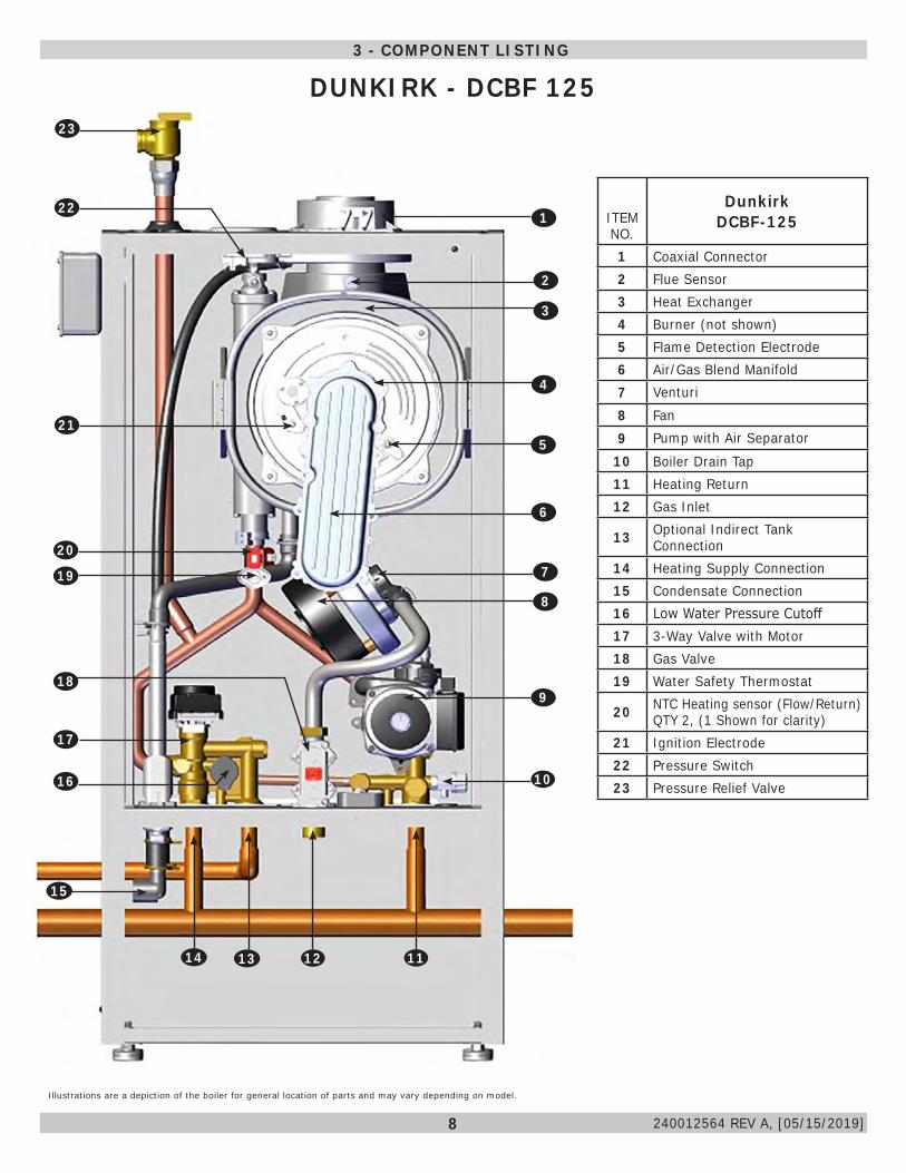
3 - COMPONENT LISTING
Illustrations are a depiction of the boiler for general location of parts and may vary depending on model.
ITEM NO.
DunkirkDCBF-125
1 Coaxial Connector2 Flue Sensor3 Heat Exchanger4 Burner (not shown)5 Flame Detection Electrode 6 Air/Gas Blend Manifold7 Venturi8 Fan9 Pump with Air Separator
10 Boiler Drain Tap11 Heating Return12 Gas Inlet
13 Optional Indirect Tank Connection
14 Heating Supply Connection15 Condensate Connection16 Low Water Pressure Cutoff17 3-Way Valve with Motor18 Gas Valve19 Water Safety Thermostat
20 NTC Heating sensor (Flow/Return) QTY 2, (1 Shown for clarity)
21 Ignition Electrode22 Pressure Switch23 Pressure Relief Valve
9
2
4
1
3
6
5
7
8
10
13
22
20
19
21
111214
15
16
17
18
23
240012564 REV A, [05/15/2019]
DUNKIRK - DCBF 125
9
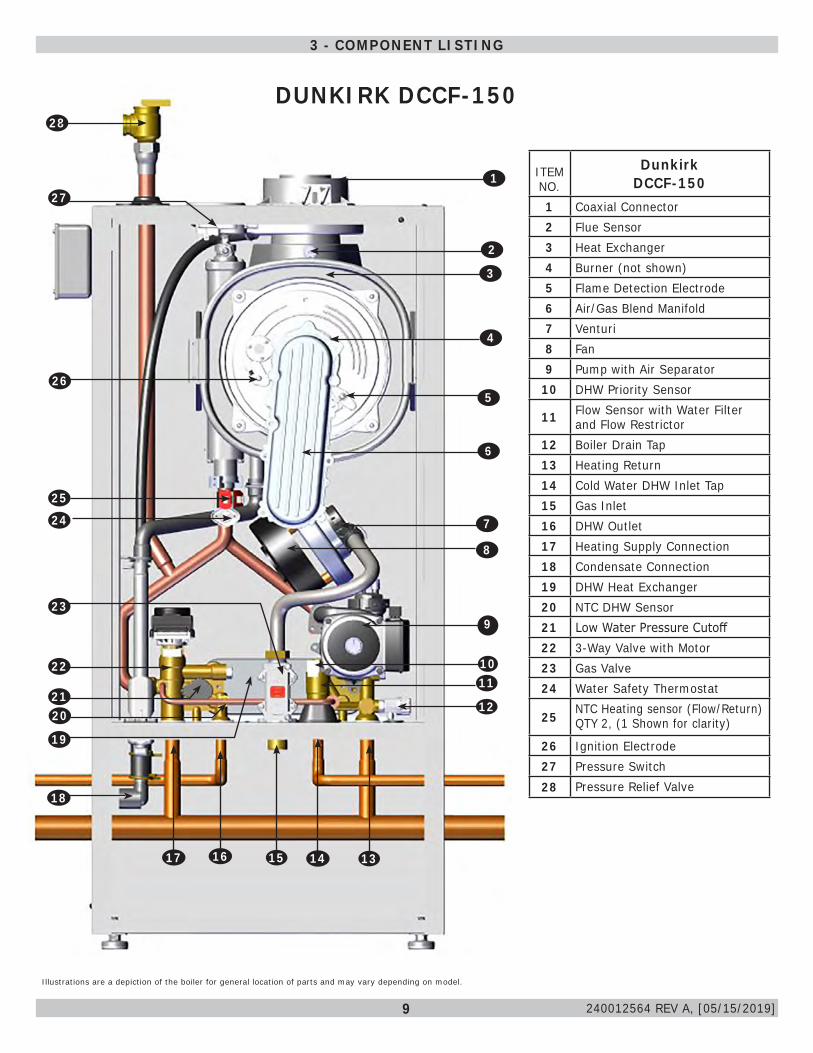
3 - COMPONENT LISTING
ITEM NO.
DunkirkDCCF-150
1 Coaxial Connector2 Flue Sensor3 Heat Exchanger4 Burner (not shown)5 Flame Detection Electrode 6 Air/Gas Blend Manifold7 Venturi8 Fan9 Pump with Air Separator
10 DHW Priority Sensor
11 Flow Sensor with Water Filter and Flow Restrictor
12 Boiler Drain Tap13 Heating Return14 Cold Water DHW Inlet Tap15 Gas Inlet16 DHW Outlet17 Heating Supply Connection18 Condensate Connection19 DHW Heat Exchanger20 NTC DHW Sensor21 Low Water Pressure Cutoff22 3-Way Valve with Motor23 Gas Valve24 Water Safety Thermostat
25 NTC Heating sensor (Flow/Return) QTY 2, (1 Shown for clarity)
26 Ignition Electrode27 Pressure Switch28 Pressure Relief Valve
Illustrations are a depiction of the boiler for general location of parts and may vary depending on model.
9
16
27
2
25
24
19
4
1
26
3
6
5
7
8
28
1011
12
14 131517
18
2021
22
23
240012564 REV A, [05/15/2019]
DUNKIRK DCCF-150
10
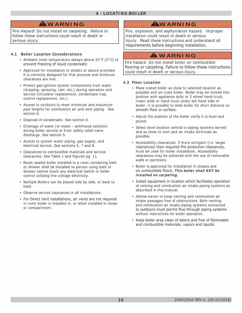
4.1 Boiler Location Considerations• Ambient room temperature always above 32°F (0°C) to
prevent freezing of liquid condensate. • Approved for installation in closets or alcove provided
it is correctly designed for that purpose and minimum clearances are met.
• Protect gas ignition system components from water (dripping, spraying, rain, etc.) during operation and service (circulator replacement, condensate trap, control replacement, etc.).
• Access to outdoors to meet minimum and maximum pipe lengths for combustion air and vent piping. See section 6.
• Disposal of condensate. See section 6.• Drainage of water (or water - antifreeze solution)
during boiler service or from safety relief valve discharge. See section 5.
• Access to system water piping, gas supply, and electrical service. See sections 5, 7 and 8.
• Clearances to combustible materials and service clearances. See Table 1 and Figures pg. 11.
• Room-sealed boiler installed in a room containing bath or shower shall be installed so person using bath or shower cannot touch any electrical switch or boiler control utilizing line voltage electricity.
• Multiple Boilers can be placed side by side, or back to back.
• Observe service clearances in all installations.• For Direct Vent installations, air vents are not required
in room boiler is installed in, or when installed in closet or compartment.
WARNINGFire Hazard! Do not install on carpeting. Failure to follow these instructions could result in death or serious injury.
!
4 - LOCATING BOILER
4.2 Floor Location• Place crated boiler as close to selected location as
possible and un-crate boiler. Boiler may be moved into position with appliance dolly or 2 wheel hand truck. Insert dolly or hand truck under left hand side of boiler. It is possible to slide boiler for short distance on smooth floor or surface.
• Adjust the position of the boiler verify it is level and plumb.
• Select level location central to piping systems served and as close to vent and air intake terminals as possible.
• Accessibility clearances, if more stringent (i.e. larger clearances) than required fire protection clearances, must be used for boiler installation. Accessibility clearances may be achieved with the use of removable walls or partitions.
• Boiler is approved for installation in closets and on combustible floors. This boiler shall NOT be installed on carpeting.
• Install equipment in location which facilitates operation of venting and combustion air intake piping systems as described in this manual.
• Advise owner to keep venting and combustion air intake passages free of obstructions. Both venting and combustion air intake piping systems connected to outdoors must permit flow through piping systems without restrictions for boiler operation.
• Keep boiler area clean of debris and free of flammable and combustible materials, vapors and liquids.
WARNINGFire hazard. Do not install boiler on combustible flooring or carpeting. Failure to follow these instructions could result in death or serious injury.
!
WARNINGFire, explosion, and asphyxiation hazard. Improper installation could result in death or serious injury. Read these instructions and understand all requirements before beginning installation.
!
240012564 REV A, [05/15/2019]
11
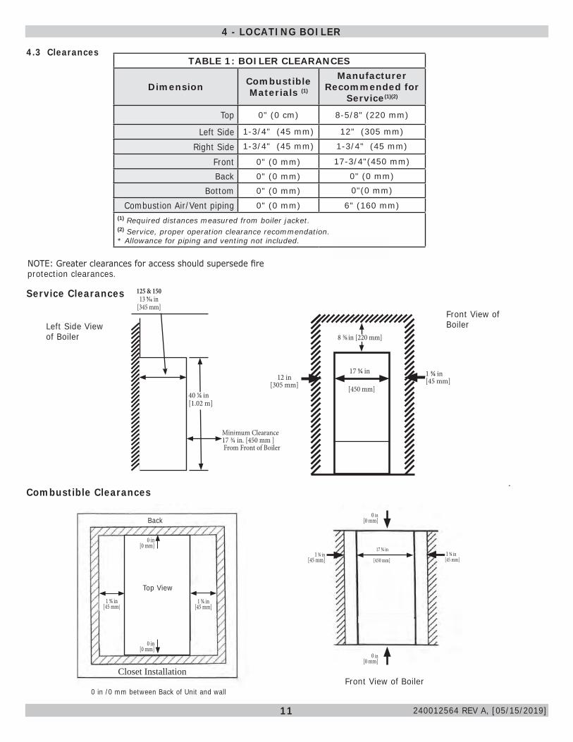
NOTE: Greater clearances for access should supersede fire protection clearances.
Minimum Clearance17 3/4 in. [450 mm ] From Front of Boiler
13.58 in /345.00 mm
12 in[305 mm]
17 3/4 in
[450 mm]
8 5/8 in [220 mm]
40 1/4 in [1.02 m]
125 & 15013 9/16 in
[345 mm]
4.3 Clearances
1 3/4 in[45 mm]
Left Side View of Boiler
Front View of Boiler
Service Clearances
4 - LOCATING BOILER
1 3/4 in [45 mm]
17 3/4 in
Top View
Back
Closet Installation
0 in /0 mm between Back of Unit and wall
1 3/4 in [45 mm]
1 3/4 in [45 mm]
1 3/4 in [45 mm] [450 mm]
Front View of Boiler
0 in [0 mm]
0 in [0 mm]
Top View
0 in[0 mm]
0 in[0 mm]
Combustible Clearances
TABLE 1: BOILER CLEARANCES
Dimension Combustible Materials (1)
Manufacturer Recommended for
Service(1)(2)
Top 0" (0 cm) 8-5/8" (220 mm)
Left Side 1-3/4" (45 mm) 12" (305 mm)
Right Side 1-3/4" (45 mm) 1-3/4" (45 mm)
Front 0" (0 mm) 17-3/4"(450 mm)
Back 0" (0 mm) 0" (0 mm)
Bottom 0" (0 mm) 0"(0 mm)
Combustion Air/Vent piping 0" (0 mm) 6" (160 mm)(1) Required distances measured from boiler jacket.(2) Service, proper operation clearance recommendation.* Allowance for piping and venting not included.
240012564 REV A, [05/15/2019]
12
WARNINGFire, explosion, and asphyxiation hazard. Improper installation could result in death or serious injury. Read these instructions and understand all requirements before beginning installation.
!
• This boiler requires a dedicated direct vent system.• Vent connections serving appliances vented by natural draft
shall not be connected into any portion of mechanical draft systems operating under positive pressure.
• Use only manufacturer approved venting materials or venting materials primer and glue approved to: ULC S636 in Canada, or UL 1738 in the U.S.
• Materials used in the U.S. shall comply with Authority having jurisdiction and in absence of such with: ANSI/ASTM D1785, ANSI/ASTM F441, ANSI/ASTM F493.
• Vent system must have unrestricted movement through walls, ceilings and roof penetrations.
• Check for proper joint construction when joining pipe to fittings.• If vent is penetrating ceilings and floors, openings must
have means of fire stopping in joist areas and proper fire-stop spacer assemblies installed.
• Standard roof flashing methods must be used to install roof flashing.
• Frame wall and roof openings to provide support for attachment of termination assemblies.
• Support piping in accordance with pipe manufacturer's instruction and authority having jurisdiction. In absence of manufacturer's instruction use pipe hooks, pipe straps, brackets, or hangers of adequate and strength located at intervals of 3 ft (1 m) or less. Allow for expansion/ contraction of pipe.
• Venting shall be supported adjacent to each joint using steel strapping or equivalent. See Figure 5-1.
WARNINGABS/PVC venting shall not to be used this product. Use of DWV plumbing pipes to vent this boiler shall be prohibited.Use of cellular core PVC (ASTM F891), cellular core CPVC, or Radel® (polyphenolsulfone) in venting systems shall be prohibited.Covering non-metallic vent pipe and fittings with thermal insulation shall be prohibited.Failure to follow these instructions could result in death or serious injury.
!
5 - COMBUSTION AIR AND VENT PIPING
NOTICEFollow venting manufacturer's equivalent lengths for specialty fittings.
• Support horizontal sections of vent pipe to prevent sags capable of accumulating condensate.
• Assemble vent materials in accordance with venting manufacturer’s instructions.
• Slope exhaust pipe minimum of 1/4” per foot, or vent manufacturer’s recommendation, whichever is greater; back toward the boiler.
• Any "in line" elbows in flue system must be taken into consideration. First elbow on the top of the boiler is included in equivalent length calculations.
• Use U.V. stabilized polypropylene when it will be exposed to sunlight, wind, or prone to freeze ups.
• Manufacturer requires use of an approved mechanical fastener, which may vary per vent pipe manufacturer, at every push-fit gasket connection when using a single wall polypropylene vent system.
5.2 Removal of Existing Boiler From Common Vent SystemWhen existing boiler is removed from common venting system, common venting system is likely to be too large for proper venting of appliances remaining connected to it. After removal of existing boiler, following steps shall be followed with each appliance remaining connected to common venting system placed in operation, while other appliances remaining connected to common venting system are not in operation:• Seal any unused openings in common venting system.• Visually inspect venting system for proper size and
horizontal pitch. Determine there is no blockage or restrictions, leakage, corrosion and other deficiencies which could cause an unsafe condition.
• When practical, close all building doors, windows, and all doors between space in which appliances remaining connected to common venting system are located and other spaces of building. Turn on clothes dryer and any appliance not connected to common venting system. Turn on exhaust fans, such as range hoods and bathroom exhaust so they will operate at maximum speed. Do not operate summer exhaust fan. Close fireplace dampers.
• Turn on appliance being inspected. Follow lighting instructions. Adjust thermostat so appliances will operate continuously.
• Test for spillage at draft hood relief opening after 5 minutes of main burner operation. Use flame of match or candle, smoke from cigarette, cigar or pipe.
• Determine each appliance remaining connected to common venting system properly vents when tested as outlined above. Then return doors, windows, exhaust fans and any other gas-burning appliance to their previous condition of use.
• Any improper operation of common venting system should be corrected so installation conforms with National Fuel Code, ANSI Z223.1/NFPA 54 and/or Natural Gas and Propane Installation Code, CAN/CSA B149.1. When re-sizing any portion of common venting system, common venting system should be re-sized to approach minimum size as determined using appropriate tables in Chapter 13 of the National Fuel Gas Code, ANSI Z223.1/NFPA 54 and/or Natural Gas and Propane Installation Code, CAN/CSA B149.1.
5.1 General• Installations shall comply with Authority having jurisdiction
and in absence of such with: » U.S. ANSI Z223.1 /NFPA 54 in the United States
240012564 REV A, [05/15/2019]
13
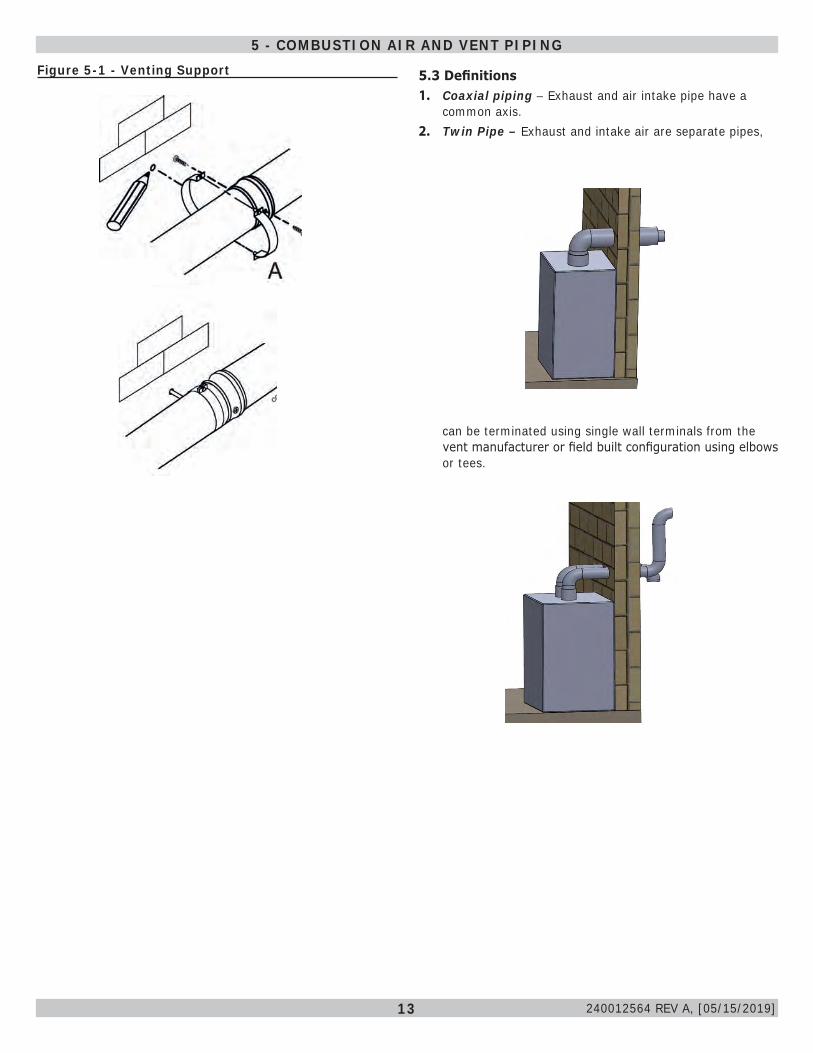
5.3 Definitions1. Coaxial piping – Exhaust and air intake pipe have a
common axis.2. Twin Pipe – Exhaust and intake air are separate pipes,
Figure 5-1 - Venting Support
5 - COMBUSTION AIR AND VENT PIPING
can be terminated using single wall terminals from the vent manufacturer or field built configuration using elbows or tees.
240012564 REV A, [05/15/2019]
14
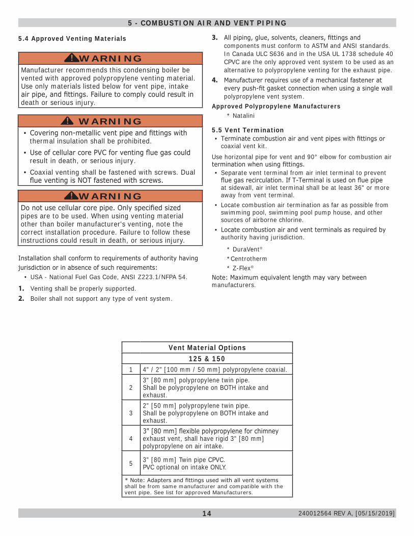
5.4 Approved Venting Materials
5.5 Vent Termination• Terminate combustion air and vent pipes with fittings or
coaxial vent kit.Use horizontal pipe for vent and 90° elbow for combustion air termination when using fittings.• Separate vent terminal from air inlet terminal to prevent
flue gas recirculation. If T-Terminal is used on flue pipe at sidewall, air inlet terminal shall be at least 36" or more away from vent terminal.
• Locate combustion air termination as far as possible from swimming pool, swimming pool pump house, and other sources of airborne chlorine.
• Locate combustion air and vent terminals as required by authority having jurisdiction.
Vent Material Options125 & 150
1 4" / 2" [100 mm / 50 mm] polypropylene coaxial.
23" [80 mm] polypropylene twin pipe. Shall be polypropylene on BOTH intake and exhaust.
32" [50 mm] polypropylene twin pipe. Shall be polypropylene on BOTH intake and exhaust.
43" [80 mm] flexible polypropylene for chimney exhaust vent, shall have rigid 3" [80 mm] polypropylene on air intake.
5 3" [80 mm] Twin pipe CPVC. PVC optional on intake ONLY.
* Note: Adapters and fittings used with all vent systems shall be from same manufacturer and compatible with the vent pipe. See list for approved Manufacturers.
Installation shall conform to requirements of authority havingjurisdiction or in absence of such requirements:
• USA - National Fuel Gas Code, ANSI Z223.1/NFPA 54.
1. Venting shall be properly supported. 2. Boiler shall not support any type of vent system.
WARNINGManufacturer recommends this condensing boiler be vented with approved polypropylene venting material. Use only materials listed below for vent pipe, intake air pipe, and fittings. Failure to comply could result in death or serious injury.
!
WARNINGDo not use cellular core pipe. Only specified sized pipes are to be used. When using venting material other than boiler manufacturer's venting, note the correct installation procedure. Failure to follow these instructions could result in death, or serious injury.
!
WARNING• Covering non-metallic vent pipe and fittings with
thermal insulation shall be prohibited.• Use of cellular core PVC for venting flue gas could
result in death, or serious injury.• Coaxial venting shall be fastened with screws. Dual
flue venting is NOT fastened with screws.
!
3. All piping, glue, solvents, cleaners, fittings and components must conform to ASTM and ANSI standards. In Canada ULC S636 and in the USA UL 1738 schedule 40 CPVC are the only approved vent system to be used as an alternative to polypropylene venting for the exhaust pipe.
4. Manufacturer requires use of a mechanical fastener at every push-fit gasket connection when using a single wall polypropylene vent system.
Approved Polypropylene Manufacturers* Natalini
* DuraVent®
*Centrotherm* Z-Flex®
Note: Maximum equivalent length may vary between manufacturers.
5 - COMBUSTION AIR AND VENT PIPING
240012564 REV A, [05/15/2019]
15
1-3/4" (45mm)
3/4" (1
9mm)
5.6 Coaxial Venting InstructionsMaximum equivalent flue lengths for Coaxial venting are:
Coaxial Pipe Vent Lengths(Includes first elbow and termination)
Boiler Size 125/150
Vent Size4"/2"
[100 mm/50 mm]Maximum Minimum
Natalini 32.80 ft [10 m]6 ft
[1.8m]DuraVent® 27.88 ft [8.5 m]
Centrotherm 24.60 ft [7.5 m]
Coaxial Elbows - Equivalent length4"/2" [100 mm/60 mm]
45° 1.64 ft. [0.5 m]90° 3.28 ft. [1.0 m]
Coaxial Termination - Equivalent length 3 ft (0.9 m)
NOTE: Coaxial venting can run horizontal or vertical.
• Connect flue elbow to top of boiler and adjust direction of elbow to desired orientation (rear, right or left).
• Measure distance from outside wall face to elbow, this dimension will be known as 'X", add distance "Y" + 2" (50 mm) to "X" this is the total dimension of the vents. See Figure 5-4.
• Mark dimension from above on outer aluminum intake vent. Measure length of waste material, and transfer dimension to inner grey flue pipe.
• Remove waste from both vents (flue and air). Verify cut ends are square and free from burrs. Insert flue back into intake air vent and pass them through hole in wall.
• Check all measurements before cutting. Clearance to combustible materials is zero when using coaxial vent system.
• After installing venting use calibrated analyzer to verify there is no recirculation of combustion.
• Ensure termination is positioned with slots at the bottom.
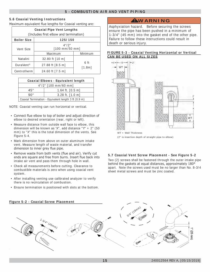
Figure 5-2 - Coaxial Screw Placement
5.7 Coaxial Vent Screw Placement - See Figure 5-2Two (2) screws shall be fastened through the outer intake pipe behind the gaskets at equal distances, approximately 180° apart. Note the screws used must be no larger than No. 8-3/4 sheet metal screws and must be zinc coated.
WARNINGAsphyxiation hazard. Before securing the screws ensure the pipe has been pushed in a minimum of 1-3/4" (45 mm) into the gasket end of the other pipe. Failure to follow these instructions could result in death or serious injury.
!
WT = Wall Thickness
(2" is insertion depth of straight pipe to elbow)
FIGURE 5-3 - Coaxial Venting Horizontal or Vertical CAN BE USED ON ALL SIZES
5 - COMBUSTION AIR AND VENT PIPING
240012564 REV A, [05/15/2019]
16
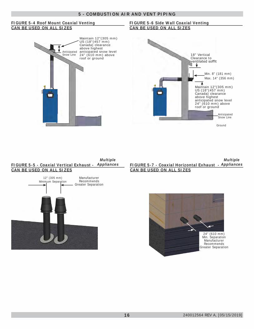
FIGURE 5-6 Side Wall Coaxial Venting CAN BE USED ON ALL SIZES
Min. 8" (181 mm) Max. 14" (356 mm)
Maintain 12"(305 mm) US (18"(457 mm) Canada) clearance above highest anticipated snow level 24" (610 mm) above roof or ground
Ground
Anticipated Snow Line
18" Vertical Clearance to ventilated soffit
FIGURE 5-4 Roof Mount Coaxial VentingCAN BE USED ON ALL SIZES
Maintain 12"(305 mm) US (18"(457 mm) Canada) clearance above highest anticipated snow level 24" (610 mm) above roof or ground
Anticipated Snow Line
FIGURE 5-5 - Coaxial Vertical Exhaust - CAN BE USED ON ALL SIZES
12" (305 mm) Minimum Separation
Manufacturer Recommends
Greater Separation
FIGURE 5-7 - Coaxial Horizontal Exhaust - CAN BE USED ON ALL SIZES
MultipleAppliances
MultipleAppliances
24" (610 mm) Min. Separation Manufacturer Recommends
Greater Separation recommends gr
5 - COMBUSTION AIR AND VENT PIPING
240012564 REV A, [05/15/2019]
17
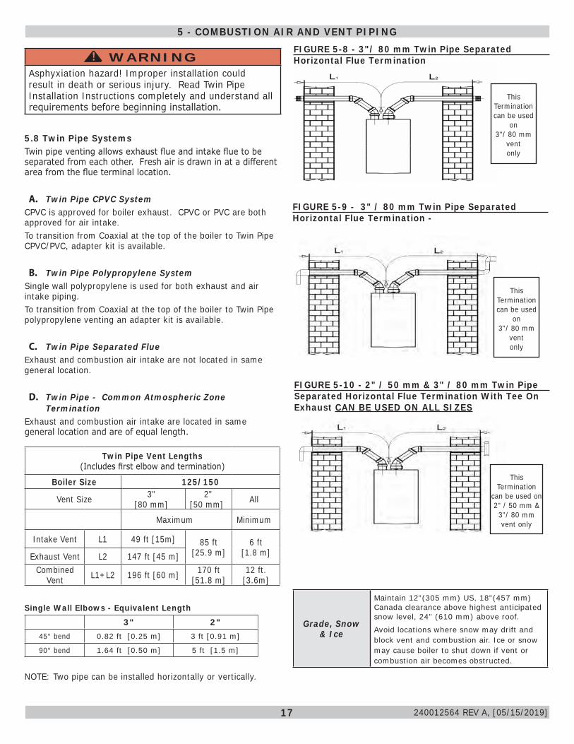
Twin Pipe Vent Lengths(Includes first elbow and termination)
Boiler Size 125/150
Vent Size 3" [80 mm]
2" [50 mm] All
Maximum Minimum
Intake Vent L1 49 ft [15m] 85 ft [25.9 m]
6 ft[1.8 m]Exhaust Vent L2 147 ft [45 m]
Combined Vent L1+L2 196 ft [60 m] 170 ft
[51.8 m]12 ft.
[3.6m]
Single Wall Elbows - Equivalent Length 3" 2"
45° bend 0.82 ft [0.25 m] 3 ft [0.91 m]
90° bend 1.64 ft [0.50 m] 5 ft [1.5 m]
NOTE: Two pipe can be installed horizontally or vertically.
FIGURE 5-8 - 3"/ 80 mm Twin Pipe Separated Horizontal Flue Termination
5.8 Twin Pipe SystemsTwin pipe venting allows exhaust flue and intake flue to be separated from each other. Fresh air is drawn in at a different area from the flue terminal location.
A. Twin Pipe CPVC SystemCPVC is approved for boiler exhaust. CPVC or PVC are both approved for air intake.To transition from Coaxial at the top of the boiler to Twin Pipe CPVC/PVC, adapter kit is available.
B. Twin Pipe Polypropylene SystemSingle wall polypropylene is used for both exhaust and air intake piping.To transition from Coaxial at the top of the boiler to Twin Pipe polypropylene venting an adapter kit is available.
C. Twin Pipe Separated FlueExhaust and combustion air intake are not located in same general location.
D. Twin Pipe - Common Atmospheric Zone Termination
Exhaust and combustion air intake are located in same general location and are of equal length.
FIGURE 5-9 - 3" / 80 mm Twin Pipe Separated Horizontal Flue Termination -
This
Termination can be used
on 3"/ 80 mm
vent only
FIGURE 5-10 - 2" / 50 mm & 3" / 80 mm Twin Pipe Separated Horizontal Flue Termination With Tee On Exhaust CAN BE USED ON ALL SIZES
Grade, Snow & Ice
Maintain 12"(305 mm) US, 18"(457 mm) Canada clearance above highest anticipated snow level, 24" (610 mm) above roof.
Avoid locations where snow may drift and block vent and combustion air. Ice or snow may cause boiler to shut down if vent or combustion air becomes obstructed.
5 - COMBUSTION AIR AND VENT PIPING
WARNINGAsphyxiation hazard! Improper installation could result in death or serious injury. Read Twin Pipe Installation Instructions completely and understand all requirements before beginning installation.
!
This
Termination can be used
on 3"/ 80 mm
vent only
This
Termination can be used on 2" / 50 mm &3"/ 80 mm vent only
240012564 REV A, [05/15/2019]
18
WARNINGAsphyxiation hazard! Improper installation could result in death or serious injury. Read Twin Pipe Installation Instructions completely and understand all requirements before beginning installation.
!
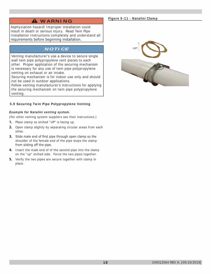
Example for Natalini venting system.(For other venting system suppliers see their instructions.)1. Place clamp so etched "UP" is facing up.2. Open clamp slightly by separating circular areas from each
other.3. Slide male end of first pipe through open clamp so the
shoulder of the female end of the pipe stops the clamp from sliding off the pipe.
4. Insert the male end of of the second pipe into the clamp on the "up" etched side. Force the two pipes together.
5. Verify the two pipes are secure together with clamp in place.
5.9 Securing Twin Pipe Polypropylene Venting
Figure 5-11 - Natalini Clamp
UP
UP
UP
NOTICEVenting manufacturer's use a device to secure single wall twin pipe polypropylene vent pieces to each other. Proper application of the securing mechanism is necessary for any use of twin pipe polypropylene venting on exhaust or air intake. Securing mechanism is for indoor use only and should not be used in outdoor applications.Follow venting manufacturer’s instructions for applying the securing mechanism on twin pipe polypropylene venting.
240012564 REV A, [05/15/2019]
19
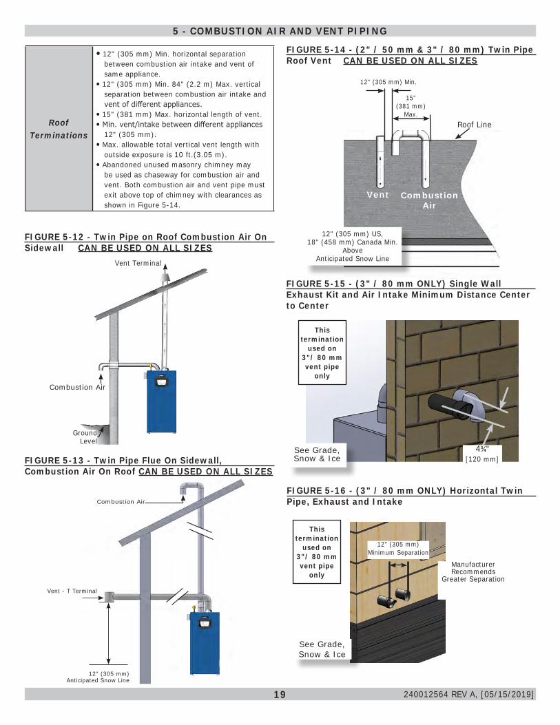
FIGURE 5-14 - (2" / 50 mm & 3" / 80 mm) Twin Pipe Roof Vent CAN BE USED ON ALL SIZES
15" (381 mm)
Max.
Vent Combustion Air
12" (305 mm) US, 18" (458 mm) Canada Min.
Above Anticipated Snow Line
Roof Line
12" (305 mm) Min.
FIGURE 5-16 - (3" / 80 mm ONLY) Horizontal Twin Pipe, Exhaust and Intake
12" (305 mm) Minimum Separation
Manufacturer Recommends
Greater Separation
43/4"[120 mm]
Combustion Air
12" (305 mm)Anticipated Snow Line
Vent - T Terminal
See Grade, Snow & Ice
See Grade, Snow & Ice
FIGURE 5-15 - (3" / 80 mm ONLY) Single Wall Exhaust Kit and Air Intake Minimum Distance Center to Center
Roof Terminations
12" (305 mm) Min. horizontal separation between combustion air intake and vent of same appliance.
12" (305 mm) Min. 84" (2.2 m) Max. vertical separation between combustion air intake and vent of different appliances.
15" (381 mm) Max. horizontal length of vent. Min. vent/intake between different appliances
12" (305 mm). Max. allowable total vertical vent length with
outside exposure is 10 ft.(3.05 m). Abandoned unused masonry chimney may
be used as chaseway for combustion air and vent. Both combustion air and vent pipe must exit above top of chimney with clearances as shown in Figure 5-14.
Vent Terminal
Combustion Air
Ground Level
FIGURE 5-12 - Twin Pipe on Roof Combustion Air On Sidewall CAN BE USED ON ALL SIZES
FIGURE 5-13 - Twin Pipe Flue On Sidewall, Combustion Air On Roof CAN BE USED ON ALL SIZES
This termination
used on 3"/ 80 mm vent pipe
only
5 - COMBUSTION AIR AND VENT PIPING
This termination
used on 3"/ 80 mm vent pipe
only
240012564 REV A, [05/15/2019]
20
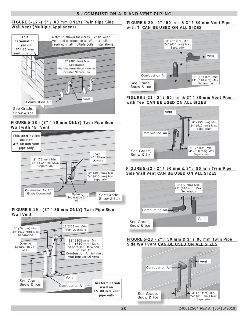
FIGURE 5-17 -( 3" / 80 mm ONLY) Twin Pipe Side Wall Vent (Multiple Appliances)
Vent
12" (305 mm) Min. Separation
Manufacturer Recommends Greater Separation
Combustion Air
See Grade, Snow & Ice
FIGURE 5-19 - (3" / 80 mm ONLY) Twin Pipe Side Wall Vent
Vent
3" (76 mm) Min. 24" (610 mm) Max.
Separation
12"(305 mm)Min. From Overhang
12" (305 mm) Min. 24" (610 mm) Max.Separation Between
Bottom Of Combustion Air Intake And Bottom Of Vent
Combustion Air
Opening Separation 24"
Min.
See Grade, Snow & Ice
FIGURE 5-18 - (3" / 80 mm ONLY) Twin Pipe Side Wall with 45° Vent
Vent 45° Elbow Upward 3" (76 mm) Min.
24" (610 mm) Max.Separation
Combustion Air, 90° Elbow Downward
12" (305 mm) Min. 24" (610 mm) Max.
Separation
Opening Separation 24"
Min.
See Grade, Snow & Ice
Note: 3" shown for clarity. 12" between vent and combustion air of other boilers required in all multiple boiler installations.
FIGURE 5-22 - 2" / 50 mm & 3" / 80 mm Twin Pipe Side Wall Vent CAN BE USED ON ALL SIZES
3" (77 mm) Min. 24" (610 mm) Max.
Separation
See Grade, Snow & Ice
Combustion Air
Vent
FIGURE 5-20 - 2" /50 mm & 3" / 80 mm Vent Pipe with T CAN BE USED ON ALL SIZES
See Grade, Snow & Ice
Combustion Air
Vent
3" (77 mm) Min. 24" (610 mm) Max.
Separation
6" (153 mm) Min. 24" (610 mm) Max.
Separation
FIGURE 5-21 - 2" / 50 mm & 3" / 80 mm Vent Pipe with Tee CAN BE USED ON ALL SIZES
See Grade, Snow & Ice
FIGURE 5-23 - 2" / 50 mm & 3" / 80 mm Twin Pipe Side Wall Vent CAN BE USED ON ALL SIZES
Combustion Air
Vent
3" (77 mm) Min. 24" (610 mm) Max.
Separation
See Grade, Snow & Ice
Vent
Combustion Air
6" (153 mm) Min. 24" (610 mm) Max.
Separation
3" (77 mm) Min. 24" (610 mm) Max.
Separation
5 - COMBUSTION AIR AND VENT PIPING
This termination
used on 3"/ 80 mm
vent pipe only
This termination used on
3"/ 80 mm vent pipe only
This termination used on
3"/ 80 mm vent pipe only
240012564 REV A, [05/15/2019]

21
5.10 (3" /80 mm Only) Flexible Vent System
Flexible Pipe Vent Lengths
Boiler Size 125/150
Vent Size 3” [80 mm] Diameter Pipe
Minimum Minimum Maximum
NataliniExhaust 6 ft [1.8 m] 75 ft [22.8 m]
Intake 6 ft [1.8 m] 50 ft [15.2 m]
DuraVent®Exhaust 6 ft [1.8 m] 82 ft [24.9 m]
Intake 6 ft [1.8 m] 50 ft [15.2 m]
CentrothermExhaust 6 ft [1.8 m] 52 ft [15.8 m]
Intake 6 ft [1.8 m] 50 ft [15.2 m]
Z-DensExhaust
NA NAIntake
Single Wall Elbows - Equivalent Length
3" [80 mm]45° bend 0.82 ft [0.25 m]
90° bend 1.64 ft [0.50 m]
• Maximum vent lengths based on equivalent straight runs only. Include rigid pipe and fittings in overall equivalent length calculations.
• Flexible venting installations use single wall polypropylene to pass flue gasses to base of chimney, then flexible venting to get them to termination at the top.
• Combustion air is not supplied through masonry chimney. Combustion air must be from outside using 3" [80 mm] single wall polypropylene.
• Position boiler to use minimum of rigid single wall polypropylene venting to the chimney.
• Follow venting manufacturer's instructions on assembly and clearances to maintain.
• Avoid sharp bends in flexible venting.
FIGURE 5-24 - (3" / 80 mm Only) Flexible Venting System CAN BE USED ON ALL SIZES
Combustion Air
Vent Terminal
Flexible Vent
Rigid Vent
5 - COMBUSTION AIR AND VENT PIPING
NOTICEFlexible vent systems shall only be run vertical. Horizontal runs before adapting to flexible must be rigid pipe.
240012564 REV A, [05/15/2019]
22
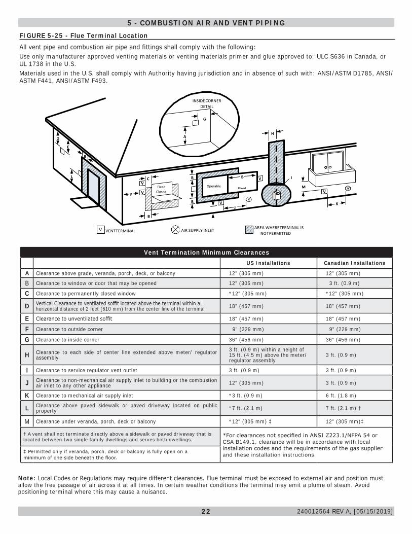
FIGURE 5-25 - Flue Terminal LocationAll vent pipe and combustion air pipe and fittings shall comply with the following:Use only manufacturer approved venting materials or venting materials primer and glue approved to: ULC S636 in Canada, or UL 1738 in the U.S. Materials used in the U.S. shall comply with Authority having jurisdiction and in absence of such with: ANSI/ASTM D1785, ANSI/ASTM F441, ANSI/ASTM F493.
INSIDE CORNER
DETAIL
G
V H D A
E
B
L C B
V
B
Fixed Closed
V I V
F V Fixed
Closed
Operable
Operable M V
B V K J
B
V VENT TERMINAL AIR SUPPLY INLET AREA WHERE TERMINAL IS
NOT PERMITTED
Vent Termination Minimum ClearancesUS Installations Canadian Installations
A Clearance above grade, veranda, porch, deck, or balcony 12" (305 mm) 12" (305 mm)
B Clearance to window or door that may be opened 12" (305 mm) 3 ft. (0.9 m)
C Clearance to permanently closed window *12" (305 mm) *12" (305 mm)
D Vertical Clearance to ventilated soffit located above the terminal within a horizontal distance of 2 feet (610 mm) from the center line of the terminal 18" (457 mm) 18" (457 mm)
E Clearance to unventilated soffit 18" (457 mm) 18" (457 mm)
F Clearance to outside corner 9" (229 mm) 9" (229 mm)
G Clearance to inside corner 36" (456 mm) 36" (456 mm)
H Clearance to each side of center line extended above meter/ regulator assembly
3 ft. (0.9 m) within a height of 15 ft. (4.5 m) above the meter/ regulator assembly
3 ft. (0.9 m)
I Clearance to service regulator vent outlet 3 ft. (0.9 m) 3 ft. (0.9 m)
J Clearance to non-mechanical air supply inlet to building or the combustion air inlet to any other appliance 12" (305 mm) 3 ft. (0.9 m)
K Clearance to mechanical air supply inlet *3 ft. (0.9 m) 6 ft. (1.8 m)
L Clearance above paved sidewalk or paved driveway located on public property *7 ft. (2.1 m) 7 ft. (2.1 m) †
M Clearance under veranda, porch, deck or balcony *12" (305 mm) ‡ 12" (305 mm)‡
† A vent shall not terminate directly above a sidewalk or paved driveway that is located between two single family dwellings and serves both dwellings.
*For clearances not specified in ANSI Z223.1/NFPA 54 or CSA B149.1, clearance will be in accordance with local installation codes and the requirements of the gas supplier and these installation instructions.‡ Permitted only if veranda, porch, deck or balcony is fully open on a
minimum of one side beneath the floor.
Note: Local Codes or Regulations may require different clearances. Flue terminal must be exposed to external air and position must allow the free passage of air across it at all times. In certain weather conditions the terminal may emit a plume of steam. Avoid positioning terminal where this may cause a nuisance.
5 - COMBUSTION AIR AND VENT PIPING
240012564 REV A, [05/15/2019]
23
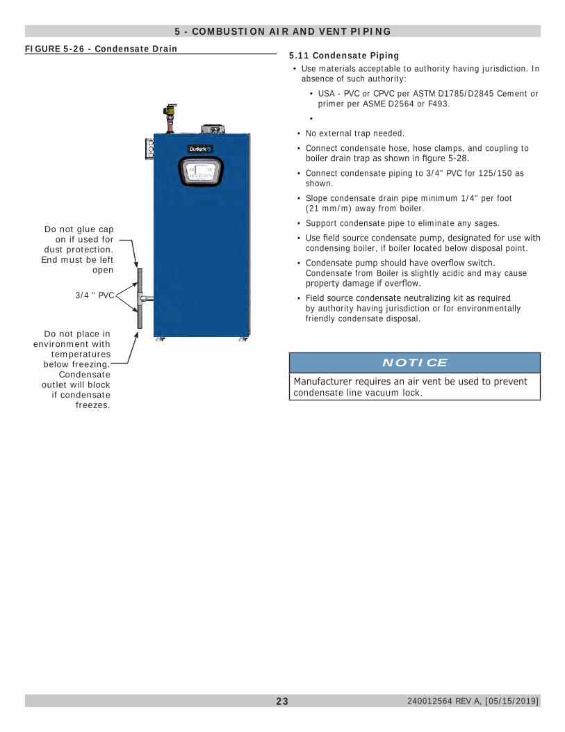
5.11 Condensate Piping• Use materials acceptable to authority having jurisdiction. In
absence of such authority:• USA - PVC or CPVC per ASTM D1785/D2845 Cement or
primer per ASME D2564 or F493.•
• No external trap needed.• Connect condensate hose, hose clamps, and coupling to
boiler drain trap as shown in figure 5-28.• Connect condensate piping to 3/4" PVC for 125/150 as
shown. • Slope condensate drain pipe minimum 1/4" per foot
(21 mm/m) away from boiler.• Support condensate pipe to eliminate any sages.• Use field source condensate pump, designated for use with
condensing boiler, if boiler located below disposal point.• Condensate pump should have overflow switch.
Condensate from Boiler is slightly acidic and may cause property damage if overflow.
• Field source condensate neutralizing kit as required by authority having jurisdiction or for environmentally friendly condensate disposal.
FIGURE 5-26 - Condensate Drain
Do not glue cap on if used for
dust protection. End must be left
open
Do not place in environment with
temperatures below freezing.
Condensate outlet will block
if condensate freezes.
NOTICEManufacturer requires an air vent be used to prevent condensate line vacuum lock.
5 - COMBUSTION AIR AND VENT PIPING
3/4 " PVC
240012564 REV A, [05/15/2019]
24
6.1 General• Primary/Secondary piping required by manufacturer.• Install piping in accordance with authority having jurisdiction.• Support system piping and safety relief valve discharge
piping. Boiler's internal piping can be damaged if subjected to excessive weight.
NOTICEThe intended use of the internal heat exchanger pump is a boiler loop. Do not use as a primary system pump.
• Size central heating pump (and domestic hot water pump, if used) for system requirements only. Internal heat exchanger pump compensates for pressure drop through boiler internal piping and heat exchanger.
• Thoroughly clean and flush system before connecting to boiler.• If oil is present in system water, use approved detergent to
wash system.
WARNING• Poison hazard. Ethylene glycol is toxic. Do not use
ethylene glycol.• Never use automotive or standard glycol antifreeze,
even ethylene glycol made for hydronic systems.• Ethylene glycol can attack gaskets and seals used in
hydronic systems.• Do not use petroleum based cleaning or sealing
compounds boiler system.• Do not fill boiler or boiler system with softened
water.• Use only inhibited propylene glycol solutions
certified by fluid manufacturer as acceptable for use with closed water heating system.
• Thoroughly clean and flush any system that used glycol before installing new Boiler.
• Provide user with Material Safety Data Sheet (MSDS) on fluid used.
! • It is necessary to semi-annually check the water quality of central heating systems.
• Manufacturer recommends installation of magnetic dirt separator in the hydronic system where there are cast iron or steel components, or where the previous boiler was a cast iron heat exchanger. The abrasive, extremely fine sediment is difficult to remove and can deposit onto heat exchange surfaces and accumulate in pump cavities causing reduced efficiency and premature wear.
• Flush system to remove any solid objects such as metal chips, fibers, or Teflon tape, etc.
• Flush system until water runs clean and piping is free of sediment.
• Use purge valve to flush zoned systems, each zone separately. If purge valves and isolation valves are not installed, install them to properly clean the system.
• When purging installations that include standing iron radiators and systems with manual vents at high points, start with nearest manual air vent. Open the vent until water flows out, then close vent. Repeat this procedure, working toward furthest air vent.
• Install a basket strainer if large amounts of sediment is present. Keep basket clear of sediment build up.
• Ensure piping in the heating system has an oxygen barrier.
6 - HYDRONIC PIPING
6.2 Special Conditions
NOTICEBoiler rated at 50 psig (345 kPa) maximum allowable working pressure. Boiler provided with 30 psig (206 kPa) safety relief valve.
NOTICESystem pressure above 43 psi [2.96 bar] WILL result in boiler shutting down.
NOTICEDo not expose boiler and condensate piping to freezing temperatures.
• System piping exposed to freezing conditions: Use inhibited propylene glycol solutions certified by fluid manufacturer for use with closed water heating system. Do not use automotive or ethylene glycol.
• Boiler installed above radiation level (or as required by authority having jurisdiction). Integral low water pressure switch is provided in boiler.
• Boiler used in connection with refrigeration system. Install piping in parallel with boiler, with appropriate valves to prevent chilled medium from entering boiler.
• System piping connected to heating coils located in air handling unit exposed to refrigerated air circulation. Install flow control valves or other automatic means to prevent gravity circulation of boiler water during cooling cycle.
240012564 REV A, [05/15/2019]
25
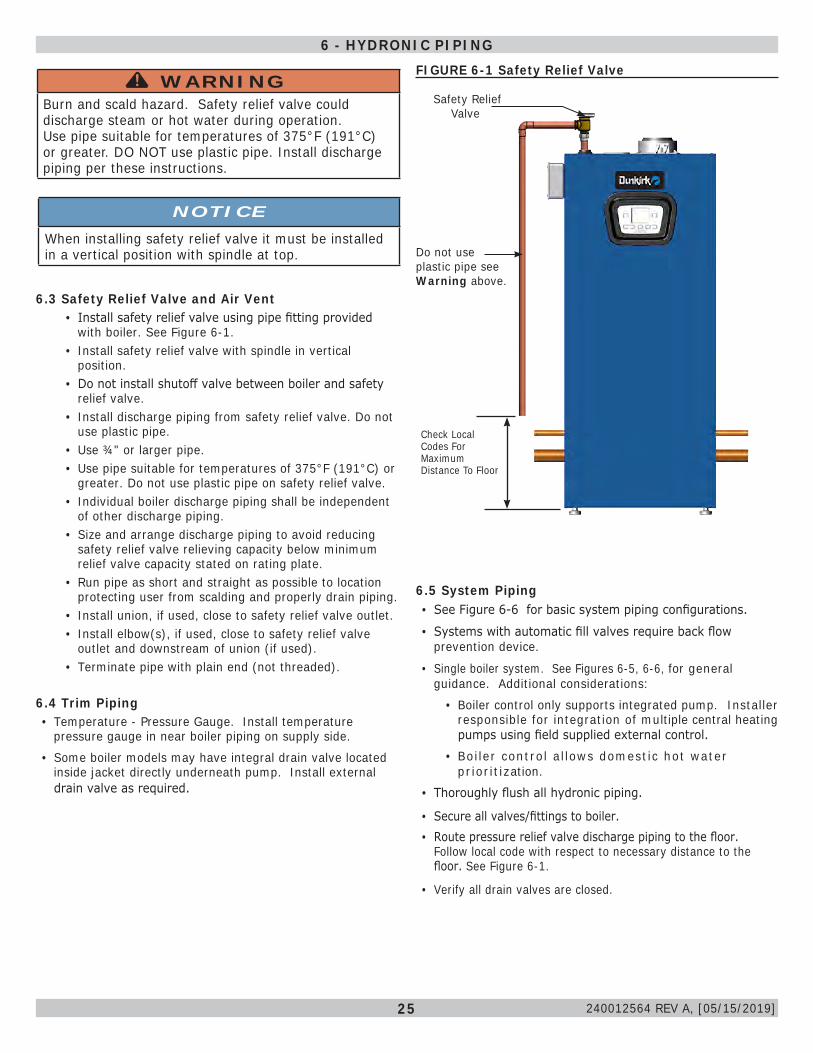
6.3 Safety Relief Valve and Air Vent• Install safety relief valve using pipe fitting provided
with boiler. See Figure 6-1.• Install safety relief valve with spindle in vertical
position.• Do not install shutoff valve between boiler and safety
relief valve.• Install discharge piping from safety relief valve. Do not
use plastic pipe.• Use ¾" or larger pipe.• Use pipe suitable for temperatures of 375°F (191°C) or
greater. Do not use plastic pipe on safety relief valve.• Individual boiler discharge piping shall be independent
of other discharge piping.• Size and arrange discharge piping to avoid reducing
safety relief valve relieving capacity below minimum relief valve capacity stated on rating plate.
• Run pipe as short and straight as possible to location protecting user from scalding and properly drain piping.
• Install union, if used, close to safety relief valve outlet.• Install elbow(s), if used, close to safety relief valve
outlet and downstream of union (if used).• Terminate pipe with plain end (not threaded).
Check Local Codes For Maximum Distance To Floor
Safety Relief Valve
Do not use plastic pipe see Warning above.
WARNINGBurn and scald hazard. Safety relief valve could discharge steam or hot water during operation. Use pipe suitable for temperatures of 375°F (191°C) or greater. DO NOT use plastic pipe. Install discharge piping per these instructions.
!
6 - HYDRONIC PIPINGFIGURE 6-1 Safety Relief Valve
6.4 Trim Piping• Temperature - Pressure Gauge. Install temperature
pressure gauge in near boiler piping on supply side. • Some boiler models may have integral drain valve located
inside jacket directly underneath pump. Install external drain valve as required.
NOTICEWhen installing safety relief valve it must be installed in a vertical position with spindle at top.
6.5 System Piping• See Figure 6-6 for basic system piping configurations.
• Systems with automatic fill valves require back flow prevention device.
• Single boiler system. See Figures 6-5, 6-6, for general guidance. Additional considerations:
• Boiler control only supports integrated pump. Installer responsible for integration of multiple central heating pumps using field supplied external control.
• Boiler control allows domestic hot water prioritization.
• Thoroughly flush all hydronic piping.
• Secure all valves/fittings to boiler.• Route pressure relief valve discharge piping to the floor.
Follow local code with respect to necessary distance to the floor. See Figure 6-1.
• Verify all drain valves are closed.
240012564 REV A, [05/15/2019]
26
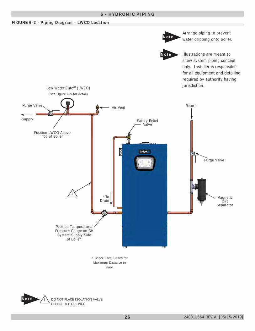
FIGURE 6-2 - Piping Diagram - LWCO Location
6 - HYDRONIC PIPING
240012564 REV A, [05/15/2019]
Low Water Cutoff (LWCO)(See Figure 6-5 for detail)
Air Vent
Supply Safety Relief Valve
Position LWCO Above Top of Boiler
1 DO NOT PLACE ISOLATION VALVE BEFORE TEE OR LWCO.
Note
*To Drain
* Check Local Codes for Maximum Distance to
Floor.
Arrange piping to prevent water dripping onto boiler.
1
Return
Purge Valve
Magnetic Dirt
Separator
Position Temperature/Pressure Gauge on CH System Supply Side
of Boiler.
Purge Valve
Note
Illustrations are meant to show system piping concept only. Installer is responsible for all equipment and detailing required by authority having jurisdiction.
Note
27
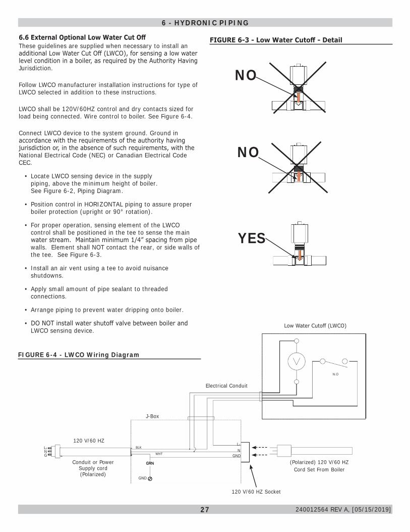
NO
NO
YES
FIGURE 6-3 - Low Water Cutoff - Detail6.6 External Optional Low Water Cut Off These guidelines are supplied when necessary to install an additional Low Water Cut Off (LWCO), for sensing a low water level condition in a boiler, as required by the Authority Having Jurisdiction.
Follow LWCO manufacturer installation instructions for type of LWCO selected in addition to these instructions.
LWCO shall be 120V/60HZ control and dry contacts sized for load being connected. Wire control to boiler. See Figure 6-4.
Connect LWCO device to the system ground. Ground in accordance with the requirements of the authority having jurisdiction or, in the absence of such requirements, with the National Electrical Code (NEC) or Canadian Electrical Code CEC.
• Locate LWCO sensing device in the supply piping, above the minimum height of boiler. See Figure 6-2, Piping Diagram.
• Position control in HORIZONTAL piping to assure proper boiler protection (upright or 90° rotation).
• For proper operation, sensing element of the LWCO control shall be positioned in the tee to sense the main water stream. Maintain minimum 1/4” spacing from pipe walls. Element shall NOT contact the rear, or side walls of the tee. See Figure 6-3.
• Install an air vent using a tee to avoid nuisance shutdowns.
• Apply small amount of pipe sealant to threaded connections.
• Arrange piping to prevent water dripping onto boiler.
• DO NOT install water shutoff valve between boiler and LWCO sensing device.
Low Water Cutoff (LWCO)
Electrical Conduit
J-Box
120 V/60 HZ
Conduit or Power Supply cord (Polarized)
L1NG
GND
L1
NGND
BLK
WHT
120 V/60 HZ Socket
(Polarized) 120 V/60 HZ Cord Set From Boiler
N.O
FIGURE 6-4 - LWCO Wiring Diagram
6 - HYDRONIC PIPING
240012564 REV A, [05/15/2019]
28
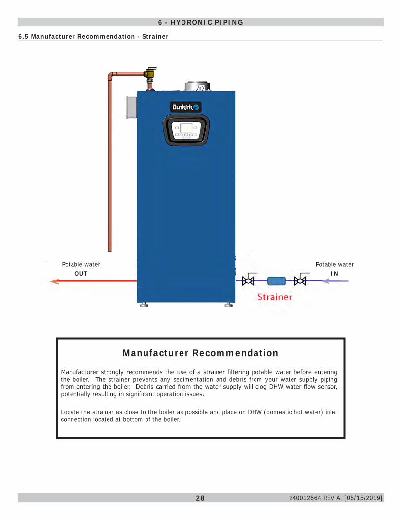
6.5 Manufacturer Recommendation - Strainer
Manufacturer Recommendation
Manufacturer strongly recommends the use of a strainer filtering potable water before entering the boiler. The strainer prevents any sedimentation and debris from your water supply piping from entering the boiler. Debris carried from the water supply will clog DHW water flow sensor, potentially resulting in significant operation issues.
Locate the strainer as close to the boiler as possible and place on DHW (domestic hot water) inlet connection located at bottom of the boiler.
6 - HYDRONIC PIPING
Potable water IN
Potable water OUT
240012564 REV A, [05/15/2019]
29
Pressure gauge - to indicate the system pressure to be maintained.
6.7 Central Heating System
Boiler is designed for use in a sealed central heating system. Design the system to operate with flow temperatures of up to 176°F (80° C), take pump head, expansion tank size, mean radiator temperature, etc. into account.
Boiler is supplied with the following components: Pressure relief valve - 30.0 psi (2.1 bar). Boiler internal pressure switch will shut boiler off below 7.5 psi / 0.5 bar and above 43.5 psi /3.0 bar.
6.8 Domestic Hot Water ModeDunkirk Boiler DCCF-150 and DCBF-125 with indirect
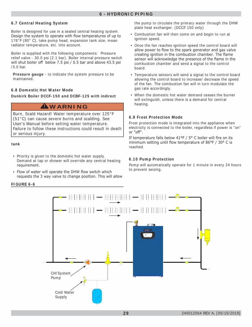
the pump to circulate the primary water through the DHW plate heat exchanger. (DCCF 150 only)
• Combustion fan will then come on and begin to run at ignition speed.
• Once the fan reaches ignition speed the control board will allow power to flow to the spark generator and gas valve creating ignition in the combustion chamber. The flame sensor will acknowledge the presence of the flame in the combustion chamber and send a signal to the control board.
• Temperature sensors will send a signal to the control board allowing the control board to increase/ decrease the speed of the fan. The combustion fan will in turn modulate the gas rate accordingly.
• When the domestic hot water demand ceases the burner will extinguish, unless there is a demand for central heating.
6.9 Frost Protection ModeFrost protection mode is integrated into the appliance when electricity is connected to the boiler, regardless if power is "on" or "off".If temperature falls below 41°F / 5° C boiler will fire on its minimum setting until flow temperature of 86°F / 30° C is reached.
6.10 Pump ProtectionPump will automatically operate for 1 minute in every 24 hours to prevent seizing.
FIGURE 6-6
6 - HYDRONIC PIPING
Cold Water Supply
CH/System Pump
tank
• Priority is given to the domestic hot water supply. Demand at tap or shower will override any central heating requirement.
• Flow of water will operate the DHW flow switch which requests the 3 way valve to change position. This will allow
WARNINGBurn, Scald Hazard! Water temperature over 125°F (51°C) can cause severe burns and scalding. See User's Manual before setting water temperature. Failure to follow these instructions could result in death or serious injury.
!
240012564 REV A, [05/15/2019]
30
CAUTIONWHAT TO DO IF YOU SMELL GAS
• Do not try to light any appliance.• Do not touch any electrical switch; do not use any
phone in your building.• Immediately call your gas supplier from a
neighbor’s phone. Follow gas supplier’s instructions.
• If you cannot reach your gas supplier, call the fire department.
!
NOTICEUse of CSA approved corrugated, semi-rigid stainless steel tubing with polyethylene jacketing is approved for use with boilers following tubing manufacturer's instructions.Use of flexible "appliance whip" gas tubing is not allowed per NFPA 54.
WARNINGFire, explosion, asphyxiation and burn hazard. Boiler piping and gas connections shall be leak tested before placing boiler in operation. Failure to follow these instructions and or improper installation could result in death or serious injury.
!
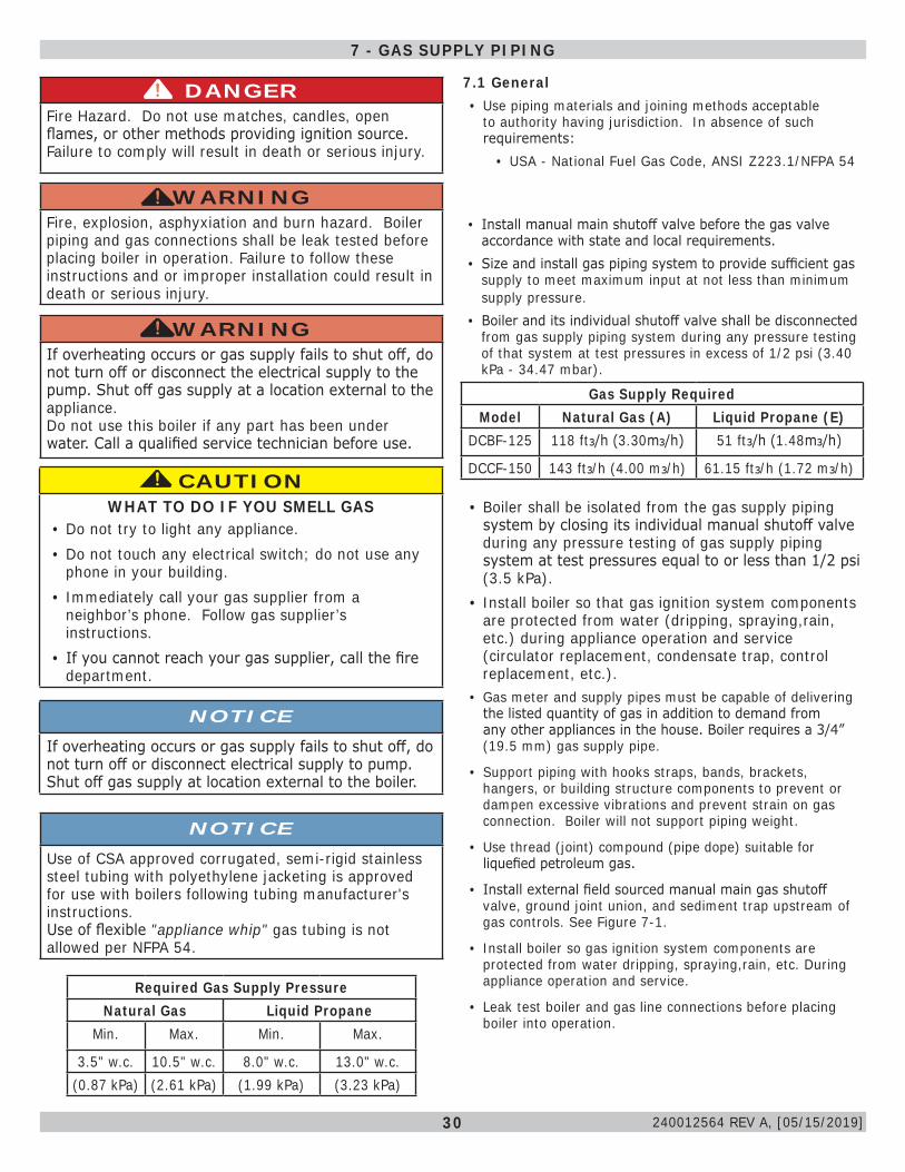
Required Gas Supply PressureNatural Gas Liquid Propane
Min. Max. Min. Max.
3.5" w.c. 10.5" w.c. 8.0" w.c. 13.0" w.c.(0.87 kPa) (2.61 kPa) (1.99 kPa) (3.23 kPa)
Gas Supply RequiredModel Natural Gas (A) Liquid Propane (E)
DCBF-125 118 ft3/h (3.30m3/h) 51 ft3/h (1.48m3/h)
DCCF-150 143 ft3/h (4.00 m3/h) 61.15 ft3/h (1.72 m3/h)
DANGERFire Hazard. Do not use matches, candles, open flames, or other methods providing ignition source. Failure to comply will result in death or serious injury.
!
WARNINGIf overheating occurs or gas supply fails to shut off, do not turn off or disconnect the electrical supply to the pump. Shut off gas supply at a location external to the appliance. Do not use this boiler if any part has been under water. Call a qualified service technician before use.
!
7 - GAS SUPPLY PIPING
NOTICEIf overheating occurs or gas supply fails to shut off, do not turn off or disconnect electrical supply to pump. Shut off gas supply at location external to the boiler.
• Boiler shall be isolated from the gas supply piping system by closing its individual manual shutoff valve during any pressure testing of gas supply piping system at test pressures equal to or less than 1/2 psi (3.5 kPa).
• Install boiler so that gas ignition system components are protected from water (dripping, spraying,rain, etc.) during appliance operation and service (circulator replacement, condensate trap, control replacement, etc.).
• Gas meter and supply pipes must be capable of delivering the listed quantity of gas in addition to demand from any other appliances in the house. Boiler requires a 3/4” (19.5 mm) gas supply pipe.
• Support piping with hooks straps, bands, brackets, hangers, or building structure components to prevent or dampen excessive vibrations and prevent strain on gas connection. Boiler will not support piping weight.
• Use thread (joint) compound (pipe dope) suitable for liquefied petroleum gas.
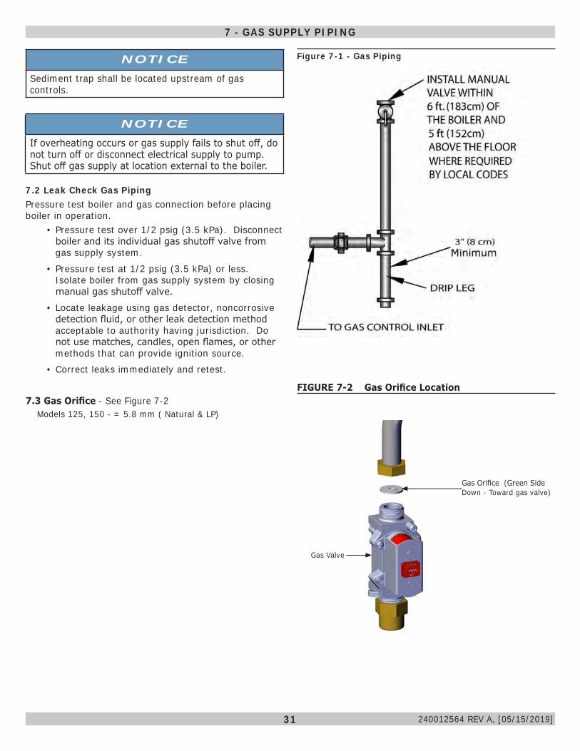
• Install external field sourced manual main gas shutoff valve, ground joint union, and sediment trap upstream of gas controls. See Figure 7-1.
• Install boiler so gas ignition system components are protected from water dripping, spraying,rain, etc. During appliance operation and service.
• Leak test boiler and gas line connections before placing boiler into operation.
7.1 General• Use piping materials and joining methods acceptable
to authority having jurisdiction. In absence of such requirements:
• USA - National Fuel Gas Code, ANSI Z223.1/NFPA 54
• Install manual main shutoff valve before the gas valve accordance with state and local requirements.
• Size and install gas piping system to provide sufficient gas supply to meet maximum input at not less than minimum supply pressure.
• Boiler and its individual shutoff valve shall be disconnected from gas supply piping system during any pressure testing of that system at test pressures in excess of 1/2 psi (3.40 kPa - 34.47 mbar).
240012564 REV A, [05/15/2019]
31
7.2 Leak Check Gas PipingPressure test boiler and gas connection before placing boiler in operation.
• Pressure test over 1/2 psig (3.5 kPa). Disconnect boiler and its individual gas shutoff valve from gas supply system.
• Pressure test at 1/2 psig (3.5 kPa) or less. Isolate boiler from gas supply system by closing manual gas shutoff valve.
• Locate leakage using gas detector, noncorrosive detection fluid, or other leak detection method acceptable to authority having jurisdiction. Do not use matches, candles, open flames, or other methods that can provide ignition source.
• Correct leaks immediately and retest.
7.3 Gas Orifice - See Figure 7-2 Models 125, 150 - = 5.8 mm ( Natural & LP)
Figure 7-1 - Gas PipingNOTICESediment trap shall be located upstream of gas controls.
7 - GAS SUPPLY PIPING
NOTICEIf overheating occurs or gas supply fails to shut off, do not turn off or disconnect electrical supply to pump. Shut off gas supply at location external to the boiler.
FIGURE 7-2 Gas Orifice Location
Gas Orifice (Green Side Down - Toward gas valve)
Gas Valve
240012564 REV A, [05/15/2019]
32
WARNINGElectrical shock hazard. Turn OFF electrical power supply at service panel before making electrical connections. Failure to do so could result in death or serious injury.
! Note Wiring diagrams can be found in Appendix A of
this Manual.
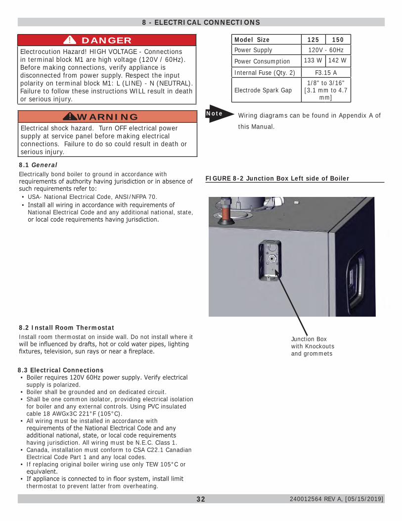
8.3 Electrical Connections• Boiler requires 120V 60Hz power supply. Verify electrical
supply is polarized.• Boiler shall be grounded and on dedicated circuit.• Shall be one common isolator, providing electrical isolation
for boiler and any external controls. Using PVC insulated cable 18 AWGx3C 221°F (105°C).
• All wiring must be installed in accordance with requirements of the National Electrical Code and any additional national, state, or local code requirements having jurisdiction. All wiring must be N.E.C. Class 1.
• Canada, installation must conform to CSA C22.1 Canadian Electrical Code Part 1 and any local codes.
• If replacing original boiler wiring use only TEW 105°C or equivalent.
• If appliance is connected to in floor system, install limit thermostat to prevent latter from overheating.
Model Size 125 150Power Supply 120V - 60Hz
Power Consumption 133 W 142 W
Internal Fuse (Qty. 2) F3.15 A
Electrode Spark Gap1/8" to 3/16"
[3.1 mm to 4.7 mm]
DANGERElectrocution Hazard! HIGH VOLTAGE - Connections in terminal block M1 are high voltage (120V / 60Hz). Before making connections, verify appliance is disconnected from power supply. Respect the input polarity on terminal block M1: L (LINE) - N (NEUTRAL). Failure to follow these instructions WILL result in death or serious injury.
!
8 - ELECTRICAL CONNECTIONS
FIGURE 8-2 Junction Box Left side of Boiler
Junction Box with Knockouts and grommets
8.2 Install Room ThermostatInstall room thermostat on inside wall. Do not install where it will be influenced by drafts, hot or cold water pipes, lighting fixtures, television, sun rays or near a fireplace.
8.1 GeneralElectrically bond boiler to ground in accordance with requirements of authority having jurisdiction or in absence of such requirements refer to:• USA- National Electrical Code, ANSI/NFPA 70.• Install all wiring in accordance with requirements of
National Electrical Code and any additional national, state, or local code requirements having jurisdiction.
240012564 REV A, [05/15/2019]
33
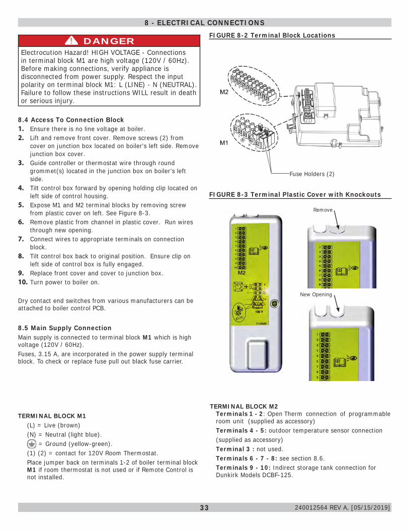
8.4 Access To Connection Block1. Ensure there is no line voltage at boiler.2. Lift and remove front cover. Remove screws (2) from
cover on junction box located on boiler's left side. Remove junction box cover.
3. Guide controller or thermostat wire through round grommet(s) located in the junction box on boiler's left side.
4. Tilt control box forward by opening holding clip located on left side of control housing.
5. Expose M1 and M2 terminal blocks by removing screw from plastic cover on left. See Figure 8-3.
6. Remove plastic from channel in plastic cover. Run wires through new opening.
7. Connect wires to appropriate terminals on connection block.
8. Tilt control box back to original position. Ensure clip on left side of control box is fully engaged.
9. Replace front cover and cover to junction box.10. Turn power to boiler on.
Dry contact end switches from various manufacturers can be attached to boiler control PCB.
8.5 Main Supply ConnectionMain supply is connected to terminal block M1 which is high voltage (120V / 60Hz).Fuses, 3.15 A, are incorporated in the power supply terminal block. To check or replace fuse pull out black fuse carrier.
TERMINAL BLOCK M1(L) = Live (brown)(N) = Neutral (light blue).
= Ground (yellow-green).(1) (2) = contact for 120V Room Thermostat.Place jumper back on terminals 1-2 of boiler terminal block M1 if room thermostat is not used or if Remote Control is not installed.
FIGURE 8-2 Terminal Block Locations
Fuse Holders (2)
DANGERElectrocution Hazard! HIGH VOLTAGE - Connections in terminal block M1 are high voltage (120V / 60Hz). Before making connections, verify appliance is disconnected from power supply. Respect the input polarity on terminal block M1: L (LINE) - N (NEUTRAL). Failure to follow these instructions WILL result in death or serious injury.
!
TERMINAL BLOCK M2Terminals 1 - 2: Open Therm connection of programmable room unit (supplied as accessory)Terminals 4 - 5: outdoor temperature sensor connection (supplied as accessory)Terminal 3 : not used.Terminals 6 - 7 - 8: see section 8.6.Terminals 9 - 10: Indirect storage tank connection for Dunkirk Models DCBF-125.
FIGURE 8-3 Terminal Plastic Cover with Knockouts
Remove
New Opening
8 - ELECTRICAL CONNECTIONS
240012564 REV A, [05/15/2019]
34
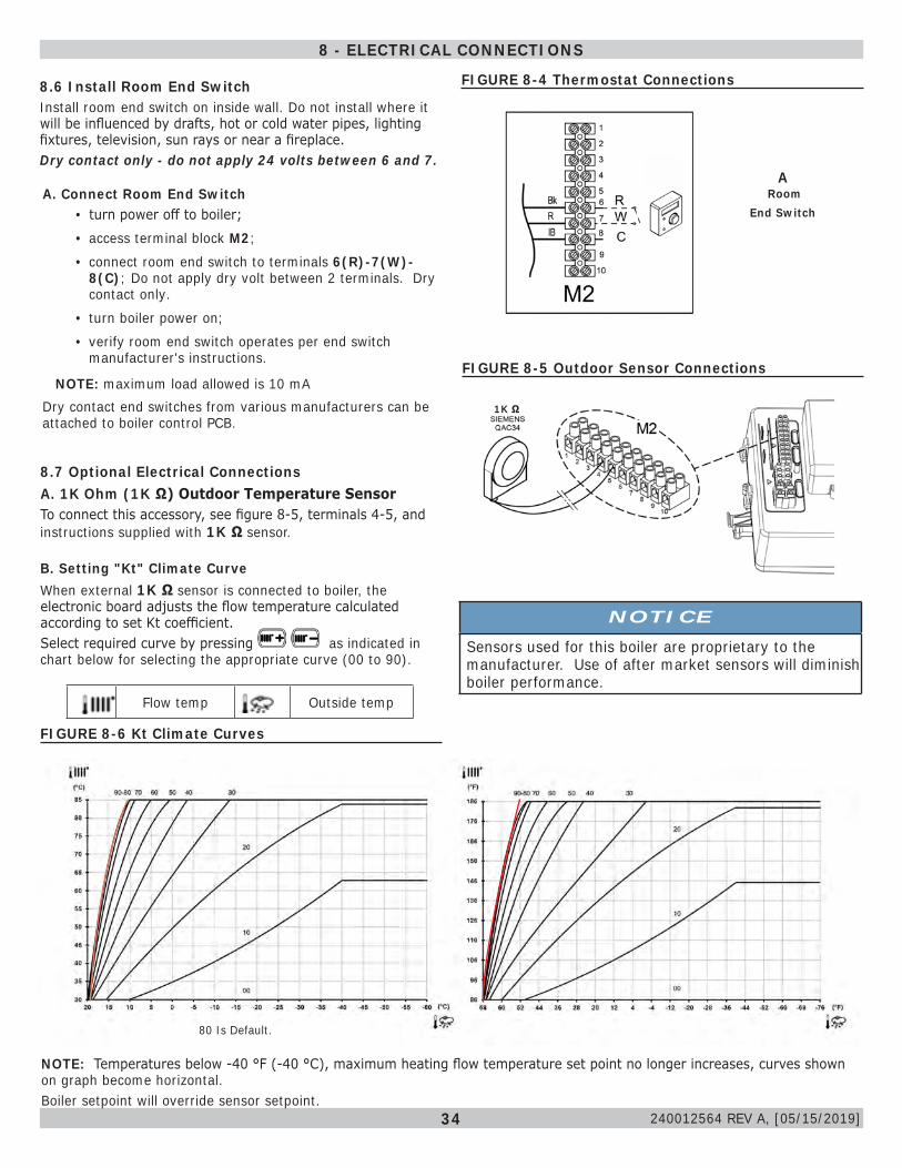
A. Connect Room End Switch• turn power off to boiler;• access terminal block M2;• connect room end switch to terminals 6(R)-7(W)-
8(C); Do not apply dry volt between 2 terminals. Dry contact only.
• turn boiler power on; • verify room end switch operates per end switch
manufacturer's instructions.
NOTE: maximum load allowed is 10 mADry contact end switches from various manufacturers can be attached to boiler control PCB.
FIGURE 8-4 Thermostat Connections8.6 Install Room End SwitchInstall room end switch on inside wall. Do not install where it will be influenced by drafts, hot or cold water pipes, lighting fixtures, television, sun rays or near a fireplace.Dry contact only - do not apply 24 volts between 6 and 7.
A Room
End Switch
8 - ELECTRICAL CONNECTIONS
8.7 Optional Electrical ConnectionsA. 1K Ohm (1K Ω) Outdoor Temperature SensorTo connect this accessory, see figure 8-5, terminals 4-5, and instructions supplied with 1K Ω sensor.
B. Setting "Kt" Climate CurveWhen external 1K Ω sensor is connected to boiler, the electronic board adjusts the flow temperature calculated according to set Kt coefficient. Select required curve by pressing as indicated in chart below for selecting the appropriate curve (00 to 90).
Flow temp Outside temp
FIGURE 8-5 Outdoor Sensor Connections
NOTE: Temperatures below -40 °F (-40 °C), maximum heating flow temperature set point no longer increases, curves shown on graph become horizontal.Boiler setpoint will override sensor setpoint.
FIGURE 8-6 Kt Climate Curves
80 Is Default.
1K Ω
NOTICESensors used for this boiler are proprietary to the manufacturer. Use of after market sensors will diminish boiler performance.
240012564 REV A, [05/15/2019]
35
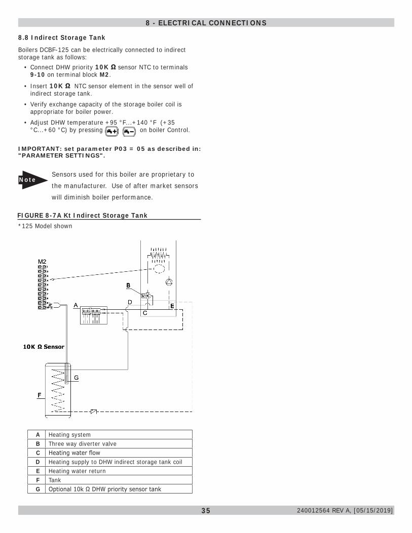
8.8 Indirect Storage Tank
A Heating systemB Three way diverter valveC Heating water flowD Heating supply to DHW indirect storage tank coilE Heating water returnF TankG Optional 10k Ω DHW priority sensor tank
Boilers DCBF-125 can be electrically connected to indirect storage tank as follows:
• Connect DHW priority 10K Ω sensor NTC to terminals 9-10 on terminal block M2.
• Insert 10K Ω NTC sensor element in the sensor well of indirect storage tank.
• Verify exchange capacity of the storage boiler coil is appropriate for boiler power.
• Adjust DHW temperature +95 °F...+140 °F (+35 °C...+60 °C) by pressing on boiler Control.
IMPORTANT: set parameter P03 = 05 as described in: "PARAMETER SETTINGS".
FIGURE 8-7A Kt Indirect Storage Tank*125 Model shown
NoteSensors used for this boiler are proprietary to
the manufacturer. Use of after market sensors
will diminish boiler performance.
8 - ELECTRICAL CONNECTIONS
240012564 REV A, [05/15/2019]
36
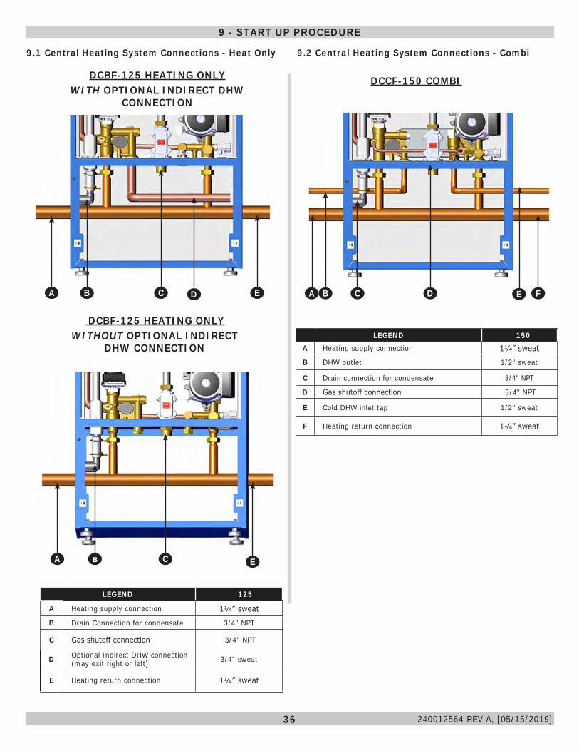
LEGEND 125
A Heating supply connection 11/4” sweat
B Drain Connection for condensate 3/4" NPT
C Gas shutoff connection 3/4" NPT
D Optional Indirect DHW connection (may exit right or left) 3/4" sweat
E Heating return connection 11/4” sweat
9.1 Central Heating System Connections - Heat Only
DCBF-125 HEATING ONLY WITH OPTIONAL INDIRECT DHW
CONNECTION
DCBF-125 HEATING ONLY WITHOUT OPTIONAL INDIRECT
DHW CONNECTION
9.2 Central Heating System Connections - Combi
DCCF-150 COMBI
LEGEND 150A Heating supply connection 11/4” sweat
B DHW outlet 1/2" sweat
C Drain connection for condensate 3/4" NPT
D Gas shutoff connection 3/4" NPT
E Cold DHW inlet tap 1/2" sweat
F Heating return connection 11/4” sweat
9 - START UP PROCEDURE
AE AB
AA
240012564 REV A, [05/15/2019]
AA ADACAB AE
Ab AC AE
AA AC AD AF
37
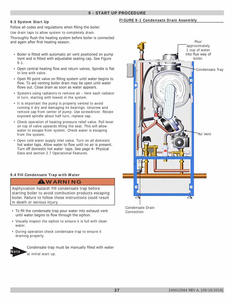
FIGURE 9-1 Condensate Drain Assembly
9.4 Fill Condensate Trap with Water
WARNINGAsphyxiation hazard! Fill condensate trap before starting boiler to avoid combustion products escaping boiler. Failure to follow these instructions could result in death or serious injury.
!
• To fill the condensate trap pour water into exhaust vent until water begins to flow through the siphon.
• Visually inspect the siphon to ensure it is full with clean water.
• During operation check condensate trap to ensure it draining properly.
NoteCondensate trap must be manually filled with water
at initial start up.
• Boiler is fitted with automatic air vent positioned on pump Vent and is fitted with adjustable sealing cap. See Figure 9-1.
• Open central heating flow and return valves. Spindle is flat in-line with valve.
• Open fill point valve on filling system until water begins to flow. To aid venting boiler drain may be open until water flows out. Close drain as soon as water appears.
• Systems using radiators to remove air - Vent each radiator in turn, starting with lowest in the system.
• It is important the pump is properly vented to avoid running it dry and damaging its bearings. Unscrew and remove cap from center of pump. Use screwdriver. Rotate exposed spindle about half turn, replace cap.
• Check operation of heating pressure relief valve. Pull lever on top of valve upwards lifting the seat. This will allow water to escape from system. Check water is escaping from the system.
• Open cold water supply inlet valve. Turn on all domestic hot water taps. Allow water to flow until no air is present. Turn off domestic hot water taps. See page 4- Physical Data and section 2.7 Operational Features.
9.3 System Start UpFollow all codes and regulations when filling the boiler.Use drain taps to allow system to completely drain.Thoroughly flush the heating system before boiler is connected and again after first heating season.
9 - START UP PROCEDURE
240012564 REV A, [05/15/2019]
Pour approximately 1 cup of water into flue way of
boiler.
Condensate Drain Connection
Air Vent
Condensate Tray
38
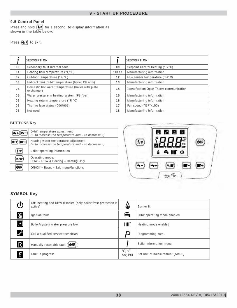
9.5 Control PanelPress and hold for 1 second, to display information as shown in the table below.
Press to exit.
DESCRIPTION DESCRIPTION
00 Secondary fault internal code 09 Setpoint Central Heating (°F/°C)01 Heating flow temperature (°F/°C) 10/11 Manufacturing information02 Outdoor temperature (°F/°C) 12 Flue sensor temperature (°F/°C)03 Indirect Tank DHW temperature (boiler CH only) 13 Manufacturing information
04 Domestic hot water temperature (boiler with plate exchanger) 14 Identification Open Therm communication
05 Water pressure in heating system (PSI/bar) 15 Manufacturing information06 Heating return temperature (°F/°C) 16 Manufacturing information07 Thermo fuse status (000/001) 17 Fan speed (“i17”x100)08 Not used 18 Manufacturing information
DHW temperature adjustment(+ to increase the temperature and – to decrease it)
Heating water temperature adjustment(+ to increase the temperature and – to decrease it)
Boiler operating information
Operating mode:DHW – DHW & Heating – Heating Only
ON/Off – Reset – Exit menu/functions
BUTTONS Key
Off: heating and DHW disabled (only boiler frost protection is active) Burner lit
Ignition fault DHW operating mode enabled
Boiler/system water pressure low Heating mode enabled
Call a qualified service technician Programming menu
Manually resettable fault ( ) Boiler information menu
Fault in progress Set unit of measurement (SI/US)
SYMBOL Key
9 - START UP PROCEDURE
240012564 REV A, [05/15/2019]
39
9.7 Commissioning For The First Time:1. Turn power to boiler on. Code "000" appears on the
display. Appliance is ready for "commissioning" procedure.2. Press at the same time. Hold for 6 seconds. "On"
appears on the display for 2 seconds followed by code "312" indicating "de-aeration" function is active. This function lasts 10 minutes.
3. Boiler will turn on after deaeration function is complete. Display will show code "000" alternating with % of ignition power and temperature value (°F / °C). • During this gas recognition function phase which
lasts about 7 minutes, type of gas being used is analyzed.
• During this function, assure maximum heat exchange to heating or DHW system (domestic hot water demand) by having all heating zones open or all domestic hot water taps open, in order to prevent boiler from switching off due to overheating.
• If boiler operates on Gas A (Natural Gas), display shows NG (Natural Gas) for about 10 seconds. Boiler is now ready for normal operation.
• If display shows LPG (Gas E), press and together and hold down for at least 4 seconds to exit without changing factory setting. Boiler will stay set to Natural Gas.
• If boiler operates on Gas E (LPG) display shows LPG (Gas E). Press for at least 6 seconds to confirm gas used.
• If display shows NG (Gas A) and does not recognize the type of gas used, press and together and hold down for at least 4 seconds to exit the function. Change parameter P02=01 as described in section 9.12 Parameter Settings of boiler Installation, Operation and Maintenance Manual. Perform Automatic Calibration Function. Manual Calibration may be necessary if combustion is not within specified range.
NOTICEDuring initial ignition, burner may not ignite. This may cause boiler to shut down until any air in gas pipes is vented. Repeat ignition procedure until gas reaches the burner. To reset boiler operation, press for at least 2 seconds.
NOTICEFirst ignitions immediately after installation, system will implement a self-learning procedure to reach correct ignition level.
9 - START UP PROCEDURE
9.8 Automatic Calibration FunctionBefore performing this function verify there are no heat demands in progress.During this function ensure there is maximum heat exchange to the system in Heating or DHW mode (DHW request) to avoid boiler shutting off due to overheating.Press and together and hold for about 6 seconds. When display indicates "On" press within 3 seconds after pressing previous buttons.
NOTICEIMPORTANT: If Calibration function does not complete, verify unit did not shut down for over-temperature. Repeat Automatic Calibration. Replace KEY if Automatic calibration does not complete after second try.
NOTICEImportant: If display indicates "303" Automatic Calibration function has not been activated. Disconnect boiler from main power supply for few seconds and repeat procedure.
1. When function is enabled, and will flash on the display.
2. After ignition sequence, which can also take place after few attempts, boiler performs three operations. Each operation lasts about 1 minute: • maximum power • ignition power • minimum power
3. Before moving to the following phase, from maximum power to ignition power and then to minimum power.
and appear on the display.
4. During this phase, power level reached by boiler and delivery temperature alternate on the display.
5. When , and flash together on the display, automatic calibration function has completed.
6. Press to exit the function. Display will show ESC.
7. Verify combustion is within specified range. If not, perform Automatic and then Manual Calibration. (See Section 9.8)
NoteBoiler must not shutoff during calibration. Open all heating zones in heating or DHW mode to ensure boiler does not shutoff.
NOTICEAll connections shall be made and water added before performing this function.
9.6 Prior to Commissioning:• Check system pressure is correct;• Power boiler;• Open gas tap (positioned under boiler);• Select required heating mode. See section 10.4
Operating Modes.
240012564 REV A, [05/15/2019]
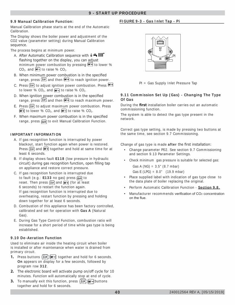
40
PI
9.10 De-Aeration FunctionUsed to eliminate air inside the heating circuit when boiler is installed or after maintenance when water is drained from primary circuit.1. Press buttons together and hold for 6 seconds.
On appears on display for a few seconds, followed by program row 312.
2. The electronic board will activate pump on/off cycle for 10 minutes. Function will automatically stop at end of cycle.
3. To manually exit this function, press buttons together and hold for 6 seconds.
9.11 Commission Set Up (Gas) - Changing The Type Of GasDuring the first installation boiler carries out an automatic commissioning function. The system is able to detect the gas type present in the network.
Correct gas type setting, is made by pressing two buttons at the same time, see section 9.7 Commissioning.
Change of gas type is made after the first installation:• Change parameter P02. See section 9.7 Commissioning
and section 9.13 Parameter Settings.• Check minimum gas pressure is suitable for selected gas:
Gas A (NG) = 3.5" (8.7 mbar) Gas E (LPG) = 8.0" (19.9 mbar)
• Place supplied label with indication of gas type close to the data plate of boiler replacing the original.
• Perform Automatic Calibration Function - Section 9.8.• Manufacturer recommends verification of CO2 concentration
on the flue.
FIGURE 9-3 - Gas Inlet Tap - Pi
PI = Gas Supply Inlet Pressure Tap
9 - START UP PROCEDURE
PI
IMPORTANT INFORMATIONA. If gas recognition function is interrupted by power
blackout, start function again when power is restored. Press and together and hold at same time for at least 6 seconds.
B. If display shows fault E118 (low pressure in hydraulic circuit) during gas recognition function, open filling tap on appliance and restore correct pressure.
C. If gas recognition function is interrupted due to fault (e.g.: E133 no gas) press to reset. Then press and (for at least 6 seconds) to restart the function again. If gas recognition function is interrupted due to overheating, restart function by pressing and holding down together for at least 6 seconds.
D. Combustion of this appliance has been factory controlled, calibrated and set for operation with Gas A (Natural Gas).
E. During Gas Type Control Function, combustion ratio will increase for a short period of time while gas type is being established.
9.9 Manual Calibration Function:Manual Calibration phase starts at the end of the Automatic Calibration.The Display shows the boiler power and adjustment of the CO2 value (parameter setting) during Manual Calibration sequence.The process begins at minimum power.
A. After Automatic Calibration sequence with flashing together on the display, you can adjust minimum power combustion by pressing to lower % CO2, and to raise % CO2.
B. When minimum power combustion is in the specified range, press and then to reach ignition power.
C. Press to adjust ignition power combustion. Press to lower % CO2, and to raise % CO2.
D. When ignition power combustion is in the specified range, press and then to reach maximum power.
E. Press to adjust maximum power combustion. Press to lower % CO2, and to raise % CO2.
F. When maximum power combustion is in the specified range, press to exit Manual Calibration Function.
240012564 REV A, [05/15/2019]
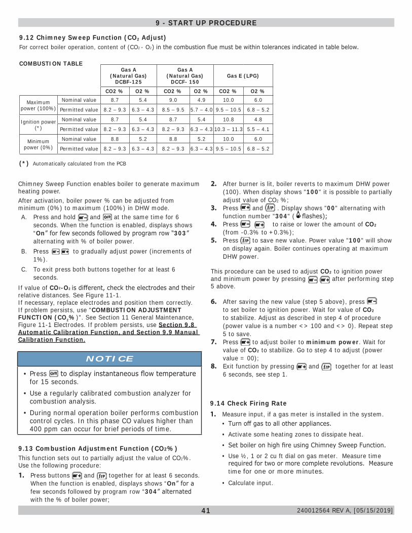
41
9.12 Chimney Sweep Function (CO2 Adjust)For correct boiler operation, content of (CO2 - O2) in the combustion flue must be within tolerances indicated in table below.
COMBUSTION TABLEGas A
(Natural Gas) DCBF-125
Gas A (Natural Gas)
DCCF- 150Gas E (LPG)
CO2 % O2 % CO2 % O2 % CO2 % O2 %
Maximum power (100%)
Nominal value 8.7 5.4 9.0 4.9 10.0 6.0
Permitted value 8.2 – 9.3 6.3 – 4.3 8.5 – 9.5 5.7 – 4.0 9.5 – 10.5 6.8 – 5.2
Ignition power (*)
Nominal value 8.7 5.4 8.7 5.4 10.8 4.8
Permitted value 8.2 – 9.3 6.3 – 4.3 8.2 – 9.3 6.3 – 4.3 10.3 – 11.3 5.5 – 4.1
Minimum power (0%)
Nominal value 8.8 5.2 8.8 5.2 10.0 6.0
Permitted value 8.2 – 9.3 6.3 – 4.3 8.2 – 9.3 6.3 – 4.3 9.5 – 10.5 6.8 – 5.2
Chimney Sweep Function enables boiler to generate maximum heating power. After activation, boiler power % can be adjusted from minimum (0%) to maximum (100%) in DHW mode.A. Press and hold and at the same time for 6
seconds. When the function is enabled, displays shows “On” for few seconds followed by program row “303” alternating with % of boiler power.
B. Press to gradually adjust power (increments of 1%).
C. To exit press both buttons together for at least 6 seconds.
If value of CO2-O2 is different, check the electrodes and their relative distances. See Figure 11-1.If necessary, replace electrodes and position them correctly. If problem persists, use "COMBUSTION ADJUSTMENT FUNCTION (CO2%)". See Section 11 General Maintenance, Figure 11-1 Electrodes. If problem persists, use Section 9.8 Automatic Calibration Function, and Section 9.9 Manual Calibration Function.
NOTICE
• Press to display instantaneous flow temperature for 15 seconds.
• Use a regularly calibrated combustion analyzer for combustion analysis.
• During normal operation boiler performs combustion control cycles. In this phase CO values higher than 400 ppm can occur for brief periods of time.
(*) Automatically calculated from the PCB
9.14 Check Firing Rate1. Measure input, if a gas meter is installed in the system.
• Turn off gas to all other appliances.• Activate some heating zones to dissipate heat.• Set boiler on high fire using Chimney Sweep Function.• Use ½, 1 or 2 cu ft dial on gas meter. Measure time
required for two or more complete revolutions. Measure time for one or more minutes.
• Calculate input.
9.13 Combustion Adjustment Function (CO2%)This function sets out to partially adjust the value of CO2%. Use the following procedure:1. Press buttons and together for at least 6 seconds.
When the function is enabled, displays shows “On” for a few seconds followed by program row “304” alternated with the % of boiler power;
2. After burner is lit, boiler reverts to maximum DHW power (100). When display shows "100" it is possible to partially adjust value of CO2 %;
3. Press and . Display shows "00" alternating with function number "304" ( flashes);
4. Press to raise or lower the amount of CO2 (from -0.3% to +0.3%);
5. Press to save new value. Power value "100" will show on display again. Boiler continues operating at maximum DHW power.
This procedure can be used to adjust CO2 to ignition power and minimum power by pressing after performing step 5 above.
6. After saving the new value (step 5 above), press to set boiler to ignition power. Wait for value of CO2 to stabilize. Adjust as described in step 4 of procedure (power value is a number <> 100 and <> 0). Repeat step 5 to save.
7. Press to adjust boiler to minimum power. Wait for value of CO2 to stabilize. Go to step 4 to adjust (power value = 00);
8. Exit function by pressing and together for at least 6 seconds, see step 1.
9 - START UP PROCEDURE
240012564 REV A, [05/15/2019]
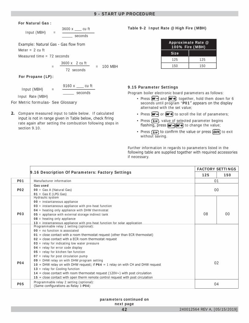
42
9.15 Parameter SettingsProgram boiler electronic board parameters as follows:
• Press and together, hold them down for 6 seconds until program “P01” appears on the display alternated with the set value;
• Press or to scroll the list of parameters;• Press , value of selected parameter begins
flashing, press to change the value;• Press to confirm the value or press to exit
without saving.
Further information in regards to parameters listed in the following table are supplied together with required accessories if necessary.
9.16 Description Of Parameters: Factory SettingsFACTORY SETTINGS
125 150P01 Manufacturer information 01
P02Gas used00 = Gas A (Natural Gas) 01 = Gas E (LPG Gas)
00
P03
Hydraulic system00 = instantaneous appliance03 = instantaneous appliance with pre-heat function 04 = heating only appliance with DHW thermostat05 = appliance with external storage indirect tank 08 = heating only appliance13 = instantaneous appliance with pre-heat function for solar application
08 00
P04
Programmable relay 1 setting (optional):00 = no function is associated01 = close contact with a room thermostat request (other than ECR thermostat)02 = close contact with a ECR room thermostat request03 = relay for indicating low water pressure04 = relay for error code display05 = relay for kitchen fan function07 = relay for post circulation pump09 = DHW relay on with DHW program setting10 = DHW relay on with DHW request; if P64 = 1 relay on with CH and DHW request13 = relay for Cooling function14 = close contact with room thermostat request (120V~) with post circulation15 = close contact with open therm remote control request with post circulation
02
P05 Programmable relay 2 setting (optional):(Same configurations as Relay 1-P04) 04
parameters continued on next page
For Natural Gas :
Input (MBH) =
3600 x cu ft
seconds
Example: Natural Gas - Gas flow from Meter = 2 cu ft Measured time = 72 seconds
=3600 x 2 cu ft
= 100 MBH 72 seconds
For Propane (LP):
Input (MBH) =9160 x cu ft
seconds
For Metric formulas- See Glossary
2. Compare measured input to table below. If calculated input is not in range given in Table below, check firing rate again after setting the combustion following steps in section 9.10.
Input Rate (MBH)
Table 9-2 Input Rate @ High Fire (MBH)
Approximate Rate @ 100% Fire (MBH)Size125 125150 150
9 - START UP PROCEDURE
240012564 REV A, [05/15/2019]
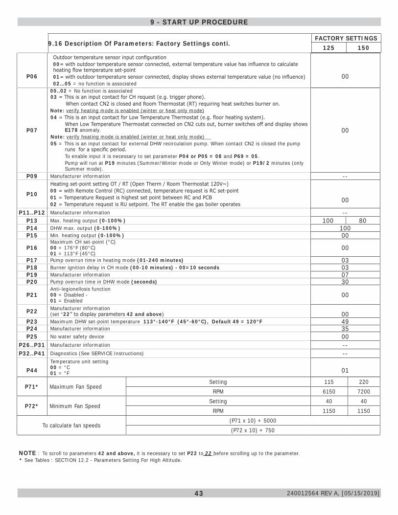
43
P07
00..02 = No function is associated 03 = This is an input contact for CH request (e.g. trigger phone).
When contact CN2 is closed and Room Thermostat (RT) requiring heat switches burner on.Note: verify heating mode is enabled (winter or heat only mode)
04 = This is an input contact for Low Temperature Thermostat (e.g. floor heating system).When Low Temperature Thermostat connected on CN2 cuts out, burner switches off and display shows E178 anomaly.
Note: verify heating mode is enabled (winter or heat only mode) 05 = This is an input contact for external DHW recirculation pump. When contact CN2 is closed the pump
runs for a specific period.To enable input it is necessary to set parameter P04 or P05 = 08 and P69 = 05.Pump will run at P19 minutes (Summer/Winter mode or Only Winter mode) or P19/2 minutes (only Summer mode).
00
P09 Manufacturer information --
P10
Heating set-point setting OT / RT (Open Therm / Room Thermostat 120V~)00 = with Remote Control (RC) connected, temperature request is RC set-point01 = Temperature Request is highest set point between RC and PCB02 = Temperature request is RU setpoint. The RT enable the gas boiler operates
00
P11..P12 Manufacturer information --P13 Max. heating output (0-100%) 100 80P14 DHW max. output (0-100%) 100P15 Min. heating output (0-100%) 00
P16Maximum CH set-point (°C)00 = 176°F (80°C) 01 = 113°F (45°C)
00
P17 Pump overrun time in heating mode (01-240 minutes) 03P18 Burner ignition delay in CH mode (00-10 minutes) - 00=10 seconds 03P19 Manufacturer information 07P20 Pump overrun time in DHW mode (seconds) 30
P21Anti-legionellosis function00 = Disabled - 01 = Enabled
00
P22 Manufacturer information(set “22” to display parameters 42 and above) 00
P23 Maximum DHW set-point temperature 113°-140°F (45°-60°C), Default 49 = 120°F 49P24 Manufacturer information 35P25 No water safety device 00
P26..P31 Manufacturer information --P32..P41 Diagnostics (See SERVICE Instructions) --
P44Temperature unit setting00 = °C01 = °F 01
* See Tables : SECTION 12.2 - Parameters Setting For High Altitude.NOTE : To scroll to parameters 42 and above, it is necessary to set P22 to 22 before scrolling up to the parameter.
P06
Outdoor temperature sensor input configuration00= with outdoor temperature sensor connected, external temperature value has influence to calculate heating flow temperature set-point01= with outdoor temperature sensor connected, display shows external temperature value (no influence)02…05 = no function is associated
00
9.16 Description Of Parameters: Factory Settings conti.FACTORY SETTINGS
125 150
9 - START UP PROCEDURE
P71* Maximum Fan SpeedSetting 115 220
RPM 6150 7200
P72* Minimum Fan SpeedSetting 40 40
RPM 1150 1150
To calculate fan speeds(P71 x 10) + 5000(P72 x 10) + 750
240012564 REV A, [05/15/2019]
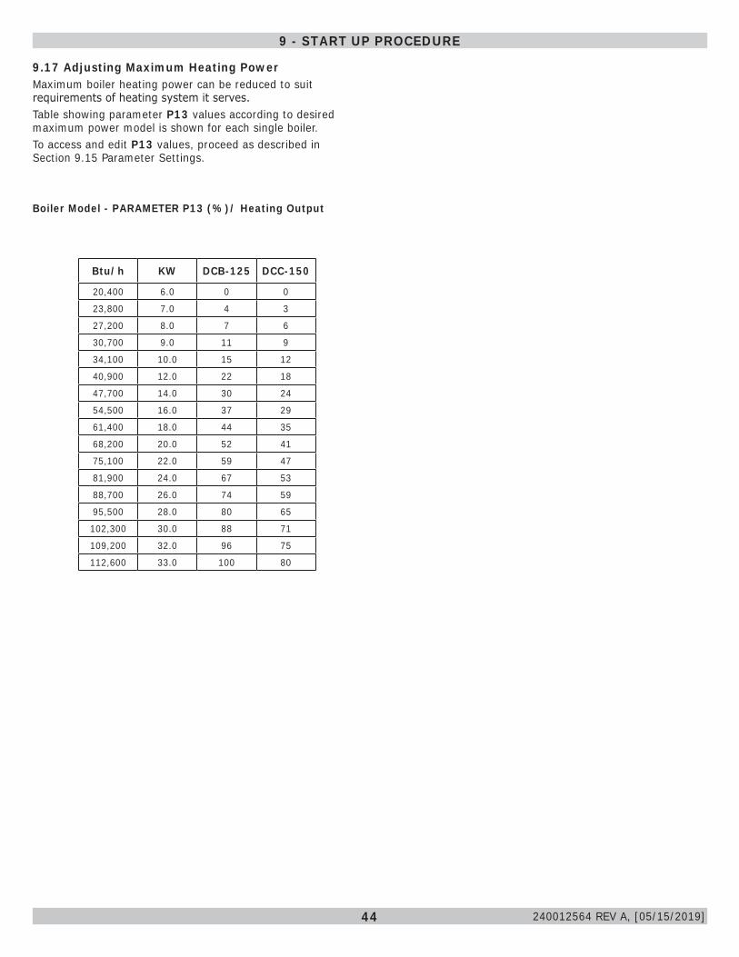
44
9.17 Adjusting Maximum Heating PowerMaximum boiler heating power can be reduced to suit requirements of heating system it serves. Table showing parameter P13 values according to desired maximum power model is shown for each single boiler.To access and edit P13 values, proceed as described in Section 9.15 Parameter Settings.
Boiler Model - PARAMETER P13 (%)/ Heating Output
Btu/h KW DCB-125 DCC-150
20,400 6.0 0 0
23,800 7.0 4 3
27,200 8.0 7 6
30,700 9.0 11 9
34,100 10.0 15 12
40,900 12.0 22 18
47,700 14.0 30 24
54,500 16.0 37 29
61,400 18.0 44 35
68,200 20.0 52 41
75,100 22.0 59 47
81,900 24.0 67 53
88,700 26.0 74 59
95,500 28.0 80 65
102,300 30.0 88 71
109,200 32.0 96 75
112,600 33.0 100 80
9 - START UP PROCEDURE
240012564 REV A, [05/15/2019]
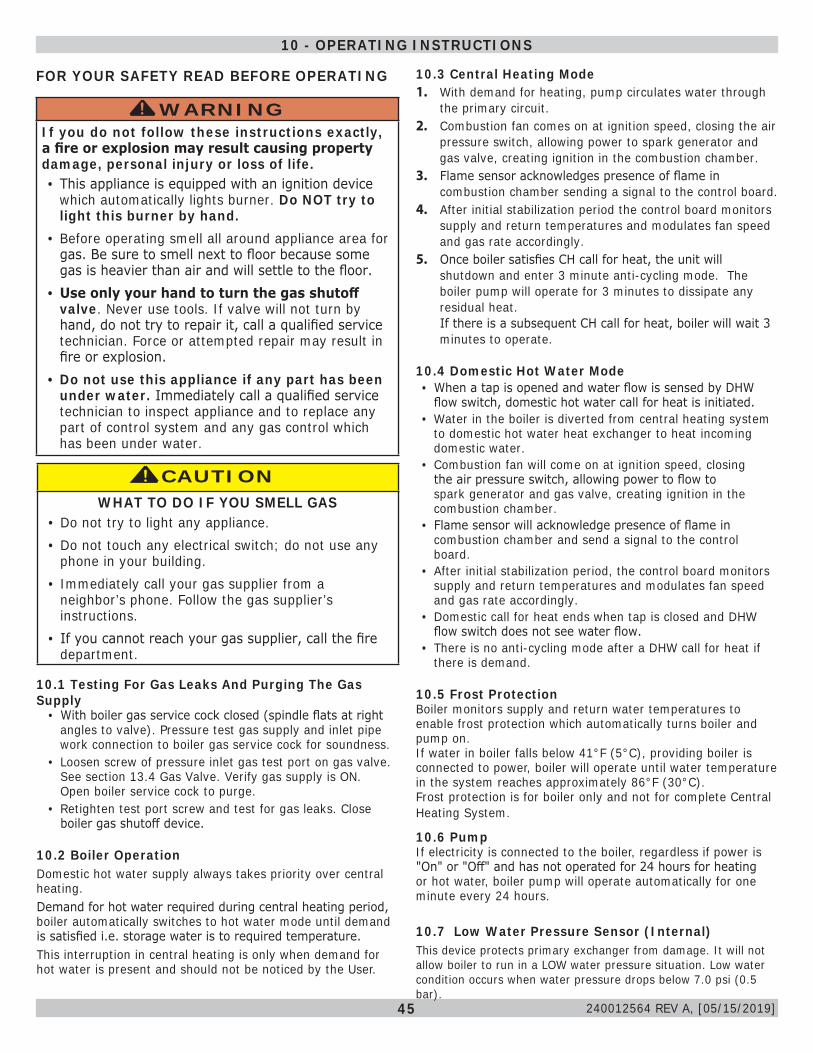
45
10.1 Testing For Gas Leaks And Purging The Gas Supply
• With boiler gas service cock closed (spindle flats at right angles to valve). Pressure test gas supply and inlet pipe work connection to boiler gas service cock for soundness.
• Loosen screw of pressure inlet gas test port on gas valve. See section 13.4 Gas Valve. Verify gas supply is ON. Open boiler service cock to purge.
• Retighten test port screw and test for gas leaks. Close boiler gas shutoff device.
WARNINGIf you do not follow these instructions exactly, a fire or explosion may result causing property damage, personal injury or loss of life.• This appliance is equipped with an ignition device
which automatically lights burner. Do NOT try to light this burner by hand.
• Before operating smell all around appliance area for gas. Be sure to smell next to floor because some gas is heavier than air and will settle to the floor.
• Use only your hand to turn the gas shutoff valve. Never use tools. If valve will not turn by hand, do not try to repair it, call a qualified service technician. Force or attempted repair may result in fire or explosion.
• Do not use this appliance if any part has been under water. Immediately call a qualified service technician to inspect appliance and to replace any part of control system and any gas control which has been under water.
!
FOR YOUR SAFETY READ BEFORE OPERATING
CAUTIONWHAT TO DO IF YOU SMELL GAS
• Do not try to light any appliance.• Do not touch any electrical switch; do not use any
phone in your building.• Immediately call your gas supplier from a
neighbor’s phone. Follow the gas supplier’s instructions.
• If you cannot reach your gas supplier, call the fire department.
!
10 - OPERATING INSTRUCTIONS
10.2 Boiler OperationDomestic hot water supply always takes priority over central heating. Demand for hot water required during central heating period, boiler automatically switches to hot water mode until demand is satisfied i.e. storage water is to required temperature. This interruption in central heating is only when demand for hot water is present and should not be noticed by the User.
10.3 Central Heating Mode1. With demand for heating, pump circulates water through
the primary circuit.2. Combustion fan comes on at ignition speed, closing the air
pressure switch, allowing power to spark generator and gas valve, creating ignition in the combustion chamber.
3. Flame sensor acknowledges presence of flame in combustion chamber sending a signal to the control board.
4. After initial stabilization period the control board monitors supply and return temperatures and modulates fan speed and gas rate accordingly.
5. Once boiler satisfies CH call for heat, the unit will shutdown and enter 3 minute anti-cycling mode. The boiler pump will operate for 3 minutes to dissipate any residual heat. If there is a subsequent CH call for heat, boiler will wait 3 minutes to operate.
10.4 Domestic Hot Water Mode• When a tap is opened and water flow is sensed by DHW
flow switch, domestic hot water call for heat is initiated.• Water in the boiler is diverted from central heating system
to domestic hot water heat exchanger to heat incoming domestic water.
• Combustion fan will come on at ignition speed, closing the air pressure switch, allowing power to flow to spark generator and gas valve, creating ignition in the combustion chamber.
• Flame sensor will acknowledge presence of flame in combustion chamber and send a signal to the control board.
• After initial stabilization period, the control board monitors supply and return temperatures and modulates fan speed and gas rate accordingly.
• Domestic call for heat ends when tap is closed and DHW flow switch does not see water flow.
• There is no anti-cycling mode after a DHW call for heat if there is demand.
10.5 Frost ProtectionBoiler monitors supply and return water temperatures to enable frost protection which automatically turns boiler and pump on. If water in boiler falls below 41°F (5°C), providing boiler is connected to power, boiler will operate until water temperature in the system reaches approximately 86°F (30°C). Frost protection is for boiler only and not for complete Central Heating System.
10.6 PumpIf electricity is connected to the boiler, regardless if power is "On" or "Off" and has not operated for 24 hours for heating or hot water, boiler pump will operate automatically for one minute every 24 hours.
10.7 Low Water Pressure Sensor (Internal) This device protects primary exchanger from damage. It will not allow boiler to run in a LOW water pressure situation. Low water condition occurs when water pressure drops below 7.0 psi (0.5 bar).
240012564 REV A, [05/15/2019]
46
11.1 Beginning of Each Heating Season• Check boiler area is free from combustible materials,
gasoline, and other flammable vapors and corrosive liquids.• Visually inspect combustion air and vent piping for proper
operation. Check for and remove any obstruction to flow of combustion air or vent gases. Immediately repair or replace pipe showing deterioration or leakage. Reassemble per instructions in section 6. Ensure proper reassembly and resealing of system.
• Visually inspect condensate drain line for proper operation. Checking for deteriorated or plugged condensate drain line. Verify condensate trap drains freely and clean as required.
• Test safety relief valve for proper operation. Refer to valve manufacturer's instructions packaged with relief valve.
• Examine heat exchanger, burner, condensate lines, and clean (if necessary) by following instructions in section 11.3 - Component Replacement And Cleaning.
CAUTION Label all wires prior to disconnection when servicing controls. Wiring errors can cause improper and dangerous operation.
!
DANGERBefore servicing, turn off electrical power to boiler at service switch. Close manual gas valve to turn gas supply OFF to boiler. Failure to comply will result in death or serious injury.
!
Note Verify proper operation after servicing.
NotePerform regular service and maintenance by qualified service agency at least once every 12 months to assure safe, trouble free operation and maximum efficiency.
• Circulator pump and combustion air blower motor furnished with boiler are permanently lubricated from factory and require no further lubrication. Lubricate field sourced pumps and/or motors according to pump and/or motor manufacturer’s instruction.
• Check following components are operating properly and are free of blockages or obstructions:
• air vent;• check venturi air inlet for blockage and clean as
required;• verify pressure test port cap and combustion test port
caps are in place;• verify supply and return sensors are properly clipped to
pipes as close to heat exchanger as possible; • Check boiler for any sign of leaks.
• Check external low water cutoff operation (if installed).• Check operation by pressing test button on low water
cutoff.• "Low Water" LED on the external LWCO should
illuminate and boiler should shut down. • Every 5 years remove low water cutoff. Reinstall after
cleaning.• Every 10 years replace low water cutoff.
• Visual inspection of flame through sight glass. Burner should be fully illuminated.
• Check heating system expansion tank.
NoteA Heat Exchanger cleaning kit is available for annual service of the boiler. See repair parts manual for part number.
11 - GENERAL MAINTENANCE AND CLEANING
240012564 REV A, [05/15/2019]
47
NOTICEPerform regular service and maintenance by qualified service agency at least once every 12 months to assure safe, trouble free operation and maximum efficiency.
11.2 Maintenance And Routine ServicingCheck and service boiler as necessary. Frequency of servicing will depend upon installation conditions and usage, manufacturer recommends annually.
• Check flue terminal outside and ensure it is not blocked.• Operate boiler. Check operation of boiler's controls.• Ensure all system connections and fittings are sound.
Correct any joints and fittings that maybe leaking.• Follow safety valve manufacturer recommendations for
service.
To ensure boiler operates at peak efficiency, following checks must be performed every year:
• check appearance and tightness of gas and combustion circuit gaskets
• check condition and position of ignition and flame sensing electrodes
• check condition of burner and its connection to aluminum front plate
• check for dirt in combustion chamber. Use vacuum cleaner for this cleaning operation
• check gas valve is calibrated correctly using combustion analyzer
• check there is no dirt in condensate trap• check central heating system pressure• check expansion tank pressure• check vent system, clean if necessary
Record details and maintain service history.
11.3 Component Replacement And Cleaning1. Remove any deposits from heat exchanger using suitable
soft brush. Do not use brush with metallic bristles.2. Check condition of the combustion chamber insulation
panels. Any damaged panels must be replaced.3. Check condition of burner and flame ports. Carefully clean
with soft brush if necessary. Blockages may be removed with stiffer non-metallic brush. Do not use a brush with metallic bristles this might damage the burner.
4. Remove any fallen deposits from bottom of inner case.5. Check condition of electrodes.6. Check spark gap, positioning and height of electrodes. 7. Check fan impeller is clean and free to rotate.
WARNINGCombustion chamber insulation in this product contains ceramic fiber material. Ceramic fibers can be converted to cristobalite in very high temperature applications. The International Agency for Research on Cancer (IARC) has concluded, Crystalline silica inhaled in the form of quartz or cristobalite from occupational sources is carcinogenic to humans (Group1). Avoid breathing dust and contact with skin and eyes. Use NIOSH certified dust respirator (N95). This type of respirator is based on the OSHA requirements for cristobalite at the time this document was written. Other types of respirators may be needed depending on the job site conditions. Current NIOSH recommendations can be found on the NIOSH website http://www.cdc.gov/niosh/homepage.html. NIOSH approved respirators, manufacturers, and phone numbers are also listed on this website. Wear long-sleeved, loose fitting clothing, gloves, and eye protection. Apply enough water to the combustion chamber lining to prevent dust. Wash potentially contaminated clothes separately from other clothing. Rinse clothes washer thoroughly.NIOSH stated First Aid. Eye: Irrigate immediately. Breathing: Fresh air.
!
WARNINGBefore servicing, turn off electrical power to boiler at service switch. Close manual gas valve to turn gas supply OFF to boiler. Test for gas leaks on any gas carrying components after servicing. Service not complete until appliance operation verified per Installation, Operation & Maintenance Manual provided with boiler.
!
WARNINGFollowing service procedures must be performed by qualified service agent. Boiler owner shall not attempt these steps. Failure to do so could result in death or serious injury.
!
CAUTIONLabel all wires prior to disconnection when servicing controls. Wiring errors can cause improper and dangerous operation. Failure to follow these instructions could result in minor or moderate injury.
!
11 - GENERAL MAINTENANCE AND CLEANING
240012564 REV A, [05/15/2019]
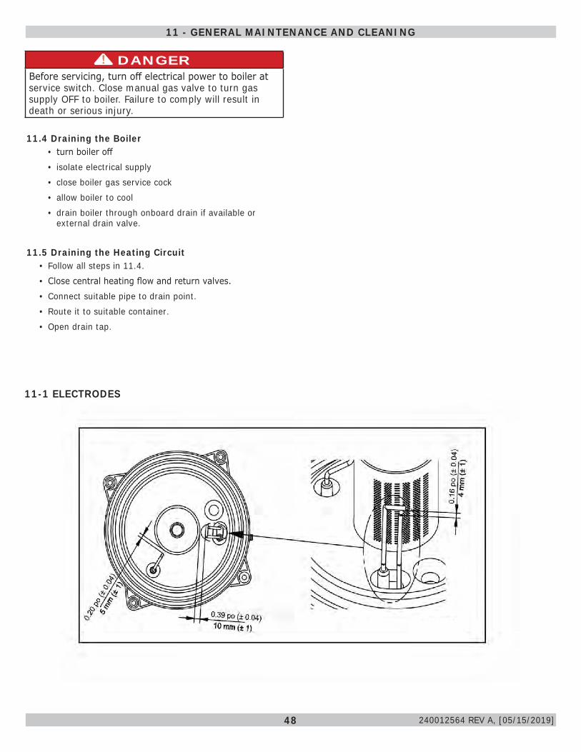
48
11-1 ELECTRODES
DANGERBefore servicing, turn off electrical power to boiler at service switch. Close manual gas valve to turn gas supply OFF to boiler. Failure to comply will result in death or serious injury.
!
11.4 Draining the Boiler• turn boiler off• isolate electrical supply • close boiler gas service cock• allow boiler to cool• drain boiler through onboard drain if available or
external drain valve.
11.5 Draining the Heating Circuit• Follow all steps in 11.4.• Close central heating flow and return valves.• Connect suitable pipe to drain point. • Route it to suitable container. • Open drain tap.
11 - GENERAL MAINTENANCE AND CLEANING
240012564 REV A, [05/15/2019]
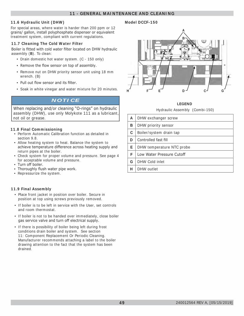
49
11.6 Hydraulic Unit (DHW)For special areas, where water is harder than 200 ppm or 12 grains/ gallon, install polyphosphate dispenser or equivalent treatment system, compliant with current regulations.
LEGEND
A DHW exchanger screw
B DHW priority sensor
C Boiler/system drain tap
D Controlled fast fill
E DHW temperature NTC probe
F Low Water Pressure Cutoff
G DHW Cold inlet
H DHW outlet
11.7 Cleaning The Cold Water FilterBoiler is fitted with cold water filter located on DHW hydraulic assembly (B). To clean:
• Drain domestic hot water system. (C - 150 only)• Remove the flow sensor on top of assembly.• Remove nut on DHW priority sensor unit using 18 mm
wrench. (B)• Pull out flow sensor and its filter.• Soak in white vinegar and water mixture for 20 minutes.
11.8 Final Commissioning• Perform Automatic Calibration function as detailed in
section 9.8.• Allow heating system to heat. Balance the system to
achieve temperature difference across heating supply and return pipes at the boiler.
• Check system for proper volume and pressure. See page 4 for acceptable volume and pressure.
• Turn off boiler.• Thoroughly flush water pipe work.• Repressurize the system.
11.9 Final Assembly• Place front jacket in position over boiler. Secure in
position at top using screws previously removed.• If boiler is to be left in service with the User, set controls
and room thermostat.• If boiler is not to be handed over immediately, close boiler
gas service valve and turn off electrical supply.• If there is possibility of boiler being left during frost
conditions drain boiler and system. See section 11: Component Replacement Or Periodic Cleaning. Manufacturer recommends attaching a label to the boiler drawing attention to the fact that the system has been drained.
Model DCCF-150
Hydraulic Assembly (Combi-150)
NOTICEWhen replacing and/or cleaning “O-rings” on hydraulic assembly (DHW), use only Molykote 111 as a lubricant, not oil or grease.
11 - GENERAL MAINTENANCE AND CLEANING
H G
240012564 REV A, [05/15/2019]
A
B
F E D C
50
11.11 Safety Flue Thermostat - DO NOT disable this safety device.Safety Flue Thermostat found on the flue inside the boiler, interrupts flow of gas to the burner if the temperature overheats.After verifying the cause of the trip, press for about 2 seconds.
11.12 Flue Pressure Switch (125-150 Only) DO NOT disable this safety device.
This device, positioned inside the sealed chamber, interrupts flow of gas to the burner if flue pressure exceeds 1.6 in w.c. (4 mbar). Verify if vent is blocked before resetting the boiler.
NOTICEWhen servicing the appliance, check the condition and position of flame sensing electrode and replace it if necessary.
11.10 User InformationAdvise and demonstrated to User the following important information:
A. How to light and turn off boiler. How to operate system controls.
B. Importance of annual servicing of boiler to ensure safe and efficient operation.
C. Servicing or replacement of parts shall be carried out by a qualified personnel.
D. Ensure boiler controls and room thermostat, if fitted, are set to User's requirements.
E. Tell User about sealed system pressure.F. Tell User if display is active and boiler has not
operated for 24 hours for heating or hot water, the pump will automatically operate for 1 minute.
G. Explain to User an internal frost thermostat is fitted in boiler, and electrical supply to boiler must be left on for frost protection to operate.
H. Show User position of pressure relief valve discharge pipe.
I. Leave this Installation, Operation and Maintenance Manual with User for use on future calls.
11 - GENERAL MAINTENANCE AND CLEANING
11.13 Replacement PartsPerform Automatic Calibration procedure described in section 9.8 if one or more of the following components are replaced. Check and adjust CO2% value as indicated in the Combustion Table.Components replaced:
• Primary heat exchanger• Fan• Gas valve• Gas orifice• Burner• Flame sensing electrode• Spark electrode
240012564 REV A, [05/15/2019]
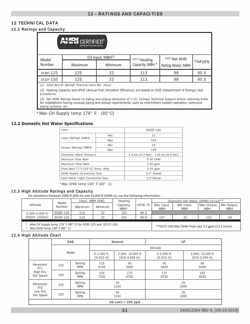
51
Model Number
CH Input, MBH(1)(1)(2) CH Heating Capacity, MBH *
(1)(3) Net AHRIRating Water, MBH
(2)AFUE%Maximum Minimum
DCBF-125 125 22 113 98 95.0DCCF-150 125 22 113 98 95.0(1) 1000 Btu/hr (British Thermal Units Per Hour)(2) Heating Capacity and AFUE (Annual Fuel Utilization Efficiency) are based on DOE (Department of Energy) test procedures.(3) Net AHRI Ratings based on piping and pickup allowance of 1.15. Contact Technical Support before selecting boiler for installations having unusual piping and pickup requirements, such as intermittent system operation, extensive piping systems, etc.
*Max CH Supply temp 176° F (80°C)
12 TECHNICAL DATA12.1 Ratings and Capacity
Item DCCF-150
Input Ratings (MBH)Min 22
Max 153
Output Ratings (MBH)Min 19
Max 136
Domestic Water Pressure 2.9 psi (0.2 bar) - 116 psi (8.0 bar)
Minimum Flow Rate 0.50 GPM
Maximum Flow Rate 3.50 gpm
Flow Rate 77°F (43°C) Temp. Rise 3.25 gpm
DHW Supply Connection Size 1/2" Sweat
Cold Water Input Connection Size 1/2"Sweat
12.2 Domestic Hot Water Specifications
*Max DHW temp 140° F (60° C)
For elevations between 2000 ft (600 m) and 10,000 ft (3048 m), use the following information:
Altitude Model Number
Input, MBH (KW) HeatingCapacity, MBH*
AFUE, %Domestic Hot Water (DHW) Circuit**
Maximum Minimum Max Input, MBH
Min Input, MBH
Max Output, MBH
Min Output, MBH
2,000-4,500 ft (600m-1350m)
DCBF-125 113 22 101 95.0DCCF-150 113 22 101 95.0 137 22 122 19
* Max CH Supply temp 176° F (80° C) for DCBF-125 and DCCF-150* Max DHW temp 140° F (60° C) **DCCF-150 Max DHW Flow rate 3.5 gpm (13.2 l/min)
12.3 High Altitude Ratings and Capacity
12 - RATINGS AND CAPACITIES
12.4 High Altitude ChartGAS Natural LP
ModelAltitude
0-2,000 ft.[0-610 m]
2,000- 10,000 ft[610-3,048 m]
0-2,000 ft.[0-610 m]
2,000- 10,000 ft[610-3,048 m]
Parameter P71
High FireFan Speed
125 SettingRPM
1156150
605600
655650
405400
150 SettingRPM
2207200
1706700
1706700
1506500
Parameter P72
Low FireFan Speed
125 SettingRPM
401150
251000
150 SettingRPM
401150
251000
CO Limit < 200 ppm
240012564 REV A, [05/15/2019]
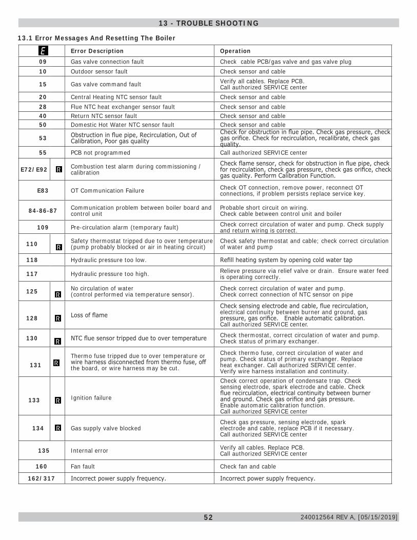
52
13.1 Error Messages And Resetting The Boiler
Error Description Operation
09 Gas valve connection fault Check cable PCB/gas valve and gas valve plug10 Outdoor sensor fault Check sensor and cable
15 Gas valve command fault Verify all cables. Replace PCB. Call authorized SERVICE center
20 Central Heating NTC sensor fault Check sensor and cable28 Flue NTC heat exchanger sensor fault Check sensor and cable40 Return NTC sensor fault Check sensor and cable50 Domestic Hot Water NTC sensor fault Check sensor and cable
53 Obstruction in flue pipe, Recirculation, Out of Calibration, Poor gas quality
Check for obstruction in flue pipe. Check gas pressure, check gas orifice. Check for recirculation, recalibrate, check gas quality.
55 PCB not programmed Call authorized SERVICE center
E72/E92 Combustion test alarm during commissioning / calibration
Check flame sensor, check for obstruction in flue pipe, check for recirculation, check gas pressure, check gas orifice, check gas quality. Perform Calibration Function.
E83 OT Communication Failure Check OT connection, remove power, reconnect OT connections, if problem persists replace service key.
84-86-87 Communication problem between boiler board and control unit
Probable short circuit on wiring. Check cable between control unit and boiler
109 Pre-circulation alarm (temporary fault) Check correct circulation of water and pump. Check supply and return wiring is correct.
110 Safety thermostat tripped due to over temperature (pump probably blocked or air in heating circuit)
Check safety thermostat and cable; check correct circulation of water and pump
118 Hydraulic pressure too low. Refill heating system by opening cold water tap
117 Hydraulic pressure too high. Relieve pressure via relief valve or drain. Ensure water feed is operating correctly.
125 No circulation of water (control performed via temperature sensor).
Check correct circulation of water and pump. Check correct connection of NTC sensor on pipe
128 Loss of flameCheck sensing electrode and cable, flue recirculation, electrical continuity between burner and ground, gas pressure, gas orifice. Enable automatic calibration. Call authorized SERVICE center.
130 NTC flue sensor tripped due to over temperature Check thermostat, correct circulation of water and pump. Check status of primary exchanger.
131Thermo fuse tripped due to over temperature or wire harness disconnected from thermo fuse, off the board, or wire harness may be cut.
Check thermo fuse, correct circulation of water and pump. Check status of primary exchanger. Replace heat exchanger. Call authorized SERVICE center. Verify wire harness installation and continuity.
133 Ignition failure
Check correct operation of condensate trap. Check sensing electrode, spark electrode and cable. Check flue recirculation, electrical continuity between burner and ground. Check gas orifice and gas pressure. Enable automatic calibration function. Call authorized SERVICE center
134 Gas supply valve blockedCheck gas pressure, sensing electrode, spark electrode and cable, replace PCB if it necessary. Call authorized SERVICE center
135 Internal error Verify all cables. Replace PCB. Call authorized SERVICE center
160 Fan fault Check fan and cable
162/317 Incorrect power supply frequency. Incorrect power supply frequency.
13 - TROUBLE SHOOTING
240012564 REV A, [05/15/2019]
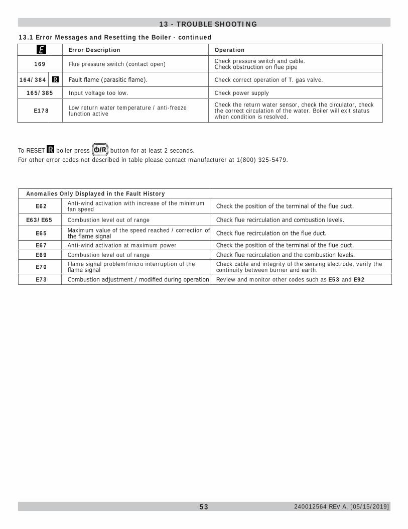
53
To RESET boiler press button for at least 2 seconds. For other error codes not described in table please contact manufacturer at 1(800) 325-5479.
13 - TROUBLE SHOOTING
13.1 Error Messages and Resetting the Boiler - continued
Anomalies Only Displayed in the Fault History
E62 Anti-wind activation with increase of the minimum fan speed Check the position of the terminal of the flue duct.
E63/E65 Combustion level out of range Check flue recirculation and combustion levels.
E65 Maximum value of the speed reached / correction of the flame signal Check flue recirculation on the flue duct.
E67 Anti-wind activation at maximum power Check the position of the terminal of the flue duct.E69 Combustion level out of range Check flue recirculation and the combustion levels.
E70 Flame signal problem/micro interruption of the flame signal
Check cable and integrity of the sensing electrode, verify the continuity between burner and earth.
E73 Combustion adjustment / modified during operation Review and monitor other codes such as E53 and E92
Error Description Operation
169 Flue pressure switch (contact open) Check pressure switch and cable. Check obstruction on flue pipe
164/384 Fault flame (parasitic flame). Check correct operation of T. gas valve.
165/385 Input voltage too low. Check power supply
E178 Low return water temperature / anti-freeze function active
Check the return water sensor, check the circulator, check the correct circulation of the water. Boiler will exit status when condition is resolved.
240012564 REV A, [05/15/2019]
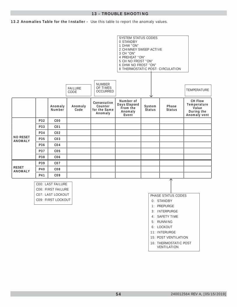
54
13.2 Anomalies Table for the Installer - Use this table to report the anomaly values.
Anomaly Number
Anomaly Code
Consecutive Counter
for the Same Anomaly
Number of Days Elapsed
From the Anomaly
Event
System Status
Phase Status
CH Flow Temperature
Value During the
Anomaly vent
NO RESET ANOMALY
P32 C00
P33 C01
P34 C02
P35 C03
P36 C04
P37 C05
P38 C06
RESET ANOMALY
P39 C07
P40 C08
P41 C09
FAILURE CODE
NUMBER OF TIMES OCCURRED
SYSTEM STATUS CODES0 STANDBY1 DHW "ON"2 CHIMNEY SWEEP ACTIVE3 CH "ON"4 PREHEAT "ON"5 CH NO FROST "ON"6 DHW NO FROST "ON"8 THERMOSTATIC POST- CIRCULATION
TEMPERATURE
C00: LAST FAILUREC06: FIRST FAILUREC07: LAST LOCKOUTC09: FIRST LOCKOUT
PHASE STATUS CODES 0: STANDBY 1: PREPURGE 3: INTERPURGE 4: SAFETY TIME 5: RUNNING 6: LOCKOUT11: INTERURGE15: POST VENTILATION16: THERMOSTATIC POST VENTILATION
13 - TROUBLE SHOOTING
240012564 REV A, [05/15/2019]
55
• APPLIANCE - Device to convert gas into energy; term includes any component, control, wiring, piping or tubing required to be part of the device.
• ANSI - American National Standards Institute, Inc. over see's creation and maintenance of voluntary consensus standards, including ANSI Z21.13/CSA 4.9: Gas-Fired Low Pressure Steam and Hot Water Boilers.
• ASME - Association of Mechanical Engineers Establishes rules of safety governing the design, fabrication, and inspection of boilers and pressure vessels, determining the MAWP of such vessels.
• ASTM - American Society for Testing and Materials. ASTM International is one of largest voluntary standards development organizations in world trusted source for technical standards for materials, products, systems, and services. Known for their high technical quality and market relevancy, ASTM International standards have important role in information infrastructure that guides design, manufacturing and trade in the global economy.
• AUTHORITY HAVING JURISDICTION - Individual or organization adopting and enforcing codes, rules, and by-laws governing various concerns of community. Commonly referred to as "final authority" for any matters relating to LIFE SAFETY and BUILDING CONSTRUCTION within a community.
• BOILER - Appliance intended to supply hot liquid for space-heating, processing or power purposes.
• BTU - Abbreviation for British Thermal Unit. Quantity of heat required to raise temperature of 1 pound of water 1°F.
• BURNER - Device for final conveyance of gas or mixture of gas and air, to combustion zone.
• CALIBRATE - Make fine adjustments or divide into marked intervals for optimal measuring.
• COAXIAL VENTING Sharing the same center.
• COMBUSTION - Rapid oxidation of fuel gases accompanied by production of heat or heat and light. Complete combustion of fuel is possible only in presence of adequate supply of Oxygen.
• COMBUSTIBLE MATERIAL - Materials made of or surfaced with wood, compressed paper, plant fibers, or other materials capable of being ignited and burned. Such material shall be considered combustible even though flame-proofed, fire-retardant treated, or plastered.
• COMBUSTION AIR - Air that is drawn into an appliance to mix with fuel and support combustion.
• CONDENSATE - Liquid separated from flue gas due to reduction in temperature.
• DIRECT VENT BOILER - Boiler constructed and installed so all combustion air is derived directly from outdoors and all vent gases are discharged to outdoors.
• DOMESTIC - Relating to household usage as opposed to commercial usage.
• DOMESTIC WATER - Potable drinking water - tap water.
• DRAFT - Pressure difference causes gases or air to flow through a chimney, vent, flue or appliance.
• FLA - Full load amps.
• FLUE - Enclosed passageway for conveying combustion gases.
• FLUE GASES - Products of combustion plus excess air in appliance flues or heat exchanger.
• GAS SUPPLIER - Party that sells commodity of Natural Gas (Gas A) or LPG (Gas E).
• HIGH-VOLTAGE - Circuit involving potential of not more than 600 volts and having circuit characteristics in excess of those of low-voltage circuit.
• HYSTERESIS (DIFFERENTIAL) -difference between the temperature at which the thermostat switches off - and the temperature at which it switches on again.
• IGNITER - Device utilizing electrical energy to ignite gas at main burner.
• LEAK CHECK - Operation performed on gas piping system to verify system does not leak.
• LICENSED QUALIFIED INSTALLER / SERVICE TECHNICIAN - any individual, firm, corporation or company that either directly or through a representative is engaged in the installation, replacement, repair or servicing of gas piping, venting systems, appliances, components, accessories, or equipment, and whose representative is experienced and trained, in such work and has complied with the requirements of the authority having jurisdiction.
• LOW WATER CUTOFF - Device constructed to automatically cut off fuel supply when surface of water in boiler falls to lowest safe water level.
• LOW-VOLTAGE - Circuit involving potential of not more than 30 volts.
14 - GLOSSARY
240012564 REV A, [05/15/2019]
56
• METRIC GAS METERS Natural Gas
MBH =127,116 x cu meters
Seconds
For example: Gas Meter measures 0.1 cubic Meters in 100 seconds
MBH =127,116 x 0.1
= 127 MBH100
Propane Gas (LP)
MBH = 383,482 x cu meters
Seconds
• NATIONAL BOARD OF BOILER AND PRESSURE VESSEL INSPECTORS - Group composed of boiler and pressure vessel inspectors representing states, cities and provinces enforcing pressure equipment laws and regulations.
• PRESSURE TEST - Operation performed to verify gas tight integrity of gas piping following its installation or modification.
• PURGE - To free gas conduit of air or gas, or mixture of gas and air.
• PURGE TIME - Period of time intended to allow for dissipation of any unburned gas or residual products of combustion.
• QUALIFIED AGENCY - Any individual, firm, corporation, or company engaged in and responsible for:
• Installation, testing, or replacement of gas piping, or connection, installation, testing, repair or servicing of appliances and equipment.
• Experienced in such work.• Familiar with all precautions required.• Complies with all requirements of authority having
jurisdiction.
• SAFETY RELIEF VALVE - Valve designed to relieve pressure in hot water supply system when pressure exceeds pressure capability of equipment.
• SAFETY SHUTOFF DEVICE - Device that will shut off gas supply to controlled burner in event source of ignition fails.
• SEDIMENT TRAP - Gas piping arrangement designed to collect any liquid or solid contaminant before reaching gas valve.
• SERVICE -Supply, installation, or maintenance of goods carried out by a Qualified Installer / Service Technician.
• TWO PIPE SYSTEM - Type of venting that allows for exhaust flue and intake air piping to be separated from each other. Fresh air may be drawn in at a different area from where flue terminal is located.
• VENT - Passageway used to convey flue gases from appliance vent connector to outdoors.
• VENTING SYSTEM - Continuous open passageway from of appliance vent connector to outdoors for purpose of removing flue or vent gases.
14 - GLOSSARY
240012564 REV A, [05/15/2019]
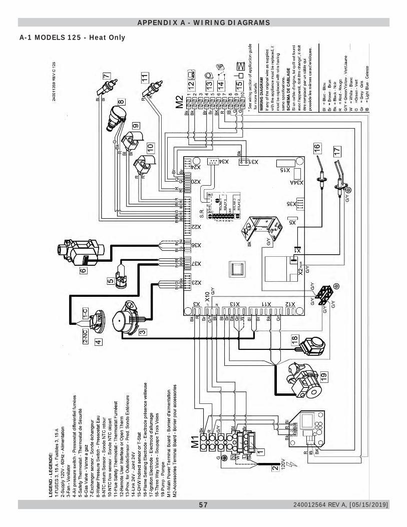
57
A-1 MODELS 125 - Heat Only
APPENDIX A - WIRING DIAGRAMS
240012564 REV A, [05/15/2019]
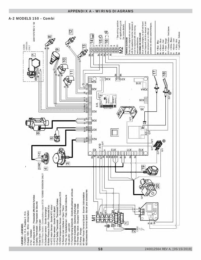
58
A-2 MODELS 150 - Combi
APPENDIX A - WIRING DIAGRAMS
240012564 REV A, [05/15/2019]
59
INSTALLATION AND CHECK-OUT CERTIFICATE
Boiler Model Serial # Date Installed___________
Measured BTU/HR input____________
Installation instructions have been followed
Checkout procedure and adjustments performed
Maintenance and Service issues reviewed with owner/ maintenance person
Installation booklet affixed on or adjacent to boiler
Installer (Company)
Address
Phone
Installer’s Name
Signature
240012564 REV A, [05/15/2019]
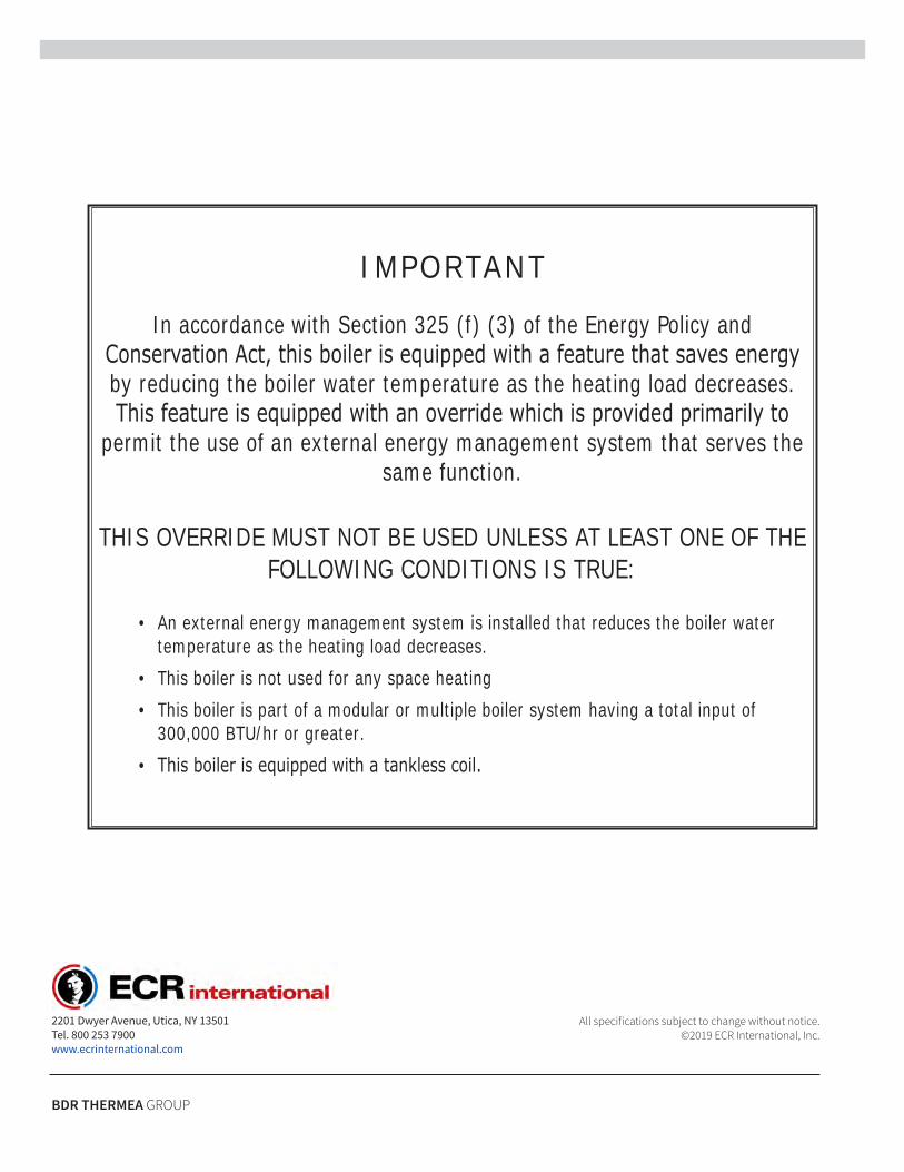
IMPORTANT
In accordance with Section 325 (f) (3) of the Energy Policy and Conservation Act, this boiler is equipped with a feature that saves energy by reducing the boiler water temperature as the heating load decreases. This feature is equipped with an override which is provided primarily to
permit the use of an external energy management system that serves the same function.
THIS OVERRIDE MUST NOT BE USED UNLESS AT LEAST ONE OF THE FOLLOWING CONDITIONS IS TRUE:
• An external energy management system is installed that reduces the boiler watertemperature as the heating load decreases.
• This boiler is not used for any space heating• This boiler is part of a modular or multiple boiler system having a total input of
300,000 BTU/hr or greater.• This boiler is equipped with a tankless coil.
All specifications subject to change without notice. ©2019 ECR International, Inc.
2201 Dwyer Avenue, Utica, NY 13501 Tel. 800 253 7900 www.ecrinternational.com
BDR THERMEA GROUP
Manufactured by: ECR International Inc.
2201 Dwyer Avenue, Utica, NY 13501 Tel. 800 253 7900
www.ecrinternational.com PN 240012560 REV. A [05/15/2019]
This manual has been prepared for use with the appropriate Installation, Operation and Maintenance Manual.
APPLICATION GUIDEFOR USE WITH
FLOOR STANDING HEATING ONLY - 125F
&
FLOOR STANDING COMBI - 150F
2
TABLE OF CONTENTS
Important Safety Information ....................................................................................................3Labor Saving Piping Manifolds / Near Boiler Piping Connections ................................................4General Information - Hydronic Piping .......................................................................................6General Information - Wiring......................................................................................................8
Piping and Wiring DiagramsPiping Legend.......................................................................................................................9
125F Zone Circulator Pumps - Piping Diagram ............................................................. 10
125F W/ Indirect Zone Pumps, DHW Tank, Tank Sensor - Wiring Diagram ........................ 11
125F W/ Indirect Zone Pumps & DHW Tank, Tank T-Stat - Wiring Diagram ....................... 12
125F With Zone Valves - Piping Diagram ..................................................................... 13
125F With Zone Valves, DHW Tank, Tank Sensor - Wiring Diagram .................................. 14
125F Indirect Zone Valves, DHW Tank W/ Tank T-Stat - Wiring Diagram .......................... 15
150F With Zone Circulator Pumps - Piping Diagram ....................................................... 16
150F With Zone Pumps - Wiring Diagram ................................................................... 17
150F With Zone Valves - Piping Diagram ..................................................................... 18
150F With Zone Valves - Wiring Diagram .................................................................... 19
Low Mass Piping and WiringLow Mass - Piping Diagram .................................................................................................. 20Low Mass - Wiring Diagram .................................................................................................. 21
Optional Equipment & Accessories Outdoor Temperature Sensor................................................................................................22 Indirect Storage Tank Sensor & Thermostat ........................................................................... 24
Wiring Diagrams125F - Heat Only Wiring Diagram .......................................................................................... 25150F - Combi Wiring Diagram .............................................................................................. 26
Altitude Effects On Boiler Performance ..................................................................................... 27
Application Table - Indirect Tank Sizing.................................................................................... 28
Low Water Cutoff Application ................................................................................................... 29
Error Code Table.......................................................................................................................31
Troubleshooting Chart................................................................................................................32
Fault Solution Sections...............................................................................................................34
PN 240012560 REV. A [05/15/2019]
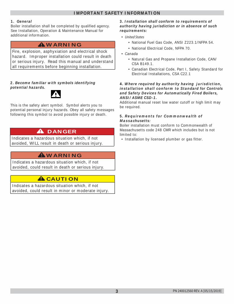
3
IMPORTANT SAFETY INFORMATION
CAUTIONIndicates a hazardous situation which, if not avoided, could result in minor or moderate injury.
!
WARNINGIndicates a hazardous situation which, if not avoided, could result in death or serious injury.
!
DANGERIndicates a hazardous situation which, if not avoided, WILL result in death or serious injury.
!
This is the safety alert symbol. Symbol alerts you to potential personal injury hazards. Obey all safety messages following this symbol to avoid possible injury or death.
2. Become familiar with symbols identifyingpotential hazards.
1. GeneralBoiler installation shall be completed by qualified agency.See Installation, Operation & Maintenance Manual foradditional information.
WARNINGFire, explosion, asphyxiation and electrical shock hazard. Improper installation could result in death or serious injury. Read this manual and understand all requirements before beginning installation.
!
3. Installation shall conform to requirements ofauthority having jurisdiction or in absence of suchrequirements:• United States
• National Fuel Gas Code, ANSI Z223.1/NFPA 54.
• National Electrical Code, NFPA 70.• Canada
• Natural Gas and Propane Installation Code, CAN/CSA B149.1.
• Canadian Electrical Code, Part I, Safety Standard forElectrical Installations, CSA C22.1
4. Where required by authority having jurisdiction,installation shall conform to Standard for Controlsand Safety Devices for Automatically Fired Boilers,ANSI/ASME CSD-1.Additional manual reset low water cutoff or high limit maybe required.
5. Requirements for Commonwealth ofMassachusetts:Boiler installation must conform to Commonwealth ofMassachusetts code 248 CMR which includes but is notlimited to:• Installation by licensed plumber or gas fitter.
PN 240012560 REV. A [05/15/2019]
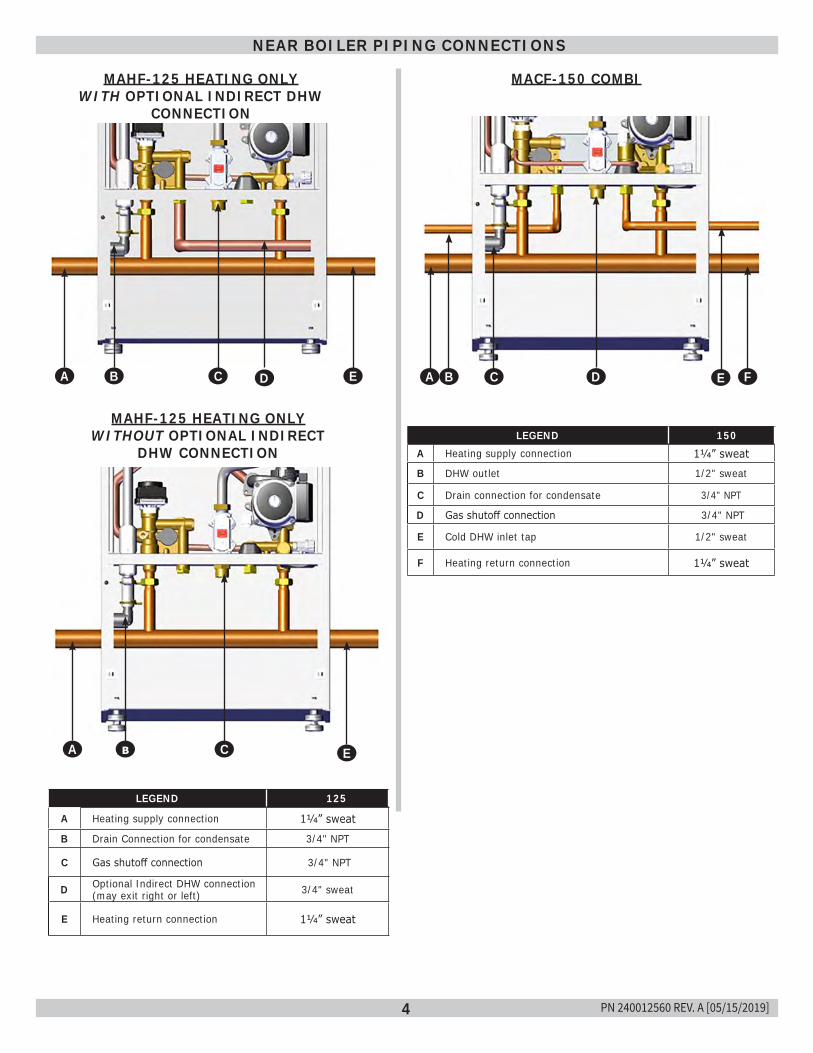
4
NEAR BOILER PIPING CONNECTIONS
LEGEND 125
A Heating supply connection 11/4” sweat
B Drain Connection for condensate 3/4" NPT
C Gas shutoff connection 3/4" NPT
D Optional Indirect DHW connection (may exit right or left) 3/4" sweat
E Heating return connection 11/4” sweat
MAHF-125 HEATING ONLY WITH OPTIONAL INDIRECT DHW
CONNECTION
MAHF-125 HEATING ONLY WITHOUT OPTIONAL INDIRECT
DHW CONNECTION
MACF-150 COMBI
LEGEND 150A Heating supply connection 11/4” sweat
B DHW outlet 1/2" sweat
C Drain connection for condensate 3/4" NPT
D Gas shutoff connection 3/4" NPT
E Cold DHW inlet tap 1/2" sweat
F Heating return connection 11/4” sweat
AE AB
AA
AA ADACAB AE
Ab AC AE
AA AC AD AF
PN 240012560 REV. A [05/15/2019]
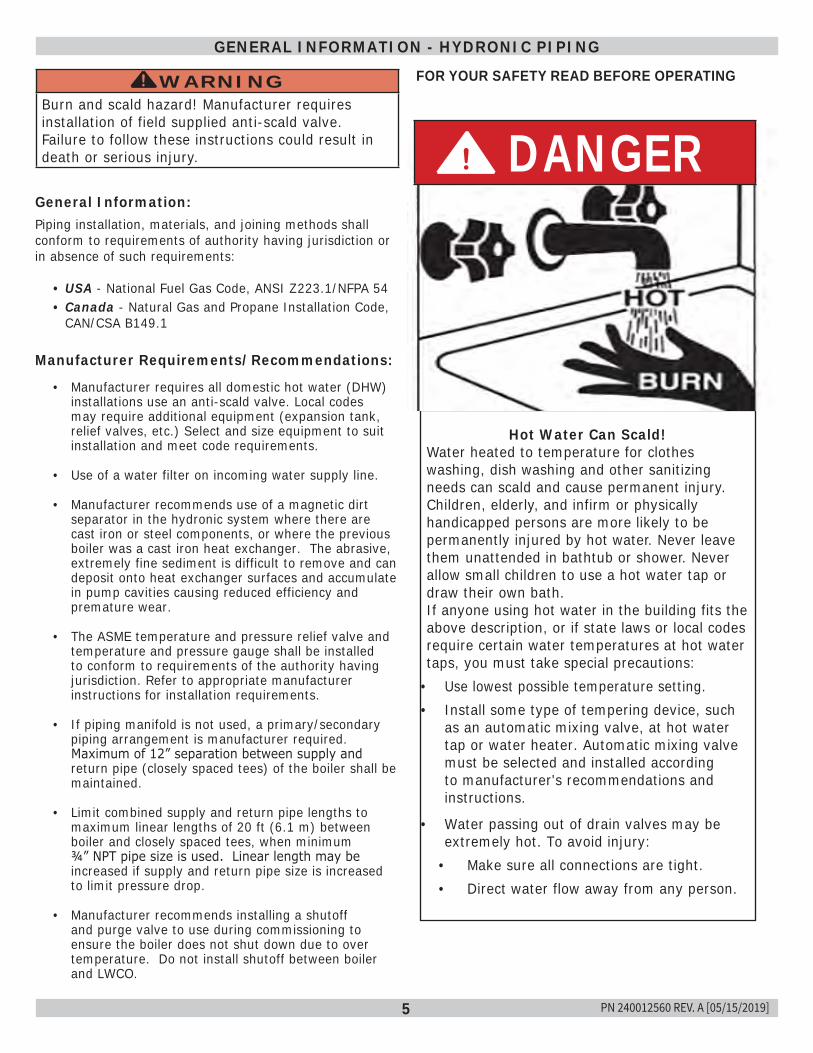
5
GENERAL INFORMATION - HYDRONIC PIPING
General Information:Piping installation, materials, and joining methods shall conform to requirements of authority having jurisdiction or in absence of such requirements:
• USA - National Fuel Gas Code, ANSI Z223.1/NFPA 54• Canada - Natural Gas and Propane Installation Code,
CAN/CSA B149.1
Manufacturer Requirements/Recommendations:
• Manufacturer requires all domestic hot water (DHW) installations use an anti-scald valve. Local codes may require additional equipment (expansion tank, relief valves, etc.) Select and size equipment to suit installation and meet code requirements.
• Use of a water filter on incoming water supply line.
• Manufacturer recommends use of a magnetic dirt separator in the hydronic system where there are cast iron or steel components, or where the previous boiler was a cast iron heat exchanger. The abrasive, extremely fine sediment is difficult to remove and can deposit onto heat exchanger surfaces and accumulate in pump cavities causing reduced efficiency and premature wear.
• The ASME temperature and pressure relief valve and temperature and pressure gauge shall be installed to conform to requirements of the authority having jurisdiction. Refer to appropriate manufacturer instructions for installation requirements.
• If piping manifold is not used, a primary/secondary piping arrangement is manufacturer required. Maximum of 12” separation between supply and return pipe (closely spaced tees) of the boiler shall be maintained.
• Limit combined supply and return pipe lengths to maximum linear lengths of 20 ft (6.1 m) between boiler and closely spaced tees, when minimum ¾” NPT pipe size is used. Linear length may be increased if supply and return pipe size is increased to limit pressure drop.
• Manufacturer recommends installing a shutoff and purge valve to use during commissioning to ensure the boiler does not shut down due to over temperature. Do not install shutoff between boiler and LWCO.
WARNINGBurn and scald hazard! Manufacturer requires installation of field supplied anti-scald valve. Failure to follow these instructions could result in death or serious injury.
! FOR YOUR SAFETY READ BEFORE OPERATING
Hot Water Can Scald!Water heated to temperature for clothes washing, dish washing and other sanitizing needs can scald and cause permanent injury.Children, elderly, and infirm or physically handicapped persons are more likely to be permanently injured by hot water. Never leave them unattended in bathtub or shower. Never allow small children to use a hot water tap or draw their own bath.If anyone using hot water in the building fits the above description, or if state laws or local codes require certain water temperatures at hot water taps, you must take special precautions:
• Use lowest possible temperature setting.• Install some type of tempering device, such
as an automatic mixing valve, at hot water tap or water heater. Automatic mixing valve must be selected and installed according to manufacturer's recommendations and instructions.
• Water passing out of drain valves may be extremely hot. To avoid injury:
• Make sure all connections are tight.• Direct water flow away from any person.
DANGER!
PN 240012560 REV. A [05/15/2019]
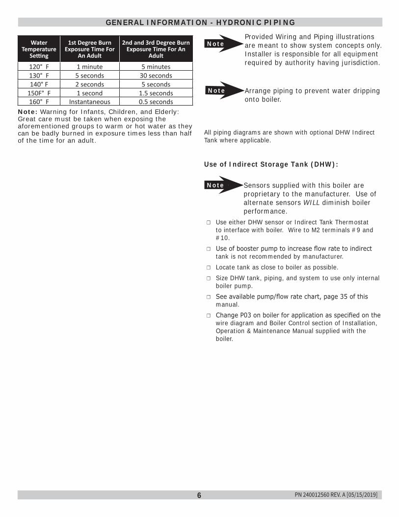
6
NoteProvided Wiring and Piping illustrations are meant to show system concepts only. Installer is responsible for all equipment required by authority having jurisdiction.
Note Arrange piping to prevent water dripping onto boiler.
All piping diagrams are shown with optional DHW Indirect Tank where applicable.
Use of Indirect Storage Tank (DHW):
Note Sensors supplied with this boiler are proprietary to the manufacturer. Use of alternate sensors WILL diminish boiler performance.
☐ Use either DHW sensor or Indirect Tank Thermostat to interface with boiler. Wire to M2 terminals #9 and #10.
☐ Use of booster pump to increase flow rate to indirect tank is not recommended by manufacturer.
☐ Locate tank as close to boiler as possible. ☐ Size DHW tank, piping, and system to use only internal
boiler pump. ☐ See available pump/flow rate chart, page 35 of this
manual. ☐ Change P03 on boiler for application as specified on the
wire diagram and Boiler Control section of Installation, Operation & Maintenance Manual supplied with the boiler.
GENERAL INFORMATION - HYDRONIC PIPING
Water Temperature
Setting
1st Degree Burn Exposure Time For
An Adult
2nd and 3rd Degree Burn Exposure Time For An
Adult
120° F 1 minute 5 minutes130° F 5 seconds 30 seconds140° F 2 seconds 5 seconds
150F° F 1 second 1.5 seconds160° F Instantaneous 0.5 seconds
Note: Warning for Infants, Children, and Elderly: Great care must be taken when exposing the aforementioned groups to warm or hot water as they can be badly burned in exposure times less than half of the time for an adult.
PN 240012560 REV. A [05/15/2019]
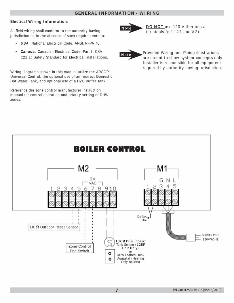
7
GENERAL INFORMATION - WIRING
Electical Wiring Information:
All field wiring shall conform to the authority having jurisdiction or, in the absence of such requirements to:
• USA: National Electrical Code, ANSI/NFPA 70,
• Canada: Canadian Electrical Code, Part I, CSA C22.1: Safety Standard for Electrical Installations.
Wiring diagrams shown in this manual utilize the ARGO™ Universal Control, the optional use of an Indirect Domestic Hot Water Tank, and optional use of a H2O Buffer Tank.
Reference the zone control manufacturer instruction manual for control operation and priority setting of DHW zones.
Note DO NOT use 120 V thermostat terminals (m1- #1 and #2).
Provided Wiring and Piping illustrations are meant to show system concepts only. Installer is responsible for all equipment required by authority having jurisdiction.
Note
SUPPLY Cord 120V/60HZ
BOILER CONTROL
10k Ω DHW Indirect Tank Sensor (125F
Unit Only)or
DHW Indirect Tank Aquastat (Heating
Only Boilers)
Do Not Use
1K Ω Outdoor Reset Sensor
Zone Control End Switch
PN 240012560 REV. A [05/15/2019]
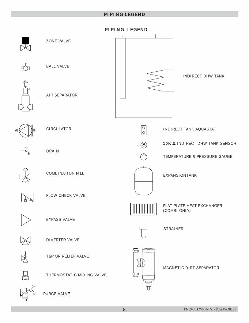
8
PIPING LEGEND
ZONE VALVE
BALL VALVE
AIR SEPARATOR
CIRCULATOR
DRAIN
COMBINATION FILL
FLOW CHECK VALVE
BYPASS VALVE
DIVERTER VALVE
T&P OR RELIEF VALVE
THERMOSTATIC MIXING VALVE
INDIRECT DHW TANK
INDIRECT TANK AQUASTAT
10K Ω INDIRECT DHW TANK SENSOR
TEMPERATURE & PRESSURE GAUGE
EXPANSION TANK
FLAT PLATE HEAT EXCHANGER (COMBI ONLY)
STRAINER
PIPING LEGEND
PURGE VALVE
MAGNETIC DIRT SEPARATOR
PN 240012560 REV. A [05/15/2019]
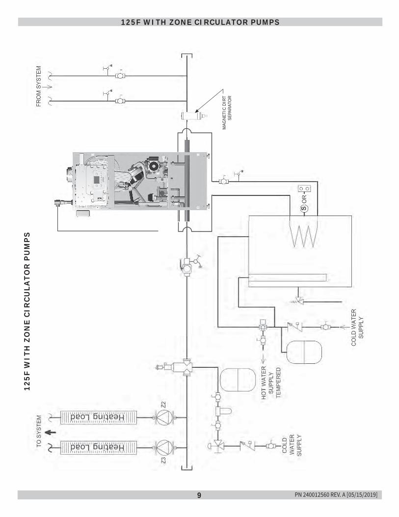
9
125F WITH ZONE CIRCULATOR PUMPS12
5F W
ITH
ZO
NE
CIR
CULA
TOR
PU
MP
S
MAG
NETI
C D
IRT
SEPA
RATO
R
PN 240012560 REV. A [05/15/2019]
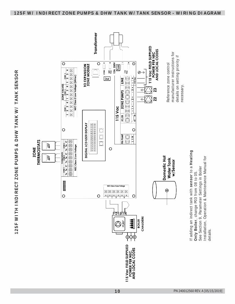
10
125F W/ INDIRECT ZONE PUMPS & DHW TANK W/TANK SENSOR - WIRING DIAGRAM
If a
ddin
g an
indi
rect
tank
with
sen
sor
to a
Hea
ting
O
nly
Boile
r, c
hang
e P0
3 fr
om 0
8 to
05.
See
Sect
ion
9, P
aram
eter
Set
tings
in B
oile
r In
stal
latio
n, O
pera
tion
& M
aint
enan
ce M
anua
l for
de
tails
.
Refe
renc
e zo
ne c
ontr
ol
man
ufac
ture
r in
stru
ctio
ns fo
r de
tails
on
sett
ing
prio
rity
if ne
cess
ary.
125F
WIT
H I
ND
IREC
T ZO
NE
PU
MP
S &
DH
W T
AN
K W
/ TA
NK
SEN
SOR
PN 240012560 REV. A [05/15/2019]
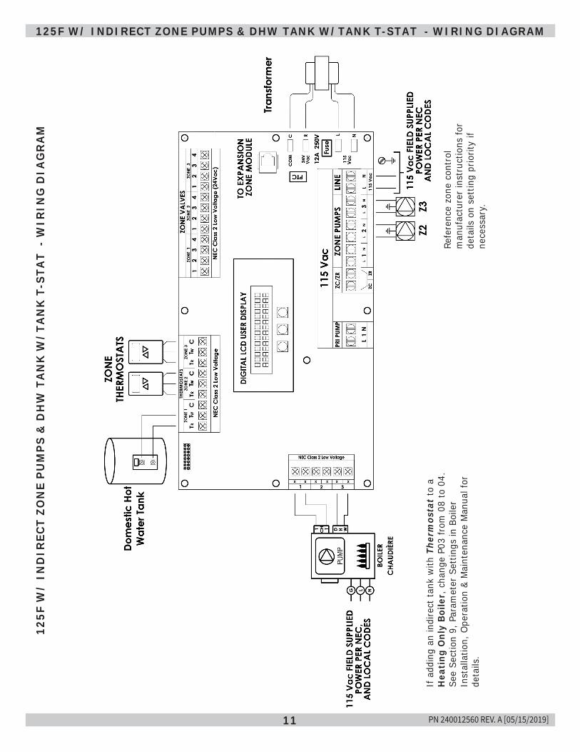
11
125F W/ INDIRECT ZONE PUMPS & DHW TANK W/TANK T-STAT - WIRING DIAGRAM12
5F W
/ IN
DIR
ECT
ZON
E P
UM
PS
& D
HW
TA
NK
W/T
AN
K T
-STA
T -
WIR
ING
DIA
GR
AM
Refe
renc
e zo
ne c
ontr
ol
man
ufac
ture
r in
stru
ctio
ns fo
r de
tails
on
sett
ing
prio
rity
if ne
cess
ary.
If a
ddin
g an
indi
rect
tank
with
The
rmos
tat
to a
H
eati
ng O
nly
Boile
r, c
hang
e P0
3 fr
om 0
8 to
04.
See
Sect
ion
9, P
aram
eter
Set
tings
in B
oile
r In
stal
latio
n, O
pera
tion
& M
aint
enan
ce M
anua
l for
de
tails
.
PN 240012560 REV. A [05/15/2019]
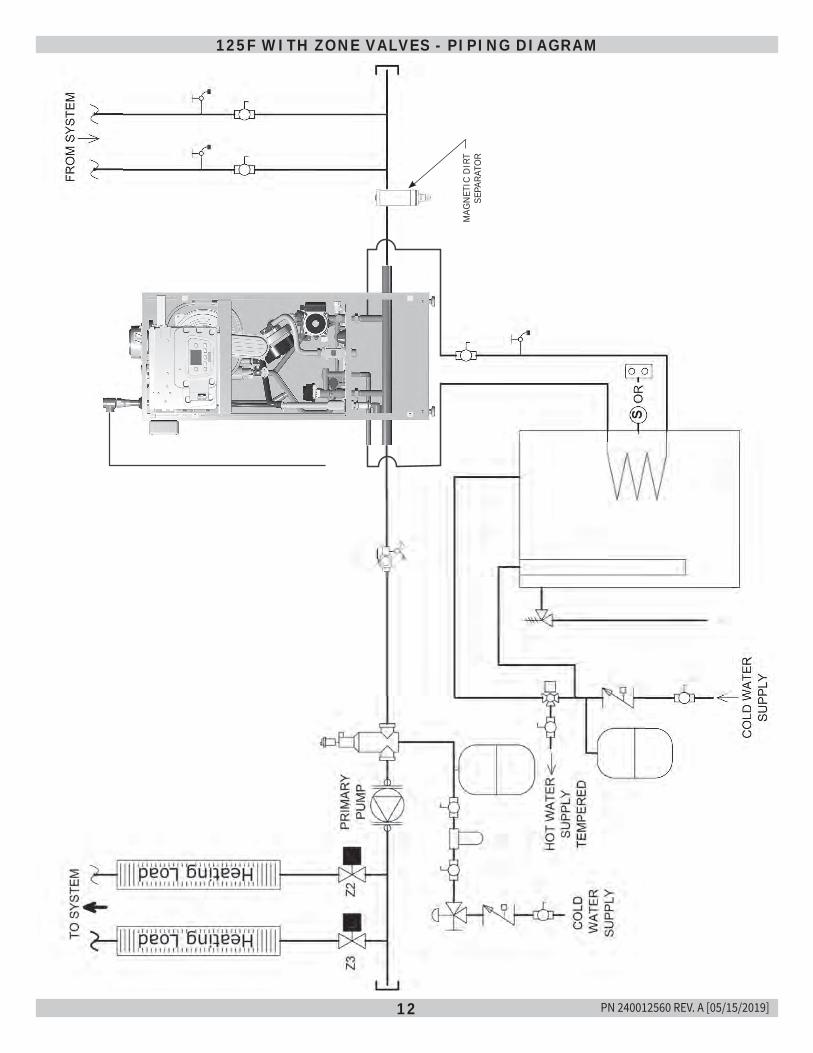
12
125F WITH ZONE VALVES - PIPING DIAGRAM
125F WITH ZONE VALVES
MAG
NETI
C D
IRT
SEPA
RATO
R
PN 240012560 REV. A [05/15/2019]
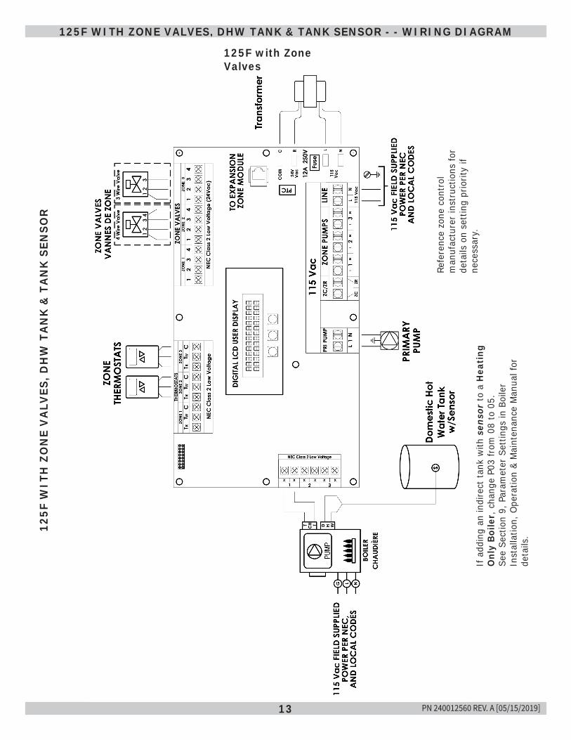
13
125F WITH ZONE VALVES, DHW TANK & TANK SENSOR - - WIRING DIAGRAM
125F with Zone Valves
125F
WIT
H Z
ON
E V
ALV
ES, D
HW
TA
NK
& T
AN
K S
ENSO
R
If a
ddin
g an
indi
rect
tank
with
sen
sor
to a
Hea
ting
O
nly
Boile
r, c
hang
e P0
3 fr
om 0
8 to
05.
See
Sect
ion
9, P
aram
eter
Set
tings
in B
oile
r In
stal
latio
n, O
pera
tion
& M
aint
enan
ce M
anua
l for
de
tails
.
Refe
renc
e zo
ne c
ontr
ol
man
ufac
ture
r in
stru
ctio
ns fo
r de
tails
on
sett
ing
prio
rity
if ne
cess
ary.
PN 240012560 REV. A [05/15/2019]
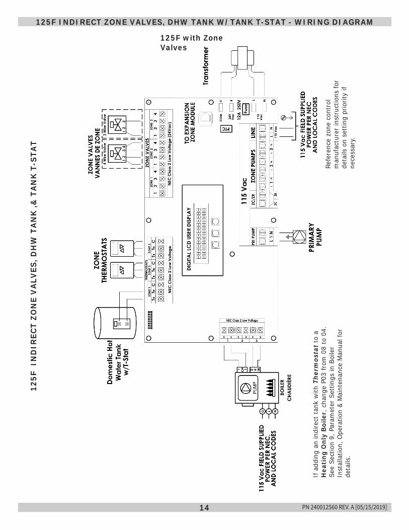
14
125F with Zone Valves
125F INDIRECT ZONE VALVES, DHW TANK W/TANK T-STAT - WIRING DIAGRAM12
5F I
ND
IREC
T ZO
NE
VA
LVES
, DH
W T
AN
K ,&
TA
NK
T-S
TAT
Refe
renc
e zo
ne c
ontr
ol
man
ufac
ture
r in
stru
ctio
ns fo
r de
tails
on
sett
ing
prio
rity
if ne
cess
ary.
If a
ddin
g an
indi
rect
tank
with
The
rmos
tat
to a
H
eati
ng O
nly
Boile
r, c
hang
e P0
3 fr
om 0
8 to
04.
See
Sect
ion
9, P
aram
eter
Set
tings
in B
oile
r In
stal
latio
n, O
pera
tion
& M
aint
enan
ce M
anua
l for
de
tails
.
PN 240012560 REV. A [05/15/2019]
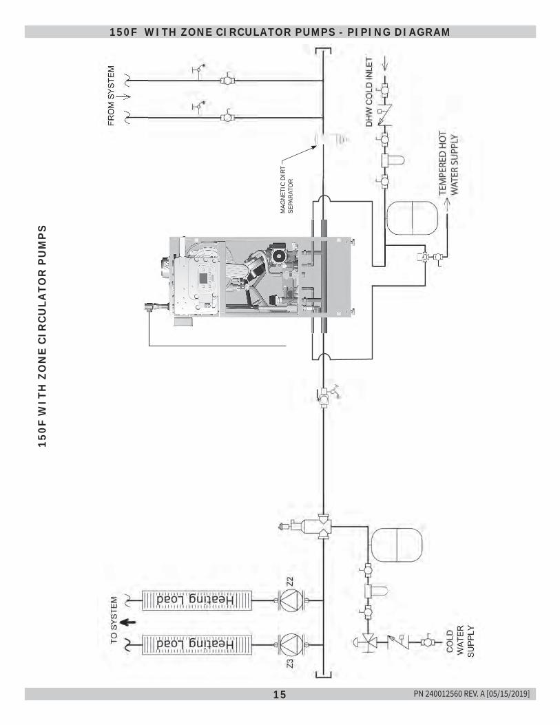
15
150F
WIT
H Z
ON
E CI
RCU
LATO
R P
UM
PS
150F WITH ZONE CIRCULATOR PUMPS - PIPING DIAGRAM
MAG
NETI
C D
IRT
SEPA
RATO
R
PN 240012560 REV. A [05/15/2019]
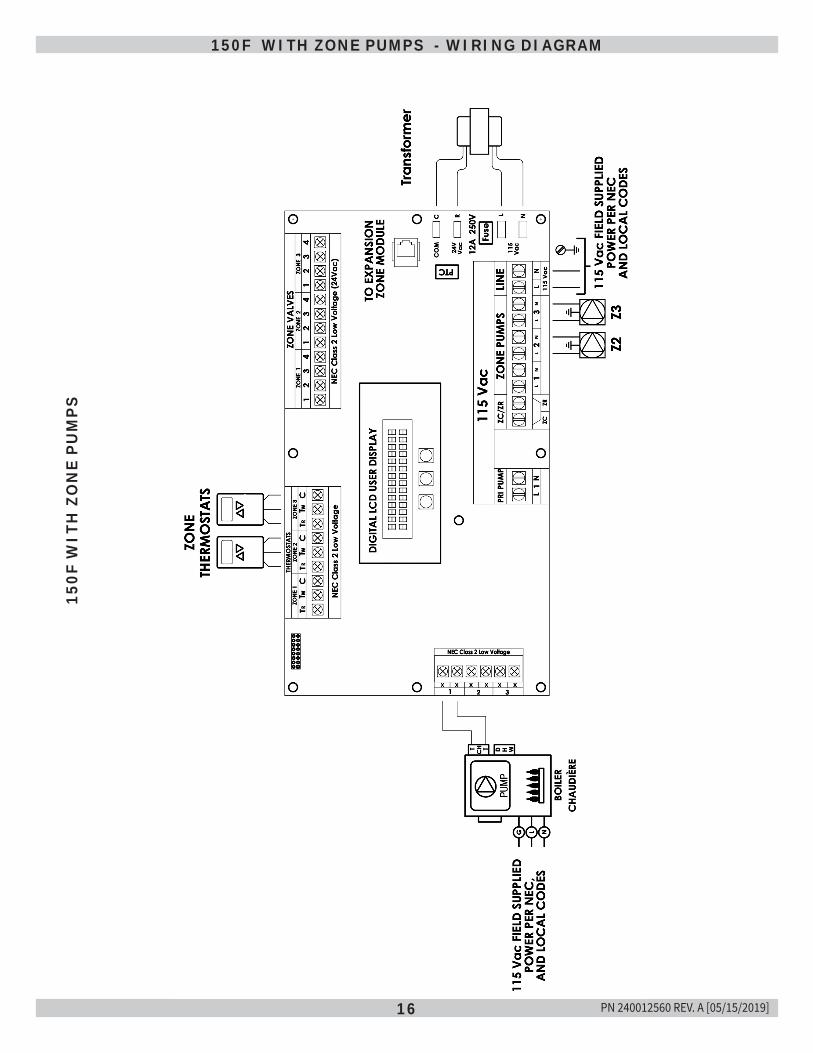
16
150F WITH ZONE PUMPS - WIRING DIAGRAM15
0F W
ITH
ZO
NE
PU
MP
S
PN 240012560 REV. A [05/15/2019]
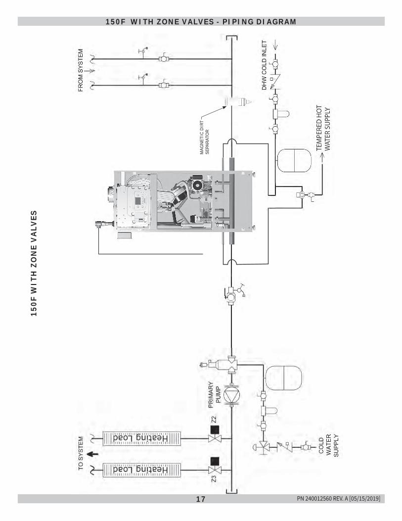
17
150F
WIT
H Z
ON
E V
ALV
ES150F WITH ZONE VALVES - PIPING DIAGRAM
MAG
NETI
C D
IRT
SEPA
RATO
R
PN 240012560 REV. A [05/15/2019]
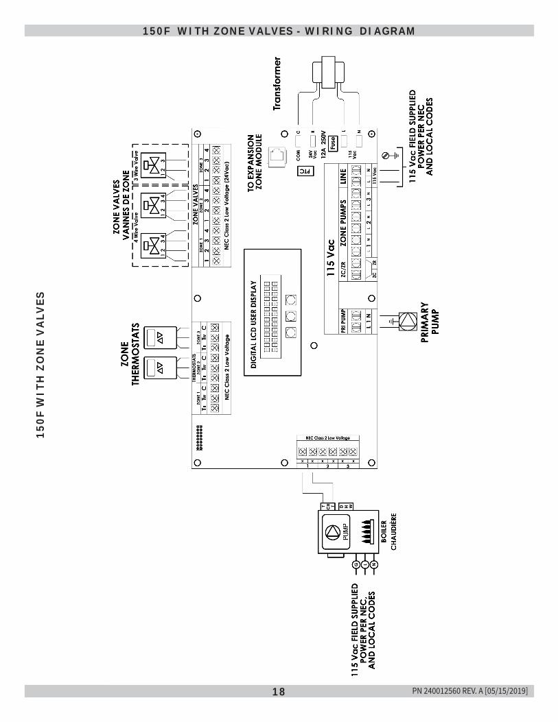
18
150F WITH ZONE VALVES - WIRING DIAGRAM15
0F W
ITH
ZO
NE
VA
LVES
PN 240012560 REV. A [05/15/2019]
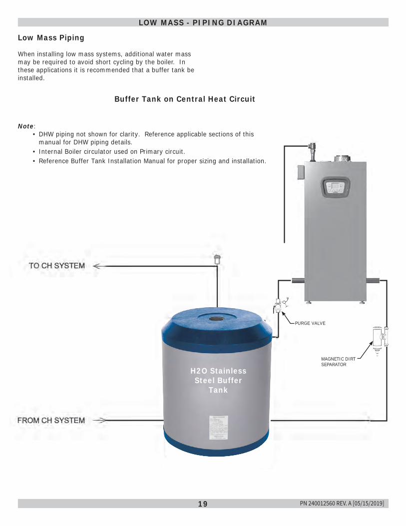
19
LOW MASS - PIPING DIAGRAM
Low Mass Piping
When installing low mass systems, additional water mass may be required to avoid short cycling by the boiler. In these applications it is recommended that a buffer tank be installed.
Note: • DHW piping not shown for clarity. Reference applicable sections of this
manual for DHW piping details.• Internal Boiler circulator used on Primary circuit.• Reference Buffer Tank Installation Manual for proper sizing and installation.
Buffer Tank on Central Heat Circuit
H2O Stainless Steel Buffer
Tank
MAGNETIC DIRT SEPARATOR
PURGE VALVE
PN 240012560 REV. A [05/15/2019]
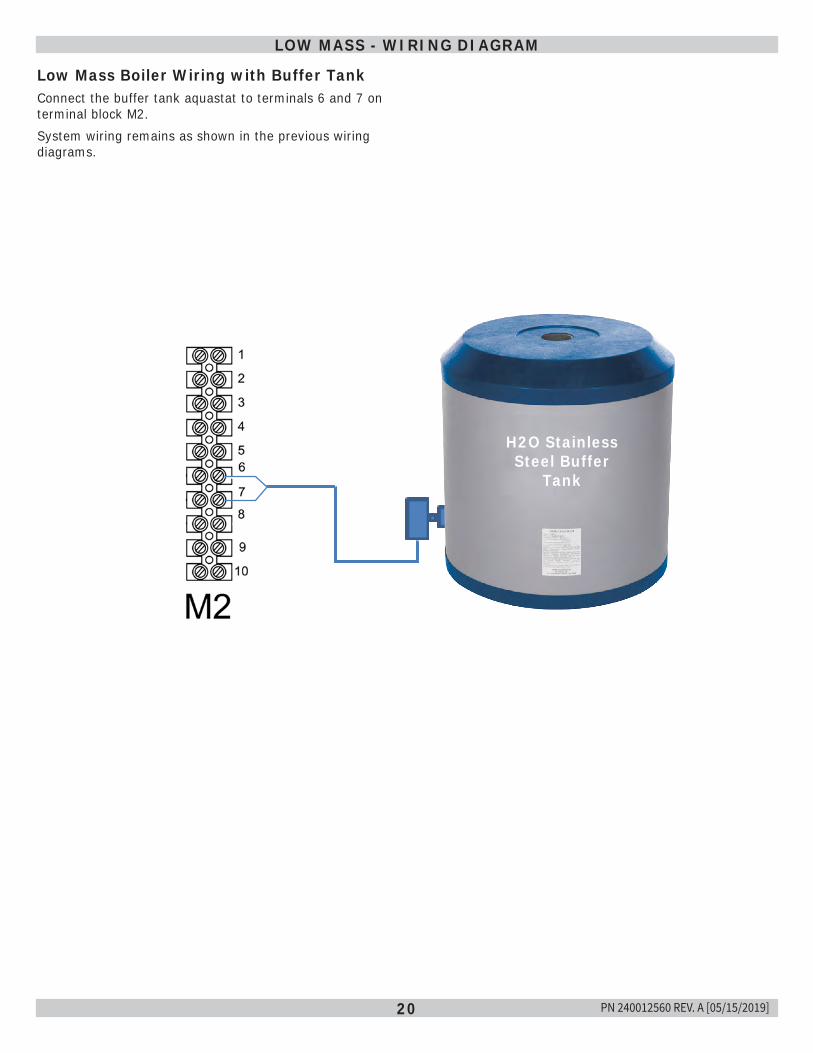
20
LOW MASS - WIRING DIAGRAM
Low Mass Boiler Wiring with Buffer TankConnect the buffer tank aquastat to terminals 6 and 7 on terminal block M2. System wiring remains as shown in the previous wiring diagrams.
H20 BUFFER TANKH2O Stainless
Steel Buffer Tank
PN 240012560 REV. A [05/15/2019]
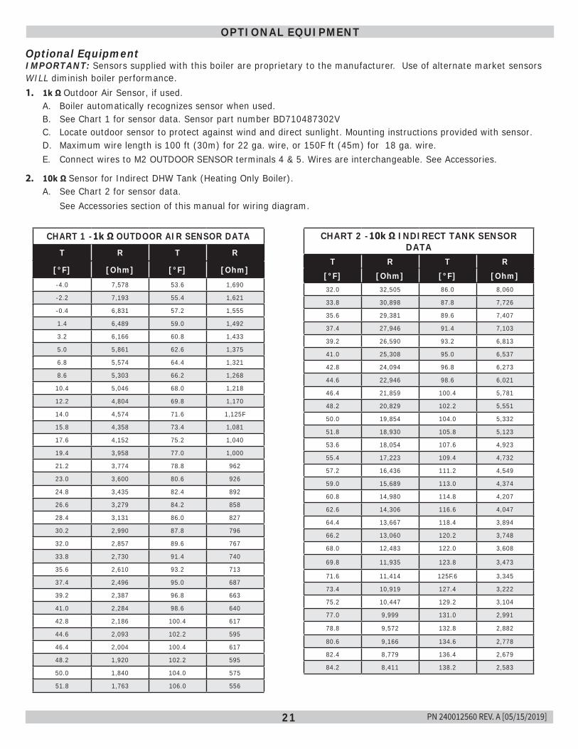
21
OPTIONAL EQUIPMENT
Optional EquipmentIMPORTANT: Sensors supplied with this boiler are proprietary to the manufacturer. Use of alternate market sensors WILL diminish boiler performance.1. 1k Ω Outdoor Air Sensor, if used.
A. Boiler automatically recognizes sensor when used.B. See Chart 1 for sensor data. Sensor part number BD710487302VC. Locate outdoor sensor to protect against wind and direct sunlight. Mounting instructions provided with sensor.D. Maximum wire length is 100 ft (30m) for 22 ga. wire, or 150F ft (45m) for 18 ga. wire.E. Connect wires to M2 OUTDOOR SENSOR terminals 4 & 5. Wires are interchangeable. See Accessories.
2. 10k Ω Sensor for Indirect DHW Tank (Heating Only Boiler).A. See Chart 2 for sensor data.
See Accessories section of this manual for wiring diagram.
CHART 1 -1k Ω OUTDOOR AIR SENSOR DATAT R T R
[°F] [Ohm] [°F] [Ohm]-4.0 7,578 53.6 1,690
-2.2 7,193 55.4 1,621
-0.4 6,831 57.2 1,555
1.4 6,489 59.0 1,492
3.2 6,166 60.8 1,433
5.0 5,861 62.6 1,375
6.8 5,574 64.4 1,321
8.6 5,303 66.2 1,268
10.4 5,046 68.0 1,218
12.2 4,804 69.8 1,170
14.0 4,574 71.6 1,125F
15.8 4,358 73.4 1,081
17.6 4,152 75.2 1,040
19.4 3,958 77.0 1,000
21.2 3,774 78.8 962
23.0 3,600 80.6 926
24.8 3,435 82.4 892
26.6 3,279 84.2 858
28.4 3,131 86.0 827
30.2 2,990 87.8 796
32.0 2,857 89.6 767
33.8 2,730 91.4 740
35.6 2,610 93.2 713
37.4 2,496 95.0 687
39.2 2,387 96.8 663
41.0 2,284 98.6 640
42.8 2,186 100.4 617
44.6 2,093 102.2 595
46.4 2,004 100.4 617
48.2 1,920 102.2 595
50.0 1,840 104.0 575
51.8 1,763 106.0 556
CHART 2 -10k Ω INDIRECT TANK SENSOR DATA
T R T R[°F] [Ohm] [°F] [Ohm]32.0 32,505 86.0 8,060
33.8 30,898 87.8 7,726
35.6 29,381 89.6 7,407
37.4 27,946 91.4 7,103
39.2 26,590 93.2 6,813
41.0 25,308 95.0 6,537
42.8 24,094 96.8 6,273
44.6 22,946 98.6 6,021
46.4 21,859 100.4 5,781
48.2 20,829 102.2 5,551
50.0 19,854 104.0 5,332
51.8 18,930 105.8 5,123
53.6 18,054 107.6 4,923
55.4 17,223 109.4 4,732
57.2 16,436 111.2 4,549
59.0 15,689 113.0 4,374
60.8 14,980 114.8 4,207
62.6 14,306 116.6 4,047
64.4 13,667 118.4 3,894
66.2 13,060 120.2 3,748
68.0 12,483 122.0 3,608
69.8 11,935 123.8 3,473
71.6 11,414 125F.6 3,345
73.4 10,919 127.4 3,222
75.2 10,447 129.2 3,104
77.0 9,999 131.0 2,991
78.8 9,572 132.8 2,882
80.6 9,166 134.6 2,778
82.4 8,779 136.4 2,679
84.2 8,411 138.2 2,583
PN 240012560 REV. A [05/15/2019]
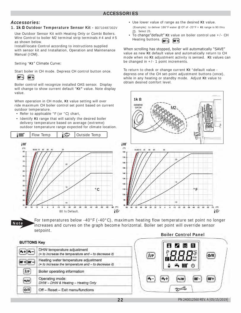
22
Accessories:
ACCESSORIES
1. 1k Ω Outdoor Temperature Sensor Kit - BD710487302V
Use Outdoor Sensor Kit with Heating Only or Combi Boilers. Wire Control to boiler M2 terminal strip terminals #4 and #5 as shown below.Install/locate Control according to instructions supplied with sensor kit and Installation, Operation and Maintenance Manual (IOM).
Setting “Kt” Climate Curve:
Start boiler in CH mode. Depress CH control button once.
Boiler control will recognize installed OAS sensor. Display will change to show current default “Kt” value. Note display value.
When operation in CH mode, Kt value setting will over ride maximum CH boiler control set point based on current outdoor temperature.• Refer to applicable °F (or °C) chart,• Identify Kt range that will satisfy the desired boiler
delivery temperature based on average (extreme) outdoor temperature range expected for climate location.
Flow Temp Outside Temp
Boiler Control Panel
NoteFor temperatures below -40°F (-40°C), maximum heating flow temperature set point no longer increases and curves on the graph become horizontal. Boiler set point will override sensor setpoint.
°F°C
• Use lower value of range as the desired Kt value. (Example): to deliver 186°F water @ OT of -20°F = Kt range is 90 thru 25. Select 25.
• To change”default” Kt value on boiler control use +/- CH Heating buttons.
When scrolling has stopped, boiler will automatically “SAVE” value as new Kt default value and automatically return to CH mode when no Kt adjustment activity is sensed. Kt values can be changed in +/- 1 point increments.
To return to check or change current Kt “default value - depress one of the CH set-point adjustment buttons (once), while in any heating or standby mode. Adjust Kt value to obtain desired comfort level.
80 Is Default.
1k Ω
PN 240012560 REV. A [05/15/2019]
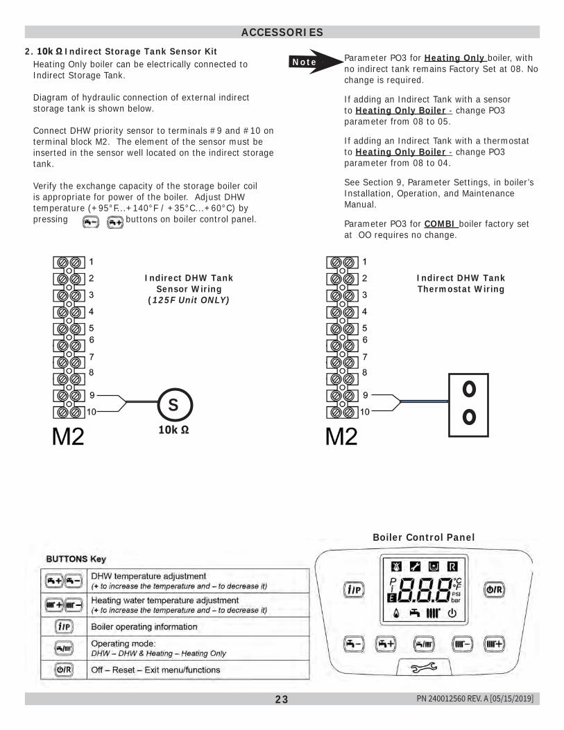
23
ACCESSORIES2. 10k Ω Indirect Storage Tank Sensor Kit
Heating Only boiler can be electrically connected to Indirect Storage Tank.
Diagram of hydraulic connection of external indirect storage tank is shown below.
Connect DHW priority sensor to terminals #9 and #10 on terminal block M2. The element of the sensor must be inserted in the sensor well located on the indirect storage tank.
Verify the exchange capacity of the storage boiler coil is appropriate for power of the boiler. Adjust DHW temperature (+95°F...+140°F / +35°C...+60°C) by pressing buttons on boiler control panel.
Boiler Control Panel
Note Parameter PO3 for Heating Only boiler, with no indirect tank remains Factory Set at 08. No change is required.
If adding an Indirect Tank with a sensor to Heating Only Boiler - change PO3 parameter from 08 to 05.
If adding an Indirect Tank with a thermostat to Heating Only Boiler - change PO3 parameter from 08 to 04.
See Section 9, Parameter Settings, in boiler’s Installation, Operation, and Maintenance Manual.
Parameter PO3 for COMBI boiler factory set at OO requires no change.
S
Indirect DHW Tank Sensor Wiring
(125F Unit ONLY)
Indirect DHW Tank Thermostat Wiring
10k Ω
PN 240012560 REV. A [05/15/2019]
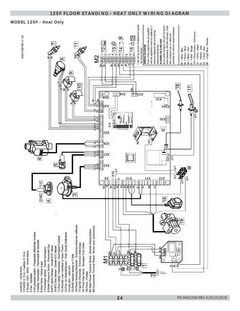
24
MODEL 125F - Heat Only
125F FLOOR STANDING - HEAT ONLY WIRING DIAGRAM
PN 240012560 REV. A [05/15/2019]
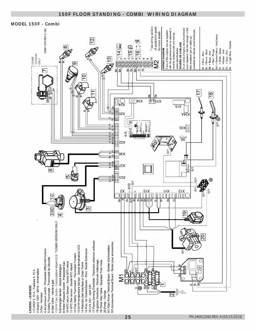
25
MODEL 150F - Combi
150F FLOOR STANDING - COMBI WIRING DIAGRAM
PN 240012560 REV. A [05/15/2019]
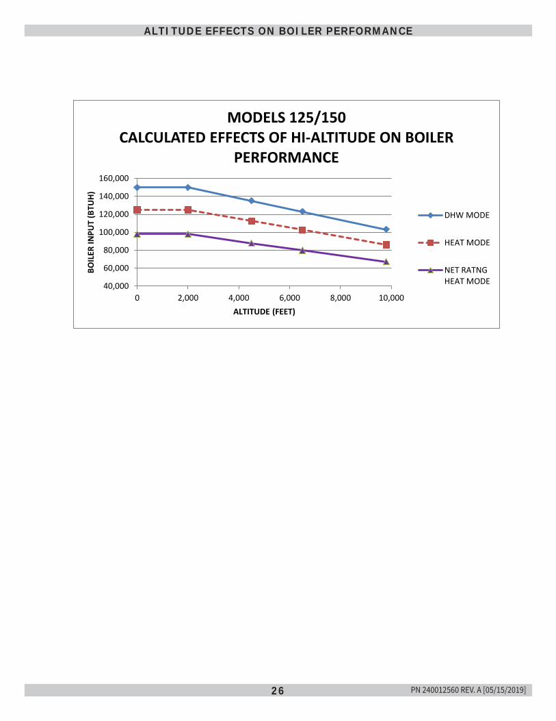
26
ALTITUDE EFFECTS ON BOILER PERFORMANCE
40,000
60,000
80,000
100,000
120,000
140,000
160,000
0 2,000 4,000 6,000 8,000 10,000
BOIL
ER IN
PUT
(BTU
H)
ALTITUDE (FEET)
MODELS 125/150 CALCULATED EFFECTS OF HI-ALTITUDE ON BOILER
PERFORMANCE
DHW MODE
HEAT MODE
NET RATNGHEAT MODE
60,00080,000
100,000120,000140,000160,000180,000200,000220,000
0 2,000 4,000 6,000 8,000 10,000
BOIL
ER IN
PUT
(BTU
H)
ALTITUDE (FEET)
MODELS 165/205 CALCULATED EFFECTS OF HI-ALTITUDE ON BOILER
PERFORMANCE
DHW MODE
HEAT MODE
NET RATNGHEAT MODE
PN 240012560 REV. A [05/15/2019]
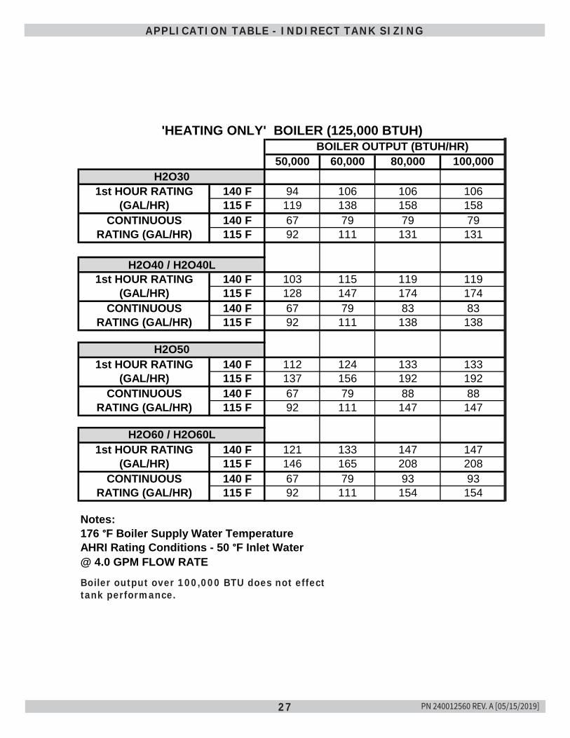
27
APPLICATION TABLE - INDIRECT TANK SIZING
BOILER OUTPUT (BTUH/HR)50,000 60,000 80,000 100,000
140 F 94 106 106 106115 F 119 138 158 158140 F 67 79 79 79115 F 92 111 131 131
H2O40 / H2O40L140 F 103 115 119 119115 F 128 147 174 174140 F 67 79 83 83115 F 92 111 138 138
H2O50140 F 112 124 133 133115 F 137 156 192 192140 F 67 79 88 88115 F 92 111 147 147
140 F 121 133 147 147115 F 146 165 208 208140 F 67 79 93 93115 F 92 111 154 154
Notes:176 °F Boiler Supply Water TemperatureAHRI Rating Conditions - 50 °F Inlet Water@ 4.0 GPM FLOW RATE
1st HOUR RATING(GAL/HR)
CONTINUOUSRATING (GAL/HR)
H2O60 / H2O60L1st HOUR RATING
(GAL/HR)CONTINUOUS
RATING (GAL/HR)
1st HOUR RATING(GAL/HR)
CONTINUOUSRATING (GAL/HR)
'HEATING ONLY' BOILER (125,000 BTUH)
H2O301st HOUR RATING
(GAL/HR)CONTINUOUS
RATING (GAL/HR)
Boiler output over 100,000 BTU does not effect tank performance.
PN 240012560 REV. A [05/15/2019]
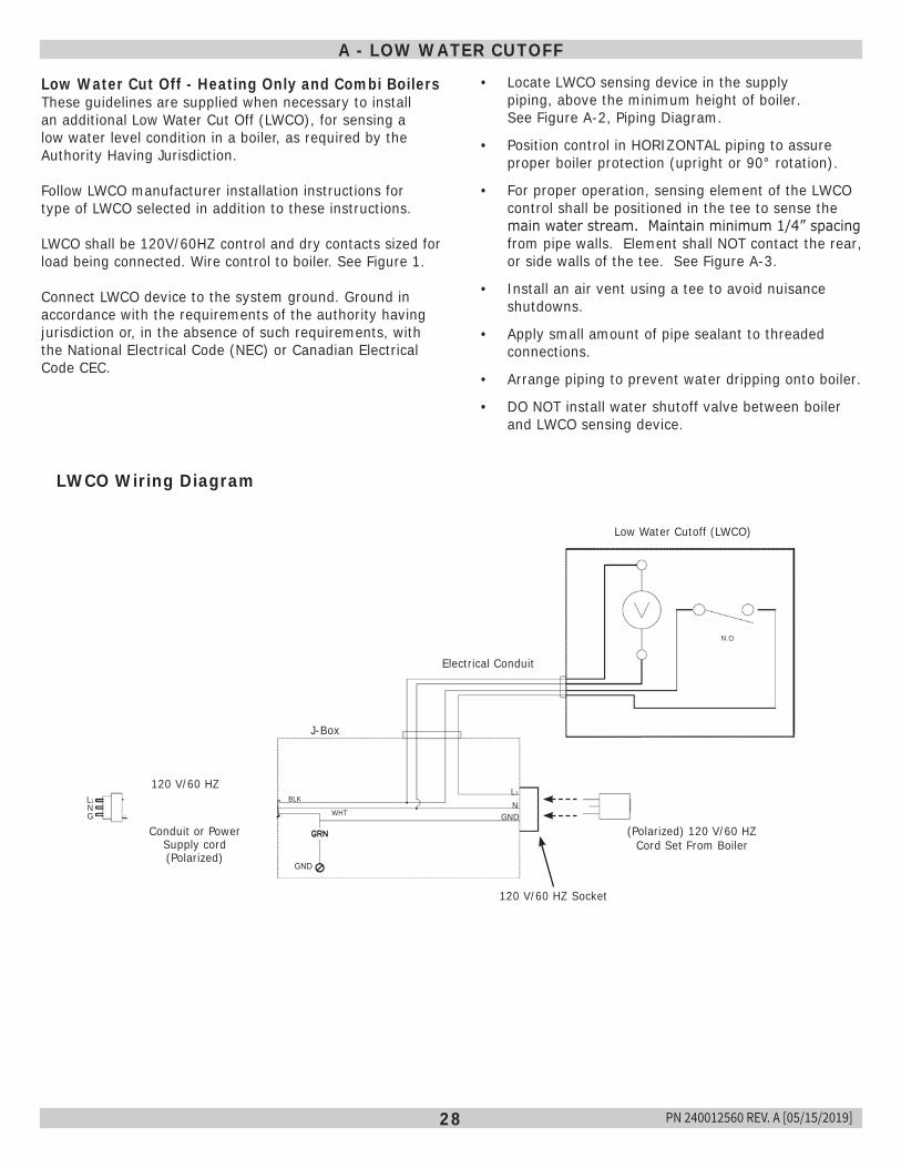
28
A - LOW WATER CUTOFF
Low Water Cut Off - Heating Only and Combi BoilersThese guidelines are supplied when necessary to install an additional Low Water Cut Off (LWCO), for sensing a low water level condition in a boiler, as required by the Authority Having Jurisdiction.
Follow LWCO manufacturer installation instructions for type of LWCO selected in addition to these instructions.
LWCO shall be 120V/60HZ control and dry contacts sized for load being connected. Wire control to boiler. See Figure 1.
Connect LWCO device to the system ground. Ground in accordance with the requirements of the authority having jurisdiction or, in the absence of such requirements, with the National Electrical Code (NEC) or Canadian Electrical Code CEC.
LWCO Wiring Diagram
Low Water Cutoff (LWCO)
Electrical Conduit
J-Box
120 V/60 HZ
Conduit or Power Supply cord (Polarized)
L1NG
GND
L1
NGND
BLK
WHT
120 V/60 HZ Socket
(Polarized) 120 V/60 HZ Cord Set From Boiler
N.O
• Locate LWCO sensing device in the supply piping, above the minimum height of boiler. See Figure A-2, Piping Diagram.
• Position control in HORIZONTAL piping to assure proper boiler protection (upright or 90° rotation).
• For proper operation, sensing element of the LWCO control shall be positioned in the tee to sense the main water stream. Maintain minimum 1/4” spacing from pipe walls. Element shall NOT contact the rear, or side walls of the tee. See Figure A-3.
• Install an air vent using a tee to avoid nuisance shutdowns.
• Apply small amount of pipe sealant to threaded connections.
• Arrange piping to prevent water dripping onto boiler.
• DO NOT install water shutoff valve between boiler and LWCO sensing device.
PN 240012560 REV. A [05/15/2019]
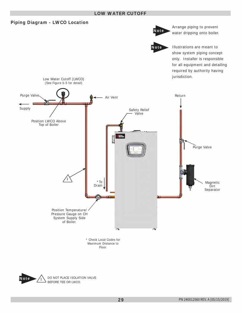
29
Piping Diagram - LWCO Location
LOW WATER CUTOFF
Low Water Cutoff (LWCO)(See Figure 6-5 for detail)
Air Vent
Supply Safety Relief Valve
Position LWCO Above Top of Boiler
1 DO NOT PLACE ISOLATION VALVE BEFORE TEE OR LWCO.
Note
*To Drain
* Check Local Codes for Maximum Distance to
Floor.
Arrange piping to prevent water dripping onto boiler.
1
Return
Purge Valve
Magnetic Dirt
Separator
Position Temperature/Pressure Gauge on CH System Supply Side
of Boiler.
Purge Valve
Note
Illustrations are meant to show system piping concept only. Installer is responsible for all equipment and detailing required by authority having jurisdiction.
Note
PN 240012560 REV. A [05/15/2019]
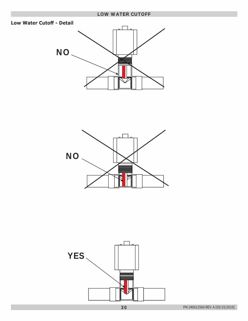
30
Low Water Cutoff - Detail
LOW WATER CUTOFF
NO
NO
YES
PN 240012560 REV. A [05/15/2019]
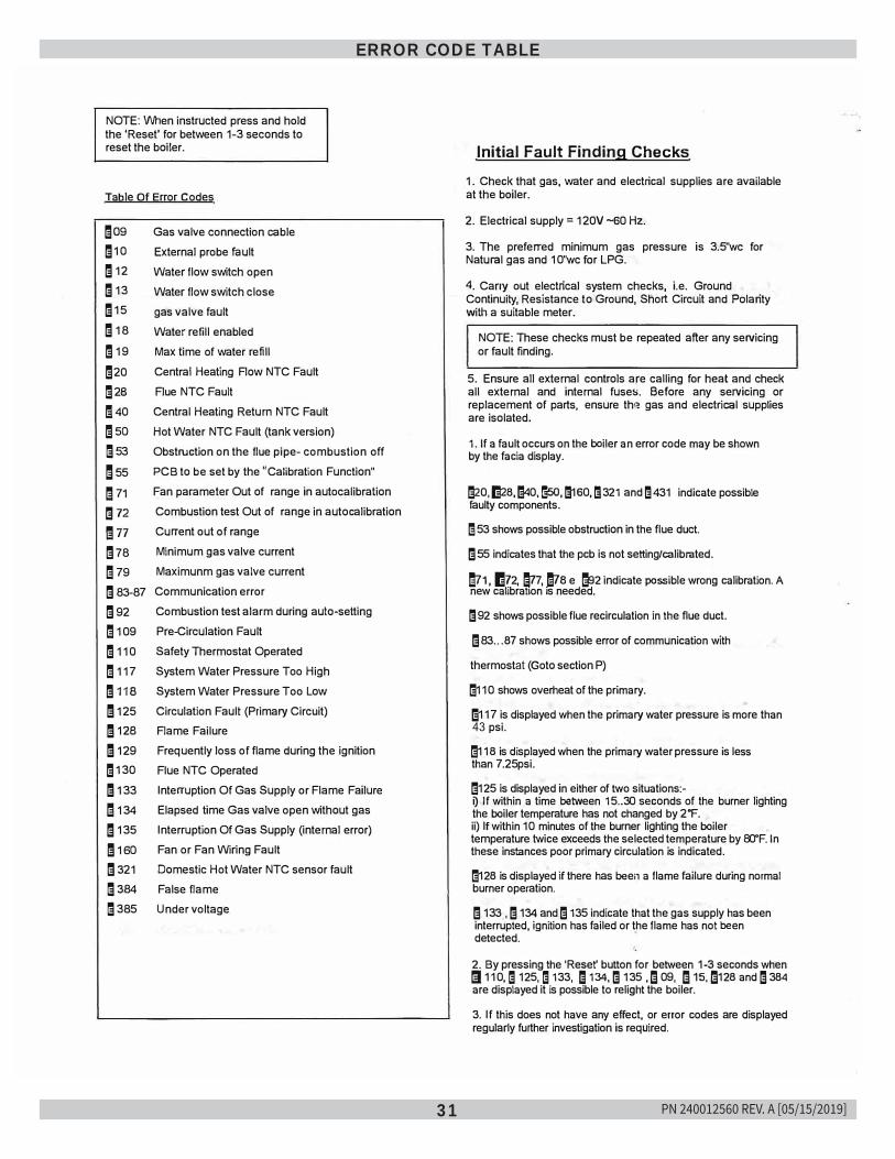
31
ERROR CODE TABLE
NOTE: When instructed press and hold the 'Reset' for between 1-3 seconds to reset the boiler.
Table Of Error Codes
mag m10 m12 m13 m15 m 18
m 19
m20 ;20
!40m5o ;53
m55
m 71
m72
mn !;78
m 79 !;83-87 !;92
m 109 m110
m 117 m11s m 125 m 120 m 129 m130 m 133
m 134 m135 m 1so !;321 ;384 ;385
Gas valve connection cable External probe fault Water flow switch open Water flow switch close gas valve fault Water refill enabled Max lime of water refill Central Heating Flow NTC Fault Flue NTC Fault Central Heating Return NTC Fault Hot Water NTC Fault (tank version) Obstruction on the flue pipe- combustion offPCB to be set by the "Calibration Function" Fan parameler Out of range in autocalibralion Combustion test Out of range in autocalibration Current out of range Minimum gas valve current Maximunm gas valve current Communication error Combustion test alarm during auto-setting Pre-Circulation Fault Safety Thermostat Operated System Water Pressure Too High System Water Pressure Too Low Circulation Faull (Primary Circuit) Flame Failure Frequently loss of flame during the ignition Flue NTC Operated Interruption Of Gas Supply or Flame Failure Elapsed time Gas valve open without gas Interruption Of Gas Supply (internal error) Fan or Fan Wiring Fault Domestic Hot Water NTC sensor fault False flame Under voltage
Initial Fault Finding Checks
1. Check that gas, water and electrical supplies are available at the boiler.
2. Electrical supply= 120V -60 Hz.
3. The preferred minimum gas pressure is 3.5"wc for Natural gas and 10"wc for LPG.
4. Carry out electrical system checks, i.e. Ground Continuity, Resistance to Ground, Short Circuit and Polaritywilh"a suitable meter.
NOTE: These checks must be repeated after any servicing or fault finding.
5. Ensure all external controls are calling for heat and check all external and internal fuses. Before any servicing or replacement of parts, ensure th� gas and electrical supplies are isolated.
1. If a fault occurs on the boiler an error code may be shownby the facia display.
!;20, fs28, !;40, !;5o, 1!1160, 1!1321 and 1!1431 indicate possible faulty components.
l!l 53 shows possible obstruction in the flue duct.
I; 55 indicates that the pcb is not setting/calibrated.
1!71, 1!72, �7, !;?a e tl2 indicate possible wrong calibration. A new calibration is needed.
1!192 shows possible flue recirculation in the flue duct.
I; 83 ... 87 shows possible error of communication with
thermostat (Goto section P)
!;110 shows overheat of the primary.
1!1117 is displayed when the primary water pressure is more than 43 psi.
!;118 is displayed when the primary water pressure is less than 7.25psi.
!;125 is displayed in either of two situations:-0 If within a time between 15 .. 30 seconds of the burner lighting the boiler temperature has not changed by 2 •F. ii) If within 10 minutes of the burner lighting the boilertemperature twice exceeds the selected temperature by 80°F. Inthese instances poor primary circulation is indicated.
!;128 is displayed if there has been a flame failure during normal burner operation.
I; 133 , I; 134 and I; 135 indicate that the gas supply has been interrupted, ignition has failed or the flame has not been detected.
2. By pressing the 'Reset' button for between 1-3 seconds when ti 110,l!I 125, l!I 133, m 134,I; 135 ,'3 09, '3 1s,'3128 andl3384 are displayed it is possible to relight the boiler.
3. If this does not have any effect, or error codes are displayed regularly further investigation is required.
PN 240012560 REV. A [05/15/2019]
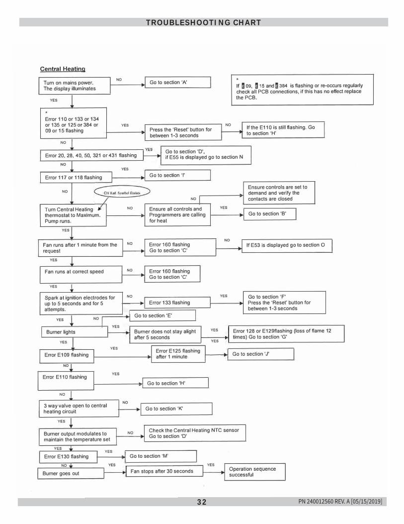
32
TROUBLESHOOTING CHART
Central Heating
Turn on mains power. The display illuminates
NO Go to section 'A'
YES
Error 11 O or 133 or 134 or 135 or 125 or 384 or 09 or 15 flashing
NO
YES Press the 'Reset' button for between 1-3 seconds
NO
If m 09, m 15 and m 384 is flashing or re-occurs regularly check all PCB connections, if this has no effect replace the PCB.
If the E11 O is still flashing. Go to section 'H'
Error 20, 28, 40, 50, 321 or 431 flashing Go to section 'D', if E55 is displayed go to section N
NO
Error 117 or 118 flashing
NO
Turn Central Heating thermostat to Maximum. Pump runs.
YES
Fan runs after 1 minute from the request
YES
Fan runs at correct speed
YES
Spark at ignition electrodes for up to 5 seconds and for 5 attempts.
YES NO
Burner lights
YES
Error E109 flashing
NO
Error E 11 O flashing
NO
3 way valve open to central heating circuit
YES
Burner output modulates to maintain the temperature set
YES
YES
YES
YES
YES Error E130 flashing
NO YES
Burner goes out
YES Go to section 'I'
NO
NO Ensure all controls and Programmers are calling for heat
NO Error 160 flashing Go to section 'C'
NO Error 160 flashing Go to section 'C'
NO
Error 133 flashing
Go to section 'E'
Burner does not stay alight after 5 seconds
Error E125 flashing after 1 minute
Go to section 'H'
NO
Go to section 'K'
YES
NO
YES
YES
YES
Ensure controls are set to demand and verify the contacts are closed
Go to section 'B'
If E53 is displayed go to section 0
Go to section 'F' Press the 'Reset' button for between 1-3 seconds
Error 128 or E129flashing (loss of flame 12 times) Go to section 'G'
Go to section 'J'
NO Check the Central Heating NTC sensor Go to section 'D'
Go to section 'M'
Fan stops after 30 seconds YES
Operation sequence successful
PN 240012560 REV. A [05/15/2019]
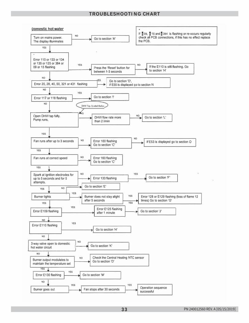
33
TROUBLESHOOTING CHART
Domestic hot water
Turn on mains power. The display illuminates
NO If ! 09, ! 15 and ! 384 is flashing or re-occurs regularly check all PCB connections, if this has no effect replace the PCB.
YES
Error 110 or 133 or 134or 135 or 125 or 384 or 09 or 15 flashing
NO
YES
Go to section 'A'
Press the 'Reset' button for between 1-3 seconds
Go to section 'D',
NO If the E11 o is still flashing. Go to section 'H'
Error 20, 28, 40, 50, 321 or 431 flashing if E55 is displayed go to section N NO
YES
Error 117 or 118 flashing Go to section 'I'
NO DH\V Top. Symbol nashcs �---'-------,,/c,
Open DHW tap fully. Pump runs.
YES
Fan runs after up to 3 seconds
YES
Fan runs at correct speed
YES
Spark at ignition electrodes forup to 5 seconds and for 5 attempts.
YES NO
YES Burner lights
YES
YES
Error E109 flashing
NO
Error E110 flashing YES
NO
NO
NO
NO
DHW flow rate more than 21/min
Error 160 flashing Go to section 'C'
Error 160 flashingGo to section 'C'
Error 133 flashing
Go to section 'E'
Burner does not stay alight after 5 seconds
Error E125 flashing after 1 minute
Go to section 'H'
NO Go to section 'L'
NO If E53 is displayed go to section 0
YES 1------�-- Go to section 'F'
YES
YES
Error 128 or E129 flashing (loss of flame 12 times) Go to section 'G'
Go to section 'J'
3 way valve open to domestic hot water circuit
NO
1----1� .. �o to section 'K'�-----------� NO
Burner output modulates to maintain the temperature set
YES YES
Error E130 flashing
NO YES
Burner goes out
NO Check the Central Heating NTC sensor Go to section 'D'
Go to section 'M'
Fan stops after 30 seconds YES
Operation sequence successful
PN 240012560 REV. A [05/15/2019]
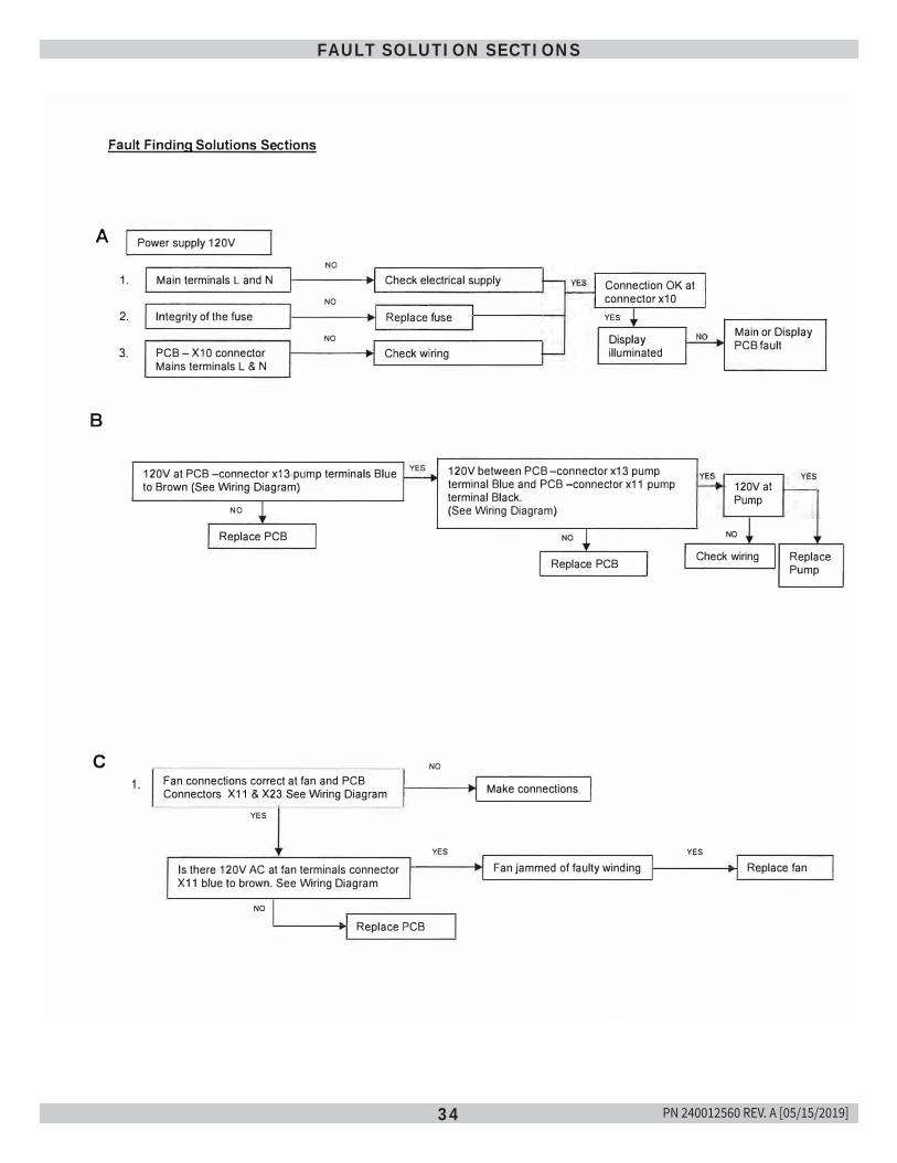
34
FAULT SOLUTION SECTIONS
A
B
C
Fault Finding Solutions Sections
1.
2.
3.
Power supply 120V
1.
NO
Main terminals L and N Check electrical supply Connection OK at connector x1 0 NO
Integrity of the fuse Replace fuse YES
NO
PCB - X1 0 connector Check wiring Display illuminated
Mains terminals L & N
120V at PCB -connector x13 pump terminals Blue to Brown (See Wiring Diagram)
NO
Replace PCB
Fan connections correct at fan and PCB Connectors X11 & X23 See Wiring Diagram
YES
NO
120V between PCB -connector x13 pump terminal Blue and PCB -connector x11 pump terminal Black. (See Wiring Diagram)
NO
Replace PCB
Make connections
Main or Display PCB fault
120V at Pump
NO
Check wiring Replace Pump
YES YES
Is there 120V AC at fan terminals connector X11 blue to brown. See Wiring Diagram
NO
Replace PCB
Fan jammed of faulty winding Replace fan
PN 240012560 REV. A [05/15/2019]
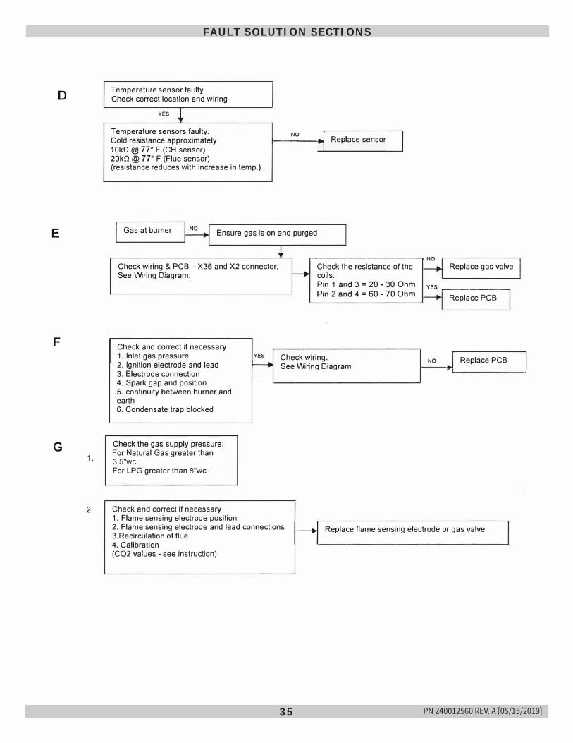
35
FAULT SOLUTION SECTIONS
D
E
F
G 1.
2.
Temperature sensor faulty. Check correct location and wiring
YES i Temperature sensors faulty. Cold resistance approximately 10k0 @ 77° F (CH sensor) 20k0 @ 77° F (Flue sensor) (resistance reduces with increase in temp.)
, __ N_o __ �.,, Replace sensor
Gas at burner Ensure gas is on and purged
.----------------, NO Check wiring & PCB - X36 and X2 connector. See Wiring Diagram.
Check and correct if necessary 1. Inlet gas pressure 2. Ignition electrode and lead 3. Electrode connection 4. Spark gap and position 5. continuity between burner and earth 6. Condensate trap blocked
Check the gas supply pressure: For Natural Gas greater than 3.5"wcFor LPG greater than 8"wc
Check and correct if necessary 1. Flame sensing electrode position
YES
f-----+
Check the resistance of the coils: Pin 1 and 3 = 20 - 30 Ohm Pin 2 and 4 = 60 - 70 Ohm
Check wiring. See Wiring Diagram
Replace gas valve
YES .-----------, Replace PCB
NO J Replace PCB
2. Flame sensing electrode and lead connections 3.Recirculation of flue 4. Calibration H Replace flame sensing electrode or gas valve
(CO2 values - see instruction)
I
PN 240012560 REV. A [05/15/2019]
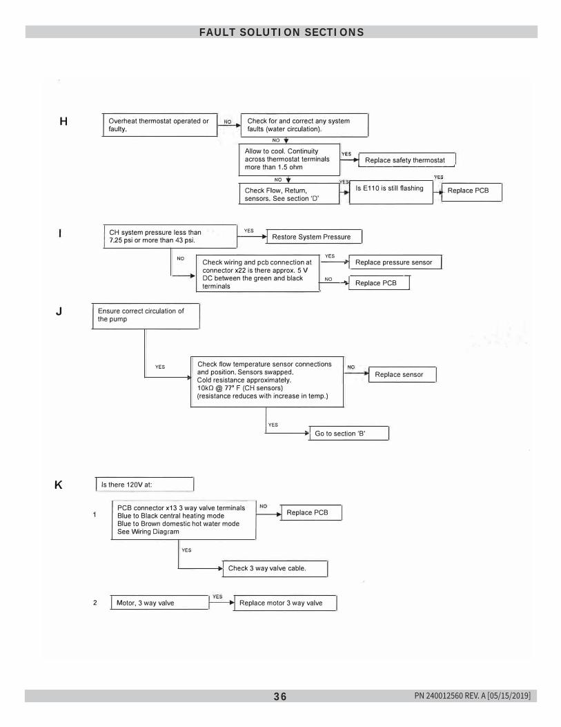
36
FAULT SOLUTION SECTIONS
H
J
K
2
Overheat thermostat operated or faulty.
Check for and correct any system faults (water circulation).
NO
�I Allow to cool. Continuity across thermostat terminals more than 1.5 ohm
� Replace safety thermostat '---------------'
NO
Check Flow, Return, sensors. See section 'D'
YES CH system pressure less than 7.25 psi or more than 43 psi. Restore System Pressure
NO
Ensure correct circulation of the pump
YES
YES Check wiring and pcb connection at connector x22 is there approx. 5 V DC between the green and black NO terminals
Check flow temperature sensor connections and position. Sensors swapped.Cold resistance approximately. 1 OkO @ 77' F (CH sensors) (resistance reduces with increase in temp.)
YES
I • I.I
I
Is E11 O is still flashing
Replace pressure sensor
Replace PCB I
Replace sensor
Go to section 'B'
Is there 120V at:
PCB connector x13 3 way valve terminals Blue to Black central heating mode Blue to Brown domestic hot water mode See Wiring Diagram
YES
Replace PCB
Check 3 way valve cable.
Motor, 3 way valve Replace motor 3 way valve
Replace PCB
I
PN 240012560 REV. A [05/15/2019]
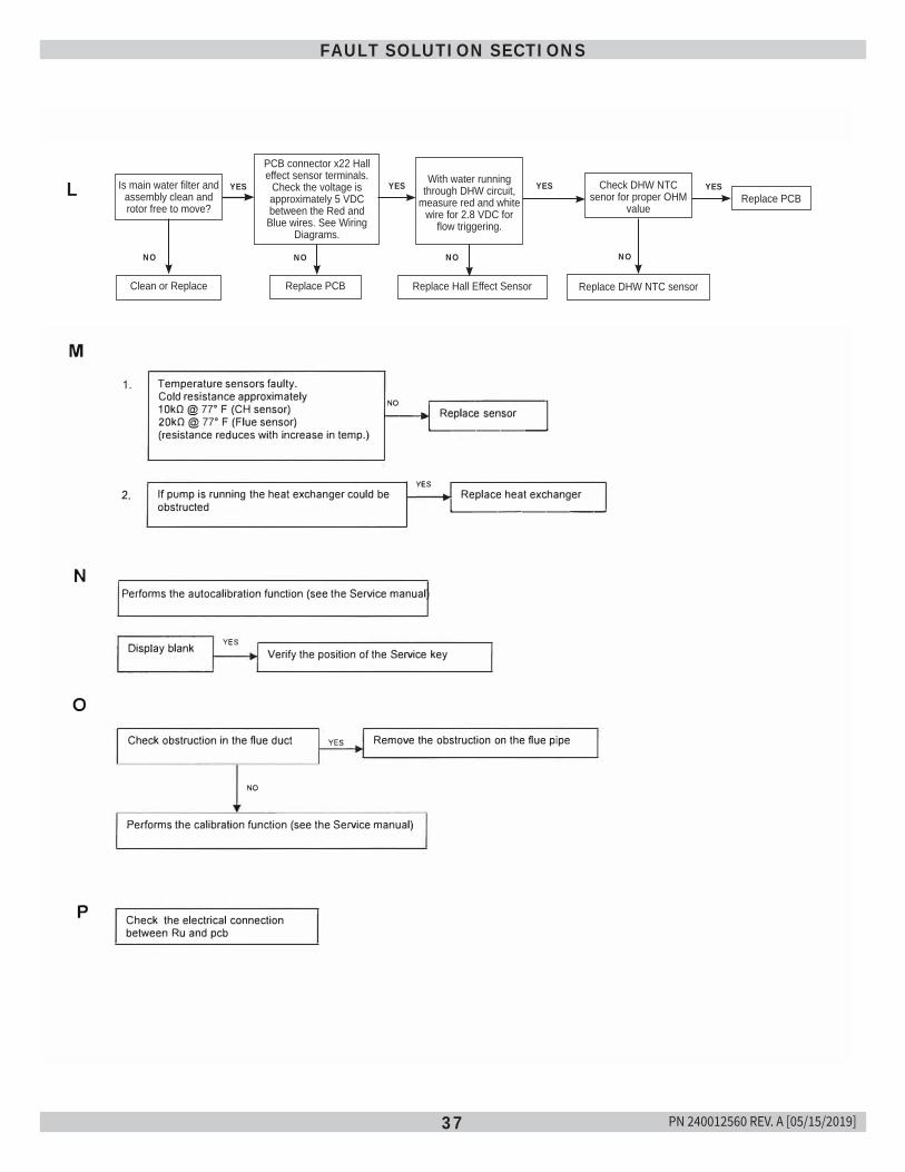
37
FAULT SOLUTION SECTIONS
L
M
N
0
p
Is main water filter and assembly clean and rotor free to move?
1.
NO
Clean or replace
YES
PCB connector x22 Hall effect sensor terminals. Check that the voltage is approximately 5 VDC between Red and Blue See Wiring Diagram
NO
Replace PCB
f----i��I Replace sensor NO
I
Temperature sensors faulty. Cold resistance approximately 1 0kO @ 77' F (CH sensor) 20kO @ 77' F (Flue sensor) (resistance reduces with increase in temp.)
·1�---�
2. If pump is running the heat exchanger could be obstructed
Performs the autocalibration function (see the Service manual)
YES
YES � I Replace heat exchanger ·1�-----�
Display blank Verify the position of the Service key
Check obstruction in the flue duct YES Remove the obstruction on the flue pipe
NO
Performs the calibration function (see the Service manual)
Check the electrical connection between Ru and pcb
Replace Hall Effect Sensor
Is main water filter and assembly clean and rotor free to move?
LPCB connector x22 Hall effect sensor terminals.
Check the voltage is approximately 5 VDC between the Red and Blue wires. See Wiring
Diagrams.
With water running through DHW circuit,
measure red and white wire for 2.8 VDC for
flow triggering.
Check DHW NTC senor for proper OHM
valueReplace PCB
YES YES YES YES
Clean or Replace Replace PCB Replace Hall Effect Sensor Replace DHW NTC sensor
NO NO NO NO
PN 240012560 REV. A [05/15/2019]
38
NOTES
PN 240012560 REV. A [05/15/2019]

• ECR international
ECR International Inc. 2201 Dwyer Avenue, Utica, NY 13501
Tel. 800 253 7900 www.ecrinternational.com
BDRTHERMEA GROUP
All specifications subject to change without notice. ©2019 ECR International, Inc.
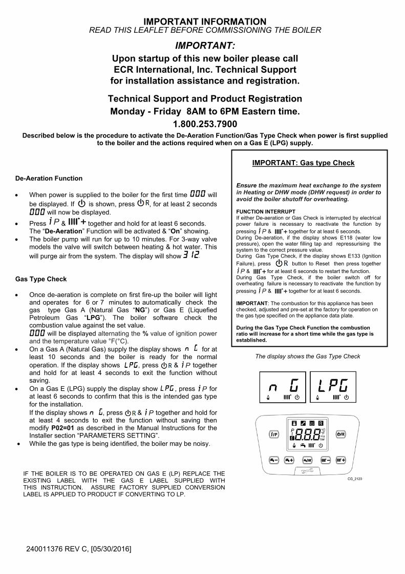
De-Aeration Function
• When power is supplied to the boiler for the first time will be displayed. If is shown, press , for at least 2 seconds
will now be displayed.
• Press & together and hold for at least 6 seconds. The “De-Aeration” Function will be activated & “On” showing.
• The boiler pump will run for up to 10 minutes. For 3-way valvemodels the valve will switch between heating & hot water. Thiswill purge air from the system. The display will show
Gas Type Check
• Once de-aeration is complete on first fire-up the boiler will lightand operates for 6 or 7 minutes to automatically check thegas type Gas A (Natural Gas “NG”) or Gas E (LiquefiedPetroleum Gas “LPG”). The boiler software check thecombustion value against the set value.
will be displayed alternating the % value of ignition powerand the temperature value °F(°C).
• On a Gas A (Natural Gas) supply the display shows for atleast 10 seconds and the boiler is ready for the normaloperation. If the display shows , press & togetherand hold for at least 4 seconds to exit the function withoutsaving.
• On a Gas E (LPG) supply the display show , press forat least 6 seconds to confirm that this is the intended gas typefor the installation.If the display shows , press & together and hold forat least 4 seconds to exit the function without saving thenmodify P02=01 as described in the Manual Instructions for theInstaller section “PARAMETERS SETTING”.
• While the gas type is being identified, the boiler may be noisy.
IF THE BOILER IS TO BE OPERATED ON GAS E (LP) REPLACE THE EXISTING LABEL WITH THE GAS E LABEL SUPPLIED WITH THIS INSTRUCTION. ASSURE FACTORY SUPPLIED CONVERSION LABEL IS APPLIED TO PRODUCT IF CONVERTING TO LP.
IMPORTANT: Gas type Check
Ensure the maximum heat exchange to the system in Heating or DHW mode (DHW request) in order to avoid the boiler shutoff for overheating.
FUNCTION INTERRUPT If either De-aeration or Gas Check is interrupted by electrical power failure is necessary to reactivate the function by pressing & together for at least 6 seconds. During De-aeration, if the display shows E118 (water low pressure), open the water filling tap and repressurising the system to the correct pressure value. During Gas Type Check, if the display shows E133 (Ignition Failure), press button to Reset then press together
& for at least 6 seconds to restart the function. During Gas Type Check, if the boiler switch off for overheating failure is necessary to reactivate the function by pressing & together for at least 6 seconds.
IMPORTANT: The combustion for this appliance has been checked, adjusted and pre-set at the factory for operation on the gas type specified on the appliance data plate.
During the Gas Type Check Function the combustion ratio will increase for a short time while the gas type is established.
The display shows the Gas Type Check
IMPORTANT INFORMATION READ THIS LEAFLET BEFORE COMMISSIONING THE BOILER
IMPORTANT: Upon startup of this new boiler please call ECR International, Inc. Technical Support
for installation assistance and registration.
Technical Support and Product Registration Monday - Friday 8AM to 6PM Eastern time.
1.800.253.7900Described below is the procedure to activate the De-Aeration Function/Gas Type Check when power is first supplied
to the boiler and the actions required when on a Gas E (LPG) supply.
240011376 REV C, [05/30/2016]
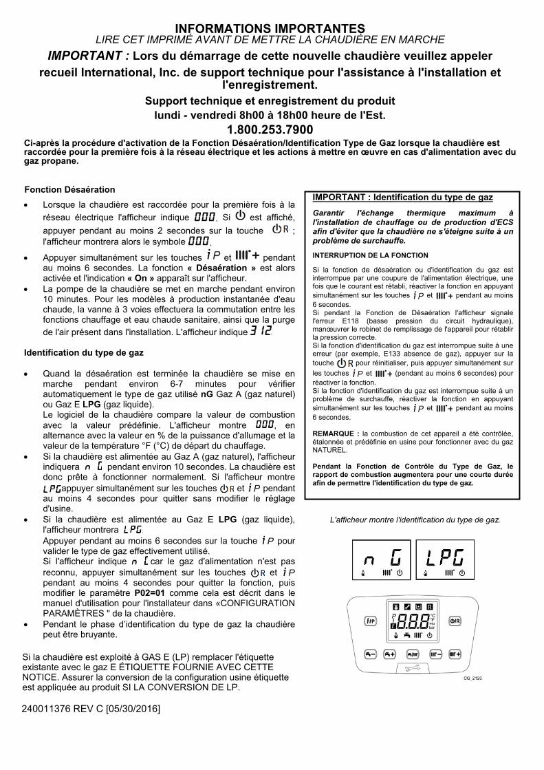
• Lorsque la chaudière est raccordée pour la première fois à laréseau électrique l'afficheur indique . Si est affiché, appuyer pendant au moins 2 secondes sur la touche ; l'afficheur montrera alors le symbole .
• Appuyer simultanément sur les touches et pendant au moins 6 secondes. La fonction « Désaération » est alors activée et l'indication « On » apparaît sur l'afficheur.
• La pompe de la chaudière se met en marche pendant environ10 minutes. Pour les modèles à production instantanée d'eauchaude, la vanne à 3 voies effectuera la commutation entre lesfonctions chauffage et eau chaude sanitaire, ainsi que la purgede l'air présent dans l'installation. L'afficheur indique
Identification du type de gaz
• Quand la désaération est terminée la chaudière se mise enmarche pendant environ 6-7 minutes pour vérifierautomatiquement le type de gaz utilisé nG Gaz A (gaz naturel)ou Gaz E LPG (gaz liquide).Le logiciel de la chaudière compare la valeur de combustionavec la valeur prédéfinie. L'afficheur montre , enalternance avec la valeur en % de la puissance d'allumage et lavaleur de la température °F (°C) de départ du chauffage.
• Si la chaudière est alimentée au Gaz A (gaz naturel), l'afficheurindiquera pendant environ 10 secondes. La chaudière estdonc prête à fonctionner normalement. Si l'afficheur montre , appuyer simultanément sur les touches et pendantau moins 4 secondes pour quitter sans modifier le réglaged'usine.
• Si la chaudière est alimentée au Gaz E LPG (gaz liquide),l'afficheur montrera ..Appuyer pendant au moins 6 secondes sur la touche pourvalider le type de gaz effectivement utilisé.Si l'afficheur indique car le gaz d'alimentation n'est pasreconnu, appuyer simultanément sur les touches etpendant au moins 4 secondes pour quitter la fonction, puismodifier le paramètre P02=01 comme cela est décrit dans lemanuel d'utilisation pour l'installateur dans «CONFIGURATIONPARAMÈTRES " de la chaudière.
• Pendant le phase d’identification du type de gaz la chaudièrepeut être bruyante.
IMPORTANT : Identification du type de gaz Garantir l'échange thermique maximum à l'installation de chauffage ou de production d'ECS afin d'éviter que la chaudière ne s'éteigne suite à un problème de surchauffe.
INTERRUPTION DE LA FONCTION
Si la fonction de désaération ou d'identification du gaz est interrompue par une coupure de l'alimentation électrique, une fois que le courant est rétabli, réactiver la fonction en appuyant simultanément sur les touches et pendant au moins 6 secondes. Si pendant la Fonction de Désaération l'afficheur signale l'erreur E118 (basse pression du circuit hydraulique), manœuvrer le robinet de remplissage de l'appareil pour rétablir la pression correcte. Si la fonction d'identification du gaz est interrompue suite à une erreur (par exemple, E133 absence de gaz), appuyer sur la touche pour réinitialiser, puis appuyer simultanément sur les touches et (pendant au moins 6 secondes) pour réactiver la fonction. Si la fonction d'identification du gaz est interrompue suite à un problème de surchauffe, réactiver la fonction en appuyant simultanément sur les touches et pendant au moins 6 secondes.
REMARQUE : la combustion de cet appareil a été contrôlée, étalonnée et prédéfinie en usine pour fonctionner avec du gaz NATUREL.
Pendant la Fonction de Contrôle du Type de Gaz, le rapport de combustion augmentera pour une courte durée afin de permettre l'identification du type de gaz.
Si la chaudière est exploité à GAS E (LP) remplacer l'étiquette existante avec le gaz E ÉTIQUETTE FOURNIE AVEC CETTE NOTICE. Assurer la conversion de la configuration usine étiquette est appliquée au produit SI LA CONVERSION DE LP.
240011376 REV C [05/30/2016]
L'afficheur montre l'identification du type de gaz.
INFORMATIONS IMPORTANTES LIRE CET IMPRIMÉ AVANT DE METTRE LA CHAUDIÈRE EN MARCHE
IMPORTANT : Lors du démarrage de cette nouvelle chaudière veuillez appelerrecueil International, Inc. de support technique pour l'assistance à l'installation et
l'enregistrement.Support technique et enregistrement du produit
lundi - vendredi 8h00 à 18h00 heure de l'Est.1.800.253.7900
Ci-après la procédure d'activation de la Fonction Désaération/Identification Type de Gaz lorsque la chaudière est raccordée pour la première fois à la réseau électrique et les actions à mettre en œuvre en cas d'alimentation avec du gaz propane.
Fonction Désaération
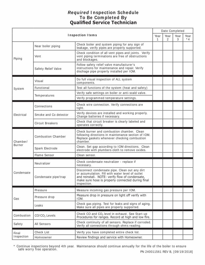
Inspection ItemsDate Completed
Year 1
Year 2
Year 3
Year *4
Piping
Near boiler piping Check boiler and system piping for any sign of leakage, verify pipes are properly supported.
VentCheck condition of all vent pipes and joints. Verify vent piping terminations are free of obstructions and blockages.
Safety Relief ValveFollow safety relief valve manufacturer's instructions for maintenance and repair. Verify dischage pipe properly installed per IOM.
System
Visual Do full visual inspection of ALL system components.
Functional Test all functions of the system (heat and safety)
TemperaturesVerify safe settings on boiler or anti-scald valve.Verify programmed temperature settings.
Electrical
Connections Check wire connection. Verify connections are tight.
Smoke and Co detector Verify devices are installed and working properly. Change batteries if necessary.
Circuit Breakers Check that circuit breaker is clearly labeled and operates correctly.
Chamber/Burner
Combustion ChamberCheck burner and combustion chamber. Clean following directions in maintenance section of IOM. Replace gaskets whenever checking combustion chamber.
Spark Electrode Clean. Set gap according to IOM directions. Clean electrode with plumbers cloth to remove oxides.
Flame Sensor Clean sensor.
Condensate
Neutralizer Check condensate neutralizer - replace if necessary.
Condensate pipe/trap
Disconnect condensate pipe. Clean out any dirt or accumulation. Fill with water level of outlet and reinstall. NOTE: verify flow of condensate, make sure hose is properly connected during final inspection.
Gas
Pressure Measure incoming gas pressure per IOM.
Pressure drop Measure drop in pressure on light off verify with IOM.
Leaks Check gas piping. Test for leaks and signs of aging. Make sure all pipes are properly supported.
Combustion CO/CO₂ Levels Check CO and CO₂ level in exhaust. See Start-upProcedures for ranges. Record at high and low fire.
Safety All Sensors Check continuity of all sensors. Replace if corroded. Verify all connections through ohms reading.
Final Inspection
Check List Verify you have completed entire check list.Homeowner Review findings and service with Homeowner.
Required Inspection ScheduleTo Be Completed By
Qualified Service Technician
* Continue inspections beyond 4th year. Maintenance should continue annually for the life of the boiler to ensuresafe worry free operation.
PN 240011561 REV B, [09/19/2018]