dcs800-ep drives 5 - 600 hp - abb ltd · 11.1 dcs800-ep signal definitions ... • dcs800-ep...
TRANSCRIPT

06/24 User’s Manual 3AUA0000148993
DCS800-EP Drives 5 - 600 HP

Any trademarks used in this manual are the property of their respective owners.

i3AUA0000148993
Chapter 1Introduction1.1 Getting Assistance . . . . . . . . . . . . . . . . . . . . . . . . . . . . . . . . . . . . . . . . . . . . . . . . . . . . . . . . . . . . . . . . . . . . 1-11.2 Safety Notices . . . . . . . . . . . . . . . . . . . . . . . . . . . . . . . . . . . . . . . . . . . . . . . . . . . . . . . . . . . . . . . . . . . . . . . . 1-1
Chapter 2Product Familiarization2.1 Overview . . . . . . . . . . . . . . . . . . . . . . . . . . . . . . . . . . . . . . . . . . . . . . . . . . . . . . . . . . . . . . . . . . . . . . . . . . . . 2-12.2 Enclosures . . . . . . . . . . . . . . . . . . . . . . . . . . . . . . . . . . . . . . . . . . . . . . . . . . . . . . . . . . . . . . . . . . . . . . . . . . 2-12.3 Connections . . . . . . . . . . . . . . . . . . . . . . . . . . . . . . . . . . . . . . . . . . . . . . . . . . . . . . . . . . . . . . . . . . . . . . . . . 2-1
Chapter 3Ratings3.1 Type Codes - Frame and Current Ratings . . . . . . . . . . . . . . . . . . . . . . . . . . . . . . . . . . . . . . . . . . . . . . . . . . . 3-1
Chapter 4Connection Information4.1 Typical Cable Sizing and Tightening Torque - North America . . . . . . . . . . . . . . . . . . . . . . . . . . . . . . . . . . . . . 4-14.2 Typical Cable Sizing and Tightening Torque - Field Supply . . . . . . . . . . . . . . . . . . . . . . . . . . . . . . . . . . . . . . . 4-2
Chapter 5Power Wiring 5.1 Grounding the Control . . . . . . . . . . . . . . . . . . . . . . . . . . . . . . . . . . . . . . . . . . . . . . . . . . . . . . . . . . . . . . . . . . 5-15.2 Incoming Power . . . . . . . . . . . . . . . . . . . . . . . . . . . . . . . . . . . . . . . . . . . . . . . . . . . . . . . . . . . . . . . . . . . . . . 5-15.3 Input Impedance . . . . . . . . . . . . . . . . . . . . . . . . . . . . . . . . . . . . . . . . . . . . . . . . . . . . . . . . . . . . . . . . . . . . . 5-3 5.3.1 Line Reactor . . . . . . . . . . . . . . . . . . . . . . . . . . . . . . . . . . . . . . . . . . . . . . . . . . . . . . . . . . . . . . . . . . 5-35.4 Protective Devices . . . . . . . . . . . . . . . . . . . . . . . . . . . . . . . . . . . . . . . . . . . . . . . . . . . . . . . . . . . . . . . . . . . . . 5-3 5.4.1 Mains Cable (AC Line Cable) Short-Circuit Protection . . . . . . . . . . . . . . . . . . . . . . . . . . . . . . . . . . . 5-3 5.4.2 DC Output Protection . . . . . . . . . . . . . . . . . . . . . . . . . . . . . . . . . . . . . . . . . . . . . . . . . . . . . . . . . . . 5-3 5.4.3 Circuit Breaker Protection (Optional) . . . . . . . . . . . . . . . . . . . . . . . . . . . . . . . . . . . . . . . . . . . . . . . . 5-3 5.4.4 Motor Connections . . . . . . . . . . . . . . . . . . . . . . . . . . . . . . . . . . . . . . . . . . . . . . . . . . . . . . . . . . . . . 5-35.5 Feedback . . . . . . . . . . . . . . . . . . . . . . . . . . . . . . . . . . . . . . . . . . . . . . . . . . . . . . . . . . . . . . . . . . . . . . . . . . . 5-3 5.5.1 Analog DC Tachometer Connection . . . . . . . . . . . . . . . . . . . . . . . . . . . . . . . . . . . . . . . . . . . . . . . . . 5-3 5.5.2 Pulse Encoder Connection . . . . . . . . . . . . . . . . . . . . . . . . . . . . . . . . . . . . . . . . . . . . . . . . . . . . . . . 5-4 5.5.3 Resolvers . . . . . . . . . . . . . . . . . . . . . . . . . . . . . . . . . . . . . . . . . . . . . . . . . . . . . . . . . . . . . . . . . . . . 5-55.6 Field Supply . . . . . . . . . . . . . . . . . . . . . . . . . . . . . . . . . . . . . . . . . . . . . . . . . . . . . . . . . . . . . . . . . . . . . . . . . 5-65.7 Control Power . . . . . . . . . . . . . . . . . . . . . . . . . . . . . . . . . . . . . . . . . . . . . . . . . . . . . . . . . . . . . . . . . . . . . . . . 5-7
Chapter 6Control Wiring6.1 Digital Inputs . . . . . . . . . . . . . . . . . . . . . . . . . . . . . . . . . . . . . . . . . . . . . . . . . . . . . . . . . . . . . . . . . . . . . . . . . 6-1 6.1.1 External Trip . . . . . . . . . . . . . . . . . . . . . . . . . . . . . . . . . . . . . . . . . . . . . . . . . . . . . . . . . . . . . . . . . . 6-1 6.1.2 Drive Enable . . . . . . . . . . . . . . . . . . . . . . . . . . . . . . . . . . . . . . . . . . . . . . . . . . . . . . . . . . . . . . . . . . 6-1 6.1.3 Other Digital Inputs . . . . . . . . . . . . . . . . . . . . . . . . . . . . . . . . . . . . . . . . . . . . . . . . . . . . . . . . . . . . . 6-16.2 Analog Inputs . . . . . . . . . . . . . . . . . . . . . . . . . . . . . . . . . . . . . . . . . . . . . . . . . . . . . . . . . . . . . . . . . . . . . . . . 6-2 6.2.1 Analog Inputs Jumper Coding . . . . . . . . . . . . . . . . . . . . . . . . . . . . . . . . . . . . . . . . . . . . . . . . . . . . . 6-36.3 Digital and Relay Outputs . . . . . . . . . . . . . . . . . . . . . . . . . . . . . . . . . . . . . . . . . . . . . . . . . . . . . . . . . . . . . . . 6-3 6.3.1 Digital Outputs . . . . . . . . . . . . . . . . . . . . . . . . . . . . . . . . . . . . . . . . . . . . . . . . . . . . . . . . . . . . . . . . 6-3 6.3.2 Relay Outputs . . . . . . . . . . . . . . . . . . . . . . . . . . . . . . . . . . . . . . . . . . . . . . . . . . . . . . . . . . . . . . . . . 6-46.4 Analog Outputs . . . . . . . . . . . . . . . . . . . . . . . . . . . . . . . . . . . . . . . . . . . . . . . . . . . . . . . . . . . . . . . . . . . . . . . 6-46.5 Communications Options . . . . . . . . . . . . . . . . . . . . . . . . . . . . . . . . . . . . . . . . . . . . . . . . . . . . . . . . . . . . . . . 6-4
Chapter 7Applying Power7.1 Installation Checklist . . . . . . . . . . . . . . . . . . . . . . . . . . . . . . . . . . . . . . . . . . . . . . . . . . . . . . . . . . . . . . . . . . . 7-1 7.1.1 Mechanical Installation . . . . . . . . . . . . . . . . . . . . . . . . . . . . . . . . . . . . . . . . . . . . . . . . . . . . . . . . . . 7-1 7.1.2 Electrical Installation . . . . . . . . . . . . . . . . . . . . . . . . . . . . . . . . . . . . . . . . . . . . . . . . . . . . . . . . . . . . 7-17.2 Drive Operation . . . . . . . . . . . . . . . . . . . . . . . . . . . . . . . . . . . . . . . . . . . . . . . . . . . . . . . . . . . . . . . . . . . . . . . 7-17.3 Apply Incoming Power . . . . . . . . . . . . . . . . . . . . . . . . . . . . . . . . . . . . . . . . . . . . . . . . . . . . . . . . . . . . . . . . . 7-17.4 Commissioning . . . . . . . . . . . . . . . . . . . . . . . . . . . . . . . . . . . . . . . . . . . . . . . . . . . . . . . . . . . . . . . . . . . . . . . 7-1
Table of Contents

ii 3AUA0000148993
Chapter 8Control Panel (Keypad) and Programming8.1 Initial Setup . . . . . . . . . . . . . . . . . . . . . . . . . . . . . . . . . . . . . . . . . . . . . . . . . . . . . . . . . . . . . . . . . . . . . . . . . . 8-1 8.1.1 Control Panel Version Information . . . . . . . . . . . . . . . . . . . . . . . . . . . . . . . . . . . . . . . . . . . . . . . . . . 8-2 8.1.2 General Display Features . . . . . . . . . . . . . . . . . . . . . . . . . . . . . . . . . . . . . . . . . . . . . . . . . . . . . . . . . 8-2 8.1.3 Assistants (QuickStart) . . . . . . . . . . . . . . . . . . . . . . . . . . . . . . . . . . . . . . . . . . . . . . . . . . . . . . . . . . 8-2 8.1.4 Assistants . . . . . . . . . . . . . . . . . . . . . . . . . . . . . . . . . . . . . . . . . . . . . . . . . . . . . . . . . . . . . . . . . . . . 8-2 8.1.5 Digital Input Selection . . . . . . . . . . . . . . . . . . . . . . . . . . . . . . . . . . . . . . . . . . . . . . . . . . . . . . . . . . . 8-3 8.1.6 Autotuning . . . . . . . . . . . . . . . . . . . . . . . . . . . . . . . . . . . . . . . . . . . . . . . . . . . . . . . . . . . . . . . . . . . 8-3 8.1.7 Parameters Entered By Assistant . . . . . . . . . . . . . . . . . . . . . . . . . . . . . . . . . . . . . . . . . . . . . . . . . . 8-48.2 Programming . . . . . . . . . . . . . . . . . . . . . . . . . . . . . . . . . . . . . . . . . . . . . . . . . . . . . . . . . . . . . . . . . . . . . . . . 8-58.3 Output Mode . . . . . . . . . . . . . . . . . . . . . . . . . . . . . . . . . . . . . . . . . . . . . . . . . . . . . . . . . . . . . . . . . . . . . . . . . 8-58.4 Local / Remote Operation . . . . . . . . . . . . . . . . . . . . . . . . . . . . . . . . . . . . . . . . . . . . . . . . . . . . . . . . . . . . . . . 8-68.5 Parameter Backup . . . . . . . . . . . . . . . . . . . . . . . . . . . . . . . . . . . . . . . . . . . . . . . . . . . . . . . . . . . . . . . . . . . . 8-6
Chapter 9Macro Selection9.1 Macro Descriptions . . . . . . . . . . . . . . . . . . . . . . . . . . . . . . . . . . . . . . . . . . . . . . . . . . . . . . . . . . . . . . . . . . . . 9-1 9.1.1 Factory Macro (Factory) . . . . . . . . . . . . . . . . . . . . . . . . . . . . . . . . . . . . . . . . . . . . . . . . . . . . . . . . . . 9-1 9.1.2 Standard Macro (Standard) . . . . . . . . . . . . . . . . . . . . . . . . . . . . . . . . . . . . . . . . . . . . . . . . . . . . . . . 9-2 9.1.3 Manual Constant Speed Macro (Man/Const) . . . . . . . . . . . . . . . . . . . . . . . . . . . . . . . . . . . . . . . . . . 9-3 9.1.4 Hand/Auto Macro (Hand/Auto) . . . . . . . . . . . . . . . . . . . . . . . . . . . . . . . . . . . . . . . . . . . . . . . . . . . . 9-4 9.1.5 Hand/Motor Pot Macro (Hand/MotPot) . . . . . . . . . . . . . . . . . . . . . . . . . . . . . . . . . . . . . . . . . . . . . . 9-5 9.1.6 Motor Pot Macro (MotPot) . . . . . . . . . . . . . . . . . . . . . . . . . . . . . . . . . . . . . . . . . . . . . . . . . . . . . . . . 9-6 9.1.7 Torque Control Macro (TorqCtrl) . . . . . . . . . . . . . . . . . . . . . . . . . . . . . . . . . . . . . . . . . . . . . . . . . . . . 9-7 9.1.8 Torque Limit Macro (TorqLimit) . . . . . . . . . . . . . . . . . . . . . . . . . . . . . . . . . . . . . . . . . . . . . . . . . . . . . 9-8 9.1.9 2Wire DC Contact US Macro (2WireDCcontUS) . . . . . . . . . . . . . . . . . . . . . . . . . . . . . . . . . . . . . . . 9-9 9.1.10 3Wire DC Contact US Macro (3WireDCcontUS) . . . . . . . . . . . . . . . . . . . . . . . . . . . . . . . . . . . . . . . 9-10 9.1.11 3Wire Standard Macro (3WireStandard) . . . . . . . . . . . . . . . . . . . . . . . . . . . . . . . . . . . . . . . . . . . . . 9-11 9.1.12 3Wire Jog Macro (3WireJog) - FLEXPAK 3000 Replacements . . . . . . . . . . . . . . . . . . . . . . . . . . . . . 9-12
Chapter 10Troubleshooting10.1 Fault Messages . . . . . . . . . . . . . . . . . . . . . . . . . . . . . . . . . . . . . . . . . . . . . . . . . . . . . . . . . . . . . . . . . . . . . . . 10-110.2 Alarm Messages . . . . . . . . . . . . . . . . . . . . . . . . . . . . . . . . . . . . . . . . . . . . . . . . . . . . . . . . . . . . . . . . . . . . . . 10-8
Chapter 11Signals and Parameters11.1 DCS800-EP Signal Definitions . . . . . . . . . . . . . . . . . . . . . . . . . . . . . . . . . . . . . . . . . . . . . . . . . . . . . . . . . . . . 11-111.2 DCS800-EP Parameter Definitions . . . . . . . . . . . . . . . . . . . . . . . . . . . . . . . . . . . . . . . . . . . . . . . . . . . . . . . . 11-22
Appendix AParameter TablesA.1 Read Only Parameters . . . . . . . . . . . . . . . . . . . . . . . . . . . . . . . . . . . . . . . . . . . . . . . . . . . . . . . . . . . . . . . . . . A-1A.2 Group 60 Parameters . . . . . . . . . . . . . . . . . . . . . . . . . . . . . . . . . . . . . . . . . . . . . . . . . . . . . . . . . . . . . . . . . . A-5
Appendix BTechnical InformationB.1 Technical Specifications . . . . . . . . . . . . . . . . . . . . . . . . . . . . . . . . . . . . . . . . . . . . . . . . . . . . . . . . . . . . . . . . B-1 B.1.1 Digital Inputs Technical Data . . . . . . . . . . . . . . . . . . . . . . . . . . . . . . . . . . . . . . . . . . . . . . . . . . . . . B-1 B.1.2 Analog Inputs Technical Data . . . . . . . . . . . . . . . . . . . . . . . . . . . . . . . . . . . . . . . . . . . . . . . . . . . . . B-1 B.1.3 Analog Outputs Technical Data . . . . . . . . . . . . . . . . . . . . . . . . . . . . . . . . . . . . . . . . . . . . . . . . . . . B-2 B.1.4 Digital Outputs Technical Data . . . . . . . . . . . . . . . . . . . . . . . . . . . . . . . . . . . . . . . . . . . . . . . . . . . . B-2 B.1.5 Relay Output Technical Data . . . . . . . . . . . . . . . . . . . . . . . . . . . . . . . . . . . . . . . . . . . . . . . . . . . . . B-2 B.1.6 Overload . . . . . . . . . . . . . . . . . . . . . . . . . . . . . . . . . . . . . . . . . . . . . . . . . . . . . . . . . . . . . . . . . . . . B-2 B.1.7 Input Reactance . . . . . . . . . . . . . . . . . . . . . . . . . . . . . . . . . . . . . . . . . . . . . . . . . . . . . . . . . . . . . . B-2 B.1.8 Fuse Protection . . . . . . . . . . . . . . . . . . . . . . . . . . . . . . . . . . . . . . . . . . . . . . . . . . . . . . . . . . . . . . . B-3B.2 Control Transformer . . . . . . . . . . . . . . . . . . . . . . . . . . . . . . . . . . . . . . . . . . . . . . . . . . . . . . . . . . . . . . . . . . . B-4B.3 AC Contactor . . . . . . . . . . . . . . . . . . . . . . . . . . . . . . . . . . . . . . . . . . . . . . . . . . . . . . . . . . . . . . . . . . . . . . . . B-4B.4 Blower Motor Starter Thermal Overload Relay . . . . . . . . . . . . . . . . . . . . . . . . . . . . . . . . . . . . . . . . . . . . . . . . B-4B.5 Accessories . . . . . . . . . . . . . . . . . . . . . . . . . . . . . . . . . . . . . . . . . . . . . . . . . . . . . . . . . . . . . . . . . . . . . . . . . B-4 B.5.1 Blower Motor Starter . . . . . . . . . . . . . . . . . . . . . . . . . . . . . . . . . . . . . . . . . . . . . . . . . . . . . . . . . . . B-5 B.5.2 Other Replacement Parts . . . . . . . . . . . . . . . . . . . . . . . . . . . . . . . . . . . . . . . . . . . . . . . . . . . . . . . . B-5B.6 Dimensions and Weights . . . . . . . . . . . . . . . . . . . . . . . . . . . . . . . . . . . . . . . . . . . . . . . . . . . . . . . . . . . . . . . . B-6 B.6.1 Dimensional and Weight Data . . . . . . . . . . . . . . . . . . . . . . . . . . . . . . . . . . . . . . . . . . . . . . . . . . . . B-6 B.6.2 Requirements for Installation . . . . . . . . . . . . . . . . . . . . . . . . . . . . . . . . . . . . . . . . . . . . . . . . . . . . . B-7

Introduction 1-13AUA0000148993
Chapter 1Introduction
The DCS800 DC industrial drive from ABB combines a power controller with a thyristor power platform that has been proven in factories all over the world. The DCS800-EP boasts a wide power range. The hardware and software are designed with you, the user in mind. Special features make installation and configuration simple and allow you to customize the application to your needs.
The information in this user’s guide supports firmware version 3.7.
This guide is intended for qualified electrical personnel familiar with installing, programming and maintaining DC drives. This guide contains information on:•InstallingandwiringtheDCS800-EPcontrol•Programmingthecontrol•Troubleshootingthecontrol
The information supplied in this guide is intended to provide abbreviated information commonly needed to install and commission the DCS800-EP. For complete details about the control see:• DCS800-EP Installation and Start-Up Manual • DCS800 Firmware Manual• DCS800 Hardware Manual
1.1 Getting Assistance
For technical assistance, contact your local sales office. Contact phone numbers are located on the inside back cover of this guide. Before calling, please review the troubleshooting section later in this guide. You will be asked for the drive model number or catalog number that is located on the nameplate along with the drive serial number.
1.2 Safety Notices
This equipment contains voltages that may be in excess of 1000 volts! Electrical shock can cause serious or fatal injury. This equipment may be connected to other machines that have rotating parts or parts that are driven by this equipment. Improper use can cause serious or fatal injury. Only qualified personnel should attempt the start-up procedure or troubleshoot this equipment.
The following statements in this section must be read and understood before proceeding with installation and use of this drive. The below classifications of cautionary statements are used in this user guide:
CLASSIFICATIONS OF CAUTIONARY STATEMENTS
WARNING: Indicates a potentially hazardous situation which, if not avoided, could result in injury or death. CAUTION: Indicates a potentially hazardous situation which, if not avoided, could result in damage to property.
PRECAUTIONS
WARNING: Do not touch any circuit board, power device or electrical connection before you first ensure that power has been disconnected and there is no high voltage present from this equipment or other equipment to which it is connected. Electrical shock can cause serious or fatal injury. Only qualified personnel should attempt the start-up procedure or troubleshoot this equipment.
WARNING: DC permanent magnet motors can induce voltage and current in the motor leads by rotating the motor shaft. Electrical shock can cause serious or fatal injury. Therefore, do not couple the load to the motor shaft until all motor connections have been made. During any maintenance inspections, be sure the motor shaft will not rotate.
WARNING: Be sure that you are completely familiar with the safe operation of this equipment. This equipment may be connected to other machines that have rotating parts or parts that are controlled by this equipment. Improper use can cause serious or fatal injury. Only qualified personnel should attempt the start-up procedure or troubleshoot this equipment.
WARNING: Do not use motor overload relays with an automatic reset feature. These are dangerous since the process may injure someone if a sudden or unexpected automatic restart occurs. If manual reset relays are not available, disable the automatic restart feature using external control wiring.
WARNING: Be sure the system is properly grounded before applying power. Do not apply AC power before you ensure that all grounding instructions have been followed. Electrical shock can cause serious or fatal injury.
WARNING: Improper operation of control may cause violent motion of the motor shaft and driven equipment. Be certain that unexpected motor shaft movement will not cause injury to personnel or damage to equipment. Certain failure modes of the control can produce peak torque of several times the rated motor torque.

1-2 Introduction 3AUA0000148993
WARNING: Motor circuit may have high voltage present whenever AC power is applied, even when motor is not rotating. Electrical shock can cause serious or fatal injury.
WARNING: Dynamic brake resistors may generate enough heat to ignite combustible materials. Keep all combustible materials and flammable vapors away from brake resistors.
WARNING: MEDICAL DEVICE/PACEMAKER DANGER - Magnetic and electromagnetic fields in the vicinity of current carrying conductors and industrial motors can result in a serious health hazard to persons with cardiac pacemakers, internal cardiac defibrillators, neurostimulators, metal implants, cochlear implants, hearing aids, and other medical devices. To avoid risk, stay away from the area surrounding a motor and its current carrying conductors.
CAUTION: Disconnect motor leads (C2, D2, and F+, F-) from control before you perform a dielectric withstand (insulation) test on the motor. Failure to disconnect motor from the control will result in extensive damage to the control. The control is tested at the factory for high voltage/leakage resistance as part of the Underwriters Laboratory requirements.
CAUTION: Suitable for use on a circuit capable of delivering not more than the RMS symmetrical short circuit amperes listed here. Panel Frame Size Module Frame Size HP RMS Symmetrical Amperes A D1 1 - 60 65 kA at maximum 600VAC B D2 35 - 125 65 kA at maximum 600VAC B D3 75 - 150 65 kA at maximum 600VAC C D3 100 - 250 65 kA at maximum 600VAC C D4 150 - 300 65 kA at maximum 600VAC D D4 400 - 600 65 kA at maximum 600VAC CAUTION: Do not connect AC power to the drive output terminals C2, D2, F+, F-. These terminals are for supplying power to the motor. Connecting AC power to these terminals may result in damage to the control.
CAUTION: ABB does not recommend using “Grounded Leg Delta” transformer supplies that may create ground loops. Instead, we recommend using a four wire Wye. •Mainsconnection You can use a switch disconnector (with fuses) in the power supply of the thyristor power converter to disconnect the electrical components of the unit from the power supply for installation and maintenance work. The type of disconnector as per EN 60947-3, Class B, so as to comply with EU regulations, or a circuit-breaker type which switches off the load circuit by means of an auxiliary contact causing the breaker’s main contacts to open. The mains disconnector must be locked in its “OPEN” position during any installation and maintenance work. WARNING: Before adjusting the drive and putting it into service, make sure that the motor and driven equipment are suitable for operation throughout the speed range provided by the drive. The drive can be adjusted to operate the motor at speeds above and below the base speed.
WARNING: Do not activate automatic fault reset functions of the Standard Application Program if dangerous situations can occur. When activated, these functions will reset the drive and resume operation after a fault.
WARNING: Do not control the motor with the disconnecting device (disconnecting switch); instead, use the control panel keys and, or commands via the I/O board of the drive.
WARNING: EMERGENCY STOP buttons must be installed at each control desk and at all other control panels requiring an emergency stop function. Pressing the STOP button on the control panel of the thyristor power converter will neither cause an emergency motor stop, nor will the drive be disconnected from any dangerous potential. To avoid unintentional operating states, or to shut the unit down in case of any imminent danger according to the standards in the safety instructions it is not sufficient to merely shut down via signals “RUN”, “drive OFF” or “Emergency Stop” respectively “control panel” or “PC tool”.
WARNING: Intended use the operating instructions cannot take into consideration every possible system configuration, operation or maintenance. Thus, they mainly give such advice only, which is required by qualified personnel for normal operation of the machines and devices in industrial installations. If in special cases the electrical machines and devices are intended for use in non- industrial installations - which may require stricter safety regulations (e.g. protection against contact by children or similar). These additional safety measures for the installation must be provided by the customer during assembly.
WARNING: The printed circuit boards contain components sensitive to electrostatic discharge. Wear a grounding wrist band when handling the boards. Do not touch the boards unnecessarily.

Introduction 1-33AUA0000148993
WARNING: Ground the drive, motor and adjoining equipment to ensure personnel safety in all circumstances, and to reduce electromagnetic emission and pick-up.
WARNING: Make sure that grounding conductors are adequately sized as required by safety regulations.
WARNING: In a multiple-drive installation, connect each drive separately to protective earth (PE).
WARNING: Minimize EMC emission and make a 360° high frequency grounding of screened cable entries at the cabinet lead-through. WARNING: Do not install a drive with EMC filter on an ungrounded power system or a high resistance- grounded (over 30 ohms) power system.
WARNING: DCS800-EP Size C and D: The drive is heavy. Do not lift it alone. Do not lift the unit by the front cover. Place the unit only on its back. WARNING: Make sure that dust from drilling does not enter the drive when installing. Electrically conductive dust inside the unit may cause damage or lead to malfunction.
WARNING: Ensure sufficient cooling.
WARNING: Do not fasten the drive by riveting or welding.
WARNING: Handle the fiber optic cables with care. When unplugging optic cables, always grab the connector, not the cable itself. Do not touch the ends of the fibers with bare hands as the fiber is extremely sensitive to dirt. The minimum allowed bend radius is 35mm (1.4 in.).

1-4 Introduction 3AUA0000148993

Product Familiarization 2-13AUA0000148993
Chapter 2Product Familiarization
2.1 Overview
The DCS800-EP is designed to provide variable speed control for DC motors. The DSC800 DC Drive is simple to install, configure and use, saving considerable time by providing - Quick installation Rapid start-upThe drive has common user and process interface with fieldbus, software tools for sizing, commissioning, maintenance and common spare parts.
The Control Panel, (Keypad/Display), has eight control buttons for programming, drive/motor control, display scrolling, and HELP screen. The display is divided into three main areas to show mode of operation, programming parameter values, monitor functions, and menu choices. An aid to simplify drive setup and programming is the ASSISTANTS feature of the Control Panel. The ASSISTANTS offer a ‘quick start’ method of entering required motor data and performance values along with autotuning for ease of drive startup and operation in the shortest possible time.
DCS800-EP can be used in the wide range of all industrial applications including:Metals, Vessels, Pulp & Paper, Ski lifts, Material handling, Magnets, Test rigs, Mining, Food & Beverage, Electrolysis, Printing, Battery Chargers, Plastic & Rubber, and more.
2.2 Enclosures
The DCS800-EP is provided as open chassis, IP00, (not NEMA rated). The drive must be mounted in a clean, dry environment and in a vertical position within a cabinet or other enclosure. Minimum clearances must be observed to provide for cabling, cooling air flow, service and maintenance. It is not for use outdoors and should be protected from direct sunlight. See Appendix B for complete environmental and dimensional information.
2.3 Connections
The connections of the DCS800-EP are segmented into the two groups classified as Power Connections and Control Connections.
Access to all connections can be gained by the removal of the front cover.
The power connections are grouped separately from the control connections. The installer must maintain separation between power connections and control connections so that electrical noise does not interfere with proper operation. See subsequent sections on power and control wiring for details of the required connections.

2-2 Product Familiarization 3AUA0000148993

Ratings 3-13AUA0000148993
Chapter 3Ratings
3.1 Type Codes - Frame and Current RatingsThe type code contains information on the specifications and configuration of the drive. The first digits from left express the basic configuration (e.g. DCS800-EP2-0050). The optional selections are given thereafter, on the nameplate by plus code. The main selections are described below. Not all selections are available for all types.
Type code: D C S 8 0 0 - EP X - Y Y Y Y - Z Z - plus codeThe “EP” in the type code designates the panel drive configuration. Further explanation of the type code can be found in the DCS800 Hardware Manual in the chapter “The DCS800”.
Table 3-1
Non-Regenerative (2Q) Regenerative (4Q) Module
FramePanel Frame
460VAC/500VDC 230VAC/240VDC
HP IAC (amps)
IDC (amps) HP IAC
(amps)IDC
(amps)DCS800-EP1-0020-05 DCS800-EP2-0025-05 D1 A 10 14 17 5 16 20DCS800-EP1-0045-05 DCS800-EP2-0050-05 D1 A 20 29 35 10 30 37DCS800-EP1-0065-05 DCS800-EP2-0075-05 D1 A 30 43 53 15 44 54DCS800-EP1-0090-05 DCS800-EP2-0100-05 D1 A 40 55 68 20 58 71DCS800-EP1-0125-05 DCS800-EP2-0140-05 D1 A 60 85 104 30 85 104DCS800-EP1-0180-05 - D2 B 75 102 125 35 102 125
- DCS800-EP2-0200-05 D2 B 100 134 164 50 143 175DCS800-EP1-0230-05 DCS800-EP2-0260-05 D2 B 125 167 205 60 168 206DCS800-EP1-0315-05 DCS800-EP2-0350-05 D3 B 150 200 145 75 208 155DCS800-EP1-0405-05 - D3 C 200 265 325 100 278 341
- DCS800-EP2-0450-05 D3 C 200 265 325 100 278 341DCS800-EP1-0470-05 DCS800-EP2-0520-05 D3 C 250 330 405 125 347 425DCS800-EP1-0610-05 - D4 C 300 392 480 150 413 506
- DCS800-EP2-0680-05 D4 C 300 392 480 150 413 506DCS800-EP1-0740-05 DCS800-EP2-0820-05 D4 D 400 522 640DCS800-EP1-0900-05 DCS800-EP2-1000-05 D4 D 500 649 795
- DCS800-EP2-1010-05 D4 D 600 775 950
Power and current ratings above are based on Heavy Duty rating, 150% overload for 60 seconds, except for 600 HP drive which is rated at 110% overload for 60 seconds.* DC Amps based on Standard NEMA motor tables. AC Amps = DC Amps * 0.816
WARNING: Do not exceed the continuous and overload current ratings shown above. The drive panel is not designed to withstand higher currents. Failure to adhere to this warning can result in personal injury and/or damage to equipment.

3-2 Ratings 3AUA0000148993

Connection Information 4-13AUA0000148993
Chapter 4Connection Information
4.1 Typical Cable Sizing and Tightening Torque - North AmericaBased on U.S. NEC Table 310.16. No more than 3 current carrying conductors per raceway.
Maximum Ambient Temperature - 40°CConductor Temperature Rating - 75°C (except where noted)
Table 4-1 Cable Size and Tightening Torque
Drive Panel
460VAC/500VDC 230VAC/240VDC AC Input L1, L2, L3
DC Output C2, D2
GroundPE
Tightening Torque (ft-lb)
HP IAC (amps)
IDC (amps) HP IAC
(amps)IDC
(amps) Typical Cable Typical Cable Minimum Cable
with breaker without breaker
L1-L2-L3 L1-L2-L3 C2,D2 PE
DCS800-EP1-0020-05 10 14 17 5 16 20 12 AWG1 10 AWG 12 AWG 35 in-lb 10 10
DCS800-EP2-0025-05 10 14 17 5 16 20 12 AWG1 10 AWG 12 AWG 35-40 in-lb 10 10DCS800-EP1-0045-05 20 29 35 10 30 37 8 AWG 8 AWG1 10 AWG 45 in-lb 10 10DCS800-EP2-0050-05 20 29 35 10 30 37 8 AWG 8 AWG1 10 AWG 45 in-lb 10 10DCS800-EP1-0065-05 30 43 53 15 44 54 6 AWG 4 AWG 10 AWG 45-50 in-lb 10 10DCS800-EP2-0075-05 30 43 53 15 44 54 6 AWG 4 AWG 10 AWG 50 in-lb 10 10DCS800-EP1-0090-05 40 55 68 20 58 71 4 AWG 2 AWG 8 AWG 50 in-lb 10 10DCS800-EP2-0100-05 40 55 68 20 58 71 4 AWG 2 AWG 8 AWG 50 in-lb 10 10DCS800-EP1-0125-05 60 85 104 30 86 105 1 AWG 1/0 AWG 6 AWG 50 in-lb 10 10DCS800-EP2-0140-05 60 85 104 30 86 105 1 AWG 1/0 AWG 6 AWG 50 in-lb 10 10DCS800-EP1-0180-05 75 102 125 30 102 125 1/0 AWG 3/0 AWG 6 AWG 23 15 23 9DCS800-EP2-0200-05 100 134 164 50 143 175 3/0 AWG 250 MCM 6 AWG 23 21 23 9DCS800-EP1-0230-05 125 167 205 60 168 206 250 MCM 350 MCM 4 AWG 23 27 23 9DCS800-EP2-0260-05 125 167 205 60 168 206 250 MCM 350 MCM 4 AWG 23 27 23 9DCS800-EP1-0315-05 150 200 245 75 208 255 300 MCM2 350 MCM2 4 AWG 23 27 23 9DCS800-EP2-0350-05 150 200 245 75 208 255 300 MCM2 350 MCM2 4 AWG 23 27 23 9DCS800-EP1-0405-05 200 265 325 100 278 341 500 MCM3,5 2 x 250 MCM4 2 AWG 23 23 23 31DCS800-EP2-0450-05 200 265 325 100 278 341 500 MCM3,5 2 x 250 MCM4 2 AWG 23 23 23 31DCS800-EP1-0470-05 250 330 405 125 347 425 2 x 250 MCM3 2 x 350 MCM4 2 AWG 23 23 23 31DCS800-EP2-0520-05 250 330 405 125 347 425 2 x 250 MCM3 2 x 350 MCM4 2 AWG 23 23 23 31DCS800-EP1-0610-05 300 392 480 150 413 506 2 x 300 MCM1,3 2 x 500 MCM4 2 AWG 23 23 23 31DCS800-EP2-0680-05 300 392 480 150 413 506 2 x 300 MCM1,3 2 x 500 MCM4 2 AWG 23 23 23 31DCS800-EP1-0740-05 400 522 640 2 x 500 MCM 3 x 350 MCM 1/0 AWG 31 42 42 31DCS800-EP2-0820-05 400 522 640 2 x 500 MCM 3 x 350 MCM 1/0 AWG 31 42 42 31DCS800-EP1-0900-05 500 649 795 3 x 350 MCM 3 x 500 MCM 2/0 AWG 31 42 42 31DCS800-EP2-1000-05 500 649 795 3 x 350 MCM 3 x 500 MCM 2/0 AWG 31 42 42 31DCS800-EP2-1010-05 600 775 950 3 x 350 MCM 4 x 500 MCM 2/0 AWG 31 42 42 31
1 For 230V, use one size larger cable diameter2 Use 90°C wire3 Unless Circuit Breaker option is selected, connecting cables require copper compression lugs with closed holes to fit the drive's 10mm bolt (2 per terminal).4 Connecting cables require copper compression lugs with closed hole to fit the drive's 10mm bolt (2 per terminal).5 For 230V, use (2) 250 MCM
For drives requiring compression lugs, use these Ilsco lugs or equivalents as shown below. Compression lugs to be installed according to the manufacturer's requirements.
Cable Size Recommended Lug
250 MCM CRA-250
300 MCM CRA-300
350 MCM CRA-350
500 MCM CRA-500-12
Note: Cable size recommendations in this manual are different from what is shown in the DSC800 Hardware Manual. For DCS800-EP, these recommendations should be followed due to differences in the continuous and overload duty ratings.
The minimum ground cable recommendation assumes that the overcurrent protection for each drive is selected to provide protection at 125% of the rated drive input current. If the overcurrent protection (e.g. circuit breaker) is sized larger than this, then larger ground cables will need to be determined manually.
4-2 Connection Information 3AUA0000148993
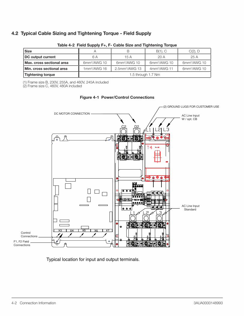
4.2 Typical Cable Sizing and Tightening Torque - Field Supply
Table 4-2 Field Supply F+, F- Cable Size and Tightening Torque
Size A B B(1), C C(2), D
DC output current 6 A 15 A 20 A 25 A
Max. cross sectional area 6mm2/AWG 10 6mm2/AWG 10 6mm2/AWG 10 6mm2/AWG 10
Min. cross sectional area 1mm2/AWG 16 2.5mm2/AWG 13 4mm2/AWG 11 6mm2/AWG 10
Tightening torque 1.5 through 1.7 Nm
(1) Frame size B, 230V, 255A, and 460V, 245A included(2) Frame size C, 460V, 480A included
Figure 4-1 Power/Control Connections
Typical location for input and output terminals.
DC MOTOR CONNECTION
(2) GROUND LUGS FOR CUSTOMER USE
AC Line InputW / opt. CB
AC Line Input Standard
ControlConnections
F1, F2 FieldConnections
C2 D2

Power Wiring 5-13AUA0000148993
Chapter 5Power Wiring
This section outlines the basics of the power wiring for the DCS800-EP.
5.1 Grounding the Control
WARNING: Be sure the system is properly grounded before applying power. Do not apply AC power before you ensure that all grounding instructions have been followed. Electrical shock can cause serious or fatal injury.
WARNING: Printed circuit boards contain components sensitive to electrostatic discharge. Wear a grounding wrist band when handling the boards. Do not touch the boards unnecessarily.
These instructions are intended for all who are responsible for the grounding of the drive. Incorrect grounding can cause physical injury, death or equipment malfunction and increase electromagnetic interference.• Ground the drive, motor and adjoining equipment to ensure personnel safety in all circumstances, and to reduce
electromagnetic emission and pick-up.• Make sure that grounding conductors are adequately sized as required by safety regulations.• In a multiple-drive installation, connect each drive separately to protective earth (PE).• Minimize EMC emission and make a 360° high frequency grounding of screened cable entries at the cabinet lead-through.• Do not install a drive with EMC filter on an ungrounded power system or a high resistance-grounded (over 30 ohms) power
system.
Note:• Power cable shields are suitable for equipment grounding conductors only when adequately sized to meet safety regulations.• As the normal leakage current of the drive is higher than 3.5mA AC or 10mA DC (stated by EN50178, 5.2.11.1) a fixed
protective earth connection is required.
5.2 Incoming Power
The DCS800-EP is designed for the incoming power ratings listed below. If your installation does not meet these ratings, contact your local sales office for support.
Table 5-1 Incoming Power
Description Rating
Input Voltage, 3-phase 230 or 460VAC as indicated on panel nameplate
Input Voltage Deviation ±10% continuous: ±15% up to 30 cycles
Note: Special consideration must be given to voltage deviation in regen mode
Rated Frequency 50/60Hz ±2%

5-2 Power Wiring 3AUA0000148993
Figure 5-1 Power Diagram - 460V Units
T1 X1
115V
X3
H1
460V
H2
H3
H40V
F6
F4 F5
DR
IVE
CH
AS
SIS
GN
D
W1
V1
U1
DC
S80
0 P
OW
ER D
1
PE
C1
K1
12
34
56
K2
12
34
56
MO
TOR
MTR
1MC
B
21
43
65
PE
480V
/3P
H60
HZ
L3
CU
STO
ME
RS
UP
PLI
ED
L2L1
GN
D
+F27
8
F9 F10
F11
L3T3
OL2
L2L1
T2T1
GN
D
MO
TOR
MTR
PE
OP
TIO
N
F+ F-
CU
STO
ME
R
EX
CIT
ER
FIE
LDO
N-B
OA
RD
TB1
TB2
CU
STO
ME
R B
LOW
ER
OP
TIO
N+0
F250
- D
ELE
TES
K1
OP
TIO
N
LL1
LL2
(RE
D)
(RE
D/W
HT)
(WH
T)
PE
GN
D
FIE
LD
+M6x
x F1 F2 F3
L1 L2 L3
C1
A1
B1
A2
B2
C2
+E21
3O
PTI
ON
F7 F8
C2
D2
ON
LYR
EG
EN
UN
ITS
With
230
V o
pti
on
230V
H1
H2
H3
H4
T1 X1
115V
X3
Inpu
t Pow
erF
4 an
d F
5 F
uses
DC
S80
0-E
Px-
350-
05 a
nd b
elow
230
Vac
inpu
t46
0 V
ac in
put
Use
(2)
FN
QR
2U
se (
2) F
NQ
R 1
-1/8
DC
S80
0-E
Px-
405-
05 a
nd a
bove
230
Vac
inpu
t46
0 V
ac in
put
Use
(2)
FN
QR
3U
se (
2) F
NQ
R 2
See
oth
er fu
se r
atin
gs in
Sec
tion
B.1
.8.

Power Wiring 5-33AUA0000148993
5.3 Input ImpedanceWhen thyristor, (SCR), power converters operate, the line voltage is momentarily short-circuited during commutation from one thyristor to the next. This causes voltage dips in the mains PCC, (point of common coupling). This “Line Notching” may affect performance of other equipment powered from the same AC supply. Adding a Line Reactor or Isolation Transformer ahead of the DC drive helps reduce Line Notching.
5.3.1 Line ReactorIn order to ensure optimum drive performance, each DCS800-EP requires a line reactor or isolation transformer on the AC input side of the drive. In some installation sites, a line reactor or transformer may already be in place, and can be used with the DCS800-EP. Drives 150HP and below can be ordered with an internal line reactor, (+E213), but be sure sufficient cabinet depth is available. See DCS800-EP Installation and Start Up Manual for dimensions and reactor recommendations. See Appendix B, Table B-5.
5.4 Protective DevicesThe drive protects itself and the input and motor cables against thermal overload when the cables are dimensioned according to the nominal current of the drive. See Tables 4-1 and 4-2.
5.4.1 Mains Cable (AC Line Cable) Short-Circuit ProtectionAlways protect the input cable with fuses. Size the fuses according to the local safety regulations, appropriate input voltage and the rated current of the drive High-Speed semiconductor fuses provide short-circuit protection.
Note AC Line Fuses: To properly protect the converter, semiconductor fuses on the incoming AC power line are required in all cases. See Appendix B.
5.4.2 DC Output ProtectionIn no case should standard fusing be used instead of semi-conductor fusing in order to save money on installation. In the event of a fault condition, the small amount of money saved can cause the semi-conductors of the other devices to explode and could also cause fires. Adequate protection against short-circuit and earth fault, as depicted in the EN50178 standard, is possible only with appropriate semi-conductor fuses.
Note DC Output Fuses: Fuses between the motor and the converter are required for all regenerative (4Q) converters. This is to protect the motor and converter if a commutation fault should occur. DC output fuses are the same type and size as AC line fuses.
See Appendix B Table B-2 for fuse type and part number furnished in the DCS800-EP Panel Drive.
5.4.3 Circuit Breaker Protection (Optional)A circuit breaker is offered for the DCS800-EP.
Circuit Breaker Protection, option plus code +F278, ratings:Instantaneous trip: All Drives: Factory set at 300% of rated current.
Thermal overload trip: 60HP (DCS800-EP1-0125-05 and DCS800-EP2-0140-05) only: Factory set to 100% of rated current.
5.4.4 Motor ConnectionsThe motor armature connections are made at the drive terminals C2 and D2, and the motor field connections are made at the field supply terminals F+ and F-. On regenerative drive models with armature fuses installed, the motor armature connections are made at terminals C2 and D2. See Figure 5-1, Power Diagram. Cable sizing and tightening torque is shown in Chapter 4, Table 4-1 and 4-2. (On non-regenerative drives, the drive has terminal blocks or replaces the DC fuse with a busbar.)
5.5 Feedback
The DCS800-EP has analog DC Tachometer and Pulse Encoder signal inputs provided as standard on the SDCS-CON-4 circuit board, or the SDCD-IOB-3 option board may be used.
5.5.1 Analog DC Tachometer ConnectionThe analog DC Tachometer input connections are made at terminal strip X3, terminals 1, 2, 3, and 4 (com). The terminal connections used depend on the value of the maximum tachometer voltage. Jumper S1 is set according to the maximum tachometer voltage. See Table 5-2.

5-4 Power Wiring 3AUA0000148993
Table 5-2
Terminal Strip X3 -
Terminal #
Maximum Tachometer
Voltage RangeJumper S1 Position
1 ±90 to ±270V 6
3 9
2 8
1 7
4
2 ±30 to ±90V
3 ±8 to ±30V
4 GND - 0V
1 ±90 to ±270V 6
3 9
2 8
1 7
4
2 ±30 to ±90V
3 ±8 to ±30V
4 GND - 0V
1 ±90 to ±270V 6
3 9
2 8
1 7
4
2 ±30 to ±90V
3 ±8 to ±30V
4 OPEN
1 ±90 to ±270V 6
3 9
2 8
1 7
4
2 Inputs Ignored
3 Inputs Ignored
4 Reserved
5.5.2 Pulse Encoder ConnectionConnecting a pulse encoder to the DCS800-EP converter: The connection diagram for a pulse encoder to the electronics of a DCS converter is quite similar, if the SDCS-CON-4 or the SDCS-IOB-3 is used. The basic difference between these two boards is the galvanically isolated circuit and pulse receivers via opto coupler on the SDCS-IOB-3 board.
Power supply for incremental encoder: SDCS-CON-4 and SDCS-IOB-3 boards have jumpers to select a supply voltage. V17 LED on SDCS-IOB-3 indicates supply is okay.
Table 5-3
Encoder Supply
Hardware Configuration
SDCS-CON-4 supplied by PIN-4 SDCS-IOB-3
5V sense controlled sense controlled
12V - sense controlled
24V no sense no sense
Sense feedback connection is recommended when power supply level for differential pulse encoder is 5V. The wiring is shown on figure below.
Default positions
Filter for AC tachw/rectifier
Parking Position - Term 4 not grounded
Reserved for Option Bd.SDCS-IOB-3 Tach input 2 through X2-23, 24

Power Wiring 5-53AUA0000148993
Commissioning hint
Note: if the drive’s measured direction of rotation is wrong or does not correspond to measured EMF speed, the SPEEDFB fault (F522) or TACH POLARITY fault (F553) may appear during start-up. If necessary, correct by exchanging the field connection.
Figure 5-2
DIFFERENTIAL
SINGLE-ENDED
= twisted pair CON-4IOB-3
X5:1
X5:2
X5:3
X5:4
X5:5
X5:6
X5:7X5:8
X5:9
X5:10
IOB-3X5:1
X5:2
X5:3
X5:4
X5:5
X5:6
X5:7X5:8
X5:9
X5:10
X5:1
X5:2
X5:3
X5:4
X5:5
X5:6
X5:10X5:9
X5:8
X5:7
X5:1
X5:2
X5:3
X5:4
X5:5
X5:6
X5:10X5:9
X5:8
X5:7
CON-4
ChA+
ChA-
ChB+
ChB-
ChZ+
ChZ-
Power sourceSense power
Sense GND
GND
ChA+
ChA-
ChB+
ChB-
ChZ+
ChZ-
Power source
GND
IOB3x3_g.dsf
If with a positive reference the position signal 3.07 or 3.08 signal does not look like the illustration below, then tracks A and A must be exchanged with inverted signals. For single-ended encoders Tracks A and B must be exchanged.
0
65535
Forward
5.5.3 ResolversTwo options are available for resolver interface. The first option is for applications where the resolver is primarily used as a positioning device, a lifting table, for example. In this case, the RRIA-01 resolver interface adapter can be used. The RSCM-01 can also be used with the RRIA-01 to double the resolver voltage to adapt it to the working range of this board.
Plus code+L516 Resolver interface adapter (RRIA-01) Resolver signal conditioning module (RSCM-01) When speed control is required, or whenever a premium interface is desired, the FEN-21 resolver interface adapter is suggested. The FEN-21 is attached to a DIN-rail mounted extension adapter which communicates to the drive over a fiber optic cable. (COM-81 or -82 is required.) The FEN-21 provides an ultra-smooth speed feedback signal for optimal speed control. (Fiber optic cable and external 24VDC supply also required.)
Field kit codeFEN-21 Resolver interface adapterFEA-01 F-series extension adapterCOM-81 or COM-82 Optical communication module
Jumper S4 (CON-4)
5V
3 6 9 12
2 5 8 11
1 4 7 10
24V
3 6 9 12
2 5 8 11
1 4 7 10
5V
3 6 9 12
2 5 8 11
1 4 7 10
24V
3 6 9 12
2 5 8 11
1 4 7 10

5-6 Power Wiring 3AUA0000148993
5.6 Field Supply
The DCS800-EP has as standard, an on board current regulated field supply. The field supply circuitry on the D1-D4 drives is on the PIN-4 board. This field supply is the same circuit and components used on the optional FEX-425-INT which is used inside the D5 drive. The onboard field supply for the D1-D4 drives is always 3-phase (since it is prewired to the U, V, W terminals). The FEX-425-INT is a half controlled three-phase field converter. The board has circuitry for synchronization and current control. The current measurement circuit is automatically scaled based on rated motor field current. The field exciter is fully controlled and monitored via serial communication from the armature converter. The field exciter is prepared to operate with three phase or single phase input. Terminals U and W are used for single phase input. See Figure 5-1, Power Diagram.

Power Wiring 5-73AUA0000148993
5.7 Control Power
The DCS800-EP has as standard, an on board control circuit transformer. This transformer secondary provides 115VAC to the drives controlling relays, cooling fans, and blower motor starter, (if equipped). The primary of the CCT is normally supplied configured for 460VAC input voltage. It can be reconfigured for 230VAC input. See Figures 5-3 and 5-4 for circuit diagrams. Reference the DCS800-EP Installation and Start-Up Manual for more detailed information.
Figure 5-3 Control Power Diagram C1 - 10HP-250HP (DCS800-EP1-0020 through EP2-0250)
T1 X1
115V
X3
H1
460V
H2
H3
H40V
F6
DR
IVE
CO
NTA
CTO
RK
1
DR
IVE
CH
AS
SIS
1X961X99DC
S80
0 C
ON
TRO
L
2X99 2X96
D08
K1
OL2
9596
BLO
WE
R M
OTO
R S
TAR
TER
TB1
DR
IVE
FA
NS
TB2
K2
1314
A1
A2
A1
A2
2X6 9X6
K2
1314
TB 3TB 4
OP
TIO
N+M
6xx
(RE
D)
(RE
D/W
HT)
(RE
D/B
LK)
(RE
D/O
RN
)
(RE
D/Y
EL)
(RE
D/W
HT)
(BR
N)
(YE
L)
(WH
T)
(WH
T/B
LK)
(OR
N)
(WH
T/O
RN
)
(WH
T/Y
EL)
(BLU
)
(VIO
)
(WH
T/R
ED
)
1X2
4X2
2X2 3X2
FAN
FAN
(RE
D/B
LU)
3
(WH
T/R
ED
)
*
*
6 A
MP
S M
AX
., 11
0VA
C o
r 24
VD
C
With
230
V o
pti
on
230V
H1
H2
H3
H4
T1 X1
115V
X3

5-8 Power Wiring 3AUA0000148993
Figure 5-4 Control Power Diagram C2 - 300HP-600HP (DCS800-EP1-0610 through EP2-1010)
T1 X1
115V
X3
H1
460V
H2
H3
H40V
F6
DR
IVE
CO
NTA
CTO
RK
1
DR
IVE
CH
AS
SIS
1X961X99DC
S80
0 C
ON
TRO
L
2X99 2X96
D08
K1
OL2
9596
BLO
WE
R M
OTO
R S
TAR
TER
TB1
DR
IVE
FA
NS
TB2
K2
1314
A1
A2
A1
A2
2X6 9X6
K2
1314
TB 3TB 4
OP
TIO
N+M
6xx
(RE
D)
(RE
D/W
HT)
(RE
D/B
LK)
(RE
D/O
RN
)
(RE
D/Y
EL)
(RE
D/W
HT)
(BR
N)
(YE
L)
(WH
T)
(WH
T/B
LK)
(OR
N)
(WH
T/O
RN
)
(WH
T/Y
EL)
(BLU
)
(VIO
)
(WH
T/R
ED
)
1X2
X2
3X2
FAN
2
3
(WH
T/R
ED
)
With
230
V o
pti
on
230V
H1
H2
H3
H4
T1 X1
115V
X3
*
*
6 A
MP
S M
AX
., 11
0VA
C o
r 24
VD
C

Control Wiring 6-13AUA0000148993
Chapter 6Control Wiring
This section outlines the basics of the control wiring for the DCS800-EP. Sample wiring diagrams are shown later for each of the different selectable macros.
6.1 Digital Inputs
The DCS800-EP is supplied with 8 digital inputs for controlling the drive and motor. The connections for these digital inputs are made on the X6 terminal strip terminals 1 through 8. The function of these digital inputs is set according to the selected application macro but can be individually adjusted as well. Application macros are used to select pre-configured setups which minimize the programming required to commission the drive. There are 12 macros available to fit various applications. 24VDC supply is available at terminal 9 of X6 for the digital control signal inputs. Terminal 10 is a digital common terminal. The digital input functions may be re-programmed to suit the application as required using group 10 parameters. For complete detailed information, see Chapter 9, Macro Selection.
The macros are listed here:• 3 Wire Jog - Simulates Reliance FlexPak 3000 digital and analog control.• Factory - Resets all parameters to default values.• Standard - Motion commanded with RUN, JOG1 or JOG2.• Manual/Const Spd - Allows for Constant, (Preset) Speeds.• Hand/Auto - DI2 selects between Hand, (Local I/O) and Auto.• Hand/Motor Pot - DI4 selects between Hand, (Local I/O), and Motorized Potentiometer.• MotPot - Speed is always controlled with digital UP and DOWN inputs.• Torque Control - DI2 switches between SPEED and TORQUE control.• Torque Limit - AI2 sets TORQUE LIMIT.• 2 Wire DC Contactor US - Controls DC contactor - Requires CONTACTOR ACK signal.• 3 Wire DC Contactor US - Controls DC contactor - Requires CONTACTOR ACK signal.• 3 Wire Standard - Drive Starts and Runs with pulsed input, Stops with opening of STOP input.
Figure 6-1 Digital Inputs
DI 1
DI 3
DI 4
DI 5
DI 6
DI 7
DI 8
+24V
1
2
3
4
5
6
7
8
9
10 0V
DI 2
X6
6.1.1 External TripTerminals are designated by the selected macro for External trip inputs. The input functions may be E-Stop, Coast Stop, Ext. Alarm, or Ext. Fault. These external trip features may be used as Customer Interlocks, drive Enable, or Run Permissive for various applications.
6.1.2 Drive EnableA Drive Enable circuit is implemented for a digital input when one of the Application Macros, Factory, Torque Control, or 3-Wire Jog is selected. If an application uses one of the other macros, and an Enable circuit is a requirement, an available digital input may be programmed as an Enable. If the Enable circuit opens while the drive/motor is running, alarm A101 is generated. The drive will continue running until a STOP is asserted. The drive cannot be restarted until the cause of the open ENABLE is determined and closed again.
6.1.3 Other Digital InputsRemaining digital inputs that may be required for operating the DCS800-EP properly for the application can be programmed for specific functions such as, Jog, Constant Speeds (presets), Hand/Auto, or additional Run Permissives.

6-2 Control Wiring 3AUA0000148993
6.2 Analog Inputs
Four analog signal inputs are provided on the standard control board in the DCS800-EP. Three inputs are on the X3 terminal strip, and one is on the X4 terminal strip. By using the on board +10VDC supply, a speed adjustment potentiometer can be used for manual speed control. See simplified diagram Figure 6.2.
6.2.1 Analog Inputs Jumper CodingHardware setting for analog inputs AI1 and AI2 for switching from voltage input to current input is accomplished by means of jumpers S2 and S3 on the SDCS-CON-4 Control Board.
Table 6-1 Jumper Coding S2 Jumper Coding Diagram
2 4*
1 3*
2 4
1 3
S3 Jumper Coding Diagram2 8*
1 7*
2 8
1 7
2 8*
1 7*
2 8
1 7
S1 Jumper Coding Diagram3 9
2 8*
1 7
3 9
2 8
1 7
3 9
2 8*
1 7
3 9
2 8
1 7
3 9
2 8*
1 7
3 9
2 8
1 7
* Default value** 250 Ohm x 20mA = 5V = 100%
Jumper parking positionNo filter; Normal DC Tachometer
Filter for AC Tachometer with rectifier
Tachometer input X3:4 connected with 0V / GND
Jumper parking position;no grounding of Tachometer input
Tachometer input 1 at X3:4 and X3:1/2/3 atSDCS-IOB-3 / PS5311
Reserved: Tachometer input 2 at X2:23 and X2:24 at SDCS-IOB-3 / PS5311
AI1 - X3:5-6: RIN = 200kOhm;Range -10V to 0V to +10V
AI1 - X3:5-6: RIN = 250kOhm; **Range IIN = -20mA to +20mA
AI2 - X3:7-8: RIN = 200kOhm;Range -10V to 0V to +10V
AI2 - X3:7-8: RIN = 250kOhm;**Range IIN = -20mA to +20mA
Jumper parking position 5-6
Pull-up resistor 4.74kOhm activated at X3.7 for PTC temperature sensor

Control Wiring 6-33AUA0000148993
Additional input range for AI1 and AI2 is available by installing the SDCS-IOB-3 option module. The hardware gain can be increased by 10 with jumpers S2 and S3, thus the input range changes from ±10V to ±1V. See DCS800, 3ADW000194R0611, Hardware manual for more information.
Up to eight analog inputs can be utilized by installing up to two additional RAIO-1 option modules.
Terminals 1 through 4 on the X3 terminal strip are provided for analog DC tachometer input signal. The voltage range allowed is from 0 - 8VDC to 0 - 270VDC. Use Jumper S1 to select Filter and grounded/not grounded.
Figure 6.2 shows connection of a potentiometer to AI1 for remote manual speed control.
Figure 6-2 Potentiometer Connection for Manual Speed Control
(5)
(6)(-)
(-)
(-)
(+)
(+)
(+)
AI 1
AI 2
AI 3
(4)
(6)
(-)
(+)AI 4
(7)
(8)
(9)
( 10)
(1)
(2)
(3)
(5)
0V
+10V
-10V
0V
X 3
X4
6.3 Digital and Relay Outputs
The DCS800-EP has digital and relay outputs which may be used to indicate states of various conditions. For example, a relay can be set up to illuminate an external indicator or sound an alarm if the drive trips on a fault.
6.3.1 Digital OutputsThere are 7 digital outputs and 1 Relay output provided in the DCS800-EP. Digital outputs, DO1 through DO7 are Relay Driver outputs limited to 50mA load, (160mA maximum for all 7 outputs). The output voltage is 22VDC unloaded and not regulated, therefore, care must be observed to ensure the outputs are not overloaded to the point that they no longer function. The outputs are short circuit protected. The function of the digital outputs is programmable in parameter group 14.Note: The factory default settings for:DO1 is 603 bit 0 = FansON – FansOffDO2 is 603 bit 5 = FieldON – FieldOffDO3 is 603 bit 7 = MainContactorOn – MainContactorOffDO4 thru DO7 is 0See Appendix B for Technical Data.
Figure 6-3 Digital Outputs
RUNNING
ALARM
FAULT
(1)
(2)
(3)
(4)
DO 1
DO 2
DO 3
DO 4
(5)
(6)
(7)
(8)
DO 5
DO 6
DO 7
0 V
X7
18-22VDC Driver50mA each up to 160mA total

6-4 Control Wiring 3AUA0000148993
6.3.2 Relay OutputsDigital Output 8, (DO8), is a relay with the normally open contacts provided on terminal strip X96 terminals 1 and 2.
Note: The factory default setting for DO8 is 603 bit 7 = MainContactorOn – MainContactorOffOutput contact rating of the DO8 relay:3A / 24VDC,0.3A / 115VDC/230VDC max,3A / 230VAC max
6.4 Analog Outputs
The SDCS-CON-4 includes 3 standard AO’s. Two AO’s are programmable. The third one, Iact, is fixed and used to display the actual armature current taken directly from the burden resistors. See Appendix B for Analog Outputs Technical Data.
Figure 6-4 Analog Outputs
(7)
(8)
(9)
(10)
AO 1
AO 2
IACT
0V
ANALOG OUT 1
ANALOG OUT 2
ANALOG C OM
ANALOG OUT - IACT
X4
6.5 Communication Options
Communication options available for the DCS800-EP include:
SDCS-DSL-4 (DCSLink)
The SDCS-DSL board provides drive to drive communication. The communication hardware and protocol is based on CAN bus. The DCSLink can be used for master-follower, and communication to either single phase or three phase field exciter. This is also used for 12-pulse operation. The communication hardware is equipped with an isolated supply and isolated transmitter. The terminator can be set by Jumper S1 and S2. See section DCS Link Wiring in the Hardware Manual.
DDCS channels with SDCS-COM-8The Distributed Drives Communication System is an optical link. Setup is with parameter group 70, DDCS Control. When this option is included, DDCS communication can be used with ACS800 drives in a leader-follower configuration. The board is equipped with four optical channels (max. data transmission speed is 4Mb for each optical channel):•Channel0isusedtocommunicatedatafromtheoverridingcontrol(FCI,APC2,AC800M,Nxxx-xx(adaptermodulesfor fieldbus), AC80) or via adapter modules from other controllers) to the DCS800-EP-drive.•Channel1isusedforDDCSI/Oextension.AIMA-01boardseeseparatedocumentation.•Channel2(Master-Follower)isusedtooperatetwoormoredrivesdependentoneachother. Channel 3 is prepared to connect the PC tool for commissioning and maintenance (DriveWindow).•ConnectorX19isusedforCDP312panelaswellasinterfaceboardNDPI.
Additional Network Communication Options available:
RCAN-01 CANopenRCNA-01 ControlNetRDNA-01 DeviceNetRETA-01 EtherNet/IP & Modbus/TCPNETA-01 Ethernet Web BrowserRMBA-01 Modbus-RTURPBA-01 Profibus DPRECA-01 EtherCat RETA-02 ProfiNetSee respective instruction manuals for more detailed information.

Applying Power 7-13AUA0000148993
Chapter 7Applying Power
This section describes the basic start-up procedure of the DCS800-EP. A more detailed description of the signals and parameters involved in the procedure can be found in the Firmware manual.
7.1 Installation Checklist
Check the mechanical and electrical installation of the drive before start-up. Go through the checklist below together with another person. Read the Safety Instructions before you work on the unit.
7.1.1 Mechanical Installation• The cabinet internal ambient temperature and the external ambient air temperature are within limits (See Mechanical Installation
and Technical Data).• The cabinet is vertically mounted on a non-flammable surface.• The cooling air can flow freely.• The motor and the driven equipment are ready for start. (See Planning the Electrical Installation).• All shield and grounding connections are properly tightened according to specified torque. (See Typical Cable Sizing and
Tightening Torque).
7.1.2 Electrical Installation(See Planning the Electrical Installation, Electrical Installation)• The drive is properly grounded.• The AC input voltage matches the drive nominal input voltage.• The AC input cables are properly seated and tightened to specified torque. (See Typical Cable Sizing and Tightening Torque).• The motor cables (C2, D2 and F+, F-) are properly seated and tightened to specified torque. (See Typical Cable Sizing and
Tightening Torque).• Proper function of the E-Stop circuitry.• Fan power wiring is connected.• Control connections are properly made and logic is sound.• There are no tools, foreign objects, dust or debris from drilling inside the drive.• Covers are in place on the drive, motor and any connection boxes.
7.2 Drive Operation
The drive can be operated:From DriveWindow, DriveWindow Light, DCS800 Control Panel, (LOC), or remotely, (REM), with digital and analog I/O or overriding control.
7.3 Apply Incoming Power
After verifying the above steps in the checklist, close the disconnect switch (or circuit breaker) that has been dedicated to the power source for the DCS800-EP. Verify Control Panel display backlight illuminates thus indicating that power has been applied to the control
7.4 Commissioning
Continue Start-Up by following one of the procedures described.
• DriveWindow Light 2 PC tool. It is highly recommended to use the start-up WIZARD in the DWL 2 PC tool to commission the DCS800-EP. This software is provided on a CD Rom disc furnished with the drive. It offers a very simple step-by-step procedure to enter parameter values needed for initial set up and autotuning. A serial communication cable is needed for interconnection between the PC Com port and X34 9 pin D-shell connector on the drive control board. (A USB to Serial adapter may be needed for PCs that do not have a 9-pin port connector).
• Commissioning can also be easily accomplished by using the Quick Start ASSISTANT feature of the keypad/display. This is also a step-by-step procedure to complete inital start-up and autotuning. See Chapter 8, Control Panel (Keypad) and Programming.
• Another PC tool that can be used for commissioning is DriveWindow. Before starting with the commissioning, connect the drive (via Ch3 on SDCS-COM-8) with DriveWindow (via e.g. initial and NDPC-12).
Detailed information on using any of the above procedures can be found in the DCS800 Firmware Manual - 3ADW000193R0701.

7-2 Applying Power 3AUA0000148993

Control Panel (Keypad) and Programming 8-13AUA0000148993
Chapter 8Control Panel (Keypad) and Programming
This section describes the Control Panel for the DCS800-EP. The Control Panel is used for commissioning the drive with START Up Assistants, parameter programming, and operational control (LOC) of the drive. The Control Panel can be used easily while installed in the front cover of the drive or it can be remotely located using optional extender mounting kits.
8.1 Initial Setup
The Control Panel is shown in Figure 8-1 with display and key function descriptions. After the drive is installed and power has been applied according to the steps outlined in Chapter 7, the motor must be identified to the drive, (commissioning).
Figure 8-1 Control Panel (Keypad)
Status LED: • Green for normal operation • Flashing green for alarms • Red for faults
Soft key 1 - Function varies, and is defined by the text in the lower-left corner of the LCD display.
Up – • Scrolls up through a menu or list
displayed in the middle of the LCD display.
• Increments a value if a parameter is selected.
• Increments the reference if the upper-right corner is highlighted (in reverse video).
LOC/REM – Changes between localand remote control of the drive.
STOP – Stops the drive in local control from DCS800-EP panel and when the Start-up Assistant is used.
LCD display – Divided into three main areas: • Top line variable, depending on the mode of operation. • Middle area – variable, in general, shows parameter values, menus or
lists. • Bottom line – shows current function of the two soft keys, and the clock
display, if enabled.
Soft key 2 – Function varies, and isdefined by the text in the lower-rightcorner of the LCD display.
Down – • Scrolls down through a menu or list
displayed in the middle of the LCD Display.
• Decrements a value if a parameter is selected.
• Decrements the reference if the upper-right corner is highlighted (in reverse video).
Help – Displays context sensitiveinformation when the button ispressed. The information displayeddescribes the item currentlyhighlighted in the middle area of thedisplay.
START – Starts the drive in local control from DCS800-EP panel and when the Start-up assistant is used.

8-2 Control Panel (Keypad) and Programming 3AUA0000148993
8.1.1 Control Panel Version InformationPrior to turning power on, press and hold the HELP (?) button then apply AC power. The display will show:Panel SW: Keypad firmware version.ROM CRC: Keypad ROM check sum.Flash Rev: Flash content version.When the HELP (?) key is released, the display will show OUTPUT MODE.
PANEL VERSION INFOPanel SW x.xxROM CRC xxxxxxxxxxFlash Rev: x.xxDCS800 Quickstart Drv
8.1.2 General Display FeaturesSoft key functions: The soft key functions are defined by the text displayed just above each key. See Figure 8-1.
Display contrast: To adjust display contrast, simultaneously press the MENU key and UP or DOWN, as appropriate.
The following modes are available in the MAIN MENU.1. ASSISTANTS
a. QuickStartb. Macroc. Nameplate Datad. Autotuning Field Curre. Autotuning Arm Currf. Speed Feedbackg. Autotuning Speedh. Field Weakening
2. PARAMETERS3. CHANGED PAR4. FAULT LOGGER5. CLOCK SET6. PAR BACKUP
8.1.3 Assistants (QuickStart)When first powered on, the display will be similar to that shown in Figure 8-1. The Control Panel can be used to commission the drive/motor to a basic operating mode. To begin, press the MENU button then select ASSISTANTS then select QuickStart. At this point, the display shows a question, “Set all parameters to Factory Default?” Select Yes or Skip, press OK. If Yes is selected, all the parameters will be reset to Factory Default values.
LOC MAIN MENU------------------1PARAMETERS
CHANGED PAREXIT ENTER
ASSISTANTS
8.1.4 AssistantsYou can step through the basic start up assistant beginning with Name Plate Data or select a specific Application Macro from the QuickStart assistant.
Table 8-1 shows the parameters listed from the QuickStart assistant menu.
LOC ASSISTANTS----------------1
MacroName Plate DataAutotuning Field CurrAutotuning Arm CurrEXIT SEL
ASSISTANTSQuickStart____________________

Control Panel (Keypad) and Programming 8-33AUA0000148993
8.1.5 Parameters Entered By AssistantTable 8-2 shows the parameters listed from the QuickStart assistant menu.
Table 8-1 Parameters Entered by AssistantParameter No. Parameter Name Description
99.08 ApplMacro (Application Macro) Selects the macro (preset parameter sets) to be loaded / stored into the RAM.
99.07 ApplRestore (Application Restore) Starts the loading/storing of the macro (preset parameter set) selected at 99.08.
99.01 Language Selects one of six languages.99.10 NomMainsVolt (Nominal AC Mains Voltage) Nominal mains voltage of the AC supply.
99.04 M1BaseSpeed (Motor 1 Base Speed) Motor 1 nameplate base speed. (Usually considered field weakening point).
30.16 M1OvrSpeed (Motor 1 Overspeed) Drive will trip on F532, MotOverSpeed fault if this value is exceeded.99.03 M1NomCur (Motor 1 Nominal DC Current) Motor 1 nominal DC armature current from motor nameplate.99.02 M1NomVolt (Motor 1 Nominal DC Voltage) Motor 1 nominal DC armature voltage from motor nameplate.50.03 M1SpeedFbSel (Motor 1 Speed Feedback Selector) Motor 1 speed feedback selection.50.04 M1EncPulseNo (Motor 1 Encoder 1 Pulse Number) Encoder 1 pulse per revolution, (ppr), number.
50.02 M1EncMeasMode (Motor 1 Encoder 1 Measuring Mode) Selects the measurement mode for pulse encoder 1.
22.01 AccTime1 (Acceleration Time 1) Time in seconds to accelerate from zero speed to maximum speed as shown by the scaling value at p2.29.
22.02 DecTime1 (Deceleration Time 1) Time in seconds to decelerate from maximum speed as shown by the scaling value at p2.29 to zero speed.
20.01 M1SpeedMin (Motor 1 Minimum Speed) Motor 1 minimum speed value in rpm.20.02 M1SpeedMax (Motor 1 Maximum Speed) Motor 1 maximum speed value in rpm.20.03 M1ZeroSpeedLim (Motor 1 Zero Speed Limit) RPM value set to denote when the motor is at zero speed.
22.12 JogAccTime (Acceleration Time Jogging) Time in seconds to accelerate from zero speed to speed scaling value at p2.29 when in JOG.
22.13 JogDecTime (Deceleration Time Jogging) Time in seconds to decelerate from scaling value at p2.29 to zero speed when in JOG.
23.02 FixedSpeed1 (Fixed Speed 1) Speed in rpm for fixed speed 1, (preset speed). Also is JOG Speed.
20.12** M1CurLimBrdg1 (Motor 1 Current Limit of Bridge 1) Forward current limit in percent of Motor 1 nominal current limit, 99.03.
20.13** M1CurLimBrdg2 (Motor 1 Current Limit of Bridge 2) Reverse current limit in percent of Motor 1 nominal current limit, 99.03.
99.12 M1UsedFexType (Motor 1 Used Field Exciter Type) Selects motor 1 type of field supply, (field exciter).99.11 M1NomFldCur (Motor 1 Nominal Field Current) Motor 1 nominal field current from motor nameplate.
30.12 M1FldMinTrip (Motor 1 Minimum Field Trip) Sets the value of field current below which a fault F541, (field loss), will occur.
44.01 FldCtrlMode (Field Control Mode) Motor 1 field control mode selection.44.02* M1KpFex, value Proportional gain of the field current controller.44.03* M1TiFex, value Integral time of the field current controller in ms.
45.02* M1PosLimCtrl (Fex Voltage Limit) Positive voltage limit for motor 1 field exciter in percent of max field voltage.
43.06* M1KpArmCur, value Proportional gain of the current controller.43.07* M1TiArmCur, value Integral time of the current controller.
43.08* M1DiscontCurLim, value Threshold continuous/discontinuous current in percent of M1NomCur, 99.03.
43.09* M1ArmL, value Inductance of armature circuit in mH.43.10* M1ArmR, value Resistance of armature circuit in mOhms.24.03* KpS, value Proportional gain of the speed controller.24.09* TiS, value Integral time of the speed controller in ms.
* Set using Autotuning Assistants.
**NOTE: TorqMax (20.05) is internally set equal to M1CurLimBridge1 (20.12) and TorqMin (20.06) is internally set equal to M1CurLimBridge2 (20.13) during the QuickStart process. Current is proportional to torque below base speed but not above base speed. If field weakening is used, and in other rare cases, it may be desirable to have a different value for maximum/minimum torque and current. If this is the case, then, after completing the QuickStart process, set these values individually through browser and DO NOT use QuickStart thereafter.

8-4 Control Panel (Keypad) and Programming 3AUA0000148993
8.1.6 Digital Input SelectionDigital inputs are assigned to functions when a macro is selected, but these settings can be adjusted independently if desired. The QuickStart Assistant allows this, or you can adjust them using the parameter browser. All the settings are in group 10 except fault/alarm functions which are in group 30.
Notice: Some digital inputs will prevent a successful Autotuning test from taking place and result in a fault, Motor Fan Acknowledge, for example. Disable unused digital input functions or reassign them by adjusting the corresponding parameter (MotFanAck10.06, for example) or correct the problem to prevent faults from occurring.
8.1.7 AutotuningAfter entering the setup parameters in the QuickStart Assistant, the user will be directed through the automatic tuning assistants, which are as follows:
• Field Current Autotuning: This will measure characteristics of the motor’s field winding and calculate tuning values for the field supply (also called “field exciter” or “FEX”) controller. This test will put current through the field winding only, so no rotation usually occurs.
• Armature Current Autotuning: This will measure the resistance and inductance of the motor’s armature winding and calculate tuning values for the armature current controller. This test will put current through the armature winding only, so no rotation usually occurs.
• Speed Feedback Assistant: This test will spin the motor and check if feedback is seen on either the tachometer or encoder channel. It will then configure the drive for that device. If no device is detected, the drive will be configured for EMF (transducerless) feedback.
• Speed Controller Autotuning: This will rotate the motor briefly to measure mechanical characteristics and calculate tuning values for the speed controller. It is best if this test is done with the motor coupled to the load but be certain it is safe to do so.
• Field Weakening Assistant: This test only needs to be done if the motor will be used above base speed. It will rotate the motor at half the nominal speed, then measure the effect at different levels of field current and calculate tuning values for the EMF controller and the field weakening controller.
Each Autotuning procedure is required (except sometimes field weakening). If an Autotuning fails or if you accidently exit the QuickStart program before all tuning is complete, you may continue the tuning process by selecting the Autotuning procedure directly from the Assistants Menu.
If an Autotuning procedure continues to fail, exit the tuning procedure and see Diagnosis (9.11) in the parameter browser for a code. Then look up the message in Table 8.2.
Table 8-2 Diagnosis (Parameter 9.11)CODE MESSAGE
11 Autotuning aborted due to fault or removal of the RUN command [UsedMCW (7.04) bit 3].12 Autotuning timeout, RUN command [UsedMCW (7.04) bit 3] was not set in time.13 Motor is still turning, no speed zero indication.14 Field current not zero.15 Armature current not zero.16 Armature voltage measurement circuit open (e.g. not connected) or interrupted. Check also current and torque limits.17 Armature circuit and/or armature voltage measurement circuit incorrectly connected.18 No load connected to the armature circuit.19 Invalid nominal armature current setting. Armature current M1MotNomCur (99.03) is set to zero.20 Field current does not decrease when the excitation is switched off.
21 Field current actual did not reach field current reference; or no detection of field resistance; or field circuit open (e.g. not connected) or interrupted.
22 No writing of control parameters for speed controller.23 Tachometer adjustment faulty or not OK or the tachometer voltage is too high during autotuning.
24 Tuning of speed controller, speed feedback assistant or tachometer fine tuning not possible due to speed limitation. See e.g. M1SpeedMin (20.01) and M1SpeedMax (20.02).
25 During these procedures, the motor may reach base speed. Thus full armature voltage is necessary. If the mains voltage is too low, the autotuning procedure is aborted. Check and adjust if needed: Mains voltage; M1NomVolt (99.02); M1BaseSpeed (99.04).
26 Field weakening not allowed. See M1SpeedFbSel (50.03) and FldCtrlMode (44.01).27 M1CurLimBrdg2 (20.13).28 Drive instead.29 No field exciter selected. See M1UsedFexType (99.12)
80 Speed does not reach set point (EMF control).81 Motor is not accelerating or wrong tachometer polarity (tachometer/encoder).82 Not enough load (too low inertia) for the detection of speed controller parameters.83 Drive not in speed control mode. See TorqSel (26.01), TorqSelMod (26.03), TorqMuxMode (26.04).
NOTICE: See DCS800 Firmware Manual for additional codes.

Control Panel (Keypad) and Programming 8-53AUA0000148993
8.2 ProgrammingUse the parameters mode to view and edit parameter values:
1. Press UP or DOWN arrow key to highlight PARAMETERS in the MAIN MENU, then press ENTER.
2. Press UP or DOWN to highlight the appropriate parameter group, then press SEL.
3. Press UP or DOWN to highlight the appropriate parameter in a group, then press EDIT to enter PAR EDIT mode.
Note: The current parameter value appears in the highlighted parameter.
4. Press UP or DOWN to step to the desired parameter value.
Note: While in the EDIT mode to get the parameter default value press UP/DOWN simultaneously.
5. Press SAVE to store the modified value and leave the PAR EDIT mode or press CANCEL to leave the PAR EDIT mode without modifications.
6. Press EXIT to return to the listing of parameter groups, and again to step back to the MAIN MENU.
LOC MAIN MENU------------------1
CHANGED PAREXIT ENTER
ASSISTANTSPARAMETERS
LOC PAR GROUPS--------------01
02 SPC Signals03 Ref Act Values04 Information05 Analog In/Out
EXIT SEL
01 Phys Act Values_____________
LOC PARAMETERS----------------9901 Language
9903 M1NomCur9904 M1BaseSpeedEXIT EDIT
9902 M1NomVolt_______________ 350V
LOC PAR EDIT---------------------
9902 M1NomVolt
350V
CANCEL SAVE
8.3 Output ModeUse the output mode to read information on the drive’s status and to operate the Drive while in local, (LOC). To reach the output mode, press EXIT until the LCD display shows status information as shown.
LOC 15rpm
17.3 ADIR MENU
15.0 rpm3.7 V
Status Information

8-6 Control Panel (Keypad) and Programming 3AUA0000148993
8.4 Local / Remote OperationThe DCS800-EP can be operated via the control panel when in Local, (LOC) or via the terminal strip inputs or network communications when in Remote, (REM). The mode can be changed by pressing the LOC/REM key on the keypad.
While in Local mode the terminal strip inputs or network communication are ignored except for digital inputs programmed for E-stop, External Fault, and/or External Alarm which remain active in Local control mode. To operate the drive from the Control Panel, speed is set with the UP and DOWN arrow keys. The START and STOP keys control motor run/stop, and the direction key, (softkey) will change motor shaft direction of rotation on regenerative drives.
8.5 Parameter BackupThe DCS800-EP Control Panel can store a full set of drive parameters. The parameter backup mode has the following functions:
UPLOAD TO PANEL: Copies all parameters from the drive into the DCS800-EP Control Panel. This includes both user sets (User1 and User2) - if defined - and internal parameters such as those created by tacho fine tuning. The DCS800-EP Control Panel memory is non-volatile and does not depend on its battery. Upload can only be done in drive state Off and local from DCS800-EP Control Panel.
DOWNLOAD FULL SET: Restores the full parameter set from the DCS800-EP Control Panel into the drive. Use this option to restore a drive, or to configure identical drives. Can only be done in drive state Off and local from DCS800-EP Control Panel.
The general procedure for parameter backup operations is:
1. Press the EXIT key to return to the MAIN MENU. Verify control panel is in local mode.
2. Press the UP or DOWN to highlight PAR BACKUP in the MAIN MENU, then press ENTER.
3. Press the UP arrow key to highlight “Upload To Panel”, press SEL.
4. After a short time, “Parameter upload successful” will appear on the display.
5. Press the DOWN arrow key to highlight “Backup Info”, press SEL.
6. “BACKUP INFO” display will show DRIVE TYPE, DRIVE RATING, and FW VERSION.
To download a parameter set to the drive:
1. Select “Download Full Set” from the PAR BACKUP menu, then press SEL.
2. After a short time, “Parameter download successful completed” will be displayed.
3. Press EXIT to return to the MAIN MENU.
LOC MAIN MENU------------------1CLOCK SET
ASSISTANTSEXIT ENTER
PAR BACKUP

Macro Selection 9-13AUA0000148993
Chapter 9Macro Selection
This section describes the application macros available in the DCS800-EP. Macros are used to select pre-configured setups which minimize the programming required to commission the drive. There are 12 macros available to fit various applications. The Macro which best fits the application is selected in parameter 99.08 - ApplMacro (Application Macro), then loaded and stored by setting parameter 99.07 - ApplRestore (Application Restore), = Yes. It can also be selected using the QuickStart Assistant.
9.1 Macro Descriptions
The following paragraphs show a connection diagram that corresponds to each of the Macros with a brief description of the digital and analog input functions.
9.1.1 Factory Macro (Factory)The Factory Macro sets up a basic digital input configuration. This macro is primarily used as a FACTORY RESET which resets all parameters to the factory default values. This should be done on initial configuration of the drive before loading a different macro. This can also be quite handy to get back to a good “starting point” when a great number of parameter changes may become too complicated and drive operation is not as expected.
Notice: All tuning values will be erased and reset to factory default.
Figure 9-1 Factory Macro Diagram
Digital Input 1
Digital Input 2
Digital Input 3
Digital Input 4
Digital Input 5
Digital Input 6
Digital Input 7
Digital Input 8
X6:1
X6:2
X6:3
X6:4
X6:5
X6:6
X6:7
X6:8
Converter Fan Ack
Main Cont. Ack
Off2 (Coast Stop)
E-stop
Motor Fan Ack
Reset
OnOff1
Start/Stop
X6:1 Closed Indicates Converter Fan AcknowledgeX6:2 Closed Indicates Motor Fan AcknowledgeX6:3 Closed indicates Main Contactor Acknowledge (K1 Via “M” Aux.)X6:4 Open initiates OFF2 ( Coast Stop) Must be closed before RunX6:5 Open initiates “E-Stop”X6:6 Closed Pulse Resets a “Fault”X6:7 Closed Initiates “Drive On” and “M” contactor closureX6:8 Closed Initiates “Drive Run”
To contactor coil circuit
D08
X96:2X96:1
X6:9 + 24 V
DIGITAL OUTPUTS
K1
1 DO1 Fans On cmd.
2 DO2 Field excit. On cmd.
3 DO3 Main contact. On cmd.
4 DO4 -
5 DO5 -
6 DO6 -
7 DO7 -
8 0 V -
X7:
3 4

9-2 Macro Selection 3AUA0000148993
9.1.2 Standard Macro (Standard)The Standard Macro features two wire START/STOP, JOG 1, and JOG 2. Speed is set at analog input 1, (AI1).
Figure 9-2 Standard Macro Diagram
Digital Input 1
Digital Input 2
Digital Input 3
Digital Input 4
Digital Input 5
Digital Input 6
Digital Input 7
Digital Input 8
X6:1
X6:2
X6:3
X6:4
X6:5
X6:6
X6:7
X6:8
Jog 1
External Fault
E-stop
Jog 2
Reset
OnOff1
Start/Stop (K1)
X6:1 Closed Initiates “Jog Speed 1 “X6:2 Closed Initiates “Jog Speed 2”X6:3 Closed Initiates “External Fault”X6:4 Closed Initiates “External Alarm”X6:5 Open Initiates “E-Stop”X6:6 Closed Pulse Resets a “ Fault “X6:7 Closed Initiates “Drive On” and “M” contactor closureX6:8 Closed Initiates “Drive Run” (May use K1 “M” contact Aux.)
To contactor coil circuit
D08
X96:2X96:1
The Default speed reference is 0-10 Volts via Analog Input 1
X3
5 -
6 +0 - 10v Speed
reference
X4
4 ( +10 V) X3
6 +
5 -
3 ( 0 V )
OR
Speed Reference Pot
X6:9 + 24 V
External Alarm
DIGITAL OUTPUTS
1 DO1 ReadyRun
2 DO2 ReadyRef (running)
3 DO3 Fault or alarm
4 DO4 Zero speed
5 DO5 Above limit
6 DO6 -
7 DO7 -
8 0 V -
X7:43

Macro Selection 9-33AUA0000148993
9.1.3 Manual Constant Speed Macro (Man/Const)The Manual Constant Speed Macro features three wire START/STOP. Speed is set at AI1. If JOG 1 or JOG 2 is asserted, speed is set to the value of parameter 23.02 or 23.03. Digital Input 4, (DI4), switches to another set of tuning values to run a different motor. NOTE: Jog inputs do not initiate motion, only change speed.
Figure 9-3 Manual Constant Speed Macro Diagram
Digital Input 1
Digital Input 2
Digital Input 3
Digital Input 4
Digital Input 5
Digital Input 6
Digital Input 7
Digital Input 8
X6:1
X6:2
X6:3
X6:4
X6:5
X6:6
X6:7
X6:8
Jog 1
Direction
Kps and Tis Selection
E-stop
Reset
On Start Pulse
Off1 Stop Pulse
X6:1 Closed Initiates “Jog Speed 1”X6:2 Closed Initiates “Jog Speed 2”X6:3 Open = “Forward” / Closed = “Reverse”X6:4 KPS and TiS ; Open = Set1, Closed = Set2X6:5 Open initiates “E-Stop”X6:6 Closed Pulse Resets a “Fault” X6:7 Pulse closed initiates “Start”X6:8 Pulse open Initiates “Stop”
To contactor coil circuit
D08
X96:2X96:1
Jog 2
X3
5 -
6 +0 - 10v Speed
reference
X4
4 ( +10 V) X3
6 +
5 -
3 (0V)
OR
The Default speed reference is 0-10 Volts via Analog Input 1
SpeedReference
Pot
X6:9 +24 V
DIGITAL OUTPUTS
1 DO1 ReadyOn
2 DO2 ReadyRef (running)
3 DO3 Tripped (fault)
4 DO4 Zero speed
5 DO5 Above limit
6 DO6 -
7 DO7 -
8 0 V -
X7:

9-4 Macro Selection 3AUA0000148993
9.1.4 Hand/Auto Macro (Hand/Auto)The Hand/Auto Macro features two wire START/STOP, (manual). Hand mode speed is set at AI1. In Auto mode, speed is set via parameter 23.01. Fieldbus module is required.
Figure 9-4 Manual Hand/Auto Macro Diagram
Digital Input 1
Digital Input 2
Digital Input 3
Digital Input 4
Digital Input 5
Digital Input 6
Digital Input 7
Digital Input 8
X6:1
X6:2
X6:3
X6:4
X6:5
X6:6
X6:7
X6:8
Start/Stop (K1)
Direction
E-stop
Hand/Auto select
Reset
OnOff1
X6:1 Closed Initiates “ Drive Run” (K1 “M” aux can be used )X6:2 Open = Hand ( Local I/O and AI1) / Closed = Auto (Main control word and 23.01)X6:3 Open = “Forward” / Closed =” Reverse”X6:4X6:5 Open Initiates “E-Stop”X6:6 Closed Pulse Resets a “Fault”X6:7 Closed Initiates “Drive On” and “M” contactor closureX6:8
To contactor coil circuit
D08
X96:2X96:1
X3
5 -
6 +0 - 10v Speed
reference
X4
4 ( +10 V) X3
6 +
5 -
3 ( 0V)
OR Speed
Reference Pot
The Default speed reference is 0-10 Volts via Analog Input 1
X6:9 + 24 V
1 DO1 ReadyOn
2 DO2 ReadyRef (running)
3 DO3 Tripped (fault)
4 DO4 Zero speed
5 DO5 Above limit
6 DO6 -
7 DO7 -
8 0 V -
X7:
3 4DIGITAL OUTPUTS

Macro Selection 9-53AUA0000148993
9.1.5 Hand/Motor Pot Macro (Hand/MotPot)The Hand/Motor Pot Macro features three wire START/STOP. Digital input 4, (DI4), switches between Motor Pot and analog input 1, (AI1).
Figure 9-5 Hand/Motor Pot Macro Diagram
Digital Input 1
Digital Input 2
Digital Input 3
Digital Input 4
Digital Input 5
Digital Input 6
Digital Input 7
Digital Input 8
X6:1
X6:2
X6:3
X6:4
X6:5
X6:6
X6:7
X6:8
Motor Pot up
Speed Ref. Select
E-stop
Reset
On Start Pulse
X6:1 Closed Initiates “Motor Pot UP”X6:2 Closed Initiates “ Motor Pot Down”X6:3 Open =” Forward” / Closed = “Reverse”X6:4 Open = Motor Pot / Closed = AI1X6:5 Open Initiates “E-Stop”X6:6 Closed Resets a “Fault “X6:7 Pulse closed initiates “Start”X6:8 Pulse open Initiates “Stop”
To contactor coil circuit
D08
X96:2X96:1
X3
5 -
6 +0 - 10v Speed
reference
X4
4 ( +10 V) X3
6 +
5 -
3 ( 0 V )
OR
Motor Pot Down
Direction
If DI4 is on , Speed is set Via AI1 as shown below
Off1 Stop Pulse
X6:9 + 24 V
DIGITAL OUTPUTS
1 DO1 ReadyOn
2 DO2 ReadyRef (running)
3 DO3 Tripped (fault)
4 DO4 Zero speed
5 DO5 Above limit
6 DO6 -
7 DO7 -
8 0 V -
X7:

9-6 Macro Selection 3AUA0000148993
9.1.6 Motor Pot Macro (MotPot)The Motor Pot Macro features two wire START/STOP. Speed is always controlled via the motor pot up and down inputs, digital input 2 and 3, (DI2, DI3). Digital input 4, (DI4), releases minimum speed to allow Motor Pot Down to reduce to zero speed.
Figure 9-6 Motor Pot Macro Diagram
Digital Input 1
Digital Input 2
Digital Input 3
Digital Input 4
Digital Input 5
Digital Input 6
Digital Input 7
Digital Input 8
X6:1
X6:2
X6:3
X6:4
X6:5
X6:6
X6:7
X6:8
Direction
Motor Pot Down
Motor Pot Min Speed
E-stop
Motor Pot Up
Reset
OnOff1
Start/Stop (K1)
X6:1 Open =”Forward” / Closed = “Reverse”X6:2 Closed Initiates Motor Pot UpX6:3 Closed Initiates Motor pot DownX6:4 Closed will allow Motor Pot Down to go to “0” SpeedX6:5 Open Initiates “E-Stop”X6:6 Closed Pulse Resets a “Fault”X6:7 Closed Initiates “Drive On” and “M” contactor ClosureX6:8 Closed initiates “Drive Run” (K1 “M” aux may be used)
To contactor coil circuit
D08
X96:2X96:1
X6:9 + 24 V
DIGITAL OUTPUTS
1 DO1 ReadyRun
2 DO2 Above limit
3 DO3 Fault or alarm
4 DO4 Zero speed
5 DO5 At Setpoint
6 DO6 -
7 DO7 -
8 0 V -
X7:
3 4

Macro Selection 9-73AUA0000148993
9.1.7 Torque Control (TorqCrtl)The Torque Control Macro features two wire START/STOP. Digital Input 2, (DI2), switches between Speed and Torque Control. While in Torque Control mode, Analog Input 1, (AI1), is used as reference. While in Speed Control mode, Analog Input 1, AI1), is used as reference, While is Speed Control, the value at parameter 23.01 is used as reference. Digital Output 4, (DO5), can control a DC contactor.
Figure 9-7 Torque Control Macro Diagram
Digital Input 1
Digital Input 2
Digital Input 3
Digital Input 4
Digital Input 5
Digital Input 6
Digital Input 7
Digital Input 8
X6:1
X6:2
X6:3
X6:4
X6:5
X6:6
X6:7
X6:8
Off2 ( Coast Stop)
External Fault
E-stop
Speed / Torque Select
Reset
OnOff1
Start/Stop (K1)
X6:1
X6:3 Closed indicates “External Fault”X6:4X6:5 Open Initiates “E-Stop”X6:6 Closed Pulse Resets a “Fault “X6:7 Closed for on1. Must be closed before “ Run”X6:8 Closed Initiates Drive Run (K1 “M” aux may be used)
To contactor coil circuit
D08
X96:2X96:1
X6:2 Open = Speed Control / Closed = Torque Control ; AI1 = Torque Ref. / 23.01 is Speed Ref.
X3
5 -
6 +0 - 10v Torque
Reference
X4
4 ( +10 V) X3
6 +
5 -
3 ( 0 v )
OR
AI1 is used as Torque Reference as shown below. In “Speed” control Parameter 23.01 sets Speed Reference Source
Torque Reference
X6:9 + 24 V
Open initiates OFF2 ( Coast Stop) Must be closed before Run
DIGITAL OUTPUTS
1 DO1 ReadyRun
2 DO2 ReadyRef (running)
3 DO3 Fault or alarm
4 DO4 Zero speed
5 DO5 DC-breaker trip cmd.
6 DO6 -
7 DO7 -
8 0 V -
X7:
3 4

9-8 Macro Selection 3AUA0000148993
9.1.8 Torque Limit Macro (TorqLimit)The Torque Limit Macro has the same configuration as the Standard Macro. It features two wire START/STOP, JOG 1 and JOG 2. Speed is set at analog input 1, (AI1) and analog input 2, (AI2) determines Torque Limit.
Figure 9-8 Torque Limit Macro Diagram
Digital Input 1
Digital Input 2
Digital Input 3
Digital Input 4
Digital Input 5
Digital Input 6
Digital Input 7
Digital Input 8
X6:1
X6:2
X6:3
X6:4
X6:5
X6:6
X6:7
X6:8
Jog 1
External Fault
External Alarm
E-stop
Jog 2
Reset
OnOff1
Start/Stop (K1)
X6:1 Closed Initiates “Jog Speed 1” X6:2 Closed Initiates “Jog Speed 2”X6:3 Closed Initiates “External Fault”X6:4 Closed Initiates “External Alarm”X6:5 Open initiates “E-Stop”X6:6 Closed Pulse Resets a “Fault “X6:7 Closed Initiates “Drive On” and “M” contactor closureX6:8 Closed Initiates “ Drive Run “(K1 “M” Aux. Contacts may be used)
To contactor coil circuit
D08
X96:2X96:1
The Default speed reference is 0-10 Volts via Analog Input 1X3
5 -
6 +0 - 10v Speed
reference
X4
4 ( +10 V) X3
6 +
5 -
3 ( 0V)
OR
X3
7 -
8 +
Torque Limit
AI2
X6:9 + 24 V
1 DO1 ReadyRun
2 DO2 ReadyRef (running)
3 DO3 Fault or alarm
4 DO4 ZeroSpeed
5 DO5 Above limit
6 DO6 -
7 DO7 -
8 0 V -
X7:
3 4
AI1
AI1
DIGITAL OUTPUTS
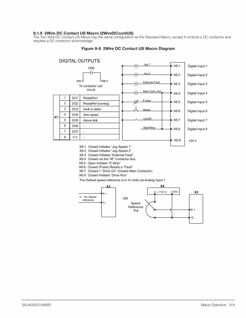
Macro Selection 9-93AUA0000148993
9.1.9 2Wire DC Contact US Macro (2WireDCcontUS)The Two Wire DC Contact US Macro has the same configuration as the Standard Macro, except it controls a DC contactor and requires a DC contactor acknowledge.
Figure 9-9 2Wire DC Contact US Macro Diagram
Digital Input 1
Digital Input 2
Digital Input 3
Digital Input 4
Digital Input 5
Digital Input 6
Digital Input 7
Digital Input 8
X6:1
X6:2
X6:3
X6:4
X6:5
X6:6
X6:7
X6:8
Jog 1
External Fault
Main Cont. Ack
E-stop
Jog 2
Reset
OnOff1
Start/Stop
X6:1 Closed Initiates “Jog Speed 1” X6:2 Closed Initiates “Jog Speed 2”X6:3 Closed Initiates “External Fault”X6:4 Closed via the “M” Contactor Aux. X6:5 Open Initiates “E-Stop”X6:6 Closed (Pulse) Resets a “Fault”X6:7 Closed = “Drive On” (Closes Main Contactor) X6:8 Closed Initiates “Drive Run”
To contactor coil circuit
D08
X96:2X96:1
X3
5 -
6 +0 - 10v Speed
reference
X4
4 ( +10 V) X3
6 +
5 -
3 (0V)
OR
The Default speed reference is 0-10 Volts via Analog Input 1
Speed Reference
Pot
X6:9 +24 V
DIGITAL OUTPUTS
1 DO1 ReadyRun
2 DO2 ReadyRef (running)
3 DO3 Fault or alarm
4 DO4 Zero speed
5 DO5 Above limit
6 DO6 -
7 DO7 -
8 0 V -
X7:

9-10 Macro Selection 3AUA0000148993
9.1.10 3Wire DC Contact US Macro (3WireDCcontUS)The Three Wire DC Contact US Macro starts with a pulsed start input at digital input 7, (DI7), and stops when digital input 8, (DI8), is pulsed open, (3Wire Control). Speed is set at Analog Input 1, (AI1). When Digital Input 1, (DI1), is asserted, speed is fixed to the value set in parameter 23.02. This Macro controls at DC Contactor and requires a DC contactor acknowledge.
Figure 9-10 3Wire DC Contact US Macro Diagram
Digital Input 1
Digital Input 2
Digital Input 3
Digital Input 4
Digital Input 5
Digital Input 6
Digital Input 7
Digital Input 8
X6:1
X6:2
X6:3
X6:4
X6:5
X6:6
X6:7
X6:8
Fixed Speed 1
External Fault
Main Cont. Ack
E-stop
Reset
On Start Pulse
Off1 Stop Pulse
X6:1 Closed Sets Speed at 23.02X6:2X6:3 Closed Initiates “External Fault”X6:4 Closed via “M” Contactor Aux.X6:5 Open Initiates “E-Stop”X6:6 Closed Pulse Resets a “Fault”X6:7 Pulse closed initiates “Start”X6:8 Pulse open Initiates “Stop”
To contactor coil circuit
D08
X96:2X96:1
The Default speed reference is 0-10 Volts via Analog Input 1
X3
5 -
6 +0 - 10v Speed
reference
X4
4 ( +10 V) X3
6 +
5 -
3 ( 0 V
OR
Speed Reference
Pot
X6:9 + 24 V
DIGITAL OUTPUTS
1 DO1 ReadyRun
2 DO2 ReadyRef (running)
3 DO3 Fault or alarm
4 DO4 Zero speed
5 DO5 Above limit
6 DO6 -
7 DO7 -
8 0 V -
X7:

Macro Selection 9-113AUA0000148993
9.1.11 3Wire Standard Macro (3WireStandard)The Three Wire Standard Macro is the same as the Three Wire DC Contact US macro. Drive starts with a pulsed start input at Digital Input 7, (DI7), and stops when Digital Input 8 (DI8), is pulsed open, (3Wire Control). Speed is set with Analog Input 1, (AI1). When Digital Input 1, (DI1), is asserted, speed is fixed to the value set in parameter 23.02.
Figure 9-11 3Wire Standard Macro Diagram
Digital Input 1
Digital Input 2
Digital Input 3
Digital Input 4
Digital Input 5
Digital Input 6
Digital Input 7
Digital Input 8
X6:1
X6:2
X6:3
X6:4
X6:5
X6:6
X6:7
X6:8
Fixed Speed 1
External Fault
External Alarm
E-stop
Reset
On Start Pulse
Off1 Stop Pulse
X6:1 Closed Sets Speed at (23.02)X6:2X6:3 Closed Initiates “External Fault”X6:4 Closed initiates “ External Alarm”X6:5 Open Initiates “E-Stop”X6:6 Closed Pulse Resets a “Fault” X6:7 Pulse closed initiates “Start”X6:8 Pulse open Initiates “Stop”
To contactor coil circuit
D08
X96:2X96:1
The Default speed reference is 0-10 Volts via Analog Input 1
X3
5 -
6 +0 - 10v Speed
reference
X4
4 ( +10 V) X3
6 +
5 -
3 ( 0v )
OR
Speed Reference
Pot
X6:9 + 24 V
DIGITAL OUTPUTS
1 DO1 ReadyRun
2 DO2 ReadyRef (running)
3 DO3 Fault or alarm
4 DO4 Zero speed
5 DO5 Above limit
6 DO6 -
7 DO7 -
8 0 V -
X7:

9-12 Macro Selection 3AUA0000148993
9.1.12 3Wire Jog Macro (3WireJog) - FLEXPAK 3000 ReplacementsThis macro simulates as closely as possible the features and control functions of the Reliance FlexPak 3000 Digital DC drive allowing the DCS800-EP drive to serve as a suitable replacement for many applications. The 3Wire Jog Macro features 3-wire START/STOP control. Digital Input 5, (DI5), switches between MANUAL speed reference Analog Input 1, (AI1), and AUTO speed reference Analog Input 2, (AI2). Jog input at Digital Input 3, (DI3), initiates motion. Digital Input 4, (DI4), can change motor shaft direction when a regenerative, (4Q), drive is used.
Figure 9-12 3Wire Jog Macro Diagram
Digital Input 1
Digital Input 2
Digital Input 3
Digital Input 4
Digital Input 5
Digital Input 6
Digital Input 7
Digital Input 8
X6:1
X6:2
X6:3
X6:4
X6:5
X6:6
X6:7
X6:8
Off2 (Coast Stop)
Jog 1
Direction
Auto/Manual Speed
Reset
On Start Pulse
Off1 Stop Pulse
X6:1 Open Initiates Coast StopX6:2 Closed Indicates Fan AcknowledgeX6:3 Closed Initiates “Jog1 Speed”X6:4 Open = Forward / Closed = ReverseX6:5 Open = Manual Speed Ref. / Closed = Auto Speed Ref.X6:6 Closed Pulse Resets a FaultX6:7 Pulse closed initiates “Start”X6:8 Pulse open Initiates “Stop”
To contactor coil circuit
D08
X96:2X96:1
The Manual speed reference is 0-10 Volts via Analog Input 1. Auto Speed Reference is AI2.
X3
5 -
6 +0 - 10v Speed
reference
X4
4 ( +10 V) X3
6 +
5 -
3 ( 0V )
OR
Fan Acknowledge
Manual Speed Reference Pot
X6:9 + 24 V
Requires Firmware 3.7 or above. (See 4.01)
DIGITAL OUTPUTS
1 DO1 ReadyRef (running)
2 DO2 Alarm
3 DO3 No Fault
4 DO4 Zero speed
5 DO5 Above limit
6 DO6
7 DO7
8 0 V
X7:

Troubleshooting 10-13AUA0000148993
Chapter 10Troubleshooting
10.1 Fault Messages
Table 10-1 Fault Description, Related Signals & ParametersFault Description Related Signals & Parameters
The drive will display a fault if this condition is true Parameter/Signal Description Default
F501 - Auxiliary Undervoltage Limit: upper voltage FixedThe auxiliary voltage is too low at terminal X99 on PIN-4 or POW-4 Board.
185V for 230V input 96V for 115V input
F502 - Armature Overcurrent ArmOverCurLev (30.09) Limit: upper current 250 pct
The armature current exceeds the overcurrent limit.
ConvOvrCur (4.16) Limit: overcurrent limit (Amps) as calculated from 30.09
MotCur (1.06) Actual: armature current
F503 - Armature Overvoltage ArmOvrVoltLev (30.08) Limit: upper voltage 120 pctThe armature voltage exceeds the overvoltage limit. ArmVoltActRel (1.13) Actual: armature voltage
F504 - Converter Overtemperature
The drive internal temperature exceeds the temperature limit.
MaxBridgeTemp (4.17) Limit: upper temperature Set by type code
BridgeTemp (1.24) Actual: bridge temperature
S MaxBrdgTemp(97.04)
Setting: overrides the maximum bridge temperature set by TypeCode (97.04)
0
F505 - Residual current detection ResCurDetectLim (30.06) Limit: upper current 4 Amps
The drive has detected a ground fault.ResCurDetectSel (30.05)
Setting: selects source of measured signal; NotUsed disables this fault.
NotUsed
ResCurDetectDel (30.07) Setting: selects the time delay 10 ms
F506 - Motor 1 Overtemperature M1FaultLimTemp (31.07) Limit: upper temperature 0
The motor 1 temperature exceeds the temperature limit.
Mot1TempMeas (1.22) Actual: temperature for motor 1
M1TempSel (31.05) Setting: selects source of measured signal NotUsed
M1KlixonSel (31.08) Setting: selects digital input when a thermoswitch is used NotUsed
F507 - Motor 1 Overload M1FaultLimLoad (31.04) Limit: upper 106 pctMotor overloaded based on calculated thermal curve. Mot1TempCalc (1.20) Actual: calculated tempF508 - Input/Output Board Not Found or Faulty
The drive cannot communicate with a previously known option board such as COM-8x, RAIO, RDIO, IOB-2, IOB-3, RTAC, or DSL-4.
Diagnosis (9.11)Actual: signal that provides additional details about the actual fault
ExtIO Status (4.20) Actual: signal showing which I/O board is missing or faulty
DCSLinkNodeID (94.01) Setting: selects the node ID for DCSLink communications 0
Group 98 Setting: parameters that enable I/O boards
F509 - Motor 2 Overtemperature M2FaultLimTemp (49.37) Limit: upper temperature 0 °C
The motor 2 temperature exceeds the temperature limit.
Mot2TempMeas (1.23) Actual: motor 2 temperature
M2TempSel (49.35) Setting: selects source of measured signal NotUsed
M2KlixonSel (49.38) Setting: selects digital input when a thermoswitch is used NotUsed
Fault Description Related Signals & ParametersThe drive will display a fault if this condition is
true Parameter/Signal Description Default

10-2 Troubleshooting 3AUA0000148993
F510 - Motor 2 Overload M2FaultLimLoad (49.34) Limit: upper 106 pctThe motor 2 current exceeds the overload limit. M2TempCalc (1.21) Actual: calculated tempF512 - Mains Low Voltage UNetMin1 (30.22) Limit: lower voltage - alarm 80 pct
The mains voltage is below the fault limit or the mains voltage is below the alarm limit for an excessive amount of time.
UNetMin2 (30.23) Limit: lower voltage - fault 60 pctMainsVoltAct (1.12) Actual: mains voltage
NomMainsVolt (99.10) Setting: nominal mains voltage
PwrLossTrip (30.21)Setting: selects the desired action when this fault occurs: immediate or delayed
Immediate
PowrDownTime (30.24)
Setting: selects the delay before a fault is set after the mains voltage falls below UNetMin1 Alarm limit
500 ms
F513 - Mains Overvoltage Limit: upper voltage - 130% of NomMainsVolt (99.10) Fixed
The mains voltage is above the fault limit for more than 10 seconds.
MainsVoltAct (1.12) Actual: mains voltage
NomMainsVolt (99.10) Setting: nominal mains voltage
F514 - Mains Not in Sync Limit: upper frequency (±5% of nominal) and change in freq. (df/dt = 17%/sec)
Fixed
The synchronization with the mains frequency has been lost. PLLin (3.20)
Actual: This should be, for 60 Hz, 16667; for 50 Hz, 20000
F515 - Motor 1 Field Supply (Exciter) Overcurrent M1FldOvrCurLev (30.13) Limit: upper current 125 pct
The field current is above the fault limit. Mot1FldCurRel (1.29) Actual: field current for motor 1
F516 - Motor 1 Field Supply (Exciter) Communication Loss FexTimeOut (94.07) Limit: time 100 ms
DSL-Link communication between the drive and the field supply (Exciter) has stopped for a time longer than the fault limit.
DCSLinkNodeID (94.01) Setting: node ID of the drive 0
M1FexNode (94.08) Setting: node ID of the Field Supply for Motor 1 21
M1UsedFexType (99.12) Setting: selects motor 1 field power supply type OnBoard
F517 - Armature Current Ripple CurRippleLim (30.19) Limit: upper current ripple 150 pct
Current ripple on the DC output exceeds the limit. This is often an indication that one or more thyristors is not working or a fuse is blown.
CurRippleFilt (1.10) Actual: current ripple
CurRippleSel (30.18)Setting: selects if a fault or alarm is generated when the limit is exceeded.
Fault
F518 - Motor 2 Field Supply (Exciter) Overcurrent M2FldOvrCurLev (49.09) Limit: upper current 125 pct
The field current is above the fault limit. Mot2FldCurRel (1.31) Actual: field current for motor 2
F519 - Motor 2 Field Supply (Exciter) Communication Loss FexTimeOut (94.07) Limit: time 100 ms
DSL-Link communication between the drive and the field supply (Exciter) has stopped for a time longer than the fault limit.
DCSLinkNodeID (94.01) Setting: node ID of the drive 0
M2FexNode (94.09) Setting: node ID of the Field Supply for Motor 2 30
M2UsedFexType (49.07) Setting: selects motor 2 field power supply type NotUsed
Fault Description Related Signals & ParametersThe drive will display a fault if this condition is
true Parameter/Signal Description Default
F521 - Field Exciter Missing (Selected Motor)
Table 10-1 Fault Description, Related Signals & Parameters (Continued)

Troubleshooting 10-33AUA0000148993
One or more field supply (exciter) faults is present for the motor currently selected (M1 or M2), including: (for M1) F515, F516, F529, F537 and/or F541; (for M2) F518, F519, F530, F538 and/or F542.
M1UsedFexType (99.12) M2UsedFexType (49.07)
Setting: selects field power supply type for respective motor
OnBoard / NotUsed
Mot1FexStatus (6.12) Mot2FexStatus (6.13)
Actual: signal showing the status of the field supply (exciter) for the respective motor
F522 - Speed Feedback (Selected Motor) EMF FbMonLev (30.15) Limit: upper EMF voltage 50 Volts
Speed feedback from a tachometer or encoder is continuously compared to EMF feedback while running. A fault indicates that the EMF was above a limit (30.15) while the motor speed was below a limit (30.14).
SpeedFbMonLev (30.14) Limit: lower tach/encoder speed 15 rpm
EMF VoltActRel (1.17)Actual: EMF voltage in percent of M1NomVolt (99.02)
SpeedActEMF (1.02) Actual: EMF speedSpeedActEnc (1.03) Actual: encoder speedSpeedActTach (1.05) Actual: tachometer speed
M1SpeedFbSel (50.03) M2SpeedFbSel (49.24)
Setting: selects speed feedback type for respective motor
EMF
SpeedFbFltMode (30.36)
Setting: selects the stopping mode for this fault and others with trip level 3: coast or dynamic brake
CoastStop
SpeedFbFltSel (30.17)
Setting: selects the desired action when this condition occurs such as fault or alarm; stop or switch to EMF feedback.
Fault
F523 - External Fan Acknowledge Missing
The Fan Acknowledge digital input was lost or was not set within 10 seconds. MotFanAck (10.06)
Setting: selects the digital input for Fan Acknowledgement
DI2
F524 - Main Contactor Acknowledge Missing
The Main Contactor Acknowledge digital input was lost or was not set within 10 seconds. MainContAck (10.21)
Setting: selects the digital input for Main Contactor Acknowledgement
DI3
F525 - Type Code Mismatch
On D1, D2, D3, or D4 modules, the current and voltage range of the type code setting is limited to 1000 Adc and 600 Vac. A fault indicates the existing setting is out of range.
TypeCode (97.01)Setting: selects the type code of the drive as shown on the nameplate
Preset by factory
ServiceMode (99.06)Setting: allows the user to change TypeCode (97.01), etc.
Normal Mode
S ConvScaleCur (97.02) Setting: adjusts the scaling of the measured DC current 0 Amps
S ConvScaleVolt (97.03) Setting: adjusts the scaling of the measured AC voltage 0 Volts
F526 - External Fault Via Digital Input
The External Fault digital input was set.
ExtFaultSel (30.31) Setting: selects the digital input for External Fault NotUsed
ExtFaultOnSel (30.33)Setting: selects when this fault is active: always or only when running
Fault
Table 10-1 Fault Description, Related Signals & Parameters (Continued)

10-4 Troubleshooting 3AUA0000148993
Fault Description Related Signals & ParametersThe drive will display a fault if this condition is
true Parameter/Signal Description Default
F527 - Converter Fan Acknowledge Missing
The Converter Fan Acknowledge digital input was lost or was not set within 10 seconds.
ConvFanAck (10.20)Setting: selects the digital input for Converter Fan Acknowledge
DI1
FanDly (21.14)
Setting: selects the length of time the fan should be running after the motor turns off during which the fan acknowledge will still be monitored
0 sec
F528 - Fieldbus Communications Loss FBTimeOut (30.35) Limit: time 100 ms
Fieldbus Communications have been interrupted for a period longer than a time limit after the first data set from the overriding control has been received.
CommModule (98.02)Setting: selects the type of communication module is in use
NotUsed
CommandSel (10.01)
Setting: selects where the motor-on commands (on, run, and stop) will come from: digital inputs, fieldbus, etc.
Local I/O
ComLossCtrl (30.28)
Setting: selects the desired action when this condition occurs: fault and ramp stop, coast stop, etc. or alarm and continue
Fault - Ramp Stop
Group 51 Setting: parameters that set up fieldbus
F529 - Motor 1 Field Supply (Exciter) not OKA fault was detected by the motor 1 field supply (exciter) during its self diagnosis or there was a power failure in field supply 1.
Check the display or the fault LED on the Field Supply Unit
F530 - Motor 2 Field Supply (Exciter) not OKA fault was detected by the motor 2 field supply (exciter) during its self diagnosis or there was a power failure in field supply 2.
Check the display or the fault LED on the Field Supply Unit
F531 - Motor Stalled (Selected Motor) StallSpeed (30.02) Limit: lower speed 5 rpm
The measured speed is less than the stall speed and the torque is greater than the stall torque for a time greater than the stall time.
StallTorque (30.03) Limit: upper torque 75 pct
StallTime (30.01) Limit: time Note: 0 disables fault 0 sec
MotSpeed (1.04) Actual: motor speedMotTorq (1.08) Actual: motor torque
F532 - Motor Overspeed (Selected Motor) M1OvrSpeed (30.16) Limit: upper speed for Motor 1 1800 rpm
The measured speed of the selected motor exceeded the respective overspeed limit.
M2OvrSpeed (49.21) Limit: upper speed for Motor 2 1800 rpm
MotSpeed (1.04) Actual: motor speedF533 - 12 Pulse Reversal Timeout 12P RevTimeOut (47.05) Limit: time 100 msOn 12-pulse systems, armature current direction did not change for a period longer than a time limit after zero current has been detected.
MotCur (1.06) Actual: armature current
F534 - 12 Pulse Current Difference DiffCurLim (47.02) Limit: upper current 10 pctFor systems configured for 12-pulse parallel operation, the current difference has exceed the limit for a period longer than the limit.
DiffCurDly (47.03) Limit: time 500 ms
Table 10-1 Fault Description, Related Signals & Parameters (Continued)

Troubleshooting 10-53AUA0000148993
Fault Description Related Signals & ParametersThe drive will display a fault if this condition is
true Parameter/Signal Description Default
F535 - 12 Pulse Communication 12P TimeOut (94.03) Limit: time 100 ms
On 12-pulse systems, DCS-Link communications between the master and the follower drive have been interrupted for a period longer than the limit.
DCSLinkNodeID (94.01) Setting: selects the node ID for DCSLink communications 0
12P SlaNode (94.04)Setting: selects the node ID of the follower in the master drive
31
F536 - 12 Pulse Follower FailureA fault has been generated in the 12-pulse follower.F537 - Motor 1 Field Supply (Exciter) ready lostMotor 1 field supply (exciter) has lost the ready-for-operation message while running. The AC supply voltage may be missing or no longer in sync.
Check the display or the fault LED on the Field Supply Unit
F538 - Motor 2 Field Supply (Exciter) ready lostMotor 2 field supply (exciter) has lost the ready-for-operation message while running. The AC voltage may be missing or no longer in sync.
Check the display or the fault LED on the Field Supply Unit
F539 - Fast Current Rise ArmCurRiseMax (30.10) Limit: upper current 325 %/msThe current through the drive has risen too quickly, exceeding the limit. This may be caused by a short circuit or incorrect tuning.
ConvCurActRel (1.15) Actual: converter DC current
F540 - SDCS-COM-8 FaultyThe SDCS-COM-8 board is no longer operable.F541 - Motor 1 Field Exciter Low Current M1FldMinTrip (30.12) Limit: lower current 50 pct
The motor 1 field current is below the current limit for a period longer than a time limit.
FldMinTripDly (45.18) Limit: time 2000 ms
Mot1FldCur (1.30) Actual: field current for motor 1
F542 - Motor 2 Field Exciter Low Current M2FldMinTrip (49.08) Limit: lower current 50 pct
The motor 2 field current is below the current limit for a period longer than a time limit.
FldMinTripDly (45.18) Limit: time 2000 ms
Mot2FldCur (1.32) Actual: field current for motor 2
F543 - SDCS-COM-8 Communication Loss Ch0 TimeOut (70.04) Ch2 TimeOut (70.14) Limit: time 100 ms
Overriding control and/or master-follower communications through channel 0 or 2 of the COM-8 have been interrupted for a period longer than the limit.
Ch0ComLoss Ctrl (70.05) Ch2ComLoss Ctrl (70.15)
Setting: selects if an alarm or fault is to be set as well as the fault stopping method if the respective channel stops working while in motion: ramp, coast, etc.
Ramp Stop
Ch0DriveBus (71.01)
Setting: selects the communication mode for Channel 0, NO = DDCS; YES = DriveBus
Yes
Table 10-1 Fault Description, Related Signals & Parameters (Continued)

10-6 Troubleshooting 3AUA0000148993
Fault Description Related Signals & ParametersThe drive will display a fault if this condition is
true Parameter/Signal Description Default
F544 - Peer to Peer, Master-Follower Communication Loss FB TimeOut (30.35) Limit: time - R-type fieldbus 100 ms
DCS-Link for fieldbus communications have been interrupted for a period longer than the limit.
MailboxCycle1 (94.13) MailboxCycle2 (94.19) MailboxCycle3 (94.25) MailboxCycle4 (94.31)
Limit: time - DCSLink 100 ms
Mailbox1 (94.12) Mailbox2 (94.18) Mailbox3 (94.24) Mailbox4 (94.30)
Setting: selects the node ID for the respective mailbox (DCSLink)
0
ComLossCtrl (30.28)
Setting: selects the desired action when this condition occurs: fault and ramp stop, coast stop, etc. or alarm and continue
Fault - Ramp Stop
F545 - Application Load Failure
The application program did not load correctly. Diagnosis (9.11)Actual: signal that provides additional details regarding this fault
F546 - Local Command Loss
Communications have been interrupted with the control panel, Drive Window, or Drive Window light while in Local Control Mode.
LocalLossCtrl (30.27)
Setting: selects the desired action when this condition occurs: fault and ramp stop, coast stop, etc. or alarm and continue
Fault - Ramp Stop
F547 - Hardware Failure
Hardware failure has been detected. Diagnosis (9.11)Actual: signal that provides additional details regarding this fault
F548 - Firmware Failure
Firmware failure has been detected or firmware did not load correctly. Diagnosis (9.11)
Actual: signal that provides additional details regarding this fault
F550 - Parameter or Memory Card Read ErrorReading the actual parameter set or a user parameter set from either flash or the Memory Card failed. Check that User1 and/or User2 have been saved properly using ApplMacro (99.08). Also check the SDCS-MEM-8 memory card. May also require replacing the SDCS-CON-4 board.F551 - Analog Input Out of Range Limit: lower voltage - 4mA or
2 Volts Fixed
One of the analog input values is below the minimum limit.
AI1 Val (5.03) AI2 Val (5.04) AI3 Val (5.05) AI4 Val (5.06) AI5 Val (5.07) AI6 Val (5.08)
Actual: voltage at the respective analog input
AI Mon4mA (30.29)
Setting: selects the desired action when this condition occurs: fault and ramp stop, coast stop, etc. or alarm and continue
Fault
ConvModeAIx
Setting: selects the type and range for analog inputs 1- 6. This alarm is active if set to 2V-10V Uni. See: 13.03, 13.07, 13.11, 13.15, 13.23, 13.27
Table 10-1 Fault Description, Related Signals & Parameters (Continued)

Troubleshooting 10-73AUA0000148993
Fault Description Related Signals & ParametersThe drive will display a fault if this condition is
true Parameter/Signal Description Default
F552 - Mechanical Brake (Selected Motor) M1BrakeFltTime (42.05) M2BrakeFltTime (49.39) Limit: time - open 1 sec
The acknowledge signal for brake open or brake engaged is missing for a period longer than the open or engage limit.
M1BrakeLongTime (42.12) M2BrakeLongTime (49.42) Limit: time - engage 4 sec
M1BrakeAckSel (42.02) M2BrakeAckSel (49.29)
Setting: selects the digital input for the brake acknowledge signal
NotUsed
BrakeFaultFunc (42.06)Selects the desired action when this condition occurs: fault, alarm, or crane.
Fault
F553 - Tachometer or Encoder Polarity (Selected Motor) EMF FbMonLev (30.15) Limit: EMF voltage 50 Volts
Speed feedback polarity from a tachometer or encoder is continuously compared to EMF feedback polarity while running. A fault indicates that the two ran in opposite directions while the motor feedback speed and EMF speed were above absolute limits. If this occurred during start up, try reversing polarity of the motor or the tach/encoder. If this occurred while in production, the tach/encoder may be faulty.
SpeedFbMonLev (30.14) Limit: tach/encoder speed 15 rpmSpeedActEMF (1.02) Actual: EMF speedSpeedActEnc (1.03) Actual: encoder speed
SpeedActTach (1.05) Actual: tachometer speed
F554 - Tachometer Range (Selected Motor)The signal from the tachometer analog input has exceeded a limit. If this occurred during start up, connect the tach to the next higher voltage terminal on drive connector X3 terminals 1, 2 or 3.
Limit: upper voltage - 10 Volts Fixed
F556 - Torque Proving (Selected Motor)
The TorqProvOK signal has not been set within a time limit after the RUN command (7.01 bit3) has been set.
M1TorqProvTime (42.10) Limit: time Note: 0 disables this fault 0 sec
TorqProvOK (7.03 bit 11)
A binary signal, set by adaptive program, application program or external controller, which indicates that the torque proving check has been successfully completed
FALSE
F557 - Reversal Time ZeroCurTimeOut (97.19) Limit: time 20 msArmature current direction did not change for a period longer than a time limit after zero current was detected. For motors with high inductance (e.g., large motors) or if motor is high voltage compared to the mains voltage, try decreasing RevDly (43.14), then increasing the limit.
RevDly (43.14)
Setting: selects the delay time for bridge reversal after zero current has been detected
5 ms
Table 10-1 Fault Description, Related Signals & Parameters (Continued)

10-8 Troubleshooting 3AUA0000148993
10.2 Alarm Messages
Table 10-2 Alarm Description, Related Signals & ParametersAlarm Description Related Signals & Parameters
The drive will display an alarm if this condition is true Parameter/Signal Description Default
A101 - Coast Stop (Off2) via Digital Input Off2 (10.08) Setting: selects the digital input for Coast Stop (Off2) DI4
The Coast Stop (Off2) digital input is cleared. A102 - Emergency Stop (Off3) via Digital Input Off3 (10.09) Setting: selects the digital
input for E-Stop (Off3)DI5
The Emergency Stop (Off3) digital input is cleared. A103 - DC Breaker Acknowledge Missing (Selected Motor) DC BreakAck (10.23)
Setting: selects the digital input for DC Breaker Acknowledge
DI11
The DC Breaker Acknowledge digital input is cleared.A104 - Converter Overtemperature
The drive internal temperature is within 5°C of the temperature limit.
MaxBridgeTemp (4.17) Limit: upper temperature Set by type code
BridgeTemp (1.24) Actual: bridge temperature
S MaxBrdgTemp (97.04)
Setting: overrides themaximum bridge temperature set by TypeCode (97.04)
0
A105 - Dynamic Braking in progress DynBrakeAck (10.22)
Setting: selects the digital input for Dynamic Braking Acknowledge
DI11
For non-US dynamic braking, the DynBrakeAck input is set while in the ON state. FlyStart (21.10)
Setting: configures flying start which may allow restarting the drive while dynamic braking is in progress
Flying Start
A106 - Motor 1 Overtemperature M1AlarmLimTemp (31.06) Limit: upper temperature 0
The motor 1 temperature exceeds the temperature limit.
Mot1TempMeas (1.22) Actual: temperature for motor 1
M1TempSel (31.05) Setting: selects source of measured signal NotUsed
M1KlixonSel (31.08) Setting: selects digital input when a thermoswitch is used NotUsed
A107 - Motor 1 Overload M1AlarmLimLoad (31.03) Limit: upper 102 pct
The motor 1 current exceeds the overload limit. M1TempCalc (1.20) Actual: calculated tempA109 - Motor 2 Overtemperature M2AlarmLimTemp (49.36) Limit: upper temperature 0
The motor 2 temperature exceeds the temperature limit.
Mot2TempMeas (1.23) Actual: temperature for motor 2
M2TempSel (49.35) Setting: selects source of measured signal NotUsed
M2KlixonSel (49.38) Setting: selects digital input when a thermoswitch is used NotUsed
A110 - Motor 2 Overload M2AlarmLimLoad (49.33) Limit: upper 102 pctThe motor 2 current exceeds the overload limit. M2TempCalc (1.21) Actual: calculated tempA111 - Mains Low Voltage UNetMin1(30.22) Limit: upper voltage - alarm 80 pct
The mains voltage is below the alarm limit.MainsVoltAct (1.12) Actual: mains voltage
NomMainsVolt (99.10) Setting: nominal mains voltage

Troubleshooting 10-93AUA0000148993
Alarm Description Related Signals & ParametersThe drive will display an alarm if this condition is
true Parameter/Signal Description Default
A112 - Peer to Peer, Master-Follower Communication Loss FB TimeOut (30.35) Limit: time - R-type fieldbus 100 ms
DCS-Link or fieldbus communications have been interrupted for a period longer than the limit.
MailboxCycle1 (94.13) Limit: time - DCSLink 100 msMailboxCycle2 (94.19) Limit: time - DCSLink 100 msMailboxCycle3 (94.25) Limit: time - DCSLink 100 msMailboxCycle4 (94.31) Limit: time - DCSLink 100 ms
Mailbox1 (94.12) Setting: selects the node ID for mailbox 1 0
Mailbox2 (94.18) Setting: selects the node ID for mailbox 2 0
Mailbox3 (94.24) Setting: selects the node ID for mailbox 3 0
Mailbox4 (94.30) Setting: selects the node ID for mailbox 4 0
ComLossCtrl (30.28)
Setting: selects the desired action when this condition occurs: fault and stop or alarm and continue at last speed or fixedspeed 1
Fault -Ramp Stop
A113 - SDCS-COM-8 Communication Loss Ch0 TimeOut (70.04) Limit: time - channel 0 100 ms
Overriding control and/or master-follower communications through channel 0 or 2 of the COM-8 have been interrupted for a period longer than the limit.
Ch2 TimeOut (70.14) Limit: time - channel 2 100 ms
Ch0ComLoss Ctrl (70.05)
Setting: selects the desired action when this condition occurs: fault and stop or alarm and continue at last speed or fixedspeed 1
Fault -Ramp Stop
Ch2ComLoss Ctrl (70.15)
Setting: selects the desired action when this condition occurs: fault and stop or alarm and continue at last speed or fixedspeed 1
Fault -Ramp Stop
Ch0DriveBus (71.01)
Setting: selects the communication mode for Channel 0, NO = DDCS; YES = DriveBus
Yes
A114 - Armature Current Deviation Limit: current - 20% of M1NomCur (99.03) or M2NomCur (49.02)
Fixed
Current reference differs from current actual by more than a limit for longer than a time limit. See alarm description in DCS800 Firmware Manual for what to check in the event of a fault.
Time: limit - 5 sec FixedCurRefUsed (3.12) Actual: current reference
MotCur (1.06) Actual: armature current
A115 - Tachometer Range (Selected Motor) Limit: upper voltage - 10 Volts Fixed
If this alarm is present for longer than 10 seconds, the signal from the tachometer analog input exceeded a limit. If present for 10 seconds and then it clears, it is an indication that M1OvrSpeed (30.16) or M2OvrSpeed (49.21) has changed and a new tach fine tuning is required.
AITacho Val (5.01) Actual: tachometer voltage
ServiceMode (99.06) Setting: initiates tach fine tuning (TachFineTune)
Normal Mode
Table 10-2 Alarm Description, Related Signals & Parameters Continued

10-10 Troubleshooting 3AUA0000148993
Alarm Description Related Signals & ParametersThe drive will display an alarm if this condition is
true Parameter/Signal Description Default
A116 - Mechanical Brake (Selected Motor) M1BrakeLongTime (42.12) M2BrakeLongTime (49.42) Limit: time - engage 4 sec
Active only when BrakeFaultFunc (42.06) = CRANE, the acknowledge signal for brake engaged is missing for a period longer than the engage limit.
M1BrakeAckSel (42.02) M2BrakeAckSel (49.29)
Setting: selects the digital input for the brake acknowledge signal
NotUsed
BrakeFaultFunc (42.06)Setting: selects the desired action when this condition occurs: fault, alarm, or crane
Fault
A117 - Armature Current Ripple CurRippleLim (30.19) Limit: upper current ripple 150 pct
DC current ripple exceeds the limit. If this occurs during start up, then current controller gain may be set too high. Otherwise, this is often an indication that one or more thyristors is not working or a fuse is blown.
CurRippleFilt (1.10) Actual: current ripple
CurRippleSel (30.18)Setting: selects if a fault or alarm is generated when the limit is exceeded
Fault
A118 - Found New Application on Memory Card
An application has been found on SDCS-MEM8 used with ControlBuilder. ParApplSave (16.06)
Setting: set to EableAppl to load and enable ControlBuilder application
Done
A119 - Application Mismatch between Drive and Memory CardThe applications previously loaded to the drive and the one on the SDCS-MEM8 do not match. ParApplSave (16.06)
Setting: set to EableAppl to load and enable new ControlBuilder application
Done
A120 - Overvoltage Protection ActiveThe overvoltage protection unit, DCF506-xxxx-51 is active, so the controller is blocking the converter output.
OvrVoltProt (10.13)Setting: selects the digital input for the signal from the overvoltage protection unit
NotUsed
A121 - Autotuning Failed
Autotuning has failed. Diagnosis (9.11)Actual: signal that provides additional details regarding this alarm
A122 - Mechanical Brake (Selected Motor) M1BrakeFltTime (42.05) M2BrakeFltTime (49.39) Limit: time - open 1 sec
Active only when BrakeFaultFunc (42.06) ≠ FAULT, the acknowledge signal for brake open or brake engaged is missing for a period longer than the open or engage limit. Or torque actual does not reach the torque limit, used, for example, for cranes with a hanging load.
M1BrakeLongTime (42.12) M2BrakeLongTime (49.42) Limit: time - engage 4 sec
StrTorqRef (42.08) Limit: lower torque
M1BrakeAckSel (42.02) M2BrakeAckSel (49.29)
Setting: selects the digital input for the brake acknowledge signal
NotUsed
BrakeFaultFunc (42.06)Setting: selects the desired action when this condition occurs: fault, alarm, or crane
Fault
A124 - Speed Scaling Out of RangeSee:Motor 1: 50.01, 20.01, 20.02, 99.04Motor 2: 49.22, 49.03, 49.19, 49.20
Diagnosis (9.11)Actual: signal that provides additional details regarding this alarm
Table 10-2 Alarm Description, Related Signals & Parameters Continued

Troubleshooting 10-113AUA0000148993
Alarm Description Related Signals & ParametersThe drive will display an alarm if this condition is
true Parameter/Signal Description Default
A125 - Speed Feedback (Selected Motor) EMF FbMonLev (30.15) Limit: upper EMF voltage 50 Volts
Speed feedback from a tachometer or encoder is continuously compared to EMF feedback while running. A fault indicates that the EMF voltage was above a voltage limit (30.15) while the motor speed was below a speed limit (30.14). This usually indicates there is a problem with the tachometer or encoder.
SpeedFbMonLev (30.14) Limit: lower tach/encoder speed 15 rpm
EMF VoltActRel (1.17)Actual: EMF voltage in percent of M1NomVolt (99.02)
SpeedActEMF (1.02) Actual: EMF speedSpeedActEnc (1.03) Actual: encoder speedSpeedActTach (1.05) Actual: tachometer speed
M1SpeedFbSel (50.03) M2SpeedFbSel (49.24)
Setting: selects speed feedback type for respective motor
EMF
SpeedFbFltSel (30.17)
Setting: selects the desired action when this condition occurs such as fault or alarm; stop or switch to EMF feedback.
Fault
A126 - External Alarm via Digital Input ExtAlarmSel (30.32) Setting: selects the digital input for External Alarm NotUsed
The External Alarm digital input is set. ExtAlarmOnSel (30.34)Setting: selects when this alarm is active: always or only when running
Alarm
A127 - Analog Input Out of Range Limit: lower voltage - 4mA or 2 Volts Fixed
One of the analog input values is below the minimum limit.
AI1 Val (5.03) AI2 Val (5.04) AI3 Val (5.05) AI4 Val (5.06) AI5 Val (5.07) AI6 Val (5.08)
Actual: voltage at the respective analog input
AI Mon4mA (30.29)
Setting: selects the desired action when this condition occurs: fault and stop or alarm and continue at last speed or fixedspeed 1
Fault
ConvModeAIx
Setting: selects the type and range for analog inputs 1- 6. This alarm is active if set to 2V-10V Uni. See: 13.03, 13.07, 13.11, 13.15, 13.23, 13.27
A128 - Fieldbus Communications Loss FBTimeOut (30.35) Limit: time 100 ms
Fieldbus Communications have been interrupted for a period longer than a time limit after the first data set from the overriding control has been received.
CommModule (98.02)Identifies what type of communication module is in use
NotUsed
CommandSel (10.01)
Setting: selects where the motor-on commands (on, run, and stop) will come from: digital inputs, fieldbus, etc.
Local I/O
ComLossCtrl (30.28)
Setting: selects the desired action when this condition occurs: fault and stop or alarm and continue at last speed or fixedspeed 1
Fault - Ramp Stop
A129 - Parameters RestoredThe parameters found in flash were invalid at power-up (checksum fault). All parameters were restored from the parameter backup.
Table 10-2 Alarm Description, Related Signals & Parameters Continued

10-12 Troubleshooting 3AUA0000148993
Alarm Description Related Signals & ParametersThe drive will display an alarm if this condition is
true Parameter/Signal Description Default
A130 - Local Command Loss
Communications have been interrupted with the control panel, Drive Window, or Drive Window Light while in Local Control Mode.
LocalLossCtrl (30.27)
Setting: selects the desired action when this condition occurs: fault and stop or alarm and continue at last speed or fixedspeed 1
Fault - Ramp Stop
A131 - Parameter AddedA new firmware program with a different amount of parameters was downloaded. The new parameters are set to their default value.
Diagnosis (9.11)Actual: signal that provides additional details regarding this alarm
A132 - Parameter Setting Conflict
The settings of some parameters are in conflict with each other. Diagnosis (9.11)
Actual: signal that provides additional details regarding this alarm
A133 - Retained Data InvalidThe retained data was invalid at power-up; the backup data was used. Backup data reflects the status during the previous power-up. Retained data includes: fault logger data, Data1 (19.01) thru Data4 (19.04), I/O options (see group 98), parameters defined by means of DCS800 ControlBuilder when the RETAIN box is checked.A134 - Parameter CompatibilityWhen downloading parameter sets or during power-up the firmware attempts to write the parameters. If setting of a parameter is not possible or not compatible, the parameter is set to default.
Diagnosis (9.11)Actual: signal that provides additional details regarding this alarm
A135 - Parameter Upload or download FailedThe checksum verification failed following a parameter upload or download. Please try again.A136 - Adaptive Program Task Time Not Set
The task time for Adaptive Programming is not set when the user attempted to start it. TimeLevSel (83.04)
Setting: selects the time period (1/scan-rate) for the Adaptive Program
Off
A137 - Speed Not Zero M1ZeroSpeedLim (20.03)M2ZeroSpeedLim (49.04) Limit: lower speed
Drive was restarted before the motor decelerated below the zero speed limit. MotSpeed (1.04) Actual: motor speed
A138 - Off2 (Coast Stop) FieldbusBit 1 from the main control word is not set, causing a start inhibit condition. MainCtrlWord (7.01) Setting bit 1 will clear this
alarmA139 - Off3 (Emergency Stop) FieldbusBit 2 from the main control word is not set, causing an estop condition. MainCtrlWord (7.01) Setting bit 2 will clear this
alarmA140 - Illegal Fieldbus SettingsThe fieldbus parameters in group 51 (fieldbus) are not set according to the fieldbus adapter or the device has not been selected.
Group 51 Fieldbus
A141 - SDCS-COM8 Firmware Version ConflictInvalid combination of drive (SDCS-CON-4) firmware and SDCS-COM-8 firmware. Drive firmware 3.7 is compatible with SDCS-COM-8 firmware 1.80 or higher. See firmware release notes for complete compatibility list. Typically requires upgrading to a newer SDCS-COM-8 board.
FirmwareVer (4.01) Actual: drive firmware version
Com8SwVersion (4.11) Actual: SDCS-COM-8 firmware version
Table 10-2 Alarm Description, Related Signals & Parameters Continued

Troubleshooting 10-133AUA0000148993
Alarm Description Related Signals & ParametersThe drive will display an alarm if this condition is
true Parameter/Signal Description Default
A142 - Memory Card Missing
A ControlBuilder application has been loaded in the drive but the memory card belonging to that application has not been found.
ParApplSave (16.06)
Setting: if memory card was intentionally removed, setting this to DisableAppl will disable this alarm
A143 - Memory Card Failure
The data found in the memory card was invalid (checksum fault). ParApplSave (16.06)
Setting: to run without the memory card and disable the ControlBuilder application, set this to DisableAppl to disable this alarm
Table 10-2 Alarm Description, Related Signals & Parameters Continued

10-14 Troubleshooting 3AUA0000148993

Signals and Parameters 11-13AUA0000148993
Chapter 11 Signals and Parameters
The DCS800-EP utilizes various parameters to determine its operation. Many of these signals/parameters will not need adjusting for most applications, but are provided to allow for a user to customize the operation of the control if desired.
The following tables provide a description of the most frequently used signals/parameters along with their scaling and unit / factory default value and adjustment range.
NOTE: Parameters with (E) are in the extended set and are only defined in the DCS800 Firmware Manual.
SIGNALS
Group Description1 Physical actual values2 Speed controller signals3 Reference actual values4 Information5 Analog I/O6 Drive logic signals7 Control words8 Status / limit words9 Fault / alarm words
PARAMETERS
Group Description10 Start / stop select11 Speed reference inputs12 Constant speed13 Analog inputs14 Digital outputs15 Analog outputs16 System control inputs19 Data storage20 Limits21 Start / stop22 Speed ramp23 Speed reference24 Speed control25 Torque reference26 Torque reference handling30 Fault functions31 Motor 1 temperature34 DCS800 Control Panel display40 PID control42 Brake control43 Current control44 Field excitation45 Field converter settings47 12-pulse operation49 Shared motion50 Speed measurement51 Fieldbus52 Modbus
60...69 Application program parameters70 DDCS control71 Drivebus83 Adaptive Program control84 Adaptive Program85 User constants86 Adaptive Program outputs88 Internal90 Receiving data sets addresses 191 Receiving data sets addresses 292 Transmit data sets addresses 193 Transmit data sets addresses 294 DCSLink control97 Measurement98 Option modules99 Start-up data

11-2 Signals and Parameters 3AUA0000148993
11.1 DCS800-EP Signal Definitions
Table 11-1 DCS800-EP Signal Definitions
Block Title Signal (Number) Selection (Value) Descriptions
GROUP 1 - Physical Actual
Values
MotSpeedFilt (1.01) Scaling: Unit: RPMFiltered Motor Speed - Filtered actual motor speed: - Choose motor speed feedback with M1SpeedFbSel (50.03) - Filter time is 1 sec plus SpeedFiltTime (50.06) (E)
SpeedActEMF (1.02)
Scaling: Unit: RPMSpeed Actual EMF - Actual speed calculated from motor EMF voltage
SpeedActEnc (1.03) Scaling: Unit: RPM
Speed Actual Encoder 1 - Actual speed measured with pulse encoder 1, terminals X5:1 - X5:10
MotSpeed (1.04) Scaling: Unit: RPMMotor Speed - Actual speed calculated or measured from what has been selected as the feedback source with parameter M1SpeedFdSel (50.03). It can be filtered with SpeedFiltTime (50.06) (E).
SpeedActTach (1.05) Scaling: Unit: RPMSpeed Actual Tach - Actual speed measured from the analog tachometer, terminals X3:1 - X3:4
MotCur (1.06) Scaling: M1NomCur (99.03)Unit: PctMotor Current - Actual motor current
MotTorqFilt (1.07) Scaling: MotNomTorque (4.23)Unit: PctFiltered Motor Torque - Filtered motor torque: - Filter time is 20 msec
MotTorq (1.08) Scaling: MotNomTorque (4.23)Unit: PctMotor Torque - Motor torque
CurRipple (1.09) Scaling: MotNomTorque (4.23)Unit: PctCurrent Ripple - Current ripple monitor output
CurRippleFilt (1.10 ) Scaling: MotNomTorque (4.23)Unit: PctFiltered Current Ripple - Filtered current ripple monitor output: - filter time is 200 msec
MainsVoltActRel (1.11) Scaling: NomMainsVolt (99.10)Unit: PctRelative Actual Mains Voltage - Actual mains voltage
MainsVoltAct (1.12) Scaling: Unit: VoltsActual Mains Voltage - Actual mains voltage: - Filter time is set at 10msec
ArmVoltActRel (1.13) Scaling: M1NomVolt (99.02)Unit: PctRelative Actual Armature Voltage - Actual armature voltage
ArmVoltAct (1.14) Scaling: Unit: VoltsActual Armature Voltage - Actual armature voltage - Filter time is 10 msec
ConvCurActRel (1.15) Scaling: ConvNomCur (4.05)Unit: PctRelative Actual Converter Current - Actual converter DC current

Signals and Parameters 11-33AUA0000148993
Block Title Signal (Number) Selection (Value) Descriptions
GROUP 1 - Physical Actual
Values(Continued)
ConvCurAct (1.16) Scaling: Unit: AmpsActual Converter Current - Actual converter DC current - Filter time is 10msec
EMFVoltActRel (1.17) Scaling: M1NomVolt (99.02)Unit: PctRelative Actual EMF - Actual EMF
Mot1TempMeas (1.22) Scaling:Unit: °C or ΩMotor 1 Measured Temperature - Temperature of motor 1 measured by the temperature sensor, used for motor overtemperature protection. Units depend on type of sensor selected by M1TempSel (31.05), degrees Celsius for PT100 or Ohms for PTC.
BridgeTemp (1.24) Scaling:Unit: °C Actual Bridge Temperature - Actual temperature of the converter thyristor bridge.
Mot1FldCurRel (1.29) Scaling: M1NomFldCur (99.11)Unit: PctMotor 1 Relative Actual Field Current - Actual field current of motor 1
Mot1FldCur (1.30) Scaling: Unit: AmpsMotor 1 Actual Field Current - Actual field current of motor 1 - Filter time is 500msec
MainsFreqAct (1.38) Scaling: Unit: HzInternal Mains Frequency - Calculated and internally controlled mains frequency. This is the output of the PLL controller.
SpeedActEnc2 (1.42) Scaling: Unit: RPMSpeed Actual Encoder 2 - Actual speed measured with pulse encoder 2 from an optional speed measurement module. NOTE: This could be resolver speed.
GROUP 2 - Speed
Controller Signals
SpeedRef2 (2.01) Scaling: Unit: RPMSpeed Reference 2 - Speed reference after being limited by M1SpeedMin (20.01) and M2SpeedMax (20.02)
SpeedRef3 (2.02) Scaling: Unit: RPMSpeed Reference 3 - Speed reference after Speed Reference 2 and after ramp generator and jog input.
SpeedErrNeg (2.03) Scaling: Unit: RPMSpeed Error Negative - Difference between speed actual and speed reference
TorqAccCompRef (2.07) Scaling: MotNomTorque (4.23)Unit: PctTorque Reference for Acceleration Compensation - The amount of torque needed to accelerate the load.
TorqRef1 (2.08) Scaling: MotNomTorque (4.23)Unit: PctTorque Reference 1 - Torque reference after being limited by parameters within the speed controller.
TorqRef2 (2.09) Scaling: MotNomTorque (4.23)Unit: PctTorque Reference 2 - Torque reference after Torque Reference 1 as output by the speed controller.
Table 11-1 DCS800-EP Signal Definitions Continued

11-4 Signals and Parameters 3AUA0000148993
Block Title Signal (Number) Selection (Value) Descriptions
GROUP 2 - Speed
Controller Signals
(Continued)
TorqRef3 (2.10) Scaling: MotNomTorque (4.23)Unit: PctTorque Reference 3 - Torque reference after Torque Reference 2, limited by TorqMaxTref (20.09) (E) and TorqMinTref (20.10) (E) and after the torque selector.
TorqRef4 (2.11) Scaling: MotNomTorque (4.23)Unit: PctTorque Reference 4 - Torque reference after Torque Reference 3 and after being combined with LoadComp (26.02) (E).
TorqRefUsed (2.13) Scaling: MotNomTorque (4.23)Unit: PctUsed Torque Reference - Final torque reference after Torque Reference 4 after gear backlash compensation and torque limiter during regeneration.
TorqCorr (2.14) Scaling: MotNomTorque (4.23)Unit: PctTorque Correction - Torque correction (by user’s analog input) as determined by TorqCorrect (26.15) (E).
dv_dt (2.16) Scaling: Unit: RPM/sdv/dt - acceleration/deceleration (speed reference change) at the output of the speed reference ramp.
SpeedRefUsed (2.17) Scaling: Unit: RPMUsed Speed Reference - Final speed reference actually being used as selected with Ref1Mux (11.02) and Ref1Sel (11.03) or Ref2Mux (11.12) (E) and Ref2Sel (11.06) (E).
SpeedRef4 (2.18) Scaling: Unit: RPMSpeed Reference 4 - Speed reference equal to Speed Reference 3 summed with SpeedCorr (23.04) (E) and limited by M1SpeedMax (20.02) and M1SpeedMin(20.01). It is the final output of the speed reference chain.
TorqMaxAll (2.19) Scaling: MotNomTorque (4.23)Unit: PctTorque Maximum All - Positive torque limit calculated from the smallest maximum torque limit, field weakening, and armature current limits, including TorqUsedMax (2.22), FluxRefFldWeak (3.24) (E) and M1CurLimBrdg1 (20.12).
TorqMinAll (2.20) Scaling: MotNomTorque (4.23)Unit: PctTorque Minimum All - Negative torque limit calculated from the largest minimum torque limit, field weakening, and armature current limits, including TorqUsedMax (2.22), FluxRefFldWeak (3.24) (E) and M1CurLimBrdg2 (20.13).
TorqUsedMax (2.22) Scaling: MotNomTorque (4.23)Unit: PctUsed Maximum Torque - Positive torque limit selected with TorqUsedMaxSel (20.18) connected to torque limiter after TorqRef4 (2.11).
TorqUsedMin (2.23) Scaling: MotNomTorque (4.23)Unit: PctUsed Minimum Torque - Negative torque limit selected with TorqUsedMinSel (20.19) connected to torque limiter after TorqRef4 (2.11).
TorqRefExt (2.24) Scaling: MotNomTorque (4.23)Unit: PctExternal Torque Reference - External torque reference value after torque reference A selector: TorqRefA (25.01) (E) and TorqRefA Sel (25.10) (E).
TorqLimAct (2.26) Scaling: Unit: Actual Used Torque Limit - Shows which parameter is actually limiting the drive’s torque output.
Table 11-1 DCS800-EP Signal Definitions Continued

Signals and Parameters 11-53AUA0000148993
Block Title Signal (Number) Selection (Value) Descriptions
GROUP 2 - Speed
Controller Signals
(Continued)
SpeedScaleAct (2.29) Scaling: Unit: RPMActual Used Speed Scaling - The value of this parameter equals 20,000 internal speed units. Typically, 20,000 units equals the largest absolute value of the two parameters M1SpeedMin (20.01) and M1SpeedMax (20.02). However, this can vary if scaled manually using M1SpeedScale (50.01) or if Motor2 is selected as indicated in MotSel (8.09) (E).
SpeedRefExt1 (2.30) Scaling: Unit: RPMExternal Speed Reference 1 - External speed reference 1 after reference 1 multiplexer Ref1Mux (11.02).
SpeedRefExt2 (2.31) Scaling: Unit: RPMExternal Speed Reference 2 - External speed reference 2 after reference 2 multiplexer Ref2Mux (11.12) (E) which is then added to SpeedRefExt1 (2.30).
SpeedRampOut (2.32) Scaling: Unit: RPMSpeed Ramp Output - Speed Reference after SpeedRefExt1 (2.30) and SpeedRefExt2 (2.31) and after the accel/decel/shape ramp.
GROUP 3 - Reference
Actual Values
CurRef (3.11) Scaling: M1NomCur (99.03)Unit: PctCurrent Reference - Current reference after being modified by the field weakening controller.
CurRefUsed (3.12) Scaling: M1NomCur (99.03)Unit: PctUsed Current Reference - Current reference after CurRef (3.11) and after being limited by M1CurLimBrdg1 (20.12) and M2CurLimBrdg2 (20.13) but it can be further limited based on speed using MaxCurLimSpeed (43.17) (E) to (43.22) (E).
ArmAlpha (3.13) Scaling: Unit: DegArmature bridge firing angle (alpha) - The firing angle of the armature bride(s).
CurActPeak (3.23) Scaling: M1NomCur (99.03)Unit: PctActual Armature Peak Current - Actual instantaneous armature peak current.
VoltRef1 (3.25) Scaling: M1NomCur (99.02)Unit: PctEMF Voltage Reference 1 - EMF voltage reference for the field current controller as selected by EMFRefSel (44.23) (E).
GROUP 4 - Information
FirmwareVer (4.01) Scaling:Unit: Firmware Version - Factory Firmware version number. If a minus sign precedes the number, the firmware is for a demo unit.
FirmwareType (4.02) Scaling:Unit: Firmware Type - Only type 80 (Standard Firmware) exists.
ApplicName (4.03) Scaling:Unit:
0 NoMemCard1 Inactive2 NoApplic
Application Program Name - If a SDCS-MEM-8 memory card is plugged in and a name has been programmed with ControlBuilder, the name will be displayed here, “winder” for example. If no name is programmed, one of the above will be displayed.
Table 11-1 DCS800-EP Signal Definitions Continued

11-6 Signals and Parameters 3AUA0000148993
Block Title Signal (Number) Selection (Value) Descriptions
GROUP 4 - Information(Continued)
ConvNomVolt (4.04) Scaling:Unit: VoltsConverter Nominal AC Voltage - The nominal AC voltage of the drive based on the drive’s TypeCode (97.01) (E). It can also be manually set with S ConvScaleVolt (97.03) (E).
ConvNomCur (4.05) Scaling:Unit: AmpsConverter Nominal DC Current - The nominal DC current of the drive based on the drive’s TypeCode (97.01) (E). It can also be manually set with S ConvScaleCur (97.02) (E).
Mot1FexType (4.06) Scaling:Unit: Motor 1 Field Exciter Type - The type of field power supply (exciter) used for motor 1 as selected with M1usedFexType (99.12).
Mot1FexSwVer (4.08) Scaling:Unit: Motor 1 field Exciter Software Version - Version of the loaded firmware in the external field power supply (exciter). If onboard is selected, 0 is displayed. (Updated on power-up only.)
ApplicVer (4.12) Scaling:Unit: Application Program Version - If a SDCS-MEM-8 memory card is plugged in and a version number has been programmed with ControlBuilder, the version number of that program is displayed here.
DriveLibVer (4.13) Scaling:Unit:Drive Library Version - The version of the factory-loaded function block library.
ConvType (4.14) Scaling:Unit:Converter Type - The frame size (D1 - D7) of the drive based on the drive’s TypeCode (97.01) (E). “ManualSet” is displayed if the nominal voltage and current are set manually with S ConvScaleVolt (97.03) (E) and S ConvScaleCur (97.02) (E).
QuadrantType (4.15) Scaling:Unit:Quadrant Type - Displays whether the regenerative bridge (bridge 2) is released for use based on the drive’s TypeCode (97.01) (E). Bridge 2 can also be manually released or blocked with S BlockBrdg2 (97.07) (E).
ConvOvrCur (4.16) Scaling:Unit: AmpsConverter Overcurrent (DC) level - Current level at which the drive will trip on ArmOvrCur (F502) fault. (Updated on power-up only.)
MaxBridgeTemp (4.17) Scaling:Unit: °CMaximum Bridge Temperature - Bridge temperature at which the drive will trip on ConvOverTemp (F504) fault based on the drive’s TypeCode (97.01) (E). It can also be manually set with S MaxBrdgTemp (97.04) (E). ConvOverTemp (A104) alarm is displayed when actual converter temperature is approximately 5 deg. C below the maximum.
DCSLinkStat1 (4.18) Scaling:Unit: DCSLink Status 1 (field exciter) - Status of the DCSLink for the field power supply (exciter) nodes 1 through 16, displayed in 16 bit hexadecimal (0000 to FFFF). Node 1 is the least significant bit; node 16 is the most significant bit. For example, 0010 indicates node 5 is active and okay and 0018 indicates nodes 4 and 5 are active and okay.
Table 11-1 DCS800-EP Signal Definitions Continued

Signals and Parameters 11-73AUA0000148993
Block Title Signal (Number) Selection (Value) Descriptions
GROUP 4 - Information(Continued)
DCSLinkStat2 (4.19) Scaling:Unit: DCSLink Status 2 (field exciter) - Status of the DCSLink for the field power supply (exciter) nodes 17 through 32. See 4.18 for additional information.
CPU Load (4.21) Scaling:Unit: PctProcessor Load - The load of the processor which should never reach 100%.
ApplLoad (4.22) Scaling:Unit: PctApplication Load - The load of the application which should never reach 100%.
MotTorqNom (4.23) Scaling:Unit: NmMotor Nominal Torque - Calculated nominal torque based on values entered for nominal current, nominal voltage and base speed.
GROUP 5 - Analog I/O
AITacho Val (5.01) Scaling: 11 V = 125% * M1OvrSpeed (30.16)Unit: VoltsAnalog Input Tacho Value - Actual voltage of the analog tachometer input. Scaling depends on the terminal to which the tachometer is wired and on jumper settings.
AI1 Val (5.03) Scaling: Unit: VoltsAnalog Input 1 Value - Actual voltage of analog input 1. Scaling depends on the type of hardware being used and on jumper settings.
AI2 Val (5.04) Scaling: Unit: VoltsAnalog Input 2 Value - Actual voltage of analog input 2. Scaling depends on the type of hardware being used and on jumper settings.
AO1 Val (5.11) Scaling: Unit: VoltsAnalog Output 1 Value - Actual voltage of analog output 1.
AO2 Val (5.12) Scaling: Unit: VoltsAnalog Output 2 Value - Actual voltage of analog output 2.
GROUP 6 - Drive Logic
Signals
SystemTime (6.01) Scaling: Unit: MinConverter System Time - Shows the number of minutes the drive CPU has been running but can be adjusted manually using SetSystemTime (16.11) (E).
CurCtrlStat1 (6.03) Scaling: Unit:
6.03.00 FANS ON command6.03.01 Loss of one mains phase6.03.02 Unused6.03.03 Motor heating function active6.03.04 Field direction: ON = reverse; OFF = forward6.03.05 FIELD ON command6.03.06 Dynamic braking active6.03.07 MAIN CONTACTOR ON command6.03.08 EUROPEAN DYNAMIC BRAKING CONTACTOR ON command6.03.09 ON = Drive is generating; OFF = Drive is motoring6.03.10 US DYNAMIC BRAKING CONTACTOR ON command6.03.11 Firing Pulses: On = active; OFF = blocked
Table 11-1 DCS800-EP Signal Definitions Continued

11-8 Signals and Parameters 3AUA0000148993
Block Title Signal (Number) Selection (Value) Descriptions
GROUP 6 - Drive Logic
Signals(Continued)
CurCtrlStat1 (6.03) (Continued) Scaling: Unit:
6.03.12 ON = continuous current; OFF = discontinuous current6.03.13 ON = zero current detected; OFF = current not zero6.03.14 TRIP DC BREAKER command (continuous signal)6.03.15 TRIP DC BREAKER command (1 s pulse)
Current Controller Status Word 1 - The current controller status word displayed in 16-bit hexadecimal (0000 to FFFF). Definition of the individual 16 bits is shown above.
CurCtrlStat2 (6.04) Scaling: Unit:
6.04.00 Fault F502 - Armature overcurrent6.04.01 Fault F513 - Mains overvoltage6.04.02 Fault F512 - Mains low voltage6.04.03 Waiting for reduction of EMF to match the mains voltage6.04.04 Fault F533 - 12-pulse reversal time, or Fault F534 - 12-pulse current difference, or
Fault F557 - reversal time is present6.04.05 If OperModeSel (43.01) = 12P: BLOCK PARTNER command;
If OperModeSel (43.01) = FieldExciter: Overvoltage protection is active6.04.06 Fault F529 - Motor 1 Field power supply (exciter) is not okay6.04.07 Fault F537 - Motor 1 Field power supply (exciter) lost ready-for-operation message
while operating6.04.08 Fault F529 - Motor 2 Field power supply (exciter) is not okay6.04.09 Fault F537 - Motor 2 Field power supply (exciter) lost ready-for-operation message
while operating6.04.10 Waiting for zero current6.04.11 Field reversal is active; armature current controller is blocked6.04.12 Unused6.04.13 Current controller not released because DevLimPLL (97.13) (E) has been reached6.04.14 Fault F514 - Mains not synchronized6.04.15 Current controller not released. This bit is set in case a relevant fault or level 3
alarm is present.Current Controller Status Word 2 - The current controller status word displayed in 16-bit hexadecimal (0000 to FFFF). For any bit, “on” indicates that the current controller is blocked, meaning CurRefUsed (3.12) is forced to zero and ArmAlpha (3.13) is forced to ArmAlphaMax (20.14). Definition of the individual 16 bits is shown above.
Mot1FexStatus (6.12) Scaling: Unit: M1 Field Power Supply (Exciter) Status - Displays a message indicating the fault status of field power supply (exciter) for motor 1. OK indicates no field faults and communications OK.
Table 11-1 DCS800-EP Signal Definitions Continued

Signals and Parameters 11-93AUA0000148993
Block Title Signal (Number) Selection (Value) Descriptions
GROUP 7 - Control Words
MainCtrlWord (7.01) Scaling: Unit:
7.01.00On (not Off1)
ON = READY RUN command; OFF = OFF1 command
7.01.01Not Off2
ON = NOT OFF2 (coast stop) command; OFF = OFF2 (coast stop)
7.01.02Not Off3
ON = NOT OFF3 (E-stop); OFF = OFF3 (E-stop)
7.01.03Run
ON = RUN command; OFF = NOT RUN, back to READY RUN command
7.01.04RampOutZero
ON = no action OFF = force speed ramp output to zero
7.01.05RampHold
ON = no action; OFF = freeze (hold) the speed ramp
7.01.06RampInZero
ON = no action; OFF = force speed ramp input to zero
7.01.07Reset
ON = reset faults (on rising edge); OFF = no action
7.01.08Inching1
ON = JOG1 command, speed = FixedSpeed1 (23.01) (E); OFF = no action
7.01.09Inching2
ON = JOG2 command, speed = FixedSpeed2 (23.02) (E); OFF = no action NOTE: Inching2 overrides Inching1
7.01.10RemoteCmd
ON = Overriding controller enable command, required for all motion; OFF = Overriding controller is disabled, no motion is possible
7.01.11Aux. control
Reserved for use by Adaptive Program, application program (ControlBuilder) or overriding control (fieldbus)
7.01.12Aux. control
Reserved for use by Adaptive Program, application program (ControlBuilder) or overriding control (fieldbus)
7.01.13Aux. control
Reserved for use by Adaptive Program, application program (ControlBuilder) or overriding control (fieldbus)
7.01.14Aux. control
Reserved for use by Adaptive Program, application program (ControlBuilder) or overriding control (fieldbus)
7.01.15Aux. control
Reserved for use by Adaptive Program, application program (ControlBuilder) or overriding control (fieldbus)Main Control Word (MCW) - The main control word can be used to control motor on/off and other functions. It can be written to by Adaptive Programming, application program (ControlBuilder) and overriding control (fieldbus). Definition of the individual 16 bits is shown above.
AuxCtrlWord (7.02) Scaling: Unit:
7.02.00 RestartDataLog
ON = Clear and restart the Data Logger; NOTE: The data logger contains six channels with 1024 samples per channel
7.02.01 TrigDataLog ON = trigger the data logger
7.02.02 RampBypass
ON = Command to bypass the speed ramp, with the ramp output forced to the value of ramp input
7.02.03 BalRampOut ON = Command to force the speed ramp output to BalRampRef (22.08) (E)
7.02.04 LineSpeedRef4
ON = Do not limit SpeedRef4 (2.18); OFF = SpeedRef4 (2.18) is limited as usual
7.02.05 DynBrakingOn
ON = Force dynamic braking regardless of the state of Off1Mode (21.02), StopMode (21.03), or E StopMode (21.04)
7.02.06 HoldSpeedCtrl ON = Freeze (hold) the I-part of the speed controller
7.02.07 WindowCtrl
ON = Release window control; OFF = Block window control
7.02.08 BalSpeedCtrl ON = Command to force the speed controller output to BalRampRef (22.08) (E)
Table 11-1 DCS800-EP Signal Definitions Continued

11-10 Signals and Parameters 3AUA0000148993
Block Title Signal (Number) Selection (Value) Descriptions
GROUP 7 - Control Words
(Continued)
AuxCtrlWord (7.02) (Continued) Scaling: Unit:
7.02.09 SyncCommand
ON = Force the position of pulse encoder 1, 2 or both* to PosCountInitLo (50.08) (E) and PosCountInitHi (50.09) (E) *Encoder selection is made with SyncCommand (10.04) (E) and SyncCommand2 (10.05) (E)
7.02.10 SyncDisable ON = Block all commands to synchronize the position of the pulse encoder(s)
7.02.11 ResetSynRdy ON = Reset the SyncRdy status bit (AuxStatWord (8.02.05))
7.02.12 Aux. control
Reserved for use by Adaptive Program, application program (ControlBuilder) or overriding control (fieldbus)
7.02.13 Aux. control
Reserved for use by Adaptive Program, application program (ControlBuilder) or overriding control (fieldbus)
7.02.14 Aux. control
Reserved for use by Adaptive Program, application program (ControlBuilder) or overriding control (fieldbus)
7.02.15 Aux. control
Reserved for use by Adaptive Program, application program (ControlBuilder) or overriding control (fieldbus)Auxiliary Control Word 1 (ACW) - Auxiliary control word is used to enable less common control functions. It can be written to by Adaptive Programming, application program (ControlBuilder) and overriding control (fieldbus). Definition of the individual 16 bits is shown above. NOTE: Unless otherwise stated, OFF = no action.
AuxCtrlWord2 (7.03) Scaling: Unit:
7.03.00 Reserved Reserved for future use
7.03.01 Reserved Reserved for future use
7.03.02 Reserved Reserved for future use
7.03.03 Reserved Reserved for future use
7.03.04 DisableBridge1 ON = command to block bride 1
7.03.05 DisableBridge2 ON = command to block bride 2
7.03.06 SupprArmCurDev
ON = Command to block Alarm 114, Armature Current Deviation. This is typically done for non-motoric applications.
7.03.07 ForceAlphaMax
ON = Command to force single firing pulses and set the firing angle to ArmAlphaMax (20.14) (E) which will extinguish the current as quickly as possible
7.03.08 DriveDirection
ON = Reverse drive direction, but only if in RdyRun state, by changing the sign of MotSpeed (1.04) and CurRef (3.11). RdyRun state means the motor is not being commanded.
7.03.09 Reserved Reserved for future use
7.03.10 DirectSpeedRef ON = Command to force the speed ramp output to DirectSpeedRef (23.15) (E)
7.03.11 TorqProvOK
ON = It has been independently proven that the selected motor is producing torque
7.03.12 ForceBrake
ON = Command to set (close) the selected motor brake; OFF = the selected motor brake is controlled by the internal brake logic in group 42
7.03.13 ResetTorqMem ON = Reset torque memory, valid only if M1StrtTorRefSel (42.07) (E) = Memory
Table 11-1 DCS800-EP Signal Definitions Continued

Signals and Parameters 11-113AUA0000148993
Block Title Signal (Number) Selection (Value) Descriptions
GROUP 7 - Control Words
(Continued)
AuxCtrlWord2 (7.03) Continued) Scaling: Unit:
7.03.14 Reserved Reserved for future use
7.03.15 ResetPIDCtrl
ON = Reset and hold PID controller; OFF = Release PID controller See group 40 in DCS800 Firmware ManualAuxiliary Control Word 2 (ACW2) - Auxiliary control word 2 is used to enable less common control functions. It can be written to by Adaptive Programming, application program (ControlBuilder) and overriding control (fieldbus). Definition of the individual 16 bits is shown above. NOTE: Unless otherwise stated, OFF = no action.
AuxCtrlWord2 (7.03) Scaling: Unit:
7.03.00 Reserved Reserved for future use
7.03.01 Reserved Reserved for future use
7.03.02 Reserved Reserved for future use
7.03.03Reserved Reserved for future use
7.03.04 DisableBridge1 ON = command to block bride 1
7.03.05 DisableBridge2 ON = command to block bride 2
7.03.06 SupprArmCurDev
ON = Command to block Alarm 114, Armature Current Deviation. This is typically done for non-motoric applications.
7.03.07 ForceAlphaMax
ON = Command to force single firing pulses and set the firing angle to ArmAlphaMax (20.14) (E) which will extinguish the current as quickly as possible
7.03.08 DriveDirection
ON = Reverse drive direction, but only if in RdyRun state, by changing the sign of MotSpeed (1.04) and CurRef (3.11). RdyRun state means the motor is not being commanded.
7.03.09 Reserved Reserved for future use
7.03.10 DirectSpeedRef ON = Command to force the speed ramp output to DirectSpeedRef (23.15) (E)
7.03.11 TorqProvOK
ON = It has been independently proven that the selected motor is producing torque
7.03.12 ForceBrake
ON = Command to set (close) the selected motor brake; OFF = the selected motor brake is controlled by the internal brake logic in group 42
7.03.13 ResetTorqMem ON = Reset torque memory, valid only if M1StrtTorRefSel (42.07) (E) = Memory
7.03.14Reserved Reserved for future use
7.03.15 ResetPIDCtrl
ON = Reset and hold PID controller; OFF = Release PID controller See group 40 in DCS800 Firmware ManualAuxiliary Control Word 2 (ACW2) - Auxiliary control word 2 is used to enable less common control functions. It can be written to by Adaptive Programming, application program (ControlBuilder) and overriding control (fieldbus). Definition of the individual 16 bits is shown above. NOTE: Unless otherwise stated, OFF = no action.
UsedMCW (7.04) Scaling: Unit: Used Main Control Word (UMCW) - The main control word actually being used as selected with the local/remote selection on the control panel and the setting of CommandSel (10.01) and HandAuto (10.07). NOTE: This value is read only. MCW (7.01) should be used for control from Adaptive Programming, application program (ControlBuilder) and overriding control (fieldbus).
Table 11-1 DCS800-EP Signal Definitions Continued

11-12 Signals and Parameters 3AUA0000148993
Block Title Signal (Number) Selection (Value) Descriptions
GROUP 7 - Control Words
(Continued)
DO CtrlWord (7.05) Scaling: Unit:
7.05.00 - 7.05.07 Digital outputs 1 through 8 Programmed with parameters in group 14
7.05.08 Digital outputs 9
This bit is written directly to DO1 on the RDIO-01 extension board defined by DIO extModule1 (98.03) (E)
7.05.09 Digital outputs 10
This bit is written directly to DO2 on the RDIO-01 extension board defined by DIO extModule1 (98.03) (E)
7.05.10 Digital outputs 11
This bit is written directly to DO1 on the RDIO-01 extension board defined by DIO extModule2 (98.04) (E)
7.05.11 Digital outputs 12
This bit is written directly to DO2 on the RDIO-01 extension board defined by DIO extModule2 (98.04) (E)
7.05.12 - 7.05.15 Reserved Reserved for future use
Digital Output Control Word (DODW) - The digital output control word is used to control digital outputs from Adaptive Programming, application program (ControlBuilder) and overriding control (fieldbus). DO1 through DO8 are programmed using the parameters in group 14. DO9 through D012 are digital outputs on the RDIO-01 extension boards. These outputs can only be programmed by writing directly to this control word with Adaptive Programming, application program (ControlBuilder) and overriding control (fieldbus).
GROUP 8 - Status / Limit
Words
MainStatWord (8.01) Scaling: Unit:
8.01.00 RdyOn ON = Ready to switch on
8.01.01 RdyRun ON = Ready to generate torque
8.01.02 RdyRef ON = Operation released, the drive is in the running state
8.01.03 Tripped ON = A fault is present
8.01.04 Off2NStatus
ON = Off2 (coast stop) is NOT active; the drive is NOT inhibited OFF = Off2 (coast stop) is active
8.01.05 Off3NStatus
ON = Off3 (Estop) is NOT active; the drive is NOT inhibited OFF = Off3 (Estop) is active
8.01.06 OnInhibited ON = OnInhibited state is active after a fault, Off2 stop, or Off3 stop
8.01.07 Alarm ON = An alarm is present
8.01.08 AtSetPoint
The motor speed is within tolerance of the reference speed after the ramp. This bit may blink during accel and decel since the reference speed changes with the ramp.
8.01.09 Remote
ON = remote control OFF = local control
8.01.10 AboveLimit Actual speed is greater than the speed defined in SpeedLev (50.10) (E)
8.01.11 - 8.01-15 Reserved Reserved for future use
Main Status Word (MSW) - The main status word identifies the current state of the drive and is typically used by Adaptive Programming, application program (ControlBuilder) and overriding control (fieldbus) to monitor the drive status.
Table 11-1 DCS800-EP Signal Definitions Continued

Signals and Parameters 11-133AUA0000148993
Block Title Signal (Number) Selection (Value) Descriptions
GROUP 8 - Status / Limit
Words(Continued)
AuxStatWord (8.02) Scaling: Unit:
8.02.00 DataLogReady ON = The content of the data logger is readable
8.02.01 OutOfWindow
ON = Actual speed is out of window defined by WinWidthPos (23.08) (E) and WinWidthNeg (23.09) (E)
8.02.02 E-StopCoast
ON = Estop function has failed. See EstopDecMin (21.05) (E), EstopDecMax (21.06) (E) and DecMonDly (21.07) (E).
8.02.03 User1 ON = Macro User1 is active. See ApplMacro (99.08).
8.02.04 User2 ON = Macro User2 is active. See ApplMacro (99.08).
8.02.05 SyncRdy
ON = Synchronization of pulse encoder 1, 2 or both* is complete. Enabled only if PosSyncMode (50.15) (E) = Single. *Encoder selection is made with SyncCommand (10.04) (E) and SyncCommand2 (10.05) (E)
8.02.06Fex1Ack ON = Motor 1 field supply (field exciter) acknowledged
8.02.07 Fex2Ack ON = Motor 2 field supply (field exciter) acknowledged
8.02.08BrakeCmd ON = Command to release the selected motor brake. See group 42.
8.02.09Limiting
ON = The drive is being limited in torque, speed, or current. See LimWord (8.03) (E).
8.02.10 TorqCtrl ON = The drive is torque controlled
8.02.11 ZeroSpeed
ON = Actual motor speed is lower than the zero speed limit defined by M1ZeroSpeedLim (20.03) or M2ZeroSpeedLim (49.04) (E)
8.02.12 EMFSpeed ON = M1SpeedFbSel (50.03) is set to EMF
8.02.13FaultOrAlarm ON = A fault or an alarm is present
8.02.14 DriveDirectionNeg
ON = Drive is being commanded in the reverse direction by AuxCtrlWord2 (7.03.08) (DriveDirection)
8.02.15 AutoReclosing ON = Auto reclosing logic is active
Auxiliary Status Word (ASW) - The auxiliary status word identifies less commonly used states of the drive and is typically used by Adaptive Programming, application program (ControlBuilder) and overriding control (fieldbus) to monitor the drive status.
Table 11-1 DCS800-EP Signal Definitions Continued

11-14 Signals and Parameters 3AUA0000148993
Block Title Signal (Number) Selection (Value) Descriptions
GROUP 8 - Status / Limit
Words(Continued)
DI StatWord (8.05) Scaling: Unit:
8.05.00 - 8.05.07 Digital inputs 1 through 8 The state of digital inputs 1 through 8
8.05.08 Digital input 9
The state of DI1 on the RDIO-01 extension board defined by DIO extModule1 (98.03) (E)
8.05.09 Digital input 10
The state of DI2 on the RDIO-01 extension board defined by DIO extModule1 (98.03) (E)
8.05.10 Digital input 11
The state of DI3 on the RDIO-01 extension board defined by DIO extModule1 (98.03) (E)
8.05.11 Digital input 12
The state of DI1 on the RDIO-01 extension board defined by DIO extModule2 (98.04) (E)
8.05.12 Digital input 13
The state of DI2 on the RDIO-01 extension board defined by DIO extModule2 (98.04) (E)
8.05.13 Digital input 14
The state of DI3 on the RDIO-01 extension board defined by DIO extModule2 (98.04) (E)
8.05.14 Reserved Reserved for future use
8.05.15 Reserved Reserved for future use
Digital Input Status Word (DISW) - The digital input status word shows the state of each of the digital inputs before they may have been inverted.
DO StatWord (8.06) Scaling: Unit:
8.06.00 - 8.06.07 Digital outputs 1 through 8 The state of digital outputs 1 through 8
8.06.08 Digital output 9
The state of digital output DO1 on the RDIO-01 extension board defined by DIO extModule1 (98.03) (E)
8.06.09 Digital output 10
The state of digital output DO2 on the RDIO-01 extension board defined by DIO extModule1 (98.03) (E)
8.06.10 Digital output 11
The state of digital output DO1 on the RDIO-01 extension board defined by DIO extModule2 (98.04) (E)
8.06.11 Digital output 12
The state of digital output DO2 on the RDIO-01 extension board defined by DIO extModule2 (98.04) (E)Digital Output Status Word (DOSW) - The digital output status word shows the state of each of the digital outputs after they may have been inversed.
DriveStat (8.08) Scaling: Unit:Drive Status - The state of the drive shown in text. Possible settings include OnInhibited, ChangeToOff, Off, RdyOn, RdyRun, Running, Stopping, Off3, Off3, and Tripped.
MacroSel (8.10) Scaling: Unit:Selected Macro - Shows which macro was last loaded using ApplMacro (99.08) and ApplRestore (99.07). Note that individual settings may have been overwritten by the user since the macro was loaded.
Table 11-1 DCS800-EP Signal Definitions Continued

Signals and Parameters 11-153AUA0000148993
Block Title Signal (Number) Selection (Value) Descriptions
GROUP 9 - Fault / Alarm
Words
FaultWord1 (9.01) Scaling: Unit:
9.01.00 F501 Auxiliary undervoltage
9.01.01 F502 Armature overcurrent
9.01.02 F503 Armature overvoltage
9.01.03 F504 Converter overtemperature
9.01.04 F505 Residual current detection
9.01.05 F506 Motor measured overtemperature
9.01.06F507 Motor 1 calculated overtemperature
9.01.07 F508 I/O board not found or is faulty
9.01.08 F509 Motor 2 measured overtemperature
9.01.09F510 Motor 2 calculated overtemperature
9.01.10 F511 Converter fan current
9.01.11 F512 Mains low (under) voltage
9.01.12 F513 Mains overvoltage
9.01.13 F514 Mains not in synch
9.01.14 F515 Motor 1 field exciter overcurrent
9.01.15F516 Motor 1 field exciter communication loss
Fault Word 1 - Fault Word 1 shows the state of the above faults.
Table 11-1 DCS800-EP Signal Definitions Continued

11-16 Signals and Parameters 3AUA0000148993
Block Title Signal (Number) Selection (Value) Descriptions
GROUP 9 - Fault / Alarm
Words(Continued)
FaultWord2 (9.02) Scaling: Unit:
9.02.00 F517 Armature current ripple
9.02.01 F518 Motor 2 field supply (field exciter) overcurrent
9.02.02 F519 Motor 2 field supply (field exciter) communication loss
9.02.03 F520 Reserved
9.02.04 F521 Selected motor field supply (field exciter) acknowledge
9.02.05 F522 Selected motor speed feedback
9.02.06 F523 External fan acknowledge missing
9.02.07 F524 Main contactor acknowledge missing
9.02.08 F525 Type code mismatch
9.02.09 F526 External fault via digital input
9.02.10 F527 Converter fan acknowledge missing
9.02.11 F528 Fieldbus communication loss
9.02.12 F529 Motor 1 field supply (field exciter) not okay
9.02.13 F530 Motor 2 field supply (field exciter) not okay
9.02.14 F531 Selected motor is stalled
9.02.15 F532 Selected motor overspeed
Fault Word 2 - Fault Word 2 shows the state of the above faults.
Table 11-1 DCS800-EP Signal Definitions Continued

Signals and Parameters 11-173AUA0000148993
Block Title Signal (Number) Selection (Value) Descriptions
GROUP 9 - Fault / Alarm
Words(Continued)
FaultWord3 (9.03) Scaling: Unit:
9.03.00 F533 12-pulse reversal timeout
9.03.01 F534 12-pulse current difference
9.03.02 F535 12-pulse communication loss
9.03.03 F536 12-pulse slave failure (appears in master)
9.03.04 F537 Motor 1 field exciter lost read-for-operation message while working
9.03.05 F538 Motor 2 field exciter lost read-for-operation message while working
9.03.06 F539 Fast current rise
9.03.07 F540 SDCS-COM-8x is faulty
9.03.08 F541 Motor 1 field exciter low (under) voltage
9.03.09 F542 Motor 2 field exciter low (under) voltage
9.03.10 F543 SDCS-COM-8x communication loss
9.03.11 F544 Peer to peer or master-follower communication loss
9.03.12 F545 Application load failure, see Diagnosis (9.11)
9.03.13 F546 Local command loss
9.03.14 F547 Hardware failure, see Diagnosis (9.11)
9.03.15 F548 Firmware failure, see Diagnosis (9.11)
Fault Word 3 - Fault Word 3 shows the state of the above faults.
Table 11-1 DCS800-EP Signal Definitions Continued
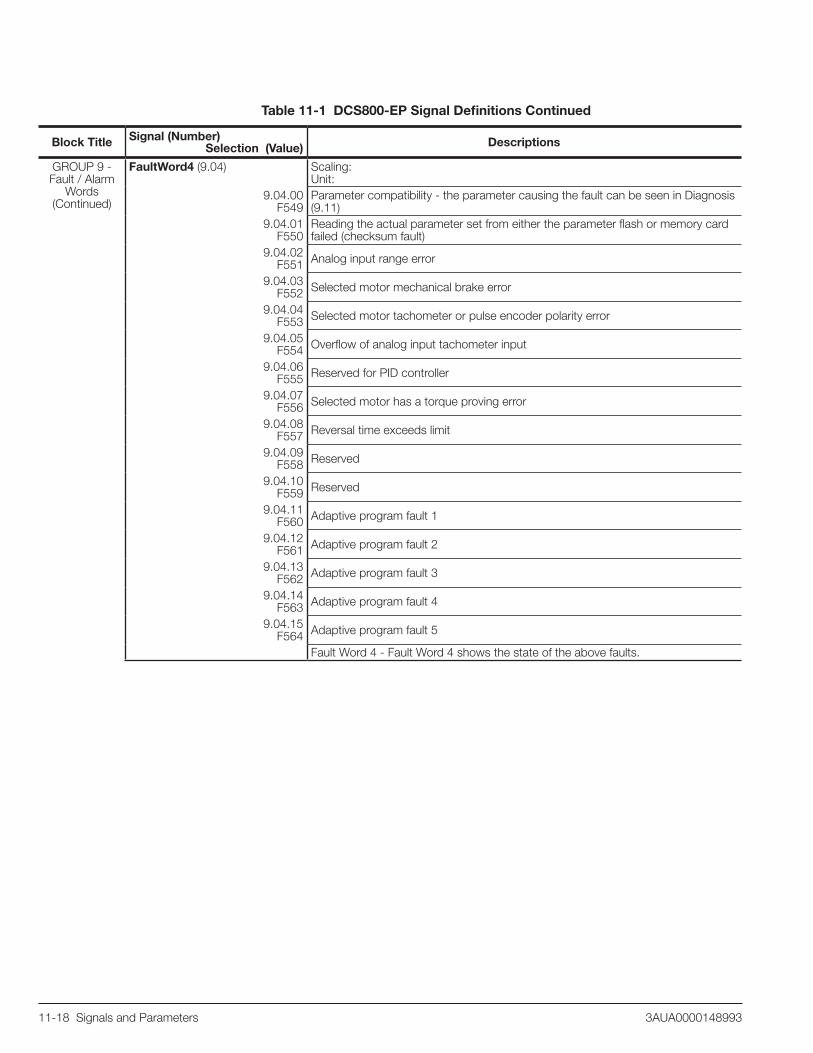
11-18 Signals and Parameters 3AUA0000148993
Block Title Signal (Number) Selection (Value) Descriptions
GROUP 9 - Fault / Alarm
Words(Continued)
FaultWord4 (9.04) Scaling: Unit:
9.04.00 F549
Parameter compatibility - the parameter causing the fault can be seen in Diagnosis (9.11)
9.04.01 F550
Reading the actual parameter set from either the parameter flash or memory card failed (checksum fault)
9.04.02 F551 Analog input range error
9.04.03 F552 Selected motor mechanical brake error
9.04.04 F553 Selected motor tachometer or pulse encoder polarity error
9.04.05 F554 Overflow of analog input tachometer input
9.04.06 F555 Reserved for PID controller
9.04.07 F556 Selected motor has a torque proving error
9.04.08 F557 Reversal time exceeds limit
9.04.09 F558 Reserved
9.04.10 F559 Reserved
9.04.11 F560 Adaptive program fault 1
9.04.12 F561 Adaptive program fault 2
9.04.13 F562 Adaptive program fault 3
9.04.14 F563 Adaptive program fault 4
9.04.15 F564 Adaptive program fault 5
Fault Word 4 - Fault Word 4 shows the state of the above faults.
Table 11-1 DCS800-EP Signal Definitions Continued
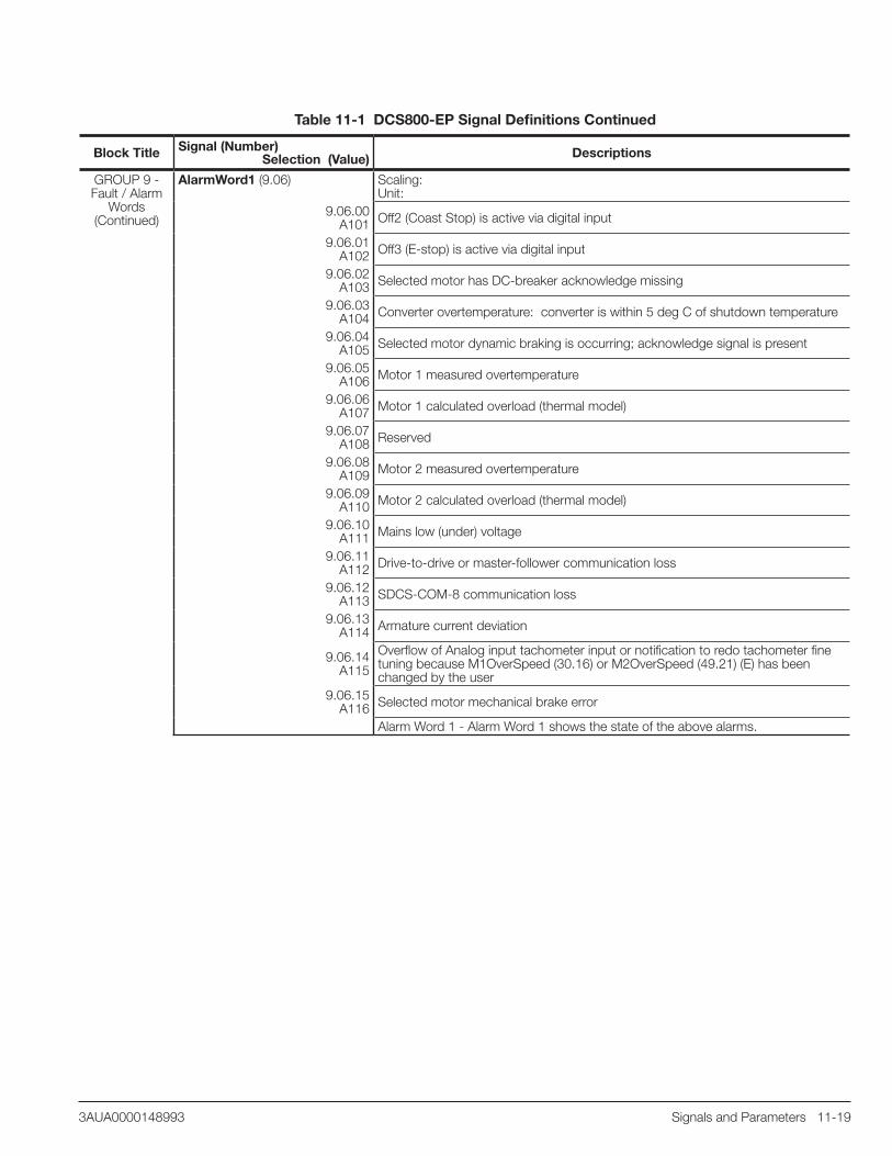
Signals and Parameters 11-193AUA0000148993
Block Title Signal (Number) Selection (Value) Descriptions
GROUP 9 - Fault / Alarm
Words(Continued)
AlarmWord1 (9.06) Scaling: Unit:
9.06.00 A101 Off2 (Coast Stop) is active via digital input
9.06.01 A102 Off3 (E-stop) is active via digital input
9.06.02A103 Selected motor has DC-breaker acknowledge missing
9.06.03 A104 Converter overtemperature: converter is within 5 deg C of shutdown temperature
9.06.04 A105 Selected motor dynamic braking is occurring; acknowledge signal is present
9.06.05 A106 Motor 1 measured overtemperature
9.06.06 A107 Motor 1 calculated overload (thermal model)
9.06.07 A108 Reserved
9.06.08 A109 Motor 2 measured overtemperature
9.06.09 A110 Motor 2 calculated overload (thermal model)
9.06.10 A111 Mains low (under) voltage
9.06.11A112 Drive-to-drive or master-follower communication loss
9.06.12 A113 SDCS-COM-8 communication loss
9.06.13A114 Armature current deviation
9.06.14A115
Overflow of Analog input tachometer input or notification to redo tachometer fine tuning because M1OverSpeed (30.16) or M2OverSpeed (49.21) (E) has been changed by the user
9.06.15 A116 Selected motor mechanical brake error
Alarm Word 1 - Alarm Word 1 shows the state of the above alarms.
Table 11-1 DCS800-EP Signal Definitions Continued

11-20 Signals and Parameters 3AUA0000148993
Block Title Signal (Number) Selection (Value) Descriptions
GROUP 9 - Fault / Alarm
Words(Continued)
AlarmWord2 (9.07) Scaling: Unit:
9.07.00 A117 Armature current ripple
9.07.01 A118 Found new application on memory card and needs to be activated
9.07.02 A119
Application on drive and memory card are different. New application needs to be activated.
9.07.03 A120 Overvoltage protection active
9.07.04 A121 Autotuning failure. See Diagnosis (9.11).
9.07.05 A122 Selected motor mechanical brake error
9.07.06 A123 One or more fault message is masked
9.07.07 A124 Speed scaling is out of range
9.07.08 A125
Selected motor tach or encoder speed feedback comparison error (compared to EMF feedback)
9.07.09A126 External alarm via digital input
9.07.10 A127 Analog input range error
9.07.11 A128 Fieldbus communication loss
9.07.12 A129
The parameters found in flash were found to be invalid at power-up (checksum error). The parameters were restored from the parameter backup.
9.07.13A130 Local command loss (typically due to disconnection of the control panel)
9.07.14 A131
A new firmware with a different amount of parameters was downloaded. The new parameters are set to their default values. The parameters causing the alarm can be identified in Diagnosis (9.11).
9.07.15 A132
Parameter setting conflict. The parameter causing the alarm can be identified in Diagnosis (9.11).Alarm Word 2 - Alarm Word 2 shows the state of the above alarms.
Table 11-1 DCS800-EP Signal Definitions Continued

Signals and Parameters 11-213AUA0000148993
Block Title Signal (Number) Selection (Value) Descriptions
GROUP 9 - Fault / Alarm
Words(Continued)
AlarmWord3 (9.08) Scaling: Unit:
9.08.00 A133
The retained data (fault logger, data1 (19.01) to data4 (19.04), etc.) is invalid. The parameters were restored from the parameter backup.
9.08.01A134
Parameter compatibility error. The parameter causing the alarm can be identified in Diagnosis (9.11).
9.08.02A135
The checksum verification failed during upload or download of parameters. Please try again.
9.08.03A136 Adaptive program task time not set in TimeLevSel (83.04) (E)
9.08.04A137
Restart of drive is not possible because the actual speed is not below the zero speed limit M1ZeroSpeedLim (20.03) or M2ZeroSpeedLim(83.04) (E)
9.08.05A138 Off2 (coast stop) is active via fieldbus
9.08.06A139 Off3 (E-stop) is active via fieldbus
9.08.07A140
The fieldbus parameters in group 51 do not match the fieldbus adapter or the device has not been selected
9.08.08A141 Invalid combination of SDCS-CON-4 firmware and SDCS-COM-8 firmware
9.08.09A142 Memory card missing. To disable, set ParApplSave (16.06) to disableAppl
9.08.10A143 Checksum failure or wrong memory card
9.08.11A301 Adaptive program alarm 1
9.08.12A302 Adaptive program alarm 2
9.08.13A303 Adaptive program alarm 3
9.08.14A304 Adaptive program alarm 4
9.08.15 A305 Adaptive program alarm 5
Alarm Word 3 - Alarm Word 3 shows the state of the above alarms.Diagnosis (9.11) Scaling:
Unit:Diagnosis - This shows a diagnostic code when selected alarms or faults are present. “Fault reset” clears this code. See DCS800 Firmware Manual for the complete list of diagnostic codes.
LastFault (9.12) Scaling: Unit:Last Fault - Displays the most recent fault.
2ndLastFault (9.13) Scaling: Unit:Second Last Fault - Displays the second most recent fault.
3rdLastFault (9.14) Scaling: Unit:Third Last Fault - Displays the third most recent fault.
Table 11-1 DCS800-EP Signal Definitions Continued

11-22 Signals and Parameters 3AUA0000148993
11.2 DCS800-EP Parameter Definitions
Table 11-2 DCS800-EP Parameter Definitions
Block Title Parameter (Number) Selection (Value) Descriptions
GROUP 10 - START/STOP
SELECT
CommandSel (10.01) Preset Value: 0 (LOCAL I/O)Range: 0 - 4
Local I/O (0) Drive is controlled by Local inputs and outputs on terminal block X6 and X7, default
MainCtrlWord (1) Drive is controlled by MainCtrlWord (7.01) typically from fieldbus.
Key (2) Automatically switches over from MainCtrlWord to Local I/O if FieldbusComm (F528) fault occurs.
12PLink (3) Drive is controlled from 12-pulse master.FexLink (4) Drive is controlled from field exciter master.
Command Select - Selects where the motor-on commands (on, run, and stop) will come from. Whatever is selected will get written to UsedMCW (7.04). NOTE: Local control mode has higher priority than the selection made with CommandSel (10.01).NOTE: Digital inputs for Off2 (10.08), E Stop (10.09) and Reset (10.03) are always active (assuming they have been assigned) even when this parameter is set to something other than Local I/O.
Direction (10.02)
Preset Value: 0 (Not Used)Range: 0 - 20
Not Used (0) Default
DI1 (1) 1 = Reverse, 0 = Forward
DI2 (2) 1 = Reverse, 0 = Forward
DI3 (3) 1 = Reverse, 0 = Forward
DI4 (4) 1 = Reverse, 0 = Forward
DI5 (5) 1 = Reverse, 0 = Forward
DI6 (6) 1 = Reverse, 0 = Forward
DI7 (7) 1 = Reverse, 0 = Forward
DI8 (8) 1 = Reverse, 0 = Forward
DI9 (9) 1 = Reverse, 0 = Forward, only available with digital extension board
DI10 (10) 1 = Reverse, 0 = Forward, only available with digital extension board
DI11 (11) 1 = Reverse, 0 = Forward, only available with digital extension board
MCW BIT11 (12) 1 = Reverse, 0 = Forward, MainCtrlWord (7.01) bit 11
MCW BIT12 (13) 1 = Reverse, 0 = Forward, MainCtrlWord (7.01) bit 12
MCW BIT13 (14) 1 = Reverse, 0 = Forward, MainCtrlWord (7.01) bit 13
MCW BIT14 (15) 1 = Reverse, 0 = Forward, MainCtrlWord (7.01) bit 14
MCW BIT15 (16) 1 = Reverse, 0 = Forward, MainCtrlWord (7.01) bit 15
ACW Bit12 (17) 1 = Reverse, 0 = Forward, AuxCtrlWord (7.02) bit 12
ACW Bit13 (18) 1 = Reverse, 0 = Forward, AuxCtrlWord (7.02) bit 13
ACW Bit14 (19) 1 = Reverse, 0 = Forward, AuxCtrlWord (7.02) bit 14
ACW Bit15 (20) 1 = Reverse, 0 = Forward, AuxCtrlWord (7.02) bit 15
Direction for Rotation Command - Selects the binary signal that controls direction of rotation, either a digital input or a reserved bit in the MCW (7.01) or ACW (7.02).

Signals and Parameters 11-233AUA0000148993
Block Title Parameter (Number) Selection (Value) Descriptions
GROUP 10 - START/STOP
SELECT (Continued)
Reset (10.03) Preset Value: 6 (DI6)Range: 0 - 20
Not Used (0)
DI1 (1) Reset by rising edge (0g1)DI2 (2) Reset by rising edge (0g1)DI3 (3) Reset by rising edge (0g1)DI4 (4) Reset by rising edge (0g1)DI5 (5) Reset by rising edge (0g1)DI6 (6) Reset by rising edge (0g1), defaultDI7 (7) Reset by rising edge (0g1)DI8 (8) Reset by rising edge (0g1)DI9 (9) Reset by rising edge (0g1), only available with digital extension board
DI10 (10) Reset by rising edge (0g1), only available with digital extension boardDI11 (11) Reset by rising edge (0g1), only available with digital extension board
MCW BIT11 (12) Reset by rising edge (0g1), MainCtrlWord (7.01) bit 11MCW BIT12 (13) Reset by rising edge ((0g1), MainCtrlWord (7.01) bit 12MCW BIT13 (14) Reset by rising edge (0g1), MainCtrlWord (7.01) bit 13MCW BIT14 (15) Reset by rising edge (0g1), MainCtrlWord (7.01) bit 14MCW BIT15 (16) Reset by rising edge (0g1), MainCtrlWord (7.01) bit 15ACW Bit12 (17) Reset by rising edge (0g1), AuxCtrlWord (7.02) bit 12
ACW Bit13 (18) Reset by rising edge (0g1), AuxCtrlWord (7.02) bit 13 ACW Bit14 (19) Reset by rising edge (0g1), AuxCtrlWord (7.02) bit 14ACW Bit15 (20) Reset by rising edge (0g1), AuxCtrlWord (7.02) bit 15
Fault Reset Command - Selects the signal that controls fault reset, either a digital input or a reserved bit in the MCW (7.01) or ACW (7.02).
MotFanAck (10.06) Preset Value: 2 (DI2)Range: 0 - 11
Not Used (0) No ReactionDI1 (1) 1= acknowledge OK, 0 = no acknowledgeDI2 (2) 1= acknowledge OK, 0 = no acknowledge, defaultDI3 (3) 1= acknowledge OK, 0 = no acknowledgeDI4 (4) 1= acknowledge OK, 0 = no acknowledgeDI5 (5) 1= acknowledge OK, 0 = no acknowledgeDI6 (6) 1= acknowledge OK, 0 = no acknowledgeDI7 (7) 1= acknowledge OK, 0 = no acknowledgeDI8 (8) 1= acknowledge OK, 0 = no acknowledge
DI9 (9) 1= acknowledge OK, 0 = no acknowledge, only available with digital extensionboard
DI10 (10) 1= acknowledge OK, 0 = no acknowledge, only available with digital extensionboard
DI11 (11) 1= acknowledge OK, 0 = no acknowledge, only available with digital extensionboardMotor Fan Acknowledge - Selects the digital input used to acknowledge that the motor blower is on. The drive trips with F523 ExtFanAck [FaultWord2 (9.02) bit 6] if a digital input for an external fan is selected and the acknowledge is missing for 10 seconds.
Table 11-2 DCS800-EP Parameter Definitions Continued

11-24 Signals and Parameters 3AUA0000148993
Block Title Parameter (Number) Selection (Value) Descriptions
GROUP 10 - START/STOP
SELECT (Continued)
HandAuto (10.07) Preset Value: 0 (Not Used)Range: 0 - 20
Not Used (0) DefaultDI1 (1) 1 = Auto, 0 = HandDI2 (2) 1 = Auto, 0 = HandDI3 (3) 1 = Auto, 0 = HandDI4 (4) 1 = Auto, 0 = HandDI5 (5) 1 = Auto, 0 = HandDI6 (6) 1 = Auto, 0 = HandDI7 (7) 1 = Auto, 0 = Hand
DI8 (8) 1 = Auto, 0 = Hand
DI9 (9) 1 = Auto, 0 = Hand, only available with digital extension boardDI10 (10) 1 = Auto, 0 = Hand, only available with digital extension boardDI11 (11) 1 = Auto, 0 = Hand, only available with digital extension board
MCW BIT11 (12) 1 = Auto, 0 = Hand, MainCtrlWord (7.01) bit 11MCW BIT12 (13) 1 = Auto, 0 = Hand, MainCtrlWord (7.01) bit 12MCW BIT13 (14) 1 = Auto, 0 = Hand, MainCtrlWord (7.01) bit 13MCW BIT14 (15) 1 = Auto, 0 = Hand, MainCtrlWord (7.01) bit 14MCW BIT15 (16) 1 = Auto, 0 = Hand, MainCtrlWord (7.01) bit 15ACW Bit12 (17) 1 = Auto, 0 = Hand, AuxCtrlWord (7.02) bit 12
ACW Bit13 (18) 1 = Auto, 0 = Hand, AuxCtrlWord (7.02) bit 13 ACW Bit14 (19) 1 = Auto, 0 = Hand, AuxCtrlWord (7.02) bit 14ACW Bit15 (20) 1 = Auto, 0 = Hand, AuxCtrlWord (7.02) bit 15
Hand (Manual) / Automatic - Selects the binary signal that controls whether the drive is in hand (Local I/O) or automatic (MainCtrlWord) control. This overrides the selection made in CommandSel (10.01). The signal can be a digital input or a reserved bit in the MCW (7.01) or ACW (7.02).
Off2 (10.08) Preset Value: 4 (DI4)Range: 0 - 20
Not Used (0)DI1 (1) 1= no Off2, 0 = Off2 activeDI2 (2) 1= no Off2, 0 = Off2 activeDI3 (3) 1= no Off2, 0 = Off2 activeDI4 (4) 1= no Off2, 0 = Off2 active, defaultDI5 (5) 1= no Off2, 0 = Off2 activeDI6 (6) 1= no Off2, 0 = Off2 activeDI7 (7) 1= no Off2, 0 = Off2 activeDI8 (8) 1= no Off2, 0 = Off2 activeDI9 (9) 1= no Off2, 0 = Off2 active, only available with digital extension board
DI10 (10) 1= no Off2, 0 = Off2 active, only available with digital extension boardDI11 (11) 1= no Off2, 0 = Off2 active, only available with digital extension board
MCW BIT11 (12) 1= no Off2, 0 = Off2 active, MainCtrlWord (7.01) bit 11MCW BIT12 (13) 1= no Off2, 0 = Off2 active, MainCtrlWord (7.01) bit 12MCW BIT13 (14) 1= no Off2, 0 = Off2 active, MainCtrlWord (7.01) bit 13MCW BIT14 (15) 1= no Off2, 0 = Off2 active, MainCtrlWord (7.01) bit 14MCW BIT15 (16) 1= no Off2, 0 = Off2 active, MainCtrlWord (7.01) bit 15ACW Bit12 (17) 1= no Off2, 0 = Off2 active, AuxCtrlWord (7.02) bit 12
ACW Bit13 (18) 1= no Off2, 0 = Off2 active, AuxCtrlWord (7.02) bit 13 ACW Bit14 (19) 1= no Off2, 0 = Off2 active, AuxCtrlWord (7.02) bit 14ACW Bit15 (20) 1= no Off2, 0 = Off2 active, AuxCtrlWord (7.02) bit 15
Off2 Coast Stop - Selects the binary signal that controls the coast stop command, either a digital input or a reserved bit in the MCW (7.01) or ACW (7.02).
Table 11-2 DCS800-EP Parameter Definitions Continued

Signals and Parameters 11-253AUA0000148993
Block Title Parameter (Number) Selection (Value) Descriptions
GROUP 10 - START/STOP
SELECT (Continued)
Off3 (10.09) Preset Value: 5 (DI5)Range: 0 - 20
Not Used (0)DI1 (1) 1= no E Stop, 0 = E Stop activeDI2 (2) 1= no E Stop, 0 = E Stop activeDI3 (3) 1= no E Stop, 0 = E Stop activeDI4 (4) 1= no E Stop, 0 = E Stop activeDI5 (5) 1= no E Stop, 0 = E Stop active, defaultDI6 (6) 1= no E Stop, 0 = E Stop activeDI7 (7) 1= no E Stop, 0 = E Stop activeDI8 (8) 1= no E Stop, 0 = E Stop activeDI9 (9) 1= no E Stop, 0 = E Stop active, only available with digital extension board
DI10 (10) 1= no E Stop, 0 = E Stop active, only available with digital extension boardDI11 (11) 1= no E Stop, 0 = E Stop active, only available with digital extension board
MCW BIT11 (12) 1= no E Stop, 0 = E Stop active, MainCtrlWord (7.01) bit 11MCW BIT12 (13) 1= no E Stop, 0 = E Stop active, MainCtrlWord (7.01) bit 12MCW BIT13 (14) 1= no E Stop, 0 = E Stop active, MainCtrlWord (7.01) bit 13MCW BIT14 (15) 1= no E Stop, 0 = E Stop active, MainCtrlWord (7.01) bit 14MCW BIT15 (16) 1= no E Stop, 0 = E Stop active, MainCtrlWord (7.01) bit 15ACW Bit12 (17) 1= no E Stop, 0 = E Stop active, AuxCtrlWord (7.02) bit 12
ACW Bit13 (18) 1= no E Stop, 0 = E Stop active, AuxCtrlWord (7.02) bit 13 ACW Bit14 (19) 1= no E Stop, 0 = E Stop active, AuxCtrlWord (7.02) bit 14ACW Bit15 (20) 1= no E Stop, 0 = E Stop active, AuxCtrlWord (7.02) bit 15
Off3 (E-stop) - Selects the binary signal that controls the emergency stop command, either a digital input or a reserved bit in the MCW (7.01) or ACW (7.02).
ParChange (10.10) Preset Value: 0 (Not Used)Range: 0 - 20
Not Used (0) Default
DI1 (1) switch to Motor2/User2 by rising edge (0g1), switch to Motor1/User1 by falling edge (1g0)
DI2 (2) switch to Motor2/User2 by rising edge (0g1), switch to Motor1/User1 by falling edge (1g0)
DI3 (3) switch to Motor2/User2 by rising edge (0g1), switch to Motor1/User1 by falling edge (1g0)
DI4 (4) switch to Motor2/User2 by rising edge (0g1), switch to Motor1/User1 by falling edge (1g0)
DI5 (5) switch to Motor2/User2 by rising edge (0g1), switch to Motor1/User1 by falling edge (1g0)
DI6 (6) switch to Motor2/User2 by rising edge (0g1), switch to Motor1/User1 by falling edge (1g0)
DI7 (7) switch to Motor2/User2 by rising edge (0g1), switch to Motor1/User1 by falling edge (1g0)
DI8 (8) switch to Motor2/User2 by rising edge (0g1), switch to Motor1/User1 by falling edge (1g0)
DI9 (9) switch to Motor2/User2 by rising edge (0g1), switch to Motor1/User1 by falling edge (1g0), only available with digital extension board
DI10 (10) switch to Motor2/User2 by rising edge (0g1), switch to Motor1/User1 by falling edge (1g0), only available with digital extension board
DI11 (11) switch to Motor2/User2 by rising edge (0g1), switch to Motor1/User1 by falling edge (1g0), only available with digital extension board
MCW BIT11 (12) switch to Motor2/User2 by rising edge (0g1), switch to Motor1/User1 by falling edge (1g0), MainCtrlWord (7.01) bit 11
Table 11-2 DCS800-EP Parameter Definitions Continued

11-26 Signals and Parameters 3AUA0000148993
Block Title Parameter (Number) Selection (Value) Descriptions
GROUP 10 - START/STOP
SELECT (Continued)
ParChange (10.10) (Continued)MCW BIT12 (13) switch to Motor2/User2 by rising edge (0g1),
switch to Motor1/User1 by falling edge (1g0), MainCtrlWord (7.01) bit 12
MCW BIT13 (14) switch to Motor2/User2 by rising edge (0g1), switch to Motor1/User1 by falling edge (1g0), MainCtrlWord (7.01) bit 13
MCW BIT14 (15) switch to Motor2/User2 by rising edge (0g1), switch to Motor1/User1 by falling edge (1g0), MainCtrlWord (7.01) bit 14
MCW BIT15 (16) switch to Motor2/User2 by rising edge (0g1), switch to Motor1/User1 by falling edge (1g0), MainCtrlWord (7.01) bit 15
ACW Bit12 (17) switch to Motor2/User2 by rising edge (0g1), switch to Motor1/User1 by falling edge (1g0),AuxCtrlWord (7.02) bit 12
ACW Bit13 (18) switch to Motor2/User2 by rising edge (0g1), switch to Motor1/User1 by falling edge (1g0),AuxCtrlWord (7.02) bit 13
ACW Bit14 (19) switch to Motor2/User2 by rising edge (0g1), switch to Motor1/User1 by falling edge (1g0),AuxCtrlWord (7.02) bit 14
ACW Bit15 (20) switch to Motor2/User2 by rising edge (0g1), switch to Motor1/User1 by falling edge (1g0),AuxCtrlWord (7.02) bit 15Parameter Change - Selects the binary signal that releases either Motor1/User1 or Motor2/User2. The choice to release Motor 1/2 (shared motion) or macros User 1/2 is defined by means of MacroChangeMode (16.05). The signal can be a digital input or a reserved bit in the MCW (7.01) or ACW (7.02).
OnOff1 (10.15) Preset Value: 7 (DI7)Range: 0 - 21
Not Used (0)DI1 (1) On by rising edge (0g1), 0 = Off1DI2 (2) On by rising edge (0g1), 0 = Off1DI3 (3) On by rising edge (0g1), 0 = Off1DI4 (4) On by rising edge (0g1), 0 = Off1DI5 (5) On by rising edge (0g1), 0 = Off1DI6 (6) On by rising edge (0g1), 0 = Off1DI7 (7) On by rising edge (0g1), 0 = Off1, defaultDI8 (8) On by rising edge (0g1), 0 = Off1DI9 (9) On by rising edge (0g1), 0 = Off1, only available with digital extension board
DI10 (10) On by rising edge (0g1), 0 = Off1, only available with digital extension boardDI11 (11) On by rising edge (0g1), 0 = Off1, only available with digital extension board
MCW BIT11 (12) On by rising edge (0g1), 0 = Off1, MainCtrlWord (7.01) bit 11MCW BIT12 (13) On by rising edge (0g1), 0 = Off1, MainCtrlWord (7.01) bit 12MCW BIT13 (14) On by rising edge (0g1), 0 = Off1, MainCtrlWord (7.01) bit 13MCW BIT14 (15) On by rising edge (0g1), 0 = Off1, MainCtrlWord (7.01) bit 14MCW BIT15 (16) On by rising edge (0g1), 0 = Off1, MainCtrlWord (7.01) bit 15ACW Bit12 (17) On by rising edge (0g1), 0 = Off1, AuxCtrlWord (7.02) bit 12
ACW Bit13 (18) On by rising edge (0g1), 0 = Off1, AuxCtrlWord (7.02) bit 13 ACW Bit14 (19) On by rising edge (0g1), 0 = Off1, AuxCtrlWord (7.02) bit 14ACW Bit15 (20) On by rising edge (0g1), 0 = Off1, AuxCtrlWord (7.02) bit 15
D17D18 (21) On and Start by rising edge (0g1) of DI7, Stop and Off1 by falling edge (1g0) of DI8. Following settings apply: OnOff1 (10.15) = StartStop (10.16) = DI7DI8.OnOff1 (Motor On) - Selects the binary signal which turns the motor on. In 2-wire mode, StartStop is also required before motion is released. In 3-wire mode, the rising edge of this signal turns the motor on and releases motion. FOR 2-WIRE CONTROL: The signal can be a digital input or a reserved bit in the MCW (7.01) or ACW (7.02). FOR 3-WIRE CONTROL: The signal must be Digital Input 7. 3-wire control is selected by setting both this parameter and StartStop (10.16) = DI7DI8.
Table 11-2 DCS800-EP Parameter Definitions Continued

Signals and Parameters 11-273AUA0000148993
Block Title Parameter (Number) Selection (Value) Descriptions
GROUP 10 - START/STOP
SELECT (Continued)
StartStop (10.16 ) Preset Value: 8 (DI8)Range: 0 - 21
Not Used (0)DI1 (1) Start by rising edge (0g1), 0 = StopDI2 (2) Start by rising edge (0g1), 0 = StopDI3 (3) Start by rising edge (0g1), 0 = StopDI4 (4) Start by rising edge (0g1), 0 = StopDI5 (5) Start by rising edge (0g1), 0 = StopDI6 (6) Start by rising edge (0g1), 0 = StopDI7 (7) Start by rising edge (0g1), 0 = StopDI8 (8) Start by rising edge (0g1), 0 = Stop, defaultDI9 (9) Start by rising edge (0g1), 0 = Stop, only available with digital extension board
DI10 (10) Start by rising edge (0g1), 0 = Stop, only available with digital extension boardDI11 (11) Start by rising edge (0g1), 0 = Stop, only available with digital extension board
MCW BIT11 (12) Start by rising edge (0g1), 0 = Stop, MainCtrlWord (7.01) bit 11MCW BIT12 (13) Start by rising edge (0g1), 0 = Stop, MainCtrlWord (7.01) bit 12MCW BIT13 (14) Start by rising edge (0g1), 0 = Stop, MainCtrlWord (7.01) bit 13MCW BIT14 (15) Start by rising edge (0g1), 0 = Stop, MainCtrlWord (7.01) bit 14MCW BIT15 (16) Start by rising edge (0g1), 0 = Stop, MainCtrlWord (7.01) bit 15ACW Bit12 (17) Start by rising edge (0g1), 0 = Stop, AuxCtrlWord (7.02) bit 12
ACW Bit13 (18) Start by rising edge (0g1), 0 = Stop, AuxCtrlWord (7.02) bit 13 ACW Bit14 (19) Start by rising edge (0g1), 0 = Stop, AuxCtrlWord (7.02) bit 14ACW Bit15 (20) Start by rising edge (0g1), 0 = Stop, AuxCtrlWord (7.02) bit 15
D17D18 (21) On and Start by rising edge (0g1) of DI7, Stop and Off1 by falling edge (1g0) of DI8. Following settings apply: OnOff1 (10.15) = StartStop (10.16) = DI7DI8.StartStop (Run) - In 2-wire mode, selects the binary signal which releases motion. In 3-wire mode, the falling edge of this signal decelerates the motor and turns it off.FOR 2-WIRE CONTROL: The signal can be a digital input or a reserved bit in the MCW (7.01) or ACW (7.02). FOR 3-WIRE CONTROL: The signal must be Digital Input 8. 3-wire control is selected by setting both this parameter and OnOff1 (10.15) = DI7DI8.
Jog1 (10.17)Jog2 (10.18)
Preset Value: 0 (Not Used)Range: 0 - 20
Not Used (0) DefaultDI1 (1) 1= Jog# active, 0 = no Jog#DI2 (2) 1= Jog# active, 0 = no Jog#DI3 (3) 1= Jog# active, 0 = no Jog#DI4 (4) 1= Jog# active, 0 = no Jog#DI5 (5) 1= Jog# active, 0 = no Jog#DI6 (6) 1= Jog# active, 0 = no Jog#DI7 (7) 1= Jog# active, 0 = no Jog#DI8 (8) 1= Jog# active, 0 = no Jog#DI9 (9) 1= Jog# active, 0 = no Jog#, only available with digital extension board
DI10 (10) 1= Jog# active, 0 = no Jog#, only available with digital extension boardDI11 (11) 1= Jog# active, 0 = no Jog#, only available with digital extension board
MCW BIT11 (12) 1= Jog# active, 0 = no Jog#, MainCtrlWord (7.01) bit 11MCW BIT12 (13) 1= Jog# active, 0 = no Jog#, MainCtrlWord (7.01) bit 12MCW BIT13 (14) 1= Jog# active, 0 = no Jog#, MainCtrlWord (7.01) bit 13MCW BIT14 (15) 1= Jog# active, 0 = no Jog#, MainCtrlWord (7.01) bit 14MCW BIT15 (16) 1= Jog# active, 0 = no Jog#, MainCtrlWord (7.01) bit 15ACW Bit12 (17) 1= Jog# active, 0 = no Jog#, AuxCtrlWord (7.02) bit 12
Table 11-2 DCS800-EP Parameter Definitions Continued

11-28 Signals and Parameters 3AUA0000148993
Block Title Parameter (Number) Selection (Value) Descriptions
GROUP 10 - START/STOP
SELECT (Continued)
Jog1 (10.17) (Continued)Jog2 (10.18) (Continued)
ACW Bit13 (18) 1= Jog# active, 0 = no Jog#, AuxCtrlWord (7.02) bit 13 ACW Bit14 (19) 1= Jog# active, 0 = no Jog#, AuxCtrlWord (7.02) bit 14ACW Bit15 (20) 1= Jog# active, 0 = no Jog#, AuxCtrlWord (7.02) bit 15
Jog 1 or 2 - Selects the binary signal for Jog # command and sets speed reference at FixedSpeed1 (23.02) or FixedSpeed2 (23.03). The signal can be a digital input or a reserved bit in the MCW (7.01) or ACW (7.02). For Jog1 only, selections also include “Dix+DIR” where Dix = DI1 through DI11. “Dix+DIR” allows the direction input, selected with Direction (10.02), to influence jog direction. In 3-wire mode (Jog1 only), it also allows this input to turn the motor on and release motion (at FixedSpeed1). NOTE: Jog2 (10.18) overrides Jog1 (10.17)NOTE: Acceleration and deceleration time for jogging is selected by JogAccTime (22.12) and JogDecTime (22.13).
ConvFanAck (10.20) Preset Value: 1 (Dl1)Range: 0 - 11
Not Used (0) No ReactionDI1 (1) 1= acknowledge OK, 0 = no acknowledge, defaultDI2 (2) 1= acknowledge OK, 0 = no acknowledgeDI3 (3) 1= acknowledge OK, 0 = no acknowledgeDI4 (4) 1= acknowledge OK, 0 = no acknowledgeDI5 (5) 1= acknowledge OK, 0 = no acknowledgeDI6 (6) 1= acknowledge OK, 0 = no acknowledgeDI7 (7) 1= acknowledge OK, 0 = no acknowledgeDI8 (8) 1= acknowledge OK, 0 = no acknowledge
DI9 (9) 1= acknowledge OK, 0 = no acknowledge, only available with digital extension board
DI10 (10) 1= acknowledge OK, 0 = no acknowledge, only available with digital extension board
DI11 (11) 1= acknowledge OK, 0 = no acknowledge, only available with digital extension boardConverter Fan Acknowledge - Selects which digital input is used to acknowledge that the drive (converter) fan is on.
MainContAck (10.21) Preset Value: (3) Dl3Range: 0 - 11
Not Used (0) No ReactionDI1 (1) 1= acknowledge OK, 0 = no acknowledgeDI2 (2) 1= acknowledge OK, 0 = no acknowledgeDI3 (3) 1= acknowledge OK, 0 = no acknowledge, defaultDI4 (4) 1= acknowledge OK, 0 = no acknowledgeDI5 (5) 1= acknowledge OK, 0 = no acknowledgeDI6 (6) 1= acknowledge OK, 0 = no acknowledgeDI7 (7) 1= acknowledge OK, 0 = no acknowledgeDI8 (8) 1= acknowledge OK, 0 = no acknowledge
DI9 (9) 1= acknowledge OK, 0 = no acknowledge, only available with digital extension board
DI10 (10) 1= acknowledge OK, 0 = no acknowledge, only available with digital extension board
DI11 (11) 1= acknowledge OK, 0 = no acknowledge, only available with digital extension boardMain Contactor Acknowledge - Selects which digital input is used to acknowledge that the main contactor is on. The main contactor is typically an AC input contactor but could also be a DC output contactor.
Table 11-2 DCS800-EP Parameter Definitions Continued

Signals and Parameters 11-293AUA0000148993
Block Title Parameter (Number) Selection (Value) Descriptions
GROUP 10 - START/STOP
SELECT (Continued)
DynBrakeAck (10.22) Preset Value: 0 (Not Used)Range: 0 - 11
Not Used (0) No Reaction, defaultDI1 (1) 1= acknowledge OK, 0 = no acknowledgeDI2 (2) 1= acknowledge OK, 0 = no acknowledgeDI3 (3) 1= acknowledge OK, 0 = no acknowledgeDI4 (4) 1= acknowledge OK, 0 = no acknowledgeDI5 (5) 1= acknowledge OK, 0 = no acknowledgeDI6 (6) 1= acknowledge OK, 0 = no acknowledgeDI7 (7) 1= acknowledge OK, 0 = no acknowledgeDI8 (8) 1= acknowledge OK, 0 = no acknowledge
DI9 (9) 1= acknowledge OK, 0 = no acknowledge, only available with digital extension board
DI10 (10) 1= acknowledge OK, 0 = no acknowledge, only available with digital extension board
DI11 (11) 1= acknowledge OK, 0 = no acknowledge, only available with digital extension boardDynamic Braking Acknowledge - Selects which digital input is used to acknowledge that the dynamic braking contactor is on. NOTE: DO NOT USE THIS SIGNAL FOR US STYLE OF DC OUTPUT CONTACTOR. USE (10.21) OR (10.23) INSTEAD.
DcBreakAck (10.23) Preset Value: 0 (Not Used)Range: 0 - 11
Not Used (0) No Reaction, defaultDI1 (1) 1= acknowledge OK, 0 = no acknowledgeDI2 (2) 1= acknowledge OK, 0 = no acknowledgeDI3 (3) 1= acknowledge OK, 0 = no acknowledgeDI4 (4) 1= acknowledge OK, 0 = no acknowledgeDI5 (5) 1= acknowledge OK, 0 = no acknowledgeDI6 (6) 1= acknowledge OK, 0 = no acknowledgeDI7 (7) 1= acknowledge OK, 0 = no acknowledgeDI8 (8) 1= acknowledge OK, 0 = no acknowledge
DI9 (9) 1= acknowledge OK, 0 = no acknowledge, only available with digital extension board
DI10 (10) 1= acknowledge OK, 0 = no acknowledge, only available with digital extension board
DI11 (11) 1= acknowledge OK, 0 = no acknowledge, only available with digital extension boardDC Breaker Acknowledge - Selects which digital input is used to acknowledge that the DC breaker or the DC output contactor is on.
Dl1Invert (10.25)Dl2Invert (10.26)Dl3Invert (10.27)Dl4Invert (10.28)Dl5Invert (10.29)Dl6Invert (10.30)Dl7Invert (10.31)Dl8Invert (10.32)Dl9Invert (10.33)Dl10Invert (10.34)Dl11Invert (10.35)
Preset Value: 0 (Direct)Preset Value: 0 (Direct)Preset Value: 0 (Direct)Preset Value: 0 (Direct)Preset Value: 0 (Direct)Preset Value: 0 (Direct)Preset Value: 0 (Direct)Preset Value: 0 (Direct)Preset Value: 0 (Direct)Preset Value: 0 (Direct)Preset Value: 0 (Direct)Range: 0 - 1
Direct (0) Direct, defaultInverted (1) Inverted
Invert Digital Input 1 to 11 - Selects whether this digital input should be inverted.
Table 11-2 DCS800-EP Parameter Definitions Continued

11-30 Signals and Parameters 3AUA0000148993
Block Title Parameter (Number) Selection (Value) Descriptions
GROUP 11 - SPEED
REFERENCE INPUTS
Ref1Mux (11.02) Preset Value: 1 (Close)Range: 0 - 21
Open (0) switch for speed ref. 1 is fixed openClose (1) switch for speed ref 1 is fixed closed, default
DI1 (2) 1= switch is closed, speed ref 1 is active; 0 = switch is open, speed ref = 0DI2 (3) 1= switch is closed, speed ref 1 is active; 0 = switch is open, speed ref = 0DI3 (4) 1= switch is closed, speed ref 1 is active; 0 = switch is open, speed ref = 0DI4 (5) 1= switch is closed, speed ref 1 is active; 0 = switch is open, speed ref = 0DI5 (6) 1= switch is closed, speed ref 1 is active; 0 = switch is open, speed ref = 0DI6 (7) 1= switch is closed, speed ref 1 is active; 0 = switch is open, speed ref = 0DI7 (8) 1= switch is closed, speed ref 1 is active; 0 = switch is open, speed ref = 0DI8 (9) 1= switch is closed, speed ref 1 is active; 0 = switch is open, speed ref = 0
DI9 (10) 1= switch is closed, speed ref 1 is active; 0 = switch is open, speed ref =0; only available with digital extension board
DI10 (11) 1= switch is closed, speed ref 1 is active; 0 = switch is open, speed ref =0; only available with digital extension board
DI11 (12)1= switch is closed, speed ref 1 is active; 0 = switch is open, speed ref =0; only available with digital extension board
MCW BIT11 (13)1= switch is closed, speed ref 1 is active; 0 = switch is open, speed ref =0; MainCtrlWord (7.01) bit 11
MCW BIT12 (14)1= switch is closed, speed ref 1 is active; 0 = switch is open, speed ref =0; MainCtrlWord (7.01) bit 12
MCW BIT13 (15) 1= switch is closed, speed ref 1 is active; 0 = switch is open, speed ref =0; MainCtrlWord (7.01) bit 13
MCW BIT14 (16) 1= switch is closed, speed ref 1 is active; 0 = switch is open, speed ref =0; MainCtrlWord (7.01) bit 14
MCW BIT15 (17) 1= switch is closed, speed ref 1 is active; 0 = switch is open, speed ref =0; MainCtrlWord (7.01) bit 15
ACW Bit12 (18) 1 = switch is closed, speed ref 1 is active; 0 = switch is open, speed ref =0; AuxCtrlWord (7.02) bit 12
ACW Bit13 (19) 1 = switch is closed, speed ref 1 is active; 0 = switch is open, speed ref =0; AuxCtrlWord (7.02) bit 13
ACW Bit14 (20)1 = switch is closed, speed ref 1 is active; 0 = switch is open, speed ref =0; AuxCtrlWord (7.02) bit 14
ACW Bit15 (21) 1 = switch is closed, speed ref 1 is active; 0 = switch is open, speed ref =0; AuxCtrlWord (7.02) bit 15Selects the binary signal that controls the reference speed. If set to OPEN (0), speed reference is always zero. If set to CLOSE (1, default) then speed reference is always dictated by Ref1Sel (11.03). If set to any other setting (2-21) and the selected DI or bit is ON, then speed reference is dictated by Ref1Sel (11.03). If the DI or bit is OFF, then speed reference is zero.
Ref1Sel (11.03) Preset Value: SpeedRef2301Range: 0 - 18
SpeedRef2301 (0)Selects SpeedRef (23.01) as the speed reference source which is typically written to by Adaptive Programming, application program (ControlBuilder) or overriding control (fieldbus), default
AuxSpeedRef2313 (1)Selects AuxSpeedRef (23.13) as the speed reference source which, when needed, is typically written to by Adaptive Programming, application program (ControlBuilder) or overriding control (fieldbus).
Al1 through Al6 (2 through 7) Selects analog input 1 through 6 as the speed reference source.
FixedSpeed1 (8) Selects FixedSpeed1 (23.02) as the speed reference source which is also the Jog1 speed.
FixedSpeed2 (9) Selects FixedSpeed2 (23.03) as the speed reference source which is also the Jog2 speed.
MotPot (10)Selects the reference speed as MotPot which increases when MotPotUp (11.13) is set, decreases when MotPotDown (11.14) is set and is limited by MotPotMin (11.15).
Others (11 through 18) See Firmware ManualSpeed Reference 1 Select - Selects the source of the reference speed when Ref1Mux (11.02) is CLOSE or the DI or bit selected with Ref1Mux (11.02) is ON.
Table 11-2 DCS800-EP Parameter Definitions Continued

Signals and Parameters 11-313AUA0000148993
Block Title Parameter (Number) Selection (Value) Descriptions
GROUP 11 - SPEED
REFERENCE INPUTS
(Continued)
MotPotUp (11.13) Preset Value: 0 (Not Used)Range: 0 - 20
Not Used (0) DefaultDI1 (1) 1= increase speed, 0 = hold speedDI2 (2) 1= increase speed, 0 = hold speedDI3 (3) 1= increase speed, 0 = hold speedDI4 (4) 1= increase speed, 0 = hold speedDI5 (5) 1= increase speed, 0 = hold speedDI6 (6) 1= increase speed, 0 = hold speedDI7 (7) 1= increase speed, 0 = hold speedDI8 (8) 1= increase speed, 0 = hold speed
DI9 (9) 1= increase speed, 0 = hold speed, only available with digital extensionboard
DI10 (10) 1= increase speed, 0 = hold speed, only available with digital extensionboard
DI11 (11) 1= increase speed, 0 = hold speed, only available with digital extensionboard
MCW BIT11 (12) 1= increase speed, 0 = hold speed, MainCtrlWord (7.01) bit 11MCW BIT12 (13) 1= increase speed, 0 = hold speed, MainCtrlWord (7.01) bit 12MCW BIT13 (14) 1= increase speed, 0 = hold speed, MainCtrlWord (7.01) bit 13MCW BIT14 (15) 1= increase speed, 0 = hold speed, MainCtrlWord (7.01) bit 14MCW BIT15 (16) 1= increase speed, 0 = hold speed, MainCtrlWord (7.01) bit 15ACW Bit12 (17) 1= increase speed, 0 = hold speed, AuxCtrlWord (7.02) bit 12
ACW Bit13 (18) 1= increase speed, 0 = hold speed, AuxCtrlWord (7.02) bit 13 ACW Bit14 (19) 1= increase speed, 0 = hold speed, AuxCtrlWord (7.02) bit 14ACW Bit15 (20) 1= increase speed, 0 = hold speed, AuxCtrlWord (7.02) bit 15
Motor Pot Up - Selects the signal that will increase the MotPot speed. MotPotDown (11.14) Preset Value: 0 (Not Used)
Range: 0 - 20NotUsed (0) Default
DI1 (1) 1= decrease speed, 0 = hold speedDI2 (2) 1= decrease speed, 0 = hold speedDI3 (3) 1= decrease speed, 0 = hold speedDI4 (4) 1= decrease speed, 0 = hold speedDI5 (5) 1= decrease speed, 0 = hold speedDI6 (6) 1= decrease speed, 0 = hold speedDI7 (7) 1= decrease speed, 0 = hold speedDI8 (8) 1= decrease speed, 0 = hold speed
DI9 (9) 1= decrease speed, 0 = hold speed, only available with digital extensionboard
DI10 (10) 1= decrease speed, 0 = hold speed, only available with digital extensionboard
DI11 (11) 1= decrease speed, 0 = hold speed, only available with digital extensionboard
MCW BIT11 (12) 1= decrease speed, 0 = hold speed, MainCtrlWord (7.01) bit 11MCW BIT12 (13) 1= decrease speed, 0 = hold speed, MainCtrlWord (7.01) bit 12MCW BIT13 (14) 1= decrease speed, 0 = hold speed, MainCtrlWord (7.01) bit 13MCW BIT14 (15) 1= decrease speed, 0 = hold speed, MainCtrlWord (7.01) bit 14MCW BIT15 (16) 1= decrease speed, 0 = hold speed, MainCtrlWord (7.01) bit 15ACW Bit12 (17) 1= decrease speed, 0 = hold speed, AuxCtrlWord (7.02) bit 12
ACW Bit13 (18) 1= decrease speed, 0 = hold speed, AuxCtrlWord (7.02) bit 13 ACW Bit14 (19) 1= decrease speed, 0 = hold speed, AuxCtrlWord (7.02) bit 14ACW Bit15 (20) 1= decrease speed, 0 = hold speed, AuxCtrlWord (7.02) bit 15
Motor Pot Down - Selects the signal that will decrease the MotPot speed.
Table 11-2 DCS800-EP Parameter Definitions Continued

11-32 Signals and Parameters 3AUA0000148993
Block Title Parameter (Number) Selection (Value) Descriptions
GROUP 11 - SPEED
REFERENCE INPUTS
(Continued)
MotPotMin (11.15) Preset Value: 0 (Not Used)Range: 0 - 20
NotUsed (0) DefaultDI1 (1) 1= released, 0 = blockedDI2 (2) 1= released, 0 = blockedDI3 (3) 1= released, 0 = blockedDI4 (4) 1= released, 0 = blockedDI5 (5) 1= released, 0 = blockedDI6 (6) 1= released, 0 = blockedDI7 (7) 1= released, 0 = blockedDI8 (8) 1= released, 0 = blockedDI9 (9) 1= released, 0 = blocked, only available with digital extension board
DI10 (10) 1= released, 0 = blocked, only available with digital extension boardDI11 (11) 1= released, 0 = blocked, only available with digital extension board
MCW BIT11 (12) 1= released, 0 = blocked, MainCtrlWord (7.01) bit 11MCW BIT12 (13) 1= released, 0 = blocked, MainCtrlWord (7.01) bit 12MCW BIT13 (14) 1= released, 0 = blocked, MainCtrlWord (7.01) bit 13MCW BIT14 (15) 1= released, 0 = blocked, MainCtrlWord (7.01) bit 14MCW BIT15 (16) 1= released, 0 = blocked, MainCtrlWord (7.01) bit 15ACW Bit12 (17) 1= released, 0 = blocked, AuxCtrlWord (7.02) bit 12
ACW Bit13 (18) 1= released, 0 = blocked, AuxCtrlWord (7.02) bit 13 ACW Bit14 (19) 1= released, 0 = blocked, AuxCtrlWord (7.02) bit 14ACW Bit15 (20) 1= released, 0 = blocked, AuxCtrlWord (7.02) bit 15
Motor Pot Minimum - Selects the signal that will release the MotPot minimum speed. When ON, minimum speed is released; when OFF, it is enforced. Minimum speed is determined by FixedSpeed1 (23.02).
GROUP 13 - ANALOG INPUTS
AI1HighVal (13.01)AI2HighVal (13.05)AI3HighVal (13.09)AI4HighVal (13.13)AI5HighVal (13.21)AI6HighVal (13.25)
Preset Value: 10000 mVoltsPreset Value: 10000 mVoltsPreset Value: 10000 mVoltsPreset Value: 10000 mVoltsPreset Value: 10000 mVoltsPreset Value: 10000 mVoltsRange: -10000 - 10000Analog Input 1 through 6 High Value - Selects the value that equates to the maximum input voltage, typically 10 Volts. For example, if the parameter that is being written to is scaled such that 10000 is the maximum value, set this parameter to 10000. If the maximum value represents 200% of rated (speed or torque), set this parameter to 5000.
AI1LowVal (13.02)AI1LowVal (13.06)AI1LowVal (13.10)AI1LowVal (13.14)AI1LowVal (13.22)AI1LowVal (13.26)
Preset Value: -10000 mVoltsPreset Value: -10000 mVoltsPreset Value: -10000 mVoltsPreset Value: -10000 mVoltsPreset Value: -10000 mVoltsPreset Value: -10000 mVoltsRange: -10000 - 10000Analog Input 1 through 6 Low Value - Selects the value that equates to the minimum input voltage, typically -10 Volts. This only applies if the analog input is bidirectional. For example, if the parameter that is being written to is scaled such that -10000 is the minimum value, set this parameter to -10000. If the minimum value represents -200% of rated (speed or torque), set this parameter to -5000.
Table 11-2 DCS800-EP Parameter Definitions Continued

Signals and Parameters 11-333AUA0000148993
Block Title Parameter (Number) Selection (Value) Descriptions
GROUP 13 - ANALOG INPUTS
(Continued)
ConvModeAI1 (13.03)ConvModeA2 (13.07)ConvModeAI3 (13.11)ConvModeAI4 (13.15)ConvModeAI5 (13.23)ConvModeAI6 (13.27)
Preset Value: +/- 10V BiPreset Value: +/- 10V BiPreset Value: +/- 10V BiPreset Value: +/- 10V BiPreset Value: +/- 10V BiPreset Value: +/- 10V BiRange: 0 - 4
+/-10V Bi (0) -10V to 10V / -20mA to +20mA bipolar input, default0V - 10V Uni (1) 0V to 10V / 0mA to 20mA unipolar input2V - 10V Uni (2) 2V to 10V / 4mA to20 mA unipolar input
5V Offset (3) 5V / 10mA offset in the range 0V to 10V / 0mA to 20mA for testing orindication of bipolar signals (e.g. torque, speed, etc.)
6V Offset (4) 6V / 12mA offset in the range 2V to 10V / 4mA to 20mA for testing orindication of bipolar signals (e.g. torque, speed, etc.)Conversion Mode Analog Input 1 through 6 - Selects the desired type of analog input. NOTE: For AI2 and AI3, the selection between voltage and current type input is done by setting jumper S2 or S3 on the drive’s main control board near terminal block X3. Position 1-2 for voltage, 3-4 for current.NOTE: AI3 - AI4 on the drive is only a voltage type input. On IOB-3, it can be a voltage or current type, depending on the setting of jumper S3 on IOB-3.AI5 - AI6 is on the RAIO-01 analog expansion board. It can be a voltage or current type, depending on the setting of jumpers on RAIO-01.
FilterAI1 (13.04)FilterAI2 (13.08)FilterAI3 (13.12)FilterAI4 (13.16)
Preset Value: 0 mSecPreset Value: 0 mSecPreset Value: 0 mSecPreset Value: 0 mSecRange: 0 - 10000 mSecFilter Time Analog Input 1 through 4 - Selects the filter time for the analog input. Increasing the filter time will cause the signal to become more steady but somewhat less responsive.
GROUP 14 - DIGITAL
OUTPUTS
DO1Index (14.01)DO2Index (14.03)DO3Index (14.05)DO4Index (14.07)DO5Index (14.09)DO6Index (14.11)DO7Index (14.13)DO8Index (14.15)
Preset Value: 603Preset Value: 603Preset Value: 603Preset Value: 0Preset Value: 0Preset Value: 0Preset Value: 0Preset Value: 603Range: -9999 - 9999Digital Output 1 through 8 Index - Selects the status word that is used to control this digital output. The format is -xxyy where - = invert digital output; xx = group; yy = index. Common status word selections include CurCtrlStat1 (6.03), CurCtrlStat2 (6.04), MainStatWord (8.01) and AuxStatWord (8.02)
DO1BitNo (14.02)DO2BitNo (14.04)DO3BitNo (14.06)DO4BitNo (14.08)DO5BitNo (14.10)DO6BitNo (14.12)DO7BitNo (14.14)DO8BitNo (14.16)
Preset Value: 0Preset Value: 5Preset Value: 0Preset Value: 0Preset Value: 0Preset Value: 0Preset Value: 0Preset Value: 7Range: 0 - 15Digital Output 1 through 8 Bit Number - Selects the bit in the status word selected with the previous parameter D0#Index that is used to control this digital output.
GROUP 15 - ANALOG OUTPUTS
IndexAO1 (15.01)IndexAO2 (15.06)
Preset Value: 0Preset Value: 0Range: -9999 - 9999Index - Analog Output 1 through 2 - Selects the source word that is used to control this analog output. The format is -xxyy where - = invert analog output; xx = group; yy = index. Common source words can be found in group 1, MotSpeedFilt (1.01) for example (entered as 101).
Table 11-2 DCS800-EP Parameter Definitions Continued

11-34 Signals and Parameters 3AUA0000148993
Block Title Parameter (Number) Selection (Value) Descriptions
GROUP 15 - ANALOG OUTPUTS(Continued)
CtrlWordAO1 (15.02)CtrlWordAO2 (15.07)
Preset Value: 0Preset Value: 0Range: -32768 - 32767Control Word - Analog Output 1 through 2 - If the previous parameter is set to zero, this parameter can be written to as the source for this analog output using Adaptive Programming, application program (ControlBuilder) or overriding control (fieldbus).
ConvModeAO1 (15.03)ConvModeAO2 (15.08)
Preset Value: +/-10V BiPreset Value: +/-10V BiRange: +/- 10V Bi - 0V-10V Abs
+/-10V Bi (0) -10V to +10V bipolar output, default0V - 10V Uni (1) 0V to 10V unipolar output2V - 10V Uni (2) 2V to 10V unipolar output
5V Offset (3) 5V offset in the range 0V to 10V for testing or indication of bipolar signals(e.g. torque, speed, etc.)
6V Offset (4) 6V offset in the range 2V to 10V for testing or indication of bipolar signals(e.g. torque, speed, etc.)
0V - 10V Abs (5) absolute 0V to 10V unipolar output (negative values are shown positive)Conversion Mode Analog Output 1 through 2 - Selects the type of analog output.
FilterAO1 (15.04)FilterAO2 (15.09)
Preset Value: 0 mSecPreset Value: 0 mSecRange: 0 - 1000Filter Time - Analog Output 1 through 2 - Selects the filter time for this analog output. Increasing the filter time will cause the signal to be more steady but somewhat less responsive.
ScaleA01 (15.05)ScaleA02 (15.10)
Preset Value: 10000 mVPreset Value: 10000 mVRange: 0 - 10000Scaling - Analog Output 1 through 2 - Set this value to the analog output voltage that should represent 100%. In most cases, the value of the source word is 100 (percent) when at the nominal value (nominal speed or torque for example). The value, sometimes, can exceed 100 pct. If the analog output should register 10 Volts at 250 pct, set this parameter to 4000 millivolts (= 10V/2.5).
GROUP 16 - SYSTEM
CONTROL INPUTS
LocLock (16.04) Preset Value: 0 (False)Range: 0 - 1
False (0) Local control is allowed.True (1) Local control is blocked.
Local Lock - Local control can be disabled by setting LocLock (16.04) to True. If LocLock (16.04) is released in local control, it becomes valid after the next changeover to remote control. No pass code is required to change LocLock (16.04).
USI Sel (16.09) Preset Value: 0 (Compact)Range: 0 - 1
Compact (0) Short parameter set (as documented in this manual)Extended (1) Complete parameter set (as documented in the DCS800 Firmware Manual).
Changes what set of parameters can be viewed and accessed through the control panel, Drive Window Light or Drive Windows. NOTE: In this chapter, parameters shown with (E) are from the extended set. All others are from the compact set.
GROUP 20 - LIMITS
M1SpeedMin (20.01) Preset Value: -1500 RPM Range: -10000 - 10000Motor 1 Minimum Speed - Selects the minimum speed reference of the motor. For bidirectional operation, this value is negative. For unidirectional operation, this value is zero.
M1SpeedMax (20.02) Preset Value: 1500 RPM Range: -10000 - 10000Motor 1 Maximum Speed - Selects the maximum speed reference of the motor. This cannot exceed 5 times base speed of the motor.
Table 11-2 DCS800-EP Parameter Definitions Continued

Signals and Parameters 11-353AUA0000148993
Block Title Parameter (Number) Selection (Value) Descriptions
GROUP 20 - LIMITS
(Continued)
M1ZeroSpeedLim (20.03) Preset Value: 75 RPM Range: 0 - 1000Motor 1 Zero Speed Limit - When the RUN command is removed, the drive considers the motor to be stopped when the actual speed falls below this level, at which time the armature current will be zeroed and the brake will be set. If no brake, the motor will coast to a stop. Unless flying start (21.10) is enabled, the motor cannot be restarted unless the speed is below this value. NOTE: TOO LOW OF A SETTING WILL PREVENT THE DRIVE FROM RESTARTING; ALARM SPEEDNOTZERO (A137) WILL BE DISPLAYED.
TorqMax (20.05) Preset Value: 100% Range: 0 - 325%Maximum Torque - When TorqUsedMaxSel (20.18) = TorqMax2005, This parameter selects the maximum torque limit in percent of MotNomTorque (4.23). However other torque limits, current limits or field weakening will take precidence if set lower. TorqMaxAll (2.19) displays the actual limit.
TorqMin (20.06) Preset Value: -100% Range: 0 - -325%Minimum Torque - When TorqUsedMinSel (20.19) = TorqMin2006, This parameter selects the minimum torque limit in percent of MotNomTorque (4.23). However other torque limits, current limits or field weakening will take precidence if set higher. TorqMinAll (2.20) displays the actual limit.
M1CurLimBrdg1 (20.12) Preset Value: 100%Range: 0 - 325Motor 1 Current Limit of Bridge 1 - Selects the current limit of bridge 1 in percent of M1NomCur (99.03). However other torque limits, current limits or field weakening will take precidence if set lower. Setting this parameter to zero will disable bridge 1.
M1CurLimBrdg2 (20.13) Preset Value: -100%Range: 0 - -325Motor 1 Current Limit of Bridge 2 - Selects the current limit of bridge 2 in percent of M1NomCur (99.03). However other torque limits, current limits or field weakening will take precidence if set higher. Setting this parameter to zero will disable bridge 2. NOTE: For non-regenerative (2 Quadrant) drives, the firmware disables this bridge by setting this to zero. Do not attempt to override this.
TorqUsedMaxSel (20.18) Preset Value: 0 (TorqMax2005) Range: 0 - 6
TorqMax2005 (0) DefaultAI1 (1) Analog input 1 AI2 (2) Analog input 2AI3 (3) Analog input 3AI4 (4) Analog input 4 AI5 (5) Analog input 5 AI6 (6) Analog input 6
Maximum Used Torque Selector - Selects what signal or parameter will be used as the maxumum torque limit. TorqUsedMax (2.22) displays the actual limit.
TorqUsedMinSel (20.19) Preset Value: TorqMin2006 Range: 0 - 7
TorqMax2006 (0) DefaultAI1 (1) Analog input 1 AI2 (2) Analog input 2AI3 (3) Analog input 3AI4 (4) Analog input 4 AI5 (5) Analog input 5 AI6 (6) Analog input 6
Negate2018 (7) negated output of TorqUsedMaxSel (20.18) is usedMinimum Used Torque Selector - Selects what signal or parameter will be used as the minimum torque limit. TorqUsedMin (2.23) displays the actual limit.
Table 11-2 DCS800-EP Parameter Definitions Continued

11-36 Signals and Parameters 3AUA0000148993
Block Title Parameter (Number) Selection (Value) Descriptions
GROUP 21 - START/STOP
Off1Mode (21.02) Preset Value: 0 (RampStop) Range: 0 - 3
RampStop (0) Decelerates using DecTime1 (22.02) or DecTime2 (22.10).TorqueLimit (1) Decelerates as fast as possible using the active torque limit.CoastStop (2) Armature current is immediately set to zero allowing the motor to coast to a stop.
DynBraking (3) Dynamic braking resistors are switched into the circuit to stop the motor.Off 1 Mode - Selects the type of stop used when the digital input defined by OnOff1 (10.15) is cleared, or, if controlled by fieldbus, when MCW (7.01.00) (On) is cleared.
StopMode (21.03) Preset Value: 0 (RampStop) Range: 0 - 3
RampStop (0) The input of the drives ramp is set to zero. Thus the drive stops accordingto DecTime1 (22.02) or DecTime2 (22.10).
TorqueLimit (1) The output of the drives ramp is set to zero. Thus the drive stops at theactive torque limit.
CoastStop (2)The firing pulses are immediately set to 150 degrees to decrease thearmature current. When the armature current is zero the firing pulses areblocked.
DynBraking (3) Dynamic braking resistors are switched into the circuit to stop the motor.Stop Mode - Selects the type of stop used when the digital input defined by StartStop (10.16) is cleared, or, if controlled by fieldbus, when MCW (7.01.03) (Run) is cleared.
E STOPMODE (21.04) Preset Value: 2 (CoastStop) Range: 0 - 3
RampStop (0)
The input of the drives ramp is set to zero. Thus the drive stops accordingto E StopRamp (22.04). When reaching M1ZeroSpeedLim (20.03) the firingpulses are set to 150 degrees to decrease the armature current. When thearmature current is zero the firing pulses are blocked, the contactors areopened, field exciter and fans are stopped.
TorqueLimit (1)
The output of the drives ramp is set to zero. Thus the drive stops at theactive torque limit. When reaching M1ZeroSpeedLim (20.03) the firingpulses are set to 150 degrees to decrease the armature current. When thearmature current is zero the firing pulses are blocked, the contactors areopened, field exciter and fans are stopped.
CoastStop (2)
The firing pulses are immediately set to 150 degrees to decrease thearmature current. When the armature current is zero the firing pulses areblocked, the contactors are opened, field exciter and fans are stopped,default.
DynBraking (3) Dynamic braking resistors are switched into the circuit to stop the motor.Emergency Stop Mode - Selects the type of stop used when the digital input defined by EStop (10.09) is cleared, or, if controlled by fieldbus, when MCW (7.01.02) (NotOff3) is cleared.
FLDHEATSEL (21.18) Preset Value: 0 (Not Used) Range: 0 - 6
Not Used (0) Disabled.
On (1) Selects the digital input defined by OnOff1 (10.15) or, if controlled by fieldbus, MCW (7.01.00) (On), to enable the field or reduce it to the field heating level.
OnRun (2) Selects the digital input defined by StartStop (10.16) or, if controlled by fieldbus, MCW (7.01.03) (Run), to enable the field or reduce it to the field heating level.
ACW bit 12 (3)Selects auxiliary control word bits controlled by Adaptive Programming, application program (ControlBuilder) or overriding control (fieldbus) to enable the field or reduce it to the field heating level.
ACW bit 13 (4)ACW bit 14 (5)ACW bit 15 (6)
Field Heat Selector - Enables and selects the type of field heating for the motor.
Table 11-2 DCS800-EP Parameter Definitions Continued

Signals and Parameters 11-373AUA0000148993
Block Title Parameter (Number) Selection (Value) Descriptions
GROUP 22 - SPEED RAMP
AccTime1 (22.01) Preset Value: 20 Sec Range: 0 - 300Acceleration Time 1 - The time the motor will accelerate from zero speed to maximum speed*.*The maximum speed of the drive is displayed in SpeedScaleAct (2.29).
DecTime1 (22.02) Preset Value: 20 Sec Range: 0 - 300Deceleration Time 1 - The time the motor will decelerate from maximum speed* to zero speed.*The maximum speed of the drive is displayed in SpeedScaleAct (2.29).
E StopRamp (22.04) Preset Value: 20 Sec Range: 0 - 3000Emergency Stop Ramp - The time the motor will decelerate from maximum speed* to zero speed in response to an emergency stop, if E StopMode (21.04) = RAMPSTOP, or in response to a trip level 4 fault, if FaultStopMode (30.30) = RAMPSTOP.*The maximum speed of the drive is displayed in SpeedScaleAct (2.29).
JogAccTime (E) (22.12) Preset Value: 20 Sec Range: 0 - 300Jog Aceleration Time - The time the motor will accelerate from zero speed to maximum speed* when the inputs defined by Jog1 (10.17) or Jog2 (10.18) is set or, if controlled by fieldbus, when MCW (7.01.08) (Inching1) or MCW (7.01.09) (Inching2) is set.*The maximum speed of the drive is displayed in SpeedScaleAct (2.29).
JogDecTime (E) (22.13) Preset Value: 20 Sec Range: 0 - 300Jog Deceleration Time - The time the motor will decelerate from maximum speed* to zero speed when the inputs defined by Jog1 (10.17) or Jog2 (10.18) ise cleared or, if controlled by fieldbus, when MCW (7.01.08) (Inching1) or MCW (7.01.09) (Inching2) is cleared. *The maximum speed of the drive is displayed in SpeedScaleAct (2.29).
GROUP 23 - SPEED
REFERENCE
SpeedRef (E) (23.01) Preset Value: 0 RPMRange: -10000 - 10000Speed Reference - By default, the speed reference used when the drive is put into RUN mode. For example, if set to 500, the motor will be commanded at 500 rpm. The speed reference selection can be changed with Ref1Sel (11.03).
FixedSpeed1 (E) (23.02) Preset Value: 0 RPMRange: -10000 - 10000Fixed Speed 1 (Jog Speed 1) - The speed reference used when the drive is put into JOG1 mode when the input defined by Jog1 (10.17) is set or, if controlled by fieldbus, when MCW (7.01.08) (Inching1) is set. Also used as the motor pot minimum speed when Ref1Sel (11.03) is set to MotPot.
FixedSpeed2 (E) (23.03) Preset Value: 0 RPMRange: -10000 - 10000The speed reference used when the drive is put into JOG2 mode when the input defined by Jog2 (10.18) is set or, if controlled by fieldbus, when MCW (7.01.09) (Inching2) is set.
GROUP 24 - SPEED
CONTROL
KpS (24.03) Preset Value: 5Range: 0 - 325P Part of Speed Controller - Proportional gain of the speed controller. This value is automatically calculated during the speed controller auto-tuning process. Higher values improve responsiveness.
TiS (24.09) Preset Value: 2500 mSecRange: 0 - 64000I Part of the Speed Controller - Integral gain of the speed controller. This value is automatically calculated during the speed controller auto-tuning process.Lower values improve responsiveness.
Table 11-2 DCS800-EP Parameter Definitions Continued

11-38 Signals and Parameters 3AUA0000148993
Block Title Parameter (Number) Selection (Value) Descriptions
GROUP 26 - TORQUE
REFERENCE HANDLING
TorqSel (E) (26.01) Preset Value: 1 (Speed)Range: 0 - 6
Zero (0) zero control, torque reference = 0Speed (1) speed control, defaultTorque (2) torque control
(3 through 6) Min, Max, Add, Limit: See DCS800 Firmware ManualTorque Selector - Selects whether the reference signal is a torque command, a speed command or other. If the drive is in torque control, AuxStatWord (8.02) bit 10 is set.
GROUP 30 - FAULT
FUNCTIONS
StallTime (30.01) Preset Value: 0 SecRange: 0 - 200Stall Time - If the measured speed is less than the stall speed and the torque is greater than the stall torque for a time greater than the stall time, then fault F531 will be generated.
StallSpeed (30.02) Preset Value: 5 RPMRange: 0 - 1000Stall Time - If the measured speed is less than the stall speed and the torque is greater than the stall torque for a time greater than the stall time, then fault F531 will be generated.
StallTorq (30.03) Preset Value: 75%Range: 0 - 325Stall Time - If the measured speed is less than the stall speed and the torque is greater than the stall torque for a time greater than the stall time, then fault F531 will be generated.
ArmOvrVoltLev (30.08) Preset Value: 120%Range: 20 - 500Armature Overvoltage Level - In percent of M1NomVolt (99.02), if the armature voltage exceeds the overvoltage level, fault F503 will be generated. It is recommended to set this at least 20% above M1NomVolt (99.02).
ArmOvrCurLev (30.09) Preset Value: 250%Range: 20 - 400Armature Overcurrent Level - In percent of M1NomCur (99.03), if the armature current exceeds this level, fault F502 will be generated. It is recommended to set this at least 25% above M1NomCur (99.03). ConvOvrCur (4.16) displays the trip level in Amps.
M1OvrSpeed (30.16) Preset Value: 1800 RPMRange: 0 - 10000Motor 1 Over Speed Limit - If the measured speed exceeds this level, fault F532 will be generated. It is recommended to set this at least 20% higher than the maximum motor speed, M1SpeedMin (20.01) or M1SpeedMin (20.02).
UNetMin1 (30.22) Preset Value: 80%Range: 0 - 150Mains Undervoltage Alarm Level - As a percent of NomMainsVolt (99.10), if the mains voltage falls below this level, alarm A111 will be generated. This value must be greater than UNetMin2 (30.23).
UNetMin2 (30.23) Preset Value: 60%Range: 0 - 150Mains Undervoltage Limit - As a percent of NomMainsVolt (99.10), if the mains voltage falls below this level, fault F512 will be generated. This value must be less than UNetMin1 (30.22).
PowrDownTime (30.24) Preset Value: 60%Range: 0 - 150Power Down Time - If the mains voltage falls below the alarm level defined by UNetMin1 (30.22) for longer than the time specified by this parameter, fault F512 will be generated.
Table 11-2 DCS800-EP Parameter Definitions Continued

Signals and Parameters 11-393AUA0000148993
Block Title Parameter (Number) Selection (Value) Descriptions
GROUP 30 - FAULT
FUNCTIONS (Continued)
FaultStopMode (30.30) Preset Value: 0 (RampStomp)Range: 0 - 3
RampStop (0) Decelerates using E StopRamp (22.04).TorqueLimit (1) Decelerates as fast as possible using the active torque limit.CoastStop (2) Armature current is immediately set to zero allowing the motor to coast to a stop.
DynBraking (3) Dynamic braking resistors are switched into the circuit to stop the motor.Fault Stop Mode - Selects the desired reaction to a trip level 4 fault.
ExtFaultSel (30.31) Preset Value: 0 (Not Used)Range: 0 - 20
NotUsed (0) No Reaction, defaultDI1 (1) 1 = fault, 0 = no faultDI2 (2) 1 = fault, 0 = no faultDI3 (3) 1 = fault, 0 = no faultDI4 (4) 1 = fault, 0 = no faultDI5 (5) 1 = fault, 0 = no faultDI6 (6) 1 = fault, 0 = no faultDI7 (7) 1 = fault, 0 = no faultDI8 (8) 1 = fault, 0 = no faultDI9 (9) 1 = fault, 0 = no fault, Only available with digital extension board
DI10 (10) 1 = fault, 0 = no fault, Only available with digital extension boardDI11 (11) 1 = fault, 0 = no fault, Only available with digital extension board
MCW BIT11 (12) 1 = fault, 0 = no fault, MainCtrlWord (7.01) bit 11MCW BIT12 (13) 1 = fault, 0 = no fault, MainCtrlWord (7.01) bit 12MCW BIT13 (14) 1 = fault, 0 = no fault, MainCtrlWord (7.01) bit 13MCW BIT14 (15) 1 = fault, 0 = no fault, MainCtrlWord (7.01) bit 14MCW BIT15 (16) 1 = fault, 0 = no fault, MainCtrlWord (7.01) bit 15ACW Bit12 (17) 1 = fault, 0 = no fault, AuxCtrlWord (7.02) bit 12
ACW Bit13 (18) 1 = fault, 0 = no fault, AuxCtrlWord (7.02) bit 13 ACW Bit14 (19) 1 = fault, 0 = no fault, AuxCtrlWord (7.02) bit 14ACW Bit15 (20) 1 = fault, 0 = no fault, AuxCtrlWord (7.02) bit 15
External Fault Selector - Selects the signal that is used to generate fault F525 ExternalDI, either a digital input or a reserved bit in the MCW (7.01) or ACW (7.02)
ExtAlarmSel (30.32) Preset Value: 0 (Not Used)Range: 0 - 20
NotUsed (0) No Reaction, defaultDI1 (1) 1 = fault, 0 = no faultDI2 (2) 1 = fault, 0 = no faultDI3 (3) 1 = fault, 0 = no faultDI4 (4) 1 = fault, 0 = no faultDI5 (5) 1 = fault, 0 = no faultDI6 (6) 1 = fault, 0 = no faultDI7 (7) 1 = fault, 0 = no faultDI8 (8) 1 = fault, 0 = no faultDI9 (9) 1 = fault, 0 = no fault, Only available with digital extension board
DI10 (10) 1 = fault, 0 = no fault, Only available with digital extension boardDI11 (11) 1 = fault, 0 = no fault, Only available with digital extension board
MCW BIT11 (12) 1 = fault, 0 = no fault, MainCtrlWord (7.01) bit 11MCW BIT12 (13) 1 = fault, 0 = no fault, MainCtrlWord (7.01) bit 12MCW BIT13 (14) 1 = fault, 0 = no fault, MainCtrlWord (7.01) bit 13MCW BIT14 (15) 1 = fault, 0 = no fault, MainCtrlWord (7.01) bit 14
Table 11-2 DCS800-EP Parameter Definitions Continued

11-40 Signals and Parameters 3AUA0000148993
Block Title Parameter (Number) Selection (Value) Descriptions
GROUP 30 - FAULT
FUNCTIONS (Continued)
ExtAlarmSel (30.32) (Continued)
Preset Value: 0 (Not Used)Range: 0 - 20
MCW BIT15 (16) 1 = fault, 0 = no fault, MainCtrlWord (7.01) bit 15ACW Bit12 (17) 1 = fault, 0 = no fault, AuxCtrlWord (7.02) bit 12 ACW Bit13 (18) 1 = fault, 0 = no fault, AuxCtrlWord (7.02) bit 13 ACW Bit14 (19) 1 = fault, 0 = no fault, AuxCtrlWord (7.02) bit 14ACW Bit15 (20) 1 = fault, 0 = no fault, AuxCtrlWord (7.02) bit 15
External Alarm Selector - Selects the signal that is used to generate alarm A126 ExternalDI, either a digital input or a reserved bit in the MCW (7.01) or ACW (7.02)
FB TimeOut (30.35) Preset Value: 100 mSecRange: 0 - 64000Fieldbus Time Out - Time period before a fieldbus communication loss fault is generated. By default, FieldBusCom (F528) fault is generated but this can be changed using ComLossCtrl (30.28) (E).
GROUP 31 - MOTORTEMP-
ERATURE
M1TempSel (31.05) Preset Value: 0 (Not Used)Range: 0 - 15
NotUsed (0) Motor 1 temperature measurement is blocked, default1PT100 AI2 (1) One PT100 connected to AI2 on SDCS-IOB-32PT100 AI2 (2) Two PT100 connected to AI2 on SDCS-IOB-33PT100 AI2 (3) Three PT100 connected to AI2 on SDCS-IOB-3
4PT100 AI2/3 (4) Four PT100, 3 connected to AI2 and 1 connected to AI3 on SDCS-IOB-35PT100 AI2/3 (5) Five PT100, 3 connected to AI2 and 2 connected to AI3 on SDCS-IOB-36PT100 AI2/3 (6) Six PT100, 3 connected to AI2 and 3 connected to AI3 on SDCS-IOB-3
1PT100 AI7 (7) One PT100 connected to AI7 on second RAIO2PT100 AI7 (8) Two PT100 connected to AI7 on second RAIO3PT100 AI7 (9) Three PT100 connected to AI7 on second RAIO
4PT100 AI7/8 (10) Four PT100, 3 connected to AI7 and 1 connected to AI8 on second RAIO5PT100 AI7/8 (11) Five PT100, 3 connected to AI7 and 2 connected to AI8 on second RAIO
6PT100 AI7/8 (12) Six PT100, 3 connected to AI7 and 3 connected to AI8 on second RAIO1PTC AI2 (13) One PTC connected to AI2 on SDCS-IOB-3
2PTC AI2/3 (14) Two PTC, 1 connected to AI2 and 1 connected to AI3 on SDCS-IOB-31PTC AI2/Con (15) One PTC connected to AI2 on SDCS-CON-4
Motor 1 Temperature Selector - Selects motor 1 measured temperature input. The result is displayed in Mot1TempMeas (1.22). For complete description, see DCS800 Firmware Manual.
M1AlarmLimTemp (31.06) Preset Value: 00C/Ω /-Range: -10 - 4000Motor 1 Alarm Limit Temperature - If the measured motor temperature exceeds this level, alarm A106 will be generated.
M1OverTemp (31.07) Preset Value: 00C/Ω /-Range: -10 - 4000Motor 1 Fault Limit Temperature - If the measured motor temperature exceeds this level, fault F506 will be generated.
M1KlixonSel (31.08) Preset Value: 0 (Not Used)Range: 0 - 11
NotUsed (0) No reaction, defaultDI1 (1) 0 = fault, 1 = no faultDI2 (2) 0 = fault, 1 = no faultDI3 (3) 0 = fault, 1 = no faultDI4 (4) 0 = fault, 1 = no faultDI5 (5) 0 = fault, 1 = no faultDI6 (6) 0 = fault, 1 = no faultDI7 (7) 0 = fault, 1 = no faultDI8 (8) 0 = fault, 1 = no faultDI9 (9) 0 = fault, 1 = no fault. Only available with digital extension board
Table 11-2 DCS800-EP Parameter Definitions Continued

Signals and Parameters 11-413AUA0000148993
Block Title Parameter (Number) Selection (Value) Descriptions
GROUP 31 - MOTORTEMP-
ERATURE (Continued)
M1KlixonSel (31.08) (Continued)
Preset Value: 0 (Not Used)Range: 0 - 11
DI10 (10) 0 = fault, 1 = no fault. Only available with digital extension boardDI11 (11) 0 = fault, 1 = no fault. Only available with digital extension board
Motor 1 Klixon Selector - Instead of using an analog sensor, a digital thermoswitch can be used. This parameter selects which digital input is used for this purpose.
GROUP 34 - DCS800-EP CONTROL
PANEL DISPLAY
DispParam1Sel (34.01)DispParam2Sel (34.08)DispParam3Sel (34.15)
Preset Value: 101Preset Value: 114Preset Value: 116Range: 0 - 9999Display Parameter # Select - Selects the signal to be displayed on rows 1, 2, and 3 of the control panel in the format xxyy where xx is the parameter group and yy is the index. Ex.: 101 is MotSpeedFilt (1.01).
GROUP 43 - CURRENT CONTROL
CurSel (43.02) Preset Value: 0 (CurRef311)Range: 0 - 12
CurRef311 (0) CurRef (3.11), the output of the torque controller, default
CurRefExt (1) CurRefExt (43.03), which would typically be written to by Adaptive Programming, application program (ControlBuilder) or overriding control (fieldbus).
AI1 through AI6 (2 through 7) Analog input 1 - 6
FexCurRef (8) FldCurRefM1 (3.30), which would typically be selected if this drive is being used as a field power supply in combination with a DCS800-EP armature converter.
Others (9 through 12) See DCS800 Firmware ManualCurrent Reference Selector - Selects the source signal for the current controller. The current controller is normally fed by the torque controller but in some rare cases, the current reference can come for an external source.
M1KpArmCur* (43.06) Preset Value: 0.1Range: 0 - 100P Part of Armature Current Controller - Proportional gain of the armature current controller.*Automatically calculated during the armature current controller auto-tuning process.
M1TiArmCur* (43.07) Preset Value: 50 mSecRange: 0 - 10000I Part of the Armature Current Controller - Integral gain of the armature current controller.*Automatically calculated during the armature current controller auto-tuning process.
M1DiscontCurLim* (43.08) Preset Value: 100%Range: 0 - 325Discontinous Current Limit - The threshold between continuous and discontinuous current as a percentage of M1NomCur (99.03). See chapter Armature Current Controller, Manual Tuning In the DCS800 Firmware Manual for further explanation of discontinuous current limit.*Automatically calculated during the armature current controller auto-tuning process.
M1ArmL* (43.09) Preset Value: 0 mHRange: 0 - 640Motor Armature Inductance - IMPORTANT: DO NOT CHANGE THIS PARAMETER UNLESS MANUALLY TUNING THE ARMATURE CONTROLLER.*Automatically calculated during the armature current controller auto-tuning process.
m1ArmR* (43.10) Preset Value: 0 mΩRange: 0 - 65500Motor Armature Resistance - IMPORTANT: DO NOT CHANGE THIS PARAMETER UNLESS MANUALLY TUNING THE ARMATURE CONTROLLER.*Automatically calculated during the armature current controller auto-tuning process.
Table 11-2 DCS800-EP Parameter Definitions Continued

11-42 Signals and Parameters 3AUA0000148993
Block Title Parameter (Number) Selection (Value) Descriptions
GROUP 44 - FIELD
EXCITATION
FldCtrlMode (44.01) Preset Value: 0 (Fix)Range: 0 - 7
Fix (0) Constant field (no field weakening).EMF (1) Field weakening is enabled.
Fix/Rev (2) Constant field (no field weakening) but field reversal is enabled.EMF/Rev (3) Field weakening is enabled and field reversal is enabled.
Fix/Opti (4) Constant field (no field weakening) but opti-torque is enabled.EMF/Opti (5) Field weakening is enabled and opti-torque is enabled.
Fix/Rev/Opti (6) Constant field (no field weakening) but both field reversal and opti-torque are enabled.
EMF/Rev/Opti (7) Field weakening, field reversal and opti-torque are all enabled.Field Control Mode - Selects the field control mode.
M1KpFex** (44.02) Preset Value: 0.2Range: 0 - 325P Part of Field Current Controller - Proportional gain of the field current controller.**Automatically calculated during the field current controller auto-tuning process.
M1TiFex** (44.03) Preset Value: 200 mSecRange: 0 - 64000I Part of the Field Current Controller - Integral gain of the field current controller.**Automatically calculated during the field current controller auto-tuning process.
GROUP 50 - SPEED
MEASURE-MENT
M1SpeedScale (50.01) Preset Value: 0 RPMRange: 0 - 6500Motor 1 Speed Scaling - Typically the drive uses M1SpeedMin (20.01) and M1SpeedMax (20.02) for speed scaling. This, however can be overriden if this parameter is greater than or equal to 10. If that is the case, then this parameter selects the maximum speed of the drive in RPM. (Internally, 20,000 speed units equals this value.)
M1SpeedfbSel (50.03) Preset Value: 0 (EMF)Range: 0 - 5
EMF (0)Speed is calculated with motor EMF voltage feedback with flux compensation (transducerless). NOTE: Field weakening is not possible if this parameter is set to EMF.
Encoder (1) Measured with pulse encoder 1 connected to terminals 1 - 9 on terminal block X5.Tacho (2) Measured with tachometer connected to terminals 1 - 4 on block X3.
External (3) MotSpeed (1.04) is updated with Adaptive Programming, application program (ControlBuilder) or overriding control (fieldbus).
Encoder2 (4) Measured with pulse encoder 2 connected to an external interface adapter.EMF Volt (5) Speed is calculated with motor EMF voltage feedback without flux compensation.
Motor 1 Speed Feedback Selector - Selects speed measurement for motor 1. M1EncPulseNo (50.04) Preset Value: 1024 PPR
Range: 20 - 10000Motor 1 Encoder 1 Pulse Number - Number of pulses per revolution (ppr) of encoder 1.
M1TachoAdjust (50.12) Preset Value: 0 RPMRange: -10000 - 10000Motor 1 Tachometer Adjust - During the “Tach Fine Tuning” auto tuning procedure, this parameter is to be set to the actual speed of the motor as measured by an independent device, such as a hand-held tachometer, in RPM. At other times, changes to this parameter have no effect.
GROUP 50 - SPEED
MEASURE-MENT
(Continued)
M1TachoVolt1000 (50.13) Preset Value: 60 VoltsRange: 0 - 270Motor 1 Tachometer Voltage at 1000 rpm - To be set to the actual tachometer voltage at 1000 rpm. This can be done automatically using the “speed feedback assistant” during auto tuning. If set to 0, auto tuning measures this and changes it to -1 when measured successfully. Otherwise, if set manually to a value greater than 0, the entered value is used.
Enc2PulseNo (50.19) Preset Value: 1024 PPRRange: 20 - 10000
Table 11-2 DCS800-EP Parameter Definitions Continued

Signals and Parameters 11-433AUA0000148993
Block Title Parameter (Number) Selection (Value) Descriptions
Encoder 2 Pulse Number - Encoder Operation: Number of pulses per revolution (ppr) of encoder 2. Resolver Operation: If a resolver is connected to an extension module (RRIA-01 or FEN-21), this parameter defines the number of pole pairs as follows: Enc2PulseNo (50.19) = 1024 * number of pole pairs.
GROUP 51 - Fieldbus
Fieldbus1 (51.01)Fieldbus2 (51.02)Fieldbus3 (51.03)Fieldbus4 (51.04)Fieldbus5 (51.05)Fieldbus6 (51.06)Fieldbus7 (51.07)Fieldbus8 (51.08)Fieldbus9 (51.09)Fieldbus10 (51.10)Fieldbus11 (51.11)Fieldbus12 (51.12)Fieldbus13 (51.13)Fieldbus14 (51.14)Fieldbus15 (51.15) Fieldbus16 (51.16)Fieldbus17 (51.17)Fieldbus18 (51.18)Fieldbus19 (51.19)Fieldbus20 (51.20)Fieldbus21 (51.21)Fieldbus22 (51.22)Fieldbus23 (51.23)Fieldbus24 (51.24)Fieldbus25 (51.25)Fieldbus26 (51.26)Fieldbus18 (51.28)Fieldbus19 (51.29)Fieldbus20 (51.30)Fieldbus21 (51.31)Fieldbus22 (51.32)Fieldbus23 (51.33)Fieldbus24 (51.34)Fieldbus25 (51.35)Fieldbus26 (51.36)
Preset Value: 0Preset Value: 0Preset Value: 0Preset Value: 0Preset Value: 0Preset Value: 0Preset Value: 0Preset Value: 0Preset Value: 0Preset Value: 0Preset Value: 0Preset Value: 0Preset Value: 0Preset Value: 0Preset Value: 0Preset Value: 0Preset Value: 0Preset Value: 0Preset Value: 0Preset Value: 0Preset Value: 0Preset Value: 0Preset Value: 0Preset Value: 0Preset Value: 0Preset Value: 0Preset Value: 0Preset Value: 0Preset Value: 0Preset Value: 0Preset Value: 0Preset Value: 0Preset Value: 0Preset Value: 0Preset Value: 0 Range: 0 - 32767Fieldbus Parameter # - Defines the communication parameters for fieldbus adapters (F-type, R-type, and N-type). Names and the number of the used parameters depend on the selected fieldbus adapter. See fieldbus adapter manual and DCS800 Firmware Manual for more information. IMPORTANT: If a fieldbus parameter is changed, its new value only takes effect after setting FBA PAR REFRESH (51.27) = RESET or at the next power up of the fieldbus adapter.
FBA PAR REFRESH (51.27) Preset Value: 0 (Done)Range: 0 -1
Done (0) Default.Reset (1) Refresh the parameters of the fieldbus adapter
Fieldbus Parameter Refresh - If a fieldbus parameter is changed, the new value only takes affect after this parameter is set to REFRESH (or at the next power up of the fieldbus adapter).NOTE: This service is only available for R-type fieldbus adapters.
Table 11-2 DCS800-EP Parameter Definitions Continued

11-44 Signals and Parameters 3AUA0000148993
Block Title Parameter (Number) Selection (Value) Descriptions
GROUP 99 - START UP
DATA
Language (99.01) Preset Value: EnglishRange: 0 - 14
English (0) DefaultEnglish AM (1) Not implemented yet.
Deutsch (2)Italiano (3)
Espanol (4)Portugues (5) Not implemented yet.
Nederlands (6) Not implemented yet.Francais (7)
Dansk (8) Not implemented yet.Suomi (9) Not implemented yet.
Svenska (10) Not implemented yet.Po-Russki (11) Not implemented yet.
Polski (12)Turkish (13) Not implemented yet.Cesky (14) Not implemented yet.
Language - Language used for the control panel, DriveWindow and DriveWindow Light.
M1NomVolt (99.02) Preset Value: 350 Volts DCRange: 5 - 2000Motor 1 Nominal DC Voltage - Nominal armature voltage rating of the DC motor as typically shown on the motor nameplate.
M1NomCur (99.03) Preset Value: 0 Amps DCRange: 0 - 30000Motor 1 Nominal DC Current - Nominal armature current rating of the DC motor as typically shown on the motor nameplate.
M1BaseSpeed (99.04) Preset Value: 1500 RPMRange: 10 - 6500Motor 1 Base Speed - Base speed of the DC motor (speed at nominal voltage) typically shown on the motor nameplate.
ServiceMode (99.06) Preset Value: 0 (NormalMode)Range: 0 - 17
NormalMode (0) Normal operating mode. OperModeSel (43.01) selects mode.ArmCurAuto (1) Autotuning - armature current controller.FieldCurAuto (2) Autotuning - field current controller.
EMF FluxAuto (3) Autotuning - EMF controller and flux linearization.SpdCtrlAuto (4) Autotuning - Speed controller.SpdFbAssist (5) Autotuning - Speed feedback assistant.ArmCurMan (6) Manual tuning - armature current controller.FieldCurMan (7) Manual tuning - field current controller.
Thy Diagnosis (8) Thyristor diagnostics - See TestFire (97.28) in DCS800 Firmware Manual.FldRevAssist (9) Test field reversal.
SetTypeCode (10)Allows user to change the following parameters which are otherwised locked: 97.01 TypeCode 97.02 S ConvScaleCur97.03 S ConvScaleVolt 45.20 S M1FldScale 45.21 S M2FldScale
SpdCtrlMan (11) Manual tuning - speed controller.EMF Man (12) Manual tuning - EMF controller.
Simulation (13) Reserved.TachFineTune (14) Autotuning - Tachometer fine tuning. See M1TachoAdjust (50.12).LD FB Config (15) Reserved for future use (load fieldbus configuration file).
DeleteAppl (16) Allows the user to delete the application program using ParApplSave (16.06).FindDiscCur (17) Find discontinuous current limit.
Service Mode - Normally set to NormalMode, allows the drive to temporarily run a special operation such as autotuning, manual tuning or thyristor testing. Except when set to NormalMode, all user reference signals are blocked.
Table 11-2 DCS800-EP Parameter Definitions Continued

Signals and Parameters 11-453AUA0000148993
Block Title Parameter (Number) Selection (Value) Descriptions
GROUP 99 - START
UP DATA (Continued)
ApplRestore (99.07) Preset Value: 0 (Done)Range: 0 - 1
Done (0) No action or macro change completed; Default.Yes (1) Macro selected with ApplMacro (99.08) will be loaded into the drive.
Application Restore - Setting to YES starts the loading/storing of the macro selected with ApplMacro (99.08). Automatically changes to DONE when complete.
ApplMacro (99.08) Preset Value: 0 (Not Used)Range:
Not Used (0) Default.
Factory (1) Load macro factory (default parameter set) into RAM and flash - User1and User2 will not be influenced.
User1Load (2) Load macro User1 into RAM and flash.User1Save (3) Save actual parameter set from RAM into macro User1.User2Load (4) Load macro User2 into RAM and flash.User2Save (5) Save actual parameter set from RAM into macro User2.
Standard (6) Load macro standard into RAM and flash.Man/Const (7) Load macro manual / constant speed into RAM and flash.Hand/Auto (8) Load macro hand (manual) / automatic into RAM and flash.
Hand/MotPot (9) Load macro hand (manual) / motor potentiometer into RAM and flash.reserved (10) reservedMotPot (11) Load macro motor potentiometer into RAM and flash.TorqCtrl (12) Load macro torque control into RAM and flash.
TorqLimit (13) Load macro torque limit into RAM and flash.DemoStandard (14) Load macro demo standard into RAM and flash. (Demo firmware only)
2WreDCcontUS (15) Load macro 2 wire with US style DC-contactor into RAM and flash.3WreDCcontUS (16) Load macro 3 wire with US style DC-contactor into RAM and flash.
3WreStandard (17) Load macro 3 wire standard into RAM and flash.Application Macro - Selects which macro will be loaded/stored into RAM and flash when ApplRestore (99.07) is set to YES. See DCS800-EP Quick Guide for macro definition. MacroSel (8.10) displays which macro was last loaded.
NomMainsVolt (99.10) Preset Value: 400 Volts AC (for -05 drives)Range: 0 - (97.01)/(97.03)Nominal Mains Voltage - The voltage of the AC power at terminals U1, V1, W1.
M1NomFldCur (99.11) Preset Value: 0.3 Amps DCRange: 0.3 - 655Motor 1 Nominal Field Current - Nominal field current rating of the DC motor as typically shown on the motor nameplate.
M1UsedFexType (99.12) Preset Value: 1 (OnBoard)Range: 0 - 22
Not Used (0) Disables field power supply (exciter).OnBoard (1) Internal field power supply (exciter) for D1 - D4 drives.
FEX-425-INT (2) Internal field power supply (exciter) for D5 drives.
Various external field exciters (3 through 10)
Selects the type of external field power supply (exciter). Set to the type code shown on the device’s nameplate. NOTE: If actual type code begins wiht DCF503B, choose the same setting that begins with DCF803. If it begins with DCF504B, choose the same setting that begins with DCF804.
Others (15 through 22) See DCS800 Firmware ManualMotor 1 Used Field Exciter Type - Selects the type of field power supply (exciter) used for motor 1.
Table 11-2 DCS800-EP Parameter Definitions Continued

11-46 Signals and Parameters 3AUA0000148993

Parameter Tables A-13AUA0000148993
Chapter AParameter Tables
A.1 Read Only Parameters
Block Title Signal (Number) Selection (Value) Descriptions User Settings
GROUP 1 - Physical Actual
Values
MotSpeedFilt (1.01) Scaling: Unit: RPM
SpeedActEMF (1.02)
Scaling: Unit: RPM
SpeedActEnc (1.03) Scaling: Unit: RPM
MotSpeed (1.04) Scaling: Unit: RPM
SpeedActTach (1.05) Scaling: Unit: RPM
MotCur (1.06) Scaling: M1NomCur (99.03)Unit: Pct
MotTorqFilt (1.07) Scaling: MotNomTorque (4.23)Unit: Pct
MotTorq (1.08) Scaling: MotNomTorque (4.23)Unit: Pct
CurRipple (1.09) Scaling: MotNomTorque (4.23)Unit: Pct
CurRippleFilt (1.10 ) Scaling: MotNomTorque (4.23)Unit: Pct
MainsVoltActRel (1.11) Scaling: NomMainsVolt (99.10)Unit: Pct
MainsVoltAct (1.12) Scaling: Unit: Volts
ArmVoltActRel (1.13) Scaling: M1NomVolt (99.02)Unit: Pct
ArmVoltAct (1.14) Scaling: Unit: Volts
ConvCurActRel (1.15) Scaling: ConvNomCur (4.05)Unit: Pct
ConvCurAct (1.16) Scaling: Unit: Amps
EMFVoltActRel (1.17) Scaling: M1NomVolt (99.02)Unit: Pct
Mot1TempMeas (1.22) Scaling:Unit: °C or Ω
BridgeTemp (1.24) Scaling:Unit: °C
Mot1FldCurRel (1.29) Scaling: M1NomFldCur (99.11)Unit: Pct
Mot1FldCur (1.30) Scaling: Unit: Amps
MainsFreqAct (1.38) Scaling: Unit: Hz
SpeedActEnc2 (1.42) Scaling: Unit: RPM
GROUP 2 - Speed
Controller Signals
SpeedRef2 (2.01) Scaling: Unit: RPM
SpeedRef3 (2.02) Scaling: Unit: RPM
SpeedErrNeg (2.03) Scaling: Unit: RPM
TorqAccCompRef (2.07) Scaling: MotNomTorque (4.23)Unit: Pct
TorqRef1 (2.08) Scaling: MotNomTorque (4.23)Unit: Pct

A-2 Parameter Tables 3AUA0000148993
Block Title Signal (Number) Selection (Value) Descriptions User Settings
GROUP 2 - Speed
Controller Signals
(Continued)
TorqRef2 (2.09) Scaling: MotNomTorque (4.23)Unit: Pct
TorqRef3 (2.10) Scaling: MotNomTorque (4.23)Unit: Pct
TorqRef4 (2.11) Scaling: MotNomTorque (4.23)Unit: Pct
TorqRefUsed (2.13) Scaling: MotNomTorque (4.23)Unit: Pct
TorqCorr (2.14) Scaling: MotNomTorque (4.23)Unit: Pct
dv_dt (2.16) Scaling: Unit: RPM/s
SpeedRefUsed (2.17) Scaling: Unit: RPM
SpeedRef4 (2.18) Scaling: Unit: RPM
TorqMaxAll (2.19) Scaling: MotNomTorque (4.23)Unit: Pct
TorqMinAll (2.20) Scaling: MotNomTorque (4.23)Unit: Pct
TorqUsedMax (2.22) Scaling: MotNomTorque (4.23)Unit: Pct
TorqUsedMin (2.23) Scaling: MotNomTorque (4.23)Unit: Pct
TorqRefExt (2.24) Scaling: MotNomTorque (4.23)Unit: Pct
TorqLimAct (2.26) Scaling: Unit:
SpeedScaleAct (2.29) Scaling: Unit: RPM
SpeedRefExt1 (2.30) Scaling: Unit: RPM
SpeedRefExt2 (2.31) Scaling: Unit: RPM
SpeedRampOut (2.32) Scaling: Unit: RPM
GROUP 3 - Reference
Actual Values
CurRef (3.11) Scaling: M1NomCur (99.03)Unit: Pct
CurRefUsed (3.12) Scaling: M1NomCur (99.03)Unit: Pct
ArmAlpha (3.13) Scaling: Unit: Deg
CurActPeak (3.23) Scaling: M1NomCur (99.03)Unit: Pct
VoltRef1 (3.25) Scaling: M1NomCur (99.02)Unit: Pct
GROUP 4 - Information
FirmwareVer (4.01) Scaling:Unit:
FirmwareType (4.02) Scaling:Unit:
ApplicName (4.03) Scaling:Unit:
ConvNomVolt (4.04) Scaling:Unit: Volts
ConvNomCur (4.05) Scaling:Unit: Amps
Mot1FexType (4.06) Scaling:Unit:

A-3 Parameter Tables 3AUA0000148993
Block Title Signal (Number) Selection (Value) Descriptions User Settings
GROUP 4 - Information(Continued)
Mot1FexSwVer (4.08) Scaling:Unit:
ApplicVer (4.12) Scaling:Unit:
DriveLibVer (4.13) Scaling:Unit:
ConvType (4.14) Scaling:Unit:
QuadrantType (4.15) Scaling:Unit:
ConvOvrCur (4.16) Scaling:Unit: Amps
MaxBridgeTemp (4.17) Scaling:Unit: °C
DCSLinkStat1 (4.18) Scaling:Unit:
DCSLinkStat2 (4.19) Scaling:Unit:
CPU Load (4.21) Scaling:Unit: Pct
ApplLoad (4.22) Scaling:Unit: Pct
MotTorqNom (4.23) Scaling:Unit: Nm
GROUP 5 - Analog I/O
AITacho Val (5.01) Scaling: 11 V = 125% * M1OvrSpeed (30.16)Unit: Volts
AI1 Val (5.03) Scaling: Unit: Volts
AI2 Val (5.04) Scaling: Unit: Volts
AO1 Val (5.11) Scaling: Unit: Volts
AO2 Val (5.12) Scaling: Unit: Volts
GROUP 6 - Drive Logic
Signals
SystemTime (6.01) Scaling: Unit: Min
CurCtrlStat1 (6.03) Scaling: Unit:
CurCtrlStat2 (6.04) Scaling: Unit:
Mot1FexStatus (6.12) Scaling: Unit:
GROUP 7 - Control Words
MainCtrlWord (7.01) Scaling: Unit:
AuxCtrlWord (7.02) Scaling: Unit:
AuxCtrlWord2 (7.03) Scaling: Unit:
AuxCtrlWord2 (7.03) Scaling: Unit:
UsedMCW (7.04) Scaling: Unit:
UsedMCW (7.04) Scaling: Unit:

A-4 Parameter Tables 3AUA0000148993
Block Title Signal (Number) Selection (Value) Descriptions User Settings
GROUP 8 - Status / Limit
Words
MainStatWord (8.01) Scaling: Unit:
AuxStatWord (8.02) Scaling: Unit:
AuxStatWord (8.02) Scaling: Unit:
DI StatWord (8.05) Scaling: Unit:
DO StatWord (8.06) Scaling: Unit:
DriveStat (8.08) Scaling: Unit:
MacroSel (8.10) Scaling: Unit:
GROUP 9 - Fault / Alarm
Words
FaultWord1 (9.01) Scaling: Unit:
FaultWord2 (9.02) Scaling: Unit:
FaultWord3 (9.03) Scaling: Unit:
AlarmWord1 (9.06) Scaling: Unit:
AlarmWord2 (9.07) Scaling: Unit:
AlarmWord3 (9.08) Scaling: Unit:
Diagnosis (9.11) Scaling: Unit:
LastFault (9.12) Scaling: Unit:
2ndLastFault (9.13) Scaling: Unit:
3rdLastFault (9.14) Scaling: Unit:

A-5 Parameter Tables 3AUA0000148993
A.2 Group 60 Parameters
Block Title Parameter (Number) Selection (Value) Descriptions User Settings
GROUP 10 - START/STOP
SELECT
CommandSel (10.01) Preset Value: 0 (LOCAL I/O)Range: 0 - 4
Direction (10.02)
Preset Value: 0 (Not Used)Range: 0 - 20
Reset (10.03) Preset Value: 6 (DI6)Range: 0 - 20
MotFanAck (10.06) Preset Value: 2 (DI2)Range: 0 - 11
HandAuto (10.07) Preset Value: 0 (Not Used)Range: 0 - 20
Off2 (10.08) Preset Value: 4 (DI4)Range: 0 - 20
Off3 (10.09) Preset Value: 5 (DI5)Range: 0 - 20
ParChange (10.10) Preset Value: 0 (Not Used)Range: 0 - 20
OnOff1 (10.15) Preset Value: 7 (DI7)Range: 0 - 21
StartStop (10.16 ) Preset Value: 8 (DI8)Range: 0 - 21
Jog1 (10.17)Jog2 (10.18)
Preset Value: 0 (Not Used)Range: 0 - 20
ConvFanAck (10.20) Preset Value: 1 (Dl1)Range: 0 - 11
MainContAck (10.21) Preset Value: (3) Dl3Range: 0 - 11
DynBrakeAck (10.22) Preset Value: 0 (Not Used)Range: 0 - 11
DcBreakAck (10.23) Preset Value: 0 (Not Used)Range: 0 - 11
Dl1Invert (10.25)Dl2Invert (10.26)Dl3Invert (10.27)Dl4Invert (10.28)Dl5Invert (10.29)Dl6Invert (10.30)Dl7Invert (10.31)Dl8Invert (10.32)Dl9Invert (10.33)Dl10Invert (10.34)Dl11Invert (10.35)
Preset Value: 0 (Direct)Preset Value: 0 (Direct)Preset Value: 0 (Direct)Preset Value: 0 (Direct)Preset Value: 0 (Direct)Preset Value: 0 (Direct)Preset Value: 0 (Direct)Preset Value: 0 (Direct)Preset Value: 0 (Direct)Preset Value: 0 (Direct)Preset Value: 0 (Direct)Range: 0 - 1
GROUP 11 - SPEED
REFERENCE INPUTS
Ref1Mux (11.02) Preset Value: 1 (Close)Range: 0 - 21
Ref1Sel (11.03) Preset Value: SpeedRef2301Range: 0 - 18
MotPotUp (11.13) Preset Value: 0 (Not Used)Range: 0 - 20
MotPotDown (11.14) Preset Value: 0 (Not Used)Range: 0 - 20
MotPotMin (11.15) Preset Value: 0 (Not Used)Range: 0 - 20

A-6 Parameter Tables 3AUA0000148993
Block Title Parameter (Number) Selection (Value) Descriptions User Settings
GROUP 13 - ANALOG INPUTS
AI1HighVal (13.01)AI2HighVal (13.05)AI3HighVal (13.09)AI4HighVal (13.13)AI5HighVal (13.21)AI6HighVal (13.25)
Preset Value: 10000 mVoltsPreset Value: 10000 mVoltsPreset Value: 10000 mVoltsPreset Value: 10000 mVoltsPreset Value: 10000 mVoltsPreset Value: 10000 mVoltsRange: -10000 - 10000
AI1LowVal (13.02)AI1LowVal (13.06)AI1LowVal (13.10)AI1LowVal (13.14)AI1LowVal (13.22)AI1LowVal (13.26)
Preset Value: -10000 mVoltsPreset Value: -10000 mVoltsPreset Value: -10000 mVoltsPreset Value: -10000 mVoltsPreset Value: -10000 mVoltsPreset Value: -10000 mVoltsRange: -10000 - 10000
ConvModeAI1 (13.03)ConvModeAI2 (13.07)ConvModeAI3 (13.11)ConvModeAI4 (13.15)ConvModeAI5 (13.23)ConvModeAI6 (13.27)
Preset Value: +/- 10V BiPreset Value: +/- 10V BiPreset Value: +/- 10V BiPreset Value: +/- 10V BiPreset Value: +/- 10V BiPreset Value: +/- 10V BiRange: 0 - 4
FilterAI1 (13.04)FilterAI2 (13.08)FilterAI3 (13.12)FilterAI4 (13.16)
Preset Value: 0 mSecPreset Value: 0 mSecPreset Value: 0 mSecPreset Value: 0 mSecRange: 0 - 10000 mSec
GROUP 15 - ANALOG OUTPUTS
DO1Index (14.01)DO2Index (14.03)DO3Index (14.05)DO4Index (14.07)DO5Index (14.09)DO6Index (14.11)DO7Index (14.13)DO8Index (14.15)
Preset Value: 603Preset Value: 603Preset Value: 603Preset Value: 0Preset Value: 0Preset Value: 0Preset Value: 0Preset Value: 603Range: -9999 - 9999
DO1BitNo (14.02)DO2BitNo (14.04)DO3BitNo (14.06)DO4BitNo (14.08)DO5BitNo (14.10)DO6BitNo (14.12)DO7BitNo (14.14)DO8BitNo (14.16)
Preset Value: 0Preset Value: 5Preset Value: 0Preset Value: 0Preset Value: 0Preset Value: 0Preset Value: 0Preset Value: 7Range: 0 - 15
IndexAO1 (15.01)IndexAO2 (15.06)
Preset Value: 0Preset Value: 0Range: -9999 - 9999
CtrlWordAO1 (15.02)CtrlWordAO2 (15.07)
Preset Value: 0Preset Value: 0Range: -32768 - 32767
ConvModeAO1 (15.03)ConvModeAO2 (15.08)
Preset Value: +/-10V BiPreset Value: +/-10V BiRange: +/- 10V Bi - 0V-10V Abs
FilterAO1 (15.04)FilterAO2 (15.09)
Preset Value: 0 mSecPreset Value: 0 mSecRange: 0 - 1000
ScaleA01 (15.05)ScaleA02 (15.10)
Preset Value: 10000 mVPreset Value: 10000 mVRange: 0 - 10000
GROUP 16 - SYSTEM
CONTROL INPUTS
LocLock (16.04) Preset Value: 0 (False)Range: 0 - 1
USI Sel (16.09) Preset Value: 0 (Compact)Range: 0 - 1

A-7 Parameter Tables 3AUA0000148993
Block Title Parameter (Number) Selection (Value) Descriptions User Settings
GROUP 20 - LIMITS
M1SpeedMin (20.01) Preset Value: -1500 RPM Range: -10000 - 10000
M1SpeedMax (20.02) Preset Value: 1500 RPM Range: -10000 - 10000
M1ZeroSpeedLim (20.03) Preset Value: 75 RPM Range: 0 - 1000
TorqMax (20.05) Preset Value: 100% Range: 0 - 325%
TorqMin (20.06) Preset Value: -100% Range: 0 - -325%
M1CurLimBrdg1 (20.12) Preset Value: 100%Range: 0 - 325
M1CurLimBrdg2 (20.13) Preset Value: -100%Range: 0 - -325
TorqUsedMaxSel (20.18) Preset Value: 0 (TorqMax2005) Range: 0 - 6
TorqUsedMinSel (20.19) Preset Value: TorqMin2006 Range: 0 - 7
GROUP 21 - START/STOP
Off1Mode (21.02) Preset Value: 0 (RampStop) Range: 0 - 3
StopMode (21.03) Preset Value: 0 (RampStop) Range: 0 - 3
E STOPMODE (21.04) Preset Value: 2 (CoastStop) Range: 0 - 3
FLDHEATSEL (21.18) Preset Value: 0 (Not Used) Range: 0 - 6
GROUP 22 - SPEED RAMP
AccTime1 (22.01) Preset Value: 20 Sec Range: 0 - 300
DecTime1 (22.02) Preset Value: 20 Sec Range: 0 - 300
E StopRamp (22.04) Preset Value: 20 Sec Range: 0 - 3000
JogAccTime (E) (22.12) Preset Value: 20 Sec Range: 0 - 300
JogDecTime (E) (22.13) Preset Value: 20 Sec Range: 0 - 300
GROUP 23 - SPEED
REFERENCE
SpeedRef (E) (23.01) Preset Value: 0 RPMRange: -10000 - 10000
FixedSpeed1 (E) (23.02) Preset Value: 0 RPMRange: -10000 - 10000
FixedSpeed2 (E) (23.03) Preset Value: 0 RPMRange: -10000 - 10000
GROUP 24 - SPEED
CONTROL
KpS (24.03) Preset Value: 5Range: 0 - 325
TiS (24.09) Preset Value: 2500 mSecRange: 0 - 64000
GROUP 26 - TORQUE
REFERENCE HANDLING
TorqSel (E) (26.01) Preset Value: 1 (Speed)Range: 0 - 6
GROUP 30 - FAULT
FUNCTIONS
StallTime (30.01) Preset Value: 0 SecRange: 0 - 200
StallSpeed (30.02) Preset Value: 5 RPMRange: 0 - 1000
StallTorq (30.03) Preset Value: 75%Range: 0 - 325
ArmOvrVoltLev (30.08) Preset Value: 120%Range: 20 - 500

A-8 Parameter Tables 3AUA0000148993
Block Title Parameter (Number) Selection (Value) Descriptions User Settings
GROUP 30 - FAULT
FUNCTIONS (Continued)
ArmOvrCurLev (30.09) Preset Value: 250%Range: 20 - 400
M1OvrSpeed (30.16) Preset Value: 1800 RPMRange: 0 - 10000
UNetMin1 (30.22) Preset Value: 80%Range: 0 - 150
UNetMin2 (30.23) Preset Value: 60%Range: 0 - 150
PowrDownTime (30.24) Preset Value: 60%Range: 0 - 150
FaultStopMode (30.30) Preset Value: 0 (RampStomp)Range: 0 - 3
ExtFaultSel (30.31) Preset Value: 0 (Not Used)Range: 0 - 20
ExtAlarmSel (30.32) Preset Value: 0 (Not Used)Range: 0 - 20
FB TimeOut (30.35) Preset Value: 100 mSecRange: 0 - 64000
GROUP 31 - MOTORTEMP-
ERATURE
M1TempSel (31.05) Preset Value: 0 (Not Used)Range: 0 - 15
M1AlarmLimTemp (31.06) Preset Value: 00C/Ω /-Range: -10 - 4000
M1OverTemp (31.07) Preset Value: 00C/Ω /-Range: -10 - 4000
M1KlixonSel (31.08) Preset Value: 0 (Not Used)Range: 0 - 11
GROUP 34 - DCS800-EP CONTROL
PANEL DISPLAY
DispParam1Sel (34.01)DispParam2Sel (34.08)DispParam3Sel (34.15)
Preset Value: 101Preset Value: 114Preset Value: 116Range: 0 - 9999
GROUP 43 - CURRENT CONTROL
CurSel (43.02) Preset Value: 0 (CurRef311)Range: 0 - 12
M1KpArmCur* (43.06) Preset Value: 0.1Range: 0 - 100
M1TiArmCur* (43.07) Preset Value: 50 mSecRange: 0 - 10000
M1DiscontCurLim* (43.08) Preset Value: 100%Range: 0 - 325
M1ArmL* (43.09) Preset Value: 0 mHRange: 0 - 640
m1ArmR* (43.10) Preset Value: 0 mΩRange: 0 - 65500
GROUP 44 - FIELD
EXCITATION
FldCtrlMode (44.01) Preset Value: 0 (Fix)Range: 0 - 7
M1KpFex** (44.02) Preset Value: 0.2Range: 0 - 325
M1TiFex** (44.03) Preset Value: 200 mSecRange: 0 - 64000
GROUP 50 - SPEED
MEASURE-MENT
M1SpeedScale (50.01) Preset Value: 0 RPMRange: 0 - 6500
M1SpeedfbSel (50.03) Preset Value: 0 (EMF)Range: 0 - 5
M1EncPulseNo (50.04) Preset Value: 1024 PPRRange: 20 - 10000
M1TachoAdjust (50.12) Preset Value: 0 RPMRange: -10000 - 10000
M1TachoVolt1000 (50.13) Preset Value: 60 VoltsRange: 0 - 270
Enc2PulseNo (50.19) Preset Value: 1024 PPRRange: 20 - 10000

A-9 Parameter Tables 3AUA0000148993
Block Title Parameter (Number) Selection (Value) Descriptions User Settings
GROUP 51 - Fieldbus
Fieldbus1 (51.01)Fieldbus2 (51.02)Fieldbus3 (51.03)Fieldbus4 (51.04)Fieldbus5 (51.05)Fieldbus6 (51.06)Fieldbus7 (51.07)Fieldbus8 (51.08)Fieldbus9 (51.09)Fieldbus10 (51.10)Fieldbus11 (51.11)Fieldbus12 (51.12)Fieldbus13 (51.13)Fieldbus14 (51.14)Fieldbus15 (51.15) Fieldbus16 (51.16)Fieldbus17 (51.17)Fieldbus18 (51.18)Fieldbus19 (51.19)Fieldbus20 (51.20)Fieldbus21 (51.21)Fieldbus22 (51.22)Fieldbus23 (51.23)Fieldbus24 (51.24)Fieldbus25 (51.25)Fieldbus26 (51.26)Fieldbus18 (51.28)Fieldbus19 (51.29)Fieldbus20 (51.30)Fieldbus21 (51.31)Fieldbus22 (51.32)Fieldbus23 (51.33)Fieldbus24 (51.34)Fieldbus25 (51.35)Fieldbus26 (51.36)
Preset Value: 0Preset Value: 0Preset Value: 0Preset Value: 0Preset Value: 0Preset Value: 0Preset Value: 0Preset Value: 0Preset Value: 0Preset Value: 0Preset Value: 0Preset Value: 0Preset Value: 0Preset Value: 0Preset Value: 0Preset Value: 0Preset Value: 0Preset Value: 0Preset Value: 0Preset Value: 0Preset Value: 0Preset Value: 0Preset Value: 0Preset Value: 0Preset Value: 0Preset Value: 0Preset Value: 0Preset Value: 0Preset Value: 0Preset Value: 0Preset Value: 0Preset Value: 0Preset Value: 0Preset Value: 0Preset Value: 0 Range: 0 - 32767
GROUP 99 - START UP
DATA
Language (99.01) Preset Value: EnglishRange: 0 - 14
M1NomVolt (99.02) Preset Value: 350 Volts DCRange: 5 - 2000
M1NomCur (99.03) Preset Value: 0 Amps DCRange: 0 - 30000
M1BaseSpeed (99.04) Preset Value: 1500 RPMRange: 10 - 6500
ServiceMode (99.06) Preset Value: 0 (NormalMode)Range: 0 - 17
ApplRestore (99.07) Preset Value: 0 (Done)Range: 0 - 1
ApplMacro (99.08) Preset Value: 0 (Not Used)Range:
NomMainsVolt (99.10) Preset Value: 400 Volts AC (for -05 drives)Range: 0 - (97.01)/(97.03)
M1NomFldCur (99.11) Preset Value: 0.3 Amps DCRange: 0.3 - 655
M1UsedFexType (99.12) Preset Value: 1 (OnBoard)Range: 0 - 22

A-10 Parameter Tables 3AUA0000148993

Dimensions and Weights B-13AUA0000148993
Chapter BTechnical Information
B.1 Technical Specifications
Table B-1 Technical Data
Specification Permitted Value
Electrical
Input Voltage, 3-phase 230/460VAC
Input Voltage Deviation ±10% continuous, ±15% short time
Note: Special consideration must be given to voltage deviation in regeneration mode
Rated Frequency 50/60Hz, ±2%
Environmental
Cabinet internal ambient temperature 0 to 40°C (32 to 104°F)
Change of ambient temperature <0.5°C (0.9°F)
Relative Humidity 5% to 95%, non-condensing
Site altitude <1000m (3,280 Ft) above sea level at 100% current>1000m (3,280 Ft) above sea level at reduced current
Storage Temperature -40 to +55°C (-40 to +131°F)
Transportation Temperature -40 to +70°C (-40 to +158°F)
Protection Class UL Type Open / IP00
Reference DCS800 Hardware Manual Technical Data
B.1.1 Digital Inputs Technical DataThe digital inputs range:0 - 7.3V - > 0 Status7.5 - 50V - > 1 Status
B.1.2 Analog Inputs Technical DataInput range of AI1 and AI2 set by parameter:- ±10V, 0V to 10V, 2V to 10V, 5V offset, 6V offset.- ±20mA, 0mA to 20mA, 4mA to 20mA, 10mA offset, 12mA offset.
Input range of AI3 and AI4 set by parameter:- ±10V, 0V to 10V, 2V to 10V, 5V offset, 6V offset.
Resolution:- 15 bits + sign.
Scan time for AI1 and AI2:- 3.3ms / 2.77ms (synchronized with mains frequency).
Scan time for AI3 and AI4:- 5ms.
Additional function:- Motor temperature measurement for a PTC or PT100 uses AI2 or AI3 on SDCS-IOB3 or AI7 or AI8 on RAIO-01 option modules. For a thermal switch, use IOB-21, IOB-22 or RDIO-01 option module (provides Isolation) with any digital input selected with M1KlixonSel (motor 1 klixon selector) (31.08). See section Motor Protection in 3ADW000193R0701 DCS800 Firmware Manual.

B-2 Dimensions and Weights 3AUA0000148993
B.1.3 Analog Outputs Technical Data
SDCS-CON-4Output range AO1 and AO2 set by parameter:- ±10V, 0V to 10V, 2V to10V, 5V offset, 6V offset.
Output range fixed AO I-act:- 8V equals the minimum of 325% M1NomCur (99.03) or 230% ConvNomCur (4.05).- see also IactScaling (4.26).- for more details see DCS800 Hardware Manual.
Resolution:- 11 bits + sign.
Cycle time for AO1 and AO2:- 5ms.
Cycle time fixed AO I-act:- directly taken from hardware.
Additional functions:- the gain of the fixed AO I-act can be adjusted by means of R110 on the SDCS-IOB-3.
All 3 standard AO’s can be replaced with SDCS-IOB-3 and extended by means of one or two RAIO-01 analog I/O extension modules. Thus the maximum number of AO’s is 7.The hardware source is selected by:- AIO ExtModule (98.06) for AO3 and AO4.- AIO MotTempMeas (98.12) for AO5 and AO6.- IO BoardConfig (98.15).
Note: The maximum amount of analog I/O extension modules is two.
B.1.4 Digital Outputs Technical DataRatings of the Relay Driver Digital Outputs 1 through 7 on the SDCS-CON-4 control board.- DO1 to DO7 maximum 50mA / 22VDC at no load.- Cycle time for DO1 to DO7 - 5ms.
B.1.5 Relay Output Technical DataOutput contact rating of the DO8 relay:- DO8 - 3A / 24VDC, maximum 0.3A / 115VDC / 230VDC, maximum 3A / 230VAC maximum- Cycle time for DO8 - 5ms.
B.1.6 Overload150% of rated current for 60 seconds followed by 15 minutes at rated current or below. NOTE: Cannot be rerated for high continuous current since all system components are sized based on these ratings.
B.1.7 Input Reactance1.5% impedance when optional line reactor is included, (available up to 150HP). NOTE: All drives require line reactor or dedicated isolation transformer with input impedance of 1.5% minimum; 4 to 10% maximum depending on system configuration. See “Line Reactors” in DCS800 Hardware Manual for detailed information.
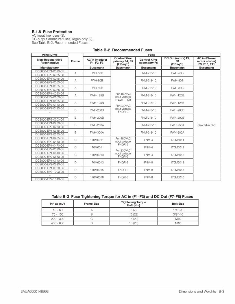
Dimensions and Weights B-33AUA0000148993
B.1.8 Fuse ProtectionAC input line fuses (3).DC output armature fuses, regen only (2).See Table B-2, Recommended Fuses.
Table B-2 Recommended FusesPanel Drive
Frame
Fuse
Non-Regenerative Regenerative
AC in (module) F1, F2, F3
Control Xfmr primary F4, F5
(2 Req’d)
Control Xfmr secondary F6
DC Out (motor) F7, F8
(2 Req’d)
AC in (Blower motor starter) F9, F10, F11
Manufacturer Bussmann Bussmann Bussmann Bussmann BussmannDCS800-EP1-0020-05
A FWH-50B
For 480VAC input voltage: FNQR-1-1/8
For 230VAC input voltage:
FNQR-2
FNM-2-8/10 FWH-50B
See Table B-6
DCS800-EP2-0025-05DCS800-EP1-0045-05
A FWH-80B FNM-2-8/10 FWH-80BDCS800-EP2-0050-05DCS800-EP1-0065-05
A FWH-80B FNM-2-8/10 FWH-80BDCS800-EP2-0075-05DCS800-EP1-0090-05
A FWH-125B FNM-2-8/10 FWH-125BDCS800-EP2-0100-05DCS800-EP1-0125-05
A FWH-125B FNM-2-8/10 FWH-125BDCS800-EP2-0140-05DCS800-EP1-0180-05
B FWH-200B FNM-2-8/10 FWH-200B––
B FWH-200B FNM-2-8/10 FWH-200BDCS800-EP2-0200-05DCS800-EP1-0230-05
B FWH-250A FNM-2-8/10 FWH-250ADCS800-EP2-0260-05DCS800-EP1-0315-05
B FWH-300A FNM-2-8/10 FWH-300ADCS800-EP2-0350-05DCS800-EP1-0405-05
C 170M6011 For 480VAC input voltage:
FNQR-2
For 230VAC input voltage:
FNQR-3
FNM-4 170M6011DCS800-EP2-0450-05DCS800-EP1-0470-05
C 170M6011 FNM-4 170M6011DCS800-EP2-0520-05DCS800-EP1-0610-05
C 170M6013 FNM-4 170M6013DCS800-EP2-0680-05DCS800-EP1-0740-05
D 170M6013 FNQR-3 FNM-8 170M6013DCS800-EP2-0820-05DCS800-EP1-0900-05
D 170M6015 FNQR-3 FNM-8 170M6015DCS800-EP2-1000-05
–D 170M6016 FNQR-3 FNM-8 170M6016
DCS800-EP2-1010-05
Table B-3 Fuse Tightening Torque for AC in (F1-F3) and DC Out (F7-F8) Fuses
HP at 460V Frame Size Tightening Torque lb-ft (Nm) Bolt Size
10 - 60 A 5 (7) 1/4”-2075 - 150 B 16 (22) 3/8”-16200 - 300 C 15 (20) M10400 - 600 D 15 (20) M10

B-4 Dimensions and Weights 3AUA0000148993
B.2 Control Transformer 230/460VAC primary; 120VAC secondary
Table B-4
Non-Regenerative (2Q)
Regenerative (4Q)
460V Motor
HP
Capacity (VA)
Capacity @ 115V (Amps)
Drive Load
(Amps)
Blower Starter Load
(Amps)
-Available-no
Starter (Amps)
with Starter (Amps)
DCS800-EP1-0020-05 DCS800-EP2-0025-05 10
250 2.17
1.46
0.03
0.71 0.68DCS800-EP1-0045-05 DCS800-EP2-0050-05 20 1.49 0.68 0.65DCS800-EP1-0065-05 DCS800-EP2-0075-05 30 1.49 0.68 0.65DCS800-EP1-0090-05 DCS800-EP2-0100-05 40 1.55 0.63 0.60DCS800-EP1-0125-05 DCS800-EP2-0140-05 60 1.55 0.63 0.60DCS800-EP1-0180-05 – 75 1.62 0.56 0.53
– DCS800-EP2-0200-05 100 1.74 0.44 0.41DCS800-EP1-0230-05 DCS800-EP2-0260-05 125 1.74 0.44 0.41DCS800-EP1-0315-05 DCS800-EP2-0350-05 150 1.74 0.44 0.41DCS800-EP1-0405-05 DCS800-EP2-0450-05 200
350 3.042.30
0.11
0.75 0.64DCS800-EP1-0470-05 DCS800-EP2-0520-05 250 2.30 0.75 0.64DCS800-EP1-0610-05 DCS800-EP2-0680-05 300 1.85 1.19 1.08DCS800-EP1-0740-05 DCS800-EP2-0820-05 400
750 6.521.85 4.67 4.56
DCS800-EP1-0900-05 DCS800-EP2-1000-05 500 2.59 3.93 3.82– DCS800-EP2-1010-05 600 2.59 3.93 3.82
NOTE: Reference instruction manual DCS800-EP Installation and Start-Up for conversion to 230VAC. Specify Plus Code +S235.
B.3 AC Contactor
AC line contactor with (1) aux. N.O. contact for customer use: 6 Amps @ 24 - 127VAC or 24VDC
B.4 Blower Motor Starter Thermal Overload Relay (Plus Code +M6xx)
Inom : Factory set to minimum rating. Must be field adjusted to actual blower motor nominal current.
RESET: Factory set to MANUAL
RESET/STOP: Factory set to “R” (RESET)
B.5 Accessories
Table B-5 Line ReactorsExternal Line Reactors
Non-Regenerative (2Q)
Regenerative (4Q) HP
Line Reactor for Configuration A Line Reactor for Configuration BManufactured by TCI
1.5% impedance
Watts Loss
Weight (Lbs.)
5% impedance
Watts Loss
Weight (Lbs.)
DCS800-EP1-0020-05 DCS800-EP2-0025-05 10 KLR16BTB 20 7 KLR16CTB 58 12DCS800-EP1-0045-05 DCS800-EP2-0050-05 20 KLR35BTB 55 8 KLR35CTB 97 22DCS800-EP1-0065-05 DCS800-EP2-0075-05 30 KLR45BTB 59 8 KLR45CTB 118 24DCS800-EP1-0090-05 DCS800-EP2-0100-05 40 KLR55BTB 70 11 KLR55CTB 150 32DCS800-EP1-0125-05 DCS800-EP2-0140-05 60 KLR110BCB 95 26 KLR110CCB 191 50DCS800-EP1-0180-05 – 75 KLR110BCB 95 26 KLR110CCB 191 50
– DCS800-EP2-0200-05 100 KLR160BCB 127 47 KLR160CCB 254 84DCS800-EP1-0230-05 DCS800-EP2-0260-05 125 KLR200BCB 135 53 KLR200CCB 337 110DCS800-EP1-0315-05 DCS800-EP2-0350-05 150 KLR200BCB 135 53 KLR200CCB 337 110DCS800-EP1-0405-05 DCS800-EP2-0450-05 200 KLR300BCB 216 54 KLR300CCB 443 122DCS800-EP1-0470-05 DCS800-EP2-0520-05 250 KLR360BCB 221 65 KLR360CCB 406 156DCS800-EP1-0610-05 DCS800-EP2-0680-05 300 KLR420BCB 275 85 KLR420CCB 500 160DCS800-EP1-0740-05 DCS800-EP2-0820-05 400 KLR600BCB 338 96 KLR600CCB 650 275DCS800-EP1-0900-05 DCS800-EP2-1000-05 500 KLR750BCB 372 147 KLR750CCB 732 295
– DCS800-EP2-1010-05 600 KLR850BCB 389 150 KLR850CCB 850 300

Dimensions and Weights B-53AUA0000148993
B.5.1 Blower Motor StarterTable B-6
Plus Code Blower HP 460VAC
Blower HP 230VAC
Blower Amps 460V/230V
Fuses F9, F10, F11 Contactor Overload
Bussmann ABB ABB+M635 1/2 - 1.1 LP-CC-2
Mini contactor120VAC coilB7-30-10-84
T16-1.3+M636 3/4 - 1.6 LP-CC-3.2 T16-1.7+M637 1 1/2 2.1/2.2 LP-CC-4 T16-2.3+M638 1.5 - 3.0 LP-CC-6 T16-3.1+M639 2 3/4 3.4/3.2 LP-CC-6 T16-4.2+M640 3 1 4.8/4.2 LP-CC-10 T16-5.7+M641 - 1-1/2 6 LP-CC-10 T16-7.6+M641 - 2 6.8 LP-CC-10 T16-7.6+M641 5 - 7.6 LP-CC-15 T16-7.6+M611 3/4 - 1.6 LPJ-3-2/10-SP
ABB contactor120V coil
A26-30-10-84
TA25DU1.8-20+M612 1 - 2.1 LPJ-4SP TA25DU2.1-20+M613 1.5 - 3.0 LPJ-6SP TA25DU3.1-20+M614 2 3/4 3.4/3.2 LPJ-6SP TA25DU4.0-20+M615 3 1 4.8/4.2 LPJ-8SP TA25DU5.0-20+M616 - 1-1/2 6 LPJ-10SP TA25DU6.5-20+M617 5 2 7.6/6.8 LPJ-15SP TA25DU8.5-20+M618 7.5 3 11/9.6 LPJ-20SP TA25DU11-20+M619 10 - 14 LPJ-20SP TA25DU14-20+M620 - 5 15.2 LPJ-25SP TA25DU19-20+M621 15 7.5 21/22 LPJ-30SP TA25DU25-20+M622 20 10 27/28 LPJ-40SP TA25DU32-20+M623 25 - 30 15 34 - 40/42 LPJ-60SP A40-30-10-84 TA42DU42-20
B.5.2 Other Replacement Parts
Table B-7 Panel Drive
Frame
FuseAC Input
Contactor K1 (1)
Control Transformer T1 (1)
Circuit Breaker 1MCB (1) Line Reactor (1)Non-Regenerative
Regenerative
Manufacturer ABB Micron ABB TCIDCS800-EP1-0020-05
A A16-30-10-84 1B250BTZ13JFK T2H025E5W KLR16BTBDCS800-EP2-0025-05DCS800-EP1-0045-05
A A26-30-10-84 1B250BTZ13JFK T2H060E5W KLR35BTBDCS800-EP2-0050-05DCS800-EP1-0065-05
A A40-30-10-84 1B250BTZ13JFK T2H060E5W KLR45BTBDCS800-EP2-0075-05DCS800-EP1-0090-05
A A50-30-11-84 1B250BTZ13JFK T2H100E5W KLR55BCBDCS800-EP2-0100-05DCS800-EP1-0125-05
A A75-30-11-84 1B250BTZ13JFK T2HQ100BW KLR110BCBDCS800-EP2-0140-05DCS800-EP1-0180-05
B A95-30-11-84 1B250BTZ13JFK T4H150E5W KLR110BCB––
B A145-30-11-84 1B250BTZ13JFK T4H250E5W KLR160BCBDCS800-EP2-0200-05DCS800-EP1-0230-05
B A145-30-11-84 1B250BTZ13JFK T4H250E5W KLR200BCBDCS800-EP2-0260-05DCS800-EP1-0315-05
B A145-30-11-84 1B250BTZ13JFK T4H250E5W KLR200BCBDCS800-EP2-0350-05DCS800-EP1-0405-05
C A260-30-11-84 B350BTZ13JFK T5H400E5W KLR300BCBDCS800-EP2-0450-05DCS800-EP1-0470-05
C A300-30-11-84 B350BTZ13JFK T5H600E5W KLR360BCBDCS800-EP2-0520-05DCS800-EP1-0610-05
C A300-30-11-84 B350BTZ13JFK T5H600E5W KLR420BCBDCS800-EP2-0680-05DCS800-EP1-0740-05
D AF460-30-11-70 B750BTZ13JFK T6H800E5W KLR600BCBDCS800-EP2-0820-05DCS800-EP1-0900-05
D AF580-30-11-70 B750BTZ13JFK T7H1200E5W KLR750BCBDCS800-EP2-1000-05
–D AF750-30-11-70 B750BTZ13JFK T7H1200E5W KLR850BCB
DCS800-EP2-1010-05

B-6 Dimensions and Weights 3AUA0000148993
B.6 Dimensions and Weights
B.6.1 Dimensional and Weight Data
Table B-8 Drive Dimensions and Weights as BuiltDCS800-EP Panel Drive
HP at 460VAC
Weight - no reactor lb. (kg.)
Weight - with reactorlb. (kg.)
Frame Size
Heightin. (mm)
Widthin. (mm)
Depthin. (mm)
10 54 (25) 61 (28)
A 18.79(477)
12.15(309)
14.40(366)
20 57 (26) 65 (30)30 59 (27) 67 (30)40 62 (28) 73 (33)60 62 (28) 88 (40)75 95 (43) 128 (58)
B 19.29(490)
20.00(508)
13.82*(351)
100 103 (47) 157 (71)125 103 (47) 163 (74)150 130 (59) 185 (84)200 231 (105) n/a
C 35.32(897)
23.58(599)
16.17(411)250 231 (105) n/a
300 260 (118) n/a400 355 (161) n/a
D 45.66(1160)
26.68(678)
16.65 (499) /19.65 (499)**500 355 (161) n/a
600 355 (161) n/a
* 19.32 inch depth when internal reactor option is included** Depth without circuit breaker option / depth with circuit breaker option
Table B-9 Drive Dimensions and Weights as ShippedDCS800-EP Panel Drive
HP at 460VAC
Weight - no reactor lb. (kg.)
Weight - with reactorlb. (kg.)
Frame Size
Heightin. (mm)
Widthin. (mm)
Depthin. (mm)
10 63 (29) 32 (15)
A 28 (711)
31 (787)
31(787)
20 66 (30) 34 (15)30 68 (31) 35 (16)40 71 (32) 37 (17)60 71 (32) 44 (20)75 104 (47) 62 (28)
B 28(711)
31(787)
31(787)
100 112 (51) 75 (34)125 112 (51) 78 (35)150 139 (63) 88 (40)200 247 (112) n/a
C 28(711)
55(1397)
31(787)250 247 (112) n/a
300 276 (125) n/a400 371 (169) n/a
D 28(711)
55(1397)
31(787)500 371 (169) n/a
600 371 (169) n/a

Dimensions and Weights B-73AUA0000148993
B.6.2 Requirements for InstallationThe drive must be installed in an upright position within a cabinet or other enclosure.The cabinet size, heat dissipation capability and clearances must conform to the requirements below.Refer to Dimensional Drawings for frame details.See Cabinet Cooling and Air Flow for the allowed ambient conditions of the drive.
Minimum ClearancesWhen installing the panel in a cabinet, minimum clearances from the panel to the cabinet walls, top and bottom must be maintained. This space is required for proper cabling, cooling air flow, service and maintenance. If one drive is mounted directly above another, see DCS800 Hardware Manual “Mechanical Installation” for additional information.
See Dimensional Drawings.
Figure B-1
Frame D Depth: Frame D drives without circuit breaker have live lugs at the highest point on the drive. Sixteen inches of cabinet depth is required plus a minimum of 1/2" air gap between lugs and cabinet door or as required by applicable codes. REMEMBER: door may flex inward!
Frame X1 (side) X2 (top) X3 (bottom)
A 0.5 in. (13 mm)
5.0 in. (127 mm)
4.0 in. (102 mm)
B 0.5 in.(13 mm)
10.0 in.(254 mm)
5.0 in.(127 mm)
C 0.5 in.(13 mm)
10.0 in.(254 mm)
5.0 in.(127 mm)
D 2.0 in.(51 mm)
12.0 in.(305 mm)
5.0 in.(127 mm)
USFMCCUSFMCC
Frame D side view

B-8 Dimensions and Weights 3AUA0000148993

Local Sales Offices
OHIO CINCINNATI 2929 CRESCENTVILLE ROAD WEST CHESTER, OH 45069 PHONE: 513-771-2600 FAX: 513-772-2219
CLEVELAND 8929 FREEWAY DRIVE MACEDONIA, OH 44056 PHONE: 330-468-4777 FAX: 330-468-4778
OKLAHOMA TULSA 5555 E. 71ST ST., SUITE 9100 TULSA, OK 74136 PHONE: 918-366-9320 FAX: 918-366-9338
OREGON PORTLAND 12651 SE CAPPS ROAD CLACKAMAS, OR 97015 PHONE: 503-691-9010 FAX: 503-691-9012
PENNSYLVANIA PHILADELPHIA 103 CENTRAL AVENUE SUITE 400B MOUNT LAUREL, NJ 08054 PHONE: 856-840-8011 FAX: 856-840-0811 PITTSBURGH 159 PROMINENCE DRIVE NEW KENSINGTON, PA 15068 PHONE: 724-889-0092 FAX: 724-889-0094
TENNESSEE MEMPHIS 4000 WINCHESTER ROAD MEMPHIS, TN 38118 PHONE: 901-365-2020 FAX: 901-365-3914
TEXAS DALLAS 2920 114TH STREET SUITE 100 GRAND PRAIRIE, TX 75050 PHONE: 214-634-7271 FAX: 214-634-8874
HOUSTON 10355 W. LITTLE YORK ROAD SUITE 300 HOUSTON, TX 77041 PHONE: 281-977-6500 FAX: 281-977-6510
UTAH SALT LAKE CITY 2230 SOUTH MAIN STREET SALT LAKE CITY, UT 84115 PHONE: 801-832-0127 FAX: 801-832-8911
STREET INDIANAPOLIS, IN 46241 PHONE: 317-246-5100 FAX: 317-246-5110
IOWA DES MOINES 1943 HULL AVENUE DES MOINES, IA 50313 PHONE: 515-263-6929 FAX: 515-263-6515
MARYLAND BALTIMORE 7071A DORSEY RUN RD ELKRIDGE, MD 21075 PHONE: 410-579-2135 FAX: 410-579-2677
MASSACHUSETTS BOSTON 6 PULLMAN STREET WORCESTER, MA 01606 PHONE: 508-854-0708 FAX: 508-854-0291
MICHIGAN DETROIT 5993 PROGRESS DRIVE STERLING HEIGHTS, MI 48312 PHONE: 586-978-9800 FAX: 586-978-9969
MINNESOTA MINNEAPOLIS 13098 GEORGE WEBER DR, SUITE 400 ROGERS, MN 55374 PHONE: 763-428-3633 FAX: 763-428-4551
MISSOURI ST LOUIS 13678 LAKEFRONT DRIVE EARTH CITY, MO 63045 PHONE: 314-373-3032 FAX: 314-373-3038
KANSAS CITY 1501 BEDFORD AVENUE NORTH KANSAS CITY, MO 64116 PHONE: 816-587-0272 FAX: 816-587-3735
NEW YORK AUBURN ONE ELLIS DRIVE AUBURN, NY 13021 PHONE: 315-255-3403 FAX: 315-253-9923
NORTH CAROLINA GREENSBORO 1220 ROTHERWOOD ROAD GREENSBORO, NC 27406 PHONE: 336-272-6104 FAX: 336-273-6628
WISCONSIN MILWAUKEE 1960 SOUTH CALHOUN ROAD NEW BERLIN, WI 53151 PHONE: 262-784-5940 FAX: 262-784-1215
INTERNATIONAL SALES FORT SMITH, AR P.O. BOX 2400 FORT SMITH, AR 72902 PHONE: 479-646-4711 FAX: 479-648-5895 CANADA EDMONTON, ALBERTA 4053-92 STREET EDMONTON, ALBERTA T6E 6R8 PHONE: 780-434-4900 FAX: 780-438-2600
TORONTO OAKVILLE, ONTARIO 2910 BRIGHTON ROAD OAKVILLE, ONTARIO, CANADA L6H 5S3 PHONE: 905-829-3301 FAX: 905-829-3302
MONTREAL, QUEBEC 5155 J-ARMAND BOMBARDIER SAINT-HUBERT, QUéBEC CANADA J3Z 1G4 PHONE: 514-933-2711 FAX: 514-933-8639
VANCOUVER, BRITISH COLUMBIA 1538 KEBET WAY PORT COQUITLAM, BRITISH COLUMBIA V3C 5M5 PHONE 604-421-2822 FAX: 604-421-3113
WINNIPEG, MANITOBA 54 PRINCESS STREET WINNIPEG, MANITOBA R3B 1K2 PHONE: 204-942-5205 FAX: 204-956-4251
MEXICO LEON, GUANAjUATO KM. 2.0 BLVD. AEROPUERTO LEON, GUANAJUATO, CP37545 MEXICO FAX: +52 477 761 2010
UNITED STATES
ARIZONA PHOENIX 4211 S 43RD PLACE PHOENIX, AZ 85040 PHONE: 602-470-0407 FAX: 602-470-0464
ARKANSAS CLARKSVILLE 706 WEST MAIN STREET CLARKSVILLE, AR 72830 PHONE: 479-754-9108 FAX: 479-754-9205
CALIFORNIA LOS ANGELES 6480 FLOTILLA STREET COMMERCE, CA 90040 PHONE: 323-724-6771 FAX: 323-721-5859
HAYWARD 21056 FORBES STREET HAYWARD, CA 94545 PHONE: 510-785-9900 FAX: 510-785-9910
COLORADO DENVER 3855 FOREST STREET DENVER, CO 80207 PHONE: 303-623-0127 FAX: 303-595-3772
CONNECTICUT WALLINGFORD 65 SOUTH TURNPIKE ROAD WALLINGFORD, CT 06492 PHONE: 203-269-1354 FAX: 203-269-5485
FLORIDA TAMPA/PUERTO RICO/ VIRGIN ISLANDS 3906 EAST 11TH AVENUE TAMPA, FL 33605 PHONE: 813-248-5078 FAX: 813-241-9514
GEORGIA ATLANTA 62 TECHNOLOGY DRIVE ALPHARETTA, GA 30005 PHONE: 770-772-7000 FAX: 770-772-7200
ILLINOIS CHICAGO 340 REMINGTON BLVD. BOLINGBROOK, IL 60440 PHONE: 630-296-1400 FAX: 630-226-9420
INDIANA INDIANAPOLIS 5525 W. MINNESOTA

ABB IncDiscrete Automation & MotionDrives and Controls16250 W. Glendale Drive New Berlin, WI 53151
Phone: 800-752-0696 Web: www.abb.us/drives
3AU
A00
0014
8993
/ R
EV
BE
FFE
CTI
VE
: 06/
23/2
014