dean hall hvac system upgrade project manual 10-7-21
TRANSCRIPT

Dean Hall HVAC System Upgrade 1 Insight Project 21-017
PROJECT MANUAL DEAN HALL HVAC SYSTEM UPGRADE
BID # B021080
ARKANSAS TECH UNIVERSITY 215 W O STREET
RUSSELLVILLE, AR 72801
OCTOBER 7, 2021
201 S CHESTER STREET LITTLE ROCK, AR 72201

HVAC SYSTEM UPGRADES FOR DEAN HALL CONSTRUCTION DOCUMENTS OCTOBER 2021
THIS PAGE INTENTIONALLY LEFT BLANK

Dean Hall HVAC System Upgrade 2 Insight Project 21-017
INSIGHT ENGINEERING PROJECT NO: 21-017 DEAN HALL HVAC SYSTEM UPGRADE
ARKANSAS TECH UNIVERSITY 215 W O STREET
RUSSELLVILLE, AR 72801 October 7, 2021
TABLE OF CONTENTS
TITLE PAGE
TABLE OF CONTENTS
SEALS PAGE
PROJECT DIRECTORY
LIST OF DRAWINGS
DIVISION 00 PROCUREMENT AND CONTRACTING REQUIREMENTS Section 00 100 Invitation to Bid Section 00 210 Supplementary Instruction to Bidders Section 00 300 Bid Form Section 00 410 Performance Bond and Payment Bond Section 00 610 Consent and Surety Section 00 700 General Conditions (AIA A101/ A201-2017) Section 00 800 Supplementary General Conditions Section 00 820 Equal Opportunity Policy Form Section 00 830 Illegal Immigrant Certification Form Section 00 850 Contract and Grant Disclosure Section 00 865 Prevailing Wage Rate Section 00 900 Release of Claims Section 00 910 Certifications Form DIVISION 01 GENERAL REQUIREMENTS Section 01 10 00 Summary of Work Section 01 29 00 Payment Procedures Section 01 31 00 Project Management and Coordination Section 01 33 00 Submittal Procedures Section 04 40 00 Quality Requirements Section 01 50 00 Temporary Facilities and Controls Section 01 60 00 Product Requirements Section 01 73 00 Execution Requirements

Dean Hall HVAC System Upgrade 3 Insight Project 21-017
DIVISION 02 EXISTING CONDITIONS Section 02 41 19 Selective Demolition DIVISION 05 METALS Section 05 40 00 Cold Formed Metal Framing DIVISION 06 WOOD PLASTICS AND COMPOSITES Section 06 10 00 Rough Carpentry DIVISION 07 THERMAL AND MOISTURE PROTECTION Section 07 54 19 PVC Roofing Section 07 62 00 Sheet Metal Flashing and Trim Section 07 92 00 Joint Sealants DIVISION 08 OPENINGS Section 08 11 00 Steel Doors and Frames Section 08 71 00 Door Hardware DIVISION 09 FINISHES Section 09 29 00 Gypsum Board Section 09 51 00 Suspended Acoustical Ceilings Section 09 90 00 Painting and Coatings DIVISION 23 HEATING, VENTILATION AND AIR CONDITIONING
Section 23 00 00 Supplementary HVAC General Conditions Section 23 05 17 Sleeves and Sleeve Seals for HVAC Piping Section 23 05 19 Meters and Gages for HVAC Piping Section 23 05 23 General Duty Valves for HVAC Piping Section 23 05 29 Hangers and Supports for HVAC Piping and Equipment
Section 23 05 33 Heat Tracing for HVAC Piping Section 23 05 53 Identification for HVAC Piping and Equipment Section 23 05 93 Testing, Adjusting, and Balancing for HVAC Section 23 07 13 Duct Insulation Section 23 07 19 HVAC Piping Insulation Section 23 09 23 Direct-Digital Control Systems Section 23 21 13 Hydronic Piping Section 23 21 23 Hydronic Pumps Section 23 25 00 HVAC Water Treatment Section 23 31 00 HVAC Ducts and Casings Section 23 33 00 Air Duct Accessories Section 23 34 23 HVAC Power Ventilators Section 23 37 00 Air Outlets and Inlets Section 23 52 16 Condensing Boilers

Dean Hall HVAC System Upgrade 4 Insight Project 21-017
Section 23 64 16 Centrifugal Water Chillers Section 23 65 00 Cooling Towers Section 23 74 33 Dedicated Outdoor Air Units Section 23 81 26.13 Small Capacity Split System Air Conditioners
Section 23 82 00 Convection Heating and Cooling Units DIVISION 26 ELECTRICAL Section 26 00 00 Supplementary Electrical General Conditions Section 26 05 05 Selective Demolition for Electrical Section 26 05 19 Low-Voltage Electrical Power Conductors and Cables Section 26 05 26 Grounding and Bonding for Electrical Systems Section 26 05 29 Hangers and Supports for Electrical Systems Section 26 05 33.13 Conduit for Electrical Systems Section 26 05 33.16 Boxes for Electrical Systems Section 26 05 48 Vibration and Seismic Controls for Electrical Systems Section 26 05 53 Identification for Electrical Systems Section 26 27 26 Wiring Devices Section 26 28 16.16 Enclosed Switches Section 26 29 13 Enclosed Controllers Section 26 51 00 Interior Lighting DIVISION 27 COMMUNICATIONS Section 27 10 00 Structured Cabling

HVAC SYSTEM UPGRADES FOR DEAN HALL CONSTRUCTION DOCUMENTS OCTOBER 2021
THIS PAGE INTENTIONALLY LEFT BLANK

Dean Hall HVAC System Upgrade 5Insight Project 21-017
INSIGHT ENGINEERING PROJECT NO: 21-017DEAN HALL HVAC SYSTEM UPGRADE
ARKANSAS TECH UNIVERSITY215 W O STREET
RUSSELLVILLE, AR 72801October 7, 2021
SEALS PAGE
I certify that these plans and technical specifications have been prepared by me or under my direct supervision and that I am a duly licensed professional engineer under the laws of the State of Arkansas. I certify that to the best of our knowledge that this portion of the plans and specifications are as required by law and in compliance with the State of Arkansas.
CORPORATION:
Insight Engineering, PLLC
Arkansas License #3523
MECHANICAL / PLUMBING ENGINEER:
Fallon Lee
State License #19764
ELECTRICAL ENGINEER:
Michael Harkey
State License #5822

HVAC SYSTEM UPGRADES FOR DEAN HALL CONSTRUCTION DOCUMENTS OCTOBER 2021
THIS PAGE INTENTIONALLY LEFT BLANK

Dean Hall HVAC System Upgrade 6 Insight Project 21-017
DEAN HALL HVAC SYSTEM UPGRADE ARKANSAS TECH UNIVERSITY
215 W O STREET RUSSELLVILLE, AR 72801
October 7, 2021
PROJECT DIRECTORY Owner Representative:
Brian Lasey, APO Facilities Management Director and Plant Engineer Phone: 479-968-0261 Email: [email protected] Design Team Project Manager:
Kimberly Koch, PE Insight Engineering, PLLC Phone: 501-237-3077 Email: [email protected] Mechanical Engineer:
Fallon Lee, PE Insight Engineering, PLLC Phone: 501-237-3077 Email: [email protected] Electrical Engineer:
Michael Harkey, PE Insight Engineering, PLLC Phone: 501-237-3077 Email: [email protected] Electrical Designer:
Trent Buie Insight Engineering, PLLC Phone: 501-237-3077 Email: [email protected]

HVAC SYSTEM UPGRADES FOR DEAN HALL CONSTRUCTION DOCUMENTS OCTOBER 2021
THIS PAGE INTENTIONALLY LEFT BLANK

Dean Hall HVAC System Upgrade 7 Insight Project 21-017
DEAN HALL HVAC SYSTEM UPGRADE ARKANSAS TECH UNIVERSITY
215 W O STREET RUSSELLVILLE, AR 72801
October 7, 2021
LIST OF DRAWINGS Drawings consist of the Contract Drawings as listed on Cover Sheet, T001 of the separately bound drawing set titled HVAC System Upgrades for Dean Hall, Russellville, Arkansas, dated October 7, 2021. SHEET NUMBER SHEET TITLE T001 COVER SHEET A001 GENERAL NOTES AND DOOR SCHEDULE AD101 FIRST FLOOR DEMOLITION PLAN AD102 SECOND FLOOR DEOMOLITION PLAN AD201 FIRST FLOOR REFLECTED CEILING DEMO PLAN AD202 SECOND FLOOR REFLECTED CEILING DEMO PLAN A101 FIRST FLOOR PLAN A102 SECOND FLOOR PLAN A201 FIRST FLOOR REFLECTED CEILING PLAN A202 SECOND FLOOR REFLECTED CEILING PLAN M001 MECHANICAL GENERAL NOTES AND LEGEND M101 FIRST LEVEL-HVAC DEMOLITION M102 SECOND LEVEL FLOOR PLAN-HVAC DEMOLITION M201 FIRST LEVEL FLOOR PLAN-HVAC M202 SECOND LEVEL FLOOR PLAN-HVAC M203 MECHANICAL ENLARGED FLOOR PLANS M204 MECHANICAL 3D VIEWS M301 MECHANICAL DETAILS M302 MECHANICAL DETAILS M303 MECHANICAL PIPING DIAGRAMS M304 MECHANICAL PIPING DIAGRAMS M305 MECHANICAL PIPING DIAGRAM M306 MECHANICAL PIPING DIAGRAM M401 MECHANICAL SCHEDULES M402 MECHANICAL SCHEDULES M403 MECHANICAL SCHEDULES M501 MECHANICAL CONTROLS M502 MECHANICAL CONTROLS E001 ELECTRICAL GENERAL NOTES AND LEGEND

Dean Hall HVAC System Upgrade 8 Insight Project 21-017
SHEET NUMBER SHEET TITLE E101 FIRST LEVEL FLOOR PLAN-DEMOLITION E102 FIRST LEVEL FLOOR PLAN-MECHANICAL POWER DEMOLITION E103 SECOND LEVEL FLOOR PLAN-DEMOLITION E104 SECOND LEVEL FLOOR PLAN-MECHANICAL POWER DEMOLITION E201 FIRST FLOOR PLAN-ELECTRICAL E202 FIRST LEVEL FLOOR PLAN-MECHANICAL POWER E203 SECOND FLOOR PLAN-ELECTRICAL E204 SECOND LEVEL FLOOR PLAN-MECHANICAL POWER E301 ELECTRICAL DIAGRAMS AND DETAILS E401 ELECTRICAL SCHEDULES E402 ELECTRICAL SCHEDULES

HVAC SYSTEM UPGRADES FOR DEAN HALL CONSTRUCTION DOCUMENTS OCTOBER 2021
INVITATION TO BID 00100-1
NOTICE TO CONTRACTORS Separate sealed bids for HVAC SYSTEM UPGRADE FOR DEAN HALL will be received until 2:00 p.m. local time, Tuesday, October 26, at ATU Procurement, 203 West O Street, Russellville, AR 72801. Tel: 479-968-0583. Bids received after this time will not be accepted. Bids will then be publicly opened and read aloud at this location following the 2:00 p.m. deadline. There will be a mandatory Pre-Bid Conference held at 2:00 pm, Wednesday, October 20th, at the east main entrance to Dean Hall, W O Street, Russellville, AR 72801. The Owner reserves the right to schedule additional mandatory meetings. Prospective bidders must attend the pre-bid conference to be eligible to bid the project. Davis-Bacon Act prevailing wage rates will apply. REVIEW OF DOCUMENTS: The official version of the complete set of the contract documents should be examined and are obtainable from: Southern Reprographics,Inc. 901 West 7th Street Little Rock, Arkansas 72201 (501) 372-4011 An official version of the complete document set will also be made available for viewing by appointment only at: Insight Engineering, PLLC 201 S Chester Street Little Rock, AR 72201 Contact: Stacy Newman, snewman@insightpllc to schedule a viewing.
OBTAINING BID DOCUMENTS:
The bid documents will be available on Monday, October 11th. The documents obtained through the Engineer or their representative(s) are considered the official version and take precedence if any discrepancies occur. Bidding documents obtained through Southern Reprographics by paying the cost of printing and shipping. Prime bidders requiring additional sets and Sub-bidders may purchase bidding documents through Southern Reprographics, Inc. It is the sole responsibility of each subcontractor and each bidder to verify that their bid is based on a complete set of construction documents including all addenda. No partial sets will be issued. The cost is non-refundable.
Each bid proposal shall include with it a bid security in the amount of 5% of the total bid offered. The bidder will be required to submit a bidder’s deposit which includes enclosing a cashier’s check payable to the order of Arkansas Tech University and drawn from a bank or trust company doing business in Arkansas or by a corporate bid bond in an amount equal to 5% of the bid. All bidders shall conform to the requirement of the Arkansas Contractors Licensing Law for Contractors and must be licensed on the day of the bid submittal. There shall be only one (1) bid submitted per State Contractor’s License. Each bid received shall have the license for that bidder. Bid shall be submitted on the form provided by the Owner and shall be delivered in a clearly identified, sealed, opaque envelope. Arkansas Tech University reserves the right to reject any or all bids and to waive any formalities.
Pursuant to Arkansas Code Annotated § 22-9-203, the Owner encourages all small, minority, and women business enterprises to submit bids for capital improvements. Encouragement is also made to all general contractors that in the event they subcontract portions of their work, consideration is given to the identified groups. The Owner reserves the right to reject any or all responses and waive formalities.

HVAC SYSTEM UPGRADES FOR DEAN HALL CONSTRUCTION DOCUMENTS OCTOBER 2021
THIS PAGE INTENTIONALLY LEFT BLANK

HVAC SYSTEM UPGRADES FOR DEAN HALL CONSTRUCTION DOCUMENTS OCTOBER 2021
SUPPLEMENTARY INSTRUCTIONS TO BIDDERS 00210-1
SECTION 00 21 00 SUPPLEMENTARY INSTRUCTION TO BIDDERS
1.01 EXAMINATION OF DRAWINGS, SPECIFICATION AND SITE OF WORK A. Bidder shall examine the Contract Documents and visit the project site of work. Bidder shall become familiar
with all existing conditions and limitations under which the Work is to be performed and shall base bid on Items necessary to perform the Work as set forth In the Contract Documents. Failure to do so is at the sole risk of the bidder. No allowance will be made to Bidders because of lack of such examination or knowledge. The submission of a Bid shall be construed as conclusive evidence that the Bidder has made such examinations.
1.02 INTERPRETATION OF CONSTRUCTION DOCUMENTS A. If any person contemplating submitting a Bid is in doubt as to the true meaning of any part of the
Construction Documents, or finds discrepancies or omissions, he may submit to the Engineer, a written request for an interpretation or correction thereof. Request for Interpretation shall be submitted on or before 5:00 pm., Thursday, October 20, 2021. Any interpretation or correction of the documents will be made only by Addendum. The Owner will not be responsible for any other explanations or interpretations of the Construction Documents. Submit all questions by email to Stacy Newman at [email protected].
1.03 BID GUARANTEE AND BONDS A. Each bid proposal shall include a bid security in the amount of five percent of the total bid offered, if the bid is
in excess of $20,000.00. The bidder will be required to submit a bidder’s deposit, which includes enclosing a cashier’s check payable to the order of ATU drawn upon a bank or trust company doing business in Arkansas or by a corporate bid bond in an amount equal to five (5) percent of the bid. The bidder shall include in the bid the bid bond amount so that the bid represents the total cost to the Owner of all work included in the contract.
The bid bond shall indemnify the Owner against failure of the Contractor to execute and deliver the contract and necessary bond (Performance and Payment Bond) for faithful performance of the contract. The bid bond shall provide that the contractor or surety must pay the damage, loss, cost and expense subject to the amount of the bid security directly arising out of the Contractor’s default in failing to execute and deliver the contract and bonds.
Owner will have the right to retain the bid security of bidders to whom an award is being considered until the Contract has been executed and bonds if required, have been furnished, or until specified time has elapsed so that bids may be withdrawn, or all bids have been rejected.
Failure to execute the Contract and file an acceptable full payment and performance bond and proof of liability insurance within 10 working days after the intent to award has been issued to the bidder shall be just cause for the cancellation of the award and forfeiture of the bid bond, which shall become the property of the agency, not as a penalty but in liquidated damages sustained. Award may then be made to the next lowest responsible bidder, or the work may be rebid and constructed under contract or otherwise as the State determines. The low bidder who fails to execute the Contract and submit an acceptable payment and performance bond and proof of liability insurance will not be permitted to bid on any subsequent advertisement of that project.
1.04 PERFORMANCE AND PAYMENT BOND: A. The bidder shall furnish a Performance and Payment Bond in the amount equal to 100 percent of contract
price, as security for faithful performance of the Contract and payment of all obligations arising thereunder within 10 days after receipt of the Intent to Award. The bond shall be written by a surety company qualified and authorized to do business in the State of Arkansas. The bond shall be executed by a resident or non-resident agent licensed by the State Insurance Commissioner, to represent the surety company. The bond shall be written in favor of the Owner. Bidder shall file the bond with the Circuit Clerk in the county where the Work is to be performed. Failure to deliver said bonds, as specified, shall be considered as having abandoned the Contract and the bid security will be retained as liquidated damages. The bidder shall include in the bid the Performance and Payment bond amount so that the bid represents the total cost to the Owner of all work included in the contract.

HVAC SYSTEM UPGRADES FOR DEAN HALL CONSTRUCTION DOCUMENTS OCTOBER 2021
SUPPLEMENTARY INSTRUCTIONS TO BIDDERS 00210-2
1.05 TIME AND DAMAGE
A. Time will be of the essence. The Contractor must agree to complete the work as stated in the Bid Form. If the work is not completed by that Date, then the Contractor agrees to pay Liquidated Damages as stated in the Bid Form.
1.06 RETAINAGE A. Refer to General and Supplementary Conditions for retainage amounts.
1.07 SUBCONTRACTORS A. In each instance where the total bid submitted by the licensed prime contractor exceeds $50,000.00, all
prime contractors, as a condition to perform work for and in the State of Arkansas shall use no other subcontractors except those licensed by the State Contractor’s Licensing Board and qualified in:
1. Mechanical (indicative of heating, air conditioning and ventilating)
2. Plumbing and Electrical (indicative of wiring and illuminating fixtures)
3. Roofing and Sheet Metal work (indicative of roofing application).
B. The prime contractor shall place the names of each subcontractor in a blank space to be provided on the Form of Proposal of his bid. It shall be mandatory that the (a) mechanical, (b) plumbing, (c) electrical and (d) roofing and sheet metal and subcontractors named on the Form of Proposal by the prime contractor awarded a contract under the provision of this Act be given contracts by the prime contractor in keeping with their proposals to perform the items for which they were named.
C. No person shall perform Work on the contract without possessing an Arkansas State License for the Work they are performing from the appropriate governing Boards. Apprentices will be appropriately supervised according to the State governing Boards requirements. In the event the prime contractor is qualified and licensed by the Arkansas State Contractor’s Licensing Board, he may use his own forces to perform those tasks listed herein as subcontractors in one or more of the trades listed.
D. Any prime contractor who submits a bid, contracts or lists unlicensed subcontractors of uses an unlicensed subcontractor, shall upon conviction be guilty of a Class A misdemeanor, and shall be fined not less than $250 and not more than $500 and may be suspended from bidding future public works contracts for a term not less than six (6) months nor more than twelve (12) months.
1.08 ELECTRICAL LICENSE REQUIREMENT A. No person shall perform electrical work on the contract without possessing an Arkansas Master or
Journeyman License from the Arkansas State Electrical Examiners Board. All electrical work and apprentice electricians shall be supervised by a Master or Journeyman Electrician on a one to one ratio. All electricians shall have a copy of their license with them at all times while on the project premises and shall be required to produce it upon request.
1.09 EMPLOYMENT OF ILLEGAL IMMIGRANTS A. Prohibition Certification by Contractor
1. The contractor must certify on line at www.arkansas.gov/dfa/procurement prior to award of a contract, that he does not employ or contract with any illegal immigrant.
2. If the contractor violates the above certification or is found to not be in compliance during the term of the contract, the state shall require the contractor to remedy the violation within 60 days of discovery of that violation. Failure to remedy the violation within the 60 day period will result in termination for breach of contract, and the contractor shall be liable to the State for the State’s actual damages.
3. If the contractor uses a subcontractor at the time of the above certification, the subcontractor shall certify that he does not employ or contract with an illegal immigrant. The subcontractor’s certification must be submitted within 30 days after award of the contract, and the contractor is required to maintain the certification on file for the remainder of the term of the contract.
4. In the event that the contractor learns that the subcontractor’s certification is in violation of the Act, and terminates the contract with the subcontractor, the termination of the subcontract for a violation of this

HVAC SYSTEM UPGRADES FOR DEAN HALL CONSTRUCTION DOCUMENTS OCTOBER 2021
SUPPLEMENTARY INSTRUCTIONS TO BIDDERS 00210-3
section will not be considered a breach of the contractor’s contract with the state. However, any subcontractor subsequently hired by the contractor shall be required to provide like certification.
1.10 MODIFICATION, WITHDRAWAL
A. Modification and Withdrawal. Bidder may withdraw bid at any time before bid opening and may resubmit up to the date and time designated for receipt of bids. No bid may be withdrawn or modified after time has been called for the bid opening. Oral modifications to bids will not be considered. Bidder may submit written modifications to bid in writing, by telegraph, or by facsimile and must be received by the design team at any time prior to the expiration of the bidding time and date. All modifications shall be signed and no modification shall show the base bid amount. Telegraph or facsimile modifications shall require written confirmation over the Bidder's original signature within 24 hours after bid opening.
1.11 SCRIVENERS’ ERROR A. Pursuant to Ark. Code Ann. § 19-4-1405 (e), bidders may request in writing to the Engineer or Owner, to be
relieved of their bid any time after the bid opening, but no later than 72 hours after receiving the intent to award, excluding Saturdays, Sundays and holidays. Scriveners’ error is an error in the calculation of a bid which can be documented by clear and convincing written evidence and which can be clearly shown by objective evidence drawn from inspection of the original work papers, documents, or materials used in the preparation of the bid sought to be withdrawn; and the bid was submitted in good faith and the mistake was due to a calculation or clerical error, an inadvertent omission, or a typographical error as opposed to an error in judgment. Failure to make a timely request constitutes a waiver by the bidder of the bidder’s right to claim that the mistake in his or her bid was a scriveners’ error.
1.12 APPLICABLE LAWS A. Labor.
1. Contractors employed upon the work will be required to conform to the labor laws of the State of Arkansas and the various acts amendatory and supplementary thereto, and to all the Laws, regulations, and legal requirements applicable thereto.
B. Discrimination.
1. Bidder shall not discriminate against any employee, applicant for employment, or subcontractor as provided by law. Bidder shall be responsible for ensuring that all subcontractors comply with federal and state laws and regulations related to discrimination. Upon a final determination by a court or administrative body having proper jurisdiction that the Bidder has violated state or federal laws or regulations, the Owner may impose a range for appropriate remedies up to and including termination of the Contract.
C. Taxes.
1. Bidder shall include in the bid all state sales tax, social security taxes, state unemployment insurance, and all other items of like nature. It is the intent that the bid shall represent the total cost to the Owner of all work included in the contract. There are no provisions for a contractor to avoid taxes by using the tax exempt number of a state agency, board, commission or institutions. Said taxes shall be included in the bid price.
D. Disclosure.
1. Potential Bidders are hereby notified that any bidder who desires to enter into a contract not exempted from the disclosure requirements, that disclosure is a condition of the Contract and that ATU cannot enter into any such contract, nor approve any such contract, for which disclosures are not made and the verbiage of paragraphs a, b, and c below will be included in the body of any contract awarded.
Potential Bidders are hereby notified that:
a. Disclosure is required to be a condition of any present or future subcontract for which the total consideration is greater than twenty-five thousand ($25,000)
b. The Contractor shall require any present or future subcontractor, for which the subcontract amount is greater than $25,000.00, to complete and sign the Contract and Disclosure and Certification. The contractor shall ensure that any agreement, current or future between the contractor and a

HVAC SYSTEM UPGRADES FOR DEAN HALL CONSTRUCTION DOCUMENTS OCTOBER 2021
SUPPLEMENTARY INSTRUCTIONS TO BIDDERS 00210-4
subcontractor for which the total consideration is greater than $25,000.00 shall contain the following:
1) Failure to make any disclosure required by Governor Executive Order 98-04, or any violation of any rule, regulation or adopted pursuant to that Order, shall be material breach of the term of this subcontract. The party who fails to make the required disclosure or who violates the rule, regulation, or policy shall be subject to all legal remedies available to the contractor.
c. The Contractor shall transmit a copy of the subcontractor’s disclosure form to the agency and a statement containing the dollar amount of the subcontract within ten (10) days upon receipt of subcontractor’s disclosure.
Note: A copy of the “Contract and Grant Disclosure and Certification Form” is included at the end of this division.
1.13 MINORITY PARTICIPATION A. Pursuant to Ark. Code Ann. § 22-9-203, the State encourages all small, minority, and women business
enterprises to submit bids for capital improvements. Encouragement is also made to all general contractors that in the event they subcontract portions of their work, consideration is given to the identified groups. 13.7 The bidding, award and administration of the contract shall be made pursuant to Ark. Code Ann. §14-4-1401 et seq., Ark. Code Ann. § 22-9-101 et seq., Ark. Code Ann. § 22-2-101 et seq.
1.14 INSPECTION A. The Contractor awarded this project agrees to allow any Federal or State inspector, acting in their official
capacity, to have access to the job site.
1.15 EVALUATION AND CONSIDERATION OF BIDS. A. It is the intent of ATU to award a Contract to the lowest responsive qualified Bidder provided the bid has
been submitted in accordance with the requirements of the Contract Documents and does not exceed the funds certified for the project by more than 25%. ATU shall have the right to waive any formalities in a bid
received and to accept the bid which, in ATU's judgment, is in its best interests and upon approval of ATU. ATU Shall have the right to accept any or all bids for a period not to exceed 30 days.
B. Tie Bids. If two or more sealed bids are equal in amount, meet Bidding Document requirements, and are the lowest received by the time of the bid opening, then the apparent low bidder will be determined by lot (placing the name of the tie bidders into a container and drawing one name). The drawing will be conducted by ATU personnel and another person so designated by ATU in the presence of a witness and the tie bidders or representatives. The witness shall be an employee of the State of Arkansas. Documentation of the drawing shall be included on the bid tabulation and be signed by those present. Nothing in the above and foregoing will diminish ATU’s reserved right to reject any and all bids and to waive any formalities.
1.16 EXECUTION OF CONTRACT The apparent low Bidder shall be prepared, if so required by the Owner, to present evidence of experience, qualifications, and financial ability to carry out the terms of the Contract.
The successful Bidder will be required to execute an Agreement with the Owner on a form identical to the Agreement Form included with the Contract Documents and the Performance and Payment Bond and Certification of Insurance within ten days after receipt of the Intent to Award. Failure of the Bidder to do so may result in the Bidder being rejected and could result in disqualification and forfeiture of bid bond.
The successful Bidder will be required to furnish Owner with proof of insurance, as prescribed by the General and Supplementary Conditions.
END OF SECTION

HVAC SYSTEM UPGRADES FOR DEAN HALL CONSTRUCTION DOCUMENTS OCTOBER 2021
BID FORM 00300-1
FORM OF BID PROPOSAL
BID TIME/DATE: 2:00 p.m., October 26, 2021 BID PLACE: Arkansas Tech University
BID FROM: ______________________________________________ BID TO: ARKANSAS TECH UNIVERSITY PROJECT: HVAC SYSTEM UPGRADE FOR DEAN HALL
ALL BLANKS ON THIS FORM MUST BE COMPLETED IN INK OR TYPE. ANY COST ITEMS MUST BE STATED NUMERICALLY AND IN WRITTEN FORM. IN CASE OF CONFLICT, WORD WILL TAKE PRECEDENT.
1. Base Bid: Having carefully examined the Contract Documents for this project, as well as the premises and all
conditions affecting the proposed construction, the undersigned proposes to provide all labor, materials, services, and equipment necessary for, or incidental to, the construction of the project in accordance with the Contract Documents within the time set forth, for the lump sum base bid of:
$
Dollar Amount Is To Be Shown Numerically and in Written Form 2. Deductive Alternate: Fan Coil Units indicated by X. List credit for removing the replacement of the fan coil units
indicated by an X on the Fan Coil Unit schedule on sheet M402 and M403 $
Dollar Amount Is To Be Shown Numerically and in Written Form 5. It is the Owner’s intent to sign the contract by as soon as possible upon providing required proof of insurance to
allow ordering of equipment and begin work. Bidder hereby agrees to commence work under this contract on or before a date to be specified in a written “Notice to Proceed” by the Owner.
6. Completion Date: Bidder agrees that the work will be substantially complete and ready for final payment
excluding retainage in accordance with the Contract Documents within one hundred and four (104) calendar days of the date of the issuance of a Notice to Proceed. The project must be substantially completed by March, 29, 2022. The Bidder further agrees to increase the size of the work force, increase daily or weekly work hours, increase the work week, increase shift sizes and/or any other necessary measures to achieve Substantial Completion of the work by the above established date. All work in classrooms, corridors, labs, restrooms, and other student spaces must be completed during Winter Break. Work in offices and faculty spaces can be completed during the spring semester up until March 29, 2022.
7. The undersigned, in compliance with the Contract Documents for the construction of the above named project,
does hereby declare:
a. That the undersigned understands that the Owner reserves the right to reject any and all bids and to waive any formality.
b. That if awarded the Contract, the undersigned will enter into Agreement and execute required performance and payment bonds and proof of insurance within 10 days after receipt of the Intent to Award, will commence work as described in Specification Section 01010 - Summary of Work, and will achieve Substantial Completion within the time indicated.
c. Should the undersigned fail to fully complete the work within the above stated date, or any agreed extension

HVAC SYSTEM UPGRADES FOR DEAN HALL CONSTRUCTION DOCUMENTS OCTOBER 2021
BID FORM 00300-2
thereof, he shall pay the Owner as fixed, agreed and not as a penalty, liquidated damages in the sum of $0 Dollars (zero) for each calendar day of delay until the work is completed or accepted. The said sum shall be withheld by the owner from payments due to be made to the Contractor by the Owner under the terms of the contract.
d. The undersigned further agrees that the bid security payable to Owner and accompanying this proposal shall become the property of the Owner as liquidated damages if the undersigned fails to execute the Contract or to deliver the required bonds and proof of insurance to the Owner within the time frame as stated in paragraph 6(b) from receipt of the Intent to Award as these acts constitute a breach of the Contractor’s duties.
e. That this bid may not be withdrawn for a period of 30 calendar days after the bid opening. f. The undersigned understands that the Owner's intent is to construct all facilities proposed within the limits
established by the funds appropriated for the project. g. The names of subcontractors and the nature of the work to be performed by each one have been included
on the Bid Form. h. Bids submitted by a “Joint Venture/Joint Adventure” shall be signed by representatives of each component
part of the Joint Venture. The licenses of each component part of the Joint Venture shall also be listed in the bid submittal. Therefore, joint venture bidders shall indicate at least two (2) signatures and two (2)licenses numbers on the Bid Form. Exception: Joint Ventures who have been properly licensed with the Arkansas Contractors Licensing Board as a “Joint Venture” need only to indicate the joint venture license number on the Bid Form. Joint Venture Bidders shall indicate at least two (2) signatures on the bid form even if they are licensed as a joint venture.
i. The Illegal Immigration Certification Form - the undersigned understands Act 157 of 2007 requires the Contractor to submit certification on line prior to award of contract and attach the Certification Confirmation Sheet to this bid.
j. The Contract and Grant Disclosure and Certification Form will be required from the successful Bidder before a Contract can be issued.
8. The following documents are attached to the bid form and made a part of this Bid.
a. Bid Security b. Equal Opportunity Disclosure Form c. Illegal Immigration Certification Confirmation Sheet or completion of Supplied Form d. Anti-Boycott of Israel Certification e. Bidder Questionnaire f. Certifications Form g. Certification Regarding Lobbying h. Certification Regarding Government-Wide Debarment and Suspension i. Buy America Certification j. DBE Responsiveness Form (Form DBE-1) k. DBE Affirmation
9. The undersigned acknowledges receipt of and inclusion as a part of the Contract Documents the following
addenda. Failure to acknowledge all addenda may result in rejection of bid. Addendum #1
Dated:
Received:
Addendum #2 Dated:
Received:
Addendum #3 Dated:
Received:
Addendum #4 Dated:
Received:
10. LISTING OF MECHANICAL, PLUMBING, ELECTRICAL AND ROOFING SUBCONTRACTORS. ALL
MECHANICAL, PLUMBING, ELECTRICAL, AND ROOFING SUBCONTRACTORS SHALL BE LISTED REGARDLESS OF QUALIFICATIONS, LICENSURE OR WORK AMOUNT FAILURE TO NAME THE SUBCONTRACTOR IN THE SPACE PROVIDED SHALL CAUSE THE BID TO BE DECLARED NON-RESPONSIVE AND THE BID WILL NOT RECEIVE CONSIDERATION. Indicate the Name(s), of each entity performing the listed work:

HVAC SYSTEM UPGRADES FOR DEAN HALL CONSTRUCTION DOCUMENTS OCTOBER 2021
BID FORM 00300-3
a. MECHANICAL (Indicative of HVAC)
Is the amount of work $50,000.00 or over?: Yes No
b. PLUMBING
Is the amount of work $50,000.00 or over?: Yes No
c. ELECTRICAL(Indicative of wiring and illuminating fixtures)
Is the amount of work $50,000.00 or over?: Yes No
d. ROOFING
Is the amount of work $50,000.00 or over?: Yes No
Respectfully Submitted,
Name of Bidder (Typed or Printed)
Address BY: (Signature and Title)
Contractor’s License Number or Contractor’s (Joint Venture) License Number(s) Telephone No. Fax No. Federal ID Number or SSN#

HVAC SYSTEM UPGRADES FOR DEAN HALL CONSTRUCTION DOCUMENTS OCTOBER 2021
THIS PAGE INTENTIONALLY LEFT BLANK

HVAC SYSTEM UPGRADES FOR DEAN HALL CONSTRUCTION DOCUMENTS OCTOBER 2021
PERFORMANCE AND PAYMENT BOND 00 40 10 -1
SECTION 004100 PERFORMANCE BOND AND PAYMENT BOND
We .............................................................................................................................................. hereinafter referred to
as Principal, and ......................................................................................................................... hereinafter referred to as
Surety, are held and firmly bound unto........................................................................................ , as oblige, hereinafter
referred to as Owner, in the initial Contract amount of .............................................................. said amount to be
deemed a performance bond payable to Owner under the terms of this Performance and Payment Bond Agreement.
The Principal and Surety state that the Surety is a solvent corporate surety company authorized to do business in the
State of Arkansas.
Principal has by written agreement dated ................................................... entered into a capital improvement contract
(Contract) with the Owner for: ...................................................................................................................................
The above referenced Contract is incorporated herein by reference.
Under this Performance and Payment Bond Agreement, the Principal and Surety shall be responsible for the following:
a. The Principal shall faithfully perform the above referenced Contract, which is incorporated herein by referenceand shall pay all indebtedness for labor and materials furnished or performed under the Contract.
b. In the event that the Principal fails to perform the Contract, the Principal and the Surety, jointly and severally,shall indemnify and save harmless the Owner from all cost and damage which the Owner may suffer by reasonof Principal’s failure to perform the Contract. Said indemnification shall include, but not be limited to, fullreimbursement and repayment to the Owner for all outlays and expenses which the Owner may incur in makinggood any such default or failure to perform the Contract by the Principal.
c. Principal shall pay all persons all indebtedness for labor or material furnished or performed under the Contractand in doing so this obligation shall be null and void. In the event that Principal fails to pay for suchindebtedness, such persons shall have a direct right of action against the Principal and Surety, jointly andseverally, under this obligation, subject to the Owner’s priority.
d. Principal shall guarantee the faithful performance of the prevailing hourly wage clause as provided in theContract.
This bond is given in accordance with Arkansas laws and regulations, including Ark. Code Ann. § 18-44-503, §19-4-1405, and § 22-9-401 et seq. The Surety guarantees that the Principal shall comply with Ark. Code Ann. § 22-9-308(d) by payment and full compliance with all prevailing hourly wage contract provisions where the contract amountexceeds the amount provided in Ark. Code Ann. § 22-9-302(1).
Any changes made in the terms of the Contract including but not limited to the amount of the contract, or in the work to be done under it, or the giving by the Owner of any extension of time for the performance of the contract, or any other forbearance on the part of either the Owner or the Principal to the other shall not in any way release the Principal and the Surety or Sureties or either or any of them, their heirs, personal representatives, successors or assigns from their liability hereunder, notice to and consent of the Surety or Sureties of any such change, extension or forbearance being are hereby voluntarily waived. In no event shall the aggregate liability of the Surety exceed the Contract documents

HVAC SYSTEM UPGRADES FOR DEAN HALL CONSTRUCTION DOCUMENTSOCTOBER 2021
PERFORMANCE AND PAYMENT BOND 00 40 10 -2
This Performance and Payment Bond Agreement is binding upon the above named parties, and their successors, heirs, assigns and personal representatives.
Executed by the parties who individually represent that each voluntarily enters into and has the authority to enter into this agreement.
BY: _____________________________________________________________ Date:_____________Contractor
BY: _____________________________________________________________ Date:_____________Arkansas Resident Agent or Non Resident Agent/ Attorney-in-Fact
Print: ____________________________________________________________ Date:_____________Agent’s Name
________________________________________________________________________________________Address
________________________________________________________________________________________City County State Zip Code
Business #: ________________________________ E-Mail: __________________________________

HVAC SYSTEM UPGRADES FOR DEAN HALL CONSTRUCTION DOCUMENTS OCTOBER 2021
CONSENT OF SURETY 00610 - 1
SECTION 00610 CONSENT OF SURETY
Comes the undersigned, who does hereby swear and affirm that: 1. My name is _________________________________________________and I am an authorized representative
of _______________________________________________________________________ a surety company.
2. With regards to the Project HVAC SYSTEM UPGRADE FOR DEAN HALL
Contract date:_______________________________________________________________________________
______________________________________________________________________________Contractor;
and the Project Owner ARKANSAS TECH UNIVERSITY; I hereby approve the final payment to the contractor. I agree that the final payment to the contractor shall not relieve the Surety Company of any of its obligations as set forth in the contract with the Owner and this contractor.
AFFIANT DATE
VERIFICATION
STATE OF ARKANSAS
COUNTY OF: SUBSCRIBED AND SWORN TO before me this ____of ___________, 20__.
NOTARY PUBLIC
MY COMMISSION EXPIRES:

HVAC SYSTEM UPGRADES FOR DEAN HALL CONSTRUCTION DOCUMENTS OCTOBER 2021
THIS PAGE INTENTIONALLY LEFT BLANK

HVAC SYSTEM UPGRADES FOR DEAN HALL CONSTRUCTION DOCUMENTS OCTOBER 2021
AIA 201-2007 Standard Form of Agreement 00700-1
SECTION 00700 GENERAL CONDITIONS
PART 1 GENERAL
1.01 INSTRUCTIONS TO BIDDERS
A. AIA Document AIA 101-2017, "Standard Form of Agreement Between Owner and Contractor” Articles 1 through 9, of the American Institute of Architects, is hereby made a part of these Documents to the same extent as if herein written out in full. The Contract Documents may have a set of the AIA General Conditions posted in place of this sheet if requested by Owner and Contractor. Copies are available for contractor purchase at: 1. Arkansas Chapter of the American Institute of Architects,
1020 West 4 Street Suite 400, Little Rock, AR 72201 Tel. 501.661.1111
2. Southern Reprographics, Inc. 901 West 7th Street, Little Rock, Arkansas 72201 (501) 372-4011
END OF SECTION

HVAC SYSTEM UPGRADES FOR DEAN HALL CONSTRUCTION DOCUMENTS OCTOBER 2021
THIS PAGE INTENTIONALLY LEFT BLANK
AIA®
Document A101TM – 2017Standard Form of Agreement Between Owner and Contractor where the basis of payment is a Stipulated Sum
AIA Document A101™ – 2017. Copyright © 1915, 1918, 1925, 1937, 1951, 1958, 1961, 1963, 1967, 1974, 1977, 1987, 1991, 1997, 2007 and 2017 byThe American Institute of Architects. All rights reserved. WARNING: This AIA® Document is protected by U.S. Copyright Law and InternationalTreaties. Unauthorized reproduction or distribution of this AIA® Document, or any portion of it, may result in severe civil and criminal penalties,and will be prosecuted to the maximum extent possible under the law. This draft was produced by AIA software at 17:11:12 ET on 10/10/2021 underOrder No.2114249652 which expires on 10/09/2022, is not for resale, is licensed for one-time use only, and may only be used in accordance withthe AIA Contract Documents® Terms of Service. To report copyright violations, e-mail [email protected] Notes: (1633837872)
1
ADDITIONS AND DELETIONS: The author of this document has added information needed for its completion. The author may also have revised the text of the original AIA standard form. An Additions and Deletions Report that notes added information as well as revisions to the standard form text is available from the author and should be reviewed.
This document has important legal consequences. Consultation with an attorney is encouraged with respect to its completion or modification.
The parties should complete A101™–2017, Exhibit A, Insurance and Bonds, contemporaneously with this Agreement. AIA Document A201™–2017, General Conditions of the Contract for Construction, is adopted in this document by reference. Do not use with other general conditions unless this document is modified.
ELECTRONIC COPYING of any portion of this AIA® Document to another electronic file is prohibited and constitutes a violation of copyright laws as set forth in the footer of this document.
AGREEMENT made as of the «» day of «» in the year «»(In words, indicate day, month and year.)
BETWEEN the Owner:(Name, legal status, address and other information)
« »« »«»«»
and the Contractor:(Name, legal status, address and other information)
« »« »« »« »
for the following Project:(Name, location and detailed description)
« University of Arkansas at Little Rock William H. Bowen School of Law RLF Chiller Replacement»« »« »
The Engineer:(Name, legal status, address and other information)
« »« »«»« »« »
The Owner and Contractor agree as follows.

AIA Document A101™ – 2017. Copyright © 1915, 1918, 1925, 1937, 1951, 1958, 1961, 1963, 1967, 1974, 1977, 1987, 1991, 1997, 2007 and 2017 byThe American Institute of Architects. All rights reserved. WARNING: This AIA® Document is protected by U.S. Copyright Law and InternationalTreaties. Unauthorized reproduction or distribution of this AIA® Document, or any portion of it, may result in severe civil and criminal penalties,and will be prosecuted to the maximum extent possible under the law. This draft was produced by AIA software at 17:11:12 ET on 10/10/2021 underOrder No.2114249652 which expires on 10/09/2022, is not for resale, is licensed for one-time use only, and may only be used in accordance withthe AIA Contract Documents® Terms of Service. To report copyright violations, e-mail [email protected].
(1633837872)
2
TABLE OF ARTICLES
1 THE CONTRACT DOCUMENTS
2 THE WORK OF THIS CONTRACT
3 DATE OF COMMENCEMENT AND SUBSTANTIAL COMPLETION
4 CONTRACT SUM
5 PAYMENTS
6 DISPUTE RESOLUTION
7 TERMINATION OR SUSPENSION
8 MISCELLANEOUS PROVISIONS
9 ENUMERATION OF CONTRACT DOCUMENTS
EXHIBIT A INSURANCE AND BONDS
ARTICLE 1 THE CONTRACT DOCUMENTSThe Contract Documents consist of this Agreement, Conditions of the Contract (General, Supplementary, and other Conditions), Drawings, Specifications, Addenda issued prior to execution of this Agreement, other documents listed in this Agreement, and Modifications issued after execution of this Agreement, all of which form the Contract, and are as fully a part of the Contract as if attached to this Agreement or repeated herein. The Contract represents the entire and integrated agreement between the parties hereto and supersedes prior negotiations, representations, or agreements, either written or oral. An enumeration of the Contract Documents, other than a Modification, appears in Article 9.
ARTICLE 2 THE WORK OF THIS CONTRACTThe Contractor shall fully execute the Work described in the Contract Documents, except as specifically indicated in the Contract Documents to be the responsibility of others.
ARTICLE 3 DATE OF COMMENCEMENT AND SUBSTANTIAL COMPLETION§ 3.1 The date of commencement of the Work shall be:(Check one of the following boxes.)
[ « » ] The date of this Agreement.
[ « » ] A date set forth in a notice to proceed issued by the Owner.
[ « » ] Established as follows:(Insert a date or a means to determine the date of commencement of the Work.)
« »
If a date of commencement of the Work is not selected, then the date of commencement shall be the date of this Agreement.
§ 3.2 The Contract Time shall be measured from the date of commencement of the Work.
§ 3.3 Substantial Completion§ 3.3.1 Subject to adjustments of the Contract Time as provided in the Contract Documents, the Contractor shall achieve Substantial Completion of the entire Work:(Check one of the following boxes and complete the necessary information.)
[ « » ] Not later than « » ( « » ) calendar days from the date of commencement of the Work.

AIA Document A101™ – 2017. Copyright © 1915, 1918, 1925, 1937, 1951, 1958, 1961, 1963, 1967, 1974, 1977, 1987, 1991, 1997, 2007 and 2017 byThe American Institute of Architects. All rights reserved. WARNING: This AIA® Document is protected by U.S. Copyright Law and InternationalTreaties. Unauthorized reproduction or distribution of this AIA® Document, or any portion of it, may result in severe civil and criminal penalties,and will be prosecuted to the maximum extent possible under the law. This draft was produced by AIA software at 17:11:12 ET on 10/10/2021 underOrder No.2114249652 which expires on 10/09/2022, is not for resale, is licensed for one-time use only, and may only be used in accordance withthe AIA Contract Documents® Terms of Service. To report copyright violations, e-mail [email protected].
(1633837872)
3
[ « » ] By the following date: « »
§ 3.3.2 Subject to adjustments of the Contract Time as provided in the Contract Documents, if portions of the Work are to be completed prior to Substantial Completion of the entire Work, the Contractor shall achieve Substantial Completion of such portions by the following dates:
Portion of Work Substantial Completion Date
§ 3.3.3 If the Contractor fails to achieve Substantial Completion as provided in this Section 3.3, liquidated damages, if any, shall be assessed as set forth in Section 4.5.
ARTICLE 4 CONTRACT SUM§ 4.1 The Owner shall pay the Contractor the Contract Sum in current funds for the Contractor’s performance of the Contract. The Contract Sum shall be « » ($ «» ), subject to additions and deductions as provided in the Contract Documents.
§ 4.2 Alternates§ 4.2.1 Alternates, if any, included in the Contract Sum:
Item Price
§ 4.2.2 Subject to the conditions noted below, the following alternates may be accepted by the Owner following execution of this Agreement. Upon acceptance, the Owner shall issue a Modification to this Agreement.(Insert below each alternate and the conditions that must be met for the Owner to accept the alternate.)
Item Price Conditions for Acceptance
§ 4.3 Allowances, if any, included in the Contract Sum:(Identify each allowance.)
Item Price
§ 4.4 Unit prices, if any:(Identify the item and state the unit price and quantity limitations, if any, to which the unit price will be applicable.)
Item Units and Limitations Price per Unit ($0.00)
§ 4.5 Liquidated damages, if any:(Insert terms and conditions for liquidated damages, if any.)
« »
§ 4.6 Other:(Insert provisions for bonus or other incentives, if any, that might result in a change to the Contract Sum.)
« »

AIA Document A101™ – 2017. Copyright © 1915, 1918, 1925, 1937, 1951, 1958, 1961, 1963, 1967, 1974, 1977, 1987, 1991, 1997, 2007 and 2017 byThe American Institute of Architects. All rights reserved. WARNING: This AIA® Document is protected by U.S. Copyright Law and InternationalTreaties. Unauthorized reproduction or distribution of this AIA® Document, or any portion of it, may result in severe civil and criminal penalties,and will be prosecuted to the maximum extent possible under the law. This draft was produced by AIA software at 17:11:12 ET on 10/10/2021 underOrder No.2114249652 which expires on 10/09/2022, is not for resale, is licensed for one-time use only, and may only be used in accordance withthe AIA Contract Documents® Terms of Service. To report copyright violations, e-mail [email protected].
(1633837872)
4
ARTICLE 5 PAYMENTS§ 5.1 Progress Payments§ 5.1.1 Based upon Applications for Payment submitted to the Engineer by the Contractor and Certificates for Payment issued by the Engineer, the Owner shall make progress payments on account of the Contract Sum to the Contractor as provided below and elsewhere in the Contract Documents.
§ 5.1.2 The period covered by each Application for Payment shall be one calendar month ending on the last day of the month, or as follows:
« »
§ 5.1.3 Provided that an Application for Payment is received by the Engineer not later than the «» day of a month, the Owner shall make payment of the amount certified to the Contractor not later than the «» days after receipt of certified Application for Payment. If an Application for Payment is received by the Engineer after the application date fixed above, payment of the amount certified shall be made by the Owner not later than «» ( «» ) days after the Engineerreceives the Application for Payment.(Federal, state or local laws may require payment within a certain period of time.)
§ 5.1.4 Each Application for Payment shall be based on the most recent schedule of values submitted by the Contractor in accordance with the Contract Documents. The schedule of values shall allocate the entire Contract Sum among the various portions of the Work. The schedule of values shall be prepared in such form, and supported by such data to substantiate its accuracy, as the Engineer may require. This schedule of values shall be used as a basis for reviewing the Contractor’s Applications for Payment.
§ 5.1.5 Applications for Payment shall show the percentage of completion of each portion of the Work as of the end of the period covered by the Application for Payment.
§ 5.1.6 In accordance with AIA Document A201™–2017, General Conditions of the Contract for Construction, and subject to other provisions of the Contract Documents, the amount of each progress payment shall be computed as follows:
§ 5.1.6.1 The amount of each progress payment shall first include:.1 That portion of the Contract Sum properly allocable to completed Work;.2 That portion of the Contract Sum properly allocable to materials and equipment delivered and suitably
stored at the site for subsequent incorporation in the completed construction, or, if approved in advance in writing by the Owner, suitably stored off the site at a location agreed upon in writing; and
.3 That portion of Construction Change Directives that the Engineer determines, in the Engineer’s professional judgment, to be reasonably justified.
§ 5.1.6.2 The amount of each progress payment shall then be reduced by:.1 The aggregate of any amounts previously paid by the Owner;.2 The amount, if any, for Work that remains uncorrected and for which the Engineer has previously
withheld a Certificate for Payment as provided in Article 9 of AIA Document A201–2017;.3 Any amount for which the Contractor does not intend to pay a Subcontractor or material supplier,
unless the Work has been performed by others the Contractor intends to pay;.4 For Work performed or defects discovered since the last payment application, any amount for which
the Engineer may withhold payment, or nullify a Certificate of Payment in whole or in part, as provided in Article 9 of AIA Document A201–2017; and
.5 Retainage withheld pursuant to Section 5.1.7.
§ 5.1.7 Retainage§ 5.1.7.1 For each progress payment made prior to Substantial Completion of the Work, the Owner may withhold the following amount, as retainage, from the payment otherwise due:(Insert a percentage or amount to be withheld as retainage from each Application for Payment. The amount of retainage may be limited by governing law.)
« Retainage shall be held in the amount of 5% of the contractor's request for payment. »

AIA Document A101™ – 2017. Copyright © 1915, 1918, 1925, 1937, 1951, 1958, 1961, 1963, 1967, 1974, 1977, 1987, 1991, 1997, 2007 and 2017 byThe American Institute of Architects. All rights reserved. WARNING: This AIA® Document is protected by U.S. Copyright Law and InternationalTreaties. Unauthorized reproduction or distribution of this AIA® Document, or any portion of it, may result in severe civil and criminal penalties,and will be prosecuted to the maximum extent possible under the law. This draft was produced by AIA software at 17:11:12 ET on 10/10/2021 underOrder No.2114249652 which expires on 10/09/2022, is not for resale, is licensed for one-time use only, and may only be used in accordance withthe AIA Contract Documents® Terms of Service. To report copyright violations, e-mail [email protected].
(1633837872)
5
§ 5.1.7.1.1 The following items are not subject to retainage:(Insert any items not subject to the withholding of retainage, such as general conditions, insurance, etc.)
« »
§ 5.1.7.2 Reduction or limitation of retainage, if any, shall be as follows:(If the retainage established in Section 5.1.7.1 is to be modified prior to Substantial Completion of the entire Work, including modifications for Substantial Completion of portions of the Work as provided in Section 3.3.2, insert provisions for such modifications.)
« When the value of the work reaches 50% of the scheduled value, including changes, the Owner may, but is not required to, reduce the amount of the retainage for subsequent pay requests. »
§ 5.1.7.3 Except as set forth in this Section 5.1.7.3, upon Substantial Completion of the Work, the Contractor may submit an Application for Payment that includes the retainage withheld from prior Applications for Payment pursuant to this Section 5.1.7. The Application for Payment submitted at Substantial Completion shall not include retainage as follows:(Insert any other conditions for release of retainage upon Substantial Completion.)
« »
§ 5.1.8 If final completion of the Work is materially delayed through no fault of the Contractor, the Owner shall pay the Contractor any additional amounts in accordance with Article 9 of AIA Document A201–2017.
§ 5.1.9 Except with the Owner’s prior approval in writing, the Contractor shall not make advance payments to suppliers for materials or equipment which have not been delivered and stored at the site.
§ 5.2 Final Payment§ 5.2.1 Final payment, constituting the entire unpaid balance of the Contract Sum, shall be made by the Owner to the Contractor when
.1 the Contractor has fully performed the Contract except for the Contractor’s responsibility to correct Work as provided in Article 12 of AIA Document A201–2017, and to satisfy other requirements, if any, which extend beyond final payment; and
.2 a final Certificate for Payment has been issued by the Engineer.
§ 5.2.2 The Owner’s final payment to the Contractor shall be made no later than 30 days after the issuance of the Engineer’s final Certificate for Payment, or as follows:
« »
ARTICLE 6 DISPUTE RESOLUTIONIn the case of any dispute, claim or question, or disagreement arising from or related to the Project or arising out of this Contract, the parties shall first attempt resolution through mutual discussion.
§ 6.1 Initial Decision MakerThe Engineer will serve as the Initial Decision Maker pursuant to Article 15 of AIA Document A201–2017, unless the parties appoint below another individual to serve as the Initial Decision Maker.(If the parties mutually agree, insert the name, address and other contact information of the Initial Decision Maker, if other than the Engineer.)
«»« »«»« »

AIA Document A101™ – 2017. Copyright © 1915, 1918, 1925, 1937, 1951, 1958, 1961, 1963, 1967, 1974, 1977, 1987, 1991, 1997, 2007 and 2017 byThe American Institute of Architects. All rights reserved. WARNING: This AIA® Document is protected by U.S. Copyright Law and InternationalTreaties. Unauthorized reproduction or distribution of this AIA® Document, or any portion of it, may result in severe civil and criminal penalties,and will be prosecuted to the maximum extent possible under the law. This draft was produced by AIA software at 17:11:12 ET on 10/10/2021 underOrder No.2114249652 which expires on 10/09/2022, is not for resale, is licensed for one-time use only, and may only be used in accordance withthe AIA Contract Documents® Terms of Service. To report copyright violations, e-mail [email protected].
(1633837872)
6
§ 6.2 Binding Dispute ResolutionFor any Claim subject to, but not resolved by, mediation pursuant to Article 15 of AIA Document A201–2017, the method of binding dispute resolution shall be as follows:(Check the appropriate box.)
[ « » ] Arbitration pursuant to Section 15.4 of AIA Document A201–2017
[ « » ] Litigation in a court of competent jurisdiction
[ « » ] Other (Specify)
« »
If the Owner and Contractor do not select a method of binding dispute resolution, or do not subsequently agree in writing to a binding dispute resolution method other than litigation, Claims will be resolved by litigation in a court of competent jurisdiction. Nothing in the Contract Documents shall be deemed a waiver by Owner of its sovereign immunity.
ARTICLE 7 TERMINATION OR SUSPENSION§ 7.1 The Contract may be terminated by the Owner or the Contractor as provided in Article 14 of AIA Document A201–2017.
§ 7.1.1 If the Contract is terminated for the Owner’s convenience in accordance with Article 14 of AIA Document A201–2017, then the Owner shall pay the Contractor a termination fee as follows:(Insert the amount of, or method for determining, the fee, if any, payable to the Contractor following a termination for the Owner’s convenience.)
« »
§ 7.2 The Work may be suspended by the Owner as provided in Article 14 of AIA Document A201–2017.
ARTICLE 8 MISCELLANEOUS PROVISIONS§ 8.1 Where reference is made in this Agreement to a provision of AIA Document A201–2017 or another Contract Document, the reference refers to that provision as amended or supplemented by other provisions of the Contract Documents.
§ 8.2 The Owner’s representative:(Name, address, email address, and other information)
«»« »« »«»« »« »
§ 8.3 The Contractor’s representative:(Name, address, email address, and other information)
« »« »« »« »

AIA Document A101™ – 2017. Copyright © 1915, 1918, 1925, 1937, 1951, 1958, 1961, 1963, 1967, 1974, 1977, 1987, 1991, 1997, 2007 and 2017 byThe American Institute of Architects. All rights reserved. WARNING: This AIA® Document is protected by U.S. Copyright Law and InternationalTreaties. Unauthorized reproduction or distribution of this AIA® Document, or any portion of it, may result in severe civil and criminal penalties,and will be prosecuted to the maximum extent possible under the law. This draft was produced by AIA software at 17:11:12 ET on 10/10/2021 underOrder No.2114249652 which expires on 10/09/2022, is not for resale, is licensed for one-time use only, and may only be used in accordance withthe AIA Contract Documents® Terms of Service. To report copyright violations, e-mail [email protected].
(1633837872)
7
§ 8.4 Neither the Owner’s nor the Contractor’s representative shall be changed without ten days’ prior notice to the other party.
§ 8.5 Insurance and Bonds§ 8.5.1 The Owner and the Contractor shall purchase and maintain insurance as set forth in AIA Document A101™–2017, Standard Form of Agreement Between Owner and Contractor where the basis of payment is a Stipulated Sum, Exhibit A, Insurance and Bonds, and elsewhere in the Contract Documents.
§ 8.5.2 The Contractor shall provide bonds as set forth in AIA Document A101™–2017 Exhibit A, and elsewhere in the Contract Documents.
§ 8.6 Notice in electronic format, pursuant to Article 1 of AIA Document A201–2017, may be given in accordance with AIA Document E203™–2013, Building Information Modeling and Digital Data Exhibit, if completed, or as otherwise set forth below:(If other than in accordance with AIA Document E203–2013, insert requirements for delivering notice in electronic format such as name, title, and email address of the recipient and whether and how the system will be required to generate a read receipt for the transmission.)
« »
§ 8.7 Other provisions:
§ 8.7.1 Equal Opportunity and Affirmative ActionThe Contractor shall comply with applicable laws, regulations and special requirements of the Contract Documentsregarding equal employment opportunity and affirmative action programs.
§ 8.7.2 CertificationsIf not already provided, the Contractor will, immediately upon execution of this Agreement, provide the Owner with all certifications and representations required by the bid documents or required by Arkansas law.
« »
ARTICLE 9 ENUMERATION OF CONTRACT DOCUMENTS§ 9.1 This Agreement is comprised of the following documents:
.1 AIA Document A101™–2017, Standard Form of Agreement Between Owner and Contractor
.2 Exhibit A, Insurance and Bonds
.3 AIA Document A201™–2017, General Conditions of the Contract for Construction as amended
.4 AIA Document E203™–2013, Building Information Modeling and Digital Data Exhibit, dated as indicated below:(Insert the date of the E203-2013 incorporated into this Agreement.)
« »
.5 Drawings:
Number Title Date Pages
.6 Specifications
Section Title Date Pages
.7 Addenda, if any:
Number Date Pages

AIA Document A101™ – 2017. Copyright © 1915, 1918, 1925, 1937, 1951, 1958, 1961, 1963, 1967, 1974, 1977, 1987, 1991, 1997, 2007 and 2017 byThe American Institute of Architects. All rights reserved. WARNING: This AIA® Document is protected by U.S. Copyright Law and InternationalTreaties. Unauthorized reproduction or distribution of this AIA® Document, or any portion of it, may result in severe civil and criminal penalties,and will be prosecuted to the maximum extent possible under the law. This draft was produced by AIA software at 17:11:12 ET on 10/10/2021 underOrder No.2114249652 which expires on 10/09/2022, is not for resale, is licensed for one-time use only, and may only be used in accordance withthe AIA Contract Documents® Terms of Service. To report copyright violations, e-mail [email protected].
(1633837872)
8
Portions of Addenda relating to bidding or proposal requirements are not part of the Contract Documents unless the bidding or proposal requirements are also enumerated in this Article 9.
.8 Other Exhibits:(Check all boxes that apply and include appropriate information identifying the exhibit where required.)
[ « » ] AIA Document E204™–2017, Sustainable Projects Exhibit, dated as indicated below:(Insert the date of the E204-2017 incorporated into this Agreement.)
« »
[ « » ] The Sustainability Plan:
Title Date Pages
[ « » ] Supplementary and other Conditions of the Contract:
Document Title Date PagesSection 00800 Supplementary General
Conditions ()0 0
.9 Other documents, if any, listed below:(List here any additional documents that are intended to form part of the Contract Documents. AIA Document A201™–2017 provides that the advertisement or invitation to bid, Instructions to Bidders, sample forms, the Contractor’s bid or proposal, portions of Addenda relating to bidding or proposal requirements, and other information furnished by the Owner in anticipation of receiving bids or proposals, are not part of the Contract Documents unless enumerated in this Agreement. Any such documents should be listed here only if intended to be part of the Contract Documents.)
« »
This Agreement entered into as of the day and year first written above.
OWNER (Signature) CONTRACTOR (Signature)
« »«» « »(Printed name and title) (Printed name and title)

AIA®
Document A201® – 2017 General Conditions of the Contract for Construction
AIA Document A201® – 2017. Copyright © 1911, 1915, 1918, 1925, 1937, 1951, 1958, 1961, 1963, 1966, 1970, 1976, 1987, 1997, 2007 and 2017 by TheAmerican Institute of Architects. All rights reserved. The “American Institute of Architects,” “AIA,” the AIA Logo, "A201," and “AIA ContractDocuments” are registered trademarks and may not be used without permission. This draft was produced by AIA software at 17:11:12 ET on 10/10/2021under Order No.2114249652 which expires on 10/09/2022, is not for resale, is licensed for one-time use only, and may only be used in accordancewith the AIA Contract Documents® Terms of Service. To report copyright violations, e-mail [email protected]. User Notes: (1633837872)
1
ADDITIONS AND DELETIONS: The author of this document has added information needed for its completion. The author may also have revised the text of the original AIA standard form. An Additions and Deletions Report that notes added information as well as revisions to the standard form text is available from the author and should be reviewed.
This document has important legal consequences. Consultation with an attorney is encouraged with respect to its completion or modification.
For guidance in modifying this document to include supplementary conditions, see AIA Document A503™, Guide for Supplementary Conditions.
ELECTRONIC COPYING of any portion of this AIA® Document to another electronic file is prohibited and constitutes a violation of copyright laws as set forth in the footer of this document.
for the following PROJECT: (Name and location or address) « » « » « » « » THE OWNER: (Name, legal status and address) « » « » « » « » THE ARCHITECT: (Name, legal status and address) « »« » « » « » TABLE OF ARTICLES 1 GENERAL PROVISIONS 2 OWNER 3 CONTRACTOR 4 ARCHITECT 5 SUBCONTRACTORS 6 CONSTRUCTION BY OWNER OR BY SEPARATE CONTRACTORS 7 CHANGES IN THE WORK 8 TIME 9 PAYMENTS AND COMPLETION 10 PROTECTION OF PERSONS AND PROPERTY 11 INSURANCE AND BONDS 12 UNCOVERING AND CORRECTION OF WORK 13 MISCELLANEOUS PROVISIONS

AIA Document A201® – 2017. Copyright © 1911, 1915, 1918, 1925, 1937, 1951, 1958, 1961, 1963, 1966, 1970, 1976, 1987, 1997, 2007 and 2017 by TheAmerican Institute of Architects. All rights reserved. The “American Institute of Architects,” “AIA,” the AIA Logo, "A201," and “AIA ContractDocuments” are registered trademarks and may not be used without permission. This draft was produced by AIA software at 17:11:12 ET on 10/10/2021under Order No.2114249652 which expires on 10/09/2022, is not for resale, is licensed for one-time use only, and may only be used in accordancewith the AIA Contract Documents® Terms of Service. To report copyright violations, e-mail [email protected]. User Notes: (1633837872)
2
14 TERMINATION OR SUSPENSION OF THE CONTRACT 15 CLAIMS AND DISPUTES

AIA Document A201® – 2017. Copyright © 1911, 1915, 1918, 1925, 1937, 1951, 1958, 1961, 1963, 1966, 1970, 1976, 1987, 1997, 2007 and 2017 by TheAmerican Institute of Architects. All rights reserved. The “American Institute of Architects,” “AIA,” the AIA Logo, "A201," and “AIA ContractDocuments” are registered trademarks and may not be used without permission. This draft was produced by AIA software at 17:11:12 ET on 10/10/2021under Order No.2114249652 which expires on 10/09/2022, is not for resale, is licensed for one-time use only, and may only be used in accordancewith the AIA Contract Documents® Terms of Service. To report copyright violations, e-mail [email protected]. User Notes: (1633837872)
3
INDEX (Topics and numbers in bold are Section headings.) Acceptance of Nonconforming Work 9.6.6, 9.9.3, 12.3 Acceptance of Work 9.6.6, 9.8.2, 9.9.3, 9.10.1, 9.10.3, 12.3 Access to Work 3.16, 6.2.1, 12.1 Accident Prevention 10 Acts and Omissions 3.2, 3.3.2, 3.12.8, 3.18, 4.2.3, 8.3.1, 9.5.1, 10.2.5, 10.2.8, 13.3.2, 14.1, 15.1.2, 15.2 Addenda 1.1.1 Additional Costs, Claims for 3.7.4, 3.7.5, 10.3.2, 15.1.5 Additional Inspections and Testing 9.4.2, 9.8.3, 12.2.1, 13.4 Additional Time, Claims for 3.2.4, 3.7.4, 3.7.5, 3.10.2, 8.3.2, 15.1.6 Administration of the Contract 3.1.3, 4.2, 9.4, 9.5 Advertisement or Invitation to Bid 1.1.1 Aesthetic Effect 4.2.13 Allowances 3.8 Applications for Payment 4.2.5, 7.3.9, 9.2, 9.3, 9.4, 9.5.1, 9.5.4, 9.6.3, 9.7, 9.10 Approvals 2.1.1, 2.3.1, 2.5, 3.1.3, 3.10.2, 3.12.8, 3.12.9, 3.12.10.1, 4.2.7, 9.3.2, 13.4.1 Arbitration 8.3.1, 15.3.2, 15.4 ARCHITECT 4 Architect, Definition of 4.1.1 Architect, Extent of Authority 2.5, 3.12.7, 4.1.2, 4.2, 5.2, 6.3, 7.1.2, 7.3.4, 7.4, 9.2, 9.3.1, 9.4, 9.5, 9.6.3, 9.8, 9.10.1, 9.10.3, 12.1, 12.2.1, 13.4.1, 13.4.2, 14.2.2, 14.2.4, 15.1.4, 15.2.1 Architect, Limitations of Authority and Responsibility 2.1.1, 3.12.4, 3.12.8, 3.12.10, 4.1.2, 4.2.1, 4.2.2, 4.2.3, 4.2.6, 4.2.7, 4.2.10, 4.2.12, 4.2.13, 5.2.1, 7.4, 9.4.2, 9.5.4, 9.6.4, 15.1.4, 15.2 Architect’s Additional Services and Expenses 2.5, 12.2.1, 13.4.2, 13.4.3, 14.2.4 Architect’s Administration of the Contract 3.1.3, 3.7.4, 15.2, 9.4.1, 9.5 Architect’s Approvals 2.5, 3.1.3, 3.5, 3.10.2, 4.2.7 Architect’s Authority to Reject Work 3.5, 4.2.6, 12.1.2, 12.2.1
Architect’s Copyright 1.1.7, 1.5 Architect’s Decisions 3.7.4, 4.2.6, 4.2.7, 4.2.11, 4.2.12, 4.2.13, 4.2.14, 6.3, 7.3.4, 7.3.9, 8.1.3, 8.3.1, 9.2, 9.4.1, 9.5, 9.8.4, 9.9.1, 13.4.2, 15.2 Architect’s Inspections 3.7.4, 4.2.2, 4.2.9, 9.4.2, 9.8.3, 9.9.2, 9.10.1, 13.4 Architect’s Instructions 3.2.4, 3.3.1, 4.2.6, 4.2.7, 13.4.2 Architect’s Interpretations 4.2.11, 4.2.12 Architect’s Project Representative 4.2.10 Architect’s Relationship with Contractor 1.1.2, 1.5, 2.3.3, 3.1.3, 3.2.2, 3.2.3, 3.2.4, 3.3.1, 3.4.2, 3.5, 3.7.4, 3.7.5, 3.9.2, 3.9.3, 3.10, 3.11, 3.12, 3.16, 3.18, 4.1.2, 4.2, 5.2, 6.2.2, 7, 8.3.1, 9.2, 9.3, 9.4, 9.5, 9.7, 9.8, 9.9, 10.2.6, 10.3, 11.3, 12, 13.3.2, 13.4, 15.2 Architect’s Relationship with Subcontractors 1.1.2, 4.2.3, 4.2.4, 4.2.6, 9.6.3, 9.6.4, 11.3 Architect’s Representations 9.4.2, 9.5.1, 9.10.1 Architect’s Site Visits 3.7.4, 4.2.2, 4.2.9, 9.4.2, 9.5.1, 9.9.2, 9.10.1, 13.4 Asbestos 10.3.1 Attorneys’ Fees 3.18.1, 9.6.8, 9.10.2, 10.3.3 Award of Separate Contracts 6.1.1, 6.1.2 Award of Subcontracts and Other Contracts for Portions of the Work 5.2 Basic Definitions 1.1 Bidding Requirements 1.1.1 Binding Dispute Resolution 8.3.1, 9.7, 11.5, 13.1, 15.1.2, 15.1.3, 15.2.1, 15.2.5, 15.2.6.1, 15.3.1, 15.3.2, 15.3.3, 15.4.1 Bonds, Lien 7.3.4.4, 9.6.8, 9.10.2, 9.10.3 Bonds, Performance, and Payment 7.3.4.4, 9.6.7, 9.10.3, 11.1.2, 11.1.3, 11.5 Building Information Models Use and Reliance 1.8 Building Permit 3.7.1 Capitalization 1.3 Certificate of Substantial Completion 9.8.3, 9.8.4, 9.8.5 Certificates for Payment 4.2.1, 4.2.5, 4.2.9, 9.3.3, 9.4, 9.5, 9.6.1, 9.6.6, 9.7, 9.10.1, 9.10.3, 14.1.1.3, 14.2.4, 15.1.4 Certificates of Inspection, Testing or Approval 13.4.4

AIA Document A201® – 2017. Copyright © 1911, 1915, 1918, 1925, 1937, 1951, 1958, 1961, 1963, 1966, 1970, 1976, 1987, 1997, 2007 and 2017 by TheAmerican Institute of Architects. All rights reserved. The “American Institute of Architects,” “AIA,” the AIA Logo, "A201," and “AIA ContractDocuments” are registered trademarks and may not be used without permission. This draft was produced by AIA software at 17:11:12 ET on 10/10/2021under Order No.2114249652 which expires on 10/09/2022, is not for resale, is licensed for one-time use only, and may only be used in accordancewith the AIA Contract Documents® Terms of Service. To report copyright violations, e-mail [email protected]. User Notes: (1633837872)
4
Certificates of Insurance 9.10.2 Change Orders 1.1.1, 3.4.2, 3.7.4, 3.8.2.3, 3.11, 3.12.8, 4.2.8, 5.2.3, 7.1.2, 7.1.3, 7.2, 7.3.2, 7.3.7, 7.3.9, 7.3.10, 8.3.1, 9.3.1.1, 9.10.3, 10.3.2, 11.2, 11.5, 12.1.2 Change Orders, Definition of 7.2.1 CHANGES IN THE WORK 2.2.2, 3.11, 4.2.8, 7, 7.2.1, 7.3.1, 7.4, 8.3.1, 9.3.1.1, 11.5 Claims, Definition of 15.1.1 Claims, Notice of 1.6.2, 15.1.3 CLAIMS AND DISPUTES 3.2.4, 6.1.1, 6.3, 7.3.9, 9.3.3, 9.10.4, 10.3.3, 15, 15.4 Claims and Timely Assertion of Claims 15.4.1 Claims for Additional Cost 3.2.4, 3.3.1, 3.7.4, 7.3.9, 9.5.2, 10.2.5, 10.3.2, 15.1.5 Claims for Additional Time 3.2.4, 3.3.1, 3.7.4, 6.1.1, 8.3.2, 9.5.2, 10.3.2, 15.1.6 Concealed or Unknown Conditions, Claims for 3.7.4 Claims for Damages 3.2.4, 3.18, 8.3.3, 9.5.1, 9.6.7, 10.2.5, 10.3.3, 11.3, 11.3.2, 14.2.4, 15.1.7 Claims Subject to Arbitration 15.4.1 Cleaning Up 3.15, 6.3 Commencement of the Work, Conditions Relating to 2.2.1, 3.2.2, 3.4.1, 3.7.1, 3.10.1, 3.12.6, 5.2.1, 5.2.3, 6.2.2, 8.1.2, 8.2.2, 8.3.1, 11.1, 11.2, 15.1.5 Commencement of the Work, Definition of 8.1.2 Communications 3.9.1, 4.2.4 Completion, Conditions Relating to 3.4.1, 3.11, 3.15, 4.2.2, 4.2.9, 8.2, 9.4.2, 9.8, 9.9.1, 9.10, 12.2, 14.1.2, 15.1.2 COMPLETION, PAYMENTS AND 9 Completion, Substantial 3.10.1, 4.2.9, 8.1.1, 8.1.3, 8.2.3, 9.4.2, 9.8, 9.9.1, 9.10.3, 12.2, 15.1.2 Compliance with Laws 2.3.2, 3.2.3, 3.6, 3.7, 3.12.10, 3.13, 9.6.4, 10.2.2, 13.1, 13.3, 13.4.1, 13.4.2, 13.5, 14.1.1, 14.2.1.3, 15.2.8, 15.4.2, 15.4.3 Concealed or Unknown Conditions 3.7.4, 4.2.8, 8.3.1, 10.3 Conditions of the Contract 1.1.1, 6.1.1, 6.1.4 Consent, Written 3.4.2, 3.14.2, 4.1.2, 9.8.5, 9.9.1, 9.10.2, 9.10.3, 13.2, 15.4.4.2
Consolidation or Joinder 15.4.4 CONSTRUCTION BY OWNER OR BY SEPARATE CONTRACTORS 1.1.4, 6 Construction Change Directive, Definition of 7.3.1 Construction Change Directives 1.1.1, 3.4.2, 3.11, 3.12.8, 4.2.8, 7.1.1, 7.1.2, 7.1.3, 7.3, 9.3.1.1 Construction Schedules, Contractor’s 3.10, 3.11, 3.12.1, 3.12.2, 6.1.3, 15.1.6.2 Contingent Assignment of Subcontracts 5.4, 14.2.2.2 Continuing Contract Performance 15.1.4 Contract, Definition of 1.1.2 CONTRACT, TERMINATION OR SUSPENSION OF THE 5.4.1.1, 5.4.2, 11.5, 14 Contract Administration 3.1.3, 4, 9.4, 9.5 Contract Award and Execution, Conditions Relating to 3.7.1, 3.10, 5.2, 6.1 Contract Documents, Copies Furnished and Use of 1.5.2, 2.3.6, 5.3 Contract Documents, Definition of 1.1.1 Contract Sum 2.2.2, 2.2.4, 3.7.4, 3.7.5, 3.8, 3.10.2, 5.2.3, 7.3, 7.4, 9.1, 9.2, 9.4.2, 9.5.1.4, 9.6.7, 9.7, 10.3.2, 11.5, 12.1.2, 12.3, 14.2.4, 14.3.2, 15.1.4.2, 15.1.5, 15.2.5 Contract Sum, Definition of 9.1 Contract Time 1.1.4, 2.2.1, 2.2.2, 3.7.4, 3.7.5, 3.10.2, 5.2.3, 6.1.5, 7.2.1.3, 7.3.1, 7.3.5, 7.3.6, 7, 7, 7.3.10, 7.4, 8.1.1, 8.2.1, 8.2.3, 8.3.1, 9.5.1, 9.7, 10.3.2, 12.1.1, 12.1.2, 14.3.2, 15.1.4.2, 15.1.6.1, 15.2.5 Contract Time, Definition of 8.1.1 CONTRACTOR 3 Contractor, Definition of 3.1, 6.1.2 Contractor’s Construction and Submittal Schedules 3.10, 3.12.1, 3.12.2, 4.2.3, 6.1.3, 15.1.6.2 Contractor’s Employees 2.2.4, 3.3.2, 3.4.3, 3.8.1, 3.9, 3.18.2, 4.2.3, 4.2.6, 10.2, 10.3, 11.3, 14.1, 14.2.1.1 Contractor’s Liability Insurance 11.1 Contractor’s Relationship with Separate Contractors and Owner’s Forces 3.12.5, 3.14.2, 4.2.4, 6, 11.3, 12.2.4

AIA Document A201® – 2017. Copyright © 1911, 1915, 1918, 1925, 1937, 1951, 1958, 1961, 1963, 1966, 1970, 1976, 1987, 1997, 2007 and 2017 by TheAmerican Institute of Architects. All rights reserved. The “American Institute of Architects,” “AIA,” the AIA Logo, "A201," and “AIA ContractDocuments” are registered trademarks and may not be used without permission. This draft was produced by AIA software at 17:11:12 ET on 10/10/2021under Order No.2114249652 which expires on 10/09/2022, is not for resale, is licensed for one-time use only, and may only be used in accordancewith the AIA Contract Documents® Terms of Service. To report copyright violations, e-mail [email protected]. User Notes: (1633837872)
5
Contractor’s Relationship with Subcontractors 1.2.2, 2.2.4, 3.3.2, 3.18.1, 3.18.2, 4.2.4, 5, 9.6.2, 9.6.7, 9.10.2, 11.2, 11.3, 11.4 Contractor’s Relationship with the Architect 1.1.2, 1.5, 2.3.3, 3.1.3, 3.2.2, 3.2.3, 3.2.4, 3.3.1, 3.4.2, 3.5.1, 3.7.4, 3.10, 3.11, 3.12, 3.16, 3.18, 4.2, 5.2, 6.2.2, 7, 8.3.1, 9.2, 9.3, 9.4, 9.5, 9.7, 9.8, 9.9, 10.2.6, 10.3, 11.3, 12, 13.4, 15.1.3, 15.2.1 Contractor’s Representations 3.2.1, 3.2.2, 3.5, 3.12.6, 6.2.2, 8.2.1, 9.3.3, 9.8.2 Contractor’s Responsibility for Those Performing the Work 3.3.2, 3.18, 5.3, 6.1.3, 6.2, 9.5.1, 10.2.8 Contractor’s Review of Contract Documents 3.2 Contractor’s Right to Stop the Work 2.2.2, 9.7 Contractor’s Right to Terminate the Contract 14.1 Contractor’s Submittals 3.10, 3.11, 3.12, 4.2.7, 5.2.1, 5.2.3, 9.2, 9.3, 9.8.2, 9.8.3, 9.9.1, 9.10.2, 9.10.3 Contractor’s Superintendent 3.9, 10.2.6 Contractor’s Supervision and Construction Procedures 1.2.2, 3.3, 3.4, 3.12.10, 4.2.2, 4.2.7, 6.1.3, 6.2.4, 7.1.3, 7.3.4, 7.3.6, 8.2, 10, 12, 14, 15.1.4 Coordination and Correlation 1.2, 3.2.1, 3.3.1, 3.10, 3.12.6, 6.1.3, 6.2.1 Copies Furnished of Drawings and Specifications 1.5, 2.3.6, 3.11 Copyrights 1.5, 3.17 Correction of Work 2.5, 3.7.3, 9.4.2, 9.8.2, 9.8.3, 9.9.1, 12.1.2, 12.2, 12.3, 15.1.3.1, 15.1.3.2, 15.2.1 Correlation and Intent of the Contract Documents 1.2 Cost, Definition of 7.3.4 Costs 2.5, 3.2.4, 3.7.3, 3.8.2, 3.15.2, 5.4.2, 6.1.1, 6.2.3, 7.3.3.3, 7.3.4, 7.3.8, 7.3.9, 9.10.2, 10.3.2, 10.3.6, 11.2, 12.1.2, 12.2.1, 12.2.4, 13.4, 14 Cutting and Patching 3.14, 6.2.5 Damage to Construction of Owner or Separate Contractors 3.14.2, 6.2.4, 10.2.1.2, 10.2.5, 10.4, 12.2.4 Damage to the Work 3.14.2, 9.9.1, 10.2.1.2, 10.2.5, 10.4, 12.2.4 Damages, Claims for 3.2.4, 3.18, 6.1.1, 8.3.3, 9.5.1, 9.6.7, 10.3.3, 11.3.2, 11.3, 14.2.4, 15.1.7 Damages for Delay 6.2.3, 8.3.3, 9.5.1.6, 9.7, 10.3.2, 14.3.2
Date of Commencement of the Work, Definition of 8.1.2 Date of Substantial Completion, Definition of 8.1.3 Day, Definition of 8.1.4 Decisions of the Architect 3.7.4, 4.2.6, 4.2.7, 4.2.11, 4.2.12, 4.2.13, 6.3, 7.3.4, 7.3.9, 8.1.3, 8.3.1, 9.2, 9.4, 9.5.1, 9.8.4, 9.9.1, 13.4.2, 14.2.2, 14.2.4, 15.1, 15.2 Decisions to Withhold Certification 9.4.1, 9.5, 9.7, 14.1.1.3 Defective or Nonconforming Work, Acceptance, Rejection and Correction of 2.5, 3.5, 4.2.6, 6.2.3, 9.5.1, 9.5.3, 9.6.6, 9.8.2, 9.9.3, 9.10.4, 12.2.1 Definitions 1.1, 2.1.1, 3.1.1, 3.5, 3.12.1, 3.12.2, 3.12.3, 4.1.1, 5.1, 6.1.2, 7.2.1, 7.3.1, 8.1, 9.1, 9.8.1, 15.1.1 Delays and Extensions of Time 3.2, 3.7.4, 5.2.3, 7.2.1, 7.3.1, 7.4, 8.3, 9.5.1, 9.7, 10.3.2, 10.4, 14.3.2, 15.1.6, 15.2.5 Digital Data Use and Transmission 1.7 Disputes 6.3, 7.3.9, 15.1, 15.2 Documents and Samples at the Site 3.11 Drawings, Definition of 1.1.5 Drawings and Specifications, Use and Ownership of 3.11 Effective Date of Insurance 8.2.2 Emergencies 10.4, 14.1.1.2, 15.1.5 Employees, Contractor’s 3.3.2, 3.4.3, 3.8.1, 3.9, 3.18.2, 4.2.3, 4.2.6, 10.2, 10.3.3, 11.3, 14.1, 14.2.1.1 Equipment, Labor, or Materials 1.1.3, 1.1.6, 3.4, 3.5, 3.8.2, 3.8.3, 3.12, 3.13, 3.15.1, 4.2.6, 4.2.7, 5.2.1, 6.2.1, 7.3.4, 9.3.2, 9.3.3, 9.5.1.3, 9.10.2, 10.2.1, 10.2.4, 14.2.1.1, 14.2.1.2 Execution and Progress of the Work 1.1.3, 1.2.1, 1.2.2, 2.3.4, 2.3.6, 3.1, 3.3.1, 3.4.1, 3.7.1, 3.10.1, 3.12, 3.14, 4.2, 6.2.2, 7.1.3, 7.3.6, 8.2, 9.5.1, 9.9.1, 10.2, 10.3, 12.1, 12.2, 14.2, 14.3.1, 15.1.4 Extensions of Time 3.2.4, 3.7.4, 5.2.3, 7.2.1, 7.3, 7.4, 9.5.1, 9.7, 10.3.2, 10.4, 14.3, 15.1.6, 15.2.5 Failure of Payment 9.5.1.3, 9.7, 9.10.2, 13.5, 14.1.1.3, 14.2.1.2 Faulty Work (See Defective or Nonconforming Work) Final Completion and Final Payment 4.2.1, 4.2.9, 9.8.2, 9.10, 12.3, 14.2.4, 14.4.3 Financial Arrangements, Owner’s 2.2.1, 13.2.2, 14.1.1.4

AIA Document A201® – 2017. Copyright © 1911, 1915, 1918, 1925, 1937, 1951, 1958, 1961, 1963, 1966, 1970, 1976, 1987, 1997, 2007 and 2017 by TheAmerican Institute of Architects. All rights reserved. The “American Institute of Architects,” “AIA,” the AIA Logo, "A201," and “AIA ContractDocuments” are registered trademarks and may not be used without permission. This draft was produced by AIA software at 17:11:12 ET on 10/10/2021under Order No.2114249652 which expires on 10/09/2022, is not for resale, is licensed for one-time use only, and may only be used in accordancewith the AIA Contract Documents® Terms of Service. To report copyright violations, e-mail [email protected]. User Notes: (1633837872)
6
GENERAL PROVISIONS 1 Governing Law 13.1 Guarantees (See Warranty) Hazardous Materials and Substances 10.2.4, 10.3 Identification of Subcontractors and Suppliers 5.2.1 Indemnification 3.17, 3.18, 9.6.8, 9.10.2, 10.3.3, 11.3 Information and Services Required of the Owner 2.1.2, 2.2, 2.3, 3.2.2, 3.12.10.1, 6.1.3, 6.1.4, 6.2.5, 9.6.1, 9.9.2, 9.10.3, 10.3.3, 11.2, 13.4.1, 13.4.2, 14.1.1.4, 14.1.4, 15.1.4 Initial Decision 15.2 Initial Decision Maker, Definition of 1.1.8 Initial Decision Maker, Decisions 14.2.4, 15.1.4.2, 15.2.1, 15.2.2, 15.2.3, 15.2.4, 15.2.5 Initial Decision Maker, Extent of Authority 14.2.4, 15.1.4.2, 15.2.1, 15.2.2, 15.2.3, 15.2.4, 15.2.5 Injury or Damage to Person or Property 10.2.8, 10.4 Inspections 3.1.3, 3.3.3, 3.7.1, 4.2.2, 4.2.6, 4.2.9, 9.4.2, 9.8.3, 9.9.2, 9.10.1, 12.2.1, 13.4 Instructions to Bidders 1.1.1 Instructions to the Contractor 3.2.4, 3.3.1, 3.8.1, 5.2.1, 7, 8.2.2, 12, 13.4.2 Instruments of Service, Definition of 1.1.7 Insurance 6.1.1, 7.3.4, 8.2.2, 9.3.2, 9.8.4, 9.9.1, 9.10.2, 10.2.5, 11 Insurance, Notice of Cancellation or Expiration 11.1.4, 11.2.3 Insurance, Contractor’s Liability 11.1 Insurance, Effective Date of 8.2.2, 14.4.2 Insurance, Owner’s Liability 11.2 Insurance, Property 10.2.5, 11.2, 11.4, 11.5 Insurance, Stored Materials 9.3.2 INSURANCE AND BONDS 11 Insurance Companies, Consent to Partial Occupancy 9.9.1 Insured loss, Adjustment and Settlement of 11.5 Intent of the Contract Documents 1.2.1, 4.2.7, 4.2.12, 4.2.13 Interest 13.5
Interpretation 1.1.8, 1.2.3, 1.4, 4.1.1, 5.1, 6.1.2, 15.1.1 Interpretations, Written 4.2.11, 4.2.12 Judgment on Final Award 15.4.2 Labor and Materials, Equipment 1.1.3, 1.1.6, 3.4, 3.5, 3.8.2, 3.8.3, 3.12, 3.13, 3.15.1, 5.2.1, 6.2.1, 7.3.4, 9.3.2, 9.3.3, 9.5.1.3, 9.10.2, 10.2.1, 10.2.4, 14.2.1.1, 14.2.1.2 Labor Disputes 8.3.1 Laws and Regulations 1.5, 2.3.2, 3.2.3, 3.2.4, 3.6, 3.7, 3.12.10, 3.13, 9.6.4, 9.9.1, 10.2.2, 13.1, 13.3.1, 13.4.2, 13.5, 14, 15.2.8, 15.4 Liens 2.1.2, 9.3.1, 9.3.3, 9.6.8, 9.10.2, 9.10.4, 15.2.8 Limitations, Statutes of 12.2.5, 15.1.2, 15.4.1.1 Limitations of Liability 3.2.2, 3.5, 3.12.10, 3.12.10.1, 3.17, 3.18.1, 4.2.6, 4.2.7, 6.2.2, 9.4.2, 9.6.4, 9.6.7, 9.6.8, 10.2.5, 10.3.3, 11.3, 12.2.5, 13.3.1 Limitations of Time 2.1.2, 2.2, 2.5, 3.2.2, 3.10, 3.11, 3.12.5, 3.15.1, 4.2.7, 5.2, 5.3, 5.4.1, 6.2.4, 7.3, 7.4, 8.2, 9.2, 9.3.1, 9.3.3, 9.4.1, 9.5, 9.6, 9.7, 9.8, 9.9, 9.10, 12.2, 13.4, 14, 15, 15.1.2, 15.1.3, 15.1.5 Materials, Hazardous 10.2.4, 10.3 Materials, Labor, Equipment and 1.1.3, 1.1.6, 3.4.1, 3.5, 3.8.2, 3.8.3, 3.12, 3.13, 3.15.1, 5.2.1, 6.2.1, 7.3.4, 9.3.2, 9.3.3, 9.5.1.3, 9.10.2, 10.2.1.2, 10.2.4, 14.2.1.1, 14.2.1.2 Means, Methods, Techniques, Sequences and Procedures of Construction 3.3.1, 3.12.10, 4.2.2, 4.2.7, 9.4.2 Mechanic’s Lien 2.1.2, 9.3.1, 9.3.3, 9.6.8, 9.10.2, 9.10.4, 15.2.8 Mediation 8.3.1, 15.1.3.2, 15.2.1, 15.2.5, 15.2.6, 15.3, 15.4.1, 15.4.1.1 Minor Changes in the Work 1.1.1, 3.4.2, 3.12.8, 4.2.8, 7.1, 7.4 MISCELLANEOUS PROVISIONS 13 Modifications, Definition of 1.1.1 Modifications to the Contract 1.1.1, 1.1.2, 2.5, 3.11, 4.1.2, 4.2.1, 5.2.3, 7, 8.3.1, 9.7, 10.3.2 Mutual Responsibility 6.2 Nonconforming Work, Acceptance of 9.6.6, 9.9.3, 12.3

AIA Document A201® – 2017. Copyright © 1911, 1915, 1918, 1925, 1937, 1951, 1958, 1961, 1963, 1966, 1970, 1976, 1987, 1997, 2007 and 2017 by TheAmerican Institute of Architects. All rights reserved. The “American Institute of Architects,” “AIA,” the AIA Logo, "A201," and “AIA ContractDocuments” are registered trademarks and may not be used without permission. This draft was produced by AIA software at 17:11:12 ET on 10/10/2021under Order No.2114249652 which expires on 10/09/2022, is not for resale, is licensed for one-time use only, and may only be used in accordancewith the AIA Contract Documents® Terms of Service. To report copyright violations, e-mail [email protected]. User Notes: (1633837872)
7
Nonconforming Work, Rejection and Correction of 2.4, 2.5, 3.5, 4.2.6, 6.2.4, 9.5.1, 9.8.2, 9.9.3, 9.10.4, 12.2 Notice 1.6, 1.6.1, 1.6.2, 2.1.2, 2.2.2., 2.2.3, 2.2.4, 2.5, 3.2.4, 3.3.1, 3.7.4, 3.7.5, 3.9.2, 3.12.9, 3.12.10, 5.2.1, 7.4, 8.2.2 9.6.8, 9.7, 9.10.1, 10.2.8, 10.3.2, 11.5, 12.2.2.1, 13.4.1, 13.4.2, 14.1, 14.2.2, 14.4.2, 15.1.3, 15.1.5, 15.1.6, 15.4.1 Notice of Cancellation or Expiration of Insurance 11.1.4, 11.2.3 Notice of Claims 1.6.2, 2.1.2, 3.7.4, 9.6.8, 10.2.8, 15.1.3, 15.1.5, 15.1.6, 15.2.8, 15.3.2, 15.4.1 Notice of Testing and Inspections 13.4.1, 13.4.2 Observations, Contractor’s 3.2, 3.7.4 Occupancy 2.3.1, 9.6.6, 9.8 Orders, Written 1.1.1, 2.4, 3.9.2, 7, 8.2.2, 11.5, 12.1, 12.2.2.1, 13.4.2, 14.3.1 OWNER 2 Owner, Definition of 2.1.1 Owner, Evidence of Financial Arrangements 2.2, 13.2.2, 14.1.1.4 Owner, Information and Services Required of the 2.1.2, 2.2, 2.3, 3.2.2, 3.12.10, 6.1.3, 6.1.4, 6.2.5, 9.3.2, 9.6.1, 9.6.4, 9.9.2, 9.10.3, 10.3.3, 11.2, 13.4.1, 13.4.2, 14.1.1.4, 14.1.4, 15.1.4 Owner’s Authority 1.5, 2.1.1, 2.3.32.4, 2.5, 3.4.2, 3.8.1, 3.12.10, 3.14.2, 4.1.2, 4.2.4, 4.2.9, 5.2.1, 5.2.4, 5.4.1, 6.1, 6.3, 7.2.1, 7.3.1, 8.2.2, 8.3.1, 9.3.2, 9.5.1, 9.6.4, 9.9.1, 9.10.2, 10.3.2, 11.4, 11.5, 12.2.2, 12.3, 13.2.2, 14.3, 14.4, 15.2.7 Owner’s Insurance 11.2 Owner’s Relationship with Subcontractors 1.1.2, 5.2, 5.3, 5.4, 9.6.4, 9.10.2, 14.2.2 Owner’s Right to Carry Out the Work 2.5, 14.2.2 Owner’s Right to Clean Up 6.3 Owner’s Right to Perform Construction and to Award Separate Contracts 6.1 Owner’s Right to Stop the Work 2.4 Owner’s Right to Suspend the Work 14.3 Owner’s Right to Terminate the Contract 14.2, 14.4
Ownership and Use of Drawings, Specifications and Other Instruments of Service 1.1.1, 1.1.6, 1.1.7, 1.5, 2.3.6, 3.2.2, 3.11, 3.17, 4.2.12, 5.3 Partial Occupancy or Use 9.6.6, 9.9 Patching, Cutting and 3.14, 6.2.5 Patents 3.17 Payment, Applications for 4.2.5, 7.3.9, 9.2, 9.3, 9.4, 9.5, 9.6.3, 9.7, 9.8.5, 9.10.1, 14.2.3, 14.2.4, 14.4.3 Payment, Certificates for 4.2.5, 4.2.9, 9.3.3, 9.4, 9.5, 9.6.1, 9.6.6, 9.7, 9.10.1, 9.10.3, 14.1.1.3, 14.2.4 Payment, Failure of 9.5.1.3, 9.7, 9.10.2, 13.5, 14.1.1.3, 14.2.1.2 Payment, Final 4.2.1, 4.2.9, 9.10, 12.3, 14.2.4, 14.4.3 Payment Bond, Performance Bond and 7.3.4.4, 9.6.7, 9.10.3, 11.1.2 Payments, Progress 9.3, 9.6, 9.8.5, 9.10.3, 14.2.3, 15.1.4 PAYMENTS AND COMPLETION 9 Payments to Subcontractors 5.4.2, 9.5.1.3, 9.6.2, 9.6.3, 9.6.4, 9.6.7, 14.2.1.2 PCB 10.3.1 Performance Bond and Payment Bond 7.3.4.4, 9.6.7, 9.10.3, 11.1.2 Permits, Fees, Notices and Compliance with Laws 2.3.1, 3.7, 3.13, 7.3.4.4, 10.2.2 PERSONS AND PROPERTY, PROTECTION OF 10 Polychlorinated Biphenyl 10.3.1 Product Data, Definition of 3.12.2 Product Data and Samples, Shop Drawings 3.11, 3.12, 4.2.7 Progress and Completion 4.2.2, 8.2, 9.8, 9.9.1, 14.1.4, 15.1.4 Progress Payments 9.3, 9.6, 9.8.5, 9.10.3, 14.2.3, 15.1.4 Project, Definition of 1.1.4 Project Representatives 4.2.10 Property Insurance 10.2.5, 11.2 Proposal Requirements 1.1.1 PROTECTION OF PERSONS AND PROPERTY 10

AIA Document A201® – 2017. Copyright © 1911, 1915, 1918, 1925, 1937, 1951, 1958, 1961, 1963, 1966, 1970, 1976, 1987, 1997, 2007 and 2017 by TheAmerican Institute of Architects. All rights reserved. The “American Institute of Architects,” “AIA,” the AIA Logo, "A201," and “AIA ContractDocuments” are registered trademarks and may not be used without permission. This draft was produced by AIA software at 17:11:12 ET on 10/10/2021under Order No.2114249652 which expires on 10/09/2022, is not for resale, is licensed for one-time use only, and may only be used in accordancewith the AIA Contract Documents® Terms of Service. To report copyright violations, e-mail [email protected]. User Notes: (1633837872)
8
Regulations and Laws 1.5, 2.3.2, 3.2.3, 3.6, 3.7, 3.12.10, 3.13, 9.6.4, 9.9.1, 10.2.2, 13.1, 13.3, 13.4.1, 13.4.2, 13.5, 14, 15.2.8, 15.4 Rejection of Work 4.2.6, 12.2.1 Releases and Waivers of Liens 9.3.1, 9.10.2 Representations 3.2.1, 3.5, 3.12.6, 8.2.1, 9.3.3, 9.4.2, 9.5.1, 9.10.1 Representatives 2.1.1, 3.1.1, 3.9, 4.1.1, 4.2.10, 13.2.1 Responsibility for Those Performing the Work 3.3.2, 3.18, 4.2.2, 4.2.3, 5.3, 6.1.3, 6.2, 6.3, 9.5.1, 10 Retainage 9.3.1, 9.6.2, 9.8.5, 9.9.1, 9.10.2, 9.10.3 Review of Contract Documents and Field Conditions by Contractor 3.2, 3.12.7, 6.1.3 Review of Contractor’s Submittals by Owner and Architect 3.10.1, 3.10.2, 3.11, 3.12, 4.2, 5.2, 6.1.3, 9.2, 9.8.2 Review of Shop Drawings, Product Data and Samples by Contractor 3.12 Rights and Remedies 1.1.2, 2.4, 2.5, 3.5, 3.7.4, 3.15.2, 4.2.6, 5.3, 5.4, 6.1, 6.3, 7.3.1, 8.3, 9.5.1, 9.7, 10.2.5, 10.3, 12.2.1, 12.2.2, 12.2.4, 13.3, 14, 15.4 Royalties, Patents and Copyrights 3.17 Rules and Notices for Arbitration 15.4.1 Safety of Persons and Property 10.2, 10.4 Safety Precautions and Programs 3.3.1, 4.2.2, 4.2.7, 5.3, 10.1, 10.2, 10.4 Samples, Definition of 3.12.3 Samples, Shop Drawings, Product Data and 3.11, 3.12, 4.2.7 Samples at the Site, Documents and 3.11 Schedule of Values 9.2, 9.3.1 Schedules, Construction 3.10, 3.12.1, 3.12.2, 6.1.3, 15.1.6.2 Separate Contracts and Contractors 1.1.4, 3.12.5, 3.14.2, 4.2.4, 4.2.7, 6, 8.3.1, 12.1.2 Separate Contractors, Definition of 6.1.1 Shop Drawings, Definition of 3.12.1 Shop Drawings, Product Data and Samples 3.11, 3.12, 4.2.7 Site, Use of 3.13, 6.1.1, 6.2.1 Site Inspections 3.2.2, 3.3.3, 3.7.1, 3.7.4, 4.2, 9.9.2, 9.4.2, 9.10.1, 13.4
Site Visits, Architect’s 3.7.4, 4.2.2, 4.2.9, 9.4.2, 9.5.1, 9.9.2, 9.10.1, 13.4 Special Inspections and Testing 4.2.6, 12.2.1, 13.4 Specifications, Definition of 1.1.6 Specifications 1.1.1, 1.1.6, 1.2.2, 1.5, 3.12.10, 3.17, 4.2.14 Statute of Limitations 15.1.2, 15.4.1.1 Stopping the Work 2.2.2, 2.4, 9.7, 10.3, 14.1 Stored Materials 6.2.1, 9.3.2, 10.2.1.2, 10.2.4 Subcontractor, Definition of 5.1.1 SUBCONTRACTORS 5 Subcontractors, Work by 1.2.2, 3.3.2, 3.12.1, 3.18, 4.2.3, 5.2.3, 5.3, 5.4, 9.3.1.2, 9.6.7 Subcontractual Relations 5.3, 5.4, 9.3.1.2, 9.6, 9.10, 10.2.1, 14.1, 14.2.1 Submittals 3.10, 3.11, 3.12, 4.2.7, 5.2.1, 5.2.3, 7.3.4, 9.2, 9.3, 9.8, 9.9.1, 9.10.2, 9.10.3 Submittal Schedule 3.10.2, 3.12.5, 4.2.7 Subrogation, Waivers of 6.1.1, 11.3 Substances, Hazardous 10.3 Substantial Completion 4.2.9, 8.1.1, 8.1.3, 8.2.3, 9.4.2, 9.8, 9.9.1, 9.10.3, 12.2, 15.1.2 Substantial Completion, Definition of 9.8.1 Substitution of Subcontractors 5.2.3, 5.2.4 Substitution of Architect 2.3.3 Substitutions of Materials 3.4.2, 3.5, 7.3.8 Sub-subcontractor, Definition of 5.1.2 Subsurface Conditions 3.7.4 Successors and Assigns 13.2 Superintendent 3.9, 10.2.6 Supervision and Construction Procedures 1.2.2, 3.3, 3.4, 3.12.10, 4.2.2, 4.2.7, 6.1.3, 6.2.4, 7.1.3, 7.3.4, 8.2, 8.3.1, 9.4.2, 10, 12, 14, 15.1.4 Suppliers 1.5, 3.12.1, 4.2.4, 4.2.6, 5.2.1, 9.3, 9.4.2, 9.5.4, 9.6, 9.10.5, 14.2.1

AIA Document A201® – 2017. Copyright © 1911, 1915, 1918, 1925, 1937, 1951, 1958, 1961, 1963, 1966, 1970, 1976, 1987, 1997, 2007 and 2017 by TheAmerican Institute of Architects. All rights reserved. The “American Institute of Architects,” “AIA,” the AIA Logo, "A201," and “AIA ContractDocuments” are registered trademarks and may not be used without permission. This draft was produced by AIA software at 17:11:12 ET on 10/10/2021under Order No.2114249652 which expires on 10/09/2022, is not for resale, is licensed for one-time use only, and may only be used in accordancewith the AIA Contract Documents® Terms of Service. To report copyright violations, e-mail [email protected]. User Notes: (1633837872)
9
Surety 5.4.1.2, 9.6.8, 9.8.5, 9.10.2, 9.10.3, 11.1.2, 14.2.2, 15.2.7 Surety, Consent of 9.8.5, 9.10.2, 9.10.3 Surveys 1.1.7, 2.3.4 Suspension by the Owner for Convenience 14.3 Suspension of the Work 3.7.5, 5.4.2, 14.3 Suspension or Termination of the Contract 5.4.1.1, 14 Taxes 3.6, 3.8.2.1, 7.3.4.4 Termination by the Contractor 14.1, 15.1.7 Termination by the Owner for Cause 5.4.1.1, 14.2, 15.1.7 Termination by the Owner for Convenience 14.4 Termination of the Architect 2.3.3 Termination of the Contractor Employment 14.2.2 TERMINATION OR SUSPENSION OF THE CONTRACT 14 Tests and Inspections 3.1.3, 3.3.3, 3.7.1, 4.2.2, 4.2.6, 4.2.9, 9.4.2, 9.8.3, 9.9.2, 9.10.1, 10.3.2, 12.2.1, 13.4 TIME 8 Time, Delays and Extensions of 3.2.4, 3.7.4, 5.2.3, 7.2.1, 7.3.1, 7.4, 8.3, 9.5.1, 9.7, 10.3.2, 10.4, 14.3.2, 15.1.6, 15.2.5 Time Limits 2.1.2, 2.2, 2.5, 3.2.2, 3.10, 3.11, 3.12.5, 3.15.1, 4.2, 5.2, 5.3, 5.4, 6.2.4, 7.3, 7.4, 8.2, 9.2, 9.3.1, 9.3.3, 9.4.1, 9.5, 9.6, 9.7, 9.8, 9.9, 9.10, 12.2, 13.4, 14, 15.1.2, 15.1.3, 15.4 Time Limits on Claims 3.7.4, 10.2.8, 15.1.2, 15.1.3
Title to Work 9.3.2, 9.3.3 UNCOVERING AND CORRECTION OF WORK 12 Uncovering of Work 12.1 Unforeseen Conditions, Concealed or Unknown 3.7.4, 8.3.1, 10.3 Unit Prices 7.3.3.2, 9.1.2 Use of Documents 1.1.1, 1.5, 2.3.6, 3.12.6, 5.3 Use of Site 3.13, 6.1.1, 6.2.1 Values, Schedule of 9.2, 9.3.1 Waiver of Claims by the Architect 13.3.2 Waiver of Claims by the Contractor 9.10.5, 13.3.2, 15.1.7 Waiver of Claims by the Owner 9.9.3, 9.10.3, 9.10.4, 12.2.2.1, 13.3.2, 14.2.4, 15.1.7 Waiver of Consequential Damages 14.2.4, 15.1.7 Waiver of Liens 9.3, 9.10.2, 9.10.4 Waivers of Subrogation 6.1.1, 11.3 Warranty 3.5, 4.2.9, 9.3.3, 9.8.4, 9.9.1, 9.10.2, 9.10.4, 12.2.2, 15.1.2 Weather Delays 8.3, 15.1.6.2 Work, Definition of 1.1.3 Written Consent 1.5.2, 3.4.2, 3.7.4, 3.12.8, 3.14.2, 4.1.2, 9.3.2, 9.10.3, 13.2, 13.3.2, 15.4.4.2 Written Interpretations 4.2.11, 4.2.12 Written Orders 1.1.1, 2.4, 3.9, 7, 8.2.2, 12.1, 12.2, 13.4.2, 14.3.1

AIA Document A201® – 2017. Copyright © 1911, 1915, 1918, 1925, 1937, 1951, 1958, 1961, 1963, 1966, 1970, 1976, 1987, 1997, 2007 and 2017 by TheAmerican Institute of Architects. All rights reserved. The “American Institute of Architects,” “AIA,” the AIA Logo, "A201," and “AIA ContractDocuments” are registered trademarks and may not be used without permission. This draft was produced by AIA software at 17:11:12 ET on 10/10/2021under Order No.2114249652 which expires on 10/09/2022, is not for resale, is licensed for one-time use only, and may only be used in accordancewith the AIA Contract Documents® Terms of Service. To report copyright violations, e-mail [email protected]. User Notes: (1633837872)
10
ARTICLE 1 GENERAL PROVISIONS § 1.1 Basic Definitions § 1.1.1 The Contract Documents The Contract Documents are enumerated in the Agreement between the Owner and Contractor (hereinafter the Agreement) and consist of the Agreement, Conditions of the Contract (General, Supplementary and other Conditions), Drawings, Specifications, Addenda issued prior to execution of the Contract, other documents listed in the Agreement, and Modifications issued after execution of the Contract. A Modification is (1) a written amendment to the Contract signed by both parties, (2) a Change Order, (3) a Construction Change Directive, or (4) a written order for a minor change in the Work issued by the Architect. Unless specifically enumerated in the Agreement, the Contract Documents do not include the advertisement or invitation to bid, Instructions to Bidders, sample forms, other information furnished by the Owner in anticipation of receiving bids or proposals, the Contractor’s bid or proposal, or portions of Addenda relating to bidding or proposal requirements. § 1.1.2 The Contract The Contract Documents form the Contract for Construction. The Contract represents the entire and integrated agreement between the parties hereto and supersedes prior negotiations, representations, or agreements, either written or oral. The Contract may be amended or modified only by a Modification. The Contract Documents shall not be construed to create a contractual relationship of any kind (1) between the Contractor and the Architect or the Architect’s consultants, (2) between the Owner and a Subcontractor or a Sub-subcontractor, (3) between the Owner and the Architect or the Architect’s consultants, or (4) between any persons or entities other than the Owner and the Contractor. The Architect shall, however, be entitled to performance and enforcement of obligations under the Contract intended to facilitate performance of the Architect’s duties. § 1.1.3 The Work The term “Work” means the construction and services required by the Contract Documents, whether completed or partially completed, and includes all other labor, materials, equipment, and services provided or to be provided by the Contractor to fulfill the Contractor’s obligations. The Work may constitute the whole or a part of the Project. § 1.1.4 The Project The Project is the total construction of which the Work performed under the Contract Documents may be the whole or a part and which may include construction by the Owner and by Separate Contractors. § 1.1.5 The Drawings The Drawings are the graphic and pictorial portions of the Contract Documents showing the design, location and dimensions of the Work, generally including plans, elevations, sections, details, schedules, and diagrams. § 1.1.6 The Specifications The Specifications are that portion of the Contract Documents consisting of the written requirements for materials, equipment, systems, standards and workmanship for the Work, and performance of related services. § 1.1.7 Instruments of Service Instruments of Service are representations, in any medium of expression now known or later developed, of the tangible and intangible creative work performed by the Architect and the Architect’s consultants under their respective professional services agreements. Instruments of Service may include, without limitation, studies, surveys, models, sketches, drawings, specifications, and other similar materials. § 1.1.8 Initial Decision Maker The Initial Decision Maker is the person identified in the Agreement to render initial decisions on Claims in accordance with Section 15.2. The Initial Decision Maker shall not show partiality to the Owner or Contractor and shall not be liable for results of interpretations or decisions rendered in good faith. § 1.2 Correlation and Intent of the Contract Documents § 1.2.1 The intent of the Contract Documents is to include all items necessary for the proper execution and completion of the Work by the Contractor. The Contract Documents are complementary, and what is required by one shall be as binding as if required by all; performance by the Contractor shall be required only to the extent consistent with the Contract Documents and reasonably inferable from them as being necessary to produce the indicated results.

AIA Document A201® – 2017. Copyright © 1911, 1915, 1918, 1925, 1937, 1951, 1958, 1961, 1963, 1966, 1970, 1976, 1987, 1997, 2007 and 2017 by TheAmerican Institute of Architects. All rights reserved. The “American Institute of Architects,” “AIA,” the AIA Logo, "A201," and “AIA ContractDocuments” are registered trademarks and may not be used without permission. This draft was produced by AIA software at 17:11:12 ET on 10/10/2021under Order No.2114249652 which expires on 10/09/2022, is not for resale, is licensed for one-time use only, and may only be used in accordancewith the AIA Contract Documents® Terms of Service. To report copyright violations, e-mail [email protected]. User Notes: (1633837872)
11
§ 1.2.1.1 The invalidity of any provision of the Contract Documents shall not invalidate the Contract or its remaining provisions. If it is determined that any provision of the Contract Documents violates any law, or is otherwise invalid or unenforceable, then that provision shall be revised to the extent necessary to make that provision legal and enforceable. In such case the Contract Documents shall be construed, to the fullest extent permitted by law, to give effect to the parties’ intentions and purposes in executing the Contract. § 1.2.2 Organization of the Specifications into divisions, sections and articles, and arrangement of Drawings shall not control the Contractor in dividing the Work among Subcontractors or in establishing the extent of Work to be performed by any trade. § 1.2.3 Unless otherwise stated in the Contract Documents, words that have well-known technical or construction industry meanings are used in the Contract Documents in accordance with such recognized meanings. § 1.3 Capitalization Terms capitalized in these General Conditions include those that are (1) specifically defined, (2) the titles of numbered articles, or (3) the titles of other documents published by the American Institute of Architects. § 1.4 Interpretation In the interest of brevity the Contract Documents frequently omit modifying words such as “all” and “any” and articles such as “the” and “an,” but the fact that a modifier or an article is absent from one statement and appears in another is not intended to affect the interpretation of either statement. § 1.5 Ownership and Use of Drawings, Specifications, and Other Instruments of Service § 1.5.1 The Architect and the Architect’s consultants shall be deemed the authors and owners of their respective Instruments of Service, including the Drawings and Specifications, and retain all common law, statutory, and other reserved rights in their Instruments of Service, including copyrights. The Contractor, Subcontractors, Sub-subcontractors, and suppliers shall not own or claim a copyright in the Instruments of Service. Submittal or distribution to meet official regulatory requirements or for other purposes in connection with the Project is not to be construed as publication in derogation of the Architect’s or Architect’s consultants’ reserved rights. § 1.5.2 The Contractor, Subcontractors, Sub-subcontractors, and suppliers are authorized to use and reproduce the Instruments of Service provided to them, subject to any protocols established pursuant to Sections 1.7 and 1.8, solely and exclusively for execution of the Work. All copies made under this authorization shall bear the copyright notice, if any, shown on the Instruments of Service. The Contractor, Subcontractors, Sub-subcontractors, and suppliers may not use the Instruments of Service on other projects or for additions to the Project outside the scope of the Work without the specific written consent of the Owner, Architect, and the Architect’s consultants. § 1.6 Notice § 1.6.1 Except as otherwise provided in Section 1.6.2, where the Contract Documents require one party to notify or give notice to the other party, such notice shall be provided in writing to the designated representative of the party to whom the notice is addressed and shall be deemed to have been duly served if delivered in person, by mail, by courier, or by electronic transmission if a method for electronic transmission is set forth in the Agreement. § 1.6.2 Notice of Claims as provided in Section 15.1.3 shall be provided in writing and shall be deemed to have been duly served only if delivered to the designated representative of the party to whom the notice is addressed by certified or registered mail, or by courier providing proof of delivery. § 1.7 Digital Data Use and Transmission The parties shall agree upon protocols governing the transmission and use of Instruments of Service or any other information or documentation in digital form. The parties will use AIA Document E203™–2013, Building Information Modeling and Digital Data Exhibit, to establish the protocols for the development, use, transmission, and exchange of digital data. § 1.8 Building Information Models Use and Reliance Any use of, or reliance on, all or a portion of a building information model without agreement to protocols governing the use of, and reliance on, the information contained in the model and without having those protocols set forth in AIA Document E203™–2013, Building Information Modeling and Digital Data Exhibit, and the requisite AIA Document G202™–2013, Project Building Information Modeling Protocol Form, shall be at the using or relying party’s sole risk

AIA Document A201® – 2017. Copyright © 1911, 1915, 1918, 1925, 1937, 1951, 1958, 1961, 1963, 1966, 1970, 1976, 1987, 1997, 2007 and 2017 by TheAmerican Institute of Architects. All rights reserved. The “American Institute of Architects,” “AIA,” the AIA Logo, "A201," and “AIA ContractDocuments” are registered trademarks and may not be used without permission. This draft was produced by AIA software at 17:11:12 ET on 10/10/2021under Order No.2114249652 which expires on 10/09/2022, is not for resale, is licensed for one-time use only, and may only be used in accordancewith the AIA Contract Documents® Terms of Service. To report copyright violations, e-mail [email protected]. User Notes: (1633837872)
12
and without liability to the other party and its contractors or consultants, the authors of, or contributors to, the building information model, and each of their agents and employees. ARTICLE 2 OWNER § 2.1 General § 2.1.1 The Owner is the person or entity identified as such in the Agreement and is referred to throughout the Contract Documents as if singular in number. The Owner shall designate in writing a representative who shall have express authority to bind the Owner with respect to all matters requiring the Owner’s approval or authorization. Except as otherwise provided in Section 4.2.1, the Architect does not have such authority. The term “Owner” means the Owner or the Owner’s authorized representative. § 2.1.2 The Owner shall furnish to the Contractor, within fifteen days after receipt of a written request, information necessary and relevant for the Contractor to evaluate, give notice of, or enforce mechanic’s lien rights. Such information shall include a correct statement of the record legal title to the property on which the Project is located, usually referred to as the site, and the Owner’s interest therein. § 2.2 Evidence of the Owner’s Financial Arrangements § 2.2.1 Prior to commencement of the Work and upon written request by the Contractor, the Owner shall furnish to the Contractor reasonable evidence that the Owner has made financial arrangements to fulfill the Owner’s obligations under the Contract. The Contractor shall have no obligation to commence the Work until the Owner provides such evidence. If commencement of the Work is delayed under this Section 2.2.1, the Contract Time shall be extended appropriately. § 2.2.2 Following commencement of the Work and upon written request by the Contractor, the Owner shall furnish to the Contractor reasonable evidence that the Owner has made financial arrangements to fulfill the Owner’s obligations under the Contract only if (1) the Owner fails to make payments to the Contractor as the Contract Documents require; (2) the Contractor identifies in writing a reasonable concern regarding the Owner’s ability to make payment when due; or (3) a change in the Work materially changes the Contract Sum. If the Owner fails to provide such evidence, as required, within fourteen days of the Contractor’s request, the Contractor may immediately stop the Work and, in that event, shall notify the Owner that the Work has stopped. However, if the request is made because a change in the Work materially changes the Contract Sum under (3) above, the Contractor may immediately stop only that portion of the Work affected by the change until reasonable evidence is provided. If the Work is stopped under this Section 2.2.2, the Contract Time shall be extended appropriately and the Contract Sum shall be increased by the amount of the Contractor’s reasonable costs of shutdown, delay and start-up, plus interest as provided in the Contract Documents. § 2.2.3 After the Owner furnishes evidence of financial arrangements under this Section 2.2, the Owner shall not materially vary such financial arrangements without prior notice to the Contractor. § 2.2.4 Where the Owner has designated information furnished under this Section 2.2 as “confidential,” the Contractor shall keep the information confidential and shall not disclose it to any other person. However, the Contractor may disclose “confidential” information, after seven (7) days’ notice to the Owner, where disclosure is required by law, including a subpoena or other form of compulsory legal process issued by a court or governmental entity, or by court or arbitrator(s) order. The Contractor may also disclose “confidential” information to its employees, consultants, sureties, Subcontractors and their employees, Sub-subcontractors, and others who need to know the content of such information solely and exclusively for the Project and who agree to maintain the confidentiality of such information. § 2.3 Information and Services Required of the Owner § 2.3.1 Except for permits and fees that are the responsibility of the Contractor under the Contract Documents, including those required under Section 3.7.1, the Owner shall secure and pay for necessary approvals, easements, assessments and charges required for construction, use or occupancy of permanent structures or for permanent changes in existing facilities. § 2.3.2 The Owner shall retain an architect lawfully licensed to practice architecture, or an entity lawfully practicing architecture, in the jurisdiction where the Project is located. That person or entity is identified as the Architect in the Agreement and is referred to throughout the Contract Documents as if singular in number. § 2.3.3 If the employment of the Architect terminates, the Owner shall employ a successor to whom the Contractor has no reasonable objection and whose status under the Contract Documents shall be that of the Architect.

AIA Document A201® – 2017. Copyright © 1911, 1915, 1918, 1925, 1937, 1951, 1958, 1961, 1963, 1966, 1970, 1976, 1987, 1997, 2007 and 2017 by TheAmerican Institute of Architects. All rights reserved. The “American Institute of Architects,” “AIA,” the AIA Logo, "A201," and “AIA ContractDocuments” are registered trademarks and may not be used without permission. This draft was produced by AIA software at 17:11:12 ET on 10/10/2021under Order No.2114249652 which expires on 10/09/2022, is not for resale, is licensed for one-time use only, and may only be used in accordancewith the AIA Contract Documents® Terms of Service. To report copyright violations, e-mail [email protected]. User Notes: (1633837872)
13
§ 2.3.4 The Owner shall furnish surveys describing physical characteristics, legal limitations and utility locations for the site of the Project, and a legal description of the site. The Contractor shall be entitled to rely on the accuracy of information furnished by the Owner but shall exercise proper precautions relating to the safe performance of the Work. § 2.3.5 The Owner shall furnish information or services required of the Owner by the Contract Documents with reasonable promptness. The Owner shall also furnish any other information or services under the Owner’s control and relevant to the Contractor’s performance of the Work with reasonable promptness after receiving the Contractor’s written request for such information or services. § 2.3.6 Unless otherwise provided in the Contract Documents, the Owner shall furnish to the Contractor one copy of the Contract Documents for purposes of making reproductions pursuant to Section 1.5.2. § 2.4 Owner’s Right to Stop the Work If the Contractor fails to correct Work that is not in accordance with the requirements of the Contract Documents as required by Section 12.2 or repeatedly fails to carry out Work in accordance with the Contract Documents, the Owner may issue a written order to the Contractor to stop the Work, or any portion thereof, until the cause for such order has been eliminated; however, the right of the Owner to stop the Work shall not give rise to a duty on the part of the Owner to exercise this right for the benefit of the Contractor or any other person or entity, except to the extent required by Section 6.1.3. § 2.5 Owner’s Right to Carry Out the Work If the Contractor defaults or neglects to carry out the Work in accordance with the Contract Documents and fails within a ten-day period after receipt of notice from the Owner to commence and continue correction of such default or neglect with diligence and promptness, the Owner may, without prejudice to other remedies the Owner may have, correct such default or neglect. Such action by the Owner and amounts charged to the Contractor are both subject to prior approval of the Architect and the Architect may, pursuant to Section 9.5.1, withhold or nullify a Certificate for Payment in whole or in part, to the extent reasonably necessary to reimburse the Owner for the reasonable cost of correcting such deficiencies, including Owner’s expenses and compensation for the Architect’s additional services made necessary by such default, neglect, or failure. If current and future payments are not sufficient to cover such amounts, the Contractor shall pay the difference to the Owner. If the Contractor disagrees with the actions of the Owner or the Architect, or the amounts claimed as costs to the Owner, the Contractor may file a Claim pursuant to Article 15. ARTICLE 3 CONTRACTOR § 3.1 General § 3.1.1 The Contractor is the person or entity identified as such in the Agreement and is referred to throughout the Contract Documents as if singular in number. The Contractor shall be lawfully licensed, if required in the jurisdiction where the Project is located. The Contractor shall designate in writing a representative who shall have express authority to bind the Contractor with respect to all matters under this Contract. The term “Contractor” means the Contractor or the Contractor’s authorized representative. § 3.1.2 The Contractor shall perform the Work in accordance with the Contract Documents. § 3.1.3 The Contractor shall not be relieved of its obligations to perform the Work in accordance with the Contract Documents either by activities or duties of the Architect in the Architect’s administration of the Contract, or by tests, inspections or approvals required or performed by persons or entities other than the Contractor. § 3.2 Review of Contract Documents and Field Conditions by Contractor § 3.2.1 Execution of the Contract by the Contractor is a representation that the Contractor has visited the site, become generally familiar with local conditions under which the Work is to be performed, and correlated personal observations with requirements of the Contract Documents. § 3.2.2 Because the Contract Documents are complementary, the Contractor shall, before starting each portion of the Work, carefully study and compare the various Contract Documents relative to that portion of the Work, as well as the information furnished by the Owner pursuant to Section 2.3.4, shall take field measurements of any existing conditions related to that portion of the Work, and shall observe any conditions at the site affecting it. These

AIA Document A201® – 2017. Copyright © 1911, 1915, 1918, 1925, 1937, 1951, 1958, 1961, 1963, 1966, 1970, 1976, 1987, 1997, 2007 and 2017 by TheAmerican Institute of Architects. All rights reserved. The “American Institute of Architects,” “AIA,” the AIA Logo, "A201," and “AIA ContractDocuments” are registered trademarks and may not be used without permission. This draft was produced by AIA software at 17:11:12 ET on 10/10/2021under Order No.2114249652 which expires on 10/09/2022, is not for resale, is licensed for one-time use only, and may only be used in accordancewith the AIA Contract Documents® Terms of Service. To report copyright violations, e-mail [email protected]. User Notes: (1633837872)
14
obligations are for the purpose of facilitating coordination and construction by the Contractor and are not for the purpose of discovering errors, omissions, or inconsistencies in the Contract Documents; however, the Contractor shall promptly report to the Architect any errors, inconsistencies or omissions discovered by or made known to the Contractor as a request for information in such form as the Architect may require. It is recognized that the Contractor’s review is made in the Contractor’s capacity as a contractor and not as a licensed design professional, unless otherwise specifically provided in the Contract Documents. § 3.2.3 The Contractor is not required to ascertain that the Contract Documents are in accordance with applicable laws, statutes, ordinances, codes, rules and regulations, or lawful orders of public authorities, but the Contractor shall promptly report to the Architect any nonconformity discovered by or made known to the Contractor as a request for information in such form as the Architect may require. § 3.2.4 If the Contractor believes that additional cost or time is involved because of clarifications or instructions the Architect issues in response to the Contractor’s notices or requests for information pursuant to Sections 3.2.2 or 3.2.3, the Contractor shall submit Claims as provided in Article 15. If the Contractor fails to perform the obligations of Sections 3.2.2 or 3.2.3, the Contractor shall pay such costs and damages to the Owner, subject to Section 15.1.7, as would have been avoided if the Contractor had performed such obligations. If the Contractor performs those obligations, the Contractor shall not be liable to the Owner or Architect for damages resulting from errors, inconsistencies or omissions in the Contract Documents, for differences between field measurements or conditions and the Contract Documents, or for nonconformities of the Contract Documents to applicable laws, statutes, ordinances, codes, rules and regulations, and lawful orders of public authorities. § 3.3 Supervision and Construction Procedures § 3.3.1 The Contractor shall supervise and direct the Work, using the Contractor’s best skill and attention. The Contractor shall be solely responsible for, and have control over, construction means, methods, techniques, sequences, and procedures, and for coordinating all portions of the Work under the Contract. If the Contract Documents give specific instructions concerning construction means, methods, techniques, sequences, or procedures, the Contractor shall evaluate the jobsite safety thereof and shall be solely responsible for the jobsite safety of such means, methods, techniques, sequences, or procedures. If the Contractor determines that such means, methods, techniques, sequences or procedures may not be safe, the Contractor shall give timely notice to the Owner and Architect, and shall propose alternative means, methods, techniques, sequences, or procedures. The Architect shall evaluate the proposed alternative solely for conformance with the design intent for the completed construction. Unless the Architect objects to the Contractor’s proposed alternative, the Contractor shall perform the Work using its alternative means, methods, techniques, sequences, or procedures. § 3.3.2 The Contractor shall be responsible to the Owner for acts and omissions of the Contractor’s employees, Subcontractors and their agents and employees, and other persons or entities performing portions of the Work for, or on behalf of, the Contractor or any of its Subcontractors. § 3.3.3 The Contractor shall be responsible for inspection of portions of Work already performed to determine that such portions are in proper condition to receive subsequent Work. § 3.4 Labor and Materials § 3.4.1 Unless otherwise provided in the Contract Documents, the Contractor shall provide and pay for labor, materials, equipment, tools, construction equipment and machinery, water, heat, utilities, transportation, and other facilities and services necessary for proper execution and completion of the Work, whether temporary or permanent and whether or not incorporated or to be incorporated in the Work. § 3.4.2 Except in the case of minor changes in the Work approved by the Architect in accordance with Section 3.12.8 or ordered by the Architect in accordance with Section 7.4, the Contractor may make substitutions only with the consent of the Owner, after evaluation by the Architect and in accordance with a Change Order or Construction Change Directive. § 3.4.3 The Contractor shall enforce strict discipline and good order among the Contractor’s employees and other persons carrying out the Work. The Contractor shall not permit employment of unfit persons or persons not properly skilled in tasks assigned to them.
AIA Document A201® – 2017. Copyright © 1911, 1915, 1918, 1925, 1937, 1951, 1958, 1961, 1963, 1966, 1970, 1976, 1987, 1997, 2007 and 2017 by TheAmerican Institute of Architects. All rights reserved. The “American Institute of Architects,” “AIA,” the AIA Logo, "A201," and “AIA ContractDocuments” are registered trademarks and may not be used without permission. This draft was produced by AIA software at 17:11:12 ET on 10/10/2021under Order No.2114249652 which expires on 10/09/2022, is not for resale, is licensed for one-time use only, and may only be used in accordancewith the AIA Contract Documents® Terms of Service. To report copyright violations, e-mail [email protected]. User Notes: (1633837872)
15
§ 3.5 Warranty § 3.5.1 The Contractor warrants to the Owner and Architect that materials and equipment furnished under the Contract will be of good quality and new unless the Contract Documents require or permit otherwise. The Contractor further warrants that the Work will conform to the requirements of the Contract Documents and will be free from defects, except for those inherent in the quality of the Work the Contract Documents require or permit. Work, materials, or equipment not conforming to these requirements may be considered defective. The Contractor’s warranty excludes remedy for damage or defect caused by abuse, alterations to the Work not executed by the Contractor, improper or insufficient maintenance, improper operation, or normal wear and tear and normal usage. If required by the Architect, the Contractor shall furnish satisfactory evidence as to the kind and quality of materials and equipment. § 3.5.2 All material, equipment, or other special warranties required by the Contract Documents shall be issued in the name of the Owner, or shall be transferable to the Owner, and shall commence in accordance with Section 9.8.4. § 3.6 Taxes The Contractor shall pay sales, consumer, use and similar taxes for the Work provided by the Contractor that are legally enacted when bids are received or negotiations concluded, whether or not yet effective or merely scheduled to go into effect. § 3.7 Permits, Fees, Notices and Compliance with Laws § 3.7.1 Unless otherwise provided in the Contract Documents, the Contractor shall secure and pay for the building permit as well as for other permits, fees, licenses, and inspections by government agencies necessary for proper execution and completion of the Work that are customarily secured after execution of the Contract and legally required at the time bids are received or negotiations concluded. § 3.7.2 The Contractor shall comply with and give notices required by applicable laws, statutes, ordinances, codes, rules and regulations, and lawful orders of public authorities applicable to performance of the Work. § 3.7.3 If the Contractor performs Work knowing it to be contrary to applicable laws, statutes, ordinances, codes, rules and regulations, or lawful orders of public authorities, the Contractor shall assume appropriate responsibility for such Work and shall bear the costs attributable to correction. § 3.7.4 Concealed or Unknown Conditions If the Contractor encounters conditions at the site that are (1) subsurface or otherwise concealed physical conditions that differ materially from those indicated in the Contract Documents or (2) unknown physical conditions of an unusual nature that differ materially from those ordinarily found to exist and generally recognized as inherent in construction activities of the character provided for in the Contract Documents, the Contractor shall promptly provide notice to the Owner and the Architect before conditions are disturbed and in no event later than 14 days after first observance of the conditions. The Architect will promptly investigate such conditions and, if the Architect determines that they differ materially and cause an increase or decrease in the Contractor’s cost of, or time required for, performance of any part of the Work, will recommend that an equitable adjustment be made in the Contract Sum or Contract Time, or both. If the Architect determines that the conditions at the site are not materially different from those indicated in the Contract Documents and that no change in the terms of the Contract is justified, the Architect shall promptly notify the Owner and Contractor, stating the reasons. If either party disputes the Architect’s determination or recommendation, that party may submit a Claim as provided in Article 15. § 3.7.5 If, in the course of the Work, the Contractor encounters human remains or recognizes the existence of burial markers, archaeological sites or wetlands not indicated in the Contract Documents, the Contractor shall immediately suspend any operations that would affect them and shall notify the Owner and Architect. Upon receipt of such notice, the Owner shall promptly take any action necessary to obtain governmental authorization required to resume the operations. The Contractor shall continue to suspend such operations until otherwise instructed by the Owner but shall continue with all other operations that do not affect those remains or features. Requests for adjustments in the Contract Sum and Contract Time arising from the existence of such remains or features may be made as provided in Article 15. § 3.8 Allowances § 3.8.1 The Contractor shall include in the Contract Sum all allowances stated in the Contract Documents. Items covered by allowances shall be supplied for such amounts and by such persons or entities as the Owner may direct, but the Contractor shall not be required to employ persons or entities to whom the Contractor has reasonable objection.

AIA Document A201® – 2017. Copyright © 1911, 1915, 1918, 1925, 1937, 1951, 1958, 1961, 1963, 1966, 1970, 1976, 1987, 1997, 2007 and 2017 by TheAmerican Institute of Architects. All rights reserved. The “American Institute of Architects,” “AIA,” the AIA Logo, "A201," and “AIA ContractDocuments” are registered trademarks and may not be used without permission. This draft was produced by AIA software at 17:11:12 ET on 10/10/2021under Order No.2114249652 which expires on 10/09/2022, is not for resale, is licensed for one-time use only, and may only be used in accordancewith the AIA Contract Documents® Terms of Service. To report copyright violations, e-mail [email protected]. User Notes: (1633837872)
16
§ 3.8.2 Unless otherwise provided in the Contract Documents, .1 allowances shall cover the cost to the Contractor of materials and equipment delivered at the site and all
required taxes, less applicable trade discounts; .2 Contractor’s costs for unloading and handling at the site, labor, installation costs, overhead, profit, and
other expenses contemplated for stated allowance amounts shall be included in the Contract Sum but not in the allowances; and
.3 whenever costs are more than or less than allowances, the Contract Sum shall be adjusted accordingly by Change Order. The amount of the Change Order shall reflect (1) the difference between actual costs and the allowances under Section 3.8.2.1 and (2) changes in Contractor’s costs under Section 3.8.2.2.
§ 3.8.3 Materials and equipment under an allowance shall be selected by the Owner with reasonable promptness. § 3.9 Superintendent § 3.9.1 The Contractor shall employ a competent superintendent and necessary assistants who shall be in attendance at the Project site during performance of the Work. The superintendent shall represent the Contractor, and communications given to the superintendent shall be as binding as if given to the Contractor. § 3.9.2 The Contractor, as soon as practicable after award of the Contract, shall notify the Owner and Architect of the name and qualifications of a proposed superintendent. Within 14 days of receipt of the information, the Architect may notify the Contractor, stating whether the Owner or the Architect (1) has reasonable objection to the proposed superintendent or (2) requires additional time for review. Failure of the Architect to provide notice within the 14-day period shall constitute notice of no reasonable objection. § 3.9.3 The Contractor shall not employ a proposed superintendent to whom the Owner or Architect has made reasonable and timely objection. The Contractor shall not change the superintendent without the Owner’s consent, which shall not unreasonably be withheld or delayed. § 3.10 Contractor’s Construction and Submittal Schedules § 3.10.1 The Contractor, promptly after being awarded the Contract, shall submit for the Owner’s and Architect’s information a Contractor’s construction schedule for the Work. The schedule shall contain detail appropriate for the Project, including (1) the date of commencement of the Work, interim schedule milestone dates, and the date of Substantial Completion; (2) an apportionment of the Work by construction activity; and (3) the time required for completion of each portion of the Work. The schedule shall provide for the orderly progression of the Work to completion and shall not exceed time limits current under the Contract Documents. The schedule shall be revised at appropriate intervals as required by the conditions of the Work and Project. § 3.10.2 The Contractor, promptly after being awarded the Contract and thereafter as necessary to maintain a current submittal schedule, shall submit a submittal schedule for the Architect’s approval. The Architect’s approval shall not be unreasonably delayed or withheld. The submittal schedule shall (1) be coordinated with the Contractor’s construction schedule, and (2) allow the Architect reasonable time to review submittals. If the Contractor fails to submit a submittal schedule, or fails to provide submittals in accordance with the approved submittal schedule, the Contractor shall not be entitled to any increase in Contract Sum or extension of Contract Time based on the time required for review of submittals. § 3.10.3 The Contractor shall perform the Work in general accordance with the most recent schedules submitted to the Owner and Architect. § 3.11 Documents and Samples at the Site The Contractor shall make available, at the Project site, the Contract Documents, including Change Orders, Construction Change Directives, and other Modifications, in good order and marked currently to indicate field changes and selections made during construction, and the approved Shop Drawings, Product Data, Samples, and similar required submittals. These shall be in electronic form or paper copy, available to the Architect and Owner, and delivered to the Architect for submittal to the Owner upon completion of the Work as a record of the Work as constructed.
AIA Document A201® – 2017. Copyright © 1911, 1915, 1918, 1925, 1937, 1951, 1958, 1961, 1963, 1966, 1970, 1976, 1987, 1997, 2007 and 2017 by TheAmerican Institute of Architects. All rights reserved. The “American Institute of Architects,” “AIA,” the AIA Logo, "A201," and “AIA ContractDocuments” are registered trademarks and may not be used without permission. This draft was produced by AIA software at 17:11:12 ET on 10/10/2021under Order No.2114249652 which expires on 10/09/2022, is not for resale, is licensed for one-time use only, and may only be used in accordancewith the AIA Contract Documents® Terms of Service. To report copyright violations, e-mail [email protected]. User Notes: (1633837872)
17
§ 3.12 Shop Drawings, Product Data and Samples § 3.12.1 Shop Drawings are drawings, diagrams, schedules, and other data specially prepared for the Work by the Contractor or a Subcontractor, Sub-subcontractor, manufacturer, supplier, or distributor to illustrate some portion of the Work. § 3.12.2 Product Data are illustrations, standard schedules, performance charts, instructions, brochures, diagrams, and other information furnished by the Contractor to illustrate materials or equipment for some portion of the Work. § 3.12.3 Samples are physical examples that illustrate materials, equipment, or workmanship, and establish standards by which the Work will be judged. § 3.12.4 Shop Drawings, Product Data, Samples, and similar submittals are not Contract Documents. Their purpose is to demonstrate how the Contractor proposes to conform to the information given and the design concept expressed in the Contract Documents for those portions of the Work for which the Contract Documents require submittals. Review by the Architect is subject to the limitations of Section 4.2.7. Informational submittals upon which the Architect is not expected to take responsive action may be so identified in the Contract Documents. Submittals that are not required by the Contract Documents may be returned by the Architect without action. § 3.12.5 The Contractor shall review for compliance with the Contract Documents, approve, and submit to the Architect, Shop Drawings, Product Data, Samples, and similar submittals required by the Contract Documents, in accordance with the submittal schedule approved by the Architect or, in the absence of an approved submittal schedule, with reasonable promptness and in such sequence as to cause no delay in the Work or in the activities of the Owner or of Separate Contractors. § 3.12.6 By submitting Shop Drawings, Product Data, Samples, and similar submittals, the Contractor represents to the Owner and Architect that the Contractor has (1) reviewed and approved them, (2) determined and verified materials, field measurements and field construction criteria related thereto, or will do so, and (3) checked and coordinated the information contained within such submittals with the requirements of the Work and of the Contract Documents. § 3.12.7 The Contractor shall perform no portion of the Work for which the Contract Documents require submittal and review of Shop Drawings, Product Data, Samples, or similar submittals, until the respective submittal has been approved by the Architect. § 3.12.8 The Work shall be in accordance with approved submittals except that the Contractor shall not be relieved of responsibility for deviations from the requirements of the Contract Documents by the Architect’s approval of Shop Drawings, Product Data, Samples, or similar submittals, unless the Contractor has specifically notified the Architect of such deviation at the time of submittal and (1) the Architect has given written approval to the specific deviation as a minor change in the Work, or (2) a Change Order or Construction Change Directive has been issued authorizing the deviation. The Contractor shall not be relieved of responsibility for errors or omissions in Shop Drawings, Product Data, Samples, or similar submittals, by the Architect’s approval thereof. § 3.12.9 The Contractor shall direct specific attention, in writing or on resubmitted Shop Drawings, Product Data, Samples, or similar submittals, to revisions other than those requested by the Architect on previous submittals. In the absence of such notice, the Architect’s approval of a resubmission shall not apply to such revisions. § 3.12.10 The Contractor shall not be required to provide professional services that constitute the practice of architecture or engineering unless such services are specifically required by the Contract Documents for a portion of the Work or unless the Contractor needs to provide such services in order to carry out the Contractor’s responsibilities for construction means, methods, techniques, sequences, and procedures. The Contractor shall not be required to provide professional services in violation of applicable law. § 3.12.10.1 If professional design services or certifications by a design professional related to systems, materials, or equipment are specifically required of the Contractor by the Contract Documents, the Owner and the Architect will specify all performance and design criteria that such services must satisfy. The Contractor shall be entitled to rely upon the adequacy and accuracy of the performance and design criteria provided in the Contract Documents. The Contractor shall cause such services or certifications to be provided by an appropriately licensed design professional, whose signature and seal shall appear on all drawings, calculations, specifications, certifications, Shop Drawings, and

AIA Document A201® – 2017. Copyright © 1911, 1915, 1918, 1925, 1937, 1951, 1958, 1961, 1963, 1966, 1970, 1976, 1987, 1997, 2007 and 2017 by TheAmerican Institute of Architects. All rights reserved. The “American Institute of Architects,” “AIA,” the AIA Logo, "A201," and “AIA ContractDocuments” are registered trademarks and may not be used without permission. This draft was produced by AIA software at 17:11:12 ET on 10/10/2021under Order No.2114249652 which expires on 10/09/2022, is not for resale, is licensed for one-time use only, and may only be used in accordancewith the AIA Contract Documents® Terms of Service. To report copyright violations, e-mail [email protected]. User Notes: (1633837872)
18
other submittals prepared by such professional. Shop Drawings, and other submittals related to the Work, designed or certified by such professional, if prepared by others, shall bear such professional’s written approval when submitted to the Architect. The Owner and the Architect shall be entitled to rely upon the adequacy and accuracy of the services, certifications, and approvals performed or provided by such design professionals, provided the Owner and Architect have specified to the Contractor the performance and design criteria that such services must satisfy. Pursuant to this Section 3.12.10, the Architect will review and approve or take other appropriate action on submittals only for the limited purpose of checking for conformance with information given and the design concept expressed in the Contract Documents. § 3.12.10.2 If the Contract Documents require the Contractor’s design professional to certify that the Work has been performed in accordance with the design criteria, the Contractor shall furnish such certifications to the Architect at the time and in the form specified by the Architect. § 3.13 Use of Site The Contractor shall confine operations at the site to areas permitted by applicable laws, statutes, ordinances, codes, rules and regulations, lawful orders of public authorities, and the Contract Documents and shall not unreasonably encumber the site with materials or equipment. § 3.14 Cutting and Patching § 3.14.1 The Contractor shall be responsible for cutting, fitting, or patching required to complete the Work or to make its parts fit together properly. All areas requiring cutting, fitting, or patching shall be restored to the condition existing prior to the cutting, fitting, or patching, unless otherwise required by the Contract Documents. § 3.14.2 The Contractor shall not damage or endanger a portion of the Work or fully or partially completed construction of the Owner or Separate Contractors by cutting, patching, or otherwise altering such construction, or by excavation. The Contractor shall not cut or otherwise alter construction by the Owner or a Separate Contractor except with written consent of the Owner and of the Separate Contractor. Consent shall not be unreasonably withheld. The Contractor shall not unreasonably withhold, from the Owner or a Separate Contractor, its consent to cutting or otherwise altering the Work. § 3.15 Cleaning Up § 3.15.1 The Contractor shall keep the premises and surrounding area free from accumulation of waste materials and rubbish caused by operations under the Contract. At completion of the Work, the Contractor shall remove waste materials, rubbish, the Contractor’s tools, construction equipment, machinery, and surplus materials from and about the Project. § 3.15.2 If the Contractor fails to clean up as provided in the Contract Documents, the Owner may do so and the Owner shall be entitled to reimbursement from the Contractor. § 3.16 Access to Work The Contractor shall provide the Owner and Architect with access to the Work in preparation and progress wherever located. § 3.17 Royalties, Patents and Copyrights The Contractor shall pay all royalties and license fees. The Contractor shall defend suits or claims for infringement of copyrights and patent rights and shall hold the Owner and Architect harmless from loss on account thereof, but shall not be responsible for defense or loss when a particular design, process, or product of a particular manufacturer or manufacturers is required by the Contract Documents, or where the copyright violations are contained in Drawings, Specifications, or other documents prepared by the Owner or Architect. However, if an infringement of a copyright or patent is discovered by, or made known to, the Contractor, the Contractor shall be responsible for the loss unless the information is promptly furnished to the Architect. § 3.18 Indemnification § 3.18.1 To the fullest extent permitted by law, the Contractor shall indemnify and hold harmless the Owner, Architect, Architect’s consultants, and agents and employees of any of them from and against claims, damages, losses, and expenses, including but not limited to attorneys’ fees, arising out of or resulting from performance of the Work, provided that such claim, damage, loss, or expense is attributable to bodily injury, sickness, disease or death, or to injury to or destruction of tangible property (other than the Work itself), but only to the extent caused by the negligent

AIA Document A201® – 2017. Copyright © 1911, 1915, 1918, 1925, 1937, 1951, 1958, 1961, 1963, 1966, 1970, 1976, 1987, 1997, 2007 and 2017 by TheAmerican Institute of Architects. All rights reserved. The “American Institute of Architects,” “AIA,” the AIA Logo, "A201," and “AIA ContractDocuments” are registered trademarks and may not be used without permission. This draft was produced by AIA software at 17:11:12 ET on 10/10/2021under Order No.2114249652 which expires on 10/09/2022, is not for resale, is licensed for one-time use only, and may only be used in accordancewith the AIA Contract Documents® Terms of Service. To report copyright violations, e-mail [email protected]. User Notes: (1633837872)
19
acts or omissions of the Contractor, a Subcontractor, anyone directly or indirectly employed by them, or anyone for whose acts they may be liable, regardless of whether or not such claim, damage, loss, or expense is caused in part by a party indemnified hereunder. Such obligation shall not be construed to negate, abridge, or reduce other rights or obligations of indemnity that would otherwise exist as to a party or person described in this Section 3.18. § 3.18.2 In claims against any person or entity indemnified under this Section 3.18 by an employee of the Contractor, a Subcontractor, anyone directly or indirectly employed by them, or anyone for whose acts they may be liable, the indemnification obligation under Section 3.18.1 shall not be limited by a limitation on amount or type of damages, compensation, or benefits payable by or for the Contractor or a Subcontractor under workers’ compensation acts, disability benefit acts, or other employee benefit acts. ARTICLE 4 ARCHITECT § 4.1 General § 4.1.1 The Architect is the person or entity retained by the Owner pursuant to Section 2.3.2 and identified as such in the Agreement. § 4.1.2 Duties, responsibilities, and limitations of authority of the Architect as set forth in the Contract Documents shall not be restricted, modified, or extended without written consent of the Owner, Contractor, and Architect. Consent shall not be unreasonably withheld. § 4.2 Administration of the Contract § 4.2.1 The Architect will provide administration of the Contract as described in the Contract Documents and will be an Owner’s representative during construction until the date the Architect issues the final Certificate for Payment. The Architect will have authority to act on behalf of the Owner only to the extent provided in the Contract Documents. § 4.2.2 The Architect will visit the site at intervals appropriate to the stage of construction, or as otherwise agreed with the Owner, to become generally familiar with the progress and quality of the portion of the Work completed, and to determine in general if the Work observed is being performed in a manner indicating that the Work, when fully completed, will be in accordance with the Contract Documents. However, the Architect will not be required to make exhaustive or continuous on-site inspections to check the quality or quantity of the Work. The Architect will not have control over, charge of, or responsibility for the construction means, methods, techniques, sequences or procedures, or for the safety precautions and programs in connection with the Work, since these are solely the Contractor’s rights and responsibilities under the Contract Documents. § 4.2.3 On the basis of the site visits, the Architect will keep the Owner reasonably informed about the progress and quality of the portion of the Work completed, and promptly report to the Owner (1) known deviations from the Contract Documents, (2) known deviations from the most recent construction schedule submitted by the Contractor, and (3) defects and deficiencies observed in the Work. The Architect will not be responsible for the Contractor’s failure to perform the Work in accordance with the requirements of the Contract Documents. The Architect will not have control over or charge of, and will not be responsible for acts or omissions of, the Contractor, Subcontractors, or their agents or employees, or any other persons or entities performing portions of the Work. § 4.2.4 Communications The Owner and Contractor shall include the Architect in all communications that relate to or affect the Architect’s services or professional responsibilities. The Owner shall promptly notify the Architect of the substance of any direct communications between the Owner and the Contractor otherwise relating to the Project. Communications by and with the Architect’s consultants shall be through the Architect. Communications by and with Subcontractors and suppliers shall be through the Contractor. Communications by and with Separate Contractors shall be through the Owner. The Contract Documents may specify other communication protocols. § 4.2.5 Based on the Architect’s evaluations of the Contractor’s Applications for Payment, the Architect will review and certify the amounts due the Contractor and will issue Certificates for Payment in such amounts. § 4.2.6 The Architect has authority to reject Work that does not conform to the Contract Documents. Whenever the Architect considers it necessary or advisable, the Architect will have authority to require inspection or testing of the Work in accordance with Sections 13.4.2 and 13.4.3, whether or not the Work is fabricated, installed or completed. However, neither this authority of the Architect nor a decision made in good faith either to exercise or not to exercise

AIA Document A201® – 2017. Copyright © 1911, 1915, 1918, 1925, 1937, 1951, 1958, 1961, 1963, 1966, 1970, 1976, 1987, 1997, 2007 and 2017 by TheAmerican Institute of Architects. All rights reserved. The “American Institute of Architects,” “AIA,” the AIA Logo, "A201," and “AIA ContractDocuments” are registered trademarks and may not be used without permission. This draft was produced by AIA software at 17:11:12 ET on 10/10/2021under Order No.2114249652 which expires on 10/09/2022, is not for resale, is licensed for one-time use only, and may only be used in accordancewith the AIA Contract Documents® Terms of Service. To report copyright violations, e-mail [email protected]. User Notes: (1633837872)
20
such authority shall give rise to a duty or responsibility of the Architect to the Contractor, Subcontractors, suppliers, their agents or employees, or other persons or entities performing portions of the Work. § 4.2.7 The Architect will review and approve, or take other appropriate action upon, the Contractor’s submittals such as Shop Drawings, Product Data, and Samples, but only for the limited purpose of checking for conformance with information given and the design concept expressed in the Contract Documents. The Architect’s action will be taken in accordance with the submittal schedule approved by the Architect or, in the absence of an approved submittal schedule, with reasonable promptness while allowing sufficient time in the Architect’s professional judgment to permit adequate review. Review of such submittals is not conducted for the purpose of determining the accuracy and completeness of other details such as dimensions and quantities, or for substantiating instructions for installation or performance of equipment or systems, all of which remain the responsibility of the Contractor as required by the Contract Documents. The Architect’s review of the Contractor’s submittals shall not relieve the Contractor of the obligations under Sections 3.3, 3.5, and 3.12. The Architect’s review shall not constitute approval of safety precautions or of any construction means, methods, techniques, sequences, or procedures. The Architect’s approval of a specific item shall not indicate approval of an assembly of which the item is a component. § 4.2.8 The Architect will prepare Change Orders and Construction Change Directives, and may order minor changes in the Work as provided in Section 7.4. The Architect will investigate and make determinations and recommendations regarding concealed and unknown conditions as provided in Section 3.7.4. § 4.2.9 The Architect will conduct inspections to determine the date or dates of Substantial Completion and the date of final completion; issue Certificates of Substantial Completion pursuant to Section 9.8; receive and forward to the Owner, for the Owner’s review and records, written warranties and related documents required by the Contract and assembled by the Contractor pursuant to Section 9.10; and issue a final Certificate for Payment pursuant to Section 9.10. § 4.2.10 If the Owner and Architect agree, the Architect will provide one or more Project representatives to assist in carrying out the Architect’s responsibilities at the site. The Owner shall notify the Contractor of any change in the duties, responsibilities and limitations of authority of the Project representatives. § 4.2.11 The Architect will interpret and decide matters concerning performance under, and requirements of, the Contract Documents on written request of either the Owner or Contractor. The Architect’s response to such requests will be made in writing within any time limits agreed upon or otherwise with reasonable promptness. § 4.2.12 Interpretations and decisions of the Architect will be consistent with the intent of, and reasonably inferable from, the Contract Documents and will be in writing or in the form of drawings. When making such interpretations and decisions, the Architect will endeavor to secure faithful performance by both Owner and Contractor, will not show partiality to either, and will not be liable for results of interpretations or decisions rendered in good faith. § 4.2.13 The Architect’s decisions on matters relating to aesthetic effect will be final if consistent with the intent expressed in the Contract Documents. § 4.2.14 The Architect will review and respond to requests for information about the Contract Documents. The Architect’s response to such requests will be made in writing within any time limits agreed upon or otherwise with reasonable promptness. If appropriate, the Architect will prepare and issue supplemental Drawings and Specifications in response to the requests for information. ARTICLE 5 SUBCONTRACTORS § 5.1 Definitions § 5.1.1 A Subcontractor is a person or entity who has a direct contract with the Contractor to perform a portion of the Work at the site. The term “Subcontractor” is referred to throughout the Contract Documents as if singular in number and means a Subcontractor or an authorized representative of the Subcontractor. The term “Subcontractor” does not include a Separate Contractor or the subcontractors of a Separate Contractor. § 5.1.2 A Sub-subcontractor is a person or entity who has a direct or indirect contract with a Subcontractor to perform a portion of the Work at the site. The term “Sub-subcontractor” is referred to throughout the Contract Documents as if singular in number and means a Sub-subcontractor or an authorized representative of the Sub-subcontractor.

AIA Document A201® – 2017. Copyright © 1911, 1915, 1918, 1925, 1937, 1951, 1958, 1961, 1963, 1966, 1970, 1976, 1987, 1997, 2007 and 2017 by TheAmerican Institute of Architects. All rights reserved. The “American Institute of Architects,” “AIA,” the AIA Logo, "A201," and “AIA ContractDocuments” are registered trademarks and may not be used without permission. This draft was produced by AIA software at 17:11:12 ET on 10/10/2021under Order No.2114249652 which expires on 10/09/2022, is not for resale, is licensed for one-time use only, and may only be used in accordancewith the AIA Contract Documents® Terms of Service. To report copyright violations, e-mail [email protected]. User Notes: (1633837872)
21
§ 5.2 Award of Subcontracts and Other Contracts for Portions of the Work § 5.2.1 Unless otherwise stated in the Contract Documents, the Contractor, as soon as practicable after award of the Contract, shall notify the Owner and Architect of the persons or entities proposed for each principal portion of the Work, including those who are to furnish materials or equipment fabricated to a special design. Within 14 days of receipt of the information, the Architect may notify the Contractor whether the Owner or the Architect (1) has reasonable objection to any such proposed person or entity or (2) requires additional time for review. Failure of the Architect to provide notice within the 14-day period shall constitute notice of no reasonable objection. § 5.2.2 The Contractor shall not contract with a proposed person or entity to whom the Owner or Architect has made reasonable and timely objection. The Contractor shall not be required to contract with anyone to whom the Contractor has made reasonable objection. § 5.2.3 If the Owner or Architect has reasonable objection to a person or entity proposed by the Contractor, the Contractor shall propose another to whom the Owner or Architect has no reasonable objection. If the proposed but rejected Subcontractor was reasonably capable of performing the Work, the Contract Sum and Contract Time shall be increased or decreased by the difference, if any, occasioned by such change, and an appropriate Change Order shall be issued before commencement of the substitute Subcontractor’s Work. However, no increase in the Contract Sum or Contract Time shall be allowed for such change unless the Contractor has acted promptly and responsively in submitting names as required. § 5.2.4 The Contractor shall not substitute a Subcontractor, person, or entity for one previously selected if the Owner or Architect makes reasonable objection to such substitution. § 5.3 Subcontractual Relations By appropriate written agreement, the Contractor shall require each Subcontractor, to the extent of the Work to be performed by the Subcontractor, to be bound to the Contractor by terms of the Contract Documents, and to assume toward the Contractor all the obligations and responsibilities, including the responsibility for safety of the Subcontractor’s Work that the Contractor, by these Contract Documents, assumes toward the Owner and Architect. Each subcontract agreement shall preserve and protect the rights of the Owner and Architect under the Contract Documents with respect to the Work to be performed by the Subcontractor so that subcontracting thereof will not prejudice such rights, and shall allow to the Subcontractor, unless specifically provided otherwise in the subcontract agreement, the benefit of all rights, remedies, and redress against the Contractor that the Contractor, by the Contract Documents, has against the Owner. Where appropriate, the Contractor shall require each Subcontractor to enter into similar agreements with Sub-subcontractors. The Contractor shall make available to each proposed Subcontractor, prior to the execution of the subcontract agreement, copies of the Contract Documents to which the Subcontractor will be bound, and, upon written request of the Subcontractor, identify to the Subcontractor terms and conditions of the proposed subcontract agreement that may be at variance with the Contract Documents. Subcontractors will similarly make copies of applicable portions of such documents available to their respective proposed Sub-subcontractors. § 5.4 Contingent Assignment of Subcontracts § 5.4.1 Each subcontract agreement for a portion of the Work is assigned by the Contractor to the Owner, provided that
.1 assignment is effective only after termination of the Contract by the Owner for cause pursuant to Section 14.2 and only for those subcontract agreements that the Owner accepts by notifying the Subcontractor and Contractor; and
.2 assignment is subject to the prior rights of the surety, if any, obligated under bond relating to the Contract.
When the Owner accepts the assignment of a subcontract agreement, the Owner assumes the Contractor’s rights and obligations under the subcontract. § 5.4.2 Upon such assignment, if the Work has been suspended for more than 30 days, the Subcontractor’s compensation shall be equitably adjusted for increases in cost resulting from the suspension. § 5.4.3 Upon assignment to the Owner under this Section 5.4, the Owner may further assign the subcontract to a successor contractor or other entity. If the Owner assigns the subcontract to a successor contractor or other entity, the Owner shall nevertheless remain legally responsible for all of the successor contractor’s obligations under the subcontract.

AIA Document A201® – 2017. Copyright © 1911, 1915, 1918, 1925, 1937, 1951, 1958, 1961, 1963, 1966, 1970, 1976, 1987, 1997, 2007 and 2017 by TheAmerican Institute of Architects. All rights reserved. The “American Institute of Architects,” “AIA,” the AIA Logo, "A201," and “AIA ContractDocuments” are registered trademarks and may not be used without permission. This draft was produced by AIA software at 17:11:12 ET on 10/10/2021under Order No.2114249652 which expires on 10/09/2022, is not for resale, is licensed for one-time use only, and may only be used in accordancewith the AIA Contract Documents® Terms of Service. To report copyright violations, e-mail [email protected]. User Notes: (1633837872)
22
ARTICLE 6 CONSTRUCTION BY OWNER OR BY SEPARATE CONTRACTORS § 6.1 Owner’s Right to Perform Construction and to Award Separate Contracts § 6.1.1 The term “Separate Contractor(s)” shall mean other contractors retained by the Owner under separate agreements. The Owner reserves the right to perform construction or operations related to the Project with the Owner’s own forces, and with Separate Contractors retained under Conditions of the Contract substantially similar to those of this Contract, including those provisions of the Conditions of the Contract related to insurance and waiver of subrogation. § 6.1.2 When separate contracts are awarded for different portions of the Project or other construction or operations on the site, the term “Contractor” in the Contract Documents in each case shall mean the Contractor who executes each separate Owner-Contractor Agreement. § 6.1.3 The Owner shall provide for coordination of the activities of the Owner’s own forces and of each Separate Contractor with the Work of the Contractor, who shall cooperate with them. The Contractor shall participate with any Separate Contractors and the Owner in reviewing their construction schedules. The Contractor shall make any revisions to its construction schedule deemed necessary after a joint review and mutual agreement. The construction schedules shall then constitute the schedules to be used by the Contractor, Separate Contractors, and the Owner until subsequently revised. § 6.1.4 Unless otherwise provided in the Contract Documents, when the Owner performs construction or operations related to the Project with the Owner’s own forces or with Separate Contractors, the Owner or its Separate Contractors shall have the same obligations and rights that the Contractor has under the Conditions of the Contract, including, without excluding others, those stated in Article 3, this Article 6, and Articles 10, 11, and 12. § 6.2 Mutual Responsibility § 6.2.1 The Contractor shall afford the Owner and Separate Contractors reasonable opportunity for introduction and storage of their materials and equipment and performance of their activities, and shall connect and coordinate the Contractor’s construction and operations with theirs as required by the Contract Documents. § 6.2.2 If part of the Contractor’s Work depends for proper execution or results upon construction or operations by the Owner or a Separate Contractor, the Contractor shall, prior to proceeding with that portion of the Work, promptly notify the Architect of apparent discrepancies or defects in the construction or operations by the Owner or Separate Contractor that would render it unsuitable for proper execution and results of the Contractor’s Work. Failure of the Contractor to notify the Architect of apparent discrepancies or defects prior to proceeding with the Work shall constitute an acknowledgment that the Owner’s or Separate Contractor’s completed or partially completed construction is fit and proper to receive the Contractor’s Work. The Contractor shall not be responsible for discrepancies or defects in the construction or operations by the Owner or Separate Contractor that are not apparent. § 6.2.3 The Contractor shall reimburse the Owner for costs the Owner incurs that are payable to a Separate Contractor because of the Contractor’s delays, improperly timed activities or defective construction. The Owner shall be responsible to the Contractor for costs the Contractor incurs because of a Separate Contractor’s delays, improperly timed activities, damage to the Work or defective construction. § 6.2.4 The Contractor shall promptly remedy damage that the Contractor wrongfully causes to completed or partially completed construction or to property of the Owner or Separate Contractor as provided in Section 10.2.5. § 6.2.5 The Owner and each Separate Contractor shall have the same responsibilities for cutting and patching as are described for the Contractor in Section 3.14. § 6.3 Owner’s Right to Clean Up If a dispute arises among the Contractor, Separate Contractors, and the Owner as to the responsibility under their respective contracts for maintaining the premises and surrounding area free from waste materials and rubbish, the Owner may clean up and the Architect will allocate the cost among those responsible.

AIA Document A201® – 2017. Copyright © 1911, 1915, 1918, 1925, 1937, 1951, 1958, 1961, 1963, 1966, 1970, 1976, 1987, 1997, 2007 and 2017 by TheAmerican Institute of Architects. All rights reserved. The “American Institute of Architects,” “AIA,” the AIA Logo, "A201," and “AIA ContractDocuments” are registered trademarks and may not be used without permission. This draft was produced by AIA software at 17:11:12 ET on 10/10/2021under Order No.2114249652 which expires on 10/09/2022, is not for resale, is licensed for one-time use only, and may only be used in accordancewith the AIA Contract Documents® Terms of Service. To report copyright violations, e-mail [email protected]. User Notes: (1633837872)
23
ARTICLE 7 CHANGES IN THE WORK § 7.1 General § 7.1.1 Changes in the Work may be accomplished after execution of the Contract, and without invalidating the Contract, by Change Order, Construction Change Directive or order for a minor change in the Work, subject to the limitations stated in this Article 7 and elsewhere in the Contract Documents. § 7.1.2 A Change Order shall be based upon agreement among the Owner, Contractor, and Architect. A Construction Change Directive requires agreement by the Owner and Architect and may or may not be agreed to by the Contractor. An order for a minor change in the Work may be issued by the Architect alone. § 7.1.3 Changes in the Work shall be performed under applicable provisions of the Contract Documents. The Contractor shall proceed promptly with changes in the Work, unless otherwise provided in the Change Order, Construction Change Directive, or order for a minor change in the Work. § 7.2 Change Orders § 7.2.1 A Change Order is a written instrument prepared by the Architect and signed by the Owner, Contractor, and Architect stating their agreement upon all of the following:
.1 The change in the Work;
.2 The amount of the adjustment, if any, in the Contract Sum; and
.3 The extent of the adjustment, if any, in the Contract Time. § 7.3 Construction Change Directives § 7.3.1 A Construction Change Directive is a written order prepared by the Architect and signed by the Owner and Architect, directing a change in the Work prior to agreement on adjustment, if any, in the Contract Sum or Contract Time, or both. The Owner may by Construction Change Directive, without invalidating the Contract, order changes in the Work within the general scope of the Contract consisting of additions, deletions, or other revisions, the Contract Sum and Contract Time being adjusted accordingly. § 7.3.2 A Construction Change Directive shall be used in the absence of total agreement on the terms of a Change Order. § 7.3.3 If the Construction Change Directive provides for an adjustment to the Contract Sum, the adjustment shall be based on one of the following methods:
.1 Mutual acceptance of a lump sum properly itemized and supported by sufficient substantiating data to permit evaluation;
.2 Unit prices stated in the Contract Documents or subsequently agreed upon;
.3 Cost to be determined in a manner agreed upon by the parties and a mutually acceptable fixed or percentage fee; or
.4 As provided in Section 7.3.4. § 7.3.4 If the Contractor does not respond promptly or disagrees with the method for adjustment in the Contract Sum, the Architect shall determine the adjustment on the basis of reasonable expenditures and savings of those performing the Work attributable to the change, including, in case of an increase in the Contract Sum, an amount for overhead and profit as set forth in the Agreement, or if no such amount is set forth in the Agreement, a reasonable amount. In such case, and also under Section 7.3.3.3, the Contractor shall keep and present, in such form as the Architect may prescribe, an itemized accounting together with appropriate supporting data. Unless otherwise provided in the Contract Documents, costs for the purposes of this Section 7.3.4 shall be limited to the following:
.1 Costs of labor, including applicable payroll taxes, fringe benefits required by agreement or custom, workers’ compensation insurance, and other employee costs approved by the Architect;
.2 Costs of materials, supplies, and equipment, including cost of transportation, whether incorporated or consumed;
.3 Rental costs of machinery and equipment, exclusive of hand tools, whether rented from the Contractor or others;
.4 Costs of premiums for all bonds and insurance, permit fees, and sales, use, or similar taxes, directly related to the change; and
.5 Costs of supervision and field office personnel directly attributable to the change.

AIA Document A201® – 2017. Copyright © 1911, 1915, 1918, 1925, 1937, 1951, 1958, 1961, 1963, 1966, 1970, 1976, 1987, 1997, 2007 and 2017 by TheAmerican Institute of Architects. All rights reserved. The “American Institute of Architects,” “AIA,” the AIA Logo, "A201," and “AIA ContractDocuments” are registered trademarks and may not be used without permission. This draft was produced by AIA software at 17:11:12 ET on 10/10/2021under Order No.2114249652 which expires on 10/09/2022, is not for resale, is licensed for one-time use only, and may only be used in accordancewith the AIA Contract Documents® Terms of Service. To report copyright violations, e-mail [email protected]. User Notes: (1633837872)
24
§ 7.3.5 If the Contractor disagrees with the adjustment in the Contract Time, the Contractor may make a Claim in accordance with applicable provisions of Article 15. § 7.3.6 Upon receipt of a Construction Change Directive, the Contractor shall promptly proceed with the change in the Work involved and advise the Architect of the Contractor’s agreement or disagreement with the method, if any, provided in the Construction Change Directive for determining the proposed adjustment in the Contract Sum or Contract Time. § 7.3.7 A Construction Change Directive signed by the Contractor indicates the Contractor’s agreement therewith, including adjustment in Contract Sum and Contract Time or the method for determining them. Such agreement shall be effective immediately and shall be recorded as a Change Order. § 7.3.8 The amount of credit to be allowed by the Contractor to the Owner for a deletion or change that results in a net decrease in the Contract Sum shall be actual net cost as confirmed by the Architect. When both additions and credits covering related Work or substitutions are involved in a change, the allowance for overhead and profit shall be figured on the basis of net increase, if any, with respect to that change. § 7.3.9 Pending final determination of the total cost of a Construction Change Directive to the Owner, the Contractor may request payment for Work completed under the Construction Change Directive in Applications for Payment. The Architect will make an interim determination for purposes of monthly certification for payment for those costs and certify for payment the amount that the Architect determines, in the Architect’s professional judgment, to be reasonably justified. The Architect’s interim determination of cost shall adjust the Contract Sum on the same basis as a Change Order, subject to the right of either party to disagree and assert a Claim in accordance with Article 15. § 7.3.10 When the Owner and Contractor agree with a determination made by the Architect concerning the adjustments in the Contract Sum and Contract Time, or otherwise reach agreement upon the adjustments, such agreement shall be effective immediately and the Architect will prepare a Change Order. Change Orders may be issued for all or any part of a Construction Change Directive. § 7.4 Minor Changes in the Work The Architect may order minor changes in the Work that are consistent with the intent of the Contract Documents and do not involve an adjustment in the Contract Sum or an extension of the Contract Time. The Architect’s order for minor changes shall be in writing. If the Contractor believes that the proposed minor change in the Work will affect the Contract Sum or Contract Time, the Contractor shall notify the Architect and shall not proceed to implement the change in the Work. If the Contractor performs the Work set forth in the Architect’s order for a minor change without prior notice to the Architect that such change will affect the Contract Sum or Contract Time, the Contractor waives any adjustment to the Contract Sum or extension of the Contract Time. ARTICLE 8 TIME § 8.1 Definitions § 8.1.1 Unless otherwise provided, Contract Time is the period of time, including authorized adjustments, allotted in the Contract Documents for Substantial Completion of the Work. § 8.1.2 The date of commencement of the Work is the date established in the Agreement. § 8.1.3 The date of Substantial Completion is the date certified by the Architect in accordance with Section 9.8. § 8.1.4 The term “day” as used in the Contract Documents shall mean calendar day unless otherwise specifically defined. § 8.2 Progress and Completion § 8.2.1 Time limits stated in the Contract Documents are of the essence of the Contract. By executing the Agreement, the Contractor confirms that the Contract Time is a reasonable period for performing the Work. § 8.2.2 The Contractor shall not knowingly, except by agreement or instruction of the Owner in writing, commence the Work prior to the effective date of insurance required to be furnished by the Contractor and Owner.

AIA Document A201® – 2017. Copyright © 1911, 1915, 1918, 1925, 1937, 1951, 1958, 1961, 1963, 1966, 1970, 1976, 1987, 1997, 2007 and 2017 by TheAmerican Institute of Architects. All rights reserved. The “American Institute of Architects,” “AIA,” the AIA Logo, "A201," and “AIA ContractDocuments” are registered trademarks and may not be used without permission. This draft was produced by AIA software at 17:11:12 ET on 10/10/2021under Order No.2114249652 which expires on 10/09/2022, is not for resale, is licensed for one-time use only, and may only be used in accordancewith the AIA Contract Documents® Terms of Service. To report copyright violations, e-mail [email protected]. User Notes: (1633837872)
25
§ 8.2.3 The Contractor shall proceed expeditiously with adequate forces and shall achieve Substantial Completion within the Contract Time. § 8.3 Delays and Extensions of Time § 8.3.1 If the Contractor is delayed at any time in the commencement or progress of the Work by (1) an act or neglect of the Owner or Architect, of an employee of either, or of a Separate Contractor; (2) by changes ordered in the Work; (3) by labor disputes, fire, unusual delay in deliveries, unavoidable casualties, adverse weather conditions documented in accordance with Section 15.1.6.2, or other causes beyond the Contractor’s control; (4) by delay authorized by the Owner pending mediation and binding dispute resolution; or (5) by other causes that the Contractor asserts, and the Architect determines, justify delay, then the Contract Time shall be extended for such reasonable time as the Architect may determine. § 8.3.2 Claims relating to time shall be made in accordance with applicable provisions of Article 15. § 8.3.3 This Section 8.3 does not preclude recovery of damages for delay by either party under other provisions of the Contract Documents. ARTICLE 9 PAYMENTS AND COMPLETION § 9.1 Contract Sum § 9.1.1 The Contract Sum is stated in the Agreement and, including authorized adjustments, is the total amount payable by the Owner to the Contractor for performance of the Work under the Contract Documents. § 9.1.2 If unit prices are stated in the Contract Documents or subsequently agreed upon, and if quantities originally contemplated are materially changed so that application of such unit prices to the actual quantities causes substantial inequity to the Owner or Contractor, the applicable unit prices shall be equitably adjusted. § 9.2 Schedule of Values Where the Contract is based on a stipulated sum or Guaranteed Maximum Price, the Contractor shall submit a schedule of values to the Architect before the first Application for Payment, allocating the entire Contract Sum to the various portions of the Work. The schedule of values shall be prepared in the form, and supported by the data to substantiate its accuracy, required by the Architect. This schedule, unless objected to by the Architect, shall be used as a basis for reviewing the Contractor’s Applications for Payment. Any changes to the schedule of values shall be submitted to the Architect and supported by such data to substantiate its accuracy as the Architect may require, and unless objected to by the Architect, shall be used as a basis for reviewing the Contractor’s subsequent Applications for Payment. § 9.3 Applications for Payment § 9.3.1 At least ten days before the date established for each progress payment, the Contractor shall submit to the Architect an itemized Application for Payment prepared in accordance with the schedule of values, if required under Section 9.2, for completed portions of the Work. The application shall be notarized, if required, and supported by all data substantiating the Contractor’s right to payment that the Owner or Architect require, such as copies of requisitions, and releases and waivers of liens from Subcontractors and suppliers, and shall reflect retainage if provided for in the Contract Documents. § 9.3.1.1 As provided in Section 7.3.9, such applications may include requests for payment on account of changes in the Work that have been properly authorized by Construction Change Directives, or by interim determinations of the Architect, but not yet included in Change Orders. § 9.3.1.2 Applications for Payment shall not include requests for payment for portions of the Work for which the Contractor does not intend to pay a Subcontractor or supplier, unless such Work has been performed by others whom the Contractor intends to pay. § 9.3.2 Unless otherwise provided in the Contract Documents, payments shall be made on account of materials and equipment delivered and suitably stored at the site for subsequent incorporation in the Work. If approved in advance by the Owner, payment may similarly be made for materials and equipment suitably stored off the site at a location agreed upon in writing. Payment for materials and equipment stored on or off the site shall be conditioned upon compliance by the Contractor with procedures satisfactory to the Owner to establish the Owner’s title to such materials

AIA Document A201® – 2017. Copyright © 1911, 1915, 1918, 1925, 1937, 1951, 1958, 1961, 1963, 1966, 1970, 1976, 1987, 1997, 2007 and 2017 by TheAmerican Institute of Architects. All rights reserved. The “American Institute of Architects,” “AIA,” the AIA Logo, "A201," and “AIA ContractDocuments” are registered trademarks and may not be used without permission. This draft was produced by AIA software at 17:11:12 ET on 10/10/2021under Order No.2114249652 which expires on 10/09/2022, is not for resale, is licensed for one-time use only, and may only be used in accordancewith the AIA Contract Documents® Terms of Service. To report copyright violations, e-mail [email protected]. User Notes: (1633837872)
26
and equipment or otherwise protect the Owner’s interest, and shall include the costs of applicable insurance, storage, and transportation to the site, for such materials and equipment stored off the site. § 9.3.3 The Contractor warrants that title to all Work covered by an Application for Payment will pass to the Owner no later than the time of payment. The Contractor further warrants that upon submittal of an Application for Payment all Work for which Certificates for Payment have been previously issued and payments received from the Owner shall, to the best of the Contractor’s knowledge, information, and belief, be free and clear of liens, claims, security interests, or encumbrances, in favor of the Contractor, Subcontractors, suppliers, or other persons or entities that provided labor, materials, and equipment relating to the Work. § 9.4 Certificates for Payment § 9.4.1 The Architect will, within seven days after receipt of the Contractor’s Application for Payment, either (1) issue to the Owner a Certificate for Payment in the full amount of the Application for Payment, with a copy to the Contractor; or (2) issue to the Owner a Certificate for Payment for such amount as the Architect determines is properly due, and notify the Contractor and Owner of the Architect’s reasons for withholding certification in part as provided in Section 9.5.1; or (3) withhold certification of the entire Application for Payment, and notify the Contractor and Owner of the Architect’s reason for withholding certification in whole as provided in Section 9.5.1. § 9.4.2 The issuance of a Certificate for Payment will constitute a representation by the Architect to the Owner, based on the Architect’s evaluation of the Work and the data in the Application for Payment, that, to the best of the Architect’s knowledge, information, and belief, the Work has progressed to the point indicated, the quality of the Work is in accordance with the Contract Documents, and that the Contractor is entitled to payment in the amount certified. The foregoing representations are subject to an evaluation of the Work for conformance with the Contract Documents upon Substantial Completion, to results of subsequent tests and inspections, to correction of minor deviations from the Contract Documents prior to completion, and to specific qualifications expressed by the Architect. However, the issuance of a Certificate for Payment will not be a representation that the Architect has (1) made exhaustive or continuous on-site inspections to check the quality or quantity of the Work; (2) reviewed construction means, methods, techniques, sequences, or procedures; (3) reviewed copies of requisitions received from Subcontractors and suppliers and other data requested by the Owner to substantiate the Contractor’s right to payment; or (4) made examination to ascertain how or for what purpose the Contractor has used money previously paid on account of the Contract Sum. § 9.5 Decisions to Withhold Certification § 9.5.1 The Architect may withhold a Certificate for Payment in whole or in part, to the extent reasonably necessary to protect the Owner, if in the Architect’s opinion the representations to the Owner required by Section 9.4.2 cannot be made. If the Architect is unable to certify payment in the amount of the Application, the Architect will notify the Contractor and Owner as provided in Section 9.4.1. If the Contractor and Architect cannot agree on a revised amount, the Architect will promptly issue a Certificate for Payment for the amount for which the Architect is able to make such representations to the Owner. The Architect may also withhold a Certificate for Payment or, because of subsequently discovered evidence, may nullify the whole or a part of a Certificate for Payment previously issued, to such extent as may be necessary in the Architect’s opinion to protect the Owner from loss for which the Contractor is responsible, including loss resulting from acts and omissions described in Section 3.3.2, because of
.1 defective Work not remedied;
.2 third party claims filed or reasonable evidence indicating probable filing of such claims, unless security acceptable to the Owner is provided by the Contractor;
.3 failure of the Contractor to make payments properly to Subcontractors or suppliers for labor, materials or equipment;
.4 reasonable evidence that the Work cannot be completed for the unpaid balance of the Contract Sum;
.5 damage to the Owner or a Separate Contractor;
.6 reasonable evidence that the Work will not be completed within the Contract Time, and that the unpaid balance would not be adequate to cover actual or liquidated damages for the anticipated delay; or
.7 repeated failure to carry out the Work in accordance with the Contract Documents. § 9.5.2 When either party disputes the Architect’s decision regarding a Certificate for Payment under Section 9.5.1, in whole or in part, that party may submit a Claim in accordance with Article 15. § 9.5.3 When the reasons for withholding certification are removed, certification will be made for amounts previously withheld.
AIA Document A201® – 2017. Copyright © 1911, 1915, 1918, 1925, 1937, 1951, 1958, 1961, 1963, 1966, 1970, 1976, 1987, 1997, 2007 and 2017 by TheAmerican Institute of Architects. All rights reserved. The “American Institute of Architects,” “AIA,” the AIA Logo, "A201," and “AIA ContractDocuments” are registered trademarks and may not be used without permission. This draft was produced by AIA software at 17:11:12 ET on 10/10/2021under Order No.2114249652 which expires on 10/09/2022, is not for resale, is licensed for one-time use only, and may only be used in accordancewith the AIA Contract Documents® Terms of Service. To report copyright violations, e-mail [email protected]. User Notes: (1633837872)
27
§ 9.5.4 If the Architect withholds certification for payment under Section 9.5.1.3, the Owner may, at its sole option, issue joint checks to the Contractor and to any Subcontractor or supplier to whom the Contractor failed to make payment for Work properly performed or material or equipment suitably delivered. If the Owner makes payments by joint check, the Owner shall notify the Architect and the Contractor shall reflect such payment on its next Application for Payment. § 9.6 Progress Payments § 9.6.1 After the Architect has issued a Certificate for Payment, the Owner shall make payment in the manner and within the time provided in the Contract Documents, and shall so notify the Architect. § 9.6.2 The Contractor shall pay each Subcontractor, no later than seven days after receipt of payment from the Owner, the amount to which the Subcontractor is entitled, reflecting percentages actually retained from payments to the Contractor on account of the Subcontractor’s portion of the Work. The Contractor shall, by appropriate agreement with each Subcontractor, require each Subcontractor to make payments to Sub-subcontractors in a similar manner. § 9.6.3 The Architect will, on request, furnish to a Subcontractor, if practicable, information regarding percentages of completion or amounts applied for by the Contractor and action taken thereon by the Architect and Owner on account of portions of the Work done by such Subcontractor. § 9.6.4 The Owner has the right to request written evidence from the Contractor that the Contractor has properly paid Subcontractors and suppliers amounts paid by the Owner to the Contractor for subcontracted Work. If the Contractor fails to furnish such evidence within seven days, the Owner shall have the right to contact Subcontractors and suppliers to ascertain whether they have been properly paid. Neither the Owner nor Architect shall have an obligation to pay, or to see to the payment of money to, a Subcontractor or supplier, except as may otherwise be required by law. § 9.6.5 The Contractor’s payments to suppliers shall be treated in a manner similar to that provided in Sections 9.6.2, 9.6.3 and 9.6.4. § 9.6.6 A Certificate for Payment, a progress payment, or partial or entire use or occupancy of the Project by the Owner shall not constitute acceptance of Work not in accordance with the Contract Documents. § 9.6.7 Unless the Contractor provides the Owner with a payment bond in the full penal sum of the Contract Sum, payments received by the Contractor for Work properly performed by Subcontractors or provided by suppliers shall be held by the Contractor for those Subcontractors or suppliers who performed Work or furnished materials, or both, under contract with the Contractor for which payment was made by the Owner. Nothing contained herein shall require money to be placed in a separate account and not commingled with money of the Contractor, create any fiduciary liability or tort liability on the part of the Contractor for breach of trust, or entitle any person or entity to an award of punitive damages against the Contractor for breach of the requirements of this provision. § 9.6.8 Provided the Owner has fulfilled its payment obligations under the Contract Documents, the Contractor shall defend and indemnify the Owner from all loss, liability, damage or expense, including reasonable attorney’s fees and litigation expenses, arising out of any lien claim or other claim for payment by any Subcontractor or supplier of any tier. Upon receipt of notice of a lien claim or other claim for payment, the Owner shall notify the Contractor. If approved by the applicable court, when required, the Contractor may substitute a surety bond for the property against which the lien or other claim for payment has been asserted. § 9.7 Failure of Payment If the Architect does not issue a Certificate for Payment, through no fault of the Contractor, within seven days after receipt of the Contractor’s Application for Payment, or if the Owner does not pay the Contractor within seven days after the date established in the Contract Documents, the amount certified by the Architect or awarded by binding dispute resolution, then the Contractor may, upon seven additional days’ notice to the Owner and Architect, stop the Work until payment of the amount owing has been received. The Contract Time shall be extended appropriately and the Contract Sum shall be increased by the amount of the Contractor’s reasonable costs of shutdown, delay and start-up, plus interest as provided for in the Contract Documents.

AIA Document A201® – 2017. Copyright © 1911, 1915, 1918, 1925, 1937, 1951, 1958, 1961, 1963, 1966, 1970, 1976, 1987, 1997, 2007 and 2017 by TheAmerican Institute of Architects. All rights reserved. The “American Institute of Architects,” “AIA,” the AIA Logo, "A201," and “AIA ContractDocuments” are registered trademarks and may not be used without permission. This draft was produced by AIA software at 17:11:12 ET on 10/10/2021under Order No.2114249652 which expires on 10/09/2022, is not for resale, is licensed for one-time use only, and may only be used in accordancewith the AIA Contract Documents® Terms of Service. To report copyright violations, e-mail [email protected]. User Notes: (1633837872)
28
§ 9.8 Substantial Completion § 9.8.1 Substantial Completion is the stage in the progress of the Work when the Work or designated portion thereof is sufficiently complete in accordance with the Contract Documents so that the Owner can occupy or utilize the Work for its intended use. § 9.8.2 When the Contractor considers that the Work, or a portion thereof which the Owner agrees to accept separately, is substantially complete, the Contractor shall prepare and submit to the Architect a comprehensive list of items to be completed or corrected prior to final payment. Failure to include an item on such list does not alter the responsibility of the Contractor to complete all Work in accordance with the Contract Documents. § 9.8.3 Upon receipt of the Contractor’s list, the Architect will make an inspection to determine whether the Work or designated portion thereof is substantially complete. If the Architect’s inspection discloses any item, whether or not included on the Contractor’s list, which is not sufficiently complete in accordance with the Contract Documents so that the Owner can occupy or utilize the Work or designated portion thereof for its intended use, the Contractor shall, before issuance of the Certificate of Substantial Completion, complete or correct such item upon notification by the Architect. In such case, the Contractor shall then submit a request for another inspection by the Architect to determine Substantial Completion. § 9.8.4 When the Work or designated portion thereof is substantially complete, the Architect will prepare a Certificate of Substantial Completion that shall establish the date of Substantial Completion; establish responsibilities of the Owner and Contractor for security, maintenance, heat, utilities, damage to the Work and insurance; and fix the time within which the Contractor shall finish all items on the list accompanying the Certificate. Warranties required by the Contract Documents shall commence on the date of Substantial Completion of the Work or designated portion thereof unless otherwise provided in the Certificate of Substantial Completion. § 9.8.5 The Certificate of Substantial Completion shall be submitted to the Owner and Contractor for their written acceptance of responsibilities assigned to them in the Certificate. Upon such acceptance, and consent of surety if any, the Owner shall make payment of retainage applying to the Work or designated portion thereof. Such payment shall be adjusted for Work that is incomplete or not in accordance with the requirements of the Contract Documents. § 9.9 Partial Occupancy or Use § 9.9.1 The Owner may occupy or use any completed or partially completed portion of the Work at any stage when such portion is designated by separate agreement with the Contractor, provided such occupancy or use is consented to by the insurer and authorized by public authorities having jurisdiction over the Project. Such partial occupancy or use may commence whether or not the portion is substantially complete, provided the Owner and Contractor have accepted in writing the responsibilities assigned to each of them for payments, retainage, if any, security, maintenance, heat, utilities, damage to the Work and insurance, and have agreed in writing concerning the period for correction of the Work and commencement of warranties required by the Contract Documents. When the Contractor considers a portion substantially complete, the Contractor shall prepare and submit a list to the Architect as provided under Section 9.8.2. Consent of the Contractor to partial occupancy or use shall not be unreasonably withheld. The stage of the progress of the Work shall be determined by written agreement between the Owner and Contractor or, if no agreement is reached, by decision of the Architect. § 9.9.2 Immediately prior to such partial occupancy or use, the Owner, Contractor, and Architect shall jointly inspect the area to be occupied or portion of the Work to be used in order to determine and record the condition of the Work. § 9.9.3 Unless otherwise agreed upon, partial occupancy or use of a portion or portions of the Work shall not constitute acceptance of Work not complying with the requirements of the Contract Documents. § 9.10 Final Completion and Final Payment § 9.10.1 Upon receipt of the Contractor’s notice that the Work is ready for final inspection and acceptance and upon receipt of a final Application for Payment, the Architect will promptly make such inspection. When the Architect finds the Work acceptable under the Contract Documents and the Contract fully performed, the Architect will promptly issue a final Certificate for Payment stating that to the best of the Architect’s knowledge, information and belief, and on the basis of the Architect’s on-site visits and inspections, the Work has been completed in accordance with the Contract Documents and that the entire balance found to be due the Contractor and noted in the final Certificate is due and payable. The Architect’s final Certificate for Payment will constitute a further representation that conditions listed in Section 9.10.2 as precedent to the Contractor’s being entitled to final payment have been fulfilled.

AIA Document A201® – 2017. Copyright © 1911, 1915, 1918, 1925, 1937, 1951, 1958, 1961, 1963, 1966, 1970, 1976, 1987, 1997, 2007 and 2017 by TheAmerican Institute of Architects. All rights reserved. The “American Institute of Architects,” “AIA,” the AIA Logo, "A201," and “AIA ContractDocuments” are registered trademarks and may not be used without permission. This draft was produced by AIA software at 17:11:12 ET on 10/10/2021under Order No.2114249652 which expires on 10/09/2022, is not for resale, is licensed for one-time use only, and may only be used in accordancewith the AIA Contract Documents® Terms of Service. To report copyright violations, e-mail [email protected]. User Notes: (1633837872)
29
§ 9.10.2 Neither final payment nor any remaining retained percentage shall become due until the Contractor submits to the Architect (1) an affidavit that payrolls, bills for materials and equipment, and other indebtedness connected with the Work for which the Owner or the Owner’s property might be responsible or encumbered (less amounts withheld by Owner) have been paid or otherwise satisfied, (2) a certificate evidencing that insurance required by the Contract Documents to remain in force after final payment is currently in effect, (3) a written statement that the Contractor knows of no reason that the insurance will not be renewable to cover the period required by the Contract Documents, (4) consent of surety, if any, to final payment, (5) documentation of any special warranties, such as manufacturers’ warranties or specific Subcontractor warranties, and (6) if required by the Owner, other data establishing payment or satisfaction of obligations, such as receipts and releases and waivers of liens, claims, security interests, or encumbrances arising out of the Contract, to the extent and in such form as may be designated by the Owner. If a Subcontractor refuses to furnish a release or waiver required by the Owner, the Contractor may furnish a bond satisfactory to the Owner to indemnify the Owner against such lien, claim, security interest, or encumbrance. If a lien, claim, security interest, or encumbrance remains unsatisfied after payments are made, the Contractor shall refund to the Owner all money that the Owner may be compelled to pay in discharging the lien, claim, security interest, or encumbrance, including all costs and reasonable attorneys’ fees. § 9.10.3 If, after Substantial Completion of the Work, final completion thereof is materially delayed through no fault of the Contractor or by issuance of Change Orders affecting final completion, and the Architect so confirms, the Owner shall, upon application by the Contractor and certification by the Architect, and without terminating the Contract, make payment of the balance due for that portion of the Work fully completed, corrected, and accepted. If the remaining balance for Work not fully completed or corrected is less than retainage stipulated in the Contract Documents, and if bonds have been furnished, the written consent of the surety to payment of the balance due for that portion of the Work fully completed and accepted shall be submitted by the Contractor to the Architect prior to certification of such payment. Such payment shall be made under terms and conditions governing final payment, except that it shall not constitute a waiver of Claims. § 9.10.4 The making of final payment shall constitute a waiver of Claims by the Owner except those arising from
.1 liens, Claims, security interests, or encumbrances arising out of the Contract and unsettled;
.2 failure of the Work to comply with the requirements of the Contract Documents;
.3 terms of special warranties required by the Contract Documents; or
.4 audits performed by the Owner, if permitted by the Contract Documents, after final payment. § 9.10.5 Acceptance of final payment by the Contractor, a Subcontractor, or a supplier, shall constitute a waiver of claims by that payee except those previously made in writing and identified by that payee as unsettled at the time of final Application for Payment. ARTICLE 10 PROTECTION OF PERSONS AND PROPERTY § 10.1 Safety Precautions and Programs The Contractor shall be responsible for initiating, maintaining, and supervising all safety precautions and programs in connection with the performance of the Contract. § 10.2 Safety of Persons and Property § 10.2.1 The Contractor shall take reasonable precautions for safety of, and shall provide reasonable protection to prevent damage, injury, or loss to
.1 employees on the Work and other persons who may be affected thereby;
.2 the Work and materials and equipment to be incorporated therein, whether in storage on or off the site, under care, custody, or control of the Contractor, a Subcontractor, or a Sub-subcontractor; and
.3 other property at the site or adjacent thereto, such as trees, shrubs, lawns, walks, pavements, roadways, structures, and utilities not designated for removal, relocation, or replacement in the course of construction.
§ 10.2.2 The Contractor shall comply with, and give notices required by applicable laws, statutes, ordinances, codes, rules and regulations, and lawful orders of public authorities, bearing on safety of persons or property or their protection from damage, injury, or loss. § 10.2.3 The Contractor shall implement, erect, and maintain, as required by existing conditions and performance of the Contract, reasonable safeguards for safety and protection, including posting danger signs and other warnings

AIA Document A201® – 2017. Copyright © 1911, 1915, 1918, 1925, 1937, 1951, 1958, 1961, 1963, 1966, 1970, 1976, 1987, 1997, 2007 and 2017 by TheAmerican Institute of Architects. All rights reserved. The “American Institute of Architects,” “AIA,” the AIA Logo, "A201," and “AIA ContractDocuments” are registered trademarks and may not be used without permission. This draft was produced by AIA software at 17:11:12 ET on 10/10/2021under Order No.2114249652 which expires on 10/09/2022, is not for resale, is licensed for one-time use only, and may only be used in accordancewith the AIA Contract Documents® Terms of Service. To report copyright violations, e-mail [email protected]. User Notes: (1633837872)
30
against hazards; promulgating safety regulations; and notifying the owners and users of adjacent sites and utilities of the safeguards. § 10.2.4 When use or storage of explosives or other hazardous materials or equipment, or unusual methods are necessary for execution of the Work, the Contractor shall exercise utmost care and carry on such activities under supervision of properly qualified personnel. § 10.2.5 The Contractor shall promptly remedy damage and loss (other than damage or loss insured under property insurance required by the Contract Documents) to property referred to in Sections 10.2.1.2 and 10.2.1.3 caused in whole or in part by the Contractor, a Subcontractor, a Sub-subcontractor, or anyone directly or indirectly employed by any of them, or by anyone for whose acts they may be liable and for which the Contractor is responsible under Sections 10.2.1.2 and 10.2.1.3. The Contractor may make a Claim for the cost to remedy the damage or loss to the extent such damage or loss is attributable to acts or omissions of the Owner or Architect or anyone directly or indirectly employed by either of them, or by anyone for whose acts either of them may be liable, and not attributable to the fault or negligence of the Contractor. The foregoing obligations of the Contractor are in addition to the Contractor’s obligations under Section 3.18. § 10.2.6 The Contractor shall designate a responsible member of the Contractor’s organization at the site whose duty shall be the prevention of accidents. This person shall be the Contractor’s superintendent unless otherwise designated by the Contractor in writing to the Owner and Architect. § 10.2.7 The Contractor shall not permit any part of the construction or site to be loaded so as to cause damage or create an unsafe condition. § 10.2.8 Injury or Damage to Person or Property If either party suffers injury or damage to person or property because of an act or omission of the other party, or of others for whose acts such party is legally responsible, notice of the injury or damage, whether or not insured, shall be given to the other party within a reasonable time not exceeding 21 days after discovery. The notice shall provide sufficient detail to enable the other party to investigate the matter. § 10.3 Hazardous Materials and Substances § 10.3.1 The Contractor is responsible for compliance with any requirements included in the Contract Documents regarding hazardous materials or substances. If the Contractor encounters a hazardous material or substance not addressed in the Contract Documents and if reasonable precautions will be inadequate to prevent foreseeable bodily injury or death to persons resulting from a material or substance, including but not limited to asbestos or polychlorinated biphenyl (PCB), encountered on the site by the Contractor, the Contractor shall, upon recognizing the condition, immediately stop Work in the affected area and notify the Owner and Architect of the condition. § 10.3.2 Upon receipt of the Contractor’s notice, the Owner shall obtain the services of a licensed laboratory to verify the presence or absence of the material or substance reported by the Contractor and, in the event such material or substance is found to be present, to cause it to be rendered harmless. Unless otherwise required by the Contract Documents, the Owner shall furnish in writing to the Contractor and Architect the names and qualifications of persons or entities who are to perform tests verifying the presence or absence of the material or substance or who are to perform the task of removal or safe containment of the material or substance. The Contractor and the Architect will promptly reply to the Owner in writing stating whether or not either has reasonable objection to the persons or entities proposed by the Owner. If either the Contractor or Architect has an objection to a person or entity proposed by the Owner, the Owner shall propose another to whom the Contractor and the Architect have no reasonable objection. When the material or substance has been rendered harmless, Work in the affected area shall resume upon written agreement of the Owner and Contractor. By Change Order, the Contract Time shall be extended appropriately and the Contract Sum shall be increased by the amount of the Contractor’s reasonable additional costs of shutdown, delay, and start-up. § 10.3.3 To the fullest extent permitted by law, the Owner shall indemnify and hold harmless the Contractor, Subcontractors, Architect, Architect’s consultants, and agents and employees of any of them from and against claims, damages, losses, and expenses, including but not limited to attorneys’ fees, arising out of or resulting from performance of the Work in the affected area if in fact the material or substance presents the risk of bodily injury or death as described in Section 10.3.1 and has not been rendered harmless, provided that such claim, damage, loss, or expense is attributable to bodily injury, sickness, disease or death, or to injury to or destruction of tangible property

AIA Document A201® – 2017. Copyright © 1911, 1915, 1918, 1925, 1937, 1951, 1958, 1961, 1963, 1966, 1970, 1976, 1987, 1997, 2007 and 2017 by TheAmerican Institute of Architects. All rights reserved. The “American Institute of Architects,” “AIA,” the AIA Logo, "A201," and “AIA ContractDocuments” are registered trademarks and may not be used without permission. This draft was produced by AIA software at 17:11:12 ET on 10/10/2021under Order No.2114249652 which expires on 10/09/2022, is not for resale, is licensed for one-time use only, and may only be used in accordancewith the AIA Contract Documents® Terms of Service. To report copyright violations, e-mail [email protected]. User Notes: (1633837872)
31
(other than the Work itself), except to the extent that such damage, loss, or expense is due to the fault or negligence of the party seeking indemnity. § 10.3.4 The Owner shall not be responsible under this Section 10.3 for hazardous materials or substances the Contractor brings to the site unless such materials or substances are required by the Contract Documents. The Owner shall be responsible for hazardous materials or substances required by the Contract Documents, except to the extent of the Contractor’s fault or negligence in the use and handling of such materials or substances. § 10.3.5 The Contractor shall reimburse the Owner for the cost and expense the Owner incurs (1) for remediation of hazardous materials or substances the Contractor brings to the site and negligently handles, or (2) where the Contractor fails to perform its obligations under Section 10.3.1, except to the extent that the cost and expense are due to the Owner’s fault or negligence. § 10.3.6 If, without negligence on the part of the Contractor, the Contractor is held liable by a government agency for the cost of remediation of a hazardous material or substance solely by reason of performing Work as required by the Contract Documents, the Owner shall reimburse the Contractor for all cost and expense thereby incurred. § 10.4 Emergencies In an emergency affecting safety of persons or property, the Contractor shall act, at the Contractor’s discretion, to prevent threatened damage, injury, or loss. Additional compensation or extension of time claimed by the Contractor on account of an emergency shall be determined as provided in Article 15 and Article 7. ARTICLE 11 INSURANCE AND BONDS § 11.1 Contractor’s Insurance and Bonds § 11.1.1 The Contractor shall purchase and maintain insurance of the types and limits of liability, containing the endorsements, and subject to the terms and conditions, as described in the Agreement or elsewhere in the Contract Documents. The Contractor shall purchase and maintain the required insurance from an insurance company or insurance companies lawfully authorized to issue insurance in the jurisdiction where the Project is located. The Owner, Architect, and Architect’s consultants shall be named as additional insureds under the Contractor’s commercial general liability policy or as otherwise described in the Contract Documents. § 11.1.2 The Contractor shall provide surety bonds of the types, for such penal sums, and subject to such terms and conditions as required by the Contract Documents. The Contractor shall purchase and maintain the required bonds from a company or companies lawfully authorized to issue surety bonds in the jurisdiction where the Project is located. § 11.1.3 Upon the request of any person or entity appearing to be a potential beneficiary of bonds covering payment of obligations arising under the Contract, the Contractor shall promptly furnish a copy of the bonds or shall authorize a copy to be furnished. § 11.1.4 Notice of Cancellation or Expiration of Contractor’s Required Insurance. Within three (3) business days of the date the Contractor becomes aware of an impending or actual cancellation or expiration of any insurance required by the Contract Documents, the Contractor shall provide notice to the Owner of such impending or actual cancellation or expiration. Upon receipt of notice from the Contractor, the Owner shall, unless the lapse in coverage arises from an act or omission of the Owner, have the right to stop the Work until the lapse in coverage has been cured by the procurement of replacement coverage by the Contractor. The furnishing of notice by the Contractor shall not relieve the Contractor of any contractual obligation to provide any required coverage. § 11.2 Owner’s Insurance § 11.2.1 The Owner shall purchase and maintain insurance of the types and limits of liability, containing the endorsements, and subject to the terms and conditions, as described in the Agreement or elsewhere in the Contract Documents. The Owner shall purchase and maintain the required insurance from an insurance company or insurance companies lawfully authorized to issue insurance in the jurisdiction where the Project is located. § 11.2.2 Failure to Purchase Required Property Insurance. If the Owner fails to purchase and maintain the required property insurance, with all of the coverages and in the amounts described in the Agreement or elsewhere in the Contract Documents, the Owner shall inform the Contractor in writing prior to commencement of the Work. Upon receipt of notice from the Owner, the Contractor may delay commencement of the Work and may obtain insurance that will protect the interests of the Contractor, Subcontractors, and Sub-Subcontractors in the Work. When the failure to

AIA Document A201® – 2017. Copyright © 1911, 1915, 1918, 1925, 1937, 1951, 1958, 1961, 1963, 1966, 1970, 1976, 1987, 1997, 2007 and 2017 by TheAmerican Institute of Architects. All rights reserved. The “American Institute of Architects,” “AIA,” the AIA Logo, "A201," and “AIA ContractDocuments” are registered trademarks and may not be used without permission. This draft was produced by AIA software at 17:11:12 ET on 10/10/2021under Order No.2114249652 which expires on 10/09/2022, is not for resale, is licensed for one-time use only, and may only be used in accordancewith the AIA Contract Documents® Terms of Service. To report copyright violations, e-mail [email protected]. User Notes: (1633837872)
32
provide coverage has been cured or resolved, the Contract Sum and Contract Time shall be equitably adjusted. In the event the Owner fails to procure coverage, the Owner waives all rights against the Contractor, Subcontractors, and Sub-subcontractors to the extent the loss to the Owner would have been covered by the insurance to have been procured by the Owner. The cost of the insurance shall be charged to the Owner by a Change Order. If the Owner does not provide written notice, and the Contractor is damaged by the failure or neglect of the Owner to purchase or maintain the required insurance, the Owner shall reimburse the Contractor for all reasonable costs and damages attributable thereto. § 11.2.3 Notice of Cancellation or Expiration of Owner’s Required Property Insurance. Within three (3) business days of the date the Owner becomes aware of an impending or actual cancellation or expiration of any property insurance required by the Contract Documents, the Owner shall provide notice to the Contractor of such impending or actual cancellation or expiration. Unless the lapse in coverage arises from an act or omission of the Contractor: (1) the Contractor, upon receipt of notice from the Owner, shall have the right to stop the Work until the lapse in coverage has been cured by the procurement of replacement coverage by either the Owner or the Contractor; (2) the Contract Time and Contract Sum shall be equitably adjusted; and (3) the Owner waives all rights against the Contractor, Subcontractors, and Sub-subcontractors to the extent any loss to the Owner would have been covered by the insurance had it not expired or been cancelled. If the Contractor purchases replacement coverage, the cost of the insurance shall be charged to the Owner by an appropriate Change Order. The furnishing of notice by the Owner shall not relieve the Owner of any contractual obligation to provide required insurance. § 11.3 Waivers of Subrogation § 11.3.1 The Owner and Contractor waive all rights against (1) each other and any of their subcontractors, sub-subcontractors, agents, and employees, each of the other; (2) the Architect and Architect’s consultants; and (3) Separate Contractors, if any, and any of their subcontractors, sub-subcontractors, agents, and employees, for damages caused by fire, or other causes of loss, to the extent those losses are covered by property insurance required by the Agreement or other property insurance applicable to the Project, except such rights as they have to proceeds of such insurance. The Owner or Contractor, as appropriate, shall require similar written waivers in favor of the individuals and entities identified above from the Architect, Architect’s consultants, Separate Contractors, subcontractors, and sub-subcontractors. The policies of insurance purchased and maintained by each person or entity agreeing to waive claims pursuant to this section 11.3.1 shall not prohibit this waiver of subrogation. This waiver of subrogation shall be effective as to a person or entity (1) even though that person or entity would otherwise have a duty of indemnification, contractual or otherwise, (2) even though that person or entity did not pay the insurance premium directly or indirectly, or (3) whether or not the person or entity had an insurable interest in the damaged property. § 11.3.2 If during the Project construction period the Owner insures properties, real or personal or both, at or adjacent to the site by property insurance under policies separate from those insuring the Project, or if after final payment property insurance is to be provided on the completed Project through a policy or policies other than those insuring the Project during the construction period, to the extent permissible by such policies, the Owner waives all rights in accordance with the terms of Section 11.3.1 for damages caused by fire or other causes of loss covered by this separate property insurance. § 11.4 Loss of Use, Business Interruption, and Delay in Completion Insurance The Owner, at the Owner’s option, may purchase and maintain insurance that will protect the Owner against loss of use of the Owner’s property, or the inability to conduct normal operations, due to fire or other causes of loss. The Owner waives all rights of action against the Contractor and Architect for loss of use of the Owner’s property, due to fire or other hazards however caused. §11.5 Adjustment and Settlement of Insured Loss § 11.5.1 A loss insured under the property insurance required by the Agreement shall be adjusted by the Owner as fiduciary and made payable to the Owner as fiduciary for the insureds, as their interests may appear, subject to requirements of any applicable mortgagee clause and of Section 11.5.2. The Owner shall pay the Architect and Contractor their just shares of insurance proceeds received by the Owner, and by appropriate agreements the Architect and Contractor shall make payments to their consultants and Subcontractors in similar manner. § 11.5.2 Prior to settlement of an insured loss, the Owner shall notify the Contractor of the terms of the proposed settlement as well as the proposed allocation of the insurance proceeds. The Contractor shall have 14 days from receipt of notice to object to the proposed settlement or allocation of the proceeds. If the Contractor does not object, the Owner shall settle the loss and the Contractor shall be bound by the settlement and allocation. Upon receipt, the Owner

AIA Document A201® – 2017. Copyright © 1911, 1915, 1918, 1925, 1937, 1951, 1958, 1961, 1963, 1966, 1970, 1976, 1987, 1997, 2007 and 2017 by TheAmerican Institute of Architects. All rights reserved. The “American Institute of Architects,” “AIA,” the AIA Logo, "A201," and “AIA ContractDocuments” are registered trademarks and may not be used without permission. This draft was produced by AIA software at 17:11:12 ET on 10/10/2021under Order No.2114249652 which expires on 10/09/2022, is not for resale, is licensed for one-time use only, and may only be used in accordancewith the AIA Contract Documents® Terms of Service. To report copyright violations, e-mail [email protected]. User Notes: (1633837872)
33
shall deposit the insurance proceeds in a separate account and make the appropriate distributions. Thereafter, if no other agreement is made or the Owner does not terminate the Contract for convenience, the Owner and Contractor shall execute a Change Order for reconstruction of the damaged or destroyed Work in the amount allocated for that purpose. If the Contractor timely objects to either the terms of the proposed settlement or the allocation of the proceeds, the Owner may proceed to settle the insured loss, and any dispute between the Owner and Contractor arising out of the settlement or allocation of the proceeds shall be resolved pursuant to Article 15. Pending resolution of any dispute, the Owner may issue a Construction Change Directive for the reconstruction of the damaged or destroyed Work. ARTICLE 12 UNCOVERING AND CORRECTION OF WORK § 12.1 Uncovering of Work § 12.1.1 If a portion of the Work is covered contrary to the Architect’s request or to requirements specifically expressed in the Contract Documents, it must, if requested in writing by the Architect, be uncovered for the Architect’s examination and be replaced at the Contractor’s expense without change in the Contract Time. § 12.1.2 If a portion of the Work has been covered that the Architect has not specifically requested to examine prior to its being covered, the Architect may request to see such Work and it shall be uncovered by the Contractor. If such Work is in accordance with the Contract Documents, the Contractor shall be entitled to an equitable adjustment to the Contract Sum and Contract Time as may be appropriate. If such Work is not in accordance with the Contract Documents, the costs of uncovering the Work, and the cost of correction, shall be at the Contractor’s expense. § 12.2 Correction of Work § 12.2.1 Before Substantial Completion The Contractor shall promptly correct Work rejected by the Architect or failing to conform to the requirements of the Contract Documents, discovered before Substantial Completion and whether or not fabricated, installed or completed. Costs of correcting such rejected Work, including additional testing and inspections, the cost of uncovering and replacement, and compensation for the Architect’s services and expenses made necessary thereby, shall be at the Contractor’s expense. § 12.2.2 After Substantial Completion § 12.2.2.1 In addition to the Contractor’s obligations under Section 3.5, if, within one year after the date of Substantial Completion of the Work or designated portion thereof or after the date for commencement of warranties established under Section 9.9.1, or by terms of any applicable special warranty required by the Contract Documents, any of the Work is found to be not in accordance with the requirements of the Contract Documents, the Contractor shall correct it promptly after receipt of notice from the Owner to do so, unless the Owner has previously given the Contractor a written acceptance of such condition. The Owner shall give such notice promptly after discovery of the condition. During the one-year period for correction of Work, if the Owner fails to notify the Contractor and give the Contractor an opportunity to make the correction, the Owner waives the rights to require correction by the Contractor and to make a claim for breach of warranty. If the Contractor fails to correct nonconforming Work within a reasonable time during that period after receipt of notice from the Owner or Architect, the Owner may correct it in accordance with Section 2.5. § 12.2.2.2 The one-year period for correction of Work shall be extended with respect to portions of Work first performed after Substantial Completion by the period of time between Substantial Completion and the actual completion of that portion of the Work. § 12.2.2.3 The one-year period for correction of Work shall not be extended by corrective Work performed by the Contractor pursuant to this Section 12.2. § 12.2.3 The Contractor shall remove from the site portions of the Work that are not in accordance with the requirements of the Contract Documents and are neither corrected by the Contractor nor accepted by the Owner. § 12.2.4 The Contractor shall bear the cost of correcting destroyed or damaged construction of the Owner or Separate Contractors, whether completed or partially completed, caused by the Contractor’s correction or removal of Work that is not in accordance with the requirements of the Contract Documents. § 12.2.5 Nothing contained in this Section 12.2 shall be construed to establish a period of limitation with respect to other obligations the Contractor has under the Contract Documents. Establishment of the one-year period for

AIA Document A201® – 2017. Copyright © 1911, 1915, 1918, 1925, 1937, 1951, 1958, 1961, 1963, 1966, 1970, 1976, 1987, 1997, 2007 and 2017 by TheAmerican Institute of Architects. All rights reserved. The “American Institute of Architects,” “AIA,” the AIA Logo, "A201," and “AIA ContractDocuments” are registered trademarks and may not be used without permission. This draft was produced by AIA software at 17:11:12 ET on 10/10/2021under Order No.2114249652 which expires on 10/09/2022, is not for resale, is licensed for one-time use only, and may only be used in accordancewith the AIA Contract Documents® Terms of Service. To report copyright violations, e-mail [email protected]. User Notes: (1633837872)
34
correction of Work as described in Section 12.2.2 relates only to the specific obligation of the Contractor to correct the Work, and has no relationship to the time within which the obligation to comply with the Contract Documents may be sought to be enforced, nor to the time within which proceedings may be commenced to establish the Contractor’s liability with respect to the Contractor’s obligations other than specifically to correct the Work. § 12.3 Acceptance of Nonconforming Work If the Owner prefers to accept Work that is not in accordance with the requirements of the Contract Documents, the Owner may do so instead of requiring its removal and correction, in which case the Contract Sum will be reduced as appropriate and equitable. Such adjustment shall be effected whether or not final payment has been made. ARTICLE 13 MISCELLANEOUS PROVISIONS § 13.1 Governing Law The Contract shall be governed by the law of the place where the Project is located, excluding that jurisdiction’s choice of law rules. If the parties have selected arbitration as the method of binding dispute resolution, the Federal Arbitration Act shall govern Section 15.4. § 13.2 Successors and Assigns § 13.2.1 The Owner and Contractor respectively bind themselves, their partners, successors, assigns, and legal representatives to covenants, agreements, and obligations contained in the Contract Documents. Except as provided in Section 13.2.2, neither party to the Contract shall assign the Contract as a whole without written consent of the other. If either party attempts to make an assignment without such consent, that party shall nevertheless remain legally responsible for all obligations under the Contract. § 13.2.2 The Owner may, without consent of the Contractor, assign the Contract to a lender providing construction financing for the Project, if the lender assumes the Owner’s rights and obligations under the Contract Documents. The Contractor shall execute all consents reasonably required to facilitate the assignment. § 13.3 Rights and Remedies § 13.3.1 Duties and obligations imposed by the Contract Documents and rights and remedies available thereunder shall be in addition to and not a limitation of duties, obligations, rights, and remedies otherwise imposed or available by law. § 13.3.2 No action or failure to act by the Owner, Architect, or Contractor shall constitute a waiver of a right or duty afforded them under the Contract, nor shall such action or failure to act constitute approval of or acquiescence in a breach thereunder, except as may be specifically agreed upon in writing. § 13.4 Tests and Inspections § 13.4.1 Tests, inspections, and approvals of portions of the Work shall be made as required by the Contract Documents and by applicable laws, statutes, ordinances, codes, rules, and regulations or lawful orders of public authorities. Unless otherwise provided, the Contractor shall make arrangements for such tests, inspections, and approvals with an independent testing laboratory or entity acceptable to the Owner, or with the appropriate public authority, and shall bear all related costs of tests, inspections, and approvals. The Contractor shall give the Architect timely notice of when and where tests and inspections are to be made so that the Architect may be present for such procedures. The Owner shall bear costs of tests, inspections, or approvals that do not become requirements until after bids are received or negotiations concluded. The Owner shall directly arrange and pay for tests, inspections, or approvals where building codes or applicable laws or regulations so require. § 13.4.2 If the Architect, Owner, or public authorities having jurisdiction determine that portions of the Work require additional testing, inspection, or approval not included under Section 13.4.1, the Architect will, upon written authorization from the Owner, instruct the Contractor to make arrangements for such additional testing, inspection, or approval, by an entity acceptable to the Owner, and the Contractor shall give timely notice to the Architect of when and where tests and inspections are to be made so that the Architect may be present for such procedures. Such costs, except as provided in Section 13.4.3, shall be at the Owner’s expense. § 13.4.3 If procedures for testing, inspection, or approval under Sections 13.4.1 and 13.4.2 reveal failure of the portions of the Work to comply with requirements established by the Contract Documents, all costs made necessary by such failure, including those of repeated procedures and compensation for the Architect’s services and expenses, shall be at the Contractor’s expense.

AIA Document A201® – 2017. Copyright © 1911, 1915, 1918, 1925, 1937, 1951, 1958, 1961, 1963, 1966, 1970, 1976, 1987, 1997, 2007 and 2017 by TheAmerican Institute of Architects. All rights reserved. The “American Institute of Architects,” “AIA,” the AIA Logo, "A201," and “AIA ContractDocuments” are registered trademarks and may not be used without permission. This draft was produced by AIA software at 17:11:12 ET on 10/10/2021under Order No.2114249652 which expires on 10/09/2022, is not for resale, is licensed for one-time use only, and may only be used in accordancewith the AIA Contract Documents® Terms of Service. To report copyright violations, e-mail [email protected]. User Notes: (1633837872)
35
§ 13.4.4 Required certificates of testing, inspection, or approval shall, unless otherwise required by the Contract Documents, be secured by the Contractor and promptly delivered to the Architect. § 13.4.5 If the Architect is to observe tests, inspections, or approvals required by the Contract Documents, the Architect will do so promptly and, where practicable, at the normal place of testing. § 13.4.6 Tests or inspections conducted pursuant to the Contract Documents shall be made promptly to avoid unreasonable delay in the Work. § 13.5 Interest Payments due and unpaid under the Contract Documents shall bear interest from the date payment is due at the rate the parties agree upon in writing or, in the absence thereof, at the legal rate prevailing from time to time at the place where the Project is located. ARTICLE 14 TERMINATION OR SUSPENSION OF THE CONTRACT § 14.1 Termination by the Contractor § 14.1.1 The Contractor may terminate the Contract if the Work is stopped for a period of 30 consecutive days through no act or fault of the Contractor, a Subcontractor, a Sub-subcontractor, their agents or employees, or any other persons or entities performing portions of the Work, for any of the following reasons:
.1 Issuance of an order of a court or other public authority having jurisdiction that requires all Work to be stopped;
.2 An act of government, such as a declaration of national emergency, that requires all Work to be stopped;
.3 Because the Architect has not issued a Certificate for Payment and has not notified the Contractor of the reason for withholding certification as provided in Section 9.4.1, or because the Owner has not made payment on a Certificate for Payment within the time stated in the Contract Documents; or
.4 The Owner has failed to furnish to the Contractor reasonable evidence as required by Section 2.2. § 14.1.2 The Contractor may terminate the Contract if, through no act or fault of the Contractor, a Subcontractor, a Sub-subcontractor, their agents or employees, or any other persons or entities performing portions of the Work, repeated suspensions, delays, or interruptions of the entire Work by the Owner as described in Section 14.3, constitute in the aggregate more than 100 percent of the total number of days scheduled for completion, or 120 days in any 365-day period, whichever is less. § 14.1.3 If one of the reasons described in Section 14.1.1 or 14.1.2 exists, the Contractor may, upon seven days’ notice to the Owner and Architect, terminate the Contract and recover from the Owner payment for Work executed, as well as reasonable overhead and profit on Work not executed, and costs incurred by reason of such termination. § 14.1.4 If the Work is stopped for a period of 60 consecutive days through no act or fault of the Contractor, a Subcontractor, a Sub-subcontractor, or their agents or employees or any other persons or entities performing portions of the Work because the Owner has repeatedly failed to fulfill the Owner’s obligations under the Contract Documents with respect to matters important to the progress of the Work, the Contractor may, upon seven additional days’ notice to the Owner and the Architect, terminate the Contract and recover from the Owner as provided in Section 14.1.3. § 14.2 Termination by the Owner for Cause § 14.2.1 The Owner may terminate the Contract if the Contractor
.1 repeatedly refuses or fails to supply enough properly skilled workers or proper materials;
.2 fails to make payment to Subcontractors or suppliers in accordance with the respective agreements between the Contractor and the Subcontractors or suppliers;
.3 repeatedly disregards applicable laws, statutes, ordinances, codes, rules and regulations, or lawful orders of a public authority; or
.4 otherwise is guilty of substantial breach of a provision of the Contract Documents. § 14.2.2 When any of the reasons described in Section 14.2.1 exist, and upon certification by the Architect that sufficient cause exists to justify such action, the Owner may, without prejudice to any other rights or remedies of the Owner and after giving the Contractor and the Contractor’s surety, if any, seven days’ notice, terminate employment of the Contractor and may, subject to any prior rights of the surety:

AIA Document A201® – 2017. Copyright © 1911, 1915, 1918, 1925, 1937, 1951, 1958, 1961, 1963, 1966, 1970, 1976, 1987, 1997, 2007 and 2017 by TheAmerican Institute of Architects. All rights reserved. The “American Institute of Architects,” “AIA,” the AIA Logo, "A201," and “AIA ContractDocuments” are registered trademarks and may not be used without permission. This draft was produced by AIA software at 17:11:12 ET on 10/10/2021under Order No.2114249652 which expires on 10/09/2022, is not for resale, is licensed for one-time use only, and may only be used in accordancewith the AIA Contract Documents® Terms of Service. To report copyright violations, e-mail [email protected]. User Notes: (1633837872)
36
.1 Exclude the Contractor from the site and take possession of all materials, equipment, tools, and construction equipment and machinery thereon owned by the Contractor;
.2 Accept assignment of subcontracts pursuant to Section 5.4; and
.3 Finish the Work by whatever reasonable method the Owner may deem expedient. Upon written request of the Contractor, the Owner shall furnish to the Contractor a detailed accounting of the costs incurred by the Owner in finishing the Work.
§ 14.2.3 When the Owner terminates the Contract for one of the reasons stated in Section 14.2.1, the Contractor shall not be entitled to receive further payment until the Work is finished. § 14.2.4 If the unpaid balance of the Contract Sum exceeds costs of finishing the Work, including compensation for the Architect’s services and expenses made necessary thereby, and other damages incurred by the Owner and not expressly waived, such excess shall be paid to the Contractor. If such costs and damages exceed the unpaid balance, the Contractor shall pay the difference to the Owner. The amount to be paid to the Contractor or Owner, as the case may be, shall be certified by the Initial Decision Maker, upon application, and this obligation for payment shall survive termination of the Contract. § 14.3 Suspension by the Owner for Convenience § 14.3.1 The Owner may, without cause, order the Contractor in writing to suspend, delay or interrupt the Work, in whole or in part for such period of time as the Owner may determine. § 14.3.2 The Contract Sum and Contract Time shall be adjusted for increases in the cost and time caused by suspension, delay, or interruption under Section 14.3.1. Adjustment of the Contract Sum shall include profit. No adjustment shall be made to the extent
.1 that performance is, was, or would have been, so suspended, delayed, or interrupted, by another cause for which the Contractor is responsible; or
.2 that an equitable adjustment is made or denied under another provision of the Contract. § 14.4 Termination by the Owner for Convenience § 14.4.1 The Owner may, at any time, terminate the Contract for the Owner’s convenience and without cause. § 14.4.2 Upon receipt of notice from the Owner of such termination for the Owner’s convenience, the Contractor shall
.1 cease operations as directed by the Owner in the notice;
.2 take actions necessary, or that the Owner may direct, for the protection and preservation of the Work; and
.3 except for Work directed to be performed prior to the effective date of termination stated in the notice, terminate all existing subcontracts and purchase orders and enter into no further subcontracts and purchase orders.
§ 14.4.3 In case of such termination for the Owner’s convenience, the Owner shall pay the Contractor for Work properly executed; costs incurred by reason of the termination, including costs attributable to termination of Subcontracts; and the termination fee, if any, set forth in the Agreement. ARTICLE 15 CLAIMS AND DISPUTES § 15.1 Claims § 15.1.1 Definition A Claim is a demand or assertion by one of the parties seeking, as a matter of right, payment of money, a change in the Contract Time, or other relief with respect to the terms of the Contract. The term “Claim” also includes other disputes and matters in question between the Owner and Contractor arising out of or relating to the Contract. The responsibility to substantiate Claims shall rest with the party making the Claim. This Section 15.1.1 does not require the Owner to file a Claim in order to impose liquidated damages in accordance with the Contract Documents. § 15.1.2 Time Limits on Claims The Owner and Contractor shall commence all Claims and causes of action against the other and arising out of or related to the Contract, whether in contract, tort, breach of warranty or otherwise, in accordance with the requirements of the binding dispute resolution method selected in the Agreement and within the period specified by applicable law, but in any case not more than 10 years after the date of Substantial Completion of the Work. The Owner and Contractor waive all Claims and causes of action not commenced in accordance with this Section 15.1.2.

AIA Document A201® – 2017. Copyright © 1911, 1915, 1918, 1925, 1937, 1951, 1958, 1961, 1963, 1966, 1970, 1976, 1987, 1997, 2007 and 2017 by TheAmerican Institute of Architects. All rights reserved. The “American Institute of Architects,” “AIA,” the AIA Logo, "A201," and “AIA ContractDocuments” are registered trademarks and may not be used without permission. This draft was produced by AIA software at 17:11:12 ET on 10/10/2021under Order No.2114249652 which expires on 10/09/2022, is not for resale, is licensed for one-time use only, and may only be used in accordancewith the AIA Contract Documents® Terms of Service. To report copyright violations, e-mail [email protected]. User Notes: (1633837872)
37
§ 15.1.3 Notice of Claims § 15.1.3.1 Claims by either the Owner or Contractor, where the condition giving rise to the Claim is first discovered prior to expiration of the period for correction of the Work set forth in Section 12.2.2, shall be initiated by notice to the other party and to the Initial Decision Maker with a copy sent to the Architect, if the Architect is not serving as the Initial Decision Maker. Claims by either party under this Section 15.1.3.1 shall be initiated within 21 days after occurrence of the event giving rise to such Claim or within 21 days after the claimant first recognizes the condition giving rise to the Claim, whichever is later. § 15.1.3.2 Claims by either the Owner or Contractor, where the condition giving rise to the Claim is first discovered after expiration of the period for correction of the Work set forth in Section 12.2.2, shall be initiated by notice to the other party. In such event, no decision by the Initial Decision Maker is required. § 15.1.4 Continuing Contract Performance § 15.1.4.1 Pending final resolution of a Claim, except as otherwise agreed in writing or as provided in Section 9.7 and Article 14, the Contractor shall proceed diligently with performance of the Contract and the Owner shall continue to make payments in accordance with the Contract Documents. § 15.1.4.2 The Contract Sum and Contract Time shall be adjusted in accordance with the Initial Decision Maker’s decision, subject to the right of either party to proceed in accordance with this Article 15. The Architect will issue Certificates for Payment in accordance with the decision of the Initial Decision Maker. § 15.1.5 Claims for Additional Cost If the Contractor wishes to make a Claim for an increase in the Contract Sum, notice as provided in Section 15.1.3 shall be given before proceeding to execute the portion of the Work that is the subject of the Claim. Prior notice is not required for Claims relating to an emergency endangering life or property arising under Section 10.4. § 15.1.6 Claims for Additional Time § 15.1.6.1 If the Contractor wishes to make a Claim for an increase in the Contract Time, notice as provided in Section 15.1.3 shall be given. The Contractor’s Claim shall include an estimate of cost and of probable effect of delay on progress of the Work. In the case of a continuing delay, only one Claim is necessary. § 15.1.6.2 If adverse weather conditions are the basis for a Claim for additional time, such Claim shall be documented by data substantiating that weather conditions were abnormal for the period of time, could not have been reasonably anticipated, and had an adverse effect on the scheduled construction. § 15.1.7 Waiver of Claims for Consequential Damages The Contractor and Owner waive Claims against each other for consequential damages arising out of or relating to this Contract. This mutual waiver includes
.1 damages incurred by the Owner for rental expenses, for losses of use, income, profit, financing, business and reputation, and for loss of management or employee productivity or of the services of such persons; and
.2 damages incurred by the Contractor for principal office expenses including the compensation of personnel stationed there, for losses of financing, business and reputation, and for loss of profit, except anticipated profit arising directly from the Work.
This mutual waiver is applicable, without limitation, to all consequential damages due to either party’s termination in accordance with Article 14. Nothing contained in this Section 15.1.7 shall be deemed to preclude assessment of liquidated damages, when applicable, in accordance with the requirements of the Contract Documents. § 15.2 Initial Decision § 15.2.1 Claims, excluding those where the condition giving rise to the Claim is first discovered after expiration of the period for correction of the Work set forth in Section 12.2.2 or arising under Sections 10.3, 10.4, and 11.5, shall be referred to the Initial Decision Maker for initial decision. The Architect will serve as the Initial Decision Maker, unless otherwise indicated in the Agreement. Except for those Claims excluded by this Section 15.2.1, an initial decision shall be required as a condition precedent to mediation of any Claim. If an initial decision has not been rendered within 30 days after the Claim has been referred to the Initial Decision Maker, the party asserting the Claim may demand mediation and binding dispute resolution without a decision having been rendered. Unless the Initial Decision Maker

AIA Document A201® – 2017. Copyright © 1911, 1915, 1918, 1925, 1937, 1951, 1958, 1961, 1963, 1966, 1970, 1976, 1987, 1997, 2007 and 2017 by TheAmerican Institute of Architects. All rights reserved. The “American Institute of Architects,” “AIA,” the AIA Logo, "A201," and “AIA ContractDocuments” are registered trademarks and may not be used without permission. This draft was produced by AIA software at 17:11:12 ET on 10/10/2021under Order No.2114249652 which expires on 10/09/2022, is not for resale, is licensed for one-time use only, and may only be used in accordancewith the AIA Contract Documents® Terms of Service. To report copyright violations, e-mail [email protected]. User Notes: (1633837872)
38
and all affected parties agree, the Initial Decision Maker will not decide disputes between the Contractor and persons or entities other than the Owner. § 15.2.2 The Initial Decision Maker will review Claims and within ten days of the receipt of a Claim take one or more of the following actions: (1) request additional supporting data from the claimant or a response with supporting data from the other party, (2) reject the Claim in whole or in part, (3) approve the Claim, (4) suggest a compromise, or (5) advise the parties that the Initial Decision Maker is unable to resolve the Claim if the Initial Decision Maker lacks sufficient information to evaluate the merits of the Claim or if the Initial Decision Maker concludes that, in the Initial Decision Maker’s sole discretion, it would be inappropriate for the Initial Decision Maker to resolve the Claim. § 15.2.3 In evaluating Claims, the Initial Decision Maker may, but shall not be obligated to, consult with or seek information from either party or from persons with special knowledge or expertise who may assist the Initial Decision Maker in rendering a decision. The Initial Decision Maker may request the Owner to authorize retention of such persons at the Owner’s expense. § 15.2.4 If the Initial Decision Maker requests a party to provide a response to a Claim or to furnish additional supporting data, such party shall respond, within ten days after receipt of the request, and shall either (1) provide a response on the requested supporting data, (2) advise the Initial Decision Maker when the response or supporting data will be furnished, or (3) advise the Initial Decision Maker that no supporting data will be furnished. Upon receipt of the response or supporting data, if any, the Initial Decision Maker will either reject or approve the Claim in whole or in part. § 15.2.5 The Initial Decision Maker will render an initial decision approving or rejecting the Claim, or indicating that the Initial Decision Maker is unable to resolve the Claim. This initial decision shall (1) be in writing; (2) state the reasons therefor; and (3) notify the parties and the Architect, if the Architect is not serving as the Initial Decision Maker, of any change in the Contract Sum or Contract Time or both. The initial decision shall be final and binding on the parties but subject to mediation and, if the parties fail to resolve their dispute through mediation, to binding dispute resolution. § 15.2.6 Either party may file for mediation of an initial decision at any time, subject to the terms of Section 15.2.6.1. § 15.2.6.1 Either party may, within 30 days from the date of receipt of an initial decision, demand in writing that the other party file for mediation. If such a demand is made and the party receiving the demand fails to file for mediation within 30 days after receipt thereof, then both parties waive their rights to mediate or pursue binding dispute resolution proceedings with respect to the initial decision. § 15.2.7 In the event of a Claim against the Contractor, the Owner may, but is not obligated to, notify the surety, if any, of the nature and amount of the Claim. If the Claim relates to a possibility of a Contractor’s default, the Owner may, but is not obligated to, notify the surety and request the surety’s assistance in resolving the controversy. § 15.2.8 If a Claim relates to or is the subject of a mechanic’s lien, the party asserting such Claim may proceed in accordance with applicable law to comply with the lien notice or filing deadlines. § 15.3 Mediation § 15.3.1 Claims, disputes, or other matters in controversy arising out of or related to the Contract, except those waived as provided for in Sections 9.10.4, 9.10.5, and 15.1.7, shall be subject to mediation as a condition precedent to binding dispute resolution. § 15.3.2 The parties shall endeavor to resolve their Claims by mediation which, unless the parties mutually agree otherwise, shall be administered by the American Arbitration Association in accordance with its Construction Industry Mediation Procedures in effect on the date of the Agreement. A request for mediation shall be made in writing, delivered to the other party to the Contract, and filed with the person or entity administering the mediation. The request may be made concurrently with the filing of binding dispute resolution proceedings but, in such event, mediation shall proceed in advance of binding dispute resolution proceedings, which shall be stayed pending mediation for a period of 60 days from the date of filing, unless stayed for a longer period by agreement of the parties or court order. If an arbitration is stayed pursuant to this Section 15.3.2, the parties may nonetheless proceed to the selection of the arbitrator(s) and agree upon a schedule for later proceedings.

AIA Document A201® – 2017. Copyright © 1911, 1915, 1918, 1925, 1937, 1951, 1958, 1961, 1963, 1966, 1970, 1976, 1987, 1997, 2007 and 2017 by TheAmerican Institute of Architects. All rights reserved. The “American Institute of Architects,” “AIA,” the AIA Logo, "A201," and “AIA ContractDocuments” are registered trademarks and may not be used without permission. This draft was produced by AIA software at 17:11:12 ET on 10/10/2021under Order No.2114249652 which expires on 10/09/2022, is not for resale, is licensed for one-time use only, and may only be used in accordancewith the AIA Contract Documents® Terms of Service. To report copyright violations, e-mail [email protected]. User Notes: (1633837872)
39
§ 15.3.3 Either party may, within 30 days from the date that mediation has been concluded without resolution of the dispute or 60 days after mediation has been demanded without resolution of the dispute, demand in writing that the other party file for binding dispute resolution. If such a demand is made and the party receiving the demand fails to file for binding dispute resolution within 60 days after receipt thereof, then both parties waive their rights to binding dispute resolution proceedings with respect to the initial decision. § 15.3.4 The parties shall share the mediator’s fee and any filing fees equally. The mediation shall be held in the place where the Project is located, unless another location is mutually agreed upon. Agreements reached in mediation shall be enforceable as settlement agreements in any court having jurisdiction thereof. § 15.4 Arbitration § 15.4.1 If the parties have selected arbitration as the method for binding dispute resolution in the Agreement, any Claim subject to, but not resolved by, mediation shall be subject to arbitration which, unless the parties mutually agree otherwise, shall be administered by the American Arbitration Association in accordance with its Construction Industry Arbitration Rules in effect on the date of the Agreement. The Arbitration shall be conducted in the place where the Project is located, unless another location is mutually agreed upon. A demand for arbitration shall be made in writing, delivered to the other party to the Contract, and filed with the person or entity administering the arbitration. The party filing a notice of demand for arbitration must assert in the demand all Claims then known to that party on which arbitration is permitted to be demanded. § 15.4.1.1 A demand for arbitration shall be made no earlier than concurrently with the filing of a request for mediation, but in no event shall it be made after the date when the institution of legal or equitable proceedings based on the Claim would be barred by the applicable statute of limitations. For statute of limitations purposes, receipt of a written demand for arbitration by the person or entity administering the arbitration shall constitute the institution of legal or equitable proceedings based on the Claim. § 15.4.2 The award rendered by the arbitrator or arbitrators shall be final, and judgment may be entered upon it in accordance with applicable law in any court having jurisdiction thereof. § 15.4.3 The foregoing agreement to arbitrate and other agreements to arbitrate with an additional person or entity duly consented to by parties to the Agreement, shall be specifically enforceable under applicable law in any court having jurisdiction thereof. § 15.4.4 Consolidation or Joinder § 15.4.4.1 Subject to the rules of the American Arbitration Association or other applicable arbitration rules, either party may consolidate an arbitration conducted under this Agreement with any other arbitration to which it is a party provided that (1) the arbitration agreement governing the other arbitration permits consolidation, (2) the arbitrations to be consolidated substantially involve common questions of law or fact, and (3) the arbitrations employ materially similar procedural rules and methods for selecting arbitrator(s). § 15.4.4.2 Subject to the rules of the American Arbitration Association or other applicable arbitration rules, either party may include by joinder persons or entities substantially involved in a common question of law or fact whose presence is required if complete relief is to be accorded in arbitration, provided that the party sought to be joined consents in writing to such joinder. Consent to arbitration involving an additional person or entity shall not constitute consent to arbitration of any claim, dispute or other matter in question not described in the written consent. § 15.4.4.3 The Owner and Contractor grant to any person or entity made a party to an arbitration conducted under this Section 15.4, whether by joinder or consolidation, the same rights of joinder and consolidation as those of the Owner and Contractor under this Agreement.

HVAC SYSTEM UPGRADES FOR DEAN HALL CONSTRUCTION DOCUMENTS OCTOBER 2021
THIS PAGE INTENTIONALLY LEFT BLANK

HVAC SYSTEM UPGRADES FOR DEAN HALL CONSTRUCTION DOCUMENTS OCTOBER 2021
SUPPLEMENTARY GENERAL CONDITIONS 00800-1
SECTION 00800 SUPPLEMENTARY GENERAL CONDITIONS
1. SUPPLEMENTARY GENERAL CONDITIONS: The following supplements modify the "General Conditions of
the Contract for Construction", AIA Document A201, 2017 Edition. Where a portion of the General Conditions is modified or deleted by these Supplementary Conditions, the unaltered portions of the General Conditions shall remain in effect.
A.
1. Substitute “Engineer” for all references to “Architect” throughout AIA Document A201-2017. 2. Inspection: The Contractor awarded this project agrees to allow any Federal or State inspector, acting in their official capacity, to have access to the job site. 3. Refer to Article 7, Change in the Work. Delete all reference to the Construction Change Directive and Minor Changes in the Work. 4. Refer to Article 9, Payment and Completion. Delete all references to Construction Change Directives.
B. 2.1.2 Delete
C. 2.2.1 Delete
D. 2.3.6 Delete in its entirety and substitute the following: "2.2.5 The Contractor will be furnished returned
deposit sets of Drawings and Project Manuals as a part of this contract. Additional sets which the Contractor may request will be supplied at the Contractor's expense."
E. 3.4. Add the following new subparagraphs:
1. 3.4.2.1 After award of the Contract, substitutions of products will be considered only under the conditions
and in the manner specified in Section 01631."
2. "3.4.4 Contractors and subcontractors employed for work shall conform to labor laws of the State of Arkansas and the various acts amendatory and supplementary thereto, and to other laws, ordinances and legal requirements applicable thereto.
3. 3.4.5 Mechanics whose work is unsatisfactory to the Owner or Engineer, or are considered by Engineer
to be unskilled or otherwise objectionable, shall be instantly dismissed from work upon notice from Engineer."
F. 3.5. Delete paragraph 3.5 in its entirety and substitute the following:
1. "3.5. The Contractor shall absolutely guarantee and warrant his and his subcontractors' work and
materials, including materials and work of suppliers of the Contractor and his subcontractors, for a period of one year from date of acceptance of project by Owner. Warranty shall be for a longer period on certain items so designated in specifications. The foregoing one-year absolute guarantee and warranty shall not in any way limit, restrict, or affect the liability of Contractor or his subcontractors for indemnity as provided for in this contract, nor shall it in any way shorten the period of limitation fixed by law for filing of any action against Contractor for enforcement or for breach of any provision of contract documents. Should Contractor elect to use any of the equipment in the building during construction period, he shall make arrangements with subcontractor or supplier that equipment for any extension of warranty of that equipment made necessary by such use. Warranty period of such equipment to Owner shall not be reduced by use of equipment by Contractor.
G. 3.8.1 In line 1 after "Documents." add "Refer to Section 01020 Allowances".

HVAC SYSTEM UPGRADES FOR DEAN HALL CONSTRUCTION DOCUMENTS OCTOBER 2021
SUPPLEMENTARY GENERAL CONDITIONS 00800-2
H. 3.8.2.2 At the end of the clause after allowances; but before and insert the following, "except when installation is specified as part of the allowance. Refer to Section 01020 Allowances".
I. 3.10.1 At the end of the paragraph add the following: "Submit in accordance with Section 01300 Submittals.
J. 3.10.2 At the end of the paragraph and the following: "Submit in accordance with Section 01300 Submittals.
K. 3.11. Delete.
L. 3.12.5 At end of subparagraph, add "Submit in accordance with Section 01300 Submittals."
M. Article 5.2 is modified by the following:
1. Article 5.2: This paragraph does not include the subcontractors protected under ACA §22-9-204.
2. 5.2.1 In line 2 delete, “as soon as practicable after award” and insert the following “fifteen days after
award.”
3. 5.2 Add new subparagraph as follows:"5.2.5 Where provisions of paragraph 5.2 conflict with Act 477 of 1961 of the State of Arkansas, as amended, the provisions of Act 477 shall govern."
N. 7.2 Delete in its entirety and substitute the following:
1. All requests for changes, additions or deductions, shall be submitted in a complete itemized breakdown
acceptable to the Owner and Engineer.
2. Wherein unit prices are stated in the contract, submit itemized break down showing each unit price and its quantities.
3. The contractor shall present an itemized accounting together with appropriate supporting data for the
purposes of considering additions or deductions. Supporting data shall include but is not limited to the following:
a. Costs of labor, including social security, old age and unemployment insurance, fringe benefits
required by agreement or custom, and worker or workmen’s compensation insurance; b. Costs of materials, supplies and equipment, including cost of transportation, whether incorporated
or consumed; c. Rental costs of machinery and equipment, exclusive of hand tools, whether rented from the
Contractor or others; d. Costs of premiums for all bonds and insurance, permit fees, and sales, use or similar taxes related to
the Work; and e. Additional costs of supervision and field office personnel directly attributable to the change f. The value of all such additions and deductions shall then be computed as set forth in Paragraph “D” g. The burden of proof of cost rests upon the Contractor. Contractor agrees that the owner have the
right, at reasonable times, to inspect and audit the books and records of the Contractor to verify the propriety and granting of such cost.
4. Compute requests for changes be they additions or deductions as follows: 5.
(1) For work performed by the Sub Contractors: Net cost of material a State Sales Tax b Net Placing cost c W.C. Insurance Premium and FICA Tax d Total ~ A (a+b+c+d) Overhead and profit, 12% X (a+b+c+d) e Total a+b+c+d+e Plus Contractors 5% Overhead and Profit f

SUPPLEMENTARY GENERAL CONDITIONS 00800-3
Total cost for “A” Credit for work omitted shall be computed as outlined in (1) “a through e” except the contractor’s share of overhead and profit percentage is 7%
(2) For work performed by Contractor: Net cost of material a State Sales Tax b Net Placing cost c W.C. Insurance Premium and FICA Tax d Subtotal ~ B (a+b+c+d) Overhead and profit, 12% X (a+b+c+d) e Allowable Bond Premium f Total cost for “B” a+b+c+d+e+f
(3) Total cost of Change Order (A + B)
(4) To the cost of that portion of the work (change) that is performed by the subcontractor, the
general contractor shall add an overhead and profit change of five (5%) percent plus the allowable bond premium.
(5) For Change Order that result in a deductive change the contractor and sub contractor are
allowed to retain 7% of overhead and profit to cover administration cost.
O. 7.3 Delete in its entirety.
P. 9.2. At the end of subparagraph , add "Submit in accordance with Section 01300."
Q. Article 9.3 is modified by the following
1. At end of subparagraph, add "Submit in accordance with Section 01300." 2. Add new clause as follows:
a. "9.3.1.3. Until Substantial Completion of the Work, 5% of each progress payment will be retained. Refer to Article 9.8.5 for adjustment in retainage upon Substantial Completion of Work.
R. Refer to 9.4 “Certificates for Payment add the Following:
a. 9.4.3 Final Payment to the Contractor: The owner shall make final payment within 30 days of completion and acceptance of the work. In the event the project extends beyond 30 days, periodic payments shall be made.
b. 9.4.4 Processing Time: Arkansas Code 19-4-1411 allows a maximum processing time for contractor payment request. The Engineer is allowed five (5) work days; the state agency, board, commission or institution five (5) working days; Transmittal times are not included in processing.
S. Refer to 9.7 Failure of Payment
1. After “....certified by the Engineer ” delete the phrase “...or awarded by binding dispute resolution,”
T. 9.8.5 At end of subparagraph, add "The payment shall be sufficient to increase the total payments to 95% of the Contract Sum, less such amounts as the Engineer shall determine for incomplete Work and unsettled claims"
U. 9.10.2 At end of subparagraph, add the following "Submit affidavit of payment of debts and claims and
affidavit of release of liens on AIA Forms G706 and G706A, respectively or on a form acceptable to the Owner"
V. 9.10.4.1 Delete the word “liens”
W. 10.3.3 Delete
X. 10.2.9 Add after 10.2.8:
1. §10.2.9 As between Owner and Contractor, Contractor is responsible to the Owner for any and all the

SUPPLEMENTARY GENERAL CONDITIONS 00800-4
safety issues relating to the Work on the Project. Contractor shall administer and manage the safety program. This will include, but not necessarily be limited to review of the safety programs of each of its Subcontractors. Contractor shall monitor the establishment and execution of effective known industry safety practices, as applicable to Work on this Project, and the compliance with all applicable regulatory and advisory agency construction safety standards. Contractor shall indemnify Owner for any and all claims of injury, damage, or violation of law made against Owner due to alleged safety issues on the Project or the safety program on the Project. The Contractor’s responsibility for review, monitoring and coordination of the Subcontractor’s safety programs shall not extend to direct control over execution of the Subcontractor’s safety programs; notwithstanding Contractor’s safety obligations to the Owner, it is agreed and understood that each individual Subcontractor shall remain controlling employer responsible for the safety programs and precautions applicable to its own work and the activities of others work in areas designated to be controlled by such Subcontractors. The designation of each individual Subcontractor as the “controlling employer responsible for safety programs and precautions applicable to its own work” shall not in any way reduce Contractor’s obligation of indemnification of Owner referenced above.
Y. Delete 11.1, 11.2, 11.3 and 11.4 in their entirety and substitute the following:
11.1 General:
11.1.1 The Contractor shall not commence work under this contract or allow any subcontractor or anyone
directly or indirectly employed by any one of them to commence work until he has obtained all insurance required under this section and duly executed certificates of such insurance have been filed with the Engineer and approved by the Owner and his agent. All insurance policies, certificates and endorsements shall be submitted to the Engineer in duplicate, one copy of which will be retained by the Engineer and the other forwarded to the Owner or his agent.
11.1.2 The Contractor shall require all subcontractors, or anyone for whose acts any of them may be liable,
to either obtain statutory Workmen's Compensation, Comprehensive General Liability and Comprehensive Automobile Insurance coverage for his (the subcontractor's) portion of the work or reimburse the Contractor for providing such insurance coverage.
11.1.3 Comprehensive General Liability Insurance and Comprehensive Automobile Liability Insurance
shall protect the Contractor from claims for bodily injury including death to the employees, or of any person other than his employees, and all other claims for property damage including water damage, legal liability, personal injury liability, damage from collapse, damage from grading, excavation and all underground work, any and all of which may arise out of or result from the Contractor's operations required for the project, whether such operations be by himself or by any subcontractor or anyone directly employed by either of them.
11.1.4 Workmen's Compensation Insurance: The Contractor shall procure and maintain at his expense
during the term of the contract, Workmen's Compensation Insurance and Employer's Insurance for all of his employees engaged at the site of the work, in accordance with the statutes of the State of Arkansas. In case any hazardous occupations are required for the execution of this work which are not covered by the above insurance, a special Employer's Liability policy shall be procured and maintained by the Contractor during the term of the contract to cover workmen engaged to such hazardous occupations.
11.1.5 Comprehensive General Liability Insurance: The Contractor shall procure and maintain during the
term of this contract, at the Contractor's expense, a Comprehensive General Liability policy with limits no less than $500,000 per occurrence or $250,000 each person and $500,000 aggregate for each accident for bodily injury and including also property damage coverage in minimum limits of $100,000 for each accident and $300,000 aggregate. This policy must include "Contractual Coverage" to cover contractual indemnity, and hold harmless the Owner and Engineer and their agents and employees from and against all claims, damages, losses, and expenses, including attorney's fees arising out of or resulting from the performance of the work, provided such claim, damage, loss, injury, sickness, disease, death or injury to or destruction of tangible property other than the work itself, including the loss of use resulting therefrom, and is caused in whole or in part by

SUPPLEMENTARY GENERAL CONDITIONS 00800-5
any negligent act or omission of the Contractor, any subcontractor, anyone directly or indirectly employed by any of them or anyone for whose acts any of them may be liable, regardless of whether or not it was caused in part by a party indemnified thereunder.
11.1.6 Comprehensive Automobile Liability Insurance: The Contractor shall procure and maintain during
the term of the contract, at the Contractor's expense, Comprehensive Automobile Liability limits not less than $500,000 per occurrence for bodily injury and $500,000 limit per occurrence for Property Damage Coverage (not less than $500,000 combined single limit). This policy shall include non-owned and hired cars and/or trucks.
11.2 Protective Liability Insurance
11.2.1 The Contractor shall procure and maintain during the term of this contract, Owners Protective
Liability Insurance with an endorsement to the policy to include as additional insured, the Engineer and the Engineer’s employees and consultants, with limits not less than $1,000,000 per occurrence for bodily injury liability and $1,000,000 per occurrence for Property Damage Liability
11.3 Property Insurance
11.3.1 The Contractor shall take out and maintain during the life of the contract and until the same has been
accepted, Builder's Risk, Fire Extended Coverage, Vandalism, and Malicious Mischief Insurance for an amount equal to 100% of the insurance property value of the project less the cost of any excavation, brick, stone, or concrete foundation, piers or other supports which are below the undersurface of the lowest basement floor, or where there is no basement, piers which are below the surface of the ground or underground flues, pipes or wiring. The said insurance coverage to be written in the name of the Contractor and Owner. The Owner’s insurance cost-to-rebuild may be covered under General Liability, with the Builder’s Risk limited to the amount of the contract.
11.3.2 The required insurance must be written by a company licensed to do business in the State of
Arkansas at the time the policy is issued. In addition, the companies must be acceptable to the Owner and his Agent.
11.3.3 The Contractor shall not cause any insurance to be canceled nor permit any insurance to lapse. All
insurance policies shall contain a clause to the effect that the policy shall not be canceled or reduced, restricted or limited until fifteen days after the Owner and Construction Coordinator have received written notice as evidenced by return receipt of registered or certified letter. Certificates of insurance shall contain transcripts from the proper office of the insurer, evidencing in particular those insured, the extend of the insurance, the location, and the operations to which the insurance applies, the expiration date, and the above mentioned notice of cancellation clause.
11.4 Performance Bond and Payment Bond
11.4.1 A successful bidder shall furnish a Performance and Payment bond within 10 days after receipt of
the Intent to Award notice. Failure to furnish the required bonds may cause forfeiture of bid guarantee to the owner as liquidated damages.
A. The Contractor shall furnish a “Performance and Payment Bond” in the amount equal to 100% of
the contract price as security for the faithful performance of this contract and for payment of all indebtedness for labor and materials furnished or performed in connection with this contract. The bond shall be written by a surety company which is qualified and is authorized to do business in the State of Arkansas and must be executed by a resident local agent who shall be entitled to full commission paid local agents and who is licensed by the Insurance Commissioner to represent the surety company executing said bond and filing with said bond, his power of attorney as his authority. The mere countersigning of a bond will not be sufficient. The bond shall be written in favor of the Owner and executed. An original and two (2) copies of the bond must be furnished, with power of attorney attached to each. The contractor shall file (not record) the original with the Clerk in the Circuit Court of the County in which the work is to be performed is located. The contractor is to pay all expense incident to the filing of the bond. The

SUPPLEMENTARY GENERAL CONDITIONS 00800-6
remaining two copies should be certified by the Clerk to evidence the filing of the original and these two copies submitted to the Owner.
B. Use the Performance and Payment Bond form provided within these specifications.
C. Pursuant to A.C.A. Section 22-9-308 (d), all contractor bonds must include such provision as will
guarantee the faithful performance of the prevailing wage rate determination as provided by this contract.
Z. 13.1 Governing Law; Delete the second sentence.
AA. In Section 13 MISCELLANEOUS PROVISIONS After Section 13.5 Add the following Section:
13.6 EMPLOYMENT POLICIES 13.6.1 The Contractor and the Contractor's Subcontractors shall not discriminate against any employee or applicant for employment because of race, religion, color, sex, or national origin. The Contractor shall take affirmative action to insure that applicants are employed, and that employees are treated during employment without regard to their race, religion, color, sex, or national origin. Such action shall include, but not be limited to the following: employment, upgrading, demotion or transfer; recruitment or recruitment advertising; layoff or termination; rates of any or other forms of compensation; and selection for training; including apprenticeship. The Contractor agrees to post in conspicuous places, available to employees and applicants for employment, notices setting forth the policies of non-discrimination.
13.6.2 The Contractor and the Contractor's Subcontractors shall, in all solicitations or advertisements for employees placed by them or on their behalf, state that all qualified applicants will receive consideration for employment without regard to race, religion, color, sex, or national origin".
13.6.3 The Contractor shall not permit it employees, subcontractors or employees of subcontractors who are sex offenders to work on the Conway County Health Department Renovation.
13.6.4 The Contractor shall not permit its employees, subcontractors or employees of subcontractors to engage in sexually harassing behavior towards Conway County Health Department staff, or any other persons present on Conway County Health Department property.
13.6.5 Pursuant to ACT 157 of 2007, The Contractors shall not employ illegal immigrants and shall not permit its sub-contractors to employ illegal immigrants.
13.6.6 The Contractor acknowledges that Conway County Health Department is tobacco free, and consistent with this policy, shall not allow its employees or employees of subcontractors to use tobacco products while on University Property
13.6.7 The Contractor acknowledges that fire arms are prohibited on Conway County Health Department property, even if a person has a concealed weapons permit, and consistent with this policy, shall not allow its employees or employees of subcontractors to bring firearms on Conway County Health Department property.
13.6.8 The Contractor acknowledges that Identification Badges are required while on Conway County Health Department property, and consistent with this policy the contractor shall provide I.D. Badges to all of its employees, and employees of subcontractors. The badges shall consist of a Photo of the person with clear indication of the Company name and the name of the employee.
13.6.9 The Contractor shall not allow its employees or employees of subcontractors to park on the grass, or sidewalks; block or impede traffic; or create traffic hazards of any sort.
13.7 COMMENCEMENT AND COMPLETION OF WORK 13.7.1 The Contractor shall Complete the Work as described in the Contract Documents on or before the date Stipulated on the Bid Form.

SUPPLEMENTARY GENERAL CONDITIONS 00800-7
13.7.2 Should the Contractor fail to complete the said works within the Stipulated time, or any agreed extension thereof, he shall pay the owner Liquidated Damages for each calender day of delay beyond that time. The amount of damages is stipulated on the Bid Form.
BB. 14.1.3 Delete and insert: If the Owner substantially breaches an obligation in 14.1.1 or 14.1.2 of this
Contract, following seven days’ written notice to the Owner, the Contractor may terminate the Contract and recover from the Owner payment for Work executed and for proven loss with respect to materials, equipment, tools, construction equipment and machinery, including reasonable overhead, profit and damages for work performed.
CC. 15.1.6.2 is modified by incorporating the following.
15.1.5.2.1 The period of time for adverse weather conditions shall be compared to the previous 5 year monthly average with days of .25 inches or more of rain. Additional time in excess of the days allowed herein, may be considered if the Contractor provides documented evidence validating how the weather adversely affected the construction time. Submit in accordance with Section 01300 Submittals. The Engineer will review claims and make recommendations to the Owner about acceptance or rejection of each claim.
15.1.6.2.2 The contractor shall factor into their Construction Schedule the following normal and reasonably anticipated weather days.
January 4 days February 4 days March 3 days April 3 days November 3 days December 3 days
DD. Refer to 15.2.1 Delete all references to “mediation” and “binding dispute resolution.”
EE. Refer to 15.2.5 Delete all references to “mediation” and “binding dispute resolution.”
FF. Refer to 15.2.6.1 Delete all references to “mediation” and “binding dispute resolution.”
GG. Refer to 15.3 Mediation; Delete in its entirety and substitute the following.
1. Parties agrees that the under Arkansas Code Annotated 19-10-201 that the Arkansas State Claims Commission shall be the exclusive forum for resolving all unresolved Disputes arising from the performance or non-performance of the contract.
HH. Refer to 15.4 Arbitration; Delete in its entirety
Miscellaneous: “All laws, rules and regulations of the State of Arkansas shall take precedence over any statements and/or inferences made in the AIA 201-2017 document. Nothing in AIA 201-2017 shall be construed as a waiver of the State of Arkansas or it’s entities sovereign immunity.”

SUPPLEMENTARY GENERAL CONDITIONS 00800-8
(This is a recommenced recap cover letter printed on the contractor letter head to accompany each of the Change Order.) Contractors Name Date Mailing address City, State, Zip code Ref: Project Name
Change Order Request # COR-000 Engineers Proposal Request # APR-000
Gentlemen Find attached for your review the cost associated with the proposed changes described in Engineers Proposal Request #-000 This change will result in a cost Addition/Reduction to our contract in the amount of ................................. $0.00 And will require additional contract time in the amount of ...................................... (0 Days) We are awaiting your review and approval before proceeding with the work described. Sincerely Company Name Attached: COR-000, APR-000

HVAC SYSTEM UPGRADES FOR DEAN HALL CONSTRUCTION DOCUMENTS OCTOBER 2021
EQUAL OPPORTUNITY DISCLOSURE FORM 00820- 1
EQUAL OPPORTUNITY DISCLOSURE FORM ARKANSAS TECH UNIVERSITY 203 West O Street Russellville, AR 72801 TELEPHONE NUMBER (479) 968-0583 Act 2157 of 2005 of the Arkansas Regular Legislative Session requires that any business or person responding to a Request for Quotation (Bid) submit their most current equal opportunity policy (EO Policy). Although bidders are encouraged to have a viable equal opportunity policy, a written response stating that the bidder does not have an EO Policy will be considered that bidder’s response and will comply with the requirement of Act 2157.
This is a mandatory requirement when submitting a bid response. Failure to summit an EO Policy or response may result in rejection of your bid. ************************************************************************************************************ TO BE COMPLETED BY BUSINESS OR PERSON SUBMITTING BID RESPONSE
EO Policy attached
EO Policy is not available
Name of Company or Person Signature Name (printed or typed) Title Date

HVAC SYSTEM UPGRADES FOR DEAN HALL CONSTRUCTION DOCUMENTS OCTOBER 2021
THIS PAGE INTENTIONALLY LEFT BLANK

HVAC SYSTEM UPGRADES FOR DEAN HALL CONSTRUCTION DOCUMENTS OCTOBER 2021
ILLEGAL IMMIGRANT CERTIFICATION FORM 00830- 1
EMPLOYMENT OF ILLEGAL IMMIGRANTS - CERTIFICATION BY BIDDER
ARKANSAS TECH UNIVERSITY 203 West O Street Russellville, Arkansas 72801 TELEPHONE NUMBER 479-968-0583 Act 157 of 2007 of the Arkansas Regular Legislative Session requires that any business or person responding to a Request for Proposal (RFP) for professional services, technical and general services or any category of construction in which the total dollar value is $25,000 or greater certify, prior to the award of the contract, that they do not employ or contract with any illegal immigrants. Bidders are to certify online at:
http://www.arkansas.gov/dfa/procurement/pro_immigrant.html This is a mandatory requirement. Failure to certify may result in rejection of your proposal, and no award will be made to a vendor who has not so certified. ************************************************************************************************************ TO BE COMPLETED BY BUSINESS OR PERSON SUBMITTING RESPONSE: Please check the appropriate statement below: _______ We have certified on-line that we do not employ or contract with any
illegal immigrants Date on-line certification completed: ___________________________________
_______ We have NOT certified on-line at this time, and we understand that
no contract can be awarded to our firm until we have done so.
Reason for non-certification: _________________________________________
Name of Company
Mailing Address
City, State & Zip
Signature
Name & Title (printed or typed)
Date

HVAC SYSTEM UPGRADES FOR DEAN HALL CONSTRUCTION DOCUMENTS OCTOBER 2021
THIS PAGE INTENTIONALLY LEFT BLANK

HVAC SYSTEM UPGRADES FOR DEAN HALL CONSTRUCTION DOCUMENTS OCTOBER 2021
CONTRACT AND GRANT DISCLOSURE CERTIFICATION FORM 00850-1
SECTION 00850 CONTRACT AND GRANT DISCLOSURE
CERTIFICATION FORM
PART 1 GENERAL 1.01 SUMMARY
A. Disclosure. Potential Bidders are hereby notified that any bidder who desires to enter into a contract not exempted fromthe disclosure requirements, that disclosure is a condition of the Contract and that the Owner cannot enter into any suchcontract, nor approve any such contract, for which disclosures are not made and the verbiage of paragraphs a, b, and cbelow will be included in the body of any contract awarded.
B. Disclosure is required to be a condition of any present or future subcontract for which the total consideration is greaterthan twenty-five thousand dollars ($25,000.00).
C. The Contractor shall require any present or future subcontractor, for which the subcontract amount is greater than$25,000.00 to complete and sign the Contract and Disclosure and Certification. The contractor shall ensure that anyagreement, current or future between the contractor and a subcontractor for which the total consideration is greater than$25,000.00 shall contain the following:1. Failure to make any disclosure required by Governor Executive Order 98-04, or any violation of any rule, regulation
or adopted pursuant to that Order shall be material breach of the term of this subcontract. The party who fails tomake the required disclosure or who violates the rule, regulation, or policy shall be subject to all legal remediesavailable to the contractor.
2. The Contractor shall transmit a copy of the subcontractor’s disclosure form to the agency and a statementcontaining the dollar amount of the subcontract within ten (10) days upon receipt of subcontractor’s disclosure.
PART 2 PRODUCTS (NOT USED) PART 3 EXECUTION (NOT USED)
END OF SECTION

HVAC SYSTEM UPGRADES FOR DEAN HALL CONSTRUCTION DOCUMENTS OCTOBER 2021
THIS PAGE INTENTIONALLY LEFT BLANK

HVAC SYSTEM UPGRADES FOR DEAN HALL CONSTRUCTION DOCUMENTS OCTOBER 2021
WAGE RATE REQUIREMENTS 00865-1
SECTION 00865 WAGE RATE REQUIREMENTS
PART 1 GENERAL
1.01 SUMMARY
A. The Contractor agrees to pay all prevailing wage rates per the attached prevailing wage rate schedule as follows, prescribed and mandated by the U.S. Department of Labor (Davis Bacon Wage Rates).
PART 2 PRODUCTS (NOT USED)
PART 3 EXECUTION (NOT USED
END OF SECTION

HVAC SYSTEM UPGRADES FOR DEAN HALL CONSTRUCTION DOCUMENTS OCTOBER 2021
THIS PAGE INTENTIONALLY LEFT BLANK

HVAC SYSTEM UPGRADES FOR DEAN HALL CONSTRUCTION DOCUMENTS OCTOBER 2021
WAGE RATE REQUIREMENTS 00865-a1
"General Decision Number: AR20210011 09/03/2021
Superseded General Decision Number: AR20200011
State: Arkansas
Construction Type: Building
BUILDING CONSTRUCTION PROJECTS (does not include single family
homes or apartments up to and including 4 stories).
County: Pope County in Arkansas.
Note: Under Executive Order (EO) 13658, an hourly minimum wage of $10.95 for calendar year 2021
applies to all contracts subject to the Davis-Bacon Act for which the contract is awarded (and any
solicitation was issued) on or after January 1, 2015. If this contract is covered by the EO, the contractor
must pay all workers in any classification listed on this wage determination at least $10.95 per hour (or
the applicable wage rate listed on this wage determination, if it is higher) for all hours spent performing
on the contract in calendar year 2021. If this contract is covered by the EO and a classification
considered necessary for performance of work on the contract does not appear on this wage
determination, the contractor must pay workers in that classification at least the wage rate determined
through the conformance process set forth in 29 CFR 5.5(a)(1)(ii) (or the EO minimum wage rate, if it is
higher than the conformed wage rate). The EO minimum wage rate will be adjusted annually. Please
note that this EO applies to the above-mentioned types of contracts entered into by the federal
government that are subject to the Davis-Bacon Act itself, but it does not apply to contracts subject only
to the Davis-Bacon Related Acts, including those set forth at 29 CFR 5.1(a)(2)-(60). Additional
information on contractor requirements and worker protections under the EO is available at
www.dol.gov/whd/govcontracts.
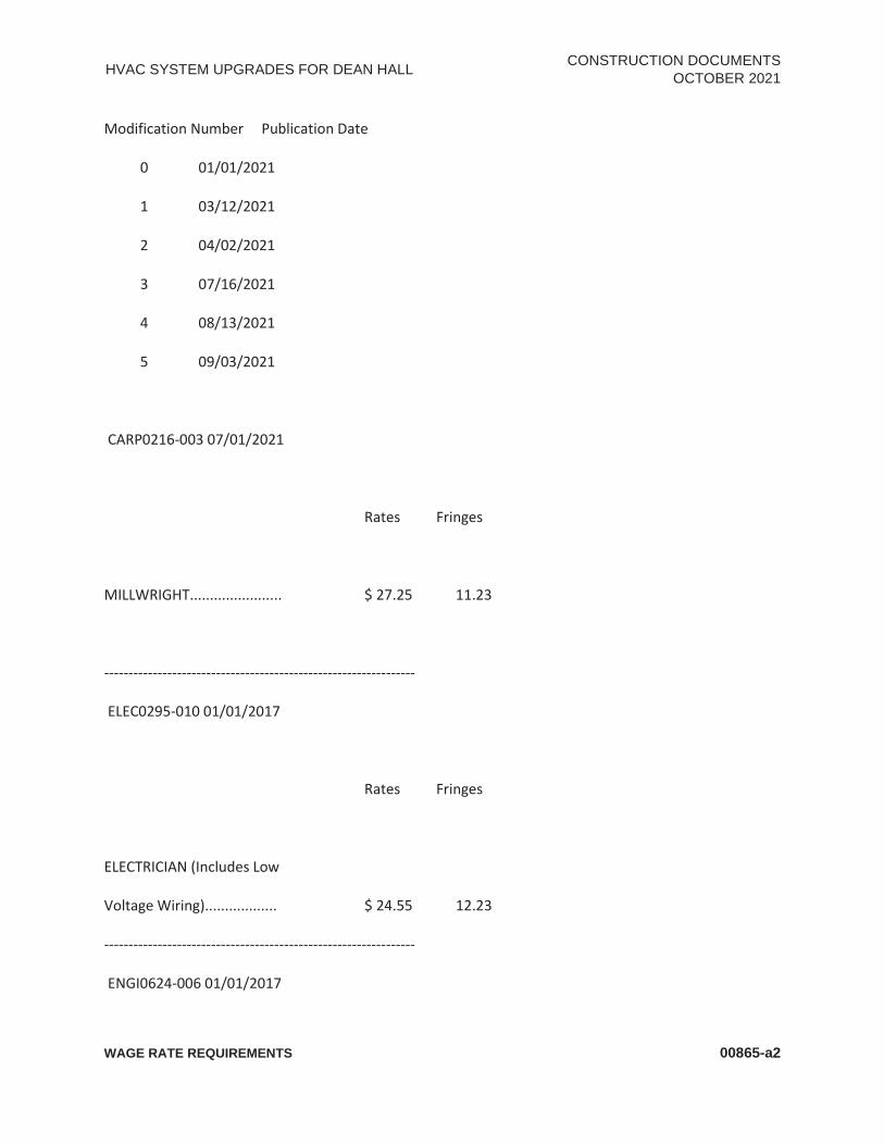
HVAC SYSTEM UPGRADES FOR DEAN HALL CONSTRUCTION DOCUMENTS OCTOBER 2021
WAGE RATE REQUIREMENTS 00865-a2
Modification Number Publication Date
0 01/01/2021
1 03/12/2021
2 04/02/2021
3 07/16/2021
4 08/13/2021
5 09/03/2021
CARP0216-003 07/01/2021
Rates Fringes
MILLWRIGHT....................... $ 27.25 11.23
----------------------------------------------------------------
ELEC0295-010 01/01/2017
Rates Fringes
ELECTRICIAN (Includes Low
Voltage Wiring).................. $ 24.55 12.23
----------------------------------------------------------------
ENGI0624-006 01/01/2017

HVAC SYSTEM UPGRADES FOR DEAN HALL CONSTRUCTION DOCUMENTS OCTOBER 2021
WAGE RATE REQUIREMENTS 00865-a3
Rates Fringes
POWER EQUIPMENT OPERATOR
Crane....................... $ 26.20 12.30
Forklift..................... $ 26.20 12.30
----------------------------------------------------------------
* IRON0321-010 08/01/2021
Rates Fringes
IRONWORKER, STRUCTURAL...... $ 23.00 19.61
----------------------------------------------------------------
PAIN0424-008 07/01/2019
Rates Fringes
PAINTER (Spray).................. $ 16.10 6.97
----------------------------------------------------------------
SUAR2015-008 01/09/2017
Rates Fringes
BRICKLAYER....................... $ 20.00 0.00

HVAC SYSTEM UPGRADES FOR DEAN HALL CONSTRUCTION DOCUMENTS OCTOBER 2021
WAGE RATE REQUIREMENTS 00865-a4
CARPENTER, Includes Drywall
Hanging, and Metal Stud
Installation..................... $ 15.21 0.00
CEMENT MASON/CONCRETE FINISHER...$ 15.62 0.00
HVAC MECHANIC: HVAC Duct
Installation..................... $ 17.27 5.03
LABORER: Common or General...... $ 12.28 2.26
LABORER: Mason Tender - Brick... $ 10.00 0.00
OPERATOR:
Backhoe/Excavator/Trackhoe....... $ 23.08 0.00
OPERATOR: Bulldozer............. $ 18.14 0.00
PAINTER (Brush and Roller)....... $ 17.78 0.00
PLUMBER.......................... $ 14.54 1.08
TRUCK DRIVER: Dump Truck........ $ 15.00 0.00
----------------------------------------------------------------

HVAC SYSTEM UPGRADES FOR DEAN HALL CONSTRUCTION DOCUMENTS OCTOBER 2021
WAGE RATE REQUIREMENTS 00865-a5
WELDERS - Receive rate prescribed for craft performing
operation to which welding is incidental.
================================================================
Note: Executive Order (EO) 13706, Establishing Paid Sick Leave for Federal Contractors applies to all
contracts subject to the Davis-Bacon Act for which the contract is awarded (and any solicitation was
issued) on or after January 1, 2017. If this contract is covered by the EO, the contractor must provide
employees with 1 hour of paid sick leave for every 30 hours they work, up to 56 hours of paid sick leave
each year. Employees must be permitted to use paid sick leave for their own illness, injury or other
health-related needs, including preventive care; to assist a family member (or person who is like family
to the employee) who is ill, injured, or has other health-related needs, including preventive care; or for
reasons resulting from, or to assist a family member (or person who is like family to the employee) who
is a victim of, domestic violence, sexual assault, or stalking. Additional information on contractor
requirements and worker protections under the EO is available at www.dol.gov/whd/govcontracts.
Unlisted classifications needed for work not included within
the scope of the classifications listed may be added after
award only as provided in the labor standards contract clauses
(29CFR 5.5 (a) (1) (ii)).
----------------------------------------------------------------

HVAC SYSTEM UPGRADES FOR DEAN HALL CONSTRUCTION DOCUMENTS OCTOBER 2021
WAGE RATE REQUIREMENTS 00865-a6
The body of each wage determination lists the classification and wage rates that have been found to be
prevailing for the cited type(s) of construction in the area covered by the wage determination. The
classifications are listed in alphabetical order of ""identifiers"" that indicate whether the particular
rate is a union rate (current union negotiated rate for local), a survey rate (weighted average rate) or a
union average rate (weighted union average rate).
Union Rate Identifiers
A four letter classification abbreviation identifier enclosed in dotted lines beginning with characters
other than ""SU"" or ""UAVG"" denotes that the union classification and rate were prevailing for that
classification in the survey.
Example: PLUM0198-005 07/01/2014.
PLUM is an abbreviation identifier of the union which prevailed in the survey for this classification,
which in this example would be Plumbers. 0198 indicates the local union number or district council
number where applicable, i.e., Plumbers Local 0198. The next number, 005 in the example, is an internal
number used in processing the wage determination. 07/01/2014 is the effective date of the most
current negotiated rate, which in this example is July 1, 2014.
Union prevailing wage rates are updated to reflect all rate changes in the collective bargaining
agreement (CBA) governing this classification and rate.

HVAC SYSTEM UPGRADES FOR DEAN HALL CONSTRUCTION DOCUMENTS OCTOBER 2021
WAGE RATE REQUIREMENTS 00865-a7
Survey Rate Identifiers
Classifications listed under the ""SU"" identifier indicate that no one rate prevailed for this classification
in the survey and the published rate is derived by computing a weighted average rate based on all the
rates reported in the survey for that classification. As this weighted average rate includes all rates
reported in the survey, it may include both union and non-union rates. Example: SULA2012-007
5/13/2014. SU indicates the rates are survey rates based on a weighted average calculation of rates and
are not majority rates. LA indicates the State of Louisiana. 2012 is the year of survey on which these
classifications and rates are based. The next number, 007 in the example, is an internal number used in
producing the wage determination. 5/13/2014 indicates the survey completion date for the
classifications and rates under that identifier.
Survey wage rates are not updated and remain in effect until a new survey is conducted.
Union Average Rate Identifiers
Classification(s) listed under the UAVG identifier indicate that no single majority rate prevailed for those
classifications; however, 100% of the data reported for the classifications was union data.
EXAMPLE: UAVG-OH-0010 08/29/2014.
UAVG indicates that the rate is a weighted union average rate. OH indicates the state. The next number,
0010 in the example, is an internal number used in producing the wage determination. 08/29/2014
indicates the survey completion date for the classifications and rates under that identifier.

HVAC SYSTEM UPGRADES FOR DEAN HALL CONSTRUCTION DOCUMENTS OCTOBER 2021
WAGE RATE REQUIREMENTS 00865-a8
A UAVG rate will be updated once a year, usually in January of each year, to reflect a weighted average
of the current negotiated/CBA rate of the union locals from which the rate is based.
----------------------------------------------------------------
WAGE DETERMINATION APPEALS PROCESS
1.) Has there been an initial decision in the matter? This can
be:
* an existing published wage determination
* a survey underlying a wage determination
* a Wage and Hour Division letter setting forth a position on
a wage determination matter
* a conformance (additional classification and rate) ruling
On survey related matters, initial contact, including requests for summaries of surveys, should be with
the Wage and Hour Regional Office for the area in which the survey was conducted because those
Regional Offices have responsibility for the Davis-Bacon survey program. If the response from this initial
contact is not satisfactory, then the process described in 2.) and 3.) should be followed.
With regard to any other matter not yet ripe for the formal process described here, initial contact
should be with the Branch of Construction Wage Determinations. Write to:
Branch of Construction Wage Determinations Wage and Hour Division U.S. Department of Labor 200 Constitution Avenue, N.W. Washington, DC 20210

HVAC SYSTEM UPGRADES FOR DEAN HALL CONSTRUCTION DOCUMENTS OCTOBER 2021
WAGE RATE REQUIREMENTS 00865-a9
2.) If the answer to the question in 1.) is yes, then an interested party (those affected by the action) can
request review and reconsideration from the Wage and Hour Administrator (See 29 CFR Part 1.8 and 29
CFR Part 7). Write to:
Wage and Hour Administrator U.S. Department of Labor 200 Constitution Avenue, N.W. Washington, DC 20210
The request should be accompanied by a full statement of the interested party's position and by any
information (wage payment data, project description, area practice material, etc.) that the requestor
considers relevant to the issue.
3.) If the decision of the Administrator is not favorable, an
interested party may appeal directly to the Administrative
Review Board (formerly the Wage Appeals Board). Write to:
Administrative Review Board U.S. Department of Labor 200 Constitution Avenue, N.W. Washington, DC 20210
4.) All decisions by the Administrative Review Board are final.
================================================================
END OF GENERAL DECISION"

HVAC SYSTEM UPGRADES FOR DEAN HALL CONSTRUCTION DOCUMENTS OCTOBER 2021
THIS PAGE INTENTIONALLY LEFT BLANK

HVAC SYSTEM UPGRADES FOR DEAN HALL CONSTRUCTION DOCUMENTS OCTOBER 2021
RELEASE OF CLAIMS 00900-1
SECTION 00900 RELEASE OF CLAIMS
Comes the undersigned, who does hereby swear and affirm that:
1. My name is: , and I
am doing business as: and my
legal address is:
2. Except as stated in Paragraph Four (4) below, pursuant to Contract #: which
was executed on: , on the following project:
.
I have paid and have otherwise satisfied all obligations for all furnished materials and equipment, all work,
labor and services performed, and for all known claims against the Contractor arising in any manner in
connection with the performance of the above referenced contract for which the Owner or his property might
in any way be held responsible.
3. Except as stated in Paragraph Four (4) below, to the best of my knowledge, information and belief, the
releases or waivers of Claims, attached hereto and incorporated herein, includes the above referenced
contract, all subcontractors, all suppliers of materials and equipment, and all performers of work, labor or
services who have or may have claims against any property of the Owner arising in any manner out of the
performance of the Contract.
4. The Exceptions are: (if none exists, then indicate “none”. The Contractor shall furnish bond(s) satisfactory to the Owner for each exception if so required by the Owner.
________________________________ ________________________ Affiant’s Signature Date VERIFICATION STATE OF: ARKANSAS
COUNTY OF:
Subscribed and Sworn To before me this day of 20 .
Notary Public
My Commission Expires:

HVAC SYSTEM UPGRADES FOR DEAN HALL CONSTRUCTION DOCUMENTS OCTOBER 2021
THIS PAGE INTENTIONALLY LEFT BLANK

HVAC SYSTEM UPGRADES FOR DEAN HALL CONSTRUCTION DOCUMENTS OCTOBER 2021
CERTIFICATIONS FORM 00 910 - 1
CERTIFICATIONS FORM
In submitting this bid, the undersigned certifies on behalf of its firm and any proposed subcontractors as follows: Eligible Bidder: The bidder warrants and represents that neither the Bidder nor its subcontractors: (1) have not within a three-year period preceding this Bid been convicted of or had a civil judgment rendered against them for commission of fraud or a criminal offense in connection with obtaining, attempting to obtain, or performing a public (federal, state or local) transaction or contract under a public transaction; violation of federal or state antitrust statutes or commission of embezzlement, theft, forgery, bribery, falsification or destruction of records, making false statements, or receiving stolen property; (2) are not presently indicted for or otherwise criminally or civilly charged by a governmental entity (federal, state or local) with commission of any of the offenses enumerated in item (1) of this certification; and (3) have not within a three-year period preceding this bid had one or more public transactions (federal, state or local) terminated for cause or default. Bid Validity: If this offer is accepted within ninety (90) calendar days from the due date, to furnish any or all services upon which prices are offered at the designated point within the time specified. Non-Collusion: The Bidder has made this Bid independently, without consultation, communication, or agreement for the purpose of restricting competition as to any matter relating to this Bid with any other firm or with any other competitor. Non-Conflict: The Bidder presents and warrants that no employee, official, board member or family member of the Central Arkansas Transit Authority is or will be pecuniarily benefited directly or indirectly in this Contract. Covenant Against Gratuities: The Bidder nor any of its employees, representatives, or agents have offered or given gratuities (in the form of entertainment, gifts, or otherwise) to any director, officer, or employee of the Central Arkansas Transit Authority with the view toward securing favorable treatment in the awarding, amending, or the making of any determination with respect to the performance of this Contract. Integrity and Ethics: The Bidder has a satisfactory record of integrity and business ethics, in compliance with 49 U.S.C. Section 5325(j)(2)(A). Public Policy: The Bidder Is in compliance with the public policies of the Federal Government, as required by 49 U.S.C. Section 5325(j)(2)(B). Administrative and Technical Capacity: The Bidder has the necessary organization, experience, accounting, and operational controls, and technical skills, or the ability to obtain them, in compliance with 49 U.S.C. Section 5325(j)(2)(D). Licensing and Taxes: The Bidder Is in compliance with applicable licensing and tax laws and regulations. Financial Resources: The Bidder has, or can obtain, sufficient financial resources to perform the contract, as required by 49 U. S. C. Section 5325 (j)(2)(D).

HVAC SYSTEM UPGRADES FOR DEAN HALL CONSTRUCTION DOCUMENTS OCTOBER 2021
CERTIFICATIONS FORM 00 910 - 2
Timeliness: The Bidder Is able to comply with the required delivery or performance schedule, taking into consideration all existing commercial and governmental business commitments. Performance Record: The Bidder is able to provide a satisfactory current and past performance record.
Employment of Illegal Immigrants: The Bidder certifies that they will not employ or contract with any illegal immigrants in their contracts with the Authority, as required by ACA § 19-11-105. Certification Signature: The Bidder attests to certifications by signature of this document. Signature Printed Name Title Date

HVAC SYSTEM UPGRADES FOR DEAN HALL CONSTRUCTION DOCUMENTS OCTOBER 2021
SUMMARY OF WORK 01 10 00 - 1
SECTION 01 10 00 SUMMARY OF WORK
PART 1 GENERAL 1.01 PROJECT
A. Project Name: HVAC System Upgrades for Dean Hall B. Owner's Name: Arkansas Tech University. C. The Project consists of the replacement of the HVAC system at Dean Hall, including cooling
tower, chiller, boiler, pumps, DOAS units, fan coils, and associated controls. 1.02 CONTRACT DESCRIPTION
A. RESPONSIBILITIES OF CONTRACTOR: Except as otherwise specifically stated in the contract, the Contractor shall provide and pay for all materials, labor, tools, equipment, transportation, supervision, temporary construction of every nature, fees, taxes legally collectible because of the work and all other services and facilities of every nature whatsoever necessary to execute the work to be done as shown and/or specified under the contract and deliver it complete and in every respect within the specified time. The Contractor will include in his or her price the listed cost of these items and will be responsible for purchasing the specific equipment from the listed source.
1.03 1CONSTRUCTION DRAWINGS AND SPECIFICATIONS: A. The Engineer will furnish up to 5 sets of contract drawings and specifications, without cost,
to the Prime Contractor for his use in constructing the work. The Prime Contractor is to supply all contract drawings and specifications to the subcontractors or material suppliers. Additional sets or portions of the contract drawings and specifications, beyond the 5 sets furnished by the Engineer, that are requested by the Prime Contractor will be furnished for the actual cost of printing at the Prime Contractor’s expense.
1.04 COORDINATION: A. Provide administrative and supervisory requirements necessary for coordination of work,
including meetings, administrative and supervisory personnel, survey, records, reports, use of site limitations, installation provisions, cutting and patching, cleaning, protection, conservation and salvage. The prime contractor shall furnish a superintendent to be on the job site whenever work is being performed. The Superintendent shall serve as a liaison between the contractor, the subcontractors, the Engineer and the Owner’s personnel. The superintendent will be required to be present any time work is being done. Coordinate storage of materials and equipment with the Engineer and the Physical Plant Director.
1.05 BUILDING OCCUPANCY: A. During the Contract Period, the building will be occupied. About ten parking spots will be
available for the Contractor’s usage. Cooperate fully with the Owner during construction operations to minimize conflicts and to facilitate the Owner’s personnel’s usage. Do not unreasonably obstruct, or interfere with, any phase of the Owner’s personnel’s operations. Make any changes in or alterations to existing facilities, including utility service, without disrupting continuous use by the Owner. Any shutdowns of services to any building will require 2 week’s written notice to the Physical Plant Director and Engineer.
B. Owner intends to continue to occupy adjacent portions of the existing building during the entire construction period.
C. Cooperate with Owner to minimize conflict and to facilitate Owner's operations. D. Schedule the Work to accommodate Owner occupancy
1.06 CONTRACTOR USE OF PREMISES A. Limit use of premises to work indicated, allowing for Owner occupancy and public use when
required. B. Keep existing driveways and entrances serving premises clear and available to the Owner’s
employees at all times. Do not use these areas for parking or storage of materials. C. Do not unreasonably encumber site with materials or equipment. Confine stockpiling of
materials and location of storage to areas in the building, to be assigned during the course

HVAC SYSTEM UPGRADES FOR DEAN HALL
CONSTRUCTION DOCUMENTS OCTOBER 2021
SUMMARY OF WORK 01 10 00 - 2
of the project. The Contractor’s field office will be located at a site adjacent to the building, directed by the Physical Plant Director. If additional storage is necessary, obtain and pay for storage off site.
D. Maintain existing buildings in safe and weather-tight condition throughout construction period. Repair any damage on property caused by construction operations. Take precautions necessary to protect building and building occupants during construction period. Do not use building toilet facilities.
E. Lock automotive type vehicles, such as passenger cars and trucks and other mechanized or motorized construction equipment, when parked and unattended, to prevent unauthorized use. Do not leave vehicles or equipment unattended with motor running or ignition key in place.
F. Smoking will not be permitted on campus. G. Upon completion of the project the Contractor will be required to repair any portion of the
facility damaged by the construction process at no expense to the Physical Plant Director. 1.07 PROJECT MEETINGS
A. The Contractor shall schedule and hold regular progress meetings to coordinate, expedite, and schedule work of contracts. Hold additional meetings as progress of work dictates or when requested by the Physical Plant Director or the Engineer. Send written notice of meeting date, time and place, and agenda of meeting to the Physical Plant Director, Engineer, separate contractors, subcontractors and others as pertinent to the agenda. Record results of meetings and distribute copies to everyone in attendance and to others affected by the decisions or actions resulting from each meeting.
END OF SECTION

HVAC SYSTEM UPGRADES FOR DEAN HALL CONSTRUCTION DOCUMENTS OCTOBER 2021
PAYMENT OPTIONS 01 29 00 - 1
SECTION 01 29 00 PAYMENT PROCEDURES
PART 1 GENERAL 1.01 SUMMARY
A. This Section specifies administrative and procedural requirements necessary to prepare and process Applications for Payment.
1.02 SCHEDULE OF VALUES A. Coordination: Coordinate preparation of the Schedule of Values with preparation of Contractor's Construction
Schedule.
1. Correlate line items in the Schedule of Values with other required administrative forms and schedules, including Application for Payment forms with Continuation Sheets, Submittals Schedule, and Contractor's Construction Schedule.
2. Submit the Schedule of Values to Engineer at earliest possible date but no later than
3. seven days before the date scheduled for submittal of initial Applications for Payment.
B. Format and Content: Use the Project Manual table of contents as a guide to establish line items for the Schedule of Values. Provide at least one line item for each Specification Section.
1. Identification: Include the following Project identification on the Schedule of Values:
a. Project name and location
b. Name of Engineer
c. Engineer’s project number
d. Contractor’s name and address
e. Date of submittal
2. Submit draft of AIA Document G703 Continuation Sheets.
3. Provide a breakdown of the Contract Sum in enough detail to facilitate continued evaluation of Applications for Payment and progress reports. Coordinate with the Project Manual table of contents. Provide several line items for principal subcontract amounts, where appropriate.
4. Round amounts to nearest whole dollar; total shall equal the Contract Sum.
5. Provide a separate line item in the Schedule of Values for each part of the Work where Applications for Payment may include materials or equipment purchased or fabricated and stored, but not yet installed.
6. Provide separate line items in the Schedule of Values for initial cost of materials, for each subsequent stage of completion, and for total installed value of that part of the Work.
7. Each item in the Schedule of Values and Applications for Payment shall be complete. Include total cost and proportionate share of general overhead and profit for each item.
a. Temporary facilities and other major cost items that are not direct cost of actual work-in-place may be shown either as separate line items in the Schedule of Values or distributed as general overhead expense, at Contractor's option.
8. Schedule Updating: Update and resubmit the Schedule of Values before the next Applications for Payment when Change Orders or Construction Change Directives result in a change in the Contract Sum.

HVAC SYSTEM UPGRADES FOR DEAN HALL CONSTRUCTION DOCUMENTS OCTOBER 2021
PAYMENT OPTIONS 01 29 00 - 2
1.03 APPLICATIONS FOR PAYMENT A. Each Application for Payment shall be consistent with previous applications and payments as certified by
Engineer and paid for by Owner.
1. Initial Application for Payment, Application for Payment at time of Substantial Completion, and final Application for Payment involve additional requirements.
B. Payment Application Times: Progress payments shall be submitted to Engineer by the 25th of the month. The period covered by each Application for Payment is one month, ending on the last day of the month.
C. Payment Application Forms: Use AIA Document G702 and AIA Document G703 Continuation Sheets as form for Applications for Payment.
1. Submit payment applications on original AIA G702 and G703 forms; or AIA licensed software of these forms. Non-AIA payment application forms or software that are similar are not acceptable.
D. Complete every entry on form. Notarize and execute by a person authorized to sign legal documents on behalf of Contractor. Engineer will return incomplete applications without action.
1. Entries shall match data on the Schedule of Values and Contractor's Construction Schedule. Use updated schedules if revisions were made.
2. Include amounts of Change Orders and Construction Change Directives issued before last day of construction period covered by application.
E. Transmittal: Submit 3 signed and notarized original copies of each Application for Payment to Engineer by a method ensuring receipt. One copy shall include waivers of lien and similar attachments if required.
1. Transmit each copy with a transmittal form listing attachments and recording appropriate information about application.
F. Waivers of Mechanic's Lien: With each Application for Payment, submit waivers of mechanic's lien from every entity who is lawfully entitled to file a mechanic's lien arising out of the Contract and related to the Work covered by the payment.
1. Submit partial waivers on each item for amount requested in previous application, after deduction for retainage, on each item.
2. When an application shows completion of an item, submit final or full waivers.
3. Owner reserves the right to designate which entities involved in the Work must submit waivers.
G. Initial Application for Payment: Administrative actions and submittals that must precede or coincide with submittal of first Application for Payment include the following:
1. List of subcontractors.
2. Schedule of Values.
3. Contractor's Construction Schedule (preliminary if not final).
4. Schedule of unit prices.
5. Submittals Schedule (preliminary if not final).
6. List of Contractor's staff assignments.
7. List of Contractor's principal consultants.
8. Copies of building permits.
9. Copies of authorizations and licenses from authorities having jurisdiction for performance of the Work.

HVAC SYSTEM UPGRADES FOR DEAN HALL CONSTRUCTION DOCUMENTS OCTOBER 2021
PAYMENT OPTIONS 01 29 00 - 3
10. Initial progress report.
11. Report of pre-construction conference.
12. Certificates of insurance and insurance policies.
13. Performance and payment bonds.
14. Data needed to acquire owner’s insurance.
H. Application for Payment at Substantial Completion: After issuing the Certificate of Substantial Completion, submit an Application for Payment showing 100 percent completion for portion of the Work claimed as substantially complete.
1. Include documentation supporting claim that the Work is substantially complete and a statement showing an accounting of changes to the Contract Sum.
2. This application shall reflect Certificates of Partial Substantial Completion issued previously for Owner occupancy of designated portions of the Work.
I. Final Payment Application: Submit final Application for Payment with releases and supporting documentation not previously submitted and accepted, including, but not limited, to the following:
1. Evidence of completion of Project closeout requirements.
2. Insurance certificates for products and completed operations where required and proof that taxes, fees, and similar obligations were paid.
3. Updated final statement, accounting for final changes to the Contract Sum.
4. AIA Document G706, "Contractor's Affidavit of Payment of Debts and Claims."
5. AIA Document G706A, "Contractor's Affidavit of Release of Liens."
6. AIA Document G707, "Consent of Surety to Final Payment."
7. Evidence that claims have been settled.
8. Final meter readings for utilities, a measured record of stored fuel, and similar data as of date of Substantial Completion or when Owner took possession of and assumed responsibility for corresponding elements of the Work.
9. Final, liquidated damages settlement statement.
PART 2 PRODUCTS (NOT USED) PART 3 EXECUTION (NOT USED) END OF SECTION

HVAC SYSTEM UPGRADES FOR DEAN HALL CONSTRUCTION DOCUMENTS OCTOBER 2021
THIS PAGE INTENTIONALLY LEFT BLANK

HVAC SYSTEM UPGRADES FOR DEAN HALL CONSTRUCTION DOCUMENTS OCTOBER 2021
PROJECT MANAGEMENT AND COORDINATION 01-31-00 - 1
SECTION 01 31 00 PROJECT MANAGEMENT AND COORDINATION
PART 1 GENERAL 1.01 SUMMARY
A. This Section includes administrative provisions for coordinating construction operations on Project including, but not limited to, the following:
1. Coordination Drawings.
2. Project meetings.
3. Requests for Interpretation (RFIs).
1.02 DEFINITIONS A. RFI: Request from Contractor seeking interpretation or clarification of the Contract Documents.
1.03 COORDINATION A. Coordination: Coordinate construction operations included in different Sections of the Specifications to ensure
efficient and orderly installation of each part of the Work. Coordinate construction operations, included in different Sections, that depend on each other for proper installation, connection, and operation. 1. Schedule construction operations in sequence required to obtain the best results where installation of
one part of the Work depends on installation of other components, before or after its own installation.
2. Make adequate provisions to accommodate items scheduled for later installation.
B. Prepare memoranda for distribution to each party involved, outlining special procedures required for coordination. Include such items as required notices, reports, and list of attendees at meetings.
1. Prepare similar memoranda for Owner and separate contractors if coordination of their Work is required.
C. Administrative Procedures: Coordinate scheduling and timing of required administrative procedures with other construction activities and activities of other contractors to avoid conflicts and to ensure orderly progress of the Work. Such administrative activities include, but are not limited to, the following:
1. Preparation of Contractor's Construction Schedule.
2. Preparation of the Schedule of Values.
3. Installation and removal of temporary facilities and controls.
4. Delivery and processing of submittals.
5. Progress meetings.
6. Pre-installation conferences.
7. Project closeout activities.
8. Startup and adjustment of systems.
9. Project closeout activities.
1.04 SUBMITTALS A. Content: Project-specific information, drawn accurately to scale. Do not base coordination drawings on
reproductions of the Contract Documents or standard printed data. Include the following information, as applicable.

HVAC SYSTEM UPGRADES FOR DEAN HALL CONSTRUCTION DOCUMENTS OCTOBER 2021
PROJECT MANAGEMENT AND COORDINATION 01-31-00 - 2
1. Indicate functional and spatial relationships of components of architectural, structural, civil, mechanical, and electrical systems.
2. Indicate dimensions shown on the Contract Drawings and make specific note of dimensions that appear to be in conflict with submitted equipment and minimum clearance requirements. Provide alternate sketches to Engineer for resolution of such conflicts. Minor dimension changes and difficult installations will not be considered changes to the Contract.
B. Sheet Size: At least 8-1/2 by 11 inches (215 by 280 mm) but no larger than 30 by 40 inches (750 by 1000 mm).
C. Number of Copies: Submit one digital copy of each submittal.
D. Refer to individual Sections for Coordination Drawing requirements for Work in those Sections.
1.05 PROJECT MEETINGS A. General: Schedule and conduct meetings and conferences at Project site, unless otherwise indicated.
1. Attendees: Inform participants and others involved, and individuals whose presence is required, of date and time of each meeting. Notify Owner and Engineer of scheduled meeting dates and times.
2. Agenda: Prepare the meeting agenda. Distribute the agenda to all invited attendees.
3. Minutes: Record significant discussions and agreements achieved. Distribute the meeting minutes to everyone concerned, including Owner and Engineer, within three days of the meeting.
B. Pre-construction Conference: Schedule a pre-construction conference before starting construction, at a time convenient to Owner and Engineer, but no later than 15 days after execution of the Agreement. Hold the conference at Project site or another convenient location. Conduct the meeting to review responsibilities and personnel assignments.
1. Attendees: Authorized representatives of Owner, Engineer, and their consultants; Contractor and its superintendent; major subcontractors; suppliers; and other concerned parties shall attend the conference. All participants at the conference shall be familiar with Project and authorized to conclude matters relating to the Work.
2. Agenda: Discuss items of significance that could affect progress, prepare the meeting agenda.
3. Minutes: Record and distribute meeting minutes.
C. Pre-installation Conferences: Conduct a pre-installation conference at Project site before each construction activity that requires coordination with other construction.
1. Attendees: Installer and representatives of manufacturers and fabricators involved in or affected by the installation and its coordination or integration with other materials and installations that have preceded or will follow, shall attend the meeting. Advise Engineer of scheduled meeting dates.
2. Record significant conference discussions, agreements, and disagreements, including required corrective measures and actions.
3. Reporting: Distribute minutes of the meeting to each party present and to parties who should have been present.
D. Progress Meetings: Conduct progress meetings at biweekly intervals. Coordinate dates of meetings with preparation of payment requests.
1. Attendees: In addition to representatives of Owner and Engineer, each contractor, subcontractor, supplier, and other entity concerned with current progress or involved in planning, coordination, or performance of future activities shall be represented at these meetings. All participants at the conference shall be familiar with Project and authorized to conclude matters relating to the Work.

HVAC SYSTEM UPGRADES FOR DEAN HALL CONSTRUCTION DOCUMENTS OCTOBER 2021
PROJECT MANAGEMENT AND COORDINATION 01-31-00 - 3
2. Agenda: Review and correct or approve minutes of previous progress meeting. Review other items of significance that could affect progress. Include topics for discussion as appropriate to status of Project.
a. Contractor's Construction Schedule: Review progress since the last meeting. Determine whether each activity is on time, ahead of schedule, or behind schedule, in relation to Contractor's Construction Schedule. Determine how construction behind schedule will be expedited; secure commitments from parties involved to do so. Discuss whether schedule revisions are required to ensure that current and subsequent activities will be completed within the Contract Time.
3. Minutes: Record the meeting minutes.
4. Reporting: Distribute minutes of the meeting to each party present and to parties who should have been present.
a. Schedule Updating: Revise Contractor's Construction Schedule after each progress meeting where revisions to the schedule have been made or recognized. Issue revised schedule concurrently with the report of each meeting.
1.06 REQUESTS FOR INTERPRETATION (RFIS) A. Procedure: Immediately on discovery of the need for interpretation of the Contract Documents, and if not
possible to request interpretation at Project meeting, prepare and submit an RFI in the form specified.
1. RFIs shall originate with Contractor. RFIs submitted by entities other than Contractor will be returned with no response.
2. Coordinate and submit RFIs in a prompt manner so as to avoid delays in Contractor's work or work of subcontractors.
B. Content of the RFI: Include a detailed, legible description of item needing interpretation and the following:
1. Project Name.
2. Date.
3. Name of Contractor.
4. Name of Engineer.
5. RFI number, numbered sequentially.
6. Specification Section number and tile and related paragraphs, as appropriate.
7. Drawing numbers and detail references, as appropriate.
8. Field dimensions and conditions as appropriate.
9. Contractor’s suggested solution(s). If Contractor’s solution(s) impact the Contract Time or the Contract Sum, Contractor shall state impact in the RFI.
10. Contractor’s Signature.
11. Attachments: Include drawings, descriptions, measurements, photos, Product Data, Shop Drawings, and other information necessary to fully describe items needing interpretation.
C. Electronic RFIs:
1. Identify each page of attachments with the RFI number and sequential page number.
D. Engineer’s Action: Engineer will review each RFI, determine action required, and return it. Allow seven working days for Engineer's response for each RFI. RFIs received after 1:00 p.m. will be considered as received the following working day.
1. The following RFIs will be returned without action:

HVAC SYSTEM UPGRADES FOR DEAN HALL CONSTRUCTION DOCUMENTS OCTOBER 2021
PROJECT MANAGEMENT AND COORDINATION 01-31-00 - 4
a. Requests for approval of submittals
b. Requests for approval of substitutions.
c. Requests for coordination information already indicated in the Contract Documents
d. . Requests for adjustments in the Contract Time or the Contract Sum.
e. Requests for interpretation of Engineer's actions on submittals.
f. Incomplete RFIs or RFIs with numerous errors.
2. Engineer's action may include a request for additional information, in which case Engineer's time for response will start again.
3. Engineer's action on RFIs that may result in a change to the Contract Time or the Contract Sum may be eligible for Contractor to submit Change Proposal according to Division 1 Section "Contract Modifications."
a. If Contractor believes the RFI response warrants change in the Contract Time or the Contract Sum, notify Engineer in writing within 10 days of receipt of the RFI response.
b. On receipt of Engineer's action, update the RFI log and immediately distribute the RFI response to affected parties. Review response and notify Engineer within seven days if Contractor disagrees with response.
c. RFI Log: Prepare, maintain, and submit a tabular log of RFIs organized by the RFI number. Submit log weekly.1. Project name.
1) Name and address of Contractor.
2) Name and address of Engineer.
3) RFI number including RFIs that were dropped and not submitted.
4) RFI description.
5) Date the RFI was submitted.
6) Date Engineer's response was received.
7) Identification of related Minor Change in the Work, Construction Change Directive, and Proposal Request, as appropriate.
PART 2 PRODUCTS (NOT USED) PART 3 EXECUTION (NOT USED) END OF SECTION

HVAC SYSTEM UPGRADES FOR DEAN HALL CONSTRUCTION DOCUMENTS OCTOBER 2021
SUBMITTAL PROCEDURES 01-33-00 - 1
SECTION 01 33 00 SUBMITTAL PROCEDURES
PART 1 GENERAL 1.01 SUMMARY
A. Section includes requirements for the submittal schedule and administrative and procedural requirements for submitting Shop Drawings, Product Data, Samples, and other submittals.
1.02 SCHEDULE OF VALUES A. Action Submittals: Written and graphic information and physical samples that require Engineer's responsive
action. Action submittals are those submittals indicated in individual Specification Sections as "action submittals."
B. Informational Submittals: Written and graphic information and physical samples that do not require Engineer's responsive action. Submittals may be rejected for not complying with requirements. Informational submittals are those submittals indicated in individual Specification Sections as "informational submittals."
C. Portable Document Format (PDF): An open standard file format licensed by Adobe Systems used for representing documents in a device-independent and display resolution-independent fixed-layout document format.
1.03 SUBMITTALS A. Submittal Stamp: Prior to transmitting submittals to Engineer, submit sample of Contractor’s submittal stamp
for approval.
B. Submittal Schedule: Submit a schedule of submittals, arranged in chronological order by dates required by construction schedule. Include time required for review, ordering, manufacturing, fabrication, and delivery when establishing dates.
C. Include additional time required for making corrections or revisions to submittals noted by Engineer and additional time for handling and reviewing submittals required by those corrections.
1. Coordinate submittal schedule with list of subcontracts, the schedule of values, and Contractor's construction schedule.
2. Initial Submittal: Submit concurrently with startup construction schedule. Include submittals required during the first 60 days of construction. List those submittals required to maintain orderly progress of the Work and those required early because of long lead time for manufacture or fabrication.
3. Final Submittal: Submit concurrently with the first complete submittal of Contractor's construction schedule.
a. Submit revised submittal schedule to reflect changes in current status and timing for submittals.
4. Format: Arrange the following information in a tabular format:
a. Scheduled date for first submittal.
b. Specification Section number and title.
c. Submittal category: Action; informational.
d. Name of subcontractor.
e. Description of the Work covered.
f. Scheduled date for Engineer's final release or approval.
g. Scheduled date of fabrication.

HVAC SYSTEM UPGRADES FOR DEAN HALL CONSTRUCTION DOCUMENTS OCTOBER 2021
SUBMITTAL PROCEDURES 01-33-00 - 2
h. Scheduled dates for purchasing.
i. Scheduled dates for installation.
j. Activity or event number.
1.04 SUBMITTAL ADMINISTRATIVE REQUIREMENTS A. Engineer's Digital Data Files: Electronic digital data files of the Contract Drawings will be provided by
Engineer for Contractor's use in preparing submittals.
1. Engineer may furnish Contractor one set of digital data files of the Contract Drawings for use in preparing Shop Drawings.
2. Engineer makes no representations as to the accuracy or completeness of digital data drawing files as they relate to the Contract Drawings.
B. Coordination: Coordinate preparation and processing of submittals with performance of construction activities.
1. Coordinate each submittal with fabrication, purchasing, testing, delivery, other submittals, and related activities that require sequential activity.
2. Submit all submittal items required for each Specification Section concurrently unless partial submittals for portions of the Work are indicated on approved submittal schedule.
3. Submit action submittals and informational submittals required by the same Specification Section as separate packages under separate transmittals.
4. Coordinate transmittal of different types of submittals for related parts of the Work so processing will not be delayed because of need to review submittals concurrently for coordination.
a. Engineer reserves the right to withhold action on a submittal requiring coordination with other submittals until related submittals are received.
C. Processing Time: Allow time for submittal review, including time for resubmittals, as follows. Time for review shall commence on Engineer's receipt of submittal. No extension of the Contract Time will be authorized because of failure to transmit submittals enough in advance of the Work to permit processing, including resubmittals.
1. Initial Review: Allow 14 days for initial review of each submittal. Allow additional time if coordination with subsequent submittals is required. Engineer will advise Contractor when a submittal being processed must be delayed for coordination.
2. Intermediate Review: If intermediate submittal is necessary, process it in same manner as initial submittal.
3. Resubmittal Review: Allow 14 days for review of each resubmittal.
4. Sequential Review: Where sequential review of submittals by Engineer's consultants, Owner, or other parties is indicated, allow 21 days for initial review of each submittal.
D. Electronic Submittals: Identify and incorporate information in each submittal file as follows:
1. Assemble complete submittal package into a single indexed file incorporating submittal requirements of a single Specification Section and transmittal form with links enabling navigation to each item.
2. Assemble complete submittal package into a single indexed file incorporating submittal requirements of a single Specification Section and transmittal form with links enabling navigation to each item.

HVAC SYSTEM UPGRADES FOR DEAN HALL CONSTRUCTION DOCUMENTS OCTOBER 2021
SUBMITTAL PROCEDURES 01-33-00 - 3
a. File name shall use project identifier and Specification Section number followed by a decimal point and then a sequential number (e.g., LNHS-061000.01). Resubmittals shall include an alphabetic suffix after another decimal point (e.g., LNHS-061000.01.A).
3. Provide means for insertion to permanently record Contractor's review and approval markings and action taken by Engineer.
4. Transmittal Form for Electronic Submittals: Use format containing the following information:
a. Project name. b. Date. c. Name and address of Engineer. d. Name of Contractor. e. Name of firm or entity that prepared submittal. f. Names of subcontractor, manufacturer, and supplier. g. Category and type of submittal. h. Specification Section number and title. i. Drawing number and detail references, as appropriate. j. Related physical samples submitted directly. k. Other necessary identification. l. Remarks.
E. Options: Identify options requiring selection by Engineer. F. Deviations and Additional Information: On an attached separate sheet, prepared on Contractor's letterhead,
record relevant information, requests for data, revisions other than those requested by Engineer on previous submittals, and deviations from requirements in the Contract Documents, including minor variations and limitations. Include same identification information as related submittal.
G. Resubmittals: Make resubmittals in same form and number of copies as initial submittal. 1. Note date and content of previous submittal. 2. Note date and content of revision in label or title block and clearly indicate extent of revision. 3. Resubmit submittals until they are marked with approval notation from Engineer's action stamp.
H. Distribution: Furnish copies of final submittals to manufacturers, subcontractors, suppliers, fabricators, installers, authorities having jurisdiction, and others as necessary for performance of construction activities. Show distribution on transmittal forms.
I. Use for Construction: Retain complete copies of submittals on Project site. Use only final action submittals that are marked with approval notation from Engineer's action stamp.
PART 2 PRODUCTS 2.01 SUBMITTAL PROCEDURES
A. General: Prepare, review, mark approval, sign, date, and submit submittals required by individual Specification Sections.
1. Electronic Submittals: Submit via email as PDF electronic files.
a. Electronic Submittals: Submit via email as PDF electronic files.
2. Mark each copy of each submittal to show which products and options are applicable.
3. Include the following information, as applicable:
a. Manufacturer's catalog cuts.
b. Manufacturer's product specifications.

HVAC SYSTEM UPGRADES FOR DEAN HALL CONSTRUCTION DOCUMENTS OCTOBER 2021
SUBMITTAL PROCEDURES 01-33-00 - 4
c. Standard color charts.
d. Statement of compliance with specified referenced standards.
e. Testing by recognized testing agency.
f. Application of testing agency labels and seals.
g. Notation of coordination requirements.
h. Availability and delivery time information.
4. For equipment, include the following in addition to the above, as applicable.
a. Wiring diagrams showing factory-installed wiring.
b. Printed performance curves.
c. Operational range diagrams.
d. Clearances required to other construction, if not indicated on accompanying Shop Drawings.
5. Submit Product Data before or concurrent with Samples.
B. Shop Drawings: Prepare Project-specific information, drawn accurately to scale.
1. Preparation: Fully illustrate requirements in the Contract Documents.
2. Submit Shop Drawings either in PDF electronic format or paper copies.
3. Sheet Size: Except for templates, patterns, and similar full-size drawings, submit Shop Drawings on sheets at least 8-1/2 by 11 inches (215 by 280 mm), but no larger than 30 by 42 inches (750 by 1067 mm).
C. Samples: Submit Samples for review of kind, color, pattern, and texture for a check of these characteristics with other elements and for a comparison of these characteristics between submittal and actual component as delivered and installed.
1. Transmit Samples that contain multiple, related components such as accessories together in one submittal package.
2. Identification: Attach label on unexposed side of Samples that includes the following:
a. Description of Sample.
b. Product name and name of manufacturer.
c. Sample source.
d. Number and title of applicable Specification Section.
3. Disposition: Maintain sets of approved Samples at Project site, available for quality-control comparisons throughout the course of construction activity. Sample sets may be used to determine final acceptance of construction associated with each set.
a. Samples that may be incorporated into the Work are indicated in individual Specification Sections. Such Samples must be in an undamaged condition at time of use.
b. Samples not incorporated into the Work, or otherwise designated as Owner's property, are the property of Contractor.
4. Samples for Initial Selection: Submit manufacturer's color charts consisting of units or sections of units showing the full range of colors, textures, and patterns available. a. Number of Samples: Submit one full set of available choices where color, pattern, texture, or similar
characteristics are required to be selected from manufacturer's product line.

HVAC SYSTEM UPGRADES FOR DEAN HALL CONSTRUCTION DOCUMENTS OCTOBER 2021
SUBMITTAL PROCEDURES 01-33-00 - 5
5. Samples for Verification: Submit full-size units or Samples of size indicated, prepared from same material to be used for the Work, and physically identical with material or product proposed for use, and that show full range of color and texture variations expected. Samples include, but are not limited to, the following: partial sections of manufactured or fabricated components; small cuts or containers of materials; complete units of repetitively used materials; swatches showing color, texture, and pattern; color range sets; and components used for independent testing and inspection. a. Number of Samples: Submit 2 sets of Samples. Engineer will retain one Sample sets; remainder
will be returned. 1) Submit a single Sample where assembly details, workmanship, fabrication techniques,
connections, operation, and other similar characteristics are to be demonstrated. 2) If variation in color, pattern, texture, or other characteristic is inherent in material or product
represented by a Sample, submit at least three sets of paired units that show approximate limits of variations.
2.02 SUBMITTAL STAMP A. The following information is required in the Contractor’s submittal stamp:
1. Name, Initials or Signature of Contractor’s reviewer 2. Date approval or approval as noted 3. Stamp action shall indicate “Approved” or “Approved as noted” of the submittal by the Contractor’s
reviewer. “Reviewed,” “Checked,” “Complies,” or other wording nomenclature is not acceptable. 2.03 DELEGATED-DESIGN SERVICES
A. Performance and Design Criteria: Where professional design services or certifications by a design professional are specifically required of Contractor by the Contract Documents, provide products and systems complying with specific performance and design criteria indicated. 1. If criteria indicated are not sufficient to perform services or certification required, submit a written request
for additional information to Engineer. B. Delegated-Design Services Certification: In addition to Shop Drawings, Product Data, and other required
submittals, submit digitally signed PDF electronic file and three paper copies of certificate, signed and sealed by the responsible design professional, for each product and system specifically assigned to Contractor to be designed or certified by a design professional. 1. Indicate that products and systems comply with performance and design criteria in the Contract
Documents. Include list of codes, loads, and other factors used in performing these services. 2.04 INFORMATION SUBMITTALS
A. General: Prepare and submit Informational Submittals indicated and upon request. 1. Number of Copies: 2 copies, unless otherwise indicated. Engineer will not return copies.
PART 3 EXECUTION 3.01 CONTRACTOR’S REVIEW
A. Action and Informational Submittals: Review each submittal and check for coordination with other Work of the Contract and for compliance with the Contract Documents. Note corrections and field dimensions. Mark with approval stamp before submitting to Engineer.
1. Contractor's Approval Required: Approval by Contractor must be indicated either by “Approved” or “Approved as noted”.
2. This is a pre-condition to Engineer's review and approval. B. Project Closeout and Maintenance Material Submittals: See requirements in Section 017700 "Closeout
Procedures."

HVAC SYSTEM UPGRADES FOR DEAN HALL CONSTRUCTION DOCUMENTS OCTOBER 2021
SUBMITTAL PROCEDURES 01-33-00 - 6
C. Approvals Stamp: Stamp each submittal with a uniform, approval stamp. Include Project name and location, submittal number, Specification Section title and number, name of reviewer, date of Contractor's approval, and statement certifying that submittal has been reviewed, checked, and approved for compliance with the Contract Documents.
3.02 ENGINEER’S ACTIONS A. Action Submittals: Engineer will review each submittal, make marks to indicate corrections or revisions
required, and return it. Engineer will stamp each submittal with an action stamp and will mark stamp appropriately to indicate “Approved,” “Approved as noted” or “Rejected.”
B. Informational Submittals: Engineer will review each submittal and will not return it or will return it if it does not comply with requirements. Engineer will forward each submittal to appropriate party.
C. Incomplete and partial submittals are unacceptable, will be considered non-responsive, and will be returned for re-submittal without review.
D. Submittals not required by the Contract Documents may be returned by the Engineer without action.
END OF SECTION

HVAC SYSTEM UPGRADES FOR DEAN HALL CONSTRUCTION DOCUMENTS OCTOBER 2021
QUALITY REQUIREMENTS 01 40 00 - 1
SECTION 01 40 00 QUALITY REQUIREMENTS
PART 1 GENERAL 1.01 SUMMARY
A. This Section includes administrative and procedural requirements for quality assurance and quality control.
1. Testing and inspection services for the following will be paid by the Owner:
a. Contractor shall pay for testing indicating failed results.
1) Testing and inspection services for other aspects of the work, such as air testing and balancing, shall be at the expense of the Contractor.
B. Testing and inspecting services are required to verify compliance with requirements specified or indicated. These services do not relieve Contractor of responsibility for compliance with the Contract Document requirements.
1. Specified tests, inspections, and related actions do not limit Contractor's other quality-assurance and -control procedures that facilitate compliance with the Contract Document requirements.
2. Requirements for Contractor to provide quality-assurance and -control services required by Architect, Owner, or authorities having jurisdiction are not limited by provisions of this Section.
1.02 DEFINITIONS A. Quality-Assurance Services: Activities, actions, and procedures performed before and during execution of the
Work to guard against defects and deficiencies and substantiate that proposed construction will comply with requirements.
B. Quality-Control Services: Tests, inspections, procedures, and related actions during and after execution of the Work to evaluate that actual products incorporated into the Work and completed construction comply with requirements. Services do not include contract enforcement activities performed by Architect.
C. Mockups: Full-size, physical assemblies that are constructed on-site. Mockups are used to verify selections made under sample submittals, to demonstrate aesthetic effects and, where indicated, qualities of materials and execution, and to review construction, coordination, testing, or operation; they are not Samples. Approved mockups establish the standard by which the Work will be judged.
D. Testing Agency: An entity engaged to perform specific tests, inspections, or both. Testing laboratory shall mean the same as testing agency.
1.03 CONFLICTING REQUIREMENTS A. General: If compliance with two or more standards is specified and the standards establish different or
conflicting requirements for minimum quantities or quality levels, comply with the most stringent requirement. Refer uncertainties and requirements that are different, but apparently equal, to Architect for a decision before proceeding.
B. Minimum Quantity or Quality Levels: The quantity or quality level shown or specified shall be the minimum provided or performed. The actual installation may comply exactly with the minimum quantity or quality specified, or it may exceed the minimum within reasonable limits. To comply with these requirements, indicated numeric values are minimum or maximum, as appropriate, for the context of requirements. Refer uncertainties to Architect for a decision before proceeding.

HVAC SYSTEM UPGRADES FOR DEAN HALL CONSTRUCTION DOCUMENTS OCTOBER 2021
QUALITY REQUIREMENTS 01 40 00 - 2
1.04 SUBMITTALS A. Testing Agencies - Qualification Data: For each type of testing required, submit proposed testing agency in
advance for approval. Include resume of testing agency, proof of qualifications in the form of a recent report on the inspection of the testing agency by a recognized authority.
B. Reports: Prepare and submit certified written reports that include the following:
1. Date of issue.
2. Project title and number.
3. Name, address, and telephone number of testing agency.
4. Dates and locations of samples and tests or inspections.
5. Names of individuals making tests and inspections.
6. Description of the Work and test and inspection method.
7. Identification of product and Specification Section.
8. Complete test or inspection data.
9. Test and inspection results and an interpretation of test results.
10. Record of temperature and weather conditions at time of sample taking and testing and inspecting.
11. Comments or professional opinion on whether tested or inspected Work complies with the Contract Document requirements.
12. Name and signature of laboratory inspector.
13. Recommendations on retesting and reinspecting.
C. Permits, Licenses, and Certificates: For Owner's records, submit copies of permits, licenses, certifications, inspection reports, releases, jurisdictional settlements, notices, receipts for fee payments, judgments, correspondence, records, and similar documents, established for compliance with standards and regulations bearing on performance of the Work.
1.05 QUALITY ASSURANCE A. General: Qualifications paragraphs in this Article establish the minimum qualification levels required;
individual Specification Sections specify additional requirements.
B. Installer Qualifications: A firm or individual experienced in installing, erecting, or assembling work similar in material, design, and extent to that indicated for this Project, whose work has resulted in construction with a record of successful in-service performance.
C. Manufacturer Qualifications: A firm experienced in manufacturing products or systems similar to those indicated for this Project and with a record of successful in-service performance, as well as sufficient production capacity to produce required units.
D. Fabricator Qualifications: A firm experienced in producing products similar to those indicated for this Project and with a record of successful in-service performance, as well as sufficient production capacity to produce required units.
E. Professional Engineer Qualifications: A professional engineer who is legally qualified to practice in jurisdiction where Project is located and who is experienced in providing engineering services of the kind indicated. Engineering services are defined as those performed for installations of the system, assembly, or product that are similar to those indicated for this Project in material, design, and extent.

HVAC SYSTEM UPGRADES FOR DEAN HALL CONSTRUCTION DOCUMENTS OCTOBER 2021
QUALITY REQUIREMENTS 01 40 00 - 3
1.06 QUALITY CONTROL A. Arranging, scheduling and coordination of tests and inspections are Contractor's responsibility. Unless
otherwise indicated, provide quality-control services specified and those required by authorities having jurisdiction. Perform quality-control services required of Contractor by authorities having jurisdiction, whether specified or not.
1. Notify testing agencies at least 48 hours in advance of time when Work that requires testing or inspecting will be performed.
2. Where quality-control services are indicated as Contractor's responsibility, submit a certified written report, in duplicate, of each quality-control service.
3. Submit additional copies of each written report directly to authorities having jurisdiction, when they so direct.
B. Manufacturer's Field Services: Where indicated, engage a factory-authorized service representative to inspect field-assembled components and equipment installation, including service connections. Report results in writing as specified in Division 1 Section "Submittal Procedures."
C. Retesting/Reinspecting: Regardless of whether original tests or inspections were Contractor's responsibility, provide quality-control services, including retesting and reinspecting, for construction that replaced Work that failed to comply with the Contract Documents.
D. Testing Agency Responsibilities: Cooperate with Architect and Contractor in performance of duties. Provide qualified personnel to perform required tests and inspections.
1. Notify Architect and Contractor promptly of irregularities or deficiencies observed in the Work during performance of its services.
2. Determine the location from which test samples will be taken and in which in-situ tests are conducted.
3. Conduct and interpret tests and inspections and state in each report whether tested and inspected work complies with or deviates from requirements.
4. Submit a certified written report, in duplicate, of each test, inspection, and similar quality-control service through Contractor.
5. Do not release, revoke, alter, or increase the Contract Document requirements or approve or accept any portion of the Work.
6. Do not perform any duties of Contractor.
E. Associated Services: Cooperate with agencies performing required tests, inspections, and similar quality-control services, and provide reasonable auxiliary services as requested. Notify agency sufficiently in advance of operations to permit assignment of personnel. Provide the following:
1. Access to the Work.
2. Incidental labor and facilities necessary to facilitate tests and inspections.
3. Adequate quantities of representative samples of materials that require testing and inspecting. Assist agency in obtaining samples.
4. Facilities for storage and field curing of test samples.
5. Delivery of samples to testing agencies.
6. Preliminary design mix proposed for use for material mixes that require control by testing agency.
7. Security and protection for samples and for testing and inspecting equipment at Project site.

HVAC SYSTEM UPGRADES FOR DEAN HALL CONSTRUCTION DOCUMENTS OCTOBER 2021
QUALITY REQUIREMENTS 01 40 00 - 4
F. Coordination: Coordinate sequence of activities to accommodate required quality-assurance and -control services with a minimum of delay and to avoid necessity of removing and replacing construction to accommodate testing and inspecting.
1. Schedule times for tests, inspections, obtaining samples, and similar activities.
PART 2 - PRODUCTS (NOT USED) PART 3 - EXECUTION 3.01 REPAIR AND PROTECTION
A. General: On completion of testing, inspecting, sample taking, and similar services, repair damaged construction and restore substrates and finishes.
1. Provide materials and comply with installation requirements specified in other Specification Sections. Restore patched areas and extend restoration into adjoining areas with durable seams that are as invisible as possible.
2. Comply with the Contract Document requirements for Division 1 Section "Cutting and Patching."
B. Protect construction exposed by or for quality-control service activities.
C. Repair and protection are Contractor's responsibility, regardless of the assignment of responsibility for quality-control services.
END OF SECTION

HVAC SYSTEM UPGRADES FOR DEAN HALL CONSTRUCTION DOCUMENTS OCTOBER 2021
TEMPORARY FACILITIES AND CONTROLS 01 50 00 - 1
SECTION 01 50 00 TEMPORARY FACILITIES AND CONTROLS
PART 1 GENERAL 1.01 SUMMARY
A. This Section includes requirements for temporary facilities and controls, including temporary utilities, support facilities, and security and protection facilities provided by the Contractor.
B. Temporary utilities include, but are not limited to, the following:
1. Water service and distribution. 2. Electric power.
C. Support facilities include, but are not limited to, the following: 1. Temporary roads and paving. 2. Dewatering facilities and drains. 3. Project identification and temporary signs. 4. Waste disposal facilities. 5. Field office. 6. Storage and fabrication sheds. 7. Lifts and hoists. 8. Construction aids and miscellaneous services and facilities.
D. Security and protection facilities include, but are not limited to, the following: 1. Environmental protection. 2. Dust protection. 3. Barricades, warning signs, and lights.
1.02 DEFINITIONS A. Permanent Enclosure: As determined by Engineer, permanent or temporary roofing is complete, insulated,
and weathertight; exterior walls are insulated and weathertight; and openings are closed with permanent construction or substantial temporary closures.
1.03 USE CHARGES A. General: Cost or use charges for temporary facilities are not chargeable to Owner or Engineer; and shall be
included in the Contract Sum. Allow other entities to use temporary services and facilities without cost, including, but not limited to, the following: 1. Owner's representatives. 2. Engineer. 3. Testing agencies. 4. Personnel of authorities having jurisdiction.
B. Sewer Service: Pay sewer service use charges for sewer usage, by all parties engaged in construction, at Project site.
C. Water Service: Pay water service use charges, whether metered or otherwise, for water used by all entities engaged in construction activities at Project site.
D. Electric Power Service: Pay electric power service use charges, whether metered or otherwise, for electricity used by all entities engaged in construction activities at Project site.
1.04 QUALITY ASSURANCE A. Standards: Comply with ANSI A10.6, NECA's "Temporary Electrical Facilities," and NFPA 241.
1. Trade Jurisdictions: Assigned responsibilities for installation and operation of temporary utilities are not intended to interfere with trade regulations and union jurisdictions.

HVAC SYSTEM UPGRADES FOR DEAN HALL CONSTRUCTION DOCUMENTS OCTOBER 2021
TEMPORARY FACILITIES AND CONTROLS 01 50 00 - 2
2. Electric Service: Comply with NECA, NEMA, and UL standards and regulations for temporary electric service. Install service to comply with NFPA 70.
B. Tests and Inspections: Arrange for authorities having jurisdiction to test and inspect each temporary utility before use. Obtain required certifications and permits.
1.05 PROJECT CONDITIONS A. Temporary Utilities: At earliest feasible time, when acceptable to Owner, change over from use of temporary
service to use of permanent service. 1. Temporary Use of Permanent Facilities: Installer of each permanent service shall assume responsibility
for operation, maintenance, and protection of each permanent service during its use as a construction facility before Owner's acceptance, regardless of previously assigned responsibilities.
B. Conditions of Use: The following conditions apply to use of temporary services and facilities by all parties engaged in the Work: 1. Keep temporary services and facilities clean and neat. 2. Relocate temporary services and facilities as required by progress of the Work. 3. Do not use Owner's dumpsters for waste disposal.
PART 2 PRODUCTS 2.01 MATERIALS
A. General: Provide new materials. Undamaged, previously used materials in serviceable condition may be used if approved by Engineer. Provide materials suitable for use in-tended.
B. Lumber and Plywood: Comply with requirements in Division 6 Section "Rough Carpentry.” C. Tarpaulins: Fire-resistive labeled with flame-spread rating of 15 or less. D. Water: Potable
2.02 EQUIPMENT A. General: Provide equipment suitable for use intended. B. Field Office: Prefabricated mobile units with lockable entrances, operable windows, and serviceable finishes;
heated and air conditioned; on foundations adequate for normal loading. C. Fire Extinguishers: Hand carried, portable, UL rated. Provide class and extinguishing agent as indicated or a
combination of extinguishers of NFPA-recommended classes for exposures. 1. Comply with NFPA 10 and NFPA 241 for classification, extinguishing agent, and size required by location
and class of fire exposure. D. Self-Contained Toilet Units: Single-occupant units of chemical, aerated recirculation, or combustion type;
vented; fully enclosed with a glass-fiber-reinforced polyester shell or similar nonabsorbent material. E. Drinking-Water Fixtures: Containerized, tap-dispenser, bottled-water drinking-water units, including paper cup
supply. F. Heating Equipment: Unless Owner authorizes use of permanent heating system, provide vented, self-
contained, liquid-propane-gas or fuel-oil heaters with individual space thermostatic control. 1. Use of gasoline-burning space heaters, open-flame heaters, or salamander-type heating units is
prohibited. 2. Heating Units: Listed and labeled, by a testing agency acceptable to authorities having jurisdiction, and
marked for intended use for type of fuel being consumed. G. Electrical Outlets: Properly configured, NEMA-polarized outlets to prevent insertion of 110- to 120-V plugs
into higher-voltage outlets; equipped with ground-fault circuit interrupters, reset button, and pilot light. H. Power Distribution System Circuits: Where permitted and overhead and exposed for surveillance, wiring
circuits, not exceeding 125-V ac, 20-A rating, and lighting circuits may be non-metallic sheathed cable.

HVAC SYSTEM UPGRADES FOR DEAN HALL CONSTRUCTION DOCUMENTS OCTOBER 2021
TEMPORARY FACILITIES AND CONTROLS 01 50 00 - 3
I. Dumpster: Size appropriate for construction waste and debris generated. Unit with lid to prevent wind action from blowing trash and debris. Provide at approved location for waste containment and collection.
2.03 SIGNS A. Bulletin Board: Protected from weather. As required for posting signs and notices required by authorities
having jurisdiction. B. Directional & Informational Signs: As required for directing construction traffic, and de-tour/redirecting traffic. C. Prohibited Signs & Messages: All other signs, such as signs for advertising purposes indicating installer, sub-
contractor and supplier entities. PART 3 EXECUTION 3.01 INSTALLATION, GENERAL
A. Locate facilities where they will serve Project adequately and result in minimum interference with performance of the Work. Relocate and modify facilities as required.
B. Provide each facility ready for use when needed to avoid delay. Maintain and modify as required. Do not remove until facilities are no longer needed or are replaced by authorized use of completed permanent facilities.
3.02 TEMPORARY UTILITY INSTALLATION A. General: Engage appropriate local utility company to install temporary service. Where utility company
provides only part of the service, provide the remainder with matching, compatible materials and equipment. Comply with utility company recommendations. 1. Arrange with utility company, and Owner for time when service can be interrupted, if necessary, to make
connections for temporary services. 2. Provide adequate capacity at each stage of construction. Before temporary utility is available, provide
trucked-in services. 3. Obtain easements to bring temporary utilities to Project site where Owner's easements cannot be used
for that purpose. B. Sewers and Drainage: If sewers are available, provide temporary connections to re-move effluent that can be
discharged lawfully. If sewers are not available or cannot be used, provide drainage ditches, dry wells, stabilization ponds, and similar facilities. If neither sewers nor drainage facilities can be lawfully used for discharge of effluent, provide containers to remove and dispose of effluent off-site in a lawful manner. 1. Do not allow effluent to clog sewers or pollute waterways before discharge. 2. Where available, connect temporary sewers directed by sewer department officials. 3. Maintain temporary sewers and drainage facilities in a clean, sanitary condition. After heavy use, restore
normal conditions promptly. 4. Provide temporary filter beds, settlement tanks, separators, and similar devices to purify effluent to levels
acceptable to authorities having jurisdiction. C. Water Service: Install water service and distribution piping in sizes and pressures adequate for construction
until permanent water service is in use. Sterilize temporary water piping before use. 1. Provide hose extensions as necessary to serve Project site. Locate hoses such that they do not pose as
a tripping hazard or cause any other interference. 2. As soon as water is required at each area, extend service to form a temporary water and fire protection
standpipe. Provide distribution piping. Space outlets so water can be reached with a 100-foot (30-m) hose. Provide one hose at each outlet.
D. Sanitary Facilities: Provide temporary toilets, wash facilities, and drinking-water fixtures. Comply with regulations and health codes for type, number, location, operation, and maintenance of fixtures and facilities. 1. Disposable Supplies: Provide toilet tissue, paper towels, paper cups, and similar disposable materials
for each facility. Maintain adequate supply. Provide covered waste containers for disposal of used material.

HVAC SYSTEM UPGRADES FOR DEAN HALL CONSTRUCTION DOCUMENTS OCTOBER 2021
TEMPORARY FACILITIES AND CONTROLS 01 50 00 - 4
2. Toilets: Install self-contained toilet units. Shield toilets to ensure privacy. Secure units within fenced-in staging areas. Use of Owner's existing toilet facilities will be not permitted.
E. Heating and Cooling: Provide temporary heating and cooling required by construction activities for curing or drying of completed installations or for protecting installed construction from adverse effects of low temperatures or high humidity. Select equipment from that specified that will not have a harmful effect on completed installations or elements being installed.
F. Ventilation and Humidity Control: Provide temporary ventilation required by construction activities for curing or drying of completed installations or for protecting installed construction from adverse effects of high humidity. Select equipment from that specified that will not have a harmful effect on completed installations or elements being installed. Coordinate ventilation requirements to produce ambient condition required and minimize energy consumption.
G. Electric Power Service: Provide weatherproof, grounded electric power service and distribution system of sufficient size, capacity, and power characteristics during construction period. Include meters, transformers, overload-protected disconnecting means, automatic ground fault interrupters, and main distribution switchgear. 1. Install electric power service underground, unless overhead service must be used. 2. Install power distribution wiring overhead and rise vertically where least exposed to damage.
H. Electric Distribution: Provide receptacle outlets adequate for connection of power tools and equipment. 1. Provide waterproof connectors to connect separate lengths of electrical power cords if single lengths will
not reach areas where construction activities are in progress. Do not exceed safe length-voltage ratio. I. Lighting: Provide temporary lighting with local switching that provides adequate illumination for construction
operations and traffic conditions. 1. Install and operate temporary lighting that fulfills security and protection requirements without operating
entire system. 2. Install exterior-yard site lighting that will provide adequate illumination for construction operations, traffic
conditions, and signage visibility when the Work is being performed. 3.03 SUPPORT FACILITIES INSTALLATION
A. General: Comply with the following: 1. Locate field offices, storage sheds, sanitary facilities, and other temporary construction and support
facilities for easy access. 2. Maintain support facilities until near Substantial Completion. Remove before Substantial Completion.
Personnel remaining after Substantial Completion will be permitted to use permanent facilities, under conditions acceptable to Owner.
B. Temporary Roads and Paved Areas: Where temporary roads and paved areas are needed by Contractor for access to areas of work, construct and maintain temporary roads and paved areas adequate to support loads and to withstand exposure to traffic during construction period. 1. Provide a reasonably level, graded, well-drained sub-grade of satisfactory soil material, compacted to not
less than 95 percent of maximum dry density in the top 6 inches (150 mm). 2. Provide gravel paving course of sub-base material not less than 3 inches (75 mm) thick; roller compacted
to a level, smooth, dense surface. 3. Provide dust-control treatment that is nonpolluting and non-tracking. Reapply treatment as required to
minimize dust. 4. Coordinate elevations of temporary roads and paved areas with permanent roads and paved areas. 5. Prepare sub-grade and install sub-base and base for temporary roads and paved areas according to
Division 2 Section "Earthwork." 6. Recondition base after temporary use, including removing contaminated material, regrading, proof-
rolling, compacting, and testing.

HVAC SYSTEM UPGRADES FOR DEAN HALL CONSTRUCTION DOCUMENTS OCTOBER 2021
TEMPORARY FACILITIES AND CONTROLS 01 50 00 - 5
C. Traffic Controls: Provide temporary traffic controls at junction of temporary roads with public roads. Include warning signs for public traffic and "STOP" signs for entrance onto public roads. Comply with requirements of authorities having jurisdiction.
D. Dewatering Facilities and Drains: Comply with requirements in applicable Division 2 Sections for temporary drainage and dewatering facilities and operations not directly associated with construction activities included in individual Sections. Where feasible, use same facilities. Maintain Project site, excavations, and construction free of water. 1. Dispose of rainwater in a lawful manner that will not result in flooding Project or adjoining property nor
endanger permanent Work or temporary facilities. E. Temporary Signs: Install signs to inform public and persons seeking entrance to Project. Do not permit
installation of unauthorized signs. 1. Prepare temporary signs to provide directional information to construction personnel and visitors. 2. Provide temporary bulletin board, with protection from weather, for posting signs and notices required by
authorities having jurisdiction. 3. No other signs are permitted.
F. Waste Disposal Facilities: Provide waste-collection containers in sizes adequate to handle waste from construction operations. Containerize and clearly label hazardous, dangerous, or unsanitary waste materials separately from other waste. Comply with Division 1 Section "Execution Requirements" for progress cleaning requirements.
G. Dumpster(s) - Collection and Disposal of Waste: Collect waste regularly. Do not allow materials to overflow resulting in poor housekeeping measures. Dispose waste materials offsite, in a lawful manner. 1. If required by authorities having jurisdiction, provide separate containers, clearly labeled, for each type of
waste material to be deposited. H. Field Office: At Contractor’s option, provide an insulated, weathertight, air-conditioned field office with
sufficient lighting for use as a common facility by personnel engaged in construction activities; of sufficient size to accommodate required office personnel and meetings of 12 persons at Project site. Keep office clean and orderly. Furnish and equip as follows: 1. Conference table and chairs for project meetings. 2. Work area with file cabinet, a plan table, a plan rack, and bookcase. 3. Private toilet complete with water closet, lavatory, and medicine cabinet with mirror. 4. Wifi-router and hard connection for Owner and Engineer’s use during construction site visit. 5. Coffee machine and supplies, including coffee, filters, cups, stirring sticks, creamer, sugar, and sugar
substitute. I. Storage and Fabrication Sheds: Provide sheds sized, furnished, and equipped to accommodate materials
and equipment involved, including temporary utility services. Sheds may be open shelters or fully enclosed spaces within building or elsewhere on-site.
J. Lifts and Hoists: Provide facilities for hoisting materials and personnel. Truck cranes and similar devices used for hoisting materials are considered "tools and equipment" and not temporary facilities.
3.04 SECURITY AND PROTECTION FACILITIES INSTALLATION A. Environmental Protection: Provide protection, operate temporary facilities, and conduct construction in ways
and by methods that comply with environmental regulations and that minimize possible air, waterway, and subsoil contamination or pollution or other undesirable effects. Avoid using tools and equipment that produce harmful noise. Restrict use of noisemaking tools and equipment to hours that will minimize complaints from per-sons or firms near Project site.
B. Stormwater Control: Provide earthen embankments and similar barriers in and around excavations and sub-grade construction, sufficient to prevent flooding by runoff of storm-water from heavy rains.

HVAC SYSTEM UPGRADES FOR DEAN HALL CONSTRUCTION DOCUMENTS OCTOBER 2021
TEMPORARY FACILITIES AND CONTROLS 01 50 00 - 6
C. Tree and Plant Protection: Install temporary fencing located as indicated or outside the drip line of trees to protect vegetation from construction damage. Protect tree root systems from damage, flooding, and erosion.
D. Security Enclosure and Lockup: Install substantial temporary enclosure around partially completed areas of construction. Provide lockable entrances to prevent unauthorized entrance, vandalism, theft, and similar violations of security.
E. Barricades, Warning Signs, and Lights: Comply with standards and code requirements for erecting structurally adequate barricades. Paint with appropriate colors, graphics, and warning signs to inform personnel and public of possible hazard. Where appropriate and needed, provide lighting, including flashing red or amber lights.
F. Temporary Enclosures: Provide temporary enclosures for protection of construction, in progress and completed, from exposure, foul weather, other construction operations, and similar activities. Provide temporary weathertight enclosure for building exterior. 1. Where heating or cooling is needed and permanent enclosure is not complete, provide insulated
temporary enclosures. Coordinate enclosure with ventilating and material drying or curing requirements to avoid dangerous conditions and effects.
2. Vertical Openings: Close openings of 25 sq. ft. (2.3 sq. m) or less with plywood or similar materials. 3. Horizontal Openings: Close openings in floor or roof decks and horizontal surfaces with load-bearing,
wood-framed construction. 4. Install tarpaulins securely using fire-retardant-treated wood framing and other materials.
G. Temporary Fire Protection: Until fire-protection needs are supplied by permanent facilities, install and maintain temporary fire-protection facilities of types needed to protect against reasonably predictable and controllable fire losses. Comply with NFPA 241. 1. Provide fire extinguishers, installed on walls on mounting brackets, visible and accessible from space
being served, with sign mounted above. a. Field Offices: Class A stored-pressure water-type extinguishers. Other Locations: Class ABC dry-
chemical extinguishers or a combination of extinguishers of NFPA-recommended classes for exposures.
b. Locate fire extinguishers where convenient and effective for their intended purpose; provide not less than one extinguisher on each floor at or near each usable stairwell.
2. Store combustible materials in containers in fire-safe locations. 3. Maintain unobstructed access to fire extinguishers, fire hydrants, temporary fire-protection facilities,
stairways, and other access routes for firefighting. 4. Prohibit smoking in hazardous fire-exposure areas. 5. Supervise welding operations, combustion-type temporary heating units, and similar sources of fire
ignition. 6. Permanent Fire Protection: At earliest feasible date in each area of Project, complete installation of
permanent fire-protection facility, including connected services, and place into operation and use. Instruct key personnel on use of facilities.
7. Develop and supervise an overall fire-prevention and first-aid fire-protection program for personnel at Project site. Review needs with local fire department and establish procedures to be followed. Instruct personnel in methods and procedures.
H. Post warnings and information. 1. Provide hoses for fire protection of sufficient length to reach construction areas. Hang hoses with a
warning sign stating that hoses are for fire-protection purposes only and are not to be removed. Match hose size with outlet size and equip with suitable nozzles.
3.05 OPERATION, TERMINATION, AND REMOVAL A. Maintenance: Maintain facilities in good operating condition until removal. Protect from damage caused by
freezing temperatures and similar elements.

HVAC SYSTEM UPGRADES FOR DEAN HALL CONSTRUCTION DOCUMENTS OCTOBER 2021
TEMPORARY FACILITIES AND CONTROLS 01 50 00 - 7
1. Maintain operation of temporary enclosures, heating, cooling, humidity control, ventilation, and similar facilities on a 24-hour basis where required to achieve indicated results and to avoid possibility of damage.
2. Prevent water-filled piping from freezing. Maintain markers for underground lines. 3. Protect from damage during excavation operations.
B. Temporary Facility Changeover: Except for using permanent fire protection as soon as available, do not change over from using temporary security and protection facilities to permanent facilities until Substantial Completion.
C. Termination and Removal: Remove each temporary facility when need for its service has ended, when it has been replaced by authorized use of a permanent facility, or no later than Substantial Completion. Complete or, if necessary, restore permanent construction that may have been delayed because of interference with temporary facility. Repair damaged Work, clean exposed surfaces, and replace construction that cannot be satisfactorily repaired. 1. Materials and facilities that constitute temporary facilities are the property of Contractor. 2. Owner reserves right to take possession of Project identification signs. 3. Remove temporary roads and paving not intended for or acceptable for integration into permanent
paving. Where area is intended for landscape development, remove soil and aggregate fill that do not comply with requirements for fill or subsoil. Remove materials contaminated with road oil, asphalt and other petrochemical compounds, and other substances that might impair growth of plant materials or lawns. Repair or replace street paving, curbs, and sidewalks at temporary entrances, as required by authorities having jurisdiction.
4. At Substantial Completion, clean and renovate permanent facilities used during construction period. Comply with final cleaning requirements in Division 1 Section "Closeout Procedures."
END OF SECTION
HVAC SYSTEM UPGRADES FOR DEAN HALL CONSTRUCTION DOCUMENTS OCTOBER 2021
THIS PAGE INTENTIONALLY LEFT BLANK
HVAC SYSTEM UPGRADES FOR DEAN HALL CONSTRUCTION DOCUMENTS OCTOBER 2021
PRODUCT REQUIREMENTS 01 60 00 - 1
SECTION 01 60 00 PRODUCT REQUIREMENTS
PART 1 GENERAL 1.01 SUMMARY
A. This Section includes administrative and procedural requirements for selection of products for use in Project; product delivery, storage, and handling; manufacturers' standard warranties on products; special warranties; product substitutions; and comparable products.
1.02 DEFINITIONS A. Products: Items purchased for incorporating into the Work, whether purchased for Project or taken from
previously purchased stock. The term "product" includes the terms "material," "equipment," "system," and terms of similar intent.
1. Named Products: Items identified by manufacturer's product name, including make or model number or other designation shown or listed in manufacturer's published product literature, that is current as of date of the Contract Documents.
2. New Products: Items that have not previously been incorporated into another project or facility. Products salvaged or recycled from other projects are not considered new products.
3. Comparable Product: Product that is demonstrated and approved through submittal process, or where indicated as a product substitution, to have the indicated qualities related to type, function, dimension, in-service performance, physical properties, appearance, and other characteristics that equal or exceed those of specified product.
B. Substitutions: Changes in products, materials, equipment, and methods of construction from those required by the Contract Documents and proposed by Contractor.
1.03 QUALITY ASSURANCE A. Compatibility of Options: If Contractor is given option of selecting between two or more products for use on
Project, product selected shall be compatible with products previously selected, even if previously selected products were also options.
1.04 PRODUCT DELIVERY, STORAGE, AND HANDLING A. Deliver, store, and handle products using means and methods that will prevent damage, deterioration, and
loss, including theft. Comply with manufacturer's written instructions.
B. Delivery and Handling
1. Schedule delivery to minimize long-term storage at Project site and to prevent overcrowding of construction spaces.
2. Coordinate delivery with installation time to ensure minimum holding time for items that are flammable, hazardous, easily damaged, or sensitive to deterioration, theft, and other losses.
3. Deliver products to Project site in an undamaged condition in manufacturer's original sealed container or other packaging system, complete with labels and instructions for handling, storing, unpacking, protecting, and installing.
4. Inspect products on delivery to ensure compliance with the Contract Documents and to ensure that products are undamaged and properly protected.
C. Storage:
1. Store products to allow for inspection and measurement of quantity or counting of units.

HVAC SYSTEM UPGRADES FOR DEAN HALL CONSTRUCTION DOCUMENTS OCTOBER 2021
PRODUCT REQUIREMENTS 01 60 00 - 2
2. Store materials in a manner that will not endanger Project structure.
3. Store products that are subject to damage by the elements, under cover in a weathertight enclosure above ground, with ventilation adequate to prevent condensation.
4. Store cementitious products and materials on elevated platforms.
5. Store foam plastic from exposure to sunlight, except to extent necessary for period of installation and concealment.
6. Comply with product manufacturer's written instructions for temperature, humidity, ventilation, and weather-protection requirements for storage.
7. Protect stored products from damage and liquids from freezing.
1.05 PRODUCT WARRANTIES A. Warranties specified in other Sections shall be in addition to, and run concurrent with, other warranties
required by the Contract Documents. Manufacturer's disclaimers and limitations on product warranties do not relieve Contractor of obligations under requirements of the Contract Documents.
B. Special Warranties: Prepare a written document that contains appropriate terms and identification, ready for execution. Submit a draft for approval before final execution.
1. Manufacturer's Standard Form: Modified to include Project-specific information and properly executed.
2. Refer to Divisions 2 through 16 Sections for specific content requirements and particular requirements for submitting special warranties.
PART 2 - PRODUCTS 2.01 PRODUCT SELECTION PROCEDURES
A. General Product Requirements: Provide products that comply with the Contract Documents, that are undamaged and, unless otherwise indicated, that are new at time of installation.
1. Provide products complete with accessories, trim, finish, fasteners, and other items needed for a complete installation and indicated use and effect.
2. Standard Products: If available, and unless custom products or nonstandard options are specified, provide standard products of types that have been produced and used successfully in similar situations on other projects.
3. Owner reserves the right to limit selection to products with warranties not in conflict with requirements of the Contract Documents.
4. Where products are accompanied by the term "as selected," Engineer will make selection.
5. Where products are accompanied by the term "match sample," sample to be matched is Engineer's.
6. Descriptive, performance, and reference standard requirements in the Specifications establish "salient characteristics" of products.
B. Product Selection Procedures:
1. Product: Where Specifications name a single product and manufacturer, provide the named product that complies with requirements.
2. Manufacturer/Source: Where Specifications name a single manufacturer or source, provide a product by the named manufacturer or source that complies with requirements.
3. Product Options: Where Specifications indicate that sizes, profiles, and dimensional requirements on Drawings are based on a specific product or system, provide the specified product or system. Comply

HVAC SYSTEM UPGRADES FOR DEAN HALL CONSTRUCTION DOCUMENTS OCTOBER 2021
PRODUCT REQUIREMENTS 01 60 00 - 3
with provisions in Part 2 "Product Substitutions" Article for consideration of an unnamed product or system.
2.02 COMPARABLE PRODUCTS A. Conditions: Engineer will consider Contractor's request for comparable product when the following conditions
are satisfied. If the following conditions are not satisfied, Engineer will return requests without action, except to record noncompliance with these requirements:
1. Evidence that the proposed product does not require extensive revisions to the Contract Documents, that it is consistent with the Contract Documents and will produce the indicated results, and that it is compatible with other portions of the Work.
2. Detailed comparison of significant qualities of proposed product with those named in the Specifications. Significant qualities include attributes such as performance, weight, size, durability, visual effect, and specific features and requirements indicated.
3. Evidence that proposed product provides specified warranty.
4. List of similar installations for completed projects with project names and addresses and names and addresses of Engineers and owners, if requested.
5. Samples, if requested.
PART 3 - EXECUTION (NOT USED)
END OF SECTION

HVAC SYSTEM UPGRADES FOR DEAN HALL CONSTRUCTION DOCUMENTS OCTOBER 2021
THIS PAGE INTENTIONALLY LEFT BLANK

HVAC SYSTEM UPGRADES FOR DEAN HALL CONSTRUCTION DOCUMENTS OCTOBER 2021
EXECUTION REQUIREMENTS 01 73 00 - 1
SECTION 01 73 00 EXECUTION REQUIREMENTS
PART 1 GENERAL 1.01 SUMMARY
A. This Section includes general procedural requirements governing execution of the Work including, but not limited to, the following:
1. Construction layout.
2. Field engineering and surveying.
3. General installation of products.
4. Progress cleaning.
5. Starting and adjusting.
6. Protection of installed construction.
7. Correction of the Work.
1.02 SUBMITTALS A. Certificates: Submit certificate signed by land surveyor certifying that location and elevation of improvements
comply with requirements.
B. Final Property Survey: Submit 2 copies showing the Work performed and record survey data.
1.03 QUALITY ASSURANCE A. Land Surveyor Qualifications: A professional land surveyor who is legally qualified to practice in jurisdiction
where Project is located and who is experienced in providing land-surveying services of the kind indicated.
1.04 SUBSTANTIAL COMPLETION A. Contractor's List of Incomplete Items: Prepare and submit a list of items to be completed and corrected
(Contractor's punch list), indicating the value of each item on the list and reasons why the Work is incomplete.
B. Submittals Prior to Substantial Completion: Complete the following a minimum of 10 days prior to requesting inspection for determining date of Substantial Completion. List items below that are incomplete at time of request.
1. Certificates of Release: Obtain and submit releases from authorities having jurisdiction permitting Owner unrestricted use of the Work and access to services and utilities. Include occupancy permits, operating certificates, and similar releases. 2. Submit closeout submittals specified in other Division 01 Sections, including project record documents, operation and maintenance manuals, final completion construction photographic documentation, damage or settlement surveys, property surveys, and similar final record information. 3. Submit closeout submittals specified in individual Sections, including specific warranties, workmanship bonds, maintenance service agreements, final certifications, and similar documents. 4. Submit maintenance material submittals specified in individual Sections, including tools, spare parts, extra materials, and similar items, and deliver to location designated by Engineer. Label with manufacturer's name and model number where applicable. 5. Submit test/adjust/balance records. 6. Submit changeover information related to Owner's occupancy, use, operation, and maintenance.

HVAC SYSTEM UPGRADES FOR DEAN HALL CONSTRUCTION DOCUMENTS OCTOBER 2021
EXECUTION REQUIREMENTS 01 73 00 - 2
C. Procedures Prior to Substantial Completion:
1. Advise owner of pending insurance change-over requirements.
2. Submit specific warranties, workmanship bonds, maintenance agreements, final certification and similar documents.
3. Obtain and submit releases enabling the owner unrestricted use of the work and access to services and utilities; including occupancy permits, operating certificates and similar releases.
4. Complete start up and testing of system and equipment
5. Instruct Owner’s personnel in operation and maintenance of products, equipment, and systems.
6. Participate with Owner in conduction inspection and walkthrough.
7. Complete final cleaning requirements, including touchup painting.
D. Inspection: Submit a written request for inspection to determine Substantial Completion a minimum of 10 days prior to date the work will be completed and ready for final inspection and tests. On receipt of request, Engineer will either proceed with inspection or notify Contractor of unfulfilled requirements. Engineer will prepare the Certificate of Substantial Completion after inspection or will notify Contractor of items, either on Contractor's list or additional items identified by Engineer, that must be completed or corrected before certificate will be issued
1. Reinspection: Request reinspection when the work identified in previous inspection as incomplete is completed or corrected.
2. Results of completed inspections will for the basis of requirements for final completion.
1.05 FINAL COMPLETION PROCEDURES A. Submittals Prior to Final Completion: Before requesting final inspection for determining final completion,
complete the following:
1. Submit a final Application for Payment according to Section 01 3000. 2. Certified List of Incomplete Items: Submit certified copy of Engineer's Substantial Completion inspection list of items to be completed or corrected (punch list), endorsed and dated by Engineer. Certified copy of the list shall state that each item has been completed or otherwise resolved for acceptance. 3. Certificate of Insurance: Submit evidence of final, continuing insurance coverage complying with insurance requirements.
B. Inspection: Submit a written request for final inspection to determine acceptance a minimum of 10 days prior to date the work will be completed and ready for final inspection and tests. On receipt of request, Engineer will either proceed with inspection or notify Contractor of unfulfilled requirements. Engineer will prepare a final Certificate for Payment after inspection or will notify Contractor of construction that must be completed or corrected before certificate will be issued. 1. Reinspection: Request reinspection when the Work identified in previous inspections as incomplete is completed or corrected.
1.06 SUBMITTAL OF PROJECT WARRANTIES A. Time of Submittal: Submit written warranties on request of Engineer for designated portions of the Work
where commencement of warranties other than date of Substantial Completion is indicated, or when delay in submittal of warranties might limit Owner's rights under warranty.
B. Organize warranty documents into an orderly sequence based on the table of contents of Project Manual. 1. Bind warranties and bonds in heavy-duty, three-ring, vinyl-covered, loose-leaf, binders, thickness as necessary to accommodate contents, and sized to receive 8-1/2-by-11-inch paper.

HVAC SYSTEM UPGRADES FOR DEAN HALL CONSTRUCTION DOCUMENTS OCTOBER 2021
EXECUTION REQUIREMENTS 01 73 00 - 3
2. Provide heavy paper dividers with plastic-covered tabs for each separate warranty. Mark tab to identify the product or installation. Provide a typed description of the product or installation, including the name of the product and the name, address, and telephone number of Installer. 3. Identify each binder on the front and spine with the typed or printed title "WARRANTIES," Project name, and name of Contractor. 4. Warranty Electronic File: Scan warranties and bonds and assemble complete warranty and bond submittal package into a single indexed electronic PDF file with links enabling navigation to each item. Provide bookmarked table of contents at beginning of document.
C. Provide additional copy of each warranty to include in operation and maintenance manuals.
PART 2 - PRODUCTS (NOT USED) PART 3 - EXECUTION 3.01 EXAMINATION
A. Existing Conditions: The existence and location of site improvements, utilities, and other construction indicated as existing are not guaranteed. Before beginning work, investigate and verify the existence and location of mechanical and electrical systems and other construction affecting the Work. Before construction, verify the location and points of connection of utility services.
B. Existing Utilities: The existence and location of underground and other utilities and construction indicated as existing are not guaranteed. Before beginning sitework, investigate and verify the existence and location of underground utilities and other construction affecting the Work.
1. Before construction, verify the location and invert elevation at points of connection of sanitary sewer, storm sewer, and water-service piping; and underground electrical services.
2. Furnish location data for work related to Project that must be performed by public utilities serving Project site.
C. Acceptance of Conditions: Examine substrates, areas, and conditions, with Installer or Applicator present where indicated, for compliance with requirements for installation tolerances and other conditions affecting performance. Record observations.
1. Verify compatibility with and suitability of substrates, including compatibility with existing finishes or primers.
2. Examine roughing-in for mechanical and electrical systems to verify actual locations of connections before equipment and fixture installation.
3. Examine walls, floors, and roofs for suitable conditions where products and systems are to be installed.
4. Proceed with installation only after unsatisfactory conditions have been corrected. Proceeding with the Work indicates acceptance of surfaces and conditions.
3.02 PREPARATION A. Existing Utility Information: Furnish information to local utility that is necessary to adjust, move, or relocate
existing utility structures, utility poles, lines, services, or other utility appurtenances located in or affected by construction. Coordinate with authorities having jurisdiction.
B. Field Measurements: Take field measurements as required to fit the Work properly. Recheck measurements before installing each product. Where portions of the Work are indicated to fit to other construction, verify dimensions of other construction by field measurements before fabrication. Coordinate fabrication schedule with construction progress to avoid delaying the Work.

HVAC SYSTEM UPGRADES FOR DEAN HALL CONSTRUCTION DOCUMENTS OCTOBER 2021
EXECUTION REQUIREMENTS 01 73 00 - 4
C. Space Requirements: Verify space requirements and dimensions of items shown diagrammatically on Drawings.
D. Review of Contract Documents and Field Conditions: Immediately on discovery of the need for clarification of the Contract Documents, submit a request for information to Architect. Include a detailed description of problem encountered, together with recommendations for changing the Contract Documents.
3.03 CONSTRUCTION LAYOUT A. Verification: Before proceeding to lay out the Work, verify layout information shown on Drawings, in relation to
the property survey and existing benchmarks. If discrepancies are discovered, notify Engineer promptly.
B. General: Engage a land surveyor to lay out the Work using accepted surveying practices.
1. Establish benchmarks and control points to set lines and levels at each story of construction and elsewhere as needed to locate each element of Project.
2. Establish dimensions within tolerances indicated. Do not scale Drawings to obtain required dimensions.
3. Inform installers of lines and levels to which they must comply.
4. Check the location, level and plumb, of every major element as the Work progresses.
5. Notify Architect when deviations from required lines and levels exceed allowable tolerances.
6. Close site surveys with an error of closure equal to or less than the standard established by authorities having jurisdiction.
C. Site Improvements: Locate and lay out site improvements, including pavements, grading, fill and topsoil placement, utility slopes, and invert elevations.
D. Building Lines and Levels: Locate and lay out control lines and levels for structures, building foundations, column grids, and floor levels, including those required for mechanical and electrical work. Transfer survey markings and elevations for use with control lines and levels. Level foundations and piers from two or more locations.
E. Record Log: Maintain a log of layout control work. Record deviations from required lines and levels. Include beginning and ending dates and times of surveys, weather conditions, name and duty of each survey party member, and types of instruments and tapes used. Make the log available for reference by Architect.
3.04 FIELD ENGINEERING A. Reference Points: Locate benchmarks, control points, and similar reference points before beginning the Work.
Preserve and protect permanent benchmarks and control points during construction operations.
B. Benchmarks: Establish and maintain benchmarks on Project site, referenced to data established by survey control points. Comply with authorities having jurisdiction for type and size of benchmark.
1. Record benchmark locations, with horizontal and vertical data, on Project Record Documents.
3.05 INSTALLATION A. General: Locate the Work and components of the Work accurately, in correct alignment and elevation, as
indicated.
1. Make vertical work plumb and make horizontal work level.
2. Where space is limited, install components to maximize space available for maintenance and ease of removal for replacement.
3. Conceal pipes, ducts, and wiring in finished areas, unless otherwise indicated.

HVAC SYSTEM UPGRADES FOR DEAN HALL CONSTRUCTION DOCUMENTS OCTOBER 2021
EXECUTION REQUIREMENTS 01 73 00 - 5
B. Comply with manufacturer's written instructions and recommendations for installing products in applications indicated.
C. Install products at the time and under conditions that will ensure the best possible results. Maintain conditions required for product performance until Substantial Completion.
D. Conduct construction operations so no part of the Work is subjected to damaging operations or loading in excess of that expected during normal conditions of occupancy.
E. Tools and Equipment: Do not use tools or equipment that produce harmful noise levels.
F. Anchors and Fasteners: Provide anchors and fasteners as required to anchor each component securely in place, accurately located and aligned with other portions of the Work.
1. Mounting Heights: Where mounting heights are not indicated, mount components at heights directed by Architect.
2. Allow for building movement, including thermal expansion and contraction.
3. Coordinate installation of anchorages. Furnish setting drawings, templates, and directions for installing anchorages, including sleeves, concrete inserts, anchor bolts, and items with integral anchors, that are to be embedded in concrete or masonry. Deliver such items to Project site in time for installation.
G. Joints: Make joints of uniform width. Where joint locations in exposed work are not indicated, arrange joints for the best visual effect. Fit exposed connections together to form hairline joints.
H. Hazardous Materials: Use products, cleaners, and installation materials that are not considered hazardous.
3.06 PROGRESS CLEANING A. General: Clean Project site and work areas daily, including common areas. Coordinate progress cleaning for
joint-use areas where more than one installer has worked. Enforce requirements strictly. Dispose of materials lawfully.
1. Comply with requirements in NFPA 241 for removal of combustible waste materials and debris.
2. Do not hold materials more than 7 days during normal weather or 3 days if the temperature is expected to rise above 80 deg F (27 deg C).
3. Containerize hazardous and unsanitary waste materials separately from other waste. Mark containers appropriately and dispose of legally, according to regulations.
B. Site: Maintain Project site free of waste materials and debris.
C. Work Areas: Clean areas where work is in progress to the level of cleanliness necessary for proper execution of the Work.
1. Remove liquid spills promptly.
2. Where dust would impair proper execution of the Work, broom-clean or vacuum the entire work area, as appropriate.
D. Installed Work: Keep installed work clean. Clean installed surfaces according to written instructions of manufacturer or fabricator of product installed, using only cleaning materials specifically recommended. If specific cleaning materials are not recommended, use cleaning materials that are not hazardous to health or property and that will not damage exposed surfaces.
E. Concealed Spaces: Remove debris from concealed spaces before enclosing the space.
F. Exposed Surfaces in Finished Areas: Clean exposed surfaces and protect as necessary to ensure freedom from damage and deterioration at time of Substantial Completion.

HVAC SYSTEM UPGRADES FOR DEAN HALL CONSTRUCTION DOCUMENTS OCTOBER 2021
EXECUTION REQUIREMENTS 01 73 00 - 6
G. Waste Disposal: Burying or burning waste materials on-site will not be permitted. Washing waste materials down sewers or into waterways will not be permitted.
H. During handling and installation, clean and protect construction in progress and adjoining materials already in place. Apply protective covering where required to ensure protection from damage or deterioration at Substantial Completion.
I. Clean and provide maintenance on completed construction as frequently as necessary through the remainder of the construction period. Adjust and lubricate operable components to ensure operability without damaging effects.
J. Limiting Exposures: Supervise construction operations to assure that no part of the construction, completed or in progress, is subject to harmful, dangerous, damaging, or otherwise deleterious exposure during the construction period.
3.07 STARTING AND ADJUSTING A. Start equipment and operating components to confirm proper operation. Remove malfunctioning units, replace
with new units, and retest.
B. Adjust operating components for proper operation without binding. Adjust equipment for proper operation.
C. Test each piece of equipment to verify proper operation. Test and adjust controls and safeties. Replace damaged and malfunctioning controls and equipment.
D. Manufacturer's Field Service: If a factory-authorized service representative is required to inspect field-assembled components and equipment installation, comply with qualification requirements in Division 1 Section "Quality Requirements."
3.08 PROTECTION OF INSTALLED CONSTRUCTION A. Provide final protection and maintain conditions that ensure installed Work is without damage or deterioration
at time of Substantial Completion.
B. Comply with manufacturer's written instructions for temperature and relative humidity.
3.09 CORRECTION OF THE WORK A. Repair or remove and replace defective construction. Restore damaged substrates and finishes.
1. Repairing includes replacing defective parts, refinishing damaged surfaces, touching up with matching materials, and properly adjusting operating equipment.
B. Restore permanent facilities used during construction to their specified condition.
C. Remove and replace damaged surfaces that are exposed to view if surfaces cannot be repaired without visible evidence of repair.
D. Repair components that do not operate properly. Remove and replace operating components that cannot be repaired.
E. Remove and replace chipped, scratched, and broken glass or reflective surfaces.
END OF SECTION

HVAC SYSTEM UPGRADES FOR DEAN HALL CONSTRUCTION DOCUMENTS OCTOBER 2021
SELECTIVE DEMOLITION 02 41 19 - 1
SECTION 02 41 19 SELECTIVE DEMOLITION
PART 1 GENERAL 1.01 SECTION INCLUDES
A. Selective Site Demolition: 1. Demolition of designated site improvements including paving, curbing, site walls, and utility structures. 2. Demolition of below-grade foundations and site improvements to depth to avoid conflict with new
construction or site work. 3. Removal of hollow items or items which could collapse. 4. Salvage of designated items. 5. Protection of site work and adjacent structures. 6. Disconnection, capping, and removal of utilities. 7. Pollution control during building demolition, including noise control. 8. Removal and legal disposal of materials. 9. Designated site improvements and adjacent construction. 10. Interruption, capping or removal of utilities as applicable.
B. Selective Building Demolition: 1. Selective demolition of interior partitions, systems, and building components designated to be removed. 2. Selective demolition of exterior facade, structures, and components designated to be removed. 3. Protection of portions of building adjacent to or affected by selective demolition. 4. Removal of abandoned utilities and wiring systems. 5. Notification to Owner of schedule of shut-off of utilities which serve occupied spaces. 6. Pollution control during selective demolition, including noise control. 7. Removal and legal disposal of materials. 8. Protection of designated site improvements and adjacent construction. 9. Salvage of designated items. 10. Interruption, capping or removal of utilities as applicable.
C. Hazardous Materials: 1. Not present. 2. Removed under separate prior contract. 3. Removed as a part of this contract.
1.02 SUBMITTALS A. Submit under provisions of Section 01 30 00 - Administrative Requirements. B. Schedule: Submit for approval selective demolition schedule, including schedule and methods for capping
utilities to be abandoned and maintaining existing utility service. 1.03 QUALITY ASSURANCE
A. Codes and Regulations: Comply with governing codes and regulations. Use experienced workers. 1.04 PRE-INSTALLATION MEETINGS
A. Convene minimum two weeks prior to starting work of this section. 1.05 SEQUENCING
A. Immediate areas of work will not be occupied during selective demolition. The public, including children, may occupy adjacent areas.
B. No responsibility for buildings and structures to be demolished will be assumed by the Owner.

HVAC SYSTEM UPGRADES FOR DEAN HALL CONSTRUCTION DOCUMENTS OCTOBER 2021
SELECTIVE DEMOLITION 02 41 19 - 2
C. Ensure that products of this section are supplied to affected trades in time to prevent interruption of construction progress.
PART 2 PRODUCTS (NOT APPLICABLE) PART 3 EXECUTION 3.01 SELECTIVE DEMOLITION
A. Demolition Operations: Do not damage building elements and improvements indicated to remain. Items of salvage value, not included on schedule of salvage items to be returned to Owner, shall be removed from structure. Storage or sale of items at project site is prohibited.
B. Utilities: Locate, identify, disconnect, and seal or cap off utilities in buildings to be demolished. C. Shoring and Bracing: Provide and maintain interior and exterior shoring and bracing. D. Occupied Spaces: Do not close or obstruct streets, walks, drives or other occupied or used spaces or facilities
without the written permission of the Owner and the authorities having jurisdiction. Do not interrupt utilities serving occupied or used facilities without the written permission of the Owner and authorities having jurisdiction. If necessary, provide temporary utilities.
E. Operations: Cease operations if public safety or remaining structures are endangered. Perform temporary corrective measures until operations can be continued properly.
F. Security: Provide adequate protection against accidental trespassing. Secure project after work hours. G. Restoration: Restore finishes of patched areas.
3.02 SCHEDULE A. Items for Protection During Demolition and Construction:
1. Existing steel structure 2. Existing Concrete Masonry Walls indicated to remain 3. Existing roof, including all flashing, curbs, penetrations, and equipment to remain. 4. Existing roof access hatch 5. Existing clay unit masonry 6. Existing quarry tile along entry 7. Portion of walls noted to remain within a wall noted to be demolished. 8. Existing doors and hardware indicated to remain.
B. Items to be Salvaged for Reinstallation: 1. Existing steel roll door in suite A
C. Items to be Salvaged for Delivery to Owner: (NOT APPLICABLE) D. Utilities Requiring Interruption, Capping, or Removal:
1. Electric 2. Water 3. Gas 4. Sewerage
END OF SECTION

HVAC SYSTEM UPGRADES FOR DEAN HALL CONSTRUCTION DOCUMENTS OCTOBER 2021
COLD FORMED METAL FRAMING 05 40 00 - 1
SECTION 05 40 00 COLD FORMED METAL FRAMING
PART 1 GENERAL 1.01 SECTION INCLUDES
A. Formed steel stud exterior wallframing.
B. B. Exterior wall sheathing.
1.02 RELATED REQUIREMENTS A. Section 05 3100 - Steel Decking.
B. Section 06 1000 - Rough Carpentry: Wood blocking and miscellaneous framing.
C. Section 07 21A0 - Thermal lnsulation: Insulation within framing members.
D. Section 07 250A - Weather Barriers: Weather barrier over sheathinq.
E. Section 07 9005 - Joint Sealers.
F. Section 09 2116 - Gypsum Board Assemblies: Lightweight, non-load bearing metal stud framing.
G. Section 09 5100 - Acoustical Ceilings: Ceiling suspension system.
1.03 REFERENCE STANDARDS A. AlSl SG02-1 - North American Specification for the Design of Cold-Formed Steel Structural
Members;American lron and Steel Institute; 2001 with 2004 supplement. (replaced SG-971)
B. ASTM 41531A153M - Standard Specification tor Zinc Coating (Hot-Dip) on lron and Steel Hardware;2009.
C. ASTM A653/A653M - Standard Specification for Steel Sheet, Zinc-Coated (Galvanized) or Zinc-lron Alloy-Coated (Galvannealed) by the Hot-Dip Process; 2011.
D. ASTM C955 - Standard Specification for Load-Bearing (Transverse and Axial) Steel Studs, Runners (Tracks), and Bracing or Bridging for Screw Application of Gypsum Panel Products and Metal Plaster Bases; 2A1k.
E. ASTM C1177|C1177M - Standard Specification for Glass Mat Gypsum Substrate for Use as Sheathing;2008.
F. AWS D1.11D1.1M – Structural Welding Code - Steel;American Welding Society;2010. G. ICC-ES AC38 - Acceptance Criteria for Water-Resistive Barriers; ICC Evaluation Service, Inc.; 2009.
G. PS 1 - Structural Plywood;2007. L SSPC-Paint 15 – Steel Joist Shop Primer; Society for Protective Coatings; 1999 (Ed. 2AO4l
H. SSPC-Paint 20 - Zinc-Rich Primers (Type l, "lnorganic," and Type ll, "Organic"); Society for Protective Coatings ; 2002 (Ed. 2004\.
1.04 ADMINISTRATIVE REQUIREMENTS A. Coordinate with work of other sections that is to be installed in or adjacent to the metal framing system,
including but not limited to structural anchors, cladding anchors, utilities, insulation, and firestopping.
1.05 SUBMITTALS A. See Section 01 3000 - Administrative Requirements, for submittal procedures.
B. Product Data: Provide manufacturer's data on factory-made framing connectors, showing compliance with requirements.

HVAC SYSTEM UPGRADES FOR DEAN HALL CONSTRUCTION DOCUMENTS OCTOBER 2021
COLD FORMED METAL FRAMING 05 40 00 - 2
C. Shop Drawings: lndicate component details, framed openings, bearing, anchorage, loading, welds, and type and location of fasteners, and accessories or items required of related work.
1. Indicate stud lavout.
2. Describe method for securing studs to tracks and for bolted framing connections.
3. Provide design engineer's stamp on shop drawings.
D. Manufacturer's lnstallation Instructions: Indicate special procedures, conditions requiring special attention.
1.06 QUALITY ASSURANCE A. Designer Qualifications: Design framing system under direct supervision of a Professional Structural Engineer
experienced in design of this Work and licensed in the State of Arkansas.
B. Manufacturer Qualifications: Company specializing in manufacturing the types of products specified in this section, and with minimum three years of documented experience.
C. lnstaller Qualifications: Company specializing in performing the work of this section with minimum 5 years of experience.
1.07 MOCK-UP A. Provide mock-up of exterior framed wall, including components specified elsewhere, such as insulation,
sheathing, window frame, door frame, exterior wall finish, and interior wall finish.
B. Location: As directed.
C. Mock-up may remain as part of the Work.
PART 2 PRODUCTS 2.01 MANUFACTURERS
A. Metal Framing, Connectors, and Accessories:
1. Clarkwestern Dietrich Building Systems LLC: www.clarkdietrich.com.
2. Marino: www.marinoware.com.
3. The Steel Network, Inc: vww.SteelNetwork.com.
4. Substitutions: See Section 01 6000 - Product Requirements.
2.02 FRAMING SYSTEM A. Provide primary and secondary framing members, bridging, bracing, plates, gussets, clips, fittings,
reinforcement, and fastenings as required to provide a complete framing system.
B. Design Criteria: Provide completed framing system having the following characteristics:
1. Design: Calculate structural characteristics of cold-formed steel framing members according to AlSl North American Specification for the Design of Cold-Formed Steel Structural Members.
2. Structural Performance: Design, engineer, fabricate, and erect to withstand specified ' design loads for project conditions within required limits.
3. Design Loads: In accordance with applicable codes.
4. Live load deflection meeting the following, unless otherwise indicated:
a. Exterior Walls: Maximum horizontal deflection under wind load of 1/180 of span.
b. Design non-axial loadbearing framing to accommodate not less than 112 in vertical deflection.

HVAC SYSTEM UPGRADES FOR DEAN HALL CONSTRUCTION DOCUMENTS OCTOBER 2021
COLD FORMED METAL FRAMING 05 40 00 - 3
5. Able to tolerate movement of components without damage, failure of joint seals, undue stress on fasteners, or other detrimental effects when subject to seasonal or cyclic day/night temperature ranges.
6. Able to accommodate construction tolerances, deflection of building structural members, and clearances of intended openings.
2.03 FRAMING MATERIALS A. Studs and Track: ASTM C955; studs formed to channel, "C", or "Sigma" shape with punched web; U-shaped
track in matching nominal width and compatible height.
1. Gage and depth: As required to meet specified performance levels.
2. Galvanized in accordance with ASTM A653/A653M G1AE275 coating.
B. Framing Connectors: Factory-made formed steel sheet, ASTM A653/A653M SS Grade 50, with G60/2180 hot dipped galvanized coating and factory punched holes.
1. Structural Performance: Maintain load and movement capacity required by applicable code, when evaluated in accordance with AlSl North American Specification for the Design of Cold Formed Steel Structural Members; minimum 16 gage, 0.06 inch thickness.
2. Movement Connections: Provide mechanical anchorage devices that accommodate movement using slotted holes, screws and anti-friction bushings, while maintaining structural performance of framing. Provide movement connections where indicated on drawings.
a. Where continuous studs bypass elevated floor slab, connect stud to slab in manner allowing vertical and horizontal movement of slab without affecting studs; allow for minimum movement of 1l2inch.
b. Where top of stud wall terminates below structural floor or roof, connect studs to structure in manner allowing vertical and horizontal movement of slab without affecting studs; allow for minimum movement of 1/2 inch.
c. Provide top track preassembled with connection devices spaced to fit stud spacing indicated on drawings; minimum track length of 12 feet.
d. Acceptable Products: VertiClip(r) or DriftClip(tm) manufactured by The Steel Network lnc.
3. Provide non-movement connections for tie-down to foundation, floor-to-floor tie-down, roof-to-wall tie-down, joist hangers, gusset plates, and stiffeners.
2.04 WALL SHEATHING A. Wall Sheathing: Glass mat faced gypsum; ASTM C11771C1177M, square long edges, 5/B inch Type X fire-
resistant.
2.05 ACCESSORTES A. Bracing, Furring, Bridging: Formed sheet steel, thickness determined for conditions encountered; finish to
match framing components.
B. Shop and Touch-Up Primer: SSPC-Paint 15, complying with VOC limitations of authorities having jurisdiction.
C. Touch-Up Primer for Galvanized Surfaces: SSPC-Paint 20, Type | - lnorganic, complying with VOC limitations of authorities having jurisdiction.
D. Water-Resistive Barrier: As specified in Section 07 2500.
2.06 FASTENERS A. Self-Drilling, Self-Tapping Screws, Bolts, Nuts and Washers: Hot dip galvanized per ASTM A153/A153M.
B. Anchorage Devices: Powder actuated.

HVAC SYSTEM UPGRADES FOR DEAN HALL CONSTRUCTION DOCUMENTS OCTOBER 2021
COLD FORMED METAL FRAMING 05 40 00 - 4
C. Anchorage Devices: Power actuated.
PART 3 EXECUTION 3.01 EXAMINATION
A. Verify that building framing components are ready to receive work.
B. Verify field measurements and adjust installation as required.
3.02 INSTALLATION OF STUDS A. lnstall components in accordance with manufacturers' instructions and ASTM C 1007 requirements.
B. Place studs at 16 inches on center; not more than2 inches from abutting walls and at each side of openings. Connect studs to tracks using fastener method.
C. Construct corners using minimum of three studs. Install double studs at wall openings, door and window jambs.
D. Install load bearing studs full length in one piece. Splicing of studs is not permitted.
E. Install load bearing studs, brace, and reinforce to develop full strength and achieve design requirements.
F. Coordinate placement of insulation in multiple stud spaces made inaccessible after erection.
G. Install intermediate studs above and below openings to align with wall stud spacing.
H. Provide deflection allowance in stud track, directly below horizontal building framing at nonload bearing framing.
I. Install framing between studs for attachment of mechanical and electrical items, and to prevent stud rotation.
J. Touch-up field welds and damaged galvanized surfaces with primer.
3.03 WALL SHEATHING A. Wall Sheathing: Secure with long dimension perpendicular to wall studs, with ends over firm bearing and
staggered, using self tapping screws.
1. Provide steel diagonal bracing at corners.
2. Place water-resistive barrier horizontally over wall sheathing, weather lapping edges and ends.
END OF SECTION

HVAC SYSTEM UPGRADES FOR DEAN HALL CONSTRUCTION DOCUMENTS OCTOBER 2021
ROUGH CARPENTRY 06 10 00 - 1
SECTION 06 10 00 ROUGH CARPENTRY
PART 1 GENERAL 1.01 DESCRIPTION
A. This section specifies wood blocking, framing, sheathing, furring, nailers, sub-flooring, rough hardware, and light wood construction.
1.02 RELATED WORK: A. Metal Stud Framing: Section 05 40 00, COLD FORMED METAL FRAMING.
B. Milled woodwork: Section 06 20 00, FINISH CARPENTRY.
C. PVC Thermoplastic Single-Ply Roofing: Section 07 54 19, PVC ROOFING.
D. Gypsum sheathing: Section 09 29 00, GYPSUM BOARD.
1.03 SUBMITTALS: A. Submit in accordance with Section 01 33 23, SHOP DRAWINGS, PRODUCT DATA, AND SAMPLES.
B. Shop Drawings showing framing connection details, fasteners, connections and dimensions.
C. Manufacturer’s Literature and Data:
1. Submit data for lumber, panels, hardware and adhesives.
2. Submit data for wood-preservative treatment from chemical treatment manufacturer and certification from treating plants that treated materials comply with requirements. Indicate type of preservative used and net amount of preservative retained.
3. Submit data for fire retardant treatment from chemical treatment manufacturer and certification by treating plant that treated materials comply with requirements. Include physical properties of treated materials based on testing by a qualified independent testing agency.
4. For products receiving a waterborne treatment, submit statement that moisture content of treated materials was reduced to levels specified before shipment to project site.
D. Manufacturer’s certificate for unmarked lumber.
1.04 PRODUCT DELIVERY, STORAGE AND HANDLING: A. Protect lumber and other products from dampness both during and after delivery at site.
B. Pile lumber in stacks in such manner as to provide air circulation around surfaces of each piece.
C. Stack plywood and other board products so as to prevent warping.
D. Locate stacks on well drained areas, supported at least 152 mm (6 inches) above grade and cover with well-ventilated sheds having firmly constructed over hanging roof with sufficient end wall to protect lumber from driving rain.
1.05 QUALITY ASSURANCE: A. Installer: A firm with a minimum of three (3) years’ experience in the type of work required by this section.
1.06 GRADING AND MARKINGS: A. Any unmarked lumber or plywood panel for its grade and species will not be allowed on VA Construction sites
for lumber and material not normally grade marked, provide manufacturer’s certificates (approved by an

HVAC SYSTEM UPGRADES FOR DEAN HALL CONSTRUCTION DOCUMENTS OCTOBER 2021
ROUGH CARPENTRY 06 10 00 - 2
American Lumber Standards approved agency) attesting that lumber and material meet the specified the specified requirements.
1.07 APPLICABLE PUBLICATIONS: A. Publications listed below form a part of this specification to extent referenced. Publications are referenced in
the text by basic designation only.
B. American Forest and Paper Association (AFPA):
NDS-15 National Design Specification for Wood Construction
WCD1-01 Details for Conventional Wood Frame Construction
C. American Institute of Timber Construction (AITC):
A190.1-07 Structural Glued Laminated Timber
D. American Society of Mechanical Engineers (ASME):
B18.2.1-12(R2013) Square and Hex Bolts and Screws
B18.2.2-10 Square and Hex Nuts
B18.6.1-81(R2008) Wood Screws
E. American Plywood Association (APA):
E30-11 Engineered Wood Construction Guide
F. ASTM International (ASTM):
A653/A653M-13 Steel Sheet Zinc-Coated (Galvanized) or Zinc-Iron Alloy Coated (Galvannealed) by the Hot Dip Process
C954-11 Steel Drill Screws for the Application of Gypsum Board or Metal Plaster Bases to Steel Studs from 0.033 inch (2.24 mm) to 0.112-inch (2.84 mm) in thickness
C1002-14 Steel Self-Piercing Tapping Screws for the Application of Gypsum Panel Products or Metal Plaster Bases to Wood Studs or Metal Studs
D198-14 Test Methods of Static Tests of Lumber in Structural Sizes
D2344/D2344M-13 Test Method for Short-Beam Strength of Polymer Matrix Composite Materials and Their Laminates
D2559-12a Adhesives for Structural Laminated Wood Products for Use Under Exterior (Wet Use) Exposure Conditions
D3498-03(R2011) Adhesives for Field-Gluing Plywood to Lumber Framing for Floor Systems
D6108-13 Test Method for Compressive Properties of Plastic Lumber and Shapes
D6109-13 Test Methods for Flexural Properties of Unreinforced and Reinforced Plastic Lumber and Related Products
D6111-13a Test Method for Bulk Density and Specific Gravity of Plastic Lumber and Shapes by Displacement
D6112-13 Test Methods for Compressive and Flexural Creep and Creep-Rupture of Plastic Lumber and Shapes
F844-07a(R2013) Washers, Steel, Plan (Flat) Unhardened for General Use
F1667-13 Nails, Spikes, and Staples

HVAC SYSTEM UPGRADES FOR DEAN HALL CONSTRUCTION DOCUMENTS OCTOBER 2021
ROUGH CARPENTRY 06 10 00 - 3
G. American Wood Protection Association (AWPA):
AWPA Book of Standards
H. Commercial Item Description (CID):
A-A-55615 Shield, Expansion (Wood Screw and Lag Bolt Self Threading Anchors)
I. Forest Stewardship Council (FSC):
FSC-STD-01-001(Ver. 4-0)FSC Principles and Criteria for Forest Stewardship
J. Military Specification (Mil. Spec.):
MIL-L-19140E Lumber and Plywood, Fire-Retardant Treated
K. K. Environmental Protection Agency (EPA):
40 CFR 59(2014) National Volatile Organic Compound Emission Standards for Consumer and Commercial Products
L. Truss Plate Institute (TPI):
TPI-85 Metal Plate Connected Wood Trusses
M. U.S. Department of Commerce Product Standard (PS)
PS 1-95 Construction and Industrial Plywood
PS 20-10 American Softwood Lumber Standard
N. ICC Evaluation Service (ICC ES):
AC09 Quality Control of Wood Shakes and Shingles
AC174 Deck Board Span Ratings and Guardrail Systems (Guards and Handrails)
PART 2 - PRODUCTS 2.01 LUMBER:
A. Unless otherwise specified, each piece of lumber must bear grade mark, stamp, or other identifying marks indicating grades of material, and rules or standards under which produced.
1. Identifying marks are to be in accordance with rule or standard under which material is produced, including requirements for qualifications and authority of the inspection organization, usage of authorized identification, and information included in the identification.
2. Inspection agency for lumber approved by the Board of Review, American Lumber Standards Committee, to grade species used.
B. Structural Members: Species and grade as listed in the AFPA NDS having design stresses as shown.
C. Lumber Other Than Structural:
1. Unless otherwise specified, species graded under the grading rules of an inspection agency approved by Board of Review, American Lumber Standards Committee.
2. Framing lumber: Minimum extreme fiber stress in bending of 7584 kPa (1100 PSI).
3. Furring, blocking, nailers and similar items 101 mm (4 inches) and narrower Standard Grade; and, members 152 mm (6 inches) and wider, Number 2 Grade.
4. Board Sub-flooring: Shiplap edge, 25 mm (1 inch) thick, not less than 203 mm (8 inches) wide.

HVAC SYSTEM UPGRADES FOR DEAN HALL CONSTRUCTION DOCUMENTS OCTOBER 2021
ROUGH CARPENTRY 06 10 00 - 4
D. Sizes:
1. Conforming to PS 20.
2. Size references are nominal sizes, unless otherwise specified, actual sizes within manufacturing tolerances allowed by standard under which produced.
E. Moisture Content:
1. Maximum moisture content of wood products is to be as follows at the time of delivery to site.
a. Boards and lumber 50 mm (2 inches) and less in thickness: 19 percent or less.
b. Lumber over 50 mm (2 inches) thick: 25 percent or less.
F. Fire Retardant Treatment:
1. Comply with Mil Spec. MIL-L-19140.
2. Treatment and performance inspection, by an independent and qualified testing agency that establishes performance ratings.
G. Preservative Treatment:
1. Do not treat Heart Redwood and Western Red Cedar.
2. Treat wood members and plywood exposed to weather or in contact with plaster, masonry or concrete, including framing of open roofed structures; sills, sole plates, furring, and sleepers that are less than 610 mm (24 inches) from ground; nailers, edge strips, blocking, crickets, curbs, cant, vent strips and other members provided in connection with roofing and flashing materials.
3. Treat other members specified as preservative treated (PT).
4. Preservative treat by the pressure method complying with AWPA Book use category system standards U1 and T1, except any process involving the use of Chromated Copper Arsenate (CCA) or other agents classified as carcinogenic for pressure treating wood is not permitted.
2.02 PLYWOOD: A. Comply with PS 1.
B. Bear the mark of a recognized association or independent inspection agency that maintains continuing control over quality of plywood which identifies compliance by veneer grade, group number, span rating where applicable, and glue type.
C. Sheathing:
1. APA rated Exposure 1 or Exterior; panel grade CD or better.
2. Wall sheathing:
a. Minimum 9 mm (11/32 inch) thick with supports 406 mm (16 inches) on center and 12 mm (15/32 inch) thick with supports 610 mm (24 inches) on center unless specified otherwise.
b. Minimum 1200 mm (48 inches) wide at corners without corner bracing of framing.
3. Roof sheathing:
a. Minimum 9 mm (11/32 inch) thick with span rating 24/0 or 12 mm (15/32 inch) thick with span rating for supports 406 mm (16 inches) on center unless specified otherwise.
b. Minimum 15 mm (19/32 inch) thick or span rating of 40/20 or 18 mm (23/32 inch) thick or span rating of 48/24 for supports 610 mm (24 inches) on center.

HVAC SYSTEM UPGRADES FOR DEAN HALL CONSTRUCTION DOCUMENTS OCTOBER 2021
ROUGH CARPENTRY 06 10 00 - 5
2.03 ROUGH HARDWARE AND ADHESIVES: A. Anchor Bolts:
1. ASME B18.2.1 and ASME B18.2.2 galvanized, 13 mm (1/2 inch) unless shown otherwise.
2. Extend at least 203 mm (8 inches) into masonry or concrete with ends bent 50 mm (2 inches).
B. Miscellaneous Bolts: Expansion Bolts: C1D A-A-55615; lag bolt, long enough to extend at least 65 mm (2-1/2 inches) into masonry or concrete. Provide 13 mm (1/2 inch) bolt unless shown otherwise.
C. Washers
1. ASTM F844.
2. Provide zinc or cadmium coated steel or cast iron for washers exposed to weather.
D. Screws:
1. Wood to Wood: ASME B18.6.1 or ASTM C1002.
2. Wood to Steel: ASTM C954, or ASTM C1002.
E. Nails:
1. Size and type best suited for purpose unless noted otherwise. Provide aluminum-alloy nails, plated nails, or zinc-coated nails, for nailing wood work exposed to weather and on roof blocking.
2. ASTM F1667:
a. Common: Type I, Style 10.
b. Concrete: Type I, Style 11.
c. Barbed: Type I, Style 26.
d. Underlayment: Type I, Style 25.
e. Masonry: Type I, Style 27.
f. Provide special nails designed for use with ties, strap anchors, framing connectors, joists hangers, and similar items. Nails not less than 32 mm (1-1/4 inches) long, 8d and deformed or annular ring shank.
F. Framing and Timber Connectors:
1. Fabricate of ASTM A653/A653M, Grade A; steel sheet not less than 1.3 mm (0.052 inch) thick unless specified otherwise. Apply standard plating to steel timber connectors after punching, forming and assembly of parts.
2. Framing Angles: Angle designed with bendable legs to provide three (3) way anchors.
3. Straps:
a. Designed to provide wind and seismic ties with sizes as shown or specified.
b. Strap ties not less than 32 mm (1-1/4 inches) wide.
c. Punched for fastener.
4. Metal Bridging:
5. Joist Hangers:
6. Timber Connectors: Fabricated of steel to shapes indicated on contract drawings.

HVAC SYSTEM UPGRADES FOR DEAN HALL CONSTRUCTION DOCUMENTS OCTOBER 2021
ROUGH CARPENTRY 06 10 00 - 6
7. Joist Ties: Mild steel flats, 5 mm by 32 mm (3/16 inch by 11/4 inch) size with ends bent about 30 degrees from horizontal, and extending at least 406 mm (16 inches) onto framing. Punch each end for three (3) spikes.
8. Wall Anchors for Joists and Rafters:
a. Mild steel strap, 5 mm by 32 mm (3/16 inch by 1-1/4 inch) with wall ends bent 50 mm (2 inches), or provide 9 mm by 130 mm (3/8 inch by 5 inch) pin through strap end built into masonry.
b. Strap long enough to extend onto three joists or rafters, and punched for spiking at each bearing.
c. Strap not less than 101 mm (4 inches) embedded end.
9. Joint Plates:
a. Steel plate punched for nails.
b. Steel plates formed with teeth or prongs for mechanically clamping plates to wood.
c. Size for axial eccentricity, and fastener loads.
G. Adhesives:
1. For field-gluing plywood to lumber framing floor or roof systems: ASTM D3498.
2. For structural laminated Wood: ASTM D2559.
PART 3 - EXECUTION 3.01 INSTALLATION OF FRAMING AND MISCELLANEOUS WOOD MEMBERS:
A. Conform to applicable requirements of the following:
1. AFPA NDS for timber connectors.
2. AITC A190.1 Timber Construction Manual for heavy timber construction.
3. AFPA WCD1 for nailing and framing unless specified otherwise.
4. APA for installation of plywood or structural use panels.
5. TPI for metal plate connected wood trusses.
B. Fasteners:
1. Nails.
a. Nail in accordance with the Recommended Nailing Schedule as specified in AFPA WCD1 where detailed nailing requirements are not specified in nailing schedule. Select nail size and nail spacing sufficient to develop adequate strength for the connection without splitting the members.
b. Use special nails with framing connectors.
c. For sheathing and sub-flooring, select length of nails sufficient to extend 25 mm (1 inch) into supports.
d. Use 8d or larger nails for nailing through 25 mm (1 inch) thick lumber and for toe nailing 50 mm (2 inch) thick lumber.
e. Use 16d or larger nails for nailing through 50 mm (2 inch) thick lumber.
f. Select the size and number of nails in accordance with the Nailing Schedule except for special nails with framing anchors.
g. Nailing Schedule; Using Common Nails:

HVAC SYSTEM UPGRADES FOR DEAN HALL CONSTRUCTION DOCUMENTS OCTOBER 2021
ROUGH CARPENTRY 06 10 00 - 7
1) Joist bearing on sill or girder, toe nail three (3) 8d nails or framing anchor.
2) Bridging to joist, toe nail each end two (2) 8d nails.
3) Ledger strip to beam or girder three (3) 16d nails under each joint.
4) Sub-flooring or Sheathing:
(a) 152 mm (6 inch) wide or less to each joist face nail two (2) 8d nails.
(b) Sub-flooring, more than 152 mm (6 inches) wide, to each stud or joint, face nail three (3) 8d nails.
(c) Plywood or structural use panel to each stud or joist face nail 8d, at supported edges 152 mm (6 inches) on center and at intermediate supports 254 mm (10 inches) on center. When gluing plywood to joint framing increase nail spacing to 305 mm (12 inches) at supported edges and 508 mm (20 inches) o.c. at intermediate supports.
5) Sole plate to joist or blocking, through sub floor face nail 20d nails, 406 mm (16 inches) on center.
6) Top plate to stud, end nail two (2) 16d nails.
7) Stud to sole plate, toe nail or framing anchor. Four (4) 8d nails.
8) Doubled studs, face nail 16d at 610 mm (24 inches) on center.
9) Built-up corner studs 16d at 610 mm (24 inches) (24 inches) on center.
10) Doubled top plates, face nails 16d at 406 mm (16 inches) on center.
11) Top plates, laps, and intersections, face nail two (2) 16d.
12) Continuous header, two pieces 16d at 406 mm (16 inches) on center along each edge.
13) Ceiling joists to plate, toenail three (3) 8d or framing anchor.
14) Continuous header to stud, four (4) 16d.
15) Ceiling joists, laps over partitions, face nail three (3) 16d or framing anchor.
16) Ceiling joists, to parallel rafters, face nail three (3) 16d.
17) Rafter to plate, toe nail three (3) 8d or framing anchor. Brace 25 mm (1 inch) thick board to each stud and plate, face nail three (3) 8d.
18) Built-up girders and beams 20d at 812 mm (32 inches) on center along each edge.
2. Bolts:
a. Fit bolt heads and nuts bearing on wood with washers.
b. Countersink bolt heads flush with the surface of nailers.
c. Embed in concrete and solid masonry or provide expansion bolts. Special bolts or screws designed for anchor to solid masonry or concrete in drilled holes may be used.
d. Provide toggle bolts to hollow masonry or sheet metal.
e. Provide bolts to steel over 2.84 mm (0.112 inch, 11 gage) in thickness. Secure wood nailers to vertical structural steel members with bolts, placed one at ends of nailer and 610 mm (24 inch) intervals between end bolts. Provide clips to beam flanges.
3. Drill Screws to steel less than 2.84 mm (0.112 inch) thick.

HVAC SYSTEM UPGRADES FOR DEAN HALL CONSTRUCTION DOCUMENTS OCTOBER 2021
ROUGH CARPENTRY 06 10 00 - 8
a. ASTM C1002 for steel less than 0.84 mm (0.033 inch) thick.
b. ASTM C954 for steel over 0.84 mm (0.033 inch) thick.
4. Power actuated drive pins may be provided where practical to anchor to solid masonry, concrete, or steel.
5. Do not anchor to wood plugs or nailing blocks in masonry or concrete. Provide metal plugs, inserts or similar fastening.
6. Screws to Join Wood:
a. Where shown or option to nails.
b. ASTM C1002, sized to provide not less than 25 mm (1 inch) penetration into anchorage member.
c. Spaced same as nails.
7. Installation of Timber Connectors:
a. Conform to applicable requirements of the AFPA NDS.
b. Fit wood to connectors and drill holes for fasteners so wood is not split.
C. Set sills or plates level in full bed of mortar on masonry or concrete walls.
1. Space anchor bolts 1219 mm (4 feet) on centers between ends and within 152 mm (6 inches) of end. Stagger bolts from side to side on plates over 178 mm (7 inches) in width.
2. Provide shims of slate, tile or similar approved material to level wood members resting on concrete or masonry. Do not use wood shims or wedges.
3. Closely fit, and set to required lines.
D. Cut notch, or bore in accordance with AFPA WCD1 passage of ducts wires, bolts, pipes, conduits and to a
E. Blocking Nailers, and Furring:
1. Install furring, blocking, nailers, and grounds where shown.
2. Provide longest lengths practicable.
3. Provide fire retardant treated wood blocking where shown at openings and where shown or specified.
4. Layers of Blocking or Plates:
a. Stagger end joints between upper and lower pieces.
b. Nail at ends and not over 610 mm (24 inches) between ends.
c. Stagger nails from side to side of wood member over 127 mm (5 inches) in width.
5. Unless otherwise shown, provide wall furring 25 mm by 75 mm (1 inch by 3 inch) continuous wood strips installed plumb on walls, using wood shims where necessary so face of furring forms a true, even plane. Space furring not over 406 mm (16 inches) on centers, butt joints over bearings and rigidly secure in place. Anchor furring on 406 mm (16 inches) centers.
F. Bridging:
1. Provide 25 mm by 75 mm (1 inch by 3 inch) lumber with ends beveled for slope.
2. Install one (1) row of bridging for joist spans over 2438 mm (8 feet), but less than 4877 mm (16 feet) long; install two (2) rows for spans over 4877 mm (16 feet) long.

HVAC SYSTEM UPGRADES FOR DEAN HALL CONSTRUCTION DOCUMENTS OCTOBER 2021
ROUGH CARPENTRY 06 10 00 - 9
3. Install an extra row of bridging between trimmer and next two (2) joists if header is more than 610 mm (2 feet) from end of trimmer or from regular row of bridging.
4. Secure with two (2) nails at ends.
5. Leave bottom ends loose until after subflooring or roof sheathing is installed.
6. Install single row of bridging at centerline of span and two (2) rows at the third points of span unless otherwise shown.
G. Roof Framing:
1. Set rafters with crown edge up.
2. Form a true plane at tops of rafters.
3. Valley, Ridge, and Hip Members:
a. Size for depth of cut on rafters.
b. Straight and true intersections of roof planes.
c. Secure hip and valley rafters to wall plates by using framing connectors.
d. Double valley rafters longer than the available lumber, with pieces lapped not less than 1219 mm (4 feet) and spiked together.
e. Butt joint and scab hip rafters longer than the available lumber.
4. Spike to wall plate and to ceiling joists except when secured with framing connectors.
5. Frame openings in roof with headers and trimmer rafters. Double headers carrying more than one (1) rafter unless shown otherwise.
6. Install 50 mm by 101 mm (2 inch by 4 inch) strut between roof rafters and ceiling joists at 1219 mm (4 feet) on center unless shown otherwise.
H. Rough Bucks:
1. Install rough wood bucks at opening in masonry or concrete where wood frames or trim occur.
2. Brace and maintain bucks plumb and true until masonry has been built around them or concrete cast in place.
3. Cut rough bucks from 50 mm (2 inch) thick stock, of same width as partitions in which they occur and of width shown in exterior walls.
4. Extend bucks full height of openings and across head of openings; fasten securely with anchors specified.
I. Sheathing:
1. Provide plywood or structural-use panels for sheathing.
2. Lay panels with joints staggered, with edge and ends 3 mm (1/8 inch) apart and nailed over bearings as specified.
3. Set nails not less than 9 mm (3/8 inch) from edges.
4. Install 50 mm by 101 mm (2 inch by 4 inch) blocking spiked between joists, rafters and studs to support edge or end joints of panels.
END OF SECTION

HVAC SYSTEM UPGRADES FOR DEAN HALL CONSTRUCTION DOCUMENTS OCTOBER 2021
THIS PAGE INTENTIONALLY LEFT BLANK

HVAC SYSTEM UPGRADES FOR DEAN HALL CONSTRUCTION DOCUMENTS OCTOBER 2021
PVC THERMOPLASTIC SINGLE-PLY ROOFING 07 54 19 - 1
SECTION 07 54 19 PVC THERMOPLASTIC SINGLE-PLY ROOFING
PART 1 GENERAL 1.01 SECTION INCLUDES
A. Mechanically attached PVC thermoplastic single-ply roofing system.
B. Fully adhered PVC thermoplastic single-ply roofing system.
C. Roof insulation.
D. Flashing accessories.
E. Edgings and terminations.
1.02 RELATED SECTIONS A. Section 05 40 00 - Steel Decking.
B. Section 06 10 00 - Rough Carpentry.
C. Section 07 62 00 - Sheet Metal Flashing and Trim.
1.03 REFERENCES A. American Society of Civil Engineers (ASCE) - ASCE 7 - Minimum Design Loads for Buildings and Other
Structures, Current Revision.
B. ASTM International (ASTM):
1. ASTM C 208 - Standard Specification for Cellulosic Fiber Insulating Board.
2. ASTM C 578 - Standard Specification for Rigid, Cellular Polystyrene Thermal Insulation.
3. ASTM C 1289 - Standard Specification for Faced Rigid Cellular Polyisocyanurate Thermal Insulation Board.
4. ASTM D 41 - Standard Specification for Asphalt Primer Used in Roofing, Dampproofing, and Waterproofing.
5. ASTM D 226 - Standard Specification for Asphalt-Saturated Organic Felt Used in Roofing and Waterproofing.
6. ASTM D 312 - Standard Specification for Asphalt Used in Roofing.
7. ASTM D 412 - Standard Test Methods for Vulcanized Rubber and Thermoplastic Elastomers-Tension.
8. ASTM D 1079 - Standard Terminology Relating to Roofing, Waterproofing, and Bituminous Materials.
9. ASTM D 2178 - Standard Specification for Asphalt Glass Felt Used in Roofing and Waterproofing.
10. ASTM D 4263 - Standard Test Method for Indicating Moisture in Concrete by the Plastic Sheet Method.
11. ASTM D 4434 - Standard Specification for Poly (Vinyl Chloride) Sheet Roofing.
12. ASTM D 4491 - Standard Test Methods for Water Permeability of Geotextiles by Permittivity.
13. ASTM D 4869 - Standard Specification for Asphalt-Saturated Organic Felt Underlayment Used in Steep Slope Roofing.
14. ASTM E 96 - Standard Test Methods for Water Vapor Transmission of Materials.
C. Factory Mutual (FM Global):

HVAC SYSTEM UPGRADES FOR DEAN HALL CONSTRUCTION DOCUMENTS OCTOBER 2021
PVC THERMOPLASTIC SINGLE-PLY ROOFING 07 54 19 - 2
1. Approval Guide.
a. Factory Mutual Standard 4470 - Approval Standard for Class 1 Roof Covers.
b. Loss Prevention Data Sheets 1-28, 1-29.
D. International Code Council (ICC):
1. International Building Code (IBC).
E. National Roofing Contractors Association (NRCA) - Low Slope Roofing and Waterproofing Manual, Current Edition.
F. Sheet Metal and Air Conditioning Contractors National Association, 1nc. (SMACNA) - Architectural Sheet Metal Manual.
G. Underwriters Laboratories (UL):
1. TGFU R1306 - "Roofing Systems and Materials Guide".
2. UL-790 - Standard Test Method for Fire Tests of Roof Coverings.
1.04 DESIGN CRITERIA A. Wind Uplift Performance:
1. Roof system is designed to withstand wind uplift forces as calculated using the current revision of ASCE-7.
2. Roof system is designed to achieve a FM 1-28 wind uplift rating.
a. Zone: 130, Exposure: C, Importance Classification: 3
b. Design Pressure Horizontal: 40 psf
c. Design Pressure Vertical: 66 psf
B. Fire Resistance Performance:
1. Roof system will achieve a UL Class A rating when tested in accordance with UL-790.
C. Thermal Performance: Roof system will achieve a minimum R value not less than 25.
D. Drainage: Provide a roof system with positive drainage where all standing water dissipates within 48 hours after precipitation ends.
E. Building Codes:
1. Roof system will meet the requirements of all federal, state and local code bodies having jurisdiction.
1.05 SUBMITTALS A. Product Data: Manufacturer's data sheets on each product to be used, including:
1. Preparation instructions and recommendations.
2. Storage and handling requirements and recommendations.
3. Installation methods.
B. Detail Drawings:
1. Submit approved plan, section, elevation or isometric drawings which detail the appropriate methods for all flashing conditions found on the project.
2. Coordinate approved drawings with locations found on the Contract Drawings.

HVAC SYSTEM UPGRADES FOR DEAN HALL CONSTRUCTION DOCUMENTS OCTOBER 2021
PVC THERMOPLASTIC SINGLE-PLY ROOFING 07 54 19 - 3
C. Selection Samples: For each finish product specified, two complete sets of chips representing manufacturer's full range of available colors, membranes, and thicknesses.
D. Verification Samples: For each finish product specified, two samples, minimum size 4 inches (100 mm) square representing actual product, color, and patterns.
1.06 QUALITY ASSURANCE A. Manufacturer Qualifications: All primary products specified in this section will be supplied by a single
manufacturer with a minimum of twenty (20) years experience.
B. Installer Qualifications:
1. All products listed in this section are to be installed by a single installer with a minimum of five (5) years demonstrated experience in installing products of the same type and scope as specified.
2. Installer shall be capable of extending the Manufacturer's Labor and Materials guarantee.
3. Installer shall be capable of extending the Manufacturer's No Dollar Limit guarantee.
C. Mock-Up: Provide a mock-up for evaluation of surface preparation, installation techniques and workmanship.
1. Finish areas designated by Architect.
2. Do not proceed with remaining work until workmanship, color, and sheen are approved by Architect.
3. Refinish mock-up area as required to produce acceptable work.
1.07 DELIVERY, STORAGE, AND HANDLING A. Store products in manufacturer's unopened packaging until ready for installation.
B. Store and dispose of hazardous materials, and materials contaminated by hazardous materials, in accordance with requirements of local authorities having jurisdiction.
1.08 PROJECT CONDITIONS A. Maintain environmental conditions (temperature, humidity, and ventilation) within limits recommended by
manufacturer for optimum results. Do not install products under environmental conditions outside manufacturer's absolute limits.
1.09 WARRANTY A. At project closeout, provide to Owner or Owners Representative an executed copy of the manufacturer's Total
System warranty, outlining its terms, conditions, and exclusions from coverage.
1. Duration: 20 Years.
2. Coverage to be extended to include accidental punctures in accordance with terms stated in the Warranty document
3. Coverage to be extended to include hail damage in accordance with terms stated in the Warranty document.
4. Coverage to be extended to include roof edge metal water tightness in accordance with terms stated in the Warranty document.
PART 2 PRODUCTS 2.01 MANUFACTURERS
A. Acceptable Manufacturer:
1. Johns Manville

HVAC SYSTEM UPGRADES FOR DEAN HALL CONSTRUCTION DOCUMENTS OCTOBER 2021
PVC THERMOPLASTIC SINGLE-PLY ROOFING 07 54 19 - 4
2. Soprema
B. Substitutions: Submit to architect for consideration
2.02 SCOPE / APPLICATION A. Roof System: Provide a waterproof roof system, capable of withstanding uplift forces as specified in this
section.
1. Membrane Attachment: Mechanically Attached.
2. Membrane Attachment: Fully Adhered.
B. Base Flashing: Provide a waterproof, fully adhered base flashing system at all penetrations, plane transitions and terminations.
C. Insulation: Provide a roof insulation system beneath the finish membrane.
2.03 MEMBRANE ATTACHMENT: MECHANICALLY ATTACHED A. Base Sheet: A non-asphaltic, resin-bound, fiberglass-reinforced mat, coated on one side with a mineral-filled
fire-resistant coating (42 inches (1067 mm) wide and 200 feet (60960 mm) long). Designed for use as a suitable substrate for direct application of Mechanically Fastened Roofing Systems over decks requiring a fastened base sheet.
B. Modified Base Sheet - 90-mil Glass fiber, reinforced, SBS-modified asphalt, base sheet that meets ASTM D 6163 Type I, Grade S for SBS-modified bituminous sheet materials. May be used as an air barrier, vapor barrier and temporary (Up to 60 days) roof. Available in 39-3/8" wide and 49'-1" long (161 square feet) weighing 0.58 lbs per square foot.
C. Air/Vapor Barrier - a 40-mil composite consisting of 35-mils of self-adhering rubberized asphalt laminated to a 5-mil woven polypropylene film.
D. PVC Membrane:
1. Color: White.
2. Membrane Thickness: 60 mil nominal.
a. Thickness over Scrim (ASTM D 4434): 0.027 inches (0.686 mm) minimum.
b. Breaking Strength (ASTM D 751): 330 lbf/in (58 kN/m) minimum.
c. Tearing Strength (ASTM D 751): 130 lbf/in (578 N/m) minimum.
d. Elongation (ASTM D 751): 30 percent minimum.
e. Field Sheet Width: 81 inches (2057 mm) maximum.
f. Field Sheet Width: 120 inches (3048 mm) maximum.
g. Length: 100 feet (30.5 m) maximum.
3. Membrane Thickness: 80 mil nominal.
a. Thickness over Scrim (ASTM D 4434): 0.037 inches (0.940 mm) minimum .
b. Breaking Strength (ASTM D 751): 360 lbf/in (63 kN/m) minimum.
c. Tearing Strength (ASTM D 751): 132 lbf/in (587 N/m) minimum.
d. Elongation (ASTM D 751): 30 percent minimum.
e. Field Sheet Width: 81 inches (2057 mm) maximum.

HVAC SYSTEM UPGRADES FOR DEAN HALL CONSTRUCTION DOCUMENTS OCTOBER 2021
PVC THERMOPLASTIC SINGLE-PLY ROOFING 07 54 19 - 5
f. Field Sheet Width: 120 inches (3048 mm) maximum.
g. Length: 75 feet (22.86 m) maximum.
2.04 MEMBRANE ATTACHMENT: FULLY ADHERED A. Base Sheet: A non-asphaltic, resin-bound, fiberglass-reinforced mat, coated on one side with a mineral-filled
fire-resistant coating (42 inches (1067 mm) wide and 200 feet (60960 mm) long). Designed for use as a suitable substrate for direct application of Mechanically Fastened Roofing Systems over decks requiring a fastened base sheet.
B. Modified Base Sheet - 90-mil Glass fiber, reinforced, SBS-modified asphalt, base sheet that meets ASTM D 6163 Type I, Grade S for SBS-modified bituminous sheet materials. May be used as an air barrier, vapor barrier and temporary (Up to 60 days) roof. Available in 39-3/8" wide and 49'-1" long (161 square feet) weighing 0.58 lbs per square foot.
C. Base Sheet - 94-mil smooth-surfaced, SBS, torch-applied membrane. Reinforced with a fiberglass mat that is saturated and coated with asphaltic bitumen and SBS elastomers which meets ASTM D6163 Type I, Grade S. SureMB 90TG is designed for use as a base-ply or inter-ply in Carlisle's multiple-ply system and can be used as an air barrier, vapor barrier or temporary (Up to 60 days) roof. Available in rolls 39-3/8" wide and 49'-1" long (164 square feet) and weighing 0.57 lbs per square foot.
D. Air/Vapor Barrier - a 40-mil composite consisting of 35-mils of self-adhering rubberized asphalt laminated to a 5-mil woven polypropylene film.
E. PVC Membrane:
1. Color: White.
2. Membrane Thickness: 60 mil nominal.
a. Thickness over Scrim (ASTM D 4434): 0.027 inches (0.686 mm) minimum.
b. Breaking Strength (ASTM D 751): 330 lbf/in (58 kN/m) minimum.
c. Tearing Strength (ASTM D 751): 130 lbf/in (578 N/m) minimum.
d. Elongation (ASTM D 751): 30 percent minimum.
e. Field Sheet Width: 81 inches (2057 mm) maximum.
f. Field Sheet Width: 120 inches (3048 mm) maximum.
g. Length: 100 feet (30.5 m) maximum.
3. Membrane Thickness: 80 mil nominal.
a. Thickness over Scrim (ASTM D 4434): 0.037 inches (0.940 mm) minimum.
b. Breaking Strength (ASTM D 751): 360 lbf/in (63 kN/m) minimum.
c. Tearing Strength (ASTM D 751): 132 lbf/in (587 N/m) minimum.
d. Elongation (ASTM D 751): 30 percent minimum.
e. Field Sheet Width: 81 inches (2057 mm) maximum.
f. Field Sheet Width: 120 inches (3048 mm) maximum.
g. Length: 75 feet (22.86 m) maximum.

HVAC SYSTEM UPGRADES FOR DEAN HALL CONSTRUCTION DOCUMENTS OCTOBER 2021
PVC THERMOPLASTIC SINGLE-PLY ROOFING 07 54 19 - 6
2.05 INSULATION A. Polyisocyanurate: A foam core insulation board covered on both sides with glass fiber reinforced facer (GRF)
meeting ASTM C 1289, Type II, Class 1.
1. Compressive Strength: Grade 2 (20 psi) (138 kPa).
2. Compressive Strength: Grade 3 (25 psi) (173 kPa).
B. Expanded Polystyrene (EPS): Rigid, closed cell foam insulation meeting ASTM C 578.
1. Compressive Strength: Type I - 10 psi (0.7 kg/sq.cm.) min.
2. Compressive Strength: Type II - 15 psi (1.1 kg/sq.cm.) min.
3. Compressive Strength: Type VIII - 30 psi (2.1 kg/sq.cm.) min.
4. Compressive Strength: Type IX - 25 psi (1.75 kg/sq.cm.) min.
C. Extruded Polystyrene: Rigid, closed-cell structured thermal barrier meeting ASTM C 578.
D. Water-resistant and silicone treated gypsum panel with embedded fiberglass facer on both sides and pre-primed on one side, GP Gypsum DensDeck Prime, distributed by Carlisle.
1. Board Thickness: 1/2 inch (13 mm).
E. Water-resistant and silicone treated gypsum panel with embedded fiberglass facer on both sides.
1. Board Thickness: 1/2 inch (13 mm).
2.06 INSULATION ADHESIVE A. FAST 100 LV or Flexible FAST 100 Adhesive: A spray or extruded applied, two-component polyurethane, low-
rise expanding foam adhesive used for attaching approved insulations to compatible substrates (concrete, cellular lightweight insulating concrete, gypsum, cementitious wood fiber, wood or steel) or existing smooth or gravel surfaced BUR, modified bitumen or cap sheets.
B. FAST Catalyst: Added to FAST Adhesive (Part B Side) to quicken adhesive reaction time.
C. FAST or Flexible FAST Dual Cartridge Adhesive: A two-component, polyurethane construction grade, low-rising expanding adhesive designed for bonding insulation to various substrates using a portable applicator.
D. FAST or Flexible FAST Dual Tank Adhesive: A two-component, polyurethane construction grade, low-rise expanding adhesive designed for bonding insulation to various substrates using a portable applicator.
E. FAST or Flexible FAST 5-gallon Jug Adhesive: a two-component, polyurethane construction grade, low-rise expanding adhesive designed for bonding insulation to various substrates, packaged for use with low pressure urethane equipment.
2.07 FLASHING ACCESSORIES A. Pre-molded corner flashing for inside corners. 60 mil thickness.
1. Color: White.
B. Pre-molded corner flashing for outside corners. 60 mil thickness.
1. Color: White.
C. 60 mil thick non-reinforced PVC flashing cut into a 4.5 inch (114 mm) diameter circle used to seal step-offs at splice intersections.
1. Color: White.

HVAC SYSTEM UPGRADES FOR DEAN HALL CONSTRUCTION DOCUMENTS OCTOBER 2021
PVC THERMOPLASTIC SINGLE-PLY ROOFING 07 54 19 - 7
D. A pre-molded flashing and clamping ring used for pipe penetrations. Available for 3/4 inch to 8 inch (19 to 203 mm) diameter pipes.
E. Pre-fabricated flashing consisting of 60 mil thick reinforced membrane for pipes 1 inch to 6 inch (25 to152 mm) in diameter. A split (cut) and overlap tab are incorporated to allow the pipe seal to be opened and wrapped around the pipe when it is not possible to pull a standard pipe flashing over a round penetration.
F. Fabricated flashings made of 60 mil thick reinforced membrane for square tubing. A split (cut) and overlap tab are incorporated into these parts to allow the seals to be opened and wrapped around a square penetration.
G. PVC Overlayment Strip: Manufacturer's standard 80 mil PVC overlayment strip.
H. Heat Weldable Walkway Roll
2.08 CLEANERS, PRIMERS, ADHESIVES AND SEALANTS A. Low VOC PVC Bonding Adhesive: A high-strength solvent based adhesive that allows bonding of PVC and
KEE-enhanced PVC membrane to various porous and non-porous substrates.
B. Water Cut-Off Mastic: A one-component, low viscosity, self wetting, Butyl blend mastic used as a compression sealing agent between membrane and applicable substrates.
C. White One-Part Pourable Sealer: Manufacturer's recommended product.
D. Primer (Low VOC) - A single component, solvent based, high-tack primer used to provide maximum adhesion between Air and Vapor Barrier and an approved substrate. Applied by spray or long nap roller with a coverage rating ranging from approximately 300 to 350 square feet per gallon on smooth finishes (i.e., concrete) to 75 square feet per gallon on porous surfaces (i.e., Dens-Deck Prime gypsum board).
E. High-tack, water-based contact adhesive for promoting adhesion of air/vapor barrier membranes and an approved substrate. Applied by roller, brush or spray.
F. Universal Single-Ply Sealant: A 100 percent solids, solvent free, one-part polyether sealant that is used as a termination bar sealant.
G. Thermoplastic One-Part Pourable Sealant: Single component, moisture curing, elastomeric polyether sealant.
H. PVC Membrane Cleaner: Clear, solvent-based cleaner used to loosen and remove contaminants from the surface of exposed membrane.
2.09 BITUMEN A. Hot Asphalt: Meets or exceeds requirements of ASTM D 312:
1. Type: Type III.
2. Type: IV.
3. Type: SEBS.
B. Cut-Back Asphalt Primer: ASTM D 41 primer for structural concrete decks, existing smooth BUR, mineral surfaced cap sheet, or modified bitumen membranes prior to mopping.
2.10 FASTENERS A. Fastener: heavy duty #15 threaded fastener with a #3 Phillips drive used with Fastening Plate to secure
Mechanically Fastened Roofing Systems. Used on minimum 22 gauge steel decks or minimum 15/32 inch (12 mm) CDX plywood decks.
B. Fastener: An oversized diameter (.315 inch (8 mm)) steel, threaded fastener used in conjunction with fastening Plates for membrane securement into minimum 22 gauge steel or wood decks on Mechanically Fastened Roofing Systems.

HVAC SYSTEM UPGRADES FOR DEAN HALL CONSTRUCTION DOCUMENTS OCTOBER 2021
PVC THERMOPLASTIC SINGLE-PLY ROOFING 07 54 19 - 8
C. Insulation Fasteners: Threaded Phillips drive fastener used with Insulation Plates for attachment to steel or wood decks.
D. Oversized diameter fastener for use on Adhered Roofing Systems to attach insulation to gypsum decks.
E. Termination Bar Nail-In: A 1-1/4 inches (32 mm) long expansion anchor with threaded drive pin used for fastening
F. Insulation Plate: metal barbed fastening plate used with fasteners for membrane or insulation securement.
G. Insulation Plate: A large diameter metal barbed fastening plate with an oversized hole for use with Carlisle HP-Xtra Fasteners for membrane securement on Mechanically Fastened Roofing Systems.
H. Seam Fastening Plate: A 2 inches (51 mm) diameter metal plate used for insulation attachment on Mechanically Fastened Systems or membrane securement at angle changes on Adhered Systems in conjunction with the appropriate fastener.
I. Insulation Fastening Plate: A nominal 3 inches (76 mm) metal plate used for insulation attachment in conjunction with the appropriate fastener.
J. Oval Barbed Plate
2.11 EDGINGS AND TERMINATIONS A. Snap-on edge system consisting of a 24 gauge galvanized metal water dam. Finish color: white
B. Anchor bar roof edge fascia system consisting of 0.100 inch (2.5 mm) thick extruded aluminum bar, corrosion resistant stainless steel fasteners and snap-on fascia cover.
C. Drip Edge: A 22 gauge pre-punched 90-degree angle cleat and 12 foot (3658 mm) long fascia sections. Kynar 500 or aluminum finish.
D. Coping: An anchor cleat with pre-slotted holes, a concealed joint cover, and 10 or 12 foot sections of coping cap. Kynar 500 finish.
E. Termination Bar: 1 inch (13 mm) wide, .098 inch (2.5 mm) thick extruded aluminum bar pre-punched with sealant ledge.
PART 3 EXECUTION 3.01 EXAMINATION
A. Do not begin installation until substrates have been properly prepared.
B. If substrate preparation is the responsibility of another installer, notify Architect of unsatisfactory preparation before proceeding.
3.02 PREPARATION A. Clean surfaces thoroughly prior to installation.
B. Prepare surfaces using the methods recommended by the manufacturer for achieving the best result for the substrate under the project conditions.
C. Do not commence Work until all other work trades have completed jobs that require them to traverse the deck on foot or with equipment.
D. A vapor retarder / temporary roof may be applied to protect the inside of the structure prior.
3.03 SUBSTRATE PREPARATION A. Steel Deck:

HVAC SYSTEM UPGRADES FOR DEAN HALL CONSTRUCTION DOCUMENTS OCTOBER 2021
PVC THERMOPLASTIC SINGLE-PLY ROOFING 07 54 19 - 9
1. Metal decks shall be a minimum uncoated thickness of 22 gauge and have a G-90 galvanized finish on all panels.
2. Decks must comply with the gauge and span requirements in the current Factory Mutual Approval Guide and be installed in accordance with Loss Prevention Data Sheet 1-28 or specific FM approval.
3. Remove any surface corrosion and repair severely corroded areas. Properly fasten loose or inadequately secured decking.
3.04 INSULATION - SYSTEM DESIGN A. Tapered System:
1. Field Slope: 1/4 inch per foot.
2. Cricket Slope: 1/4 inch per foot.
3. Attachment Method: Adhered.
3.05 INSULATION PLACEMENT A. Install insulation or membrane underlayment over the substrate with boards butted tightly together with no
joints or gaps greater than 1/4 inch (6 mm). Stagger joints both horizontally and vertically if multiple layers are provided.
B. Secure insulation to the substrate with the required mechanical fasteners or insulation adhesive in accordance with the manufacturer's current application guidelines.
C. Do not install wet, damaged or warped insulation boards.
D. Stagger joints in one direction unless joints are to be taped. Install insulation boards snug. Gaps between board joints shall not exceed 1/4 inch (6 mm). Fill all gaps in excess of 1/4 inch (6 mm) with same insulation material.
E. Miter and fill the edges of the insulation boards at ridges, valleys and other changes in plane to prevent open joints or irregular surfaces. Avoid breaking or crushing of the insulation at the corners.
F. Do not install any more insulation than will be completely waterproofed each day.
3.06 INSULATION ATTACHMENT A. Securely attach insulation to the roof deck for Adhered or Mechanically Fastened Roofing Systems.
Attachment must have been successfully tested to meet or exceed the calculated uplift pressure required by the International Building Code (ASCE-7) or ANSI/SPRI WD-1.
B. Enhance the perimeter and corner areas in accordance with the International Building Code (ASCE-7) or ANSI/SPRI WD-1.
C. Install insulation layers, maximum 4 feet by 4 feet (1220 mm by 1220 mm) board size, in a full and uniform mopping of hot asphalt applied at the rate of 25 lb/square (1.2 kg/sm). Stagger the joints of additional layers in relation to the insulation joints in the layer(s) below by a minimum of 6 inches (152 mm).
D. Install insulation layers, maximum 4 feet by 4 feet (1220 mm by 1220 mm), applied with FAST adhesive, or a maximum 4 feet by 8 feet (1220 mm by 2438 mm), applied with Flexible FAST Adhesive, coverage rate as necessary to achieve the specified attachment and uplift rating. Press each board firmly into place after adhesive develops strings when touched, typically 1-1/2 to 2 minutes after adhesive was applied, and roll with a weighted roller. Add temporary weight and use relief cuts to ensure boards are well adhered. Stagger the joints of additional layers by a minimum of 6 inches (152 mm).

HVAC SYSTEM UPGRADES FOR DEAN HALL CONSTRUCTION DOCUMENTS OCTOBER 2021
PVC THERMOPLASTIC SINGLE-PLY ROOFING 07 54 19 - 10
3.07 SEAM WELDING A. Hot-air weld membrane using an Automatic Hot Air Welding Machine or Hot Air Hand Welder in accordance
with the manufacturer's current guidelines. At all splice intersections, roll the seam with a silicone roller to ensure a continuous hot air welded seam.
B. Overlay all splice intersections with joint covers.
C. Probe all seams once the hot air welds have thoroughly cooled (approximately 30 minutes).
D. Repair all seam deficiencies the same day they are discovered.
E. Apply Cut Edge Sealant on all cut edges of reinforced membrane (where the scrim reinforcement is exposed) after seam probing is complete. Cut Edge Sealant is not required but recommended on flat surfaces and is not required on vertical splices.
3.08 FLASHING A. Flashing of parapets, curbs, expansion joints and other parts of the roof must be performed using a reinforced
membrane.
B. Follow manufacturer's typical flashing procedures for all wall, curb, and penetration flashing including metal edging/coping and roof drain applications.
3.09 DAILY SEALS A. On phased roofing, when the completion of flashings and terminations is not achieved by the end of the work
day, a daily seal must be performed to temporarily close the membrane to prevent water infiltration.
B. Complete an acceptable membrane seal in accordance with the manufacturer's requirements.
3.10 PROTECTION A. Protect installed products until completion of project.
B. Touch-up, repair or replace damaged products before Substantial Completion.
END OF SECTION

HVAC SYSTEM UPGRADES FOR DEAN HALL CONSTRUCTION DOCUMENTS OCTOBER 2021
SHEET METAL FLASHING AND TRIM 07 62 00 - 1
SECTION 07 62 00 SHEET METAL FLASHING AND TRIM
PART 1 GENERAL 1.01 SUMMARY
A. Metal Fascia.
B. Metal Coping.
C. Metal Gravel Stop,
D. Metal Drip Edge.
E. Metal Coping Cap.
F. Vented and Non-Vented Eave and Fascia.
G. Ridge Vent.
H. Ballast paver terminations.
I. Accessories.
1.02 RELATED SECTIONS A. Section 06 15 00 - Wood Decking.
B. Section 06 20 00 - Finish Carpentry.
C. Section 07 42 13 - Metal Wall Panels.
D. Section 07 50 00 - Membrane Roofing.
1.03 REFERENCES A. ANSI/SPRI ES-1 - Wind Design Standard for Edge Systems Used with Low Slope Roofing Systems.
B. Florida Building Code, including the High Velocity Hurricane Zone.
C. Miami-Dade County NOA No. 03-0108.06.
D. Factory Mutual Research Corporation Approval Guide.
E. SPRI Single Ply Roofing Industry Standards.
F. SMACNA: Sheet Metal and Air Conditioning Contractors’ National Association, Inc
1.04 SUBMITTALS A. Submit under provisions of Section 01 30 00 - Administrative Requirements.
B. Product Data: Manufacturer's data sheets on each product to be used, including:
C. Preparation instructions and recommendations.
D. Storage and handling requirements and recommendations.
E. Installation methods.
F. Shop Drawings: Show profiles, joining method, location of accessory items, anchorage and flashing details, adjacent construction interface, and dimensions.
G. Selection Samples: For each finish product specified, two complete sets of color charts representing manufacturer's full range of available colors and patterns.

HVAC SYSTEM UPGRADES FOR DEAN HALL CONSTRUCTION DOCUMENTS OCTOBER 2021
SHEET METAL FLASHING AND TRIM 07 62 00 - 2
H. Verification Samples: For each finish product specified, two sample chips representing actual product, color, and patterns.
I. Manufacturer's Certificates: Certify products meet or exceed specified requirements.
1.05 QUALITY ASSURANCE A. Manufacturer Qualifications: Company specializing in manufacturing Products specified in this section with
minimum twenty five years documented experience.
B. Installer Qualifications: Company specializing in the installation of products specified in this section with minimum five years documented experience.
C. Mock-Up: Provide a mock-up for evaluation of surface preparation techniques and application workmanship.
1. Finish areas designated by Engineer.
2. Do not proceed with remaining work until workmanship, color, and sheen are approved by Engineer.
3. Refinish mock-up area as required to produce acceptable work.
1.06 DELIVERY, STORAGE, AND HANDLING A. Store products in manufacturer's unopened packaging until ready for installation.
B. Store materials in a dry, protected, well-vented area.
C. Remove protective plastic surface film immediately before installation.
D. Store and dispose of solvent-based materials, and materials used with solvent-based materials, in accordance with requirements of local authorities having jurisdiction.
1.07 SEQUENCING A. Ensure that information required for installation of products of this section are furnished to affected trades in
time to prevent interruption of construction progress.
B. Ensure that products of this section are supplied to affected trades in time to prevent interruption of construction progress.
C. Coordinate installation with roof membrane manufacturer's installation instructions.
1.08 PROJECT CONDITIONS A. Maintain environmental conditions (temperature, humidity, and ventilation) within limits recommended by
manufacturer for optimum results. Do not install products under environmental conditions outside manufacturer's absolute limits.
1.09 WARRANTY A. Provide the manufacturer's warranty specified under products for the roof edge system, when installed per
manufacturer's instructions. Warranty will not exceed the life of the roof membrane on which the product was originally installed.
B. Provide a 30 year warranty for manufacturer approved 70 percent Kynar colors for the painted finish covering color fade, chalk, and film integrity.
PART 2 PRODUCTS 2.01 MANUFACTURERS 2.02 ROOF EDGE PRODUCTS
A. Standard Fascia: Decorative metal fascia with continuous extruded aluminum bar.

HVAC SYSTEM UPGRADES FOR DEAN HALL CONSTRUCTION DOCUMENTS OCTOBER 2021
SHEET METAL FLASHING AND TRIM 07 62 00 - 3
1. Construction:
a. Fascia metal gauge:
1) .040 inch (1 mm) thick formed aluminum.
2) 24 gauge galvanized steel.
b. Aluminum Finish:
1) Standard color Kynar-500 as selected by the Engineer from roof edge manufacturer's color chart.
2) Custom Kynar-500 color as selected by the Engineer.
c. Fascia: Standard 12 feet 0 inches (3.65 m) lengths.
d. Extruded bar: Shall be continuous 6063-T6 alloy aluminum at 12 feet 0 inches (3.65 m) standard lengths with pre-punched slotted holes. All bar miters are welded.
1) Injection Molded EPDM Bar Splice to allow thermal movement expansion of extruded aluminum anchor bar.
2) Fasteners: 2 inch (51 mm) stainless steel with driver.
2. Fully Adhered or Mechanically Attached Single-Ply Version
a. Performance:
1) Lifetime, 215 mph Wind Warranty.
2) Tested per ANSI/SPRI ES-1 Standard to a design pressure of 290 lbs./ft 2 to comply with the International Building Code.
3) Factory Mutual 1-645 approved for wind up lift protection.
4) Miami-Dade Approved (No. 13-0419.03 12/11/18) to comply with the "High Velocity Hurricane Zone of the Florida Building Code".
3. Built-Up or Modified Version
a. Performance:
1) Lifetime, 215 mph Wind Warranty.
2) Tested per ANSI/SPRI ES-1 Standard to a design pressure of 290 lbs./ft 2 to comply with the International Building Code.
3) Factory Mutual 1-645 approved for wind up lift protection.
4) Miami-Dade Approved (No. 13-0419.03 12/11/18) to comply with the "High Velocity Hurricane Zone of the Florida Building Code".
B. Two-part assembly consisting of a continuous extruded aluminum bar and exterior fascia with fasteners.
1. Construction:
a. Fascia Metal:
1) .050 inch (1.27 mm) thick-formed aluminum.
2) .063 inch (1.6 mm) thick-formed aluminum.

HVAC SYSTEM UPGRADES FOR DEAN HALL CONSTRUCTION DOCUMENTS OCTOBER 2021
SHEET METAL FLASHING AND TRIM 07 62 00 - 4
b. Finish:
1) Standard color Kynar-500 as selected by the Engineer from roof edge manufacturer's color chart.
2) Custom Kynar-500 color as selected by the Engineer.
c. Fascia: standard 12 feet 0 inches (3.65 m) lengths with matching concealed joint splice plates.
d. Extruded bar: Shall be continuous 6063-T6 alloy aluminum at 12 feet 0 inches (3.65 m) standard lengths with pre-punched slotted holes. All bar miters are welded.
1) Injection Molded EPDM Bar Splice to allow thermal movement expansion of extruded aluminum anchor bar.
2) Fasteners: 2 inch (51 mm) stainless steel with driver.
2. Fully Adhered or Mechanically Attached Single-Ply Version:
a. Performance:
1) Lifetime, 215 mph Wind Warranty.
2) Tested per ANSI/SPRI ES-1 Standard to comply with the International Building Code.
3. Built-Up or Modified Version:
4. Performance:
a. Lifetime, 215 mph Wind Warranty.
b. Tested per ANSI/SPRI ES-1 Standard to comply with the International Building Code.
C. A three-part assembly consisting of a continuous extruded aluminum bar, exterior fascia and continuous formed galvanized steel cleat with fasteners.
1. Construction:
a. Fascia Metal:
1) .050 inch (1.27 mm) thick-formed aluminum.
2) .063 inch (1.6 mm) thick-formed aluminum.
b. Finish:
1) Standard color Kynar-500 as selected by the Engineer from roof edge manufacturer's color chart.
2) Custom Kynar-500 color as selected by the Engineer.
c. Fascia: standard 12 feet 0 inches (3.65 m) lengths with matching concealed joint splice plates.
d. Extruded Bar: Shall be continuous 6063-T6 alloy aluminum in 12 feet 0 inches (3.65 m) standard lengths with pre-punched slotted holes. All bar miters are welded.
1) Injection Molded EPDM Bar Splice to allow thermal movement expansion of extruded aluminum anchor bar.
2) Fasteners: 2 inch (51 mm) stainless steel and 1/4 inch (6 mm) by 1-1/4 inch (32 mm) masonry/wood with driver.
e. Anchor Bar Cleat: Standard 12 feet 0 inches (3.65 m) lengths of commercial type 20 gauge G-90 galvanized steel with pre-punched holes.

HVAC SYSTEM UPGRADES FOR DEAN HALL CONSTRUCTION DOCUMENTS OCTOBER 2021
SHEET METAL FLASHING AND TRIM 07 62 00 - 5
2. Fully Adhered or Mechanically Attached Single-Ply Version:
a. Performance:
1) Lifetime, 215 mph Wind Warranty
2) Tested per ANSI/SPRI ES-1 Standard to a design pressure of 190 lbs./ft 2 to comply with the International Building Code.
3) Factory Mutual 1-270 approved for wind up lift protection.
3. Built-Up or Modified Version
a. Performance:
1) Lifetime, 215 mph Wind Warranty
2) Tested per ANSI/SPRI ES-1 Standard to a design pressure of 190 lbs./ft 2 to comply with the International Building Code.
3) Factory Mutual 1-270 approved for wind up lift protection.
D. Three-part assembly consisting of a continuous extruded aluminum bar, exterior fascia and continuous formed galvanized steel cleat with fasteners.
1. Construction:
a. Fascia Metal:
1) .050 inch (1.27 mm) thick-formed aluminum.
2) .063 inch (1.6 mm) thick-formed aluminum.
b. Finish:
1) Standard color Kynar-500 as selected by the Engineer from roof edge manufacturer's color chart.
2) Custom Kynar-500 color as selected by the Engineer.
c. Fascia: standard 12 feet 0 inches (3.65 m) lengths with matching concealed joint splice plates.
d. Extruded Bar: Shall be continuous 6063-T6 alloy aluminum in 12 feet 0 inches (3.65 m) standard lengths with pre-punched slotted holes. All bar miters are welded.
1) Injection Molded EPDM Bar Splice to allow thermal movement expansion of extruded aluminum anchor bar.
2) Fasteners: 2 inch (51 mm) stainless steel and 1/4 inch (6 mm) by 1-1/4 inch (32 mm) masonry/wood with driver.
e. Waterdam: Standard 12 feet 0 inches (3.65 m) lengths of commercial type 24 gauge G-90 galvanized steel with pre-punched slotted holes.
f. Anchor Bar Cleat: Standard 12 feet 0 inches (3.65m) lengths of commercial type 20 gauge G-90 galvanized steel with pre-punched holes.
2. Existing Beveled Wood Nailer Version
a. Performance:
1) Lifetime, 215 mph Wind Warranty
2) Tested per ANSI/SPRI ES-1 Standard to a design pressure of 190 lbs./ft 2 to comply with the International Building Code.

HVAC SYSTEM UPGRADES FOR DEAN HALL CONSTRUCTION DOCUMENTS OCTOBER 2021
SHEET METAL FLASHING AND TRIM 07 62 00 - 6
E. Edge Systems One Gravel Stop: Features an "L" shaped continuous cleat with pre-slotted fastening holes.
1. Metal:
a. .040 inch (1.01 mm) aluminum.
b. .050 inch (1.27 mm) aluminum.
c. .063 inch (1.6 mm) aluminum.
d. 24 gauge galvanized steel.
e. Aluminum Finish:
1) Standard color Kynar-500 as selected by the Engineer from roof edge manufacturer's color chart.
2) Custom Kynar-500 color as selected by the Engineer.
2. Fascia: standard 12 feet 0 inches (3.65 m) lengths with matching concealed joint splice plates.
3. Splice Plates and 22 gauge galvanized continuous cleats with slotted holes are included
4. Performance:
a. 5 Year Workmanship Warranty.
F. Continuous Cleat Coping
1. Construction:
a. Metal:
1) .040 inch (1.01 mm) aluminum.
2) .050 inch (1.27 mm) aluminum.
3) .063 inch (1.6 mm) aluminum.
4) 24 gauge galvanized steel.
b. Aluminum Finish:
1) Standard color Kynar-500 as selected by the Engineer from roof edge manufacturer's color chart.
2) Custom Kynar-500 color as selected by the Engineer.
c. Construction:
1) Coping cap: length of 12 feet 0 inches (3.65 m), widths to 24 inch (101.6 mm) manufactured to job requirements. True radii may be built to template.
2) Coping vertical face and back leg: 2-1/4 inch to 12-1/2 inch (57 mm to 3175 mm) manufactured to job requirements.
3) Concealed splice plates: 8 inch (203 mm) wide. Finish to match finish of coping cap with factory applied dual non-curing sealant strips.
4) Continuous Cleat: 20 gauge pre-punched galvanized cleat with stainless steel spring mechanically locked to cleat normally 12 inch (305 mm) wide at 4 foot 0 inch (1.22 m) on center. Mechanically fastened as indicated and detailed.
d. Fasteners: 1-1/2 inch (38 mm) Stainless Steel with driver.
2. Flat Version

HVAC SYSTEM UPGRADES FOR DEAN HALL CONSTRUCTION DOCUMENTS OCTOBER 2021
SHEET METAL FLASHING AND TRIM 07 62 00 - 7
a. Performance:
1) 20 Year, 110 mph Wind Warranty
2) Tested per ANSI/SPRI ES-1 Standard to comply with the International Building Code.
3) Factory Mutual 1-90 approved for wind up lift protection.
3. Tapered Version
a. Performance:
1) 20 Year, 110 mph Wind Warranty
2) Tested per ANSI/SPRI ES-1 Standard to comply with the International Building Code.
3) Factory Mutual 1-90 approved for wind up lift protection.
4. Over 6 inch to 12 inch Face Height, Tapered Version
a. Performance:
1) 20 Year, 110 mph Wind Warranty
2) Tested per ANSI/SPRI ES-1 Standard to comply with the International Building Code.
3) Factory Mutual approved for wind up lift protection.
5. Over 6 inch to 12 inch Face Height, Masonry Attached Tapered Version
a. Performance:
1) 20 Year, 110 mph Wind Warranty
2) Tested per ANSI/SPRI ES-1 Standard to comply with the International Building Code.
6. Larger than 16 inch Wall Size Tapered Version
a. Performance:
1) 20 Year, 110 mph Wind Warranty
2) Tested per ANSI/SPRI ES-1 Standard to comply with the International Building Code.
7. Existing Slope with Nailer Version
a. Performance:
1) 20 Year, 110 mph Wind Warranty
2) Tested per ANSI/SPRI ES-1 Standard to comply with the International Building Code.
3) Factory Mutual 1-90 approved for wind up lift protection.
8. Existing Slope without Nailer Version
a. Performance:
1) 20 Year, 110 mph Wind Warranty
2) Tested per ANSI/SPRI ES-1 Standard to comply with the International Building Code.
3) Factory Mutual 1-90 approved for wind up lift protection.
9. Existing Slope without Nailer, Over 6 inch to 12 inch Face Height, Masonry Attached Version
a. Performance:

HVAC SYSTEM UPGRADES FOR DEAN HALL CONSTRUCTION DOCUMENTS OCTOBER 2021
SHEET METAL FLASHING AND TRIM 07 62 00 - 8
1) 20 Year, 110 mph Wind Warranty
2) Tested per ANSI/SPRI ES-1 Standard to comply with the International Building Code.
10. Double Tapered Coping:
a. Performance:
1) 20 Year, 110 mph Wind Warranty.
2) Arched Coping: Full, snap-on design with no crimping. Pre-punched fastening holes ensure proper attachment to the building substrate.
G. Expansion Joint: Expansion joint prevents condensation by insulating against internal building temperatures.
1. Roof to Roof Version
a. Fascia Metal:
1) .040 inch (1.01 mm) aluminum.
2) .050 inch (1.27 mm) aluminum.
3) .063 inch (1.6 mm) aluminum.
4) 24 gauge galvanized steel.
b. Aluminum Finish:
1) Standard color Kynar-500 as selected by the Engineer from roof edge manufacturer's color chart.
2) Custom Kynar-500 color as selected by the Engineer.
c. Provided in 12 feet 0 inches (3.65 m) lengths with pre-punched holes.
d. Concealed splice plate design.
e. Provided with special articulatory cleat that allows four-way movement for the expansion and contraction.
f. Performance:
1) 5 Year Workmanship Warranty.
2. Roof to Wall Version
a. Fascia Metal:
1) .040 inch (1.01 mm) aluminum.
2) .050 inch (1.27 mm) aluminum.
3) .063 inch (1.6 mm) aluminum.
4) 24 gauge galvanized steel.
b. Aluminum Finish:
1) Standard color Kynar-500 as selected by the Engineer from roof edge manufacturer's color chart.
2) Custom Kynar-500 color as selected by the Engineer.
c. Provided in 12 feet 0 inches (3.65 m) lengths with pre-punched holes.
d. Concealed splice plate design.

HVAC SYSTEM UPGRADES FOR DEAN HALL CONSTRUCTION DOCUMENTS OCTOBER 2021
SHEET METAL FLASHING AND TRIM 07 62 00 - 9
e. Provided with special articulatory cleat that allows four-way movement for the expansion and contraction.
f. Performance:
1) 5 Year Workmanship Warranty.
2.03 ACCESSORIES A. Miters and end caps shall be fabricated by manufacturer to suit the conditions indicated on the Drawings.
B. Provide fasteners consistent with manufacturer's instructions for each product that is suitable for the substrate to which it is being installed.
PART 3 EXECUTION 3.01 EXAMINATION
A. Do not begin installation until substrates have been properly prepared.
B. Verify that the substrate is dry, clean and free of foreign matter.
C. If substrate preparation is the responsibility of another installer, notify Engineer of unsatisfactory preparation before proceeding.
3.02 PREPARATION A. Clean surfaces thoroughly prior to installation.
B. Prepare surfaces using the methods recommended by the manufacturer for achieving the best result for the substrate under the project conditions.
C. Verify the manufacturer's roof edge details for accuracy to fit the assembly prior to fabrication.
3.03 INSTALLATION A. Install in accordance with manufacturer's installation instructions.
B. Use provided fasteners consistent with manufacturer's instructions, suitable for the substrate to which it is being installed.
C. Install water cut-off, as recommended by the membrane manufacturer, under the anchor bar.
3.04 PROTECTION A. Protect installed products until completion of project.
B. Touch-up, repair or replace damaged products before Substantial Completion.
END OF SECTION

HVAC SYSTEM UPGRADES FOR DEAN HALL CONSTRUCTION DOCUMENTS OCTOBER 2021
THIS PAGE INTENTIONALLY LEFT BLANK

HVAC SYSTEM UPGRADES FOR DEAN HALL CONSTRUCTION DOCUMENTS OCTOBER 2021
JOINT SEALANTS 07 92 00 - 1
SECTION 07 92 00 JOINT SEALANTS
PART 1 GENERAL 1.01 SECTION INCLUDES
A. Sealants.
B. Sealant applications schedule.
1.02 RELATED SECTIONS 1.03 REFERENCES
A. AAMA 808.3 - Specification for Exterior Perimeter Sealing Compound.
B. ASTM International (ASTM):
1. ASTM C 510 - Standard Test Method for Staining and Color Change of Single- or Multicomponent Joint Sealants.
2. ASTM C 661 - Standard Test Method for Indentation Hardness of Elastomeric-Type Sealants by Means of a Durometer.
3. ASTM C 679 - Standard Test Method for Tack-Free Time of Elastomeric Sealants.
4. ASTM C 719 - Standard Test Method for Adhesion and Cohesion of Elastomeric Joint Sealants Under Cyclic Movement (Hockman Cycle).
5. ASTM C 794 - Standard Test Method for Adhesion-in-Peel of Elastomeric Joint Sealants.
6. ASTM C 834 - Standard Test Method for Adhesion-in-Peel of Elastomeric Joint Sealants.
7. ASTM C 920 - Standard Specification for Elastomeric Joint Sealants.
8. ASTM C1382 - Standard Test Method for Determining Tensile Adhesion Properties of Sealants When Used in Exterior Insulation and Finish Systems (EIFS) Joints.
9. ASTM D 412 - Standard Test Methods for Vulcanized Rubber and Thermoplastic ElastomersTension.
10. ASTM D 6511 - Standard Test Methods for Solvent Bearing Bituminous Compounds.
11. ASTM E 84 - Standard Test Method for Surface Burning Characteristics of Building Materials.
12. ASTM E 90 - Standard Test Method for Laboratory Measurement of Airborne Sound Transmission Loss of Building Partitions and Elements.
13. ASTM E 162 - Standard Test Method for Surface Flammability of Materials Using a Radiant Heat Energy Source.
14. ASTM E 662 - Standard Test Method for Specific Optical Density of Smoke Generated by Solid Materials.
15. ASTM G 155 - Standard Practice for Operating Xenon Arc Light Apparatus for Exposure of Non-Metallic Materials.
C. CAN/CGSB-19. 13-M87 - Sealing Compound, One-Component, Elastomeric, Chemical Curing.
D. FDA regulation 21-CFR-177.2600 - Rubber Articles Intended For Repeated Use.
E. Federal specification TT-S-00230C - Sealing Compound: Elastomeric Type, Single Component (For Calking, Sealing, And Glazing In Buildings And Other Structures).

HVAC SYSTEM UPGRADES FOR DEAN HALL CONSTRUCTION DOCUMENTS OCTOBER 2021
JOINT SEALANTS 07 92 00 - 2
F. GreenSeal GS-36 Specifications - Standard For Adhesives For Commercial Use.
G. National Science Foundation (NSF) 51 - Food Equipment Materials.
H. South Coast Air Quality Management District (SCAQMD) Rule #1168 - Adhesive And Sealant Applications.
I. Underwriters Laboratory (UL) 723 - Test for Surface Burning Characteristics of Building Materials.
1.04 SUBMITTALS A. Submit under provisions of Section 01 30 00 - Administrative Requirements.
B. Product Data: Manufacturer's data sheets on each product to be used, including:
1. Preparation instructions and recommendations.
2. Storage and handling requirements and recommendations.
3. Installation methods.
1.05 QUALITY ASSURANCE A. Manufacturer Qualifications: Minimum 5 year experience manufacturing similar products.
B. Installer Qualifications: Minimum 2 year experience installing similar products.
C. Mock-Up: Provide a mock-up for evaluation of surface preparation techniques and application workmanship.
1. Finish areas designated by Architect.
2. Do not proceed with remaining work until workmanship is approved by Architect.
3. Refinish mock-up area as required to produce acceptable work.
1.06 PRE-INSTALLATION MEETINGS A. Convene minimum two weeks prior to starting work of this section.
1.07 DELIVERY, STORAGE, AND HANDLING A. Deliver and store products in manufacturer's unopened packaging bearing the brand name and
manufacturer's identification until ready for installation.
B. Handling: Handle materials to avoid damage.
1.08 PROJECT CONDITIONS A. Maintain environmental conditions (temperature, humidity, and ventilation) within limits recommended by
manufacturer for optimum results. Do not install products under environmental conditions outside manufacturer's recommended limits.
1.09 SEQUENCING A. Ensure that products of this section are supplied to affected trades in time to prevent interruption of
construction progress.
SECTION 2 PRODUCTS 2.01 MANUFACTURERS 2.02 SEALANTS
A. Acrylic:
B. Rubber:
C. Urethane:

HVAC SYSTEM UPGRADES FOR DEAN HALL CONSTRUCTION DOCUMENTS OCTOBER 2021
JOINT SEALANTS 07 92 00 - 3
2.03 SEALANT APPLICATIONS SCHEDULE A. Application: Masonry Veneer:
B. Application: Rough Carpentry:
C. Application: Miscellaneous Rough Carpentry:
D. Application: Sheathing Roof and Wall:
E. Application: Gypsum Sheathing:
F. Application: Sheathing, Moisture Resistant:
G. Application: Cementitious Sheathing:
H. Application: Exterior Finish Carpentry:
I. Application: Ornamental Woodwork:
J. Application: Wood Trim:
K. Application: Gypsum Board:
L. Application: Plastic Shower & Dressing Compartment:
M. Application: Cultured Marble Countertops:
N. Application: Solid Surface Countertops:
O. Application: Fiber Cement Siding:
P. Application: Joint Sealants:
Q. Application: Acoustical Joint Sealants:
SECTION 3 EXECUTION 3.01 EXAMINATION
A. Do not begin installation until substrates have been properly prepared.
B. If substrate preparation is the responsibility of another installer, notify Architect of unsatisfactory preparation before proceeding.
3.02 PREPARATION A. Clean surfaces thoroughly prior to installation.
B. Prepare surfaces using the methods recommended by the manufacturer for achieving the best result for the substrate under the project conditions.
3.03 INSTALLATION A. Install in accordance with manufacturer's instructions and approved submittals.
3.04 PROTECTION A. Protect installed products until completion of project.
B. Touch-up, repair or replace damaged products before Substantial Completion.
END OF SECTION

HVAC SYSTEM UPGRADES FOR DEAN HALL CONSTRUCTION DOCUMENTS OCTOBER 2021
THIS PAGE INTENTIONALLY LEFT BLANK

HVAC SYSTEM UPGRADES FOR DEAN HALL CONSTRUCTION DOCUMENTS OCTOBER 2021
STEEL DOORS AND FRAMES 08 11 00 - 1
SECTION 08 11 00 STEEL DOORS AND FRAMES
PART 1 GENERAL 1.01 SECTION INCLUDES
A. Steel doors and steel frames.
1.02 REFERENCES A. ANSI/NFPA 80 - Standard for Fire Doors and Windows.
B. ANSI A115.IG - Installation Guide for Doors and Hardware
C. ANSI A250.8 - SDI-100 Recommended Specifications for Standard Steel Doors and Frames.
D. ANSI A250.10 - Test Procedure and Acceptance Criteria for Prime Painted Steel Surfaces for Steel Doors and Frames.
E. ANSI A250.11, Recommended Erection Instructions for Steel Frames.
F. ASTM E 152 - Standard Methods of Fire Tests of Door Assemblies.
G. ASTM A 366/A 366M - Standard Specification for Commercial Steel (CS) Sheet, Carbon, (0.15 Maximum Percent) Cold-Rolled.
H. ASTM A 653/A 653M - Standard Specification for Steel Sheet, Zinc-Coated (Galvanized) or Zinc-Iron Alloy-coated (Galvannealed) by the Hot-Dip Process.
I. A 924 - Specification for General Requirements for Steel Sheet, Metallic Coated by the Hot Dip Process
J. ASTM A 1008/A 1008M - Standard Specification for Steel, Sheet, Cold-Rolled, Carbon, Structural, High-Strength Low-Alloy, High-Strength Low-Alloy with Improved Formability, Solution Hardened, and Bake Hardenable
K. HMMA-820 TN03 - Guidelines for Glazing of Hollow Metal Transoms, Sidelights and Windows
L. NYC MEA 142-98-M Vol. II - E.Fire Door Assemblies: Accepted for use City of New York, Department of Buildings.
M. NFPA 252 - Standard Methods of Fire Tests for Door Assemblies.
N. UL 10B - Standard for Fire Tests of Door Assemblies.
O. UL 10C - Positive Pressure Fire Tests of Door Assemblies.
P. UL 63 - Outline of Investigation for Fire Door Frames
Q. U.S. Green Building Council, LEED Building Design and Construction (BD+C)Version 4.0 Rating System. (LEED v4.0)
1.03 SUBMITTALS A. Submit under provisions of Section 01 30 00 - Administrative Requirements.
B. Product Data: Manufacturer's data sheets on each product to be used, including:
1. Preparation instructions and recommendations.
2. Storage and handling requirements and recommendations.
3. Installation methods.

HVAC SYSTEM UPGRADES FOR DEAN HALL CONSTRUCTION DOCUMENTS OCTOBER 2021
STEEL DOORS AND FRAMES 08 11 00 - 2
C. Shop Drawings: Include schedule identifying each unit, with door marks or numbers referencing drawings. Show layout, profiles, product components and anchorages.
1. Indicate frame configuration, anchor types and spacing, location of cutouts for hardware, reinforcement, to ensure doors and frames are properly prepared and coordinated to receive hardware.
2. Indicate door elevations, internal reinforcement, closure method, and cutouts for glass lights and louvers.
a. Include statement indicating costs for each product having recycled content.
D. Samples: 18 by 24 inches (457 by 610 mm) cut away sample door with provisions for lockset, hinge and corner section of frame.
E. Manufacturer's Certificates: Certify products meet or exceed specified requirements.
1.04 QUALITY ASSURANCE A. Manufacturer Qualifications: Minimum five years documented experience manufacturing products specified
this Section.
B. Installer Qualifications: Minimum five years documented experience installing products specified this Section.
C. All products shall conform to the requirements of ANSI A250.8 Recommended Specifications for Standard Steel Doors and Frames".
D. Fire Rated Doors and Frames:
1. Doors and frames shall be tested in accordance with UL 10B, "Fire Tests of Door Assemblies", NFPA 252, "Fire Tests of Door Assemblies", and UL 10C, "Positive Pressure Fire Tests of Door Assemblies".
2. Doors and frames must have an approved marking or physical label, applied by an authorized facility, in accordance with the procedure set forth by an independent certification agency.
3. Fire door assemblies in exit enclosures and exit passageways; maximum transmitted temperature end point rating of not more than 250 degrees F (121 degrees C) above ambient at the end of 30 minutes of the standard fire test exposure.
4. Conform to applicable codes for fire ratings. It is the intent of this specification that hardware and its application comply or exceed the standards for labeled openings. In case of conflict between types required for fire protection, furnish type required by NFPA and UL.
E. Fire Door Assemblies: Accepted for use City of New York, Department of Buildings MEA 142-98-M Vol. II. UL tested in accordance with ASTM E 152, 3 hr for:
1. Single Swing doors not exceeding 48 inches wide by 96 inches high or 46 inches wide by 102 inches high or 40 inches wide by 108 inches high; Doors swinging in pairs with single point latches 96 inches high or 80 inches wide by 108 inches high.
F. Stairwell Doors shall have a 250 degree F temperature rise rating (30 minute fire test duration.) The fire label on the door shall indicate the specific hourly rating.
1.05 DELIVERY, STORAGE, AND HANDLING A. Store products in manufacturer's unopened packaging until ready for installation.
B. Store doors vertically in a dry area, under a proper vented cover. Place on 4 inch (102 mm) high wood sills to prevent rust or damage. Provide 1/4-inch (6 mm) space between doors to promote air circulation.
C. Store frames in an upright position with heads uppermost under cover. Place on 4 inch (102 mm) high wood sills to prevent rust and damage. Store assembled frames five units maximum in a stack with 2 inch (51 mm) space between frames to promote air circulation.
D. Do not use non-vented plastic or canvas shelters to prevent rust or damage.

HVAC SYSTEM UPGRADES FOR DEAN HALL CONSTRUCTION DOCUMENTS OCTOBER 2021
STEEL DOORS AND FRAMES 08 11 00 - 3
E. Should wrappers become wet, remove immediately.
1.06 SEQUENCING A. Ensure that locating templates and other information required for installation of products of this section are
furnished to affected trades in time to prevent interruption of construction progress.
B. Ensure that products of this section are supplied to affected trades in time to prevent interruption of construction progress.
1.07 COORDINATION A. Coordinate Work with other directly affected sections involving manufacture or fabrication of internal cutouts
and reinforcement for door hardware, electric devices and recessed items.
B. Coordinate Work with frame opening construction, door and hardware installation.
C. Sequence installation to accommodate required door hardware.
D. Verify field dimensions for factory assembled frames prior to fabrication.
SECTION 2 PRODUCTS 2.01 MANUFACTURERS
A. Provide all steel doors and frames from a single manufacturer.
2.02 DOORS A. General: Construct exterior/interior doors to the following designs and gages:
1. Exterior Doors: Zinc-Iron Alloy-Coated galvannealed steel, ASTM A 653, Class A60:
a. Thickness:
1) 18 gage (1 mm).
2) 16 gage (1.3 mm).
3) 14 gage (1.7 mm).
b. Include galvannealed components and internal reinforcements with galvannealed doors.
c. Close tops of exterior swing-out doors to eliminate moisture penetration. Galvannealed steel top caps are permitted.
2. Interior Doors: Cold-rolled steel, ASTM A 1008/A 1008M:
a. Thickness:
1) 20 gage (0.8 mm).
2) 18 gage (1 mm).
3) 16 gage (1.3 mm).
4) 14 gage (1.7 mm).
3. Interior Doors: Zinc-Iron Alloy-Coated galvannealed steel, ASTM A 653, Class A60:
a. Thickness:
1) 20 gage (0.8 mm).
2) 18 gage (1 mm).
3) 16 gage (1.3 mm).

HVAC SYSTEM UPGRADES FOR DEAN HALL CONSTRUCTION DOCUMENTS OCTOBER 2021
STEEL DOORS AND FRAMES 08 11 00 - 4
4. Include galvannealed components and internal reinforcements.
5. Prime Finish Doors: Clean, phosphatize and factory prime painted doors indicated on Door Schedule as HM.
6. Glass moldings and stops:
a. Fabricate from 24 gage (0.5 mm) steel conforming to:
1) Interior openings ASTM designation A 366 cold rolled steel.
2) Exterior openings ASTM designation A 924 Zinc-Iron Alloy-Coated galvannealed steel with a zinc coating of 0.06 ounces per square foot (A60) for exterior openings.
b. Install trim into the door as a four sided welded assembly with mitered, reinforced and welded corners.
c. Trim: identical on both sides of the door.
d. Exposed fasteners are not permitted.
e. Labeled and non-labeled doors: use the same trim.
f. Acceptable mounting methods:
1) Fit into a formed area of the door face, not extending beyond the door face, and interlocking into the recessed area
2) Cap the cutout not extend more than 1/16 inch (1.6 mm) from the door face.
7. Hardware Reinforcements:
a. Hinge reinforcements for full mortise hinges: minimum 7 gage (4.76 mm).
b. Lock reinforcements: minimum 16 gage (1.3 mm).
c. Closer reinforcements: minimum 14 gage (1.7 mm) steel, 20-inch (508 mm) long.
d. Galvannealed doors: include galvannealed hardware reinforcements.
e. Projection welded hinge and lock reinforcements to the edge of the door.
f. Provided adequate reinforcements for other hardware as required.
B. Full Flush Doors:
1. Door Thickness: 1-3/4 inches (45 mm).
2. Door faces reinforced and sound deadened as follows:
a. Honeycomb Core: Reinforced, stiffened, sound deadened and insulated with impregnated Kraft honeycomb core completely filling the inside of the doors and laminated to inside faces of both panels using contact adhesive applied to both panels and honeycomb core.
b. Steel Stiffened Core: Vertical stiffeners, hat-shaped, minimum 20 gage (0.8 mm) steel, type same as face sheet material, spaced 6 inches (150 mm) apart and welded to inside of face sheets 5 inches (127 mm) on center; full-thick glass fiber insulation between stiffeners.
3. Vertical edge seams: Provide doors with continuous vertical mechanical inter-locking joints at lock and hinge edges. Finish edges as follows:
a. Visible Interlocked Edge: Continuous vertical mechanical interlocking joints with visible edge seams and continuous bead of structural epoxy in internal vertical connection

HVAC SYSTEM UPGRADES FOR DEAN HALL CONSTRUCTION DOCUMENTS OCTOBER 2021
STEEL DOORS AND FRAMES 08 11 00 - 5
b. Filled Vertical Edges (F): Continuous vertical mechanical interlocking joints with internal epoxy seal; edge seams epoxy filled and ground smooth.
c. Welded Vertical Edges (W): Continuous vertical mechanical interlocking joints; edge seams welded, epoxy filled, and ground smooth.
4. Bevel hinge and lock door edges 1/8 inch (3 mm) in 2 inches (50 mm). Square edges on hinge and/or lock stiles are not acceptable.
5. Reinforce top and bottom of doors with galvannealed 14 gage (1.7 mm), welded to both panels.
6. Glazing Bead: Formed steel sheet.
7. Fire Rating: Supply door units bearing Labels for fire ratings indicated in Door Schedule for the locations indicated.
C. Temperature Rise Doors:
1. Door Thickness: 1-3/4 inches (45 mm).
2. Mineral Fiber Core: Full 1-3/4 inches (45 mm) mineral fiber core material designed to comply with the 250 degrees F (121 degrees C) maximum temperature rise rating.
3. Vertical edge seams: Provide doors with continuous vertical mechanical inter-locking joints at lock and hinge edges. Finish edges as follows:
a. Visible Interlocked Edge: Continuous vertical mechanical interlocking joints with visible edge seams and continuous bead of structural epoxy in internal vertical connection
b. Filled Vertical Edges (F): Continuous vertical mechanical interlocking joints with internal epoxy seal; edge seams epoxy filled and ground smooth.
c. Welded Vertical Edges (W): Continuous vertical mechanical interlocking joints; edge seams welded, epoxy filled, and ground smooth.
4. Bevel hinge and lock door edges 1/8 inch (3 mm) in 2 inches (50 mm). Square edges on hinge and/or lock stiles are not acceptable.
5. Reinforce top and bottom of doors with galvannealed 14 gage (1.7 mm), welded to both panels.
6. Fire Rating: Supply door units bearing Labels for fire ratings indicated in Door Schedule for the locations indicated.
D. Full Glass Entrance Doors:
1. Exterior Doors: 14 gage (1.7 mm) Zinc-Iron Alloy-Coated galvannealed steel, ASTM A 653, Class A60.
2. Interior Doors: 14 gage (1.7 mm) Cold-rolled steel, ASTM A 1008/A 1008M.
3. Door Thickness: 1-3/4 inches (45 mm).
a. Honeycomb Core: Reinforced, stiffened, sound deadened and insulated with impregnated Kraft honeycomb core completely filling the inside of the doors and laminated to inside faces of both panels using contact adhesive applied to both panels and honeycomb core
4. Vertical edge seams: Provide doors with continuous vertical mechanical inter-locking joints at lock and hinge edge seams epoxy filled and ground smooth. Reinforce intersections of the vertical stiles and bottom rails with internal corner gussets to provide added strength and rigidity.
5. Bevel hinge and lock door edges 1/8 inch (3 mm) in 2 inches (50 mm). Square edges on hinge and/or lock stiles are not acceptable.

HVAC SYSTEM UPGRADES FOR DEAN HALL CONSTRUCTION DOCUMENTS OCTOBER 2021
STEEL DOORS AND FRAMES 08 11 00 - 6
2.03 DOOR FRAMES A. General: Construct exterior/interior metal door frames to the following designs and gages;
1. Exterior Frames: Zinc-Iron Alloy-Coated galvannealed steel, ASTM A 653, Class A60:
a. Thickness:
1) 16 gage (1.3 mm).
2) 14 gage (1.7 mm).
2. Interior Frames in Masonry: Zinc-Iron Alloy-Coated galvannealed steel, ASTM A 653, Class A60, galvannealed steel.
a. Thickness:
1) 16 gage (1.3 mm).
2) 14 gage (1.7 mm).
3. Interior Frames in stud wall construction: cold rolled steel, ASTM A 1008/A 1008M.
a. Thickness:
1) 18 gage (1 mm).
2) 16 gage (1.3 mm).
3) 14 gage (1.7 mm).
4. Interior KD Drywall Frames (Pressure Fit): cold rolled steel, ASTM A 1008/A 1008M.
a. Thickness:
1) 18 gage (1 mm).
2) 16 gage (1.3 mm).
3) 14 gage (1.7 mm).
5. Include galvannealed components and internal reinforcements with galvannealed frames.
6. Electrical Requirements: Coordinate all electrical requirements for doors and frames. Make provisions for installation of electrical items so that wiring can be readily removed and replaced.
a. Provide cutouts and reinforcements required for metal door frame to accept electric components.
b. Frame with Electrical Hinges: Weld UL listed grout guard cover box welded over center hinge reinforcing. Top or bottom hinge locations are not permitted.
c. Provide cutouts and reinforcements required to accept security system components.
d. Coordinate with Section 08 71 53 - Security Door Hardware for electrified hardware items.
B. Flush Steel Frames:
1. Construction: Three-piece knock-down frames; mitered joints, with locking tab at each head and jamb intersection.
2. Construction: Factory-welded three sided frames in accordance with UL 63.
a. Face welded: Weld miter joints between head and jamb faces completely along their length either internally or externally. The remaining elements of the frame profile (soffit, stop and rabbets) are not welded. Grind and finish face joints smooth.

HVAC SYSTEM UPGRADES FOR DEAN HALL CONSTRUCTION DOCUMENTS OCTOBER 2021
STEEL DOORS AND FRAMES 08 11 00 - 7
b. Full profile welded:
1) Weld miter joints between head and jamb faces completely along their length either internally or externally.
2) Internally weld perimeter profile joints full length of soffit and rabbets with hairline seams on external meeting surfaces. Grind and finish face joints smooth.
3. Profile:
a. 2 inches (51 mm) face dimension with 5/8 inch (16 mm) high stop, and types and throat dimensions indicated on the Door Schedule.
b. 1 inch (25 mm) face dimension with 5/8 inch (16 mm) high stop, and types and throat dimensions indicated on the Door Schedule.
c. Custom special face dimension with 5/8 inch (16 mm) high stop, and types and throat dimensions indicated on the Door Schedule.
4. Provide following reinforcement and accessories:
a. Hinge Preparation for 4-1/2 inches (114 mm) high, standard weight, or heavy weight, full mortise hinges; with plaster guard.
b. Hinge Preparation for 5 inch (127 mm) high, universal standard weight, or heavy weight, full mortise hinges; with plaster guard.
c. Strike preparation (single doors) for 4-7/8 inch (123 mm) universal strike; with plaster guard.
d. Silencers. Prepare frames to receive inserted type door silencers, 3 per strike jamb on single doors, and 2 per head for pair of doors. Stick-on silencers are not permitted.
5. Fire Rating: Supply frame units bearing Labels for fire ratings indicated in Door Schedule for the locations indicated.
6. Finish: Factory prime finish in accordance with ANSI A 250.10.
C. Steel Frames for Drywall:
1. Profile:
a. Profile: 2 inches (51 mm) face dimension, 1/2 inch (13 mm) backbend with 5/16 inch (8 mm) return, 5/8 inch (16 mm) high stop, types and throat dimensions indicated.
2. Provide following reinforcement and accessories:
a. Hinge preparation for 4-1/2 inches (114 mm) high, full mortise hinges, 0.134 inch (3.4 mm) or 0.180 inch (4.6 mm) leaf thickness.
b. Strike preparation (single doors) for 4-7/8 inch (125 mm) universal strike; with plaster guard.
c. Closer reinforcement: minimum 14 gage (1.7 mm) steel.
d. Projection weld hinge and strike reinforcements to the door frame.
e. Provide metal plaster guards for all mortised cutouts.
f. Include galvannealed hardware reinforcements in all galvannealed frames.
g. Silencers. Prepare frames to receive inserted type door silencers, 3 per strike jamb on single doors, and 2 per head for pair of doors. Stick-on silencers are not permitted.
3. Anchors: Locate adjustable anchors in each jamb 4 inches (102 mm) from the top of the door opening to hold frame in rigid alignment.
HVAC SYSTEM UPGRADES FOR DEAN HALL CONSTRUCTION DOCUMENTS OCTOBER 2021
STEEL DOORS AND FRAMES 08 11 00 - 8
a. Provide 14 ga. pressure anchors used in conjunction with base floor clips as required.
4. Fire Rating: Supply frame units bearing Labels for fire ratings indicated in Door Schedule for the locations indicated.
5. Finish: Factory prime finish.
2.04 ACCESSORIES A. Anchors: Manufacturer's standard framing anchors, specified in manufacturer's printed installation instructions
for project conditions.
B. Astragals for pairs of doors: Manufacturer's standard for labeled and non-labeled openings.
C. Plaster Guards: Same material as door frame, minimum 24 gage (0.5 mm) minimum; provide for all strike boxes.
D. Silencers: Resilient rubber, Inserted type, three per strike jamb for single openings and two per head for paired openings. Stick-on silencers shall not be permitted except on hollow metal framing systems.
E. Glazing: Specified in Section 08 83 13 - Mirrored Glass Glazing.
F. Door Louvers:
1. Inserted: 1 inch (25 mm) thick, inverted "Y" blade type, inserted into an opening prepared in the door faces. Blades are made from 18 gage (1.0 mm) steel and welded to a fabricated sub-frame. Louver is held in place by a retaining frame (shroud), supplied with louver.
a. Free air space is 50 percent of louver area.
b. Size: As indicated on the Drawings.
c. Frame: with tamper proof fasteners.
2. Fusible Link: Louvers are 1 inch (25 mm) thick, steel "Z" blade type, containing a fusible link that will break at a prescribed temperature, releasing a closing mechanism. Free air space is 30 percent of louver area.
a. UL Rated.
b. Size: As indicated on the Drawings.
c. Frame: with tamper proof fasteners.
2.05 FABRICATI0N A. Steel Frames:
1. Three-piece knock-down frames: Head and jamb intersecting corners die-cut, mitered at 45 degrees, with locking tabs for rigid connection when assembled.
2. Factory-welded frames: Head and jamb intersecting corners mitered at 45 degrees, with back welded joints ground smooth.
a. Continuous faceweld the joint between the head and jamb faces along their length either internally or externally. Grind, prime paint, and finish smooth face joints with no visible face seams.
b. Externally weld, grind, prime paint, and finish smooth face joints at meeting mullions or between mullions and other frame members per a current copy of ANSI A250.8.
c. Provide temporary steel spreaders (welded to the jambs at each rabbet of door openings) on welded frames during shipment. Remove temporary steel spreaders prior to installation of the frame.

HVAC SYSTEM UPGRADES FOR DEAN HALL CONSTRUCTION DOCUMENTS OCTOBER 2021
STEEL DOORS AND FRAMES 08 11 00 - 9
3. Provide cutouts and reinforcements required for electrical and security components specified elsewhere in this specification.
2.06 FINISHES A. Chemical Treatment: Treat steel surfaces to promote paint adhesion.
B. Factory Prime Finish: Meet requirements of ANSI A250.10.
PART 3 EXECUTION 3.01 EXAMINATION
A. Do not begin installation until substrates have been properly prepared.
B. Verify that substrate conditions are acceptable for installation of doors and frames in accordance with manufacturer's installation instructions and technical bulletins.
C. Verify door frame openings are installed plumb, true, and level.
D. Select fasteners of adequate type, number, and quality to perform intended functions.
E. If substrate preparation is the responsibility of another installer, notify Architect of unsatisfactory preparation before proceeding.
3.02 PREPARATION A. Clean surfaces thoroughly prior to installation.
B. Prepare surfaces using the methods recommended by the manufacturer for achieving the best result for the substrate under the project conditions.
3.03 INSTALLATION A. Install in accordance with manufacturer's instructions.
B. Install frames plumb, level, rigid and in true alignment in accordance with ANSI A250.11, "Recommended Erection Instructions for Steel Frames" and ANSI A115.IG, "Installation Guide for Doors and Hardware".
C. All frames other than slip-on types shall be fastened to the adjacent structure to retain their position and stability. Drywall slip-on frames shall be installed in prepared wall openings, and shall use pressure type and sill anchors to maintain stability.
D. Where grouting is required in masonry installations, frames shall be braced or fastened to prevent the pressure of the grout from deforming the frame members. Grout shall be mixed to provide a 4 inch (102 mm) maximum slump and hand troweled into place. Grout mixed to a thin "pumpable" consistency shall not be used.
E. Install fire-rated doors and frames in accordance with NFPA 80 and local code authority requirements.
F. Install doors to maintain alignment with frames to achieve maximum operational effectiveness and appearance. Adjust to maintain perimeter clearances as required. Shim as needed to assure the proper clearances are achieved.
G. Glaze and seal exterior transom, sidelight and window frames in accordance with HMMA-820 TN03.
H. Install hardware as specified in Section 08 71 53 - Security Door Hardware in accordance with the hardware manufacturer's recommendations and templates. ANSI A115.IG, "Installation Guide for Doors and Hardware" shall be consulted for other pertinent information.
3.04 CLEARANCES A. Clearance between the door and frame head and jambs for both single swing and pairs of doors shall be 1/8
inch (3.2 mm).

HVAC SYSTEM UPGRADES FOR DEAN HALL CONSTRUCTION DOCUMENTS OCTOBER 2021
STEEL DOORS AND FRAMES 08 11 00 - 10
B. Clearance between the meeting edges of pairs of doors shall be 3/16 inch plus or minus 1/16 inch (5 mm plus or minus 1.6 mm). For fire rated applications, the clearance between the meeting edges of pairs of doors shall be 1/8 inch plus or minus 1/16 inch (3.2 mm plus or minus 1.6 mm).
C. Bottom clearance shall be 3/4 inch (19 mm) (Standard).
D. The clearance between the face of the door and door stop shall be 1/16 inch to 1/8 inch (1.6 mm plus or minus 3.2 mm).
E. All clearances shall be, unless otherwise specified, subject to a tolerance of plus or minus 1/32 inch (.4 mm).
3.05 ADJUSTING AND CLEANING A. Adjust doors for free swing without binding.
B. Adjust hinge sets, locksets, and other hardware. Lubricate using a suitable lubricant compatible with door and frame coatings.
C. Remove temporary coverings and protection of adjacent work areas. Repair or replace damaged installed products. Clean installed products in accordance with manufacturer's instructions before owner's acceptance.
D. Remove from project site and legally dispose of construction debris associated with this work.
3.06 PROTECTION A. Protect installed products until completion of project.
B. Touch-up, repair or replace damaged products before Substantial Completion.
END OF SECTION

HVAC SYSTEM UPGRADES FOR DEAN HALL CONSTRUCTION DOCUMENTS OCTOBER 2021
DOOR HARDWARE 08 71 00 - 1
SECTION 08 71 00 DOOR HARDWARE
PART 1 GENERAL 1.01 SECTION INCLUDES
A. Door hardware for doors specified in "Hardware Sets" and required by actual conditions. Include screws, bolts, expansion shields, electrified door hardware, and other devices for proper application of hardware.
B. Products supplied but not installed under this Section:
1. Hardware for aluminum doors will be furnished under this Section, but installed under Division 08 Openings.
2. Electrified hardware will be furnished under this Section, but installed by the security contractor.
3. Final replacement of cylinder cores shall be installed by Owner.
1.02 RELATED DIVISIONS A. Division 08 - Openings.
B. Division 13 - Special Construction.
1.03 REFERENCES A. American National Standards Institute/Builders Hardware Manufacturers Association (ANSI):
1. ANSI/BHMA A156.1 Butts & Hinges (2006).
2. ANSI/BHMA A156.2 Bored & Preassembled Locks & Latches (2011).
3. ANSI/BHMA A156.3 Exit Devices (2008).
4. ANSI/BHMA A156.4 Door Controls - Closers (2008).
5. ANSI/BHMA A156.5 Cylinders and Input Devices for Locks (2010).
6. ANSI/BHMA A156.6 Architectural Door Trim (2010).
7. ANSI/BHMA A156.7 Template Hinge Dimensions (2009).
8. ANSI/BHMA A156.8 Door Controls - Overhead Stops and Holders (2010).
9. ANSI/BHMA A156.10 Power Operated Pedestrian Doors (2011).
10. ANSI/BHMA A156.12 Interconnected Locks & Latches (2005).
11. ANSI/BHMA A156.13 Mortise Locks & Latches (2005).
12. ANSI/BHMA A156.14 Sliding & Folding Door Hardware (2007).
13. ANSI/BHMA A156.15 Closer Holder Release Devices (2011).
14. ANSI/BHMA A156.16 Auxiliary Hardware (2008).
15. ANSI/BHMA A156.17 Self Closing Hinges & Pivots (2010).
16. ANSI/BHMA A156.18 Materials & Finishes (2006).
17. ANSI/BHMA A156.19 Power Assist & Low Energy Power Operated Doors (2007).
18. ANSI/BHMA A156.21 Thresholds (2009).
19. ANSI/BHMA A156.22 Door Gasketing Systems (2012).

HVAC SYSTEM UPGRADES FOR DEAN HALL CONSTRUCTION DOCUMENTS OCTOBER 2021
DOOR HARDWARE 08 71 00 - 2
20. ANSI/BHMA A156.23 Electromagnetic Locks (2010).
21. ANSI/BHMA A156.24 Delayed Egress Locks (2003).
22. ANSI/BHMA A156.25 Electrified Locks (2007).
23. ANSI/BHMA A156.26 Continuous Hinges (2006).
24. ANSI/BHMA A156.28 Keying Systems (2007).
25. ANSI/BHMA A156.29 Exit Locks and Alarms (2007).
26. ANSI/BHMA A156.30 High Security Cylinders (2007).
27. ANSI/BHMA A156.31 Electric Strikes (2007).
28. ANSI/BHMA A156.32 Integrated Door Assemblies (2008).
29. ANSI/BHMA A156.36 Auxiliary Locks (2010).
30. ANSI/BHMA A156.115 Hardware Preparation in Steel Doors and Steel Frames (2006).
31. ANSI/BHMA A156.115W Hardware Preparation in Wood Doors with Wood or Steel Frames (2006).
32. ANSI/BHMA A250.13 Testing and Rating of Severe Windstorm Resistant Components for Swinging Door Assemblies (2003).
B. International Code Council/American National Standards Institute (ICC/ANSI)/ADA:
1. ICC/ANSI A117.1 Standards for Accessible and Usable Buildings and Facilities 2003.
2. ICC/ANSI A117.1 Standards for Accessible and Usable Buildings and Facilities 2009.
3. Americans with Disabilities Act Accessibility Guidelines (ADAAG).
C. Underwriters Laboratories, Inc. (UL):
1. UL 10C Positive Pressure Fire Test of Door Assemblies.
2. UL 1784 Air Leakage Test of Door Assemblies.
3. UL/ULC Listed.
D. Door and Hardware Institute (DHI):
1. DHI Publication - Keying Systems and Nomenclature (1989).
2. DHI Publication - Abbreviations and Symbols.
3. DHI Publication - Installation Guide for Doors and Hardware.
4. DHI Publication - Sequence and Format of Hardware Schedule (1996).
E. National Fire Protection Agency (NFPA)
1. NFPA 70 National Electrical Code 2005.
2. NFPA 70 National Electrical Code 2008.
3. NFPA 70 National Electrical Code 2011.
4. NFPA 80 Standard for Fire Doors and Other Opening Protective's 1999.
5. NFPA 80 Standard for Fire Doors and Other Opening Protective's 2007.
6. NFPA 80 Standard for Fire Doors and Other Opening Protective's 2010.
7. NFPA 101 Life Safety Code 2003.

HVAC SYSTEM UPGRADES FOR DEAN HALL CONSTRUCTION DOCUMENTS OCTOBER 2021
DOOR HARDWARE 08 71 00 - 3
8. NFPA 101 Life Safety Code 2006.
9. NFPA 101 Life Safety Code 2012.
10. NFPA 105 Standard for the Installation of Smoke Door Assemblies 2003.
11. NFPA 105 Standard for the Installation of Smoke Door Assemblies 2007.
12. NFPA 105 Standard for the Installation of Smoke Door Assemblies 2010.
F. Building Codes
1. IBC International Building Code 2006, 2009, 2012.
2. Local Building Code.
G. Miami Dade Building Code Compliance:
1. Provide products where indicated with NOA numbers approved by Miami-Dade Building Code Compliance.
H. Florida Building Code Compliance:
1. Provide products where indicated with Florida Building Code Certification Number.
1.04 SUBMITTALS A. Submit in accordance with Conditions of the Contract and provisions of Section 01 30 00 - Administrative
Requirements.
B. Shop Drawings: Hardware schedule shall be organized in vertical format illustrated in DHI Publications Sequence and Formatting for the Hardware Schedule. Include abbreviations and symbols page according to DHI Publications Abbreviations and Symbols. Complete nomenclature of items required for each door opening as indicated
1. Coordinate the final Door Hardware Schedule with doors, frames, and related work to ensure proper size, thickness, hand, function, and finish of hardware.
2. Architectural Hardware Consultant (AHC), as certified by DHI, who shall affix seal attesting to completeness and correctness, shall review hardware schedule prior to submittal.
C. Submit manufacturer's catalog sheet on design, grade and function of items listed in hardware schedule. Identify specific hardware item per sheet, provide index, and cover sheet.
D. Coordination: Distribute door hardware templates to related divisions within fourteen days of receiving approved door hardware submittals.
E. Electrified Hardware: Provide electrical information to include voltage, and amperage requirements for electrified door hardware and description of operation.
1. Description of operation for each electrified opening to include description of component functions including location, sequence of operation and interface with other building control systems.
2. Wiring Diagrams: Detail wiring for power, signal, and control system and differentiate between manufacturers installed and field installed wiring. Include the following:
a. System schematic.
b. Point to point wiring diagram.
c. Riser diagram.
d. Elevation of each door.

HVAC SYSTEM UPGRADES FOR DEAN HALL CONSTRUCTION DOCUMENTS OCTOBER 2021
DOOR HARDWARE 08 71 00 - 4
3. Detail interface between electrified door hardware and fire alarm, access control, security, and building control systems.
F. Upon door hardware submittal approval, provide for each electrified opening, three copies of point-to-point diagrams.
G. Maintenance Tool and Instructions: Furnish a complete set of specialized tools and maintenance instructions for Owner's continued adjustment, maintenance, removal, and replacement of door hardware.
H. Closeout Submittals: Submit to Owner in a three-ring binder or CD if requested.
1. Warranties.
2. Maintenance and operating manual including list of maintenance tools.
3. Maintenance service agreement.
4. Record documents.
5. Copy of approved hardware schedule.
6. Copy of approved keying schedule with bitting list.
7. Door hardware supplier name, phone number and fax number.
1.05 QUALITY ASSURANCE A. Electrified door hardware shall be Listed and Labeled as defined in NFPA 70, Article 100, by a testing agency
acceptable to authority having jurisdiction.
B. Hardware supplier shall employ an Architectural Hardware Consultant (AHC) as certified by DHI and a member of the seal program who shall be available at reasonable times during course of work for Project hardware consultation.
1. Electrified Door Hardware Supplier Qualifications: Experienced door hardware supplier who has completed projects with electrified door hardware similar in material, design, and extent to that indicated for this Project, whose work has resulted in construction with a record of successful in-service performance.
C. Door hardware shall conform to ICC/ANSI A117.1. Handles, Pulls, Latches, Locks, and operating devices: Shape that is easy to grasp with one hand and does not require tight grasping, tight pinching, or twisting of the wrist.
D. Fire Rated Door Assemblies: Where fire-rated door assemblies are indicated, provide door hardware rated for use in assemblies complying with NFPA 80 that are listed and labeled by a qualified testing agency, for fire-protection ratings indicated, based on testing at positive pressure according to UL 10C, unless otherwise indicated.
E. Fire Door Inspection: Prior to receiving certificate of occupancy have fire rated doors inspected by an independent certified Fire and Egress Door Assembly Inspector (FDAI), as certified by Intertek (ITS), a written report shall be submitted to Owner and Contractor. Doors failing inspection shall be adjusted, replaced, or modified to be within appropriate code requirements.
F. Smoke and Draft Control Door Assemblies: Where smoke and draft control door assemblies are required, provide door hardware that meets requirements of assemblies tested according to UL 1784 and installed in compliance with NFPA 105.
G. Door hardware shall be certified to ANSI/BHMA standards as noted, participate, and be listed in BHMA Certified Products Directory.
H. Pre-installation Meeting: Comply with requirements in Division 1 Section "Project Meetings".

HVAC SYSTEM UPGRADES FOR DEAN HALL CONSTRUCTION DOCUMENTS OCTOBER 2021
DOOR HARDWARE 08 71 00 - 5
1. Convene meeting seven days before installation. Participants required to attend:
2. Contractor, installer, material supplier, manufacturer representatives, electrical contractor, security consultant and fire alarm consultant.
3. Include in conference decisions regarding proper installation methods and procedures for receiving and handling hardware.
4. Review sequence of operation for each type of electrified door hardware, inspect, and discuss electrical roughing-in and other preparatory work performed by other trades.
5. Review and finalize construction schedule and verify availability of materials, installer's personnel, equipment, and facilities needed to make progress and avoid delays.
I. Within fourteen days of receipt of approved door hardware submittals contact Owner with representative from hardware supplier to establish a keying conference. Verify keyway, visual key identification, number of master keys and keys per lock. Provide keying system per Owner’s instructions.
J. Installer Qualifications: Specialized in performing installation of this Section and shall have five years minimum documented experience.
K. Hardware listed in Par.: Hardware Schedule is intended to establish a type and grade.
1.06 DELIVERY, STORAGE AND HANDLING A. Provide a clean, dry, and secure room for hardware delivered to Project but not yet installed.
B. Furnish hardware with each unit marked and numbered in accordance with approved finish hardware schedule. Include door and item number for each type of hardware.
C. Pack each item complete with necessary parts and fasteners in manufacturer's original packaging.
D. Deliver permanent key, cores, access control credentials, software and related accessories directly to Owner via registered mail or overnight package service. Instructions for delivery to Owner shall be established at "Keying Conference."
E. Waste Management and Disposal: Separate waste materials for reuse or recycling in accordance with Division 1.
1.07 PROJECT CONDITIONS A. Maintain environmental conditions (temperature, humidity, and ventilation) within limits recommended by
manufacturer for optimum results. Do not install products under environmental conditions outside manufacturer's recommended limits.
1.08 WARRANTY A. General Warranty: Owner may have under provisions of the Contract Documents and shall be in addition to
and run concurrent with other warranties made by Contractor under requirements of the Contract documents.
B. Special Warranty: Warranties specified in this article shall not deprive Owner of other rights. Contractor, hardware supplier, and hardware installer shall be responsible for servicing hardware and keying related problems.
1. Ten years for manual door closers.
2. Five years for mortise, auxiliary and bored locks.
3. Five years for exit devices.
4. Two years for electromechanical door hardware.

HVAC SYSTEM UPGRADES FOR DEAN HALL CONSTRUCTION DOCUMENTS OCTOBER 2021
DOOR HARDWARE 08 71 00 - 6
C. Products judged defective during warranty period shall be replaced or repaired in accordance with manufacturer's warranty at no cost to Owner. There is no warranty against defects due to improper installation, abuse, and failure to exercise normal maintenance.
PART 2 PRODUCTS 2.01 MANUFACTURERS
A. Product numbers listed in the following specifications are taken from the catalogs of manufacturers listed as follows:
(H) Hager Hinge Company
(S) Schlage Lock
(V) Von Duprin, lncorporated
(L) LCN
(NG) National Guard products
B. Products of the following manufacturers will be considered acceptable provided they are of equivalent weight, function, and design.
Butts:
Hager Ives McKinney
Locks:
Corbin Ruswin Falcon Best
Panic Devices:
Corbin Russwin Falcon Precision
Door Closers:
Corbin Russwin Falcon Stanley Door
Trim:
Rockwood Ives
Door Stops and Miscellaneous Holders:
Rockwood Ives
Thresholds and Weather striping:
National Guard Hager Pemko
2.02 FINISH A. The finish in general shall be satin chrome (BHMA 626 OR BHMA 652).
B. Satin stainless steel (BHMA 630) may be provided at the supplier's option.
C. Door closers shall be painted aluminum (BHMA 689).
D. Kick plates shall be .050 stainless Steel
E. Thresholds and weather-strips shall be mill finish aluminum.
2.03 FASTENERS A. Where sex nut bolts are specified in paragraph 3.05, furnish sex bolts sized to the thickness of the door.

HVAC SYSTEM UPGRADES FOR DEAN HALL CONSTRUCTION DOCUMENTS OCTOBER 2021
DOOR HARDWARE 08 71 00 - 7
B. Wood screws are to be threaded to the head.
C. Material of fasteners shall be ferrous or non-ferrous matching the product being applied.
D. Length of fasteners shall be sufficient to afford adequate thread engagement.
2.04 KEYING A. All locks are to be subject to the existing Corbin Russwin master key system. Locks are to be keyed alike in
groups as required.
B. Furnish four (4) keys per keyed alike set and two (2) keys each for all other locks.
C. There shall be six (6) master keys furnished.
D. Keying is to be coordinated with owner's representative.
PART 3 EXECUTION 3.01 EXAMINATION
A. Examine doors and frames, with Installer present, for compliance with requirements for installation tolerances, labeled fire-rated door assembly construction, wall and floor construction, and other conditions affecting performance.
B. Examine roughing-in for electrical power systems to verify actual locations of wiring connections before electrified door hardware installation.
C. Proceed with installation only after unsatisfactory conditions have been corrected.
3.02 INSTALLATION A. Install hardware per manufacturer's instructions and in compliance with the following as applicable:
1. NFPA 80; NFPA 105; ICC/ANSI A117.1; ANSI/BHMA A156.115 Hardware Preparation in Steel Doors and Steel Frames; ANSI/BHMA A156.115W Hardware Preparation in Wood Doors with Wood or Steel Frames; DHI Publication - Installation Guide for Doors and Hardware; UL10C/UBC7-2; Local building code.
2. Approved shop drawings.
3. Approved finish hardware schedule.
B. Do not install surface mounted items until finishes have been completed on substrates involved. Set unit level, plumb and true to line location. Adjust and reinforce attachment substrate as necessary for proper installation and operation.
3.03 FIELD QUALITY CONTROL A. Material supplier to schedule final walk through to inspect hardware installation ten business days before final
acceptance of Owner. Material supplier shall provide a written report detailing discrepancies of each opening to General Contractor within seven calendar days of walk through.
3.04 ADJUSTMENT, CLEANING AND DEMONSTRATING A. Adjustment: Adjust and check each opening to ensure proper operation of each item of finish hardware.
Replace items that cannot be adjusted to operate freely and smoothly or as intended for application at no cost to Owner.
B. Cleaning: Clean adjacent surfaces soiled by hardware installation. Clean finished hardware per manufacturer's instructions after final adjustments has been made. Replace items that cannot be cleaned to manufacturer's level of finish quality at no cost to Owner.

HVAC SYSTEM UPGRADES FOR DEAN HALL CONSTRUCTION DOCUMENTS OCTOBER 2021
DOOR HARDWARE 08 71 00 - 8
C. Demonstration: Conduct a training class for building maintenance personnel demonstrating the adjustment, operation of mechanical and electrical hardware. Special tools for finished hardware to be turned over and explained usage at this meeting.
3.05 PROTECTION A. Leave manufacturer's protective film intact and provide proper protection for all other finish hardware items
that do not have protective material from the manufacture until Owner accepts Project as complete.
3.06 HARDWARE SET SCHEDULE A. Leave manufacturer's protective film intact and provide proper protection for all other finish hardware items
that do not have protective material from the manufacture until Owner accepts Project as complete.
HW-1 EACH TO HAVE:
(H) 3 EA HINGE BB1279 4-1/2 x 4-1/2
(S) 1 EA PASSAGE SET 19010 03A
(H) 1 EA STOP 232W
3.07 PROTECTION A. Guide: Door hardware items have been placed in sets which are intended to be a guide of design, grade,
quality, function, operation, performance, exposure, and like characteristics of door hardware, and may not be complete. Provide door hardware required to make each set complete and operational.
B. Hardware schedule does not reflect handing, backset, method of fastening and like characteristics of door hardware and door operation.
C. Review door hardware sets with door types, frames, sizes and details on drawings. Verify suitability and adaptability of items specified in relation to details and surrounding conditions.
END OF SECTION

HVAC SYSTEM UPGRADES FOR DEAN HALL CONSTRUCTION DOCUMENTS OCTOBER 2021
GYPSUM BOARD 09 29 00 - 1
SECTION 09 29 00 GYPSUM BOARD
PART 1 GENERAL 1.01 SECTION INCLUDES
A. Standard Gypsum Board.
B. Fire-Resistant Gypsum Board.
C. Lightweight Gypsum Board.
D. Abuse Resistant Gypsum Board.
E. High Impact Resistant Gypsum Board.
F. Mold and Water Resistant Gypsum Board.
G. Flexible Gypsum Board. (PABCO FLEX Regular Gypsum Board)
H. Interior Ceiling Gypsum Board
I. Acoustic Accessories - Acoustical Sealant: As specified in Division 07 Section "Joint Sealants." (QuietSeal Pro Acoustic Sealant and QuietPutty Acoustic Putty)
1.02 RELATED SECTIONS A. Section 05 40 00 - Cold-Formed Metal Framing.
B. Section 07 91 23 - Backer Rods.
C. Section 13 48 13 - Manufactured Sound and Vibration Control Components.
1.03 REFERENCES A. ASTM International (ASTM):
1. ASTM C 473 - Standard Test Methods for Physical Testing of Gypsum Panel Products.
2. ASTM C 475 - Standard Specification for Joint Compound and Joint Tape for Finishing.
3. ASTM C 514 - Standard Specifications for Nails for the Application of Gypsum Board.
4. ASTM C 639 - Standard Test Method for Rheological (Flow) Properties of Elastomeric Sealants.
5. ASTM C 681 - Standard Test Method for Volatility of Oil- and Resin-Based, Knife-Grade, Channel Glazing Compounds.
6. ASTM C 840 - Standard Specification for Application and Finishing of Gypsum Board.
7. ASTM C 919 - Standard Practice for Use of Sealants in Acoustical Applications.
8. ASTM C 920 - Standard Specification for Elastomeric Joint Sealants.
9. ASTM C 1002 - Standard Specification for Steel Self-Piercing Tapping Screws for the Application of Gypsum Panel Products or Metal Plaster Bases to Wood Studs or Steel Studs.
10. ASTM C 1177 - Standard Specification for Glass Mat Gypsum Substrate for Use as Sheathing.
11. ASTM C 1178 - Standard Specification for Coated Glass Mat Water Resistant Gypsum Backing Panel.
12. ASTM C 1280 - Standard Specification for Application of Gypsum Sheathing.
13. ASTM C 1325 - Standard Specification for Non-Asbestos Fiber-Mat Reinforced Cementitious Backer Units.

HVAC SYSTEM UPGRADES FOR DEAN HALL CONSTRUCTION DOCUMENTS OCTOBER 2021
GYPSUM BOARD 09 29 00 - 2
14. ASTM C 1396 - Standard Specification for Gypsum Board.
15. ASTM C 1629 - Standard Classification for Abuse Resistant Nondecorated Interior Gypsum Panel Products and Fiber reinforced Cement Panels.
16. ASTM C 1658 - Standard Specification for Glass Mat Gypsum Panels.
17. ASTM D 750 - Standard Test Method for Rubber Deterioration in Carbon-Arc Weathering Apparatus.
18. ASTM D 925 - Standard Test Methods for Rubber Property-Staining of Surfaces (Contact, Migration, and Diffusion).
19. ASTM D 2202 - Standard Test Method for Slump of Sealants.
20. ASTM D 3273 - Standard Test Method for Resistance to Growth of Mold on the Surface of Interior Coatings in an Environmental Chamber.
21. ASTM E 72 - Standard Test Methods of Conducting Strength Tests of Panels for Building Construction.
22. ASTM E 84 - Standard Test Method for Surface Burning Characteristics of Building Materials.
23. ASTM E 90 - Standard Test Method for Laboratory Measurement of Airborne Sound Transmission Loss of Building Partitions and Elements.
24. ASTM E 96 - Standard Test Methods for Water Vapor Transmission of Materials.
25. ASTM E 119 - Standard Test Methods for Fire Tests of Building Construction and Materials.
26. ASTM E 136 - Standard Test Method for Behavior of Materials in a Vertical Tube Furnace at 750 176; C.
27. ASTM E 695-03 - Standard Test Method of Measuring Relative Resistance of Wall, Floor, and Roof Construction to Impact Loading.
28. ASTM E 2126-02a - Standard Test Methods for Cyclic (Reversed) Load Test for Shear Resistance of Walls for Buildings.
29. ASTM G 21 - Standard Practice for Determining Resistance of Synthetic Polymeric Materials to Fungi.
B. Gypsum Association (GA):
1. GA-214 - Recommended Levels of Gypsum Board Finish.
2. GA-216 - Application and Finishing of Gypsum Panel Products.
3. GA-231 - Assessing Water Damage to Gypsum Board.
4. GA-238 - Guidelines for the Prevention of Mold Growth on Gypsum Board
5. GA-253 - Application of Gypsum Sheathing.
6. GA-801 - Handling and Storage of Gypsum Panel Products: A Guide For Distributors, Retailers, and Contractors.
1.04 SUBMITTALS A. Refer to Section 01 30 00 - Administrative Requirements Submittal Procedures
B. Product Data: Submit manufacturer current technical literature for each component.
C. LEED Submittals:
1. Product Data for Credit MR 4 Recycled Content: For products having recycled content, documentation indicating percentages by weight of post-consumer and pre-consumer recycled content. Include statement indicating contractor costs for each product having recycled content.
HVAC SYSTEM UPGRADES FOR DEAN HALL CONSTRUCTION DOCUMENTS OCTOBER 2021
GYPSUM BOARD 09 29 00 - 3
2. Product Data for Credit EQ 4.1 Low Emitting Materials: For adhesives used to laminate gypsum board panels to substrates, including printed statement of VOC content.
3. Product Data for Credit MR 5 Regional Materials: Identify each regional material along with the location of its extraction, or manufacture. Include distance to Project, contractor material cost for each regional item, and percentage by weight that is considered regional.
D. Samples:
1. Board: Submit sample of each panel product specified, 4 inches x 6 inches (102 mm x 152 mm)
2. Trim: Submit sample of each type of trim specified, 12 inches (305 mm) long.
3. Texture: Submit sample 12 inch square of textured coated gypsum board.
E. Quality Assurance Submittals:
1. Provide products manufactured in North America only.
2. Design Data, Test Reports: Provide manufacturer test reports indicating product compliance with indicated requirements.
3. Manufacturer Instructions: Provide manufacturer's written installation instructions
F. Closeout Submittals:
1. Refer to Section 01 70 00 - Execution and Closeout Requirements Closeout Submittals.
1.05 QUALITY ASSURANCE A. Installer shall have experience with installation of gypsum board under similar conditions.
B. Fire-Resistance-Rated Assemblies: For fire-rated assemblies, provide materials and construction identical to those tested in assembly indicated according to ASTM E 119 by an independent testing agency.
C. STC-Rated Assemblies: For STC-rated assemblies, provide materials and construction identical to those tested in assembly indicated according to ASTM E 90 and classified according to ASTM E 413 by an independent testing agency.
D. Mock-ups:
1. Install mock-up using approved gypsum products, including fasteners and related accessories per manufacturer's current printed instructions and recommendations.
a. Mock-up size: 10 feet by 10 feet
b. Mockup for designated level of exposed gypsum board finish and each designated texture finish indicated.
c. Mock-up Substrate: Match wall assembly construction.
d. Mock-up may remain as part of the work.
1.06 DELIVERY, STORAGE AND HANDLING A. Store materials inside under cover and keep them dry and protected against damage from weather,
condensation, direct sunlight, construction traffic and other causes in accordance with GA-238 and manufacturer recommendations. Stack product flat to prevent sagging. In addition, follow guidelines found in GA-801.
1.07 PROJECT CONDITIONS A. Environmental Limitations: Comply with ASTM C 840 or GA-216 requirements, whichever are more stringent.
B. Do not install interior products until installation areas are enclosed and conditioned.

HVAC SYSTEM UPGRADES FOR DEAN HALL CONSTRUCTION DOCUMENTS OCTOBER 2021
GYPSUM BOARD 09 29 00 - 4
C. Do not install panels that are wet, those that are moisture damaged, and those that are mold damaged.
1. Indications that panels are wet or moisture damaged include, but are not limited to, discoloration, sagging, or irregular shape.
2. Indications that panels are mold damaged include, but are not limited to, fuzzy or splotchy surface contamination and discoloration.
1.08 SEQUENCING A. Ensure that products of this section are supplied to affected trades in time to prevent interruption of
construction progress.
PART 2 PRODUCTS 2.01 MANUFACTURER 2.02 STANDARD GYPSUM BOARD
A. Basis of Design:
1. Panel Physical Characteristics:
2. Core: Regular Gypsum Core.
3. Surface Paper: 100 percent recycled content paper on front, back and long edges.
4. Long Edges: Tapered.
5. Overall Thickness/ Weight: 1/4 inch (6.4 mm) 1.1lbs/ft2..
6. Overall Thickness/ Weight: 3/8 inch (9.5 mm) 1.3lbs/ft2..
7. Overall Thickness/ Weight: 1/2 inch (12.7 mm) 1.5lbs/ft2.
8. Panel complies with requirements of ASTM C 1396.
2.03 FIRE-RESISTANT GYPSUM BOARD A. Basis of Design:
1. Panel Physical Characteristics:
2. Core: Super C Gypsum Core.
3. Surface Paper: 100 percent recycled content paper on front, back and long edges.
4. Long Edges: Tapered.
5. Overall Thickness: 1/2 inch (12.7mm).
6. Weight: 2.0lbs/ft2.
7. Panel complies with requirements of ASTM C 1396.
B. Basis of Design: Type X Gypsum Board.
1. Panel Physical Characteristics:
2. Core: Type X Gypsum Core.
3. Surface Paper: 100 percent recycled content paper on front, back and long edges.
4. Long Edges: Tapered.
5. Long Edges: Rounded.

HVAC SYSTEM UPGRADES FOR DEAN HALL CONSTRUCTION DOCUMENTS OCTOBER 2021
GYPSUM BOARD 09 29 00 - 5
6. Overall Thickness: 5/8 inch (15.8mm).
7. Weight: 2.2lbs/ft2.
8. Panel complies with Type X requirements of ASTM C 1396.
C. Basis of Design:
1. Panel Physical Characteristics:
a. Core: Type C Gypsum Core.
b. Surface Paper: 100 percent recycled content paper on front, back and long edges.
c. Long Edges: Tapered.
d. Overall Thickness: 5/8 inch (15.8mm).
e. Weight: 2.4lbs/ft2.
f. Panel complies with Type X requirements of ASTM C 1396.
2.04 LIGHTWEIGHT GYPSUM BOARD (CEILINGS) A. Basis of Design:
1. Panel Physical Characteristics:
a. Core: LiteCore Gypsum Core.
b. Surface Paper: 100 percent recycled content paper on front, back and long edges.
c. Long Edges: Tapered.
d. Overall Thickness: 1/2 inch (12.7mm).
e. Weight: 1.5lbs/ft2.
f. Panel complies with requirements of ASTM C 1396.
2.05 ABUSE RESISTANT GYPSUM BOARD A. Basis of Design: Type X Gypsum Board.
1. Panel Physical Characteristics:
a. Core: Type X Gypsum Core.
b. Surface Paper: 100 percent recycled content heavy mold/mildew/moisture/water and abrasion-resistant paper on front, and 100 percent recycled content heavy mold/mildew/water-resistant paper on back and long edges.
c. Long Edges: Tapered.
d. Overall Thickness: 5/8 inch (15.8mm).
e. Weight: 2.9lbs/ft2.
f. Panel complies with Type X requirements of ASTM C 1396.
g. Surface Abrasion Resistance: Classification Level 2 in accordance with ASTM C 1629.
h. Indentation Resistance: Classification Level 2 in accordance with ASTM C 1629.
i. Soft Body Impact Resistance: Classification Level 2 in accordance with ASTM C 1629.
j. Mold/Mildew Resistance: 10 when tested in accordance with ASTM D 3273.

HVAC SYSTEM UPGRADES FOR DEAN HALL CONSTRUCTION DOCUMENTS OCTOBER 2021
GYPSUM BOARD 09 29 00 - 6
2.06 HIGH IMPACT RESISTANT GYPSUM BOARD A. Basis of Design:
1. Panel Physical Characteristics:
a. Core: Type X Gypsum Core.
b. Surface Paper: 100 percent recycled content heavy mold/mildew/moisture/water and abrasion-resistant paper on front, and 100 percent recycled content heavy mold/mildew/water-resistant paper on back and long edges.
c. Long Edges: Tapered.
d. Overall Thickness: 5/8 inch (15.8mm).
e. Weight: 2.9lbs/ft2.
f. Panel complies with Type X requirements of ASTM C 1396.
g. Surface Abrasion Resistance: Classification Level 2 in accordance with ASTM C 1629.
h. Indentation Resistance: Classification Level 2 in accordance with ASTM C 1629.
i. Soft Body Impact Resistance: Classification Level 2 in accordance with ASTM C 1629.
j. Mold/Mildew Resistance: 10 when tested in accordance with ASTM D 3273.
k. Humidified Deflection: 5/8 inch (15.8mm) when tested in accordance with ASTM C 473.
l. Water Absorption: < 5% by weight when tested in accordance with ASTM C 473.
2.07 FLEXIBLE GYPSUM BOARD 2.08 INTERIOR CEILING GYPSUM BOARD
A. Basis of Design: Interior Ceiling Regular Gypsum Board.
1. Panel Physical Characteristics:
2. Core: Regular Gypsum Core.
3. Surface Paper: 100 percent recycled content paper on front, back and long edges.
4. Long Edges: Tapered.
5. Long Edges: Rounded.
6. Overall Thickness: 1/2 inch (12.7mm).
7. Weight: 1.8lbs/ft2.
8. Panel complies with requirements of ASTM C 1396.
9. Humidified Deflection: <=5/16 inch (8mm) when tested in accordance with ASTM C 473.
2.09 ACOUSTIC ACCESSORIES - ACOUSTICAL SEALANT: A. Physical Characteristics:
1. Standard Specification for Latex Sealants: Grade -18 degrees C in accordance with ASTM C 834.
2. Extrusion Rate: >=2.1 g/s when tested in accordance with ASTM C1183 Method B.
3. Artificial Weathering: No wash-out, slump, or cracking. Also <=25% total bond area loss tested in accordance with ASTM C 732 for 500 Hours.

HVAC SYSTEM UPGRADES FOR DEAN HALL CONSTRUCTION DOCUMENTS OCTOBER 2021
GYPSUM BOARD 09 29 00 - 7
4. Volume Shrinkage: <=30% when tested in accordance with ASTM C1241 Type OP.
5. Low Temperature Flexibility: No adhesion loss or cracking through to substrate after 500 hours when tested in accordance with ASTM C 734.
6. Recovery and Adhesion Loss: >=75% recovery and <=25% total bond area loss when tested in accordance with ASTM C 736.
7. Slump: No slump observed when tested in accordance with ASTM D 2202.
8. Stain Index: 1 when tested in accordance with ASTM D 2203.
9. Surface Burning: NFPA Class A Fire-Rating when tested in accordance with ASTM E 84.
10. VOC content < 0.1 g/L.
PART 3 EXECUTION 3.01 EXAMINATION
A. Examine areas and substrates, with Installer present, and including welded hollow-metal frames and framing, for compliance with requirements and other conditions affecting performance.
B. Examine panels before installation. Reject panels that are wet, moisture damaged, and mold damaged.
C. Proceed with installation only after unsatisfactory conditions have been corrected.
3.02 APPLYING AND FINISHING PANELS, GENERAL A. Comply with ASTM C 840, GA-216 or GA-214.
B. Install ceiling panels across framing to minimize the number of abutting end joints and to avoid abutting end joints in central area of each ceiling. Stagger abutting end joints of adjacent panel not less than one framing member.
C. Install panels with face side out. Butt panels together for a light contact at edges and ends with not more than 1/16 inch (1.5 mm) of open space between panels. Do not force into place.
D. Locate edge and end joints over supports, except in ceiling applications where intermediate supports or gypsum board back-blocking is provided behind end joints. Do not place tapered edges against cut edges or ends. Stagger vertical joints on opposite sides of partitions. Do not make joints other than control joints at corners of framed openings.
E. Form control and expansion joints with space between edges of adjoining gypsum panels.
F. Cover both faces of support framing with gypsum panels in concealed spaces (above ceilings, etc.), except in chases braced internally.
1. Unless concealed application is indicated or required for sound, fire, air, or smoke ratings, coverage may be accomplished with scraps of not less than 8 sq. ft. (0.7 sq. m) in area.
2. Fit gypsum panels around ducts, pipes, and conduits.
3. Where partitions intersect structural members projecting below underside of floor/roof slabs and decks, cut gypsum panels to fit profile formed by structural members; allow 1/4 to 3/8 inch (6 to 9 mm) wide joints to install sealant.
G. Isolate perimeter of gypsum board applied to non-load-bearing partitions at structural abutments, except floors. Provide 1/4 to 1/2 inch (6 to 12 mm) wide spaces at these locations, and trim edges with edge trim where edges of panels are exposed. Seal joints between edges and abutting structural surfaces with acoustical sealant.

HVAC SYSTEM UPGRADES FOR DEAN HALL CONSTRUCTION DOCUMENTS OCTOBER 2021
GYPSUM BOARD 09 29 00 - 8
H. Attachment to Steel Framing: Attach panels so leading edge or end of each panel is attached to open (unsupported) edges of stud flanges first.
I. Wood Framing: Install gypsum panels over wood framing, with floating internal corner construction. Do not attach gypsum panels across the flat grain of wide-dimension lumber, including floor joists and headers. Float gypsum panels over these members, or provide control joints to counteract wood shrinkage.
J. STC-Rated Assemblies: Seal construction at perimeters, behind control joints, and at openings and penetrations with a continuous bead of QuietSeal Pro or equivalent acoustical sealant. Install acoustical sealant at both faces of partitions at perimeters and through penetrations. Comply with ASTM C 919 and with manufacturer's written recommendations for locating edge trim and closing off sound-flanking paths around or through assemblies, including sealing partitions above acoustical ceilings. Install sound attenuation blankets before installing gypsum panels, unless blankets are readily installed after panels have been installed on one side.
3.03 APPLYING INTERIOR GYPSUM BOARD A. Install interior gypsum board in the following locations:
1. Regular Type: Vertical or horizontal surfaces, unless otherwise indicated.
2. Type X: Where required for fire-resistance-rated assembly.
3. Type C: Where required for specific fire-resistance-rated assembly indicated.
4. Super C: Where required for specific fire-resistance-rated assembly indicated on Drawings.
5. Ceiling Type: Ceiling surfaces.
6. Moisture and Mold-Resistant Type: As indicated on Drawings.
7. Sound Damped Gypsum Board: As indicated on Drawings.
B. Single-Layer Application:
1. On ceilings, apply gypsum panels before wall/partition board application to greatest extent possible and at right angles to framing, unless otherwise indicated.
2. On partitions/walls, apply gypsum panels vertically (parallel to framing), unless otherwise indicated or required by fire-resistance-rated assembly, and minimize end joints.
a. Stagger abutting end joints not less than one framing member in alternate courses of panels.
b. At stairwells and other high walls, install panels horizontally, unless otherwise indicated or required by fire-resistance-rated assembly.
3. On furring members, apply gypsum panels vertically (parallel to framing) or horizontally (perpendicular to framing) with vertical joints offset at least one furring member. Locate edge joints of base layer over furring members.
4. Fastening Methods: Apply gypsum panels to supports with steel drill screws.
C. Multilayer Application:
1. On ceilings, apply gypsum board indicated for base layers before applying base layers on walls/partitions; apply face layers in same sequence. Apply base layers at right angles to framing members and offset face-layer joints 1 framing member, 16 inches (400 mm) minimum, from parallel base-layer joints, unless otherwise indicated or required by fire-resistance-rated assembly.
2. On partitions/walls, apply gypsum board indicated for base layers and face layers vertically (parallel to framing) with joints of base layers located over stud or furring member and face-layer joints offset at least

HVAC SYSTEM UPGRADES FOR DEAN HALL CONSTRUCTION DOCUMENTS OCTOBER 2021
GYPSUM BOARD 09 29 00 - 9
one stud or furring member with base-layer joints, unless otherwise indicated or required by fire-resistance-rated assembly. Stagger joints on opposite sides of partitions.
3. On furring members, apply base layer vertically (parallel to framing) and face layer either vertically (parallel to framing) or horizontally (perpendicular to framing) with vertical joints offset at least one furring member. Locate edge joints of base layer over furring members.
4. Fastening Methods: Fasten base layers and face layers separately to supports with screws.
D. Laminating to Substrate: Where gypsum panels are indicated as directly adhered to a substrate (other than studs, joists, furring members, or base layer of gypsum board), comply with gypsum board manufacturer's written recommendations and temporarily brace or fasten gypsum panels until fastening adhesive has set.
E. Curved Surfaces:
1. Install panels horizontally (perpendicular to supports) and unbroken, to extent possible, across curved surface plus 12-inches (304.8 mm-) long straight sections at ends of curves and tangent to them.
2. For double-layer construction, fasten base layer to studs with screws 16 inches (406.4 mm) o.c. Center gypsum board face layer over joints in base layer, and fasten to studs with screws spaced 12 inches (304.8 mm) o.c.
3.04 INSTALLING TRIM ACCESSORIES A. General: For trim with back flanges intended for fasteners, attach to framing with same fasteners used for
panels. Otherwise, attach trim according to manufacturer's written instructions.
B. Control Joints: Install control joints at locations indicated on Drawings and if not shown, according to ASTM C 840 or GA-216 and in specific locations approved by Architect for visual effect.
C. Interior Trim: Install in the following locations:
1. Cornerbead: Use at outside corners, unless otherwise indicated.
2. LC-Bead: Use at exposed panel edges.
D. Exterior Trim: Install in the following locations:
1. Cornerbead: Use at outside corners.
2. LC-Bead: Use at exposed panel edges.
3.05 FINISHING GYPSUM BOARD A. General: Treat gypsum board joints, interior angles, edge trim, control joints, penetrations, fastener heads,
surface defects, and elsewhere as required to prepare gypsum board surfaces for decoration. Promptly remove residual joint compound from adjacent surfaces.
B. Prefill open joints, rounded or beveled edges, and damaged surface areas.
C. Apply joint tape over gypsum board joints, except those with trim having flanges not intended for tape.
D. Gypsum Board Finish Levels: Finish panels to levels indicated below and according to ASTM C 840, GA-216 or GA-214:
1. Locations to receive Level 0 finish (no taping, finishing, or accessories required): Non-fire-rated , non-sound-rated, and non-smoke-rated assemblies in ceiling plenums and concealed areas, and in temporary construction
2. Locations to receive Level 1 finish (all joints and interior angles shall have tape set in joint compound. Surface shall be free of excess joint compound. Tool marks and ridges are acceptable): Fire rated, sound rated, and smoke rated assemblies in plenum areas above ceilings, in attics, and in areas where the assembly would generally be concealed.

HVAC SYSTEM UPGRADES FOR DEAN HALL CONSTRUCTION DOCUMENTS OCTOBER 2021
GYPSUM BOARD 09 29 00 - 10
3. Locations to receive Level 2 finish (all joints and interior angles shall have tape embedded in joint compound and wiped with a joint knife leaving a thin coating of joint compound over all joints and interior angles. Fastener heads and accessories shall be covered with a coat of joint compound): Surfaces to receive moisture resistant gypsum board as a surfacing.
4. Locations to receive Level 3 finish (all joints and interior angles shall have tape embedded in joint compound and one additional coat of joint compound applied over all joints and interior angles. Fastener heads and accessories shall be covered with two separate coats of joint compound): Areas which are to receive heavy or medium-texture (spray or hand applied) before final painting, or where heavy-grade wall coverings are to be applied as the final decoration. This level of finish is not recommended where smooth painted surfaces or light to medium wall coverings are specified.
5. Locations to receive Level 4 finish (all joints and interior angles shall have tape embedded in joint compound and two separate coats of joint compound applied over all flat joints): All flat and eggshell paints, light textures, or wall coverings.
6. Locations to receive Level 5 finish (all joints and interior angles shall have tape embedded in joint compound and two separate coats of joint compound applied over all flat joints. A thin skim coat of joint compound trowel applied, or a material manufactured especially for this purpose and applied in accordance with manufacturer's recommendations, shall be applied to the entire surface. The surface shall be smooth and free of tool marks and ridges): Gloss or semi-gloss paints, and areas where severe lighting conditions occur.
3.06 PROTECTION A. Protect installed products from damage from weather, condensation, direct sunlight, construction, and other
causes during remainder of the construction period.
B. Remove and replace panels that are wet, moisture damaged, and mold damaged.
1. Indications that panels are wet or moisture damaged include, but are not limited to, discoloration, sagging, or irregular shape.
2. Indications that panels are mold damaged include, but are not limited to, fuzzy or splotchy surface contamination and discoloration.
END OF SECTION

HVAC SYSTEM UPGRADES FOR DEAN HALL CONSTRUCTION DOCUMENTS OCTOBER 2021
SUSPENDED ACOUSTICAL CEILINGS 09 51 00 - 1
SECTION 09 51 00 SUSPENDED ACOUSTICAL CEILINGS
PART 1 GENERAL 1.01 SECTION INCLUDES
A. Suspended acoustical ceilings including the following:
1. Acoustical tiles (direct applied) and panels (suspended).
2. Exposed tee metal grid ceiling system and perimeter trim.
1.02 RELATED SECTIONS A. Section 07 21 16 - Blanket Insulation.
B. Section 07 90 00 - Joint Protection.
1.03 REFERENCES A. ASTM International (ASTM):
1. ASTM A635 - Standard Specification for Steel.
2. ASTM C367 - Standard Test Methods for Strength Properties of Prefabricated Architectural Acoustical Tile or Lay-in Ceiling Panels.
3. ASTM C635 - Standard Specification for the Manufacture, Performance, and Testing of Metal Suspension Systems for Acoustical Tile and Lay-in Panel Ceilings.
4. ASTM C636 - Standard Practice for Installation of Metal Ceiling Suspension Systems for Acoustical Tile and Lay-In Panels.
5. ASTM E84 - Surface Burning Characteristics.
6. ASTM E119 - Fire Tests of Building Construction and Material.
7. ASTM E580 - Standard Practice for Application of Ceiling Suspension Systems for Acoustical Tile and Lay-in Panels in Areas Requiring Seismic Restraint.
8. ASTM E1264 - Standard Classification for Acoustical Ceiling Products.
B. American Society of Civil Engineers (ASCE):
1. ASCE 7 - Minimum Design Loads for Buildings and Other Structures.
C. Ceiling and Interior Systems Construction Association (CISCA):
1. CISCA Handbook - Acoustical Ceilings: Use and Practice.
2. ASCE 7 and CISCA - Recommendations for Direct Hung Acoustical Tile and Lay-In Panel Ceilings - Seismic Zones 0-2.
3. ASCE 7 and CISCA - Recommendations for Direct Hung Acoustical Suspension Ceiling Assemblies - Seismic Zones 3-4.
D. Underwriters Laboratory (UL):
1. UL - Fire Resistance Directory.
2. UL 723 - Standard for Test for Surface Burning Characteristics of Building Materials.
3. CAN/ULC S102 - Surface Burning Characteristics of Building Materials and Assemblies.

HVAC SYSTEM UPGRADES FOR DEAN HALL CONSTRUCTION DOCUMENTS OCTOBER 2021
SUSPENDED ACOUSTICAL CEILINGS 09 51 00 - 2
E. Warnock Hersey (WH):
1. WH - Certification Listings.
1.04 DESIGN / PERFORMANCE REQUIREMENTS A. Suspension System: Rigidly secure acoustic ceiling system including integral mechanical and electrical
components with maximum deflection of 1:360.
B. Fire-Test-Response Characteristics:
1. Fire-Resistance Characteristics: Where indicated on the Drawings, provide acoustical panel ceilings identical to those of assemblies tested for fire resistance per ASTM E 119 by UL or another testing and inspecting agency acceptable to authorities having jurisdiction.
a. Identify materials with appropriate markings of applicable testing and inspecting agency.
2. Surface-Burning Characteristics: Acoustical panels complying with ASTM E1264 for Class A, B, or C products specified, when tested per ASTM E84.
1.05 SUBMITTALS A. Submit under provisions of Section 01 30 00 - Administrative Requirements.
B. Product Data: Manufacturer's data sheets on each product to be used, including:
1. Preparation instructions and recommendations.
2. Dimensions, load carrying capacity, and performance standards compliance.
3. Storage and handling requirements and recommendations.
4. Installation and maintenance instructions.
C. Shop Drawings: Reflected ceiling plan indicating ceiling layouts, dimensions and perimeter conditions, and ceiling schedule including panel and grid types to match codes used on the Drawings. Indicate grid layouts and related dimensioning, junctions with other work or ceiling finishes, interrelation of mechanical and electrical items related to system. Indicate method of suspension where interference exists.
D. Selection Samples: For each finish product specified, two complete sets of color chips representing manufacturer's full range of available colors and patterns.
E. Verification Samples: For each finish product specified, two samples, actual size of acoustical units, and two samples minimum size 12 inches (300 mm) long of main tees and cross tees square, representing actual product, color, finish and patterns.
F. Manufacturer's Certificates: Certify products meet or exceed specified requirements.
G. Closeout Submittals: Provide manufacturer's maintenance instructions that include recommendations for periodic cleaning and maintenance of all components.
1.06 QUALITY ASSURANCE A. Manufacturer Qualifications: Company specializing in manufacturing products specified in this section with
minimum three years documented experience.
B. Manufacturer member in good standing of CISCA (Ceiling and Interior Systems Construction Association)
C. Installer Qualifications: Company specializing in performing Work of this section with minimum three years documented experience.
D. Mock-Up: Provide a mock-up for evaluation of surface preparation techniques and application workmanship.
1. Finish areas designated by Architect.

HVAC SYSTEM UPGRADES FOR DEAN HALL CONSTRUCTION DOCUMENTS OCTOBER 2021
SUSPENDED ACOUSTICAL CEILINGS 09 51 00 - 3
2. Do not proceed with remaining work until workmanship, color, and sheen are approved by Architect.
3. Refinish mock-up area as required to produce acceptable work.
E. Pre-installation Conference: Conduct conference at Project site minimum one week before installation. Agenda shall include project conditions, coordination with work of other trades, and layout of items which penetrate ceilings.
1.07 DELIVERY, STORAGE, AND HANDLING A. Deliver in unopened bundles and store in a dry place with adequate air circulation. Do not deliver material to
building until wet conditions such as concrete, plaster, paint, and adhesives have been completed and cured.
B. Store products in manufacturer's unopened packaging until ready for installation.
C. Protect system components from excessive moisture in shipment, storage, and handling.
1.08 SEQUENCING A. Sequence Work to ensure acoustic ceilings are not installed until building is enclosed, sufficient heat is
provided, dust generating activities and wet work have terminated, and overhead work is completed, tested, and approved.
B. Install acoustic units after interior wet work is dry.
C. Ensure that products of this section are supplied to affected trades in time to prevent interruption of construction progress.
1.09 PROJECT CONDITIONS A. Maintain environmental conditions (temperature, humidity, and ventilation) within limits recommended by
manufacturer for optimum results. Do not install products under environmental conditions outside manufacturer's recommended limits.
1.10 WARRANTY A. Warranty: Provide manufacturer's standard warranty against manufacturing defects in material or
workmanship when installed in accordance with the current CISCA Handbook and ASTM C367.
1. Warranty Period: 30 years.
1.11 EXTRA MATERIALS A. See Section 01 60 00 - Product Requirements.
B. Deliver extra acoustical units for Owner's use in maintenance. Label and store where directed by the Owner including codes used on the Drawings. Do not deliver to the Project site until the Owner is prepared to receive and store maintenance materials.
1. Tile: Furnish 5 percent of total acoustic unit area of extra tile to Owner.
2. Panels: Furnish 5 percent of total acoustic unit area of extra panels to Owner.
3. Suspension System Components: Furnish 5 percent of each exposed component of the quantity installed.
PART 2 PRODUCTS 2.01 MANUFACTURERS 2.02 ACOUSTICAL TILES AND PANELS
A. Acoustical Panel Type:

HVAC SYSTEM UPGRADES FOR DEAN HALL CONSTRUCTION DOCUMENTS OCTOBER 2021
SUSPENDED ACOUSTICAL CEILINGS 09 51 00 - 4
1. Basis of Design: Subject to compliance with project requirements, the design is based on the following: USG Interiors, LLC,
a. Radar Basic.
2. Classification: Provide ceiling panels complying with ASTM E 1264 for type, form and pattern as follows:
a. Type: III, mineral base with painted finish
b. Form: 2, water felted
c. Pattern: C & E, perforated, small holes and light texture.
3. Color: Flat White 050.
4. LR: Not less than 0.83.
5. NRC: Not less than 0.55.
6. CAC: Not less than 35.
7. Edge/Joint Detail: SQ Square.
8. Suspension Grid/Width: 15/16 inch (24 mm).
9. Panel Thickness: 3/4 inch (19 mm).
10. Modular Size: 24 by 24 inches (600 by 600 mm), 24 by 48 inches (600 by 1200 mm) As indicated in a drawings.
11. Recycled Content: Up to [58%].
12. VOC Emissions: Third party (GREENGUARD Gold) certified for low-emitting performance, meets California Department of Public Health’s (CDPH) Standard Method v1.1-2010 (CA Section 01350). Certificates of Compliance for Low VOC Emissions are available on usg.com and at productguide.ulenvironment.com
2.03 SUSPENSION SYSTEM COMPONENTS - TYPICAL A. Provide suspension system components from the same manufacturer as the acoustical ceiling components
unless approved by the ceiling manufacturer in writing to comply with manufacturer's installation and warranty requirements.
B. Performance Standards: Suspension system manufacturer's standard direct-hung metal suspension system and attachment devices complying with project requirements and applicable building codes and regulations applicable at the location of the project.
1. Suspension components shall comply with ASTM C635.
2.04 SUSPENSION SYSTEM COMPONENTS - GYSPSUM BOARD APPLICATIONS A. 1-3/8 inch (35 mm), Heavy-Duty, Double Web Drywall Suspension Grid:
1. Non-fire Rated Grid
2. Furring Runners: 0.020 inch (0.5 mm) thick steel, 1-3/8 inch (35 mm) wide knurled face by 1-1/2 inch (38 mm) high by 144 inch (3657 mm) long with factory punched cross tee slots, hanger holes, and non-directional bayonet end tab couplings.
3. Furring Tees: 0.020 inch (0.5 mm) thick steel, 1-3/8 inch (35 mm) wide, knurled face by 1-1/2 inch (38 mm) high by 48 inch (1219 mm) long with end tab couplings, factory punched cross tee slots, and hanger holes.

HVAC SYSTEM UPGRADES FOR DEAN HALL CONSTRUCTION DOCUMENTS OCTOBER 2021
SUSPENDED ACOUSTICAL CEILINGS 09 51 00 - 5
4. Furring Cross Channels: 0.020 inch (0.5 mm) thick steel, 1-3/8 inch (35 mm) wide knurled face by 7/8 inches high by 48 inches long with straight locking end tabs.
5. Cross Tees: 0.020 inch (0.5 mm) thick steel, steel, 15/16 inch (23.8 mm) wide by 1-1/2 inch (38 mm) high by 48 inch (1219 mm) long with stab-type end tab couplings, factory punched cross tee slots, and hanger holes. Coated with factory applied white baked-on enamel paint finish.
6. Wall Track: 0.020 inch (0.5 mm) thick steel, 1-9/16 inch (40 mm) high by 120 inch (3048 mm) long with 1 inch (25 mm) top and bottom flange.
2.05 SUSPENSION SYSTEM COMPONENTS - GENERAL APPLICATIONS A. 9/16 inch (14.2 mm) Exposed Grid:
1. Non-fire Rated Grid
2. Intermediate duty
3. Main Tees:
a. Materials: Commercial quality galvanized steel 9/16 inch (14.2 mm) wide l by 1-1/2 or 1-5/8 inch (38 or 41.2 mm) high as recommended by the manufacturer based on application, by longest practical length with factory punched cross tee slots, hanger holes, miters, and integral couplings.
b. Capping: Steel with standard factory applied baked-on enamel paint.
c. Capping: Aluminum with standard factory applied baked-on enamel paint.
4. Cross Tees:
a. Materials: Commercial quality galvanized steel 9/16 inch (14.2 mm) wide by 1-1/2 inch (38 mm) high by longest practical length, factory punched cross tee slots, hanger holes, and either snap-in or stab-in end tabs.
b. Finish and Reveal: Identical to main tees.
2.06 SUSPENSION SYSTEM COMPONENTS - BOLT-SLOT APPLICATIONS A. 9/16 inch (14.3 mm) Bolt Slot Suspension:
1. Non-fire Rated Grid
2. Intermediate duty.
3. Main Tees:
a. Materials: Commercial quality galvanized steel 9/16 inch (14.3 mm) wide with reveal by 1-1/2 or 1-5/8 inch (38 or 41.2 mm) high as recommended by the manufacturer based on application, by longest practical length with factory punched cross tee slots, hanger holes, and integral couplings.
b. Capping: Steel with standard factory applied baked-on enamel paint.
c. Capping: Aluminum with standard factory applied baked-on enamel paint.
4. Cross Tees:
a. Materials: Commercial quality galvanized steel 9/16 inch (14.3 mm) wide with reveal by 1-1/2 inch (38 mm) high by longest practical length, factory punched cross tee slots, hanger holes, and either snap-in or stab-in end tabs.
b. Finish and Reveal: Identical to main tees.
2.07 METAL EDGE MOLDING AND TRIM A. Roll-Formed, Sheet-Metal Edge Moldings and Trim:

HVAC SYSTEM UPGRADES FOR DEAN HALL CONSTRUCTION DOCUMENTS OCTOBER 2021
SUSPENDED ACOUSTICAL CEILINGS 09 51 00 - 6
1. Size: 2 inch (50 mm) high with horizontal face.
2. Size: 4 inch (100 mm) high with horizontal face.
3. Size: 6 inch (150 mm) high with horizontal face.
4. Size: 8 inch (200 mm) high with horizontal face.
5. Size: 10 inch (250 mm) high with horizontal face.
6. Size: 12 inch (300 mm) high with horizontal face.
7. Panels to be straight as indicated on approved drawings.
8. Panels to be curved as indicated on approved drawings.
9. Corners to be factory mitered.
10. 90-degree corner kits are allowed in place of mitered corners on straight sections.
B. Splice Plate: Manufactured from galvanized steel with set screw for splicing sections of perimeter trim.
C. Grid Clips: Manufactured from galvanized steel with set screw for attaching perimeter trim to suspension system members.
D. Paired Bracket: Manufactured from electro-galvanized steel and used for back-to-back Infinity installations. Size bracket to maintain panel vertical surfaces as follows:
1. 2-1/4 inch (57 mm) apart with 3/4 inch (19 mm) opening at bottom.
2. 2-7/8 inches (73 mm) apart with 1-3/8 inch (35 mm) opening at bottom.
3. As shown on the Drawings.
2.08 ACCESSORIES A. Gypsum Access Doors: Glass reinforced gypsum designed specifically for use with suspended drywall
ceilings, taped and finished to integrate with a minimum of visible lines. Provide in the following size:
1. 24 inch (609 mm) square.
2. 30 inch (762 mm) square.
B. Angle Moldings:
1. Angle Moldings: Manufactured from 0.020 inch (0.5 mm) thick steel, 3/4 inch (19 mm) wide, height as recommended by manufacturer, by longest length practical for project applications. Finish identical to main tees and cross tees.
2. Angle Moldings: Manufactured from 0.020 inch (0.5 mm) thick steel, 15/16 inch (24 mm) wide, height as recommended by manufacturer, by longest length practical for project applications. Finish identical to main tees and cross tees.
3. Angle Moldings: Manufactured from 0.020 inch (0.5 mm) thick steel, 7/8 inch (22 mm) wide, height as recommended by manufacturer, by longest length practical for project applications. Finish identical to main tees and cross tees.
C. Channel Moldings:
1. Manufactured from 0.018 inch (0.45 mm) thick steel with factory applied standard white baked-on enamel paint finish.
D. Shadow Line Moldings:

HVAC SYSTEM UPGRADES FOR DEAN HALL CONSTRUCTION DOCUMENTS OCTOBER 2021
SUSPENDED ACOUSTICAL CEILINGS 09 51 00 - 7
1. Manufactured from 0.020 inch (0.5 mm) thick steel with hemmed edge. Finished with factory applied standard baked-on enamel paint.
E. Unopposed Tee Clips:
1. Manufactured of galvanized steel.
2. Provide where code compliant connection is needed, and two cross tees are not connected or where a cross tee does not have another cross tee to engage the end.
F. Acoustic Sealant for Perimeter Moldings: Specified in Section 07 90 00 - Joint Protection.
G. Gasket for Perimeter Moldings: Where gasket is not factory installed but required for applications, provide closed cell rubber sponge tape.
2.09 FINISHES A. Provide the following factory finish:
1. White.
PART 3 EXECUTION 3.01 EXAMINATION
A. Do not begin installation until substrates have been properly prepared.
B. Verify layout of hangers will not interfere with other work.
C. Verify acoustical unit layout conditions, which will adversely affect installation.
D. If layout or substrate preparation is the responsibility of another installer, notify Architect of unsatisfactory preparation before proceeding.
E. Verify wet work such as plastering and concrete is complete and dry. Verify building is enclosed and under standard occupancy conditions prior to start of installation.
F. Commencement of installation constitutes Installer's acceptance of substrate conditions.
3.02 PREPARATION A. Clean surfaces thoroughly prior to installation.
B. Prepare surfaces using the methods recommended by the manufacturer for achieving the best result for the substrate under the project conditions.
3.03 INSTALLATION A. Install in accordance with manufacturer's instructions and in proper relationship with adjacent construction,
including the following:
1. Comply with ASTM C636 and seismic design requirements indicated, according to manufacturer's written instructions and CISCA's "Ceiling Systems Handbook".
2. Install hangers plumb and free from contact with insulation or other objects within ceiling plenum that are not part of supporting structure or of ceiling suspension system.
3. Additional Hanger Wires: Wrapped tightly 3 full turns to structure and component at locations where imposed loads could cause deflection exceeding 1/360 span or tolerances specified below.
B. Measure each ceiling area and establish layout of acoustical panels to balance border widths at opposite edges of each ceiling. Avoid using less-than-half-width panels at borders.
C. Suspend ceiling hangers from building's structural members, plumb and free from contact with insulation or other objects within ceiling plenum. Splay hangers only where required and, if permitted with fire-resistance-

HVAC SYSTEM UPGRADES FOR DEAN HALL CONSTRUCTION DOCUMENTS OCTOBER 2021
SUSPENDED ACOUSTICAL CEILINGS 09 51 00 - 8
rated ceilings, to miss obstructions; offset resulting horizontal forces by bracing, countersplaying, or other equally effective means.
D. Where width of ducts and other construction within ceiling plenum produces hanger spacings that interfere with location of hangers, use trapezes or equivalent devices. When steel framing does not permit installation of hanger wires at spacing required, install carrying channels or other supplemental support for attachment of hanger wires.
E. Do not support ceilings directly from permanent metal forms or floor deck; anchor into concrete slabs.
F. Do not attach hangers to steel deck tabs.
G. Install edge moldings and trim of type indicated at perimeter of acoustical ceiling area and where necessary to conceal edges of acoustical panels. Screw attach moldings to substrate at intervals not more than 16 inches (400 mm) o.c. and not more than 3 inches (75 mm) from ends. Miter corners accurately and connect securely.
H. Install suspension system runners so they are square and securely interlocked with one another. Remove and replace dented, bent, or kinked members.
I. Install seismic separation tees so they are square and securely interlocked with one another, and in compliance with requirements of authority having jurisdiction.
J. Angle Moldings: Install on vertical surfaces, intersecting suspension components as recommended by the manufacturer.
K. Channel Moldings: Install on vertical surfaces, intersecting suspension components as recommended by the manufacturer.
L. Shadow Line Moldings: Install on vertical surfaces, intersecting suspension components as recommended by the manufacturer.
M. Install edge moldings and trim of type indicated at perimeter of acoustical ceiling area and where necessary to conceal edges of acoustical panels.
1. Screw attach moldings to substrate at intervals not more than 16 inches (400 mm) on center and not more than 3 inches (75 mm) from ends, leveling with ceiling suspension system to a tolerance of 1/8 inch in 12 feet (3.2 mm in 3.6 m).
2. Miter corners accurately and connect securely.
3. Do not use exposed fasteners, including pop rivets, on moldings and trim.
N. Acoustic Units:
1. Fit acoustic units in place, free from damaged edges or other defects detrimental to appearance and function.
2. Lay directional patterned units in accordance with the approved reflected ceiling plan. Fit border trim neatly against abutting surfaces.
3. Install units after above ceiling work is complete.
4. Install acoustic units level, in uniform plane, and free from twist, warp, and dents. Press panels from above to set into grids. Do not pull from face.
5. Cutting Acoustic Units:
a. Cut to fit irregular grid and perimeter edge trim.
b. Cut square reveal edges to field cut units.
c. Cut bevel edges to field cut units.

HVAC SYSTEM UPGRADES FOR DEAN HALL CONSTRUCTION DOCUMENTS OCTOBER 2021
SUSPENDED ACOUSTICAL CEILINGS 09 51 00 - 9
6. Where bullnose or round corners or obstructions occur, install preformed closures to match perimeter molding.
3.04 ERECTION TOLERANCES A. Maximum Variation from Flat and Level Surface: 1/8 inch in 10 feet (3 mm in 3 m).
B. Maximum Variation from Plumb of Grid Members Caused by Eccentric Loads: 2 degrees.
3.05 PROTECTION AND CLEANING A. Protect installed products until completion of project.
B. Clean adjacent surfaces and remove unused materials and debris from site.
C. Clean exposed surfaces in accordance with manufacturer's written instructions.
D. Remove and reinstall improperly installed material.
E. Remove damaged components, replace with undamaged components.
F. Touch-up, repair or replace damaged units until satisfactory results are obtained.
G. Clean with non-solvent based non-abrasive commercial cleaning solution.
END OF SECTION

HVAC SYSTEM UPGRADES FOR DEAN HALL CONSTRUCTION DOCUMENTS OCTOBER 2021
THIS PAGE INTENTIONALLY LEFT BLANK

HVAC SYSTEM UPGRADES FOR DEAN HALL CONSTRUCTION DOCUMENTS OCTOBER 2021
INTERIOR, EXTERIOR AND INDUSTRIAL PAINTS AND COATINGS 09 90 00 - 1
SECTION 09 90 00 INTERIOR, EXTERIOR AND INDUSTRIAL PAINTS AND COATINGS
PART 1 GENERAL 1.01 SECTION INCLUDES
A. Interior paint and coatings systems including surface preparation.
B. Interior high-performance paint and coatings systems including surface preparation.
C. Exterior paint and coatings systems including surface preparation.
1.02 RELATED SECTIONS A. Section 03 30 00 - Cast-in-Place Concrete.
B. Section 04 20 00 - Unit Masonry: Concrete Masonry Units (CMU) and brick.
C. Section 08 11 13.16 - Custom Hollow Metal Doors and Frames.
D. Section 09 29 00 - Gypsum Board
1.03 REFERENCES A. Steel Structures Painting Council (SSPC):
1. SSPC-SP 1 - Solvent Cleaning.
2. SSPC-SP 2 - Hand Tool Cleaning.
3. SSPC-SP 3 - Power Tool Cleaning.
4. SSPC-SP5/NACE No. 1, White Metal Blast Cleaning.
5. SSPC-SP6/NACE No. 3, Commercial Blast Cleaning.
6. SSPC-SP7/NACE No. 4, Brush-Off Blast Cleaning.
7. SSPC-SP10/NACE No. 2, Near-White Blast Cleaning.
8. SSPC-SP11, Power Tool Cleaning to Bare Metal.
9. SSPC-SP12/NACE No. 5, Surface Preparation and Cleaning of Metals by Waterjetting Prior to Recoating.
10. SSPC-SP 13 / NACE No. 6 Surface Preparation for Concrete.
B. Material Safety Data Sheets / Environmental Data Sheets: Per manufacturer's MSDS/EDS for specific VOCs (calculated per 40 CFR 59.406). VOCs may vary by base and sheen.
C. South Coast Air Quality Management District (SCAQMD): Rule 1113 - Architectural Coatings.
D. Green Seal, Inc.:
1. GS-11 Standard for Paints and Coatings (1st Edition, May 20,1993).
2. GC-03 - Environmental Criteria for Anti-Corrosive Paints.
E. United States Green Building Council (USGBC): LEED-09 NC/CI/CS.
1.04 SUBMITTALS A. Submit under provisions of Section 01 30 00 - Administrative Requirements.
B. Product Data: For each paint system indicated, including.

HVAC SYSTEM UPGRADES FOR DEAN HALL CONSTRUCTION DOCUMENTS OCTOBER 2021
INTERIOR, EXTERIOR AND INDUSTRIAL PAINTS AND COATINGS 09 90 00 - 2
1. Product characteristics.
2. Surface preparation instructions and recommendations.
3. Primer requirements and finish specification.
4. Storage and handling requirements and recommendations.
5. Application methods.
6. Cautions for storage, handling and installation.
C. Selection Samples: Submit a complete set of color chips that represent the full range of manufacturer's products, colors and sheens available.
D. Verification Samples: For each finish product specified, submit samples that represent actual product, color, and sheen.
E. Only submit complying products based on project requirements (i.e. LEED). One must also comply with the regulations regarding VOCs (CARB, OTC, SCAQMD, LADCO). To ensure compliance with district regulations and other rules, businesses that perform coating activities should contact the local district in each area where the coating will be used.
1.05 QUALITY ASSURANCE A. Installer Qualifications: A firm or individual experienced in applying paints and coatings similar in material,
design, and extent to those indicated for this Project, whose work has resulted in applications with a record of successful in-service performance.
B. Paint exposed surfaces. If a color of finish, or a surface is not specifically mentioned, Architect will select from standard products, colors and sheens available.
C. Do not paint prefinished items, concealed surfaces, finished metal surfaces, operating parts, and labels unless indicated.
D. Mock-Up: Provide a mock-up for evaluation of surface preparation techniques and application workmanship.
1. Finish surfaces for verification of products, colors and sheens.
2. Finish area designated by Architect.
3. Provide samples that designate primer and finish coats.
4. Do not proceed with remaining work until the Architect approves the mock-up.
1.06 DELIVERY, STORAGE, AND HANDLING A. Delivery: Deliver manufacturer's unopened containers to the work site. Packaging shall bear the
manufacturer's name, label, and the following list of information.
1. Product name, and type (description).
2. Application and use instructions.
3. Surface preparation.
4. VOC content.
5. Environmental handling.
6. Batch date.
7. Color number.

HVAC SYSTEM UPGRADES FOR DEAN HALL CONSTRUCTION DOCUMENTS OCTOBER 2021
INTERIOR, EXTERIOR AND INDUSTRIAL PAINTS AND COATINGS 09 90 00 - 3
B. Storage: Store and dispose of solvent-based materials, and materials used with solvent-based materials, in accordance with requirements of local authorities having jurisdiction.
C. Store materials in an area that is within the acceptable temperature range, per manufacturer's instructions. Protect from freezing.
D. Handling: Maintain a clean, dry storage area, to prevent contamination or damage to the coatings.
1.07 PROJECT CONDITIONS A. Maintain environmental conditions (temperature, humidity, and ventilation) within limits recommended by
manufacturer for optimum results. Do not install products under environmental conditions outside manufacturer's recommended limits.
1.08 EXTRA MATERIALS A. Furnish extra paint materials from the same production run as the materials applied and in the quantities
described below. Package with protective covering for storage and identify with labels describing contents. Deliver extra materials to Owner.
B. Furnish Owner with an additional one percent of each material and color, but not less than 1 gal (3.8 l) or 1 case, as appropriate.
PART 2 PRODUCTS 2.01 MANUFACTURERS
A. Acceptable Manufacturer: Sherwin-Williams, which is located at: 101 Prospect Ave.; Cleveland, OH 44115; Toll Free Tel: 800-524-5979; Tel: 216-566-2000; Fax: 440-826-1989; Email: request info [email protected]; Web: www.swspecs.com .
B. Requests for substitutions will be considered in accordance with provisions of Section 01 60 00 - Product Requirements.
2.02 APPLICATIONS/SCOPE A. Interior Paints and Coatings:(LEED-09 NC/CI/CS COMPLIANT)
1. Concrete: Poured, precast, tilt-up, cast-in-place, cement board, plaster.
2. Concrete: Floors (Non-Vehicular).
3. Masonry: Concrete masonry units, including split-face, scored, and smooth block.
4. Metal: Aluminum, galvanized steel.
5. Metal: Structural steel, joists, trusses, beams, partitions and similar items.
6. Wood: Walls, ceilings, doors, trim and similar items.
7. Drywall: Drywall board, Gypsum board.
B. Interior High Performance Paints and Coatings:
1. Concrete: Poured, precast, tilt-up, cast-in-place, cement board.
2. Concrete: Ceilings.
3. Masonry: CMU - concrete, split face, scored, smooth, stucco.
4. Non-Ferrous Metal: Galvanized steel and aluminum.
5. Metal Ferrous: Ceilings, structural steel, joists, trusses, beams, and similar items including dryfall coatings.

HVAC SYSTEM UPGRADES FOR DEAN HALL CONSTRUCTION DOCUMENTS OCTOBER 2021
INTERIOR, EXTERIOR AND INDUSTRIAL PAINTS AND COATINGS 09 90 00 - 4
6. Wood: Walls, ceilings, doors, trim, cabinet work, and similar items.
7. Drywall: Drywall board, Gypsum board
8. Plaster: Walls, ceilings.
C. Exterior Paints and Coatings:
1. Concrete: Cementitious siding, flexboard, transite, and shingles (non-roof).
2. Masonry: Concrete masonry units, cinder or concrete block.
3. Concrete: Concrete floors, patios, porches, steps and platforms, (non-vehicular).
4. Metal: Aluminum, galvanized steel.
5. Metal: Miscellaneous iron, ornamental iron, ferrous metal.
6. Wood: Floors (non-vehicular), and platforms.
7. Wood: Siding, trim, shutters, sash, and miscellaneous hardboard.
8. Architectural PVC, plastic, fiberglass.
9. Drywall: Gypsum board, and exterior drywall.
10. Vinyl: Siding, EIFS, synthetic stucco.
2.03 PAINT MATERIALS - GENERAL A. Paints and Coatings:
1. Unless otherwise indicated, provide factory-mixed coatings. When required, mix coatings to correct consistency in accordance with manufacturer's instructions before application. Do not reduce, thin, or dilute coatings or add materials to coatings unless such procedure is specifically described in manufacturer's product instructions.
2. For opaque finishes, tint each coat including primer coat and intermediate coats, one-half shade lighter than succeeding coat, with final finish coat as base color. Or follow manufactures product instructions for optimal color conformance.
B. Primers: Where the manufacturer offers options on primers for a particular substrate, use primer categorized as "best" by the manufacturer.
C. Coating Application Accessories: Provide all primers, sealers, cleaning agents, cleaning cloths, sanding materials, and clean-up materials required, per manufacturer's specifications.
D. Color: Refer to tenant’s scope narrative for paint colors, and as selected..
2.04 INTERIOR PAINT SYSTEMS A. MASONRY: CMU - Concrete, Split Face, Scored, Smooth, High Density, Low Density, Fluted.
1. Latex Systems:
a. Semi-Gloss Finish:
1) 1st Coat: S-W PrepRite Block Filler, B25W25 (75-125 sq ft/gal).
2) 2nd Coat: S-W ProMar 200 Zero VOC Latex Semi-Gloss, B31-2600 Series.
3) 3rd Coat: S-W ProMar 200 Zero VOC Latex Semi-Gloss, B31-2600 Series (4 mils wet, 1.6 mils dry per coat).
b. Semi-Gloss Finish:
HVAC SYSTEM UPGRADES FOR DEAN HALL CONSTRUCTION DOCUMENTS OCTOBER 2021
INTERIOR, EXTERIOR AND INDUSTRIAL PAINTS AND COATINGS 09 90 00 - 5
1) 1st Coat: S-W PrepRite Block Filler, B25W25 (75-125 sq ft/gal).
2) 2nd Coat: S-W Harmony Interior Latex Semi-Gloss, B10 Series.
3) 3rd Coat: S-W Harmony Interior Latex Semi-Gloss, B10 Series (4 mils wet, 1.4 mils dry per coat).
c. Semi-Gloss Finish High Performance:
1) 1st Coat: S-W PrepRite Block Filler, B25W25 (75-125 sq ft/gal).
2) 2nd Coat: S-W Pro Industrial Semi-Gloss Acrylic Coating, B66-650 Series.
3) 3rd Coat: S-W Pro Industrial Semi-Gloss Acrylic Coating, B66-650 Series (6.0 mils wet, 2.5 mils dry per coat).
d. Eg-Shel / Satin Finish:
1) 1st Coat: S-W PrepRite Block Filler, B25W25 (75-125 sq ft/gal).
2) 2nd Coat: S-W ProMar 200 Zero VOC Latex Eg-Shel, B20-2600 Series.
3) 3rd Coat: S-W ProMar 200 Zero VOC Latex Eg-Shel, B20-2600 Series (4 mils wet, 1.7 mils dry per coat).
B. METAL: Aluminum, Galvanized.
1. Latex Systems:
a. Gloss Finish High Performance:
1) 1st Coat: S-W Pro Industrial Pro-Cryl Universal Primer, B66-1310 Series (5.0 mils wet, 2.0 mils dry).
2) 2nd Coat: S-W Pro Industrial DTM Acrylic Gloss, B66 Series.
3) 3rd Coat: S-W Pro Industrial DTM Acrylic Gloss, B66 Series (6-10 mils wet, 2.5-4.0 mils dry per coat).
b. Semi-Gloss Finish High Performance:
1) 1st Coat: S-W Pro Industrial Pro-Cryl Universal Primer, B66-1310 Series (5.0 mils wet, 2.0 mils dry).
2) 2nd Coat: S-W Pro Industrial DTM Acrylic Semi-Gloss, B66 Series.
3) 3rd Coat: S-W Pro Industrial DTM Acrylic Semi-Gloss, B66 Series (6-10 mils wet, 2.5-4.0 mils dry per coat).
C. METAL: Galvanized; Ceilings, Duct work.
1. Multi-Surface Acrylic Coating System:
a. Gloss Finish High Performance:
1) 1st Coat: S-W Pro Industrial Multi-Surface Acrylic, B66-1500 Series.
2) 2nd Coat: S-W Pro Industrial Multi-Surface Acrylic, B66-1500 Series (5.0 mils wet, 2.0 mils dry per coat).
2. Dryfall Waterborne Topcoats:
a. Semi-Gloss Finish:
1) 1st Coat: S-W Pro Industrial Waterborne Acrylic Dryfall, B42-80 Series

HVAC SYSTEM UPGRADES FOR DEAN HALL CONSTRUCTION DOCUMENTS OCTOBER 2021
INTERIOR, EXTERIOR AND INDUSTRIAL PAINTS AND COATINGS 09 90 00 - 6
2) 2nd Coat: S-W Pro Industrial Waterborne Acrylic Dryfall, B42-80 Series (5.8 mils wet, 2.3 mils dry per coat).
b. Eg-Shel Finish:
1) 1st Coat: S-W Pro Industrial Waterborne Acrylic Dryfall, B42-80 Series.
2) 2nd Coat: S-W Pro Industrial Waterborne Acrylic Dryfall, B42-80 Series (6.0 mils wet, 1.9 mils dry per coat).
c. Flat Finish:
1) 1st Coat: S-W Pro Industrial Waterborne Acrylic Dryfall, B42-80 Series.
2) 2nd Coat: S-W Pro Industrial Waterborne Acrylic Dryfall, B42-80 Series (6.0 mils wet, 1.7 mils dry per coat).
D. METAL - (Structural Steel Columns, Joists, Trusses, Beams, Miscellaneous and Ornamental Iron, Structural Iron, Ferrous Metal)
1. Latex Systems:
a. Gloss Finish High Performance:
1) 1st Coat: S-W Pro Industrial Pro-Cryl Universal Primer, B66-1310 Series (5.0 mils wet, 2.0 mils dry).
2) 2nd Coat: S-W Pro Industrial DTM Acrylic Gloss, B66 Series.
3) 3rd Coat: S-W Pro Industrial DTM Acrylic Gloss, B66 Series (6-10 mils wet, 2.5-4.0 mils dry per coat).
b. Semi-Gloss Finish High Performance:
1) 1st Coat: S-W Pro Industrial Pro-Cryl Universal Primer, B66-1310 Series (5.0 mils wet, 2.0 mils dry).
2) 2nd Coat: S-W Pro Industrial DTM Acrylic Semi-Gloss, B66 Series.
3) 3rd Coat: S-W Pro Industrial DTM Acrylic Semi-Gloss, B66 Series (6-10 mils wet, 2.5-4.0 mils dry per coat).
E. WOOD - (Walls, Ceilings, Doors, Trim):
1. Latex Systems:
a. Gloss Finish:
1) 1st Coat: S-W Premium Wall and Wood Primer, B28W8111 (4 mils wet, 1.8 mils dry).
2) 2nd Coat: S-W ProClassic Waterborne Acrylic Gloss, B21-51 Series.
3) 3rd Coat: S-W ProClassic Waterborne Acrylic Gloss, B21-51 Series (4 mils wet, 1.5 mils dry per coat).
b. Semi - Gloss Finish:
1) 1st Coat: S-W Premium Wall and Wood Primer, B28W8111 (4 mils wet, 1.8 mils dry).
2) 2nd Coat: S-W ProClassic Waterborne Acrylic Semi-Gloss, B31 Series.
3) 3rd Coat: S-W ProClassic Waterborne Acrylic Semi-Gloss, B31 Series (4 mils wet, 1.3 mils dry per coat).
F. DRYWALL - (Walls, Ceilings, Gypsum Board and similar items)

HVAC SYSTEM UPGRADES FOR DEAN HALL CONSTRUCTION DOCUMENTS OCTOBER 2021
INTERIOR, EXTERIOR AND INDUSTRIAL PAINTS AND COATINGS 09 90 00 - 7
1. Latex Systems:
a. Semi-Gloss Finish:
1) 1st Coat: S-W ProMar200 Zero VOC Interior Latex Primer, B28W2600 (4 mils wet, 1.5 mils dry).
2) 2nd Coat: S-W ProMar 200 Zero VOC Latex Semi-Gloss, B31-2600 Series.
3) 3rd Coat: S-W ProMar 200 Zero VOC Latex Semi-Gloss, B31-2600 Series (4 mils wet, 1.6 mils dry per coat).
b. Eg-Shel / Satin Finish:
1) 1st Coat: S-W ProMar 200 Zero VOC Interior Latex Primer, B28W2600 (4 mils wet, 1.5 mils dry).
2) 2nd Coat: S-W ProMar 200 Zero VOC Latex Eg-Shel, B20-2600 Series.
3) 3rd Coat: S-W ProMar 200 Zero VOC Latex Eg-Shel, B20-2600 Series (4 mils wet, 1.7 mils dry per coat).
2.05 HIGH PERFORMANCE INTERIOR PAINT SYSTEMS A. MASONRY - (CMU - Concrete, Split Face, Scored, Smooth, High Density, Low Density, Fluted, Stucco).
1. Latex Systems:
a. Gloss Finish:
1) 1st Coat: S-W Heavy Duty Block Filler, B42W46 (18.0-34.0 mils wet, 10.0-18.0 mils wet).
2) 2nd Coat: S-W Pro Industrial DTM Acrylic Gloss, B66 Series.
3) 3rd Coat: S-W Pro Industrial DTM Acrylic Gloss, B66 Series (6-10 mils wet, 2.5-4.0 mils dry per coat).
b. Semi-Gloss Finish:
1) 1st Coat: S-W Heavy Duty Block Filler, B42W46 (18.0-34.0 mils wet, 10.0-18.0 mils wet).
2) 2nd Coat: S-W Pro Industrial DTM Acrylic Semi-Gloss, B66 Series.
3) 3rd Coat: S-W Pro Industrial DTM Acrylic Semi-Gloss, B66 Series (6-10 mils wet, 2.5-4.0 mils dry per coat).
B. Non-Ferrous- (Galvanized and Aluminum):
1. Latex Systems:
a. Gloss Finish:
1) 1st Coat: S-W Pro Industrial DTM Acrylic Gloss, B66 Series.
2) 2nd Coat: S-W Pro Industrial DTM Acrylic Gloss, B66 Series (6.0-10.0 mils wet, 2.5-4.0 mils dry per coat).
b. Semi-Gloss Finish:
1) 1st Coat: S-W Pro Industrial DTM Acrylic Semi-Gloss, B66 Series.
2) 2nd Coat: S-W Pro Industrial DTM Acrylic Semi-Gloss, B66 Series (6.0-10.0 mils wet, 2.5-4.0 mils dry per coat).
c. Semi-Gloss Finish:

HVAC SYSTEM UPGRADES FOR DEAN HALL CONSTRUCTION DOCUMENTS OCTOBER 2021
INTERIOR, EXTERIOR AND INDUSTRIAL PAINTS AND COATINGS 09 90 00 - 8
1) 1st Coat: S-W Pro Industrial Pro-Cryl Universal Primer, B66-1310 Series (5.0-10.0 mils wet, 1.8-3.6 mils dry per coat).
2) 2nd Coat: S-W Metalatex Semi-Gloss Coating, B42 Series.
3) 3rd Coat: S-W Metalatex Semi-Gloss Coating, B42 Series (4.0-11.0 mils wet, 1.5-4.0 mils dry per coat).
C. METAL - (Structural Steel Columns, Joists, Trusses, Beams, Miscellaneous and Ornamental Iron, Structural Iron, Ferrous Metal).
1. Latex Systems:
a. Gloss Finish:
1) 1st Coat: S-W Pro Industrial DTM Acrylic Gloss, B66 Series.
2) 2nd Coat: S-W Pro Industrial DTM Acrylic Gloss, B66 Series (6.0-10.0 mils wet, 2.5-4.0 mils dry per coat).
b. Semi-Gloss Finish:
1) 1st Coat: S-W Pro Industrial DTM Acrylic Semi-Gloss, B66 Series.
2) 2nd Coat: S-W Pro Industrial DTM Acrylic Semi-Gloss, B66 Series (6.0-10.0 mils wet, 2.5-4.0 mils dry per coat).
D. METAL - (Ceilings - Structural Steel, Joists, Trusses, Beams).
1. MultiSurface Acrylic Coating:
a. Gloss Finish:
1) 1st Coat: S-W Pro Industrial Multi-Surface Acrylic Gloss, B66-1500 Series.
2) 2nd Coat: S-W Pro Industrial Multi-Surface Acrylic Gloss, B66-1500 Series (3.75-5.0 mils wet, 1.5-2.0 mils dry per coat).
b. Semi-Gloss Finish:
1) 1st Coat: S-W Pro Industrial Multi-Surface Acrylic Semi-Gloss, B66-1550 Series.
2) 2nd Coat: S-W Pro Industrial Multi-Surface Acrylic Semi-Gloss, B66-1550 Series (3.75-5.0 mils wet, 1.5-2.0 mils dry per coat).
E. DRYWALL - (Walls, Ceilings, Gypsum Board).
1. Latex Systems:
a. Semi-Gloss Finish:
1) 1st Coat: S-W ProMar 200 Zero VOC Latex Primer, B28W02600 (4.0 mils wet, 1.5 mils dry).
2) 2nd Coat: S-W Pro Industrial DTM Acrylic Semi-Gloss, B66 Series.
3) 3rd Coat: S-W Pro Industrial DTM Acrylic Semi-Gloss, B66 Series (6.0-10 mils wet, 2.5-4.0 mils dry per coat).
b. Eg-Shel/Satin Finish:
1) 1st Coat: S-W ProMar 200 Zero VOC Latex Primer, B28W02600 (4.0 mils wet, 1.5 mils dry).
2) 2nd Coat: S-W Pro Industrial DTM Acrylic Eg-Shel, B66 Series.
3) 3rd Coat: S-W Industrial DTM Acrylic Eg-Shel, (6.0-10 mils wet, 2.5-4.0 mils dry per coat).

HVAC SYSTEM UPGRADES FOR DEAN HALL CONSTRUCTION DOCUMENTS OCTOBER 2021
INTERIOR, EXTERIOR AND INDUSTRIAL PAINTS AND COATINGS 09 90 00 - 9
F. PLASTER - (Walls, Ceilings).
1. Latex Systems:
a. Semi-Gloss Finish:
1) 1st Coat: S-W Loxon Concrete & Masonry Primer Sealer, A24W8300 (5.3-8.0 mils wet, 2.1-3.2 mils dry).
2) 2nd Coat: S-W Pro Industrial Acrylic Coating Semi-Gloss, B66-650 Series.
3) 3rd Coat: S-W Pro Industrial Acrylic Coating Semi-Gloss, B66-650 Series. (6.0-12.0 mils wet, 2.1-4.2 mils dry per coat).
b. Low Sheen Finish:
1) 1st Coat: S-W Loxon Concrete & Masonry Primer Sealer, A24W8300 (5.3-8.0 mils wet, 2.1-3.2 mils dry).
2) 2nd Coat: S-W Pro Industrial Acrylic Coating Eg-Shel, B66-660 Series.
3) 3rd Coat: S-W Pro Industrial Acrylic Coating Eg-Shel, B66-660 Series. (6.0-12.0 mils wet, 2.1-4.2 mils dry per coat).
c. Flat Finish:
1) 1st Coat: S-W Loxon Concrete & Masonry Primer Sealer, A24W8300 (5.3-8.0 mils wet, 2.1-3.2 mils dry).
2) 2nd Coat: S-W Pro Industrial DTM Acrylic Primer/Finish, B66W11.
3) 3rd Coat: S-W Pro Industrial DTM Acrylic Primer/Finish, B66W11 (5.0-10 mils wet, 1.9- 3.9 mils dry per coat).
2.06 EXTERIOR PAINT SYSTEMS A. CONCRETE (Cementitious Siding, Flexboard, Transite Board, Shingles (Non-Roof), Common Brick, Stucco,
Tilt-up, Precast, and Poured-in-place Cement).
1. Latex Systems:
a. Gloss Finish:
1) 1st Coat: S-W Loxon Concrete & Masonry Primer Sealer, A24W8300 (5.3-8.0 mils wet, 2.1-3.2 mils dry).
2) 2nd Coat: S-W A-100 Exterior Latex Gloss, A8 Series.
3) 3rd Coat: S-W A-100 Exterior Latex Gloss, A8 Series (4.0 mils wet, 1.3 mils dry per coat).
b. Gloss Finish- Early Moisture Resistant:
1) 1st Coat: S-W Loxon Concrete & Masonry Primer Sealer, A24W8300 (5.3-8.0 mils wet, 2.1-3.2 mils dry).
2) 2nd Coat: S-W Resilience Exterior Latex Gloss, K44 Series.
3) 3rd Coat: S-W Resilience Exterior Latex Gloss, K44 Series (4.0 mils wet, 1.6 mils dry per coat).
c. Semi-Gloss Finish:
1) 1st Coat: S-W Loxon Concrete & Masonry Primer Sealer, A24W8300 (5.3-8.0 mils wet, 2.1-3.2 mils dry).
2) 2nd Coat: S-W Metalatex Acrylic Semi-Gloss, B42 Series.

HVAC SYSTEM UPGRADES FOR DEAN HALL CONSTRUCTION DOCUMENTS OCTOBER 2021
INTERIOR, EXTERIOR AND INDUSTRIAL PAINTS AND COATINGS 09 90 00 - 10
3) 3rd Coat: S-W Metalatex Acrylic Semi-Gloss, B42 Series (4.0-11.0 mils wet, 1.5-4.0 mils dry per coat).
2. Elastomeric System: Not including cementitious siding, Flexboard, Transite board or shingles (non-roof).
a. Flat Finish:
1) 1st Coat: S-W Loxon Concrete & Masonry Primer Sealer, A24W8300 (5.3-8.0 mils wet, 2.1-3.2 mils dry).
2) 2nd Coat: S-W ConFlex XL Elastomeric High Build Coating, A5-400 Series.
3) 3rd Coat: S-W ConFlex XL Elastomeric High Build Coating, A5-400 Series (13.0-16.0 mils wet, 6.0-7.5 mils dry per coat).
b. Flat Finish:
1) 1st Coat: S-W Loxon BlockSurfacer, A24W00200 (16.0 mils wet, 8.8 mils dry).
2) 2nd Coat: S-W SherLastic Elastomeric Masonry Coating, A5-600 Series.
3) 3rd Coat: S-W SherLastic Elastomeric Masonry Coating, A5-600 Series (10.0-14.0 mils wet, 4.0-6.0 mils dry per coat).
B. MASONRY: Concrete Masonry Units (CMU)- Cinder or Concrete Block.
1. Latex Systems:
a. Gloss Finish:
1) 1st Coat: S-W PrepRite Block Filler, B25W25 (75-125 sq ft/gal).
2) 2nd Coat: S-W A-100 Exterior Latex Gloss, A8 Series.
3) 3rd Coat: S-W A-100 Exterior Latex Gloss, A8 Series (4.0 mils wet, 1.3 mils dry per coat).
b. Gloss Finish - Early Moisture Resistant Finish:
1) 1st Coat: S-W PrepRite Block Filler, B25W25 (75-125 sq ft/gal).
2) 2nd Coat: S-W Resilience Exterior Latex Gloss, K44 Series.
3) 3rd Coat: S-W Resilience Exterior Latex Gloss, K44 Series (4.0 mils wet, 1.6 mils dry per coat).
c. Semi-Gloss Finish:
1) 1st Coat: S-W PrepRite Block Filler, B25W25 (75-125 sq ft/gal).
2) 2nd Coat: S-W Metalatex Acrylic Semi-Gloss, B42 Series.
3) 3rd Coat: S-W Metalatex Acrylic Semi-Gloss, B42 Series (4.0-11.0 mils wet, 1.5-4.0 mils dry per coat).
2. Elastomeric System:
a. Flat Finish:
1) 1st Coat: S-W Loxon BlockSurfacer, A24W00200 (16.0 mils wet, 8.8 mils dry).
2) 2nd Coat: S-W ConFlex XL Elastomeric High Build Coating, A5-400 Series.
3) 3rd Coat: S-W ConFlex XL Elastomeric High Build Coating, A5-400 Series (13.0-16.0 mils wet, 6.0-7.5 mils dry per coat).
b. Flat Finish:

HVAC SYSTEM UPGRADES FOR DEAN HALL CONSTRUCTION DOCUMENTS OCTOBER 2021
INTERIOR, EXTERIOR AND INDUSTRIAL PAINTS AND COATINGS 09 90 00 - 11
1) 1st Coat: S-W Loxon BlockSurfacer, A24W00200 (16.0 mils wet, 8.8 mils dry).
2) 2nd Coat: S-W Sherlastic Elastomeric Coating, A5-600 Series.
3) 3rd Coat: S-W Sherlastic Elastomeric Coating, A5-600 Series (10.0-14.0 mils wet, 4.0-6.0 mils dry per coat).
3. Stain System:
a. Solid Color Waterborne Finish:
1) 1st Coat: S-W Loxon Vertical Concrete Stain, A31 Series.
2) 2nd Coat: S-W Loxon Vertical Concrete Stain, A31 Series (50-250 sq/ft gal).
4. Clear Water Repellant:
a. Clear Finish:
1) 1st Coat: S-W Loxon 7% Siloxane Water Repellant, A10T7.
2) 2nd Coat: S-W Loxon 7% Siloxane Water Repellant, A10T7 (50-200 sq ft/ gal).
C. METAL: Misc. Iron, Ornamental Iron, Structural Iron and Steel, Ferrous Metal.
1. Latex Systems:
a. Gloss Finish:
1) 1st Coat: S-W Pro Industrial Pro-Cryl Universal Primer, B66-1310 Series (5.0-10.0 mils wet, 1.8-3.6 mils dry).
2) 2nd Coat: S-W A-100 Exterior Latex Gloss, A8 Series.
3) 3rd Coat: S-W A-100 Exterior Latex Gloss, A8 Series (4.0 mils wet, 1.3 mils dry per coat).
b. Semi-Gloss Finish:
1) 1st Coat: S-W Pro Industrial Pro-Cryl Universal Primer, B66-1310 Series (5.0-10.0 mils wet, 1.8-3.6 mils dry).
2) 2nd Coat: S-W Metalatex Acrylic Semi-Gloss, B42 Series.
3) 3rd Coat: S-W Metalatex Acrylic Semi-Gloss, B42 Series (4.0-11.0 mils wet, 1.5-4.0 mils dry per coat).
D. WOOD: Siding, Trim, Shutters, Sashes, Hardboard-Bare/Primed.
1. Latex Systems:
a. Gloss Finish:
1) 1st Coat: S-W Exterior Latex Wood Primer, B42W8041 (4.0 mils wet, 1.4 mils dry).
2) 2nd Coat: S-W A-100 Exterior Latex Gloss, A8 Series.
3) 3rd Coat: S-W A-100 Exterior Latex Gloss, A8 Series (4.0 mils wet, 1.3 mils dry per coat).
b. Gloss Finish - Early Moisture Resistant Finish:
1) 1st Coat: S-W Exterior Latex Wood Primer, B42W8041 (4.0 mils wet, 1.4 mils dry).
2) 2nd Coat: S-W Resilience Exterior Latex Gloss, K44 Series.
3) 3rd Coat: S-W Resilience Exterior Latex Gloss, K44 Series (4.0 mils wet, 1.6 mils dry per coat).
c. Semi-Gloss Finish:
HVAC SYSTEM UPGRADES FOR DEAN HALL CONSTRUCTION DOCUMENTS OCTOBER 2021
INTERIOR, EXTERIOR AND INDUSTRIAL PAINTS AND COATINGS 09 90 00 - 12
1) 1st Coat: S-W Exterior Latex Wood Primer, B42W8041 (4.0 mils wet, 1.4 mils dry).
2) 2nd Coat: S-W Metalatex Acrylic Semi-Gloss, B42 Series.
3) 3rd Coat: S-W Metalatex Acrylic Semi-Gloss, B42 Series (4.0-11.0 mils wet, 1.5-4.0 mils dry per coat).
E. ARCHITECTURAL PVC, PLASTIC, FIBERGLASS
1. Latex Systems:
a. Gloss Finish:
1) 1st Coat: S-W Extreme Bond Bonding Primer, B51W00150 (3.1 mils wet, .9 mils dry).
2) 2nd Coat: S-W A-100 Exterior Latex Gloss, A8 Series.
3) 3rd Coat: S-W A-100 Exterior Latex Gloss, A8 Series (4.0 mils wet, 1.3 mils dry per coat).
b. Gloss Finish - Early Moisture Resistant Finish:
1) 1st Coat: S-W Extreme Bond Bonding Primer, B51W00150 (3.1mils wet, .9 mils dry).
2) 2nd Coat: S-W Resilience Exterior Latex Gloss, K44 Series.
3) 3rd Coat: S-W Resilience Exterior Latex Gloss, K44 Series (4.0 mils wet, 1.6 mils dry per coat).
c. Semi-Gloss Finish:
1) 1st Coat: S-W Extreme Bond Bonding Primer, B51W00150 (3.1 mils wet, .9 mils dry).
2) 2nd Coat: S-W Metalatex Acrylic Semi-Gloss, B42 Series.
3) 3rd Coat: S-W Metalatex Acrylic Semi-Gloss, B42 Series (4.0-11.0 mils wet, 1.5-4.0 mils dry per coat).
d. Satin Finish:
1) 1st Coat: S-W Extreme Bond Bonding Primer, B51W00150 (3.1 mils wet, .9 mils dry).
2) 2nd Coat: S-W A-100 Exterior Latex Satin, A82 Series.
3) 3rd Coat: S-W A-100 Exterior Latex Satin, A82 Series (4.0 mils wet, 1.5 mils dry per coat).
e. Satin Finish - Early Moisture Resistant Finish:
1) 1st Coat: S-W Extreme Bond Bonding Primer, B51W00150 (3.1 mils wet, .9 mils dry).
2) 2nd Coat: S-W Resilience Exterior Latex Satin, K43 Series.
3) 3rd Coat: S-W Resilience Exterior Latex Satin, K43 Series (4.0 mils wet, 1.6 mils dry per coat).
f. Flat Finish:
1) 1st Coat: S-W Extreme Bond Bonding Primer, B51W00150 (3.1 mils wet, .9 mils dry).
2) 2nd Coat: S-W A-100 Exterior Latex Flat, A6 Series.
3) 3rd Coat: S-W A-100 Exterior Latex Flat, A6 Series (4.0 mils wet, 1.2 mils dry per coat).
g. Flat Finish - Early Moisture Resistant Finish:
1) 1st Coat: S-W Extreme Bond Bonding Primer, B51W00150 (3.1 mils wet, .9 mils dry).
2) 2nd Coat: S-W Resilience Exterior Latex Flat, K42 Series.
3) 3rd Coat: S-W Resilience Exterior Latex Flat, K42 Series (4.0 mils wet, 1. 6 mils dry per coat).

HVAC SYSTEM UPGRADES FOR DEAN HALL CONSTRUCTION DOCUMENTS OCTOBER 2021
INTERIOR, EXTERIOR AND INDUSTRIAL PAINTS AND COATINGS 09 90 00 - 13
PART 3 EXECUTION 3.01 EXAMINATION
A. Do not begin installation until substrates have been properly prepared; notify Architect of unsatisfactory conditions before proceeding. If substrate preparation is the responsibility of another installer, notify Architect of unsatisfactory preparation before proceeding.
B. Proceed with work only after conditions have been corrected and approved by all parties, otherwise application of coatings will be considered as an acceptance of surface conditions.
C. Previously Painted Surfaces: Verify that existing painted surfaces do not contain lead based paints, notify Architect immediately if lead based paints are encountered.
3.02 SURFACE PREPARATION A. General: Surfaces shall be dry and in sound condition. Remove oil, dust, dirt, loose rust, peeling paint or other
contamination to ensure good adhesion.
1. Prior to attempting to remove mildew, it is recommended to test any cleaner on a small, inconspicuous area prior to use. Bleach and bleaching type cleaners may damage or discolor existing paint films. Bleach alternative cleaning solutions are advised.
2. Remove mildew before painting by washing with a solution of 1 part liquid household bleach and 3 parts of warm water. Apply the solution and scrub the mildewed area. Allow the solution to remain on the surface for 10 minutes. Rinse thoroughly with clean water and allow the surface to dry before painting. Wear protective glasses or goggles, waterproof gloves, and protective clothing. Quickly wash off any of the mixture that comes in contact with your skin. Do not add detergents or ammonia to the bleach/water solution.
3. Remove items including but not limited to thermostats, electrical outlets, switch covers and similar items prior to painting. After completing painting operations in each space or area, reinstall items removed using workers skilled in the trades involved.
4. No exterior painting should be done immediately after a rain, during foggy weather, when rain is predicted, or when the temperature is below 50 degrees F (10 degrees C), unless products are designed specifically for these conditions. On large expanses of metal siding, the air, surface and material temperatures must be 50 degrees F (10 degrees F) or higher to use low temperature products.
B. Aluminum: Remove all oil, grease, dirt, oxide and other foreign material by cleaning per SSPC-SP1, Solvent Cleaning.
C. Block (Cinder and Concrete): Remove all loose mortar and foreign material. Surface must be free of laitance, concrete dust, dirt, form release agents, moisture curing membranes, loose cement, and hardeners. Concrete and mortar must be cured at least 30 days at 75 degrees F (24 degrees C). The pH of the surface should be between 6 and 9, unless the products are designed to be used in high pH environments. On tilt-up and poured-in-place concrete, commercial detergents and abrasive blasting may be necessary to prepare the surface. Fill bug holes, air pockets, and other voids with a cement patching compound.
D. Concrete, SSPC-SP13 or NACE 6: This standard gives requirements for surface preparation of concrete by mechanical, chemical, or thermal methods prior to the application of bonded protective coating or lining systems. The requirements of this standard are applicable to all types of cementitious surfaces including cast-in-place concrete floors and walls, precast slabs, masonry walls, and shotcrete surfaces. An acceptable prepared concrete surface should be free of contaminants, laitance, loosely adhering concrete, and dust, and should provide a sound, uniform substrate suitable for the application of protective coating or lining systems.
E. Cement Composition Siding/Panels: Remove all surface contamination by washing with an appropriate cleaner, rinse thoroughly and allow to dry. Existing peeled or checked paint should be scraped and sanded to a sound surface. Pressure clean, if needed, with a minimum of 2100 psi pressure to remove all dirt, dust,

HVAC SYSTEM UPGRADES FOR DEAN HALL CONSTRUCTION DOCUMENTS OCTOBER 2021
INTERIOR, EXTERIOR AND INDUSTRIAL PAINTS AND COATINGS 09 90 00 - 14
grease, oil, loose particles, laitance, foreign material, and peeling or defective coatings. Allow the surface to dry thoroughly. The pH of the surface should be between 6 and 9, unless the products are designed to be used in high pH environments.
F. Copper and Stainless Steel: Remove all oil, grease, dirt, oxide and other foreign material by cleaning per SSPC-SP 2, Hand Tool Cleaning.
G. Exterior Composition Board (Hardboard): Some composition boards may exude a waxy material that must be removed with a solvent prior to coating. Whether factory primed or unprimed, exterior composition board siding (hardboard) must be cleaned thoroughly and primed with an alkyd primer.
H. Drywall - Exterior: Must be clean and dry. All nail heads must be set and spackled. Joints must be taped and covered with a joint compound. Spackled nail heads and tape joints must be sanded smooth and all dust removed prior to painting. Exterior surfaces must be spackled with exterior grade compounds.
I. Drywall - Interior: Must be clean and dry. All nail heads must be set and spackled. Joints must be taped and covered with a joint compound. Spackled nail heads and tape joints must be sanded smooth and all dust removed prior to painting.
J. Galvanized Metal: Clean per SSPC-SP1 using detergent and water or a degreasing cleaner to remove greases and oils. Apply a test area, priming as required. Allow the coating to dry at least one week before testing. If adhesion is poor, Brush Blast per SSPC-SP16 is necessary to remove these treatments.
K. Plaster: Must be allowed to dry thoroughly for at least 30 days before painting, unless the products are designed to be used in high pH environments. Room must be ventilated while drying; in cold, damp weather, rooms must be heated. Damaged areas must be repaired with an appropriate patching material. Bare plaster must be cured and hard. Textured, soft, porous, or powdery plaster should be treated with a solution of 1 pint household vinegar to 1 gallon of water. Repeat until the surface is hard, rinse with clear water and allow to dry.
L. Steel: Structural, Plate, And Similar Items: Should be cleaned by one or more of the surface preparations described below. These methods are used throughout the world for describing methods for cleaning structural steel. Visual standards are available through the Society of Protective Coatings. A brief description of these standards together with numbers by which they can be specified follow.
1. Solvent Cleaning, SSPC-SP1: Solvent cleaning is a method for removing all visible oil, grease, soil, drawing and cutting compounds, and other soluble contaminants. Solvent cleaning does not remove rust or mill scale. Change rags and cleaning solution frequently so that deposits of oil and grease are not spread over additional areas in the cleaning process. Be sure to allow adequate ventilation.
2. Hand Tool Cleaning, SSPC-SP2: Hand Tool Cleaning removes all loose mill scale, loose rust, and other detrimental foreign matter. It is not intended that adherent mill scale, rust, and paint be removed by this process. Before hand tool cleaning, remove visible oil, grease, soluble welding residues, and salts by the methods outlined in SSPC-SP1.
3. Power Tool Cleaning, SSPC-SP3: Power Tool Cleaning removes all loose mill scale, loose rust, and other detrimental foreign matter. It is not intended that adherent mill scale, rust, and paint be removed by this process. Before power tool cleaning, remove visible oil, grease, soluble welding residues, and salts by the methods outlined in SSPC-SP1.
4. White Metal Blast Cleaning, SSPC-SP5 or NACE 1: A White Metal Blast Cleaned surface, when viewed without magnification, shall be free of all visible oil, grease, dirt, dust, mill scale, rust, paint, oxides, corrosion products, and other foreign matter. Before blast cleaning, visible deposits of oil or grease shall be removed by any of the methods specified in SSPC-SP1 or other agreed upon methods.
5. Commercial Blast Cleaning, SSPC-SP6 or NACE 3: A Commercial Blast Cleaned surface, when viewed without magnification, shall be free of all visible oil, grease, dirt, dust, mill scale, rust, paint, oxides, corrosion products, and other foreign matter, except for staining. Staining shall be limited to no more than

HVAC SYSTEM UPGRADES FOR DEAN HALL CONSTRUCTION DOCUMENTS OCTOBER 2021
INTERIOR, EXTERIOR AND INDUSTRIAL PAINTS AND COATINGS 09 90 00 - 15
33 percent of each square inch of surface area and may consist of light shadows, slight streaks, or minor discoloration caused by stains of rust, stains of mill scale, or stains of previously applied paint. Before blast cleaning, visible deposits of oil or grease shall be removed by any of the methods specified in SSPC-SP1 or other agreed upon methods.
6. Brush-Off Blast Cleaning, SSPC-SP7 or NACE 4: A Brush-Off Blast Cleaned surface, when viewed without magnification, shall be free of all visible oil, grease, dirt, dust, loose mill scale, loose rust, and loose paint. Tightly adherent mill scale, rust, and paint may remain on the surface. Before blast cleaning, visible deposits of oil or grease shall be removed by any of the methods specified in SSPC-SP 1 or other agreed upon methods.
7. Power Tool Cleaning to Bare Metal, SSPC-SP11: Metallic surfaces that are prepared according to this specification, when viewed without magnification, shall be free of all visible oil, grease, dirt, dust, mill scale, rust, paint, oxide corrosion products, and other foreign matter. Slight residues of rust and paint may be left in the lower portions of pits if the original surface is pitted. Prior to power tool surface preparation, remove visible deposits of oil or grease by any of the methods specified in SSPC-SP1, Solvent Cleaning, or other agreed upon methods.
8. Near-White Blast Cleaning, SSPC-SP10 or NACE 2: A Near White Blast Cleaned surface, when viewed without magnification, shall be free of all visible oil, grease, dirt, dust, mill scale, rust, paint, oxides, corrosion products, and other foreign matter, except for staining. Staining shall be limited to no more than 5 percent of each square inch of surface area and may consist of light shadows, slight streaks, or minor discoloration caused by stains of rust, stains of mill scale, or stains of previously applied paint. Before blast cleaning, visible deposits of oil or grease shall be removed by any of the methods specified in SSPC-SP1 or other agreed upon methods.
9. High- and Ultra-High Pressure Water Jetting for Steel and Other Hard Materials: SSPC-SP12 or NACE 5: This standard provides requirements for the use of high- and ultra-high pressure water jetting to achieve various degrees of surface cleanliness. This standard is limited in scope to the use of water only without the addition of solid particles in the stream.
10. Water Blasting, SSPC-SP12/NACE No. 5: Removal of oil grease dirt, loose rust, loose mill scale, and loose paint by water at pressures of 2,000 to 2,500 psi at a flow of 4 to 14 gallons per minute.
M. Vinyl Siding, Architectural Plastics, EIFS and Fiberglass: Clean vinyl siding thoroughly by scrubbing with a warm, soapy water solution. Rinse thoroughly. Do not paint vinyl siding with any color darker than the original color, unless the paint system features Sherwin-Williams VinylSafe technology. Painting with darker colors that are not Sherwin-Williams VinylSafe may cause siding to warp. Follow all painting guidelines of the vinyl manufacturer when painting. Only paint properly installed vinyl siding. Deviating from the manufacturer's painting guidelines may cause the warranty to be voided.
N. Stucco: Must be clean and free of any loose stucco. If recommended procedures for applying stucco are followed, and normal drying conditions prevail, the surface may be painted in 30 days. The pH of the surface should be between 6 and 9, unless the products are designed to be used in high pH environments such as Loxon.
O. Wood: Must be clean and dry. Prime and paint as soon as possible. Knots and pitch streaks must be scraped, sanded, and spot primed before a full priming coat is applied. Patch all nail holes and imperfections with a wood filler or putty and sand smooth.
3.03 INSTALLATION A. Apply all coatings and materials with the manufacturer's specifications in mind. Mix and thin coatings
according to manufacturer's recommendations.

HVAC SYSTEM UPGRADES FOR DEAN HALL CONSTRUCTION DOCUMENTS OCTOBER 2021
INTERIOR, EXTERIOR AND INDUSTRIAL PAINTS AND COATINGS 09 90 00 - 16
B. Do not apply to wet or damp surfaces. Wait at least 30 days before applying to new concrete or masonry. Or follow manufacturer's procedures to apply appropriate coatings prior to 30 days. Test new concrete for moisture content. Wait until wood is fully dry after rain or morning fog or dew.
C. Apply coatings using methods recommended by manufacturer.
D. Uniformly apply coatings without runs, drips, or sags, without brush marks, and with consistent sheen.
E. Apply coatings at spreading rate required to achieve the manufacturers recommended dry film thickness.
F. Regardless of number of coats specified, apply as many coats as necessary for complete hide, and uniform appearance.
G. Inspection: The coated surface must be inspected and approved by the Architect just prior to the application of each coat.
3.04 PROTECTION A. Protect finished coatings from damage until completion of project.
B. Touch-up damaged coatings after substantial completion, following manufacturer's recommendation for touch up or repair of damaged coatings. Repair any defects that will hinder the performance of the coatings.
END OF SECTION

HVAC SYSTEM UPGRADES FOR DEAN HALL CONSTRUCTION DOCUMENTSOCTOBER 2021
SUPPLEMENTARY HVACGENERAL CONDITIONS 23 00 00 - 1
SECTION 23 00 00SUPPLEMENTARY HVAC GENERAL CONDITIONS
PART 1 GENERAL1.01 RELATED DOCUMENTS
A. Drawings and general provisions of the Contract, including General and SupplementaryConditions and Division 01 Specification Sections, apply to this Section.
1.02 SUMMARYA. Section includes supplementary general requirements for the following :
1. Conflicting Requirements2. Specifications and Drawing Conventions3. Phased Construction4. Coordination with Occupants5. Work Restrictions6. Fees, Permits, and Inspection7. Submittals8. Closeout Submittals9. Quality Assurance10. Product Delivery, Storage, and Handling11. Product Warranties12. Product Selection Procedures13. Delegated Design14. Coordination Drawings15. Emergency, Operation, and Maintenance Manuals16. Record Drawings17. Salvage and Demolition Waste18. General Coordination for HVAC Work19. Cutting and Patching20. Painting
1.03 DEFINITIONSA. "Action Submittals": Written and graphic information and physical samples that require
Engineer's responsive action. Action submittals are those submittals indicated in individualSpecification Sections as "action submittals."
B. "Approved": When used to convey Engineer's action on Contractor's submittals,applications, and requests, "approved" is limited to Engineer's duties and responsibilities asstated in the Conditions of the Contract.
C. "Basis-of-Design Product": A product in which a specific manufacturer's product is namedon the drawings or is accompanied by the words "basis-of-design product" in thespecifications, including make or model number or other designation, to establish thesignificant qualities related to type, function, dimension, in-service performance, physicalproperties, appearance, and other characteristics for purposes of evaluating comparableproducts of additional manufacturers named in the specification.
D. "Construction Waste": Building and site improvement materials and other solid wasteresulting from construction, remodeling, renovation, or repair operations. Constructionwaste includes packaging.
E. "Cutting": Removal of in-place construction necessary to permit installation or performanceof other work.
F. "Demolition Waste": Building and site improvement materials resulting from demolition orselective demolition operations.
G. "Directed": A command or instruction by Architect. Other terms including "requested,""authorized," "selected," "required," and "permitted" have the same meaning as "directed."
H. "Disposal": Removal off-site of demolition and construction waste and subsequent sale,recycling, reuse, or deposit in landfill or incinerator acceptable to authorities havingjurisdiction.
I. "Furnish": To supply, deliver, unload, and inspect for damage.

HVAC SYSTEM UPGRADES FOR DEAN HALL CONSTRUCTION DOCUMENTSOCTOBER 2021
SUPPLEMENTARY HVACGENERAL CONDITIONS 23 00 00 - 2
J. "General": Basic Contract definitions are included in the Conditions of the Contract.K. "Indicated": Requirements expressed by graphic representations or in written form on
Drawings, in Specifications, and in other Contract Documents. Other terms including"shown," "noted," "scheduled," and "specified" have the same meaning as "indicated."
L. "Informational Submittals": Written and graphic information and physical samples that donot require Engineer's responsive action. Submittals may be rejected for not complying withrequirements. Informational submittals are those submittals indicated in individualSpecification Sections as "informational submittals."
M. "Install": To unpack, assemble, erect, apply, place, finish, cure, protect, clean, start up, andmake ready for use.
N. "Patching": Fitting and repair work required to restore construction to original conditionsafter installation of other work.
O. "Product": Material, machinery, components, equipment, fixtures,and systems forming thework result. Not materials or equipment used for preparation, fabrication, conveying, orerection and not incorporated into the work result. Product may be new, never before used,or re-used materials or equipment.
P. "Project Site": Space available for performing construction activities. The extent of Projectsite is shown on Drawings and may or may not be identical with the description of the landon which Project is to be built.
Q. "Provide": Furnish and install, complete and ready for the intended use.R. "Regulations": Laws, ordinances, statutes, and lawful orders issued by authorities having
jurisdiction, and rules, conventions, and agreements within the construction industry thatcontrol performance of the Work.
S. "Salvage": Recovery of demolition and construction waste and subsequent sale or reuse inanother facility.
T. "Salvage and Reuse": Recovery of demolition and construction waste and subsequentincorporation into the Work.
U. "System": An organized collection of parts, equipment, or subsystems united by regularinteraction.
1.04 ABBREVIATIONS AND ACRONYMSA. Industry Organizations: Where abbreviations and acronyms are used in Specifications or
other Contract Documents, they shall mean the recognized name of the entities in thefollowing list. Names, telephone numbers, and Web sites are subject to change and arebelieved to be accurate and up-to-date as of the date of the Contract Documents.AABC Associated Air Balance Council (202) 737-0202
www.aabchq.com
AHRI Air Conditioning, Heating, and Refrigeration Institute (703) 524-8800www.ahrinet.org
AIA American Institute of Architects (The) (800) 242-3837www.aia.org (202) 626-7300
AMCA Air Movement and Control Association International, Inc. (847) 394-0150www.amca.org
ANSI American National Standards Institute (202) 293-8020www.ansi.org
ARI Air-Conditioning & Refrigeration Institute (703) 524-8800www.ari.org

HVAC SYSTEM UPGRADES FOR DEAN HALL CONSTRUCTION DOCUMENTSOCTOBER 2021
SUPPLEMENTARY HVACGENERAL CONDITIONS 23 00 00 - 3
ASCE American Society of Civil Engineers (800) 548-2723www.asce.org (703) 295-6300
ASHRAE American Society of Heating, Refrigerating and Air-Conditioning Engineers (800) 527-4723
www.ashrae.org (404) 636-8400
ASME ASME International (800) 843-2763(American Society of Mechanical EngineersInternational) (973) 882-1170
www.asme.org
ASTM ASTM International (610) 832-9500(American Society for Testing and MaterialsInternational)www.astm.org
AWS American Welding Society (800) 443-9353www.aws.org (305) 443-9353
CGA Compressed Gas Association (703) 788-2700www.cganet.com
CIMA Cellulose Insulation Manufacturers Association (888) 881-2462www.cellulose.org (937) 222-2462
CSI Construction Specifications Institute (The) (800) 689-2900www.csinet.org (703) 684-0300
EJMA Expansion Joint Manufacturers Association, Inc. (914) 332-0040www.ejma.org
HI Hydronics Institute (908) 464-8200www.gamanet.org
IGMA Insulating Glass Manufacturers Alliance (613) 233-1510www.igmaonline.org
ISA Instrumentation, Systems, and Automation Society, The (919) 549-8411www.isa.org
ISO International Organization for Standardization 41 22 749 01 11www.iso.ch
MSS Manufacturers Standardization Society of The Valve andFittings Industry Inc. (703) 281-6613
www.mss-hq.com
NADCA National Air Duct Cleaners Association (202) 737-2926www.nadca.com

HVAC SYSTEM UPGRADES FOR DEAN HALL CONSTRUCTION DOCUMENTSOCTOBER 2021
SUPPLEMENTARY HVACGENERAL CONDITIONS 23 00 00 - 4
NEBB National Environmental Balancing Bureau (301) 977-3698www.nebb.org
NEMA National Electrical Manufacturers Association (703) 841-3200www.nema.org
NFPA NFPA (800) 344-3555(National Fire Protection Association) (617) 770-3000www.nfpa.org
SMACNA Sheet Metal and Air Conditioning Contractors' National Association (703) 803-2980
www.smacna.org
UL Underwriters Laboratories Inc. (877) 854-3577www.ul.com (847) 272-8800
B. Code Agencies: Where abbreviations and acronyms are used in Specifications or otherContract Documents, they shall mean the recognized name of the entities in the followinglist. Names, telephone numbers, and Web sites are subject to change and are believed tobe accurate and up-to-date as of the date of the Contract Documents.ICC International Code Council (888) 422-7233
www.iccsafe.org
C. Federal Government Agencies: Where abbreviations and acronyms are used inSpecifications or other Contract Documents, they shall mean the recognized name of theentities in the following list. Names, telephone numbers, and Web sites are subject tochange and are believed to be accurate and up-to-date as of the date of the ContractDocuments.DOE Department of Energy (202) 586-9220
www.energy.gov
EPA Environmental Protection Agency (202) 272-0167www.epa.gov
FCC Federal Communications Commission (888) 225-5322www.fcc.gov
OSHA Occupational Safety & Health Administration (800) 321-6742www.osha.gov (202) 693-1999
PHS Office of Public Health and Science (202) 690-7694http://www.hhs.gov/ophs/
USPS Postal Service (202) 268-2000www.usps.com
D. Standards and Regulations: Where abbreviations and acronyms are used in Specificationsor other Contract Documents, they shall mean the recognized name of the standards andregulations in the following list. Names, telephone numbers, and Web sites are subject tochange and are believed to be accurate and up-to-date as of the date of the ContractDocuments.ADAAG Americans with Disabilities Act (ADA) (800) 872-2253

HVAC SYSTEM UPGRADES FOR DEAN HALL CONSTRUCTION DOCUMENTSOCTOBER 2021
SUPPLEMENTARY HVACGENERAL CONDITIONS 23 00 00 - 5
1.05 CODES AND STANDARDSA. All materials and workmanship shall comply with all applicable codes, specifications, local
ordinances, industry standards and utility company regulations. Where specific coderequirements apply, they shall be included in the job, whether or not specifically shown orelsewhere specified.
B. Applicable codes and standards shall include all state laws, local ordinances, utilitycompany regulations, and the applicable requirements of the following adopted codes andstandards.1. Building Codes for Arkansas
a. Arkansas Energy Code 2014 (based on ANSI/ASHRAE/IESNA Standard90.1-2007)
b. Arkansas Mechanical Code 2010c. Accessibility Code ICC/ANSI A117.1 2003
1.06 CONFLICTING REQUIREMENTSA. Conflicting requirements: If compliance with standards, codes, regulations, and
specifications establish different or conflicting requirements for minimum quantities orquality levels, comply with the most stringent requirement. Refer conflicting requirementsthat are different, but apparently equal, to Engineer for a decision before proceeding.
B. Minimum Quantity or Quality Levels: The quantity or quality level shown or specified shallbe the minimum provided or performed. The actual installation may comply exactly with theminimum quantity or quality specified, or it may exceed the minimum within reasonablelimits. To comply with these requirements, indicated numeric values are minimum ormaximum, as appropriate, for the context of requirements. Refer uncertainties to Engineerfor a decision before proceeding.
1.07 SPECIFICATION AND DRAWING CONVENTIONSA. Specification Content: The Specifications use certain conventions for the style of language
and the intended meaning of certain terms, words, and phrases when used in particularsituations. These conventions are as follows:1. Imperative mood and streamlined language are generally used in the Specifications.
The words "shall," "shall be," or "shall comply with," depending on the context, areimplied where a colon (:) is used within a sentence or phrase.
2. Specification requirements are to be performed by Contractor unless specificallystated otherwise.
B. Division 01 General Requirements: Requirements of Sections in Division 01 apply to theWork of all Sections in the Specifications.
C. Drawing Coordination: Requirements for materials and products identified on Drawings aredescribed in detail in the Specifications. One or more of the following are used on Drawingsto identify materials and products:1. Terminology: Materials and products are identified by the typical generic terms used
in the individual Specifications Sections.2. Abbreviations: Materials and products are identified by abbreviations published as
part of the U.S. National CAD Standard and scheduled on Drawings.3. Keynoting: Materials and products are identified by reference keynotes referencing
Specification Section numbers found in this Project Manual.4. The HVAC Drawings show the general arrangement of all piping, equipment and
appurtenances and shall be followed as closely as actual building construction and thework of other trades will permit. The work shall conform to the requirements shown onall of the drawings. General and Structural Drawings shall take precedence overHVAC Drawings. Because of the small scale of the HVAC Drawings, it is not possibleto indicate all offsets, fittings, and accessories, which may be required. The Contractorshall investigate the structural and finish conditions affecting the work and shallarrange his work accordingly, providing such fittings, offsets, valves and accessoriesas may be required to meet such conditions.
1.08 PHASED CONSTRUCTIONA. The Contractor shall refer to the General Requirements of this specification and prepare all
work schedules required to perform all work as shown on the Drawings and as hereinspecified.

HVAC SYSTEM UPGRADES FOR DEAN HALL CONSTRUCTION DOCUMENTSOCTOBER 2021
SUPPLEMENTARY HVACGENERAL CONDITIONS 23 00 00 - 6
B. All services such as, but not limited to chilled water, heating water, and controls shall bemaintained to all areas of the building during this Contract. Temporary service connectionswill be required where necessary to maintain these services. The Contractor will makethese connections as required to provide continuous service.
C. It will be the responsibility of the Contractor to carefully review the drawings, specificationsand existing conditions with reference to these types of services so that the building mayfunction normally during the construction process.
1.09 COORDINATION WITH OCCUPANTSA. Partial Owner Occupancy: Owner will occupy the premises during entire construction
period, with the exception of areas under construction. Cooperate with Owner duringconstruction operations to minimize conflicts and facilitate Owner usage. Perform the Workso as not to interfere with Owner's operations. Maintain existing exits unless otherwiseindicated.1. Maintain access to existing walkways, corridors, and other adjacent occupied or used
facilities. Do not close or obstruct walkways, corridors, or other occupied or usedfacilities without written permission from Owner and authorities having jurisdiction.
2. Provide not less than 72 hours' notice to Owner of activities that will affect Owner'soperations.
B. Owner Limited Occupancy of Completed Areas of Construction: Owner reserves the rightto occupy and to place and install equipment in completed portions of the Work, prior toSubstantial Completion of the Work, provided such occupancy does not interfere withcompletion of the Work. Such placement of equipment and limited occupancy shall notconstitute acceptance of the total Work.1. Architect will prepare a Certificate of Substantial Completion for each specific portion
of the Work to be occupied prior to Owner acceptance of the completed Work.2. Obtain a Certificate of Occupancy from authorities having jurisdiction before limited
Owner occupancy.3. Before limited Owner occupancy, HVAC systems shall be fully operational, and
required tests and inspections shall be successfully completed. On occupancy, Ownerwill operate and maintain HVAC systems serving occupied portions of Work.
4. On occupancy, Owner will assume responsibility for maintenance and custodialservice for occupied portions of Work.
1.10 WORK RESTRICTIONSA. Existing Utility Interruptions: Do not interrupt utilities serving facilities occupied by Owner or
others unless permitted under the following conditions and then only after providingtemporary utility services according to requirements indicated:1. Notify Owner not less than 7 days in advance of proposed utility interruptions.2. Obtain Owner's written permission before proceeding with utility interruptions.3. Any accidental disturbance of services as a result of this Contract will be immediately
restored by the Contractor at no additional cost to the Owner.B. Noise, Vibration, and Odors: Coordinate operations that may result in high levels of noise
and vibration, odors, or other disruption to Owner occupancy with Owner.1. Notify Owner not less than 2 days in advance of proposed disruptive operations.2. Obtain Owner's written permission before proceeding with disruptive operations.
1.11 FEES, PERMITS, AND INSPECTIONSA. All required fees, permits and inspections of all kind shall be obtained and paid for by the
Contractor under the section of the specifications for which they are required.B. Certificate of Final Inspection: Under each applicable section of the specifications, the
Contractor shall, upon completion of the work under that section, furnish a certificate of finalinspection to the Engineer from the inspection department having jurisdiction.
1.12 SUBMITTALSA. Submittal Schedule
1. Submit a schedule of submittals, arranged in chronological order by dates required byconstruction schedule. Include time required for review, ordering, manufacturing,fabrication, and delivery when establishing dates. Include additional time required formaking corrections or revisions to submittals noted by Engineer and additional time for

HVAC SYSTEM UPGRADES FOR DEAN HALL CONSTRUCTION DOCUMENTSOCTOBER 2021
SUPPLEMENTARY HVACGENERAL CONDITIONS 23 00 00 - 7
handling and reviewing submittals required by those corrections.a. Coordinate submittal schedule with list of subcontracts, the schedule of values,
and Contractor's construction schedule.b. Initial Submittal: Submit concurrently with startup construction schedule. Include
submittals required during the first 60 days of construction. List those submittalsrequired to maintain orderly progress of the Work and those required earlybecause of long lead time for manufacture or fabrication.
c. Final Submittal: Submit concurrently with the first complete submittal ofContractor's construction schedule.1) Submit revised submittal schedule to reflect changes in current status and
timing for submittals.d. Format: Arrange the following information in a tabular format:
1) Scheduled date for first submittal.2) Specification Section number and title.3) Submittal category: Action; informational.4) Name of subcontractor.5) Description of the Work covered.6) Scheduled date for Engineer's final release or approval.
B. Submittal Administrative Requirements1. General Submittal Procedure Requirements: Prepare and submit submittals required
by individual Specification Sections. Types of submittals are indicated in individualSpecification Sections.a. Submit submittals to Engineer through the Architect.b. Engineer, through Architect, will return annotated file.
2. Digital Data Files:a. Electronic digital data files of the Project drawings may be provided by Engineer
for Contractor's use in preparing submittals.b. Electronic digital data files supplied for use in submittal preparation will be subject
to terms and conditions of the Engineer’s Release Form. A signed release formand any payment required must be returned to the Engineer prior to thetransmission of an electronic digital data files.
c. Electronic digital data file formats may include AutoCAD drawings, Revitconverted to AutoCAD drawings, or Revit model.
3. Coordination: Coordinate preparation and processing of submittals with performanceof construction activities.a. Coordinate each submittal with fabrication, purchasing, testing, delivery, other
submittals, and related activities that require sequential activity.b. Submit all submittal items required for each Specification Section concurrently
unless partial submittals for portions of the Work are indicated on approvedsubmittal schedule.
c. Submit action submittals and informational submittals required by the sameSpecification Section as separate packages under separate transmittals.
d. Coordinate transmittal of different types of submittals for related parts of the Workso processing will not be delayed because of need to review submittalsconcurrently for coordination.1) Engineer reserves the right to withhold action on a submittal requiring
coordination with other submittals until related submittals are received.4. Processing Time: Allow time for submittal review, including time for resubmittals, as
follows. Time for review shall commence on Engineer's receipt of submittal. Noextension of the Contract Time will be authorized because of failure to transmitsubmittals enough in advance of the Work to permit processing, includingresubmittals.a. Initial Review: Allow 14 days for initial review of each submittal. Allow additional
time if coordination with subsequent submittals is required. Engineer will adviseContractor when a submittal being processed must be delayed for coordination.
b. Intermediate Review: If intermediate submittal is necessary, process it in samemanner as initial submittal.
c. Resubmittal Review: Allow 14 days for review of each resubmittal.5. Electronic Submittals: Identify and incorporate information in each electronic submittal
file as follows:

HVAC SYSTEM UPGRADES FOR DEAN HALL CONSTRUCTION DOCUMENTSOCTOBER 2021
SUPPLEMENTARY HVACGENERAL CONDITIONS 23 00 00 - 8
a. Assemble complete submittal package into a single indexed file incorporatingsubmittal requirements of a single Specification Section and transmittal form withlinks enabling navigation to each item.
b. Name file with submittal number or other unique identifier, including revisionidentifier.1) File name shall use project identifier and Specification Section number
followed by a decimal point and then a sequential number (e.g.,LNHS-061000.01). Resubmittals shall include an alphabetic suffix afteranother decimal point (e.g., LNHS-061000.01.A).
c. Provide means for insertion to permanently record Contractor's review andapproval markings and action taken by Engineer.
d. Transmittal Form for Electronic Submittals: Use electronic form containing thefollowing information:1) Project name.2) Name and address of Architect.3) Name and address of Engineer.4) Name of Contractor.5) Name of firm or entity that prepared submittal.6) Names of subcontractor, manufacturer, and supplier.7) Category and type of submittal.8) Submittal purpose and description.9) Specification Section number and title.10) Specification paragraph number or drawing designation and generic name
for each of multiple items.11) Drawing number and detail references, as appropriate.12) Location(s) where product is to be installed, as appropriate.13) Related physical samples submitted directly.14) Indication of full or partial submittal.15) Transmittal number.16) Submittal and transmittal distribution record.17) Other necessary identification.18) Remarks.
e. Metadata: Include the following information as keywords in the electronicsubmittal file metadata:1) Project name.2) Number and title of appropriate Specification Section.3) Manufacturer name.4) Product name.
6. Options: Identify options requiring selection by Engineer.7. Deviations and Additional Information: On an attached separate sheet, prepared on
Contractor's letterhead, record relevant information, requests for data, revisions otherthan those requested by Engineer on previous submittals, and deviations fromrequirements in the Contract Documents, including minor variations and limitations. Include same identification information as related submittal.
8. Resubmittals: Make resubmittals in same form and number of copies as initialsubmittal.a. Note date and content of previous submittal.b. Note date and content of revision in label or title block and clearly indicate extent
of revision.c. Resubmit submittals until they are marked with approval notation from Engineer's
action stamp.9. Distribution: Furnish copies of final submittals to manufacturers, subcontractors,
suppliers, fabricators, installers, authorities having jurisdiction, and others asnecessary for performance of construction activities. Show distribution on transmittalforms.
10. Use for Construction: Retain complete copies of submittals on Project site. Use onlyfinal action submittals that are marked with approval notation from Engineer's actionstamp.
11. Comparable Product Requests: Submit request for consideration of each comparableproduct. Identify product or fabrication or installation method to be replaced. Include

HVAC SYSTEM UPGRADES FOR DEAN HALL CONSTRUCTION DOCUMENTSOCTOBER 2021
SUPPLEMENTARY HVACGENERAL CONDITIONS 23 00 00 - 9
Specification Section number and title and Drawing numbers and titles.a. Include data to indicate compliance with the requirements specified in
"Comparable Products" Article.b. Engineer’s Action: If necessary, Engineer will request additional information or
documentation for evaluation within one week of receipt of a comparable productrequest. Engineer will notify Contractor through Architect of approval or rejectionof proposed comparable product request within 14 days of receipt of request, or 7days of receipt of additional information or documentation, whichever is later.1) Use product specified if Engineer does not issue a decision on use of a
comparable product request within time allocated.1.13 CLOSEOUT SUBMITTALS
A. Closeout submittals shall include, but not limited to, the following:1. Operation and Maintenance Materials2. Record Drawings3. Final Approved Submittals
B. Operation and Maintenance Materials Submittals1. Manual Content: Operations and maintenance manual content is specified in
individual Specification Sections to be reviewed at the time of Section submittals. Submit reviewed manual content formatted and organized as required by this Section.a. Engineer will comment on whether content of operations and maintenance
submittals are acceptable.b. Where applicable, clarify and update reviewed manual content to correspond to
revisions and field conditions.2. Format: Submit operations and maintenance manuals in the following format:
a. PDF electronic file. Assemble each manual into a composite electronicallyindexed file. Submit on digital media acceptable to Engineer.1) Name each indexed document file in composite electronic index with
applicable item name. Include a complete electronically linked operationand maintenance directory.
2) Enable inserted reviewer comments on draft submittals.b. In addition to the electronic submit provide two paper copies of the corrected final
submittal as part of the “Closeout Documents”. Include a complete operation andmaintenance directory. Enclose title pages and directories in clear plasticsleeves. Engineer, through Architect, will return two copies. The two papercopies will be provided to the Owner as part of the “Closeout Documents”
3. Final Manual Submittal: Submit each manual in final form prior to requestinginspection for Substantial Completion and at least 30 days before commencingdemonstration and training. Engineer will return copy with comments.a. Correct or revise each manual to comply with Engineer's comments. Submit
copies of each corrected manual within 15 days of receipt of Engineer'scomments and prior to commencing demonstration and training.
C. Product Data: Collect information into a single submittal for each element of constructionand type of product or equipment.1. If information must be specially prepared for submittal because standard published
data are not suitable for use, submit as Shop Drawings, not as Product Data.2. Mark each copy of each submittal to show which products and options are applicable.3. Include the following information, as applicable:
a. Manufacturer's catalog cuts.b. Manufacturer's product specifications.c. Standard color charts.d. Statement of compliance with specified referenced standards.e. Testing by recognized testing agency.f. Application of testing agency labels and seals.g. Notation of coordination requirements.h. Availability and delivery time information.
4. For equipment, include the following in addition to the above, as applicable:a. Wiring diagrams showing factory-installed wiring.b. Printed performance curves.

HVAC SYSTEM UPGRADES FOR DEAN HALL CONSTRUCTION DOCUMENTSOCTOBER 2021
SUPPLEMENTARY HVACGENERAL CONDITIONS 23 00 00 - 10
c. Operational range diagrams.d. Clearances required to other construction, if not indicated on accompanying Shop
Drawings.D. Shop Drawings: Prepare Project-specific information, drawn accurately to scale and
sufficiently large to show all pertinent features of the item, method of connections, andnotations clearly legible. Do not base Shop Drawings on reproductions of the ContractDocuments or standard printed data, unless submittal based on Engineer's digital datadrawing files is otherwise permitted.1. Preparation: Fully illustrate requirements in the Contract Documents. Include the
following information, as applicable:a. Identification of products.b. Schedules.c. Compliance with specified standards.d. Notation of coordination requirements.e. Notation of dimensions established by field measurement.f. Relationship and attachment to adjoining construction clearly indicated.g. Seal and signature of professional engineer if specified.
E. Coordination Drawing Submittals: Comply with requirements specified in Section 01 3100"Project Management and Coordination."
F. Test and Inspection Reports and Schedule of Tests and Inspections Submittals: Complywith requirements specified in Section 01 4000 "Quality Requirements."
G. Closeout Submittals and Maintenance Material Submittals: Comply with requirementsspecified in Section 01 7700 "Closeout Procedures."
H. Maintenance Data: Comply with requirements specified in Section 01 7823 "Operation andMaintenance Data."
I. Qualification Data: Prepare written information that demonstrates capabilities andexperience of firm or person. Include lists of completed projects with project names andaddresses, contact information of Engineers and owners, and other information specified.
J. Installer Certificates: Submit written statements on manufacturer's letterhead certifying thatInstaller complies with requirements in the Contract Documents and, where required, isauthorized by manufacturer for this specific Project.
K. Manufacturer Certificates: Submit written statements on manufacturer's letterheadcertifying that manufacturer complies with requirements in the Contract Documents. Include evidence of manufacturing experience where required.
L. Product Certificates: Submit written statements on manufacturer's letterhead certifying thatproduct complies with requirements in the Contract Documents.
M. Material Certificates: Submit written statements on manufacturer's letterhead certifying thatmaterial complies with requirements in the Contract Documents.
N. Material Test Reports: Submit reports written by a qualified testing agency, on testingagency's standard form, indicating and interpreting test results of material for compliancewith requirements in the Contract Documents.
O. Product Test Reports: Submit written reports indicating that current product produced bymanufacturer complies with requirements in the Contract Documents. Base reports onevaluation of tests performed by manufacturer and witnessed by a qualified testing agency,or on comprehensive tests performed by a qualified testing agency.
P. Research Reports: Submit written evidence, from a model code organization acceptable toauthorities having jurisdiction, that product complies with building code in effect for Project. Include the following information:1. Name of evaluation organization.2. Date of evaluation.3. Time period when report is in effect.4. Product and manufacturers' names.5. Description of product.6. Test procedures and results.7. Limitations of use.

HVAC SYSTEM UPGRADES FOR DEAN HALL CONSTRUCTION DOCUMENTSOCTOBER 2021
SUPPLEMENTARY HVACGENERAL CONDITIONS 23 00 00 - 11
Q. Pre-construction Test Reports: Submit reports written by a qualified testing agency, ontesting agency's standard form, indicating and interpreting results of tests performed beforeinstallation of product, for compliance with performance requirements in the ContractDocuments.
R. Compatibility Test Reports: Submit reports written by a qualified testing agency, on testingagency's standard form, indicating and interpreting results of compatibility tests performedbefore installation of product. Include written recommendations for primers and substratepreparation needed for adhesion.
S. Field Test Reports: Submit written reports indicating and interpreting results of field testsperformed either during installation of product or after product is installed in its final location,for compliance with requirements in the Contract Documents.
1.14 QUALITY ASSURANCEA. Products:
1. Compatibility of Options: If Contractor is given option of selecting between two ormore products for use on Project, select product compatible with products previouslyselected, even if previously selected products were also options.a. Each contractor is responsible for providing products and construction methods
compatible with products and construction methods of other contractors.b. If a dispute arises between contractors over concurrently selectable but
incompatible products, Architect will determine which products shall be used.1.15 PRODUCT DELIVERY, STORAGE, AND HANDLING
A. Deliver, store, and handle products using means and methods that will prevent damage,deterioration, and loss, including theft and vandalism. Comply with manufacturer's writteninstructions.
B. Delivery and Handling:1. Schedule delivery to minimize long-term storage at Project site and to prevent
overcrowding of construction spaces.2. Coordinate delivery with installation time to ensure minimum holding time for items
that are flammable, hazardous, easily damaged, or sensitive to deterioration, theft,and other losses.
3. Deliver products to Project Site in an undamaged condition in manufacturer's originalsealed container or other packaging system, complete with labels and instructions forhandling, storing, unpacking, protecting, and installing.
4. Inspect products on delivery to determine compliance with the Contract Documentsand to determine that products are undamaged and properly protected.
C. Storage:1. Store products to allow for inspection and measurement of quantity or counting of
units.2. Store materials in a manner that will not endanger Project structure.3. Store products that are subject to damage by the elements, under cover in a
weathertight enclosure above ground, with ventilation adequate to preventcondensation or moisture damage..
4. Protect foam plastic from exposure to sunlight, except to extent necessary for periodof installation and concealment.
5. Comply with product manufacturer's written instructions for temperature, humidity,ventilation, and weather-protection requirements for storage.
6. Protect stored products from damage and liquids from freezing.1.16 PRODUCT WARRANTIES
A. Warranties specified in other Sections shall be in addition to, and run concurrent with, otherwarranties required by the Contract Documents. Manufacturer's disclaimers and limitationson product warranties do not relieve Contractor of obligations under requirements of theContract Documents.1. Manufacturer's Warranty: Written warranty furnished by individual manufacturer for a
particular product and specifically endorsed by manufacturer to Owner.2. Special Warranty: Written warranty required by the Contract Documents to provide
specific rights for Owner.

HVAC SYSTEM UPGRADES FOR DEAN HALL CONSTRUCTION DOCUMENTSOCTOBER 2021
SUPPLEMENTARY HVACGENERAL CONDITIONS 23 00 00 - 12
B. Special Warranties: Prepare a written document that contains appropriate terms andidentification, ready for execution.1. Manufacturer's Standard Form: Modified to include Project-specific information and
properly executed.2. Specified Form: When specified forms are included with the Specifications, prepare a
written document using indicated form properly executed.3. See other Sections for specific content requirements and particular requirements for
submitting special warranties.C. Submit warranties in accordance with “Closeout Procedures.”
1.17 FIELD CONDITIONSA. The Contractor shall visit the site of the building before submitting a proposal on this work,
and shall thoroughly familiarize himself with the existing conditions and operations. Failureon his part to do this will not be cause of extras after the contract is signed, by reason ofunforeseen conditions.
1.18 WARRANTYA. The Contractor shall, after completion of the original test of the installation, and acceptance
by the Engineer, provide any service incidental to the proper performance of the HVACunder guarantees outlined above for a period of 1 full year after acceptance by theEngineer and Owner. Regardless of anything to the contrary in warranties by the equipmentmanufacturer involved, the Contractor's warranty shall run for 1 full year after finalacceptance by the Engineer.
PART 2 PRODUCTSA. Performance and Design Criteria: Where professional design services or certifications by a
design professional are specifically required of Contractor by the Contract Documents,provide products and systems complying with specific performance and design criteriaindicated.1. If criteria indicated are not sufficient to perform services or certification required,
submit a written request for additional information to Engineer.B. Delegated-Design Services Certification: In addition to Shop Drawings, Product Data, and
other required submittals, submit 2 paper copies of certificate, signed and sealed by theresponsible design professional, for each product and system specifically assigned toContractor to be designed or certified by a design professional.1. Indicate that products and systems comply with performance and design criteria in the
Contract Documents. Include list of codes, loads, and other factors used in performingthese services.
2.02 PRODUCT SELECTION PROCEDURESA. General Product Requirements: Provide products that comply with the Contract
Documents, are undamaged and, unless otherwise indicated, are new at time of installation.1. Provide products complete with accessories, trim, finish, fasteners, and other items
needed for a complete installation and indicated use and effect.2. Standard Products: If available, and unless custom products or nonstandard options
are specified, provide standard products of types that have been produced and usedsuccessfully in similar situations on other projects.
3. Were two or more units of materials or equipment of the same type or class arerequired, these units shall be products of one manufacturer.
4. Owner reserves the right to limit selection to products with warranties not in conflictwith requirements of the Contract Documents.
5. Where products are accompanied by the term "as selected," Architect will makeselection.
6. Descriptive, performance, and reference standard requirements in the Specificationsestablish salient characteristics of products.
7. Products containing asbestos shall not be used.B. Product Selection Procedures:
1. Product: Where Specifications name a single manufacturer and product, provide thenamed product that complies with requirements. Comparable products orsubstitutions for Contractor's convenience will not be considered.

HVAC SYSTEM UPGRADES FOR DEAN HALL CONSTRUCTION DOCUMENTSOCTOBER 2021
SUPPLEMENTARY HVACGENERAL CONDITIONS 23 00 00 - 13
2. Manufacturer/Source: Where Specifications name a single manufacturer or source,provide a product by the named manufacturer or source that complies withrequirements. Comparable products or substitutions for Contractor's convenience willnot be considered.
3. Products:a. Restricted List: Where Specifications include a list of names of both
manufacturers and products, provide one of the products listed that complies withrequirements. Comparable products or substitutions for Contractor's convenienceshall be considered.
b. Nonrestricted List: Where Specifications include a list of names of both availablemanufacturers and products, provide one of the products listed, or an unnamedproduct, that complies with requirements. Comply with requirements in"Comparable Products" Article for consideration of an unnamed product.
4. Manufacturers:a. Restricted List: Where Specifications include a list of manufacturers' names,
provide a product by one of the manufacturers listed that complies withrequirements. Comparable products or substitutions for Contractor's convenienceshall be considered.
b. Nonrestricted List: Where Specifications include a list of available manufacturers,provide a product by one of the manufacturers listed, or a product by an unnamedmanufacturer, that complies with requirements. Comply with requirements in"Comparable Products" Article for consideration of an unnamed manufacturer'sproduct.
5. Basis-of-Design Product: Where Specifications name a product, or refer to a productindicated on Drawings, and include a list of manufacturers, provide the specified orindicated product or a comparable product by one of the other named manufacturers. Drawings and Specifications indicate sizes, profiles, dimensions, and othercharacteristics that are based on the product named. Comply with requirements in"Comparable Products" Article for consideration of an unnamed product by one of theother named manufacturers.
C. Visual Selection Procedure: Where Specifications include the phrase "as selected byArchitect” or similar phrase, select a product that complies with requirements. Architect willselect option from manufacturer's product line that includes both standard and premiumitems.
D. Comparable Products1. Conditions for Consideration: Engineer will consider Contractor's request for
comparable product when the following conditions are satisfied. If the followingconditions are not satisfied, Architect may return requests without action, except torecord noncompliance with these requirements:a. Evidence that the proposed product does not require revisions to the Contract
Documents, that it is consistent with the Contract Documents and will produce theindicated results, and that it is compatible with other portions of the Work.
b. Detailed comparison of significant qualities of proposed product with those namedin the Specifications. Significant qualities include attributes such as performance,weight, size, durability, visual effect, and specific features and requirementsindicated.
c. Evidence that proposed product provides specified warranty.d. List of similar installations for completed projects with project names and
addresses and names and addresses of architects and owners, if requested.e. Contractor is responsible for any modification required by products other than the
basis of design product at no additional cost to the owner including but not limitedto modifications to supports and connections,
2.03 COORDINATION DRAWINGSA. Coordination Drawings, General: Prepare coordination drawings according to requirements
in individual Sections, and additionally where installation is not completely shown on ShopDrawings, where limited space availability necessitates coordination, or if coordination isrequired to facilitate integration of products and materials fabricated or installed by morethan one entity.

HVAC SYSTEM UPGRADES FOR DEAN HALL CONSTRUCTION DOCUMENTSOCTOBER 2021
SUPPLEMENTARY HVACGENERAL CONDITIONS 23 00 00 - 14
1. Content: Project-specific information, drawn accurately to a scale large enough toindicate and resolve conflicts. Do not base coordination drawings on standard printeddata. Include the following information, as applicable:a. Use applicable Drawings as a basis for preparation of coordination drawings.
Prepare sections, elevations, and details as needed to describe relationship ofvarious systems and components.
b. Coordinate the addition of trade-specific information to the coordination drawingsby multiple contractors in a sequence that best provides for coordination of theinformation and resolution of conflicts between installed components beforesubmitting for review.
c. Indicate functional and spatial relationships of components of architectural,structural, civil, mechanical, and electrical systems.
d. Indicate space requirements for routine maintenance and for anticipatedreplacement of components during the life of the installation.
e. Show location and size of access doors required for access to concealed valvesand other controls.
f. Indicate required installation sequences.g. Indicate dimensions shown on the Drawings. Specifically note dimensions that
appear to be in conflict with submitted equipment and minimum clearancerequirements. Provide alternate sketches to Architect indicating proposedresolution of such conflicts. Minor dimension changes and difficult installationswill not be considered changes to the Contract.
B. Coordination Drawing Organization: Organize coordination drawings as follows:1. Floor Plans and Reflected Ceiling Plans: Show architectural and structural elements,
and mechanical, plumbing, fire-protection, low voltage, and electrical work. Showlocations of visible ceiling mounted devices relative to acoustical ceiling grid.Supplement plan drawings with section drawings where required to adequatelyrepresent the work.
2. Plenum Space: Indicate subframing for support of ceiling and wall systems,mechanical, plumbing,fire protection, low voltage, and electrical equipment, andrelated work.
3. Mechanical Rooms: Provide coordination drawings for mechanical rooms showingplans and elevations of mechanical, plumbing, fire-protection, low voltage, andelectrical equipment.
4. Structural Penetrations: Indicate penetrations and openings required for alldisciplines.
5. Mechanical and Plumbing Work: Show the following:a. Sizes and bottom elevations of ductwork, piping, and conduit runs, including
insulation, bracing, flanges, and support systems.b. Dimensions of major components, such as dampers, valves, diffusers, access
doors, cleanouts and electrical distribution equipment.c. Fire-rated enclosures around ductwork.
6. Electrical Work: Show the following:a. Runs of vertical and horizontal conduit 1-1/4 inches in diameter and larger.b. Light fixture, exit light, emergency battery pack, smoke detector, and other fire-
alarm locations.c. Panel board, switch board, switchgear, transformer, busway, generator, and
motor control center locations.d. Location of pull boxes and junction boxes, dimensioned from column center lines.
7. Fire-Protection System: Show the following:a. Locations of standpipes, mains piping, branch lines, pipe drops, and sprinkler
heads.8. Review: Architect will review coordination drawings to confirm that the Work is being
coordinated, but not for the details of the coordination, which are Contractor'sresponsibility. If Architect determines that coordination drawings are not beingprepared in sufficient scope or detail, or are otherwise deficient, Architect will so informContractor, who shall make changes as directed and resubmit.
C. Coordination Digital Data Files: Prepare coordination digital data files according to thefollowing requirements:1. File Preparation Format: DXF operating in Microsoft Windows operating system.

HVAC SYSTEM UPGRADES FOR DEAN HALL CONSTRUCTION DOCUMENTSOCTOBER 2021
SUPPLEMENTARY HVACGENERAL CONDITIONS 23 00 00 - 15
2. File Submittal Format: Submit or post coordination drawing files using format same asfile preparation format and supply Portable Data File (PDF) format.
2.04 EMERGENCY, OPERATION, AND MAINTENANCE MANUALSA. Directory: Prepare a single, comprehensive directory of emergency, operation, and
maintenance data and materials, listing items and their location to facilitate ready access todesired information. Include a section in the directory for each of the following:1. List of documents.2. List of systems.3. List of equipment.4. Table of contents.
B. List of Systems and Subsystems: List systems alphabetically. Include references tooperation and maintenance manuals that contain information about each system.
C. List of Equipment: List equipment for each system, organized alphabetically by system. For pieces of equipment not part of system, list alphabetically in separate list.
D. Tables of Contents: Include a table of contents for each emergency, operation, andmaintenance manual.
E. Identification: In the documentation directory and in each operation and maintenancemanual, identify each system, subsystem, and piece of equipment with same designationused in the Contract Documents. If no designation exists, assign a designation accordingto ASHRAE Guideline 4, "Preparation of Operating and Maintenance Documentation forBuilding Systems."
F. Manual Contents: Organize into sets of manageable size. Arrange contents alphabeticallyby system, subsystem, and equipment. If possible, assemble instructions for subsystems,equipment, and components of one system into a single binder.
G. Manuals, Electronic Files: Submit manuals in the form of a multiple file compositeelectronic PDF file for each manual type required.1. Electronic Files: Use electronic files prepared by manufacturer where available.
Where scanning of paper documents is required, configure scanned file for minimumreadable file size.
2. File Names and Bookmarks: Enable bookmarking of individual documents based onfile names. Name document files to correspond to system, subsystem, and equipmentnames used in manual directory and table of contents. Group documents for eachsystem and subsystem into individual composite bookmarked files, then createcomposite manual, so that resulting bookmarks reflect the system, subsystem, andequipment names in a readily navigated file tree. Configure electronic manual todisplay bookmark panel on opening file.
H. Operation Manual1. Content: In addition to requirements in this Section, include operation data required in
individual Specification Sections and the following information:a. System, subsystem, and equipment descriptions. Use designations for systems
and equipment indicated on Contract Documents.b. Performance and design criteria if Contractor has delegated design responsibility.c. Operating standards.d. Operating procedures.e. Operating logs.f. Wiring diagrams.g. Control diagrams.h. Piped system diagrams.i. Precautions against improper use.j. License requirements including inspection and renewal dates.
2. Descriptions: Include the following:a. Product name and model number. Use designations for products indicated on
Contract Documents.b. Manufacturer's name.c. Equipment identification with serial number of each component.d. Equipment function.e. Operating characteristics.

HVAC SYSTEM UPGRADES FOR DEAN HALL CONSTRUCTION DOCUMENTSOCTOBER 2021
SUPPLEMENTARY HVACGENERAL CONDITIONS 23 00 00 - 16
f. Limiting conditions.g. Performance curves.h. Engineering data and tests.i. Complete nomenclature and number of replacement parts.
3. Operating Procedures: Include the following, as applicable:a. Startup procedures.b. Equipment or system break-in procedures.c. Routine and normal operating instructions.d. Regulation and control procedures.e. Instructions on stopping.f. Normal shutdown instructions.g. Seasonal and weekend operating instructions.h. Required sequences for electric or electronic systems.i. Special operating instructions and procedures.
4. Systems and Equipment Controls: Describe the sequence of operation, and diagramcontrols as installed.
5. Piped Systems: Diagram piping as installed, and identify color-coding where requiredfor identification.
I. Maintenance Manuals1. Content: Organize manual into a separate section for each product, system,
subsystem, material, and finish. Include source information, product information,maintenance procedures, repair materials and sources, and warranties and bonds, asdescribed below.
2. Source Information: List each product, system, or subsystem included in manual,identified by product name and arranged to match manual's table of contents. Foreach product, list name, address, and telephone number of Installer or supplier andmaintenance service agent, and cross-reference Specification Section number andtitle in Project Manual and drawing or schedule designation or identifier whereapplicable.
3. Product Information: Include the following, as applicable:a. Product name and model number.b. Manufacturer's name.c. Color, pattern, and texture.d. Material and chemical composition.e. Reordering information for specially manufactured products.f. Standard maintenance instructions and bulletins.g. Drawings, diagrams, and instructions required for maintenance, including
disassembly and component removal, replacement, and assembly.h. Identification and nomenclature of parts and components.i. List of items recommended to be stocked as spare parts.
4. Maintenance Procedures: Include manufacturer's written recommendations and thefollowing:a. Inspection procedures.b. Types of cleaning agents to be used and methods of cleaning.c. List of cleaning agents and methods of cleaning detrimental to product.d. Schedule for routine cleaning and maintenance.e. Repair instructions.f. Test and inspection instructions.g. Troubleshooting guide.h. Precautions against improper maintenance.i. Disassembly; component removal, repair, and replacement; and reassembly
instructions.j. Aligning, adjusting, and checking instructions.k. Demonstration and training video recording, if available.
5. Repair Materials and Sources: Include lists of materials and local sources of materialsand related services.
6. Warranties and Bonds: Include copies of warranties and bonds and lists ofcircumstances and conditions that would affect validity of warranties or bonds.a. Include procedures to follow and required notifications for warranty claims.

HVAC SYSTEM UPGRADES FOR DEAN HALL CONSTRUCTION DOCUMENTSOCTOBER 2021
SUPPLEMENTARY HVACGENERAL CONDITIONS 23 00 00 - 17
7. Maintenance and Service Schedules: Include service and lubrication requirements,list of required lubricants for equipment, and separate schedules for preventive androutine maintenance and service with standard time allotment.a. Scheduled Maintenance and Service: Tabulate actions for daily, weekly, monthly,
quarterly, semiannual, and annual frequencies.b. Maintenance and Service Record: Include manufacturers' forms for recording
maintenance.8. Spare Parts List and Source Information: Include lists of replacement and repair parts,
with parts identified and cross-referenced to manufacturers' maintenancedocumentation and local sources of maintenance materials and related services.
9. Maintenance Service Contracts: Include copies of maintenance agreements withname and telephone number of service agent.
10. Warranties and Bonds: Include copies of warranties and bonds and lists ofcircumstances and conditions that would affect validity of warranties or bonds.a. Include procedures to follow and required notifications for warranty claims.
2.05 RECORD DRAWINGSPART 3 EXECUTION3.01 CONTRACTOR'S SUBMITTAL REVIEW
A. Action and Informational Submittals: Review each submittal and check for coordination withother Work of the Contract and for compliance with the Contract Documents. Notecorrections and field dimensions. Mark with approval stamp before submitting to Architect.
B. Approval Stamp: Stamp each submittal with a uniform, approval stamp. Include Projectname and location, submittal number, Specification Section title and number, name ofreviewer, date of Contractor's approval, and statement certifying that submittal has beenreviewed, checked, and approved for compliance with the Contract Documents.
3.02 ENGINEER'S SUBMITTAL ACTIONA. Action Submittals: Engineer will review each submittal, make marks to indicate corrections
or revisions required, and return it. Engineer will stamp each submittal with an action stampand will mark stamp appropriately to indicate action.
B. Informational Submittals: Engineer will review each submittal and will not return it, or willreturn it if it does not comply with requirements. Engineer will forward each submittal to theArchitect to forward to the appropriate party.
C. Partial submittals prepared for a portion of the Work will be reviewed when use of partialsubmittals has received prior approval from Engineer.
D. Incomplete submittals are unacceptable, will be considered nonresponsive, and will bereturned for resubmittal without review.
E. Submittals not required by the Contract Documents may be returned by the Engineerwithout action.
3.03 SALVAGE AND DEMOLITION WASTEA. Salvaged Items for Reuse in the Work: Salvage items for reuse and handle as follows:
1. Clean salvaged items.2. Store items in a secure area until installation.3. Protect items from damage during transport and storage.4. Install salvaged items to comply with installation requirements for new materials and
equipment. Provide connections, supports, and miscellaneous materials necessary tomake items functional for use indicated.
B. Salvaged Items for Owner's Use: Salvage items for Owner's use and handle as follows:1. Clean salvaged items.2. Store items in a secure area until delivery to Owner.3. Transport items to Owner's storage area designated by Owner.4. Protect items from damage during transport and storage.
C. Equipment: Drain tanks, piping, and fixtures. Seal openings with caps or plugs. Protectequipment from exposure to weather.
3.04 CONSTRUCTION WASTE

HVAC SYSTEM UPGRADES FOR DEAN HALL CONSTRUCTION DOCUMENTSOCTOBER 2021
SUPPLEMENTARY HVACGENERAL CONDITIONS 23 00 00 - 18
A. General: Except for items or materials to be salvaged, recycled, or otherwise reused,remove waste materials from Project site and legally dispose of them in a landfill orincinerator acceptable to authorities having jurisdiction.1. Except as otherwise specified, do not allow waste materials that are to be disposed of
accumulate on-site.2. Remove and transport debris in a manner that will prevent spillage on adjacent
surfaces and areas.3. Disposal: Remove waste materials from Owner's property and legally dispose of them
3.05 GENERAL COORDINATION FOR HVAC WORKA. The Contractor shall compare the HVAC Drawings and Specifications with the drawings
and specifications for other trades and shall report any discrepancies between them to theEngineer and obtain written instructions for changes necessary in the HVAC Work. TheHVAC Work shall be installed in cooperation with other trades installing related work.Before installation, the Contractor shall make proper provision to avoid interferences. Allchanges required in the work of the Contractor caused by a failure to coordinate the workwith other trades shall be made by the Contractor at his own expense.
B. Anchor bolts, sleeves, inserts and supports that may be required for the HVAC Work shallbe furnished under the same section of the specifications as the respective items to besupported, and they shall be installed, except as otherwise specified, by the trade furnishingand installing the material in which they are to be located. Location of anchor bolts, sleeves,inserts and supports shall be directed by the trade requiring them, which trade shall alsoinsure that they are properly installed. Any expense resulting from the improper location orinstallation of anchor bolts, sleeves, inserts and supports shall be paid for by the Contractorunder the section of the specifications for the trade with the responsibility for directing theirproper location.
C. Slots, chases, openings and recesses through floors, walls, ceilings and roofs as specifiedwill be provided by the various trades in their respective materials, but the trade requiringthem shall see that they are properly located, and shall do any cutting and patching causedby the neglect to do so. Slots, chases, openings and recesses in existing structure shall becut by the trade requiring them and patched and repaired by that trade.
D. Locations of pipes, ductwork, equipment, etc. shall be adjusted to accommodate the workand to avoid interferences anticipated and encountered. The Contractor shall determine theexact route and location of each pipe and duct prior to fabrication.1. Right-of-Way: Lines which pitch shall have the right of way over those which do not
pitch. For example: plumbing drains shall normally have right of way. Lines whoseelevations cannot be changed shall have the right of way over lines whose elevationscan be changed.
2. Offsets, transitions and changes in direction in pipes and ducts shall be made asrequired to maintain proper head room and pitch of sloping lines whether or notindicated on the drawings. The Contractor shall furnish and install all traps, air vents,sanitary vents, etc., as required to effect these offsets, transitions and changes indirection.
3. Installation and Arrangement: The Contractor shall install all HVAC Work to permitremoval (without damage to other parts) of coils, heat exchanger bundles, fan shaftsand wheels, filters, belt guards, sheaves and drives, and all other parts requiringperiodic replacement or maintenance. The Contractor shall arrange pipes, ducts, andequipment to permit ready access to valves, cocks, control components and to clearthe openings of swinging and overhead doors and of access panels.
4. Ductwork: The Contractor shall change the cross-sectional dimensions of ductworkwhen required to meet job conditions but shall maintain at least the same equivalentcross-sectional area. The Contractor shall secure the approval of the Engineer prior tofabrication of ductwork requiring such changes.
5. Access: The Contractor shall provide all necessary access panels in walls, ceilings,equipment, ducts. etc., as required for inspection of interiors and for propermaintenance and or installation of equipment valves. Where changes from the plansare made by the Contractor in the installation of his work, he shall provide any and allaccess panels required as a result of these changes.
E. Connections Different From Those Shown: Where equipment requiring differentarrangement or connections from those shown is approved, it shall be the responsibility of

HVAC SYSTEM UPGRADES FOR DEAN HALL CONSTRUCTION DOCUMENTSOCTOBER 2021
SUPPLEMENTARY HVACGENERAL CONDITIONS 23 00 00 - 19
the Contractor to install the equipment to operate properly with the intent of the drawingsand specifications. When directed, the Contractor shall submit drawings showing theproposed installation. If the proposed installation is approved, the Contractor shall make allincidental changes in piping, ductwork, supports, insulation, etc. The Contractor shallprovide any additional valves, fittings, and other additional equipment required for theproper operation of the system resulting from the selection of equipment, including allrequired changes in affected trades. The Contractor shall be responsible for the properlocation of roughing in and connections by other trades. All changes shall be made at noincrease in the contract amount or additional cost to the other trades.
F. Connections: All piping connecting to equipment shall be installed without strain at thepiping connection
G. Inaccessible Equipment1. Where the Engineer or Owner determines that the Contractor has installed equipment
not conveniently accessible for operation and maintenance, equipment shall beremoved and reinstalled or remedial action (such as providing access panels)performed as directed at no additional cost to the Owner.
2. The term "conveniently accessible" is defined as capable of being reached without theuse of ladders, or without climbing or crawling under or over obstacles such as motors,fans, pumps, belt guards, transformers, high voltage lines, piping, and ductwork.
H. Electrical Coordination1. Power: All power and motor wiring shall be performed under Division 26 unless
otherwise noted for specific items. Control and interlock wiring shall be done by theContractor of this Division.
2. Starters and Drives: All motor starters and drives unless included in other sections ofthe specifications shall be by Division 26. Furnish auxiliary contacts on magneticstarters to permit interlocking of starting circuits.
3. Disconnects: All equipment furnished under this Division required to have a means ofdisconnect shall be supplied with a disconnect or a disconnect shall be furnished andinstalled by Division 26. The Contractor shall coordinate between this Division andDivision 26 to ensure that all disconnects required for the Project are furnished andinstalled.
4. The Contractor of this Division shall furnish and install any low voltage relays,pressure switches, and similar items required for the proper operation of the HVACequipment.
I. Dedicated Electrical Space: The space equal to the width and depth of the equipment andextending from the floor to a height of 6 feet above the equipment or to the structuralceiling, whichever is lower, shall be dedicated to the electrical installation. No piping, ducts,leak protection apparatus, or other equipment foreign to the electrical installation shall belocated in this zone. The area above the dedicated space shall be permitted to containforeign systems, provided protection is installed to avoid damage to the electrical equipmentfrom condensation, leaks or breaks in foreign systems. Every effort shall be made toeliminate foreign systems above equipment to the structural ceiling. If this is not possible,the Contractor shall encase any pipe in a second pipe with a minimum number of joints.Provide 18 gauge (minimum) galvanized, 4 inch (minimum) deep drain pans under pipingand ductwork located or passing over electrical equipment. Pipe 1" drain from pan tonearest floor drain. Drain pan shall be adequately supported and constructed to hold 4inches of water without collapse.
J. Lubrication: The Contractor shall be held responsible for all damage to bearings while theequipment is being operated up to the date of acceptance of the equipment. The Contractorshall be required to protect all bearings during installation and shall thoroughly grease steelshafts to prevent corrosion. All motors and other equipment shall be provided with coversas required for proper protection during construction. Pump shafts, fan shafts, motor shafts,etc. shall be coated to prevent deterioration in moist or wet atmospheres.
3.06 CUTTING AND PATCHINGA. General: Employ skilled workers to perform cutting and patching. Proceed with cutting and
patching at the earliest feasible time, and complete without delay.1. Under each section of the specifications, the Contractor shall be responsible for all
required cutting, etc., incident to his work under that section, and shall make allsatisfactory repairs, but in no case shall the Contractor cut into any major structural

HVAC SYSTEM UPGRADES FOR DEAN HALL CONSTRUCTION DOCUMENTSOCTOBER 2021
SUPPLEMENTARY HVACGENERAL CONDITIONS 23 00 00 - 20
element, beam or column.2. Each trade shall bear the expense of all cutting, patching, repairing or replacing of the
work of other trades because of fault, error or tardiness or because of any damagedone by own workmanship.
3. Cut in-place construction to provide for installation of other components orperformance of other construction, and subsequently patch as required to restoresurfaces to their original condition.
B. Existing Warranties: Remove, replace, patch, and repair materials and surfaces cut ordamaged during installation or cutting and patching operations, by methods and withmaterials so as not to void existing warranties.
C. Temporary Support: Provide temporary support of work to be cut.D. Protection: Protect in-place construction during cutting and patching to prevent damage.
Provide protection from adverse weather conditions for portions of Project that might beexposed during cutting and patching operations.
E. Adjacent Occupied Areas: Where interference with use of adjoining areas or interruption offree passage to adjoining areas is unavoidable, coordinate cutting and patching accordingto requirements the “Occupant Coordination” article.
F. Existing Utility Services and Mechanical/Electrical Systems: Where existingservices/systems are required to be removed, relocated, or abandoned, bypass suchservices/systems before cutting to prevent interruption to occupied areas.
G. Cutting: Cut in-place construction by sawing, drilling, breaking, chipping, grinding, andsimilar operations, including excavation, using methods least likely to damage elementsretained or adjoining construction. If possible, review proposed procedures with originalInstaller; comply with original Installer's written recommendations.1. In general, use hand or small power tools designed for sawing and grinding, not
hammering and chopping. Cut holes and slots neatly to minimum size required, andwith minimum disturbance of adjacent surfaces. Temporarily cover openings when notin use.
2. Finished Surfaces: Cut or drill from the exposed or finished side into concealedsurfaces.
3. Concrete and Masonry: Cut using a cutting machine, such as an abrasive saw or adiamond-core drill.
4. Excavating and Backfilling: Comply with requirements in applicable Sections whererequired by cutting and patching operations.
5. Cut off pipe in walls or partitions to be removed. Cap, valve, or plug and sealremaining portion of pipe or conduit to prevent entrance of moisture or other foreignmatter after cutting.
6. Proceed with patching after construction operations requiring cutting are complete.H. Patching: Patch construction by filling, repairing, refinishing, closing up, and similar
operations following performance of other work. Patch with durable seams that are asinvisible as practicable. Provide materials and comply with installation requirementsspecified in other Sections, where applicable.1. Inspection: Where feasible, test and inspect patched areas after completion to
demonstrate physical integrity of installation.2. Exposed Finishes: Restore exposed finishes of patched areas and extend finish
restoration into retained adjoining construction in a manner that will minimize evidenceof patching and refinishing.a. Clean piping and similar features before applying paint or other finishing
materials.b. Restore damaged pipe covering to its original condition.
3. Floors and Walls: Where walls or partitions that are removed extend one finished areainto another, patch and repair floor and wall surfaces in the new space. Provide aneven surface of uniform finish, color, texture, and appearance. Remove in-place floorand wall coverings and replace with new materials, if necessary, to achieve uniformcolor and appearance.a. Where patching occurs in a painted surface, prepare substrate and apply primer
and intermediate paint coats appropriate for substrate over the patch, and applyfinal paint coat over entire unbroken surface containing the patch. Provide

HVAC SYSTEM UPGRADES FOR DEAN HALL CONSTRUCTION DOCUMENTSOCTOBER 2021
SUPPLEMENTARY HVACGENERAL CONDITIONS 23 00 00 - 21
additional coats until patch blends with adjacent surfaces.4. Ceilings: Patch, repair, or rehang in-place ceilings as necessary to provide an even-
plane surface of uniform appearance.5. Exterior Building Enclosure: Patch components in a manner that restores enclosure to
a weathertight condition and ensures thermal and moisture integrity of buildingenclosure.
I. Cleaning: Clean areas and spaces where cutting and patching are performed. Removepaint, mortar, oils, putty, and similar materials from adjacent finished surfaces.
3.07 PAINTINGA. The Contractor shall remove all rust, oil and grease from exposed surfaces and clean all
apparatus or materials specified to be painted under this section of the specifications. Contractor shall paint equipment, piping, etc., in accordance with Division 9. Equipmentspecified to have factory finishes shall be protected until completion of the Contract, withContractor being responsible for maintaining finishes.
B. Apply paint to exposed piping according to the following, unless otherwise indicated:1. Interior, Ferrous Piping: Use semi-gloss, acrylic-enamel finish. Include finish coat
over enamel undercoat and primer.2. Interior, Galvanized-Steel Piping: Use semi-gloss, acrylic-enamel finish. Include 2
finish coats over galvanized metal primer.3. Interior, Ferrous Supports: Use semi-gloss, acrylic-enamel finish. Include finish coat
over enamel undercoat and primer.4. Do not paint piping specialties with factory-applied finish.5. Damage and Touchup: Repair marred and damaged factory-painted finishes with
materials and procedures to match original factory finish.6. Galvanized surfaces damaged during installation shall be repaired with a galvanized
repair compound complying with Mil Spec DOD-P-21035B. Any equipment scratched,marred or damaged will be repainted to the original condition.
END OF SECTION

HVAC SYSTEM UPGRADES FOR DEAN HALL CONSTRUCTION DOCUMENTS OCTOBER 2021
THIS PAGE INTENTIONALLY LEFT BLANK

HVAC SYSTEM UPGRADES FOR DEAN HALL CONSTRUCTION DOCUMENTSOCTOBER 2021
SLEEVES AND SLEEVE SEALSFOR HVAC PIPING 23 05 17 - 1
SECTION 23 05 17SLEEVES AND SLEEVE SEALS FOR HVAC PIPING
PART 1 GENERAL1.01 SECTION INCLUDES
A. Pipe sleeves.B. Manufactured sleeve-seal systems.
1.02 RELATED REQUIREMENTSA. Section 07 84 00 - Firestopping.B. Section 23 05 23 - General-Duty Valves for HVAC Piping.C. Section 23 05 53 - Identification for HVAC Piping and Equipment: Piping identification.D. Section 23 07 16 - HVAC Equipment Insulation.E. Section 23 07 19 - HVAC Piping Insulation.
1.03 REFERENCE STANDARDSA. ASTM C592 - Standard Specification for Mineral Fiber Blanket Insulation and Blanket-Type
Pipe Insulation (Metal-Mesh Covered) (Industrial Type).B. ASTM E814 - Standard Test Method for Fire Tests of Penetration Firestop Systems.
1.04 SUBMITTALSA. See Section 01 30 00 - Administrative Requirements, for submittal procedures.B. Shop Drawings: Indicate pipe materials used, jointing methods, supports, floor and wall
penetration seals. Indicate installation, layout, weights, mounting and support details, andpiping connections.
C. Maintenance Materials: Furnish the following for Owner's use in maintenance of project.1. See Section 01 60 00 - Product Requirements, for additional provisions.2. Extra Valve Stem Packings: Two for each type and size of valve.
1.05 QUALITY ASSURANCEA. Manufacturer Qualifications: Company specializing in manufacturing the Products specified
in this section with minimum three years documented experience.B. Installer Qualifications: Company specializing in performing work of the type specified this
section.1. Minimum three years experience.2. Approved by manufacturer.
C. Clean equipment, pipes, valves, and fittings of grease, metal cuttings, and sludge that mayhave accumulated from the installation and testing of the system.
1.06 DELIVERY, STORAGE, AND HANDLINGA. Deliver and store sleeve and sleeve seals in shipping containers, with labeling in place.B. Provide temporary protective coating on cast iron and steel sleeves if shipped loose.
1.07 WARRANTYA. See Section 01 78 00 - Closeout Submittals, for additional warranty requirements.B. Correct defective Work within a five year period after Date of Substantial Completion.
PART 2 PRODUCTS2.01 PIPE SLEEVES
A. Vertical Piping:1. Sleeve Length: 1 inch above finished floor.2. Provide sealant for watertight joint.3. Blocked Out Floor Openings: Provide 1-1/2 inch angle set in silicon adhesive around
opening.4. Drilled Penetrations: Provide 1-1/2 inch angle ring or square set in silicone adhesive
around penetration.

HVAC SYSTEM UPGRADES FOR DEAN HALL CONSTRUCTION DOCUMENTSOCTOBER 2021
SLEEVES AND SLEEVE SEALSFOR HVAC PIPING 23 05 17 - 2
B. Sleeves in concrete or masonry construction, and where collapse is possible, shall beschedule 40 pipe, or Type K copper.
C. Penetrations in concrete beam flanges are permitted but are prohibited through ribs orbeams without prior approval from the Engineer.
D. Clearances:1. Provide allowance for insulated piping.2. Wall, Floor, Floor, Partitions, and Beam Flanges: Two (2) pipe sizes larger than pipe
served.3. All Rated Openings: Caulked tight with fire stopping material in compliance with
ASTM E814 in accordance with Section 07 84 00 to prevent the spread of fire, smoke,and gases.
2.02 MANUFACTURED SLEEVE-SEAL SYSTEMSA. Modular/Mechanical Seal:
1. Synthetic rubber interlocking links continuously fill annular space between pipe andwall/casing opening.
2. Provide watertight seal between pipe and wall/casing opening.3. Elastomer element size and material in accordance with manufacturer's
recommendations.4. Glass reinforced plastic pressure end plates.
PART 3 EXECUTION3.01 PREPARATION
A. Ream pipe and tube ends. Remove burrs. Bevel plain end ferrous pipe.B. Remove scale and foreign material, from inside and outside, before assembly.
3.02 INSTALLATIONA. Route piping in orderly manner, plumb and parallel to building structure. Maintain gradient.B. Install piping to conserve building space, to not interfere with use of space and other work.C. Install piping and pipe sleeves to allow for expansion and contraction without stressing pipe,
joints, or connected equipment.D. Structural Considerations:
1. Do not penetrate building structural members unless indicated.E. Provide sleeves when penetrating floors, walls, and partitions. Seal pipe including sleeve
penetrations to achieve fire resistance equivalent to fire separation required.1. Aboveground Piping:
a. Pack solid using mineral fiber in compliance with ASTM C592.b. Fill space with an elastomer caulk to a depth of 0.50 inch where penetrations
occur between conditioned and unconditioned spaces.2. All Rated Openings: Caulk tight with fire stopping material in compliance with ASTM
E814 in accordance with Section 07 84 00 to prevent the spread of fire, smoke, andgases.
3. Caulk exterior wall sleeves watertight with lead and oakum or mechanicallyexpandable chloroprene inserts with mastic-sealed components.
F. Manufactured Sleeve-Seal Systems:1. Install manufactured sleeve-seal systems in sleeves located in grade slabs and
exterior concrete walls at piping entrances into building.2. Provide sealing elements of the size, quantity, and type required for the piping and
sleeve inner diameter or penetration diameter.3. Locate piping in center of sleeve or penetration.4. Install field assembled sleeve-seal system components in annular space between
sleeve and piping.5. Tighten bolting for a water-tight seal.6. Install in accordance with manufacturer's recommendations.
G. When installing more than one piping system material, ensure system components arecompatible and joined to ensure the integrity of the system. Provide necessary joiningfittings. Ensure flanges, union, and couplings for servicing are consistently provided.
HVAC SYSTEM UPGRADES FOR DEAN HALL CONSTRUCTION DOCUMENTSOCTOBER 2021
SLEEVES AND SLEEVE SEALSFOR HVAC PIPING 23 05 17 - 3
3.03 CLEANINGA. Upon completion of work, clean all parts of the installation.B. Clean equipment, pipes, valves, and fittings of grease, metal cuttings, and sludge that may
have accumulated from the installation and testing of the system.C. See Section 01 74 19 - Construction Waste Management and Disposal, for additional
requirements.END OF SECTION

HVAC SYSTEM UPGRADES FOR DEAN HALL CONSTRUCTION DOCUMENTS OCTOBER 2021
THIS PAGE INTENTIONALLY LEFT BLANK

HVAC SYSTEM UPGRADES FOR DEAN HALL CONSTRUCTION DOCUMENTSOCTOBER 2021
METERS AND GAUGES FORHVAC PIPING 23 05 19 - 1
SECTION 23 05 19METERS AND GAUGES FOR HVAC PIPING
PART 1 GENERAL1.01 SECTION INCLUDES
A. Pressure gauges and pressure gauge taps.B. Thermometers and thermometer wells.
1.02 REFERENCE STANDARDSA. ASME B40.100 - Pressure Gauges and Gauge Attachments.B. ASTM E1 - Standard Specification for ASTM Liquid-in-Glass Thermometers.C. AWWA M6 - Water Meters -- Selection, Installation, Testing, and Maintenance.D. UL 393 - Indicating Pressure Gauges for Fire-Protection Service.
1.03 SUBMITTALSA. See Section 01 30 00 - Administrative Requirements, for submittal procedures.B. Product Data: Provide list that indicates use, operating range, total range and location for
manufactured components.PART 2 PRODUCTS2.01 PRESSURE GAUGES
A. Pressure Gauges: ASME B40.100, UL 393 drawn steel case, phosphor bronze bourdontube, rotary brass movement, brass socket, with front recalibration adjustment, black scaleon white background.1. Case: Steel with brass bourdon tube.2. Size: 4-1/2 inch diameter.3. Mid-Scale Accuracy: One percent.4. Scale: Psi.
2.02 PRESSURE GAUGE TAPPINGSA. Syphon: Steel, Schedule 40, 1/4 inch angle or straight pattern.
2.03 STEM TYPE THERMOMETERSA. Thermometers - Fixed Mounting: Red- or blue-appearing non-toxic liquid in glass; ASTM
E1; lens front tube, cast aluminum case with enamel finish.B. Thermometers - Adjustable Angle: Red- or blue-appearing non-toxic liquid in glass; ASTM
E1; lens front tube, cast aluminum case with enamel finish, cast aluminum adjustable jointwith positive locking device; adjustable 360 degrees in horizontal plane, 180 degrees invertical plane.
2.04 THERMOMETER SUPPORTSA. Socket: Brass separable sockets for thermometer stems with or without extensions as
required, and with cap and chain.B. Flange: 3 inch outside diameter reversible flange, designed to fasten to sheet metal air
ducts, with brass perforated stem.2.05 TEST PLUGS
A. Test Plug: 1/4 inch or 1/2 inch brass fitting and cap for receiving 1/8 inch outside diameterpressure or temperature probe with Nordel core for temperatures up to 350 degrees F.
B. Test Kit: Carrying case, internally padded and fitted containing one 2-1/2 inch diameterpressure gauges, one gauge adapters with 1/8 inch probes, two 1 inch dial thermometers.
PART 3 EXECUTION3.01 INSTALLATION
A. Install in accordance with manufacturer's instructions.B. Install positive displacement meters with isolating valves on inlet and outlet to AWWA M6.
Provide full line size valved bypass with globe valve for liquid service meters.

HVAC SYSTEM UPGRADES FOR DEAN HALL CONSTRUCTION DOCUMENTSOCTOBER 2021
METERS AND GAUGES FORHVAC PIPING 23 05 19 - 2
C. Provide one pressure gauge per pump, installing taps before strainers and on suction anddischarge of pump. Pipe to gauge.
D. Install pressure gauges with pulsation dampers. Provide gauge cock to isolate each gauge. Provide siphon on gauges in steam systems. Extend nipples and siphons to allowclearance from insulation.
E. Install thermometers in piping systems in sockets in short couplings. Enlarge pipes smallerthan 2-1/2 inch for installation of thermometer sockets. Ensure sockets allow clearancefrom insulation.
F. Install thermometers in air duct systems on flanges.G. Install thermometer sockets adjacent to controls system thermostat, transmitter, or sensor
sockets. Refer to Section 23 09 43. Where thermometers are provided on local panels,duct or pipe mounted thermometers are not required.
H. Locate duct mounted thermometers minimum 10 feet downstream of mixing dampers, coils,or other devices causing air turbulence.
I. Coil and conceal excess capillary on remote element instruments.J. Provide instruments with scale ranges selected according to service with largest
appropriate scale.K. Install gauges and thermometers in locations where they are easily read from normal
operating level. Install vertical to 45 degrees off vertical.L. Adjust gauges and thermometers to final angle, clean windows and lenses, and calibrate to
zero.M. Locate test plugs adjacent thermometers and thermometer sockets.
END OF SECTION

HVAC SYSTEM UPGRADES FOR DEAN HALL CONSTRUCTION DOCUMENTSOCTOBER 2021
GENERAL-DUTY VALVES FORHVAC PIPING 23 05 23 - 1
SECTION 23 05 23GENERAL-DUTY VALVES FOR HVAC PIPING
PART 1 GENERAL1.01 SECTION INCLUDES
A. Applications.B. General requirements.C. Globe valves.D. Ball valves.E. Butterfly valves.F. Check valves.G. Gate valves.H. Chainwheels.
1.02 RELATED REQUIREMENTSA. Section 23 05 53 - Identification for HVAC Piping and Equipment.B. Section 23 07 19 - HVAC Piping Insulation.C. Section 23 21 13 - Hydronic Piping.
1.03 ABBREVIATIONS AND ACRONYMSA. CWP: Cold working pressure.B. EPDM: Ethylene propylene copolymer rubber.C. NBR: Acrylonitrile-butadiene, Buna-N, or nitrile rubber.D. NRS: Nonrising stem.E. OS&Y: Outside screw and yoke.F. PTFE: Polytetrafluoroethylene.G. RS: Rising stem.H. SWP: Steam working pressure.I. TFE: Tetrafluoroethylene.
1.04 REFERENCE STANDARDSA. API STD 594 - Check Valves: Flanged, Lug Wafer, and Butt-Welding.B. ASME B1.20.1 - Pipe Threads, General Purpose (Inch).C. ASME B16.5 - Pipe Flanges and Flanged Fittings: NPS 1/2 through NPS 24 Metric/Inch
Standard.D. ASME B16.18 - Cast Copper Alloy Solder Joint Pressure Fittings.E. ASME B31.9 - Building Services Piping.F. ASTM A126 - Standard Specification for Gray Iron Castings for Valves, Flanges, and Pipe
Fittings.G. ASTM B62 - Standard Specification for Composition Bronze or Ounce Metal Castings.H. AWWA C606 - Grooved and Shouldered Joints.I. MSS SP-45 - Bypass and Drain Connections.J. MSS SP-67 - Butterfly Valves.K. MSS SP-71 - Cast Iron Swing Check Valves, Flanged and Threaded Ends.L. MSS SP-80 - Bronze Gate, Globe, Angle and Check Valves.M. MSS SP-110 - Ball Valves Threaded, Socket-Welding, Solder Joint, Grooved and Flared
Ends.1.05 SUBMITTALS
A. See Section 01 30 00 - Administrative Requirements, for submittal procedures.

HVAC SYSTEM UPGRADES FOR DEAN HALL CONSTRUCTION DOCUMENTSOCTOBER 2021
GENERAL-DUTY VALVES FORHVAC PIPING 23 05 23 - 2
B. Product Data: Provide data on valves including manufacturers catalog information. Submitperformance ratings, rough-in details, weights, support requirements, and pipingconnections.
C. Warranty: Submit manufacturer warranty and ensure that forms have been completed inOwner's name and registered with manufacturer.
D. Operation and Maintenance Data: Include manufacturer's descriptive literature, operatinginstructions, maintenance and repair data, and parts listings.
1.06 QUALITY ASSURANCEA. Manufacturer:
1. Obtain valves for each valve type from single manufacturer.2. Company must specialize in manufacturing products specified in this section, with not
less than three years of documented experience.1.07 DELIVERY, STORAGE, AND HANDLING
A. Prepare valves for shipping as follows:1. Minimize exposure of operable surfaces by setting plug and ball valves to open
position.2. Protect valve parts exposed to piped medium against rust and corrosion.3. Protect valve piping connections such as grooves, weld ends, threads, and flange
faces.4. Adjust globe, gate, and angle valves to the closed position to avoid clattering.5. Secure check valves in either the closed position or open position.
B. Use the following precautions during storage:1. Maintain valve end protection and protect flanges and specialties from dirt.
a. Provide temporary inlet and outlet caps.b. Maintain caps in place until installation.
2. Store valves in shipping containers and maintain in place until installation.a. Store valves indoors in dry environment.b. Store valves off the ground in watertight enclosures when indoor storage is not an
option.PART 2 PRODUCTS2.01 APPLICATIONS
A. See drawings for specific valve locations.B. Provide the following valves for the applications if not indicated on drawings:
1. Throttling (Hydronic): Butterfly, Ball, Globe, and Angle.2. Isolation (Shutoff): Butterfly, Gate, Ball, and Plug.
C. Substitutions of valves with higher CWP classes or SWP ratings for same valve types arepermitted when specified CWP ratings or SWP classes are not available.
D. Required Valve End Connections for Non-Wafer Types:1. Steel Pipe:
a. 2 NPS and Smaller: Threaded ends.2. Copper Tube:
a. 2 NPS and Smaller: Threaded ends (Exception: Solder-joint valve-ends).E. Chilled Water Valves:
1. 2 NPS and Smaller, Brass and Bronze Valves:a. Threaded ends.b. Ball: Full port, two piece, stainless steel trim.c. Swing Check: Bronze disc, Class 150.
2. 2-1/2 NPS and Larger, Iron Valves:a. 2-1/2 NPS to 6 NPS: Threaded ends.b. Ball: 2-1/2 NPS to 10 NPS, Class 150.c. Single-Flange Butterfly: 2-1/2 NPS to 12 NPS, aluminum-bronze disc, EPDM
seat, 200 CWP.d. Swing Check: Metal seats, Class 125.e. Center-Guided Check: Compact-wafer, metal seat, Class 125.

HVAC SYSTEM UPGRADES FOR DEAN HALL CONSTRUCTION DOCUMENTSOCTOBER 2021
GENERAL-DUTY VALVES FORHVAC PIPING 23 05 23 - 3
f. Plate-Type Check: Single plate, metal seat, Class 125.g. Gate: NRS, Class 125.h. Globe: Class 125.
F. Condenser Water Valves:1. 2 NPS and Smaller, Brass, Bronze, and [_______] Valves:
a. Ball: Full port, one piece, brass trim.b. Swing Check: Bronze disc, Class 125.c. Gate: NRS, Class 125.d. Globe: Bronze disc, Class 125.
2. 2-1/2 NPS and Larger, Iron Valves:a. 2-1/2 NPS to 4 NPS: Threaded ends.b. Single-Flange Butterfly: 14 NPS to 24 NPS, 150 CWP, aluminum-bronze disc,
EPDM seat, 150 CWP.c. Swing Check: Metal seats, Class 125.d. Iron Center-Guided Check: 2-1/2 NPS to 24 inch, compact-wafer, metal seat,
Class 125.e. Iron Plate-Type Check: Single plate, metal seat, Class 125.f. Iron Gate: NRS, Class 125.g. Iron Globe: 2-1/2 NPS to 12 NPS, Class 125.
G. Heating Hot Water Valves:1. 2 NPS and Smaller, Brass and Bronze Valves:
a. Threaded ends.b. Ball: Full port, two piece, stainless steel trim.c. Swing Check: Bronze disc, Class 150.
2.02 GENERAL REQUIREMENTSA. Valve Pressure and Temperature Ratings: No less than rating indicated; as required for
system pressures and temperatures.B. Valve Sizes: Match upstream piping unless otherwise indicated.C. Valve Actuator Types:
1. Hand Lever: Quarter-turn valves 6 NPS and smaller [______________].D. Valves in Insulated Piping: Provide 2 NPS stem extensions and the following features:
1. Ball Valves: Extended operating handle of non-thermal-conductive material, andprotective sleeve that allows operation of valve without breaking the vapor seal ordisturbing insulation.
E. Memory Stops: Fully adjustable after insulation is installed.F. Valve-End Connections:
1. Threaded End Valves: ASME B1.20.1.2. Pipe Flanges and Flanged Fittings 1/2 NPS through 24 NPS: ASME B16.5.3. Solder Joint Connections: ASME B16.18.4. Grooved End Connections: AWWA C606.
G. General ASME Compliance:1. Building Services Piping Valves: ASME B31.9.
H. Bronze Valves:1. Fabricate from dezincification resistant material.2. Copper alloys containing more than 15 percent zinc are not permitted.
I. Valve Bypass and Drain Connections: MSS SP-45.J. Source Limitations: Obtain each valve type from a single manufacturer.
2.03 BRASS BALL VALVESA. Two Piece, Full Port with Stainless Steel Trim:
1. Comply with MSS SP-110.2. SWP Rating: 150 psig.3. CWP Rating: 600 psig.4. Body: Forged brass.5. Ends: Threaded.

HVAC SYSTEM UPGRADES FOR DEAN HALL CONSTRUCTION DOCUMENTSOCTOBER 2021
GENERAL-DUTY VALVES FORHVAC PIPING 23 05 23 - 4
6. Ball: Chrome-plated brass.2.04 BRONZE BALL VALVES
A. Two Piece, Full Port with Bronze or Brass Trim:1. Comply with MSS SP-110.2. SWP Rating: 150 psig.3. CWP Rating: 600 psig.4. Body: Bronze.5. Ends: Threaded.6. Seats: PTFE .7. Stem: Bronze or brass.
2.05 IRON, SINGLE FLANGE BUTTERFLY VALVESA. Lug type: Bi-directional dead end service without downstream flange.
1. Comply with MSS SP-67, Type I.2. CWP Rating: 150 psig, 200 psig, and [_____] psig.3. Body Material: ASTM A536 ductile iron.4. Stem: One or two-piece stainless steel.5. Seat: EPDM.
2.06 BRONZE SWING CHECK VALVESA. Class 150: CWP Rating: 300 psig (2070 kPa).
1. Comply with MSS SP-80, Type 3.2. Body Design: Horizontal flow.3. Body Material: Bronze, ASTM B62.4. Ends: Threaded.5. Disc: Bronze.
2.07 IRON, FLANGED END SWING CHECK VALVESA. Class 125: CWP Rating: 200 psig (1380 kPa) with Metal Seats and Class 125: CWP
Rating: 150 psig (1035 kPa) with Metal Seats.1. Comply with MSS SP-71, Type I.2. Body: Gray iron with bolted bonnet in accordance with ASTM A126.3. Trim: Bronze.4. Gasket: Asbestos free.
2.08 IRON, PLATE-TYPE CHECK VALVESA. Class 125 Single-Plate:
1. Comply with API STD 594.2. 2-1/2 NPS to 12 NPS, CWP Rating: 200 psig.3. Body Design: Wafer, spring-loaded plate.4. Body Material: ASTM A126, gray iron.
PART 3 EXECUTION3.01 EXAMINATION
A. Discard all packing materials and verify that valve interior, including threads and flanges,are completely clean without signs of damage or degradation that could result in leakage.
B. Verify valve parts to be fully operational in all positions from closed to fully open.C. Confirm gasket material to be suitable for the service, to be of correct size, and without
defects that could compromise effectiveness.D. Should valve is determined to be defective, replace with new valve.
3.02 INSTALLATIONA. Provide unions or flanges with valves to facilitate equipment removal and maintenance
while maintaining system operation and full accessibility for servicing.B. Provide separate valve support as required and locate valve with stem at or above center of
piping, maintaining unimpeded stem movement.C. Install check valves where necessary to maintain direction of flow as follows:
1. Lift Check: Install with stem plumb and vertical.

HVAC SYSTEM UPGRADES FOR DEAN HALL CONSTRUCTION DOCUMENTSOCTOBER 2021
GENERAL-DUTY VALVES FORHVAC PIPING 23 05 23 - 5
2. Swing Check: Install horizontal maintaining hinge pin level.3. Orient plate-type and center-guided into horizontal or vertical position, between
flanges.END OF SECTION

HVAC SYSTEM UPGRADES FOR DEAN HALL CONSTRUCTION DOCUMENTS OCTOBER 2021
THIS PAGE INTENTIONALLY LEFT BLANK

HVAC SYSTEM UPGRADES FOR DEAN HALL CONSTRUCTION DOCUMENTSOCTOBER 2021
HANGERS AND SUPPORTSFOR HVAC PIPING ANDEQUIPMENT
23 05 29 - 1
SECTION 23 05 29HANGERS AND SUPPORTS FOR HVAC PIPING AND EQUIPMENT
PART 1 GENERAL1.01 SECTION INCLUDES
A. Support and attachment components for equipment, piping, and other HVAC/hydronic work.1.02 RELATED REQUIREMENTS
A. Section 03 30 00 - Cast-in-Place Concrete: Concrete equipment pads.B. Section 05 50 00 - Metal Fabrications: Materials and requirements for fabricated metal
supports.1.03 REFERENCE STANDARDS
A. ASTM A123/A123M - Standard Specification for Zinc (Hot-Dip Galvanized) Coatings on Ironand Steel Products.
B. ASTM A153/A153M - Standard Specification for Zinc Coating (Hot-Dip) on Iron and SteelHardware.
C. ASTM A181/A181M - Standard Specification for Carbon Steel Forgings, for General -Purpose Piping.
D. ASTM A36/A36M - Standard Specification for Carbon Structural Steel.E. ASTM A47/A47M - Standard Specification for Ferritic Malleable Iron Castings.F. ASTM B633 - Standard Specification for Electrodeposited Coatings of Zinc on Iron and
Steel.G. ASTM E84 - Standard Test Method for Surface Burning Characteristics of Building
Materials.H. ASTM E96/E96M - Standard Test Methods for Water Vapor Transmission of Materials.I. MFMA-4 - Metal Framing Standards Publication.J. MSS SP-58 - Pipe Hangers and Supports - Materials, Design, Manufacture, Selection,
Application, and Installation.K. UL 723 - Standard for Test for Surface Burning Characteristics of Building Materials.
1.04 ADMINISTRATIVE REQUIREMENTSA. Coordination:
1. Coordinate sizes and arrangement of supports and bases with the actual equipmentand components to be installed.
2. Coordinate the work with other trades to provide additional framing and materialsrequired for installation.
3. Coordinate compatibility of support and attachment components with mountingsurfaces at the installed locations.
4. Coordinate the arrangement of supports with ductwork, piping, equipment and otherpotential conflicts installed under other sections or by others.
5. Notify Engineer of any conflicts with or deviations from Contract Documents. Obtaindirection before proceeding with work.
B. Sequencing:1. Do not install products on or provide attachment to concrete surfaces until concrete
has fully cured in accordance with Section 03 30 00.1.05 SUBMITTALS
A. See Section 01 30 00 - Administrative Requirements, for submittal procedures.B. Product Data: Provide manufacturer's standard catalog pages and data sheets for channel
(strut) framing systems, post-installed concrete and masonry anchors, and thermalinsulated pipe supports.
C. Shop Drawings: Include details for fabricated hangers and supports where materials ormethods other than those indicated are proposed for substitution.1. Application of protective inserts, saddles, and shields at pipe hangers for each type of
insulation and hanger.

HVAC SYSTEM UPGRADES FOR DEAN HALL CONSTRUCTION DOCUMENTSOCTOBER 2021
HANGERS AND SUPPORTSFOR HVAC PIPING ANDEQUIPMENT
23 05 29 - 2
D. Evaluation Reports: For products specified as requiring evaluation and recognition by ICCEvaluation Service, LLC (ICC-ES), provide current ICC-ES evaluation reports upon request.
E. Installer's Qualifications: Include evidence of compliance with specified requirements.F. Manufacturer's Instructions: Indicate application conditions and limitations of use stipulated
by product testing agency. Include instructions for storage, handling, protection,examination, preparation, and installation of product.
1.06 QUALITY ASSURANCEA. Comply with applicable building code.B. Maintain at the project site a copy of each referenced document that prescribes execution
requirements.C. Product Listing Organization Qualifications: An organization recognized by OSHA as a
Nationally Recognized Testing Laboratory (NRTL) and acceptable to authorities havingjurisdiction.
1.07 DELIVERY, STORAGE, AND HANDLINGA. Receive, inspect, handle, and store products in accordance with manufacturer's
instructions.PART 2 PRODUCTS2.01 SUPPORT AND ATTACHMENT COMPONENTS
A. General Requirements:1. Comply with MSS SP-58.2. Provide all required hangers, supports, anchors, fasteners, fittings, accessories, and
hardware as necessary for the complete installation of plumbing work.3. Provide products listed, classified, and labeled as suitable for the purpose intended,
where applicable.4. Where support and attachment component types and sizes are not indicated, select in
accordance with manufacturer's application criteria as required for the load to besupported. Include consideration for vibration, equipment operation, and shock loadswhere applicable.
5. Do not use wire, chain, perforated pipe strap, or wood for permanent supports unlessspecifically indicated or permitted.
6. Steel Components: Use corrosion resistant materials suitable for the environmentwhere installed.a. Zinc-Plated Steel: Electroplated in accordance with ASTM B633.b. Galvanized Steel: Hot-dip galvanized after fabrication in accordance with ASTM
A123/A123M or ASTM A153/A153M.B. Materials for Metal Fabricated Supports: Comply with Section 05 50 00.C. Metal Channel (Strut) Framing Systems: Factory-fabricated continuous-slot metal channel
(strut) and associated fittings, accessories, and hardware required for field-assembly ofsupports.1. Manufacturers:
a. Source Limitations: Furnish channels (struts) and associated fittings,accessories, and hardware produced by a single manufacturer.
2. Comply with MFMA-4.D. Hanger Rods: Threaded zinc-plated steel unless otherwise indicated.
1. Minimum Size, Unless Otherwise Indicated or Required:a. Equipment Supports: 1/2 inch diameter.b. Piping up to 1 inch (27 mm) nominal: 1/4 inch diameter.c. Piping larger than 1 inch (27 mm) nominal: 3/8 inch diameter.d. Trapeze Support for Multiple Pipes: 3/8 inch diameter.
E. Steel Cable:1. Manufacturers:
a. Source Limitations: Furnish associated fittings, accessories, and hardwareproduced by a single manufacturer.
F. Thermal Insulated Pipe Supports:

HVAC SYSTEM UPGRADES FOR DEAN HALL CONSTRUCTION DOCUMENTSOCTOBER 2021
HANGERS AND SUPPORTSFOR HVAC PIPING ANDEQUIPMENT
23 05 29 - 3
1. General Construction and Requirements:a. Insulated pipe supports to be provided at hanger, support, and guide locations on
pipe requiring insulation or additional support.b. Surface Burning Characteristics: Flame spread index/smoke developed index of
5/30, maximum, when tested in accordance with ASTM E84 or UL 723.c. Pipe supports to be provided for nominally sized, 1/2 inch to 30 inch iron pipes.d. Insulation inserts to consist of rigid polyisocyanurate (urethane) insulation
surrounded by a 360 degree, PVC jacketing.2. PVC Jacket:
a. Pipe insulation protection shields to be provided with a ball bearing hinge andlocking seam.
b. Minimum Service Temperature: Minus 40 degrees F.c. Maximum Service Temperature: 180 degrees F.d. Moisture Vapor Transmission: 0.0071 perm inch, when tested in accordance with
ASTM E96/E96M.e. Thickness: 60 mil.
G. Pipe Supports:1. Liquid Temperatures Up To 122 degrees F:
a. Overhead Support: MSS SP-58 Types 1, 3 through 12.b. Support From Below: MSS SP-58 Types 35 through 38.
2. Operating Temperatures from 122 to 446 degrees F:a. Overhead Support: MSS SP-58 Type 1 or 3 through 12, with appropriate saddle
of MSS SP-58 Type 40 for insulated pipe.H. Beam Clamps: MSS SP-58 Types 19 through 23, 25 or 27 through 30 based on required
load.1. Material: ASTM A36/A36M carbon steel or ASTM A181/A181M forged steel.2. Provide clamps with hardened steel cup-point set screws and lock-nuts for anchoring
in place.I. Riser Clamps:
1. Provide copper plated clamps for copper tubing support.2. For insulated pipe runs, provide two bolt-type clamps designed for installation under
insulation.J. Pipe Hangers: For a given pipe run, use hangers of the same type and material.
1. Material: Malleable iron, ASTM A47/A47M; or carbon steel, ASTM A36/A36M.2. Provide coated or plated hangers to isolate steel hangers from dissimilar metal tube or
pipe.K. Intermediate Pipe Guides: Use pipe clamps with oversize pipe sleeve that provides
clearance around pipe.1. Pipe Diameter 6 inches and Smaller: Provide minimum clearance of 0.16 inch.
L. Pipe Alignment Guides: Galvanized steel.1. Pipe Diameter 8 inches and Smaller: Spider or sleeve type.
M. Dielectric Barriers: Provide between metallic supports and metallic piping and associateditems of dissimilar type; acceptable dielectric barriers include rubber or plastic sheets orcoatings attached securely to pipe or item.
N. Pipe Shields for Insulated Piping:1. General Construction and Requirements:
a. Surface Burning Characteristics: Comply with ASTM E84 or UL 723.b. Shields Material: UV-resistant polypropylene with glass fill.c. Maximum Insulated Pipe Outer Diameter: 12-5/8 inch.d. Minimum Service Temperature: Minus 40 degrees F.e. Maximum Service Temperature: 178 degrees F.f. Pipe shields to be provided at hanger, support, and guide locations on pipe
requiring insulation or additional support.O. Anchors and Fasteners:
1. Unless otherwise indicated and where not otherwise restricted, use the anchor andfastener types indicated for the specified applications.

HVAC SYSTEM UPGRADES FOR DEAN HALL CONSTRUCTION DOCUMENTSOCTOBER 2021
HANGERS AND SUPPORTSFOR HVAC PIPING ANDEQUIPMENT
23 05 29 - 4
PART 3 EXECUTION3.01 EXAMINATION
A. Verify that field measurements are as indicated.B. Verify that mounting surfaces are ready to receive support and attachment components.C. Verify that conditions are satisfactory for installation prior to starting work.
3.02 INSTALLATIONA. Install products in accordance with manufacturer's instructions.B. Provide independent support from building structure. Do not provide support from piping,
ductwork, conduit, or other systems.C. Unless specifically indicated or approved by Engineer, do not provide support from
suspended ceiling support system or ceiling grid.D. Unless specifically indicated or approved by Engineer, do not provide support from roof
deck.E. Do not penetrate or otherwise notch or cut structural members without approval of
Structural Engineer.F. Provide thermal insulated pipe supports complete with hangers and accessories. Install
thermal insulated pipe supports during the installation of the piping system.G. Equipment Support and Attachment:
1. Use metal fabricated supports or supports assembled from metal channel (strut) tosupport equipment as required.
2. Use metal channel (strut) secured to studs to support equipment surface-mounted onhollow stud walls when wall strength is not sufficient to resist pull-out.
3. Use metal channel (strut) to support surface-mounted equipment in wet or damplocations to provide space between equipment and mounting surface.
4. Securely fasten floor-mounted equipment. Do not install equipment such that it relieson its own weight for support.
H. Secure fasteners according to manufacturer's recommended torque settings.I. Remove temporary supports.
3.03 FIELD QUALITY CONTROLA. See Section 01 40 00 - Quality Requirements, for additional requirements.B. Inspect support and attachment components for damage and defects.C. Repair cuts and abrasions in galvanized finishes using zinc-rich paint recommended by
manufacturer. Replace components that exhibit signs of corrosion.D. Correct deficiencies and replace damaged or defective support and attachment
components.END OF SECTION

HVAC SYSTEM UPGRADES FOR DEAN HALL CONSTRUCTION DOCUMENTSOCTOBER 2021
HEAT TRACING FOR HVACPIPING 23 05 33 - 1
SECTION 23 05 33HEAT TRACING FOR HVAC PIPING
PART 1 GENERAL1.01 RELATED REQUIREMENTS
A. Section 23 05 53 - Identification for HVAC Piping and Equipment.1.02 REFERENCE STANDARDS
A. IEEE 515.1 - IEEE Standard for the Testing, Design, Installation, and Maintenance ofElectrical Resistance Trace Heating for Commercial Applications.
B. ITS (DIR) - Directory of Listed Products.C. NFPA 70 - National Electrical Code.D. UL (DIR) - Online Certifications Directory.
1.03 SUBMITTALSA. See Section 01 30 00 - Administrative Requirements, for submittal procedures.B. Product Data: Provide data for electric heat tracing.C. Shop Drawings: Indicate electric heat tracing layout, electrical terminations, thermostats,
controls, branch circuit connections, and length of cable.1.04 WARRANTY
A. See Section 01 78 00 - Closeout Submittals, for additional warranty requirements.B. Provide two year manufacturer warranty for cables, connection kits, accessories, and
controls.PART 2 PRODUCTS2.01 PLASTIC INSULATED SERIES RESISTANCE ELECTRIC HEATING CABLE
A. Provide products listed, classified, and labeled by UL (DIR), ITS (DIR), or testing firmacceptable to authorities having jurisdiction (AHJ).
B. Factory Rating and Testing: Comply with IEEE 515.C. Heating Element:
1. Resistor Wire: Provide single, dual strained, or resistor.2. Terminations: Waterproof, factory assembled, non-heating leads with connectors at
both ends.D. Insulated Jacket: Minimum 4.0 mil polyimide film with silicon jacket or fluoropolymer resin.E. Cable Cover: Provide aluminum braid and silicon, thermoplastic fluoropolymer, or [____]
outer jacket.F. Maximum Operating Temperature: 150 [___] degrees F.G. Electrical Characteristics:
2.02 ACCESSORIESA. Provide Accessories As Indicated or As Required for Complete Installation, Including but
Not Limited To:1. Warning labels for attachment to exterior of piping insulation. Refer to Section 23 05
53.2.03 CONTROLS
A. Pipe Mounted Thermostats:1. Remote bulb unit with adjustable temperature range from 30 to 50 degrees F.
PART 3 EXECUTION3.01 EXAMINATION
A. Verify that piping and equipment are ready to receive work.B. Verify field measurements are as indicated on shop drawings.C. Verify required power is available, in proper location, and ready for use.
3.02 INSTALLATION

HVAC SYSTEM UPGRADES FOR DEAN HALL CONSTRUCTION DOCUMENTSOCTOBER 2021
HEAT TRACING FOR HVACPIPING 23 05 33 - 2
A. Install in accordance with manufacturer's recommendations.B. Comply with installation requirements of IEEE 515.1 and NFPA 70, Article 427.C. Apply heating cable linearly on pipe with fiberglass tape only after piping has successfully
completed any required pressure testing.D. Comply with all national and local code requirements.E. Identification:
1. After thermal insulation installation, apply external pipeline decals to indicate presenceof the thermal insulation cladding at intervals not to exceed 20 ft including claddingover each valve or other equipment that may require maintenance.
3.03 FIELD QUALITY CONTROLA. See Section 01 40 00 - Quality Requirements, for additional requirements.B. Perform start-up by factory technician, factory representative, or [___________] as per
Owner's requirements.C. Field Testing and Inspections:
1. Inspect for sources of water entry and proper sealing.2. Inspect weather barrier to confirm that no sharp edges are contacting the trace
heating.3. Minimum Acceptable Insulation Resistance: 20 megohms or greater at a test voltage
of 2500 VDC for polymer insulated trace heaters.4. Test heating cable integrity with megohmmeter at the following intervals:5. Measure voltage and current at each unit.
3.04 PROTECTIONA. Protect installed products from damage until Date of Substantial Completion.
END OF SECTION

HVAC SYSTEM UPGRADES FOR DEAN HALL CONSTRUCTION DOCUMENTSOCTOBER 2021
IDENTIFICATION FOR HVACPIPING AND EQUIPMENT 23 05 53 - 1
SECTION 23 05 53IDENTIFICATION FOR HVAC PIPING AND EQUIPMENT
PART 1 GENERAL1.01 SECTION INCLUDES
A. Nameplates.B. Tags.C. Stencils.D. Pipe markers.E. Ceiling tacks.
1.02 RELATED REQUIREMENTSA. Section 09 91 23 - Interior Painting: Identification painting.
1.03 REFERENCE STANDARDSA. ASME A13.1 - Scheme for the Identification of Piping Systems.B. ASTM D709 - Standard Specification for Laminated Thermosetting Materials.
1.04 SUBMITTALSA. See Section 01 30 00 - Administrative Requirements for submittal procedures.B. List: Submit list of wording, symbols, letter size, and color coding for mechanical
identification.C. Chart and Schedule: Submit valve chart and schedule, including valve tag number,
location, function, and valve manufacturer's name and model number.D. Manufacturer's Installation Instructions: Indicate special procedures, and installation.E. Project Record Documents: Record actual locations of tagged valves.
PART 2 PRODUCTS2.01 IDENTIFICATION APPLICATIONS
A. Air Handling Units: Nameplates.B. Automatic Controls: Tags. Key to control schematic.C. Dampers: Ceiling tacks, where located above lay-in ceiling.D. Instrumentation: Tags.E. Piping: Tags.F. Small-sized Equipment: Tags.G. Thermostats: Nameplates.H. Valves: Tags and ceiling tacks where located above lay-in ceiling.
2.02 NAMEPLATESA. Letter Color: White.B. Letter Height: 1/4 inch.C. Background Color: Black.D. Plastic: Comply with ASTM D709.
2.03 TAGSA. Plastic Tags: Laminated three-layer plastic with engraved black letters on light contrasting
background color. Tag size minimum 1-1/2 inch diameter.B. Valve Tag Chart: Typewritten letter size list in anodized aluminum frame.
2.04 STENCILSA. Stencils: With clean cut symbols and letters of following size:
1. 3/4 to 1-1/4 inch Outside Diameter of Insulation or Pipe: 8 inch long color field, 1/2inch high letters.
2. 1-1/2 to 2 inch Outside Diameter of Insulation or Pipe: 8 inch long color field, 3/4 inchhigh letters.

HVAC SYSTEM UPGRADES FOR DEAN HALL CONSTRUCTION DOCUMENTSOCTOBER 2021
IDENTIFICATION FOR HVACPIPING AND EQUIPMENT 23 05 53 - 2
B. Stencil Paint: As specified in Section 09 91 23, semi-gloss enamel, colors complying withASME A13.1.
2.05 PIPE MARKERSA. Color: Comply with ASME A13.1.B. Plastic Pipe Markers: Factory fabricated, flexible, semi- rigid plastic, preformed to fit around
pipe or pipe covering; minimum information indicating flow direction arrow and identificationof fluid being conveyed.
C. Plastic Tape Pipe Markers: Flexible, vinyl film tape with pressure sensitive adhesivebacking and printed markings.
D. Color code as follows:1. Heating and Cooling: Green with white letters.
2.06 CEILING TACKSA. Description: Steel with 3/4 inch diameter color coded head.B. Color code as follows:
1. HVAC Equipment: Yellow.2. Heating/Cooling Valves: Blue.
PART 3 EXECUTION3.01 PREPARATION
A. Degrease and clean surfaces to receive adhesive for identification materials.B. Prepare surfaces in accordance with Section 09 91 23 for stencil painting.
3.02 INSTALLATIONA. Install nameplates with corrosive-resistant mechanical fasteners, or adhesive. Apply with
sufficient adhesive to ensure permanent adhesion and seal with clear lacquer.B. Install tags with corrosion resistant chain.C. Apply stencil painting in accordance with Section 09 91 23.D. Install plastic pipe markers in accordance with manufacturer's instructions.E. Install plastic tape pipe markers complete around pipe in accordance with manufacturer's
instructions.F. Use tags on piping 3/4 inch diameter and smaller.
1. Identify service, flow direction, and pressure.2. Install in clear view and align with axis of piping.3. Locate identification not to exceed 20 feet on straight runs including risers and drops,
adjacent to each valve and Tee, at each side of penetration of structure or enclosure,and at each obstruction.
G. Locate ceiling tacks to locate valves or dampers above lay-in panel ceilings. Locate incorner of panel closest to equipment.
END OF SECTION

HVAC SYSTEM UPGRADES FOR DEAN HALL CONSTRUCTION DOCUMENTSOCTOBER 2021
TESTING, ADJUSTING, ANDBALANCING FOR HVAC 23 05 93 - 1
SECTION 23 05 93TESTING, ADJUSTING, AND BALANCING FOR HVAC
PART 1 GENERAL1.01 SECTION INCLUDES
A. Testing, adjustment, and balancing of air systems.1.02 RELATED REQUIREMENTS
A. Section 01 40 00 - Quality Requirements: Employment of testing agency and payment forservices.
1.03 REFERENCE STANDARDSA. AABC (NSTSB) - AABC National Standards for Total System Balance, 7th Edition.B. ASHRAE Std 111 - Measurement, Testing, Adjusting, and Balancing of Building HVAC
Systems.C. NEBB (TAB) - Procedural Standards for Testing Adjusting and Balancing of Environmental
Systems.D. SMACNA (TAB) - HVAC Systems Testing, Adjusting and Balancing.
1.04 SUBMITTALSA. See Section 01 30 00 - Administrative Requirements, for submittal procedures.B. Installer Qualifications: Submit name of adjusting and balancing agency and TAB
supervisor for approval within 30 days after award of Contract.C. TAB Plan: Submit a written plan indicating the testing, adjusting, and balancing standard to
be followed and the specific approach for each system and component.1. Submit to Engineer.2. Include certification that the plan developer has reviewed Contract Documents, the
equipment and systems, and the control system with the Engineer and other installersto sufficiently understand the design intent for each system.
3. Include at least the following in the plan:a. List of all air flow, water flow, sound level, system capacity and efficiency
measurements to be performed and a description of specific test procedures,parameters, formulas to be used.
b. Copy of field checkout sheets and logs to be used, listing each piece ofequipment to be tested, adjusted and balanced with the data cells to be gatheredfor each.
c. Identification and types of measurement instruments to be used and their mostrecent calibration date.
d. Discussion of what notations and markings will be made on the duct and pipingdrawings during the process.
e. Final test report forms to be used.f. Expected problems and solutions, etc.g. Procedures for formal deficiency reports, including scope, frequency and
distribution.D. Control System Coordination Reports: Communicate in writing to the controls installer all
setpoint and parameter changes made or problems and discrepancies identified during TABthat affect, or could affect, the control system setup and operation.
E. Final Report: Indicate deficiencies in systems that would prevent proper testing, adjusting,and balancing of systems and equipment to achieve specified performance.1. Submit under provisions of Section 01 40 00.2. Revise TAB plan to reflect actual procedures and submit as part of final report.3. Submit draft copies of report for review prior to final acceptance of Project. Provide
final copies for Engineer and for inclusion in operating and maintenance manuals.4. Include actual instrument list, with manufacturer name, serial number, and date of
calibration.5. Form of Test Reports: Where the TAB standard being followed recommends a report
format use that; otherwise, follow ASHRAE Std 111.6. Units of Measure: Report data in both I-P (inch-pound) and SI (metric) units.

HVAC SYSTEM UPGRADES FOR DEAN HALL CONSTRUCTION DOCUMENTSOCTOBER 2021
TESTING, ADJUSTING, ANDBALANCING FOR HVAC 23 05 93 - 2
7. Include the following on the title page of each report:a. Name of Testing, Adjusting, and Balancing Agency.b. Address of Testing, Adjusting, and Balancing Agency.c. Telephone number of Testing, Adjusting, and Balancing Agency.d. Project name.e. Project location.f. Project Engineer.g. Project Engineer.h. Project Contractor.i. Report date.
F. Project Record Documents: Record actual locations of flow measuring stations andbalancing valves and rough setting.
PART 2 PRODUCTS - NOT USEDPART 3 EXECUTION3.01 GENERAL REQUIREMENTS
A. Perform total system balance in accordance with one of the following:1. AABC (NSTSB), AABC National Standards for Total System Balance.2. ASHRAE Std 111, Practices for Measurement, Testing, Adjusting and Balancing of
Building Heating, Ventilation, Air-Conditioning, and Refrigeration Systems.3. SMACNA (TAB).
B. Begin work after completion of systems to be tested, adjusted, or balanced and completework prior to Substantial Completion of the project.
C. Where HVAC systems and/or components interface with life safety systems, including fireand smoke detection, alarm, and control, coordinate scheduling and testing and inspectionprocedures with the authorities having jurisdiction.
D. TAB Agency Qualifications:1. Company specializing in the testing, adjusting, and balancing of systems specified in
this section.2. Having minimum of three years documented experience.3. Certified by one of the following:
a. AABC, Associated Air Balance Council: www.aabc.com/#sle; upon completionsubmit AABC National Performance Guaranty.
b. NEBB, National Environmental Balancing Bureau: www.nebb.org/#sle.c. TABB, The Testing, Adjusting, and Balancing Bureau of National Energy
Management Institute: www.tabbcertified.org/#sle.E. TAB Supervisor and Technician Qualifications: Certified by same organization as TAB
agency.3.02 EXAMINATION
A. Verify that systems are complete and operable before commencing work. Ensure thefollowing conditions:1. Systems are started and operating in a safe and normal condition.2. Temperature control systems are installed complete and operable.3. Proper thermal overload protection is in place for electrical equipment.4. Final filters are clean and in place. If required, install temporary media in addition to
final filters.5. Duct systems are clean of debris.6. Fans are rotating correctly.7. Fire and volume dampers are in place and open.8. Air coil fins are cleaned and combed.9. Access doors are closed and duct end caps are in place.10. Air outlets are installed and connected.11. Duct system leakage is minimized.12. Hydronic systems are flushed, filled, and vented.13. Service and balance valves are open.

HVAC SYSTEM UPGRADES FOR DEAN HALL CONSTRUCTION DOCUMENTSOCTOBER 2021
TESTING, ADJUSTING, ANDBALANCING FOR HVAC 23 05 93 - 3
B. Submit field reports. Report defects and deficiencies that will or could prevent propersystem balance.
C. Beginning of work means acceptance of existing conditions.3.03 PREPARATION
A. Hold a pre-balancing meeting at least one week prior to starting TAB work.1. Require attendance by all installers whose work will be tested, adjusted, or balanced.
B. Provide instruments required for testing, adjusting, and balancing operations. Makeinstruments available to Engineer to facilitate spot checks during testing.
C. Provide additional balancing devices as required.3.04 ADJUSTMENT TOLERANCES
A. Air Outlets and Inlets: Adjust total to within plus 10 percent and minus 5 percent of designto space. Adjust outlets and inlets in space to within plus or minus 10 percent of design.
B. Hydronic Systems: Adjust to within plus or minus 10 percent of design.3.05 RECORDING AND ADJUSTING
A. Ensure recorded data represents actual measured or observed conditions.B. Permanently mark settings of valves, dampers, and other adjustment devices allowing
settings to be restored. Set and lock memory stops.C. After adjustment, take measurements to verify balance has not been disrupted or that such
disruption has been rectified.D. Leave systems in proper working order, replacing belt guards, closing access doors, closing
doors to electrical switch boxes, and restoring thermostats to specified settings.3.06 AIR SYSTEM PROCEDURE
A. Adjust air handling and distribution systems to provide required or design supply, return,and exhaust air quantities at site altitude.
B. Measure air quantities at air inlets and outlets.C. Adjust distribution system to obtain uniform space temperatures free from objectionable
drafts and noise.D. Use volume control devices to regulate air quantities only to extend that adjustments do not
create objectionable air motion or sound levels. Effect volume control by duct internaldevices such as dampers and splitters.
E. Vary total system air quantities by adjustment of fan speeds. Provide drive changesrequired. Vary branch air quantities by damper regulation.
F. Provide system schematic with required and actual air quantities recorded at each outlet orinlet.
G. Measure static air pressure conditions on air supply units, including filter and coil pressuredrops, and total pressure across the fan. Make allowances for 50 percent loading of filters.
H. Adjust outside air automatic dampers, outside air, return air, and exhaust dampers fordesign conditions.
I. Measure temperature conditions across outside air, return air, and exhaust dampers tocheck leakage.
3.07 WATER SYSTEM PROCEDUREA. Adjust water systems to provide required or design quantities.B. Use calibrated Venturi tubes, orifices, or other metered fittings and pressure gages to
determine flow rates for system balance. Where flow metering devices are not installed,base flow balance on temperature difference across various heat transfer elements in thesystem.
C. Adjust systems to provide specified pressure drops and flows through heat transferelements prior to thermal testing. Perform balancing by measurement of temperaturedifferential in conjunction with air balancing.
D. Effect system balance with automatic control valves fully open to heat transfer elements.

HVAC SYSTEM UPGRADES FOR DEAN HALL CONSTRUCTION DOCUMENTSOCTOBER 2021
TESTING, ADJUSTING, ANDBALANCING FOR HVAC 23 05 93 - 4
E. Effect adjustment of water distribution systems by means of balancing cocks, valves, andfittings. Do not use service or shut-off valves for balancing unless indexed for balancepoint.
3.08 SCOPEA. Test, adjust, and balance the following:
1. HVAC Pumps.2. Water Tube Boilers.3. Reciprocating Water Chillers.4. Centrifugal Water Chillers.5. Induced Draft Cooling Tower.6. Air Coils.7. Air Handling Units.8. Air Inlets and Outlets.
3.09 MINIMUM DATA TO BE REPORTEDA. Pumps:
1. Manufacturer.2. Size/model.3. Service.4. Design flow rate, pressure drop, BHP.5. Actual flow rate, pressure drop, BHP.
B. Combustion Equipment:1. Boiler manufacturer.2. Model number.3. Heat input.4. Percent combustion efficiency.5. Heat output.
C. Chillers:1. Manufacturer.2. Capacity.3. Model number.4. Evaporator entering water temperature, design and actual.5. Evaporator leaving water temperature, design and actual.6. Evaporator pressure drop, design and actual.7. Evaporator water flow rate, design and actual.8. Condenser entering water temperature, design and actual.9. Condenser pressure drop, design and actual.10. Condenser water flow rate, design and actual.
D. Cooling Tower:1. Manufacturer.2. Model number.3. Entering air WB temperature, specified and actual.4. Leaving air WB temperature, specified and actual.5. Condenser water entering temperature.6. Condenser water leaving temperature.7. Condenser water flow rate.8. Fan RPM.
E. Cooling Coils:1. Identification/number.2. Location.3. Service.4. Manufacturer.5. Air flow, design and actual.6. Entering air DB temperature, design and actual.7. Entering air WB temperature, design and actual.8. Leaving air DB temperature, design and actual.9. Leaving air WB temperature, design and actual.

HVAC SYSTEM UPGRADES FOR DEAN HALL CONSTRUCTION DOCUMENTSOCTOBER 2021
TESTING, ADJUSTING, ANDBALANCING FOR HVAC 23 05 93 - 5
10. Water flow, design and actual.11. Water pressure drop, design and actual.12. Entering water temperature, design and actual.13. Leaving water temperature, design and actual.14. Saturated suction temperature, design and actual.15. Air pressure drop, design and actual.
F. Heating Coils:1. Identification/number.2. Location.3. Service.4. Manufacturer.5. Air flow, design and actual.6. Water flow, design and actual.7. Water pressure drop, design and actual.8. Entering water temperature, design and actual.9. Leaving water temperature, design and actual.10. Entering air temperature, design and actual.11. Leaving air temperature, design and actual.12. Air pressure drop, design and actual.
G. Exhaust Fans:1. Manufacturer.2. Model number.3. Air flow, specified and actual.4. Fan RPM.
END OF SECTION

HVAC SYSTEM UPGRADES FOR DEAN HALL CONSTRUCTION DOCUMENTS OCTOBER 2021
THIS PAGE INTENTIONALLY LEFT BLANK

HVAC SYSTEM UPGRADES FOR DEAN HALL CONSTRUCTION DOCUMENTSOCTOBER 2021
DUCT INSULATION 23 07 13 - 1
SECTION 23 07 13DUCT INSULATION
PART 1 GENERAL1.01 SECTION INCLUDES
A. Duct insulation.B. Insulation jackets.
1.02 RELATED REQUIREMENTSA. Section 01 61 16 - Volatile Organic Compound (VOC) Content Restrictions.B. Section 07 84 00 - Firestopping.C. Section 23 05 53 - Identification for HVAC Piping and Equipment.D. Section 23 31 00 - HVAC Ducts and Casings: Glass fiber ducts.
1.03 REFERENCE STANDARDSA. ASTM C518 - Standard Test Method for Steady-State Thermal Transmission Properties by
Means of the Heat Flow Meter Apparatus.B. ASTM C534/C534M - Standard Specification for Preformed Flexible Elastomeric Cellular
Thermal Insulation in Sheet and Tubular Form.C. ASTM C553 - Standard Specification for Mineral Fiber Blanket Thermal Insulation for
Commercial and Industrial Applications.D. ASTM C612 - Standard Specification for Mineral Fiber Block and Board Thermal Insulation.E. ASTM E84 - Standard Test Method for Surface Burning Characteristics of Building
Materials.F. ASTM E96/E96M - Standard Test Methods for Water Vapor Transmission of Materials.G. UL 723 - Standard for Test for Surface Burning Characteristics of Building Materials.
1.04 SUBMITTALSA. See Section 01 30 00 - Administrative Requirements, for submittal procedures.B. Product Data: Provide product description, thermal characteristics, list of materials and
thickness for each service, and locations.C. Manufacturer's Instructions: Indicate installation procedures necessary to ensure
acceptable workmanship and that installation standards will be achieved.1.05 QUALITY ASSURANCE
A. Manufacturer Qualifications: Company specializing in manufacturing products of the typespecified in this section with not less than three years of documented experience.
1.06 DELIVERY, STORAGE, AND HANDLINGA. Accept materials on site in original factory packaging, labelled with manufacturer's
identification, including product density and thickness.B. Protect insulation from weather and construction traffic, dirt, water, chemical, and
mechanical damage, by storing in original wrapping.1.07 FIELD CONDITIONS
A. Maintain ambient temperatures and conditions required by manufacturers of adhesives,mastics, and insulation cements.
B. Maintain temperature during and after installation for minimum period of 24 hours.PART 2 PRODUCTS2.01 REGULATORY REQUIREMENTS
A. Surface Burning Characteristics: Flame spread index/Smoke developed index of 25/50,maximum, when tested in accordance with ASTM E84 or UL 723.
2.02 GLASS FIBER, FLEXIBLEA. Manufacturer:B. Insulation: ASTM C553; flexible, noncombustible blanket.

HVAC SYSTEM UPGRADES FOR DEAN HALL CONSTRUCTION DOCUMENTSOCTOBER 2021
DUCT INSULATION 23 07 13 - 2
1. K value: 0.36 at 75 degrees F, when tested in accordance with ASTM C518.2. Maximum Service Temperature: 1200 degrees F.3. Maximum Water Vapor Absorption: 5.0 percent by weight.
C. Vapor Barrier Jacket:1. Kraft paper with glass fiber yarn and bonded to aluminized film.2. Moisture Vapor Permeability: 0.02 perm inch, when tested in accordance with ASTM
E96/E96M.3. Secure with pressure sensitive tape.
D. Vapor Barrier Tape:1. Kraft paper reinforced with glass fiber yarn and bonded to aluminized film, with
pressure sensitive rubber based adhesive.E. Indoor Vapor Barrier Mastic:
1. Vinyl emulsion type acrylic or mastic, compatible with insulation, black color.2.03 GLASS FIBER, RIGID
A. Insulation: ASTM C612; rigid, noncombustible blanket.1. K Value: 0.24 at 75 degrees F, when tested in accordance with ASTM C518.2. Maximum Service Temperature: 450 degrees F.3. Maximum Water Vapor Absorption: 5.0 percent.4. Maximum Density: 8.0 lb/cu ft.
B. Vapor Barrier Jacket:1. Kraft paper with glass fiber yarn and bonded to aluminized film.2. Moisture Vapor Permeability: 0.02 perm inch, when tested in accordance with ASTM
E96/E96M.C. Vapor Barrier Tape:
1. Kraft paper reinforced with glass fiber yarn and bonded to aluminized film, withpressure sensitive rubber based adhesive.
D. Indoor Vapor Barrier Finish:1. Cloth: Untreated; 9 oz/sq yd weight, glass fabric.2. Vinyl emulsion type acrylic, compatible with insulation, black color.
2.04 FLEXIBLE ELASTOMERIC CELLULAR INSULATIONA. Insulation: Preformed flexible elastomeric cellular rubber insulation complying with ASTM
C534/C534M Grade 1, in sheet form.1. Minimum Service Temperature: Minus 40 degrees F.2. Maximum Service Temperature: 180 degrees F.3. Connection: Waterproof vapor barrier adhesive.
2.05 JACKETSA. Canvas Jacket: UL listed 6 oz/sq yd plain weave cotton fabric treated with dilute fire
retardant lagging adhesive.PART 3 EXECUTION3.01 EXAMINATION
A. Test ductwork for design pressure prior to applying insulation materials.B. Verify that surfaces are clean, foreign material removed, and dry.
3.02 INSTALLATIONA. Install in accordance with manufacturer's instructions.B. Install in accordance with NAIMA National Insulation Standards.C. Insulated Ducts Conveying Air Below Ambient Temperature:
1. Provide insulation with vapor barrier jackets.2. Finish with tape and vapor barrier jacket.3. Continue insulation through walls, sleeves, hangers, and other duct penetrations.4. Insulate entire system, including fittings, joints, flanges, fire dampers, flexible
connections, and expansion joints.D. Insulated Ducts Conveying Air Above Ambient Temperature:

HVAC SYSTEM UPGRADES FOR DEAN HALL CONSTRUCTION DOCUMENTSOCTOBER 2021
DUCT INSULATION 23 07 13 - 3
1. Insulate fittings and joints. Where service access is required, bevel and seal ends ofinsulation.
3.03 SCHEDULESA. All supply and return air ductwork above ceilings shall be insulated with 1" thick glass fiber
duct wrap.B. The top of all supply grilles shall be insulated with 2" thick glass fiber duct wrap.
END OF SECTION

HVAC SYSTEM UPGRADES FOR DEAN HALL CONSTRUCTION DOCUMENTS OCTOBER 2021
THIS PAGE INTENTIONALLY LEFT BLANK

HVAC SYSTEM UPGRADES FOR DEAN HALL CONSTRUCTION DOCUMENTSOCTOBER 2021
HVAC PIPING INSULATION 23 07 19 - 1
SECTION 23 07 19HVAC PIPING INSULATION
PART 1 GENERAL1.01 SECTION INCLUDES
A. Piping insulation.B. Flexible removable and reusable blanket insulation.C. Jackets and accessories.
1.02 RELATED REQUIREMENTSA. Section 23 21 13 - Hydronic Piping: Placement of hangers and hanger inserts.
1.03 REFERENCE STANDARDSA. ASTM B117 - Standard Practice for Operating Salt Spray (Fog) Apparatus.B. ASTM B209 - Standard Specification for Aluminum and Aluminum-Alloy Sheet and Plate.C. ASTM B209M - Standard Specification for Aluminum and Aluminum-Alloy Sheet and Plate
(Metric).D. ASTM C177 - Standard Test Method for Steady-State Heat Flux Measurements and
Thermal Transmission Properties by Means of the Guarded-Hot-Plate Apparatus.E. ASTM C534/C534M - Standard Specification for Preformed Flexible Elastomeric Cellular
Thermal Insulation in Sheet and Tubular Form.F. ASTM C547 - Standard Specification for Mineral Fiber Pipe Insulation.G. ASTM C552 - Standard Specification for Cellular Glass Thermal Insulation.H. ASTM C795 - Standard Specification for Thermal Insulation for Use in Contact with
Austenitic Stainless Steel.I. ASTM D610 - Standard Practice for Evaluating Degree of Rusting on Painted Steel
Surfaces.J. ASTM E84 - Standard Test Method for Surface Burning Characteristics of Building
Materials.K. ASTM E96/E96M - Standard Test Methods for Water Vapor Transmission of Materials.L. UL 723 - Standard for Test for Surface Burning Characteristics of Building Materials.
1.04 SUBMITTALSA. See Section 01 30 00 - Administrative Requirements, for submittal procedures.B. Product Data: Provide product description, thermal characteristics, list of materials and
thickness for each service, and locations.1.05 QUALITY ASSURANCE
A. Manufacturer Qualifications: Company specializing in manufacturing the Products specifiedin this section with not less than three years of documented experience.
1.06 DELIVERY, STORAGE, AND HANDLINGA. Accept materials on site, labeled with manufacturer's identification, product density, and
thickness.1.07 FIELD CONDITIONS
A. Maintain ambient conditions required by manufacturers of each product.B. Maintain temperature before, during, and after installation for minimum of 24 hours.
PART 2 PRODUCTS2.01 REGULATORY REQUIREMENTS
A. Surface Burning Characteristics: Flame spread index/Smoke developed index of 25/50,maximum, when tested in accordance with ASTM E84 or UL 723.
2.02 GLASS FIBER, RIGIDA. Insulation: ASTM C547 and ASTM C795; rigid molded, noncombustible, with wicking
material to transport condensed water to the outside of the system for evaporation to the

HVAC SYSTEM UPGRADES FOR DEAN HALL CONSTRUCTION DOCUMENTSOCTOBER 2021
HVAC PIPING INSULATION 23 07 19 - 2
atmosphere.1. K Value: ASTM C177, 0.23 at 75 degrees F.2. Maximum Service Temperature: 220 degrees F.3. Maximum Moisture Absorption: 0.2 percent by volume.
B. Insulation: ASTM C547 and ASTM C795; semi-rigid, noncombustible, end grain adhered tojacket.1. K Value: ASTM C177, 0.24 at 75 degrees F.2. Maximum Service Temperature: 650 degrees F.3. Maximum Moisture Absorption: 0.2 percent by volume.
C. Vapor Barrier Jacket: White kraft paper with glass fiber yarn, bonded to aluminized film;moisture vapor transmission when tested in accordance with ASTM E96/E96M of 0.02perm-inches.
D. Tie Wire: 0.048 inch stainless steel with twisted ends on maximum 12 inch centers.E. Fibrous Glass Fabric:
1. Cloth: Untreated; 9 oz/sq yd weight.2. Blanket: 1.0 lb/cu ft density.3. Weave: 5 by 5.
F. Indoor Vapor Barrier Finish:1. Cloth: Untreated; 9 oz/sq yd weight.2. Vinyl emulsion type acrylic, compatible with insulation, black color.
G. Outdoor Vapor Barrier Mastic: Vinyl emulsion type acrylic or mastic, compatible withinsulation, black color.
2.03 CELLULAR GLASSA. Pipe and Tubing Insulation: ASTM C552, Type II, Grade 6.
1. K Value: 0.35 at 100 degrees F.2. Service Temperature Range: From 250 degrees F to 800 degrees F.3. Water Vapor Permeability: 0.005 perm inch maximum per inch.4. Water Absorption: 0.5 percent by volume, maximum.5. Density: A minimum of 6.12 lb/cu ft.
B. Block Insulation: ASTM C552, Type I, Grade 6.1. K Value: 0.35 at 100 degrees F.2. Service Temperature: 800 degrees F, maximum.3. Water Vapor Permeability: 0.005 perm inch maximum per inch.4. Water Absorption: 0.5 percent by volume, maximum.
2.04 FLEXIBLE ELASTOMERIC CELLULAR INSULATIONA. Insulation: Preformed flexible elastomeric cellular rubber insulation complying with ASTM
C534/C534M Grade 1; use molded tubular material wherever possible.1. Minimum Service Temperature: Minus 40 degrees F.2. Maximum Service Temperature: 180 degrees F.3. Connection: Waterproof vapor barrier adhesive.
B. Elastomeric Foam Adhesive: Air dried, contact adhesive, compatible with insulation.2.05 JACKETS
A. PVC Plastic.1. Jacket: One piece molded type fitting covers and sheet material, off-white color.
a. Minimum Service Temperature: 0 degrees F.b. Maximum Service Temperature: 150 degrees F.c. Moisture Vapor Permeability: 0.002 perm inch, maximum, when tested in
accordance with ASTM E96/E96M.d. Thickness: 10 mil.e. Connections: Brush on welding adhesive.
2. Covering Adhesive Mastic: Compatible with insulation.B. ABS Plastic:
1. Jacket: One piece molded type fitting covers and sheet material, off-white color.a. Minimum Service Temperature: Minus 40 degrees F.

HVAC SYSTEM UPGRADES FOR DEAN HALL CONSTRUCTION DOCUMENTSOCTOBER 2021
HVAC PIPING INSULATION 23 07 19 - 3
b. Maximum Service Temperature: 180 degrees F.c. Moisture Vapor Permeability: 0.012 perm inch, when tested in accordance with
ASTM E96/E96M.d. Thickness: 30 mil.e. Connections: Brush on welding adhesive.
C. Aluminum Jacket: ASTM B209 (ASTM B209M) formed aluminum sheet.1. Thickness: 0.016 inch sheet.2. Finish: Smooth.3. Joining: Longitudinal slip joints and 2 inch laps.4. Fittings: 0.016 inch thick die shaped fitting covers with factory attached protective
liner.2.06 ACCESSORIES
A. General Requirements:1. Provide required accessories in accordance with and subject to the recommendations
of the insulation manufacturer.2. Furnish compatible materials which do not contribute to corrosion, soften, or otherwise
attack surfaces to which applied, in either the wet or dry state.3. Comply with ASTM C795 requirements for materials to be used on stainless steel
surfaces.4. Supply materials that are asbestos free.
B. Corrosion Inhibitors:1. Corrosion Control Gel:
a. Corrosion Protection: Comply with ASTM B117 and ASTM D610.PART 3 EXECUTION3.01 EXAMINATION
A. Test piping for design pressure, liquid tightness, and continuity prior to applying insulationmaterials.
B. Verify that surfaces are clean and dry, with foreign material removed.3.02 INSTALLATION
A. Install in accordance with manufacturer's instructions.B. Install in accordance with NAIMA National Insulation Standards.C. Insulated Pipes Conveying Fluids Below Ambient Temperature:
1. Insulate entire system, including fittings, valves, unions, flanges, strainers, flexibleconnections, and expansion joints.
D. Glass Fiber Insulated Pipes Conveying Fluids Below Ambient Temperature:1. Provide vapor barrier jackets, factory-applied or field-applied; secure with self-sealing
longitudinal laps and butt strips with pressure sensitive adhesive. Secure with outwardclinch expanding staples and vapor barrier mastic.
2. Insulate fittings, joints, and valves with molded insulation of like material and thicknessas adjacent pipe. Finish with glass cloth and vapor barrier adhesive or PVC fittingcovers.
E. For hot piping conveying fluids 140 degrees F or less, do not insulate flanges and unions atequipment, but bevel and seal ends of insulation.
F. For hot piping conveying fluids over 140 degrees F, insulate flanges and unions atequipment.
G. Glass Fiber Insulated Pipes Conveying Fluids Above Ambient Temperature:1. Provide standard jackets, with or without vapor barrier, factory-applied, or field-
applied. Secure with self-sealing longitudinal laps and butt strips with pressure-sensitive adhesive. Secure with outward clinch expanding staples.
2. Insulate fittings, joints, and valves with insulation of like material and thickness asadjoining pipe. Finish with glass cloth and adhesive or PVC fitting covers.
H. Inserts and Shields:1. Application: Piping 1-1/2 inches diameter or larger.2. Shields: Galvanized steel between pipe hangers or pipe hanger rolls and inserts.

HVAC SYSTEM UPGRADES FOR DEAN HALL CONSTRUCTION DOCUMENTSOCTOBER 2021
HVAC PIPING INSULATION 23 07 19 - 4
3. Insert location: Between support shield and piping and under the finish jacket.4. Insert Configuration: Minimum 6 inches long, of same thickness and contour as
adjoining insulation; may be factory fabricated.5. Insert Material: Hydrous calcium silicate insulation or other heavy density insulating
material suitable for the planned temperature range.I. Continue insulation through walls, sleeves, pipe hangers, and other pipe penetrations.
Finish at supports, protrusions, and interruptions. At fire separations, refer to Section 0784 00.
3.03 SCHEDULEA. Heating Systems:
1. Heating Water Supply and Return:a. NPS 1 inch and Smaller:
1) Mineral Fiber, Preformed Pipe, Type 1: 1 inch thickb. NPS 1-1/4 to NPS 4 and Larger: Insulation shall be the following:
1) Pipe insulation wicking system suitable for service temperature above 32deg. F.
2) Mineral Fiber, Preformed Pipe, Type 1: 1-1/2 inch thickB. Cooling Systems:
1. Chilled Water:a. NPS 3 inch and Smaller: Insulation shall be one of the following:
1) Mineral-Fiber, Preformed Pipe Insulation, Type 1: 1 inch thick2. Condensate Drains from Cooling Coils:
a. All Pipe Sizes: Insulation shall be one of the following:1) Mineral-Fiber, Preformed Pipe Insulation. Type 1: 1/2 inch thick
3. Refrigerant Suction and Liquid:END OF SECTION

HVAC SYSTEM UPGRADES FOR DEAN HALL CONSTRUCTION DOCUMENTSOCTOBER 2021
DIRECT-DIGITAL CONTROLSYSTEMS 23 09 23 - 1
SECTION 23 09 23DIRECT-DIGITAL CONTROL SYSTEMS
PART 1- GENERAL1.01 SUMMARY
A. Furnish all labor, materials, equipment, and service necessary for a complete and operatingInstrumentation and Control System, utilizing Direct Digital Control (DDC) technology asshown on the drawings and as described herein.
B. The Instrumentation and Control system shall consist of a high-speed, peer – to- peernetwork of Building Controller(s) (BC, Direct Digital Control (DDC) controller(s), server(s),and /or Operator Workstation(s) to comprise a complete Energy Monitoring and ControlSystem (EMCS) for the facility or campus as described herein and/or shown on thedrawings.
C. The EMCS shall accommodate simultaneous multiple user operation Access to the systemdata and shall be limited by operator password.
D. The EMCS shall be capable of total integration into the facility or campus infrastructuresystems with user access to all system data either locally over a secure intranet within thebuilding or by remote access on the secured local campus network.
E. The EMCS shall include HVAC control, alarm monitoring, data trending, reporting andmaintenance management functions related to normal facility operations all as indicated onthe drawings and elsewhere in this specification.
F. The EMCS shall include all sensors, DDC controllers, instruments, valves, actuators,devices, installation, and service for a complete and functional EMCS and DDC system. Allcontrol devices are included under this section unless specifically specified elsewhere in theSpecification or shown on the drawings.
G. The EMCS shall communicate to third party systems such as chillers, boilers, air handlingsystems, energy metering systems, other energy management systems, and other buildingmanagement related devices as specified and/or shown on the drawings.1. The EMCS shall be designed such that each mechanical system will operate under
standalone DDC control in the event of a network communication failure, or the loss ofother controllers and continue to independently operate the unaffected equipment.
H. All labor, material, equipment, and software not specifically referred to herein or on theplans, but are required to meet the functional intent of this specification, shall be providedwithout additional cost to the owner.
I. The EMCS shall integrate into the existing EMCS serving the existing campus. The existingbuilding controls are Siemens or andover. The new controls system will fully integrate withthe existing controls. The main Building controller shall be upgraded or replaced to thelatest manufacturer's available building controller, which shall become the primary interfacewith everything in the building. All existing and addition portions of the controls shall beaccessible through the new control system. Owner shall have first right of refusal on allexisting control components uninstalled during this project.
1.02 DEFINITIONSA. ATC Contractor: Contractor responsible to furnish, install, and commission the Energy
Management and Control System systems provided under this section.B. DDC: Direct digital controlC. EMCS: Energy Monitoring and Control SystemD. I/O: Input/OutputE. MS/TP: Master slave/token passingF. PC: Personal computerG. PID: Proportional plus integral plus derivativeH. RTD: Resistance temperature detector.
1.03 CODES AND STANDARDS:A. Work, materials, and equipment shall comply with the most restrictive of local, state, and
federal authorities’ codes and ordinances or these plans and specifications’. As a

HVAC SYSTEM UPGRADES FOR DEAN HALL CONSTRUCTION DOCUMENTSOCTOBER 2021
DIRECT-DIGITAL CONTROLSYSTEMS 23 09 23 - 2
minimum, the installation shall comply with the current editions in effect 30 days prior toreceipt of bids of the following codes:1. National Electric Code (NEC)
a. International Building Code (IBC)2. International Mechanical Code (IMC)3. Underwriters laboratories: Products shall be UL-916-PAZX listed4. ANSI/ASHRAE Standard 135-2008 (BACnet)5. FCC, Part 15, Subpart J, Class A Computing Devices
1.04 SEQUENCES OF OPERATION:A. Sequences of operation for each item of equipment and system are indicated on the
drawings.1.05 SYSTEM PERFORMANCE
A. Performance Standards. System shall conform to the following minimum standards overnetwork connections:1. Graphic Display. A graphic with 20 dynamic points shall display with current data
within 10 seconds2. Graphic Refresh. A graphic with 20 dynamic points shall update with current data
within 8 seconds3. Object Command. Devices shall react to command of a binary object within 2
seconds. Devices shall begin reacting to command of an analog object within 2seconds
4. Object Scan. Data used or displayed at a controller or workstation shall have beencurrent within the previous 6 seconds
5. Alarm Response Time. An object that goes into alarm shall be annunciated at theworkstation within 45 seconds
6. Program Execution Frequency. Custom and standard applications shall be capable ofrunning as often as once every 5 seconds. Select execution times consistent with themechanical process under control
7. Performance Programmable controllers shall be able to completely execute DDC PIDcontrol loops at a frequency adjustable down to once per second. Select executiontimes consistent with the mechanical process under control
8. Multiple Alarm Annunciation. Each workstation on the network shall have the ability toreceive alarms within 5 seconds of other workstations.
9. Reporting Accuracy. System shall report values with minimum end to end accuracylisted in Table 1
1.06 CONTROL STABILITY AND ACCURACY. CONTROL LOOPS SHALL MAINTAINMEASURED VARIABLE AT SET POINT WITHIN TOLERANCES LISTEDA. Measured Variable Reported Accuracy
1. Space Temperature +0.5 degree F2. Ducted Air +0.5 degree F Average Temperature Air +0.5 degree F3. Outside Air +0.5 degree F Dew Point +1.8 degree F4. Water Temperature +0.25 degree F5. Differential Temperature +0.25 degree F6. Relative Humidity – Space +3.0%7. RH Relative Humidity – Duct +2.0%8. RH Relative Humidity – Calculations +1.0% RH, relative humidity used in calculation
for enthalpy, dew point, etc.9. Water Flow +1.0% of full scale10. Air Pressure – ducts +1.0% of full scale11. Water Pressure +1.0% of full scale for both absolute and differential pressure12. Electrical – A, V, W, PF +1.0% of full scale13. Carbon Monoxide – CO +5 parts per million (PPM)14. Carbon Dioxide – C02 +50 parts per million (PPM)
B. CONTROLLED VARIABLE CONTROL ACCURACY OPERATING RANGE1. Air Pressure +0.1 inches w.g. 0 to 3 inches w.g.2. Air Pressure +0.0001 inches w.g. -0.1 to 0.1 inches w.g.3. Airflow +2.0% to 100% of design

HVAC SYSTEM UPGRADES FOR DEAN HALL CONSTRUCTION DOCUMENTSOCTOBER 2021
DIRECT-DIGITAL CONTROLSYSTEMS 23 09 23 - 3
4. Space Temperature +1.0 degrees F to 85 degrees F5. Duct Temperature +1.0 degrees F to 120 degrees F6. Humidity +2.0% RH 10% to 90%7. RH Fluid Pressure +1.5 psi 0 to 150 psi8. Fluid Pressure +1.0 inches w.g. 0 to 50 inches w.g.
1.07 SUBMITTALSA. Product Data and Shop Drawings: Meet requirements of the general conditions of the
specifications on Shop Drawings Product Data, and Samples. In addition, ATC Contractorshall provide shop drawings or other submittals on all hardware, software, and installation. ATC contractor must receive Owner approval for every type of controller to be installed. No work may begin on any segment of this project until submittals have been successfullyreviewed for conformity with the design intent. Provide quantity of submittals and shopdrawings as defined in the general conditions of the specifications.
B. Provide drawings as Adobe Portable Document Format (PDF) and Auto CAD compatiblefiles on optical disk with three 11x17 prints of each drawing.
C. When manufacturer’s product data sheets apply to a product series rather than a specificproduct, the data specifically applicable to the project shall be highlighted or clearlyindicated by other means. Provide a table of contents for the product data sheets to allowease of access for review and maintenance reference. Each submitted piece of literatureand drawings shall clearly reference the specification and/or drawing that the submittal is tocover. General catalogs shall not be accepted as cut sheets to fulfill submittalrequirements. Submittals shall be provided within 3 weeks of contract award.
D. Submittals shall include:1. Direct Digital Control System Hardware:2. A complete bill of materials of equipment to be used indicating quantity, manufacturer,
mode number, and other relevant technical data.3. Manufacturer’s description and technical data, such as performance curves, product
specification sheets, and installation/maintenance instructions for the items listedbelow and other relevant items not listed below:
4. Direct Digital Controller5. Transducers/Transmitters6. Sensors (including accuracy data)7. Actuators8. Valves9. Relays/Switches
E. Control Panels1. Power Supply2. Batteries3. Operator Interface Equipment4. Wiring
a. Wiring diagrams and layouts for each control panel. Show all terminationnumbers
b. Schematic diagrams for all field sensors and controllers. Provide floor plans of allsensor locations and control hardware.
F. EMCS Central System Hardware and Software:1. A complete bill of material of equipment used, indicating quantity, manufacturer, model
number, and other relevant technical data2. Manufacturer’s description and technical data, such as product specification sheets
and installation/maintenance instructions for the items listed below and other relevantitem not listed below.
3. Interface Equipment4. Operating System Software5. Operator Interface Software6. Color Graphic Software7. Third-Party Software
G. Schematic diagrams for all control, communication, and power wiring. Provide a schematicdrawing of the central system installation. Label all cables and ports with computer

HVAC SYSTEM UPGRADES FOR DEAN HALL CONSTRUCTION DOCUMENTSOCTOBER 2021
DIRECT-DIGITAL CONTROLSYSTEMS 23 09 23 - 4
manufacturers’ model numbers and functions. Show all interface wiring to the controlsystem.
H. Riser diagrams of wiring between central control unit and all control panelsI. Submittal shall include color copies of each of the graphics screen to be provided for the
Operator Interface or Web Browser including a flowchart (site map) indicating how thegraphics are to be linked to one another for system navigation. The graphics are intendedto be 90% complete at the submittal stage with the only remaining changes to be based onreview comments from the A/E design team and/or Owner. Submittals will be returned asnon-responsive without items listed in this paragraph. Also, furnish graphics screens forreview in Adobe Portable Document Format (PDF).
J. Controlled Systems:1. Riser diagrams showing control network layout, communication protocol, and wire
types.2. A schematic diagram of each controlled system. Each schematic shall have all
elements labeled with point names shown or listed. The schematics shall graphicallyshow the location of all control elements in the system.
3. A schematic wiring diagram for each controlled system. Each schematic shall have allelements labeled. Where a control element is the same as that shown on the controlsystem schematic, it shall be labeled with the same name. All terminals shall belabeled.
4. A bill of material for each controlled system. Each element of the controlled systemshall be listed in table format. The table shall show element name, type of device,manufacturer, model number, and product data sheet number.
5. Shop drawings shall include a complete description of the operation of the controlsystem, including sequences of operation. The description shall include and referencea schematic diagram of the controlled system.
6. A point list for each system controller including both inputs and outputs (I/O) point, andthe location of the I/O.
1.08 PROJECT RECORD DOCUMENTS:A. Upon project completion, submit three copies of record (as built) documents. The
documents shall include:1. Project Record Drawings. As-built versions of the submittal shop drawings provided
as Adobe Portable Drawings (PDF), current version of Auto CAD compatible files onoptical media and as 11 x 17 prints.
2. Testing and Commissioning Reports and Checklists. Completed versions of reports,checklists, and trend logs used to meet requirements of Part 3: Control SystemDemonstration and Acceptance.
3. Operation and Maintenance (O & M) Manual in Adobe Portable Document Format(PDF) and the quantity of hard copy documents required in the General Conditions ofthese specifications.
4. As-built versions of submittal product data in Adobe Portable Document Format (PDF)and the quantity of hard copy documents required in the General Conditions of thesespecifications.
5. Names, addresses, and 24-hour telephone numbers of installing contractors andservice representatives for equipment and control systems.
6. Operator’s manual with procedures for operating control systems: Logins on and off,handling alarms, producing point reports, trending data, overriding computer control,and changing set points and variables. Furnish in Adobe Portable Document Format(PDF) and the quantity of hard copy documents required in the General conditions ofthese specifications.
7. Programming manual or set of manuals with description of programming language andsyntax, of statements for algorithms and calculations used, of point database creationand modification, of program creating and modification, and of editor use. Furnish inAdobe Portable Document Format (PDF) and the quantity of hard copy documentsrequired in the General Conditions of these specifications.
8. Engineering, installation, and maintenance manual or set of manuals that explainshow to design and install new points, panels and other hardware; how to performpreventive maintenance and calibration; how to debug hardware problems; and how torepair or replace hardware.

HVAC SYSTEM UPGRADES FOR DEAN HALL CONSTRUCTION DOCUMENTSOCTOBER 2021
DIRECT-DIGITAL CONTROLSYSTEMS 23 09 23 - 5
9. Documentation of all programs created using custom programming language includingset points, tuning parameters, and object database. Furnish in Adobe PortableDocument Format (PDF) and the quantity of hard copy documents required in theGeneral Conditions of these specifications.
10. Graphic files, programs and database on US thumb drive or optical media11. List of recommended spare parts with part numbers and suppliers. Furnish in Adobe
Portable Document Format (PDF) and the quantity of hard copy documents required inthe General conditions of these specifications.
12. Complete original – issue documentation, installations, and maintenance informationfor furnished third-party hardware including computer equipment an sensors
13. Complete original – issue copies of any software necessary to monitor, override andedit points and/or program sequences, including but not limited to; operating systems,customer programming language, operator workstation software, and graphicssoftware.
14. Licenses, guarantees, and warranty documents for equipment and systems.15. Recommended preventive maintenance procedures for system components, including
schedule of tasks such as inspection, cleaning and calibration; time between tasksand task descriptions. Furnish in Adobe Portable Document Format (PD) and thequantity of hard copy documents required in the General Condition of thesespecifications.
16. A separate binder that includes as-build versions of product data, shop drawings andpoint lists included in the original submittals.
1.09 QUALITY ASSURANCE:A. Materials and equipment shall be the products of manufacturers regularly engaged in the
production and installation of energy Management System (EMCS). Materials andequipment shall be the manufacturer’s latest standard design that complies with thespecifications.
B. System Installer Qualifications:1. Installing contractor shall be an established licensed distributor with the control system
manufacturer of not less than three (3) years.2. Installing ATC Contractor shall have successfully completed EMCS Manufacturer’s
training classes on the EMCS being installed on this project. The installing contractorshall include the control system submittals a copy of the certification of completedtraining indicating hours of instruction.
3. The installing contractor shall have all local, state and/or federal licenses required toperform work and shall provide proof of licensing submittal.
C. All electronic equipment shall conform to the requirements of FCC Regulations, Part 15,Section 15, governing radio frequency, and electromagnetic interference and shall be solabeled.
D. All system components shall be designed to be fault tolerant. Components shall operate ina satisfactory manner and without damage at plus 10% to minus 15% rated voltage andplus 3% to minus 3% line Frequency. All inputs and outputs shall be equipped with static,transient, and short-circuit protection.
1.10 OWNERSHIP OF PROPRIETARY MATERIALA. Project-Specific software and documentation shall become Owner’s property. This
includes, but is not limited to:1. Graphics2. Record drawings3. Database4. Application programming code5. Documentation
1.11 DELIVERY, STORAGE, AND HANDLINGA. Factory-Mounted Components: Where control devices specified in this Section are
indicated to be factory mounted on equipment, arrange for shipping of control devices toequipment manufacturer.
1.12 SYSTEM SOFTWARE: A. Update to latest version of software at Project completion.

HVAC SYSTEM UPGRADES FOR DEAN HALL CONSTRUCTION DOCUMENTSOCTOBER 2021
DIRECT-DIGITAL CONTROLSYSTEMS 23 09 23 - 6
1.13 INTENT OF DRAWINGS AND SPECIFICTIONSA. This specification defines the minimum equipment and performance requirements for an
inter-operable Instrumentation and Control System.B. The implied and stated intent of the drawings and specifications is to establish minimum
acceptable quality standards for device – level integration of material and equipment as wellas workmanship and to provide a complete and operable EMCS.
C. The drawings are diagrammatic intending to show a workable general arrangement andlocation of components and are not necessarily complete or rigid in all details.
D. The intent of the EMCS architecture is to provide operators complete access to the controlsystem via the secured local campus network.
1.14 WARRANTY:A. Warrant work as follows:
1. Warrant labor and materials for specified control system free from defects for a periodof 12 months after final acceptance. Control system failures during warranty periodshall be adjusted, repaired, or replaced at no additional cost or reduction in serviced toOwner. Respond during normal business hours within 24 hours of Owner’s warrantyservice request.
2. Work shall have a single warranty date, even if Owner receives beneficial use due toearly system start-up. If specified work is split into multiple contracts or multi-phasecontract, each contract or phase shall have a separate warranty start date and period.
3. If Engineer determines that equipment and systems operate satisfactorily at the end ofthe final start-up, testing, and commissioning phase, Engineer will certify in writing thatcontrol system operation has been tested and accepted in accordance with the termsof this specification. Date of acceptance shall begin warranty period.
4. Provide updates to operator workstation software, project-specific software, graphicsoftware, database software, and firmware that resolve contractor-identified softwaredeficiencies at no charge during warranty period. If available, owner can purchase in-warranty service agreement to receive upgrades for functional enhancementsassociated with above-mentioned items.
5. Exception: Contractor shall not be required to warrant reused devices except thosethat have been rebuilt or repaired. Installation labor and materials shall be warranted. Demonstrate operable condition of reused devices at time of Engineer’s acceptance.
1.15 COORDINATIONA. EMCS and System Integration:
1. EMCS Communication Protocols: Communication protocols for the EMCS shall bethe BACnet in accordance with the codes and standards section of this specification.
2. EMCS Integration: The ATC Contractor shall be responsible for the integration of allBACnet or Modbus controllers or gateways shown on the control diagrams and/or asspecified with HVAC equipment and other systems, into EMCS.
3. All hardware, wiring, software, and programming required for BACnet or MODBUscommunication(s) from equipment controller(s), gateway(s), and other systems shallbe furnished and installed by the ATC Contractor
B. All points available through the BACnet or MODBUS controller(s) and gateway(s) shall bemapped through to the EMCS Network such that this information is available at the EMCSOperator interface. HVAC Equipment: Where indicted on the control diagrams or specified,the HVAC equipment supplier shall be responsible for providing a BACnet or MODBUSinterface for the HVAC equipment to communicate with the EMCS. HVAC equipmentsupplier shall be responsible for submitting and providing a complete listing of all availablepoints the EMCS supplier including passwords required. Other Systems: Where indicatedon the control diagrams or specified, the system equipment supplier(s) shall be responsiblefor providing BACnet or MODBUs interface(s) to communicate with the EMCS. Examplesof other systems include, but are not limited to, switchgear monitoring systems, lightingsystems. Other system suppliers shall be responsible for submitting and providing acomplete list of all available points to the EMCS supplier including any passwords required.1. BACnet floor and MODBUS communication cabling from HVAC equipment, other
systems, or gateways, to the EMCS shall be furnished and installed by the ATCContractor.

HVAC SYSTEM UPGRADES FOR DEAN HALL CONSTRUCTION DOCUMENTSOCTOBER 2021
DIRECT-DIGITAL CONTROLSYSTEMS 23 09 23 - 7
2. EMCS network cabling shall be furnished and installed by the ATC Contractor.3. ATC Contractor shall furnish all necessary Ethernet switches and associated hardware
for connections to the owner’s network. All switches must be MOXA EDS-309-3M-STor Owner approved comparable replacement.
1.16 POWER WIRINGA. Power wiring required for the control system shall be furnished and installed by the ATC
Contractor unless otherwise noted on the drawings or in the specifications.B. Control transformers for 24 VAC power are furnished, installed, and wired by the ATC
contractor unless otherwise noted on the drawings or in the specifications.C. Power wiring to the EMCS Control Panels shall be furnished and installed by the Electrical
Contractor.D. Power wiring to the field equipment panels shall be furnished and installed by the Electrical
Contractor.E. Power wiring to damper actuators and control valves shall be furnished and installed by the
ATC Contractor.F. Power wiring to Variable Frequency Motor Controllers from electrical panels and from
Variable Frequency Motor Controllers to motors shall be furnished and installed by theElectrical contractor.
G. Power wiring from electrical panels to motor starters and from motor starters to motors shallbe furnished and installed by the Electrical Contractor.
1.17 MOTOR STARTERSA. Motor starters shall be furnished and installed by the Electrical Contractor.B. Motor starters shall be furnished with 120VAC control transformers (when necessary),
Hand-off-Automatic switches, and auxiliary contacts. Control wiring shall be 24-volt.C. Power wiring form electrical panels to motor starter and from motor starter to motor shall be
furnished and installed by the Electrical Contractor.D. Control and interlock wiring for motor starter to accomplish the sequence of operations
indicated on the control drawings shall be furnished and installed by the ATC Contractor.1.18 VARIABLE FREQUENCY MOTOR CONTROLLERS
A. Variable Frequency Motor Controller(s), not provided as integral part of other equipment,shall be furnished by the ATC Contractor.
B. Refer to Variable Frequency Motor Controller section of this specification and the VariableFrequency Motor Controller schedule on the drawings.
C. Control and interlock wiring for Variable Frequency Motor Controller(s) shall be furnishedand installed by the ATC Contractor.
D. Power wiring from electrical panel to Variable Frequency Motor Controller(s) and fromVariable Frequency Motor controllers to motors shall be furnished and installed by theElectrical Contractor.
E. Each VFD shall be enabled/disabled via a dedicated control relay between the VFD andBMS controller.
F. Each VFD shall receive a speed reference via a 0-10V signal from the BMS controller.G. A dedicated control relay shall be installed to handle the VFD fault output to BMS for each
VFD.H. A status point (% Power) for each VFD shall be tied to the BMS controller.
1.19 CONTROL DAMPERS AND ACTUATORSA. Control dampers are furnished and installed by the Sheet metal Contractor.B. Control damper actuators shall be furnished and installed by the ATC contractor.C. Refer to drawings for quantities, sizes, and locations of control dampers.
1.20 AIR HANDLING UNITSA. Air handling units shall be furnished with outside air dampers as required. Damper
actuators shall be furnished and installed by the ATC Contractor.

HVAC SYSTEM UPGRADES FOR DEAN HALL CONSTRUCTION DOCUMENTSOCTOBER 2021
DIRECT-DIGITAL CONTROLSYSTEMS 23 09 23 - 8
B. Filters shall be furnished with magnehelic air gauges. Differential pressure switches (dirtyfilter alarms) and associated instrumentation piping shall be furnished and installed by theATC contractor.
C. Air handling unit isolation smoke dampers shall be furnished with factory mounted electricactuators with integral end switches. Control wiring to close isolation smoke dampers whenair handling unit stops shall be furnished and installed by the ATC contractor.
D. Interlock wiring from isolation smoke damper end switches for air handling unit safetyshutdown shall be furnished and installed by the ATC Contractor.
E. Programmable fire alarm relay, wiring to close isolation smoke damper actuator shall befurnished and installed by the Fire Alarm Contractor.
F. Programmable fire alarm relay for AHU Shutdown and fire alarm wiring form fire alarmpanel to programmable fire alarm relay shall be furnished and installed by the Fire AlarmContractor. Control wiring form fire alarm relay to air handling unit control panel shall befurnished and installed by the ATC Contractor.
G. Duct mounted smoke detectors shall be furnished and installed by the Fire AlarmContractor.
H. An outdoor air damper with actuator must be installed with any air handling unit with anoutdoor air inlet.
I. An air handling unit with an outdoor air inlet must be installed with a low limit thermostat.J. The low limit thermostat must be installed as part of a hard wired safety circuit.K. The safety circuit shall include (at a minimum) all valve actuators and the outdoor air
damper.L. Any air handling unit with an outdoor air inlet shall be installed with spring return (normally
open) valve actuators.M. Heating water and chilled water control valves shall be furnished by the ATC Contractor and
installed in piping by the Mechanical Contractor.N. The air handling unit shall be furnished with a preheat coil where scheduled. The ATC
contractor shall furnish preheat control valves for installation by the Mechanical Contractor. The ATC Contractor shall furnish and install the wiring for the preheat coil valve.
O. Variable Frequency Motor Controllers shall be furnished by the ATC Contractor andinstalled by the Electrical Contractor. Refer to Variable Frequency Controller section of thisspecification and the Variable Frequency Motor controller schedule on the drawings.
P. ATC Contractor shall furnish at the interface of the ATC, a graphic representation of the airhandling unit(s) with all data points as shown on the contract drawing control diagram(s),listed in these specifications, and/or as indicated on the point list(s). The graphicrepresentation shall be lined to the floor plan graphic as described hereinafter. All datapoints shall be dynamic indicating the current value(s) at the sensors.
1.21 EXHAUST FANSA. Exhaust fans shall be furnished with motorized dampers and electric actuators. Control
wiring to dampers shall be furnished and installed by the ATC contractor.B. Variable Frequency Motor Controller schedule on the drawings.C. Power wiring to Variable Frequency Motor controller(s) and from Variable Frequency Motor
Controller(s) to the motor(s) shall be furnished and installed by the Electrical Contractor.D. Motor starters for the units shall be furnished and installed by the Electrical Contractor.
Motor starters shall be equipped with HOA switches and 120V control transformers.E. Power wiring to motor starter(s) and from the motor starter(s) to the motor(s) shall be
furnished and installed by the Electrical Contractor.F. ATC Contractor shall furnish at the user interface of the EMCS, a graphic representation of
the exhaust fan(s) with all data points as shown on the contract drawing control diagram(s),listed in these specifications, and/or as indicated on the point list(s). The graphicrepresentation shall be linked to the floor plan graphic as described hereinafter. All datapoints shall be dynamic indicating the current value(s) at the sensors.
1.22 FAN COIL UNITS (120V/1 PHASE)

HVAC SYSTEM UPGRADES FOR DEAN HALL CONSTRUCTION DOCUMENTSOCTOBER 2021
DIRECT-DIGITAL CONTROLSYSTEMS 23 09 23 - 9
A. Power wiring for controllers shall be furnished and installed by the Electrical Contractor.B. Control transformers, enclosures, and 24 VAC power wiring to controllers shall be furnished
and installed by the ATC Contractor.C. Chilled water and/or heater water control valves for units shall be furnished by the ATC
Contractor.D. Valves shall be installed in piping by the Mechanical Contractor.E. Control and interlock wiring for units shall be furnished and installed by the ATC Contractor.F. ATC Contractor Shall furnish at the user interface of the EMCS, a graphic representation of
the fan coil unit(s), with all data points as shown on the contract drawing control diagram(s),listed in these specifications, and/or as indicated on the point list(s). The graphicrepresentation shall be linked to the floor plan graphic as described hereinafter. All datapoints shall be dynamic indicating the current value(s) at the sensors.
1.23 BOILERSA. Each boiler shall be enabled/disabled via a dedicated control relay between the boiler and
BMS controller.B. Each boiler shall receive a set point via a 0-10V signal from the BMS controller.C. A dedicated control relay shall be installed to handle the boiler alarm output to the BMS
controller for each boiler.D. The system sensor for each boiler shall be installed in a separate dry well and per the
manufacturer’s specifications.1.24 CHILLERS
A. A dedicated control relay shall be installed to handle the alarm output to the BMS controllerfor each chiller.
1.25 CHILLED WATER SYSTEMA. Sensors and brass and/or stainless steel wells for temperature sensors shall be furnished
by the ATC Contractor. Brass and/or stainless steel wells shall be installed in piping by theMechanical Contractor. Refer to control diagrams for location and quantities of sensors andbrass and/or stainless steel wells. Chilled water control valves shall be furnished by theATC Contractor. Valves shall be installed in piping by the ATC Contractor. Refer to controldiagrams for location and quantities of control valves. Water flow meters shall be furnishedby the ATC Contractor. Water flow meters shall be installed on piping by the MechanicalContractor. Refer to control diagrams for location and quantities of water flow meters.
B. Differential pressure sensors shall be furnished and installed by the ATC Contractor. Tapsin piping and isolation valves for pressure sensors are furnished and installed in piping byMechanical Contractor. ATC Contractor shall furnish at the user interface of the EMCS, agraphic representation of the chilled water system(s) with all data points as shown on thecontract drawing control diagram(s), listed in these specifications, and/or as indicated onthe point list(s). The graphic representation shall be linked to the floor plan graphic asdescribed hereinafter. All data points shall be dynamic indicating the current value(s) at thesensors.
1.26 HEATING WATER SYSTEMA. Sensors and brass and/or stainless steel wells for temperature sensors shall be furnished
by the ATC Contractor. Brass and/or stainless steel wells shall be installed in piping by theMechanical Contractor. Refer to control diagrams for location and quantities of sensors andbras and/or stainless steel wells. Heating water control valves shall be furnished by theATC Contractor. Valves shall be installed in piping by the Mechanical Contractor. Refer tocontrol diagrams for location and quantities of control valves.
B. Water flow meters shall be furnished by the ATC Contractor. Water Flow meters shall beinstalled on piping by the ATC Contractor. Refer to control diagrams for location andquantities of water flow métiers.
C. Differential pressure sensors shall be furnished and installed by the ATC Contractor. Tapsin piping and solation valves for pressure sensors are furnished and installed in piping byMechanical Contractor. Variable Frequency Motor Controllers shall be furnished by theATC Contractor. Refer to Variable Frequency Motor Controller sections of this specification

HVAC SYSTEM UPGRADES FOR DEAN HALL CONSTRUCTION DOCUMENTSOCTOBER 2021
DIRECT-DIGITAL CONTROLSYSTEMS 23 09 23 - 10
and the Variable Frequency Motor Controller schedule on the drawings.D. ATC Contractor shall furnish at the user interface of the EMCS, a graphic representation of
the heating water system(s) with all data pints as shown on the contract drawing controldiagrams(s), listed in these specifications, and/or as indicated on the pint list(s). Thegraphic representation shall be lined to the floor plan graphic as described hereinafter. Alldata points shall be dynamic indicating the current value(s) at the sensors
PART 2 – PRODUCTS2.01 MANUFACTURERS
A. In other Part 2 articles where titles below introduce lists, the following requirements apply toproduct selection:
B. Manufacturers: Subject to compliance with requirements, provide products by one of themanufacturers specified.
2.02 CONTROL SYSTEMA. Approved EMCS Manufacturers subject to compliance with specifications:
1. Alerton2. Siemens
2.03 OPEN INTEROPERABLE, INTEGRATED ARCHITECTURESA. The intent of this specification is to provide a peer to peer networked, stand-alone,
distributed control system with the capability to integrate ANSI/ASHRAE Standard 135-2008BACnet, LonWorks technology, MODBUS, OPC, and other open and proprietarycommunication protocols in one open, interoperable system.
B. The supplied computer software shall employ object-oriented technology (OOT) forrepresentation of all data and control devise within the system. In addition, adherence toindustry standard including ANSI/ASHRAE Standard 135-2008, BACnet and LonMark toassure interoperability between all system components tis required.
C. For each BACnet device, the device supplier must provide a PICS document showing theinstalled device’s compliance level. Minimum compliance is Level3, with the ability tosupport data read, and write functionality. Physical connection of BACnet devices shall bevia Ethernet (BACnet/IP), and/or RS-485 (BACnet MSTP) as specified.
D. All components and controllers supplied under this Division shall be true – peer-to-peercommunicating devices.
E. The supplied system must incorporate the ability to access all data.F. A hierarchical topology is required to assure reasonable system response time and to
manage the flow and sharing of data without unduly burdening the EMCS internal intranetnetwork.
G. System response time for graphic uploads and point updates shall not exceed 60 seconds.H. Maximum acceptable response time from any alarm occurrence from the point of origin to
the point of annunciation shall not exceed 5 second for network connected user interfaces.I. Maximum acceptable response time form any alarm occurrence at the point of origin to the
point of annunciation shall not exceed 60 seconds for remote or dial-up connected userinterfaces.
2.04 NETWORKSA. The existing EMCS Local Area Network (LAN) shall be utilized for integration of building
data.B. The EMCS Sub-networks shall be used for communications from Building Controllers to
Terminal Equipment Controllers, and other system controllers.C. Approved protocols for the EMCS LAN include:
1. EMCS LAN – BACnet/IPD. Approved protocols for the EMCS Sub-networks include:
1. EMS Sub-networks – BACnet/MSTP2.05 COMMUNICATION

HVAC SYSTEM UPGRADES FOR DEAN HALL CONSTRUCTION DOCUMENTSOCTOBER 2021
DIRECT-DIGITAL CONTROLSYSTEMS 23 09 23 - 11
A. Control products, communication media, connectors, repeaters, hubs, and routers shallcomprise a BACnet internetwork, Controller, and operator interface communication shallconform, ANSIASHRAE Standard 135-2008, and BACnet.
B. Each Building Controller shall have a communication port for connection to an operatorinterface.
C. Internetwork operator interface and value passing shall be transparent to internetworkarchitecture. An operator interface connected to a Building Controller shall allow theoperator to interface with all Building Controller(s) as if directly connected. BuildingController information such as data, status, reports, system software, and custom programsshall be view able and editable from any operator interface connected to the BuildingController, inputs, outputs, and control variables used to integrate control strategies acrossmultiple building of DDC controllers shall be readable by each controller on theinternetwork. Program and test all cross-controller links required to execute specifiedcontrol system operating. An authorized operator shall be able to edit cross-controller linksby typing a standard object address.
D. System expansion shall be unlimited with additional controllers, associated devices, andwiring. Expansion shall not require operator interface hardware additions or softwarerevisions.
E. Workstations, building controllers and DDC controllers with real-time clocks shall use theBACnet Time Synchronization service. The system shall automatically synchronize systemclocks daily form and operator-designated device via the internetwork. The system shallautomatically adjust for daylight savings and standard time as applicable.
2.06 BUILDING CONTROLLER SOFTWAREA. Furnish the following applications software for building and energy management. All
software applications shall reside and operate in the system controllers. Editing ofapplications shall occur at the operator workstation. The ATC Contractor shall provide anew workstation to accommodate the EMCA.
B. System Security: User access shall be secured using individual security passwords anduser names.1. Passwords shall restrict the user to the objects, applications and system functions as
assigned by the system manager2. User Logon/Log Off attempts shall be recorded.3. The system shall protect itself from unauthorized use by automatically logging off
following the last keystroke. The delay time shall be user-definable.C. Scheduling: Provide the capability to schedule each object or group of objects in the
system. Each schedule shall consist of the following:1. Weekly Schedule: Provide separate schedules for each day of the week. Each of
these schedules should include the capability for start, stop, optimal start, optimalstop, and night economizer. Each schedule may consist of up to 10 events. Whengroups of objects are scheduled together, provide the capability to adjust the start andstop times for each member.
2. Exception schedules:a. Provide the ability or the operator to designate any day of the year as an
exception schedule. Exception schedules may be defined up to a year inadvance. Once an exception schedule is executed, it will be discarded andreplaced by the standard schedule of that day of the week.
3. Holiday schedules:a. Provide the capability for the operator to define up to 99 special or holiday
schedules. The operator shall be able to define the length of each holiday period.D. System Coordination:
1. Provide a standard application for the proper coordination of equipment. Thisapplication shall provide the operator with a method of grouping together equipmentbased on function and location. This group may then be used for scheduling andother applications.
E. Binary Alarms:1. Each binary object hall be set to alarm based on the operator specified state. Provide
the capability to automatically and manually disable alarming.

HVAC SYSTEM UPGRADES FOR DEAN HALL CONSTRUCTION DOCUMENTSOCTOBER 2021
DIRECT-DIGITAL CONTROLSYSTEMS 23 09 23 - 12
F. Analog Alarms:1. Each analog object shall have both high and low alarm limits. Alarming must be able
to be automatically and manually disable.G. Alarm Reporting:
1. The operator shall be able to determine the action to be taken in the event of an alarm. Alarms shall be routed to the appropriated workstations based on time and otherconditions. An alarm shall be able to start programs, print, be logged in the event log,generate custom messages, and display graphics. Boiler and chiller alarms must berouted to UCAPD workstation
H. Sequencing:1. Provide application software based upon the sequence of operation specified to
properly sequence chillers, boilers, and pumps.I. PID Control:
1. A PID (proportional – integral –derivative) algorithm with direct or reverse action andanti-windup shall be supplied. The algorithm shall calculate a time-varying analogvalue that is used to position an output or stage a series of outputs. The controlledvariable, set point, and PID gains shall be user-selectable.
J. Staggered Start:1. This application shall prevent all controlled equipment from simultaneously restarting
after a power outage. The order, in which equipment (or groups of equipment) isstarted, along with the time delay between starts, shall be user – selectable.
K. Anti-Short Cycling:1. All binary output objects shall be protected from short cycling. This feature shall allow
minimum on time and off time to be selected.L. On/Off Control with Differential:
1. Provide an algorithm that allows a binary output to be cycled based on a controlledvariable and set point. The algorithm shall be direct acting or reverse acting andincorporate an adjustable differential.
2.07 BUILDING CONTROLLERS (BC):A. Any proposed building controllers must receive Owner approval prior to installation.
2.08 CUSTOM APPLICATION CONTROLLERSA. Any proposed building controllers must receive Owner approval prior to installation.B. General:
1. Provide an adequate number of Customer Application controllers to achieve theperformance specified in the Pat 1 Article on - System Performance Each of thesepanels shall meet the following requirements. The customer application controllershall have sufficient memory to support its operating system, database, andprogramming requirements. Data shall be shared between networked customapplication controllers. The operating system of the controller shall manage the inputand output communication signals to allow distributed controllers to share real andvirtual object information and allow central monitoring and alarms. Controllers thatperform scheduling shall have a real-time clock. The custom application controllershall continually check the status of its processor and memory circuits. If an abnormaloperation is detected, the controller shall assume a predetermined failure mode andgenerate an alarm notification. The custom application controller shall communicatewith other BACnet devices on the internetwork using the Read (Execute and Initiate). Property services of ANSI/ASHRAE Standard 135-2008.
C. Communication:1. Each custom application controller shall reside on a BACnet network using the MS/TP
Data Link/Physical layer protocol or LonTalk protocol. The controller shall provide aservice communication port using BACnet Data Link/Physical layer protocol orLonTalk protocol for connection to a portable operator’s terminal.
D. Environment:1. Controller hardware shall be suitable for the anticipated ambient conditions.2. Controllers used in conditioned space shall be mounted in dustproof enclosures and
shall be rater for operation at 0 degrees centigrade to 50 degrees centigrade (32
HVAC SYSTEM UPGRADES FOR DEAN HALL CONSTRUCTION DOCUMENTSOCTOBER 2021
DIRECT-DIGITAL CONTROLSYSTEMS 23 09 23 - 13
degrees Fahrenheit o 120 degrees Fahrenheit)3. Serviceability:
a. Provide diagnostic LEDs for power, communication, and processor. All wiringconnections shall be made to field-removable, modular terminal strips or to atermination card connected by a ribbon cable.
4. Memory:a. The custom application controller shall maintain all BIOs and programming
information in the event of a power loss for at least 72 hours.5. Immunity to power and noise:
a. Controller shall be able to operate at 90% to 110% of nominal voltage rating andshall perform an orderly shutdown below 80% nominal voltage. Operation shallbe protected against electrical noise of 5 to 120 Hz and from keyed radios up to 5W at 1 m (3ft).
2.09 APPLICATION SPECIFIC CONTROLLERSA. General:
1. Application specific controllers (ASCs) are microprocessor based DDC controllers,which through hardware or firmware design are dedicated to control a specific piece ofequipment they are not fully user-programmable but are customized for operationwithin the confines of the equipment they are designed to serve. Application specificcontrollers shall communicate with other BACnet devices on the internetwork using theRead (Execute and Initiate) and Write (Execute and Initiate) Property service asdefined in Clause 15.5 of ANSI/ASHRAE Standard 135-2004. Each ASC shall becapable of stand-alone operation and shall continue to provide control functionswithout being connected to the network. Each ASC will contain sufficient I/O capacityto control the target system.
B. Communication:1. The controller shall reside on a BACnet network using the MS/TP Data Link/Physical
layer protocol. Each network of controllers shall be connected to one buildingcontroller. Each controller shall have a BACnet Data Link/Physical layer compatibleconnection for a laptop computer or a portable operator’s tool. This connection shallbe extended to a space temperature sensor port where shown.
C. Environment:1. The hardware shall be suitable for the anticipated ambient conditions.2. Controllers used in conditioned space shall be mounted in dust proof enclosures and
shall be rated for operation at 0 degrees centigrade to 50 degrees centigrade (32degrees Fahrenheit to 120 degrees Fahrenheit).
D. Serviceability:1. Provide diagnostic LEDs for power, communication, and processor. All wiring
connections shall be made to field removable, modular terminal strips or to atermination card connected by a ribbon cable.
E. Memory:1. The application specific controller shall use nonvolatile memory and maintain all BIOs
and programming information in the event of a power loss.F. Immunity to power and noise:
1. Controllers shall be able to operate at 90% to 110% of nominal voltage rating and shallperform an orderly shutdown below 80%. Operation shall be protected againstelectrical noise of 5-120 Hz and from keyed radios up to 5 W at 1 m (3 ft.).
G. Transformer:1. Power supply for the ASC must be rated at a minimum of 125% of ASC power
consumption and shall be of the fused or current limiting type.2.10 INPUT/OUTPUT INTERFACE
A. Hardwired inputs and outputs may tie into the system through building, custom application,or application specific controllers.
B. All input points and output points shall be protected such that shorting of the point to itself,to another point, or to ground will cause no damage to the controller. All input and outputpoints shall be protected from voltage up to 24V of any duration, such that contact with thisvoltage will cause no damage to the controller

HVAC SYSTEM UPGRADES FOR DEAN HALL CONSTRUCTION DOCUMENTSOCTOBER 2021
DIRECT-DIGITAL CONTROLSYSTEMS 23 09 23 - 14
C. Binary inputs shall allow the monitoring of On/Off signals from remote devices. The binaryinputs shall provide a wetting current of at least 12 MA to be compatible with commonlyavailable control devices and shall be protected against the effects of contact bounce andnoise. Binary inputs shall sense – dry contact closure without external power (other thanthat provided by the controller) being applied.
D. Pulse accumulation input objects:1. This type of object shall conform to all the requirements of binary input objects and
also accept up to 10 pulses per second for pulse accumulationE. Analog inputs shall allow the monitoring of low-voltage (0 to 10 VDC), current (4 to 20mA),
or resistance signals (thermistor, RTD). Analog inputs shall be compatible with – and fieldconfigurable to commonly available sensing devices.
F. Binary outputs shall provide for On/Off operations or a pulsed low-voltage signal for pulsewidth modulation control. Binary outputs on building and custom application controllersshall have (or be modified to include) three-position (On/Off/Auto) override switches andstatus lights. Outputs shall be selectable for either normally open or normally closedoperation.
G. Analog outputs shall provide a modulating signal for the control of end devices. Outputsshall provide either a 0 to 10 VDC or a 4 to 20 mA signal as required to provide propercontrol of the output device. Analog outputs on building or custom application controllersshall have status lights and (have or be modified to include) a two-position(AUTO/MANUAL) switch and manually adjustable potentiometer for manual override. Analog outputs shall not exhibit a drift of greater than 0.4% of range per year.
2.11 SYSTEM OBJECT CAPACITY:A. The system size shall be expandable to at least twice the number of input/output objects
required for this project. Additional controllers (along with associated devices and wiring)shall be all that is necessary to achieve this capacity requirement. The operator interfacesinstalled for this project shall not require any hardware additions or software revisions toexpand the system.
2.12 FIELD EQUIPMENTA. All control components not required by functions to be remotely located such as sensing
devices and valves shall be installed in metal enclosure approved for the environment.1. Enclosures shall be lockable with a hinged front door.2. All wiring terminations shall be made at numbered terminal blocks.3. Nameplates shall be installed at all devices.
2.13 DAMPER ACTUATORSA. Electronic Damper Actuators: Actuators shall e of the 24 VAC for designed for modulating
or two-position appropriate for the application shown on the control drawings.B. Actuators will have minimum torque as required to provide smooth operation of the
dampers under loaded conditions. Actuators on dampers in contact with outside air andsequenced with dampers in contact with outside air shall have spring return.
C. Multiple damper actuators shall be used on large dampers or dampers with high close offrequirements.
D. Control supplier is responsible for proper selection of size and quantity to match application.2.14 CONTROL RELAYS:
A. Control relays shall be UL listed plug in type with dust cover and LED – energized indicator. Contact rating, configuration, and coil voltage shall be suitable for application.
B. Time delay relays shall be UL listed solid state plug in type with adjustable time delay.Delay shall be adjustable +/-200% (minimum) from set point shown on plans. Contactrating, configuration, and coil voltage shall be suitable for application. Provide NEMA 1enclosure when not installed in local control panel.
2.15 SENSORS:A. Space Temperature Sensors (Thermostat): Space Temperature Sensors shall be enclosed
in a durable plastic case with base plate and ventilation openings.

HVAC SYSTEM UPGRADES FOR DEAN HALL CONSTRUCTION DOCUMENTSOCTOBER 2021
DIRECT-DIGITAL CONTROLSYSTEMS 23 09 23 - 15
1. Thermostat shall be complete with thermistor type sensor, manual override button,digital temperature indication for setpoint and space temperature, setpoint adjustment,and terminal jack for connection to portable operator’s terminal. Sensor range shall be55/95 degrees Fahrenheit. Refer to Table 1: Reporting Accuracy for sensor accuracy.
B. Duct Mounted Averaging Temperature Sensors: Duct averaging temperature sensors shallbe furnished where indicated on control drawings.1. Averaging sensors shall be one (1) linear foot in length for every two (2) square foot of
duct cross sectional area.2. Sensors shall be thermistor or platinum RTD type. Sensor range shall be as required
for the application.3. Refer to Table 1: Reporting Accuracy for sensor accuracy.
C. Duct Mounted Temperature Sensors: Sensors shall be thermistor or platinum RTD type. Sensors shall suitable for application and environment. Sensor range shall be as requiredfor the application. Refer to Table1: Reporting Accuracy for sensor accuracy.
D. Pipe Mounted Temperature Sensors: Sensors shall be installed in brass or stainless-steeltemperature wells. Sensors shall be thermistor or platinum RTD type. Sensor range shallbe as required for the application. Refer to Table 1: Reporting Accuracy for sensoraccuracy.
E. Duct Static Pressure Sensors: Duct static pressure sensors shall have a range suitable forthe application. Sensor shall be an integral LCD readout for continuous display of currentvalue. Sensors shall be located where shown on the drawings or, if not shown, in the Fieldequipment Panels. Refer to Table 1: Reporting Accuracy for sensor accuracy.
F. Building Pressure Sensor: The building pressure sensors shall have a range of -0.10 to+0.010 inches. w.c. Refer to Table 1: Reporting Accuracy for sensor accuracy.
G. Differential Air Pressure Sensors: Differential air pressure sensors shall have a rangesuitable for the application. Sensors shall be located where shown on the drawings or if notshown, in the field equipment panels. Sensor shall be temperature compensated with autozero function. Refer to table 1: Reporting Accuracy for sensor accuracy.
H. Duct Mounted Humidity Sensors: Sensors shall be enclosed in a durable plastic case withinsertion sensing element. Refer to Table 1: Reporting Accuracy for sensor accuracy.
I. Outside Air Humidity Sensors: Refer to Table 1: Reporting Accuracy for sensor accuracy.J. Differential Pressure Sensors for Wet Media: Differential pressure sensors for wet media
shall be as manufactured by Veris Industries or approved equal. Transmitter output shallbe directly proportional to the measured differential pressure. Sensor span and zero shallbe adjustable. Electronics housing shall be NEMA 4. Sensor shall have integral LCDdisplay with range appropriate for application. Refer to Table 1: Reporting accuracy forsensor accuracy.
K. Moisture Sensors: Moisture sensors shall be designed to detect the presence ofcondensate and other liquid overflow in auxiliary drain pans that are normally dry. Uponsensing moisture, the sensor shall stop the system and send an alarm the EMCS. Thesensor shall be solid state with hydrophilic pad, integral feet, stainless steel sensor array,epoxy encapsulated electronics, and double throw relays. Switch shall be equal to WetSwitch WS-1.
L. Carbon Dioxide Sensor: Sensor shall use non-dispersive infrared technology with self-calibrating algorithm; suitable over a temperature range of 32 degrees Fahrenheit to 120degrees Fahrenheit; range selectable for 0 to 200 ppm or 0 to 5000 ppm. Sensor shall bewall or duct mounted as indicated on control diagrams. Refer to Table 1: Reportingaccuracy for sensor accuracy.
M. Occupancy Sensor: Passive infrared, with time delay, daylight sensor lockout, sensitivitycontrol, and 180-degree field of view with vertical sensing adjustment; for flush or ceilingmounting.
N. Current Sensors (motor monitor service):1. Current sensors for motor status indication shall be of the microprocessor-based type.
Sensors shall output a 4-20 mA or0 – 10Vdc signal that is proportional to motorcurrent.
O. Voltage Transformers (metering service):

HVAC SYSTEM UPGRADES FOR DEAN HALL CONSTRUCTION DOCUMENTSOCTOBER 2021
DIRECT-DIGITAL CONTROLSYSTEMS 23 09 23 - 16
1. AC voltage transformers shall be UL/CSA recognized, 00 VAC rated, complete withbuilt-in fuse protection.
2. Transformers shall be suitable for ambient temperatures of 4 degrees centigrade to 55degrees centigrade (40 degrees Fahrenheit to 130 degrees Fahrenheit) and shallprovide +/-0.5% accuracy at 24 VAC and a 5 VA load.
3. Windings (except for terminals) shall be completely enclosed with metal or plasticmaterial.
2.16 THERMOMETERS:A. Local read thermometers shall be installed on the inlets and outlets of heat exchangers,
boilers and chillers.2.17 TRANSIT TIME ULTRASONIC FLOW METER:
A. For chilled water and heating water flow metering, furnishes and install ultrasonic flow metershall be Dynasonics Model DTFXL2-XN1-NN with display and DTTN type sensors or Ownerapproved comparable replacement. The transit time ultrasonic flow measurement systemshall be a microprocessor based transit time (time of flight) measuring type providing anelectronic output signal proportional to the flow of liquid in closed piping systems as may setconnected by up to 20 feet [~6 meters] of cable.
B. Transducer:1. Primary Sensor: The compression-mode acoustic transducer shall contain a polarized
Zirconium crystal with impedance-matched wave-guide.2. Universal transducers shall operate on pip sizes ranging from 2” through 100” [50
through 2540 mm].3. Transducer housing shall be PVC, CPVC, Teflon, Ultem, or Vespel.4. Process connection shall be ½-inch conduit.5. Non-integral transducer mount operating temperature shall be -40 degrees to 250
degrees Fahrenheit [-40 degrees to + 121 degrees centigrade].C. Transmitter:
1. Enclosure shall be NEMA 4X ABS2. Power supply shall be 11-28 VDC.3. Operating temperature shall be -40 degrees Fahrenheit to 185 degrees Fahrenheit
[-40 degrees to 85 degrees centigrade].4. Process outputs: The transmitter shall contain two integral output options.
a. 4-20 mA into 900 ohms: 12-bit resolution; shares ground with power supplycommon.
b. 0-1,000 Hz pulse output; switch selectable between a non-ground referenced ACsignal that simulates turbine flow meter magnetic pickup (500 mVpp) and aground referenced square wave (5 Vpp).
c. Control and Programming.5. All parameter and commands shall be entered via a personal computer, Windows
Software utility and programming cable.6. Data Collection shall be 20 MHz to 40 MHz
D. Transmitter and Transducer Performance:1. Measuring range -40 to + 40FPS [-12 to +12 MPS].2. Accuracy shall be +/- 1% of reading or +/-0.01 FPS [+/-0.003 MPS], whichever is
greater. Sensitivity is 0.001 FPS [0.001 MPS].3. Maximum separation between transmitter and transducer shall be 990 feet.
E. Indication:1. Display shall be two lines: 8-digit LCD with .7” high numerical values and 8 digit LCD
with 0.35” high alphanumeric values, display is backlighted with white LEDS.2. Indicators for Run and Program modes and Relay 1 and Relay 2 status.
F. Calibration:1. Flow meter calibration data shall be entered via a personal computer, Windows
software utility and infrared communicator.G. Transmitter Function Details: The following shall be provided:
1. The flow meter shall output, via a communications cable between the flow meter andPC, flow rate, positive, negative, and net flow accumulations, and diagnostic data.

HVAC SYSTEM UPGRADES FOR DEAN HALL CONSTRUCTION DOCUMENTSOCTOBER 2021
DIRECT-DIGITAL CONTROLSYSTEMS 23 09 23 - 17
2. Local display shall display flow rate and total accumulated flows.3. The transducers shall be mounted at the measuring site and shall be installed in
accordance with the manufacturer’s recommendations.4. The transducers shall transmit and receive acoustic signals to accurately measure
liquid flow.5. Operational range shall be adjustable be entering new data via infrared communicator
or optional keypad.6. The flow meter shall be capable of zero to full-scale output simulation to assure proper
operation with regards to flow charts or pump control parameters.7. The power to operate the transducers shall come solely from the transmitter over the
signal interconnection cable.8. The flow meter shall have a FLASH memory and shall not require a battery to ensure
protection of stored data.9. Flow meter shall provide automatic Reynolds Number and speed of sound
compensation.2.18 SWITCHES:
A. Current Switches1. Current switches for motor status indication shall be of the microprocessor-based type.2. Switches shall be capable of detecting between normal and abnormal loads (self-
calibrating).3. Current switches shall be Veris Industries Hawkeye or approved equal4. Current switches used in Variable Frequency Motor Controller applications shall be
specific for the application.B. Differential Pressure Switches: Differential pressure switches shall be used to provide dirty
filter alarm indication. Set points shall be adjustable at switch.C. Low Limit Temperature Switches:
1. Low temperature limit switches shall be installed as shown on the control drawings.2. Sensing elements shall have one (1) foot of element length per one (1) square foot of
cross sectional area of duct. Sensing elements shall respond to the lowesttemperature sensed by any one-foot section.
3. Switches shall have 2 normally closed dry contact outputs (fan safety and digital input)with a manual reset pushbutton.
4. Low limit sensing shall be installed such that the entire cross-sectional area is coveredby the sensing element. Multiple low limit temperature switches shall be used asrequired to protect the system form low temperature conditions.
D. High Static Pressure Switches:1. A high static pressure switch with adjustable setpoint shall be installed in the
discharge ductwork of each air handling unit.2. Switches shall have two sets of normally closed dry contact outputs (fan safety and
digital input) with a manual pushbutton reset.2.19 TRANSFORMERS:
A. Class 2 Power Limited: Furnish Class 2 current limiting type or furnish over currentprotection tin both primary and secondary circuits for class 2 service in accordance withNEC requirement. Limit connected loads to 80% of rated capacity.
B. Control transformers shall be UL listed.2.20 CONTROL VALVES:
A. Control valves shall be two-way or three-way blending type with equal percentagecharacteristic as indicated on the drawings. Control valves have a minimum close offpressure rating as follows:1. Water Valves: 1) Two-way: 150% of total system (pump) head. 2) Three-way: 300% of
pressure differential between ports A and B at design flow or 100% or total system(pump) head.
2.21 WATER VALVES:A. Body and trim style and materials shall be in accordance with manufacturer’s
recommendations for design conditions and service shown, with equal percentage ports formodulating service.

HVAC SYSTEM UPGRADES FOR DEAN HALL CONSTRUCTION DOCUMENTSOCTOBER 2021
DIRECT-DIGITAL CONTROLSYSTEMS 23 09 23 - 18
B. Sizing Criteria:1. Two-position service: Line Size2. Two-way modulating service: Pressure drop shall equal to twice the pressure drop
through heat exchanger (load), 50% of the pressure difference between supply andreturn mains, or 5 psi, whichever is greater.
3. Three-way modulating service: Pressure drop equal to twice the pressure dropthrough the heat exchanger (load), or 5 psi maximum.
4. Valves 1/2 in. through 2 in. shall be bronze body or cast brass ANSI class 250, springloaded, PTFE packing, quick opening for two-position service. Two-way valves tohave replaceable compost on disc or stainless-steel ball.
5. Valve 2 ½ in. and larger shall be cast iron ANSI class125 with guided plug and PTFEpacking.
6. Control valves used for isolation or greater than 6 inches shall be butterfly type withactuators sized for application.
2.22 WATER VALVES SHALL FAIL NORMALLY OPEN OR CLOSED, AS SCHEDULED ONPLANS, OR AS FOLLOWS:A. Water zone valves- normally open preferred.B. Heating coils in air handlers – normally open.C. Chilled water control valves – normally open.D. Other applications – scheduled or as required by sequences of operation. Valve types,
body material, and pressure rating shall be suitable for the application. Valve packing shallbe spring – loaded and self – adjusting Teflon. Actuators for valves shall be modulating ortwo-position (on/off) to meet the application as sown on the control drawings. Fail safewhere required, shall require return to normal position on loss of power or control. Globevalves will not be acceptable for water control service. Refer to control diagrams forquantity and location of control valves.
PART 3 EXECUTION3.01 EXAMINATION
A. Verify that power supply is available to control units and operator workstation.B. The entire set of drawings shall be thoroughly examined for control device and equipment
locations, and discrepancies, conflicts, or omissions shall be reported to theArchitect/Engineer for resolution before rough-in work is started.
C. The Contractor shall inspect the site to verify that equipment is installable as shown, andany discrepancies, conflicts, or omissions shall be reported to the Engineer for resolutionbefore rough – in work is started.
3.02 PROTECTIONA. The ATC Contractor shall protect all work and material from damage by his/her work or
workers, and shall be liable for all damage thus caused.B. The ATC Contractor shall be responsible for work and equipment until finally inspected,
tested, and accepted. The ATC Contractor shall protect work against theft or damage, andshall carefully store material and equipment received on site that is not immediatelyinstalled. The ATC Contractor shall close all open ends of work with temporary covers orplugs during storage and construction to prevent entry of foreign objects.
3.03 INSTALLATIONA. Install software in control units and operator workstation(s). Implement all features of
programs to specified requirements and as appropriate to sequence of operation.B. Connect and configure equipment and software to achieve sequence of operation specified.C. Verify location of thermostats, humidistats, and other exposed control sensors with
drawings and room details before installation. Install devices 48 inches above the floor.D. Install averaging elements in ducts and plenums in crossing or zigzag pattern.E. Install guards on thermostats in the following locations:
1. Entrances.2. Public areas.3. Where indicated.

HVAC SYSTEM UPGRADES FOR DEAN HALL CONSTRUCTION DOCUMENTSOCTOBER 2021
DIRECT-DIGITAL CONTROLSYSTEMS 23 09 23 - 19
F. Install damper motors on outside of duct in warm areas, not in locations exposed to outdoortemperatures.
3.04 ELECTRICAL WIRING AND CONNECTION INSTALLATIONA. All control and interlock wiring shall comply with the national and local electrical codes and
the electrical division of these specifications.B. Where Class 2 wires are in concealed and accessible locations above ceilings, approved
cables not in raceway may be used provided that:1. Circuits meet National Electric Code Class 2 (current limited requirements.2. Low voltage power circuits shall be sub fused when required to meet Class 2 current
limit.3. All cables shall be UL listed for application, i.e., cables used in ceiling plenums shall
be UL listed specifically for that purpose.C. Do not install Class 2 wiring in raceway containing Class 1 wiring. Boxes and panels
containing high voltage may not be used for low voltage wiring except for the purpose ofinterfacing the two (e.g. relays and transformers).
D. Where class 2 wiring is installed above accessible ceilings without raceway, wiring shall berun parallel along a surface or perpendicular to it, and bundled, using approved wire ties atno greater than 5 ft. intervals. Such bundled cable shall be fastened to the structure, usingD rings or cable tray for cable management, at 5 ft. intervals or more often to achieve a neatand workman like result.
E. All wire to device connections shall be made at a terminal blocks or terminal strip. All wire-to-wire connections shall be at a terminal block, or with a crimped connector. All wiringwithin enclosures shall be neatly bundled and anchored to permit access and preventrestriction to devices and terminals.
F. Maximum allowable voltage for control wiring shall be 24V. If only higher voltages areavailable, the ATC Contractor shall provide step down transformers.
G. All wiring shall be installed as continuous lengths, where possible. Any required splicesshall be made only within an approved junction box or other approved protective device.
H. Install plenum wiring in sleeves where it passes through walls and floors. Maintain firerating at all penetrations in accordance with other sections of this specification and localcodes.
I. Size of raceway, size, and type of wire shall be the design responsibility of the ATCcontractor, in keeping with the manufacturer’s recommendation and National Electric Code.
J. Thermostats and space sensors shall be installed on concealed junction boxes properlysupported by the wall framing.
K. Wiring and/or cabling for thermostats and space sensors shall be installed in approvedraceway, concealed in building walls, from space sensor junction box to above ceiling level(stub up).
L. Control and status relays are to be located in designated enclosures only. Control andstatus relays may be located within packaged equipment control panel enclosures ifadequate room is provided in the enclosure. Control and status relays shall be runseparately from other wiring.
M. Follow manufacturer’s installation recommendations for all communication and networkcabling. Network or communication cabling shall be run separately from other wiring.
N. The ATC Contractor shall terminate all control and/or interlock wiring and shall maintainupdated (as built) wiring diagrams with terminations identified at the job site.1. Flexible metal conduits and liquid tight flexible metal conduits shall not exceed 3’ in
length and shall be supported at each end. Flexible metal conduit less than 1/2”electrical trade size shall not be used. In areas exposed to moisture, including chillerand boiler rooms, liquid tight flexible metal conduits shall be used and be properlysealed to prevent condensation.
2. Control wiring shall be numbered at all terminations in accordance with the submitteddiagrams.
3. Control wiring in mechanical rooms, and where exposed to damage in the normalcourse of building operations, shall be installed in raceway per the electrical section of

HVAC SYSTEM UPGRADES FOR DEAN HALL CONSTRUCTION DOCUMENTSOCTOBER 2021
DIRECT-DIGITAL CONTROLSYSTEMS 23 09 23 - 20
the specifications and the NEC.4. Control wiring in wet areas shall be installed in raceway suitable for the location per
the electrical section of the specifications and the NEC.5. Where raceway penetrates supply, return, or exhaust air plenums or ductwork, all
raceway shall be sealed to prevent migration of air into raceway e.g., under floor airdistribution systems.
6. Install equipment, piping, wiring, and raceway parallel to building lines i.e. horizontal,vertical, and parallel to walls, wherever possible.
7. Provide sufficient slack and flexible connections to prevent damage from vibration ofpiping and equipment.
8. Install all equipment in readily accessible location as defined by chapter 1 article 100part A of the NEC. Control panels shall be attached to structural walls unless mountedin equipment enclosure specifically designed for that purpose. Panels shall bemounted to allow for unobstructed access for service.
9. Verify integrity of all wiring to ensure continuity and freedom from shorts and grounds.10. All equipment, installation, and wiring shall comply with acceptable industry
specifications and standards for performance, reliability, and compatibility and beexecuted in strict adherence to local codes and standard practices.
11. Connect manual reset limit controls independent of manual control switch positions. Automatic duct heater resets may be connected in interlock circuit of powercontrollers.
12. Connect hand off auto selector switches to override automatic interlock controls whenswitch is in hand position.
3.05 INSTALLATION OF SENSORSA. Install sensors in accordance with the manufacturer’s recommendations.B. Mount sensors rigidly and adequate for the environment within which the sensor operates.C. Space sensors shall be installed on concealed junction boxes properly supported by the
wall framing.D. Wiring and/or cabling for all space sensors shall be installed in EMT raceway, concealed in
building walls from junction box to above ceiling level (stub up).E. All wires attached to sensors shall be air sealed in their conduits or in the wall to stop air
transmitted for other area affecting sensor readings.3.06 INSTALL DUCT STATIC PRESSURE TAP WITH TUBE END FACING DIRECTLY DOWN
STREAM OF AIRFLOW.A. Sensors used in mixing plenums, and hot and cold decks shall be of the averaging type.
Averaging sensors shall be installed in a serpentine manner horizontally across duct. Eachbend shall be supported with a capillary clip.
B. Averaging sensors shall be installed such that each 2 square foot of cross sectional area iscovered by 1 linear foot of averaging element.
C. Temperature Low Limits(s) shall be installed such that each 1 square foot of cross sectionalarea of coil is covered by 1 linear foot of averaging element.
D. All pipe mounted temperature sensors shall be installed in wells. Install all liquidtemperature sensors with heat conducting fluid in thermal wells.
E. Install outdoor air temperature sensors on north wall complete with sun shield at designatedlocation.
3.07 ACTUATORSA. Mount and link control damper actuators per manufacturer’s instructions.B. To compress seals when spring return actuators are used on normally closed dampers,
power actuator to approximately 5-degree open position, manually close the damper, andthen tighten the linkage.
C. Check operation of damper/actuator combination to confirm that actuator modulatesdamper smoothly throughout stroke to both open and closed positions.
D. Valves: Actuators shall be mounted on valves with adapters approved by the actuatormanufacturer. Actuators and adapters shall be mounted following manufacture’srecommendations.

HVAC SYSTEM UPGRADES FOR DEAN HALL CONSTRUCTION DOCUMENTSOCTOBER 2021
DIRECT-DIGITAL CONTROLSYSTEMS 23 09 23 - 21
E. All power wiring for actuators is by the ATC Contractor.3.08 IDENTIFICATION OF HARDWARE AND WIRING
A. All wiring and cabling, including that within factory fabricated panels, shall be labeled ateach end within 2” of termination with a cable identifier and other descriptive information.
B. Permanently label or code each point of field terminal strips to show the instrument or itemserved.
C. Identify control panels with minimum ½” letters on nameplates.D. Identify all other control components with permanent labels. Identifiers shall match record
documents. All plug in components shall be labeled such that removal of the componentdoes not remove the label.
3.09 CONTROLLERSA. Provide a separate Controller for each major piece of HVAC equipment. A custom
application controller may control more than one system if all points associated with thatsystem are assigned to the same controller. Points used for control loop reset such asoutside air or space temperature are exempt from this requirement.
B. Building Controllers and Custom Application Controllers shall be selected to provide aminimum of 10% spare I/O point capacity for each point type found at each location. If inputpoints are not universal, 10% of each type is required.
3.10 PROGRAMMINGA. Provide sufficient internal memory for the specified control sequences and trend logging.
There shall be a minimum of 25% of available memory free for future use.B. Point Naming: System point names shall be modular in design, allowing easy operator
interface without the use of a written point index.C. Software Programming: Provide programming for the system as written in the
specifications and adhere to the sequence strategies provided. All other systemprogramming necessary for the operation of the system but not specified in this documentshall also be provided by the ATC Contractor. Imbed into any custom written controlprograms sufficient comment statements or inherent flows diagrams to clearly describeeach section of the program. The comment statement shall reflect the language used in thesequence of operations.
3.11 OPERATOR INTERFACE AND WEB BROWSER GRAPHIC SCREENSA. Standard graphics – Provide graphics for al mechanical systems and floor plans of the
building. This includes each chilled water system, hot water system, chiller, boiler, airhandler, and all terminal equipment. Point information on the graphic displays shalldynamically update. Show on each graphic all input and output pints for the system. Also,show relevant calculated pints such as set points.
B. Show terminal equipment information on a graphic summary table. Provide dynamicinformation for each point shown.
C. The contractor shall provide all the labor necessary to install, initialize, start up, andtroubleshoot all operator interface software and its functions as described in this section. This includes any operating system software, the operator interface database, and anythird party software installation and integration required for successful operation of theoperator interface.
D. The ATC Contractor shall, as a minimum, develop and implement color graphic screens tobe used on the operator interface and/or web browser for the following:1. Building Risers shall include a graphic screen depicting the building floor level(s),
service Yard(s), Central Plant(s), Energy Usage, etc.2. Building riser graphic screen shall include, as a minimum, links to graphic screens for
systems serving the building including:a. Chilled water system(s)b. Heating water system(s)c. Building floor level(s)
3. Building floor level graphic screens shall include building floor plan layouts showinglocation all rooms (room names and /or numbers must be clearly visible) with currentspace temperature displayed including, as a minimum:

HVAC SYSTEM UPGRADES FOR DEAN HALL CONSTRUCTION DOCUMENTSOCTOBER 2021
DIRECT-DIGITAL CONTROLSYSTEMS 23 09 23 - 22
a. Officesb. Corridorsc. Mechanical rooms
4. Building floor level graphic screens shall include, as a minimum, locations and links tographic screens for each:a. Air handling unitb. Fan coil unitsc. Exhaust fans
5. Each building floor level graphic screen shall include links to graphic screens for thesystem serving to building floor level including:a. Chilled water systemsb. Heating water systems
6. Air handling unit(s) graphic screens shall include all information as shown on thecontract control drawings with links to the associated VFD graphic screens. Graphicscreen(s) shall have at minimum:a. Control valve(s), Control damper(s), Sensor(s), Safetiesb. Outside air temperaturec. Outside humidityd. Discharge air temperature (F)e. Air temperature after any preheat or reheat coilsf. Static pressureg. Filter differential pressureh. Low limit fault alarmi. High static fault alarmj. Water coil supply and return temperature (F)k. Fan statusl. Fan speed referencem. Fan speed override (if applicable)n. Damper position(s)o. Damper position override (if possible)p. Heating signal override (if applicable)q. Cooling signal overrider. Links to graphic screens for associated: 1) building floor level(s), 2) Chilled water
system(s), 3) heating water system(s), 4) As built sequence of operation(s).7. Heating water boiler graphic screens shall include all information as shown on the
contract control drawings and all information available through the EMCS interface. Minimum if not shown on drawings:a. Boiler
1) Entering and leaving water temperature2) System water flow rate3) Ambient dry-bulb temperature4) Boiler status5) Boiler alarm
b. Boiler Mode1) Occupied2) Unoccupied (off)
c. Links to graphic screen(s)1) Air handling unit screen(s)2) Heating water system screen(s)3) Building floor level graphic screen(s)4) Building riser graphic screen(s)
8. Pumps graphic screens shall include all information as shown on the contract drawingcontrol diagrams with links to the associated VFD graphic. Minimum if not shown ondrawings:a. Pump Mode
1) Hand2) Off3) Auto4) Bypass

HVAC SYSTEM UPGRADES FOR DEAN HALL CONSTRUCTION DOCUMENTSOCTOBER 2021
DIRECT-DIGITAL CONTROLSYSTEMS 23 09 23 - 23
b. Current pump speed (RPM)c. Current pump VFD control set point
1) Control signal (0-100%)d. Pump AFC Alarme. Pump status
1) Pump failure(a) Pump control on- Status OFF after 15 seconds delay
9. Variable Frequency Motor Controllers (VFD) graphic screens shall include allinformation as shown on the contract control drawings and all information availablefrom the EMCS interface to the VFD Minimum if not shown on drawings:a. VFD mode
1) Hand2) Off3) Auto4) Bypass
b. Current Motor Speed (RPM)c. Current motor frequency (Hz)d. Current VFD control set point
1) Frequency (Hz)2) Speed (RPM)3) Control signal (0-100%)
e. VFD Alarmf. Motor Statusg. Output voltage each phase (V)h. Motor current each phase (A)i. Power output (KW)j. Power consumption (KWh)k. Power factorl. VFD Minimum Frequencym. VFD Maximum Frequencyn. VFD Current limito. VFD Acceleration timep. VFD Deceleration timeq. VFD Safety status
10. Fan coil unit(s) graphic screens shall include all information as shown on the contractcontrol drawings and all information available through the EMCS interface. Minimum ifnot shown on drawings:a. Room temperature and set pointb. Cooling Set Point (F)c. Heating Set Point (F)d. Dead bande. Room Humidityf. Fan speed (0-100%)g. Chilled water valve (0-100%)h. Hot water valve (0-100%)i. Discharge air temperature (F)j. Return air temperature (F)k. Links to graphic screens for
1) Building floor level plan11. Each graphic display shall indicate the current status of the associated points and
equipment.12. Each color graphic display shall have a schematic background that accurately
indicated the location of equipment, valves, dampers, sensors, etc.13. Each graphic display shall have a link to the building graphic display (home page).14. Each graphic display shall have a link to the sequence of operation for the associated
equipment and systems.15. Each graphic display shall indicate the current outside air temperature and relative
humidity.

HVAC SYSTEM UPGRADES FOR DEAN HALL CONSTRUCTION DOCUMENTSOCTOBER 2021
DIRECT-DIGITAL CONTROLSYSTEMS 23 09 23 - 24
16. Specific content and arrangement of graphic displays shall be coordinated with ownerand engineer.
3.12 ALARMS:A. The ATC contractor shall develop and implement waring and alarm set points and
messages for all systems. Warning and alarm messages shall be coordinated with ownerand engineer.
3.13 TESTING, ADJUSTING, AND BALANCING ASSISTANCEA. The ATC Contractor shall provide the Testing, Adjusting, and Balancing (TAB) Contractor
access to the EMCS Operator interface or a temporary EMCS Operator Interface for use inthe balancing process. The EMCS Operator Interface shall be operational when the TABContractor begins TAB work or paragraph C below shall be provided.
B. The ATC contractor shall provide eight (8) hours of instruction to the TAB Contractor in theuse of the EMCS Operator Interface or Web Browser to manipulate the control system forTAB purposes. The ATC Contractor shall instruct the TAB Contractor in the followingadjustments as a minimum:1. Verify, calibrate, and set minimum and maximum air terminal until airflows.2. Override air terminal units to full flow to verify supply, exhaust, and return airflows.3. Override control valves for full flow tests of coils and pumps.4. Override control dampers to verify supply, exhaust, return, and ventilation airflows and
set minimum and maximum values in EMCS.5. Trend set up for documenting temperatures for TAB purposes
C. In lieu of paragraph A or B above, the ATC Contractor shall provide a technician, employedby the ATC Contractor, familiar with this project and the control system installed to assistthe Testing, Adjusting, and Balancing (TAB) Contractor in adjustments to the controlsystems for the duration of the TAB work. The ATC technician shall be available anytimethe TAB Contractor is on site including nights and weekends.
3.14 FIELD QUALITY CONTROLA. Manufactureres Field Service: Engage factory-authorized service representative to inspect,
test, and adjust field-assembled components and equipment installation, includingconnections, and to assist in field-testing. Report results in writing.1. Perform the following field tests and inspections and prepare test reports:
a. Operational Test:1) After electrical circuitry has been energized, start units to confirm proper unit
operation. Remove and replace malfunctioning units and retest.2) Test and adjust controls and safeties.3) Leak Test: After installation, charge system and test for leaks. Repair leaks
and retest until no leaks exist.4) Pressure test control air piping at 30 psig or 1.5 times the operating pressure
for 24 hours, with maximum –psig loss.5) Pressure text high-pressure control air piping at 150 psig and low-pressure
control air piping 30 psig for 2 hours, with maximum 1-psig loss.6) Test calibration of electronic controllers by disconnecting input sensors and
stimulating operation with compatible signal generator.7) Test each point through its full operating range to verify that safety and
operating control set points are as required.8) Test each control loop to verify stable mode of operation and compliance
with sequence of operation. Adjust PID actions.9) Test each system for compliance with sequence of operation.10) Test software and hardware interlocks.
b. DDC Verification:1) Verify that instruments are installed before calibration, testing, and loop or
lea checks.2) Check instruments for proper location and accessibility.3) Check instrument installation for direction of flow, elevation, orientation,
insertion depth, and other applicable considerations.4) Check instrument tubing for proper fittings, slope, material, and support.5) Check installation of air supply for each instrument.

HVAC SYSTEM UPGRADES FOR DEAN HALL CONSTRUCTION DOCUMENTSOCTOBER 2021
DIRECT-DIGITAL CONTROLSYSTEMS 23 09 23 - 25
6) Check flow instruments. Inspect tag number and line and bore size, andverify that inlet side is identified and that meters are installed correctly
7) Check pressure instruments, piping slope, installation of valve manifold, andself-contained pressure regulators.
8) Check temperature instruments, material, and length of sensing elements.9) Check control valves. Verify that they are in correct direction.10) Check air-operated dampers. Verify that pressure gages are provided and
that proper blade alignment, either parallel or opposed, has been provided.(a) Check DDC system as follows:
(1) Verify that DDC Controller power supply is from emergency powersupply, if applicable.
(2) Verify that wire at control panels are tagged with their servicedesignation and approved tagging system
(3) Verify that spare I/O capacity has been provided.(4) Verify that DDC controllers are protected from power supply
surges.(5) Replace damaged or malfunctioning controls and equipment and
repeat testing procedures.3.15 ADJUSTING
A. Calibrating and Adjusting:1. Calibrate instruments.2. Make three-point calibration test for both linearity and accuracy for each analog
instrument.3. Calibrate equipment and procedures using manufacturer’s written recommendations
and instruction manuals. Use test equipment with accuracy at least double that ofinstrument being calibrated.
4. Calibration shall be accomplished with instruments calibrated within the year of use bya NIST traceable lab. Submit instrument calibration with submittals.
B. Control system inputs and outputs:1. Check analog inputs at 0, 50, and 100 percent of span2. Check analog outputs using milliamp ere meter at 0, 50, and 100 percent output.3. Check digital inputs using jumper wire.4. Check digital outputs using ohmmeter to test for contact making or breaking.5. Check resistance temperature inputs at 0, 50, and 100 percent of span using a
precision-resistant source.C. Flow:
1. Set differential pressure flow transmitters for 0 and 100 percent values with 3-pointcalibration accomplished at 50, 90, and 100 percent of span.
2. Manually operate flow switches to verify that they make or break contact.D. Pressure:
1. Calibrate pressure transmitters at 0, 50, and 100 of span.2. Calibrate pressure switches to make or break contacts, with adjustable differential set
at minimum.E. Temperature:
1. Calibrate resistance temperature transmitters at 0, 50, and 100 percent of span usinga precision-resistance source
2. Calibrate temperature switches to make or break contacts.3. Stroke and adjust control valves and dampers, following the manufacturer’
recommended procedure, so that valve and damper is 0, 50 and 100 percent closed.4. Provide diagnostic and test instruments for calibration and adjustment of system.5. Provide written description of procedures and equipment for calibrating each type of
instrument. Submit procedures review and approval before initiating startupprocedures.
6. Adjust initial temperature and humidity set points.3.16 OCCUPANCY ADJUSTMENTS:
A. When requested within 12 months of date of substantial completion, provide on-siteassistance in adjusting system to suit actual occupied conditions. Provide up to three visits

HVAC SYSTEM UPGRADES FOR DEAN HALL CONSTRUCTION DOCUMENTSOCTOBER 2021
DIRECT-DIGITAL CONTROLSYSTEMS 23 09 23 - 26
to Project during other than normal occupancy hours for this purpose.3.17 FUNCTIONAL TESTS
A. General Procedure. Due to the vast difference that exist between DDC systems, thesystems that can effectively control, the types of controls and sensors available and theinterface potentials with the new and existing installations, a project-specific set offunctional tests must guide the testing. The following list of test is meant to act as a guide. All inputs, outputs, and global variables that have been forced for purposes of performingthe following tests must be returned to an as-programmed state. Through the userinterface, conduct the following series of tests:1. Raise/lower space temperatures in software to verify if the system responds
appropriately.2. Raise/lower the missed-air temperature and verify damper positions.3. Raise/lower static pressure set point and verify variable speed driver control.4. Verify that time-of-day start-up and shutdown control sequence initiated the proper
system response.5. Verify if all alarm conditions are monitored.6. Initiate boiler and chiller alarms and verify ATU PD recognizes alarm condition.7. Verify all local safety interlocks (i.e. low limit, high limit, etc.) function properly.8. Conduct an emergency start-up after power failure test. Verify that all systems return
to automatic control.9. Verify DDC system maintains required outside air requirements under low outside air
temperature conditions.10. Disconnect communication cable to the DDC system and verify if the DDC panel can
control the respective system (stand-alone control).11. Disconnect a DDC space-temperature sensor and verify control sequence default.
3.18 DEMONSTRATIONA. Engage a factory-authorized service representative to train owner’s maintenance personnel
to adjust, operate, and maintain HVAC instrumentation and controls.3.19 ON-SITE OPERATOR INSTRUCTION TRAINING
A. During the system commissioning and at such time acceptable performance of the EMCShardware and software has been established, the ATC Contractor shall provide on-siteoperator instruction to the owner’ operating personnel. Operator instruction shall be doneduring normal working hours and shall be perform by a competent representative familiarwith the system hardware, software, and accessories.
END OF SECTION

HVAC SYSTEM UPGRADES FOR DEAN HALL CONSTRUCTION DOCUMENTSOCTOBER 2021
HYDRONIC PIPING 23 21 13 - 1
SECTION 23 21 13HYDRONIC PIPING
PART 1 GENERAL1.01 SECTION INCLUDES
A. Hydronic system requirements.B. Heating water piping, above grade.C. Chilled water piping, above grade.D. Condenser water piping, above grade.E. Equipment drains and overflows.F. Pipe hangers and supports.G. Unions, flanges, mechanical couplings, and dielectric connections.H. Valves:
1. Ball valves.2. Check valves.
1.02 RELATED REQUIREMENTSA. Section 08 31 00 - Access Doors and Panels.B. Section 23 05 23 - General-Duty Valves for HVAC Piping.C. Section 23 05 53 - Identification for HVAC Piping and Equipment.D. Section 23 07 19 - HVAC Piping Insulation.E. Section 23 25 00 - HVAC Water Treatment: Pipe cleaning.
1.03 REFERENCE STANDARDSA. ASME BPVC-IX - Qualification Standard for Welding, Brazing, and Fusing Procedures;
Welders; Brazers; and Welding, Brazing, and Fusing Operators.B. ASME B16.3 - Malleable Iron Threaded Fittings: Classes 150 and 300.C. ASME B16.18 - Cast Copper Alloy Solder Joint Pressure Fittings.D. ASME B16.22 - Wrought Copper and Copper Alloy Solder-Joint Pressure Fittings.E. ASME B31.9 - Building Services Piping.F. ASTM A53/A53M - Standard Specification for Pipe, Steel, Black and Hot-Dipped, Zinc-
Coated, Welded and Seamless.G. ASTM A183 - Standard Specification for Carbon Steel Track Bolts and Nuts.H. ASTM A234/A234M - Standard Specification for Piping Fittings of Wrought Carbon Steel
and Alloy Steel for Moderate and High Temperature Service.I. ASTM B32 - Standard Specification for Solder Metal.J. ASTM B88 - Standard Specification for Seamless Copper Water Tube.K. ASTM B88M - Standard Specification for Seamless Copper Water Tube (Metric).L. ASTM D2000 - Standard Classification System for Rubber Products in Automotive
Applications.M. ASTM F708 - Standard Practice for Design and Installation of Rigid Pipe Hangers.N. ASTM F1476 - Standard Specification for Performance of Gasketed Mechanical Couplings
for Use in Piping Applications.O. AWS A5.8M/A5.8 - Specification for Filler Metals for Brazing and Braze Welding.P. AWS D1.1/D1.1M - Structural Welding Code - Steel.Q. AWWA C606 - Grooved and Shouldered Joints.R. MSS SP-58 - Pipe Hangers and Supports - Materials, Design, Manufacture, Selection,
Application, and Installation.1.04 ADMINISTRATIVE REQUIREMENTS

HVAC SYSTEM UPGRADES FOR DEAN HALL CONSTRUCTION DOCUMENTSOCTOBER 2021
HYDRONIC PIPING 23 21 13 - 2
A. Preinstallation Meeting: Conduct a preinstallation meeting one week prior to the start of thework of this section; require attendance by all affected installers.
B. Sequencing: Ensure that utility connections are achieved in an orderly and expeditiousmanner.
1.05 SUBMITTALSA. See Section 01 30 00 - Administrative Requirements, for submittal procedures.B. Product Data:
1. Include data on pipe materials, pipe fittings, valves, and accessories.2. Provide manufacturers catalog information.3. Indicate valve data and ratings.4. Show grooved joint couplings, fittings, valves, and specialties on drawings and product
submittals, specifically identified with the manufacturer's style or series designation.C. Manufacturer's Installation Instructions: Indicate hanging and support methods, joining
procedures.D. Project Record Documents: Record actual locations of valves.E. Maintenance Data: Include installation instructions, spare parts lists, exploded assembly
views.F. Maintenance Materials: Furnish the following for Owner's use in maintenance of project.
1. See Section 01 60 00 - Product Requirements, for additional provisions.1.06 QUALITY ASSURANCE
A. Manufacturer Qualifications: Company specializing in manufacturing products of the typespecified in this section, with minimum three years of documented experience.
B. Provide all grooved joint couplings, fittings, valves, specialties, and grooving tools from asingle manufacturer.
C. Date stamp all castings used for coupling housings, fittings, valve bodies, etc. for qualityassurance and traceability.
D. Coupling Manufacturer:1. Perform on-site training by factory-trained representative to the Contractor's field
personnel in the proper use of grooving tools and installation of grooved joint products.2. Periodic job site visits by factory-trained representative to ensure best practices in
grooved joint installation.3. A distributor's representative is not considered qualified to perform the training.
1.07 DELIVERY, STORAGE, AND HANDLINGA. Accept valves on site in shipping containers with labeling in place. Inspect for damage.B. Provide temporary protective coating on cast iron and steel valves.C. Provide temporary end caps and closures on piping and fittings. Maintain in place until
installation.D. Protect piping systems from entry of foreign materials by temporary covers, completing
sections of the work, and isolating parts of completed system.PART 2 PRODUCTS2.01 HYDRONIC SYSTEM REQUIREMENTS
A. Comply with ASME B31.9 and applicable federal, state, and local regulations.B. Piping: Provide piping, fittings, hangers, and supports as required, as indicated, and as
follows:1. Where more than one piping system material is specified, provide joining fittings that
are compatible with piping materials and ensure that the integrity of the system is notjeopardized.
2. Use non-conducting dielectric connections whenever jointing dissimilar metals.3. Grooved mechanical joints may be used in accessible locations only.
a. Accessible locations include those exposed on interior of building, in pipe chases,and in mechanical rooms, aboveground outdoors, and as approved by Engineer.
b. Use rigid joints unless otherwise indicated.

HVAC SYSTEM UPGRADES FOR DEAN HALL CONSTRUCTION DOCUMENTSOCTOBER 2021
HYDRONIC PIPING 23 21 13 - 3
c. Use gaskets of molded synthetic rubber with central cavity, pressure-responsiveconfiguration, and complying with ASTM D2000, Grade 2CA615A15B44F17Z forcirculating medium up to maximum 230 degrees F or Grade M3BA610A15B44Zfor circulating medium up to maximum 200 degrees F.
d. Provide steel coupling nuts and bolts complying with ASTM A183.4. Provide pipe hangers and supports in accordance with ASME B31.9 or MSS SP-58
unless indicated otherwise.C. Pipe-to-Valve and Pipe-to-Equipment Connections: Use flanges, unions, or grooved
couplings to allow disconnection of components for servicing; do not use direct welded,soldered, or threaded connections.1. Where grooved joints are used in piping, provide grooved valve/equipment
connections if available; if not available, provide flanged ends and grooved flangeadapters.
D. Valves: Provide valves where indicated:1. Provide drain valves where indicated, and if not indicated, provide at least at main
shut-off, low points of piping, bases of vertical risers, and at equipment. Use 3/4 inchgate valves with cap; pipe to nearest floor drain.
2. For throttling, bypass, or manual flow control services, use globe, ball, or butterflyvalves.
3. For throttling and isolation service in chilled and condenser water systems, use onlybutterfly valves.
4. In heating water or chilled water systems, butterfly valves may be usedinterchangeably with gate and globe valves.
5. For shut-off and to isolate parts of systems or vertical risers, use gate, ball, or butterflyvalves.
E. Welding Materials and Procedures: Comply with ASME BPVC-IX.2.02 HEATING WATER [______] PIPING, ABOVE GRADE
A. Copper Tube: ASTM B88 (ASTM B88M), Type K (A), drawn, using one of the followingjoint types:1. Solder Joints: ASME B16.18 cast brass/bronze or ASME B16.22 solder wrought
copper fittings.a. Solder: ASTM B32 lead-free solder, HB alloy (95-5 tin-antimony) or tin and silver.b. Braze: AWS A5.8M/A5.8 BCuP copper/silver alloy.
2. Grooved Joints: AWWA C606 grooved tube, fittings of same material, and copper-tube-dimension mechanical couplings.
3. Tee Connections: Mechanically extracted collars with notched and dimpled branchtube.
4. Mechanical Press Sealed Fittings: Double pressed type complying with ASMEB16.22, utilizing EPDM, nontoxic synthetic rubber sealing elements.
2.03 CHILLED WATER PIPING, ABOVE GRADEA. Steel Pipe: ASTM A53/A53M, Schedule 40, black; using one of the following joint types:
1. Welded Joints: ASTM A234/A234M, wrought steel welding type fittings; AWSD1.1/D1.1M welded.
2. Threaded Joints: ASME B16.3, malleable iron fittings.3. Grooved Joints: AWWA C606 grooved pipe, fittings of same material, and mechanical
couplings.B. Copper Tube: ASTM B88 (ASTM B88M), Type K (A), hard drawn; using one of the
following joint types:1. Solder Joints: ASME B16.18 cast brass/bronze or ASME B16.22, solder wrought
copper fittings.a. Solder: ASTM B32 lead-free solder, HB alloy (95-5 tin-antimony) or tin and silver.
2. Grooved Joints: AWWA C606 grooved tube, fittings of same material, and copper-tube-dimension mechanical couplings.
3. Tee Connections: Mechanically extracted collars with notched and dimpled branchtube.
4. Mechanical Press Sealed Fittings: Double pressed type complying with ASMEB16.22, utilizing EPDM, nontoxic synthetic rubber sealing elements.

HVAC SYSTEM UPGRADES FOR DEAN HALL CONSTRUCTION DOCUMENTSOCTOBER 2021
HYDRONIC PIPING 23 21 13 - 4
2.04 CONDENSER WATER PIPING, ABOVE GRADEA. Steel Pipe: ASTM A53/A53M, Schedule 40, black.
1. Welded Joints: ASTM A234/A234M, wrought steel welding type fittings with finishmatching piping; AWS D1.1/D1.1M welded.
2. Threaded Joints: ASME B16.3, malleable iron fittings with finish matching piping.3. Grooved Joints: AWWA C606 grooved pipe, fittings of same material, and mechanical
couplings.B. Copper Tube: ASTM B88 (ASTM B88M), Type K (A), drawn; using one of the following
joint types:1. Solder Joints: ASME B16.18 cast brass/bronze or ASME B16.22 solder wrought
copper fittings.a. Solder: ASTM B32 lead-free solder, HB alloy (95-5 tin-antimony) or tin and silver.
2. Grooved Joints: AWWA C606 grooved tube, fittings of same material, and copper-tube-dimension mechanical couplings.
3. Tee Connections: Mechanically extracted collars with notched and dimpled branchtube.
2.05 EQUIPMENT DRAINS AND OVERFLOWSA. Copper Tube: ASTM B88 (ASTM B88M), Type K (A), drawn; using one of the following
joint types:1. Solder Joints: ASME B16.18 cast brass/bronze or ASME B16.22 solder wrought
copper fittings; ASTM B32 lead-free solder, HB alloy (95-5 tin-antimony) or tin andsilver.
2. Grooved Joints: AWWA C606 grooved pipe, fittings of same material, andmechanical couplings.
2.06 PIPE HANGERS AND SUPPORTSA. Provide hangers and supports that comply with MSS SP-58.
1. If type of hanger or support for a particular situation is not indicated, select appropriatetype using MSS SP-58 recommendations.
B. In grooved installations, use rigid couplings with offsetting angle-pattern bolt pads or withwedge-shaped grooves in header piping to permit support and hanging in accordance withASME B31.9.
2.07 UNIONS, FLANGES, MECHANICAL COUPLINGS, AND DIELECTRIC CONNECTIONSA. Unions for Pipe 2 Inches and Less:
1. Copper Pipe: Bronze, soldered joints.B. Flanges for Pipe 2 Inches and Greater:
1. Copper Piping: Bronze.2. Gaskets: 1/16 inch thick, preformed neoprene.
C. Mechanical Couplings for Grooved and Shouldered Joints: Two or more curved housingsegments with continuous key to engage pipe groove, circular C-profile gasket, and bolts tosecure and compress gasket.1. Dimensions and Testing: In accordance with AWWA C606.2. Mechanical Couplings: Comply with ASTM F1476.3. Gasket Material: EPDM suitable for operating temperature range from minus 30
degrees F to 230 degrees F.4. Bolts and Nuts: Hot dipped galvanized or zinc-electroplated steel.5. When pipe is field grooved, provide coupling manufacturer's grooving tools.
D. Dielectric Connections:1. Waterways:
a. Water impervious insulation barrier capable of limiting galvanic current to 1percent of short circuit current in a corresponding bimetallic joint.
b. Dry insulation barrier able to withstand 600-volt breakdown test.c. Construct of galvanized steel with threaded end connections to match connecting
piping.d. Suitable for the required operating pressures and temperatures.
2. Flanges:

HVAC SYSTEM UPGRADES FOR DEAN HALL CONSTRUCTION DOCUMENTSOCTOBER 2021
HYDRONIC PIPING 23 21 13 - 5
a. Dielectric flanges with same pressure ratings as standard flanges.b. Water impervious insulation barrier capable of limiting galvanic current to 1
percent of short circuit current in a corresponding bimetallic joint.c. Dry insulation barrier able to withstand 600-volt breakdown test.d. Construct of galvanized steel with threaded end connections to match connecting
piping.e. Suitable for the required operating pressures and temperatures.
2.08 BALL VALVESA. Up To and Including 2 Inches:
1. Bronze two piece body, stainless steel ball, teflon seats and stuffing box ring, leverhandle with balancing stops, solder ends with union.
2.09 SWING CHECK VALVESA. Up To and Including 2 Inches:
1. Bronze body, bronze trim, bronze rotating swing disc, with composition disc, solderends.
PART 3 EXECUTION3.01 PREPARATION
A. Ream pipe and tube ends. Remove burrs. Bevel plain end ferrous pipe.B. Prepare pipe for grooved mechanical joints as required by coupling manufacturer.C. Remove scale and dirt on inside and outside before assembly.D. Prepare piping connections to equipment using jointing system specified.E. Keep open ends of pipe free from scale and dirt. Protect open ends with temporary plugs
or caps.F. After completion, fill, clean, and treat systems. Refer to Section 23 25 00 for additional
requirements.3.02 INSTALLATION
A. Install in accordance with manufacturer's instructions.B. Route piping in orderly manner, parallel to building structure, and maintain gradient.C. Install piping to conserve building space and to avoid interference with use of space.D. Group piping whenever practical at common elevations.E. Sleeve pipe passing through partitions, walls, and floors.F. Slope piping and arrange to drain at low points.G. Install piping to allow for expansion and contraction without stressing pipe, joints, or
connected equipment. Refer to Section 23 05 16.1. Flexible couplings may be used in header piping to accommodate thermal growth,
thermal contraction in lieu of expansion loops.H. Grooved Joints:
1. Install in accordance with the manufacturer's latest published installation instructions.2. Gaskets to be suitable for the intended service, molded, and produced by the coupling
manufacturer.I. Pipe Hangers and Supports:
1. Install in accordance with ASME B31.9, ASTM F708, or MSS SP-58.2. Install hangers to provide minimum 1/2-inch space between finished covering and
adjacent work.3. Place hangers within 12 inches of each horizontal elbow.4. Use hangers with 1-1/2 inches minimum vertical adjustment. Design hangers for pipe
movement without disengagement of supported pipe.5. Support vertical piping at every other floor. Support riser piping independently of
connected horizontal piping.6. Where several pipes can be installed in parallel and at same elevation, provide
multiple or trapeze hangers.

HVAC SYSTEM UPGRADES FOR DEAN HALL CONSTRUCTION DOCUMENTSOCTOBER 2021
HYDRONIC PIPING 23 21 13 - 6
J. Provide clearance in hangers and from structure and other equipment for installation ofinsulation and access to valves and fittings. Refer to Section 23 07 19.
K. Provide access where valves and fittings are not exposed. Coordinate size and location ofaccess doors with Section 08 3100.
L. Use eccentric reducers to maintain top of pipe level.M. Where pipe support members are welded to structural building framing, scrape, brush
clean, and apply one coat of zinc-rich primer to welds.N. Prepare unfinished pipe, fittings, supports, and accessories, ready for finish painting. Refer
to Section 09 91 23.O. Install valves with stems upright or horizontal, not inverted.
3.03 SCHEDULESA. Hanger Spacing for Copper Tubing.
1. 1/2 Inch and 3/4 inch: Maximum span, 5 feet; minimum rod size, 1/4 inch.2. 1 Inch: Maximum span, 6 feet; minimum rod size, 1/4 inch.3. 1-1/2 Inches and 2 Inches: Maximum span, 8 feet; minimum rod size, 3/8 inch.4. 2-1/2 Inches: Maximum span, 9 feet; minimum rod size, 3/8 inch.
B. Hanger Spacing for Steel Piping.1. 1/2 Inch, 3/4 Inch, and 1 Inch: Maximum span, 7 feet; minimum rod size, 1/4 inch.2. 1-1/4 Inches: Maximum span, 8 feet; minimum rod size, 3/8 inch.3. 1-1/2 Inches: Maximum span, 9 feet; minimum rod size, 3/8 inch.4. 2 Inches: Maximum span, 10 feet; minimum rod size, 3/8 inch.5. 2-1/2 Inches: Maximum span, 11 feet; minimum rod size, 3/8 inch.6. 3 Inches: Maximum span, 12 feet; minimum rod size, 3/8 inch.7. 4 Inches: Maximum span, 14 feet; minimum rod size, 1/2 inch.
C. Hanger Spacing for Plastic Piping.1. 1/2 Inch: Maximum span, 42 inches; minimum rod size, 1/4 inch.2. 3/4 Inch: Maximum span, 45 inches; minimum rod size, 1/4 inch.3. 1 Inch: Maximum span, 51 inches; minimum rod size, 1/4 inch.4. 1-1/4 Inches: Maximum span, 57 inches; minimum rod size, 3/8 inch.5. 1-1/2 Inches: Maximum span, 63 inches; minimum rod size, 3/8 inch.
END OF SECTION

HVAC SYSTEM UPGRADES FOR DEAN HALL CONSTRUCTION DOCUMENTSOCTOBER 2021
HYDRONIC PUMPS 23 21 23 - 1
SECTION 23 21 23HYDRONIC PUMPS
PART 1 GENERAL1.01 SECTION INCLUDES
A. Pumps1.02 RELATED REQUIREMENTS1.03 ADMINISTRATIVE REQUIREMENTS
A. The equipment in this specification has been pre-bid, pre-selected, and ordered by theOwner.
B. The equipment is Owner furnished, Contractor installed.C. The cost of the equipment (including vendor's commission, overhead and profit) shall not be
included in the Contractor's price.D. The Contractor shall be responsible for arranging shipping, accepting delivery, first year
labor warranty, and insurances.E. The selected equipment is scheduled on the drawings for information purposes only.F. Coordinate with the equipment supplier,G. Preinstallation Meeting: Conduct a preinstallation meeting one week prior to the start of the
work of this section; require attendance by all affected installers.H. Sequencing: Ensure that utility connections are achieved in an orderly and expeditious
manner.1.04 DELIVERY, STORAGE, AND HANDLING
A. Contractor shall coordinate and accept equipment delivery, storage, and handling withOwner's selected equipment provider.
B. Comply with manufacturer's installation instructions for rigging, unloading, and transportingunits.
PART 2 PRODUCTS2.01 HVAC PUMPS - GENERAL
A. Pumps have been purchased and ordered by the Owner.PART 3 EXECUTION3.01 PREPARATION
A. Verify that electric power is available and of the correct characteristics.3.02 INSTALLATION
A. Install in accordance with manufacturer's instructions.B. Provide access space around pumps for service. Provide no less than minimum space
recommended by manufacturer.C. Decrease from line size with long radius reducing elbows or reducers. Support piping
adjacent to pump such that no weight is carried on pump casings. For close-coupled orbase-mounted pumps, provide supports under elbows on pump suction and discharge linesizes 4 inches and over.
D. Provide drains for bases and seals, piped to and discharging into floor drains.E. Check, align, and certify alignment of base-mounted pumps prior to start-up.F. Install close-coupled and base-mounted pumps on concrete housekeeping base, with
anchor bolts, set and level, and grout in place. Refer to Section 03 30 00.G. Lubricate pumps before start-up.
END OF SECTION

HVAC SYSTEM UPGRADES FOR DEAN HALL CONSTRUCTION DOCUMENTS OCTOBER 2021
THIS PAGE INTENTIONALLY LEFT BLANK

HVAC SYSTEM UPGRADES FOR DEAN HALL CONSTRUCTION DOCUMENTSOCTOBER 2021
HVAC WATER TREATMENT 23 25 00 - 1
SECTION 23 25 00HVAC WATER TREATMENT
PART 1 GENERAL1.01 SECTION INCLUDES
A. Materials.1. System cleaner.2. Closed system treatment (water).3. Condenser water system treatment (cooling towers).
1.02 RELATED REQUIREMENTSA. Section 23 21 13 - Hydronic Piping.
1.03 REFERENCE STANDARDSA. UL (DIR) - Online Certifications Directory.
1.04 SUBMITTALSA. See Section 01 30 00 - Administrative Requirements, for submittal procedures.
1.05 QUALITY ASSURANCEA. Manufacturer Qualifications: Company specializing in manufacturing the type of products
specified in this section, with minimum three years of documented experience. Companyshall have local representatives with water analysis laboratories and full time servicepersonnel.
PART 2 PRODUCTS2.01 REGULATORY REQUIREMENTS
A. Comply with applicable codes for addition of non-potable chemicals to building mechanicalsystems and to public sewage systems.
B. Comply with UL (DIR) requirements.C. Perform work in accordance with local health department regulations.D. Provide certificate of compliance from Authority Having Jurisdiction indicating approval of
installation.2.02 MATERIALS
A. System Cleaner:1. Liquid alkaline compound with emulsifying agents and detergents to remove grease
and petroleum products; sodiumtripoly phosphate and sodium molybdate.2. Biocide chlorine release agents such as sodium hypochlorite or calcium hypochlorite
or microbiocides such as quarternary ammonia compounds, tributyltin oxide,methylene bis (thiocyanate).
B. Closed System Treatment (Water):1. Sequestering agent to reduce deposits and adjust pH; polyphosphate.2. Corrosion inhibitors; boron-nitrite, sodium nitrite and borax, sodium totyltriazole, low
molecular weight polymers, phosphonates, sodium molybdate, or sulphites.3. Conductivity enhancers; phosphates or phosphonates.
C. Condenser Water System Treatment (Cooling Towers):1. Sequestering agent to inhibit scaling; phosphonates, sodium polyphosphates, lignin
derivatives, synthetic polymer polyelectrolytes, or organic phosphates.2. Acid to reduce alkalinity and pH; sulphuric acid.3. Corrosion inhibitor; zinc-phosphate, phosphonate-phosphate, phosphonate-molybdate
and phosphonate-silicate, sodium tolyltriazole, or low molecular weight polymers.4. Biocide chlorine release agents such as sodium hypochlorite or calcium hypochlorite.
PART 3 EXECUTION3.01 PREPARATION
A. Systems shall be operational, filled, started, and vented prior to cleaning. Use water meterto record capacity in each system.
B. Place terminal control valves in open position during cleaning.

HVAC SYSTEM UPGRADES FOR DEAN HALL CONSTRUCTION DOCUMENTSOCTOBER 2021
HVAC WATER TREATMENT 23 25 00 - 2
C. Verify that electric power is available and of the correct characteristics.3.02 CLEANING SEQUENCE
A. Concentration:1. As recommended by manufacturer.
B. Hot Water Heating Systems:1. Apply heat while circulating, slowly raising temperature to 160 degrees F and maintain
for 12 hours minimum.2. Remove heat and circulate to 100 degrees F or less; drain systems as quickly as
possible and refill with clean water.3. Circulate for 6 hours at design temperatures, then drain.4. Refill with clean water and repeat until system cleaner is removed.
C. Chilled Water Systems:1. Circulate for 48 hours, then drain systems as quickly as possible.2. Refill with clean water, circulate for 24 hours, then drain.3. Refill with clean water and repeat until system cleaner is removed.
3.03 INSTALLATIONA. Install in accordance with manufacturer's instructions.
3.04 CLOSED SYSTEM TREATMENTA. Provide one bypass feeder on each system. Install isolating and drain valves and
necessary piping. Install around balancing valve downstream of circulating pumps unlessindicated otherwise.
B. Introduce closed system treatment through bypass feeder when required or indicated bytest.
C. Provide 3/4 inch water coupon rack around circulating pumps with space for 4 testspecimens.
END OF SECTION

HVAC SYSTEM UPGRADES FOR DEAN HALL CONSTRUCTION DOCUMENTSOCTOBER 2021
HVAC DUCTS AND CASINGS 23 31 00 - 1
SECTION 23 31 00HVAC DUCTS AND CASINGS
PART 1 GENERAL1.01 SECTION INCLUDES
A. Metal ductwork.B. Nonmetal ductwork.
1.02 RELATED REQUIREMENTSA. Section 23 05 93 - Testing, Adjusting, and Balancing for HVAC.B. Section 23 07 13 - Duct Insulation: External insulation and duct liner.C. Section 23 33 00 - Air Duct Accessories.D. Section 23 36 00 - Air Terminal Units.E. Section 23 37 00 - Air Outlets and Inlets.
1.03 REFERENCE STANDARDSA. ASTM A36/A36M - Standard Specification for Carbon Structural Steel.B. ASTM A653/A653M - Standard Specification for Steel Sheet, Zinc-Coated (Galvanized) or
Zinc-Iron Alloy-Coated (Galvannealed) by the Hot-Dip Process.C. ASTM E84 - Standard Test Method for Surface Burning Characteristics of Building
Materials.D. NFPA 90A - Standard for the Installation of Air-Conditioning and Ventilating Systems.E. SMACNA (DCS) - HVAC Duct Construction Standards Metal and Flexible.
1.04 SUBMITTALSA. See Section 01 30 00 - Administrative Requirements, for submittal procedures.
1.05 QUALITY ASSURANCEA. Manufacturer Qualifications: Company specializing in manufacturing the type of products
specified in this section, with minimum three years of documented experience, andapproved by manufacturer.
1.06 FIELD CONDITIONSA. Do not install duct sealants when temperatures are less than those recommended by
sealant manufacturers.B. Maintain temperatures within acceptable range during and after installation of duct sealants.
PART 2 PRODUCTS2.01 DUCT ASSEMBLIES
A. Regulatory Requirements: Construct ductwork to comply with NFPA 90A standards.B. Ducts: Galvanized steel, unless otherwise indicated.C. Low Pressure Supply (System with Cooling Coils): 1/2 inch w.g. pressure class, galvanized
steel.D. Return and Relief: 1/2 inch w.g. pressure class, galvanized steel.E. General Exhaust: 1/2 inch w.g. pressure class, galvanized steel.
2.02 MATERIALSA. Galvanized Steel for Ducts: Hot-dipped galvanized steel sheet, ASTM A653/A653M FS
Type B, with G60/Z180 coating.B. Joint Sealers and Sealants: Non-hardening, water resistant, mildew and mold resistant.
1. Type: Heavy mastic or liquid used alone or with tape, suitable for joint configurationand compatible with substrates, and recommended by manufacturer for pressure classof ducts.
2. Surface Burning Characteristics: Flame spread index of zero and smoke developedindex of zero, when tested in accordance with ASTM E84.
3. For Use With Flexible Ducts: UL labeled.

HVAC SYSTEM UPGRADES FOR DEAN HALL CONSTRUCTION DOCUMENTSOCTOBER 2021
HVAC DUCTS AND CASINGS 23 31 00 - 2
C. Gasket Tape: Provide butyl rubber gasket tape for a flexible seal between transfer ductconnector (TDC), transverse duct flange (TDF), applied flange connections, and angle ringsconnections.
D. Hanger Rod: ASTM A36/A36M; steel, galvanized; threaded both ends, threaded one end,or continuously threaded.
2.03 DUCTWORK FABRICATIONA. Fabricate and support in accordance with SMACNA (DCS) and as indicated.B. Provide duct material, gages, reinforcing, and sealing for operating pressures indicated.C. Increase duct sizes gradually, not exceeding 15 degrees divergence wherever possible;
maximum 30 degrees divergence upstream of equipment and 45 degrees convergencedownstream.
D. Fabricate continuously welded round and oval duct fittings in accordance with SMACNA(DCS).
2.04 MANUFACTURED DUCTWORK AND FITTINGSA. Round Ducts: Round lockseam duct with galvanized steel outer wall.
1. Manufacture in accordance with SMACNA (DCS).B. Flexible Ducts: Two ply vinyl film supported by helically wound spring steel wire.
1. Insulation: Fiberglass insulation with polyethylene vapor barrier film.2. Pressure Rating: 10 inches WG positive and 1.0 inches WG negative.3. Maximum Velocity: 4000 fpm.4. Temperature Range: Minus 10 degrees F to 160 degrees F.
PART 3 EXECUTION3.01 INSTALLATION
A. Install, support, and seal ducts in accordance with SMACNA (DCS).B. Install in accordance with manufacturer's instructions.C. During construction provide temporary closures of metal or taped polyethylene on open
ductwork to prevent construction dust from entering ductwork system.D. Flexible Ducts: Connect to metal ducts with adhesive.E. Flexible Ducts shall be no longer tahn four (4) feet and be free of sharp bends restricting
flow.F. Duct sizes indicated are inside clear dimensions. For lined ducts, maintain sizes inside
lining.G. Locate ducts with sufficient space around equipment to allow normal operating and
maintenance activities.H. Use crimp joints with or without bead for joining round duct sizes 8 inch and smaller with
crimp in direction of air flow.I. Use double nuts and lock washers on threaded rod supports.
3.02 TESTINGA. Ductwork shall be tested for leakage accorinding to SMACNA guidelines by mechanical
contractor. This testing shall be witnessed by the Engineer and/or Owner's representative.3.03 CLEANING
A. See Section 01 74 19 - Construction Waste Management and Disposal, for additionalrequirements.
B. Clean duct systems with high power vacuum machines. Protect equipment that could beharmed by excessive dirt with filters, or bypass during cleaning. Provide adequate accessinto ductwork for cleaning purposes.
END OF SECTION

HVAC SYSTEM UPGRADES FOR DEAN HALL CONSTRUCTION DOCUMENTSOCTOBER 2021
AIR DUCT ACCESSORIES 23 33 00 - 1
SECTION 23 33 00AIR DUCT ACCESSORIES
PART 1 GENERAL1.01 SECTION INCLUDES
A. Duct test holes.B. Flexible duct connectors.C. Volume control dampers.D. Miscellaneous products:
1. Duct opening closure film.1.02 RELATED REQUIREMENTS
A. Section 23 31 00 - HVAC Ducts and Casings.1.03 REFERENCE STANDARDS
A. NFPA 90A - Standard for the Installation of Air-Conditioning and Ventilating Systems.B. SMACNA (DCS) - HVAC Duct Construction Standards Metal and Flexible.
1.04 SUBMITTALSA. See Section 01 30 00 - Administrative Requirements, for submittal procedures.B. Product Data: Provide for shop fabricated assemblies including volume control dampers.
Include electrical characteristics and connection requirements.C. Shop Drawings: Indicate for shop fabricated assemblies including volume control dampers.
1.05 QUALITY ASSURANCEA. Manufacturer Qualifications: Company specializing in manufacturing the type of products
specified in this section, with minimum three years of documented experience.1.06 DELIVERY, STORAGE, AND HANDLING
A. Protect dampers from damage to operating linkages and blades.PART 2 PRODUCTS2.01 DUCT TEST HOLES
A. Temporary Test Holes: Cut or drill in ducts as required. Cap with neat patches, neopreneplugs, threaded plugs, or threaded or twist-on metal caps.
2.02 FLEXIBLE DUCT CONNECTORSA. Fabricate in accordance with SMACNA (DCS) and as indicated.B. Flexible Duct Connections: Fabric crimped into metal edging strip.
1. Fabric: UL listed fire-retardant neoprene coated woven glass fiber fabric to NFPA90A, minimum density 30 oz per sq yd.a. Net Fabric Width: Approximately 2 inches wide.
2. Metal: 3 inches wide, 24 gage, 0.0239 inch thick galvanized steel.C. Maximum Installed Length: 14 inch.
2.03 VOLUME CONTROL DAMPERSA. Fabricate in accordance with SMACNA (DCS) and as indicated.B. Splitter Dampers:
1. Material: Same gage as duct to 24 inches size in either direction, and two gagesheavier for sizes over 24 inches.
2. Blade: Fabricate of single thickness sheet metal to streamline shape, secured withcontinuous hinge or rod.
3. Operator: Minimum 1/4 inch diameter rod in self aligning, universal joint action,flanged bushing with set screw .
C. Single Blade Dampers:1. Fabricate for duct sizes up to 6 by 30 inch.2. Blade: 24 gage, 0.0239 inch, minimum.
D. Quadrants:

HVAC SYSTEM UPGRADES FOR DEAN HALL CONSTRUCTION DOCUMENTSOCTOBER 2021
AIR DUCT ACCESSORIES 23 33 00 - 2
1. Provide locking, indicating quadrant regulators on single and multi-blade dampers.2. On insulated ducts mount quadrant regulators on stand-off mounting brackets, bases,
or adapters.3. Where rod lengths exceed 30 inches provide regulator at both ends.
2.04 MISCELLANEOUS PRODUCTSA. Duct Opening Closure Film: Mold-resistant, self-adhesive film to keep debris out of ducts
during construction.1. Thickness: 2 mils.2. High tack water based adhesive.3. UV stable light blue color.4. Elongation Before Break: 325 percent, minimum.
PART 3 EXECUTION3.01 INSTALLATION
A. Install accessories in accordance with manufacturer's instructions, NFPA 90A, and followSMACNA (DCS). Refer to Section 23 31 00 for duct construction and pressure class.
B. Provide duct test holes where indicated and required for testing and balancing purposes.C. Provide balancing dampers at points on supply, return, and exhaust systems where
branches are taken from larger ducts as required for air balancing. Install minimum 2 ductwidths from duct take-off.
D. Use splitter dampers only where indicated.E. Provide balancing dampers on duct take-off to diffusers, grilles, and registers, regardless of
whether dampers are specified as part of the diffuser, grille, or register assembly.END OF SECTION

HVAC SYSTEM UPGRADES FOR DEAN HALL CONSTRUCTION DOCUMENTSOCTOBER 2021
HVAC POWER VENTILATORS 23 34 23 - 1
SECTION 23 34 23HVAC POWER VENTILATORS
PART 1 GENERAL1.01 SECTION INCLUDES
A. Roof exhausters.1.02 REFERENCE STANDARDS
A. AMCA (DIR) - (Directory of) Products Licensed Under AMCA International Certified RatingsProgram.
B. AMCA 99 - Standards Handbook.C. AMCA 204 - Balance Quality and Vibration Levels for Fans.D. AMCA 210 - Laboratory Methods of Testing Fans for Certified Aerodynamic Performance
Rating.E. AMCA 300 - Reverberant Room Method for Sound Testing of Fans.F. AMCA 301 - Methods for Calculating Fan Sound Ratings from Laboratory Test Data.
PART 2 PRODUCTS2.01 POWER VENTILATORS - GENERAL
A. Static and Dynamically Balanced: AMCA 204 - Balance Quality and Vibration Levels forFans.
B. Performance Ratings: Determined in accordance with AMCA 210 and bearing the AMCACertified Rating Seal.
C. Sound Ratings: AMCA 301, tested to AMCA 300 and bearing AMCA Certified SoundRating Seal.
D. Fabrication: Comply with AMCA 99.E. Electrical Components: Listed and classified by Underwriters Laboratories Inc. as suitable
for the purpose specified and indicated.2.02 ROOF EXHAUSTERS
A. Fan Unit: V-belt or direct driven as indicated, with spun aluminum housing; resilientmounted motor; 1/2 inch mesh, 0.62 inch thick aluminum wire birdscreen; square base tosuit roof curb with continuous curb gaskets.
B. Roof Curb: 12 inch high self-flashing of galvanized steel with continuously welded seams,built-in cant strips.
C. Backdraft Damper: Gravity actuated, aluminum multiple blade construction, felt edged withoffset hinge pin, nylon bearings, blades linked, and line voltage motor drive, power open,spring return.
D. Sheaves: Cast iron or steel, dynamically balanced, bored to fit shafts and keyed; variableand adjustable pitch motor sheave selected so required rpm is obtained with sheaves set atmid-position; fan shaft with self-aligning pre-lubricated ball bearings.
PART 3 EXECUTION3.01 INSTALLATION
A. Install in accordance with manufacturer's instructions.B. Extend ducts to roof exhausters into roof curb. Counterflash duct to roof opening.C. Install backdraft dampers on inlet to roof and wall exhausters.
END OF SECTION

HVAC SYSTEM UPGRADES FOR DEAN HALL CONSTRUCTION DOCUMENTS OCTOBER 2021
THIS PAGE INTENTIONALLY LEFT BLANK

HVAC SYSTEM UPGRADES FOR DEAN HALL CONSTRUCTION DOCUMENTSOCTOBER 2021
AIR OUTLETS AND INLETS 23 37 00 - 1
SECTION 23 37 00AIR OUTLETS AND INLETS
PART 1 GENERAL1.01 SECTION INCLUDES
A. Diffusers:1. Perforated ceiling diffusers.
B. Registers/grilles:1. Ceiling-mounted, exhaust and return register/grilles.2. Ceiling-mounted, supply register/grilles.
1.02 RELATED REQUIREMENTSA. Section 09 91 23 - Interior Painting: Painting of ducts visible behind outlets and inlets.
1.03 REFERENCE STANDARDSA. ASHRAE Std 70 - Method of Testing the Performance of Air Outlets and Inlets.
1.04 SUBMITTALSA. See Section 01 30 00 - Administrative Requirements for submittal procedures.B. Product Data: Provide data for equipment required for this project. Review outlets and
inlets as to size, finish, and type of mounting prior to submission. Submit schedule ofoutlets and inlets showing type, size, location, application, and noise level.
C. Project Record Documents: Record actual locations of air outlets and inlets.1.05 QUALITY ASSURANCE
A. Test and rate air outlet and inlet performance in accordance with ASHRAE Std 70.PART 2 PRODUCTS2.01 CEILING SUPPLY REGISTERS/GRILLES
A. Refer to air device schedules for construction and performance requirements.2.02 CEILING EXHAUST AND RETURN REGISTERS/GRILLES
A. Refer to air device schedules for construction and performance requirements.PART 3 EXECUTION3.01 INSTALLATION
A. Install in accordance with manufacturer's instructions.B. Check location of outlets and inlets and make necessary adjustments in position to comply
with architectural features, symmetry, and lighting arrangement.C. Install diffusers to ductwork with air tight connection.D. Provide balancing dampers on duct take-off to diffusers, and grilles and registers, despite
whether dampers are specified as part of the diffuser, or grille and register assembly.E. Paint ductwork visible behind air outlets and inlets matte black. Refer to Section 09 91 23.
END OF SECTION

HVAC SYSTEM UPGRADES FOR DEAN HALL CONSTRUCTION DOCUMENTS OCTOBER 2021
THIS PAGE INTENTIONALLY LEFT BLANK

HVAC SYSTEM UPGRADES FOR DEAN HALL CONSTRUCTION DOCUMENTSOCTOBER 2021
CONDENSING BOILERS 23 52 16 - 1
SECTION 23 52 16CONDENSING BOILERS
PART 1 GENERAL1.01 SECTION INCLUDES
A. Boiler construction.B. Boiler trim.C. Fuel burning system.D. Factory installed controls.
1.02 RELATED REQUIREMENTSA. Section 03 30 00 - Cast-in-Place Concrete.B. Section 23 09 13 - Instrumentation and Control Devices for HVAC.C. Section 23 21 14 - Hydronic Specialties.D. Section 23 21 23 - Hydronic Pumps.E. Section 23 25 00 - HVAC Water Treatment.F. Section 23 51 00 - Breechings, Chimneys, and Stacks.G. Section 26 05 83 - Wiring Connections: Electrical characteristics and wiring connections.
1.03 REFERENCE STANDARDSA. NFPA 54 - National Fuel Gas Code.
1.04 ADMINISTRATIVE REQUIREMENTSA. The equipment in this specification has been pre-bid, pre-selected, and ordered by the
Owner.B. The equipment is Owner furnished, Contractor installed.C. The cost of the equipment (including vendor's commission, overhead and profit) shall not be
included in the Contractor's price.D. The Contractor shall be responsible for arranging shipping, accepting delivery, first year
labor warranty, and insurances.E. The selected equipment is scheduled on the drawings for information purposes only.F. Coordinate with the equipment supplier,G. Preinstallation Meeting: Conduct a preinstallation meeting one week prior to the start of the
work of this section; require attendance by all affected installers.H. Sequencing: Ensure that utility connections are achieved in an orderly and expeditious
manner.1.05 DELIVERY, STORAGE, AND HANDLING
A. Contractor shall coordinate and accept equipment delivery, storage, and handling withOwner's selected equipment provider.
B. Protect boilers from damage by leaving factory inspection openings and shipping packagingin place until final installation.
PART 2 PRODUCTS2.01 OWNER-FURNISHED PRODUCTS
A. Boiler has been selected and purchased by the Owner.PART 3 EXECUTION3.01 INSTALLATION
A. Install in accordance with manufacturer's instructions.B. Install boiler and provide connection of natural gas service in accordance with requirements
of NFPA 54 and applicable codes.C. Install boiler on concrete housekeeping base, sized minimum of 4 inches larger than boiler
base in accordance with Section 03 30 00.

HVAC SYSTEM UPGRADES FOR DEAN HALL CONSTRUCTION DOCUMENTSOCTOBER 2021
CONDENSING BOILERS 23 52 16 - 2
D. Coordinate factory installed controls with Section 23 09 13.E. Coordinate provisions for water treatment in accordance with Section 23 25 00.F. Pipe relief valves to nearest floor drain.G. Pipe cooled condensate produced by the combustion process from the boiler condensate
connection and/or flue stack with suitable piping material to neutralizer prior to discharginginto nearest floor drain.
H. Provide piping connection and accessories in accordance with Section 23 21 14.I. Provide for connection to electrical service in accordance with Section 26 05 83.J. Vent combustion fumes in accordance with manufacturer's recommendations. Refer to
Section 23 51 00.3.02 CLOSEOUT ACTIVITIES
A. See Section 01 78 00 - Closeout Submittals, for closeout submittals.END OF SECTION

HVAC SYSTEM UPGRADES FOR DEAN HALL CONSTRUCTION DOCUMENTSOCTOBER 2021
CENTRIFUGAL WATERCHILLERS 23 64 16 - 1
SECTION 23 64 16CENTRIFUGAL WATER CHILLERS
PART 1 GENERAL1.01 SECTION INCLUDES
A. Chiller package.B. Charge of refrigerant and oil.C. Controls and control connections.D. Chilled water connections.E. Condenser water connections.F. Starters.G. Electrical power connections.
1.02 RELATED REQUIREMENTSA. Section 26 05 83 - Wiring Connections.
1.03 ADMINISTRATIVE REQUIREMENTSA. The equipment in this specification has been pre-bid, pre-selected, and ordered by the
Owner.B. The equipment is Owner furnished, Contractor installed.C. The cost of the equipment (including vendor's commission, overhead and profit) shall not be
included in the Contractor's price.D. The Contractor shall be responsible for arranging shipping, accepting delivery, first year
labor warranty, and insurances.E. The selected equipment is scheduled on the drawings for information purposes only.F. Coordinate with the equipment supplier,G. Preinstallation Meeting: Conduct a preinstallation meeting one week prior to the start of the
work of this section; require attendance by all affected installers.H. Sequencing: Ensure that utility connections are achieved in an orderly and expeditious
manner.1.04 DELIVERY, STORAGE, AND HANDLING
A. Contractor shall coordinate and accept equipment delivery, storage, and handling withOwner's selected equipment provider.
B. Comply with manufacturer's installation instructions for rigging, unloading, and transportingunits.
PART 2 PRODUCTS2.01 WATER COOLED CHILLER
A. Chiller has been selected and purchased by the Owner.PART 3 EXECUTION3.01 INSTALLATION
A. Install in accordance with manufacturer's instructions.B. Provide for connection to electrical service.C. Align chiller on concrete foundations, sole plates, and sub-bases. Level, grout, and bolt in
place.D. Arrange piping for easy dismantling to permit tube cleaning.
3.02 SYSTEM STARTUPA. See Section 01 78 00 - Closeout Submittals, for closeout submittals.B. Supply initial charge of refrigerant and oil.
3.03 CLOSEOUT ACTIVITIESA. See Section 01 78 00 - Closeout Submittals, for closeout submittals.

HVAC SYSTEM UPGRADES FOR DEAN HALL CONSTRUCTION DOCUMENTSOCTOBER 2021
CENTRIFUGAL WATERCHILLERS 23 64 16 - 2
B. Train operating personnel in operation and maintenance of units.END OF SECTION

HVAC SYSTEM UPGRADES FOR DEAN HALL CONSTRUCTION DOCUMENTSOCTOBER 2021
COOLING TOWERS 23 65 00 - 1
SECTION 23 65 00COOLING TOWERS
PART 1 GENERAL1.01 SECTION INCLUDES
A. Cooling Towers1.02 RELATED REQUIREMENTS
A. Section 22 10 05 - Plumbing Piping.B. Section 23 21 13 - Hydronic Piping.
1.03 REFERENCE STANDARDS1.04 QUALITY ASSURANCE
A. Installer Qualifications: Company specializing in performing the type of work specified inthis section with minimum three years of experience and approved by manufacturer.
1.05 ADMINISTRATIVE REQUIREMENTSA. The equipment in this specification has been pre-bid, pre-selected, and ordered by the
Owner.B. The equipment is Owner furnished, Contractor installed.C. The cost of the equipment (including vendor's commission, overhead and profit) shall not be
included in the Contractor's price.D. The Contractor shall be responsible for arranging shipping, accepting delivery, first year
labor warranty, and insurances.E. The selected equipment is scheduled on the drawings for information purposes only.F. Coordinate with the equipment supplier,G. Preinstallation Meeting: Conduct a preinstallation meeting one week prior to the start of the
work of this section; require attendance by all affected installers.H. Sequencing: Ensure that utility connections are achieved in an orderly and expeditious
manner.1.06 DELIVERY, STORAGE, AND HANDLING
A. Contractor shall coordinate and accept equipment delivery, storage, and handling withOwner's selected equipment provider.
B. Comply with manufacturer's installation instructions for rigging, unloading, and transportingunits.
PART 2 PRODUCTS2.01 COOLING TOWERS
A. Cooling tower has been purchased and ordered by Owner,PART 3 EXECUTION3.01 INSTALLATION
A. Install in accordance with manufacturer's instructions.B. Connect condenser water piping with flanged connections to tower. Pitch condenser water
supply to tower and condenser water suction away from tower. Refer to Section 23 21 13.C. Connect make-up water piping with flanged or union connections to tower. Pitch to tower.
Refer to Section 22 10 05.END OF SECTION

HVAC SYSTEM UPGRADES FOR DEAN HALL CONSTRUCTION DOCUMENTS OCTOBER 2021
THIS PAGE INTENTIONALLY LEFT BLANK

HVAC SYSTEM UPGRADES FOR DEAN HALL CONSTRUCTION DOCUMENTSOCTOBER 2021
DEDICATED OUTDOOR AIRUNITS 23 74 33 - 1
SECTION 23 74 33DEDICATED OUTDOOR AIR UNITS
PART 1 GENERAL1.01 SECTION INCLUDES
A. Fan Section.B. Coil Section.C. Damper Section.D. Ultraviolet Lights.E. Controls.
1.02 RELATED REQUIREMENTSA. Section 23 33 00 - Air Duct Accessories: Flexible duct connections.
1.03 REFERENCE STANDARDSA. AHRI 410 - Forced-Circulation Air-Cooling and Air-Heating Coils.B. AMCA 500-D - Laboratory Methods of Testing Dampers for Rating.C. ASHRAE Std 90.1 I-P - Energy Standard for Buildings Except Low-Rise Residential
Buildings.D. NFPA 90A - Standard for the Installation of Air-Conditioning and Ventilating Systems.E. UL (DIR) - Online Certifications Directory.F. UL 153 - Portable Electric Luminaries.G. UL 508A - Industrial Control Panels.H. UL 1598 - Luminaires.I. UL 1995 - Heating and Cooling Equipment.
1.04 SUBMITTALSA. See Section 01 30 00 - Administrative Requirements, for submittal procedures.B. Product Data: Provide data with dimensions, duct and service connections, accessories,
controls, electrical nameplate data, and wiring diagrams.C. Shop Drawings: Indicate dimensions, duct and service connections, accessories, controls,
electrical nameplate data, and wiring diagrams.D. Operation And Maintenance Data: Include manufacturer's descriptive literature, operating
instructions, installation instructions, maintenance and repair data, and parts listing.E. Warranty: Submit manufacturers warranty and ensure forms have been filled out in
Owner's name and registered with manufacturer.1.05 WARRANTY
A. See Section 01 78 00 - Closeout Submittals, for additional warranty requirements.B. Provide five year manufacturers warranty for compressor/condenser unit.
PART 2 PRODUCTS2.01 REGULATORY REQUIREMENTS
A. Products Requiring Electrical Connection: Listed and classified by UL (DIR) as suitable forthe purpose specified and indicated.
2.02 FABRICATIONA. Casing and Components: Steel panels, STD GA. G-90 reinforced with structural angles
and channels to ensure rigidity; access panels to burner and blower motor assemblies fromeither side of unit.
B. Insulation: Neoprene faced glass fiber insulation 2 inch thick on complete unit.C. Finish: Heat resistant baked enamel.
2.03 FILTERSA. Filter: Removable 2 inches thick high velocity permanent filters in metal frames.

HVAC SYSTEM UPGRADES FOR DEAN HALL CONSTRUCTION DOCUMENTSOCTOBER 2021
DEDICATED OUTDOOR AIRUNITS 23 74 33 - 2
2.04 FANA. Fan: Statically and dynamically balanced centrifugal fan mounted on solid steel shaft with
heavy duty self-aligning pre-lubricated ball bearings and V-belt drive with matching motorsheaves and belts.
B. Unit mounted fan variable frequency drive.C. Electrical Characteristics:
2.05 COIL SECTIONA. Casing: Provide access to both sides of coils. Enclose coils with headers and return bends
exposed outside casing. Slide coils into casing through removable end panel with blank offsheets and sealing collars at connection penetrations.
B. Drain Pans: 24 inch downstream of coil and down spouts for cooling coil banks more thanone coil high.
C. Eliminators: Three break of galvanized steel, mounted over drain pan.D. Air Coils:
1. Certify capacities, pressure drops, and selection procedures in accordance with AHRI410.
2. Refer to Section 23 82 00.E. Fabrication:
1. Tubes: 5/8 inch 20 percent OD seamless copper expanded into fins, brazed joints.2. Fins: Aluminum.3. Casing: Die formed channel frame of galvanized steel.
F. Water Cooling Coils:1. Headers: Cast iron, seamless copper tube, or prime coated steel pipe with brazed
joints.2. Configuration: Drainable, with threaded plugs for drain and vent; threaded plugs in
return bends and in headers opposite each tube.2.06 DAMPER SECTION
A. Mixing Section: Provide a functional section to support the damper assembly formodulating the volume of outdoor air.
B. Damper Blades:1. Double-skin airfoil design with metal, compressible jamb seals and extruded-vinyl
blade-edge seals on each blade.2. Self-lubricating stainless steel or synthetic sleeve bearings.3. Comply with ASHRAE Std 90.1 I-P for rated maximum leakage rate.4. Provide leakage testing and pressure ratings in compliance with AMCA 500-D test
methods.5. Arrange in parallel or opposed-blade configuration.
2.07 ULTRAVIOLET LIGHTSA. Tested and recognized by UL 153, UL 1598 and UL 1995 for luminaries, heating, and
cooling equipment.B. UV-C (Short Wave) Light Array Performance: Provide not less than 190 microwatts per sq
inch.C. Construction:
1. Factory assemble and test UV-C fixtures in the air handling unit.a. UV-C system to be commissioned by manufacturer field representative.
2. Materials:a. Provide UV-C resistant polymeric materials or shield from direct or indirect UV-C
light with UV-C tolerant material.b. UV-C Fixtures: Stainless steel to resist corrosion.
3. Lamp Life: 9000 hrs minimum with no more than 5/8 inch 20 percent loss of outputafter two years of continuous use.
4. Mount UV-C fixtures on slide-out rack to enable servicing from unit exterior via accessdoor.
5. View Port: Provide with cover to allow viewing of the UV-C light array.

HVAC SYSTEM UPGRADES FOR DEAN HALL CONSTRUCTION DOCUMENTSOCTOBER 2021
DEDICATED OUTDOOR AIRUNITS 23 74 33 - 3
6. Control Panel: Provide a control panel for each UV-C light array.a. Control panel to comply with UL 508A
2.08 CONTROLSA. Controls: Pre-wire unit for connection of power supply. Field wiring from unit to remote
control panel makes unit operative.B. Remote Control Panel: On-off-auto switch, summer-winter switch, heat-off-cool switch,
indicating lights for supply fan, exhaust fan, pilot operation, burner operation, lockoutindication, and clogged filter indication.
C. Timer: Operates fan system on low volume at night.PART 3 EXECUTION3.01 INSTALLATION
A. Install in accordance with manufacturer's instructions.B. Install to NFPA 90A.C. Provide flexible duct connections on inlet and outlet from unit; refer to Section 23 33 00.
3.02 MAINTENANCEA. Provide service and maintenance of units for one year from Date of Substantial Completion.
END OF SECTION

HVAC SYSTEM UPGRADES FOR DEAN HALL CONSTRUCTION DOCUMENTS OCTOBER 2021
THIS PAGE INTENTIONALLY LEFT BLANK

HVAC SYSTEM UPGRADES FOR DEAN HALL CONSTRUCTION DOCUMENTSOCTOBER 2021
SMALL-CAPACITY SPLIT-SYSTEM AIR CONDITIONERS 23 81 26.13 - 1
SECTION 23 81 26.13SMALL-CAPACITY SPLIT-SYSTEM AIR CONDITIONERS
PART 2 PRODUCTS1.01 SYSTEM DESIGN
A. Split-System Heating and Cooling Units: Self-contained, packaged, matched factory-engineered and assembled, pre-wired indoor and outdoor units; UL listed.1. Heating and Cooling: Air-source electric heat pump located in outdoor unit with
evaporator; auxiliary electric heat.2. Provide refrigerant lines internal to units and between indoor and outdoor units, factory
cleaned, dried, pressurized and sealed, with insulated suction line.B. Performance Requirements: See Drawings for additional requirements.C. Electrical Characteristics:
1. [____] kW.2. [____] volts, single phase, 60 Hz.3. [____] amperes maximum fuse size.4. Disconnect Switch: Factory mount disconnect switch on equipment under provisions
of Section 26 05 83.1.02 INDOOR AIR HANDLING UNITS FOR DUCTLESS SYSTEMS
A. Indoor Units: Self-contained, packaged, factory assembled, pre-wired unit consisting ofcabinet, supply fan, evaporator coil, and controls; wired for single power connection withcontrol transformer.
B. Evaporator Coils: Copper tube aluminum fin assembly, galvanized or polymer drain pansloped in all directions to drain, drain connection, refrigerant piping connections, restricteddistributor or thermostatic expansion valve.1. Construction and Ratings: In accordance with AHRI 210/240 and UL 207.2. Manufacturer: System manufacturer.
C. Remote Actuators:1.03 OUTDOOR UNITS
A. Outdoor Units: Self-contained, packaged, pre-wired unit consisting of cabinet, withcompressor and condenser.1. Comply with AHRI 210/240.2. Refrigerant: R-410A.3. Cabinet: Galvanized steel with baked enamel finish, easily removed and secured
access doors with safety interlock switches, glass fiber insulation with reflective liner.4. Construction and Ratings: In accordance with AHRI 210/240 with testing in
accordance with ASHRAE Std 23.1 and UL 207.B. Compressor: Hermetic, two speed 1800 and 3600 rpm, AHRI 520 resiliently mounted
integral with condenser, with positive lubrication, crankcase heater, high pressure control,motor overload protection, service valves and drier. Provide time delay control to preventshort cycling and rapid speed changes.
C. Air Cooled Condenser: Aluminum fin and copper tube coil, AHRI 520 with direct drive axialpropeller fan resiliently mounted, galvanized fan guard.1. Condenser Fans: Direct-drive propeller type.
D. Coil: Air-cooled, aluminum fins bonded to copper tubes.E. Accessories: Filter drier, high pressure switch (manual reset), low pressure switch
(automatic reset), service valves and gauge ports, thermometer well (in liquid line).1. Provide thermostatic expansion valves.2. Provide heat pump reversing valves.
F. Operating Controls:1. Control by room thermostat to maintain room temperature setting.2. Low Ambient Kit: Provide refrigerant pressure switch to cycle condenser fan on when
condenser refrigerant pressure is above 285 psig and off when pressure drops below140 psig for operation to 0 degrees F.
PART 3 EXECUTION

HVAC SYSTEM UPGRADES FOR DEAN HALL CONSTRUCTION DOCUMENTSOCTOBER 2021
SMALL-CAPACITY SPLIT-SYSTEM AIR CONDITIONERS 23 81 26.13 - 2
2.01 INSTALLATIONA. Install in accordance with NFPA 90A and NFPA 90B.
END OF SECTION

HVAC SYSTEM UPGRADES FOR DEAN HALL CONSTRUCTION DOCUMENTSOCTOBER 2021
CONVECTION HEATING ANDCOOLING UNITS 23 82 00 - 1
SECTION 23 82 00CONVECTION HEATING AND COOLING UNITS
PART 1 GENERAL1.01 SECTION INCLUDES
A. Fan-coil units.1.02 RELATED REQUIREMENTS
A. Section 23 07 19 - HVAC Piping Insulation.B. Section 23 21 13 - Hydronic Piping.C. Section 23 31 00 - HVAC Ducts and Casings.
1.03 REFERENCE STANDARDSA. AHRI Directory of Certified Product Performance - Air-Conditioning, Heating, and
Refrigeration Institute (AHRI).B. AHRI 440 - Performance Rating of Room Fan-Coils.C. NFPA 70 - National Electrical Code.D. NFPA 90A - Standard for the Installation of Air-Conditioning and Ventilating Systems.
1.04 ADMINISTRATIVE REQUIREMENTSA. The equipment in this specification has been pre-bid, pre-selected, and ordered by the
Owner.B. The equipment is Owner furnished, Contractor installed.C. The cost of the equipment (including vendor's commission, overhead and profit) shall not be
included in the Contractor's price.D. The Contractor shall be responsible for arranging shipping, accepting delivery, first year
labor warranty, and insurances.E. The selected equipment is scheduled on the drawings for information purposes only.F. Coordinate with the equipment supplier,G. Preinstallation Meeting: Conduct a preinstallation meeting one week prior to the start of the
work of this section; require attendance by all affected installers.H. Sequencing: Ensure that utility connections are achieved in an orderly and expeditious
manner.1.05 DELIVERY, STORAGE, AND HANDLING
A. Contractor shall coordinate and accept equipment delivery, storage, and handling withOwner's selected equipment provider.
B. Comply with manufacturer's installation instructions for rigging, unloading, and transportingunits.
PART 2 PRODUCTS2.01 OWNER-FURNISHED PRODUCTS
A. Fan Coils have been selected and purchased by the Owner.2.02 FAN-COIL UNITS
A. Performance Data and Safety Requirements:1. Unit capacities certified in accordance with AHRI 440.2. Provide products listed, classified, and labeled by Underwriters Laboratories Inc. (UL),
Intertek (ETL), or testing firm acceptable to Authority Having Jurisdiction as suitablefor the purpose indicated.
3. Insulation to comply with NFPA 90A requirements for flame spread and smokegeneration.
4. Equipment wiring to comply with requirements of NFPA 70.B. Required Directory Listings: AHRI Directory of Certified Product Performance - Air-
Conditioning, Heating, and Refrigeration Institute (AHRI).C. Coils:

HVAC SYSTEM UPGRADES FOR DEAN HALL CONSTRUCTION DOCUMENTSOCTOBER 2021
CONVECTION HEATING ANDCOOLING UNITS 23 82 00 - 2
1. Evenly spaced aluminum fins mechanically bonded to copper tubes.2. Water Coil: Suitable for working temperatures not less than 200 degrees F.3. Provide drain pan under cooling coil easily removable for cleaning.
D. Coil Piping Packages:1. Ball Valves:
a. Brass body for shutoff and hydronic balancing.b. Provide pressure/temperature ports.
2. Y Strainers:a. Bronze body.b. "Y" type configuration with brass cap.c. Maximum Operating Pressure: Minimum 450 psi.d. Screen: Stainless steel.
E. Horizontal Recessed Units:1. Provide with a galvanized steel cabinet, easily removed panels, glass fiber insulation,
integral air outlet, and inlet grilles with minimum 18 gage, 0.0478 inch thick sheet steelbottom panel.
2. Ducted Units: Provide with air inlet and outlet duct collars.F. Finish: Factory applied baked primer coat on visible surfaces of enclosure or cabinet.G. Fans: Centrifugal forward-curved double-width wheels, statically and dynamically balanced,
direct driven.H. Motor: Tap wound multiple speed permanent split capacitor with sleeve bearings, resiliently
mounted.I. Controls:
1. Provide units with control valves furnished by the automatic temperature controlsmanufacturer.
2. Controls Interface:a. Relay board.b. 24-volt transformer.
J. Filter: Easily removed 1 inch thick glass fiber throw-away type, located to filter air beforecoil.
PART 3 EXECUTION3.01 EXAMINATION
A. Verify that surfaces are suitable for installation.B. Verify that field measurements are as indicated on drawings.
3.02 INSTALLATIONA. Install in accordance with manufacturer's recommendations.B. Install equipment exposed to finished areas after walls and ceilings are finished and
painted.C. Do not damage equipment or finishes.D. Fan-Coil Units:
1. Install as indicated.3.03 FIELD QUALITY CONTROL
A. See Section 01 40 00 - Quality Requirements, for additional requirements.3.04 CLEANING
A. See Section 01 74 19 - Construction Waste Management and Disposal, for additionalrequirements.
B. After construction and painting is completed, clean exposed surfaces of units.C. Touch-up marred or scratched surfaces of factory-finished cabinets using finish materials
furnished by the manufacturer.3.05 CLOSEOUT ACTIVITIES
A. See Section 01 78 00 - Closeout Submittals, for closeout submittals.

HVAC SYSTEM UPGRADES FOR DEAN HALL CONSTRUCTION DOCUMENTSOCTOBER 2021
CONVECTION HEATING ANDCOOLING UNITS 23 82 00 - 3
3.06 PROTECTIONA. Provide finished cabinet units with protective covers during the balance of construction.
END OF SECTION

HVAC SYSTEM UPGRADES FOR DEAN HALL CONSTRUCTION DOCUMENTS OCTOBER 2021
THIS PAGE INTENTIONALLY LEFT BLANK

HVAC SYSTEM UPGRADES FOR DEAN HALL CONSTRUCTION DOCUMENTSOCTOBER 2021
SUPPLEMENTARYELECTRICAL GENERALCONDITIONS
26 00 00 - 1
SECTION 26 00 00SUPPLEMENTARY ELECTRICAL GENERAL CONDITIONS
PART 1 - GENERAL1.01 RELATED DOCUMENTS
A. Drawings and general provisions of the Contract, including General and SupplementaryConditions and Division 1 Specification Sections, apply to this Section.
1.02 SUMMARYA. Section includes supplementary general requirements for the following:
1. Codes and Standards2. Conflicting Requirements3. Specifications and Drawing Conventions4. Coordination with Occupants5. Fees, Permits, and Inspection6. Submittals7. Products8. Warranties9. Electrical License Requirement10. Operation and Maintenance Manuals11. Demolition, Salvage, and Waste12. General Coordination for Electrical Work13. Cutting and Patching14. Excavation and Trenching15. Painting16. Continuity Tests17. Connection Torque Tests18. Mechanical Operation Tests19. Rotational Tests
1.03 DEFINITIONSA. General: Basic Contract definitions are included in the Conditions of the Contract.B. "Approved": When used to convey Engineer's action on Contractor's submittals,
applications, and requests, "approved" is limited to Engineer's duties and responsibilities asstated in the Conditions of the Contract.
C. "Directed": A command or instruction by Engineer. Other terms including "requested,""authorized," "selected," "required," and "permitted" have the same meaning as "directed."
D. "Indicated": Requirements expressed by graphic representations or in written form onDrawings, in Specifications, and in other Contract Documents. Other terms including"shown," "noted," "scheduled," and "specified" have the same meaning as "indicated."
E. "Regulations": Laws, ordinances, statutes, and lawful orders issued by authorities havingjurisdiction, and rules, conventions, and agreements within the construction industry thatcontrol performance of the Work.
F. "Furnish": Supply and deliver to Project site, ready for unloading, unpacking, assembly,installation, and similar operations.
G. "Install": Operations at Project site including unloading, temporarily storing, unpacking,assembling, erecting, placing, anchoring, applying, working to dimension, finishing, curing,protecting, cleaning, and similar operations.
H. "Provide": Furnish and install, complete and ready for the intended use.I. "Project Site": Space available for performing construction activities. The extent of Project
site is shown on Drawings and may or may not be identical with the description of the landon which Project is to be built.
J. Products: Items obtained for incorporating into the Work, whether purchased for Project ortaken from previously purchased stock. The term "product" includes the terms "material,""equipment," "system," and terms of similar intent.1. Named Products: Items identified by manufacturer's product name, including make or
model number or other designation shown or listed in manufacturer's published
HVAC SYSTEM UPGRADES FOR DEAN HALL CONSTRUCTION DOCUMENTSOCTOBER 2021
SUPPLEMENTARYELECTRICAL GENERALCONDITIONS
26 00 00 - 2
product literature, that is current as of date of the Contract Documents.2. New Products: Items that have not previously been incorporated into another project
or facility. Products salvaged or recycled from other projects are not considered newproducts.
3. Comparable Product: Product that is demonstrated and approved through submittalprocess to have the indicated qualities related to type, function, dimension, in-serviceperformance, physical properties, appearance, and other characteristics that equal orexceed those of specified product.
K. Basis-of-Design Product: A product in which a specific manufacturer's product is named onthe drawings or is accompanied by the words "basis-of-design product" in thespecifications, including make or model number or other designation, to establish thesignificant qualities related to type, function, dimension, in-service performance, physicalproperties, appearance, and other characteristics for purposes of evaluating comparableproducts of additional manufacturers named in the specification.
L. Construction Waste: Building and site improvement materials and other solid wasteresulting from construction, remodeling, renovation, or repair operations. Constructionwaste includes packaging.
M. Demolition Waste: Building and site improvement materials resulting from demolition orselective demolition operations.
N. Disposal: Removal off-site of demolition and construction waste and subsequent sale,recycling, reuse, or deposit in landfill or incinerator acceptable to authorities havingjurisdiction.
O. Salvage: Recovery of demolition or construction waste and subsequent sale or reuse inanother facility.
P. Salvage and Reuse: Recovery of demolition or construction waste and subsequentincorporation into the Work.
Q. System: An organized collection of parts, equipment, or subsystems united by regularinteraction.
R. Cutting: Removal of in-place construction necessary to permit installation or performanceof other work.
S. Patching: Fitting and repair work required to restore construction to original conditions afterinstallation of other work.
1.04 CODES, STANDARDS, AND REFERENCESA. All materials and workmanship shall comply with all applicable codes, specifications, local
ordinances, industry standards and utility company regulations. Where specific coderequirements apply, they shall be included in the job, whether or not specifically shown orelsewhere specified.
B. The latest applicable edition of specifications and standards of issues listed below butreferred to thereafter by basic designation only, form a part of these specifications:1. National Electrical Code2. National Fire Protection Association’s Recommended Practices3. Local, City & State Codes & Ordinances4. National Electrical Safety Code5. Underwriter’s Laboratories, Inc.6. Illumination Engineering Society7. Institute of Electrical & Electronic Engineers8. Insulated Power Cable Engineers Association9. National Electrical Manufacturers Association10. Earthquake Requirement of the International Building Code11. American Society for Testing Materials12. Occupational Safety & Health Act13. Service requirements of serving utility company14. Americans with Disabilities Act (ADA)15. ASHRAE / IESNA Standard 90.116. Arkansas Energy Code
1.05 CONFLICTING REQUIREMENTS

HVAC SYSTEM UPGRADES FOR DEAN HALL CONSTRUCTION DOCUMENTSOCTOBER 2021
SUPPLEMENTARYELECTRICAL GENERALCONDITIONS
26 00 00 - 3
A. Conflicting requirements: If compliance with standards, codes, regulations, andspecifications establish different or conflicting requirements for minimum quantities orquality levels, comply with the most stringent requirement. Refer conflicting requirementsthat are different, but apparently equal, to Engineer for a decision before proceeding.
1.06 SPECIFICATION AND DRAWING CONVENTIONSA. Specification Content: The Specifications use certain conventions for the style of language
and the intended meaning of certain terms, words, and phrases when used in particularsituations. These conventions are as follows:1. Imperative mood and streamlined language are generally used in the Specifications.
The words "shall," "shall be," or "shall comply with," depending on the context, areimplied where a colon (:) is used within a sentence or phrase.
2. Specification requirements are to be performed by Contractor unless specificallystated otherwise.
B. Drawing Coordination: Requirements for materials and products identified on Drawings aredescribed in detail in the Specifications. One or more of the following are used on Drawingsto identify materials and products:1. Terminology: Materials and products are identified by the typical generic terms used
in the individual Specifications Sections.2. Abbreviations: Materials and products are identified by abbreviations published as
part of the U.S. National CAD Standard and scheduled on Drawings.3. Keynoting: Materials and products are identified by reference keynotes referencing
Specification Section numbers found in this Project Manual.1.07 COORDINATION WITH OCCUPANTS
A. Full Owner Occupancy: Owner will occupy site and building(s) during entire constructionperiod. Cooperate with Owner during construction operations to minimize conflicts andfacilitate Owner usage. Perform the Work so as not to interfere with Owner's day-to-dayoperations. Maintain existing exits unless otherwise indicated.1. Maintain access to existing walkways, corridors, and other adjacent occupied or used
facilities. Do not close or obstruct walkways, corridors, or other occupied or usedfacilities without written permission from Owner and approval of authorities havingjurisdiction.
2. Notify Owner not less than 72 hours in advance of activities that will affect Owner'soperations.
1.08 WORK RESTRICTIONSA. Existing Utility Interruptions: Do not interrupt utilities serving facilities occupied by Owner or
others unless permitted under the following conditions and then only after providingtemporary utility services according to requirements indicated:1. Notify Owner not less than 7 days in advance of proposed utility interruptions.
1.09 FEES, PERMITS, AND INSPECTIONSA. This Contractor shall be responsible for all costs incurred by any serving utility, municipal
authority, and/or Owner for the relocation, removal, and installation of temporary or newservices.
B. The Contractor shall be responsible for coordinating and providing the exact serviceequipment and installation methods with the serving utility, municipal authority, and/orOwner prior to bidding. Failure to do so will not constitute sufficient grounds for anauthorized change order to the project.
1.10 PROJECT / SITE CONDITIONS:A. Install Work in locations shown on Drawings, unless prevented by Project conditions. The
Architect / Owner reserves the right to relocate any device a maximum distance of 6’ - 0” atthe time of installation without an extra cost being incurred.
B. Prepare drawings showing proposed rearrangement of Work to meet Project conditions,including changes to Work specified in other Sections. Obtain permission of Architect /Engineer before proceeding.
1.11 SUBMITTAL ADMINISTRATIVE REQUIREMENTS

HVAC SYSTEM UPGRADES FOR DEAN HALL CONSTRUCTION DOCUMENTSOCTOBER 2021
SUPPLEMENTARYELECTRICAL GENERALCONDITIONS
26 00 00 - 4
A. General Submittal Procedure Requirements: Prepare and submit submittals required byindividual Specification Sections. Types of submittals are indicated in individualSpecification Sections.1. The Contractor shall submit five (5) copies to the Architect for approval, a list of all
equipment he proposes to furnish, together with descriptive literature, capacities,manufacturer’s name, approximately delivery date and any other pertinent factsconcerning the various items. The submittal shall consist of a tabulation of all itemsincluded, followed by catalog and data sheets, wiring diagrams, etc., all bound in onefolder, loose leaf sheets will not be acceptable.
2. The equipment listed herein or on the drawings will be furnished as specified unlessscheduled “or equal”. If “or equal” is indicated, the product of any reputablemanufacturer regularly engaged in the commercial production of the specifiedequipment will not be excluded on the basis of minor differences, provided all essentialrequirements of this specification relative to materials, limitations of available space forequipment, capacity, and performance are met. The Contractor shall be responsiblefor any and all additional costs required by modifications to architectural, structural,mechanical or electrical facilities, devices, systems, etc. resulting from the approvedsubstitution.
3. Wherever the substituted equipment actually furnished under these specificationsrequires the use of larger connections, more connections, or a different connectionarrangement than indicated on the drawings or specified under these specifications,the Contractor shall furnish a scaled drawing showing how he proposes to installsubstituted equipment. Drawings shall show clearances and be coordinated with othermechanical and electrical equipment in the space. Should a substitution require theArchitect or Engineer to provide additional services to accommodate it, the Contractorshall be responsible for costs incurred by the Architect or Engineer.
4. All equipment having motors 1-1/2 horsepower and larger shall include have as part ofthe submittal package, a written description of the motor, manufacturer, model numberand motor efficiency at full load. Failure to include motor data in the equipmentsubmittal shall result in the automatic rejection of the submittal.
5. The Contractor shall submit shop drawings to the Architect in accordance with theschedule prepared by the General Contractor but not later than 45 calendar days afterthe date of the agreement. Failure to submit shop drawings within 45 days, shalldisqualify the Contractor from substituting specified equipment.
6. The contractor shall not install any equipment or materials until the shop drawings forthe equipment or materials have been approved.
7. The Contractor shall submit five (5) copies to the Architect for approval, a list of allequipment he proposes to furnish, together with descriptive literature, capacities,manufacturer’s name, approximately delivery date and any other pertinent factsconcerning the various items. The submittal shall consist of a tabulation of all itemsincluded, followed by catalog and data sheets, wiring diagrams, etc., all bound in onefolder, loose leaf sheets will not be acceptable.
8. The equipment listed herein or on the drawings will be furnished as specified unlessscheduled “or equal”. If “or equal” is indicated, the product of any reputablemanufacturer regularly engaged in the commercial production of the specifiedequipment will not be excluded on the basis of minor differences, provided all essentialrequirements of this specification relative to materials, limitations of available space forequipment, capacity, and performance are met. The Contractor shall be responsiblefor any and all additional costs required by modifications to architectural, structural,mechanical or electrical facilities, devices, systems, etc. resulting from the approvedsubstitution.
9. Wherever the substituted equipment actually furnished under these specificationsrequires the use of larger connections, more connections, or a different connectionarrangement than indicated on the drawings or specified under these specifications,the Contractor shall furnish a scaled drawing showing how he proposes to installsubstituted equipment. Drawings shall show clearances and be coordinated with othermechanical and electrical equipment in the space. Should a substitution require theArchitect or Engineer to provide additional services to accommodate it, the Contractorshall be responsible for costs incurred by the Architect or Engineer.
10. All equipment having motors 1-1/2 horsepower and larger shall include have as part ofthe submittal package, a written description of the motor, manufacturer, model number

HVAC SYSTEM UPGRADES FOR DEAN HALL CONSTRUCTION DOCUMENTSOCTOBER 2021
SUPPLEMENTARYELECTRICAL GENERALCONDITIONS
26 00 00 - 5
and motor efficiency at full load. Failure to include motor data in the equipmentsubmittal shall result in the automatic rejection of the submittal.
11. The Contractor shall submit shop drawings to the Architect in accordance with theschedule prepared by the General Contractor but not later than 45 calendar days afterthe date of the agreement. Failure to submit shop drawings within 45 days, shalldisqualify the Contractor from substituting specified equipment.
12. The contractor shall not install any equipment or materials until the shop drawings forthe equipment or materials have been approved.
13. Engineer will return annotated file.B. Digital Data Files:
1. Electronic digital data files of the Project drawings may be provided by Engineer forContractor's use in preparing submittals.
2. Electronic digital data files supplied for use in submittal preparation will be subject toterms and conditions of the Engineer’s Release Form. A signed release form and anypayment required must be returned to the Engineer prior to the transmission of anelectronic digital data files.
3. Electronic digital data file formats may include AutoCAD drawings, Revit converted toAutoCAD drawings or Revit Model.
C. Coordination: Coordinate preparation and processing of submittals with performance ofconstruction activities.
D. Processing Time: Allow time for submittal review, including time for resubmittals, asfollows. Time for review shall commence on Engineer's receipt of submittal. No extensionof the Contract Time will be authorized because of failure to transmit submittals enough inadvance of the Work to permit processing, including resubmittals.1. Initial Review: Allow 14 days for initial review of each submittal. Allow additional time
if coordination with subsequent submittals is required. Engineer will advise Contractorwhen a submittal being processed must be delayed for coordination.
2. Resubmittal Review: Allow 14 days for review of each resubmittal.E. Electronic Submittals: Identify and incorporate information in each electronic submittal file
as follows:1. Name file with submittal number or other unique identifier, including revision identifier.2. Transmittal Form for Electronic Submittals: Use electronic form containing the
following information:a. Project name.b. Name and address of Engineer.c. Name of Construction Manager.d. Name of Contractor.e. Name of firm or entity that prepared submittal.f. Names of subcontractor, manufacturer, and supplier.g. Category and type of submittal.h. Specification Section number and title.i. Indication of full or partial submittal.j. Remarks.
F. Options: Identify options requiring selection by Engineer.G. Resubmittals: Make resubmittals in same form and number of copies as initial submittal.
1. Note date and content of revision in label or title block and clearly indicate extent ofrevision.
2. Resubmit submittals until they are marked with approval notation from Engineer.1.12 CLOSEOUT SUBMITTALS
A. Closeout submittals shall include, but not limited to, the following:1. Operation and Maintenance Materials2. Record Drawings3. Demonstration and Training Materials
1.13 QUALITY ASSURANCEA. Products:

HVAC SYSTEM UPGRADES FOR DEAN HALL CONSTRUCTION DOCUMENTSOCTOBER 2021
SUPPLEMENTARYELECTRICAL GENERALCONDITIONS
26 00 00 - 6
1. Compatibility of Options: If Contractor is given option of selecting between two ormore products for use on Project, select product compatible with products previouslyselected, even if previously selected products were also options.a. Each contractor is responsible for providing products and construction methods
compatible with products and construction methods of other contractors.b. If a dispute arises between contractors over concurrently selectable but
incompatible products, Engineer will determine which products shall be used.1.14 PRODUCT DELIVERY, STORAGE, AND HANDLING
A. Deliver, store, and handle products using means and methods that will prevent damage,deterioration, and loss, including theft and vandalism. Comply with manufacturer's writteninstructions.
B. Delivery and Handling:1. Schedule delivery to minimize long-term storage at Project site and to prevent
overcrowding of construction spaces.2. Coordinate delivery with installation time to ensure minimum holding time for items
that are flammable, hazardous, easily damaged, or sensitive to deterioration, theft,and other losses.
3. Deliver products to Project site in an undamaged condition in manufacturer's originalsealed container or other packaging system, complete with labels and instructions forhandling, storing, unpacking, protecting, and installing.
4. Inspect products on delivery to determine compliance with the Contract Documentsand to determine that products are undamaged and properly protected.
C. Storage:1. Store products to allow for inspection and measurement of quantity or counting of
units.2. Store materials in a manner that will not endanger Project structure.3. Store products that are subject to damage by the elements, under cover in a
weathertight enclosure above ground, with ventilation adequate to preventcondensation or moisture damage.
4. Protect foam plastic from exposure to sunlight, except to extent necessary for periodof installation and concealment.
5. Comply with product manufacturer's written instructions for temperature, humidity,ventilation, and weather-protection requirements for storage.
6. Protect stored products from damage and liquids from freezing.7. Provide a secure location and enclosure at Project site for storage of materials and
equipment by Owner's construction forces. Coordinate location with Owner.1.15 PRODUCT WARRANTIES
A. Warranties specified in other Sections shall be in addition to, and run concurrent with, otherwarranties required by the Contract Documents. Manufacturer's disclaimers and limitationson product warranties do not relieve Contractor of obligations under requirements of theContract Documents.1. Manufacturer's Warranty: Written warranty furnished by individual manufacturer for a
particular product and specifically endorsed by manufacturer to Owner.2. Special Warranty: Written warranty required by the Contract Documents to provide
specific rights for Owner.B. Submit warranties in accordance with “Closeout Procedures.”
1.16 FIELD CONDITIONSA. The Contractor shall visit the site of the building before submitting a proposal on this work,
and shall thoroughly familiarize himself with the existing conditions and operations. Failureon his part to do this will not be cause of extras after the contract is signed, by reason ofunforeseen conditions.
1.17 GUARANTEE/WARRANTYA. The work herein specified shall be free from defects in workmanship and material under
normal use and service. If, within twelve (12) months from date of substantial completionand Owner acceptance of the work herein described, any of the equipment or materials, orthe installation thereof, is found to be defective in workmanship or material, it shall be

HVAC SYSTEM UPGRADES FOR DEAN HALL CONSTRUCTION DOCUMENTSOCTOBER 2021
SUPPLEMENTARYELECTRICAL GENERALCONDITIONS
26 00 00 - 7
replaced or repaired free of charge.B. The Contractor shall, after completion of the original test of the installation, and acceptance
by the Engineer, provide any service incidental to the proper performance of the electricalsystems under guarantees outlined above for a period of 1 full year after acceptance by theEngineer and Owner. Regardless of anything to the contrary in warranties by the equipmentmanufacturer involved, the Contractor's warranty shall run for 1 full year after finalacceptance by the Engineer.
1.18 ELECTRICAL LICENSE REQUIREMENTA. No person shall perform electrical work on the contract without possessing a Master’s or
Journeyman’s License from the State Electrical Examiners Board. All electrical work andapprentice electricians shall be supervised by a Master or Journeyman Electrician on a oneto one ratio.
B. All electricians shall have a copy of their license with them and shall be required to show itto an appropriate inspector upon request.
PART 1 PRODUCTS2.01 SUBMITTAL PROCEDURES
A. General Submittal Procedure Requirements: Prepare and submit submittals required byindividual Specification Sections. Types of submittals are indicated in individualSpecification Sections.1. Submit electronic submittals to Engineer.
a. Engineer will return annotated file. Annotate and retain one copy of file as anelectronic Project record document file.
B. Product Data: Collect information into a single submittal for each element of constructionand type of product or equipment.1. Mark each copy of each submittal to show which products and options are applicable.2. Include the following information, as applicable:
a. Manufacturer's catalog cuts.b. Manufacturer's product specifications.c. Standard color charts.d. Statement of compliance with specified referenced standards.e. Testing by recognized testing agency.f. Application of testing agency labels and seals.
3. For equipment, include the following in addition to the above, as applicable:a. Wiring diagrams showing factory-installed wiring.
C. Shop Drawings: Prepare Project-specific information, drawn accurately to scale andsufficiently large to show all pertinent features of the item, method of connections, andnotations clearly legible. Do not base Shop Drawings on reproductions of the ContractDocuments or standard printed data, unless submittal based on Engineer's digital datadrawing files is otherwise permitted.1. Preparation: Fully illustrate requirements in the Contract Documents. Include the
following information, as applicable:a. Identification of products.b. Schedules.c. Compliance with specified standards.d. Notation of coordination requirements.
2.02 DELEGATED-DESIGN SERVICESA. Performance and Design Criteria: Where professional design services or certifications by a
design professional are specifically required of Contractor by the Contract Documents,provide products and systems complying with specific performance and design criteriaindicated.
2.03 PRODUCT SELECTION PROCEDURESA. General Product Requirements: Provide products that comply with the Contract
Documents, are undamaged and, unless otherwise indicated, are new at time of installation.1. Provide products complete with accessories, trim, finish, fasteners, and other items
needed for a complete installation and indicated use and effect.

HVAC SYSTEM UPGRADES FOR DEAN HALL CONSTRUCTION DOCUMENTSOCTOBER 2021
SUPPLEMENTARYELECTRICAL GENERALCONDITIONS
26 00 00 - 8
2. Standard Products: If available, and unless custom products or nonstandard optionsare specified, provide standard products of types that have been produced and usedsuccessfully in similar situations on other projects.
3. Where two or more units of materials or equipment of the same type or class arerequired, these units shall be products of one manufacturer.
4. Where products are accompanied by the term "as selected," Engineer will makeselection.
5. Products containing asbestos shall not be used.6. Or Equal: For products specified by name and accompanied by the term "or equal," or
"or approved equal," or "or approved," comply with requirements in "ComparableProducts" Article to obtain approval for use of an unnamed product.
B. Product Selection Procedures:1. Product: Where Specifications name a single manufacturer and product, provide the
named product that complies with requirements. Comparable products orsubstitutions for Contractor's convenience will not be considered.
2. Manufacturer/Source: Where Specifications name a single manufacturer or source,provide a product by the named manufacturer or source that complies withrequirements. Comparable products or substitutions for Contractor's convenience willnot be considered.
3. Products:a. Restricted List: Where Specifications include a list of names of both
manufacturers and products, provide one of the products listed that complies withrequirements. Comparable products or substitutions for Contractor's convenienceshall be considered.
4. Basis-of-Design Product: Where Specifications name a product, or refer to a productindicated on Drawings, and include a list of manufacturers, provide the specified orindicated product or a comparable product by one of the other named manufacturers. Drawings and Specifications indicate sizes, profiles, dimensions, and othercharacteristics that are based on the product named. Comply with requirements in"Comparable Products" Article for consideration of an unnamed product by one of theother named manufacturers.
C. Visual Selection Specification: Where Specifications include the phrase "as selected byEngineer” or similar phrase, select a product that complies with requirements. Engineer willselect color, gloss, pattern, density, or texture from manufacturer's product line that includesboth standard and premium items.
2.04 COMPARABLE PRODUCTSA. Conditions for Consideration: Engineer will consider Contractor's request for comparable
product when the following conditions are satisfied. If the following conditions are notsatisfied, Engineer may return requests without action, except to record noncompliance withthese requirements:1. Evidence that the proposed product does not require revisions to the Contract
Documents, that it is consistent with the Contract Documents and will produce theindicated results, and that it is compatible with other portions of the Work.
2. Detailed comparison of significant qualities of proposed product with those named inthe Specifications. Significant qualities include attributes such as performance,weight, size, durability, visual effect, and specific features and requirements indicated.
3. Evidence that proposed product provides specified warranty.4. Contractor is responsible for any modification required by products other than the
basis of design product at no additional cost to the owner including but not limited tomodifications to supports and connections.
2.05 OPERATION AND MAINTENANCE DOCUMENTATION DIRECTORYA. After approval of materials and equipment for use in this project, a copy of an Operation
and Maintenance Manual shall be submitted for approval.B. Directory: Prepare a single, comprehensive directory of emergency, operation, and
maintenance data and materials, listing items and their location to facilitate ready access todesired information. Include a section in the directory for each of the following:1. List of documents.2. List of equipment.

HVAC SYSTEM UPGRADES FOR DEAN HALL CONSTRUCTION DOCUMENTSOCTOBER 2021
SUPPLEMENTARYELECTRICAL GENERALCONDITIONS
26 00 00 - 9
3. Table of contents.C. List of Equipment: List equipment for each system, organized alphabetically by system.
For pieces of equipment not part of system, list alphabetically in separate list.D. Tables of Contents: Include a table of contents for each emergency, operation, and
maintenance manual.E. Upon final approval, submit one (1) bound copy of the approved Operation and
Maintenance Manual to the Architect and hold two (2) copies for instruction of Owner ashereinafter specified.
2.06 REQUIREMENTS FOR EMERGENCY, OPERATION, AND MAINTENANCE MANUALSA. Manuals, Electronic Files: Submit manuals in the form of a multiple file composite
electronic PDF file for each manual type required.1. Electronic Files: Use electronic files prepared by manufacturer where available.
Where scanning of paper documents is required, configure scanned file for minimumreadable file size.
2. File Names and Bookmarks: Enable bookmarking of individual documents based onfile names. Name document files to correspond to system, subsystem, and equipmentnames used in manual directory and table of contents. Group documents for eachsystem and subsystem into individual composite bookmarked files, then createcomposite manual, so that resulting bookmarks reflect the system, subsystem, andequipment names in a readily navigated file tree. Configure electronic manual todisplay bookmark panel on opening file.
2.07 EQUIPMENT AND MATERIALS:A. All materials shall be new and shall bear the manufacturer’s name, trade name and the UL
label in every case where a standard has been established for the particular material. Theequipment to be furnished under each section of the specification shall be essentially thestandard product of a manufacturer regularly engaged in the production of the required typeof equipment, and shall be the manufacturer’s latest approved design.
B. When 2 or more units of materials or equipment of the same type or class are required,these units shall be products of 1 manufacturer. Equipment and materials of the samegeneral type shall be of the same make throughout the work to provide uniformappearance, operation and maintenance. Manufacturers of equipment assemblies, whichuse components made by others, assume complete responsibility for the final assembledproduct.
C. Nameplate bearing manufacturer's name or identifiable trademark shall be securely affixedin a conspicuous place on equipment, or name or trademark cast integrally with equipment,stamped or otherwise permanently marked on each item of equipment.
D. Asbestos products or equipment or materials containing asbestos shall not be used.E. Equipment and materials shall be delivered to the site and stored in the original containers,
suitably sheltered from the elements. Items subject to moisture damage (such as controls)shall be stored in dry, heated spaces.
F. Equipment shall be tightly covered and protected against dirt, water, and chemical ormechanical injury and theft. At the completion of the work, fixtures, equipment, andmaterials shall be cleaned and polished thoroughly. Damage or defects developing beforeacceptance of the work shall be made good at the Contractor’s expense.
G. It shall be the responsibility of the Contractor to insure that items to be furnished fit thespace available. The Contractor shall make necessary field measurements to ascertainspace requirements, including those for connections, and shall furnish and install such sizesand shapes of equipment that the final installation shall suit the true intent and meaning ofthe Drawings and Specifications.
H. Manufacturer’s directions shall be followed completely in the delivery, storage, protection,and installation of all equipment and materials. Should the Contractor perform any workthat does not comply with the manufacturer’s directions, he shall bear all costs arising incorrecting the deficiencies.
2.08 EQUIPMENT ACCESSORIES:

HVAC SYSTEM UPGRADES FOR DEAN HALL CONSTRUCTION DOCUMENTSOCTOBER 2021
SUPPLEMENTARYELECTRICAL GENERALCONDITIONS
26 00 00 - 10
A. The Contractor shall furnish and install all equipment, accessories, connections, andincidental items necessary to fully complete the work, ready for use, occupancy andoperation by the Owner, whether or not specifically shown on the plans or herein specified.
B. Connections: All final connections to equipment shall be installed as required by themanufacturer and/or Vendor.
C. Connections Different From Those Shown: Where equipment requiring differentarrangement or connections from those shown is approved, it shall be the responsibility ofthe Contractor to install the equipment to operate properly with the intent of the drawingsand specifications. When directed, the Contractor shall submit drawings showing theproposed installation. If the proposed installation is approved, the Contractor shall make allincidental changes. The Contractor shall provide any additional equipment required for theproper operation of the system resulting from the selection of equipment, including allrequired changes in affected trades. The Contractor shall be responsible for the properlocation of roughing in and connections by other trades. All changes shall be made at noincrease in the contract amount or additional cost to the other trades.
PART 1 - EXECUTION3.01 CONTRACTOR'S SUBMITTAL REVIEW
A. Action and Informational Submittals: Review each submittal and check for coordination withother Work of the Contract and for compliance with the Contract Documents. Notecorrections and field dimensions. Mark with approval stamp before submitting to Engineer.
B. Approval Stamp: Stamp each submittal with a uniform, approval stamp. Include Projectname and location, submittal number, Specification Section title and number, name ofreviewer, date of Contractor's approval, and statement certifying that submittal has beenreviewed, checked, and approved for compliance with the Contract Documents.
3.02 ENGINEER'S SUBMITTAL ACTIONA. Action Submittals: Engineer will review each submittal, make marks to indicate corrections
or revisions required, and return it.B. Partial submittals prepared for a portion of the Work will be reviewed when use of partial
submittals has received prior approval from Engineer.C. Incomplete submittals are unacceptable, will be considered nonresponsive, and will be
returned for resubmittal without review.D. Submittals not required by the Contract Documents may be returned by the Engineer
without action.3.03 SALVAGING DEMOLITION WASTE
A. Salvaged Items for Reuse in the Work: Salvage items for reuse and handle as follows:1. Clean salvaged items.2. Store items in a secure area until installation.3. Protect items from damage during transport and storage.4. Install salvaged items to comply with installation requirements for new materials and
equipment. Provide connections, supports, and miscellaneous materials necessary tomake items functional for use indicated.
B. Salvaged Items for Owner's Use: Salvage items for Owner's use and handle as follows:1. Clean salvaged items.2. Store items in a secure area until delivery to Owner.3. Transport items to Owner's storage area designated by Owner.4. Protect items from damage during transport and storage.
3.04 DISPOSAL OF WASTEA. General: Except for items or materials to be salvaged, recycled, or otherwise reused,
remove waste materials from Project site and legally dispose of them in a landfill orincinerator acceptable to authorities having jurisdiction.1. Except as otherwise specified, do not allow waste materials that are to be disposed of
accumulate on-site.2. Remove and transport debris in a manner that will prevent spillage on adjacent
surfaces and areas.

HVAC SYSTEM UPGRADES FOR DEAN HALL CONSTRUCTION DOCUMENTSOCTOBER 2021
SUPPLEMENTARYELECTRICAL GENERALCONDITIONS
26 00 00 - 11
3. Disposal: Remove waste materials from Owner's property and legally dispose of them3.05 RECORD DRAWING RECORDING AND MAINTENANCE
A. Recording: Maintain one copy of each submittal during the construction period for projectrecord document purposes. Post changes and revisions to project record documents asthey occur; do not wait until end of Project.
3.06 COORDINATION OF WORKA. The Contractor shall compare the Electrical Drawings and Specifications with the drawings
and specifications for other trades and shall report any discrepancies between them to theEngineer and obtain written instructions for changes necessary in the Electrical Work. TheElectrical Work shall be installed in cooperation with other trades installing related work. Before installation, the Contractor shall make proper provision to avoid interferences. Allchanges required in the work of the Contractor caused by a failure to coordinate the workwith other trades shall be made by the Contractor at his own expense.
B. Anchor bolts, sleeves, inserts and supports that may be required for the Electrical Workshall be furnished under the same section of the specifications as the respective items to besupported, and they shall be installed, except as otherwise specified, by the trade furnishingand installing the material in which they are to be located. Location of anchor bolts,sleeves, inserts and supports shall be directed by the trade requiring them, which tradeshall also insure that they are properly installed. Any expense resulting from the improperlocation or installation of anchor bolts, sleeves, inserts and supports shall be paid for by theContractor under the section of the specifications for the trade with the responsibility fordirecting their proper location.
C. Slots, chases, openings and recesses through floors, walls, ceilings and roofs as specifiedwill be provided by the various trades in their respective materials, but the trade requiringthem shall see that they are properly located, and shall do any cutting and patching causedby the neglect to do so. Slots, chases, openings and recesses in existing structure shall becut by the trade requiring them and patched and repaired by that trade.
D. Locations of conduits, equipment, etc. shall be adjusted to accommodate the work and toavoid interferences anticipated and encountered. The Contractor shall determine the exactroute and location of each pipe and duct prior to fabrication.1. Installation and Arrangement: The Contractor shall install all Electrical Work to permit
removal (without damage to other parts) of coils, heat exchanger bundles, belt guards,sheaves and drives, and all other parts requiring periodic replacement ormaintenance. The Contractor shall arrange pipes and equipment to permit readyaccess to valves, cocks, control components and to clear the openings of swingingand overhead doors and of access panels.
2. Access: The Contractor shall provide all necessary access panels in walls, ceilings,equipment, etc., as required for inspection of interiors and for proper maintenance andor installation of equipment valves. Where changes from the plans are made by theContractor in the installation of his work, he shall provide any and all access panelsrequired as a result of these changes.
E. Connections Different From Those Shown: Where equipment requiring differentarrangement or connections from those shown is approved, it shall be the responsibility ofthe Contractor to install the equipment to operate properly with the intent of the drawingsand specifications. When directed, the Contractor shall submit drawings showing theproposed installation. If the proposed installation is approved, the Contractor shall make allincidental changes in conduit, back box, device locations, etc. The Contractor shall provideany additional conduit, fittings, and other additional equipment required for the properoperation of the system resulting from the selection of equipment, including all requiredchanges in affected trades. The Contractor shall be responsible for the proper location ofroughing in and connections by other trades. All changes shall be made at no increase inthe contract amount or additional cost to the other trades.
F. Connections: All conduit connecting to equipment shall be installed without strain at theconduit connection
G. Inaccessible Equipment1. Where the Engineer or Owner determines that the Contractor has installed equipment
not conveniently accessible for operation and maintenance, equipment shall beremoved and reinstalled or remedial action (such as providing access panels)

HVAC SYSTEM UPGRADES FOR DEAN HALL CONSTRUCTION DOCUMENTSOCTOBER 2021
SUPPLEMENTARYELECTRICAL GENERALCONDITIONS
26 00 00 - 12
performed as directed at no additional cost to the Owner.2. The term "conveniently accessible" is defined as capable of being reached without the
use of ladders, or without climbing or crawling under or over obstacles such as motors,fans, pumps, belt guards, transformers, high voltage lines, piping, and ductwork.
H. Electrical Coordination1. Power: All power and motor wiring shall be performed under Division 26 unless
otherwise noted for specific items. Control and interlock wiring shall be done by theContractor of this Division.
2. Starters and Drives: All motor starters and drives unless included in other sections ofthe specifications shall be by Division 26. Furnish auxiliary contacts on magneticstarters to permit interlocking of starting circuits.
3. Disconnects: All equipment furnished under this Division required to have a means ofdisconnect shall be supplied with a disconnect or a disconnect shall be furnished andinstalled by Division 26.
I. Dedicated Electrical Space: The space equal to the width and depth of the equipment andextending from the floor to a height of 6 feet above the equipment or to the structuralceiling, whichever is lower, shall be dedicated to the electrical installation. No piping, leakprotection apparatus, or other equipment foreign to the electrical installation shall belocated in this zone. The area above the dedicated space shall be permitted to containforeign systems, provided protection is installed to avoid damage to the electrical equipmentfrom condensation, leaks or breaks in foreign systems. Every effort shall be made toeliminate foreign systems above equipment to the structural ceiling. If this is not possible,the Contractor shall encase any pipe in a second pipe with a minimum number of joints.
J. Lubrication: The Contractor shall be held responsible for all damage to bearings while theequipment is being operated up to the date of acceptance of the equipment. TheContractor shall be required to protect all bearings during installation and shall thoroughlygrease steel shafts to prevent corrosion. All motors and other equipment shall be providedwith covers as required for proper protection during construction. Fan shafts, pump shafts,motor shafts, etc. shall be coated to prevent deterioration in moist or wet atmospheres.
3.07 CUTTING AND PATCHINGA. Cutting and Patching, General: Employ skilled workers to perform cutting and patching.
Proceed with cutting and patching at the earliest feasible time, and complete without delay.1. Under each section of the specifications, the Contractor shall be responsible for all
required cutting, etc., incident to his work under that section, and shall make allsatisfactory repairs, but in no case shall the Contractor cut into any major structuralelement, beam or column.
2. Each trade shall bear the expense of all cutting, patching, repairing or replacing of thework of other trades because of fault, error or tardiness or because of any damagedone by own workmanship.
3. Cut in-place construction to provide for installation of other components orperformance of other construction, and subsequently patch as required to restoresurfaces to their original condition.
B. Existing Warranties: Remove, replace, patch, and repair materials and surfaces cut ordamaged during installation or cutting and patching operations, by methods and withmaterials so as not to void existing warranties.
C. Temporary Support: Provide temporary support of work to be cut.D. Protection: Protect in-place construction during cutting and patching to prevent damage.
Provide protection from adverse weather conditions for portions of Project that might beexposed during cutting and patching operations.
E. Adjacent Occupied Areas: Where interference with use of adjoining areas or interruption offree passage to adjoining areas is unavoidable, coordinate cutting and patching accordingto requirements the “Occupant Coordination” article.
F. Existing Utility Services and Mechanical/Electrical Systems: Where existingservices/systems are required to be removed, relocated, or abandoned, bypass suchservices/systems before cutting to prevent interruption to occupied areas.
G. Patching: Patch construction by filling, repairing, refinishing, closing up, and similaroperations following performance of other work. Patch with durable seams that are as

HVAC SYSTEM UPGRADES FOR DEAN HALL CONSTRUCTION DOCUMENTSOCTOBER 2021
SUPPLEMENTARYELECTRICAL GENERALCONDITIONS
26 00 00 - 13
invisible as practicable. Provide materials and comply with installation requirementsspecified in other Sections, where applicable.1. Inspection: Where feasible, test and inspect patched areas after completion to
demonstrate physical integrity of installation.2. Exposed Finishes: Restore exposed finishes of patched areas and extend finish
restoration into retained adjoining construction in a manner that will minimize evidenceof patching and refinishing.a. Clean piping, conduit, and similar features before applying paint or other finishing
materials.3. Floors and Walls: Where walls or partitions that are removed extend one finished area
into another, patch and repair floor and wall surfaces in the new space. Provide aneven surface of uniform finish, color, texture, and appearance. Remove in-place floorand wall coverings and replace with new materials, if necessary, to achieve uniformcolor and appearance.
4. Ceilings: Patch, repair, or re-hang in-place ceilings as necessary to provide an even-plane surface of uniform appearance.
H. Cleaning: Clean areas and spaces where cutting and patching are performed. Removepaint, mortar, oils, putty, and similar materials from adjacent finished surfaces.
3.08 EXCAVATION AND TRENCHING FOR ELECTRICAL CONDUITA. The Contractor shall perform all excavation of every description and of whatever
substances encountered to the depths indicated on the drawings or as otherwise specified. During excavation, material suitable for backfilling shall be piled in an orderly manner asufficient distance from the banks of the trench to avoid overloading and to prevent slides orcave-ins. Such grading shall be done as may be necessary to prevent surface water fromflowing into trenches or other excavations, and any water accumulating therein shall beremoved by pumping or by other methods. Unless otherwise indicated, excavation shall beby open cut except that short sections of a trench may be tunneled if the conduit or sleevescan be safely and properly installed and backfill can be properly tamped in such tunnelsections.
B. Trench Excavation: Trenches shall be of necessary width for proper laying of the conduit,and the banks shall be as nearly vertical as practical. The bottom of the trenches shall beaccurately graded to provide uniform bearing and support for the conduit on undisturbedsoil at every point along its entire length. Except where rock is encountered, care shall betaken not to excavate below the depths indicated. Where rock excavations are required,the rock shall be excavated to a minimum overdepth of 4 inches below the trench depthsindicated on the drawings, or specified. Overdepths in the rock excavation andunauthorized overdepths shall be backfilled with loose, granular, moist earth, thoroughlytamped. Whenever wet or otherwise unstable soil that is incapable of properly supportingthe pipe is encountered in the bottom of the trench, such soil shall be removed to the depthrequired and the trench backfilled to the proper grade coarse sand, fine gravel or othersuitable materials, as hereinafter specified.
C. Depth of Cover: Trenches for utilities shall be of a depth that will provide the followingminimum depths of cover from existing grade or from indicated finish grade, whichever islower, unless otherwise specifically shown. Exact depth of cover by Utility.
D. Protection of Existing Utilities: Existing utility lines to be retained that are shown on theDrawings or the locations of which are made known to the Contractor prior to excavation, aswell as all utility lines uncovered during excavation operations, shall be protected fromdamage during excavation and backfilling, and if damaged, shall be repaired by theContractor at his expense.
3.09 BACKFILLING OF TRENCHESA. Trenches shall not be backfilled until the utilities systems as installed confirm to the
requirements of the drawings and specifications.B. Normal Backfill: Where compacted backfill is not specified the trenches shall be carefully
backfilled with the materials approved for backfilling (See appropriate section), deposited in6” layers and thoroughly and carefully rammed until the pipe has a cover of not less thanone foot. The remainder of the backfill material shall then be carefully placed in the trenchin one foot layers and tamped. Settling the backfill with water will not be permitted. Thesurface shall be graded to a reasonable uniformity and the mounding over trenches left in a

HVAC SYSTEM UPGRADES FOR DEAN HALL CONSTRUCTION DOCUMENTSOCTOBER 2021
SUPPLEMENTARYELECTRICAL GENERALCONDITIONS
26 00 00 - 14
uniform and neat condition. Surface condition shall be equipment to match the existingcondition prior to trenching (sod, asphalt, etc.).
C. Compacted backfill shall be used under slabs on grade, building structure, concrete pavingand asphaltic concrete paving. The soils used in the fill shall be granular in nature and shallnot contain roots, sod, rubbish or stones over 1-1/2” maximum dimension.
3.10 PAINTINGA. The Contractor shall remove all rust, oil and grease from exposed surfaces and clean all
apparatus or materials specified to be painted under this section of the specifications. Equipment specified to have factory finishes shall be protected until completion of theContract, with Contractor being responsible for maintaining finishes.
B. Apply paint to exposed piping according to the following, unless otherwise indicated:1. Damage and Touchup: Repair marred and damaged factory-painted finishes with
materials and procedures to match original factory finish.2. Galvanized surfaces damaged during installation shall be repaired with a galvanized
repair compound. Any equipment scratched, marred or damaged will be repainted tothe original condition.
3.11 CONTINUITY TEST:A. The Contractor shall perform a continuity test on the affected portion of the electrical system
prior to energizing the system to insure proper cable connections.3.12 CONNECTION TORQUE TESTS:
A. All larger conductor bolted connections shall be torque tested using a torque wrench. Torque shall be to National Electrical Testing Association’s (NETA) Standards.
3.13 MECHANICAL OPERATION TESTS:A. All electrical equipment, such as switches, circuit breakers, etc., shall be tested by
operating the device to verify that the mechanical portions of the device are functioning.3.14 ROTATIONAL TESTS:
A. The Contractor shall assist all other trades in performing rotational tests on all motorsprovided under this contract. If rotational tests determine that conductors must betransposed to change direction of rotation, the conductors shall be changed at the make-upbox on the motor; or if the change is made elsewhere, then the conductor’s color codingshall be changed.
END OF SECTION

HVAC SYSTEM UPGRADES FOR DEAN HALL CONSTRUCTION DOCUMENTSOCTOBER 2021
SELECTIVE DEMOLITION FORELECTRICAL 26 05 05 - 1
SECTION 26 05 05SELECTIVE DEMOLITION FOR ELECTRICAL
PART 1 - GENERAL1.01 SECTION INCLUDES
A. Electrical demolition.1.02 RELATED REQUIREMENTS
A. Drawings and general provisions of Contract, including General and SupplementaryConditions and Division 1 Specification sections, apply to work specified in this section.
1.03 DESCRIPTION OF WORKA. The extent of general building demolition work is shown on drawings. Coordinate the
required electrical work with the general demolition.B. Demolition includes complete wrecking of structures and removal and disposal of
demolished materials, as shown on drawings and herein specified.C. Interior demolition includes complete wrecking of interior partitions, work above ceilings,
finishes, and structures and removal and disposal of demolished materials, as shown ondrawings and herein specified.
D. The Owner shall have the option of retaining any items removed. The Contractor shalldeliver these items to the Owner’s designated storage area. Any items not retained by theOwner shall be disposed of off site by the Contractor.
E. Contractor shall be responsible for the protection of all existing spaces, materials, andequipment during all construction activities.
1.04 JOB CONDITIONSA. Condition of Structures: The Owner assumes no responsibility for actual condition of
structures to be demolished.B. Conditions of the structure existing at time of inspection for bidding purposes will be
maintained by owner in so far as practicable. However, variations within structure mayoccur by Owner’s removal and salvage operations prior to start of demolition work. Thedrawings are schematic and provided as an aid in bidding. The contractor shall visit the siteand determine the actual conditions prior to bidding.
C. Partial Removal: Items of salvable value to Contractor may be removed from structure aswork progresses. Salvaged items must be transported from site as they are removed.
D. Storage or sale of removed items on site will not be permitted.E. Traffic: Conduct demolition operations and removal of debris to ensure minimum
interference with roads, streets, walks, occupied areas, and other adjacent occupied orused facilities.
F. Protections: Ensure safe passage of persons around or through area of demolition. Conduct operations to prevent injury to adjacent buildings, structures, other facilities, andpersons.
G. Install temporary electrical services, lighting, etc., as required by the Owner or authoritieshaving jurisdiction.
H. Damages: Promptly repair damages caused to adjacent facilities by demolition operationsat no cost to Owner.
PART 3 EXECUTION2.01 EXAMINATION
A. Verify field measurements and circuiting arrangements are as indicated.B. Verify that abandoned wiring and equipment serve only abandoned facilities.C. Report discrepancies to Engineer before disturbing existing installation.D. Beginning of demolition means installer accepts existing conditions.
2.02 PREPARATIONA. Disconnect electrical systems in walls, floors, and ceilings to be removed.

HVAC SYSTEM UPGRADES FOR DEAN HALL CONSTRUCTION DOCUMENTSOCTOBER 2021
SELECTIVE DEMOLITION FORELECTRICAL 26 05 05 - 2
B. Coordinate utility service outages with utility company.C. Provide temporary wiring and connections to maintain existing systems in service during
construction. When work must be performed on energized equipment or circuits, usepersonnel experienced in such operations.
D. Existing Electrical Service: Maintain existing system in service until new system iscomplete and ready for service. Disable system only to make switchovers and connections. Minimize outage duration.1. Obtain permission from Owner at least 24 hours before partially or completely
disabling system.E. Existing Fire Alarm System: Maintain existing system in service until new system is
accepted. Disable system only to make switchovers and connections. Minimize outageduration.1. Notify Owner before partially or completely disabling system.
2.03 DEMOLITION AND EXTENSION OF EXISTING ELECTRICAL WORKA. Remove, relocate, and extend existing installations to accommodate new construction.B. Remove abandoned wiring to source of supply.C. Remove exposed abandoned conduit, including abandoned conduit above accessible
ceiling finishes. Cut conduit flush with walls and floors, and patch surfaces.D. Disconnect abandoned outlets and remove devices. Remove abandoned outlets if conduit
servicing them is abandoned and removed. Provide blank cover for abandoned outlets thatare not removed.
E. Disconnect and remove abandoned panelboards and distribution equipment.F. Disconnect and remove electrical devices and equipment serving utilization equipment that
has been removed.G. Disconnect and remove abandoned luminaires. Remove brackets, stems, hangers, and
other accessories.H. Repair adjacent construction and finishes damaged during demolition and extension work.I. Maintain access to existing electrical installations that remain active. Modify installation or
provide access panel as appropriate.J. Extend existing installations using materials and methods compatible with existing electrical
installations, or as specified.2.04 DISPOSAL OF DEMOLISHED MATERIALS
A. General: Remove from site debris, rubbish, and other materials resulting from demolitionoperations. Pay all fees related to removal and dumping.1. Remove and dispose of interior demolition debris only.2. Burning of removed materials from demolished structures will not be permitted on site.
B. Removal:1. Transport materials removed from demolished structures and dispose of off site.
2.05 CLEANING AND REPAIRA. See Section 01 74 19 - Construction Waste Management and Disposal for additional
requirements.B. Clean and repair existing materials and equipment that remain or that are to be reused.C. Panelboards: Clean exposed surfaces and check tightness of electrical connections.
Replace damaged circuit breakers and provide closure plates for vacant positions. Providetyped circuit directory showing revised circuiting arrangement.
D. Luminaires: Remove existing luminaires for cleaning. Use mild detergent to clean allexterior and interior surfaces; rinse with clean water and wipe dry. Replace lamps, ballastsand broken electrical parts.
END OF SECTION

HVAC SYSTEM UPGRADES FOR DEAN HALL CONSTRUCTION DOCUMENTSOCTOBER 2021
LOW-VOLTAGE ELECTRICALPOWER CONDUCTORS ANDCABLES
26 05 19 - 1
SECTION 26 05 19LOW-VOLTAGE ELECTRICAL POWER CONDUCTORS AND CABLES
PART 1 GENERAL1.01 SECTION INCLUDES
A. Single conductor building wire.B. Underground feeder and branch-circuit cable.C. Service entrance cable.D. Armored cable.E. Metal-clad cable.F. Variable-frequency drive cable.G. Wiring connectors.H. Electrical tape.I. Heat shrink tubing.J. Oxide inhibiting compound.K. Wire pulling lubricant.L. Cable ties.M. Firestop sleeves.
1.02 RELATED REQUIREMENTSA. Section 07 84 00 - Firestopping.B. Section 26 05 05 - Selective Demolition for Electrical: Disconnection, removal, and/or
extension of existing electrical conductors and cables.C. Section 26 05 26 - Grounding and Bonding for Electrical Systems: Additional requirements
for grounding conductors and grounding connectors.1.03 REFERENCE STANDARDS
A. ASTM B3 - Standard Specification for Soft or Annealed Copper Wire.B. ASTM B8 - Standard Specification for Concentric-Lay-Stranded Copper Conductors, Hard,
Medium-Hard, or Soft.C. ASTM B33 - Standard Specification for Tin-Coated Soft or Annealed Copper Wire for
Electrical Purposes.D. ASTM B787/B787M - Standard Specification for 19 Wire Combination Unilay-Stranded
Copper Conductors for Subsequent Insulation.E. ASTM D3005 - Standard Specification for Low-Temperature Resistant Vinyl Chloride Plastic
Pressure-Sensitive Electrical Insulating Tape.F. NECA 1 - Standard for Good Workmanship in Electrical Construction.G. NECA 120 - Standard for Installing Armored Cable (AC) and Metal-Clad Cable (MC).H. NEMA WC 70 - Power Cables Rated 2000 Volts or Less for the Distribution of Electrical
Energy.I. NETA ATS - Acceptance Testing Specifications for Electrical Power Equipment and
Systems.J. NFPA 70 - National Electrical Code.K. UL 4 - Armored Cable.L. UL 44 - Thermoset-Insulated Wires and Cables.M. UL 83 - Thermoplastic-Insulated Wires and Cables.N. UL 486A-486B - Wire Connectors.O. UL 486C - Splicing Wire Connectors.P. UL 486D - Sealed Wire Connector Systems.Q. UL 493 - Thermoplastic-Insulated Underground Feeder and Branch-Circuit Cables.

HVAC SYSTEM UPGRADES FOR DEAN HALL CONSTRUCTION DOCUMENTSOCTOBER 2021
LOW-VOLTAGE ELECTRICALPOWER CONDUCTORS ANDCABLES
26 05 19 - 2
R. UL 510 - Polyvinyl Chloride, Polyethylene, and Rubber Insulating Tape.S. UL 1569 - Metal-Clad Cables.
1.04 ADMINISTRATIVE REQUIREMENTSA. Coordination:
1. Coordinate sizes of raceways, boxes, and equipment enclosures installed under othersections with the actual conductors to be installed, including adjustments for conductorsizes increased for voltage drop.
2. Coordinate with electrical equipment installed under other sections to provideterminations suitable for use with the conductors to be installed.
3. Notify Engineer of any conflicts with or deviations from Contract Documents. Obtaindirection before proceeding with work.
1.05 SUBMITTALSA. See Section 01 30 00 - Administrative Requirements, for submittal procedures.B. Product Data: Provide manufacturer's standard catalog pages and data sheets for
conductors and cables, including detailed information on materials, construction, ratings,listings, and available sizes, configurations, and stranding.
C. Project Record Documents: Record actual installed circuiting arrangements. Record actualrouting for underground circuits.
1.06 QUALITY ASSURANCEA. Comply with requirements of NFPA 70.B. Manufacturer Qualifications: Company specializing in manufacturing the products specified
in this section with minimum three years documented experience.1.07 DELIVERY, STORAGE, AND HANDLING
A. Receive, inspect, handle, and store conductors and cables in accordance withmanufacturer's instructions.
1.08 FIELD CONDITIONSA. Do not install or otherwise handle thermoplastic-insulated conductors at temperatures lower
than 14 degrees F, unless otherwise permitted by manufacturer's instructions. Wheninstallation below this temperature is unavoidable, notify Engineer and obtain directionbefore proceeding with work.
PART 2 - PRODUCTS2.01 CONDUCTOR AND CABLE APPLICATIONS
A. Do not use conductors and cables for applications other than as permitted by NFPA 70 andproduct listing.
B. Provide single conductor building wire installed in suitable raceway unless otherwiseindicated, permitted, or required.1. Exceptions:
C. Nonmetallic-sheathed cable is not permitted.D. Armored cable is permitted only as follows:
1. Where not otherwise restricted, may be used:a. Where concealed above accessible ceilings for final connections from junction
boxes to luminaires.1) Maximum Length: 6 feet.
E. Metal-clad cable is permitted only as follows:1. Where not otherwise restricted, may be used:
a. Where concealed above accessible ceilings for final connections from junctionboxes to luminaires.1) Maximum Length: 6 feet.
2.02 CONDUCTOR AND CABLE GENERAL REQUIREMENTSA. Provide products that comply with requirements of NFPA 70.B. Provide products listed, classified, and labeled as suitable for the purpose intended.

HVAC SYSTEM UPGRADES FOR DEAN HALL CONSTRUCTION DOCUMENTSOCTOBER 2021
LOW-VOLTAGE ELECTRICALPOWER CONDUCTORS ANDCABLES
26 05 19 - 3
C. Unless specifically indicated to be excluded, provide all required conduit, boxes, wiring,connectors, etc. as required for a complete operating system.
D. Comply with NEMA WC 70.E. Thermoplastic-Insulated Conductors and Cables: Listed and labeled as complying with UL
83.F. Thermoset-Insulated Conductors and Cables: Listed and labeled as complying with UL 44.G. Conductors for Grounding and Bonding: Also comply with Section 26 05 26.H. Conductors and Cables Installed Where Exposed to Direct Rays of Sun: Listed and labeled
as sunlight resistant.I. Conductors and Cables Installed Exposed in Spaces Used for Environmental Air (only
where specifically permitted): Plenum rated, listed and labeled as suitable for use in returnair plenums.
J. Conductor Material:1. Provide copper conductors only. Aluminum conductors are not acceptable for this
project. Conductor sizes indicated are based on copper.2. Copper Conductors: Soft drawn annealed, 98 percent conductivity, uncoated copper
conductors complying with ASTM B3, ASTM B8, or ASTM B787/B787M unlessotherwise indicated.
3. Tinned Copper Conductors: Comply with ASTM B33.K. Minimum Conductor Size:
1. Branch Circuits: 12 AWG.L. Where conductor size is not indicated, size to comply with NFPA 70 but not less than
applicable minimum size requirements specified.M. Conductor Color Coding:
1. Color code conductors as indicated unless otherwise required by the authority havingjurisdiction. Maintain consistent color coding throughout project.
2. Color Coding Method: Integrally colored insulation.a. Conductors size 4 AWG and larger may have black insulation color coded using
vinyl color coding electrical tape.3. Color Code:
a. 480Y/277 V, 3 Phase, 4 Wire System:1) Phase A: Brown.2) Phase B: Orange.3) Phase C: Yellow.4) Neutral/Grounded: Gray.
b. 208Y/120 V, 3 Phase, 4 Wire System:1) Phase A: Black.2) Phase B: Red.3) Phase C: Blue.4) Neutral/Grounded: White.
c. Equipment Ground, All Systems: Green.d. Travelers for 3-Way and 4-Way Switching: Pink.e. For modifications or additions to existing wiring systems, comply with existing
color code when existing code complies with NFPA 70 and is approved by theauthority having jurisdiction.
f. For control circuits, comply with manufacturer's recommended color code.2.03 SINGLE CONDUCTOR BUILDING WIRE
A. Manufacturers:1. Copper Building Wire:
a. Encore Wire Corporationb. General Cable Technologies Corporationc. Southwire Companyd. Advance Wire and Cable, Inc
B. Description: Single conductor insulated wire.
HVAC SYSTEM UPGRADES FOR DEAN HALL CONSTRUCTION DOCUMENTSOCTOBER 2021
LOW-VOLTAGE ELECTRICALPOWER CONDUCTORS ANDCABLES
26 05 19 - 4
C. Conductor Stranding:1. Feeders and Branch Circuits:
a. Size 10 AWG and Smaller: Solid.b. Size 8 AWG and Larger: Stranded.
D. Insulation Voltage Rating: 600 V.E. Insulation:
1. Copper Building Wire: Type THHN/THWN or THHN/THWN-2, except as indicatedbelow.a. Fixture Wiring Within Luminaires: Type TFFN/TFN for luminaires with labeled
maximum temperature of 90 degrees C; Approved suitable type for luminaireswith labeled maximum temperature greater than 90 degrees C.
2.04 ARMORED CABLEA. Manufacturers:
1. AFC Cable Systems Inc2. Encore Wire Corporation3. Southwire Company
B. Description: NFPA 70, Type AC cable listed and labeled as complying with UL 4, and listedfor use in classified firestop systems to be used.
C. Conductor Stranding:1. Size 10 AWG and Smaller: Solid.2. Size 8 AWG and Larger: Stranded.
D. Insulation Voltage Rating: 600 V.E. Insulation: Type THHN.F. Grounding: Combination of interlocking armor and integral bonding wire.G. Armor: Steel, interlocked tape.
2.05 METAL-CLAD CABLEA. Manufacturers:
1. AFC Cable Systems Inc2. Encore Wire Corporation3. Southwire Company
B. Description: NFPA 70, Type MC cable listed and labeled as complying with UL 1569, andlisted for use in classified firestop systems to be used.
C. Conductor Stranding:1. Size 10 AWG and Smaller: Solid.2. Size 8 AWG and Larger: Stranded.
D. Insulation Voltage Rating: 600 V.E. Insulation: Type THHN, THHN/THWN, or THHN/THWN-2.F. Grounding: Full-size integral equipment grounding conductor.G. Armor: Steel, interlocked tape.
2.06 WIRING CONNECTORSA. Description: Wiring connectors appropriate for the application, suitable for use with the
conductors to be connected, and listed as complying with UL 486A-486B or UL 486C asapplicable.
B. Wiring Connectors for Splices and Taps:1. Copper Conductors Size 8 AWG and Smaller: Use twist-on insulated spring
connectors, mechanical connectors, or compression connectors.2. Copper Conductors Size 6 AWG and Larger: Use mechanical connectors or
compression connectors.C. Wiring Connectors for Terminations:
1. Provide terminal lugs for connecting conductors to equipment furnished withterminations designed for terminal lugs.

HVAC SYSTEM UPGRADES FOR DEAN HALL CONSTRUCTION DOCUMENTSOCTOBER 2021
LOW-VOLTAGE ELECTRICALPOWER CONDUCTORS ANDCABLES
26 05 19 - 5
2. Provide compression adapters for connecting conductors to equipment furnished withmechanical lugs when only compression connectors are specified.
3. Where over-sized conductors are larger than the equipment terminations canaccommodate, provide connectors suitable for reducing to appropriate size, but notless than required for the rating of the overcurrent protective device.
4. Provide motor pigtail connectors for connecting motor leads in order to facilitatedisconnection.
5. Copper Conductors Size 8 AWG and Larger: Use mechanical connectors orcompression connectors where connectors are required.
D. Do not use insulation-piercing or insulation-displacement connectors designed for use withconductors without stripping insulation.
E. Do not use push-in wire connectors as a substitute for twist-on insulated spring connectors.F. Twist-on Insulated Spring Connectors: Rated 600 V, 221 degrees F for standard
applications and 302 degrees F for high temperature applications; pre-filled with sealantand listed as complying with UL 486D for damp and wet locations.1. Manufacturers:
a. 3Mb. Ideal Industries, Incc. NSI Industries LLC
G. Mechanical Connectors: Provide bolted type or set-screw type.1. Manufacturers:
a. Burndy LLCb. Ilscoc. Thomas & Betts Corporation
H. Compression Connectors: Provide circumferential type or hex type crimp configuration.1. Manufacturers:
a. Burndy LLCb. Ilscoc. Thomas & Betts Corporation
2.07 ACCESSORIESA. Electrical Tape:
1. Vinyl Color Coding Electrical Tape: Integrally colored to match color code indicated;listed as complying with UL 510; minimum thickness of 7 mil; resistant to abrasion,corrosion, and sunlight; suitable for continuous temperature environment up to 221degrees F.
2. Vinyl Insulating Electrical Tape: Complying with ASTM D3005 and listed as complyingwith UL 510; minimum thickness of 7 mil; resistant to abrasion, corrosion, and sunlight;conformable for application down to 0 degrees F and suitable for continuoustemperature environment up to 221 degrees F.
3. Moisture Sealing Electrical Tape: Insulating mastic compound laminated to flexible,all-weather vinyl backing; minimum thickness of 90 mil.
B. Heat Shrink Tubing: Heavy-wall, split-resistant, with factory-applied adhesive; rated 600 V;suitable for direct burial applications; listed as complying with UL 486D.
C. Oxide Inhibiting Compound: Listed; suitable for use with the conductors or cables to beinstalled.
D. Wire Pulling Lubricant: Listed; suitable for use with the conductors or cables to be installedand suitable for use at the installation temperature.1. Manufacturers:
a. 3M:b. American Polywater Corporationc. Ideal Industries, Inc:
E. Cable Ties: Material and tensile strength rating suitable for application.F. Sealing Systems for Roof Penetrations: Premanufactured components and accessories as
required to preserve integrity of roofing system and maintain roof warranty; suitable forcables and roofing system to be installed; designed to accommodate existing penetrationswhere applicable.

HVAC SYSTEM UPGRADES FOR DEAN HALL CONSTRUCTION DOCUMENTSOCTOBER 2021
LOW-VOLTAGE ELECTRICALPOWER CONDUCTORS ANDCABLES
26 05 19 - 6
G. Firestop Sleeves: Listed; provide as required to preserve fire resistance rating of buildingelements.1. Products:
a. HoldRite, a brand of Reliance Worldwide Corporation; HydroFlame ProSeries/HydroFlame Custom Built.
PART 3 EXECUTION3.01 EXAMINATION
A. Verify that interior of building has been protected from weather.B. Verify that work likely to damage wire and cable has been completed.C. Verify that raceways, boxes, and equipment enclosures are installed and are properly sized
to accommodate conductors and cables in accordance with NFPA 70.D. Verify that field measurements are as indicated.E. Verify that conditions are satisfactory for installation prior to starting work.
3.02 PREPARATIONA. Clean raceways thoroughly to remove foreign materials before installing conductors and
cables.3.03 INSTALLATION
A. Circuiting Requirements:1. Unless dimensioned, circuit routing indicated is diagrammatic.2. When circuit destination is indicated without specific routing, determine exact routing
required.3. Arrange circuiting to minimize splices.4. Maintain separation of Class 1, Class 2, and Class 3 remote-control, signaling, and
power-limited circuits in accordance with NFPA 70.5. Maintain separation of wiring for emergency systems in accordance with NFPA 70.6. Circuiting Adjustments: Unless otherwise indicated, when branch circuits are
indicated as separate, combining them together in a single raceway is not permitted.a. Provide no more than six current-carrying conductors in a single raceway.
Dedicated neutral conductors are considered current-carrying conductors.b. Increase size of conductors as required to account for ampacity derating.c. Size raceways, boxes, etc. to accommodate conductors.
7. Common Neutrals: Unless otherwise indicated, sharing of neutral/groundedconductors among up to three single phase branch circuits of different phasesinstalled in the same raceway is not permitted. Provide dedicated neutral/groundedconductor for each individual branch circuit.
8. Provide oversized neutral/grounded conductors where indicated and as specifiedbelow.a. Provide 200 percent rated neutral for feeders serving panelboards with 200
percent rated neutral bus.B. Install products in accordance with manufacturer's instructions.C. Perform work in accordance with NECA 1 (general workmanship).D. Install armored cable (Type AC) in accordance with NECA 120.E. Install metal-clad cable (Type MC) in accordance with NECA 120.F. Installation in Raceway:
1. Tape ends of conductors and cables to prevent infiltration of moisture and othercontaminants.
2. Pull all conductors and cables together into raceway at same time.3. Do not damage conductors and cables or exceed manufacturer's recommended
maximum pulling tension and sidewall pressure.4. Use suitable wire pulling lubricant where necessary, except when lubricant is not
recommended by the manufacturer.G. Paralleled Conductors: Install conductors of the same length and terminate in the same
manner.

HVAC SYSTEM UPGRADES FOR DEAN HALL CONSTRUCTION DOCUMENTSOCTOBER 2021
LOW-VOLTAGE ELECTRICALPOWER CONDUCTORS ANDCABLES
26 05 19 - 7
H. Secure and support conductors and cables in accordance with NFPA 70 using suitablesupports and methods approved by the authority having jurisdiction. Provide independentsupport from building structure. Do not provide support from raceways, piping, ductwork, orother systems.1. Installation Above Suspended Ceilings: Do not provide support from ceiling support
system. Do not provide support from ceiling grid or allow conductors and cables to layon ceiling tiles.
2. Installation in Vertical Raceways: Provide supports where vertical rise exceedspermissible limits.
I. Terminate cables using suitable fittings.1. Armored Cable (Type AC):
a. Use listed fittings and anti-short, insulating bushings.b. Cut cable armor only using specialized tools to prevent damaging conductors or
insulation. Do not use hacksaw or wire cutters to cut armor.2. Metal-Clad Cable (Type MC):
a. Use listed fittings.b. Cut cable armor only using specialized tools to prevent damaging conductors or
insulation. Do not use hacksaw or wire cutters to cut armor.J. Install conductors with a minimum of 12 inches of slack at each outlet.K. Where conductors are installed in enclosures for future termination by others, provide a
minimum of 5 feet of slack.L. Neatly train and bundle conductors inside boxes, wireways, panelboards and other
equipment enclosures.M. Group or otherwise identify neutral/grounded conductors with associated ungrounded
conductors inside enclosures in accordance with NFPA 70.N. Make wiring connections using specified wiring connectors.
1. Make splices and taps only in accessible boxes. Do not pull splices into raceways ormake splices in conduit bodies or wiring gutters.
2. Remove appropriate amount of conductor insulation for making connections withoutcutting, nicking or damaging conductors.
3. Do not remove conductor strands to facilitate insertion into connector.4. Clean contact surfaces on conductors and connectors to suitable remove corrosion,
oxides, and other contaminates. Do not use wire brush on plated connector surfaces.5. Mechanical Connectors: Secure connections according to manufacturer's
recommended torque settings.6. Compression Connectors: Secure connections using manufacturer's recommended
tools and dies.O. Insulate splices and taps that are made with uninsulated connectors using methods suitable
for the application, with insulation and mechanical strength at least equivalent to unsplicedconductors.
P. Insulate ends of spare conductors using vinyl insulating electrical tape.Q. Field-Applied Color Coding: Where vinyl color coding electrical tape is used in lieu of
integrally colored insulation as permitted in Part 2 under "Color Coding", apply halfoverlapping turns of tape at each termination and at each location conductors areaccessible.
R. Install firestopping to preserve fire resistance rating of partitions and other elements, usingmaterials and methods specified in Section 07 84 00.
S. Unless specifically indicated to be excluded, provide final connections to all equipment anddevices, including those furnished by others, as required for a complete operating system.
END OF SECTION

HVAC SYSTEM UPGRADES FOR DEAN HALL CONSTRUCTION DOCUMENTS OCTOBER 2021
THIS PAGE INTENTIONALLY LEFT BLANK

HVAC SYSTEM UPGRADES FOR DEAN HALL CONSTRUCTION DOCUMENTSOCTOBER 2021
GROUNDING AND BONDINGFOR ELECTRICAL SYSTEMS 26 05 26 - 1
SECTION 26 05 26GROUNDING AND BONDING FOR ELECTRICAL SYSTEMS
PART 1 - GENERAL1.01 SECTION INCLUDES
A. Grounding and bonding requirements.B. Conductors for grounding and bonding.C. Connectors for grounding and bonding.D. Ground bars.E. Ground rod electrodes.F. Chemically-enhanced ground electrodes.G. Ground enhancement material.
1.02 RELATED REQUIREMENTSA. Section 26 05 19 - Low-Voltage Electrical Power Conductors and Cables: Additional
requirements for conductors for grounding and bonding, including conductor color coding.B. Section 26 05 53 - Identification for Electrical Systems: Identification products and
requirements.C. Section 26 56 00 - Exterior Lighting: Additional grounding and bonding requirements for
pole-mounted luminaires.1.03 REFERENCE STANDARDS
A. IEEE 81 - IEEE Guide for Measuring Earth Resistivity, Ground Impedance, and EarthSurface Potentials of a Grounding System.
B. NECA 1 - Standard for Good Workmanship in Electrical Construction.C. NETA ATS - Acceptance Testing Specifications for Electrical Power Equipment and
Systems.D. NFPA 70 - National Electrical Code.E. UL 467 - Grounding and Bonding Equipment.
1.04 ADMINISTRATIVE REQUIREMENTSA. Coordination:
1. Verify exact locations of underground metal water service pipe entrances to building.2. Coordinate the work with other trades to provide steel reinforcement complying with
specified requirements for concrete-encased electrode.3. Notify Engineer of any conflicts with or deviations from Contract Documents. Obtain
direction before proceeding with work.B. Sequencing:
1. Do not install ground rod electrodes until final backfill and compaction is complete.1.05 SUBMITTALS
A. See Section 01 30 00 - Administrative Requirements for submittals procedures.B. Product Data: Provide manufacturer's standard catalog pages and data sheets for
grounding and bonding system components.C. Manufacturer's Instructions: Indicate application conditions and limitations of use stipulated
by product testing agency. Include instructions for storage, handling, protection,examination, preparation, and installation of product.
D. Field quality control test reports.E. Project Record Documents: Record actual locations of grounding electrode system
components and connections.1.06 QUALITY ASSURANCE
A. Comply with requirements of NFPA 70.B. Maintain at the project site a copy of each referenced document that prescribes execution
requirements.

HVAC SYSTEM UPGRADES FOR DEAN HALL CONSTRUCTION DOCUMENTSOCTOBER 2021
GROUNDING AND BONDINGFOR ELECTRICAL SYSTEMS 26 05 26 - 2
C. Manufacturer Qualifications: Company specializing in manufacturing the products specifiedin this section with minimum three years documented experience.
D. ANSI/IEEE Compliance: Comply with C114.1 (IEEE Std 142) and IEEE Stds Nos. 241 and242 pertaining to grounding and ground-fault protection of power systems.
E. ANSI/UL Compliance: Comply with requirements of ANSI/UL and UL standards pertainingto grounding and ground-fault protection equipment and devices. Provide products whichhave been UL-listed and labeled.
F. NEMA Compliance: Comply with NEMA Stds Pub Nos. PB 1.2 and AB 1, pertaining toconstruction and installation of ground-fault protection devices and molded-case circuitbreakers.
1.07 DELIVERY, STORAGE, AND HANDLINGA. Receive, inspect, handle, and store products in accordance with manufacturer's
instructions.PART 2 - PRODUCTS2.01 GROUNDING AND BONDING REQUIREMENTS
A. Existing Work: Where existing grounding and bonding system components are indicated tobe reused, they may be reused only where they are free from corrosion, integrity andcontinuity are verified, and where acceptable to the authority having jurisdiction.
B. Do not use products for applications other than as permitted by NFPA 70 and productlisting.
C. Unless specifically indicated to be excluded, provide all required components, conductors,connectors, conduit, boxes, fittings, supports, accessories, etc. as necessary for a completegrounding and bonding system.
D. Where conductor size is not indicated, size to comply with NFPA 70 but not less thanapplicable minimum size requirements specified.
E. Grounding System Resistance:1. Achieve specified grounding system resistance under normally dry conditions unless
otherwise approved by Engineer. Precipitation within the previous 48 hours does notconstitute normally dry conditions.
2. Grounding Electrode System: Not greater than 5 ohms to ground, when testedaccording to IEEE 81 using "fall-of-potential" method.
3. Between Grounding Electrode System and Major Electrical Equipment Frames,System Neutral, and Derived Neutral Points: Not greater than 0.5 ohms, when testedusing "point-to-point" methods.
F. Grounding Electrode System:1. Provide connection to required and supplemental grounding electrodes indicated to
form grounding electrode system.a. Provide continuous grounding electrode conductors without splice or joint.b. Install grounding electrode conductors in raceway where exposed to physical
damage. Bond grounding electrode conductor to metallic raceways at each endwith bonding jumper.
2. Metal Underground Water Pipe(s):a. Provide connection to underground metal domestic and fire protection (where
present) water service pipe(s) that are in direct contact with earth for at least 10feet at an accessible location not more than 5 feet from the point of entrance tothe building.
b. Provide bonding jumper(s) around insulating joints/pipes as required to make pipeelectrically continuous.
c. Provide bonding jumper around water meter of sufficient length to permit removalof meter without disconnecting jumper.
3. Metal In-Ground Support Structure:a. Provide connection to metal in-ground support structure that is in direct contact
with earth in accordance with NFPA 70.4. Concrete-Encased Electrode:
a. Provide connection to concrete-encased electrode consisting of not less than 20feet of either steel reinforcing bars or bare copper conductor not smaller than 4

HVAC SYSTEM UPGRADES FOR DEAN HALL CONSTRUCTION DOCUMENTSOCTOBER 2021
GROUNDING AND BONDINGFOR ELECTRICAL SYSTEMS 26 05 26 - 3
AWG embedded within concrete foundation or footing that is in direct contact withearth in accordance with NFPA 70.
5. Provide additional ground electrode(s) as required to achieve specified groundingelectrode system resistance.
G. Bonding and Equipment Grounding:1. Provide bonding for equipment grounding conductors, equipment ground busses,
metallic equipment enclosures, metallic raceways and boxes, device groundingterminals, and other normally non-current-carrying conductive materials enclosingelectrical conductors/equipment or likely to become energized as indicated and inaccordance with NFPA 70.
2. Provide insulated equipment grounding conductor in each feeder and branch circuitraceway. Do not use raceways as sole equipment grounding conductor.
3. Where circuit conductor sizes are increased for voltage drop, increase size ofequipment grounding conductor proportionally in accordance with NFPA 70.
4. Unless otherwise indicated, connect wiring device grounding terminal to branch circuitequipment grounding conductor and to outlet box with bonding jumper.
5. Terminate branch circuit equipment grounding conductors on solidly bondedequipment ground bus only. Do not terminate on neutral (grounded) orisolated/insulated ground bus.
6. Provide bonding jumper across expansion or expansion/deflection fittings provided toaccommodate conduit movement.
7. Provide bonding for interior metal piping systems in accordance with NFPA 70. Thisincludes, but is not limited to:
8. Provide bonding for metal building frame.2.02 GROUNDING AND BONDING COMPONENTS
A. General Requirements:1. Provide products listed, classified, and labeled as suitable for the purpose intended.2. Provide products listed and labeled as complying with UL 467 where applicable.
B. Conductors for Grounding and Bonding, in Addition to Requirements of Section 26 05 26:1. Use insulated copper conductors unless otherwise indicated.
a. Exceptions:1) Use bare copper conductors where installed underground in direct contact
with earth.2) Use bare copper conductors where directly encased in concrete (not in
raceway).C. Connectors for Grounding and Bonding:
1. Description: Connectors appropriate for the application and suitable for theconductors and items to be connected; listed and labeled as complying with UL 467.
2. Unless otherwise indicated, use exothermic welded connections for underground,concealed and other inaccessible connections.
3. Unless otherwise indicated, use mechanical connectors, compression connectors, orexothermic welded connections for accessible connections.
4. Manufacturers - Mechanical and Compression Connectors:a. Advanced Lightning Technology (ALT)b. Burndy LLCc. Harger Lightning & Groundingd. Thomas & Betts Corporation
5. Manufacturers - Exothermic Welded Connections:a. Burndy LLCb. Cadweld, a brand of Erico International Corporationc. thermOweld, subsidiary of Continental Industries; division of Burndy LLC
PART 3 EXECUTION3.01 EXAMINATION
A. Verify that work likely to damage grounding and bonding system components has beencompleted.
B. Verify that field measurements are as indicated.

HVAC SYSTEM UPGRADES FOR DEAN HALL CONSTRUCTION DOCUMENTSOCTOBER 2021
GROUNDING AND BONDINGFOR ELECTRICAL SYSTEMS 26 05 26 - 4
C. Verify that conditions are satisfactory for installation prior to starting work.3.02 INSTALLATION
A. Install products in accordance with manufacturer's instructions.B. Perform work in accordance with NECA 1 (general workmanship).C. Ground Rod Electrodes: Unless otherwise indicated, install ground rod electrodes
vertically. Where encountered rock prohibits vertical installation, install at 45 degree angleor bury horizontally in trench at least 30 inches (750 mm) deep in accordance with NFPA 70or provide ground plates.1. Outdoor Installations: Unless otherwise indicated, install with top of rod 6 inches
below finished grade.D. Make grounding and bonding connections using specified connectors.
1. Remove appropriate amount of conductor insulation for making connections withoutcutting, nicking or damaging conductors. Do not remove conductor strands to facilitateinsertion into connector.
2. Remove nonconductive paint, enamel, or similar coating at threads, contact points,and contact surfaces.
3. Exothermic Welds: Make connections using molds and weld material suitable for theitems to be connected in accordance with manufacturer's recommendations.
4. Mechanical Connectors: Secure connections according to manufacturer'srecommended torque settings.
5. Compression Connectors: Secure connections using manufacturer's recommendedtools and dies.
E. Identify grounding and bonding system components in accordance with Section 26 05 53.F. Neutrals of lighting systems shall be grounded independently and in accordance with the
National Electrical Code.G. All metal raceway system, including cabinets, conduit and boxes, shall be grounded to a
water pipe with UL approved grounding clamp in accordance with the National ElectricalCode.
H. An equipment ground conductor shall be installed in all conduits.3.03 FIELD QUALITY CONTROL
A. See Section 01 40 00 - Quality Requirements, for additional requirements.B. Inspect and test in accordance with NETA ATS except Section 4.C. Perform inspections and tests listed in NETA ATS, Section 7.13.D. Perform ground electrode resistance tests under normally dry conditions. Precipitation
within the previous 48 hours does not constitute normally dry conditions.E. Investigate and correct deficiencies where measured ground resistances do not comply with
specified requirements.F. Submit detailed reports indicating inspection and testing results and corrective actions
taken.END OF SECTION

HVAC SYSTEM UPGRADES FOR DEAN HALL CONSTRUCTION DOCUMENTSOCTOBER 2021
HANGERS AND SUPPORTSFOR ELECTRICAL SYSTEMS 26 05 29 - 1
SECTION 26 05 29HANGERS AND SUPPORTS FOR ELECTRICAL SYSTEMS
PART 1 - GENERAL1.01 SECTION INCLUDES
A. Support and attachment requirements and components for equipment, conduit, cable,boxes, and other electrical work.
1.02 RELATED REQUIREMENTSA. Section 03 30 00 - Cast-in-Place Concrete: Concrete equipment pads.B. Section 05 50 00 - Metal Fabrications: Materials and requirements for fabricated metal
supports.C. Section 26 05 33.13 - Conduit for Electrical Systems: Additional support and attachment
requirements for conduits.D. Section 26 05 36 - Cable Trays for Electrical Systems: Additional support and attachment
requirements for cable tray.E. Section 26 05 33.16 - Boxes for Electrical Systems: Additional support and attachment
requirements for boxes.F. Section 26 05 48 - Vibration and Seismic Controls for Electrical Systems.G. Section 26 51 00 - Interior Lighting: Additional support and attachment requirements for
interior luminaires.1.03 REFERENCE STANDARDS
A. ASTM A123/A123M - Standard Specification for Zinc (Hot-Dip Galvanized) Coatings on Ironand Steel Products.
B. ASTM A153/A153M - Standard Specification for Zinc Coating (Hot-Dip) on Iron and SteelHardware.
C. ASTM B633 - Standard Specification for Electrodeposited Coatings of Zinc on Iron andSteel.
D. MFMA-4 - Metal Framing Standards Publication.E. NECA 1 - Standard for Good Workmanship in Electrical Construction.F. NFPA 70 - National Electrical Code.G. NFPA 101 - Life Safety Code.
1.04 ADMINISTRATIVE REQUIREMENTSA. Coordination:
1. Coordinate sizes and arrangement of supports and bases with the actual equipmentand components to be installed.
2. Coordinate the work with other trades to provide additional framing and materialsrequired for installation.
3. Coordinate compatibility of support and attachment components with mountingsurfaces at the installed locations.
4. Coordinate the arrangement of supports with ductwork, piping, equipment and otherpotential conflicts installed under other sections or by others.
5. Notify Engineer of any conflicts with or deviations from Contract Documents. Obtaindirection before proceeding with work.
B. Sequencing:1. Do not install products on or provide attachment to concrete surfaces until concrete
has fully cured in accordance with Section 03 30 00.1.05 SUBMITTALS
A. See Section 01 30 00 - Administrative Requirements, for submittal procedures.B. Product Data: Provide manufacturer's standard catalog pages and data sheets for channel
(strut) framing systems, non-penetrating rooftop supports, and post-installed concrete andmasonry anchors.
1.06 QUALITY ASSURANCE

HVAC SYSTEM UPGRADES FOR DEAN HALL CONSTRUCTION DOCUMENTSOCTOBER 2021
HANGERS AND SUPPORTSFOR ELECTRICAL SYSTEMS 26 05 29 - 2
A. Comply with NFPA 70.B. Comply with applicable building code.
1.07 DELIVERY, STORAGE, AND HANDLINGA. Receive, inspect, handle, and store products in accordance with manufacturer's
instructions.PART 2 - PRODUCTS2.01 SUPPORT AND ATTACHMENT COMPONENTS
A. General Requirements:1. Provide all required hangers, supports, anchors, fasteners, fittings, accessories, and
hardware as necessary for the complete installation of electrical work.2. Provide products listed, classified, and labeled as suitable for the purpose intended,
where applicable.3. Where support and attachment component types and sizes are not indicated, select in
accordance with manufacturer's application criteria as required for the load to besupported. Include consideration for vibration, equipment operation, and shock loadswhere applicable.
4. Do not use products for applications other than as permitted by NFPA 70 and productlisting.
5. Steel Components: Use corrosion resistant materials suitable for the environmentwhere installed.a. Indoor Dry Locations: Use zinc-plated steel or approved equivalent unless
otherwise indicated.b. Outdoor and Damp or Wet Indoor Locations: Use galvanized steel, stainless
steel, or approved equivalent unless otherwise indicated.c. Zinc-Plated Steel: Electroplated in accordance with ASTM B633.d. Galvanized Steel: Hot-dip galvanized after fabrication in accordance with ASTM
A123/A123M or ASTM A153/A153M.B. Components for Vibration Isolation and/or Seismic Controls: Comply with Section 26 05 48.C. Conduit and Cable Supports: Straps, clamps, etc. suitable for the conduit or cable to be
supported.1. Conduit Straps: One-hole or two-hole type; steel or malleable iron.2. Conduit Clamps: Bolted type unless otherwise indicated.3. Manufacturers:
a. Cooper Crouse-Hinds, a division of Eaton Corporationb. Erico International Corporationc. HoldRite, a brand of Reliance Worldwide Corporation
D. Outlet Box Supports: Hangers, brackets, etc. suitable for the boxes to be supported.1. Manufacturers:
a. Cooper Crouse-Hinds, a division of Eaton Corporationb. Erico International Corporationc. HoldRite, a brand of Reliance Worldwide Corporation
E. Metal Channel (Strut) Framing Systems: Factory-fabricated continuous-slot metal channel(strut) and associated fittings, accessories, and hardware required for field-assembly ofsupports.1. Comply with MFMA-4.2. Minimum Channel Thickness: Steel sheet, 12 gage, 0.1046 inch.3. Minimum Channel Dimensions: 1-5/8 inch width by 13/16 inch height.4. Manufacturers:
a. Cooper B-Line, a division of Eaton Corporationb. Thomas & Betts Corporationc. Unistrut, a brand of Atkore International Inc
F. Hanger Rods: Threaded zinc-plated steel unless otherwise indicated.1. Minimum Size, Unless Otherwise Indicated or Required:
a. Equipment Supports: 1/2 inch diameter.b. Busway Supports: 1/2 inch diameter.

HVAC SYSTEM UPGRADES FOR DEAN HALL CONSTRUCTION DOCUMENTSOCTOBER 2021
HANGERS AND SUPPORTSFOR ELECTRICAL SYSTEMS 26 05 29 - 3
c. Single Conduit up to 1 inch (27 mm) trade size: 1/4 inch diameter.d. Single Conduit larger than 1 inch (27 mm) trade size: 3/8 inch diameter.e. Trapeze Support for Multiple Conduits: 3/8 inch diameter.f. Outlet Boxes: 1/4 inch diameter.g. Luminaires: 1/4 inch diameter.
G. Non-Penetrating Rooftop Supports for Low-Slope Roofs: Steel pedestals with thermoplasticor rubber bases that rest on top of roofing membrane, not requiring any attachment to theroof structure and not penetrating the roofing assembly, with support fixtures as specified.1. Base Sizes: As required to distribute load sufficiently to prevent indentation of roofing
assembly.2. Attachment/Support Fixtures: As recommended by manufacturer, same type as
indicated for equivalent indoor hangers and supports.3. Mounting Height: Provide minimum clearance of 6 inches under supported
component to top of roofing.4. Manufacturers:
a. Cooper B-Line, a division of Eaton Corporationb. Erico International Corporationc. PHP Systems/Designd. Unistrut, a brand of Atkore International Inc: www.unistrut.com/#sle.
H. Anchors and Fasteners:1. Unless otherwise indicated and where not otherwise restricted, use the anchor and
fastener types indicated for the specified applications.2. Concrete: Use preset concrete inserts, expansion anchors, or screw anchors.3. Solid or Grout-Filled Masonry: Use expansion anchors or screw anchors.4. Hollow Stud Walls: Use toggle bolts.5. Steel: Use beam clamps, machine bolts, or welded threaded studs.6. Sheet Metal: Use sheet metal screws.7. Wood: Use wood screws.8. Plastic and lead anchors are not permitted.9. Powder-actuated fasteners are not permitted.10. Hammer-driven anchors and fasteners are not permitted.11. Preset Concrete Inserts: Continuous metal channel (strut) and spot inserts specifically
designed to be cast in concrete ceilings, walls, and floors.a. Comply with MFMA-4.b. Channel Material: Use galvanized steel.c. Minimum Channel Thickness: Steel sheet, 12 gage, 0.1046 inch minimum base
metal thickness.d. Manufacturer: Same as manufacturer of metal channel (strut) framing system.
PART 3 - EXECUTION3.01 EXAMINATION
A. Verify that field measurements are as indicated.B. Verify that mounting surfaces are ready to receive support and attachment components.C. Verify that conditions are satisfactory for installation prior to starting work.
3.02 INSTALLATIONA. Install products in accordance with manufacturer's instructions.B. Perform work in accordance with NECA 1 (general workmanship).C. Provide independent support from building structure. Do not provide support from piping,
ductwork, or other systems.D. Unless specifically indicated or approved by Engineer, do not provide support from
suspended ceiling support system or ceiling grid.E. Unless specifically indicated or approved by Engineer, do not provide support from roof
deck.F. Do not penetrate or otherwise notch or cut structural members without approval of
Structural Engineer.

HVAC SYSTEM UPGRADES FOR DEAN HALL CONSTRUCTION DOCUMENTSOCTOBER 2021
HANGERS AND SUPPORTSFOR ELECTRICAL SYSTEMS 26 05 29 - 4
G. Provide required vibration isolation and/or seismic controls in accordance with Section 2605 48.
H. Field-Welding (where approved by Engineer): Comply with Section 05 50 00.I. Equipment Support and Attachment:
1. Use metal fabricated supports or supports assembled from metal channel (strut) tosupport equipment as required.
2. Use metal channel (strut) secured to studs to support equipment surface-mounted onhollow stud walls when wall strength is not sufficient to resist pull-out.
3. Use metal channel (strut) to support surface-mounted equipment in wet or damplocations to provide space between equipment and mounting surface.
4. Securely fasten floor-mounted equipment. Do not install equipment such that it relieson its own weight for support.
J. Preset Concrete Inserts: Use manufacturer provided closure strips to inhibit concreteseepage during concrete pour.
K. Secure fasteners according to manufacturer's recommended torque settings.L. Remove temporary supports.
3.03 FIELD QUALITY CONTROLA. See Section 01 40 00 - Quality Requirements, for additional requirements.B. Inspect support and attachment components for damage and defects.C. Repair cuts and abrasions in galvanized finishes using zinc-rich paint recommended by
manufacturer. Replace components that exhibit signs of corrosion.D. Correct deficiencies and replace damaged or defective support and attachment
components.END OF SECTION

HVAC SYSTEM UPGRADES FOR DEAN HALL CONSTRUCTION DOCUMENTSOCTOBER 2021
CONDUIT FOR ELECTRICALSYSTEMS 26 05 33.13 - 1
SECTION 26 05 33.13CONDUIT FOR ELECTRICAL SYSTEMS
PART 1 GENERAL1.01 SECTION INCLUDES
A. Galvanized steel rigid metal conduit (RMC).B. Aluminum rigid metal conduit (RMC).C. Intermediate metal conduit (IMC).D. PVC-coated galvanized steel rigid metal conduit (RMC).E. Flexible metal conduit (FMC).F. Liquidtight flexible metal conduit (LFMC).G. Electrical metallic tubing (EMT).H. Rigid polyvinyl chloride (PVC) conduit.I. Liquidtight flexible nonmetallic conduit (LFNC).J. Reinforced thermosetting resin conduit (RTRC).K. Conduit fittings.L. Accessories.
1.02 RELATED REQUIREMENTSA. Section 07 84 00 - Firestopping.B. Section 26 05 26 - Grounding and Bonding for Electrical Systems.
1. Includes additional requirements for fittings for grounding and bonding.C. Section 26 05 29 - Hangers and Supports for Electrical Systems.D. Section 26 05 33.16 - Boxes for Electrical Systems.E. Section 26 05 48 - Vibration and Seismic Controls for Electrical Systems.F. Section 26 05 53 - Identification for Electrical Systems: Identification products and
requirements.G. Section 26 21 00 - Low-Voltage Electrical Service Entrance: Additional requirements for
electrical service conduits.H. Section 27 10 00 - Structured Cabling: Additional requirements for communications
systems conduits.I. Section 33 71 19 - Electrical Underground Ducts, Ductbanks, and Manholes.
1.03 REFERENCE STANDARDSA. ANSI C80.1 - American National Standard for Electrical Rigid Steel Conduit (ERSC).B. ANSI C80.3 - American National Standard for Electrical Metallic Tubing -- Steel (EMT-S).C. ANSI C80.5 - American National Standard for Electrical Rigid Metal Conduit -- Aluminum
(ERMC-A).D. NECA 1 - Standard for Good Workmanship in Electrical Construction.E. NECA 101 - Standard for Installing Steel Conduits (Rigid, IMC, EMT).F. NECA 102 - Standard for Installing Aluminum Rigid Metal Conduit.G. NECA 111 - Standard for Installing Nonmetallic Raceways (RNC, ENT, LFNC).H. NEMA FB 1 - Fittings, Cast Metal Boxes, and Conduit Bodies for Conduit, Electrical Metallic
Tubing, and Cable.I. NEMA RN 1 - Polyvinyl-Chloride (PVC) Externally Coated Galvanized Rigid Steel Conduit
and Intermediate Metal Conduit.J. NEMA TC 2 - Electrical Polyvinyl Chloride (PVC) Conduit.K. NEMA TC 3 - Polyvinyl Chloride (PVC) Fittings for Use with Rigid PVC Conduit and Tubing.L. NEMA TC 14 (SERIES) - Reinforced Thermosetting Resin Conduit and Fittings Series.M. NFPA 70 - National Electrical Code.

HVAC SYSTEM UPGRADES FOR DEAN HALL CONSTRUCTION DOCUMENTSOCTOBER 2021
CONDUIT FOR ELECTRICALSYSTEMS 26 05 33.13 - 2
N. UL 1 - Flexible Metal Conduit.O. UL 6 - Electrical Rigid Metal Conduit-Steel.P. UL 6A - Electrical Rigid Metal Conduit-Aluminum, Red Brass, and Stainless Steel.Q. UL 360 - Liquid-Tight Flexible Steel Conduit.R. UL 514B - Conduit, Tubing, and Cable Fittings.S. UL 651 - Schedule 40, 80, Type EB and A Rigid PVC Conduit and Fittings.T. UL 797 - Electrical Metallic Tubing-Steel.U. UL 1203 - Explosion-Proof and Dust-Ignition-Proof Electrical Equipment for Use in
Hazardous (Classified) Locations.V. UL 1242 - Electrical Intermediate Metal Conduit-Steel.W. UL 1660 - Liquid-Tight Flexible Nonmetallic Conduit.X. UL 2420 - Belowground Reinforced Thermosetting Resin Conduit (RTRC) and Fittings.
1.04 ADMINISTRATIVE REQUIREMENTSA. Coordination:
1. Coordinate minimum sizes of conduits with the actual conductors to be installed,including adjustments for conductor sizes increased for voltage drop.
2. Coordinate the arrangement of conduits with structural members, ductwork, piping,equipment and other potential conflicts installed under other sections or by others.
3. Verify exact conduit termination locations required for boxes, enclosures, andequipment installed under other sections or by others.
4. Coordinate the work with other trades to provide roof penetrations that preserve theintegrity of the roofing system and do not void the roof warranty.
5. Notify Engineer of any conflicts with or deviations from Contract Documents. Obtaindirection before proceeding with work.
B. Sequencing:1. Do not begin installation of conductors and cables until installation of conduit is
complete between outlet, junction and splicing points.1.05 SUBMITTALS
A. See Section 01 30 00 - Administrative Requirements for submittals procedures.B. Product Data: Provide manufacturer's standard catalog pages and data sheets for conduits
and fittings.C. Shop Drawings:
1. Indicate proposed arrangement for conduits to be installed within structural concreteslabs, where permitted.
2. Include proposed locations of roof penetrations and proposed methods for sealing.D. Project Record Documents: Record actual routing for conduits installed underground,
conduits embedded within concrete slabs, and conduits 2 inch (53 mm) trade size andlarger.
1.06 QUALITY ASSURANCEA. Comply with requirements of NFPA 70.B. Maintain at the project site a copy of each referenced document that prescribes execution
requirements.1.07 DELIVERY, STORAGE, AND HANDLING
A. Receive, inspect, handle, and store conduit and fittings in accordance with manufacturer'sinstructions.
PART 2 - PRODUCTS2.01 CONDUIT APPLICATIONS
A. Do not use conduit and associated fittings for applications other than as permitted by NFPA70 and product listing.
B. Unless otherwise indicated and where not otherwise restricted, use the conduit typesindicated for the specified applications. Where more than one listed application applies,

HVAC SYSTEM UPGRADES FOR DEAN HALL CONSTRUCTION DOCUMENTSOCTOBER 2021
CONDUIT FOR ELECTRICALSYSTEMS 26 05 33.13 - 3
comply with the most restrictive requirements. Where conduit type for a particularapplication is not specified, use galvanized steel rigid metal conduit.
C. Underground:1. Under Slab on Grade: Use galvanized steel rigid metal conduit, PVC-coated
galvanized steel rigid metal conduit, rigid PVC conduit, or reinforced thermosettingresin conduit (RTRC).
2. Exterior, Direct-Buried: Use galvanized steel rigid metal conduit, PVC-coatedgalvanized steel rigid metal conduit, rigid PVC conduit, or reinforced thermosettingresin conduit (RTRC).
3. Exterior, Embedded Within Concrete: Use galvanized steel rigid metal conduit,intermediate metallic conduit (IMC), PVC-coated galvanized steel rigid metal conduit,rigid PVC conduit, or reinforced thermosetting resin conduit (RTRC).
4. Where rigid polyvinyl (PVC) conduit is provided, transition to galvanized steel rigidmetal conduit where emerging from underground.
5. Where rigid polyvinyl (PVC) conduit larger than 2 inch (53 mm) trade size is provided,use galvanized steel rigid metal conduit elbows for bends.
6. Where steel conduit is installed in direct contact with earth where soil has a resistivityof less than 2000 ohm-centimeters or is characterized as severely corrosive based onsoils report or local experience, use corrosion protection tape to providesupplementary corrosion protection or use PVC-coated galvanized steel rigid metalconduit.
7. Where steel conduit emerges from concrete into soil, use corrosion protection tape toprovide supplementary corrosion protection for a minimum of 4 inches on either side ofwhere conduit emerges or use PVC-coated galvanized steel rigid metal conduit.
D. Concealed Within Masonry Walls: Use galvanized steel rigid metal conduit or electricalmetallic tubing (EMT).
E. Concealed Within Hollow Stud Walls: Use galvanized steel rigid metal conduit or electricalmetallic tubing (EMT).
F. Concealed Above Accessible Ceilings: Use galvanized steel rigid metal conduit or electricalmetallic tubing (EMT).
G. Interior, Damp or Wet Locations: Use galvanized steel rigid metal conduit.H. Exposed, Interior, Not Subject to Physical Damage: Use galvanized steel rigid metal
conduit or electrical metallic tubing (EMT).I. Exposed, Interior, Subject to Physical Damage: Use galvanized steel rigid metal conduit.
1. Locations subject to physical damage include, but are not limited to:a. Where exposed below 8 feet, except within electrical and communication rooms
or closets.J. Exposed, Exterior: Use galvanized steel rigid metal conduit or PVC-coated galvanized steel
rigid metal conduit.K. Concealed, Exterior, Not Embedded in Concrete or in Contact With Earth: Use galvanized
steel rigid metal conduit.L. Corrosive Locations Above Ground: Use PVC-coated galvanized steel rigid metal conduit,
aluminum rigid metal conduit, or reinforced thermosetting resin conduit (RTRC).1. Corrosive locations include, but are not limited to:
a. Cooling towers.M. Hazardous (Classified) Locations: Use galvanized steel rigid metal conduit, aluminum rigid
metal conduit, or PVC-coated galvanized steel rigid metal conduit.N. Connections to Luminaires Above Accessible Ceilings: Use flexible metal conduit.
1. Maximum Length: 6 feet.O. Connections to Vibrating Equipment:
1. Dry Locations: Use flexible metal conduit.2. Damp, Wet, or Corrosive Locations: Use liquidtight flexible metal conduit.3. Maximum Length: 6 feet unless otherwise indicated.4. Vibrating equipment includes, but is not limited to:
a. Transformers.b. Motors.

HVAC SYSTEM UPGRADES FOR DEAN HALL CONSTRUCTION DOCUMENTSOCTOBER 2021
CONDUIT FOR ELECTRICALSYSTEMS 26 05 33.13 - 4
2.02 CONDUIT REQUIREMENTSA. Existing Work: Where existing conduits are indicated to be reused, they may be reused
only where they comply with specified requirements, are free from corrosion, and integrity is verified by pulling a mandrel through them.
B. Electrical Service Conduits: Also comply with Section 26 21 00.C. Communications Systems Conduits: Also comply with Section 27 10 00.D. Fittings for Grounding and Bonding: Also comply with Section 26 05 26.E. Provide all conduit, fittings, supports, and accessories required for a complete raceway
system.F. Provide products listed, classified, and labeled as suitable for the purpose intended.G. Minimum Conduit Size, Unless Otherwise Indicated:
1. Branch Circuits: 3/4 inch (21 mm) trade size.2. Branch Circuit Homeruns: 3/4 inch (21 mm) trade size.3. Control Circuits: 1/2 inch (16 mm) trade size.4. Underground, Interior: 3/4 inch (21 mm) trade size.5. Underground, Exterior: 1 inch (27 mm) trade size.
H. Where conduit size is not indicated, size to comply with NFPA 70 but not less than applicable minimum size requirements specified.
2.03 GALVANIZED STEEL RIGID METAL CONDUIT (RMC)A. Manufacturers:
1. Allied Tube & Conduit2. Republic Conduit3. Wheatland Tube, a Division of Zekelman Industries
B. Description: NFPA 70, Type RMC galvanized steel rigid metal conduit complying with ANSIC80.1 and listed and labeled as complying with UL 6.
C. Fittings:1. Manufacturers:
a. Bridgeport Fittings Incb. O-Z/Gedney, a brand of Emerson Electric Coc. Thomas & Betts Corporation
2. Non-Hazardous Locations: Use fittings complying with NEMA FB 1 and listed andlabeled as complying with UL 514B.
3. Hazardous (Classified) Locations: Use fittings listed and labeled as complying with UL1203 for the classification of the installed location.
4. Material: Use steel or malleable iron.a. Do not use die cast zinc fittings.
5. Connectors and Couplings: Use threaded type fittings only. Threadless set screw andcompression (gland) type fittings are not permitted.
2.04 ALUMINUM RIGID METAL CONDUIT (RMC)A. Manufacturers:
1. Allied Tube & Conduit2. Republic Conduit3. Wheatland Tube, a Division of Zekelman Industries
B. Description: NFPA 70, Type RMC aluminum rigid metal conduit complying with ANSI C80.5and listed and labeled as complying with UL 6A.
C. Fittings:1. Manufacturers:
a. Bridgeport Fittings Incb. O-Z/Gedney, a brand of Emerson Electric Coc. Thomas & Betts Corporation
2. Non-Hazardous Locations: Use fittings complying with NEMA FB 1 and listed andlabeled as complying with UL 514B.
3. Hazardous (Classified) Locations: Use fittings listed and labeled as complying with UL1203 for the classification of the installed location.

HVAC SYSTEM UPGRADES FOR DEAN HALL CONSTRUCTION DOCUMENTSOCTOBER 2021
CONDUIT FOR ELECTRICALSYSTEMS 26 05 33.13 - 5
4. Material: Use aluminum.5. Connectors and Couplings: Use threaded type fittings only. Threadless set screw and
compression (gland) type fittings are not permitted.2.05 PVC-COATED GALVANIZED STEEL RIGID METAL CONDUIT (RMC)
A. Manufacturers:1. Thomas & Betts Corporation2. Robroy Industries
B. Description: NFPA 70, Type RMC galvanized steel rigid metal conduit with externalpolyvinyl chloride (PVC) coating complying with NEMA RN 1 and listed and labeled ascomplying with UL 6.
C. Exterior Coating: Polyvinyl chloride (PVC), nominal thickness of 40 mil.D. PVC-Coated Fittings:
1. Manufacturer: Same as manufacturer of PVC-coated conduit to be installed.2. Non-Hazardous Locations: Use fittings listed and labeled as complying with UL 514B.3. Hazardous (Classified) Locations: Use fittings listed and labeled as complying with UL
1203 for the classification of the installed location.4. Material: Use steel or malleable iron.5. Exterior Coating: Polyvinyl chloride (PVC), minimum thickness of 40 mil.
E. PVC-Coated Supports: Furnish with exterior coating of polyvinyl chloride (PVC), minimumthickness of 15 mil.
2.06 FLEXIBLE METAL CONDUIT (FMC)A. Manufacturers:
1. AFC Cable Systems, Inc2. Electri-Flex Company3. International Metal Hose
B. Description: NFPA 70, Type FMC standard wall steel flexible metal conduit listed andlabeled as complying with UL 1, and listed for use in classified firestop systems to be used.
C. Fittings:1. Manufacturers:
a. Bridgeport Fittings Incb. O-Z/Gedney, a brand of Emerson Electric Coc. Thomas & Betts Corporation
2. Description: Fittings complying with NEMA FB 1 and listed and labeled as complyingwith UL 514B.
3. Material: Use steel or malleable iron.a. Do not use die cast zinc fittings.
2.07 LIQUIDTIGHT FLEXIBLE METAL CONDUIT (LFMC)A. Manufacturers:
1. AFC Cable Systems, Inc2. Electri-Flex Company3. International Metal Hose
B. Description: NFPA 70, Type LFMC polyvinyl chloride (PVC) jacketed steel flexible metalconduit listed and labeled as complying with UL 360.
C. Fittings:1. Manufacturers:
a. Bridgeport Fittings Incb. O-Z/Gedney, a brand of Emerson Electric Coc. Thomas & Betts Corporation
2. Description: Fittings complying with NEMA FB 1 and listed and labeled as complyingwith UL 514B.
3. Material: Use steel or malleable iron.a. Do not use die cast zinc fittings.
2.08 ELECTRICAL METALLIC TUBING (EMT)A. Manufacturers:

HVAC SYSTEM UPGRADES FOR DEAN HALL CONSTRUCTION DOCUMENTSOCTOBER 2021
CONDUIT FOR ELECTRICALSYSTEMS 26 05 33.13 - 6
1. Allied Tube & Conduit2. Republic Conduit3. Wheatland Tube, a Division of Zekelman Industries
B. Description: NFPA 70, Type EMT steel electrical metallic tubing complying with ANSIC80.3 and listed and labeled as complying with UL 797.
C. Fittings:1. Manufacturers:
a. Bridgeport Fittings Incb. O-Z/Gedney, a brand of Emerson Electric Coc. Thomas & Betts Corporation
2. Description: Fittings complying with NEMA FB 1 and listed and labeled as complyingwith UL 514B.
3. Material: Use steel or malleable iron.a. Do not use die cast zinc fittings.
4. Connectors and Couplings: Use compression (gland) type.a. Do not use indenter type connectors and couplings.b. Do not use set-screw type connectors and couplings.
5. Embedded Within Concrete (where permitted): Use fittings listed as concrete-tight.Fittings that require taping to be concrete-tight are acceptable.
2.09 RIGID POLYVINYL CHLORIDE (PVC) CONDUITA. Manufacturers:
1. Cantex Inc2. Carlon, a brand of Thomas & Betts Corporation3. JM Eagle
B. Description: NFPA 70, Type PVC rigid polyvinyl chloride conduit complying with NEMA TC2 and listed and labeled as complying with UL 651; Schedule 40 unless otherwiseindicated, Schedule 80 where subject to physical damage; rated for use with conductorsrated 90 degrees C.
C. Fittings:1. Manufacturer: Same as manufacturer of conduit to be connected.2. Description: Fittings complying with NEMA TC 3 and listed and labeled as complying
with UL 651; material to match conduit.2.10 LIQUIDTIGHT FLEXIBLE NONMETALLIC CONDUIT (LFNC)
A. Manufacturers:1. AFC Cable Systems, Inc2. Electri-Flex Company3. International Metal Hose
B. Description: NFPA 70, Type LFNC liquidtight flexible nonmetallic conduit listed and labeledas complying with UL 1660.
C. Fittings:1. Manufacturer: Same as manufacturer of conduit to be connected.2. Description: Fittings complying with NEMA FB 1 and listed and labeled as complying
with UL 514B; suitable for the type of conduit to be connected.2.11 REINFORCED THERMOSETTING RESIN CONDUIT (RTRC)
A. Manufacturers:1. Champion Fiberglass, Inc2. FRE Composites3. United Fiberglass of America, Inc
B. Description: NFPA 70, Type RTRC reinforced thermosetting resin conduit complying withNEMA TC 14 (SERIES).
C. Supports: Per manufacturer's recommendations.D. Fittings: Same type and manufacturer as conduit to be connected.
1. Cement-Tight Joints: Use bonded coupling or bell and spigot.2. Cement- and Water-Tight Joints: Use adhesive and manufacturer's standard gaskets.

HVAC SYSTEM UPGRADES FOR DEAN HALL CONSTRUCTION DOCUMENTSOCTOBER 2021
CONDUIT FOR ELECTRICALSYSTEMS 26 05 33.13 - 7
2.12 ACCESSORIESA. Corrosion Protection Tape: PVC-based, minimum thickness of 20 mil.B. Conduit Joint Compound: Corrosion-resistant, electrically conductive; suitable for use with
the conduit to be installed.C. Solvent Cement for PVC Conduit and Fittings: As recommended by manufacturer of
conduit and fittings to be installed.D. Epoxy Adhesive for RTRC Conduit and Fittings: As recommended by manufacturer of
conduit and fittings to be installed.E. Pull Strings: Use nylon cord with average breaking strength of not less than 200 pound-
force.F. Sealing Compound for Sealing Fittings: Listed for use with the particular fittings to be
installed.G. Modular Seals for Conduit Penetrations: Rated for minimum of 40 psig; Suitable for the
conduits to be installed.H. Sealing Systems for Roof Penetrations: Premanufactured components and accessories as
required to preserve integrity of roofing system and maintain roof warranty; suitable forconduits and roofing system to be installed; designed to accommodate existingpenetrations where applicable.1. Products:
a. Menzies Metal Products; Electrical Roof Stack and Capb. Menzies Metal Products; Electrical Retro Box
I. Flashing Panels for Exterior Wall Penetrations: Premanufactured components andaccessories as required to preserve integrity of building envelope; suitable for conduits andfacade materials to be installed.1. Manufacturers:
a. Quickflash Weatherproofing Products, IncJ. Firestop Sleeves: Listed; provide as required to preserve fire resistance rating of building
elements.1. Products:
a. HoldRite, a brand of Reliance Worldwide Corporation; HydroFlame ProSeries/HydroFlame Custom Built: www.holdrite.com/#sle.
K. Duct Bank Spacers: Nonmetallic; designed for maintaining conduit/duct spacing forconcrete encasement in open trench installation; suitable for the conduit/duct arrangementto be installed.1. Products:
a. Advance Products & Systems, LLC; Duct Bank SpacersL. Bore Spacers: Nonmetallic; designed for maintaining conduit/duct spacing for installation
within casing; furnished with roller wheels to facilitate installation, openings to facilitate groutflow, and holes for stabilization cable; suitable for the casing and conduit/duct arrangementto be installed.1. Products:
a. Advance Products & Systems, LLC; Bore SpacersPART 3 - EXECUTION3.01 EXAMINATION
A. Verify that field measurements are as indicated.B. Verify that mounting surfaces are ready to receive conduits.C. Verify that conditions are satisfactory for installation prior to starting work.
3.02 INSTALLATIONA. Install products in accordance with manufacturer's instructions.B. Perform work in accordance with NECA 1 (general workmanship).C. Install galvanized steel rigid metal conduit (RMC) in accordance with NECA 101.D. Install aluminum rigid metal conduit (RMC) in accordance with NECA 102.

HVAC SYSTEM UPGRADES FOR DEAN HALL CONSTRUCTION DOCUMENTSOCTOBER 2021
CONDUIT FOR ELECTRICALSYSTEMS 26 05 33.13 - 8
E. Install PVC-coated galvanized steel rigid metal conduit (RMC) using only tools approved bythe manufacturer.
F. Install rigid polyvinyl chloride (PVC) conduit in accordance with NECA 111.G. Install liquidtight flexible nonmetallic conduit (LFNC) in accordance with NECA 111.H. Conduit Routing:
1. Unless dimensioned, conduit routing indicated is diagrammatic.2. When conduit destination is indicated without specific routing, determine exact routing
required.3. Conceal all conduits unless specifically indicated to be exposed.4. Conduits in the following areas may be exposed, unless otherwise indicated:
a. Electrical rooms.b. Mechanical equipment rooms.c. Within joists in areas with no ceiling.
5. Unless otherwise approved, do not route conduits exposed:a. Across floors.b. Across roofs.c. Across top of parapet walls.d. Across building exterior surfaces.
6. Conduits installed underground or embedded in concrete may be routed in theshortest possible manner unless otherwise indicated. Route all other conduits parallelor perpendicular to building structure and surfaces, following surface contours wherepractical.
7. Arrange conduit to maintain adequate headroom, clearances, and access.8. Arrange conduit to provide no more than the equivalent of four 90 degree bends
between pull points.9. Arrange conduit to provide no more than 150 feet between pull points.10. Route conduits above water and drain piping where possible.11. Arrange conduit to prevent moisture traps. Provide drain fittings at low points and at
sealing fittings where moisture may collect.12. Maintain minimum clearance of 6 inches between conduits and piping for other
systems.13. Maintain minimum clearance of 12 inches between conduits and hot surfaces. This
includes, but is not limited to:a. Heaters.b. Hot water piping.c. Flues.
14. Group parallel conduits in the same area together on a common rack.I. Conduit Support:
1. Secure and support conduits in accordance with NFPA 70 and Section 26 05 29 usingsuitable supports and methods approved by the authority having jurisdiction.
2. Provide required vibration isolation and/or seismic controls in accordance with Section26 05 48.
3. Provide independent support from building structure. Do not provide support frompiping, ductwork, or other systems.
4. Installation Above Suspended Ceilings: Do not provide support from ceiling supportsystem. Do not provide support from ceiling grid or allow conduits to lay on ceilingtiles.
5. Use conduit strap to support single surface-mounted conduit.a. Use clamp back spacer with conduit strap for damp and wet locations to provide
space between conduit and mounting surface.6. Use metal channel (strut) with accessory conduit clamps to support multiple parallel
surface-mounted conduits.7. Use conduit clamp to support single conduit from beam clamp or threaded rod.8. Use trapeze hangers assembled from threaded rods and metal channel (strut) with
accessory conduit clamps to support multiple parallel suspended conduits.9. Use non-penetrating rooftop supports to support conduits routed across rooftops (only
where approved).10. Use of spring steel conduit clips for support of conduits is not permitted.

HVAC SYSTEM UPGRADES FOR DEAN HALL CONSTRUCTION DOCUMENTSOCTOBER 2021
CONDUIT FOR ELECTRICALSYSTEMS 26 05 33.13 - 9
11. Where conduit support intervals specified in NFPA 70 and NECA standards differ,comply with the most stringent requirements.
J. Connections and Terminations:1. Use approved zinc-rich paint or conduit joint compound on field-cut threads of
galvanized steel conduits prior to making connections.2. Where two threaded conduits must be joined and neither can be rotated, use three-
piece couplings or split couplings. Do not use running threads.3. Use suitable adapters where required to transition from one type of conduit to another.4. Provide drip loops for liquidtight flexible conduit connections to prevent drainage of
liquid into connectors.5. Terminate threaded conduits in boxes and enclosures using threaded hubs or double
lock nuts for dry locations and raintight hubs for wet locations.6. Where spare conduits stub up through concrete floors and are not terminated in a box
or enclosure, provide threaded couplings equipped with threaded plugs set flush withfinished floor.
7. Provide insulating bushings or insulated throats at all conduit terminations to protectconductors.
8. Secure joints and connections to provide maximum mechanical strength and electricalcontinuity.
K. Penetrations:1. Do not penetrate or otherwise notch or cut structural members, including footings and
grade beams, without approval of Structural Engineer.2. Make penetrations perpendicular to surfaces unless otherwise indicated.3. Provide sleeves for penetrations as indicated or as required to facilitate installation.
Set sleeves flush with exposed surfaces unless otherwise indicated or required.4. Conceal bends for conduit risers emerging above ground.5. Seal interior of conduits entering the building from underground at first accessible
point to prevent entry of moisture and gases.6. Provide suitable modular seal where conduits penetrate exterior wall below grade.7. Where conduits penetrate waterproof membrane, seal as required to maintain integrity
of membrane.8. Make penetrations for roof-mounted equipment within associated equipment openings
and curbs where possible to minimize roofing system penetrations. Wherepenetrations are necessary, seal as indicated or as required to preserve integrity ofroofing system and maintain roof warranty. Include proposed locations of penetrationsand methods for sealing with submittals.
9. Install firestopping to preserve fire resistance rating of partitions and other elements,using materials and methods specified in Section 07 84 00.
L. Underground Installation:1. Minimum Cover, Unless Otherwise Indicated or Required:
a. Underground, Exterior: 24 inches.b. Under Slab on Grade: 12 inches to bottom of slab.
2. Provide underground warning tape in accordance with Section 26 05 53 along entireconduit length for service entrance where not concrete-encased.
M. Hazardous (Classified) Locations: Where conduits cross boundaries of hazardous(classified) locations, provide sealing fittings located as indicated or in accordance withNFPA 70.
N. Conduit Movement Provisions: Where conduits are subject to movement, provideexpansion and expansion/deflection fittings to prevent damage to enclosed conductors orconnected equipment. This includes, but is not limited to:1. Where conduits cross structural joints intended for expansion, contraction, or
deflection.2. Where calculated in accordance with NFPA 70 for rigid polyvinyl chloride (PVC)
conduit installed above ground to compensate for thermal expansion and contraction.3. Where calculated in accordance with NFPA 70 for reinforced thermosetting resin
conduit (RTRC) conduit installed above ground to compensate for thermal expansionand contraction.
4. Where conduits are subject to earth movement by settlement or frost.

HVAC SYSTEM UPGRADES FOR DEAN HALL CONSTRUCTION DOCUMENTSOCTOBER 2021
CONDUIT FOR ELECTRICALSYSTEMS 26 05 33.13 - 10
O. Condensation Prevention: Where conduits cross barriers between areas of potentialsubstantial temperature differential, provide sealing fitting or approved sealing compound atan accessible point near the penetration to prevent condensation. This includes, but is notlimited to:1. Where conduits pass from outdoors into conditioned interior spaces.2. Where conduits pass from unconditioned interior spaces into conditioned interior
spaces.3. Where conduits penetrate coolers or freezers.
P. Provide pull string in all empty conduits and in conduits where conductors and cables are tobe installed by others. Leave minimum slack of 12 inches at each end.
Q. Provide grounding and bonding in accordance with Section 26 05 26.R. Identify conduits in accordance with Section 26 05 53.
3.03 FIELD QUALITY CONTROLA. See Section 01 40 00 - Quality Requirements, for additional requirements.B. Repair cuts and abrasions in galvanized finishes using zinc-rich paint recommended by
manufacturer. Replace components that exhibit signs of corrosion.C. Where coating of PVC-coated galvanized steel rigid metal conduit (RMC) contains cuts or
abrasions, repair in accordance with manufacturer's instructions.D. Correct deficiencies and replace damaged or defective conduits.
3.04 CLEANINGA. Clean interior of conduits to remove moisture and foreign matter.
3.05 PROTECTIONA. Immediately after installation of conduit, use suitable manufactured plugs to provide
protection from entry of moisture and foreign material and do not remove until ready forinstallation of conductors.
END OF SECTION

HVAC SYSTEM UPGRADES FOR DEAN HALL CONSTRUCTION DOCUMENTSOCTOBER 2021
BOXES FOR ELECTRICALSYSTEMS 26 05 33.16 - 1
SECTION 26 05 33.16BOXES FOR ELECTRICAL SYSTEMS
PART 1 - GENERAL1.01 SECTION INCLUDES
A. Outlet and device boxes up to 100 cubic inches, including those used as junction and pullboxes.
B. Cabinets and enclosures, including junction and pull boxes larger than 100 cubic inches.C. Boxes and enclosures for integrated power, data, and audio/video.D. Boxes for hazardous (classified) locations.E. Floor boxes.F. Underground boxes/enclosures.G. Accessories.
1.02 RELATED REQUIREMENTSA. Section 03 30 00 - Cast-in-Place Concrete.B. Section 07 84 00 - Firestopping.C. Section 08 31 00 - Access Doors and Panels: Panels for maintaining access to concealed
boxes.D. Section 26 05 26 - Grounding and Bonding for Electrical Systems.E. Section 26 05 29 - Hangers and Supports for Electrical Systems.F. Section 26 05 33.13 - Conduit for Electrical Systems:
1. Conduit bodies and other fittings.2. Additional requirements for locating boxes to limit conduit length and/or number of
bends between pulling points.G. Section 26 05 48 - Vibration and Seismic Controls for Electrical Systems.H. Section 26 05 53 - Identification for Electrical Systems: Identification products and
requirements.I. Section 26 27 26 - Wiring Devices:
1. Wall plates.2. Floor box service fittings.3. Poke-through assemblies.4. Access floor boxes.5. Additional requirements for locating boxes for wiring devices.
J. Section 27 10 00 - Structured Cabling: Additional requirements for communicationssystems outlet boxes.
K. Section 33 71 19 - Electrical Underground Ducts, Ductbanks, and Manholes: Concretemanholes for electrical systems.
1.03 REFERENCE STANDARDSA. NECA 1 - Standard for Good Workmanship in Electrical Construction.B. NECA 130 - Standard for Installing and Maintaining Wiring Devices.C. NEMA FB 1 - Fittings, Cast Metal Boxes, and Conduit Bodies for Conduit, Electrical Metallic
Tubing, and Cable.D. NEMA OS 1 - Sheet-Steel Outlet Boxes, Device Boxes, Covers, and Box Supports.E. NEMA 250 - Enclosures for Electrical Equipment (1000 Volts Maximum).F. NFPA 70 - National Electrical Code.G. SCTE 77 - Specification for Underground Enclosure Integrity.H. UL 50 - Enclosures for Electrical Equipment, Non-Environmental Considerations.I. UL 50E - Enclosures for Electrical Equipment, Environmental Considerations.J. UL 508A - Industrial Control Panels.

HVAC SYSTEM UPGRADES FOR DEAN HALL CONSTRUCTION DOCUMENTSOCTOBER 2021
BOXES FOR ELECTRICALSYSTEMS 26 05 33.16 - 2
K. UL 514A - Metallic Outlet Boxes.L. UL 1203 - Explosion-Proof and Dust-Ignition-Proof Electrical Equipment for Use in
Hazardous (Classified) Locations.1.04 ADMINISTRATIVE REQUIREMENTS
A. Coordination:1. Coordinate the work with other trades to avoid placement of ductwork, piping,
equipment, or other potential obstructions within the dedicated equipment spaces andworking clearances for electrical equipment required by NFPA 70.
2. Coordinate arrangement of electrical equipment with the dimensions and clearancerequirements of the actual equipment to be installed.
3. Coordinate minimum sizes of boxes with the actual installed arrangement ofconductors, clamps, support fittings, and devices, calculated according to NFPA 70.
4. Coordinate minimum sizes of pull boxes with the actual installed arrangement ofconnected conduits, calculated according to NFPA 70.
5. Coordinate the placement of boxes with millwork, furniture, devices, equipment, etc.installed under other sections or by others.
6. Coordinate the work with other trades to preserve insulation integrity.7. Coordinate the work with other trades to provide walls suitable for installation of flush-
mounted boxes where indicated.8. Notify Engineer of any conflicts with or deviations from Contract Documents. Obtain
direction before proceeding with work.1.05 SUBMITTALS
A. See Section 01 30 00 - Administrative Requirements, for submittal procedures.B. Product Data: Provide manufacturer's standard catalog pages and data sheets for cabinets
and enclosures, boxes for hazardous (classified) locations, floor boxes, and undergroundboxes/enclosures.1. Underground Boxes/Enclosures: Include reports for load testing in accordance with
SCTE 77 certified by a professional engineer or an independent testing agency uponrequest.
C. Manufacturer's Installation Instructions: Indicate application conditions and limitations ofuse stipulated by product testing agency. Include instructions for storage, handling,protection, examination, preparation, and installation of product.
D. Maintenance Materials: Furnish the following for Owner's use in maintenance of project.1. See Section 01 60 00 - Product Requirements, for additional provisions.2. Keys for Lockable Enclosures: Two of each different key.
1.06 QUALITY ASSURANCEA. Comply with requirements of NFPA 70.B. Maintain at the project site a copy of each referenced document that prescribes execution
requirements.1.07 DELIVERY, STORAGE, AND HANDLING
A. Receive, inspect, handle, and store products in accordance with manufacturer'sinstructions.
PART 2 - PRODUCTS2.01 BOXES
A. General Requirements:1. Do not use boxes and associated accessories for applications other than as permitted
by NFPA 70 and product listing.2. Provide all boxes, fittings, supports, and accessories required for a complete raceway
system and to accommodate devices and equipment to be installed.3. Provide products listed, classified, and labeled as suitable for the purpose intended.4. Where box size is not indicated, size to comply with NFPA 70 but not less than
applicable minimum size requirements specified.5. Provide grounding terminals within boxes where equipment grounding conductors
terminate.

HVAC SYSTEM UPGRADES FOR DEAN HALL CONSTRUCTION DOCUMENTSOCTOBER 2021
BOXES FOR ELECTRICALSYSTEMS 26 05 33.16 - 3
B. Outlet and Device Boxes Up to 100 cubic inches, Including Those Used as Junction andPull Boxes:1. Use sheet-steel boxes for dry locations unless otherwise indicated or required.2. Use cast iron boxes or cast aluminum boxes for damp or wet locations unless
otherwise indicated or required; furnish with compatible weatherproof gasketedcovers.
3. Use suitable concrete type boxes where flush-mounted in concrete.4. Use suitable masonry type boxes where flush-mounted in masonry walls.5. Use raised covers suitable for the type of wall construction and device configuration
where required.6. Use shallow boxes where required by the type of wall construction.7. Do not use "through-wall" boxes designed for access from both sides of wall.8. Sheet-Steel Boxes: Comply with NEMA OS 1, and list and label as complying with UL
514A.9. Cast Metal Boxes: Comply with NEMA FB 1, and list and label as complying with UL
514A; furnish with threaded hubs.10. Boxes for Supporting Luminaires and Ceiling Fans: Listed as suitable for the type and
weight of load to be supported; furnished with fixture stud to accommodate mountingof luminaire where required.
11. Boxes for Ganged Devices: Use multigang boxes of single-piece construction. Do notuse field-connected gangable boxes unless specifically indicated or permitted.
12. Minimum Box Size, Unless Otherwise Indicated:a. Wiring Devices (Other Than Communications Systems Outlets): 4 inch square by
1-1/2 inch deep (100 by 38 mm) trade size.b. Communications Systems Outlets: Comply with Section 27 10 00.c. Communications Systems Outlets: 4 inch square by 2-1/8 inch (100 by 54 mm)
trade size.d. Ceiling Outlets: 4 inch octagonal or square by 1-1/2 inch deep (100 by 38 mm)
trade size.13. Wall Plates: Comply with Section 26 27 26.14. Manufacturers:
a. Hubbell Incorporated; Bell Productsb. Hubbell Incorporated; RACO Productsc. O-Z/Gedney, a brand of Emerson Electric Cod. Thomas & Betts Corporation
C. Cabinets and Enclosures, Including Junction and Pull Boxes Larger Than 100 cubic inches:1. Comply with NEMA 250, and list and label as complying with UL 50 and UL 50E, or UL
508A.2. NEMA 250 Environment Type, Unless Otherwise Indicated:
a. Indoor Clean, Dry Locations: Type 1, painted steel.b. Outdoor Locations: Type 3R, painted steel.
3. Junction and Pull Boxes Larger Than 100 cubic inches:a. Provide screw-cover or hinged-cover enclosures unless otherwise indicated.b. Boxes 6 square feet and Larger: Provide sectionalized screw-cover or hinged-
cover enclosures.4. Cabinets and Hinged-Cover Enclosures, Other Than Junction and Pull Boxes:
a. Provide lockable hinged covers, all locks keyed alike unless otherwise indicated.b. Back Panels: Painted steel, removable.c. Terminal Blocks: Provide voltage/current ratings and terminal quantity suitable
for purpose indicated, with 25 percent spare terminal capacity.5. Finish for Painted Steel Enclosures: Manufacturer's standard grey unless otherwise
indicated.6. Manufacturers:
a. Cooper B-Line, a division of Eaton Corporationb. Hoffman, a brand of Pentair Technical Productsc. Hubbell Incorporated; Wiegmann Products
D. Boxes and Enclosures for Integrated Power, Data, and Audio/Video: Size and configurationas indicated or as required with partitions to separate services; field-connected gangable

HVAC SYSTEM UPGRADES FOR DEAN HALL CONSTRUCTION DOCUMENTSOCTOBER 2021
BOXES FOR ELECTRICALSYSTEMS 26 05 33.16 - 4
boxes may be used.1. Manufacturers:
a. Hubbell IncorporatedE. Boxes for Hazardous (Classified) Locations: Listed and labeled as complying with UL 1203
for the classification of the installed location.1. Manufacturers:
a. Appleton, a brand of Emerson Electric Cob. Cooper Crouse-Hinds, a division of Eaton Corporationc. Hubbell Incorporated; Killark Products
F. Floor Boxes:1. Description: Floor boxes compatible with floor box service fittings provided in
accordance with Section 26 27 26; with partitions to separate multiple services;furnished with all components, adapters, and trims required for complete installation.
2. Use cast iron floor boxes within slab on grade.3. Use sheet-steel or cast iron floor boxes within slab above grade.4. Metallic Floor Boxes: Fully adjustable (with integral means for leveling adjustment
prior to and after concrete pour).5. Manufacturer: Same as manufacturer of floor box service fittings.
G. Underground Boxes/Enclosures:1. Description: In-ground, open bottom boxes furnished with flush, non-skid covers with
legend indicating type of service and stainless steel tamper resistant cover bolts.2. Size: As indicated on drawings.3. Depth: As required to extend below frost line to prevent frost upheaval, but not less
than 12 inches.4. Provide logo on cover to indicate type of service.5. Applications:
a. Sidewalks and Landscaped Areas Subject Only to Occasional NondeliberateVehicular Traffic: Use polymer concrete enclosures, with minimum SCTE 77 Tier8 load rating.
b. Parking Lots, in Areas Subject Only To Occasional Nondeliberate VehicularTraffic: Use polymer concrete enclosures, with minimum SCTE 77 Tier 15 loadrating.
c. Do not use polymer concrete enclosures in areas subject to deliberate vehiculartraffic.
6. Polymer Concrete Underground Boxes/Enclosures: Comply with SCTE 77.a. Manufacturers:
1) Hubbell Incorporated; Quazite Products; [______]: www.hubbellpowersystems.com/#sle.
2) MacLean Highline; [__________]: www.macleanhighline.com/#sle.3) Oldcastle Precast, Inc; [__________]: www.oldcastleprecast.com/#sle.
b. Combination fiberglass/polymer concrete boxes/enclosures are acceptable.c. Product(s):
1) MacLean Highline PHA Series: Straight wall, all-polymer concrete splicebox/pull box; available Tier 8, Tier 15, and Tier 22 load ratings.
2) MacLean Highline CHA Series: Fiberglass/polymer concrete splice box/pullbox; available Tier 8 and Tier 15 load ratings.
3) MacLean Highline CVA Series: Fiberglass/polymer concrete splice vault;available Tier 8, Tier 15, and Tier 22 load ratings.
2.02 ACCESSORIESA. Flashing Panels for Exterior Wall Penetrations: Premanufactured components and
accessories as required to preserve integrity of building envelope; suitable for boxes andfacade materials to be installed.1. Manufacturers:
a. Quickflash Weatherproofing Products, Inc: www.quickflashproducts.com/#sle.PART 3 - EXECUTION3.01 EXAMINATION
A. Verify that field measurements are as indicated.

HVAC SYSTEM UPGRADES FOR DEAN HALL CONSTRUCTION DOCUMENTSOCTOBER 2021
BOXES FOR ELECTRICALSYSTEMS 26 05 33.16 - 5
B. Verify that mounting surfaces are ready to receive boxes.C. Verify that conditions are satisfactory for installation prior to starting work.
3.02 INSTALLATIONA. Install products in accordance with manufacturer's instructions.B. Install boxes in accordance with NECA 1 (general workmanship) and, where applicable,
NECA 130, including mounting heights specified in those standards where mountingheights are not indicated.
C. Arrange equipment to provide minimum clearances in accordance with manufacturer'sinstructions and NFPA 70.
D. Provide separate boxes for emergency power and normal power systems.E. Unless otherwise indicated, provide separate boxes for line voltage and low voltage
systems.F. Flush-mount boxes in finished areas unless specifically indicated to be surface-mounted.G. Unless otherwise indicated, boxes may be surface-mounted where exposed conduits are
indicated or permitted.H. Box Locations:
1. Locate boxes to be accessible. Provide access panels in accordance with Section 0831 00 as required where approved by the Architect.
2. Unless dimensioned, box locations indicated are approximate.3. Locate boxes as required for devices installed under other sections or by others.
a. Switches, Receptacles, and Other Wiring Devices: Comply with Section 26 2726.
b. Communications Systems Outlets: Comply with Section 27 10 00.4. Locate boxes so that wall plates do not span different building finishes.5. Locate boxes so that wall plates do not cross masonry joints.6. Unless otherwise indicated, where multiple outlet boxes are installed at the same
location at different mounting heights, install along a common vertical center line.7. Do not install flush-mounted boxes on opposite sides of walls back-to-back. Provide
minimum 6 inches horizontal separation unless otherwise indicated.8. Acoustic-Rated Walls: Do not install flush-mounted boxes on opposite sides of walls
back-to-back; provide minimum 24 inches horizontal separation.9. Fire Resistance Rated Walls: Install flush-mounted boxes such that the required fire
resistance will not be reduced.a. Do not install flush-mounted boxes on opposite sides of walls back-to-back;
provide minimum 24 inches separation where wall is constructed with individualnoncommunicating stud cavities or protect both boxes with listed putty pads.
b. Do not install flush-mounted boxes with area larger than 16 square inches or suchthat the total aggregate area of openings exceeds 100 square inches for any 100square feet of wall area.
10. Locate junction and pull boxes as indicated, as required to facilitate installation ofconductors, and to limit conduit length and/or number of bends between pulling pointsin accordance with Section 26 05 33.13.
11. Locate junction and pull boxes in the following areas, unless otherwise indicated orapproved by the Architect:a. Concealed above accessible suspended ceilings.b. Within joists in areas with no ceiling.c. Electrical rooms.d. Mechanical equipment rooms.
I. Box Supports:1. Secure and support boxes in accordance with NFPA 70 and Section 26 05 29 using
suitable supports and methods approved by the authority having jurisdiction.2. Provide required seismic controls in accordance with Section 26 05 48.3. Provide independent support from building structure except for cast metal boxes (other
than boxes used for fixture support) supported by threaded conduit connections inaccordance with NFPA 70. Do not provide support from piping, ductwork, or othersystems.

HVAC SYSTEM UPGRADES FOR DEAN HALL CONSTRUCTION DOCUMENTSOCTOBER 2021
BOXES FOR ELECTRICALSYSTEMS 26 05 33.16 - 6
4. Installation Above Suspended Ceilings: Do not provide support from ceiling grid orceiling support system.
J. Install boxes plumb and level.K. Flush-Mounted Boxes:
1. Install boxes in noncombustible materials such as concrete, tile, gypsum, plaster, etc.so that front edge of box or associated raised cover is not set back from finishedsurface more than 1/4 inch or does not project beyond finished surface.
2. Install boxes in combustible materials such as wood so that front edge of box orassociated raised cover is flush with finished surface.
3. Repair rough openings around boxes in noncombustible materials such as concrete,tile, gypsum, plaster, etc. so that there are no gaps or open spaces greater than 1/8inch at the edge of the box.
L. Floor-Mounted Cabinets: Mount on properly sized 3 inch high concrete pad constructed inaccordance with Section 03 30 00.
M. Install boxes as required to preserve insulation integrity.N. Metallic Floor Boxes: Install box level at the proper elevation to be flush with finished floor.O. Underground Boxes/Enclosures:
1. Install enclosure on gravel base, minimum 6 inches deep.2. Flush-mount enclosures located in concrete or paved areas.3. Mount enclosures located in landscaped areas with top at 1 inch above finished grade.4. Install additional bracing inside enclosures in accordance with manufacturer's
instructions to minimize box sidewall deflections during backfilling. Backfill with coverbolted in place.
P. Install permanent barrier between ganged wiring devices when voltage between adjacentdevices exceeds 300 V.
Q. Install firestopping to preserve fire resistance rating of partitions and other elements, usingmaterials and methods specified in Section 07 84 00.
R. Close unused box openings.S. Install blank wall plates on junction boxes and on outlet boxes with no devices or equipment
installed or designated for future use.T. Provide grounding and bonding in accordance with Section 26 05 26.U. Identify boxes in accordance with Section 26 05 53.
3.03 CLEANINGA. Clean interior of boxes to remove dirt, debris, plaster and other foreign material.
3.04 PROTECTIONA. Immediately after installation, protect boxes from entry of moisture and foreign material until
ready for installation of conductors.END OF SECTION

HVAC SYSTEM UPGRADES FOR DEAN HALL CONSTRUCTION DOCUMENTSOCTOBER 2021
VIBRATION AND SEISMICCONTROLS FOR ELECTRICALSYSTEMS
26 05 48 - 1
SECTION 26 05 48VIBRATION AND SEISMIC CONTROLS FOR ELECTRICAL SYSTEMS
PART 1 - GENERAL1.01 SECTION INCLUDES
A. Vibration isolation requirements.B. Seismic control requirements.C. Vibration isolators.D. External seismic snubber assemblies.E. Seismic restraint systems.
1.02 RELATED REQUIREMENTSA. Section 03 30 00 - Cast-in-Place Concrete.B. Section 05 50 00 - Metal Fabrications: Materials and requirements for fabricated metal
supports.C. Section 26 05 29 - Hangers and Supports for Electrical Systems.
1.03 DEFINITIONSA. Electrical Component: Where referenced in this section in regards to seismic controls,
applies to any portion of the electrical system subject to seismic evaluation in accordancewith applicable codes, including distributed systems (e.g., conduit, cable tray).
B. Seismic Restraint: Structural members or assemblies of members or manufacturedelements specifically designed and applied for transmitting seismic forces betweencomponents and the seismic force-resisting system of the structure.
1.04 REFERENCE STANDARDSA. ASHRAE (HVACA) - ASHRAE Handbook - HVAC Applications.B. NECA 1 - Standard for Good Workmanship in Electrical Construction.C. NFPA 70 - National Electrical Code.
1.05 ADMINISTRATIVE REQUIREMENTSA. Coordination:
1. Coordinate selection and arrangement of vibration isolation and/or seismic controlcomponents with the actual equipment to be installed.
2. Coordinate the work with other trades to provide additional framing and materialsrequired for installation.
3. Coordinate compatibility of support and attachment components with mountingsurfaces at the installed locations.
4. Notify Engineer of any conflicts with or deviations from Contract Documents. Obtaindirection before proceeding with work.
B. Sequencing:1. Do not install products on or provide attachment to concrete surfaces until concrete
has fully cured in accordance with Section 03 30 00.1.06 QUALITY ASSURANCE
A. Comply with NFPA 70.B. Comply with applicable building code.
PART 2 - PRODUCTS2.01 VIBRATION ISOLATION REQUIREMENTS
A. Design and provide vibration isolation systems to reduce vibration transmission tosupporting structure from vibration-producing electrical equipment and/or electricalconnections to vibration-isolated equipment.
B. Comply with applicable general recommendations of ASHRAE (HVACA), where not inconflict with other specified requirements:
C. General Requirements:1. Select vibration isolators to provide required static deflection.

HVAC SYSTEM UPGRADES FOR DEAN HALL CONSTRUCTION DOCUMENTSOCTOBER 2021
VIBRATION AND SEISMICCONTROLS FOR ELECTRICALSYSTEMS
26 05 48 - 2
2. Select vibration isolators for uniform deflection based on distributed operating weightof actual installed equipment.
3. Select seismic type vibration isolators to comply with seismic design requirements,including conditions of equipment seismic certification where applicable.
4. Select vibration isolators for outdoor equipment to comply with wind designrequirements.
5. Select vibration-isolated equipment support bases and associated vibration isolators toprovide minimum 2-inch operating clearance beneath base unless otherwise indicated.
D. Equipment Isolation:E. Conduit Isolation:
1. Use flexible conduit or cable for electrical connections to vibration-isolated equipment,including equipment installed under other sections or by others.
PART 3 EXECUTION3.01 EXAMINATION
A. Verify that field measurements are as shown on the drawings.B. Verify that mounting surfaces are ready to receive vibration isolation and/or seismic control
components and associated attachments.C. Verify that conditions are satisfactory for installation prior to starting work.
3.02 INSTALLATIONA. Install products in accordance with manufacturer's instructions.B. Install products in accordance with applicable requirements of NECA 1 (general
workmanship).C. Install anchors and fasteners in accordance with ICC Evaluation Services, LLC (ICC-ES)
evaluation report conditions of use where applicable.D. Secure fasteners according to manufacturer's recommended torque settings.E. Install flexible conduit and cable connections to provide sufficient slack for vibration isolation
and/or seismic relative displacements as indicated or as required.F. Vibration Isolation Systems:
1. Clean debris from beneath vibration-isolated equipment that could cause short-circuiting of isolation.
2. Use elastomeric grommets for attachments where required to prevent short-circuitingof isolation.
3. Adjust isolators to be free of isolation short circuits during normal operation.4. Do not overtighten fasteners such that resilient material isolator pads are compressed
beyond manufacturer's maximum recommended deflection.3.03 FIELD QUALITY CONTROL
A. See Section 01 40 00 - Quality Requirements, for additional requirements.B. Inspect vibration isolation and/or seismic control components for damage and defects.C. Vibration Isolation Systems:
1. Verify isolator static deflections.2. Verify vibration isolation performance during normal operation; investigate sources of
isolation short circuits.D. Correct deficiencies and replace damaged or defective vibration isolation and/or seismic
control components.END OF SECTION

HVAC SYSTEM UPGRADES FOR DEAN HALL CONSTRUCTION DOCUMENTSOCTOBER 2021
IDENTIFICATION FORELECTRICAL SYSTEMS 26 05 53 - 1
SECTION 26 05 53IDENTIFICATION FOR ELECTRICAL SYSTEMS
PART 1 - GENERAL1.01 SECTION INCLUDES
A. Electrical identification requirements.B. Identification nameplates and labels.C. Wire and cable markers.D. Voltage markers.E. Underground warning tape.F. Floor marking tape.G. Warning signs and labels.
1.02 RELATED REQUIREMENTSA. Section 09 91 13 - Exterior Painting.B. Section 09 91 23 - Interior Painting.C. Section 26 05 19 - Low-Voltage Electrical Power Conductors and Cables: Color coding for
power conductors and cables 600 V and less; vinyl color coding electrical tape.D. Section 26 05 73 - Power System Studies: Arc flash hazard warning labels.E. Section 26 23 00 - Low-Voltage Switchgear: Factory-installed mimic bus.F. Section 26 27 26 - Wiring Devices - Lutron: Device and wallplate finishes; factory pre-
marked wallplates.G. Section 27 10 00 - Structured Cabling: Identification for communications cabling and
devices.1.03 REFERENCE STANDARDS
A. NFPA 70 - National Electrical Code.B. NFPA 70E - Standard for Electrical Safety in the Workplace.C. UL 969 - Marking and Labeling Systems.
1.04 ADMINISTRATIVE REQUIREMENTSA. Coordination:
1. Verify final designations for equipment, systems, and components to be identified priorto fabrication of identification products.
B. Sequencing:1. Do not conceal items to be identified, in locations such as above suspended ceilings,
until identification products have been installed.2. Do not install identification products until final surface finishes and painting are
complete.1.05 SUBMITTALS
A. See Section 01 30 00 - Administrative Requirements for submittals procedures.B. Product Data: Provide manufacturer's standard catalog pages and data sheets for each
product.C. Shop Drawings: Provide schedule of items to be identified indicating proposed
designations, materials, legends, and formats.1.06 QUALITY ASSURANCE
A. Comply with requirements of NFPA 70.1.07 FIELD CONDITIONS
A. Do not install adhesive products when ambient temperature is lower than recommended bymanufacturer.
PART 2 - PRODUCTS2.01 IDENTIFICATION REQUIREMENTS
HVAC SYSTEM UPGRADES FOR DEAN HALL CONSTRUCTION DOCUMENTSOCTOBER 2021
IDENTIFICATION FORELECTRICAL SYSTEMS 26 05 53 - 2
A. Existing Work: Unless specifically excluded, identify existing elements to remain that are not already identified in accordance with specified requirements.
B. Identification for Equipment:1. Use identification nameplate to identify each piece of electrical distribution and control
equipment and associated sections, compartments, and components.a. Switchgear:
1) Identify ampere rating.2) Identify voltage and phase.3) Identify power source and circuit number. Include location when not within
sight of equipment.4) Use identification nameplate to identify load(s) served for each branch
device. Identify spares and spaces.b. Switchboards:
1) Identify ampere rating.2) Identify voltage and phase.3) Identify power source and circuit number. Include location when not within
sight of equipment.4) Use identification nameplate to identify load(s) served for each branch
device. Identify spares and spaces.c. Panelboards:
1) Identify ampere rating.2) Identify voltage and phase.3) Identify power source and circuit number. Include location when not within
sight of equipment.4) Identify main overcurrent protective device. Use identification label for
panelboards with a door. For power distribution panelboards without a door, use identification nameplate.
5) Use typewritten circuit directory to identify load(s) served for panelboards with a door. Identify spares and spaces using pencil.
6) For power panelboards without a door, use identification nameplate to identify load(s) served for each branch device. Identify spares and spaces.
d. Transformers:1) Identify kVA rating.2) Identify voltage and phase for primary and secondary.3) Identify power source and circuit number. Include location when not within
sight of equipment.4) Identify load(s) served. Include location when not within sight of equipment.
e. Enclosed switches, circuit breakers, and motor controllers:1) Identify voltage and phase.2) Identify power source and circuit number. Include location when not within
sight of equipment.3) Identify load(s) served. Include location when not within sight of equipment.
2. Service Equipment:a. Use identification nameplate to identify each service disconnecting means.
3. Available Fault Current Documentation: Use identification label to identify the available fault current and date calculations were performed at locations requiring documentation by NFPA 70 including but not limited to the following.a. Service equipment.b. Industrial control panels.c. Motor control centers.d. Elevator control panels.e. Industrial machinery.
4. Arc Flash Hazard Warning Labels: Use warning labels to identify arc flash hazards for electrical equipment, such as switchboards, panelboards, industrial control panels, meter socket enclosures, and motor control centers that are likely to require examination, adjustment, servicing, or maintenance while energized.a. Minimum Size: 3.5 by 5 inches.b. Legend: Include orange header that reads "WARNING", followed by the word
message "Arc Flash and Shock Hazard; Appropriate PPE Required; Do not

HVAC SYSTEM UPGRADES FOR DEAN HALL CONSTRUCTION DOCUMENTSOCTOBER 2021
IDENTIFICATION FORELECTRICAL SYSTEMS 26 05 53 - 3
operate controls or open covers without appropriate personal protectionequipment; Failure to comply may result in injury or death; Refer to NFPA 70E forminimum PPE requirements" or approved equivalent.
c. Service Equipment: Include the following information in accordance with NFPA70.1) Nominal system voltage.2) Available fault current.3) Clearing time of service overcurrent protective device(s).4) Date label applied.
C. Identification for Conductors and Cables:1. Color Coding for Power Conductors 600 V and Less: Comply with Section 26 05 19.2. Identification for Communications Conductors and Cables: Comply with Section 27 10
00.3. Use identification nameplate or identification label to identify color code for
ungrounded and grounded power conductors inside door or enclosure at each piece offeeder or branch-circuit distribution equipment when premises has feeders or branchcircuits served by more than one nominal voltage system.
4. Use wire and cable markers to identify circuit number or other designation indicatedfor power, control, and instrumentation conductors and cables at the followinglocations:
5. Use underground warning tape to identify direct buried cables.D. Identification for Raceways:
1. Use voltage markers or color-coded bands to identify systems other than normalpower system for accessible conduits at maximum intervals of 20 feet.a. Color-Coded Bands: Use field-painting or vinyl color coding electrical tape to
mark bands 3 inches wide.1) Color Code:
(a) Emergency Power System: Red.2) Field-Painting: Comply with Section 09 91 23 and 09 91 13.3) Vinyl Color Coding Electrical Tape: Comply with Section 26 05 19.
2. Use underground warning tape to identify underground raceways.2.02 IDENTIFICATION NAMEPLATES AND LABELS
A. Identification Nameplates:1. Manufacturers:
a. Brimar Industries, Incb. Kolbi Pipe Marker Coc. Seton Identification Products
2. Materials:a. Indoor Clean, Dry Locations: Use plastic nameplates.b. Outdoor Locations: Use plastic, stainless steel, or aluminum nameplates suitable
for exterior use.3. Plastic Nameplates: Two-layer or three-layer laminated acrylic or electrically non-
conductive phenolic with beveled edges; minimum thickness of 1/16 inch; engravedtext.
4. Stainless Steel Nameplates: Minimum thickness of 1/32 inch; engraved or laser-etched text.
5. Aluminum Nameplates: Anodized; minimum thickness of 1/32 inch; engraved or laser-etched text.
6. Mounting Holes for Mechanical Fasteners: Two, centered on sides for sizes up to 1inch high; Four, located at corners for larger sizes.
B. Identification Labels:1. Manufacturers:
a. Brady Corporation:b. Brother International Corporationc. Panduit Corp
2. Materials: Use self-adhesive laminated plastic labels; UV, chemical, water, heat, andabrasion resistant.

HVAC SYSTEM UPGRADES FOR DEAN HALL CONSTRUCTION DOCUMENTSOCTOBER 2021
IDENTIFICATION FORELECTRICAL SYSTEMS 26 05 53 - 4
3. Text: Use factory pre-printed or machine-printed text. Do not use handwritten textunless otherwise indicated.
C. Format for Equipment Identification:1. Minimum Size: 1 inch by 2.5 inches.2. Legend:
a. System designation where applicable:1) Emergency Power System: Identify with text "EMERGENCY".2) Fire Alarm System: Identify with text "FIRE ALARM".
b. Equipment designation or other approved description.3. Text: All capitalized unless otherwise indicated.4. Minimum Text Height:
a. System Designation: 1 inch.b. Equipment Designation: 1/2 inch.
5. Color:a. Normal Power System: White text on black background.b. Fire Alarm System: White text on red background.
D. Format for General Information and Operating Instructions:1. Minimum Size: 1 inch by 2.5 inches.2. Legend: Include information or instructions indicated or as required for proper and
safe operation and maintenance.3. Text: All capitalized unless otherwise indicated.4. Minimum Text Height: 1/4 inch.5. Color: Black text on white background unless otherwise indicated.
2.03 WIRE AND CABLE MARKERSA. Manufacturers:
1. Brady Corporation2. HellermannTyton3. Panduit Corp
B. Markers for Conductors and Cables: Use wrap-around self-adhesive vinyl cloth, wrap-around self-adhesive vinyl self-laminating, heat-shrink sleeve, plastic sleeve, plastic clip-on,or vinyl split sleeve type markers suitable for the conductor or cable to be identified.
C. Markers for Conductor and Cable Bundles: Use plastic marker tags secured by nylon cableties.
D. Legend: Power source and circuit number or other designation indicated.E. Text: Use factory pre-printed or machine-printed text, all capitalized unless otherwise
indicated.F. Minimum Text Height: 1/8 inch.G. Color: Black text on white background unless otherwise indicated.
2.04 VOLTAGE MARKERSA. Markers for Conduits: Use factory pre-printed self-adhesive vinyl, self-adhesive vinyl cloth,
or vinyl snap-around type markers.B. Minimum Size:
1. Markers for Conduits: As recommended by manufacturer for conduit size to beidentified.
C. Legend:1. Markers for System Identification:
D. Color: Black text on orange background unless otherwise indicated.2.05 UNDERGROUND WARNING TAPE
A. Manufacturers:1. Brady Corporation2. Brimar Industries, Inc3. Seton Identification Products

HVAC SYSTEM UPGRADES FOR DEAN HALL CONSTRUCTION DOCUMENTSOCTOBER 2021
IDENTIFICATION FORELECTRICAL SYSTEMS 26 05 53 - 5
B. Materials: Use non-detectable type polyethylene tape suitable for direct burial, unlessotherwise indicated.1. Exception: Use foil-backed detectable type tape where required by serving utility or
where directed by Owner.C. Non-detectable Type Tape: 6 inches wide, with minimum thickness of 4 mil.D. Foil-backed Detectable Type Tape: 3 inches wide, with minimum thickness of 5 mil, unless
otherwise required for proper detection.E. Legend: Type of service, continuously repeated over full length of tape.F. Color:
2.06 WARNING SIGNS AND LABELSA. Manufacturers:
1. Brimar Industries, Inc2. Clarion Safety Systems, LLC3. Seton Identification Products
B. Comply with ANSI Z535.2 or ANSI Z535.4 as applicable.C. Warning Signs:
1. Materials:2. Minimum Size: 7 by 10 inches unless otherwise indicated.
D. Warning Labels:1. Materials: Use factory pre-printed or machine-printed self-adhesive polyester or self-
adhesive vinyl labels; UV, chemical, water, heat, and abrasion resistant; producedusing materials recognized to UL 969.
2. Machine-Printed Labels: Use thermal transfer process printing machines andaccessories recommended by label manufacturer.
3. Minimum Size: 2 by 4 inches unless otherwise indicated.PART 3 - EXECUTION3.01 PREPARATION
A. Clean surfaces to receive adhesive products according to manufacturer's instructions.3.02 INSTALLATION
A. Install products in accordance with manufacturer's instructions.B. Install identification products to be plainly visible for examination, adjustment, servicing, and
maintenance. Unless otherwise indicated, locate products as follows:1. Surface-Mounted Equipment: Enclosure front.2. Flush-Mounted Equipment: Inside of equipment door.3. Free-Standing Equipment: Enclosure front; also enclosure rear for equipment with
rear access.4. Elevated Equipment: Legible from the floor or working platform.5. Branch Devices: Adjacent to device.6. Interior Components: Legible from the point of access.7. Conduits: Legible from the floor.8. Conductors and Cables: Legible from the point of access.
C. Install identification products centered, level, and parallel with lines of item being identified.D. Secure nameplates to exterior surfaces of enclosures using stainless steel screws and to
interior surfaces using self-adhesive backing or epoxy cement.E. Install self-adhesive labels and markers to achieve maximum adhesion, with no bubbles or
wrinkles and edges properly sealed.F. Install underground warning tape above buried lines with one tape per trench at 3 inches
below finished grade.G. Mark all handwritten text, where permitted, to be neat and legible.
3.03 FIELD QUALITY CONTROLA. See Section 01 40 00 - Quality Requirements, for additional requirements.

HVAC SYSTEM UPGRADES FOR DEAN HALL CONSTRUCTION DOCUMENTSOCTOBER 2021
IDENTIFICATION FORELECTRICAL SYSTEMS 26 05 53 - 6
B. Replace self-adhesive labels and markers that exhibit bubbles, wrinkles, curling or othersigns of improper adhesion.
END OF SECTION

HVAC SYSTEM UPGRADES FOR DEAN HALL CONSTRUCTION DOCUMENTSOCTOBER 2021
WIRING DEVICES 26 27 26 - 1
SECTION 26 27 26WIRING DEVICES
PART 1 - GENERAL1.01 SECTION INCLUDES
A. Wall switches.B. Fan speed controllers.C. Receptacles.D. Wall plates.E. Floor box service fittings.F. Poke-through assemblies.G. Access floor boxes.
1.02 RELATED REQUIREMENTSA. Section 26 05 19 - Low-Voltage Electrical Power Conductors and Cables: Manufactured
wiring systems for use with access floor boxes with compatible pre-wired connectors.B. Section 26 05 26 - Grounding and Bonding for Electrical Systems.C. Section 26 05 33.16 - Boxes for Electrical Systems.D. Section 26 05 33.23 - Surface Raceways for Electrical Systems: Surface raceway systems,
including multioutlet assemblies.E. Section 26 05 53 - Identification for Electrical Systems: Identification products and
requirements.F. Section 26 05 83 - Wiring Connections: Cords and plugs for equipment.G. Section 26 09 23 - Lighting Control Devices: Devices for automatic control of lighting,
including occupancy sensors, in-wall time switches, and in-wall interval timers.1.03 REFERENCE STANDARDS
A. FS W-C-596 - Connector, Electrical, Power, General Specification for.B. FS W-S-896 - Switches, Toggle (Toggle and Lock), Flush-mounted (General Specification).C. NECA 1 - Standard for Good Workmanship in Electrical Construction.D. NECA 130 - Standard for Installing and Maintaining Wiring Devices.E. NEMA WD 1 - General Color Requirements for Wiring Devices.F. NEMA WD 6 - Wiring Devices - Dimensional Specifications.G. NFPA 70 - National Electrical Code.H. UL 20 - General-Use Snap Switches.I. UL 498 - Attachment Plugs and Receptacles.J. UL 514D - Cover Plates for Flush-Mounted Wiring Devices.K. UL 943 - Ground-Fault Circuit-Interrupters.L. UL 1472 - Solid-State Dimming Controls.M. UL 1917 - Solid-State Fan Speed Controls.
1.04 ADMINISTRATIVE REQUIREMENTSA. Coordination:
1. Coordinate the placement of outlet boxes with millwork, furniture, equipment, etc.installed under other sections or by others.
2. Coordinate wiring device ratings and configurations with the electrical requirements ofactual equipment to be installed.
3. Coordinate the placement of outlet boxes for wall switches with actual installed doorswings.
4. Coordinate the installation and preparation of uneven surfaces, such as split faceblock, to provide suitable surface for installation of wiring devices.
5. Coordinate the core drilling of holes for poke-through assemblies with the workcovered under other sections.

HVAC SYSTEM UPGRADES FOR DEAN HALL CONSTRUCTION DOCUMENTSOCTOBER 2021
WIRING DEVICES 26 27 26 - 2
6. Notify Engineer of any conflicts or deviations from Contract Documents to obtaindirection prior to proceeding with work.
1.05 SUBMITTALSA. See Section 01 30 00 - Administrative Requirements, for submittal procedures.B. Product Data: Provide manufacturer's catalog information showing dimensions, colors, and
configurations.1. Wall Dimmers: Include derating information for ganged multiple devices.
C. Manufacturer's Installation Instructions: Indicate application conditions and limitations ofuse stipulated by product testing agency. Include instructions for storage, handling,protection, examination, preparation, and installation of product.
D. Operation and Maintenance Data:1. Wall Dimmers: Include information on operation and setting of presets.2. GFCI Receptacles: Include information on status indicators.
E. Project Record Documents: Record actual installed locations of wiring devices.F. Maintenance Materials: Furnish the following for Owner's use in maintenance of project.
1. See Section 01 60 00 - Product Requirements, for additional provisions.2. Screwdrivers for Tamper-Resistant Screws: Two for each type of screw.3. Extra Keys for Locking Switches: Two of each type.
1.06 QUALITY ASSURANCEA. Comply with requirements of NFPA 70.B. Manufacturer Qualifications: Company specializing in manufacturing the products specified
in this section with minimum three years documented experience.C. Products: Listed, classified, and labeled as suitable for the purpose intended.
1.07 DELIVERY, STORAGE, AND PROTECTIONA. Store in a clean, dry space in original manufacturer's packaging until ready for installation.
PART 2 - PRODUCTS2.01 WIRING DEVICE APPLICATIONS
A. Provide wiring devices suitable for intended use and with ratings adequate for load served.B. For single receptacles installed on an individual branch circuit, provide receptacle with
ampere rating not less than that of the branch circuit.C. Provide weather resistant GFCI receptacles with specified weatherproof covers for
receptacles installed outdoors or in damp or wet locations.D. Provide tamper resistant receptacles for receptacles installed in dwelling units.E. Provide GFCI protection for receptacles installed within 6 feet of sinks.F. Provide GFCI protection for receptacles installed in kitchens.G. Provide GFCI protection for receptacles serving electric drinking fountains.H. For flush floor service fittings, use tile rings for installations in tile floors.I. For flush floor service fittings, use carpet flanges for installations in carpeted floors.
2.02 WIRING DEVICE FINISHESA. Provide wiring device finishes as described below unless otherwise indicated.B. Wiring Devices, Unless Otherwise Indicated: Color to be selected by Engineer from
Manufacturer's list of standard colors.C. Wiring Devices Installed in Wet or Damp Locations: Color to be selected by Engineer from
Manufacturer's list of standard colors. with weatherproof cover.2.03 WALL SWITCHES
A. Manufacturers:1. Hubbell Incorporated2. Leviton Manufacturing Company, Inc3. Pass & Seymour, a brand of Legrand North America, Inc

HVAC SYSTEM UPGRADES FOR DEAN HALL CONSTRUCTION DOCUMENTSOCTOBER 2021
WIRING DEVICES 26 27 26 - 3
B. Wall Switches - General Requirements: AC only, quiet operating, general-use snapswitches with silver alloy contacts, complying with NEMA WD 1 and NEMA WD 6, and listedas complying with UL 20 and where applicable, FS W-S-896; types as indicated on thedrawings.1. Wiring Provisions: Terminal screws for side wiring and screw actuated binding clamp
for back wiring with separate ground terminal screw.C. Standard Wall Switches: Commercial specification grade, 20 A, 120/277 V with standard
toggle type switch actuator and maintained contacts; single pole single throw, double polesingle throw, three way, or four way as indicated on the drawings.
2.04 FAN SPEED CONTROLLERSA. Manufacturers:
1. Leviton Manufacturing Company, Inc2. Lutron Electronics Company, Inc; Maestro Series3. Pass & Seymour, a brand of Legrand North America, Inc
B. Description: 120 V AC, solid-state, full-range variable speed, slide control type withseparate on/off switch, with integral radio frequency interference filtering, fan noiseelimination circuitry, power failure preset memory, complying with NEMA WD 1 and NEMAWD 6, and listed as complying with UL 1917.1. Current Rating: 1.5 A unless otherwise indicated or required to control the load
indicated on the drawings.2.05 RECEPTACLES
A. Manufacturers:1. Hubbell Incorporated2. Leviton Manufacturing Company, Inc3. Pass & Seymour, a brand of Legrand North America, Inc
B. Receptacles - General Requirements: Self-grounding, complying with NEMA WD 1 andNEMA WD 6, and listed as complying with UL 498, and where applicable, FS W-C-596;types as indicated on the drawings.1. Wiring Provisions: Terminal screws for side wiring or screw actuated binding clamp
for back wiring with separate ground terminal screw.2. NEMA configurations specified are according to NEMA WD 6.
C. Convenience Receptacles:1. Standard Convenience Receptacles: Commercial specification grade, 20A, 125V,
NEMA 5-20R; single or duplex as indicated on the drawings.2. Weather Resistant Convenience Receptacles: Commercial specification grade, 20A,
125V, NEMA 5-20R, listed and labeled as weather resistant type complying with UL498 Supplement SE suitable for installation in damp or wet locations; single or duplexas indicated on the drawings.
D. GFCI Receptacles:1. GFCI Receptacles - General Requirements: Self-testing, with feed-through protection
and light to indicate ground fault tripped condition and loss of protection; listed ascomplying with UL 943, class A.a. Provide test and reset buttons of same color as device.
2. Standard GFCI Receptacles: Commercial specification grade, duplex, 20A, 125V,NEMA 5-20R, rectangular decorator style.
3. Weather Resistant GFCI Receptacles: Commercial specification grade, duplex, 20A,125V, NEMA 5-20R, rectangular decorator style, listed and labeled as weatherresistant type complying with UL 498 Supplement SE suitable for installation in dampor wet locations.
4. Tamper Resistant GFCI Receptacles: Commercial specification grade, duplex, 20A,125V, NEMA 5-20R, rectangular decorator style, listed and labeled as tamper resistanttype.
5. Tamper Resistant and Weather Resistant GFCI Receptacles: Commercialspecification grade, duplex, 20A, 125V, NEMA 5-20R, rectangular decorator style,listed and labeled as tamper resistant type and as weather resistant type complyingwith UL 498 Supplement SE suitable for installation in damp or wet locations.
2.06 WALL PLATES

HVAC SYSTEM UPGRADES FOR DEAN HALL CONSTRUCTION DOCUMENTSOCTOBER 2021
WIRING DEVICES 26 27 26 - 4
A. Manufacturers:1. Hubbell Incorporated2. Leviton Manufacturing Company, Inc3. Lutron Electronics Company, Inc4. Pass & Seymour, a brand of Legrand North America, Inc
B. Wall Plates: Comply with UL 514D.1. Configuration: One piece cover as required for quantity and types of corresponding
wiring devices.2. Size: Standard.3. Screws: Metal with slotted heads finished to match wall plate finish.
C. Nylon Wall Plates: Smooth finish, high-impact thermoplastic.D. Stainless Steel Wall Plates: Brushed satin finish, Type 302 stainless steel.E. Weatherproof Covers for Damp Locations: Gasketed, cast aluminum, with self-closing
hinged cover and corrosion-resistant screws; listed as suitable for use in wet locations withcover closed.
F. Weatherproof Covers for Wet Locations: Gasketed, cast aluminum, with hinged lockablecover and corrosion-resistant screws; listed as suitable for use in wet locations while in usewith attachment plugs connected and identified as extra-duty type.
PART 3 - EXECUTION3.01 EXAMINATION
A. Verify that field measurements are as indicated.B. Verify that outlet boxes are installed in proper locations and at proper mounting heights and
are properly sized to accommodate devices and conductors in accordance with NFPA 70.C. Verify that wall openings are neatly cut and will be completely covered by wall plates.D. Verify that final surface finishes are complete, including painting.E. Verify that floor boxes are adjusted properly.F. Verify that branch circuit wiring installation is completed, tested, and ready for connection to
wiring devices.G. Verify that core drilled holes for poke-through assemblies are in proper locations.H. Verify that openings in access floor are in proper locations.I. Verify that conditions are satisfactory for installation prior to starting work.
3.02 PREPARATIONA. Provide extension rings to bring outlet boxes flush with finished surface.B. Clean dirt, debris, plaster, and other foreign materials from outlet boxes.
3.03 INSTALLATIONA. Perform work in accordance with NECA 1 (general workmanship) and, where applicable,
NECA 130, including mounting heights specified in those standards unless otherwiseindicated.
B. Coordinate locations of outlet boxes provided under Section 26 05 33.16 as required forinstallation of wiring devices provided under this section.1. Mounting Heights: Unless otherwise indicated, as follows:
a. Wall Switches: 48 inches above finished floor.b. Wall Dimmers: 48 inches above finished floor.c. Fan Speed Controllers: 48 inches above finished floor.d. Receptacles: 18 inches above finished floor or 6 inches above counter.
2. Orient outlet boxes for vertical installation of wiring devices unless otherwise indicated.3. Where multiple receptacles, wall switches, or wall dimmers are installed at the same
location and at the same mounting height, gang devices together under a commonwall plate.
4. Locate wall switches on strike side of door with edge of wall plate 3 inches from edgeof door frame. Where locations are indicated otherwise, notify Engineer to obtaindirection prior to proceeding with work.

HVAC SYSTEM UPGRADES FOR DEAN HALL CONSTRUCTION DOCUMENTSOCTOBER 2021
WIRING DEVICES 26 27 26 - 5
5. Locate receptacles for electric drinking fountains concealed behind drinking fountainaccording to manufacturer's instructions.
C. Install wiring devices in accordance with manufacturer's instructions.D. Install permanent barrier between ganged wiring devices when voltage between adjacent
devices exceeds 300 V.E. Where required, connect wiring devices using pigtails not less than 6 inches long. Do not
connect more than one conductor to wiring device terminals.F. Connect wiring devices by wrapping conductor clockwise 3/4 turn around screw terminal
and tightening to proper torque specified by the manufacturer. Where present, do not usepush-in pressure terminals that do not rely on screw-actuated binding.
G. Unless otherwise indicated, connect wiring device grounding terminal to branch circuitequipment grounding conductor and to outlet box with bonding jumper.
H. Provide GFCI receptacles with integral GFCI protection at each location indicated. Do notuse feed-through wiring to protect downstream devices.
I. Install wiring devices plumb and level with mounting yoke held rigidly in place.J. Install wall switches with OFF position down.K. Install vertically mounted receptacles with grounding pole on top and horizontally mounted
receptacles with grounding pole on left.L. Install wall plates to fit completely flush to wall with no gaps and rough opening completely
covered without strain on wall plate. Repair or reinstall improperly installed outlet boxes orimproperly sized rough openings. Do not use oversized wall plates in lieu of meeting thisrequirement.
M. Install blank wall plates on junction boxes and on outlet boxes with no wiring devicesinstalled or designated for future use.
3.04 FIELD QUALITY CONTROLA. See Section 01 40 00 - Quality Requirements, for additional requirements.B. Inspect each wiring device for damage and defects.C. Operate each wall switch, wall dimmer, and fan speed controller with circuit energized to
verify proper operation.D. Test each receptacle to verify operation and proper polarity.E. Test each GFCI receptacle for proper tripping operation according to manufacturer's
instructions.F. Correct wiring deficiencies and replace damaged or defective wiring devices.
3.05 ADJUSTINGA. Adjust devices and wall plates to be flush and level.
3.06 CLEANINGA. Clean exposed surfaces to remove dirt, paint, or other foreign material and restore to match
original factory finish.END OF SECTION

HVAC SYSTEM UPGRADES FOR DEAN HALL CONSTRUCTION DOCUMENTS OCTOBER 2021
THIS PAGE INTENTIONALLY LEFT BLANK

HVAC SYSTEM UPGRADES FOR DEAN HALL CONSTRUCTION DOCUMENTSOCTOBER 2021
ENCLOSED SWITCHES 26 28 16.16 - 1
SECTION 26 28 16.16ENCLOSED SWITCHES
PART 1 - GENERAL1.01 SECTION INCLUDES
A. Enclosed safety switches.1.02 RELATED REQUIREMENTS
A. Section 26 05 26 - Grounding and Bonding for Electrical Systems.B. Section 26 05 29 - Hangers and Supports for Electrical Systems.C. Section 26 05 53 - Identification for Electrical Systems: Identification products and
requirements.D. Section 26 28 13 - Fuses.
1.03 REFERENCE STANDARDSA. NECA 1 - Standard for Good Workmanship in Electrical Construction.B. NEMA 250 - Enclosures for Electrical Equipment (1000 Volts Maximum).C. NEMA KS 1 - Heavy Duty Enclosed and Dead-Front Switches (600 Volts Maximum).D. NETA ATS - Acceptance Testing Specifications for Electrical Power Equipment and
Systems.E. NFPA 70 - National Electrical Code.F. UL 50 - Enclosures for Electrical Equipment, Non-Environmental Considerations.G. UL 50E - Enclosures for Electrical Equipment, Environmental Considerations.H. UL 98 - Enclosed and Dead-Front Switches.I. UL 869A - Reference Standard for Service Equipment.
1.04 ADMINISTRATIVE REQUIREMENTSA. Coordination:
1. Coordinate the work with other trades. Avoid placement of ductwork, piping,equipment, or other potential obstructions within the dedicated equipment spaces andwithin working clearances for electrical equipment required by NFPA 70.
2. Coordinate arrangement of electrical equipment with the dimensions and clearancerequirements of the actual equipment to be installed.
3. Verify with manufacturer that conductor terminations are suitable for use with theconductors to be installed.
4. Notify Engineer of any conflicts with or deviations from Contract Documents. Obtaindirection before proceeding with work.
1.05 SUBMITTALSA. See Section 01 30 00 - Administrative Requirements, for submittal procedures.B. Product Data: Provide manufacturer's standard catalog pages and data sheets for
enclosed switches and other installed components and accessories.1.06 QUALITY ASSURANCE
A. Comply with requirements of NFPA 70.B. Manufacturer Qualifications: Company specializing in manufacturing the products specified
in this section with minimum three years documented experience.1.07 DELIVERY, STORAGE, AND HANDLING
A. Store in a clean, dry space. Maintain factory wrapping or provide an additional heavycanvas or heavy plastic cover to protect units from dirt, water, construction debris, andtraffic.
B. Handle carefully in accordance with manufacturer's written instructions to avoid damage toenclosed switch internal components, enclosure, and finish.
PART 2 - PRODUCTS2.01 MANUFACTURERS

HVAC SYSTEM UPGRADES FOR DEAN HALL CONSTRUCTION DOCUMENTSOCTOBER 2021
ENCLOSED SWITCHES 26 28 16.16 - 2
A. Eaton CorporationB. Schneider Electric; Square D ProductsC. Siemens Industry, IncD. Source Limitations: Furnish enclosed switches and associated components produced by
the same manufacturer as the other electrical distribution equipment used for this projectand obtained from a single supplier.
2.02 ENCLOSED SAFETY SWITCHESA. Description: Quick-make, quick-break enclosed safety switches listed and labeled as
complying with UL 98; heavy duty; ratings, configurations, and features as indicated on thedrawings.
B. Provide products listed, classified, and labeled as suitable for the purpose intended.C. Unless otherwise indicated, provide products suitable for continuous operation under the
following service conditions:1. Altitude: Less than 6,600 feet.2. Ambient Temperature: Between -22 degrees F and 104 degrees F.
D. Horsepower Rating: Suitable for connected load.E. Voltage Rating: Suitable for circuit voltage.F. Short Circuit Current Rating:
1. Provide enclosed safety switches, when protected by the fuses or supply sideovercurrent protective devices to be installed, with listed short circuit current rating notless than the available fault current at the installed location as indicated on thedrawings.
2. Minimum Ratings:a. Heavy Duty Single Throw Switches Protected by Class R, Class J, Class L, or
Class T Fuses: 200,000 rms symmetrical amperes.b. Double Throw Switches Protected by Class R, Class J, or Class T Fuses:
100,000 rms symmetrical amperes.G. Provide with switch blade contact position that is visible when the cover is open.H. Fuse Clips for Fusible Switches: As required to accept fuses indicated.I. Conductor Terminations: Suitable for use with the conductors to be installed.J. Provide insulated, groundable fully rated solid neutral assembly where a neutral connection
is required, with a suitable lug for terminating each neutral conductor.K. Provide solidly bonded equipment ground bus in each enclosed safety switch, with a
suitable lug for terminating each equipment grounding conductor.L. Enclosures: Comply with NEMA 250, and list and label as complying with UL 50 and UL
50E.1. Environment Type per NEMA 250: Unless otherwise indicated, as specified for the
following installation locations:a. Indoor Clean, Dry Locations: Type 1.b. Outdoor Locations: Type 3R.
2. Finish for Painted Steel Enclosures: Manufacturer's standard, factory applied greyunless otherwise indicated.
M. Provide safety interlock to prevent opening the cover with the switch in the ON position withcapability of overriding interlock for testing purposes.
N. Heavy Duty Switches:1. Comply with NEMA KS 1.2. Conductor Terminations:
a. Provide mechanical lugs unless otherwise indicated.b. Lug Material: Copper, suitable for terminating copper conductors only.
3. Provide externally operable handle with means for locking in the OFF position,capable of accepting three padlocks.a. Provide means for locking handle in the ON position where indicated.

HVAC SYSTEM UPGRADES FOR DEAN HALL CONSTRUCTION DOCUMENTSOCTOBER 2021
ENCLOSED SWITCHES 26 28 16.16 - 3
O. Provide the following features and accessories where indicated or where required tocomplete installation:1. Hubs: As required for environment type; sized to accept conduits to be installed.2. Integral fuse pullers.
PART 3 - EXECUTION3.01 EXAMINATION
A. Verify that field measurements are as indicated.B. Verify that the ratings of the enclosed switches are consistent with the indicated
requirements.C. Verify that mounting surfaces are ready to receive enclosed safety switches.D. Verify that conditions are satisfactory for installation prior to starting work.
3.02 INSTALLATIONA. Install products in accordance with manufacturer's instructions.B. Perform work in accordance with NECA 1 (general workmanship).C. Arrange equipment to provide minimum clearances in accordance with manufacturer's
instructions and NFPA 70.D. Provide required support and attachment in accordance with Section 26 05 29.E. Install enclosed switches plumb.F. Except where indicated to be mounted adjacent to the equipment they supply, mount
enclosed switches such that the highest position of the operating handle does not exceed79 inches above the floor or working platform.
G. Provide grounding and bonding in accordance with Section 26 05 26.H. Provide fuses complying with Section 26 28 13 for fusible switches as indicated or as
required by equipment manufacturer's recommendations.3.03 FIELD QUALITY CONTROL
A. See Section 01 40 00 - Quality Requirements, for additional requirements.B. Inspect and test in accordance with NETA ATS, except Section 4.C. Perform inspections and tests listed in NETA ATS, Section 7.5.1.1.D. Correct deficiencies and replace damaged or defective enclosed safety switches or
associated components.3.04 ADJUSTING
A. Adjust tightness of mechanical and electrical connections to manufacturer's recommendedtorque settings.
3.05 CLEANINGA. Clean dirt and debris from switch enclosures and components according to manufacturer's
instructions.B. Repair scratched or marred exterior surfaces to match original factory finish.
END OF SECTION

HVAC SYSTEM UPGRADES FOR DEAN HALL CONSTRUCTION DOCUMENTS OCTOBER 2021
THIS PAGE INTENTIONALLY LEFT BLANK

HVAC SYSTEM UPGRADES FOR DEAN HALL CONSTRUCTION DOCUMENTSOCTOBER 2021
ENCLOSED CONTROLLERS 26 29 13 - 1
SECTION 26 29 13ENCLOSED CONTROLLERS
PART 1 - GENERAL1.01 SECTION INCLUDES
A. Enclosed NEMA controllers for low-voltage (600 V and less) applications:1. Magnetic motor starters.2. General purpose contactors.3. Manual motor starters.4. Motor-starting switches without overload protection.
B. Overcurrent protective devices for motor controllers, including overload relays.C. Control accessories:
1. Auxiliary contacts.2. Pilot devices.3. Control and timing relays.4. Control power transformers.
1.02 RELATED REQUIREMENTSA. Section 26 05 26 - Grounding and Bonding for Electrical Systems.B. Section 26 05 29 - Hangers and Supports for Electrical Systems.C. Section 26 28 13 - Fuses: Fuses for fusible switches.
1.03 REFERENCE STANDARDSA. IEEE C57.13 - IEEE Standard Requirements for Instrument Transformers.B. NECA 1 - Standard for Good Workmanship in Electrical Construction.C. NEMA 250 - Enclosures for Electrical Equipment (1000 Volts Maximum).D. NEMA ICS 2 - Industrial Control and Systems Controllers, Contactors and Overload Relays
Rated 600 Volts.E. NEMA ICS 5 - Industrial Control and Systems: Control Circuit and Pilot Devices.F. NEMA ICS 6 - Industrial Control and Systems: Enclosures.G. NEMA KS 1 - Heavy Duty Enclosed and Dead-Front Switches (600 Volts Maximum).H. NETA ATS - Acceptance Testing Specifications for Electrical Power Equipment and
Systems.I. NFPA 70 - National Electrical Code.J. UL 98 - Enclosed and Dead-Front Switches.K. UL 489 - Molded-Case Circuit Breakers, Molded-Case Switches and Circuit Breaker
Enclosures.L. UL 60947-1 - Low-Voltage Switchgear and Controlgear - Part 1: General Rules.M. UL 60947-4-1 - Low-Voltage Switchgear and Controlgear - Part 4-1: Contactors and Motor-
starters - Electromechanical Contactors and Motor-starters.1.04 ADMINISTRATIVE REQUIREMENTS
A. Coordination:1. Coordinate the work with other trades to avoid placement of ductwork, piping,
equipment, or other potential obstructions within the dedicated equipment spaces andworking clearances required by NFPA 70.
2. Coordinate the work to provide motor controllers and associated overload relayssuitable for use with the actual motors to be installed.
3. Coordinate the work to provide controllers and associated wiring suitable for interfacewith control devices to be installed.
4. Coordinate arrangement of electrical equipment with the dimensions and clearancerequirements of the actual equipment to be installed.
5. Verify with manufacturer that conductor terminations are suitable for use with theconductors to be installed.

HVAC SYSTEM UPGRADES FOR DEAN HALL CONSTRUCTION DOCUMENTSOCTOBER 2021
ENCLOSED CONTROLLERS 26 29 13 - 2
6. Notify Engineer of any conflicts with or deviations from Contract Documents. Obtaindirection before proceeding with work.
1.05 SUBMITTALSA. See Section 01 30 00 - Administrative Requirements, for submittal procedures.B. Product Data: Provide manufacturer's standard catalog pages and data sheets for motor
controllers, enclosures, overcurrent protective devices, and other installed components andaccessories.
C. Shop Drawings: Indicate dimensions, voltage, controller sizes, short circuit current ratings,conduit entry locations, conductor terminal information, and installed features andaccessories.
D. Project Record Documents: Record actual installed locations of controllers and finalequipment settings.1. Include nameplate data of actual installed motors and associated overload relay
selections and settings.E. Maintenance Data: Include information on replacement parts and recommended
maintenance procedures and intervals.F. Maintenance Materials: Furnish the following for Owner's use in maintenance of project.
1. See Section 01 60 00 - Product Requirements, for additional provisions.1.06 QUALITY ASSURANCE
A. Comply with requirements of NFPA 70.B. Manufacturer Qualifications: Company specializing in manufacturing the products specified
in this section with minimum three years documented experience.1.07 DELIVERY, STORAGE, AND HANDLING
A. Store in a clean, dry space. Maintain factory wrapping or provide an additional heavycanvas or heavy plastic cover to protect units from dirt, water, construction debris, andtraffic.
B. Handle carefully in accordance with manufacturer's written instructions to avoid damage tointernal components, enclosure, and finish.
PART 2 - PRODUCTS2.01 MANUFACTURERS
A. Eaton CorporationB. Rockwell Automation, Inc; Allen-Bradley ProductsC. Schneider Electric; Square D Products
2.02 ENCLOSED CONTROLLERSA. Provide enclosed controller assemblies consisting of all required components, control
power transformers, instrumentation and control wiring, accessories, etc. as necessary for acomplete operating system.
B. Provide products listed, classified, and labeled as suitable for the purpose intended.C. Description: Enclosed controllers complying with NEMA ICS 2, and listed and labeled as
complying with UL 60947-1 and UL 60947-4-1; ratings, configurations and features asindicated on the drawings.
D. Service Conditions:1. Provide controllers and associated components suitable for operation under the
following service conditions without derating:a. Altitude:
1) Class 1 Km Equipment (devices utilizing power semiconductors, e.g.variable frequency controllers): Less than 3,300 feet.
2) Class 2 Km Equipment (electromagnetic and manual devices): Less than6,600 feet.
b. Ambient Temperature: Between 32 degrees F and 104 degrees F.2. Provide controllers and associated components suitable for operation at indicated
ratings under the service conditions at the installed location.

HVAC SYSTEM UPGRADES FOR DEAN HALL CONSTRUCTION DOCUMENTSOCTOBER 2021
ENCLOSED CONTROLLERS 26 29 13 - 3
E. Short Circuit Current Rating:1. Provide controllers with listed short circuit current rating not less than the available
fault current at the installed location as indicated on the drawings.F. Conductor Terminations: Suitable for use with the conductors to be installed.G. Enclosures:
1. Comply with NEMA ICS 6.2. Environment Type per NEMA 250: Unless otherwise indicated, as specified for the
following installation locations:a. Indoor Clean, Dry Locations: Type 1 or Type 12.b. Outdoor Locations: Type 3R or Type 4.c. Hazardous (Classified) Locations: Type 7/9, as required for the classification of
the installed location.3. Finish: Manufacturer's standard unless otherwise indicated.
H. Instrument Transformers:1. Comply with IEEE C57.13.2. Select suitable ratio, burden, and accuracy as required for connected devices.3. Current Transformers: Connect secondaries to shorting terminal blocks.4. Potential Transformers: Include primary and secondary fuses with disconnecting
means.I. Magnetic Motor Starters: Combination type unless otherwise indicated.
1. Combination Magnetic Motor Starters: NEMA ICS 2, Class A combination motorcontrollers with magnetic contactor(s), externally operable disconnect and overloadrelay(s).
2. Configuration: Full-voltage non-reversing unless otherwise indicated.3. Disconnects: Circuit breaker type.
a. Circuit Breakers: Motor circuit protectors (magnetic-only) unless otherwiseindicated or required.
b. Provide externally operable handle with means for locking in the OFF position.Provide safety interlock to prevent opening the cover with the disconnect in theON position with capability of overriding interlock for testing purposes.
c. Provide auxiliary interlock for disconnection of external control power sourceswhere applicable.
4. Overload Relays: Bimetallic thermal type unless otherwise indicated.J. General Purpose Contactors: Combination type unless otherwise indicated.
1. Combination Contactors: NEMA ICS 2, Class A combination controllers with magneticcontactor(s) and externally operable disconnect, but without integral overload relay(s).
2. Configuration: Full-voltage non-reversing unless otherwise indicated.3. Disconnects: Circuit breaker type.
a. Circuit Breakers: Thermal magnetic unless otherwise indicated or required.b. Provide externally operable handle with means for locking in the OFF position.
Provide safety interlock to prevent opening the cover with the disconnect in theON position with capability of overriding interlock for testing purposes.
c. Provide auxiliary interlock for disconnection of external control power sourceswhere applicable.
K. Manual Motor Starters:1. Description: NEMA ICS 2, Class A manually-operated motor controllers with overload
relay(s).2. Configuration: Non-reversing unless otherwise indicated.3. Fractional-Horsepower Manual Motor Starters:
a. Furnish with toggle operator.b. Overload Relays: Bimetallic or melting alloy thermal type.
4. Integral-Horsepower Manual Motor Starters:a. Furnish with toggle or pushbutton operator.b. Overload Relays: Bimetallic or melting alloy thermal type.
L. Motor-Starting Switches: Horsepower-rated switches without overload protection; toggleoperator.

HVAC SYSTEM UPGRADES FOR DEAN HALL CONSTRUCTION DOCUMENTSOCTOBER 2021
ENCLOSED CONTROLLERS 26 29 13 - 4
2.03 OVERCURRENT PROTECTIVE DEVICESA. Overload Relays:
1. Provide overload relays and, where applicable, associated current elements/heaters,selected according to actual installed motor nameplate data, in accordance withmanufacturer's recommendations and NFPA 70; include consideration for motorservice factor and ambient temperature correction, where applicable.
2. Inverse-Time Trip Class Rating: Class 20 unless otherwise indicated or required.3. Trip-free operation.4. Visible trip indication.5. Resettable.
a. Employ manual reset unless otherwise indicated.b. Do not employ automatic reset with two-wire control.
6. Bimetallic Thermal Overload Relays:a. Interchangeable current elements/heaters.b. Adjustable trip; plus/minus 10 percent of nominal, minimum.c. Trip test function.
7. Melting Alloy Thermal Overload Relays:a. Interchangeable current elements/heaters.
B. Fusible Disconnect Switches:1. Description: Quick-make, quick-break, dead-front fusible switch units complying with
NEMA KS 1, and listed and labeled as complying with UL 98; ratings, configurations,and features as indicated on the drawings.
2. Fuse Clips: As required to accept indicated fuses.3. Provide externally operable handle with means for locking in the OFF position. Provide
means for locking switch cover in the closed position. Provide safety interlock toprevent opening the cover with the switch in the ON position with capability ofoverriding interlock for testing purposes.
C. Circuit Breakers:1. Interrupting Capacity (not applicable to motor circuit protectors):
a. Provide circuit breakers with interrupting capacity as required to provide the shortcircuit current rating indicated, but not less than specified minimum requirements.
b. Fully Rated Systems: Provide circuit breakers with interrupting capacity not lessthan the short circuit current rating indicated.
2. Motor Circuit Protectors:a. Description: Instantaneous-trip circuit breakers furnished with magnetic
instantaneous tripping elements for short circuit protection, but not with thermalinverse time tripping elements for overload protection; UL 489 recognized only foruse as part of a listed combination motor controller with overload protection;ratings, configurations, and features as indicated on the drawings.
b. Provide field-adjustable magnetic instantaneous trip setting.2.04 CONTROL ACCESSORIES
A. Auxiliary Contacts:1. Comply with NEMA ICS 5.2. Provide number and type of contacts indicated or required to perform necessary
functions, including holding (seal-in) circuit and interlocking, plus one normally open(NO) and one normally closed (NC) spare contact for each magnetic motor starter,minimum.
B. Pilot Devices:1. Comply with NEMA ICS 5; heavy-duty type.2. Pushbuttons: Unless otherwise indicated, provide momentary, non-illuminated type
with flush button operator; normally open or normally closed as indicated or asrequired.
3. Selector Switches: Unless otherwise indicated, provide maintained, non-illuminatedtype with knob operator; number of switch positions as indicated or as required.
4. Indicating Lights: Push-to-test type unless otherwise indicated.5. Provide LED lamp source for indicating lights and illuminated devices.
C. Control and Timing Relays:

HVAC SYSTEM UPGRADES FOR DEAN HALL CONSTRUCTION DOCUMENTSOCTOBER 2021
ENCLOSED CONTROLLERS 26 29 13 - 5
1. Comply with NEMA ICS 5.2. Provide number and type of relays indicated or required to perform necessary
functions.D. Control Power Transformers:
1. Size to accommodate burden of contactor coil(s) and all connected auxiliary devices,plus [_____] VA spare capacity.
2. Include primary and secondary fuses.PART 3 - EXECUTION3.01 EXAMINATION
A. Verify that field measurements are as indicated.B. Verify that ratings of enclosed controllers are consistent with the indicated requirements.C. Verify that mounting surfaces are ready to receive enclosed controllers.D. Verify that conditions are satisfactory for installation prior to starting work.
3.02 INSTALLATIONA. Install products in accordance with manufacturer's instructions.B. Install controllers in accordance with NECA 1 (general workmanship).C. Arrange equipment to provide minimum clearances in accordance with manufacturer's
instructions and NFPA 70.D. Provide required support and attachment in accordance with Section 26 05 29.E. Install enclosed controllers plumb and level.F. Provide grounding and bonding in accordance with Section 26 05 26.G. Install all field-installed devices, components, and accessories.H. Provide fuses complying with Section 26 28 13 for fusible switches as indicated.I. Where accessories are not self-powered, provide control power source as indicated or as
required to complete installation.J. Set field-adjustable controllers and associated components according to installed motor
requirements, in accordance with manufacturer's recommendations and NFPA 70.K. Set field-adjustable circuit breaker tripping function settings as indicated.
3.03 FIELD QUALITY CONTROLA. See Section 01 40 00 - Quality Requirements, for additional requirements.B. Inspect and test in accordance with NETA ATS, except Section 4.C. Motor Starters: Perform inspections and tests listed in NETA ATS, Section 7.16.1.1. Tests
listed as optional are not required.D. Fusible Switches: Perform inspections and tests listed in NETA ATS, Section 7.5.1.1.E. Molded Case Circuit Breakers: Perform inspections and tests listed in NETA ATS, Section
7.6.1.1 for circuit breakers larger than [_____] amperes. Tests listed as optional are notrequired.
F. Correct deficiencies and replace damaged or defective enclosed controllers or associatedcomponents.
3.04 ADJUSTINGA. Adjust tightness of mechanical and electrical connections to manufacturer's recommended
torque settings.3.05 CLEANING
A. Clean dirt and debris from controller enclosures and components according tomanufacturer's instructions.
B. Repair scratched or marred exterior surfaces to match original factory finish.3.06 PROTECTION
A. Protect installed enclosed controllers from subsequent construction operations.END OF SECTION

HVAC SYSTEM UPGRADES FOR DEAN HALL CONSTRUCTION DOCUMENTS OCTOBER 2021
THIS PAGE INTENTIONALLY LEFT BLANK

HVAC SYSTEM UPGRADES FOR DEAN HALL CONSTRUCTION DOCUMENTSOCTOBER 2021
INTERIOR LIGHTING 26 51 00 - 1
SECTION 26 51 00INTERIOR LIGHTING
PART 1 - GENERAL1.01 SECTION INCLUDES
A. Interior luminaires.B. Emergency lighting units.C. Exit signs.D. Ballasts and drivers.E. Lamps.F. Accessories.
1.02 RELATED REQUIREMENTSA. Section 26 05 29 - Hangers and Supports for Electrical Systems.B. Section 26 05 33.16 - Boxes for Electrical Systems.C. Section 26 27 26 - Wiring Devices: Manual wall switches and wall dimmers.
1.03 REFERENCE STANDARDSA. IES LM-80 - Approved Method: Measuring Luminous Flux and Color Maintenance of LED
Packages, Arrays, and Modules.B. NECA 1 - Standard for Good Workmanship in Electrical Construction.C. NECA/IESNA 500 - Standard for Installing Indoor Commercial Lighting Systems.D. NECA/IESNA 502 - Standard for Installing Industrial Lighting Systems.E. NEMA LE 4 - Recessed Luminaires, Ceiling Compatibility.F. NFPA 70 - National Electrical Code.G. NFPA 101 - Life Safety Code.H. UL 844 - Luminaires for Use in Hazardous (Classified) Locations.I. UL 924 - Emergency Lighting and Power Equipment.J. UL 1598 - Luminaires.K. UL 1598C - Light-Emitting Diode (LED) Retrofit Luminaire Conversion Kits.L. UL 8750 - Light Emitting Diode (LED) Equipment for Use in Lighting Products.
1.04 ADMINISTRATIVE REQUIREMENTSA. Coordination:
1. Coordinate the installation of luminaires with mounting surfaces installed under othersections or by others. Coordinate the work with placement of supports, anchors, etc.required for mounting. Coordinate compatibility of luminaires and associated trims withmounting surfaces at installed locations.
2. Coordinate the placement of luminaires with structural members, ductwork, piping,equipment, diffusers, fire suppression system components, and other potentialconflicts installed under other sections or by others.
3. Coordinate the placement of exit signs with furniture, equipment, signage or otherpotential obstructions to visibility installed under other sections or by others.
4. Notify Engineer of any conflicts or deviations from Contract Documents to obtaindirection prior to proceeding with work.
1.05 SUBMITTALSA. See Section 01 30 00 - Administrative Requirements, for submittal procedures.B. Shop Drawings:
1. Indicate dimensions and components for each luminaire that is not a standard productof the manufacturer.
2. Provide photometric calculations where luminaires are proposed for substitution uponrequest.

HVAC SYSTEM UPGRADES FOR DEAN HALL CONSTRUCTION DOCUMENTSOCTOBER 2021
INTERIOR LIGHTING 26 51 00 - 2
C. Product Data: Provide manufacturer's standard catalog pages and data sheets includingdetailed information on luminaire construction, dimensions, ratings, finishes, mountingrequirements, listings, service conditions, photometric performance, installed accessories,and ceiling compatibility; include model number nomenclature clearly marked with allproposed features.1. LED Luminaires:
a. Include estimated useful life, calculated based on IES LM-80 test data.2. Lamps: Include rated life, color temperature, color rendering index (CRI), and initial
and mean lumen output.D. Project Record Documents: Record actual connections and locations of luminaires and any
associated remote components.1.06 QUALITY ASSURANCE
A. Comply with requirements of NFPA 70.B. Manufacturer Qualifications: Company specializing in manufacturing the products specified
in this section with minimum three years documented experience.1.07 DELIVERY, STORAGE, AND PROTECTION
A. Receive, handle, and store products according to NECA/IESNA 500 (commercial lighting),NECA/IESNA 502 (industrial lighting), and manufacturer's written instructions.
B. Keep products in original manufacturer's packaging and protect from damage until ready forinstallation.
1.08 FIELD CONDITIONSA. Maintain field conditions within manufacturer's required service conditions during and after
installation.1.09 WARRANTY
A. See Section 01 78 00 - Closeout Submittals, for additional warranty requirements.B. Provide three year manufacturer warranty for LED luminaires, including drivers.C. Provide five year pro-rata warranty for batteries for emergency lighting units.D. Provide ten year pro-rata warranty for batteries for self-powered exit signs.
PART 2 - PRODUCTS2.01 LUMINAIRE TYPES
A. Furnish products as indicated in luminaire schedule included on the drawings.2.02 LUMINAIRES
A. Provide products that comply with requirements of NFPA 70.B. Provide products that are listed and labeled as complying with UL 1598, where applicable.C. Provide products listed, classified, and labeled as suitable for the purpose intended.D. Unless otherwise indicated, provide complete luminaires including lamp(s) and all sockets,
ballasts, reflectors, lenses, housings and other components required to position, energizeand protect the lamp and distribute the light.
E. Unless specifically indicated to be excluded, provide all required conduit, boxes, wiring,connectors, hardware, supports, trims, accessories, etc. as necessary for a completeoperating system.
F. Provide products suitable to withstand normal handling, installation, and service without anydamage, distortion, corrosion, fading, discoloring, etc.
G. Recessed Luminaires:1. Ceiling Compatibility: Comply with NEMA LE 4.2. Luminaires Recessed in Insulated Ceilings: Listed and labeled as IC-rated, suitable
for direct contact with insulation and combustible materials.3. Luminaires Recessed in Sloped Ceilings: Provide suitable sloped ceiling adapters.
H. Hazardous (Classified) Location Luminaires: Listed and labeled as complying with UL 844for the classification of the installed location.

HVAC SYSTEM UPGRADES FOR DEAN HALL CONSTRUCTION DOCUMENTSOCTOBER 2021
INTERIOR LIGHTING 26 51 00 - 3
I. Luminaires Mounted in Continuous Rows: Provide quantity of units required for lengthindicated, with all accessories required for joining and aligning.
2.03 EXIT SIGNSA. Description: Exit signs complying with NFPA 101 and applicable state and local codes, and
listed and labeled as complying with UL 924.1. Number of Faces: Single- or double-face as indicated or as required for installed
location.2. Directional Arrows: As indicated or as required for installed location.
B. Powered Exit Signs: Internally illuminated with LEDs unless otherwise indicated.2.04 BALLASTS AND DRIVERS
A. Ballasts/Drivers - General Requirements:1. Provide ballasts containing no polychlorinated biphenyls (PCBs).2. Minimum Efficiency/Efficacy: Provide ballasts complying with all current applicable
federal and state ballast efficiency/efficacy standards.B. Dimmable LED Drivers:
1. Dimming Range: Continuous dimming from 100 percent to five percent relative lightoutput unless dimming capability to lower level is indicated, without flicker.
2. Control Compatibility: Fully compatible with the dimming controls to be installed.a. Wall Dimmers: See Section 26 27 26.
2.05 LAMPSA. Lamps - General Requirements:
1. Unless explicitly excluded, provide new, compatible, operable lamps in each luminaire.2. Verify compatibility of specified lamps with luminaires to be installed. Where lamps are
not specified, provide lamps per luminaire manufacturer's recommendations.3. Minimum Efficiency: Provide lamps complying with all current applicable federal and
state lamp efficiency standards.4. Color Temperature Consistency: Unless otherwise indicated, for each type of lamp
furnish products which are consistent in perceived color temperature. Replace lampsthat are determined by the Engineer to be inconsistent in perceived color temperature.
PART 3 - EXECUTION3.01 EXAMINATION
A. Verify that field measurements are as indicated.B. Verify that outlet boxes are installed in proper locations and at proper mounting heights and
are properly sized to accommodate conductors in accordance with NFPA 70.C. Verify that suitable support frames are installed where required.D. Verify that branch circuit wiring installation is completed, tested, and ready for connection to
luminaires.E. Verify that conditions are satisfactory for installation prior to starting work.
3.02 PREPARATIONA. Provide extension rings to bring outlet boxes flush with finished surface.B. Clean dirt, debris, plaster, and other foreign materials from outlet boxes.
3.03 INSTALLATIONA. Coordinate locations of outlet boxes provided under Section 26 05 33.16 as required for
installation of luminaires provided under this section.B. Perform work in accordance with NECA 1 (general workmanship).C. Install products in accordance with manufacturer's instructions.D. Install luminaires securely, in a neat and workmanlike manner, as specified in NECA 500
(commercial lighting) and NECA 502 (industrial lighting).E. Provide required support and attachment in accordance with Section 26 05 29.F. Install luminaires plumb and square and aligned with building lines and with adjacent
luminaires.

HVAC SYSTEM UPGRADES FOR DEAN HALL CONSTRUCTION DOCUMENTSOCTOBER 2021
INTERIOR LIGHTING 26 51 00 - 4
G. Suspended Ceiling Mounted Luminaires:1. Do not use ceiling tiles to bear weight of luminaires.2. Do not use ceiling support system to bear weight of luminaires unless ceiling support
system is certified as suitable to do so.3. Secure lay-in luminaires to ceiling support channels using listed safety clips at four
corners.4. In addition to ceiling support wires, provide two galvanized steel safety wire(s),
minimum 12 gauge, connected from opposing corners of each recessed luminaire tobuilding structure.
5. See appropriate Division 9 section where suspended grid ceiling is specified foradditional requirements.
H. Recessed Luminaires:1. Install trims tight to mounting surface with no visible light leakage.2. Non-IC Rated Luminaires: Maintain required separation from insulation and
combustible materials according to listing.3. Luminaires Recessed in Fire-Rated Ceilings: Install using accessories and
firestopping materials to meet regulatory requirements for fire rating.I. Suspended Luminaires:
1. Install using the suspension method indicated, with support lengths and accessoriesas required for specified mounting height.
2. Install canopies tight to mounting surface.J. Install accessories furnished with each luminaire.K. Bond products and metal accessories to branch circuit equipment grounding conductor.L. Exit Signs:
1. Unless otherwise indicated, connect unit to unswitched power from same circuitfeeding normal lighting in same room or area. Bypass local switches, contactors, orother lighting controls.
M. Install lamps in each luminaire.N. Lamp Burn-In: Operate lamps at full output for prescribed period per manufacturer's
recommendations prior to use with any dimming controls. Replace lamps that failprematurely due to improper lamp burn-in.
3.04 FIELD QUALITY CONTROLA. See Section 01 40 00 - Quality Requirements, for additional requirements.B. Inspect each product for damage and defects.C. Operate each luminaire after installation and connection to verify proper operation.D. Correct wiring deficiencies and repair or replace damaged or defective products. Repair or
replace excessively noisy ballasts as determined by Engineer.3.05 ADJUSTING
A. Aim and position adjustable luminaires to achieve desired illumination as indicated or asdirected by Engineer. Secure locking fittings in place.
B. Exit Signs with Field-Selectable Directional Arrows: Set as indicated or as required toproperly designate egress path as directed by Engineer or authority having jurisdiction.
3.06 CLEANINGA. Clean surfaces according to NECA 500 (commercial lighting), NECA 502 (industrial
lighting), and manufacturer's instructions to remove dirt, fingerprints, paint, or other foreignmaterial and restore finishes to match original factory finish.
3.07 CLOSEOUT ACTIVITIES3.08 PROTECTION
A. Protect installed luminaires from subsequent construction operations.END OF SECTION

HVAC SYSTEM UPGRADES FOR DEAN HALL CONSTRUCTION DOCUMENTS OCTOBER 2021
STRUCTURED CABLING 27 10 00 - 1
SECTION 27 10 00 STRUCTURED CABLING
PART 1 - GENERAL 1.01 SECTION INCLUDES
A. Communications system design requirements. B. Communications pathways. C. Copper cable and terminations. D. Fiber optic cable and interconnecting devices. E. Communications equipment room fittings. F. Communications outlets. G. Communications grounding and bonding. H. Communications identification.
1.02 RELATED REQUIREMENTS A. Section 07 84 00 - Firestopping. B. Section 26 05 26 - Grounding and Bonding for Electrical Systems. C. Section 26 05 33.13 - Conduit for Electrical Systems. D. Section 26 05 33.16 - Boxes for Electrical Systems. E. Section 26 05 53 - Identification for Electrical Systems: Identification products.
1.03 REFERENCE STANDARDS A. BICSI N1 - Installation Practices for Telecommunications and ICT Cabling and Related
Cabling Infrastructure, 1st Edition. B. NFPA 70 - National Electrical Code. C. TIA-568 (SET) - Commercial Building Telecommunications Cabling Standard Set. D. TIA-568.2 - Balanced Twisted-Pair Telecommunications Cabling and Components
Standards. E. TIA-569 - Telecommunications Pathways and Spaces. F. TIA-606 - Administration Standard for Telecommunications Infrastructure. G. TIA-607 - Generic Telecommunications Bonding and Grounding (Earthing) for Customer
Premises. H. UL 444 - Communications Cables. I. UL 514C - Nonmetallic Outlet Boxes, Flush-Device Boxes, and Covers. J. UL 1863 - Communications-Circuit Accessories.
1.04 ADMINISTRATIVE REQUIREMENTS A. Coordination:
1. Coordinate requirements for service entrance and entrance facilities with Communications Service Provider.
2. Coordinate the work with other trades to avoid placement of other utilities or obstructions within the spaces dedicated for communications equipment.
3. Coordinate arrangement of communications equipment with the dimensions and clearance requirements of the actual equipment to be installed.
4. Notify Engineer of any conflicts with or deviations from Contract Documents. Obtain direction before proceeding with work.
1.05 SUBMITTALS A. See Section 01 30 00 - Administrative Requirements, for submittal procedures. B. Product Data: Provide manufacturer's standard catalog pages and data sheets for each
product.

HVAC SYSTEM UPGRADES FOR DEAN HALL
CONSTRUCTION DOCUMENTS OCTOBER 2021
STRUCTURED CABLING 27 10 00 - 2
C. Shop Drawings: Show compliance with requirements on isometric schematic diagram of network layout, showing cable routings, telecommunication closets, rack and enclosure layouts and locations, service entrance, and grounding, prepared and approved by BICSI Registered Communications Distribution Designer (RCDD).
D. Evidence of qualifications for installer. E. Field Test Reports. F. Project Record Documents: Prepared and approved by BICSI Registered Communications
Distribution Designer (RCDD). 1. Record actual locations of outlet boxes and distribution frames. 2. Show as-installed color coding, pair assignment, polarization, and cross-connect
layout. 3. Identify distribution frames and equipment rooms by room number on drawings.
G. Operation and Maintenance Data: List of all components with part numbers, sources of supply, and operation and maintenance instructions; include copy of project record documents.
1.06 QUALITY ASSURANCE A. Manufacturer Qualifications: At least 5 years experience manufacturing products of the
type specified. B. Installer Qualifications: A company having at least 3 years experience in the installation
and testing of the type of system specified, and: 1. Employing a BICSI Registered Communications Distribution Designer (RCDD). 2. Supervisors and installers factory certified by manufacturers of products to be
installed. C. Products: Listed, classified, and labeled as suitable for the purpose intended.
1.07 DELIVERY, STORAGE, AND HANDLING A. Store products in manufacturer's unopened packaging until ready for installation. B. Keep stored products clean and dry.
1.08 WARRANTY A. See Section 01 78 00 - Closeout Submittals, for additional warranty requirements. B. Correct defective Work within a 2 year period after Date of Substantial Completion.
PART 2 - PRODUCTS 2.01 SYSTEM DESIGN
A. Provide a complete permanent system of cabling and pathways for voice and data communications, including cables, conduits and wireways, pull wires, support structures, enclosures and cabinets, and outlets. 1. Comply with TIA-568 (SET) (cabling) and TIA-569 (pathways) (commercial standards). 2. Provide fixed cables and pathways that comply with NFPA 70 and TIA-607 and are UL
listed or third party independent testing laboratory certified. 3. Provide connection devices that are rated for operation under conditions of 32 to 140
degrees F at relative humidity of 0 to 95 percent, noncondensing. 4. In this project, the term plenum is defined as return air spaces above ceilings, inside
ducts, under raised floors, and other air-handling spaces. B. Cabling to Outlets: Specified horizontal cabling, wired in star topology to distribution frame
located at center hub of star; also referred to as "links". 2.02 COPPER CABLE AND TERMINATIONS
A. Manufacturers: 1. CommScope 2. General Cable Technologies Corporation 3. Siemon Company
B. Copper Horizontal Cable: 1. Description: 100 ohm, balanced twisted pair cable complying with TIA-568.2 and
listed and labeled as complying with UL 444.
HVAC SYSTEM UPGRADES FOR DEAN HALL
CONSTRUCTION DOCUMENTS OCTOBER 2021
STRUCTURED CABLING 27 10 00 - 3
2. Cable Type - Voice and Data: TIA-568.2 Category 6 UTP (unshielded twisted pair); 23 AWG.
3. Cable Capacity: 4-pair. 4. Cable Applications: Use listed NFPA 70 Type CMP plenum cable unless otherwise
indicated. 5. Cable Jacket Color - Voice and Data Cable: Blue. 6. Product(s):
a. CommScope; SYSTIMAX Twisted Pair Cables; GigaSPEED XL Category 6 U/UTP Cable
b. CommScope; Uniprise Twisted Pair Cables; CS34 Series Category 6 U/UTP Cable
c. General Cable Technologies Corporation; GenSPEED Cables: C. Jacks and Connectors: Modular RJ-45, non-keyed, terminated with 110-style insulation
displacement connectors (IDC); high impact thermoplastic housing; suitable for and complying with same standard as specified horizontal cable; UL 1863 listed. 1. Performance: 500 mating cycles. 2. Voice and Data Jacks: 8-position modular jack, color-coded for both T568A and
T568B wiring configurations. 3. Product(s):
a. CommScope; SYSTIMAX RJ45 Jacks; MGS400 Series Category 6 U/UTP Modular Jacks
b. CommScope; Uniprise RJ45 Jacks; UNJ600 Series Category 6 U/UTP Modular Jacks
2.03 COMMUNICATIONS OUTLETS A. Manufacturers:
1. CommScope 2. Siemon Company
B. Outlet Boxes: Comply with Section 26 05 33.16. 1. Provide depth as required to accommodate cable manufacturer's recommended
minimum conductor bend radius. 2. Minimum Size, Unless Otherwise Indicated:
a. Voice Only Outlets: 4 inch by 2 inch by 2-1/8 inch deep (100 by 50 by 54 mm) trade size.
b. Data or Combination Voice/Data Outlets: 4 inch square by 2-1/8 inch deep (100 by 54 mm) trade size.
c. Fiber Optic Outlets: 4-11/16 inch square by 2-1/8 inch deep (119 by 54 mm) trade size.
C. Wall Plates: 1. Comply with system design standards and UL 514C. 2. Accepts modular jacks/inserts. 3. Capacity:
a. As indicated on drawings. 2.04 GROUNDING AND BONDING COMPONENTS
A. Comply with TIA-607. 2.05 IDENTIFICATION PRODUCTS
A. Comply with TIA-606. 2.06 SOURCE QUALITY CONTROL
A. See Section 01 40 00 - Quality Requirements, for additional requirements. B. Factory test cables according to TIA-568 (SET).
PART 3 - EXECUTION 3.01 INSTALLATION - GENERAL

HVAC SYSTEM UPGRADES FOR DEAN HALL
CONSTRUCTION DOCUMENTS OCTOBER 2021
STRUCTURED CABLING 27 10 00 - 4
A. Comply with latest editions and addenda of TIA-568 (SET) (cabling), TIA-569 (pathways), TIA-607 (grounding and bonding), BICSI N1, NFPA 70, and SYSTEM DESIGN as specified in PART 2.
B. Comply with Communication Service Provider requirements. C. Grounding and Bonding: Perform in accordance with TIA-607 and NFPA 70.
3.02 INSTALLATION OF PATHWAYS A. Install pathways with the following minimum clearances:
1. 48 inches from motors, generators, frequency converters, transformers, x-ray equipment, and uninterruptible power systems.
2. 12 inches from power conduits and cables and panelboards. 3. 5 inches from fluorescent and high frequency lighting fixtures. 4. 6 inches from flues, hot water pipes, and steam pipes.
B. Outlet Boxes: 1. Coordinate locations of outlet boxes provided under Section 26 05 33.16 as required
for installation of telecommunications outlets provided under this section. a. Mounting Heights: Unless otherwise indicated, as follows:
1) Telephone and Data Outlets: 18 inches above finished floor. 2) Telephone Outlets for Side-Reach Wall-Mounted Telephones: 54 inches
above finished floor to top of telephone. 3) Telephone Outlets for Forward-Reach Wall-Mounted Telephones: 48 inches
above finished floor to top of telephone. b. Orient outlet boxes for vertical installation of wiring devices unless otherwise
indicated. c. Provide minimum of 24 inches horizontal separation between flush mounted
outlet boxes installed on opposite sides of fire rated walls. d. Unless otherwise indicated, provide separate outlet boxes for line voltage and low
voltage devices. e. Locate outlet boxes so that wall plate does not span different building finishes. f. Locate outlet boxes so that wall plate does not cross masonry joints.
3.03 INSTALLATION OF EQUIPMENT AND CABLING A. Cabling:
1. Do not bend cable at radius less than manufacturer's recommended bend radius; for unshielded twisted pair use bend radius of not less than 4 times cable diameter.
2. Do not over-cinch or crush cables. 3. Do not exceed manufacturer's recommended cable pull tension. 4. When installing in conduit, use only lubricants approved by cable manufacturer and do
not chafe or damage outer jacket. B. Service Loops (Slack or Excess Length): Provide the following minimum extra length of
cable, looped neatly: 1. At Distribution Frames: 120 inches. 2. At Outlets - Copper: 12 inches.
C. Copper Cabling: 1. Category 5e and Above: Maintain cable geometry; do not untwist more than 1/2 inch
from point of termination. 2. For 4-pair cables in conduit, do not exceed 25 pounds pull tension. 3. Use T568B wiring configuration.
D. Identification: 1. Use wire and cable markers to identify cables at each end. 2. Use manufacturer-furnished label inserts, identification labels, or engraved wallplate to
identify each jack at communications outlets with unique identifier. 3.04 FIELD QUALITY CONTROL
A. See Section 01 40 00 - Quality Requirements, for additional requirements. B. Comply with inspection and testing requirements of specified installation standards.

HVAC SYSTEM UPGRADES FOR DEAN HALL
CONSTRUCTION DOCUMENTS OCTOBER 2021
STRUCTURED CABLING 27 10 00 - 5
C. Visual Inspection: 1. Inspect cable jackets for certification markings. 2. Inspect cable terminations for color coded labels of proper type. 3. Inspect outlet plates and patch panels for complete labels.
D. Testing - Copper Cabling and Associated Equipment: 1. Category 5e and Above Backbone: Perform near end cross talk (NEXT) and
attenuation tests. 2. Category 5e and Above Links: Perform tests for wire map, length, attenuation, NEXT,
and propagation delay. E. Final Testing: After all work is complete, including installation of telecommunications
outlets, and telephone dial tone service is active, test each voice jack for dial tone. END OF SECTION