how hvac impacts your business - energy star · how hvac impacts your business october 14th, 2015...
TRANSCRIPT

How HVAC Impacts Your Business
October 14th, 2015
Dean Gamble, US EPA
Agenda
• 3 major steps of HVAC design
• 3 major steps of HVAC commissioning
• Interactive quiz – with prizes!
• How this impacts your business
• Questions & answers
2
3
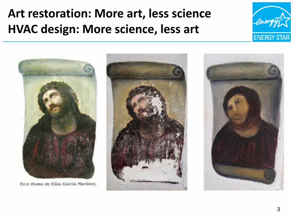
Art restoration: More art, less scienceHVAC design: More science, less art
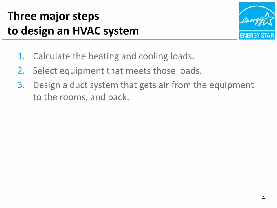
Three major steps to design an HVAC system
4
1. Calculate the heating and cooling loads.
2. Select equipment that meets those loads.
3. Design a duct system that gets air from the equipment to the rooms, and back.

Step 1: Calculate Heating & Cooling Loads
5

• Energy moves from more to less.
90°F - Outside
40°F
Coole
90°F
70°F - Outside
6
A cooler with ice
70°F
A cup of hot coffee
120°F
Step 1:Calculate heating & cooling loads
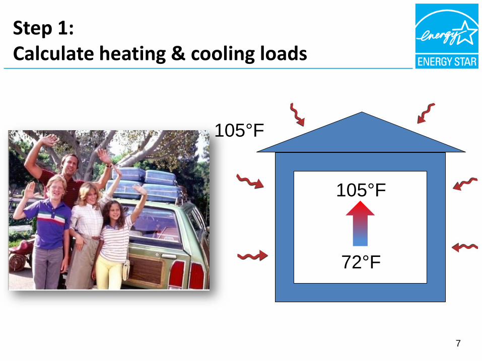
105°F
72°F
7
105°F
Step 1:Calculate heating & cooling loads

• Heat transfer can be quantified in British Thermal Units (Btu’s).
• 1 Btu is approximately equal to the energy in a single match.
8
Step 1:Calculate heating & cooling loads
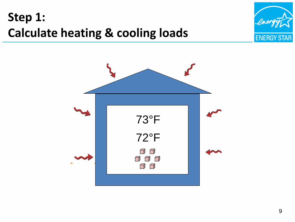
72°F
73°F
9
Step 1:Calculate heating & cooling loads
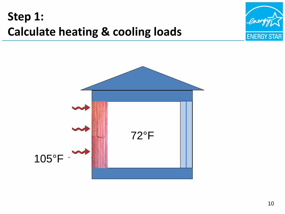
105°F
72°F
10
Step 1:Calculate heating & cooling loads

105°F
11
72°F
Air B
arr
ier
Step 1:Calculate heating & cooling loads

12
105°F
72°F
Step 1:Calculate heating & cooling loads

72°F
73°F
13
Step 1:Calculate heating & cooling loads

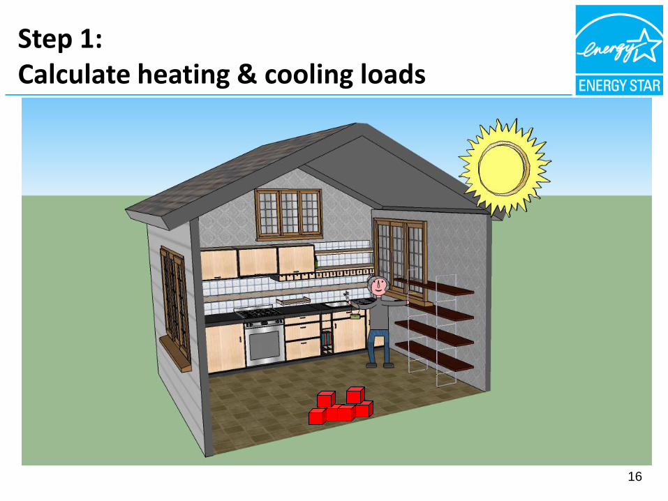
Step 1:Calculate heating & cooling loads
• Cooling load is the maximum Btu’s likely to be added to the home in a single hour during the year.
14
Step 1:Calculate heating & cooling loads
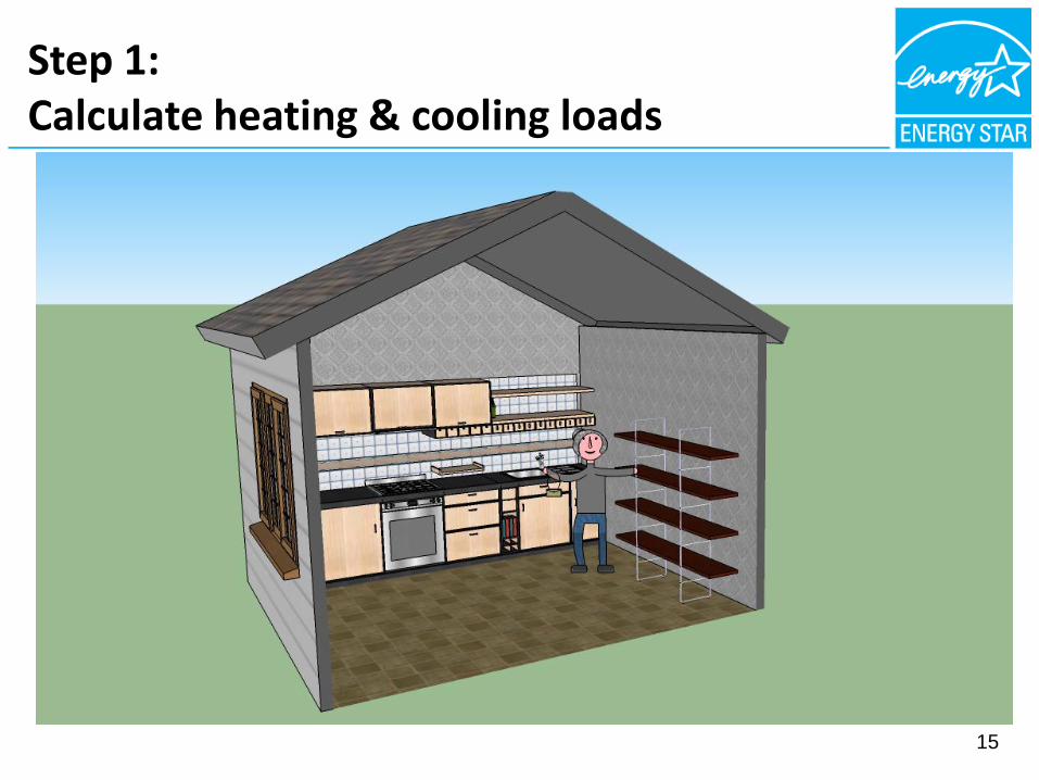
15
Step 1:Calculate heating & cooling loads
16

Step 1:Calculate heating & cooling loads
17

Step 1:Calculate heating & cooling loads
18

Step 1:Calculate heating & cooling loads
• Heating load is the maximum Btu’s likely to be lost from the home in a single hour during the year.
19

Step 1:Calculate heating & cooling loads
• ACCA Manual J is a standard process to calculate loads.
• It defines all variables that go into load calculations.
• It provides guidance on key inputs.
20
Summary of Step 1:Calculate heating & cooling loads
• The first major step in the design process is to calculate the heating and cooling loads.
• ACCA Manual J provides a reliable standard process for calculating loads.
21

Step 2: Select the
Heating & Cooling Equipment

Step 2: Select equipment that meets loads
• Cooling Load – Maximum Btu’s per hour added to the home.
• Cooling Capacity – Btu’s per hour that equipment can remove from the home.
23
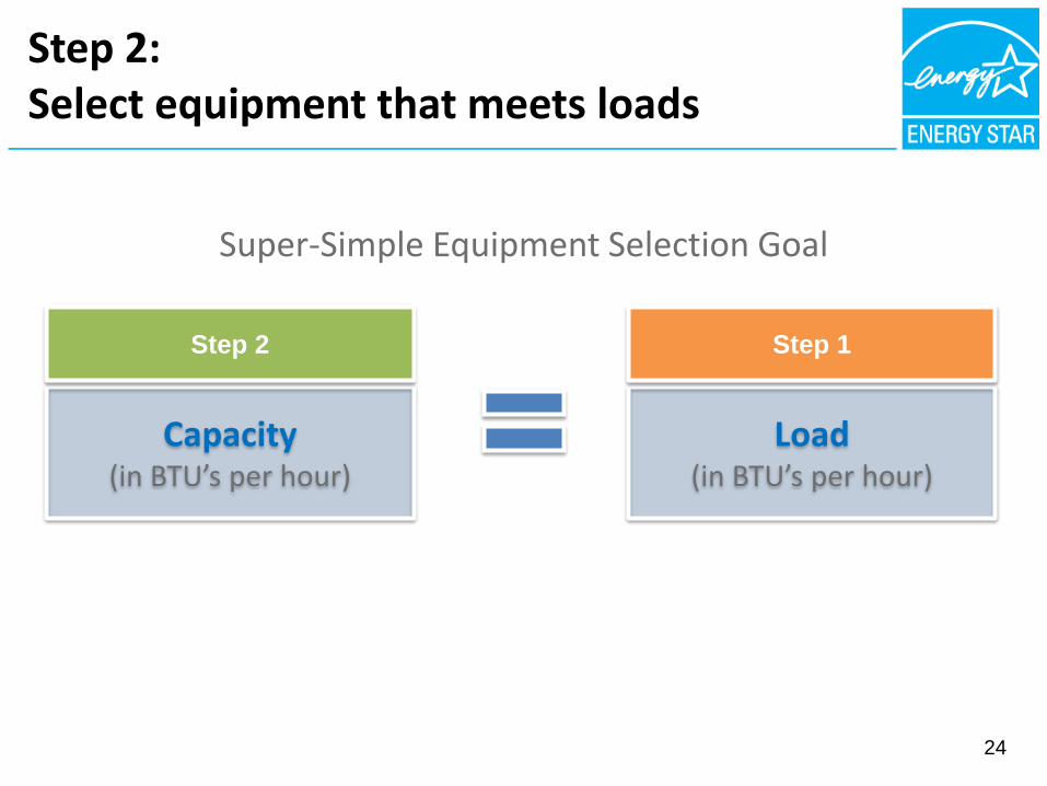
Step 2:Select equipment that meets loads
24
Super-Simple Equipment Selection Goal
Capacity(in BTU’s per hour)
Load(in BTU’s per hour)
Step 2 Step 1

Step 2: Select equipment that meets loads
25
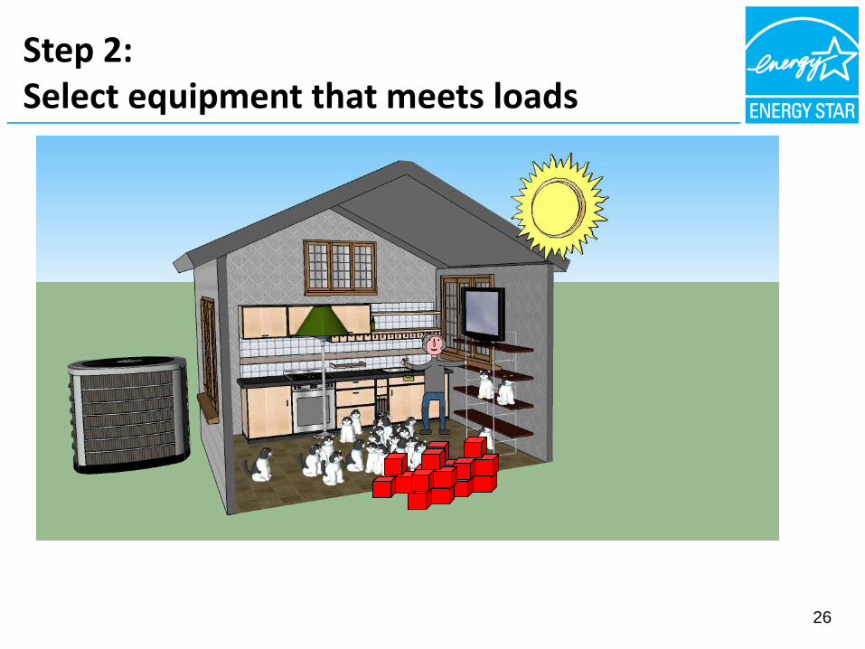
Step 2: Select equipment that meets loads
26
Step 2: Select equipment that meets loads
• Heating Load – Btu’s per hour lost from the home.
• Heating Capacity – Btu’s per hour that equipment can add to the home.
27
• Example: Selecting equipment that meets load is like buying a shirt that fits
Step 2: Select equipment that meets loads
28

Step 2: Select equipment that meets loads
• ACCA Manual S is a standard process to select equipment using the calculated loads.
29

Summary of Step 2: Select equipment that meets loads
• The second major step in the design process is to select equipment that equals the heating & cooling load.
• ACCA Manual S provides a reliable standard process for doing this and includes limitations on over-sizing.
30

Step 3: Design the Duct System
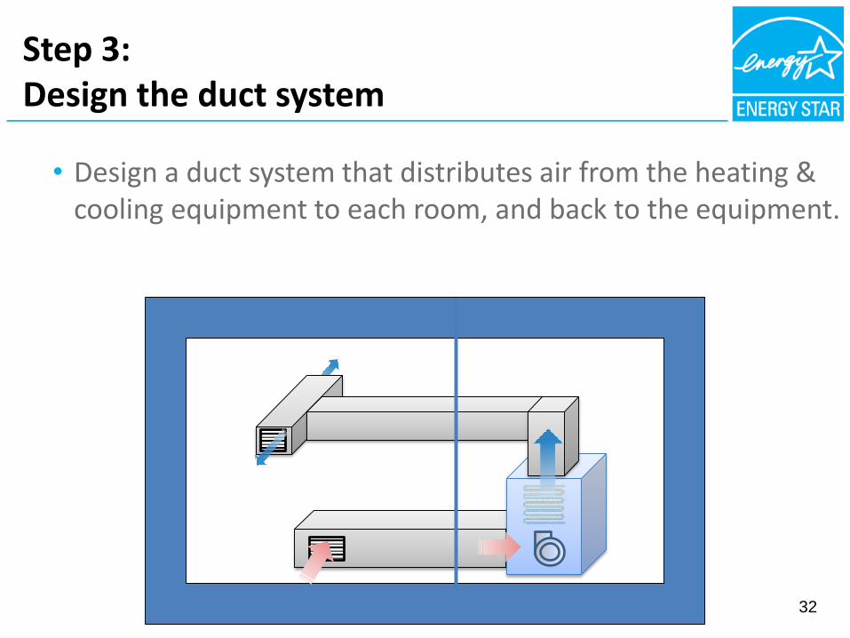
Step 3:Design the duct system
• Design a duct system that distributes air from the heating & cooling equipment to each room, and back to the equipment.
32
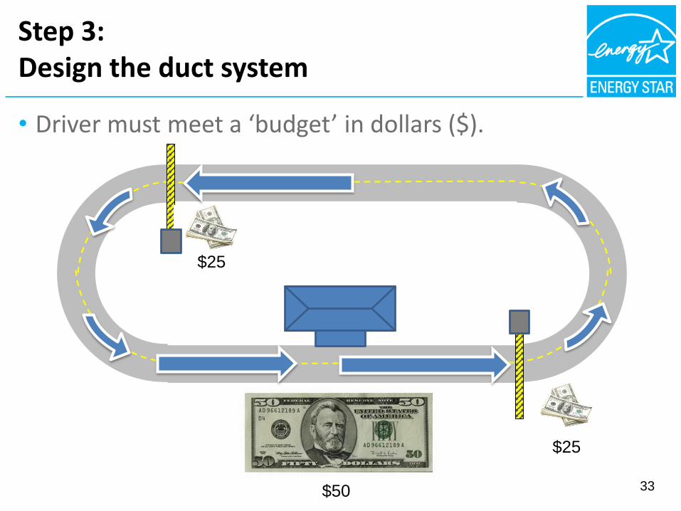
• Driver must meet a ‘budget’ in dollars ($).
Step 3:Design the duct system
33
$25
$25
$50
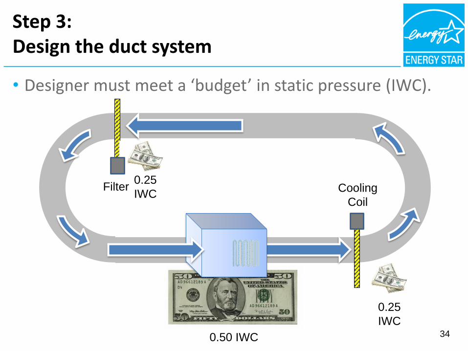
• Designer must meet a ‘budget’ in static pressure (IWC).
Step 3:Design the duct system
34
0.25
IWC
0.25
IWC
0.50 IWC
Cooling
Coil
Filter

Step 3:Design the duct system
35
Step 3:Design the duct system
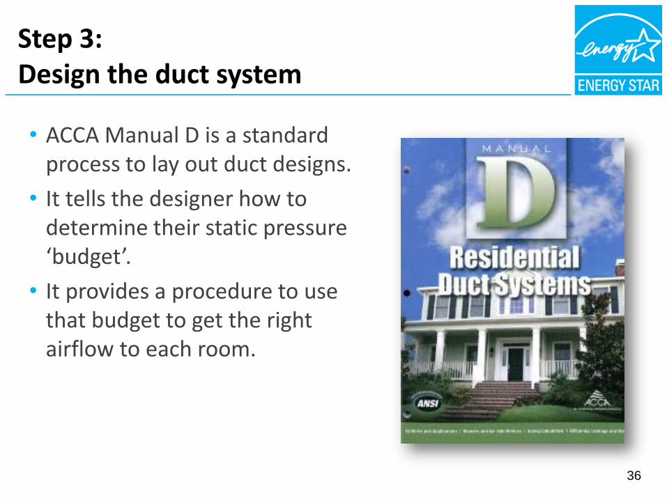
• ACCA Manual D is a standard process to lay out duct designs.
• It tells the designer how to determine their static pressure ‘budget’.
• It provides a procedure to use that budget to get the right airflow to each room.
36

Summary of Step 3:Design the duct system
• The third major step in the design process is to design a duct system that works with the selected equipment.
• ACCA Manual D provides a standard process for doing this. It ensures that the static pressure of the duct system is not too high.
37
Heating & cooling design summary
• The HVAC design process has three major steps:
– Step 1: Calculate the heating and cooling loads (Manual J).
– Step 2: Select equipment with capacity to meet those loads (Manual S).
– Step 3: Design a duct system that can get air from the equipment to the rooms and back (Manual D).
• The ENERGY STAR Certified Homes program requires this important design process to help maintain the efficiency, comfort, and quality of every certified home.
38
Heating & Cooling Commissioning
Three major steps to commission an HVAC system
40
1. Measure HVAC fan airflow.
2. Check refrigerant charge.
3. Ensure that system is balanced.
Step 1:
Measure HVAC Fan Airflow

42
• Loads have been calculated
• Equipment has been selected
• Duct system has been designed
• Equipment and ducts have been installed
• So why do we need to check the HVAC fan airflow?
Step 1:Measure HVAC fan airflow
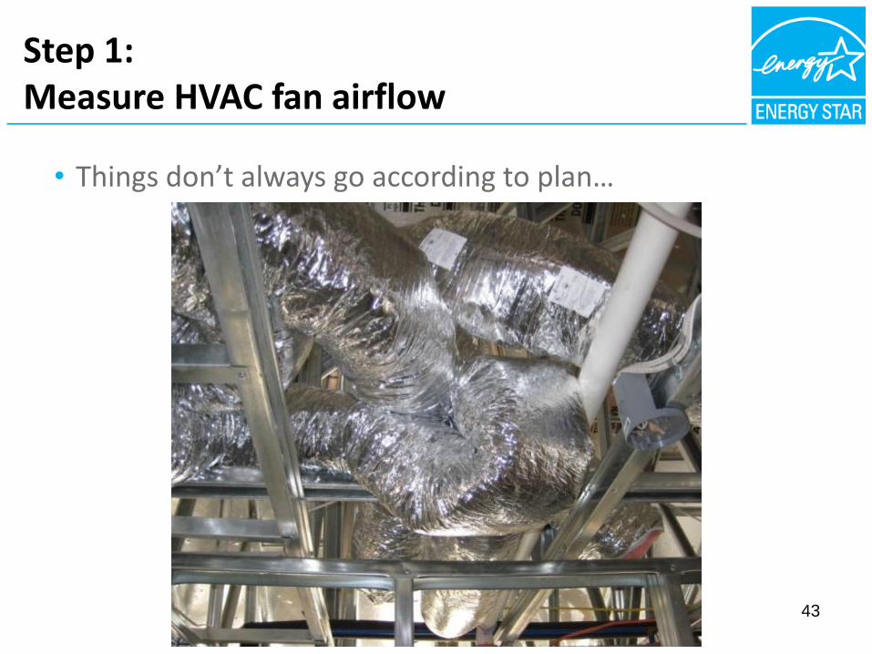
43
• Things don’t always go according to plan…
Step 1:Measure HVAC fan airflow
44
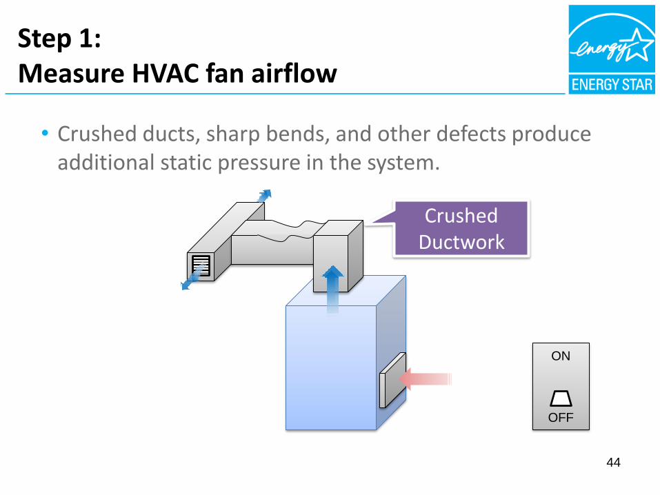
• Crushed ducts, sharp bends, and other defects produce additional static pressure in the system.
ON
OFF
Crushed Ductwork
Step 1:Measure HVAC fan airflow

• Visit www.energystar.gov/newhomeshvac
• Click on “Requirements & Resources for Contractors”
• Then click on “How to Measure HVAC Fan Airflow”
Step 1:Measure HVAC fan airflow
https://www.youtube.com/watch?v=Dbt-gZEACXg&list=PLMvJzVnMdhhvhOKDyE_mURr0_JPC277G4&index=3

46
• In <20 minutes, fan airflow can be determined by measuring the static pressure & checking the fan speed setting.
• This ensures the system is operating as designed, so that the equipment can heat and cool the home as designed.
Summary of Step 1:Measure HVAC fan airflow

47
Step 2:Check Refrigerant Charge

48
Warm indoor air is blown over a cold
refrigerant coil.
Outdoor air is blown over the hot
refrigerant coil.
The air’s heat is transferred to the
refrigerant.
The refrigerant’s heat is transferred to the outdoor air.
1
2 4
3
Inside the
House
Outside the
House
Step 2:Check refrigerant charge
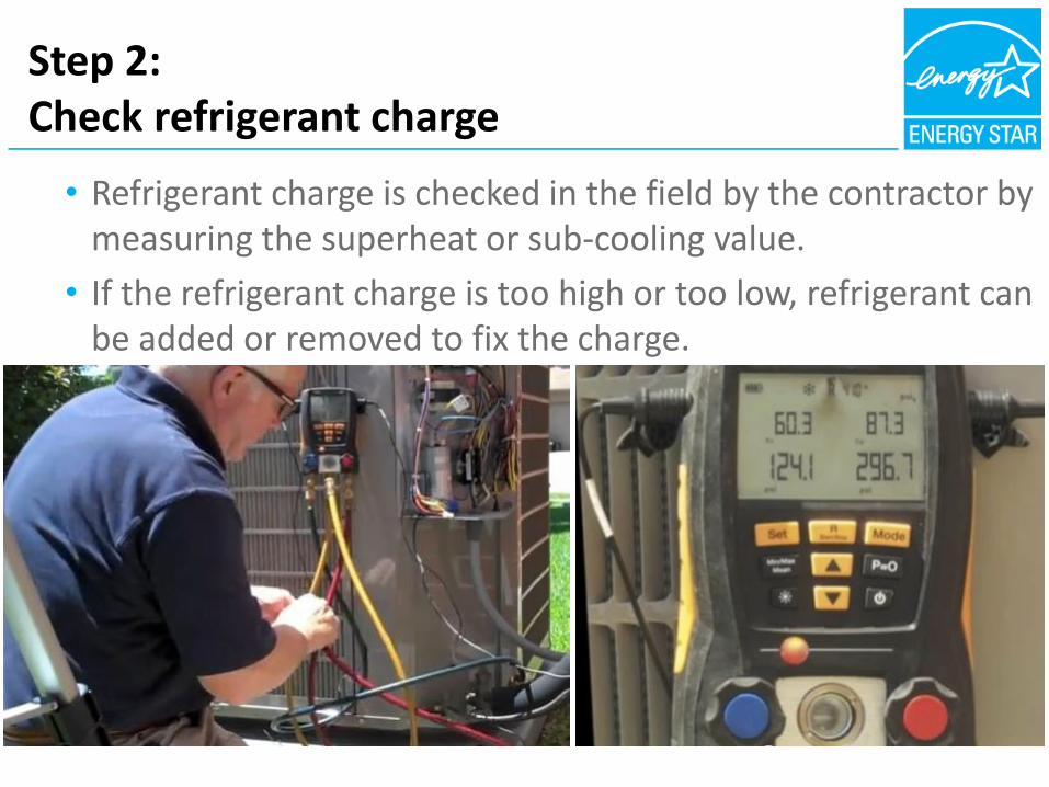
• Refrigerant charge is checked in the field by the contractor by measuring the superheat or sub-cooling value.
• If the refrigerant charge is too high or too low, refrigerant can be added or removed to fix the charge.
Step 2:Check refrigerant charge
Why is the amount of refrigerant so important to the operation of the A/C unit?
• Keep temperatures within target ranges.
Consequences of improper charging:
• Inefficient operation.
• Premature compressor failures.
50
Step 2:Check refrigerant charge

• Refrigerant is a vehicle to transfer heat.
• Too much or too little refrigerant can impact capacity, efficiency, and durability.
• Refrigerant charge can be tested by the contractor in <20 minutes to ensure that the right amount is in the system.
51
Summary of Step 2:Check refrigerant charge

Step 3:
Ensure System is Balanced
53
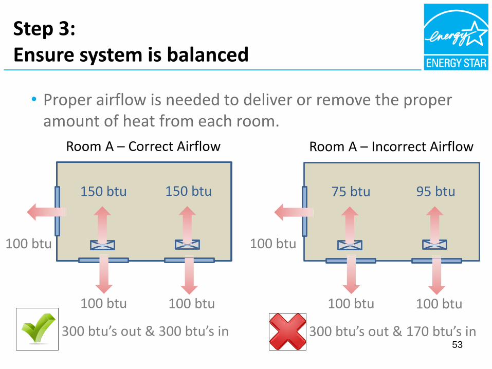
• Proper airflow is needed to deliver or remove the proper amount of heat from each room.
Room A – Correct Airflow
150 btu
100 btu
100 btu 100 btu
150 btu
300 btu’s out & 300 btu’s in
Room A – Incorrect Airflow
95 btu
100 btu
100 btu 100 btu
75 btu
300 btu’s out & 170 btu’s in
Step 3:Ensure system is balanced

• Unforeseen events that impact airflow relative to the design
54
Closed damper
Electrical wire
Step 3:Ensure system is balanced
55
• Air balancing ensures that the right btu’s are added to and removed from each room.
• Can find problems caused by work that occurs after the equipment installation and start-up process.
Summary of Step 3:Ensure system is balanced

Summary –Heating & Cooling Commissioning
56
• Step 1 - Measure HVAC fan airflow to ensure the proper amount of heated and cooled air is produced.
• Step 2 - Check refrigerant charge to ensure that the proper amount of heat is transferred from inside the house to the outside.
• Step 3 - Balance airflows at the registers to ensure proper amount of heat is delivered or removed from each room.

Interactive Quiz!

How HVAC Impacts
Your Business
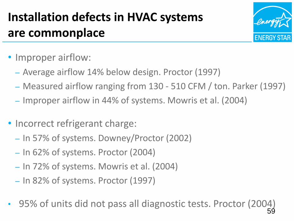
Installation defects in HVAC systems are commonplace
• Improper airflow:
– Average airflow 14% below design. Proctor (1997)
– Measured airflow ranging from 130 - 510 CFM / ton. Parker (1997)
– Improper airflow in 44% of systems. Mowris et al. (2004)
• Incorrect refrigerant charge:
– In 57% of systems. Downey/Proctor (2002)
– In 62% of systems. Proctor (2004)
– In 72% of systems. Mowris et al. (2004)
– In 82% of systems. Proctor (1997)
• 95% of units did not pass all diagnostic tests. Proctor (2004)59

60
• Lower first cost due to right-sized equipment.
• Reduced risk of comfort and warranty problems.
• Reputation is not left to chance.
For Builders

61
• Increased opportunity for services.
• Lowered risk of dissatisfied clients.
• Eventually, HERS points.
For Raters
62
• Potential for increased energy savings.
• Potential for increased demand savings.
• Better outcomes during evaluations.
For Utilities

ENERGY STAR Certified Homes
Web:Main: www.energystar.gov/newhomespartnersTechnical: www.energystar.gov/newhomesguidelinesTraining: www.energystar.gov/newhomestrainingHVAC: www.energystar.gov/newhomesHVAC
Email:[email protected]
Social Media:
@energystarhomes
facebook.com/energystar
Contacts:
Dean GambleUS EPATechnical Manager, ENERGY STAR Certified [email protected]
63