residential electrical inspector (cae) hvac lesson 11 ... · this presentation details the steps...
TRANSCRIPT
Residential Electrical Inspector (CAE)
HVAC
Lesson 11
Based on the 2014 OESC
Updated: January 2017
2 of 46

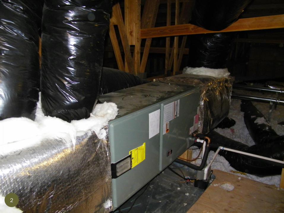
This presentation details the steps involved and the
code requirements for electrical inspection of HVAC
equipment.
After completion of this presentation, the inspector
should be capable of verifying that the HVAC
equipment was installed in line with the electrical
requirements of the Oregon Electrical Specialty Code
and National Electrical Code.
3 of 46

Introduction
Basic Information
4 of 46

C
B Disconnect
HVAC
Equip
Typical installation consists of an overcurrent device, wiring
to a local disconnect and wiring and conduit to the
equipment. The disconnect may contain fuses depending
upon manufacturers installation instructions.
5 of 46

C
B
Disconnect HVAC
Equip
Electrical items to inspect on an HVAC change-out.
1. Is overcurrent protection correct?
2. Is wire size from overcurrent device to disconnect correct?
3. Is the right disconnect installed?
4. Is the wiring method from disconnect to unit correct?
5. Is the wiring from disconnect to the unit correct?
1
2
3
6 of 46
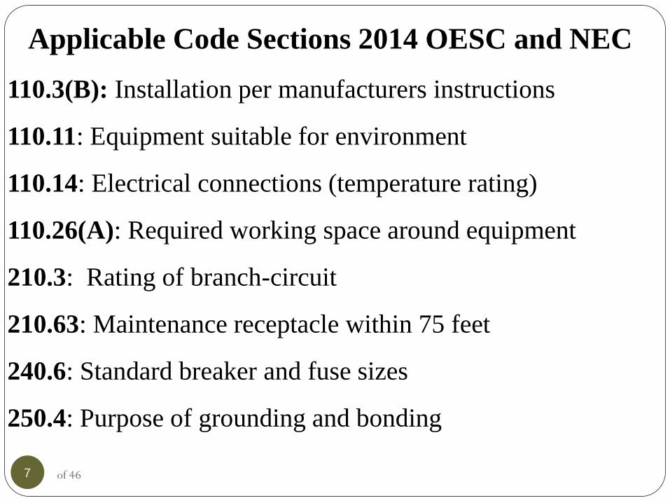
Applicable Code Sections 2014 OESC and NEC
110.3(B): Installation per manufacturers instructions
110.11: Equipment suitable for environment
110.14: Electrical connections (temperature rating)
110.26(A): Required working space around equipment
210.3: Rating of branch-circuit
210.63: Maintenance receptacle within 75 feet
240.6: Standard breaker and fuse sizes
250.4: Purpose of grounding and bonding
7 of 46
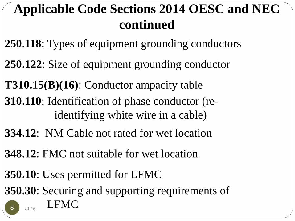
Applicable Code Sections 2014 OESC and NEC
continued
250.118: Types of equipment grounding conductors
250.122: Size of equipment grounding conductor
T310.15(B)(16): Conductor ampacity table
310.110: Identification of phase conductor (re-
identifying white wire in a cable)
334.12: NM Cable not rated for wet location
348.12: FMC not suitable for wet location
350.10: Uses permitted for LFMC
350.30: Securing and supporting requirements of
LFMC
8 of 46

Applicable Code Sections 2014 OESC and NEC
continued
356.10: Uses permitted for LFNC
356.30: Securing and supporting of LFNC
424.3(B) Heating circuits are considered to be
continuous requiring a 125% adder
440.6(A): Use nameplate information for install
440.14: Disconnect location (in sight of)
9 of 46
Caution:
One portion of an HVAC installation often misunderstood
deals with sizing of conductors and their overcurrent
protection. Generally Article 240 specifies that
conductors need to be protected to their ampacity. 240.3
modifies this requirement as it applies to HVAC
equipment. As long as the appropriate circuit breaker
(HACR) or fuse (one time) is used, the conductor may be
smaller than traditionally used for a specific overcurrent
device.
10 of 46

Definitions: NM Cable: Nonmetallic-Sheathed Cable. A factory
assembly of two or more insulated conductors enclosed
within an overall nonmetallic jacket.
11 of 46

Service-Entrance Cable A single conductor or multi-conductor assembly provided
with or without an overall covering, primarily used for
services, and of the following types:
Type SE. Service- entrance cable having a flame-retardant,
moisture-resistant covering.
Type USE. Service -entrance cable, identified for
underground use, having a moisture-resistant covering, but
not required to have a flame-retardant covering.
12 of 46

SE Cable is
generally marked
with the number of
and size of
conductors
13 of 46
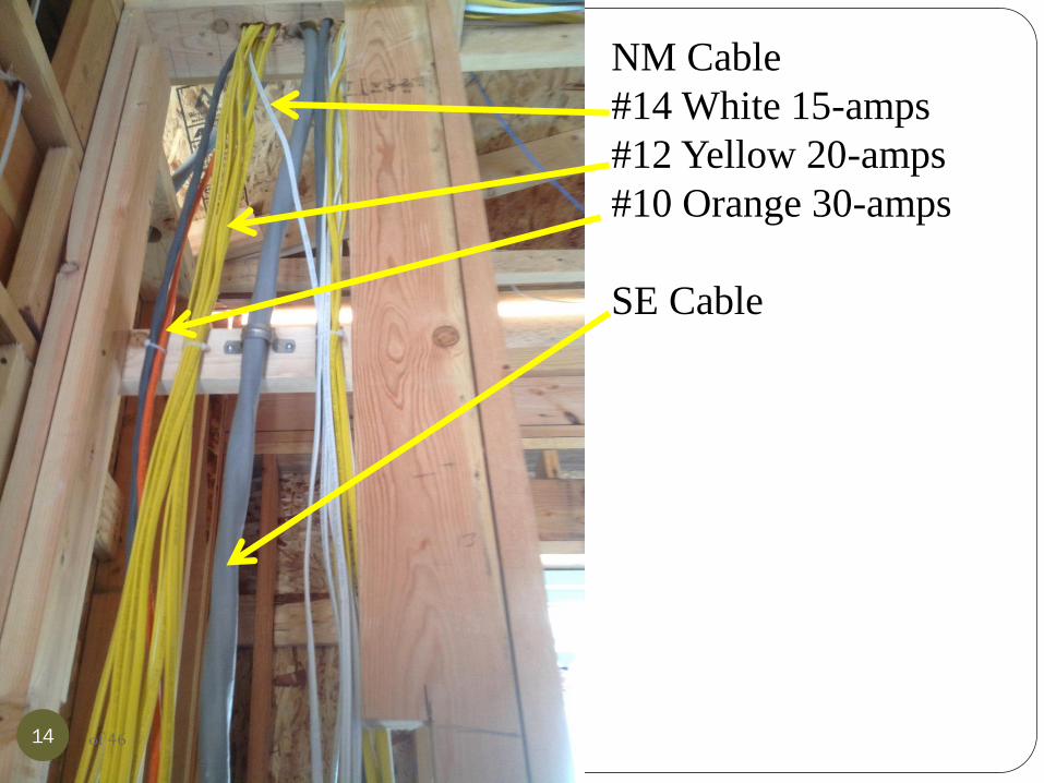
NM Cable
#14 White 15-amps
#12 Yellow 20-amps
#10 Orange 30-amps
SE Cable
14 of 46
Step 1
Determine Installation
Requirements
15 of 46
In order to start the electrical portion of the inspection, basic
information is required. The minimum ampacity of the
circuit is needed, the type of and size of overcurrent
protection is needed (fuses and/or circuit breaker)? What are
the environmental conditions, (wet location, corrosion, dust,
etc.)? Are the wiring methods approved for the environment,
(conductors, raceway type, securing/supporting etc.)? Is a
fused disconnect required?
16 of 46

Look for
maximum size
overcurrent
protection and
minimum
ampacity of the
circuit. Get the
information
from the
nameplate
17 of 46

Verify that the
HVAC products
are certified and
installed
according to
nameplate
information and
information
instructions
18 of 46
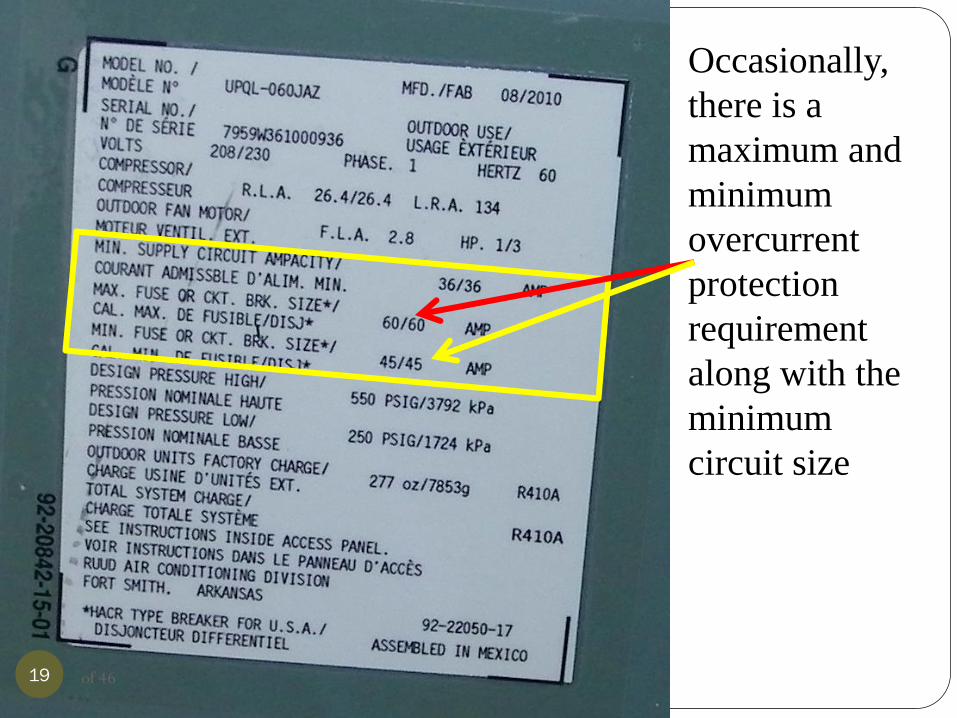
Occasionally,
there is a
maximum and
minimum
overcurrent
protection
requirement
along with the
minimum
circuit size
19 of 46
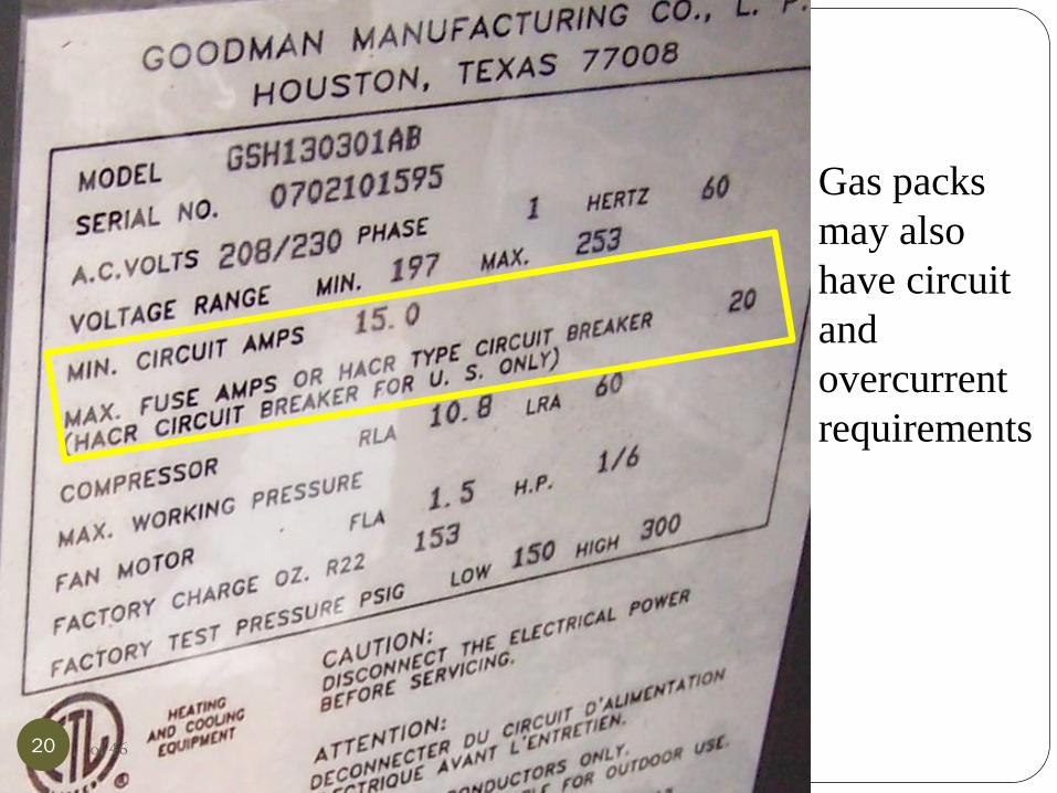
Gas packs
may also
have circuit
and
overcurrent
requirements
20 of 46
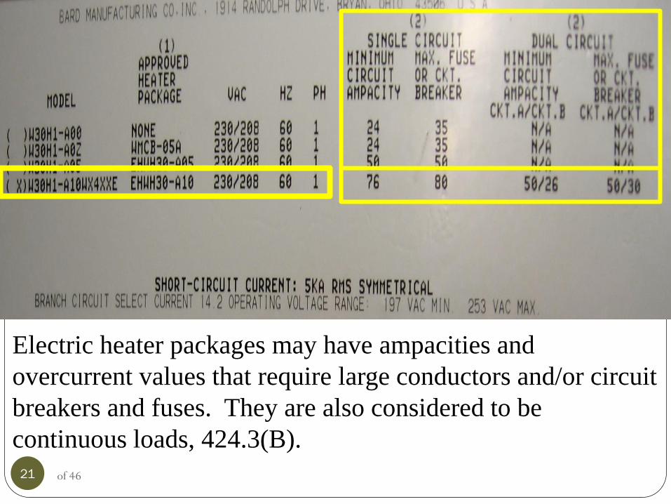
Electric heater packages may have ampacities and
overcurrent values that require large conductors and/or circuit
breakers and fuses. They are also considered to be
continuous loads, 424.3(B).
21 of 46
Step 2
Verify that ampacity of the conductors
and overcurrent protection meet the
nameplate information
22 of 46

When looking at conductors, environmental conditions may
come into play. Heat is the biggest issue associated with
conductors. As heat increases, the ability of a conductor to
carry a specific load (amps) drops. The ampacity table found
at T310.15(B)(16) is based upon an ambient temperature of
86F. If the conductors are installed on the side of the
structure facing the sun, the temperature can increase beyond
the 86F range. Also, the lugs that the conductors are landed
on may only be rated for 60C. A location outside is
considered to be a wet location. NM Cable (Romex) is not
approved for this application.
23 of 46

The conductors that run from the disconnect to the unit
should have a marking along the side of the conductor. The
marking identifies the insulation (outer jacket) of the
conductor and identifies what type of environment the
conductor is rated for. The marking should be THWN-2 or
equivalent. The “W” designator indicates the conductor is
rated for wet locations and the “-2” indicates a starting
temperature rating of 90C.
24 of 46

25 of 46
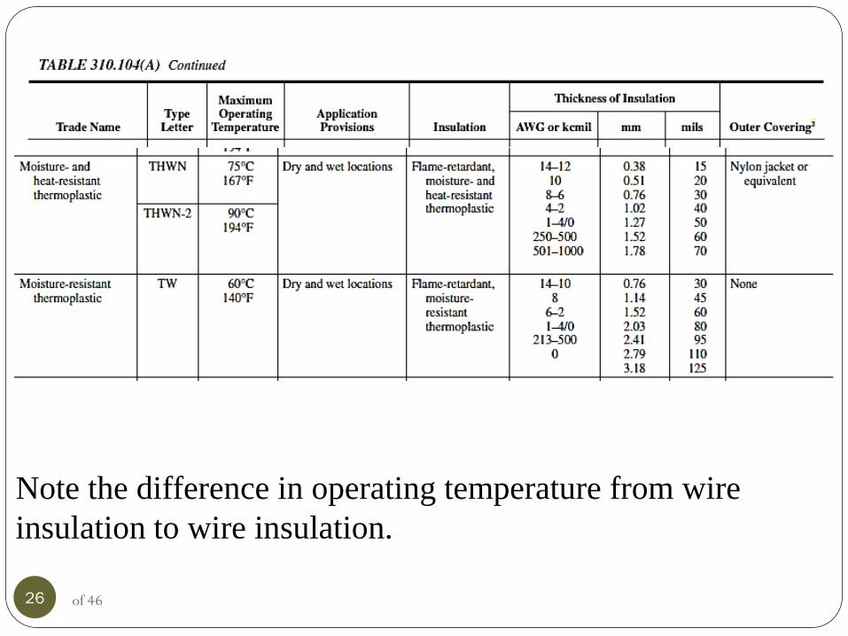
Note the difference in operating temperature from wire
insulation to wire insulation.
26 of 46

An HVAC unit indicates a minimum circuit ampacity and OC
of 35-amps, if NM Cable is used, a #8 conductor is required
from the panel to the disconnect and a #10 THWN-2 could be
used from the disconnect to the equipment. 27 of 46

NM Cable is always rated upon the ampacities found in the
60C column of Table 310.15(B)(16). If SE Cable is used to
supply a heating unit and the SE Cable is installed in
insulation, then the SE Cable ampacity is also based upon the
60C column. Ampacities of free conductors in a raceway are
based upon the insulation rating and the termination ratings
of the lugs. If the lugs have no markings or the disconnect or
equipment is not marked, then the 60C column is used for the
ampacity.
28 of 46
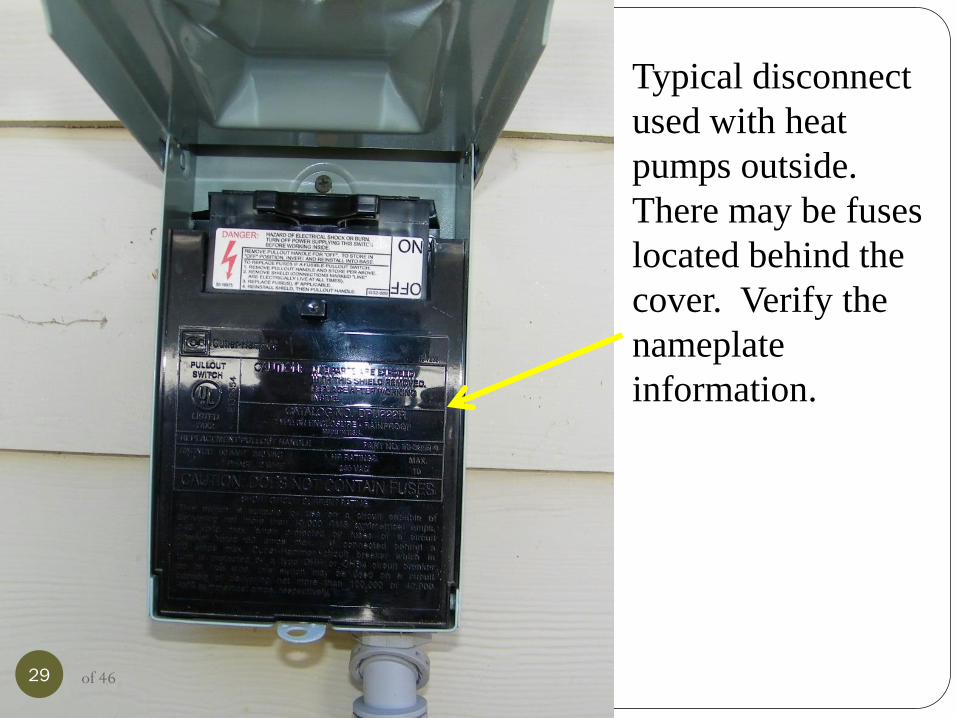
Typical disconnect
used with heat
pumps outside.
There may be fuses
located behind the
cover. Verify the
nameplate
information.
29 of 46
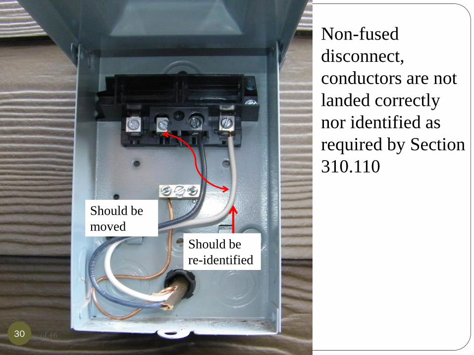
Non-fused
disconnect,
conductors are not
landed correctly
nor identified as
required by Section
310.110
Should be
moved
Should be
re-identified
30 of 46
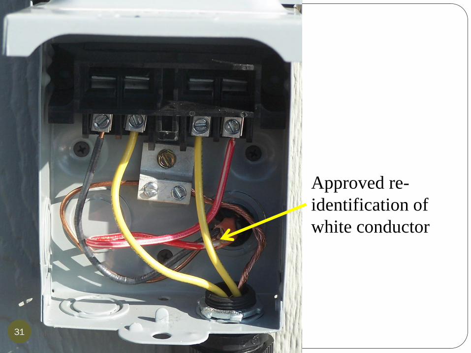
Approved re-
identification of
white conductor
31 of 46
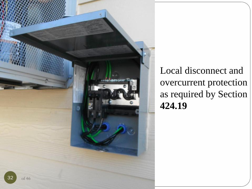
Local disconnect and
overcurrent protection
as required by Section
424.19
32 of 46

Fused disconnect,
white conductor needs
re-identified.
Note lack of
grounding.
33 of 46
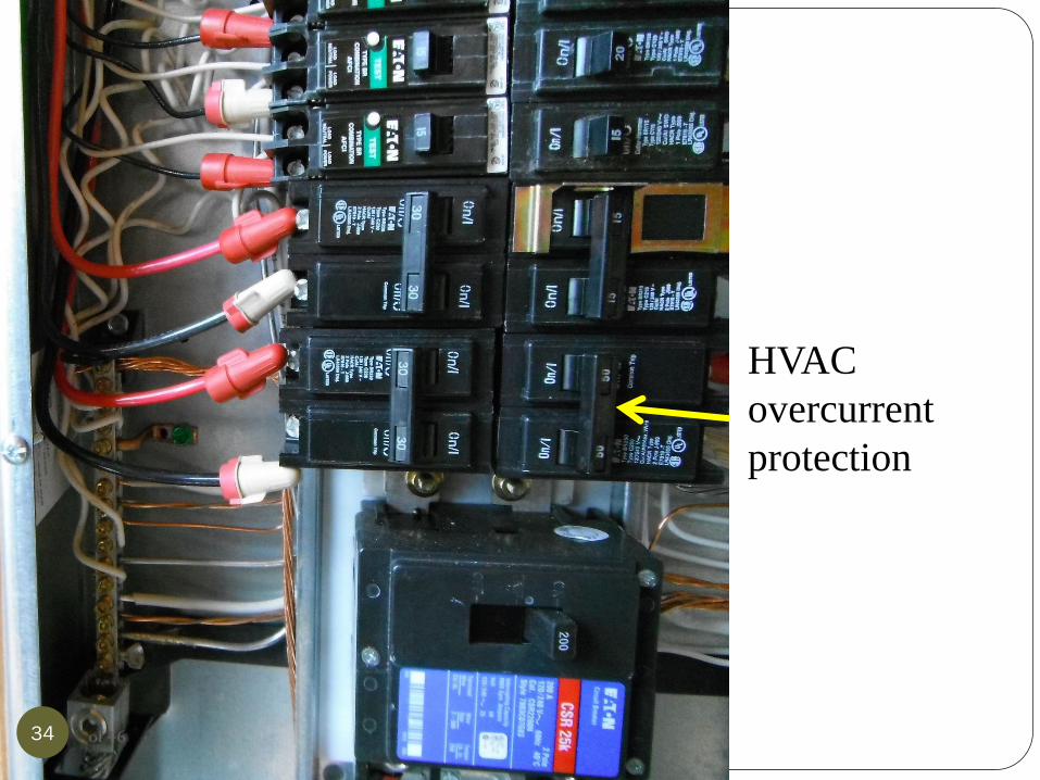
HVAC
overcurrent
protection
34 of 46
Step 3
Wiring Methods
35 of 46

Typical installation;
individual conductors
rated for a wet
location are installed
in liquid-tight
flexible non-metallic
conduit. (LFNC),
Article 356. Check
for proper securing
and supporting, tight
connections and
proper sizing.
36 of 46

Disconnects are
required to be in sight
of a heat pump (Section
440.14) and lockable.
The gate blocks the
view of the disconnect.
In sight of means:
visible and within 50
feet.
37 of 46
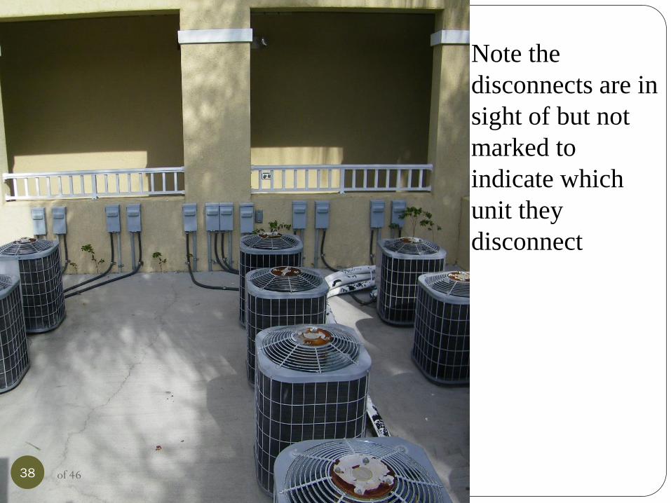
Note the
disconnects are in
sight of but not
marked to
indicate which
unit they
disconnect
38 of 46
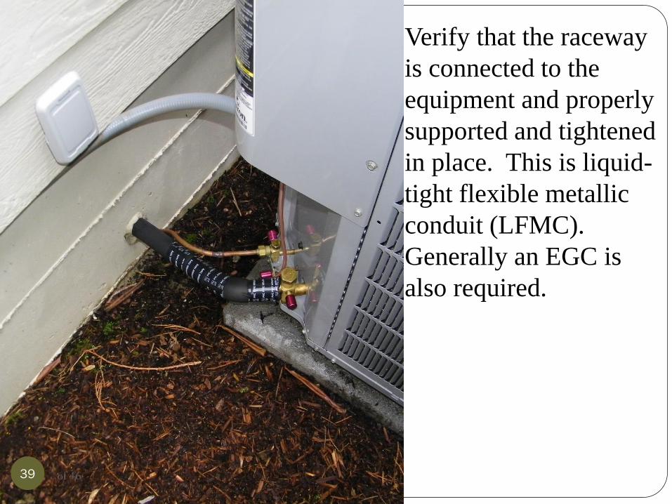
Verify that the raceway
is connected to the
equipment and properly
supported and tightened
in place. This is liquid-
tight flexible metallic
conduit (LFMC).
Generally an EGC is
also required.
39 of 46
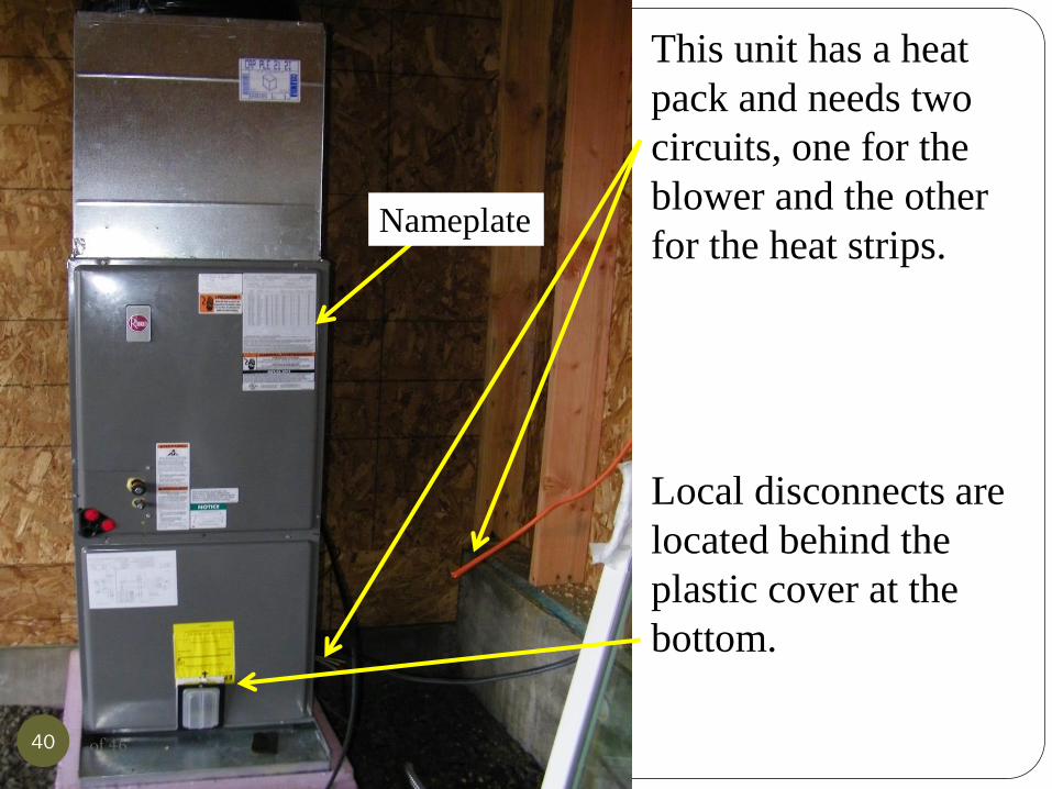
This unit has a heat
pack and needs two
circuits, one for the
blower and the other
for the heat strips.
Local disconnects are
located behind the
plastic cover at the
bottom.
Nameplate
40 of 46

Same situation
as the previous
slide but the unit
is laid on it’s
side.
41 of 46

NM Cable used outdoors
in a wet location. This is
a violation of Section
334.10 and 334.12
42 of 46

FMC and
metal box
are
required to
be
grounded
43 of 46

Copper SE cable used for
a temporary connection to
a heat pack
44 of 46

#10 NM Cable in the
wall, THWN-2 is used
outside in the
raceway. Note the
EGC’s and bonding to
the enclosure.
45 of 46
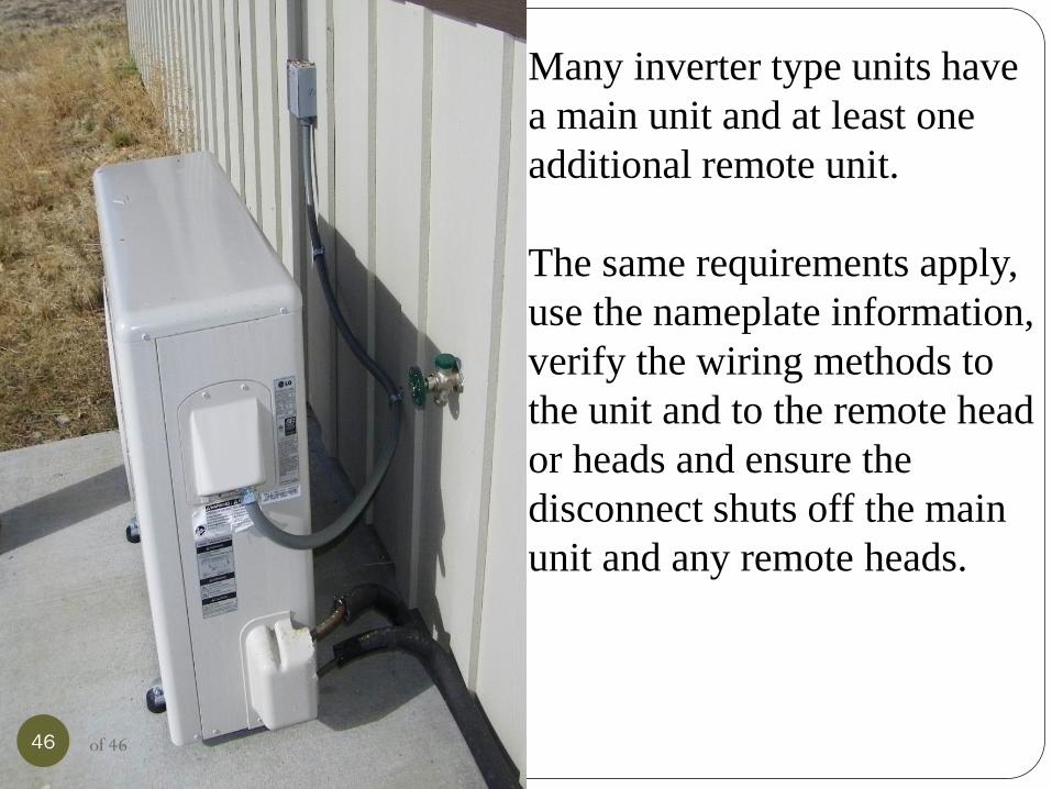
Many inverter type units have
a main unit and at least one
additional remote unit.
The same requirements apply,
use the nameplate information,
verify the wiring methods to
the unit and to the remote head
or heads and ensure the
disconnect shuts off the main
unit and any remote heads.
46 of 46