debris-flow runout distance: laboratory experiments on the ... · debris-flow runout distance:...
TRANSCRIPT
Debris-flow runout distance: laboratory experiments on the role of Bagnold, Savage and friction numbers
F. Bettella1, T. Bisantino2, V. D’Agostino1 & F. Gentile2 1Department of Land and Agro-Forest Environments, University of Padova, Italy 2Department of Agro-Environmental and Territorial Sciences, University of Bari, Italy
Abstract
An experimental apparatus, consisting of a tilting flume and a final horizontal plane, has been used to investigate the depositional features of debris materials collected from the Pulsano watershed (Southern-Italy). Experiments have been carried out to study the flow behaviour of mixtures at sediment concentrations 0.4≤Cv≤0.6 and maximum grain size of the particles 4mm≤d≤19mm. The flow behavior is described on the basis of the evolution of the front position in the channel and of the runout distance, lateral spreading and flow depth in the horizontal plane. An attempt is made to rate the experimental flows according to the classification of flow regimes based on threshold values of dimensionless Bagnold, Savage and Friction numbers. As a conclusion the experimental results highlight a threshold behaviour of debris-flow mixtures in the runout phase. This results from a particular combination of maximum grain diameters in play and a volumetric concentration limit. When approaching such combination the shape and the maximum length of the deposit change drastically if compared to those of the inertia-dominated regime. Keywords: debris flow, small scale experiments, flow regime.
1 Introduction
The estimation of the spreading of debris-flows on alluvial fans has a major role in assessing debris-flow hazards. Laboratory tests on small-scale models are a
Monitoring, Simulation, Prevention and Remediation of Dense and Debris Flows IV 27
www.witpress.com, ISSN 1743-3533 (on-line) WIT Transactions on Engineering Sciences, Vol 73, © 201 WIT Press2
doi:10.2495/DEB120031
suitable approach for studying debris-flow deposition under controlled conditions if proper scale-independent variables are accounted for the analysis (D’Agostino et al. [1]). The inertial grain-flow and viscoplastic models have been widely used as tools for description and interpretation of debris-flow deposits. In very concentrated granular flows the formation of very dissipative medium particles modifies the flow behavior: the main interactions between particles are collisions and the fluid phase has a minor role in the generation of stresses. The frictional behavior is exhibited at very low shear rates so stony debris flows or rock falls belong to the frictional-collisional regime according to Ancey and Evesque [2]. Debris-flow deposition results from grain-contact friction and bed friction concentrated along the flow margins. The frictional resistance can occur in relatively homogeneous debris flows, but is enhanced if margins are composed predominantly of coarse clasts (Major and Iverson [3]). Solid friction is one of the mechanisms of shear resistance and momentum transport in debris-flow matrix. Liquid viscosity, viscoplastic or viscous creep, particle collisions, effect of inertial grain-flow, influence the debris-flow features and are subject to variations during the motion. Using an inclined plane and a novel imaging system (Cochard and Ancey [4]) tested viscoplastic fluids at concentrations Cv≤0.4. The flow behavior of the different mixtures was the following: the inertia-dominated regime at the beginning is followed by a near-equilibrium regime in which the balance between gravitational and viscous forces dominates the flow. Different dimensionless parameters can be used to assess the momentum-transport processes and distinguish flow regimes in debris flows (Iverson and LaHusen [5], Iverson [6] and Coussot and Ancey [7]). Three of these dimensionless numbers represent the ratios of the main sources of flow resistance (frictional, collisional and viscous forces): the Bagnold, Savage and friction numbers. In this paper experiments with an inclined channel and a final horizontal plane - able to reproduce the fan formation of natural mixtures of particles and fluid - are discussed. Debris flow with different sediment concentrations (Cv=0.4; 0.5, and 0.6) and a given maximum grain size of the particles (dmax= 4; 5.6; 9.5, and 19 mm) are generated. The flow behaviour is then described on the basis: of the evolution of the front position along the channel; of the runout distance, lateral spreading and flow depth in the horizontal plane. An attempt is made to classify the experimental flows according to flow regimes described by threshold values of dimensionless Bagnold, Savage and friction numbers.
2 Material and methods
2.1 Experimental setup
The experimental apparatus used for the analysis of the debris-flow deposition is a rheometer (fig. 1; tab.1) consisting of a fixed horizontal plane (1.5m x 1m) and a tilting plane (2m x 1m) with an inclination (α) between 0° and 38° where a
28 Monitoring, Simulation, Prevention and Remediation of Dense and Debris Flows IV
www.witpress.com, ISSN 1743-3533 (on-line) WIT Transactions on Engineering Sciences, Vol 73, © 201 WIT Press2
rectangular 0.15m x 0.33m section flume is installed. Both the horizontal plane and the flume are covered with a surface with element in relief in order to reproduce the roughness of natural depositional areas.
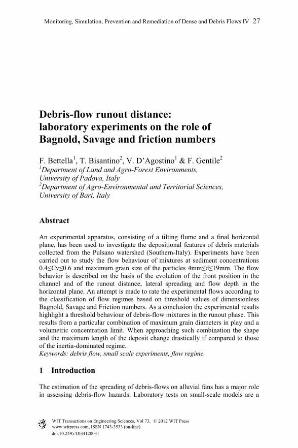
Table 1: Photocells positions along the flume for the measure of the front velocity (the Start photocell turns on the timer).
Photocells Distance (m) Spacing (m) Start 0.325 -
1 0.650 0.325 2 0.950 0.300 3 1.250 0.300 4 1.500 0.250 5 1.700 0.200 6 1.900 0.200
Figure 1: View of the experimental apparatus during a test with debris-flow material.
On the horizontal plane a square grid (0.05 x 0.05m) is painted for the analysis of the shape and geometry of the deposits. At the flume head a steel tank having a square base (0.15x0.15m) and height h = 0.33m is mounted. The tank has a removable gate which is used to operate the immediate release of the debris mixture (dam break). Testing is done by stirring the mixture in the tank to avoid sedimentation, tilting the flume channel to the desired slope and removing the gate to allow a rapid release of the mixture. Surface velocity profiles in the channel are obtained thanks to 6 photocells (Table 1 and Figure 1). Runout distance, lateral spreading and flow depth are also measured on the horizontal plane.
Monitoring, Simulation, Prevention and Remediation of Dense and Debris Flows IV 29
www.witpress.com, ISSN 1743-3533 (on-line) WIT Transactions on Engineering Sciences, Vol 73, © 201 WIT Press2
2.2 Experimental data
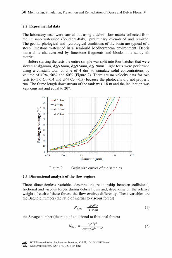
The laboratory tests were carried out using a debris-flow matrix collected from the Pulsano watershed (Southern-Italy), preliminary oven-dried and remixed. The geomorphological and hydrological conditions of the basin are typical of a steep limestone watershed in a semi-arid Mediterranean environment. Debris material is characterized by limestone fragments and blocks in a sandy-silt matrix. Before starting the tests the entire sample was split into four batches that were sieved at d 4mm, d 5.6mm, d 9.5mm, d 19mm. Eight tests were performed using a constant total volume of 4 dm3 to simulate solid concentrations by volume of 40%, 50% and 60% (Figure 2). There are no velocity data for two tests (d<5.6 CV=0.4 and d<4 CV =0.5) because the photocells did not properly run. The flume length downstream of the tank was 1.8 m and the inclination was kept constant and equal to 20°.
Figure 2: Grain size curves of the samples.
2.3 Dimensional analysis of the flow regime
Three dimensionless variables describe the relationship between collisional, frictional and viscous forces during debris flows and, depending on the relative weight of each of these forces, the flow evolves differently. These variables are the Bagnold number (the ratio of inertial to viscous forces)
(1)
the Savage number (the ratio of collisional to frictional forces)
(2)
30 Monitoring, Simulation, Prevention and Remediation of Dense and Debris Flows IV
www.witpress.com, ISSN 1743-3533 (on-line) WIT Transactions on Engineering Sciences, Vol 73, © 201 WIT Press2
and the friction number (the ratio of frictional to viscous forces)
(3)
where is the shear rate, s the clast density, f the interstitial fluid density, the mean grain size, vs the solid volume fraction, the viscosity of the interstitial fluid, h the flow depth, the angle of internal friction and g the gravitational acceleration. On the basis of the experiments carried out by different Authors, collisional forces dominate over viscous forces when NBAG>200, collisional forces dominate over frictional forces if NSAV>0.1, and frictional forces dominate over viscous forces for Nf>2000 (Bagnold [8], Savage and Hutter [9], Iverson [10]). Following Iverson [10], the interstitial fluid density was estimated assuming that the entire mass of silt and clay contributed to the interstitial fluid.
3 Results and discussion
3.1 Flow regime in the channel
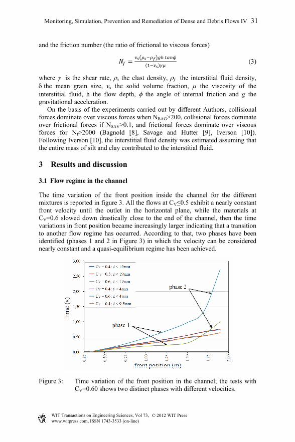
The time variation of the front position inside the channel for the different mixtures is reported in figure 3. All the flows at CV≤0.5 exhibit a nearly constant front velocity until the outlet in the horizontal plane, while the materials at CV=0.6 slowed down drastically close to the end of the channel, then the time variations in front position became increasingly larger indicating that a transition to another flow regime has occurred. According to that, two phases have been identified (phases 1 and 2 in Figure 3) in which the velocity can be considered nearly constant and a quasi-equilibrium regime has been achieved.
Figure 3: Time variation of the front position in the channel; the tests with CV=0.60 shows two distinct phases with different velocities.
Monitoring, Simulation, Prevention and Remediation of Dense and Debris Flows IV 31
www.witpress.com, ISSN 1743-3533 (on-line) WIT Transactions on Engineering Sciences, Vol 73, © 201 WIT Press2
Bagnold, Savage and friction numbers have been calculated assuming the characteristic diameter equal to D90 and considering the average front velocities in the two phases (V1 and V2) and the shear rates and (calculated as ratio of average front velocity to flow thickness) of the mixtures in each phase. The viscosity of the interstitial fluid is very sensitive to the changes in the volume fraction of silt and clay and can vary by one order of magnitude at any particular volume fraction. In this work the Einstein formula [11] to calculate the viscosity of the interstitial fluid was adopted:
1 ′ (4)
where φ is the fine fraction (clay-silt; d<0.02 mm) and the constant B’ is the intrinsic viscosity (Einstein coefficient). In table 2 the physical and dynamic characteristics of the mixtures are reported.
Table 2: Experimental dataset and physical and dynamic characteristics of the mixtures.
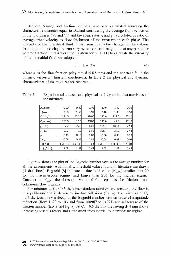
Figure 4 shows the plot of the Bagnold number versus the Savage number for all the experiments. Additionally, threshold values found in literature are drawn (dashed lines). Bagnold [8] indicates a threshold value (NBAG) smaller than 20 for the macroviscous regime and larger than 200 for the inertial regime. Considering NSAV, the threshold value of 0.1 separates the frictional and collisional flow regimes. For mixtures at CV ≤0.5 the dimensionless numbers are constant, the flow is in equilibrium and is driven by inertial collisions (fig. 4). For mixtures at CV =0.6 the tests show a decay of the Bagnold number with an order of magnitude reduction (from 1623 to 183 and from 100987 to 14771) and a increase of the friction number (tab. 3 and fig. 5). At CV =0.6 the mixture having d<4 mm shows increasing viscous forces and a transition from inertial to intermediate regime.
D90 (cm) 0.30 0.30 1.40 1.40 1.40 0.70
h (cm) 3.90 1.60 3.90 2.10 1.80 3.50
V1(cm/s) 264.0 124.0 250.0 222.0 335.0 271.0
V2 (cm/s) 264.0 14.0 250.0 222.0 49.0 271.0
1 (1/s) 67.7 77.5 64.1 105.7 186.1 77.4
2 (1/s) 67.7 8.8 64.1 105.7 27.2 77.4
0.15 0.15 0.08 0.08 0.08 0.10
Cvfine 0.06 0.09 0.03 0.04 0.05 0.04
(Pa s) 1.2E‐03 1.4E‐03 1.1E‐03 1.2E‐03 1.2E‐03 1.2E‐03
s (g/cm3) 1.45 1.45 1.45 1.45 1.45 1.45
32 Monitoring, Simulation, Prevention and Remediation of Dense and Debris Flows IV
www.witpress.com, ISSN 1743-3533 (on-line) WIT Transactions on Engineering Sciences, Vol 73, © 201 WIT Press2
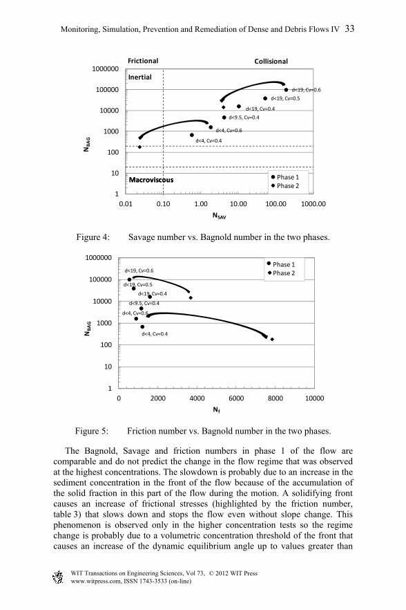
Figure 4: Savage number vs. Bagnold number in the two phases.
Figure 5: Friction number vs. Bagnold number in the two phases.
The Bagnold, Savage and friction numbers in phase 1 of the flow are comparable and do not predict the change in the flow regime that was observed at the highest concentrations. The slowdown is probably due to an increase in the sediment concentration in the front of the flow because of the accumulation of the solid fraction in this part of the flow during the motion. A solidifying front causes an increase of frictional stresses (highlighted by the friction number, table 3) that slows down and stops the flow even without slope change. This phenomenon is observed only in the higher concentration tests so the regime change is probably due to a volumetric concentration threshold of the front that causes an increase of the dynamic equilibrium angle up to values greater than
d<4, Cv=0.4
d<4, Cv=0.6
d<19, Cv=0.4
d<19, Cv=0.5
d<19, Cv=0.6
d<9.5, Cv=0.4
1
10
100
1000
10000
100000
1000000
0.01 0.10 1.00 10.00 100.00 1000.00
NBAG
NSAV
MacroviscousMacroviscous
Frictional Collisional
Inertial
Phase 1Phase 2
d<4, Cv=0.4
d<4, Cv=0.6
d<19, Cv=0.4
d<19, Cv=0.5
d<19, Cv=0.6
d<9.5, Cv=0.4
1
10
100
1000
10000
100000
1000000
0 2000 4000 6000 8000 10000
NBAG
Nf
Phase 1Phase 2
Monitoring, Simulation, Prevention and Remediation of Dense and Debris Flows IV 33
www.witpress.com, ISSN 1743-3533 (on-line) WIT Transactions on Engineering Sciences, Vol 73, © 201 WIT Press2
20°. At the lower CV the flow in the channel remains in equilibrium because the liquid phase inhibits the solid plug formation and the regime change is not observed. In these cases only the slope change can stop the flow and the change of regime is observed only in the horizontal plane.
3.2 Depositional features
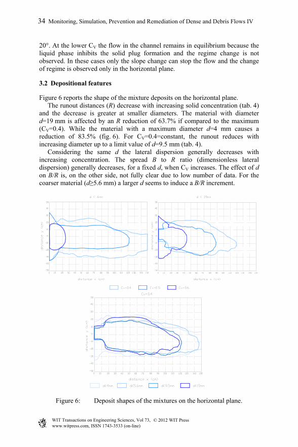
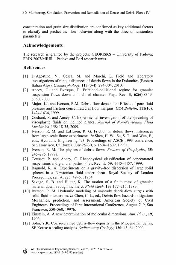
Figure 6 reports the shape of the mixture deposits on the horizontal plane. The runout distances (R) decrease with increasing solid concentration (tab. 4) and the decrease is greater at smaller diameters. The material with diameter d=19 mm is affected by an R reduction of 63.7% if compared to the maximum (CV=0.4). While the material with a maximum diameter d=4 mm causes a reduction of 83.5% (fig. 6). For CV=0.4=constant, the runout reduces with increasing diameter up to a limit value of d=9.5 mm (tab. 4). Considering the same d the lateral dispersion generally decreases with increasing concentration. The spread B to R ratio (dimensionless lateral dispersion) generally decreases, for a fixed d, when CV increases. The effect of d on B/R is, on the other side, not fully clear due to low number of data. For the coarser material (d≥5.6 mm) a larger d seems to induce a B/R increment.
Figure 6: Deposit shapes of the mixtures on the horizontal plane.
34 Monitoring, Simulation, Prevention and Remediation of Dense and Debris Flows IV
www.witpress.com, ISSN 1743-3533 (on-line) WIT Transactions on Engineering Sciences, Vol 73, © 201 WIT Press2
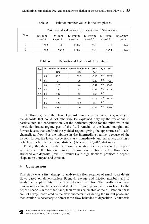
Table 3: Friction number values in the two phases.
Phase
Test material and volumetric concentration of the mixture
D<4mm CV=0.4
D<4mm CV=0.6
D<19mm CV=0.4
D<19mm CV=0.5
D<19mm CV=0.6
D<9.5mm CV=0.4
1 1203 885 1587 756 537 1147
2 1203 7835 1587 756 3673 1147
Table 4: Depositional features of the mixtures.
The flow regime in the channel provides an interpretation of the geometry of the deposits that could not otherwise be explained only by the variations in particle size and concentration. On the horizontal plane for the mixtures in the inertia-dominated regime part of the fluid remains at the lateral margins and formes levees that confined the yielded region, giving the appearance of a self-channelized flow. For the mixture in the intermediate regime, because of the viscous forces, the lateral dispersion starts immediately and increases, causing a notable reduction of the runout distance (the case of CV=0.6, d=4 mm). Finally the data of table 4 shows a relation exists between the deposit geometry and the friction number because low frictions in the flow cause stretched out deposits (low B/R values) and high frictions promote a deposit shape more compact and circular.
4 Conclusions
This study was a first attempt to analyze the flow regimes of small scale debris flows based on dimensionless Bagnold, Savage and friction numbers and to verify their applicability in the flow behavior prediction. The results show these dimensionless numbers, calculated at the runout phase, are correlated to the deposit shape. On the other hand, their values calculated at the full motion phase are not always correlated to the flow characteristics during the runout phase and then caution is necessary to forecast the flow behavior at deposition. Volumetric
dmax Cv Runout distance R
(cm)
Lateral dispersion B
(cm)
Area
(m2)
B/R Nf
0.6 43.5 32.5 0.15 0.8 3673
0.5 87 39 0.29 0.5 756
0.4 120 48 0.42 0.4 1587
9.5 0.4 122 42 0.44 0.3 1147
5.6 0.4 147 42 0.58 0.3 ‐
0.6 25 39 0.03 1.6 7835
0.5 122 33.5 0.4 0.3 ‐
0.4 151.5 50 0.53 0.3 1203
19
4
Monitoring, Simulation, Prevention and Remediation of Dense and Debris Flows IV 35
www.witpress.com, ISSN 1743-3533 (on-line) WIT Transactions on Engineering Sciences, Vol 73, © 201 WIT Press2
concentration and grain size distribution are confirmed as key additional factors to classify and predict the flow behavior along with the three dimensionless parameters.
Acknowledgements
The research is granted by the projects: GEORISKS – University of Padova; PRIN 2007/MIUR – Padova and Bari research units.
References
[1] D’Agostino, V., Cesca, M. and Marchi, L. Field and laboratory investigations of runout distances of debris flows in the Dolomites (Eastern Italian Alps). Geomorphology, 115 (3-4): 294-304, 2010.
[2] Ancey, C. and Evesque, P. Frictional-collisional regime for granular suspension flows down an inclined channel. Phys. Rev. E, 62(6):8349-8360, 2000.
[3] Major, J.J. and Iverson, R.M. Debris-flow deposition: Effects of pore-fluid pressure and friction concentrated at flow margins. GSA Bulletin, 111(10): 1424-1434, 1999.
[4] Cochard, S. and Ancey, C. Experimental investigation of the spreading of viscoplastic fluids on inclined planes, Journal of Non-Newtonian Fluid Mechanics, 158: 18-35, 2009.
[5] Iverson, R. M. and LaHusen, R. G. Friction in debris flows: Inferences from large-scale flume experiments. In Shen, H. W., Su, S. T., and Wen, F., eds., Hydraulic Engineering ’93, Proceedings of ASCE 1993 conference, San Francisco, California, July 25–30, p. 1604–1609, 1993a.
[6] Iverson, R. M. The physics of debris flows. Reviews of Geophysics, 35: 245–296, 1997a.
[7] Coussot, P. and Ancey, C. Rheophysical classification of concentrated suspensions and granular pastes. Phys. Rev. E, 59: 4445–4457, 1999.
[8] Bagnold, R. A. Experiments on a gravity-free dispersion of large solid spheres in a Newtonian fluid under shear. Royal Society of London Proceedings, ser. A, 225: 49–63, 1954.
[9] Savage, S. B. and Hutter, K. The motion of a finite mass of granular material down a rough incline. J. Fluid Mech. 199:177–215, 1989.
[10] Iverson, R. M. Hydraulic modeling of unsteady debris-flow surges with solid-fluid interactions. In Chen, C. L., ed., Debris flow hazards mitigation: Mechanics, prediction, and assessment: American Society of Civil Engineers, Proceedings of First International Conference, August 7–9, San Francisco, 550–560, 1997b.
[11] Einstein, A. A new determination of molecular dimensions. Ann. Phys., 19, 1906.
[12] Sohn, Y.K. Coarse-grained debris-flow deposits in the Miocene fan deltas, SE Korea: a scaling analysis. Sedimentary Geology, 130: 45–64, 2000.
36 Monitoring, Simulation, Prevention and Remediation of Dense and Debris Flows IV
www.witpress.com, ISSN 1743-3533 (on-line) WIT Transactions on Engineering Sciences, Vol 73, © 201 WIT Press2