deductive fault simulation with functionalblocks diagnosis, digital simulation is used to...
TRANSCRIPT

IEEE TRANSACTIONS ON COMPUTERS, VOL. C-27, NO. 8, AUGUST 1978
Deductive Fault Simulationwith Functional Blocks
PREMACHANDRAN R. MENON, MEMBER, IEEE, AND STEPHEN G. CHAPPELL, MEMBER, IEEE
Abstract-This paper presents a method of propagating the effectsof faults through functional blocks using the deductive (fault list)technique. An extension of the method is shown to be effective forsimulating internal faults in functional blocks. The techniques pre-sented here have been used for implementing the functional simula-tion capability in the Logic Analysis for Maintenance Planning(LAMP) System at Bell Laboratories.
Index Terms-Deductive, faults, fault lists, fault propagation,functional, functional faults, simulation.
I. INTRODUCTIOND IGITAL simulation is a widely used tool in design
verification and diagnosis of digital systems [1]-[3]. Infault diagnosis, digital simulation is used to determine thebehavior of the digital circuit in the presence of certain faultsand compare it with the normal circuit behavior. This typeof simulation, calledfault simulation, is used to determine theset of faults detected by a test sequence and also to determinethe output patterns produced by these faults.Two different techniques are commonly used for fault
simulation. In parallel simulation [1], [4], [5], the normal(fault-free) circuit and a number of faulty circuits, each ofwhich is usually assumed to contain a single fault, aresimulated simultaneously. The number ofcircuits simulatedsimultaneously is determined by the word size of the hostmachine (i.e., the computer on which the simulation pro-gram is run). If a large number of faults is to be simulated, itmay be necessary to partition the set of all faults into subsetswhich can be simulated simultaneously, and simulate eachsubset separately. This would require several passes throughthe simulation program.
In deductive simulation [6]-[8] faulty circuits are notexplicitly simulated. Instead, only the normal circuit issimulated and the single faults that will cause any output tobe incorrect are determined by a deductive technique. Thecomputation involved in determining the set of faults thatcause the output of any gate in the circuit to be incorrect (fordeductive simulation) is usually more complex than thatrequired in determining the output of a gate for the normaland faulty circuits simultaneously (for parallel simulation).However, a single pass through the deductive simulationprogram is sufficient to determine the effects of a largenumber of faults. Thus, the computation time required forsimulating a large number of faults is reduced, but at theexpense of memory requirements. Chang et al. [9] haveshown experimentally that deductive simulation is more
Manuscript received January 5, 1977.The authors are with Bell Laboratories, Naperville, IL 60540.
cost effective than parallel simulation when a large circuit isto be simulated with a large number of faults.Most of the existing simulation programs perform fault
simulation at the gate level. When the size ofthe circuit is toolarge for cost-effective gate-level simulation, it is frequentlyuseful to simulate parts of the circuit such as memories,registers, decoders, etc., at a functional level. That is, we wishto treat such functional blocks as "black boxes" whoseinput/output behavior is specified (but whose actual gatelevel realization is unknown) and determine the effects offaults in the gate-level circuit on the complete circuit. Thisapproach will make the simulation of larger circuits feasiblesince large functional blocks will usually require less hostcomputer resources than the corresponding gate-level cir-cuits. Functional simulation also eliminates the necessity forgenerating gate-level simulation models of functional blockswhose gate-level realization is not known.Some of the existing programs which use the parallel
simulation technique are capable ofsimulating certain typesof functional blocks [4]. A deductive technique applicable tocombinational functions and flip-flops has been proposed[10] but not implemented.
This paper presents a method ofpropagating the effects offaults through arbitrary types of functional blocks using thedeductive fault simulation technique. An extension of themethod is also presented for simulating faults internal tofunctional blocks. These techniques have been implementedin the Logic Analysis and Maintenance Planning (LAMP)System [11], [12] at Bell Laboratories.
II. GATE-LEVEL DEDUCTIVE SIMULATION
Before discussing deductive simulation of functionalblocks, let us briefly review the deductive technique appliedto gate-level simulation. The method was developed byArmstrong [6] and is used in the LAMP System [11], [12]. Amore thorough discussion of this topic is contained in [6]and [12].Each gate in the circuit is assumed to operate with zero
delay, but the output of the gate may be delayed by aninteger value. The fault-free output value'of a gate at anytime during simulation is called its true value. Associatedwith each gate output is afault list which is the set of faults inthe circuit, any one of which will cause the output ofthe gateto be incorrect (i.e., the complement of the current truevalue). The fault list associated with a gate output is a subsetof the set of all faults being simulated. A null fault list at agate output indicates that none of the simulated faults willcause the gate output to be complemented. A fault is
0018-9340/78/0800-0689$00.75 (© 1978 IEEE
689

IEEE TRANSACTIONS ON COMPUTERS, VOL. C-27, NO. 8, AUGUST 1978
detected if it is a member of the fault list associated with amonitored (i.e., observable) gate output.The output fault list of a gate can be determined from the
gate type, its input true values, input fault lists and the faultsbeing simulated on the gate. For example, consider a 3-inputNAND gate with inputs a, b, c and output d and the only faultssimulated on the gate being the output stuck-at-0 andstuck-at-I denoted by do and d1, respectively. Let the inputtrue values be a = 0, b = 1, c = 1. Denoting set intersection,union, and difference by r-, u, and -, respectively, and thefault list associated with a lead by the corresponding uppercase letter, the output fault list D is given by
D = A - (B u C) u {do}.Thus, the gate output will be incorrect, if a has the wrongvalue but b and c have the correct value, or ifthe output itselfis stuck-at-O.The fault list represented by A - (B u C) may be con-
sidered to have propagated through the gate, and the fault dois associated with the gate. If a circuit contains feedback, afault associated with a gate may propagate around thefeedback path to the inputs of the same gate. Such faultsmust be handled in a special way in order to obtain correctresults. For the above example, the general equation for theoutput fault list, accounting for possible feedback, is
D = A-(B u C)-{d1} u {do}indicating that d1 cannot be detected at the gate output, evenif it propagates to the particular gate around a feedbackpath.A 3-valued simulation will be assumed throughout this
paper. The unknown value, x, may be due to uninitializedflip-flops or the result of oscillations or critical races. Weshall associate a null fault list with every lead whose truevalue is unknown. This may result in some inaccuracy, but isa simple alternative to treating some faults as conditionallydetectable (star faults) [6], [8].
III. FUNCTIONAL BLOCK DEFINITION
The functional blocks (or simply functions) which weshall consider may represent arbitrary combinational orsequential circuits. Each function may have any number(subject to some practical constraints) ofinputs and outputs.Boolean variables that are internal to functions may also beused to represent internal states of sequential functions.Different delays may be associated with the outputs of afunction. Although any combinational or sequential circuitcan be defined in this manner, it is useful to be able to specifyand simulate certain commonly used types offunctions suchas registers and memories, without treating each internal bitindividually.The following examples offunctional block definitions are
in the Function Definition Language (FDL) implemented inthe LAMP System [13]. Key words in the language areshown in upper case. The interpretation of the functiondefinitions in the examples should be fairly obvious.
Example 1:
GPF: seq;INPUTS: a, b, c, d;OUTPUTS: zl, z2;BOOLEAN: y;DEF:
IF a & b THEN zi = 0; z2 = 0; y = 0ELSE IF a & fb & fly
THEN y= 1; ZI = Cld; z2 = 0ELSE Zi = 1; z2 = 1 FI FI FED
The first statement defines seq as a general purposefunction (GPF). The inputs are a, b, c, and d, and the outputsare zI and z2. y is an internal Boolean variable. The functiondefinition begins with DEF and ends with FED. Similarly, FI'Sterminate IF statements. The symbols &, 1, and 7 denotelogical AND, OR, and NOT, respectively. No delay has beenspecified in this function; outputs assume the newlycomputed value a unit delay (when delay is unspecified) afterany input or internal Boolean variable changes. No delay isassociated with Boolean variables, but the value of a Bool-ean variable is not updated until all the outputs have beenevaluated. The Boolean variable retains its previous valuefor all unspecified conditions. Although the function definedabove is extremely simple, it should be clear that anysequential function can be defined in this manner.Example 2:
MEM: meml;SIZE: 256, 16;PREFIX: in, out, ad;INPUTS: write, read, in[O-15], ad[O-15];OUTPUTS: out[O-15];HISTORY: 2;DEF:
IF write & write (-1) & 7 read & f read (-1)THEN meml<ad[O-7]> = in[O-15];
AT 2, out[O-15] = SOELSE IF 7 write& f write (-1)& read& read (-1)
THEN AT 2, out[O-15] = meml<ad[O-7]>ELSE AT 2, out[O-15] = out[O-15]FI Fl FED
The function meml is a memory (MEM) with 256 16-bitwords as specified by SIZE. The names in, out, and ad aredeclared to be prefixes, implying that two decimal digits willbe concatenated with them to form names. HISTORY = 2indicates that the present and one previous value of eachinput may be used in the function definition. The inputs tothe function consist of the data input leads inOO-in 15,address leads adOO-adO7 and read and write controls, readand write. If write = 1 and read = 0 at the present time andone unit time ago, then the values of inOO-inl5 are writteninto the memory word specified by the eight address bitsadOO-adO7. If the condition for writing the memory is not
690
MENON AND CHAPPELL: DEDUCTIVE FAULT SIMULATION WITH FUNCTIONAL BLOCKS
satisfied, it is implied the contents of the memory areunchanged. The outputs outOO-outl5 are specified to be 0(denoted by SO, i.e., string of O's) under this condition. Theconditions for reading are also specified in essentially thesame manner. A delay of two is associated with the outputs(specified by AT 2).The above examples are intended to give a flavor of the
type of functions under consideration. Another functiontype in FDL is the register (REG), which is similar to memory,except that individual bits may be accessed directly. Addi-tional details of the language and how interconnectionsbetween functional blocks and gates are specified are givenelsewhere [13].
In the following sections, we present a method of propa-gating faults through functions and simulating internalfaults in them. We shall discuss the method in terms offunctional blocks defined in FDL. However, the method isvalid for arbitrary functions and is independent of thelanguage used to specify the functions.
IV. FAULT PROPOGATION THROUGH FUNCTIONAL BLOCKS
A. General MethodLet a function be specified for all input sequences it may
receive in the fault-free circuit and in the presence ofany oneof the simulated faults external to the function. This condi-tion can be satisfied by specifying the function completely,i.e., for all combinations of inputs and internal states. Theeffect of a fault external to a function is that an incorrectinput sequence may be applied to its inputs. The incorrectsequence applied to the inputs of a function can be deter-mined from the sequence of true values and fault listsappearing at the function inputs. If the function is specifiedfor all incorrect sequences applied to it, the incorrect outputsequences can be determined without knowing how thefunction is realized, provided the function.itself is fault-free.Thus, the input sequence and the sequence ofinput fault listsare sufficient for determining the output true value and faultlist sequences.
Since the function outputs and output fault lists areindependent of the function realization, we can use anyrepresentation of the function that is computationallyconvenient. We have chosen to use Boolean expressions ofthe internal variables and outputs for this purpose. The truevalues and fault lists associated with the internal variablesand outputs can be computed directly from theseexpressions.
Let x =(x1, x2, ,xm),y = (y1, Y2,, Y) and z = (z1,Z2, **, Z,,) denote the inputs, internal variables, and outputs,respectively, of a function. In the function definition, eachinternal variable and output is defined by one or moreassignment statements that may be expressed in the form:
yi =fi(x, Y)z t th j(x,Y, Zj)
where the prime denotes the next value ofthe variable. Note
that each output is allowed to be a function ofitselfso that itcan retain its previous value under specified conditions. Torepresent the control specified by the IF-THEN-ELSE structure,we associate a variable cj with each IF. The variable cj willhave the value 1 if the IF condition is true and 0 otherwise.Each assignment statement can be represented by a term ofthe form fi -rc7, where c* denotes cj or c; depending onwhether the assignment is in the THEN or ELSE part of thecondition represented by Cj and 7r represents the logical ANDover all cJ that control the particular assignment vianestingofIF-THEN-ELSE structures. The equation for each output andinternal variable is obtained by summing (logical OR) theterms corresponding to individual assignments.The equations generated as discussed above are used for
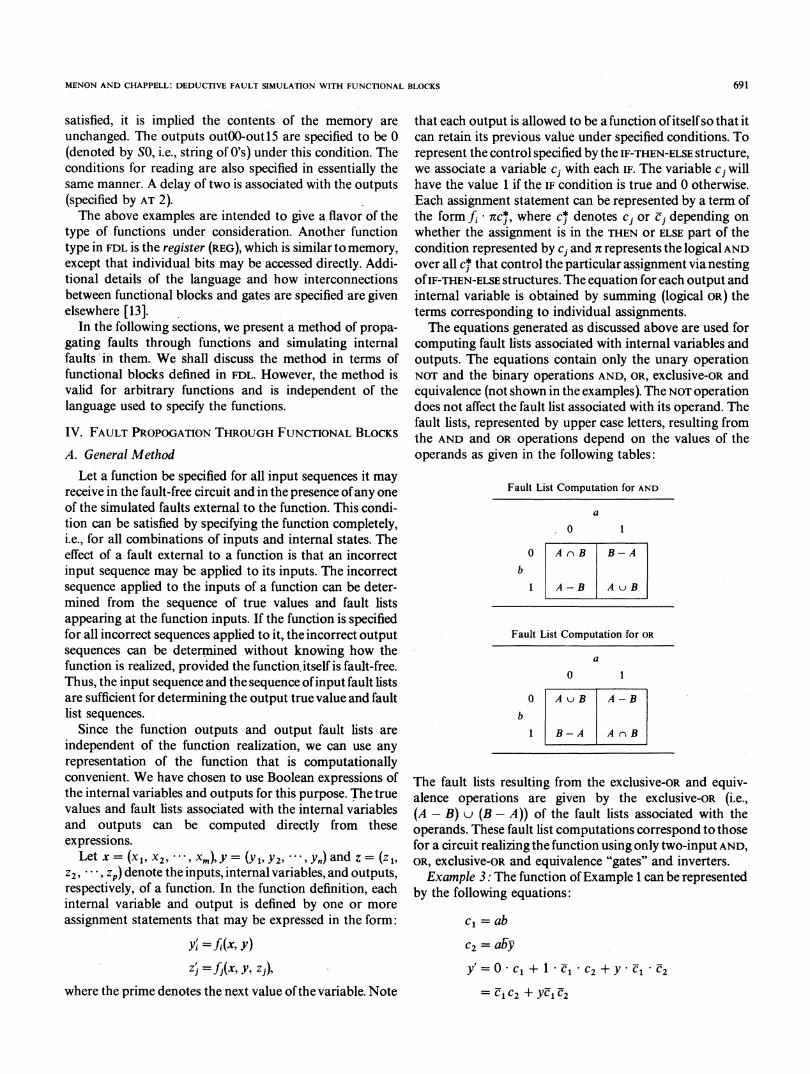
computing fault lists associated with internal variables andoutputs. The equations contain only the unary operationNOT and the binary operations AND, OR, exclusive-oR andequivalence (not shown in the examples). The NOT operationdoes not affect the fault list associated with its operand. Thefault lists, represented by upper case letters, resulting fromthe AND and OR operations depend on the values of theoperands as given in the following tables:
Fault List Computation for AND
a
.0 1
0 A rB B-A
b
1 A-B AuB
Fault List Computation for OR
a
0 1
0 A uB A-B
b
1 B-A AnB
The fault lists resulting from the exclusive-oR and equiv-alence operations are given by the exclusive-OR (i.e.,(A -B) u (B - A)) of the fault lists associated with theoperands. These fault list computations correspond to thosefor a circuit realizing the function using only two-input AND,OR, exclusive-OR and equivalence "gates" and inverters.Example 3: The function ofExample 1 can be represented
by the following equations:
cl = ab
C2 = abyY'=° C1+1+I C2 +Y C1 2
= C1 C2 + YCUl2
691

IEEE TRANSACTIONS ON COMPUTERS, VOL. c-27, NO. 8, AUGUST 1978
zl' = 0 cC1 + (c + d) C-1 * C2 + e1 *2
= (c + d)elc2 + C1C-2z2' = 0. C1 + O * El * C2 + 1 * 2
= C1C2.
In the above equations, cl and c2 are variables associatedwith the two IF conditions and y', zl', and z2' denote the nextvalues of y, zl, and z2, respectively. The term yc- c2 in theequation for y' retains the previous value of y for theunspecified condition c1 = C2= 0. To see how these equa-tions may be used to compute output fault lists in terms offault lists associated with inputs and internal variables,consider the case where a = 1, b = 0,c = O,d-1, y = 0. Letthe fault list associated with each variable be denoted by thecorresponding upper case letter. Thus, c1 = 0 and using thetable for the AND operation, we obtain the fault list asso-ciated with it as C1 = B - A.
Similarly, c2 = 1 and C2 = A u B u Y, by repeated useof the same table. Note that the fault list associated with acomplemented variable (for example b) is the same as thefault list (B) associated with the uncomplemented variable.The new fault list Y' associated with the internal Boolean
variable y can now be computed from the fault lists C1 andC2 and the previous fault list Y associated with y.y = tl + t2 where t1 = c1c2 and t2= el 2y. Now, t1 = 1and t2 = 0; therefore y' = 1,
T1= C1 C2
and
T2= (C2 Y) - C1.Finally, using the table for the OR operation,
Y' = T1 - T2 = (C1 U C2)-(C2 r Y-Cl).Continuing in the same manner, we obtain
Zl = (c + d)-l C2 + C1C2 = t3 + t4
T3= (D - C) u C1 u C2
T4 = C2 - C1
I =T3-T4
= C1 C2
2= C2 - C1.
As mentioned earlier, the true values and fault lists ofinternal Boolean variables are updated only after all othercomputations are completed. This ensures that the samevalues of Boolean variables are used throughout the evalua-tion of a function.
Registers are evaluated by treating each internal bit ofmemory as an internal Boolean variable. Equations aregenerated for each bit of internal memory and each outputbit and evaluated as in Example 3.The method of evaluating functions discussed above may
give incorrect results in some cases when one or more inputvalues are unknown. Consider the statement:
IF a THEN b = C ELSE b = d Fl
If the value of the variable a is unknown but c = d, then theoutput b is defined. However, if a = x (unknown) theequation
b = ac + ad
will give the correct value namely, b = 0 if c = d = 0, but theincorrect (pessimistic) value b = x if c = d = 1. Note thatthis type of inaccuracy also occurs in 3-valued gate-levelsimulation.
B. Fault Propagation Through MemoriesFault list computation in memories is slightly more
complex because address selection is implicit in the functiondescription. Furthermore, faults on address leads will causeincorrect words in the memory to be accessed. Describing amemory in the following form enables the computation offault lists directly from the equations.
Let n be the number of words in the memory and k thenumber of address leads 2k > n. Associated with eachmemory location (word) we define a binary variable ai,0 < i < n - 1 such that ai = 1 if and only if the signals onthe address leads (treated as a k-bit binary number) repre-sent the number i; otherwise, ai = 0. That is, each airepresents a decoded address, and ai = 1 implies that word iof the memory is selected. A fault list Ai may now beassociated with each variable a,. The fault list Ai has theusual meaning: it is the set of faults that will cause ai to becomplemented. Thus, if ai= 0, any fault in A i will cause thelocation i to be accessed. If aj = 1, A j is the set of faults thatwill cause location j not to be accessed.
Let c = (cl, c2, CcO) be a binary vector denoting thesignals on the address leads and let j be the integer repre-sented by the vector c. That is, j= 2k- 1C + 2k-2C2 +... + Ck. For any i, the fault list Ai is computed as follows:Let bi = (bi1, bi2, -.., bik) be the binary vector representingthe integer i. Compute the vector di= (di1, di2, , d,where dip = cp bip, 1 < p < k, where D representsmodulo 2 addition (exclusive-OR).The vector di will have l's in exactly those positions where
the vectors c and bi differ. Therefore, the location i will beselected instead of the location j ifand only ifa fault externalto the memory causes exactly those address leads corre-sponding to positions where dip= 1 to be incorrect,1 < p < k. The fault list Ai should contain only faults thatare contained in the fault list of every address lead for whichdip = l and none of the address leads for which dip= 0,1 < p < k. This can be stated mathematically as follows. Let
D1i = {pIdip= 1, I < p < k}
Doi = {qldiq =0O, .< q < k}
Cp= fault list associated with cp
If ai = 0,
(i.e., the pth address lead).
Ai-Cz- -(ncp-u Cq)peDli q eDoi
692

MENON AND CHAPPELL: DEDUCTIVE FAULT SIMULATION WITH FUNCTIONAL BLOCKS
If ai= 1,k
Ai= U Cp.p= 1
The second equation indicates that a fault on alead will cause the correct location not to be aWith the variables ai and the associated fault 1
as above, equations representing the write and r
tions can be obtained. In order to write into locconditions for writing must be satisfied and aiSimilarly, the contents oflocation i are read out ifthe read condition is satisfied. The following exaonstrates the computation of fault lists associatmemory of Example 2.Example 4: Let w and r denote temporary vai
O . i< 255, 0 <.j < 15 the variable representinMof the ith word, and m,j the next value of m,j.From Example 2, let
w= write write (-1). read read (-
r = read read (-1). write write (-
Memory write:
mij = w ai inj + (w a;) mij,where inj is the jth data input, 0 < i < 255, 0 <Memory read:
255
At2, out,= E W*r a, mij + O w + outi=o
where outj and out[, refer to the present andrespectively of the jth output bit.Using the above equations, the true value au
associated with every memory bit and every outcomputed as in Example 3. For writing memoryof accessing incorrect locations due to address fasimulated by computing the fault list associatedmemory bit. Similarly, the summation over awords in the equation for memory read reflects t]ity ofaccessing incorrect locations due to faults aaddress leads. The summation is obtained by i"out[0-15] = memlKad[O-7]>" in the function d
IF ao THEN out[ = mojELSE IF a1 THEN OUtJ = m1j
ELSE IF a255 THEN out'j = M25
for 0 <j< 15.If the location selected is k, then all nonnull f
and Aj, i = j, i * k,j * k, aredisjoint (i.e.,no faultthe memory can cause two incorrect locations tosimultaneously). Also Ai ' Ak. Therefore, terms
mny addressccessed.ists definedread opera--ation i, the
if ai = 0 and Ai = 0 then mij will retain its previous value.Therefore, the new true values and fault lists need not becomputed in such cases. Similarly, if ai = 0 and Ai = , theterm wrai m,j will have no effect on the true value or fault listassociated with the output out' in the memory read equa-tion. Thus, the summation need be performed only over all isuch that ai $ 0 or Ai * 0
V. INTERNAL FAULTS IN FUNCTIONAL BLOCKSmust be 1. The method of propagating fault lists through functionalia,= 1, and blocks can be modified to simulate internal faults whichimple dem- change the behavior of functions. In order to simulate theseed with the internal faults it is necessary to describe completely not only
the normal behavior of the function, but also its behavior inriables, mij, the presence of every internal fault to be simulated. Thisg thejth bit imposes a practical limit on the number of internal faults
that can be simulated. However, internal faults in functionsare not restricted to the classical stuck-type faults, and
1) therefore provide a convenient means of simulating sometypes ofnonclassical faults. We shall first present the method
1). in terms of a function with a single output. -Let x = (x1, x2, , xn) and let g(x) be an expression
which describes the normal behavior of the function. Letg1(x) represent the behavior of the functional block in the
:j < 15. presence of an internal fault o I. Now consider the functionh(x,f1)=f1 g(x) +±f' g1(x). Clearly h(x,fl) = g(x) iff' = 0,and h(x) g1(x) if f, = 1. We shall refer to]f1 as the faultvariable.w
'T9 Let us assign the true value 0 and the fault list F1 = {cx 1} toO <j. < 15 the fault variable f1. Now, h(x, fl) describes not only the
.1 . 15 behavior of the normal function but also the behavior ofthenext values function with the single fault cx1. Since]f' = 0, the true value
of the function is always given by g(x).id fault list The internal fault a 1 which transforms the function g(x) to;put may be g1(x) can be treated as a stuck-at-1 fault on the inputf] ofthe, the effects function h(x,f1). Thus, the internal fault ocI can be simulatediults can be by treating it as a fault on the fault variablef1 (which behavesLwith every like an input with true value 0 and fault list {cx }) andll memory propagating it through the function h(x, fl). The methodhe possibil- also eliminates the need for explicitly deleting faults internalLffecting the to a function from the input fault lists of the function due tonterpreting feedback, as in the case of gate-level simulation. This isefinition as necessary in gate-level simulation because the faulty behav-
ior of a gate is not explicitly defined.The following example shows how a short circuit between
two leads can be simulated as an internal fault in a function.This is intended only to demonstrate the method. It may not
5.j be an efficient method for simulating short circuit faults.Example 5: Consider the case where the effect of a short
ault lists Ai circuit between two leads results in the logical AND of thetexternal to signals on them to appear on both leads. This can bebe accessed represented by a function with inputs a and b and outputs a'containing and b'. If]fs is the fault variable associated with the fault
ai aj, i $ j, for all i, j, will not affect the computation of thetrue values or fault lists of the outputs and are omitted from at = fsa +fsabthe equation. b' =f5b +fab.The computation of the new true values and fault lists of
memory bits can be simplified by making use ofthe fact that Let as denote the short-circuit fault, i.e., Fs = {os}, and let
693
IEEE TRANSACTIONS ON COMPUTERS, VOL. c-27, NO. 8, AUGUST 1978
the inputs and the input fault lists be
a=0, A={cxl,fJo}b=1, B={f30,y1}
where x1, P0, and y1 are arbitrary external faults. The outputtrue values and fault lists can be computed directly from theequations to be
at = 0; A' = {al, fi}
b' = 1; B' = {fo, ya,xs}.If the input fault lists are A = {C 1, fio, acs} and B = {fo, y l},then we obtain the output fault lists
A' = {ali Po, CLs}
B' = {f0, Y1}for the same input true values. Note that the internal fault csappearing in the input fault list A is treated correctly.Another type of fault that can be simulated as an internal
fault in a function is timing faults. The function realized bythe gate is unaffected by the fault but the delay associatedwith the function is increased.Example 6: Let a gate realize the NOR of two inputs x and
y. If the normal delay through the gate is 5 and the timingfault ot, causes the delay to increase to 10, the behavior ofthegate can be represented as follows:
Z =fx(-5)Y(-5) +ftX(- 10)y-(- 10)where ft = 0 and the fault list Ft associated with f, is {at}.The method discussed above for simulating single internal
faults can also be used for simulating a number of internalfaults (occurring individually). Let fi be a fault variablerepresenting a fault oi, 1 < i < k. If g is the normal functionand gi is the function resulting from the single internal faultoci, the internal faults can be simulated using the equation:h(x, fi, f2, ,A) =f1g1(x) +f2g2(x) +
+fkgk(x) +f1 f2 ... fkg(X).Since the fault lists Fi are all disjoint and only one fault canbe present in the function at any time, it is not necessary tospecify the function for conditions such asfi ]Tj. Any internalfault ai can be excluded from simulation by simply makingFi = 0 (null fault list). Instead of describing each faultyfunction separately as discussed above, fault variables can beused within nested IF-THEN-ELSE statements, thus specifyingparts of the function definition affected by each internal fault[13]. This method will, in general, result in shorter functiondefinitions than the description of individual faultyfunctions.With the approach discussed in this section, simulation of
internal faults in functions is an extension of fault listpropagation through functions described earlier.
VI. IMPLEMENTATION
The method discussed in Sections IV and V has beenimplemented in the LAMP System. Each function isdescribed in the Function Definition Language as shown in
Examples 1 and 2. Prior to simulation, function descriptionsare converted from the IF-THEN-ELSE form to Boolean equa-tions. These equations are used for computing true valuesand fault lists. Equations are represented in the reversePolish (postfix) form [14] for simulation.A last-in, first-out execution stack is used for evaluating
functions. All operations performed are binary or unaryBoolean operations and assignments, permitting the use ofsimple evaluation routines. Intermediate results obtainedduring evaluation, both true values and fault list pointers areleft in the execution stack. This method is quite general andindependent of the function being simulated. Futurechanges in the function types or Function Definition Lan-guage features will not necessitate changes in the evaluationprograms.
Evaluation of a function is normally initiated when one ormore of its inputs change. New true values and fault lists arecomputed for internal variables and function outputs. Inter-nal Boolean variables are updated after all the outputs havebeen evaluated. The outputs are updated at the timesspecified in the function description. (This defaults to 1, i.e.,the next time interval, if it is not specified.) This methodguarantees that all outputs are computed based on thecurrent values of internal variables.
Unlike internal variables, memory bits are updated assoon as their true values and fault lists are computed. Thismethod was adopted in order to reduce the memory require-ments of the program. A consequence of this method ofcomputation is that the computed memory outputs aresensitive to the order in which the write and read operationsare specified. However, this is not a serious disadvantagesince the behavior of the memory function can usually bespecified with sufficient accuracy by appropriate ordering ofstatements in the function definition.
In gate level simulation, it is sufficient to evaluate theoutput of a gate only if one or more of its inputs havechanged (selective trace [15]). This may not be sufficient inthe case of functions since they may depend on internalstates and previous inputs. As in the case of gates, a functionis evaluated whenever one or more of its inputs change (truevalue or fault list). In addition, it is reevaluated if the truevalue or fault list ofany internal (Boolean) variable changes.If a function depends on previous values of inputs, it isscheduled for recomputation at the next instant ofsimulatedtime if the current true value and fault list ofevery input andall previous values and fault lists saved for that input are notequal.The current implementation of function evaluation does
not recognize critical races. Effects of simultaneous inputchanges will be determined by the simulator in the order inwhich these changes are perceived by the simulator.
VII. CONCLUSIONA method of propagating faults through functions using
the deductive fault simulation technique has been presented.An extension of the method is shown to be capable ofsimulating arbitrary internal faults in functions. Althoughthe need for specifying the faulty behavior of functions may
694

MENON AND CHAPPELL: DEDUCTIVE FAULT SIMULATION WITH FUNCTIONAL BLOCKS
restrict the number of internal faults that can be simulatedpractically, the capability makes the same simulator usefulfor widely different technologies and fault classes. A lan-guage for defining functions for simulation is presented.However, the techniques presented are independent of thelanguage used for defining functions.The functional simulation capabilities and algorithms
described here have been implemented in the LAMP Systemat Bell Laboratories. They have been widely used to simulatememories, microprocessors and other large circuits. Weexpect that functional simulation is the vehicle which willallow us to simulate the larger and more complex circuitsresulting from the new 'semiconductor technologies in a
cost-effective manner.
ACKNOWLEDGMENT
The authors are indebted to J. F. Pellegrin, A. W. Roberts,and A. M. Schowe who developed different parts of thefunctional simulation feature.
REFERENCES[1] S. Seshu, "On an improved diagnosis program," IEEE Trans. Elec-
tron. Comput., vol. EC-14, pp. 76-79, Feb. 1965.[2] F. H. Hardie and R. J. Suhocki, "Design and use of fault simulation
for Saturn computer design," IEEE Trans. Electron. Comput., vol.EC-16, pp. 412-429, Aug. 1967.
[3] T. T. Butler, T. G. Hallin, K. W. Johnson, and J. J. Kulzer, "LAMP:Application to switching system development," Bell Syst. Tech. J.,vol. 53, pp. 1535-1555, Oct. 1974.
[4] S. A. Szygenda, D. M. Rouse, and E. W. Thompson, "A model andimplementation of a universal time delay simulator," in Proc. 1970Spring Joint Comput. Conf., pp. 207-216, 1970.
[51 H. Y. Chang, E. G. Manning, and G. A. Metze, Fault Diagnosis ofDigital Systems. New York: Wiley, 1970, ch. 4.
[6] D. B. Armstrong, "A deductive method of simulating faults in logiccircuits," IEEE Trans. Comput., vol. C-21, pp. 464-471, May 1972.
[7] H. C. Godoy and R. E. Vogelsburg, "Single pass error effect deter-mination (SPEED)," IBM Tech. Disclo. Bull., vol. 13, pp. 3343-3344,Apr. 1971.
[8] A. D. Friedman and P. R. Menon, Fault Detection in Digital Circuits.Englewood Cliffs, NJ: Prentice-Hall, 1971, ch. 5.
[9] H. Y. Chang, S. G. Chappell, C. H. Elmendorf, and L. D. Schmidt,"Comparison of parallel and deductive fault simulation methods,"IEEE Trans. Comput., vol. C-23, pp. 1132-1138, Nov. 1974.
[10] A. Friedes, "The propagation of fault lists through combinational or
sequential circuits," in Proc. Workshop on Fault Detection and Diag-nosis in Digital Circuits and Systems, Lehigh University, pp. 12-41,Dec. 1970.
[11] H. Y. Chang, G. W. Smith, and R. B. Walford, "LAMP: Systemdescription," Bell Syst. Tech. J., vol. 53, pp. 1431-1449, Oct. 1974.
[12] S. G. Chappell, C. H. Elmendorf, and L. D. Schmidt, "LAMP: Logic-circuit simulators;" Bell Syst. Tech. J., vol. 53, pp. 1451-1475, Oct.1974.
[13] S. G. Chappell, P. R. Menon, J. F. Pellegrin, and A. M. Schowe,"Functional simulation in the LAMP system," in Proc. 13th DesignAutomation Conf., pp. 42-47, June 1976.
[14] D. E. Knuth, The Art of Computer Programming, Vol. 1-Fundamental Algorithms. Reading, MA: Addison-Wesley, 1968.
[15] P. R. Menon, "A simulation program for logic circuits," Bell Lab.,Naperville, IL, Intemal Memo., Mar. 1965.
Premachandran R. Menon (M'70) reoeived theB.Sc. degree from Banaras Hindu University,Banaras, India, in 1953, and the Ph.D. degreefrom the University of Washington, Seattle, in1962, both in electrical engineering.He was with the Delhi Cloth Mills, Delhi, India,
from 1953 to 1957. From 1957 to 1963 he waswith the Department of Electrical Engineering,University of Washington, where he became anacting Assistant Professor in 1962. He joined theComputing Techniques Research Department of
Bell Laboratories, Murray Hill, NJ, in 1963, and transferred to -BellLaboratories, Naperville, IL, in 1971. His current interests are switchingtheory, fault diagnosis, and software verification. He is a coauthor ofFault Detection in Digital Circuits (Englewood Cliffs, NJ: Prentice-Hall,1971) and Theory and Design ofSwitching Circuits (Woodland Hills, CA:Computer Science Press, 1975).
Stephen G. Chappell (M'72) received the B.E.E.degree in 1969 from Georgia Institute of Tech-nology, Atlanta, the M.S. degree in electrical engi-neeringin 1971,and the Ph.D. degree in computerscience in 1973 from Northwestern University,Evanston, IL.
After joining Bell Laboratories, Naperville, IL,he was concemed with problems of logic-designautomation, particularly logic simulation andautomatic test generation. Currently, he is super-visor of a group concerned with the development
and use of high level programming languages in electronic switchingsystems.
Dr. Chappell is a member of Eta Kappa Nu and Tau Beta Pi.
695