deep borehole field test requirements and controlled...
TRANSCRIPT
SANDIA REPORT SAND2015-6009 Unlimited Release Printed July 2015
Deep Borehole Field Test Requirements and Controlled Assumptions Ernest L. Hardin, SNL
Prepared by Sandia National Laboratories Albuquerque, New Mexico 87185 and Livermore, California 94550
Sandia National Laboratories is a multi-program laboratory managed and operated by Sandia Corporation, a wholly owned subsidiary of Lockheed Martin Corporation, for the U.S. Department of Energy's National Nuclear Security Administration under contract DE-AC04-94AL85000. Approved for public release; further dissemination unlimited.
ii
Issued by Sandia National Laboratories, operated for the United States Department of Energy by Sandia Corporation. NOTICE: This report was prepared as an account of work sponsored by an agency of the United States Government. Neither the United States Government, nor any agency thereof, nor any of their employees, nor any of their contractors, subcontractors, or their employees, make any warranty, express or implied, or assume any legal liability or responsibility for the accuracy, completeness, or usefulness of any information, apparatus, product, or process disclosed, or represent that its use would not infringe privately owned rights. Reference herein to any specific commercial product, process, or service by trade name, trademark, manufacturer, or otherwise, does not necessarily constitute or imply its endorsement, recommendation, or favoring by the United States Government, any agency thereof, or any of their contractors or subcontractors. The views and opinions expressed herein do not necessarily state or reflect those of the United States Government, any agency thereof, or any of their contractors. Printed in the United States of America. This report has been reproduced directly from the best available copy. Available to DOE and DOE contractors from U.S. Department of Energy Office of Scientific and Technical Information P.O. Box 62 Oak Ridge, TN 37831 Telephone: (865) 576-8401 Facsimile: (865) 576-5728 E-Mail: [email protected] Online ordering: http://www.osti.gov/bridge Available to the public from U.S. Department of Commerce National Technical Information Service 5285 Port Royal Rd. Springfield, VA 22161 Telephone: (800) 553-6847 Facsimile: (703) 605-6900 E-Mail: [email protected] Online order: http://www.ntis.gov/help/ordermethods.asp?loc=7-4-0#online
Deep Borehole Field Test Requirements and Controlled Assumptions July 21, 2015
iii
SAND2015-6009 Unlimited Release Printed July 2015
DEEP BOREHOLE FIELD TEST REQUIREMENTS AND CONTROLLED ASSUMPTIONS
Ernest L. Hardin Sandia National Laboratories
P.O. Box 5800 Albuquerque, NM 87185-0747, USA
ABSTRACT This document presents design requirements and controlled assumptions intended for use in the engineering development and testing of: 1) prototype packages for radioactive waste disposal in deep boreholes; 2) a waste package surface handling system; and 3) a subsurface system for emplacing and retrieving packages in deep boreholes. Engineering development and testing is being performed as part of the Deep Borehole Field Test (DBFT; SNL 2014a). This document presents parallel sets of requirements for a waste disposal system and for the DBFT, showing the close relationship. In addition to design, it will also inform planning for drilling, construction, and scientific characterization activities for the DBFT.
The information presented here follows typical preparations for engineering design. It includes functional and operating requirements for handling and emplacement/retrieval equipment, waste package design and emplacement requirements, borehole construction requirements, sealing requirements, and performance criteria. Assumptions are included where they could impact engineering design. Design solutions are avoided in the requirements discussion.

Deep Borehole Field Test Requirements and Controlled Assumptions July 21, 2015
iv
ACKNOWLEDGEMENTS This set of requirements and assumptions has benefited greatly from reviews by Gordon Appel, Geoff Freeze, Kris Kuhlman, Bob MacKinnon, Steve Pye, David Sassani, Dave Sevougian, and Jiann Su.
Deep Borehole Field Test Requirements and Controlled Assumptions July 21, 2015
v
TABLE OF CONTENTS ABSTRACT ................................................................................................................................... iii
ACKNOWLEDGEMENTS ........................................................................................................... iv
TABLE OF CONTENTS ................................................................................................................ v
LIST OF TABLES .......................................................................................................................... 1
1. INTRODUCTION ....................................................................................................... 2
2. REQUIREMENTS ...................................................................................................... 4
2.1 Industrial Safety and Health Requirements Discussion .............................................. 4
2.2 Radiological Protection Requirements Discussion ..................................................... 4
2.3 Security and Safeguards Requirements Discussion .................................................... 4
2.4 Quality Assurance Requirements Discussion .............................................................. 5
2.5 Other Statutory and Regulatory Requirements Discussion ......................................... 5
2.6 Functional Requirements Discussion .......................................................................... 5
2.7 Operating Requirements Discussion ........................................................................... 5
2.8 Performance Criteria Discussion ................................................................................. 6
2.9 Borehole Design and Construction Requirements Discussion .................................... 7
2.10 Waste Packaging Requirements Discussion ................................................................ 8
2.11 Waste Package Emplacement and Retrieval Requirements Discussion.................... 10
2.12 Borehole Sealing Requirements Discussion .............................................................. 11
2.13 Characterization Testing Requirements Discussion .................................................. 12
3. CONTROLLED ASSUMPTIONS DISCUSSION ................................................... 12
4. REFERENCES .......................................................................................................... 16
6. TABLES .................................................................................................................... 18
Deep Borehole Field Test Requirements and Controlled Assumptions July 21, 2015
1
LIST OF TABLES
Table 1. Requirements for the DBFT, and cross-walk to waste disposal requirements. .............. 18
Table 2. Controlled assumptions for deep borehole waste disposal and the DBFT. .................... 24
Deep Borehole Field Test Requirements and Controlled Assumptions July 21, 2015
2
DEEP BOREHOLE FIELD TEST REQUIREMENTS AND CONTROLLED ASSUMPTIONS
July 21, 2015
1. INTRODUCTION
This document presents design requirements and controlled assumptions for the engineering development and testing of a prototype waste package, a waste package surface handling system, and a subsurface system for emplacing and retrieving packages in a deep borehole, as part of the Deep Borehole Field Test (DBFT; SNL 2014a). The utility of the DBFT engineering activities depends on how well they simulate actual conditions of disposal. This document reflects this “inheritance” by presenting parallel sets of requirements for waste disposal and the DBFT, where it is technically possible and not premature to do so. A second purpose of this document is to inform the planning for drilling, construction, and characterization activities within the DBFT, by presenting requirements that may impact those activities.
The information presented here follows typical preparations for engineering design. It includes functional and operating requirements for handling and emplacement/retrieval equipment, performance criteria, waste package design and emplacement requirements, borehole construction requirements, and sealing requirements. Assumptions are included if they could impact engineering design. Design solutions are avoided in the requirements discussion.
The basic description of the DBFT, and reference design for a disposal system, follow the current project technical baseline (Arnold et al. 2011, 2013, and 2014; SNL 2014a). Prototype waste packages to be developed for the DBFT, and the systems to handle, emplace, and retrieve them, will be similar but not necessarily the same as those described in this foregoing work.
Waste packaging nomenclature has been extended in this document to distinguish between thin-wall canisters used to contain wastes at upstream facilities, the borehole disposal overpack, and the waste package assembled from one or more canisters and a disposal overpack. Also, a waste package suitable for borehole emplacement may be used directly for loading of uncanistered waste forms. These definitions become increasingly important as the DBFT interfaces with upstream waste management activities.
Importantly, this is a “living document” that will be updated as design proceeds, and as non-technical requirements and criteria are developed (e.g., safety, health, security, safeguards, QA, legal, etc.).

Deep Borehole Field Test Requirements and Controlled Assumptions July 21, 2015
3
Deep Borehole Field Test Requirements and Controlled Assumptions July 21, 2015
4
2. REQUIREMENTS
The requirements from this report are presented in Table 1, and controlled assumptions are in Table 2. The following numbered subsections provide discussion and examples to clarify the requirements and assumptions listed in Tables 1 and 2.
Where information is to-be-determined (TBD), the reasons include present lack of definition for: 1) disposal mission with respect to waste forms; 2) siting and depths of DBFT boreholes and disposal boreholes; 3) future deep borehole waste disposal project organization and scope; 4) regulations specific to future waste borehole disposal projects; 5) waste-specific and site-specific safety strategies; 6) confirmatory data collection associated with disposal boreholes; 7) future requirements that may be based on DBFT results; 8) long-term control and ownership of borehole sites; and 9) provisions for nuclear materials security and safeguards. Requirements and assumptions may be revisited when additional information is available in these areas.
2.1 Industrial Safety and Health Requirements Discussion
Safety and health analysis requirements for non-nuclear activities exist in various forms such as the Integrated Safety Management System (Department of Energy), the Environment, Health & Safety program of the American Petroleum Institute, the Oil and Gas Extraction Safety program (National Institute for Occupational Safety and Health), and the Engineered Safety program at Sandia National Laboratories. The broadest of them focus on both worker safety and environmental protection. Any of these overlapping programs can be adopted and used effectively in DBFT engineering design. The selection of one or another is not likely to affect the final design if broadly accepted safety and environmental precepts are followed. Accordingly, full implementation of the ISMS program of the sponsoring Department of Energy is identified as a DBFT requirement.
For waste disposal activities a broader framework would be used in design, encompassing radiological exposure and dose, nuclear criticality, nuclear quality assurance, and so on. The particulars of such a program are beyond the scope of the DBFT, and are TBD.
2.2 Radiological Protection Requirements Discussion
Actual disposal operations will be conducted in a manner to ensure that radiological exposures comply with appropriate regulations (e.g., 10 CFR 20), including the requirement that worker doses are as low as reasonably achievable (ALARA). The DBFT will not involve radioactive materials, except for sealed logging sources, which will be removed. For the DBFT to simulate waste disposal operations, this means that the test operations will be designed and implemented to clearly demonstrate the means of radiological protection, even though radiological protection is not required for demonstration activities. For example, actual waste package handling operations will make use of shielding, but for the DBFT such shielding may be simulated.
2.3 Security and Safeguards Requirements Discussion
Safeguards and security of nuclear materials is beyond the scope of the DBFT. Much is known about the potential for the assumed waste forms to self-protect, and the security and safeguards considerations for waste storage and transportation. One connection to the DBFT is the size of canisters and waste packages used to disposition relatively small, highly radioactive sealed sources (Table 1).
Deep Borehole Field Test Requirements and Controlled Assumptions July 21, 2015
5
2.4 Quality Assurance Requirements Discussion
The QA requirements for the ongoing Used Fuel Disposition R&D program are applicable to the DBFT engineering design effort (DOE 2012; SNL 2014b). The specific QA requirements for waste disposal are beyond the scope of the DBFT.
2.5 Other Statutory and Regulatory Requirements Discussion
The National Environmental Protection Act (NEPA) is applicable to any future Federal waste disposal activities, and to the DBFT including site preparation, drilling, testing, and borehole plugging/abandonment activities. The type of NEPA assessment (e.g., categorical exclusion or Environmental Impact Statement) will be determined and implemented prior to initiating field activities.
State and local permits are needed (e.g., for land use, drilling, or environmental controls) as appropriate, from cognizant jurisdictions. The types of permits needed will vary with location, and may vary between the DBFT and any future waste disposal activities. These state and local permits will be secured after the location of the DBFT is identified.
Waste disposal boreholes may be classified as injection wells in accordance with 40CFR144, but the applicability of this regulation to future deep borehole disposal projects is TBD. For the DBFT, no radioactive waste or hazardous waste will be transported to the site, nor will such wastes be introduced to the Characterization and Field Test Boreholes.
2.6 Functional Requirements Discussion
The DBFT has multiple objectives including development and demonstration of scientific characterization methods for evaluating site suitability. Borehole drilling and construction, and DBFT engineering development and implementation activities, will be integrated with the overall program and consistent with evaluation of the safety and feasibility of deep borehole disposal. In other words, the overall program is expected to include rock and groundwater sampling, flow testing, geophysical logging, and other characterization activities, with which the other DBFT activities (drilling, construction, demonstration) must not interfere.
For future waste disposal activities, the characterization objective may also apply as each disposal borehole is constructed. Disposal activities will be performed in a manner consistent with long-term waste isolation, in accordance with a safety strategy that depends on the waste type and site-specific factors, and is TBD.
Design for future waste disposal will ensure that nuclear criticality cannot occur in handling and disposal of actual waste. For the DBFT, no nuclear waste and no nuclear materials capable of criticality will be used, other than sealed sources used for well logging (Section 1.2).
The potential waste forms for deep borehole disposal include powerful emitters of penetrating radiation (gamma, neutron), so the DBFT engineering design will include accommodation for appropriate shielding.
2.7 Operating Requirements Discussion
Operating requirements for actual waste disposal will be developed in large part based on experience from the DBFT, and are therefore TBD. However, a number of operational requirements on the DBFT can be inferred based on desired features of the disposal system.
Deep Borehole Field Test Requirements and Controlled Assumptions July 21, 2015
6
Borehole disposal overpacks (and canisters that contain the waste, as applicable) will be loaded and sealed by welding at specialized nuclear material handling facilities. Thus, waste packages will be delivered to the disposal site sealed, and in condition ready for direct emplacement in the disposal borehole. Welding provides a permanent seal and has been a preferred closure solution for mined geologic disposal in repository R&D programs.
Materials used in the Characterization Borehole and in the Field Test Borehole will be analyzed and approved before use. Material use will be logged as to quantity, date, location, and manner of introduction to the hole. These measures will help to ensure that scientific characterization data can be meaningfully interpreted and not technically challenged. An important part of the Material Control program will be chemical or stable isotopic tracers mixed with fluids used in the borehole. Other materials may also be tagged with tracers as deemed appropriate by scientific analysis. An effective and workable Material Control program will also benefit future waste disposal operations by limiting interference with future characterization data collection, and limiting potential impacts to waste isolation after waste borehole sealing and closure.
To prevent stuck waste packages, a verification method such as wireline logging will be used immediately prior to package emplacement or retrieval operations to verify the condition of guidance casing. Wireline logging may also be used periodically when package emplacement is not active, to monitor ongoing changes in borehole condition. The approach will be used and evaluated during DBFT test waste package emplacement/retrieval operations.
2.8 Performance Criteria Discussion
As noted above the DBFT has multiple objectives, and the engineering development and implementation elements are parts of the overall program. Accordingly, engineering activities will be conducted so as to allow characterization of the hydrogeologic setting from the surface to total depth, including the overburden, seal zone, and disposal zone. For future waste disposal boreholes this requirement is focused on any confirmatory data to be collected, the nature of which is TBD.
Boreholes drilled for the DBFT and for future waste disposal may stand unused for long periods of time. The DBFT boreholes may become laboratories for subsurface research (see Table 2), while disposal boreholes may be idled during license proceedings, delays in waste preparation, and so forth. For the DBFT boreholes a service lifetime is adopted (Table 1), considering potential casing corrosion, formation creep, and other time-dependent processes. This service lifetime is posed as a criterion and not a requirement, especially for the DBFT, because of the uncertainties involved with degradation processes in the downhole environment.
Service lifetime criteria apply to borehole construction materials (cement, casing) and also to fluids in the borehole. Drilling and emplacement fluids may be affected by aging and settling processes. Changes in fluid properties must be taken into account in managing borehole condition, and in preparing for waste emplacement operations. For example, increased viscosity may slow emplacement of waste packages, and possibly cause pressure surges with the potential to damage casing.
The functions of borehole fluid include mechanical support of the borehole wall, and lubrication of drill string and wireline operations, in addition to flushing of cuttings during drilling. Fluid also provides buoyant support to downhole tools and waste packages. Borehole fluid can be replaced by circulating new or different fluid, and it can be stratified by placing heavier fluids
Deep Borehole Field Test Requirements and Controlled Assumptions July 21, 2015
7
deeper in the hole. Thus, the emplacement fluid in the disposal zone of a waste disposal borehole may have different properties than drilling fluid, or completion fluid used above the disposal zone.
2.9 Borehole Design and Construction Requirements Discussion
Borehole lineal horizontal deviation is specified by Arnold et al. (2011) to prevent multiple disposal boreholes from intercepting at depth, and to promote heat dissipation. A maximum deviation of 50 m ensures that adjacent disposal boreholes do not intersect, and are at least 100 m apart over the extent of the disposal zone, if the collar spacing is at least 200 m. For the Characterization Borehole a more relaxed deviation of 100 m is specified because it does not represent the type of borehole intended for waste disposal. However, this does not preclude the possibility of deploying the test package handling and emplacement systems in the Characterization Borehole.
The requirement to limit dogleg severity will reduce the potential for stuck waste packages (or tubulars during drilling and construction). Dogleg severity (typically expressed in degrees per change in apparent depth, e.g., degrees per 100 feet) reflects borehole curvature, not deviation. Permissible dogleg severity is determined as a function of borehole or casing diameter, diameter of strings being run in the borehole, bending stress, material properties (e.g., steel grade), spacing of tool joints (controls stiffness), and buoyant weight.
If waste packages are lowered a few at a time on a wireline, then the main impact of doglegs occurs during borehole construction. If waste packages are emplaced in long strings on drill pipe, then the main impact may be during emplacement because of the relatively small radial clearance between waste packages and guidance casing. Maximum dogleg severity for the DBFT is TBD and will be determined by engineering analysis prior to drilling. The possibility that dogleg severity may be strongly limited (e.g., to accommodate drill-string emplacement of long strings of waste packages) means that directional drilling capability should be assumed (Table 2).
As a practical matter all boreholes will have some deviation so that drill pipe, waste packages, wireline tools, etc., will slide or rest against the “low” side. This means that waste packages and downhole tools will generally contact the casing, so the internal surface of the casing should be flush.
The reference design of Arnold et al. (2011) for heat-generating waste specifies slotted or perforated liner in the disposal zone, to allow heated fluid to escape to the formation rather than building up pressure that could damage plugs or seals. This requirement is specified here for disposal boreholes, but not for DBFT boreholes. Heater tests such as that proposed for the Characterization Borehole (Vaughn et al. 2012) could place additional requirements on borehole construction, but are TBD.
In the Field Test Borehole (and in disposal boreholes) the seal zone will be uncemented, and the guidance casing used for waste emplacement will be removed prior to sealing (Arnold et al. 2011). For the DBFT Characterization Borehole casing removal is not required because the hole will not be sealed. Casing removal can be problematic especially after long periods of time some consideration should be given to what happens if the casing becomes stuck. .For the Field Test Borehole, the casing plan will mirror that planned for disposal boreholes, and the entire guidance casing will be removed). Casing removal demonstration will be an integral part of the DBFT
Deep Borehole Field Test Requirements and Controlled Assumptions July 21, 2015
8
program, although casing may be reinstalled in the seal zone interval depending on intended future uses of the borehole.
The reference disposal concept calls for bridge plugs within the guidance casing, spaced about 200 m apart in the disposal zone, with approximately 33 feet (10 m) of cement placed over each bridge plug to bear the weight of waste packages (Arnold et al. 2011). If the annulus between the borehole wall and the guidance casing is not also cemented, then the 13-3/8” slotted guidance casing will support the weight of up to 400 waste packages and ten cement plugs, a total of approximately 1.8106 pounds, in column loading. The reference design allows for cement to run into the annulus where its movement would be impeded by heavy, oil-based emplacement mud. The total cement volume would be equal to the casing volume plus the annular volume, over the 10-meter cemented interval. A measurement to the top of the finished cement plug would be used to determine successful installation.
To provide greater assurance that excessive compression of the guidance casing will not occur, the annulus could also be cemented in some or all of the cement plug intervals. One way to do this would be to use an inflatable annular casing packer at the same elevation as the casing bridge plug. The same measurement to the top of the cement plug would confirm installation. This method would control the cement, support the guidance casing, and ensure that there are uncemented intervals in the disposal zone between cement plugs for dissipation of fluid pressure caused by waste heating.
For the DBFT, plugs will not be installed in the Characterization or Field Test Boreholes in a manner that could interfere with availability of the boreholes for additional testing. This does not preclude installing cement at the bottom of either borehole in conjunction with (i.e., before or after) installation of guidance casing.
2.10 Waste Packaging Requirements Discussion
Reference waste package sizes (Arnold et al. 2011) were determined using common sizes for drill bits and casing. A range of diameters is available for disposal overpacks (and borehole and casing sizes), but two sizes are being considered for the DBFT: small and large. As discussed below, for the larger packages (both test and actual disposal waste packages) the maximum diameter that could be achieved is 11” (28.0 cm), and for the small packages it is 4.95” (12.6 cm). These limits are consistent with borehole diameter and casing designs documented in the reference design (Arnold et al. 2011). Overpack internal length will be nominally 5 m, to accommodate various waste forms (including spent fuel as analyzed by Arnold et al. 2011).
The diameter of waste packages that can be run in standard sized casing depends on the radial clearance. Radial clearance between the waste packages and the casing internal diameter (ID) controls the potential for packages to become stuck, especially if assembled in long strings (up to 200 m; Arnold et al. 2011). Radial clearance affects the terminal velocity if packages were to fall unsupported down the borehole, which is also related to the speed at which packages can be lowered or raised.
Hoag (2006) proposed radial clearance of 0.9” (2.3 cm) for packages 13-3/8” (34 cm) in diameter. Arnold et al. (2011) proposed minimum radial clearance of 0.25” (0.66 cm) which was controlled by off-the-shelf buttress-type connectors with outer diameter of 12.1” (30.7 cm). For this document, the minimum radial clearance for large-size disposal overpacks is set to 0.7” (1.8 cm), giving a maximum package diameter of 11.0” (28.0 cm), for the 12.49” drift within

Deep Borehole Field Test Requirements and Controlled Assumptions July 21, 2015
9
13-3/8” casing (Arnold et al. 2011). Applying the same minimum radial clearance to small overpacks the maximum package diameter is 4.95” (12.6 cm) for the nominal ID (16.2 cm) of 7-inch casing.
Mechanical integrity means appropriate resistance to external hydrostatic loading, combined with axial tensile and compressive loads, and bending loads if present. Waste packages may be loaded in tension during emplacement, retrieval, or during fishing operations to recover packages (which may be stuck). Waste packages may be loaded in compression when strings are set on the bottom of the borehole (or on intermediate plugs).
Hydrostatic loading combined with axial and bending loads constitute the maximum loading condition. The maximum design hydrostatic pressure for test waste packages is 65 MPa (9,600 psi) based on assumed fluid density in a 5,000-meter column (Table 2). The minimum hydrostatic pressure for waste disposal packages is 50 MPa (7,350 psi) based on the density of pure water. The maximum pressure for actual waste packages is TBD because it depends on the properties of the so-called emplacement mud, and how it is introduced.
A minimum safety factor of 2.0 with respect to elastic/plastic failure calculations with idealized geometry will be used for mechanical analyses of the waste package wall, following a design procedure such as Corradi et al. (2008) based on ASME Case CC-2286-1. A minimum safety factor of 2.0 will also be applied using numerically calculated stresses at the package ends. The safety factor should be reasonably conservative, comparable to those used in other critical systems (e.g., pipelines, rigging, etc.). The consequences of accidental breach during operations include radiological contamination of the borehole, surface equipment, and the basement rock unit (the reference casing plan of Arnold et al. 2011 would preclude contaminated wellbore fluid from reaching the overburden directly). For actual waste disposal overpacks, the design safety factor will depend heavily on results obtained in the DBFT, and is therefore TBD.
The natural geothermal gradient may lead to formation temperatures at 5 km depth as high as 170C (based on gradient of 30 C/km, and mean annual surface temperature of 20C). Drilling and emplacement operations will circulate cooler fluid, but borehole fluid temperature will recover to formation temperatures after a few weeks without circulation. This is the maximum (unheated) in situ temperature for test waste packages, and for actual waste packages if they produce little heat.
Temperature rise from emplacement of waste will vary with waste characteristics and canisterization, increasing the maximum disposal zone temperature (at the package surface). For Cs/Sr capsules stacked end-to-end the peak temperature rise for the hottest capsules emplaced in granite in 2016 would be approximately 120C (Arnold et al. 2014, Section 3). Considering that these capsules will more likely be disposed of ten years later, and that most of the capsules are cooler than the hottest ones, the maximum temperature rise will be 80C and the maximum package surface temperature will be approximately 250C. The calculations show that the disposal zone will approach peak temperatures within a few hundred days after emplacement, and is therefore likely to occur during the operational period for waste emplacement and borehole sealing. Note that the saturated vapor pressure of water at 250C is 3.9 MPa (576 psi; Weast and Astle 1981, p. D-169) so that boiling will not occur for water-based fluids.
Deep Borehole Field Test Requirements and Controlled Assumptions July 21, 2015
10
Heated testing is not currently planned for the Field Test Borehole, so the maximum test waste package temperature is 170C. Design of tools or test packages to be used in a borehole thermal test, for example in the Characterization Borehole, are TBD.
Waste packages will have flush external surfaces, with API standard tapers at diameter changes (e.g., at joints between packages, or where the package body meets connectors fixed at each end). The smooth, tapered exterior will prevent hangup on casing joints, shoes, collars, etc. The requirement applies to both test waste packages and waste disposal packages.
Package connections for drill-string emplacement will include: 1) a threaded connection to packages below; and 2) a threaded connection to drill pipe above for emplacement or fishing. Package connections for wireline emplacement will include a releasable cable head and a fishing neck, both located on top. The package bottom will include a threaded connection for attaching additional hardware such as instrumentation, centralizers, shock absorbing materials, etc.
Package connections will have sufficient strength to withstand mechanical loads during emplacement, retrieval, and fishing of stuck packages (or package strings, if packages are threaded together). Thrust and rotation conditions required to engage or disengage connections downhole must be consistent with capabilities of drill-string, wireline, or coiled tubing delivery systems (as applicable).
Waste package containment is required through all phases of disposal operations, until the borehole is sealed. Additional containment longevity may be required depending on the disposal environment, waste radionuclide half-life, and other characteristics. Thus, for longer-lived radionuclides the containment lifetime might be increased to supplement natural barrier performance, through choices of disposal overpack materials, fabrication methods, treatments, and engineered controls on the disposal environment. These considerations do not apply to DBFT test waste packages, which will be retrieved immediately. The DBFT will demonstrate that waste packages can be designed, fabricated, loaded, sealed, emplaced and retrieved without loss or leakage. Packages will be inspected for damage and leakage after the conclusion of emplacement/retrieval operations.
Test waste packages will have negative buoyancy in emplacement fluid of the maximum density (see Section 1.9 and assumptions in Table 2) so that they do not float after they are emplaced, and so they can be more readily emplaced (e.g., on a wireline, which requires that packages sink). The same requirement applies to actual waste packages, and includes the weight of loaded waste, but the maximum fluid density in disposal boreholes is TBD.
2.11 Waste Package Emplacement and Retrieval Requirements Discussion
The foremost requirements are that waste packages will not be dropped or become stuck during emplacement or retrieval. A corollary is that packages will be emplaced at the intended depths.
For waste disposal boreholes, retrieval could involve removal of all cement, plugs, and other obstructions, as necessary to access the disposal zone. For the DBFT Field Test Borehole retrieval means that packages are emplaced, released, then reattached and hoisted from the borehole. This definition replicates all the emplacement and retrieval steps except those that could require installation and removal of plugs or seals. Package retrieval may be performed

Deep Borehole Field Test Requirements and Controlled Assumptions July 21, 2015
11
using a different method than used for emplacement (e.g., emplaced by wireline, retrieved using a drill string).
One of the technical criteria for site suitability for waste disposal is no significant upward flow of groundwater from the disposal zone due to natural hydraulic gradients. This could mean that there is no significant upward gradient from the disposal zone to the ground surface. In that case blowout preventers would not be needed, unless required by permit or regulation. Nevertheless, requirements for blowout preventers on waste disposal boreholes will depend on site-specific conditions and history of nearby drilling activities. For the DBFT, blowout preventers could be required especially if history is not available from prior drilling. Accordingly, test waste package emplacement and retrieval equipment will be designed to function with or without blowout preventers in place on the Field Test Borehole wellhead.
During emplacement operations waste packages will be transferred from a transportation cask to the borehole, and connected to the emplacement equipment (i.e., either drill pipe or a wireline). For drill-string emplacement, this will involve holding one or more packages stationary in the hole, while additional packages or pipe sections are added to the string. Two or more redundant holding mechanisms (e.g., shield doors, pipe slips, and/or pipe rams) will bear the weight of the string as up to 40 waste packages and more than 100 lengths of pipe are added. For wireline emplacement operations, two or more redundant mechanisms will hold the package and block off the wellbore when the wireline is connected. For both cases, the holding mechanisms will be redundant so that single-point failures cannot cause release of a package or string, resulting in: 1) one or more waste packages dropped in the borehole, potentially onto other packages; or 2) a drill string dropped onto packages connected to its lower end, or onto packages already emplaced.
Fluid level in the hole (in the guidance casing, assuming isolation from the intermediate casing) should be closely monitored during emplacement, plugging, and sealing operations, particularly if drill-string or coiled tubing is used (these methods displace more fluid than wireline). This can be accomplished using mud ports at the wellhead, and a trip tank that allows for close monitoring to check for fluid losses and over-pressure conditions. For 5” drill pipe lowering a string of 40 waste packages, minimum trip tank volume would be approximately 200 bbl.
2.12 Borehole Sealing Requirements Discussion
In waste disposal boreholes the seal zone will be completed with a low-permeability material (less than 10-16 m2) that seals against the borehole wall. Sealing material will function at temperatures up to 200C (where affected by heat from the disposal zone, but at some distance away) and retain these properties throughout the thermal period which could last up to 2,000 years after emplacement depending on the type of heat-generating waste.
Seals will resist mechanical loading (e.g., from casing corrosion, borehole wall collapse, or from the weight of an overlying fluid column). Seals will be designed as a system with multiple, redundant components and materials to ensure system function even after failure of a single sealing element or material.
The DBFT does not include any in situ emplacement or testing of seals.
Deep Borehole Field Test Requirements and Controlled Assumptions July 21, 2015
12
2.13 Characterization Testing Requirements Discussion
These requirements provide for a relevant testing program that minimizes unnecessary activities and test interference in the DBFT. Testing requirements for future waste disposal boreholes will depend on the types of measurements and samples required.
3. CONTROLLED ASSUMPTIONS DISCUSSION
Waste forms to be disposed of in deep boreholes are identified for the purpose of designing the DBFT. The assumed waste forms to be considered for the DBFT include granular HLW materials, vitrified HLW, HLW in sealed capsules, and spent fuel. The waste forms to be considered in a future deep borehole waste disposal system are TBD.
The depth of DBFT boreholes is assumed to be 5,000 m, to facilitate design of test waste packages and emplacement/retrieval equipment. The actual depth of the Characterization and Field Test Boreholes may be different depending on site-specific aspects of the geologic setting, if scientific and engineering test objectives can be realized. The borehole depth for waste disposal would depend on site characteristics, drilling capability, and the engineering design of the disposal system.
Waste packages strings are assumed to be limited to 40 or fewer, consistent with the reference design (Arnold et al. 2011). This assumption impacts package loading and design for mechanical and containment integrity. For waste disposal this assumption determines how many packages will be supported by separate plugs in the disposal zone. For the DBFT there are no plug installations planned (Section 1.9), so this assumption limits to 40 the maximum total number of test waste packages in the Field Test Borehole.
The minimum density of fluid anywhere in disposal boreholes (used for buoyancy calculations, not an average), and in DBFT boreholes when waste packages are present, is assumed to be that of pure water. This is assumed at every point in the borehole rather than as an average because it controls the buoyant weight of waste packages. Oil-based muds may be used, but are assumed to be weighted such that the density is at least that of pure water during emplacement operations. This assumption could possibly be relaxed if waste package buoyant weight limits can be met, or after all waste packages are permanently emplaced in a borehole (e.g., to allow for settling of solids) as long as the borehole fluid continues to meets its functional requirements (Section 1.8).
The maximum average density (used for pressure calculations) of fluid present when waste packages are also present is assumed to be 1.3 the density of water (~10.8 lb/gallon). This value is based on engineering judgment as to the average fluid density that will be needed during emplacement of waste packages. The basement rock will be crystalline and significantly framework-supported, so formation overpressure is not expected. This means that formation fluid pressure will be close to that imposed by the fluid column, which may contain brine.
Greater mud or fluid densities may be used in drilling and completion activities, but waste packages will be introduced only after these activities are complete. An emplacement fluid program could be used to flush drilling mud from the completed hole. In the reference concept (Arnold et al. 2011) the emplacement borehole will be fully lined with casing before such flushing would be done.
Deep Borehole Field Test Requirements and Controlled Assumptions July 21, 2015
13
An important consideration is the density of formation fluids that may influence the borehole fluid composition and density. The density of saturated sodium chloride brine is approximately 10 lb/gallon, or 1.25 pure water. Other salts may be present in basement brine such as CaCl2, which may further increase brine density. Concentrated brine in the basement may thereby have density that exceeds 1.3 the density of water, in which case a stratification scheme might be used in the borehole to control the maximum average fluid density. The maximum average fluid density in waste disposal boreholes is TBD.
Finally, the overburden is assumed to be sediments that could, in principle, be overpressured with respect to a column of pure water. For a large overpressure of 1 psi/ft the pressure at 6,560 ft (2 km) depth would be 6,560 psi (45 MPa) compared to 2,940 psi for pure water. This condition is unlikely in a geologic setting selected for waste disposal, and lack of an upward hydraulic gradient is one criterion for siting the DBFT (SNL 2014a). A slight overpressure that is a small fraction of this bound, or a borehole pressure transient during operations, could be consistent with achieving the assumed maximum average fluid density.
Definition of test package failure to include any containment breach or leakage is assumed in order to simplify interpretation of DBFT results. Uncontrolled dropping of test waste packages in a test borehole, and uncontrolled dropping of drill pipe onto one or more packages in the test borehole, are assumed to be failure conditions equivalent to package breach. For this definition the drop-in method of package emplacement (Bates et al. 2011) would be considered controlled, as would package retrieval activities (i.e., planned fishing of waste packages).
Maximum borehole deviation at total depth was originally set by thermal analysis and waste isolation performance assessment (Arnold et al. 2011, 2014). Dogleg severity is a different aspect of straightness that mainly impacts the installation or retrieval of casing. Casing has larger diameter than drill pipe and tends to be stiffer, increasing friction in dogleg sections. It also typically has less wall thickness and is subject to buckling. A maximum dogleg severity assumption of 3/100 ft is based on expert judgment, and in combination with maximum deviation, should produce a borehole without casing installation or retrieval problems. The potential impact on casing installation is greater in the upper section of any borehole, so maximum dogleg severity in the upper 1,000 m is assumed to be 2/100 ft. These values are marginal with respect to whether directional drilling equipment will be needed. In other words, they might be obtained using more conventional drilling equipment and methods, depending on site conditions, but they should be readily achievable using directional drilling. Dogleg severity at these levels is not expected to produce significant additional stress in a string of waste packages with threaded joints (SNL 2015, in prep.).
The DBFT will not involve demonstration of waste package storage at the borehole site. For actual disposal operations it is possible to construct and license a storage facility nearby or onsite. Such a facility would be within the state of industry practice. Accordingly, storage demonstration is beyond the scope of the DBFT. A similar statement can be made about facilities to fabricate, load, and close (weld) waste packages. Packaging of waste materials will require a hot cell, and may require welding, inspection, or other technologies that are not readily implemented in the field. For the DBFT, packages will be sealed, inspected, and tested before being delivered to the site.
The DBFT Characterization and Field Test Boreholes may be plugged and abandoned at the conclusion of the DBFT, or they may be transferred (together or separately) to control by a
Deep Borehole Field Test Requirements and Controlled Assumptions July 21, 2015
14
different entity such as a university or State agency. Such a transfer could support research, groundwater resource development, or other application agreeable to the parties. Disposition of the boreholes will be determined at the conclusion of the DBFT.
An assumption on maximum waste package weight is provided for handling system, emplacement system, and canister design. Beginning with the reference design (Arnold et al. 2011) the loaded waste package will have a dry weight of approximately 4,620 lb (2,100 kg). This is based on the following assumptions on the disposal overpack:
Outer diameter: 11 in. (28 cm) Composition: steel Wall thickness: 1.2 in (3.1 cm) Length: 18.5 ft (5.65 m) Solid steel ends: 6 and 12 in thick (15 and 30 cm) Waste contents: 367 pressurized water reactor rods (at 2.39 kg/rod).
Using higher strength tubing for the package body, the wall thickness can be reduced thereby reducing weight (SNL 2015). Also, the DOE-owned, granular high-level waste forms are much less dense than reactor spent fuel. Thus, the assumed maximum dry weight of 4,620 lb is a reasonable bound that allows for connectors and adapters attached to the ends, impact-absorbing attachments, etc.
Displaced volume is ~12.2 ft3 (0.345 m3). The buoyancy will be 990 lb (450 kg) in emplacement fluid with density of 1.3 pure water (and 760 lb in pure water). The net buoyant weight of a loaded disposal overpack in emplacement fluid will therefore be 3,630 lb (3,860 lb in pure water).

Deep Borehole Field Test Requirements and Controlled Assumptions July 21, 2015
15

Deep Borehole Field Test Requirements and Controlled Assumptions July 21, 2015
16
4. REFERENCES
Arnold, B.W., P.V. Brady, S.J. Bauer, C. Herrick, S. Pye and J. Finger 2011. Reference Design and Operations for Deep Borehole Disposal of High-Level Radioactive Waste. SAND2011-6749. Albuquerque, NM: Sandia National Laboratories.
Arnold, B.W., P. Brady, S. Altman, P. Vaughn, D. Nielson, J. Lee, F. Gibb, P. Mariner, K. Travis, W. Halsey, J. Beswick and J. Tillman 2013. Deep Borehole Disposal Research: Demonstration Site Selection Guidelines, Borehole Seals Design, and RD&D Needs. FCRD-USED-2013-000409. U.S. Department of Energy, Office of Used Nuclear Fuel Disposition. October, 2013.
Arnold, B.W., P. Brady, M. Sutton, K. Travis, R. MacKinnon, F. Gibb and H. Greenberg 2014. Deep Borehole Disposal Research: Geological Data Evaluation, Alternative Waste Forms, and Borehole Seals. FCRD-USED-2014-000332. U.S. Department of Energy, Office of Used Nuclear Fuel Disposition. September, 2014.
Bates, E.A., M.J. Driscoll and J. Buongiorno 2011. “A Drop-in Concept for Deep Borehole Canister Emplacement.” Proceedings of the 2011 International High-Level Radioactive Waste Management Conference. Albuquerque NM. April, 2011.
DOE (U.S. Department of Energy) 2012. Fuel Cycle Technologies Quality Assurance Program Document, Revision 2. U.S. Department of Energy, Office of Fuel Cycle Technology Research & Development. December, 2012.
Hoag, C.I. 2006. Canister Design for Deep Borehole Disposal of Nuclear Waste. SM Thesis, Dept. of Nuclear Science and Engineering, The Massachusetts Institute of Technology, Cambridge, Mass. May, 2006.
SNL (Sandia National Laboratories) 2014a. Project Plan: Deep Borehole Field Test. FCRD-UFD-2014-000592, Rev. 0. U.S. Department of Energy, Office of Used Nuclear Fuel Disposition. September, 2014.
SNL (Sandia National Laboratories) 2014b. Sandia National Laboratories QA Program Interface Document for FCT Activities. FCRD-TIO-2011-000032, Rev. 3. U.S. Department of Energy, Office of Used Nuclear Fuel Disposition. October, 2014.
SNL (Sandia National Laboratories) 2015 (in preparation). Deep Borehole Disposal Waste Package Design Concepts.
Vaughn, P., B.W. Arnold, S.J. Altman, P.V. Brady and W. Payton Gardner 2012. Site Characterization Methodology for Deep Borehole Disposal. Sandia National Laboratories, Albuquerque, NM. SAND2012-7981. September, 2012.
Weast, R.C. and M.J. Astle 1981. CRC Handbook of Chemistry and Physics. CRC Press, Boca Raton, FL.

Deep Borehole Field Test Requirements and Controlled Assumptions July 21, 2015
17

Deep Borehole Field Test Requirements and Controlled Assumptions July 21, 2015
18
6. TABLES Table 1. Requirements for the DBFT, and cross-walk to waste disposal requirements.
Waste Disposal Requirement Deep Borehole Field Test Requirement
1.1 Industrial Safety and Health
(Applicable requirements for radiological hazard identification and analysis, safety‐in‐design, and related measures for deep borehole disposal are TBD.)
Integrated Safety Management – The Department of Energy’s ISMS policies and procedures shall apply to the DBFT.
1.2 Radiological Protection
Radiation Exposure to Workers and the Public – Waste package loading, welding/sealing, handling, transport, emplacement, and retrieval equipment and operations shall comply with applicable radiological dose standards (e.g., 10CFR20). Engineered measures shall maintain exposures as low as reasonably achievable.
Radioactive Materials – Radioactive sealed sources will be used for well logging. No other designated radioactive materials nor any radioactive wastes will be used in the DBFT.
Test Design to Demonstrate Radiological Protection Capability – DBFT waste package handling, emplacement, and retrieval shall be performed so as to demonstrate that radiation exposure to workers could be effectively limited.
1.3 Safeguards and Security Requirements
(Safeguards and security requirements for deep borehole disposal of radioactive waste are TBD.)
Field Site Security – Security of field operations shall conform to standard practices of drill site management. (Safeguards requirements are not applicable; see Radioactive Materials above.)
Self‐Protection – Prototype waste packages shall be designed with dimensions (size, weight) that would promote self‐protection of actual packaged wastes.
1.4 Quality Assurance Requirements
(QA requirements for deep borehole disposal are TBD.) Quality Assurance – The Office Fuel Cycle Technology R&D, Office of Used Nuclear Fuel Disposition, QA program, or equivalent, shall apply to the DBFT.
1.5 Other Statutory and Regulatory Requirements
NEPA – The National Environmental Protection Act is applicable to borehole disposal activities but specific details are TBD.
NEPA – The National Environmental Protection Act is applicable to test borehole drilling, testing, and borehole plugging/abandonment activities.
State/Local Administered Permits – Drilling, land use, and environmental permits are required, as appropriate, from cognizant jurisdictions.
State/Local Administered Permits – Drilling, land use, and environmental permits are required, as appropriate, from cognizant jurisdictions.
(Applicability of injection well regulations such as 40CFR144 to deep borehole disposal of radioactive wastes is TBD.)
Radioactive Waste – No radioactive waste shall be introduced to the Characterization Borehole and the Field Test Boreholes, nor shall radioactive waste be transported onto or stored at the site.
Hazardous Waste – No designated hazardous waste shall be introduced to the Characterization Borehole and the Field Test Boreholes.
1.6 Functional Requirements
Deep Borehole Field Test Requirements and Controlled Assumptions July 21, 2015
19
Waste Disposal Requirement Deep Borehole Field Test Requirement
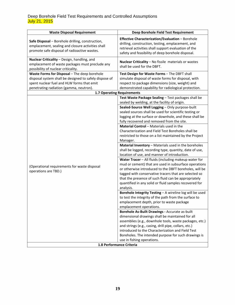
Safe Disposal – Borehole drilling, construction, emplacement, sealing and closure activities shall promote safe disposal of radioactive wastes.
Effective Characterization/Evaluation – Borehole drilling, construction, testing, emplacement, and retrieval activities shall support evaluation of the safety and feasibility of deep borehole disposal.
Nuclear Criticality – Design, handling, and emplacement of waste packages must preclude any possibility of nuclear criticality.
Nuclear Criticality – No fissile materials or wastes shall be used for the DBFT.
Waste Forms for Disposal – The deep borehole disposal system shall be designed to safely dispose of spent nuclear fuel and HLW forms that emit penetrating radiation (gamma, neutron).
Test Design for Waste Forms – The DBFT shall simulate disposal of waste forms for disposal, with respect to package dimensions (size, weight) and demonstrated capability for radiological protection.
1.7 Operating Requirements
(Operational requirements for waste disposal operations are TBD.)
Test Waste Package Sealing – Test packages shall be sealed by welding, at the facility of origin.
Sealed‐Source Well Logging – Only purpose‐built sealed sources shall be used for scientific testing or logging at the surface or downhole, and these shall be fully recovered and removed from the site.
Material Control – Materials used in the Characterization and Field Test Boreholes shall be restricted to those on a list maintained by the Project Manager.
Material Inventory – Materials used in the boreholes shall be logged, recording type, quantity, date of use, location of use, and manner of introduction.
Water Tracer – All fluids (including makeup water for mud or cement) that are used in subsurface operations or otherwise introduced to the DBFT boreholes, will be tagged with conservative tracers that are selected so that the presence of such fluid can be appropriately quantified in any solid or fluid samples recovered for analysis.
Borehole Integrity Testing – A wireline log will be used to test the integrity of the path from the surface to emplacement depth, prior to waste package emplacement operations.
Borehole As‐Built Drawings ‐ Accurate as‐built dimensional drawings shall be maintained for all assemblies (e.g., downhole tools, waste packages, etc.) and strings (e.g., casing, drill pipe, collars, etc.) introduced to the Characterization and Field Test Boreholes. The intended purpose for such drawings is use in fishing operations.
1.8 Performance Criteria
Deep Borehole Field Test Requirements and Controlled Assumptions July 21, 2015
20
Waste Disposal Requirement Deep Borehole Field Test Requirement
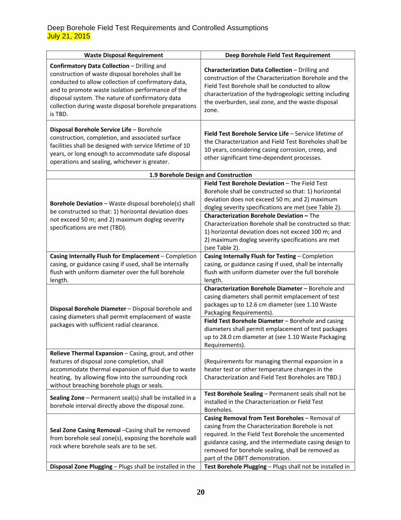
Confirmatory Data Collection – Drilling and construction of waste disposal boreholes shall be conducted to allow collection of confirmatory data, and to promote waste isolation performance of the disposal system. The nature of confirmatory data collection during waste disposal borehole preparations is TBD.
Characterization Data Collection – Drilling and construction of the Characterization Borehole and the Field Test Borehole shall be conducted to allow characterization of the hydrogeologic setting including the overburden, seal zone, and the waste disposal zone.
Disposal Borehole Service Life – Borehole construction, completion, and associated surface facilities shall be designed with service lifetime of 10 years, or long enough to accommodate safe disposal operations and sealing, whichever is greater.
Field Test Borehole Service Life – Service lifetime of the Characterization and Field Test Boreholes shall be 10 years, considering casing corrosion, creep, and other significant time‐dependent processes.
1.9 Borehole Design and Construction
Borehole Deviation – Waste disposal borehole(s) shall be constructed so that: 1) horizontal deviation does not exceed 50 m; and 2) maximum dogleg severity specifications are met (TBD).
Field Test Borehole Deviation – The Field Test Borehole shall be constructed so that: 1) horizontal deviation does not exceed 50 m; and 2) maximum dogleg severity specifications are met (see Table 2).
Characterization Borehole Deviation – The Characterization Borehole shall be constructed so that: 1) horizontal deviation does not exceed 100 m; and 2) maximum dogleg severity specifications are met (see Table 2).
Casing Internally Flush for Emplacement – Completion casing, or guidance casing if used, shall be internally flush with uniform diameter over the full borehole length.
Casing Internally Flush for Testing – Completion casing, or guidance casing if used, shall be internally flush with uniform diameter over the full borehole length.
Disposal Borehole Diameter – Disposal borehole and casing diameters shall permit emplacement of waste packages with sufficient radial clearance.
Characterization Borehole Diameter – Borehole and casing diameters shall permit emplacement of test packages up to 12.6 cm diameter (see 1.10 Waste Packaging Requirements).
Field Test Borehole Diameter – Borehole and casing diameters shall permit emplacement of test packages up to 28.0 cm diameter at (see 1.10 Waste Packaging Requirements).
Relieve Thermal Expansion – Casing, grout, and other features of disposal zone completion, shall accommodate thermal expansion of fluid due to waste heating, by allowing flow into the surrounding rock without breaching borehole plugs or seals.
(Requirements for managing thermal expansion in a heater test or other temperature changes in the Characterization and Field Test Boreholes are TBD.)
Sealing Zone – Permanent seal(s) shall be installed in a borehole interval directly above the disposal zone.
Test Borehole Sealing – Permanent seals shall not be installed in the Characterization or Field Test Boreholes.
Seal Zone Casing Removal –Casing shall be removed from borehole seal zone(s), exposing the borehole wall rock where borehole seals are to be set.
Casing Removal from Test Boreholes – Removal of casing from the Characterization Borehole is not required. In the Field Test Borehole the uncemented guidance casing, and the intermediate casing design to removed for borehole sealing, shall be removed as part of the DBFT demonstration.
Disposal Zone Plugging – Plugs shall be installed in the Test Borehole Plugging – Plugs shall not be installed in
Deep Borehole Field Test Requirements and Controlled Assumptions July 21, 2015
21
Waste Disposal Requirement Deep Borehole Field Test Requirement
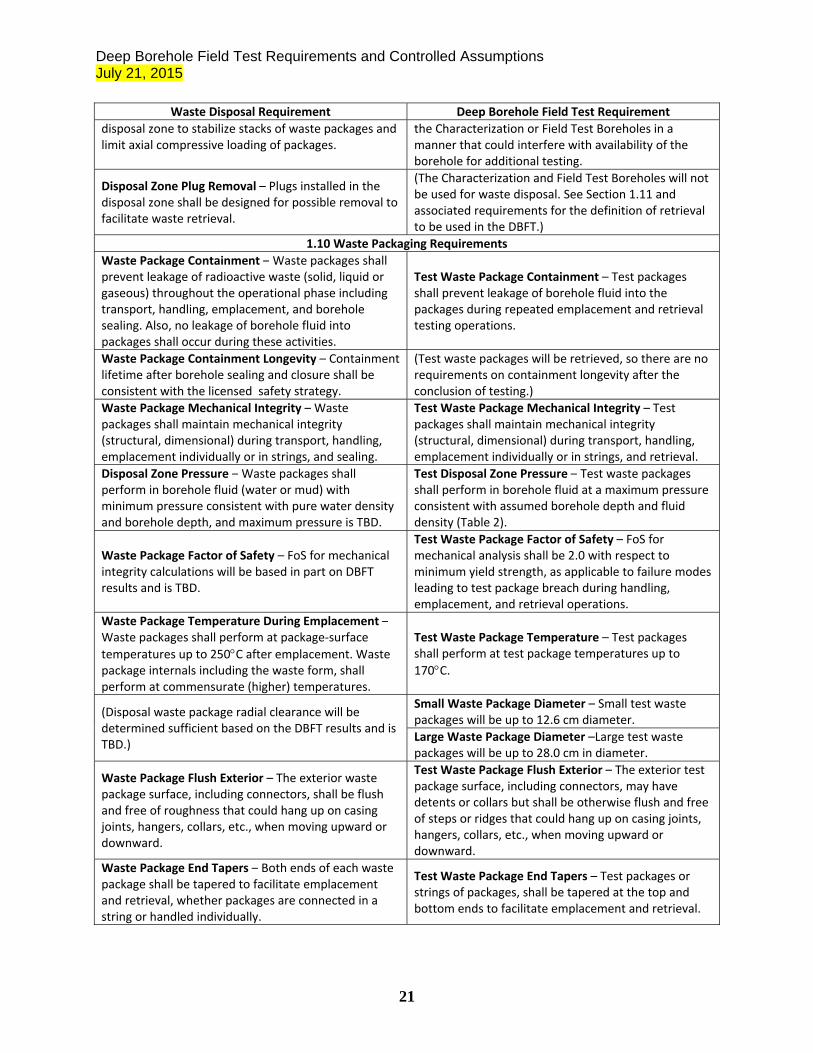
disposal zone to stabilize stacks of waste packages and limit axial compressive loading of packages.
the Characterization or Field Test Boreholes in a manner that could interfere with availability of the borehole for additional testing.
Disposal Zone Plug Removal – Plugs installed in the disposal zone shall be designed for possible removal to facilitate waste retrieval.
(The Characterization and Field Test Boreholes will not be used for waste disposal. See Section 1.11 and associated requirements for the definition of retrieval to be used in the DBFT.)
1.10 Waste Packaging Requirements
Waste Package Containment – Waste packages shall prevent leakage of radioactive waste (solid, liquid or gaseous) throughout the operational phase including transport, handling, emplacement, and borehole sealing. Also, no leakage of borehole fluid into packages shall occur during these activities.
Test Waste Package Containment – Test packages shall prevent leakage of borehole fluid into the packages during repeated emplacement and retrieval testing operations.
Waste Package Containment Longevity – Containment lifetime after borehole sealing and closure shall be consistent with the licensed safety strategy.
(Test waste packages will be retrieved, so there are no requirements on containment longevity after the conclusion of testing.)
Waste Package Mechanical Integrity – Waste packages shall maintain mechanical integrity (structural, dimensional) during transport, handling, emplacement individually or in strings, and sealing.
Test Waste Package Mechanical Integrity – Test packages shall maintain mechanical integrity (structural, dimensional) during transport, handling, emplacement individually or in strings, and retrieval.
Disposal Zone Pressure – Waste packages shall perform in borehole fluid (water or mud) with minimum pressure consistent with pure water density and borehole depth, and maximum pressure is TBD.
Test Disposal Zone Pressure – Test waste packages shall perform in borehole fluid at a maximum pressure consistent with assumed borehole depth and fluid density (Table 2).
Waste Package Factor of Safety – FoS for mechanical integrity calculations will be based in part on DBFT results and is TBD.
Test Waste Package Factor of Safety – FoS for mechanical analysis shall be 2.0 with respect to minimum yield strength, as applicable to failure modes leading to test package breach during handling, emplacement, and retrieval operations.
Waste Package Temperature During Emplacement –Waste packages shall perform at package‐surface
temperatures up to 250C after emplacement. Waste package internals including the waste form, shall perform at commensurate (higher) temperatures.
Test Waste Package Temperature – Test packages shall perform at test package temperatures up to
170C.
(Disposal waste package radial clearance will be determined sufficient based on the DBFT results and is TBD.)
Small Waste Package Diameter – Small test waste packages will be up to 12.6 cm diameter.
Large Waste Package Diameter –Large test waste packages will be up to 28.0 cm in diameter.
Waste Package Flush Exterior – The exterior waste package surface, including connectors, shall be flush and free of roughness that could hang up on casing joints, hangers, collars, etc., when moving upward or downward.
Test Waste Package Flush Exterior – The exterior test package surface, including connectors, may have detents or collars but shall be otherwise flush and free of steps or ridges that could hang up on casing joints, hangers, collars, etc., when moving upward or downward.
Waste Package End Tapers – Both ends of each waste package shall be tapered to facilitate emplacement and retrieval, whether packages are connected in a string or handled individually.
Test Waste Package End Tapers – Test packages or strings of packages, shall be tapered at the top and bottom ends to facilitate emplacement and retrieval.
Deep Borehole Field Test Requirements and Controlled Assumptions July 21, 2015
22
Waste Disposal Requirement Deep Borehole Field Test Requirement
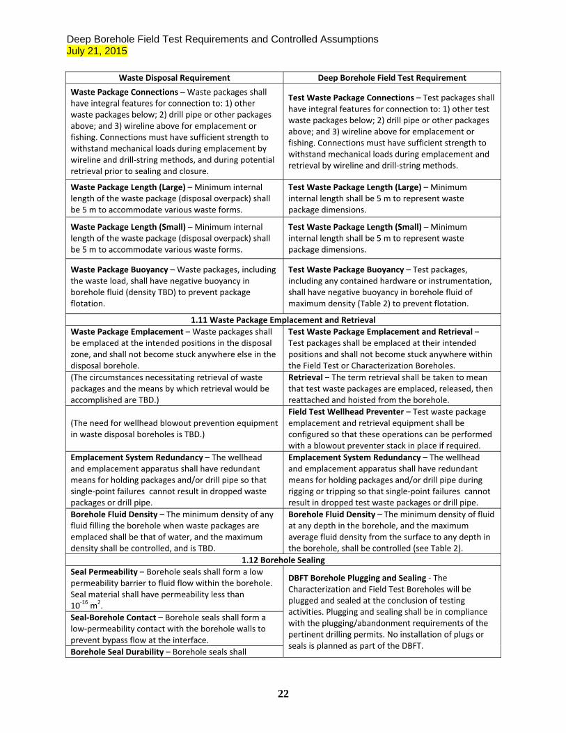
Waste Package Connections – Waste packages shall have integral features for connection to: 1) other waste packages below; 2) drill pipe or other packages above; and 3) wireline above for emplacement or fishing. Connections must have sufficient strength to withstand mechanical loads during emplacement by wireline and drill‐string methods, and during potential retrieval prior to sealing and closure.
Test Waste Package Connections – Test packages shall have integral features for connection to: 1) other test waste packages below; 2) drill pipe or other packages above; and 3) wireline above for emplacement or fishing. Connections must have sufficient strength to withstand mechanical loads during emplacement and retrieval by wireline and drill‐string methods.
Waste Package Length (Large) – Minimum internal length of the waste package (disposal overpack) shall be 5 m to accommodate various waste forms.
Test Waste Package Length (Large) – Minimum internal length shall be 5 m to represent waste package dimensions.
Waste Package Length (Small) – Minimum internal length of the waste package (disposal overpack) shall be 5 m to accommodate various waste forms.
Test Waste Package Length (Small) – Minimum internal length shall be 5 m to represent waste package dimensions.
Waste Package Buoyancy – Waste packages, including the waste load, shall have negative buoyancy in borehole fluid (density TBD) to prevent package flotation.
Test Waste Package Buoyancy – Test packages, including any contained hardware or instrumentation, shall have negative buoyancy in borehole fluid of maximum density (Table 2) to prevent flotation.
1.11 Waste Package Emplacement and Retrieval
Waste Package Emplacement – Waste packages shall be emplaced at the intended positions in the disposal zone, and shall not become stuck anywhere else in the disposal borehole.
Test Waste Package Emplacement and Retrieval –Test packages shall be emplaced at their intended positions and shall not become stuck anywhere within the Field Test or Characterization Boreholes.
(The circumstances necessitating retrieval of waste packages and the means by which retrieval would be accomplished are TBD.)
Retrieval – The term retrieval shall be taken to mean that test waste packages are emplaced, released, then reattached and hoisted from the borehole.
(The need for wellhead blowout prevention equipment in waste disposal boreholes is TBD.)
Field Test Wellhead Preventer – Test waste package emplacement and retrieval equipment shall be configured so that these operations can be performed with a blowout preventer stack in place if required.
Emplacement System Redundancy – The wellhead and emplacement apparatus shall have redundant means for holding packages and/or drill pipe so that single‐point failures cannot result in dropped waste packages or drill pipe.
Emplacement System Redundancy – The wellhead and emplacement apparatus shall have redundant means for holding packages and/or drill pipe during rigging or tripping so that single‐point failures cannot result in dropped test waste packages or drill pipe.
Borehole Fluid Density – The minimum density of any fluid filling the borehole when waste packages are emplaced shall be that of water, and the maximum density shall be controlled, and is TBD.
Borehole Fluid Density – The minimum density of fluid at any depth in the borehole, and the maximum average fluid density from the surface to any depth in the borehole, shall be controlled (see Table 2).
1.12 Borehole Sealing
Seal Permeability – Borehole seals shall form a low permeability barrier to fluid flow within the borehole. Seal material shall have permeability less than 10‐16 m2.
DBFT Borehole Plugging and Sealing ‐ The Characterization and Field Test Boreholes will be plugged and sealed at the conclusion of testing activities. Plugging and sealing shall be in compliance with the plugging/abandonment requirements of the pertinent drilling permits. No installation of plugs or seals is planned as part of the DBFT.
Seal‐Borehole Contact – Borehole seals shall form a low‐permeability contact with the borehole walls to prevent bypass flow at the interface.
Borehole Seal Durability – Borehole seals shall

Deep Borehole Field Test Requirements and Controlled Assumptions July 21, 2015
23
Waste Disposal Requirement Deep Borehole Field Test Requirement
function at temperatures up to 200C, and throughout the duration of the thermal period.
Seals Environment – Borehole seals shall resist mechanical loading from overlying materials in the borehole, retaining low‐permeability properties.
Redundant Seal Design – Seals and sealing materials shall be designed to provide redundant performance.
1.13 Characterization Testing
(Testing, logging, sampling, and other data collection requirements for disposal boreholes are TBD.)
Safety Basis for Testing – Testing, logging, sampling, and other data collection shall be directly linked to the deep borehole disposal safety case.
Testing Baseline – Testing, logging, sampling, and other data collection, and disposition of samples, shall be specified in a testing baseline.
Test Interference – Surface and subsurface testing activities shall be evaluated prior to deployment to determine whether they may significantly interfere with other testing activities.

Deep Borehole Field Test Requirements and Controlled Assumptions July 21, 2015
24
Table 2. Controlled assumptions for deep borehole waste disposal and the DBFT.
2. Controlled Assumptions
Waste Disposal Assumption Deep Borehole Field Test Assumption
(Specific waste forms to be disposed of in deep boreholes, at specific sites or geologic settings, are TBD.)
Demonstrating Disposal of Waste Forms – The DBFT will demonstrate technologies for disposal of waste packages that are designed to contain granular waste forms, HLW glass, HLW in sealed capsules, or spent nuclear fuel.
(Borehole total depth for borehole disposal of radioactive waste is TBD.)
Test Borehole Total Depth – The Characterization and Field Test Boreholes shall be 5,000 m in depth.
Waste Package Strings – When waste packages are connected together and emplaced in the borehole (by any method) the number of packages is limited to 40. In addition, the number of packages stacked in the disposal zone and not separated by a casing plug, is also limited to 40 no matter whether they are emplaced individually or in strings of any size.
Test Waste Package Strings – When test waste packages are connected together and emplaced in the borehole (by any method) the number of packages is limited to 40.
(Leakage control requirements for waste packages during operations are TBD.)
Test Waste Package Failure – For testing purposes package failure leading to leakage is defined as uncontrolled dropping of one or more packages in the borehole, or uncontrolled dropping of drill pipe onto one or more packages in the borehole.
(The need for packaging or waste storage facilities in the field, proximal to disposal borehole locations, is TBD.)
Test Waste Package Storage On‐Site – Test packages may be stored temporarily on‐site, in a safe manner consistent with the objectives of the DBFT.
Waste Packaging and Storage Demonstrations – The DBFT will not demonstrate the means of packaging actual wastes, or the storage of packages containing actual waste, in the field proximal to borehole locations.
(Long‐term control and ownership of sites for deep borehole disposal of radioactive waste are TBD.)
Site Ownership at DBFT Conclusion – Assume that control of the field site and borehole(s) will be transferred to a different entity, or a different purpose, at the conclusion of the DBFT. Thus, the Characterization and Field Test Boreholes will be left in serviceable condition, to the extent possible.
(The need for directional drilling for disposal boreholes is TBD, and may depend on whether waste packages are emplaced using a wireline method, or lowered in long strings on drill pipe.)
Dogleg Severity Directional Drilling – Dogleg severity
will be limited to 2/100 ft in the upper 1,000 m of the Characterization and Field Test Boreholes, and to
3/100 ft below that (see maximum deviation requirement).
(Minimum and maximum density of borehole fluid in disposal boreholes when waste packages are present are TBD.)
Borehole Fluid Density – Borehole fluid maximum average density (average from the surface to package
depth) is assumed to be 1.3 the density of pure water at in situ conditions. Minimum density anywhere in the borehole is assumed to be that of pure water.
(Maximum weight of disposal waste packages is TBD.)
Test Waste Package Maximum Weight – Single test waste packages can weigh up to 4,620 lb (2,100 kg) loaded, in air, including connectors, adapters, and any other items that may be affixed to the ends.
Deep Borehole Field Test Requirements and Controlled Assumptions July 21, 2015
25
DISTRIBUTION 1 Mark Denton AREVA Federal Services LLC 7207 IBM Drive, CLT-2C Charlotte, NC 28262 1 MS0747 Ernest Hardin 6224 (electronic copy) 1 MS0747 Geoff Freeze 6224 (electronic copy) 1 MS0747 Kris Kuhlman 6224 (electronic copy) 1 MS0747 David Sassani 6224 (electronic copy) 1 MS0899 Technical Library 9536 (electronic copy)
Deep Borehole Field Test Requirements and Controlled Assumptions July 21, 2015
26