definition and analysis of hardware- and software-fault...
TRANSCRIPT

Definition and Analysis of Hardware- and
Software-Fault-Tolerant Architectures
Jean-Claude Laprie, Jean Arlat, Christian Bbounes,
and Karama Kanoun
LAAS-CNRS
0th experimental and real-life safety-related systems have begun to use design diversity to tolerate
software faults.’ Such systems focus strongly on design faults, where the term “design” encompasses everything from system requirements to realization during both initial production and future modifi- cations. Design faults are a source of common-mode failures, which defeat
replication (that cope with physical faults) and generally have catastrophic conse- quences.
Precomputer safety-related systems minimized common-mode failures hardware and railways’ interlocking system).’
To confine computer failures, a system must automatically check execution re- sults for the errors that could lead to fail- ure. There are two main approaches to de- tecting errors caused by design faults:
Systems in which one piece of hardware
B ( 1 ) Acceptance tests of the results via
executable assertions. These asser- tions are generalized, formalized versions of likelihood checks used in process control.
(2) Diversified design, so that the re- sults of two software variants can be compared (as in the Airbus A-300 and A-3 10 airliners and the Swedish
software are subject to fault-tolerance strategies based on strict Software failures and
require architectures that tolerate both
through diversified design, that is, two or more systems delivering the same service through separate designs and realizations. A typical example is a hardwired elec- tronic channel backed by an electro- mechanic or electropneumatic channel. In addition, system architecture was based on the federation of equipment, where each piece of equipment implemented one or more subfunctions of the system rather than the entire system. Such partitioning confined equipment failures to subfunc- tions, allowing the system’s global func- tion to continue, although possibly in a degraded mode.
software faults.
Computer-based safety-related systems generally retain the federation approach. Each subfunction is implemented by a “complete” computer comprising hard- ware and executive and application soft- ware. Examples of this approach include airplane flight-control systems (such as in the Boeing 757/767 airliner) and nuclear- plant monitors (such as Merlin-GCrin’s Systtme de Protection IntCgrC NumCrique).
The federation approach generally re- quires far more processing elements than are needed for computing power alone; for instance, the Boeing757/767 flight-control system comprises 80 distinct functional microprocessors, 300 when we account for redundancy.
We could use computers better in such systems if the same hardware supported software for several subfunctions. Such an approach, called integration, is subject to software failures, which are due to design faults only. Thus, integration requires soft- ware-fault tolerance. Moreover, some safety-related systems (such as those in the
39 0018-9162/90/0700-0039$01.00 Q 1990 IEEE July 1990

Table 1. Main characteristics of the software-fault-tolerance strategies. ~~
Method Error-Processing Judgment on Variant-Execution Consistency of Suspension of No. Variants
Acceptability During Error f Sequential Technique Result Scheme Input Data Service Delivery to Tolerate
Processing Faults
Recovery Error detection by Blocks acceptance tests (RBI and backward
recovery
Absolute, with respect to specification
Sequential Implicit, from Yes, duration f+ 1 back ward necessary for recovery executing one principle or more variants
N Self-checking Error detection Programming and result (NSCP) switching
Detection by acceptance tests
Detection by comparison
N-Version Vote Programming ( N W
Absolute, with respect to specification
Relative, on variant results
Relative, on variant results
f+ 1 Parallel Explicit, by Yes, duration dedicated necessary for mechanisms result switching
Parallel Explicit, by Yes, duration 2Cf+l) dedicated necessary for mechanisms result switching
Parallel Explicit, by No f+2 dedicated mechanisms
NASA Space Shuttle and the Airbus A-320 airliner) are moving toward limiting or eliminating manual or noncomputer backup systems. This is an additional in- centive for software-fault tolerance, since safe system behavior becomes entirely dependent on reliable software behavior.
This article elaborates on previous work to present a structured definition of hard- ware- and software-fault-tolerant architec- tures.2 We have tried to be as general as possible, dealing with specific classes of faults or techniques only when necessary. (More specific definitions extending the recovery block approach3 and N-version programming4 have appeared elsewhere.) After discussing software-fault-tolerance methods, we present a set of hardware- and software-fault-tolerant architectures and analyze and evaluate three of them. A side- bar addresses the cost issues related to soft- ware-fault tolerance.
conditions and inputs. The common speci- fication must explicitly address the deci- sion points, that is, it must state when to make decisions and what data to base them on (the data processed by the decider).
The best-documented techniques for tolerating software design faults are the recovery block (RB) approach5 and N - version programming (NVP).6 In the first approach, the variants are called alternates and thedecider is an acceptance test, which is applied sequentially to the alternates’ results. If the results of the primary alter- nate do not satisfy the acceptance test, the secondary alternate executes. In the sec- ond approach, the variants are called ver- sions, and the decider is a vote based on all versions’ results.
We use the term “variant” rather than “alternate” or “version” because “alter- nate” reflects sequential execution, which is a feature specific to the recovery block approach, and “version” has another mean- ing: successive versions of a system result- ing from fault removal or functionality evolution. During the life of a diversely designed system, several versions of the
Software-fault- tolerance methods
variants will be generated. The hardware-fault-tolerant architec-
tures equivalent to RB and NVP are stand- by sparing and N-modular redundancy, respectively. A third approach to hard- ware-fault tolerance, active dynamic re- dundancy, is very popular (especially
In a diversified design, the different systems produced from a common service specification are called variants. A diver- sified design has at least two variants plus a decider, which monitors the results of variant execution, given consistent initial
when based on self-checking components, such as in the AT&T Electronic Switching System and the Stratus system), but it has not been described in the literature as a generic technique for software-fault tolerance. However, self-checking pro- gramming has long been defined;’ a self- checking program results from adding re- dundancy to a program so that it can check its own dynamic behavior during execu- tion. A self-checking software component consists of either a variant and an accep- tance test or two variants and a comparison algorithm.
Fault tolerance is provided by the paral- lel execution of at least two self-checking components. At each execution of such a system, one component “acts” (that is, it delivers service or results to the controlled or monitored application), while the other components remain “hot” spares. When the acting component fails, a spare begins delivering service. If a spare fails, the act- ing component continues delivering ser- vice. Error processing is thus performed through error detection and possible switching of results. We call this approach N self-checking programming (NSCP).
It could be argued that NSCP is just a parallel recovery block scheme, but the latter’s backward recovery strategy pre- vents it from being reduced to the associa- tion of alternates together with an accep- tance test. In NSCP, when a self-checking
40 COMPUTER
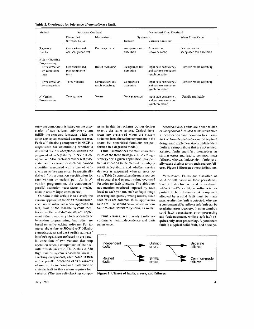
Table 2. Overheads for tolerance of one software fault.
Method Structural Overhead Operational Time Overhead
Diversified Mechanisms Systematic When Errors Occur Software Layer Decider Variants Execution
Recovery One variant and Recovery cache Blocks one acceptance test
N Self-checking Programming
Error detection One variant and Result switching by acceptance two acceptance tests tests
Error detection Three variants Comparators and by comparison result switching
N-Version Two variants Voters Programming
Acceptance test Accesses to One variant and execution recovery cache acceptance test execution
Acceptance test Input data consistency Possible result switching execution and variants execution
synchronization
Comparison Input data consistency Possible result switching execution and variants execution
synchronization
Vote execution Input data consistency Usually negligible and variants execution synchronization
software component is based on the asso- ciation of two variants, only one variant fulfills the expected functions, while the other acts as an extended acceptance test. Each self-checking component in NSCP is responsible for determining whether a delivered result is acceptable, whereas the judgment of acceptability in NVP is co- operative. Also, each acceptance test asso- ciated with a variant, or each comparison algorithm associated with a pair of vari- ants, can be the same or can be specifically derived from a common specification for each variant or variant pair. As in N - version programming, the components’ parallel execution necessitates a mecha- nism to ensure input consistency.
Our aim in this article is to classify the various approaches to software-fault toler- ance, not to introduce a new approach. In fact, most of the real-life systems men- tioned in the introduction do not imple- ment either a recovery block approach or N-version programming, but rather are based on self-checking software. For in- stance, the Airbus A-300 and A-310 flight- control systems and the Swedish railways’ interlocking system are based on the paral- lel execution of two variants that stop operation when a comparison of their re- sults reveals an error. The Airbus A-320 flight-control system is based on two self- checking components, each based in turn on the parallel execution of two variants whose results are compared. Tolerance of a single fault in this system requires four variants. (The two self-checking compo-
nents in this last scheme do not deliver exactly the same service. Critical func- tions are preserved when the system switches from the acting component to the spare, but noncritical functions are per- formed in a degraded mode.)
Table 1 summarizes the main character- istics of the three strategies. In selecting a strategy for a given application, pay par- ticular attention to the method for judging result acceptability and whether service delivery is suspended when an error oc- curs. Table 2 summarizes the main sources of structural and operation-time overhead for software-fault tolerance. The table does not mention overhead imposed by tests local to each variant, such as input range checking and grossly wrong results, since such tests are common to all approaches (and are - or should be -present in non- fault-tolerant software systems, as well).
Fault classes. We classify faults ac- cording to their independence and their persistence.
Independence . Faults are either related or independem6 Related faults result from a specification fault common to all vari- ants or from dependencies in the separate designs and implementations. Independent faults are simply those that are not related. Related faults manifest themselves as similar errors and lead to common-mode failures, whereas independent faults usu- ally cause distinct errors and separate fail- ures. Figure 1 illustrates these definitions.
Pers i s t ence . Faults are classified as solid or soft based on their persisrence. Such a distinction is usual in hardware, where a fault’s solidity or softness is im- portant to fault tolerance. A component affected by a solid fault must be made passive after the fault is detected, whereas a component affected by a soft fault can be used after error recovery. In other words, a solid fault necessitates error processing and fault treatment, while a soft fault re- quires only error processing. A permanent fault is a typical solid fault, and a tempo-
Independent Distinct Separate faults wwl failures
Related Similar Common-mode faults failures
I I Figure 1. Classes of faults, errors, and failures.
July 1990 41

The cost of software-fault tolerance Fault tolerance introduces additional
costs; we estimate those costs here. Since design diversity affects costs dif- ferently according to the life-cycle phases, we start with cost distribution among the various life-cycle activities for classical, non-fault-tolerant, soft- ware. Our simplified life-cycle model‘ (see the first table) groups all activities relating to verification and validation (V&V) separately.
Three maintenance categories cover the software’s entire operational life.’ Corrective maintenance concerns fault removal and involves design, imple- mentation, and V&V. Adaptive mainte- nance adjusts software to environ- mental changes and also involves specification activity. Perfective mainte- nance improves the software’s function; thus, it actually concerns software evo- lution, and so involves all development activities, starting with modified require- ments.
The cost breakdowns for the life- cycle and maintenance’ do not address a specific class of software. However, since we are concerned with critical ap- plications, we must incorporate some multiplicative factors that depend on the particular activity.* The last two col- umns, which are derived from the data in the other columns, give the life-cycle cost distribution for development only and for development and maintenance.
Software cost elements for non-fault-tolerant software.
Life-Cycle Multipliers Cost Distribution Activity Cost Breakdown’ for Critical Development Development
Applications2 and Maintenance
Development Requirements 3% 1.3 8% 6 % Specification 3 % 1.3 8% 7 % Design 5% 1.3 13% 14% Implementation 7 Yo 1.3 19% 19%
and Validation 1 5% 1.8 52% 54% Verification
Maintenance. 67%
*Of this, 20% is for corrective maintenance, 25% is for adaptive maintenance, and 55% is for perfective maintenance.’
From this table, it appears that main- tenance does not significantly affect cost distribution over the other life-cycle activities (in fact, the discrepancy is likely to be lower than indicated). Ac- cordingly, let’s assume in the following
back-to-back testing, and V&V tools, such as test harnesses. We cannot ac- curately estimate such factors given the current state of the art. We can, how- ever, give reasonable ranges of vari- ations.
example that the figures for develop- ment only are general and cover the en- tire life-cycle, since we are concerned only with relative costs.
software, we must introduce factors to account for the overheads associated with the decision points and the decid- ers and to account for the cost reduc- tion in V&V caused by commonalties among variants. These commonalties include actual V&V activities, such as
To determine the cost of fault-tolerant
Consider the following factors: * r is the multiplier associated with the
decision points, with 1 c r c 1.2. *S is the multiplier associated with the
decider, with 1 c s c 1.1 for NVP and NSCP when error detection is per- formed through comparison, and 1 < s c 1.3 for RB and NSCP when error de- tection is performed through accep- tance tests. This difference reflects the differences in the deciders, that is, the fact that the deciders are specific when
rary fault (either transient or intermittent) is a typical soft fault.
Let’s now consider software faults in operational programs. Once a program has been thoroughly debugged, problems are more likely to arise from subtle fault con- ditions (such as limit conditions, race conditions, or strange underlying hard- ware conditions) than from easily identifi- able faults. Just a slight change in the execution context could keep fault condi- tions from occurring again, thus keeping the software from failing again. Since the likelihood of such an error occurring again is negligible, we can extend the notion of a soft fault to software.8
Another important consideration for error recovery is the notion of local and global variables for the components. Let’s call the program between two decision points a diversity unit. Generally, error recovery requires that the diversity units be procedures (so their activation and behavior do not depend on any internal
state). In other words, all data needed by a diversity unit must be global data. The data’s global nature can result from the nature of the application itself. One ex- ample is physical-process monitoring (such as nuclear-plant protection), where tasks begin based on sensor data and do not use data from previous processing. The data’s global nature can also result from transforming local data into global data. This incurs overhead and could decrease diversity (since the decision-point specifi- cation must be more precise). A simplified example is a filtering function that consti- tutes a diversity unit. In this example, past samples should be part of the global data.
Although these classifications apply to all software-fault-tolerance methods, we can alter the general rules somewhat in specific, application-dependent cases. For example, there is an alternate solution for NSCP and NVP when the overhead cannot be afforded or when transforming local data into global data will decrease diver-
sity too much. This solution involves fault treatment, that is, i t eliminates failed vari- ants from further processing.
Let’s summarize the preceding discus- sion by adopting the following definitions for soft and solid faults: A soft software fault has a negligible likelihood of recur- rence and is recoverable, while a solid software fault is recurrent under normal operation or cannot be recovered.
Defining hardware- and software-fault- tolerant architectures
Our discussion of architectures that tol- erate both hardware and software faults emphasizes the dependencies among the software- and hardware-fault-tolerance methods and the effects of solid and soft software faults on the architecture defini- tion. We investigate two levels of fault-
42 COMPUTER
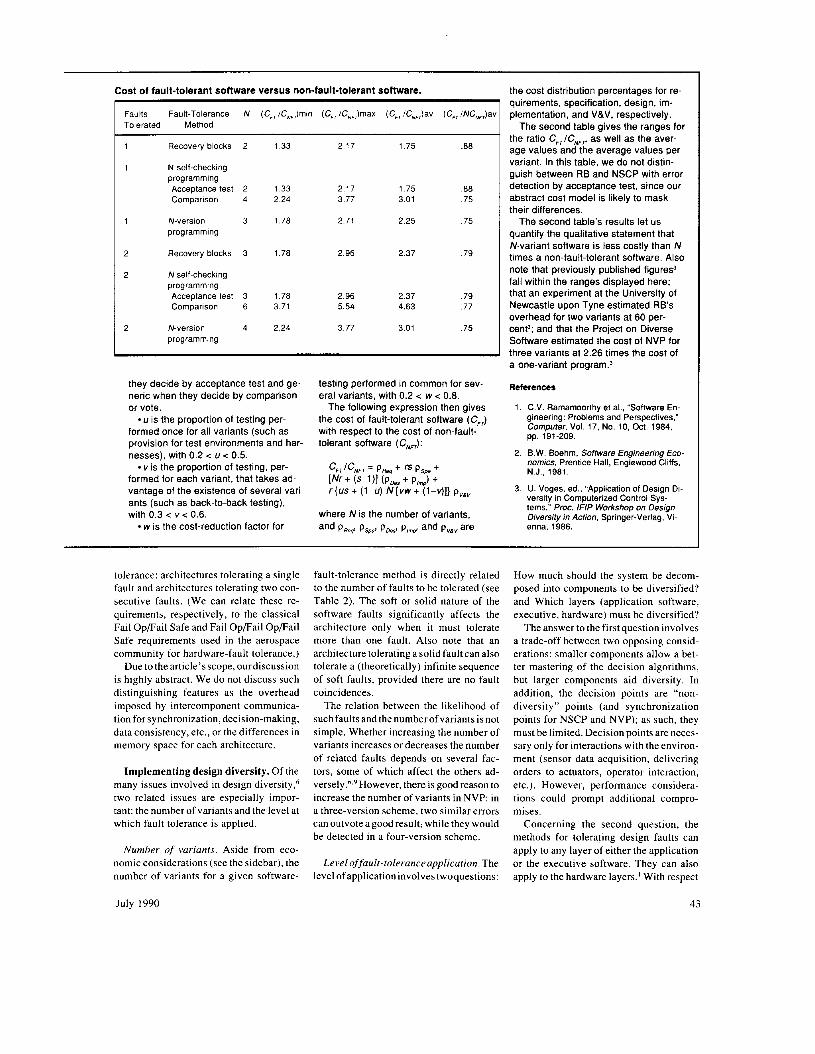
Cost of fault-tolerant software versus non-fault-tolerant software.
Faults Fault-Tolerance N (C,,/C,Jmin (C,,/C,,)max (C, /CN,,)av (C,, /NC,,,)av Tolerated Method
Recovery blocks 2 1.33
N self-checking programming Acceptance test 2 1.33 Comparison 4 2.24
N-version 3 1.78 programming
Recovery blocks 3 1.78
N self-checking programming Acceptance test 3 1.78 Comparison 6 3.71
N-version 4 2.24 programming
2.17
2.17 3.77
2.71
2.96
2.96 5.54
3.77
1.75
1.75 3.01
2.25
2.37
2.37 4.63
3.01
~
.88
.88
.75
.75
.79
.79
.77
.75
they decide by acceptance test and ge- neric when they decide by comparison or vote.
U is the proportion of testing per- formed once for all variants (such as provision for test environments and har- nesses), with 0.2 < U < 0.5.
vis the proportion of testing, per- formed for each variant, that takes ad- vantage of the existence of several vari- ants (such as back-to-back testing), with 0.3 < v < 0.6.
w is the cost-reduction factor for
testing performed in common for sev- eral variants, with 0.2 < w < 0.8.
The following expression then gives the cost of fault-tolerant software ( Cm) with respect to the cost of non-fault- tolerant software (C,,):
‘FTl‘NFT = P R q + ” P S p +
[Nr + (s-1 )I (Pms + P,J + rIus + ( 1 4 N [ v w + (1-411 P”&
and PReq’ PSWl PD& P,,,S and P,, are where N is the number of variants,
the cost distribution percentages for re- quirements, specification, design, im- plementation, and V&V, respectively.
the ratio C,,/C,,, as well as the aver- age values and the average values per variant. In this table, we do not distin- guish between RB and NSCP with error detection by acceptance test, since our abstract cost model is likely to mask their differences.
The second table’s results let us quantify the qualitative statement that N-variant software is less costly than N times a non-fault-tolerant software. Also note that previously published figures3 fall within the ranges displayed here; that an experiment at the University of Newcastle upon Tyne estimated RB’s overhead for two variants at 60 per- cent and that the Project on Diverse Software estimated the cost of NVP for three variants at 2.26 times the cost of a one-variant ~ r o g r a m . ~
References
The second table gives the ranges for
1. C.V. Ramamoorthy et al., “Software En- gineering: Problems and Perspectives,” Computer, Vol. 17. No. 10, Oct. 1984,
2. B.W. Boehm, Sofbvare Engineering Eco- nomics, Prentice Hall, Englewood Cliffs, N.J., 1981.
3. U. Voges, ed., “Application of Design Di. versity in Computerized Control Sys- tems,” Proc. /NP Workshop on Design Diversity in Action, Springer-Verlag, Vi- enna, 1986.
pp. 191-209.
tolerance: architectures tolerating a single fault and architectures tolerating two con- secutive faults. (We can relate these re- quirements, respectively, to the classical Fail OpFail Safe and Fail Op/Fail OpFai l Safe requirements used in the aerospace community for hardware-fault tolerance.)
Due to the article’s scope, our discussion is highly abstract. We do not discuss such distinguishing features as the overhead imposed by intercomponent communica- tion for synchronization, decision-making, data consistency, etc., or the differences in memory space for each architecture.
Implementing design diversity. Of the many issues involved in design diversity,6 two related issues are especially impor- tant: the number of variants and the level at which fault tolerance is applied.
Number of variants. Aside from eco- nomic considerations (see the sidebar), the number of variants for a given software-
fault-tolerance method is directly related to the number of faults to be tolerated (see Table 2). The soft or solid nature of the software faults significantly affects the architecture only when it must tolerate more than one fault. Also note that an architecture tolerating a solid fault can also tolerate a (theoretically) infinite sequence of soft faults, provided there are no fault coincidences.
The relation between the likelihood of such fault sandthe numberofvariantsisnot simple. Whether increasing the number of variants increases or decreases the number of related faults depends on several fac- tors, some of which affect the others ad- v e r ~ e l y . ~ . ~ However, there is good reason to increase the number of variants in NVP: in a three-version scheme, two similar errors can outvote agood result; while they would be detected in a four-version scheme.
Level offault-toleranceapplication. The level of application involves twoquestions:
How much should the system be decom- posed into components to be diversified? and Which layers (application software, executive, hardware) must be diversified?
The answer to the first question involves a trade-off between two opposing consid- erations: smaller components allow a bet- ter mastering of the decision algorithms, but larger components aid diversity. In addition, the decision points are “non- diversity” points (and synchronization points for NSCP and NVP); as such, they must be limited. Decision points are neces- sary only for interactions with the environ- ment (sensor data acquisition, delivering orders to actuators, operator interaction, etc.). However, performance considera- tions could prompt additional compro- mises.
Concerning the second question, the methods for tolerating design faults can apply to any layer of either the application or the executive software. They can also apply to the hardware layers.’ With respect
July 1990 43
f- ’F E!
NVP/1/1
Hardware error- confinement area
Software error- confinement area
Idle variant
NSCP/l/l/rn
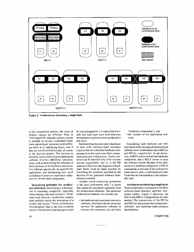
Figure 2. Architectures tolerating a single fault.
to the computation process, the states of distinct variants are different. Thus, in NSCP and NVP, when the variants execute in parallel on distinct (redundant) hard- ware, agiven layer’sdiversity yields differ- ent states in its underlying layers, even if they are not diversified (except, of course, at the decision points). The decision to diversify layers underlying the application software involves additional considera- tions, such as determining the influence of those portions of the hardware and execu- tive software specifically designed for the application, and determining how much confidence to place on experience valida- tion for off-the-shelf components.
Structuring principles for architec- ture definition. Structuring is a prerequi- site to mastering complexity, especially when dealing with fault t~ le rance .~ Hard- ware-fault-tolerance mechanisms usually (and usefully) match the structuring of a system into layers.’O Given performance considerations (that is, the time needed to recover from an error) and damage created
by error propagation, it is especially desir- able that each layer have fault-tolerance mechanisms to process errors produced in that layer.
Implementing this principle in hardware to deal with software-fault tolerance requires that the redundant hardware com- ponents be in the same state when compu- tation proceeds without error. Such a con- dition can be satisfied only if the variants execute sequentially, that is, in the RB approach. However, the diagnosis of hard- ware faults could be made possible by examining the syndrome provided by the deciders of the particular software-fault- tolerance method.
Another useful structuring mechanism is the error-confinement area,” a notion that cannot be considered separately from the architectural elements. The particular architectural elements we consider are:
the hardware and associated executive software, which provide the necessary services for application software to execute (for concision, we call these
“hardware components”), and
ware. the variants of the application soft-
Considering both hardware and soft- ware faults helps distinguish hardware and software error-confinement areas (HECAs and SECAs, respectively). In our discus- sion, a HECA covers at least one hardware component, and a SECA covers at least one software variant. Because of our defi- nition of a hardware component, a HECA corresponds to that part of the architecture made passive after a solid hardware fault. It can thus be interpreted as a line replace- able unit.
Architectures tolerating a single fault. Three architectures correspond to the three software-fault-tolerance methods men- tioned earlier. Figure 2 illustrates the SECA and HECA configurations for each method. The intersections of the SECAs and HECAs characterize the architectures’ software- and hardware-fault-tolerance dependencies.
44 COMPUTER

Table 3. Synthesis of the properties of the hardware-and-software-fault-tolerant architectures.
Architecture Hardware Properties in Addition to Nominal Fault Tolerance Fault-Tolerance After a HECA Is Made Passive Components/ Hardware Faults Software Faults Hardware Software
Variants
RB/1/1
NSCP/1/1
Low error latency Detection provided by local diagnosis
Tolerance of one independent fault
Tolerance of two faults in hardware components of the same SECA; detection of three or four faults in hardware components
Tolerance of two independent faults in the same SECA; detection of two related faults in disjoint SECAs; detection of two, three, or four independent faults
Detection Detection of independent faults
NSCP/l/l/m Tolerance of two faults in hardware components of the same SECA
Detection Detection of independent faults
NVP/1/1
RB/2/1
NSCP/2/ 1
NVP/2/1
Detection of two or three faults
Detection of two or three independent faults
Detection Detection of independent faults
Tolerance of one independent fault
Low error latency Detection provided by local diagnosis
Detection of three to six faults in hardware components
Detection of two or three independent faults
Detection Detection of independent faults
Detection of three or four faults in hardware components; tolerance of combinations of single fault in hardware component and independent software fault in nonduplicated variant
Detection of two or three independent faults
Detection Detection of independent faults
Detection of three or four faults in hardware components
Detection of two related faults; tolerance of two independent faults; detection of three or four independent faults
NVP/2/2 Detection Detection of independent faults
We identify the architectures via a con- densed expression of the form: X/i / ; / . . ., where X is the software-fault-tolerance method (RB, NSCP, or NVP), i is the number of hardware faults tolerated, and; is the number of software faults tolerated. We add further labels to this expression when necessary. Table 3 summarizes the main fault-tolerance properties of the architectures discussed here and in the next section.
However, related faults between a variant and the acceptance test cannot be tolerated or detected.
The hardware components operate in hot standby redundancy and always exe- cute the same variant. Thus, hardware faults are detected by a high-coverage, concurrent comparison between the accep- tance test results and the hardware results. When a discrepancy is detected during execution of the primary alternate or the acceptance test, the secondary executes so that the fault is tolerated (if the fault is soft). If the discrepancy persists (which would occur if the fault were solid), the failed HECA is identified by running diag- nostic programs on each HECA. The failed HECA is thus made passive and service continuity is ensured.
The architecture remains software-fault tolerant after this hardware degradation,
and subsequent hardware faults are de- tected by either the acceptance test or peri- odic execution of the diagnostics.
NSCPIII1. The basic NSCP/l/l archi- tecture (see Figure 2) comprises
four hardware components grouped in two pairs in hot standby redundancy, each pair forming a HECA; and four variants grouped in two pairs, each pair forming a self-checking soft- ware component, with error detection performed by comparison. Each vari- ant pair also forms a SECA associated with a HECA.
The computational states of the hard- ware components cannot be directly com- pared due to the diversification imposed by the variants. However, a comparison of each variant pair’s results also effectively
RBIIII . This architecture duplicates a two-variant RB on two hardware compo- nents. Two variants and their instances of the acceptance test constitute two distinct SECAs and intersect each HECA. The RB method assures that each HECA is soft- ware-fault tolerant. A variant’s indepen- dent faults are tolerated, while related faults between variants are detected.
July 1990 45
RBI211 N SC PI21 1
NVPl211 NVPl212
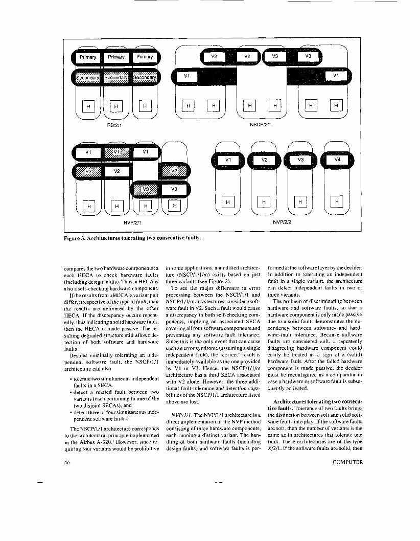
Figure 3. Architectures tolerating two consecutive faults.
compares the two hardware components in each HECA to check hardware faults (including design faults). Thus, a HECA is also a self-checking hardware component.
If the results from a HECA’s variant pair differ, irrespective of the type of fault, then the results are delivered by the other HECA. If the discrepancy occurs repeat- edly, thus indicating a solid hardware fault, then the HECA is made passive. The re- sulting degraded structure still allows de- tection of both software and hardware faults.
Besides nominally tolerating an inde- pendent software fault, the NSCP/1/1 architecture can also
tolerate two simultaneous independent faults in a SECA, detect a related fault between two variants (each pertaining to one of the two disjoint SECAs), and detect three or four simultaneous inde- pendent software faults.
The NSCP/I/l architecture corresponds to the architectural principle implemented in the Airbus A-320.‘ However, since re- quiring four variants would be prohibitive
in some applications, a modified architec- ture (NSCP/l/l/m) exists based on just three variants (see Figure 2).
To see the major difference in error processing between the NSCP/1/1 and NSCP/l/l/m architectures, consider a soft- ware fault in V2. Such a fault would cause a discrepancy in both self-checking com- ponents, implying an associated SECA covering all four software components and preventing any software-fault tolerance. Since this is the only event that can cause such an error syndrome (assuming a single independent fault), the “correct” result is immediately available as the one provided by V1 or V3. Hence, the NSCP/l/l/m architecture has a third SECA associated with V2 alone. However, the three addi- tional fault-tolerance and detection capa- bilities of the NSCP/1/1 architecture listed above are lost.
NVPIlI1. The NVP/I/l architecture is a direct implementation of the NVP method consisting of three hardware components, each running a distinct variant. The han- dling of both hardware faults (including design faults) and software faults is per-
formed at the software layer by the decider. In addition to tolerating an independent fault in a single variant, the architecture can detect independent faults in two or, three variants.
The problem of discriminating between hardware and software faults, so that a hardware component is only made passive due to a solid fault, demonstrates the de- pendency between software- and hard- ware-fault tolerance. Because software faults are considered soft, a repeatedly disagreeing hardware component could easily be treated as a sign of a (solid) hardware fault. After the failed hardware component is made passive, the decider must be reconfigured as a comparator in case a hardware or software fault is subse- quently activated.
Architectures tolerating two consecu- tive faults. Tolerance of two faults brings the distinction between soft and solid soft- ware faults into play. If the software faults are soft, then the number of variants is the same as in architectures that tolerate one fault. These architectures are of the type X/2/1. If the software faults are solid, then
46 COMPUTER
the number of variants must increase be- cause a failed variant cannot execute fur- ther. These architectures are of the type x/2/2.
Figure 3 shows architectures that toler- ate two faults. The first three architectures (RB/2/1, NSCP/2/1, and NVP/2/1) tolerate two hardware faults and a single software fault. Another NVP-based architecture (NVP/2/2) deals with solid software faults by tolerating two consecutive (solid) faults in hardware or software.
RBIZII. This architecture comprises three hardware components arranged in triple modular redundancy. Its ability to tolerate software faults is the same as that of RB/l / l . When a solid hardware fault is detected, the corresponding hardware component is made passive, thus degrad- ing the architecture to a level analogous to the RB/l/l architecture. Accordingly, each hardware component must include local diagnosis, even if it is basically useless in handling the first hardware fault.
NSCPIZII. This architecture is a direct extension of NSCP/l/l/m. A supplemen- tary duplex HECA supports a software self-checking component made up of two variants, resulting in a symmetric distribu- tion of the three SECAs among the three HECAs. Since all the variants are dupli- cated, hardware faults can be instantly diagnosed by comparing the results from all hardware components. The architecture also detects simultaneous independent faults in two or three variants.
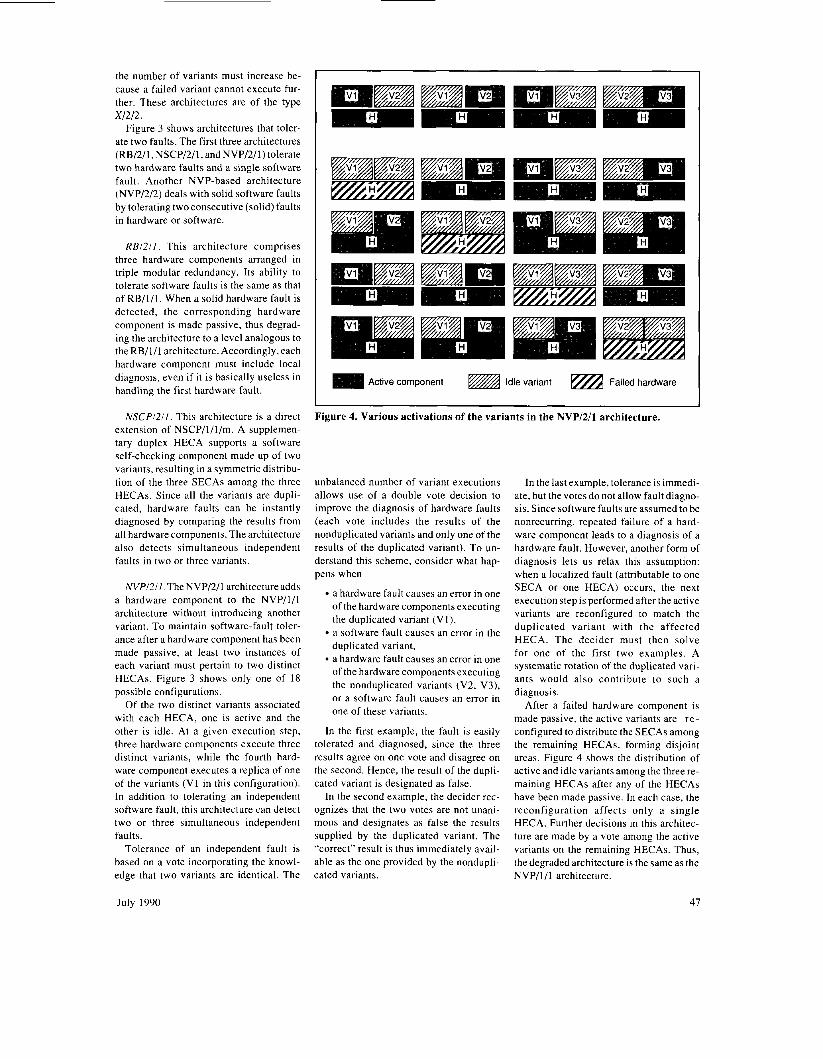
NVPRII .The NVP/2/l architecture adds a hardware component to the NVP/l/I architecture without introducing another variant. To maintain software-fault toler- ance after a hardware component has been made passive, at least two instances of each variant must pertain to two distinct HECAs. Figure 3 shows only one of 18 possible configurations.
Of the two distinct variants associated with each HECA, one is active and the other is idle. At a given execution step, three hardware components execute three distinct variants, while the fourth hard- ware component executes a replica of one of the variants (V1 in this configuration). In addition to tolerating an independent software fault, this architecture can detect two or three simultaneous independent faults.
Tolerance of an independent fault is based on a vote incorporating the knowl- edge that two variants are identical. The
Active component Idle variant Failed hardware
Figure 4. Various activations of the variants in the NVP/2/1 architecture.
unbalanced number of variant executions allows use of a double vote decision to improve the diagnosis of hardware faults (each vote includes the results of the nonduplicated variants and only one of the results of the duplicated variant). To un- derstand this scheme, consider what hap- pens when
a hardware fault causes an error in one of the hardware components executing the duplicated variant (VI), a software fault causes an error in the duplicated variant, a hardware fault causes an error in one of the hardware components executing the nonduplicated variants (V2, V3), or a software fault causes an error in one of these variants.
In the first example, the fault is easily tolerated and diagnosed, since the three results agree on one vote and disagree on the second. Hence, the result of the dupli- cated variant is designated as false.
In the second example, the decider rec- ognizes that the two votes are not unani- mous and designates as false the results supplied by the duplicated variant. The “correct” result is thus immediately avail- able as the one provided by the nondupli- cated variants.
In the last example, tolerance is immedi- ate, but the votes do not allow fault diagno- sis. Since software faults are assumed to be nonrecurring, repeated failure of a hard- ware component leads to a diagnosis of a hardware fault. However, another form of diagnosis lets us relax this assumption: when a localized fault (attributable to one SECA or one HECA) occurs, the next execution step is performed after the active variants are reconfigured to match the duplicated variant with the affected HECA. The decider must then solve for one of the first two examples. A systematic rotation of the duplicated vari- ants would also contribute to such a diagnosis.
After a failed hardware component is made passive, the active variants are re - configured to distribute the SECAs among the remaining HECAs, forming disjoint areas. Figure 4 shows the distribution of active and idle variants among the three re- maining HECAs after any of the HECAs have been made passive. In each case, the reconfiguration affects only a single HECA. Further decisions in this architec- ture are made by a vote among the active variants on the remaining HECAs. Thus, the degraded architecture is the same as the NVP/l/l architecture.
July 1990 47

Table 4. Probability of failure: Ps,x = Ps,D,x + Ps,u,x
I Probability of Detected Failure: P,,,,x Probability of Undetected Failure: Ps,Lj,,y I RB/1/1 Separate: (P,,~,)' Common-mode: P
Common-mode: PID,RB + Pzl K R
Separate: 4(P,,,v,scP)z [ 1 - NSCP/1/1 Common-mode: P?l,,N,sc.P + 4P 31.,NSCP
+ ((P,,,s,,)*/4)1 + P4V.NSCP + 'R \D,NSCP
Common-mode: P,,,N,s,P + 4P?1,,NSCP
NVP/1/1 Separate: 3(P,,,,)' [ 1-(2/3)P,,,v,,] Common-mode: 3P2L.,NC.P + P I C . , N l . P
Common-mode: P,,,,, + P,,,,N,P
Table 5. Comparison of analytical and experimental results.
2.91 x I O ' 4.48 x l o h 1.09 x IO-' 3.90 x 10' 3.67 x IO-'
NVPl212. To understand the effect of solid software faults on architectures that tolerate two faults, consider the NVP method. Such an architecture requires four disjoint HECAs and SECAs, hence the NVP/2/2 architecture.
This architecture might seem to be a direct extension of NVP/I/I, adding only one HECA and an associated SECA, but there are major differences in error pro- cessing. The fault-tolerance decision is now based on finding a single set of two or more agreeing results among the four vari- ant results provided. Also, after the first discrepancy is discovered, the designated hardware component and its associated variant are made passive without any at- tempt to diagnose the fault as a hardware or software fault. Further decisions are then
made by vote among the remaining vari- ants, making the degraded architecture similar to the NVP/l/I architecture. How- ever, unlike the other NVP-based architec- tures, subsequent faults are treated the same as the first detected fault.
Besides tolerance to two consecutive independent software faults, this architec- ture lets the system tolerate two simultane- ous independent faults, detect related faults between two variants, and detect simultaneous faults in three or four vari- ants. The Fault-Tolerant Processor/ Attached Processor' is an implementation of this architecture: a quad configuration of the core fault-tolerant processor sup- ports the execution of four different pieces of application software on four distinct ap- plication processors.
0 Proper Service Delivery State
0 Detected Failure State
@ Undetected Failure State
Figure 5. Generic model of architecture behavior.
48
Analyzing and evaluating architectures
In discussing how to conduct a dependa- bility analysis of hardware- and software- fault-tolerant architectures when adopting a Markov approach, we consider three architectures that tolerate a single hard- ware or software fault: RB/I/l, NSCP/l/I and NVP/I/I.
Analyzing software-fault-tolerant architectures. Our analysis emphasizes the distinctions among the different sources of failures - independent and related faults in the variants and the de- cider - and assumes that only one type of fault can cause errors during each execu- tion. Also, we do not address the underly- ing fault-tolerance mechanisms, that is, establishment and restoration of recovery points for RB, and version synchroniza- tion, establishment of cross-check points, and the decision mechanisms for NSCP and NVP.
We classify failures as separate or com- mon-mode and as detected or undetected. Separate failures result from independent faults in the variants, whereas common- mode failures can result either from related faults or from independent faults in the decider. We also distinguish between two types of related faults: those among the variants and those between the variants and the decider. We consider a failure detected when the decider identifies no acceptable result and no output result is delivered. A failure is undetected when erroneous results are delivered.
We also assume that the probability of a fault is identical for all variants of a given architecture. We make this assumption to simplify the notation; i t does not alter the significance of the results (it is simple to deduce the generalization to the case where variant characteristics are distinguished).
To characterize the probabilities of fail- ure, we introduce the following notation for the X/l / l architectures:
is the probability of activating an independent fault in one variant of X on execution P,,,, is the probability of activating an independent fault in the decider of X on execution Pnl.,x is the probability of activating a related fault among n variants of X on execution P,,,, is the probability of activating a
COMPUTER

Table 6. Specific state and transition definitions.
States and Interstate RB/I/I Transitions
NSCP/I/I NVP/I/I
1
2
3
4
1 to 2
1 t o 3
1 to 4
2 to 3
2 to 4
2 (RB +hardware component) operational
(RB + hardware component) operational
Detected failure
Undetected failure
2(2(variant + hardware component)) operational
2(variant + hardware component) operational
Detected failure
Undetected failure
3(variant + hardware component) operational
2(variant + hardware component) operational
Detected failure
Undetected failure
Covered hardware component failure:
2c'H,RB
Noncovered hardware component failure or detected RB failure:
2"H.RB + 'S.D.RB
Undetected RB failure: h,,,,,,
Covered hardware component failure or detected RB failure: ~ h ~ , ~ ~ + h,,,,,,
Noncovered hardware component failure or undetected RB failure:
c h H , R B + ' s , u , R B
-
Hardware component failure: 4hH,,,,,
Detected NSCP failure: hs,D,Nscp
Undetected NSCP failure: h,,,,N,cp
Hardware component failure or detected two-variant failure: 2h,,,,,, + h,,D,,,.
Undetected two-variant failure: h,,,,,,,
Hardware component failure: 3hH,,,
Detected NVP failure: )\,,D,Nvp
Undetected NVP failure h, u N I . P
Hardware component failure or detected two-variant failure: 2hHNVP + h,, *, Undetected two-variant failure: h, , 21.
related fault among the variants and the decider of X on execution Ps,D,x is the probability of a detected failure of X on execution Ps,,,x is the probability of an unde- tected failure of X on execution PsPix + P,,u,x = P,,,, the probability of a failure of X on execution
Table 4 summarizes the probabilities of failure and separates them into the sepa- rate/common-mode and detectedhnde- tected categories. The table shows that either separate failures or common-mode failures can be detected, while only com- mon-mode failures can go undetected. Comparing the probabilities is difficult due to the different parameter values for each architecture. However, some general observations are possible.
Although a large number of experiments have analyzed NVP, no quantitative study has reported the decider's reliability. Still, the probabilities of failure associated with the deciders can differ significantly. Due to the generic character and functional simplicity of the NSCP (comparison) and NVP (voting) deciders, the probabilities are likely ranked as follows:
For separate failures, the influence of independent faults differs significantly. For RB, the probability of separate failure equals the square of the probability that independent faults will occur, while the probability for NVP is almost three times as much, and four times as much for NSCP. This difference results from the number of variants and the type of decision. How- ever, it does not mean that RB and NSCP are the only architectures that allow detec- tion of related-fault combinations among the variants. All related faults in NVP re- sult in undetected failures. (This is due to our analysis' limitation to architectures that tolerate only one fault. Increasing the number of versions would allow NVP methods to detect some related faults.)
Although related faults among variants do not affect the probability of undetected failure for the RB architecture, they are the major contributor to undetected failure for NSCP and NVP. However, comparing the respective probabilities of undetected fail- ure is not simple.
Experiments on multiversion software help us estimate some elementary proba- bilities of the expressions in Table 4. For example, Table 5 shows that the results obtained from the model agree with previ- ous experimental result^.^ The first three
columns show the values derived for the model parameters from the experimental results. The fourth column gives the asso- ciated probability of failure, computed from the expressions of Table 4 using these parameter values and excluding decider fault parameters. The last column shows the experimental statistic for the probabil- ity of failure.
Evaluating hardware and software architectures. Inmodeling the behavior of the architectures, we assume
only one type of fault can cause an error (either hardware or software) during each execution; the variant is not discarded after error detection and recovery, but is given the new input data at the next step (that is, software faults are soft); and the hardware components and the soft- ware-fault-tolerant architectures have constant failure rates.
Models. The generic model in Figure 5 describes the hardware and software be- havior for the RB/l / l , NSCP/I/l , and NVP/1/1 architectures. Table 6 gives the specific definitions for states and interstate transitions of the model. The transition
July 1990 49
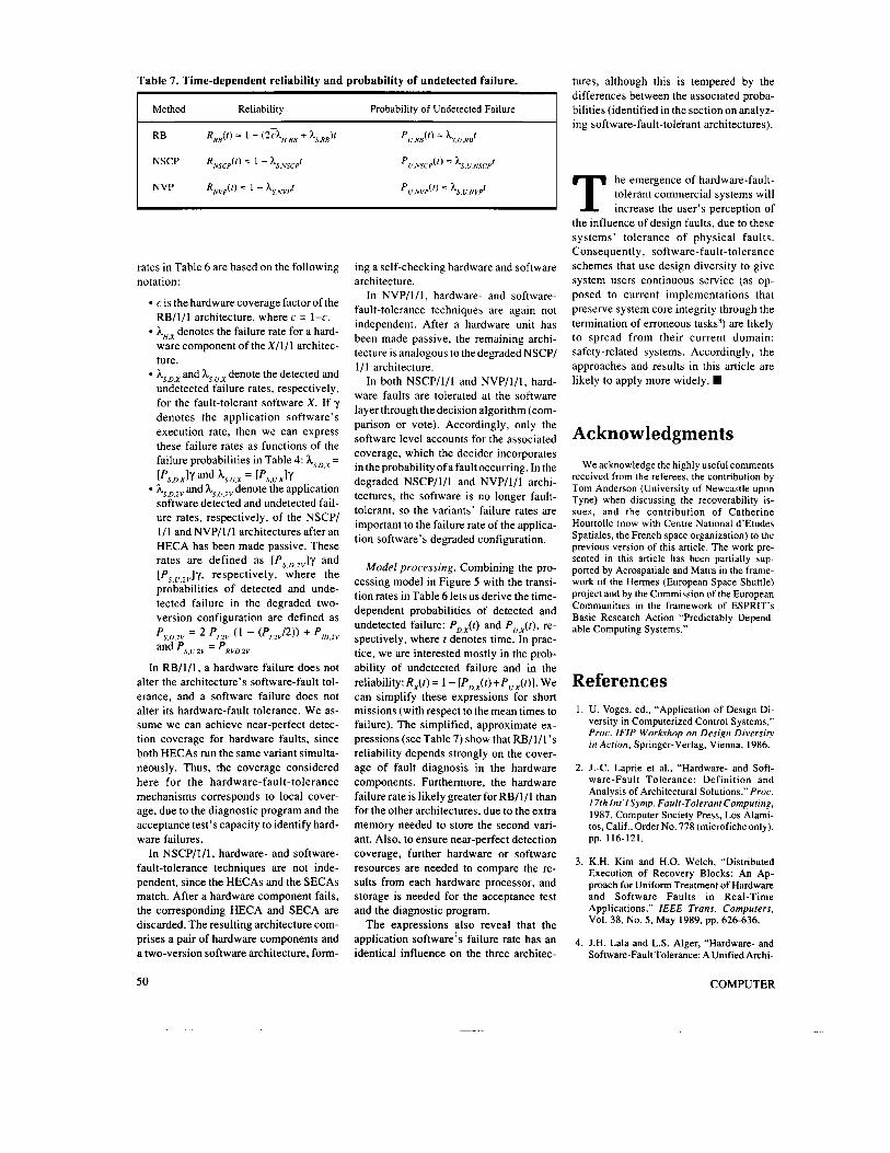
Table 7. Time-dependent reliability and probability of undetected failure.
I Method Reliability Probability of Undetected Failure I
I
rates in Table 6 are based on the following notation:
c is the hardware coverage factor of the RB/1/1 architecture, where c= 1-c. hH,x denotes the failure rate for a hard- ware component of theX/1/1 architec- ture. hs,D,x and ks,u,x denote the detected and undetected failure rates, respectively, for the fault-tolerant software X. If y denotes the application software’s execution rate, then we can express these failure rates as functions of the failure probabilities in Table 4: hs,D,x =
hs,D,2V and hs,u,2v denote the application software detected and undetected fail- ure rates, respectively, of the NSCP/ 1/1 and NVP/l/l architectures after an HECA has been made passive. These rates are defined as [Ps,D,2v]y and [Ps,u,2v]y, respectively, where the probabilities of detected and unde- tected failure in the degraded two- version configuration are defined as
[‘S,D,X]y and kS,U,X = [‘S,U,X1y
‘S.D.2V = and ‘S,U,ZV = ‘RVD,ZV
‘/,2V ( l - (‘/.2J2)) + ‘/D,ZV
In RB/l/ l , a hardware failure does not alter the architecture’s software-fault tol- erance, and a software failure does not alter its hardware-fault tolerance. We as- sume we can achieve near-perfect detec- tion coverage for hardware faults, since both HECAs run the same variant simulta- neously. Thus, the coverage considered here for the hardware-fault-tolerance mechanisms corresponds to local cover- age, due to the diagnostic program and the acceptance test’s capacity to identify hard- ware failures.
In NSCP/I/l , hardware- and software- fault-tolerance techniques are not inde- pendent, since the HECAs and the SECAs match. After a hardware component fails, the corresponding HECA and SECA are discarded. The resulting architecture com- prises a pair of hardware components and a two-version software architecture. form-
ing a self-checking hardware and software architecture.
In NVP/1/1, hardware- and software- fault-tolerance techniques are again not independent. After a hardware unit has been made passive, the remaining archi- tecture is analogous to the degraded NSCP/ 1/1 architecture.
In both NSCP/l/l and NVP/1/1, hard- ware faults are tolerated at the software layer through the decision algorithm (com- parison or vote). Accordingly, only the software level accounts for the associated coverage, which the decider incorporates in the probability of a fault occurring. In the degraded NSCP/l/l and NVP/1/1 archi- tectures, the software is no longer fault- tolerant, so the variants’ failure rates are important to the failure rate of the applica- tion software’s degraded configuration.
Model processing. Combining the pro- cessing model in Figure 5 with the transi- tion rates in Table 6 lets us derive the time- dependent probabilities of detected and undetected failure: and Po,x( f ) , re- spectively, where ? denotes time. In prac- tice, we are interested mostly in the prob- ability of undetected failure and in the reliability: Rx(t ) = 1 - [PD,(t)+Pu,x(t)]. We can simplify these expressions for short missions (with respect to the mean times to failure). The simplified, approximate ex- pressions (see Table 7) show that RB/l/l ’s reliability depends strongly on the cover- age of fault diagnosis in the hardware components. Furthermore, the hardware failure rate is likely greater forRB/l/ l than for the other architectures, due to the extra memory needed to store the second vari- ant. Also, to ensure near-perfect detection coverage, further hardware or software resources are needed to compare the re- sults from each hardware processor, and storage is needed for the acceptance test and the diagnostic program.
The expressions also reveal that the application software’s failure rate has an identical influence on the three architec-
tures, although this is tempered by the differences between the associated proba- bilities (identified in the section on analyz- ing software-fault-tolerant architectures).
he emergence of hardware-fault- tolerant commercial systems will T increase the user’s perception of
the influence of design faults, due to these systems’ tolerance of physical faults. Consequently, software-fault-tolerance schemes that use design diversity to give system users continuous service (as op- posed to current implementations that preserve system core integrity through the termination of erroneous taskss) are likely to spread from their current domain: safety-related systems. Accordingly, the approaches and results in this article are likely to apply more widely. W
Acknowledgments We acknowledge the highly useful comments
received from the referees, the contribution by Tom Anderson (University of Newcastle upon Tyne) when discussing the recoverability is- sues, and the contribution of Catherine Hourtolle (now with Centre National d’Etudes Spatiales, the French space organization) to the previous version of this article. The work pre- sented in this article has been partially sup- ported by Aerospatiale and Matra in the frame- work of the Hermes (European Space Shuttle) project and by the Commission of the European Communities in the framework of ESPRIT’S Basic Research Action “Predictably Depend- able Computing Systems.”
References 1. U. Voges, ed., “Application of Design Di-
versity in Computerized Control Systems,” Proc. IFIP Workshop on Design Diversity in Action, Springer-Verlag, Vienna, 1986.
2. J.-C. Laprie et al., “Hardware- and Soft- ware-Fault Tolerance: Definition and Analysis of Architectural Solutions,” Proc. 17th Int’lSymp. Fault-Tolerant Computing, 1987, Computer Society Press, Los Alami- tos, Calif., Order No. 778 (microfiche only), pp. 116-121.
3. K.H. Kim and H.O. Welch, “Distributed Execution of Recovery Blocks: An Ap- proach for Uniform Treatment of Hardware and Software Faults in Real-Time Applications,” IEEE Trans. Computers, Vol. 38, No. 5 , May 1989, pp, 626-636.
4. J.H. Lala and L.S. Alger, “Hardware- and Software-Fault Tolerance: A UnifiedArchi-
50 C 0 M P U T E R

tectural Approach,” Proc. 18th Int’l Symp. Fault-Tolerant Computing, 1988, Com- puter Society Press, Los Alamitos, Calif., Order No. 867, pp. 240-245.
5 . B. Randell, “Design-Fault Tolerance,” in The Evolution of Fault-Tolerant Comput- ing, A. Avizienis, H. Kopetz, and J.-C. Laprie, eds., Springer-Verlag, Vienna, 1987, pp. 251-270.
6 . A. Avizienis, “The N-Version Approach to Fault-Tolerant Systems,” IEEE Trans. Soft-
ware Engineering, Vol. SE- 1 1, No. 12, Dec. 1985, pp. 1,491-1,501.
7. S.S. Yau and R.C. Cheung, “Design of Self- Checking Software,” Proc. 1975 Int’l Conf. Reliable Software, pp. 450-457.
8. J.N. Gray, “Why Do Computers Stop and What Can Be Done About It?” Proc. Fifth Symp. Reliability in Distributed Software and Database Systems, 1986, Computer Society Press, Los Alamitos, Calif., Order No. 690 (microfiche only), pp. 3-12.
Jean-Claude Laprie is directeur de recherche of CNRS, the French national organization for scientific research. He joined LAAS-CNRS in 1968, where he has directed the research group on fault tolerance and dependable computing since 1975. He was chair of the IEEE Computer Society Technical Committee on Fault-Tolerant Computing in 1984.1985 and has been chair of the IFIP working group on Dependable Comput- ing and Fault Tolerance since 1986.
Laprie received the Certified Engineer degree from the Higher National School for Aeronauti- cal Constructions, Toulouse, France, in 1968, and the Doctor in Engineering degree in auto- matic control and the Doctor-&-Sciences de- gree in computer science from the University of Toulouse in 1971 and 1975, respectively.
Jean Arlat is chargC de recherche of CNRS. He joined LAAS-CNRS, where he is a member of the research group on fault tolerance and de- pendable computing, in 1976. His research focuses on evaluating dependability including both analytical modeling and experimental fault injection.
Arlat received the Certified Engineer degree from the National Institute of Applied Sciences, Toulouse, France and the Doctor in Engineering degree from the National Polytechnic Institute, Toulouse, France, in 1976 and 1979, respec- tively. He is a member of the IEEE Computer Society’s technical committees on fault toler- ance and simulation.
Christian BCounes is chargC de recherche of INRIA, the French National Institute for Com- puting and Automatic Control Research. He joined LAAS in 1974 as a member of the group on fault tolerance and dependable computing. His research interests include stochastic petri nets, modeling, and dependability evaluation.
BCounes received the Certified Engineer degree from the National Institute of Applied Sciences, Toulouse, France, in 1973 and the Doctor in Engineering degree in automatic con- trol from the University of Toulouse, in 1977.
9. J.C. Knight and N.G. Leveson, “An Empiri- cal Study of Failure Probabilities in Multi- version Software,” Proc. 16th IEEE Int’l Symp. Fault-Tolerant Computing, 1986, Computer Society Press, Los Alamitos, Calif., Order No. 703, pp. 165-170.
10. D.P. Siewiorek and D. Johnson, “A Design Methodology for High-Reliability Sys- tems: The Intel 432,” in The Theory and Practice of Reliable System Design, D.P. Siewiorek and R.S. Swarz, eds., Digital Press, 1982.
Karama Kanoun is chargCe de recherche of CNRS. She joined LAAS in 1977 as a member of the group on fault tolerance and dependable computing. Her research interests include mod- eling and evaluating computer system dependa- bility, considering hardware as well as software.
Kanoun received the Certified Engineer degree from the National School of Civil Avia- tion, Toulouse, France in 1977, and the Doctor- Engineer and Doctor-&-Sciences degrees from the National Institute Polytechnique of Tou- louse in 1980 and 1989, respectively.
Readers can contact the authors at LAAS-CNRS, 7 Avenue du Colonel Roche, 31077 Toulouse Cedex, France.
Moving? Name (Please Print)
PLEASE NOTIFY US 4 WEEKS IN ADVANCE New Address
MAIL TO: IEEE Service Center 445 Hoes Lane Piscataway, NJ 08854
City StatelCountry Zip
This notice of address change will apply to all
List new address above. If you have a question about your subscription,
ATTACH LABEL
IEEE publications to which you subscribe.
place label here and clip this form to your letter.
July 1990 51