deflections of uniformly loaded floors a beam-spring analog · beam, are replaced by simple coil...
TRANSCRIPT

United StatesDepartment of DeflectionsAgriculture
Forest Service of UniformlyForestProductsLaboratory Loaded FloorsResearchPaperFPL 449 A Beam-Spring analog
William J. McCutcheon

Abstract
A new method for computing the performance of uniformlyloaded wood floors is presented. The procedure presents afloor as a simple structure consisting of a beam supported byelastic springs. The method computes midspan joistdeflections which are virtually identical to those obtainedfrom a large-scale finite element program, but at a fraction ofthe computational effort. Also, computations agree veryclosely with laboratory results. A simple BASIC program ispresented for implementing the procedure.
Keywords: Floors, deflections, wood-joist, uniform load
September 1984
McCutcheon, William J. Deflections of uniformly loaded floors: A beam-springanalog. Res. Pap. FPL 449. Madison, WI: U.S. Department of Agriculture,Forest Service, Forest Products Laboratory; 1984. 15 p.
A limited number of free copies of this publication are available to the publicfrom the Forest Products Laboratory. P.O. Box 5130, Madison, WI 53705.Laboratory publications are sent to over 1,000 libraries in the United States andelsewhere.
The Laboratory is maintained in cooperation with the University of Wisconsin.
The use of trade, firm, or corporation names in this publication is for theinformation and convenience of the reader. Such use does not constitute anofficial endorsement or approval by the U.S. Department of Agriculture of anyproduct or service to the exclusion of others which may be suitable.

Deflectionsof UniformlyLoaded FloorsA Beam-Spring Analog
William J. McCutcheon, Engineer
Forest Products Laboratory, Madison, Wis.
Introduction
Wood-joist floor systems have long been analyzed anddesigned by assuming that the joists act as simple beams incarrying the design load. This simple method neglects manycomplex interactions among a floor’s components-the joists,sheathing, and connectors-which affect its strength andstiffness. It also neglects material variability in that itassumes all joists have identical mechanical properties. Asimple analytical method is presented here which accuratelyaccounts for these interactions in computing floor stiffness;deflections computed by this method compare very closelywith those obtained from a more complex and costlyprocedure.
Prior research has addressed the problem of floor analysisand produced analytical methods and computer models whichaccurately predict the true behavior of light-frame floors.McCutcheon (1977) presented an analytical method forcomputing the stiffness of floors with partial compositeaction. Based on a T-beam model, the method accounts forinterlayer slip due to the nonrigid attachment of the floorsheathing to the joists. Thompson, Vanderbilt, andGoodman (1977) developed a finite element computerprogram, FEAFLO, for calculating the performance of woodfloors. Based on a crossing beam analysis, this modelconsiders some factors not included in the simpler T-beammodel, most notably joist-to-joist variability and two-wayaction. However, when the two methods were usedconcurrently in a cooperative study (McCutcheon et al. 1981)to compute the average deflections of typical floorconfigurations subjected to uniform loads, they producedresults which were in very close agreement.
Foschi (1982) presented a finite element analysis techniquewhich includes lateral and torsional joist deformations asdegrees of freedom and considers plate action in thesheathing; these are not considered in the FEAFLO orT-beam procedures.
Recently, the FEAFLO program was used to predict thebehavior of floors constructed with joists whose propertieswere determined in an in-grade survey (Bufano et al. 1980;Vanderbilt et al. 1980). These simulations considered threestiffness criteria: average midspan joist deflection, soft-spotdeflection, and greatest individual joist deflection in eachfloor.
The T-beam model is computationally much more efficientthan a large-scale finite element program. Because itrepresents a floor as a single beam, it is applicable to thecomputation of average joist deflection; however, it cannotdirectly compute soft-spot or individual joist deflections. Anextension of the T-beam method to consider such additionaldeflection criteria will provide a simple and economicalternative for determining floor performance.
This paper presents a method for predicting the performanceof wood floors under uniform loads. Using an analog whichrepresents a floor as a beam supported by elastic springs, theT-beam method (McCutcheon 1977) is extended to accountfor variability of joist stiffness and two-way action due to thecross-joist distributional properties of the sheathing. It isshown that this method computes individual midspan joistdeflections which are virtually identical to those obtainedfrom a large-scale finite element program (Thompson et al.1977), and is capable of accurately predicting the performanceof real floors. A simple BASIC program is presented forimplementing the procedure.

Methodology
A light-frame floor system consists of multiple parallel woodjoists to which are fastened a sheathing made of plywood orother sheet material. In order to use the T-beam model toaccount for composite joist behavior and to also considertwo-way action, it is necessary to conceptually simplify a floorin two steps. At the first level of abstraction, the sheathing iscompressed into a narrow beam which spans across thesimply-supported joists (fig. 1). This beam distributes theload among the joists. At the second level the joists, whichact as leaf springs in supporting the sheathing distributionbeam, are replaced by simple coil springs (fig. 2). Thesespring stiffnesses account for joist-sheathing compositeaction. The resulting structure is a beam supported by elasticsprings. The ends of the beam may be either simplysupported (fig. 2a) or spring supported (fig. 2b), dependingupon whether the end joists on the floor are fully supportedalong their lengths or are free to deflect, respectively.
Joist “Spring” Properties
Each spring in the analog represents a floor joist, whosebending stiffness is increased by partial interaction with thesheathing. The aforementioned T-beam analysis(McCutcheon 1977) derived the following equations to definethe composite bending stiffness, EIj, of a joist:
(1)
(2)
(3)
(4)
where
EIj
EIR
EIU
(EA)1, (EA)2
h
tdjL´
kn
= effective bending stiffness of the joist,including partial composite action
= bending stiffness of the joist if the sheathingis rigidly attached
= stiffness of the unconnected joist andsheathing, taken as the stiffness of the barejoist
= axial stiffness of the flange (sheathing) andweb (joist) of the T-beam
= distance between centroids of the flange andweb = ½ (t + dj)
= sheathing thickness= joist depth= distance between discontinuities (open gaps)
in the sheathing in the direction of the joistspan
= nail stiffness (load/slip ratio), assuminglinear nail behavior
= average nail spacing.
Figure I.--Floor system with sheathing“distribution beam” supported by simply-supported joists.(ML84 5180)
Figure 2.--Beam-spring analog structure with endjoists fully supported (a) or free to deflect (b).(ML84 5181)
sn
2

The midspan deflection, 4, of a uniformly loaded joist is
(5)
where
w = load per unit lengthL = joist span.
The linear spring constant, kj, required for the analog is theratio of joist load to joist deflection:
Thus, the equivalent spring constant for each joist iscomputed by equation (6) after the joist’s bending stiffness,EIj, is computed by the T-beam method summarized byequations (14).
Sheathing “Beam” Properties
The bending stiffness of the analog beam is equal to thestiffness of the sheathing in the cross-joist direction. If thereare no discontinuities in the sheathing in this direction, thatis, if the sheathing is long enough to extend the full width ofthe floor, the analog beam stiffness, EIb, is equal to 1/1 2 EsLt3.However, gaps are usually present and these disrupt thecontinuity of the sheathing and reduce its bending stiffness.The resulting reduced stiffness can be approximated byaveraging out the effect of these discontinuities. Forexample, if the sheathing spans six joist spaces (as occurs withtypical 16-in. spacing and 96-in. lengths of sheathing), adiscontinuity occurs at every sixth joist in each row ofsheathing. Thus, on the average, there is one-sixth of a gapat each joist crossing, and the average stiffness is reduced byone-sixth.
For the general case, the bending stiffness may beapproximated by
where
EIb = bending stiffness of analog beamEs = bending MOE of sheathing in cross-joist
(7)
Solution of Analog Structure
Analyzing a wood floor system with a finite element programinvolves the solution of a large number of simultaneousequations. A single joist may be broken into as many as 20segments, and analysis of a lo-joist floor will thereforerequire the solution of up to 200 equations. The beam-springanalog involves just one degree of freedom per joist and,therefore, a lo-joist floor can be analyzed with just 10simultaneous equations.
The actual equations which result from this method arederived in appendix A, and a simple BASIC program forimplementing the method is presented in appendix B.Appendix C presents complete input and output for analyzingone floor.
directionS = joist spacing
= length of sheathing (typically 96 in.)L,t = previously defined.

Results
Comparison of Model withFinite Element Solution
We used the finite element program FEAFLO to determinethe deflection characteristics and distributions of wood floorsconstructed with joists whose properties were determinedfrom a large-scale sampling program (Bufano et al. 1980;Vanderbilt et al. 1980). Each floor comprised ten 2 by 8joists which were free to deflect, plus an additionalcontinually supported joist at each end (fig. 2a). Floorperformance was characterized by three values: (1) theaverage midspan deflection of the eight interior joists, (2) the“soft-spot” deflection, defined as the highest averagedeflection of any three adjacent joists, and (3) the maximumdeflection of any single joist. The “as-graded” joist datawere used to analyze 138 floors for Douglas-fir (green) joists,and 107 floors for southern pine joists.
From each group (Douglas-fir and southern pine), 11 floorswere analyzed by the beam-spring analog. These correspondto the stiffest floor, the floors at the 10th percentile of thestiffness distribution, the 20th percentile,. . . , 90th percentile,and the most limber floor.
The input data to the beam-spring model were the samevalues used in the FEAFLO analyses:
Joist spacing, s = 16 inches (ii.)Joist span, L = 157 in. (Douglas-fir)
L = 154 in. (southern pine)Sheathing thickness, t = 0.5782 in.Sheathing axial modulus, along span, Ea = 0.9404 × 10⁶ lb/in.2
Sheathing bending modulus, across span,Eb = 1.487 × 10⁶ lb/in.2
Nail stiffness (as assumed in FEAFLO analyses),kn = 30,000 lb/in.
Average nail spacing, sn = 6.7 in.Joist size, nominal 2 by 8, actual dimensions input for each
joistJoist modulus input for each joistLength of sheathing, = 96 in.
The T-beam model can account for the presence of completediscontinuities, i.e., open gaps, in the sheathing; but theFEAFLO analyses assumed flexible gaps between the 48-inch-wide pieces of plywood. Therefore, it was necessary todetermine empirically an equivalent distance (greater than 48in.) between open gaps, L '. Previously McCutcheon et al.(1981) determined that L ' = 96 inches can be used toaccount for flexible gaps with a stiffness of 10,000 lb/in.2/in.In these analyses, a gap stiffness of 5,000 lb/in.2/in. was usedin the FEAFLO input, and L ' = 75 inches gave goodagreement between the two methods.
The FEAFLO and beam-spring analyses (table 1) givevirtually identical results for all three deflection criteria--average interior deflection, soft spot, and maximum joist.Complete FEAFLO data were available for southern pinefloor No. 74, and are compared to the beam-spring data intable 2. These results are presented graphically in figure 3,which also shows the results of a traditional bare joistanalysis, which assumes no composite action and no two-wayaction.
Figure 3.--Comparison of bare joist, finite element(FEAFLO). and beam-spring model analyses ofsouthern pine floor No. 74. (ML84 5182)
4

Table 1.--Comparison of floor deflections as computed by finite element program (FEAFLO) and beam-spring analog
Floor No. Average eight interior joists Soft spot (three joist average) Maximum (at joist number)FEAFLO Beam-spring Difference FEAFLO Beam-spring Difference FEAFLO Beam-spring Difference
In.
82 0.2315 0.2331 +0.769 .2989 .3007 +0.6
103 .3091 .3111 +0.615 .3189 .3209 +0.6
111 .3296 .3310 +0.499 .3421 .3443 +0.6
130 .3483 .3504 +0.629 .3576 .3586 +0.355 .3735 .3756 +0.662 .4047 4059 +0.335 .4591 .4609 +0.4
35 .222891 .281437 .290390 .302136 .316924 .3244
174 .337729 .346531 .354512 .379265 .4494
.2240
.2797
.2914
.3063
.3180
.3247
.3383
.3474
+0.5-0.6+0.4+1.4+0.3+0.1-0.2+0.3
.3549 +0.1 .3939 .3912 -0.5 .3993 (9) .3989 (8) -0.1
.2366 .2390 +1.0 .2545 (2) .2593 (2) +1.9
.2977 .3022 +1.5 .3419 (9) .3218 (8) -5.9
.3106 .3102 -0.1 .3220 (7) .3224 (7) +0.1
.3166 .3140 -0.8 .3438 (9) .3301 (3) -4.0
.3472 .3484 +0.3 .3628 (6) .3572 (6) -1.5
.3675 .3658 -0.5 .3822 (9) .3810 (8) -0.3
.3713 .3708 -0.1 .3964 (9) .3842 (9) -3.1
.3653 .3643 -0.3 .3832 (9) .3770 (8) -1.6
.3792 0.0 .4120 .4097 -0.6 .4700 (9) .4508 (9) -4.1
.4512 +0.4 .4852 .4876 +0.5 .4993 (3) .4994 (3) +0.01Complete analyses of this floor are presented in table 2 and figure 3.
In. Pct In. In.
DOUGLAS-FIR
0.2673 0.2743.3109 .3119.3189 .3211.3355 .3383.3631 .3627.3521 .3554.3712 .3721.3730 .3720.4209 .4227.4332 .4355.4979 .4990
SOUTHERN PINE
Pct
+2.6 0.3078 (2) 0.3142 (2) +2.1+0.3 .3220 (8) .3242 (8) +0.7+0.7 .3273 (7) .3285 (7) +0.4+0.8 .3441 (3) .3450 (3) +0.3-0.1 .3755 (8) .3787 (8) +0.9+0.9 .3580 (3) .3601 (3) +0.6+0.2 .3758 (5) .3749 (8) -0.2-0.3 .3996 (9) .3862 (9) -3.4+0.4 .4460 (3) .4401 (3) -1.3+0.5 .4410 (8) .4489 (8) +1.8+0.2 .5174 (4) .5146 (4) -0.5
In. In. Pct
Table 2.--Complete analysis of southern pine floor No. 74
JoistNo.
1
2
3
Width
In.1.501
1.493
1.513
Joist properties Joist deflectionDepth Modulus of FEAFLO Beam-spring Difference Bare joist
elasticityIn. 106 lb/in2 In. In. Pct In
7.250 2.152 0.2102 0.2222 +5.7 0.3173
7.188 1.446 .3108 .3165 +1.8 .4871
7.219 1.835 .3106 .3128 +0.7 .3739
4 1.486 7.219 1.887 .3008 .3019 +0.4 .3702
5 1.500 7.250 1.629 .3197 .3197 0.0 .4194
6 1.505 7.219 1.127 .3462 .3433 -0.8 .6121
7 1.545 7.281 1.699 .3439 .3484 +1.3 .3855
8 1.505 7.219 1.304 .3734 .3797 +1.7 .5290
9 1.510 7.250 1.159 .3964 .3842 -3.1 .5856
10 1.514 7.219 1.476 .2564 .2714 +5.9 .4645
Average (8 interior joists) .3377 .3383 +0.2
Soft spot (joists 7, 8, and 9) .3713 .3708 -0.1
Maximum individual (joist 9) .3964 .3842 -3.1
5

Comparison of Model with Test Data
In developing the original T-beam analysis method(McCutcheon 1977), the performance of seven floors wasevaluated experimentally. Of these seven, two floors wereintentionally constructed with joists which had high degrees ofvariability in their stiffnesses. (The other five had nearlyuniform joist properties.) Designated N-3 for the floor withnailed sheathing and G-3 for the floor with the sheathingattached by means of a rigid adhesive, these two are of thegreatest interest because they are most useful in assessing thebeam-spring model’s ability to properly account for joist-to-joist variability.
The properties of the floors and the corresponding input datato the model were:
Number of joists, all free to deflect (fig. 2b), 9Joist span, L = 144 in.Joist spacing, s = 15.8125 in. (average of six spaces at 16
in. and two at 15.25 in.)Joist size, 2 by 8 in. nominal, 1.5 by 7.25 in. actualJoist moduli, determined individuallySheathing thickness, t = 0.625 in.Sheathing properties, determined experimentally:
axial modulus, along span, Ea = 0.5 x 10⁶ lb/in.2
bending modulus, across span, Eb = 1 x 10⁶ lb/in.2
Length of sheathing, = 96 in.Width of sheathing, L ' = 48 in. (N-3)
= 144 in. (G-3, glued tongue-and-groove edges)
(N-3) nail stiffness (as computed by McCutcheon 1977),kn = 9,400 lb/in. average nail spacing, sn = 7.43 in.
(G-3) rigid adhesive, kn = 1 x 1025 lb/in.sn = 1
Except for end joists 1 and 9, the analog was an excellentpredictor of floor N-3’s performance, especially at the higherload (table 3, fig. 4). However, it is unlikely that the samenail-slip modulus would apply to both load levels. Use of ahigher modulus at the lower load, to account for the steeperslope of a curvilinear load-slip curve, would bring thecomputed results into even closer agreement with theexperimental.
The analog also did a good job of predicting the glued floor’sperformance (table 4, fig. 5), except for the anomaly at joists7 and 8, where the experimental deflection of the apparentlystiffer joist, No. 8, was greater than that of the more limberjoist, No. 7.
Figure 4.--Experimental and analytical midspanjoist deflections for floor N-3. (ML84 5183)
Figure 5.--Experimental and analytical midspanjoist deflections for floor G-3. (*Deflection gageNo. 3 malfunctioned) (ML84 5184)
6

Table 3.--Comparison of experimental and analytical performance of floor N-3
Joist Modulus
Joist deflection at49.2 pounds per
square foot
Joist deflection at98.8 pounds per
square footNo. of
elas-ticity
10 6 lb/in.2
Test
In.
Beam-spring
In.
Differ-ence
Pct
Test
In.
Beam-spring
In.
Differ-ence
Pct
1 2.32 0.183 0.139 - 24.0 0.386 0.279 - 27.72 1.85 .303 .320 + 5.6 .639 .644 + 0.83 1.29 .349 .370 + 6.0 .734 .742 + 1.14 2.40 .297 .318 + 7.1 .646 .639 - 1.15 2.03 .290 .317 + 9.3 .638 .636 - 0.36 1.42 .331 .339 + 2.4 .692 .680 - 1.77 2.27 .291 .298 + 2.4 .594 .599 - 0.88 2.67 .232 .240 + 3.4 .483 .483 09 1.74 .190 .151 - 20.5 .381 .304 - 20.2
Table 4.--Comparison of experimental and analytical performance of floor G-3
JoistNo.
Modulusof
elas-
Joist deflection at Joist deflection at Joist deflection at48.1 pounds per 97.8 pounds per 156.4 pounds per
square foot square foot square foot
Test Beam- Differ- Test Beam- Differ- Test Beam- Differ-ticity
106 lb./in.2 In.spring
In.ence
Pct In.spring
In.ence
Pct In.spring
In.ence
Pct
123456789 1.75 .137 .108
1Deflection gage malfunctioned, floor G-3, joist 3.
2.34 0.115 0.0971.88 .182 .2001.26 (1) .2232.39 .189 .1912.05 .197 .1911.40 .216 .2072.22 .158 .1882.67 .178 .161
- 15.7+ 9.9
-+ 1.1- 3 . 0- 4 . 2+ 19.0- 9 . 6- 21.2
0.232 0.196.369 .408(1) .454
.384 .388
.398 .389
.428 .422
.325 .382
.344 .328
.277 .220
- 15.5+ 10.6
-+ 1.0- 2 . 3- 1 . 4+ 17.5- 4 . 7- 20.6
0.376.593(1)
.620
.636
.678
.539
.544
.443
0.314.652.727.620.622.675.611.524.352
-16 .5+ 9.9
0- 2 . 2- 0 . 4+ 13.4- 3 . 7-20 .5
7

Discussion
The input to this method consists of the physical dimensionsand mechanical properties of the floor’s components.
Joist bending stiffnesses can be easily determined from simplebeam flexure tests, such as those specified by ASTM StandardD 198 (ASTM 1976). Similarly, sheathing properties (axialstiffness parallel to the joists and bending stiffnessperpendicular) can be measured from axial and bending testsof appropriately oriented sheathing specimens. Standards forthese tests may be found in ASTM D 3500, D 3501, andD 3043.
Appropriate nail stiffnesses may be more difficult to define.The performance of mechanical fasteners is the subject ofcontinuing research by a number of investigators. Asresearch in this area progresses, it should be possible todetermine which test procedures are most appropriate fordefining nail performance in various structural applications.The current state of the art for testing mechanical fasteners isgiven in ASTM D 1761.
However, a floor’s performance is relatively insensitive tochanges in the interlayer fastener stiffness. For example, ifthe nail stiffness kn in experimental floor N-3 (table 3) isincreased by a factor of 2.5 from 9,400 to 23,500, thecomputed joist deflections will decrease by about 6 percent.Similarly, if kn in southern pine floor No. 74 (table 2) isreduced by 2.5 from 30,000 to 12,000, the deflections willincrease by an average of only 16 percent.
Conclusion
A simple method has been presented for computing themidspan joist deflections in a uniformly loaded wood joistfloor. A T-beam model accounts for the composite actionbetween the joists and sheathing, and a beam-on-elastic-springs model accounts for joist variability and two-wayaction.
The method yields calculated results which are virtuallyidentical to those obtained from a large-scale finite elementanalysis, but at a fraction of the computational effort, andresults also compared closely with experimental data.
8
Literature Cited
American Society for Testing and Materials. Annual book ofASTM standards. Part 22. Wood, Adhesives. Philadelphia,PA: ASTM; 1976.
Bufano, J. T.; Criswell, M. E.; Vanderbilt, M. D. Responseof uniformly loaded floors using in-grade lumber data.Struct. Res. Pap. No. 27. Fort Collins, CO: ColoradoState University, Civil Engineering Department; 1980.
Foschi, R. O. Structural analysis of wood floor systems.Journal of Structural Division, Proceedings AmericanSociety of Civil Engineers 108(ST7): 1557-1574; 1982.
McCutcheon, W. J. Method for predicting the stiffness ofwood-joist floor systems with partial composite action.Res. Pap. FPL 289. Madison, WI: U.S. Department ofAgriculture, Forest Service, Forest Products Laboratory;1977.
McCutcheon, W. J.; Vanderbilt, M. D.; Goodman, J. R.;Criswell, M. E. Wood joist floors: Effects of joistvariability on floor stiffness. Res. Pap. FPL 405. Madison,WI: U.S. Department of Agriculture, Forest Service,Forest Products Laboratory; 1981.
Thompson, E. G.; Vanderbilt, M. D.; Goodman, J. R.FEAFLO: A program for the analysis of layered woodsystems. Computers and Structures VII: 237-248;1977.
Vanderbilt, M. D.; Criswell, M. E.; Bodig, J.; Moody, R. C.;Gromala, D. Linear and nonlinear floor behavior. Struct.Res. Pap. No. 34. Fort Collins, CO: Colorado StateUniversity, Civil Engineering Department; 1980.
Appendix ADerivation of Beam-Spring Equations
Simply Supported Beam
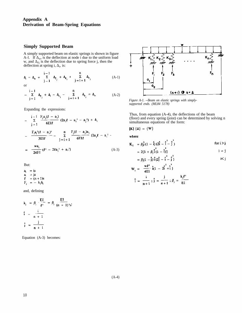
A simply supported beam on elastic springs is shown in figureA-l. If ∆w, is the deflection at node i due to the uniform loadw, and ∆Fj is the deflection due to spring force j, then thedeflection at spring i, ∆i, is:
or
Expanding the expressions:
But:
and, defining
(A-1)
(A-2)
(A-3)
Equation (A-3) becomes:
(A-4)
Figure A-1. --Beam on elastic springs with simply-supported ends. (ML84 5178)
Thus, from equation (A-4), the deflections of the beam(floor) and every spring (joist) can be determined by solving nsimultaneous equations of the form:
10

Beam with “Free” Ends
A beam with its ends spring-supported is shown in figure A-2.The derivation for this case is similar to that for the simply-supported beam except that additional terms are required toaccount for the movement of the beam ends. The deflectionat node i is
(A-5)
Again, the problem reduces to a set of n simultaneousequations of the form
[K] {∆ } = {W}
Figure A-2.--Beam on elastic springs with “free”ends. (ML84 5179)
and
for all i
11

Appendix B:Basic Program for Floor Analysis
The following BASIC program implements the methodpresented. It is written to run on a Sharp model 1500 pocketcomputer but can easily be modified for other machines. Theprogram prompts for input data and requires that all units beconsistent; e.g., if span is in inches, then joist dimensionsmust also be in inches, and if joist E is in pounds per squareinch, then uniform load must also be in pounds per squareinch, not pounds per square foot.
The program is organized as follows:
Segment “F”, statements 10-40Initiate new problem (clear memory).Input floor type (simply supported or “free”).Input number of joists.
“J”, 100-170Input joist data (spacing, span, widths, depths, elasticmoduli).Note: Input zero for properties which are not identical for
all joists.
“S”, 200-250Input sheathing data (thickness, Eaxial, Ebending, gap
spacings).
“N”, 300-320Input nail data (stiffness, spacing).
“D”, 400-790Solution:400-450 computes T-beam stiffnesses.455 computes load vector.460-495 assembles stiffness matrix.500-507 modifies stiffness matrix for “free” ends.510-740 solves simultaneous equations.750-790 computes average, soft spot, and maximum
deflection coefficients.
“L” 795Input uniform load.
“A”, 800-860Display joist deflections.
999 End.
12

Program Listing
10: “F”:CLEAR :WAIT 015: CLS :PRINT “FLOOR TYPE(SS or FRee)
”;:INPUT F$16: IF F$ = “SS”GOTO 3017: IF F$ = “FR”GOTO 3020: GOTO 1530: CLS :PRINT “No. of JOISTS = ”;:INPUT N40: DIM B(N),D(N),E(N),K(N,N),Q(N),BT(N)
100: “J”:J$ = “JOIST”:WAIT 0102: CLS :PRINT J$ + “ SPACING = ”;:INPUT S103: LL=(N-1+(F$=“SS”)*2)*S105: CLS :PRINT J$+ “ SPAN = ”;:INPUT L110: CLS :PRINT J$+ “ WIDTH (all) = ”;:INPUT B115: CLS :PRINT J$+ “ DEPTH (all) = ”;:INPUT D120: CLS :PRINT J$+ “ MOE (all) = ”;:INPUT E125: USING “# # #”130: FOR J = 1TO N140: IF B>0LET B(J) = B:GOTO 150145: CLS :PRINT J$;J;“ WIDTH = ”;:INPUT B(J)150: IF D>0LET D(J)=D:GOTO 160155: CLS :PRINT J$;J;“ DEPTH = ”;:INPUT D(J)160: IF E>0LET E(J)=E:GOTO 170165: CLS :PRINT J$;J;“ MOE = ”;:INPUT E(J)170: NEXT J200: “S”:S$ = “SHTHNG”:WAIT 0210: CLS :PRINT S$+ “THICKNESS = ”;:INPUT T220: CLS :PRINT S$+ “E(axia1) = ”;:INPUT EA230: CLS :PRINT S$+ “E(bndg) = ”;:INPUT EB240: CLS :PRINT “GAP(along joist) = ”;:INPUT LJ250: CLS :PRINT “GAP(perp to joist) = ”;:INPUT LS300: “N”:N$ = “NAIL”:WAIT 0310: CLS :PRINT N$+ “STIFFNESS = ”;:INPUT KN320: CLS :PRINT N$+ “SPACING = ”;:INPUT SN400: “D”:IS=EB*T^3/12*L*(1-S/LS)405: FOR J = 1TO N:JJ =(J - 1 + (F$ = “SS”))*S/LL410: A1 =EA*T*S:A2=E(J)*B(J)*D(J):IU=A2*
D(J) ^ 2/12415: IF F$ = “FR”AND(J = 1 OR J =N)LET A1 = A1/2420: H2 = (D(J) + T) ^ 2/4:IR= IU + A1*A2/(A1+ A2)*H2430: FD = 10/(H2*KN/SN*LJ ^ 2*IR/IU/(IR - IU) + 10)440: EI = IR/( 1 + FD*(IR/IU - 1))450: BT = 76.8*EI/IS*(LL/L)^3:BT(J) = BT455: Q(J)=LL^4*L/4/IS*JJ*(1-2*JJ ^2 + J J^ 3 )460: FOR I = 1TO N:II = (I - 1 + (F$ = “SS”))*S/LL470: IF I>JLET K(I,J)=BT*JJ*(1 - II)*
(2*II-II ^ 2 - JJ ^ 2)480: IF I = JLET K(I,J) = 2*(3 + BT*II ^ 2*(1-II) ^ 2)490: IF I< JLET K(I,J) = BT*(1 - JJ)*II*
(2*J J - I I^ 2 - J J ^2 )495: NEXT I:NEXT J500: IF F$ = “SS”GOTO 510
501: FOR I = 1TO N:II = (I - 1)/(N - 1)502: Q(I) = Q(I) + 3*LL ^ 4*L/IS*((1- II)/BT(1) +
II/BT(N))503: FOR J=1TO N:JJ=(J - 1)/(N-1)504: K(I,J)=K(I,J)+6*BT(J)*((1- II)*(1 - JJ)/BT
(1) + II*JJ/BT(N))505: IF J=1OR J=N LET K(I,J)=0506: NEXT J:NEXT I507: K(1,1) = 6:K(N,N) = 6510: FORK=1TO N-1520: FOR I=K+1TO N530: IF K = 1GOTO 570540: FOR J=1TO K-1550: K(I,K) = K(I,K) - K(I,J)*K(J,K)560: NEXT J570: K(I,K) = K(I,K)/K(K,K)580: NEXT I590: FOR I=K + 1TO N600: FOR J=1TO K610: K(K+1,I)=K(K+1,I)-K(K+1,J)*K(J,I)620: NEXT J:NEXT I630: NEXT K640: FOR I=2TO N650: FOR K=1 TO I-1660: Q(I) = Q(I) - K(I,K)*Q(K)670: NEXT K:NEXT I680: FOR I = NTO 1 STEP - 1690: IF I = NGOTO 730700: FOR K=I+1TO N710: Q(I) = Q(I) - K(I,K)*Q(K)720: NEXT K730: Q(I) = Q(I)/K(I,I)740: NEXT I750: MX=0:SS=0:SI=0760: FOR J=2TO N-1770: IF Q(J) > MXLET MX = Q(J):AM = J780: X = (Q(J - 1) + Q(J) + Q(J + 1))/3:IFX > SSLET
SS=X:AS=J790: SI = SI + Q(J):NEXT J:BEEP I795: “L”:WAIT 0:CLS:PRINT “UNIFORM LOAD =
”;:INPUT Q800: “A”:U$ = “ # # . # # # # ”:WAIT :CLS810: PRINT “AVE. DEFL = ”;USING U$;SI/(N - 2)*Q820: PRINT “SOFT SPOT = ”;USING U$;SS*Q;
“ @ ”;USING ;AS830: PRINT “MAX. DEFL = ”;USING U$;MX*Q;
“ @ ”;USING ;AM840: FOR I = 1TO N850: PRINT “DEFL”; USING “ # # # ”;I; “ = ”;USING
U$;Q(I)*Q860: NEXT I999: END
13

Appendix C:Sample Input and Output
To demonstrate the use of the BASIC program, completeinput and output are presented for experimental floor N-3(table 3).
Program Prompt Input
FLOOR TYPE (SS OR FR)? FRNO. OF JOISTS = ? 9JOIST SPACING = ? 15.8125JOIST SPAN = ? 144JOIST WIDTH (all) = ?1 1.5JOIST DEPTH (all) = ?1 7.25JOIST MOE (all) = ?1 0JOIST 1 MOE = ? 2.32E6JOIST 2 MOE = ? 1.85E6JOIST 3 MOE = ? 1.29E6JOIST 4 MOE = ? 2.40E6JOIST 5 MOE = ? 2.03E6JOIST 6 MOE = ? 1.42E6JOIST 7 MOE = ? 2.27E6JOIST 8 MOE = ? 2.67E6JOIST 9 MOE = ? 1.74E6SHTHNG THICKNESS = ? .625SHTHNG E (axial) = ? .5E6SHTHNG E (bndg) = ? 1E6GAP (along joist) = ? 48GAP (perp to joist) = ? 96NAIL STIFFNESS = ? 9400NAIL SPACING = ? 7.43
(Program computes for approximately 2 minutes)
UNIFORM LOAD = ? 49.2/144
1Enter zero if joist properties are not all identical; in this case,program prompts for individual entry.
14
output
AVE. DEFL = 0.3145SOFT SPOT = 0.3360 @ 3MAX. DEFL = 0.36% @ 3DEFL 1 = 0.1388DEFL 2 = 0.3204DEFL 3 = 0.3696DEFL 4 = 0.3181DEFL 5 = 0.3167DEFL 6 = 0.3385DEFL 7 = 0.2981DEFL 8 = 0.2403DEFL 9 = 0.1511
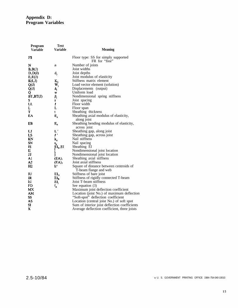
Appendix D:Program Variables
ProgramVariable
2.5-10/84
TextVariable Meaning
Floor type: SS for simply supportedFR for “free”
Number of joistsJoist widthsJoist depthsJoist modulus of elasticityStiffness matrix elementLoad vector element (solution)Displacements (output)Uniform loadNondimensional spring stiffnessJoist spacingFloor widthFloor spanSheathing thicknessSheathing axial modulus of elasticity,
along joistSheathing bending modulus of elasticity,
across joistSheathing gap, along joistSheathing gap, across joistNail stiffnessNail spacingSheathing EINondimensional joist locationNondimensional joist locationSheathing axial stiffnessJoist axial stiffnessSquare of distance between centroids of
T-beam flange and webStiffness of bare joistStiffness of rigidly connected T-beamJoist T-beam stiffnessSee equation (3)Maximum joist deflection coefficientLocation (joist No.) of maximum deflection“Soft-spot” deflection coefficientLocation (central joist No.) of soft spotSum of interior joist deflection coefficientsAverage deflection coefficient, three joists
U. S. GOVERNMENT PRINTING OFFICE 1984–754-040-10010
15