deformation mechanisms during indentation of · pdf filedeformation mechanisms during...
TRANSCRIPT

DEFORMATION MECHANISMS DURING INDENTATION OF NANOSCALE METALLIC/CERAMIC
LAMINATED COMPOSITES K.K. Chawla1, P.-L. Sun2, T.-Y. Lin3, J.P. Chu3, D.R.P. Singh4, N. Chawla4, Y.-L. Shen5 1University of Alabama at Birmingham, BEC 254, 1530 Third Ave. South, Birmingham, AL35209, USA. [email protected] of Materials Science and Engineering, Feng Chia University, Taichung 40724, Taiwan 3Graduate Institute of Engineering, National Taiwan University of Science and Technology, Taipei 10607, Taiwan
4School of Materials, Fulton School of Engineering, Arizona State University, Tempe, AZ 85287-8706, USA 5Department of Mechanical Engineering, University of New Mexico, Albuquerque, NM 87131, USA
SUMMARY Examples of metallic laminates abound in history. Metallic laminates made of steel have been used to make Samurai swords. The famous iron pillar of Delhi consists of laminae of wrought iron. Other mundane examples include laminates copper/aluminum and copper/stainless laminates for use in kitchen utensils. More recently, researchers have been investigating multilayered composites consisting of metal/metal and metal/ceramic laminates. Extensive work on ultra high carbon steel (UHCS) laminates that have compositions very similar to ancient Damascus or Wootz steels, showed excellent impact properties. Results from our work on Al/SiC nanolaminates made by physical vapor deposition are presented. TEM analysis shows no reaction product at the interface between Al and SiC and a high degree of flexibility of brittle SiC layers under indentation. Cracking under indentation started at a depth of 1000 nm in SiC layers. This occurred at sites where kinks formed in SiC which appeared to occur at sites of shear localization.
Keywords: Al/SiC, Laminates, indentation, ultra high carbon steel

INTRODUCTION Laminates made of one or more type of sheet materials are commonly observed in nature. Examples from Mother Nature include nacre, abalone shell, etc. Examples of metallic laminates abound in history. Metallic laminates made of steel have been used to make Samurai swords. The famous iron pillar of Delhi consists of laminae of wrought iron. Steel laminates to make blades were made in 400 BC or earlier. The Japanese sword is a laminated composite. Figure 1 shows this laminated microstructure [1]. These have been used in industrial practice for quite some time. Other mundane examples include laminates copper/aluminum and copper/stainless laminates for use in kitchen utensils. Multilayered metal/ceramic composite materials are very attractive because they can show very high strength, fatigue resistance, thermal resistance, wear resistance, and biocompatibility.Extensive work has been done on ultra high carbon steel (UHCS) laminates [2]. These steels have compositions very similar to ancient Damascus or Wootz steels. These laminated composites containing UHCS that showed excellent impact properties. Under certain conditions of strain rate and temperature, these laminates also can exhibit superplastic properties.
A general view of the structure of laminates at different length scales is provided in Fig. 2 [3-5]. In this study, we have synthesized multilayered Al/SiC composites by DC/RF magnetron sputtering. The elastic and plastic behavior of the multilayered materials was investigated by nanoindentation. In this paper we focus on thecharacterization of the microstructure of the multilayered structures, by transmission electron microscopy (TEM), before and after indentation.
Fig. 1. Laminated microstructure of Japanese sword (from ref. 1.)

Nb- Nb5Si3 [5]
Nb
Nb5Si3
MICROLAMINATE
Al-SiC [3]
NANOLAMINATE
100 nm
SiC
Al
Si
1 mm
Glass Fiber
AlMACROLAMINATE
10-1
010
-910
-810
-710
-610
-510
-410
-310
-2m
eter
s
LEN
GTH
SC
ALE
GLARE (Glass reinforced Aluminum) [4]
Unique Mechanical Properties
10 μm
Fig. 2 Laminates at different length scales.
EXPERIMENTAL PROCEDURE
Magnetron sputtering system was used to synthesize Al/SiC multilayers. A Si (111) single crystal Si was used as a substrate for depositing the multilayers. Aluminum targets (> 99.99% purity, Kurt J. Lesker, PA) were sputtered at a DC power of 95 watts and Ar working pressure of 3.0 mTorr. SiC layers were sputtered from a target made by hot isostatic pressing (HIP) (> 99.5% purity, Kurt J. Lesker, PA) using identical argon pressure and an RF power of 215 watts. Prior to deposition, an average base pressure in the range of 1.3 × 10⁻⁵ Pa was obtained. Target pre-sputtering was carried out to remove oxides or contaminants prior to film deposition. The substrate was also rotated during deposition to ensure uniformity of the deposited layers. Deposition rates of approximately 7.5 nm/min and 3.9 nm/min were obtained for Al and SiC, respectively. The multilayer sample comprised of 41 alternating layers of Al and SiC on a Si(111) substrate. Each layer had a thickness of approximately 50 nm.
Nanoindentation was conducted using a commercial nanoindenter (Nano-XP, MTS Systems, Minneapolis, MN). The indenter was calibrated using a fused silica standard. At least 20 indentations were made on each of the samples. A three-sided Berkovich indenter was used to make indentations of depths of 500 , 1000 , and 2000 nm.TEM samples from indented nanolaminate samples, were fabricated by a dual beam focused ion beam (FIB) with a Field Emission Gun SEM (FEI, Nova 200 NanoLab). FIB offers versatility in micromachining of a variety of materials. It was particularly suited for this study because the nanolaminates consisted of alternating hard and soft layers. A thin platinum layer was deposited on the sample prior to FIB machining to minimize ion beam damage. A Ga+ ion source was used for milling the surface at a voltage of 30 kV. A wide “trench” in the region of interest was milled at a high beam current of 20 nA.

The sample was then milled at a relatively low beam current of 50 pA and “lifted-out” by a probe that bonded the sample with Pt.
RESULTS AND DISCUSSION
TEM analysis showed an absence of any reaction at the interface between Al and SiC, Fig. 3. The SiC was amorphous as shown by the high resolution TEM micrograph in Fig. 4. The amorphous structure of SiC can be attributed to the relatively low processing temperature (less than 100 oC). A thin layer of SiO2 is present between the Si substrate the nanolaminate. Figure 5 provides more information on thickness of Al and SiC nanolayers. Note the layers are relatively uniform throughout the thickness of the laminate.
Deformation of these nanolaminates under indentation by a Berkovitch indenter was studied by TEM of the cross-section of the laminate.Deformation of Al/SiC laminate in a nanoindenter at a depth of 500 nm is shown in the TEM micrograph in Fig. 6. No cracking was observed. A higher magnification image is shown in Fig. 7. TEM. Note the absence of any cracking and flattening and thinning of the Al layer under the indenter. When deformed to a depth of 1000 nm, cracks form in SiC, see Fig. 8. The Al/SiC interface remains intact. A higher magnification view of cracking in SiC is shown in Fig. 9. Note that the crack is confined entirely in the SiC layer. What is remarkable is the extreme flexibility of SiC layers under the indenter. Examples of this are shown in Figs. 10 and 11, TEM micrographs taken at an indentation depth of 2000 nm. Note the bending and kinking of the SiC layers under indentation. Small cracks can be seen in SiC layers. Kink formation leading to cracking in brittle SiC would appear to occur at sites of shear localization.
Laminates at the nm scale exhibited significant flexibility during nanoindentation. The damage took place by plastic deformation in at the aluminum layers, extreme bending of SiC layers, and localized cracking of SiC at the kink sites.
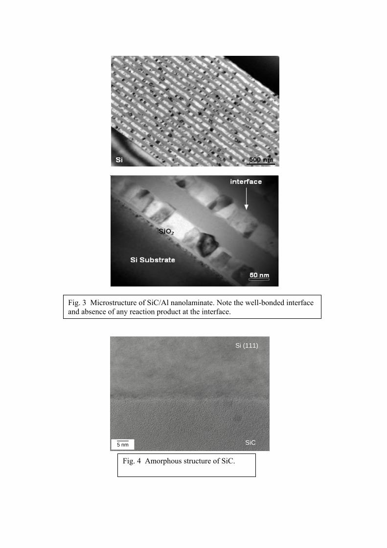
Fig. 3 Microstructure of SiC/Al nanolaminate. Note the well-bonded interface and absence of any reaction product at the interface.
Si (111)
SiC 5 nm
Fig. 4 Amorphous structure of SiC.

Increasing Si substrate contribution
0
100
200
300
400
500
600
-50
0
50
100
150
200
0 500 1000 1500 2000
Load
(mN
)
Modulus (G
Pa)
Displacement into Surface (nm)
Fracture of Si
Fracture of SiC layers
First Al
Layer
SUBSTRATE
Young’s Modulus
Load
0
1
2
3
4
5
0
40
80
120
160
40 80 120 160 200
Load
(mN
)
Modulus (G
Pa)
D isplacem ent into Surface (nm )
Fig. 5. (a) Load versus displacement curve from nanoindentation of Al50SiC50 composite. The evolution of Young’s modulus with indentation displacement is shown. (b) Magnified view of the early part of the indentation process. After indentation of the first Al layer, a plateau commensurate with the Young’s modulus of the overall composite is observed.
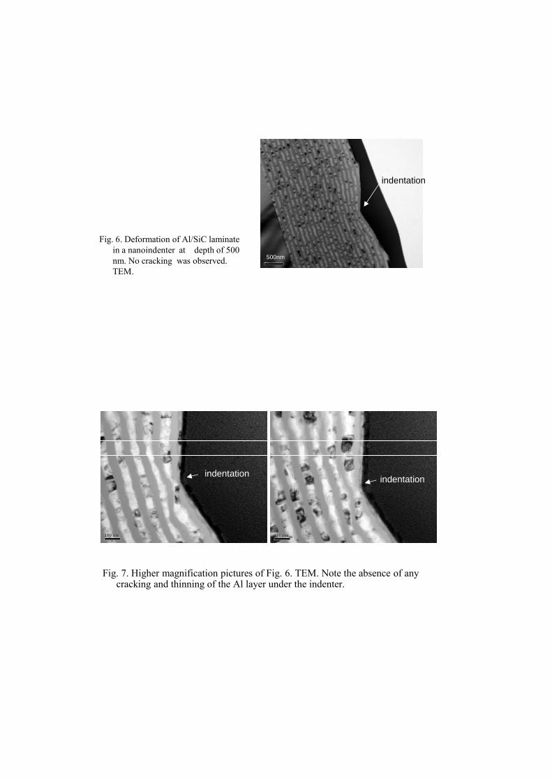
Fig. 6. Deformation of Al/SiC laminate in a nanoindenter at depth of 500 nm. No cracking was observed. TEM.
500nm
indentation
Fig. 7. Higher magnification pictures of Fig. 6. TEM. Note the absence of any cracking and thinning of the Al layer under the indenter.
indentationindentation
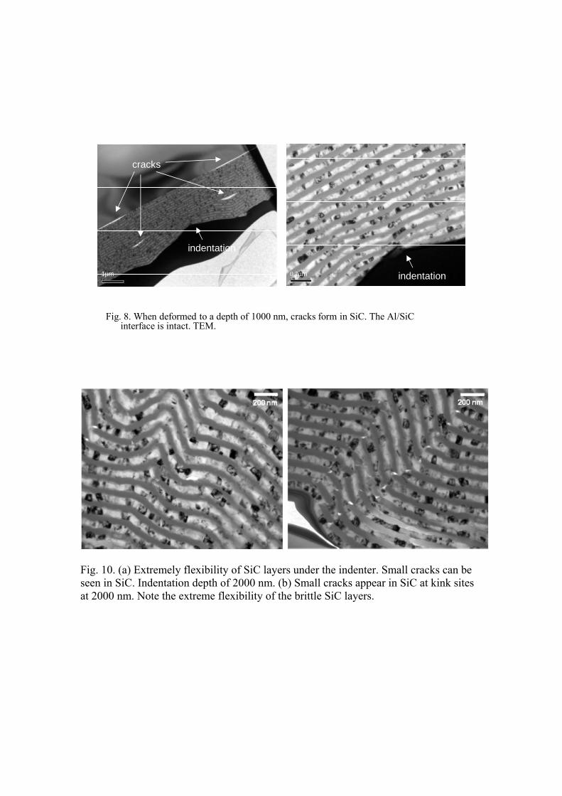
Fig. 8. When deformed to a depth of 1000 nm, cracks form in SiC. The Al/SiCinterface is intact. TEM.
1μm 0.2μm
indentation
cracks
indentation
Fig. 10. (a) Extremely flexibility of SiC layers under the indenter. Small cracks can be seen in SiC. Indentation depth of 2000 nm. (b) Small cracks appear in SiC at kink sites at 2000 nm. Note the extreme flexibility of the brittle SiC layers.

CONCLUSIONS Plenty of examples of metallic laminates, of one form or another, can be found in early historic times. In the present work, Al/SiC nanolaminates were synthesized by DC/RF magnetron sputtering process. TEM analysis of these laminates subjected to nanoindentation showed extreme flexibility of the brittle SiC layers, which deformed considerably along with plastic deformation of aluminum layers. SiC layers showed formation of small cracks when deformed to depths of 1000 nm and above. However, the Al/SiC interface remained intact and no reaction product was observed.
REFERENCES
1. J.D. Verhoeven, A.H. Pendray, and W.E. Dauksch, JOM, 50 (9) (1998), pp. 58-
64.
2. D.R. Lesuer, C.K. Syn, O.D. Sherby, J. Wadsworth, J.J. Lewandowski, and W.H. Hunt, Int. Mater. Rev., (1996) 41 169-197.
3. Deng X., Chawla N, Chawla K, Koopman, M., and Chu J.P. (2005) Adv Eng Mater 7:1099
4. H.J.M. Woerden, J. Sinke, and P.A. Hooimeijer, “Maintenance of GLARE Structures and GLARE as Riveted or Bonded Repair Material,” Appl. Comp. Mater., 10 (2003), pp. 307–329.
5. A.J. Gavens, D. Van Heerden, T.P. Weihs, and T. Foecke,Metall. Mater. Trans. A, 30 (11) (1999), pp. 2959–2965