delhi technological university - auvsi suas · team uas-dtu plans a comeback at suas 2017...
TRANSCRIPT
1 | DELHI TECHNOLOGICAL UNIVERSITY
DELHI
TECHNOLOGICAL
UNIVERSITY
ABSTRACT:
Team UAS-DTU plans a comeback at SUAS 2017 completion with its UAS Lazarus. It comprises of a 2m
wingspan airframe and an EPO foam body. Since the 2014 SUAS competition, the team has shifted from
point and shoot cameras to android based smartphone primary imagery task. The system is capable of
autonomously detecting static virtual objects and accordingly change its path, showing its obstacle
avoidance capabilities. An open source mission planning software has been modified for providing
interoperability, which was prioritized above all the other tasks. Paramount attention was given to the
accessibility of sub-systems, which favored rapid prototyping and easier debugging. Live mission is
observed at the ground control station. Risk and safety management were identified as high priority and
were applied at every stage of the evolving design. This paper highlights the design rationale, development
and testing procedures followed for meeting the established system requirements.

2 | DELHI TECHNOLOGICAL UNIVERSITY
Table of Contents
1. Systems Engineering Approach
1.1. Mission Requirement Analysis …………...……………………………………………...…......3
1.2. Design Rationale …………………………………...……………………………………….......3
1.2.1. Design and Development Model ………...…………………………………….….......3
1.2.2. Air Vehicle Selection ……………...………………………………………….…........3
1.2.3. Autopilot Selection ……………….……………………………………...….….…......4
1.2.4. Imagery System ……………………………………………………………….……....5
1.3. Expected Task Performance …………………………...………………………………….........6
1.4. Programmatic Risks and Mitigations …….……………………………………………….........6
2. UAS Design Description ………………………………………………………………………….…...........7
2.1. Airframe ………………………………….………………………………………………..........7
2.2. Propulsion System ………………………………………………………………………….......8
2.3. Power Systems ……………………………………………….....................................................9
2.4. Autopilot Systems ………………………………………………................................................9
2.4.1. Software in The Loop Simulation (SITL) .……….………………………………….….9
2.4.2. Control Law and Navigation Tuning ………………………………….........….…….10
2.5. Gimbal Sub-System …………………………………………………………………...…...….10
2.6. Communication System ……………………………………………………………...….…….10
2.7. Ground Control System ……………………………………………………………...….……10
2.8. Off Axis Target Capture System …………………………………………………….…….….11
2.9. Payload Drop System ……………………………………………………………...…….……11
2.10. Imagery System ……………………………………………………………...…………….….11
2.10.1. Autonomous Imagery Acquisition System …………………………………...….….12
2.10.2. GUI ……………………………………………………………...……………….….12
2.10.3. Image Analysis ……………………………………………………………...………12
2.11. Inter-operability ……………………………………………………………...……….…….…14
2.12. Sense, Detect and Avoid (SDA) ……………………………………………………...…….…14
3. Mission Planning and Profile ……………………………………………………………...………………14
3.1. Mission Tasks Attempted ……………………………………………………………....….….14
3.2. Mission Profile ……………………………………………………………...………………...15
4. Test and Evaluation Results ……………………………………………………………...……………..…15
4.1. Developmental Testing ……………………………………………………………...……..…15
4.1.1. Mechanical Vibrations Test …………………………………………………....……16
4.2. Individual Component Testing ………………………………………………………..………16
4.2.1. Autonomous Flight Testing …………………………………………………...….…16
4.2.2. Payload Drop ……………………………………………………………...…………16
4.2.2.1. Payload Drop Survival ………………………………………...…...…16
4.2.2.2. Accuracy ……………………………………………………...………16
4.2.3. SDA ……………………………………………………………...……………..…..17
4.2.4. Imagery Testing ………………………………………………………….…...….…17
4.2.5. Communication Systems Testing ……………………………………………......…18
4.2.6. Off-Axis testing ……………………………………………………………......…18
5. Safety Considerations …………………………………………………………………………….....……19
5.1. Design Safety ……………………………………………………………...…………....……19
5.2. Operational Safety ……………………………………………………………………...……19
6. Conclusion ……………………………………………………………...……………………………...…20

3 | DELHI TECHNOLOGICAL UNIVERSITY
Table 1: Mission Requirement Analysis
1. SYSTEMS ENGINEERING APPROACH
The competition, apart from being a mission-oriented challenge which tests the technical advances made by a team,
also scrutinizes its systems engineering approach. The team therefore outlined its systems engineering approach
towards successful completion of the mission
1.1. Mission Requirement Analysis
The team carefully analyzed the mission tasks and identified the key areas where major developments were required.
The sub-tasks were prioritized according to their respective weightage in their domain:
1.2. Design Rationale
1.2.1. Design and Development Model
A development model had to be chosen which could support rapid
development and testing due to time constraints. The team’s design
rationale is based on a Rapid Application Development (RAD) model,
a process of designing in which different components are developed in
parallel as if they were mini projects, which helped the team to reduce
the development time.
Task Threshold Prioritized Task List
Autonomous Flight
• Autonomous Takeoff and Land
• Autonomous Navigation
waypoint off-set <100 ft.
1. Autonomous Navigation
2. Autonomous Takeoff
Autonomous Land
Search Area Intelligence gathering
• Target and characteristics detection
• GPS Tagging with error
N/A
Error<150ft
Payload Drop
• Deliver a Payload at a given spot
without compromising the payload
Distance from bulls
eye<150 feet and at least
80% water contained
1. Safe delivery of payload
2. Minimize the distance from bullseye
Interoperability operations
• Download mission along with all data
• Upload targets acquired in Search
Area Intelligence Gathering Upload
telemetry data
Refresh rate
> 1Hz
1. Download mission and other necessary data
2. Upload telemetry at required rate
3. Upload targets acquired through Search
Area Intelligence Gathering task
Sense, Detect and Avoid N/A 1. Static Obstacle Avoidance
2. Dynamic Obstacle Avoidance
Mission Time Flight time<20 min
Post processing <20 min
Fig 1. RAD Development Model

4 | DELHI TECHNOLOGICAL UNIVERSITY
Table 2. Airframe Comparison
Table 3. Mission Requirement Analysis
1.2.2 Air Vehicle Selection
The team shortlisted 3 air frames on the basis of experience in integration of a COTS frames.
RMRC Anaconda had an edge over the other air frames in terms of size and payload capacity. It displayed
commendable endurance performance. It was selected as the airframe for the sub-system.
1.2.3 Autopilot Selection
The team decided to shift from the earlier choice of PIXHAWK as a Flight Controller Board and decided to conduct
a comparison between the APM 2.6, 3DR PIXHAWK and HEX PIXHAWK-2 based on their technical specifications
as well as their suitability for the mission requirements.
Features APM 2.6 Pixhawk Pixhawk 2
DIMENSIONS 35X35X5 mm 81x50x16 mm 94X44X17 mm
PROCESSOR Atmel's ATMEGA 2560
and ATMEGA 32U (No
FPU)
32-bit ARM Cortex
M4 core with FPU
32-bit ARM Cortex M4 core with
FPU
RAM 8 KB 256 KB 256 KB
MCU FREQUENCY
AND FLASH SIZE
16 MHz; 256 KB Flash 168 MHz; 2 MB
Flash
168 MHz; 2MB Flash
UPGRADEABILITY Upgrades stopped Frequent Updates
Available
Frequent Updates Available
ROBUSTNESS Low High Very High (Built in IMU heating
system; Isolated and dampened
IMU)
COST 65 $ (With GPS) 199.9 $ 348 $
Parameter Units Requirements RMRC
Anaconda
Finwing
Air Titan
Skywalker
X-8
Wingspan mm <3000 2060 2520 2122
Payload capacity Pounds >6 8 9 8
Payload volume Cubic
inch >400 477 412 450
Take off/Landing
requirements - - Paved Runway Paved Runway
Catapult, Hand
Launched
Configuration - - Conventional with
Invert V Tail
Conventional with
H Tail
Blended Wing
Body
Cruise speed Meters/sec <18 14 12 16
Approx.
Endurance Minutes >30 38 30 28
Cost USD - $379 $390 $250

5 | DELHI TECHNOLOGICAL UNIVERSITY
Table 4. Camera Comparison and Selection
Comparisons between the three revealed that the PICHAWK 2 was better adapted to the mission requirements with
its triple redundant, isolated and dampened IMU system; two onboard compasses and multiple GPS system providing
reliable and accurate positioning and the robustness provided by the built-in IMU heating system and DF17 interface
connectors. Thus, the team decided to choose the HEX PIXHAWK 2 as its Flight Controller Board.
1.2.4 Imagery System
The use of mobile phone camera for imagery system was unprecedented in the team history. Previously, the team used
Cannon G10 point and shoot camera, but better results were expected using the phone camera after analyzing the
tradeoffs between the 2 type of cameras.
**OIS-Optical Image Stabilisation
Evidently, selection of smart phone as the primary imagery payload was advantageous.
Average
Specifications/Class
Of Cameras
Smartphone
Cameras
P&S, SLR/DSLR
Cameras Rationale
Resolution(MP) 12-18. 14-30
15 MP determined to be most
suitable since greater resolution
resulted in larger file size
Equivalent (28-31) x (14-16) (21-35) x (14.2-16)
Larger Sensor resulted in a better
field of view Sensor Size(mm)
Weight(in grams) 120-170 250-700 Smartphones had an edge in weight
redundancy
Dimensions(in mm) (135-156)x(68-73)x(6-9) (110-160)x(60-
110)x(50-90)
Lighter payload augments the
mission time
ISO Range 100-1600 100-3200
ISO of near about 400-800 is
preferred in sufficient light to avoid
motion blur.
Shutter Speed
Range(in s) 1/32-3 1/400-15
1/16 s shutter speed with 400 ISO for
photography in ample light
Sensors internally
Available
Barometer, Compass,
GPS
GPS, Compass in
some models
Barometer, Compass, GPS are
favourable
Other Specs OIS*, Autofocus, Back
Illuminated Sensor etc.
OIS*, Autofocus
etc.
OIS proved to be important in
lowering the levels of jello effect
Processor Quad-Octa Core,
1.8-2.7 GHz,1.5-4
GB RAM size
Single-Dual Core,
0.5-1.2 GHz, 512 MB
of RAM
Better processor allowed the pre-
processing on board and thus
eliminating the need of an on-board
processor.
Specifications
Operating Systems UNIX based Android OS Proprietary OS, differs
with brands
UNIX based Android OS have a
larger community of developers and
allows the whole process to be open-
source
Availability HIGH HIGH High availability crucial
Price(USD) 124-310 155-775 Price of budget smartphones and
cameras
Highly favorable Moderately favorable Not favorable

6 | DELHI TECHNOLOGICAL UNIVERSITY
Table 5. Test flights performance
Table 6. Test flights performance
1.3 Expected Task Performance
The table below summarizes the team’s performance during the flight testing and evaluation phase. A total number of
30 flights were conducted and the progress made in each task is as follows:
1.4 Programmatic Risks and Mitigation
The Team listed and prioritized the risks that could have been met with during each stage of the preparation. The
priority of the risks defines the amount of time that need to be invested on the mitigation of the risk. Likewise, the
team has always emphasized on identifying risks affecting the project as a whole and formulated plans for their
mitigation.
Risk Description Likelihood Impact Mitigation Strategy
Complete airframe loss
Loss of airframe during flight testing
Medium High An alternate airframe kept operational at all times with backup subsystems installed
Delay in Sub-system testing
Sub-system failure lead to postponement of scheduled flight
Low Medium A multirotor frame kept operational for fast deployment and testing images
Conducting test flight
Objection on conducting flights in the college premises after the announcement new D.G.C.A. rules for UAV operations
Medium High Timely approval taken from college authorities in accordance with the flight test schedule.
Sub-systems compatibility issues
Designed sub-systems not compatible in terms of size, software, or accessibility
High Medium Regular Inter-Department meetings for discussing the under development sub-systems and identification of multi-disciplinary failure points
Mechanical vibrations
Acquired images distorted due to jello effect making the imagery algorithms in-accurate
Medium High Development of anti-Vibration mount and incorporating it into the gimbal sub-system
Safety Pilot Un-availability of a safety pilot directly affects the teams' ability to safely conduct a flight test
Medium High Training of select crew members as safety pilots before and during the flight tests
Task Performance during test flights Flight tests
conducted Status
Autonomous Flight Full autonomous flight conducted 25 Will accomplish
Waypoint Plan
Following
Waypoint navigation with 5 m off-set 22 Will accomplish
Search Area
Intelligence gathering
60 % success rate with processed images 20 Will accomplish
Sense, Detect and Avoid Static objects dodged with 45 % success rate 7 Will attempt
Payload Drop Accuracy of 38 feet achieved 11 Will accomplish
Interoperability Refresh rates above 4 Hz achieved 12 Will accomplish
Off Axis Target Ground tested - Will attempt

7 | DELHI TECHNOLOGICAL UNIVERSITY
2. UAS DESIGN DESCRIPTION
2.1 Airframe Key requirements which were considered while selecting the airframe
were high payload weight, long endurance flight, ample volume for
payload, small takeoff distance ,easy assembly and repairability. The
design rationale suggested Anaconda as the optimal airframe for
SUAS 2017.
Anaconda is a twin boom, inverted V-tail pusher design. The frame
sports an expanded polyolefin foam built body which allows quick
modifications and repairs to the damages incurred during flight test.
Major modifications include the increment in the ground clearance of
the frame for accommodating the camera gimbal and the payload drop
system. A customized base plate for the fuselage was also fabricated
for providing mounting solutions for the various subsystems inside
Parameter Specification
Wing span (m) 2
Max G.T.O.W. (kg) 5
Takeoff distance (m) 10
Maximum endurance
(min)
35
Stall: cruise: max
velocity(m/s)
11:16:20
Wind tolerance
(kmph)
25
Propulsion motor T-Motor AT
3520-5, 880 kV
Propulsion battery 16000 4S mAh
Fig 2. System Architecture
Table 7. Airframe specifications

8 | DELHI TECHNOLOGICAL UNIVERSITY
and outside the frame. This allowed exclusiveness between
the avionics and airframes preparation procedures, making
interdependency delays minimal. Critical parts of the
airframe were strengthened using 120 GSM Glass Fibre so
as to enhance the survivability of the frame during crashes.
A dedicated nose gear was designed for increasing the
ground clearance of the frame as well as providing a
smoother ground roll during take-offs and landings.
Throughout the flights, the frame was keenly observed for
wing fluttering, which is a sign of overloaded air frame.
No such observations were made which led to the
finalization of the Anaconda as the frame for SUAS 2017
competition.
2.2 Propulsion System
The propulsion system of the Anaconda consists of a T-Motor
AT 3520-5, 880 kV Brushless Electric Out-runner motor with a
four cell 16,000 mAh Lithium Polymer battery. The motor used
is a 1300 Watt rated motor on which thrust measurements were
conducted on a test rig. An 80A ESC was found to be suitable
with the propulsion system since maximum current drawn
during thrust test was noted to be not more than 45 A. Thrust
requirements were estimated by performing regular flight tests.
The estimate of the endurance was taken by noting down the
average Ampere-hours consumed after each flight test. This data
was plotted against the flight time and after linear
approximations, an endurance of about 35 minutes was
estimated.
Moreover, a comparison between the thrust obtained at 4s
16000mAh and at 5s 5000mAh was carried out and it was
found that they provided maximum thrust of 3.68 Kgs and
4.20 Kgs respectively. The former met the requirements and
thus was opted for the competition. A mathematical estimate
of the battery capacity was made as follows:
𝑇ℎ𝑟𝑒𝑠ℎ𝑜𝑙𝑑 𝐵𝑎𝑡𝑡𝑒𝑟𝑦 𝐶𝑎𝑝𝑎𝑐𝑖𝑡𝑦= (𝐶𝑢𝑟𝑟𝑒𝑛𝑡 𝐷𝑟𝑎𝑤𝑛 𝑎𝑡 𝑓𝑢𝑙𝑙 𝑡ℎ𝑟𝑢𝑠𝑡 ∗ 𝑡𝑖𝑚𝑒 𝑓𝑜𝑟 𝑡𝑎𝑘𝑒𝑜𝑓𝑓 𝑅𝑜𝑢𝑡𝑖𝑛𝑒)+ (𝐶𝑢𝑟𝑟𝑒𝑛𝑡𝑑𝑟𝑎𝑤𝑛 𝑎𝑡 𝑐𝑟𝑢𝑖𝑠𝑒 𝑠𝑝𝑒𝑒𝑑 ∗ 𝑀𝑖𝑠𝑠𝑖𝑜𝑛 𝑇𝑖𝑚𝑒)= (45𝐴 ∗ 20𝑠) + (13𝐴 ∗ 30𝑚𝑖𝑛) = 6.75𝐴ℎ
Fig 3. Aerial System
Fig 4. Throttle vs Thrust and Current curve
Fig 5. Comparison of 4s and 5s Batteries

9 | DELHI TECHNOLOGICAL UNIVERSITY
2.3 Power Systems
The avionics system is powered by a 3-cell, 3300 mAh
Lithium Polymer battery. The team decided to power
control surface actuators with the same source due to little
loading effects on five volts line through 5 volts battery
eliminator circuit (BEC). The maximum power
consumption of each component is displayed in table.
Based on the current consumption of each avionics
component the endurance is estimated as below.
𝐴𝑣𝑖𝑜𝑛𝑖𝑐𝑠 𝐸𝑛𝑑𝑢𝑟𝑎𝑛𝑐𝑒 =𝐵𝑎𝑡𝑡𝑒𝑟𝑦 𝐶𝑎𝑝𝑎𝑐𝑖𝑡𝑦(𝐴ℎ) ∗ 60
𝑀𝑎𝑥𝑖𝑚𝑢𝑚 𝐶𝑢𝑟𝑟𝑒𝑛𝑡 (𝐴)
𝐸𝑛𝑑𝑢𝑟𝑎𝑛𝑐𝑒 =3.3 ∗ 60
1.97= 100 𝑚𝑖𝑛
𝐹𝑎𝑐𝑡𝑜𝑟 𝑜𝑓 𝑆𝑎𝑓𝑒𝑡𝑦 = 𝐶𝑎𝑙𝑐𝑢𝑙𝑎𝑡𝑒𝑑 𝐸𝑛𝑑𝑢𝑟𝑎𝑛𝑐𝑒
𝑇ℎ𝑟𝑒𝑠ℎ𝑜𝑙𝑑 𝐸𝑛𝑑𝑢𝑟𝑎𝑛𝑐𝑒=
100
30
𝐹𝑎𝑐𝑡𝑜𝑟 𝑜𝑓 𝑆𝑎𝑓𝑒𝑡𝑦 = 3.33
2.4 Autopilot Systems
The 3DR Pixhawk 2 is an open source autopilot is suitable for the academic, hobby and industrial communities. The
correct combination of parameters, calibration and tuning, can provide with the required results with high accuracy.
2.4.1 Software in the
Loop Simulation (SITL)
Before actual testing on the
frame, various software
systems were tested in a
software-in-the-loop
simulation using JSBSIM,
an open source Flight
Dynamics model. All
changes made to the source
code as well as the code for
the Interoperability system
and Object Avoidance
were tested in a flight
simulation prior to actual
flight. The Flight
Simulator also helped to
simulate events such as
loss of RC Downlink and
various weather conditions which helped in error reduction and smooth and safe operation of flight.
Avionics Components
Maximum Current
Drawn (A)
Ubiquiti BULLET 0.583
Pixhawk 2 0.268
2.4 GHz RC Receiver 0.130
GPS Module 0.092
Telemetry Radio 0.053
Safety Switch 0.002
Battery Eliminator Circuit
(BEC)
0.125
Elevon Actuator Servos 0.35
Landing Gear Servo 0.12
Camera Gimbal Servos 0.25
Total 1.97
Table 8. Power Consumption estimate
Fig 6. Simulation of a test mission in JSBSIM using SITL

10 | DELHI TECHNOLOGICAL UNIVERSITY
2.4.2 Control Law and Navigation Tuning
Aircraft tuning being a necessity for autonomous flight was extensively carried out during the initial phase of
preparation. Auto-tune mode of the flight controller was used in order to initially coarse tune the plane within the safe
flying limits. PID tuning of roll, pitch and yaw loops was carried out later by giving extreme left and right rolls, up
and down pitches and left and right yaw via RC iteratively. The fine tuning was followed by Navigational loops tuning
improving the waypoint tracking accuracy and minimizing snaking effect. Throttle and cruise speed were also
effectively tuned in order to make sure that maximum endurance can be obtained. Finally, Total Energy Control
System tuning was carried out to increase the power efficiency while ascending or descending altitude, further,
improving the endurance achieved.
2.5 Gimbal Sub-system
To point the camera towards the ground during the mission, a 2-
axis, servo actuator based, roll and pitch gimbal was
conceptualized and developed. Special attention was given to the
maximum roll angle attained, as it directly affected the off-axis
target capture algorithm. Light material like aluminum, wood and
composites were used for the fabrication.
The camera gimbal is controlled via the autopilot which generates
signals for the phone to always face the nadir point counteracting
the air vehicle orientation.
2.6 Communication System
The team utilizes three communication channels for continuous transmission of information to and from the Ground
Control Station. Manual Radio Control: provides an overriding R/C access of the plane to the safety pilot in case of
an emergency. A Futaba T10CAG RX-TX set enhanced by an Immersion EzUHF Transmitter module is used. The
communication takes place at a frequency of 433MHz.Telemetry downlink and uplink is carried out to the onboard
autopilot Pixhawk via a 915 MHz link with an output signal of 100 mW and Frequency Hopping Spread Spectrum
capabilities. The imagery system consists for two Ubiquiti Bullet 2HP WIFI routers (One mounted on the UAS and
another on GCS) connected over a frequency of 2.4 GHz for downlink of images captured by the On-board mobile
phone used for imagery using 802.11 Wi-Fi protocol. An in-house fabricated Patch Antenna is used which has been
thoroughly tested for range and transfer rates.
2.7 Ground Control Station
The GCS acts as the hub for the intelligence,
surveillance, and reconnaissance (ISR) data generated
by the unmanned aircraft’s payload. The GCS uses two
terminals run under the aircraft operator i.e. one running
mission planner, another running the interoperability
server connected to the former terminal via Ethernet
cable. The pilot can closely monitor the UAV from the
GCS. Under the payload operator, one terminal has all
Machine Vision capabilities where imagery is received
Fig 7: Roll tuning logs of the aircraft
Fig 8: Camera Gimbal
Fig 9. Ground Control Station
11 | DELHI TECHNOLOGICAL UNIVERSITY
and final identified objects are submitted. The GCS contains safety equipment like fire extinguisher, safety goggles
and other essential tools. The GCS was designed with a credo to provide a portable, integrated and rugged system,
which can reduce the overall setup time for the UAV and increase the efficiency of the intelligence dissemination at
each terminal.
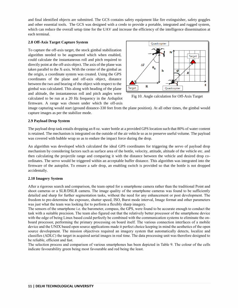
2.8 Off-Axis Target Capture System
To capture the off-axis target, the stock gimbal stabilization
algorithm needed to be augmented which when enabled,
could calculate the instantaneous roll and pitch required to
directly point at the off-axis object. The axis of the plane was
taken parallel to the X-axis. With the center of the gimbal as
the origin, a coordinate system was created. Using the GPS
coordinates of the plane and off-axis object, distance
between the two and bearing of the object with respect to the
gimbal was calculated. This along with heading of the plane
and altitude, the instantaneous roll and pitch angles were
calculated to be run at a 20 Hz frequency in the Ardupilot
firmware. A range was chosen under which the off-axis
image capturing would start (ground distance-330 feet from the plane position). At all other times, the gimbal would
capture images as per the stabilize mode.
2.9 Payload Drop System
The payload drop task entails dropping an 8 oz. water bottle at a provided GPS location such that 80% of water content
is retained. The mechanism is integrated on the outside of the air vehicle so as to preserve useful volume. The payload
was covered with bubble wrap so as to endure the impact force during the drop.
An algorithm was developed which calculated the ideal GPS coordinates for triggering the servo of payload drop
mechanism by considering factors such as surface area of the bottle, velocity, attitude, altitude of the vehicle etc. and
then calculating the projectile range and comparing it with the distance between the vehicle and desired drop co-
ordinates. The servo would be triggered within an acceptable buffer distance. This algorithm was integrated into the
firmware of the autopilot. To ensure a safe drop, an enabling switch is provided so that the bottle is not dropped
accidentally.
2.10 Imagery System
After a rigorous search and comparison, the team opted for a smartphone camera rather than the traditional Point and
shoot cameras or a SLR/DSLR camera. The image quality of the smartphone cameras was found to be sufficiently
detailed and sharp for further segmentation tasks, without the need for any enhancement or post development. The
freedom to pre-determine the exposure, shutter speed, ISO, Burst mode interval, Image format and other parameters
was just what the team was looking for to perform a flexibly sharp imagery.
The sensors of the smartphone i.e. the barometer, compass, the GPS, were found to be accurate enough to conduct the
task with a suitable precision. The team also figured out that the relatively better processor of the smartphone device
with the edge of being Linux based could perfectly be combined with the communication systems to eliminate the on-
board processor, performing the primary processing on board itself. The various connection interfaces of a mobile
device and the UNIX based open source applications made it perfect choice keeping in mind the aesthetics of the open
source development. The mission objectives required an imagery system that automatically detects, localize and
classifies (ADLC) the target in acquired aerial images in real time. The data processing unit was therefore designed to
be reliable, efficient and fast.
The selection process and comparison of various smartphones has been depicted in Table 9. The colour of the cells
indicate favourability green being most favourable and red being the least.
Fig 10. Angle calculation for Off-Axis Target

12 | DELHI TECHNOLOGICAL UNIVERSITY
Smartphone Camera resolution
(in mp)
Price
(in usd) Remarks
Samsung GALAXY S4 13 140 Moving Lens made it more prone to
distortion due to mechanical vibrations
Samsung GALAXY S5 16 210 In photo comparison test ,
S5 had a better result than S4
Samsung GALAXY S6 16 545 Best Camera Among S4,S5,S6
HTC ONE M9 20 279 QUALITY INFERIOR THAN S4, Large
file size
LG G4 16 387 COMPARABLE TO S4
ONE PLUS 3 16 418 Exceptionally good camera , comparable to
S6, exceptionally good in low light
Moto G4 plus 16 201 Comparable to s4 , performs bad in low
light
2.10.1 Autonomous Image Acquisition Unit
The images are captured using on-board mobile (S 5) phone camera which is controlled by an Android Application.
There are three android applications used namely Open Camera (Open Source android application),FTP Server(Free
Android application), UAS-T3(Locally Designed and developed Android App). Licenses of all the apps allow them
to be included in the autonomous image acquisition unit, and the combination of all he apps allow the imagery system
to capture images autonomously tagging them with related metadata and then relaying them to the ground in real time.
The camera is two axis gimbal stabilized which counters the roll factor of the UAV and provides stable images. The
Android Application controls the camera parameters and needs to be set before the camera is installed on-board. The
application can be controlled remotely through an on-board computer, Banana Pi. It takes three seconds to capture
two consecutive images, which ensures optimum overlap. As soon as an image is captured, the GPS is stored in the
image metadata. These acquired images are simultaneously transmitted to the ground control station for processing
via 5GHz data link provided by the on-board router. The image transfer takes about three seconds. This time interval
proven to be sufficient for real time image processing within given mission time.
2.10.2 Graphical User Interface (GUI)
A GUI was created using the MATLAB app designer.
It runs independent processes running on separate
threads, reducing the execution time significantly. The
GUI displays the images captured and potential targets
present in the image. The various characteristics of the
potential target is displayed with an option to either
submit the data obtained or discard it. The details of
all processed targets are stored in a SQL database
common to all users. The GUI is capable of generating
a text file for submission in accordance with the
competition’s requirements thereby reducing the
mission completion time.
2.10.3 Image Analysis
The team this year shifted to a combination of codes written in Matlab, python and C++ language, using the open-
source library OpenCV 3.0.0. This unison of various algorithms allow faster processing of images and simultaneously
checking the results to improve the accuracy. Total time to process an image was enough to process almost 300 images
Fig 11. Graphical User Interface
Table 9. Smartphone selection
13 | DELHI TECHNOLOGICAL UNIVERSITY
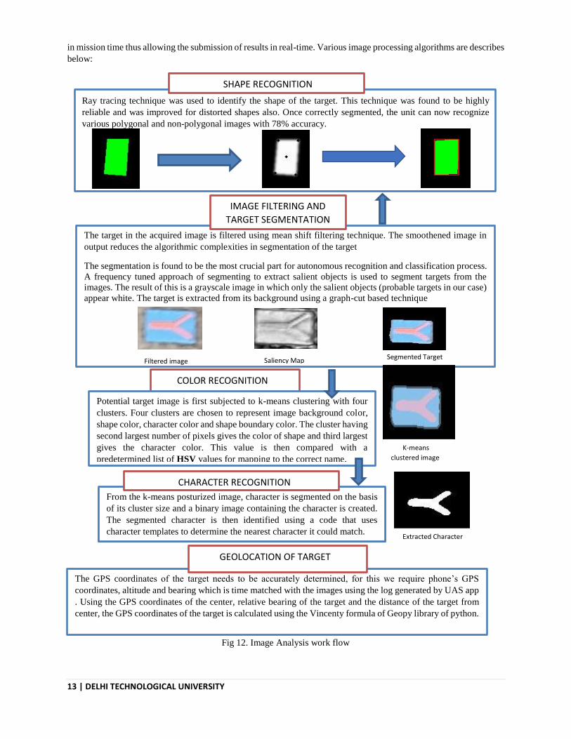
in mission time thus allowing the submission of results in real-time. Various image processing algorithms are describes
below:
The target in the acquired image is filtered using mean shift filtering technique. The smoothened image in
output reduces the algorithmic complexities in segmentation of the target
The segmentation is found to be the most crucial part for autonomous recognition and classification process.
A frequency tuned approach of segmenting to extract salient objects is used to segment targets from the
images. The result of this is a grayscale image in which only the salient objects (probable targets in our case)
appear white. The target is extracted from its background using a graph-cut based technique
Filtered image Saliency Map Segmented Target
IMAGE FILTERING AND
TARGET SEGMENTATION
Ray tracing technique was used to identify the shape of the target. This technique was found to be highly
reliable and was improved for distorted shapes also. Once correctly segmented, the unit can now recognize
various polygonal and non-polygonal images with 78% accuracy.
SHAPE RECOGNITION
COLOR RECOGNITION
Potential target image is first subjected to k-means clustering with four
clusters. Four clusters are chosen to represent image background color,
shape color, character color and shape boundary color. The cluster having
second largest number of pixels gives the color of shape and third largest
gives the character color. This value is then compared with a
predetermined list of HSV values for mapping to the correct name. K-means
clustered image
From the k-means posturized image, character is segmented on the basis
of its cluster size and a binary image containing the character is created.
The segmented character is then identified using a code that uses
character templates to determine the nearest character it could match.
CHARACTER RECOGNITION
Extracted Character
The GPS coordinates of the target needs to be accurately determined, for this we require phone’s GPS
coordinates, altitude and bearing which is time matched with the images using the log generated by UAS app
. Using the GPS coordinates of the center, relative bearing of the target and the distance of the target from
center, the GPS coordinates of the target is calculated using the Vincenty formula of Geopy library of python.
GEOLOCATION OF TARGET
Fig 12. Image Analysis work flow
14 | DELHI TECHNOLOGICAL UNIVERSITY
2.11 Inter-operability
The team divided the Interoperability System integration into two parts:
• Primary Interop - This included initial essential tasks required before the mission demonstration in the setup task
assigned, which include:
o Continuous upload of Telemetry data by converting and forwarding the MAVLink packages to the
Interop server.
o Getting Mission information and obstacle information from the Interop server and saving it as a binary
file in the form of a 2D list so that it can be accessed by other scripts for autonomous data upload.
• Secondary Interop – This includes uploading of target images and it’s corresponding Json file onto the Interop
server along with other operation such as deleting and editing a target on the server.
To proceed with the task, the team made necessary changes to the Python script provided for Interop so that command
based interface carries out all the functions for Primary Interop task and a GUI from secondary Interop task. At this
point, the team was able to perform all the tasks using the Client class provided which gave a telemetry transfer rate
of 4Hz. But, to improve the performance and reliability of the system, the team is working on the AsynClient which
is already in the state of completion and testing.
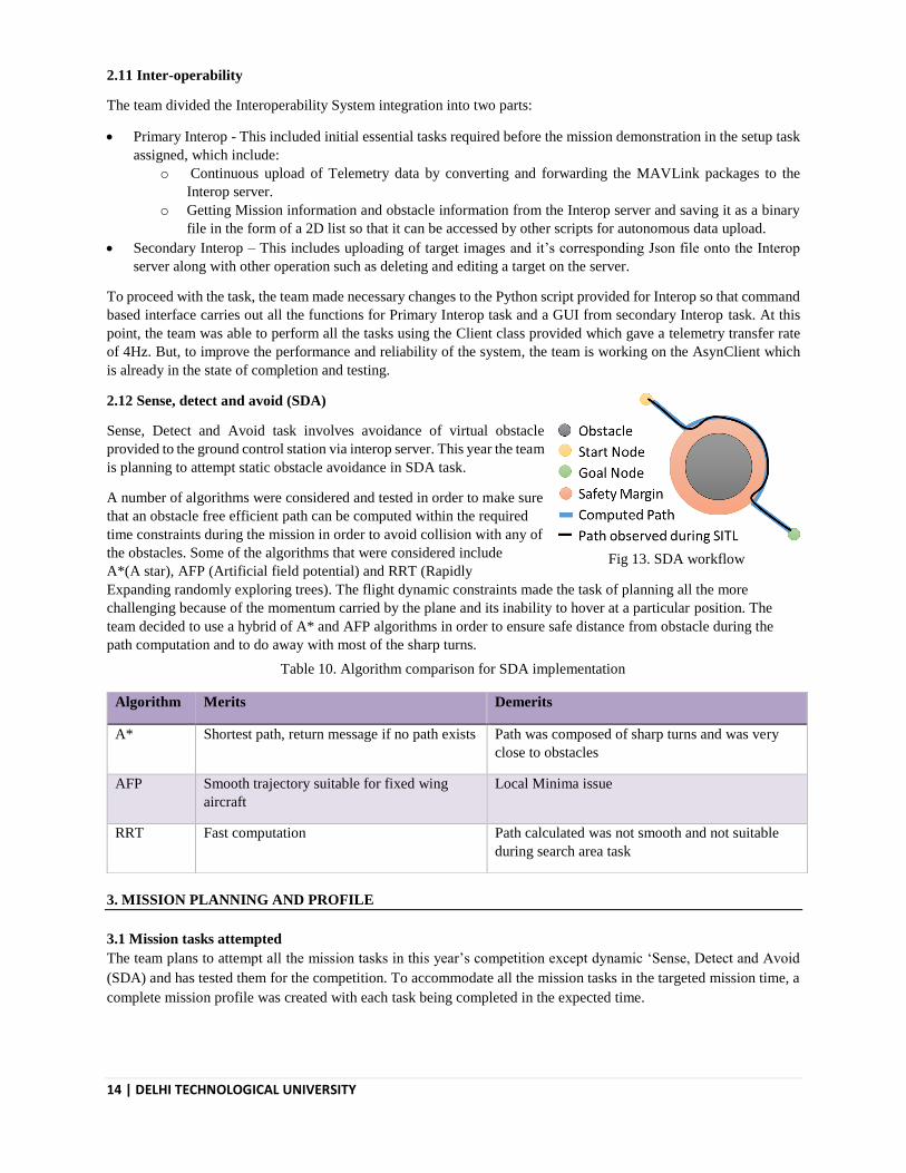
2.12 Sense, detect and avoid (SDA)
Sense, Detect and Avoid task involves avoidance of virtual obstacle
provided to the ground control station via interop server. This year the team
is planning to attempt static obstacle avoidance in SDA task.
A number of algorithms were considered and tested in order to make sure
that an obstacle free efficient path can be computed within the required
time constraints during the mission in order to avoid collision with any of
the obstacles. Some of the algorithms that were considered include
A*(A star), AFP (Artificial field potential) and RRT (Rapidly
Expanding randomly exploring trees). The flight dynamic constraints made the task of planning all the more
challenging because of the momentum carried by the plane and its inability to hover at a particular position. The
team decided to use a hybrid of A* and AFP algorithms in order to ensure safe distance from obstacle during the
path computation and to do away with most of the sharp turns.
3. MISSION PLANNING AND PROFILE
3.1 Mission tasks attempted
The team plans to attempt all the mission tasks in this year’s competition except dynamic ‘Sense, Detect and Avoid
(SDA) and has tested them for the competition. To accommodate all the mission tasks in the targeted mission time, a
complete mission profile was created with each task being completed in the expected time.
Algorithm Merits Demerits
A* Shortest path, return message if no path exists Path was composed of sharp turns and was very
close to obstacles
AFP Smooth trajectory suitable for fixed wing
aircraft
Local Minima issue
RRT Fast computation Path calculated was not smooth and not suitable
during search area task
Table 10. Algorithm comparison for SDA implementation
Fig 13. SDA workflow

15 | DELHI TECHNOLOGICAL UNIVERSITY
3.2 Mission Profile
On the basis of the sample
search area provided, a
simulated mission profile
was created. The plan
consists of the various
mission tasks in the
competition, the altitude
of the UAS during each
task and the time
dedicated to each task.
According to the mission
profile created, the total
estimated time to complete
all the tasks is around 25
minutes with a buffer of 3
minutes.
Safety is a major concern
during UAS operation. At
every step of UAS
integration, starting from the design phase to the final deployment of the UAS safety regulations were the major
concern of the Team. The degree of safety was based upon the number called “factor of safety” (FOS) which provided
a safety margin for the design of all critical elements A higher FOS implied greater the safety margin and hence, more
reliability.
4. TEST AND EVALUATION RESULTS
4.1 Developmental Testing
Subsequent tests were conducted during the construction of the system for studying the performance of the UAS and
improvising accordingly. The following table depicts the mission testing plan adopted by the team :
S No. Task Expected performance
during flight test Failure Back-up Strategy
1
Autonomous
flight
1. Takeoff
Comfortable takeoff within
prescribed runway length
No lift-off within the take-
off distance
Manual over-ride and forced
takeoff
2. Waypoint
Navigation
Tolerable overshoot from
waypoints during mission
Way point overshoot>100
feet
Re-tuning of control
parameters and re-attempt
3. Land
Suitable landing approach
Landing waypoint
overshoot
Manual over ride and re-
attempt if battery levels are
nominal
2
Air drop
1. Bulls Eye Off-set > 150 feet
N/A
Re-enforcing the protecting
case for next attempt 2. Bottle doesn’t break bottle loses more than 20
% water
3
SDA(static)
Virtual obstacle dodged
Collision with the virtual
obstacles
Change parameters affecting
the algorithm and re-attempt
4
ADLC
1.All characteristics of the
captured images recognized
2. Geo location tagged with
error <150ft
Geo tag error>150 feet
N/A
5
Inter-
operability Refresh Rate >5 Hz Refresh rate <1 Hz
Disconnect and re-connect to
the server
Table 11. Mission Testing Plan
Fig 14. Simulation Mission Profile

16 | DELHI TECHNOLOGICAL UNIVERSITY
4.1.1 Mechanical Vibrations Test: Since smartphones are lighter and smaller in size as compared to dedicated point and shoot
cameras, they are more susceptible to mechanical vibrations, which tend to distort the captured
images and makes the target detection inaccurate. To minimize the problem, a dedicated
vibration isolation mount for the gimbal sub-system was designed and installed. It includes a
combination of vibration isolating sorbothane balls and two composite fiber plates, which
isolated the whole sub system from the fuselage. The graphs depict the magnitude vibrations
felt by the phone with and without the isolation mount. It was observed that the anti-vibration
system was able to reduce the vibrations from a value of 7m/s2 to 1 m/s2.
4.2 Individual Component Testing
4.2.1 Autonomous flight Testing
To control plane output to pilot input, extensive tuning was carried out on the frame to maximize performance. Auto
flights revealed a waypoint following offset of 20 meters which was mitigated by carrying out navigation tuning which
reduced the turning offset and resulted in accurate following of waypoint plan. Initial glitches in achieving a smooth
auto-takeoff were countered by using TECS tuning which considerably improved auto takeoff and landing.
4.2.2 Payload Drop
4.2.2.1 Payload Drop Survival
Since the payload had to survive the high altitude drop,
combinations of impact absorbing material were tested. Medium
sized bubble wrap along with packing foam were selected due to the
achievement of satisfactory results. Various drop attitudes were
estimated and the covering was reinforced by adding extra bubble
wrap and packing foam at positions of high stress , like neck of the
bottle. . The drop altitude maintained for the tests was 60m,.The
team will be attempting he payload drop from an altitude between
40-60 m
4.2.2.2 Accuracy
In the initial flights, the payload mechanism was tested manually.
Once the algorithm was incorporated into the firmware, it was tested
for 10 flight missions and an accuracy of 38 feet was obtained.
-5
0
5
10
1
31
61
91
12
1
15
1
18
1
21
1
24
1
27
1
30
1
33
1
36
1
39
1
42
1
45
1
Vibration Isolation Testing
Without isolation (m/s2)
With isolation (m/s2)
Fig 16. Vibration Isolation testing results (left), Vibration isolated image (middle) and vibration un-isolated
image (right)
Fig 15. Target
020406080
100120
First
Second
Third
Fourth
Fifth
Sixth
Seventh
Eighth
Ninth
Tenth
Distance from Target (Feet)
Fig 17. Payload drop test results

17 | DELHI TECHNOLOGICAL UNIVERSITY
4.2.3 SDA
The dedicated script written for SDA
task was tested several times on
ground before being used in test
flight for safety reasons. Interop
server was set up to contain obstacles
and mission waypoints, which were
downloaded via the interop client
and used to make an obstacle free
path. The figure given below
illustrates the path and waypoints
before and after the implementation
of SDA script. Further, the testing
was also done via ‘Software in The
Loop’ for verifying the sub-system.
4.2.4. Imagery Testing
Once the mechanical vibrations were isolated, images were tested on a regular basis for various characteristics. The
optimization of the algorithm was carried out as the number of flight increased. The images captured by Galaxy S5
from an altitude of 140 – 150 feet were found of sufficient image quality for the various data analysis tasks. The image
data analysis system has been rigorously tested with different type of target shapes, alphabets and colours. The
processing of an image roughly takes 4 seconds. The accuracy of the results would increase on the grounds with
uniformity in grass cover and less pattern variations. The shapes that can be identified by the program autonomously
include circle, semicircle, quarter-circle, triangle, square, trapezoid, pentagon, heptagon, octagon, star, cross.
S.NO SEGMENTE
D
TARGET
EXTRACTED
CHARACTER
SHAPE SHAPE
COLOR
LETTER LETTER
COLOR
GPS
ACCURACY
(m)
1
SEMI-CIRCLE WHITE X RED 28.753280,77
.115921
7 m
2
SEMI-CIRCLE GREY < WHITE 28.753617,77
.116038
6 m
Table 12. Imagery testing results
Fig 18. Occupancy grid (left) and generated path (right)
Fig 19. Waypoint plan before and after execution of SDA script (left and right respectively)

18 | DELHI TECHNOLOGICAL UNIVERSITY
3
QUARTER
CIRCLE
BLUE T WHITE
28.754009,77
.117266
85 m
4
QUARTER
CIRCLE
BLUE Y RED 28.75331,77.
116891
9 m
5
TRIANGLE RED H PURPLE 28.752736,77
.116442
12 m
6
SQUARE GREY 1 BLUE 28.750224,77
.116386
135 m
7
RECTANGLE WHITE M BLUE 28.753203,77
.115640
11 m
8
CIRCLE BLUE N RED 28.753895,77
.115826
17 m
4.2.5 Communication systems testing
To confirm reliability of the in-house fabricated
antennas, CST simulations and ground testing were
conducted on the 2.4 GHz patch antennas. The range
of the communication system was tested on ground by
increasing the distance between the station and the
access point and observing the RSSI (Received Signal
Strength Indicator) and ping delays. The data transfer
rates obtained by the system were plotted with the
distance between the GCS and the air-borne system. A
minimum transfer speed of 0.5 MBps was obtained at
a range of 235 m for which the mission shall continue
effectively.
4.2.6 Off axis Testing The off-axis code provides instantaneous values of roll and pitch to be given to the gimbal servos as a PWM pulse for
the time duration during which it’s enabled. Due to its substantial dependence on the plane GPS coordinates, which
vary considerably, the PWM values vary rapidly and caused servo jittering. The frequency loops of computation were
changed from a frequency of 60Hz to 20Hz in order to minimise the jittering, eventually removing it completely. The
code was successfully ground tested by moving the autopilot and gimbal on a pre-planned route keeping the target’s
location fixed in order to check whether the gimbal pointed at the correct location. A similar test was conducted by
changing the altitude of autopilot rapidly in order to check whether the gimbal tilted as required or not. Test flights
for the same still need to be conducted in order to achieve reliable results during flight.
Fig 20. Communication system range testing results

19 | DELHI TECHNOLOGICAL UNIVERSITY
5. SAFETY CONSIDERATIONS
5.1 Design Safety The nose of the airframe, the nose gear along with the motor mount was strengthened to provide protection in case of a rough landing impact. The airframe was flown with dead weights as avionics, to check the airworthiness of the airframe. It was concluded that the frame is inherently stable, with good stall and landing characteristics due to presence of high lift devices, which deliver a smooth take-off and landing. The camera mount on the stock airframe was located on the nose, but mounting a gimbal on the nose could damage the camera, in an event of nose down landing. Thus, the gimbal was placed behind the nose gear, which gave it protection. A vibration isolator was designed and installed on the gimbal which significantly reduced any vibrations to travel to the camera, and affect the quality and resolution of the images, giving improved results.
5.2 Operational Safety
A safe and secure system promises accomplishments. Thus, the team gives safety concerns a very thorough attention and follows well defined protocols during the flights to minimize risk. Rigorous ground as well as flight testing of equipment was done. Every subsystem (landing gear, gimbal, payload drop, nose gear) is made functional, tested and optimised for efficient use. A series of thorough pre-flight and post-flight checks of the system are done to ensure a safe flight. The crew makes safe the structure (joints and attachments are carefully secured), the control surfaces, the landing gear, subsystems as well as the static stability of the frame. It checks the transmitter & receiver feedback, battery levels, the autopilot functionality, propulsion, GPS, airspeed, reliable telemetry connection, servos, ESCs, GCS parameters and correct response of the control surfaces in manual and stabilise mode. The functionality of image processing algorithm, the battery level of the phone as well as the storage space on the device is also checked. Safety equipment such as fire extinguisher, first aid along with food and water was carried at every flight. The safety officer ensures a stable, structurally strong airframe, making sure all the operative equipment function properly; along with checking the weather forecast for strong winds possibility or bad weather. The take-off and landing approaches are decided; the landing strip & airspace is cleared of any obstructions for take-off. Thus, personnel as well as aircraft safety is ensured and flights take place. Prior and Post flight discussions would discuss the issues such as responsibility allocation, flight objective, conclusions of flights, improvements and aim for subsequent flights. To conclude, the safety operations for a flight were performed with stark sincerity and professionalism.
Failure Mode Indication Primary Response Secondary Response
Tertiary Response
Telemetry Link Loss
Link Indicator Turns Red On MCC; Erratic Navigational Behaviour
If Link Between 60% And 80%; Mission Continued
If Link Less Than 60%, Switch To Manual And Troubleshoot Communication System
N/A
Image Acquisition System Fails
Image Synchronisation Fails/ Unresponsive
Reset Router Power; If Link Re-Establishes Within 3 Min, Mission Continued
Emergency Landing For Imagery Troubleshooting
N/A
R/C Link Failure
Actuator Response Time Increases; Erratic Plane Response
Automatically Shifted To RPV Using Autopilot Link, Mission Continues
R/C Link Established, Mission Continues
Telemetry Link Unreliable, Emergency Landing, Mission Stops For Troubleshooting
Table 13. Failure Mode Analysis

20 | DELHI TECHNOLOGICAL UNIVERSITY
Mission Control Workstation Crashes
Workstation Hangs Or Shuts Off
Shift To R/C Meanwhile Backup Computer Brought In, Mission Continues
Mission Control Computer Ready, Switch To Auto, Mission Continues
Battery Level Unsafe
Indicated On Ground Station
Battery Level Below Safe Level, Approximate 5 Mins Flight Left
Battery Level Below Danger Level, Shift To Manual And Emergency Landing
Motor Cut-off Continuously Falling Airspeed And/or Altitude
Chances Of Motor Cut-off, Switch To Manual Emergency Landing
N/A N/A
Component Disintegration
Falling Debris, Erratic Behaviour
Emergency Landing; Mission Call Off
N/A N/A
Imagery Terminal Crashes
No Output On Screen Flight Continues; Backup Terminal Brought In
N/A
Unable To Hold Altitude/ Enters No Fly Zone
Altitude Or Position Error Observed On the GCS
Switch To Manual; Mission Continues, Adjust Control Law Gains
Switch To Autopilot And Observe, Problem Rectified, Mission Continues
Problem Persists, Mission Continues
Code Blue: Mission Continues, Fully Autonomous
Code Yellow: Mission Continues, Manual Overrid
Code Red: Mission Haults, Emergency Landing
6. Conclusion
Unmanned Aerial Systems, Delhi Technological University has performed thorough engineering analysis for its UAS Lazarus, while adhering to its RAD developmental model throughout the process. This journal paper reflects the team’s grasp over Systems Engineering and its earnest effort to achieve the level of fidelity that is required at SUAS. Lazarus after having completed 5 autonomous hours of flight despite 6 mild and 2 severe crashes equipped with reliable sub-systems complemented by a robust ground control station is capable of executing the designated task with precision, accuracy and reliability. The team looks forward to participate in SUAS 2017 and feels confident of a podium finish.
Sponsored by: