deliverable d113 initial guidance for using hydrogen in … · gexcon gexcon as, fantoftvegen 38...
TRANSCRIPT

HYSAFE – Safety of Hydrogen As an Energy Carrier
SIXTH FRAMEWORK PROGRAMME NETWORK OF
EXCELLENCE
Safety of Hydrogen as an Energy Carrier
Contract No SES6-CT-2004-502630
Deliverable D113
Initial Guidance for Using Hydrogen in Confined
Spaces - Results from InsHyde
Coordination: NCSRD and INERIS
Contributions (alphabetically): BMW, BRE, FH-ICT, FZJ, FZK, GEXCON,
HSL, INASMET, INERIS, JRC, KI, NCSRD,
STATOIL/HYDRO, UNIPI, UU
Reviewers: VOLVO, AVT, STATOIL/HYDRO
Dissemination level: Public
Document version: 1.1
Date of preparation: 30 January 2009

HYSAFE – Safety of Hydrogen As an Energy Carrier
Page 2 of 89
Executive Summary
This report aims at gathering the knowledge learned during the InsHyde project, as well on a
theoretical point of view as on a practical point of view.
This report will focus on the use of hydrogen in confined spaces and the necessary safety measures to
be taken. It does not aim at gathering all the documents issued by InsHyde and HySafe on this subject
but to give an overview of each topic. References to detailed documents, available via HySafe, will be
made in each chapter so that each reader may deepen the subject of interest for him or her.
To be fully complete, this report will also make references to existing standards and best practices.
In a first chapter, the physical properties of hydrogen will be briefly summarized.
In a second chapter, we will focus on the risk control measures to be applied for a safe use of
hydrogen indoor. This chapter aims at improving the safety of existing systems and at designing a safe
system in an integrated way.
In a third chapter, we will focus on the behaviour of hydrogen in potentially accidental situations and
this means release, dispersion and of course ignition and explosion.
In the fourth chapter we will give a short overview of risk assessment methodology and some
examples of what have been done amongst HySafe partners to design safe experiments with hydrogen.
At last, all the procedures followed by HySafe partners to design and perform safe experiments with
hydrogen (dispersion, ignition, explosion, etc…) are gathered in the annex.
The authors would like to thank the European Commission for partial funding of this work through
the HySafe NoE project.

HYSAFE – Safety of Hydrogen As an Energy Carrier
Page 3 of 89
Contents
Executive Summary ............................................................................................................................... 2
Contents .................................................................................................................................................. 3
Organizations key................................................................................................................................... 6
Authors Table ......................................................................................................................................... 7
Nomenclature ......................................................................................................................................... 8
1 Introduction..................................................................................................................................... 9
1.1 Presentation of HySafe and InsHyde................................................................................................... 9
1.2 Scope....................................................................................................................................................... 9
1.3 Hydrogen basic properties.................................................................................................................. 10
1.4 Hydrogen combustion ......................................................................................................................... 10
1.5 Confined spaces and hydrogen systems............................................................................................. 11
1.6 Referenced documents ........................................................................................................................ 11
2 Risk control measures when using hydrogen indoors................................................................. 12
2.1 Fuel supply and storage arrangement ............................................................................................... 12 2.1.1 Storage .......................................................................................................................................... 12 2.1.2 Piping ............................................................................................................................................ 13
2.2 Detection .............................................................................................................................................. 15 2.2.1 Hydrogen sensors and detectors .................................................................................................... 15
2.2.1.1 Terminology .............................................................................................................................. 15 2.2.1.2 Detection technologies .............................................................................................................. 15 2.2.1.3 Sensors performance data.......................................................................................................... 15
2.2.2 Regulations, technical standards and guidelines............................................................................ 16 2.2.2.1 Performance targets................................................................................................................... 17
2.2.3 Recommendations ......................................................................................................................... 18 2.2.3.1 Choice of detector for inside applications ................................................................................. 18 2.2.3.2 Positioning................................................................................................................................. 18 2.2.3.3 Visible and audible alarm and alert level .................................................................................. 19 2.2.3.4 Inspection, maintenance and calibration.................................................................................... 19
2.2.4 Review of existing best practices at HySafe facilities ................................................................... 19 2.2.4.1 Practices at the Joint Research Centre solid state hydrogen storage.......................................... 19
2.3 Ventilation and exhaust ...................................................................................................................... 20 2.3.1 Natural or forced ventilation ......................................................................................................... 21
2.3.1.1 Natural ventilation..................................................................................................................... 21 2.3.1.2 Forced ventilation...................................................................................................................... 22
2.3.2 Design of ventilation ..................................................................................................................... 22 2.3.2.1 Design of natural ventilation ..................................................................................................... 23 2.3.2.2 Design of forced ventilation ...................................................................................................... 23
2.3.3 Exhaust and vent ........................................................................................................................... 24
2.4 Fire and explosion safety .................................................................................................................... 24 2.4.1 Introduction ................................................................................................................................... 24 2.4.2 The fire triangle and the fire tetrahedron....................................................................................... 25 2.4.3 Minimum ignition energy, minimum ignition temperature and flammability limits ...................... 25 2.4.4 Types of ignition sources............................................................................................................... 26
2.4.4.1 Hot surfaces............................................................................................................................... 26

HYSAFE – Safety of Hydrogen As an Energy Carrier
Page 4 of 89
2.4.4.2 Open flames............................................................................................................................... 27 2.4.4.3 Electric sparks ........................................................................................................................... 27
2.4.5 Protection by hazard segregation................................................................................................... 28 2.4.6 Protection by storage limitation..................................................................................................... 29 2.4.7 Protection by controlling ignition sources..................................................................................... 29 2.4.8 Building design, compartmentation and means of escape ............................................................. 31 2.4.9 Explosion venting.......................................................................................................................... 32
2.5 Commissioning, inspections, training and worker protection ......................................................... 35 2.5.1 Commissioning.............................................................................................................................. 35 2.5.2 Purging .......................................................................................................................................... 36
2.5.2.1 Special requirements for LH2.................................................................................................... 36 2.5.3 Inspection ...................................................................................................................................... 37 2.5.4 Training......................................................................................................................................... 37 2.5.5 Worker protection ......................................................................................................................... 37
2.6 Reference documentation ................................................................................................................... 37
3 Hydrogen behaviour in accidental situations .............................................................................. 41
3.1 Hydrogen release and dispersion ....................................................................................................... 41 3.1.1 Introduction ................................................................................................................................... 41 3.1.2 Overview of existing experiments ................................................................................................. 41 3.1.3 Effect of release conditions ........................................................................................................... 41 3.1.4 Effect of confinement .................................................................................................................... 43 3.1.5 Effect of ventilation....................................................................................................................... 45 3.1.6 Effect of obstructions .................................................................................................................... 47 3.1.7 Effect of scaling............................................................................................................................. 47
3.2 Hydrogen ignition................................................................................................................................ 48 3.2.1 Frequency of occurrences of ignition sources ............................................................................... 48 3.2.2 Ignition hazard analysis ................................................................................................................. 48
3.2.2.1 Rubbing/Grinding...................................................................................................................... 50 3.2.2.2 Impact........................................................................................................................................ 50 3.2.2.3 Sparks........................................................................................................................................ 50
3.2.3 Review of spontaneous ignition experiments/simulation............................................................... 50
3.3 Hydrogen explosion............................................................................................................................. 51 3.3.1 Introduction ................................................................................................................................... 51 3.3.2 Experiments by FZK-Pro-Science................................................................................................. 52 3.3.3 Experiments by KI......................................................................................................................... 53
3.4 Hydrogen fire....................................................................................................................................... 53 3.4.1 Introduction ................................................................................................................................... 53 3.4.2 Previous work................................................................................................................................ 53 3.4.3 Effect of walls ............................................................................................................................... 55 3.4.4 Fire protection measures ............................................................................................................... 55
3.5 Reference documentation ................................................................................................................... 57
4 Risk assessment recommendations .............................................................................................. 62
4.1 Risk assessment methodology............................................................................................................. 62 4.1.1 Hazard Identification..................................................................................................................... 62 4.1.2 Event tree modelling ..................................................................................................................... 63
4.2 Consequence assessment ..................................................................................................................... 63 4.2.1 Engineering approach.................................................................................................................... 63
4.2.1.1 Jets............................................................................................................................................. 63 4.2.1.2 Accumulation models ................................................................................................................ 63
4.2.2 Using CFD..................................................................................................................................... 63 4.2.3 Performing Experiments................................................................................................................ 66

HYSAFE – Safety of Hydrogen As an Energy Carrier
Page 5 of 89
4.2.3.1 General safeguards .................................................................................................................... 67 4.2.3.2 Dispersion experiments ............................................................................................................. 67 4.2.3.3 Combustion experiments ........................................................................................................... 68
4.3 Reference documentation ................................................................................................................... 69
Annex-1 Experiences from HYSAFE members........................................................................... 70
A1.1 Schematic for the assessment and prevention of explosive risks ................................................. 70
A1.2 Safety assessment for hydrogen laboratory at FZJ...................................................................... 70 A1.2.1 Description of facilities and test procedures.................................................................................. 71 A1.2.2 Safety assessment .......................................................................................................................... 71
A1.2.2.1 Laboratory ............................................................................................................................. 71 A1.2.2.2 Flow reactor facilities ............................................................................................................ 71 A1.2.2.3 Pressure vessel facility .......................................................................................................... 71
A1.3 Safety assessment for Statoil/Hydro 15 bar electrolyser.............................................................. 72 A1.3.1 Prevention of the formation of explosive atmosphere ................................................................... 72
A1.3.1.1 Ventilation............................................................................................................................. 72 A1.3.1.2 Hydrogen gas and fire detection............................................................................................ 73
A1.3.2 Measures to avoid the ignition of explosive atmospheres ............................................................. 73 A1.3.3 Mitigation of the detrimental effects of an explosion .................................................................... 73
A1.4 BMW (H2 research centre – 250 bar CGH2 and LH2) ............................................................... 74
A1.5 Safety assessment of the PEMFC test laboratory at INASMET................................................. 74 A1.5.1 Description of facilities and test procedures.................................................................................. 74 A1.5.2 Safety assessment .......................................................................................................................... 74
A1.5.2.1 Laboratory ............................................................................................................................. 74 A1.5.2.2 Fuel cell station ..................................................................................................................... 74
A1.6 Safety assessment for explosion risks at Fh-ICT Solid Oxide Fuel Cell Laboratory................. 75
A1.7 Safety assessment for hydrogen facilities at UNIPI...................................................................... 76 A1.7.1 Description of facilities and test procedures.................................................................................. 76
A1.7.1.1 CVE (Chamber View Explosion) .......................................................................................... 76 A1.7.1.2 HPBT (Hydrogen Pipeline Break Test)................................................................................. 76
A1.7.2 Safety assessment .......................................................................................................................... 77
A1.8 Safety assessment for the Safety Vessel A1 on the hydrogen test site HYKA at FZK............... 77 A1.8.1 Description of the facility.............................................................................................................. 77 A1.8.2 Description of the technological/test procedures........................................................................... 77 A1.8.3 Release/Filling procedure.............................................................................................................. 78 A1.8.4 Safeguards ..................................................................................................................................... 78 A1.8.5 Safety assessments......................................................................................................................... 78
A1.9 Safety assessment for dispersion and explosion testing at INERIS............................................. 79 A1.9.1 General legal frame ....................................................................................................................... 79 A1.9.2 Safety rules.................................................................................................................................... 79 A1.9.3 Safety study ................................................................................................................................... 79
A1.10 Safety assessment for the “Globus” facility at KI ........................................................................ 80 A1.10.1 Description of the facility.......................................................................................................... 80 A1.10.2 Safeguards ................................................................................................................................. 80 A1.10.3 General safety assessments........................................................................................................ 80
A1.10.3.1 Work and safety instructions for personnel .......................................................................... 81
A1.11 HSL Risk assessment....................................................................................................................... 82

HYSAFE – Safety of Hydrogen As an Energy Carrier
Page 6 of 89
Organizations key
Name Address
AVT A.V.Tchouvelev & Associates Inc., 6591 Spinnaker Circle, Mississauga, ON L5W 1R2, CA
BRE BRE Fire and Security, Watford, Herts WD25 9XX, UK
BMW BMW Group, Forschung und Technik, Hanauer Straße 46, 80992 München
CEA Heat Transfer and Fluid Mechanics Laboratory and Experimental Fluids mechanics Laboratory, CEA, F-91191 Gif-sur-Yvette Cedex,
France
DNV DNV Research and Innovation, Oslo, Norway
FH-ICT Fraunhofer -ICT, Germany
FZJ Forschungszentrum Juelich, 52425 Juelich, Germany
FZK IKET, Forschungszentrum Karlsruhe, Postfach 3640, 76021 Karlsruhe, Germany
GEXCON GEXCON AS, Fantoftvegen 38 Box 6015 Postterminalen N-5892 BERGEN Norway
HSE-HSL Health and Safety Laboratory, Harpur Hill, Buxton, Derbyshire, SK17 9JN, UK
INASMET INASMET-Tecnalia, San Sebastian, Spain
INERIS Accidental Risks Division, INERIS, Parc Technologique Alata, BP2, F-60550 Verneuil-en-Halatte, France
JRC Joint Research Centre of the European Commission, Institute for Energy, 1755 ZG Petten, The Netherlands
KI Kurchatov Institute, Moscow, Russia
NCSRD Environmental Research Laboratory, National Centre for Scientific Research Demokritos, 15310 Aghia Paraskevi, Attikis, Greece
STATOIL/HYDRO STATOIL/HYDRO, Norway
UNIPI Università degli Studi di Pisa, Dipartimento di Ingegneria Meccanica Nucleare e della Produzione, via Diotisalvi 2, 56126, Pisa, Italy
UU HySAFER centre, University of Ulster (UU), Newtownabbey, BT37 0QB, Northern Ireland, UK
VOLVO Volvo Technology Corp., Dept. 06120 Chalmers Teknikpark, 412 88 Gothenburg, Sweden

HYSAFE – Safety of Hydrogen As an Energy Carrier
Page 7 of 89
Authors Table
Section Title Performed
Contributions
1 Introduction INERIS (lead)
1.1 Presentation of HySafe and InsHyde INERIS
1.2 Scope INERIS
1.3 Hydrogen basic properties INERIS
1.4 Hydrogen combustion INERIS
1.5 Confined spaces and hydrogen systems INERIS
2 Risk control measures when using hydrogen indoors INERIS (lead)
2.1 Fuel supply and storage arrangement INERIS
2.2 Detection JRC, INERIS
2.3 Ventilation and exhaust INERIS, UNIPI
2.4 Fire and explosion safety HSL, BRE, UU, GEXCON,
2.5 Commissioning, inspections, training and worker protection INERIS, BMW
3 Hydrogen behaviour in accidental situations NCSRD (lead)
3.1 Hydrogen release and dispersion NCSRD
3.2 Hydrogen ignition HSL, UU
3.3 Hydrogen explosion KI, FZK
3.4 Hydrogen fire HSL, UU
4 Risk assessment recommendations DNV (lead)
4.1 Risk assessment methodology DNV
4.2 Consequence assessment NCSRD (lead), GEXCON, UU, FZJ
Annex 1 Experiences from HySafe members FZJ (lead)
A1.1 Schematic for the assessment and prevention of explosive risks Fh-ICT
A1.2 FZJ (ISR hydrogen lab) Safety assessment for hydrogen laboratory at FZJ FZJ
A1.3 Safety assessment for STATOIL|HYDRO 15 bar electrolyzer STATOIL|HYDRO
A1.4 BMW (H2 research centre – 250 bar CGH2 and LH2) BMW
A1.5 Safety assessment of the PEMFC test laboratory at INASMET INASMET
A1.6 Safety assessment for explosion risks at Fh-ICT Solid Oxide Fuel Cell Laboratory Fh-ICT
A1.7 Safety assessment for hydrogen facilities at UNIPI UNIPI
A1.8 Safety assessment for the safety vessel A1 on the hydrogen test HYKA at FZK FZK
A1.9 Safety assessment for dispersion and explosion testing at INERIS INERIS
A1.10 Safety assessment for the ‘Globus’ facility at KI KI
A1.11 HSL Risk assessments HSL

HYSAFE – Safety of Hydrogen As an Energy Carrier
Page 8 of 89
Nomenclature
A vent area of an explosion venting device (m2)
Brt turbulent Bradley number
Ei expansion ratio of combustion products, Ei = MuiTbi/MbiTui Ksafety safety factor
LEL Lower Explosive Limit
LFL Lower Flammability Limit
LIR Flame Length based on IR flame emission
LUV Flame Length based on UV flame emission
LVIS Visible Flame Length
M molecular mass (kg/mol)
Po stagnation pressure of the gas (bar)
Pe pressure at the exit (bar)
Qvent ventilation rate (m3/h)
Qleak leak rate (m3/h)
R universal gas constant (R = 8,31 J/K/mol)
Sui burning velocity at initial conditions (m/s)
V enclosure volume (m3)
WIR Flame Width based on IR flame emission
cui speed of sound at initial conditions (cui = (γuRTui/Mui)0.5 in m/s)
pi initial absolute pressure (bar)
pred reduced overpressure (bar)
pstat static activation pressure (bar gauge)
∆tdetection time for the fire or incident to be detected
∆talarm time from detection to an alarm being generated
∆tpre-movement time following alarm for the person(s) to start their escape
∆ttravel actual time to travel (walk or otherwise assisted) to a place of safety
α empirical constant (α = 1 for hydrogen)
β empirical constant (β = 0.8 for hydrogen)
γu specific heats ratio for unburned mixture
πred dimensionless maximum explosion overpressure
πv dimensionless static activation pressure
π0 3.14

HYSAFE – Safety of Hydrogen As an Energy Carrier
Page 9 of 89
1 INTRODUCTION
1.1 Presentation of HySafe and InsHyde
The Network of Excellence (NoE) HySafe (http://www.hysafe.net), a research project supported by
the European Commission under the 6th Framework Programme, contributes to the safe transition to a
more sustainable development in Europe by facilitating the safe introduction of hydrogen
technologies and applications. HySafe contributes to the implementation of the Key Action
"Integrating and strengthening the ERA" within the Energy, Environment and Sustainable
Development. HySafe is one of the first IPHE (International Partnership for the Hydrogen Energy)
recognized projects and currently the only one dedicated to safety aspects.
The HySafe network will bring together competencies and experience from various research and
industrial fields (automotive, gas and oil, chemical and nuclear). The consortium consists of 25
partners including research organizations, governmental agencies, universities and industry from 12
countries: Germany (5 partners), France (3), Norway (3), UK (3), Netherlands (2), Spain (2),
Denmark, Greece, Italy, Poland, Sweden, Russia and Canada. Much effort has been concentrated on
the hydrogen safety issues relevant to the nuclear industry during the past 20 years, including
comprehensive safety studies and the development of innovative mitigation techniques. At the same
time industry and research dealing with today's fossil energy carriers are now confronting issues
associated with everyday use of the technology by the general public.
The main objective of the HySafe network will therefore be to strengthen, integrate and focus
fragmented research efforts to provide a basis that will allow removal of safety-related barriers to
implementation of hydrogen as an energy carrier. In this way the network will also contribute to
promoting public awareness and trust in hydrogen technology within Europe by providing a basis for
communicating the risks associated with hydrogen.
The network intends to promote the development of an integrated, competitive scientific and
industrial community in Europe capable of jointly addressing the challenges presented by the
development of an excellent safety culture across Europe. Synthesis, integration and harmonisation of
these efforts are expected to break new ground in the field of hydrogen safety and contribute to the
increase of public acceptability of hydrogen as an energy carrier.
In the HySafe network, the project InsHyde is dedicated to the use of hydrogen systems in confined
spaces and more specifically to hazard control for small/medium leaks. The main objective is to
produce a best practice document containing recommendations for the safe use of fixed and mobile
hydrogen systems in buildings, including ventilation, building design and detection.
1.2 Scope
The scope of this document is to provide general guidance on the use of hydrogen in confined spaces.
Concerned public is all interested stakeholders: research and industrial as well as general public.
This document summarises the results obtained during InsHyde project in various fields (detection,
dispersion, explosion, ignition, modelling, etc) as well as during HySafe activities (see Biennial report
on Hydrogen Safety1, Hyper
2 and HyApproval
3 projects).

HYSAFE – Safety of Hydrogen As an Energy Carrier
Page 10 of 89
This document does not claim to be a standard but only to give guidance, based on the experiences of
the HySafe partners.
1.3 Hydrogen basic properties
At standard temperature and pressure conditions, hydrogen is a colourless, odourless, tasteless, non-
toxic, non-corrosive, non-metallic diatomic gas, which is in principle physiologically not dangerous.
One of its most important characteristics is its low density. It is positively buoyant above a
temperature of 22 K that is over (almost) the whole temperature range of its gaseous state. The
positive buoyancy of hydrogen is a favourable safety effect in unconfined areas, but can cause a
hazardous situation in (partially) confined spaces, where the hydrogen can accumulate, for example
underneath a roof. Hydrogen gas exhibits a high diffusivity and a high buoyant velocity thus it rapidly
mixes with the ambient air upon release.
Hydrogen forms molecules of small size with small molecular weight and has low viscosity. As a
result, hydrogen can leak at a larger molecular flow rate, permeates through materials and passes
through smaller leak paths than other gases. Diffusion in small amount is possible even through intact
materials, in particular organic materials, which may lead to gas accumulation in confined spaces.
Hydrogen also exhibits a positive Thompson-Joule effect at temperatures above 193 K, the inversion
temperature. This means that the temperature of hydrogen gas increases upon depressurisation, which
in turn may lead to ignition. For example, if a sudden pressure drop from 20 MPa to ambient pressure
takes place the temperature changes by six degrees. This makes hydrogen more susceptible to ignition
after sudden release from high pressure containment
1.4 Hydrogen combustion
Hydrogen burns in a non-luminous, almost invisible pale blue, hot flame to water vapour liberating
the chemically bound energy as heat (gross heat of combustion). The flammability range of hydrogen
(at room temperature) is between 4 and 75 % vol. in air, whereas the maximum flame temperature of a
burning (premixed stoichiometric) hydrogen-air mixture is 2403 K.
The auto-ignition temperature for hydrogen, which is the minimum temperature of a hot surface that
can ignite a flammable mixture, is 858 K. It is relatively high, but can be lowered by catalytic
surfaces. Hydrogen gas does not have a flash point as it is already a gas at ambient conditions.
Therefore, cryogenic hydrogen will flash at all temperatures above its boiling point of 20 K.
For a given combustible mixture and ignition type, there is a minimum energy below which ignition
does not occur (minimum ignition energy). The minimum ignition energy varies with composition and
has a minimum value where the mixture is nearer to stoichiometry. Over the flammable range of
hydrogen-air mixtures the minimum ignition energy varies by almost three orders of magnitude and
can be as low as 0.017 mJ, a value much lower than that of hydrocarbon-air mixtures.
The burning velocity of hydrogen in air at stoichiometric ambient conditions is 2.55 m/s reaching a
maximum of 3.2 m/s at a concentration of 40.1%, which would even increase to 11.75 m/s in pure
oxygen. These values are higher than the ones of hydrocarbon fuel-air mixtures due to the fast
chemical kinetics and high diffusivity of hydrogen.
The detonability is usually in the range of 18% to 59% of hydrogen concentration in air by volume.

HYSAFE – Safety of Hydrogen As an Energy Carrier
Page 11 of 89
1.5 Confined spaces and hydrogen systems
A hydrogen system is defined as a system using or producing hydrogen such as a fuel cell generating
electricity from hydrogen or an electrolyser generating hydrogen from water.
A confined space is defined as a space containing parts where hydrogen can accumulate. This may
even be a storage room without walls but with a roof susceptible to generate an accumulation of
hydrogen or an enclosure in which a hydrogen system is located.
1.6 Referenced documents
Besides the references listed in the text, the reader is advised to refer to the following additional
sources for information on the topics of this chapter: [4], [5], [6], [7], [8], [9], [10], [11], [12], [13],
[14]
1 HySafe, The Biennial Report on Hydrogen Safety, http://www.hysafe.org/wiki/BRHS/BRHS
2 http://www.hyperproject.eu/
3 http://www.hyapproval.org/
4 ISO/TR15916, “Basic considerations for the safety of hydrogen systems”, First edition, 2004-02-15
5 FM Global Property Loss Prevention Data Sheets 7-91, “Hydrogen”, September 2000
6 National Aeronautics and Space Administration, “SAFETY STANDARD FOR HYDROGEN AND
HYDROGEN SYSTEMS - Guidelines for Hydrogen System Design, Materials Selection, Operations, Storage,
and Transportation”, NSS 1740.16, February 1997 7 NFPA 853, “Standard for the Installation of Stationary Fuel Cell Power Plants”, 2007 Edition
8 NFPA 50A: 1999 “Gaseous Hydrogen Systems at Consumer Sites”
9 IEC/CDV 62282-3-3, “Fuel cell technologies - Part 3-3: Stationary fuel cell power plants - Installation”
10 US DOE Regulators’ Guide to Permitting Hydrogen Technologies - Overview, Module 1 - Permitting
Stationary Fuel Cell Installations, Version 1.0 PNNL-14518 Released 1/12/2004 11 AiAAA G-095 (2004), Guide to Safety of Hydrogen and Hydrogen Systems
12 Harris, R. J., (1983), “The Investigation and Control of Gas Explosions in Buildings and Heating Plants”,
British Gas Corporation, Midlands, England 13 IEC 62282-3-1 “Fuel cell technologies - Part 3-1: Stationary fuel cell power systems - Safety”
14 1127-1:1997, “Explosive atmospheres - Explosion prevention and protection - Part 1: Basic concepts and
methodology”

HYSAFE – Safety of Hydrogen As an Energy Carrier
Page 12 of 89
2 RISK CONTROL MEASURES WHEN USING HYDROGEN
INDOORS
The main hazards associated with hydrogen in confined spaces include the following:
• leakage
• oxygen displacement up to anoxia
• fire
• explosion
• pressure
• cryogenic burns (specific hazard related to liquid hydrogen at about 20 K)
• hydrogen embrittlement
• exposure
To handle hazards, various measures shall be taken. They are usually divided in inherent safety and
safety barriers. For an optimum safety, those two principles shall be used together.
The inherent safety principles consist in the following:
• replacing hazardous products or processes by safer ones
• limiting the quantities
• moderating the working conditions (temperature, pressure, etc)
• simplifying the process and equipment
As hydrogen can not be replaced in the considered applications, the last three principles shall be
applied.
For hazards that are not or cannot be eliminated by the previous measures, protection measures, safety
barriers, shall be taken. Safety barriers’ principles consist in prevention, detection, protection and
intervention
Safety measures such as avoiding a leak, limiting leak’s magnitude and hydrogen quantity to be
released, detecting a leak or a fire, interrupting a leak, avoiding hydrogen accumulation and ignition
or explosion and finally limiting the damages in a case of an ignition or explosion will be commented
in the following chapter.
2.1 Fuel supply and storage arrangement
2.1.1 Storage
Following the inherent safety principles, hydrogen should be stored outdoors and the quantity stored
should be limited to the needs. With an outdoor storage, safety distances may be defined depending
on the size of the storage and the type of elements around the storage (other flammable gas storage,
adjacent walls, buildings, etc). Proposed values are given in NFPA 50A1 (for gaseous hydrogen
systems), NFPA 50B2 (for liquefied hydrogen systems), NFPA 55
3 (for compressed gases and

HYSAFE – Safety of Hydrogen As an Energy Carrier
Page 13 of 89
cryogenic fluids) and NFPA 524. For example, an outdoor storage of hydrogen containers should be
located at more than 1.5 m distance from all doors and openings of a building. It should also be
protected against vehicle collision if it is located near a road, according to these NFPA standards.
Hydrogen might be stored indoors in limited quantities. Different values are proposed in standards,
such as:
• 85 Nm3 mentioned in FM Global Property Loss Prevention Data Sheets
5
• 11 Nm3 mentioned in NFPA 853
6
Hydrogen storage equipment, for both liquid and gaseous hydrogen, should be in accordance with
applicable regulations or approved standards::
• designed, fabricated, and tested in accordance with applicable regulations or approved standards
• constructed with materials compatible with hydrogen and in accordance with applicable
regulations or approved standards
• insulated with thermal insulation material compatible with hydrogen and in accordance with
applicable regulations or approved standards (especially liquid-hydrogen storage containers)
• equipped with a shutoff valve on the discharge port and as close to the vessel as possible
• equipped with a pressure control system
• equipped with an approved ventilation system
• equipped with pressure-relief devices to prevent overpressure
• located in accordance with appropriate quantity-distance standards
• legibly marked with the name “Hydrogen” or “Liquid Hydrogen — Flammable Gas” for
gaseous or liquid containers as appropriate or in the appropriate national language
Liquid hydrogen storage vessels should be checked for the accumulation of impurities such as oxygen
and nitrogen. Oxygen particulate in cryogenic hydrogen gas can deflagrate. Near-stoichiometric
mixtures of oxygen particulate in liquid hydrogen have the potential to detonate. Oxygen
accumulation in stored hydrogen should not exceed 2 % volume fraction when the mixture is allowed
to warm to a gaseous state in the confinement.
2.1.2 Piping
As a first step, before installation, existing best practices should be reviewed. Gas piping in general
has already been widely studied especially in petroleum industry. Standards, depending on nature of
the pipe, exist like ISO 1307 “ Rubber and plastics hoses - Hose sizes, minimum and maximum inside
diameters, and tolerances on cut-to-length hoses”, ISO 37 “ Rubber, vulcanized or thermoplastic -
Determination of tensile stress-strain properties”, ISO 188 “ Rubber, vulcanized or thermoplastic -
Accelerated ageing and heat resistance tests”, ISO 4672 “ Rubber and plastics hoses - Sub-ambient
temperature flexibility tests”, ISO 1402 “ Rubber and plastics hoses and hose assemblies. Hydrostatic
testing”, ISO 1436-1:2001 “Rubber hoses and hose assemblies - Wire-braid-reinforced hydraulic types
- Specification - Part 1: oil-based fluid applications”. More specific to fuel cells is the standard ISO
15649 “Petroleum and natural gas industries – Piping” and IEC EN 62282-3-1:2007 “Fuel cell
technologies - Part 3-1: stationary fuel cell power systems – Safety”.
When hydrogen is stored outdoors, working pressure should be minimized indoors whereas pressure
reducing valve should preferably be located outdoors. Design of the piping should include inherent
HYSAFE – Safety of Hydrogen As an Energy Carrier
Page 14 of 89
safety principles such as limiting the use of non-welded connections, use of compatible with hydrogen
materials and firmly anchored piping. To limit the quantity that can be released, flow limiters or
excess flow systems may be used whereas overpressure should also be controlled through rupture
discs or safety valves.
In case of release, an emergency shut down valve and a manual valve should be installed and safely
located on the system. An automatic shut down should occur related to different incidents (leak
detection, loss of ventilation, loss of electricity or power, etc). Consideration must be taken to detect
and stop leaks in confined areas as quickly as possible to prevent the build-up of flammable gas
clouds. This includes also measures to prevent backflow or flow from high pressures downstream or
upstream the leak source. Reliable systems coupled gas detection and subsequent automatic response
of shut-off/sectioning valves are crucial.
After installation of a hydrogen system, an initial control and periodic controls should be performed.
General considerations on hydrogen piping, for both liquid and gaseous hydrogen, are:
• design, fabricate and test in accordance with applicable regulations or approved standards
• construct with appropriate materials
• have appropriate flexibility (such as expansion joints, loops and offsets)
• locate in accordance with applicable regulations or appropriate standards
• do not locate beneath electrical power lines
• avoid buried lines wherever possible
• if lines are to be buried, consider the effects of galvanic corrosion, the difficulty in conducting a
visual inspection for line integrity, and the possibility that a leak can take a path to an
unforeseeable location, resulting in an accumulation and an explosion hazard (leak checks are
difficult to perform on buried lines, with the exception of pressure-decay techniques)
• galvanic corrosion can occur, particularly when moisture is present, with dissimilar metals and
should be considered in socket-type piping joints. The more corrosive (less noble) material will
preferentially corrode and should be used for the female part
• use appropriate supports, guides and anchors
• use appropriate pressure-relief devices
• insulate with appropriate thermal insulation (especially for piping of liquid hydrogen and cold
gaseous hydrogen)
• label as to contents and direction of flow
• for liquid hydrogen systems, sections that can be isolated without pressure relief should be
avoided
When liquid hydrogen is used, piping should be checked for the accumulation of impurities such as
oxygen and nitrogen as solid air in a liquid hydrogen piping system can plug lines and orifices and can
interfere with the operation of valves and other equipment.
HYSAFE – Safety of Hydrogen As an Energy Carrier
Page 15 of 89
2.2 Detection
2.2.1 Hydrogen sensors and detectors
When using hydrogen in confined spaces the employment of a hydrogen detection system for early
detection of leaks is essential to facilitate the activation of alarms and shutdown of the leak and where
necessary, the safe evacuation of person(s) and the activation of single or multi-level safety
operations. There are numerous hydrogen sensors/detector commercially available operating on
various detection principles. When installing a hydrogen gas detection system the following questions
need to be considered7:
• Which is the most suitable sensing technology?
• How many sensors are required?
• Where should the sensors/detectors be located in relation to high points in the enclosure and
natural or forced ventilation patterns?
• What are the appropriate alarm thresholds for the hydrogen detection system?
• What other chemical species are likely to be present that may interfere with sensors response?
• Are poisoning agents likely to be present?
• What is the appropriate response time that is required?
2.2.1.1 Terminology
For clarity a distinction shall be made between a hydrogen sensor and a hydrogen detector. A
hydrogen sensor is an assembly containing one or more hydrogen sensing elements that provides a
continuously changing physical quantity (signal) in correlation to the physical quantity provided by
the sensing element(s). A sensor may also contain circuit components associated with the sensing
elements. A hydrogen detector on the other hand is an apparatus containing a hydrogen sensor
(internally or externally), which provides at least one of such functions as built-in alarm indication,
output contacts for alarm, output signal for alarm.
2.2.1.2 Detection technologies
The various types of hydrogen detection technologies currently in use are described in detail in
Chapter 5 (Safety Measures/Safety Barriers) of the HySafe Biennial Report on Hydrogen Safety
(BRHS8) together with a description of emerging technologies for hydrogen detection. The most
commonly used and most widely commercially available sensors are electrochemical, catalytic and
metal oxide semiconductor type sensors. Other less common but still commercially available sensors
include gas field effect (GFE) type sensors, thermal conductivity detectors (TCD) and acoustic
sensors.
2.2.1.3 Sensors performance data
Some important factors to consider in the selection of a hydrogen sensor include accuracy, measuring
range, response time, ambient working conditions, lifetime and stability9. A market investigation on
the performance of commercially available sensors has been performed in work package IP1.2 of
InsHyde10. The investigation was based on the technical information (product specifications,
datasheets) made available by manufacturers and the major findings are summarized in Table 1.

HYSAFE – Safety of Hydrogen As an Energy Carrier
Page 16 of 89
Table 1: Optimum performance data for a range of various types of commercially available
sensorsi
Electrochem Catalytic MOS Acoustic TCD GFE
Min Max Min Max Min Max Min Max Min Max Min Max Measuring
Range (ppm) 1 50000 1 40000 1 20000 1 100% 1 100% 10 50000
Min Max Min Max Min Max Min Max Min Max Min Max Temperature
Range (°°°°C) -20 55 -20 60 -40 80 -20 80 -40 55 -40 120
Min Max Min Max Min Max Min Max Min Max Min Max Pressure
Range (bar) 0.7 1.3 0.7 1.3 0.8 1.2 0.8 1.2 0.8 1.2 - -
Electrochem Catalytic MOS Acoustic TCD GFE
Min Max Min Max Min Max Min Max Min Max Min Max Humidity
Range (%RH) 10 95 0 100 5 100 0 99 0 99 0 95
Power
consumption
(mW)
100 250 500 100 500 80 000
Accuracy (%
of signal) - 1 10 10 4 -
Lifetime (hrs) 25 800 43 000 43 000 43 000 43 000 -
Dynamic
Response
Time (s)
30 8 4 1 10 2
Sensitivity to
H2 (ppm) 2 (resol.) 100 (resol.) 100 (resol.) 2000 (resol.) 1000(resol.) 10 (LDL)
Output Drift (%
signal
loss/month)
1.67 1 - - - -
Max. Gas
Velocity (m/s) 6 6 3 1 1 -
2.2.2 Regulations, technical standards and guidelines
Applicable regulations or other legal requirements must be complied with. Consulting appropriate
standards, regulations and guidelines can assist in the choice and correct use of a particular type(s) of
hydrogen detection system most suitable for an application. The application of regulations and
standards must be considered in the context of the specific application or environment. Technical
standards for flammable gas sensors exist for many years, although not specifically for hydrogen
(Table 2). The most important among the technical standard is the International Standard IEC
6007911. Since this standard does not specifically focus on hydrogen the ISO Technical Committee
197 started such an activity under working group 13 for the performance and testing of Hydrogen
Detectors. The Draft International Standard (DIS) version of ISO/DIS 26142 is currently under ballot.
Detailed information on regulations, codes and standards relating to flammable gases and hydrogen is
published in Chapter 6 of the HySafe BRHS8.
Table 2: Technical standards for performance requirements and practices for hydrogen and
flammable gas sensors
Performance Requirements Country Notes
IEC 61779-1 to 5 ed 1.0:
1998
Electrical apparatus for the detection and measurement of flammable gases
Intl. Replaced by IEC 60079-29-1
ANSI/ISA 12.13.01-2003 (IEC 61779-1 through 5 Mod) U.S.
i Where omitted, data was not available from the manufacturer's specifications

HYSAFE – Safety of Hydrogen As an Energy Carrier
Page 17 of 89
EN 61779-1 to 5: 2000 (IEC 61779-1 through 5 Mod) E.U. (CEN)
Supersede EN 50054 to 50058:1998 as of 30.06.2003
NZS 61779 1- to 5:2000 (IEC 61779-1 through 5 Mod) AUS Supersede AS 2275. 1&2-1979
FM 6310, 6320:2001 Approval Standard for combustible gas detectors
U.S. Partially based on ANSI/ISA 12.13.01-2000
UL 2075:2004 Standard for Gas and Vapor Detectors and Sensors
U.S. Toxic and combustible gas and vapor detectors and sensors
CSA C22.2 No. 152-M1984 Combustible gas detection instruments CAN
GOST 13320:1981 Automatic instruments of continuous action used for gas analysis. General requirements
RUS
GB 15322 Parts 1 to
6:2003
Combustible gas detectors CHINA
JIS M 7626:1994 Stationary type combustible gas alarm JAP Reaffirmed 2005
JIS M 7653:1996 Portable type combustible gas detector JAP Methane detectors, excluding interferometric, Reaffirmed 2005
ISO DIS 26142 Hydrogen detectors Intl. WG 13 of ISO TC 197
Recommended practices
IEC 61779-6 ed 1.0 Guide for the selection, installation, use and maintenance of apparatus for the detection and measurement of flammable gases
Intl. Group II apparatus for use in industrial and commercial safety Replaced by IEC 60079-29-2
ANSI/ISA-RP12.13.02-2003 (IEC 61779-6 Mod) U.S.
BS EN 50073:1999 Guide for selection, installation, use and maintenance of apparatus for the detection and measurement of combustible gases or oxygen
U.K. & E.U. (CEN)
In-house manuals & safety guidelines
NASA NSS 1740.16 Safety Standard for Hydrogen and Hydrogen Systems
U.S. Chapter 6.1: Hydrogen detectors
2.2.2.1 Performance targets
Some general hydrogen performance targets for hydrogen safety sensors are given below12, however,
specifications should be selected that are appropriate to the application under consideration:
• Measurement range:0.1–10% H2 in air
• Operating temperature: -30–+80 °C
• Humidity range: 10-98%
• Response time: t[90] < 1 sec
• Accuracy: 5%
• Lifetime: 5 yrs
Considering these performance targets and the capabilities of commercially available hydrogen
detection systems, shortcomings of current detection techniques are highlighted in Table 3.
Table 3: Indications where commercially available sensors meet or fail to meet current
performance targets
Criteria
Target
Electrochem
Catalytic
MOS
Acoustic
TCD
GFE
Min Max Min Max Min Max Min Max Min Max Min Max Min Max Measuring
Range (%) 0.1 10 � � � � � � � � � � � �
Min Max Min Max Min Max Min Max Min Max Min Max Min Max Temperature
Range (°°°°C) -30 +80 � � � � � � � � � � � �

HYSAFE – Safety of Hydrogen As an Energy Carrier
Page 18 of 89
Min Max Min Max Min Max Min Max Min Max Min Max Min Max Humidity
Range (%RH) 10 98 � � � � � � � � � � � �
Response
Time t[90] (s) <1 � � � � � �
Accuracy (%) 5 - � � � � -
Lifetime (yrs) 5 � � � � � -
2.2.3 Recommendations
2.2.3.1 Choice of detector for inside applications
Due to the considerable differences in the various requirements for indoor applications no sensor type
is currently capable of meeting all performance target sets. Each detection technology has advantages
and disadvantages depending on its intended application. When considering a hydrogen detector for a
particular application the desired performance capabilities and ambient conditions for the application
must be considered. A cross comparison between the expected (extreme) conditions of the
application, the performance expectations and the performance specifications of a detector is
therefore required. For example a detector destined for use indoors can only tolerate a higher
minimum operating temperature. Another solution is to incorporate two or more sensors employing
different techniques in the hydrogen detection system whereby the shortcomings of one sensor type
(e.g. accurate but incapable of working at low expected temperatures in the application) is covered by
another sensor type (e.g. less accurate but capable of operating over a wide temperature range). Based
on this information the most suitable detection apparatus or indeed a combination of detection devices
can be chosen to cover the full requirement range as best as possible.
2.2.3.2 Positioning
Recommendations on detector positioning can be found in IEC 61779-611. Hydrogen detectors should
be used wherever hydrogen is used and where hazardous accumulations of gas may occur. Sensors
should also be located close to any potential sources of major release of gas; however, to avoid
nuisance alarms, they should generally not be located immediately adjacent to equipment that may
produce inconsequential leakage in normal operation.
For an accurate and detailed discussion on positioning of detectors the reader is referred to Corsi13.
Key points include:
• In order to choose the correct location to install the detection device(s) an understanding of how
a gas leak disperses is required. Hydrogen being less dense than air will rise when released and
disperse rapidly.
• When positioning detectors local air flow also needs to be considered. Intuitively hydrogen
detectors should be placed above a potential leak source however air flow may carry the
hydrogen 'downstream', away from the detector and before reaching the ceiling. In that case
detection may be delayed or even prevented.
• Temperature can also have an effect on the dispersion of a gas. As hot air rises a layer of lower
density air forms at the ceiling creating a 'thermal barrier' which may slow the diffusion of
leaking hydrogen enough to delay detection at the sensor.
• When hydrogen is stored as a cryogenic liquid and leaks (either liquid hydrogen or any gaseous
hydrogen close to the temperature of liquid hydrogen) its density is initially greater than air
causing it to settle to the ground before heating up, becoming lighter than air and eventually
rising.

HYSAFE – Safety of Hydrogen As an Energy Carrier
Page 19 of 89
• Dilution of hydrogen increases the further the detector is from the site of the leak. As a result
the actual hydrogen concentration can be higher than the concentration indicated by the
detection device when the device is located far away from the leak site. For this reason detectors
should be placed close to a potential leak site and should be sufficient in number to cover the
installation.
2.2.3.3 Visible and audible alarm and alert level
Recommendations in standards for leak warning alarms activated by the hydrogen detector include:
• An alarm at 25% LEL9, 14, 6
• An alarm at 60% LEL with automatic corrective action (i.e. system shutdown)14, 6
• Hydrogen system operators should have a portable hydrogen detector available for their use9
In industry these concentration levels are usually lower e.g. 20% low alarm and 30-40% high alarm.
Ideally alarms should be audible and visible. Automatic corrective actions are actions that can be
automatically triggered including forced ventilation, isolation of hydrogen storage or auto-shutdown.
2.2.3.4 Inspection, maintenance and calibration
The performance of most detectors deteriorates with time, the rate depending on the type of sensor
and the operating conditions (e.g. dusty, corrosive or damp environment). Functioning must be
checked with the frequency recommended by the manufacturer. Checking should include:
• that a zero reading is obtained in a clean atmosphere
• that a correct response is obtained for exposure to a known concentration
• If data logging is required, that the logging period is appropriate for all data points over the
required measurement time can be stored in memory
• for portable instruments, the battery condition
2.2.4 Review of existing best practices at HySafe facilities
2.2.4.1 Practices at the Joint Research Centre solid state hydrogen storage
The goal of this laboratory is the assessment of the performance of materials as solid-state storage of
hydrogen. The laboratory consists basically of various equipment measuring the hydrogen storage
capacity of different materials by gravimetric, volumetric and spectrometric methods. Hydrogen is
supplied from a standard gas bottle placed in an ad-hoc building to the laboratory via a distribution
system of pipes and regulating valves.
The total amount of hydrogen in all instruments, assuming that they are all working at the same time
at their maximal capacity, is 0.5 g and the maximal content in the distribution pipes is 10 g. The
maximal amount of hydrogen which could be discharged into the laboratory is given by the content of
a full gas bottle, approximately 1 kg.
The laboratory is equipped with a ventilation system able to renew air 8 times in an hour. An
integrated safety system controls the laboratory normal operations and the possible accidental
hydrogen release, by means of detectors, automatic alarm and interlocked pressure release devices.
Risk analysis, failure mode & effect analysis and maximum credible accident analyses have been
HYSAFE – Safety of Hydrogen As an Energy Carrier
Page 20 of 89
performed. For the purpose of this chapter, description is here limited to the hydrogen detection
system.
Fume hoods are installed on top of each instrument working with hydrogen. They are connected to a
dedicated and independent evacuation system which discharge “used” hydrogen from equipments to
the roof of the building. In every fume hood a hydrogen sensor is installed, for the early detection of
possible leakage from the equipment. An additional sensor is installed under the ceiling of the room,
aiming at the detection of leaks from the hydrogen distribution system which are not taken into
account by the fume hood sensors. Sensors are connected to electronics and detector monitors visible
from inside and outside the laboratory.
Upon request of the Institute Safety Manager, detectors alarm is set at 10% of the LEL, which is a
much more stringent value than the 25% of the LEL usually advised (see section above). In the event
the hydrogen alarm level is reached, the detector issues an audio and visual alarm and sends a signal
to the safety valve which opens and depressurises the hydrogen supply and distribution system.
CFD simulations have been used to identify possible hydrogen release accidents which could not have
been taken into account during the safety design. For example, the instantaneous guillotine rupture of
a hydrogen distribution system pipe at 200 bar with horizontal hydrogen release has not been
considered as credible, and not been included in the design. The CFD simulation15 has shown that in
this case the hydrogen concentration in air exceeds the LFL locally and for some seconds. This is due
to the high release speed of hydrogen from the leak and the horizontal flow direction assumed, so that
the first sensor to detect hydrogen would not be that situated above the leak, but that one installed
near the opposite wall. Consequently, a sensor has been installed on the ceiling of the laboratory, at an
optimised position for an early detection of such a leak.
2.3 Ventilation and exhaust
Ventilation is one of the most important engineering controls available for improving or maintaining
the quality of the air in the occupational work environment. As a general definition, ventilation is a
method of controlling a hazardous environment through the replacement of the atmosphere by fresh
air.
When hydrogen is used in confined spaces, ventilation must be ensured and controlled. It is one of the
most efficient and usual safety measure in order to avoid the formation of a dangerous explosive
atmosphere. To be efficient, ventilation should follow some rules of design and dimensioning. The
limit of the ventilation should also be known.
Ventilation can be used to control an explosive atmosphere (resulting from a leak) in different
manner, depending on the ratio between ventilation rate and leak rate, such as:
• to avoid the accumulation of gas by extracting the combustible gas thus avoiding the formation
of an explosive atmosphere
• to reduce the volume of the explosive atmosphere (dilution effect)
• to limit the time presence of an explosive atmosphere
Ventilation may be forced or natural. The performance of natural ventilation depends highly on
climatic conditions whereas forced ventilation delivers a constant and controlled flow rate of fresh air.

HYSAFE – Safety of Hydrogen As an Energy Carrier
Page 21 of 89
2.3.1 Natural or forced ventilation
To move air requires creating a pressure difference between two points. Air will then move from the
region of higher to the region of lower pressure, at a rate that depends on the magnitude of the
pressure difference and on the impedance to air flow offered by ducts, objects and friction.
Two main types of ventilation are recognized:
• Passive or natural ventilation: The air flow is created by the difference in pressures (source of
wind) or gas densities (differential heating) between the outside and the inside of an enclosed
space.
• Active or forced ventilation: The air flow (pressure difference) is created by artificial means
such as fan, blower or other mechanical means that push or induce the gas stream through a
ventilation system. The forced ventilation of an area may be either general or local.
2.3.1.1 Natural ventilation
Natural ventilation is the process of supplying and removing air through an indoor space by natural
means. There are two types of natural ventilation occurring in buildings: “wind driven ventilation”
and “stack ventilation” (i.e. pressures are generated by buoyancy).
Stack effect is temperature induced. When there is a temperature difference between two adjoining
volumes of air the warmer air will have lower density and be more buoyant thus will rise above the
cold air creating an upward air stream.
In general the wind pressures are far greater than the buoyancy ones. However, the most efficient
design for a natural ventilation system should implement both types of ventilation.
Natural ventilation in buildings relies mostly in wind pressure differences but stack effect can
augment this type of ventilation and partly restore air flow rates during hot, still days. Moreover, stack
ventilation can be implemented so that the air inflow in the building does not rely solely on wind
direction. But, it is also important to highlight that wind can either augment the stack effect or reduce
its effect depending on its speed, direction and the design of air inlets and outlets. Therefore
prevailing winds must be taken into account when designing stack effect ventilation.
Wind driven ventilation
The impact of wind on the building form creates areas of positive pressure on the windward side of a
building and negative pressure on the leeward and sides. Thus building shape is crucial in creating the
wind pressures that will drive air flow through its apertures.
Wind driven ventilation has several significant benefits:
• Readily available (natural occurring force)
• Relatively economic implementation
• User friendly (when provisions for control are provided to occupants)
Some of the important limitations of wind driven ventilation:
• Unpredictable and difficulties in harnessing due to speed and direction variations
HYSAFE – Safety of Hydrogen As an Energy Carrier
Page 22 of 89
• The quality of air it introduces in buildings may be polluted for example due to proximity to an
urban or industrial area
• May create discomfort to workers
Stack ventilation
In order for a building to be ventilated adequately via stack effect a temperature gradient is needed, so
that warmer indoor air rises and escapes the building at higher openings, while colder, denser air from
the exterior enters the building through lower level openings. Stack effect increases with greater
temperature difference and increased height between the higher and lower apertures. Stack driven
ventilation has several significant benefits:
• Does not rely on wind.
• Natural occurring force (hot air rises)
• Relatively stable air flow (compared to wind)
• Greater control in choosing areas of air intake
• Sustainable method
On the other hand, some limitations are:
• Lower magnitude compared to wind ventilation
• Relies on temperature differences (inside/outside)
• Design restrictions (height, location of apertures) and may incur extra costs (ventilator stacks,
taller spaces)
• The quality of air it introduces in buildings may be polluted for example due to proximity to an
urban or industrial area
In any case (wind driven or stack ventilation) the discharge from the outlet openings should be
directed or conducted to a safe location and the ventilation openings shall be designed so that they
will not become obstructed during normal operation by dust, snow or vegetation.
2.3.1.2 Forced ventilation
Forced ventilation is provided by artificial means such as fans, blowers, etc. The artificial ventilation
of an area may be either general or local; a local exhaust system is used to control air contaminant by
trapping it at or near the source, in contrast to dilution ventilation which lets the contaminant spread
throughout the environment and be diluted later. Although artificial ventilation is mainly applied
inside an enclosed space, it can also be applied in the open air to compensate for restricted or impeded
natural ventilation.
2.3.2 Design of ventilation
When designing a ventilation system, the main issue is to ensure a sufficient ventilation rate to avoid
the formation of a dangerous explosive atmosphere. Design of the ventilation system can be made
following good practices, calculating a foreseeable leak rate (non-catastrophic) and setting the
response time and sensitivity of automatic detection systems.
Among good practices, different ACH (Air Changes per Hour) are recommended:

HYSAFE – Safety of Hydrogen As an Energy Carrier
Page 23 of 89
• in EUR 968916, 1.2 ACH is considered as too low whereas 6.3 ACH is appropriate. Yet for
hydrogen 20 ACH is recommended
• in FM Global Pr. Loss Prev. Data Sheets5, buildings should be ventilated at minimum 10 ACH.
Rate should be 25 ACH in case of hydrogen being detected
• in NSS 1740.169, the proposed rate is 1 ft
3 (0.0283 m
3) of fresh air for 1 ft² (0.0929 m²) of floor
(around 6 ACH for a 3 m high room). Whatever the situation, ventilation system should keep
hydrogen concentration below 25% of LFL.
It should to be noticed that good practices always refer to room volume and not to leak rate.
When the designing of ventilation is based on leak rate, this rate has to be evaluated based upon
different scenarios identified through risk assessment procedures. In this case, ventilation rates
depend on leak rate and not on room volume. Minimum ventilation flow is calculated as follows:
safetyleakvent KQLFL
Q100
= (1)
For hydrogen Ksafety is usually 4 (i.e. hydrogen concentration is kept below 25% LFL) or 10 (i.e.
hydrogen concentration is kept below 10% LFL) depending on activities in the room. According to a
French specification17 25% LFL is considered acceptable in ATEX zoning, if there is no one in the
room, and 10% LFL for a working area.
Detection should be used together with ventilation. As a good practice, leak detection may activate an
emergency shut down of the installation. If the lower detectable leak rate is known, ventilation rate
may also be dimensioned so as to dilute a leak below the lowest detectable leak rate.
2.3.2.1 Design of natural ventilation
General considerations on designing natural ventilation include the following:
• openings should be realised in high and low parts
• flow rate depends on temperature differences between inside and outside and on wind. For
example, cool air enters the local and warmer air is extracted by high openings
• performance of natural ventilation highly depends on height between upper and lower openings,
dimensions of those openings, etc
A British standard may be used for the designing of natural ventilation: BS 592218, natural renewal in
buildings is around 0.2 ACH.
2.3.2.2 Design of forced ventilation
General considerations on designing mechanical ventilation include the following:
• when hydrogen source is well localised, ventilation should be located upon the source, rather
than ventilate the whole room
• always use extraction mode
• extraction should be located on the highest point and openings for fresh air introduction should
be located near the floor
• extraction and introduction points should be distant
• extraction fan should be compatible for use in explosive atmosphere (ATEX)

HYSAFE – Safety of Hydrogen As an Energy Carrier
Page 24 of 89
• hydrogen detector may be installed in ventilation conduit
• two ventilation rates may be distinguished: normal rate and emergency rate (activated either by
an automatic system or a manual one)
• ventilation should be activated prior to hydrogen being introduced into the system and
maintained as long as the system is fed with hydrogen
• ventilation should not be stopped in case of emergency unless the hydrogen source is isolated or
confined
• in case of shut down of ventilation (due to current loss for example) or low efficiency
(ventilation rate lower than a defined critical rate) all hydrogen sources should be automatically
isolated
Both methods, good practices and calculation of ventilation rate based on evaluation of leak rate,
should be used together to reach a safe system. Ventilation is not meant to contain an explosive
atmosphere caused by a catastrophic breakdown. Moreover, in case of leakage, there is always an
explosive atmosphere present near the leak source (usually of low volume) which ventilation can not
reduce (due to momentum of leak).
2.3.3 Exhaust and vent
Systems using hydrogen are equipped with purge and vent system for safety reasons. For example the
purge system allows to replace hydrogen with nitrogen before opening the system to air or to replace
air with nitrogen after having opened the system, for repairs or maintenance, before allowing
hydrogen inside the pipes.
When purging hydrogen or if a vent opens to avoid a pressure increase of hydrogen inside the system,
the gas should be collected within a pipe system and release outside of the confined space so that it
has not to be taken into account for the dimensioning of ventilation. This point is addressed in NFPA
853 and in IEC 62282-3, 105/91/CDV.
2.4 Fire and explosion safety
2.4.1 Introduction
Hydrogen may be distributed from a grid and/or stored at/near the point of use. As well as general
safety concerns there will be inherent hazards associated with these activities dependent on the exact
means of hydrogen supply and storage. For example if a high pressure jet of hydrogen is ignited an
essentially invisible flame will be produced which may cause injury to persons as well as
compromising surrounding buildings/installations and possibly leading to secondary effects. Also if a
hydrogen leak is not instantly ignited and is allowed to mix with air and accumulate into a flammable
atmosphere, upon ignition overpressures effects, thermal radiation effects and flying debris/missiles
may also cause damage to persons and property. In general terms the strategy for making a hydrogen
installation safe, in terms of fire and explosion hazards, should follow this hierarchy:
• First, take measures to ensure a flammable atmosphere cannot develop, e.g. prevent leaks or
provide adequate ventilation
• Second, avoid any sources of ignition around where a flammable atmosphere may form
• Third, use segregation, suppression, containment and other mitigation technique to reduce any
expose to fire and explosion effects
HYSAFE – Safety of Hydrogen As an Energy Carrier
Page 25 of 89
Therefore, it should be the first priority with any hydrogen installation to avoid the loss of
containment of any flammable gases by using high-quality engineering and taking into account the
design operation and maintenance of the hydrogen handling equipment.
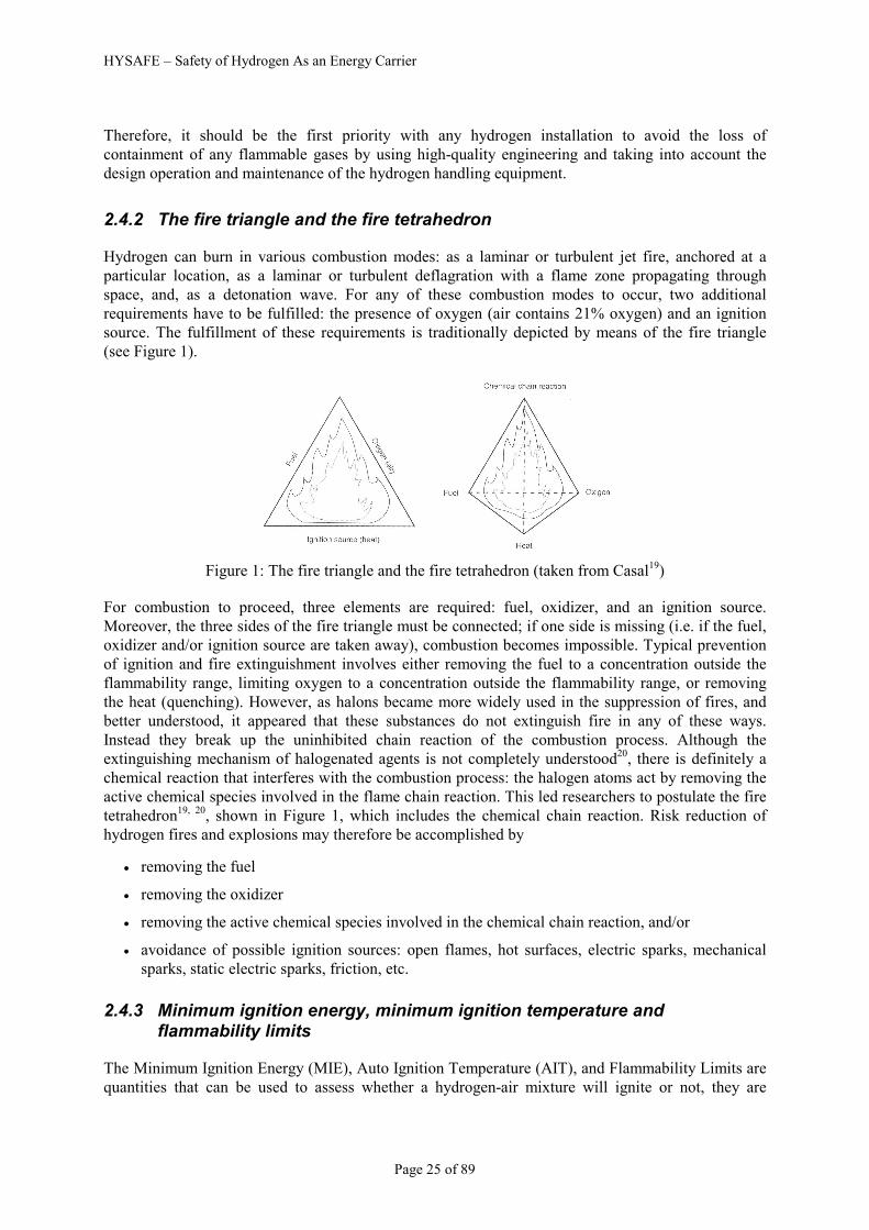
2.4.2 The fire triangle and the fire tetrahedron
Hydrogen can burn in various combustion modes: as a laminar or turbulent jet fire, anchored at a
particular location, as a laminar or turbulent deflagration with a flame zone propagating through
space, and, as a detonation wave. For any of these combustion modes to occur, two additional
requirements have to be fulfilled: the presence of oxygen (air contains 21% oxygen) and an ignition
source. The fulfillment of these requirements is traditionally depicted by means of the fire triangle
(see Figure 1).
Figure 1: The fire triangle and the fire tetrahedron (taken from Casal19)
For combustion to proceed, three elements are required: fuel, oxidizer, and an ignition source.
Moreover, the three sides of the fire triangle must be connected; if one side is missing (i.e. if the fuel,
oxidizer and/or ignition source are taken away), combustion becomes impossible. Typical prevention
of ignition and fire extinguishment involves either removing the fuel to a concentration outside the
flammability range, limiting oxygen to a concentration outside the flammability range, or removing
the heat (quenching). However, as halons became more widely used in the suppression of fires, and
better understood, it appeared that these substances do not extinguish fire in any of these ways.
Instead they break up the uninhibited chain reaction of the combustion process. Although the
extinguishing mechanism of halogenated agents is not completely understood20, there is definitely a
chemical reaction that interferes with the combustion process: the halogen atoms act by removing the
active chemical species involved in the flame chain reaction. This led researchers to postulate the fire
tetrahedron19, 20
, shown in Figure 1, which includes the chemical chain reaction. Risk reduction of
hydrogen fires and explosions may therefore be accomplished by
• removing the fuel
• removing the oxidizer
• removing the active chemical species involved in the chemical chain reaction, and/or
• avoidance of possible ignition sources: open flames, hot surfaces, electric sparks, mechanical
sparks, static electric sparks, friction, etc.
2.4.3 Minimum ignition energy, minimum ignition temperature and flammability limits
The Minimum Ignition Energy (MIE), Auto Ignition Temperature (AIT), and Flammability Limits are
quantities that can be used to assess whether a hydrogen-air mixture will ignite or not, they are

HYSAFE – Safety of Hydrogen As an Energy Carrier
Page 26 of 89
generally used in assessing the basic safety of a substance and where extra precautions need to be
taken. Although it is often not that simple as hydrogen has some positive properties with regard to
safety and a thorough investigation should be carried out to identify any safety concerns relating to
specific hydrogen systems. As a means of comparison the MIE, AIT and flammability limits are listed
in Table 4 for hydrogen and a typical natural gas composition.
Table 4: Some physical properties of Hydrogen and Natural Gas
MIE (mJ) AIT (oC) Flammability Limits (v/v)
Hydrogen 0.02 520 4% - 75%
Natural Gas 0.30 580 4% - 15%
2.4.4 Types of ignition sources
2.4.4.1 Hot surfaces
Ignition by a hot surface occurs as a result of local heating of the hydrogen-oxidant mixture to the
point where a sufficiently large volume reaches the autoignition temperature and the combustion
reaction is initiated. For this to occur generally requires the surface to be at a temperature above the
autoignition temperature8. Generally auto-ignition results from either the exothermic or the chain
branching character of the oxidation reactions which, at certain conditions, self-accelerate to reach
high conversion and heat release rates8. The autoignition temperature varies with concentration and
has its lowest value at 495 oC (see Figure 2). To avoid accidental ignitions by hot surfaces, their
temperature has to be kept below this value.
Figure 2: Auto-ignition temperature of hydrogen-air mixtures21, 22. Solid line: 0% H2O. Symbol
markers: square = 0% H2O, up-triangle = 10% H2O, lozenge = 20% H2O, down-triangle = 30% H2O,
circle = 0% H2O ignition, bullet = 0% H2O no ignition.

HYSAFE – Safety of Hydrogen As an Energy Carrier
Page 27 of 89
2.4.4.2 Open flames
Combustible hydrogen-air mixtures within the flammability limits will inevitably ignite upon contact
with open flames. Flammability limits are the chemical compositions of fuel-oxidizer mixtures
beyond which no steady state flame propagation can be sustained. These critical mixture compositions
vary with temperature: the flammable range becomes wider with increasing temperature. At room
temperature (20oC), and 1 bar, the lower flammability limit in air is at 4% hydrogen and the upper
flammability limit at 75% (see Figure 3). More extensive flammability diagrams have been compiled
in BRHS8. Obviously, open flames should be avoided in confined spaces where hydrogen is utilised
and accidental releases may occur. Furthermore, requirements for ventilation (natural, forces) must be
such that initial releases of hydrogen are rapidly diluted to a concentration below the lower
flammability limit.
Figure 3: Lower and upper flammability limits of hydrogen-air mixtures as a function of
temperature21, 22
. Symbol markers: bullet = lower flammability limit upward propagation, square =
lower flammability limit downward propagation, lozenge = lower flammability limit downward
propagation, circle = lower flammability limit downward propagation, black up-triangle = lower
flammability limit downward propagation; black square = upper flammability limit.
2.4.4.3 Electric sparks
Hydrogen-air mixtures are known to be susceptible to spark ignition. The sensitivity of a combustible
mixture to ignition is expressed in terms of the Minimum Ignition Energy. This quantity is usually
determined by causing ignition by a low-inductance spark from a capacitor discharge (the measured
values are known to depend on the electrode geometry and the resistance-inductance-capacitance
parameters of the discharge circuits22) and the minimum ignition energy is taken to be equal to the
energy stored in the capacitor22. It is known that the actual energy deposited is known to be only a
fraction of the total energy stored in the capacitor. Figure 4 shows the behaviour of the Minimum
Ignition Energy obtained in this manner for hydrogen-air mixtures at various concentrations and
pressures. It is seen that the Minimum Ignition Energy increases with increasing pressure and that its

HYSAFE – Safety of Hydrogen As an Energy Carrier
Page 28 of 89
lowest value occurs at the stoichiometric concentration. For practical circumstances, i.e. hydrogen
releases under atmospheric conditions of pressure and temperature, the total energy that can be
released by an electric spark may not exceed 0.02 mJ. It may be argued that the occurrence of the
stoichiometric concentration is unlikely, or not likely to exist for a long period after an accidental
release. However, the Minimum Ignition Energy of a hydrogen-air mixture at conditions of 1 bar, near
the flammability limits is only 6 mJ, which is still very low.
Figure 4: Minimum spark ignition energy for hydrogen-air mixtures22, 23, 24
2.4.5 Protection by hazard segregation
Arranging the component parts of an installation in an appropriate way can significantly reduce the
likelihood of an explosion. The risk from explosion will usually be much lower when the hydrogen-
handling equipment is well separated from electrical equipment or other ignition sources.
The buoyancy of hydrogen should be taken into account and used to reduce the risk from fire and
explosion when designing or arranging the components of a fuel cell system. This can be done
through the following measures:
• Equipment for handling hydrogen and foreseeable sources of ignition should be segregated or
physically separated
• For fuel cells the hydrogen storage area should be separated from the fuel cell and the fuel cell
from any equipment using its electrical output
• Any potential ignition sources should be located well below any equipment from which
hydrogen may leak

HYSAFE – Safety of Hydrogen As an Energy Carrier
Page 29 of 89
• Avoid locating potential sources of ignition, such as non-flameproof electrical light fittings,
immediately below horizontal bulkheads or impervious ceilings under which hydrogen may
accumulate
• Ensure that any area, enclosure or housing etc., into which hydrogen may leak, is designed to
prevent the gas becoming trapped and is equipped with effective high- and low-ventilation
• Systems using or storing hydrogen should not be located beneath unprotected electrical
equipment or high-voltage power lines25
• Gas-tight compartments or bulkheads and ventilation should be used to reduce the likelihood of
leaking hydrogen reaching potential ignition sources
Recommended separation distances are the minimum distances considered necessary to mitigate the
effects of likely foreseeable events and prevent a minor incident escalating into a major one26.
Separation distances are used to quantify the separation of different hazards, such as high-pressure
hydrogen storage from an ignition source, or a hazard from vulnerable objects or people.
The recommended distances are intended to give people and equipment a suitable degree of protection
from a foreseeable event on the installation, such as a hydrogen leak and subsequent jet fire. The
separation that they provide should ensure that the risk to people from heat radiation or from flame
impingement onto other flammable materials is low. Separation distances are also calculated to give
protection to the installation from off-site events such as impact from vehicles or machinery, releases
of flammable materials, uncontrolled ignition sources or the radiant effects of off-site fires etc.
The use of established separation distances around equipment handling or storing hydrogen or other
dangerous substances has traditionally been considered a fundamental requirement for the design of
safe installations. Separation distances should be measured horizontally from those points in the
system where, in the course of operation, an escape of hydrogen may occur. The most recent version
of an applicable regulation or appropriate standard should be consulted for additional information on
the appropriate use of separation distances.
In circumstances where it is not practicable to use minimum separation distances an acceptable
situation may be achieved through the use of fire-resistant barriers or other risk reduction
techniques25. There may also be situations where the recommended distances are considered
inappropriate, for example when the operating pressure of the system is low. Where recommended
separation distances are not employed, the onus is on the duty holder to demonstrate through suitable
assessment that the risk is acceptable and has been reduced to as low as is reasonably practicable.
2.4.6 Protection by storage limitation
Consideration should be given to the rate of hydrogen consumption/use and the timescales of
consumption/use in order to minimize the amount of hydrogen stored to as low as is reasonably
practicable.
2.4.7 Protection by controlling ignition sources
A flammable mixture will not ignite or explode if a source of ignition is absent. Although it is
extremely difficult to eliminate all sources of ignition, avoiding ignition sources should be an
important part of the overall risk reduction strategy. The control of ignition sources should be
practiced wherever a potentially explosive atmosphere may be present by using the following
techniques:

HYSAFE – Safety of Hydrogen As an Energy Carrier
Page 30 of 89
• Carrying out a hazardous area assessment
• Identifying the nature and extent of hazardous zones
• Using suitable signs to denote the boundaries of hazardous zones
• Locating electrical equipment in non-hazardous zones
• Using appropriately classified equipment in hazardous areas
• Using continuity bonding, earthing and anti-static clothing to avoid static sparks
• Avoid hot work, vehicles, smoking and the use of mobile phones
• Providing lightning protection, where appropriate
When planning the installation of a hydrogen system it is important to consider whether it will
introduce new fire and explosion hazards into an area where previously these were absent or whether
the proposed location is already in a hazardous area. Does the need to control ignition sources result
from the possibility of a hydrogen leak from the new installation or does the new installation represent
the introduction of a possible ignition source into an existing hazardous area.
Where a potentially explosive atmosphere may be present in the workplace, it is required that
employers assess and identify those areas in which ignition sources need to be controlled27. The areas
where explosive atmospheres could be formed must be identified and designated as hazardous zones
according to the principles of Hazardous Area Classification28, 29, 30
.
The results from the area classification exercise should be used to ensure that the appropriate category
of equipment is used in the hydrogen installation and that only suitable equipment is present in the
vicinity of the new installation.
For situations where hydrogen and/or other flammable gases or liquids may be present, the following
classifications should be used where appropriate:
• Zone 0 – An area in which an explosive atmosphere is present continuously or for long periods.
Only category 1 equipment should be used in these areas
• Zone 1 – An area where an explosive atmosphere is likely to occur during normal operation.
Only category 1 or 2 equipment should be used in these areas
• Zone 2 – An area where an explosive atmosphere is not likely to occur during normal operation
and, if it does occur, is likely to do so infrequently and will only last for a short period. Only
category 1, 2 or 3 equipment should be used in these areas
Electrical equipment appropriate for use in the different areas of the workplace should be determined
once the hazardous areas have been identified and classified28, 30
. When selecting electrical equipment
for use in hazardous areas, the temperature class and the apparatus group appropriate for the type of
flammable atmosphere likely to be present should be specified.
The hazardous area classification should also be used to ensure that suitable controls are placed on all
other foreseeable sources of ignition including hot work, smoking, vehicles, mechanical equipment,
mobile phones and work clothing.
Precautions should also be taken to prevent the build-up of static charges that may lead to an
incendive discharge. These may include:
• Ensuring that all pipework is conductive and has effective electrical continuity, especially over
mechanical joints such as flanges

HYSAFE – Safety of Hydrogen As an Energy Carrier
Page 31 of 89
• Ensuring that all pipework and equipment is effectively earthed
• Carrying out and documenting appropriate earthing/continuity checks
• Wearing antistatic clothing and footwear in hazardous areas
• Providing appropriate protection against the risk of lightening where appropriate25
Any equipment, which could be used in a potentially explosive atmosphere, is fully covered by the EC
directive 94/9/EC (ATEX Regulations)31. Essentially, depending on the likelihood of an explosive
atmosphere being present in the vicinity of the components, the component must not act as either an
electrical or hot surface ignition source. When designing and constructing hydrogen handling
equipment the following points should be considered:
• If the equipment is likely to be used where a potentially explosive atmosphere may be present it
should comply with the ATEX Regulations31 and any local standards
28, 32
• Ensure that electrical/electronic components, connectors, materials etc. employed are suitable
for the intended use and environment
• Locate the electrical/electronic components of the installation below any foreseeable sources of
hydrogen leakage
• Use suitable gas-tight barriers to separate electrical/electronic equipment from areas where
hydrogen may be present
• Use appropriate ventilation to prevent the formation of potentially explosive mixtures
• The use of explosion resistant equipment or explosion relief may be appropriate in certain
situations
2.4.8 Building design, compartmentation and means of escape
In addition to satisfying the requirements of relevant safety legislation and building codes, garages,
workshops and other buildings housing hydrogen systems should be designed with due consideration
to the safe handling of hydrogen. ISO/TR 159169 and NFPA 55
33 provide advice on the design of
buildings housing hydrogen systems.
Compartmentation is the term used to describe the segregation of parts of a building to restrict the
spread of fire and smoke for specified periods, e.g. 60 minutes. This can keep the fire limited to the
compartment of origin and protect other spaces such as stairs from the ingress of smoke. It is
important for means of escape provision, fire and rescue operations and also provides some level of
property and structural protection. Regional and international regulations and design guidance, e.g.
IBC34 and NFPA 5000
35, embody the principles of compartmentation and will stipulate the minimum
fire and smoke resistance required. There may be a requirement to locate the hydrogen system within
a fire resisting compartment.
A fire compartment consists not only of walls, floors and ceilings, but the also the means to prevent
heat and smoke transfer via the penetrations to the compartment, e.g. at doors and ventilation ducts.
Here, the fire resistance rating of the doors and ducts should be consistent with the compartment they
serve. Dampers may be required inside ducts to effectively seal off the compartment in the event of
fire. Furthermore, gaps surrounding the doors and ducts should be correspondingly fire and smoke
protected. This can be in the form of intumescing coatings and seals, which expand under the
influence of fire generated heat.

HYSAFE – Safety of Hydrogen As an Energy Carrier
Page 32 of 89
Account of the strong buoyancy of hydrogen should be made, e.g. elimination of explosion hazard
caused by accumulation of hydrogen under a ceiling. Appropriate natural or mechanical ventilation
should be provided to reduce the risk associated with accumulated hydrogen. For more information on
ventilation see section 2.3.
The provision for mean of escape in the event of fire and emergency forms a key element of building
design. This is obvious in the case of large public and commercial buildings where there may be high
numbers of persons, e.g. shopping malls, sports stadia, high-rise office accommodation, or in large
residential premises with common, public access areas. It must be considered also in low occupancy
buildings such as private one-family homes or warehouses where relatively few employees are be
present at any one time.
The basic remit of means of escape provision is to enable persons to evacuate the building to a place
of safety before conditions become untenable. As for compartmentation, this is embodied in regional
and international regulations and design guidance. A building will be deemed to provide suitable
means of escape if, for the designed emergency scenarios, the required safe escape time (RSET) is
greater than the available safe escape time (ASET) by an agreed margin. The ASET is the time from
the initiation of the fire or accident until conditions are no longer adequate for people to escape. The
RSET consists of series of component times as follows36,
tRSET = ∆tdetection+∆talarm+∆tpre-movement + ∆ttravel (2)
The travel time will generally consist of the time to reach the exit(s) plus the time to pass through the
exit(s). In conducting an RSET calculation the distribution of the building population in terms of
awareness, mobility etc should be considered.
2.4.9 Explosion venting
Explosion venting is the most wide spread and cost effective deflagration mitigation technique. It is
aimed at limiting excessive explosion-incurred pressures and by means of pressure relief through a
specially designed vent from the instant when its opening pressure has been achieved. The reduced
explosion pressure shall not exceed the known design pressure of an enclosure. Design of explosion
vents may be based on the vent sizing correlations or application of the computational fluid dynamics
(CFD) tools validated against vented deflagration experiments. The vent sizing correlations are based
on a number of assumptions and usually are applied to the worst case scenario of the fastest burning
mixture combustion in practically empty enclosure with initially quiescent conditions. CFD based
methods are capable to account for realistic enclosure geometry, obstructions, and non-uniform
mixture distribution. To analyse the predictive capabilities of CFD tools, they should be based on
models which are thoroughly verified and validated for the enclosure and combustion scenario and
whose details are published in peer reviewed journals.
In general the vent sizing formulas of NFPA 6837 (2007 Edition) and its European version standard
EN 1499438 are not applicable to hydrogen. The “consensus” is to use the value of KG for hydrogen
equal to 550 bar·m/sec from Table E1 in Equation 7.3.3.2 (applicable for KG below or equal to 550
bar·m/sec) of the NFPA standard. Some examples of comparison between the experimental data on
vented hydrogen-air deflagrations and the predictions by the vent sizing technology described below
and the NFPA 6837 (2007 Edition) standard are presented in Table 5. The vent sizing correlations
were applied to tunnel explosions as follows: the volume of uniform hydrogen-air mixture represents
an “enclosure volume” and the “enclosure vent area” is equal to double of a cross sectional area of the
tunnel. More details on comparison between experimental data and predictions by the vent sizing
technology and the NFPA 68 Equation 7.3.3.2 with KG=550 bar·m/sec are given in [39]. From Table 5

HYSAFE – Safety of Hydrogen As an Energy Carrier
Page 33 of 89
it can be seen that the NFPA 68, and hence EN14994, significantly overestimate vent areas and
reduced pressure (sometimes up to 6985%) in some cases and underestimate in other cases, thereby
being not conservative, compared to the vent sizing correlations demonstrating essentially closer to
experiment predictions.
Table 5: Comparison between experimental data and predictions by the vent sizing correlations
and the NFPA 68 (Edition 2007) standard
Vent Area, A (m2) Reduced pressure, Pred Test
H2,
vol.
%
Shape V,
m3 VSCa %b NFPAc %b Expd VSCa %b NFPAc %b Expd
K-10–45-C40 10 Sphere 6.85 0.2214 39 0.986 521 0.1590 0.54 79 6.49 2063 0.300
K-15-15-C40 15 Sphere 6.85 0.0753 326 0.223 1163 0.0177 5.34 46 260.00 6985 3.670
K-15-25-C40 15 Sphere 6.85 0.1002 104 0.238 384 0.0491 4.20 27 46.90 1321 3.300
K-15-45-C40 15 Sphere 6.85 0.2378 50 0.311 95 0.1590 2.68 27 6.49 209 2.100
K-20-15-C40 20 Sphere 6.85 0.0536 203 0.185 947 0.0177 6.14 22 260.00 5069 5.030
K-20-25-C40 20 Sphere 6.85 0.0819 67 0.196 300 0.0491 5.13 13 46.90 931 4.550
K-20-45-C40 20 Sphere 6.85 0.1643 3 0.222 40 0.1590 3.74 1 6.49 75 3.700
P-1-C41 29.6 Cylinder 0.95 0.2132 7 0.110 -45 0.2000 1.35 8 0.45 -64 1.250
P-2-C41 29.6 Cylinder 0.95 0.4176 39 0.233 -22 0.3000 0.74 85 0.26 -35 0.400
SRI-30-F42 30 Tunnel 37.4 11.95 61.5 1.112 -85 7.48 1.73 33 0.05 -96 1.300
SRI-20-F42 20 Tunnel 37.4 11.82 58 2.434 -67 7.48 0.78 122 0.05 -85 0.280
SRI-15-F42 15 Tunnel 37.4 7.55 1 3.127 -58 7.48 0.23 0 0.05 -77 0.220 a Vent Sizing Correlations. b Deviation of prediction from corresponding experimental value, calculated by the formula: 100x (Apred - Aexp.)/Aexp, where A is a reduced
pressure or a vent area. c NFPA 68 (2007 edition) vent sizing by Equation 7.3.3.2. d Experimental data
The conservative form of the vent sizing correlations was developed at the HySAFER centre of the
University of Ulster. The procedure for calculating the vent area in an empty enclosure or enclosure
with insignificant influence of obstacles is as follows:
1) Calculate the value of the dimensionless reduced explosion overpressure
i
redred p
p=π (3)
2) Determine the value of dimensionless static activation pressure
( )i
istat
ppp +=νπ (4)
3) Calculate the value of the dimensionless pressure complex 5.2
νππ red based on the data from the
two previous steps
4) Calculate the value of the turbulent Bradley number Brt by the use of one of the following two
equations depending on the value of the above mentioned dimensionless pressure complex 5.2
νππ red :
5.25.25.2 65.5 then 1 if −⋅=< t
redred Brνν π
ππ
π (5)

HYSAFE – Safety of Hydrogen As an Energy Carrier
Page 34 of 89
25.05.25.2 8.59.7 then 1 if t
redred Br⋅−=≥νν π
ππ
π (6)
5) Using Figure 5 determine the appropriate values of laminar burning velocity and the expansion
ratio for the hydrogen-air mixture in the enclosure. For instance, for stoichiometric hydrogen-air
mixture at initial pressure 1 bar and temperature 298 K, the following value of burning velocity can be
used for the purpose of vent sizing: Su0=1.96 m/s43, 44
, the corresponding value of expansion ratio can
be taken as Ei=6.88. The influence of the initial temperature on the laminar burning velocity can be
estimated from the formula45
0
2980
m
uiu
TSS
⋅= (7)
where Su0 is the laminar burning velocity at 298 K (Fig. 1); T is the initial temperature and m0 =1.7.
0.00.20.40.60.81.01.21.41.61.82.02.22.42.62.83.03.23.43.63.84.0
0.1 0.2 0.3 0.4 0.5 0.6
Hydrogen concentration (vol. %)
Laminar burning velocity
(m/s)
0.00.40.81.21.62.02.42.83.23.64.04.44.85.25.66.06.46.87.27.68.0
Expansion ratio
Laminar burning velocity
Expansion ratio
Figure 5: Laminar burning velocity and expansion ratio for hydrogen-air mixtures at initial pressure 1
bar and temperature 298 K
6) Determine the vent area by numerical solving of the following transcendental equation (by
changing area A until the left hand side of the equation is equal to the right hand side):
( )( )
( ) ( )11
173.05.011
364.0
4.0
32
4.0
3230
−⋅⋅⋅+
−⋅⋅⋅⋅
⋅+⋅+⋅
=
⋅
⋅⋅
−
iui
g
iui
ui
u
iui
t
ESVe
ESV
cAA
Ec
VBr
β
νπ
γ
π (8)
where empirical coefficients e=2 and g=0.94.
HYSAFE – Safety of Hydrogen As an Energy Carrier
Page 35 of 89
The correlations have been calibrated against experimental data for hydrogen-air deflagrations for the
following range of conditions:
• L/D ≤ 5.43
• V ≤ 37.4 m3
• 0.005 < A/V2/3 < 0.34
• 0 kPa ≤ pstat ≤ 13.5 kPa
• pi =1 bar abs
• 0.3 ≤ πred ≤ 5
2.5 Commissioning, inspections, training and worker protection
Working on a system or checking it, should only be performed by persons trained accordingly and a
maintenance timetable should describe the frequency and the detailed procedure.
2.5.1 Commissioning
The commissioning of the facilities to use H2 should generally comprise the following actions:
• visual inspection of the system particularly with regard to abrasion (also valid for section 2.5.2)
• mechanical inspection: every element of the system such as fittings, gaskets, weldings has to be
checked in accordance with the instructions provided by the manufacturer (e.g. screwing it at
the correct torque)
• pressure test with an inert gas to check tightness of the system in order to identify possible leak
or blocking of piping or valves (especially those for pressure release). For this purpose, different
methods can be carried out:
• global testing of the entire system: the pressurized facility has to be isolated and the evolution of
the pressure inside has to be monitored; no decrease of pressure for a sufficiently long time
signifies the tightness of the facility. If a decrease of pressure is observed, which means that
there is at least one leaking element, an individual check of every components is necessary
• single component tightness checking: fittings can be tested by a deposit of water charged with a
tension-active product (soap): possible leak can be spotted where bubbles on the fittings are
generated. However, this method must not be applied in a cryogenic system as the water will
freeze and damage the components. Another testing method is to pressurize the facility with a
traceable gas and to use a sniffer to detect a possible leak
• different gases can be used to perform a pressure test:
• Helium: is expensive but has several advantages. Its molecular size is close to hydrogen’s, so a
facility which is tight with helium will probably be tight with hydrogen. The freezing point of
helium is lower than of hydrogen’s, so it can also be used for a LH2-system without danger of
affecting valves. A helium leak can easily be detected using a sniffer
• Nitrogen or air (consisting of 80% N2): they are cheaper than other gases but cannot be detected
by sensors and the system has to be evacuated or purged afterwards (see also section 2.5.2.1).
They can be used for pressure tightness testing. They cannot be used for leak testing.
• A mixture of N2 and H2 (5-10%): it is safe, can be easily traced and will show realistic leakage
of H2. The system has to be evacuated or purged afterwards (see also section 2.5.2.1)
HYSAFE – Safety of Hydrogen As an Energy Carrier
Page 36 of 89
• some devices (such as valve gaskets) are difficult to keep completely and continuously tight.
Thus, it is acceptable to use valve gaskets not completely tight but it is necessary to measure
their leak flow rate and to regularly carry out an inspection operation which consists in verifying
that the leak flow rate remains lower than a certain predefined value
• in case of a leak, the leaking element has to be tentatively re-tightened, repaired or replaced
When the tightness of a facility can be considered sufficient, the gas which has been used for this
checking has to be eliminated by applying a vacuum to the facility (for the parts of the facility which
are always kept pressurized by hydrogen, for example cylinders, they do not have to be evacuated).
Then the facility can be pressurized by hydrogen and commissioned.
In ANSI/CSA FC 1-200446, testing methods are also proposed for a hydrogen system. Yet no
commissioning is recommended after on-site installation.
2.5.2 Purging
Gaseous and liquid hydrogen systems must be purged of air, oxygen, or other oxidizers prior to
admitting hydrogen to the systems, and purged of hydrogen before opening the system to the
atmosphere. Purging should be done to prevent the formation of flammable mixtures and can be
accomplished in several ways. Piping systems and vessels intended for gaseous hydrogen service
should be inerted by suitable purging or evacuation procedures. If the piping systems are extensive or
complicated, successive evacuations broken first by an inert gas and finally with hydrogen are most
reliable. Evacuating and purging of equipment in gaseous hydrogen service should include the
following procedure:
Step 1: Evacuate the equipment and break the vacuum with an inert gas, such as nitrogen. Purge with
an inert gas if equipment design does not permit evacuation.
Step 2: Repeat step 1 at least three times. If analytical equipment is available, purge system until
oxygen content of residual gas is either less than or meets the process specification impurity level.
Step 3: Hydrogen may now be introduced to the equipment
Step 4: Flush system with hydrogen until required purity is reached. Vent all waste hydrogen through
a flue or flare stack. Any purge method should be repeated as often as required to be certain a
flammable mixture cannot be formed upon introducing hydrogen or air to the system
The above information on purging is taken from [47] and [48].
2.5.2.1 Special requirements for LH2
Withdrawal of liquid from a tanker, tank, or liquid cylinder requires the use of a closed system, with
proper safety relief devices, which can be evacuated and/or purged to eliminate the possibility of
creating a flammable atmosphere or explosive mixture of liquid air and liquid hydrogen. Purging
should be done with helium since liquid hydrogen can solidify other gases, such as nitrogen, and
cause plugging and possible rupture of the transfer line or storage vessel. Liquid transfer lines must be
vacuum insulated to minimize product loss through vaporization or the formation of liquid air on the
lines with subsequent oxygen enrichment. All equipment must be electrically grounded and bonded
before transferring liquid.

HYSAFE – Safety of Hydrogen As an Energy Carrier
Page 37 of 89
2.5.3 Inspection
The inspection operations which must be carried out consist mainly of:
• regularly measuring the global leak flow rate of the facility
• checking that the leak flow rate remains lower than a predefined level
• in case the leak flow rate is higher than the predefined level, identifying the elements which
have too high leak flow rates for repairing or replacement
2.5.4 Training
The workers who have to run hydrogen facilities should be trained relative to the following:
• general properties of hydrogen (flammable gas, easily ignitable, particularly by electrostatic
source, poor flame visibility but very hot flame, low density…) and in the case of LH2 specific
cryogenic properties of H2, N2, O2 and the hazards associated
• description and explanation of commissioning and inspection procedures
• description and explanation of safety measures and procedures
• description and explanation of functioning of the facility
• emergency guidelines
• practical experiments
2.5.5 Worker protection
As mentioned in paragraph 2.5.4, workers having to run hydrogen facilities should be trained. The
training includes prevention measures against accidents. Amongst prevention measures, protection
measures have to be applied:
• the workers should be equipped with IPE (individual protection equipment) (such as cryogenic
equipment to handle liquid hydrogen and antistatic clothes to manipulate hydrogen) and also if
necessary to be equipped with a personal H2-sensor
• the working places or premises should be equipped with controlled ventilation, natural or
forced, in order that any leak could be diluted by air at a sufficient flow rate, and that any ATEX
accumulation could be prevented
In a general way, the regulation 94/9/CE and 1999/92/CE must be applied.
2.6 Reference documentation
Besides the references listed in the text, the reader is advised to refer to the following additional
sources for information on the topics of this chapter: [49], [50], [51], [52], [53], [54], [55], [56], [57],
[58], [59], [60], [61], [62], [63], [64], [65], [66], [67], [68], [69], [70], [71], [72], [73], [74], [75],
[76], [77], [78], [79], [80], [81], [82], [83], [84], [85], [86], [87], [88], [89], [90], [91], [92], [93]
1 NFPA 50A: 1999 “Gaseous Hydrogen Systems at Consumer Sites”
2 NFPA 50B, “Standard for liquefied hydrogen systems at consumer sites”, 1997 Edition

HYSAFE – Safety of Hydrogen As an Energy Carrier
Page 38 of 89
3 NFPA 55, “Standard for the storage, use and handling of compressed and liquefied gases in portable cylinders”,
1997 Edition 4 NFPA 52: Vehicular Fuel Systems Code, 2006 edition
5 FM Global Property Loss Prevention Data Sheets 7-91, “Hydrogen”, September 2000
6 NFPA 853, “Standard for the Installation of Stationary Fuel Cell Power Plants”, 2007 Edition
7 Planning and designing gas detection systems, Wolfgang Jessel, Sensor Weekly, Vol 19 (1), January 2002 -
http://archives.sensorsmag.com/articles/0102/34/main.shtml 8 HySafe, The Biennial Report on Hydrogen Safety, http://www.hysafe.org/wiki/BRHS/BRHS
9 ISO/TR15916, “Basic considerations for the safety of hydrogen systems”, First edition, 2004-02-15
10 HySafe D54, Report on detectors performance assessment (JRC), December 2007, downloadable at
http://www.hysafe.org/documents?deliverable=54 11 International Electrotechnical Commission (IEC), (1998), International Standard IEC 61779, “Electrical
apparatus for the detection and measurement of flammable gases”, Parts 1 to 6, International Electrotechnical
Commission (IEC), First edition, 1999 12 DOE-sponsored Workshop on Sensor Needs and Requirements for Proton-Exchange Membrane Fuel Cell
Systems and Direct- Injection Engines, January 25 and 26, 2000, Lawrence Livermore Laboratories Publ.,
UCRL-ID-137767, Livermore (CA) 13 Corsi, J., “Area Monitoring of Hazardous Gases and Vapors”, Sensors magazine online- January 2000
14 National Aeronautics and Space Administration, “SAFETY STANDARD FOR HYDROGEN AND
HYDROGEN SYSTEMS - Guidelines for Hydrogen System Design, Materials Selection, Operations, Storage,
and Transportation”, NSS 1740.16, February 1997 15 Heitsch, M., Baraldi, D., Moretto, P., Wilkening, H, “Safety of laboratories for new hydrogen techniques”,
presented at the International Conference on Hydrogen Safety, 11-13.09.2007, San Sebastian (E) 16 Commission des communautés européennes “Eléments pour un guide de sécurité hydrogène”, vol. 1 et 2, EUR
9689, 1985 17 Circulaire du 9 mai 1985 commentant les décrets n°84-1094 et 84-1093 du 7 décembre 1984
18 BS 5922:1991 – “Codes of practice for ventilation principles and designing of natural ventilation”
19 Casal J., “Evaluation of the effects and consequences of major accidents in industrial plants”, Industrial Safety
Series, Elsevier, Amsterdam, 2008 20 Grant C.C. Halon design calculations. In P.J. DiNenno, D. Drysdale, C.L. Beyler, W.D. Walton, R.L.P. Custer,
J.R. Hall, and J.M. Watts, editors, SFPE Handbook of Fire Protection Engineering, Section 4: Design
Calculations, chapter 4-6, pages 4-149 - 4-172. National Fire Protection Association, Quincy, Massachusetts,
third edition, 2002 21 Stamps D.W. and Berman M., “High-temperature hydrogen combustion in reactor safety applications”,
Nuclear Science and Engineering, 109:39-48, 1991 22 Lee J.H.S. and Berman M., “Hydrogen combustion and its application to nuclear reactor safety”, In G.A.
Greene, J.P. Hartnett, T.F. Irvine Jr., and Y.I. Cho, editors, Heat Transfer in Nuclear Reactor Safety, volume 29
of Advances in Heat Transfer, chapter 2, pages 59-123. Academic Press, New York, 1997 23 Drell I.L. and Belles F.E., “Survey of hydrogen combustion properties”, Report NACA 1383, National
Advisory Committee for Aeronautics, Cleveland, Ohio, 1958 24 Lewis B. and von Elbe G., Combustion, Flames and Explosions of Gases. Academic Press, third edition, 1987
25 Gaseous hydrogen stations: IGC Doc 15/96 European Industrial Gases Association
26 Determination of safety distances - IGC Doc 75/01/E/rev: European Industrial Gases Association
27 Dangerous substances and explosive atmospheres, Dangerous substances and explosive atmospheres
regulations 2002, Approved Code of Practice and Guidance, 2003: L138 HSE Books ISBN 0 7176 2202 7 28 BS EN 60079-10: 2003 Electrical apparatus for explosive gas atmospheres. Classification of hazardous areas:
British Standards Institution 29 Area classification code for installations handling flammable fluids, Model code of safe practice in the
petroleum industry, Part 15: Institute of Petroleum ISBN 0 85293 223 5 30 PD 60079-14: 2000 A guide to the application of BS 60079-14: British Standards Institution
31 ATEX Regulations - EC Directive 94/9/EC

HYSAFE – Safety of Hydrogen As an Energy Carrier
Page 39 of 89
32 The Equipment and Protective Systems Intended for Use in Potentially Explosive Atmospheres Regulations.
1996: SI 1996/192 The Stationery Office ISBN 0 11 053999 0 33 NFPA 55 (2005 ed.), Standard for the storage, use and handling of compressed gases and cryogenic fluids in
portable and stationary containers, cylinders and tanks 34 International Code Council, 2006 International Building Code
35 NFPA 5000 (2006 ed.). Building construction and safety code
36 BSI (British Standards). PD 7974-6:2004. The application of fire safety engineering principles to fire safety
design of buildings - part 6: Human factors 37 NFPA 68, 2007. Standard on Explosion Protection by Deflagration Venting, National Fire Protection
Association, NFPA, 1 Batterymarch Park, Quincy, Massachusetts, USA 02169-7471 38 EN14994: 2007. Gas Explosion Venting Protective Systems
39 Molkov V., Verbecke F., Saffers J.B., Venting of uniform hydrogen-air deflagrations in enclosures and
tunnels: vent sizing and prediction of overpressure, Submitted for presentation at the 7th ISHPMIE, St.
Petersburg, Russia, July 7–11, 2008 40 Kumar, R., Dewit, W., & Greig, D. (1989). Vented explosion of hydrogen-air mixtures in a large volume.
Combustion Science and Technology, 66, 251-266 41 Pasman H.J., Groothuisen Th.M. and Gooijer P.H. (1974) Design of Pressure Relief Vents, in “Loss
Prevention and Safety Promotion in the Process Industries”, Ed. Buschman C.H., Elsevier, New-York, pp.185-
189 42 Y. Sato, E. Merilo, M. Groethe, J. Colton, S. Chiba, H. Iwabuchi, Homogeneous hydrogen deflagrations in a
sub-scale vehicle tunnel, Proceedings of the National Hydrogen Association Conference, Long Beach, CA, USA,
March 12 - March 16, 2006 43 N. Lamoureux, N. Djebaili-Chaumeix, C.-E. Paillard, Flame velocity determination for H2-aie-He-Co2
mixtures using the spherical bomb, Experimental thermal and Fluid science, 2003 44 S.D. Tse, D. L., Zhu, C. K. Law, Morphology and burning rates of expanding spherical flames in H2/O2/inert
mixtures up to 60 atmospheres. Proceedings of the 28th Symposium (International) on Combustion. (pp. 1793–
1800). Pittsburgh, PA: the Combustion Institute, 2000 45 Babkin V.S., Private communication. Institute of Chemical Kinetics and Combustion, Siberian Branch,
Russian Academy of Science, Novosibirsk, Russia, 2003 46 ANSI/CSA America FC 1-2004, Stationary Fuel Cell Power Systems
47 http://www-safety.deas.harvard.edu/services/hydrogen.html
48 EIGA 06/02/E “Safety in storage, handling and distribution of liquid hydrogen”
49 EN 764-7, May 2002, Pressure equipment – Part 7: Safety systems for unfired pressure equipment
50 CGA Publication PS21: 2005 "Adjacent Storage of Compressed H2 & other Flamm. Gases”
51 CGA Publication G5.4: 2005 "Hydrogen Piping Systems at Consumer Sites"
52 ISO 12100-2: 2004 “Safety of machinery. Basic concepts, general principles for design”
53 IEC 60079-29-1 & 2, Electrical Apparatus for Explosive Gas Atmospheres Part 1 Elect. appa. For the
detection and measurement of flammable gases-General Requirements & Test Methods - Part 2 Elect. appa. For
the detection and measurement of flammable gases-Guide for the selection, installation, use and maintenance 54 IEC 62282-3-1 Fuel cell technologies - Part 3-1: Stationary fuel cell power systems –Safety
55 European Standard EN 50073, Guide for the selection, installation, use and maintenance of apparatus for the
detection and measurement of combustible gases or oxygen", CENELEC, April 1999 56 CGA Publication G5.5 : 2004 "Hydrogen Vent Systems"
57 Harris, R. J., The Investigation and Control of Gas Explosions in Buildings and Heating Plants, British Gas
Corporation, Midlands, England, 1983 58 NFPA 69 ”Standard on Explosion Prevention Systems”
59 1999/92/EC, Safety and health protection of workers potentially at risk from explosive atmospheres (15th
individual Directive within the meaning of Article 16 of Directive 89/391/EEC 60 IEC 60079-10 “Electrical apparatus for explosive gas atmospheres - Part 10: Classification of hazardous areas”
61 IEC 60079-14 “Electrical apparatus for explosive gas atmospheres - Part 14: Electrical installations in
hazardous areas (other than mines)”

HYSAFE – Safety of Hydrogen As an Energy Carrier
Page 40 of 89
62 IEC 60079-17 “Electrical apparatus for explosive gas atmospheres - Part 17: Inspection and maintenance of
electrical installations in hazardous areas (other than mines) 63 1127-1:1997, Explosive atmospheres — Explosion prevention and protection — Part 1: Basic concepts and
methodology 64 Commission européenne, Guide de bonne pratique à caractère non contraignant en vue de la mise en oeuvre de
la directive 1999/92/CE, Janvier 2003 65 HySafe D54. Report on detectors performance assessment (JRC), December 2007, downloadable at
http://www.hysafe.org/documents?deliverable=54 66 ISO/TR15916, “Basic considerations for the safety of hydrogen systems”, First edition, 2004-02-15
67 BS 5922:1991 – “Codes of practice for ventilation principles and designing of natural ventilation”
68 Area classification code for installations handling flammable fluids, Model code of safe practice in the
petroleum industry, Part 15: Institute of Petroleum ISBN 0 85293 223 5 69 International Sensor Technology Website, http://www.intlsensor.com/
70 HYSAFE Review on best practices for the handling of hydrogen in confined spaces, Presentation by Lionel
Perette, InsHyde meeting, INERIS, 17 January 2006 71 UK Health and Safety Executive, “The selection and use of flammable gas detectors”, www.hsebooks.co.uk
72 Miller, J., “U.S. Standardization of Gas Detection Equipment”, January 2001
73 American National Standards Association, http://webstore.ansi.org/ansidocstore/
74 K. Hall, “New International Working Group Focuses on Hydrogen-Specific Detectors”, H2 & FC Safety, April
2006 75 Umweltsensortechnik Website http://www.umweltsensortechnik.de
76 Nemoto N.E.T Website: http://www.nemototech.com/
77 First Technology Website; http://www.firsttech.co.uk/
78 e2V technologies Website, http://www.e2vtechnologies.com/
79 Hoffstein S. et al, Proceedings of the 1999 U.S DOE Hydrogen Program Review NREL/CP-570-26938
80 Wan J.K.S. et al. Sensors and Actuators B 32 (1996) 233-237
81 Dwivedi D. et al., Sensors and Actuators B 71 (2000) 161-168
82 Varghese O. et al., Sensors and Actuators B 93 (2003) 338–344
83 Roy S. et al., Sensors and Actuators B 94 (2003) 298–303
84 Sumima et al., Sensors and Actuators B 108 (2005) 508-514
85 Tajima K., Sensors and Actuators B 108 (2005) 973–978
86 DiMeo F. et al., US Patent 6897960 B2 (2005)
87 Health & Safety Laboratory, “ Outstanding safety questions concerning the use of gas turbines for power
generation –Executive report ”, CM/04/02,2004 88 CAN/BNQ 1784-000, Canadian Hydrogen Installation Code
89 IEC/CDV 62282-3-3, Fuel cell technologies – Part 3-3: Stationary fuel cell power plants – Installation
90 European Industrial Gases Association, Gaseous hydrogen stations, Technical Report IGC Doc 15/06/E,
EIGA, Brussels, 2006. Revision of Doc 15/96 and Doc 15/05 91 ISO 16110-1, Hydrogen generators using fuel processing technologies - Part 1: Safety
92 ISO/DIS 22734-1, Hydrogen generators using water electrolysis process - Part 1: Industrial and commercial
applications 93 ISO/CD 22734-2, Hydrogen generators using water electrolysis process - Part 2: Residential applications

HYSAFE – Safety of Hydrogen As an Energy Carrier
Page 41 of 89
3 HYDROGEN BEHAVIOUR IN ACCIDENTAL SITUATIONS
3.1 Hydrogen release and dispersion
3.1.1 Introduction
This section examines the hydrogen release and dispersion behaviour mainly by reference to
experimental observations. Addressed are also simulations performed against these experiments,
when available, in order to assess the ability to predict the observed behaviour. This section is not a
complete review of the matter. Focus is given to information generated within HySafe whenever
possible.
The dispersion behaviour of hydrogen when released in an enclosure depends on the release
conditions (flow rate, pressure, exit velocity, exit temperature, location and direction), on the
enclosure geometry (size and shape of enclosure, size, shape and location of ventilation openings,
presence of obstacles) on the atmospheric conditions inside the enclosure (ambient temperature,
mechanical ventilation) and on the atmospheric conditions outside the enclosure (ambient temperature
and presence of wind).
3.1.2 Overview of existing experiments
Table 6 presents a list of the existing experiments related to hydrogen release and dispersion within
enclosures. Helium experiments are included as they under certain conditions can be used to
investigate the hydrogen dispersion phenomena. The findings from the listed experiments will be
analyzed in the next sections.
Table 6: Experiments with Hydrogen or Helium subsonic release in confined spaces
Reference Released
substance
H2 mass flow rate
(g/s) Exit diameter (mm) Enclosure volume (m
3)
Russian tests H2 0.383 10 20
Swain hallway H2 0.08 243.2 2.62
Swain garage He 0.17 159.6 66.83
CEA M1-7 He 0.94-21.95 75-250 100
CEA MH1-2 He 0.5 75 100
CEA-Garage 1-5 He 0.025-1.0 5-30 41.26
INERIS Gallery H2 0.2-1.0 5-20 78.4
GEXCON D27 H2 0.098 12 0.22
JARI box 1-3 H2 0.014 7.9-46.7 1.0
3.1.3 Effect of release conditions
The release conditions define the structure of the flow and dispersion field close to the source where
the effects of the enclosure geometry could be at first neglected, unless the release is very close to
obstructions. Depending on the release conditions we may have hole like releases producing subsonic
jets or sonic jets depending on the storage pressure. Storage at high pressure also gives rise to
permeation leaks through the storage vessel surface. Liquefied hydrogen storage on the other hand
and the associated boil-off phenomenon gives rise to cold gaseous subsonic jet at the point of exhaust.
A liquid or two-phase release from a liquefied hydrogen storage vessel is also another possibility. The
various types of releases are examined below separately.

HYSAFE – Safety of Hydrogen As an Energy Carrier
Page 42 of 89
According to Chen and Rodi (1980)1 the flow field of axi-symmetric subsonic jets can be divided into
3 regions, based on the relative importance of buoyancy: the non-buoyant jet region (NBJ), the
buoyant jet region (BJ) and the buoyant plume region (BP). The dimensionless parameter which
characterizes the importance of the buoyancy with respect to the inertia forces is the Richardson
number (equal to the inverse Froude number). Chen and Rodi after reviewing the available
experimental data provided correlations for the bounding limits of each region as well as for the axial
concentration and velocity profiles. The non-Boussinesqu form of these correlations has been
addressed by Dai et al. (1994)2. The structure of the flow for helium jets was studied experimentally
by Panchapakesan and Lumley (1993)3 and more recently by Des Jardin et al. (2004)
4.
When the ratio between storage pressure and ambient pressure is above 1.9 the hydrogen flow through
the nozzle will be sonic. This type of flow is often referred to as under expanded jet, because exit
pressure is above the ambient and an expansion to atmospheric pressure occurs away of the nozzle.
Known correlations for the axial concentration decay of under expanded jets have been proposed by
Birch et al. (1984)5, Ewan et al. (1986)
6, Birch et al. (1987)
7 and more recently by Yuceil and Otugen
(2002)8. The general approach is to use the correlations for subsonic non buoyant jets and replace the
exit diameter with a fictitious diameter which is more characteristic of the expanded conditions. The
structure of hydrogen sonic jets has been experimentally investigated by Ruffin et al. (1996)9,
Chaineaux (1999)10, Shirvill et al. (2005)
11 and FZK. FZK tests were performed within the framework
of HYSAFE. The FZK tests and the HSL-Shell tests (Shirvill et al.) were used for CFD validation and
inter-comparison within HYSAFE (SBEPV4 and V10 respectively).
Permeation leaks involve diffusive transport of hydrogen molecules through the surface material. This
is significantly more pronounced in storage tanks that do not have metallic containment, high storage
pressure, have a high surface area and long residence times and occurs over an extended period of
time. According to Schefer et al. (2006)12, permeation of hydrogen through a metal involves
adsorption and dissociation of molecular hydrogen to atomic hydrogen on the inner surface, followed
by diffusion of atomic hydrogen through the metal and finally recombination to molecular hydrogen
and desorption at the outer surface. Equations are provided for the permeation rate of hydrogen
through several common metals. The results show the sensitivity of hydrogen flux to type of material,
temperature and pressure. In automotive applications for tanks without metallic containment
(commonly referred to as Types 3 and 4), draft regulations and standards include limits on the
acceptable permeation rates. For non-metallic liner materials, the draft ECE regulations permit a
maximum hydrogen permeation rate of 1.0Ncm3/hr per litre internal volume of the container for the
settled pressure at 150C for a full container at start of life (GRPE, 2003)
13, while an SAE standard,
J2578 adopts 75Ncm3/min (75NmL/min) at 85
0C/ end of life and at nominal working pressure for a
standard passenger vehicle (the SAE rate is independent of the size of the storage system).
ISODIS15869.3 permits up 2.8Ncm3/hr per litre internal volume of the container based on similar
conditions to the ECE draft.
For releases from liquefied hydrogen storage systems heat transfer between cold hydrogen and the
surrounding environment is important14,15
. For liquid or two-phase releases pool spreading and
evaporation are additionally important phenomena16.
Table 7 below compares various types of releases based on the mass flow rate from theoretical
systems rather than actual measurements. It has been based on information collected within HySafe.
Table 7: Comparison between various types of releases
Case Inventory (kg) /
Duration
Initial H2 mass flow rate (g/s)
(C=const, V=-variable)

HYSAFE – Safety of Hydrogen As an Energy Carrier
Page 43 of 89
Leak from CGH2 car17 6 (2 hours) 0.8 C
PRD release for CGH2 car at 70 MPa 6 (100 s) 448 V
Boil Off from LH2 car at normal operation 10 (years) 6e-5 C
Boil-Off from LH2 car at malfunction 10 (7 days) 0.017 C
PRD release for LH2 car 10 (13 min) 12.5 V
PRD release for CGH2 bus at 20 MPa18 5 (< 1min) 230 V
PRD release for CGH2 bus at 35 MPa 5 ((< 1min) 400 V
PRD release for CGH2 bus at 70 MPa 5 ((< 1min) 750 V
Connection leak for CGH2 bus 0.71 C
Fuel cell purging for CGH2 bus 0.014 C
Permeation from CGH2 bus. Maximum permitted for 8
x 334L cylinders at 20 MPa 40 (years) 6e-5 C
3.1.4 Effect of confinement
In the absence of any ventilation openings and for low enough release momentum hydrogen will rise
due to buoyancy, mixing with air and start accumulating at the upper part of the enclosure. The
knowledge about the characteristics of the accumulated hydrogen-air mixture (size, and
concentration) and their time evolution are important for risk assessment. According to experience
from geophysical applications by Baines and Turner (1967)19 and measurements on the build-up of
concentration within an enclosed volume following a natural gas release by Cleaver et al. (1994)20 the
depth of the gas-air mixture depends on the “overturning number”, which expresses the ratio between
the destabilizing buoyancy-induced- momentum gained as the lighter than air plume rises towards the
ceiling and the stabilizing buoyancy forces associated with an increase of gas concentration with
height. When this ratio is larger than a critical value “overturning” takes place and a well mixed layer
of constant depth is formed. When this ratio is smaller than this critical value then a stratified layer is
produced, which grows downwards with time from the ceiling as the release is continued. After the
release has ended the hydrogen/air layer will tend to disperse as it expands slowly towards the ground
due to molecular diffusion. After the end of the release and at times much larger than the release
duration hydrogen would be homogeneously mixed with the air in the enclosure. In case of high
release momentum dominating over the buoyancy effects, high levels of mixing due to impinging and
recirculating flow conditions could lead to fully homogeneous conditions during the release period.
Relevant experiments are reviewed below.
The long term evolution of the hydrogen/air mixing after the end of a low momentum release inside a
hermetically closed space has been studied experimentally by Shebeko et al. (1988)21. Experiment
identified in HYSAFE as “Russian-2” was performed inside a vertically located cylindrical vessel of
20 m3 volume and 5.5m height. Hydrogen was released vertically upwards from the vessel axis of
symmetry, 1.4m below the top, at a rate of 0.38g/s (4.5 l/s) for 60 s from a 10 mm orifice. Hydrogen
concentration was measured at 6 points along the axis after the release phase for a period of 250
minutes. This experiment was used for extensive CFD validation within the framework of HYSAFE,
see22. The comparison between model predictions and measured hydrogen concentration profiles
revealed significant differences with the general tendency to overestimate concentrations in the region
above the source and underestimate them below the source. The reasons for the experimentally
observed fast hydrogen transport down to the bottom of the vessel were reported as a knowledge gap.
Factors that could contribute to the enhancement of the downwards movement of hydrogen were
proposed. Compression heating in association with assumed constant wall temperature boundary
conditions could create a downdraft of hydrogen along the cylinder walls. Lower turbulence decay
predicted by LES modelling aided the downwards transfer of hydrogen in addition to laminar
diffusion. Sensors readings being affected by the flow was also proposed to explain the observed
discrepancy between predictions and experiments. It was noted that the sensors above the source were

HYSAFE – Safety of Hydrogen As an Energy Carrier
Page 44 of 89
hit by the jet and if not properly calibrated (not reported by the experimentalists) for such conditions,
this could lead to lower experimental sensor readings and eventually discrepancy to the predictions.
The effect of the confinement on the structure of the flow and concentration field of subsonic helium
jets during the release phase has been investigated by Caron-Charles and Blumenfeld (2001) 23 in the
MISTRA facility. Seven tests were performed and three Richardson numbers were investigated. It was
shown that both velocity and concentration axial profiles depart from the plume correlations
mentioned in the above section. This departure was attributed to the progressive decrease of the
buoyancy of the plume as the containment is progressively filled with helium and to the large
backflow due to impingement at the top.
In the more recent MISTRA experiments MH1 and MH2 (2004)24, the structure of the flow field of
subsonic helium jets was investigated not only during the 30min release phase but also for 90min after
the end of release to study the stratification. These experiments exhibiting a very good repeatability
were shared within HYSAFE.
The short and long term evolution of the hydrogen/air mixing of a low momentum release inside an
unventilated space at constant pressure has been studied experimentally by Lacome et al. (2007)25,
within the framework of HYSAFE. The experiments were performed inside a garage like gallery of
dimensions 7.2x3.78x2.88 m, using hydrogen and helium for h2 mass flow ranging from 0.2 g/s to 1
g/s (vol. flow from 2.3 to 11.5 l/s) for 240 s release time. Diameter of orifice varied from 5 to 20 mm.
The release was vertically upwards from the horizontal centre of the facility, 0.265m above the
ground. Hydrogen concentration was measured at 12 positions along the jet axis and laterally
displaced to it for a period of 90 min. The experiments showed that a horizontally almost homogenous
and vertically stratified layer of hydrogen/air mixture developed fast close to the ceiling. Vertical
concentration profiles (see Figure 6) show that hydrogen concentrations are rather homogenous in the
formed layer near the ceiling. The higher the layer concentration the more the slope of the profile
increases. With increase of the release flow rate the concentration gradient between the hydrogen
layer and the ground increases. During the release phase, concentration in the layer is mainly
correlated with the flow rate. This layer did not change significantly during the period after the end of
release (diffusion phase). For test INERIS-6C (1g/s and 20mm orifice) the flammable hydrogen/air
mixture occupied approximately half the height of the facility. For the 0.2g/s release the concentration
did not exceed the LFL. Homogeneous conditions were reached four hours after the release. The
performed helium tests showed a strong similarity with hydrogen. Test INERIS-6C was used for
extensive CFD validation within HYSAFE, see26. Blind and post calculations were performed. In
contrast to “Russian 2” behaviour some partners’ blind calculations overestimated the mixing of
hydrogen with air and predicted transition to homogeneous conditions in the enclosure much faster
than the experimental evidence. This behaviour was attributed to poor discretization accuracy options
selected by the CFD users. Improved discretization characteristics (higher order convective schemes,
increased vertical grid resolution and smaller time steps) showed to improve the predictions in
comparison with the experiments.

HYSAFE – Safety of Hydrogen As an Energy Carrier
Page 45 of 89
Figure 6: Vertical concentration profile at end of release for various release rates, according to
Lacome et al. (2007)
Helium dispersion experiments were performed by CEA27 in a full scale newly built realistic
GARAGE facility within the framework of the InsHyde project and the French project DRIVE28. The
GARAGE interior dimensions were 5.76 m (length) x 2.96 m (width) x 2.42 m (height). Results were
presented for test cases performed in the free volume of GARAGE without any ventilation. Tests 1
and 2 were performed with a flow rate of 688 NL/min (2 g/s helium) using the same nozzle diameter
of 20.7 mm and varying the release duration from 121 to 500 s respectively. Tests 3 and 4 were
performed with a flow rate of 18 NL/min (0.05 g/s helium) using the same release duration 3740 s and
varying the nozzle diameter from 5 to 29.7 mm respectively. In this series helium concentration
during and after injection phase was measured at 64 monitoring points. For the given aspect ratio of
the GARAGE and test conditions, no overturning of flow takes place and stratified layers are formed
inside the geometry. The analysis of results clearly showed that for the leaks inside the unventilated
GARAGE, the risk induced is most strongly affected by the total volume of the gas released rather
than the flow rate. For the test cases with similar initial conditions peak concentration levels increases
with an increase in the injected volume. Test cases with similar injected gas volumes but different
initial conditions, show almost identical peak concentration levels at the end of injection phase.
However, variations in flow rates influence the mixing behaviour inside the GARAGE that in turn
changes the decay rates of gas concentrations. Test cases with higher injected volumes of gas
represent the worse condition and takes longer time to reduce the concentration levels below lower
flammability limit of hydrogen.
3.1.5 Effect of ventilation
Ventilation is used as the main mitigation measure in case of hydrogen stored in confined
environments. It can be natural or forced. Natural ventilation is due to the buoyancy forces between
the light hydrogen and the heavy surrounding air. In case of natural ventilation one should also
account for the effects of temperature differences between inner space and outside and the effect of
wind blowing outside. These two effects could aid or oppose the ventilation efficiency of the
enclosure, see Barley et al. (2007)29. Forced ventilation is applied using various venting systems, such
as fans. Below a review is given on hydrogen release experiments with ventilation.
The GEOMET experiments30 were done inside a garage with a single vent in the middle of one wall.
Hydrogen was released under a plywood sheet simulating a hydrogen leak trapping gas under a
vehicle. Hydrogen concentration was measured at 6 locations for 2 hours of leakage and a tracer gas
was used to quantify natural ventilation through the vent. The primary objective of the experiments
was to gather data to be used for the determination of necessary vent size to keep hydrogen below 2%

HYSAFE – Safety of Hydrogen As an Energy Carrier
Page 46 of 89
in a residential garage during the charging cycle of an electric vehicle. Additionally, the data was used
for model verification (FLUENT) by Swain et al. 31.
The Swain garage tests31,32
were the experimental part of a research program investigating possible
modifications of existing garages to become suitable for hydrogen fuelled vehicles. This program was
the continuation of previous work performed by Swain et al.31
(GEOMET experiments). The
investigated modifications were the garage and its door without using forced ventilation and the
garage itself using forced ventilation. The setup was a single garage, built indoors, with a mockup of a
vehicle inside. The sensors were located at the four corners. Helium was used to simulate hydrogen
flow from beneath the vehicle. Initially, two single vent geometries were tested (one with the vent just
above the middle of the door and the other with the vent at the top of the door). Helium concentration
in the garage increased with the vent located at the top because fresh air descended after entering the
garage. Next, nine double vent (either fully open or screened) door geometries were tested. The
results of the open vents showed that the ventilation rates were a strong function of the total vent area
and a weak function of the relative upper to lower vent area. Finally, 80 CFM forced ventilation at the
garage ceiling was investigated. It was found that 80SCFM ventilation is as effective as 161SCFM
ventilation from upper and lower garage door vents. The Swain garage tests were used for CFD
validation by Papanikolaou and Venetsanos (2005)33.
Swain half scale hallway34 consisted of helium and hydrogen dispersion experiments in a simple
vented enclosure. A hallway was chosen to simulate a scenario in which leaking hydrogen moves
from one room to another. Helium or hydrogen leaked from the floor at one end of the hallway. At the
other end there was a roof vent and a lower door vent. Concentration was measured at 4 locations.
The helium experiment was used to calibrate a CFD model which in turn was used to predict the
hydrogen concentration distribution. These results were then compared with the experimental
hydrogen data to verify the model. It was found that the helium calibrated CFD model accurately
predicted hydrogen concentrations and that helium and hydrogen behave similarly. Additionally, the
enclosure shape and leak location determine whether helium or hydrogen produces higher
concentrations at a given location and time. The Swain hallway tests were also used for CFD
validation by Agranat et al. (2004)35.
BMW performed helium dispersion tests in a real scale garage36. The objective of the BMW tests was
to investigate and evaluate the effect of temperature rise due to the catalytic boil-off converter, of
water vapour emission, of O2 reduction in air and the effect of gaseous hydrogen emission in the
event of a fault (<60 g/h) in garages. The garage was either fully sealed or had a gap between the door
and its frame or two ventilation apertures. It was found that the limit of 4% vol. was exceeded within
a few minutes inside the fully sealed garage, the concentration remained below the LFL for the second
case and door ventilation aperture cross-sections of 2x120 cm2 were necessary for the third case.
Finally, the reduction of O2 could be avoided with much smaller ventilation apertures than were
needed in the dispersion experiments.
Small scale experiments were performed by JARI37 with Schlieren visualization to investigate the
dispersion from continuous hydrogen releases from the centre of a box bottom surface with varying
exit diameters and velocities and natural ventilation openings along two opposite walls of the box.
Tanaka et al. (2005)38, carried out hydrogen release experiments inside an enclosure of dimensions
5x6x4m, having 1m height ventilation opening on all sidewalls (half or fully open) and containing an
array of 35 x 250 L cylinders. This system represented the storage room of a hydrogen refuelling
station. The scenarios investigated were 40MPa storage pressure horizontal releases from one cylinder
with orifices of diameters 0.8, 1.6 and 8 mm. The experiments were simulated by Tanaka et al. using a
zone model. More on zone models as applied to hydrogen dispersion can be found in section 4.2.1.

HYSAFE – Safety of Hydrogen As an Energy Carrier
Page 47 of 89
The experiments were also used for CFD validation by Papanikolaou and Venetsanos (2007)39 within
the framework of HYSAFE.
Puzach (2003)40 proposed a correlation for the height of the local explosion zone formed over the
source of hydrogen in case of a room with one vent opening, based on CFD simulations.
3.1.6 Effect of obstructions
The effect of obstructions is to enhance turbulent mixing and to create regions were the hydrogen
could be trapped. The first effect is related to jet impingement. The second effect is more pronounced
when the ceiling is compartmented.
The effects of the obstructions were taken into account in the Swain garage tests by using a wooden
car mock-up within the garage.
GEXCON (2003) conducted small scale hydrogen dispersion experiments in confined compartmented
and naturally ventilated space41. Concentration was measured from high momentum (tests D06 and
D58) and low momentum (test D27) jets at 12 locations. The GEXCON tests were shared within
HYSAFE. A CFD validation exercise based on test D27 was performed and reported by HYSAFE
partners, see42.
3.1.7 Effect of scaling
Performing hydrogen release and dispersion experiments is associated with certain risk. The
experiences of the HYSAFE partners in controlling and minimizing this risk are examined in detail in
chapter Annex-1. Two of these risk reducing factors are based on experimental scaling, namely the
use of smaller scale facilities and the use of helium instead of hydrogen. The use of a smaller scale
facility is adopted to minimize the volume of combustible cloud formed. Using helium instead of
hydrogen is adopted because helium is not combustible. Below we examine the restrictions that these
solutions imply for the phenomena that can be measured.
When performing scaled experiments one should preserve the various non-dimensional numbers, see
Agranat et al. (2004). The importance of buoyancy forces relative to the inertia forces is given by the
Richardson number. The importance of inertia compared to viscous forces is given by the Reynolds
number. For jets the jet diameter and velocity is used for length and velocity scales (L, U)
respectively, see for example Chen and Rodi (1980). In the density difference the subscripts (a) and
(g) denote ambient air and released gas respectively. The density in the denominator is characteristic
of the inertia forces and depends on the region of the flow. In regions of the flow with large
concentrations (e.g. close to source), the released gas density is more appropriate. In regions of the
flow with low enough concentrations the ambient air density is more representative (Boussinesqu
approximation).
( )2U
gLRi
ga
ρ
ρρ −= ,
νUL
=Re
In properly scaled experiments Reynolds and the Richardson numbers have to be identical. For same
length and velocity scales this ratio is equal to 0.47, when using the released gas density in the
denominator, see Agranat et al. (2004). This means that in regions of the flow with large
concentrations the buoyancy of the flow is strongly underestimated when using helium. On the other
HYSAFE – Safety of Hydrogen As an Energy Carrier
Page 48 of 89
hand it can be easily shown that this ratio becomes 0.92 when the ambient air density is used. This
justifies the use of helium instead of hydrogen in regions where the concentrations are low.
The situation will improve when the velocities in the helium experiment are scaled by 0.68. For high
Re numbers the viscous effects are negligible and Ri number similarity is achieved by the reduced
velocity.
If there is freedom to change the length scale the helium experiment should be geometrically enlarged
by 37%, what corresponds to a length scale of 1.37. With a velocity scale of 0.8, i.e. 20% smaller
velocities in the helium experiment, both parameters the Re and the Ri number will be identical in the
experiment and in the prototype.
If compressibility and thermal effects have to be accounted for the similarity requirements will
change. However, for the considered releases the Re and Ri identity are sufficient.
3.2 Hydrogen ignition
3.2.1 Frequency of occurrences of ignition sources
A good starting point in assessing the behaviour of hydrogen released in accidental situations is to
look at the behaviour in previous incidents. Table 8 below lists data retrieved from Major Hazard
Incident Database Service43 and analyzed by Astbury & Hawksworth
44. The summary of sources
identified and their frequency is given and it is worthy of note that since this is a major hazard
incident database, releases of hydrogen which simply dispersed and did not involve fire, explosion or
other major hazard are not recorded, so the non-ignition being reported as zero is not necessarily an
indication that all hydrogen releases ignited. The significant thing to note is the higher percentage of
incidents where the ignition source was not identified. This is an indication of the sensitivity of
hydrogen to ignition and that mechanisms are viable which generally are not for other flammable
atmospheres. The key source here is probably spontaneous ignition, which is discussed below in 3.2.3.
Table 8: Data of previous hydrogen incidents
Ignition source Hydrogen incidents Non- Hydrogen incidents
Number % Number %
Arson 0 0 37 2.6
Collision 2 2.5 121 8.4
Flame 3 3.7 113 7.9
Hot surface 2 2.5 56 3.9
Electric 2 2.5 114 7.9
Friction spark 2 2.5 33 2.3
Non identified 70 86.3 942 65.5
Non ignition 0 0 21 1.5
Total 81 100 1437 100
3.2.2 Ignition hazard analysis
The likelihood and circumstances of ignition of hydrogen release depend on a number of factors. The
first of these is obviously the nature of the release / build–up of hydrogen and considering ignition of
releases from vehicles and stationary sources inside and outside structures the following aims to
identify some of the key factors.
HYSAFE – Safety of Hydrogen As an Energy Carrier
Page 49 of 89
Quantity/rate of release of hydrogen and release pressure are clearly key issues. For example, for
spontaneous ignition to occur, the data produced to date would appear to indicate that storage
pressures of at least 30 bar are required. Having noted this, it would still appear to be good practice to
take note of guidance to avoid spontaneous ignition where cost effective to do so at pressures below
this limit. For an internal stationary fuel cell system, pressures of the order of 30 bar are unlikely to be
found (in the building preferably). The assumption is that the storage at higher pressure is external to
any buildings/enclosure and regulated down before entering the building/enclosure.
For vehicle applications, the situation is different and potentially more difficult and it will be
necessary to bring the associated high-pressure storage into buildings such as garages, workshops and
bus stations etc.
In addition to the above, other factors that should possibly be considered are ventilation in relation to
structures/buildings and vehicles. For information, ventilation rates used for domestic dwellings in
relation to natural gas build up are 0.5–3 Air Changes per Hour (ACH). For the inside of vehicles
(which is not directly applicable) rates of 0.5 ACH for an external air velocity of 1 m/s to 7 ACH for
10 m/s have been quoted.
Below, release/ignition scenarios for rapid/catastrophic releases are described as examples and the
types of ignition that might occur.
• Rapid/catastrophic release as a result of failure of containment potentially resulting in an
instantaneous (few seconds or less) release of a few kg of H2
o Indoors (assuming low levels of ventilation)
� Spontaneous ignition – violent explosion
� Early ignition – violent explosion
� Delayed ignition – explosion
o Outdoors
� Spontaneous ignition – explosion violence of which depends on confinement
� Early ignition - as in previous
� Delayed ignition – weak explosion again depending on level of confinement
• Operation of a safety device on storage (releasing a few kg of H2 over a few seconds to tens of
seconds)
o Indoors (assuming low levels of ventilation)
� Spontaneous ignition – burning jet
� Early ignition – burning jet with possible initial explosion
� Delayed ignition – explosion followed by burning jet. Opportunity to
evacuate?
o Outdoors
� Spontaneous ignition – burning jet
� Early ignition – burning jet with possible initial explosion
� Delayed ignition – weak or possibly no explosion depending on level of
confinement followed by burning jet
HYSAFE – Safety of Hydrogen As an Energy Carrier
Page 50 of 89
3.2.2.1 Rubbing/Grinding
Brearley and Tolson45 measured power levels and contact loads required to ignite flammable gas
mixtures by a 25 mm cube of stainless steel frictionally heated through rubbing against a stainless
steel wheel at circumferential velocities of 5 and 20 m/s. In these tests a contact load of 750 N was
required to ignite hydrogen. This equates to a dissipated power of approximately 2 kW and a power
density of approximately 0.5 W/mm. No temperature recordings were made in the tests. It was noted
that in most cases the ignition was caused by the hot spot close to the point of contact.
In Powell’s46 review he summarises data from various experiments breaking them into two categories
with rubbing speeds above and below 10 m/s.
Work at HSL (MECHEX Project47) has shown that at low rubbing speeds, hydrogen was ignited at a
temperature close to the auto-ignition temperature. The conditions were: power 0.7 kW and rubbing
speed 0.7 m/s which caused ignition at 530°C. Ignition occurred from the hot surface with few sparks
produced from the low speed conditions.
3.2.2.2 Impact
In his paper, Powell48 states how little energy is needed to ignite flammable gases and vapours with
impact of light metals and their alloys, producing burning particles with temperatures in excess of
2000°C from light impacts (<1J) with material such as Cerium, Titanium Zirconium, Hafnium and
their alloys. Impacts on smears of aluminium or magnesium on rusty steel are also equally incendive.
There is therefore a high probability of igniting hydrogen under these conditions.
Powell reports on ignitions caused by impacts between very hard steels (>550 VPN). Energies of 250
to 1000 J are required to ignite methane-air, with slightly lower energies igniting IIA vapours. For
steel with with VPN pf approximately 550, an energy of 180 J was sufficient to cause ignition.
Ignition of hydrogen-air mixtures from impacts involving very hard steels are therefore very likely.
3.2.2.3 Sparks
There are a number of key properties of burning metal particles or sparks that are relevant to their
ability to cause ignition of a flammable atmospheres. These include: size, material, velocity,
temperature, number, combustion rate and time. There is a metal to metal contact pressure and
relative velocity threshold for spark production during impact, rubbing or grinding. Above the
threshold metal particles are lost from the weaker of the two materials. Generally, particles are only
produced when the relative velocity between the two surfaces exceeds 1 m/s (Bernend and Ritter49).
3.2.3 Review of spontaneous ignition experiments/simulation
One of the main problems of hydrogen behaviour in accidental situations is the spontaneous ignition
of high-pressure hydrogen releases. Up-to-date safety codes and standards for piping, storage and use
of high pressure compressed gas systems handling hydrogen completely miss out on this phenomenon.
Unexpected spontaneous ignition of hydrogen releases were reported in numerous cases both in small-
scale (Dryer et al.50, Golub et al.
51, Mogi et al.
52) and large-scale experiments (Groethe et al.
53,
Chaineaux et al.54).
Postulated mechanisms of hydrogen ignition include ignition by shock waves, reverse Joule-
Thompson effect, electrostatic charge generation, hot surface ignition, diffusion ignition of sudden

HYSAFE – Safety of Hydrogen As an Energy Carrier
Page 51 of 89
hydrogen releases and others. A comprehensive review of the postulated mechanisms for spontaneous
ignition of high-pressure hydrogen leaks can be found in Astbury and Hawksworth44 and BRHS
55.
A hydrogen release through a pressure relief device in accidental situation is potentially prone to
ignition. Dryer et al.50 studied hydrogen releases and their consecutive ignition through a rupture
membrane into open atmosphere and different pipe geometries attached downstream. They
demonstrated that geometry downstream of the rupture membrane greatly affects the spontaneous
ignition emergence. The authors suggested that the transient shocks, developing within pipes
downstream of the rupture membrane, are the major mechanism responsible for spontaneous ignition
of the compressed flammable hydrogen-air mixture. Results published in recent papers (Golub et al.51,
Mogi52) are generally in line with those by Dryer et al.
50. This leads to the conclusion that the slow
opening of the rupture membrane and absence of congestion downstream of the membrane should
result in safer release of high-pressure hydrogen into atmosphere.
The review by Astbury and Hawksworth44 also suggests that straightforward pure release of hydrogen
into atmosphere does not ignite by itself. Spontaneous ignition of large-scale hydrogen releases
(Groethe et al.53, Chaineaux et al.
54) is thought to be due to the presence of obstacles and/or dust
entrainment into the jet, both causing an electrostatic charge and ignition.
Devaud et al.56 found that even when ignited, a pure hydrogen jet could not sustain combustion for a
nozzle diameter below 1 mm. This threshold nozzle diameter thought to depend on the pressure in the
hydrogen reservoir. The finding has a potential to contribute to inherently safe design of pressure
relief devices, though a further research is required.
3.3 Hydrogen explosion
3.3.1 Introduction
The release of large amounts of hydrogen and the formation of a combustible mixture can accompany
industrial accidents. Slow burning of such mixtures is in most cases not a severe hazard to industrial
facilities. Fast deflagration with speeds above 500 m/s and detonation are the explosion processes that
cause serious damage. For this reason it is necessary to know the conditions when such explosion
processes might be possible. Recent experimental and theoretical investigations in this field have
significantly improved our understanding of the possibility and mechanism of the explosion
processes. These results give a firm basis for explosion hazard determination and allow the evaluation
of potential explosion hazards during hydrogen mixture combustion.
Several excellent review papers on hydrogen explosion were published57, 58, 59, 60
. Results of detailed
investigations on detonation properties of hydrogen mixtures have been considered thoroughly in the
review of Guirao et al. The critical analysis of the results of large-scale experiments on hydrogen
detonation is contained in the interesting and useful review of Berman. These papers formulate the
basic approach to the solution of the explosion problem and made a preliminary evaluation of the
hazard.
Flame propagation in an enclosure or through congested area generates acoustic waves that, after
reflections from walls and obstacles, can interact with the flame front and develop flame perturbations
through a variety of instability mechanisms. Such instabilities have been observed by many
researchers61, 62, 63, 64, 65
. Generally, if confinement and/or obstruction are present, several powerful
instabilities may strongly influence flame propagation. Sufficient fast flames can produce a shock
wave that can reflect off a wall and interact with the flame, this can result in severe flame distortion
which can induce flame acceleration and in extreme cases, cause transition to detonations66, 67
.

HYSAFE – Safety of Hydrogen As an Energy Carrier
Page 52 of 89
3.3.2 Experiments by FZK-Pro-Science
Hydrogen distribution and combustion experiments were performed during May 2006 by Pro-Science-
FZK, within the framework of HySafe/InsHyde68.
In the scenarios analyzed, a limited amount of hydrogen, possibly enclosed in the pipes and the engine
of a faulty hydrogen powered vehicle, is accidentally released. The study investigated the hazard
potential of this limited amount of hydrogen when it is released into an almost open geometry with no
additional venting, travelling upwards as free jet until it either reaches a horizontal plate, is
accumulated in a hood above the release or penetrates a porous system on its way upwards.
Based on the discussion of possible realistic hydrogen release scenarios a test matrix was developed,
covering a wide range of release rates and exit velocities. Hydrogen release scenarios of up to 10 g
hydrogen through one of three different nozzles with release times from 1 to 70 s into a low confined
ambience were investigated.
In 33 experiments the concentration distribution and the shape of the free jet H2 cloud was
determined via concentration measurements. The hydrogen concentrations measured in vertical
direction along the axis of the jet can be described by mathematical functions, the measured
horizontal hydrogen concentration profiles of the jet exhibit the shape of Gaussian distribution
functions. Furthermore the possibility of an accumulation of the released hydrogen in a hood above
the jet was investigated. Additionally the experiments concerning the hydrogen distribution behaviour
were supplemented by Background-Oriented-Schlieren (BOS) photography.
In 81 combustion experiments pressure and sound level measurements were performed for the
scenarios described. The ignition of the released hydrogen was initiated in positions along the axis of
the release, where concentrations of about 30 Vol.-% H2 (almost stoichiometric concentration) were
determined in the distribution experiments. Due to the ignition of the undisturbed free jet a maximum
overpressure of 11.1 mbar was detected by the pressure gauge in the closest distance (0.403 m) to the
ignition source, with a maximum sound level of 121 dB(A) in a distance of three meters from the
ignition (experiment PlF03). In the experiments where a hydrogen accumulation in a hood above the
release was investigated, a maximum overpressure of 53.2 mbar was measured by the pressure gauge
at the highest position inside the hood in a distance of 0.78 m to the ignition, with a maximum sound
level that exceeded the measuring range of the sound level meter (130 dB(A)) in a distance of three
meters from the ignition (experiment PlF08).
In the experiments, where grid net layer structures were used as flame acceleration devices to simulate
porous materials in the vicinity of the hydrogen source, a maximum overpressure of 9176 mbar was
recorded by the pressure sensor in the closest distance (0.345 m) to the ignition, while a maximum
overpressure of 410 mbar was measured by the pressure sensor in the largest distance of 1.945 m to
the ignition (experiment PlC22). In this experiment no sound level measurements were performed to
protect the sound level meter.
The current work provides an extensive data base for the validation of numerical codes, used to
simulate the distribution behaviour and combustion loads of hydrogen free jets. It is intended to help
evaluating the hazard potential of hydrogen free jets in the safety assessment of future hydrogen
applications.

HYSAFE – Safety of Hydrogen As an Energy Carrier
Page 53 of 89
3.3.3 Experiments by KI
The distribution and combustion of large high pressure jet releases of hydrogen both into free space
and into congested area have been experimentally investigated by Kurchatov Institute, within the
framework of HySafe/InsHyde. More than one hundred experiments were performed at the “Vargos”
testing site. Released hydrogen mass varied from 0.1Kg to 1.0Kg with average ejection rate of 200
g/s. Different levels of congestion were tested. The influence of additional small congested area was
investigated. Different geometrical conditions were modelled and different combustion regimes were
obtained.
Main conclusions from the experiments are:
• Spontaneous autoignition of mixture during ejection was not observed.
• For hydrogen release amount more than 400g in uncongested area no ignition was observed
because the hydrogen concentration in a point of ignition is lower than flammability limit.
• In a case of congested area (blockage ratios 0.3 and 0.54) ignition and slow combustion took
place in all experiments. The maximum overpressure in these experiments was lower than 60
mbar.
• In experiments with additional congestion maximum overpressure reaches 400 mbar.
• During experiments special geometry was found that results in fast deflagration with
overpressure more than 10 atm.
3.4 Hydrogen fire
3.4.1 Introduction
If an unintended hydrogen release finds an ignition source then a fire results. In the case of a high
pressure release the fire burns back to source and a jet fire is generated. Air is entrained as a result of
shear forces between the jet and the surrounding air and the velocity of the release contributes
significantly to the jet fire behaviour. In the event of a jet fire the issues which can be important
concerning safety are the resulting flame length, blow off and radiation from the fire.
In the case of an unintended release in a confined space, such as a garage, the likelihood that the jet
fire may impinge on a wall, surface or obstacle is increased. There is also the possibility that surfaces
such as the walls and floor will have an effect in the event that the jet fire occurs parallel to such a
surface. Therefore when considering fires in enclosed spaces, the influences of surfaces and barriers
should be borne in mind alongside the phenomenon associated with free jet fires.
3.4.2 Previous work
Numerous references exist concerning free jet fires. However, information and guidelines relating to
impinging jet fires and the effect of surfaces on fires is more limited and these are areas of ongoing
research.
Considering first the phenomenon associated with jet fires, V. Molkov reviewed69 the state of the art
in hydrogen safety including recent developments on the subject of jet fires. This work noted from the
existing literature that hydrogen discharging through circular orifices larger than a critical diameter
sustain stable lifted flames irrespective of the reservoir pressure driving the release, while at smaller
diameters, stable burning will only be achieved at operating pressures higher than a particular,

HYSAFE – Safety of Hydrogen As an Energy Carrier
Page 54 of 89
diameter dependent, threshold and, in the case of pure hydrogen, the critical diameter is
approximately 1 mm. Hydrogen has much higher turbulent blow-off velocity in comparison to that of
hydrocarbons. Thus, turbulent diffusion hydrogen flames exist at velocities far in excess compared to
those of turbulent diffusion hydrocarbon flames in air.
The luminosity of undiluted hydrogen flame is quite low. Though, at real conditions of accidental
combustion the entrainment of atmospheric particulates can change this characteristic and make
hydrogen flames visible even in daylight. Due to the absence of carbon and the presence of heat
absorbing water in hydrogen combustion a hydrogen fire produces considerably less heat than a
hydrocarbon fire. As mentioned, a hydrogen flame is almost invisible in daylight however it does emit
both infrared and ultraviolet radiation.
The flame length of a jet fire will have important implications for the assessment of safety distances.
In general is should be noted that it has been demonstrated experimentally that flame length increases
with total jet mass flow rate and jet nozzle diameter (Schefer et al. 70
) Work by Sandia in this area
(Schefer R. W. et al.70, Schefer, Houf , et al.
71 and Houf and Schefer
72) illustrated that definitions of
flame length can be based on infrared flame emission or ultraviolet flame emission. They determined
the average values for LVIS/LIR to be 0.88 and for LUV/LIR to be 0.78. Their experiments were
performed in order to characterize both the thermal and radiation properties of an open-flame
hydrogen plume. They found good comparison with hydrocarbon flame lengths and thus demonstrated
that non-dimensional correlations are valid for a range of fuels including hydrogen. They found that,
when plotted as a function of Froude number the measured flame lengths for a range of operating
conditions collapse onto the same curve. The ratio of the maximum measured flame width WIR to
length LIR in the large-scale experiments performed by Sandia, Schefer et al.71 agrees well with the
value of 0.17 given in the literature. The calculation of the radiative heat flux from jet fires is
important from a safety perspective and thus methodologies have been presented in the literature.
Houf and Schefer72 calculated radiative heat flux together with visible flame length for hydrogen jet
fire for a range of reservoir pressures 18-1000 atm and nozzle diameters 0.25-9.525 mm. A calculation
method is presented in their work.
Mogi et al.73 investigated the flame characteristics of a rapid leakage of high-pressure hydrogen gas. A
jet diffusion flame was injected horizontally from convergent nozzles ranging from 0.1 to 4 mm for
reservoir pressures ranging from 0.01 to 40 MPa. The authors found that flame sizes depended not
only on the nozzle diameter but also on the upstream pressure. Radiation from the hydrogen flame
was predicted based on the flow rate of the gas and the distance from the flame. The authors plotted
the flame length and width as functions of spouting pressure, they found that for low spouting
pressures the length and width of the flame were almost independent of the spouting pressure.
However for spouting pressures larger than 1 MPa the length and width increased with increasing
spouting pressure, as the density of hydrogen increased and hence the mass flow.
Measurements were performed recently to characterise the dimensional and radiative properties of
large-scale vertical hydrogen-jet flames from high-pressure up to 172 atm (7.94 mm diameter nozzle)
and 413 atm (5.08 mm diameter nozzle) storage tanks (Schefer et al.70, 71
). The flames reached steady
state at a time less than 5 s after the start of the release. The results verify that engineering
correlations and scaling laws developed for low-pressure, smaller-scale flames and different fuels can
be used to a priori predict dimensional characteristics, that is flame length and radiative heat flux from
a wide variety of chocked-flow hydrogen-jet flames. The concept of notional nozzle for
underexpanded jets and a simplified model were used to find parameters for substitution into existing
correlations. It has been demonstrated that the gas behaviour departs from that of an ideal gas and
alternate formulations for non-ideal gas must be introduced. In the same work radiative heat flux
HYSAFE – Safety of Hydrogen As an Energy Carrier
Page 55 of 89
contours from hydrogen-air flames for storage pressures in the range of about 18 to 1000 atm and leak
diameters from 0.25 to 9.525 mm were assessed for three heat flux levels.
Engineering correlations have been validated for simple jets and jet fires. However, every installation
is different and more sophisticated modelling tools are necessary to assess specific situations. With
this in mind CFD is often used as a tool for modelling both ignited and unignited jets. Both RANS
and LES approaches can be found in the literature, alongside numerous approaches to modelling
combustion. Examples include Houf, Evans & Schefer74 and Fairweather & Woolley
75.
3.4.3 Effect of walls
The effect of walls and barriers on an impinging jet fire is an area in which research is currently being
carried out. Recently Tchouvelev et al.76 used CFD to investigate the effectiveness of small 1x1 m
barriers as a means to reduce clearance distances. The protective wall was 1m away from a 700 bar,
60 L tank from which an incidental hydrogen release from a 6 mm orifice impinged horizontally onto
the wall. The authors considered both the ideal and real gas laws in their modelling approach. They
found that the ideal gas law overestimates the hydrogen mass release rates by up to 50% in the first 5
s of the release. The ideal gas law was found to overestimate the total mass of hydrogen release to the
atmosphere by about 45%. If the real gas law is used the codes and standards can be relaxed and the
separation distances can be decreased by the introduction of the wall of a proper size in the direction
of release. Benard et al.77 considered the effect of surfaces on the extent of high pressure vertical and
horizontal hydrogen and methane unignited jets using CFD. The authors considered a constant flow
rate release of hydrogen from a 284 bar storage unit through an 8.5 mm orifice located 1 meter from
the ground. The extent of the flammable cloud with time was compared to the maximum flammable
cloud obtained during CFD simulations of free jets. In the work it was found that the presence of a
surface affected the maximum horizontal extent of hydrogen jets, to a lesser extent (30 % extent
increase) than methane jets (125% extent increase). This difference was attributed to the buoyancy
differences between hydrogen and methane. In the case of vertical jets, the effect of the surface on the
extent of the jet was similar for both gasses, 113% increase for methane and 126% increase for
hydrogen. The work was not experimentally validated and stresses the importance of conducting
further work on the effect of surfaces on jets.
3.4.4 Fire protection measures
Fire protection measures should be taken to prevent the potential hazard of a jet fire. Some
information on current practice and some additional recommendations is included below.
A first step to fire protection is prevention. When possible the formation of a flammable atmosphere
should be prevented through minimizing potential leaks and releases; this should be the first priority
in all cases.
In addition to minimizing all leaks, ignition sources should be avoided, as discussed in Section 2.4.7
and finally measures should be taken to mitigate the effects of a fire.
In the case of piping, all joints and links should be located outside confined spaces, such as the fuel
cell enclosure, when possible. In order to minimize the possibility of a leak occurring, piping, valves,
regulators, or other equipment shall be located or otherwise be protected against physical damage as
recommended in NFPA 85378, Chapter 8.
The installation should be designed to avoid or minimize the accumulation of hydrogen in any
confined spaces, and where necessary natural or forced ventilation shall be used to ensure this.

HYSAFE – Safety of Hydrogen As an Energy Carrier
Page 56 of 89
Preventive measures against fires should include automatic or manual process shutdown systems,
sprinklers, deluge systems, water spray systems, dry-chemical extinguishing systems, and halon
systems. Facilities shall provide appropriate automatic fire detection and suppression systems for
hydrogen systems containing significant hazards. Recommendations can be found in NASA “Safety
standard for hydrogen and hydrogen systems”79.
Based on DIRECTIVE 2006/42/EC80 a fuel cell, and any hydrogen generation and processing
equipment must be designed and constructed in such a way as to avoid any risk of fire or overheating
posed by the equipment itself or by gases, liquids, dust, vapours or other substances produced or used
by the equipment. In addition, if the fuel cell or the hydrogen generation and processing equipment is
in need of protection against the effects of lightning while being used, then it must be fitted with a
system for conducting the resultant electrical charge to earth (DIRECTIVE 2006/42/EC80). In any case
hydrogen containers and associated piping shall be electrically grounded and bonded (NFPA 85378
Chapter 8).
Permanently installed hydrogen containers must be provided with substantial supports, constructed of
non-combustible material securely anchored to firm foundations of non-combustible material and
compressed gas containers, cylinders, tanks, and systems shall be secured against accidental
dislodgement (American IPG Module 2 Permitting Hydrogen Motor Fuel Dispensing Facilities81).
Note: Combustible refers to materials capable of undergoing combustion and non-combustible
describes materials not capable of supporting combustion.
Adequate means of giving alarm in the event of a fire shall be provided. These should be clearly
marked and suitably located (EIGA IGC Doc 15/06/E82).
Location of gas detection systems in the room shall be chosen to provide the earliest warning of the
combustible gases present. It is recommended that a hydrogen sensor is placed at the most elevated
point of the confined space.
In addition to hydrogen detectors, gas detectors and fire detectors shall also be installed. In particular
fire or smoke detectors should be installed in equipment that represents a fire hazard.
A hydrogen flame is nearly invisible, and the emissivity of a hydrogen fire is low; consequently,
means should be provided for detecting the presence of a hydrogen flame in all areas in which leaks,
spills, or hazardous accumulations of hydrogen may occur (NASA79).
Additional protection measures should be taken to deal with secondary fires and explosions resulting
from primary fires and explosions.
Hydrogen fires shall not be extinguished until the supply of hydrogen is shut off because of the danger
of re-ignition or explosion. In the event of fire, large quantities of water shall be sprayed on adjacent
equipment to cool the equipment and prevent involvement in the fire. Combination fog and solid
stream nozzles shall be preferred to permit widest adaptability in fire control (NASA79).
Small hydrogen fires have been extinguished by dry chemical extinguishers or with carbon dioxide,
nitrogen, and steam (NASA79).
Water spray systems shall be provided for hydrogen storage containers, grouped piping, and pumps
where potential fire hazard exists. The system(s) shall be arranged to deliver a uniform spray pattern
over 100 percent of the container surface, pumps, and adjacent piping. Manual control stations shall
be located outside the hazardous area, but within effective sight of the facility protected (NASA79).

HYSAFE – Safety of Hydrogen As an Energy Carrier
Page 57 of 89
Concerning handling cylinder fires; the personnel shall not try to put a fire out unless the cylinder is
in the open or in a well-ventilated area free of combustibles and ignition sources. Extreme care should
be taken in attempting to extinguish the fire. The process may create a mixture of air and escaping
hydrogen that, if reignited, might explode. In most instances, personnel shall not attempt to remove
the burning cylinder, but the burning cylinder and any surrounding cylinders and combustibles should
be kept cool by spraying them with water (NASA79).
The only positive way of handling a hydrogen fire is to let it burn under control until the hydrogen
flow can be stopped. A hazardous combustible mixture starts forming at once if the hydrogen fire is
extinguished and the hydrogen flow is not stopped (NASA79).
Carbon dioxide may be used in the presence of hydrogen fires. Although some toxic carbon monoxide
may be produced in the flame, it will not be a large amount. Anyone breathing in the hot flame gases
will be affected in any case, regardless of the presence of carbon monoxide (NASA79).
Surrounding equipment, when necessary, shall be cooled with water jets or sprays during the fire
(HyApproval WP283).
When selecting a hydrogen gas detector, potential interference with other gases should be considered
(HyApproval WP283).
3.5 Reference documentation
1 Chen C.J. and Rodi W. (1980), Vertical Turbulent Buoyant Jets –A review of Experimental Data, HMT-4.
Pergamon. 2 Dai, Z., Tseng, L.K & Faeth, G.M., Structure of round, fully-developed, buoyant plumes, J. Heat Transfer -
ASME, 116(2), 1994. 409-417. 3 Panchapakesan N.R. and Lumley J.L., (1993), Turbulence measurement in axisymmetric jets of air and helium.
Part 2: Helium Jet, J. Fluid Mech., Vol. 246, pp. 225-247. 4 P.E. Des Jardin, T.J. O’Hem and S.R. Tieszen, (2004), Large eddy simulation and experimental measurements
of the near field of a large turbulent helium plume, Physics of Fluids, 16, pp. 1866-1883 5 Birch, A.D., Brown, D.R., Dodson, M.G., and Swaffield, F., The Structure and Concentration Decay of high
Pressure Jets of Natural Gas, Combustion Science and Technology (1984) 36, 249-261 6 Ewan B.C.R. and Moodie K., Structure and velocity measurements in under-expanded jets, Combustion Science
and Technology (1986) 45, 275-288 7 Birch, A.D., Hughes, D.J., and Swaffield, F., Velocity Decay of High Pressure Jets, Combustion Science and
Technology (1987) 52, 161-171. 8 K.B. Yuceil and M.V. Otugen, (2002), Scaling parameters for under expanded jets, Physics of Fluids, 14, pp.
4206-4215 9 Ruffin E., Mouilleau Y. and Chaineaux J., Large scale characterization of the concentration field of
supercritical jets of hydrogen and methane, J. Loss Prevention Process Ind., (1996), 9, pp. 279-284 10 Chaineaux J., Leak of Hydrogen from a pressurized vessel-Measurement of the resulting concentration field,
EIHP Workshop on dissemination of goals, preliminary results and validation of the methodology, Bruxelles,
(1999), pp.156-161 11 Shirvill L.C., Roberts P., Butler C.J., Roberts T.A. and Royle M., Characterisation of the hazards from jet
releases of hydrogen, First International Conference on Hydrogen Safety, Pisa, Italy, 8-10 September, 2005 12 Schefer W.F., Houf W.G., San Marchi C., Chernicoff W.P., Englom L., (2006), “Characterization of leaks
from compressed hydrogen dispensing systems and related components”, Int. Journal of Hydrogen Energy, 31,
pp. 1247-1260 13 GRPE Informal Group “Hydrogen/Fuel Cell Vehicles” (UN ECE WP.29) Proposal For A New Draft
Regulation: Uniform Provisions Concerning The Approval Of: 1. Specific Components Of Motor Vehicles Using

HYSAFE – Safety of Hydrogen As an Energy Carrier
Page 58 of 89
Compressed Gaseous Hydrogen; 2. Vehicles With Regard To The Installation Of Specific Components For The
Use Of Compressed Gaseous Hydrogen, Revision 12b, http://www.eihp.org/unece/drafts/cgh2/CGH2R-12.pdf,
October 2003. 14 Venetsanos A.G., Bartzis J.G. (2007), CFD modelling of large-scale LH2 spills in open environment, Int. J.
Hydrogen Energy, 32, 2171-2177. 15 Statharas, J.C., Venetsanos, A.G., Bartzis, J.G., Würtz, J., Schmidtchen, U., “Analysis of data from spilling
experiments performed with liquid hydrogen”, (2000) Journal of Hazardous Materials A77 (1-3), pp 57-75 16 K. Verfondern and B. Dienhart, (1997), “Experimental and theoretical investigation of liquid hydrogen pool
spreading and vaporization”, Int. J. Hydrogen Energy, Vol. 22, No 7, pp. 649-660. 17 Parsons and Brinckerhoff in association with TIAX and University of Miami, (2004), Support facilities for
hydrogen fuelled vehicles-Conceptual design and cost analysis study, California Fuel Cell Partnership (CaFCP)
Technical report. 18 Venetsanos A.G., Baraldi D., Adams P., Heggem P.S., Wilkening H. (2008), CFD Modelling of Hydrogen
Release, Dispersion and Combustion for Automotive Scenarios, Journal of Loss Prevention in the Process
Industries, 21, 162-184 19 W.D. Baines and J.S. Turner, Turbulent buoyant convection from a source in a confined region, J. Fluid
Mech., 37 (1967) 51-80 20 Cleaver R.P., Marshall M.R. and Linden P.F., (1994) “The build-up of concentration within a single enclosure
volume following a release of natural gas”, J. Hazardous Materials, 36, pp. 209-226 21 Shebeko Yu.N., Keller V.D., Yeremenko O.Ya., Smolin I.M., Serkin M.A., Korolchenko A.Ya, (1988),
“Regularities of formation and combustion of local hydrogen-air mixtures in a large volume”, Chemical Industry,
Vol.21, pp.24(728)-27(731) (in Russian) 22 Gallego E., Migoya E., Martin-Valdepenas J.M., Crespo A., Garcia J., Venetsanos A.G., Papanikolaou E.,
Kumar S., Studer E., Dagba Y., Jordan T., Jahn W., Oíset S., Makarov D., An Inter-comparison Exercise on the
Capabilities of CFD Models to Predict Distribution and Mixing of H2 in a Closed Vessel, Int. J. Hydrogen
Energy, 32, No 13, 2007, pp. 2235-2245. 23 M. Caron-Charles and L. Blumenfeld, (2001), “The MISTRA experiment for Field Containment Code
Validation: First Results”, 9th Int. Conf. on Nuclear Engineering, Ninth International Conference On Nuclear
Engineering (ICONE-9), Nice, France, April 8-12 24 H. Paillere and I. Tkatschenko, (2004), “Synthesis of MISTRA experimental helium release and dispersion
results for MH1 and MH2 tests”, www.hysafe.org 25 J.M. Lacome, Y. Dagba, D. Jamois, L. Perrette, Ch. Proust, Large-Scale Hydrogen Release In An Isothermal
Confined Area, Second International Conference on Hydrogen Safety, San Sebastian, Spain, 11-13 September,
2007 26 A.G. Venetsanos, E. Papanikolaou, M. Delichatsios, J. Garcia, O.R. Hansen, M. Heitsch, A. Huser, W. Jahn,
T. Jordan, J-M. Lacome, H.S. Ledin, D. Makarov, P. Middha, E. Studer, A.V. Tchouvelev, A. Teodorczyk, F.
Verbecke, M.M. van der Voort, An Inter-Comparison Exercise On the Capabilities of CFD Models to Predict the
Short and Long Term Distribution and Mixing of Hydrogen in a Garage, 2nd International Conference on
Hydrogen Safety, San Sebastian, Spain, 11-13 September, 2007 27 Gupta, S., Brinster, J., Studer, E., Tkatschenko, I., Hydrogen related risks within a private garage:
concentration measurements in a realistic full scale experimental facility, 2nd International Conference on
Hydrogen Safety, San Sebastian, Spain, 11-13 September, 2007 28 Perrette L, Paillere H, Joncquet G. (2006). Presentation of French national project DRIVE : Experimental data
for the evaluation of hydrogen risks onboard vehicles, the validation of numerical tools and the edition of
guidelines. Proceedings of WHEC 16, 13-16 June, Lyon, France. 29 Barley C.D., Gawlik K., Ohi J., Hewett R., Analysis of buoyancy-driven ventilation of hydrogen from
buildings, 2nd International Conference on Hydrogen Safety, San Sebastian Spain, 11-13 September, 2007
30 GEOMET final report IE-2647 “Hydrogen Emissions from EV Batteries Undergoing Charging in Residential
Garages”, prepared for Electric Power Research Institute, Palo Alto, CA, by GEOMET Technologies, Inc.,
October 22, 1993 31 Swain M.R., Schriber J.A. and Swain M.N., (1998a) “Addendum to Hydrogen Vehicle Safety Report:
Residential Garage Safety Assessment. Phase-1: Risks in Indoor vehicle storage”, Prepared for Directed
Technologies Inc., pp 118

HYSAFE – Safety of Hydrogen As an Energy Carrier
Page 59 of 89
32 Swain M.R., Grilliot E.S. and Swain M.N., (1998b) “Addendum to Hydrogen Vehicle Safety Report:
Residential Garage Safety Assessment. Phase-2: Risks in Indoor vehicle storage”, Prepared for Directed
Technologies Inc., pp 35 33 Papanikolaou, E. A., Venetsanos, A. G., “CFD Modelling for Slow Hydrogen Releases in a Private Garage
without Forced Ventilation”, International Conference on Hydrogen Safety, Pisa, Italy, 8-10 September, 2005 34 Swain M.R., Grilliot E.S. and Swain M.N., (1999) “Experimental verification of a hydrogen risk assessment
method”, Chemical Health & Safety, pp 28-32 35 Agranat V., Cheng Z. and Tchouvelev A., (2004), “CFD Modeling of Hydrogen Releases and Dispersion in
Hydrogen Energy Station”, Proceeding of WHEC-15, Yokohama 36 Fürst S., Dub M., Gruber M., Lechner W. and Müller C., (2005), “Safety of hydrogen-fueled motor vehicles
with IC engines”, 1st International Conference on Hydrogen Safety, Pisa, Italy 37 T. Hayashi and S. Watanabe, (2004) “Hydrogen Safety for Fuel Cell Vehicles”, Proceeding of WHEC-15,
Yokohama 38 Tanaka, T., Azuma, T., Evans, J. A. et al., Experimental Study on Hydrogen Explosions in a Full-Scale
Hydrogen Filling Station Model, 1st International Conference on Hydrogen Safety, Pisa, Italy, 2005
39 Papanikolaou E.A. and Venetsanos A.G., CFD simulations of hydrogen release and dispersion inside the
storage room of a hydrogen refuelling station using the ADREA-HF code, 2nd International Conference on
Hydrogen Safety, San Sebastian Spain, 11-13 September, 2007 40 Puzach S.V., Some features of formation of local combustible hydrogen-air mixtures during continuous release
of hydrogen in a room, Int. J. Hydrogen Energy, 28 (2003), pp. 1019-1026 41 GexCon-03-F46201-rev00 report (confidential), 2003
42 T. Jordan, J. García, O. Hansen, A. Huser, S. Ledin, P. Middha, V. Molkov, J. Travis, A. Venetsanos, F.
Verbecke, J. Xiao, Results of the HySafe CFD Validation Benchmark SBEPV5, 2nd International
Conference on Hydrogen Safety, San Sebastian Spain, 11-13 September, 2007 43 http://www.hse.gov.uk/infoserv/mhidas.htm
44 Astbury, G. R. & Hawksworth, S. J., (2005), “Spontaneous ignition of hydrogen leaks: a review of postulated
mechanisms”, 1st International Conference on Hydrogen Safety. Pisa, Italy 45 Brearley and Tolson, (1995), The frictional ignition properties of (18/8) stainless steel. HSL internal report
IR/L/IC/95/02 46 Powell F., (1984), Ignition of gases and vapours by hot surfaces and particles – a review, 9
th International
Symposium on the Prevention of Occupational Accidents and Diseases in the Chemical industry, Luzer, pp. 267-
292 47 Mechanical Ignition Hazards in Potentially Explosive Atmospheres (MECHEX), (EU contract GRD2-2000-
30035), 2005, EC/05/27, S Hawksworth & J GummerEC/05/27 48 Powell F. (1986), Can non-sparking tools and materials prevent gas explosions?, Gas-Wasser-Abwasser 66,
Jahrang Nr. 6 49 E. and Ritter K. Mechanically produced sparks. Section 2.4 of the Handbook of Explosion Protection, Edited
by Henrikus Steen, Published by in Germany by Wiley VCH. HSE translation No 2000/20 50 Dryer, F. L., Chaos, M., Zhao, Z., Stein, J. N., Alpert, J. Y. & Homer, C. J., (2007), “Spontaneous ignition of
pressurized releases of hydrogen and natural gas into air”, Combustion Science and Technology, 179, 32 51 Golub, V. V., Baklanov, Golovastov, S. V., Ivanov, M. F., Laskin I.N., Saveliev A.S., Semin N.V. & Volodin,
V. V., (2007), “Mechanisms of high-pressure hydrogen gas self-ignition in tubes”, Journal of Loss Prevention in
the Process Industries, available online 16 July 2007 52 Mogi, T., Shina, H., Kim, D., and Horiguchi, S., (2006), “Ignition of High Pressure Hydrogen by a Rapid
Discharge”, 31st Combustion Symposium. W-i-P poster session ed. Heidelberg, Germany 53 Groethe, M., Merilo, E., Colton, J., Chiba, S., Sato, Y. & Iwabuchi, H., (2005), “Large-scale hydrogen
deflagrations and detonations”, 1st International Conference on Hydrogen Safety. Pisa, Italy 54 Chaineaux, J., Mavrothalassitis, G. & Pineau, J., (1990), “Modernisation and validation tests of the discharge
in air of a vessel pressurised by a flammable gas”, Progress in Astronautics and Aeronautics. Dynamics of
Detonations and Explosions: Explosion Phenomena, 134, 34 55 HySafe. The Biennial Report on Hydrogen Safety. http://www.hysafe.org/wiki/BRHS/BRHS

HYSAFE – Safety of Hydrogen As an Energy Carrier
Page 60 of 89
56 Devaud, C.B., Kelman, J.B., Moss, J.B. and Stewart, C.D., (2002), “Stability of underexpanded supersonic jet
flames burning H2-CO mixtures”, Shock Waves, 12, 241 57 J.H.S. Lee, I.O.Moen, The Mechanism of Transition from Deflagration to Detonation in Vapor Cloud
Explosions, Prog. Energy Combust. Sci. 6 (1980) 359-377. 58 J.H. Lee, R. Knystautas, A. Freiman, High Speed Turbulent Deflagrations and Transition to Detonation in H2-
Air Mixtures, Combust. Flame 56 (1984) 227-239 59 C. M. Guirao, R. Knystautas and J. H. Lee, A Summary of Hydrogen-Air Detonations for Reactor Safety,
NUREG/CR-4961, Sandia National Laboratories / McGill University (April 1989) 60 M. Berman, A Critical Review of Recent Large-Scale Experiments on Hydrogen-Air Detonations, Nuclear
Science and Engineering 93 (1986) 321-347 61 H. Guenoche, The detonation and deflagration of gas mixtures, Rev. Inst. Franc. Petrole, 4:48, 1949
62 J.C. Leyer and N. Manson, Development of vibratory flame propagation in short closed tubes and vessels,
Proceedings of Combustion Institute, 13:551-557, 1971 63 S.M. Kogarko and D.L. Ryzhkov, A study of the amplification of compression waves during combustion, Sov.
Phys. Tech. Phys., 31:211, 1961 64 C.J.M. Van Wingerden and J.P. Zeeuwen, On the role of acoustically driven flame instabilities in vented gas
explosions and elimination, Combustion and Flame, 51:109-111, 1983 65 F. Tamanini and J.L. Chaffee, Turbulent vented gas explosions with and without acoustic waves, Proceedings
of the Combustion Institute, 42:1845-1851, 1992 66 T. Scarincini, J.H. Lee, G.O. Thomas, R. Brambrey and D.H. Edwards, Dynamics of heterogeneous
combustion and reacting systems, Edts. A.L. Kuhlet al., AIAA Progress in Astronautics and Aeronautics,
Washington DC, 152:3-24, 1993 67 G.O. Thomas, C.J. Sands, R.J. Brambrey and S.A. Jones, Experimental observations of the onset of turbulent
combustion following shock-flame interaction, Proceedings of the 16th International Colloquium on the
Dynamics of Explosions and Reactive Systems, Cracow, 2-5, 1997 68 A. Friedrich, J. Grune, N. Kotchourko, A. Kotchourko, K. Sempert, G. Stern, M. Kuznetsov, Experimental
study of jet-formed hydrogen-air mixtures and pressure loads from their deflagrations in low confined
surroundings, 2nd International Conference on Hydrogen Safety, San Sebastian, Spain, 11-13 Sept. 2007 69 Molkov V., Hydrogen Safety Research: State-of-the-art, 5th International Seminar on Fire and Explosion
Hazards. 2007, Edinburgh, UK 70 Schefer R. W., Houf W. G., Bourne B. and Colton J., (2006)“Spatial and radiative properties of an open-flame
hydrogen plume”, International journal of hydrogen energy, 31, pp 1332 -1340 71 Schefer R. W., Houf W. G., Williams T. C., Bourne B. and Colton J., (2007), “Characterization of high-
pressure, underexpanded hydrogen-jet flames”, International Journal of Hydrogen Energy, 32, 12, pp 2081-2093 72 Houf W. and Schefer R., (2007), “Predicting radiative heat fluxes and flammability envelopes from unintended
releases of hydrogen”, International Journal of Hydrogen Energy, 32, pp 136-151 73 Mogi T., Nishida H. and Horiguchi S., (2005), “Flame characteristics of high-pressure hydrogen gas jet”, 1st
ICHS, Pisa, Italy 74 Houf W. G., Evans G. H., Schefer R. W., (2007), “Analysis of jet flames and unignited jets from unintended
releases of hydrogen”, 2nd ICHS, San Sebastian, Spain 75 Fairweather M., Woolley R. M., (2003),“First-order conditional moment closure modelling of turbulent,
nonpremixed hydrogen flames”, Combustion and Flame, 133, pp 393-405 76 Tchouvelev A. V., Cheng, Z., Agranat V. M. and Zhubrin S. V., (2007),“Barriers as means to reduce clearance
distances”, International Journal of Hydrogen Energy,32, 12, pp 1409-1415 77 Benard P,. Tchouvelev A, Hourri A, Chen Z and Angers B, (2007), “High Pressure Hydrogen Jets in the
Presence of a surface”, 2nd ICHS, San Sebastian, Spain 78 NFPA 853, “Standard for the Installation of Stationary Fuel Cell Power Plants”, 2007 Edition
79 National Aeronautics and Space Administration, “SAFETY STANDARD FOR HYDROGEN AND
HYDROGEN SYSTEMS - Guidelines for Hydrogen System Design, Materials Selection, Operations, Storage,
and Transportation”, NSS 1740.16, February 1997

HYSAFE – Safety of Hydrogen As an Energy Carrier
Page 61 of 89
80 Directive 2006/42/EC of the European Parliament and of the Council of 17 May 2006 on machinery and
amending Directive 95/16/EC (recast) (http://eur-
lex.europa.eu/LexUriServ/LexUriServ.do?uri=OJ:L:2006:157:0024:0086:EN:PDF) 81 US Department of Energy, Module 2: Permitting hydrogen motor fuel dispensing facilities. Hydrogen, Fuel
Cells & Infrastructure Technologies Program, PNNL-14518, December 2004 82 European Industrial Gases Association, Gaseous hydrogen stations, Technical Report IGC Doc 15/06/E,
EIGA, Brussels, 2006. Revision of Doc 15/96 and Doc 15/05 83 HyApproval WP2, “Handbook for hydrogen refuelling station approval”, Technical Report Deliverable 2.2,
Version 2.0, HyApproval Consortium, www.hyapproval.org, December 2007. Prepared under FP6 Priority 1.6,
Contract Number SES6 - 019813

HYSAFE – Safety of Hydrogen As an Energy Carrier
Page 62 of 89
4 RISK ASSESSMENT RECOMMENDATIONS
4.1 Risk assessment methodology
Risk assessment methodologies are developed for a wide range of applications, and most
methodologies would also be applicable to confined spaces. The key issue is to maintain focus on the
physical properties of confined spaces – and especially of the confined spaces of the object being
analyzed.
As a simple illustration one could mention that reduced ventilation may imply that a release of inert
gas (e.g. nitrogen) that would be considered harmless in an open space, may represent a severe
asphyxiation hazard in a confined space. Ventilation is indeed a parameter that will normally have
significant impact on risk in confined spaces. If mechanical ventilation is used, a risk assessment
should also assess cases where mechanical ventilation is not available.
The basic steps of a risk assessment, with “confined space recommendations” are given below.
4.1.1 Hazard Identification
The purpose of this step is to identify all hazards of relevance to the risk assessment. Each hazard
should be described in terms of accident(s) it may lead to. In order to identify the hazards which may
arise, a systematic review should be made of technical as well as operational conditions which may
influence the risk. For confined spaces such conditions should include:
Ventilation conditions and reliability of ventilation
Safety philosophy, especially fire and gas detection and alarming systems, hydrogen shut-off valves,
pressure relief devices and emergency procedures
Escape routes
Education and training of personnel
Historical records and experience from previous risk analysis do provide a useful input to the hazard
identification process. The Hydrogen Incident and Accident Database (HIAD) is a source containing
an increasing number of historical records.
Systematic methods such as Hazard and Operability (HAZOP) studies1 or Failure Mode and Effect
Analysis (FMEA)2 can be used to identify hazards “not heard of” and is recommended if there are few
historical records or if the consequences of an unwanted event could be severe.
Whatever method and depth of assessment is chosen, a hazard identification should be carried out as a
team exercise, and for each hazard identified, implemented and possible risk control measures should
also be discussed and recorded. For assessment of hydrogen in confined spaces, an expert on relevant
accidental phenomena (Section 3) and on risk control measures when using hydrogen indoors (Section
2) should be part of the team.

HYSAFE – Safety of Hydrogen As an Energy Carrier
Page 63 of 89
4.1.2 Event tree modelling
Following the hazard identification the different possible effects of an initial event (e.g. hydrogen
leakage) should be investigated using an event tree (see e.g. Rausand, M. and A. Høyland 3 System
Reliability Theory, Section 3.6)
There are several commercial suppliers of software for event tree assessments, e.g. Relex Software
Event Tree Analysis – ETA4 and an event tree function is also included in QRA software such as
EFFECTS5 and SAFETI
6.
For modelling of hydrogen releases in confined spaces special attention should be given to detection
(Section 2.2), ventilation (Section 2.3), to the reliability of these measures and to any dependencies
between them. Moreover, hydrogen ignition (Section 3.2) and particularly the frequency of the
occurrences of ignition sources (Section 3.2.1) would be of interest, along with building design and
means of escape (Section 2.4.8).
4.2 Consequence assessment
4.2.1 Engineering approach
The engineering approach includes correlations and or simple predictive models. Although the CFD
approach is applied by many engineers, this is examined separately in the next section below.
4.2.1.1 Jets
Correlations have been proposed to describe the structure of jet like releases under ignited or
unignited conditions. For unignited jets a review has been given in section 3.1.3 above.
4.2.1.2 Accumulation models
For the accumulation of hydrogen in an enclosure simple models have been proposed. For the basic
concepts of one could refer to section 10.20 of Lees, (1996)7.
The accumulation model of Cleaver et al. (1994)8 developed for natural gas has been applied to
predict the hydrogen release experiments of Tanaka et al. (2005)9. The same tests were modelled
using CFD see section 3.1.5 above.
A simplified model has been proposed by Barley et al. (2007)10 for the buoyancy driven ventilation
from buildings. The simplified model results were compared with CFD simulations.
The gas build-up in a domestic property following releases of methane/hydrogen mixtures has been
investigated by Lowesmith et al. (2007)11. Experiments wee performed and a zone model was
developed and validated using the performed tests.
4.2.2 Using CFD
At the present time, many of the hydrogen safety analyses are performed using screening tools and
codes and standards. There is a limited use of Computational Fluid Dynamics (CFD). These methods
are faster than CFD, but may have a limited validity for hydrogen systems. In general, these tools lack
the ability to model the physical processes accurately whereas they use only part of the information

HYSAFE – Safety of Hydrogen As an Energy Carrier
Page 64 of 89
available. Furthermore, they are sometimes not applicable, due to limitations, in realistic situations.
Even if they are applicable, they can be non-conservative or far too conservative. These methods are
usually unable to evaluate the effect of a change in geometry/layout or the impact of a mitigation
measures. In particular, screening tools will have difficulties to correctly describe situations in which
jet mixing is important (such as when a jet impinges on a surface). In enclosed geometries, local
accumulation of gas may occur even though the “average” concentration can be deemed safe based on
ventilation standards. The use of simplified screening tools can quite often be considered questionable
for situations involving hydrogen accumulation and explosion in confined or semi-confined spaces.
On the other hand, using experiments to evaluate risk can prove to be too expensive, and prohibitive
at large scales. Scale down and simplifications are of limited value because “validation” of scaling
often fails and it is difficult to know the impact of simplifications. There is also potential for errors
and repeatability while measurement principles may be questionable. Furthermore, it is sometimes
difficult to find experiments to represent the realistic hazard situation, and the results obtained for a
given experiment could be non-representative. Therefore, it can be concluded that experiments are
seldom an optimal way to evaluate a potential risk. Also, laboratory scale experiments and theoretical
studies are not directly applicable to a given safety problem.
CFD can be a tool to combine available knowledge from both experiments and theoretical studies by
developing “physical” models and evaluating their predictions. CFD tools have the potential to model
the relevant physics involved in safety analyses. Herein, models can be developed based on
established conservation laws, experimental input, and expert judgment. However, conservation laws
are insufficient to solve the relevant problems by themselves as many phenomena occur at scales
smaller than “realistic” grid resolution (0.01-1.00 m). Dedicated experiments can be used to develop
sub-grid models by performing extensive validation against measured data. With CFD, it is possible to
take into account the effects of buildings, mitigation measures, piping and vessel arrangements, etc.
which has been found to have a strong influence on the consequences of any accident or unwanted
incident. In the oil and gas industry, CFD has been used more and more in recent years as a part of
quantitative risk assessment (QRA) studies. CFD calculations can also be used to reduce unnecessary
conservatism in QRA calculations.
CFD calculations have the capability to “accurately” describe problems involving dispersion
(generation of gas clouds from any release), ventilation, fire, and explosion. They are especially
useful in complicated geometries and it has been shown that congestion, confinement, and
arrangement of objects can have a large influence on the consequences of an accident. The screening
tools are unable to capture transients and can thus underestimate the effects of an incident. Most leaks
can have different directions, giving different dispersion results. If the leaks impinge on vessels or
piping, the resulting gas clouds can be very different compared to free leaks. CFD tools can be used to
estimate these effects.
Ventilation characteristics in an enclosed system play a very strong role in the consequences of any
eventual accident. However, the interaction between locations of air inlets/outlets, ventilation speed,
and process geometry is very complex, and can be evaluated in a reasonable manner by the use of
CFD. CFD tools can predict local accumulation of dangerous gas clouds and stratification effects after
a release. Local temperature and pressure also influences the concentration profile and hence inherent
danger significantly. These parameters can be reasonably represented using CFD calculations.
Decrease of computational cost and progress of computational fluid dynamics (CFD) has led to
increasingly wide use of CFD simulations of fluid flow processes to design, operate and investigate
different engineered systems including off-design and accident conditions (AIAA12). Credibility of
CFD simulations is therefore of immediate interest for practitioners, legal authorities and members of
public affected by decisions based on CFD simulations. The statement that “responsibility for
HYSAFE – Safety of Hydrogen As an Energy Carrier
Page 65 of 89
ensuring the validity of CFD models for fire applications resides with the fire community” (BS ISO
13387-313) is equally applicable to the field of hydrogen safety research and hydrogen safety
community as well. A framework for assessing reliability of CFD simulations is provided in AIAA12
guide and BS ISO 13387-313.
AIAA12 guide introduces a general procedure for assessing CFD simulations based on two major
principles of verification and validation defined as follows:
� Verification: The process of determining that a model implementation accurately represents the
developer's conceptual description of the model and the solution to the model.
� Validation: The process of determining the degree to which a model is an accurate representation
of the real world from the perspective of the intended uses of the model.
Verification determines only whether the model is solved right while validation is supposed to
provide evidence that the model simulations are correct representation of the real world.
The guide provides a methodology for verification and validation process, analysis of model
sensitivity, uncertainty and error, comparison with experiment, model calibration and benchmarking.
The standard BS ISO 13387-313 is specific to the fire modelling area. However general definitions and
methodology may be applied with the same success to the hydrogen safety area. BS ISO 13387-313
standard generally describes similar methodology of verification and validation of CFD models and
simulation, quantification of model uncertainty, sensitivity and numerical accuracy.
The standard also identifies different categories of potential users of CFD models and their needs.
This brings forward importance of sufficient and detailed model documentation. Documentation
should be comprised of both user manual and detailed technical documentation. User manual is a self-
contained description of the programme implementing the mathematical model and provides
instructions on its use. Technical documentation should “… present the governing equations; describe
the mathematical techniques, list any auxiliary programmes or external data files required; provide
information on the source, contents and use of data libraries; indicate the extent to which the model
meets this part of ISO/TR 1338713”. The standard stresses that the documentation should be sufficient
to assess “the scientific and technical basis of the models”. Eventually, the technical documentation
should be sufficiently detailed to allow all calculation results to be reproduced “by an independent
engineer without using the described computer programme”.
Research and applications in the field of CFD modelling of fires and explosions actively conducted
during last decades resulted in gathered experience and critical judgement. Additional guiding
materials on fire and explosion modelling and assessment of their credibility are available from
different sources. Particularly, HSL guidance (Gobeau et al.14) is aimed to assessment of CFD
modelling of the movement of combustion products in complex spaces and to advise on the adequacy
of the modelling. Objective of another HSL document (Lea and Ledin15) is critical assessment of the
strengths and weaknesses of available gas explosion models.
Therefore, a primary requirement for the use of any such tool, in addition to the models capturing the
correct physics, is extensive validation against available small- and large-scale experiments (with
studies on variations of various important parameters that may affect explosion loads and hence risk).
The validation should be an integrated part of development, and not be the responsibility of the end
user. Blind tests, without any prior knowledge of experimental results, are very important in getting
confidence in CFD predictions. An example of such activity is the INERIS garage benchmark carried
as a part of the InsHyde internal project in the NoE HySafe (Venetsanos et al.16). Clear user guidelines
HYSAFE – Safety of Hydrogen As an Energy Carrier
Page 66 of 89
must exist and different users of the same CFD-tool should be able to achieve similar results, even
when predicting blind. Without proper user guidelines based on extensive validation work, very
mixed prediction capability can be expected.
CFD tools can also be integrated into the risk assessment methodology. Recently, a 3-step approach
for performing risk assessment of hydrogen applications based on CFD has been proposed (Hansen
and Middha17). Based on CFD calculations, a typical risk assessment procedure can be summarized as
follows:
• Step 1: Worst-case assessment (3-5 calculations)
The worst credible scenario is exploded (e.g. the stoichiometric cloud covering the entire geometry).
If unacceptable consequences are seen, modifications of design are evaluated and/or mitigation
methods are considered (or more detailed analysis in step 2 is performed)
• Step 2: “Realistic worst-case” assessment (20-30 calculations)
Releases (realistic rates, locations, etc.) are simulated with ventilation and worst-case “realistic”
flammable cloud is estimated. This scenario is exploded and the consequences are evaluated. If the
consequences are still unacceptable, modifications of design are evaluated and/or mitigation methods
are considered (or more detailed analysis in step 3 is performed)
• Step 3: Probabilistic risk assessment (100-200 calculations)
A range of releases and ventilation conditions is simulated, and cloud size distribution is established.
Explosions with various cloud sizes are simulated, and risk is evaluated against acceptance criteria.
The possible reduction of risk by modifications or mitigation is evaluated
The purpose of the procedure is to standardize the analyses so that the risk of explosions can be
compared between different areas, installations and concepts, even if the analyses are performed in
different circumstances and by different personnel. The procedure is based on the NORSOK standard
Z-013, Annex G (NORSOK18).
Various steps of the procedure can be simplified by replacing some of the calculations by using a less
precise, conservative assumption. It is not necessary to follow the procedure rigorously if it can be
documented that simplifications do not influence the results significantly. Symmetry considerations,
reasoning and simplifications based on understanding of the physics may be used to reduce the
number of scenarios to be considered for simulation by a CFD-tool.
4.2.3 Performing Experiments
These recommendations have been derived from the procedures HySafe partners have performed
when setting up and commissioning their facilities. In general, these procedures still depend largely
on the national rules for general explosion safety and include little specific measures with regard to
hydrogen (see section A1.1). However, specific expertise of the experimental staff may lead to
additional measures.
Performing experiments means in many cases entering unknown territory which makes the task of risk
assessment sometimes difficult if not impossible. In contrast to the civil application where the basic
goals of risk assessment in hydrogen safety is avoiding the formation of flammable mixtures and
avoiding combustion or explosion, inside the facilities usually the formation of flammable mixtures
and sometimes even explosions are intended. Experiments may be distinguished in experiments where

HYSAFE – Safety of Hydrogen As an Energy Carrier
Page 67 of 89
at least explosions have to be avoided (i.e. dispersion experiments in most cases) and those where
explosions are intended (combustion experiments).
Different experiments may include many different details. Some exemplary specific examples
provided by HySafe partners are given in the annex of this document.
4.2.3.1 General safeguards
For the building surrounding the facility (laboratory, technical hall) rules for explosion prevention
apply. General aspects like
• storing hydrogen
• piping systems
have been treated in chapter 2.1 of this document.
All mechanical and electrical equipment installed inside the facilities should correspond to the
European and national regulations (ATEX etc.). Experimental facilities should be inspected by
corresponding experts (fire brigade, safety department, etc.) before going into operation.
During an experiment accessible parts of the facility should be locked and observed by video cameras.
Signal lights outside the building should indicate that the access to the test site is forbidden during an
experiment.
4.2.3.2 Dispersion experiments
As only confined spaces are covered in this report, dispersion experiments considered are performed
by intentionally releasing hydrogen into an enclosure or test chamber. Dispersion in open
environment is not regarded. The abovementioned considerations for storage and piping hydrogen
apply.
All the mechanical and electrical equipment installed in the facility should be selected according to
the requirements of all the applicable European and national regulations (ATEX, Machine Directive,
PED, etc.). All infrastructure and control units of the test chamber should be located outside the
building that houses the test chamber. All its features and the features of the experimental set-up must
be adjusted via remote control from a control stand. The interior of the enclosure as well as the
interior of the building around it should be monitored via video cameras and several hydrogen
sensors. Hydrogen sensors with alarm devices should be used in the control stands where the
hydrogen flows are adjusted. Apart from these control stands no hydrogen lines should be present in
confined spaces where personnel can be present.
4.2.3.2.1 Release/Filling procedure
Prior to any experiment with hydrogen containing mixtures the facility should be locked and no
person should be allowed to enter until the experiment is completed.
During hydrogen release experiments the properties of the release can be tuned via the release nozzle
diameter and the pressure inside the gas feed line. The gas flow should be checked by flow meters or
the like in the feed line as well as in the bypass and release line.
4.2.3.2.2 Finishing a release experiment

HYSAFE – Safety of Hydrogen As an Energy Carrier
Page 68 of 89
After the end of the experiment, the venting system of the test chamber should be turned on and the
chamber can be unlocked as soon as none of the hydrogen sensors inside detects any hydrogen.
4.2.3.3 Combustion experiments
No ignition sources should be present in the facilities except the ignition sources needed for the
experiments (spark/glow igniters). These ignition sources must remain disconnected from their power
supply until the ignition has to be initiated.
The following general steps should be considered:
• filling the enclosure/gas bag with H2/air mixture
• explosion test
• aborting a test
4.2.3.3.1 Filling the enclosure/gas bag with H2/air mixture
Hazards include a possible leak of flammable mixture from filling lines, gas analyser or enclosure/gas
bag and the bursting of the gas bag due to overfilling. Ignition of any leaks external to the enclosure
could cause injuries to any staff close to the leak. If filling continues after a burst of the gas bag or
when the gas bag is leaking, it could lead to the generation of a larger volume of flammable gas
mixture than intended in the test enclosure. Ignition under these circumstances could lead to excessive
explosion pressures and damage the test enclosure. In order to avoid this, all gas filling lines should
be checked for leaks before the test. The outlet from the gas analyser is to be piped to outside the
control room. A suitable flashback arrester shall be incorporated in the gas filling line close to the gas
bag. The gas should be metered into the enclosure/gas bag, preventing the possibility of adding too
much gas to the test enclosure as a result of leaks or the gas bag bursting. CCTV (Closed Circuit
Television) installed in the test enclosure, to monitor the experiment, should also be used to monitor
the facility during filling. If a split is detected filling must be immediately stopped.
4.2.3.3.2 Explosion test
The person igniting the mixture should be specifically trained in accordance with applicable
requirements.
In order to ensure that the blast will be contained within the test enclosure, explosion pressures should
be restricted to less than 1 barg of the pressure rating for the test enclosure. To ensure overpressures
greater than 1 barg are not generated the volume of flammable mixture should be increased in small
increments as the test series progresses. As an added precaution an exclusion zone should be enforced
about the test enclosure before the mixture is ignited.
The explosion within the test enclosure may generate harmful levels of thermal radiation. The effects
of thermal radiation should be confined to within the test enclosure in order to avoid the need of
measures in addition to those to control the blast effects.
Missiles in the form of flying debris may be generated by the explosion blast. Any missiles generated
must be contained within the test enclosure, if additional measures shall be avoided.
A loud noise could be generated within the test enclosure and near any vent. The noise levels outside
the enclosure should be determined and could demand additional measures to reduce further the
exposure of staff to noise.
4.2.3.3.3 Aborting a test
HYSAFE – Safety of Hydrogen As an Energy Carrier
Page 69 of 89
If the igniter fails then a flammable mixture will be left in the test enclosure. Aborting a test before
the ignition stage, e.g. as a result of a leak or bag burst, could if it is not possible to ignite the gas also
leave a flammable mixture in the test enclosure. If the gas bag has not burst it will be inflated with air
until the bag bursts. The gas mixture should then be purged from the enclosure by remotely opening
the ports (using pneumatically operated valves) in the end plates and using an air blower to force
ventilation in the enclosure.
4.3 Reference documentation
1 Kletz, Trevor (1999). Hazop and Hazan, 4th Edition, Taylor & Francis. ISBN 0-85295-421-2.
2 International Electrotechnical Commission (IEC), Analysis Techniques for System Reliability: Procedure for
Failure Mode and Effects Analysis (FMEA), July 1985 3 Rausand, M. and A. Høyland, "System Reliability Theory; Models, Statistical Methods and Applications"
(Second Edition), Wiley, New York, 2004, 4 http://www.event-tree.com/
5 TNO EFFECTS 7, www.tno.nl/effects/
6 DNV SAFETI, http://www.dnv.com/services/software/products/safeti/
7 F.P. Lees, Loss Prevention in the Process Industries, Butterworth-Heinemann, Second edition (1996)
8 Cleaver R.P., Marshall M.R. and Linden P.F., (1994) “The build-up of concentration within a single enclosure
volume following a release of natural gas”, J. Hazardous Materials, 36, pp. 209-226 9 Tanaka, T., Azuma, T., Evans, J. A. et al., Experimental Study on Hydrogen Explosions in a Full-Scale
Hydrogen Filling Station Model, 1st International Conference on Hydrogen Safety, Pisa, Italy, 2005
10 Barley C.D., Gawlik K., Ohi J., Hewett R., Analysis of buoyancy-driven ventilation of hydrogen from
buildings, 2nd International Conference on Hydrogen Safety, San Sebastian Spain, 11-13 September, 2007
11 Lowesmith B.J., Hankinson G., Spataru C., Stobbart M., Gas build-up in a domestic property following
releases of methane/hydrogen mixtures, 2nd International Conference on Hydrogen Safety, San Sebastian Spain,
11-13 September, 2007. 12 AIAA, 1988, Guide for the Verification and Validation of Computational Fluid Dynamics Simulations, G-
O77-1998 13 BS ISO 13387-3, 1999, Fire safety engineering, Part 3: Assessment and verification of mathematical fire
models 14 Gobeau N., Ledin H.S., Lea C.J., (2002), “Guidance for HSE Inspectors: Smoke movement in complex
enclosed spaces - Assessment of Computational Fluid Dynamics”, HSL/2002/29, Fire and Explosion Group, HSL 15 Lea C. J., Ledin H. S. (2002), “A Review of the State-of-the-Art in Gas Explosion Modelling”, HSL/2002/02.
Fire and Explosion Group, HSL 16 Venetsanos A.G., Papanikolaou E., Delichatsios M., Garcia J., Hansen O.R., Heitsch M., Huser, A., Jahn W.,
Jordan T., Lacome J-M., Ledin H.S., Makarov D., Middha P., Studer E., Tchouvelev A,V., Teodorcyk A.,
Verbecke F., van der Voort M.M., (2007), “An inter-comparison exercise on the capabilities of CFD models to
predict the short and long term distribution and mixing of hydrogen in a garage”, 2nd ICHS, San Sebastian, Spain
17 Hansen, O.R., Middha, P., 2008, CFD-Based Risk Assessment for Hydrogen Applications, Process Safety
Progress, 27(1), 29-34 18 NORSOK Standard Z-013, 2001. Risk and emergency preparedness analysis, Norwegian Technology Center,
Oslo, Norway Rev. 2 (September 1, 2001).
Available from www.standard.no/pronorm-3/data/f/0/01/50/3_10704_0/Z-013.pdf

HYSAFE – Safety of Hydrogen As an Energy Carrier
Page 70 of 89
ANNEX-1 EXPERIENCES FROM HYSAFE MEMBERS
A1.1 Schematic for the assessment and prevention of explosive risks
Assessment and prevention of explosive risks
Are flammable substances present?
Can sufficient dispersal in air give rise to an explosive mixture?
Assessment of sources and amounts of
explosive atmosphere necessary!
Is the formation of an explosive atmosphere possible?
The formation of hazardous explosive atmosphere
must limited as far as possible.
Is the formation of a hazardous explosive atmosphere completely
prevented?
Is the ignition of hazardous explosive atmosphere completely
prevented?
Explosion
protection
measures
are necessary!
Further explosion
protection measures
necessary !
In zones 20, 21 and 22 the ignition of deposited dusts must also be taken into account.
For defect free
operation
For foreseeable
malfunction and
for defect free
operation
For forseeable malfunction and
For defect free operation
(standard operation) and
For occasional mechanical
defects
By gases, vapours, mists,
By dusts
Avoid effective ignition sources
rarely and short-term
Zone 2
Zone 22
Occasionally
Zone 1
Zone 21
Constantly, long term, frequently
Zone 0
Zone 20
By gases, vapours, mists,
By dusts
Hazardous explosive atmosphere is present
Constructive measures, that limit the effects of an explosion to a harmless amount
Further explosion
protection measures
necessary!
No explosion protection measures
necessary
No explosion protection measures
necessary
No further explosion protection measures
necessary
No further explosion protection measures
necessary
No further explosion protection measures
necessary
N
N
N
Y
Y
Y
Y
Y
N
Y
N
A1.2 Safety assessment for hydrogen laboratory at FZJ
HYSAFE – Safety of Hydrogen As an Energy Carrier
Page 71 of 89
A1.2.1 Description of facilities and test procedures
Three facilities (REKO facilities) are under operation for experimental studies on catalytic hydrogen
recombiners. The operational behaviour of catalyst samples in contact with hydrogen/air mixtures is
studied. The catalyst temperature reaches values of up to 600°C, in some special arrangements up to
1000°C. The facilities REKO-1 and REKO-3 represent open flow reactors (ambient pressure). The
REKO-2 facility is a pressure vessel with a design pressure of 10 barg.
A1.2.2 Safety assessment
A1.2.2.1 Laboratory
All facilities, especially the flow reactors, leave residual hydrogen to the environment. Release of
hydrogen through leakages is possible as well. In order to avoid formation of higher concentrations
inside the room local exhaust ventilation is used above the facilities. Releases not affected by the
ventilation (leakages) are detected by hydrogen sensors at the room ceilings. A detection of 20% LFL
leads to automatic closure of the hydrogen feed line outside the building which limits the release to
the negligible residual amount inside the piping system. With this measure the catalytic reaction stops
as well and catalyst temperatures decrease. A detection of 40% LFL leaves a status signal to the
central safety office of the research centre. In order to reduce the residual risk the laboratory was
designed to relieve the explosion pressure by means of lightweight design of one building front.
A1.2.2.2 Flow reactor facilities
Under normal operation, the vertical upwards directed flow inside the reaction tubes contains a
mixture of air, hydrogen and steam. Inside the catalyst section, the exothermal conversion of hydrogen
and oxygen to water takes place at ambient pressure. The gaseous mixture leaving the facility at the
upper opening is released to the environment by means of an active ventilation system.
Inside the flow channel flammable mixtures are regularly present under normal operational
conditions. The inlet conditions are controlled by means of mass flow controllers. The outlet
concentration is measured by means of hydrogen analysers. The catalyst temperature is monitored
continuously. In case of high catalyst temperatures as result of the exothermal reaction (> 500°C) the
hydrogen feed is closed automatically by means of a magnetic valve.
A1.2.2.3 Pressure vessel facility
The pressure vessel (150 litre, 10 bar, 150°C) is designed for withstanding hydrogen explosions.
Hydrogen is fed by means of mass flow controllers. Inside the vessel catalyst elements recombine
hydrogen with oxygen in an exothermal reaction. After completion of the experiment the residual
gaseous mixture is released to the environment by means of a purge gas (nitrogen).
Inside the vessel flammable mixtures are regularly present under normal operational conditions. The
atmosphere composition is controlled (and limited) by means of mass flow controllers. The hydrogen
concentration is measured by means of hydrogen analysers. The catalyst temperature is monitored
continuously. In case of high catalyst temperatures as result of the exothermal reaction (> 500°C) the
hydrogen feed is closed automatically by means of a magnetic valve. In addition to the pressure-
resistant vessel design the vessel is equipped with a safety valve.

HYSAFE – Safety of Hydrogen As an Energy Carrier
Page 72 of 89
A1.3 Safety assessment for Statoil/Hydro 15 bar electrolyser
The following description is representative for the 15 bare alkaline electrolysers at the CUTE
hydrogen stations and CEP Berlin station where Norsk Hydro has delivered the hydrogen production
unit. It should be underlined that the hydrogen technology is still under development and other or
future Statoil/Hydro electrolyser systems might have some differences compared to this description.
The hydrogen electrolyser plant is designed for automatic operation and requires only periodic
maintenance checks. Flow, pressure and temperature alarms are supplied where appropriate to warn
of any malfunction.
Control of the complete plant is done by a master control-panel located inside the control-room
compartment in the container. The production process is fully automated and automatic shut down
will take place in case of deviations from the normal conditions. All Alarms/Trips have to be reset
prior to start up.
The electrolyser enclosure is unattended. Inspection and alarm call are worked out and maintenance
and service procedures are specified. The installations are continuously monitored from a remote
control room.
Emergency switches at the refuelling station, remote emergency switches or alarm-generating systems
can also activate shut down.
A1.3.1 Prevention of the formation of explosive atmosphere
Prior to maintenance operations in the production unit all hydrogen processing equipment will be
depressurized and inertized with nitrogen.
There are safety valves at the H2 and O2 separators, hydrogen buffer tank and instrument air system.
The outlet from the safety valves is located in a safe area where the flow of gas will not have
hazardous consequences, 4-5 m above ground level. Ventilation outlets from hydrogen and oxygen
are located at diametrically opposite locations above the enclosure roof.
The ventilation points are designed so that safety valves are physically protected against ice
formation, clogging due to bird droppings, dust etc.
All pieces of equipment are approved and CE marked according to:
• Pressure Equipment Directive 97/23/EC (Approved by notified body)
• Directive 94/9/EC Equipment and protective systems intended for use in potentially explosive
atmospheres (ATEX manufacturer directive)
• Directive 89/336/EEC Electromagnetic compatibility
• Directive 98/37/EC Machinery
All valves will go to fail safe position in case of loss of power and instrument air. An UPS
(Uninterrupted Power Supply) system is installed, and will in case of loss of power initiate a
controlled shut down of the production unit. In case of loss of instrument air an emergency backup
system for instrument gas is supplied and will shut down the system safely.
A1.3.1.1 Ventilation

HYSAFE – Safety of Hydrogen As an Energy Carrier
Page 73 of 89
Ventilation is based on requirements to necessary cooling of process equipment or emergency
ventilation in case of gas detection. The ventilation system is mechanical. The fans are usually located
at the outlet of the upper wall or in the roof. Air is sucked into the enclosure through two slits located
at a low position on the sidewalls for the enclosure. The ventilation capacity vary dependent on
cooling requirements, weather conditions, risk assessment studies, but lies between 5 – 100 ACH.
The electrolyser is shut down if the ventilation fails.
A1.3.1.2 Hydrogen gas and fire detection
Hydrogen gas and fire detectors are installed under the ceiling of the enclosure. In case of gas
(concentration<40 % LFL) or fire detection inside the container, the production is shut down the
hydrogen gas inside the process units is ventilated to atmosphere to a safe location and hydrogen
processing equipment is flushed with inert gas (nitrogen). In case of gas detection, concentration > 20
% LFL a service alarm is activated. The need for calibration is checked every 3rd month.
A significant hydrogen or oxygen leak may also lead to imbalance between the oxygen and the
hydrogen side of the electrolysis process. In case of too large deviations from normal operation, the
production will be shut down and the system purged in several sequences.
A1.3.2 Measures to avoid the ignition of explosive atmospheres
The container is divided into two separate parts:
1) A “Non hazardous area” containing control system and DC power supply, F&G (Fire & Gas;
control functions related to gas, fire and smoke detection). No hydrogen processing equipment is
located in the non-hazardous area.
2) The Hazardous area (zone 2) contains hydrogen processing equipment, electrolyte system,
electrolyser, cooling water system, feeding water system, drying and purification unit, and nitrogen
valve panel.
These sections are separated by a reinforced steel wall designed to withstand a certain explosion
pressure.
All electrical equipment is grounded. All metallic parts are at ground potential.
The container cladding and all equipment are in steel. All equipment is grounded and there is an
over-voltage protection on the incoming power supply.
Operation and maintenance personnel shall touch the walls or other metallic parts at ground potential
prior to entering the container.
Open fire and other ignition sources, including smoking and cell phones are forbidden for all persons
going inside the container and at the station area, both work personnel and visitors.
A1.3.3 Mitigation of the detrimental effects of an explosion
Some of the walls of the enclosures consist of explosion relief panels. The wall steel panels are
assumed to deform, collapse or loosen if the inside pressure reaches a large enough value.
In case of an explosion:

HYSAFE – Safety of Hydrogen As an Energy Carrier
Page 74 of 89
• The wall panel load resistance is low, in order to vent out any explosion pressure
• The wall panels will not disengage from the steel structure to prevent damages from missiles.
A1.4 BMW (H2 research centre – 250 bar CGH2 and LH2)
BMW possesses the typical automobile test facilities as for material and engine testing, climate
chamber or crash tests. In these cases hydrogen is normally replaced by nitrogen or helium for safety
reasons.
In combination with hydrogen engine test rigs (LH2, CGH2), refilling equipment and workshops for
vehicle assembling/ repair can be used. For each facility a separate risk assessment was prepared and
safety measures installed respectively, containing the typical tools like hydrogen sensors, flow meters,
groundings, ventilation systems and emergency cut-outs.
A1.5 Safety assessment of the PEMFC test laboratory at INASMET
A1.5.1 Description of facilities and test procedures
The fuel cell test laboratory comprises a PEM fuel cell test station (FuelCon C050) and auxiliary
equipment for manufacturing fuel cell components. This test station is used for the electrochemical
testing of PEM fuel cell single cells and small stacks up to 500W power, at temperatures up to 200°C.
It has an automatic running mode, controlled by PLC and using proprietary software under PC
control. The gas supply to this test station includes three gas lines one of hydrogen (99.9999%
purity), one of nitrogen (99.9995% purity) and one of oxygen (99.9992% purity). The inlet pressure
for these gases into the fuel cell test equipment is 5 bars, having a pressure regulator to control the gas
entry to the fuel cell hardware.
A1.5.2 Safety assessment
A1.5.2.1 Laboratory
The gas bottles with the pressure regulators are located outside the laboratory, in a well ventilated
external area, and connected to the laboratory by stainless steel pipes. An electro-valve has been
inserted in the hydrogen gas line close to the bottle.
The laboratory area is well ventilated by means of a ventilator, ATEX certified, that assures more
than one air changes per minute.
A hydrogen sensor in placed at the roof of the laboratory. Its configuration includes two alarm levels:
• 10% LEL (0.4 % H2): the electro-valve is closed, with interruption of hydrogen supply to the
laboratory
• 20% LEL (0.8 % H2): the optico-acoustic alarm is activated
Additionally, the laboratory is equipped with sealed lighting and all the electrical switches are placed
outside.
A1.5.2.2 Fuel cell station

HYSAFE – Safety of Hydrogen As an Energy Carrier
Page 75 of 89
The operative procedure for the fuel cell station (according to ISO 9001 quality system) includes the
description of equipment alarms and safety issues. The system is equipped with several alarms, with
different colour signals (red-yellow-green) according to the severity of the fault. The alarms related to
problems in the fuel cell stack that may lead to possible hydrogen leaks, are classified as red alarms
and have an immediate effect of shutting-down the equipment and closing the hydrogen supply to the
stack.
All alarm values are managed by the PLC, independent from the PC. This creates a maximum degree
of operation safety. Furthermore the station has a hardwired emergency circuit.
A1.6 Safety assessment for explosion risks at Fh-ICT Solid Oxide Fuel
Cell Laboratory
Gefährdungsbeurteilung Explosionsschutz
Assessment of explosive risks by flammable liquids or gases in rooms/open air (based on: BetrSichV, BGR 104)
Page 1
Description of facility Solid Oxide Fuel Cell Laboratory
Flammable substances lt. unit lt. register of dangerous goods lt. data sheet of substance
of: Gases vapours mists Disposal
intended
Occasionally during normal operation
rarely, due to leakages or malfunction
Prevented by protection measures acc. E 1.2-1.4 BGR 104
Sources of disposal SOFC test bench, ovens for fuel cell experiments
Protection measures acc. E 1.2-1.4 BGR 104, (Prevention or limitation of explosive atmosphere) The temperature of the flammable substance(s) is always beneath the minimum level for an explosion, –min. 5°C (pure substances),- 15°C (mixtures) below the flash-point and the substances won’t be sprayed.
Measures for guaranty: - the technical tightness, the facility is: always tight , technically tight - low pressure
Natural ventilation , Exhaustion ,
Technical ventilation: Air change number:____, Control of efficiency: flow meter
Gas sensor , Measures at low alarm (V)/ High alarm and alarm level: Interruption of gas supply V at 20% LEL, H at 40% LEL:
Inspection of above mentioned technical devices - before start of operation yes , last regular inspection yes
Hazardous amount? ( 1/10.000 volume of hazardous atmosphere in relation to the room volume or max. 10 l) Yes , no , small leakages are detected rapidly and immediately removed
Classification of zones
zone 0 zone 1 zone 2
Extension and limits
see: -Ex-Zone plan -sep. document
No risk of explosion,

HYSAFE – Safety of Hydrogen As an Energy Carrier
Page 76 of 89
Page 2
Description of facility Solid Oxide Fuel Cell Laboratory Protection measures acc. E 2 BGR 104 ( Prevention of ignition sources) Specification acc. 11. GSGV: 1 Group: Category: Explosion group: Temperature class: IP-Code (if applicable):
Specification acc. ElexV:
Zone ability yes , no , Explosion group: Temperature class: IP-Code (if applicable):
2 Testing or. monitoring (especially of the electric equipment):
3 Installation or test certificates 4 Facilities are tested before operation , 5 Facilities are tested regulary (acc. testing manual)
6 Measures for prevention of ignition of non-electrical devices 7 Not applicable
Hot surfaces 8 9
Flames or hot gases 10 11
Mechanically induced sparks 12 13
Static electricity 14 15
Lightning-strike 16 17
Other ignition sources 18 19
20 Marking of dangerous (explosive) areas ( acc. § 43 BGV A1 and BGV A8, BetrSichV) 21
22
complete:
23 yes no
24 Further measures to reduce the remaining risks Not required:
Explosion pressure relief by yielding partial areas: Which areas?
Estimation of effects of a possible explosion 25 on persons: 26 27
28 On room or the building: 29
30 On building's surroundings:
31
A1.7 Safety assessment for hydrogen facilities at UNIPI
A1.7.1 Description of facilities and test procedures
A1.7.1.1 CVE (Chamber View Explosion)
CVE is a large vented room (about 27 m3) where hydrogen vented deflagration experiments are
conducted with homogeneous and non homogeneous concentration distributions. Some special
features of this apparatus are: (1) two side of the chamber are entirely covered with panes of glass (in
the upper and one lateral side) in order to view and video record the flame’s shape propagation; (2)
variable vent area; (3) variable number and location of the ignition points; (4) variable number and
location of the hydrogen concentration measurement points.
To supply hydrogen within the CVE, 3 hydrogen bottles at 200 bar are present on site; downstream
the bottles there is a pressure regulator which lowers the hydrogen pressure to 5 barg, prior the
delivering to the CVE for the deflagration tests.
A1.7.1.2 HPBT (Hydrogen Pipeline Break Test)
HPBT is an experimental apparatus (long pipeline) intended to investigate: (1) the behaviour of low
pressure hydrogen release from a pipe into free air (release from calibrate holes) and (2) the ignition
of the hydrogen jet (jet-fire from calibrated holes). Hydrogen is stored in cylinders and is fed to a
medium pressure tank (reservoir) which is needed to guarantee the fixed pressure value and a constant
flow rate for all test duration. The following parameters can be changed during the tests: orifice size,
angle of release, release pressure and release time.

HYSAFE – Safety of Hydrogen As an Energy Carrier
Page 77 of 89
To supply hydrogen for the test, a bank of high pressure storage bottles (20 cylinders at 200 bar) is
present on site There is also a bank of nitrogen for the purging of the apparatus prior and after any
test. Downstream the hydrogen storage, a pressure regulator lowers the gas pressure to 10 barg to feed
the medium pressure tank (reservoir). The hydrogen within the HPBT is at ambient temperature. To
grant that inside the apparatus there is always pure hydrogen (at start-up and after any purging), there
are 3 gas sensors for the measurement of hydrogen concentration and 3 gas sensors for the
measurement of oxygen concentration.
A1.7.2 Safety assessment
For the hydrogen bottles and the storage area of the labs, a “Fire Brigade Permitting Licence” has
been obtained; the license procedure asks for (1) a description of the storage area and surroundings;
(2) a technical description of the storages and related components, (3) the presentation of the
operating and of the emergency conditions, (4) the description of the alarms and shut-down systems,
and (5) the description of the safety measure (prevention and/or mitigation) adopted to prevent risk
from the non-scheduled deviations from the operating conditions. Referring to HPBT apparatus, in
order to have the permitting licence it was necessary to surround hydrogen high pressure storages by 3
concrete walls 2.5 m high and 200 mm thick, and nitrogen high pressure storages by 2 concrete walls
2 m high and 150 mm thick.
For all the test site and experimental apparatus: a safety analysis has been carried out and the risks
have been evaluated in accordance with the requirements of the “Directive 89/391/EEC - Safety and
health of workers” and other national regulations. Based on these results, safety measures have been
implemented with special care to the safety of the workers.
Detailed procedures have been compiled for the experiment preparation phase, experiment conduction
phase and apparatus recovering after the experiment (purge, inerting, etc.). Furthermore, emergency
procedures have been compiled: in any moment it is possible to stop any kind of test and purge the
facilities from the control area.
A1.8 Safety assessment for the Safety Vessel A1 on the hydrogen test
site HYKA at FZK
A1.8.1 Description of the facility
The horizontally oriented safety-vessel A1 has a cylindrical shape with two hemispherical endings.
One of these endings acts as a lid that can be opened completely making accessible the internal
volume of approx. 98 m3. The vessel has a total length of approx. 12 m, an internal diameter of
approx. 3 m and was designed for a maximum internal static pressure of 100 bar. Mainly combustion
experiments are performed in this vessel, where it acts as a shield to restrict the effects of the
combustion (shock waves, missiles) to its interior.
A1.8.2 Description of the technological/test procedures
All infrastructure and control units of the safety-vessel are located outside the vessel on the hydrogen
test site. All its features and the features of the experimental set-up can be adjusted via remote control
from a control stand. The vessel is supplied with hydrogen from gas cylinders and its interior is
supervised by two hydrogen sensors.

HYSAFE – Safety of Hydrogen As an Energy Carrier
Page 78 of 89
A1.8.3 Release/Filling procedure
Prior to any experiment with hydrogen containing mixtures the corresponding facility is locked and no
person is allowed to enter it until the experiment is over.
When a test vessel is filled with hydrogen containing mixtures inside the test chamber/safety-vessel,
all gaseous components of the mixture to be investigated are piped into the facility separately via
mass flow controllers. Mixing of the components takes places only inside the facility, or, if possible,
inside the test vessel, to avoid any burnable mixtures outside the facility. To avoid any unintended
hydrogen accumulations outside the test vessel, the amount of hydrogen used during an experiment is
monitored and compared with the amount that was calculated in advance for the particular
experiment. Temperature and pressure inside the filling system and the test vessel are monitored and
recorded, any unexpected behaviour leads to an abortion of the experiment and the mixture produced
so far is carefully released through an exhaust pipe to the ambience. Several burst membranes are
intended to reduce the damage to the filling system due to a possible self ignition event during the
filling procedure. After the filling procedure is completed all pipes from the control stand to the
facility are evacuated to avoid any burnable mixture inside. This prevents flames from striking back
into the filling system in case of a failure of a valve during the experiment.
A1.8.4 Safeguards
The experimental facility was inspected by the fire brigade of the FZK and classified in zones. All
mechanical and electrical equipment installed inside the facilities corresponds to the European and
German regulations (ATEX, ElexV, etc.).
During an experiment the safety vessel is locked. Signal lights outside the building and the safety-
vessel indicate that the access to the test site is forbidden during an experiment.
No ignition sources are present in the facilities except the ignition sources needed for the experiments
(spark/glow igniters). These ignition sources remain disconnected from their power supply until the
ignition has to be initiated.
The safety vessel is monitored by hydrogen sensors.
Hydrogen sensors with alarm devices are used in the control stands where the hydrogen flows are
adjusted. Apart from these control stands no hydrogen lines are present in confined spaces where
personnel can be present.
A1.8.5 Safety assessments
Prior to any experiment three documents have to be produced:
• Safety/risk analysis: A safety/risk analysis has to be performed prior to any experiment with
hydrogen containing mixtures. In this analysis hazards arising from the handling of hydrogen as
well as hazards due to the work in the facility itself have to be identified for the three stages of
an experiment: preparation, conduction and post test activities.
• Work and safety instructions: The work and safety instructions contain a detailed description of
the facility, the experimental procedure and the safety regulations connected with the
experiment. It furthermore identifies the personnel allowed on the test site during an experiment
and their responsibilities. The work and safety instructions have to be signed after reading by all
persons present during an experiment.
HYSAFE – Safety of Hydrogen As an Energy Carrier
Page 79 of 89
Explosion prevention document: In the explosion prevention document the two documents above are
clearly summarized. It contains all information or links to information needed for a safe performance
of the experiment.
A1.9 Safety assessment for dispersion and explosion testing at INERIS
A1.9.1 General legal frame
The facilities are located in a zone where pyrotechnical devices and explosives may be used.
Basically, this means that explosions are admitted provided given thresholds of overpressure, missiles
energy and thermal load are not surpassed at the fences.
The nature of the “pyrotechnical” activity is not prescribed nor obviously the way to run them but a
tight risk management methodology is enforced. In particular, safety rules need to be written
describing the responsibilities and the means to achieve safety. Note that applying the ATEX directive
within the present context may not be relevant nor achievable (for instance when a powerful laser
device is used which by no means could be ATEX approved because of intrinsic power) so that it is
possible to choose another route provided someone holds the responsibility. A second requirement is
to train quarterly each operator in order to inform about the procedures and to obtain a feed back from
the application of the safety rules. Note that this “responsibility” burden and this training requirement
mean writing safety studies and operating procedures.
A1.9.2 Safety rules
The size of the “pyrotechnical” zone is defined in an official General Safety Document which can be
audited by the authorities. It contains:
• the various infrastructures are described with their limitations (e.g. in terms of TNT equivalence
, maximum overpressure…) are given based on their intrinsic resistance and maximum
thresholds at the fence of the zone. If some specific attention is needed (watching over the roof
of the galleries for instance), it is also mentioned ;
• the operators habilitated to run the tests and the people entitled to manage the experimental
activity are nominated
• the maximum number of people authorised to work simultaneously on the site plus the possible
mutual exclusions of activities
• the general procedure to obtain the permission to run a test (safety study, planning…).
If a particularly complex/dangerous infrastructure is available such as the 2 m3 explosion bomb at
INERIS, a Specific Safety Document may be produced stressing out the baseline safety procedure.
A1.9.3 Safety study
For a specific test campaign (as InsHyde), a safety study need to be produced in which the following
items are addressed:
• Description of the hardware, working principle, measurements ;
• Identification of the risks (preliminary analysis) including explosions, fires, toxics, pneumatic
bursting, optics…

HYSAFE – Safety of Hydrogen As an Energy Carrier
Page 80 of 89
• Estimation of the consequences in terms of pressure, flame ball, missiles… and related safety
distance ;
• Definition of prevention techniques (limitations of the maximum flowrate + ventilation for
instance, glasses, etc.) and protection (venting wall) and related minimized consequences. About
the explosion risk, it is generally assumed that an explosive atmosphere will explode ;
• Operational procedure written with the operators and checked on the first test. It should include
the normal way to operate and foresee what to do if something usual appears like the failure of
the ignition device or of a prevention technique (fan out of service).
A1.10 Safety assessment for the “Globus” facility at KI
A1.10.1 Description of the facility
The experimental apparatus “Globus” for measurements of laminar burning velocities in
hydrogen/air/CO2 mixtures represents a spherical bomb consisting of two hemispheres and two
flanges made of carbon steel. Internal diameter of the hemispheres is 280 mm, total volume of the
facility is 11.5 litre. Apparatus is also used for different tests with hydrogen and hydrocarbon
mixtures. The apparatus has one or two chamber configuration (depends on experiment). Another
option is a glass window for photo or video registration of combustion processes. The mixture is
ignited at the desired location by an electric spark generated by two wire electrodes of 0.2 mm
diameter spaced by 2 mm. Special provisions are made to shorten the spark duration. It is achieved by
use of a thyratron switch in the ignition circuit. The apparatus is equipped with thermostat that keeps
experimental area at up to 500K±1K.
A1.10.2 Safeguards
The experimental facility was inspected by the fire brigade of the KI. All mechanical and electrical
equipment used in the “Globus” facility corresponds to the Russian regulations (GOST, etc.).
All the technological buildings connected with the hydrogen production, storage or usage of hydrogen
are equipped with the alarm systems or intercom.
No ignition sources are present near the facility except the ignition sources needed for the
experiments (spark/glow igniters). These ignition sources remain disconnected from their power
supply until the ignition has to be initiated.
Gas supply system is visually controlled and hydraulic-pressure tested before start of test series.
A1.10.3 General safety assessments
Prior to any experimental facility design and usage two documents have to be produced:
• Safety documentation for hydrogen experimental facility design. Safety documentation has to be
prepared prior to experiment facility construction development. All mechanical and electrical
equipment used in this facility should correspond to the Russian regulations (GOST, etc.). This
document should include a description of the hydrogen storage area, description of the storage
system and gas supply system, description of the operational conditions, description of the alarm
system and shut-down system. Analyses of potential hazards arising from the handling of

HYSAFE – Safety of Hydrogen As an Energy Carrier
Page 81 of 89
hydrogen as well as hazards due to the work of the facility itself have to be identified and
described for the three stages of an experiment: preparation, conduction and post test activities.
A1.10.3.1 Work and safety instructions for personnel
The work and safety instructions include a detailed description of the facility, the experimental
procedure and the safety regulations connected with the experiment. It should identify the
qualification of the personnel allowed on the test site during an experiment and their personal
responsibilities. The work and safety instructions have to be signed after reading by all persons
present during an experiment.

HYSAFE – Safety of Hydrogen As an Energy Carrier
Page 82 of 89
A1.11 HSL Risk assessment
HSL RISK ASSESSMENTS Section: Explosion Control Date: Section Head: S J Hawksworth Signature of Section Head: Approval signature by Group Head: Date: Project/work activity title (where appropriate): Vehicle blast damage tests (JS1302008G)
STEPS STEP 1 STEP 2 STEP 3 STEP 4 STEP 5
Work activity Identified hazards Consequences and to
whom
Risk with controls
(must be ALARP)
Controls Actions to maintain
controls
1. Installation of instrumentation in the test enclosure.
(i) Restricted working space. (ii) Use of step ladders
(i) Restricted working space in the test enclosure when vehicle is in the enclosure. Cuts and bruises to staff working in the enclosure. (ii) Step ladders will be required for installing equipment in the upper part of the test chamber (maximum working height 2.5 m)
ALARP
(i)The Confined Space Regulations do not apply as the entrance is considered large enough to ensure easy access and adequate ventilation of the enclosure. Staff working in the enclosure will be required to wear hard hat, eye protection and safety boots. (ii) Step ladders will be only used on level surfaces. Two members of staff to be always present when step ladders are in use.
Day to day Line Management Supervision.

HYSAFE – Safety of Hydrogen As an Energy Carrier
Page 83 of 89
2. Preparation of a vehicle for a test and installation in the test enclosure..
(i) Draining of fuel from the vehicle. (ii) Removal of vehicle battery. (iii) Moving vehicle into the test enclosure.
(i) Spillage of fuel creating a fire hazard and possible burn injuries to staff. (ii) Short-circuiting of battery during removal, resulting in minor burns to staff. Burns from battery acid (iii) Strain injuries, or cuts and bruise to staff moving the vehicle.
ALARP (i) Draining to be carried out in an open area and fuel transferred to container(s) suitable for flammable liquids. Absorbent material to be at hand for mopping up any spills. Staff to wear flameproof overalls, disposable gloves and eye protection. (ii) Precautions taken to ensure battery terminals are not short-circuited by spanners or other tools and that the battery casing is damaged during removal. Staff to wear eye protection. (iii) The vehicle will be pushed or winched into the enclosure using a purpose made ramp. All staff to wear appropriate PPE (hard hat, safety boots, gloves and eye protection).
Day to day Line Management Supervision.

HYSAFE – Safety of Hydrogen As an Energy Carrier
Page 84 of 89
3. Installation of gas bag, gas filling lines and ignitor in the test enclosure.
(i) Use of step ladders (ii) Explosive materials. (iii) Moving the enclosure end plate
(i)Step ladders will be required for inserting the gas bag into the test chamber (maximum working height 2.5 m) (ii) Accidental ignition of the electric matchhead or chemical ignitors, used for the ignition source, could cause eye or burn injuries to staff. (iii) Possible cuts, bruises and crush injuries to staff moving the end plate and attaching it to the enclosure opening.
ALARP (i) Step ladders will be only used on level ground. Two members of staff to be always present when step ladders are in use. (ii) Firing leads to be shorted (twisted together) during installation in the test machine. Only staff experienced in the handling of matchheads or chemical ignitors will be allowed to install them in the gas bag. Eye protection to be worn while handling matchheads or chemical ignitors. (iii) The teleporter will be used to lift the end plate into place. Staff trained in the use of the teleporter and moving heavy objects. All staff to wear appropriate PPE (hard hat, safety boots, gloves and eye protection).
Day to day Line Management Supervision.
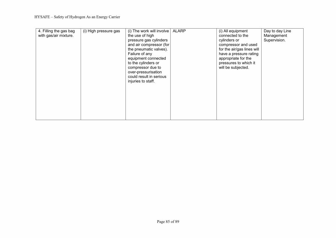
HYSAFE – Safety of Hydrogen As an Energy Carrier
Page 85 of 89
4. Filling the gas bag with gas/air mixture.
(i) High pressure gas
(i) The work will involve the use of high pressure gas cylinders and air compressor (for the pneumatic valves). Failure of any equipment connected to the cylinders or compressor due to over-pressurisation could result in serious injuries to staff.
ALARP (i) All equipment connected to the cylinders or compressor and used for the air/gas lines will have a pressure rating appropriate for the pressures to which it will be subjected.
Day to day Line Management Supervision.

HYSAFE – Safety of Hydrogen As an Energy Carrier
Page 86 of 89
4 (cont).
(ii) Flammable gas
(ii) Possible leak of flammable mixture from the filling lines, gas analyser or gas bag. Bursting of the gas bag due to overfilling. Ignition of any leaks external to the enclosure could cause injuries to any staff close to the leak. If filling continued once a gas bag burst, or with a leaking gas bag, this could lead to the generation of a larger volume of flammable gas mixture than intended in the test enclosure. Ignition under these circumstances could lead to excessive explosion pressures and damage to the test enclosure.
ALARP (ii) All gas filling lines and to be checked for leaks before the test. The outlet from the gas analyser to be piped to outside the control room. A suitable flashback arrester will be incorporated in the gas filling line close to the gas bag. The gas will be metered into the gas bag, preventing the possibility of adding too much gas to the test enclosure as a result of leaks or the gas bag bursting. The CCTV installed in the test enclosure, to monitor the vehicle response, will be also used to monitor the gas bag during filling. If a split is detected filling will be immediately stopped. The gas mixture will then be ignited, or if ignition fails the test enclosure purged as described in 6.
Day to day Line Management Supervision.

HYSAFE – Safety of Hydrogen As an Energy Carrier
Page 87 of 89
5. Explosion test
(i) Blast effects (ii) Thermal radiation
(i) The blast will be contained within the test enclosure. (ii) The explosion within the test enclosure will generate harmful levels of thermal radiation. There is a small risk that this could initiate a fire in the vehicle, eg ignition of fuel leaking from a ruptured fuel tank, from sparks produced by short circuiting of electrical circuits, etc.
ALARP (i) Explosion pressures will be restricted to less than 1 barg (the pressure rating for the test enclosure). To ensure overpressures greater than 1 barg are not generated the volume of flammable mixture will be increased in small increments as the test series progresses. As an added precaution an exclusion zone of 100 m radius will be enforced about the test enclosure before the mixture is ignited. (ii) The effects of thermal radiation will be confined to within the test enclosure, so no measures in addition to those to control the blast effects are required. To minimise the risk of the vehicle catching fire the fuel will be drained from the vehicle and the vehicle battery will also be removed.
Day to day Line Management Supervision.

HYSAFE – Safety of Hydrogen As an Energy Carrier
Page 88 of 89
5 (cont). (iii) Missiles (flying debris) (iv) Noise
(iii) Body panels and other items may be blown off during the test. (iv) A loud noise could be generated within the test enclosure.
ALARP (iii) Any missiles generated will be contained within the test enclosure, so no measures in addition to those to control the blast effects are required (iv) Experience from similar tests has shown that the noise levels outside the enclosure are minimal. Therefore, no additional measures are considered necessary to reduce further the exposure of staff to noise.
Day to day Line Management Supervision.
6. Aborting a test
Flammable gas If the ignitor fails then a flammable mixture will be left in the test enclosure. Aborting a test before the ignition stage, eg as a result of a leak or bag burst, could if it is not possible to ignite the gas also leave a flammable mixture in the test enclosure.
ALARP If the gas bag has not burst it will be inflated with air until the bag bursts. The gas mixture will then be purged from the enclosure by remotely opening the ports (using pneumatically operated valves) in the end plates and using an air blower to force ventilate the enclosure (minimum time of one hour).
Day to day Line Management Supervision.
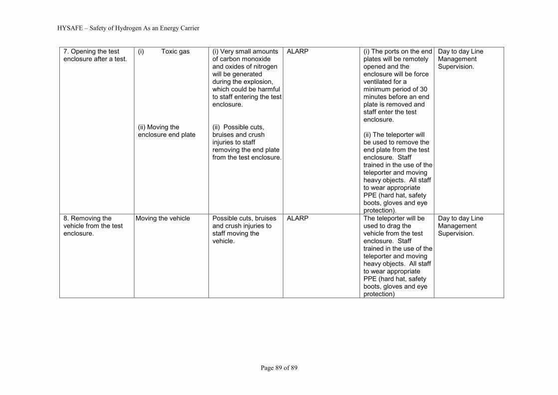
HYSAFE – Safety of Hydrogen As an Energy Carrier
Page 89 of 89
7. Opening the test enclosure after a test.
(i) Toxic gas (ii) Moving the enclosure end plate
(i) Very small amounts of carbon monoxide and oxides of nitrogen will be generated during the explosion, which could be harmful to staff entering the test enclosure. (ii) Possible cuts, bruises and crush injuries to staff removing the end plate from the test enclosure.
ALARP (i) The ports on the end plates will be remotely opened and the enclosure will be force ventilated for a minimum period of 30 minutes before an end plate is removed and staff enter the test enclosure. (ii) The teleporter will be used to remove the end plate from the test enclosure. Staff trained in the use of the teleporter and moving heavy objects. All staff to wear appropriate PPE (hard hat, safety boots, gloves and eye protection).
Day to day Line Management Supervision.
8. Removing the vehicle from the test enclosure.
Moving the vehicle Possible cuts, bruises and crush injuries to staff moving the vehicle.
ALARP The teleporter will be used to drag the vehicle from the test enclosure. Staff trained in the use of the teleporter and moving heavy objects. All staff to wear appropriate PPE (hard hat, safety boots, gloves and eye protection)
Day to day Line Management Supervision.