deliverable: d1.2 initial robot platform · deliverable: d1.2 - initial robot platform 8. moreover,...
TRANSCRIPT
Deliverable: D1.2
Initial Robot Platform
Consortium
UNIVERSITEIT VAN AMSTERDAM (UvA)YDREAMS - INFORMATICA S.A. (YD)
IDMIND - ENGENHARIA DE SISTEMAS LDA (IDM)UNIVERSIDAD PABLO DE OLAVIDE (UPO)
IMPERIAL COLLEGE OF SCIENCE, TECHNOLOGY AND MEDICINE (ICL)UNIVERSITEIT TWENTE (UT)
Grant agreement no. 288235Funding scheme STREP
DOCUMENT INFORMATION
Project
Project acronym: FROG
Project full title: Fun Robotic Outdoor Guide
Grant agreement no.: 288235
Funding scheme: STREP
Project start date: 1 October 2011
Project duration: 36 Months
Call topic: ICT-2011.2.1 Cognitive Systems and Robotics (a), (d)
Project web-site: www.frogrobot.eu
Document
Deliverable number: D1.2
Deliverable title: Initial Robot Platform
Due date of deliverable: M12 - 30 September 2012
Actual submission date: M13 - 1 October 2012
Editors: IDMind
Authors: IDMind, UPO
Reviewers: IDMind
Participating beneficiaries: IDMind
Work Package no.: 1
Work Package title: Robot Specification, Design and Construction
Work Package leader: IDMind
Work Package participants: All Partners
Estimated person-months for deliverable: 11
Dissemination level: Public
Nature: Report
Version: 1
Draft/Final: Final
No of pages (including cover): 33
Keywords: Robot base platform, electronics, mechanics

Table of Contents1. Summary................................................................................................................................................. 42. Data Collection at the Royal Alcazar (Seville)..........................................................................................5
2.1. Data Collection Robot Platform.........................................................................................................52.2. Data Collection................................................................................................................................. 62.3. Data Collection First Conclusions.....................................................................................................7
3. Robot Platform Base Electronics...........................................................................................................103.1. Updated Electronic Power Architecture..........................................................................................103.2. Updated Low-level Communication Architecture............................................................................103.3. Motor Controller Board................................................................................................................... 113.4. Sensor&Charger Board..................................................................................................................13
3.4.1. Sensor&Management Board................................................................................................143.4.2 Power Switch Board..............................................................................................................153.4.3 Charger Board.......................................................................................................................153.4.4 Sonar Board.......................................................................................................................... 17
3.5. Charger Docking Station.................................................................................................................174. Robot Platform Design and Mechanics..................................................................................................18
4.1. Locomotion..................................................................................................................................... 195. First Tests With The Robot Platform Base.............................................................................................22Annex A. Onboard Navigation Computer to Board Controllers Software Protocol.....................................24
A.1. Motor Board Communication Protocol............................................................................................24A.2. Sensor&Management Communication Protocol............................................................................28
Annex B. Robot Platform CAD Drawings...................................................................................................32

1. SummaryThis deliverable reports the first iteration of the technical robot platform on which further hardware and software systems will be integrated.
Some of the options taken in the construction of the platform resulted from the experiments on field during the Data Collection meeting that occurred by the end of May at the Royal Alcazar in Seville. For this Data Collection meeting, the perception and navigation sensors specified in Deliverable 1.1 were integrated in an existing IDMind robot platform. These sensors were positioned according to the specifications provided by the partners.
This document starts by describing the Data Collection robot platform, the work performed at the Data Collection meeting and the obtained results. Based on the results, some small changes were introduced in the specified (in D1.1) Electronic Hardware Architecture. This document provides an update of the architecture and describes the low-level electronics which has been already designed and produced in compliance with the new architecture.
In parallel with the electronic hardware study, design and production, the robot platform mechanics were designed and produced. This process is also reported in this document.
A low-level communication protocol has been developed for the communication between the navigation computer and the Motor Controller and the Sensor&Charger Boards. Annex A describes the protocol and the implemented control commands.
The document ends with some conclusions and results about this first iteration of the FROG platform.
FROG – FP7 STREP nr. 288235Deliverable: D1.2 - Initial Robot Platform 4

2. Data Collection at the Royal Alcazar (Seville)On the 28th and 29th of May, 2012, the FROG partners had an hardware integration and data collection workshop at the Royal Alcazar of Seville, to collect data from the environment, using an existing robot platform equipped with the project perception and navigation sensors. This data collection will be an important input for the various instantiations of the actual system being built. The following subsections describe the robot that has been used and some of the conclusions taken from the meeting.
2.1. Data Collection Robot PlatformFor this data collection workshop the consortium made use of an existing IDMind robot platform. This is a two wheel differential robot with one caster wheel on the back. It uses two 150W Maxon motors with two PI controllers with 250W drivers for locomotion. For navigation it has an on-board computer. To power the system it uses two 12V 20Ah batteries to power the motors and electronics.
For the data collection the following equipment was integrated in the platform:
• Six 12V 18Ah batteries;
• Two 600W Power Inverters;
• One desktop from UvA;
• One laptop from ICL;
• One external hard drive Lacie 2TB Minimus USB 3.0 Desktop Hard Drive from ICL;
• One set of stereo cameras from UvA and UPO;
• One stand alone camera from ICL;
• One 22'' touch-screen monitor for debugging;
• One Kinetic Xbox camera from ICL
• Three Hokuyo UTM-30LX lasers from UPO
• One inertial sensor XSens MTi-G from UPO
Figure 1 depicts the communication architecture that has been used to synchronize the acquisition of data from the sensors. An Ethernet wireless router was providing unique IPs for each computer and enabling a wireless link to an external laptop that was controlling the robot. An Ethernet 1Gigabyte Switch was used to test the transfer of information between ICL and UVA computers that needed to share camera information.
The on-board navigation computer was performing the following tasks:
• sending velocity references to the Motor Controllers;
• collecting raw data from the laser, IMU and motor encoders;
• providing a NTP server to synchronize all the collected data.
The UvA desktop was performing the following tasks:
• collecting stereo camera data for future processing and analysis.
The ICL laptop was performing the following tasks:
• collecting stand alone camera data for future processing and analysis;
FROG – FP7 STREP nr. 288235Deliverable: D1.2 - Initial Robot Platform 5

• collecting Kinetic data (video and sound) for future processing and analysis.
Figure 1. Data Collection Communication Architecture
2.2. Data CollectionOn the 29th of May, 2012, the data collection robot (see Figure 2) was deployed in two scenarios. In the morning the robot collected data in a purely outdoor scenario and in the afternoon in a mixed scenario including both outdoor and indoor routes. In both situations, and for battery power conservation reasons, the robot was placed static in a specific localization while capturing data for UvA and ICL (for future visitor posture and emotion analysis). UvA has recorded stereo camera data with different people at different distances and postures. ICL has recorded camera data with different people facing the camera while showing different emotional states. Then the robot was remotely controlled through a specific route while capturing stereo, laser and IMU data for UPO (for future localization and navigation analysis).
Figure 2. Data Collection Robot Platform
Also on these scenarios, YD made some light measurements to evaluate the possibility of AR projection and the use of other pointing devices over different surfaces.
FROG – FP7 STREP nr. 288235Deliverable: D1.2 - Initial Robot Platform 6

2.3. Data Collection First ConclusionsIn terms of kinematics, it was verified that the use of a two wheels differential drive robot, with a caster wheel, has some drawbacks compared with the four wheel differential drive that has been selected for the kinematics of FROG. The data collection robot faced some difficulties when the caster wheel (with no traction) went through small gaps in the ground.
Moreover, as the partners had no constraints in terms of on-board power processing and weight, the total weight of this data collection robot was about 160 Kg. The components that more contributed to the weight of the robot were:
• the desktop with about 36Kg;
• 8 lead-acid batteries with a total weight of 45Kg;
• a supporting structure with a total weight of 18Kg.
To reduce the weight of the final FROG robot special attention will be given to the materials to be used and the power consumption of the on-board electronic equipment, e.g., each computer must be selected taken in consideration the “required processing power” vs “required energy power”. Attention should also be given to the duplication of resources that will increase the robot components and the weight of the robot. The selection of a different battery technology to increase the available power while reducing the weight should also be considered.
In terms of the sensors of the platform (see Section 2.1), initial preliminary tests were performed. One of the tests concerned the platform odometry and the XSense’s MTi-G IMU, which incorporates a GPS receiver and that provides a INS solution.
Several tests were performed at the patio of the Alcazar, one of the potential places with GPS reception. Figures 3 and 4 show the estimated pose of the data collection robot estimated by using the platform odometry and the solution provided by the MTi-G unit.
Figure 3. Estimated pose (position and orientation) by using odometry and the solution given by the XSense’s MTi-G INS
FROG – FP7 STREP nr. 288235Deliverable: D1.2 - Initial Robot Platform 7

Figure 4. The same information, superposed to an Alcazar’s map
The actual trajectory performed was a close square-like trajectory. As it is shown in the pictures, the odometry drifts, as it was expected. And the INS pose estimation, while able to close the loop at the main patio, provides an erroneous estimation, most likely due to jumps in the GPS estimation. Nevertheless, the linear accelerations and angular velocities provided by the MTi-G are of good quality and will be employed by the localization algorithms.
The data gathered by the Hokuyo’s UTM-30LX were also checked out. Even though these lasers are designed to operate in outdoor scenarios, from previous experiences it was known that they can be affected by direct sunlight. Actually, the vertical laser, employed for ramps and steps perception, was seriously affected by the sun. By placing a shade over it is possible to avoid this problem.
Figure 5. Pioneer based robot used for extra tests in the Royal Alcazar
FROG – FP7 STREP nr. 288235Deliverable: D1.2 - Initial Robot Platform 8

Moreover, UPO has replicated locally most of the sensors over a Pioneer 3AT platform in order to perform local navigation tests (see Figure 5). This setup has been also employed to confirm that a 4-wheel configuration, as the one being developed, is suitable for navigating at the Royal Alcazar scenario. As the final mechanical design is even bigger than the one of a Pioneer 3AT, it is expected that the behaviour is even more stable.
FROG – FP7 STREP nr. 288235Deliverable: D1.2 - Initial Robot Platform 9

3. Robot Platform Base ElectronicsAfter the Data Collection meeting some modifications have been introduced into the electronic architecture previously specified in D1.1. Subsections 3.1. and 3.2. present the new updated Power and Low-level Communication Architectures. Subsection 3.3 describes the developed Motor Board. Subsection 3.4 describes the Sensor&Charge board Architecture that has been divided in three individual boards: Sensor&Management, Power Switch and Charger Board. Subsection 3.5 describes the charger docking station.
3.1. Updated Electronic Power ArchitectureThe robot will be powered by 12V 17-20AH batteries. It will use one pair of 12V batteries, serially connected, to deliver 24V to the motor drivers. Up to six other batteries will provide energy to all the other electronic components (computers, sensors, electronic boards, etc.). A dedicated charging unit will be developed and used inside the robot to charge each battery. The on-board power will be managed by the Sensor&Charger board. This board will measure the batteries level, battery charge, and also control the units (motors, sensors, actuators and inverters) powered by the batteries.
All the on-board electronic systems will be powered by the battery system. The ATX computer power supply will be providing regulated voltages (from 5V to 12V) and it will be also included an inverter able to provide 600W 230V AC to any device requiring AC power supply (e.g. monitors). Several DC-DC converters will also be used to provide regulated power to lasers, cameras and other DC powered devices. Figure 6 depicts the updated on-board power architecture.
Figure 6. Updated on-board Power Architecture
3.2. Updated Low-level Communication ArchitectureThe on-board robot navigation computer will communicate with the two boards (Sensor & Charger Board and the Motor Board controller) using 2 USB ports. In each board there will be a USB to RS232
FROG – FP7 STREP nr. 288235Deliverable: D1.2 - Initial Robot Platform 10
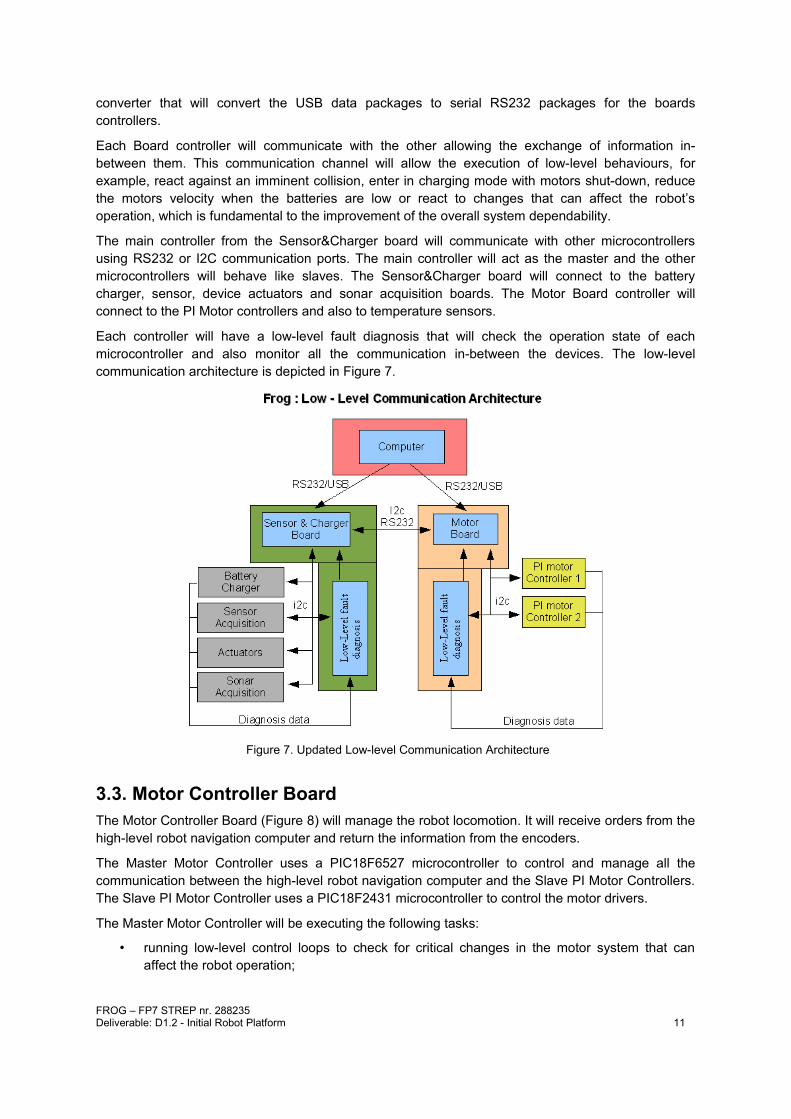
converter that will convert the USB data packages to serial RS232 packages for the boards controllers.
Each Board controller will communicate with the other allowing the exchange of information in-between them. This communication channel will allow the execution of low-level behaviours, for example, react against an imminent collision, enter in charging mode with motors shut-down, reduce the motors velocity when the batteries are low or react to changes that can affect the robot’s operation, which is fundamental to the improvement of the overall system dependability.
The main controller from the Sensor&Charger board will communicate with other microcontrollers using RS232 or I2C communication ports. The main controller will act as the master and the other microcontrollers will behave like slaves. The Sensor&Charger board will connect to the battery charger, sensor, device actuators and sonar acquisition boards. The Motor Board controller will connect to the PI Motor controllers and also to temperature sensors.
Each controller will have a low-level fault diagnosis that will check the operation state of each microcontroller and also monitor all the communication in-between the devices. The low-level communication architecture is depicted in Figure 7.
Figure 7. Updated Low-level Communication Architecture
3.3. Motor Controller BoardThe Motor Controller Board (Figure 8) will manage the robot locomotion. It will receive orders from the high-level robot navigation computer and return the information from the encoders.
The Master Motor Controller uses a PIC18F6527 microcontroller to control and manage all the communication between the high-level robot navigation computer and the Slave PI Motor Controllers. The Slave PI Motor Controller uses a PIC18F2431 microcontroller to control the motor drivers.
The Master Motor Controller will be executing the following tasks:
• running low-level control loops to check for critical changes in the motor system that can affect the robot operation;
FROG – FP7 STREP nr. 288235Deliverable: D1.2 - Initial Robot Platform 11

• providing a I2C bus observer to check the information received from the I2C slave devices, detecting any failure in the communication or in the devices;
• verifying the proper operation of each Slave PI Motor Controller by exchanging status information with them;
• controlling the motors and drivers temperature while controlling the power of their cooling fans;
• monitoring the power supply;
• measuring the motors current.
The Slaves PI Motor Controllers will be executing the following tasks:
• receiving velocity references from the Master Motor Controller;
• reading, periodically, the encoders pulses;
• sending the encoders counts to the Master Motor Controller;
• calculating the error between the velocity reference and the measured velocity;
• implementing a PI controller to calculate the motor actuation;
• implementing an anti-windup error limit;
• implementing a velocity reference and acceleration/deceleration profile;
• nullifying the motor dead-zone effect;
• limiting the maximum velocity of the motors.
Figure 8. Motor Controller Board Architecture
The Master Motor Controller will receive velocity commands from the computer and return the encoder pulses. The Controller will connect to two PI Microcontrollers that will generate the control actuations to follow the velocity references. Each microcontroller will connect to the motor using a 1000W H-bridge and will provide the pulses measured by the encoder.
Each microcontroller is optically isolated from the motor driver using a high-speed optocoupler for the control actuation signals and an optical amplifier for the current measurements. It is also optically isolated from the computer communication port, again using a high-speed bidirectional optocoupler.
FROG – FP7 STREP nr. 288235Deliverable: D1.2 - Initial Robot Platform 12

Several low-level fault diagnostics have been implemented to detect problems in the normal work of each component or lack of communication. The Board has several information led lights allowing to check visually the state of each component described previously.
Figure 9 depicts the Motor Controller Board that has been developed for the FROG platform.
Figure 9. Developed Motor Controller Board
The Motor Board will communicate with the Sensor&Management Board exchanging information about the system status, diagnostics and environment condition, allowing low-level robot reactions to changes that can affect the robot’s operation.
The board is able to communicate with the computer through a USB-to-RS232 converter and with the Sensor&Management Board through a RS232 bidirectional communication.
3.4. Sensor&Charger BoardThe Sensor&Charger Board will be responsible for the power management and also the sensor acquisition. It will receive orders from the on-board robot navigation computer and return information about the batteries, sensors and actuators. The Sensor&Charger Board architecture is depicted in Figure 10.
Due to its complexity, it was decided to separate the Sensor&Charge Board in three different boards: Sensor&Management, Power Switch and Charger Board.
The Sensor&Management Board controller will be responsible for all the communications, control signals and sensor acquisitions. The Power Switch Board will be controlled by the Sensor&Management Board controller allowing to activate, deactivate or put in charge 5 extra batteries that can be used to power on-board equipment. The Charger Board will be responsible for charging each individual battery.
FROG – FP7 STREP nr. 288235Deliverable: D1.2 - Initial Robot Platform 13
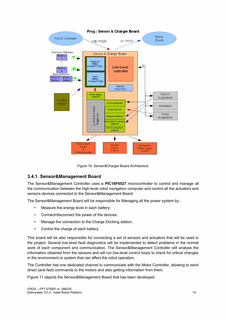
Figure 10. Sensor&Charger Board Architecture
3.4.1. Sensor&Management BoardThe Sensor&Management Controller uses a PIC18F6527 microcontroller to control and manage all the communication between the high-level robot navigation computer and control all the actuators and sensors devices connected to the Sensor&Management Board.
The Sensor&Management Board will be responsible for Managing all the power system by :
• Measure the energy level in each battery;
• Connect/disconnect the power of the devices;
• Manage the connection to the Charge Docking station;
• Control the charge of each battery.
This board will be also responsible for connecting a set of sensors and actuators that will be used in the project. Several low-level fault diagnostics will be implemented to detect problems in the normal work of each component and communication. The Sensor&Management Controller will analyse the information obtained from the sensors and will run low-level control loops to check for critical changes in the environment or system that can affect the robot operation.
The Controller has one dedicated channel to communicate with the Motor Controller, allowing to send direct (and fast) commands to the motors and also getting information from them.
Figure 11 depicts the Sensor&Management Board that has been developed.
FROG – FP7 STREP nr. 288235Deliverable: D1.2 - Initial Robot Platform 14

Figure 11. Developed Sensor&Management Board.
3.4.2 Power Switch BoardThe Power Switch Board (see Figure 12) is able to activate, deactivate or put in charge mode up to 5 batteries that can be used to power different components of the robot. It is possible to connect several batteries in parallel to power equipments demanding more energy. It has also possible to charge each battery independently.
This board will be controlled by the Sensor&Management Board that will provide all the signals to activate, deactivate or put in charge each battery. The Power Switch Board has also electronics to measure the voltage of each battery. All the control signals and voltage measurements circuits are completely decoupled by the use of optocouplers and opto-amplifiers.
Finally this board connects to the Charger Board that will allow the connection and charge of up to 8 batteries.
Figure 12.Developed Power Switch Board.
3.4.3 Charger BoardThis board will charge up 8 batteries independently. Each charging circuit will use a 3 phase lead acid battery charger already developed, tested and used by IDMind in some previous projects.
The charger has the following phases:
1. Bulk Phase. In this charging phase the charger will supply a constant 2A current to the battery that is charging. This will allow to charge the battery to about 70% of his capability.
2. Absorption Phase. After leaving the Bulk Phase the charger will enter the Absorption Phase where the charger will supply a constant voltage to the battery until it reaches about 100 to 120% of his capability.
FROG – FP7 STREP nr. 288235Deliverable: D1.2 - Initial Robot Platform 15

3. Maintaining Phase. When the battery is fully charged the charger will leave the absorption phase and enter the Maintenance Phase where a 13,4V supply is supplied to the battery until the battery is disconnected from the charger.
The charging process for the 12V 20Ah batteries used in the FROG robot is the following. If the battery is dried (9.5V - 0%) the battery will start to charge in Bulk phase for about 7 hours at 2A. In the end of the 7 hours the level of the battery is about 70%, that means that the charge level will raise about 10% each hour. After +/- 7 hours the charger will enter into the Absorption phase where there will be an increase of about 5% of level of battery each hour. After 5 to 6 hours the battery Level will reach 100%-120% (depending of the type of battery, number of cycles and correct maintenance) .
After this period the system will enter in Maintaining phase, and the battery will maintain the charge level.
Figure 13 shows the battery charge behaviour using the developed charger. Only the Bulk and Absorption phases are displayed. The Maintaining phase start can be set to any point of the Absorption phase by the change of the value of one resistor component.
Figure 13. Battery charge behaviour.
The Charger Board was already designed and is in production stage. Figure 14 shows the final layout of the FROG Battery Charger Board.
Figure 14. Frog battery Charger Board.
FROG – FP7 STREP nr. 288235Deliverable: D1.2 - Initial Robot Platform 16

3.4.4 Sonar BoardThe Sonar Board (depicted in Figure 15) will be controlling the fire of up to 16 sonars. This board will be connected to the Sensor&Management board thought a I2C connection. The information provided by this board can be used to adopt low-level safety behaviours, for example reducing the velocity of the robot in the presence of an obstacle.
The sonars currently being tested in the robot are the XL- MaxSonar®- WRC1™.
Figure 15. Sonar Processor Board (left) and robot front sonars (right).
3.5. Charger Docking StationOne important capability of the robot is the possibility to work without human intervention. To achieve this point the robot must be able to manage the on-board power and autonomously charge itself. One charger docking station will be developed and installed in a service area, where the robot can enter and plug itself. This docking station will provide the necessary power that the on-board battery chargers need to charge the batteries. The docking station is a passive power station and all the control of the charging process is managed by the on-board Sensor&Charger Board. The docking station will be equipped with switch mode power supply able to power all the on-board equipment and at the same time provide about 2,5A of current for each of the 8 battery chargers.
The mechanics of the docking mechanism, on-board the robot and on the docking station, are now being study.
FROG – FP7 STREP nr. 288235Deliverable: D1.2 - Initial Robot Platform 17

4. Robot Platform Design and MechanicsThe mechanics of FROG are being designed in SolidWorks, taking in attention the chosen kinematics and the final placement of the actuators and sensors. Most of the sensors that will be included have been already tested in the data collection robot.
Figure 16 show the platform base CAD rendering, including the 260mm wheels, the two motors, the batteries distribution, the bumpers, the sonars and the front and back bumpers.
Figure 16. Mechanics CAD rendering
The main body of the robot platform base and the pulley system has been constructed using POM material. Figure 17 depicts the assembled robot base.
Figure 17. Assembled robot base.
Figure 18 shows the laser support and the front bumper.
Figure 19 show the placement of sensors according with their disposition in the data collection platform. This will be used as input for the outer shell design and also for the inner structure that be will used to fix all the components to the robot platform base.
FROG – FP7 STREP nr. 288235Deliverable: D1.2 - Initial Robot Platform 18

Figure 18. Laser support and bumper
Figure 19. Equipment positioning on the robot
4.1. LocomotionTwo changes were introduced in the locomotion system from the one that has been specified in D1.1. The wheel radius is now 0.13m and it is connected to the gearbox through a set of timing pulleys with a reduction of 2.00:1. The motor calculations were updated just to confirm the choice of the motor.
It has been specified a robot weight of 50Kg with an additional payload of 30 kg and running at a maximum speed of 1.5m/s. To calculate the required motor and gearbox torque it has been defined three slope inclinations that the robot should be able to overcome: 5, 15 and 25 degrees. For the motor calculation and considering a standard wheel with 0.13m of radius, the following values will be obtained.
FROG – FP7 STREP nr. 288235Deliverable: D1.2 - Initial Robot Platform 19

Description 5 degrees 15 degrees 25 degrees
Robot Mass 50 50 50
Robot Payload 30 30 30
Wheel Radius (m) 0.13 0.13 0.13
Gravity acceleration (m/s2) 9.8 9.8 9.8
Robot Force (N) for X degrees 68.33 202.91 331.33
Torque @ Wheel Axis (Nm) 8.88 26.38 43.07
Once the required wheel axis torque has been calculated, it will be defined the gearbox and the gear connection between the wheel axis and the gearbox axis that is able to support the calculated torque. The wheel will be connected to the gearbox through a set of timing pulleys with a reduction of 2.00:1. The chosen gearbox is a Maxon Gearmotor with Planetary Gearhead GP62 19:1.
Description 5 degrees 15 degrees 25 degrees
Torque @ Wheel Axe (Nm) 8.88 26.38 43.07
Timing pulley set reduction 2.0 2.0 2.0
Torque @ Gearbox (Nm) 4.44 13.34 21.54
Max. Continuous Torque(Nm) 25 25 25
Intermittently permissible torque at gear output (Nm)
37 37 37
Max. Efficiency (%) 75 75 75
Torque @ Motor Axe (Nm) 0.31 0.93 1.51
The gearbox will connect to a motor that is able to provide the required torque to drive the robot. The chosen motors are the Maxon RE50 of 200W at 24V.
Assigned power rating: 200 WNominal Voltage: 24 VNo load speed: 5950 rpmStall Torque: 8920mNmMax. continuous torque: 405mNmMax. Velocity@24V: 1.4 - 1.5 m/sFROG – FP7 STREP nr. 288235Deliverable: D1.2 - Initial Robot Platform 20
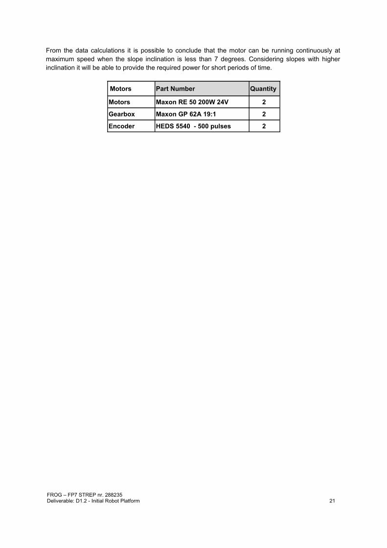
From the data calculations it is possible to conclude that the motor can be running continuously at maximum speed when the slope inclination is less than 7 degrees. Considering slopes with higher inclination it will be able to provide the required power for short periods of time.
Motors Part Number Quantity
Motors Maxon RE 50 200W 24V 2
Gearbox Maxon GP 62A 19:1 2
Encoder HEDS 5540 - 500 pulses 2
FROG – FP7 STREP nr. 288235Deliverable: D1.2 - Initial Robot Platform 21

5. First Tests With The Robot Platform BaseThe robot platform base is currently being tested at IDMind's premises. This includes both the mechanics and electronics.
Using the developed motor controllers it was possible to test the robot platform base in indoor and outdoor environments. These first tests provide a better understanding about the effectiveness of the developed kinematics. With this kinematic configuration, the robot easily manages small obstacles and has a very good traction even when one or two wheels are loosing contact from ground.
The robot is able to perform a perfect 360º rotation around its centre of mass. In the next stages of the robot construction, while more components will be added to the platform, special attention should be taken to maintain the centre of mass in the centre of the platform.
The number of motor encoder pulses per wheel rotation have been measured:
• left encoder pulses per one left wheel rotation = 77011 pulses
• right encoder pulses per one right wheel rotation = 76953 pulses
The number of motor encoder pulses per meter have also been measured:
• left encoder pulses per meter = 96514 pulses
• right encoder pulses per meter = 96752 pulses
Using both measurements it is possible to calculate the average wheel diameters:
• left wheel diameter = 0.254 m
• right wheel diameter = 0.253 m
A complete 360º rotation of the robot around its centre of mass takes:
• left motor encoder pulses per 360º = 303725 pulses
• right encoder pulses per 360º = 308454 pulses
The PI motor controller slaves calculate a new actuation every 8,3ms. The calculation is using the number of pulses acquired for each period of 8.3ms and determines the error with the velocity reference given by the on-board navigation computer. To transform the velocity reference from m/s to microcontroller references the following calculation must be performed:
Velocity Controller References = [Velocity (m/s)]*800
Figure 20 shows the Measured No-Load Velocity vs Velocity Controller References. It uses 100 velocity controller reference steps. The velocity is quite linear until about 1.7m/s, after that the robot controller is unable to follow the references due to battery voltage/power limitation. The obtained results validate the motor calculations.
Figure 20. Measured No-Load Velocity vs Velocity Controller References
FROG – FP7 STREP nr. 288235Deliverable: D1.2 - Initial Robot Platform 22

The motor controller implements an acceleration/deceleration profile to reduce the consumed energy and smooth the robot movements. The acceleration/deceleration profile has an increase/decrease of one reference step every 0.84ms. The robot takes about 0.67s to increase the reference from 0m/s to 1m/s.
Figure 21. Robot Frog Base Platform real tests setup
The robot platform base, as depicted in Figure 21, weights 32 Kg without batteries. With 4 batteries the platform weights 54 Kg.
FROG – FP7 STREP nr. 288235Deliverable: D1.2 - Initial Robot Platform 23

Annex A. On-board Navigation Computer to Board Controllers Software ProtocolThe On-board Navigation Computer is able to communicate with the Motor and Sensor&Management boards using two independent USB Ports. In each board a FTDI USB to RS232 converter converts the USB data connection to a TTL Serial PORT data connection for the Microcontrollers on the Boards.
The board MicroController uses a serial COM (it uses a FTDI USB to RS232 chip) with the following UART settings:
Baud rate: 115200bpsData bits: 8Stop bits: 1Parity bit: No parityHW Flow Control: Disabled
To communicate with the robot boards the following protocol is used:
Write -> [Command][First Byte][Second Byte][....]
Read -> [Command][First Byte][Second Byte][....][Send Number][CheckSum_H][CheckSum_L]
Where :
[Command] is the set or get command;
[Send Number] is an incremental number that counts all the sends that each microcontroller has already performed;
[CheckSum_H:CheckSum_L] is the checksum of the [Command]+[First Byte]+[Second Byte]+ [....]+[Send Number].
A.1. Motor Board Communication ProtocolSet Velocity Command
[Command]=0x56
[Left wheel Velocity]=[Left wheel Velocity High][Left wheel Velocity Low]
[Right wheel Velocity]=[Right wheel Velocity High][Right wheel Velocity Low]
Write -> [0x56][Left wheel Velocity High][Left wheel Velocity Low][Right wheel Velocity High][Right wheel Velocity Low]
Read -> [0x56][Send Number][CheckSum_H][CheckSum_L]
To obtain the Left and Right Wheel Velocities, use the following known equations:Left wheel Velocity = - (Linear Velocity + Rotation Velocity);Right wheel Velocity = (Linear Velocity - Rotation Velocity);
To obtain the High and Low bytes use:Left wheel Velocity High = (byte) (Left wheel Velocity >> 8);Left wheel Velocity High = (byte) (Left wheel Velocity & 0xFF);Right wheel Velocity High = (byte) (Right wheel Velocity >> 8);
FROG – FP7 STREP nr. 288235Deliverable: D1.2 - Initial Robot Platform 24

Right wheel Velocity High = (byte) (Right wheel Velocity & 0xFF);
Get Encoders Ticks Command
[Command]=0x4A
Write ->[0x4A]
Read ->[0x4A][Left Motor Ticks High][Left Motor Ticks Low][Right Motor Ticks High][Right Motor Ticks Low][Send Number][CheckSum_H][CheckSum_L]
To get the Left Motor Ticks:Left Motor Ticks =(int)Left Motor Ticks High*256+Left Motor Ticks Low;
To get the Right Motor Ticks:Right Motor Ticks =(int)Right Motor Ticks High*256+Right Motor Ticks Low;
To calculate the CheckSum use the following formula:CheckSum= 0x4A+Left Motor Ticks High+Left Motor Ticks Low+
Right Motor Ticks High+Right Motor Ticks Low+Send Number;
Get Motor Current Command
[Command]=0x50
Write ->[0x50]
Read ->[0x50][Left Motor current] [Right Motor current] [Send Number] [CheckSum_H] [CheckSum_L]
To get the real measured current measured do:Left Motor measured current=(double)((double)[Left Motor current]/10.0);
andRight Motor measured current=(double)((double)[Right Motor current]/10.0);
Get Motor Board Voltage Command
[Command]=0x51
Write ->[0x51]
Read ->[0x51] [Motor Voltage] [Driver Voltage] [Electronics Voltage] [Power Status] [Send Number] [CheckSum_H] [CheckSum_L]
Where:
[Motor Voltage] is the voltage measure of the power supply of the motors. In normal operation it will have a value between 21V and 26V. Motor voltage power = (double)((double)[Motor Voltage]*2.0 / 10.0);
[Driver Voltage] is the voltage measured of the power supply of the drivers for the motors. In normal operation the value should be between 12 to 15V. Driver voltage power = (double)((double)[Driver Voltage] / 10.0);
[Electronics Voltage] is the voltage measured of the power supply of the control electronics. In normal operation the value should be between 9.5 to 13V. Electronics voltage power = (double)((double)[Electronics Voltage] / 10.0);
FROG – FP7 STREP nr. 288235Deliverable: D1.2 - Initial Robot Platform 25

[Power Status] is the voltage status [AXXXXBCD].
where:
• A =0 : Motor Drivers disabled;
• A =1 : Motor Drivers enabled;
• B =0 : Motor Power not OK;
• B =1 : Motor Power OK;
• C =0 : Driver Power not OK;
• D =1 : Driver Power OK;
• D =0 : Electronic Power not OK;
• D =1 : Electronic Power OK.
Get Temperature Command
[Command]=0x52
Write ->[0x52]
Read ->[0x52] [Left Motor Temperature] [Right Motor Temperature] [Left Motor Driver Temperature] [Right Motor Driver Temperature] [Temperature Status] [Send Number] [CheckSum_H] [CheckSum_L]
where:
[Left Motor Temperature] is the temperature of the left motor in ºC;
[Right Motor Temperature] is the temperature of the right motor in ºC;
[Left Motor Driver Temperature] is the temperature of the Left Motor Driver in ºC;
[Right Motor Driver Temperature] is the temperature of the Right Motor Driver in ºC;
[Temperature Status] is the temperature status [XXXXABCD]where:
• A=0 : Left Motor Temperature less that 40ºC;
• A=1 : Left Motor Temperature more that 40ºC;
• B=0 : Right Motor Temperature less that 40ºC;
• B=1 : Right Motor Temperature more that 40ºC;
• C=0 : Left Motor Driver Temperature less that 40ºC;
• C=1 : Left Motor Driver Temperature more that 40ºC;
• D=0 : Right Motor Driver Temperature less that 40ºC;
• D=1 : Right Motor Driver Temperature more that 40ºC.note: the 40ºC value can be changed after a better evaluation of the robot operation.
Set Cooling Fans Command
[Command]=0x53
Write ->[0x53][Fan Control]
Read ->[0x53][Send Number] [CheckSum_H] [CheckSum_L]
where:
FROG – FP7 STREP nr. 288235Deliverable: D1.2 - Initial Robot Platform 26

[Fan Control] allow automatic or manual control of the fans to cool the motors and the drivers. [AXXXBCDE][A]=0 manual control of the fans[A]=1 automatic control of the fans. One or more fans will start to cool a motor or a motor driver when its temperature reaches the 40ºC and stop to work when the temperature is reduced to about 25º. It will not be possible to control the fans manually.In manual control mode:
• [B]=0 : turn OFF the left motor fan;
• [B]=1 : turn ON the left the motor fan;
• [C]=0 : turn OFF the right motor fan;
• [C]=1 : turn ON the right the motor fan;
• [D]=0 : turn OFF the left motor driver fan;
• [D]=1 : turn ON the left motor driver fan;
• [E]=0 : turn OFF the right motor driver fan;
• [E]=1 : turn ON the right motor driver fan.
In automatic control the controller will update automatically the [B] to [E] bits. Using 0 when the fans are OFF and 1 when the fans are ON.
note: The 40ºC and 25ºC values can be changed after a better evaluation of the robot operation.
Get Cooling Fans Command
[Command]=0x54
Write ->[0x54]
Read ->[0x54][Fan Control][Send Number] [CheckSum_H] [CheckSum_L]
where:[Fan Control] reads the Fan Control status byte described previously on the “Set Cooling Fans Command”
Get Communication Status Command
[Command]=0x55
Write ->[0x55]
Read ->[0x55][Communication Status][Send Number] [CheckSum_H] [CheckSum_L]
where:[Communication Status] is the communication status between the Motor board and the navigation computer, the PI motor controller slaves and the Sensor&Management Board. [AXXXBXCD]
• [A]=0 :Normal communication with the navigation computer;
• [A]=1 :No communication or communication error with the navigation computer;
• [B]=0 :Normal communication with the Sensor&Management Board;
• [B]=1 :No communication or communication error with the Sensor&Management Board;
• [C]=0 :Normal communication with the Left PI motor controller Slave;
• [C]=1 :No communication or communication error the Left PI motor controller Slave;
• [D]=0 :Normal communication with the Right PI motor controller Slave;
FROG – FP7 STREP nr. 288235Deliverable: D1.2 - Initial Robot Platform 27

• [D]=1 :No communication or communication error the Right PI motor controller Slave.
A.2. Sensor&Management Communication Protocol
Enable/Disable/Charge Motors Power
[Command]=0x45
Write ->[0x45][Control]
Read ->[0x45] [Send Number] [CheckSum_H] [CheckSum_L]
where:
• [Control] =0 : Motor power Disabled;
• [Control] =1 : Charge motor power enable Mode;
• [Control] =2 : Motor power Enable.
Enable/Disable/Charge Auxiliary Power Battery 1 to 5
[Command]=0x40 to 0x44
Write ->[0x40 to 0x44][Control]
Read ->[0x40 to 0x44] [Send Number] [CheckSum_H] [CheckSum_L]
where:
• [Control] =0 : Auxiliary power battery (1 to 5) Disabled;
• [Control] =1 : Charge auxiliary power battery ( 1 to 5) enable Mode;
• [Control] =2 : Auxiliary power battery (1 to 5) Enable.
Enable/Charge Electronic Power Battery
[Command]=0x46
Write ->[0x46][Control]
Read ->[0x46] [Send Number] [CheckSum_H] [CheckSum_L]
where:
• [Control] =1 : Charge electronic battery enable Mode;
• [Control] =2 : Electronic power battery Enable.
Get Batteries Voltage Command
[Command]=0x51
Write ->[0x51]
Read ->[0x51] [24V Motor Battery] [Motor High Battery] [Motor Low Battery] [Electronics Battery] [Charger] [Send Number] [CheckSum_H] [CheckSum_L]
Where:[ 24V Motor Battery] is the sum of the Motor High and Motor Low battery voltages. When in charging mode the value is +/- 0V.To obtain the real measured voltage of this battery the following formula must be used:
FROG – FP7 STREP nr. 288235Deliverable: D1.2 - Initial Robot Platform 28

Motor battery voltage = (double)((double)[ 24V Motor Battery]*2.0 / 10.0);
[Motor High Battery] is the battery that will connect to the (+) of the Motor Drivers Power supply and the (+ ) of the [Motor Low Battery]. It will be only different from 0V when in charging mode.To obtain the real measured voltage of this battery the following formula must be used:
Motor High battery voltage = (double)((double)[Motor High Battery] / 10.0);
[Motor Low Battery] is the battery that will connect to the (-) of the Motor Drivers Power supply and the (-) of the [Motor High Battery]. It will be only different from 0V when in charging mode.To obtain the real measured voltage of this battery the following formula must be used:
Motor Low battery voltage = (double)((double)[Motor High Battery] / 10.0);
[Electronics Battery] is the battery that powers all the electronics and the onboard Navigation Computer.To obtain the real measured voltage of this battery the following formula must be used:
Electronic battery voltage = (double)((double)[Electronics Battery]/ 10.0);
[Charger] is the power from the docking station.To obtain the real measured voltage in the charger the following formula must be used:
Charger voltage = (double)((double)[Charger]/ 10.0);
Get Auxiliary Batteries Voltage Command
[Command]=0x52
Write ->[0x52]
Read ->[0x52] [PC1 Battery] [PC2 Battery] [PC3 Battery] [PC4 Battery] [PC5 Battery] [Send Number] [CheckSum_H] [CheckSum_L]
Where:[ PC1-PC5 Battery] are auxiliary batteries that can be used to power computers or other electronic devices that the robot can carry.To obtain the real measured voltage of this battery the following formula must be used:
PC1-PC5 battery voltage = (double)((double)[ PC1-PC5] / 10.0);
Get Bumpers Command
[Command]=0x53
Write ->[0x53]
Read ->[0x53] [Bumpers][Send Number] [CheckSum_H] [CheckSum_L]
Where:[Bumpers] allows to detect collisions in different parts of the robot. The received [bumpers] byte indicates if a bump is being detected. Bumper byte has the following composition [0000ABCD] where:
• [A] is the front left bump;
• [B] is the front right bump;
• [C] is the rear left bump;
• [D] is the rear right bump.Each bit can assume two possible values: 0 if no bump is being detected or 1 if a bump is being detected.FROG – FP7 STREP nr. 288235Deliverable: D1.2 - Initial Robot Platform 29

Get Sonars Command
[Command]=0x54
Write ->[0x54]
Read ->[0x54] [Sonar0_High_Byte] [Sonar0_High_Byte] ---- [Sonar15_High_Byte] [Sonar15_High_Byte] [Send Number][CheckSum_H] [CheckSum_L]
The get sonars command will retrieve the distance information of 16 sonar sensor in cm.
To get the distance value in cm the following calculation must be performed:
Sonar 0..15=(int)[Sonar0..15_High_Byte]*256+[Sonar0..15_Low_Byte];
note: The number of sonar sensors to be use will depend on future tests.
Enable/Disable Sonars Command
[Command]=0x55
Write ->[0x55][Control]
Read ->[0x55] [Send Number] [CheckSum_H] [CheckSum_L]
where:
• [Control] =0 : Disable sonar readings;
• [Control] =1 : Enable sonar readings.
Get Environmental Sensors Command
[Command]=0x56
Write ->[0x56]
Read ->[0x56] [Temperature] [Humidity] [Rain] [Send Number][CheckSum_H] [CheckSum_L]
The Environmental sensors command retrieves the information of the environment temperature, humidity and rain where:[Temperature] retrieves a temperature between 0ºC to 125ºC;[Humidity] retrieves the relative humidity between 0% and 100%;[Rain] Detects if it is or not raining.
Get Communication Status Command
[Command]=0x57
Write ->[0x57]
Read ->[0x57] [Communication Status] [Send Number] [CheckSum_H] [CheckSum_L]
The communication status command retrieves the information about the communication status where:[Communication Status] is the communication status between the Sensor&Management board and the navigation computer, the Sonar Controller board, the Motor Controller Board and other slave devices. [AXBXCXEF]
• [A]=0 :Normal communication with the navigation computer;
• [A]=1 :No communication or communication error with the navigation computer;
• [B]=0 :Normal communication with the Motor Controller Board;
FROG – FP7 STREP nr. 288235Deliverable: D1.2 - Initial Robot Platform 30

• [B]=1 :No communication or communication error with the he Motor Controller Board;
• [C]=0 :Normal communication with the Sonar Controller board;
• [C]=1 :No communication or communication error the Sonar Controller board;
• [E]=0 :Normal communication with the Slave device 1;
• [E]=1 :No communication or communication error the Slave device 1;
• [F]=0 :Normal communication with the Slave device 2;
• [F]=1 :No communication or communication error the Slave device 2.
FROG – FP7 STREP nr. 288235Deliverable: D1.2 - Initial Robot Platform 31

Annex B. Robot Platform CAD DrawingsFigures 21, 22, 23 and 24 depict the platform mechanics and its measures.
Figure 21. Robot Platform Top CAD Design
Figure 22. Robot Platform Lateral CAD Design
FROG – FP7 STREP nr. 288235Deliverable: D1.2 - Initial Robot Platform 32

Figure 23. Robot Platform front CAD Design
Figure 24. Robot Platform pulley system CAD Design
FROG – FP7 STREP nr. 288235Deliverable: D1.2 - Initial Robot Platform 33