department of chemical engineering national institute of...
TRANSCRIPT
A
Project Report
On
Steady state simulation of an Azeotropic
Distillation system using Aspen Plus
Submitted by
Parkhe Shashank Raosaheb
(Roll No: 111CH0505)
In partial fulfillment of the requirements for the degree in
Bachelor of Technology in Chemical Engineering
Under the guidance of
Dr. Pradip Chowdhury
Department of Chemical Engineering
National Institute of Technology Rourkela
May, 2015

II
CERTIFICATE
This is certified that the work contained in the thesis entitled “Steady state simulation of an
Azeotropic distillation system using Aspen Plus,” submitted by Parkhe Shashank Raosaheb
(111CH0505), has been carried out under my supervision and this work has not been submitted
elsewhere for a degree.
____________________
Date:
Place: (Thesis Supervisor)
Dr. Pradip Chowdhury
Assistant Professor, Department of
Chemical Engineering
NIT Rourkela

III
Acknowledgements
First and the foremost, I would like to offer my sincere gratitude to my thesis supervisor, Dr.
Pradip Chowdhury for his immense interest and enthusiasm on the project. His technical
prowess and vast knowledge on diverse fields left quite an impression on me. He was always
accessible and worked for hours with me. Although the journey was beset with complexities but
I always found his helping hand. He has been a constant source of inspiration for me.
I am also thankful to all faculties and support staff of Department of Chemical
Engineering, National Institute of Technology Rourkela, for their constant help and extending
the departmental facilities for carrying out my project work.
I would like to extend my sincere thanks to my friends and colleagues. Last but not the least, I
wish to profoundly acknowledge my parents for their constant support.
________________________
(Parkhe Shashank Raosaheb)
111CH0505

IV
ABSTRACT
Ethanol-water forms homogeneous minimum boiling azeotrope and it has most common
occurrence in many industrial processes. There are various techniques exist to separate
azeotropic compositions. In this work we studied the basic features of azeotropic distillation
using Aspen plus simulation. Since entrainers are indispensable in separating constant boiling
mixtures, in this work, performances of three different entrainers were studied viz. benzene, n-
pentane and cyclohexane. The effect of various process variables viz. reflux-ratio and distillate
rate on the purity of the final products was studied in detail. RadFrac simulator was used to study
the distillation process and NRTL method was used as the base thermodynamic method.
It has been found out after simulation that cyclohexane performed best where maximum purity of
ethanol (99.91%) was obtained closely followed by n-pentane (99.84%) and benzene (99.77%)
as entrainers. The optimum number of stages were 25 (for n-pentane), 45 each for benzene and
cyclohexane respectively.

V
CONTENTS
PAGE NO.
Abstract IV
List of Tables VII
List of Figures VIII
Notation and abbreviation IX
CHAPTER 1: Introduction 1
1.1 Introduction 1
1.2 Azeotropic Distillation 2
1.3Background of present research work 3
1.4 Research Objectives 3
CHAPTER 2: Literature Review 5
2.1 Introduction 5
2.2. Azeotrope 5
2.3. Types of azeotropes 6
2.3.1. Positive azeotrope or Minimum boiling azeotrope 6
2.3.2 Negative azeotrope or Maximum boiling azeotrope 8
2.4 Ethanol water azeotropic mixture 9
2.5 Types of distillation process for azeotropic mixtures 10
2.6 Ethanol-water azeotropic distillation separation 11
CHAPTER 3: Simulation and Software Work 13
3.1 Process simulation 13
3.2 Aspen Plus Software 14
3.3 Distillation Column Model Used 14
VI
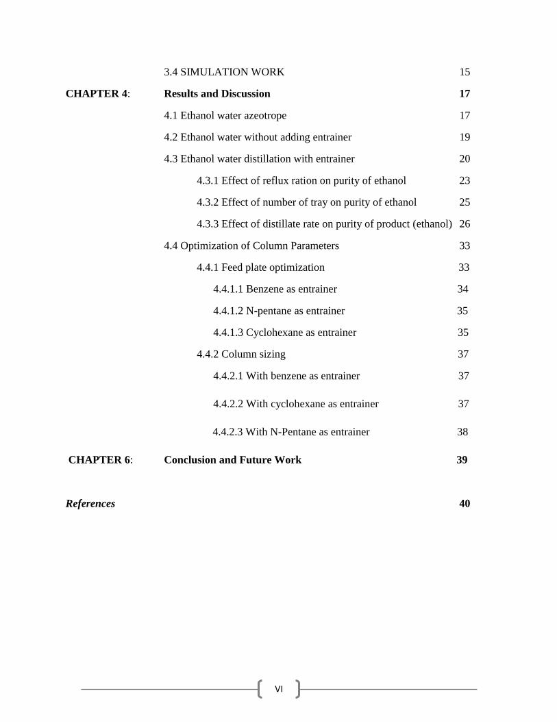
3.4 SIMULATION WORK 15
CHAPTER 4: Results and Discussion 17
4.1 Ethanol water azeotrope 17
4.2 Ethanol water without adding entrainer 19
4.3 Ethanol water distillation with entrainer 20
4.3.1 Effect of reflux ration on purity of ethanol 23
4.3.2 Effect of number of tray on purity of ethanol 25
4.3.3 Effect of distillate rate on purity of product (ethanol) 26
4.4 Optimization of Column Parameters 33
4.4.1 Feed plate optimization 33
4.4.1.1 Benzene as entrainer 34
4.4.1.2 N-pentane as entrainer 35
4.4.1.3 Cyclohexane as entrainer 35
4.4.2 Column sizing 37
4.4.2.1 With benzene as entrainer 37
4.4.2.2 With cyclohexane as entrainer 37
4.4.2.3 With N-Pentane as entrainer 38
CHAPTER 6: Conclusion and Future Work 39
References 40
VII
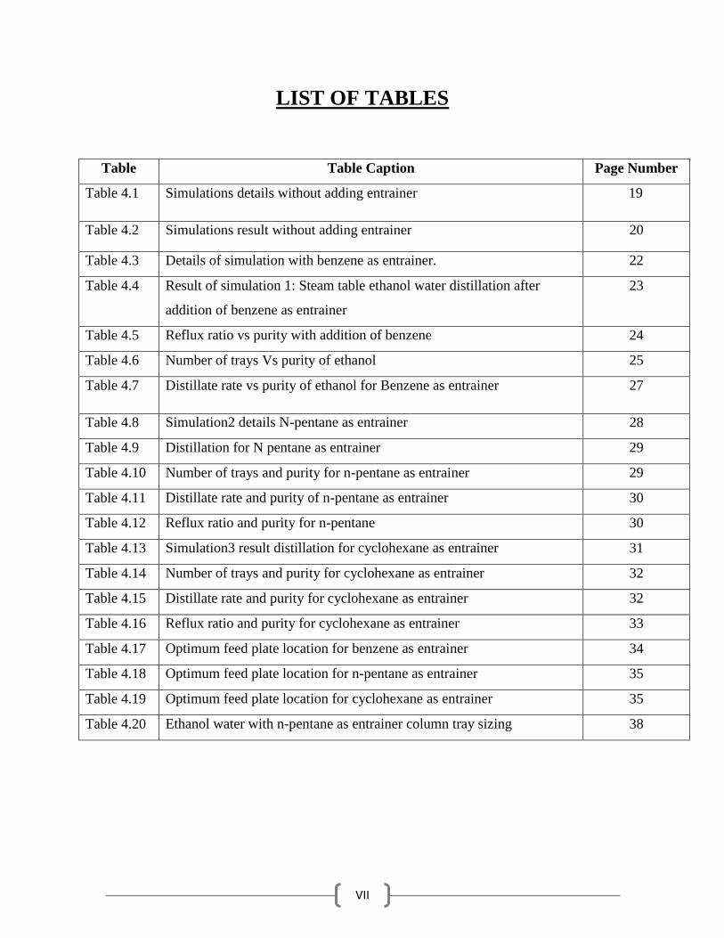
LIST OF TABLES
Table Table Caption Page Number
Table 4.1 Simulations details without adding entrainer 19
Table 4.2 Simulations result without adding entrainer 20
Table 4.3 Details of simulation with benzene as entrainer. 22
Table 4.4 Result of simulation 1: Steam table ethanol water distillation after
addition of benzene as entrainer
23
Table 4.5 Reflux ratio vs purity with addition of benzene 24
Table 4.6 Number of trays Vs purity of ethanol 25
Table 4.7 Distillate rate vs purity of ethanol for Benzene as entrainer 27
Table 4.8 Simulation2 details N-pentane as entrainer 28
Table 4.9 Distillation for N pentane as entrainer 29
Table 4.10 Number of trays and purity for n-pentane as entrainer 29
Table 4.11 Distillate rate and purity of n-pentane as entrainer 30
Table 4.12 Reflux ratio and purity for n-pentane 30
Table 4.13 Simulation3 result distillation for cyclohexane as entrainer 31
Table 4.14 Number of trays and purity for cyclohexane as entrainer 32
Table 4.15 Distillate rate and purity for cyclohexane as entrainer 32
Table 4.16 Reflux ratio and purity for cyclohexane as entrainer 33
Table 4.17 Optimum feed plate location for benzene as entrainer 34
Table 4.18 Optimum feed plate location for n-pentane as entrainer 35
Table 4.19 Optimum feed plate location for cyclohexane as entrainer 35
Table 4.20 Ethanol water with n-pentane as entrainer column tray sizing 38

VIII
LIST OF FIGURES
Figure Figure Caption Page Number
Fig 2.1 Phase diagram of a positive azeotrope 7
Fig 2.2 Phase diagram of negative azeotrope. 8
Fig 2.3 Ethanol water composition curve/ y-x diagram 9
Fig 2.4 VLE diagram for ethanol-water system showing composition curve for
ethanol and water
10
Fig 2.5 Azeotropic distillation diagram for ethanol water azeotropic distillation 12
Fig 3.1 ASPEN PLUS V 8.4 Normal window 14
Fig 3.2 NRTL method input window 15
Fig 3.3 Successful status of simulation run and steam result display window 16
Fig 4.1 Txy diagram of ethanol water mixture 17
Fig 4.2 x-y curve/ concentration profile curve for ethanol water mixture 18
Fig 4.3 Two column ASPEN flow sheet for ethanol-water azeotropic
distillation
21
Fig 4.4 Simplified flow sheet of second column for azeotropic distillation 21
Fig 4.5 Reflux ratio vs purity of ethanol 24
Fig 4.6 Number of trays vs purity of ethanol 26
Fig 4.7 Purity vs distillate rate graph for benzene as entrainer 27
Fig 4.8 Purity vs number of trays for n-pentane 29
Fig 4.9 Purity vs distillate rate for n-pentane as entrainer 30
Fig 4.10 Purity vs reflux ratio for n-pentane 31
Fig 4.11 Purity vs number of trays for cyclohexane 32
Fig 4.12 Purity vs distillate rate for cyclohexane as entrainer 32
Fig 4.13 Purity vs reflux ratio for cyclohexane as entrainer 33
Fig 4.14 Heat duty vs feed location for benzene 34
Fig 4.15 Heat duty vs feed plate location for n-pentane as entrainer 35
Fig 4.16 Heat duty vs feed location plate for n-pentane as entrainer 36

IX
NOTATIONS AND ABREVIATIONS
τ12
and τ21
= dimensionless interaction parameter
∆g12
and ∆g21
= interaction energy parameters
R = gas constant
T= Absolute Temperature
Uij = Energy between surfaces i and j

1
CHAPTER 1
INTRODUCTION
This chapter highlights the basics on azeotropic distillation system. It mainly focus on the
ethanol water azeotropic distillation to get high purity ethanol as product. The background of the
present thesis work is suitably explained. The objectives are also properly highlighted.
1.1. INTRODUCTION
Production of fuel grade bioethanol has recently got attention because of two important things.
First, it is frequently being used as a fuel oxygenate in place of methyl t-butyl ether (MTBE).
The second reason that it is used as alternate fuel. Sugar fermentation process gives rise to
production of bioethanol; it can also be prepared by chemical process or as a byproduct of some
chemical processes [1]. Sources of ethanol are mainly sugar and crops. Crops are grown
specifically for energy use this includes maize, wheat and corn crops, waste straw. There is also
ongoing research into the use of municipal solid waste to produce ethanol fuel.
Ethanol or ethyl alcohol (C2H5OH) is a clear colorless liquid, which is degrade biologically, less
toxic and causes minor ecological contamination if split. Ethanol gives carbon dioxide and water
when it burns. Pollution caused by the petroleum product are being reduce by this such as SOx
and NOx. Octane number of ethanol is high and has replaced as an octane enhancer in petrol [1].
Bioethanol and biodiesel the alternatives of the fuels which we use. The production of alternate
type of fuel is due to the realization that crude oil stocks are limited, hence shifted towards more
renewable sources of energy. As alternative fuels this bioethanol and biodiedel have got newly
attention and have virtually limitless potential for growth However; separation of bioethanol is
the main problem in production of bioethanol, because water present in it. The separation of
ethanol from water is difficult because azeotrope present in the mixture. There are several
methods of high purity ethanol separation such as [2]:

2
1. Azeotropic distillation
2. Extractive distillation
3. Pressure swing method
4. Chemical action separation
5. Distillation using dissolved salt
1.2 AZEOTROPIC DISTILLATION:
Azeotropic distillation is different kind of technique which is used to break the azeotrope of
the mixture in separate distillation column. In chemical engineering azeotropic distillation
normally refers the addition of another compound to produce another azeotrope which is
heterogeneous lower boiling azeotrope and it produces two immiscible liquid phases e.g
benzene is added is ethanol water mixture to break the azeotrope and to separate ethanol.
A separation technique for azeotropic mixture has very crucial importance in industry and
distillation is the major process used for such separations. Most liquid mixtures of organic
components form non ideal systems. The presence of some specific groups, mainly polar
groups such as oxygen, nitrogen, chlorine and fluorine, often results in the formation of
azeotropes. However, separation becomes complicated because presence of non-ideality and
azeotrope in mixture [3].
An azeotrope cannot be separated the constituents of an azeotrope by simple distillation
process since at this point no enrichment of vapor phase presence. Therefore, the separation
of this mixture involves the other techniques by putting an additional component, called
entrainer. Entrainer affects the volatility of one of the azeotrope constituents more than
another and form ternary azeotrope. But, after using entrainer it may cause some unwanted
impurities and side streams because large energy consume by this process.
Azeotropic mixtures may often be effectively separated by distillation by adjusting the reflux
ratio of the system

3
1.3 Background of present research work:
Alcohol-water mixture has a very common occurrence in many industrially important
processes. However, apart from methanol-water, most of the combinations form non-
ideal solutions. Vapor-liquid equilibrium study generally shows that non-ideal solutions
form homogeneous or heterogeneous minimum or maximum boiling azeotropes.
Separation of azeotropes using conventional distillation processes doesn’t yield the
desired degree of purity in terms of distillate or bottom products and hence we need to
resort to alternative routes or techniques. Addition of a third component as an entrainer
which changes the relative volatility of the constituting species is the most common
method in azeotropic process. In our understanding, studying the azeotropic
characteristics and separation mechanism of ethanol-water solution is very fundamental
before venturing into separation of higher order alcohol-water systems and this was the
reason and motivation behind taking up this project.
1.4 Research objective:
The main objective of this work is to study the separation of homogeneous minimum boiling
azeotropic ethanol-water system using Aspen-plus simulation. The simulation approach follows
a steady-state method. Since entrainers play a pivotal role in azeotropic system, this particular
aspect has been studied in detail. Thus, the objectives of this work are:
Steady state simulation of ethanol-water system using Aspen plus simulation
Effect of three different entrainers viz. benzene, n-pentane and cyclohexane in overall
performance of the system
Study the effects of various manipulated variables viz. distillate rate and reflux-ratio on
the product purity

4
Locate optimum feed plate location for various combinations and to find out reboiler
heat duties
Optimize the column sizing (diameter and height) from the best possible result
combinations

5
CHAPTER 2
LITERATURE REVIEW
In this chapter a brief review on, to understand the difficulties in the seperation with the ethanol-
water system, it is important to study the phenomenon that applicable to non-ideal VLE
behavior, and ho to overcome from the non-ideal VLE. How azeotrope formed and how to break
it is briefly discussed in this chapter. In this chapter a review is presented on:
2.1 Introduction
Azeotrope and formation of this azeotrope in ethanol water mixture.
Brief descriptions of methods to overcome from the azeotropic behavior of the mixture.
Review of the list of chemicals use as entrainer in azeortopic distillation for high purity of
ethanol production.
2.2 Azeotrope:
An azeotrope is a mixture of chemical components that has identical compositions of the
liquid & vapor phases in equilibrium with each other. This is occurs because of molecular
interactions between different chemical components [4]. If the element contains similar
structures and elementary molecules then the molecular interaction will be very much less
hence azeotrope do not occurs examples: mixture of hydrocarbons (propane, butane, pentane
etc.) this have phase equilibrium system. But if components are dissimilar then molecule can
exhibits either repulsive or attractive forces at the given temperature vapor pressure increases
by the repulsion or may give rise to minimum boiling point azeotrope. Activity coefficients
become greater than one because of the repulsion. If the repulsion sufficiently greater, the
repulsive forces give rise to formation of heterogeneous minimum-boiling point azeotropes

6
(two liquid phases). The azeotrope boils at a temperature that is lesser than the boiling point
of the lighter component [4].
The methanol–water mixture is an example of mixture which has modest non ideality. The
OH end of the molecule of CH2OH and H2O molecule are similar, but the hydrocarbon CH3
end of the CH2OH molecule is different from water. So the system shows a minor amount of
non-ideality, change in relative volatility as liquid composition changes represents this.
If addition of extra more CH2 group and when get the ethanol–water system, then it causes
large repulsion because the CH3–CH2 end of the ethanol molecule is somewhat different than
the OH end of the molecules of water. The system shows more non ideality and a minimum-
boiling azeotrope occurs. This is homogeneous azeotrope (only one liquid phase is in
equilibrium with a vapor phase). If addition of two more CH2 groups and when we move
towards the n-butanol–water system, then the repulsion is more than the ethanol water [4].
The result is the formation of a heterogeneous minimum boiling azeotrope with two liquid
phases in equilibrium with a vapor phase. In some chemicals compounds molecules attract
instead of repulsion then this attraction reduce the effective vapor pressure of the compound
and then it forms maximum boiling azeotrope due to molecular attraction. An example of
maximum boiling azeotrope is nitric acid- water, chloroform- acetone, water and formic acid
mixture etc.
2.3 Types of azeotropes:
2.3.1. Positive azeotrope or Minimum boiling azeotrope:
The azeotrope boils at a temperature that is lower than the boiling point of the lighter
component, positive azeotrope also called minimum boiling azeotrope
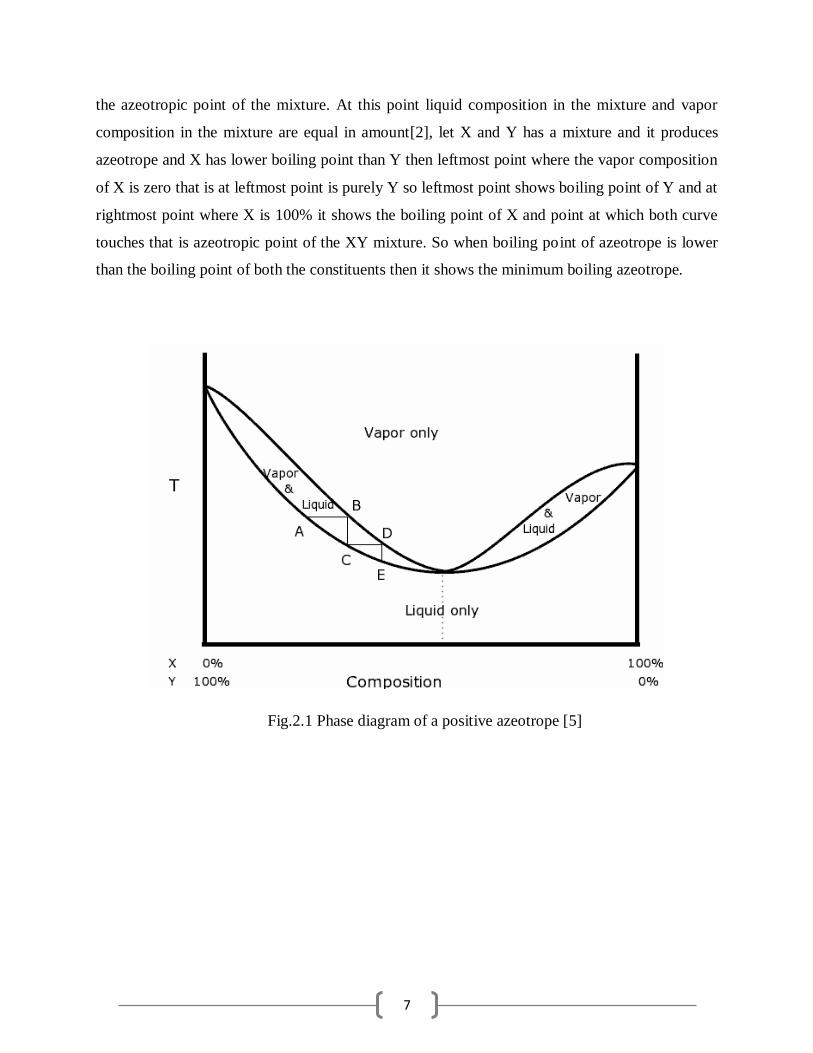
The Fig.2.1 represents the TXY diagram that is temperature vs composition curve of the mixture
diagram. It shows a minimum boiling azeotrope of different constituent; provide the boiling
temperature of various compositions. The upper curve represents the vapor compositions while
lower curve represents the liquid compositions in the mixture. While boiling it has a mixture of
both liquid and vapor phase. The point at which both curve touches each other that point shows
7
the azeotropic point of the mixture. At this point liquid composition in the mixture and vapor
composition in the mixture are equal in amount[2], let X and Y has a mixture and it produces
azeotrope and X has lower boiling point than Y then leftmost point where the vapor composition
of X is zero that is at leftmost point is purely Y so leftmost point shows boiling point of Y and at
rightmost point where X is 100% it shows the boiling point of X and point at which both curve
touches that is azeotropic point of the XY mixture. So when boiling point of azeotrope is lower
than the boiling point of both the constituents then it shows the minimum boiling azeotrope.
Fig.2.1 Phase diagram of a positive azeotrope [5]

8
2.3.2 Negative azeotrope or Maximum boiling point azeotrope:
The boiling point of this azeotrope is higher compared to the boiling points of its components.
Negative azeotrope also called maximum boiling point azeotrope.
Fig.2.2 represents the Txy diagram for negative azeotrope that is temperature vs composition
curve. In the figure upper curve is the vapor composition while lower curve is the liquid
composition in the two phase mixture. When the mixture is heated then its azeotrope has the
boiling point more than the boiling point of the individual components then this mixture shows
the negative azeotrope or maximum boiling azeotrope. In this figure leftmost point is the boiling
point of the Y whereas the rightmost point shows the boiling point of the Y and point at which
both curve touches each other, then temperature at this point is the temperature of the azeotrope.
And it is clearly shows that azeotrope has higher boiling temperature than the temperature of
both X and Y.
Fig.2.2 Phase diagram of negative azeotrope [5]

9
2.4 Ethanol water azeotropic mixture:
Ethanol also called ethyl alcohol which is a colorless, volatile and can catch fire type of liquid.
Molecular formula of ethanol is C2H5OH which is straight chain compound. It is a constitutional
isomer of dimethyl ether. Ethanol is often abbreviated as EtOH, using the common organic
chemistry notation of representing the ethyl group (C2H5). Ethanol boils at 78.4ºC while water
boils at 100ºC. Mixtures of ethanol and water boils at 78.2 ̊C mixture of ethanol and water forms
an azeotrope at 96 volume% ethanol and 4% water at normal pressure and temperature (351 K).
This azeotropic composition is strongly depends on temperature and pressure [4].
Fig. 2.3 Ethanol water composition curve/ y-x diagram

10
Fig.2.4 VLE diagram for ethanol-water system showing composition curve for ethanol and
water[6]
2.5 Types of distillation process for azeotropic mixtures.
The separation of azeotropic systems can be achieved by the addition of a suitable solvent, which
influences the activity coefficient and relative volatility. Methods for separating azeotropic
mixtures as follow:
Extractive distillation –At the top of the column solvent which has high boiling point is
added to similarly change the relative volatility in order to make separation. Bottom is
separated by the second column to recycle the solvent [7]
.
Azeotropic Distillation – where another compound which is entrainer is added to the
mixture, this entrainer affects the relative volatility of the one compound and separation
becomes easier.

11
Distillation using salts – the salts dissolves in the mixtures of liquid and changes the
relative volatilities such that separation becomes possible.
Pressure swing distillation – To separate binary azeotropes two columns which are
operated at different pressures are used which change appreciably in composition over a
moderate pressure range or where a separating agent which forms a pressure-sensitive
azeotrope is added to separate a pressure-insensitive azeotrope.
Reactive distillation – the separating agent reacts very good and reversibly with one of
the azeotropic constituents in the mixture. To recover the initial component reaction is
reversed by the distillation of the product from the non-reacting components [8].
So this project focuses on azeotropic distillation hence it was reviewed.
2.6 Ethanol-water azeotropic distillation separation:
When the process requires high purity of ethanol as final product. Ethanol is mainly produced in
process of fermentation. A typical mixture from a fermentation process has very low ethanol
concentrations (4–6 mol %). In the column operating at atmospheric pressure mixture is fed into
it from bottom high purity of water is taken out but purity of the ethanol cannot exceeds more
than 90% [5]..
Some brilliant engineers gave the idea of running the fermentation liquid through a conventional
“preconcentrator” distillation column which takes water as bottom product, and in distillate it
produces 84% ethanol and 16% water. This binary mixture is further fed into a second
distillation column. Also fed to the top of this column as reflux is a stream that contains a high
concentration of benzene [9]. The benzene acts as a “light entrainer” that goes to top and take
water with it because the large dissimilarity between water and benzene becomes the water very

12
volatile. The ethanol goes out from the bottom acts that water is the “heavier” component
(normal boiling point of ethanol is 351.5 K, while that of water is 373.2 K).
The overhead vapor is a ternary mixture of all three components. And bottom product of the
second column will get the high purity ethanol as product. The overhead vapor in second column
further can be treated to recycle the components.
Fig.2.5 Azeotropic distillation diagram for ethanol water azeotropic distillation

13
CHAPTER 3
SIMULATION AND SOFTWARE WORK
In this chapter brief overview of the software and simulation working process is discussed. This
chapter will leads to understand about the specific details about the software and minor thing
about the simulation working technique which are going to use for the azeotropic distillation
process.
3.1 PROCESS SIMULATION:
Process simulation is utilized for the configuration, advancement, investigation, and
enhancement of specialized methodologies, for example, chemical plants, natural system, natural
frameworks, power stations, complex assembling operations, organic methods, and similar kind
of techniques.
3.2 ASPEN PLUS SOFTWARE:
For the simulation process we have used the software Aspen Tech’s ASPEN PLUS™ V 8.4
licensed version software. And all the simulation was performed in this ASPEN PLUS V 8.4.
This ASPEN PLUS software permits you to make your own methodology model, beginning with
the flow sheet, then indicating the chemical components and working conditions. ASPEN
PLUSTM will take the majority of your details and, one click, simulate the model. The process
simulation is the activity that executes every vital calculation expected to understand the result of
the framework, thus anticipating its action. At the point when the computations are finished,
ASPEN PLUSTM records the outcomes, stream by stream and unit by unit, so you can watch
what happened to the synthetic types of your chemical process [5].

14
Fig.3.1 ASPEN PLUS V 8.4 Normal window
3.3 DISTILLATION COLUMN MODEL USED:
The distillation column used were all are RadFrac MODELS. RadFrac model is widely used for
the azeotropic distillation mixture. They are gives us to vary the process parameters like we can
change the number of trays, reflux ratio, distillate rate easily. And from tray to tray variation of
feed is possible in the RadFrac model.

15
Fig.3.2 NRTL method input window
3.4 SIMULATION WORK:
We have successfully carried out the simulation work for the azeotropic distillation for the
ethanol water azeotropic distillation system. For this simulation work we have taken the RadFrac
column and process which is used in simulation was NRTL method, because NRTL method
normally performs better for the azeotropic distillation system. Working pressure for the ethanol
water azeotropic distillation simulation was taken 1 atm. And it was carried out for the 350ºK.
After the simulation successfully completed steam result for the simulation process was checked
for the results and comparing the different results for the different working conditions of various
process.

16
Fig.3.3 Successful status of simulation run and steam result display window

17
CHAPTER 4
RESULTS AND DISCUSSION
This chapter summarizes all the results. All simulation data for ethanol water distillation with
and without entrainers to get high purity ethanol as product. Interesting observations are made
and explained in detail. The results of different entrainers and behavior of column various like
reflux ratio, distillate rate and number of tray are plotted and explained in detail. The relative
graphs and tables are plotted to explain process parameters. Comparisons of simulation data to
get optimum data are explained.
4.1 Ethanol water azeotrope:
Fig.4.1 Txy diagram of ethanol water mixture

18
Fig.4.2 x-y curve/ concentration profile curve for ethanol water mixture
Fig.4.1 and Fig4.2 x-y curve for the ethanol water mixture give us the idea about the azeotropic
point of the mixture.it is shown that at concentration of nearly 95% ethanol and 4%water it
follows the azeotropic point beyond that point further separation is not possible by simple
distillation process. The Txy diagram for the ethanol/water system at a pressure of 1 atm. The
abscissa shows the mole fraction of ethanol; the ordinate, temperature. The lower curve is the
“saturated liquid” line, which gives the mole fraction of ethanol in the liquid phase x. The upper
curve is the “saturated vapor” line, which gives the mole fraction of ethanol in the vapor phase y.
Drawing a horizontal line at some temperature and reading off the intersection of this line with
the two curves give the compositions of the two phases.

19
4.2 Ethanol water without adding entrainer:
It is single column distillation, by simulation it is state that by normal distillation process ethanol
and after mixture cannot get separated completely. In this simulation only up to 89% purity of
ethanol is achieved, it is very important to get high purity of ethanol by further distillation with
other technique i.e. azeotropic distillation using entrainer,
Details of simulation1:
Table: 4.1 Simulations detail without adding entrainer:
Parameters and conditions: Value
Feed flow rate: 250 kmol/hr
Feed composition: ethanol
Water
0.5 mole fraction
0.5 mole fraction
Feed temperature 350 K
Pressure : 1atm
Number of tray 50
Feed location 35
Distillate rate 100 kmol/hr
Reflux ratio 10

20
Table: 4.2 Simulations result without adding entrainer:
4.3 Ethanol water distillation with entrainer:
Fig 4.3 shows the process diagram, now it is carried out by two column. In first column normal
distillation of ethanol and water is performed to get around 84% ethanol and 16% water
concentration. And then this mixture is feed to second column with entrainer to get high purity
ethanol.
But, here we have taken only second column for study to simplify the process and to maily focus
on second column where azeotropic distillation takes place. This is to get high purity ethanol, i.e
feed inserted in this second column is 84% ethanol and 16% water and high concentration of
benzene was added as entrainer and from bottom, pure ethanol is taken out as product, and from
top mixture of ethanol water is taken out which can be used further.

21
Fig.4.3 Two column ASPEN flow sheet for ethanol-water azeotropic distillation
Fig.4.4 Simplified flow sheet of second column for azeotropic distillation

22
Details of simulation2:
Table 4.3 Details of simulation with benzene as entrainer:
Parameters and conditions: Value
Feed flow rate: 250 kmol/hr
Feed composition: ethanol
Water
0.84 mole fraction
0.16 mole fraction
Feed temperature 350 K
Pressure : 1atm
Entrainer: Benzene 1.0 mole fraction
Entrainer flow rate 150 kmol/hr
Number of tray 45
Feed location
Benzene feed location
35
38
Distillate rate 380kmol/hr
Reflux ratio 0.5

23
Table: 4.4 Result of simulation 1: Steam table ethanol water distillation after addition of benzene
as entrainer:
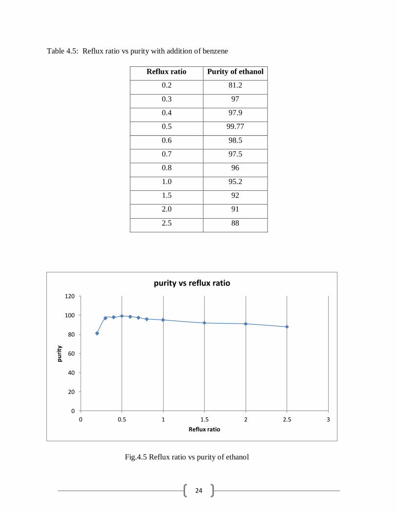
4.3.1 Effect of reflux ration on purity of ethanol:
For the purity reflux ratio play an important role. As ethanol is our bottom product it shows
increasing purity of ethanol as the reflux ratio is decreasing continuously up to reflux ratio 0.5.
At reflux ratio 0.5 it shows purity around 99.15% and further reduction in reflux ratio decreasing
purity. As reflux ratio is decreased below 0.5 its purity goes on decreasing. Data at distillate rate
380kmol/hr and total number of trays are 45
24
Table 4.5: Reflux ratio vs purity with addition of benzene
Reflux ratio Purity of ethanol
0.2 81.2
0.3 97
0.4 97.9
0.5 99.77
0.6 98.5
0.7 97.5
0.8 96
1.0 95.2
1.5 92
2.0 91
2.5 88
Fig.4.5 Reflux ratio vs purity of ethanol
0
20
40
60
80
100
120
0 0.5 1 1.5 2 2.5 3
pu
rity
Reflux ratio
purity vs reflux ratio

25
4.3.2 Effect of number of tray on purity of ethanol:
Total number of trays in distillation column is important factor in column properties. It
determines the column height and diameter and total energy required for reboiler and condenser
to condensate and heating. If number of trays are less then purity of the product will decrease and
if there are large or infinite number of trays then purity will increase but reboiler heat duty will
increase and effectively price will also increase. Hence trays to be keep at optimum level where
beyond that purity will be nearly same. Hence here data was taken at reflux ratio 0.5 and
distillate rate 350kmol/hr.
It is observed that above 42 trays 99% purity is achieved and then further increasing number of
plates will increase very less purity. In graph it is observed that above 45 trays graph is showing
nearly straight line.
Table: 4.6 Number of trays vs purity of ethanol:
Number of tray Purity of ethanol in %
Reboiler heat duty
In x (10^6) cal/sec.
15 92.7 1.2256
20 94 1.2322
22 96.5 1.2325
23 97.07 1.2342
25 98 1.2349
30 98.8 1.23578
41 99.07 1.23529
42 99.09 1.23529
45 99.15 1.23510
50 99.21 1.2354
60 99.27 1.2368
70 99.31 1.238
80 99.38 1.2389
100 99.39 1.457

26
Fig.4.6 Number of trays vs purity of ethanol
4.3.3 Effect of distillate rate on purity of product (ethanol):
Distillate rate is also important parameter column for distillation. For ethanol water with benzene
as entrainer it is shown in table. As the distillate rate increases our product i.e ethanol from
bottom product purity increases. So increasing distillate rate increases the purity of product of
ethanol, but after certain value no more increase in purity for further increase in distillate rate.
From graph it is shown here that the above 350kmol/hr purity becomes 99%. At 350kmol/hr
99.1% purity while at 380kmol/hr 99.77% purity and nearly straight line i.e nearly same purity
for further increase in distillate rate. Above 350kmol/hr purity become nearly same but reboiler
heat duty increases i.e more energy consumption.
90
91
92
93
94
95
96
97
98
99
100
0 20 40 60 80 100 120
Pu
rity
number of trays
Purity vs Number of Tray

27
Table 4.7 Distillate rate vs purity of ethanol for Benzene as entrainer:
Distillate Rate Purity
150 54
180 57
200 60
250 74
310 97
320 96
330 96.5
350 99.1
380 99.77
390 99.88
395 99.88
Fig 4.7 Purity vs distillate rate graph for benzene as entrainer
0
20
40
60
80
100
120
0 50 100 150 200 250 300 350 400 450
pu
rity
Distillate rate
purity vs distillate rate

28
Entrainer2: N-PENTANE AS ENTRAINER
Details of simulation3:
Table 4.8 Simulation2 details N-pentane as entrainer:
Parameters and conditions: Value
Feed flow rate: 250 kmol/hr
Feed composition: ethanol
Water
0.84 mole fraction
0.16 mole fraction
Feed temperature 350 K
Pressure : 1atm
Entrainer N-pentane 1.0 mole fraction
Entrainer flow rate 150 kmol/hr
Number of tray 25
Feed location
Benzene feed location
15
20
Distillate rate 360kmol/hr
Reflux ratio 0.15

29
Table 4.9 Distillation for N pentane as entrainer:
Here for n-pentane as entrainer 99.84% purity of ethanol is achieved. When distillate rate is 360
kmol/hr. and reflux ratio is 0.15 and feed location is at 15th
tray above the column. And for this
947825 cal/sec reboiler heat duty was required.
4.3.4 Effect of tray number, reflux ratio and effect of distillate rate:
Table: 4.10 Number of trays and purity for n-pentane as entrainer
Fig.4.8 Purity vs number of trays for n-pentane
Number
of
Trays
Purity
20 98.8
25 99.84
28 99.7
30 99.78
35 99.84
40 99.839
45 99.84
50 99.83
30
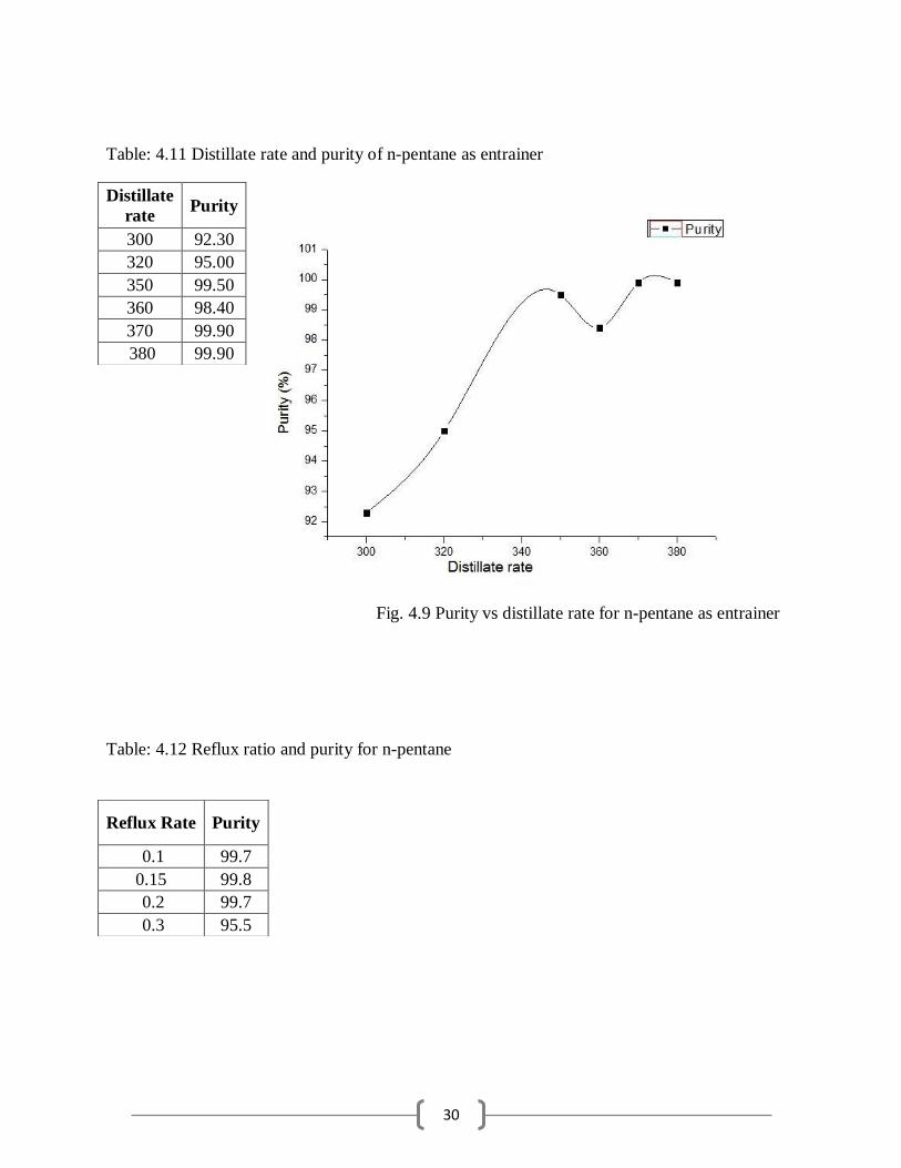
Table: 4.11 Distillate rate and purity of n-pentane as entrainer
Fig. 4.9 Purity vs distillate rate for n-pentane as entrainer
Table: 4.12 Reflux ratio and purity for n-pentane
Distillate
rate Purity
300 92.30
320 95.00
350 99.50
360 98.40
370 99.90
380 99.90
Reflux Rate Purity
0.1 99.7
0.15 99.8
0.2 99.7
0.3 95.5

31
Fig. 4.10 Purity vs reflux ratio for n-pentane
Entrainer3: CYCLOHEXANE AS ENTRAINER:
Table 4.13 Simulation3 result distillation for cyclohexane as entrainer:

32
Table: 4.14 Number of trays and purity for cyclohexane as entrainer:
Fig. 4.11 Purity vs number of trays for cyclohexane
Table: 4.15 Distillate rate and purity for cyclohexane as entrainer
Fig. 4.12 Purity vs distillate rate for cyclohexane as entrainer
Number
of
Trays
Purity
30 92.50
32 98.30
35 98.90
36 99.01
37 99.09
40 99.25
42 99.30
45 99.91
47 99.91
50 99.92
60 99.92
100 99.92
Distillate Rate Purity
350 96.02
360 97.81
370 99.37
380 99.91
390 99.91
395 99.92

33
Table: 4.16 Reflux ratio and purity for cyclohexane as entrainer
Fig. 4.13 Purity vs reflux ratio for cyclohexane as entrainer
4.4 Optimization of Column Parameters:
4.4.1 Feed plate optimization: For optimum feed plate location in most distillation columns the major working expense is
reboiler heat duty. In the event that refrigeration were utilized as a part of the condenser, this
heat reduction cost would likewise be expansive. For our propane/isobutane illustration, the
pressure was intentionally set with the goal that cooling water could be utilized as a part of the
condenser. Therefore reboiler heat duty of the column should be kept low or minimum [10].
Reflux Ratio Purity
0.15 99.91
0.2 99.70
0.3 99.33
0.4 98.52
0.5 97.53
0.8 92.78
1 89.52

34
4.4.1.1 Benzene as Entrainer:
Table: 4.17 Optimum feed plate location for benzene as entrainer
Fig.4.14 Heat duty vs feed location for benzene
At feed location plate 40 it is showing minimum reboiler heat duty which is 5.74232 MW so at
feed 40th tray is optimum feed tray location.
Feed
Location
Heat
Duty
MW
25 5.74611
28 5.74608
30 5.74602
35 5.74493
38 5.74271
40 5.74232
42 5.74270
43 5.74291

35
4.4.1.2 N-pentane as entrainer:
Table: 4.18 Optimum feed plate location for n-pentane as entrainer
Fig.4.15 Heat duty vs feed plate location for n-pentane as entrainer
At feed location 17th plate it is showing minimum reboiler heat duty which is 4.12863 MW so at
17th plate is optimum feed location.
4.4.1.3 Cyclohexane as entrainer:
Table: 4.19 Optimum feed plate location for cyclohexane as entrainer
Feed
Location
Heat Duty
MW
2 4.14855
5 4.14799
10 4.14515
12 4.14211
15 4.12991
17 4.12863
20 4.12924
22 4.13004
23 4.13072
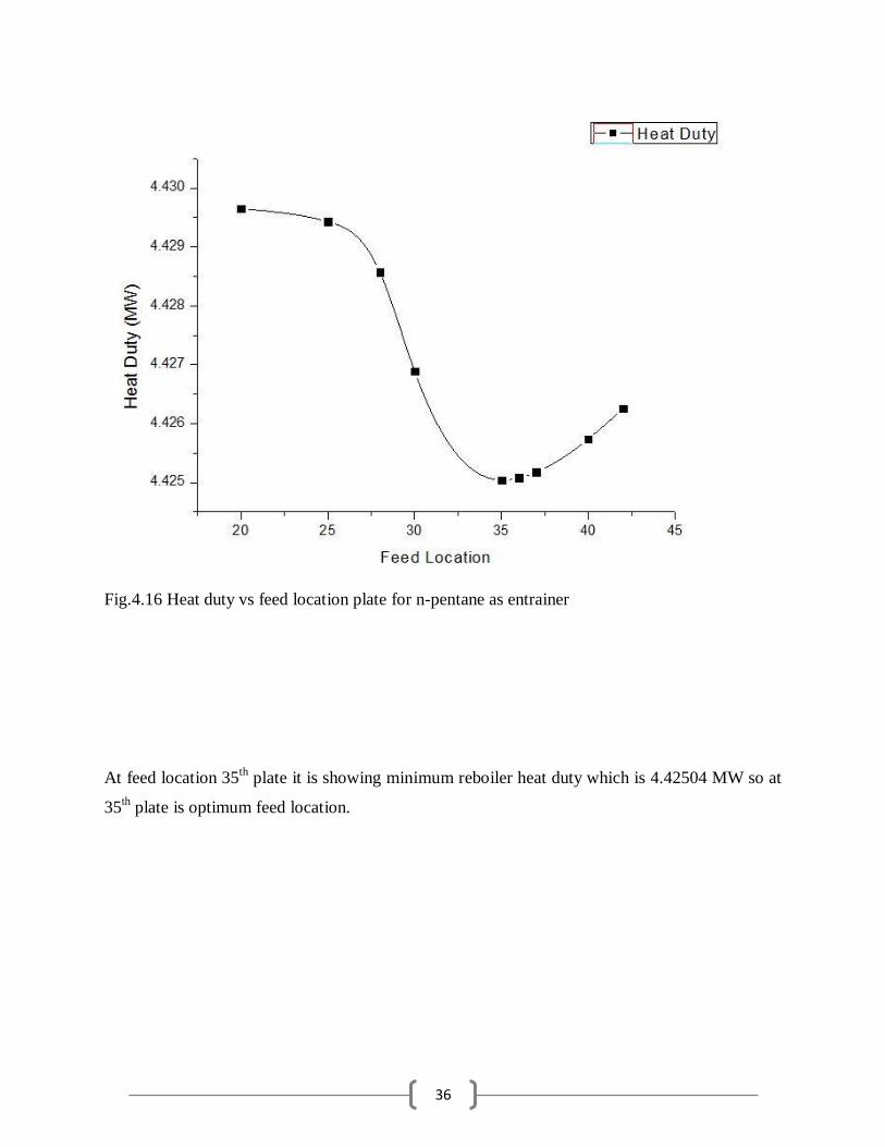
Feed
Location
Heat
Duty
20 4.42965
25 4.42943
28 4.42857
30 4.42689
35 4.42504
36 4.42508
37 4.42518
40 4.42574
42 4.42626
36
Fig.4.16 Heat duty vs feed location plate for n-pentane as entrainer
At feed location 35th
plate it is showing minimum reboiler heat duty which is 4.42504 MW so at
35th plate is optimum feed location.

37
4.4.2 Column sizing:
Length:
Calculating the height of the column is very easy if we know the number of trays present in the
column. The normal distance between adjacent trays (tray spacing) is 0.61 m (2 ft) [10]. If there
are NT stages, the number of trays is NT -2 (one stage for the reflux drum and one for the
reboiler).
L= 1.2(0.61)(NT - 2) ……(1)
4.4.2.1 Ethanol water with benzene as entrainer column:
Ethanol: 84%, water 16%mole fraction.
Reflux ratio: 0.5, distillate rate: 380, Number of stages: 45
Purity: 99.77
Length of column= 1.2 (0.61) (NT -2)
Length of column= 31.476m and diameter of column= 1.829m (from ASPEN tray sizing result)
4.4.2.2 Ethanol water with cyclohexane as entrainer column:
Ethanol: 84%, water 16% mole fraction
Reflux ratio: 0.1, distillate rate = 380, number of stages= 45
Purity = 99.91%
Length of column=37.476m and column diameter= 1.764m

38
4.4.2.3 Ethanol water with N-pentane as entrainer column:
Ethanol: 84%, water 16%mole fraction.
Reflux ratio: 0.15, distillate rate: 360, Number of stages: 25
Purity: 99.84%
Length of column= 1.2 (0.61) (NT -2)
Length of column= 16.36m and diameter of column= 1.62m
Table 4.20 Ethanol water with N-Pentane as entrainer column tray sizing

39
CHAPTER 6
CONCLUSIONS AND FUTURE WORKS
We have successfully simulated an azeotropic distillation system for separating ethanol water
mixture using three different entrainers namely 1) benzene 2) n-pentane 3) cyclohexane it has
been found out after simulation that cyclohexane performance is best where we get maximum
purity of ethanol(99.91%) followed by n-pentane(99.84%) and benzene (99.77%) entrainer. In
all the three case after simulation we have found out the respective number of stages 25 for n-
pentane, 45 for benzene and 45 for cyclohexane. This work is particularly important because
alcohol water is abundantly form in various industrial important processes and their separation
become critical and that’s why understanding the distillation procedure become more and more
crucial that’s why azeotropic distillation is becoming important and in similar way extractive
distillation and divided wall distillation are equally capable of separating azeotropic mixture so
as in future work same work can be used in extractive distillation system as well as in divided
wall distillation system as a future reference. As well as we have just carried out the steady state
distillation system however for any industrial process dynamic distillation is more crucial
because there would be sudden change in the system which needs to be controlled so controller
mechanism has to put in to the place and that is the reason why dynamic simulation comes in to
that place so as in extension of this project dynamic simulation can as well be done to find out
controller parameters.

40
REFERENCES
[1] Vane, L. M, “Pervaporation-Membrane process for bioethanol recovery, solvent dehydration
and contaminant removal”, Case study, 1-5 (2005)
[2] Francisco, María, Agustín S. B. González, Sara Lago García de Dios, Wilko Weggemans,
and Maaike C. Kroon. "Comparison of a low transition temperature mixture (LTTM) formed by
lactic acid and choline chloride with choline lactate ionic liquid and the choline chloride salt:
physical properties and vapour–liquid equilibria of mixtures containing water and ethanol",
RSC Advances, 3, 23553-23561 (2013)
[3] Luyben, William L, I-Lung Chien. “Design and control of distillation systems for separating
azeotropes”, 1-94, (2010)
[4] Aspen Plus - Introduction, emich.edu. N.p., n.d. Web. (2015)
[5] Luyben W. L, "More Complex Distillation Systems", Distillation Design and Control Using
Aspen™ Simulation, 8-66 (2013)
[6] Ohe, S, “Computer Aided Data book of vapour pressure (Liquid-Vapour Equilibrium in
Binary Systems)”, Tokyo, Kodansha, 4, 171-321 (1991)
[7] Mahdi, Taha, Arshad Ahmad, Mohamad Mahmoud Nasef, and Adnan Ripin. "State-ofthe-
Art Technologies for Separation of Azeotropic Mixtures", Separation and Purification Reviews,
44, 3-10 (2015)
[8] Doherty M. F. "Distillation, Azeotropic, and Extractive", Kirk-Othmer Encyclopedia of
Chemical Technology, US 8,309,755 B2, 1-12 (2012)
[9] Geankoplis C. J., “Transport Processes and Unit Operations”, Third Edition, Prentice-Hall,
Upper Saddle River, NJ, 758-761 (1993)
41
[10] Luyben W. L. “Setting up a Steady-State Simulation”, Distillation Design and Control Using
AspenTM Simulation, 45-83 (2006)