department of transportation -...
TRANSCRIPT

Department of Transportation Office of Project Development 700 E Broadway Avenue Pierre, South Dakota 57501-2586 605/773-3268 FAX: 605/773-2614
September 27, 2018 ADDENDUM NO. 1
RE: Item #1, October 3, 2018 Letting - NH 0212(173)397, PCN 04E9, Deuel County - Mill & PCCP Overlay, Pipe Work; Replace Structure (RCBC) & Approach Grading
TO WHOM IT MAY CONCERN: The following addenda to the plans shall be inserted and made a part of your proposal for the referenced project. SPECIAL PROVISIONS: Please remove the Index of Special Provisions and replace with
attached Index of Special Provisions revised 9/10/18.
Please remove the “Special Provision for Contract Time”, dated 8/22/18 and replace with the “Special Provision for Contract Time”, dated 9/27/18. Please add the “Detour Agreement provided by the MNDOT” and place it after the “Special Provision for On-The-Job Training Program”, dated 3/10/16. Please remove the “Special Provision for Contractor Furnished Mix Design for PCC Pavement”, dated 8/15/16 and replace with the “Special Provision for Contractor Furnished Mix Design for PCC Pavement”, dated 8/30/18.
SDEBS BID PROPOSAL: The electronic bid proposal for this contract has been revised to include the changes associated with this addendum. Bidders must log in to the SDEBS to retrieve and incorporate these changes into their bid.
Quantities for Bid Items were changed: Bid Item 634E0110 “Traffic Control Signs” changed from 1,743.7 SqFt to 1,656.7 SqFt Bid Item 634E0275 “Type 3 Barricade” changed from 96 Each to 93 Each Bid Item 634E1002 “Detour Signing” changed from 2,182.0 SqFt to 4,237.7 SqFt Bid Items were removed: Bid Item 632E2510 “Type 2 Object Marker Back to Back” Bid Item 633E1300 “Pavement Marking Paint, White” Bid Item 633E1305 “Pavement Marking Paint, Yellow”
Connecting South Dakota and the Nation

PLANS: Please destroy sheets A1 and A2 and replace with the enclosed sheets, dated 9-27-18. Please destroy sheets C1-C18 and replace with the enclosed sheets, dated 9-26-18. Please destroy sheet M2 and replace with the enclosed sheet, dated 9-19-18.
Sheet A1: The following bid items have been revised: Bid Item 634E0110 “Traffic Control Signs” changed from 1,743.7 SqFt to 1,656.7 SqFt Bid Item 634E0275 “Type 3 Barricade” changed from 96 Each to 93 Each Bid Item 634E1002 “Detour Signing” changed from 2,182.0 SqFt to 4,237.7 SqFt The following bid item has been removed: Bid Item 632E2510 “Type 2 Object Marker Back to Back” Sheet A2: The following bid items have been removed: Bid Item 633E1300 “Pavement Marking Paint, White” Bid Item 633E1305 “Pavement Marking Paint, Yellow” Section C: Replace Section C in its entirety. The detour route has changed, resulting in the need to
replace the entire section. Sheet M2: The following bid items have been removed: Bid Item 633E1300 “Pavement Marking Paint, White” Bid Item 633E1305 “Pavement Marking Paint, Yellow” The PERMANENT PAVEMENT MARKING ON CAR DETOUR ROUTES note was
removed from the plans. Pen and Ink Change: Sheet M11 is no longer needed and shall be considered null and void.
Sincerely, Sam Weisgram Engineering Supervisor SW/cj CC: Jeff Senst, Aberdeen Region Engineer Matt Brey, Watertown Area Engineer

REV. 9/10/18
INDEX OF SPECIAL PROVISIONS PROJECT NUMBER(S): NH 0212(173)397 PCN: 04E9 TYPE OF WORK: MILL & PCCP OVERLAY, PIPE WORK; REPLACE STRUCTURE (RCBC)
& APPROACH GRADING COUNTY: DEUEL The following clauses have been prepared subsequent to the Standard Specifications for Roads and Bridges and refer only to the above described improvement, for which the following Proposal is made. The Contractor’s attention is directed to the need for securing from the Department of Environment & Natural Resources, Foss Building, Pierre, South Dakota, permission to remove water from public sources (lakes, rivers, streams, etc.). The Contractor should make his request as early as possible after receiving his contract, and insofar as possible at least 30 days prior to the date that the water is to be used. Sue Bogen is the official in charge of the Watertown Career Center for Deuel County. THE FOLLOWING ITEMS ARE INCLUDED IN THIS PROPOSAL FORM: Special Provision for Contract Time, dated 9/27/18. Special Provision for On-The-Job Training Program, dated 3/10/16. Detour Agreement provided by the MNDOT. Special Provision for Prosecution and Progress, dated 9/7/16. Special Provision for Cooperation by Contractor and Department, dated 8/17/17. Special Provision Regarding Section 404 of the Clean Water Act, dated 8/22/18. Fact Sheet #23. Special Provision for Contractor Staking, dated 8/22/18. Special Provision for IRI PCC Pavement Smoothness, dated 8/16/16. Special Provision for Durable Pavement Markings, dated 8/22/18. Special Provision for Contractor Furnished Mix Design for PCC
Pavement, dated 8/30/18. List of Utilities.

Special Provision for South Dakota Electronic Bid System, dated 7/23/18. Special Provision for Contractor Administered Preconstruction Meeting, dated 3/15/16. Fuel Adjustment Affidavit, DOT form 208 dated 7/15. Standard Title VI Assurance, dated 3/1/16. Special Provision For Disadvantaged Business Enterprise, dated 5/20/15. Special Provision For EEO Affirmative Action Requirements on Federal and Federal-aid
Construction Contracts, dated 9/1/97. Special Provision For Required Contract Provisions Federal-aid Construction Contracts, Form
FHWA 1273 (Rev. May/1/12), dated 4/30/13. Required Contract Provisions Federal-aid Construction Contracts, Form
FHWA 1273 (Rev. 5/1/12). Special Provision for Cargo Preference Act, dated 1/20/16. Special Provision Regarding Minimum Wage on Federal-Aid Projects, dated 4/30/13. Wage and Hour Division US Department of Labor Washington DC.
- US Dept. of Labor Decision Number SD180001, dated 4/6/18. Special Provision for Supplemental Specifications to 2015 Standard Specifications for Roads
and Bridges, dated 4/18/18. Special Provision for Errata to 2015 Standard Specifications for Roads and Bridges,
dated 4/4/18. Special Provision for Price Schedule for Miscellaneous Items, dated 6/6/18. Special Provision Regarding Storm Water Discharge, dated 5/8/18. General Permit for Storm Water Discharges Associated with Construction
Activities, dated 4/1/18. http://denr.sd.gov/des/sw/IPermits/ConstructionGeneralPermit2018.pdf

STATE OF SOUTH DAKOTADEPARTMENT OF TRANSPORTATION
SPECIAL PROVISIONFOR
CONTRACT TIME
PROJECT NH 0212(173)397; PCN 04E9DEUEL COUNTY
SEPTEMBER 27, 2018
Field Work Completion
The Contractor will complete the project by the October 18, 2019 field work completion date.
100 Calendar Day Count for Field Work Completion
In addition, the Contractor will complete all work on the project within 100 calendar days. The Department will begin to count calendar days when the Contractor’s operation impedes traffic on US 212 with the following exception; if the Contractor begins work on the replacement of the box culvert before beginning all other work on US 212, the day count will not begin until the subsequent work impedes traffic. The Department will continue to count calendar days until the Contractor returns unimpeded thru-traffic to the entire length of US 212, including the segment of the box culvert replacement, and completes all work on the project. The Department will count calendar days in accordance with Section 8.6 B.
The Engineer, in the Engineer’s sole discretion, will determine when the day count will begin and when the project is complete.
If the Contractor does not complete all work within the calendar day completion requirement, the Department will make a disincentive assessment in the amount of $2000 per calendar day.
Sta. a754+00 to Sta. a777+92.98 Two-Way Traffic Accommodations
The Contractor will maintain two-way traffic from Sta. a754+00 to Sta. a777+92.98 from June 27, 2019 to July 5, 2019. The Contractor will maintain two-way traffic to accommodate a business located at Sta. a754+00. Two-way traffic will only need to be maintained during the hours of operation for the business.
The Department will make a disincentive assessment in the amount of $500 per calendar day for the Contractor’s failure to comply with the two-way traffic
accommodations. The Department will not grant time extensions for the two-way traffic accommodations for any reason.
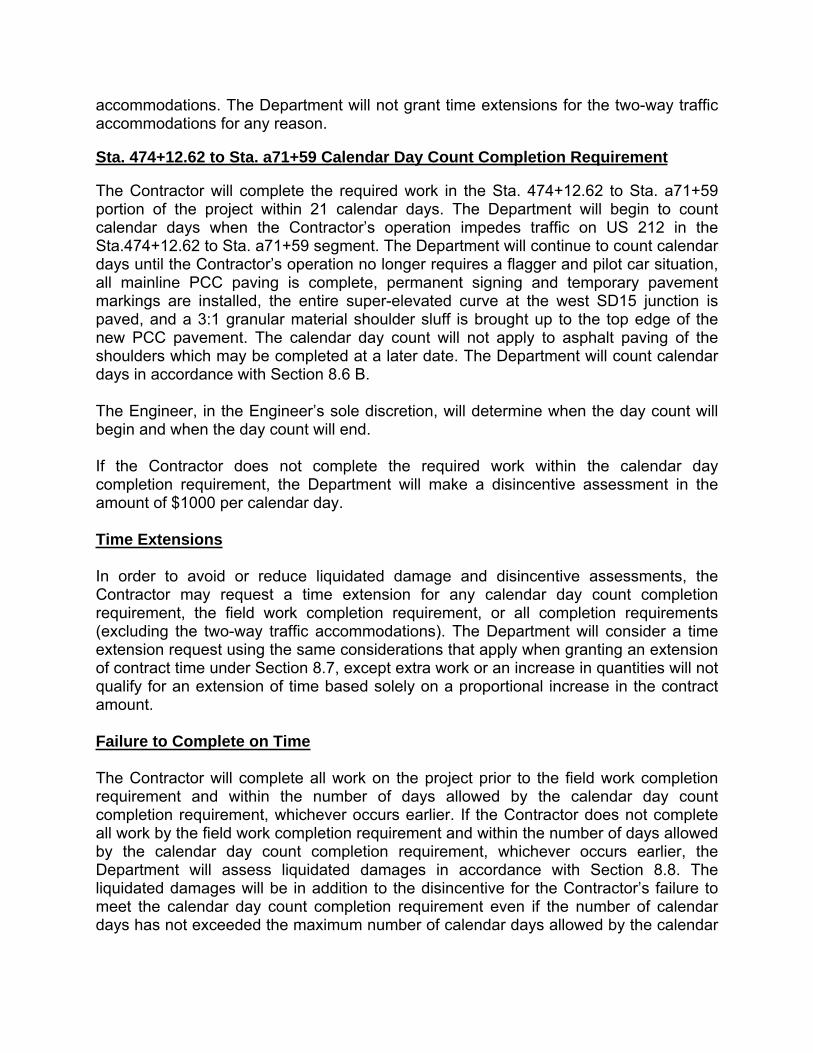
Sta. 474+12.62 to Sta. a71+59 Calendar Day Count Completion Requirement
The Contractor will complete the required work in the Sta. 474+12.62 to Sta. a71+59 portion of the project within 21 calendar days. The Department will begin to count calendar days when the Contractor’s operation impedes traffic on US 212 in the Sta.474+12.62 to Sta. a71+59 segment. The Department will continue to count calendar days until the Contractor’s operation no longer requires a flagger and pilot car situation, all mainline PCC paving is complete, permanent signing and temporary pavement markings are installed, the entire super-elevated curve at the west SD15 junction is paved, and a 3:1 granular material shoulder sluff is brought up to the top edge of the new PCC pavement. The calendar day count will not apply to asphalt paving of the shoulders which may be completed at a later date. The Department will count calendar days in accordance with Section 8.6 B.
The Engineer, in the Engineer’s sole discretion, will determine when the day count will begin and when the day count will end.
If the Contractor does not complete the required work within the calendar day completion requirement, the Department will make a disincentive assessment in the amount of $1000 per calendar day.
Time Extensions
In order to avoid or reduce liquidated damage and disincentive assessments, the Contractor may request a time extension for any calendar day count completion requirement, the field work completion requirement, or all completion requirements (excluding the two-way traffic accommodations). The Department will consider a time extension request using the same considerations that apply when granting an extension of contract time under Section 8.7, except extra work or an increase in quantities will not qualify for an extension of time based solely on a proportional increase in the contract amount.
Failure to Complete on Time
The Contractor will complete all work on the project prior to the field work completion requirement and within the number of days allowed by the calendar day count completion requirement, whichever occurs earlier. If the Contractor does not complete all work by the field work completion requirement and within the number of days allowed by the calendar day count completion requirement, whichever occurs earlier, the Department will assess liquidated damages in accordance with Section 8.8. The liquidated damages will be in addition to the disincentive for the Contractor’s failure to meet the calendar day count completion requirement even if the number of calendar days has not exceeded the maximum number of calendar days allowed by the calendar

day count completion requirement. The Department will assess liquidated damages for each calendar day the work (project) is late until the Contractor completes all field work.
In the event the Contractor does not complete all field work on time, the Department will count calendar days in accordance with Section 8.6 B.
Expected Adverse Weather Days
The Department has provided Attachment 1 for information purposes only as a guide to bidders. This table depicts the typical number of adverse weather days expected for any given month, based on historical records. The Department will consider this project a surfacing project in Zone 6.
The Department will consider expected adverse weather days cumulative in nature over the time period when the Contractor is actively pursuing completion of the work. The Department will not consider adverse weather days during an extended period of time when the Contractor is not pursuing completion of the work. When considering a time extension for any calendar day count completion requirement or the field work completion of the project, the Engineer will compare the total number of expected adverse weather days against the total number of actual adverse weather days for the time period during which the work was being completed.
* * * * *

ATTACHMENT 1
Figure A - Expected Adverse Weather Days for South Dakota
Table 1 - Expected Adverse Weather Days for South Dakota
Zone 1 Zone 2 Zone 3 Zone 4 Zone 5 Zone 6 Zone 1 Zone 2 Zone 3 Zone 4 Zone 5 Zone 6Jan 18 18 16 16 22 24 18 18 15 16 21 23Feb 19 18 12 14 19 21 19 18 12 14 19 21Mar 12 10 9 8 11 13 12 10 9 8 10 12Apr 6 5 8 5 6 6 5 4 6 4 4 4May 6 6 8 6 6 6 5 5 6 4 4 5Jun 7 6 7 6 7 8 5 5 5 4 5 6Jul 5 5 6 5 6 7 4 4 5 3 4 5
Aug 4 4 5 4 5 6 3 3 4 3 4 4Sep 3 3 4 3 4 5 2 2 3 2 3 4Oct 4 3 5 3 4 4 3 3 4 2 3 3Nov 11 9 8 7 10 12 11 9 8 7 10 11Dec 21 19 15 14 20 22 21 19 15 14 20 22
Grading Projects Surfacing and Structural Projects
NOTE: Includes Holidays and Weekends.


ContractorFurnishedPCCPMixDesign(20180830).docx Page 1
STATE OF SOUTH DAKOTADEPARTMENT OF TRANSPORTATION
SPECIAL PROVISIONFOR
CONTRACTOR FURNISHED MIX DESIGN FOR PCC PAVEMENT
AUGUST 30, 2018
This work consists of the Contractor establishing a mix design and providing a concrete paving mix for the Portland Cement Concrete (PCC) pavement of sufficient quality to serve the purpose for which the PCC pavement is intended.
Make the following changes to the specifications:
Section 380.3 A. - Delete this section and replace with the following:
A. Concrete Quality, Proportioning, and Field Performance:
1. Contractor Responsibility: The Contractor shall be responsible for the selection of materials meeting the specifications and shall be responsible for the design and composition of all concrete mixes used in the PCC pavement. The Contractor shall be responsible to produce and deliver a concrete paving mix that is uniform, consistent, workable, finishable, and that meets all requirements of the contract. The Contractor shall install a PCC pavement that is homogeneous, consolidated, durable, and free of defects.
The Contractor is responsible for the actual field performance of the concrete mix and any adverse impacts resulting from the materials used on the project and the Contractor’s batching, mixing, hauling, placing, consolidating, finishing, and curing of the concrete mix. Department review of the Contractor’s proposed mix design under Section 380.3 A.3. does not relieve the Contractor of any obligations set out in this specification or in the contract as a whole.
2. Mix Design Parameters:
On small areas using stationary side formed paving methods, the Engineer may permit the substitution of Class A45 concrete for the concrete paving mix. Class A45 shall meet the requirements of Section 460, except the concrete shall have a minimum 28 day compressive strength of 4000 psi, slump range of between 1 inch and 3 inches, and

ContractorFurnishedPCCPMixDesign(20180830).docx Page 2
shall contain fly ash. Fly ash shall constitute 20% to 25% of the cementitious material at a 1:1 ratio by weight.
For all other areas and any areas where the Contractor utilizes slip form paving equipment, the following requirements shall apply:
a. Mix Design Proportioning: The Contractor shall select mix proportions conforming to the following.
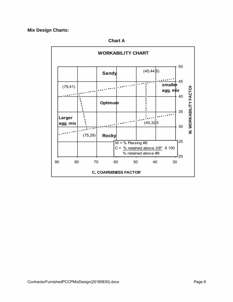
1) Combined Aggregate: Mix designs shall be based on aggregate specific gravities at saturated surface dry (SSD) condition. The mix design process shall produce a mix design that will plot within the optimum limits listed in Chart A. The mix design shall also meet the following requirements when plotted on the 0.45 power chart. The best fit line plotted on the 0.45 power chart shall use a top size of 1 inch aggregate for jointed concrete pavement and 1.5 inch aggregate for Continuously Reinforced Concrete Pavements (CRCP). The combined gradation when plotted on the 0.45 power chart should fit within the limits as defined in Chart B for jointed concrete pavement or Chart C for CRCP. CRCP mix designs shall retain a minimum of 11.5% of the total aggregate above the 1 inch sieve.
2) Cementitious Material Content: The mix design shall establish a cementitious material content (total of cement, fly ash, and other cementitious additions). The minimum cementitious material content shall be 575 pounds per cubic yard. The maximum cementitious material content shall be 800 pounds per cubic yard.
3) Fly ash: Fly ash shall be included in the concrete mixture. Fly ash shall constitute 20% to 25% of the cementitious material at a 1:1 ratio by weight.
4) Water/Cementitious Material Ratio: The mix design shall establish a maximum water/cementitious material ratio, which shall not exceed 0.42 pounds/pounds.
5) Coarse Aggregate Percentage: The mix design shall establish the percentage of coarse aggregates to be used. The minimum coarse aggregate content shall be 55% by weight of total aggregates.
6) Air Content: The volumetrics of the mix design shall be based on 6.5% entrained air content.
b. Contractor Laboratory Trial Batch Testing: The Contractor will obtain laboratory tests on trial batches of the proposed mix design.

ContractorFurnishedPCCPMixDesign(20180830).docx Page 3
1) Procedures: The trial batch testing must be performed by a competent testing facility. The Department may perform an on-site inspection of the testing facility’s mix design procedures and equipment. If the Department, in its sole discretion, deems a testing facility to be incapable of performing accurate, reliable, or valid testing, the Department may require the Contractor to obtain trial batch testing from a different testing facility. Trial batch testing shall be conducted in accordance with the American Concrete Institute Publication 211.1, ASTM C192.
A minimum of four trial batches shall be required; two batches shall have identical proportions of aggregates and two batches shall have identical water/cementitious ratios or cementitious contents. Of the four trial batches, no two trial batches shall contain the same proportions. A different proportion of aggregate must be at least a 1% (of total aggregate) sand change or a 2% (of total coarse aggregate) rock change. A different water/cementitious ratio shall be at least a 0.02 change. A different cementitious content change shall be an addition or subtraction of at least 20 pounds of cementitious materials.
2) Testing Results: Through the trial batch laboratory testing, the Contractor must demonstrate that the proposed mix design reliably achieves the following laboratory test results:
a) Slump: The slump at 20 minutes after completion of mixing for each trial mix shall be between 1.25 inches and 2.75 inches for slip-formed pavements and between 2.25 inches and 3.75 inches for formed pavements. The initial slump immediately after completion of mixing shall be tested and reported as well. The concrete for the 20 minute slump shall be exposed to ambient air temps between 68°F to 86°F.
b) Air content: The air content for all concrete trial mixes shall have an entrained air content of 6.5% to 8.0%.
c) Compressive Strength: The mix design shall be based upon obtaining an average minimum compressive strength of 5200 psi at 28 days.
A minimum of 3 cylinders at each age and for each trial shall be tested for compressive strength at 7, 14, and 28 days. All 9 cylinders must be made from the same batch of concrete. The cylinders must be consolidated by the rodding method.

ContractorFurnishedPCCPMixDesign(20180830).docx Page 4
d) Temperature: The fresh concrete temperature shall be between 68°F and 86°F immediately after completion of mixing.
Consideration for expected field temperatures may be made when evaluating laboratory trials. Changes that cause a deviation from the requirements of this provision for expected field temperatures must be submitted and evaluated by the Concrete Engineer prior to performing trial batches.
3) Waiver of Laboratory Trial Batch Requirements: The Contractor may ask the Department to waive the Contractor’s trial batch testing requirements if: (1) the mix design was successfully used on a previous Department project; and (2) the mix design is unchanged or the Contractor has made only minor modifications in the mix design, such as changes in admixtures and cementitious materials with the same ASTM designated type of material or small variations to aggregate proportions. The decision to waive the Contractor’s trial batch testing requirements is solely within the discretion of the Department.
The Department’s waiver of the laboratory trial batch testing requirements does not in any way relieve the Contractor of any obligations set out in this specification or in the contract as a whole. If required by the Engineer, the Contractor shall perform a plant gradation check or a plant mixed trial batch or both prior to use of the proposed mix design in field production. The Contractor shall submit these results to the Department’s Concrete Engineer for Department review.
If the Contractor intends to use another party’s successfully used mix design, the Contractor must provide written proof to the Department that the use of the mix design has been authorized by the other party.
c. Proposed Mix Design Submissions: A minimum of 40 calendar days prior to the anticipated use in field production, the Contractor shall submit the proposed mix design and supporting documentation to the Department’s Concrete Engineer.
If laboratory trial batch testing requirements have not been waived, the Contractor shall submit the results of the trial batch testing with a completed Contractor Concrete Mix Design form (DOT-24). The trial batch testing results shall include all batched weights, admixtures and dosages, aggregate moisture contents, fresh concrete results (initial and 20 minute slump, initial air content, initial unit weight, and initial temperature), actual water/cementitious material ratio, compressive

ContractorFurnishedPCCPMixDesign(20180830).docx Page 5
strengths, aggregate gradations (including production tests), aggregate quality results, and required material certifications. The Contractor shall also supply any additional data, supporting documentation, and samples requested by the Department.
If laboratory trial batch testing has been waived, the Contractor shall submit aggregate gradations (including production tests), and required material certifications with a DOT-24. The Contractor shall also supply any additional data, supporting documentation, and samples requested by the Department.
3. Department Review: The Department will review the Contractor’s proposed mix design to determine if it conforms to the Department’s materials and proportioning specifications. The Department may also review the Contractor’s laboratory trial batch testing to determine compliance with required laboratory trial batch testing procedures and test results. The Department may, in its sole discretion, perform laboratory trial batch testing to replicate, to the Department’s satisfaction, the Contractor’s laboratory trial batch testing results.
When the Department performs laboratory trial batch testing, the Department will not begin laboratory trial batch testing until the Contractor’s trial batch samples have obtained an average compressive strength of at least 4000 psi at 7 days or at least 5200 psi at 28 days. The Department will attempt to replicate one of the submitted mix design trials. Satisfactory replication occurs when the Department’s laboratory trial batch samples obtain an average compressive strength of at least 4000 psi at 7 days, at least 5200 psi at 28 days, or the average compressive strength is no more than 10% less than the Contractor’s submitted 28 day strength. In the sole discretion of the Department’s Concrete Engineer’s, the Department may complete the replication process based on adequate strength results prior to 28 days.
If the Department is unable to replicate the Contractor’s laboratory trial batch testing to the Department’s satisfaction, the Department will perform a second laboratory trial batch testing at the Contractor’s request. If the Department is unable to replicate, to the Department’s satisfaction, the Contractor’s laboratory batch testing results for the proposed mix design after two attempts, the costs involved with any further laboratory trial batch testing will be at the Contractor’s expense.
The Contractor will not begin production and placement of the concrete mix until the Department’s Concrete Engineer has confirmed, in writing, a successful review consisting of: (1) the Contractor’s proposed mix design conforms to the Department’s materials and proportioning specifications; and (2) if applicable, the Contractor’s laboratory trial batch testing results

ContractorFurnishedPCCPMixDesign(20180830).docx Page 6
comply with required laboratory trial batch testing procedures and test results; and (3) if applicable, the Department has replicated the Contractor’s laboratory trial batch testing results to the Department’s satisfaction.
4. Field Performance and Testing: In addition to the responsibilities set out in 380.3 A.1, the Contractor shall provide a concrete paving mix conforming to the most recent mix design proposed to and successfully reviewed by the Department. The concrete paving mix provided by the Contractor must also satisfy the following field tests:
a. Slump: For the slip-form method, the slump of the concrete shall not be more than 2 inches at the time of placement. For the stationary side form method, the slump of the concrete shall be between 1 inch and 3 inches at the time of placement.
b. Entrained Air Content: All concrete shall contain 6.5% entrained air with an allowable tolerance of +1% to -1.5%. Air shall be entrained by an air-entraining admixture.
c. Water/Cementitious Ratio: The concrete shall not exceed the maximum Water/Cementitious ratio “W/C Ratio” as listed on the mix design. The W/C Ratio will be calculated as per 380.3 B.2 to compare the as-batched concrete against the mix design maximum.
d. Admixture Dosages: The Contractor may adjust the admixture dosages listed on the final mix design submitted for use by the Contractor on the DOT-24 within the manufacturer’s guidelines.
e. Compressive Strength: Concrete shall exhibit a minimum compressive strength of 4000 psi at 28 days. The 28 day compressive strength shall be determined in accordance with Section 460.3 B.
5. Mix Design Modification: If, after successful Department review, the Contractor wishes to modify its mix design, the Contractor shall complete and submit a new DOT-24 to the Department’s Concrete Engineer. A modification includes, but is not limited to, changes in aggregate source, changes in gradation targets, new admixtures, changes in brand name of admixtures, changes in brand name of cementitious materials, and changes to aggregate percentage splits.
If the Contractor proposes to make modifications to the mix design that the Department’s Concrete Engineer deems to be significant, the Contractor will obtain laboratory trial batch testing of the modified mix design in accordance with section 380.3 A.2.b. The Contractor shall submit the laboratory trial batch testing results to the Department’s Concrete

ContractorFurnishedPCCPMixDesign(20180830).docx Page 7
Engineer for Department review. Significant modifications include, but are not limited to aggregate source, combined coarse aggregate gradation target, and combined total aggregate gradation target.
If the Contractor proposes to make modifications to the mix design that the Department’s Concrete Engineer deems to be minor, the Department will not require the Contractor to perform laboratory trial batch testing but may require the Contractor to perform a plant gradation check or a plant mixed trial batch or both. The Contractor shall submit the results of any plant gradation check and plant mixed trial batch to the Department’s Concrete Engineer for Department review. Changes to the aggregate percentage splits will require the Contractor to submit supporting documentation including, but not limited to the basis for the change and gradation test results. Minor modifications include, but are not limited to new admixtures, changes in brand name of admixtures, changes in brand name of cementitious materials, and changes to aggregate percentage splits.
The Department may, upon request from the Contractor, waive or modify the Contractor’s laboratory trial batch testing, plant gradation check, or plant mixed trial batch requirement of the modified mix design.
The Contractor will not begin production and placement of the modified concrete mix until the Department’s Concrete Engineer has confirmed, in writing, a successful review consisting of: (1) the Contractor’s proposed mix design conforms to the Department’s materials and proportioning specifications; and (2) if applicable, the Contractor’s laboratory trial batch testing results comply with required laboratory trial batch testing procedures and test results; and (3) if applicable, the Department has replicated the Contractor’s laboratory trial batch testing results to the Department’s satisfaction.
Section 820.1 A. - Delete this section and replace with the following:
A. Coarse Aggregate for Concrete Pavement: The coarse aggregate shall consist of ledge rock. Coarse aggregate for Continuously Reinforced Concrete Pavement shall conform to Size #20. Coarse aggregate for all other PCC Pavements shall conform to Size #15.
ContractorFurnishedPCCPMixDesign(20180830).docx Page 8
Mix Design Charts:
Chart A
WORKABILITY CHART
20
25
30
35
40
45
50
30405060708090
C, COARSENESS FACTOR
W, W
ORK
ABIL
ITY
FACT
OR
Sandy
(75,29) Rocky
Larger agg. mix
Optimum
smaller agg. mix
(45,32.5)
(45,44.5)
(79,41)
W = % Passing #8C = % retained above 3/8" X 100 % retained above #8

ContractorFurnishedPCCPMixDesign(20180830).docx Page 9
Chart B
1" 0.45 POWER GRADATION
05
101520253035404550556065707580859095
100#1
00#2
00 #50
#30
#16 #8 #4 3/8
1/2
3/4 1
Upper Low erSeive Limit Limit
1" 100 92 3/4" 96 80 1/2" 81 65 3/8" 72 56 #4 55 39 #8 42 26 #16 33 17 #30 27 11
Chart C
1.5" 0.45 POWER GRADATION
05
101520253035404550556065707580859095
100
#16 #8 #4 1/2" 1.5"1"3/4"#30
#50 3/8"
#200
#100
Upper LowerSeive Limit Limit
1.5" 100 92 1" 88.5 75 3/4" 81 65 1/2" 68 52 3/8" 61 45 #4 47 31 #8 37 20 #16 29 13 #30 23 7
* * * * *

A1 A4
TOTALSHEETS
PROJECT SHEETSTATE OF SOUTH
DAKOTAESTIMATE OF QUANTITIES AND ENVIRONMENTAL COMMITMENTS NH 0212(173)397
Revised 09/27/2018 AR09/27/2018Plotting Date:
Section B - Grading Section D - Erosion and Sediment Control
INDEX OF SHEETSBIO ITEM NUMBER
BID ITEM NUMBER
ITEM QUANTITY UNIT ITEM QUANTITY UNIT
A1 to A2 Estimate of Quantities for Sections B, C, D, E, F, M,and SEnvironmental Commitments
004E0030 Maintenance of Traffic Diversion(s) Lump Sum LS 110E1690 Remove Sediment 2.0 CuYd
004E0050 Remove Traffic Diversion(s) Lump Sum LS 110E1700 Remove Silt Fence 155 Ft A3 to A4009E0010 Mobilization Lump Sum LS 230E0010 Placing Topsoil 862 CuYd
009E3230 Grade Staking 30331 Mile 730E0100 Cover Crop Seeding 1.0 Bu
009E3240 Graded Centerline Staking 14723 Mile 730E0251 Special Permanent Seed Mixture 1 65 LbSection E - Structure
Site 1 - Alternate B Str. No. 20-109-030
009E3250 Miscellaneous Staking 14.865 Mile 732E0100 Mulching 7.0 Ton
009E3280 Slope Staking 0.260 Mile 734 E0154 12” Diameter Erosion Control Wattle 620 Ft
009E3290 Structure Staking 1 Each 734 E0165 Remove and Reset Erosion Control Wattle 155 Ft
Three Man Survey Crew009E3300 40.0 Hour 734E0604High Flow Silt Fence 620 FtBIO ITEM NUMBER
ITEM QUANTITY UNIT009E4200 Construction Schedule, Category II Lump Sum LS 734 E0610 Mucking Silt Fence 43 CuYd
009E4220 Project Management, Category II Lump Sum LS 734 E0620 Repair Silt Fence 155 Ft 250E0030 Incidental Work. Structure Lump Sum LS110E0600 Remove Fence 827 Ft 900E1320 Construction Entrance Each1 420E0200 Structure Excavation, Box Culvert 116 CuYd120E0010 Unclassified Excavation 13,314 CuYd 421E0200 Box Culvert Undercut 180 CuYd120E0600 Contractor Furnished Borrow Excavation CuYd1,858 560E2148 2-11’x10‘ Precast Concrete Box Culvert, Furnish 126 0 Ft120E2000 Undercutting 2,370 CuYd 560E2149 2-11‘x10' Precast Concrete Box Culvert, Install 126 0 Ft
Section E - Structure Site 1 - Alternate A Str. No. 20-109-030
120E6100 Water for Embankment 143.1 MGal 560E3148 2 Each2-11’x10' Precast Concrete Box Culvert End Section. Furnish600E0300 Type III Field Laboratory 1 Each
560E3149 2 Each2-11'x10‘ Precast Concrete Box Culvert End Section. Install
620E0030 Type 3 Right-of-Way Fence 827 Ft
620E0510 Type 1 Temporary Fence 1,000 Ft c700E0210 Class B Riprap 91.0 Ton o
“O<620E1020 2 Post Panel 4 Each BID ITEM
NUMBER831E0110 Type B Drainage Fabric 102 SqYd OITEM QUANTITY UNIT o
0620E1030 3 Post Panel 6 Each C/)0
250E0030 Incidental Work. Structure Lump Sum LS O
LU420E0200 Structure Excavation. Box Culvert 152 CuYd o0
421E0200 Box Culvert Undercut 199 CuYd =5Q
Q_460E0120 Class A45 Concrete. Box Culvert 375.1 CuYd
480E0100 Reinforcing Steel 50.868 Lb0
Section C - Traffic Control 700E0210 Class B Riprap Ton84 7Type B Drainage Fabric831E0110 96 SqYd
BIO ITEM NUMBER
ITEM QUANTITY UNIT
634E0010 Flagging 800.0 Hour
634E0020 Pilot Car 400.0 Hour
634E0110 Traffic Control Signs 1.656.7 SqFt
634E0120 Traffic Control. Miscellaneous Lump Sum LS
634E0275 Type 3 Barricade 93 Each
634E1002 Detour Signing 4.237.7 SqFt

A2 A4
TOTALSHEETS
PROJECT SHEETSTATE OF SOUTH
DAKOTA NH 0212(173)397
Section E - Structure Str. No. 20-194-030
Revised 09/27/2018 AR09/27/2018Plotting Date:
Section F - Surfacing Section M - Pavement MarkingBID ITEM NUMBER
BID ITEM NUMBER
ITEM QUANTITY UNITITEM QUANTITY UNIT BID ITEM NUMBER
ITEM QUANTITY UNIT110E0400 Remove Drop Inlet 2 Each120E0010 Unclassified Excavation 62 CuYd
633E0030 Cold Applied Plastic Pavement Marking. 24* 500 Ft110E0420 Remove Drop Inlet Frame and Grate Assembly 2 Each250E0010 Incidental Work Lump Sum LS
633E0040 Cold Applied Plastic Pavement Marking. Arrow 10 Each110E0500 Remove Pipe Culvert Ft46410E2600 Membrane Sealant Expansion Joint 91.8 Ft
633E3000 Durable Pavement Marking. 4* White 155.250 FtFt110E0700 Remove 3 Cable Guardrail 610430E0300 Granular Bridge End Backfill 58.8 CuYd
633E3005 Durable Pavement Marking, 4" Yellow 35,500 Ft110E0730 Ftemove Beam Guardrail 1.110.0 Ft430E0510 Approach Slab Underdrain Excavation 6.4 CuYd
633E5015 500 FtGrooving for Cold Applied Plastic Pavement Marking,110E0740 Remove 3 Cable Guardrail Anchor Assembly 4 Each430E0700 Precast Concrete Headwall for Drain Each4 24*110E0810 Remove Rubrail 50.0 Ft 633E5025 10 EachGrooving for Cold Applied Plastic Pavement Marking,
Arrow460E0070 Class A45 Concrete. Bridge Repair CuYd4.4
120E0100 Unclassified Excavation. Digouts 364 CuYd460E0150 Concrete Approach Slab for Bridge SqYd209.0 633E5100 Grooving for Durable Pavement Marking, 4" 190,750 Ft120E6200 Water for Granular Material 591.6 MGal460E0160 Concrete Approach Sleeper Slab for Bridge SqYd74.0260E1010Base Course 1.823.1 Ton460E0300Breakout Structural Concrete 4.8 CuYd260E1030 Base Course, Salvaged 45.753.6 Ton460E0380 Install Dowel in Concrete 72 Each Section S - Permanent Signing260E2030 Gravel Cushion. Salvaged 1.797.9 Ton480E0200 Epoxy Coated Reinforcing Steel 364 Lb260E6000 Granular Material. Furnish Ton23,775.8480E0504 No. 4 Rebar Splice 28 Each BID ITEM
NUMBERITEM QUANTITY UNIT270E0200 Blend, Haul, and Stockpile Granular Material Ton47.551.6480E0505 No. 5 Rebar Splice 48 Each
320E0005 PG 58-34 Asphalt Binder 974 9 Ton480E0506 No. 6 Rebar Splice Each44 Remove Traffic Sign Each110E0130 70320E1070Class HR Asphalt Concrete 23.329.5 Ton480E5000 Galvanic Anode 36 Each 632E1320 2.0*x2.0" Perforated Tube Post 729.0 Ft320E3000 Compaction Sample 3 Each680E0040 4* Underdrain Pipe 131 Ft 632E1340 2.5"x2.5” Perforated Tube Post 224.0 Ft320E5010 Saw and Seal Shoulder Joint 155.659 Ft680E2500 Porous Backfill 5.8 Ton 632E2022 Each2954”x4* White Delineator Back to Back with 1.12 Lb/Ft
Post c330E0010 MC-70 Asphalt for Prime Ton185.4 o“O
632E3203 SqFtFlat Aluminum Sign, Nonremovable Copy High Intensity
410.5 <330E0100 SS-1h or CSS-1 h Asphalt for Tack 44.5 Ton O
o0330E0210 SS-1h or CSS-1 h Asphalt for Flush Seal 35.3 Ton 632E3205 SqFt180.1Flat Aluminum Sign, Nonremovable Copy SuperA/ery
High IntensityCO(A<0O332E0010 Cold Milling Asphalt Concrete 271.322 SqYdLU
380E0050 8* Nonreinforced PCC Pavement SqYd244.414.6 'd-o0=5
380E0070 9" Nonreinforced PCC Pavement SqYd2.844.0 QCL
380E6000 Dowel Bar 136.411 Each
380E6110 Insert Steel Bar in PCC Pavement 28 Each0
410E2600 Membrane Sealant Expansion Joint Ft91.8 SPECIFICATIONS450E0122 18" RCP Class 2. Furnish Ft48
Standard Specifications for Roads and Bridges, 2015 Edition and Required Provisions, Supplemental Specifications, and Special Provisions as included in the Proposal.
450E0130 18" RCP. Install Ft48
450E2008 18" RCP Flared End. Furnish 2 Each
450E2009 18" RCP Flared End. Install 2 Each630E0500Type 1 MGS Ft175.0630E1500Type 1 Guardrail Transition Each4
630E2019 MGS Tangent End Terminal Each4
632E2220 Guardrail Delineator 16 Each
670E3000 1.5' x 3' Type D Drop Inlet Each2
670E3200 Type D Frame and Grate 2 Each
670E5400 Precast Drop Inlet Collar Each2
900E0010 Refurbish Single Mailbox Each6

477th A
ve.
BEGIN NH 0212(173)397
END NH 0212(173)397
23
30
31363534
27 26 25
21201 9242322
1 5 1 4 1 31 8
1 7 1 61 5
22
1 41 3
1 81 7 1 6
23
241 9 20
21
TUNERVILLE
212
1 5
212
Creek
Creek
LAKE
ALICE
33
21
1 6
4
1 5
INDEX OF SHEETSSection C: Traffic Control Plans
R 49 W
R 49 W R 48 W
T 1
17 N
R 47 W
R 48 W
R 47 W
MRM 412.45Range 47 WestSection 15-Township 117 North-of the Southwest corner of874.80 feet East and 860.6 feet NorthMinnesota State Line. Approximatelyof F.A.P. F 034-6(3) on the South Dakota-Station 778+12.75=Station 778+12.75
MRM 397+0.275Range 49 Westof Section 34-Township 117 North-1.40 feet North of the Southwest corner F.A.P. F 034-6(3). Approximately Station 0+00=Station 0+00 on
Lost
T 1
17 N
So
uth
Dak
ota
Min
nesota
485th A
ve.
484th A
ve.
483rd A
ve.
482nd A
ve.
481st
Ave.
480th A
ve.
479th A
ve.
478th A
ve.
476th A
ve.
475th A
ve.
168th St.
170th St.
487th A
ve.
486th A
ve.
MRM 401.75Station 234+12.00Str. No. 20-109-030
STATE OFSHEET
NO.
TOTAL
SHEETSPROJECT
SOUTH
DAKOTA
STATE OFSHEET
NO.
TOTAL
SHEETSPROJECT
SOUTH
DAKOTA
09/19/2018Plotting Date:
TR
AB17882
1:200
1
Plotted
Fro
m -
Plot
Scale -
File - ...\
Addendu
m
Plans\
Title
C.dgn
Plot
Na
me -
NH 0212(173)397
Standard PlatesC18-C20
Itemized List of Traffic ControlC17
Business Signing TableC16
Overwidth Detour Signing TableC15
Detour Signing TableC14
Special Signing DetailC12-C13
Business Sign LayoutC11
Overwidth Detour LayoutC9-C10
Detour LayoutC7-C8
Closure Begin/End Traffic Control DetailC5-C6
Fixed Location Sign DetailC4
Plan NotesC2-C3
General Layout & IndexC1
Rev. 9-26-18 SLS C1 C20
PROJECTSTATE OFSOUTH
DAKOTA NH 0212(173)397SHEET TOTAL
SHEETS
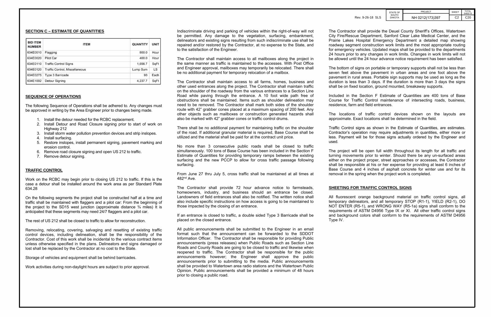
SECTION C – ESTIMATE OF QUANTITIES
SEQUENCE OF OPERATIONS
The following Sequence of Operations shall be adhered to. Any changes must be approved in writing by the Area Engineer prior to changes being made.
1. Install the detour needed for the RCBC replacement.2. Install Detour and Road Closure signing prior to start of work on
Highway 212 3. Install storm water pollution prevention devices and strip inslopes.4. Install surfacing.5. Restore inslopes, install permanent signing, pavement marking and
erosion control.6. Remove road closure signing and open US 212 to traffic.7. Remove detour signing.
TRAFFIC CONTROL
Work on the RCBC may begin prior to closing US 212 to traffic. If this is the case a detour shall be installed around the work area as per Standard Plate 634.28
On the following segments the project shall be constructed half at a time and traffic shall be maintained with flaggers and a pilot car: From the beginning of the project to the SD15 west junction (approximate distance ¾ miles) It is anticipated that these segments may need 24/7 flaggers and a pilot car. The rest of US 212 shall be closed to traffic to allow for reconstruction.
Removing, relocating, covering, salvaging and resetting of existing traffic control devices, including delineation, shall be the responsibility of the Contractor. Cost of this work shall be incidental to the various contract items unless otherwise specified in the plans. Delineators and signs damaged or lost shall be replaced by the Contractor at no cost to the State.
Storage of vehicles and equipment shall be behind barricades.
Work activities during non-daylight hours are subject to prior approval.
Indiscriminate driving and parking of vehicles within the right-of-way will not be permitted. Any damage to the vegetation, surfacing, embankment, delineators and existing signs resulting from such indiscriminate use shall be repaired and/or restored by the Contractor, at no expense to the State, and to the satisfaction of the Engineer.
The Contractor shall maintain access to all mailboxes along the project in the same manner as traffic is maintained to the accesses. With Post Office and Engineer approval, mailboxes may temporarily be relocated. There shall be no additional payment for temporary relocation of a mailbox.
The Contractor shall maintain access to all farms, homes, business and other used entrances along the project. The Contractor shall maintain traffic on the shoulder of the roadway from the various entrances to a Section Line Road while paving through the entrance. A 10 foot wide path free of obstructions shall be maintained. Items such as shoulder delineation may need to be removed. The Contractor shall mark both sides of the shoulder route with 42” grabber cones placed at a maximum spacing of 200 feet. Any other objects such as mailboxes or construction generated hazards shall also be marked with 42” grabber cones or traffic control drums.
There shall be no additional payment for maintaining traffic on the shoulder of the road. If additional granular material is required, Base Course shall be utilized and the material shall be paid for at the contract unit price.
No more than 3 consecutive public roads shall be closed to traffic simultaneously. 100 tons of Base Course has been included in the Section F Estimate of Quantities for providing temporary ramps between the existing surfacing and the new PCCP to allow for cross traffic passage following surfacing.
From June 27 thru July 5, cross traffic shall be maintained at all times at 482nd Ave.
The Contractor shall provide 72 hour advance notice to farmsteads, homeowners, industry, and business should an entrance be closed. Landowners of field entrances shall also be notified. The written notice shall also include specific instructions on how access is going to be maintained to those impacted by the closing of an entrance.
If an entrance is closed to traffic, a double sided Type 3 Barricade shall be placed on the closed entrance.
All public announcements shall be submitted to the Engineer in an email format such that the announcement can be forwarded to the SDDOT Information Officer. The Contractor shall be responsible for providing Public announcements (press releases) when Public Roads such as Section Line Roads and County Roads are going to be closed to traffic and likewise when reopened to traffic. The Contractor shall be responsible for the public announcements however; the Engineer shall approve the public announcements prior to submitting to the media. Public announcements shall be provided to Watertown area radio stations and the Watertown Public Opinion. Public announcements shall be provided a minimum of 48 hours prior to closing a public road.
The Contractor shall provide the Deuel County Sheriff’s Offices, Watertown City Fire/Rescue Department, Sanford Clear Lake Medical Center, and the Prairie Lakes Hospital Emergency Department a detailed map showing roadway segment construction work limits and the most appropriate routing for emergency vehicles. Updated maps shall be provided to the departments 24 hours prior to any changes in work limits. Changes in work limits will not be allowed until the 24 hour advance notice requirement has been satisfied.
The bottom of signs on portable or temporary supports shall not be less than seven feet above the pavement in urban areas and one foot above the pavement in rural areas. Portable sign supports may be used as long as the duration is less than 3 days. If the duration is more than 3 days the signs shall be on fixed location, ground mounted, breakaway supports.
Included in the Section F Estimate of Quantities are 400 tons of Base Course for Traffic Control maintenance of intersecting roads, business, residence, farm and field entrances.
The locations of traffic control devices shown on the layouts are approximate. Exact locations shall be determined in the field.
Traffic Control signs as shown in the Estimate of Quantities, are estimates. Contractor’s operation may require adjustments in quantities, either more or less. Payment will be for those signs actually ordered by the Engineer and used.
The project will be open full width throughout its length for all traffic and turning movements prior to winter. Should there be any un-surfaced areas either on the project proper, street approaches or accesses, the Contractor shall be responsible at his or her expense for providing at least 6 inches of Base Course and 4 inches of asphalt concrete for winter use and for its removal in the spring when the project work is completed.
SHEETING FOR TRAFFIC CONTROL SIGNS
All fluorescent orange background material on traffic control signs, all temporary delineators, and all temporary STOP (R1-1), YIELD (R2-1), DO NOT ENTER (R5-1), and WRONG WAY (R5-1a) signs shall conform to the requirements of ASTM D4956 Type IX or XI. All other traffic control signs and background colors shall conform to the requirements of ASTM D4956 Type IV.
Rev. 9-26-18 SLS C2 C20

PROJECTSTATE OFSOUTH
DAKOTA NH 0212(173)397SHEET TOTAL
SHEETS
DETOUR ROUTE
Interstate 29, South Dakota Highways 15 and 20, US Highway 75 and Minnesota Highway 40 have been established as the detour route.
Interstate 29, US Highways 12 and 75 have been established as an overwidth detour route.
Signs shall be constructed as required per the Manual on Uniform Traffic Control Devices (MUTCD), the latest edition of "Standard Highway Signs", and/or as specified on the Detour Route Sign Layout sheet shown in the plans.
All sign material shall comply with Section 982 of the Specifications.
All upper/lower case letters and numerals shall be as required per the MUTCD, the latest edition of "Standard Highway Signs”, and/or as illustrated on the Special Design Signs sheets.
All signs shall be manufactured in accordance with the sheeting manufacturer’s recommendations utilizing a matched component system, including inks, electronic cuttable films, and protective overlay films.
All black legend and borders shall be nonreflectorized (unless otherwise specified in these plans).
The Contractor shall use neoprene washers (against the sign sheeting). A minimum of two bolts shall be used to attach signs to posts.
The Contractor shall provide the Watertown Area Engineer 30 days advance notice prior to implementing the detour routes.
Rev. 9-26-18 SLS C3 C20

1000 Ft
County/Township Road
Typical Intersecting Road Detail
Project
Inters
ecting R
oad
Directed by the Engineeras Construction Dictates as-Barricades to be Closed634.32 to allow for local trafficor placed as per Standard Plate -Barricades moved to the side
212
1 5
1 5
212
476
AV
E
479
AV
E
480
AV
E
481
AV
E
482
AV
E
483
AV
E
484
AV
E
485
AV
E
486
AV
E
487
AV
E
170 ST
171 ST
168 ST
167 ST
477
AV
E
AHEAD
ROAD
CLOSED
BREAKAWAY SUPPORTSFIXED LOCATION SIGNS GROUND MOUNTED,
LOCAL TRAFFIC ONLY
ROAD CLOSED
MILE AHEAD1
8' Wide Double Sided 8' Wide Double Sided 8' Wide Double Sided
6' Wide Double Sided
Type 3 Barricade Type 3 BarricadeType 3 Barricade
CLOSED
ROAD
Type 3 Barricade
END
ROAD WORK
AHEAD
ROAD
WORK
END
ROAD WORK
AHEAD
ROAD
WORK
Receive Traffic Control
Intersecting Roads to
STATE OFSHEET
NO.
TOTAL
SHEETSPROJECT
SOUTH
DAKOTA
STATE OFSHEET
NO.
TOTAL
SHEETSPROJECT
SOUTH
DAKOTA
09/19/2018Plotting Date:
TR
AB17882
1:210
2
Plotted
Fro
m -
Plot
Scale -
File - ...\
Fixed
Location
Signs
Layout.dgn
Plot
Na
me -
NH 0212(173)397 Rev. 9-26-18 SLS C4 C20

US 212
All barricades to be Type 3, 8 ft. double sided
SD 15
Type 3 Barricade
CLOSED
ROAD
Type 3 BarricadeType 3 Barricade
CLOSED
ROAD
500 FT
1000 FT
CLOSED
ROAD
500 ft
500 ft
BEGIN CLOSURE DETAIL
Type 3 Barricade Type 3 Barricade
STATE OFSHEET
NO.
TOTAL
SHEETSPROJECT
SOUTH
DAKOTA
STATE OFSHEET
NO.
TOTAL
SHEETSPROJECT
SOUTH
DAKOTA
09/19/2018Plotting Date:
TR
AB17882
1:240
3
Plotted
Fro
m -
Plot
Scale -
File - ...\
Begin
Closure
Detail.dgn
Plot
Na
me -
NH 0212(173)397 Rev. 9-26-18 SLS C5 C20

US 212
CLOSED
ROAD
500 FT 1000 FT
CLOSED
ROAD
All barricades to be Type 3, 8 ft. double sided
500 ft500 ft
Type 3 Barricade
CLOSED
ROAD
Type 3 BarricadeType 3 BarricadeType 3 Barricade
END CLOSURE DETAIL
STATE OFSHEET
NO.
TOTAL
SHEETSPROJECT
SOUTH
DAKOTA
STATE OFSHEET
NO.
TOTAL
SHEETSPROJECT
SOUTH
DAKOTA
09/19/2018Plotting Date:
TR
AB17882
1:240
4
Plotted
Fro
m -
Plot
Scale -
File - ...\
End
Closure
Detail.dgn
Plot
Na
me -
NH 0212(173)397
101 St
Min
nesota
South D
akota
Rev. 9-26-18 SLS C6 C20

20
1 5
1 23
1 2
29
20
1 58
29
21 2
81
2
22 22
1 5
20
11 0
1 221 2
75
D-1
D-1
1 2
DAWSON
ORTONVILLE
D-2
2
2
34
1
MARIETTA40
CLEAR
LAKE
WATERTOWN
Big Stone
City
Summit
M
INN
ES
OT
A
SO
UT
H D
AK
OT
A67
D-2
7 75
US 212of ClosedSegment
Revillo
South
Shore
CANBY
75
68Castlewood
COUNTY
7
D-2
D-2
34
MILBANK 7
1 2
109
75
STATE OFSHEET
NO.
TOTAL
SHEETSPROJECT
SOUTH
DAKOTA
STATE OFSHEET
NO.
TOTAL
SHEETSPROJECT
SOUTH
DAKOTA
09/19/2018Plotting Date:
TR
AB17882
1:28000
5
Plotted
Fro
m -
Plot
Scale -
File - ...\
Detour
Route.dgn
Plot
Na
me -
NH 0212(173)397 DETOUR SIGN LAYOUT(Fixed Location, Ground Mounted, Breakaway Support Signs)
Detour Route
1314
10
9
8
4
7
14
15
1
15
12
9
1
11
129
13
14
9
1
13
14
16
6
1
9
1
9
17
17
D-2
This sheet to be used with Sheet C8.
5
6
1
9
5
a
a
a
a
ab
on Sheet C8See Insert A
c
MADISON
1000
750
500
350
200
(MPH)WORK
PRIOR to SPEED
POSTED
0 - 30
45 - 50
35 - 40
55
60 - 75
(Ft)
SignsWarning Advance
Spacing of
OW-1, OW-2, OW-4 D-1, D-2 A-1, A-2shall be installed in the following order:installed prior to an intersection, the signsWhen more than one Special Sign is to be
does not obscure any existing signs.All signs to be installed so that the sign
between existing urban, 100'-200' rural signs.spacing to maintain a minimum 50'-100' Distance shown are minimums, adjust
to the table based on posted speed limits.All other sign spacing shall be according
approximately 100 ft from intersections. Signs 4, 6, 12 and 14 to be placed
and beginning of detours. approximately 200 ft from intersections Signs 1, 8, 9, and 16 to be placed
shall apply:guide signs are in place, then the followingadjacent to in place guide signs. If noDetour guide signs shall be placed
signs placed on detour route.ground mount support and permanentis to be coordinated with fixed location Installation and location of detour signs
NOTES:
Rev. 9-26-18 SLS C7 C20

D-1 D-2
MADISON
DETOUR
WEST
212
DETOUR
WEST
212
3
DETOUR
WEST
212
42
DETOUR
WEST
212
1
DETOUR
WEST
212
5
DETOUR
WEST
212
6
DETOUR
WEST
212
7
DETOUR
WEST
212
8
END DETOUR
212
DETOUR
212
11
DETOUR
212
1210
DETOUR
212
9
DETOUR
212
13
DETOUR
212
14
DETOUR
212
15
DETOUR
212
16
EAST EAST EAST EAST EAST EAST EAST
EAST
END
17
This sheet to be used with Sheet C7.
AHEAD
DETOUR
a
Type 3 Barricade
LOCAL TRAFFIC ONLY
ROAD CLOSED
MILES AHEAD5
b
SPEED
60LIMIT
STATE OFSHEET
NO.
TOTAL
SHEETSPROJECT
SOUTH
DAKOTA
STATE OFSHEET
NO.
TOTAL
SHEETSPROJECT
SOUTH
DAKOTA
09/19/2018Plotting Date:
TR
AB17882
1:11200
6
Plotted
Fro
m -
Plot
Scale -
File - ...\
Detour
Route.dgn
Plot
Na
me -
NH 0212(173)397
Type 3 Barricade
c
LOCAL TRAFFIC ONLY
ROAD CLOSED
MILES AHEAD12
1
5
6
3
9
1211
40
a4
a
D-1
D-1
5
6
North and South Jct'sLocate signs between
75
75
40
INSERT A
Rev. 9-26-18 SLS C8 C20

20
1 5
1 5
1 09
1 23
25
1 2
1 2
29
20
1 58
29
21 2
81
2
28
22 22
1 5
20
11 0
1 2
Big Stone
City
ORTONVILLE
MADISON
21 2
75
OW-1
OW-1
7
1 2
DAWSON
ODESSA
ORTONVILLE
OW-2
OW-4
OW-2
OW-4
OW-2
2
2
34
1
5
6
MARIETTA40
OW-134
CLEAR
LAKE
MILBANK
WATERTOWN
WEBSTER
Big Stone
City
Summit
Estelline
Toronto
Wilmot
A-1
M
INN
ES
OT
A
SO
UT
H D
AK
OT
A
A-1A-1
OVERWIDTH DETOUR AND ADVISORY SIGN LAYOUT(Fixed Location, Ground Mounted, Breakaway Support Signs)
67
A-1
A-2i
A-2
A-2i
A-2
A-2i
A-2i
A-2
A-2
A-2
OW-4i
OW-2i
OW-4i
OW-2i
A-2
A-2
See Insert A
7
1 2
75
1 2
109
75
M
INN
ES
OT
A
SO
UT
H D
AK
OT
A
5
6
56
1
1
1
1
5
6
1
1
7
8
1
9 99
9
9
9
9
10
1512
4
1413
OW-2
13 14
9
11
12
11 12 9
13
14
16
INSERT A
STATE OFSHEET
NO.
TOTAL
SHEETSPROJECT
SOUTH
DAKOTA
STATE OFSHEET
NO.
TOTAL
SHEETSPROJECT
SOUTH
DAKOTA
09/19/2018Plotting Date:
TR
AB17882
1:35000
7
Plotted
Fro
m -
Plot
Scale -
File - ...\
Over
width
Detour.dgn
Plot
Na
me -
NH 0212(173)397
Overwidth Detour Route
11
A-1
7 7515
14
13
143
4
US 212of ClosedSegment
Revillo
South
Shore
CANBY
75
68Castlewood
10
COUNTY
7
10
10
This sheet to be used with Sheet C10.
A-2 A-2
11
12
1000
750
500
350
200
(MPH)WORK
PRIOR to SPEED
POSTED
0 - 30
45 - 50
35 - 40
55
60 - 75
(Ft)
SignsWarning Advance
Spacing of
OW-1, OW-2, OW-4 D-1, D-2 A-1, A-2shall be installed in the following order:installed prior to an intersection, the signsWhen more than one Special Sign is to be
does not obscure any existing signs.All signs to be installed so that the sign
between existing urban, 100'-200' rural signs.spacing to maintain a minimum 50'-100' Distance shown are minimums, adjust
to the table based on posted speed limits.All other sign spacing shall be according
approximately 100 ft from intersections. Signs 4, 6, 12 and 14to be placed
and beginning of detours. approximately 200 ft from intersections Signs 1, 8, 9, and 16 to be placed
shall apply:guide signs are in place, then the followingadjacent to in place guide signs. If noDetour guide signs shall be placed
signs placed on detour route.ground mount support and permanentis to be coordinated with fixed location Installation and location of detour signs
NOTES:
Rev. 9-26-18 SLS C9 C20

0W-4i0W-2i
0W-2i
A-2iA-2A-1
0W-2OW-1 0W-4
OVERWIDTH
DETOUR
WEST
212
OVERWIDTH
DETOUR
WEST
212
3
OVERWIDTH
DETOUR
WEST
212
42
OVERWIDTH
DETOUR
WEST
212
1
OVERWIDTH
DETOUR
WEST
212
5
OVERWIDTH
DETOUR
WEST
212
6
OVERWIDTH
DETOUR
WEST
212
7
OVERWIDTH
DETOUR
WEST
212
8
END OVERWIDTH
DETOUR
212
OVERWIDTH
DETOUR
212
11
OVERWIDTH
DETOUR
212
1210
OVERWIDTH
DETOUR
212
9
OVERWIDTH
DETOUR
212
13
OVERWIDTH
DETOUR
212
14
OVERWIDTH
DETOUR
212
15
OVERWIDTH
DETOUR
212
16
END
EAST EAST EAST EAST EAST EAST EAST
EAST
3.5" 29.1" 3.4"
3'-0"
3"
6"B
3"1'-0"
Background - White
Border and Legend - Black
This sheet to be used with Sheet C9.
STATE OFSHEET
NO.
TOTAL
SHEETSPROJECT
SOUTH
DAKOTA
STATE OFSHEET
NO.
TOTAL
SHEETSPROJECT
SOUTH
DAKOTA
09/19/2018Plotting Date:
TR
AB17882
1:11200
8
Plotted
Fro
m -
Plot
Scale -
File - ...\
Over
width
Detour.dgn
Plot
Na
me -
NH 0212(173)397 Rev. 9-26-18 SLS C10 C20

TUNERVILLE
212
1 5
1 5
212
REVILLO
20
20
15474
AV
E
475
AV
E
476
AV
E
477
AV
E
480
AV
E
481
AV
E
482
AV
E
483
AV
E
484
AV
E
485
AV
E
486
AV
E
488
AV
E
487
AV
E
479
AV
E
163 ST
165 ST
166 ST
POP. 119
panelStyle:guide_con_general_services.ssipanelName:namepanelQuantity:1panelStation:nonepanelMaterial:0legendMaterial:0panelMounting:0panelWidthLock:1panelHeightLock:1marginAlign:9panelRoundCorners:0constructPanelMode:0constructPanels:36|24|18panelSizes:panelStandard:2levels:GSCOLORFILL|GSBWFILL|GSOUTLINEversion:2widthRounding:6heightRounding:6panelShape:0panelBorderRadius:12.000chevronTipRadius:12.000chevronShoulderRadius:12.000
3.7" 22.8" 3.6"
2'-6"
2.3"
3"C1.5"3"C
2.3"
1'-0"
BORDER
R=1"
TH=0.5"
panelStyle:guide_con_general_services.ssipanelName:namepanelQuantity:1panelStation:nonepanelMaterial:0legendMaterial:0panelMounting:0panelWidthLock:1panelHeightLock:1marginAlign:9panelRoundCorners:0constructPanelMode:0constructPanels:36|24|18panelSizes:panelStandard:2levels:GSCOLORFILL|GSBWFILL|GSOUTLINEversion:2widthRounding:6heightRounding:6panelShape:0panelBorderRadius:12.000chevronTipRadius:12.000chevronShoulderRadius:12.000 panelStyle:guide_con_general_services.ssipanelName:namepanelQuantity:1panelStation:nonepanelMaterial:0legendMaterial:0panelMounting:0panelWidthLock:1panelHeightLock:1marginAlign:9panelRoundCorners:0constructPanelMode:0constructPanels:36|24|18panelSizes:panelStandard:2levels:GSCOLORFILL|GSBWFILL|GSOUTLINEversion:2widthRounding:6heightRounding:6panelShape:0panelBorderRadius:12.000chevronTipRadius:12.000chevronShoulderRadius:12.000
5.5" 19.4" 5.3"
2'-6"
2.4"
3"C1.5"3"C
2.3"
1'-0"
BORDER
R=1"
TH=0.5"
3" 18" 3"
2'-0"
2.4"3"C1.5"3"C2.3"
1'-0"
BORDER
R=1"
TH=0.5"
(Fixed Location, Ground Mounted, Breakaway Support Signs)
STATE OFSHEET
NO.
TOTAL
SHEETSPROJECT
SOUTH
DAKOTA
STATE OFSHEET
NO.
TOTAL
SHEETSPROJECT
SOUTH
DAKOTA
09/19/2018Plotting Date:
TR
AB17882
1:8750
9
Plotted
Fro
m -
Plot
Scale -
File - ...\
Business
Signing.dgn
Plot
Na
me -
NH 0212(173)397 BUSINESS SIGN LAYOUT
B-1 B-2 B-3
B-1#
B-1$B-2$
B-2#
B-3%
$ #%
FireworksCountryBig
FireworksHolicPyro-
FireworksDixie
Min
nesota
South D
akota
212
1000
750
500
350
200
(MPH)WORK
PRIOR to SPEED
POSTED
0 - 30
45 - 50
35 - 40
55
60 - 75
(Ft)
SignsWarning Advance
Spacing of
through July 5th only.Business signs shall be in place from June 27
does not obscure any existing signs.All signs to be installed so that the sign
between existing urban, 100'-200' rural signs.spacing to maintain a minimum 50'-100' Distance shown are minimums, adjust
to the table based on posted speed limits.Business sign spacing shall be according
signs placed on detour route.ground mount support and permanentis to be coordinated with fixed location Installation and location of detour signs
NOTES:
Rev. 9-26-18 SLS C11 C20

panelStyle:construction_guide.ssilevels:GSCOLORFILL|GSBWFILL|GSOUTLINE
panelStyle:construction_guide.ssiconstructPanels:36|24|18levels:GSCOLORFILL|GSBWFILL|GSOUTLINEpanelBorderRadius:12.000chevronTipRadius:12.000chevronShoulderRadius:12.000
5.9" 138.4" 6"
12'-6"
41.8"
18.1"
42.4"
45.5"
10"D
46.7"
5.3"
10"D
5.5"
0.7"
5"
10"D
5.4"
18.1"
5.6"
10"D
5.5"
0.7"
5"
10"D
5.4"
45.9"
10"D
46.3"
8'-6"
BORDER
R=1.5"
TH=0.63"
IN=0.47"
6" 138.4" 5.9"
12'-6"
41.9"
18.1"
42.4"
45.6"
10"D
46.8"
5.4"
10"D
5.5"
0.7"
5"
10"D
5.4"
18.1"
5.6"
10"D
5.5"
0.7"
4.9"
10"C
5.5"
46"
10"D
46.4"
8'-6"
BORDER
R=1.5"
TH=0.63"
IN=0.47"
STATE OFSHEET
NO.
TOTAL
SHEETSPROJECT
SOUTH
DAKOTA
STATE OFSHEET
NO.
TOTAL
SHEETSPROJECT
SOUTH
DAKOTA
09/19/2018Plotting Date:
TR
AB17882
1:3.078
10
Plotted
Fro
m -
Plot
Scale -
File - ...\
Traffic
Control
Sign
Design.dgn
Plot
Na
me -
NH 0212(173)397
6" 138.4" 5.9"
12'-6"
41.9"
18.1"
42.4"
45.6"
10"D
46.8"
5.4"
10"D
5.5"
0.7"5"
10"D
5.4"
18.1"
5.6"
10"D
5.5"
0.7"4.9"
10"C
5.5"
46"
10"D
46.4"
8'-6
"
BORDER
R=1.5"
TH=0.63"
IN=0.47"
0W-4i0W-2i
0W-2i
panelStyle:construction_guide.ssiconstructPanels:36|24|18levels:GSCOLORFILL|GSBWFILL|GSOUTLINEpanelBorderRadius:12.000chevronTipRadius:12.000chevronShoulderRadius:12.000
panelStyle:construction_guide.ssiconstructPanels:36|24|18levels:GSCOLORFILL|GSBWFILL|GSOUTLINEpanelBorderRadius:12.000chevronTipRadius:12.000chevronShoulderRadius:12.000
4.9" 110.8" 4.7"
10'-0"
34.6"
14.5"
35"
37.6"
8"D
38.5"
5.4"
8"D
4.4"0.7"3.9"
8"D
4.3"
14.5"
4.5"
8"D
4.3"0.7"3.9"
8"D
5.5"
37.9"
8"D
38.2"
7'-0"
BORDER
R=1.5"
TH=0.63"
IN=0.47"
4.8" 110.8" 4.8"
10'-0"
34.6"
14.5"
35"
37.6"
8"D
38.6"
5.4"
8"D
4.3"0.7"4"
8"D
4.4"
14.5"
4.4"
8"D
4.4"0.7"3.9"
8"C
5.5"
37.9"
8"D
38.2"
7'-0"
BORDER
R=1.5"
TH=0.63"
IN=0.47"
6.5" 107.8" 6.1"
10'-0"
34.7"
14.5"
3.9"
8"D
23.2"
5.5"
8"D
4.3"0.7"4"
8"D
7.2"
8"C
4.1"
14.5"
1.8"0.7"3.9"
8"C
5.5"
7'-0"
BORDER
R=1.5"
TH=0.63"
IN=0.47"
SPECIAL SIGN DESIGNS
0W-2OW-1 0W-4
Rev. 9-26-18 SLS C12 C20

STATE OFSHEET
NO.
TOTAL
SHEETSPROJECT
SOUTH
DAKOTA
STATE OFSHEET
NO.
TOTAL
SHEETSPROJECT
SOUTH
DAKOTA
09/19/2018Plotting Date:
TR
AB17882
1:3.078
11
Plotted
Fro
m -
Plot
Scale -
File - ...\
Traffic
Control
Sign
Design.dgn
Plot
Na
me -
NH 0212(173)397
7.2" 111.7" 7.4"
10'-6"
7.1"
20.2"
14.2"
10"D
50.8"
12.1"
10"D
9"
0.7"4.6"
20.2"
4.9"
10"D
6.5"
0.7"
6.5"
10"D
7.1"
41.4"
10"D
50.9"
8'-6"
BORDER
R=1.5"
TH=0.63"
IN=0.47"
panelStyle:construction_guide.ssipanelName:namepanelQuantity:1panelStation:nonepanelMaterial:0legendMaterial:0panelMounting:0panelWidthLock:1panelHeightLock:1marginAlign:9panelRoundCorners:0constructPanelMode:0constructPanels:36|24|18panelSizes:panelStandard:2levels:GSCOLORFILL|GSBWFILL|GSOUTLINEversion:2widthRounding:6heightRounding:6panelShape:0panelBorderRadius:12.000chevronTipRadius:12.000chevronShoulderRadius:12.000
panelStyle:construction_guide.ssipanelName:namepanelQuantity:1panelStation:nonepanelMaterial:0legendMaterial:0panelMounting:0panelWidthLock:1panelHeightLock:1marginAlign:9panelRoundCorners:0constructPanelMode:0constructPanels:36|24|18panelSizes:panelStandard:2levels:GSCOLORFILL|GSBWFILL|GSOUTLINEversion:2widthRounding:6heightRounding:6panelShape:0panelBorderRadius:12.000chevronTipRadius:12.000chevronShoulderRadius:12.000
panelStyle:construction_guide.ssipanelName:namepanelQuantity:1panelStation:nonepanelMaterial:0legendMaterial:0panelMounting:0panelWidthLock:1panelHeightLock:1marginAlign:9panelRoundCorners:0constructPanelMode:0constructPanels:36|24|18panelSizes:panelStandard:2levels:GSCOLORFILL|GSBWFILL|GSOUTLINEversion:2widthRounding:6heightRounding:6panelShape:0panelBorderRadius:12.000chevronTipRadius:12.000chevronShoulderRadius:12.000
7.6" 88" 6.6"
8'-6"
6.8"
16.1"
11.3"
8"D
41.8"
10.8"
8"D
7.1"
0.7"3.6"
16.1"
4"
8"D
5.2"
0.7"
5.1"
8"D
6.7"
34.2"
8"D
41.8"
7'-0"
BORDER
R=1.5"
TH=0.63"
IN=0.47"
7.2" 94.1" 7"
9'-0"
6.8"
16.1"
25.5"
8"D
27.6"
10.8"
8"D
7.3"
0.7"
5.5"
8"D
4"
16.2"
3.6"0.7"4.4"
8"D
6.8"
7'-0"
BORDER
R=1.5"
TH=0.63"
IN=0.47"
7.2" 94.2" 6.8"
9'-0"
6.8"
16.1"
25.5"
8"D
27.6"
10.8"
8"D
7.3"
0.7"
5.5"
8"D
4"
16.2"
3.6"0.7"4.4"
8"D
6.8"
7'-0"
BORDER
R=1.5"
TH=0.63"
IN=0.47"
6.5" 89.2" 6.6"
8'-6"
6.7"
16.1"
11.4"
8"D
41.8"
10.8"
8"D
7.2"
0.7"3.5"
16.1"
4"
8"D
5.2"
0.7"
5"
8"D
6.8"
34.2"
8"D
41.8"
7'-0"
BORDER
R=1.5"
TH=0.63"
IN=0.47"
SPECIAL SIGN DESIGNS
A-2iA-2A-1
D-1 D-2
Rev. 9-26-18 SLS C13 C20

DETOUR SIGNING TABLEDESCRIPTION/ILLUSTRATION DIMENSIONS
(INCHES)AREA( Sq Ft)
QUANTITY TOTAL( Sq Ft)
DESCRIPTION/ILLUSTRATION DIMENSIONS(INCHES)
AREA( Sq Ft)
QUANTITY TOTAL( Sq Ft)
DETOUR (M4-8) 24'' X 12'' 2.0 52 104.0 ADVANCE TURN 90 LEFT (M5-1L) 21'' X 15'' 2.2 7 15.3
END (M4-8b) 24'' X 12'' 2.0 2 4.0 ADVANCE TURN 90 RIGHT (M5-1R) 21'' X 15'' 2.2 5 10.9
US HWY 212 ROUTE MARKER (M1-4) 30'' X 24'' 5.0 52 260.0 LEFT ARROW (M6-1) 21'' X 15'' 2.2 8 17.5
DIRECTIONAL MARKER EAST (M3-2) 24'' X 12'' 2.0 25 50.0 RIGHT ARROW (M6-1) 21'' X 15'' 2.2 7 15.3
DIRECTIONAL MARKER WEST (M3-4) 24'' X 12'' 2.0 27 54.0 UP ARROW (M6-3) 21'' X 15'' 2.2 4 8.8
ADVANCE TURN ARROW RIGHT (M5-2R) 21'' X 15'' 2.2 3 6.6D-1
108'' X 84'' 63.0 4 252.0
D-2
102'' X 84'' 59.5 5 297.5
724.0 TOTAL 371.9
STATE OFSHEET
NO.
TOTAL
SHEETSPROJECT
SOUTH
DAKOTA
STATE OFSHEET
NO.
TOTAL
SHEETSPROJECT
SOUTH
DAKOTA
TR
AB17882
Plotted
Fro
m -
NH 0212(173)397 Rev. 9-26-18 SLS C14 C20

OVERWIDTH DETOUR AND ADVISORY SIGNING TABLEDESCRIPTION/ILLUSTRATION DIMENSIONS
(INCHES)AREA( Sq Ft)
QUANTITY TOTAL( Sq Ft)
DESCRIPTION/ILLUSTRATION DIMENSIONS(INCHES)
AREA( Sq Ft)
QUANTITY TOTAL( Sq Ft)
DETOUR (M4-8) 24'' X 12'' 2.0 63 126.0 ADVANCE TURN 90 LEFT (M5-1L) 21'' X 15'' 2.2 8 17.5
END (M4-8b) 24'' X 12'' 2.0 2 4.0 ADVANCE TURN 90 RIGHT (M5-1R) 21'' X 15'' 2.2 7 15.3
US HWY 212 ROUTE MARKER (M1-4) 30'' X 24'' 5.0 63 315.0 LEFT ARROW (M6-1) 21'' X 15'' 2.2 9 19.7
DIRECTIONAL MARKER EAST (M3-2) 24'' X 12'' 2.0 36 72.0 RIGHT ARROW (M6-1) 21'' X 15'' 2.2 9 19.7
DIRECTIONAL MARKER WEST (M3-4) 24'' X 12'' 2.0 27 54.0 UP ARROW (M6-3) 21'' X 15'' 2.2 8 17.5
OVERWDITH 36'' X 12'' 3.0 63 189.0 ADVANCE TURN ARROW RIGHT (M5-2R) 21'' X 15'' 2.2 3 6.6A-1
108'' X 84'' 63.0 5 315.0
A-2
102'' X 84'' 59.5 9 535.5
A-2i
126'' X 102'' 89.3 4 357.0
OW-1
120'' X 84'' 70.0 3 210.0
0W-2
120'' X 84'' 70.0 4 280.0
0W-2i
150'' X 102'' 106.3 2 212.5
0W-4
120'' X 84'' 70.0 2 140.0
0W-4i
150'' X 102'' 106.3 2 212.5
1,852.0 TOTAL 1,266.8
STATE OFSHEET
NO.
TOTAL
SHEETSPROJECT
SOUTH
DAKOTA
STATE OFSHEET
NO.
TOTAL
SHEETSPROJECT
SOUTH
DAKOTA
TR
AB17882
Plotted
Fro
m -
NH 0212(173)397 Rev. 9-26-18 SLS C15 C20

BUSINESS SIGNING TABLEDESCRIPTION/ILLUSTRATION DIMENSIONS
(INCHES)AREA( Sq Ft)
QUANTITY TOTAL( Sq Ft)
DESCRIPTION/ILLUSTRATION DIMENSIONS(INCHES)
AREA( Sq Ft)
QUANTITY TOTAL( Sq Ft)
LEFT ARROW (M6-1) 21'' X 15'' 2.2 2 4.4 UP ARROW (M6-3) 21'' X 15'' 2.2 1 2.2
RIGHT ARROW (M6-1) 21'' X 15'' 2.2 2 4.4B-1
30'' X 12'' 2.5 2 5.0
B-2
30'' X 12'' 2.5 2 5.0
B-3
24'' X 12'' 2.0 1 2.0
15.8 TOTAL 7.2
STATE OFSHEET
NO.
TOTAL
SHEETSPROJECT
SOUTH
DAKOTA
STATE OFSHEET
NO.
TOTAL
SHEETSPROJECT
SOUTH
DAKOTA
TR
AB17882
Plotted
Fro
m -
NH 0212(173)397 Rev. 9-26-18 SLS C16 C20

ITEMIZED LIST FOR TRAFFIC CONTROL SIGNSCONVENTIONAL ROAD
SIGNCODE SIGN DESCRIPTION NUMBER SIGN SIZE SQFT
PER SIGN SQFT0.000001
R2-1 SPEED LIMIT 60 2 24'' x 30'' 5.0 10.0R11-2 ROAD CLOSED 22 48'' x 30'' 10.0 220.0
R11-3a ROAD CLOSED __ MILES AHEAD LOCAL TRAFFIC ONLY 23 60'' x 30'' 12.5 287.5W1-4 REVERSE CURVE (L or R) 4 48'' x 48'' 16.0 64.0W1-6 LARGE ARROW (one direction) 6 48'' x 24'' 8.0 48.0W8-1 BUMP 6 48'' x 48'' 16.0 96.0W8-6 TRUCK CROSSING 4 48'' x 48'' 16.0 64.0
W13-1P ADVISORY SPEED (plaque) 4 30'' x 30'' 6.3 25.2W20-1 ROAD WORK AHEAD 10 48'' x 48'' 16.0 160.0W20-2 DETOUR AHEAD 8 48'' x 48'' 16.0 128.0W20-3 ROAD CLOSED AHEAD 20 48'' x 48'' 16.0 320.0W20-3 ROAD CLOSED 500 FT 2 48'' x 48'' 16.0 32.0W20-3 ROAD CLOSED 1000 FT 2 48'' x 48'' 16.0 32.0W20-4 ONE LANE ROAD AHEAD 4 48'' x 48'' 16.0 64.0W20-7 FLAGGER (symbol) 6 48'' x 48'' 16.0 96.0G20-2 END ROAD WORK 2 36'' x 18'' 4.5 9.0
- TYPE 2 OBJECT MARKER 2 6'' x 12'' 0.5 1.0 0.000001
CONVENTIONAL ROADTRAFFIC CONTROL SIGNS SQFT 1656.7
1
STATE OFSHEET
NO.
TOTAL
SHEETSPROJECT
SOUTH
DAKOTA
STATE OFSHEET
NO.
TOTAL
SHEETSPROJECT
SOUTH
DAKOTA
TR
AB17882
Plotted
Fro
m -
NH 0212(173)397 Rev. 9-26-18 SLS C17 C20

DAKOTA
SOUTH
STATE OFPROJECT
SHEETSHEETS
TOTAL
09/13/2018Plotting Date:
TR
AB17882
1:200
1
Plotted
Fro
m -
Plot
Scale -
File - ...\63423_
&_63428.dgn
Plot
Na
me -
NH 0212(173)397 Rev. 9-26-18 SLS C18 C20

DAKOTA
SOUTH
STATE OFPROJECT
SHEETSHEETS
TOTAL
09/13/2018Plotting Date:
TR
AB17882
1:200
2
Plotted
Fro
m -
Plot
Scale -
File - ...\63429_
&_63432.dgn
Plot
Na
me -
NH 0212(173)397 Rev. 9-26-18 SLS C19 C20

DAKOTA
SOUTH
STATE OFPROJECT
SHEETSHEETS
TOTAL
09/13/2018Plotting Date:
TR
AB17882
1:200
3
Plotted
Fro
m -
Plot
Scale -
File - ...\63485_
&_63499.dgn
Plot
Na
me -
NH 0212(173)397 Rev. 9-26-18 SLS C20 C20

SECTION M – ESTIMATE OF QUANTITIES
DURABLE PAVEMENT MARKINGS ON US 212
The Contractor shall mark the centerline skip lines, no passing zones and edgelines with a durable pavement marking, as per the Special Provision for Durable Pavement Markings. NO PASSING ZONES
Exact location of the no passing zones will be determined in the field and marked by the Engineer. It is estimated that there will be 6 no passing zones adding up to a total length of 14,325 Ft.
NH 0212(173)397 M2 M12
STATE OFSHEET
NO.
TOTAL
SHEETSPROJECT
SOUTH
DAKOTA
STATE OFSHEET
NO.
TOTAL
SHEETSPROJECT
SOUTH
DAKOTA
trab10100
Plotted
Fro
m -
Revised 09/19/2018 CJP