department of transportation augusta, maine the attached: "geotechnical design report for...
TRANSCRIPT
JOHN ELlAS BALDACCI
GOVERNOR
STATE O F MAINE
DEPARTMENT OF TRANSPORTATION 16 STATE H O U S E STATION
AUGUSTA, MAINE
04333-0016
October 2,2007 Subject: Hallowell Project No. 014277.00 Pin No. 014277.00 Amendment No. 2
DAVID A. COLE
COMMISSIONER
Dear SirIMs:
Make the following changes to the Bid Documents.
In the Bid Book, on the: "Notice to Contractors" page, in the first paragraph within the . -
first sentence, CHANGE the Bid Opening date fiom October 3,2007 to October 10, 2007. Make this change in pen and ink.
On the: ''Notice to Contractors" page, in the eighth paragraph that begins: "Each bid must be made.. ." within the last sentence, CHANGE the Bond percentage fiom "100%" to "50%. Make this change in pen and ink.
REMOVE the existing: "Contract Agreement, Offer & Award" two sets, eight pages total (pages 6 thru 13 in the book) and REPLACE with the attached updated: "Contract Agreement, Offer & Award" two sets, eight pages total.
REMOVE the existing: "Special Provision, Section 107.1.1, Time, Contract Completion Date" dated 8- 14-07, one page total (page 30 in the book) and REPLACE with the attached updated: "Special Provision, Section 107.1.1, Time, Contract Completion Date" dated 10-2-07, one page total.
In: "Section 6, Special Provision, Specification for Refurbishing an Existing Shelter and Equipping it for an Emergency Power Generator Installation" nineteen pages total, REMOVE the existing page nineteen: "4. Measurement and Payment" dated 8-17-07 (page 183 in the book) and REPLACE with the attached updated: "4. Measurement and Payment" dated 9-27-07, one page total.
ADD the attached: "Geotechnical Design Report for Granite Hill Tower Replacement, Town of Hallowell, Kennebec County, Maine" twenty-seven pages total.
Consider this information prior to submitting your bid on October 10,2007.
Contracts & Specifications Engineer
PRlNTED ON RECYCLED PAPER
T H E MAINE DEPARMENT O F TRANSPORTATION IS AN AFFIRMATIVE ACTION - EQUAL OPPORTUNITY EMPLOYER
CONTRACT AGREEMENT, OFFER & AWARD
AGREEMENT made on the date last signed below, by and between the State of Maine, acting through and by its Department of Transportation (Department), an agency of state government with its principal administrative offices located at Child Street, Augusta, Maine, with a mailing address at 16 State House Station, Augusta, Maine 04333-0016, and ________________ ____________ a corporation or other legal entity organized under the laws of the State of _ _______, with its principal place of business located at ___ _____ ________________________________________________________________________ The Department and the Contractor, in consideration of the mutual promises set forth in this Agreement (the “Contract”), hereby agree as follows: A. The Work.
The Contractor agrees to complete all Work as specified or indicated in the Contract including Extra Work in conformity with the Contract, PIN No. 14277.00 for a Radio Communication Tower in the City of Hallowell, County of Kennebec, Maine. The Work includes construction, maintenance during construction, warranty as provided in the Contract, and other incidental work. The Contractor shall be responsible for furnishing all supervision, labor, equipment, tools supplies, permanent materials and temporary materials required to perform the Work including construction quality control including inspection, testing and documentation, all required documentation at the conclusion of the project, warranting its work and performing all other work indicated in the Contract. The Department shall have the right to alter the nature and extent of the Work as provided in the Contract; payment to be made as provided in the same.
B. Time.
The Contractor agrees to complete all Work, except warranty work, on or beforeJanuary 4, 2008. Further, the Department may deduct from moneys otherwise due the Contractor, not as a penalty, but as Liquidated Damages in accordance with Sections 107.7 and 107.8 of the State of Maine Department of Transportation Standard Specifications, Revision of December 2002 and related Special Provisions.
C. Price.
The quantities given in the Schedule of Items of the Bid Package will be used as the basis for determining the original Contract amount and for determining the amounts of the required Performance Surety Bond and Payment Surety Bond, and that the amount of this offer is ______________________________________________ _ ___________________________________________________________________ $_ ________________________ Performance Bond and Payment Bond each being 50% of the amount of this Contract.
D. Contract.
This Contract, which may be amended, modified, or supplemented in writing only, consists of the Contract documents as defined in the Plans, Standard Specifications, Revision of December 2002, Standard Details Revision of December 2002 as updated through advertisement, Supplemental Specifications, Special Provisions, Contract Agreement; and Contract Bonds. It is agreed and understood that this Contract will be governed by the documents listed above.
E. Certifications.
By signing below, the Contractor hereby certifies that to the best of the Contractor’s knowledge and belief: 1. All of the statements, representations, covenants, and/or certifications required or
set forth in the Bid and the Bid Documents, including those in the Federal Contract Provisions Supplement, and the Contract are still complete and accurate as of the date of this Agreement.
2. The Contractor knows of no legal, contractual, or financial impediment to entering
into this Contract. 3. The person signing below is legally authorized by the Contractor to sign this
Contract on behalf of the Contractor and to legally bind the Contractor to the terms of the Contract.

F. Offer.
The undersigned, having carefully examined the site of work, the Plans, Standard Specifications Revision of December 2002, Standard Details Revision of December 2002 as updated through advertisement, Supplemental Specifications, Special Provisions, Contract Agreement; and Contract Bonds contained herein for construction of: PIN: 14277.00 – Radio Communication Tower, in the City of Hallowell, State of Maine, on which bids will be received until the time specified in the “Notice to Contractors” do(es) hereby bid and offer to enter into this contract to supply all the materials, tools, equipment and labor to construct the whole of the Work in strict accordance with the terms and conditions of this Contract at the unit prices in the attached “Schedule of Items”.
The Offeror agrees to perform the work required at the price specified above and in accordance with the bids provided in the attached “Schedule of Items” in strict accordance with the terms of this solicitation, and to provide the appropriate insurance and bonds if this offer is accepted by the Government in writing.
As Offeror also agrees:
First: To do any extra work, not covered by the attached “Schedule of Items”, which may be ordered by the Resident, and to accept as full compensation the amount determined upon a “Force Account” basis as provided in the Standard Specifications, Revision of December 2002, and as addressed in the contract documents.
Second: That the bid bond at 5% of the bid amount or the official bank check, cashier’s check, certificate of deposit or U. S. Postal Money Order in the amount given in the “Notice to Contractors”, payable to the Treasurer of the State of Maine and accompanying this bid, shall be forfeited, as liquidated damages, if in case this bid is accepted, and the undersigned shall fail to abide by the terms and conditions of the offer and fail to furnish satisfactory insurance and Contract bonds under the conditions stipulated in the Specifications within 15 days of notice of intent to award the contract.
Third: To begin the Work as stated in Section 107.2 of the Standard Specifications Revision of December 2002 and complete the Work within the time limits given in the Special Provisions of this Contract.
Fourth: The Contractor will be bound to the Disadvantaged Business Enterprise (DBE) Requirements contained in the attached Notice (Additional Instructions to Bidders) and submit a completed Contractor’s Disadvantaged Business Enterprise Utilization Plan by 4:30pm on the day of bid opening to the Contracts Engineer.
Fifth: That this offer shall remain open for 30 calendar days after the date of opening of bids.
Sixth: The Bidder hereby certifies, to the best of its knowledge and belief that: the Bidder has not, either directly or indirectly, entered into any agreement, participated in any collusion, or otherwise taken any action in restraint of competitive bidding in connection with its bid, and its subsequent contract with the Department.
IN WITNESS WHEREOF, the Contractor, for itself, its successors and assigns, hereby execute two duplicate originals of this Agreement and thereby binds itself to all covenants, terms, and obligations contained in the Contract Documents. CONTRACTOR ____________________________ _______________________________________ Date (Signature of Legally Authorized Representative of the Contractor) ____________________________ _______________________________________ Witness (Name and Title Printed) G. Award.
Your offer is hereby accepted. This award consummates the Contract, and the documents referenced herein.
Office of Information Technology ____ ________________ __ Date By: Richard B. Thompson Chief Information Officer Witness

CONTRACT AGREEMENT, OFFER & AWARD
AGREEMENT made on the date last signed below, by and between the State of Maine, acting through and by its Department of Transportation (Department), an agency of state government with its principal administrative offices located at Child Street, Augusta, Maine, with a mailing address at 16 State House Station, Augusta, Maine 04333-0016, and ________________ ____________ a corporation or other legal entity organized under the laws of the State of _ _______, with its principal place of business located at ___ _____ ________________________________________________________________________ The Department and the Contractor, in consideration of the mutual promises set forth in this Agreement (the “Contract”), hereby agree as follows: A. The Work.
The Contractor agrees to complete all Work as specified or indicated in the Contract including Extra Work in conformity with the Contract, PIN No. 14277.00 for a Radio Communication Tower in the City of Hallowell, County of Kennebec, Maine. The Work includes construction, maintenance during construction, warranty as provided in the Contract, and other incidental work. The Contractor shall be responsible for furnishing all supervision, labor, equipment, tools supplies, permanent materials and temporary materials required to perform the Work including construction quality control including inspection, testing and documentation, all required documentation at the conclusion of the project, warranting its work and performing all other work indicated in the Contract. The Department shall have the right to alter the nature and extent of the Work as provided in the Contract; payment to be made as provided in the same.
B. Time.
The Contractor agrees to complete all Work, except warranty work, on or beforeJanuary 4, 2008. Further, the Department may deduct from moneys otherwise due the Contractor, not as a penalty, but as Liquidated Damages in accordance with Sections 107.7 and 107.8 of the State of Maine Department of Transportation Standard Specifications, Revision of December 2002 and related Special Provisions.

C. Price.
The quantities given in the Schedule of Items of the Bid Package will be used as the basis for determining the original Contract amount and for determining the amounts of the required Performance Surety Bond and Payment Surety Bond, and that the amount of this offer is ______________________________________________ _ ___________________________________________________________________ $_ ________________________ Performance Bond and Payment Bond each being 50% of the amount of this Contract.
D. Contract.
This Contract, which may be amended, modified, or supplemented in writing only, consists of the Contract documents as defined in the Plans, Standard Specifications, Revision of December 2002, Standard Details Revision of December 2002 as updated through advertisement, Supplemental Specifications, Special Provisions, Contract Agreement; and Contract Bonds. It is agreed and understood that this Contract will be governed by the documents listed above.
E. Certifications.
By signing below, the Contractor hereby certifies that to the best of the Contractor’s knowledge and belief: 1. All of the statements, representations, covenants, and/or certifications required or
set forth in the Bid and the Bid Documents, including those in the Federal Contract Provisions Supplement, and the Contract are still complete and accurate as of the date of this Agreement.
2. The Contractor knows of no legal, contractual, or financial impediment to entering
into this Contract. 3. The person signing below is legally authorized by the Contractor to sign this
Contract on behalf of the Contractor and to legally bind the Contractor to the terms of the Contract.

F. Offer.
The undersigned, having carefully examined the site of work, the Plans, Standard Specifications Revision of December 2002, Standard Details Revision of December 2002 as updated through advertisement, Supplemental Specifications, Special Provisions, Contract Agreement; and Contract Bonds contained herein for construction of: PIN: 14277.00 – Radio Communication Tower, in the City of Hallowell, State of Maine, on which bids will be received until the time specified in the “Notice to Contractors” do(es) hereby bid and offer to enter into this contract to supply all the materials, tools, equipment and labor to construct the whole of the Work in strict accordance with the terms and conditions of this Contract at the unit prices in the attached “Schedule of Items”.
The Offeror agrees to perform the work required at the price specified above and in accordance with the bids provided in the attached “Schedule of Items” in strict accordance with the terms of this solicitation, and to provide the appropriate insurance and bonds if this offer is accepted by the Government in writing.
As Offeror also agrees:
First: To do any extra work, not covered by the attached “Schedule of Items”, which may be ordered by the Resident, and to accept as full compensation the amount determined upon a “Force Account” basis as provided in the Standard Specifications, Revision of December 2002, and as addressed in the contract documents.
Second: That the bid bond at 5% of the bid amount or the official bank check, cashier’s check, certificate of deposit or U. S. Postal Money Order in the amount given in the “Notice to Contractors”, payable to the Treasurer of the State of Maine and accompanying this bid, shall be forfeited, as liquidated damages, if in case this bid is accepted, and the undersigned shall fail to abide by the terms and conditions of the offer and fail to furnish satisfactory insurance and Contract bonds under the conditions stipulated in the Specifications within 15 days of notice of intent to award the contract.
Third: To begin the Work as stated in Section 107.2 of the Standard Specifications Revision of December 2002 and complete the Work within the time limits given in the Special Provisions of this Contract.
Fourth: The Contractor will be bound to the Disadvantaged Business Enterprise (DBE) Requirements contained in the attached Notice (Additional Instructions to Bidders) and submit a completed Contractor’s Disadvantaged Business Enterprise Utilization Plan by 4:30pm on the day of bid opening to the Contracts Engineer.
Fifth: That this offer shall remain open for 30 calendar days after the date of opening of bids.

Sixth: The Bidder hereby certifies, to the best of its knowledge and belief that: the Bidder has not, either directly or indirectly, entered into any agreement, participated in any collusion, or otherwise taken any action in restraint of competitive bidding in connection with its bid, and its subsequent contract with the Department.
IN WITNESS WHEREOF, the Contractor, for itself, its successors and assigns, hereby execute two duplicate originals of this Agreement and thereby binds itself to all covenants, terms, and obligations contained in the Contract Documents. CONTRACTOR ____________________________ _______________________________________ Date (Signature of Legally Authorized Representative of the Contractor) ____________________________ _______________________________________ Witness (Name and Title Printed) G. Award.
Your offer is hereby accepted. This award consummates the Contract, and the documents referenced herein.
Office of Information Technology ____ ________________ __ Date By: Richard B. Thompson Chief Information Officer Witness

GRANITE HILL PIN 14277.00 10-2-07
Special Provision
Section 107.1.1 Time Contract Completion Date With the exception of the documentation, all contractor’s physical work at the site shall be completed by November 23, 2007. The Contract Completion Date is January 4, 2008.

Granite Hill PIN 14277.00 9-27-07
4. MEASUREMENT AND PAYMENT
4.1 Method of measurement.
Method of Measurement: The following items will be paid for by the lump sum:
ITEM # DESCRIPTION 645.91 Communications Equipment Shelter, Repaired, Reconditioned, Refurbished, Set 645.92 Communications Equipment Shelter, Refurbished, Inspection and Acceptance, Field Testing 645.93 Communications Equipment Shelter, Refurbished, Inspection and Acceptance, Final Acceptance 645.94 Communications Equipment Shelter, Refurbished, Inspection and Acceptance, Training
4.2 Basis of payment.
The accepted Communications Equipment Shelter items will be paid for at the contract lump sum prices which will include payment for all respective items as called for in the contract, designed, delivered, stored, placed, constructed, installed, tested, documented, all clearing, demolition, remediation, preparation, materials, labor, equipment, training and incidentals necessary to complete the work. Payment will be made under:
ITEM # DESCRIPTION UNIT 645.91 Communications Equipment Shelter, Repaired, Reconditioned, Refurbished , Set LS
645.92 Communications Equipment Shelter, Refurbished, Inspection and Acceptance, Field Testing LS
645.93 Communications Equipment Shelter, Refurbished, Inspection and Acceptance, Final Acceptance LS
645.94 Communications Equipment Shelter, Refurbished, Inspection and Acceptance, Training LS
END OF DOCUMENT


TABLE OF CONTENTS Section Page
1.0 GEOTECHNICAL DESIGN SUMMARY .................................................................................................1
1.1 FOUNDATION SUPPORT ....................................................................................................................1 1.2 ROCK ANCHORS FOR LATERAL AND UPLIFT LOAD RESISTANCE ..................................................1 1.3 LATERAL AND UPLIFT LOAD RESISTANCE WITHOUT ROCK ANCHORS ........................................2 1.4 SITE PREPARATION ..........................................................................................................................2 1.5 FINAL PLAN REVIEW AND CONSTRUCTION MONITORING .............................................................2
2.0 INTRODUCTION.........................................................................................................................................3 3.0 SITE AND SUBSURFACE CONDITIONS ................................................................................................3
3.1 SITE CONDITIONS .............................................................................................................................3 3.2 SUBSURFACE CONDITIONS ...............................................................................................................3 3.3 LABORATORY TESTING....................................................................................................................4
4.0 EVALUATION AND RECOMMENDATIONS.........................................................................................4 4.1 FOUNDATIONS - GEOTECHNICAL DESIGN .......................................................................................5
4.1.1 LRFD Geotechnical Design of Tower Foundations - General ...............................................5 4.1.1.a. Strength Limit State Analyses ...............................................................5 4.1.1.b. Service Limit State Analyses..................................................................7
4.1.2 Bearing Capacity ................................................................................................................7 4.1.3 Settlement ...........................................................................................................................7 4.1.4 Groundwater Table .............................................................................................................7 4.1.5 Frost Depth .........................................................................................................................8 4.1.6 Rock Anchors for Lateral and Uplift Load Resistance .......................................................8 4.1.7 Lateral and Uplift Load Resistance Without Rock Anchors...............................................9
4.2 SITE PREPARATION ..........................................................................................................................9 4.3 FINAL PLAN REVIEW AND CONSTRUCTION MONITORING ...........................................................10
5.0 CLOSURE ...................................................................................................................................................10
REFERENCES
Appendix - A, Figures Figure 1, Site Location Map Figure 2, Boring Location Plan Appendix - B, Field Exploration and Test Data Appendix - C, Laboratory Test Data Appendix - D, Calculations

Granite Hill Radio Tower Hallowell, Maine, PIN 14277
September 2007
1.0 GEOTECHNICAL DESIGN SUMMARY This report summarizes our geotechnical engineering evaluations for the Granite Hill Radio Tower in the Town of Hallowell, Kennebec County, Maine. The design and construction recommendations below are discussed in greater detail in Section 4.0, Evaluation and Recommendations.
1.1 Foundation Support A mat foundation or individual leg pier pad foundations, with or without rock anchors should
be considered for design Use an allowable contact bearing pressure of 15 tons per square foot (tsf) for Allowable
Stress Design (ASD) or a factored bearing resistance of 20 tsf for Load and Resistance Factor Design (LRFD) for foundations constructed on competent bedrock
Use a minimum footing width of 3 feet for pier pad foundations Settlement will be negligible and less than ½-inch for foundations constructed on competent
bedrock and will occur as the tower is built Assume the groundwater table at the finished grade ground surface Foundations constructed on shallow, sound bedrock at a depth of 6.5 feet or more will satisfy
frost depth requirements
1.2 Rock Anchors for Lateral and Uplift Load Resistance Use an allowable rock/grout bond stress of 125 psi or less (ASD) or 150 psi or less (LRFD)
for anchor design Limit rock anchor working loads to the allowable structural capacity for an anchor tendon
(60 percent of the specified minimum tensile strength of the tendon steel) or the allowable geotechnical capacity, whichever is less for ASD design. For LRFD, the maximum factored load group shall not exceed the nominal yield strength of the anchor bar times a resistance factor ϕ = 0.80.
Use a minimum bond length of 10 feet and a free stressing length of 10 feet for bar tendons or 15 feet for strand tendons
Use bar or strand anchor tendons furnished with double corrosion protection Provide anchor hole diameter in accordance with manufacturer’s recommendations Use a rock engagement angle of 60 degrees Assume a total unit weight of 168 pounds per cubic foot (pcf) for rock within the engagement
cone Assumed groundwater level at the ground surface Performance test all installed rock anchors to 1.33 times the design load and lock off at a load
specified by the design engineer not exceeding 70 percent of the minimum specified tensile strength of the anchor tendon (ASD) or a minimum of 50 percent of the nominal (unfactored) anchor load (LRFD)
Page 1 of 10

Granite Hill Radio Tower Hallowell, Maine, PIN 14277
September 2007
1.3 Lateral and Uplift Load Resistance Without Rock Anchors Neglect passive earth pressure for lateral load resistance Use a concrete/rock interface coefficient of friction of 0.7 for foundations on level bedrock.
The resisting interface force is 0.7 times the normal load on the base of the foundation. The normal load should include the buoyant unit weight of concrete for the portion below the
ground surface, regular weight concrete above ground surface, and the tower dead load Improve concrete/bedrock interface sliding resistance by anchoring, doweling, or benching if
the prepared bedrock surface is sloped steeper than 4:1 (H:V) in any direction
1.4 Site Preparation Clean the bedrock surface to remove all soil, and loose or fractured rock using mechanical
means Bedrock surfaces sloping steeper than 4H:1V shall be excavated to a completely level surface
or benched level surface Wash the bedrock surface with high pressure water jet for final preparation Divert surface water away from excavation and remove groundwater from excavation using
sump pump Use backfill meeting the requirements of MaineDOT 703.20, Gravel Borrow compacted to
95 percent of Modified Proctor maximum dry density
1.5 Final Plan Review and Construction Monitoring The Radio Tower Project Team geotechnical engineer should review final plans and
specifications A qualified geotechnical engineer or construction engineer should observe:
- Foundation subgrade prior to placement of footing form work - Rock anchor installation and performance testing if rock anchors are used, and - Placement and compaction of backfill soils around the perimeter and/or the top of the tower foundation
The radio tower shop drawings should be reviewed by the Maine Department of Transportation (MaineDOT) structures group to verify that loading criteria, load conditions, anchorage, performance criteria, and required factors of safety (FS) conform to current radio tower structural standards.
Page 2 of 10

Granite Hill Radio Tower Hallowell, Maine, PIN 14277
September 2007
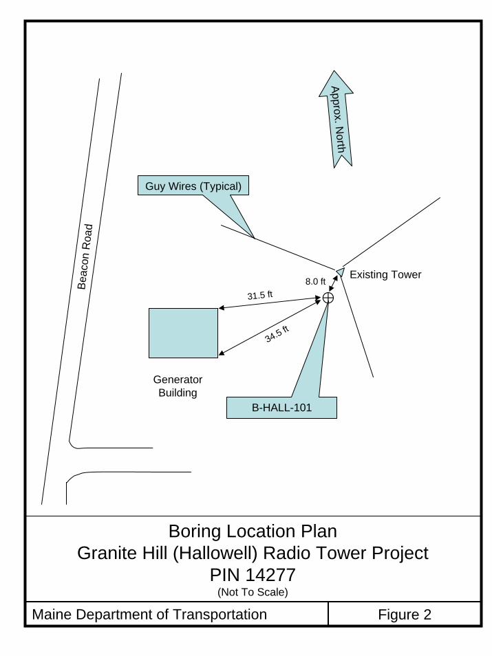
2.0 INTRODUCTION MaineDOT plans to install a new 180-foot self supported radio tower at the existing radio tower facility on Granite Hill, Hallowell, Maine, shown on the Site Location Map on Figure 1 in Appendix A. The proposed new tower will be constructed on a new foundation(s) adjacent to the site of existing tower (exact location not yet known). Figure 2 in Appendix A shows the existing site features. The new Granite Hill tower is planned to be a self supporting tower. We understand that the foundation design will be provided by the tower manufacturer selected by MaineDOT for this site.
3.0 SITE AND SUBSURFACE CONDITIONS
3.1 Site Conditions The site is easily accessed by a narrow gravel road called Beacon Road. The radio tower site is on the east side of Beacon Road approximately 700 feet south of the intersection with Winthrop Street. Conventional rubber-tired construction equipment will be able to access the site. The existing tower is a guyed tower approximately 100 feet high and is operated by the Emergency Management Agency (EMA). There is an existing generator building about 40 feet from the existing tower (see Figure 2). During preparation of this report no information was available concerning the design and construction of the existing tower, guy anchorages and support building foundations. Other than the generator building, the nearest existing structure to the proposed site is a private residence approximately 300 feet north of the tower site and on the west side of Beacon Street. The ground surface topography within the fenced radio tower property slopes down moderately from east to west. Surficial drainage will generally follow the local topography and carry surface water away in all directions, although some rainfall will be retained in the thin surficial soils on the flatter areas of the site. Surficial geology maps of the region indicate glacial till surficial soils and many bedrock outcrops. The entire area within the fenced radio tower property is soil covered and no bedrock outcrops are visible.
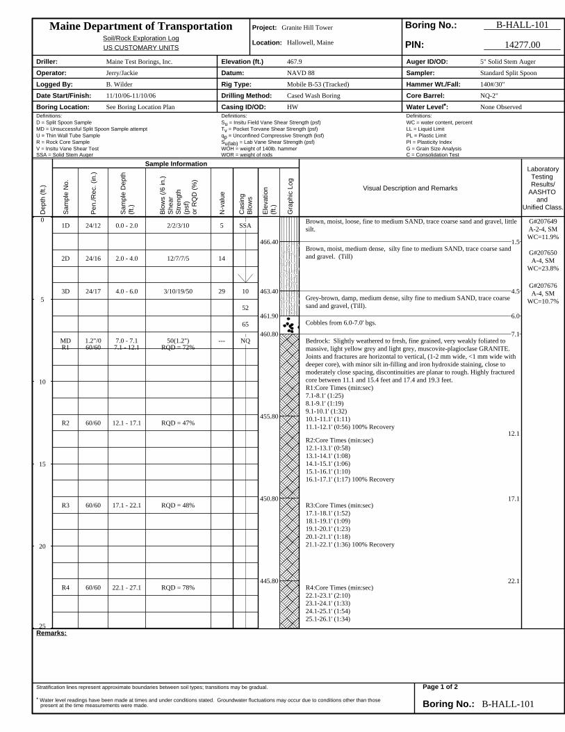
3.2 Subsurface Conditions We investigated the subsurface conditions in the vicinity of the proposed tower site by drilling one boring to a depth of approximately 32.1 feet below ground surface (bgs) at the location shown on Figure 2. The test boring, designated B-HALL-101, was drilled on 10 November 2006 by Maine Test Borings, Inc. of Brewer, Maine, using a track-mounted Mobile B-53 drill rig. MaineDOT technician Bruce Wilder was present throughout the field program to select the boring location, determine protocols for rock sampling and log the conditions encountered. Drilling in soil was performed using Standard Penetration Test split spoon sampling protocols.
Page 3 of 10

Granite Hill Radio Tower Hallowell, Maine, PIN 14277
September 2007 Drilling in bedrock was performed using cased wash boring methods and diamond NQ2 rock coring with a double-tube core barrel, which produced a 3-inch diameter borehole and a 2-inch diameter rock core sample. The borehole was grouted after the exploration was completed. In the boring, we found fine to medium sand with trace coarse sand and gravel and little silt over glacial till comprised of silty fine to medium sand with trace coarse sand and gravel over bedrock. The bedrock is consistently comprised of slightly weathered to fresh, fine-grained muscovite-plagioclase granite. Joints and fractures are close to moderately close, generally 1-2 mm or less wide with minor silt in-filling and iron staining. We observed highly fractured zones between 11.1 and 15.4 feet below top of bedrock and 17.4 and 19.3 feet below top of bedrock. The observed rock quality designations (RQD’s) ranged between 47 percent in Run R-2 (12.1 to 17.1 ft bgs), and 92 percent in Run R-5 (27.1 to 32.1 ft bgs). Thus, the observed rock quality ranged from poor to excellent. We did not encounter groundwater at the time the boring was conducted. However, the groundwater level will fluctuate with seasonal changes, runoff, and adjacent construction activities. For a more detailed description of the subsurface conditions, please refer to the boring log in Appendix B, Field Exploration and Test Data.
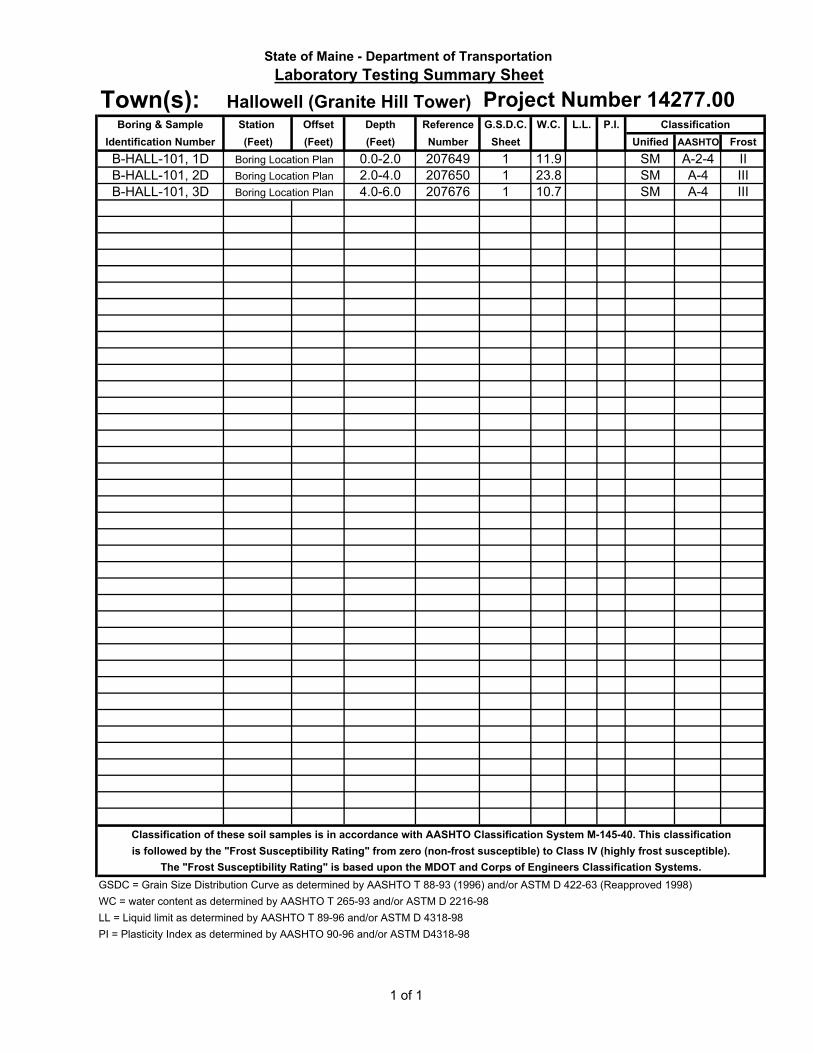
3.3 Laboratory Testing We conducted a laboratory soil testing program on selected samples recovered from the test boring to assess physical property characteristics. Laboratory soil testing was performed by the MaineDOT soils lab in Bangor, Maine. We conducted grain size analysis and moisture content determinations on soil samples 1D (0.0-2.0 ft.), 2D (2.0-4.0 ft.), and 3D (4.0-6.0 ft). Golder Associates, Inc., Brunswick, Maine, conducted a total of eight point load index tests on selected portions of bedrock core samples from Run R-3 (17.1-22.1 ft bgs), and Run R-5 (27.1-32.1 ft. bgs) and summarized the results in their report dated 15 February 2007 (Golder Associates, 2007). The point load tests were conducted using a Roc Test Pil-7 apparatus. Point load index test data can be used to assess variations in the rock unconfined compressive strength. The Golder point load test results estimate average rock uniaxial compressive strengths of 24,000 pounds per square inch (psi) and 26,700 psi in diametrical and axial point load tests, respectively, on intact portions of bedrock core, respectively. Results of laboratory testing are presented in Appendix C, Laboratory Test Data. The AASHTO and USCS soil classification and water content data are also presented on the boring logs in Appendix B. The Golder Associates, Inc., rock test results have been excerpted from their report and have been placed in Appendix C.
4.0 EVALUATION and RECOMMENDATIONS
The tower and the foundation support requirements will be designed in accordance with the Standard TIA-222-F (Telecommunications Industry Association, June 1996, Reaffirmed March 2003) for ASD methodology or TIA-222-G, August 2005, and TIA-222-G1, April 2007, for
Page 4 of 10

Granite Hill Radio Tower Hallowell, Maine, PIN 14277
September 2007 LRFD methodology. Although the design loads for a 180-foot tower are currently unknown, we understand that loads for a triangular tower of this height can be on the order of 100 to 300 kips/leg for compression and uplift. To provide resistance against lateral, overturning and uplift loads, the tower foundation typically consists of a large mat foundation or concrete pier pads for each leg. At shallow bedrock sites, rock anchor installation may be cost effective. The final tower design loads will depend on the type and square foot area of antennas, wind and ice loading for the site, load and performance criteria, anchorage, and required factors of safety (FS) (ASD design) or factored loads and factored resistances (LRFD design).
4.1 Foundations - Geotechnical Design We recommend that the new tower foundation be supported directly on sound bedrock. Based on our boring exploration, we expect sound bedrock to occur either at the bedrock surface or within about one foot of the rock surface. We recommend consideration of both a mat foundation, and individual concrete pier pad foundations, with or without rock anchors as required by the design. Typically, a concrete foundation pier pad without rock anchors for a three-legged self-supporting tower would have dimensions on the order of 10 to 15-foot square, 2 to 3 feet thick, and be founded 5 or 6 feet below the ground surface. However, the engineered foundation for this project may vary in dimensions and embedment, based on site-specific loading and performance criteria. Alternately, rock anchors could be designed to resist lateral and uplift loads for a shallower pier pad foundation beneath the entire structure, or for individual foundations for each tower leg.
4.1.1 LRFD Geotechnical Design of Tower Foundations - General
4.1.1.a. Strength Limit State Analyses Loads. Tower foundations (rock anchored spread footing foundations, individual pier leg spread footings and mat foundations) shall be designed so that the factored design strength (or factored resistance) of the particular foundation element meets or exceeds the five strength limit state (factored) load combinations cited in TIA-222-G Article 2.3.2. Loads shall be calculated in accordance with TIA-222-G Article 2.0. Project foundations shall be designed for the following site and structure classifications: Ground Conditions: Site Class B (Table 2-11, p.45) Structure Class: Class III (Table 2-1, p.39) The earthquake spectral response acceleration at short periods (Ss) for the site is less than 1.0. Based on the criteria found in Article 2.7, TIA-222-G, earthquake effects may be ignored for strength limit analyses of the foundations. Resistances. Resistance of tower foundations shall be designed for the strength limit states in accordance with TIA-222-G Article 9.0 and the criteria defined in this report. When conflicting
Page 5 of 10
Granite Hill Radio Tower Hallowell, Maine, PIN 14277
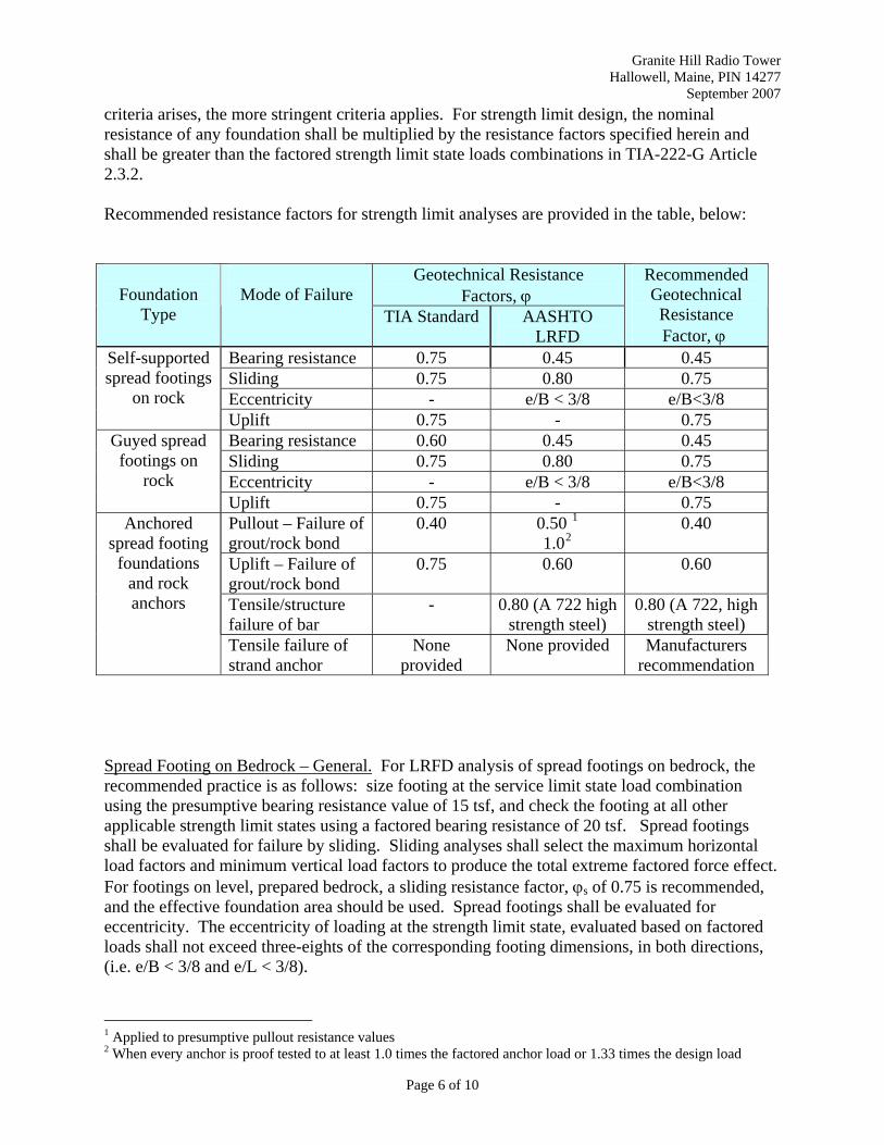
September 2007 criteria arises, the more stringent criteria applies. For strength limit design, the nominal resistance of any foundation shall be multiplied by the resistance factors specified herein and shall be greater than the factored strength limit state loads combinations in TIA-222-G Article 2.3.2. Recommended resistance factors for strength limit analyses are provided in the table, below:
Geotechnical Resistance Factors, ϕ
Foundation
Type
Mode of Failure
TIA Standard AASHTO LRFD
Recommended Geotechnical Resistance Factor, ϕ
Bearing resistance 0.75 0.45 0.45 Sliding 0.75 0.80 0.75 Eccentricity - e/B < 3/8 e/B<3/8
Self-supported spread footings
on rock Uplift 0.75 - 0.75 Bearing resistance 0.60 0.45 0.45 Sliding 0.75 0.80 0.75 Eccentricity - e/B < 3/8 e/B<3/8
Guyed spread footings on
rock Uplift 0.75 - 0.75 Pullout – Failure of grout/rock bond
0.40 0.50 1
1.020.40
Uplift – Failure of grout/rock bond
0.75 0.60 0.60
Tensile/structure failure of bar
- 0.80 (A 722 high strength steel)
0.80 (A 722, high strength steel)
Anchored spread footing
foundations and rock anchors
Tensile failure of strand anchor
None provided
None provided Manufacturers recommendation
Spread Footing on Bedrock – General. For LRFD analysis of spread footings on bedrock, the recommended practice is as follows: size footing at the service limit state load combination using the presumptive bearing resistance value of 15 tsf, and check the footing at all other applicable strength limit states using a factored bearing resistance of 20 tsf. Spread footings shall be evaluated for failure by sliding. Sliding analyses shall select the maximum horizontal load factors and minimum vertical load factors to produce the total extreme factored force effect. For footings on level, prepared bedrock, a sliding resistance factor, ϕs of 0.75 is recommended, and the effective foundation area should be used. Spread footings shall be evaluated for eccentricity. The eccentricity of loading at the strength limit state, evaluated based on factored loads shall not exceed three-eights of the corresponding footing dimensions, in both directions, (i.e. e/B < 3/8 and e/L < 3/8).
1 Applied to presumptive pullout resistance values 2 When every anchor is proof tested to at least 1.0 times the factored anchor load or 1.33 times the design load
Page 6 of 10
Granite Hill Radio Tower Hallowell, Maine, PIN 14277
September 2007 4.1.1.b. Service Limit State Analyses
Foundation resistances shall be calculated using a ϕ of 1.0 when investigating foundation displacements for the serviceability limit states; (reference TIA-222-G Article 9.4.1). Foundation and anchorage displacements need not be calculated for the service and strength limit state combination, except when the structure is supported solely by a nonredundant foundation or single mat or caisson. Calculated displacement shall be less than 0.75 inch for the service limit state analysis. Serviceability limit state analyses shall investigate displacement under the service limit state load combinations in accordance with TIA-222-G, Article 2.8.
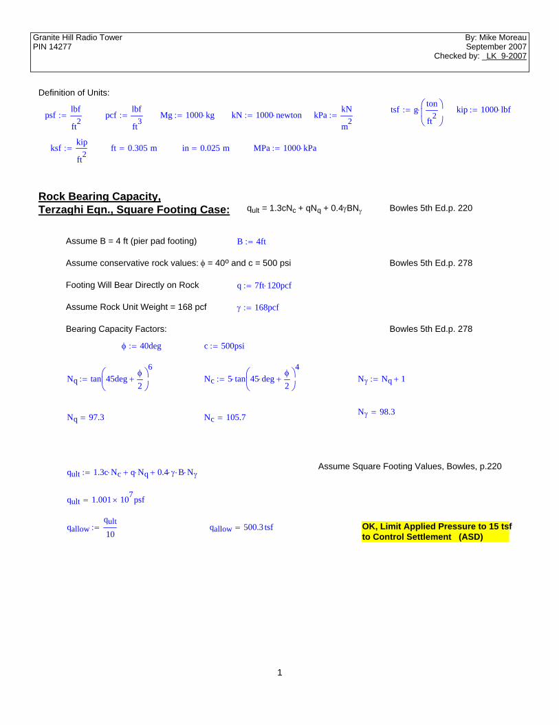
4.1.2 Bearing Capacity When correlated to the estimated rock compressive strengths determined from the point load index tests, the allowable bearing pressure for foundations bearing directly on sound bedrock is typically in the range of 1/3 to 1/10 the unconfined compressive strength (Bowles, p. 278). Presumptive allowable bearing pressures for granite published in Fang, 1991, Table 3.8, range between 30 and 60 tsf. We estimated theoretical bearing capacity values on the order of 500 tsf using equations and correlations found in Bowles. However, based on our observations of the bedrock conditions and our experience at similar sites, we recommend an allowable contact bearing pressure of 15 tsf (ASD design) or factored bearing resistance of 20 tsf (LRFD design) for strength limit state analyses be used for compression loads for design. We recommend a minimum footing width of 3 feet regardless of footing pressures for individual tower leg foundations if a large pier pad is not used. In no instance shall the maximum footing pressure exceed the allowable concrete bearing stress, regardless of the bedrock bearing capacity. To verify that the foundation bearing conditions are consistent with our findings in the boring exploration, we recommend that the exposed footing subgrade be observed and approved by an experienced engineer or geologist.
4.1.3 Settlement We expect that foundation settlement will be negligible and less than ½-inch for foundations bearing on sound bedrock and with bearing pressures less than or equal to 15 tsf. Any anticipated settlement will occur rapidly as the foundation and tower are constructed.
4.1.4 Groundwater Table We did not encounter groundwater at the time of the boring exploration. However, we noted that the upper layer of bedrock was slightly weathered and fractured as evidenced by the low RQD in core Run R-1. Consequently, we recommend that the groundwater table be assumed at the finished grade surface for design purposes.
Page 7 of 10
Granite Hill Radio Tower Hallowell, Maine, PIN 14277
September 2007
4.1.5 Frost Depth The design freezing index for Hallowell, Maine, is 1620 F-degree days which would indicate an average frost depth of 6.5 feet based on the soil type and natural water content (Table 5-1, MaineDOT Bridge Design Guide, 2003). Our exploration found only about 7.1 feet soil and cobbles. Since sound rock is not frost-susceptible and the recommended frost depth is very nearly at the rock surface, we recommend that foundations be constructed on sound bedrock. We recommend that the bedrock conditions be confirmed by an experienced engineer or geologist during construction.
4.1.6 Rock Anchors for Lateral and Uplift Load Resistance We encountered competent granite bedrock at the site with an average unconfined compressive strength of about 25,375 psi. Consequently, permanent rock anchors incorporating ASTM A 722 150 psi thread bars or ASTM A 416 strand anchors may be used to provide uplift and lateral load resistance for the tower foundation. Bond stresses in Post-Tensioning Institute, 2004, indicate typical average ultimate rock/grout bond stresses in competent granite between 250 and 450 psi. The granite at this site is generally poor down to approximately 22 feet. Consequently, we recommend using the lower bound value. Considering an ultimate rock/grout bond stress of 250 psi and a FS of 2, we recommend that a maximum ASD rock/grout bond stress of 125 psi should be used for ASD designs (PTI, 2004; NAVFAC, 1983). A factored resistance for anchor pullout of 150 psi should be used for LRFD designs. Either bar type anchors such as Dywidag or Williams threadbar anchors or strand type anchors may be used, however bar anchors are commonly used. Based on the findings of our exploration, laboratory testing, and rock anchor design guidance from several references (NAVFAC, DM 7.3, 1983; Post-Tensioning Institute, 2004; Fang, 1991), we recommend the following criteria for rock anchor design: Use anchor tendons furnished with double corrosion protection Size the anchor tendon for a design load less than 60 percent of the specified minimum
tensile strength of the tendon steel, or the allowable geotechnical capacity, whichever is less for ASD design. For LRFD, the maximum factored load group shall not exceed the nominal yield strength of the anchor bar times a resistance factor of ϕ = 0.80. We defer to manufacturer’s recommendations for strand anchor resistance factors (no guidance documents available)
Use a minimum rock/grout bond length of 10 feet regardless of the design load Provide anchor hole diameter in accordance with manufacturer’s recommendations Limit the allowable rock/grout bond stress to the values described above Assume a rock engagement angle of 60 degrees Assume a total unit weight of 168 pcf for rock within the engagement cone Assume the groundwater level at the ground surface
The free stressing length will depend on the type of anchor tendon used. We recommend minimum free stressing lengths of 10 feet for bar anchors and 15 feet for strand anchors.
Page 8 of 10

Granite Hill Radio Tower Hallowell, Maine, PIN 14277
September 2007 We recommend that all of the rock anchors installed for the tower foundation be performance tested in accordance with the procedures described by the Post-Tensioning Institute. Specifically, we recommend a maximum test load of 1.33 times the design load, provided the maximum test load does not exceed 80 percent of the anchor tendon’s specified minimum tensile strength. After testing, all anchors should be locked off at a load specified by the design engineer not exceeding 70 percent of the minimum specified tensile strength of the anchor (ASD design). For LRFD design, the anchor lock off load should be equal to a minimum of 50 percent of the nominal (unfactored) anchor load.
4.1.7 Lateral and Uplift Load Resistance Without Rock Anchors Lateral loads may be resisted using concrete/bedrock interface friction. We do not recommend using passive earth pressure because surficial soils are thin and loose. For base friction, we recommend using a concrete/rock interface coefficient of friction of 0.7. The resisting interface force is 0.7 times the normal load on the base of the foundation (NAVFAC, 1983). This assumes a completely level or benched level bedrock surface and cast-in-place foundations. The normal load should include the buoyant weight of the tower foundation below the ground surface, regular weight concrete above ground surface, the buoyant weight of any overlying soil below the ground surface (if the foundation is embedded below ground surface), and the dead load of the tower. A minimum factor of safety of 1.5 against overturning is recommended for ASD design (TIA-222-F). For ASD design in accordance with TIA-222-F, uplift resistance for a pier pad foundation may be provided by the weight of the concrete pier and, if the foundation is embedded, the weight of the soil overlying the foundation enclosed within an inverted pyramid whose sides form a 30 degree angle with the vertical. The unit weight of soil overlying the foundation is required to be assumed equal to 100 pcf per TIA-222-F. Similarly, the weight of the foundation concrete is required to be assumed equal to 150 pcf for this analysis. Based on our site explorations, buoyant unit weights should be used for soil and concrete for foundations constructed below the ground surface at this site.
4.2 Site Preparation We anticipate that shallow leveling bench excavations will be made to construct the tower foundation. The foundation subgrade should consist of sound bedrock. The bearing surface should be cleaned of all overburden soils, and loose, disturbed or visibly fractured bedrock should be removed by mechanical means. Mechanical means include expansive agents, use of hydraulic hoe rams, hydraulic splitters, or wedging and prying. We recommend final bedrock surface preparation by washing with a high pressure water jet. The nature, slope, and degree of fracturing in the bedrock will not be evident until the foundation excavation is made. We recommend anchoring, doweling, benching or other means of improving sliding resistance if the prepared bedrock surface is steeper than 4:1 (H:V) in any direction. Surface water should be diverted from the foundation excavation throughout the period of construction. We recommend removing any groundwater encountered at the base of the
Page 9 of 10

Granite Hill Radio Tower Hallowell, Maine, PIN 14277
September 2007 foundation excavation by using a sump pump located in a corner of the excavation outside of the foundation footprint. If required, the contractor should use a foundation backfill soil material meeting the requirements of MaineDOT Standard Specification 703.20, Gravel Borrow. The backfill soil should be placed in 8-inch thick loose lifts and compacted to 95 percent of the Modified Proctor (ASTM D 1557) maximum dry density.
4.3 Final Plan Review and Construction Monitoring We recommend that the Radio Tower Project Team geotechnical engineer review the final drawings and specifications to confirm that the earthwork and foundation recommendations are properly interpreted and implemented in the design and specifications. We also recommend that a qualified geotechnical engineer or construction engineer observe and evaluate the following tower foundation construction phases: Foundation subgrade prior to placement of footing formwork Rock anchor installation and performance testing, if applicable, and Placement and compaction of backfill soils around the perimeter and/or the top of the tower
foundation Finally, we recommend that the radio tower shop drawings be reviewed by the Maine Department of Transportation structures group to verify that loading criteria, load conditions, anchorage, performance criteria, and required FS conform to current radio tower structural standards.
5.0 CLOSURE This report has been prepared for use by the MaineDOT Radio Tower Replacement Team, for specific application to the Granite Hill tower replacement. The report has been prepared in accordance with generally accepted soil and foundation engineering practices. No other intended use or warranty is expressed or implied. In the event that any changes in the nature, design, or location of the proposed tower are planned, this report should be reviewed by a geotechnical engineer to assess the appropriateness of the conclusions and recommendations and to modify the recommendations as appropriate to reflect the changes in design. Further, the analyses and recommendations are based in part upon limited soil explorations completed at discrete locations on the project site. If variations from the conditions encountered during the investigation appear evident during construction, it may also become necessary to re-evaluate the recommendations made in this report.
Page 10 of 10

REFERENCES American Association of State Highway and Transportation Officials, (2007), LRFD Bridge
Design Specifications, 4th Ed, AASHTO, Washington, D.C. Bowles, Joseph E. (1996), Foundation Analysis and Design, 5th Edition, McGraw-Hill, New
York, NY. Fang, Hsai-Yang (1991), Foundation Engineering Handbook, Second Edition, Van Nostrand
Reinhold, New York, NY. Golder Associates, Inc., (2007), Rock Core Testing Results, Four MaineDOT Radio Tower Sites,
Contract U1210060676, Consultant, Brunswick, ME. MaineDOT, (2003) Bridge Design Guide, MaineDOT Bridge Program, Augusta, ME. NAVFAC, (1983), Soil Dynamics, Deep Stabilization, and Special Geotechnical Construction,
Design Manual 7.3, Naval Facilities Engineering Command, Alexander, VA. Post-Tensioning Institute, (2004), Recommendations for Prestressed Rock and Soil Anchors,
Post-Tensioning Institute, Phoenix, AZ. Telecommunications Industry Association, (2003), TIA-222-F, Structural Standards for Steel
Antenna Towers and Antenna Supporting Structures, TIA Standards and Technology Dept., Arlington, VA, June 1996 and reaffirmed March 2003.
Telecommunications Industry Association, (2005), TIA-222-G, Structural Standard for Antenna
Supporting Structures and Antennas, TIA Standards and Technology Dept., Arlington, VA, effective January 1, 2006.
Telecommunications Industry Association, (2007), TIA-222-G-1, Structural Standard for Steel
Antenna Towers and Antenna Supporting Structures – Addendum 1, TIA Standards and Technology Dept., Arlington, VA.

APPENDIX - A
Figures

FOYE
RD
NYE
RD
GRANITE HILL RD
WINTHROP ST
KERNS HILL RD
BEAC
ON
ST
69°50'0"W
69°50'0"W
44°1
8'30
"N
44°1
8'30
"N
Location: 044 18'30''N 069 49'59''WProject ID: 14277.00Project Manager: Joel Kittredge
Date: 10/12/06Road Names:
1 inch equals 308 feet Page 1 of 1Town(s): Hallowell (Granite Hill Mtn)
Proposed tower Location
k
Boring Location PlanGranite Hill (Hallowell) Radio Tower Project
PIN 14277(Not To Scale)
Maine Department of Transportation Figure 2
Approx. North
8.0 ft
GeneratorBuilding
34.5 ft
31.5 ft
Beac
on R
oad
⊕
Guy Wires (Typical)
Existing Tower
B-HALL-101

APPENDIX - B
Field Exploration and Test Data
0
5
10
15
20
25
1D
2D
3D
MDR1
R2
R3
R4
24/12
24/16
24/17
1.2"/060/60
60/60
60/60
60/60
0.0 - 2.0
2.0 - 4.0
4.0 - 6.0
7.0 - 7.17.1 - 12.1
12.1 - 17.1
17.1 - 22.1
22.1 - 27.1
2/2/3/10
12/7/7/5
3/10/19/50
50(1.2")RQD = 72%
RQD = 47%
RQD = 48%
RQD = 78%
5
14
29
---
SSA
10
52
65
NQ
466.40
463.40
461.90
460.80
455.80
450.80
445.80
Brown, moist, loose, fine to medium SAND, trace coarse sand and gravel, littlesilt.
1.5Brown, moist, medium dense, silty fine to medium SAND, trace coarse sandand gravel. (Till)
4.5Grey-brown, damp, medium dense, silty fine to medium SAND, trace coarsesand and gravel, (Till).
6.0Cobbles from 6.0-7.0' bgs.
7.1Bedrock: Slightly weathered to fresh, fine grained, very weakly foliated tomassive, light yellow grey and light grey, muscovite-plagioclase GRANITE.Joints and fractures are horizontal to vertical, (1-2 mm wide, <1 mm wide withdeeper core), with minor silt in-filling and iron hydroxide staining, close tomoderately close spacing, discontinuities are planar to rough. Highly fracturedcore between 11.1 and 15.4 feet and 17.4 and 19.3 feet.R1:Core Times (min:sec)7.1-8.1' (1:25)8.1-9.1' (1:19)9.1-10.1' (1:32)10.1-11.1' (1:11)11.1-12.1' (0:56) 100% Recovery
12.1R2:Core Times (min:sec)12.1-13.1' (0:58)13.1-14.1' (1:08)14.1-15.1' (1:06)15.1-16.1' (1:10)16.1-17.1' (1:17) 100% Recovery
17.1R3:Core Times (min:sec)17.1-18.1' (1:52)18.1-19.1' (1:09)19.1-20.1' (1:23)20.1-21.1' (1:18)21.1-22.1' (1:36) 100% Recovery
22.1R4:Core Times (min:sec)22.1-23.1' (2:10)23.1-24.1' (1:33)24.1-25.1' (1:54)25.1-26.1' (1:34)
G#207649A-2-4, SMWC=11.9%
G#207650A-4, SM
WC=23.8%
G#207676A-4, SM
WC=10.7%
Maine Department of Transportation Project: Granite Hill Tower Boring No.: B-HALL-101Soil/Rock Exploration Log Location: Hallowell, MaineUS CUSTOMARY UNITS PIN: 14277.00
Driller: Maine Test Borings, Inc. Elevation (ft.) 467.9 Auger ID/OD: 5" Solid Stem Auger
Operator: Jerry/Jackie Datum: NAVD 88 Sampler: Standard Split Spoon
Logged By: B. Wilder Rig Type: Mobile B-53 (Tracked) Hammer Wt./Fall: 140#/30"
Date Start/Finish: 11/10/06-11/10/06 Drilling Method: Cased Wash Boring Core Barrel: NQ-2"
Boring Location: See Boring Location Plan Casing ID/OD: HW Water Level*: None ObservedDefinitions: Definitions: Definitions:D = Split Spoon Sample Su = Insitu Field Vane Shear Strength (psf) WC = water content, percentMD = Unsuccessful Split Spoon Sample attempt Tv = Pocket Torvane Shear Strength (psf) LL = Liquid LimitU = Thin Wall Tube Sample qp = Unconfined Compressive Strength (ksf) PL = Plastic LimitR = Rock Core Sample Su(lab) = Lab Vane Shear Strength (psf) PI = Plasticity IndexV = Insitu Vane Shear Test WOH = weight of 140lb. hammer G = Grain Size AnalysisSSA = Solid Stem Auger WOR = weight of rods C = Consolidation Test
Remarks:
Stratification lines represent approximate boundaries between soil types; transitions may be gradual.
* Water level readings have been made at times and under conditions stated. Groundwater fluctuations may occur due to conditions other than thosepresent at the time measurements were made. Boring No.: B-HALL-101
Dep
th (f
t.)
Sam
ple
No.
Sample Information
Pen
./Rec
. (in
.)
Sam
ple
Dep
th(ft
.)
Blo
ws
(/6 in
.)S
hear
Stre
ngth
(psf
)or
RQ
D (%
)
N-v
alue
Cas
ing
Blo
ws
Ele
vatio
n(ft
.)
Gra
phic
Log
Visual Description and Remarks
LaboratoryTesting Results/
AASHTO and
Unified Class.
Page 1 of 2

25
30
35
40
45
50
R5 60/60 27.1 - 32.1 RQD = 92%440.80
435.80
26.1-27.1' (1:36) 100% Recovery
27.1R5:Core Times (min:sec)27.1-28.1' (1:30)28.1-29.1' (1:07)29.1-30.1' (1:27)30.1-31.1' (1:41)31.1-32.1' (1:36) 100% Recovery
32.1Bottom of Exploration at 32.1 feet below ground surface.
Maine Department of Transportation Project: Granite Hill Tower Boring No.: B-HALL-101Soil/Rock Exploration Log Location: Hallowell, MaineUS CUSTOMARY UNITS PIN: 14277.00
Driller: Maine Test Borings, Inc. Elevation (ft.) 467.9 Auger ID/OD: 5" Solid Stem Auger
Operator: Jerry/Jackie Datum: NAVD 88 Sampler: Standard Split Spoon
Logged By: B. Wilder Rig Type: Mobile B-53 (Tracked) Hammer Wt./Fall: 140#/30"
Date Start/Finish: 11/10/06-11/10/06 Drilling Method: Cased Wash Boring Core Barrel: NQ-2"
Boring Location: See Boring Location Plan Casing ID/OD: HW Water Level*: None ObservedDefinitions: Definitions: Definitions:D = Split Spoon Sample Su = Insitu Field Vane Shear Strength (psf) WC = water content, percentMD = Unsuccessful Split Spoon Sample attempt Tv = Pocket Torvane Shear Strength (psf) LL = Liquid LimitU = Thin Wall Tube Sample qp = Unconfined Compressive Strength (ksf) PL = Plastic LimitR = Rock Core Sample Su(lab) = Lab Vane Shear Strength (psf) PI = Plasticity IndexV = Insitu Vane Shear Test WOH = weight of 140lb. hammer G = Grain Size AnalysisSSA = Solid Stem Auger WOR = weight of rods C = Consolidation Test
Remarks:
Stratification lines represent approximate boundaries between soil types; transitions may be gradual.
* Water level readings have been made at times and under conditions stated. Groundwater fluctuations may occur due to conditions other than thosepresent at the time measurements were made. Boring No.: B-HALL-101
Dep
th (f
t.)
Sam
ple
No.
Sample Information
Pen
./Rec
. (in
.)
Sam
ple
Dep
th(ft
.)
Blo
ws
(/6 in
.)S
hear
Stre
ngth
(psf
)or
RQ
D (%
)
N-v
alue
Cas
ing
Blo
ws
Ele
vatio
n(ft
.)
Gra
phic
Log
Visual Description and Remarks
LaboratoryTesting Results/
AASHTO and
Unified Class.
Page 2 of 2

APPENDIX - C
Laboratory Test Data
Station Offset Depth Reference G.S.D.C. W.C. L.L. P.I.
(Feet) (Feet) (Feet) Number Sheet Unified AASHTO Frost
0.0-2.0 207649 1 11.9 SM A-2-4 II
2.0-4.0 207650 1 23.8 SM A-4 III
4.0-6.0 207676 1 10.7 SM A-4 III
Classification of these soil samples is in accordance with AASHTO Classification System M-145-40. This classification
is followed by the "Frost Susceptibility Rating" from zero (non-frost susceptible) to Class IV (highly frost susceptible).
The "Frost Susceptibility Rating" is based upon the MDOT and Corps of Engineers Classification Systems.
GSDC = Grain Size Distribution Curve as determined by AASHTO T 88-93 (1996) and/or ASTM D 422-63 (Reapproved 1998)
WC = water content as determined by AASHTO T 265-93 and/or ASTM D 2216-98
LL = Liquid limit as determined by AASHTO T 89-96 and/or ASTM D 4318-98
PI = Plasticity Index as determined by AASHTO 90-96 and/or ASTM D4318-98
Identification Number
B-HALL-101, 1D
Project Number 14277.00
B-HALL-101, 2D
Boring Location Plan
Boring Location Plan
Boring Location Plan
Classification
State of Maine - Department of Transportation
Laboratory Testing Summary Sheet
Town(s): Hallowell (Granite Hill Tower)Boring & Sample
B-HALL-101, 3D
1 of 1

3"
2"1-1/2"
1"
3/4"
1/2"
3/8"
1/4"
#4
#8
#10
#16
#20
#40
#60
#100
#200
0.05
0.03
0.010
0.005
0.001
76.2
50.8
38.1
25.4
19.05
12.7
9.53
6.35
4.75
2.36
2.00
1.18
0.85
0.426
0.25
0.15
0.075
0.05
0.03
0.005
GRAVEL
SAND
SILT
SIEVE ANALYSIS
US Standard Sieve Numbers
HYDROMETER ANALYSIS
Grain Diameter, mm
State of Maine Department of Transportation
GRAIN
SIZE DISTRIBUTIO
N CURVE
100
10
10.1
0.01
0.001
Grain Diameter, mm
0
10
20
30
40
50
60
70
80
90
100
Percent Finer by Weight
100
90
80
70
60
50
40
30
20
10
0
Percent Retained by Weight
CLAY
SHEET NO.
UNIFIED CLASSIFICATION
SAND, little silt, trace gravel.
Silty SAND, trace gravel.
Silty SAND, trace gravel.
11.9
23.8
10.7
B-HALL-101/1D
B-HALL-101/2D
B-HALL-101/3D
0-2.0
2.0-4.0
4.0-6.0
Depth, ft
Boring/Sample No.
Description
W, %
LL
PL
PI
� ��� � ��� � ��� � ��� � ��� � ���
SHEET 1
Hallowell
014277.00
WHITE, TERRY A 2/7/2007
PIN
Town
Reported by/Date
Offset, ft
Station

073-86802 MaineDOTFebruary 2007
PROJECT LOCATIONBORINGNUMBER
CORERUN
NUMBERDEPTH
(ft)TESTTYPE2
De EQUIV.CORE
DIAMETER(in)
PFORCE ATFAILURE3
(lb)
FSIZE
CORRECTION(De/50)
IsPOINTLOAD
STRENGTHINDEX4
(psi)
ESTIMATEDUCS BASED
ONCORRELATION
WITH POINTLOAD INDEX5
(psi) ROCK TYPE
B-1 R1 3.2-4.2 D 2.00 3288 1.01 824 18,950
B-1 R1 3.2-4.2 D 1.99 3964 1.00 1008 23,180
B-1 R1 3.2-4.2 D 2.01 4126 1.01 1034 23,770
B-1 R1 3.2-4.2 A 2.23 4780 1.06 1022 23,500
B-1 R1 3.2-4.2 A 2.29 2326 1.08 479 11,020
B-1 R1 3.2-4.2 A 2.20 5063 1.06 1107 25,470
Waterboro, ME B-WATE-101 R3 12.9-13.8 D 1.97 2275 1.00 587 13,500
B-WATE-101 R3 12.9-13.8 D 1.97 2343 1.00 605 13,910
B-WATE-101 R3 12.9-13.8 D 1.97 2848 1.00 735 16,900
B-WATE-101 R3 12.9-13.8 A 2.22 4019 1.06 865 19,900
B-WATE-101 R3 12.9-13.8 A 2.27 3134 1.07 655 15,070
B-WATE-101 R3 12.9-13.8 A 2.04 3168 1.02 777 17,880
B-WATE-102 R1 4.1-5.0 D 1.97 2796 1.00 722 16,600
B-WATE-102 R1 4.1-5.0 D 2.01 1330 1.01 333 7,660
B-WATE-102 R1 4.1-5.0 A 1.97 3660 1.00 945 21,720
B-WATE-102 R1 4.1-5.0 A 1.71 4019 0.93 1283 29,500
Hallowell, ME B-HALL-101 R3 18.9-19.9 D 2.01 3327 1.01 833 19,170
B-HALL-101 R3 18.9-19.9 D 1.99 4460 1.00 1134 26,080
B-HALL-101 R3 18.9-19.9 A 2.28 5896 1.08 1223 28,140
B-HALL-101 R3 18.9-19.9 A 2.19 5101 1.05 1124 25,850
B-HALL-101 R5 29.7-30.6 D 1.99 4541 1.00 1154 26,550
B-HALL-101 R5 29.7-30.6 D 1.97 4109 1.00 1060 24,390
B-HALL-101 R5 29.7-30.6 A 2.29 4716 1.08 972 22,360
B-HALL-101 R5 29.7-30.6 A 2.20 6059 1.06 1324 30,460
Woodstock, ME B-WOOD-101 R1 2.2-2.8 D 1.97 924 1.00 238 5,480
B-WOOD-101 R1 2.2-2.8 D 1.97 1881 1.00 486 11,170
B-WOOD-101 R1 2.2-2.8 A 1.37 1244 0.83 553 12,730
B-WOOD-101 R1 2.2-2.8 A 2.13 2335 1.04 535 12,310
B-WOOD-101 R4 17.0-17.8 D 1.97 1039 1.00 268 6,170
B-WOOD-101 R4 17.0-17.8 D 1.97 1569 1.00 405 9,310
B-WOOD-101 R4 17.0-17.8 A 1.94 3044 0.99 805 18,520
B-WOOD-101 R4 17.0-17.8 A 1.72 2057 0.93 650 14,940
Notes:1. All tests were performed in accordance with ASTM D 57312. D = Diametral / A = Axial3. Force at Failure (P) calculated from Gauge reading at failure x Ram Area of Jack (1.474 in2)4. Is = Point Load Strength Index = (P/De
2) x F5. Estimated uniaxial compressive strength (UCS) values calculated from Is x 23 based on correlation in "Rock Slope Engineering" Hoek and Bray, 1981.6. ft = feet; in = inch; psi = pounds per square inch
Checked by: JRSReviewed by: MSP
Spruce MountainTower
Cadillac MountainRadio Tower
Mount DesertIsland, ME
Ossipee HillTower
Granite HillTower
biotite-muscoviteGNEISS
biotite-muscoviteGNEISS
muscovite-plagioclaseGRANITE
muscovite-plagioclaseGRANITE
muscovite-biotiteGNEISS
muscovite-biotiteGNEISS
biotite-hornblendeGRANITE
TABLE 1
MAINE DOT RADIO TOWER SITESROCK CORE TESTING
SUMMARY OF POINT LOAD INDEX TEST RESULTS
Golder Associates Inc.

APPENDIX - D
Calculations
Granite Hill Radio TowerPIN 14277
By: Mike MoreauSeptember 2007
Checked by: _LK 9-2007
Definition of Units:
tsf gton
ft2⎛⎜⎝
⎞⎟⎠
⋅:= kip 1000 lbf⋅:=psflbf
ft2:= pcf
lbf
ft3:= Mg 1000 kg⋅:= kN 1000 newton⋅:= kPa
kN
m2:=
ksfkip
ft2:= ft 0.305 m= in 0.025 m= MPa 1000 kPa⋅:=
Rock Bearing Capacity,Terzaghi Eqn., Square Footing Case: qult = 1.3cNc + qNq + 0.4γBNγ Bowles 5th Ed.p. 220
Assume B = 4 ft (pier pad footing) B 4ft:=
Assume conservative rock values: φ = 40o and c = 500 psi Bowles 5th Ed.p. 278
Footing Will Bear Directly on Rock q 7ft 120⋅ pcf:=
Assume Rock Unit Weight = 168 pcf γ 168pcf:=
Bearing Capacity Factors: Bowles 5th Ed.p. 278
φ 40deg:= c 500psi:=
Nq tan 45degφ2
+⎛⎜⎝
⎞⎟⎠
6:= Nc 5 tan 45 deg⋅
φ2
+⎛⎜⎝
⎞⎟⎠
4⋅:= Nγ Nq 1+:=
Nγ 98.3=Nq 97.3= Nc 105.7=
Assume Square Footing Values, Bowles, p.220qult 1.3c Nc⋅ q Nq⋅+ 0.4 γ⋅ B⋅ Nγ⋅+:=
qult 1.001 107× psf=
qallowqult10
:= qallow 500.3 tsf= OK, Limit Applied Pressure to 15 tsfto Control Settlement (ASD)
1

Granite Hill Radio TowerPIN 14277
By: Mike MoreauSeptember 2007
Checked by: _LK 9-2007
LRFD Rock Bearing Resistance
Nominal
Rs 15tsf 3⋅:= Rs 45 tsf=
Factored
φs 0.45:= AASHTO LRFD Code
OK, Limit Factored Pressure to20 tsf to Control Settlement (LRFD)qfactored φs Rs⋅:= qfactored 20.25 tsf=
Frost Protection:
From the Maine Design Freezing Index Map:
DFI = 1620 degree-days
Site has Granular Soils With Wn = 10% to 24%
From the 2003 Bridge Design Guide Table 5-1:
Frost_depth0.2 87.5in 84.8in−( )⋅ 84.8in+[ ] 0.2 72.4in 70.2in−( )⋅ 70.2in+[ ]+
2:=
Frost_depth 77.99 in=
Frost_depth 6.499 ft= Use 6.5 feet
Average Rock Unconfined Compressive Strength:
Avg19170psi 26080psi+ 28140psi+ 25850psi+ 26550psi+ 24390psi+ 22360psi+ 30460psi+
8:=
Avg 25375psi=
2

Granite Hill Radio TowerPIN 14277
By: Mike MoreauSeptember 2007
Checked by: _LK 9-2007
Gout/Rock Unconfined Compressive Strength:
Nominal Grout/Rock Bond Stress
250 psi Post Tensioning Institute, 2004
Factored
φs 0.60:= AASHTO LRFD Code
OK, Limit Grout/Bond Stressto 150 psi (LRFD)BondStressfactored φs 250⋅ psi:= BondStressfactored 150psi=
3