department of transportation, infrastructure and energy ... · department of transportation,...
TRANSCRIPT

Department of Transportation, Infrastructure and Energy
General Provisions and Contract Specificationsfor Highway Construction
Revised 2019

GENERAL PROVISIONS AND CONTRACT SPECIFICATIONS FOR HIGHWAY CONSTRUCTIONDepartment of Transportation, Infrastructure and Energy
SPECIFICATIONS: Current StatusDate: January 2019
DIVISION / Section Latest RevisionDate
100 - General Provisions
101 2019.01.14
102 2019.01.14
103 2019.01.14
104 2018.01.15
105 2016.01.15
106 2019.01.14
107 2019.01.14
200 - Earthwork
201 2019.01.14
202 2012.02.09
203 2012.02.09
204 2014.01.15
205 2003.03.27
206 2014.01.15
207 2014.01.15
208 2015.01.15
209 2017.02.17
210 2002.04.10
211 2019.01.14
212 2017.02.17
213 2017.02.17
214 2019.01.14
215 2019.01.14
216 2003.03.27
217 2015.01.15
218 2006.03.28
219 2019.01.14

GENERAL PROVISIONS AND CONTRACT SPECIFICATIONS FOR HIGHWAY CONSTRUCTIONDepartment of Transportation, Infrastructure and Energy
DIVISION / Section Latest RevisionDate
220 2015.01.15
300 - Drainage
301 2016.01.15
Figures 301-01 & 301-02 2019.01.14
302 2009.02.04
303 2019.01.14
Figure 303-01 (New) 2019.01.14
304 2007.02.09
305 2016.01.15
306 2013.01.15
307 2012.02.09
308 2016.01.15
309 2015.01.15
310 2015.01.15
311 2015.01.15
312 2017.02.17
Figures 312-01 & 312-02 Revised 2002
400 - Granular Material
401 2016.01.15
402 2016.01.15
500 - Bitumen
501 2019.01.14
502 Rescinded
503 2018.01.23
600 - Pavement
601 2018.01.15
602 Rescinded
603 See Below
603.01/02 2019.01.08
603.03 2019.01.14

GENERAL PROVISIONS AND CONTRACT SPECIFICATIONS FOR HIGHWAY CONSTRUCTIONDepartment of Transportation, Infrastructure and Energy
DIVISION / Section Latest RevisionDate
603.04 Rescinded
603.05 2016.01.15
603.06 2007.02.09
603.07 2007.02.09
603.08/09 1997.05.16
603.10 2011.02.14
603.11 2018.01.15
603.12 2019.01.14
603.13 2013.01.05
603.14 2016.01.15
603.15 2016.01.15
603.16 2000.02.29
603.17/18 1997.05.16
604 Rescinded
605 Rescinded
606 1994.03.28
607 1994.04.11
608 1998.03.03
609 See Below
609.01/02 2016.01.15
609.03 2012.02.09
609.04 2013.01.15
609.05 2013.01.15
609.06/07 2013.01.15
610 2017.02.17
700 - Rehabilitation
701 1999.01.13
702 2003.03.27
703 2000.02.29
704 2019.01.14

GENERAL PROVISIONS AND CONTRACT SPECIFICATIONS FOR HIGHWAY CONSTRUCTIONDepartment of Transportation, Infrastructure and Energy
DIVISION / Section Latest RevisionDate
705 2003.03.27
706 2004.05.05
707 2005.04.15
708 1994.03.28
709 1996.04.15
710 1994.03.28
711 2004.05.05
712 2019.01.08
713 1999.01.13
714 2003.03.27
715 2019.01.14
716 2013.01.15
800- Environment
801 2017.02.17
Figures 801-01, 801-02,801-03, and 801-04
Revised 2002
802 1994.03.28
803 2016.01.15
804 2013.01.15
805 2019.01.14
806 2013.01.15
807 2013.01.15
808 2017.02.17
809 2014.01.15
810 Rescinded
811 2016.02.12
812 2004.05.05
813 2013.01.15
900 - Safety

GENERAL PROVISIONS AND CONTRACT SPECIFICATIONS FOR HIGHWAY CONSTRUCTIONDepartment of Transportation, Infrastructure and Energy
DIVISION / Section Latest RevisionDate
901 2017.02.17
902 2005.04.15
903 2017.02.17
Figure 903-01 Revised 2017
Figure 903-02 Revised 2016
Figure 903-03 2005
Figure 903-04 Revised 2010
904 2011.02.14
Figure 904-01 Revised 2001
905 2016.01.15
906 2015.01.15
907 2016.01.15
Figures 907-01, 907-02(1 of 2) and 907-2 (2 of 2)
Revised 2001
908 2017.02.17
909 2016.01.15
1000 - Electrical
1001 2016.01.15
1002 2014.01.15
1003 2016.01.15
1004 2014.01.15
1100 - Concrete
1101 2019.01.14
1102 2016.01.15
Figures 1102-01and 1102-02
Revised 2002
1103 2014.01.15
Figure 1103-01Figure 1103-02
Revised 2005Revised 2001
1104 2003.03.27

DIVISION / Section Latest RevisionDate
1200 - Miscellaneous
1201 1999.01.18
1202 1994.03.28
1300 - Supplementals As required
Appendix 1 - Tender Form& Agreement Sample
2016.01.15
Appendix 2 2012.02.09
Appendix 3 2018.01.15
Appendix 4 2003.03.27

Revision #26
Delete Section
Insert Section
Note: Blue text indicates additions, red strikethrough text indicates removal, green indicates relocated. All drawings/figures to be inserted into the 2019 paper and electronic versions of the Spec manual. DIVISION 100 GENERAL PROVISIONS 101 TERMINOLOGY AND DEFINITIONS 101.02 101.02 Definitions
Certificate of Final Acceptance: A written statement prepared by the Engineer stating the date on which the work has been accepted by the Department and the warranty period has ended Final Acceptance: The date when the warranty period has ended and there are no warranty items. Substantial Completion: The identity state of a contract when the work or improvement is ready for use or is being used for the purpose intended and when the work remaining to be done under contract is capable of being complete or corrected at a cost of not more than ten percent (10%) of the final Contract price.
Total Completion: The identity of a contract when all work which was described in the contract has been completed. Warm Mix Asphalt (WMA): Warm Mix Asphalt is a generic term for a variety of technologies that allow Hot Mix Asphalt producers to lower temperatures at which the material is mixed and placed on the road.
102 INSTRUCTIONS TO BIDDERS 102.07 102.07 Bid and Performance Security
All certified cheques, irrevocable standby letters of credit, bank drafts and bonds are to be made payable to the Minister of Finance, Energy and Municipal Affairs, Province of Prince Edward Island.

102.11 102.11 Material Guaranty Guarantee
103 SCOPE OF WORK 103.05 103.05 Acceptance of the Work
The Engineer shall accept the work when all of the work has been completed and inspected and there are no deficiencies, and issue a Certificate of Final Completion. The Engineer shall issue a Final Acceptance Letter and release the Security Deposit following the expiration of the one year warranty period and after all deficiencies identified have been rectified. The Engineer shall issue a Certificate of Final Completion when all of the work has been completed, inspected and there are no identified deficiencies. The Engineer shall issue a Certificate of Final Acceptance and release the Security Deposit following the expiration of the one year warranty period and after any warranty issues have been rectified.
106 PROSECUTION AND PROGRESS 106.05 106.05 Liquidated Damages
The Contractor shall be assessed liquidated damages for each working day beyond the number of working days and/or the completion date as both specified in the Contract or beyond any extension of time that may be granted in accordance with Provision 106.04. The liquidated damages for work being carried out on Arterial Highways shall be assessed at $1,000.00 $1,250.00 per day for each day beyond the time of Final Completion. For work carried out on other highways or within any tendered project outside of highway limits liquidated damages shall be assessed at $700.00 $850.00 a day for each day beyond the time of Final Completion.

107 PAYMENT 107.07 107.07 Records of Contractor Open for Inspection
The Contractor's payrolls, time books, account books, invoices and statements shall be, at all times, open for inspection and extraction by the Engineer or any authorized representative of the Minister. The Contractor shall assist enable the Engineer or representative to ascertain as far as possible, the exact payment, sums or claims so due and remaining unpaid by the Contractor. The Contractor shall keep proper accounts and records of the cost to the Contractor of the Work and of all expenditures or commitments made by the Contractor under Contract including the related invoices, receipts, vouchers, bill of ladings and statements. Such accounts, invoices, receipts, vouchers, bill of ladings and statements shall, at all times, be open to audit, copying, extracting information and inspection by the authorized representatives of Government. The Contractor shall provide all facilities for the audits, inspections, copying and extractions and shall provide Government and its authorized representatives with all information that is requested from the accounts, records, invoices, receipts, vouchers, bill of ladings and statements.
Subject to statutory limitations, the Contractor shall not, without the written consent of Government, dispose of the accounts, records, invoices, receipts, vouchers, bill of ladings and statements related to the Contract, but shall preserve and keep the same available for audit, copying, extracting information and inspections at any time.

200 EARTHWORK 201 CLEARING 201.02 201.02 Construction Method
All brush and other debris resulting from the clearing shall be burned without damage to adjacent property, or otherwise disposed of at the Contractor's own expense, as the Engineer may direct. Burning shall be in accordance with the Provisions of the Fire Prevention Act and Regulations. The Contractor shall take precautions to prevent the fires from spreading and shall be liable for any damages caused in the performance of this work. All brush and other debris resulting from the clearing shall be disposed of at the Contractor's own expense. Burning shall only occur at the discretion of the Engineer. Any burning shall be in accordance with the Provisions of the Fire Prevention Act and Regulations. The Contractor shall take precautions to prevent the fires from spreading and shall be liable for any damages on the existing property as well as any adjacent property caused in the performance of this work.
211 SHOULDER MATERIAL
211.04 211.04 Scheduling and Liquidated Damages
All shoulder material shall be placed within four days of no later than four days after the completion of the final lift of asphalt in each year. Liquidated damages of $300.00 per day
214 TAP DRAIN INSTALLATION
214.02 214.02 Construction Method
Straw or Hay mulch shall be supplied and placed on all bare soil surfaces on a daily basis.
215 DITCHING
215.02 215.02 Construction Method
Straw or Hay mulch shall be supplied and placed on all bare soil surfaces as required by the Engineer.

219 GEOGRID REINFORCEMENT 219.02 219.02 Material
Geogrid to be BX1100, BX1200, as manufactured by Tensar or equivalent in terms of physical properties and strength.
The geogrid shall be a biaxially formed regular grid structure; resistant to ultra-violet degradation, to damage under normal construction practices, and to all forms of biological or chemical degradation normally encountered in the material being reinforced. It shall also have the characteristics outlined in Table 219-1.
Table 219-1Requirements for Geogrid Reinforcement
Property Type 1 Minimum
Type 2 Minimum
Test
Aperture Stability for Punched and Drawn (m-N/deg)
0.32 0.65 ASTM D7864/ D7864M-15
Aperture Size along Roll Length (mm)
25 25 Calipered
Open Area (%) 70 70 Calipered
Rib Thickness at Ribs (mm) 0.76 1.27 Calipered
Polypropylene Material (%) 98 98 ASTM D-4101
Carbon Black Material (%) 0.5 0.5 ASTM D-4218
Flexural Rigidity along Roll Length (mg/cm)
250,000 750,000 ASTM D-7748 D7748-12
Strength at Junctions (kg/m) 1,116 ASTM D-7737-11
Tensile Strength @ 2% Strain MD/XMD (kN/M)
280/450 4.1 / 6.6
410/620 6.0 / 9.0
ASTM D-6637-10
Tensile Strength @ 5% Strain MD/XMD (kN/M)
410/620 8.5 / 13.4
810/1340 11.8 / 19.6
ASTM D-6637-10
Efficiency of Junctions (%) 93 93 ASTM D-7737-11

Division DRAINAGE 301 STORM SEWER INSTALLATION 301-01 Updated figure 301-01 Inlet Grate 301-02 Updated figure 301-02 Outlet Grate 303-01 New figure added for adjustable manhole covers 303.02 303.02 Material
The Contractor shall supply the appropriate type of material to perform the required work.
Adjusting rings for precast concrete structures shall be precast or cast-in-place as indicated on the Drawings or as directed by the Engineer and shall be the same shape as the frames and covers. The outer size of the adjusting rings must be at least as large as the frames and covers but shall not extend beyond the edge of the catch basin.
Adjusting rings for corrugated steel catch basins shall be steel ring inserts made to the height required specifically to fit inside the seat of the existing frame and also to accept the cover. The design of the steel ring insert shall be approved by the Engineer prior to manufacturing.
Adjustable manhole frames and covers shall be C-50M1 Cone Shaped Frame / Autostable as manufactured by Bibby-Ste-Croix, or approved equivalent, meeting the requirements of CSA B70.1 and shall be as shown on Detail Drawing No. 303-01.
Division 600 PAVEMENT 603.01/02 HOT MIX ASPHALTIC CONCRETE 603.02.01 603.02.01 Asphalt Cement
Department Staff shall have access to all Asphalt Binder delivery slips at the asphalt plant as the material is delivered. If Department Staff are not present at the time of delivery, then a copy of the delivery slip(s) shall be retained in the asphalt plant control room for Department Staff.

Adding new Section: 603.02.07 603.02.07 Warm Mix Asphalt (WMA)
WMA technologies must be approved by the Engineer prior to its use. Technology approved for previous work is not guaranteed approval on all future work. The Contractor shall supply all materials required for the production of WMA. Supporting documentation from the WMA supplier for the proper preparation, storage and handling of their product shall be obtained by the Contractor and submitted to the Engineer.
603.03 603.03 Hot Mix Asphaltic Concrete
The percent passing the 4.75 mm seive size ±2% for the blended aggregate graduations for given mix types shall be as follows:
Mix Types A
Percent Passing 4.75 mm sieve size 50%
B+C 64%
C 63%
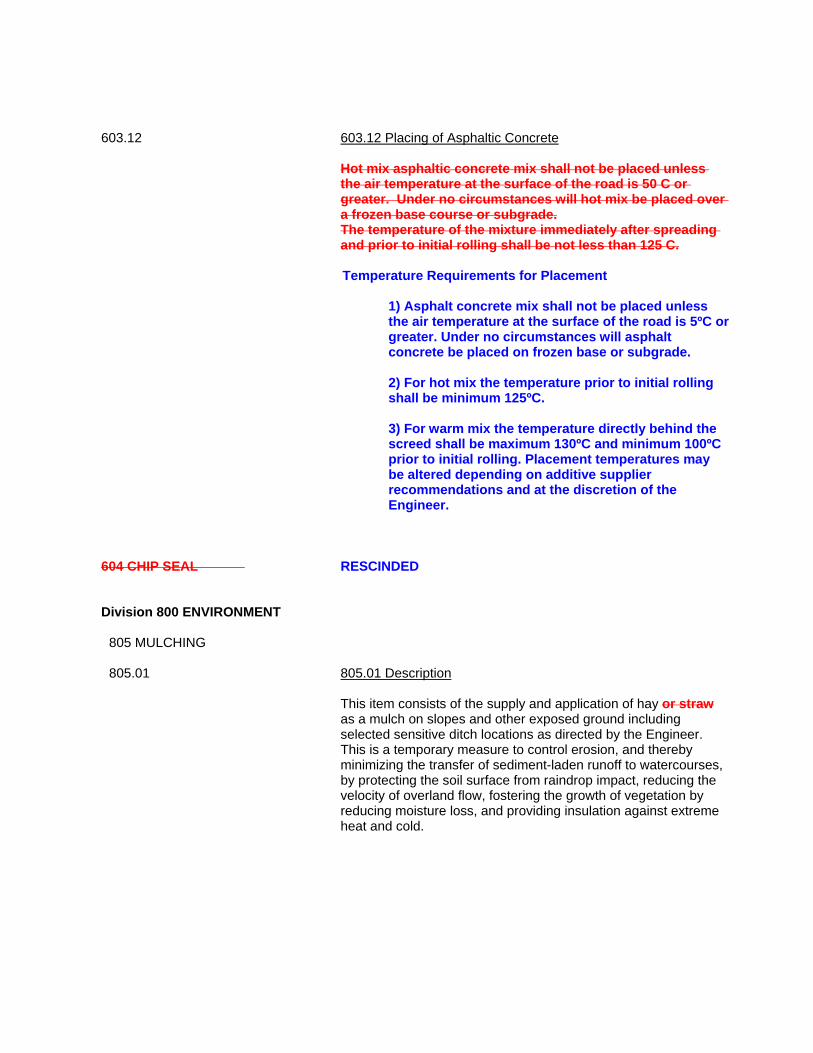
603.12 603.12 Placing of Asphaltic Concrete
Hot mix asphaltic concrete mix shall not be placed unless the air temperature at the surface of the road is 50 C or greater. Under no circumstances will hot mix be placed over a frozen base course or subgrade. The temperature of the mixture immediately after spreading and prior to initial rolling shall be not less than 125 C.
Temperature Requirements for Placement
1) Asphalt concrete mix shall not be placed unless the air temperature at the surface of the road is 5ºC or greater. Under no circumstances will asphalt concrete be placed on frozen base or subgrade.
2) For hot mix the temperature prior to initial rolling
shall be minimum 125ºC. 3) For warm mix the temperature directly behind the
screed shall be maximum 130ºC and minimum 100ºC prior to initial rolling. Placement temperatures may be altered depending on additive supplier recommendations and at the discretion of the Engineer.
604 CHIP SEAL RESCINDED
Division 800 ENVIRONMENT
805 MULCHING 805.01 805.01 Description
This item consists of the supply and application of hay or straw as a mulch on slopes and other exposed ground including selected sensitive ditch locations as directed by the Engineer. This is a temporary measure to control erosion, and thereby minimizing the transfer of sediment-laden runoff to watercourses, by protecting the soil surface from raindrop impact, reducing the velocity of overland flow, fostering the growth of vegetation by reducing moisture loss, and providing insulation against extreme heat and cold.

805.02 805.02 Material
Hay or straw mulch shall be supplied by the Contractor. It shall be reasonably free of noxious weeds as per the Weed Control Act and other undesirable materials. It shall not be so wet, decayed or compacted that it inhibits even and uniform spreading. Hay mulch is the preferred material over straw mulch for areas that are to become vegetated. However, when mulching for overwintering protection, straw mulch should be used.
805.03 805.03 Construction Method and Maintenance
To avoid the mulch from being blown around, the length of hay or straw should be chopped to 200-300 mm. Mulching should be spread by the use of mechanical means such as a bale buster unless the job is small enough to be done by hand. Hay or straw mulch shall be spread evenly and uniformly over the designated areas at a rate of 6000 kg per hectare with a coverage rate of 85% as deemed acceptable by the Engineer. At the request of the Engineer, the contractor shall be required to provide weigh scale documentation showing that the specified spread rate is being met.

Division 1100 CAST-IN-PLACE 1101 1101.08 1101.08 Concrete Mixes The Contractor shall comply with the following procedure:
Proportion normal density concrete in accordance with CAN/CSA-A23.1, Alternative 1, to give following properties for a suspended slab at a manhole chamber or a bridge deck:
- Use Type General Use Blended (GUb) cement. - Minimum compressive strength at 28 days: 35 MPa. - Minimum cement content: to CAN/CSA-A23.1. - Class of exposure: C-1. - Nominal size of coarse aggregate: 20 mm. - Slump at time and point of discharge: 80 mm ± 30 mm. - Air content: 5 to 8%. - Maximum water-cement ratio 0.40.
- Chemical admixtures: to CAN/CSA-A266.4M. Proportion normal density concrete in accordance with CAN/CSA-A23.1, Alternative 1, for all concrete except for a suspended slab at a manhole chamber or a bridge deck, to give the following properties:
- Use Type General Use (GU) cement. - Minimum compressive strength at 28 days: 32 MPa. - Minimum cement content: to CAN/CSA-A23.1. - Class of exposure: C-2. - Nominal size of coarse aggregate: 20 mm. - Slump at time and point of discharge: 80 mm ± 30 mm. - Air content: 5 to 8%. - Maximum water-cement ratio: 0.45. - Chemical admixtures: to CAN/CSA-A266.4M.

GENERAL PROVISIONS AND CONTRACT SPECIFICATIONSFOR HIGHWAY CONSTRUCTION
DEPARTMENT OF TRANSPORTATION, INFRASTRUCTURE AND ENERGY
TABLE OF CONTENTS
i
DIVISION 100 GENERAL PROVISIONS101 Terminology and Definitions102 Instructions to Bidders103 Scope of Work104 Control of Work105 Legal Relations and Responsibilities106 Prosecution and Progress107 Payment
DIVISION 200 EARTHWORK201 Clearing202 Grubbing203 Excavation204 Topsoil Removal and Reinstatement205 Borrow from Adjacent Land206 Borrow From Pit207 Granular Base208 Fine Grading209 Compaction210 Preparing Shoulders211 Shoulder Material212 Topsoil for Landscaping213 Random Rip Rap214 Tap Drain Installation215 Ditching216 Culvert End Cleanout217 Trench Excavation and Backfilling218 Geotechnical Fabric219 Geogrid Reinforcement220 Bedding Material
DIVISION 300 DRAINAGE301 Storm Sewer Pipe Installation302 Catch Basin Installation303 Catch Basin, Manhole and Valve Adjustment304 Drain Tile Installation305 Roadway Culvert Installation306 Driveway Culvert Placement307 Culvert Extension308 Culvert Removal 309 Timber Box Culvert310 Concrete Box Culvert311 Multi-Plated Corrugated Steel Arch312 Culvert End Treatment

GENERAL PROVISIONS AND CONTRACT SPECIFICATIONSFOR HIGHWAY CONSTRUCTION
DEPARTMENT OF TRANSPORTATION, INFRASTRUCTURE AND ENERGY
TABLE OF CONTENTS
ii
DIVISION 400 GRANULAR MATERIAL401 Aggregate402 Bedding Material
DIVISION 500 BITUMEN501 Asphalt Cement502 Asphalt Prime (RESCINDED)503 Asphalt Emulsions
DIVISION 600 PAVEMENT601 Tack Coat Application602 Prime Coat Application (RESCINDED)603 Hot Mix Asphaltic Concrete - Compaction604 Chip Seal (RESCINDED)605 Double Emulsified Asphalt Slurry Seal (RESCINDED)606 Asphaltic Concrete Curb607 Asphalt Crack Filling608 Cold Mix Bituminous Patching Material609 Hot Mix Asphaltic Concrete - End Result Specification610 HMA Driveway Mix
DIVISION 700 REHABILITATION701 Pulverize in Place702 Pulverize, Stockpile and Replace RAP703 Pulverize, and Stockpile RAP704 Cold Plane, Stockpile and Replace RAP705 Cold Plane Construction Joint706 Cold Plane and Patch707 Asphalt Reinforcement Mesh Placement708 Polystyrene Foam Board Placement709 Pavement Restoration710 Cutting Asphalt711 Excavate and Patch712 Cold Plane, Stockpile and Replace Rap as Shoulder Material713 Longitudinal Cold Plane Construction Joint714 Curb Removal715 Cold Plane, Transport and Pave716 Cold Plane and Stockpile
DIVISION 800 ENVIRONMENT801 Check Dams802 Water for Dust Control803 Hydro Seeding804 Landscaping and Seeding805 Mulching806 Silt Fence

GENERAL PROVISIONS AND CONTRACT SPECIFICATIONSFOR HIGHWAY CONSTRUCTION
DEPARTMENT OF TRANSPORTATION, INFRASTRUCTURE AND ENERGY
TABLE OF CONTENTS
iii
807 Erosion Control Mats808 Sediment Trap809 Sodding810 Maintenance and Sediment Control (RESCINDED)811 Straw Bale Barrier812 Compost813 Gabions
DIVISION 900 SAFETY901 Signallers902 Removal of Flex Beam Guiderail903 Flex Beam Guiderail904 Pavement Edge Delineation905 Temporary Marking906 Traffic Control Devices907 Vehicle Configurations and Restrictions908 Traffic Control Plan909 Installation of Guiderail End Treatment
DIVISION 1000 ELECTRICAL 1001 Electrical General Provisions1002 Telephone Ductbank1003 Basic Materials1004 Traffic Signals
DIVISION 1100 CONCRETE 1101 Cast-In-Place Concrete1102 Curb and Gutter1103 Concrete Sidewalk and Flatwork1104 Precast Concrete Span
DIVISION 1200 MISCELLANEOUS1201 Chain Link Fence and Gates1202 Cash Allowance
DIVISION 1300 SUPPLEMENTAL SPECIFICATIONS
APPENDIX 1 SAMPLE TENDER DOCUMENT
APPENDIX 2 ENVIRONMENTAL REQUIREMENTS
APPENDIX 3 TEMPORARY WORKPLACE TRAFFIC CONTROL MANUAL 2005
APPENDIX 4 WEIGH SCALE PROCEDURES

GENERAL PROVISIONS AND CONTRACT SPECIFICATIONSFOR HIGHWAY CONSTRUCTION
DEPARTMENT OF TRANSPORTATION, INFRASTRUCTURE AND ENERGY
GENERAL PROVISIONS 100
101 Terminology and Definitions
102 Instructions to Bidders
103 Scope of Work
104 Control of Work
105 Legal Relations and Responsibilities
106 Prosecution and Progress
107 Payment

GENERAL PROVISIONS AND CONTRACT SPECIFICATIONSFOR HIGHWAY CONSTRUCTION
DEPARTMENT OF TRANSPORTATION, INFRASTRUCTURE AND ENERGY
TERMINOLOGY AND DEFINITIONS 101
2019.01.14 101-1
101.01 Terminology
This document titled "General Provisions and Contract Specifications for HighwayConstruction", hereinafter referred to as 'this Document', contains information which isrelevant to the administration of highway construction contracts.
This Document is divided into Divisions (i.e. 100), Sections (i.e. 101), Provisions (i.e. 101.01)and Sub-Provisions (i.e. 101.01.01). Unless otherwise specified in the text, all references toSpecifications, Divisions, Sections, Provisions, Sub-Provisions, Tables or Figures shall referto this Document.
Whenever in this Document it is provided that anything is, is to be or to be done, if, as, whenor where "contemplated", "required", "directed", "deemed necessary", "permitted","suspended", "approved", "directed", "unacceptable", "suitable", "satisfactory","unsatisfactory", or "sufficient", such expressions shall have the same force as if followed bythe words "by the Engineer" or "to the Engineer" as the case may be.
101.02 Definitions
Wherever, in any part of the Contract, the following words, expressions, pronouns orabbreviations are used, the intent and meaning shall be as follows:
AASHTO: American Association of State Highway and Transportation Officials
ASTM:American Society for Testing and Materials.
Addendum:A change in a Tender issued prior to the time and date of Tender Closing, stated in theAdvertisement, which has the effect of modifying the Tender. An addendum shall beconsidered as an integral component of the Tender and shall be deemed to take precedenceover all other components of the Tender.
Advertisement:A public or private announcement stating the name of the tender, project location, and thetime, date, and location of the opening. The announcement shall either be published on theGovernment’s website www.gov.pe.ca/tenders, in the newspapers of P.E.I. or take the formof a letter of invitation.
Bank Draft:A cheque issued by a bank on behalf of the Bidder guaranteeing payment to the Departmentas described by the conditions in the Tender Form and Agreement if the agreement isexecuted by the Minister.
Bid Bond:A bond issued by a surety company on behalf of a Bidder to guarantee to the Departmentthat the Bidder will procure a Performance Bond and will carry out the work if the agreementis executed by the Minister.

GENERAL PROVISIONS AND CONTRACT SPECIFICATIONSFOR HIGHWAY CONSTRUCTION
DEPARTMENT OF TRANSPORTATION, INFRASTRUCTURE AND ENERGY
TERMINOLOGY AND DEFINITIONS 101
2019.01.14 101-2
Bidder:A person, partnership or corporation, acting directly or through a duly authorizedrepresentative, submitting a Tender for the work contemplated.
Borrow:An excavated material used in the construction of a subgrade; with the origin of the sourcebeing located either inside or outside the right-of-way.
Bridge:Any structure having a span of 3 metres or more which carries pedestrian or vehicular traffic.
CGSB:Canadian General Standards Board
CSA:Canadian Standards Association
CSP:Corrugated Steel Pipe
Certificate of Final Acceptance:A written statement prepared by the Engineer stating the date on which the work has beenaccepted by the Department and the warranty period has ended.
Certificate of Final Completion:A written statement prepared by the Engineer stating the date on which the work has beencompleted.
Certificate of Final Quantities:A written statement of final quantities prepared by the Engineer and agreed to by theContractor in writing.
Certificate of Substantial Completion:A written statement prepared by the Engineer stating the date on which the work has beensubstantially completed.
Certified Cheque:A cheque issued by the Bidder and certified by a bank guaranteeing that the Bidder hassufficient funds on deposit to cover payment to the Department as described by theconditions in the Tender Form and Agreement if the agreement is signed by the Minister.
Construction Period:That time referred to in the contract during which the work can be carried out.
Contract:The agreement between the Contractor and the Department covering the performance of thework and furnishing of construction materials. The Contract shall include the Advertisement,this Document, the Plans, the Agreement, Addenda, Schedule, the Special Provisions, theRelease from Liability and any Supplemental Agreements.
Contract Limits:The geographic locations of the beginning and end of a project.

GENERAL PROVISIONS AND CONTRACT SPECIFICATIONSFOR HIGHWAY CONSTRUCTION
DEPARTMENT OF TRANSPORTATION, INFRASTRUCTURE AND ENERGY
TERMINOLOGY AND DEFINITIONS 101
2019.01.14 101-3
Contract Time:The number of working days, as stipulated in the contract document, to complete thework.
Contractor:The party of the first part to the Contract acting directly or indirectly through agents oremployees, who is primarily liable for the acceptable performance of the Contract and alsofor the payment of all legal debts pertaining to the work.
Culvert:Any structure not classified as a bridge which provides an opening under a roadway.
Department:The Department of Transportation, Infrastructure and Energy of the Province of PrinceEdward Island.
Deputy Minister:The Deputy Minister of Transportation, Infrastructure and Energy of the Province of PrinceEdward Island.
Engineer:The person assigned by the Department to be in charge of the work, who is a Member ofEngineers PEI, acting directly or indirectly through a designated assistant or representative.
Final Acceptance:The date when the warranty period has ended and there are no warranty items.
Final Completion:The date when there is no work remaining to be done under contract.
Final Inspection:Inspection which will take place no sooner than 11 months from the date of substantialcompletion. A Final Inspection Letter will be forwarded to the contractor outlining anywarranty issues (if any) which shall be addressed under this contract prior to release of theperformance security.
Granular Base:A layer of granular material of specified type and thickness between the sub-base and thebase of the pavement surface.
Highway: The right-of-way which is reserved for use in construction of the roadway and its appertainingstructures.
Irrevocable Letter of Credit:A written promise, issued by a bank on behalf of the Bidder, guaranteeing payment to theDepartment as described by the conditions in the Tender Form and Agreement and theirrevocable letter of credit if the agreement is signed by the Minister.

GENERAL PROVISIONS AND CONTRACT SPECIFICATIONSFOR HIGHWAY CONSTRUCTION
DEPARTMENT OF TRANSPORTATION, INFRASTRUCTURE AND ENERGY
TERMINOLOGY AND DEFINITIONS 101
2019.01.14 101-4
Labour and Materials Bond:A bond issued by a surety company on behalf of the Contractor to guarantee to theDepartment that all claimants will be paid for labour and materials used on the workdescribed in the terms of the Contract.
Local Material: Material that has its source on Prince Edward Island.
Major Item:A major item is any item of work which is required for the project to fully operate as intendedand in a safe manner. For example, roadway granulars, asphalt, select borrow, pipe work,etc. would be considered a major item. Landscaping would not be considered a major item.
Minister:The Minister of Transportation, Infrastructure and Energy of the Province of Prince EdwardIsland.
Overburden:A layer of partially organic material located immediately below topsoil which is unacceptablefor use in construction and also unacceptable as topsoil.
PCP:Pre-cast Concrete Pipe
Pavement:A layer or layers of asphaltic or Portland cement concrete placed over an existing pavement,base, sub-base or subgrade.
Performance Bond:A bond issued by a surety company on behalf of the Contractor to guarantee to theDepartment proper performance of the terms of the Contract.
Plans/Drawings: Any plans, profiles, typical cross-sections, supplemental drawings or exact reproductionsthereof, which are approved or stamped by the Engineer and show the location, character,dimensions and/or detail of the work to be done and which are to be considered part of theContract.
Principals:The officers and individuals holding more than a 10% interest in a corporation; the partnersin a partnership or the owners of an unincorporated firm.
Province:The Province of Prince Edward Island.
RAP:Reclaimed Asphalt Pavement
Roadbed: That portion of the roadway extending from shoulder line to shoulder line; in other words, thesubgrade and shoulders taken as a unit.

GENERAL PROVISIONS AND CONTRACT SPECIFICATIONSFOR HIGHWAY CONSTRUCTION
DEPARTMENT OF TRANSPORTATION, INFRASTRUCTURE AND ENERGY
TERMINOLOGY AND DEFINITIONS 101
2019.01.14 101-5
Roadway:That portion of the highway included between the outside lines of gutters or ditches includingall appertaining structures and all slopes, ditches, channels, and waterways necessary forproper drainage and protection.
SADT:Summer Average Daily Traffic
Security Deposit:A deposit in the form of a certified cheque, bid bond, letter of credit or bank draft as securityas described in the Tender Form and Agreement for due fulfilment of the Contract.
Schedule:A document whereby the contractor shows specific contract tasks being done on a time line.
Slope: Rise to run expressed as a percent or run to rise expressed as a ratio.
Snowtrap:A field adjacent to the right-of-way with a terrain that causes snow to gather upon theroadway.
Specifications:All written or printed descriptions or instructions pertaining to the method and manner ofperforming the work or to the quantities and qualities of the materials to be furnished andwork to be carried out under the Contract; this includes the Tender, this Document,Supplemental Specifications, Special Provisions and Addenda, together with all writtenagreements made or to be made pertaining to the method or manner of performing the workor to the quantities or qualities of materials to be furnished and works to be carried out underthe Contract.
Special Provisions:Special directions containing requirements peculiar to the work not adequately provided forby the General Provisions and Contract Specifications for Highway Construction.
Stop Work Order:An order given in writing by the Engineer which directs the Contractor to stop work. An ordercommunicated verbally or in writing by a Department Representative to the Contractor thatdirects the Contractor to immediately stop work. This shall be followed up with a formalwritten Stop Work Order from the Engineer. The written order will state the reason, theconditions and the deadline for compliance with the order.
Sub-base:A layer of material or specified type and thickness between the Subgrade and the Base.
Sub-Contractor:Any person, company or entity that provides a service to, or on behalf of, the Contractor inorder to facilitate any aspect of the work
Subgrade:The earth or rock surface, whether in cut or in fill, that is prepared for the sub-base and base.

GENERAL PROVISIONS AND CONTRACT SPECIFICATIONSFOR HIGHWAY CONSTRUCTION
DEPARTMENT OF TRANSPORTATION, INFRASTRUCTURE AND ENERGY
TERMINOLOGY AND DEFINITIONS 101
2019.01.14 101-6
Substantial Completion:The state of a contract when the work or improvement is ready for use or is being used forthe purpose intended and when the work remaining to be done under contract is capable ofbeing complete or corrected at a cost of not more than ten percent (10%) of the final Contractprice.
Supplemental Specifications: Specifications which are supplemental to this Document.
Supplier:A person, corporation or entity which supplies materials to be incorporated into the work bythe Contractor or his affiliates.
Surplus Material:Any and all unused material the Department has placed a value on and may be stockpiledfor future use or transported to another site.
Technician:An assistant to the Engineer who is assigned to make inspection of work performed or beingperformed or of materials furnished or being furnished or to do such other work as assignedby the Engineer.
Tender: An offer by the Bidder for work on which the Department requires formal bids to be preparedand submitted.
Tender Form:The approval form for work on which the Department requires formal bids to be prepared andsubmitted.
Thickness:The compacted depth of a lift or layer of material after placement within the roadbed.
Ticket:A voucher, issued by a designated employee of the Department at the point of origin of a loadto a truck driver and delivered to a designated employee of the Department at the work site,describing the quantity of material upon which payment of the load is to be based, showingthe project number; road name; contractor; source number; scale number; truck owner/ truckdriver; truck and trailer plate numbers with number of axles on each; open or closed haul;haul length; date; time loaded and unloaded; signatures of Department weigher and checker(who cannot be the same person;) and volume in cubic metres if measured by volume, orgross weight, tare weight, and net weight of material in kilograms or pounds if measured byweight. The ticket shall indicate that it is for either Pit to Stockpile, Stockpile to Road, Void,or, Non-pay Item.
Topsoil:A fertile, friable soil of loamy character that contains a normal amount of organic matter.
Transportation and Infrastructure Renewal:Transportation and Public Works or Transportation and Infrastructure Renewal, which maybe stated within this document, shall mean Transportation, Infrastructure and Energy.

GENERAL PROVISIONS AND CONTRACT SPECIFICATIONSFOR HIGHWAY CONSTRUCTION
DEPARTMENT OF TRANSPORTATION, INFRASTRUCTURE AND ENERGY
TERMINOLOGY AND DEFINITIONS 101
2019.01.14 101-7
Warm Mix Asphalt (WMA):Warm Mix Asphalt is a generic term for a variety of technologies that allow Hot Mix Asphaltproducers to lower temperatures at which the material is mixed and placed on the road.
Warranty Period:Unless otherwise stipulated in the Contract Documents, the Warranty Period shall be definedas a period of 12 consecutive months from the date of substantial completion, as indicatedin the Certificate of Substantial Completion.
Watercourse: An area which has a sediment bed and may or may not contain water, and without limitingthe generality of the foregoing, includes the full length and width of the sediment bed, bankand shore of any stream, spring, creek, brook, river, lake, pond, bay, estuary or coastal body,any water therein, and any part thereof, up to and including the watercourse boundary.
Watercourse boundary: In a non-tidal watercourse, the edge of the sediment bed, and (ii) in a tidal watercourse, thetop of the bank of the watercourse, and where there is no discernible bank, means the meanhigh water mark of the watercourse.
Wetland: A “wetland” shall be defined as (i) an area which contains hydric soil, aquatic or water-tolerantvegetation, and may or may not contain water, and includes any water therein and everythingup to and including the wetland boundary, and (ii) without limiting the generality of theforegoing, includes any area identified in the Prince Edward Island Wetland Inventory asopen water, deep marsh, shallow marsh, salt marsh, seasonally flooded flats, brackishmarsh, a shrub swamp, a wooded swamp, a bog or a meadow;
Wetland Boundary:
Where the vegetation in a wetland changes from aquatic or water-tolerant vegetation toterrestrial vegetation or water-intolerant vegetation. A wetland by this definition is any areawith hydric soils and aquatic/water tolerant vegetation which may/may not be on the inventoryand may/may not contain water.
Waste Material: A material of any form which is deemed of no use to the Department and is to be disposed of by the Contractor.
Weigh Scale:A device used for the measurement of weight.
Work: All of the work specified in the contract as contemplated.
Work Day:Any calendar day from the time of commencement of the work until the completion ofthe work, other than Saturday, Sunday or Statutory holidays.

GENERAL PROVISIONS AND CONTRACT SPECIFICATIONSFOR HIGHWAY CONSTRUCTION
DEPARTMENT OF TRANSPORTATION, INFRASTRUCTURE AND ENERGY
INSTRUCTIONS TO BIDDERS 102
2019.01.14 102-1
102.01 Conformity of Work with Plans and Specifications
The Contractor shall perform all work and shall furnish all materials, unless specifiedelsewhere in the Contract, and complete the whole of the work in strict conformance with theplans and specifications.
102.02 Contents of Tender
The Department shall furnish the Bidder with a Tender Form and Agreement which will showan estimate of the various quantities of work to be performed, materials to be furnished andthe time before which the work must be completed.
All papers bound, attached or supplied with the Tender Form and Agreement are a necessarypart thereof and must not be removed from the Tender Package.
Special Provisions which are issued with the Tender Form and Agreement shall supersedeall other components of the Tender but Addenda may be issued at any time prior to the timeand date specified in the Advertisement for Tender Closing which may have the effect ofmodifying a Special Provision or any other Tender component.
Addenda issued within 24 hours of the closing date, which affect a change in scope to thecontract, shall require an extension to the closing date of the tender. The Engineer shalldetermine the effect of a change in scope and the appropriate extension to the closing daterequired due to the effect.
102.03 Bidder Investigations
The Bidder shall fully investigate the site and become acquainted with the location andcharacter of the terrain upon which the work is being undertaken. The Bidder shall alsobecome familiar with the plans, profiles, specifications, both general and special provisions,soil borings and reports, and all other information concerning the work which may be suppliedby the Department to those bidding the Contract.
No claims for extras will be entertained by the Engineer, unless the Bidder can show that theextra cost arose from unforeseen circumstances not covered by the information provided toBidders by the Department, or not obvious to a prudent Bidder before entering into theContract.
102.04 Preparation of Tender
The Bidder must submit the Tender on the forms furnished by the Department. The blankspaces in the Tender Form and Agreement must be filled in for each and every item for whicha quantity is given.
The Bidder must write in ink the prices, both in words and numerals, for which the Bidderproposes to do each item of the work contemplated. The Bidder must extend the total foreach item of the work and carry out a summation to the total value of the work to be doneunder the Tender.
If the Tender Form and Agreement is made out by an individual, the individual's name andPost Office address must be shown; if it is made out by a firm or partnership, the name andPost Office address of each member of the firm or partnership must be shown; and if it is

GENERAL PROVISIONS AND CONTRACT SPECIFICATIONSFOR HIGHWAY CONSTRUCTION
DEPARTMENT OF TRANSPORTATION, INFRASTRUCTURE AND ENERGY
INSTRUCTIONS TO BIDDERS 102
2019.01.14 102-2
made out by a corporation, the person signing the Tender must show the name of theProvince under the laws of which the corporation was incorporated and the names, titles, andbusiness addresses of the President, Secretary and Treasurer.
102.05 Delivery of Tender
The Tender must be received on or before the time and date of the Tender Closing specifiedin the advertisement. Each Tender Form and Agreement must be submitted in a sealedenvelope and should be marked:
"Tender for . . . .. . . . . . . . . . . . . . . . . . . . . . . . . . . . ."
If forwarded by registered mail, the sealed and marked envelope should be enclosed inanother and sent to the Minister, Department of Transportation, Infrastructure and Energy,PO Box 2000, Charlottetown, Prince Edward Island, C1A 7N8; if forwarded other than byregistered mail, it should be delivered to the Minister of the Prince Edward IslandTransportation, Infrastructure and Energy, 11 Kent Street, Charlottetown.
Faxed or emailed submissions, edits, changes, etc. shall not be accepted.
102.06 Rejection of Tender
Tenders will be rejected if they show any omissions, form alterations, additions not called for,conditional or alternate bids, or irregularities of any kind, or if they contain a clause in whichthe Bidder reserves the right to accept or reject a Contract awarded. The right to reject anyor all Tenders is reserved by the Minister; and lowest or any Tender will not necessarily beaccepted.
102.07 Bid and Performance Security
Bid Security:
The Tender shall be accompanied by either:(a) a certified cheque equal to the amount specified in the Tender Form and Agreement; or(b) a bank draft equal to the amount specified in the Tender Form and Agreement; or(c) a bid format irrevocable standby letter of credit equal to the amount specified in theTender Form and Agreement (on a Government approved form); or(d) a bid bond equal to the amount specified in the Tender Form and Agreement. (The bidbond shall be from a surety company authorized to do business in Canada guaranteeing tosupply a performance bond and a labour and materials bond equal to the amount specifiedin the Tender Form and Agreement.)
The Bidder shall forfeit the bid security to the Minister if the Bidder fails to enter into aContract when called upon to do so.
Performance Security:
Before Work commences on the project a Performance Security shall be filed with theDepartment. This Security shall remain in place until the warranty period expires (one yearafter substantial completion). This Performance Security shall be either:(a) a certified cheque in the minimum amount of ten percent (10%) of the Contract value,excluding HST, which shall be retained until the warranty period (one (1) year after

GENERAL PROVISIONS AND CONTRACT SPECIFICATIONSFOR HIGHWAY CONSTRUCTION
DEPARTMENT OF TRANSPORTATION, INFRASTRUCTURE AND ENERGY
INSTRUCTIONS TO BIDDERS 102
2019.01.14 102-3
substantial completion) has elapsed. Note: A certified cheque which has not been cashedshall be replaced within six months of the issue date; or(b) a bank draft in the minimum amount of ten percent (10%) of the Contract value, excludingHST, which shall be retained until the warranty period (one (1) year substantial completion)has elapsed.(c) a performance format irrevocable standby letter of credit on a government approved formin the minimum amount of ten percent ( 10% ) of the Contract value, excluding HST, whichshall be retained until the warranty period (one (1) year after substantial completion) haselapsed. A performance standby letter of credit must have an automatic renewal clausewithin the body of the agreement; or(d) a performance bond equal to 50% of the Contract value, excluding HST and a labour andmaterials bond equal to 25% of the Contract value, excluding HST which shall be retaineduntil the warranty period (one (1) year after substantial completion) has elapsed. Thecompany issuing these bonds must be authorized to do business in Canada. A performancebond and/or a labor and materials bond which matures prior to the end of the warranty periodshall be replaced, by the Contractor, with new Security of equal value, before maturity. TheMinister may limit the performance security to bonds only to assure the completion of thework.
When a contract is to be completed over several construction years, and portions of thecontract are considered by the Engineer as complete, but the entire Contract is not, theEngineer can issue a certificate of Substantial completion for those portions of the Work thatare complete, and the Security which would be appropriate for that Work can be releasedafter the one year warranty expires.
All certified cheques, irrevocable standby letters of credit, bank drafts, and bonds are to bemade payable to the Minister of Finance, Province of Prince Edward Island.
The Contractor will forfeit the performance security to the Minister if the Contractor fails tocarry out the Contract when called upon to do so.
The Government approved templates for the Bid Format and Performance Format irrevocablestandby letters of credit can be found in Appendix 1. Bidders who choose to use the letter ofcredit as security must provide them as shown on these approved templates. Any deviationfrom this standard template may be cause for rejection of the Tender. The letters shall be onthe Bidder’s preferred Financial Institutions letter head and shall be signed and sealed bypersonnel having proper authority.
102.08 Withdrawal of Tender
A bidder will be permitted to withdraw the Tender, unopened after it has been deposited, ifa request is received by the Department in writing prior to the latest time for receivingtenders.
102.09 Disqualification of Tender
Each Bidder shall submit only one (1) Tender.

GENERAL PROVISIONS AND CONTRACT SPECIFICATIONSFOR HIGHWAY CONSTRUCTION
DEPARTMENT OF TRANSPORTATION, INFRASTRUCTURE AND ENERGY
INSTRUCTIONS TO BIDDERS 102
2019.01.14 102-4
102.10 Competency of Bidder
Bidders must be capable of performing the various items of work bid upon. Bidders shall,upon the request of the Department, provide a statement covering experience on similar workand a statement of their financial resources.
102.11 Material Guarantee
Upon the request of the Department, Bidders shall furnish a complete statement of the origin,composition and manufacture of all materials to be used in the construction of the worktogether with any manufacturers' instructions. Upon the request of the Department, Biddersshall furnish samples of any or all materials to be used in the work; these samples may besubject to testing as required by the Department to determine their quality and fitness for thework.
102.12 Open Truck Haul
For all truck haul for which Department tickets are issued, the Contractor shall permit anyperson, partnership or corporation to supply trucks for haulage of material to be used in theContract, without giving preference to the Contractor's own trucks. The Contractor shall payfor trucks employed to haul materials to a work site at rates not less than the currentgovernment rates which may be re-established from time to time by the Department.
For those materials which are weighed for payment, only those trucks which can be fullysupported by the scales as required by Measurements Canada, shall be permitted to haul.These trucks must also conform to the Vehicle Configurations and Restrictions as providedin Section 907 of these specifications.
For those materials which are paid by volume, the trucks must conform to the VehicleConfigurations and Restrictions as provided in Section 907 of these specifications.
The truck haul shall be considered to be that distance from the point of loading to the centreof the work being carried out in the Contract Agreement.
Truck haul shall be determined in advance of any material being delivered to the work site.The Department representative and the Contractor shall be in agreement with truck haulmeasurement, prior to commencing the work.
The Contractor shall limit the truck haul to those roads that can accommodate two-way trafficflow. In the case of the material source being located on a road that can not meet thisrequirement, the Contractor may be required to provide pull-off areas as directed by theEngineer.
The Contractor may stockpile materials one time only prior to their incorporation into thework. Stockpile sites shall be determined and approved in advance of the stockpiling of thematerials. The Contractor shall install weigh scales in accordance with Section 107.03 ateither the production site or the stockpile site. In the case of materials imported by floatingvessel, the contractor may stockpile materials one time prior to their incorporation into thework.

GENERAL PROVISIONS AND CONTRACT SPECIFICATIONSFOR HIGHWAY CONSTRUCTION
DEPARTMENT OF TRANSPORTATION, INFRASTRUCTURE AND ENERGY
INSTRUCTIONS TO BIDDERS 102
2019.01.14 102-5
In the case of materials imported by truck, the Contractor must stockpile materials one timeonly prior to their incorporation into the work. The haul from the stockpile to the work siteshall be the open haul and no scales shall be required at the production site.
102.13 Scheduling of the Work
The Contractor shall submit a schedule prior to being awarded the Contract. The Departmentshall notify the successful bidder. After receiving the notification, the Contractor shall haveseven (7) working days to deliver an acceptable schedule. The schedule shall be limited tothe number of working days as stipulated in the Tender Form and Agreement and shall bewithin the construction period as defined in Section 101.02 Definitions. The Departmentreserves the right to ask the Contractor to revise the schedule prior to the time ofcommencement of the work. In no case, shall the scheduled completion date surpass thetime of completion as stated in the Tender Form and Agreement.
102.14 Errors or Omissions
The bidder shall notify the Department of any errors or omissions found in the Tenderdocument prior to the Tender closing.
102.15 References
All reference to acts, regulations, testing procedures, and methods shall be understood to bethe latest update to such acts, regulations, testing procedures, and methods, unless stateddifferently in the Tender Form and Agreement.
102.16 Taxes
Harmonized Sales Tax. The Province is not exempt for Harmonized Sales Tax (HST)purposes. As a result, the aggregate amount of Tender for Department Contracts are subjectto HST, however, prices submitted shall not include HST. The HST payable by theDepartment will be added as a separate item during Department processing of progresspayments and, therefore, HST will not appear as a cost in the aggregate amount of Tender.
Bidders are advised that they are eligible to claim an Input Tax Credit (ITC) for a portion ofthe HST paid in relation to the Contract to the requirements of the Government of Canada.
102.17 Procedures for Tender Openings and Evaluations
102.17.1 Tender Opening.
A preliminary check will be conducted at the Tender opening to ensure thefollowing information has been included.
• Security Deposit. Each Tender is reviewed to ensure that a SecurityDeposit accompanies the Tender.
• Aggregate Amount of Tender (Contract Price). Each Tender isreviewed to ensure the total aggregate amount of Tender (Contractprice) has been included.
• All signed Addenda (if any).

GENERAL PROVISIONS AND CONTRACT SPECIFICATIONSFOR HIGHWAY CONSTRUCTION
DEPARTMENT OF TRANSPORTATION, INFRASTRUCTURE AND ENERGY
INSTRUCTIONS TO BIDDERS 102
2019.01.14 102-6
• Failure to meet these requirements shall result in rejection of theTender at the Tender opening stage.
102.17.2 Tender Evaluations.
All Tenders not rejected at the Tender opening will be subject to a detailedevaluation by Department staff before a recommendation is made for awardof Tender. This detailed review will take place as soon as possible after thepublic opening and will consist of the following:
• Tender Form. The Tender shall be submitted on the proper form,supplied by the Department. Unit prices shall be written in ink ortypewritten and shall be given in both words and numerals in theappropriate columns. Forms shall not be altered, unless called forin a Department Addendum.
• Bid Conditions. The Bidder is not permitted to include conditionswith their Tender.
• Bid Security. Bid Security, meeting the requirements of Clause102.07, shall be included with the Tender.
• Signatures/Acknowledgements. The Tender Form and Agreementshall be completed and signed as an acknowledgement of thereceipt and understanding of the Tender documents.
• Arithmetic Checks. The Tender will be checked for arithmetic errors.In cases where the written unit price does not agree with thenumeric price, the written unit price will be used. All mathematicerrors will be corrected by Department staff and the rating ofTenders as to total Bid will be based on the corrected totals.
Failure to meet the requirements of the above items will result in therejection of the Tender.
• Unbalanced Bids. Each unit price in the Tender submission shallrepresent its proportionate share of the total cost of The Work.Unbalanced Bidding is not permitted. The Minister reserves theright, in their sole and absolute discretion, to deem a Tendersubmission unbalanced and may reject any and all Tenders, whichthey so deem, and for this purpose, to be unbalanced.
• Identical Bids. Where two or more acceptable Bids are identical, thesuccessful Bidder shall be selected by means of a coin tossperformed by the Department in the presence of the identicalBidders.

GENERAL PROVISIONS AND CONTRACT SPECIFICATIONSFOR HIGHWAY CONSTRUCTION
DEPARTMENT OF TRANSPORTATION, INFRASTRUCTURE AND ENERGY
SCOPE OF WORK 103
2019.01.14 103-1
103.01 Quantities
The quantities set forth in Schedule C of the Tender Form and Agreement are based onestimated quantities. If when carrying out the work and/or supplying materials under theContract, the quantities are foreseen to exceed the Contract amount, then the Contractorshall notify the Engineer.
Either party may request a price adjustment when quantities on major items, as stated withinthe Tender Form and Agreement, vary by more than 25% from the contract quantity.Adjustments to unit prices, in the case of an over-run, shall be applied only to that quantitythat is over and above 125% of the original quantity.
103.02 Changes and Alterations
The Engineer may, in writing, at any time, alter the quantity of work to be done or materialsto be supplied. The Contractor shall continue with the work and either party may request unitprice adjustments in accordance with Provision 103.01.
In the case where the changes and alterations within the Contract affect methods ofconstruction and procedures, then either party may request in writing negotiations to takeplace to determine the price adjustments to the Contract. The work shall not continue untilthese negotiations are finalized; unless, in the Engineer's opinion, a stop work order wouldaffect the safety of the travelling public or the completion of the Contract.
103.03 Extra Work
Work which can not be covered by any of the various items for which there is a bid price inthe Contract shall be deemed as extra work. No additional work outside that which isincluded in the Contract shall be done by the Contractor except upon the written order of theEngineer.
Work that is deemed to be extra shall be paid in the order outlined below:
Firstly, the extra work will be paid for at rates agreed to by the Engineer and the Contractorprior to the extra work actually beginning.
Secondly, if the Engineer directs the Contractor to begin the extra work prior to rates of paybeing agreed to by the Engineer and the Contractor, and a rate of pay for the item iscontained within the regularly published PEI TIE Standard Prices - Unbid Jobs, then therates published in the Standard Prices - Unbid Jobs shall be used as the basis for payment.Note, if the work is carried out by a Sub-Contractor then the Contractor may add 5% to theserates.
Finally, if the Engineer directs the Contractor to begin the extra work prior to rates of paybeing agreed to by the Engineer and the Contractor, and a rate of pay for the item is notcontained within the regularly published PEI TIE Standard Prices - Unbid Jobs then theamount to be paid for the extra work shall be calculated as follows:
The Contractor shall keep accurate records, as agreed upon, of quantities or costs andpresent an account of the cost of the change in the work, together with vouchers whereapplicable. The Contractor shall present the valuation in detail giving actual material trade
GENERAL PROVISIONS AND CONTRACT SPECIFICATIONSFOR HIGHWAY CONSTRUCTION
DEPARTMENT OF TRANSPORTATION, INFRASTRUCTURE AND ENERGY
SCOPE OF WORK 103
2019.01.14 103-2
price (not list price) and actual labour costs (including unemployment insurance and workerscompensation premiums, vacation pay, etc.) and the actual cost of equipment rental, if notcovered in the Province of Prince Edward Island Machinery Rental Rates. To these pricesthe Contractor may add the following percentage amounts to determine the total cost to theOwner.
1. For work involving the General Contractor only, the General Contractor adds 10%to his costs.
2. For work involving a sub-contractor only, the sub-contractor adds 10% to his costs,submits this price to the General Contractor who adds 5%.
3. For work involving the General Contractor and a Sub-Contractor, the Sub-Contractoradds 10% to his costs, submits his price to the General Contractor who adds 5%; tothis amount the General Contractor adds the cost of his own work plus 10% of thecost of his own work only. The General Contractor does not add a further 5% to thecost of his own work.
Note: If the extra work includes machinery rental costs which are covered within the abovenoted Machinery Rental Rates publication then these costs shall be added to the subtotal ofall other costs (ie no markup will be allowed by the Contractor actually doing the work,however the General Contractor may add 5% to a sub-contractors machinery rental rates)as calculated in any of the above methods numbered 1 through 3. Machinery costs whichare not covered in the Machinery Rental Rates Publication will then be included in thecalculations of the above methods numbered 1 through 3.
The cost of any extra work shall not include the costs of service vehicles or the wages ofsupervisory personnel except under special circumstances authorized by the Engineer.
The Engineer may request the Contractor to provide vouchers for all labour and materialsused for extra work. All provisions of the Contract shall apply to extra work and no extra workshall cancel or impair the Contract.
103.04 Final Cleanup
Before the work will be accepted in accordance with Provision 103.05, the Contractor shallassure that the area within the limits of the Contract are cleaned of all rubbish, excessmaterial, equipment, and temporary structures except for long term environmental structures.In addition, all ground grades shall match the surrounding terrain. Final cleanup costs shallbe considered incidental to the performance of the work.
103.05 Acceptance of the Work
The Engineer shall issue a Certificate of Substantial Completion and shall list anydeficiencies to the Contract that need to be corrected by the Contractor.
The Engineer may accept any portion of the work when it is distinct and separate from thewhole of the work.

GENERAL PROVISIONS AND CONTRACT SPECIFICATIONSFOR HIGHWAY CONSTRUCTION
DEPARTMENT OF TRANSPORTATION, INFRASTRUCTURE AND ENERGY
SCOPE OF WORK 103
2019.01.14 103-3
The acceptance of any work does not alleviate the Contractor's responsibility for the qualityof the work and materials supplied.
The Engineer shall issue a Certificate of Final Completion when all of the work has beencompleted, inspected and there are no identified deficiencies.
The Engineer shall issue a Certificate of Final Acceptance and release the Security Depositfollowing the expiration of the one year warranty period and after any warranty issues havebeen rectified.
103.06 Subletting or Assigning of Contract
The Contractor may name any Sub-Contractors to the Contract under Schedule E of theTender Form and Agreement.
This clause does not apply to the supply of materials but upon the award of Contract, theContractor shall be required to name the suppliers in writing prior to commencing work.
The Department reserves the right to reject any Sub-Contractor due to non-performance orinability to do the work.
In no case, shall any assignment or subletting of the Contract relieve the Contractor fromresponsibility for due performance and completion of the work.

GENERAL PROVISIONS AND CONTRACT SPECIFICATIONSFOR HIGHWAY CONSTRUCTION
DEPARTMENT OF TRANSPORTATION, INFRASTRUCTURE AND ENERGY
CONTROL OF WORK 104
2018.01.15 104-1
104.01 Authority
The Engineer is the Department's representative and has authority to assure that theContractor completes all work in accordance with the plans and specifications. The Engineershall determine the quantities of the work that are to be paid for under the Contract, and shallrespond to all questions relating to the Contract.
The Engineer shall render decisions on all claims by the Contractor. The Contractor shall, atthe Contractor's own expense, furnish all reasonable aid and assistance to the Engineer toenable proper inspection of the work.
Notwithstanding any Departmental inspections, the failure of the Engineer to condemndefective work or material shall not constitute a waiver of a specification or the acceptanceof the defective work or material. The Contractor shall remain liable for any defective workor material and shall be responsible to correct any deficiencies.
104.02 Claims
All claims shall be submitted in writing to the Engineer prior to the acceptance of the work bythe Department. The Contractor shall be required to submit in writing any additionalinformation that may be requested for the purpose of assessing the claims. Failure to submitthe additional information requested, in writing, will be sufficient cause for not accepting theclaim.
104.03 Modification of Methods and Procedures
If at any time, the Engineer finds that the Contractor's methods, equipment and proceduresare found to be unsafe or non-productive to the progress and quality of the work, then theEngineer may request in writing that the Contractor modify methods, equipment andprocedures so that the safety, progress and quality of the work are maintained. Failure of theContractor to comply with the Engineer's request may result in a stop work order beingissued.
104.04 Plans and Working Drawings
Detailed plans of the existing conditions with a comprehensive description of the constructioncontemplated shall be available from the Department.
Working drawings showing shop details, erection diagrams, falsework, formwork, and anyother such details that may be required for the work shall be submitted and approved by theContractor for review and acceptance by the Department prior to work commencing.
The review and acceptance of any working drawings shall not alleviate the Contractor fromthe responsibility for the soundness of such working drawings or for the work they represent.
The Contractor shall not deviate from the contract plans or approved working drawings by thecontractor without approval in writing from the Engineer.

GENERAL PROVISIONS AND CONTRACT SPECIFICATIONSFOR HIGHWAY CONSTRUCTION
DEPARTMENT OF TRANSPORTATION, INFRASTRUCTURE AND ENERGY
CONTROL OF WORK 104
2018.01.15 104-2
104.05 Conflicts and Omissions
The onus is on the Contractor to report any conflicts or omissions within the Contract plansand specifications as soon as they become apparent. The Engineer shall determine whichis to be followed and how the work is to be carried out. The Contractor shall not be entitledto additional compensation for work not specifically mentioned in the plans and specificationswhich is obviously necessary to complete the contracted work.
104.06 Lines and Grades
The Engineer will only set such stakes that are necessary to properly define the location,alignment, elevation and grade of the work. The Contractor shall give a reasonable notice ofthe time and place where the lines and grades will be needed.
All stakes, marks and reference points shall be carefully preserved by the Contractor.
The Contractor may be held responsible for the cost of replacing stakes, marks or referencepoints that, in the opinion of the Engineer, were disturbed unnecessarily when carrying outthe work.
Whenever necessary, work shall be suspended for such reasonable time as may benecessary for the layout and inspection of any portion of the work. The Contractor shall notbe allowed any extra compensation for this necessary suspension of the work.
104.07 Right of Entry
At any time during the work, the Department, its servants or agents, may enter the Contractlimits for the purpose of constructing or installing such collateral works that are necessary forthe completion of the work. The Contractor shall accommodate any collateral work byscheduling their work so as not to interfere.
In the case, where the Contractor has knowledge of the collateral work at the time of biddingor when the collateral work does not affect the Contractor's methods and procedures, noclaim shall be allowed by the Contractor.
104.08 Contractor's Responsibility
The Contractor shall continually give attention to the work while it is in progress. TheContractor shall identify and place a competent and reliable representative with authority toact for the Contractor in charge of the work.
The Contractor shall at all times supply a sufficient number of personnel and equipment toassure that the work is diligently completed in accordance with the specifications and the timespecified.
104.09 Notice to Contractor
Any notice, order or direction given in writing by the Engineer to the Contractor orrepresentative, shall be deemed 'given' whether delivered by hand, mail, facsimile or by

GENERAL PROVISIONS AND CONTRACT SPECIFICATIONSFOR HIGHWAY CONSTRUCTION
DEPARTMENT OF TRANSPORTATION, INFRASTRUCTURE AND ENERGY
CONTROL OF WORK 104
2018.01.15 104-3
email. Failure of the Contractor to respond to such notice, order or direction may result in astop work order.
104.10 Damage by Vehicles and Other Equipment
If at any time damage is being done or is likely to be done to areas outside the limits of theContract or to work already completed within the Contract, the Contractor, at the Contractor'sown expense, shall make changes in the type of equipment or its use and shall alter loadingsso as to remove the cause of such damage.
The Engineer may restrict the use of some local roads as haul routes in order to preventdamage to the road structures.
Any damage caused by the Contractor's vehicles or equipment while carrying out the workshall be repaired at the Contractor's own expense, unless such damage, in the opinion of theEngineer was unavoidable. Nevertheless, the Contractor shall take every reasonable stepto avoid such damage.
104.11 Excess Loading of Motor Vehicles
The Contractor shall not cause or permit vehicles to be loaded beyond the legal limits asspecified in the Roads Act and Regulations whether such vehicle is owned by the Contractoror otherwise.
Vehicles hauling materials to the work site which are weighed by Department personnel willnot be issued a ticket if such weight is in excess of the specified legal limits.
104.12 Defective Work and Materials
No material shall be used in the work until it has been approved by the Engineer. All rejectedmaterial shall be removed and replaced with approved material at the Contractor's ownexpense.
If the Contractor fails to remove the defective work or material within 24 hours, the Engineermay issue a stop work order. The failure of the Engineer to disapprove of any defective workor materials does not alleviate the Contractor from responsibility for the work.
The work performed by the Contractor shall have a warranty period of 1 year from the dateof substantial completion. If any failure due to poor workmanship or defective material occurswithin the warranty period, the Contractor, at the Contractor's own expense, shall repair thedeficiency.
104.13 Materials Supplied by the Department
When the Department is supplying material under the Contract, the Contractor shall give theDepartment sufficient notice for the delivery of the material. When the Department issupplying liquid asphalt cement, the Contractor shall pick up the asphalt cement from thesource designated in the Contract. If any damage is done to material by the Contractor afterdelivery, it shall be repaired or replaced at the Contractor's own expense.

GENERAL PROVISIONS AND CONTRACT SPECIFICATIONSFOR HIGHWAY CONSTRUCTION
DEPARTMENT OF TRANSPORTATION, INFRASTRUCTURE AND ENERGY
CONTROL OF WORK 104
2018.01.15 104-4
104.13.01 Materials Supplied by the Contractor
When the Contractor supplies the material under the contract, the material shall meet allspecifications and manufacturing standards for the type of material supplied. The unit bidprice for the supply of material shall include all manufacturing costs, freight charges, royalties,duties and applicable provincial taxes.
104.14 Utilization of Surplus Material and Disposal of Waste Material
All material which is not re-used on a project will be considered surplus unless theEngineer deems it to be waste. The Department will retain ownership and responsibilityof all surplus material even if it is to be used outside the contract limits. If theContractor is requested by the Engineer to move surplus material off site or to stockpileand reload the surplus material, the Contractor shall be compensated for the haul offsite and/or the additional work of reloading the material.
For waste material, once it is removed from the project site by the Contractor, theContractor assumes ownership and responsibility of the waste material includingresponsibility for proper disposal or reuse of the material. The contractor shall ensurethat the material is disposed of in compliance with all associated environmental actsand regulations such as the provincial Environmental Protection Act and the federalFisheries Act.
The unit bid price shall be full compensation for the proper disposal or reuse of thematerial.
104.15 Pit Requirements
Prior to hauling of any material from any pit, the Contractor will make sure that the pit has avalid permit issued by the Department of Communities, Land and Environment. No materialshall be hauled from any pit to the work site without this permit in place.
The contractor is also required to maintain the entrance to a pit to allow safe passage ofDepartmental staff vehicles and trucks hauling material. Any damage caused by the failureto do so will be repaired at the Contractor’s expense.
The contractor is required to operate and maintain all pits in accordance with all associatedenvironmental acts and regulations including the provincial Environmental Protection Actand the federal Fisheries Act.
104.16 Use of Tarpaulins
The Contractor shall assure that all trucks hauling material to and from the work site areequipped with tarpaulins which are installed as part of a rail mounted system or they are ofsuch size that they can fully cover the truck box. The Engineer may direct that any or allloads entering or leaving the work site shall be covered from the point of loading to thepoint of unloading. Failure of the trucker to carry out the direction of the Engineer mayrestrict the trucker from hauling to the work site.

GENERAL PROVISIONS AND CONTRACT SPECIFICATIONSFOR HIGHWAY CONSTRUCTION
DEPARTMENT OF TRANSPORTATION, INFRASTRUCTURE AND ENERGY
CONTROL OF WORK 104
2018.01.15 104-5
104.17 Environmental Protection
The Contractor shall carry out the work on the contract according to the Plans andSpecifications and the Approval to Proceed issued by the Environmental ManagementSection in such a manner so as to be in compliance with various environmental Actsand Regulations of the Province of Prince Edward Island and/or the Government ofCanada which concern the protection of the environment, and any approvals or permitsissued to the owner or Contractor in accordance therewith. The Contractor shall carryout any extra work, as directed by the Engineer, to protect the environment inaccordance with provision 103.03.
All Work shall be carried out in accordance with the following documents:
1. Specifications Manual Division 800 - Environment
2. Environmental Requirements, Appendix A2.
3. PEI Transportation, Infrastructure and Energy Environmental Protection Plan
If the Contractor fails to protect the environment in accordance with the above, then asuspension of the work may be ordered as per Section 3 of Appendix A2-Environmental Requirements.
The Engineer may employ others to do whatever work is necessary for the protectionof the environment and shall deduct the cost from any monies owed to the Contractor.Failure of the Engineer to act shall not relieve the Contractor of any contractualresponsibility.
All pits or plants from which material is taken or produced for use in the work shall complywith the regulations of the Environmental Protection Act and Regulations now in place andwith the Environmental Requirements of Appendix 2.

GENERAL PROVISIONS AND CONTRACT SPECIFICATIONSFOR HIGHWAY CONSTRUCTION
DEPARTMENT OF TRANSPORTATION, INFRASTRUCTURE AND ENERGY
LEGAL RELATIONS AND RESPONSIBILITIES 105
2016.01.15 105-1
105.01 Contractor Liable for Risks
Contractor shall assume all risks and contingencies in connection with the work and shallbear all loss or damage. If any such loss or damage shall occur before final completion,delivery and acceptance of the work, the Contractor shall immediately, at the Contractor'sown expense, repair, restore and re-execute the damaged work within the specified time forcompletion. The Contractor shall repair, at the Contractor's own expense, all deficits andfailures from any causes whatsoever whether such deficits or failures are due to thenegligence of the Contractor or due to bad workmanship; and the Contractor shall indemnifyand save harmless the Minister from any and all claims, losses or damages in respectthereof.
105.02 Contractor Liable for Damages
The Contractor shall use due care that no person or property is injured and that no rights areinfringed in the prosecution of the work. The Contractor shall be solely responsible for allclaimable damages. The Contractor shall, at the Contractor's own expense, shall make suchtemporary provisions as may be necessary to ensure the avoidance of any such damage,injury or infringement; to prevent the interruption of, or damage or menace to, the traffic onany public or private road; and to secure to all persons and corporations the uninterruptedenjoyment of all their rights during the performance of the work. The Contractor shallindemnify and save harmless the Minister from and against all claims and demands, losses,costs, damages, actions, suits or other proceedings.
105.03 Mail Boxes
The Contractor, at the Contractor's own expense, shall carefully remove and satisfactorilyreplace any mail boxes in order to carry out the Contract.
Any mail boxes damaged by the Contractor shall be repaired or replaced at the Contractor'sown expense.
105.04 Insurance Requirements
The Contractor shall, without limiting its obligations for liabilities herein and at the Contractor'sown expense, provide and maintain the following insurances in forms and amountsacceptable to the Minister.
Comprehensive General Liability in an amount not less than $3,000,000.00 inclusive peroccurrence against bodily injury and property damage. The Government of Prince EdwardIsland is to be added as an insured under this policy. Such insurance shall include but is notto be limited to the following:
Products and Completed Operations LiabilityOwner's and Contractor's Protective LiabilityBlanket Written Contractual LiabilityContingent Employer's LiabilityPersonal Injury LiabilityNon-owned Automobile LiabilityCross LiabilityEmployees as Additional InsuredBroad Form Property Damage

GENERAL PROVISIONS AND CONTRACT SPECIFICATIONSFOR HIGHWAY CONSTRUCTION
DEPARTMENT OF TRANSPORTATION, INFRASTRUCTURE AND ENERGY
LEGAL RELATIONS AND RESPONSIBILITIES 105
2016.01.15 105-2
Operation of Attached MachineryShoring, blasting, excavating, under-pinning, demolition, removal, pile driving and caissonwork, work below ground surface, tunnelling and grading as application.Elevator and Hoist Liability.
Automobile Liability in an amount not less than $2,000,000.00 on all vehicles owned, leased,operated or licensed in the name of the Contractor.
All the foregoing insurance shall be primary and shall not require the sharing of any loss byany insurer of the Province and shall preclude subrogation by the Insurer against theGovernment of Prince Edward Island.
105.04.01 Proof of Insurance
A certified copy of the required insurance shall be submitted prior to commencing work andshall be subject to the Engineer's approval for adequacy of protection. Approval by theEngineer of any policy filed by the Contractor shall in no way relieve the Contractor of itsobligations to provide the insurance referred to in the Contract, nor shall it imply that thepolicies are in accord with the terms of the agreement.
All required insurance shall be endorsed to provide the Government with 60 days advancenotice of cancellation or material change.
The Contractor shall ensure that the Products and Completed Operations coverage, asapplicable, shall be in force for the duration of the warranty period.
The Contractor hereby waives all rights of recourse against the Province with regard todamage to the Contractor's property.
The Contractor shall require and ensure that each Sub-contractor submits a certified copyof the required insurance in accordance with provision 105.04 Insurance Requirements.
105.05 Detours
No detour shall be established without the authorization of the Engineer.
The Engineer may indicate as a Special Provision to the contract that a detour will be put inplace to divert traffic around the work zone. When such a provision is included in theContract, all required traffic control devices will be erected, maintained and removed by theDepartment at the Department's expense. Other work required for the construction of sucha detour shall be included in the bid items of the Contract.
Notwithstanding the proceeding paragraph, the Engineer may order that a detour beimplemented to divert traffic around the work zone if, in the opinion of the Engineer, the workzone is unsafe for the travelling public. When such a detour is implemented, all requiredtraffic control devices will be erected, maintained and removed by the Department. If thedetour is due to the Contractor not carrying out the work in accordance with Provision 105.07the costs will be billed to the Contractor.
The Engineer may direct that any detour be removed and subsequently re-established fromtime to time. The Contractor shall be responsible for removing barricades from the travelledportion of the roadway, removing from view all signs pertaining to the detour, replacingbarricades and replacing the signs pertaining to the detour. Such temporary removal and
GENERAL PROVISIONS AND CONTRACT SPECIFICATIONSFOR HIGHWAY CONSTRUCTION
DEPARTMENT OF TRANSPORTATION, INFRASTRUCTURE AND ENERGY
LEGAL RELATIONS AND RESPONSIBILITIES 105
2016.01.15 105-3
replacement of any detour shall not be measured for payment but shall be considered asincidental to the work.
105.06 Provision of a Road Through the Work
Unless otherwise provided, the Contractor shall, at the Contractor's own expense, makesuitable provisions to accommodate all traffic, pedestrian or vehicular over any part of thehighway upon which work is being performed under the Contract. The Contractor shall, withthe least amount of inconvenience, provide for the safety of the travelling public during non-working hours, weekends and statutory holidays.
The work shall be completed progressively in order to assure a minimum disruption to thetravelling public. The grading operation shall not proceed more than 1.5 km ahead of theplacing of materials and in no case, shall more than 3 km of roadway remain unpaved withinthe Contract. Any work not affecting the original travelled way may proceed as directed bythe Engineer.
105.07 Accommodating Traffic
Where pursuant to Provision 105.05, a detour is to be implemented to divert traffic aroundthe work site, the Contractor shall provide traffic control persons to direct traffic through thedetour as required to comply with the provisions of the latest edition of the PEI TemporaryWorkplace Traffic Control Manual of Appendix 3.
Where pursuant to Provision 105.06, a road is to be maintained through the work site, theContractor shall provide, install, maintain and remove all traffic control devices, at theContractor's own expense, as specified in the latest edition of the PEI Temporary WorkplaceTraffic Control Manual of Appendix 3. All traffic control signs, markings, devices andprocedures used must conform to or exceed the intent of the applicable specifications of thelatest edition of the PEI Temporary Workplace Traffic Control Manual. The Contractor shallalso provide traffic control persons to direct traffic through the work site in accordance withthe latest edition of the PEI Temporary Workplace Traffic Control Manual of Appendix 3.
The Contractor shall provide a Traffic Control Plan (as per the latest edition of the PEITemporary Workplace Traffic Control Manual) which shall be completed and signed by atrained and accredited Traffic Control Manager. All Traffic Control Plan(s) must be approvedby the Department prior to work commencing on site.
Without limiting the responsibility of the Contractor to properly notify the public of and protectit from traffic hazards, the Engineer may require the Contractor to provide additionalnotification or protection for the public.
If at any time the Contractor fails to provide safe passage and control of traffic on any existingroad or detour for which the Contractor is responsible, and if the Contractor fails toimmediately correct an unsatisfactory condition upon being directed, the Engineer may issuea stop work order and may immediately correct the unsatisfactory condition and take suchother action as is deemed necessary to provide for the safe passage and control of traffic.The Engineer may deduct from any monies due to the Contractor on account of any cost.Failure to act on the part of the Engineer under this paragraph shall not relieve the Contractorfrom any contractual responsibilities.

GENERAL PROVISIONS AND CONTRACT SPECIFICATIONSFOR HIGHWAY CONSTRUCTION
DEPARTMENT OF TRANSPORTATION, INFRASTRUCTURE AND ENERGY
LEGAL RELATIONS AND RESPONSIBILITIES 105
2016.01.15 105-4
105.08 Access to Adjoining Property
Adequate vehicular and pedestrian access to all properties adjacent to the work shall beprovided at the Contractor's own expense.
When interruptions are necessary due to the nature of the work, the Contractor shall notifythe landowners 24 hours in advance of the disruption. The Contractor shall schedule thework to minimize the effect of such disruptions.
105.09 Protection of Utilities
The Contractor shall be responsible for determining the location of all utilities located withinthe work area prior to commencing the work. During the course of the Contract, it is theContractor's responsibility to consult with municipal authorities or utility companies for furtherinformation in regard to the exact location of these utilities; to exercise the necessary carein construction operations; and to take such precautions as are necessary to safeguard theutility from damage. The Contractor shall, at the Contractor's own expense, dig excavationpits for the location of any underground utility.
The preceding paragraph shall in no way relieve the Contractor of any obligations undervarious provisions of the Contract dealing with the Contractor's responsibilities for damageclaims.
Damage to any utility, that the Engineer deems to be unavoidable due to the prosecution ofwork, shall be handled as Extra Work in accordance with Provision 103.03. No claims willbe allowed for additional work required in locating any utility or for damage caused by theContractor that, in the opinion of the Engineer, was avoidable.
105.10 Use of Explosives
The use of explosives must be approved by the Engineer. The Contractor shall conform toall regulations of the Occupational Health and Safety Act pertaining to the use and handlingof explosives. Blasting shall be controlled electrically and the total electrical requirements ofthe circuits shall be within the stated capacity of the electrical equipment. Charges are to bea size and number compatible with the requirements of the project. In addition to standardsignals at the time of blasting, the Contractor shall warn all affected residents in advance thatblasting will take place. Storage and transportation of explosives shall be in accordance withthe provisions of the Explosives Act and any other requirements requested by therepresentative of the Explosive Division of the Federal Department of Energy, Mines andResources.
105.11 Protection Against Royalties and Patented Inventions
The Contractor shall indemnify and save harmless the Department from all and every claimfor damages, royalties or fees for the infringement of any patented invention or copyrightoccasioned in connection with work done or material furnished under the Contract.
105.12 Protection of Survey Monuments
The Contractor shall be responsible for the cost of replacement of any geodetic bench mark,survey monument or property marker which is disturbed or destroyed in the course of thework unless such disturbance or destruction is previously authorized in writing by theEngineer.

GENERAL PROVISIONS AND CONTRACT SPECIFICATIONSFOR HIGHWAY CONSTRUCTION
DEPARTMENT OF TRANSPORTATION, INFRASTRUCTURE AND ENERGY
PROSECUTION AND PROGRESS 106
2019.01.14 106-1
106.01 Time and Order of Completion
The Engineer may direct the Contractor, in writing, as to the time, precedence or order inwhich any work is to be done under the Contract.
106.02 Time of Commencement
The Contractor shall commence work in accordance to the Schedule of Work submittedunder Section 102.13, unless directed otherwise by the Engineer, and shall proceedcontinuously, diligently and with all reasonable dispatch consistent with the proper executionof the work until final completion. The rate of progress shall be such to ensure its finalcompletion within the specified time.
After the schedule has been approved, any changes to the date of commencement willrequire a minimum of one week’s notice to the Engineer and approval from the Engineer toallow for the proper utilization and scheduling of Department workers. Revised schedulesmust be signed by the Contractor and approved by the Department prior to starting work.
The Contractor must advise the Engineer 48 hours in advance of the need for requiredemployees.
106.03 Time of Completion
The whole of the work to be done under the Contract shall be completed in accordance to theSchedule of Work submitted under Section 102.13. In no case shall the Time of Completionexceed the completion of work date as specified in the Tender Document.
106.04 Extension of Time
An extension of time may be granted in writing by the Engineer in the event of the work beingdelayed due to a change of scope in the work, a significant unit quantity increase, loss ofproduction due to above average weather conditions, delays in material supplied by othersand any other causes beyond the Contractor's control. Such extensions shall be for suchtime as the Engineer may prescribe, and the Engineer shall fix the terms on which the saidextension may be granted. Any existing E.M.S. permit pertaining to this contract may needto be extended and changes to it may be necessary. An application by the Contractor foran extension of time as herein provided shall be made to the Engineer, in writing, prior to theend of the specified contract time. Where applicable, all bonds or other surety furnished tothe Department by the Contractor shall be amended where necessary at the expense of theContractor to provide coverage beyond the date of any extension of time granted, and theContractor shall furnish the Department with evidence of such amendment of the bonds orother surety.
Any extension of time that may be granted to the Contractor shall be so granted andaccepted without prejudice to any rights of the Department whatsoever under the Contract.All such rights shall continue to be in full force and in effect after the specified constructionperiod.

GENERAL PROVISIONS AND CONTRACT SPECIFICATIONSFOR HIGHWAY CONSTRUCTION
DEPARTMENT OF TRANSPORTATION, INFRASTRUCTURE AND ENERGY
PROSECUTION AND PROGRESS 106
2019.01.14 106-2
106.05 Liquidated Damages
The Contractor shall pay liquidated damages for each working day beyond the number ofworking days and/or the completion date as both specified in the Contract or beyond anyextension of time that may be granted in accordance with Provision 106.04.
The liquidated damages for work being carried out on Arterial Highways shall be assessedat $1,250.00 per day. For work carried out on other highways or within any tendered projectoutside of highways limits liquidated damages shall be assessed at $850.00 a day.
106.06 Non-Fulfilment of the Contract
If the Contractor fails to complete or carry out the work under the terms of the Contract, theEngineer may notify the Contractor in writing to discontinue all work. The Engineer mayemploy such other means that may be necessary to complete the work and, in such case,the Contractor shall have no claims for further payment for loss or damage against theDepartment. If the cost for completing the work exceeds the sum which would have beenpaid under the Contract, then the Department shall deduct the additional cost from anymonies due or surety that the Contractor has in place.
106.07 Suspension of Work
The Contractor shall, upon verbal or written notice by way of a stop work order from aDepartment Representative, discontinue or delay any or all work and the work shall not beresumed until the Engineer directs so in writing.
106.08 Termination of Contract
The Minister may at any time, by notice in writing to the Contractor, terminate the work or anyportion thereof and the Contractor shall thereupon be entitled to payment for all workperformed by the Contractor as of the date of termination.
106.09 Labour Disputes
Except to the extent that relief is granted under Provision 106.04, the Contractor shall bearthe risk and responsibility of any loss, damage or expense to the work or to the Contractorarising from strikes or labour disputes other than such loss, damage or expense caused bythe failure of the Department to meet its contractual obligations.
106.10 Character and Employment of Workers
Whenever the Engineer informs the Contractor, in writing, that any person or personsinvolved in the work are, in the opinion of the Engineer, incompetent, unfaithful or disorderly,such person or persons shall be discharged from the work and shall not again be employedon the work without the consent, in writing, of the Engineer.
106.11 Permits and Licenses
Permits and licenses of a temporary nature normally required for the prosecution of the workshall be secured and paid for by the Contractor.

GENERAL PROVISIONS AND CONTRACT SPECIFICATIONSFOR HIGHWAY CONSTRUCTION
DEPARTMENT OF TRANSPORTATION, INFRASTRUCTURE AND ENERGY
PROSECUTION AND PROGRESS 106
2019.01.14 106-3
No extension of time for completion of the work will be allowed due to a delay in theContractor obtaining any licenses or permits.
106.12 Limitation of Operations
Except for such work as may be required to maintain the travelled roadway in a safe andsatisfactory condition for traffic, the Contractor shall not carry out operations under theContract between a half (½ ) hour before sunset and a half (½) hour after sunrise on anyworking day, or at any time on Saturday, Sunday or statutory holidays.
The Engineer may require the Contractor to work on Saturdays, Sundays or Statutoryholidays to assure the safety of the travelling public. In addition, the Engineer may requirethe Contractor to work on Saturdays in order to complete the work.
The Engineer may in writing require the Contractor to cease or limit operations under theContract, on any working day or days, if the operations are of such nature, or if the work isso located, or if the traffic is of such volume that the Engineer deems it necessary orexpedient to do so.
106.13 Occupational Health and Safety Act
The Contractor is required to carry out the work in accordance to the Occupational Healthand Safety Act of Prince Edward Island. The Contractor will not be entitled to any extensionof time or additional monies due to delays arising from a stop work order issued under theOccupational Health and Safety Act.
In the event that the Department is issued a stop work order under the Occupational Healthand Safety Act in relation to the contract, the Engineer will then issue a stop work order to theContractor as per section 106.07. Failure of the Contractor to comply with the conditions ofthe stop work order shall result in a $5000 penalty.
The Contractor shall submit to the Department a copy of all Occupational Health and Safety(OH&S) reports (independent of report content) related to the contract. The Contractor shallalso submit to the Department written documentation of corrective/remedial measures takento address any issue identified as requiring such in an OH&S report.
106.14 Workers' Compensation Insurance
Prior to commencing the work and prior to receiving payment on the Certificate of SubstantialCompletion, the Contractor shall provide evidence of compliance with the requirements of theProvince with respect to Workers Compensation Insurance including payment duethereunder.
At any time during the term of the Contract, when requested by the Engineer, the Contractorshall provide such evidence of compliance.

GENERAL PROVISIONS AND CONTRACT SPECIFICATIONSFOR HIGHWAY CONSTRUCTION
DEPARTMENT OF TRANSPORTATION, INFRASTRUCTURE AND ENERGY
PAYMENT 107
2019.01.14 107-1
107.01 Payments to the Contractor
Progress payments equal to 85% of the value of work completed, as determined by theEngineer, will be made monthly to the Contractor as the work progresses. Such progresspayments shall be based on a written progress estimate prepared by the Engineer. The 15%holdback is to meet the requirements of the Mechanics’ Lien Act. The Contractor shall supplya statutory declaration that 80% of the monies the Contractor owes in carrying out the workto date has been paid for the second and each subsequent progress payment.
The Engineer shall deduct any liquidated damages from all payments made to the Contractor.
The Engineer shall make a deduction for any defective or deficient work from all paymentsmade to the Contractor, except the final payment. The Engineer shall deduct either doublethe Engineer's estimated costing for the defective or deficient work or an amount set at theEngineers discretion for the repair of any defective or deficient work.
Notwithstanding the foregoing, no payment shall be construed to be an acceptance of anydefective work or material.
The Engineer may release the holdback no less than 60 days after the date of substantialcompletion, provided that the Contractor has submitted a statutory declaration stating thatall monies the Contractor owes in carrying out the work have been paid. The Contractor shallalso provide evidence of compliance with the requirements of Workers' Compensationinsurance.
When a contract is to be completed over several construction years, and portions of thecontract are considered by the Engineer as complete, but the entire Contract is not, theEngineer can issue an Interim Certificate of Substantial Completion for those portions of theWork that are complete. The Engineer may release the portion of holdback no less than 60days after the date of interim substantial completion, provided that the Contractor hassubmitted a statutory declaration stating that all monies the Contractor owes in carrying outthe work have been paid. Performance Security, however, which would be appropriate forthat Work will only be released after the one year warranty expires from the total contract’ssubstantial completion date.
After the Engineer is satisfied that all work associated with the contract has been completed,a Certificate of Final Completion will be issued and a Certificate of Final Quantities will bepresented to the contractor. Final payment, ensuring that all quantities in the contract will bepaid at 100% of their value will be made once the Contractor accepts the Certificate of FinalQuantities.
107.02 Measurement of Excavated Materials by Volume
Whenever the Contract requires the payment for excavation at a price per cubic metre, thevolumes shall be measured in their original position and computed in cubic metres Wheneverthe Contract requires the payment for excavation at a price per cubic metre, the volumesshall be measured in their original position and computed in cubic metres by the method ofaverage end areas unless otherwise specified. by comparing the original triangulated threedimensional surface to the excavated or graded triangulated three dimensional surface.These two surfaces combine to form an enclosed volume. The number generated for thisvolume in cubic metres represents the excavation quantity.

GENERAL PROVISIONS AND CONTRACT SPECIFICATIONSFOR HIGHWAY CONSTRUCTION
DEPARTMENT OF TRANSPORTATION, INFRASTRUCTURE AND ENERGY
PAYMENT 107
2019.01.14 107-2
107.03 Measurement of Weighed Materials
Where the Contract includes tender items that require measurement for payment byweighing, the Contractor, shall provide, install and maintain as necessary, weigh scalesmeeting the requirements of the Government of Canada Weights and Measures Act andRegulations, and in accordance with the Weigh Scale Procedures of Appendix 4.
Where an individual line item for granular material exceeds 3000t, the contractor shall ensurethat scales of a minimum of 18.3m (60ft) are used to weigh the material. Split weighing shallnot be permitted.
If the contractor has more than one certified scale at the source, the longer scale shall be thescale of record. In the event the shorter scale is equal or greater than 18.3m (60ft) eitherscale can be considered the scale of record.
Weight measurements shall be made by the weigher supplied by the Department.
When a platform scale is being used on the Contract, the tares of the hauling vehicles will bedetermined before work commences and as required by the Engineer. Vehicles which arebeing weighed for the tare, shall contain the normal hauling complement of a driver andaccessories such as spare tires and tools. Each truck and each coupled vehicle combinationshall have a distinguishing number prominently displayed where it will be readily visible to theweigher. The distinguishing number shall be a minimum of 125mm high and located at thetop front corner on both sides of the trailer box of all pup trailers, semi-trailers, belly dumptrailers and flow-boy trailers. The distinguishing number for a trailer must be the same as thenumber plate issued by Highway Safety Division for that trailer.
All costs of providing, installing, maintaining and testing weighing equipment in accordancewith this specification and the cost of any delay and inconvenience which may result shall beborne by the Contractor as part of the work to be carried out at the Contract price for theitems which are measured for payment by weighing; however, the Contractor will not becharged for labour and equipment supplied by the Department to carry out tests and checks.
107.04 Measurement of Quantities Delivered by Volume
When materials are being paid by volume delivered, payment will be based on truckmeasurement.
107.05 Payment of Workers
At minimum, the Contractor shall, in addition to employee benefits and vacation pay, paysignallers (as required under Section 901) employed for the purpose of this Contract, at leastthe current rate from the latest Standard Negotiated Rates as established by the Minister ofTransportation, Infrastructure and Energy in addition to employee benefits and vacation pay.Should the rate change between the time of bid closing and construction, a pay adjustmentshall be applied to make up the difference.
The Contractor shall, in addition to any fringe benefits, pay all other workers employed bythe Contract at wage rates, not less than those established by the Minimum Wage Order,

GENERAL PROVISIONS AND CONTRACT SPECIFICATIONSFOR HIGHWAY CONSTRUCTION
DEPARTMENT OF TRANSPORTATION, INFRASTRUCTURE AND ENERGY
PAYMENT 107
2019.01.14 107-3
issued under authority of the Labour Act. The Contractor shall pay workers employed on thework at intervals of not less than twice a month.
The Contractor shall require each Sub-Contractor, or other person doing any part of the work,to covenant with the Department that workers employed on the work by such Sub-Contractors, will be paid at the wage rates and intervals in accordance with this Provision.
Where any person employed by the Contractor or any Sub-Contractor, or other person onwork contemplated by this Contract, is paid less than the amount required to be paid underthis Contract, the Department may deduct from any monies payable to the Contractor underthis or any other Contract, and pay to such person a sum sufficient to bring that person'swages up to the amount required.
No claim for extra payment from the Contractor will be considered by the Departmentconcerning any change in the Minimum Wage Order which may occur during prosecution ofthe Contract.
107.06 Haulage
The cost of open truck haul, in accordance with Provision 102.12 shall be included in the unitbid price for all bid items measured in tonnes or cubic metres. If the truck haul rate shouldchange after the tender call, then the unit bid prices shall be adjusted to accommodate thechange.
107.07 Records of Contractor Open for Inspection
The Contractor shall keep proper accounts and records of the cost to the Contractor of theWork and of all expenditures or commitments made by the Contractor under Contractincluding the related invoices, receipts, vouchers, bill of ladings and statements. Suchaccounts, invoices, receipts, vouchers, bill of ladings and statements shall, at all times, beopen to audit, copying, extracting information and inspection by the authorizedrepresentatives of Government. The Contractor shall provide all facilities for the audits,inspections, copying and extractions and shall provide Government and its authorizedrepresentatives with all information that is requested from the accounts, records, invoices,receipts, vouchers, bill of ladings and statements.
Subject to statutory limitations, the Contractor shall not, without the written consent ofGovernment, dispose of the accounts, records, invoices, receipts, vouchers, bill of ladingsand statements related to the Contract, but shall preserve and keep the same availablefor audit, copying, extracting information and inspections at any time.
107.08 Pay Adjustments
The $1.00 added for transporting hot mix asphalt as described in the Trucking Rates tablein the PEI Standard Negotiated Rates document shall not be included in the fueladjustment calculations. The intent of this dollar is compensation for tarping and cleaningthe truck box.

GENERAL PROVISIONS AND CONTRACT SPECIFICATIONSFOR HIGHWAY CONSTRUCTION
DEPARTMENT OF TRANSPORTATION, INFRASTRUCTURE AND ENERGY
EARTHWORK 200
201 Clearing
202 Grubbing
203 Roadway Excavation
204 Topsoil Removal and Reinstatement
205 Borrow from Adjacent Land
206 Borrow From Pit
207 Granular Base
208 Fine Grading
209 Compaction
210 Preparing Shoulders
211 Shoulder Material
212 Topsoil for Landscaping
213 Random Rip Rap
214 Tap Drain Installation
215 Ditching
216 Culvert End Cleanout
217 Trench Excavation and Backfilling
218 Geotechnical Fabric
219 Geogrid Reinforcement
220 Bedding Material

GENERAL PROVISIONS AND CONTRACT SPECIFICATIONSFOR HIGHWAY CONSTRUCTION
DEPARTMENT OF TRANSPORTATION, INFRASTRUCTURE AND ENERGY
CLEARING 201
2019.01.14 201-1
201.01 Description
Clearing shall consist of the removal and disposal of all trees, shrubs, fallen timber, logs andother surface litter within the right-of-way and other areas as directed and designated by theEngineer.
Refer to Section 3.1 Vegetation, Clearing, and Disposal of TIE’s Environmental ProtectionPlan.
201.02 Construction Method
Areas to be cleared shall be marked or staked by the Engineer prior to any clearingoperation.
All brush and trees, shall be cut off at a height no greater than 300 mm above ground.
Timber of any value shall be cleared of limbs and piled neatly outside the right-of-way unlessotherwise directed by the Engineer. All timber shall be the property of the Department.
All brush and other debris resulting from the clearing shall be disposed of at the Contractor’sown expense. Burning shall only occur at the discretion of the Engineer. Any burning shallbe in accordance with the Provisions of the Fire Prevention Act and Regulations. TheContractor shall take precautions to prevent the fires from spreading and shall be liable forany damages caused in the performance of this work.
201.03 Method of Measurement
The quantity to be measured under this Section shall be the number of hectares actuallycleared derived from measurements made by the Engineer.
201.04 Basis of Payment
Clearing will be paid for at the unit bid price per hectare and this price shall be fullcompensation for tools, machines, labour and incidentals necessary to perform the work.

GENERAL PROVISIONS AND CONTRACT SPECIFICATIONSFOR HIGHWAY CONSTRUCTION
DEPARTMENT OF TRANSPORTATION, INFRASTRUCTURE AND ENERGY
GRUBBING 202
2012.02.09 202-1
202.01 Description
Grubbing shall consist of the removal and disposal of all stumps and roots and other debris,hereinafter referred to as debris.
Refer to Section 3.2 Grubbing, Stripping, and Materials Excavation of TIE’s EnvironmentalProtection Plan.
202.02 Construction Method
Environmental protection measures shall be installed if possible prior to beginning anyexcavation. Otherwise, materials for environmental protection measures shall be on-site priorto excavation work and shall be installed at the earliest appropriate opportunity in consultationwith the County Environmental Officer. All work carried out under this Section shall be donein accordance with the Environmental Requirements of Appendix 2.
Grubbing shall be carried out for a distance of not more than 1 km ahead of gradingoperations. The work shall consist of grubbing within the right-of-way and other areas asdesignated by the Engineer. Areas to be grubbed shall be marked or staked by the Engineerprior to grubbing.
Grubbing will not be required under embankments of 2 m or more.
Debris shall become the property of the Contractor, and shall be disposed of at theContractor's own expense. Application for and acquisition of, relevant permits, permissionfrom landowners and compliance with applicable laws, regulations and codes shall be theresponsibility of the Contractor. A copy of any documents related to the foregoing shall beforwarded to the Engineer.
202.03 Method of Measurement
The quantity to be measured under this Section shall be the number of hectares actuallygrubbed.
202.04 Basis of Payment
Grubbing shall be paid at the unit bid price per hectare derived from measurements made bythe Engineer of the designated and actually grubbed areas. All tools, machines, labour andincidentals shall be fully compensated for in the unit bid price for grubbing.

GENERAL PROVISIONS AND CONTRACT SPECIFICATIONSFOR HIGHWAY CONSTRUCTION
DEPARTMENT OF TRANSPORTATION, INFRASTRUCTURE AND ENERGY
EXCAVATION 203
2012.02.09 203-1
203.01 Description
This work consists of excavating materials within the Contract limits. Included would be thehauling and placement of suitable material within the Contract limits, the hauling andstockpiling (on-site) of surplus material for future use, and the hauling and disposal of wastematerial. This work is to be undertaken in accordance with Section 104.14
Refer to Section 3.2 Grubbing, Stripping, and Materials Excavation of TIE’s EnvironmentalProtection Plan
203.02 Classification of Excavated Materials
All excavated materials shall be classified for purposes of payment as rock, muck, earth orpavement as described herein. All decisions concerning classification of excavated materialwill be made by the Engineer.
203.02.01 Rock Excavation
Material classified as rock shall include material excavated from solid masses or ledges ofigneous, sedimentary or metamorphic rock in their original or stratified bed or position andall boulders and detached fragments which measure one (1) m3 or more in volume.
203.02.02 Muck Excavation
Material classified as muck may include bog and underlying material, tree stumps, rootsand/or organic matter. Muck shall be in a saturated, flowable state, high in silt or claycontent, requiring a water tight truck box to haul the material preventing drainage unto thehaul road.
203.02.03 Pavement Excavation
Material classified as pavement shall be asphaltic concrete, Portland cement concrete andPortland cement stabilized soil (i.e. soil cement), which may occur in a layer or incombinations of layers.
203.02.04 Common Earth Excavation
Material classified as common earth excavation shall include all other materials ofwhatsoever nature that may not be defined as rock, muck or pavement. This classificationof material shall apply to all roadway and drainage construction work except culverts, stormsewers and other underground pipe or conduit.
203.02.05 Earth Excavation for Pipe
Material classified as earth excavation for pipe shall include all other materials of whatsoevernature that may not be defined as rock, muck or pavement which result from the installationor replacement of roadway culverts.

GENERAL PROVISIONS AND CONTRACT SPECIFICATIONSFOR HIGHWAY CONSTRUCTION
DEPARTMENT OF TRANSPORTATION, INFRASTRUCTURE AND ENERGY
EXCAVATION 203
2012.02.09 203-2
203.03 Construction Method
Prior to carrying out any work, the Contractor shall locate all underground services and shalltake all necessary precautions to mitigate damage.
Environmental protection measures shall be installed, if possible, prior to beginning anyexcavation. Otherwise, materials for environmental protection measures shall be on-site priorto excavation work and shall be installed at the earliest appropriate opportunity in consultationwith the County Environmental Officer. All work carried out under this Section shall be donein accordance with the EMS Approval to Proceed and the Environmental Requirements ofAppendix 2.
The Contractor shall not excavate materials until cross-section measurements necessary tosatisfy Provision 203.04 have been taken.
The Contractor shall perform all excavation operations in such a manner that flooding ofembankment materials and roadway foundation materials is avoided; either by providingeffective surface drainage during all stages of the work or in the case of sub-excavation andstripping operations, where provision for surface drainage is not feasible, by placing backfillmaterial as soon as practical after excavation.
All materials that are to be incorporated in the work may be subject to testing by the Engineerto determine suitability for use.
The Contractor shall consult with the Engineer for instruction regarding use of excavatedmaterials which may be incorporated in the work, disposed of due to poor quality orstockpiled to be used for other work. The Engineer shall determine what material is waste,and the Contractor shall dispose of the material in accordance with provision 104.14.
When embankments less than 2 m in height are to be built, the Contractor shall first stripunsuitable materials from the foundation area.
Should the Contractor excavate to a depth greater than provided for in this Provision, theContractor shall be required to backfill such excavations at the Contractor's own expense andno payment shall be made for the backfill material or work required.
All excavated material used in the construction of the roadway shall be spread in uniformlayers not exceeding 200 mm in thickness over the full width of the embankment.Embankments shall be constructed such that the first lift, when sloped, forms the toe of theslopes and each subsequent lift shall be completed to the full width prior to placing the nextlift. Rock and rock fragments shall be uniformly distributed and broken to a maximum sizeof 100 mm. Each layer shall be shaped to the design cross-section and shall be thoroughlycompacted in accordance with Section 209 to 95% Standard Proctor Density.
Grading of excavated materials shall be performed within a tolerance of 25 mm.

GENERAL PROVISIONS AND CONTRACT SPECIFICATIONSFOR HIGHWAY CONSTRUCTION
DEPARTMENT OF TRANSPORTATION, INFRASTRUCTURE AND ENERGY
EXCAVATION 203
2012.02.09 203-3
Excavations which are potentially hazardous to the travelling public shall not proceed morethan 300 m in advance of the backfilling operation; such excavations shall be
backfilled with the specified material and compacted prior to closing down operations eachday.
203.04 Method of Measurement
The quantity to be paid for under this Section shall be the number of cubic metres ofexcavated material as shown on the cross-section sheets between the original position of theground lines as cross-sectioned and the lines of the completed and accepted excavation ascomputed by the average end area method. Whenever material is to be excavated, theContractor shall notify the Engineer so that proper measurements or cross-sections can bemade. No allowance will be made for material excavated before such measurements orcross-sections have been made. No allowance for excavated material will be made beyondthe slope lines as indicated on the Plans or as directed by the Engineer.
203.05 Basis of Payment
The measured volume of excavation shall be paid for at the unit bid price per cubic metre forexcavation of rock, muck, pavement or earth material as the case may be, and this priceshall be full compensation for all the work including hauling and disposal of waste materials,hauling and stockpiling of surplus material, hauling and placement of suitable material,including compaction, equipment, tools, labour, water for compaction and incidentalsnecessary to complete the work.
Common earth excavation shall be divided into two payment line items:
Common Earth Excavation: suitable/surplus - hauling and placement of suitable materialand/or the hauling and stockpiling (on-site) of surplus material for future use, and CommonEarth Excavation: waste - hauling and disposal of waste material
Topsoil removal and reinstatement shall be paid for under Section 204. Environmentalprotection measures shall be paid for in accordance with the Section for the type ofenvironmental protection installed.
Should the Contractor fail to demonstrate diligent care in locating and protecting undergroundservices, all resulting repairs shall be the responsibility and the expense of the Contractor.

GENERAL PROVISIONS AND CONTRACT SPECIFICATIONSFOR HIGHWAY CONSTRUCTION
DEPARTMENT OF TRANSPORTATION, INFRASTRUCTURE AND ENERGY
TOPSOIL REMOVAL AND REINSTATEMENT 204
99.01.16 204-1
204.01 Description
This work shall consist of the excavation, stockpiling and redistribution of topsoil andoverburden as necessary.
204.02 Construction Method
Environmental protection measures shall be installed if possible prior to beginning anyexcavation. Otherwise, materials for environmental protection measures shall be on-site priorto excavation work and shall be installed at the earliest appropriate opportunity. All workcarried out under this Section shall be done in accordance with the EnvironmentalRequirements of Appendix 2.
The Contractor shall remove all topsoil and overburden to the depth specified by the Engineerand shall neatly and separately stockpile the material at a site approved by the Engineer.
After removal and stockpiling of topsoil and overburden, the Contractor shall ensure that noother material is added to the topsoil and overburden stockpiles.
When the material is to be replaced on adjacent land, the overburden and topsoil shall bespread in uniform layers. When the material is to be reinstated within the right-of-way, theContractor shall place each layer to the depth determined by the Engineer.
Prior to reinstatement, the area shall be scarified, harrowed and cleared of all loose rocks andstones.
204.03 Method of Measurement
The quantity to be paid for under this Section shall be the number of cubic metres of topsoiland overburden actually removed and replaced. Typically, cross-section drawings will beprepared for computation by the average end area method. No allowance will be made formaterial removed prior to the measurement of the original cross-sections.
204.04 Basis of Payment
Topsoil removal and reinstatement shall be paid for at the unit bid price per cubic metre andthis price shall be full compensation for all work, tools, equipment, labour and incidentalsnecessary to complete the work.

GENERAL PROVISIONS AND CONTRACT SPECIFICATIONSFOR HIGHWAY CONSTRUCTION
DEPARTMENT OF TRANSPORTATION, INFRASTRUCTURE AND ENERGY
BORROW FROM ADJACENT LAND 205
2003.03.27 205-1
205.01 Description
This work shall consist of the removal of borrow material from land adjacent to the work.Included would be the hauling and placement of suitable material for the construction ofembankments within the contract limits, the hauling and stockpiling (on-site) of surplusmaterial for future use, and the disposal of unsuitable or waste material.
205.02 Construction Method
Environmental protection measures shall be installed if possible prior to any excavation.Otherwise, materials for environmental protection measures shall be on-site prior toexcavation work and shall be installed at the earliest appropriate opportunity. All work carriedout under this Section shall be done in accordance with the Environmental Requirements ofAppendix 2.
The Contractor shall enter into an agreement with the land owner authorizing the Contractorto excavate material from the land and, upon request, shall show proof of such an agreement.
The construction method shall be performed in accordance with Section 203 and as specifiedherein.
Topsoil and overburden shall be removed and reinstated in accordance with Section 204. Theadjacent land shall be cross-sectioned prior to stripping of the topsoil and overburden andcross-sectioned again prior to the removal of any borrow material. The extent of the topsoiland overburden removal shall be limited by the right-of-way and a line perpendicular to theright-of-way of a minimum 10:1 slope projected from the design ditch grade to the surfaceunless otherwise specified by the Engineer.
Borrow material taken from adjacent land shall be approved by the Engineer prior toplacement on the work and rejected material shall be considered as waste to be disposed ofby the Contractor.
205.03 Method of Measurement
The quantity to be measured under this Section shall be the number of cubic metres ofborrow material as shown on the cross-section sheets and as computed by the average endarea method. No allowance will be made for material excavated before measurements orcross-sections have been made.
205.04 Basis of Payment
The measured volume of borrow from adjacent land shall be paid for at the unit bid price percubic metre and this price shall be full compensation for all work, material, transportation,equipment, tools, labour, water for compaction and incidentals necessary to complete thework.

GENERAL PROVISIONS AND CONTRACT SPECIFICATIONSFOR HIGHWAY CONSTRUCTION
DEPARTMENT OF TRANSPORTATION, INFRASTRUCTURE AND ENERGY
BORROW FROM PIT 206
2014.01.15 206-1
206.01 Description
When sufficient quantities of material suitable for highway embankments are not obtainablefrom excavation within the right-of-way in accordance with Section 203 or from land adjacentto the work in accordance with Section 205, the Contractor shall provide borrow material frompits.
* Refer to 8.7 Excavation Pits of TIE’s Environmental Protection Plan.
206.02 Material
Borrow material specified in the work shall be of the type indicated in Schedule C of theTender according to the following:
All borrow that is to be incorporated in the work shall be subject to tests by the Engineer todetermine its suitability. Such tests may involve chemical or physical analysis to determinethe organic content, bearing capacity, density and stability. The Engineer reserves the rightto reject any material based on the test results or on the basis of field performance.
206.02.01 Common Borrow
Common Borrow shall be non-plastic and free from lumps of clay or other deleterious materialand shall have a maximum of 35% passing the 75 μm Sieve. Regardless of the properties,use of common borrow shall be subject to the approval of the Engineer.
206.02.02 Select Borrow
Select Borrow shall be non-plastic, well graded, and composed of clean, uncoated particlesfree from lumps of clay or other deleterious material with a maximum particle size of 100 mm,and a maximum of 30% of the material passing the 4.75 mm Sieve shall pass the 75 μmSieve.
206.02.03 Premium Borrow
Premium Borrow shall be non-plastic, well graded, and composed of clean, uncoatedparticles free from lumps of clay and other deleterious material with a maximum particle size of 100 mm, and a maximum of 20% of the material passing the 4.75 mm Sieve shall passthe 75 μm Sieve.
206.03 Construction Method
The Contractor, before entering any borrow pit site for operation purposes shall comply withProvision 104.15. All work carried out under this Section shall be done in accordance withthe Environmental Requirements of Appendix 2.
The Contractor shall clear and grub borrow areas and shall remove and stockpile topsoil andoverburden.
Where the borrow material is to be measured for payment by weight, the Contractor shallprovide for weighing in accordance with Provision 107.03.

GENERAL PROVISIONS AND CONTRACT SPECIFICATIONSFOR HIGHWAY CONSTRUCTION
DEPARTMENT OF TRANSPORTATION, INFRASTRUCTURE AND ENERGY
BORROW FROM PIT 206
2014.01.15 206-2
The Contractor shall ensure that the pit is excavated in such a manner as to avoid floodingof borrow material.
All borrow used in the construction of the roadway shall be spread in uniform layers notexceeding 450 mm in thickness over the full width of the embankment. Embankments shallbe constructed such that the first lift, when sloped, forms the toe of the slopes and eachsubsequent lift shall be completed to the full width prior to placing the next lift. Rock and rockfragments shall be uniformly distributed and broken to a maximum size of 100 mm. Eachlayer shall be shaped to the design cross-section and shall be thoroughly compacted inaccordance with Section 209 to 95% of the Standard Proctor Density.
All completed embankments shall truly conform to the lines and grades given by the Engineerwithin a tolerance of 25 mm.
206.04 Method of Measurement
Measurement for payment under this Section shall be the number of cubic metres or tonnesof borrow. The units of measurement shall be as indicated in Schedule C of the Tender.
When borrow material is to be supplied by the cubic metre, the unit of measure for paymentshall be by the volume of the truck box actually filled with borrow material.
Where borrow is to be measured for payment by weight, the quantity to be paid for under thisSection shall be the number of tonnes of borrow material weighed in accordance withProvision 107.03.
206.05 Basis of Payment
Borrow from any pit, shall be paid for at the unit bid price per cubic metre or tonne and thisprice shall be full compensation for all work, royalty payments to land owners, crop damage,removal and stockpiling of topsoil and overburden, trimming of pit slopes, replacement ofoverburden and topsoil on the pit, all equipment, tools, labour and incidentals necessary tocompete the work.
GENERAL PROVISIONS AND CONTRACT SPECIFICATIONSFOR HIGHWAY CONSTRUCTION
DEPARTMENT OF TRANSPORTATION, INFRASTRUCTURE AND ENEFGY
GRANULAR BASE 207
2014.01.15 207-1
207.01 Description
This item shall consist of the supply and placement of aggregate to produce a granular basefor the roadbed.
207.02 Material
The material to be supplied under this item shall be in accordance with Section 401 and shallbe of the classification specified in the Tender.
207.03 Construction Method
The Contractor shall prepare the subgrade or sub-base to receive the granular base byscarifying, scraping and compacting as necessary to conform to the lines and grades givenby the Engineer, within a tolerance of 25 mm and to provide compaction to 95% StandardProctor Density in accordance with Section 209.
The Contractor will be completely responsible for ensuring the aggregate supplied isconsistent with respect to particle size distribution and all physical properties as specified inSection 401. The Engineer may reject material received and may refuse any productionsource if the material lacks consistency or is proven to perform poorly. Aggregate suppliedto the work shall not vary significantly in moisture content. Saturated aggregate will not beaccepted for use in the work.
The Contractor shall provide for weighing of the gravel in accordance with Provision 107.03.
Placement of aggregate as granular base shall be within a tolerance of 25 mm to the linesand grades given by the Engineer. Notwithstanding the acceptable tolerance, work specifiedelsewhere may require more precise grading to ensure successful achievement of the work(i.e. pavements).
Unless specified elsewhere, all aggregate used in the construction of the granular base shallbe spread in uniform layers not exceeding 300 mm in thickness over the full width of theroadway. Each layer shall be shaped to the design cross-section and shall be thoroughlycompacted, in accordance with Section 209 to a minimum of 98% Standard Proctor Density,prior to the placement of the next layer.
207.04 Method of Measurement
Measurement for payment under this Section shall be the number of cubic metres or tonnesof aggregate for granular base. The units of measurement shall be as indicated in ScheduleC of the Tender.
When granular base material is to be supplied by the cubic metre, the unit of measure forpayment shall be by the volume of the truck box actually filled with aggregate.
When granular base is specified by the tonne, the aggregate shall be weighed in accordancewith Provision 107.03.

GENERAL PROVISIONS AND CONTRACT SPECIFICATIONSFOR HIGHWAY CONSTRUCTION
DEPARTMENT OF TRANSPORTATION, INFRASTRUCTURE AND ENEFGY
GRANULAR BASE 207
2014.01.15 207-2
207.05 Basis of Payment
Granular base shall be paid for at the unit bid price per cubic metre or tonne and this priceshall be full compensation for all work, aggregate, material, tools, equipment, labour andincidentals necessary to perform the work.

GENERAL PROVISIONS AND CONTRACT SPECIFICATIONSFOR HIGHWAY CONSTRUCTION
DEPARTMENT OF TRANSPORTATION, INFRASTRUCTURE AND ENERGY
FINE GRADING 208
2012.02.09 208-1
208.01 Description
Fine grading shall consist of shaping the roadway surface as shown on the contract Drawingsor as directed by the Engineer, to a final cross-section and profile in preparation for paving.
208.02 Construction Method
The required widths and lengths of the roadway surface shall be scarified, unless otherwisedirected by the Engineer, up to a depth of 150 mm to produce the specified grade and cross-section and shall be compacted in accordance with Section 209 to a minimum of 98%Standard Proctor Density.
Where insufficient material is obtained in the scarifying or blading operation to bring thecross-section and grade to within the specified tolerance, the Contractor shall provideadditional material as provided for elsewhere in the Contract and such material shall beplaced to ensure homogeneity with the surrounding material.
The surface to be fine graded shall be to the width specified by the Engineer, but shall notbe less than the width of the proposed pavement plus 500 mm on either side. The maximumacceptable deviation from grade at any location shall be 10 mm of that specified.
The shaping and compaction operations shall continue until the surface conforms to thespecified requirements and shall be repeated as required to maintain the surface until it iscovered by pavement.
The equipment used, shall consist of a rubber tired motor grader with a fully functionalblade. Prior to fine grading, the blade shall be inspected with a string line or straight edge toensure the edge is true and not worn or cupped. If the edge is worn, cupped or damaged,it shall be replaced or repaired prior to use for fine grading.
208.03 Method of Measurement
The area of roadway surface actually fine graded as herein provided shall be measured forpayment in square metres.
208.04 Basis of Payment
Fine grading shall be paid for at the unit bid price per square metre and this price shall be fullcompensation for all work, including scarifying and regrading, equipment, tools, labour, waterfor compaction and incidentals necessary to complete the work.
Payment for additional materials provided will be paid in accordance with the section for thetype of material supplied.

GENERAL PROVISIONS AND CONTRACT SPECIFICATIONSFOR HIGHWAY CONSTRUCTION
DEPARTMENT OF TRANSPORTATION, INFRASTRUCTURE AND ENERGY
COMPACTION 209
2017.02.17 209-1
209.01 Description
This work shall consist of the compaction required on the subgrade, sub-base and basecourse materials.
209.02 Construction Method
The Contractor shall provide the necessary compaction equipment to achieve the requiredcompaction.
The required compaction shall be indicated in the various specifications for supply andplacement of material.
The test method to assure that the required density is achieved shall be ASTM D-698 for thesupply and placement of all materials except for Granular A and B as defined in Section 401which shall be AASHTO T-99 (Method A) and T-224.
The Contractor shall take appropriate measures to ensure that the moisture content of thesubject material is appropriate to achieve the specified density. This may require reworkingthe material and air-drying or the application of water to the material.
209.03 Method of Measurement
There shall be no measurement for payment under this Section.
209.04 Basis of Payment
No payment shall apply to this Section.
Compaction shall be supplied and paid for according to the various specifications for sub-grade, sub-base and base materials.

GENERAL PROVISIONS AND CONTRACT SPECIFICATIONSFOR HIGHWAY CONSTRUCTION
DEPARTMENT OF TRANSPORTATION, INFRASTRUCTURE AND ENERGY
PREPARING SHOULDERS 210
2002.04.10 210-1
210.01 Description
This work shall consist of excavating unsuitable material from the unpaved shoulder to thebottom of the asphaltic concrete in preparation for placement of new shoulder material.
210.02 Construction Method
The Contractor shall excavate the existing unpaved shoulders to the lines and gradesindicated by the Engineer. Surplus shoulder material shall be disposed of in accordance withProvision 104.14. The excavated surface shall be shaped to slope away from the pavementat a rate of 4% and shall be compacted in accordance to Section 209 to 95% of StandardProctor Density.
Excavations shall not be left open overnight.
Waste material from the excavation shall be disposed of by the Contractor.
The allowable deviation from grade shall be 25 mm.
210.03 Method of Measurement
The quantity to be measured under this Section shall be the number of square metres ofshoulders actually prepared.
210.04 Basis of Payment
Preparing shoulders shall be paid for at the unit bid price per square metre and this priceshall be full compensation for excavation and disposal of material, grading, compaction, andtools, equipment, labour and incidentals necessary to complete the work.

GENERAL PROVISIONS AND CONTRACT SPECIFICATIONSFOR HIGHWAY CONSTRUCTION
DEPARTMENT OF TRANSPORTATION, INFRASTRUCTURE AND ENERGY
SHOULDER MATERIAL 211
2019.01.14 211-1
211.01 Description
This work shall consist of the supply and placement of aggregate, milled asphalt pavement,borrow or topsoil on the shoulders of the roadway.
211.02 Material
The material to be supplied under this Section shall be of the type specified in Schedule Cof the Tender and shall be approved by the Engineer prior to placement.
Aggregate shall meet all specifications for the class specified in Section 401. Borrow materialshall be in accordance with Sub-Provision 206.02.02 and Topsoil shall be in accordance withSection 212 with the additional requirement that 100% of both materials shall pass the 50mm Sieve.
211.03 Construction Method
The Contractor shall prepare the shoulder, as provided for elsewhere in the Contract, andshall ensure that any debris has been removed.
Shoulder material shall be placed by a shouldering machine approved by the Engineer.
The Contractor shall produce a final graded surface having a uniform 4% cross-slope towardthe ditch except on the outer edge of a super-elevated curve where the Contractor shallconsult with the Engineer for direction.
Where shoulder material is to be placed after paving, compaction of aggregate and borrowshall be achieved using an appropriate rubber-tired roller in accordance with Section 209 to95% of the Standard Proctor Density. The Engineer may approve the use of an alternativetype of roller if safe operation of a rubber-tired roller can not be achieved. Topsoil shall becompacted to the satisfaction of the Engineer. Excess shoulder material shall be removedat the Contractor's own expense. All handwork required at driveways and intersectingroadways ,etc. must be completed immediately following the shouldering process or theliquidated damages shall come in to effect.
The Contractor shall sweep any excess material from the paved surface.
The Contractor shall be responsible for repairing to the satisfaction of the Engineer, at theContractor's own expense, any damage caused to the paved surface by the shoulderingoperation.
211.04 Scheduling and Liquidated Damages
Shoulder material placement shall commence:
(I) for a one year project: no later than four days after each individual section wasready for shouldering. (Section : length of roadway paved in one day)
(ii) for a multiple year project: no later than four days after each individual section wasready for shouldering each year.
All shoulder material shall be placed within four days of the completion of the final lift ofasphalt in each year. Liquidated damages of $300.00 per day shall be assessed for each day
GENERAL PROVISIONS AND CONTRACT SPECIFICATIONSFOR HIGHWAY CONSTRUCTION
DEPARTMENT OF TRANSPORTATION, INFRASTRUCTURE AND ENERGY
SHOULDER MATERIAL 211
2019.01.14 211-2
beyond 4 days after the asphalt paving is completed. This shall apply regardless of whetherpaved shoulders exist.
211.05 Method of Measurement
The quantity to be measured under this Section shall be the number of tonnes of shouldermaterial placed.
211.06 Basis of Payment
Shoulder material shall be paid for at the unit bid price per tonne for supply and placementof shoulder material and this price shall be full compensation for all work, royalty paymentsto land owner, equipment, tools, labour and incidentals necessary to complete the work.
GENERAL PROVISIONS AND CONTRACT SPECIFICATIONSFOR HIGHWAY CONSTRUCTION
DEPARTMENT OF TRANSPORTATION, INFRASTRUCTURE AND ENERGY
TOPSOIL AND LANDSCAPING 212
2017.02.17 212-1
212.01 Description
This work shall consist of the supply and placement of topsoil for in areas designated by theEngineer.
212.02 Material
Topsoil shall be a fertile, friable, loamy soil. Topsoil shall not contain excessive amounts ofroots, stones, sods, clods or other foreign matter. Topsoil shall come from a source whichdoes not contain past or current evidence of invasive plants or seed. The Engineer shallaccept or reject topsoil based on the overall quality and/or source of the material.
212.03 Construction Method
Areas to be landscaped with topsoil shall be scarified or tilled to a depth of 50 mm and thenuniformly graded such that after topsoil placement the areas shall blend in with the adjoiningtopography.
Topsoil shall be spread on the prepared areas to a uniform depth of 100 mm unlessotherwise directed. Stones and all other deleterious materials shall be removed to thesatisfaction of the Engineer. The final product shall be considered landscaped and ready forseeding.
The Contractor shall perform a cleanup of excess topsoil spilled outside of the areasdesignated for landscaping.
212.04 Method of Measurement
The quantity to be measured for payment under this Section shall be the number of tonnes,in accordance with Provision 107.03, or the number of cubic metres by truck box measure.
212.05 Basis of Payment
Topsoil shall be paid for at the unit bid price per tonne or cubic metre and this price shall befull compensation for the supply of topsoil, and all work including but not necessarily limitedto landscaping, scarifying, tilling, grading, land levelling, raking, tools, equipment, labour andincidentals necessary to complete the work.

GENERAL PROVISIONS AND CONTRACT SPECIFICATIONSFOR HIGHWAY CONSTRUCTION
DEPARTMENT OF TRANSPORTATION, INFRASTRUCTURE AND ENERGY
RANDOM RIP RAP 213
2017.02.21 213-1
213.01 Description
This item consists of the supply and placement of Class 1 and Class 2 random rip rap inaccordance with the plans or as directed by the Engineer.
*Refer to Section 7.1.10 Rip Rap of TIE’s Environmental Protection Plan.
213.02 Material
Materials shall be supplied by the Contractor after being approved by the Engineer. TheEngineer shall be notified of rip rap sources in writing at least 14 days prior to the Contractorobtaining material. The rock shall be free of splits, seams, laminations, weak cleavages ordefects likely to impair its soundness during handling and placing or result in undesirableweathering and disintegration from the action of air, water and ice. Any Rip Rap with featuressuch as seams, joints, lenses and bands of similar or different lithological material (e.g.conglomerates) that tend to form planes of weakness along which the stone material breaksof separates shall be rejected. Random rip rap material supplied under this item shall be awell-graded mixture and shall meet the gradation sizes as specified in Table 213-1. The leastdimension of any rock shall not be less than one half of the greatest dimension. In addition,random rip rap shall satisfy the following physical requirements:
Class 1 - Class 1 random rip rap shall consist of clean hard, durable quarried stonehaving a density of not less than 2.6 tonne/m3 and a maximum petrographic number of 150.The rock material, if subjected to the Los Angeles Abrasion Test (ASTM C131), shall havea loss not greater than 35%. When tested for soundness, five cycles of magnesium sulphate(ASTM C88), the rock material shall have a loss not greater than 15%. Sandstone rock willnot be acceptable for use as Class 1 random rip rap. Rock when tested by the Freeze/Thawtest method in accordance with MTO LS - 614, shall have a loss not greater than 15%.
Class 2 - Class 2 random rip rap shall consist of clean, hard, durable field or quarrystone free of overburden and organic soil and approved for use by the Engineer. Rock withvisible planes of weakness and/or subject to distinct deterioration by water or weather will notbe accepted.
The contractor shall always use Class 1 random rip rap unless otherwise specified.
213.03 Construction Method
The Contractor shall provide for the weighing of random laid rip rap material in accordancewith Provision 107.03. Before placing random rip rap, grades and slopes of underlyingmaterial shall be shaped as shown on the Plans or as directed by the Engineer. Random riprap shall be placed in areas shown on the plans or as directed by the Engineer. The randomrip rap shall be placed by procedures and equipment approved by the Engineer until specifieddimensions are obtained. No pushing of the stones by bulldozers or other equipment will beallowed.
The random rip rap shall be placed in such a manner that underlying slopes are not disturbedand material is not wasted. The rip rap shall be placed such that each rock is stable, secureand supported by rocks below and the placement shall be controlled to ensure that a uniformand continuous cover is achieved. When random rip rap is placed on top of a geotextile, theContractor shall take due care to prevent damage to the geotextile material.

GENERAL PROVISIONS AND CONTRACT SPECIFICATIONSFOR HIGHWAY CONSTRUCTION
DEPARTMENT OF TRANSPORTATION, INFRASTRUCTURE AND ENERGY
RANDOM RIP RAP 213
2017.02.21 213-2
213.04 Quality Control/Quality Assurance
The acceptability of the rock for use shall be determined based on available service recordsand/or laboratory/field test results. Any additional prequalification testing shall be carried outat the discretion of the Engineer. Control of gradation of material as delivered to the site shallbe by visual examination. Any difference in opinion between the Engineer and the Contractorshall be resolved by testing carried out by qualified personnel in accordance with ASTMD5519 Test Method A. The Contractor shall provide the equipment, a sorting site and anylabour required to undertake such testing.
The cost associated with any required prequalification testing shall be borne by theContractor. The cost of the provision of materials, labour and equipment to resolvedisagreement between the Owner and the Contractor shall be borne by the Contractor if thetest results show that the material does not conform to the specified gradation, otherwise theOwner shall bear the cost of the testing. The cost of any retesting to resolve the supply ofthe specified material gradation shall be borne by the Contractor.
213.05 Method of Measurement
Measurement for payment of random rip rap shall only include material supplied and placedin accordance with the provisions of this Section and acceptable to the Engineer.
The quantity to be measured under this Section shall be the acceptable number of tonnes ofrandom rip rap weighed in accordance with Provision 107.03.
213.06 Basis of Payment
Random rip rap material shall be paid for at the unit bid price per tonne and this price shallbe full compensation for supply and placement including labour, tools, equipment, loading,delivering, stockpiling, transporting both to the site and on site, as required.

GENERAL PROVISIONS AND CONTRACT SPECIFICATIONSFOR HIGHWAY CONSTRUCTION
DEPARTMENT OF TRANSPORTATION, INFRASTRUCTURE AND ENERGY
RANDOM RIP RAP 213
2017.02.21 213-3
Table 213-1 Random Rip Rap Gradation
Finer by Mass (%)
Size(mm)
R-5 R-25 R-50 R-100 R-250 R-500 R-1000
1300 - - - - - - 100
1100 - - - - - - 70-90
1000 - - - - - 100 -
900 - - - - - 70-90 40-55
820 - - - - 100 - -
710 - - - - 70-90 40-50 -
600 - - - 100 - - -
570 - - - - 40-55 - -
530 - - - 70-90 - - -
480 - - 100 - - - -
420 - - 70-90 40-55 - - 0-3
380 - 100 - - - - -
330 -50-90 0-20
- -0-3
-
260 - 0-20 - 0-3 0-3 - -
220 100 0-5 0-5 -
190 70-90 - - -
150 40-55 - - -
120 - - - -
75 0-3 - - -
Thickness (1)
(mm)300 500 600 800 1100 1400 1600
(1) Measured perpendicular to the prepared surface(2) The titles R-5, R-25, etc. refer to minimum average mass in Kg.

GENERAL PROVISIONS AND CONTRACT SPECIFICATIONSFOR HIGHWAY CONSTRUCTION
DEPARTMENT OF TRANSPORTATION, INFRASTRUCTURE AND ENERGY
TAP DRAIN INSTALLATION 214
2019.01.14 214-1
214.01 D escription
This work shall consist of construction of diversion ditches outside of the roadway, hereafter referred to as tap drains.
* Refer to Section 7.1.11.1 Tap Drains of TIE’s Environmental Protection Plan.
214.02 C onstruction Method
Environmental protection measures shall be installed, if possible, prior to beginning anyexcavation. Otherwise, materials for environmental protection measures shall be on-site priorto excavation work and shall be installed at the earliest appropriate opportunity. All work carriedout under this Section shall be done in accordance with the Environmental Requirements ofAppendix 2.
The Engineer shall lay out the line and grade of the tap drain prior to excavation. The tap drainshall be constructed to have a minim um 1 m wide flat bottom and side slopes not steeper than1:2 unless otherwise directed by the Engineer.
Clearing, grubbing and topsoil rem oval and reinstatem ent, as required, shall be perform ed inaccordance with the respective Provisions 201.02, 202.02 and 204.02.
Hay mulch shall be supplied and placed on all bare soil surfaces on a daily basis. Excavated
material deem ed as surplus may be reused or stockpiled for future use. TheContractor shall transport this material within the job site to a location indicated by theEngineer.
Excavated material deem ed as waste shall be disposed of in accordance with Provision104.14
214.03 Method of Measurement
The quantity to be measured for tap drain construction shall be the number of linear metersof tap drain constructed.
214.04 Basis of Payment
Payment under this Section shall be at the unit bid price per linear meter and this price shallbe full compensation for all work, clearing, grubbing, excavation, stockpiling, and topsoil removal and reinstatement, equipment, labour and incidentals necessary to perform the work.

GENERAL PROVISIONS AND CONTRACT SPECIFICATIONSFOR HIGHWAY CONSTRUCTION
DEPARTMENT OF TRANSPORTATION, INFRASTRUCTURE AND ENERGY
DITCHING 215
2019.01.14 215-1
215.01 Description
This work shall consist of excavating and regrading the existing ditch within the roadway, andremoving sediment build-up around inlets and outlets of roadway and driveway culvertslocated within the limits of the work.
Refer to Section 3.3 Ditching of TIE’s Environmental Protection Plan.
215.02 Construction Method
Environmental protection measures shall be installed, if possible, prior to beginning anyexcavation. Otherwise, materials for environmental protection measures shall be on-site priorto excavation work and shall be installed at the earliest appropriate opportunity in consultationwith the County Environmental Officer. All work carried out under this Section shall be donein accordance with the EMS Approval to Proceed and the Environmental Requirements ofAppendix 2.
The excavation shall proceed in the upstream direction.
The ditch shall be reshaped to have a 1 m wide flat bottom with side slopes not steeper than2:1. In cases where the available right-of-way is insufficient in width to achieve the desiredcross-section, the Engineer shall direct the Contractor on a case specific basis.
Immediately upon completion of the ditching or, as a minimum, at the end of the day, and ifso directed by the Engineer disturbed slope areas within 10m of a culvert shall be stabilizedas indicated in Section 312 - Culvert End Treatment.
Hay mulch shall be supplied and placed on all bare soil surfaces as required by the Engineer.
Excavated material deemed as surplus may be reused or stockpiled for future use. TheContractor shall transport this material within the job site to a location indicated by theEngineer. Excavated material deemed as waste shall be disposed of in accordance withProvision 104.14.
215.03 Method of Measurement
Measurement for payment under this Section shall be the number of linear metres of ditchreshaped.
No measurement for payment will be made under this section for culvert end treatments butshall be made under Section 312.
215.04 Basis of Payment
Payment under this Section shall be at the unit bid price per linear metre and this price shallbe full compensation for all work including excavation, tools, labour, equipment andincidentals necessary to perform the work.
Payment for culvert end treatments shall be in accordance with Section 312.
Payment for environmental protection measures shall be paid for in accordance with thesection for the type of protection required.
GENERAL PROVISIONS AND CONTRACT SPECIFICATIONSFOR HIGHWAY CONSTRUCTION
DEPARTMENT OF TRANSPORTATION, INFRASTRUCTURE AND ENERGY
CULVERT END CLEANOUT 216
2003.03.27 216-1
216.01 Description
The work to be carried out under this Section involves excavation of earth build-up near theends of drainage culverts. This item is essentially a maintenance measure designed tocorrect accumulated sediment build-up from local sources of soil erosion
216.02 Construction Method
The Contractor shall excavate excess material from within the ditch and culvert usingappropriate hand and power tools. Handwork shall be required in many cases to avoiddamage to the culverts.
The Contractor shall dig a sump at the downstream end of the culvert.
Sediment or rock deposits inside the culvert shall be removed.
Damage to culverts as a result of this work shall be repaired to the satisfaction of theEngineer at the expense of the Contractor.
Upon completion, the original ditch profile and cross-section shall be restored to allowunobstructed drainage and the transition to the existing ditch shall be smooth.
The Engineer may specify a location within the job for surplus material to be deposited for re-use; if not re-used, waste material shall be disposed of by the Contractor.
Excavation under this Section shall not exceed 10 m in length at any culvert end.
Immediately upon completion of the culvert end clean out extension or, as a minimum, at theend of the work day, disturbed slope areas within 10m of the culvert shall be stabilized asindicated in Section 312 - Culvert End Treatment.
216.03 Method of Measurement
The quantity to be measured for payment under this Section shall be the number of culvertends improved.
No measurement for payment will be made under this section for culvert end treatments butshall be made under Section 312.
216.04 Basis of Payment
Payment under this Section shall be at the unit bid price per culvert end improved and thisprice shall be full compensation for all work, tools, labour, equipment and incidentalsnecessary to perform the work.
Payment for culvert end treatments shall be in accordance with Section 312.
Payment for Random Rip Rap shall be in accordance with Section 213.
GENERAL PROVISIONS AND CONTRACT SPECIFICATIONSFOR HIGHWAY CONSTRUCTION
DEPARTMENT OF TRANSPORTATION, INFRASTRUCTURE AND ENERGY
TRENCH EXCAVATION AND BACKFILLING 217
2015.01.15 217-1
217.01 Scope
This Section specifies the requirements to perform excavation of all types of material, todispose of unsuitable and surplus material, to place bedding material, to place excavatedmaterial as backfill, and to furnish backfill material.
The work generally includes, but is not necessarily limited to the following items:
- Trench excavation and backfilling for pipelines, conduits andappurtenances.
- Structure excavation and backfilling for manholes, catch basins,chambers, signal pole bases and controller cabinet bases.
- Supply and placement of bedding material.
- Control of water in trench excavations by de-watering.
- Removal and disposal of surplus and/or unsuitable material.
- Sheeting, shoring, trench boxes and bracing to support trenchwalls, sides of excavations, existing structures or utilities.
217.02 Existing Structures and Underground Services
Furnish temporary support, adequate protection and maintenance for all underground andsurface structures, drains, forcemains, water systems, sewers, trees, utility poles and otherobstructions under the direction of the Engineer.
Restore, upon completion of the work, structures which have been disturbed.
Wherever obstructions not shown on Drawings are encountered that interfere with the work,the Engineer shall have the authority to change the Drawings and order a deviation from theline and grade or arrange with the owner to remove, relocate and reconstruct the obstructingstructure. The Contractor shall have no claim for any delays resulting from unforeseenobstructions encountered during the progress of the work.
The Contractor shall proceed with caution in excavation and preparation of trenches so thatthe exact location of all buried pipes and services and underground structures may bedetermined. The Contractor shall be responsible for any repair of pipes, services andstructures, when broken or otherwise damaged.
During the work, the Contractor shall not unreasonably interfere with flow of sewage or waterin any existing sewer or drain nor jeopardize public health in any way. Wherever a sanitarysewer is pumped or diverted, it shall be carried entirely in closed pipes. Temporary diversionof sanitary sewerage through an open channel shall not be permitted.
Whenever it is necessary to explore and excavate to determine the location of existingunderground utilities, it shall be at the Contractor's own expense.

GENERAL PROVISIONS AND CONTRACT SPECIFICATIONSFOR HIGHWAY CONSTRUCTION
DEPARTMENT OF TRANSPORTATION, INFRASTRUCTURE AND ENERGY
TRENCH EXCAVATION AND BACKFILLING 217
2015.01.15 217-2
217.03 Support of Excavation
Suitably slope or properly shore sides of excavations according to site conditions and usesupport where necessary.
The choice of any method of support shall be the responsibility of the Contractor; however,drawings and calculations for the method of support, designed by a qualified professionalEngineer in accordance with the Provincial Safety Requirements, are to be submitted to theEngineer for approval.
If it is desirable that any support, other than that which may be shown on the Drawings, beleft in the excavations, then the Engineer will issue instructions accordingly.
Every precaution shall be taken against slips or falls; if a slip or fall occurs the Contractorshall execute remedial work, as the Engineer considers necessary, including filling withapproved granular material.
217.04 Material
Select backfill material: approved material from site excavation. Such material shall be freefrom stumps, trees, roots, sod, muck or other deleterious material, and shall not contain rock,boulders or masonry larger than 150 mm in diameter. The material shall be free from frostand it shall not be placed on frozen ground or in water.
Bedding material shall be the class specified, in accordance with Sections 401 and 402.
217.05 Construction Method - General
Compute amounts and nature of excavation required and excavate all materials encounteredon the work site.
Protect property or structures above or below ground.
Where excavation is to be performed through existing pavement, cut pavement in accordancewith Section 710.
Found excavated surfaces on solid undisturbed ground. If the excavated surface, isunsuitable, the Engineer will determine what work is required to secure a proper foundation.If such work is due solely to the nature of the ground, then the Engineer will measure thework, but if such work is due to any act or default of the Contractor resulting in disturbanceof natural ground conditions, then the Contractor shall execute the work at no additional costto the Contract.
Any excavation to a depth greater than shown on the Drawings shall be at no additional costto the Contract, unless ordered by the Engineer. Make good trench bottoms with approvedgranular material adequately compacted, as approved by the Engineer, or with concrete asmay be necessary for the safety or stability of the work.
Pile excavated material so it will not endanger personnel or the work, reduce sight distancesor obstruct roadways.
Leave utility controls unobstructed and accessible at all times.
GENERAL PROVISIONS AND CONTRACT SPECIFICATIONSFOR HIGHWAY CONSTRUCTION
DEPARTMENT OF TRANSPORTATION, INFRASTRUCTURE AND ENERGY
TRENCH EXCAVATION AND BACKFILLING 217
2015.01.15 217-3
Do not obstruct drainage ditches or natural watercourses.
Remove all waste material, with the Engineer's approval, from the site at no additional costto the Contract.
The Engineer reserves the right to re-use surplus material for embanking, general gradingor other improvements or uses on site.
Control grading so that the surface of the ground will be properly sloped to prevent water fromrunning into excavated areas.
217.05.01 Draining, Pumping and Thawing
Keep all excavations and trenches free of water at all times. Control excavations to preventsurface water running into excavated areas and promptly remove any accumulated water.
Supply and maintain pumps, in number and capacity sufficient to keep all excavations dryand free from water at all times. Operate all equipment for as long as necessary.
Dispose of water removed from excavations in a manner that will prevent damage to publichealth, private property or the work. Pumping of water containing silt or other suspendedmaterial into streams or drainage courses is prohibited.
Ensure that all sub-drains, sump holes, wells or the like do not endanger the stability of thework. On completion of the work completely backfill and consolidate any excavations.
Excavate, remove or thaw out frozen ground as necessary.
217.05.02 Structure Excavation
Extend excavations a sufficient distance from foundations to allow the placement andremoval of forms, installation of services and inspection.
217.05.03 Trench Excavation
Trenches for piping and related excavations shall be of sufficient width and depth at all pointsto allow pipes to be laid, joints to be formed and appurtenant structures to be built. Whenneeded, allow for sheeting and shoring, pumping, draining and removal and replacement ofmaterials unsuitable for foundations.
Excavate trenches so pipe can be laid to the alignment and depth required. Excavate onlyso far in advance of pipe laying as permitted by the Engineer; in most cases this shall be onlywhat can be backfilled in the same day. Brace and drain trench so workmen can work safelyand efficiently.
Remove all organic material and soft deposits until medium dense to dense materials areencountered or to a depth as specified by the Engineer.
Do not stockpile excavated materials alongside trenches if the bearing soil will cause trenchside failure or bottom uplift.

GENERAL PROVISIONS AND CONTRACT SPECIFICATIONSFOR HIGHWAY CONSTRUCTION
DEPARTMENT OF TRANSPORTATION, INFRASTRUCTURE AND ENERGY
TRENCH EXCAVATION AND BACKFILLING 217
2015.01.15 217-4
217.05.04 Bedding - General
Bear foundations of all structures including pipe surrounds on 150 mm granular beddingmaterial unless otherwise shown on the Drawings. The bedding material shall be compactedto 95% Standard Proctor Density except when under existing or proposed asphalt which shallbe compacted to a minimum of 98% Standard Proctor Density in accordance with Section209. In confined areas of the excavation, bedding shall be compacted using suitable handor plate tampers. Neatly finish all bearing surfaces to the required levels and grades.
217.05.05 Backfilling - General
After pipelines and structures have been built, backfill trenches and other excavated areasas specified with materials shown on the Drawings. Remove all timber and debris fromexcavations before backfilling. Do not cover or put out of view any work until it has beenexamined, approved and measured by the Engineer. If any work is covered without approvalof the Engineer, it must be uncovered for examination.
Any stones greater than 100 mm shall not be placed within 300 mm of the structure or pipe.
217.05.06 Backfilling Structures
After installation of structures and after authority to proceed, backfill excavations using selectbackfill material.
Place backfill in horizontal layers not more than 200 mm deep.
Compact each layer to obtain a minimum density of 98% Standard Proctor Density inaccordance with Section 209.
Bring backfill up evenly on all sides to a suitable elevation above grade to allow anticipatedsettlement.
217.05.07 Backfilling Trenches
Backfill trench from top of bedding to top of subgrade using materials shown on theDrawings.
Place backfill in 200 mm layers and compact in accordance with Section 209 to 95%Standard Proctor Density with the exception of under existing or proposed asphalt which shallbe compacted in accordance with Section 209 to a minimum of 98% Standard ProctorDensity.
During backfilling, keep trenches free of water at all times and control water to preventsurface water from running into excavated areas. Remove any silty materials which becomewetted and subsequently liquid or extremely plastic.
Leave surfaces of backfill initially high and make good any settlement of trench backfilling.
217.06 Method of Measurement
There shall be no measurement for payment under this Section.
217.07 Basis of Payment
No payment shall apply to this Section

GENERAL PROVISIONS AND CONTRACT SPECIFICATIONSFOR HIGHWAY CONSTRUCTION
DEPARTMENT OF TRANSPORTATION AND PUBLIC WORKS
GEOTECHNICAL FABRIC 218
2006.03.28 218-1
218.01 Description
This work involves supplying and placing of geotechnical fabric to be used as a separationlayer between successive layers of distinct materials.
218.02 Material
The plastic yarn of the geotechnical fabric and the threads used in sewing operations shallconsist of a long chain synthetic polymer composed of at least 85% by mass of propylene,ethylene, ester, amide or vinylidene-chloride, and shall consist of stabilizers or inhibitorsadded to the base plastic to make the filaments resistant to deterioration by ultraviolet andheat exposure.
Type N1, N2, N3 and N4 fabric shall be a previous sheet of non-woven plastic yarn.
Type W1 and W2 fabric shall be a sheet of woven plastic yarn.
The geotechnical fabric shall conform to the requirements as listed in Table 218-1
The material shall be handled and protected as per the manufacturer’s instructions andrecommendations, until incorporated into the work.
The Contractor shall submit in advance of the work a mill certificate for the geotechnicalfabric to be supplied, as well as the manufacturer’s recommended procedures for installationand instructions for handling of the selected geotextile.
218.03 Construction Method
The Contractor shall carry out the work as indicated in the contract documents and/or asdirected by the Engineer.
Install geotechnical fabric on a surface that has no stumps, brush, limbs or other material thatmay tear or puncture the fabric.
The fabric shall be layered in accordance with the manufacturer's recommendations.
Fabric that is damaged shall be replaced immediately.
218.04 Method of Measurement
The quantity to be measured under this Section shall be the area in square metres ofgeotechnical filter fabric placed.
218.05 Basis of Payment
Payment for the work under this Section shall be the unit bid price per square metre for eachtype of geotechnical fabric supplied and installed. It shall be the full compensation for thematerial, the cost, the labour, tools, equipment and incidentals necessary to complete thework.
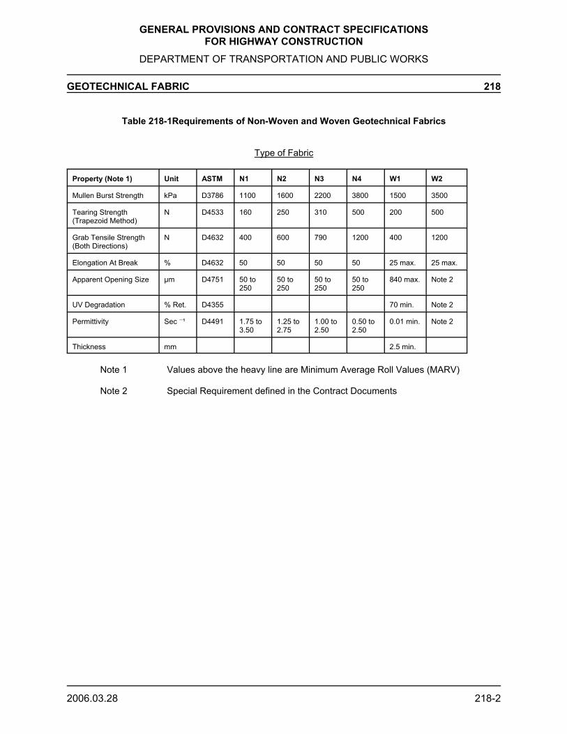
GENERAL PROVISIONS AND CONTRACT SPECIFICATIONSFOR HIGHWAY CONSTRUCTION
DEPARTMENT OF TRANSPORTATION AND PUBLIC WORKS
GEOTECHNICAL FABRIC 218
2006.03.28 218-2
Table 218-1Requirements of Non-Woven and Woven Geotechnical Fabrics
Type of Fabric
Property (Note 1) Unit ASTM N1 N2 N3 N4 W1 W2
Mullen Burst Strength kPa D3786 1100 1600 2200 3800 1500 3500
Tearing Strength(Trapezoid Method)
N D4533 160 250 310 500 200 500
Grab Tensile Strength(Both Directions)
N D4632 400 600 790 1200 400 1200
Elongation At Break % D4632 50 50 50 50 25 max. 25 max.
Apparent Opening Size µm D4751 50 to250
50 to250
50 to250
50 to250
840 max. Note 2
UV Degradation % Ret. D4355 70 min. Note 2
Permittivity Sec G¹ D4491 1.75 to3.50
1.25 to2.75
1.00 to2.50
0.50 to2.50
0.01 min. Note 2
Thickness mm 2.5 min.
Note 1 Values above the heavy line are Minimum Average Roll Values (MARV)
Note 2 Special Requirement defined in the Contract Documents

GENERAL PROVISIONS AND CONTRACT SPECIFICATIONSFOR HIGHWAY CONSTRUCTION
DEPARTMENT OF TRANSPORTATION, INFRASTRUCTURE AND ENERGY
GEOGRID REINFORCEMENT 219
2019.01.14 219-1
219.01 Description
This work includes the supply and placement of geogrid which will serve to strengthen theroadbed.
219.02 Material
Geogrid to be BX1100 or BX1200 as manufactured by Tensar or equivalent in terms ofphysical properties and strength.
The geogrid shall be a biaxially formed regular grid structure; resistant to ultra-violetdegradation, to damage under normal construction practices, and to all forms of biologicalor chemical degradation normally encountered in the material being reinforced. It shall alsohave the characteristics outlined in Table 219-1.
Table 219-1Requirements for Geogrid Reinforcement
Property Type 1Minimum
Type 2Minimum
Test
Aperture Stability for Punchedand Drawn (m-N/deg)
0.32 0.65 ASTM D7864/D7864M-15
Aperture Size along Roll Length(mm)
25 25 Calipered
Open Area (%) 70 70 Calipered
Rib Thickness at Ribs (mm) 0.76 1.27 Calipered
Polypropylene Material (%) 98 98 ASTM D4101
Carbon Black Material (%) 0.5 0.5 ASTM D4218
Flexural Rigidity along RollLength (mg/cm)
250,000 750,000 ASTM D7748-12
Strength at Junctions (kg/m) 1,116 ASTM D7737-11
Tensile Strength @ 2% StrainMD/XMD (kN/M)
4.1/ 6.6 6.0 / 9.0 ASTM D6637-10
Tensile Strength @ 5% StrainMD/XMD (kN/M)
8.5/ 13.4 11.8 / 19.6 ASTM D6637-10
Efficiency of Junctions (%) 93 93 ASTM D7737-11
219.03 Construction Method
GENERAL PROVISIONS AND CONTRACT SPECIFICATIONSFOR HIGHWAY CONSTRUCTION
DEPARTMENT OF TRANSPORTATION, INFRASTRUCTURE AND ENERGY
GEOGRID REINFORCEMENT 219
2019.01.14 219-2
The Contractor shall supply material in standard rolls for general application wheredesignated by the Engineer.
The geogrid shall be laid on the prepared surface as indicated on the contract Drawings oras directed by the Engineer.
Geogrid shall be laid in accordance with manufacturer's recommendations. Cut and overlapgeogrid to accommodate curves, underground structures and other protrusions. Securegeogrid to prevent separation and to provide anchorage in accordance with manufacturer'srecommendations.
219.04 Method of Measurement
The quantity to be measured under this Section shall be the number of square metres ofgeogrid actually used.
219.05 Basis of Payment
Geogrid shall be paid for at the unit bid price per square metre and this price shall be fullcompensation for the material, the work, labour, tools, equipment and other incidentalsnecessary to complete the work.

GENERAL PROVISIONS AND CONTRACT SPECIFICATIONSFOR HIGHWAY CONSTRUCTION
DEPARTMENT OF TRANSPORTATION, INFRASTRUCTURE AND ENERGY
BEDDING MATERIAL 220
2015.01.15 220-1
220.01 Description
This work involves the supply, placement and compaction of granular bedding material fortrenches, catch basins, storm sewers, sidewalks, conduits or similar work.
220.02 Material
Bedding material shall be the material specified in the Tender document and it shall be inaccordance with Section 401 or 402.
220.03 Construction Method
Bedding material shall be placed and compacted to 95% Standard Proctor Density exceptwhen under existing or proposed asphalt which shall be compacted to a minimum of 98%Standard Proctor Density in accordance with Section 209.
220.04 Method of Measurement
Measurement for payment of bedding material shall be the number of tonnes or cubic metresplaced.
220.05 Basis of Payment
Payment for bedding material shall be at the unit bid price per tonne or per cubic metresupplied, placed and compacted.

GENERAL PROVISIONS AND CONTRACT SPECIFICATIONSFOR HIGHWAY CONSTRUCTION
DEPARTMENT OF TRANSPORTATION, INFRASTRUCTURE AND ENERGY
DRAINAGE 300
301 Storm Sewer Pipe Installation
302 Catch Basin Installation
303 Catch Basin, Manhole and Valve Adjustment
304 Drain Tile Installation
305 Roadway Culvert Installation
306 Driveway Culvert Placement
307 Culvert Extension
308 Culvert Removal
309 Timber Box Culvert
310 Concrete Box Culvert
311 Multi-Plated Corrugated Steel Arch
312 Culvert End Treatment

GENERAL PROVISIONS AND CONTRACT SPECIFICATIONSFOR HIGHWAY CONSTRUCTION
DEPARTMENT OF TRANSPORTATION, INFRASTRUCTURE AND ENERGY
STORM SEWER INSTALLATION 301
2016.01.15 301-1
301.01 Description
The work of this Section shall consist of storm sewer installation of Pre-cast Concrete Pipe(PCP), Corrugated Steel Pipe (CSP), Double Walled Polethylene Pipe (DWP) or Poly VinylChloride Pipe (PVC), excavation of trenches, placement of bedding material, dewatering andbackfilling.
301.02 Material
301.02.01 Pre-cast Concrete Pipe (PCP)
Unless specified otherwise in the Tender document, all concrete storm sewer pipes, outfallpipes, catch basin leads and flexible gaskets are to be supplied by the Contractor.
Concrete storm sewer pipe, outfall pipe, and catch basin lead are to be to ASTM C-76, ClassIII reinforced concrete pipe designed for flexible rubber gasket joints to ASTM C-443 and tothe diameter indicated on the Drawings.
301.02.02 Corrugated Steel Pipe (CSP)
Unless specified otherwise, all corrugated steel storm sewer pipes, outfall pipes, catch basinleads and couplings are to be supplied by the Department in accordance with Provision104.13.
301.02.03 Double Walled Polyethylene Pipe DWP
Unless specified in the Tender Agreement, all Double Walled Polyethlene Pipe (DWP ) andall pipe fittings and gaskets are to by supplied by the Contractor.
High density polyethylene pipe shall meet the requirements of the latest CAN/CSA StandardB182.8 with a minimum stiffness of 320 kPa, joined together with an integral gasketed bellconnection. The gasket is to be Type 2 (silt tight).
Double Walled Polyethylene Pipe (DWP), 300mm to 900mm diameter, has a smooth-walledinterior and a corrugated exterior wall that is manufactured in standard lengths ofapproximately six metres.
301.02.04 Poly Vinyl Chloride Pipe (PVC)
Unless specified in the Tender Agreement, all Poly Vinyl Pipe (PVC), pipe fittings andgaskets are to be supplied by the Contractor.
Poly Vinyl Pipe, up to 450mm diameter, shall meet the requirements of the latest CAN/CSAStandard B182.1 and B182.2. The pipe shall be able to be joined by an integral gasketed belland spigot connection. The gasket is to be Type 2 (silt tight).
301.02.0 Galvanized Steel Grate
Unless specified in the Tender Agreement, all galvanized steel grates and fasteners are tobe supplied by the Contractor.

GENERAL PROVISIONS AND CONTRACT SPECIFICATIONSFOR HIGHWAY CONSTRUCTION
DEPARTMENT OF TRANSPORTATION, INFRASTRUCTURE AND ENERGY
STORM SEWER INSTALLATION 301
2016.01.15 301-2
All steel grates and fasteners shall be hot-dipped galvanized steel with a minimum coatingof 610 g/ m2 squared as per CSA G164.
301.03 Construction Method - General
The Contractor shall begin work at the downgradient end of the section to be installed.Trench excavation, bedding and backfill shall be in accordance with Section 217. Theexcavated width of the bottom of the trench shall not be less than 300 mm nor more than 600mm greater than the diameter of the pipe. At the location of any bends, the trench shall beshaped to accommodate bends.
All excavated trenches shall conform to the Prince Edward Island Occupational Health andSafety Act and Regulations with particular note to Part 12 and Part 50.
Bedding material shall be placed by hand, in layers not exceeding 150 mm, under the bottomone third ( a) of the pipe for PCP and CSP pipes. DWP and PVC pipes shall be backfilledwith bedding material to 300 mm above pipe or pipe diameter whichever is less.
Pipes are to be installed with the use of laser or survey equipment specifically manufacturedfor pipe installation. Pipes which are not true in alignment or which show improperinstallation shall be taken out and relaid at the Contractor’s own expense.
Exposed inlets and outlets of storm sewer systems shall be tapered 3:1 (horizontal:vertical).Pipes 450 mm or greater in diameter and connected to closed storm sewer systems shallrequire galvanized steel grates to restrict access to the system. Open ended pipes 450 mmor greater in diameter and greater than 24 metres in length shall require galvanized steelgrates to be fastened at the inlets and outlets. Bars shall be orientated vertically at inlets andhorizontally at outlets.
Installation of storm sewer grates shall be in accordance with Figures 301-1and Figure 301-2.
301.03.01 Pre-cast Concrete Pipe (PCP)
For PCP installation, recesses shall be excavated for the bells. The bell ends shall be placedup-grade with the spigot end fully entered into the bell.
301.03.02 Corrugated Steel Pipe (CSP)
CSP shall be installed in such a manner so that the inside circumferential laps pointdownstream. Corrugated steel pipe couplings shall be placed so that the joint of thecouplings are near horizontal. The bolted joint connection on the coupling should beoverlapped from the top, and should be located on the lower half of the culvert (i.e. between3 and 9 o'clock').
301.03.03 Double Walled Polyethylene (DWP ) and Poly Vinyl Chloride Pipe (PVC)
For Polyethylene and PVC installation, recesses shall be excavated for bells. The bell endsshall be placed upgrade with the spigot end fully entered into the bell.

GENERAL PROVISIONS AND CONTRACT SPECIFICATIONSFOR HIGHWAY CONSTRUCTION
DEPARTMENT OF TRANSPORTATION, INFRASTRUCTURE AND ENERGY
STORM SEWER INSTALLATION 301
2016.01.15 301-3
301.04 Method of Measurement
Measurement for PCP, CSP, DWP or PVC under this Section shall be the number of linearmetres of pipe installed for each diameter of pipe used in the work.
Bedding material supplied under this Section shall be measured for payment in accordancewith Section 220.
Measurement for galvanized steel grates under this section shall be the number of gratesinstalled for each diameter specified in the contract.
Additional material supplied for backfill shall be measured in accordance with the respectivespecification.
301.05 Basis of Payment - General
Payment under this Section shall be at the unit bid price for each diameter of pipe installedand this price shall be full compensation for excavation, disposal of waste or surplus material,shoring, bracing, placement of pipe, tapering exposed inlets and outlets, dewatering,backfilling, compaction, equipment, tools, lasers or survey equipment, labour, water forcompaction and incidentals necessary to perform the work.
Payment for supply of bedding material and additional backfill material will be made inaccordance with the respective specification.
Payment for the supply and installation of fittings such as couplings, elbows, tees, wyes andcrosses shall be included in the unit bid price for each diameter and type of pipe installed.This shall also include any top grates installed at the inlet of the drain pipes, galvanized inletand outlet steel grates and all incidentals necessary to perform the work.
301.05.01 Pre-cast Concrete Pipe (PCP)
The unit bid price for PCP installation as defined in Provision 301.05 shall also be fullcompensation for the supply of the concrete pipe, outfall pipe, catch basin leads and gasketsunless specified otherwise in the Tender document.
301.05.02 Corrugated Steel Pipe (CSP)
The unit bid price for CSP installation as defined in Provision 301.05 shall not includecompensation for the corrugated steel pipe, outfall pipe, catch basin leads or couplings; asthese will be supplied by the Department in accordance with Provision 104.13 unlessspecified otherwise in the Tender document.
301.05.03 Double Walled Polyethylene (DWP) and Poly Vinyl Chloride Pipe (PVC)
The unit bid price for Polyethylene and PVC pipe installation, as defined in Provision 301.05shall be full compensation for the supply of the pipe, gaskets and incidentals required toperform the work.

GENERAL PROVISIONS AND CONTRACT SPECIFICATIONSFOR HIGHWAY CONSTRUCTION
DEPARTMENT OF TRANSPORTATION, INFRASTRUCTURE AND ENERGY
STORM SEWER INSTALLATION 301
2016.01.15 301-4
301.05.04 Galvanized Steel Grate
The unit bid price for galvanized steel inlet and outlet grates, as defined in Provision 301.05,shall include full compensation for the supply and installation of the grate and all incidentalsrequired to perform the work.

²

²

GENERAL PROVISIONS AND CONTRACT SPECIFICATIONSFOR HIGHWAY CONSTRUCTION
DEPARTMENT OF TRANSPORTATION, INFRASTRUCTURE AND ENERGY
CATCH BASIN INSTALLATION 302
2009.02.04 302-1
302.01 Description
The work of this Section shall consist of the installation of precast concrete (PCP - Pre-castConcrete Pipe) or corrugated steel (CSP - Corrugated Steel Pipe) catch basins, grade rings,adjusting rings, frames and covers including excavation, placement of bedding material,dewatering, backfilling and compaction.
302.02 Material
302.02.01 Pre-cast Concrete (PCP) Catch Basin
Unless specified otherwise in the Tender document, all pre-cast catch basins, grade rings,adjusting rings, frames, and covers are to be supplied by the Contractor.
Precast catch basin sections for municipal services are to be to ASTM C-478, circular, witha flat top section and opening offset. Catch basins shall be constructed with a precast or cast-in-place base.
Adjusting rings shall be precast or cast-in-place as indicated on the Drawings or as directedby the Engineer and shall be the same shape as the frames and covers. The outer size ofthe adjusting rings must be at least as large as the frames and covers but shall not extendbeyond the edge of the catch basin. Multiple adjusting rings shall be of identical shape anddiameter, and shall be installed in true vertical alignment with no overhanging edges.
Whenever possible, catch basins must be constructed to allow for a minimum 230 mm depthof adjusting rings. Every effort shall be made to minimize the number adjusting rings usedfor each catch basin.
Joints are to be made watertight using bituminous gaskets or neoprene O-rings.
Frames and covers are to be standard, tough, grey cast iron to ASTM A-48 and are to be thetype and manufactured as indicated on the Drawings. Bearing surface of covers are to becast or machined to give continuous contact over the entire surface.
302.02.02 Corrugated Steel (CSP) Catch Basin
Unless specified otherwise in the Tender document, all corrugated steel catch basins, ringsand covers are to be supplied by the Department in accordance with Provision 104.13.Adjusting rings shall be steel ring inserts made to the specific height required and made tofit inside the existing frame and to accept cover. The design of the steel ring insert shall beapproved by the Engineer prior to the manufacturing.
302.03 Construction Method - General
The Contractor shall excavate to the invert elevation and undercut the elevation by 150 mm.The minimum dimension of a catch basin excavation shall be no less than 1 m larger thanthe diameter of the catch basin.
The granular bedding material shall be placed and compacted such that an area is created300 mm larger than the diameter of the catch basin.
Backfilling and excavation shall be done in accordance with Section 217 and as specifiedherein.

GENERAL PROVISIONS AND CONTRACT SPECIFICATIONSFOR HIGHWAY CONSTRUCTION
DEPARTMENT OF TRANSPORTATION, INFRASTRUCTURE AND ENERGY
CATCH BASIN INSTALLATION 302
2009.02.04 302-2
The Contractor shall seal all connections between the catch basin and the base, inlets oroutlets of storm drains prior to backfilling. When grouting is required to seal theseconnections, it shall be completed on both the inside and outside of the catch basin.
302.03.01 Pre-cast Concrete (PCP) Catch Basin
Pre-cast bases shall be placed on the bedding material and levelled. If the base is to be castin place, the Contractor shall ensure a proper surface is formed to accept the intermediatesections.
The Contractor shall place a ring of mortar on the pre-cast or cured in-place base to thecircumference of the catch basin. The first pre-cast catch basin section shall be placed in themortar so that it is level and so that the joint is completely sealed. The subsequent pre-castintermediate or top sections will be placed and sealed using rubber o-rings or ram-nek andproperly orientated to ensure the specified inlets and outlets. Precast adjusting rings shall beplaced on top of the catch basin structure using ram-nek or other approved sealant and shallbe oriented properly to match the longitudinal and cross slopes required. Cast-in-placeadjusting rings shall be formed and poured in place in a manner to provide a watertight seal.Ram-nek or other approved sealant shall be used to join the adjusting ring and frame.
302.03.02 Corrugated Steel (CSP) Catch Basin
The Contractor shall place 3 level concrete bricks or blocks 100 mm in height around thecircumference of the corrugated steel catch basin. The top of the corrugated steel catchbasin when placed shall be at the specified grade and shall be orientated to ensure properinlet and outlet connections. Cast-in-place concrete shall be placed inside and outside thecorrugated steel catch basin to a minimum thickness of 250mm and shall be given sufficienttime to cure prior to backfilling. If height adjustment is required due to improper manufacturingor improper placement of catch basin, the contractor shall supply and place adjusting ringsas required.
302.04 Method of Measurement
Measurement under this Section shall be the number of pre-cast concrete (PCP) orcorrugated steel (CSP) catch basins installed for each diameter specified.
302.05 Basis of Payment - General
Payment under this Section shall be at the unit bid price for the number of catch basinsinstalled for each diameter and this price shall be full compensation for installation,excavation, dewatering, undercutting, shoring, bracing, placement of bedding material,construction of forms, construction of bases, placement of backfill, compaction andequipment, cement, concrete, tools, labour, water for compaction and incidentals necessaryto perform the work.
Payment for supply of bedding material and additional backfill material will be made inaccordance with the respective specification.

GENERAL PROVISIONS AND CONTRACT SPECIFICATIONSFOR HIGHWAY CONSTRUCTION
DEPARTMENT OF TRANSPORTATION, INFRASTRUCTURE AND ENERGY
CATCH BASIN INSTALLATION 302
2009.02.04 302-3
302.05.01 Pre-cast Concrete (PCP) Catch Basin
The unit bid price for pre-cast concrete catch basin installation as defined in Provision 302.05shall also be full compensation for the supply of the pre-cast concrete catch basins, adjustingrings, frames and covers unless specified otherwise in the Tender document.
302.05.02 Corrugated Steel (CSP) Catch Basin
The unit bid price for corrugated steel catch basins as defined in Provision 302.05 shall notinclude compensation for the corrugated steel catch basins, frames or covers; as thesematerials will be supplied by the Department unless otherwise specified in the Tenderdocument. The unit bid price shall include full compensation for the supply and installationof adjusting rings if they are required due to improper installation by the Contractor.

GENERAL PROVISIONS AND CONTRACT SPECIFICATIONSFOR HIGHWAY CONSTRUCTION
DEPARTMENT OF TRANSPORTATION, INFRASTRUCTURE AND ENERGY
CATCH BASIN, MANHOLE AND VALVE ADJUSTMENT 303
2019.01.14 303-1
303.01 Description
This work shall consist of raising or lowering existing corrugated steel or concrete catchbasins and concrete manholes or valve boxes to meet the final pavement elevation.
303.02 Material
The Contractor shall supply the appropriate type of material to perform the required work.
Adjusting rings for precast concrete structures shall be precast or cast-in-place as indicatedon the Drawings or as directed by the Engineer and shall be the same shape as the framesand covers. The outer size of the adjusting rings must be at least as large as the frames andcovers but shall not extend beyond the edge of the catch basin.
Adjusting rings for corrugated steel catch basins shall be steel ring inserts made to the heightrequired specifically to fit inside the seat of the existing frame and also to accept the cover.The design of the steel ring insert shall be approved by the Engineer prior to manufacturing.
Adjustable manhole frames and covers shall be C-50M1 Cone Shaped Frame/ Autostableas manufactured by Bibby-Ste-Croix, or approved equivalent, meeting the requirements ofCSA B70.1 and shall be as shown on Detail Drawing No. 303-01.
303.03 Construction Method
The Contractor, when raising existing corrugated steel catch basins, shall determine theheight required to meet the new grade and shall manufacture a steel ring insert to raise thecatch basin cover to the desired grade.
The Contractor when lowering existing corrugated steel catch basins shall cut and removeany existing pavement around the catch basin, excavate around the catch basin to a depthsufficient to adjust the catch basin to the desired elevation. The Contractor shall cut thecatch basin vertically to remove the ring and cover and shall reset the ring and cover into thecorrugation at the new pavement elevation. The Contractor shall insure that the ring andcover are secure and will not pop out under traffic.
The Contractor, when raising existing concrete catch basins or manholes, shall use concretegrade rings or shall supply cast-in-place concrete to the appropriate depth to meet the newgrade. When lowering concrete catch basins or manholes, the Contractor will remove graderings to meet the new grade.
The Contractor shall use the available adjustment of the valve boxes, or supply extensionpieces or modify existing, to raise or lower the valve box to the appropriate elevation.
The Contractor shall ensure methods and materials are acceptable to the appropriate utilityowners.

GENERAL PROVISIONS AND CONTRACT SPECIFICATIONSFOR HIGHWAY CONSTRUCTION
DEPARTMENT OF TRANSPORTATION, INFRASTRUCTURE AND ENERGY
CATCH BASIN, MANHOLE AND VALVE ADJUSTMENT 303
2019.01.14 303-2
303.04 Method of Measurement
The quantity to be measured under this Section shall be the number of catch basins,manholes or valve boxes actually raised or lowered.
Pavement placed while performing this work shall be measured for payment in accordancewith Section 709.
303.05 Basis of Payment
Payment under this Section shall be at unit bid price per catch basin or manhole actuallylowered or raised and this price shall be full compensation for all adjustment rings,equipment, tools, labour, and incidentals necessary to complete the work.
Payment of pavement restoration shall be made in accordance with Section 709.

C-50M1
C-50M1

GENERAL PROVISIONS AND CONTRACT SPECIFICATIONSFOR HIGHWAY CONSTRUCTION
DEPARTMENT OF TRANSPORTATION, INFRASTRUCTURE AND ENERGY
DRAIN TILE INSTALLATION 304
2007.02.09 304-1
304.01 Description
This specification applies to the supply and installation of drain tile in the shoulder region ofthe highway.
304.02 Material
The drain tile is to be 100 mm diameter, Type 2, perforated corrugated plastic tubing incompliance with CGSB 41-GP-29 Ma.
304.03 Drain Tile Location
The drain tile is to be placed in the shoulder of the highway along a line parallel to the outsideedge of the pavement, or as outlined in the plans or drawings or as directed by the Engineer.
304.04 Drain Tile Depth and Grading
The drain tile shall be placed 1 m below the normal grade of the edge of the asphalt surface,or as outlined in the plans or drawings or as directed by the Engineer.
The constructed grade should not deviate from the design grade by more than 15% of thedrain tile diameter. It is intended that the drain tile be located at a consistent depth in thecross-section. Reverse grades are not allowed.
304.05 Laying Drain Tile - Open Trench Installation
The method of installation is to be with trencher, Ditch Witch or equivalent, equipment. Abackhoe with a 300 mm wide bucket may be used; however, extra costs for drainageaggregate shall be incidental.
The equipment shall construct a smooth bottomed open trench 300mm in depth. The widthof the opening shall conform closely to the outside diameter of the drain tile.
The drain tile shall be placed in the bottom of the trench and the remainder of the trench shallbe filled with Class D drainage aggregate. The drain tile must be protected from deformationduring placement of the Class D aggregate.
Following placement of the Class D aggregate the trench shall be covered with the GranularBase prior to the road being opened to traffic to provide additional protection to the drain tile.
Drain tile shall not be stretched more than 7% of its normal length. Directional changes indrain tile can be made without the use of fittings, provided the centre-line radius of the bendis not less than 5 times the tube diameter.
This is the preferred method of drain tile installation.
304.06 Laying Drain Tile - Plow Installation
The method of installation is to be with drainage plow equipment. This is not the preferredmethod of installation and shall be approved only if the Contractor can demonstrate to theEngineer that the installation is acceptable

GENERAL PROVISIONS AND CONTRACT SPECIFICATIONSFOR HIGHWAY CONSTRUCTION
DEPARTMENT OF TRANSPORTATION, INFRASTRUCTURE AND ENERGY
DRAIN TILE INSTALLATION 304
2007.02.09 304-2
The drainage plow equipment should construct a smooth bottomed opening in the soil andmaintain the opening until the flexible drain tile has been properly installed.
The size of the opening should conform closely to the outside diameter of the drain tile.
Drain tile must be protected from deformation and from floating in wet trenches.
The inside of the drain tile shall be kept clean during construction. All soil and debris shallbe removed before additional tubing is laid.
Drain tile shall not be stretched more than 7% of its normal length. Directional changes indrain tile can be made without the use of fittings, provided the centre-line radius of the bendis not less than 5 times the tube diameter.
304.07 Connections
Where lengths of drain tile are to be joined, the ends must be square and all ragged orburred edges removed. A plastic coupling shall be used to secure the ends of the drain tilein proper alignment and to prevent the joint from separating during installation.
304.08 Backfilling
At the end of each day, the exposed end of the drain tile is to be covered to prevent entry ofdebris or sediment. During this process, care shall be taken to ensure that the drain tile isnot damaged from excessive traffic or equipment loads.
304.09 Filter Envelopes
The drain tile is to be installed with an envelope material surrounding the drain tile to restrainthe entry of base soil particles.
304.10 Outfall
Drains will be located at regular 400 m outfall intervals and will discharge into the roadsideditch subject to a minimum freeboard distance of 300 mm as shown on the contractDrawings. Where the 300 mm freeboard between the end pipe invert and the ditch bottomis not achievable, the Engineer will determine the location of the drain; in some cases, thedrain may have to be relocated or omitted for this reason.
The outfall end pipe is to be 100 mm in diameter of rigid non-perforated pipe complete witha hinged grate. The joint between the end pipe and the drain tile shall be securely sealed.
304.11 Method of Measurement
The quantities to be measured for payment under this Section shall be the number of linearmetres of drain tile installed and the number of outfalls installed.
No measurement for payment will be made under this Section for drain tile or outfallinstallations required as a result of faulty placement.

GENERAL PROVISIONS AND CONTRACT SPECIFICATIONSFOR HIGHWAY CONSTRUCTION
DEPARTMENT OF TRANSPORTATION, INFRASTRUCTURE AND ENERGY
DRAIN TILE INSTALLATION 304
2007.02.09 304-3
304.12 Basis of Payment
Payment under this Section shall be at the unit bid price per linear metre of drain tile and peroutfall and this price shall be full compensation for all work, including excavation, materials,labour, equipment and incidentals necessary to carry out the work.
Payment for the supply of drainage aggregate shall be accordance with Section 220. Excessdrainage aggregate required to fill trench created by backhoe and bucket shall not bemeasured for payment.

GENERAL PROVISIONS AND CONTRACT SPECIFICATIONSFOR HIGHWAY CONSTRUCTION
DEPARTMENT OF TRANSPORTATION, INFRASTRUCTURE AND ENERGY
ROADWAY CULVERT INSTALLATION 305
2016.01.15 305-1
305.01 Description
The work to be carried out under this Section shall include the removal of existing roadwayculverts, all excavation, and the installation of new roadway culverts. This may also includethe installation of watercourse culvert installations, see Section 7.2 of TIE’s EnvironmentalProtection Plan.
305.02 Material
305.02.01 Pre-cast Concrete Pipe (PCP)
Unless specified otherwise in the Tender document, all concrete pipes and flexible gasketsare to be supplied by the Contractor.
Concrete pipe is to be to ASTM C-76, Class III reinforced concrete pipe designed for flexiblerubber gasket joints to ASTM C-443 and to the diameter indicated on the Drawings.
305.02.02 Corrugated Steel Pipe (CSP)
Unless specified otherwise, all corrugated steel pipes and couplings are to be supplied by theDepartment in accordance with Provision 104.13.
305.02.03 Double Walled Polyethylene (DWP) or Poly Vinyl Chloride Pipe (PVC)
Unless specified in the Tender Agreement, all Double Walled Polyethylene or PVC Pipe, pipefittings and gaskets are to be supplied by the Contractor.
Double Walled Polyethylene Pipe, 300mm to 900mm diameter, has a smooth-walled interiorand a corrugated exterior wall that is manufactured in standard lengths of approximately six(6) metres to class R 320 (320 kPa) and is joined together with integral gasketed snap bellconnection or integral gasketed bell and spigot connection and which meets the requirementsof CSA B182.6 or CSA B182.8.
For diameters up to 450 mm a PVC pipe (SDR 35) with integral gasketed bell and spigotjoints can be used which meets the requirements of CSA B182.1, and CSA B182.2
305.03 Construction Method
Unless approved by the Engineer, the Contractor shall make provisions for two-way trafficduring the work. All work carried out under this Section shall be done in accordance with theEMS Approval to Proceed and the Environmental Requirements of Appendix 2.
Excavation shall begin at the downstream end of the pipe, and shall be performed inaccordance with Section 203 and shall comply with the Occupational Health and Safety Actand Regulations.
Watercourse culverts must be installed in compliance with the PEI Watercourse and WetlandAlteration Guidelines (PEIWWAG), see Appendix 2, section 9. Unless otherwise specifiedwatercourse culvert installations may only occur between June 1 and September 30 of anygiven year. The watercourse must be isolated during installation of the culvert (unlessspecified otherwise in the EMS Approval to Proceed). The pipe shall be laid parallel to flowon a uniform slope of 200:1 unless otherwise specified, and shall have the inlet and outletembedded 0.2D of the culvert, and at a slope of not more than 0.5% (unless specifically
GENERAL PROVISIONS AND CONTRACT SPECIFICATIONSFOR HIGHWAY CONSTRUCTION
DEPARTMENT OF TRANSPORTATION, INFRASTRUCTURE AND ENERGY
ROADWAY CULVERT INSTALLATION 305
2016.01.15 305-2
authorized). A pre-construction survey in accordance with the PEIWWAG must becompleted prior to any work taking place. A surveyor must be onsite during the installationof the culvert to ensure proper slope is achieved.
The Contractor shall excavate the roadbed to the specified line and grade to a width of 600mm on both sides of the pipe. The excavated material shall be conserved for re-use asdirected by the Engineer, and it shall be stockpiled in a manner and location which will notendanger the work or delay the travelling public.
Existing roadway culverts shall be removed in accordance with Section 308.
Bedding material shall be placed to a depth of a 150 mm below the pipe and in layers notexceeding 150 mm under the bottom a of the pipe. Bedding material shall be compactedto a minimum of 98% Standard Proctor Density in accordance with Section 209. In confinedareas of the excavation, bedding shall be compacted using suitable hand or plate tampers.In the case of concrete pipe, the bed shall be shaped to ensure uniform load bearing aroundthe bell end.
Prior to backfilling, the work shall be inspected. Backfilling shall be by hand under the bottomhalf of the pipe. Machine backfilling is acceptable for the remaining work provided compactionis achieved on individual layers not exceeding 200 mm. Backfill material shall be thatapproved by the Engineer. Stones larger than 100 mm shall not be placed within 300 mm ofthe pipe.
Exposed inlets and outlets of the roadway culvert shall be tapered 3:1 (horizontal:vertical).
Compaction shall be achieved in accordance with Section 209 to a minimum of 98%Standard Proctor Density.
Immediately upon completion of culvert installation or, as a minimum, at the end of the workday, disturbed slope areas within 10 m of the culvert shall be stabilized as indicated inSection 312 - Culvert End Treatment.
Where directed by the Engineer, old roadbed culverts shall be removed and relayed,extended or renewed in the same manner as specified for new culverts.
All pipe placed under this Section which is not in true alignment or which shows anysettlement after laying shall be taken out and relayed at the Contractor's own expense.
305.03.01 Pre-cast Concrete Pipe (PCP)
For PCP installation, recesses shall be excavated for the bells. The bell ends shall be placedup-grade with the spigot end fully entered into the bell. All joints are to be as tight aspossible.
305.03.02 Corrugated Steel Pipe (CSP)
CSP shall be installed in such a manner so that the inside circumferential laps pointdownstream. Corrugated steel pipe couplings shall be placed so that the joint of thecouplings are near horizontal. The bolted joint connection on the coupling should beoverlapped from the top, and should be located on the lower half of the culvert (i.e. between
GENERAL PROVISIONS AND CONTRACT SPECIFICATIONSFOR HIGHWAY CONSTRUCTION
DEPARTMENT OF TRANSPORTATION, INFRASTRUCTURE AND ENERGY
ROADWAY CULVERT INSTALLATION 305
2016.01.15 305-3
3 and 9 o'clock').
Helical corrugated steel pipe shall be placed so the helix angle is constant for the total lengthof the installation and each pipe section in a series shall be installed so the lock seam formsa continuous helix.
305.03.03 Double Walled Polyethylene (DWP ) and Poly Vinyl Chloride Pipe (PVC)
For Polyethylene and PVC installation, recesses shall be excavated for bells. The bell endsshall be placed upgrade with the spigot end fully entered into the bell.
305.04 Method of Measurement
Measurement for PCP, CSP, DWP or PVC under this Section shall be the number of linearmetres of pipe installed for each diameter of pipe used in the work.
New material supplied for backfilling roadway culverts shall not be measured for paymentunder this Section but shall be included elsewhere in the Contract.
No measurement for payment will be made under this section for culvert end treatments butshall be made under Section 312.
305.05 Basis of Payment
Payment under this Section shall be at the unit bid price per linear metre for each size andtype of culvert supplied and installed and this price shall be full compensation for the supply,unloading, laying, tapering inlets and outlets, dewatering, backfilling, compacting, equipment,labour and all incidentals necessary to perform the work.
Payment for the supply of backfill material required under this Section shall be in accordancewith the respective specification.
Payment for the supply of bedding material shall be in accordance with Section 220.
Excavations with depths less than 2 metres measured from centreline grade to the invert ofthe pipe at centreline shall be considered incidental to the work and shall not be measuredor paid for. The contractor shall ensure that excavation measures are conducted in strictaccordance with WCB and OH&S regulations.
Payments for excavations with depths greater than 2 metres measured from centreline gradeto the invert of the pipe at centreline shall be in accordance with Section 203 but the volumeto be measured for payment for pipe excavation shall not exceed the volume calculated bythe product of the depth equal to the nominal pipe diameter plus 1.2 metres. All otherexcavation required or directed by the Engineer to facilitate a smooth transition shall be paidat the price of common roadway excavation price.
Payment for the supply and installation of fittings such as couplings, elbows, tees, wyes andcrosses shall be included in the unit bid price for each diameter and type of pipe installed.This shall also include any top grates installed at the inlet of the drain pipes, galvanized inletand outlet steel grates and all incidentals necessary to perform the work.
Payment for removal of culverts shall be in accordance with Section 308.
Payment for culvert end treatments shall be in accordance with Section 312.

GENERAL PROVISIONS AND CONTRACT SPECIFICATIONSFOR HIGHWAY CONSTRUCTION
DEPARTMENT OF TRANSPORTATION, INFRASTRUCTURE AND ENERGY
ROADWAY CULVERT INSTALLATION 305
2016.01.15 305-4
305.05.01 Pre-cast Concrete Pipe (PCP)
The unit bid price for PCP installation shall also be full compensation for the supply of theconcrete pipe, grates, gaskets and incidentals required to perform the work unless specifiedotherwise in the Tender document.
305.05.02 Corrugated Steel Pipe (CSP)
The unit bid price for CSP installation shall not include compensation for the corrugated steelpipe and couplings; as these will be supplied by the Department in accordance with Provision104.13 unless specified otherwise in the Tender document.
305.05.03 Double Walled Polyethylene (DWP) and Poly Vinyl Chloride Pipe (PVC)
The unit bid price for Polyethylene and PVC pipe installation shall be full compensation forthe supply of the pipe, grates, gaskets and incidentals required to perform the work unlessspecified otherwise in the Tender document.

GENERAL PROVISIONS AND CONTRACT SPECIFICATIONSFOR HIGHWAY CONSTRUCTION
DEPARTMENT OF TRANSPORTATION, INFRASTRUCTURE AND ENERGY
DRIVEWAY CULVERT PLACEMENT 306
2013.01.15 306-1
306.01 Description
The work to be carried out under this Section shall include the installation and backfilling ofdriveway culverts.
306.02 Material
306.02.01 Pre-cast Concrete Pipe (PCP)
Unless specified otherwise in the Tender document, all concrete pipes and flexible gasketsare to be supplied by the Contractor.
Concrete pipe is to be to ASTM C-76, Class III reinforced concrete pipe designed for flexiblerubber gasket joints to ASTM C-443 and to the diameter indicated on the Drawings.
306.02.02 Corrugated Steel Pipe (CSP)
Unless specified otherwise, all corrugated steel pipes and couplings are to be supplied by theDepartment in accordance with Provision 104.13.
306.02.03 Double Walled Polyethylene (DWP) or Poly Vinyl Chloride Pipe (PVC)
Unless specified in the Tender Agreement, all Double Walled Polyethylene or PVC Pipe, pipefittings and gaskets are to be supplied by the Contractor.
Double Walled Polyethylene Pipe, 300 mm to 900 mm diameter, has a smooth-walled interiorand a corrugated exterior wall that is manufactured in standard lengths of approximately six(6) metres to class R 320 (320 kPa) and is joined together with integral gasketed snap bellconnection or integral gasketed bell and spigot connection and which meets the requirementsof CSA B182.6 or CSA B182.8.
For diameters up to 450 mm a PVC pipe (SDR 35) with integral gasketed bell and spigotjoints can be used which meets the requirements of CSA B182.1, and CSA B182.2
306.03 Construction Method
The Contractor shall excavate the area to the lines and grades specified.
On the direction of the Engineer, the Contractor shall undercut the location of a drivewayculvert to a specified depth. When no undercutting is specified, the Contractor shall grade theditch uniformly and shall compact the ditch bottom to a depth of 300 mm, in accordance withSection 209 to 95% of Standard Proctor Density.
Backfill material shall be approved by the Engineer and shall be placed by hand under thebottom half of the culvert. The top half of the culvert may be backfilled by machine in layersnot exceeding 200 mm.
The top of the driveway shall be constructed to a width of not more than 6.1 m unlessotherwise directed by the Engineer. Exposed inlets and outlets of the roadway culvert shall

GENERAL PROVISIONS AND CONTRACT SPECIFICATIONSFOR HIGHWAY CONSTRUCTION
DEPARTMENT OF TRANSPORTATION, INFRASTRUCTURE AND ENERGY
DRIVEWAY CULVERT PLACEMENT 306
2013.01.15 306-2
be tapered 3:1 (horizontal:vertical). The backfill material at each end of the culvert shall beneatly graded and shaped to provide a uniform slope not steeper than 3:1 (horiz:vert).
Immediately upon completion of culvert installation or, as a minimum, at the end of the workday, disturbed slope areas within 10 m of the culvert shall be stabilized as indicated inSection 312 - Culvert End Treatment.
Where directed by the Engineer, old driveway culverts shall be removed and relayed,extended or renewed in the same manner as specified for new culverts.
All pipe which is not in true alignment or which shows any settlement after laying, shall betaken out and replaced.
306.03.01 Pre-cast Concrete Pipe (PCP)
For PCP installation, the bed shall be shaped to ensure uniform load bearing around the bellends. The bell ends shall be placed upgrade and the spigot ends are to be fully entered intothe bells. All joints are to be as tight as possible.
306.03.02 Corrugated Steel Pipe (CSP)
CSP shall be installed in such a manner so that the inside circumferential laps pointdownstream. Corrugated steel pipe couplings shall be placed so that the joint of thecouplings are near horizontal. The bolted joint connection on the coupling should beoverlapped from the top, and should be located on the lower half of the culvert (i.e. between3 and 9 o'clock').
Helical corrugated steel pipe shall be placed so the helix angle is constant for the total lengthof the installation and each pipe section in a series shall be installed so the lock seam formsa continuous helix.
306.03.03 Double Walled Polyethylene (DWP ) and Poly Vinyl Chloride Pipe (PVC)
For Polyethylene and PVC installation, recesses shall be excavated for bells. The bell endsshall be placed upgrade with the spigot end fully entered into the bell.
306.04 Method of Measurement
Measurement for PCP, CSP, DWP or PVC under this Section shall be the number of linearmetres of pipe installed for each diameter of pipe used in the work.
New material supplied for backfilling driveway culverts shall not be measured for paymentunder this Section but shall be included elsewhere in the Contract.
No measurement for payment will be made under this section for culvert end treatments butshall be made under Section 312.
306.05 Basis of Payment

GENERAL PROVISIONS AND CONTRACT SPECIFICATIONSFOR HIGHWAY CONSTRUCTION
DEPARTMENT OF TRANSPORTATION, INFRASTRUCTURE AND ENERGY
DRIVEWAY CULVERT PLACEMENT 306
2013.01.15 306-3
Payment under this Section shall be at the unit bid price per linear metre for each size andtype of culvert supplied and installed and this price shall be full compensation for the all work,supply, unloading, excavation, laying, tapering inlets and outlets, dewatering, backfilling,compacting, equipment, labour and all incidentals necessary to perform the work.
Payment for the supply of backfill material required under this Section shall be in accordancewith the respective specification.
Payment for the supply of bedding material shall be in accordance with Section 220.
Payment for culvert end treatments shall be in accordance with Section 312.
306.05.01 Pre-cast Concrete Pipe (PCP)
The unit bid price for PCP installation shall also be full compensation for the supply of theconcrete pipe, grates, gaskets and incidentals required to perform the work unless specifiedotherwise in the Tender document.
306.05.02 Corrugated Steel Pipe (CSP)
The unit bid price for CSP installation shall not include compensation for the corrugated steelpipe and couplings; as these will be supplied by the Department in accordance with Provision104.13 unless specified otherwise in the Tender document.
306.05.03 Double Walled Polyethylene (DWP) and Poly Vinyl Chloride Pipe (PVC)
The unit bid price for Polyethylene and PVC pipe installation shall be full compensation forthe supply of the pipe, grates, gaskets and incidentals required to perform the work unlessspecified otherwise in the Tender document.

GENERAL PROVISIONS AND CONTRACT SPECIFICATIONSFOR HIGHWAY CONSTRUCTION
DEPARTMENT OF TRANSPORTATION, INFRASTRUCTURE AND ENERGY
CULVERT EXTENSION 307
2012.02.09 307-1
307.01 Description
The work to be carried out under this Section relates to the restoration of, or extension of,drainage culverts. This work is intended to be a maintenance measure where it is moreeconomical to extend service life of an existing culvert than to replace it.
This may also include the extension of watercourse culverts, see Section 7.2 Culverts ofTIE’s Environmental Protection Plan.
307.02 Material
All couplings and corrugated steel pipe or polyethylene pipe used to make the restorationshall be supplied by the Department in accordance with Provision 104.13.
All new concrete pipe to ASTM C-76 Class III reinforced concrete pipe designed for flexiblerubber gasket joints to ASTM C-443 shall be supplied by the Contractor.
307.03 Construction Method
Watercourse culvert extensions must be installed in compliance with the PEI Watercourseand Wetland Alteration Guidelines (PEIWWAG), see Appendix 2, section 9. Unlessotherwise specified watercourse culvert extensions may only occur between June 1 andSeptember 30 of any given year. The watercourse must be fully isolated during constructionactivities unless otherwise specified on the EMS Approval to Proceed. A pre-constructionsurvey in accordance with the PEIWWAG must be completed prior to any work taking place.A surveyor must be onsite during the installation of the culvert to ensure proper slope isachieved.
The Contractor shall excavate the existing fill material from around the end of the culvert andreserve it for re-use. Damage to the ends of the culvert, if present, shall be cut-off with amethod approved by the Engineer. The result shall be a smooth, distortion-free, straightedge perpendicular to the line and grade of flow (i.e. gradient).
The Contractor shall excavate existing fill material from around the end of the concrete culvertto expose a full intact bell or spigot joint. The joint shall be completely cleaned prior to placinglubricant and gaskets and additional concrete pipe materials.
A length of corrugated steel pipe will be joined using a coupling band and the total exposedpipe shall be backfilled and shaped as necessary to restore the original drainage course.This may result in a culvert slightly longer or shorter than the original.
The culvert to be joined onto must be cleaned of soil and debris to ensure the culvertfunctions properly and to enable an effective coupling with the extension pipe.
The extension pipe shall be placed on a similar line and grade as the original pipe unlessotherwise specified by the Engineer. The Contractor will ensure that this alignment ismaintained throughout the work.
Couplings shall be placed so that the joint of the coupling is near horizontal. The joint shouldoccur at mid-length of the coupling. The bolted joint connection on the coupling should be

GENERAL PROVISIONS AND CONTRACT SPECIFICATIONSFOR HIGHWAY CONSTRUCTION
DEPARTMENT OF TRANSPORTATION, INFRASTRUCTURE AND ENERGY
CULVERT EXTENSION 307
2012.02.09 307-2
overlapped from the top, and should be located on the lower half of the culvert (i.e. between"3 and 9 o'clock").
Exposed inlets and outlets of the roadway culvert shall be tapered 3:1 (horizontal:vertical).
Backfilling by hand is necessary below the mid-elevation of the culvert circumference, butmay be done by machine for the upper regions.
All backfill material shall be approved by the Engineer and shall be compacted to 95%Standard Proctor Density except when under existing or proposed asphalt which shall becompacted to 100% Standard Proctor Density. Stones larger than 100 mm shall not beplaced within 300 mm of the culvert.
Immediately upon completion of the culvert extension or, as a minimum, at the end of thework day, disturbed slope areas within 10m of the culvert shall be stabilized as indicated inSection 312 - Culvert End Treatment.
307.04 Method of Measurement
The quantity to be measured under this Section shall be the number of linear metres ofculvert extension placed.
No measurement for payment will be made under this section for culvert end treatments butshall be made under Section 312.
307.05 Basis of Payment
Payment under this Section shall be at the unit bid price per linear metre and this price shallbe full compensation for loading, material transportation, excavation, removal of damagedpipe sections, if any, coupling of culverts, tapering inlets and outlets, supply or reinstatementof backfill material, compaction of backfill, shaping of backfill, and all equipment and labournecessary to complete the work.
Payment for supply of pipe shall be included in unit bid price per size when materials aresupplied by the Contractor.
Extra backfill, if required, may be supplied at no additional cost from ditching or from surplusearth excavation generated within the work site. If the Engineer chooses to use a foundationmaterial such as borrow it shall be paid for in accordance with the respective specification.
Payment for culvert end treatments shall be in accordance with Section 312.

GENERAL PROVISIONS AND CONTRACT SPECIFICATIONSFOR HIGHWAY CONSTRUCTION
DEPARTMENT OF TRANSPORTATION, INFRASTRUCTURE AND ENERGY
CULVERT REMOVAL 308
2016.01.15 308-1
308.01 Description
This work shall consist of the removal of roadway culverts and driveway culverts.
308.02 Construction Method
When the Engineer directs that roadway culverts or driveway culverts are to be removed fromthe roadway, the Contractor shall excavate the surrounding material and remove the culvertwithout damage.
The interior of the pipe shall be cleared of any accumulated sediment, rocks or debris.
Re-usable culverts shall be stockpiled for pickup by the Department. Culverts which in theopinion of the Engineer are not worthy of salvage shall be disposed of by the Contractor.
The Engineer shall establish the limits of material to be removed in order to recover anyculvert and the Contractor shall not excavate beyond the limits established by the Engineer.
308.03 Method of Measurement
Measurement for payment under this Section shall be the number of linear metres of culvertsalvaged or disposed of.
No measurement for payment will be made for excavation of materials required for theremoval of driveway culverts.
Measurement for payment will be made for excavation of materials required for the removalof roadway culverts.
308.04 Basis of Payment
Removal of culverts shall be paid for at the unit bid price per linear metre and this price shallbe full compensation for removal, cleaning and stockpiling of the reusable culverts, disposalof un-salvageable culverts, equipment, tools, labour and incidentals necessary to completethe work.
Excavations with depths less than 2 metres measured from centreline grade to the invert ofthe pipe at centreline shall be considered incidental to the work and shall not be measuredfor payment. The contractor shall ensure that excavation methods are conducted in strictaccordance with WCB and OH&S regulations.
Payments for excavations with depths greater than 2 metres measured from centreline gradeto the invert of the pipe at centreline shall be in accordance with Section 203 but the volumeto be measured for payment for pipe excavation shall not exceed the volume calculated bythe product of the depth equal to the distance from the underside of bedding to the undersideof common roadway excavation by the width equal to the nominal pipe diameter plus 1.2metres. All other excavation required or directed by the Engineer to facilitate a smoothtransition shall be paid at the price of common roadway excavation price.
All other excavation required or directed by the Engineer to facilitate a smooth transition shallbe paid at the price of common roadway excavation price.

GENERAL PROVISIONS AND CONTRACT SPECIFICATIONSFOR HIGHWAY CONSTRUCTION
DEPARTMENT OF TRANSPORTATION, INFRASTRUCTURE AND ENERGY
CULVERT REMOVAL 308
2016.01.15 308-2
Suitable excavated materials will be reinstated at no additional cost as per Section 207.
Additional backfill materials will be paid under the respective section.

GENERAL PROVISIONS AND CONTRACT SPECIFICATIONSFOR HIGHWAY CONSTRUCTION
DEPARTMENT OF TRANSPORTATION, INFRASTRUCTURE AND ENERGY
TIMBER BOX CULVERT 309
2015.01.15 309-1
309.01 Description
This work consists of the building of a timber box culvert as shown in Figure 309-1 withpressure treated wood as shown on the Plans or as designated by the Engineer.
If this work includes a watercourse refer to Section 7.2 Culverts of TIE’s EnvironmentalProtection Plan.
309.02 Material
The material shall be eastern hemlock graded to NLGA Rule 1 structural grade lumber (upto 25% may be Rule 2 structural) treated in accordance to CAN/CSA-080.1 M and withminimum preservative retention as per CAN/CSA 080.14.
Where non-treated lumber is specified as part of the construction it shall be hemlock andshall be approved by the Engineer before being used in the structure.
Hardware including pins, bolts, washers, nails and all other items necessary to beincorporated into the work shall be as shown on Figure 309-1 or as specified by the Engineer.
Borrow, bedding material, rip rap and other materials required for backfilling and bedding forthe structure shall meet the respective specifications for that item.
309.03 Construction Method
All work carried out under this Section shall be done in accordance with the EMS Approvalto Proceed and the Environmental Requirements of Appendix 2.
Timber boxes that carry watercourses must be installed in compliance with the PEIWatercourse and Wetland Alteration Guidelines (PEIWWAG), see Appendix 2, section 9.Unless otherwise specified watercourse structure installations may only occur between June1 and September 30 of any given year. The watercourse must be isolated during installationof the timber box (unless specified otherwise in the EMS Approval to Proceed). A pre-construction survey in accordance with the PEIWWAG must be completed prior to any worktaking place. A surveyor must be onsite during the installation of the timber box to ensureproper slope is achieved.
The Contractor shall place signs and other warning devices and keep such in place and ingood repair until the work is completed. Such warning devices shall meet the requirement ofthe respective specifications for that item. All work carried out under this Section shall bedone in accordance with the Environmental Requirements of Appendix 2.
All asphalt pavement in the work area shall be cut and removed by the Contractor before theexcavation is started. Existing culverts shall be removed and disposed of as part of this work.
The excavation shall be to an elevation as established by the Engineer to provide a hardbottom suitable to support the box structure.
Excavation to a depth of 1 m below the bottom of the sills shall be included in the bid pricefor the construction of the box. Excavation beyond the 1 m depth below the bottom of thesills shall be paid for as foundation excavation and shall be included in the unit bid price for

GENERAL PROVISIONS AND CONTRACT SPECIFICATIONSFOR HIGHWAY CONSTRUCTION
DEPARTMENT OF TRANSPORTATION, INFRASTRUCTURE AND ENERGY
TIMBER BOX CULVERT 309
2015.01.15 309-2
this Section. In calculating this excavation quantity use the depth of the excavation belowthe 1 m, times the length of the box plus 2 m, times the width of the box plus 1 m on eachside of the box.
Both during the excavation if required and after the excavation, all exposed soil on the slopesof the excavation shall be covered with a suitable material to prevent the potential of soilerosion and deposition into the stream.
The Contractor shall dismantle the existing structure and pile the used material in such amanner to facilitate its removal from the site. This material will be picked up by theDepartment and returned to the bridge stock yard or disposed of as directed by the Engineer.
The excavated hole shall be kept free of water during the placement of bedding material, sillsand abutments for the new structure. This cost shall be included in the bid price.
The Contractor shall supply all labour and material necessary for the proper execution of thework as well as all necessary false work that may be required for the safety of the workmen.
The bedding material shall be compacted to 95% Standard Proctor Density except whenunder existing or proposed asphalt which shall be compacted to a minimum 98% StandardProctor Density in accordance with Section 209. The surface of the bedding material shallhave a uniform compacted surface. In confined areas of the excavation the bedding shall becompacted using suitable vibratory hand or plate tamper.
The treated wood culvert shall be laid out and the timber shall be placed and fastened asshown on the construction Drawings and as directed by the Engineer.
The sills on which the box is constructed must be located accurately to line, grade and spanin accordance with the construction Drawings.
Assembly is performed on site directly on the prepared sills. Holes for drift pins shall be 3mm less than the diameter of the pin and drilled to a depth of 50 mm less than the length ofthe pin. The heads of all pins shall be driven sufficiently into the timber that the overlayingtimber will have a proper bearing on the timber beneath. Holes for the bolts shall be boredto the proper size so that the bolt can be driven without damage to the lumber. All bolts shallhave 2 washers - 1 under the head and 1 under the nut.
Backfill to the top of the structure with select borrow in accordance with Sub-Provision206.02.02. It shall be placed in layers of not more than 200 mm and compacted to aminimum of a minimum 98% of Standard Proctor Density. It shall be placed on both sidesof the structure to approximately the same elevation simultaneously. From the top of thestructure to the subgrade elevation the original excavated material shall be placed in layersand compacted to 100% Standard Proctor Density. If the excavated material is deemed tobe unsuitable for backfill material (i.e. moisture content too high) then additional material asapproved by the Engineer will be used in its place. The unsuitable material will be disposedof as per the Engineer's approval.
Random rip rap, R-25, in accordance with Section 213, shall be supplied and placed by theContractor as directed by the Engineer. This shall include all work necessary to prepare thearea to be rip rapped.

GENERAL PROVISIONS AND CONTRACT SPECIFICATIONSFOR HIGHWAY CONSTRUCTION
DEPARTMENT OF TRANSPORTATION, INFRASTRUCTURE AND ENERGY
TIMBER BOX CULVERT 309
2015.01.15 309-3
Unless approval is granted by the Engineer to establish a detour which would have to besigned according to Department specifications, two-way traffic must be maintained at alltimes.
309.04 Method of Measurement
Measurement for payment under this Section shall be by the FBM (Foot Board Measure) forall wood work.
Measurement for payment for excavation shall be in accordance with Section 203 andProvision 309.03.
Measurement for borrow, bedding material and rip rap shall be made in accordance with therespective specification.
309.05 Basis of Payment
Payment under this Section shall be at the unit bid price measured in FBM and this priceshall be full compensation for all tools, equipment, labour, materials and other incidentalsnecessary to perform the work.
Payment for excavation except for the 1 m below the bottom of the sills under this Sectionshall be made in accordance with Section 203. Payment for the 1 m of excavation below thebottom of the sills shall be based on cubic metres as measured in accordance with Provision309.03.
Payment for bedding material shall be made in accordance with Section 220.
Payment for borrow under this Section shall be made in accordance with Section 206.

GENERAL PROVISIONS AND CONTRACT SPECIFICATIONSFOR HIGHWAY CONSTRUCTION
DEPARTMENT OF TRANSPORTATION, INFRASTRUCTURE AND ENERGY
CONCRETE BOX CULVERT 310
2015.01.15 310-1
310.01 Description
Work under this Section will require the removal of an existing structure and replacement witha concrete box culvert manufactured in accordance with ASTM C-789.
If this work includes a watercourse refer to Section 7.2 Culverts of TIE’s EnvironmentalProtection Plan.
310.02 Material
Bedding material shall be as specified in accordance with Sections 401 and 402.
Backfill material shall be select borrow in accordance with Sub-Provision 206.02.02.
Concrete box culvert is a product manufactured in accordance with ASTM C-789 to the sizeand dimensions as shown on the Plan.
310.03 Construction Method
All work carried out under this Section shall be done in accordance with the EMS Approvalto Proceed and the Environmental Requirements of Appendix 2.
Concrete boxes that carry watercourses must be installed in compliance with the PEIWatercourse and Wetland Alteration Guidelines (PEIWWAG), see Appendix 2, section 9.Unless otherwise specified watercourse structure installations may only occur between June1 and September 30 of any given year. The watercourse must be isolated during installationof the concrete box (unless specified otherwise in the EMS Approval to Proceed). A pre-construction survey in accordance with the PEIWWAG must be completed prior to any worktaking place. A surveyor must be onsite during the installation of the concrete box to ensureproper slope is achieved.
The Contractor shall organize the work such that the removal and replacement of any lengthof section is completed in the same day. The Contractor shall be required to set up adequatetraffic control measures to the satisfaction of the Engineer prior to construction. The existingguiderail shall be dismantled and reinstalled by the Contractor. All work carried out under thisSection shall be done in accordance with the Environmental Requirements of Appendix 2.
The asphalt shall be cut in a clean and vertical fashion. The asphalt shall be deemed aswaste. Excavated material shall be piled such that it does not produce a traffic hazard.Surplus excavated material shall be deemed as waste material. The Contractor shalldewater the excavation in order to install the new box culvert and place the bedding material.
The bedding material shall be compacted to 95% Standard Proctor Density except whenunder existing or proposed asphalt which shall be compacted to a minimum 98% StandardProctor Density in accordance with Section 209 prior to the placement of the concrete boxculvert. The surface of the bedding material shall have a uniform compacted surface. Inconfined areas of the excavation the bedding shall be compacted using suitable vibratoryhand or plate tampers.
The box culvert shall be placed to the lines and grades shown on the Plan and shall have alljoints oriented downstream.

GENERAL PROVISIONS AND CONTRACT SPECIFICATIONSFOR HIGHWAY CONSTRUCTION
DEPARTMENT OF TRANSPORTATION, INFRASTRUCTURE AND ENERGY
CONCRETE BOX CULVERT 310
2015.01.15 310-2
Backfilling of the structure using select borrow shall be done in symmetrical lifts with each liftno greater than 200 mm. Each lift placed shall be uniformly compacted to a minimum 98%Standard Proctor Density prior to the placement of any successive lift.
310.04 Method of Measurement
Measurement for payment under this Section shall be the number of concrete box culvertsinstalled.
Excavation shall be measured by the average end area method in accordance with Section203.
Bedding material shall be measured by the tonne placed in accordance with Section 220.
310.05 Basis of Payment
Payment under this Section shall be at the unit bid price per concrete box culvert and thisprice shall be full compensation for supply and placement of the box culvert, beddingpreparation, removal of existing culvert, dewatering, placing and compacting select borrowand incidentals necessary to complete the work.
Bedding material shall be paid for in accordance with Section 220.
Excavation shall be paid for in accordance with Section 203.

GENERAL PROVISIONS AND CONTRACT SPECIFICATIONSFOR HIGHWAY CONSTRUCTION
DEPARTMENT OF TRANSPORTATION, INFRASTRUCTURE AND ENERGY
MULTI-PLATED CORRUGATED STEEL ARCH 311
2015.01.15 311-1
311.01 Description
This work consists of the construction of a multi-plated corrugated steel arch.
Refer to Section 7.2 Culverts of TIE’s Environmental Protection Plan.
311.02 Material
The plates shall be corrugated steel to CSA CAN 3-G A01-M15. All bolts and nuts shall bespecial heated steel to ASTM F-568 and ASTM A-563. The galvanizing on these bolts andnuts must meet CSA G-164 Class 5. Hardware including pins, bolts, washers, spikes andother necessary items for construction shall be as shown on Figure 311-1.
The arch rails shall be pressure treated eastern hemlock wood graded to NLGG Rule 1. Atleast 25% must be structural grade lumber treated in accordance with CAN/CSA 080.1 M andwith a minimum preservative retention in accordance with 080.14 M.
Where non-treated lumber is specified it shall be approved by the Engineer.
Select borrow, bedding material, rip rap and other materials required for backfilling andbedding shall meet the respective specification.
311.03 Construction Method
The Contractor shall place and keep in good repair signs and other warning devices. Suchwarning devices shall meet the requirement of the respective specification. All work carriedout under this Section shall be done in accordance with the EMS Approval to Proceed andthe Environmental Requirements of Appendix 2.
All structures that carry watercourses must be installed in compliance with the PEIWatercourse and Wetland Alteration Guidelines (PEIWWAG), see Appendix 2, section 9.Unless otherwise specified watercourse structure installations may only occur between June1 and September 30 of any given year. The watercourse must be isolated during installationor extension of the arch culvert (unless specified otherwise in the EMS Approval to Proceed).A pre-construction survey in accordance with the PEIWWAG must be completed prior to anywork taking place. A surveyor must be onsite during the installation or extension of the archculvert to ensure proper slope is achieved.
All asphalt pavement shall be cut and removed by the Contractor before excavationcommences. Existing culverts shall be removed and disposed of as part of this work.
The excavation shall be to hard bottom suitable to support the arch to an elevation asestablished by the Engineer.
Excavation to a depth of 1 m below the bottom of the sills shall be included in the unit bidprice for this Section. Excavation beyond 1 m below the sills shall be paid for as foundationexcavation. In calculating this excavation use the depth of the excavation below the 1 m,times the length of the arch plus 2 m, times the width of the arch plus 1 m on each side of thearch.
Both during and after the excavation all exposed soil on the slopes of the excavation shallbe covered with a suitable material to prevent soil erosion and deposition into the stream.

GENERAL PROVISIONS AND CONTRACT SPECIFICATIONSFOR HIGHWAY CONSTRUCTION
DEPARTMENT OF TRANSPORTATION, INFRASTRUCTURE AND ENERGY
MULTI-PLATED CORRUGATED STEEL ARCH 311
2015.01.15 311-2
The Contractor shall dismantle the existing structure and pile the used material to facilitateits removal from the site. This material will be picked up by the Department and returned tothe bridge stock yard or disposed of as directed by the Engineer.
The excavated hole shall be kept free of water during the placement of bedding material, sillsand rails. This cost shall be included in the unit bid price.
The Contractor shall supply all labour and material necessary for the proper execution of thework; as well as, all necessary falsework that may be required for the safety of the workmen.
Bedding material shall be compacted to a minimum 98% Standard Proctor Density inaccordance with Section 209. The surface of the bedding material shall have a uniformcompacted surface. In confined areas of the excavation the bedding shall be compactedusing suitable vibratory hand or plate tampers.
The arch rails on which the bottom plates rest must be located accurately to line, grade andspan in accordance with the construction Drawings.
Plate by plate assembly shall be performed directly on the arch rails. Holes for drift pins shallbe 3 mm less than the diameter of the pin and drilled to a depth of 50 mm less than the lengthof the pin. The pin heads shall be driven so that the overlaying timber will have properbearing on the timber beneath. The bolts should be torqued to a minimum of 250 N-m anda maximum of 500 N-m. The curved surface of the nut shall be placed against the plate.
Backfill to the top of the arch structure with select borrow in accordance with Sub-Provision206.02.02. From the top of the structure, to the existing subgrade elevation, the originalexcavated material shall be placed. If the excavated material is deemed to be an unsuitablebackfill material (i.e. moisture content too high) then additional material as approved by theEngineer will be used. The unsuitable material will be disposed of as per the Engineer'sapproval.
Backfill material shall be placed in layers no more than 200 mm and compacted to a minimum98% of Standard Proctor Density in accordance with Section 209. Backfill material shall beplaced on both sides of the structure simultaneously to approximately the same elevation.
R-25 random rip rap in accordance with Section 213, shall be supplied and placed by theContractor as directed by the Engineer. This work shall include preparation of the area to berip rapped.
Two-way traffic must be maintained at all times, unless the Engineer approves a detour.
311.04 Method of Measurement
Measurement for payment under this Section shall be by the FBM (Foot Board Measure) forall wood work and by the linear meter for the multi-plated steel arch.
Measurement for borrow shall be in accordance with Section 206.
Measurement for bedding material shall be in accordance with Section 220.

GENERAL PROVISIONS AND CONTRACT SPECIFICATIONSFOR HIGHWAY CONSTRUCTION
DEPARTMENT OF TRANSPORTATION, INFRASTRUCTURE AND ENERGY
MULTI-PLATED CORRUGATED STEEL ARCH 311
2015.01.15 311-3
311.05 Basis of Payment
Payment under this Section shall be at the unit bid price per FBM for wood work and perlinear metre for steel work and this price shall be full compensation for all work, tools,equipment, labour and incidentals necessary to perform the work.
Payment for excavation except for the 1 m below the bottom of the sills shall be made inaccordance with Section 203. Payment for the 1 m of excavation below the bottom of thesills shall be based on cubic meters as measured in accordance with Provision 311.03.
Payment for borrow under this Section shall be made in accordance with Section 206.
Payment for bedding material shall be made in accordance with Section 220.

GENERAL PROVISIONS AND CONTRACT SPECIFICATIONSFOR HIGHWAY CONSTRUCTION
DEPARTMENT OF TRANSPORTATION, INFRASTRUCTURE AND ENERGY
CULVERT END TREATMENT 312
2017.02. 312-1
312.01 Description
The work to be carried out under this Section shall include the stabilization and protection ofditch slopes adjacent drainage culverts as a result of work carried out in Sections 215 -Ditching, 216 - Culvert End Cleanout, 305 - Roadway Culvert Installation, 306 - DrivewayCulvert Placement, and 307 - Culvert Extension and shall include the necessary excavationand installation of geotechnical fabric, mulching and random rip rap as required to completethe work of this section.
*Refer to Sections 7.1.6 Mulching and 7.1.10 Rip Rap of TIE’s Environmental ProtectionPlan.
312.02 Material
R-5 Rip Rap as specified in Section 213 Random Rip Rap.
Type N2 geotechnical fabric as specified in Section 218 - Geotechnical Fabric.
Mulching as specified in Section 805 - Mulching.
Erosion control mats as specified in Section 807 - Erosion Control Mats.
312.03 Construction Method - Roadway Culverts/High Erosion Potential Driveway Culverts
Immediately upon completion of roadway culvert installation or, as a minimum, at the end ofthe work day, disturbed slope areas within 10 m of the culvert shall be stabilized with mulchfrom top of foreslope to top of backslope.
At the inlet, the contractor shall place random R5 riprap to a 300mm depth over geotechnicalfabric from the toe of the foreslope of the ditch to a minimum of 1 metre above the top of theculvert as indicated in Figure 312-01, Culvert End Treatment (Inlet). The riprap apron shallextend 2 meters on either side of the centreline of the culvert. The elevation of the ditch atthe inlet shall not be lower than the culvert inlet. Mulch stabilization is acceptable at theculvert on a temporary basis not to exceed two days unless otherwise directed by theEngineer.
At the outlet, the contractor shall place random R5 riprap to a 300mm depth overgeotechnical fabric from a minimum of 1 meter beyond the end of the culvert (into the ditch)to a minimum of 1 meter above the top of the culvert as indicated in Figure 312-02, CulvertEnd Treatment (Outlet). The riprap apron shall extend 2 meters on either side of thecentreline of the culvert. For culverts not carrying streamflow, the elevation of the ditch at theoutlet shall not be higher than the culvert outlet. Mulch stabilization is acceptable at theculvert on a temporary basis not to exceed two days otherwise directed by the Engineer.
At the inlet and outlet of the culvert to a minimum distance of 10 m on either side of theculvert, the remaining disturbed fill slope areas (not riprapped) shall be mulched from top offoreslope to top of backslope. This includes the slope area above the riprap to the top of theslope.
All mulch shall be removed from slopes prior to final grading. After slopes have been gradedto the satisfaction of the Engineer, and the disturbed areas have been hydro seeded, thenall areas shall be re-mulched or erosion control mats shall be placed as directed by Engineer.

GENERAL PROVISIONS AND CONTRACT SPECIFICATIONSFOR HIGHWAY CONSTRUCTION
DEPARTMENT OF TRANSPORTATION, INFRASTRUCTURE AND ENERGY
CULVERT END TREATMENT 312
2017.02. 312-2
312.04 Construction Method - Driveway Culverts - Low Erosion Potential
Immediately upon completion of driveway culvert installation or, as a minimum, at the end ofthe work day, disturbed slope areas within 10m of the culvert shall be stabilized from top offoreslope to top of backslope.
At locations with low erosion potential (i.e. locations with small ditch flow volumes, lowvelocities, etc.), erosion control mat (i.e. jute mat, erosion control blanket) shall be installedfrom a minimum of 1 m beyond the end of the culvert (into the ditch) to a minimum of 1 mabove the top of the culvert. At inlets to culverts the elevation of the ditch shall not be lowerthan the culvert inlet. At culvert outlets the elevation of the ditch shall not be higher than theculvert outlet. The erosion control mat shall extend 2 m on either side of the centerline of theculvert along the foreslope of the driveway or to a combined distance of 2m along theforeslope of the driveway and the foreslope and/or backslope of the roadway ditch.Remaining disturbed fill slope areas at the driveway shall be mulched. All mulch shall beremoved from slopes prior to final grading. After slopes have been graded to the satisfactionof the Engineer, and the disturbed areas have been hydro seeded, then all areas shall be re-mulched or erosion control mats shall be placed as directed by Engineer.
312.05 Construction Method - Ditching, Culvert End Cleanouts and Culvert Extension
The method of culvert end treatment stabilization and protection to be followed when carryout work relating to Sections 215 - Ditching, 216 - Culvert End Cleanout, and Section 307 -Culvert Extension shall be determined by the type of culvert being cleaned or extended. Forexample, if a roadway culvert is being extended then the Contractor shall follow the methoddescribed in provision 312.03 but if ditching is being carried out near a driveway culvert andthe Engineer indicates that there is low erosion potential then the method to be followed shallbe the method described in Provision 312.04.
312.06 Method of Measurement
Measurement for payment made under this section shall be the number of Roadway andHigh Erosion Potential Driveway culvert ends treated regardless of culvert diameter.
No measurement for payment will be made for excavation required to prepare the area forplacement of the geotechnical fabric and rip rap as it will be considered incidental to the workof this Section.
Measurement for payment for rip rap shall be measured under Section 213 - Random RipRap.
Measurement for payment for geotechnical fabric shall be measured under Section 218 -Geotechnical Fabric.
No measurement for payment will be made for Low Erosion Potential Driveway Culvert endstreated.
Measurement for payment for mulching and/or re-mulching shall be measured under Section805 - Mulching.

GENERAL PROVISIONS AND CONTRACT SPECIFICATIONSFOR HIGHWAY CONSTRUCTION
DEPARTMENT OF TRANSPORTATION, INFRASTRUCTURE AND ENERGY
CULVERT END TREATMENT 312
2017.02. 312-3
Measurement for payment for erosion control mats shall be measured under Section 807 -Erosion Control Mats.
312.07 Basis of Payment
Payment under this section shall be at the unit bid price for the number of Roadway and HighErosion Potential Driveway culvert ends treated regardless of culvert diameter and this priceshall be full compensation for all labour, excavation, equipment, tools, materials andincidentals necessary to complete the work of this section.
Payment for rip rap required under this section shall be in accordance with Section 213 -Random Rip Rap.
Payment for geotechnical fabric required under this section shall be in accordance withSection 218 - Geotechnical Fabric.
Payment for supply and placement of mulching and/or re-mulching required under thissection shall be in accordance with Section 805 - Mulching.
Payment for supply and placement of erosion control mats required under this section shallbe in accordance with Section 807 - Erosion Control Mats.

GENERAL PROVISIONS AND CONTRACT SPECIFICATIONSFOR HIGHWAY CONSTRUCTION
DEPARTMENT OF TRANSPORTATION, INFRASTRUCTURE AND ENERGY
GRANULAR MATERIAL 400
401 Aggregate
402 Bedding Material

GENERAL PROVISIONS AND CONTRACT SPECIFICATIONSFOR HIGHWAY CONSTRUCTION
DEPARTMENT OF TRANSPORTATION, INFRASTRUCTURE AND ENERGY
AGGREGATE 401
2016.01.15 401-1
401.01 Scope
This Section outlines the source, processing, sampling, testing and quality requirements foraggregates to be incorporated in Department work or stockpiled for Department use.
401.02 Quality of Material
Aggregate shall satisfy all requirements of the specification for the type of material furnished,and unless otherwise specified, shall be one or a blend of the following:
Crushed rock composed of hard, sound, durable, uncoated, cubical fragments of consistentquality produced from non-sedimentary bedrock or non-sedimentary boulders.
Boulders shall be defined in accordance with ASTM D-653 as rock fragments, usuallyrounded, with an average dimension of 305 mm or greater.
Crushed or uncrushed of naturally formed, hard, sound, durable, uncoated particles ofconsistent quality, produced from gravel formations.
Aggregate specified in the Tender shall conform to Tables 401-1 and 401-2, and shall beapproved by the Engineer. Aggregate shall be free from flat elongated or other objectionableparticles and shall be well graded from coarse to fine. The gradings shall not show markedfluctuations from opposite extremes of the limiting sizes and the plotted curve shall flow ina manner free from acute changes in direction.
Blending of acceptable aggregate will be permitted in order to satisfy the gradationrequirements for the class of material specified. The blending shall be performed in anapproved manner which consistently produces a well graded product. Blending to improvequality will not be permitted except to increase the percentage of crushed particles ordecrease the percentage of flat and elongated particles.
Class A material shall be processed by crushing quarried rock. The fine aggregate passingthe 4.75 mm Sieve shall consist of resulting particles from the crushing of the coarseaggregate.
Class B material shall be processed by crushing and screening. The fine aggregate passingthe 4.75 mm sieve shall consist of particles from the crushing of the coarse aggregate and/ornatural sand.
Crushing of Class C material shall not be required.
Class D materials shall be processed by crushing quarried rock.
Aggregates may be rejected based on past field performance regardless of compliancewith gradation or physical requirements.
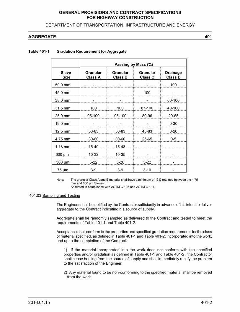
GENERAL PROVISIONS AND CONTRACT SPECIFICATIONSFOR HIGHWAY CONSTRUCTION
DEPARTMENT OF TRANSPORTATION, INFRASTRUCTURE AND ENERGY
AGGREGATE 401
2016.01.15 401-2
Table 401-1 Gradation Requirement for Aggregate
Passing by Mass (%)
Sieve Size
GranularClass A
GranularClass B
GranularClass C
DrainageClass D
50.0 mm - - - 100
45.0 mm - - 100 -
38.0 mm - - - 60-100
31.5 mm 100 100 87-100 40-100
25.0 mm 95-100 95-100 80-96 20-65
19.0 mm - - - 0-30
12.5 mm 50-83 50-83 45-83 0-20
4.75 mm 30-60 30-60 25-65 0-5
1.18 mm 15-40 15-43 - -
600 μm 10-32 10-35 - -
300 μm 5-22 5-26 5-22 -
75 μm 3-9 3-9 3-10 -
Note: The granular Class A and B material shall have a minimum of 13% retained between the 4.75mm and 600 μm Sieves.As tested in compliance with ASTM C-136 and ASTM C-117.
401.03 Sampling and Testing
The Engineer shall be notified by the Contractor sufficiently in advance of his intent to deliveraggregate to the Contract indicating his source of supply.
Aggregate shall be randomly sampled as delivered to the Contract and tested to meet therequirements of Table 401-1 and Table 401-2.
Acceptance shall conform to the properties and specified gradation requirements for the classof material specified, as defined in Table 401-1 and Table 401-2, incorporated into the work,and up to the completion of the Contract.
1) If the material incorporated into the work does not conform with the specifiedproperties and/or gradation as defined in Table 401-1 and Table 401-2 , the Contractorshall cease hauling from the source of supply and shall immediately rectify the problemto the satisfaction of the Engineer.
2) Any material found to be non-conforming to the specified material shall be removedfrom the work.

GENERAL PROVISIONS AND CONTRACT SPECIFICATIONSFOR HIGHWAY CONSTRUCTION
DEPARTMENT OF TRANSPORTATION, INFRASTRUCTURE AND ENERGY
AGGREGATE 401
2016.01.15 401-3
If the Contractor’s methods results in segregation of the materials as defined by ASTM C-125and tested in accordance with ASTM C-136 the Contractor shall cease work immediately andcorrect deficiency.
If segregation of material occurs the Contractor shall scarify and make good the work in placeor shall remove the segregated material from the work.
The acceptance of material shall not preclude its future rejection if it is subsequently foundto lack consistency or if its field performance is unsatisfactory.
Table 401-2 Physical Requirements for Aggregate
TestClass
AClass
BClass
CClass
DASTM
Los AngelesAbrasion,Max. % Loss
35 50 60 50 C-131
MagnesiumSulfateSoundness, Max.% Loss
15 - - 15 C-88
Crushed, Min. % 75(1) 50(2) - 75(1) -
Flat andElongated, Max.% (3)
20 20 - 20 -
Plasticity Index(Max)
3 3 3 - D-4318
PetrographicNumber, Max. (4)
150 - - 150 -
(1) The percent of crushed material will be determined on the fraction of particles by massretained on the 4.75 mm Sieve having 2 or more mechanically fractured faces.
(2) The percent of crushed material will be determined on the fraction of particles by massretained on the 4.75 mm Sieve having 1 mechanically fractured face.
(3) Flat and elongated particles are those whose greatest mean dimension in the longitudinalaxis compared to the least mean dimension in the plane perpendicular to the longitudinalaxis exceeds a ratio of 4:1.
(4) Petrographic number to be determined using current Department test procedures.

GENERAL PROVISIONS AND CONTRACT SPECIFICATIONSFOR HIGHWAY CONSTRUCTION
DEPARTMENT OF TRANSPORTATION, INFRASTRUCTURE AND ENERGY
AGGREGATE 401
2016.01.15 401-4
401.04 Excavation, Processing, Handling and Stockpiling
The Contractor, before commencing excavation of aggregate from any pit, shall comply withProvision 104.15.
The Contractor shall clear and grub pit areas and shall remove and stockpile topsoil andoverburden pursuant to Provision 204.02 to prevent infiltration of deleterious matter.
The Contractor shall ensure that the pit is excavated and the aggregate stockpile isconstructed in such a manner as to prevent flooding of the materials.
Where necessary, to satisfy the requirements of the type of materials specified, aggregatesshall be screened, crushed, washed and otherwise processed with equipment which is ofadequate capacity and capable of consistently yielding an acceptable product.
Aggregates shall be washed only in properly designed and constructed washing plants.Truck, mixer or similar washing methods will not be permitted. The water to be used forwashing aggregate shall be clean and free from injurious amounts of oil, alkali, acid, organicmatter or other deleterious substances. Washed materials or materials excavated fromunderwater shall be stored for at least 24 hours or longer as determined by the Engineer toallow all free water to drain and to attain a uniform water content.
Aggregates shall be handled, transported and stockpiled in such a manner and with suchequipment that segregation and/or contamination is avoided.
Storage areas shall be level, well drained, free of all foreign materials, and of adequatebearing capacity to support the stockpiles. The storage area shall be situated on solid groundwith a suitable haul road. Storage areas and haul roads, must withstand heavy equipmentand trucks. The Contractor will provide and ensure access for the Department or its agentsat any time.
Stockpiles shall be either far enough apart or separated by substantial dividers to preventintermingling. Stockpiles shall be built up in layers not exceeding 1 m in depth. Each layershall be completed over the entire area of the stockpile before beginning the next layer.Special attention should be given, that each layer interlocks with the underneath layer.Coning of the piles or spilling of material over the edges will not be permitted. The use ofbulldozers is not permitted to construct stockpiles, other than to level spot dumped truckloads or to maintain haul roads.
It is the express responsibility of the Contractor to ensure that stockpiles contain material ofacceptable quality and of uniform distribution. Aggregates which are contaminated withforeign matter, segregated or mixed with other aggregates shall not be used and shall beremoved from the stockpiles immediately.
The Contractor will provide for weighing of the aggregate in conformity with Provision 107.03.

GENERAL PROVISIONS AND CONTRACT SPECIFICATIONSFOR HIGHWAY CONSTRUCTION
DEPARTMENT OF TRANSPORTATION, INFRASTRUCTURE AND ENERGY
BEDDING MATERIAL 402
2016.01.15 402-1
402.01 Scope
This Section outlines the gradation requirements for bedding material to be incorporated inDepartment work or stockpiled for Department use.
402.02 Quality of Material
Bedding material shall meet the gradation requirements outlined in Tables 402-1and 402.2.Samples will be taken on a regular basis during the work to ensure that the requirements ofTable 402-1 and 402-2 are met.
Table 402-1Gradation Requirement for Bedding Material
SieveSize
Passing(%)
9.5 mm 100
4.75 mm 87-98
2.36 mm 55-95
1.18 mm 30-90
600 μm 10-70
300 μm 0-35
150 μm 0-15
75 μm 0-12
Note:There shall be a maximum of 35% difference between the percents passing consecutive sieves.
Table 402-2 Gradation Requirement for Crushed Glass
SieveSize
Passing(%)
12.5 mm9.5 mm
4.75 mm2.36 mm1.18 mm0.75 mm
10090-10045-8525-7010-300-10

GENERAL PROVISIONS AND CONTRACT SPECIFICATIONSFOR HIGHWAY CONSTRUCTION
DEPARTMENT OF TRANSPORTATION, INFRASTRUCTURE AND ENERGY
BITUMEN 500
501 Asphalt Cement
502 Asphalt Prime (RESCINDED 2018)
503 Asphalt Emulsions

GENERAL PROVISIONS AND CONTRACT SPECIFICATIONSFOR HIGHWAY CONSTRUCTION
DEPARTMENT OF TRANSPORTATION, INFRASTRUCTURE AND ENERGY
ASPHALT CEMENT 501
2019.01.14 501-1
501.01 Scope
This Section is the material specification for Performance Graded Asphalt Cement(PGAC) and Performance Graded Asphalt Cement with elastic recovery (PGAC-E).Performance Graded Asphalt Cement (PGAC) and Performance Graded Asphalt Cementwith elastic recovery (PGAC-E) shall be homogeneous, free of water and any contaminationand shall not foam when heated to the temperatures specified by the Supplier for the safehandling and use of the product. It shall be shipped, used and handled at all times inaccordance with the Suppliers’s requirements.
501.02 Quality of Material
(PGAC) and (PGAC-E) shall conform to the requirements of AASHTO M320 - Table 1Performance Graded Asphalt Binder Specification for the Performance Grade(s) specifiedin the contract for each hot mix type. Additionally, PGAC-E shall meet the following elasticrecovery requirements when tested in accordance with ASTM-D6084 testing procedure B.
PGAC-E 70-28-E elastic recovery $60%.
501.03 Method of Measurement
The quantity to be measured for payment under this section shall be the number oftonnes of asphalt cement utilized by the Contractor in producing hot mix asphalticconcrete as determined by calibrated asphalt cement pump metered settings loggedby the Department as metered into the mix and calculated for the tonnage of hot mixasphaltic concrete produced.
501.04 Basis of Payment
The supply and transportation of performance grade asphalt cement will be paid for atthe Contractor’s unit bid price per tonne of asphalt cement. This price shall be fullcompensation for any and all expenses that may be incurred for the supply, transportand delivery of the performance grade asphalt cement to the Contractor’s plant,including the cost of any anti-stripping additive required to meet design mixrequirements as well as any storage, heating and handling requirements.
The unit bid price per tonne of PG Grade asphalt cement specified shall be adjusted usingthe PG Grade 58-28 price index as posted 48 hours prior to closing of tender and the timewhen the asphalt cement is incorporated into the work. The price index to be used forcomparison shall be the price as determined in the Maritime Suppliers Rack Price or asartificially established by the Department in the Special Provisions.
A link to the index can be found at:
https://princeedwardisland.ca/en/information/transportation-infrastructure/monthly-average-asphalt-binder-rack-price-2008
The payment adjustment will be in dollars per tonne of asphalt binder. A payment adjustmentwill be established for each month of paving in which the price index for the month differs bymore than $10/tonne from the posted price index at the time in which tenders for the Contractwere opened. When the price index differential is less than $10/tonne there will be no

GENERAL PROVISIONS AND CONTRACT SPECIFICATIONSFOR HIGHWAY CONSTRUCTION
DEPARTMENT OF TRANSPORTATION, INFRASTRUCTURE AND ENERGY
ASPHALT CEMENT 501
2019.01.14 501-2
adjustment established for that month.
The payment adjustment for the month will be calculated as follows, where:
PA = Payment Adjustment for asphalt binder in dollarsT = Posted PG asphalt binder price index at the time of Tender OpeningP = PG asphalt binder price index for month of pavingQ = Quantity of asphalt binder in tonnes
When P > (T + $10/tonne), the Contractor receives an additional payment from the Owner asfollows:
PA = (P - (T + $10/tonne)) x Q
When P < (T - $10/tonne), the Owner deducts from payments due to the Contractor as follows:
PA = (T - $10/tonne) - P) x Q
Examples:
1. A Contractor’s unit bid price for asphalt cement was $325 for a tender that closed inFebruary. The posted price index 48 hours prior to tender closing was $283.75 and the workwas undertaken in May when the price index was $293.25.
$283.75 - $10 = $273.75$283.75 + $10 = $293.75
Since the price index at time of paving ($293.25) falls within the ± $10/tonne range of the priceindex 48 hours prior to tender closing there would be no adjustment to the unit price of theasphalt cement.
2. A Contractor’s unit bid price for asphalt cement was $325 for a tender that closed inFebruary. The posted price index 48 hours prior to tender closing was $283.75 and the workwas undertaken in June when the price index was $260.00 and 250t of cement was used.
$283.75 - $10 = $273.75$283.75 + $10 = $293.75
Since the price index at time of paving ($260.00) falls outside the ± $10/tonne range of theprice index 48 hours prior to tender closing an adjustment to the amount paid to the Contractorwould be required.
The price would be adjusted using the P < (T - $10/tonne) formula. Thus the Owner will deductthe following amount from payment to the Contractor:
PA = ((283.75 - 10) - 260) x 250 = $3437.50
3. A Contractor’s unit bid price for asphalt cement was $325 for a tender that closed inFebruary. The posted price index 48 hours prior to tender closing was $283.75 and the workwas undertaken in August when the price index was $310 and 250t of cement was used.

GENERAL PROVISIONS AND CONTRACT SPECIFICATIONSFOR HIGHWAY CONSTRUCTION
DEPARTMENT OF TRANSPORTATION, INFRASTRUCTURE AND ENERGY
ASPHALT CEMENT 501
2019.01.14 501-3
$283.75 - $10 = $273.75$283.75 + $10 = $293.75
Since the price index at time of paving ($310.00) falls outside the ± $10/tonne range of theprice index 48 hours prior to tender closing an adjustment to the amount paid to the Contractorwould be required.
The price would be adjusted using the P > (T + $10/tonne) formula. Thus the Owner will addthe following amount to the payment to the Contractor:
PA = (310 - (283.75 + 10)) x 250 = $4062.50

Section 502Rescinded
2018
Section 502Rescinded
2018
GENERAL PROVISIONS AND CONTRACT SPECIFICATIONSFOR HIGHWAY CONSTRUCTION
DEPARTMENT OF TRANSPORTATION, INFRASTRUCTURE AND ENERGY
ASPHALT PRIME 502
18.01.15 502-1
502.01 Scope
This Section is the material specification for asphalt prime.
502.02 Quality of Material
Asphalt prime emulsion shall conform in all respects to Table 502-1.
Asphalt prime cutback shall conform in all respects to Table 502-2.
Table 502-1Requirements for Asphalt Prime Emulsion
Test Min. Max. ASTM
Tests on Emulsion
Flash Point Tag Open Cup (EC)45 - D-1310
Saybolt Furol Viscosity at 50EC (mm2/s) 80 175 D-244
Residue by Distillation (%) 40 - D-244(1)
Oil Distillate by Volume (%) - 25 D-244(1)
Storage Stability, 24 hr (%)
- 1.5 D-244
Tests on Residue
Penetration at 25EC,100 g, 5 s (0.1 mm)
100 200 D-5
Ductility at 25EC, 5 cm/min (cm)
100 - D-113(2)
Solubility in Trichloroethylene byMass (%) 97.5 -
D-2042
(1) Follow ASTM D-244 except use high temperature distillation thermometer. Bringthe final temperature to 360EC and terminate heating immediately.
(2) If the Ductility at 25EC is less than 100, the material will be acceptable if itsDuctility at 15EC is more than 100.

Section 502Rescinded
2018
Section 502Rescinded
2018
GENERAL PROVISIONS AND CONTRACT SPECIFICATIONSFOR HIGHWAY CONSTRUCTION
DEPARTMENT OF TRANSPORTATION, INFRASTRUCTURE AND ENERGY
ASPHALT PRIME 502
18.01.15 502-2
Table 502-2Requirements for Asphalt Prime Cutback
Test Min. Max. ASTM
Kinematic Viscosity at 60EC (mm2/s) 20 35 D-2170
Distillation Tests % of Totalto 360EC
to 190EC (%) 20 80 D-402
to 225EC (%) - 60 D-402
to 260EC (%) 70 - D-402
to 315EC (%) 85 - D-402
Distillation Residue to 360EC,Difference by Volume (%)
50 - D-402
Tests on Residue
Penetration at 25EC, 100 g, 5 s (0.1mm)
80 200 D-5
Ductility at 25EC ,5 cm/min (cm)
100 - D-113(1)
Solubility in Trichloroethylene byMass (%)
99.5 - D-2042
(1)If the Ductility at 25EC is less than 100, the material will be acceptable if its Ductility at 15EC is more than 100.

GENERAL PROVISIONS AND CONTRACT SPECIFICATIONSFOR HIGHWAY CONSTRUCTION
DEPARTMENT OF TRANSPORTATION, INFRASTRUCTURE AND ENERGY
ASPHALT EMULSIONS 503
18.01.26 503-1
503.01 Scope
This Section is the material specification for asphalt emulsions.
503.02 Quality of Material
Asphalt Emulsions used for tack coats shall conform in all respects to the requirements ofTables 503-1 or 503-2.
Table 503-1Requirements for Tack Coat Material
Type SS-1 SS-1 h
Test Min. Max. Min. Max. ASTM
Tests on Emulsion
Saybolt Furol Viscosityat 25EC (mm2/s) 20 100 20 100 D-244
Residue by Distillation (%) 57 - 57 - D-244
Settlement in 5 days (%) - 5 - 5 D-244
Retention by Mass on an 850 μmSieve (%)
- 0.1 - 0.1 D-244
Cement Mixing Test (%) - 2 - 2 D-244
Storage Stability in 24 hr (%) - 1 - 1 D-244
Tests on Residue
Penetration at 25EC, 100 g, 5 s (0.1mm)
100 200 40 90 D-5
Ductility at 25EC, 5 cm/min (cm) 40 - 40 - D-113
Solubility in Trichloroethylene byMass (%)
97.5 - 97.5 - D-2042

GENERAL PROVISIONS AND CONTRACT SPECIFICATIONSFOR HIGHWAY CONSTRUCTION
DEPARTMENT OF TRANSPORTATION, INFRASTRUCTURE AND ENERGY
ASPHALT EMULSIONS 503
18.01.26 503-2
Table 503-2Requirements for Tack Coat Material
Type RS-1 RS-1 h
Test Min. Max. Min. Max. ASTM
Tests on Emulsion
Saybolt Furol Viscosityat 25EC (mm2/s) 20 100 20 100 D-244
Residue by Distillation (%) 55 - 55 - D-244
Settlement in 5 days (%) - 3 - - D-244
Retention by Mass on an 850 μmSieve (%)
- 0.1 - 0.1 D-244
Cement Mixing Test (%) - - - - D-244
Storage Stability in 24 hr (%) - - - 1 D-244
Tests on Residue
Penetration at 25EC, 100 g, 5 s (0.1mm)
100 200 40 90 D-5
Ductility at 25EC, 5 cm/min (cm) 60 - - - D-113
Solubility in Trichloroethylene byMass (%)
97.5 - 97.5 - D-2042

GENERAL PROVISIONS AND CONTRACT SPECIFICATIONSFOR HIGHWAY CONSTRUCTION
DEPARTMENT OF TRANSPORTATION, INFRASTRUCTURE AND ENERGY
PAVEMENT 600
601 Tack Coat Application
602 Prime Coat Application (RESCINDED 2018)
603 Hot Mix Asphaltic Concrete603.01/02 Description/Material603.03 Mix Design and Job Mix Formula603.04 Handling of Materials603.05 Equipment603.06 Plant Calibrations603.07 Manufacture of the Mixture603.08/09 Transportation of the Mixture/Communication603.10 Seal Course Trial Area603.11 Requirements for Completed Pavement Courses603.12 Placing of Asphalt Concrete603.13 Construction of Joints603.14 Compaction603.15 Smoothness603.16 Cleanup603.17/18 Method of Measurement/Basis of Payment
604 Chip Seal (RESCINDED 2018)
605 Double Emulsified Asphalt Slurry Seal
606 Asphalt Concrete Curb
607 Asphalt Crack Filling
608 Cold Mix Bituminous Patching Material
609 Hot Mix Asphaltic Concrete - End Result Specification (ERS)609.01/02 Description/Materials609.03 Mix Design and Job Mix Formula609.04 Construction609.05 Quality Control Testing609.06/07 Measurement for Payment/Payment

GENERAL PROVISIONS AND CONTRACT SPECIFICATIONSFOR HIGHWAY CONSTRUCTION
DEPARTMENT OF TRANSPORTATION, INFRASTRUCTURE AND ENERGY
TACK COAT APPLICATION 601
2018.01.16 601-1
601.01 Description
This work shall consist of the supply and application of a bituminous emulsion as a tack coaton an existing asphaltic concrete surface or on a portland cement concrete surface.
601.02 Material
Tack coat material shall be asphaltic emulsion and shall be in accordance with Section 503.
601.03 Equipment
The distributor shall be so designed, equipped, maintained and operated that asphalticmaterial at even heat may be applied uniformly on variable widths at readily determined andcontrolled rates with uniform pressure.
The distributor shall be capable of applying asphaltic material within plus or minus 5% of thedesired rate and in a continuous and uniform manner both longitudinally and across the widthof the spray bar.
The distributor shall be equipped with a rear mounted spray bar parallel to the surface to besprayed. The spray bar must be capable of being adjusted in width from 2.5 - 3.7 m.
The spray bar height shall be adjustable and shall be set at such a height that the spray fanfrom any nozzle overlays the spray fan from the adjacent nozzle by 50% so that a uniformlysprayed surface results.
All spray nozzles shall be in good condition, of the same manufacture, size and type. Nozzlesshall have valves capable of instant full opening and positive cut-off. All spray nozzles shallbe set in the bar so that the nozzle slots make the same horizontal angle (i.e. 15 - 300 ) withthe longitudinal axis of the bar.
The distributor shall be equipped with a suitable thermometer with a minimum range of 10 -1500 C, placed to accurately show the temperature of the distributor contents. Tack coatmaterial must be circulated during the entire heating process in the distributor.
The distributor shall be equipped with a tachometer registering m/min that is visibly locatedto enable the truck driver to maintain constant application speeds at specified rates.
The distributor pump shall be equipped with a tachometer registering R/min passing throughthe nozzles and shall be readily visible to the operator.
The distributor shall be equipped with an accurate distance measuring device.
The distributor shall be equipped with a sampling valve.
601.04 Construction Method
Paved surfaces which are to be covered with hot mix asphaltic concrete shall be tack coated.Surfaces of asphaltic concrete courses which are to be covered by subsequent courses ofasphaltic concrete shall also be tack coated.

GENERAL PROVISIONS AND CONTRACT SPECIFICATIONSFOR HIGHWAY CONSTRUCTION
DEPARTMENT OF TRANSPORTATION, INFRASTRUCTURE AND ENERGY
TACK COAT APPLICATION 601
2018.01.16 601-2
No tack coat shall be applied in wet weather or when the air temperature is less than 50 Cunless otherwise directed by the Engineer.
The surface to be treated shall be cleaned with a power broom, air line, or other approvedequipment that will leave a clean, dry surface free from dust, dirt or other objectionablematerial.
The emulsion shall be heated and maintained at a temperature between 40 - 650 C and shallbe applied to the surface at a rate of 0.35 - 0.5 R/m2 SS-1and SS-1h, and 0.15-0.25 R/m2 forRS-1 and RS-1h as specified by the Engineer. The SS-1 and SS-1h emulsion shall bemixed with water to form a 50-50 mixture.
The material shall be applied evenly and shall form a thin unbroken film on the surface.
The application of tack coat shall not extend beyond the limit of asphaltic concrete to bespread and compacted in a day.
At the end of the day tack coat may be applied to accommodate paving operations on thefollowing day.
After applying the tack coat, the Contractor shall, by means of barricades, signallers, trafficconvoys or other means, prevent the passage of traffic upon the tack coat until it has driedto a proper condition of tackiness as determined by the Engineer. The Engineer may directthat the Contractor reapply tack coat material to any surface where the original tack coatplaced by the Contractor has been worn off by the traffic.
No asphaltic concrete shall be placed upon the tack coat until it has dried to a propercondition of tackiness, as determined by the Engineer. The Contractor is advised that theperiod required for such drying will depend upon weather conditions; it will not be less than30 minutes and could be as long as 3 hours.
601.05 Method of Measurement
Measurement for payment under this Section shall be the number of square metres ofpavement to which tack coat is applied.
No measurement shall be made for the re-Application of a tack coat which has been worn offby traffic.
601.06 Basis of Payment
Payment under this Section shall be at the unit bid price per square metre and this price shallbe full compensation for material, heating, handling, transportation, tools, labour, equipmentand incidentals necessary to carry out the work.
No payment shall be made under this Section for the reapplication of a tack coat, which maybe directed by the Engineer, in the event of traffic wearing off the original application.

Section 602Rescinded
2018
Section 602Rescinded
2018
GENERAL PROVISIONS AND CONTRACT SPECIFICATIONSFOR HIGHWAY CONSTRUCTION
DEPARTMENT OF TRANSPORTATION, INFRASTRUCTURE AND ENERGY
PRIME COAT APPLICATION 602
2018.01.15 602-1
602.01 Description
This work shall consist of the supply and application of bituminous prime and sand cover ona previously prepared surface.
602.02 Material
Prime coat material shall consist of an asphaltic emulsion or an asphaltic cutback inaccordance with Section 502. Sand cover shall conform to the gradation specified in Table602-1.
Table 602-1Gradation Requirement for Sand
SieveSize
Passing(%)
9.5 mm 100
4.75 mm 87-98
2.36 mm 55-95
1.18 mm 30-90
600 μm 10-70
300 μm 0-35
150 μm 0-15
75μm 0-6
602.03 Equipment
The distributor shall be so designed, equipped, maintained and operated that asphalticmaterial at even heat may be applied uniformly on variable widths at readily determined andcontrolled rates with uniform pressure.
The distributor shall be capable of applying asphaltic material within plus or minus 5% of thedesired rate and in a continuous and uniform manner both longitudinally and across the widthof the spray bar.
The distributor shall be equipped with a rear mounted spray bar parallel to the surface to besprayed. The spray bar must be capable of being adjusted in width from 2.5 - 3.7 m.
The spray bar height shall be adjustable and shall be set at such a height that the spray fanfrom any nozzle overlays the spray fan from the adjacent nozzle by 50% so that a uniformlysprayed surface will result.
All spray nozzles shall be in good condition, of the same manufacture, size and type. Nozzlesshall have valves capable of instant full opening and positive cut-off. All spray nozzles shallbe set in the bar so that the nozzle slots make the same horizontal angle (i.e. 15 - 30E ) withthe longitudinal axis of the bar.

Section 602Rescinded
2018
Section 602Rescinded
2018
GENERAL PROVISIONS AND CONTRACT SPECIFICATIONSFOR HIGHWAY CONSTRUCTION
DEPARTMENT OF TRANSPORTATION, INFRASTRUCTURE AND ENERGY
PRIME COAT APPLICATION 602
2018.01.15 602-2
The distributor shall be equipped with a suitable thermometer with a range of 10 - 150EC,placed to accurately show the temperature of the distributor contents. Prime coat materialmust be circulated during the entire heating process in the distributor.
The distributor shall be equipped with a tachometer registering m/min that is visibly locatedto enable the truck driver to maintain constant application speeds at specified rates.
The distributor pump shall be equipped with a tachometer registering R/min passing throughthe nozzles and shall be readily visible to the operator.
The distributor shall be equipped with an accurate distance measuring device.
The distributor shall be equipped with a sampling valve.
Cover sand shall be spread using an approved spreader.
602.04 Construction Method
Unless otherwise directed by the Engineer any roadway surface which is to be covered withhot mix asphaltic concrete shall be prime coated. The Engineer shall be notified at least 4hours prior to the start of bituminous priming.
Prime shall not be applied in wet weather or when the air temperature is less than 10ºCunless otherwise directed by the Engineer.
The prime shall be heated prior to its application to temperatures between 40 - 550 C for anemulsion and between 27 - 450 C for a cutback.
The prime shall be applied to the surface at the rate of 0.9 - 1.8 R/m2 as specified by theEngineer. The prime shall be applied evenly and shall form a thin unbroken film at thesurface. Following the application of prime, a minium curing time of 20 minutes shall beprovided before a sand cover is applied for the purpose of preventing tracking by vehicles.This sand cover should be applied evenly at a rate not exceeding 12 kg/m2. The Engineer canwaive the use of sand if conditions permit the Contractor to control traffic so that it can bekept off the primed road until the prime has set up.
After applying the prime coat, the Contractor shall, by means of barricades, flagmen, trafficcones or other means, prevent the passage of traffic upon the prime coat until it has dried toa proper condition of tackiness as determined by the Engineer. The Engineer may direct thatthe Contractor reapply prime coat material to any surface where the original prime coatplaced by the Contractor has been worn off by traffic.
Asphaltic concrete shall not be laid on the primed surfaces within 6 hours of an emulsifiedprime application and 48 hours after a cutback prime application.
602.05 Method of Measurement
Measurement for payment under this Section shall be the number of square metres ofroadway to which prime coat is applied.
No measurement shall be made for the re-application of a prime coat which has been wornoff by traffic.

Section 602Rescinded
2018
Section 602Rescinded
2018
GENERAL PROVISIONS AND CONTRACT SPECIFICATIONSFOR HIGHWAY CONSTRUCTION
DEPARTMENT OF TRANSPORTATION, INFRASTRUCTURE AND ENERGY
PRIME COAT APPLICATION 602
2018.01.15 602-3
602.06 Basis of Payment
Payment under this Section shall be at the unit bid price per square metre and this price shallbe full compensation for material, heating, handling, transportation, application material, tools,labour, equipment and incidentals necessary to carry out the work.
No payment shall be made under this Section for the re-application of a prime coat, whichmay be directed by the Engineer, in the event of traffic wearing off the original prime coat.

GENERAL PROVISIONS AND CONTRACT SPECIFICATIONS FOR HIGHWAY CONSTRUCTION
DEPARTMENT OF TRANSPORTATION, INFRASTRUCTURE AND ENERGY
HOT MIX ASPHALTIC CONCRETE - Description/Material 603.01/02
2019.01.14 603.01/02-1
603.01 Description
This Section defines the requirements for the materials, equipment and methods to befollowed for production, transportation of hot mixed, hot laid asphaltic concrete forpavement construction and other purposes.
603.02 Material
All materials to be incorporated into the work will be subject to test by the Engineer todetermine suitability. Such tests may consist of chemical or physical analysis todetermine wearability, soundness, density, stability or any other property pertinent tothe satisfactory completion of the work. Acceptance by the Engineer based on thesuitability tests shall not relieve the Contractor of the responsibility of maintaining auniform acceptable product throughout the contract period.
603.02.01 Asphalt Cement
The Contractor shall supply as a bid item Performance Graded Asphalt Cement(PGAC) or Performance Graded Asphalt Cement with elastic recovery (PGAC-E) to beincorporated into the Department's work. Unless otherwise specified, the asphaltcement shall be PG 58-28 and shall conform in all respects to the performance graderequirements of AASHTO M320 Table 1- Performance Graded Asphalt BinderSpecification.
When anti-stripping additives are required, the asphalt cement shall meet the specifiedrequirements of AASHTO M320 Table 1, after the addition of the required additives.
When the selected WMA technology requires that additives be added to the asphaltcement, acceptance of the asphalt cement shall be based on the samples that containthe WMA additive.
The Contractor shall supply the applicable mixing and compaction temperatures for theperformance graded asphalt cement specified in addition to the supplier documentationindicating current test results meeting the requirements of AASHTO M320 Table 1 afterthe addition of required anti-stripping additives if necessary.
Department Staff shall have access to all Asphalt Binder delivery slips at the asphaltplant as the material is delivered. If Department Staff are not present at the timeof delivery then a copy of the delivery slip(s) shall be retained in the asphalt plantcontrol room for Department Staff.
The Department will conduct quality assurance testing by testing random samplestaken from the Contractor’s asphalt cement storage tanks located at the hot mix plantfor the purpose of ensuring that the material used in the work conforms to therequirements of AASHTO M320 Table 1.
603.02.02 Mineral Filler
Mineral Filler shall meet the requirements of ASTM D-242.

GENERAL PROVISIONS AND CONTRACT SPECIFICATIONS FOR HIGHWAY CONSTRUCTION
DEPARTMENT OF TRANSPORTATION, INFRASTRUCTURE AND ENERGY
HOT MIX ASPHALTIC CONCRETE - Description/Material 603.01/02
2019.01.14 603.01/02-2
603.02.03 Asphaltic Concrete Stripping
The Contractor is hereby advised that if their aggregate for asphaltic concrete ismoisture susceptible they shall have the option of either using a liquid anti-strippingadditive from the Department’s list of acceptable products, using hydrated lime, orchanging their source of aggregate.
The Department may determine that an anti-stripping additive is required if one of thefollowing conditions occurs:
- The long term tensile strength ratio (TSR) of the asphaltic concrete as per the latestedition of AASHTO T283 (average of Conditioned & Freeze/Thaw TSR values) isless than 0.80.
- The conditioned & freeze thaw tensile strength values shall not be less than 400 kPa.
- Material that has been conditioned per the latest edition of AASHTO T283 meetsthe 0.80 minimum requirement but a visual examination indicates there is evidenceof stripping.
- If based on past performance the aggregate source is known to be prone tostripping.
603.02.04 Anti-Stripping Agents
Any anti-stripping agent intended for use shall be incorporated in the mix design in theproportion to be used during production and in accordance with the Manufacturer’sSpecifications.
The anti-stripping agents shall consist of one of the following:
- Hydrated Lime (Ca(OH) 2) meeting the requirements of ASTM C-141
- Liquid Anti-Stripping Additives (from the approved list)
Manufacturer Product
Akzo Nobel Chemicals Redicote C 3082Akzo Nobel Chemicals Redicote 95-SMeadwestvaco Corp Evotherm M1Morton International Pave Bond “T” LiteMorton International Pave Bond LiteTravis Chemicals Travcor 4501ARR-MAZ Products AD-here LOF 6500Ultrapave Ultracote (UP-5000)Zydex ZycosilZydex Zycotherm
Inclusion on this list does not attest to efficacy of use with any specific aggregate orapproval for use on any specific project. Testing for each product shall be required forthis purpose. This list is subject to revision.

GENERAL PROVISIONS AND CONTRACT SPECIFICATIONS FOR HIGHWAY CONSTRUCTION
DEPARTMENT OF TRANSPORTATION, INFRASTRUCTURE AND ENERGY
HOT MIX ASPHALTIC CONCRETE - Description/Material 603.01/02
2019.01.14 603.01/02-3
603.02.04.01 Approval of Anti-Stripping Agents
Approval to use an anti-stripping agent will only be given if it is determined from thelatest edition of AASHTO T283 that the long-term TSR of the mix with an anti-strippingagent equals or exceeds 0.80 ( conditioned & freeze thaw tensile strength values meetor exceeds 400 kPa) and the visual examination indicates there is no evidence ofstripping. The Contractor shall also demonstrate the capability of properly addinghydrated lime to the mix at the hot-mix plant if hydrated lime is proposed for use as ananti-stripping agent. In all cases a minimum of 10 working days are required to performthe stripping test after the aggregates have been received by the Materials Lab. Anadditional 10 working days will be required for re-testing of aggregate with an anti-stripping agent.
603.02.04.02 Addition of Liquid Anti-Stripping Additive
The liquid anti-stripping additive shall be added at a rate as determined by the mixdesign (minimum 0.5% or 0.4% ARR-MAZ AD-here LOF 6500) to the asphalt cementat the Supplier’s depot, concurrently, with loading of the asphalt cement into theCarriers tanker.
603.02.04.03 Information Sessions
At a pre-construction meeting the Contractor and the Department will review therequirements for use of the liquid anti-stripping additive, including proper procedures,worker information, use of protective clothing and equipment, site supervision andcontingency.
The Contractor shall advise workers of the proper procedures to be followed whenworking with asphalt cement or asphaltic concrete containing anti-stripping additives.
603.02.05 Aggregates
Coarse aggregate to be supplied for the manufacture of asphaltic concrete shallconsist of crushed gravel or crushed stone, composed of clean, sound, hard anddurable particles free from a coating of silt, and/or clay and shall not contain otherdeleterious materials. Coarse aggregate shall conform to the physical requirementsfor coarse aggregate shown in Table 603-1 and 603-2 or as otherwise approved bythe Engineer.
Irrespective of compliance with the physical requirements of Table 603-1 and 603-2,a coarse aggregate may be rejected on the basis of past field performance.
Fine aggregate to be supplied for the manufacture of asphaltic concrete shall consistof manufactured material processed by crushing quarried rock or natural sand andgravel, the particles of which shall be clean, hard, durable and free from coatings ofsilt, clay or other deleterious material. Fine aggregate shall conform to the physicaland gradation requirements shown in Table 603-3 or as otherwise approved by theEngineer in writing. The fraction between any 2 of the following consecutive sieves(4.75 mm, 2.36 mm, 1.18 mm, 600 μm, 300 μm, 150 μm) shall be a minimum of 7 %.A minimum of 25% fine aggregate, processed by crushing quarried rock, shall beincorporated into all asphaltic mixes.

GENERAL PROVISIONS AND CONTRACT SPECIFICATIONS FOR HIGHWAY CONSTRUCTION
DEPARTMENT OF TRANSPORTATION, INFRASTRUCTURE AND ENERGY
HOT MIX ASPHALTIC CONCRETE - Description/Material 603.01/02
2019.01.14 603.01/02-4
Table 603-1Gradation Requirement for Coarse Aggregate - ASTM C-136
Material Size 9.5 mm 12.5 mm 19.0 mm
Sieve Size
Passing(%)
Passing(%)
Passing(%)
25.0 mm - - 100
19.0 mm - 100 90-100
12.5 mm 100 90-100 50-75
9.5 mm 80-100 45-75 20-55
6.3 mm 15-50 - -
4.75 mm 0-15 0-15 0-15
Table 603-2 Physical Requirements for Coarse Aggregate
TestA
BaseB
SealC
SealASTM
Los Angeles Abrasion, Max. %Loss
35 35 35 C-131
Magnesium Sulfate Soundness,Max. % Loss 15 15 15 C-88
Absorption, Max. % 1.7 1.7 1.7 C-127
Crushed, Min. % 75 75 75 (1)
Flat and Elongated, Max. % 20 20 20 (2)
Petrographic Number, Max. 200 140 140 (3)
4.75 mm Sieve, Max. % Passing 15 15 15 C-136
75 μm Sieve with PI # 3, Max. %Passing
3 3 3 C-117
(1) Crushed percentage is the fraction of particles by mass retained on the 4.75 mm Sieve having two or
more freshly fractured faces for Classes A, B, C.(2) Flat and elongated particles to be determined using current Department test procedures.(3) Petrographic number to be determined using current Department test procedures.

GENERAL PROVISIONS AND CONTRACT SPECIFICATIONS FOR HIGHWAY CONSTRUCTION
DEPARTMENT OF TRANSPORTATION, INFRASTRUCTURE AND ENERGY
HOT MIX ASPHALTIC CONCRETE - Description/Material 603.01/02
2019.01.14 603.01/02-5
Table 603-3 Physical and Gradation Requirements for Fine Aggregate
TestA
BaseB
SealD
Sand Seal ASTM
Magnesium Sulfate Soundness,Max. % Loss 15 15 15 C-88
4.75 mm Sieve,Min. % Passing 85 85 85 C-136
75 μm Sieve,Max. % Passing 8 8 8 C-117
603.02.06 Blending Sand
Blending sand supplied for the manufacture of asphaltic concrete shall consist ofclean, tough, durable particles, free of silt, clay or other deleterious material.
The gradation of the blending sand shall be such that when incorporated into theasphaltic concrete mix, the resultant mix shall meet the requirements of Tables 603-4, 603-5 and 603-6.
The blending sand shall have 100 percent passing the 9.5 mm Sieve and amaximum of 50% passing the 300 μm Sieve.
The physical requirements of the blending sand shall be as specified in Table 603-3with the exception of the limitation on the maximum % passing the 75 μm Sieve.
The maximum mass of blending sand to be used in the total mix shall not exceed12% for all mixes except “D” mix.
603.02.07 Warm Mix Asphalt (WMA)
WMA technologies must be approved by the Engineer prior to its use. Technologyapproved for previous work is not guaranteed approval on all future work.
The Contractor shall supply all materials required for the production of WMA.Supporting documentation from the WMA supplier for the proper preparation,storage and handling of their product shall be obtained by the Contractor andsubmitted to the Engineer.

GENERAL PROVISIONS AND CONTRACT SPECIFICATIONS FOR HIGHWAY CONSTRUCTION
DEPARTMENT OF TRANSPORTATION, INFRASTRUCTURE AND ENERGY
HOT MIX ASPHALTIC CONCRETE - Mix Design and Job Mix Formula 603.03
2018.01.15 603.03-1
603.03 Mix Design and Job Mix Formula
603.03.01 Responsibility for Design Mix
Authority Mix Design
The Engineer shall be notified when stockpiles meeting minimum size requirementsof coarse aggregate, fine aggregate, blending sand and performance grade asphaltcement representative of the material to be used in the work are available for samplingat the plant site.
The Engineer will arrange for samples of each material to be taken and submitted tothe Department's laboratory for mix design purposes after stockpile requirements asspecified in Subsection 603.04.01 have been met. The Contractor will be notified ofthe composition of the mix design no later than three (3) weeks after the day on whichall of the representative samples were received by the Department's laboratory. TheContractor shall not commence mix production before such notification.
A new asphalt mix design shall be required if any change occurs in the nature orsource of the aggregate and/or the supplier of the performance graded asphaltcement.
Contractor Mix Design
Preparation and submission of the asphalt mix design for the Department's approvalis optional to the Contractor. In conformance with this specification, the Contractorshall use professional engineering services and a qualified testing laboratory to assessthe performance grade asphalt cement and aggregate materials proposed for use andto carry out the design of the asphalt mix.
603.03.01.01 Requirement for Asphalt Mix Design
The asphalt mix design shall follow the Marshall method of mix design based on 75Blows and be in accordance with the latest edition of the Asphalt Institute Publication,Mix Design Methods for Asphalt Concrete Manual Series No. 2 (MS-2).
The asphalt cement grade shall be PG 58-28, unless otherwise specified. The designpercent of asphalt cement shall be that percent which yields design air voids of4%±½.%.
The job mix formula shall be the approved asphalt mix design specifying the aggregateblend proportions and the optimium percentage of asphalt cement that yields target airvoids as determined by contract SADT (Summer Average Daily Traffic).
SADT
< 30003000 - 10,000
> 10,000
Target Air Voids (± 0.5%)
2.53.03.5

GENERAL PROVISIONS AND CONTRACT SPECIFICATIONS FOR HIGHWAY CONSTRUCTION
DEPARTMENT OF TRANSPORTATION, INFRASTRUCTURE AND ENERGY
HOT MIX ASPHALTIC CONCRETE - Mix Design and Job Mix Formula 603.03
2018.01.15 603.03-2
The percent passing the 4.75 mm sieve size ±2% for the blended aggregate gradations forgiven mix types shall be as follows:
Mix Type
AB & C
Percent Passing 4.75 mm sieve size
50%64%
The asphalt mix design data and the proposed job mix formula determined by theDepartment’s Laboratory or submitted by the Contractor for the Department's reviewand approval shall include for each blend the following:1) The name of the testing firm responsible for the mix design.2) The specific location(s) of the source(s) of mineral aggregate.3) The source and type of mineral admixture and the percentage to be used.4) The percentage of aggregate passing each of the specified sieves for each
aggregate to be incorporated into the mixture.5) The proportion of each material (in percent of aggregate), including hydrated
lime, if required, as an anti-stripping additive.6) The composite gradation based on (4) and (5) above.7) The composite gradation plotted on a 0.45 power graph paper.8) The results of all aggregate testing, determinations, etc., as defined in Tables
603.1, 603.2 and 603.3 of Section 603, of the General Provisions and ContractSpecifications for Highway Construction manual, including bulk specific gravityand apparent specific gravity for both the coarse and fine aggregates. The75µm material shall be removed prior to the determination of the specificgravities. In addition, aggregates shall be tested as per the latest edition ofAASHTO T283 to determine if they are prone to stripping (tensile strength ratio<0.8 and conditioned freeze thaw tensile strength values less than 400 kPa )as well as no visual evidence of stripping. Provided an anti-stripping additiveis required, hydrated lime or an effective liquid anti-stripping additive shall beused and tested for compliance as per the latest edition of AASHTO T283(tensile strength ratio >0.8 and conditioned and freeze thaw tensile strengthvalues meet or exceed 400 kPa) with no visual evidence of stripping.
9) The mix design with a minimum of four (4) different asphalt contents (minimum0.5 % between each point) with at least one point above and one point belowthe optimum asphalt percentage that reports the following: (i) The percentage (in units of one tenth of 1%) of asphalt cement to
beaded, based on the total weight of the mixture.(ii) The Marshall test results for the individual and average bulk specific
gravity, stability and flow of at least three specimens at each asphaltcontent.
(iii) The maximum theoretical specific gravity at each asphalt content.(iv) The percent of air voids in the mixture for each asphalt content.(v) The percent voids in mineral aggregate (VMA) at each asphalt content.(vi) The percent voids filled with asphalt (VFA) at each asphalt content.(vii) The design asphalt content as a percent of total mix.
10) All Marshal mix design characteristics, including graphs used in arriving at thefinal mix design, the bulk relative density of the combined aggregates and theasphalt absorption of the combined aggregates.
11) The source and current test results of the performance graded asphalt cement

GENERAL PROVISIONS AND CONTRACT SPECIFICATIONS FOR HIGHWAY CONSTRUCTION
DEPARTMENT OF TRANSPORTATION, INFRASTRUCTURE AND ENERGY
HOT MIX ASPHALTIC CONCRETE - Mix Design and Job Mix Formula 603.03
2018.01.15 603.03-3
to be incorporated into the Department’s work meeting the requirements ofAHSTO M-320 Table 1 for performance graded asphalt cement includingapplicable mixing and compaction temperatures.
The Contractor shall submit the following with the asphalt mix design for verificationpurposes:
(a) One - 20 kg sample of each representative virgin aggregate.(b) Thirty-two 1.2 kg samples of representative virgin aggregate blended to the
design mix gradation of the asphalt mix aggregate.(c) Four Litres of the type of performance grade asphalt cement to be used.
603.03.01.02 Design Mix Approval
Design mix approval will be based on the design mix tests and the correspondingrequirements detailed in Tables 603.4 and 603.5 of Section 603, of the GeneralProvisions and Contract Specifications for Highway Construction.
A new asphalt mix design shall be required if any change occurs in the nature orsource of the aggregate and/or the supplier of the performance graded asphaltcement.
The Engineer shall not accept any asphalt mix produced prior to the Contractorreceiving written approval of the asphalt mix design.
The job mix formula shall be the approved asphalt mix design specifying the aggregateblend proportions and the optimum percentage of asphalt cement that yields target airvoids as determined by contract SADT (Summer Average Daily Traffic).
SADT
< 30003000 - 10,000
> 10,000
Target Air Voids (± 0.5%)
2.53.03.5
Once the job mix formula has been designated by the Engineer, the Contractor shallbe required to produce an asphaltic concrete mixture conforming to the requirementsspecified in Table 603-4, Table 603-5 and Table 603-6.
The mix design and job mix formula shall remain in effect until changed in writing. Should the aggregate source change, or when unsatisfactory results or otherconditions make it necessary, a new mix design will be required.
The Department's laboratory shall require fifteen (15) working days from the time ofreceipt of Contractor submitted asphalt mix design and samples to evaluate theasphalt mix design.As part of the asphalt mix design evaluation, the Department's laboratory shalldetermine the following properties:
(i) Combined aggregate gradation;(ii) Bulk specific gravity for the asphalt mix aggregate;(iii) Marshal density;(iv) Theoretical maximum specific gravity of the asphalt mix at the design asphalt

GENERAL PROVISIONS AND CONTRACT SPECIFICATIONS FOR HIGHWAY CONSTRUCTION
DEPARTMENT OF TRANSPORTATION, INFRASTRUCTURE AND ENERGY
HOT MIX ASPHALTIC CONCRETE - Mix Design and Job Mix Formula 603.03
2018.01.15 603.03-4
content and at each asphalt content considered by the Contractor above andbelow the design asphalt content.
(v) The difference between the property values submitted by the Contractor andthe property values as determined by the Department's laboratory shall notexceed the amounts shown as follows:
Property Maximum Permissible Variation
Bulk Specific Gravity of Aggregate ± 0.015
Marshall Density ± 12 kg/m3
Theoretical Maximum SpecificGravity
± 0.010
The asphalt mix design shall be rejected if the maximum permissible variations areexceeded.
Table 603-4Blended Aggregate Gradation and Asphalt Content for Asphaltic Concrete Mixes
Passing (%)
SieveSize
A Base
B Seal
CSeal
D SandSeal
25.0 mm 100 - - -
19.0 mm 90-100 - 100 -
12.5 mm 71-86 100 90-100 -
9.5 mm 60-78 90-100 76-91 100
4.75 mm 39-61 55-75 49-72 85-100
2.36 mm 23-49 32-60 28-58 65-85
1.18 mm 16-34 19-45 19-40 45-70
600 μm 11-24 13-35 13-27 30-55
300 μm 7-16 8-22 9-18 15-35
150 μm 5-10 5-12 6-11 7-20
75 μm 3.3-6 4.5-6.5 3.7-6 5.5-8
Asphalt Cement
% by Mass ofTotal Mixture
4.7-6.0 5.5-7.0 5.3-6.5 6.5-8.5

GENERAL PROVISIONS AND CONTRACT SPECIFICATIONS FOR HIGHWAY CONSTRUCTION
DEPARTMENT OF TRANSPORTATION, INFRASTRUCTURE AND ENERGY
HOT MIX ASPHALTIC CONCRETE - Mix Design and Job Mix Formula 603.03
2018.01.15 603.03-5
Table 603-5Physical Requirements for Dense Graded Asphaltic Concrete
TestA
BaseB
SealC
SealD
SandSeal
Stability at 60EC (N) 5800 5800 5800 3400
Flow (0.25 mm) 8-16 8-16 8-16 8-16
Air Voids (%) 2.5-4.5 2.5-4.5 2.5-4.5 3-5
Min. VMA (%) 13 15 14 16
VFA (%) 68-78 70-80 70-80 70-85
Table 603-6Mix Control Tolerance Variation from Job Mix Formula
SieveSize
AllowableVariation
of % Passing(± %)
25.0 mm 5
19.0 mm 5
16.0 mm 5
12.5 mm 5
9.5 mm 5
4.75 mm 5
2.36 mm 4
1.18 mm 4
600 μm 3
300 μm 3
150 μm 2
75 μm 1
AsphaltCement
0.3
GENERAL PROVISIONS AND CONTRACT SPECIFICATIONS FOR HIGHWAY CONSTRUCTION
DEPARTMENT OF TRANSPORTATION, INFRASTRUCTURE AND ENERGY
HOT MIX ASPHALTIC CONCRETE - Mix Design and Job Mix Formula 603.03
2018.01.15 603.03-6
603.03.02 Physical Requirements of the Mixture
The mixture shall be uniform and shall consist of a mixture of coarse and/or fineaggregate together with any required blend sand, mineral filler or lime, and mixed withasphalt cement.
The mineral constituents shall be combined in such proportions as to produce a mixtureconforming to the gradation requirements of Table 603-4. The grading shall not showmarked fluctuations from opposite extremes of the limiting sizes.
Mixtures shall meet the physical requirements of the properties specified in Table 603-5. Current Department test procedures will be used to determine these properties.
603.03.03 Mix Control Tolerances
Once the job mix formula has been designated by the Engineer, the Contractor shall berequired to produce an asphaltic concrete mixture conforming to the mix controltolerance as specified in Table 603-6.

GENERAL PROVISIONS AND CONTRACT SPECIFICATIONS FOR HIGHWAY CONSTRUCTION
DEPARTMENT OF TRANSPORTATION, INFRASTRUCTURE AND ENERGY
HOT MIX ASPHALTIC CONCRETE - Handling of Materials 603.04
2007.02.09 603.04-1
603.04 Handling of Materials
603.04.01 Stockpile Requirements
Stockpiling sites shall be level, well drained, free of all foreign materials and of adequatebearing capacity to support the mass of the stockpiled materials. Stockpiles shall be eitherfar enough apart or separated by substantial dividers to prevent intermingling.
For all aggregates except where stockpiled on Portland cement concrete, asphaltic concreteor on otherwise acceptably stabilized areas, the bottom 150 mm of the stockpile is not to beincorporated into the Department's work.
Stockpiles shall be built up in layers not exceeding 1 m in depth. Each layer shall becompleted over the entire area of the stockpile before beginning the next layer. Coning of thepiles or spilling of material over the edges of the pile will not be permitted. Traffic over thestockpile surface shall be limited to that required for adequate levelling or removal.
The minimum size of each coarse and fine aggregate stockpile shall be 1000 tonnes. Theminimum size of the stockpile(s) of blending sand shall be 150 tonnes.
Before any production of asphaltic concrete mixture has commenced, aggregate stockpilesof the required size and gradation shall be provided at the asphalt plant site. Minimumstockpile requirements shall be maintained throughout the project. Aggregates brought to thesite after production has commenced shall be stored in separate stockpiles.
A minimum of 2 working days between the arrival of asphalt aggregate and its incorporationinto the asphaltic concrete mixture will be required to facilitate complete analysis of theaggregate prior to its use.
603.04.02 Handling, Feeding and Drying of Aggregate
Aggregate shall be loaded into the cold feed bins so as to prevent the mixing of separatedsizes of aggregate. Mixing of materials on site or loading of more than one material into asingle bin shall not be permitted.
Where the Contractor chooses to use a batch or continuous mix operation, the aggregateshall be dried and heated in the drier and separated by screening into hot storage bins.When the aggregate is delivered to the mixer, it shall be at a temperature consistent withproper mixing and laying and shall in no case exceed 165EC. Surfaces of dried aggregateshall be free of carbon or unburnt fuel oil.
The aggregate shall be sufficiently dried as evidenced by the lack of noticeable steaming,bubbling, or foaming of the asphalt mixture and the absence of visible free water on thetailgate of the truck box.
If insufficient drying is evident, the Contractor shall take steps as deemed necessary toprovide properly dried aggregates.

GENERAL PROVISIONS AND CONTRACT SPECIFICATIONS FOR HIGHWAY CONSTRUCTION
DEPARTMENT OF TRANSPORTATION, INFRASTRUCTURE AND ENERGY
HOT MIX ASPHALTIC CONCRETE - Equipment 603.05
2016.01.15 603.05-1
603.05 Equipment
603.05.01 Requirement of all Mixing Plants
603.05.01.01 Air Quality Permit Requirements
The Contractor must comply with all applicable sections of the Department’s Environmental Protection Plan (EPP) which forms part of these Specifications.
The Contractor must supply all asphaltic concrete from an asphalt plant that has a valid AirQuality Permit issued by the PEI Department of Environment, Labour and Justice (ELJ).
The Contractor must supply the Engineer with a copy of a valid Air Quality Permit for eachasphalt plant which will be used to supply asphaltic concrete to the Contractor or projectbefore production begins.
If the Department receives a copy of a written notice from EJL to the Owner of an asphaltplant that the asphalt plant does not posses a valid Air Quality Permit or that the Air QualityPermit for that plant has been revoked, then the Department will not accept asphalticconcrete from that plant.
603.05.01.02 Inspection Requirements
All equipment shall be on the site and available for inspection, testing and approval beforeoperations commence.
Plants used for the manufacture of asphaltic concrete under this Section shall conform to therequirements of ASTM D-995.
The Engineer, or authorized representative, shall have access at all times to any or all partsof the plant and equipment pertaining to the work. In order to ensure that the manufactureof the mixture is in strict accordance with the specifications, the Department may usewhatever recording devices are deemed necessary for permanent records including audioand video records.
Stairways to the mixer platform and to the asphalt cement storage tank manholes, andladders to other plant units shall provide accessibility to all plant operations. Ample andunobstructed space shall be provided on the mixing platform. A platform shall be providedin the vicinity of the plant to permit inspection and sampling of the mixture before it isdelivered to the work site.
603.05.01.03 Equipment for Preparation of Asphalt Cement
Asphalt Cement storage tanks shall be capable of heating the material under effective andpositive control at all times and maintaining a range between 130 - 165º C. When the amountof asphalt cement added to the mixture is measured volumetrically, the actual workingtemperature shall not vary by more than plus or minus 5º C .
A circulating system of adequate size shall be provided for the asphalt cement to ensureproper and continuous circulation between the working tank and the mixer during the entireoperating period. A sampling valve shall be between the working tank and the mixer. Allpipe lines and fittings shall be insulated to prevent heat loss.
There shall be a separate tank and circulation line for each grade of asphalt cement being

GENERAL PROVISIONS AND CONTRACT SPECIFICATIONS FOR HIGHWAY CONSTRUCTION
DEPARTMENT OF TRANSPORTATION, INFRASTRUCTURE AND ENERGY
HOT MIX ASPHALTIC CONCRETE - Equipment 603.05
2016.01.15 603.05-2
used in the work.
603.05.01.04 Cold Feed System
Bin dimensions and geometry shall be such as to provide a free flow of material at all times.An individual cold feed bin shall be provided for each size, type or aggregate gradation. Eachbin shall be equipped with individual gate controls to provide accurate and positiveproportioning. Partitions of sufficient height to eliminate intermingling of the aggregate shallbe provided between adjoining bins. If the cold feed bins are being fed with a front-endloader, the width of each bin must be at least 500 mm wider than the width of the loaderbucket.
A variable speed control shall be permitted only if it is properly designed to give total andproportional control of the cold feed system.
603.05.01.05 Drier
This clause is not applicable to drum mixers.
A rotary drier, of sufficient capacity to heat and dry the aggregate to the required temperature,shall be provided.
603.05.01.06 Screens
This clause is not applicable to drum mixers.
Plant screens capable of screening all aggregates to the sizes required for proportioning eachtype of asphalt mixture, and capable of handling capacities in excess of the hourly mixercapacity, shall be provided.
All screens shall have square openings, unless otherwise specified by the Engineer. Screensshall be kept clean and in good repair.
603.05.01.07 Hot Aggregate Storage Bins
This clause is not applicable to drum mixers.
The plant shall contain a minimum of two (2) hot aggregate storage bins arranged to ensureseparate and adequate storage of appropriate aggregate fractions. Each bin shall be of asize and at a location to prevent material from backing up into other bins. An oversize chuteshall be provided to prevent oversize aggregate from becoming incorporated in the mix.Gates on hot storage bins shall be so constructed as to prevent leakage when they areclosed.
Each bin shall be provided with a safe and suitable device for obtaining test samples.
603.05.01.08 Asphalt Cement Control Unit
Satisfactory means shall be provided to incorporate the required quantity of asphalt cementinto the mixture. All measuring devices shall be sensitive to a one percent (1%) variationabove or below the actual mass required. Suitable insulation shall be provided formaintaining the temperature of the asphalt cement in pipelines, meters, weigh buckets, spraybars, containers or flow lines.The remainder of this clause is not applicable to drum mixers.

GENERAL PROVISIONS AND CONTRACT SPECIFICATIONS FOR HIGHWAY CONSTRUCTION
DEPARTMENT OF TRANSPORTATION, INFRASTRUCTURE AND ENERGY
HOT MIX ASPHALTIC CONCRETE - Equipment 603.05
2016.01.15 603.05-3
The asphalt cement shall be delivered to the pugmill in a thin uniform sheet or in multiplestreams over the full length or width of the mixer.
603.05.01.09 Thermometric Equipment
Suitable thermometric equipment shall be provided to register the temperature of the asphaltas delivered to the mixer. The indicator dial, graduated from 100 - 200ºC in 2ºC increments,shall be mounted where it is clearly visible to the operator at all times.
Each asphalt cement storage tank shall be equipped with a similarly graduated thermometerinstalled in the asphalt cement feed line near the mixer's discharge pipe. Plants shall have approved recording thermometers, pyrometers, or approved recordingthermometric instruments at the discharge chute of the drier to register and automaticallyrecord the temperature of the heated aggregate. In drum mixers, where the temperature ofthe hot bituminous mixture is registered and recorded with a printed recorder that can bemonitored by the plant operator, the printed record shall be available to the Department.
603.05.01.10 Dust Collectors
This clause is not applicable to drum mixers.
All plants shall be equipped with a primary dry dust collecting system and a wet or drysecondary dust collecting system.
Provisions shall be made to waste all of the collected materials or to uniformly return all orany portion of the dry material to the mixture, as required, to meet mix design.
603.05.01.11 Filler Attachments
Should filler be required in the mixture, the plant shall be equipped with all filler feedingequipment necessary to uniformly incorporate the prescribed proportion of filler into themixture.
603.05.01.12 Hydrated Lime
Should hydrated lime be required in the mixture, the plant shall be equipped with all feedingequipment necessary to uniformly incorporate the prescribed proportion of lime. The feedingequipment shall be mounted so as to permit thorough dry mixing with the aggregate prior tocontact with the asphalt cement.
603.05.01.13 Hot Mix Surge Bins
If the Contractor elects to use a hot mix surge bin, it shall be designed, constructed andoperated so that there shall be no segregation of, or damage to, the mix due to the surge binor it's appurtenances. The hot mix surge bin shall be operated in such a manner during drawdown to prevent free discharge of hot mix from the conveyor belt to the truck. The maximumallowable time which an asphalt mixture can be stored in a hot mix surge bin shall be 4 hours.
603.05.01.14 Hot Mix Storage Silos
If the Contractor elects to use a hot mix storage silo, it shall be designed, constructed andoperated so that there shall be no segregation of, or damage to, the mix. The storage siloshall be equipped with an appropriate holding and batching system at the top of the silo,coordinated with plant production, to prevent complete discharge so that mix is not permittedto fall directly into the silo.

GENERAL PROVISIONS AND CONTRACT SPECIFICATIONS FOR HIGHWAY CONSTRUCTION
DEPARTMENT OF TRANSPORTATION, INFRASTRUCTURE AND ENERGY
HOT MIX ASPHALTIC CONCRETE - Equipment 603.05
2016.01.15 603.05-4
Storage silos, equipped with a heating system, shall be capable of maintaining thetemperature without localized overheating.
Storage silos shall be equipped with mix level indicators, and when the plant is in continuousoperation, the minimum level of mix in the silo must be maintained above the one-third (a)capacity level.
Storage in the silo up to 20 hours shall be permitted provided:
(I) that the penetration of the asphalt cement recovered from the stored asphalt concrete is equal to or greater than the penetration after the thin film oven test of theoriginal asphalt cement before mixing, and
(ii) which, when discharged from the storage silo, was free flowing and without lumps,and
(iii) which, when delivered to the paver, was at or above 135EC
603.05.01.15 Mix Production Control
At all times during mix production, a Plant Operator, competent and familiar with theoperation of the plant, shall be at the control console. The Contractor shall designate aqualified person solely for this operation during the production of asphaltic concrete. TheDepartment reserves the right to reject any mix produced during the Plant Operator'sabsence.
603.05.01.16 Asphalt Plant Inspector's Quarters
At any asphalt plant the Contractor shall provide, at the Contractor's own expense, workingquarters for the Asphalt Plant Inspector having the following dimensions and equipment.
a) Outside dimension: Min. (3 x 2.4 x 2.4 m).
b) Equipment:
- 1 door and padlock- 1 window that opens, Min. (700 x 600 mm)- 1 chair- 1 sturdy and well supported bench along the 3 m wall (700 mm wide x 900
mm high)- Electricity: 1 overhead light and at least 1 wall plug
c) The working quarters shall be located so that the Inspector is able to observe theoperation from the building.
d) This building is to be for the sole use of the Asphalt Inspector. The Contractor is notto store equipment or supplies in it.
603.05.02 Special Requirements for Batch Mixing Plants
603.05.02.01 Material Level Indicators
A material level indicator shall be installed in each hot aggregate bin at the 2/3 full level andshall be connected to remote high-low indicator lights mounted at the operator's station.

GENERAL PROVISIONS AND CONTRACT SPECIFICATIONS FOR HIGHWAY CONSTRUCTION
DEPARTMENT OF TRANSPORTATION, INFRASTRUCTURE AND ENERGY
HOT MIX ASPHALTIC CONCRETE - Equipment 603.05
2016.01.15 603.05-5
603.05.02.02 Weigh Hopper
The equipment shall include a means to accurately weigh each bin size of aggregate in aweigh hopper suspended on scales and this weigh hopper shall be of ample size to hold afull batch without running over. The hopper shall be supported on fulcrums and knife edgesand constructed so that the fulcrums and knife edges are not easily thrown out of alignmentor adjustment. The hopper shall be dimensioned and constructed to prevent segregation ofthe dry aggregate prior to mixing. Gates on the hopper shall be constructed to preventleakage when closed.
603.05.02.03 Plant Scales
Scales for weighing aggregates and asphalt cement shall be the dial type and of a standardmake and design. Scales for weighing aggregates shall be accurate and sensitive to 0.5%of the maximum load required, and shall provide a positive means of balancing the tare massof the hopper and asphalt bucket. At the beginning of each construction season, after eachplant set-up and prior to batching any materials, and whenever it is deemed necessary by theEngineer, the Contractor shall verify the accuracy of the scales.
603.05.02.04 Mixer Unit
The plant shall include an approved twin shaft pugmill type batch mixer that can produce auniform mixture within the tolerances required. The clearance of the blades from the innersurfaces of the pugmill liners shall not exceed 20 mm. The mixer shall be constructed toprevent leakage of the contents. The mixer shall be fitted with separate dry and wet mixingcycle timers and locking devices so that asphalt cement cannot be discharged and thepugmill gate cannot be opened until the desired mixing times have elapsed.
Mixing time shall be determined as the minimum time required to fully coat all aggregateparticles with a uniform coating of bitumen.
603.05.03 Special Requirements for Drum Mixers
603.05.03.01 Aggregate Feed System
A positive interlocked automatic shut-off shall be provided so that the plant shuts downautomatically after a 15 second disruption in the flow of aggregate from any cold feed bin.
The Contractor shall be responsible for obtaining aggregate moisture contents and adjustingthe system accordingly to ensure the correct proportion of asphalt cement and aggregate aremaintained.
A vibrating screen of adequate size and capacity shall be provided for oversize material andother debris from the combined cold feed.
The conveyor belt, with the load cell, shall be equipped with a positive means to preventbuild-up of material.
603.05.03.02 Asphalt Cement Control Unit
A flow switch shall be installed in the delivery system which will automatically stop the plantif an interruption occurs in the asphalt cement flow.
The asphalt cement metering system shall have provision to compensate for fluctuations inspecific gravity and temperature. The Contractor shall be responsible for calculating andadjusting specific gravity values for temperature fluctuations of 5ºC or a temperature

GENERAL PROVISIONS AND CONTRACT SPECIFICATIONS FOR HIGHWAY CONSTRUCTION
DEPARTMENT OF TRANSPORTATION, INFRASTRUCTURE AND ENERGY
HOT MIX ASPHALTIC CONCRETE - Equipment 603.05
2016.01.15 603.05-6
compensating system shall be installed in the asphalt cement line from the storage tank.
A positive means of controlling the delay time between initial aggregate flow and initialasphalt cement delivered shall be employed.
603.05.03.03 Calibration
The asphalt feed system shall be equipped with a calibration system to allow asphalt cementto be bypassed into a container and weighed. The asphalt cement metering system shall becalibrated to an accuracy of plus or minus 1% through the actual working range of thesystem, at the start of the paving season, whenever the weighing conveyor is moved andwhenever deemed necessary by the Engineer.
The aggregate belt scale on the cold feed conveyor shall be calibrated within an accuracy ofplus or minus 0.5% through the actual working range of the system at the start of theContract, whenever the weighing conveyor is moved, and whenever deemed necessary bythe Engineer.
603.05.04 Placement Equipment
Pavers shall be self-propelled and capable of laying a consistent, satisfactory mat which istrue to the specified geometrics, cross-section and alignment as directed by the Engineer.
The term "screed" shall mean the unit of the paver which strikes off and imparts an initialcompaction to the mix.
Pavers shall be equipped with hoppers and distributing screws to place the mixture evenlyin front of the screed.
Pavers shall be equipped with screeds and shall be capable of spreading the mixtures,without segregation in thickness from 12 - 200 mm, and in widths to at least 4 m inincrements of 250 mm. The screed shall be adjustable to level and crown and shall beheated in an approved manner.
Pavers shall be equipped with automatic longitudinal and transverse grade and slope controlswhich are capable of being operated from either side of the paver.
The longitudinal grade control shall be adjustable for small mat thickness increments withoutstopping the paver and shall be equipped to operate from either a 12 m ski or floating beam,a 3 m ski, or a joint matching shoe as required. Where the ski is a flexible unit, it shall beequipped with a spring-tensioned wire extending between brackets fitted on and slightlyabove each end of the ski. The sensing grid shall ride on the wire and not on the ski.
The term "screed extension" shall mean the section of screed plate, mould board,tamperbar/vibrator and spreading screw which are used to extend the basic screed to thedesired paving width.
The term "hydraulic strike-off" shall mean an extension to the mould board and strike-offwhich can be extended beyond the screed while the paver is operating, to place any strike-offmixtures in narrow transitions or tapers.
Vibrating hydraulic extendable screeds and vibrating bolt-on screed extensions shall be usedin placing mat widths greater than three (3) m. Only hydraulic extendable screeds shall beused for paving varying width such as transitions or tapers. Hot overlays using fixed screedextensions shall only be permitted with the approval of the Engineer. All extensions shallprovide the same degree of heat and vibration as the main screed. Hydraulic strike-off

GENERAL PROVISIONS AND CONTRACT SPECIFICATIONS FOR HIGHWAY CONSTRUCTION
DEPARTMENT OF TRANSPORTATION, INFRASTRUCTURE AND ENERGY
HOT MIX ASPHALTIC CONCRETE - Equipment 603.05
2016.01.15 603.05-7
extensions will not be allowed in the laying of regular or specified mat widths or when placingsurface mixture. A three (3) m straight edge shall be provided on each paver. This straightedge shall be of metal or wood.
Provided a Remix Paver has been permitted for use by the Engineer, the Contractor shall bepaid a cost of $1.15 per tonne premium, for all non-segregated, uniformly textured, smoothasphaltic concrete applied using an approved Remix Paver.
Areas subject to repairs, as a result of segregation and non-uniform texture or areas subjectto negative smoothness price adjustments, will not be eligible for the cost per tonnepremium. Repairs, if required, shall be at the Contractor’s expense and shall extend the fullwidth and full depth of the mat in which the repair work is performed.
603.05.05 Compaction Equipment
All rollers shall be of types specifically designed for asphalt compaction.
Rollers shall be in good condition and capable of reversing without backlash. Steel wheeled rollers shall be equipped with a means of supplying a controlled flow of waterto the wheels to prevent adhesion of the asphalt mix.
Pneumatic-tired rollers shall be self-propelled with a mechanical means of adjusting the tire inflation pressure. Wheels shall be mounted with smooth tread rubber tires. Approved
skirts or windbreaks shall be provided on rollers to protect tires from the cooling air.
All rollers with rubber tires shall be equipped with a means to prevent the asphalt mix fromadhering to the rubber tires.
Vibratory rollers shall be equipped with a device that accurately indicates the speed of theroller and the vibrating frequency. All vibratory rollers shall be equipped with an accuratespeedometer that indicates speed in increments of one (1) km/hr through the normaloperating range. All vibratory rollers shall be equipped with a gauge showing the frequencyof vibration per minute when operating in vibratory mode. The frequency of vibration shallnot be less than 2200 vibrations per minute. All vibratory rollers shall be capable ofautomatically stopping the vibrations prior to stopping.
Compaction equipment shall consist of at least one of each of the following:
a) Vibratory roller
b) Pneumatic tire roller
c) Steel-drum tandem finish roller.
603.05.06 Material Transfer Vehicle
603.05.06 Material Transfer Vehicle
Provided a Material Transfer Vehicle (MTV) has been permitted for use by the Engineerthe Contractor shall be paid a cost per tonne premium, for all non-segregated, uniformlytextured, smooth asphaltic concrete applied using an approved Material TransferVehicle (MTV).
Material Transfer Vehicles (MTVs) proposed for use by the Contractor must beevaluated and approved by the Department. Material Transfer Vehicles (MTVs) shallbe self-propelled equipment capable of transferring asphaltic concrete from the hauling

GENERAL PROVISIONS AND CONTRACT SPECIFICATIONS FOR HIGHWAY CONSTRUCTION
DEPARTMENT OF TRANSPORTATION, INFRASTRUCTURE AND ENERGY
HOT MIX ASPHALTIC CONCRETE - Equipment 603.05
2016.01.15 603.05-8
equipment into the paver. The MTV is not to come in direct contact with the paver, andshall meet the following criteria:
(i) Minimum storage capacity of 15 tonne.
(ii) A conveyor system to transfer asphaltic concrete from the hauling equipment tothe aver hopper insert; and
(iii) An auger system in the MTV or paddle mixers in the storage hopper to re-mixthe asphaltic concrete prior to discharge from the Material Transfer Vehicle intothe paver hopper insert.
Provided a Material Transfer Vehicle (MTV) has been permitted for use by theEngineer, the Contractor shall be paid a cost of $3.00 per tonne premium for use on thesurface course, and paid a cost of $1.15 per tonne premium for use on the base coursefor all non-segregated, uniformly textured, smooth asphaltic concrete.
Areas subject to repairs, as a result of segregation and non-uniform texture or areassubject to negative smoothness price adjustments, will not be eligible for the cost pertonne premium. Repairs, if required, shall be at the Contractor’s expense and shallextend the full width and full depth of the mat in which the repair work is performed.

GENERAL PROVISIONS AND CONTRACT SPECIFICATIONS FOR HIGHWAY CONSTRUCTION
DEPARTMENT OF TRANSPORTATION, INFRASTRUCTURE AND ENERGY
HOT MIX ASPHALTIC CONCRETE - Plant Calibrations 603.06
2007.02.09 603.06-1
603.06 Plant Calibrations
All asphalt plants must be calibrated to meet accuracy requirements in accordance with theDepartment's plant calibration procedures at the commencement of each paving season andat each set-up for portable plants using the truck scale (certified by a scale company) at theasphalt plant site.
The Engineer shall be notified a minimum of 24 hours in advance by the Contractor when theplant is ready for verification of the calibrated system.
Calibration verification of the asphalt plant will occur during the daylight hours only.
The Department, at the discretion of the Engineer, shall randomly check the asphalt plant toensure the mixture can be produced within the required plant calibration tolerances and if theplant does not meet the required tolerance a re-calibration of the plant may be required.
GENERAL PROVISIONS AND CONTRACT SPECIFICATIONS FOR HIGHWAY CONSTRUCTION
DEPARTMENT OF TRANSPORTATION, INFRASTRUCTURE AND ENERGY
HOT MIX ASPHALTIC CONCRETE - Manufacture of the Mixture 603.07
2007.02.09 603.07-1
603.07 Manufacture of the Mixture
603.07.01 Batch and Continuous Mix
For batch and continuous mixing, the mix proportions of the hot aggregate including anyblending sand from each individual hot bin, filler and lime when required, and the asphaltcement, shall be measured separately and accurately. In batch mixing, the asphalt cementshall be added after the hot aggregate, and filler and lime when required, had been chargedinto the mixer and thoroughly dry mixed for at least 15 seconds. Mixing shall be continuedfor a period of not less than 25 seconds or longer if necessary, to produce a uniformhomogenous mixture in which all particles of the mineral aggregate are thoroughly anduniformly coated. In continuous mixing, the mixing period shall be as determined by theformula given in Sub-Provision 603.05.03.04 but not less than 40 seconds and longer ifnecessary, to produce a uniform homogenous mixture.
The temperature of the mixture as it is discharged from the mixer shall be controlled withinplus or minus 50 C of the temperature designated by the Engineer to be consistent withproper mixing and laying and in no case in excess of 1600 C.
603.07.02 Drier Drum Mixer
The plant shall not be operated outside the production range established during plant weightcell calibration.
The heating, coating, and mixing of the asphalt mix shall be accomplished in an approvedparallel flow drier-mixer. The aggregate shall enter the drum at the burner end and travelparallel to the flame and exhaust gas stream. Heating shall be controlled to prevent fractureof the aggregate or excessive oxidation of the asphalt. The system shall be equipped withautomatic burner controls and shall provide for continuous printing of a temperature recordingof the bituminous mixture at discharge to be monitored by the plant operator. The printedrecord of mix temperatures shall also be available to the Department for inspection.
The mixing period and temperature shall produce a uniform mixture in which all the particlesare thoroughly coated. Facilities for sampling and observing the mix at this point shall beprovided.
The temperature of the mix immediately after mixing shall not exceed 1650 C. The methodused to transfer the mixture from the drum mixer to the haulage units shall be designed,constructed and operated so that no segregation of, or damage to, the mix occurs.
603.07.03 Moisture Content
The maximum moisture content allowed in the asphaltic concrete mix as it is discharged tothe surge bin, storage silo, or plug mill shall not exceed 0.15%.
The aggregate shall be dried sufficiently so that visual evidence of moisture, such as but notlimited to the presence of foaming, slumping or stripping of the mix, does not occur.

GENERAL PROVISIONS AND CONTRACT SPECIFICATIONS FOR HIGHWAY CONSTRUCTION
DEPARTMENT OF TRANSPORTATION, INFRASTRUCTURE AND ENERGY
HOT MIX ASPHALTIC CONCRETE - Transportation of the Mixture/Communication 603.08/09
97.05.16 603.08/09-1
603.08 Transportation of the Mixture
The mixture shall be transported from the asphalt plant to the work site in vehicles withsmooth metal boxes in good and leak-proof condition and previously cleaned of all foreignmaterials. Each vehicle shall be equipped with a tarpaulin of canvas or other suitablematerial. Such tarpaulins shall be on the truck at all times and shall be of sufficient size tooverhang the fully loaded truck box and to be tied down on three sides. Tarpaulins shallprevent air flow from contacting the mixture as well as preventing water from entering thetruck box. Tarpaulins shall be rolled off the hot mix before the load is dumped into thespreader.
Truck boxes shall be lightly coated with a uniform application of a release agent just beforeeach loading. If liquid agent is used, the truck boxes must be drained after each applicationand before each loading. All release agents shall comply with occupational health and safetyrequirements and must not be detrimental to the mix.
Delivery of hot mix to the work site shall be scheduled such that spreading and compactingof the hot mix complies with the time restraints imposed by Provision 106.12. In no case shalltemperature be increased at the plant to offset long distance hauling unless authorized by theEngineer in writing.
603.09 Communication Between Road and Plant
Direct communications between the paving operation and the plant shall be the responsibilityof the Contractor. Inability to control the delivery of the mixture shall not be cause for theacceptance of work which does not meet the requirements of the Contract, nor shall it relievethe Contractor's responsibility for rejected loads.

GENERAL PROVISIONS AND CONTRACT SPECIFICATIONS FOR HIGHWAY CONSTRUCTION
DEPARTMENT OF TRANSPORTATION, INFRASTRUCTURE AND ENERGY
HOT MIX ASPHALTIC CONCRETE - Seal Course Trial Area 603.10
2018.01.15 603.10-1
603.10 Seal Course Trial Area
On projects which require asphaltic concrete type B & C, the Contractor shall be required toproduce seal course mix for sampling and testing before placement commences. At thediscretion of the Engineer, the Contractor shall place a minimum of 60 tonnes of seal coursemix on a trial area.
The placement of seal course shall be typical of the entire Contract and shall allow theevaluation of the equipment performance under normal operation. Locations such asinterchange ramps or intersections are not suitable. The trial area shall be a section whichrequires a covering seal course mix. Where the base course is 70 mm or greater in thicknessthe asphalt shall be laid in 2 lifts in the trial area so that the upper lift of 35 mm thickness maybe constructed using seal course mix.
The placement of seal course shall not be permitted until the Contractor has demonstratedin the trial area that the materials, equipment, personnel and methods of operation arecapable of producing a satisfactory pavement meeting design and specification requirements.
The construction of the trial area may involve moving road equipment back and forth orchanging methods of operation or changing plant facilities and operation until the Engineeris assured that the trial area is satisfactory. If deficiencies in the mixture, equipment,operations or end results are indicated, during the construction of the trial area, work on thetrial area shall be suspended until the deficiencies are corrected.
No additional payment shall be made to the Contractor for carrying out the operational worknecessary for construction of the trial area, as all associated costs are to be included in theContract unit bid price for seal course.

GENERAL PROVISIONS AND CONTRACT SPECIFICATIONS FOR HIGHWAY CONSTRUCTIONDEPARTMENT OF TRANSPORTATION, INFRASTRUCTURE AND ENERGY
HOT MIX ASPHALTIC CONCRETE - Requirements for Completed Pavement Courses 603.11
2018.01.15 603.11-1
603.11 Requirements for Completed Pavement Courses
After final compaction, the surface of each course, and across longitudinal joints other thanat a crown, shall be free from deviations exceeding 4 mm as measured with a 3 m straightedge.
Each course after final compaction shall be smooth and true to the required cross-slope andgrade. The Contractor shall be responsible for the determination of mix course thicknesses,unless otherwise specified by the Engineer.
The minimum thickness for A mix shall not be less than 50 mm.
The minimum thickness for B & C mix shall not be less than 35 mm.
The thickness of combined courses shall be within 5 mm of the specified design thickness.
Each course shall be within 0.5% of the specified cross-slope.
Levelling courses shall not be subject to the 5 mm thickness tolerance.
The finished surface of any pavement course shall have a uniform texture and be free ofvisible signs of poor workmanship.
If the Engineer determines that any load of asphalt concrete is visually unacceptable forreasons of being segregated or the aggregate being improperly coated, it will be rejected forused in the work.
Any obvious defects, as determined by the Engineer, will be cause for rejection of thepavement. Such defects shall include, but not necessarily be limited to, the following:
(i) Segregated areas;(ii) Areas of excess or insufficient asphalt cement;(iii) Roller marks;(iv) Cracking or tearing;(v) Improper matching of longitudinal and transverse joints;(vi) Tire marks;(vii) Sampling locations not properly reinstated;(viii) Improperly constructed patches;(ix) Improper cross slope and;(x) Fuel spills on the mat.
The Department reserves the right to reject pavement not meeting the requirements of thisspecification and reserves the right to require that the Contractor replace the pavement at nocost to the Department.

GENERAL PROVISIONS AND CONTRACT SPECIFICATIONS FOR HIGHWAY CONSTRUCTION
DEPARTMENT OF TRANSPORTATION, INFRASTRUCTURE AND ENERGY
HOT MIX ASPHALTIC CONCRETE - Placing of Asphaltic Concrete 603.12
2019.01.14 603.12-1
603.12 Placing of Asphaltic Concrete
Prior to placing any course of asphalt on a granular grade the Contractor shall ensure thatfine grading has been achieved and that the necessary planning with respect to mat widthsor transitions has been conducted.
The mixture shall be laid only upon a base which is firm and free from standing water. Notless than 300 m of prepared grade shall be maintained ahead of the paver. This requirementshall be waived at the end of the lane, or at the end of the paving operation for that day. Priorto the delivery of the mix, the prepared base shall be cleaned of all loose or foreign materialby the use of a power broom or other suitable means.
A course shall not be placed upon a previously laid course until at least 12 hours followingthe final compaction of the previously laid course.
Immediately after each course is laid and before roller compaction commences, the surfaceshall be checked and any deficiencies in surface geometrics or texture shall be corrected.Irregularities in alignment and grade along the outside edges shall be corrected before rolling.
The Contractor shall provide competent workmen who are capable of correcting all pavementirregularities.
The mixture shall be dumped in the centre of the spreader hopper and care shall beexercised to avoid over-loading and spillage of the mixture.
The automatic screed controls and all compaction aids on the paver shall be in operationduring placing of the mixture unless otherwise directed.
To ensure continuous operation, pavers shall operate at uniform speeds to match the outputof the plant provided that a consistent and satisfactory mat is being laid. However, in no caseshall the speed of the paver exceed 10 m/min.
The longitudinal alignment of the paver shall be controlled by a string line set from thealignment stakes. The string-line shall be set on the outer edges of the pavement so that thepaver is directed at all times by the alignment stakes and not by the edge of the precedingcourses.
The longitudinal grade of single pavers, or the lead paver shall be controlled by an approved12 m ski or a 12 m floating beam. Where such a ski is a flexible unit, it shall be equipped witha spring tensioned wire extending between brackets fitted on and slightly above each end ofthe ski. The sensing grid shall ride on the wire and not on the ski.
When placing a second or subsequent mat using a single paver, joints shall be matchedusing an approved ski not less than 3 m in length or an approved joint matching shoe, whichwould ride on the previously placed compacted mat.
Automatic longitudinal grade controls shall be required to be used in combination withtransverse slope controls or as otherwise approved by the Engineer.

GENERAL PROVISIONS AND CONTRACT SPECIFICATIONS FOR HIGHWAY CONSTRUCTION
DEPARTMENT OF TRANSPORTATION, INFRASTRUCTURE AND ENERGY
HOT MIX ASPHALTIC CONCRETE - Placing of Asphaltic Concrete 603.12
2019.01.14 603.12-2
In narrow base widening, deep or irregular sections, intersections, turnouts or driveways,where it is impractical to spread and finish the base, levelling or seal mixtures by machinemethods the Contractor shall spread the mixture by hand. During hand spreading, loads shallnot be dumped any faster than they can be properly handled. When it is necessary to handspread the mixture in areas adjacent to machine laid areas, such hand spreading shall becarried out concurrent with machine laying in order to obtain a good joint.
A mixture which does not comply with the requirements or a mixture which cannot beincorporated in the work shall be rejected. The Department shall charge the Contractor thecost of those materials which are supplied by the Department and that are contained in therejected work or mixture.
When the Contractor chooses to supply asphaltic concrete to the contract from more thanone asphalt plant, the asphaltic concrete mix supplied shall be required to be comprised ofaggregates from the same aggregate sources unless otherwise approved by the Engineer.
Temperature Requirements for Placement
1) Asphalt concrete mix shall not be placed unless the air temperature atthe surface of the road is 5ºC or greater. Under no circumstances willasphalt concrete be placed on frozen base or subgrade.
2) For hot mix the temperature prior to initial rolling shall be minimum125ºC.
3) For warm mix the temperature directly behind the screed shall bemaximum 130ºC and minimum 100ºC prior to initial rolling. Placementtemperatures may be altered depending on additive supplierrecommendations and at the discretion of the Engineer.

GENERAL PROVISIONS AND CONTRACT SPECIFICATIONS FOR HIGHWAY CONSTRUCTION
DEPARTMENT OF TRANSPORTATION, INFRASTRUCTURE AND ENERGY
HOT MIX ASPHALTIC CONCRETE - Construction of Joints 603.13
2013.01.15 603.13-1
603.13 Construction of Joints
All joints shall be so constructed to ensure a thorough and continuous bond and to providea smooth riding surface.
All dirt, foreign material and loose material shall be removed from all faces against whichjoints are to be made.
All faces at which joints are to be made shall be painted with a thin uniform coating of jointpainting material, with the exception of joints between adjacent lanes of Mix D. Joints notmeeting requirements shall be repaired to the satisfaction of the Engineer.
603.13.01 Requirements for Longitudinal Joints
Joints shall be properly "set up" with the back of a rake or lute at proper height and gradeprior to rolling to form a correct, clean and neat joint.
The width of subsequent courses shall be adjusted to an off set of 150-300 mm to ensure thatlongitudinal joints do not coincide vertically.
When matching a compacted joint, the thickness of the uncompacted mat shall be set toallow for compaction, and the paver shall overlap the adjoining mat by at least 50 mm. Aftercompaction the measured deviation across longitudinal joints other than at the crown shallnot exceed 4 mm as measured with a 3 meter straight edge.
603.13.02 Requirements for Transverse Joints with New Asphaltic Concrete
Transverse joints between asphaltic concrete laid under this Contract (i.e. new asphalticconcrete) shall be constructed by cutting a straight vertical face to the full thickness of theproposed lift. Adjacent mats shall be staggered a minimum of 6 m to a maximum of 40 m.The excess material shall be removed to the full thickness of the proposed lift to maintain therequired lift thickness.
The paver shall not move more than 20 m from any transverse joint until that joint has beencompacted and measured with a straight edge by the Contractor.
Measurements of Transverse Joints shall be taken at right angles to the joint. Jointmeasurements shall be recorded at the centre and quarter points of the mat width. The 3 mstraight edge shall be positioned to record the greatest measured deviation in any of thefollowing positions:
-Extending back 3 m from the joint on the previously placed mat -Projecting forward 3 m from the joint on the mat being placed. -Centering the straight edge on the joint.
After compaction, the measured deviation across the transverse joints for A mixes shall notexceed 6 mm as measured with a 3 m straight edge. Transverse joints exceeding thismeasured deviation shall be repaired immediately.
After compaction, the measured deviation across the transverse joints for B and D mixesshall not exceed 4 mm as measured with a 3 m straight edge.

GENERAL PROVISIONS AND CONTRACT SPECIFICATIONS FOR HIGHWAY CONSTRUCTION
DEPARTMENT OF TRANSPORTATION, INFRASTRUCTURE AND ENERGY
HOT MIX ASPHALTIC CONCRETE - Construction of Joints 603.13
2013.01.15 603.13-2
Transverse joints not meeting the measured deviation requirement shall be repaired to thesatisfaction of the Engineer at the Contractor's own expense; the Contractor may be requiredto meet the measured deviation requirement by cold planing and replacing. Any joints considered for cold planing and replacing shall be planed the full travel or passinglane width and a minimum of 20 m in length. The depth of cold planing shall be the thicknessoriginally specified for the mix being planed. The entire cold planing and replacing operationshall be done at the Contractor's own expense.
Replacement asphaltic concrete shall be with an approved asphaltic concrete mixture andshall be of the type originally specified.
Materials removed by cold planing shall become the property of the Contractor. The materialsshall be hauled and stockpiled in accordance with environmental regulations. All costsassociated with the hauling and stockpiling of this material shall be at the Contractor's ownexpense.
The repaired section shall be in accordance with Section 603.
603.13.03 Requirements for Transverse Construction Joints with Existing Asphaltic Concrete
Joints between asphaltic concrete laid under this Contract and existing asphaltic concreteshall be constructed as follows.
When matching into an existing asphaltic concrete pavement the transverse joint for the firstlift shall be prepared by cutting the existing pavement to a straight vertical face and removingsuch area and depth of the existing pavement as may be necessary to ensure the full depthof asphaltic concrete thickness to be placed.
Successive lifts shall be offset from the previous joint by a minimum of 5 m and shall beprepared by cutting the existing pavement to a straight vertical face and removing such areaand depth of the existing pavement as may be necessary to ensure the successive liftthickness.
Adjacent mats on the final lift of asphalt base and on the asphalt seal shall be offset aminimum of 3 m.

GENERAL PROVISIONS AND CONTRACT SPECIFICATIONSFOR HIGHWAY CONSTRUCTION
DEPARTMENT OF TRANSPORTATION, INFRASTRUCTURE AND ENERGY
HOT MIX ASPHALTIC CONCRETE - Compaction 603.14
2016.01.15 603.14-1
603.14 General Requirements For Compaction
Compaction equipment requirements shall be as per section 603.05.06, CompactionEquipment Requirements.
In all cases, the production and placement of mixture shall be controlled so that all rollingshall be completed a ½ hour before sunset.
603.14.01 Definitions
Lot: A discrete quantity of material or work to which an acceptanceprocedure is applied.
Mean (X): The arithmetic average of a group of test measurements.
Random Sample: A sample selected in such a way that every element of the populationhas an equally likely opportunity to be included in the sample.
Sample: A subset of the lot, measurements on which are used to assessthe quality of the lot.
Standard Deviation: The square root of the value found by adding the squares of theindividual deviations of each test result from the mean of the testresults, and dividing by one less than the number of tests.
603.14.02 Sampling
Pavement sampling will be conducted using the Stratified Random Sampling Procedure.The sampling frequency will be based on lots. A lot will normally be one day's production ofeach hot mix type. A lot will be terminated when the operation changes from one pavementcourse to another or moves to a different contract. Each lot will be divided into fourapproximately equal sublots.
The Engineer, using random numbers, will determine the sample location for each sublot.
Random pavement core samples obtained from each sublot will not be taken within 300mm of a longitudinal or transverse joint or pavement edge.
Random pavement core samples shall be obtained not later than the next working dayafter the compaction of the lot.
Each core shall have a minimum nominal diameter of at least 150 mm and a maximumnominal diameter of 200 mm and shall consist of the full layer being sampled.
The Contractor, with approval of the Engineer, may elect to arrange for independent coresampling, in conformance with this specification. Care shall be taken to ensure that coresare not damaged during coring operations or in transit. Core samples shall be deliveredwithin two hours of sampling to the TIR Laboratory for analysis. Holes resulting from theremoval of pavement samples shall be repaired to the satisfaction of the Engineer inconformance to the specification.
Core samples shall be placed in a suitable container which will protect the sample integrityduring transport and until testing. Each sample shall be labelled with the contractor, contractnumber, highway number, date sampled, mix type, lot number, sublot number, lift number,design lift thickness, station location and offset of the highway.

GENERAL PROVISIONS AND CONTRACT SPECIFICATIONSFOR HIGHWAY CONSTRUCTION
DEPARTMENT OF TRANSPORTATION, INFRASTRUCTURE AND ENERGY
HOT MIX ASPHALTIC CONCRETE - Compaction 603.14
2016.01.15 603.14-2
603.14.03 Determination of Percent Compaction
The percent compaction will be determined by the Department on the random samplesusing the following procedure:
% Compaction = BRD x 100MMRD
Where MMRD = The mean maximum theoretical relative density of the sublotrandom cores determined by ASTM D2041.
BRD = The bulk relative density of a random core obtained from thelot, determined by ASTM D2726-90 for specimens thatcontain moisture.
The mean percent compaction for the lot will be determined by calculating the mean of thefour sublot random core percent compaction results.
603.14.04.01 Acceptance Procedure
Acceptance for the lot will be based on the lot average compaction.
The lot mean and individual percent compaction value will be reported to one decimal place.
The price adjustment for a given lot based on the lot average method will be determined byreference to the appropriate price adjustment in Table 603.8 provided:
1. Each sublot core shall meet or exceed 89.5% of the mean maximum theoretical relativedensity for the lot.
2. Each sublot core shall not exceed 97.5% of the mean maximum theoretical relativedensity for the lot.
3. Subject to the discretion of the Engineer, rejectable lots/sublots shall be repaired/re-decisioned as per 603.14.04.03 or price adjusted. The Engineer will indicate what areasin the lot, as determined by coring are to be repaired or subject to price adjustment forthe value of re-instating the mix.
4. Provided the area subject to rejection is permitted to remain in the work as per theEngineer's discretion, the area shall be subject to price adjustment. This value will bedetermined by the Engineer and shall be the value of the tendered asphalt mix plus thevalue of the tendered liquid asphalt to replace the asphalt in the rejected area. Theasphalt volume would be determined by using a depth equal to the mat thickness, a widthequal to lane width (plus the paved shoulder width if applicable) and a length defined byacceptable cores. For the purpose of this exercise the density of the asphalt shall be 2.5tonnes per cubic meter. Any sublot subject to rejection that has been covered withasphaltic concrete prior to the compaction results being determined shall be subject to$10.00/tonne price adjustment. In addition the lower rejection limit of 89.5% or the upperrejection of 97.5 %, depending on the limit failed shall be used for the covered failedsublot to calculate the mean lot average for price adjustment for the lot. Either the priceadjustment calculated for the failed sublot for asphaltic concrete remaining in the workas per the Engineer’s discretion, or the price adjustment calculated for the coveredasphaltic concrete prior to the compaction results being determined for the sublot shallapply.

GENERAL PROVISIONS AND CONTRACT SPECIFICATIONSFOR HIGHWAY CONSTRUCTION
DEPARTMENT OF TRANSPORTATION, INFRASTRUCTURE AND ENERGY
HOT MIX ASPHALTIC CONCRETE - Compaction 603.14
2016.01.15 603.14-3
Table 603-8 Price Adjustment Per Tonne Based on Lot AveragePercent of Maximum Theoretical Relative Density
Lot Average Price Adjustment Per Tonne
>97.5 Reject
97.5-95.5 0
95.4 $0.25
95.3 $0.50
95.2 $0.75
95.1 $1.00
95.0-93.5 $1.25
93.4 $1.00
93.3 $0.75
93.2 $0.50
93.1 $0.25
93.0-92.5 0
92.4 ($0.10)
92.3 ($0.20)
92.2 ($0.30
92.1 ($0.40
92.0 ($0.50)
91.9 ($0.60)
91.8 ($0.70)
91.7 ($0.80)
91.6 ($0.90)
91.5 ($1.00)
91.4 ($1.10)
91.3 ($1.20
91.2 ($1.30)
91.1 ($1.40)
91.0 ($1.50)
90.9 ($1.75)
90.8 ($2.00)
90.7 ($2.25)
90.6 ($2.50)
90.5 ($2.75)
90.4 ($3.00)
90.3 ($3.25)
90.2 ($3.50)
90.1 ($3.75)
90.0 ($4.00)
89.9 ($5.00)
89.8 ($6.00)
89.7 ($7.00)
89.6 ($8.00)
89.5 ($9.00)
<89.5 Reject

GENERAL PROVISIONS AND CONTRACT SPECIFICATIONSFOR HIGHWAY CONSTRUCTION
DEPARTMENT OF TRANSPORTATION, INFRASTRUCTURE AND ENERGY
HOT MIX ASPHALTIC CONCRETE - Compaction 603.14
2016.01.15 603.14-4
603.14.04.02 Retesting
Each sample will be checked for validity in accordance with ASTM E 178-80, StandardPractice for Dealing with Outlying Observations using a "T" test at a 5 percent significancelevel (two-sided).
1) If the outlier test procedure shows that the test result is valid then the testresult will be used in the calculations.
2) If the outlier test procedure shows that the test result is not valid, the testresult will be discarded unless there is an obvious error in the calculationsor in transposing of the numbers. If there is no obvious error, areplacement sample shall be obtained for retesting within 300 mm of theoriginal randomly determined core location.
3) The test results from the replacement sample will be binding on both theContractor and the Engineer and will be used in the determination of themean lot average.
Provided the sublot has not been covered with asphaltic concrete:
1) Any sublot subject to rejection will automatically be re-sampled within 300mm of the original randomly determined core location.
2) If this verification sample confirms that the sublot sample is subject torejection, subsequent samples will be obtained at 20 metre increments. These subsequent samples will be obtained in both directions, within thesublot, in order to establish the extent of the area subject to rejection, amean of the final sublot samples defining the rejection areas shall beutilized to calculate the mean lot average for price adjustment for the lot.
3) If the verification sample does not confirm that the sublot sample issubject to rejection, the verification sample will be substituted for theoriginal sublot sample.
Any sublot which has been covered with asphaltic concrete shall not be retested to:
1) Check for validity in accordance with ASTM E 178-80, Standard Practicefor Dealing with Outlying Observations using a "T" test at a 5 percentsignificance level (two-sided).
2) Verify rejection or to determine the extent of the rejection area.
Covered rejectable sublots shall be subject to a $10.00/tonne price adjustment. Inaddition the lower rejection limit of 89.5% or the upper rejection of 97.5%, depending onthe limit failed shall be used for the rejected sublot to calculate the mean lot average forprice adjustment for the lot.
603.14.04.03 Repairing And Re-Decisioning
When the Engineer requires a rejectable lot/sublot to be repaired, the Engineer willindicate what areas in the lot are to be repaired.
These areas shall be repaired by removal and replacement or as approved by theEngineer prior to re-decisioning. The minimum width of repair shall be the width of thelane and/or shoulder being repaired. The minimum length shall be sufficient for a paver tobe used for carrying out the repair and shall not be less than 40 metres in length.

GENERAL PROVISIONS AND CONTRACT SPECIFICATIONSFOR HIGHWAY CONSTRUCTION
DEPARTMENT OF TRANSPORTATION, INFRASTRUCTURE AND ENERGY
HOT MIX ASPHALTIC CONCRETE - Compaction 603.14
2016.01.15 603.14-5
When repairs are made to all or parts of a lot the lot shall be re-decisioned. Replacementcore samples shall be obtained for all sublots which were subject to rejection. The testresults from the replacement samples will be binding on both the Contractor and theEngineer and will be used in the determination of the mean lot average.

GENERAL PROVISIONS AND CONTRACT SPECIFICATIONS FOR HIGHWAY CONSTRUCTION
DEPARTMENT OF TRANSPORTATION, INFRASTRUCTURE AND ENERGY
HOT MIX ASPHALTIC CONCRETE - Smoothness 603.15
2016.01.15 603.15-1
603.15 Smoothness
603.15.01 Definitions
International Roughness Index (IRI). IRI is a statistical measurement used to determinethe amount of roughness in a measured longitudinal profile. IRI will be measured in mm/mand reported to two (2) decimal places for all procedures relating to this specification.
Reporting Interval. The reporting interval for this specification shall be 100 metres foroverall IRI, and 10 metres for localized roughness.
Localized Roughness. Localized roughness is reported in 10 metre intervals where the IRIexceeds an established value as set out in Table 603.15-2 of this specification, for aparticular roadway category.
Segment. A segment of Roadway shall be defined by the full lane width (including pavedshoulders) over a defined length. The segment length shall be 10 metres for localizedroughness. The segment length shall be 100 metres for overall IRI, however, shortersegment lengths may exist as outlined in Item 603.15.04.02.
Project Chainage. The distance as measured by the High Speed Profiler will be referencedto the contract stake chainage, but will be the only chainage deemed accurate andacceptable for the smoothness specification.
603.15.02 References
All reference standards shall be current issue or latest revision at the first date of Tenderadvertisements. This specification refers to the following standards, specifications orpublications:• ASTM E 950 Standard Test Method for Measuring the Longitudinal Profile of TravelledSurfaces with an Accelerometer Established Inertial Profiling Reference• PEITIR General Provisions and Contract Specifications for Highway Construction.
603.15.03 Equipment
A Class 1 inertial laser profiler, with moving average filter (high pass 300 ft and low pass 1ft), will be used for all smoothness measurements under this specification. The equipmentwill be installed and operated in accordance with the manufacturer’s recommendations andASTM E 950.
603.15.04 Smoothness Testing Procedures
The Department or its designated representative will conduct smoothness testing inaccordance with ASTM E 950. The Department’s smoothness testing results will be usedin determining payment adjustments and areas requiring Corrective Work.
603.15.04.01 Profile Measurements
The profiler will conduct three (3) complete passes in each lane, recording the right and leftwheel path IRI values simultaneously at 10 metre intervals. The final IRI will be the averageof the three passes reported at 10 metre intervals. The 100 metre interval averages will thenbe computed from the 10 metre interval average IRI values.

GENERAL PROVISIONS AND CONTRACT SPECIFICATIONS FOR HIGHWAY CONSTRUCTION
DEPARTMENT OF TRANSPORTATION, INFRASTRUCTURE AND ENERGY
HOT MIX ASPHALTIC CONCRETE - Smoothness 603.15
2016.01.15 603.15-2
The profile measurements shall be collected in the direction of traffic. The start and endlocation of measurement for each lane shall be 20 metres from the transverse constructionjoints or in the case of a tapered lane at the locations defined by which the full lane widthoccurs.
603.15.04.02 Exclusions:
The 30 metre segments at both ends of the section under contract defined by the transverseconstruction joints shall be excluded from smoothness calculations. Bridge structures(excluding culverts and arches), underpass structures and overpass structures located withinany 10 metre segment, including the 10 metre segments immediately before and after astructure will be excluded from payment adjustments under this specification.
603.15.05 Payment Adjustments
The Engineer will provide the Contractor with a copy of the smoothness test results, includingdetailed payment adjustment summaries and Compulsory Corrective Work requirements.
603.15.05.01 100 Metre Segments
Payment adjustments for 100 metre segments will be calculated based on the overallaverage IRI in mm/m for each 100 metre segment in each lane in accordance with Table603.15-1.

GENERAL PROVISIONS AND CONTRACT SPECIFICATIONS FOR HIGHWAY CONSTRUCTION
DEPARTMENT OF TRANSPORTATION, INFRASTRUCTURE AND ENERGY
HOT MIX ASPHALTIC CONCRETE - Smoothness 603.15
2016.01.15 603.15-3
Table 603.15-1 Price Adjustment for each 100 metre Segment in each Lane
IRI (mm/m) Pay Adjustment
0.00 - 0.10 $950.00
0.11 - 0.20 $860.00
0.21 - 0.30 $770.00
0.31 - 0.40 $670.00
0.41 - 0.50 $570.00
0.51 - 0.60 $470.00
0.61 - 0.70 $370.00
0.71 - 0.80 $270.00
0.81 - 0.90 $160.00
0.91 - 1.00 $50.00
1.01 - 1.10 ($70.00)
1.11 - 1.20 ($190.00)
1.21 - 1.30 ($320.00)
1.31 - 1.40 ($450.00)
1.41 - 1.50 ($590.00)
1.51 - 1.60 ($740.00)
1.61 - 1.70 ($900.00)
1.71 - 1.80 ($1070.00)
1.81 - 1.90 ($1260.00)
1.91 - 2.00 ($1480.00)
2.01 - 2.10 ($1720.00)
2.11 - 2.20 ($2040.00)
2.21 - 2.30 ($2750.00)
2.31 - 2.40 ($3290.00)
2.41 - 2.50 ($3300.00)
2.51 - 3.00 ($3300.00)
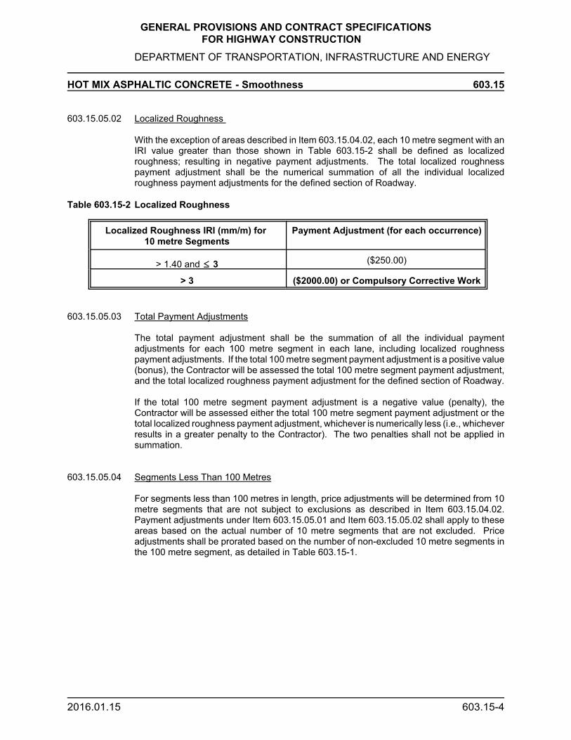
GENERAL PROVISIONS AND CONTRACT SPECIFICATIONS FOR HIGHWAY CONSTRUCTION
DEPARTMENT OF TRANSPORTATION, INFRASTRUCTURE AND ENERGY
HOT MIX ASPHALTIC CONCRETE - Smoothness 603.15
2016.01.15 603.15-4
603.15.05.02 Localized Roughness
With the exception of areas described in Item 603.15.04.02, each 10 metre segment with anIRI value greater than those shown in Table 603.15-2 shall be defined as localizedroughness; resulting in negative payment adjustments. The total localized roughnesspayment adjustment shall be the numerical summation of all the individual localizedroughness payment adjustments for the defined section of Roadway.
Table 603.15-2 Localized Roughness
Localized Roughness IRI (mm/m) for 10 metre Segments
Payment Adjustment (for each occurrence)
> 1.40 and # 3 ($250.00)
> 3 ($2000.00) or Compulsory Corrective Work
603.15.05.03 Total Payment Adjustments
The total payment adjustment shall be the summation of all the individual paymentadjustments for each 100 metre segment in each lane, including localized roughnesspayment adjustments. If the total 100 metre segment payment adjustment is a positive value(bonus), the Contractor will be assessed the total 100 metre segment payment adjustment,and the total localized roughness payment adjustment for the defined section of Roadway.
If the total 100 metre segment payment adjustment is a negative value (penalty), theContractor will be assessed either the total 100 metre segment payment adjustment or thetotal localized roughness payment adjustment, whichever is numerically less (i.e., whicheverresults in a greater penalty to the Contractor). The two penalties shall not be applied insummation.
603.15.05.04 Segments Less Than 100 Metres
For segments less than 100 metres in length, price adjustments will be determined from 10metre segments that are not subject to exclusions as described in Item 603.15.04.02.Payment adjustments under Item 603.15.05.01 and Item 603.15.05.02 shall apply to theseareas based on the actual number of 10 metre segments that are not excluded. Priceadjustments shall be prorated based on the number of non-excluded 10 metre segments inthe 100 metre segment, as detailed in Table 603.15-1.

GENERAL PROVISIONS AND CONTRACT SPECIFICATIONS FOR HIGHWAY CONSTRUCTION
DEPARTMENT OF TRANSPORTATION, INFRASTRUCTURE AND ENERGY
HOT MIX ASPHALTIC CONCRETE - Smoothness 603.15
2016.01.15 603.15-5
Example 1: 100 metre Segment (Station 7+700 - 7+800)Exclusions apply in four (4) of the individual 10 m segments (20 m bridge + 10 m ateach end)
10 Metre Segment
IRI (mm/m)
Exclusion Applies? (yes/no)
Localized Roughness Payment Adjustment
Average IRI over 60metre Segment
IRIPayment Adjustment (See Table603.15-1)
Total PaymentAdjustment (forthis 60 metreSegment)
7+700 - 7+710 0.53 No $0 (0.53+0.39+0.34 +0.23 + 0.28 + 1.42)/6
= 0.53
+$470 x6/10
= +$282
+$282 - $250 = +$32
7+710 - 7+720 0.39 No $0
7+720 - 7+730 0.34 No $0
7+730 - 7+740 0.23 No $0
7+740 - 7+750 0.28 No $0
7+750 - 7+760 1.15 Yes (Bridge Approach)
$0
7+760 - 7+770 1.86 Yes (Bridge) $0
7+770 - 7+780 2.43 Yes (Bridge) $0
7+780 - 7+790 0.91 Yes (Bridge Approach)
$0
7+790 - 7+800 1.42 No -$250
Example 2: 30 metre Segment (Station 6+420 - 6+450) at end of paving sectionExclusions Apply in one (1) of the individual 10 m segments
10 Metre Segment
IRI (mm/m)
Exclusion Applies? (yes/no)
Localized Roughness Payment Adjustment
Average IRIover 30 metreSegment
IRI Payment Adjustment (See Table603.15-1)
Total Payment Adjustment (forthis 30 metreSegment)
6+420 - 6+430 0.88 No $0 (0.88 + 1.45)/2= 1.16
-$190 x 2/10 = -$38
-$38 - $250 = -$250
6+430 - 6+440 1.45 No -$250
6+440 - 6+450 1.65 Yes(Manhole)
$0
603.15.06 Mandatory Penalty
The Contractor shall be subjected to a mandatory penalty of -$2000.00 for each 10 metresegment with an IRI > 3.00 mm/m, with exception of areas defined in Section 603.15.04.02.

GENERAL PROVISIONS AND CONTRACT SPECIFICATIONS FOR HIGHWAY CONSTRUCTION
DEPARTMENT OF TRANSPORTATION, INFRASTRUCTURE AND ENERGY
HOT MIX ASPHALTIC CONCRETE - Smoothness 603.15
2016.01.15 603.15-6
603.15.06.01 The Engineer reserves the right to require Compulsory Corrective Work on any 10 metresegments with an IRI > 3.00 mm/m. In any 10 metre segments where Compulsory CorrectiveWork is required, the Department will waive the -$2000.00 penalty.
The Engineer shall notify the Contractor if Compulsory Corrective Work is required.
603.15.06.02 Compulsory Corrective Work Procedures
Corrective work shall consist of Removal and Replacement of the surface course of asphalticconcrete pavement. The minimum length of any repair area shall be 10 metres.
Removal and Replacement: On each of the 10 metre segments affected, the Contractor shallremove (by cold planing) and replace the full width of the lane and the full depth of thesurface course of asphaltic concrete pavement affected, including paved shoulders.
Compulsory Corrective Work Requirements: The asphaltic concrete repair shall conform witheither Section 603 or 609 of the Department’s Specification, as stated in the Contract.
Incidental Corrective Work: Corrective Work may result in additional incidental costs,including but not limited to: tack coat, additional shoulder gravelling, guardrail adjustments,re-application of pavement markings, etc. Such work shall be carried out in accordance withthe Department’s specifications and at the Contractor’s expense.
Disposal of Asphaltic Concrete: Asphaltic concrete that has been removed as a result ofCorrective Work undertaken by the Contractor shall become the property of the Contractorto haul, stockpile or otherwise dispose of in an environmentally acceptable manner, at theContractor’s expense.
603.15.06.03 Retesting Following Corrective Work
After Corrective Work has been completed, each of the 100 metre segments containingcorrective work will be retested, using the same profiler used in the original testing. The newIRI values will be used and the recalculated results will be binding.
Should the new IRI results indicate further Mandatory Penalty 10 metre segments as statedin Item 603.15.06, the Contractor shall be subject to the Mandatory Penalty as stated in Item603.15.06.
603.15.06.04 Costs for Corrective Work
All costs associated with Corrective Work shall be the responsibility of the Contractor.

GENERAL PROVISIONS AND CONTRACT SPECIFICATIONS FOR HIGHWAY CONSTRUCTION
DEPARTMENT OF TRANSPORTATION, INFRASTRUCTURE AND ENERGY
HOT MIX ASPHALTIC CONCRETE - Cleanup 603.16
2000.02.29 603.16-1
603.16 Cleanup
In addition to complying with the terms of Provision 103.04, the Contractor shall thoroughlyremove from all bridges, culverts, catch basins, curbs, gutters and other structures asphaltor other work materials.

GENERAL PROVISIONS AND CONTRACT SPECIFICATIONS FOR HIGHWAY CONSTRUCTION
DEPARTMENT OF TRANSPORTATION, INFRASTRUCTURE AND ENERGY
HOT MIX ASPHALTIC CONCRETE - Method of Measurement/Basis of Payment 603.17/18
97.05.16 603.17/18-1
603.17 Method of Measurement
The quantity to be measured under this Section shall be the number of tonnes of each classof asphaltic concrete acceptably placed.
Cold planing of transverse construction joints shall be measured in accordance with Section705.
Tack and prime coat applications shall be measured in accordance with Section 601 and 602respectively.
No measurement shall be made for the remedial work outlined in Sub-Provisions 603.13.02and 603.15.02.
603.18 Basis of Payment
Payment under this Section shall be at the unit bid price per tonne for each type of hot mixasphaltic concrete and this price shall be full compensation for materials, other than thosesupplied by the Department; handling, hauling, storing, stockpiling, cutting of existingpavement, painting of joints, mixing, hauling, placing and compacting hot mix asphalticconcrete, tools, labour, equipment, materials and incidentals necessary to complete the work.
Payment for cold planing of transverse construction joints shall be in accordance with Section705.
No extra payment shall be made for paving intersections, aprons, driveway entrances, extrawidths, deep or irregular sections other than the number of tonnes of asphaltic concrete ofeach class acceptably placed.
Tack and prime coat applications shall be paid in accordance with Section 601 and 602respectively.
No payment shall be made for the remedial work outlined in Sub-Provisions 603.13.02 and603.15.02.

Section 604Rescinded
2018
Section 604Rescinded
2018
GENERAL PROVISIONS AND CONTRACT SPECIFICATIONSFOR HIGHWAY CONSTRUCTION
DEPARTMENT OF TRANSPORTATION, INFRASTRUCTURE AND ENERGY
CHIP SEAL 604
18.01.15 604-1
604.01 Description
This Section covers the requirements for the design, surface preparation, application ofBituminous Binder and the supply and application of aggregate for either single or doublechip seal surface treatments.
604.01.01 Single Surface Treatment
A single chip seal surface treatment shall consist of a single application of binder followedby a single application of Class E aggregate.
604.01.02 Double Surface Treatment
A double chip seal surface treatment shall consist of a single application of binder followedby a single application of Class E aggregate, and a second application of binder followed bya single application of Class E aggregate.
604.02 Material
604.02.01 Chip Seal Aggregate
The chip seal aggregate must be crushed quarried rock and shall be of high quality and freeof soft disintegrated stone, clay or other deleterious materials. The screening and crushingof natural gravel deposits to produce chip seal aggregate shall not be permitted.
The crushed aggregate shall be screened and washed over a 6.35 mm screen. Aggregateshall be washed only in properly designed and constructed washing plants. Truck or mixerwashing of aggregates and washing methods of like intent will not be permitted.
Water used for washing aggregates shall be clean and free from injurious amounts of oil,acid, alkali, organic matter or other deleterious substances. Where it is specified that the chipseal aggregate is to be stockpiled, it shall be washed first.
The aggregates shall meet the requirements of Tables 604-1 and 604-2.
Aggregate in stockpiles shall be free of all chlorides.
604.02.02 Asphalt Emulsion
Asphalt emulsion shall be RS-2K or HP-200 and shall meet the requirements of Table 604-3when delivered to the job site.

Section 604Rescinded
2018
Section 604Rescinded
2018
GENERAL PROVISIONS AND CONTRACT SPECIFICATIONSFOR HIGHWAY CONSTRUCTION
DEPARTMENT OF TRANSPORTATION, INFRASTRUCTURE AND ENERGY
CHIP SEAL 604
18.01.15 604-2
Table 604-1Gradation Requirement for Aggregate
SieveSize
Passing(%)
ASTM
12.5 mm 100 C-136
9.5 mm 80-100 C-136
6.7 mm 0 - 43 C-136
4.75 mm 0 - 10 C-136
75 μm 0 - 1.5 C-117
Note: A minimum of 50% of the material in the total gradation must pass the 9.5 mm Sieve and beretained on the 6.7 mm Sieve.
Table 604-2Physical Requirements for Aggregate
Test Class E ASTM
Los Angeles Abrasion,Max. % Loss
25 C-131
Magnesium SulfateSoundness, Max. % Loss
12 C-88
Crushed, Min. % (1) 100 -
Flat and Elongated,Max. % (2)
20 -
Flakiness Index, Max. (%) 35 -
Petrographic Number, Max. (3)
135 -
(1) The percent of crushed material will be determined on the fraction of particles by mass retainedon the 4.75 mm Sieve having two or more mechanically fractured faces.
(2) Flat and elongated particles are those whose greatest mean dimension in the longitudinal axiscompared to the least mean dimension in the plane perpendicular to the longitudinal axisexceeds a ratio of 4:1.
(3) Petrographic number to be determined using current Department test procedures.
604.03 Equipment
The Contractor shall supply all tools, machinery and equipment required in the execution ofall phases of the work. Such equipment shall at all times be maintained in first class workingcondition and shall at all time be operated by skilled and experienced operators.

Section 604Rescinded
2018
Section 604Rescinded
2018
GENERAL PROVISIONS AND CONTRACT SPECIFICATIONSFOR HIGHWAY CONSTRUCTION
DEPARTMENT OF TRANSPORTATION, INFRASTRUCTURE AND ENERGY
CHIP SEAL 604
18.01.15 604-3
604.03.01 Pressure Distributor
The pressure distributor used for applying asphalt emulsion shall consist of a fully insulatedtank permanently and rigidly mounted on a truck or trailer; that is capable of accuratelymaintaining any speed required for spraying and capable of applying the binder with plus orminus 5% of the desired application rate.
The distributor shall be provided with the following minimum equipment:
- Hand spray attachments to uniformly apply emulsion to any areas missed by thedistributor.
- An efficient and positive means of uniformly heating emulsion and maintaining thecontents at a constant selected temperature without local overheating, and asatisfactory method of circulating the contents during the entire heating process.
- An approved thermometer with a minimum range of 10º - 150º C graduated inintervals of not more than 10º C with subdivisions at every 1º C, placed to accuratelyshow the temperature of the distributor contents.
- An approved tachometer, driven from a fifth wheel, mounted so that it is readilyvisible to the driver. The tachometer must clearly and accurately register distancestravelled when spraying emulsion and must allow the driver to maintain the constantspeed required to ensure the specified rate of application.
- A bitumen pump tachometer with plus or minus 5% accuracy which registers pumpspeed.
- A pressure gauge with plus or minus 15 kPa accuracy indicating the pressure in thespray bar.
- A rear mounted adjustable spray bar set parallel to the surface to be sprayed toprovide required spraying widths from 2.5 to 3.5 m. The distributor shall be equippedwith a spray bar heating device. The distributor shall circulate a uniform viscosityand pressure of the emulsion at each nozzle, both before and during sprayingoperations. The circulating system shall also have a strainer to prevent clogging ofthe bar and nozzles. The spray bar height shall be adjustable and shall be set atsuch a height that the spray fan from any nozzle overlaps the spray fan from theadjacent nozzle by 50% to ensure a uniformly sprayed surface. Spray bar heightadjustment shall be made by the height set when the distributor is ½ full.
- Spray bar nozzles shall be designed and set to ensure uniform fan shaped sprays.The nozzles shall not produce such a fine mist that the emulsion will blow awayresulting in a non-uniform emulsion coating. All spray nozzles shall be of the samemanufacture, size, type and in good condition and shall be provided with valvescapable of instant full opening and positive cut-off. All spray nozzles shall be set inthe bar so that the nozzles slots make the same horizontal 30E angle with thelongitudinal axis of the bar. Before work commences and periodically as requiredduring spraying operations, the nozzles on the spray bar shall be removed andimmersed in a solvent for a period of time sufficient to remove all congealed asphalt.

Section 604Rescinded
2018
Section 604Rescinded
2018
GENERAL PROVISIONS AND CONTRACT SPECIFICATIONSFOR HIGHWAY CONSTRUCTION
DEPARTMENT OF TRANSPORTATION, INFRASTRUCTURE AND ENERGY
CHIP SEAL 604
18.01.15 604-4
- A strainer shall be provided in the filling line to prevent entry of foreign material intothe tank.
- A sampling cock fitted on the spray bar or circulating line is required to allow samplesof the emulsion to be obtained directly from the distributor.
Table 604-3Requirements for Emulsified Asphalt
Type RS-2K HP-200
Test Min. Max. Min. Max. ASTM
Tests on Emulsion
Saybolt Furol Viscosityat 50EC (mm2/s) 150 400 50 350 D-244
Residue by Distillation (%) 65 - 65 - D-244
Settlement in 5 days (%) - 5 - 3 D-244
Oil Portion of Distillate by Mass (%) - 3 - - D-244
Retention by Mass on an 850 μmSieve(%)
- 0.1 - 0.1 D-244
Coating (1) - - - - -
Particle Charge Positive Negative
Tests on Residue
Penetration at 25EC, 100 g, 5 s (0.1mm)
100 250 100 200 D-5
Ductility at 25EC, 5 cm/min (cm) 60 - 46 - D-113
Solubility in Trichloroethylene byMass (%)
97.5 - 97.5 - D-2042
(1) Follow ASTM D-244 procedure for wet aggregate except that the limestone aggregate and dust is replacedby the test aggregate. The stone should not be less than 75% coated, both before and after washing.

Section 604Rescinded
2018
Section 604Rescinded
2018
GENERAL PROVISIONS AND CONTRACT SPECIFICATIONSFOR HIGHWAY CONSTRUCTION
DEPARTMENT OF TRANSPORTATION, INFRASTRUCTURE AND ENERGY
CHIP SEAL 604
18.01.15 604-5
604.03.02 Mechanical Aggregate Spreader
The self-propelled aggregate spreader shall be capable of continuously and uniformlyspreading closely regulated quantities of aggregate within plus or minus 10% of theapplication rate selected.
The spreader shall be equipped with a rear-mounted aggregate hopper. The spreader shallbe equipped with a front hopper and an approved means of transferring the aggregate to thishopper from the rear. The front hopper shall be equipped with an oversize reject screen andmetering gauges. The gates shall adjust the spreading width and shall be adjustable toobtain a uniform flow of aggregate across the spreading width. These gates shall also bedesigned to provide simultaneous movement or closure from the operator's position. Theflow of aggregate from the metering gates shall be further controlled by a spread roller, therotation of which shall automatically commence when the metering gates are opened.
604.03.03 Rollers
Steel-tired rollers shall have tandem wheels and weigh at least 7 tonnes and shall exert apressure on the compression roll of at least 3.5 kg/mm per roll width. Pneumatic-tired rollersshall be self-propelled and have a minimum ballasted weight of 8 tonnes. A minimum of 2pneumatic-tired rollers shall be used on each section of work.
604.03.03 Mechanical Broom
Shall be of an approved type suitable for pavement use.
604.04 Construction
604.04.01 Qualifications of Contractor
To be eligible as a bidder, the Contractor must have had previous experience of theapplication of chip seal of a similar nature in similar climatic conditions.
The Contractor's foreman on this project shall have a minimum of 3 years experience.
604.04.02 Design
The Contractor shall assess the roadway surface condition and design the requiredapplication rates for binder and aggregate for either single or double chip seal treatments.A copy of which shall be forwarded to the Engineer.
604.04.03 Guarantee
The Contractor will be required to guarantee the work and associated items for a period of1 year after completion against all defects, due either to defective workmanship and/ormaterial. Any repairs required will be carried out expeditiously at the Contractor's ownexpense.
604.04.04 Inspection

Section 604Rescinded
2018
Section 604Rescinded
2018
GENERAL PROVISIONS AND CONTRACT SPECIFICATIONSFOR HIGHWAY CONSTRUCTION
DEPARTMENT OF TRANSPORTATION, INFRASTRUCTURE AND ENERGY
CHIP SEAL 604
18.01.15 604-6
The Engineer will have the right to inspect all or any of the materials at source, manufactureor storage. The Contractor will arrange for the Engineer to have the right of access to thesupplier's premises for purposes of inspection.
604.04.05 Surface Preparation
Before chip seal operations commence the contractor shall completely clean the pavementof all dirt and other debris. Cleaning shall be by the use of a power broom. Should there beany depressions not completely cleaned with the power broom, then the Contractor shallclean such spots with a hand broom.
604.04.06 Pavement Restoration and Crack Filling
Pavement restoration and crack filling shall be carried out to repair pavement pot-holes andcracks prior to the carrying out of the chip seal surface treatment operations.
The pavement restoration shall be in accordance with Section 709. Crack filling shall be inaccordance with Section 607.
604.04.06.01 Trail Areas
When required by the Engineer, trial areas shall be used to establish the correct rates ofapplication of binder and aggregate. A trial area shall be at least 100 m long and 1 lane wide.The rates of application of the binder and aggregate shall be determined by carefullymeasuring the contents of the distribution before and after spraying the trial area and bycarefully measuring the quantity of aggregate applied.
604.04.07 Application of Emulsion
All required patching and crack filling shall be carried out to the satisfaction of the Engineer,at least 24 hours prior to chip seal emulsion application.
The emulsion shall be applied at a temperature in the range 60 - 80º C.
The emulsion shall be applied at the design rate as designed for either single or double chipseal treatments. For any given area the emulsion shall be applied at the rate designed bythe Contractor.
During the application of the emulsion, the distributor shall be operated by a minimum of 2men, one of whom shall be stationed on the rear platform, to control the application. Theforward speed of the distributor shall not exceed 1.6 m/s.
604.04.08 Application of Aggregate
The crushing and stockpiling of chip seal aggregates must be 100% complete prior toapplication to the road surface.
The aggregate shall be uniformly distributed at the application rate designed by theContractor for both single and double chip seal treatments.
The aggregate application operation shall be coordinated with the emulsion application sothat no more than 30 m separates the emulsion application and the aggregate spreading.

Section 604Rescinded
2018
Section 604Rescinded
2018
GENERAL PROVISIONS AND CONTRACT SPECIFICATIONSFOR HIGHWAY CONSTRUCTION
DEPARTMENT OF TRANSPORTATION, INFRASTRUCTURE AND ENERGY
CHIP SEAL 604
18.01.15 604-7
Application of aggregate operations for the day shall be completed at least 2 hours beforesunset.
604.04.09 Rolling
Immediately after the application of the aggregate, pneumatic-tired rolling shall be carried outin such a manner that the entire treated area received at least 2 passes. Final rolling shallconsist of 1 pass of a steel wheel roller.
The rollers shall be operated at such a speed that there is no aggregate pick up but in nocase shall the speed of the rollers exceed 10 km/hr.
All rolling shall be completed with 30 m of the aggregate spreader. Initial rolling shall occurwithin 1 minute of the application of the aggregate.
The minimum number of rollers required is 2 pneumatic-tired rollers and 1 steel roller. If thiscombination of rollers is not sufficient to maintain the completed rate of progress additionalrollers shall be provided.
604.04.10 Mechanical Brooming
The chip seal treated surfaced shall be swept with a power broom. All excess aggregateshall be removed and disposed of by the Contractor, at the Contractor's own expense.Sweeping shall not be carried out until the treatment has set to a sufficient degree so that thechip seal is not damaged.
On chip seal treated surfaces open to traffic, power brooming shall be carried out within 48hours of the application of aggregate.
604.04.11 Temperature and Weather
Chip seal operations shall not be carried out when, in the opinion of the Engineer, roadconditions, high humidity, imminence of rain, wetness or dampness are present.
Asphalt emulsion application operations shall not be carried out when the air temperature isless than 15º C.
Chip seal treatment shall not be carried out before June 1 or after September 1, unlessotherwise directed by the Engineer.
604.04.12 Protection of Work and Traffic Control
When possible, the traffic shall be kept off the treated surface until the chip seal is resistantto damage. When traffic must go over the surface before it is fully cured, the Contractor shallcontrol traffic speed by means of directing the traffic in convoys. The Contractor shall providea lead vehicle to ensure that convoys proceed at low speed. Traffic control is to bemaintained until power brooming has been completed.
604.05 Method of Measurement

Section 604Rescinded
2018
Section 604Rescinded
2018
GENERAL PROVISIONS AND CONTRACT SPECIFICATIONSFOR HIGHWAY CONSTRUCTION
DEPARTMENT OF TRANSPORTATION, INFRASTRUCTURE AND ENERGY
CHIP SEAL 604
18.01.15 604-8
Measurement for payment under this Section shall be the number of square metres ofacceptable chip seal applied.
Measurement for pavement restoration shall be in accordance with Section 709.
Measurement for crack filling shall be in accordance with Section 607.
604.06 Basis of Payment
Payment for chip seal shall be at the unit bid price per square metre and this price shall befull compensation for labour, materials, equipment, roadway surface preparation, supply andapplication of asphalt binder, supply and application of aggregate, rolling, power brooming,traffic control, royalties and incidentals necessary to perform the work.
No compensation other than the Contract price shall be made for variations in the rate ofapplication or for the treatment of any areas, as required by the Engineer.
Payment for pavement restoration shall be in accordance with Section 709.
Payment for crack filling shall be in accordance with Section 607.

Section 605Rescinded
2017
Section 605Rescinded
2017
GENERAL PROVISIONS AND CONTRACT SPECIFICATIONSFOR HIGHWAY CONSTRUCTION
DEPARTMENT OF TRANSPORTATION, INFRASTRUCTURE AND ENERGY
DOUBLE EMULSIFIED ASPHALT SLURRY SEAL 605
2017.02.17 605-1
605.01 General
605.01.01 Scope
This Section covers the requirements for the design, testing, surface preparation, trafficcontrol and quality control required for the proper application of a double emulsified asphaltslurry seal.
605.01.02 Description
The slurry seal shall consist of a mixture of an approved emulsified asphalt, mineralaggregate, water and specified additive. The slurry seal mix shall be proportioned, mixed anduniformly spread over a properly prepared surface. The completed slurry seal shall be ahomogeneous mat, adhered firmly to the prepared surface and with a skid resistant surfacetexture.
605.01.03 Applicable Specifications
The following specifications and all test methods therein dealing with mineral aggregates,mineral filler and slurry seal form a part of this specification:
American Society for Testing Materials and International Slurry SealAssociation.
All material, equipment and construction procedures shall conform, unlessotherwise directed, to the "Recommended Slurry Seal Surface" publishedby the International Slurry Seal Association except as modified by therequirements of this project specification.
605.01.04 Qualifications of Contractor
The Contractor must have had previous experience on the application of slurry seal of asimilar nature in similar climatic conditions. The Contractor must list at least 5 similar jobswhich on investigation will prove to have been completed in a satisfactory manner.
The Contractor's foreman on this project shall have a minimum of 3 year's experience onsimilar projects.
605.01.05 Guarantee
The Contractor will be required to guarantee the work and all associated items for a periodof 1 year after contract completion date against all defects, due either to defectiveworkmanship and/or materials. Any repairs required will be carried out expeditiously at theContractor's own expense.
605.01.06 Inspection
The Engineer will have the right to inspect all or any of the work materials at the source,manufacture or storage. The Contractor will arrange for the Engineer to have the right ofaccess to the supplier's premises as may be necessary for the purpose of inspection.

Section 605Rescinded
2017
Section 605Rescinded
2017
GENERAL PROVISIONS AND CONTRACT SPECIFICATIONSFOR HIGHWAY CONSTRUCTION
DEPARTMENT OF TRANSPORTATION, INFRASTRUCTURE AND ENERGY
DOUBLE EMULSIFIED ASPHALT SLURRY SEAL 605
2017.02.17 605-2
605.01.07 Mix Design
The Contractor shall assess the contract roadway surface condition.
All materials shall be pretested by a qualified materials testing firm as to their suitability foruse in slurry seal. A complete laboratory analysis and mix design, including the Wet TrackAbrasion Test shall be submitted to the Engineer prior to commencement of the work.
605.02 Material
The emulsified asphalt shall conform to the requirements of ASTM D-2397 for CSS-1Hemulsion type.
The mineral aggregate shall consist of manufactured crushed quarried rock such as granite,or other high quality aggregate. The aggregate shall be clean and free from vegetable matterand other deleterious substances.
When tested according to ASTM C-131, the aggregate shall show an abrasion loss of notmore than 25%. When tested according to ASTM C-88, the aggregate shall show a loss ofnot more than 15% by use of magnesium sulphate.
Mineral filler in the form of normal Portland cement shall be considered part of the blendedaggregate and shall be used in the proportion determined by the mix design.
When tested by ASTM C-136 and ASTM C-117, the aggregate and mineral filler shall meetthe gradation of Table 605-1 as specified by the International Slurry Seal Association.
All water shall be potable and compatible with the slurry mix. Compatibility must be insuredby the Contractor.
Additives may be used to accelerate or retard the break-set of the slurry seal or improve thefinished surface. The use of additives in the slurry mix or in individual materials shall bemade initially in quantities predetermined by the mix design with field adjustments, if required,after approval by the Engineer.
605.03 Equipment
All equipment, tools and machines used in the performance of this work shall be maintainedin satisfactory working order at all times.
The slurry seal mixing equipment shall be a continuous flow mixing unit. The unit must havesuitable means of accurately metering each individual material being fed into the mixer. Allfeeding mechanisms must be continuous feed and proportioning must remain constant at alltimes. The unit shall be equipped with approved devices so that the machine can beaccurately calibrated and the material quantities of materials used during any period can beestimated.
The spreader box shall be equipped to prevent loss of slurry seal from all sides and shall beequipped with a flexible rear strike-off. It shall be capable of producing a uniform surface itsfull width and shall be equipped with hydraulically-powered augers to keep the slurry inmotion and to help keep the mixture uniformly spread across the spreader box width.

Section 605Rescinded
2017
Section 605Rescinded
2017
GENERAL PROVISIONS AND CONTRACT SPECIFICATIONSFOR HIGHWAY CONSTRUCTION
DEPARTMENT OF TRANSPORTATION, INFRASTRUCTURE AND ENERGY
DOUBLE EMULSIFIED ASPHALT SLURRY SEAL 605
2017.02.17 605-3
Suitable crack and surface cleaning equipment, barricading equipment, hand tools and anysupport equipment shall be provided as necessary to perform the work.
Table 605-1Gradation Requirement for Aggregate and Mineral Filler
SieveSize
Type II -Passing (%)
9.5 mm 100
4.75 mm 90-100
2.36 mm 65-90
1.18 mm 45-70
600 μm 30-50
300 μm 18-30
150 μm 10-21
75 μm 5-15
605.04 Construction
605.04.01 Traffic Control
The Contractor will be responsible for all traffic control.
Suitable methods, including directing the traffic in convoys shall be used by the Contractorto protect the slurry seal from traffic until the new surface will support the traffic withoutdamage. Opening to traffic does not constitute acceptance of the work. The Engineer shallbe notified of the methods to be used.
Any damage to the new surface during the curing period done by traffic or the Contractor'sequipment will be repaired at the Contractor's own expense.
605.04.02 Weather Limitation
The slurry seal shall not be applied if either the pavement or air temperature is below 150 Cand falling, but may be applied when both pavement and air temperatures are above 100 Cand rising. No slurry seal shall be applied when there is danger that the finished product willfreeze before 24 hours. The mixture shall not be applied when weather conditions prolongtraffic opening to beyond a reasonable time.
605.04.03 Surface Preparation
Immediately prior to applying the slurry seal, the surface shall be cleared of all loose material,silt spots, vegetation, oil spots and other objectionable material. Any standard cleaningmethod will be acceptable. If water is used, cracks will be allowed to dry thoroughly beforeslurry sealing. The Engineer shall approve the surface preparation prior to sealing.

Section 605Rescinded
2017
Section 605Rescinded
2017
GENERAL PROVISIONS AND CONTRACT SPECIFICATIONSFOR HIGHWAY CONSTRUCTION
DEPARTMENT OF TRANSPORTATION, INFRASTRUCTURE AND ENERGY
DOUBLE EMULSIFIED ASPHALT SLURRY SEAL 605
2017.02.17 605-4
605.04.04 Application of the Slurry Surface
The surface shall be pre-wetted by fogging ahead of the slurry box when in the opinion of theEngineer, it is required by local conditions. Water used in pre-wetting the surface shall beapplied such that the entire surface is damp with no apparent flowing water in front of theslurry box. The rate of application of the fog spray shall be adjusted during the day to suittemperatures, surface texture, humidity and pavement surface dryness.
The slurry mixture shall be of the desired consistency when deposited on the surface and noadditional elements shall be added. A sufficient amount of slurry shall be carried in all partsof the spreader at all times so that complete coverage is obtained. No lumping, balling orunmixed aggregate shall be permitted. No segregation of the emulsion and aggregate finesfrom the coarse aggregate will be permitted. If the coarse aggregate settles to the bottomof the mix, the slurry will be removed from the pavement. No excessive breaking of theemulsion will be allowed in the spreader box. No streaks caused by oversized aggregate willbe left in the finished pavement.
605.04.05 Joints
No excessive build-up or unsightly appearance shall be permitted on longitudinal ortransverse joints.
605.04.06 Handwork
Areas which cannot be reached with the slurry seal machine shall be surfaced using handsqueegees to provide complete and uniform slurry seal coverage. The area to be handworked shall be lightly dampened prior to mix placement and the slurry shall be workedimmediately. Care shall be exercised to leave no unsightly appearance from hand work. Thesame finish as applied by the spreader box shall be required. Hand work shall be completedduring the machine applying process.
605.05 Method of Measurement
Measurement for payment under this Section shall be the number of square metres ofacceptable slurry seal.
605.06 Basis of Payment
Payment for slurry seal surface treatment shall be at the unit bid price per square metre ofapplication and this price shall be full compensation for materials, preparation, mixing,application, labour, equipment, tools, test mix design, traffic control and incidentals tocomplete the work.
No compensation other than the Contract price shall be made for variations in the rate ofapplication or for the re-treatment of any areas, as required by the Engineer.

GENERAL PROVISIONS AND CONTRACT SPECIFICATIONSFOR HIGHWAY CONSTRUCTION
DEPARTMENT OF TRANSPORTATION, INFRASTRUCTURE AND ENERGY
ASPHALTIC CONCRETE CURB 606
94.03.28 606-1
606.01 Description
This work shall consist of the manufacture and placement of asphaltic concrete curb inaccordance with the Plans or as directed by the Engineer.
606.02 Material
The hot mix, hot placed asphaltic concrete shall meet the requirements for asphalt curb andshall be approved by the Engineer prior to placing. The liquid asphalt cement shall besupplied by the Contractor.
606.03 Construction
The hot mix, hot placed asphalt curb shall be placed on a clean area that has previously beencoated with an approved bituminous tack coat at a rate as directed by the Engineer. Asphalticcurb shall be placed using an approved asphalt curb spreader which will produce a standard15 cm curb.
606.04 Method of Measurement
Measurement for payment under this Section shall be the number of linear metres ofasphaltic curb acceptably constructed.
606.05 Basis of Payment
Asphaltic concrete curb shall be paid for at the unit bid price per linear metre and this priceshall be full compensation for the supply and placement of the curb, all labour, equipment,materials, tools and incidentals necessary to complete the work.

GENERAL PROVISIONS AND CONTRACT SPECIFICATIONSFOR HIGHWAY CONSTRUCTION
DEPARTMENT OF TRANSPORTATION, INFRASTRUCTURE AND ENERGY
ASPHALT CRACK FILLING 607
94.04.11 607-1
607.01 Description
This work shall consist of the routing and sealing of random and straight cracks in asphalticconcrete and Portland cement concrete pavement.
607.02 Material
Material used for sealing shall be specifically designed to form resilient adhesive andeffective seals for cracks and joints. The material shall fully conform to the requirements ofASTM D-1190 or D-3405 and shall be subject to the Engineer's approval.
Current recommended materials are Hydrotech 6165 or 6160.
607.03 Equipment
Routing equipment shall have self-cleaning vertical routing bits which are capable ofproducing joints 40 mm in width and 15 mm deep.
The melting kettle shall be a double boiler with indirect heating; using a high flash point oil(Min. 3150C) as a heat transfer medium. The kettle shall have an effective mechanicallyoperated agitator and shall be equipped with a positive thermostatic temperature control. Thekettle shall be portable, mounted on rubber tires and equipped with a metal shield beneaththe fire box to protect the pavement.
607.04 Construction Method
The bags shall be stripped from the compound and the material shall be cut into blocks ofapproximately 4.5 kg before being placed in the melting kettle. The kettle should be chargedby adding a few sections of compound at a time.
The sealing compound shall be melted to the temperature specified by the manufacturer, butany material heated in excess of 2300 C at any stage of the melting or pouring operation shallnot be used in the work. The joint sealing compound shall be poured as soon as possibleafter the correct pouring temperature is reached. Only as much compound as can be pouredin a day in accordance with Provision 106.12 shall be melted.
Cracks shall be routed to a depth of 10 mm and to the width of the crack or 40 mm whicheveris less.
Following the routing operation and immediately prior to placing new joint sealing compound,all residual dust and debris created by the routing operation shall be thoroughly cleaned fromthe cut by a compressed a air/hot lance. The Contractor is to sweep the debris to the gutterand dispose of it in accordance with Provision 104.14.
The joints shall be sealed in a neat manner so that upon completion of the work the surfaceof the sealing material shall be flush with, or not more than 3 mm below the adjacentpavement surface.
The pouring of joints shall only be undertaken when the joint surfaces are dry and the airtemperature in the shade is 100 C.

GENERAL PROVISIONS AND CONTRACT SPECIFICATIONSFOR HIGHWAY CONSTRUCTION
DEPARTMENT OF TRANSPORTATION, INFRASTRUCTURE AND ENERGY
ASPHALT CRACK FILLING 607
94.04.11 607-2
607.05 Method of Measurement
The quantity to be measured for payment under this Section shall be the number of linearmetres of cracks filled to the satisfaction of the Engineer.
607.06 Basis of Payment
Payment under this Section shall be at the unit bid price per linear metre and this price shallbe full compensation for routing of cracks or joints, supply of crack filling compound, disposalof routed material, placement of crack filling material, all tools, equipment, labour, materials,and incidentals required to perform the work.
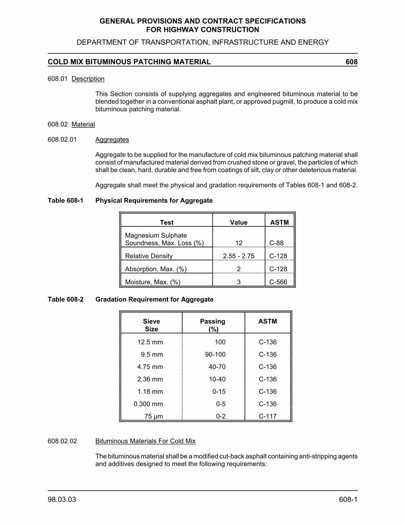
GENERAL PROVISIONS AND CONTRACT SPECIFICATIONSFOR HIGHWAY CONSTRUCTION
DEPARTMENT OF TRANSPORTATION, INFRASTRUCTURE AND ENERGY
COLD MIX BITUMINOUS PATCHING MATERIAL 608
98.03.03 608-1
608.01 Description
This Section consists of supplying aggregates and engineered bituminous material to beblended together in a conventional asphalt plant, or approved pugmill, to produce a cold mixbituminous patching material.
608.02 Material
608.02.01 Aggregates
Aggregate to be supplied for the manufacture of cold mix bituminous patching material shallconsist of manufactured material derived from crushed stone or gravel, the particles of whichshall be clean, hard, durable and free from coatings of silt, clay or other deleterious material.
Aggregate shall meet the physical and gradation requirements of Tables 608-1 and 608-2.
Table 608-1 Physical Requirements for Aggregate
Test Value ASTM
Magnesium Sulphate Soundness, Max. Loss (%) 12 C-88
Relative Density 2.55 - 2.75 C-128
Absorption, Max. (%) 2 C-128
Moisture, Max. (%) 3 C-566
Table 608-2 Gradation Requirement for Aggregate
SieveSize
Passing (%)
ASTM
12.5 mm 100 C-136
9.5 mm 90-100 C-136
4.75 mm 40-70 C-136
2.36 mm 10-40 C-136
1.18 mm 0-15 C-136
0.300 mm 0-5 C-136
75 μm 0-2 C-117
608.02.02 Bituminous Materials For Cold Mix
The bituminous material shall be a modified cut-back asphalt containing anti-stripping agentsand additives designed to meet the following requirements:

GENERAL PROVISIONS AND CONTRACT SPECIFICATIONSFOR HIGHWAY CONSTRUCTION
DEPARTMENT OF TRANSPORTATION, INFRASTRUCTURE AND ENERGY
COLD MIX BITUMINOUS PATCHING MATERIAL 608
98.03.03 608-2
- Stripping resistance- Flexible and cohesive properties at cold temperatures- Adhesive quality in wet application - Long stockpile life of the cold mix bituminous patching material.
The bituminous material shall be in accordance with the requirements of Table 608-3.
Engineered bituminous products not complying with the physical properties specified in Table608-3 may be approved for use upon review of documentation indicating the material'sphysical test properties.
Table 608-3 Requirements for Bituminous Material
Test Min. Max. ASTM
Kinematic Viscosity at 60E C (mm2/s) 250 500 D-2170
Distillation Tests % of Totalto 360E C
to 225EC (%) 0 10 D-402
to 260EC (%) 15 55 D-402
to 315EC (%) 60 87 D-402
Distillation Residue to 360EC,Difference by Volume (%)
67 - D-402
Water Content (%) - 0.2 D-95
Tests on Residue
Penetration at 25EC, 100 g, 5 s (0.1mm)
120 250 D-5
Ductility at 25EC , 5 cm/min (cm) 100 - D-113
Solubility in Trichloroethylene byMass (%)
99 - D-2042
608.03 Cold Mix Production
Aggregates shall be pre-dried and allowed to cool to a temperature between 60 - 85EC priorto being utilized in the mix, unless otherwise approved by the Engineer.
The aggregate and bitumen shall be mixed to ensure a homogenous mixture with all particlesof the mineral aggregate thoroughly coated with bitumen.
The temperature of the final mixture at discharge shall not exceed 70EC.
Cold Mix Production shall occur during daylight hours only.

GENERAL PROVISIONS AND CONTRACT SPECIFICATIONSFOR HIGHWAY CONSTRUCTION
DEPARTMENT OF TRANSPORTATION, INFRASTRUCTURE AND ENERGY
COLD MIX BITUMINOUS PATCHING MATERIAL 608
98.03.03 608-3
608.04 Quality Control
Quality control shall be the responsibility of the Contractor. The manufactured cold mixbituminous patching material must meet the following specification requirements.
The extracted bitumen content from the cold mix shall be in accordance with Table 608-4.
Table 608-4 Minimum Requirements for Extracted Bitumen Content
Aggregate Absorption(%)
Extracted Bitumen(%)
Min. Max. Min.
0.0 1.0 4.5
1.1 1.5 5.0
1.6 2.0 5.5
Extracted bitumen content by ASTM D-2172
The retained coating of bitumen on aggregate must be in excess of 75% when tested inaccordance with the following test for stripping resistance:
50 g of the cold mix will be placed in 400 mR of boiling distilled water in a 600mR glass beaker. It will be stirred with a glass rod at one revolution persecond for 3 min.
The percentage coating retained will then be visually evaluated. Retainedcoatings of less than 75 % shall constitute failure.
The estimated coated area shall be above 95%, as specified in ASTM D-1664.
The cold mix must remain flexible and cohesive to -10EC and must be capable of retainingadhesive qualities in place during wet application.
The cold mix must be capable of remaining pliable and usable in uncovered stockpiles for aminimum of 2 years.
608.05 Quality Assurance
At least 1 week prior to proposed production of the cold mix bituminous patching material theContractor shall:
Notify the Department to:
- Allow scheduling of moisture testing of the aggregate.- Schedule a Department representative to be at the site at
the time of mixing.

GENERAL PROVISIONS AND CONTRACT SPECIFICATIONSFOR HIGHWAY CONSTRUCTION
DEPARTMENT OF TRANSPORTATION, INFRASTRUCTURE AND ENERGY
COLD MIX BITUMINOUS PATCHING MATERIAL 608
98.03.03 608-4
Deliver to the Department:
- A sample of the proposed engineered bituminous material.
- Test documentation of the proposed engineeredbituminous material indicating compliance withspecification requirements.
- Aggregate test documentation indicating compliance withphysical and gradation requirements.
The Contractors shall provide to the Department records of testing of the cold mixedbituminous patching material showing compliance.
The cold mixed bituminous patching material shall be randomly sampled by Departmentrepresentatives at the time of mixing.
608.06 Method of Measurement
Measurement for payment under this Section shall be the number of tonnes of cold mixbituminous patching material acceptably produced.
608.07 Basis of Payment
Cold mix bituminous patching material shall be paid for at the unit bid price per tonnedelivered to the stockpile(s) and this price shall be full compensation for all work, material,trucking to the stockpiles, tools, equipment, labour and incidentals necessary to perform thework.
Drying aggregates prior to mixing shall be considered incidental to the work.

GENERAL PROVISIONS AND CONTRACT SPECIFICATIONS FOR HIGHWAY CONSTRUCTION
DEPARTMENT OF TRANSPORTATION, INFRASTRUCTURE AND ENERGY
HOT MIX ASPHALTIC CONCRETE - END RESULT SPECIFICATION (ERS) 609.01/02
2016.01.15 609.01/02-1
609.01 Description
609.01.01 General
This Item defines the requirements for the supply and placement of hot mixedconventional asphaltic concrete for pavement construction and other purposes.
The asphaltic concrete shall be identified by the following mix designations:
- Hot mixed conventional asphaltic concrete base mix - A.- Hot mixed recycled asphaltic concrete base mix - HRA.- Hot mixed conventional asphaltic concrete surface mix - B.
It shall be the Contractor’s responsibility to provide an acceptable product as specified.
- The Contractor shall implement and maintain a quality control system that willprovide assurance that all components, as well as end result products,submitted to the Owner for acceptance, conform to the Contract requirements.
- This responsibility is without regard to whether the products are manufacturedby the Contractor or purchased from suppliers or subcontractors.
Quality assurance tests shall be performed, by the Engineer, on random samples takeneither at the job site or at the supplier’s plant.
609.01.02 Definitions
End Result Specification (ERS):A specification under which the Engineer monitors the Contractor’s control of theprocess that produces the items of construction and accepts or rejects the end productaccording to a specified quality assurance plan; the Contractor is entirely responsiblefor quality control; end product acceptance is the responsibility of the Owner andincludes a statistically oriented program of quality assurance testing.
Design Mix Formula (DMF):The Laboratory determination of the precise proportions of asphalt binder andaggregates to be blended together to meet the specified properties for the asphalticconcrete mix.
Job Mix Formula (JMF):The establishment of the single definite percentage passing the 4.75 mm and 75 µmsieve fraction of aggregate, the percentage of blending sand and the asphalt bindercontent that will produce the desired mix properties under field conditions.- Percentage of materials constituting the JMF to be stated on the JMF sheet.
Asphalt Binder Content:- Design Asphalt Binder Content - the asphalt binder content established by the
DMF.- Approved Asphalt Binder Content - the asphalt binder content determined by
the JMF.- Actual Asphalt Binder Content - the amount of asphalt binder in the mix as
determined by ASTM D2172 or as per current TIR Test Procedures Manual,Series 400 Bituminous Materials LTP-418 (Asphalt Content of BituminousPaving Mixtures by the Ingnition Method).

GENERAL PROVISIONS AND CONTRACT SPECIFICATIONS FOR HIGHWAY CONSTRUCTION
DEPARTMENT OF TRANSPORTATION, INFRASTRUCTURE AND ENERGY
HOT MIX ASPHALTIC CONCRETE - END RESULT SPECIFICATION (ERS) 609.01/02
2016.01.15 609.01/02-2
Lot:A portion of the Work being considered for acceptance and is further defined as thefollowing:
- A plant production of 1800 t ± 50 t where approved changes to the Job MixFormula have not occurred.
- If it is the last time the mix is produced with this criterion the following shallapply;- If the plant production is 600 t or less, the production will be added to
the previous Lot.- If the plant production is more than 600 t but less than 1800 t, the
production will be designated as a Lot.- A separate Lot will be established if, in the Engineer’s opinion,
conditions of construction indicate that it is likely that a portion of a lotwill be significantly different for the remainder of that Lot.
Stratified Random Sample:The division of the Lot into 3 or more areas or segments’ a random sample is takenfrom each area or segment in an un-biassed way.
Sample Mean:The arithmetic mean of a set of 3 or more test results constituting the sample.
Mean of the Deviations:The sum of the absolute values of the deviations from the JMF or the air voids (4.00%)divided by the number of tests in the Lot.
Thickness:The specified thickness as measured from the core samples.
609.02 Materials
609.02.01 Asphalt Binder
The Contractor shall supply as a bid item Performance Graded Asphalt Cement(PGAC) or Performance Graded Asphalt Cement with elastic recovery (PGAC-E) to beincorporated into the Department's work. Unless otherwise specified, the asphaltcement shall be PG 58-28 and shall conform in all respects to the performance graderequirements of AASHTO M320 Table 1- Performance Graded Asphalt BinderSpecification.
Provided Asphalt Concrete HRA is used as per section 609.03.01.01, the Contractorshall supply as a bid item performance graded asphalt cement to be incorporated intothe Department's work; the total asphalt cement, being comprised of both reclaimedasphalt cement and virgin asphalt cement, shall meet the requirements of PG 58-28unless otherwise specified and shall conform in all respects to the performance graderequirements of AASHTO M320 Table 1- Performance Graded Asphalt BinderSpecification.
When anti-stripping additives are required, the asphalt cement shall meet the specifiedrequirements of AASHTO M320 Table 1, after the addition of the required additives.
The Contractor shall supply the applicable mixing and compaction temperatures for theperformance graded asphalt cement specified in addition to the supplier documentationindicating current test results meeting the requirements of AASHTO M320 Table 1 after

GENERAL PROVISIONS AND CONTRACT SPECIFICATIONS FOR HIGHWAY CONSTRUCTION
DEPARTMENT OF TRANSPORTATION, INFRASTRUCTURE AND ENERGY
HOT MIX ASPHALTIC CONCRETE - END RESULT SPECIFICATION (ERS) 609.01/02
2016.01.15 609.01/02-3
the addition of required anti-stripping additives if necessary.
609.02.02 Mineral Filler
Mineral Filler shall meet the requirements of ASTM D-242.
609.02.03 Asphaltic Concrete Stripping
Any anti-stripping agent intended for use shall be incorporated in the mix design in theproportion to be used during production and in accordance with the Manufacturer’sSpecifications.
Anti-stripping admixtures shall be supplied by the Contractor.
The requirement for an anti-stripping admixture is determined at the asphaltic concretemix design stage.
The anti-stripping agents shall consist of one of the following:
- Hydrated Lime (Ca(OH)2) meeting the requirements of ASTM C-141
- Liquid Anti-Stripping Additives (from the approved list)
Table 609-2 Approved Anti-stripping Admixtures
Manufacturer Product
Akzo Nobel Chemicals Redicote C 3082Akzo Nobel Chemicals Redicote 95-SMeadwestvaco Corp Evotherm M1Morton International Pave Bond “T” LiteMorton International Pave Bond LiteTravis Chemicals Travcor 4501ARR-MAZ Products AD-here LOF 6500Ultrapave Ultracote (UP-5000)Zydex ZycosilZydex Zycotherm
Inclusion on this list does not attest to efficacy of use with any specific aggregate orapproval for use on any specific project. Testing for each product shall be required forthis purpose. This list is subject to revision.
The type and dosage of all asphalt binder anti-stripping admixtures shall be noted onthe delivery slip.
The Department may determine that an anti-stripping additive is required if one of thefollowing conditions occurs:
- The long term tensile strength ratio (TSR) of the asphaltic concrete as per latestedition of AASHTO T283 (average of Conditioned & Freeze/Thaw TSR values) is lessthan 0.80.
- The conditioned and freeze thaw tensile strength values shall not be less than 400kPa.

GENERAL PROVISIONS AND CONTRACT SPECIFICATIONS FOR HIGHWAY CONSTRUCTION
DEPARTMENT OF TRANSPORTATION, INFRASTRUCTURE AND ENERGY
HOT MIX ASPHALTIC CONCRETE - END RESULT SPECIFICATION (ERS) 609.01/02
2016.01.15 609.01/02-4
- Material that has been conditioned as per the latest edition of AASHTO T283 meetsthe 0.80 minimum requirement but a visual examination indicates there is evidenceof stripping.
- If based on past performance the aggregate source is known to be prone to stripping.
609.02.04 Addition of Liquid Anti-Stripping Additive
The liquid anti-stripping additive shall be added at a rate as determined by the mixdesign to the asphalt cement at the Supplier’s depot, concurrently, with loading of theasphalt cement into the Carriers tanker.
609.02.05 Information Sessions
At a pre-construction meeting the Contractor and the Department will review therequirements for use of the liquid anti-stripping additive, including proper procedures,worker information, use of protective clothing and equipment, site supervision andcontingency.
The Contractor shall advise workers of the proper procedures to be followed whenworking with asphalt cement or asphaltic concrete containing anti-stripping additives.
609.02.06 Aggregates
609.02.06.01 Coarse Aggregate
Coarse aggregate shall be supplied by the Contractor.
The coarse aggregate shall be prepared by crushing rock or gravel and shall consistof hard, sound, durable particles, free from adherent coatings, shale, clay, loam, schistand other soft or disintegrated pieces, or other deleterious substances.
Coarse aggregate is the portion retained on the 4.75 mm sieve, tested in accordancewith ASTM C136, and shall meet the physical requirements of Table 609-1.
Coarse aggregate may be produced from pit run gravel by crushing the fraction retainedon the 31.5 mm sieve, provided that no more than 10% of the retained material passesthe 31.5 mm sieve, as determined by ASTM C136 and C117.
Coarse aggregate may be rejected on the basis of past performance.
609.02.06.02 Fine Aggregate
Fine aggregate shall be supplied by the Contractor.
Fine aggregate shall be prepared by crushing rock or gravel or screening amanufactured sand and shall consist of hard, sound, durable particles free fromadherent coatings, shale, clay, loam, schist and other soft or disintegrated pieces, orother deleterious substances.
Washed materials shall be stockpiled for at least 24 hours prior to use to allow freewater to drain from the aggregate and to allow the material to attain a uniform moisturecontent.

GENERAL PROVISIONS AND CONTRACT SPECIFICATIONS FOR HIGHWAY CONSTRUCTION
DEPARTMENT OF TRANSPORTATION, INFRASTRUCTURE AND ENERGY
HOT MIX ASPHALTIC CONCRETE - END RESULT SPECIFICATION (ERS) 609.01/02
2016.01.15 609.01/02-5
Fine aggregate shall be that portion passing the 4.75 mm sieve, when tested inaccordance with ASTM C117 and C136, and shall meet the physical requirements ofTable 609-1.
Fine aggregate may be produced from pit run gravel by crushing the fraction retainedon the 6.3 mm sieve, provided that no more than 5% of the retained material passesthe 31.5 mm sieve, as determined by ASTM C136 and C117.Fine aggregate may be rejected on the basis of past performance.
609.02.06.03 Blending Sand
Blending sand shall be supplied by the Contractor.
Blending sand supplied for the manufacture of asphaltic concrete shall consist ofclean, tough, durable particles, free of silt, clay or other deleterious material.
Blending sand shall be used to obtain acceptable physical asphaltic concrete mixproperties as outlined in Table 609-1.
The maximum mass of blending sand to be used in the total asphaltic concrete mixshall not exceed 10% of the total mass.
Blending sand shall have 100.0% passing the 9.5 mm sieve prior to the introductioninto the cold feed at the plant.
The gradation of the blending sand shall be such that when incorporated into theasphaltic concrete mix, the resultant mix shall meet the requirements of Table 609-1.
609.02.06.04 RAP
If applicable to the Contract:
RAP shall be supplied by the Owner in designated stockpiles or obtained by theContractor as per section 715 of PEITIR specifications.
The Contractor shall be responsible for the incorporation of RAP into the asphaltconcrete base mix.
RAP shall be free of contamination and shall be stockpiled and reintroduced backinto the asphalt base mix within 14 Days of the introduction into the cold feed at theplant, in such a manner that all particles pass the 50 mm sieve for HRA, when testedin accordance with ASTM C136.

GENERAL PROVISIONS AND CONTRACT SPECIFICATIONS FOR HIGHWAY CONSTRUCTION
DEPARTMENT OF TRANSPORTATION, INFRASTRUCTURE AND ENERGY
HOT MIX ASPHALTIC CONCRETE - END RESULT SPECIFICATION (ERS) 609.01/02
2016.01.15 609.01/02-6
Table 609-1 Marshall Asphaltic Concrete Mix Requirements
Sieve Size Type A/HRA Type BASTM Designation % (by mass) Passing Each Sieve
Coarse Aggregate 25.0 mm 100.0 -19.0 mm 84.0-98.0 -16.0 mm 72.0-94.0 -12.5 mm 60.0-87.0 100.0 9.5 mm 51.0-75.0 76.0-98.0 6.3 mm 41.0-66.0 60.0-84.0
Fine Aggregate 4.75 mm 34.0-60.0 52.0-70.02.36 mm 22.0-50.0 36.0-65.01.18 mm 12.0-42.0 25.0-55.0 600 µm 6.0-32.0 16.0-44.0 300 µm 3.0-20.0 8.0-26.0 150 µm 2.0-8.0 4.0-12.0 75 µm 2.0-6.0 (A)
2.0-6.5 (HRA)2.0-6.0
Physical Requirements For Asphaltic Concrete
Stability at 600C (N) (Minimum) 5800 5800Flow (0.25 mm) 40040 8-16Air Voids % 2.5-4.5 2.5-4.5VMA % (min) 13.5 15.5Voids Filled with Asphalt % 68.0-78.0 70.0-80.0TSR (Average of Conditioned & Freeze/ThawTSR values) %(min) AASHTO T283 (latestedition)
80 80
Dust to Binder Ratio 0.6-1.2 0.6-1.2Physical Requirements For Coarse Aggregate
Los Angeles Abrasion, Max % Loss ASTM C 131
35 35
Magnesium Sulfate Soundness, Max % LossASTM C 88
15 15
Petrographic No.(max)* TIR Method LTP-210
200 140
Flat & Elongated Particle %(max @4:1) TIR Method LTP-209
20 20
Crushed Particles (min % by wt., two face) TIR Method LTP-208
75 75
Absorption %(max) ASTM C 127 1.7 1.7Plasticity Index (max) TIR Method LTP-304 3 3Note: Not mandatory, the Owner reserves the right to obtain a Petrographic No.
Physical Requirements For Fine Aggregate
Magnesium Sulfate Soundness, Max % LossASTM C 88
15 15
Uncompacted Void Content% (min) ASTMC1252
45.0 45.0

GENERAL PROVISIONS AND CONTRACT SPECIFICATIONS FOR HIGHWAY CONSTRUCTION
DEPARTMENT OF TRANSPORTATION, INFRASTRUCTURE AND ENERGY
HOT MIX ASPHALTIC CONCRETE - END RESULT SPECIFICATION (ERS) 609.03
2012.02.09 609.03-1
609.03 Mix Design and Job Mix Formula
609.03.01 Responsibility for Design Mix Formula
Preparation and submission of the asphalt DMF for the Owner’s approval is the responsibilityof the Contractor.
The Contractor shall use professional Engineering services and a qualified testingLaboratory, to assess the aggregate materials proposed for use and to carry out the designof the asphalt concrete mix.
609.03.01.01 Requirement for Asphalt Mix Design
The asphalt mix design shall follow the Marshall method of mix design based on 75Blows and be in accordance with the latest edition of the Asphalt Institute Publication,Mix Design Methods for Asphalt Concrete Manual Series No. 2 (MS-2).
The asphalt concrete mix design, at the Design Asphalt Content, shall meet the requirementsin Table 609-1 for the Asphalt Concrete Mix Type specified.
The amount of RAP in the hot mixed recycled asphalt concrete base mix shall be as specifiedin the Contract documents.
609.03.01.02 Approval of Design Mix Formula
Design mix approval will be based on the design mix tests and the correspondingrequirements detailed in Table 609.1.
A new asphalt mix design shall be required if any change occurs in the nature or sourceof the aggregate and/or the supplier of the performance graded asphalt cement.
The Engineer shall not accept any asphalt mix produced prior to the Contractor receivingwritten approval of the asphalt mix design.
The mix design and job mix formula shall remain in effect until changed in writing. Shouldthe aggregate source or the asphalt binder source change, or when unsatisfactory resultsor other conditions make it necessary, a new mix design will be required.
All submissions shall include the Contract number.
The material samples shall be tagged and indicate the Contract number, the location ofthe source, pit/quarry ID number as indicated by the Engineer, the date sampled, thesample location and the type/size of the material.
Sampling of the current year’s production of aggregates for the DMF shall not beundertaken until:
- At least 30% of each aggregate type is in stockpile, when the tendered Quantityfor the mix designation is less than 10,000 tonnes; or
- At least 2000 tonnes of each aggregate type is in stockpile, when the tenderedQuantity for the mix designation exceeds 10,000 tonnes.
The Contractor shall submit the DMF including the following information/materials to theEngineer for approval at a location(s) designated by the Engineer.

GENERAL PROVISIONS AND CONTRACT SPECIFICATIONS FOR HIGHWAY CONSTRUCTION
DEPARTMENT OF TRANSPORTATION, INFRASTRUCTURE AND ENERGY
HOT MIX ASPHALTIC CONCRETE - END RESULT SPECIFICATION (ERS) 609.03
2012.02.09 609.03-2
- A list of all constituent materials, including aggregate sources(s), blending sandsources(s), asphalt binder source(s) and anti-stripping admixture source(s).
- The average gradation of each aggregate to be used in the asphalt concrete mix.
- The percentage by mass of each aggregate (including blending sand) to be usedin the asphalt concrete mix.
- Provided Asphalt Concrete HRA is used, the Abson recovery analysis and resultsper 1000 tonnes of RAP to be used.
- Extraction and gradation analysis and results per 500 tonnes of RAP to be used.
- The asphalt concrete mix design gradation of the combined aggregate (includingblending sand) plotted on 0.45 power graph paper.
- Other characteristics of the combined aggregate specified in Table 609-1.
- Including the results of all aggregate testing, determinations, etc., asdefined in Table 609.1, including the bulk specific gravity and theapparent specific gravity for both the coarse and fine aggregate. The 75µm material shall be removed prior to the determination of the specificgravaties. In addition, aggregates shall be tested as per latest edition ofAASHTO T283 to determine if they are prone to stripping (tensilestrength ratio <0.8 and conditioned and freeze thaw tensile strengthvalues less than 400 kPa) as well as no visual evidence of stripping.Provided an anti-stripping additive is required, hydrated lime or aneffective liquid anti-stripping additive shall be used and tested forcompliance as per latest edition of AASHTO T283 (tensile strength ratio>0.8 and conditioned and freeze thaw tensile strength values meet orexceed 400 kPa) with no visual evidence of stripping.
- The mix design with a minimum of four (4) different asphalt contents (minimum0.5 % between each point) with at least one point above and one point below theoptimum asphalt percentage that reports the following: (i) The percentage (in units of one tenth of 1%) of asphalt cement to be
added, based on the total weight of the mixture.(ii) The Marshall test results for the individual and average bulk specific
gravity, stability and flow of at least three specimens at each asphaltcontent.
(iii) The maximum theoretical specific gravity at each asphalt content.(iv) The percent of air voids in the mixture for each asphalt content.(v) The percent voids in mineral aggregate (VMA) at each asphalt content.(vi) The percent voids filled with asphalt (VFA) at each asphalt content.(vii) The design asphalt content as a percent of total mix.
- All Marshal mix design characteristics, including bulk relative density specimenmass, graphs used in arriving at the final asphalt concrete mix design, the bulkrelative density of each individual material and the combined aggregates, and theasphalt absorption of the combined aggregates.
- The source and current test results of the performance graded asphalt cement tobe incorporated into the Department’s work meeting the requirements of Table501-1 for performance graded asphalt cement including applicable mixing and

GENERAL PROVISIONS AND CONTRACT SPECIFICATIONS FOR HIGHWAY CONSTRUCTION
DEPARTMENT OF TRANSPORTATION, INFRASTRUCTURE AND ENERGY
HOT MIX ASPHALTIC CONCRETE - END RESULT SPECIFICATION (ERS) 609.03
2012.02.09 609.03-3
compaction temperatures.
The Contractor shall submit the following with the asphalt mix design for verificationpurposes:
(i) Eight-18 kg samples of coarse aggregate, (ten)-18 kg samples of fine aggregate, (two)-18 kg samples of blending sand.
(ii) Thirty-three 1150g samples of representative virgin aggregate blended to the designmix gradation of the asphalt mix aggregate.
(iii) Eight 2500g samples of representative virgin aggregate blended to the design mixgradation of the asphalt mix aggregate.
(iv) Four Litres of the type of performance grade asphalt cement to be used including theanti-stripping agent if required.
(v) One-18 kg sample of representative RAP per 500 ton of RAP to be used.
In order to calibrate the ignition oven, additional samples are required: (3)-18 kg samplesof coarse aggregate, (3)-18 kg samples of fine aggregate, (3)-18kg samples of RAP, (1)-18kg samples of blending sand, and 3L/mix of asphalt binder, will be required to be deliveredto a lab designated by the Engineer.
The Engineer will require up to fifteen (15) days from the time of receipt of the DMF, forevaluation by the Owner’s Laboratory.
The evaluation period will include verification of the asphalt concrete mix design, moisturesensitivity testing, and verification of the bulk relative densities of the coarse and fineaggregates and blending sand(s).
In case of discrepancy in the bulk relative density values of the aggregates or blendingsand(s), the Engineer’s results shall prevail.
If the DMF does not meet the requirements of Table 609-1 it shall be rejected.
- The Engineer shall provide a written explanation to the Contractor that details why theDMF failed.
- The Contractor shall then provide another complete DMF and re-submit it to theEngineer for approval.
- The Engineer will not accept any asphalt concrete mix produced prior to the Contractorreceiving written approval of the DMF from the Engineer.
- Once the DMF has been approved, the Engineer shall prepare samples of thecombined aggregates and a sample of the asphalt binder for calibration of the ignitionfurnace to be used for the quality assurance.
- The Engineer shall deliver the calibration samples to the quality assurance laboratory.
- The Engineer shall complete calibration of the ignition furnace within 3 days ofapproval of the DMF.
- Production of asphalt concrete mix shall not start until the ignition furnace has beencalibrated for the DMF.
The Contractor shall be responsible to pay the Owner’s associated costs if the Contractor

GENERAL PROVISIONS AND CONTRACT SPECIFICATIONS FOR HIGHWAY CONSTRUCTION
DEPARTMENT OF TRANSPORTATION, INFRASTRUCTURE AND ENERGY
HOT MIX ASPHALTIC CONCRETE - END RESULT SPECIFICATION (ERS) 609.03
2012.02.09 609.03-4
submits for evaluation more than one asphalt concrete mix design per Contractconventional mix designation.
- Testing costs incurred by the Owner shall be charged as per TIR Standard LaboratoryRate Schedule.
609.03.01.03 Approval of Job Mix Formula
The contractor shall submit the JMF to the Engineer for approval. The Contractor’ssubmission shall include the following information:
- The percentage by mass of each aggregate (including blending sand) to be used in theasphalt concrete mix.
- The percentage by mass passing the 4.75 mm and 75 µm sieves of the combinedaggregates and blending sand.
- The asphalt binder content as a percentage of the mass of the total mix.
The JMF, when compared to the DMF, shall be within the following limits:
±3.0% for material passing the 4.75 mm sieve.±0.8% for material passing the 75 µm sieve.±0.3% for asphalt binder.
The Engineer’s written approval of the JMF will allow the Contractor to begin production.
Rejection of the JMF shall require the appropriate action based on the Engineer’sassessment.
609.03.01.04 JMF Adjustments During Production
Adjustments to the JMF shall only be made upon approval of the Engineer. In no case willchanges to the JMF be accepted during production of the Lot.
The Contractor shall submit a revised DMF in accordance with 609.03 for a change in theaggregate source or the asphalt binder source used in the asphaltic concrete mix.
609.03.02 Submittals
The Contractor shall submit, in writing, the proposed sources(s) of supply of coarseaggregate and fine aggregate for approval by the Engineer.
The Contractor shall notify the Engineer three (3) days in advance of the commencementof the production of asphaltic concrete mix.
The Contractor shall submit in writing, the proposed supplier of the asphalt binder.
The Contractor shall supply, upon request, a sample of the asphalt binder (2L/mix)including any proposed admixture(s), in a volume proportional to the asphalt bindersample.
The Contractor shall supply, upon request, the optimum mixing and compactiontemperature, for PG asphalt binders.
The Contractor shall submit at the time of delivery to the plant the refinery certification and

GENERAL PROVISIONS AND CONTRACT SPECIFICATIONS FOR HIGHWAY CONSTRUCTION
DEPARTMENT OF TRANSPORTATION, INFRASTRUCTURE AND ENERGY
HOT MIX ASPHALTIC CONCRETE - END RESULT SPECIFICATION (ERS) 609.03
2012.02.09 609.03-5
delivery slip for each tanker load of asphalt binder.
If the source or supply of the asphalt binder changes during the Work, the Contractor shallsubmit in writing, this proposed change prior to using the new asphalt binder supply in theWork.
Other submittals are required for this Item and are contained within the sections applicableto the specific phase of the work being undertaken.
Submittals are required in accordance with any cross-referenced Item forming part of thisitem.
609.03.03 Composition of Asphaltic Concrete Mix
609.03.03.01 Asphalt Binder Content
For the purpose of establishing the Unit Price for asphaltic concrete, the Bidder shallassume an asphalt binder content for the asphaltic concrete mix as follows:
- Asphaltic Concrete “A” 5.0 % of the total specified tonnage.- Asphaltic Concrete “B” 6.0 % of the total specified tonnage.- Asphaltic Concrete “HRA” 3.5% of the total specified tonnage.

GENERAL PROVISIONS AND CONTRACT SPECIFICATIONS FOR HIGHWAY CONSTRUCTION
DEPARTMENT OF TRANSPORTATION, INFRASTRUCTURE AND ENERGY
HOT MIX ASPHALTIC CONCRETE - END RESULT SPECIFICATION (ERS) 609.04
2013.01.15 609.04-1
609.04 Construction
609.04.01 General
The Contractor shall carry out the Work as indicated in the Contract documents and/oras specifically directed by the Engineer
609.04.01.01 Air Quality Permit Requirements
The Contractor must comply with all applicable sections of the Department’s EnvironmentalProtection Plan (EPP) which forms part of these Specifications.
The Contractor must supply all asphaltic concrete from an asphalt plant that has a valid AirQuality Permit issued by the PEI Department of Environment, Labour and Justice (ELJ).
The Contractor must supply the Engineer with a copy of a valid Air Quality Permit for eachasphalt plant which will be used to supply asphaltic concrete to the Contractor or projectbefore production begins.
If the Department receives a copy of a written notice from ELJ to the Owner of an asphaltplant that the asphalt plant does not posses a valid Air Quality Permit or that the Air QualityPermit for that plant has been revoked, then the Department will not accept asphalticconcrete from that plant.
609.04.02 Equipment
Equipment shall be designated and operated to produce an end product complying with therequirements of this Specification.
Equipment used shall be of adequate rated capacity and shall be in good working order.
609.04.02.01 Mixing Plant
The asphalt mixing plant and its’ components shall meet the requirements of ASTM D 995and the Contract Documents.
609.04.02.02 Hot Mix Surge Bins
If the Contractor elects to use a hot mix surge bin, it shall be designed, constructed andoperated so that there shall be no segregation of, or damage to, the mix due to the surge binor it's appurtenances. The hot mix surge bin shall be operated in such a manner during drawdown to prevent free discharge of hot mix from the conveyor belt to the truck. The maximumallowable time which an asphalt mixture can be stored in a hot mix surge bin shall be 4 hours.
609.04.02.03 Hot Mix Storage Silos
If the Contractor elects to use a hot mix storage silo, it shall be designed, constructed andoperated so that there shall be no segregation of, or damage to, the mix. The storage siloshall be equipped with an appropriate holding and batching system at the top of the silo,coordinated with plant production, to prevent complete discharge so that mix is not permittedto fall directly into the silo.
Storage silos, equipped with a heating system, shall be capable of maintaining thetemperature without localized overheating.

GENERAL PROVISIONS AND CONTRACT SPECIFICATIONS FOR HIGHWAY CONSTRUCTION
DEPARTMENT OF TRANSPORTATION, INFRASTRUCTURE AND ENERGY
HOT MIX ASPHALTIC CONCRETE - END RESULT SPECIFICATION (ERS) 609.04
2013.01.15 609.04-2
Storage silos shall be equipped with mix level indicators, and when the plant is in continuousoperation, the minimum level of mix in the silo must be maintained above the one-third (a)capacity level.
Storage in the silo up to 20 hours shall be permitted provided:
(I) that the penetration of the asphalt cement recovered from the stored asphalticconcrete is equal to or greater than the penetration after the thin film oven test of theoriginal asphalt cement before mixing, and
(ii) which, when discharged from the storage silo, was free flowing and without lumps,and
(iii) which, when delivered to the paver, was at or above 135EC.
609.04.02.04 Asphalt Plant Inspector's Quarters
At any asphalt plant the Contractor shall provide, at the Contractor's own expense, workingquarters for the Asphalt Plant Inspector having the following dimensions and equipment:
a) Outside dimension: Min. (3 x 2.4 x 2.4 m).b) Equipment:
- 1 door and padlock- 1 window that opens, Min. (700 x 600 mm)- 1 chair- 1 sturdy and well supported bench along the 3 m wall (700 mm wide x 900
mm high)- Electricity: 1 overhead light and at least 1 wall plug
c) The working quarters shall be located so that the Inspector is able to observe theoperation from the building.
d) This building is to be for the sole use of the Asphalt Inspector. The Contractor is notto store equipment or supplies in it.
609.04.02.05 Plant Scales
Scales for weighing aggregates and asphalt cement shall be the dial type and of a standardmake and design. Scales for weighing aggregates shall be accurate and sensitive to 0.5%of the maximum load required, and shall provide a positive means of balancing the tare massof the hopper and asphalt bucket. At the beginning of each construction season, after eachplant set-up and prior to batching any materials, and whenever it is deemed necessary by theEngineer, the Contractor shall verify the accuracy of the scales.
609.04.02.06 Calibration
The asphalt feed system shall be equipped with a calibration system to allow asphalt cementto be bypassed into a container and weighed. The asphalt cement metering system shall becalibrated to an accuracy of plus or minus 1% through the actual working range of thesystem, at the start of the paving season, whenever the weighing conveyor is moved andwhenever deemed necessary by the Engineer.
The aggregate belt scale on the cold feed conveyor shall be calibrated within an accuracy ofplus or minus 0.5% through the actual working range of the system at the start of theContract, whenever the weighing conveyor is moved, and whenever deemed necessary by

GENERAL PROVISIONS AND CONTRACT SPECIFICATIONS FOR HIGHWAY CONSTRUCTION
DEPARTMENT OF TRANSPORTATION, INFRASTRUCTURE AND ENERGY
HOT MIX ASPHALTIC CONCRETE - END RESULT SPECIFICATION (ERS) 609.04
2013.01.15 609.04-3
the Engineer.
609.04.03 Placing Equipment
Pavers shall be self-propelled and capable of laying a consistent, satisfactory mat which istrue to the specified geometrics, cross-section and alignment as directed by the Engineer.
The term "screed" shall mean the unit of the paver which strikes off and imparts an initialcompaction to the mix.
The term "hydraulic strike-off" shall mean an extension to the mould board and strike-offwhich can be extended beyond the screed while the paver is operating, to place any strike-offmixtures in narrow transitions or tapers.
Vibrating hydraulic extendable screeds and vibrating bolt-on screed extensions shall be usedin placing mat widths greater than three (3) m. Only hydraulic extendable screeds shall beused for paving varying width such as transitions or tapers. Hot overlays using fixed screedextensions shall only be permitted with the approval of the Engineer. All extensions shallprovide the same degree of heat and vibration as the main screed. Hydraulic strike-offextensions will not be allowed in the laying of regular or specified mat widths or when placingsurface mixture
Pavers shall be equipped with hoppers and distributing screws to place mixture evenly infront of the screeds.
Pavers shall be equipped with vibrating screeds and shall be capable of spreading mixtures,without segregation and with a smooth and uniform textured surface, to the requiredthickness and in widths from 3 m to 5 m.
Screeds shall be equipped with heaters which are capable of preheating the entire screedand screed extensions.
The Contractor shall provide a 3 m straight edge with each paver.
Pavers shall be equipped with automatic screed controls for the control of longitudinal gradeand transverse Slope.
- The longitudinal grade control shall be equipped to operate from either side of thepaver and be capable of providing longitudinal grade control as well as matchinglongitudinal joints.
- The transverse Slope control shall also be capable of operating from either side ofthe paver.
- The Contractor shall use a minimum 12 m ski/floating beam or an approvedequivalent for longitudinal grade control.
- A joint matching shoe may be used to control longitudinal grade of subsequent matsplaced adjacent to the original mat.
- A calibrated Slope indicator shall be installed in a readily visible location on eachpaver.
Longitudinal grade control shall be used on all lifts and transverse slope controls shall beused on all lifts except surface course unless otherwise directed by the Engineer.

GENERAL PROVISIONS AND CONTRACT SPECIFICATIONS FOR HIGHWAY CONSTRUCTION
DEPARTMENT OF TRANSPORTATION, INFRASTRUCTURE AND ENERGY
HOT MIX ASPHALTIC CONCRETE - END RESULT SPECIFICATION (ERS) 609.04
2013.01.15 609.04-4
Vibrating hydraulic screed extensions and vibrating bolt-on screed extensions shall be usedin placing mat widths greater than 3 m.
Hydraulic strike-off extensions are only acceptable when laying mats or irregular widthsoutside of the driving lanes.
Provided a Remix Paver has been permitted for use by the Engineer, the Contractor shall bepaid a cost of $1.15 per tonne premium, for all non-segregated, uniformly textured, smoothasphaltic concrete applied using an approved Remix Paver.
Areas subject to repairs, as a result of segregation and non-uniform texture or areas subjectto negative smoothness price adjustments, will not be eligible for the cost per tonnepremium. Repairs, if required, shall be at the Contractor’s expense and shall extend the fullwidth and full depth of the mat in which the repair work is performed.
609.04.04 Compaction Equipment
All rollers shall be of types specifically designed for asphaltic concrete compaction.
Compaction Equipment shall consist of at least one of each of the following:
(I) Vibratory roller
(ii) Pneumatic-tired roller
(iii) A combination steel-drum vibratory/pneumatic tire roller may be used in place of thevibratory and pneumatic rollers.
(iv) Steel-drum tandem finish roller
All rollers with rubber tires shall be equipped with a means to prevent the asphalt mix fromadhering to the rubber tires.
Hydrocarbon fuels or solvents shall not be used.
609.04.05 Material Transfer Vehicle
Provided a Material Transfer Vehicle (MTV) has been permitted for use by the Engineer theContractor shall be paid a cost per tonne premium, for all non-segregated, uniformly textured,smooth asphaltic concrete applied using an approved Material Transfer Vehicle (MTV).
Material Transfer Vehicles (MTVs) proposed for use by the Contractor must be evaluated andapproved by the Department. Material Transfer Vehicles (MTVs) shall be self-propelledequipment capable of transferring asphaltic concrete from the hauling equipment into thepaver. The MTV is not to come in direct contact with the paver, and shall meet the followingcriteria:
(I) Minimum storage capacity of 20 tonne.
(ii) A conveyor system to transfer asphaltic concrete from the hauling equipment to thepaver hopper insert; and
(iii) An auger system in the MTV or paddle mixers in the storage hopper to re-mix theasphaltic concrete prior to discharge from the Material Transfer Vehicle into thepaver hopper insert.

GENERAL PROVISIONS AND CONTRACT SPECIFICATIONS FOR HIGHWAY CONSTRUCTION
DEPARTMENT OF TRANSPORTATION, INFRASTRUCTURE AND ENERGY
HOT MIX ASPHALTIC CONCRETE - END RESULT SPECIFICATION (ERS) 609.04
2013.01.15 609.04-5
Provided a Material Transfer Vehicle (MTV) has been permitted for use by the Engineer, theContractor shall be paid a cost of $3.00 per tonne premium for use on the surface course,and paid a cost of $1.15 per tonne premium for use on the base course for all non-segregated, uniformly textured, smooth asphaltic concrete.
Areas subject to repairs, as a result of segregation and non-uniform texture or areas subjectto negative smoothness price adjustments, will not be eligible for the cost per tonnepremium. Repairs, if required, shall be at the Contractor’s expense and shall extend the fullwidth and full depth of the mat in which the repair work is performed.
609.04.06 Production and Placing of Asphaltic Concrete Mix
609.04.06.01 Production of Mix
Asphaltic concrete shall be produced to meet the requirements of Table 609-4.
609.04.06.02 Trial Mix
Trial mixes are the property of the Contractor and shall be placed outside the Work Site,unless otherwise authorized by the Engineer for the purpose of padding or patching.
609.04.06.03 Mixing and Temperatures
Mixing temperature for all types of plants shall be such that the temperature of the asphalticconcrete mix when discharged from the mixer unit shall be controlled within ± 5EC of thetemperature requirement of the DMF, unless otherwise authorized by the Engineer.
The minimum mixing temperature shall be 125EC.
The maximum mixing temperature shall be 165EC or the temperature recommended by theasphalt binder supplier.
The heating of the asphalt mix shall be controlled to prevent the fracture of the aggregate anddamage to the asphalt binder.
The system shall be equipped with automatic burner controls and shall provide a printedrecord of the mix temperature at discharge.
The asphalt binder recovered by extraction from the asphalt mix shall meet the requirementsof the Pressure Aging Vessel (PAV) as specified in AASHTO M320. Table 1 - PerformanceGraded Asphalt Binder Specification.
Overnight storage in silos will not be permitted.
609.04.06.04 Moisture Content:
The Maximum moisture content allowed in the asphaltic concrete mix as it is discharged tothe surge bin, storage silo or pug mill shall be 0.15%.
The aggregate shall be dried sufficiently so that visual evidence of moisture, such as but notlimited to the presence of foaming, slumping or stripping of the mix, does not occur.

GENERAL PROVISIONS AND CONTRACT SPECIFICATIONS FOR HIGHWAY CONSTRUCTION
DEPARTMENT OF TRANSPORTATION, INFRASTRUCTURE AND ENERGY
HOT MIX ASPHALTIC CONCRETE - END RESULT SPECIFICATION (ERS) 609.04
2013.01.15 609.04-6
609.04.06.05 Transportation of Asphaltic Concrete
609.04.06.05.01 Transportation of the Mixture
The mixture shall be transported from the asphalt plant to the work site in vehicles withsmooth metal boxes in good and leak-proof condition and previously cleaned of all foreignmaterials. Each vehicle shall be equipped with a tarpaulin of canvas or other suitablematerial. Such tarpaulins shall be on the truck at all times and shall be of sufficient size tooverhang the fully loaded truck box and to be tied down on three sides. Tarpaulins shallprevent air flow from contacting the mixture as well as preventing water from entering thetruck box. Tarpaulins shall be rolled off the hot mix before the load is dumped into thespreader.
Truck boxes shall be lightly coated with a uniform application of a release agent just beforeeach loading. If liquid agent is used, the truck boxes must be drained after each applicationand before each loading. All release agents shall comply with occupational health andsafety requirements and must not be detrimental to the mix.
Delivery of hot mix to the work site shall be scheduled such that spreading and compactingof the hot mix complies with the time restraints imposed by Provision 106.12. In no caseshall temperature be increased at the plant to offset long distance hauling unlessauthorized by the Engineer in writing.
Hydrocarbon fuels or solvents shall not be used.
Tarpaulins shall be rolled back and the hot asphaltic concrete shall be uncoveredimmediately prior to dumping the load into the paver.
609.04.06.05.02 Timing of Paving Operations
Paving operations shall only be conducted during the daylight hours unless specificallyaltered by written approval of the Engineer.
If Asphalt Concrete HRA is used per section 609.03.01.01, placement of new asphaltconcrete shall commence within 21 days of the commencement of the cold milling operation.
609.04.06.06 Placing Asphaltic Concrete
A course shall not be placed upon a previously laid course until at least 12 hours followingthe final compaction of the previously laid course.
Immediately after each course is laid and before roller compaction commences, the surfaceshall be checked and any deficiencies in surface geometrics or texture shall be corrected.Irregularities in alignment and grade along the outside edges shall be corrected beforerolling.
The longitudinal grade of single pavers, or the lead paver shall be controlled by an approved12 m ski or a 12 m floating beam. Where such a ski is a flexible unit, it shall be equippedwith a spring tensioned wire extending between brackets fitted on and slightly above eachend of the ski. The sensing grid shall ride on the wire and not on the ski.
When placing a second or subsequent mat using a single paver, joints shall be matchedusing an approved ski not less than 3 m in length or an approved joint matching shoe, whichwould ride on the previously placed compacted mat.

GENERAL PROVISIONS AND CONTRACT SPECIFICATIONS FOR HIGHWAY CONSTRUCTION
DEPARTMENT OF TRANSPORTATION, INFRASTRUCTURE AND ENERGY
HOT MIX ASPHALTIC CONCRETE - END RESULT SPECIFICATION (ERS) 609.04
2013.01.15 609.04-7
Automatic longitudinal grade controls shall be required to be used in combination withtransverse slope controls or as otherwise approved by the Engineer.
When the Contractor chooses to supply asphaltic concrete to the contract from more thanone asphalt plant, the asphaltic concrete mix supplied shall be required to be comprised ofaggregates from the same aggregate sources unless otherwise approved by the Engineer.
Prior to placing any course of asphalt on a granular grade the Contractor shall ensure thatfine grading has been achieved and that the necessary planning with respect to mat widthsor transitions has been conducted.
The Contractor shall place asphaltic concrete on a dry surface.
Asphaltic concrete shall not be placed under adverse weather conditions of precipitation.
When placing asphaltic concrete surface mix, the surface temperature of the material to beoverlaid shall be a minimum of 5 °C.
When paving on Aggregate Base, the Aggregate Base must be free from standing water.
All prepared surfaces shall be cleaned of loose or foreign material prior to placing of theasphaltic concrete.
Milled and aged asphaltic concrete surfaces shall be treated with bituminous tack coat priorto the placing of asphaltic concrete.
The removed material shall be disposed of and the exposed surfaces shall be prepared asidentified in the Contract Documents or as directed by the Engineer.
Contact edges of existing mats and contact faces of curbs, gutters, manholes, sidewalksand bridge structures shall receive an application of tack before placing the asphalticconcrete.
The temperature of the asphaltic concrete shall be a minimum of 125 °C prior to initialcompaction.
The maximum temperature of the asphaltic concrete shall be 165 oC or the temperaturerecommended by the asphalt binder supplier.
When laying base and/or surface course, the alignment of the paver shall be controlled bya standard method, such as following a stringline, placed by the Contractor from analignment designated by the Engineer.
Irregularities in alignment and grade along the outside edge of the asphaltic concrete shallbe corrected by the addition or removal of asphaltic concrete before the edge is rolled.
The cross slope of the asphaltic concrete surface shall be within ± 0.5 % (±15 mm whenmeasured over 3 m, perpendicular to the centreline) of the cross slope specified in theContract Documents or provided by the Engineer.
In narrow base widening, deep or irregular sections, intersections, turn-outs or drivewayswhere it is impractical to spread and finish asphaltic concrete by machine methods, theasphaltic concrete shall be spread by hand in accordance with standard hand placementpractices.
Paving of intersections, extra widths and other variations from standard lane alignment and

GENERAL PROVISIONS AND CONTRACT SPECIFICATIONS FOR HIGHWAY CONSTRUCTION
DEPARTMENT OF TRANSPORTATION, INFRASTRUCTURE AND ENERGY
HOT MIX ASPHALTIC CONCRETE - END RESULT SPECIFICATION (ERS) 609.04
2013.01.15 609.04-8
as defined in the Contract Documents, whether by hand spreading or machine laying, shallbe carried out concurrently with the machine laying operation of the regular mat, unlessotherwise approved by the Engineer.
Driveway entrances and aprons shall be paved concurrently or after the machine layingoperation of the regular mat.
Spreading of asphaltic concrete by hand shall be kept to a minimum and shall be carried outconcurrently with the machine laying operation of the regular mat, unless otherwiseapproved by the Engineer.
Adjacent asphaltic concrete mats, including those placed on shoulders, shall be completedto approximately the same location at the end of each day's paving.
Damage to the mat as a result of contaminant spills from the Contractor’s Equipment shallbe immediately repaired by the Contractor to the satisfaction of the Engineer
All placement, spreading, compacting and rolling shall occur only during daylight hours, andany loads arriving at the Work Site such that these requirements cannot be met, shall berejected by the Engineer.
609.04.07 Construction of Joints
Joints shall be constructed to ensure thorough and continuous bond and to provide asmooth riding surface.
Dirt or other foreign and loose material shall be removed from the faces against which jointsare to be made.
All faces at which joints are to be made shall be painted with a thin uniform coating of jointpainting material. Joints not meeting requirements shall be repaired to the satisfaction ofthe Engineer.
The Contractor shall remove and dispose of waste materials, resulting from jointconstruction or other work activity, outside the Work Site before the end of each week.
609.04.07.01 Requirements for Longitudinal Joints
The width of subsequent courses shall be adjusted to an off set of 150-300 mm to ensurethat longitudinal joints do not coincide vertically.
When matching a compacted joint, the thickness of the uncompacted mat shall be set toallow for compaction, and the paver shall overlap the adjoining mat by at least 50 mm. Aftercompaction the measured deviation across longitudinal joints other than at the crown shallnot exceed 4 mm as measured with a 3 metre straight edge.
The following requirements shall apply when constructing longitudinal joints:
All longitudinal joints shall receive an application of tack coat.
Longitudinal joints shall not be permitted between the edges of driving Lanes in the finallift of asphalt concrete.
Longitudinal joints shall be constructed to ensure that maximum compression under rollingis achieved.

GENERAL PROVISIONS AND CONTRACT SPECIFICATIONS FOR HIGHWAY CONSTRUCTION
DEPARTMENT OF TRANSPORTATION, INFRASTRUCTURE AND ENERGY
HOT MIX ASPHALTIC CONCRETE - END RESULT SPECIFICATION (ERS) 609.04
2013.01.15 609.04-9
On surface courses, the method of making joints shall be such that excess material is notscattered on the surface of the freshly laid mat and all excess material shall be carefullyremoved.
609.04.07.02 Requirements for Transverse Joints with New Asphaltic Concrete
Transverse joints between asphaltic concrete laid under this Contract (i.e. new asphalticconcrete) shall be constructed by cutting a straight vertical face to the full thickness of theproposed lift. Adjacent mats shall be staggered a minimum of 6 m to a maximum of 40 m.The excess material shall be removed to the full thickness of the proposed lift to maintainthe required lift thickness.
The paver shall not move more than 20 m from any transverse joint until that joint has beencompacted and measured with a straight edge by the Contractor.
Measurements of Transverse Joints shall be taken at right angles to the joint. Jointmeasurements shall be recorded at the centre and quarter points of the mat width. The 3m straight edge shall be positioned to record the greatest measured deviation in any of thefollowing positions:
-Extending back 3 m from the joint on the previously placed mat -Projecting forward 3 m from the joint on the mat being placed. -Centering the straight edge on the joint.
After compaction, the measured deviation across the transverse joints for A mixes shall notexceed 6 mm as measured with a 3 m straight edge. Transverse joints exceeding thismeasured deviation shall be repaired immediately.
After compaction, the measured deviation across the transverse joints for B mixes shall notexceed 4 mm as measured with a 3 m straight edge.
Transverse joints not meeting the measured deviation requirement shall be repaired to thesatisfaction of the Engineer at the Contractor's own expense; the Contractor may berequired to meet the measured deviation requirement by cold planing and replacing. Any joints considered for cold planing and replacing shall be planed the full travel or passinglane width and a minimum of 20 m in length. The depth of cold planing shall be the thicknessoriginally specified for the mix being planed. The entire cold planing and replacing operationshall be done at the Contractor's own expense.
Replacement asphaltic concrete shall be with an approved asphaltic concrete mixture andshall be of the type originally specified.
Materials removed by cold planing shall become the property of the Contractor. Thematerials shall be hauled and stockpiled in accordance with environmental regulations. Allcosts associated with the hauling and stockpiling of this material shall be at the Contractor'sown expense.
The repaired section shall be in accordance with Section 609.
A Transverse Construction Joint shall be constructed at the end of each day’s work and atother times when paving is halted for a period of time which will permit the asphalticconcrete to cool below 125°C.
Where the asphaltic concrete surface and/or base course has been terminated due to theconditions noted previously, a smooth 1.5m long taper shall be paved.
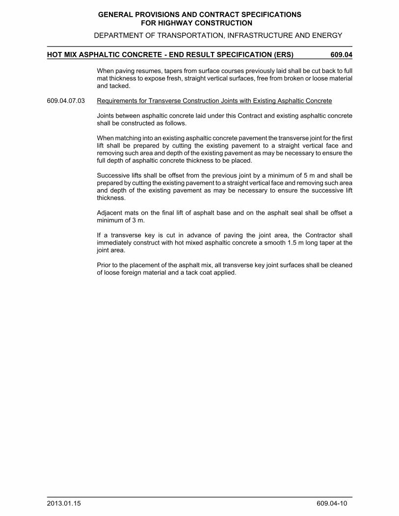
GENERAL PROVISIONS AND CONTRACT SPECIFICATIONS FOR HIGHWAY CONSTRUCTION
DEPARTMENT OF TRANSPORTATION, INFRASTRUCTURE AND ENERGY
HOT MIX ASPHALTIC CONCRETE - END RESULT SPECIFICATION (ERS) 609.04
2013.01.15 609.04-10
When paving resumes, tapers from surface courses previously laid shall be cut back to fullmat thickness to expose fresh, straight vertical surfaces, free from broken or loose materialand tacked.
609.04.07.03 Requirements for Transverse Construction Joints with Existing Asphaltic Concrete
Joints between asphaltic concrete laid under this Contract and existing asphaltic concreteshall be constructed as follows.
When matching into an existing asphaltic concrete pavement the transverse joint for the firstlift shall be prepared by cutting the existing pavement to a straight vertical face andremoving such area and depth of the existing pavement as may be necessary to ensure thefull depth of asphaltic concrete thickness to be placed.
Successive lifts shall be offset from the previous joint by a minimum of 5 m and shall beprepared by cutting the existing pavement to a straight vertical face and removing such areaand depth of the existing pavement as may be necessary to ensure the successive liftthickness.
Adjacent mats on the final lift of asphalt base and on the asphalt seal shall be offset aminimum of 3 m.
If a transverse key is cut in advance of paving the joint area, the Contractor shallimmediately construct with hot mixed asphaltic concrete a smooth 1.5 m long taper at thejoint area.
Prior to the placement of the asphalt mix, all transverse key joint surfaces shall be cleanedof loose foreign material and a tack coat applied.

GENERAL PROVISIONS AND CONTRACT SPECIFICATIONS FOR HIGHWAY CONSTRUCTION
DEPARTMENT OF TRANSPORTATION, INFRASTRUCTURE AND ENERGY
HOT MIX ASPHALTIC CONCRETE - END RESULT SPECIFICATION (ERS) 609.05
2013.01.15 609.05-1
609.05 Quality Control Testing
609.05.01 General
The Contractor shall be totally responsible for quality control testing throughout every stageof the Work, from the crushing and production of aggregates, to the final accepted product,to ensure materials and workmanship conform with the requirements of this Specification.
609.05.01.01 Inspection Testing Plan (ITP)
The Contractor shall submit, in writing to the Engineer, an ITP covering all phases of theContract performance, and the name of the party retained to conduct the ITP, within ten(10) days after the Contract award.
The ITP shall include, but not be limited to, identification and description of inspection andrequired test procedures to be used during the entire life of the Contract.
The ITP shall be sufficiently comprehensive and detailed, to assure the Engineer of theContractor’s willingness and ability to control the construction production and processes.
Once accepted by the Engineer the plan becomes a part of the Contract and shall beenforced accordingly.
The ITP may have to be updated and revised, by the Contractor, as conditions warrant.
609.05.01.02 Sampling and Test Results
Where specified, random sampling procedures shall be followed, and where no specificrandom sampling procedure is specified the sampling procedure shall be as identified bythe Contractor.
The Contractor shall be responsible for the interpretation of the test results and thedetermination of any action to be taken to ensure that all materials and work conform to therequirements of the Contract.
At no time will the Engineer issue instructions to the Contractor, as to setting of dials,gauges, scales and meters.
However, the Engineer may advise the Contractor against the continuance of anyoperations or sequence of operations which will result in non-compliance with Specificationrequirements.
The Contractor shall maintain records of all inspection and tests.
Results of all quality control tests shall be available for examination by the Engineer at alltimes and copies shall be provided to the Engineer on a daily basis.
609.05.02 Quality Assurance Testing and Adjustments
The Contractor shall provide an end product conforming in quality and accuracy of detailto the dimensional and tolerance requirements of the Plans and Specifications.
While the Contractor shall be fully and exclusively responsible for producing the endproduct, acceptance testing is the responsibility of the Engineer.

GENERAL PROVISIONS AND CONTRACT SPECIFICATIONS FOR HIGHWAY CONSTRUCTION
DEPARTMENT OF TRANSPORTATION, INFRASTRUCTURE AND ENERGY
HOT MIX ASPHALTIC CONCRETE - END RESULT SPECIFICATION (ERS) 609.05
2013.01.15 609.05-2
Certain requirements, limits and tolerances are specified regarding the quality of materialsand workmanship to be supplied.
The Engineer shall test for compliance with these requirements as described in 609.05.02.
The test methods indicated in Table 609-3 will be used to determine materialcharacteristics.
Table 609-3 Test Methods
Test Description Test Method
Sampling Mixes (TIR Test Method LTP-101A) ASTM D 979
Coring ASTM D 5361
Ignition Method (TIR Test Method LTP-418)
Percent Fracture (TIR Test Method LTP-208)
Sieve Analysis (TIR Test Method LTP-202) ASTM C136/ASTM C 117
Bulk Relative Density (TIR Test Method LTP-401) ASTM D 2726
Theoretical Maximum Relative Density (TIR Test Method LTP-404) ASTM 2041
Voids Calculations, Asphaltic Concrete Specimens (TI R Test Method LTP-405) ASTM D 3203
Percent Compaction, Asphaltic Concrete Pavement (TIR Test Method LTP-408)
Forming Marshall Specimens, Field Method (TIR Standard Plant Procedures)
Moisture Content, Oven Method Asphaltic Concrete Mix (TIR Test Method LTP-416) ASTM D 2172
Smoothness of Pavements, Profiler Method ASTM E 950
Stratified Random Test Sites for ERS Projects ASTM D 3665
Appeal Testing as outlined in Specifications
Asphalt Binder: Flash and Fire PointsViscosityRheological PropertiesRolling Thin Film OvenAccelerated Aging (PAV)Flexible Creep Stiffness
AASHTO T 48 or ASTM D 92AASHTO T316 or ASTM D 4402
AASHTO T315AASHTO T 240AASHTO R28AASHTO T313
TSR (Average of Conditioned & Freeze/Thaw TSR values) AASHTO T283 (latest edition)
In all test methods used as reference in this specification, metric sieves as specified in ASTM E11 shall besubstituted for any other specified wire cloth sieves.
The Engineer reserves the right to inspect and/or test any of the Contractor’s operations ormaterials and those of subcontractors and suppliers, regardless of location.
Such inspections and tests shall not relieve the Contractor of his responsibilities tocontrol quality.
The Engineer’s approval of any materials or mixture shall in no way relieve theContractor from his obligation to provide materials, mixtures and workmanship inaccordance with the Specifications.

GENERAL PROVISIONS AND CONTRACT SPECIFICATIONS FOR HIGHWAY CONSTRUCTION
DEPARTMENT OF TRANSPORTATION, INFRASTRUCTURE AND ENERGY
HOT MIX ASPHALTIC CONCRETE - END RESULT SPECIFICATION (ERS) 609.05
2013.01.15 609.05-3
The loose and core samples shall be taken by the Contractor in the presence of the Engineer.
The random locations shall be determined by the Engineer. Pavement sampling willbe conducted using the Stratified Random Sampling Procedure.
The Engineer will be responsible for the labeling, storing, and transporting of theloose samples to the Owner’s laboratories.
The Engineer shall be responsible for labeling the cores. Each sample shall belabelled with the contractor, contract number, highway number, date sampled, mixtype, lot number, sublot number, lift number, design lift thickness, station locationand offset of the highway
The Contractor shall be responsible for the storage and transportation of the coresto the Owner's Laboratory, within 2 hours of coring, for testing. Core samples shallbe placed in a suitable container which will protect the sample integrity duringtransport and until testing.
Each core shall have a minimum nominal diameter of at least 150 mm and amaximum nominal diameter of 200 mm and shall consist of the full layer beingsampled.
The Contractor shall reinstate the pavement at each core sample location inconjunction with removal of the core by de-watering the core hole and filling it withhot mixed asphaltic concrete in 50 mm lifts to the pavement surface elevation,compacting each lift with 25 blows using a standard compaction device.
The Engineer will provide the Contractor with a copy of the results of acceptance tests withinone (1) working day of their availability.
Acceptance test results for a given Lot will not be reported to the Contractor until the qualitycontrol results for that Lot have been reported to the Engineer.
If any one of the control characteristics of a Lot is outside the acceptance limits as listed inTable 609-4, then the Lot will be rejected automatically regardless of the values of the othercontrol characteristics.
Tests performed by the Engineer will not be considered to be quality control tests.
Random sampling methods will not be applied to the following areas:
Areas of obvious surface defects as indicated in 609.05.08, which shall be markedand repaired in accordance with 609.05.10.
Small areas such as tapers, aprons, Bridge approaches, gores and areas ofhandwork, and asphalt mix used for isolated levelling and repair of failed areas.
The procedure for dealing with an outlier test result shall be as follows:
When an individual test result from a Lot is questionable, the validity of the test resultin question will be determined in accordance with ASTM E 178, Standard Practicefor Dealing with Outlying Observations using a “t” test at a 5 percent significancelevel.

GENERAL PROVISIONS AND CONTRACT SPECIFICATIONS FOR HIGHWAY CONSTRUCTION
DEPARTMENT OF TRANSPORTATION, INFRASTRUCTURE AND ENERGY
HOT MIX ASPHALTIC CONCRETE - END RESULT SPECIFICATION (ERS) 609.05
2013.01.15 609.05-4
If the outlier test procedure shows that the challenged test result is valid then the testresult will be used in the calculations.
609.05.03 Asphalt Density
Compaction testing shall be based on a Lot average method.
Pavement samples will be taken on the road by coring, using stratified random samplingprocedures. Four tests per Lot will be selected as follows:
The Lot will be divided into 4 segments of approximately equal length.
In each segment a test site will be located by using random numbers to determine thelongitudinal distance from the end of the segment and the lateral distance from the edge ofthe segment.
In no case will a lateral distance be less than 0.3 m from the edge of a mat.
Cores will not be taken within 25 m of a loose sample location.
Cores shall be obtained in accordance with ASTM D5361, within a minimum of 12 hours anda maximum of 24 hours after the placement of the Lot.
The maximum may be extended to 72 hours in order to exclude Saturday andSunday unless the Contractor is placing asphaltic concrete on either day.
The percent compaction will be determined by the Department on the random samplesusing the following procedure:
% Compaction = BRD x 100MMRD
Where MMRD = The mean maximum theoretical relative density ofthe sublot random cores determined by ASTMD2041.
BRD = The bulk relative density of a random core obtainedfrom the lot, determined by ASTM D2726 forspecimens that contain moisture.
The mean percent compaction for the lot will be determined by calculating the meanof the four sublot random core percent compaction results.
609.05.04 Asphalt Content, Gradation and Air Voids
Loose samples will be taken on the road behind the paver before compaction, with 3samples per Lot selected as follows:
A Lot will be divided into 3 segments of approximately equal quantity.
For each segment random numbers will be used to determine the tonnage at whichto obtain the sample.
Each sample will be split in two equal portions, one portion will be tested, and the

GENERAL PROVISIONS AND CONTRACT SPECIFICATIONS FOR HIGHWAY CONSTRUCTION
DEPARTMENT OF TRANSPORTATION, INFRASTRUCTURE AND ENERGY
HOT MIX ASPHALTIC CONCRETE - END RESULT SPECIFICATION (ERS) 609.05
2013.01.15 609.05-5
other will be set aside in the event that an appeal is requested by the Contractor.
If the plant production is 600 t or less, one additional random loose sample will be obtained,and the production will be added to the previous Lot.
609.05.05 Smoothness
The Profile requirements shall be specified in the Contract Documents.
The smoothness of the final lift of newly placed asphaltic concrete pavement will bechecked with a High Speed Profiler as soon as possible after final rolling.
609.05.05.01 Definitions
International Roughness Index (IRI). IRI is a statistical measurement used to determinethe amount of roughness in a measured longitudinal profile. IRI will be measured in mm/mand reported to two (2) decimal places for all procedures relating to this specification.
Reporting Interval. The reporting interval for this specification shall be 100 metres foroverall IRI, and 10 metres for localized roughness.
Localized Roughness. Localized roughness is reported in 10 metre intervals where the IRIexceeds an established value as set out in Table 609-9 of this specification.
Segment. A segment of Roadway shall be defined by the full lane width (including pavedshoulders) over a defined length. The segment length shall be 10 metres for localizedroughness. The segment length shall be 100 metres for overall IRI, however, shortersegment lengths may exist as outlined in Item 609.05.05.04.02.
Project Chainage. The distance as measured by the High Speed Profiler will be referencedto the contract stake chainage, but will be the only chainage deemed accurate andacceptable for the smoothness specification.
609.05.05.02 References
All reference standards shall be current issue or latest revision at the first date of Tenderadvertisements. This specification refers to the following standards, specifications orpublications:• ASTM E 950 Standard Test Method for Measuring the Longitudinal Profile of TravelledSurfaces with an Accelerometer Established Inertial Profiling Reference• PEITIR General Provisions and Contract Specifications for Highway Construction.
609.05.05.03 Equipment
A Class 1 inertial laser profiler, with moving average filter (high pass 300 ft and low pass1 ft), will be used for all smoothness measurements under this specification. Theequipment will be installed and operated in accordance with the manufacturer’srecommendations and ASTM E 950.
609.05.05.04 Smoothness Testing Procedures
The Department or its designated representative will conduct smoothness testing inaccordance with ASTM E 950. The Department’s smoothness testing results will be usedin determining payment adjustments and areas requiring Corrective Work.

GENERAL PROVISIONS AND CONTRACT SPECIFICATIONS FOR HIGHWAY CONSTRUCTION
DEPARTMENT OF TRANSPORTATION, INFRASTRUCTURE AND ENERGY
HOT MIX ASPHALTIC CONCRETE - END RESULT SPECIFICATION (ERS) 609.05
2013.01.15 609.05-6
609.05.05.04.01 Profile Measurements: The profiler will conduct three (3) complete passes in each lane,recording the right and left wheel path IRI values simultaneously at 10 metre intervals. Thefinal IRI will be the average of the three passes reported at 10 metre intervals. The 100metre interval averages will then be computed from the 10 metre interval average IRIvalues.
The profile measurements shall be collected in the direction of traffic. The start and endlocation of measurement for each lane shall be 20 metres from the transverse constructionjoints or in the case of a tapered lane at the locations defined by which the full lane widthoccurs.
609.05.05.04.02 Exclusions: The 20 metre segments at both ends of the section under contract defined bythe transverse construction joints shall be excluded from smoothness calculations. Bridgestructures (excluding culverts and arches), underpass structures and overpass structureslocated within any 10 metre segment, including the 10 metre segments immediately beforeand after a structure will be excluded from payment adjustments under this specification.
Areas requiring hand work, tapers, intersections, gore areas, aprons, etc. will be excludedfrom this specification.
Individual 10 metre segments exhibiting roughness, which can be directly attributed tophysical features of the roadway including iron works or curb/gutter match-ins, may beexcluded from payment adjustments as determined by the Engineer.
609.05.05.05 Mandatory Penalty
The Contractor shall be subjected to a mandatory penalty of -$2000.00 for each 10 metresegment with an IRI > 3.00 mm/m, with exception of areas defined in Section609.05.05.04.02.
609.05.05.05.01 The Engineer reserves the right to require Compulsory Corrective Work on any 10 metresegments with an IRI > 3.00 mm/m. In any 10 metre segments where CompulsoryCorrective Work is required, the Department will waive the -$2000.00 penalty.
The Engineer shall notify the Contractor if Compulsory Corrective Work is required.
609.05.05.05.02 Compulsory Corrective Work Procedures: Corrective work shall consist of Removal andReplacement of the surface course of asphaltic concrete pavement. The minimum lengthof any repair area shall be 10 metres.
Removal and Replacement: On each of the 10 metre segments affected, theContractor shall remove (by cold planing) and replace the full width of the lane andthe full depth of the surface course of asphaltic concrete pavement affected,including paved shoulders.
Compulsory Corrective Work Requirements: The asphaltic concrete repair shallconform with either Section 603 or 609 of the Department’s Specification, as statedin the Contract.
Incidental Corrective Work: Corrective Work may result in additional incidental costs,including but not limited to: tack coat, additional shoulder gravelling, guardrailadjustments, re-application of pavement markings, etc. Such work shall be carriedout in accordance with the Department’s specifications and at the Contractor’sexpense.

GENERAL PROVISIONS AND CONTRACT SPECIFICATIONS FOR HIGHWAY CONSTRUCTION
DEPARTMENT OF TRANSPORTATION, INFRASTRUCTURE AND ENERGY
HOT MIX ASPHALTIC CONCRETE - END RESULT SPECIFICATION (ERS) 609.05
2013.01.15 609.05-7
Disposal of Asphaltic Concrete: Asphaltic concrete that has been removed as aresult of Corrective Work undertaken by the Contractor shall become the propertyof the Contractor to haul, stockpile or otherwise dispose of in an environmentallyacceptable manner, at the Contractor’s expense.
609.05.05.05.03 Retesting Following Corrective Work: After Corrective Work has been completed, each ofthe 100 metre segments containing corrective work will be retested, using the same profilerused in the original testing. The new IRI values will be used and the recalculated resultswill be binding.
Should the new IRI results indicate further Mandatory Penalty 10 metre segments as statedin Item 609.05.05.05, the Contractor shall be subject to the Mandatory Penalty as statedin Item 609.05.05.05.
609.05.05.05.03 Costs for Corrective Work: All costs associated with Corrective Work shall be theresponsibility of the Contractor.
609.05.06 Asphalt Binder
Asphalt binder samples shall be obtained and packaged as follows:
Samples shall be a minimum size of one (1) litre and shall be taken from the Contractor’sstorage tank in accordance with ASTM D140.
The sample containers shall be supplied by the Engineer.
The Contractor shall obtain one (1) asphalt binder sample per 5000 t of asphaltic concretemix production, taken in accordance with ASTM D140 from the Contractor’s asphalt binderstorage tank(s).
If Asphalt Concrete HRA is used per section 609.03.01.01, the Contractor shall obtain one(1) asphalt binder sample per 10,000 t of asphaltic concrete mix production, taken inaccordance with ASTM D140 from the Contractor’s asphalt binder storage tank(s). TheEngineer shall label the samples with the Contract number, date, time, grade and type ofasphalt binder, supplier, refinery, and the name and the proportions of any additives addedto the asphalt binder.
If a sample test result falls outside of the material requirements specified in 609.02.01, theEngineer may require that the Contractor suspend the asphaltic concrete mix production.
Compliance shall be verified by the Engineer before the asphaltic concrete mix productionis allowed to continue.
609.05.07 Thickness
The Contractor shall place the asphaltic concrete in lifts at the thickness indicated in theContract Documents and/or as specifically directed by the Engineer.
Thickness shall be evaluated on a Lot by Lot basis.
The Pavement Thickness shall be determined from the test results of the cores obtainedaccording to 609.05.03.
If the Thickness does not meet the requirements of Table 609-4 then the deficient area

GENERAL PROVISIONS AND CONTRACT SPECIFICATIONS FOR HIGHWAY CONSTRUCTION
DEPARTMENT OF TRANSPORTATION, INFRASTRUCTURE AND ENERGY
HOT MIX ASPHALTIC CONCRETE - END RESULT SPECIFICATION (ERS) 609.05
2013.01.15 609.05-8
shall be repaired as indicated in 609.05.10.
Table 609-4 Acceptance/Rejection Requirements by Lot
Measurement Types of Mix (&Sieve Size) Lot Payment
Repair /ReplaceRejectIncreased Full Reduced
Bulk Relative Density as(%) of TheoreticalMaximum RelativeDensity (%)
All > 92.5 92.5 92.4 – 89.5 < 89.5
Asphalt Content (%)(Mean of Deviations ofLot from JMF)
A, HRAB
N.A.N.A.
0.0 – 0.40.0 – 0.3
0.41 – 0.650.31 – 0.50
> 0.65> 0.50
Gradation (%)(Mean of Deviations ofLot from JMF)
(See Note 1)
A, HRA (4.75mm) (75 µm)
N.A.N.A.
0.0 – 6.00.0 – 0.8
6.1 – 10.00.9 – 1.5
> 10.0> 1.5
B (4.75 mm) (75 µm)
N.A.N.A.
0.0 – 5.00.0 – 0.5
5.1 – 9.00.6 – 1.2
> 9.0> 1.2
Cores with ThicknessWithin Tolerance (#)(See Note 2)
All N.A. 3 of 4 N.A. 2 of 4
Air Voids (%)Mean of Deviations fromTarget Value of 3.5%
All N.A. 1.00 1.01 - 2.0 > 2.0
NOTE 1 (Additional Requirements for Gradation):a) If the average of Lot test results for the 4.75 mm sieve size falls outside the gradation limits of
Table 609-1, the Lot will be rejected.b) If the average of Lot test results for the 75 µm sieve size exceeds the upper gradation limit of
Table 609-1, the following will apply:Exceeds by # 1.0%, the Lot Payment will be reduced by $5.00/t;Exceeds by > 1.0%, the Lot will be rejected.
NOTE 2 (Thickness):a) Thickness =Measured Thickness obtained from core samples.b) Lift Thickness Tolerance by Type of Mix
Tolerance = 0.80 x Specified Thickness (HRA)Tolerance = 0.85 x Specified Thickness (A,B )
c) If the thickness of either lift of base mix is less than the tolerance, the Contractor shall place thenext lift of asphaltic concrete to achieve a thickness equivalent to the total thickness of the twolifts as specified in the Contract. The total thickness of the two lifts for the deficient Lot shall beverified by coring the two lifts in the area of the deficient Lot.
609.05.08 Surface Defects
The finished surface of any Pavement course shall have a uniform texture and be free of visiblesigns of poor workmanship and bumps and/or dips exceeding 3 mm as measured with a 3 mstraight edge.
Any obvious defects, as determined by the Engineer, will be cause for rejection of the Pavementcourse.

GENERAL PROVISIONS AND CONTRACT SPECIFICATIONS FOR HIGHWAY CONSTRUCTION
DEPARTMENT OF TRANSPORTATION, INFRASTRUCTURE AND ENERGY
HOT MIX ASPHALTIC CONCRETE - END RESULT SPECIFICATION (ERS) 609.05
2013.01.15 609.05-9
Such defects shall include but not necessarily be limited to the following:
- Segregated areas.- Areas of excess or insufficient asphalt binder.- Roller marks.- Cracking or tearing.- Improper matching of longitudinal and transverse joints.- Tire marks.- Sampling locations not properly reinstated.- Improperly constructed patches.- Improper coss slope.- Contaminant spills on the mat.- Flushed Areas
609.05.09 Appeal of Lot Test Results
The Contractor may appeal the results of acceptance testing of the density, asphalt content,gradation and thickness for any rejected or penalized Lot only once.
Appeals shall only be considered for all tests within the Lot.
Any attempt to improve density on the appealed Lot after the Engineer has tested the Lot foracceptance shall void the appeal and the original test results will apply.
The following procedures will apply for an appeal:
The Contractor shall serve notice of appeal to the Engineer, in writing, within 48 hours of receiptof the test results.
The Contractor and the Engineer shall agree on a time at which the cores for the appealof the Lot will be taken.
The cores for the appeal of the Lot shall be taken within 48 hours of the submission ofthe notice for the appeal.
If the density or thickness of the Lot is appealed, the Contractor shall take 4 more coresat random locations, as determined by the Engineer. These cores will be tested by theOwner.
If the asphalt content, gradation or air voids is appealed, the Engineer will take theremaining portion of the samples obtained in 609.05.04 and test them at the Owner’sLaboratory.
The Contractor may have a representative present during the period of the testing; theContractor’s representative shall comment on anything concerning the testing which hedoes not consider to be valid and the Engineer shall respond to all comments in orderto resolve them.
Prior to leaving the testing Laboratory, any unresolved comments regarding thetesting procedures are to be given to the Engineer in writing.
Any comments, with respect to the testing procedures, which are made subsequentto the Contractor’s representative leaving the Laboratory, will not be considered.

GENERAL PROVISIONS AND CONTRACT SPECIFICATIONS FOR HIGHWAY CONSTRUCTION
DEPARTMENT OF TRANSPORTATION, INFRASTRUCTURE AND ENERGY
HOT MIX ASPHALTIC CONCRETE - END RESULT SPECIFICATION (ERS) 609.05
2013.01.15 609.05-10
The test results from the original Lot will be combined with the test results of the newsamples.
A new Sample Mean or the Mean of the Deviations for the combined test results willbe determined and this value will be used for acceptance and Unit Price adjustment.
For thickness appeals 6 of the 8 test results must meet or exceed the lift thicknesstolerance specified in Table 609-4.
The new Lot test results so obtained shall be binding on both the Contractor and the Owner.
609.05.10 Repairs
609.05.10.01 General
Repairs to the Work to improve smoothness shall be carried out in accordance with Item609.05.05.05.02 and within thirty (30) days from the time the Contractor receives theEngineer's written assessment of the Work.
Repairs to correct surface defects shall be carried out in accordance with this Item within one(1) year from the time the Contractor completes placement of the asphaltic concrete.
The asphaltic concrete used for replacement or overlay to correct surface defects shall bethe same asphaltic concrete mix designation as that which is removed or overlaid.
Any asphaltic concrete which does not conform to the requirements of this Item shall notbe incorporated in the Work.
Repairs required in accordance with 609.05.05 shall be carried out for the full width of thedriving Lane, including the paved shoulders.
609.05.10.02 Removal and Replacement
The full thickness of the appropriate lift of pavement in the rejected Lot shall be removed bycold milling or other means as approved by the Engineer.
All joints shall be tack-coated.
Repaired areas will be retested for acceptance; those failing will be rejected and shall requirefurther repair.
Material removed shall become the property of the Contractor, who shall dispose of thematerial outside the Work Site.
609.05.10.03 Overlaying
The overlay shall extend the full width of the underlying pavement surface and have afinished compacted thickness of not less than 50 mm for a base course and 40 mm for asurface course.
A key shall be constructed at each end of the overlaid section.
If an overlay results in the need for repairs or adjustments to the adjacent materials within the

GENERAL PROVISIONS AND CONTRACT SPECIFICATIONS FOR HIGHWAY CONSTRUCTION
DEPARTMENT OF TRANSPORTATION, INFRASTRUCTURE AND ENERGY
HOT MIX ASPHALTIC CONCRETE - END RESULT SPECIFICATION (ERS) 609.05
2013.01.15 609.05-11
Work Area, the Contractor shall carry out the repairs and adjustments at his own expenseand to the satisfaction of the Engineer.
Repaired areas will be retested for acceptance.
- Those failing will be rejected and a second overlay will not be permitted.
- The Contractor shall then carry out repairs in accordance with 609.05.10.02.
- Removal depth shall be sufficient to remove the full thickness of the overlay lift and theoriginal unsatisfactory surface lift.

GENERAL PROVISIONS AND CONTRACT SPECIFICATIONS FOR HIGHWAY CONSTRUCTION
DEPARTMENT OF TRANSPORTATION, INFRASTRUCTURE AND ENERGY
HOT MIX ASPHALTIC CONCRETE - END RESULT SPECIFICATION (ERS) 609.06/07
2013.01.15 609.06/07-1
609.06 Measurement for Payment
609.06.01 Method of Measurement - Asphaltic Concrete
The quantity to be measured under this Section shall be the number of tonnes of each classof asphaltic concrete acceptably placed subject to payment adjustments.
The quantity of asphaltic concrete for a Lot shall not exceed that calculated as follows:
- Specified length x specified width x specified thickness x density x 1.1.
609.06.02 Unit Price Adjustment (UPA) of the Lot
The UPAs for asphaltic concrete are as shown in Tables 609-5, 609-6, 609-7 and 609-10.
If repairs are carried out by removal and replacement or overlay of the asphaltic concrete, theUPA for the Lot will be based on quality assurance testing carried out on the repaired Lot.
The Unit Price (UP) for asphaltic concrete base or surface mixes will be adjusted for each Lotas follows:
- UPLot = UP + 3 (UPADensity + UPA Asphalt Content + UPAGradation + UPA Air Voids)
609.06.03 Payment Adjustment for Smoothness
The Engineer will provide the Contractor with a copy of the smoothness test results, includingdetailed payment adjustment summaries and Compulsory Corrective Work requirements.
609.06.03.01 100 Metre Segments: Payment adjustments for 100 metre segments will be calculated basedon the overall average IRI in mm/m for each 100 metre segment in each lane in accordancewith Table 609-8.
609.06.03.02 Localized Roughness: With the exception of areas described in Item 609.05.05.04.02, each10 metre segment with an IRI value greater than those shown in Table 609-9 shall be definedas localized roughness, resulting in negative payment adjustments. The total localizedroughness payment adjustment shall be the numerical summation of all the individuallocalized roughness payment adjustments for the defined section of Roadway.
609.06.03.03 Total Payment Adjustments: The total payment adjustment shall be the summation of all theindividual payment adjustments for each 100 metre segment in each lane, including localizedroughness payment adjustments. If the total 100 metre segment payment adjustment is apositive value (bonus), the Contractor will be assessed the total 100 metre segment paymentadjustment, and the total localized roughness payment adjustment for the defined section ofRoadway.
If the total 100 metre segment payment adjustment is a negative value (penalty), theContractor will be assessed either the total 100 metre segment payment adjustment or thetotal localized roughness payment adjustment, whichever is numerically less (i.e., whicheverresults in a greater penalty to the Contractor). The two penalties shall not be applied insummation.
609.06.03.04 Segments Less Than 100 Metres: For segments less than 100 metres in length, priceadjustments will be determined from 10 metre segments that are not subject to exclusionsas described in Item 609.05.05.04.02. Payment adjustments under Item 609.06.03.01 and

GENERAL PROVISIONS AND CONTRACT SPECIFICATIONS FOR HIGHWAY CONSTRUCTION
DEPARTMENT OF TRANSPORTATION, INFRASTRUCTURE AND ENERGY
HOT MIX ASPHALTIC CONCRETE - END RESULT SPECIFICATION (ERS) 609.06/07
2013.01.15 609.06/07-2
Item 609.06.03.02 shall apply to these areas based on the actual number of 10 metresegments that are not excluded. Price adjustments shall be prorated based on the numberof non excluded 10 metre segments in the 100 metre segment, as detailed in Table 609-8.
Example 1: 100 metre Segment (Station 7+700 - 7+800)Exclusions apply in four (4) of the individual 10 m segments (20 m bridge + 10m at each end)
10 Metre Segment
IRI (mm/m)
Exclusion Applies? (yes/no)
Localized Roughness Payment Adjustment
Average IRI over 60metre Segment
IRI Payment Adjustment (See Table609-8)
Total PaymentAdjustment(for this 60metreSegment)
7+700 - 7+710 0.53 No $0 (0.53+0.39+0.34 +0.23 + 0.28 + 1.42)/6
= 0.53
+$470 x 6/10 = +$282
+$282 - $250 = +$32
7+710 - 7+720 0.39 No $0
7+720 - 7+730 0.34 No $0
7+730 - 7+740 0.23 No $0
7+740 - 7+750 0.28 No $0
7+750 - 7+760 1.15 Yes (Bridge Approach)
$0
7+760 - 7+770 1.86 Yes (Bridge) $0
7+770 - 7+780 2.43 Yes (Bridge) $0
7+780 - 7+790 0.91 Yes (Bridge Approach)
$0
7+790 - 7+800 1.42 No -$250
Example 2: 30 metre Segment (Station 6+420 - 6+450) at end of paving sectionExclusions Apply in one (1) of the individual 10 m segments
10 Metre Segment
IRI (mm/m)
Exclusion Applies? (yes/no)
Localized Roughness Payment Adjustment
Average IRIover 30 metreSegment
IRI Payment Adjustment (See Table609-8)
Total Payment Adjustment (forthis 30 metreSegment)
6+420 - 6+430 0.88 No $0 (0.88 + 1.45)/2= 1.16
-$190 x 2/10 = -$38
-$38 - $250 = -$288
6+430 - 6+440 1.45 No -$250
6+440 - 6+450 1.65 Yes(Manhole)
$0

GENERAL PROVISIONS AND CONTRACT SPECIFICATIONS FOR HIGHWAY CONSTRUCTION
DEPARTMENT OF TRANSPORTATION, INFRASTRUCTURE AND ENERGY
HOT MIX ASPHALTIC CONCRETE - END RESULT SPECIFICATION (ERS) 609.06/07
2013.01.15 609.06/07-3
609.06.04 Method of Measurement - Asphalt Cement
The quantity to be measured for payment under this section shall be the number oftonnes of asphalt cement utilized by the Contractor in producing hot mix asphalticconcrete as determined by the extractions from the random samples provided by thecontractor to the Department and calculated for the tonnage of hot mix asphalticconcrete produced.
Provided Asphalt Concrete HRA is used as per section 609.03.01.01, the quantity to bemeasured for payment under this section shall be the number of tonnes of asphaltcement supplied by the Contractor in producing hot mix asphaltic concrete asdetermined by the extractions (extractions adjusted for the mean reclaimed asphalt cementcontent of RAP as per section 609.03.01.02) from the random samples provided by theContractor to the Department and calculated for the tonnage of hot mix asphalticconcrete produced.
Table 609-5 Unit Price Adjustment For Density (UPAd)
% of TheoreticalMaximum Relative
Density(Lot Average)
Unit Price Adjustment($ per Tonne)
% of TheoreticalMaximum Relative
Density(Lot Average)
Unit PriceAdjustment
($ per Tonne)
93.0 +1.00 91.1 -2.8092.9 +0.80 91.0 -3.0092.8 +0.60 90.9 -3.4092.7 +0.40 90.8 -3.8092.6 +0.20 90.7 -4.2092.5 0.00 90.6 -4.6092.4 -0.20 90.5 -5.0092.3 -0.40 90.4 -5.4092.2 -0.60 90.3 -5.8092.1 -0.80 90.2 -6.2092.0 -1.00 90.1 -6.6091.9 -1.20 90.0 -7.0091.8 -1.40 89.9 -8.0091.7 -1.60 89.8 -9.0091.6 -1.80 89.7 -10.0091.5 -2.00 89.6 -11.0091.4 -2.20 89.5 -12.0091.3 -2.40 <89.5 reject91.2 -2.60

GENERAL PROVISIONS AND CONTRACT SPECIFICATIONS FOR HIGHWAY CONSTRUCTION
DEPARTMENT OF TRANSPORTATION, INFRASTRUCTURE AND ENERGY
HOT MIX ASPHALTIC CONCRETE - END RESULT SPECIFICATION (ERS) 609.06/07
2013.01.15 609.06/07-4
Table 609-6 Unit Price Adjustment For Asphalt Content (UPAa)
Mean of the Deviations of Actual Asphalt Content From the Approved Asphalt Content
Unit Price adjustment forAsphalt Content ($ per Tonne)
0.00 to 0.40 0.000.41 to 0.45 -1.000.46 to 0.50 -2.00
Type A/HRA 0.51 to 0.55 -3.000.56 to 0.60 -4.000.61 to 0.65 -5.00
> 0.65 reject
0.00 to 0.30 0.000.31 to 0.35 -1.00
Type B 0.36 to 0.40 -2.000.41 to 0.45 -3.000.46 to 0.50 -4.00
> 0.50 reject

GENERAL PROVISIONS AND CONTRACT SPECIFICATIONS FOR HIGHWAY CONSTRUCTION
DEPARTMENT OF TRANSPORTATION, INFRASTRUCTURE AND ENERGY
HOT MIX ASPHALTIC CONCRETE - END RESULT SPECIFICATION (ERS) 609.06/07
2013.01.15 609.06/07-5
Table 609-7 Unit Price Adjustment For Gradation (UPAg)
Sieve Size ASTM
Designation
Mean of the Deviations of the Gradation from theJMF
Unit PriceAdjustment for
Gradation
Type A/HRA Type B $ per Tonne
0.0 to 6.0 0.0 to 5.0 0.006.1 to 6.2 5.1 to 5.2 -0.506.3 to 6.4 5.3 to 5.4 -1.006.5 to 6.6 5.5 to 5.6 -1.506.7 to 6.8 5.7 to 5.8 -2.00
4.75 mm 6.9 to 7.0 5.9 to 6.0 -2.507.1 to 7.2 6.1 to 6.2 -3.007.3 to 7.4 6.3 to 6.4 -3.507.5 to 7.6 6.5 to 6.6 -4.007.7 to 7.8 6.7 to 6.8 -4.507.9 to 8.0 6.9 to 7.0 -5.008.1 to 9.0 7.1 to 8.0 -10.00
9.1 to 10.0 8.1 to 9.0 -15.00> 10.0 > 9.0 reject
0.0 to 0.8 0.0 to 0.5 0.000.9 0.6 -0.501.0 0.7 -1.50
75 µm 1.1 0.8 -3.001.2 0.9 -5.001.3 1.0 -7.50
1.4 to 1.5 1.1 to 1.2 -12.00> 1.5 > 1.2 reject
In addition to the above acceptance/rejection requirements for gradation, thefollowing shall apply:
(a) The Lot will be rejected if the average of the Lot test results for the 4.75mm size falls outside the gradation limits specified in Table 609-1.
(b) The Lot payment will be reduced by $5.00 per Tonne if the average of theLot test results for the 75 µm size exceeds, up to a maximum of 1.0%, theupper gradation limit specified in Table 609-1.
(c) The Lot will be rejected if the average of the Lot test results for the 75 µmsize exceeds, by more than 1.0 %, the upper gradation limit specified inTable 609-1.

GENERAL PROVISIONS AND CONTRACT SPECIFICATIONS FOR HIGHWAY CONSTRUCTION
DEPARTMENT OF TRANSPORTATION, INFRASTRUCTURE AND ENERGY
HOT MIX ASPHALTIC CONCRETE - END RESULT SPECIFICATION (ERS) 609.06/07
2013.01.15 609.06/07-6
Table 609-8 Payment Adjustment For Smoothness
IRI (mm/m) Pay Adjustment
0.00 - 0.10 $950.00
0.11 - 0.20 $860.00
0.21 - 0.30 $770.00
0.31 - 0.40 $670.00
0.41 - 0.50 $570.00
0.51 - 0.60 $470.00
0.61 - 0.70 $370.00
0.71 - 0.80 $270.00
0.81 - 0.90 $160.00
0.91 - 1.00 $50.00
1.01 - 1.10 ($70.00)
1.11 - 1.20 ($190.00)
1.21 - 1.30 ($320.00)
1.31 - 1.40 ($450.00)
1.41 - 1.50 ($590.00)
1.51 - 1.60 ($740.00)
1.61 - 1.70 ($900.00)
1.71 - 1.80 ($1070.00)
1.81 - 1.90 ($1260.00)
1.91 - 2.00 ($1480.00)
2.01 - 2.10 ($1720.00)
2.11 - 2.20 ($2040.00)
2.21 - 2.30 ($2750.00)
2.31 - 2.40 ($3290.00)
2.41 - 2.50 ($3300.00)
2.51 - 3.00 ($3300.00)
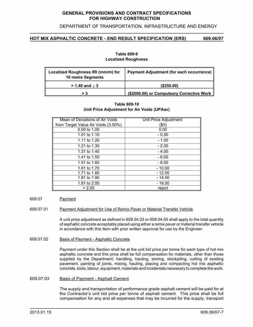
GENERAL PROVISIONS AND CONTRACT SPECIFICATIONS FOR HIGHWAY CONSTRUCTION
DEPARTMENT OF TRANSPORTATION, INFRASTRUCTURE AND ENERGY
HOT MIX ASPHALTIC CONCRETE - END RESULT SPECIFICATION (ERS) 609.06/07
2013.01.15 609.06/07-7
Table 609-9Localized Roughness
Localized Roughness IRI (mm/m) for 10 metre Segments
Payment Adjustment (for each occurrence)
> 1.40 and # 3 ($250.00)
> 3 ($2000.00) or Compulsory Corrective Work
Table 609-10Unit Price Adjustment for Air Voids (UPAav)
Mean of Deviations of Air Voidsfrom Target Value Air Voids (3.50%)
Unit Price Adjustment ($/t)
0.00 to 1.00 0.001.01 to 1.10 - 0.501.11 to 1.20 - 1.001.21 to 1.30 - 2.001.31 to 1.40 - 4.001.41 to 1.50 - 6.001.51 to 1.60 - 8.001.61 to 1.70 - 10.001.71 to 1.80 - 12.001.81 to 1.90 - 14.001.91 to 2.00 - 16.00
> 2.00 reject
609.07 Payment
609.07.01 Payment Adjustment for Use of Remix Paver or Material Transfer Vehicle
A unit price adjustment as defined in 609.04.03 or 609.04.05 shall apply to the total quantityof asphaltic concrete acceptably placed using either a remix paver or material transfer vehiclein accordance with this Item with prior written approval for use by the Engineer.
609.07.02 Basis of Payment - Asphaltic Concrete
Payment under this Section shall be at the unit bid price per tonne for each type of hot mixasphaltic concrete and this price shall be full compensation for materials, other than thosesupplied by the Department; handling, hauling, storing, stockpiling, cutting of existingpavement, painting of joints, mixing, hauling, placing and compacting hot mix asphalticconcrete, tools, labour, equipment, materials and incidentals necessary to complete the work.
609.07.03 Basis of Payment - Asphalt Cement
The supply and transportation of performance grade asphalt cement will be paid for atthe Contractor’s unit bid price per tonne of asphalt cement. This price shall be fullcompensation for any and all expenses that may be incurred for the supply, transport

GENERAL PROVISIONS AND CONTRACT SPECIFICATIONS FOR HIGHWAY CONSTRUCTION
DEPARTMENT OF TRANSPORTATION, INFRASTRUCTURE AND ENERGY
HOT MIX ASPHALTIC CONCRETE - END RESULT SPECIFICATION (ERS) 609.06/07
2013.01.15 609.06/07-8
and delivery of the performance grade asphalt cement to the Contractor’s plant, including thecost of any anti-stripping additive required to meet design mix requirements as well as anystorage, heating and handling requirements.
The unit bid price per tonne of PG Grade asphalt cement specified shall be adjusted usingthe PG Grade 58-28 price index as posted 48 hours prior to closing of tender and the timewhen the asphalt cement is incorporated into the work. The price index to be used forcomparison shall be the price as determined in the Maritime Suppliers Rack Price or asartificially established by the Department in the Special Provisions.
This index can be found at: http://www.gov.pe.ca/tir/index.php3?number=1038714&lang=E
The payment adjustment will be in dollars per tonne of asphalt binder. A payment adjustmentwill be established for each month of paving in which the price index for the month differs bymore than $10/tonne from the price index for the month in which tenders for the Contractwere opened. When the price index differential is less than $10/tonne there will be noadjustment established for that month.
The payment adjustment for the month will be calculated as follows, where:
PA = Payment Adjustment for asphalt binder in dollarsT = PG asphalt binder price index for the month of Tender OpeningP = PG asphalt binder price index for month of pavingQ = Quantity of asphalt binder in tonnes
When P > (T + $10/tonne), the Contractor receives an additional payment from the Owneras follows:
PA = (P - (T + $10/tonne)) x Q
When P < (T - $10/tonne), the Owner deducts from payments due to the Contractor asfollows:
PA = ((T - $10/tonne) - P) x QExamples:
1. A Contractors unit bid price for asphalt cement was $325 for a tender that closed inFebruary. The posted price index 48 hours prior to tender closing was $283.75 and the workwas undertaken in May when the price index was $293.25.
$283.75 - $10 = $273.75$283.75 + $10 = $293.75
Since the price index at time of paving ($293.25) falls within the ± $10/tonne range of theprice index 48 hours prior to tender closing there would be no adjustment to the unit price ofthe asphalt cement.
2. A Contractors unit bid price for asphalt cement was $325 for a tender that closed inFebruary. The posted price index 48 hours prior to tender closing was $283.75 and the workwas undertaken in June when the price index was $260.00 and 250t of cement was used.

GENERAL PROVISIONS AND CONTRACT SPECIFICATIONS FOR HIGHWAY CONSTRUCTION
DEPARTMENT OF TRANSPORTATION, INFRASTRUCTURE AND ENERGY
HOT MIX ASPHALTIC CONCRETE - END RESULT SPECIFICATION (ERS) 609.06/07
2013.01.15 609.06/07-9
$283.75 - $10 = $273.75$283.75 + $10 = $293.75
Since the price index at time of paving ($260.00) falls outside the ± $10/tonne range of theprice index 48 hours prior to tender closing an adjustment to the amount paid to theContractor would be required.
The price would be adjusted using the P < (T - $10/tonne) formula. Thus, the Owner willdeduct the following amount from payment to the Contractor:
PA = ((283.75 - 10) - 260) x 250 = $3437.50
3. A Contractors unit bid price for asphalt cement was $325 for a tender that closed inFebruary. The posted price index 48 hours prior to tender closing was $283.75 and the workwas undertaken in August when the price index was $310 and 250t of cement was used.
$283.75 - $10 = $273.75$283.75 + $10 = $293.75
Since the price index at time of paving ($310.00) falls outside the ± $10/tonne range of theprice index 48 hours prior to tender closing an adjustment to the amount paid to theContractor would be required.
The price would be adjusted using the P > (T + $10/tonne) formula. Thus, the Owner will addthe following amount to the payment to the Contractor:
PA = (310 - (283.75 + 10)) x 250 = $4062.50
Compensation to the Contractor or the Owner for differences between the asphalt bindercontent as determined by extracted asphalt content, and the assumed asphalt binder contentspecified in 609.03.03.01 for the total payable tonnage, will be as follows:
Payment to the Contractor will be made for asphalt content in excess of the assumedasphalt binder content specified in 609.03.03.01 for the total payable tonnage, subjectto the following limitations:
The maximum amount of asphalt content used in the above calculation will be the“Approved Asphalt Binder Content,” from the JMF and subsequent approvedadjustments, plus 0.65 % for Type A/HRA mix and 0.5 % for Type B mix.
Credit shall be given to the Owner for all asphalt binder content below the assumedasphalt binder content for the total payable tonnage.
Payments and credits will be based on the actual price per tonne as bid to theContractor by the supplier for the Work.
Payments and credits will be determined on a day by day basis.
This determination is independent from and has no relationship to calculations fordetermining Unit Price adjustments as determined under 609.05.02.

GENERAL PROVISIONS AND CONTRACT SPECIFICATIONS FOR HIGHWAY CONSTRUCTION
DEPARTMENT OF TRANSPORTATION, INFRASTRUCTURE AND ENERGY
HOT MIX ASPHALTIC CONCRETE - END RESULT SPECIFICATION (ERS) 609.06/07
2013.01.15 609.06/07-10
In the case that the Contractor initiates an appeal under 609.05.09, the following shall apply:
If the new test results after the appeal process indicates that a penalty no longer applies,then the testing costs incurred by the Owner during the appeal procedures for that Lotwill be borne by the Owner.
Payment to the Contractor will be made for the sampling costs.
If the new test results after the appeal process verify that a penalty still applies orrejection remains valid for that Lot, the testing costs incurred by the Owner during theappeal procedure shall be charged, in accordance with Table 609-11, to the Contractor.
If the Contractor carries out improvements for smoothness as outlined in Item 609.05.05, thesmoothness shall be retested.
The Contractor shall be charged for the smoothness retesting in accordance with Table609-11.
Table 609-11 Fixed Rates
ItemReference
Description Unit Fixed Rate
609 Smoothness Retesting Per Hour $100.00
609 Payment of Appeal Testing Costs (Density) Per Core $40.00
609 Approval of 2nd and Subsequent MixDesign(s)
Per MixDesign
$2000.00
609 Payment of Appeal Testing CostsDensityAsphalt ContentAsphalt Content and GradationThicknessAir Voids
Lump Sum$500.00$400.00$500.00$200.00$500.00

GENERAL PROVISIONS AND CONTRACT SPECIFICATIONS FOR HIGHWAY CONSTRUCTION
DEPARTMENT OF TRANSPORTATION, INFRASTRUCTURE AND ENERGY
HMA DRIVEWAY MIX 610
2017.02.17 610-1
610.01 Description
This Section defines the requirements for the materials, equipment and methods to befollowed for production, transportation of hot mixed, hot laid asphaltic concrete fordriveway pavement construction and other purposes.
610.02 Material
Hot Mix Asphaltic Concrete used under this section shall be in accordance to section603. Asphalt Cement used under this section shall be in accordance to section 501.
610.03 Method of Measurement
Measurement for this item shall be the number of tonnes of each type of asphaltic concreteacceptably placed for driveway hookups measured from the outside pavement edge of themainline paving work to a location determined by the Department for each driveway.
610.04 Basis of Payment
Payment under this item shall be at the unit bid price per tonne for each type of hot mixasphaltic concrete acceptably placed and this price shall be full compensation for labour,materials, equipment, preparation, supply of Hot Mix Asphalt, compacting and all otherincidentals required to perform the work.
Asphalt Cement used in this item shall be paid in accordance with Section 501.

GENERAL PROVISIONS AND CONTRACT SPECIFICATIONSFOR HIGHWAY CONSTRUCTION
DEPARTMENT OF TRANSPORTATION, INFRASTRUCTURE AND ENERGY
REHABILITATION 700
701 Pulverize in Place
702 Pulverize, Stockpile and Replace RAP
703 Pulverize and Stockpile RAP
704 Cold Plane, Stockpile and Replace RAP
705 Cold Plane Construction Joint
706 Cold Plane and Patch
707 Transverse Crack Repair with Reinforcement Mesh
708 Polystyrene Foam Board Placement
709 Pavement Restoration
710 Cutting Asphalt
711 Excavate and Patch
712 Cold Plane, Stockpile and Replace RAP as Shoulder Material
713 Longitudinal Cold Plane Construction Joint
714 Curb Removal
715 Cold Plane, Transport and Pave
716 Cold Plane, Transport and Stockpile

GENERAL PROVISIONS AND CONTRACT SPECIFICATIONSFOR HIGHWAY CONSTRUCTION
DEPARTMENT OF TRANSPORTATION, INFRASTRUCTURE AND ENERGY
PULVERIZE IN PLACE 701
99.01.13 701-1
701.01 Description
This work shall consist of pulverizing asphaltic concrete, portland cement, soil-cement orcombinations thereof in place and utilization of the pulverized material as a base course.
701.02 Construction Method
The Contractor is responsible for determining the depth of pulverization required for thepavement structure.
The Contractor shall cut back shoulder material along the edge of the asphaltic concrete tobe pulverized to the depth specified by the Engineer to prevent contamination of thepulverized material. The Contractor will pulverize the existing materials to its full depth usingan approved method. After being pulverized, the material shall conform to the gradationspecified in Table 701-1.
Table 701-1Gradation Requirement for Pulverized Material after Processing
Sieve Size
Passing(%)
50 mm 100
25 mm 75-100
12.5 mm 55-83
4.75 mm 35-60
1.18 mm 15-45
600 μm 10-35
300 μm 5-25
75 μm 0-10
The pulverized material shall be uniformly graded to the specified lines and grades withina tolerance of 25 mm and thoroughly compacted in accordance with Section 209 to 95%Standard Proctor Density.
Limit shoulder and pulverizing operation to what can be graded daily to allow safepassage of traffic.
When 100 mm or less of new granular material is to be added, it must be thoroughlymixed with the pulverized roadbed. Grading and compaction shall be in accordance withthis Section.Maintain the grade and compaction of entire roadbed until the project is complete. Thepulverized material may be spread across an area smaller or larger than the originalpavement.

GENERAL PROVISIONS AND CONTRACT SPECIFICATIONSFOR HIGHWAY CONSTRUCTION
DEPARTMENT OF TRANSPORTATION, INFRASTRUCTURE AND ENERGY
PULVERIZE IN PLACE 701
99.01.13 701-2
701.03 Method of Measurement
Measurement for payment under this Section shall be the number of square metres ofpavement pulverized in-place.
New granular material added to the roadbed will be measured for payment as specified inaccordance with Section 207.
701.04 Basis of Payment
Payment under this Section shall be at the unit bid price per square metre and this priceshall be full compensation for cutting back shoulders, pulverizing, grading, compacting,maintaining the graded base course, tools, labour, equipment, water for compaction andincidentals necessary to carry out the work.
New granular material added will be paid for in accordance with Section 207.

GENERAL PROVISIONS AND CONTRACT SPECIFICATIONSFOR HIGHWAY CONSTRUCTION
DEPARTMENT OF TRANSPORTATION, INFRASTRUCTURE AND ENERGY
PULVERIZE, STOCKPILE AND REPLACE RAP 702
2003.03.27 702-1
702.01 Description
This work includes pulverizing the existing asphaltic concrete, stockpiling pulverized materialand placing the Reclaimed Asphalt Pavement (RAP) on the roadbed as a base material.
702.02 Construction Method
The Contractor shall cut back shoulder material along the edge of the asphaltic concrete tobe pulverized to the depth specified by the Engineer to prevent contamination of the RAP.
The Contractor shall break the existing asphaltic concrete to its full depth using an approvedmethod. The Contractor shall prevent soil-cement, sub-base material or other contaminantsfrom mixing with the broken asphaltic concrete.
The Contractor shall limit shoulder and pulverizing operation to what can be graded daily toallow safe passage of traffic.
The Contractor shall provide a suitable stockpile site and submit a proposed site plan andstockpile procedures to the Engineer for review; strip and stockpile the topsoil andoverburden. The Contractor shall provide security for the stockpile, which may involve a gatewith lock and key, to prevent losses; and ensure the RAP stockpile site meets all safety andenvironmental regulations. At the completion of the contract, the contractor will reinstate thetopsoil and overburden, and be responsible for seeding the area of the stockpile site.
The RAP shall meet the gradation specified in Table 702-1.
Table 702-1Gradation Requirement for RAP
Sieve Size
Passing(%)
50 mm 100
25 mm 75-100
12.5 mm 55-83
4.75 mm 35-60
1.18 mm 15-45
600 μm 10-35
300 μm 5-25
75 μm 0-10
The pulverized material shall be uniformly placed and graded to the specified lines andgrades within a tolerance of 25 mm and thoroughly compacted in accordance with Section 209 to 95% Standard Proctor Density.

GENERAL PROVISIONS AND CONTRACT SPECIFICATIONSFOR HIGHWAY CONSTRUCTION
DEPARTMENT OF TRANSPORTATION, INFRASTRUCTURE AND ENERGY
PULVERIZE, STOCKPILE AND REPLACE RAP 702
2003.03.27 702-2
702.03 Method of Measurement
Measurement for payment under this Section shall be the number of square metres ofasphalt actually removed from the road.
702.04 Basis of Payment
Payment under this Section shall be at the unit bid price per square metre and this priceshall be full compensation for cutting back shoulders, pulverizing asphaltic concrete, preparing, cleaning, and reinstating stockpile sites, providing the necessaryenvironmental and safety protection, security, transporting RAP, crushing, placing,grading, compacting, maintaining the replaced material, tools, labour, equipment, waterfor compaction and incidentals necessary to carry out the work.
New granular material added to the roadbed shall be paid for in accordance with Section207.

GENERAL PROVISIONS AND CONTRACT SPECIFICATIONSFOR HIGHWAY CONSTRUCTION
DEPARTMENT OF TRANSPORTATION, INFRASTRUCTURE AND ENERGY
PULVERIZE AND STOCKPILE RAP 703
2000.02.29 703-1
703.01 Description
This work includes pulverizing the existing asphalt concrete, transporting the ReclaimedAsphalt Pavement (RAP) and constructing a RAP stockpile.
703.02 Construction Method
The Contractor shall cut back shoulder material along the edge of the asphalt concrete to bepulverized to the depth specified by the Engineer in order to prevent contamination of theRAP.
The Contractor shall break the existing asphaltic concrete to its full depth using an approvedmethod. The Contractor shall prevent soil-cement, sub-base material or other contaminantsfrom mixing with the broken asphaltic concrete.
The size of the RAP shall not be greater than the maximum size that can be efficiently loadedinto trucks.
The RAP shall be transported to a designated site and the RAP shall be crushed by anapproved method so that all material will pass a 50 mm Sieve. The crushed RAP shall beplaced in a stockpile in such a manner that it does not become contaminated with othermaterial.
The Contractor shall provide security for the RAP stockpile, which may include a gate withlock and key, to prevent losses.
After the broken asphalt concrete has been removed, the roadbed shall be graded to providesafe passage for traffic. The shoulder and pulverizing operation shall be limited to what canbe graded daily to allow safe passage of traffic during non-working hours in accordance withSection 105.06.
703.03 Method of Measurement
Measurement for payment under this Section shall be the number of square metres of roadactually pulverized and stockpiled.
703.04 Basis of Payment
Payment under this Section shall be at the unit bid price per square metre and this price shallbe full compensation for cutting back shoulders, breaking asphaltic concrete, RAPtransportation to stockpile site, providing for the necessary environmental and safetyprotection, security, RAP crushing, construction of RAP stockpiles, all tools, material,equipment and incidentals necessary to carry out the work.

GENERAL PROVISIONS AND CONTRACT SPECIFICATIONSFOR HIGHWAY CONSTRUCTION
DEPARTMENT OF TRANSPORTATION, INFRASTRUCTURE AND ENERGY
COLD PLANE, STOCKPILE AND REPLACE RAP 704
2003.03.27 704-1
704.01 Description
This work includes the cold planing, removal and stockpiling of asphaltic concrete from theroadway, and placement of the Reclaimed Asphalt Pavement (RAP) on the roadbed.
704.02 Construction Method
The cold planer shall be a self-propelled commercially designed unit, equipped with automaticlongitudinal and transverse grade and slope controls. Minimum planing width capability shallbe 2 m. All RAP material shall pass a 50 mm Sieve.
The cold planer shall be further equipped with a loading conveyor to facilitate the removal andtransportation of the RAP directly by truck. Depositing of the RAP directly on the roadwayshall not be permitted.
The longitudinal and transverse grade and slope controls shall be equipped to operate froma ski or matching shoe and capable of maintaining a profile grade elevation or cross slope.
The contractor will reshape or remove any material required to establish proper drainageat the end of each days milling production.
With full depth removal, care shall be taken in the removal of the asphaltic concrete not tocontaminate the RAP with the underlying base material. If the Contractor removes thespecified thickness in more than one layer, then material from each layer must be stockpiledseparately as directed by the Engineer. For partial depth removal, the loose materialremaining after removal of the RAP shall be cleaned from the surface prior to opening totraffic.
The contractor shall provide a suitable stockpile site and submit a proposed site plan andstockpile procedures to the Engineer for review. The contractor shall strip and stockpile thetopsoil and overburden in accordance with Section 204; and provide security for the stockpile,which may involve a gate with a lock and key, to prevent losses. At the completion of thecontract, the contractor will reinstate the topsoil and overburden and be responsible forseeding the area located at the stockpile site.
Proper stockpiling procedures shall be followed in constructing RAP stockpiles. Stockpilesshall be built up in 1 m deep layers. RAP placed in stockpiles by trucks shall be uniformlystop-dumped to prevent segregation. The use of heavy equipment in constructing thestockpiles shall be such to prevent compaction of the RAP. The Contractor must ensurestockpile site meets all safety and environmental regulations.
Stockpiles shall be placed on a level well drained base capable of supporting the entireweight of the stockpile and in such a manner to ensure maximum recovery of the RAPwithout contamination.
The RAP shall be uniformly placed and graded to the specified lines and grades within atolerance of 25 mm and thoroughly compacted in accordance with Section 209 to 95%Standard Proctor Density.
When 100 mm or less of new granular material is to be added, it must be thoroughly mixedwith the RAP.

GENERAL PROVISIONS AND CONTRACT SPECIFICATIONSFOR HIGHWAY CONSTRUCTION
DEPARTMENT OF TRANSPORTATION, INFRASTRUCTURE AND ENERGY
COLD PLANE, STOCKPILE AND REPLACE RAP 704
2003.03.27 704-2
704.03 Method of Measurement
Measurement for payment under this Section shall be the number of square metres of asphaltic concrete cold planed.
704.04 Basis of Payment
Cold planing of asphaltic concrete, shall be paid for at the unit bid price per square metre andthis price shall be full compensation for cold planing, preparing the site for stockpiling andreinstating, security, construction of Rap stockpile, providing environmental and safetyprotection necessary, transporting, placing, mixing, and compacting cold planed Rap,equipment, tools, labour and incidentals necessary to compete the work.
New granular material added to the road bed shall be paid for in accordance with Section207.

GENERAL PROVISIONS AND CONTRACT SPECIFICATIONSFOR HIGHWAY CONSTRUCTION
DEPARTMENT OF TRANSPORTATION, INFRASTRUCTURE AND ENERGY
COLD PLANE CONSTRUCTION JOINT 705
2003.03.27 705-1
705.01 Description
Work under this Section includes cold planing existing asphalt concrete across the width ofthe road at the beginning and end of the Contract limits. The purpose of this work is to allowthe proper grade transition with the existing pavements.
The depth to cold plane shall be determined by the new overlay thickness. Cold planedmaterial will be removed and placed as directed.
705.02 Construction Method
The Contractor shall cold plane the existing asphaltic concrete surface to satisfy the pavingrequirements for transverse construction joints as detailed in Sub-Provision 603.13.03.
All areas which have been cold planed shall be swept and tacked.
Subject to Section 104.14, the Rap material resulting from this work shall be deemed surplusor waste by the Engineer.
705.03 Method of Measurement
The quantity to be measured under this Section shall be the number of square metres ofpavement which have been cold planed and tacked.
705.04 Basis of Payment
Payment under this Section shall be at the unit bid price per square metre and this price shallbe full compensation for all work, tools, equipment, disposal of waste material, labour, tackand incidentals necessary to complete the work.

GENERAL PROVISIONS AND CONTRACT SPECIFICATIONSFOR HIGHWAY CONSTRUCTION
DEPARTMENT OF TRANSPORTATION, INFRASTRUCTURE AND ENERGY
COLD PLANE AND PATCH 706
2004.05.05 706-1
706.01 Description
This work shall consist of cold planing designated areas to a depth determined by theEngineer, and patching with hot mix asphaltic concrete.
706.02 Construction Method
The Contractor shall cold plane areas to be patched to a depth determined by theEngineer.
The cold planed edges are to be vertical and the area shall be broomed clean prior to tackcoat application.
The areas shall be patched with an approved asphaltic concrete mix determined by theEngineer. The asphaltic concrete production and placement shall be in accordance toSection 603.
Work shall be scheduled so that at the end of each day all patches are flush with theadjacent pavement and so that no planed areas are left open.
Subject to Section 104.14, the Rap material resulting from this work shall be deemed surplus or waste by the Engineer.
706.03 Method of Measurement
The quantity to be measured under this Section shall be the number of square metres ofpatch completed. If the Contractor is required to cold plane to a depth greater than 50mm, as designated by the Engineer, then the additional depth beyond 50 mm shall alsobe measured for payment under this section.
706.04 Basis of Payment
Payment for this work shall be at the unit bid price per square metre and this price shallbe adjusted for cold planing depths greater than 50 mm according to the followingformula:
(50 mm + Additional Depth in mm) x Unit Bid Price 50 mm
The unit price bid shall be full compensation for planing, preparation and cleaning, supplyand placement of tack coat material, supply and placement of asphaltic concrete,compaction, and all equipment, tools, labour, and incidentals necessary to complete thework.

GENERAL PROVISIONS AND CONTRACT SPECIFICATIONSFOR HIGHWAY CONSTRUCTION
DEPARTMENT OF TRANSPORTATION, INFRASTRUCTURE AND ENERGY
ASPHALT REINFORCEMENT MESH PLACEMENT 707
2005.04.15 707-1
707.01 Description
This item relates to the strengthening of cracks or joints to be treated.
The Engineer shall designate the cracks or joints to be treated.
All relevant sections of Division 600 shall be in effect.
707.02 Material
The road reinforcement mesh must be self adhesive type made of glass fibre strand:GLASGRID 8502(R) or equivalent in terms of tensile strength, area weight, elongation, meltpoint and bond.
Asphaltic concrete for patching shall be Class C or Class B in accordance with Section 603.
Tack coat shall be in accordance with Section 601.
707.03 Coordination with Other Work
Successful completion of this work requires coordination with the asphaltic concrete levellingcourse placement. The timing and order of individual tasks may be affected.
707.04 Construction Method
A sectional view shall be shown on the Drawings that illustrates the location of thereinforcement in the pavement.
(1) Transverse Cracks and Longitudinal Cracks
a) The crack shall be cold planed to a width of 500 mm and to a depth of 50 mm. Allplaned asphaltic concrete shall be reclaimed and spread on a designated road.
b) The planed area shall be thoroughly cleaned in preparation for patching.
c) Tack coat shall be applied to the planed area.
d) The planed area shall be repaved full depth and width with asphaltic concrete ClassC or Class B. Patch smoothness is important to ensure a successful bond with thereinforcement mesh.
e) Immediately prior to placement of the levelling course, the Contractor shall supplyand install the reinforcement mesh over the patches according to the manufacturer’sinstructions. Unless otherwise directed by the Engineer, the Contractor shall arrangeto have a manufacturer's representative on site to provide technical support andassistance to the work crews on the first day of application.
f) Reinforcement mesh shall be bonded to the pavement by rolling in place with apneumatic roller weighing no less than ten (10) tonnes.
g) A second course of reinforcement mesh may be placed, as directed by the Engineer,between subsequent layers of asphaltic concrete at the crack location.

GENERAL PROVISIONS AND CONTRACT SPECIFICATIONSFOR HIGHWAY CONSTRUCTION
DEPARTMENT OF TRANSPORTATION, INFRASTRUCTURE AND ENERGY
ASPHALT REINFORCEMENT MESH PLACEMENT 707
2005.04.15 707-2
(2) Longitudinal Joints
a) Tack Coat shall be applied to the longitudinal joint.
b) Immediately prior to placement of the levelling course, the Contractor shall supplyand install the reinforcement mesh over the joint according to the manufacturer’sinstructions. Unless otherwise directed by the Engineer, the Contractor shall arrangeto have a manufacturer’s representative on site to provide technical support andassistance to the work crews on the first day of application.
c) Reinforcement mesh shall be bonded to the pavement by rolling in place with apneumatic roller weighing no less than ten (10) tonnes.
d) A second course of reinforcement mesh may be placed, as directed by the Engineer,between subsequent layers of asphaltic concrete at the joint location.
707.05 Method of Measurement
The quantities to be measured for payment under this Section shall be the number of squaremetres of reinforcement mesh acceptably placed.
707.06 Basis of Payment
Reinforcement mesh shall be paid at the unit bid price per square metre and this price shallbe full compensation for preparing the pavement surface, supplying, placing and rolling themesh.
Cold planing and patching shall be paid for in accordance with Section 706.

GENERAL PROVISIONS AND CONTRACT SPECIFICATIONSFOR HIGHWAY CONSTRUCTION
DEPARTMENT OF TRANSPORTATION, INFRASTRUCTURE AND ENERGY
POLYSTYRENE FOAM BOARD PLACEMENT 708
94.03.28 708-1
708.01 Description
This Section applies to the supply and placement of polystyrene foam boards (600 mm x 2.4m) for the purpose of roadbed insulation.
The material shall be polystyrene foam board (600 mm x 2.4 m) having a compressivestrength rating equal to or greater than 415 kPa and meeting or exceeding CGSB 51.20-M87,Type IV.
708.02 Construction Method
The foam boards shall be placed as shown in the contract drawings and plans. For the mostpart, the boards shall be placed directly on the existing paved surface except for a nominal600 mm extension beyond the edge of the existing paved shoulder; and except for thetransition zones at either end of the job, in which case the foam boards shall be placed ongrade as shown in the detailed contract Drawings.
The foam boards shall be placed in areas designated in the Contract, lengthwise and parallelto the centreline of the roadway to obtain tight butt joints and staggered transverse joints.The boards should be secured during the backfilling process by placing small piles of thespecified granular material on the boards immediately after installation.
Placement of granular base shall be in accordance with Section 207, except that whenplaced over the polystyrene foam boards; it shall be placed in 1 lift by end dumping andspreading.
Traffic shall not be permitted on the polystyrene foam board sections until the full depth of thegranular base course has been placed and compacted in accordance with Section 207.
At the end of each working day, the polystyrene foam board placement shall have progressedto the same station on both sides of the centreline and a minimum 10 m temporary ramp ofgranular material shall be constructed to provide traffic a smooth transition between existingand granular base grades. When placement resumes, care shall be taken during the removalof the temporary ramps to ensure that the foam boards are not damaged and that a true edgeis exposed and available to join on to.
708.03 Method of Measurement
Measurement for payment under this Section shall be the number of square metres of roadsurface covered with polystyrene foam boards based on board count for the variousthicknesses used.
708.04 Basis of Payment
Payment under this Section shall be at the unit bid price per square metre and this price shallbe full compensation for all of the work and for all labour, equipment, materials, polystyrenefoam boards and incidentals necessary to complete the work.

GENERAL PROVISIONS AND CONTRACT SPECIFICATIONSFOR HIGHWAY CONSTRUCTION
DEPARTMENT OF TRANSPORTATION, INFRASTRUCTURE AND ENERGY
PAVEMENT RESTORATION 709
96.04.15 709-1
709.01 Description
The work carried out under this Section shall include the restoration of pavement surfacescut or damaged during the course of other work.
709.02 Construction Method
The Contractor shall excavate, level and clear the area to be restored to a depth of 150 mmif the adjacent pavement is asphaltic concrete combined with soil-cement stabilization or tothe subgrade if the adjacent pavement consists of full depth asphaltic concrete or asphalticconcrete combined with a granular base course.
Each layer shall be compacted, in accordance with Section 209, to 95% Standard ProctorDensity except the top 150 mm which shall be compacted to 100% Standard Proctor Density.
Where the adjacent pavement includes a granular base course, the Contractor shall placeequivalent granular material by hand in the area to be restored in layers not exceeding 150mm and shall compact each layer, in accordance with Section 209 to 95% Standard ProctorDensity. The granular material shall be placed to the top of the granular base course in theadjacent pavement.
The Contractor shall clean and apply tack coat to the edges of adjacent pavement.
The Contractor shall place hot mix base course asphaltic concrete, Class "A", approved bythe Engineer, by hand in uniform layers not exceeding 75 mm in thickness in accordance withSection 603. Sub-section 603.14 General Requirements for Compaction shall not apply toasphalt placed under this Section.
The Contractor shall place a layer of hot mix seal course asphaltic concrete, Class"C", ontop of the base course asphalt in layers not exceeding 50 mm and shall compact it inaccordance with Section 603. Sub-section 603.14 General Requirements for Compactionshall not apply to asphalt placed under this Section.
709.03 Method of Measurement
The quantity to be paid for under this Section shall be the number of square metres ofpavement restored as authorized by the Engineer.
No measurement shall be made for granular base course material, tack coat or hot mixasphaltic concrete placed under this Section.
No measurement for payment shall be made under this Section for pavement restorationrequired as a result of the Contractor's negligence in performing any components of the work.
709.04 Basis of Payment
Pavement restoration shall be paid for at the unit bid price per square metre and this priceshall be full compensation for excavation, supply and placement of granular base coursematerial, supply and placement of tack coat material, supply and placement of hot mixasphaltic concrete, compaction, warranty of the work, equipment, tools, labour andincidentals necessary to complete the work.

GENERAL PROVISIONS AND CONTRACT SPECIFICATIONSFOR HIGHWAY CONSTRUCTION
DEPARTMENT OF TRANSPORTATION, INFRASTRUCTURE AND ENERGY
CUTTING ASPHALT 710
94.03.28 710-1
710.01 Description
This work shall consist of cutting pavement in neat and straight lines or as directed by theEngineer.
710.02 Construction Method
The Contractor shall cut to the full depth of pavement, using a saw or jackhammer, the lineson the pavement surface as designated by the Engineer. The Contractor shall ensure thatall such cuts are neat, straight, vertical and that pavement to be left in place is not damaged.
710.03 Method of Measurement
Measurement for payment under this Section shall only apply to pavement cut with theEngineer's approval.
The quantity to be measured under this Section shall be the number of linear metres ofpavement cut to full depth. If the depth of cut is greater than 100 mm than the additionaldepth beyond 100 mm shall also be measured for payment under this Section.
710.04 Basis of Payment
Payment under this Section shall be at the unit bid price per linear metre of cut pavement andthis price shall be adjusted for cuts greater than 100 mm according to the following formula:
100 mm + Additional Thickness x Unit Bid Price 100 mm
The unit bid price shall be full compensation for equipment, tools, labour and incidentalsnecessary to complete the work.

GENERAL PROVISIONS AND CONTRACT SPECIFICATIONSFOR HIGHWAY CONSTRUCTION
DEPARTMENT OF TRANSPORTATION, INFRASTRUCTURE AND ENERGY
EXCAVATE AND PATCH 711
2004.05.05 711-1
711.01 Description
This work shall consist of the restoration of the pavement to the lines as directed by theEngineer.
711.02 Construction Method
The Contractor shall cut to the full depth of the pavement, excavate and level.
The Contractor shall clean and apply tack coat to the edges of the adjacent pavement.
The Contractor shall place an approved asphaltic concrete mix determined by theEngineer in the excavated area in accordance with Section 603.
Subject to Section 104.14, the Rap material resulting from this work shall be deemed surplus or waste by the Engineer.
711.03 Method of Payment
The quantity to be paid for under this Section shall be the number of square metres ofpavement excavated and patched.
711.04 Basis of Payment
The number of square metres of pavement excavated and patched shall be paid for at theunit bid price per square metre and this price shall be full compensation for excavation,supply and placement of tack coat material, supply and placement of asphaltic concrete,compaction, and all equipment, tools, labour and incidentals necessary to complete thework.

GENERAL PROVISIONS AND CONTRACT SPECIFICATIONSFOR HIGHWAY CONSTRUCTION
DEPARTMENT OF TRANSPORTATION, INFRASTRUCTURE AND ENERGY
COLD PLANE, STOCKPILE AND REPLACE RAP AS SHOULDER MATERIAL 712
2003.03.27 712-1
712.01 Description
This work includes the cold planing, removal and stockpiling of asphaltic concrete from theroadway, and placement of the Reclaimed Asphalt Pavement (RAP) as shoulder material.
712.02 Construction Method
The cold planer shall be a self-propelled commercially designed unit, equipped with automaticlongitudinal and transverse grade and slope controls. Minimum planing width capability shallbe 2 m. All RAP material shall pass a 50 mm Sieve.
The cold planer shall be further equipped with a loading conveyor to facilitate the removal andtransportation of the RAP directly by truck. Depositing of the RAP directly on the roadwayshall not be permitted.
The contractor will reshape or remove any material required to establish proper drainageat the end of each days milling production.
The longitudinal and transverse grade and slope controls shall be equipped to operate froma ski or matching shoe and capable of maintaining a profile grade elevation or cross slope.
With full depth removal, care shall be taken in the removal of the asphaltic concrete not tocontaminate the RAP with the underlying base material. If the Contractor removes thespecified thickness in more than one layer, then material from each layer must be stockpiledseparately as directed by the Engineer. For partial depth removal, the loose materialremaining after removal of the RAP shall be cleaned from the surface prior to opening totraffic.
The contractor shall provide a suitable stockpile site and submit a proposed site plan andstockpile procedures to the Engineer for review. The contractor shall strip and stockpile thetopsoil and overburden in accordance with Section 204; and provide security for the stockpile,which may involve a gate with a lock and key, to prevent losses. At the completion of thecontract, the contractor will reinstate the topsoil and overburden and be responsible forseeding the area located at the stockpile site.
Proper stockpiling procedures shall be followed in constructing RAP stockpiles. Stockpiles shall be built up in 1 m deep layers. RAP placed in stockpiles by trucks shall
be uniformly stop-dumped to prevent segregation. The use of heavy equipment in
constructing the stockpiles shall be such to prevent compaction of the RAP. The Contractor must ensure the stockpile site meets all safety and environmental regulations.
The Stockpiles shall be placed on a level well drained base capable of supporting the entireweight of the stockpile and in such a manner to ensure maximum recovery of the RAPwithout contamination.
The Contractor should provide security for the stockpile, which may include a gate with lockand key, to prevent losses.
The Contractor shall prepare the shoulder, as provided for elsewhere in the contract, andshall ensure that any debris has been removed from the shoulder.

GENERAL PROVISIONS AND CONTRACT SPECIFICATIONSFOR HIGHWAY CONSTRUCTION
DEPARTMENT OF TRANSPORTATION, INFRASTRUCTURE AND ENERGY
COLD PLANE, STOCKPILE AND REPLACE RAP AS SHOULDER MATERIAL 712
2003.03.27 712-2
The RAP material shall be placed by a shouldering machine previously approved by theEngineer.
The Contractor shall produce a final graded surface having a uniform 4% cross-slope towardsthe ditch except on the outer edge of a super-elevated curve where the Contractor shallconsult with the Engineer for direction.
Where shoulder material is to be placed after paving, compaction of aggregate shall beachieved by using an appropriate rubber-tired roller, in accordance with Section 209, to 95%of the Standard Proctor Density. The Engineer may approve the use of an alternative typeof roller if safe operation of a rubber-tired roller cannot be achieved. Excess shouldermaterial shall be removed at the Contractor's own expense.
712.03 Method of Measurement
Measurement for payment under this Section shall be the number of square metres ofasphaltic concrete cold planed.
712.04 Basis of Payment
Cold planing of asphaltic concrete, shall be paid for at the unit bid price per square metre andthis price shall be full compensation for cold planing, preparing the site for stockpiling,reinstatement of stockpile site, security of stockpiled material, providing environmental andsafety protection necessary, placing cold planed RAP, equipment, tools, labour andincidentals necessary to compete the work.

GENERAL PROVISIONS AND CONTRACT SPECIFICATIONSFOR HIGHWAY CONSTRUCTION
DEPARTMENT OF TRANSPORTATION, INFRASTRUCTURE AND ENERGY
LONGITUDINAL COLD PLANE CONSTRUCTION JOINT 713
99.01.13 713-1
713.01 Description
Work under this Section includes cold planing along the longitudinal edge of the existingasphalt. The purpose of this work is to add additional width of asphalt to the existingstructure, in multiple lifts of varying thickness, as directed by the Engineer.
The depth and width to cold plane will be determined by the Engineer. Cold planed materialwill be removed and placed as directed. The longitudinal cold planing will correspond with theplacement of the individual lifts of asphalt. As directed by the Engineer, the cold planing maybe required to be completed over a period of days due to safety concerns for the travellingpublic.
713.02 Construction Method
The Contractor will cold plane the existing asphaltic concrete surface to satisfy the pavingrequirements for longitudinal construction joints as detailed in Sub-Provision 603.13.01.
All areas which have been cold planed will be swept.
The RAP material resulting from this work may be used in other work as directed by theEngineer, or otherwise disposed of by the Contractor.
713.03 Method of Measurement
The quantity to be measured under this Section will be the number of square metres ofpavement which has been cold planed.
713.04 Basis of Payment
Payment under this Section shall be at the unit bid price per square metre and this price shallbe full compensation for all work, tools, equipment, labour and incidentals necessary tocomplete the work. No additional payments will be authorized for float charges if the coldplaner is removed and returned to site.

GENERAL PROVISIONS AND CONTRACT SPECIFICATIONSFOR HIGHWAY CONSTRUCTION
DEPARTMENT OF TRANSPORTATION, INFRASTRUCTURE AND ENERGY
CURB REMOVAL 714
2003.03.27 714-1
714.01 Description
This work includes the removal & disposal of the existing concrete curb or asphaltic concretecurb and the adjacent material.
714.02 Construction Methods
The Contractor shall remove the existing curb along with the adjacent material to a maximumof 0.5 metres behind the existing curb. The work will include loading the curb, adjacentmaterial and disposing of the material; sweeping and cleaning of the area as required.
714.03 Method of Measurement
Measurement of payment under this section shall be the number of linear meters of curbremoved.
714.04 Basic of Payment
Payment under this section shall be at the unit bid price per linear meter and this price shallbe full compensation for removing and disposing of the curb and adjacent material, sweeping,general clean up, tools, labour, equipment, and incidentals necessary to carry out the work.

GENERAL PROVISIONS AND CONTRACT SPECIFICATIONSFOR HIGHWAY CONSTRUCTION
DEPARTMENT OF TRANSPORTATION, INFRASTRUCTURE AND ENERGY
COLD PLANE, TRANSPORT AND PAVE 715
2014.01.15 715-1
715.01 Description
This work includes the cold planing, removal and transporting of asphaltic concrete from theroadway, and placement of the Reclaimed Asphalt Pavement (RAP) on a roadbed as apaving operation.
715.02 Construction Method
The cold planer shall be a self-propelled commercially designed unit, equipped with automaticlongitudinal and transverse grade and slope controls. The longitudinal and transverse gradeand slope controls shall be equipped to operate from a ski or matching shoe and capable ofmaintaining a profile grade elevation and cross slope. The cold planer shall have a minimumplaning width capability of 2 m. All RAP material shall pass a 50 mm sieve.
The cold planer shall be further equipped with a loading conveyor to facilitate the removal andtransportation of the RAP directly by truck. The contractor will deliver the RAP directly to analternate site, directed by the Engineer, and place with an approved asphalt spreader andcompaction equipment in accordance with Section 603.05.
With full depth removal, care shall be taken in the removal of the asphaltic concrete not tocontaminate the RAP with the underlying base material. If the Contractor removes thespecified thickness in more than one layer, then material from each layer must be placed asdirected by the Engineer. For partial depth removal, the loose material remaining afterremoval of the RAP shall be cleaned from the surface prior to opening to traffic.
The length of haul from the cold planing operation to the placement operation will be specifiedby the Engineer. The Rap shall meet the gradation specified in Table 715-1.
Table 715-1 Gradation Requirement for RAP
Sieve Size
Passing(%)
50 mm 100
25 mm 75-100
12.5 mm 55-83
4.75 mm 35-60
1.18 mm 15-45
600 μm 10-35
300 μm 5-25
75 μm 0-10

GENERAL PROVISIONS AND CONTRACT SPECIFICATIONSFOR HIGHWAY CONSTRUCTION
DEPARTMENT OF TRANSPORTATION, INFRASTRUCTURE AND ENERGY
COLD PLANE, TRANSPORT AND PAVE 715
2014.01.15 715-2
715.03 Method of Measurement
Measurement for payment under this Section shall be the number of square metres ofasphaltic concrete cold planed.
715.04 Basis of Payment
The cold planing of asphaltic concrete, shall be paid for at the unit bid price per square metreand this price shall be full compensation for cold planing, transporting, placing cold planedRAP, compacting, equipment, tools, labour, and incidentals necessary to complete the work.
Open haul rates shall apply to this item. Should the actual haul distance differ from thespecified distance, a price adjustment (increase and decrease) shall apply based on theactual haul distance.

GENERAL PROVISIONS AND CONTRACT SPECIFICATIONSFOR HIGHWAY CONSTRUCTION
DEPARTMENT OF TRANSPORTATION, INFRASTRUCTURE AND ENERGY
COLD PLANE, TRANSPORT AND STOCKPILE 716
2013.01.15 716-1
716.01 Description
This work includes the cold planing of the existing asphalt concrete, transporting thereclaimed asphalt pavement (RAP) and constructing a RAP stockpile.
716.02 Construction Method
The cold planer shall be a self-propelled commercially designed unit, equipped with automaticlongitudinal and transverse grade and slope controls. Minimum planing width capability shallbe 2 m. All RAP material shall pass a 50 mm Sieve.
The cold planer shall be further equipped with a loading conveyor to facilitate the removal andtransportation of the RAP directly by truck.
The longitudinal and transverse grade and slope controls shall be equipped to operate froma ski or matching shoe and capable of maintaining a profile grade elevation or cross slope.
The contractor will reshape or remove any material required to establish proper drainage atthe end of each days milling production.
With full depth removal, care shall be taken in the removal of the asphaltic concrete not tocontaminate the RAP with the underlying base material. If the Contractor removes thespecified thickness in more than one layer, then material from each layer must be stockpiledseparately as directed by the Engineer. For partial depth removal, the loose materialremaining after removal of the RAP shall be cleaned from the surface prior to opening totraffic.
The Engineer shall provide a stockpile location for the RAP. The Contractor shall provideequipment to construct the stockpile.
Proper stockpiling procedures shall be followed in constructing RAP stockpiles. Stockpilesshall be built up in 1 m deep layers. RAP placed in stockpiles by trucks shall be uniformlystop-dumped to prevent segregation. The use of heavy equipment in constructing thestockpiles shall be such to prevent compaction of the RAP. The Contractor must ensurestockpile site meets all safety and environmental regulations.
716.03 Method of Measurement
Measurement for payment under this Section shall be the number of square metres ofasphaltic concrete cold planed.
716.04 Basis of Payment
Cold planing of asphaltic concrete, shall be paid for at the unit bid price per square metre andthis price shall be full compensation for cold planing, transporting and preparing the site forstockpiling, construction of Rap stockpile, providing environmental and safety protectionnecessary, equipment, tools, labour and incidentals necessary to compete the work.
This shall be an open haul. Should the actual haul distance differ from the specified distance,a price adjustment (increase or decrease) shall apply based on the actual haul distance.

GENERAL PROVISIONS AND CONTRACT SPECIFICATIONSFOR HIGHWAY CONSTRUCTION
DEPARTMENT OF TRANSPORTATION AND INFRA STRUCTURE RENEWAL
ENVIRONMENT 800
801 Check Dams
802 Water for Dust Control
803 Hydro Seeding
804 Seeding
805 Mulching
806 Silt Fence
807 Erosion Control Mats
808 Sediment Trap
809 Sodding
810 RESCINDED (2016)
811 Straw Bale Barrier
812 Compost
813 Gabions

GENERAL PROVISIONS AND CONTRACT SPECIFICATIONSFOR HIGHWAY CONSTRUCTION
DEPARTMENT OF TRANSPORTATION, INFRASTRUCTURE AND ENERGY
CHECK DAMS 801
2017.02.17 801-1
801.01 Description
This work shall consist of the in-place construction of rip rap or straw bale check dams or flowchecks. They shall be constructed across roadside drainage ditches and throughout cutsections to trap sediment and to prevent erosion of a small gully or ditch bottom and to trapsediment by reducing velocity and concentration.
*Refer to Section 7.1.1 Check Dams for TIE’S Environmental Protection Plan.
801.02 Material and Construction Method - General
All materials are to be supplied by the Contractor. Geotechnical fabric shall be in accordancewith the requirements of Section 218. Random rip rap shall be supplied in accordance withthe requirements of Section 213. Check dams are to be installed during construction and afterthe ditches are brought to final grade.
Check dams are to be constructed along any new ditching of the highway at spacingsdetermined in sensitive areas by dividing 61 metres by the ditch grade in percent. Thisspacing provides for the placement of the check dams so that the crest of the downstreamstructure is at the same elevation as the toe of the upstream structure. Spacing may beincreased where site conditions warrant, for example, in long stretches where the ditches arevery flat. In these instances, the maximum spacing shall not exceed 500 metres.
801.03 Maintenance
The Contractor shall maintain check dams in a functional condition until the grass on seededslopes and ditch bottom is sufficiently established to be an effective deterrent to erosion. Thisincludes inspections after each rainfall, immediate repairs to structures found not functioningproperly and removal of sediment deposits.
The Contractor shall dispose of the sediment deposits at a location at least 30 m away froma watercourse, and in such a manner that the sediment will not be returned to the work areaor watercourse.
The Contractor shall remove the sediment deposits prior to the level of sedimentationreaching a point within 100 mm of the crest of the notch.
The Engineer may require that some or all check dams be maintained after substantialcompletion of the work.
801.04 Decommissioning
The Contractor shall remove the check dams after the site has been stabilized and leveland seed the areas that are disturbed during the removal.
801.05 Rip Rap Check Dam
Check dams in this section are to be installed as indicated on Figures 801-01 and 801-02.
Rip Rap check dams are to be used in ditches where the ditch slope is greater than 2 (%) two percent.

GENERAL PROVISIONS AND CONTRACT SPECIFICATIONSFOR HIGHWAY CONSTRUCTION
DEPARTMENT OF TRANSPORTATION, INFRASTRUCTURE AND ENERGY
CHECK DAMS 801
2017.02.17 801-2
The Contractor shall comply with the following procedure:
Excavate a sediment pit just upstream of where the check dam is to be constructed.
Key the check dam 150 mm into the slopes and ditch surface to prevent undermining.Place geotechnical fabric on the prepared area starting at the toe of slope of the sediment pit and overlap edges by 100 mm. Roll out the fabric in the direction of flow
and extend underneath the apron. Note that the aprons in these structures are not
keyed into the soil.
Place riprap for the check dam and apron on the fabric being careful not to cause anydamage.
Make the top of the check dam at least 300 mm wide. The crest of the spillway on the dam is to be located 300 mm below the elevation at the ends of the dam to
ensure flow over the spillway and to avoid overtopping at the edges where erosion mayoccur. The height of the spillway shall be a minimum of 300 mm.
801.06 Straw Bale Check Dams
Straw bale check dams are more suitable for treating runoff from small drainage areasor where ditches have relatively flat gradients, equal to or less than 2 (%) two percent,and have low velocities. Straw bale check dams shall be comprised of a minimum of5 bales, with additional bales installed as required.
Check dams in this section are to be installed as indicated on Figures 801-03 and 801-04.The Contractor shall comply with the following procedure:
Remove rocks, roots, logs and other debris and grade as required.
Prepare 100 mm deep trench along entire footprint of check dam. Embed straw balesin trench and place the bales tightly together. Drive two sturdy wooden stakes through eachbale, deep enough to anchor them securely. Drive the stakes in each bale toward thepreviously laid bale to force the bales together.
Wedge loose straw between any cracks or openings , the subsequent movement of theloose straw tends to seal any undetected openings in the barrier.
On both sides of the check dam, the bales shall extend up the ditch side slope toensure flow over the spillway and to avoid overtopping at the edges of the check damwhere erosion may occur. The crest of the spillway on the dam is to be located aminimum of 300 mm below the elevation where the upper most bale and the ditchintersect.
A sediment collection pit shall be excavated upstream of the check dam.

GENERAL PROVISIONS AND CONTRACT SPECIFICATIONSFOR HIGHWAY CONSTRUCTION
DEPARTMENT OF TRANSPORTATION, INFRASTRUCTURE AND ENERGY
CHECK DAMS 801
2017.02.17 801-3
801.07 Method of Measurement
The quantity to be measured for payment shall be the number of check dams that areconstructed and maintained as per this specification.
801.08 Basis of Payment
Payment for work under this item shall be a unit price for each type of check dam and shallbe full compensation for all labour, equipment and material to install, maintain anddecommission the check dams including the disposal of all surplus materials andaccumulated sediments, and site reinstatement to a condition acceptable to the Engineer.
Maintenance and decommissioning is the responsibility of the contractor until the end of thewarranty period.
Payment forrip rap required under this section shall be in accordance with Section 213 -Random Rip Rap.
Payment for geotechnical fabric required under this section shall be in accordance withSection 218 - Geotechnical Fabric.

GENERAL PROVISIONS AND CONTRACT SPECIFICATIONSFOR HIGHWAY CONSTRUCTION
DEPARTMENT OF TRANSPORTATION, INFRASTRUCTURE AND ENERGY
WATER FOR DUST CONTROL 802
94.03.28 802-1
802.01 Description
This work shall consist of supplying and placing water to be used for dust control.
802.02 Construction Method
Locations where water is to be applied, the amount of water to be applied and the times atwhich it shall be applied shall be determined by the Engineer.
At least one mobile water application unit of at least 4.5 kR capacity for applying water shallbe available on the work site at all times. Water shall be applied by means of a pressure typedistributor equipped with a spray system of nozzles that will ensure a uniform application ofwater.
The intake hose to the tank shall be equipped with a device satisfactory to the Engineer toprevent fish from being pumped into the tank.
802.03 Method of Measurement
Measurement for payment under this Section shall be the volume of water applied as directedby the Engineer measured in kilolitres.
802.04 Basis of Payment
Payment under this Section shall be at the unit bid price per kilolitre of water applied and thisprice shall be full compensation for supply, transportation and placement of water for dustcontrol, tools, labour, equipment, materials and incidentals necessary to perform the work.

GENERAL PROVISIONS AND CONTRACT SPECIFICATIONSFOR HIGHWAY CONSTRUCTION
DEPARTMENT OF TRANSPORTATION, INFRASTRUCTURE AND ENERGY
HYDRO SEEDING 803
2016.01.15 803-1
803.01 Description
This work shall consist of hydraulically seeding areas designated by the Engineer adjacentto the highway to produce a uniform cover of grasses. Once established, the grasses willprotect against erosion and sedimentation, reduce runoff flow velocities and improveinfiltration, and provide for sediment removal (buffer strip).
*Refer to Section 7.1.5 Seeding and Hydroseeding of TIE’s Environmental ProtectionPlan.
803.02 Material
The composition of seed shall be Canada No. 1 Mixture as defined by Table 803-1.
The following proportion of seeds should be added as a "nurse crop" to the Canada No. 1Mixture of Table 803-1.
May 1 - July 31: Add 25% oats, minimum seed purity 98%, minimum germination80%.
Aug. 1- Sept 30: Add 25% winter rye, minimum seed purity 98%, minimum germination85%.
A nurse crop is a quick growing annual added to permanent mixtures that germinates andgrows rapidly holding the soil until the slower growing perennial seedlings becomeestablished.
Table 803-1Composition of Seed Mixture
Mixture Composition(Canada No. 1)
Proportion(%)
Germination(%)
Purity (%)
Creeping Red Fescue 55 85 97
Red Top Canada 5 94 98
Timothy 10 92 96
Kentucky Blue Grass 10 85 98
White Dutch Clover 10 90 94
Perennial Rye Grass 10 95 98
The mixture for mulching and seeding shall, for each 1000 R of water, consist of 5 kg ofseed mixture, 50 kg of 10-10-30 fertilizer, 220 kg of dolomitic lime and 60 kg of hydraulicmulch material.
The hydraulic mulch material shall be capable of dispersing rapidly in water to form ahomogeneous slurry and of remaining in this state when agitated or mixed with otherspecified materials. When applied, the hydraulic mulch shall be capable of forming an
GENERAL PROVISIONS AND CONTRACT SPECIFICATIONSFOR HIGHWAY CONSTRUCTION
DEPARTMENT OF TRANSPORTATION, INFRASTRUCTURE AND ENERGY
HYDRO SEEDING 803
2016.01.15 803-2
absorptive mat, which will allow moisture to percolate into the underlying soil. It shallcontain no growth or germination inhibitor. The mulch shall be dry, be free of weeds andall other foreign material and shall be supplied in packages indicating the weight.
The hydraulic mulch shall be a mixture consisting of cellulose pulp and natural sun-driedfibres processed in 20 mm minimum and 25 mm maximum lengths.
803.03 Construction Method
After the areas to be treated have been brought to grade, they shall be harrowed to bringthe top 50 mm to a loose friable condition. This area shall be left with a true uniformsmooth surface. Any stones greater than 50 mm shall be removed and disposed of.
Hydro seeding shall not be permitted on hardened or crusted soil. Areas to be hydroseeded shall be dressed as above or otherwise left in a loosened condition free of ruts,ridges or deleterious materials such as sticks, roots or large rocks.
Hydro seeding shall be carried out as soon as possible after completing surfacepreparation.
Depending on conditions and the size of the project, the Engineer may require that hydroseeding be done in stages as the work progresses.
The hydraulic method of seeding and mulching shall be used. The work shall be done withan approved machine operated by a competent crew. The materials shall be mixed withwater in the tank of the machine and kept agitated to ensure a uniform mix andsuspension at all times during the operation. The equipment must be designed andoperated to uniformly distribute seed, fertilizer and mulch on the designated areas at therates specified.
The rate of application shall be 22.5 kR of mixture per hectare.
On a trial basis, beginning in 2016, TIE will provide a representative of the Department tobe present during the preparation of the hydroseed mix to ensure that the composition (asidentified in the specification manual) is being met. Additionally, TIE will provide arepresentative to measure the application of the hydroseed to ensure that thespecification is being met. This effort and the results will be used to determine whether ornot changes need to be made to the specification of the hydroseed.
Seeded shoulders shall be rolled to the satisfaction of the Engineer.
Areas of poor growth which exceed five percent of the total area seeded shall be re-seeded. The success of the seeding will be judged on its growth at the end of the growthseason.
No work under this Section shall be carried out prior to May 1 or after September 30without written approval from the Engineer.
Hydro seeding should not be performed under windy conditions or during periods ofrainfall, in standing water, or under adverse conditions, as determined by the Engineer.

GENERAL PROVISIONS AND CONTRACT SPECIFICATIONSFOR HIGHWAY CONSTRUCTION
DEPARTMENT OF TRANSPORTATION, INFRASTRUCTURE AND ENERGY
HYDRO SEEDING 803
2016.01.15 803-3
Within 30 m of a watercourse, the following schedule will apply:
- if hydro seeding prior to June 1 or after September 30, the hydro seed shall becompletely covered with an erosion control material within 48 hours. Thismaterial shall be either: (a) Mulching “1" (as per Section 805) covered with jutemat (as per Section 807); or (b) erosion control blanket (as per Section 807).
- if, due to lateness of the season, hydro seeding is not possible, the exposed areashall be completely covered for “over-wintering” with an erosion control materialbeing either: (a) Mulching “1" (as per Section 805) covered with jute mat (as perSection 807); or (b) erosion control blanket (as per Section 807). Then, early inthe next growing season, the erosion control material shall be removed, the areashall be harrowed, smoothed and stones removed as described above, and thenhydro seeded.
803.04 Maintenance
The Contractor shall inspect regularly and after rainfalls of 5 mm or more accumulation,and re-seed areas as required until the area has stabilized.
Additional fertilizer may be applied to facilitate thicker growth.
The Contractor shall not remove sediment control structures until the seeded area hasbeen properly stabilized. Disturbed areas shall be levelled and seeded.
803.05 Method of Measurement
Measurement for payment under this Section shall be the area of land hydro seeded andmeasured in square metres.
Measurement for payment for any required erosion control material shall be as per theapplicable sections (i.e. Section 805 Mulching and Section 807 Erosion Control Mats) forspecified materials.
803.06 Basis of Payment
Payment under this Section shall be at the unit bid price per square metre and this priceshall be full compensation for preparation of the area to be hydro seeded, supply of thehydro seed mixture, placement of the mixture, all tools, labour, equipment, materials andother incidentals necessary to perform the work.
Payment for any required erosion control material shall be as per the applicable sections(i.e. Section 805 Mulching and Section 807 Erosion Control Mats) for specified materials.

GENERAL PROVISIONS AND CONTRACT SPECIFICATIONSFOR HIGHWAY CONSTRUCTION
DEPARTMENT OF TRANSPORTATION, INFRASTRUCTURE AND ENERGY
SEEDING 804
2013.01.15 804-1
804.01 Description
This work shall consist of seeding areas as designated by the Engineer.
*Refer to Section 7.1.5 Seeding and Hyrdroseeding of TIE’s Environmental Protection Plan.
804.02 Material
Grass seed shall be certified No. 1 Grade, Government of Canada Seeds Regulation, witha minimum germination of 75% and a minimum purity of 97%. The grass seed mixture shallbe as recommended by the Department of Agriculture. Fertilizer shall be completelysynthetic, slow release fertilizer with maximum 35% water soluble nitrogen. Fertilizer tocontain proportions of nitrogen, phosphoric acid and potash as recommended for the areaby the Department of Agriculture.
804.03 Construction Method
The Contractor shall cultivate areas to be seeded to 100 mm depth and shall fine grade thearea free from humps and hollows and free of deleterious and refuse material. Wastematerial shall be disposed of in accordance with Provision 104.14. Commercial fertilizer shallbe spread and raked at a rate of 2.3 kg per 93 m2 on areas to be seeded.
The Contractor shall seed the designated area during early spring or between August 15 andOctober 15. Sow during calm weather using suitable equipment to the approval of theEngineer. Spread seed evenly at a rate of 2.3 kg per 93 m2. Sow half of the required amountof seed in one direction and the remainder at right angles. Incorporate seed into soil to aminimum depth of 5 mm. Mix carefully with a light chain harrow or wire rakes and roll areaimmediately afterward with a water ballast type lawn or agricultural type roller.
Lawns planted during the spring season shall be maintained after planting and as long as isnecessary to establish a close stand of grass, free of weeds and undesirable grasses. Lawnsplanted during the fall planting season shall be maintained in the same manner as for springplanting but they shall not be deemed acceptable until the following July 1st, provided a lawnof close stand of grass of varieties specified free of weeds and undesirable grasses isestablished.
The Contractor shall apply water immediately after rolling with a fine spray to a depthpenetration of at least 50 mm. Water shall be potable and free of impurities that would inhibitgermination.
804.04 Method of Measurement
The quantity to be measured under this Section shall be the number of square metres ofseeding deemed acceptable by the Engineer.
804.05 Basis of Payment
Seeding shall be paid for at the unit bid price per square metre and this price shall be fullcompensation for materials, equipment tools, labour and incidentals necessary to completethe work.

GENERAL PROVISIONS AND CONTRACT SPECIFICATIONSFOR HIGHWAY CONSTRUCTION
DEPARTMENT OF TRANSPORTATION, INFRASTRUCTURE AND ENERGY
MULCHING 805
2019.01.14 805-1
805.01 Description
This item consists of the supply and application of hay as a mulch on slopes and otherexposed ground including selected sensitive ditch locations as directed by the Engineer. Thisis a temporary measure to control erosion, and thereby minimizing the transfer of sediment-laden runoff to watercourses, by protecting the soil surface from raindrop impact, reducingthe velocity of overland flow, fostering the growth of vegetation by reducing moisture loss,and providing insulation against extreme heat and cold.
*Refer to Section 7.1.6 Mulching of TIE’s Environmental Protection Plan.
805.02 Material
Hay mulch shall be supplied by the Contractor. It shall be reasonably free of noxious weedsas per the Weed Control Act and other undesirable materials. It shall not be so wet, decayedor compacted that it inhibits even and uniform spreading.
805.03 Construction Method and Maintenance
Prior to mulching, complete the required grading, surface roughening, and seeding. Removelarge rocks and other debris that may prohibit uniform coverage.
To avoid the mulch from being blown around, the length of hay should be chopped to 200-300 mm. Mulching should be spread by the use of mechanical means such as a bale busterunless the job is small enough to be done by hand.
Hay mulch shall be spread evenly and uniformly over the designated areas at a rate of6000 kg per hectare with a coverage rate of 85% as deemed acceptable by the Engineer. At the request of the Engineer, the contractor shall be required to provide weigh scaledocumentation showing that the specified spread rate is being met.
Mulch shall be applied immediately after the area is shaped and seeded to the Engineer’ssatisfaction to minimize the amount of exposed soil at any one time. Mulch may also beplaced as temporary erosion control on unseeded areas. Anchoring of the mulch shall bedone immediately after the mulch is applied by application of a binder or tackifier, or bymechanically incorporating the mulch into the soil surface.
Rough ground and steep slopes require more mulch and binder than finished or flatterground and the Contractor shall adjust application rates to ensure the soil is covered withan appropriate thickness of mulch.
Mulched areas should be inspected regularly and after rainfalls of 5 mm or moreaccumulation and repaired as required, until the area has stabilized.
The Contractor shall maintain the mulch by repairing all damaged mulch and byre-mulching bare spots resulting from the shifting of mulch by wind, water or other means. This shall include additional mulch as required.

GENERAL PROVISIONS AND CONTRACT SPECIFICATIONSFOR HIGHWAY CONSTRUCTION
DEPARTMENT OF TRANSPORTATION, INFRASTRUCTURE AND ENERGY
MULCHING 805
2019.01.14 805-2
805.04 Method of Measurement
Measurement for payment under this Section shall be the number of square metres ofground surface acceptably mulched.
805.05 Basis of Payment
Mulching shall be paid for at the unit bid price per square metre and this price shall be fullcompensation for all materials, tools, labour, equipment and incidentals necessary toperform and maintain the work.
Re-mulching of bare spots caused by the shifting of the mulch by wind, water or othercause beyond the control of the Contractor will also be measured for payment at the unitbid price at the discretion of the Engineer.

GENERAL PROVISIONS AND CONTRACT SPECIFICATIONSFOR HIGHWAY CONSTRUCTION
DEPARTMENT OF TRANSPORTATION, INFRASTRUCTURE AND ENERGY
SILT FENCES 806
2013.01.15 806-1
806.01 Description
Work under this Section will consist of the construction of silt control fences at locations asindicated on Plans or by the Engineer. Silt fencing is commonly used to surround a disturbedwork site.
806.02 Type 1 Silt Fence
* Refer to Section 7.1.3 Silt Fences on Land of TIE’s Environmental Protection Plan.
Type 1 silt fences are used on land as a temporary sediment control measure in situationswhere sheet or overland flows are expected. Straw bale barriers may be required to reinforce.
The silt fence shall be installed just up-slope of the area to be protected in order toprevent silt from being conveyed to an adjacent property or watercourse/ wetland.
The silt fence may be setback from the toe of slopes provided that sufficient area isavailable. This provides for more sediment storage area and locates the fence where runoffvelocities are lower.
806.02.01 Material
Geotextile filter fabric shall be 600 mm in width and conform to the minimum requirementsof Table 806-1.
Wooden stakes shall be 50 mm square and a minimum length of 1.5 m.
Staples will be heavy duty wire staples of 25 mm minimum length.
Table 806-1Requirements for Geotextile Filter Fabric For Type 1 Silt Fence
Property Min. ASTM
Grab Tensile Strength (N) 400 D-4632
Elongation at Break Point (%) 25 max. D-4632
Permativity (cm/s) 0.230 D-4491
Apparent Opening Size (μm) 480 D-4751
UV Degradation (%) 70 D-4355
GENERAL PROVISIONS AND CONTRACT SPECIFICATIONSFOR HIGHWAY CONSTRUCTION
DEPARTMENT OF TRANSPORTATION, INFRASTRUCTURE AND ENERGY
SILT FENCES 806
2013.01.15 806-2
806.02.02 Construction Method
At designated locations, the Contractors will excavate a 100 mm x 100 mm trench on the up-slope side of the fence as shown in Figure 806-1. The silt fence may be set back from the toeof slopes, area permitting and provided setbacks are maintained. This provides moresediment storage area and lowers runoff velocities.
The Contractor shall drive the sturdy 50 mm square wooden stakes, spaced 2 m apart, atleast 400 mm into the ground along the down-slope side of the trench. The filter fabric willbe in a continuous roll cut to the length of the barrier to avoid joints. When joints areunavoidable, filter fabric will be spliced together on a support stake with a minimum 150 mmoverlap.
The filter fabric will be attached to the stake on the upstream side extending the bottom 200mm into the trench as shown on Figure 806-1 using 25 mm heavy duty wire staples.
The Contractor shall backfill and compact the excavated soil in the trench over the filterfabric.
Prefabricated silt fence systems, at the discretion of the Engineer, may be used if theymeet the above material requirements. They will be installed as per the manufacturer’sinstructions should they differ from the above method.
806.02.03 Maintenance
The Contractor shall contain sediment runoff and maintain the silt fence in a functionalcondition as long as necessary as follows:
- inspect all silt fences after each rainfall and at least daily duringperiods of prolonged rainfall;
- all silt fences or parts thereof that are damaged will be repairedimmediately to the satisfaction of the Engineer;
- trapped sediment will be removed when it has accumulated to alevel half the height of the fence and will be disposed of at alocation approved by the Engineer in consultation with the CountyEnvironmental Officer and in compliance with the terms andconditions of the EMS Approval to Proceed, see section 7.1.3 - SiltFences on Land of TIR’s EPP.
The Engineer may require that some or all silt fences be maintained after substantialcompletion of the work.

GENERAL PROVISIONS AND CONTRACT SPECIFICATIONSFOR HIGHWAY CONSTRUCTION
DEPARTMENT OF TRANSPORTATION, INFRASTRUCTURE AND ENERGY
SILT FENCES 806
2013.01.15 806-3
806.02.04 Decommissioning
If specified by the Engineer, the Contractor shall remove the silt fence at the completion ofthe job and dress and seed the area to the satisfaction of the Engineer.
At the discretion of the Engineer, the Contractor shall gather silt fencing and stakes that areno longer required and place these in neat piles for collection and reuse by the Engineer.
806.02.05 Method of Measurement
Measurement for payment for Type 1 Silt Fence under this Section will be the number oflinear metres of silt fence installed.
806.02.06 Basis of Payment
Type 1 Silt Fences will be paid for at the unit bid price per linear metre. This price
will be full compensation for supplying, placing, maintaining and decommissioning ofall items required to carry out the work as specified herein and as instructed by theEngineer.
Maintenance and decommissioning that is required after substantial completion of the sitework shall be paid for under Section 810.
806.03 Type 2 Silt Fence
* Refer to Section 7.1.4 Silt Containment in Water of TIE's Environmental Protection
Plan.
Type 2 Silt Fences are used in or alongside aquatic environments. The Type 2 silt fence issimilar to the Type 1 silt fences used on land. They are typically used along the toe of slopesof embankments that are constructed in a tidal zone of a river or an estuary. They will beconfigured in accordance with Figure 806-2.
806.03.01 Materials
The Geotextile filter fabric for the Type 2 Silt Fence and the Silt Boom will conformto the minimum requirements of Table 806.03.01.

GENERAL PROVISIONS AND CONTRACT SPECIFICATIONSFOR HIGHWAY CONSTRUCTION
DEPARTMENT OF TRANSPORTATION, INFRASTRUCTURE AND ENERGY
SILT FENCES 806
2013.01.15 806-4
Table 806.03.01 Requirements for Geotextile Filter Fabric For Type 2 Silt Fences and Silt Booms
Property Woven Non-woven Test Method
Grab Tensile Strength (N) 1275 1000 Can 2-4.2-M77
Mullen Burst (kPa) 3600 2500 Can 2-4.2-M77
Tear Strength (N) 475 475 Can 2-4.2-M77
Elongation at Break (%) 18 70-100 Can 2-4.2-M77
Filtration Opening Size (um) 220 60 MOT, Ont.
Note: Because of the smaller Filtration Opening Size of the non-woven material, it isrecommended that this material be used in dredging projects.
For the Type 2 Silt Fence, all posts will consist of a local species, non-treated timber.The posts will be planed smooth and be straight and true to line. Post lengths will
vary and be 150 mm X 150 mm as a minimum. The geotextile material will befastened to the posts by wooden laths.
806.03.02 Construction Method
The Contractor shall, for Type 2 Silt Fence, drive posts along the required alignment to apoint where support for the fence is attained and cut posts off 500 mm above HHW.
The Contractor shall install geotextile fabric to the posts using the wooden laths; overlapfabric as required to ensure connections are tight and place rip rap along the bottom of thegeotextile fabric as shown in Figure 806-02.
806.03.03 Maintenance
The Type 2 Silt Fence will be maintained in a like new condition. Repairs required becauseof damages will be made immediately or as instructed by the Engineer.
A sufficient amount of replacement geotextile filter fabric and posts will be maintainedon site for emergency repairs.
806.03.04 Decommissioning
Following completion of all construction activities in the contract, the contractor will dismantlethe Type 2 Silt Fence. This work will include the removal of all posts, bracing, rip rap, fabricand all other items incorporated into the work. If the posts are unable to be removed, theyshould be cut off 75 mm below the mudline.
At the discretion of the Engineer, the Contractor shall gather silt fence materials includingfabric, posts, riprap and bracing that are no longer required and place these in neat piles forcollection and reuse by the Engineer.

GENERAL PROVISIONS AND CONTRACT SPECIFICATIONSFOR HIGHWAY CONSTRUCTION
DEPARTMENT OF TRANSPORTATION, INFRASTRUCTURE AND ENERGY
SILT FENCES 806
2013.01.15 806-5
806.03.05 Method of Measurement
Measurement for payment for Type 2 Silt Fence under this Section will be the numberof linear metres of silt fence installed.
806.03.06 Basis of Payment
Measurement for payment for Type 2 Silt Fence under this section will be on a linearmetres basis for the supply , placing, maintaining and decommissioning of all itemsrequired to carry out the work as specified herein and as instructed by the engineer.
There will be no separate payment for the supply and placing of posts, bracing, geotextile filter fabric, rip rap, connections or any other items.
806.04 Silt Boom
* Refer to Section 7.1.4 Silt Containment in Water of TIR's Environmental Protection
Plan.
* Refer to section 4.Prevention of the Transportation/Introduction of Invasive Species inAppendix 2, Environmental Requirements
Silt booms are used in aquatic environments and are anchored at the bottom but have a floating boom at the top to keep the boom or containment structure above the waterlevel. Silt Booms are particularly used in dredging projects, or bridge replacementprojects . They minimize sediment transport from a disturbed area of work so as toprovide a stagnant area. They will be in accordance with Figure 806-03.
806.04.01 Materials
The Geotextile filter fabric for the Silt Boom will conform to the minimum requirementsof Table 806.03.01.
Flotation, whether PVC pipe or foam, will have sufficient buoyancy to provide continuoussupport and a minimum 50 mm freeboard. Typical flotation should be a minimum 100 mmdiameter.
Silt curtain load lines attached along the flotation material will be 8 mm steel cable or19 mm nylon or polypropylene rope.
Silt curtain ballast should be 8 or 10 mm steel chain.

GENERAL PROVISIONS AND CONTRACT SPECIFICATIONSFOR HIGHWAY CONSTRUCTION
DEPARTMENT OF TRANSPORTATION, INFRASTRUCTURE AND ENERGY
SILT FENCES 806
2013.01.15 806-6
806.04.02 Construction Method
The silt curtain of the boom will have a sleeve sewn along the entire top edge so asto contain the flotation and the load line within the sleeve. A sleeve is also sewn alongthe bottom edge so as to contain the ballast. The ballast will hold the fabric down andprevent sediment laden water from seeping out under the bottom of the curtain.
The silt boom should be placed a minimum of 5 metres beyond the work area. The siltcurtain depth should be 450 mm (slack) deeper than the water depth (during high tide).
Anchors (kedge anchors, concrete blocks, danforth anchors) will be used to providepositive positioning to ensure the silt curtain will not be dislocated.
806.04.03 Maintenance
The silt boom will be maintained in a like new condition. Repairs required because ofdamages will be made immediately or as instructed by the Engineer.
A sufficient amount of replacement geotextile filter fabric and floatation material willbe maintained on site for emergency repairs.
806.04.04 Decommissioning
Following completion of all construction activities in the contract, the contractor will dismantlethe entire Silt Boom. This work will include the removal of all flotation, silt curtains fabric, steelcable, steel chain anchors and all other items incorporated into the work.
806.04.05 Method of Payment
Measurement for payment under this section will be on a linear metre basis for thesupply, placing, maintaining and decommissioning of all items required to carry out thework as specified herein and as instructed by the engineer.
806.04.06 Basis of Payment
Work done under this section will be paid for at the linear metre bid price. The bidderwill include in the linear metre bid price all costs of labour, tools, equipment, materials,installation, maintenance, decommissioning and incidentals to complete the work tothe satisfaction of the engineer.

GENERAL PROVISIONS AND CONTRACT SPECIFICATIONSFOR HIGHWAY CONSTRUCTION
DEPARTMENT OF TRANSPORTATION, INFRASTRUCTURE AND ENERGY
EROSION CONTROL MATS 807
2013.01.15 807-1
807.01 Description
The work in this Section consists of the installation of temporary erosion control mats, eitherjute mat or erosion control blankets, to protect newly seeded soils from erosion caused byoverland flows or to provide cover for overwinter protection of late season grading work. Notethat, throughout this Section, the term erosion control mat pertains to both (a) jute mat and(b) the various types of erosion control blankets.
These mats are for application on steep slopes and stream banks where erosion hazard ishigh, in newly constructed ditch areas located just upstream of watercourses that are seededoutside of the normal construction period (refer to Section 803 Hydro seeding), in areaswhere moving water is likely to wash out new vegetation (e.g., in grassed waterways,diversion ditches, and drainage ditches), and where mulch is applied and wind protection isimportant. As well, erosion control material is recommended for the back slope, fore slopeand bottom of ditches where the ditch is located within 30 m of a watercourse and the ditchgradient is greater than 5%.
*Refer to Section 7.1.7 Erosion Control Mats of TIE’s Environmental Protection Plan.
807.02 Material Types
The selection of erosion control mat type is dependant upon many factors including slope,water flow volume and velocity, the length of time that temporary protection is required, andarea sensitivity.
For all erosion control mat types, staples for anchoring the mat shall be U-shaped No. 11gauge wire or heavier. Their length shall be 150 mm to 300 mm, with the longer staples usedon loose, sandy or unstable soils.
Jute Mat#1 For low to moderate embankment slopes, and for low flow channels where protection
is required for a short period before vegetation is established, Jute Mat isrecommended.
#2 Jute Mat is useful as a cover material for mulched areas.
Jute Mat shall be a cloth of uniform plain weave of undyed and unbleached single jute yarn,1.22 mm in width plus or minus 25 mm and weighing an average of 600 g/per linear metrewith a tolerance of plus or minus 5%. The yarn shall be of a loosely twisted constructionhaving an average twist of not less than 1.6 turns per 25 mm and shall not vary in thicknessby more than ½ its normal diameter.
Erosion Control Blanket - Straw BlanketFor moderate to steep embankment slopes and low flow channels where protection isrequired for a short period before vegetation is established, a straw blanket is recommended.Depending on the erosion conditions, the straw blanket will be sewn together by either asingle biodegradable net on top or by a straw filter matrix between two biodegradable nets.
Erosion Control Blanket - Straw-Coconut Fibre BlanketFor severe embankment slopes and medium flow channels requiring long-term protectionbefore vegetation is established, a straw-coconut fibre blanket is recommended. This blanket
GENERAL PROVISIONS AND CONTRACT SPECIFICATIONSFOR HIGHWAY CONSTRUCTION
DEPARTMENT OF TRANSPORTATION, INFRASTRUCTURE AND ENERGY
EROSION CONTROL MATS 807
2013.01.15 807-2
shall include ultraviolet stabilized netting and a high quality straw, either single or doublematrix, supplemented with coconut fibre or an excelsior blanket of curled wood excelsior of80% 150 mm or longer fibre, covered on top with a biodegradable plastic mesh.
Erosion Control Blanket - Coconut BlanketFor extreme embankment slopes and high velocity flow channels, and for applicationsrequiring semi-permanent to permanent protection and vegetal reinforcement, a coconutblanket is recommended. This blanket shall include a 100% coconut filter matrix betweentwo heavy duty, ultra violet stabilized nets or curled wood excelsior blanket of 80%, 150 mmor longer fibre and with each side covered with black, extra heavy duty extruded plastic meshnetting.
807.03 Construction Method
Figures 807-1 and 807-2 correspond to the text in this Section, and are applicable for bothjute mat and erosion control blanket installations.
After the site has been shaped and graded to the approved design, the Contractor shallprepare a uniformly even seedbed relatively free from gullies, large roots, rocks greater than40 mm in diameter, and other debris/obstructions that will prevent uniform contact of theprotective covering with the soil surface.
The most critical aspect of installing erosion control mats is obtaining firm, continuous contactbetween the material and the mulch and/or the soil. Without good contact, erosion mayoccur.
The Contractor shall not stretch the mat material but allow it to lay loosely on the soil.
In ditches or channels, the erosion control mat is to be laid out in the direction of flow. Onsteep slopes, the mat is to be laid out with its length extending from the top to the bottom ofthe slope. The Contractor shall start laying the mat from the top of the ditch or slope andunroll down grade.
Anchor slots: At the up slope end of the site, the Contractor shall construct a 150 mm deeptrench and staple the upper edge of the matting into the trench using staple spacing of 300mm; then backfill and firmly compact the trench (i.e., anchor slot.)
Overlap: Where the erosion control mat lengths are laid side by side on the down slope, thesides will be overlapped by a minimum of 100 mm, and the overlapped materials will bestapled down the centre of the overlap every 450 mm, making sure the mat material issmooth and in firm contact with the soil.
Where mat lengths are installed with no overlap, staple spacing along their outside edges canbe 600 mm.
Joining Lengths of Erosion Control Mat: Where two mat lengths must be joined end-to-end,the down slope mat shall be first stapled into an anchor slot trench which shall be backfilledand compacted as outlined above. Then, the up slope mat shall be laid overtop of thefinished anchor slot, overlapping the slot and the exposed down slope mat by 300 mm. Theoverlap shall be then stapled at 300 mm spacing on centre.
GENERAL PROVISIONS AND CONTRACT SPECIFICATIONSFOR HIGHWAY CONSTRUCTION
DEPARTMENT OF TRANSPORTATION, INFRASTRUCTURE AND ENERGY
EROSION CONTROL MATS 807
2013.01.15 807-3
Additional Erosion Check Slots: On slopes or ditches more than 30 m long, there should bean erosion check slot installed at 15 m intervals. Check slots are trenches 100 mm deep by100 mm wide. During the mat lay out process, the mat shall be installed in the trench,stapled at 300 mm spacing along the down slope side of the trench, and then the mat willcontinue to be laid (on the down slope side of the ditch or slope). The trench shall bebackfilled and the soil compacted firmly. It may be beneficial to determine the need forerosion check slots, and construct the trenches accordingly, before laying the erosion controlmat.
All staples are to be flush with the ground and secured as per the manufacturer'sspecifications. Additional staples may be required to secure the erosion control mat indepressions.
The Contractor shall make sure that the erosion control mat is well anchored so that it doesnot slip or wash out.
Any water that may accumulate underneath the fabric must be prevented from movingdownward with sufficient velocity to cause erosion.
If a berm or dyke is located at the top of the slope, the Contractor shall extend the erosioncontrol mat over the berm and anchor it behind the berm.
At a point where the erosion control mat is discontinued or where the mat meets a structure,the Contractor shall fold 100 mm of the material underneath and staple at a minimum intervalof every 300 mm across the width of the mat.
If the manufacturer’s installation requirements are more stringent than those identified above,then the manufacturer’s requirements are to be followed.
807.04 Maintenance
Inspect regularly and after rainfalls of 5 mm or more accumulation, and repair areas if/asrequired, until the area has stabilized.
Do not remove sediment control structures until the area has been properly stabilized.
807.05 Method of Measurement
The areas covered with the erosion control mat as outlined in Provision 807.03 shall bemeasured for payment in square metres and no compensation for mat overlap will beconsidered.
807.06 Basis of Payment
Payment under this Section shall be at the unit bid price per square metre for the erosioncontrol mat as specified and this price shall be full compensation for all labour, equipment,material, mats or blankets, staples, maintenance, materials and incidentals necessary toperform the work.

GENERAL PROVISIONS AND CONTRACT SPECIFICATIONSFOR HIGHWAY CONSTRUCTION
DEPARTMENT OF TRANSPORTATION, INFRASTRUCTURE AND ENERGY
SEDIMENT TRAPS 808
2017.02.17 808-1
808.01 Description
Work under this Section consists of the construction of a temporary sediment trap/pond, bybuilding an earthen embankment with a stone outlet, to detain silt-laden run-off from smalldisturbed areas (generally less than 2 ha) long enough to allow the majority of sediment tosettle. These sediment traps receive concentrated runoff flows and are commonly installedin newly constructed road ditches at the down gradient point of the ditch work or immediatelyadjacent to this point of the ditch, to function as a last location for sediment settling prior torelease of the runoff water.
*Refer to Section 7.1.2 Sediment Traps of TIE’s Environmental Protection Plan.
808.02 Material
The random rip rap for the stone outlet shall be Class R-5 in accordance with Section 213.
The geotechnical fabric shall have the minimum specifications as shown in Table 808-1.
Table 808-1Requirements for Geotechnical Fabric
Property Min.
Non-Woven Tensile Strength (N) 690
Tear Strength (N) 310
Equivalent Open Size - EOS (μm) 50-150
Elongation at Break (%) 70-100
808.03 Construction
Sediment traps should be an initial installation at a work site, constructed prior to grubbingthe site. Sediment traps should not be located within 20 metres of an inlet or an outlet of across road drainage structure.
The sediment trap should be designed to ensure that the ponding behind the structureachieves the purpose of providing adequate opportunity for suspended solids in the runoffwater to settle.
The trap length should be at least twice the average width, and the trap depth should beapproximately 1 m to provide adequate sediment retention capacity and to lessen thefrequency of clean-out. The trap depth can be increased should a greater retention volumebe desired.
The trap shall have earthen embankments (berms) that will form an impoundment area. Thearea under the embankments shall be cleared, grubbed and stripped of any vegetation orroots before clean, excavated fill is placed and compacted in 150 mm layers. Theembankment side slopes should be no steeper than 1:1. The top and outside slopes of the

GENERAL PROVISIONS AND CONTRACT SPECIFICATIONSFOR HIGHWAY CONSTRUCTION
DEPARTMENT OF TRANSPORTATION, INFRASTRUCTURE AND ENERGY
SEDIMENT TRAPS 808
2017.02.17 808-2
earthen embankments shall be hydro seeded or seeded and covered with jute matimmediately after installation.
Immediately beyond the downstream end of the stone outlet, an apron area shall beexcavated to a depth of approximately 300 mm (below the bottom of impoundment elevation)to receive the overflow water and to minimize associated erosion.
Following preparation of the impoundment embankments and the apron area, the stone outletarea shall be prepared. The outlet shall be located at the downstream end of the trap, withits main spillway elevation approximately 300 mm below the top of the impoundmentembankments to ensure that discharge occurs through the spillway. The spillway shall havea minimum width of 600 mm in accordance with Figure 808-1.
Once the subgrade for the base and side slopes of the outlet as well as the apron are broughtto grade, the geotechnical fabric shall be placed on these prepared earthen surfaces. Theedges of the fabric will overlap onto the earthen embankment areas at least 100 mm. At theupstream side of the outlet, the fabric shall be securely toed-in to the earthen base of theimpoundment. At the downstream side of the outlet, the fabric shall extend into the apronarea and be securely toed-in to its earthen base material.
The riprap for the spillway core will then be placed on the fabric, being careful not to damagethe fabric. The top of the spillway shall be 300 mm lower than the adjacent embankments,and the spillway core will extend across the full width of the outlet.
The core riprap then needs to be wrapped with geotechnical fabric. At the upstream side ofthe outlet, the fabric shall again extend down to the impoundment base and be securelytoed-in to the earthen base of the impoundment. This will avoid undermining at the upstreamside of the outlet. The fabric will wrap overtop of the spillway riprap core, down thedownstream side of the core, and will extend into the apron and be securely toed-in to itsearthen base material. This fabric will extend at least as far into the apron as the previouslyinstalled fabric so that runoff flows overtop of the fabric and undermining of the apron isavoided.
Finally, place remaining riprap on the side slopes of the outlet and on the downstream sideof the spillway (covering the fabric in these locations), and in the apron area (includingovertop of the fabric in the apron).
808.04 Maintenance
The Contractor shall inspect regularly and after rainfalls of 5 mm or more accumulation andrepair any damaged areas.
Sediment shall be removed and the trap restored to its original dimensions when the trap isb full of sediment in accordance with Section 810.
The Contractor shall dispose of sediment at a location approved by the Engineer inconsultation with the County Environmental Officer and in compliance with the terms andconditions of the EMS Approval to Proceed, see section 7.1.2 - Sediment Traps andSediment Collection Areas of TIE’s EPP.
The Contractor shall remove the sediment trap after the area has stabilized and the trap isno longer needed for siltation control. Then, the site should be levelled and revegetated.

GENERAL PROVISIONS AND CONTRACT SPECIFICATIONSFOR HIGHWAY CONSTRUCTION
DEPARTMENT OF TRANSPORTATION, INFRASTRUCTURE AND ENERGY
SEDIMENT TRAPS 808
2017.02.17 808-3
The Engineer may require that some or all sediment traps be maintained after substantialcompletion of the work.
808.05 Measurement of Payment
Measurement for payment under this Section shall be the number of sediment trapsconstructed and maintained.
808.06 Basis of Payment
Payment under this Section shall be at the unit bid price per sediment trap and this price shallbe full compensation for the excavation, embankment construction, placement of filter fabric,placement of riprap, labour and incidentals necessary to build, install, maintain, dispose ofall surplus materials including sediments, and level and revegetate the site to a conditionacceptable to the Engineer.
Payment forrip rap required under this section shall be in accordance with Section 213 -Random Rip Rap.
Payment for geotechnical fabric required under this section shall be in accordance withSection 218 - Geotechnical Fabric.
Maintenance and decommissioning is the responsibility of the contractor until the end of thewarranty period.

GENERAL PROVISIONS AND CONTRACT SPECIFICATIONSFOR HIGHWAY CONSTRUCTION
DEPARTMENT OF TRANSPORTATION, INFRASTRUCTURE AND ENERGY
SODDING 809
2014.01.15 809-1
809.01 Description
This Section specifies the requirements for the supply, transportation and placement of sodbehind curbs, as indicated on Drawings, or for the maintenance of sodded areas.
*Refer to Section 7.1.8 Sodding of TIEs Environmental Protection Plan.
809.02 Source Quality Control
Obtain Engineer's approval of sod at the source of supply.
When the proposed source of sod is approved, use no other source without writtennotification.
809.03 Delivery and Storage
Schedule deliveries in order to keep storage at the work site to a minimum without causingdelays.
Deliver, unload and store sod on pallets.
Deliver sod to the site within 24 hours of being lifted and lay sod within 36 hours of beinglifted.
Do not deliver small, irregular or broken pieces of sod.
During wet weather allow sod to dry sufficiently to prevent tearing during lifting and handling.
During dry weather protect sod from drying and water sod as necessary to ensure its vitalityand prevent dropping of soil in handling. Dry sod will be rejected.
809.04 Scheduling
Schedule sod laying to coincide with the topsoil operations of Section 204 and/or 212.
809.05 Material
Nursery sod shall provide sod with good cover of living or growing grass including grass thatis seasonally dormant during the cold or dry seasons and that is capable of renewing growthafter the dormant period. Cut sod from living, thickly matted turf, relatively free from weedsor other undesirable foreign plants, stones or roots.
Topsoil shall be in accordance with Section 204 and/or 212.
Fertilizer shall be 6-12-12 grade, uniform in composition, free flowing and suitable forapplication with approved equipment. The fertilizer shall be supplied in unopened waterproofbags fully labelled. Fertilizer other than the standard for grades specified must be approvedby the Engineer and must not have less than the minimum requirements for the gradesspecified. At least 50% of the fertilizer's components are to be derived from organic sources.
Lime shall be ground agricultural or dolomitic limestone, containing not less than 85% totalcarbonates. It shall be ground so that 100% will pass a 10-mesh screen and 50% will pass

GENERAL PROVISIONS AND CONTRACT SPECIFICATIONSFOR HIGHWAY CONSTRUCTION
DEPARTMENT OF TRANSPORTATION, INFRASTRUCTURE AND ENERGY
SODDING 809
2014.01.15 809-2
a 100-mesh screen. Lime may be substituted for ground agricultural limestone at thediscretion of the Engineer.
Water shall be potable.
809.06 Construction Method
809.06.01 Spreading Topsoil
Do not spread topsoil until Engineer has inspected subgrade.
Apply 100 mm topsoil to areas to be sodded.
Spread topsoil with adequate moisture in uniform layers during dry weather over approved,dry, unfrozen subgrade, where sodding is indicated.
The topsoil shall be graded so that the finished grade for sodded areas matches thesurrounding landscape.
Remove stones, roots, grass, weeds, construction materials, debris and foreign, non-organicobjects from topsoil.
Roll topsoil with 45 kg roller, 900 mm wide, to compact and retain surface.
809.06.02 Soil Additives
Apply lime, or other soil additives at a rate determined from the soil sample.
Mix soil additives well into full depth of the topsoil by cultivating or rotor-tilling prior to theapplication of fertilizer.
809.06.03 Fertilizer
Apply fertilizer at least one week after lime application and at least six (6) days beforesodding.
Spread fertilizer with mechanical spreaders over entire area at manufacturer's recommendedrate of application.
Mix fertilizer thoroughly into upper 50 mm of soil.
809.06.04 Laying of Sod
Obtain approval of topsoil grade and depth before starting sodding.
Lay sod during growing season. Sodding during dry summer period, at freezing temperaturesor over frozen soil is not acceptable.
Lay sod in rows, perpendicular to slope, smooth and even with adjoining areas and withstaggered joints. Butt sections closely without overlapping or leaving gaps between sections.Cut out irregular or thin sections with a sharp knife.

GENERAL PROVISIONS AND CONTRACT SPECIFICATIONSFOR HIGHWAY CONSTRUCTION
DEPARTMENT OF TRANSPORTATION, INFRASTRUCTURE AND ENERGY
SODDING 809
2014.01.15 809-3
Provide close contact between sod and soil by means of light rolling. Heavy rolling to correctgrade irregularities is not permitted.
Water immediately after sod laying to obtain moisture penetration in top 100 mm of topsoil.
Provide adequate protection of sodded areas against erosion and mechanical damage.Remove protection after lawn areas have been accepted.
809.07 Maintenance
Take care and maintain all sodded areas until final acceptance of the work.
Water all sodded areas throughout the twelve (12) month maintenance period.
Repair damaged areas to the approval of the Engineer.
Mow sodded areas an average of three (3) cuts per month during the entire growing season.
Cut grass to height of 40 mm. Use equipment that is in good working order with sharp cuttingblades.
Remove grass clippings from sodded areas. Hand trim or use trimmer for grass adjacent tostructures, curbs, trees, fences or where necessary.
Ensure clippings do not get on to hard surfaces.
Apply weed killer in accordance with manufacturer's instructions if broadleaf weeds start todevelop.
809.08 Acceptance
Grassed areas will be accepted by the Engineer at the end of the maintenance periodprovided that:
- Grassed areas are properly established
- Turf is free of bare and dead spots and without weeds
Areas grassed in the fall will be accepted the following spring one (1) month after the startof the growing season provided the conditions specified are fulfilled.
809.09 Method of Measurement
Measurement for payment under this Section shall be the number of square metres of sodplaced.
809.10 Basis of Payment
Payment for sodding shall be at the unit bid price per square metre and this price shall be fullcompensation for the supply and placement of nursery sod, soil additives, watering,maintenance and incidentals necessary to complete the work.

GENERAL PROVISIONS AND CONTRACT SPECIFICATIONSFOR HIGHWAY CONSTRUCTION
DEPARTMENT OF TRANSPORTATION, INFRASTRUCTURE AND ENERGY
SODDING 809
2014.01.15 809-4
Topsoil shall be paid according to Section 204 and/or 212.

Section 810RESCINDED
2016
Section 810RESCINDED
2016
GENERAL PROVISIONS AND CONTRACT SPECIFICATIONSFOR HIGHWAY CONSTRUCTION
DEPARTMENT OF TRANSPORTATION, INFRASTRUCTURE AND ENERGY
MAINTENANCE AND DECOMMISSIONING OF SEDIMENT CONTROL STRUCTURES 810
2013.01.15 810-1
810.01 Description
This work shall consist of the maintenance and decommissioning of check dams, silt fences,sediment traps, and straw bale barriers, and the removal of sediment therefrom aftersubstantial completion of the work. The work requires prior approval by the Engineer
All work under this section will be considered as extra work.
*Refer to Section 7.1.12 Removal of Non-Permanent Erosion Control Devices of TIE’sEnvironmental Protection Plan.
810.02 Monitoring
To ensure that erosion and sediment control measures are in effective working order, theircondition must be monitored prior to forecasts of storm events, during a storm event andfollowing a storm event.
810.03 Maintenance
Sediment that is accumulated by check dams and settlement traps shall be removed in amanner that avoids escape of silt to the downstream side of the structure so as to avoiddamage to the control structure.
Accumulated sediment shall be removed when it reaches a depth of one-half the effectiveheight of the control structure.
Accumulated sediment shall be removed immediately prior to the removal of the controlmeasures.
The sediment removed shall be disposed of as per the Engineer's instructions.
For all control structures accumulated sediment shall be removed as necessary to performrepairs.
Maintenance of the sediment control structure shall comply with the appropriate section.
810.04 Decommissioning
Decommissioning of the sediment control structure shall comply with the appropriate section.
810.05 Method of Measurement
Measurement for payment under this section shall be the time spent for the extra work asdirected by the Engineer.
810.06 Basis of Payment
Payment for extra work will be full compensation for all labour, equipment and materialsrequired to do the work.

GENERAL PROVISIONS AND CONTRACT SPECIFICATIONSFOR HIGHWAY CONSTRUCTION
DEPARTMENT OF TRANSPORTATION, INFRASTRUCTURE AND ENERGY
STRAW BALE BARRIER 811
2016.01.15 811-1
811.01 Description
This work shall consist of the installation and maintenance of straw bales (or hay bales asdirected by the Engineer) to control sediment-laden runoff and prevent sediments fromleaving the construction site.
They shall be installed as perimeter containment for temporary material stockpiles, asreinforcement for perimeter silt fencing, or down gradient of disturbed areas where erosionoccurs in the form of sheet or rill erosion.
811.02 Material and Construction Method
All materials are to be supplied by the contractor.
The Contractor shall place the bales on their sides and tightly together so that the twine is notin contact with the ground.
Bales shall be secured by driving two sturdy wooden or steel stakes through each bale, deepenough to anchor them securely. The Contractor shall drive the first stake in each baletoward the previously laid bale to force the bales together.
The Contractor shall wedge loose straw between any cracks or other openings and scatterloose straw over the soil on the uphill side of the barrier. Subsequent movement of theloose straw tends to seal any undetected openings in the barrier.
Straw bale barriers shall be installed as shown on Figure 811-1. Straw bale barriersshall be keyed-in to a 100 mm deep trench at the Engineer’s discretion.
811.03 Maintenance
The Contractor shall comply with the following procedure:
Inspect regularly and after rainfalls of 5 mm or more accumulation and repair as required.Undercutting and end flow are a common problem.
Clean out accumulated sediment regularly and before it reaches one half the height of thebarrier.
Dispose of sediment at an approved location in consultation with the County EnvironmentalOfficer and in compliance with the terms and conditions of the EMS Approval to Proceed, seesection 7.1.3 - Silt Fences on Land of TIE’s EPP.
If weather forecasts indicate that a significant rainfall may occur, it is recommended thatbarriers be checked and cleaned out prior to the rainfall as a preventative measure.
Bales should be replaced if they become clogged with sediment.
Remove structures after the area has stabilized, level and seed areas disturbed duringremoval, and inspect regularly and repair if / as required until the area has stabilized.
The Engineer may require that some or all straw bale barriers be maintained after substantialcompletion of the work.

GENERAL PROVISIONS AND CONTRACT SPECIFICATIONSFOR HIGHWAY CONSTRUCTION
DEPARTMENT OF TRANSPORTATION, INFRASTRUCTURE AND ENERGY
STRAW BALE BARRIER 811
2016.01.15 811-2
811.04 Method of Measurement
Measurement for payment under this Section shall be the number of straw bales that areinstalled and maintained as per this specification.
811.05 Basis of Payment
Payment for straw bale barriers shall be at the unit bid price per straw bale and this priceshall be full compensation for the supply and installation of the bale, stakes and loose straw,labour, equipment, tools and incidentals necessary to install, maintain, decommission thebarrier including disposal of all surplus materials and accumulated sediments, and sitereinstatement to a condition acceptable to the Engineer.
Maintenance and decommissioning is the responsibility of the contractor until the end of thewarranty period.

GENERAL PROVISIONS AND CONTRACT SPECIFICATIONSFOR HIGHWAY CONSTRUCTION
DEPARTMENT OF TRANSPORTATION, INFRASTRUCTURE AND ENERGY
COMPOST 812
2004.05.25 812-1
812.01 Description
This item consists of the supply and application of approved compost material as shownon the plans or as directed by the Engineer.
This specification refers to standards, specifications or publications noted below. Allreference standards shall be current issue or latest revision at the first date of tenderadvertisement.
C CCME Guidelines for Compost QualityC ADI International (PEI) Inc. Compost from Organic-based Waste Resources
Brochure 1-.3-.3C IWMC Compost from Organic-based Waste Resources Brochure 1-.4-.5C Canada Fertilizers Act and Regulations
812.02 Material
The compost material shall be supplied by the Contractor, and shall be an organicsubstance produced from the aerobic decomposition of organic matter. The compostmaterial shall not contain any visible refuse material nor any material toxic to plantestablishment or growth. The composted material may be derived from, but not limitedto, leaves, yard trimmings, food scraps, food processing residues, manure and otheragricultural residues, bark and other forest residues, soiled or un-recycled paper andbiosolids.
Compost materials shall meet all applicable provincial and federal regulations andguidelines for compost production (see above reference materials). Compost materialshall meet the CCME Guidelines for Category A. Compost material shall meet thephysical requirements shown in Table 1 or meet requirements designated by theEngineer.
812.02.01 Submissions and Design Requirements
Prior to delivery of compost to the site, the Contractor shall provide the Engineer withthe following information:
C Correspondence verifying that the compost meets CCME Guidelines forCategory A Compost
C Correspondence verifying that the compost material meets the physicalrequirements in Table 1.
The Engineer may require the Contractor to provide a sample of the compost forconfirmatory purposes.

GENERAL PROVISIONS AND CONTRACT SPECIFICATIONSFOR HIGHWAY CONSTRUCTION
DEPARTMENT OF TRANSPORTATION, INFRASTRUCTURE AND ENERGY
COMPOST 812
2004.05.25 812-2
Table 1 (as received basis)
Compost for ManufacturedTopsoil
Erosion Control Compost General Use Compost
Organic Matter Content: >30%dry mass
Organic Matter Content: 40-60% dry mass
Organic Matter Content: 40-60% dry mass
Moisture Content: 40-60% Moisture Content: 40-60% Moisture Content: 40-60%
Particle Size: 100% passing 25 mm sieve
Particle Size: 100% passing 80 mm andapprox. 70% passing 25 mmsieve
Particle Size: 100% passing 25 mm andapprox. 70% passing 10 mmsieve
Soluble Salts: 5.0 max. dS/m Soluble Salts: 5.0 max. dS/m Soluble Salts: 5.0 max. dS/m
pH: 5.0 - 8.5 pH: 5.0 - 8.5 pH: 5.0 - 8.5
812.03 Construction Method
After the designated areas have been graded according to the lines and gradesapproved by the Engineer, compost of the specified type shall be placed according tothe following descriptions. Compost materials shall be loose and friable and be free ofdust at the time of application. No compost materials shall be stored on site within 30m of a watercourse.
812.03.01 Compost Manufactured Topsoil
Compost manufactured topsoil shall consist of soil material amended with 20 - 30%compost by volume. The soil material shall be free from trash, branches and otherobjectionable materials, and shall be approved by the Engineer prior to beginning themixing process.
Blended On-siteCompost shall be evenly spread in a uniform layer over the previously prepared slopeand thoroughly mixed to the depths shown on the plans or as directed by the Engineer.
Pre-blendedTopsoil manufactured off-site shall be spread over the prepared slope in a uniform layerto a depth of 10 - 20 cm. The topsoil shall be free of objectionable materials.
812.03.02 Erosion Control Compost
Compost materials shall be spread evenly over the prepared subgrade or slopes toform a uniform layer of a thickness of 50 - 75 mm or as shown on the plans. Compostshall not be used for erosion control on slopes steeper than 2:1.

GENERAL PROVISIONS AND CONTRACT SPECIFICATIONSFOR HIGHWAY CONSTRUCTION
DEPARTMENT OF TRANSPORTATION, INFRASTRUCTURE AND ENERGY
COMPOST 812
2004.05.25 812-3
812.03.03 General Use Compost
General use compost shall be applied as a top dressing over established areas of turf,grass or other ground cover to the depth specified on the plans or as directed by theEngineer.
812.04 Method of Measurement
Measurement for compost shall be the area in square metres where compostmanufactured topsoil (both blended on-site and pre-blended), erosion control compost,general use compost has been acceptably applied and in place, measured along theslope of the ground.
812.05 Basis of Payment
812.05.01 Compost manufactured topsoil
812.05.02 Erosion control compost
812.05.03 General use compost
Payment at the contract unit price for the above tender item(s) shall be fullcompensation for all labour, equipment and material necessary to perform the work,and shall include supply and transport.
Where soil material used in the production of Compost Manufactured Topsoil originatesfrom off-site locations, payment for the soil material shall be consistent with termsdescribed in Sections 205.04 and 206.05.
Slope preparation prior to use of compost materials and removal of objectionablematerials will not be measured for payment, but shall be considered as incidental to thebid items under which the excavation or embankment construction of such areas wascarried out.
If hydroseeding is required, payment for hydroseeding will be made as per Section 803.

GENERAL PROVISIONS AND CONTRACT SPECIFICATIONSFOR HIGHWAY CONSTRUCTION
DEPARTMENT OF TRANSPORTATION, INFRASTRUCTURE AND ENERGY
GABIONS 813
2013.01.15 813-1
813.01 Description
This Item consists of the supply and installation of gabion baskets fabricated from wiremesh and filled with rock.
*Refer to Section 7.1.9 Gabions of TIE’s Environmental Protection Plan.
813.02 Materials
All materials shall be supplied by the Contractor.
Gabion baskets shall be fabricated of galvanized wire mesh.
Fasteners to secure the baskets shall be supplied in a material compatible with thematerial type and properties of the basket.
Rocks used in the construction of gabions shall be clean, hard, sound and durable, withthe least dimension of any rock equal to or greater than one and one-half times themesh size, and shall not exceed 300 mm in greatest dimension.
Rock used for basket fill material, when tested by Los Angeles Abrasion test methodin accordance with ASTM C131 and/or C535, shall have an abrasion loss not greaterthan 40%.
Rocks shall be of a size that at least two layers of overlapping rock are required to fillthe gabion.
Geotextile shall be supplied in accordance Section 218, Type N1.
Gabion baskets shall conform to the following minimum standards:
Factory fabricated so that the sides, ends, lid and internal diaphragms can be readilyassembled at the work area into rectangular baskets of the sizes indicated in theContract Documents.
When the length exceeds horizontal width, diaphragms of the same mesh as the gabionbasket walls shall be used to divide the basket into equal cells of a length not in excessof the horizontal width.
Wire mesh shall be a uniform regular pattern, with a maximum nominal opening sizeof 80 by 100 mm, and fabricated to be non-ravelling.
Selvedge edges of the mesh shall be securely fastened together so that the joints,which are formed, are as strong as the body of the mesh.
Hot dip galvanized wire shall have a minimum coverage of 260 grams/square metreand shall conform to ASTM Tests: A641, A90, and A764.
Wire shall be dimensioned, as a minimum, as indicated in Table 813.1
The Contractor shall supply free draining backfill behind the gabion Structure.

GENERAL PROVISIONS AND CONTRACT SPECIFICATIONSFOR HIGHWAY CONSTRUCTION
DEPARTMENT OF TRANSPORTATION, INFRASTRUCTURE AND ENERGY
GABIONS 813
2013.01.15 813-2
Table 813.1Minimum Twisted Galvanized Wire Dimensions
Application Diameter
Mesh 2.95 mm
Selvedges 3.80 mm
Binding 2.20 mm
Interlocking Wire Fasteners 3.17 mm
813.03 Submittals
The Contractor shall submit, in advance of the work, a mill certificate for the gabionmaterials to be supplied.
The Contractor shall submit, upon request, the manufacturer’s recommendedprocedures for installation and instructions for handling of the selected gabion.
The Contractor shall notify the Engineer, in writing, for approval of the source of supplyof rock, at least 14 days in advance of obtaining material from the source proposed.
Submittals are required in accordance with any cross-referenced Item forming part ofthis Item.
813.04 Construction
The Contractor shall carry out the work as indicated in the Contract Documents and/oras specifically directed by the Engineer.
The Contractor shall prepare the grades and slopes of the underlying material as shownon the Plans or as directed by the Engineer.
The Contractor shall place the gabions on a prepared compacted soil foundation gradeand shall assemble the gabions according to the manufacturer’s instructions andrecommendations.
The gabion baskets in any row shall be filled in stages to minimize void spaces and sothat local deformations are avoided.
The upstream and downstream ends of a gabion basket shall be blended into theexisting bank with the use of rock, rip rap, or vegetation.
The rock for the exposed rock face(s) of the gabion basket shall be hand placed toensure proper alignment and a neat, compact, square appearance.
Bulges in the gabions shall not exceed 40 mm at the most extreme point measured inany cell.
The geotextile shall be placed in accordance with Section 218.

GENERAL PROVISIONS AND CONTRACT SPECIFICATIONSFOR HIGHWAY CONSTRUCTION
DEPARTMENT OF TRANSPORTATION, INFRASTRUCTURE AND ENERGY
GABIONS 813
2013.01.15 813-3
813.05 Measurement for Payment
The quantity to be measured under this Section shall be the volume in cubic metres ofgabions supplied and installed in accordance with this Item.
Measurement additional backfill material and geotextile will be made in accordance withthe respective Specification Section.
813.06 Basis of Payment
Payment for work under this Item shall be at the unit bid price for the number of cubicmetres of gabions supplied and installed and shall be full compensation for all materials,including rock, work, additional costs associated with backfill materials and incidentalsnecessary to complete the work unless specified otherwise in this section.
Payment for free draining backfill, additional backfill material and geotextile will be madein accordance with the respective Specification Section.

GENERAL PROVISIONS AND CONTRACT SPECIFICATIONSFOR HIGHWAY CONSTRUCTION
DEPARTMENT OF TRANSPORTATION, INFRASTRUCTURE AND ENERGY
GABIONS 813
2013.01.15 813-4
FIGURE 813-1 Gabion Details

GENERAL PROVISIONS AND CONTRACT SPECIFICATIONSFOR HIGHWAY CONSTRUCTION
DEPARTMENT OF TRANSPORTATION, INFRASTRUCTURE AND ENERGY
SAFETY 900
901 Traffic Control Persons
902 Removal of Flex Beam Guiderail
903 Flex Beam Guiderail
904 Pavement Edge Delineation
905 Temporary Marking
906 Traffic Control Devices
907 Vehicle Configurations and Restrictions
908 Traffic Control Plan
909 Installation of Guiderail End Treatment

GENERAL PROVISIONS AND CONTRACT SPECIFICATIONSFOR HIGHWAY CONSTRUCTION
DEPARTMENT OF TRANSPORTATION, INFRASTRUCTURE AND ENERGY
TRAFFIC CONTROL PERSONS 901
2017.02.17 901-1
901.01 Description
This work shall consist of the provision of traffic control persons to direct traffic safely throughthe work site or around detours.
901.02 Personnel
The traffic control persons must meet the requirements of Section 13.1 of the 2016Temporary Workplace Traffic Control Manual and Section 50.4 of the Occupational Healthand Safety Act Regulations.
901.03 Equipment
The Contractor shall ensure that all traffic control persons on the work site are clothed andequipped as specified in Section 13.1 of the 2016 Temporary Workplace Traffic ControlManual and Part 50 of the Occupational Health and Safety Act Regulations. All traffic controlpersons working on projects must be equipped with two-way radios of a quality acceptableto the Engineer.
901.04 Methods
The Contractor shall ensure that the traffic control persons comply with Section 13.1 of the2016 Temporary Workplace Traffic Control Manual and Part 50 of the Occupational Healthand Safety Act Regulations when directing traffic.
901.05 Requirements
The Contractor shall ensure that traffic control persons are at the work site and at the properlocation to direct traffic as required by Section 13.1 of the 2016 Temporary Workplace TrafficControl Manual and Part 50 of the Occupational Health and Safety Act Regulations.
Traffic control persons shall ensure that a valid accreditation certificate is carried with themat all times while on the job site.
901.06 Method of Measurement
The quantity to be measured for payment under this section shall be the number of hourswhich traffic control persons actually control traffic.
901.07 Basis of Payment
Payment for traffic control persons shall be at the unit price per hour set by the Departmentand this shall be full compensation for labour, equipment, and incidentals to carry out thework. No compensation shall be provided to the Contractor for holiday pay or overtimeexpenses that may occur.

GENERAL PROVISIONS AND CONTRACT SPECIFICATIONSFOR HIGHWAY CONSTRUCTION
DEPARTMENT OF TRANSPORTATION, INFRASTRUCTURE AND ENERGY
REMOVAL OF FLEX BEAM GUIDERAIL 902
2005.04.15 902-1
902.01 Description
This work shall consist of the removal of flex beam guiderail from a roadway.
902.02 Construction Method
The Contractor shall remove existing guiderail from areas designated by the Engineer. Thiswork shall include removal of bolts, pulling of posts and filling post holes with approvedmaterial as directed by the Engineer.
All material recovered in the dismantling operation including, but not limited to, posts, blocks,delineators and guiderail sections shall remain the property of the Department. TheContractor shall stockpile all such materials in a manner and at a location approved by theEngineer.
902.03 Method of Measurement
The quantity to be measured under this Section shall be the number of linear metres ofguiderail removed excluding overlapped guiderail.
902.04 Basis of Payment
Payment under this Section shall be at the unit bid price per linear metre and this price shallbe full compensation for dismantling the guiderail, transporting materials to the stockpile,stockpiling materials, tools, labour, materials, equipment and incidentals necessary to carryout the work.

GENERAL PROVISIONS AND CONTRACT SPECIFICATIONSFOR HIGHWAY CONSTRUCTION
DEPARTMENT OF TRANSPORTATION, INFRASTRUCTURE AND ENERGY
FLEX BEAM GUIDERAIL 903
2017.02.17 903-1
903.01 Description
This work shall consist of the supply and erection of a flex beam guiderail.
903.02 Material
Unless otherwise specified, all materials shall be supplied by the Contractor.
903.02.01 Posts and Blocks
All guiderail posts and posts shall be manufactured from a suitable hardwood species andconform with the requirements for No. 1 Structural Posts and Timber, graded inaccordance with the National Lumber Grading Authority (NLGA) Standard Grading Rulesfor Canadian Lumber.
The dimensions of hardwood guiderail posts shall be 150mm x 200mm x 1676 mm.Matching hardwood blocks shall be 150mm x 200mm x 356mm. All posts and blocks shallbe treated with chromated copper arsenate (CCA) in accordance with CSA-080.Penetration and retention of preservatives shall conform to the requirements of CSA080.14, Table 1.
Structural steel posts and blocking shall conform to CAN/CSA-G40.21-350W steel andshall be hot dipped galvanized after fabrication in accordance with G164- 610 g/m2. Sizeand dimensions of steel posts shall be as shown on Standard Sketch 903-01.
903.02.02 Beams
All steel beams dimensions and cross-section shall be in accordance with Figure 903-1.The rail shall be Class A, Type 2, W-beam steel beams, conforming to AASHTO M180.
Rails shall be punched for bolt holes in conformity with the AASHTO Standard, to thedesignated spacings as shown in Figure 903-1. There shall be no onsite alteration ordrilling of new holes.
Properties of the base metal for the rails shall conform to the following requirements:
Minimum Yield Point 345 MPaMinimum Tensile Strength 483 MPaMinimum Elongation Minimum 12% in 50 mm length
The rails and terminal elements thickness shall be manufactured according to Table 2(Class A, Type 2) of AASHTO Standard M180 with nominal base metal thickness of 2.82mm (2.59 mm minimum).
903.03 Construction Method
The Contractor shall erect guiderails at the locations and for the length directed by theEngineer.
Erection of guiderails shall be in accordance with Figures 903-1 and 903-2.

GENERAL PROVISIONS AND CONTRACT SPECIFICATIONSFOR HIGHWAY CONSTRUCTION
DEPARTMENT OF TRANSPORTATION, INFRASTRUCTURE AND ENERGY
FLEX BEAM GUIDERAIL 903
2017.02.17 903-2
The Contractor shall thoroughly compact the bottom of the hole. The guard rail posts shallrest directly and solidly on the bottom of the hole at the time of installation. Backfill shallbe compacted, in layers not exceeding 150 mm, for the full depth of the excavation. Thecontractor shall ensure the final elevation of fill matches the adjacent grade.
Guard rail and guide posts shall be installed plumb, and set according to alignment andgrade, as shown on the drawings or as directed by the Engineer. The rail elements shallbe erected to produce a smooth continuous rail parallel to the line and grade of thehighway surface as directed by the Engineer. All rail elements shall be lapped in thedirection of traffic.
903.04 Method of Measurement
The quantity to be measured under this Section shall be the number of linear metres ofguiderail erected excluding overlapped guiderail.
903.05 Basis of Payment
Payment under this Section shall be at the unit bid price per linear metre and this priceshall be full compensation for supply of guiderail system materials, erection of theguiderail, tools, labour, equipment and incidentals necessary to complete the work.

GENERAL PROVISIONS AND CONTRACT SPECIFICATIONSFOR HIGHWAY CONSTRUCTION
DEPARTMENT OF TRANSPORTATION, INFRASTRUCTURE AND ENERGY
CONSTRUCTION ZONE EDGE DELINEATION 904
2011.02.14 904-1
904.01 Description
The work under this Section consists of the supply, erection, maintenance and removal ofdelineators along the edge of the travelling surface within the construction zone.
904.02 Material
Construction zone edge delineation shall consist of signs having alternating black and highintensity reflective orange stripes of at least 120 mm in width. The minimum size of thedelineator sign shall be 300 mm wide by 600 mm high. The delineator shall be in accordancewith Figure 904-1.
904.03 Construction Method
Construction zone edge delineation shall be supplied, erected and maintained along alledges of the travelling surface within the construction zone. Delineators shall be placed aswork progresses with no sections under construction left undelineated overnight. Delineatorsshall be maintained until immediately prior to placement of shoulder material when they shallbe removed from the work site.
The delineators shall be erected 1 m from edge of pavement on the shoulder at a spacing of100 m on highway sections, or as specified by the Engineer. The delineator shall be erectedso that the bottom of the delineator sign is between 800 mm and 1200 mm above the top ofthe travelling surface.
904.04 Maintenance
The delineators shall be maintained in proper position and must be clean and legible at alltimes. Maintenance shall include removal and reinstallation as required by the Engineer.Damaged or faded delineators shall be repaired or replaced as soon as possible.
904.05 Method of Measurement
Construction zone edge delineation shall be measured by the number of delineators erectedand maintained. The number may be recorded at any time between the erection and removalof the delineators. Those delineators erected but not maintained will not be recorded.
904.06 Basis of Payment
Payment under this Section shall be at the unit bid price per Construction zone edgedelineator.

GENERAL PROVISIONS AND CONTRACT SPECIFICATIONSFOR HIGHWAY CONSTRUCTION
DEPARTMENT OF TRANSPORTATION, INFRASTRUCTURE AND ENERGY
TEMPORARY MARKING 905
2016.01.15 905-1
905.01 Description
Temporary marking tape or Temporary Overlay Markers (TOMS) shall be placed on all newasphaltic concrete base and seal courses, all surface treatments, all milled pavementsurfaces and all tack coated asphaltic concrete base courses as work progresses with nonew road surface left unmarked overnight.
905.02 Material
Temporary marking shall consist of reflective pavement marking tape or TOMS with adhesivebacking. The adhesive shall adhere the tape or TOM to the roadway surface so that they arenot removed, displaced, rolled or torn by traffic. Nails may be required to be used to ensureTOMS are not removed, displaced, rolled or torn by traffic. Temporary marking tape 100 mmin width,TOMS 100 mm in width by 50 mm in height (reflective on two sides), and nails shallbe supplied by the Contractor.
905.03 Construction Method
Yellow tape or TOMS are to be used to separate lanes of traffic in opposing directions. Whitetape or TOMS (reflective one side) are to be used to separate lanes of traffic in the samedirection.
The tape is to be placed in 500 mm lengths every 20 m and the TOMS are to be placedevery 40 m or as specified by the Engineer.
905.04 Method of Measurement
Measurement for payment under this Section shall be the number of linear metres of tapeapplied or the number of TOMS placed.
905.05 Basis of Payment
Payment under this Section shall be at the unit bid price per linear metre for tape and at theunit bid price per unit for TOMS. This price shall be full compensation for supply andapplication of temporary marking, tools, labour, equipment and incidentals necessary to carryout the work.

GENERAL PROVISIONS AND CONTRACT SPECIFICATIONSFOR HIGHWAY CONSTRUCTION
DEPARTMENT OF TRANSPORTATION, INFRASTRUCTURE AND ENERGY
TRAFFIC CONTROL DEVICES 906
2015.01.26 906-1
906.01 Scope
The requirement of this Section is that the Contractor have a supply of traffic control devicesavailable on the work site before construction begins.
906.02 Material
The Contractors shall have the following traffic control devices on the work site beforeconstruction begins:
40 traffic cones40 plastic traffic posts2 construction zone signs2 construction ahead signs2 Work Zone signs2 Construction Ends signs
In addition to the listed traffic control devices the Contractor must have the following at allarterial highway work sites:
40 traffic barrels40 plastic traffic posts
As work progresses the Contractor must supply and maintain any additional traffic controldevices as required by the Engineer.
Traffic barrels must be constructed of impact resistant, flexible low density polyethylene.Minimum wall thickness shall be 2.4 mm. The traffic barrel shall be 2 piece construction witha breakaway base that locks in place after ballast is placed in the barrel.
The height of the traffic barrel shall be not more than 1 m and not less than 910 mm. Theoutside diameter of the barrel shall be 585 mm and the barrel shall be tapered to an outsidetop diameter of 455 mm.
The colour of the traffic barrel shall be "safety orange" and shall have 5 reflective alternatingbands of orange and white high intensity sheeting. At the request of the Engineer thecontractor shall clean or replace any deficient reflective striping. The minimum width of eachband of sheeting shall be 100 mm and shall be the same circumference of the traffic barrel.
906.03 Construction Method
The traffic control devices are to be placed on the work site as required in accordance withthe Traffic Control Procedures for Road Work of Appendix 3 to indicate a safe roadway fortraffic.
The above requirements do not alleviate the Contractor's responsibility of accommodatingtraffic in accordance with Provision 105.07.
906.04 Method of Measurement
There shall be no measurement for payment under this Section.
906.05 Basis of Payment
The provision of all signs, traffic cones and barrels are incidental to the work.

GENERAL PROVISIONS AND CONTRACT SPECIFICATIONSFOR HIGHWAY CONSTRUCTION
DEPARTMENT OF TRANSPORTATION, INFRASTRUCTURE AND ENERGY
VEHICLE CONFIGURATIONS AND RESTRICTIONS 907
2016.01.15 907-1
907.01 Scope
This Section specifies the vehicle configuration which may be used to haul various materialsto the work site and the type of traffic control that must be in place for each highway projectdepending on traffic control (i.e. approved detours) and traffic volumes (i.e. Summer AverageDaily Traffic - SADT).
907.02 Vehicle Configurations on all Highway Projects
Truck: Single unit vehicle with end dump, 2 or 3 axles, no trailers.
Truck with Pup Trailer (TPT): Truck with 2 or 3 axle trailer connected to the truck by adrawbar.
Tractor Semi-Trailer (TST): 2 or 3 axle tractor with 2 or 3 axle end-dump semi-trailerconnected through a 5th wheel and kingpin.
Tractor Belly Dump (TBD): 2 or 3 axle tractor with 2 or 3 axle belly dump semi-trailerconnected through a 5th wheel and kingpin.
Train: 2 or 3 axle tractor with more than 1 trailer or semi-trailer.
Tractor with Flow-Boy Trailer (TFB): 2 or 3 axle tractor with 2 or 3 axle semi-trailer connectedthrough a 5th wheel and a kingpin and the semitrailer is equipped with a conveyor in the floor to unload to the rear of the trailer.
Tractor Scissor Dump (TSD): 2 or 3 axle tractor with 2 axle quarter frame end dump semi-trailer connected through a 5th wheel and kingpin.
907.03 Vehicle Restrictions on Highway Projects with an Approved Detour
907.03.01 Materials Haul Restrictions
1. Only trucks and tractors with flow-boy trailers will be permitted to haul asphalticconcrete and RAP.
2. Only trucks, trucks with pup trailers, and tractors with flow-boy trailers will bepermitted to haul shoulder material.
3. Unless restricted in other sections of this policy, trucks, trucks with pup trailers,tractor semi-trailers, tractor belly dumps and tractors with flow-boy trailers will bepermitted to haul bulk materials on the work site.
4. Trains will not be permitted to haul any materials.
907.03.02 Traffic Restrictions
1. All vehicles may haul in any order.
907.03.03 Safety Requirements
1. Tractor semi-trailers will not be permitted to dump on roads where the super-elevation or cross-slope is greater than 3%.
2. Tractor semi-trailers will not be permitted to move ahead or in reverse with the dumpbody raised.

GENERAL PROVISIONS AND CONTRACT SPECIFICATIONSFOR HIGHWAY CONSTRUCTION
DEPARTMENT OF TRANSPORTATION, INFRASTRUCTURE AND ENERGY
VEHICLE CONFIGURATIONS AND RESTRICTIONS 907
2016.01.15 907-2
907.03.04 Contractor Requirements
1. The Contractor must provide sufficient equipment for spreading the material afterdumping.
2. The Contractor must prepare a levelled area where tractor semi-trailers are permittedto dump.
907.04 Vehicle Restrictions on Highway Projects with SADT < 1000
907.04.01 Material Haul Restrictions
1. Only trucks and tractors with flow-boy trailers will be permitted to haul asphalticconcrete and RAP.
2. Only trucks, trucks with pup trailers, and tractors with flow-boy trailers will bepermitted to haul shoulder material.
3. Unless restricted in other sections of this policy, trucks, trucks with pup trailers,tractor semi-trailers, tractor belly dumps and tractors with flow-boy trailers will bepermitted to haul bulk materials on the work site.
4. Trains will not be permitted to haul any materials.
907.04.02 Traffic Restrictions
1. All vehicles may haul in any order.2. On gravel and sandstone hauls, all vehicles must turn in a designated turning area
if one is provided by the Contractor.
907.04.03 Safety Requirements
1. Any designated turning area must have safe stopping sight distance at the entranceand exit.
2. Tractor semi-trailers will not be permitted to dump on roads where the super-elevation or cross-slope is greater than 3%.
3. Tractor semi-trailers will not be permitted to move ahead or in reverse with the dumpbody raised.
4. Traffic must be stopped from the time the tractor semi-trailer starts to raise the dumpbody until the empty dump body has been lowered to the level of the top of thetractor cab.
5. Signallers must control all areas where any vehicle is in the dumping queue. Thisrequirement includes entering, waiting, dumping and leaving the queue.
6. No loaded vehicles will be permitted to turn on the travelled portion of the highway.7. The dumping sequence for trucks must comply with the 3 stages of Figure 907-01
when the paving operation is proceeding toward the asphalt plant.8. The dumping sequence for tractor semi-trailers must comply with the 4 stages of
Figure 907-02.
907.04.04 Contractor Requirements
1. The Contractor must provide sufficient equipment for spreading the material afterdumping.
2. The Contractor must prepare a level plane where tractor semi-trailers are permittedto dump.

GENERAL PROVISIONS AND CONTRACT SPECIFICATIONSFOR HIGHWAY CONSTRUCTION
DEPARTMENT OF TRANSPORTATION, INFRASTRUCTURE AND ENERGY
VEHICLE CONFIGURATIONS AND RESTRICTIONS 907
2016.01.15 907-3
3. The Contractor must provide 2 additional signallers, 1 located at each end of thetractor semi-trailer, at sites where tractor semi-trailers are permitted.
907.05 Vehicle Restrictions on Highway Projects with SADT >1000 but <4000
907.05.01 Material Haul Restrictions
1. Only trucks and tractors with flow-boy trailers will be permitted to haul asphalticconcrete and RAP.
2. Only trucks, trucks with pup trailers, and tractors with flow-boy trailers will bepermitted to haul shoulder material.
3. Unless restricted in other sections of this policy, trucks, trucks with pup trailers,tractor semi-trailers, tractor belly dumps and tractors with flow-boy trailers will bepermitted to haul bulk materials on the work site.
4. Trains will not be permitted to haul any materials.
907.05.02 Traffic Restrictions
1. On gravel and sandstone hauls, all vehicles must turn in a designated turning areaif one is provided by the Contractor.
2. Tractor semi-trailers may only haul on the ratio of 1 tractor semi-trailer to 3 other haulvehicles.
907.05.03 Safety Requirements
1. Any designated turning area must have safe stopping sight distance at the entranceand exit.
2. Tractor semi-trailers will not be permitted to dump on roads where the super-elevation or cross-slope is greater than 3%.
3. Tractor semi-trailers will not be permitted to move ahead or in reverse with thedump body raised.
4. Traffic must be stopped from the time the tractor semi-trailer starts to raise thedump body until the empty dump body has been lowered to the level of the top of thetractor cab.
5. Signallers must control all areas where any vehicle is in the dumping queue. This requirement includes entering, waiting, dumping and leaving the queue.
6. No loaded vehicles will be permitted to turn on the travelled portion of the highway.7. The dumping sequence for trucks must comply with the 3 stages of Figure 907-01
when the paving operation is proceeding toward the asphalt plant.8. The dumping sequence for tractor semi-trailers must comply with the 4 stages
of Figure 907-02.
907.05.04 Contractor Requirements
1. The Contractor must provide sufficient equipment for spreading the material afterdumping.
2. The Contractor must prepare a levelled area where tractor semi-trailers are permittedto dump.
3. The Contractor must provide 2 additional signallers, 1 located at each end of thetractor semi-trailer, at sites where tractor semi-trailers are permitted.

GENERAL PROVISIONS AND CONTRACT SPECIFICATIONSFOR HIGHWAY CONSTRUCTION
DEPARTMENT OF TRANSPORTATION, INFRASTRUCTURE AND ENERGY
VEHICLE CONFIGURATIONS AND RESTRICTIONS 907
2016.01.15 907-4
907.05.05 Truckers Association Requirements
The Prince Edward Island Truckers Association is responsible for enforcing the ratio of 1tractor semi-trailers to 3 other haul vehicles prior to loading and weighing. This ratio is to beenforced prior to leaving the loading area.
907.06 Vehicle Restrictions on Highway Projects with SADT > 4000
907.06.01 Material Haul Restrictions
1. Only trucks and tractors with flow-boy trailers will be permitted to haul asphalticconcrete and RAP.
2. Only trucks, trucks with pup trailers, and tractors with flow-boy trailers will bepermitted to haul shoulder material.
3. Unless restricted in other sections of this policy, trucks, trucks with pup trailers,tractor belly dumps and tractors with flow-boy trailers will be permitted to haul bulkmaterials on the work site.
4. Tractor semi-trailers and trains will not be permitted to haul any materials.
907.06.02 Traffic Restrictions
1. On gravel and sandstone hauls, all vehicles must turn in a designated turning areaif one is provided by the Contractor.
907.06.03 Safety Requirements
1. Any designated turning area must have safe stopping sight distance at the entranceand exit.
2. Signallers must control all areas where any vehicle is in the dumping queue. Thisrequirement includes entering, waiting, dumping, and leaving the dumping queue.
3. No loaded vehicles will be permitted to turn on the travelled portion of the highway.4. The dumping sequence for trucks must comply with the 3 stages of Figure 907-01
when the paving operation is proceeding toward the asphalt plant.
907.07 Method of Measurement
There shall be no measurement for payment under this Section.
907.08 Basis of Payment
Compliance with this Section shall be incidental to the work.

GENERAL PROVISIONS AND CONTRACT SPECIFICATIONSFOR HIGHWAY CONSTRUCTION
DEPARTMENT OF TRANSPORTATION, INFRASTRUCTURE AND ENERGY
TRAFFIC CONTROL PLAN 908
2017.02.17 908-1
908.01 Description
This work shall consist of the preparation, implementation, maintenance and supervisionassociated with a Traffic Control Plan.
908.02 Preparation
The Contractor shall provide the Engineer with a Traffic Control Plan (TCP) at least fiveworking days prior to the commencement of construction. The TCP will describe thetemporary traffic controls to be used on the site at all times during the various phases ofconstruction. The TCP will pay special attention to areas with more than 2 lanes,intersections, detours, accommodating pedestrians in urban areas, and any other areasrequested by the Engineer. The TCP shall be implemented and monitored by the Contractorin accordance with the fundamental principles outlined in Section 5.0 of the 2016 TemporaryWorkplace Traffic Control Manual. The Contractor shall ensure that the necessary standardof care is followed and documented as outlined in Section 3.0 of the 2016 TemporaryWorkplace Traffic Control Manual is met.
908.03 Traffic Control Manager
The Contractor shall have a Traffic Control Manager (TCM) whose sole responsibility is tocontrol traffic on the site at all times when work is underway. The Contractor will designatethe Traffic Control Manager to the Engineer at least five working days prior tocommencement of the work and provide a proof of certification showing that the person isaccredited. The Traffic Control Manager shall be trained in Work Zone Traffic Control, andshall be responsible for the supervision of all signallers, compliance with the TCP, and thecondition, placement, relocation, and removal of all traffic control devices. The Traffic ControlManager shall maintain daily records of the number, location and condition of all traffic controldevices on the site. Copies of the daily records shall be provided to the Department. TheTCM shall be available on site as required by the Engineer to address any traffic controlissues as they arise.
908.04 Revisions
Revisions to the TCP may be made with the Engineers approval. Revisions mustbe requested at least 2 working days prior to implementation.
908.05 Equipment
Traffic Control Devices used in the TCP must comply with those in Appendix 3 or receive approval from the Engineer at least 2 working days prior to implementation.
908.06 Method of Measurement
Measurement for this section will be based on the provision of a Traffic Control Plan and aTraffic Control Manager providing active traffic control on the site.
908.07 Basis of Payment
Payment under this section shall be at the unit price per hour set by the Department and thisprice shall be full compensation for the following:

GENERAL PROVISIONS AND CONTRACT SPECIFICATIONSFOR HIGHWAY CONSTRUCTION
DEPARTMENT OF TRANSPORTATION, INFRASTRUCTURE AND ENERGY
TRAFFIC CONTROL PLAN 908
2017.02.17 908-2
! providing a written Traffic Control Plan with drawings covering the placement ofsigns, signallers, detours and all other traffic control devices associated with the worksite;
! providing any revisions to the Traffic Control Plan and drawings;
! providing a Traffic Control Manager whose sole responsibility is to control traffic onthe site at all times when work is underway, who supervises the signallers; installs,maintains and removes all traffic control devices and maintains daily records of thetraffic control devices and signallers on the site.

GENERAL PROVISIONS AND CONTRACT SPECIFICATIONSFOR HIGHWAY CONSTRUCTION
DEPARTMENT OF TRANSPORTATION, INFRASTRUCTURE AND ENERGY
INSTALLATION OF GUIDERAIL END TREATMENT 909
2016.01.15 909-1
909.01 Description
This work shall consist of the installation of guiderail end treatment at the end of asection of installed guiderail.
909.02 Material
EAGRTs shall meet the requirements of National Cooperative Highway ResearchProgram(NCHRP) Report 350, Test Level 3. Only proprietary EAGRTs will beacceptable, including those made by the following:
Energy Absorption Systems Inc., Chicago, Illinois.
Road System Inc., Big Spring, Texas.
Trinity Industries Inc., Dallas, Texas.
Posts shall be a steel “breakaway” type designed for the EAGRT to be supplied onthe Contract. A yellow and black hazard marker, minimum 300 mm x 600 mm andmade from 3M Hi-Intensity reflective sheeting or equivalent, shall be supplied witheach EAGRT
909.03 Requirements
The contractor shall submit, at least 14 days in advance of the work, the type of EAGRTsystem proposed for the work, the name of the manufacturer, and at least three copies ofShop Drawings stamped by a professional Engineer clearly showing in detail thecomponents and installation of the system.
Prior to delivery of the EAGRT systems to the Work Site, the Contractor shall submitwritten certification that the EAGRT has been designed to meet the requirements ofNCHRP Report 350 Test Level 3; have been fabricated of materials consistent with thedesign; and will function as designed.
909.04 Construction Method
The Contractor shall carry out the Work as indicated in the approved Shop Drawings or asdirected by the Engineer.
The Contractor shall be prepared to arrange for a technical representative of thesupplier/manufacturer of the EAGRT to be on site for the initial installation on the Contractto ensure that correct construction procedures are established.
The impact end of each EAGRT may be offset up to 300 mm away from the line of theguide rail installation if the line is not on a horizontal curve, as determined by the

GENERAL PROVISIONS AND CONTRACT SPECIFICATIONSFOR HIGHWAY CONSTRUCTION
DEPARTMENT OF TRANSPORTATION, INFRASTRUCTURE AND ENERGY
INSTALLATION OF GUIDERAIL END TREATMENT 909
2016.01.15 909-2
Engineer. The impact head of each EAGRT shall be cleaned thoroughly as recommendedby the manufacturer of the reflective sheeting hazard marker.
Installation of any EAGRT system shall be performed within 2 Days of the guide railinstallation to which it will be attached.
909.05 Method of Measurement
The quantity to be measured under this section shall be the number of guiderail endtreatments installed.
909.06 Basis of Payment
Payment under this Section shall be at the unit bid price for guiderail end treatmentsupply and installation and this price shall be full compensation for the supply andinstallation of guiderail end treatment, tools, labour, equipment, and incidentalsnecessary to complete the work.

GENERAL PROVISIONS AND CONTRACT SPECIFICATIONSFOR HIGHWAY CONSTRUCTION
DEPARTMENT OF TRANSPORTATION, INFRASTRUCTURE AND ENERGY
ELECTRICAL 1000
1001 Electrical General Provisions
1002 Telephone Ductbank
1003 Basic Materials
1004 Traffic Signals

GENERAL PROVISIONS AND CONTRACT SPECIFICATIONSFOR HIGHWAY CONSTRUCTION
DEPARTMENT OF TRANSPORTATION, INFRASTRUCTURE AND ENERGY
ELECTRICAL GENERAL PROVISIONS 1001
2016.01.15 1001-1
1001.01 Scope
This Section details the requirements for traffic signal systems and ductwork as shown on theDrawings or as specified.
1001.02 Codes and Standards
Installation must be in accordance with CSA 22.1 except where otherwise specified.
Must comply with the CSA Electrical Bulletins in force at time of Tender submission; whilenot identified and specified by number in this Division, the Bulletins are to be considered aspart of the related CSA Part II standard.
Abbreviations for electrical terms: to CSA Z85.
1001.03 Permits and Fees
Submit to the Electrical Inspection Division of the Department of Communities, Land andEnvironment the necessary number of drawings and specifications for examination andapproval prior to commencement of work.
Must pay associated fees.
Engineer will provide Drawings at no cost.
1001.04 Care, Operation and Start-Up
Instruct operating personnel in the operation, care and maintenance of equipment.
Arrange and pay for the services of the manufacturer's factory service engineer to supervisestart-up of the installation and to check, adjust, balance and calibrate the components.
Provide services for such period and for as many visits as necessary to put equipment inoperation and to ensure that operating personnel are conversant with all aspects of theequipment's care and operation.
1001.05 Voltage Ratings
Operating voltages: to CSA C235.
Motors, electric heating, control and distribution devices and equipment to operatesatisfactorily at 60 Hz within normal operating limits established by CSA C235 Equipment tooperate in extreme operating conditions as established in above standard without damage.
1001.06 Inspection
Furnish a Certificate of Acceptance from the Chief Electrical Inspector of the Province ofPrince Edward Island.
1001.07 Materials and Equipment
Equipment and material to be CSA certified and manufactured to standard quoted.

GENERAL PROVISIONS AND CONTRACT SPECIFICATIONSFOR HIGHWAY CONSTRUCTION
DEPARTMENT OF TRANSPORTATION, INFRASTRUCTURE AND ENERGY
ELECTRICAL GENERAL PROVISIONS 1001
2016.01.15 1001-2
1001.08 Finishes
Shop finish metal enclosure surfaces by removing rust and scale, cleaning, applying rustresistant primer inside and outside and by applying a minimum of 2 coats of finish enamel.
Clean and touch up surfaces of shop-painted equipment scratched or marred duringshipment or installation, to match original paint.
Clean, prime and paint exposed hangers, racks and fastenings to prevent rusting.
1001.09 Wiring Identification
Identify wiring, with permanent identifying numbers, on both ends of phase conductors offeeders and branch circuit wiring.
Maintain phase sequence and colour coding throughout.
Colour code wiring to CSA C22.1.
Ensure that colour coded wires in traffic control cable are matched throughout the system.
Provide colour coding of the traffic signal wiring system as indicated on the ContractDrawings.
1001.10 Wiring Terminations
Lugs, terminals and screws used for termination of wiring must be suitable for either copperor aluminum conductors.
1001.11 Manufacturer's and CSA Labels
Manufacturer's nameplates and CSA labels are to be visible and legible after equipment isinstalled.
1001.12 Warning Signs
Provide warning signs, as specified or to meet requirements of the Chief Electrical Inspectorof the Province of Prince Edward Island.
Use decal signs that are a minimum of (20 x 300 mm) in size.
1001.13 Protection
Protect exposed live equipment during construction for personnel safety.
Shield and mark all live parts, (i.e. "LIVE 120 VOLTS"), with appropriate voltage.
1001.14 Conduit and Cable Installation
Install conduit and sleeves prior to the pouring of concrete.
Install cables, conduits and fittings, that are to be embedded or plastered over, neatly andclose to the structure so that furring is minimized.
GENERAL PROVISIONS AND CONTRACT SPECIFICATIONSFOR HIGHWAY CONSTRUCTION
DEPARTMENT OF TRANSPORTATION, INFRASTRUCTURE AND ENERGY
ELECTRICAL GENERAL PROVISIONS 1001
2016.01.15 1001-3
1001.15 Tests
Conduct and pay for all tests for control, signal and traffic systems installed under thisContract.
Carry out tests in the presence of the Engineer.
Provide instruments, meters, equipment and personnel required to conduct tests during andat conclusion of project.
Submit test results.
Furnish manufacturer's certificate or letter confirming that entire installation as it pertains to each system has been installed to manufacturer's instructions.
1001.16 Insulation Resistance Testing
Megger circuits, feeders and equipment up to 350 V with a 500 V instrument.
Check resistance to ground before energizing.
1001.17 Coordination of Protective Devices
Ensure that circuit protective devices such as over current trips, relays and fuses, areinstalled to values and settings as specified.
1001.18 Cleaning
Do cleaning in accordance with Provision 103.04.
GENERAL PROVISIONS AND CONTRACT SPECIFICATIONSFOR HIGHWAY CONSTRUCTION
DEPARTMENT OF TRANSPORTATION, INFRASTRUCTURE AND ENERGY
TELEPHONE DUCTBANK 1002
2014.01.15 1002-1
1002.01 Description
Work in this Section includes supply and installation of the concrete encased telephoneductbank as indicated on the Drawings and as specified.
1002.02 Material
PVC duct type EBII.
Marker tape: yellow plastic that is suitable for direct burial.
Pulling rope: 6 mm diameter nylon in each duct.
Concrete to be in accordance with Section 1101.
1002.03 Construction Method
Install underground ductbanks as indicated.
Install ducts founded on undisturbed soil or on well compacted bedding material inaccordance with Section 220.
Make transitions offsets and changes in direction using 50 bend sections.
Install marker tape and backfill with materials indicated on the Drawings.
The Contractor must prove that all ducts are clear of obstructions before the Engineer willaccept the work. This will be accomplished by blowing a flight through each duct and pullingan approved plug or mandrel through each duct or by a similar approved process. Each ductwill be strung using nylon pulling ropes.
Ducts are to be supported at 1.5 m intervals using interlocking type spacers with vertical andhorizontal interlocks. Base and intermediate spacers are to be used and assembledaccording to manufacturer's instructions.
Ducts are to be joined using solvent weld couplings or suitable waterproof couplings. Ensurethese junctions are smooth and free of any sharp protrusions which could damage cablesbeing pulled into the ducts.
Stagger coupling of conduits to bell ends both vertically and horizontally a minimum of 150mm.
1002.04 Inspection
Do not backfill until the Engineer has inspected the work.
1002.05 Method of Measurement
The quantity to be measured under this Section shall be the number of linear metres ofductbank measured horizontally along the centreline for each type of ductbank constructedterminating at the vertical faces of the structures.

GENERAL PROVISIONS AND CONTRACT SPECIFICATIONSFOR HIGHWAY CONSTRUCTION
DEPARTMENT OF TRANSPORTATION, INFRASTRUCTURE AND ENERGY
TELEPHONE DUCTBANK 1002
2014.01.15 1002-2
1002.06 Basis of Payment
Payment under this Section shall be at the unit bid price per linear metre and this price shallbe full compensation for constructing ductbanks, trench excavation and backfilling, disposalof surplus materials, supply and placement of ducts, spacers, jointing, concrete, formwork,bedding, marker tape and incidentals necessary to complete the work and testing.

GENERAL PROVISIONS AND CONTRACT SPECIFICATIONSFOR HIGHWAY CONSTRUCTION
DEPARTMENT OF TRANSPORTATION, INFRASTRUCTURE AND ENERGY
BASIC MATERIALS 1003
2016.01.15 1003-1
1003.01 Scope
This Section details basic materials. It should be noted that Drawings do not show all conduitand cable locations; those shown are in schematic form only.
1003.02 Material
Copper conductors: to CSA C22.2 No. 38-M.
Moulded case circuit breakers: to CSA C22.2 No. 5-M.
Grounding equipment: to CSA C22.2 No. 41-M.
1003.03 Conductors
Copper conductors for power supply and beacon light wiring: size as indicated with 600 Vor 1000 V insulation of chemically cross-linked thermosetting polyethylene material ratedRW90.
Traffic control cables: 7 conductor, 14 AWG, soft drawn, 7 strand copper with PVC insulation(type TW minus 400 C) rated 600 V, type IMSA 19-1 or equal.
Detector lead-in cable: 2 conductor, twisted and shielded, size 14-2, PVC jacketed, Belden#8720 - 600 V or approved equal.
Detector loops: IMSA 51-5 cable within a PVC Jacket installed as detailed on the Drawings.
1003.04 Connectors
Pressure type wire connectors: with current carrying parts of copper alloy sized to fit copperconductors as required.
Bushing stud connectors: to EEMAC 1Y-2 to consist of:- Connector body and stud clamp for stranded copper conductors.- Stud clamp bolts.- Sized for conductors as indicated.
1003.05 Conduits
Rigid PVC conduit: to CSA C22.2 No. 211.2, size as indicated on the Drawings.
1003.06 Conduit Fastenings
One hole malleable iron straps to secure surface conduits 50 mm and smaller. Two holesteel straps for conduits larger than 50 mm.
1003.07 Conduit Fittings
Fittings manufactured for use with conduit specified.
Factory "ells" where 900 bends are required for 25 mm and larger conduits.

GENERAL PROVISIONS AND CONTRACT SPECIFICATIONSFOR HIGHWAY CONSTRUCTION
DEPARTMENT OF TRANSPORTATION, INFRASTRUCTURE AND ENERGY
BASIC MATERIALS 1003
2016.01.15 1003-2
1003.08 Expansion Fittings for Rigid Conduit
Watertight expansion fittings suitable for linear expansion and 20 mm deflection in alldirections. Locate expansion fittings where indicated on the Drawings.
1003.09 Fittings - General
Bushing and connectors with nylon insulated throats.
Knock-out fillers to prevent entry of foreign materials.
Conduit outlet bodies for conduit up to 32 mm and pull boxes for larger conduits.
1003.10 Service Fittings
Service entrance fitting made of 2 piece PVC, size as indicated on drawings.
1003.11 Grounding Equipment
Provide insulated ground conductor complete with connectors as indicated between groundlugs of controller equipment and ground rods, as indicated. Protect conductor with conduitas indicated.
1003.12 Traffic Loop Sealants
Medium hard asphaltic base compound that requires heating for installation. Acceptableproduct - Novoid C or approved equivalent.
1003.13 Disconnect Switch and Meter Base
Provide a 2 pole 60 A disconnect switch in EEMAC 4X stainless steel enclosure. Provide 40A fuses of type recommended by controller manufacturer.
Provide utility meter base as required by Maritime Electric.
1003.14 Method of Construction
1003.14.01 Installation of Cables and Cable Supports
Do not use wire lashing or perforated straps to support or secure raceways or cables.
Do not use supports or equipment installed for other trades for conduit or cable supportexcept with permission of the other trade and the approval of the Engineer.
Install fastenings and supports as required for each type of equipment, cables and conduitsand in accordance with manufacturer's installation recommendations.
Conductors are shown on Drawings or in cable tables in approximate locations. Confirmlocations of cable runs with Engineer before installation.
1003.14.02 Installation of Wire and Cable Connectors
Remove insulation carefully from ends of conductors and:

GENERAL PROVISIONS AND CONTRACT SPECIFICATIONSFOR HIGHWAY CONSTRUCTION
DEPARTMENT OF TRANSPORTATION, INFRASTRUCTURE AND ENERGY
BASIC MATERIALS 1003
2016.01.15 1003-3
- Install mechanical pressure type connectors and tighten screws with appropriate toolrecommended by manufacturer. Installation shall meet secureness tests inaccordance with CSA C22.2 No. 65-M.
- Install crimp type connectors to manufacturer's recommendations.
1003.14.03 Installation of Conduit
Install conduits to cause minimum interference in spaces through which they pass.
Replace conduit if kinked or flattened more than 1/10th of its original diameter.
Install nylon fish cord in empty conduits.
Where conduits become blocked, remove and replace blocked section.
Dry conduits out before installing wire.
1003.14.04 Surface Conduits
Run parallel or perpendicular to structure lines.
1003.14.05 Conduit Poured in Concrete
Encase conduits completely in concrete as detailed on the Drawings.
1003.14.06 Installation of Ground
Install complete permanent, continuous, system in conduit to equipment and provideelectrodes, conductors, connectors, accessories, as indicated on the drawings, to conformto requirements of the Engineer and the local authority having jurisdiction over installation.
Install connectors to manufacturer's instructions.
Protect exposed grounding conductors from mechanical injury.
Make buried connections, electrodes, using copper welding by thermite process.
Use mechanical connectors for grounding connections to equipment provided with lugs.
Soldered joints are not permitted.
Install bonding wire for flexible conduit, connected at both ends to grounding bushing,solderless lug, clamp or cup washer and screw. Neatly cleat bonding wire to exterior offlexible conduit.
Bond single conductor, metallic armoured cables to cabinet at supply end and provide non-metallic entry plate at load end.
Install grounding connections to service equipment.

GENERAL PROVISIONS AND CONTRACT SPECIFICATIONSFOR HIGHWAY CONSTRUCTION
DEPARTMENT OF TRANSPORTATION, INFRASTRUCTURE AND ENERGY
BASIC MATERIALS 1003
2016.01.15 1003-4
1003.14.07 Tests of Grounding System
Perform grounding tests as required by the Electrical Inspection Division of the Departmentof Communities, Land and Environment.
1003.14.08 Traffic Loop Sealant
Prepare joint surfaces, mix compounds and place sealant in accordance with manufacturer'sinstructions.

GENERAL PROVISIONS AND CONTRACT SPECIFICATIONSFOR HIGHWAY CONSTRUCTION
DEPARTMENT OF TRANSPORTATION, INFRASTRUCTURE AND ENERGY
TRAFFIC SIGNALS 1004
2014.01.15 1004-1
1004.01 Description
Provide all labour, tools, equipment and materials necessary to complete the traffic controlsystem.
Install the following equipment supplied by the Department:
- Traffic signals, heads and lenses- Poles, brackets and trusses- Traffic controller and flasher unit- Mounting hardware- Precast concrete pole bases available for pickup at the storage yard located on
Riverside Drive, north of Queen Elizabeth Hospital, or as directed by Engineer.
Supply and installation of the following:
- Concrete base for signal controller- Conduits and junction boxes- Vehicle detector loops- System wiring including traffic signal cable, twisted and shielded lead-in cable,
detector loop cable, beacon signal and power service wiring including fuseddisconnect switch
1004.02 Existing Underground Utilities
The intersection may contain underground telephone, street lighting, storm and sanitarysewer and water utilities. The location of these utilities as indicated on the Drawings shallbe approximate only.
1004.03 Power Supply
Known utility pole locations are shown on the Drawings.
The Contractor shall co-ordinate the installation of traffic signal power supply with MaritimeElectric.
1004.04 Material
Concrete and reinforcement shall be in accordance with Section 1101. Concrete mix forcontroller base and junction boxes to produce 32 MPa minimum compressive strength at 28days.
Granular base material shall be in accordance with Section 401.
Anchor bolts shall be in accordance with Section 1101.
Conduit as shall be in accordance with Provision 1003.05.

GENERAL PROVISIONS AND CONTRACT SPECIFICATIONSFOR HIGHWAY CONSTRUCTION
DEPARTMENT OF TRANSPORTATION, INFRASTRUCTURE AND ENERGY
TRAFFIC SIGNALS 1004
2014.01.15 1004-2
1004.05 Construction Method
1004.05.01 Excavation and Backfill
The Contractor shall excavate and backfill in accordance with Section 217.
1004.05.02 Bedding Material
The Contractor shall comply with the following procedure:
Place bedding material beneath signal bases and controller foundation to details indicatedor as directed.
Shape bed true to grade to provide a uniform horizontal bearing surface for base structures.
Bedding material, in accordance with Section 220, shall be placed in 150 mm layers andcompact 95% Standard Proctor Density in accordance with Section 209.
1004.05.03 Concrete
The Contractor shall comply with the following procedure:
Do concrete work in accordance with Section 1101.
Form vertical surfaces to full height using forming material that will not deform under loadingby plastic concrete.
Accurately place reinforcing steel and anchor bolts in positions indicated and hold firmlyduring placing, compacting and setting of concrete.
Finish exposed surfaces to a smooth uniform finish, free of open texture and exposedaggregate.
Install precast concrete bases supplied by the Department where shown on the Drawings.Provide backfill in accordance with the respective specifications.
The grade on the top of the concrete base for poles shall be a minimum of 25 mm and amaximum of 50 mm above the top of the adjacent curb, or, if no curb exists, above thefinished grade of the surrounding material. The grade on the top of the concrete base forcontroller cabinet shall be as shown on the drawings.
1004.05.04 Installation of Poles
The Contractor shall comply with the following procedure:
Prior to erection of the poles clean the under surfaces of all base plates and treat with a non-staining sealant.
Install poles with handhold facing away from the roadway.

GENERAL PROVISIONS AND CONTRACT SPECIFICATIONSFOR HIGHWAY CONSTRUCTION
DEPARTMENT OF TRANSPORTATION, INFRASTRUCTURE AND ENERGY
TRAFFIC SIGNALS 1004
2014.01.15 1004-3
Field drill apertures for installation of signal wiring from truss bracket. De-burr edges of holesand install rubber grommets.
Secure poles in a vertical position.
Tighten all nuts to a ½ turn beyond snug tight condition ensuring that all parts of the joint arebrought into full contact with each other and that all bolts are in tension.
Grout the space between the underside of the pole base and the top of the concrete basewith approved non-metallic, non-shrink grout.
1004.05.05 Installation of Signal Brackets
The Contractor shall comply with the following procedure:
Install truss, side post and post top brackets in the positions shown on the Drawings.
Attach the brackets to the metal poles in the manner recommended by the manufacturer.
Slip-fit signal hangers onto the tenons of the truss brackets and secure in position.
1004.05.06 Installation of Signal Heads
The Contractor shall comply with the following procedure:
Orient signal heads as shown on the Drawings.
Secure signal heads in a horizontal or vertical alignment to the satisfaction of the Engineer.
Install signal lenses in signal head assembly.
1004.05.07 Installation of Conduit
The Contractor shall install conduit in the locations and to the details shown on the Drawings.
1004.05.08 Installation of Detector Loops
The Contractor shall comply with the following procedure:
Install loop wire continuous from curbside junction box around loop and back to junction box.Splices are not permitted.
Twist wires from loop to junction box. Use 18 turns per metre with equal lay on each wire.
Splice loop leads to detector lead-in cable using scotchcast 85-10 3M splice kit or equivalentas approved by the Engineer.
Centre detector loop in the traffic lane to the dimensions shown on the Drawings.Install detector loops in a slot formed in the pavement to the details indicated on theDrawings.

GENERAL PROVISIONS AND CONTRACT SPECIFICATIONSFOR HIGHWAY CONSTRUCTION
DEPARTMENT OF TRANSPORTATION, INFRASTRUCTURE AND ENERGY
TRAFFIC SIGNALS 1004
2014.01.15 1004-4
To complete the loop connection extend one of the slots toward the curb. Twist the loopconductors where they enter the under-curb conduit sleeve and extend to the designatedjunction box as detailed on the Drawings.
Clean slots of loose material and moisture to the approval of the Engineer.
Exercise extreme care during installation to ensure that the loop turns are wound in 1direction. Stack individual loop turns directly one above another. Prevent individual wires fromtwisting on themselves.
Install loops to following procedure:
- Apply 6 mm layer sealant to bottom of slot.
- Temperature control sealant to prevent burning of the wire insulation.
- After sealant has set sufficiently lay the first turn in the slot. Install wire slack to allowcontraction.
- Apply additional sealant to fill slots on either side of the loop. Do not cover top ofwire.
- Repeat preceding steps until all turns have been installed and sealant is applied toits final levels, 1.6 mm above finished road grade.
- Twist loop leads about one another - 18 twists per metre.
- Group and twist individual loop feeder pairs and extend through conduit sleevesunder curb to junction box as indicated on the Drawing. Ensure conduit sleeve ispacked with sealant before asphalt is laid. Connect each set of lane loops in seriesto the 2C twisted/shielded lead-in cable.
- Route copper lead-in cable via underground conduit to the traffic signal controllercabinet and connect to the detector harness as directed by the controllermanufacturer.
Check the continuity, resistance to ground and insulation leakage at 500 V. Perform thischeck in the presence of the Engineer.
1004.05.09 Installation of Traffic Signal Controller Cabinet
The Contractor shall comply with the following procedure:
Secure controller cabinet to the concrete base by use of chuck-end type anchors completewith stainless steel machine bolts and lock washers. The number and location of bolts to beas per the cabinet manufacturer's instructions.
Assemble and secure control equipment components within the cabinet.
Install beacon flasher unit on cabinet as indicated.

GENERAL PROVISIONS AND CONTRACT SPECIFICATIONSFOR HIGHWAY CONSTRUCTION
DEPARTMENT OF TRANSPORTATION, INFRASTRUCTURE AND ENERGY
TRAFFIC SIGNALS 1004
2014.01.15 1004-5
Bring traffic signal and detector lead-in cables and power supply and ground wire conductorsinto the cabinet and make connections as shown on the Drawings and in accordance withthe manufacturer's instructions.
All wiring and connections shall be in accordance with Sections 1001 and 1003.
1004.05.10 Installation of Power Supply
The Contractor shall comply with the following procedure:
Install conduit risers on power supply pole as shown on the Drawings.
Install supply conductors in the conduits in a continuous run between the service entrancefitting and the controller.
Provide a minimum of 1.5 m of supply conductors coiled at the service entrance for finalconnection to the overhead supply by Maritime Electric.
All wiring to be in accordance with Sections 1001 and 1003.
1004.05.11 Installation of Traffic Signal Control Equipment
The Contractor shall comply with the following procedure:
Install controller only after all signal system and power feed wiring has been completed.
The signal system shall be energized and placed in the operating mode immediately afterinstallation.
The control equipment is to be tested by operating the system for at least 1 hour in thepresence of the Engineer prior to setting the system on "all flash" operation.
1004.06 Testing and Commissioning
The Contractor shall comply with the following procedure:
Test the continuity, resistance to ground and insulation leakage of the detector loop.
Ensure that all signal heads are securely covered during periods when the signal system isnot in operation.
1004.07 Method of Measurement
Measurement for payment under this Section shall be a unit measurement based on thecompletion of the traffic control system specified.
1004.08 Basis of Payment
Payment under this Section shall be at the unit bid price as a lump sum and this price shallbe full compensation for the following:

GENERAL PROVISIONS AND CONTRACT SPECIFICATIONSFOR HIGHWAY CONSTRUCTION
DEPARTMENT OF TRANSPORTATION, INFRASTRUCTURE AND ENERGY
TRAFFIC SIGNALS 1004
2014.01.15 1004-6
- Excavation and backfill, disposal of surplus material, supply, placement andcompaction of bedding material, concrete, reinforcing, grout and anchor bolts.
- The acceptance, transportation, and installation items supplied by the Departmentincluding traffic signal poles, bases and signal heads complete with truss brackets,spring cushion hangers, appurtenances and wiring, and the signal controller andflasher unit installed on the concrete base constructed by the Contractor, includingducts, bolts, wiring, cabinet, all connections and system testing.
- The supply and installation of junction boxes complete with conduit stubs, groundrods, frames and covers, ducts including timber planks, signal wiring, andconnections, detector loops including saw cutting asphalt, sealant, connection of loopwiring to lead wires in junction box; and power supply including conduit, maindisconnect, utility metre base, miscellaneous appurtenances, conductors andconnection to utility.

GENERAL PROVISIONS AND CONTRACT SPECIFICATIONSFOR HIGHWAY CONSTRUCTION
DEPARTMENT OF TRANSPORTATION, INFRASTRUCTURE AND ENERGY
CONCRETE 1100
1101 Cast-In-Place Concrete
1102 Curb and Gutter
1103 Concrete Sidewalk and Flatwork
1104 Precast Concrete Span

GENERAL PROVISIONS AND CONTRACT SPECIFICATIONSFOR HIGHWAY CONSTRUCTION
DEPARTMENT OF TRANSPORTATION, INFRASTRUCTURE AND ENERGY
CAST-IN-PLACE CONCRETE 1101
2019.01.14 1101-1
1101.01 Description
This Section specifies requirements for constructing, supplying, transporting and placing cast-in-place concrete.
1101.02 Reference Standards
Cast-in-place concrete work shall be in accordance with CAN3-A23.1-M and testing shall bein accordance with CAN-A23.2-M except where otherwise specified.
1101.03 Samples
The Contractor shall inform the Engineer of proposed source of aggregates in advance of thework and shall provide access for sampling as requested.
1101.04 Certificates
The Contractor shall provide the following certification to the Engineer:
Prior to starting concrete work submit the manufacturer's test date and the certification byqualified independent inspection and testing laboratory that the materials will meet specifiedrequirements.
Provide certification that plant, equipment, and materials to be used in the cast-in-placeconcrete work comply with requirements of CAN3-A23.1M.
Provide certification that mix proportions selected will produce concrete of specified qualityand yield and that the strength will comply with CAN3-A23.1M.
1101.05 Quality Control
The Contractor shall submit proposed quality control procedures for the Engineer's approval.
1101.06 Material
The Contractor shall supply and use only materials meeting the following standards:
Formwork lumber: plywood and wood formwork materials conforming to CAN3-A23.1-M.
Form release agent: Chemically active release agents containing compounds that react withfree lime present in concrete to provide water insoluble soaps to prevent a film from settingon the forms.
Reinforcement shall be billet steel conforming to CSA G40.12, Grade 400, unless otherwisespecified.
Chairs, bolsters, bar supports and spacers shall be of adequate strength to supportreinforcing construction conditions.
Portland cement: to CAN3-A5, Type General Use (GU), except high-early strength cement,if permitted, shall be Type 30.
Water: to CAN3-A23.1.

GENERAL PROVISIONS AND CONTRACT SPECIFICATIONSFOR HIGHWAY CONSTRUCTION
DEPARTMENT OF TRANSPORTATION, INFRASTRUCTURE AND ENERGY
CAST-IN-PLACE CONCRETE 1101
2019.01.14 1101-2
Aggregates: to CAN3-A23.1.M Course aggregates to be normal density.
Air entraining admixture: to CAN3-A266.1-M.
Chemical Admixtures: to CAN3-A266.2-M. Owner to approve accelerating or set retardingadmixtures during cold and hot weather placing.
Supplementary cementing materials and their use: to CAN3-A23.5-M.
Non-shrink grout: premixed compound consisting of non-metallic aggregate, Portlandcement, water reducing and plasticizing agents, of pouring consistency, capable ofdeveloping compressive strength of 30 MPa at 28 days.
Curing compound: to CAN3-A23.1-M white.
Bolts and anchor bolts to ASTM A-307.
Pre-moulded joint filler: bituminous impregnated fibreboard to ASTM D-1751.
Granular base as specified in Section 401.
Bedding material as specified in Section 402.
1101.07 Reinforcing Fabrication
The Contractor shall comply with the following procedure:
Fabricate reinforcing to CAN3-A23.1-M.
Obtain Engineer's approval for locations of reinforcement splices.
Fabricate reinforcing steel within the following tolerances:
- Sheared length: plus or minus 25 mm.
Ship bundles of reinforcement bar, clearly identified in accordance with bar lists.
1101.08 Concrete Mixes
The Contractor shall comply with the following procedure:
Proportion normal density concrete in accordance with CAN3-A23.1, Alternative 1, for allconcrete except for a suspended slab at a manhole chamber or a bridge deck, to give thefollowing properties:
- Use Type General Use (GU) cement.- Minimum compressive strength at 28 days: 32 MPa.- Minimum cement content: to CAN3-A23.1-M.- Class of exposure: C-2.- Nominal size of coarse aggregate: 20 mm.- Slump at time and point of discharge: 80 mm ± 30 mm.- Air content: 5 to 8%.- Maximum water-cement ratio 0.45.
GENERAL PROVISIONS AND CONTRACT SPECIFICATIONSFOR HIGHWAY CONSTRUCTION
DEPARTMENT OF TRANSPORTATION, INFRASTRUCTURE AND ENERGY
CAST-IN-PLACE CONCRETE 1101
2019.01.14 1101-3
- Chemical admixtures: to CAN3-A266.4M.
Proportion normal density concrete in accordance with CAN3-A23.1, Alternative 1, to givefollowing properties for a suspended slab at a manhole chamber or a bridge deck:
- Use Type General Use Blended (GUb) cement.- Minimum compressive strength at 28 days: 35 MPA.- Minimum cement content: to CAN3-A23.1M.- Class of exposure: C-1.- Nominal size of coarse aggregate: 20 mm.- Slump at time and point of discharge: 80 mm ± 30 mm.- Air content: 5 to 8%.- Maximum water-cement ratio: 0.40.- Chemical admixtures: to CAN3-A266.4M.
Do not change concrete mix without prior approval of the Engineer. Should a change inmaterial source be proposed, a new mix design shall be provided for approval by theEngineer.
1101.09 Workmanship
The Contractor shall comply with the following procedure:
Obtain Engineer's approval and provide 24 hours notice prior to concrete placement.
Pumping of concrete is permitted only after approval of equipment and mix.
Ensure reinforcement and inserts are not disturbed during concrete placement.
Maintain accurate records of poured concrete items to indicate date, location of pour, quality,air temperature and test samples taken.
Protect and cure concrete in extreme weather in accordance with CAN3-A23.1-M. Prior toconcrete placement in adverse weather conditions obtain Engineer's approval of proposedmethod for protection of concrete during placing and curing.
Do not place concrete on frozen ground.
In locations where new concrete is dowelled to existing work, drill holes in existing concrete.Place dowels of deformed steel reinforcing bars as shown on the Drawings and pack solidlywith non-shrink grout to positively position and anchor dowels.
Do not place load on new concrete until authorized by Engineer.
Control joints are to be a minimum of ¼ and a maximum of a of the section thickness.
Saw cutting may be allowed if done as soon as concrete has set sufficiently to resist ravellingand before shrinkage cracks appear.
Fill control joints with backer rods and sealant in accordance with manufacturer'srecommendations.

GENERAL PROVISIONS AND CONTRACT SPECIFICATIONSFOR HIGHWAY CONSTRUCTION
DEPARTMENT OF TRANSPORTATION, INFRASTRUCTURE AND ENERGY
CAST-IN-PLACE CONCRETE 1101
2019.01.14 1101-4
Install isolation joint filler around manholes and catch basins and along the length adjacentto concrete curbs, catch basins or permanent structures.
Horizontal and vertical alignment of the forms shall be within 6 mm of the design location.
1101.10 Erecting Forms
The Contractor shall comply with the following procedure:
Verify lines and levels before proceeding with formwork and ensure that the dimensionsagree with the Drawings.
Construct forms to produce finished concrete conforming to the shape, dimensions, locationsand levels indicated within tolerances required by CAN3-A23.1-M.
Align form joints and make them watertight. Keep form joints to a minimum.
Leave formwork in place for a minimum of 6 days after placement during cold weather (5 ºC ) or 2 days during normal weather (16º C).
Adequately shore and brace members subjected to additional loads during construction.
Assume full responsibility for any damage to the structure due to premature removal of forms.
1101.11 Placing Reinforcement
The placement and positioning of reinforcing steel shall conform with CAN3-A23.3.
All reinforcing shall be clean, free from mill scale, oil, grease or other matter before and aftererection and shall be kept in a condition approved by the Engineer.
All reinforcing steel shall be secured rigidly in position by annealed iron wire or suitable clipsat intersections and well supported on reinforcing chairs.
The Contractor shall ensure that the positions of the bars do not alter during concreteplacement and that the cover as shown on the Contract drawings is maintained at all times.
The Contractor shall obtain the Engineer's approval of reinforcing steel quantities andplacement before placing concrete.
1101.12 Inserts
The Contractor shall comply with the following procedure:
Set anchor bolts to templates under supervision of the appropriate trade prior to placingconcrete.
With Engineer's approval, grout anchor bolts in preformed holes or holes drilled after concretehas set. Formed holes are to be at least 100 mm in diameter. Drilled holes are to be aminimum of 25 mm larger in diameter than the bolts to be used.
Protect anchor bolt holes from water accumulations.

GENERAL PROVISIONS AND CONTRACT SPECIFICATIONSFOR HIGHWAY CONSTRUCTION
DEPARTMENT OF TRANSPORTATION, INFRASTRUCTURE AND ENERGY
CAST-IN-PLACE CONCRETE 1101
2019.01.14 1101-5
Set bolts and fill holes with non-shrink grout.
Set inserts and openings as indicated. Openings greater than (100 x 100 mm) not indicatedon the Drawings must be approved by Engineer.
Do not eliminate or displace reinforcement to accommodate hardware. If inserts cannot belocated as specified, obtain Engineer's approval for modifications before placing concrete.
1101.13 Finishing
The Contractor shall comply with the following procedure:
Finish concrete in accordance with CAN3-A23.1-M.
Finish exposed surfaces to a smooth uniform finish, free of open texture and exposedaggregate. Do not work more mortar to surface than required. Do not use neat cement asa dryer to facilitate finishing.
Trowel smooth the top surfaces of concrete foundations and bases.
Round edges, including edges of joints, with a 6 mm radius edging tool.
Finish surfaces to within 6 mm in 3 m, from lines, level or grade as measured with a straightedge placed on surface.
Apply curing compound to finished surfaces at a rate recommended by manufacturer.
Finish the perimeter of all slabs with an edger.
1101.14 Defective Work
Concrete shall be deemed defective when it contains excessive honeycombing, embeddeddebris or when the 28-day strength in any defined area is less than 95% of the specifiedstrength.
1101.15 Method of Measurement
There shall be no measurement for payment under this section.
1101.16 Basis of Payment
No payment shall apply to this section. Cast-in-place concrete shall be supplied and paid foraccording to the various specifications for curb and gutter, sidewalk/flatwork, or other biditems as specified.

GENERAL PROVISIONS AND CONTRACT SPECIFICATIONSFOR HIGHWAY CONSTRUCTION
DEPARTMENT OF TRANSPORTATION, INFRASTRUCTURE AND ENERGY
CURB AND GUTTER 1102
2016.01.15 1102-1
1102.01 Description
This Section specifies requirements for constructing concrete curb and curb and gutter ongranular base to lines, grades, dimensions and typical cross-sections indicated or directed.
1102.02 Materials
The Contractor shall supply and use only materials meeting the following standards:
Cast-in-place concrete and reinforcing shall be in accordance with Section 1101.
Concrete mix for cast-in-place concrete shall be designed to produce 32 MPa minimumcompressive strength at 28 days and containing 20 mm maximum size, coarse aggregate.Water cement ratio by weight shall not exceed 0.45. The concrete shall have an air contentof 5% to 8%. Class of exposure C-2.
Isolation joint filler: to ASTM D1751, 12 mm preformed, not-extruding, resilient, bituminoustype.
Curing compound: to ASTM C309, “Ritecure” as manufactured by Sternsons or MB-429 asmanufactured by Master Builders.
Chemical grout: epoxy acrylate resin. Acceptable product: Hilti C-100.
Granular base under curb and gutter: Granular Class ‘A’ as specified in Section 401.
1102.03 Construction Methods
The Contractor shall comply with the following procedure:
Construction of curb or curb and gutter shall be in accordance with Figures 1102.1, 1102.2,1102.3 and 1102.4.
Do not place concrete until finished granular base is inspected and approved.
Place granular base material to lines, widths and depths indicated.
Compact granular base to a minimum 98% Standard Proctor Density.
Concrete for curbs and curb and gutter to be shaped by forms of either wood or metalconstruction or by use of a slip form paver. Extruding equipment and mule configuration tobe approved before construction begins.
Form vertical surfaces to full depth using forming material that will not deform under loadingby plastic concrete.
Securely position forms to required lines and grades.
Horizontal and vertical alignment of the forms prior to placing concrete shall not vary morethan 6 mm from the correct alignment and grade.
Coat forms with approved form release agent.

GENERAL PROVISIONS AND CONTRACT SPECIFICATIONSFOR HIGHWAY CONSTRUCTION
DEPARTMENT OF TRANSPORTATION, INFRASTRUCTURE AND ENERGY
CURB AND GUTTER 1102
2016.01.15 1102-2
Obtain acceptance of forms before placing concrete.
Do concrete and reinforcing work in accordance with Section 1101 and as specified herein.
Finish exposed surfaces to a smooth uniform finish, free of open texturing and exposedaggregate. Do not work more mortar to surface than required. Do not use neat cement asa drier to facilitate finishing.
Round edges, including edges of joints, with 6 mm radius edging tool.
Finish surfaces to within 6 mm in 3 metres from line, level or grade as measured with astraight edge placed on surface.
Apply curing compound to finished surfaces at a rate recommended by manufacturer.
Control joints to be a minimum of ¼ to a maximum of a of the section thickness.
Space control joints every 3 metres for curbs unless otherwise indicated.
Provide control joints within 150 mm of change in cross-section of curbs and gutters.
Finish perimeter of all slabs with an edger.
Saw cutting may be allowed if done as soon as concrete has set sufficiently to resist ravellingand before shrinkage cracks appear.
When new curb is adjacent to sidewalks make joints of curb and sidewalk coincide.
Install isolation joint filler around manholes and catch basins and along length adjacent toconcrete curbs, catch basins, or permanent structures.
1102.04 Method of Measurement
The quantity of curb and curb and gutter for which payment will be made shall be measuredin linear metres constructed. Modified curb sections across driveways are to be included inthe measurement.
1102.04 Basis of Payment
The unit bid price for each of these items shall be for the number of linear metres asmeasured by the method of measurement.
Such payment shall be full compensation for excavation and foundation preparation; supply,transporting and placing concrete, reinforcing and dowels, excavation and compaction ofgranular base, formwork, finishing, jointing and curing; and for all labour and other materialsnecessary to complete the work.
Backfill behind curbs shall be paid for in accordance with the section for the type of materialsupplied.
Granular base under curb and gutter shall be paid for under Section 207.

GENERAL PROVISIONS AND CONTRACT SPECIFICATIONS
FOR HIGHWAY CONSTRUCTION
CURB AND GUTTER 1102
450nm
250 200
174
�11,.·1,
. b. R $0� · �• •
150nm Or" ,,. ,,. 180nm • •
• • •
b b• • •
1 ,,. ,,. R50nm
\.,.• ..... ....
b b b l .....
• •
I - R50nm 420nm 20nm Or" ,,. ,,. ,,. ,,. ,,. ,,. 450nm
• • • • • • • • • • • •
b b b b b b• • • • • •
,,. ,,. ,,. ,,. ,,. ,,.
270mn • • • • • • 270nm245nm 2'40mn CONCRETE CURB ,,.
•
b ,,. b •
•
b
. . . .
•
,,. ,,. ,,. ,,. ,,. ,,. • • • • •
• • • • • •
b b b b b• • • • • •
. . . . .
. . . . a a a a . •
, 0
<I • <I 0. o o· o o· o o· o o·
' <1. <I ' <1. <I ' <1. <I ' <1. <I ' <1<I • <I <I<I O O • ...
0 <I ) •, 0<1
n .
<I <I <I <I <I <I <I • <I <I • <1 4 COMPACTED GRANULAR BASE <1 4 0
0
4 • o<I o<I o<I • ' o<I
o��o��
o��o��
. . n . . . n . . . n . . . n
CROSS-SECTION (N.T.S.)
<I <I (. .
0 0 ' •
n •
FIGURE 1102-01 CONCRETE CURB AND GUTTER ON GRANULAR BASE
REVISED 2002
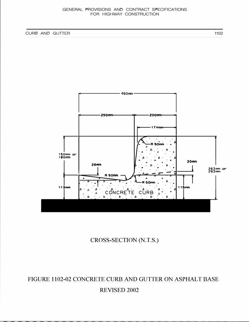
450mm
GENERAL PROVISIONS AND CONTRACT SPECIFICATIONS
FOR HIGHWAY CONSTRUCTION
1102CURB AND GUTTER
113mm
250mm 200mm
174mm
ASPHALT BASE
R
R
R
50mm
50mm
50mm
115mm
20mm
25mm
113mm
250mm 200mm
174mm
ASPHALT BASE
R
R
R
50mm
50mm
50mm
115mm
20mm
25mm
CONCRETE CURB
CROSS-SECTION (N.T.S.)
FIGURE 1102-02 CONCRETE CURB AND GUTTER ON ASPHALT BASE
150mm or
180mm
263mm or
293mm
REVISED 2002

CC
450mm
R250m
m
GENERAL PROVISIONS AND CONTRACT SPECIFICATIONS
FOR HIGHWAY CONSTRUCTION
1102CURB AND GUTTER
COMPACTED GRANULAR BASE
225mm
150mm
250mm
R 75mm
25mm
50mm
CURB REDUCTION
12mm SLOPE
COMPACTED GRANULAR BASE
225mm
150mm
250mm
R 75mm
25mm
50mm
CURB REDUCTION
12mm SLOPE
CONCRETE CURB
CROSS-SECTION (N.T.S.)
FIGURE 1102-03 SEMI-MOUNTABLE CURB AND GUTTER
REVISED 2002
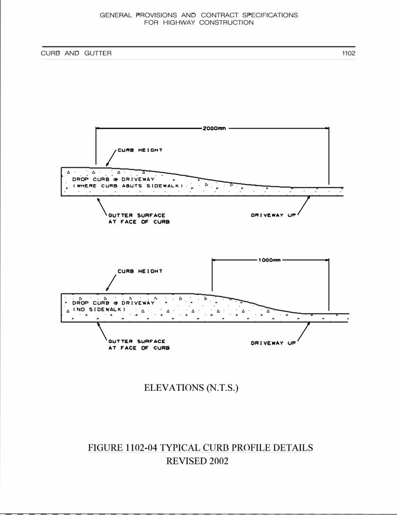
DROP CURB @ DRIVEWAY
(WHERE CURB ABUTS SIDEWALK)
DROP CURB @ DRIVEWAY
(NO SIDEWALK)
GENERAL PROVISIONS AND CONTRACT SPECIFICATIONSFOR HIGHWAY CONSTRUCTION
1102CURB AND GUTTER
2000mm
1000mm
DRIVEWAY UP
DRIVEWAY UP
CURB HEIGHT
CURB HEIGHT
GUTTER SURFACE
AT FACE OF CURB
GUTTER SURFACE
AT FACE OF CURB
2000mm
1000mm
DRIVEWAY UP
DRIVEWAY UP
CURB HEIGHT
CURB HEIGHT
GUTTER SURFACE
AT FACE OF CURB
GUTTER SURFACE
AT FACE OF CURB
ELEVATIONS (N.T.S.)
FIGURE 1102-04 TYPICAL CURB PROFILE DETAILS
REVISED 2002

GENERAL PROVISIONS AND CONTRACT SPECIFICATIONSFOR HIGHWAY CONSTRUCTION
DEPARTMENT OF TRANSPORTATION, INFRASTRUCTURE AND ENERGY
CONCRETE SIDEWALK AND FLATWORK 1103
2016.01.15 1103-1
1103.01 Description
This Section specifies requirements for constructing concrete sidewalk and flatwork ongranular base to lines, grades, dimensions and typical cross-sections indicated ordirected.
1103.02 Material
The Contractor shall supply and use only materials meeting the following standards:
Cast-in-place concrete shall be in accordance with Section 1101.
Concrete mix for cast-in-place concrete shall be designed to produce 32 MPa minimumcompressive strength at 28 days and containing 20 mm maximum size, coarse aggregate.Water cement ration by weight shall not exceed 0.45. The concrete shall have an aircontent of 5% to 8%. Class of exposure C-2.
Isolation joint filler: to ASTM D1751, 12 mm preformed, non-extruding, resilient,bituminous type.
Curing compound: to ASTM C309, , ”Ritecure” or equivalent.
Granular base under sidewalk/flatwork: Class `A` as specified in Section 401.
Wire mesh Reinforcement: 150x150 MW18.7xMW18.7 welded wire fabric which meetsthe requirements of CSA G30.5-M.
1103.03 Construction Methods
1103.03.01 Preparation and Inspection
Construction of sidewalk/flatwork shall be in accordance with Figures 1103.1 and 1103.2.
Do not place concrete until finished granular base is inspected and approved.
1103.03.02 Forming
The Contractor shall comply with the following procedure:
Concrete for sidewalk/flatwork to be shaped by wood or metal forms.
Form vertical surfaces to full depth using forming material that will not deform underloading by plastic concrete.
Securely position forms to required lines and grades.
Horizontal and vertical alignment of the forms prior to placing concrete shall not vary morethan 6 mm from the correct alignment and grade.
Coat forms with approved form release agent.
Obtain acceptance of forms before placing concrete.

GENERAL PROVISIONS AND CONTRACT SPECIFICATIONSFOR HIGHWAY CONSTRUCTION
DEPARTMENT OF TRANSPORTATION, INFRASTRUCTURE AND ENERGY
CONCRETE SIDEWALK AND FLATWORK 1103
2004.05.05 1103-2
Slip-form paving machines may be used for placing concrete sidewalk/flatwork but only inareas approved by the Engineer. The machine shall have automatic grade and linecontrol and be able to spread, vibrate, shape and finish the concrete in a single pass whileproducing a dense and homogenous concrete section.
1103.03.03 Concrete
The Contractor shall comply with the following procedure:
Do concrete and reinforcing work in accordance with Section 1101.
Finish exposed surfaces to a smooth uniform finish, free of open texturing and exposedaggregate. Do not work more mortar to surface than required. Do not use neat cementas a drier to facilitate finishing. Broom finish sidewalk/flatwork, transverse to the directionof traffic, to provide a non-skid, uniform texture.
Finish perimeter of all slabs with an edger.
Round edges, including edges of joints, with 6 mm radius edging tool.
Finish surfaces to within 6 mm in 3 metres from line, level or grade as measured with astraight edge placed on surface.
Apply curing compound to finished surfaces at a rate recommended by manufacturer.
1103.03.04 Jointing
The Contractor shall comply with the following procedure:
Control joints to be a minimum of one-quarter to a maximum of one-third of the sectionthickness.
Provide control joints within 150 mm of change in cross-section of curbs and gutters.
Saw cutting may be allowed if done as soon as concrete has set sufficiently to resistravelling and before shrinkage cracks appear.
Install joints at intervals of:
- 7.5 metres for isolation joints- 1.5 metres for transverse control joints
or as directed by the Project Engineer.
Isolation joints shall be installed around manholes and catch basins and along lengthadjacent to concrete curbs, catch basins, and permanent structures.
1103.04 Measure of Measurement
The quantity of sidewalk/flatwork for which payment will be made shall be measured insquare metres.

GENERAL PROVISIONS AND CONTRACT SPECIFICATIONSFOR HIGHWAY CONSTRUCTION
DEPARTMENT OF TRANSPORTATION, INFRASTRUCTURE AND ENERGY
CONCRETE SIDEWALK AND FLATWORK 1103
2004.05.05 1103-3
1103.05 Basis of Payment
The unit bid price for these items shall be for the number of square metres ofsidewalk/flatwork as measured by the method of measurement.
Such payment shall be full compensation for excavation and foundation preparation;supplying, transporting and placing concrete, formwork, wire mesh reinforcement,finishing, jointing and curing; surface reinstatement (unless otherwise specified); cuttingconcrete curb for wheel chair ramps and for all labour and materials necessary tocomplete the work.
Backfill behind sidewalk shall be paid for in accordance with the section for the type ofmaterial supplied.
Granular base under sidewalk/flatwork shall be paid under Section 220.

GENERAL PROVISIONS AND CONTRACT SPECIFICATIONSFOR HIGHWAY CONSTRUCTION
DEPARTMENT OF TRANSPORTATION, INFRASTRUCTURE AND ENERGY
PRECAST CONCRETE SPAN 1104
2003.03.27 1104-1
1104.01 Description
This section specifies requirements for the design, manufacture, delivery and installation ofprecast concrete spans.
1104.02 Material
Concrete shall be in compliance with CSA CAN3-A23.1 and shall have a compressivestrength of 35 MPa at 28 days.
Reinforcing steel shall either be wire fabric in compliance with CAN/CSA G30.5 - Grade 450or be high strength deformed round bars in compliance with CSA G30.12 - Grade 400.
Joint water proofing and recommended primer shall be Rub’r Nek joint waterproofing or anequivalent approved by the Engineer.
1104.03 Construction Methods
1104.03.01 Design and Manufacturing
The manufacture of precast concrete spans shall not commence until the shop drawings havebeen approved by the department and have been stamped by a Professional Engineerlicensed to practice in Prince Edward Island. Approval of shop drawings by the departmentwill not relieve the manufacturer of the responsibility for correctness of dimensions, size ofcomponents and details of fabrication in accordance with the latest editions of AASHTOStandard Specifications for Highway Bridges, CSA CANS-A23.3 Design of ConcreteStructures and CAN/CSA-S6 Design of Highway Bridges.
Curing shall conform to CSA A23.1-94. All sections should be covered for a minimum periodof three consecutive days or spread with a curing agent.
The manufacturer will be responsible for all labour laws, patents and licensing fees, dutiesand handling charges, transportation and all other charges.
The manufacturer will ensure that each section will have a quality assurance document asspecified in CSA A251. Mill certificates, concrete mix design and other Quality Assurancedocuments shall be prepared in binder format and delivered to the department on completionof the contract.
1104.03.02 Inspection
The department shall have the right to inspect the manufacture of the precast concrete spanand the authority to order production to stop if the work does not conform to plans, shopdrawings or specifications. The manufacturer shall notify the department five calender daysin advance of the commencement of any phase of manufacturing.
To ensure proper jointing of sections to a maximum of 10 mm gap when installed at the jobsite, the manufacturer shall fit a random number of three sections at the factory.
Each span and footing section shall have the lot number, date of manufacture, name ofmanufacturer and specification designation marked on them by indentation or waterproofpaint.

GENERAL PROVISIONS AND CONTRACT SPECIFICATIONSFOR HIGHWAY CONSTRUCTION
DEPARTMENT OF TRANSPORTATION, INFRASTRUCTURE AND ENERGY
PRECAST CONCRETE SPAN 1104
2003.03.27 1104-2
1104.03.03 Delivery to Site
It is the responsibility of the contractor to deliver the concrete span to the site safely and bythe time specified in the contract.
1104.03.04 Placement
It is the responsibility of the contractor to properly place the concrete span and footings to thedesign criteria indicated by the project engineer.
1104.04 Method of Measurement
Measurement for payment under this Section shall be the number of linear metres of precastconcrete span installed.
1104.05 Basis of Payment
Payment under this section shall be at the unit bid price per linear metre of precast concretespan and is to include all applicable taxes. This price shall be full compensation for all thework including, the supply and placement of footings, the supply and placement of theconcrete span, transportation, equipment, tools, labour, curing, grouting, waterproofing, joint-filling, reinforcing steel and incidentals necessary to complete the work.

GENERAL PROVISIONS AND CONTRACT SPECIFICATIONSFOR HIGHWAY CONSTRUCTION
DEPARTMENT OF TRANSPORTATION, INFRASTRUCTURE AND ENERGY
MISCELLANEOUS 1200
1201 Chain Link Fence and Gates

GENERAL PROVISIONS AND CONTRACT SPECIFICATIONSFOR HIGHWAY CONSTRUCTION
DEPARTMENT OF TRANSPORTATION, INFRASTRUCTURE AND ENERGY
CHAIN LINK FENCE AND GATES 1201
99.01.18 1201-1
1201.01 Description
This work includes the supply, transportation and erection of chain link fences and gates.
1201.02 Reference Standards
CAN/CSA-23.1 Concrete Materials and Methods of Concrete ConstructionCAN/CGSB-138.1 Fence, Chain Link, FabricCAN/CGSB-138.2 Fence, Chain Link, Framework, Zinc-Coated SteelCAN/CGSB-138.3 Fence, Chain Link, InstallationCAN/CGSB-138.4 Fence, Chain Link, GatesCAN/CGSB-1-GP-181M Organic Zinc Rich Coating
1201.03 Shop Drawings
Shop Drawings are to show details of the work and are to indicate dimensions, materials,finish, fittings and hardware, installation requirements and other pertinent information.
Check all shop drawings prior to submission. Determine and verify all field measurements,field construction criteria, materials and similar data and check and coordinate each shopdrawing with the requirements of the work. Sign and date each shop drawing to confirmcompliance with Provision 1201.02.
Submit 6 copies of the shop drawings to the Engineer for review.
Engineer will not review shop drawings if it is evident that they are not in accordance withProvision 1201.02.
After review, the Engineer will return 4 copies of shop drawings. The Contractor shall makeall corrections as noted and resubmit.
Do not proceed with work involving relevant products until completion of shop drawings.
1201.04 Material
1201.04.01 Concrete mixes and materials: to CAN/CSA-23.1. Nominal coarse aggregate size to be 20mm. Compressive strength: 20 MPa minimum at 28 days.
1201.04.02 Chain link fence fabric: to CAN/CGSB-138.1. 9 Gauge, Type 1, Class A, heavy style. Heightof Fabric: 2.4m or as indicated on the drawings.
1201.04.03 Posts, braces and rails to: CAN/CGSB-138.2, galvanized steel pipe, dimensions as follows:
Line Posts: 60mm diameter schedule 40 hot dipped galvanized tubular steel pipe.
Terminal Posts: 90mm diameter schedule 40 hot dipped galvanized tubular steel pipe, withstretching bands and bars for attaching fabric to the post. Terminal posts at double gateopenings greater than 6m in width shall be 114mm diameter.
Top Rails: 43mm diameter schedule 40 hot dipped galvanized tubular steel pipe.

GENERAL PROVISIONS AND CONTRACT SPECIFICATIONSFOR HIGHWAY CONSTRUCTION
DEPARTMENT OF TRANSPORTATION, INFRASTRUCTURE AND ENERGY
CHAIN LINK FENCE AND GATES 1201
99.01.18 1201-2
Braces: Gate, corner, straining and end posts shall be braced by a centre rail of the samematerial as the top rail, between the gate, corner or end post and the next post.
1201.04.04 Bottom tension wire: single strand, galvanized steel wire, 5 mm diameter.
1201.04.05 Tie wire fasteners: single strand, aluminum coated or galvanized steel wire conforming torequirements of fence fabric, 5 mm diameter.
1201.04.06 Tension bars: Min. (5 X 20 mm) galvanized steel.
1201.04.07 Tension bar bands: Min. (3 X 20 mm) galvanized steel or Min. (5 X 20 mm) aluminum.
1201.04.08 Gate frames: to ASTM A-53, galvanized steel pipe, standard weight 42.9 mm outsidediameter pipe for outside frame, 33.3 mm outside diameter pipe for interior bracing.
Fabricate gates as indicated with electrically welded joints and hot dipped galvanized afterwelding or paint gates with minimum 2 coats of zinc rich coating after welding.
Fasten fence fabric to gate with twisted selvage at top.
Furnish gates with galvanized malleable iron hinges, latch and latch catch with provision fora padlock which can be attached and operated from either side of installed gate.
Furnish double gates with chain hook to hold gates open, and a centre rest with a drop boltto hold gates closed.
1201.04.09 Fittings and hardware: cast aluminum alloy, galvanized steel or malleable or ductile cast iron.Post caps to provide waterproof fit, to fasten securely over posts and to carry top rail.Extension arms to provide waterproof fit, to hold top rails and an outward or inward projection,as directed and to hold barbed wire overhang. Provide projection with clips or recesses tohold 3 strands of barbed wire spaced 100 mm apart. Projection length of approximately 300mm long to project from fence at 45º above horizontal. Turnbuckles to be drop forged.
1201.04.10 Organic zinc rich coating: to CGSB 1-GP-181M.
1201.04.11 Barbed wire: 2 mm diameter galvanized steel wire to ASTM A-121, 4 point barbs, 125 mmspacing.
1201.05 Finishes
Galvanizing for chain link fabric: to CAN/CGSB-138.1 Grade 2.Galvanizing for pipe: 550 g/m2 minimum to ASTM A-90.
Galvanizing for barbed wire: to ASTM A-121, Class 2.
Galvanizing for other fittings: to CSA G164.
1201.06 Construction Method
1201.06.01 Grading

GENERAL PROVISIONS AND CONTRACT SPECIFICATIONSFOR HIGHWAY CONSTRUCTION
DEPARTMENT OF TRANSPORTATION, INFRASTRUCTURE AND ENERGY
CHAIN LINK FENCE AND GATES 1201
99.01.18 1201-3
Remove debris and correct ground undulations along fence line to obtain smooth uniformgradient between posts. Provide a clearance between bottom of fence and ground surfaceno more than 75 mm.
1201.06.02 Erection of Fence
Erect fence along lines as directed by Engineer and in accordance with CAN/CGSB-138.3
Excavate post holes to 1500 mm depth x 300mm diameter or to dimensions as indicated bymethods approved by Engineer.
Space line posts 2.4m apart as measured parallel to the ground surface or to spacing asindicated.
Space straining posts at equal intervals not exceeding 150 m if distance between end orcorner posts on straight continuous lengths of fence, over reasonably smooth grade, isgreater than 150 m.
Install additional straining posts at sharp changes in grade and where directed by Engineer.
Install corner post where change in alignment exceeds 10º.
Install end posts at end of fence and at buildings. Install gate posts on both sides of gateopenings.
Place concrete in post holes then embed posts in concrete to depths as indicated on theDrawings. Extend concrete 50 mm above ground level and slope it to drain away from theposts. Brace to hold posts in plumb position, true to alignment and elevation until concretehas set.
Do not install fence fabric until concrete has cured a minimum of 5 days.
Install brace between end and gate posts and nearest line post, place in centre of panel andparallel to ground surface. Install braces on both sides of corner and straining posts in similarmanner as required.
Install overhang tops and caps.
Install top rail between posts and fasten securely to terminal posts and secure waterproofcaps and overhang tops.
Install bottom tension wire, stretch tightly and fasten securely to end, corner, gate andstraining posts with turnbuckles and tension bar bands.
Lay out fence fabric. Stretch tightly to tension recommended by manufacturer and fasten toend, corner, gate and straining posts with the tension bar secured to post and with tensionbar bands spaced at 300 mm intervals. Knuckled selvedge at bottom. Twisted selvedge attop.
Secure fabric to top rails, line posts and bottom tension wire with tie wires at 450 mmintervals. Give tie wires two twists.
Install barbed wire strands and clip securely to lugs of each bracket.

GENERAL PROVISIONS AND CONTRACT SPECIFICATIONSFOR HIGHWAY CONSTRUCTION
DEPARTMENT OF TRANSPORTATION, INFRASTRUCTURE AND ENERGY
CHAIN LINK FENCE AND GATES 1201
99.01.18 1201-4
1201.06.03 Installation of Gates
Install gates in locations where directed by Engineer.
Level contours between gate posts and set gate bottom approximately 40 mm above groundsurface.
Determine position of centre gate rest for double gate. Cast gate rest in concrete as directed.Dome concrete above ground level to shed water.
Install gate stops where directed.
1201.06.04 Touch-up
Clean damaged surfaces with wire brush removing loose and cracked coatings. Apply 2coats of organic zinc-rich paint to damaged areas. Pre-treat damaged surfaces according tomanufacturers' instructions for zinc-rich paint.
1201.06.05 Cleaning
Clean and trim areas disturbed by operations. Dispose of surplus material and reinstatedisturbed surfaces as directed by Engineer.
1201.07 Method of Measurement
Measurement for payment under this Section shall be the number of linear metres of chainlink fence including gates installed.
1201.08 Basis of Payment
Payment shall be at the unit bid price per linear metre and this price shall be fullcompensation for supply, transportation, handling, storage and all labour, tools and materialsnecessary to complete the work.

GENERAL PROVISIONS AND CONTRACT SPECIFICATIONSFOR HIGHWAY CONSTRUCTION
DEPARTMENT OF TRANSPORTATION, INFRASTRUCTURE AND ENERGY
SUPPLEMENTAL SPECIFICATIONS 1300
19.01.14 1
Appendix 1- Tender Document
Appendix 2- Environment Workplace Traffic Control Manual
Appendix 3- Temporary Workplace Traffic Control Manual
Appendix 4- Weight Scale Procedures

DEPARTMENT OF TRANSPORTATION, INFRASTRUCTURE AND ENERGYProvince of Prince Edward Island
TENDER FORM AND AGREEMENTRevision 0
THIS AGREEMENT made by and between ..............................................., herein called the Contractor, theParty of the First Part and The Government of Prince Edward Island as represented by the Honourable PaulaJ. Biggar, herein called the Minister, the Party of the Second Part.
WITNESS, AS FOLLOWS:
1. Definitions
The definition of terms used in this Tender Form and Agreement shall conform in all respects to thedefinition of terms contained in the document entitled "General Provisions and Contract Specificationsfor Highway Construction," published by the Department of Transportation, Infrastructure and Energyof the Province of Prince Edward Island as amended on the date of closing of Tenders pursuant tothis Agreement.
2. General Covenant
The Contractor hereby covenants and agrees with the Minister as herein provided in connection withthe following work, namely:
For a distance of
The work includes:
TENDER CLOSES:

Page 2Rev. 0
3. No Implied Contract
It is hereby understood and agreed between the parties hereto that no implied Contract of any kindwhatsoever, by, or on behalf, of the Minister shall arise or be implied from anything contained in thisContract, or from any position or situation of the parties at any time, and that this Contract made bythe Minister is, and shall be, the only Contract upon which any rights against the Minister are to befounded.
4. How Party of the First Part is Read
Whenever this Contract is entered into by more than one party or parties of the first part, the word"Contractor" shall be read "Contractors," and pronouns in the Contract referring to the Contractorsshall be read as plural and whenever a corporation is the Party of the First Part, the said pronounsshall be read accordingly.
5. Consideration of Clauses as Covenants
Wherever it is stipulated that anything shall be done or performed by either of the Parties hereto, itshall have the same effect and be constructed as if such Party had entered into a covenant with theother Party to do or perform the same, and as if such covenant had been expressly made on the partof the Contractor, not only on the Contractor's own behalf, but also on the behalf of the Contractor'slegal representative, successors or assigns; and as if any such covenant on the part of the Ministerhas been made on behalf of the Minister, and the Minister's successors in office.
6. Contractors Submission Respecting the Agreement
The Contractor shall, as part of the Contractor's submission respecting this Contract, complete theattached Schedule B, Identification of Principles; Schedule C, Schedule of Tendered Unit Prices;Schedule D, Schedule of Equipment to be used on the work; and Schedule E, Schedule of Sub-Contractors.
The Contract including all appended schedules shall be completed in complete conformity with theinstructions to bidders contained in the document entitled "General Provisions and ContractSpecification for Highway Construction".
In presenting the Contractor’s submission for consideration by the Minister, the Contractorunderstands that until, and unless, the Contract is endorsed by the Minister, no Contract between theparties shall exist and the Minister shall not be bound to endorse any Contract.
7. Performance by Contractor
The Contractor, at the Contractor's own expense, shall, except as herein otherwise specificallyprovided, furnish and provide all and every kind of labour and superintendence, services, tools,implements, machinery, plant materials, articles and whatsoever is necessary for the due executionof the work. The Contractor shall fully construct and erect the work in the most thorough, professionaland substantial manner, in every respect to the satisfaction and approval of the Engineer. TheContractor shall complete the work within the time specified herein and deliver it to the Minister in themanner and upon the terms and conditions of the Contract.

Page 3Rev. 0
8. Bid and Performance Security
The Contractor hereby and herewith deposits with and delivers to the Minister, as security of the duefulfilment of the Contract, one of the following, which shall remain in effect for a minimum of 30 daysafter tender closing:
a) a certified cheque in the amount stipulated in Schedule A - Schedule of Special Provisions.
OR
b) a bank draft in the amount stipulated in Schedule A - Schedule of Special Provisions.
OR
c) a bid format irrevocable standby letter of credit on a government approved form in theamount stipulated in Schedule A - Schedule of Special Provisions.
OR
d) a bid bond in the amount stipulated in Schedule A - Schedule of Special Provisions. Thebond shall be from a surety company authorized to carry on business in Canadaguaranteeing to supply a performance bond equal to 50% of the Contract value, excludingHST and a labour and material bond equal to 25% of the Contract value, excluding HST.
Performance security must be filed with the Department before work on the project commences. Thissecurity shall be held and retained by the Minister for the due and faithful performance, observanceand fulfilment by the Contractor of all the covenants, provisos, agreements, conditions andreservations in this Contract contained on the part of the Contractors to be observed, performed andcomplied with shall be in the form of:
e) a certified cheque in the minimum amount of ten percent (10%) of the Contract value,excluding HST, which shall be retained until the warranty period (one (1) year aftersubstantial completion) has elapsed.
OR
f) a bank draft in the minimum amount of ten percent (10%) of the Contract value, excludingHST, which shall be retained until the warranty period (one (1) year substantialcompletion) has elapsed.
OR
g) a performance format irrevocable standby letter of credit on a government approved formin the minimum amount of ten percent ( 10% ) of the Contract value, excluding HST,which shall be retained until the warranty period (one (1) year after substantialcompletion) has elapsed.
OR
h) a performance bond equal to 50% of the Contract value, excluding HST and a labour andmaterials bond equal to 25% of the Contract value, excluding HST both of which shall beretained until the warranty period (one (1) year after substantial completion) has elapsed.

Page 4Rev. 0
8. Bid and Performance Security (continued)
All performance security which has an expiry date which precedes the end of warranty date must berenewed prior to the time that the security would expire. The bidder will forfeit security to the Ministerif the bidder fails to enter into or carry out the Contract when called upon to do so.
It is understood and agreed that the Contractor assumes risk and must bear any loss in respect to theperformance security as aforesaid, occasioned by the failure or insolvency of the banks on which anycheque was drawn or in which any deposit was made in connection with the security aforesaid.
If at any time hereafter the said Contractor should make default under the said Contract, or if theMinister acting under the powers reserved in the said Contract shall determine that the said works,or any portion thereof remaining to be done, should be taken out of the hands of the Contractor andbe completed in any manner or way whatsoever than by the Contractor, or if the Contractor refusesor neglects to pay for work done or materials supplied by any person in connection with the said work,the Minister may, in either case dispose of said security for the carrying out of the construction andcompletion of the work of the Contract or for paying any salaries or wages for work done, or anyaccounts for materials supplied for the said works that may be left unpaid by the said Contractor.
In the event of any breach, default or non-performance being made or suffered by the Contractor inor in respect of any of the terms and conditions, covenants, provisions, agreements, or restrictionsherein contained, which on the part of the said Contractor should be observed, performed or compliedwith, the said security so delivered to or deposited with the Minister or by the Minister received inrespect thereof, shall by the Contractor, be forfeited absolutely to the Minister.
Upon the due and faithful performance, observance and fulfilment by the Contractor of all the terms,provisions, covenants, agreements, conditions, reservations, hereinbefore contained, on the part ofthe Contractor to be observed, performed and complied with, the Minister shall surrender theperformance security.
9. Minister Covenants to Pay
In consideration of the faithful performance by the Contractor of all and singular covenants,agreements and provisions of the Contract, the Minister hereby covenants and agrees with theContractor that, on the full completion by the Contractor of all the work as specified in the Contract,within the time specified and limited for the final completion thereof, and to the entire satisfaction ofthe Engineer to be evidenced by the certificate of the Engineer in writing, the said Minister will welland truly pay, or cause to be paid, to the said Contractor the amount of the Contract price,representing the actual quantities in the several items in the Schedule of Prices, identified asSchedule C to this Contract, at the unit prices or lump sum prices quoted by the Contractor. Thisamount paid to the Contractor as above, shall include all and every kind of work, labour,superintendence, services, tools, implements, machinery, plant materials, articles and thingswhatsoever necessary for the full execution and completion of the work to the entire satisfaction ofthe Engineer.
10. Final Payment
It is hereby agreed by the parties hereto that the payment of the final amount due under the Contract,and the adjustment and payment of any bills that may be rendered for work done, in accordance withany alteration in or addition to the same, shall release the Minister from any and all claims or liabilityon account of work performed under the said Contract or any alteration in or addition to the same.

Page 5Rev. 0
11. No Waiver
It is hereby agreed that no condoning, excusing, or overlooking by the Minister, or any person actingon the Minister's behalf on previous occasions of breaches or defaults similar to that for which anyaction is taken or power is exercised, or forfeiture is claimed or enforced against the Contractor, shallbe taken as a waiver of any provisions of the Contract, or as defeating, affecting or prejudicing in anyway the right of the Minister under the Contract.
12. Components of the Contract
Any and all plans or drawings prepared by the Department, the document titled “General Provisionsand Contract Specifications for Highway Construction”, the advertisement, the Tender Form andAgreement together with Schedule A, Schedule of Special Provisions; Schedule B, Identification ofPrincipals; Schedule C, Schedule of Tendered Unit Prices; Schedule D, Schedule of Equipment; andSchedule E, Schedule of Sub-Contractors, as well as any addenda which may be issued by theDepartment pursuant to this Contract shall hereby be a part of this Contract as fully and to the sameeffect as if the same had been set forth at length in the body of the Contract.
13. Completion of Work
The Contractor agrees to complete the work on, or before date/month/year.
14. FOIPP Clause
1. By submitting your bid, you agree to disclosure of the information supplied, subject to theprovisions of the Freedom of Information and Protection of Privacy Act (FOIPP).
2. Anything submitted in your bid that you consider to be "confidential information" because ofits proprietary nature should be marked as "confidential" and will be subject to appropriateconsideration under the Freedom of Information and Protection of Privacy Act.
3. During the delivery and installation of goods and/or services, you may have access toconfidential or personal information. Should this occur, you must ensure that suchinformation is not released to any third party or unauthorized individual.
4. Any information provided on this Contract may be subject to release under the Freedom ofInformation and Protection of Privacy Act. You will be consulted prior to the release of anyinformation.

Page 6Rev. 0
IN WITNESS WHEREOF the parties hereto have hereby caused these presents to be signed and sealedon the dates stated.
SIGNED, SEALED AND DELIVERED SIGNED, SEALED AND DELIVEREDby the Contractor on the [ ] day by the Minister on the [ ] dayof [ ], 20[ ]. of [ ], 20[ ].
.................................................................. .................................................................CONTRACTOR MINISTER
In the presence of: In the presence of:
................................................................. ..................................................................

Page 7Rev. 0
SCHEDULE ASCHEDULE OF SPECIAL PROVISIONS

Page 8Rev. 0
SCHEDULE BIDENTIFICATION OF PRINCIPALS
Name of Contractor:
Mailing Address:
Telephone:
Fax:
Principal's Name:
Title:
Mailing Address:
If Contractor is a corporation in which province of Canada is the corporation registered:
_________________________________________________________________________________

Page 9Rev. 0
SCHEDULE C SCHEDULE OF PRICES

Page 10Rev. 0
SCHEDULE DSCHEDULE OF EQUIPMENT TO BE USED ON THE WORK

Page 11Rev. 0
SCHEDULE ESCHEDULE OF SUB-CONTRACTORS
2012.02.09 A2-1
APPENDIX 2
ENVIRONMENTAL REQUIREMENTS
Department of Transportation, Infrastructure and Energy Province of Prince Edward Island
- Environmental Management Section -

2012.02.09 A2-2
ENVIRONMENTAL REQUIREMENTS TABLE of CONTENTS
1. Description
2. Conditions of Approval
3. Compliance and Delays
4. Prevention of the Transportation / Introduction of Invasive Species
5. Pollution Control
6. Water and Runoff Control
7. Release of Fuel and Other Hazardous Substances
8. Accidental Events and Environmental Emergencies

2012.02.09 A2-3
ENVIRONMENTAL REQUIREMENTS
1. DESCRIPTION
1. The Contractor shall carry out the work on the Contract according to the Plans and Specifications and in such a manner so as to be in compliance with various Acts and Regulations of the Province of Prince Edward Island and/or the Government of Canada which concerns the protection of the environment, and any approvals or permits issued to the Owner or the Contractor in accordance therewith.
2. The installation of environmental controls shall be coordinated with the County
Environmental Officer and the Engineer. Environmental protection measures shall be installed whenever possible prior to the commencement of the work.
If not possible to provide the environmental protection prior to the commencement of the work, the Contractor shall, as a minimum, have all materials required for the environmental protection available on site prior to the commencement of any work and shall install the environmental measures as soon as practical in the work progression.
3. If, during the work, any suspected artifacts of historical or archaeological value are
uncovered or any endangered plant or animal species or any contaminated soil(s) is identified, the Contractor shall cease work until the site has been reviewed by representatives of the appropriate agencies and the Engineer has approved resumption of the work.
4. The Contractor shall follow sound environmental construction practices. Guidance in this
practice to the application of his work shall be derived from, but not limited exclusively to, the following documents:
< Division 800 of the Specifications Manual - Environment
< Environmental Requirements, Appendix 2.
< P.E.I. TIE’s Environmental Protection Plan
2. CONDITIONS OF APPROVAL
1. The Contractor shall complete the work in accordance with the following conditions:
< All sediment and erosion control measures shall be carried out as detailed on the Plans and as included in the Specifications.
< Measures determined by the appropriate regulatory authorities (i.e. Provincial
Environment Department, Fisheries and Oceans Canada, etc) as necessary for the protection of watercourses/wetlands affected directly or indirectly by the Work.
< Conditions outlined in the associated Approval-to-Proceed issued by TIE’s
Environmental Management Section.

2012.02.09 A2-4
2. Any debris and excavated material within the work area shall be removed from the watercourse and adjacent areas for disposal or placement in a manner such that it cannot be returned to the watercourse.
< Removal of debris, whether natural or left behind by others, will be measured for
payment in accordance with provision 103.03, Extra Work. < Removal and disposal of excavated material will be measured for payment under
the appropriate excavation item(s).
3. All necessary precautions shall be taken by the Contractor to prevent discharge or loss of any harmful material into a watercourse including, but not limited to, creosote, fuels, hydrocarbons, biocides, fertilizers, cement, lime, paint or fresh concrete.
4. No work, including but not limited to grubbing, excavation, embankment construction or
installation of drainage structures shall take place within 30m of a watercourse or wetland without an EMS Approval to Proceed. < The installation and maintenance of these structures shall be in accordance with
Section 800.
5. In dewatering an excavation, whether a roadway cut, foundation excavation, a pit or a quarry, the Contractor shall ensure that any turbid water pumped out or released is released into either: a) a grassed riparian area a minimum of 15m outside any watercourse or wetland area, or, b) a collection area created for the purpose of filtering sediment-laden water. The area where the pumped water will be released must be approved by the County Environmental Officer and may require additional sediment/erosion controls.
< It shall be the Contractor’s responsibility to install and maintain, at his cost, to the
satisfaction of the Provincial Environment Department, any erosion control measures for pits and quarries that may be required, and to obtain permission to pump or release any turbid water onto properties abutting and beyond.
< The Contractor shall be responsible at his cost for any and all damage resulting
from the dewatering.
6. Slopes for soil fill materials over natural watercourses shall be stabilized immediately upon completion of culvert installation or, as a minimum, at the end of each days’ embankment construction as follows:
< Random R5 riprap or larger shall be placed to a 300 mm depth over geotechnical
fabric from toe of slope to a minimum of 1 m above the top of the culvert (pipe or box). This riprap apron shall extend to a minimum of 3 m on either side of the culvert, and shall be wider at the Engineer’s discretion.
< To a minimum distance of 10 m on either side of the culvert ( pipe or box), the
remaining disturbed fill slope areas (not riprapped) shall be mulched from toe of slope to top of slope. This includes the slope area above the riprap to the top of the slope. At the discretion of the Engineer, slopes with larger erosion potential shall have the mulch covered by jute mat or replaced by straw blanket.
< All mulch and erosion control mats shall be removed from slopes prior to final
grading and seeding. After slopes have been graded to the satisfaction of the Engineer, and the disturbed areas have been hydro seeded, then all areas shall be

2012.02.09 A2-5
re-mulched and any erosion control mats shall be re-installed.
7. The Contractor shall not place an earth or rock causeway in the watercourse for the purposes of creating a temporary access structure without specific approval of the Engineer and the appropriate regulatory authority(ies), in writing.
8. All in-stream work shall be carried out between June 1 and September 30, or as
otherwise directed in the permit(s). The Contractor shall notify the Engineer, in writing, at least seven days in advance of the anticipated date of commencement of in-stream work.
< Watercourse culvert installation guidelines must be followed
< In-stream work shall be kept to a minimum by either: installing the pipe in-the-dry
and diverting the flow into it upon completion; by constructing a temporary plastic- lined diversion channel in-the-dry; and/or by pumping the stream flow around the work area.
< If it is necessary to isolate the stream from the work area, the Contractor shall
construct cofferdams consisting of sandbags wrapped in 6mm plastic.
< The Engineer, upon receiving notice from the Contractor as to when construction shall actually commence, will arrange an on-site meeting with representatives from each of the Department’s Environment Section, Provincial Environment Department, Fisheries and Oceans Canada, and the Contractor, prior to commencement of the in-stream work.
< No in-stream work shall commence until the Engineer verifies with the regulatory
agencies having jurisdiction, that the work site is approved for the commencement of in-stream work.
9. Erosion control measures shall be as detailed in the Contract Documents and, if
additional measures are required in addition to those indicated, the Engineer shall order and approve such work under the appropriate items.
10. Any natural materials produced and/or supplied by excavation either from pits and/or
quarries shall not contain any friable, soluble or reactive minerals or other deleterious materials or conditions that would make the material prone to decomposition or disintegration, or present any environmental hazard, from the presence of the parent material or its by-products, when exposed to the natural elements after placement in the work.
11. Additional conditions of approval, as specified in environmental permit(s) issued to the
Owner for the work, and/or as detailed in the Contract Documents, shall be carried out by the Contractor.
3. COMPLIANCE AND DELAYS
1. For each maintenance or construction project, a project assessment/registration application must be submitted by the proponent (typically the project manager or supervisor representing PEITIE) to the Environmental Management Section for review and approval. Once the project application is received, the Environmental Management

2012.02.09 A2-6
Section will coordinate all aspects of its review and assessment, issuance of associated permits and approvals from the Section or other regulatory agencies.
2. The proponent is responsible to ensure that all project-related permits and approvals are
posted in a visible location at the project work area at all times.
3. Failure by the Contractor to carry out the work in accordance with the requirements of this Section will result in the Contractor being liable for any fines, levies, or penalties made under environment-related Acts or Regulations of the Province of Prince Edward Island and the Government of Canada.
4. The Engineer will be responsible for the day to day field monitoring and for ensuring that
the specifications are implemented by the Contractor. TIE’s Environmental Management Section shall assist to ensure that all environmental protection measures which are part of the Contract are adhered to by the Contractor.
5. The Department will have Environment Officers who will act as a liaison between the
Department and other Provincial and Federal regulatory bodies responsible for environmental protection. The Environment Officer will also liaise with the Engineer and assist in ensuring that environmental compliance is being enforced.
6. The Department’s Environment Officers shall make recommendations to remedy
insufficient environmental protection measures on projects. The Environmental Management Section (Manager or Environmental Coordinator) may coordinate, with the Engineer, to have the project work suspended until the Contractor remedies the environmental protection measures as per the specifications in the Department’s General Provisions and Contract Specifications for Highway Construction, the TIE Environmental Protection Plan and all regulatory permits and approvals.
7. In circumstances where the insufficient environmental protection poses no immediate
threat to the environment, the Contractor shall implement the necessary remedies to the satisfaction of the Department within a specified timeframe.
8. In circumstances where insufficient environmental protection, ongoing work activities, or
site conditions do pose an immediate threat to the environment, either the project work can be suspended immediately, or immediate action by the Contractor to remedy the situation can be ordered, whichever is appropriate, as per Section 3.6.
9. Any delays to the Contractor’s work operation resulting from suspension of work for failure
to follow the requirements of this Section will not be considered as a basis of claim for extra costs, nor for any extension of the contract completion date.
4. PREVENTION OF THE TRANSPORTATION / INTRODUCTION OF INVASIVE SPECIES
1. Environmental Concerns
Waters of Atlantic Canada are experiencing the effects of invasive aquatic plant and animal species from around the world. Once these non-native or invasive species have established themselves in a new ecosystem (absent of their natural predators) they can harm native species, possibly causing entire ecosystems to be disrupted due to habitat destruction or food chain alteration (i.e. preying on native species, transmitting disease, etc.).

2012.02.09 A2-7
The principal invasive species in the Gulf of St. Lawrence and the Canadian Atlantic coast are Tunicates (Styela clava), Green Crab (Carcinus maenas) and Green Alga's (i.e. Oyster Thief (Codium fragile tomentosoides)). Up to date information on the present distribution of these species in the Northumberland Strait can be obtained by calling the Habitat Management Branch of Fisheries and Oceans Canada at (902) 863-5670. Information on the Gulf of St. Lawrence can also be found at www.glf.dfo-mpo.gc.ca and for the Canadian Atlantic coasts at www.northeastANS.org.
2. Pathways
Non-native and invasive species may be unintentionally introduced into a marine environment via various marine construction and improvement projects. These species have the potential to alter the native ecosystems and have negative impacts on the commercial fishing and aquaculture industries. Potential pathways for spreading these species include, but are not limited to, the following:
< Species or their water borne larva travelling in bilge and ballast water of various
marine construction equipment (i.e., barges, scows, etc.).
< Marine sediments remaining in excavation equipment, barges or trucks.
< Species being attached to or carried in the bottom/hull of various boats or barges.
3. Environmental Protection Procedures
The following protection procedures are intended to reduce the potential risk of transporting and introducing invasive marine/terrestrial species:
< All dredging equipment including excavators/cranes, floating plant, scows,
barges and work boats are to be free of all marine growth prior to mobilization to the site.
< The Contractor will make all equipment available for inspection by regulatory
authorities (i.e. Provincial Environment Department, Federal Department of Environment and the Habitat Management Branch of Fisheries and Oceans Canada, or other agencies) if requested. Any growth identified is to be completely removed from the equipment in an environmentally acceptable manner and using methods approved by the regulatory authority.
< The Contractor is to coordinate removal and cleaning operations to ensure they
abide by all requirements of the Provincial Environment Department, Federal Department of Environment, the Habitat Management Branch of Fisheries and Oceans Canada and any other applicable agencies.
< The Contractor shall ensure that all costs associated with the requirements of
this section are included in the bid price.
4. The Contractor is required to:
< Be familiar with Invasive Species Management Plans, Codes of Practice, or other documents that relate to the control and spread of aquatic invasive species, and acquire any special regulatory permits or approvals associated

2012.02.09 A2-8
with the use of their equipment in or near a marine environment, other than the typical permits and approvals acquired by the Department or proponent to conduct the work.
< Produce independent documentation (eg. Divers inspection reports and video
of inspection, etc. of boats, barges or scows) as to when and how they had conducted the above mentioned mitigation measures, at the request of the Department or a regulatory agency, at any time.
5. POLLUTION CONTROL
1. The Contractor shall not dump, spill or dispose of any overburden, trees, brush,
petroleum products, or other debris into any watercourse, or other natural water basin, or into any area which may ultimately cause pollution to water drainage or storage systems and/or ground water.
2. It shall be the Contractor’s responsibility to familiarize himself with the applicable
legislation and regulations and to obtain all necessary permits and approvals for his operations.
6. WATER AND RUNOFF CONTROL
1. The Contractor shall perform his work in a manner so as to not obstruct the flow of
surface drainage or natural watercourses.
2. The Contractor shall direct or discharge water resulting from the work in a manner not detrimental to public and private property, or any portion of the work completed or under construction.
7. RELEASE OF FUEL AND OTHER HAZARDOUS SUBSTANCES
1. The Contractor, including any subcontractors and/or any agent(s) of the Contractor
involved in any aspect of the Contract, shall be responsible for all containment and cleanup of any release of fuel and/or other hazardous materials, regardless of the cause of the release. All fuel, lubricants, or other toxic chemicals shall be stored a minimum of 30m from a watercourse or wetland. A two-man system for proper refueling of equipment when within 30metres of a watercourse or wetland area must be in place.
2. This Section shall include the work site, all lands being used by the Contractor and under the
control of the Owner, and/or any Crown Land being utilized for the work under the Contract.
8. ACCIDENTAL EVENTS AND ENVIRONMENTAL EMERGENCIES
1. Response Procedures for Accidental Events - Contingency plans and response procedures to be followed for unplanned environmental events are provided in the TIE Environmental Protection Plan, Section 9.0 Contingency Plans for Unplanned Events.
2. Key Contact List - Key organizations and/or individuals that may be contacted (a) during
environmental emergency situations, or (b) to assist with routine environmental issues are provided in the TIE Environmental Protection Plan, Section 10.0 Key Contact List. In general, the person managing the work, should:

2012.02.09 A2-9
< For an environmental emergency, directly contact Emergency Response Personnel using the names and numbers provided.
< For routine, or non-emergency issues, contact Provincial Personnel using the names
and numbers provided.
9. Watercourse Culvert Installation Guidelines (full guidelines available at http://www.gov.pe.ca/photos/original/eef_wet_alter_3.pdf)
1. A pre-construction stream survey must be completed prior to watercourse culvert
replacements or new installations. This survey must include the following information: ‚ (a) first upstream (of existing structure or planned structure location) riffle elevation ‚ (b) first downstream (of existing structure or planned structure location) riffle
elevation ‚ (c) inlet bottom (top of rib/lip/edge) of culvert elevation ‚ (d) outlet bottom (top of rib/lip/edge ) of culvert elevation ‚ (e) stream length - A to B ‚ (f) culvert length - C to D ‚ (g) calculation of stream slope ‚ (h) calculation of culvert slope Ensure that a representative of the Environmental Management Section is on site during the pre-construction survey.
2. Watercourse culvert installations may only take place during the period of June 1 to
September 30 of any given year and only if an EMS Approval to Proceed has been issued.
3. Watercourse culvert maximum length (under low-risk guidelines, and EMS Approval to Proceed) is 20 metres, unless otherwise approved in consultation with PEI Department of Communities, Land and Environment and the Department of Fisheries and Oceans.
4. Culvert must be embedded a minimum of 20% of its’ diameter (.2D).
5. Surveyor must be onsite during culvert replacement or installation.
6. Stream must be isolated during replacement or installation through use of a coffer dam ( not
longer than 8 hrs) and/or cofferdam combined with pumping water through, around, or over the work area.
7. Culvert must be installed at a slope not greater than .5%.
8. Culvert diameter must not exceed 48"/4 ft under the low-risk guideline and EMS Approval to
Proceed, unless otherwise approved in consultation with PEI Department of Communities, Land and Environment and the Department of Fisheries and Oceans.
9. A post construction culvert survey must be completed upon completion of the
replacement/installation.


