department of transportation united … documents/5p/5ps... · 2017-07-13 · of common hull form...
TRANSCRIPT

DEPARTMENT OF TRANSPORTATIONUNITED STATES COAST GUARD
U.S. Coast Guard (G-MMT-4)Washington, DC 20593(202) 426-2197
NVIC 11-809 Oct 1980
NAVIGATION AND VESSEL INSPECTION CIRCULAR NO. 11-80
Subj: .Structural Plan Review Guidelines for Aluminum Small Passenger Vessel
1. PURPOSE. The attached guidelines for structural plan review of small passenger vessels(Subchapter T) constructed of aluminum are intended to facilitate plan review of such vessels bythe local Officer in Charge, Marine Inspection (OCMI), without having to refer the plans to aCoast Guard Merchant Marine Technical (mmt) Branch for review. The guidelines are applicableto hull forms similar to those of commercial crewboats used primarily in the oil exploitationindustry. Such boats have deep-Vee hull forms, lengths from 60 to 135 feet, and speeds up to about24 knots. Boats meeting the guidelines are structurally satisfactory for full Ocean Serviceapplications.
2. DISCUSSION.
a. The standards specified in Subpart 177.10 of Title 46, Code of Federal Regulations, forsmall passenger vessels envisioned a fairly simple process for structural plan review. Formany years the experience of the local OCMI and the few structural standards andguidelines that were available to him were sufficient for most structural approval purposes.
b. The industrial crewboat industry in this country began and has flourished over the pastthree decades primarily within the local boundaries of the New Orleans Marine InspectionZone. The evolution of the modern crewboat was gradual, and the knowledge andexperience of the local OCMI was sufficient for most routine plan approval of aluminumcrewboats and similar small passenger vessels. In recent years, however, the structuraldesigns have become more sophisticated, and the boats are being built elsewhere aroundthe country. The absence of published standards has forced the OCMI’s to forward plansto District mmt branches for formal structural analysis and review. This has increasedboth the plan review workload and the turn around time for plans. The lack of establishedstructural standards for these boats has been a problem in mmt as well.
c. There have been a number of technical papers the subject within the last 10 years, andvarious organizations are presently working on guidelines or standards that my eventuallybe applied to these boats. The similarity of hull forms and operational service of crewboatsmakes possible general guidelines that are applicable to most of these vessels. The planreview guidance which is attached will be used by the Coast Guard for structural planreview and approval of applicable aluminum boats until other acceptable guidance orstandards are available.

NAVIGATION AND VESSEL INSPECTION CIRCULAR NO. 11-80
2
3. ACTION. Enclosure (1) contains guidelines based on satisfactory historical experience, and itshould be used in structural plan review of small passenger vessels which meet the applicabilityparameters stated within. Vessels which do not meet the applicability parameters should bereviewed by other means or referred to a Merchant Marine Technical Branch for review. Theseguidelines are not mandatory on the designer, and any other acceptable structural standards such asLloyd's Rules or American Bureau of Shipping Rules may be used as appropriate.
End: (1) Aluminum Small Passenger Vessel Structure Review Guide NON-STANDARD DISTRIBUTION:
Ce: Baltimore (75); San Francisco, Mobile, Guam, Pittsburgh, Providence, Norfolk (50); Galveston(30); Cleveland, Portland, OR, Sturgeon Bay (25); San Diego, Savannah, Buffalo, Corpus Christi(20); Tampa, Milwaukee, Louisville, Detroit, Toledo, Nashville, Anchorage (15); Portland, ME,Duluth, Charleston, Huntington, Minneapolis-St Paul (Dubuque), San Juan (10); Juneau,Cincinnati, Memphis, Wilmington, Paducah, Albany (5) extra
Cm: New Orleans (250); New York (200); Seattle (100); Houston (50); Terminal Is. (LA-LB),Philadelphia (40) extra
Em: Morgan City (200); New London, Houma (30); Ludington (8) extra Ketchikan, Lake Charles (5)extra

Enclosure (1) to NVIC 11-80
3
Aluminum Small Passenger Vessel Structure Review Guide
Purpose - This guide is intended to facilitate structural plan review of an aluminum small passenger vesselof common hull form and whose design is based on the commercial crewboat used in the offshore oilindustry. There is a wealth of successful operational experience with such boats, but the designs are fairlycomplex and not based on a standard set of rules. This guide will enable a person with limited engineeringbackground to quickly check a design for minimum structural adequacy. Designs of unusual form orapplication should be reviewed by Merchant Marine Technical personnel. Values given in this guide areaverage minimums based on hull forms and structural arrangements typical of Gulf of Mexico industrialcrewboats built between 1975 and 1980. This guide should not be used for designing the structure of aboat. The minimum scantlings shown herein are to be used as a general indication of the adequacy of' astructural component. There are many other factors involved in the proper design of' a boat which are notconsidered here, such as serviceability, special operating requirements, and construction practices.
Applicability - A large sampling of aluminum crewboat plans from the files of Commander, Eighth CoastGuard District (mmt) indicated a fairly narrow range for design parameters. The tables and figures in thisguide are based on those existing vessels and are generally applicable within the following ranges:
Length (L) 60 ft to 135 ft (See 46 CFR 75.10-19)Speed 16 kts to 24 ktsBeam 6 ft + .15L ("10%)Deadrise 13 to 20 degreesLCG Midships to 8% of length aft of midshipsDisplacement generally within range of Figure 3Vee hull form approximately as shown in Figure 5
The term "crewboat" is used in this guide to refer to any aluminum vessel lying within the above ranges of'parameters.
Summary - The remainder of this guide is organized into the following headings:
Hull Strength - A discussion of the various components that make up a structure, their individualfunctions, and how each is evaluated for structural adequacy.
Hull Loads - How the various loads acting on structural components are evaluated.
Material Properties - A discussion of maximum allowable stress for various structural components.
Evaluation of Structure - A step-by-step procedure for evaluating the adequacy of' structuralcomponents.
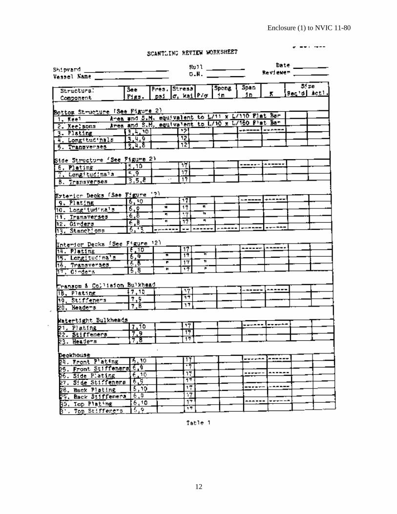
Scantling Review Worksheet - A recommended form to use during the structural evaluation.
References - A selected list of reference material used in developing this guide.
Figures - Sketches and graphs to be used during the structural review.
Tables of Section Modulus of various shapes attached to plating (Appendix A).
Worked Example of a Structural Review (Appendix B).

Enclosure (1) to NVIC 11-80
4
Hull Strength - The structure of a boat is essentially an arrangement of plating and framing. Figure 1 is anexample of a typical stiffened structural panel designed to support (or resist) a lateral load on its surface. Ina boat, the lateral load is from the water pressure on the outside of the hull. Assume that the four edges ofthe panel shown are bounded by substantial structures such as bulkheads, decks, or side or bottomstructures, so that the edges of the panel remain straight and in place, or very nearly so. Those edges areconsidered "supported" by the structure that keeps them rigid.
If the plate were fairly small and thick and carrying a light load, no additional stiffening or reinforcementwould be required. In normal ship structures such is not the case, so structural shapes such as angles andtees are used to stiffen the panel. The strength of a stiffened panel comes mostly from the stiffeners and notthe plating, which means that the majority of the load is carried by the stiffeners. The terminology used inthis guide will be to call those stiffeners running longitudinally (fore and aft) "longitudinals" and thoserunning transversely (athwartships) "transverse frames." When the discussion applies to both longitudinalsand transverse frames, the terms "frame," "member," and "beam" may be used in a generic sense. Variousother terminology is used to describe framing, such as longitudinal frames, (longitudinals), transverses,stiffeners, stringers, shapes, and girders, to name some of the most common. The terms used in this guideare somewhat standard, but other terms may be used elsewhere in the industry. A typical hull structuralpanel consists of plating, longitudinals, and transverse frames. It is important that the user of this guidebecome familiar with structural arrangements so that individual structural components can be recognizedby their function rather than by their name.
Figure 1 represents a structural arrangement commonly used in crewboats. The larger of the two types ofstructural frames running from one edge of the panel to the other are the primary strength members of thepanel. They are designed to carry the entire load of the panel, and therefore are considered to be supportedonly at their ends. In typical crewboat designs, these are the transverse frames. Running perpendicular tothese are the smaller longitudinals, which are supported by the transverse frames. For the panel shown inFigure 1, the unsupported span of the transverse frames is their entire length, which is also the width of thepanel. The longitudinals must carry only the load between transverse frames, so the unsupported span ofthe longitudinals is the spacing of the transverse frames (not the length of the panel). The plating mustcarry the load between the longitudinals, so it is considered to have a span equal to the spacing of thelongitudinals. In general, the span of plating is the spacing of the attached frames which are closesttogether, which in most crewboat designs is the spacing of the longitudinals. If a frame were not welded orotherwise firmly attached to the plating, it could not be considered a support for the plating.
Figure 2 shows a typical side and bottom structure for a crewboat. The chine is the dividing line betweenbottom structure and side structure. The side structure is identical to the stiffened panel of Figure 1, withthe fore and aft edges supported by transverse bulkheads, the upper edge by the deck, and the lower edgeby the bottom panel. The bottom structure differs from the side structure in that there are two very largelongitudinal members called “keelsons." There may be any number of keelsons installed between the keeland chine, and they may or may not be large enough to be considered as supports for the b6ttom transverseframes. Because the width of the bottom panel and the load it carries are larger than those of the side panel,the transverse frames on the bottom would have to be much larger than those on the side to carry the load.Therefore, keelsons are installed to help support the transverse frames. The keelsons shown in Figure 2 alsostiffen the bottom pitting and replace longitudinals that otherwise would be located there.Another important design consideration is continuity of structure. To provide rigidity to the overallstructure, the frames must be properly aligned. The deck, side, and bottom transverse frames must all be inthe same transverse plane of the boat, and longitudinals must be properly aligned on both sides of atransverse frame or bulkhead. Alignment is necessary to assure that the various loads being carried by thestructure will have a smooth and continuous path to follow. In addition to continuity of alignment,

Enclosure (1) to NVIC 11-80
5
continuity of size is also important to ensure that the structure is capable of transmitting a load to adjacentstructure. Side transverse frames in particular must provide a satisfactory load path between the deck andbottom transverse frames, and so they must be sized accordingly.
The foregoing discussion applies primarily to the structure in the mid-portion of the boat. Hull structuretoward the ends may be configured differently to withstand particular loads such as wave impact orpropeller induced vibration.
Hull Loads - Each area of the boat is designed to accommodate the loading it is expected to encounter. Themost severe loads on a crewboat are the loads on the hull bottom due to the combined effects of the advanceof the boat into waves and the pitching and heaving accelerations of the boat. The resulting pressures arecal1ed "impact" pressures for lack of a better term, although the physical process is not a true impact in thetraditional sense of the word. The maximum pressure of each impact exists only momentarily and over asmall portion. of the hull bottom. The location on the hull, the size of the area affected, and the magnitudeof maximum impact pressure vary with each wave encounter. The effects of the impact are less severewhen considered over a large area of the hull bottom. Figure LI portrays this varying impact pressureprofile on the hull bottom. Structural components such as plating and longitudinals must be designed for ahigher percentage of the impact pressure than the transverse frames, which support a greater area. Figure 3shows impact pressure as a function of vessel length and normal operating displacement. Other variablessuch as speed and longitudinal center of gravity are of secondary importance in their effect on impactpressure for typical crewboats.
The remainder of the hull structure can be reviewed assuming a static (constant) pressure based on extremebut realistic expected loadings as indicated in Figures 5 through 7.
Material Properties - Aluminum has different structural fatigue properties than steel; it does not exhibit anendurance limit and its fatigue life is less than that of steel at a given stress level.. Fatigue should not beconfused with fracture or other types of failure. Fatigue is a gradual deterioration of strength due tomicroscopic cracks which may occur in cases where the loads and resulting stresses are cyclic and of a highmagnitude, such as on the bottom structure of a crewboat. The allowable stress of the structure in such acase is determined based on the fatigue properties of the material and a statistical representation of thestresses. For 5086 aluminum alloy the allowable stress for the hull bottom structure is 12 ksi (12,000 psi).Merchant Marine Technical should be consulted for advice on allowable stress when other alloys are usedin the hull bottom structure.
Hull structure other than bottom structure is reviewed to an allowable stress which is based on the weldedyield strength of the material with a factor of safety applied to it. For vessel structures other than bottomplating, bottom longitudinals, and bottom transverse frames, an allowable stress of 17 ksi should be usedfor 5000 and 6000 series aluminum alloy shapes and plates. The alloys most commonly used are 5086,5083, 5056, and 6061. Merchant Marine Technical should be advised of instances where any other alloysare indicated on the structural plans.
Evaluation of' Structure - Table 1 is a formatted worksheet which can be used during structural review of acrewboat. When completely filled in, Table 1 can be made a permanent part of the vessel file for futurereference. The procedure for reviewing structural plating and framing is out3ined in Table 1 and followsthis general pattern for both plating and framing:
Step 1. Identify componentStep 2. Determine loading (pressure, P)Step 3. Determine allowable stress (0)

Enclosure (1) to NVIC 11-80
6
Step 4. Divide pressure by stress (P10)Step 5. Measure spacing of stiffenersStep 6. Measure span of frame (framing only)Step 7. Determine K-factor for frame (framing only)Step 8. Determine required thickness (plating) or section modulus (framing)Step 9. Compare results of Step 8 to actual thickness or section modulus
A worked example of a structural review is given in Appendix B. As 9 OCT 1980 can be seenin the example, a numerical precision of 2 or 3 significant figures is sufficient.
Step 1. Structural Component: The structural component to be checked can be identified throughcomparison of the boat's plans with the components labeled in Figures 4 through 7. Figures 2 and 12 showgenerally how the component might be situated with respect to surrounding structure. The first (second inthe case of hull bottom structure) number after the name of the component refers to a figure identifying thelocation of the member and other pertinent information in a section view of the hull.
Step 2. Pressure: The design pressure (in pounds per square inch, psi) for review purposes is also shown onFigures 4 through 7. In the case of hull bottom structure and side transverse frames, use the first twofigures cited (the first gives the impact portion of the pressure and the second gives the applicable formulato obtain the pressure for use in the Worksheet.) The hull bottom impact pressure on Figure 3 is based onthe normal loaded displacement, A(long tons), and the normal operating speed, V (knots). A long ton is2240 pounds, and a knot is 1.15 miles per hour. Normal loaded displacement is the displacement at whichthe boat normally operates, not necessarily the full load displacement corresponding to the subdivisiondraft. If the displacement is unknown, it is acceptable to assume a displacement near the middle of therange of displacements for the boat's length as indicated on Figure 3. The design pressure for certaincomponents is based on the impact pressure from Figure 3 times an "area reduction factor" as follows:
Component Area Reduction Factor
Bottom PlatingBottom LongitudinalsBottom Transverse FramesSide Transverse Frames
0.60.60.50.2
To this is added a static pressure of 0.444 times the normal loaded draft in feet as shown in Figure 4 forbottom structure; and 0.444 times the head "h" from Figure 5 for side transverse frames.
In cases where pressure is stated as a head "h", the pressure in psi equals 0.444 times h in feet. Althoughthe pressure represents a head of saltwater, it can be used for freshwater service as well.
Step 3. Stress: The allowable stress (σ ) of 5086 alloy used for plating, longitudinals, and transverseframes on the hull bottom is 12 ksi (12,000 psi) because of fatigue considerations for those structuralcomponents. The remainder of the structure has an allowable stress of 17 ksi. At present only 5086, 5083,5456, and 6061 alloys are acceptable without the specific approval of Merchant Marine Technical.
Step 4. P / σ : Divide the pressure (psi) by the allowable stress (ksi).
Step 5. Spacing: For plating use the spacing of the closest spaced stiffeners to which it is attached. Thiswould generally be the longitudinal frames on the hull bottom, sides, and deck, and the vertical stiffeners onthe bulkheads, transom, and deckhouse. For structure members such as longitudinals, transverse frames,

Enclosure (1) to NVIC 11-80
7
and girders use the actual spacing of the member. In all oases give the spacing in inches. Be sure to use theproper scale when measuring dimensions from a drawing.
Step 6. Span of Frames: The span of frames is measured along the length of the frame between supports.Refer to the discussion of hull strength if you are not sure what supports what. In general, the largermember supports the smaller member. In all cases give the span of the member in inches.
For bottom transverse frames only, the span to use in evaluating the frames depends on whether or not thekeelsons are considered as effective supports. A later discussion of keelsons explains how to determine this.If keelsons are not effective supports, the span of the bottom transverse frame is from keel to chine. If thekeelsons are effective as supporting members, the span of bottom transverse frames is assumed to be halfthe distance from keel to chine, no matter how many keelsons are installed.
Where the ends of the frames are supported by brackets, measure the span between points about one fourthof the length of each bracket from its toe.
Step 7. K-Factor for Frames: The factor K is really a partial solution to the beam bending equation forfixed end conditions:
K L S= 2 12 000/ ,Where: L = Unsupported span of beam (inches)
S = Spacing of beams (inches)
Figures 8 and 9 are graphical solutions to the above equation, and they differ only in the dimensions of thescales. In general, Figure 8 will apply to transverse frames and deck girders, and Figure 9 will apply tolongitudinals, and stiffeners on bulkheads, the transom, end the deckhouse. In both cases read up from thehorizontal axis (unsupported span) until the appropriate curve for stiffener spacing is found. The K axis islogarithmic so be careful interpolating intermediate values of K.
Step 8. Required Plating Thickness: To find the required thickness for plating use Figure 10. Find thestiffener spacing on the horizontal axis and the value of P10- on the vertical axis. The band that containsthe point where these values intersect on the graph is the required plating thickness. The thickness ofplating of decks carrying cargo must not be less than that indicated on the line marked "minimum for cargodeck plating." Also, if the point of intersection falls above the horizontal line where the P/σ ratio equals1.4, then the stiffeners may be spaced too closely together for the plate to achieve the level of effectivenessassumed in the tables in Appendix A. This is discussed more in Step 9.
Frame Size Required: Section modulus is a term used to denote the strength of' a beam. It is a functionsolely of the cross sectional dimensions of' the beam, and it is independent of material, structuralconstraints, or any other factor. The bending moment (force) on a beam and the resultant stress in the beamare related by the beam’s section modulus. In Table 1 the required section modulus for structural membersis calculated by multiplying the P/σ ratio by K. The units for section modulus thus obtained are in inchescubed (in3).Step 9. Actual Plating Thickness: The actual thickness of the plating at the location being checked shouldbe indicated on the structural drawing. This thickness is compared to the calculated required platingthickness to determine acceptability.
Actual Frame Size: If' a stiffener or frame is welded directly to a plate, the plate contributes to the strengthof the frame, and a portion of' the plate can be considered as an integral part of' the frame. Figure 11 showstwo conventional framing systems: in the "fixed frame" design the transverse frame is attached directly tothe hull plating so the section modulus of the frame would include the contribution of the plating; in the

Enclosure (1) to NVIC 11-80
8
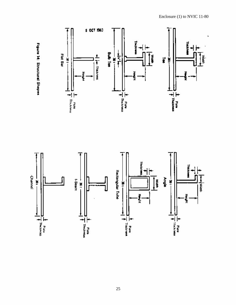
“floating frame" design, the transverse frame is not attached directly to the plating, so the section modulusof the frame does not include any effect from the plating. In both cases shown in Figure 11 the longitudinalsare attached to the plating, and their section modulus would include the effect of' the plating. In the casewhere a frame and plate are attached, only the portion of' the plate in close proximity to the frame reallycontributes to the strength of' the frame For aluminum structures the Coast Guard uses 38 times (38t) thethickness of the plating as effective in this manner. If' the spacing of' the attached frames is less than 38t,then only the actual spacing between frames contributes to the strength of' the frame. The actual spacing of'plating stiffeners should always be checked against 38t; and If it is less than 38t, The tables of' Appendix Ashould not be used because they would overestimate the strength of' the frame. Those tables list the sectionmodulus of' frames by themselves and also attached to plating of' various thickness assuming that 38t of'the plating effectively contributes to the frame's strength. As an example of' how the tables are read, pageA-1 shows that a 3.00 X 1.50 x 1/4 Bulb Tee attached to 3/8 inch plate has a section modulus of' 1.73inches cubed (in3). That shape has a section modulus of' 0.64 in3 if it is not attached to any plating.
If' a beam is attached to plating but the effective width of the plating is less than 38t, the section modulusof' the combined beam and plate will be between those values given for an unattached beam and an attachedbeam. The actual be calculated by methods explained in most section modulus in such a case can structuralreference books.
A structural handbook should be used to find the section modulus of' a frame which is not attached to plate.Since section modulus is a geometric property and not a material property steel and aluminum members of'the same geometry have the same section modulus, so any handbook that shows the proper shape can beused to determine the section modulus. There may be minor variations in the section moduli of steel andaluminum sections of the same size due to differences in production practices (extrusion of aluminumversus rolling of steel). The variations are usually the results of different radii of the corners. Moststructural manuals list section properties of a beam with respect to two axes; the axis that should be used isperpendicular to the direction of the applied load. Some handbooks and manuals that can be used are listedlater as References.
If the actual section modulus of the frame is equal to or greater than the required section modulus of theframe, it is acceptable. It is not good engineering practice to trade off the sizes of structural components.such as accepting a stiffened that is a little too small because the plating to which it is attached is thickerthan required. This is because plating and framing play different roles in supporting external loads.Likewise, the sizes of longitudinals and transverse frames cannot be traded off to obtain equivalentstrength.
Keel: The keel is a substantial structural component that runs the entire length of' the boat in the middle ofthe hull bottom. The bottom transverse frames rely on the rigidity of the keel as their lower support. Thekeel must also withstand loads from drydocking and low speed groundings. The size and shape of the keelmay vary from boat to boat, but it is often a flat bar up to an inch thick, and it is sometimes capped with aheavy flange. The keel’s area and section modulus should be equivalent to that of a flat bar whose thicknessin inches is L/110 and whose height is L/11, where L is the length of' the boat in feet.
Keelsons: Keelsons may be Installed for reasons other than to support the hull bottom structure. Since ahull bottom panel is a grillage structure, two small keelsons may provide the same strength and degree ofsupport as a single large keelson. To be considered effective as strength members, the total area and sectionmodulus of all keelsons on a bottom panel should be equivalent to that of a single flat bar whose thicknessand height are L/160 and L/10 respectively, where L is the length of the boat. If the keelsons areundersized, they should not be rejected, but they cannot be considered effective in supporting the bottomtransverse frames.

Enclosure (1) to NVIC 11-80
9
The section modulus of a flat bar section of' thickness "t" and height "h" is
S M h t. . /= 2 6
Bottom plating to which keels and keelsons are attached is not included in determining the section modulusof those members. Appendix A includes areas and section moduli of sections that are commonly used forkeels and keelsons.
Stanchions: Decks, especially exterior decks designed to carry cargo, are often supported by stanchionswhich run from the hull bottom structure to the deck structure. Figure 12 shows a stanchion running up tothe deck girder which it supports. Brackets are normally installed at the ends of' stanchions, but they havebeen omitted from the figure for clarity. In Figure 13 stanchion length is measured from bracket to bracket,extending into the bracket one fourth of' the bracket length from the toe. If' no bracket is installed, thelength is measured to the face of' the flange of' the girder, keelson, or other structural component to whichthe stanchion is attached. The area of' deck which is considered to be supported by a stanchion is thatportion or deck which is closer to the stanchion than to other main supporting structures such as hull sides,bulkheads, or other stanchions. This area is assumed to be the sum of' the half'-lengths of' the girders oneach side of' the attention times the sum of' the half-lengths of' the transverse frames on each side of' thegirder. This area is that of a rectangle whose length on one side is equal to half' the length of' a girder onone side of' the stanchion plus half' the length of' the girder on the other side of' the stanchion, and whosedimension on the other side is equal to half' the length of' a frame on one side of' the stanchion plus half thelength of the frame on the other side of' the stanchion. In Figure 13, the intersection of' "Area of' DeckSupported" and "Stanchion Length" must be below the line representing stanchion size; so when using thatfigure, read up to find the required stanchion size.
Decks: Decks may be framed either transversely or longitudinally. In either case the frames that directlysupport the plating are supported by orthogonal (perpendicular) beams or girders. Table 1 identifies theframes supporting the deck plating as "longitudinals" although in some cases they may actually runtransversely. The various structural components of the deck are based on the same design pressure andallowable stress. This is indicated by a ditto (") in Table 1.
General Structural Configuration: The structural plans for a vessel may show that frame spacing is non-uniform in a particular area or that the structural arrangement differs from that described in this guide. Ifthe purpose of a structural component is unclear or the proper approach to take in evaluating it isuncertain, Merchant Marine Technical should be consulted. Techniques used in evaluating a vessel'sstructure are largely learned through the experience gained over many structural evaluations. When astructural plan is being reviewed, it may be necessary to check several identical components to determinewhich is the most critical in the structure. For example, a tank bulkhead may have two strakes of' plate,with the lower one thicker than the upper one. Each strake should be checked; the head used to determinepressure for each one would be from the appropriate reference line (1; feet above the deck in this case)down to the lower edge of the strake. The ability to perceive which area of' structure is critical and shouldbe checked only comes with the confidence gained through repeated exercises in structural evaluation.
References
Books
Simpson, Tracy W. Aluminum Boats. Oakland: Kaiser Aluminum & Chemical Sales, Inc. 19614.
Aluminum Afloat. Pittsburgh: Aluminum Company of America. 1968.

Enclosure (1) to NVIC 11-80
10
Rules for Building and Classing Aluminum Vessels 1975. New York: American Bureau of'Shipping.
Articles and Reports
Allen, Raymond G., and Robert R. Jones. "A Simplified Method for Determining StructuralDesign-Limit Pressures on High Performance Marine Vehicles." Prepared for the AIMISNAMEAdvanced Marine Vehicles Conference, San Diego. (April 17, 1978).
Altenburg, C. J., and others. "Design Considerations for Aluminum Hull Structures Study ofAluminum Bulk Carrier." Ship Structure Committee Report SSC-218. Washington: U. S. CoastGuard Headquarters. 1971.
Blaze, Gary C. "The 5000-Series Alloys Suitable for Welded Structural Applications." AlcoaGreen Letter. New Kensington: Aluminum Company of America. Rev. March 19714.
Grant, James E., and others. "Considerations for the Structural Detailing of Aluminum Ships."Alcoa Center: Aluminum Company of America. November 19714.
Heller, S. R., and N. H. Jasper. "On the Structural Design of Planing Craft." Proceedings of theRoyal Institute of Naval Architecture. London. 1961, pp. 49-65.
Henrickson, William A., and John S. Spencer. "A Synthesis of Aluminum Crewboat StructuralDesign." Prepared for presentation at the Gulf Section of the Society of Naval Architects andMarine Engineers. (October 15, 1980).
Mindlin, Harold, and Carl E. Jaske. "Summary Report on Fatigue Properties of 5083, 5086, and51456 Aluminum-Alloy Sheet and Plate." Richmond: Reynolds Metals Company. October 1968.
Silvia, Peter A. "Structural Design of Planing Craft, A State of the Art Survey." Prepared forpresentation at the Chesapeake Section of the Society or Naval Architects and Marine Engineers.(March 9, 1978).
Spencer, John S. "Structural Design of Aluminum Crewboats." Marine Technology. New York:Society of Naval Architects and Marine Engineers. (July 1975) pp. 267-2714.
Manuals
Lev, Frank M., and Natale S. Nappi. "Properties of' Combined Aluminum Beam and Plate."Report 4336. Bethesda: Naval Ship Research and Development Center. March 1974.
Manual of Steel Construction. New York: American Institute of Steel Construction, Inc. 1967.
"Aluminum Construction Manual, Specifications for Aluminum Structures." New York: TheAluminum Association. April 1976.
"Aluminum Construction Manual, Section 3, Engineering Data for Aluminum Structures." NewYork: The Aluminum Association. January 1975.

Enclosure (1) to NVIC 11-80
11
"Aluminum Standards and Data." New York: The A3uminum Association. March 1979.
Enclosure (1) to NVIC 11-80
12

Enclosure (1) to NVIC 11-80
13

Enclosure (1) to NVIC 11-80
14

Enclosure (1) to NVIC 11-80
15

Enclosure (1) to NVIC 11-80
16

Enclosure (1) to NVIC 11-80
17

Enclosure (1) to NVIC 11-80
18

Enclosure (1) to NVIC 11-80
19

Enclosure (1) to NVIC 11-80
20

Enclosure (1) to NVIC 11-80
21

Enclosure (1) to NVIC 11-80
22

Enclosure (1) to NVIC 11-80
23

Enclosure (1) to NVIC 11-80
24
Enclosure (1) to NVIC 11-80
25

Appendix A Enclosure (1) to NVIC 11-80
26

Appendix A Enclosure (1) to NVIC 11-80
27

Appendix A Enclosure (1) to NVIC 11-80
28

Appendix A Enclosure (1) to NVIC 11-80
29

Appendix A Enclosure (1) to NVIC 11-80
30

Appendix A Enclosure (1) to NVIC 11-80
31

Appendix A Enclosure (1) to NVIC 11-80
32

Appendix A Enclosure (1) to NVIC 11-80
33

Appendix A Enclosure (1) to NVIC 11-80
34

Appendix A Enclosure (1) to NVIC 11-80
35

Appendix A Enclosure (1) to NVIC 11-80
36

Appendix A Enclosure (1) to NVIC 11-80
37

Appendix B Enclosure (1) to NVIC 11-80
38

Enclosure (1) to NVIC 11-80
39
Keel
Equivalent Flat Bar:
t = L/110 = 85/110 = 0.77" (width)
h = L/11 = 85/11 = 7.73” (height)
A = (t)(h) = (0.77)(7.73) = 5.95 in2 (required area)
S.M. = (h2)(t)/6 = (7.732)(0.77)/6 - 7.67 in3 (required section modulus)
From Page A-12, for an 8"x3"x5/8" Capped Plate
A = 6.48 in2
S.M. = 8.72 in3 (keel is satisfactory)
Keelsons
Equivalent Flat Bar:
t = L/160 = 85/160 = 0.53" (width)
h = L/11 = 85/11 = 7.73” (height)
A = (t)(h) = (0.77)(7.73) = 5.95 in2 (required area)
S.M. = (h2)(t)/6 = (7.732)(0.77)/6 - 7.67 in3 (required section modulus)
One keelson is a 16"x2"x1/4" Capped Plate, and the other is an 8"x2"xl/4’ Tee, neither or whichappear on pages A-10 through A-12 for Keels and Keelsons.
The S.M. of' the smaller keelson is found on page A-4: 8"x2"x1/4" Tee on no plate has S.M. =3.142 in3
The area of' the section can be estimated by multip1ying the sum of the web and flange dimensions(8"+2") by the thickness (1/4"). A = (8 + 2)(1/4) = 2.50 in2.
A conservative estimate for the area and section modulus of' the 16"x2"x1/4" Capped Plate isobtained by ignoring the 2" flange and treating the section as a flat bar with
A = (h)(t) = (16)(1/4) = 4.00 in2
S.M. = (h2)(t)/6 = (162)(1/4)/6 = 10.67 in3
The combined area of the keelsons is 2.50 + 4.00 = 6.50 in2
The combined S.M. of the keelsons is 3.42 + 10.67 = 14.09 in3

Enclosure (1) to NVIC 11-80
40
Although the 16"x2"x1/4" Capped Plate keelson is not listed in the tables of Appendix A, its areaand S.M. could also have been roughly estimated by comparison to the 16"x2.5"xl/4" FlangedPlate on page A-12, which almost the same size and has almost the same section properties.
Since the combined area and section modulus of the keelsons exceed the required values, thekeelsons can be considered as effective supporting members for the transverse frames.
Bottom Structure
Impact Pressure:
L = 85 ft (length overall)∆ = 75 Long Tons (displacement)
From Figure 3, P1 13.0 psi (impact pressure)
Bottom Plating and Longitudinals:
d = 4.0 ft (draft)
P = (0.6)(Pi) + (0.444)(d) (design pressure)= (0.6)(13.0) + (0.444)(4.0) = 9.58 psi
σ = 12 ksi (design stress)s =- 17" (stiffener spacing)P / σ = 0.80
From Figure 10, 3/8" plate is required (plating is satisfactory)
l = 36" (span of longitudinals)s = 17" (spacing of longitudinals)
From Figure 9, K = 1.84
S.M. = (P/σ )(K) = (required section modulus)= (0.80)(1.84) = 1.47 in3
From Page A-1, 2.50"x1.50"x1/4" Bulb Tee on 3/8 plate hasS.M. = 1.35 in3 (the section is too small)
Any shape having a section modulus of at least 1.47 in would be acceptable, such as a3.00"x1.50"x1/4” Bulb Tee, which has a section modulus of' 1.73 in3 on 3/8" plate.
Bottom Transverse Frames
P = (0.5)(Pi) + (0.444)(d) (design pressure)= (0.5)(13.0) + (0.444)(4.0) = 8.28 psi
σ = 12 ksi (design stress)

Enclosure (1) to NVIC 11-80
41
P/σ = 0.69
l = 94/2 = 47" (span of' transverse frame)
One half the length of the transverse frame can be used as the unsupported span because thekeelsons are large enough to be considered effective supports.
s = 36" (spacing of transverse frames)
From Figure 8, K = 6.63
S.M. = (P/σ )(K) (required section modulus)= (0.69)(6.63) = 4.57 in3
From Page A-3, a 6.00"x2.00"x1/4” Bulb Tee on 3/8" plate has aS.M. = 5.47 in3 (frame is satisfactory)
Side Structure
Plating
h = distance from the bottom of the side plate (chine) to a point 4 feet abovethe deck at side. (design head)= 65/12 + 4.0 = 9.42 ft
P = (0.444)(h) (design pressure)= (0.444)(9.42) = 4.18 psi
σ = 17 ksi (design stress)
P/σ = 0.25
s = 17" (stiffener spacing)
From Figure 10, 1/4" plate is required (5/16” plate is satisfactory)
Longitudinals
h = distance from lowest side longitudinal to a point 4 feet above thedeck at side. (design head)= 48/12 + 4.0 = 8.0 ft
P = 0.444)(h) (design pressure)= (0444)(8.00) = 3.55 psi
σ = 17 ksi (design stress)
P/σ = 0.21
l = 36” (span of longitudinals)

Enclosure (1) to NVIC 11-80
42
s = 17” (spacing of longitudinals)
From Figure 9, K = 1.84
S.M. = (P/σ )(K) (required section modulus)= (0.21)(1.84) - 0.39 in3
From Page A-1, a 2.50'1x1.50"xl/4" Bulb Tee on 5/16” plate hasS.M. = 1.30 in3 (longitudinal is satisfactory)
Side Transverse Frames
h = distance from middle of span of side transverse frame to a point 4 feetabove the deck at side (design head)= (65/12)(1/2) + 4 = 6.71 ft
P = (0.2)(Pi) + (0.444)(h) (design pressure)= (0.2)(13.0) + (0.444)(6.71) = 5.58 psi
σ = 17 ksi (design stress)
P/σ = 0.33
l = 53” (span of transverse frame)
s = 36” (spacing of transverse frames)
From Figure 8, K = 8.43
S.M. = (P/σ )(K) (required section modulus)= (0.34)(8.43) = 2.78 in3
From Page A-7, a 4.00"x3.28” Std I-Beam not attached to plate hasS.M. = 3.39 in3 (frame is satisfactory)
Deck Structure
From Figure 6, P = 1.78 psi (design pressure)
σ = 17 ksi (design stress)
P/σ = 0.10
Plating
s = 17” (stiffener spacing)
From Figure 10, 5/16" plate is required for deck plate where deckcargo is carried. (plating is satisfactory)

Enclosure (1) to NVIC 11-80
43
Longitudinals
l = 36” (span of longitudinals)
s = 17” (spacing of longitudinals)
From Figure 9, K = 1.84
S.M. = (P/σ )(K) (required section modulus)= (0.10)(1.84) = 0.18 in3
From Page A-5, a 2.00"xl/4” Flat Bar on 5/16” plate hasS.M. = 0.38 in3 (longitudinal is satisfactory)
Deck Transverse Frames
1 = 76" (span of transverse frame)
s = 36" (spacing of transverse frames)
From Figure 8, K = 17.33
S.M. = (P/σ )(K) (required section modulus)= (0.10)(17.33) = 1.73 in3
From Page A-3, a 4.00”x2.00"xl/4” Tee attached to 5/16" plate hasS.M. = 2.98 in3 (frame is satisfactory)
Deck Girder
l = 15/2 ft = 90” (span of deck girder)
The span of the deck girder is the maximum distance between supports such as bulkheads andother stanchions. In this case it is the distance between the stanchion and a bulkhead.
s = 76" (spacing of' deck girder)
The spacing of' the deck girder is the width of the wider of the two panels on each side of it. In thiscase, the inboard panel is 68" (2 x 34”), and the outboard panel is 76" wide.
The spacing exceeds the range of Figure 8, 50 USC the expressionK = (L2)(s)/12,000 = (902)(76)/12,000 = 51.30
S.M. = (P/σ )(K) = (0.10)(51.30) = 5.13 in3
From Page A-8, a 6.00"x3.00# Std Channel attached to 5/16" plate hasS.M. = 5.88 in3 (girder is satisfactory)
Stanchion
Enclosure (1) to NVIC 11-80
44
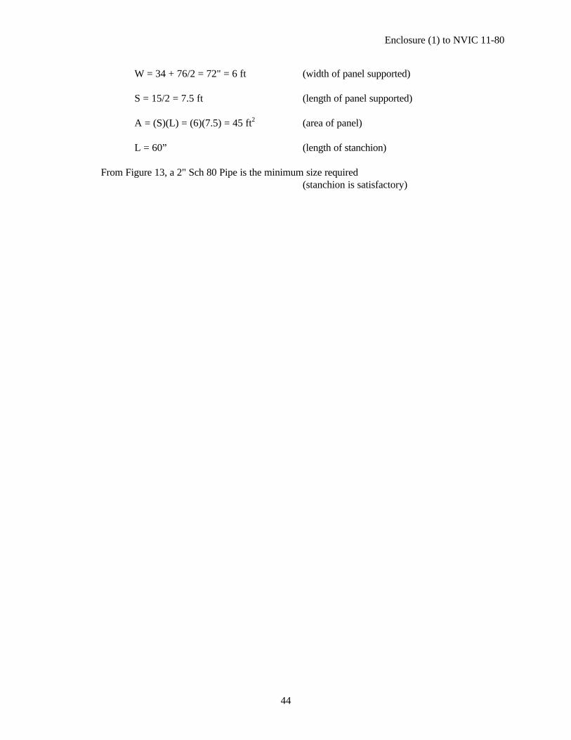
W = 34 + 76/2 = 72" = 6 ft (width of panel supported)
S = 15/2 = 7.5 ft (length of panel supported)
A = (S)(L) = (6)(7.5) = 45 ft2 (area of panel)
L = 60” (length of stanchion)
From Figure 13, a 2" Sch 80 Pipe is the minimum size required(stanchion is satisfactory)