u.s. supplement to classnk rules for the classification … documents/5p/5ps/alternate... ·...
TRANSCRIPT
1
U.S. SUPPLEMENT to ClassNK Rules for the Classification of Ships
USCG Approval: March 9, 2016
Approved U.S. Supplement to the ClassNK Rules

2
CONTENTS
Page
1. Introduction 3
2. Critical Ship Safety Systems 4
3. Tonnage Measurements 35
4. Load Line 36
5. SOLAS Consolidated Edition 2009 37
6. MARPOL 73/78 41
7. IBC Code Supplemental Requirement 44
8. IGC Code supplemental Requirement 48

3
Chapter 1 Introduction
This U.S. Supplement contains supplemental requirements of the United States Coast Guard
which are contained in Titles 33 and 46 of the Code of Federal Regulations but not covered
by ClassNK Regulations for the Classification and Registry of Ships, 2011 Edition and
associated ClassNK Rules, 2011 Edition.
This Supplement is applicable to U.S. Flag vessels issued a Certificate of Inspection (COI)
under 46 CFR Subchapter D (Tank Vessels), Subchapter I (Cargo and miscellaneous
Vessels) or Subchapter O (Certain Bulk Dangerous Cargoes) that are classed by Nippon
Kaiji Kyokai (ClassNK), and that are issued with or intended to be issued with one or more
of the following certificates:
International Tonnage Certificate
International Load Line Certificate
SOLAS Cargo Ship Safety Construction Certificate
SOLAS Cargo Ship Safety Equipment Certificate
International Oil Pollution Prevention (IOPP) Certificate
International Air Pollution Prevention(IAPP) Certificate
Safety Management Certificate and Document of Compliance (ISM Code)
International Anti-fouling System (IAFS) Certificate
International Certificate of Fitness for the Carriage of Dangerous Chemicals in Bulk
(IBC Code)
International Certificate of Fitness for the Carriage of Liquefied Gases in Bulk (IGC
Code)
ClassNK may also issue the Document of Compliance for ships carrying dangerous goods
enrolled in Safety of Life at Sea, 1974, as amended, regulation II-1/19, to vessels to which it
is applicable.
Compliance with requirements associated with the issuance of one or more of the
international certificates listed above, as applicable to ship type and size, is to be verified
during plan review and survey of ClassNK classed ships registered in the United States of
America.

4
Chapter 2 Critical Ship Safety Systems
2.1 46 CFR Subchapter D – Tank Vessels 2.1.1 Purpose of regulations. [46 CFR 30.01-1 ]
The rules and regulations in 46 CFR Subchapter are prescribed for all tank vessels in
accordance with the intent of the various statutes administered by USCG and to provide for a
correct and uniform administration of the vessel inspection requirements applicable to tank
vessels.
2.1.2 Guards at dangerous places [46 CFR 32.02-15] All exposed and dangerous places such as gears and machinery shall be properly protected
with covers, guards or rails in order that the danger of accidents may be minimized. On
vessels equipped with radio communication, the lead-ins shall be efficiently incased or
insulated to insure against accidental shock. Such lead-ins shall be located so as not to
interfere with the launching of lifeboats and life rafts.
2.1.3 Pumps, Piping, and Hose for Cargo Handling [46 CFR 32.50] -1. Cargo pumps for tank vessels constructed on or after November 10, 1936 [§ 32.50-1]
Where cargo pump shafts pierce gastight bulkheads, stuffing boxes with readily accessible
gastight glands shall be provided.
-2. Cargo discharge [46 CFR 32.50-3 ]
(a) Pumps or other acceptable means shall be used to discharge cargo from gravity type
cargo tanks vented at gauge pressures of 4 pounds per square inch or less.
(b) The use of compressed air as the primary means of discharging cargo from such tanks is
prohibited.
-3. Cargo piping on tank vessels constructed on or after July 1, 1951 [46 CFR 32.50-15 ]
(a) On all tank vessels, the construction or conversion of which is started on or after July 1,
1951, the cargo piping shall be:
(1) A fixed cargo piping system shall be installed on a tank vessel carrying Grade A, B,
or C cargo. The piping shall be arranged so as to avoid excessive stresses at the
joints. For sizes exceeding 2 inches in diameter, flanged, welded, or other approved
types of joints shall be employed. Packing material shall be suitable for the cargo
carried. Connections at bulkheads shall be made so that the plating does not form
part of a flanged joint. Piping may be carried through bunker spaces and deep tanks
provided it is run through a pipe tunnel. The tunnel may be omitted where the pipe is
extra heavy, all joints are welded, and bends are installed to provide for expansion
and contraction.
(2) Tank vessels carrying only Grades D and E cargo may use a portable piping system
in lieu of a fixed piping system meeting the requirements of paragraph (a)(1) of this
section, provided:
(i) The hose complies with 33 CFR 154.500 or the portable piping complies with
part 56 of 46 CFR;
(ii) The connections comply with 33 CFR 156.130;
(iii) A shutoff valve is at or near the point of entry into the tank;
(iv) Except for the carriage of animal fats and vegetable oils, the system has a
closure which forms a vapor-tight seal on the tank opening through which the
cargo is transferred, is bolted or dogged in place, and has the hose and drop line
connected to it; and
(v) Except for the carriage of animal fats and vegetable oils, the system has a
metallic drop line which complies with 46 CFR 153.282.
(3) Cargo piping shall not pass through spaces containing machinery where sources of
vapor ignition are normally present: Provided, that, in special cases the Commandant

5
may permit the piping to pass through such spaces if Grade E liquids only are
involved.
(b) Valve operating rods in cargo tanks shall be solid, except that tank barges having plug
cocks inside the cargo tanks may have operating rods of extra heavy pipe with the
annular space between the lubricant tube and the pipe wall sealed with a nonsoluble
material to prevent penetration of the cargo. Valve operating rods shall be of ample size,
well guided and supported, and attached to the valve stems in a manner so as to prevent
the operating rods from working loose. Where the operating rods pass through a deck,
gastight stuffing boxes shall be fitted. The leads of operating rods shall be as direct as
possible. Valves shall be of suitable design for the intended service.
(c) All cargo loading and discharge hose connections shall be fitted with valves or blind
flanges.
-4. Remote manual shutdown for internal combustion engine driven cargo pump on
tank vessels [46 CFR 32.50-35 ]
(a) Any tank vessel which is equipped with an internal combustion engine driven cargo pump
on the weather deck shall be provided with a minimum of one remote manual shutdown
station, conspicuously marked, and located at the midpoint of such vessel, or 100 feet
from the engine, whichever is the more practical. The remote quick acting manual
shutdown shall be installed on the engine so as to provide a quick and effective means of
stopping the engine (such as by cutting off the intake air).
(b) This regulation applies to all installations of this type on tank vessels, but for such
installations now on existing tankships at the date of next biennial inspection or October 1,
1963, whichever occurs later.
2.1.4 Bilge Systems [46 CFR 32.52]
-1. Bilge piping for pump rooms and adjacent cofferdams on tank vessels constructed or
converted on or after November 19, 1952 [46 CFR 32.52-5(c) ]
(a) Means shall be provided for controlling the cargo or pump room bilge pumps and their
suctions or discharges in order that a flooded pump room may be pumped out. Suitable
portable or manually operated pumps may be accepted as complying with this provision,
or alternatively, the pump controls shall be arranged so that they are operable from inside
the pump room and either from an accessible position outside the pump room, or from the
pump room casing above the freeboard deck.
2.1.5 Inert Gas System [46 CFR 32.53] -1. Exemptions. [46 CFR 32.53-3 ]
(a) USCG grants exemptions for crude oil tankers of less than 40,000 deadweight tons not
fitted with high capacity tank washing machines, if the vessel's owner can show that
compliance would be unreasonable and impracticable due to the vessel's design
characteristics.
(b) Requests for exemptions must be submitted in writing to: Commandant (CG–OES), U.S.
Coast Guard, 2100 2nd St. SW., Stop 7126, Washington, DC 20593–7126.
(c) Each request must be supported by documentation showing that:
(1) The system would be detrimental to the safe operation of the vessel;
(2) It is physically impracticable to install the system; or
(3) Adequate maintenance of the system would be impossible.
(d) The vessel's owner may request a conference. The exemption request file will be
available for use in the conference and additional arguments or evidence in any form
may be presented. The conference will be recorded. The presiding officer summarizes
the material presented at the conference and submits written recommendations to the
Assistant Commandant for Marine Safety and Environmental Protection.
6
(e) The Assistant Commandant for Marine Safety and Environmental Protection reviews
the exemption request file and decides whether to grant or deny the exemption. The
decision shall include an explanation of the basis on which the exemption is granted or
denied, and constitutes final agency action.
-2. General [46CFR 32.53-10]
(a) Each inert gas system must be designed, constructed and installed in accordance with
the provisions of SOLAS II–2, regulation 62, with the following provisions:
(1) Acceptable types of water seals include the wet and semiwet type. Other types of
seals may be accepted on a case by case basis if approval is given by USCG
Marine Safety Center.
(2) If a vapor collection system required to meet 46 CFR part 39 is connected to the
inert gas system, the instruction manual required by SOLAS II–2, regulation 62.21
must include procedures relating to vapor collection operations.
2.1.6 Ventilation and Venting [46 CFR 32.55] -1. Ventilation of tank vessels constructed on or after July 1, 1951 [ 46 CFR 32.55-1]
(a) Compartments containing machinery where sources of vapor ignition are normally
present shall be ventilated in such a way as to remove vapors from points near the floor
level or the bilges. Effective steam or air actuated gas ejectors, blowers or ventilators
fitted with heads for natural ventilation, with at least one duct extending to immediately
below the floor plates will be approved for this purpose. Machinery spaces below the
freeboard deck, in which fuels with flash point of 110 °F or lower are used, shall be
equipped with power ventilation. (See 46 CFR 32.60–20 for other requirements
concerning pumprooms.)
2.1.7 Deck foam system(46 CFR 34.20)
-1. The foam agent, its container, measuring devices, and other items peculiar to
this system shall be of an approved type. (46 CFR 34.20-10(a))
-2. The deck foam system on each tankship that has a keel laying date on or after
January 1, 1975, must be capable of being actuated, including introduction of
foam to the foam main, within three minutes of notification of a fire. (46 CFR
34.20-10(e))
-3. All piping, valves, and fittings of ferrous materials shall be protected inside and
outside against corrosion unless specifically approved otherwise by the
Commandant. (46 CFR 34.20-15(b))
2.1.8 Water spray extinguishing system(46 CFR 34.25)
Distribution piping shall be of materials resistant to corrosion, except that steel
or iron pipe may be used if inside corrosion resistant coatings which will not
flake off and clog the nozzles are applied. Materials readily rendered ineffective
by heat of a fire shall not be used. The piping shall be subject to approval for
each installation. (46 CFR 34.25-15(b))
2.1.9 Portable and semiportable extinguishers(46 CFR 34.50)
-1. The frame or support of each size III, IV, and V fire extinguisher required by 46
CFR Table 34.50–10(a) or Table 95.50–10(a) must be welded or otherwise
permanently attached to a bulkhead or deck. (46 CFR 34.50-20(a))(46 CFR
95.50-20(a))
-2. If a size III, IV, or V fire extinguisher has wheels and is not required by 46 CFR
Table 34.50–10(a) or Table 95.50–10(a), it must be securely stowed when not in

7
use to prevent it from rolling out of control under heavy sea conditions. (46 CFR
34.50-20(b)) (46 CFR 95.50-20(b)) 2.1.10 VAPOR CONTROL SYSTEMS [46CFR PART 39]
2.1.10.1 General [46 CFR 39.10] -1. Applicability [46 CFR 39.10-1]
(a) Except as specified by paragraph (c) of this section, this part applies to each tank vessel
operating in the navigable waters of the United States, when collecting vapors of crude
oil, gasoline blends, or benzene emitted from a vessel's cargo tanks through a vapor
control system.
(b) A tank vessel which transfers vapors of flammable or combustible cargoes other than
crude oil, gasoline blends, or benzene, to a facility covered by 33 CFR part 154 must
meet the requirements prescribed by the Commandant (CG–OES).
(c) A tank vessel with an existing vapor collection system specifically approved by the
USCG for the collection of cargo vapor which was operating prior to July 23, 1990, is
subject only to 46 CFR 39.30–1 and 46 CFR 39.40–5 of this part as long as it transfers
cargo vapor only to the specific facilities for which it was approved.
(d) This part does not apply to the collection of vapors of liquefied flammable gases as
defined in 46 CFR 30.10–39.
-2. Definitions [46 CFR 39.10-3 ]
As used in 46 CFR subchapter D:
Cargo deck area means that part of the weather deck that is directly over the cargo tanks.
Existing vapor collection system means a vapor collection system which was operating prior
to July 23, 1990.
Facility vapor connection means the point in a facility's fixed vapor collection system where
it connects with the vapor collection hose or the base of the vapor collection arm.
Independent as applied to two systems means that one system will operate with a failure of
any part of the other system except power sources and electrical feeder panels.
Inerted means the oxygen content of the vapor space in a cargo tank is reduced to 8 percent
by volume or less in accordance with the inert gas requirements of 46CFR 32.53or 46 CFR
153.500.
Lightering or lightering operation means the transfer of a bulk liquid cargo from a tank vessel
to a service vessel.
Marine Safety Center means the Commanding Officer, U.S. Coast Guard Marine Safety
Center, 1900 Half Street, SW, Suite 1000, Room 525, Washington, DC 20024 for visitors.
Send all mail to Commanding Officer, U.S. Coast Guard Marine Safety Center, 2100 2nd St.
SW., Stop 7102, Washington, DC 20593–7102, in a written or electronic format. Information
for submitting the VSP electronically can be found at http://www.uscg.mil/HQ/MSC.
Maximum allowable transfer rate means the maximum volumetric rate at which a vessel may
receive cargo or ballast.
New vapor collection system means a vapor collection system which is not an existing vapor
collection system.
Service vessel means a vessel which transports bulk liquid cargo between a facility and
another vessel.
8
Topping-off operation means the transfer of a bulk liquid cargo from a service vessel to
another vessel in order to load the receiving vessel to a deeper draft.
Vapor balancing means the transfer of vapor displaced by incoming cargo from the tank of a
vessel receiving cargo into a tank of the vessel or facility delivering cargo via a vapor
collection system.
Vapor collection system means an arrangement of piping and hoses used to collect vapor
emitted from a vessel's cargo tanks and to transport the vapor to a vapor processing unit.
Vapor control system means an arrangement of piping and equipment used to control vapor
emissions collected from a vessel. It includes the vapor collection system and vapor
processing unit.
Vapor processing unit means the components of a vapor control system that recovers,
destroys, or disperses vapor collected from a vessel.
Vessel vapor connection means the point in a vessel's fixed vapor collection system where it
connects with the vapor collection hose or arm.
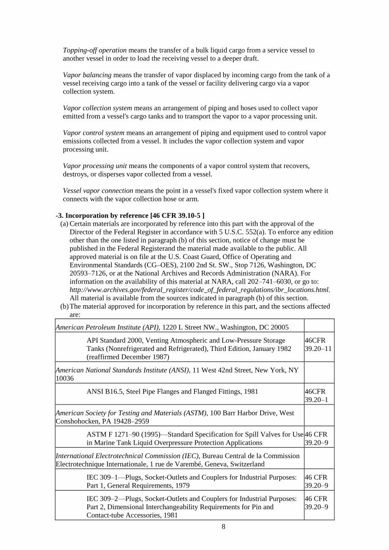
-3. Incorporation by reference [46 CFR 39.10-5 ]
(a) Certain materials are incorporated by reference into this part with the approval of the
Director of the Federal Register in accordance with 5 U.S.C. 552(a). To enforce any edition
other than the one listed in paragraph (b) of this section, notice of change must be
published in the Federal Registerand the material made available to the public. All
approved material is on file at the U.S. Coast Guard, Office of Operating and
Environmental Standards (CG–OES), 2100 2nd St. SW., Stop 7126, Washington, DC
20593–7126, or at the National Archives and Records Administration (NARA). For
information on the availability of this material at NARA, call 202–741–6030, or go to:
http://www.archives.gov/federal_register/code_of_federal_regulations/ibr_locations.html.
All material is available from the sources indicated in paragraph (b) of this section.
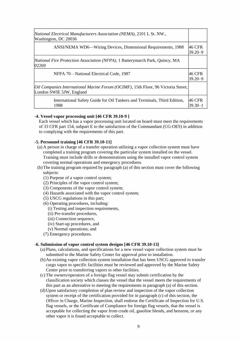
(b) The material approved for incorporation by reference in this part, and the sections affected
are:
American Petroleum Institute (API), 1220 L Street NW., Washington, DC 20005
API Standard 2000, Venting Atmospheric and Low-Pressure Storage
Tanks (Nonrefrigerated and Refrigerated), Third Edition, January 1982
(reaffirmed December 1987)
46CFR
39.20–11
American National Standards Institute (ANSI), 11 West 42nd Street, New York, NY
10036
ANSI B16.5, Steel Pipe Flanges and Flanged Fittings, 1981 46CFR
39.20–1
American Society for Testing and Materials (ASTM), 100 Barr Harbor Drive, West
Conshohocken, PA 19428–2959
ASTM F 1271–90 (1995)—Standard Specification for Spill Valves for Use
in Marine Tank Liquid Overpressure Protection Applications
46 CFR
39.20–9
International Electrotechnical Commission (IEC), Bureau Central de la Commission
Electrotechnique Internationale, 1 rue de Varembé, Geneva, Switzerland
IEC 309–1—Plugs, Socket-Outlets and Couplers for Industrial Purposes:
Part 1, General Requirements, 1979
46 CFR
39.20–9
IEC 309–2—Plugs, Socket-Outlets and Couplers for Industrial Purposes:
Part 2, Dimensional Interchangeability Requirements for Pin and
Contact-tube Accessories, 1981
46 CFR
39.20–9
9
National Electrical Manufacturers Association (NEMA), 2101 L St. NW.,
Washington, DC 20036
ANSI/NEMA WD6—Wiring Devices, Dimensional Requirements, 1988 46 CFR
39.20–9
National Fire Protection Association (NFPA), 1 Batterymarch Park, Quincy, MA
02269
NFPA 70—National Electrical Code, 1987 46 CFR
39.20–9
Oil Companies International Marine Forum (OCIMF), 15th Floor, 96 Victoria Street,
London SWIE 5JW, England
International Safety Guide for Oil Tankers and Terminals, Third Edition,
1988
46 CFR
39.30–1
-4. Vessel vapor processing unit [46 CFR 39.10-9 ]
Each vessel which has a vapor processing unit located on board must meet the requirements
of 33 CFR part 154, subpart E to the satisfaction of the Commandant (CG-OES) in addition
to complying with the requirements of this part.
-5. Personnel training [46 CFR 39.10-11]
(a) A person in charge of a transfer operation utilizing a vapor collection system must have
completed a training program covering the particular system installed on the vessel.
Training must include drills or demonstrations using the installed vapor control system
covering normal operations and emergency procedures.
(b) The training program required by paragraph (a) of this section must cover the following
subjects:
(1) Purpose of a vapor control system;
(2) Principles of the vapor control system;
(3) Components of the vapor control system;
(4) Hazards associated with the vapor control system;
(5) USCG regulations in this part;
(6) Operating procedures, including:
(i) Testing and inspection requirements,
(ii) Pre-transfer procedures,
(iii) Connection sequence,
(iv) Start-up procedures, and
(v) Normal operations; and
(7) Emergency procedures.
-6. Submission of vapor control system designs [46 CFR 39.10-13]
(a) Plans, calculations, and specifications for a new vessel vapor collection system must be
submitted to the Marine Safety Center for approval prior to installation.
(b) An existing vapor collection system installation that has been USCG approved to transfer
cargo vapor to specific facilities must be reviewed and approved by the Marine Safety
Center prior to transferring vapors to other facilities.
(c) The owners/operators of a foreign flag vessel may submit certification by the
classification society which classes the vessel that the vessel meets the requirements of
this part as an alternative to meeting the requirements in paragraph (a) of this section.
(d) Upon satisfactory completion of plan review and inspection of the vapor collection
system or receipt of the certification provided for in paragraph (c) of this section, the
Officer in Charge, Marine Inspection, shall endorse the Certificate of Inspection for U.S.
flag vessels, or the Certificate of Compliance for foreign flag vessels, that the vessel is
acceptable for collecting the vapor from crude oil, gasoline blends, and benzene, or any
other vapor it is found acceptable to collect.

10
2.1.10.2 Design and Equipment [46 CFR 39.20] -1. Vapor collection system [46 CFR 39.20-1 ]
(a) Each vapor collection system must meet the following requirements:
(1) Except as allowed by paragraph (a)(3) of this section or the Commandant (CG-OES),
vapor collection piping must be permanently installed, with the vessel's vapor
connection located as close as practical to the loading manifold;
(2) If the vessel collects vapors from incompatible cargoes simultaneously, it must keep the
incompatible vapors separate throughout the entire vapor collection system;
(3) A vessel certified to carry cargo listed in Table 151.05 of part 151 or Table 1 of part
153 of 46 CFR subchapter D may have vapor connections located in the vicinity of each
tank in order to preserve segregation of cargo systems, in lieu of common header
piping;
(4) A means must be provided to eliminate liquid condensate which may collect in the
system, such as draining and collecting liquid from each low point in the line;
(5) Vapor collection piping must be electrically bonded to the hull and must be electrically
continuous; and
(6) An inerted tankship must have a means to isolate the inert gas supply from the vapor
collection system. The inert gas main isolation valve required by SOLAS 74 as
amended, chapter II–2, Regulation 62.10.8 may be used to satisfy this requirement.
(b) The vapor collection system must not interfere with the proper operation of the cargo tank
venting system.
(c) An isolation valve capable of manual operation must be provided at the vessel vapor
connection. The valve must have an indicator to show clearly whether the valve is in the
open or closed position, unless the valve position can be readily determined from the valve
handle or valve stem.
(d) The last 1.0 meter (3.3 feet) of vapor piping before the vessel vapor connection must be:
(1) Painted red/yellow/red with:
(i) The red bands 0.1 meter (0.33 feet) wide, and
(ii) The middle yellow band 0.8 meter (2.64 feet) wide; and
(2) Labeled “VAPOR” in black letters at least 50 millimeters (2 inches) high.
(e) Each vessel vapor connection flange must have a permanently attached 0.5 inch diameter
stud at least 1.0 inch long projecting outward from the flange face. The stud must be located
at the top of the flange, midway between bolt holes, and in line with the bolt hole pattern.
(f) Each hose used for transferring vapors must:
(1) Have a design burst pressure of at least 25 psig;
(2) Have a maximum allowable working pressure of at least 5 psig;
(3) Be capable of withstanding at least 2.0 psi vacuum without collapsing or constricting;
(4) Be electrically continuous with a maximum resistance of ten thousand (10,000) ohms;
(5) Have flanges with:
(i) A bolt hole arrangement complying with the requirements for 150 pound class ANSI
B16.5 flanges, and
(ii) One or more 0.625 inch diameter holes in the flange located midway between bolt
holes and in line with the bolt hole pattern;
(6) Be abrasion resistant and resistant to kinking; and
(7) Have the last 1.0 meter (3.3 feet) of each end of the vapor hose marked in accordance with
paragraph (d) of this section.
(g) Vapor hose handling equipment must be provided with hose saddles which provide adequate
support to prevent kinking or collapse of hoses.
-2. Cargo gauging system [46 CFR 39.20-3 ]
(a) Each cargo tank of a tank vessel that is connected to a vapor collection system must be
equipped with a cargo gauging device which:
(1) Provides a closed gauging arrangement as defined in 46 CFR 151.15.10 that does not
require opening the tank to the atmosphere during cargo transfer;
(2) Allows the operator to determine the liquid level in the tank for the full range of liquid
levels in the tank;
(3) Indicates the liquid level in the tank at the location where cargo transfer is controlled;

11
and
(4) If portable, is installed on the tank during the entire transfer operation.
(b) Except when a tank barge complies with 46 CFR 39.20–9(a) of this part, each cargo tank of
a barge must have a high level indicating device that:
(1) Provides a visual indication of the liquid level in the cargo tank when the cargo level is
within 1.0 meter (3.28 feet) of the tank top;
(2) Has the maximum liquid level permitted under 46 CFR 39.30–1(e) of this part at even
keel conditions conspicuously and permanently marked on the indicating device; and
(3) Is visible from all cargo control areas on the tank barge.
-3. Tankship liquid overfill protection [46 CFR 39.20-7]
(a) Each cargo tank of a tankship must be equipped with an intrinsically safe high level alarm
and a tank overfill alarm.
(b) The high level alarm and tank overfill alarm required by paragraph (a) of this section, if
installed after July 23, 1990 must:
(1) Be independent of each other;
(2) Alarm in the event of loss of power to the alarm system or failure of electrical circuitry
to the tank level sensor; and
(3) Be able to be checked at the tank for proper operation prior to each transfer or contain an
electronic self-testing feature which monitors the condition of the alarm circuitry and
sensor.
(c) The high level alarm required by paragraph (a) of this section must:
(1) Alarm before the tank overfill alarm, but no lower than 95 percent of tank capacity;
(2) Be identified with the legend “High Level Alarm” in black letters at least 50 millimeters
(2 inches) high on a white background; and
(3) Have audible and visible alarm indications that can be seen and heard on the vessel where
cargo transfer is controlled.
(d) The tank overfill alarm required by paragraph (a) of this section must:
(1) Be independent of the cargo gauging system;
(2) Have audible and visible alarm indications that can be seen and heard on the vessel where
cargo transfer is controlled and in the cargo deck area;
(3) Be identified with the legend “TANK OVERFILL ALARM” in black letters at least 50
millimeters (2 inches) high on a white background; and
(4) Alarm early enough to allow the person in charge of transfer operations to stop the
transfer operation before the cargo tank overflows.
(e) If a spill valve is installed on a cargo tank fitted with a vapor collection system, it must meet
the requirements of 46 CFR 39.20–9(c) of this part.
(f) If a rupture disk is installed on a cargo tank fitted with a vapor collection system, it must
meet the requirements of 46 CFR 39.20–9(d) of this part.
-4. Tank barge liquid overfill protection [46 CFR 39.20-9 ]
Each cargo tank of a tank barge must have one of the following liquid overfill protection
arrangements.
(a) A system meeting the requirements of 46 CFR39.20–7 of this part which:
(1) Includes a self-contained power supply;
(2) Is powered by generators installed on the barge; or
(3) Receives power from a facility and is fitted with a shore tie cable and a 120 volt 20 amp
explosion-proof plug which meets:
(i) ANSI/NEMA WD6;
(ii) NFPA 70, Articles 410–57 and 501–12; and
(iii) 46 CFR 111.105–9 of this chapter.
12
(b) An intrinsically safe overfill control system which:
(1) Is independent of the cargo gauging device required by 46 CFR 39.20–3(a) of this part;
(2) Actuates an alarm and automatic shutdown system at the facility overfill control panel,
or on the vessel to be lightered if a lightering operation, 60 seconds before the tank
becomes 100 percent liquid full;
(3) Is able to be checked at the tank for proper operation prior to each loading;
(4) Consists of components which, individually or in series, will not generate or store a
total of more than 1.2 V, 0.1 A, 25 mW, or 20 microjoules;
(5) Has at least one tank overfill sensor switch with normally closed contacts per cargo
tank;
(6) Has all tank overfill sensor switches connected in series;
(7) Has interconnecting cabling that meets 46 CFR 111.105–15(b) of this chapter; and
(8) Has a male plug with a 5 wire, 16 amp connector body meeting IEC 309–1/309–2
which is:
(i) Configured with pins S2 and R1 for the tank overfill sensor circuit, pin G connected to
the cabling shield, and pins N and T3 reserved for an optional high level alarm circuit
meeting the requirements of this paragraph; and
(ii) Labeled “Connector for Barge Overflow Control System” and with the total inductance
and capacitance of the connected switches and cabling.
(c) A spill valve which:
(1) Meets ASTM F 1271 (incorporated by reference, see 46 CFR 39.10–5);
(2) Relieves at a pressure higher than the pressure at which the pressure relief valves
meeting the requirements of 46 CFR 39.20–11 operate;
(3) Limits the maximum pressure at the cargo tank top during liquid overfill, at the
maximum loading rate for the tank, to not more than the maximum design working
pressure for the tank; and
(4) If the vessel is in ocean or coastwise service, has provisions to prevent opening due to
cargo sloshing.
(d) A rupture disk arrangement which meets paragraphs (c)(2), (c)(3) and (c)(4) of this section
and is approved by the Commandant (CG-OES).
-5. Vapor overpressure and vacuum protection [46 CFR 39.20-11]
(a) The cargo tank venting system required by 46 CFR 32.55 of this chapter must:
(1) Be capable of discharging cargo vapor at 1.25 times the maximum transfer rate such
that the pressure in the vapor space of each tank connected to the vapor collection
system does not exceed:
(i) The maximum design working pressure for the tank, or
(ii) If a spill valve or rupture disk is fitted, the pressure at which the device operates;
(2) Not relieve at a pressure corresponding to a pressure in the cargo tank vapor space of
less than 1.0 psig;
(3) Prevent a vacuum in the cargo tank vapor space, whether generated by withdrawal of
cargo or vapor at maximum rates, that exceeds the maximum design vacuum for any
tank connected to the vapor collection system; and
(4) Not relieve at a vacuum corresponding to a vacuum in the cargo tank vapor space of less
than 0.5 psi below atmospheric pressure.
(b) Each pressure-vacuum relief valve must:
(1) Be tested for venting capacity in accordance with paragraph 1.5.1.3 of API 2000; and
(2) Have a means to check that the device operates freely and does not remain in the open
position, if installed after July 23, 1991.
(c) The relieving capacity test required by paragraph (b)(1) of this section must be carried out
with a flame screen fitted at the vacuum relief opening and at the discharge opening if the
pressure-vacuum relief valve is not designed to ensure a minimum vapor discharge velocity
of 30 meters (98.4 ft.) per second.

13
-6. High and low vapor pressure protection for tankships [46 CFR 39.20-13]
Each tankship vapor collection system must be fitted with a pressure sensing device that
senses the pressure in the main vapor collection line, which:
(a) Has a pressure indicator located on the vessel where the cargo transfer is controlled; and
(b) Has a high pressure and a low pressure alarm that:
(1) Is audible and visible on the vessel where cargo transfer is controlled;
(2) Alarms at a high pressure of not more than 90 percent of the lowest pressure relief
valve setting in the cargo tank venting system; and
(3) Alarms at a low pressure of not less than four inches water gauge (0.144 psig) for an
inerted tankship, or the lowest vacuum relief valve setting in the cargo tank venting
system for a non-inerted tankship.
46 CFR 39.30—Operations
2.1.10.3 Operations (46 CFR 39.30) -1. Operational requirements [46 CFR 39.30-1]
(a) Vapor from a tank vessel may not be transferred to:
(1) A facility in the United States which does not have its letter of adequacy endorsed as
meeting the requirements of 33 CFR part 154, subpart E; or
(2) In the case of a lightering or topping off operation, a vessel which does not have its
certificate of inspection or certificate of compliance endorsed as meeting the
requirements of this part.
(b) The pressure drop through the vapor collection system from the most remote cargo tank to
the vessel vapor connection must be:
(1) Determined for each cargo handled by the vapor collection system at the maximum
transfer rate and at lessor transfer rates;
(2) Based on a 50 percent cargo vapor and air mixture, and a vapor growth rate appropriate
for the cargo being loaded; and
(3) Included in the vessel's oil transfer procedures as a table or graph showing the liquid
transfer rate versus the pressure drop.
(c) If a vessel carries vapor hoses, the pressure drop through the hoses must be included in the
pressure drop calculations required by paragraph (b) of this section.
(d) The rate of cargo transfer must not exceed the maximum allowable transfer rate as
determined by the lesser of the following:
(1) Eighty (80) percent of the total venting capacity of the pressure relief valves in the cargo
tank venting system when relieving at the set pressure required by 46 CFR 39.20–11(a) of
this part;
(2) The total vacuum relieving capacity of the vacuum relief valves in the cargo tank venting
system when relieving at the set pressure required by 46 CFR 39.20–11(a) of this part;
(3) The rate based on pressure drop calculations at which, for a given pressure at the facility
vapor connection, or if lightering at the vapor connection of the vessel receiving cargo,
the pressure in any cargo tank connected to the vapor collection system exceeds 80
percent of the setting of any pressure relief valve in the cargo tank venting system.
(e) A cargo tank must not be filled higher than:
(1)98.5 percent of the cargo tank volume; or
(2)The level at which an overfill alarm complying with 46 CFR 39.20–7 or 46 CFR
39.20–9(b)(2) of this part is set.
(f) A cargo tank must not be opened to the atmosphere during cargo transfer operations except
as provided in paragraph (g) of this section.
(g) A cargo tank may be opened to the atmosphere for gauging or sampling while a tank vessel
is connected to a vapor control system if the following conditions are met:
14
(1) The cargo tank is not being filled;
(2) Except when the tank is inerted, any pressure in the cargo tank vapor space is first
reduced to atmospheric pressure by the vapor control system;
(3) The cargo is not required to be closed or restricted gauged by Table 151.05 of part 151 or
Table 1 in part 153 of 46 CFR; and
(4) For static accumulating cargo, all metallic equipment used in sampling or gauging is
electrically bonded to the vessel before it is put into the tank, remains bonded to the
vessel until it is removed from the tank, and if the tank is not inerted, a period of 30
minutes has elapsed since loading of the tank was completed.
(h) For static accumulating cargo the initial transfer rate must be controlled in accordance with
Section 7.4 of the OCIMF, International Safety Guide for Oil Tankers and Terminals, in
order to minimize the development of a static electrical charge.
(i) If cargo vapor is collected by a facility that requires the vapor from the vessel to be inerted in
accordance with 33 CFR 154.820(a) or (b), the oxygen content in the vapor space of each
cargo tank connected to the vapor collection system must not exceed 8 percent by volume at
the start of cargo transfer. The oxygen content of each tank must be measured at a point one
meter (3.28 feet) below the tanktop and at a point equal to one-half of the ullage. Where
tanks have partial bulkheads, the oxygen content of each area of that tank formed by each
partial bulkhead must be measured at a point one meter (3.28 feet) below the tanktop and at a
point equal to one-half of the ullage.
(j) If the vessel is equipped with an inert gas system, the isolation valve required by 46 CFR
39.20–1(a)(6) must remain closed during vapor transfer.
(k) Unless equipped with an automatic self-test and circuit monitoring feature, each high level
alarm and tank overfill alarm required by 46 CFR 39.20–7 or §39.20–9, on a cargo tank
being loaded, must be tested at the tank for proper operation within 24 hours prior to the start
of cargo transfer.
2.1.10.4 Lightering and Topping-Off Operations with Vapor Balancing [46 CFR 39.40] -1. General requirements for vapor balancing [46 CFR 39.40-1]
(a) Except as provided in paragraph (b) of this section, each vessel which uses vapor balancing
while conducting a lightering or topping-off operation must meet the requirements of this
subpart in addition to the requirements of 46 CFR 39.10, 39.20, and 39.30 of this part.
(b) An arrangement to control vapor emissions during a lightering or topping-off operation
which does not use vapor balancing must receive approval from the Commandant
(CG-OES).
(c) A vapor balancing operation must not use a compressor or blower to assist vapor transfer
without approval from the Commandant (CG-OES).
(d) Vapor balancing is prohibited when the cargo tanks on a vessel discharging cargo are
inerted and the cargo tanks on a vessel receiving cargo are not inerted.
(e) A vessel which intends to engage in a lightering or topping-off operation while collecting
cargo vapor from other than crude oil, gasoline, or benzene must receive specific approval
from the Commandant (CG-OES).
-2. Design and equipment for vapor balancing [46 CFR 39.40-3 ]
(a) If the cargo tanks on a vessel discharging cargo and a vessel receiving cargo are inerted, the
service vessel must:
(1) Have a means to inert the vapor transfer hose prior to transferring cargo vapor; and
(2) Have an oxygen analyzer with a sensor or sampling connection fitted within 3 meters
(9.74 ft.) of the vessel vapor connection which:
(i) Activates an audible and visible alarm at a location on the service vessel where cargo
transfer is controlled when the oxygen content in the vapor collection system exceeds 8
percent by volume;

15
(ii) Has an oxygen concentration indicator located on the service vessel where the cargo
transfer is controlled; and
(iii) Has a connection for injecting a span gas of known concentration for calibration and
testing of the oxygen analyzer.
(b) If the cargo tanks on a vessel discharging cargo are not inerted, the vapor collection line on
the service vessel must be fitted with a detonation arrester that meets the requirements of 33
CFR 154.822(a) located within 3 meters (9.74 ft.) of the vessel vapor connection.
(c) An electrical insulating flange or one length of non-conductive hose must be provided
between the vessel vapor connection on the service vessel and the vapor connection on the
vessel being lightered or topped-off.
-3. Operational requirements for vapor balancing [46 CFR 39.40-5 ]
(a) During a lightering or topping-off operation each cargo tank being loaded must be connected
by the vapor collection system to a cargo tank which is being discharged.
(b) If the cargo tanks on both the vessel discharging cargo and the vessel receiving cargo are
inerted, the following requirements must be met:
(1) Each tank on a vessel receiving cargo which is connected to the vapor collection system
must be tested prior to cargo transfer to ensure that the oxygen content in the vapor space
does not exceed 8 percent by volume. The oxygen content of each tank must be measured
at a point one meter (3.28 feet) below the tanktop and at a point equal to one-half of the
ullage. Where tanks have partial bulkheads, the oxygen content of each area of that tank
formed by each partial bulkhead must be measured at a point one meter (3.28 feet) below
the tanktop and at a point equal to one-half of the ullage;
(2) The oxygen analyzer required by 46 CFR 39.40–3(a) must be tested for proper operation
prior to the start of each transfer operation;
(3) The oxygen content of vapors being transferred must be continuously monitored during
the transfer operation;
(4) Cargo transfer must be terminated if the oxygen content exceeds 8 percent by volume and
must not be restarted until the oxygen content in the tanks of the vessel receiving cargo is
reduced to 8 percent by volume or less; and
(5) The vapor transfer hose must be purged of air and inerted prior to starting vapor transfer.
(c) The isolation valve, required by 46 CFR 39.20–1(c), located on the service vessel must not
be opened until the pressure in the vapor collection system on the vessel receiving cargo
exceeds the pressure in the vapor collection system on the vessel discharging cargo.
(d) The cargo transfer rate must be controlled from the vessel discharging cargo, and must not
exceed the maximum allowable transfer rate for the vessel receiving cargo.
(e) The pressure in the vapor space of any cargo tank connected to the vapor collection line on
either the vessel receiving cargo or the vessel discharging cargo must not exceed 80 percent
of the lowest setting of any pressure relief valve during ballasting or cargo transfer.
(f) All impressed current cathodic protection systems must be deenergized during cargo transfer
operations.
(g) Tank washing is prohibited unless the cargo tanks on both the vessel discharging cargo and
the vessel receiving cargo are inerted or the tank is isolated from the vapor collection line.
2.2 46 CFR Subchapter F – Marine Engineering
2.2.1 Additional requirements of Boilers

16
-1. Fusible plugs (46 CFR 52.01–50) (a) All boilers, except watertube boilers, with a maximum allowable working pressure in excess
of 206 kPa gauge (30 psig), if fired with solid fuel not in suspension, or if not equipped for
unattended waterbed operation, must be fitted with fusible plugs. Fusible plugs must
comply with only the requirements of A19 and A20 of section I of the ASME Boiler and
Pressure Vessel Code (incorporated by reference; see 46 CFR52.01–1) and be stamped on
the casing with the name of the manufacturer, and on the water end of the fusible metal
‘‘ASME Std.’’ Fusible plugs are not permitted where the maximum steam temperature to
which they are exposed exceeds 218 °C (425 °F).
(b) Vertical boilers shall be fitted with one fusible plug located in a tube not more than 2 inches
below the lowest gage cock.
(c) Externally fired cylindrical boilers with flues shall have one plug fitted to the shell
immediately below the fire line not less than 4 feet from the front end.
(d) Firebox, Scotch, and other types of shell boilers not specifically provided for, having a
combustion chamber common to all furnaces, shall have one plug fitted at or near the center
of the crown sheet of the combustion chamber.
(e) Double-ended boilers, having individual combustion chambers for each end, in which
combustion chambers are common to all the furnaces in one end of the boiler, shall have
one plug fitted at or near the center of the crown sheet of each combustion chamber.
(f) Boilers constructed with a separate combustion chamber for each individual furnace shall be
fitted with a fusible plug in the center of the crown sheet of each combustion chamber.
(g) Boilers of types not provided for in this section shall be fitted with at least one fusible plug
of such dimensions and located in a part of the boiler as will best meet the purposes for
which it is intended.
(h) Fusible plugs shall be so fitted that the smaller end of the filling is in direct contact with the
radiant heat of the fire, and shall be at least 1 inch higher on the water side than the plate or
flue in which they are fitted, and in no case more than 1 inch below the lowest permissible
water level.
(i) The lowest permissible water level shall be determined as follows:
(1) Vertical fire tube boilers, one-half of the length of the tubes above the lower tube sheets.
(2) Vertical submerged tube boilers 1 inch above the upper tube sheet.
(3) Internally fired fire tube boilers with combustion chambers integral with the boiler, 2
inches above the highest part of the combustion chamber.
(4) Horizontal-return tubular and dry back Scotch boilers, 2 inches above the top row of
tubes.
(k)(1) Fusible plugs shall be cleaned and will be examined by the marine inspector at each
inspection for certification, periodic inspection, and oftener if necessary. If in the marine
inspector’s opinion the condition of any plug is satisfactory, it may be continued in use.
(2)When fusible plugs are renewed at other than the inspection for certification and no
marine inspector is in attendance, the Chief Engineer shall submit a written report to the
Officer in Charge, Marine Inspection, who issued the certificate of inspection informing
him of the renewal. This letter report shall contain the following information:
(i) Name and official number of vessel.
(ii) Date of renewal of fusible plugs.
(iii) Number and location of fusible plugs renewed in each boiler.
(iv) Manufacturer and heat number of each plug.
(v) Reason for renewal.
- 2. Safety valves and safety relief valves (46 CFR 52.01–120)
(a) A safety valve must:
(1) Be stamped in accordance with PG–110 of section I of the ASME Boiler and Pressure
Vessel Code;
(2) Have its capacity certified by the National Board of Boiler and Pressure Vessel
Inspectors;
(3) Have a drain opening tapped for not less than 6mm (1⁄4 in.) NPS; and
(4) Not have threaded inlets for valves larger than 51mm (2 in.) NPS.

17
(b) On river steam vessels whose boilers are connected in batteries without means of isolating
one boiler from another, each battery of boilers shall be treated as a single boiler and
equipped with not less than two safety valves of equal size.
(c) On new installations the safety valve nominal size for propulsion boilers and superheaters
must not be less than 38mm (11⁄2 in.) nor more than 102mm (4 in.). Safety valves 38mm
(11⁄2 in.) to 114mm (41⁄2 in.) may be used for replacements on existing boilers. The safety
valve size for auxiliary boilers must be between 19mm (3⁄4 in.) and 102mm (4 in.) NPS.
The nominal size of a safety valve is the nominal diameter (as defined in 56.07–5(b)) of the
inlet opening.
(d) Lever or weighted safety valves now installed may be continued in use and may be repaired,
but when renewals are necessary, lever or weighted safety valves shall not be used. All such
replacements shall conform to the requirements of this section.
(e) Gags or clamps for holding the safety valve disk on its seat shall be carried on board the
vessel at all times.
(f) (Modifies PG–73.2.) Cast iron may be used only for caps and lifting bars. When used for
these parts, the elongation must be at least 5 percent in 51mm (2 inch) gage length.
Nonmetallic material may be used only for gaskets and packing.
Drum pilot actuated superheater safety valves are permitted provided the setting of the
pilot valve and superheater safety valve is such that the superheater safety valve will open
before the drum safety valve.
*NPS: Nominal Pipe Size
2.2.2 Additional requirements of Pressure Vessels
-1. Standard hydrostatic test (46 CFR 54.10-10)
(a) The hydrostatic-test pressure must be at least one and three-tenths (1.30) times the
maximum allowable working pressure stamped on the pressure vessel, multiplied by the
ratio of the stress value “S” at the test temperature to the stress value “S” at the design
temperature for the materials of which the pressure vessel is constructed. The values for “S”
shall be taken from Tables UCS 23, UNF 23, UHA 23, or UHT 23 of section VIII of the
ASME Boiler and Pressure Vessel Code (incorporated by reference, see 46 CFR 54.01–1).
The value of “S” at test temperature shall be that taken for the material of the tabulated
value of temperature closest to the test temperature. The value of “S” at design temperature
shall be as interpolated from the appropriate table. No ratio less than one shall be used. The
stress resulting from the hydrostatic test shall not exceed 90 percent of the yield stress of the
material at the test temperature. External loadings which will exist in supporting structure
during the hydrostatic test should be considered. The design shall consider the combined
stress during hydrostatic testing due to pressure and the support reactions. This stress shall
not exceed 90 percent of the yield stress of the material at the test temperature. In addition
the adequacy of the supporting structure during hydrostatic testing should be considered in
the design.
(b) The hydrostatic test pressure shall be applied for a sufficient period of time to permit a
thorough examination of all joints and connections. The test shall not be conducted until the
vessel and liquid are at approximately the same temperature.
-2. Pneumatic test (46 CFR 54.10-15)
(a) Except for enameled vessels, for which the pneumatic test pressure shall be at least equal to,
but need not exceed, the maximum allowable working pressure to be marked on the vessel,
the pneumatic test pressure shall be at least equal to one and one-tenth (1.10) times the
maximum allowable working pressure to be stamped on the vessel multiplied by the lowest
ratio (for the materials of which the vessel is constructed) of the stress value “S” for the test
temperature of the vessel to the stress value “S” for the design temperature (see UG–21 of
section VIII of the ASME Boiler and Pressure Vessel Code (incorporated by reference; see
46 CFR 54.01–1)). In no case shall the pneumatic test pressure exceed one and one-tenth
(1.10) times the basis for calculated test pressure as defined in UA–60(e) of section VIII of
the ASME Boiler and Pressure Vessel Code.
(b) The pneumatic test of pressure vessels shall be accomplished as follows:

18
(1) The pressure on the vessel shall be gradually increased to not more than half the test
pressure.
(2) The pressure will then be increased at steps of approximately one-tenth the test pressure
until the test pressure has been reached.
(3) The pressure will then be reduced to the maximum allowable working pressure of the
vessel to permit examination.
(c) Pressure vessels pneumatically tested shall also be leak tested. The test shall be capable of
detecting leakage consistent with the design requirements of the pressure vessel. Details of
the leak test shall be submitted to the Commandant for approval.
-3. General (46 CFR 54.15–1)
The markings shall be in accordance with 46 CFR for devices covered by 46 CFR 54.15–10.
-4. Protective devices (46 CFR 54.15-5)
(a) An unfired steam boiler evaporator or heat exchanger (see 46 CFR 54.01–10) shall be
equipped with protective devices as required by 46 CFR 54.15–15.
(b) All pressure vessels other than unfired steam boilers shall be protected by pressure-relieving
devices that will prevent the pressure from rising more than 10 percent above the maximum
allowable working pressure, except when the excess pressure is caused by exposure to fire or
other unexpected source of heat.
(c) Safety devices need not be provided by the pressure vessel manufacturer. However,
overpressure protection shall be provided prior to placing the vessel in service.
-5. Safety and relief valves (46 CFR 54.15–10)
(a) Safety and relief valves for steam or air service shall be provided with a substantial lifting
device so that the disk can be lifted from its seat when the pressure in the vessel is 75
percent of that at which the valve is set to blow.
(b) Cast iron may be employed in the construction of relief valves for pressures not exceeding
125 pounds per square inch and temperatures not exceeding 450 °F. Seats or disks of cast
iron are prohibited.
(c) The spring in a relief valve in service for pressures up to and including 250 pounds per
square inch shall not be reset for any pressure more than 10 percent above or 10 percent
below that for which the relief valve is marked. For higher pressures, the spring shall not be
reset for any pressure more than 5 percent above or 5 percent below that for which the relief
valve is marked.
-6. Relief devices for unfired steam boilers, evaporators, and heat exchangers (46 CFR
54.15–15)
(a) The relieving capacity of evaporator safety valves required by this section shall be at least
equal to the capacity of the orifice fitted in the steam supply to the evaporator. The orifice
capacity shall be determined in accordance with the formula in paragraph of this section as
appropriate:
(1) Where the set pressure of the evaporator shell safety valve is 58 percent or less than the
setting of the safety valve in the steam supply:
(2) Where the set pressure of the evaporator shell safety valve exceeds 58 percent of the
setting of the safety valve on the steam supply:
where: W=The required orifice capacity, in pounds per hour. A=Cross-sectional area of
rounded entrance orifice, in square inches. The orifice shall be installed near the steam
inlet or the coils or tubes and where no orifice is employed the area used in the formula
shall be that of the inlet connection or manifold.
P=Set pressure of steam supply safety valve, in pounds per square inch, absolute.
P1=Set pressure of evaporator shell safety valve, in pounds per square inch, absolute.
(b) On new installations and where the orifice size of an existing unfired steam boiler or
evaporator is increased, an accumulation test shall be made by closing all steam outlet

19
connections except the safety valves for a period of five minutes. When conducting the
accumulation test, the water shall be at the normal operating level and the steam pressure
shall be at the normal operating pressure, and while under this test the pressure shall not rise
more than 6 percent above the safety valve setting.
2.2.3 Piping Systems and Appurtenances (46 CFR 56.15)
-1. Pipe joining fittings (46 CFR 56.15-1 )
(a) Threaded, flanged, socket-welding, buttwelding, and socket-brazing pipe joining fittings,
made in accordance with the applicable standards in Tables 56.60–1(a) and 56.60–1(b) of
46 CFR and of materials complying with 46 CFR 56.60 of this part, may be used in piping
systems within the material, size, pressure, and temperature limitations of those standards
and within any further limitations specified in subchapter F of 46 CFR. Fittings must be
designed for the maximum pressure to which they may be subjected, but in no case less
than 50 pounds per square inch gage.
(b) Pipe joining fittings not accepted for use in piping systems in accordance with paragraph
(a) of this section must meet the following:
(1) All pressure-containing materials must be accepted in accordance with 46 CFR 56.60–1
of this part.
(2) Fittings must be designed so that the maximum allowable working pressure does not
exceed one-fourth of the burst pressure or produce a primary stress greater than
one-fourth of the ultimate tensile strength of the material for Class II systems and for all
Class I, I-L, and II-L systems receiving ship motion dynamic analysis and
nondestructive examination. For Class I, I-L, or II-L systems not receiving ship motion
dynamic analysis and nondestructive examination under 46 CFR 56.07–10(c) of this
part, the maximum allowable working pressure must not exceed one-fifth of the burst
pressure or produce a primary stress greater than one-fifth of the ultimate tensile
strength of the material. The maximum allowable working pressure may be determined
by—
(i) Calculations comparable to those of ASME B31.1 (incorporated by reference; see
46 CFR 56.01–2) or Section VIII of the ASME Boiler and Pressure Vessel Code
(incorporated by reference; see 46 CFR 56.01–2);
(ii) Subjecting a representative model to a proof test or experimental stress analysis
described in paragraph A–22 of Section I of the ASME Boiler and Pressure Vessel
Code (incorporated by reference; see 46 CFR 56.01–2); or
(iii) Other means specifically accepted by the Marine Safety Center.
(c) Fittings must be tested in accordance with 46 CFR 56.97–5 of this part.
(d) If welded, fittings must be welded in accordance with 46 CFR 56.70 and 46 CFR part 57 or
by other processes specifically approved by the Marine Safety Center. In addition, for
fittings to be accepted for use in piping systems in accordance with this paragraph, the
following requirements must be met:
(1) For fittings sized three inches and below—
(i) The longitudinal joints must be fabricated by either gas or arc welding;
(ii) One fitting of each size from each lot of 100 or fraction thereof must be flattened
cold until the opposite walls meet without the weld developing any cracks;
(iii) One fitting of each size from each lot of 100 or fraction thereof must be
hydrostatically tested to the pressure required for a seamless drawn pipe of the
same size and thickness produced from equivalent strength material, as determined
by the applicable pipe material specification; and
(iv) If a fitting fails to meet the test in paragraph (d)(1)(ii) or (d)(1)(iii) of this section,
no fitting in the lot from which the test fitting was chosen is acceptable.
(2) For fittings sized above three inches—
(i) The longitudinal joints must be fabricated by arc welding;
(ii) For pressures exceeding 150 pounds per square inch, each fitting must be
radiographically examined as specified in Section VIII of the ASME Boiler and
Pressure Vessel Code;

20
(iii) For pressures not exceeding 150 pounds per square inch, the first fitting from each
size in each lot of 20 or fraction thereof must be examined by radiography to
ensure that the welds are of acceptable quality;
(iv) One fitting of each size from each lot of 100 or fraction thereof must be
hydrostatically tested to the pressure required for a seamless drawn pipe of the
same size and thickness produced from equivalent strength material, as determined
by the applicable pipe material specification; and
(v) If a fitting fails to meet the test in paragraph (d)(2)(iii) or (d)(2)(iv) of this section,
no fitting in the lot from which the test fitting was chosen is acceptable.
(e) Single welded butt joints without the use of backing strips may be employed in the
fabrication of pipe joining fittings of welded construction provided radiographic
examination indicates that complete penetration is obtained.
(f) Each pipe joining fitting must be marked in accordance with MSS SP–25 (incorporated by
reference; see 46 CFR 56.01–2).
-2. Fluid-conditioner fittings (46 CFR 56.15-5 )
(a) Fluid conditioner fittings certified in accordance with 46 CFR 50.25 are acceptable for use
in piping systems.
(b) Fluid conditioner fittings, not containing hazardous materials as defined in 46 CFR 150.115
of this chapter, which are made in accordance with the applicable standards listed in Table
56.60–1(b) of 46 CFR and of materials complying with 46 CFR 56.60 of this part, may be
used within the material, size, pressure, and temperature limitations of those standards and
within any further limitations specified in 46 CFR subchapter F.
(c) The following requirements apply to nonstandard fluid conditioner fittings which do not
contain hazardous materials as defined in 46 CFR 150.115 of this chapter:
(1) The following nonstandard fluid conditioner fittings must meet the applicable
requirements in 46 CFR 54.01–5 (c)(3), (c)(4), and (d) of this chapter or the remaining
provisions in part 54 of this chapter, except that USCG shop inspection is not required:
(i) Nonstandard fluid conditioner fittings that have a net internal volume greater than
0.04 cubic meters (1.5 cubic feet) and that are rated for temperatures and pressures
exceeding those specified as minimums for Class I piping systems.
(ii) Nonstandard fluid-conditioner fittings that have an internal diameter exceeding 15
centimeters (6 inches) and that are rated for temperatures and pressures exceeding
those specified as minimums for Class I piping systems.
(2) All other nonstandard fluid conditioner fittings must meet the following:
(i) All pressure-containing materials must be accepted in accordance with 46 CFR
56.60–1 of this part.
(ii) Nonstandard fluid conditioner fittings must be designed so that the maximum
allowable working pressure does not exceed one-fourth of the burst pressure or
produce a primary stress greater than one-fourth of the ultimate tensile strength of
the material for Class II systems and for all Class I, I-L, and II-L systems receiving
ship motion dynamic analysis and nondestructive examination. For Class I, I-L, or
II-L systems not receiving ship motion dynamic analysis and nondestructive
examination under 46 CFR 56.07–10(c) of this part, the maximum allowable
working pressure must not exceed one-fifth of the burst pressure or produce a
primary stress greater than one-fifth of the ultimate tensile strength of the material.
The maximum allowable working pressure may be determined by—
(A) Calculations comparable to those of ASME B31.1 (incorporated by reference;
see 46 CFR 56.01–2) or Section VIII of the ASME Boiler and Pressure Vessel
Code (incorporated by reference; see 46 CFR 56.01–2);
(B) Subjecting a representative model to a proof test or experimental stress analysis
described in paragraph A–22 of Section I of the ASME Boiler and Pressure
Vessel Code (incorporated by reference, see 46 CFR 56.01–2); or
(C) Other means specifically accepted by the Marine Safety Center.

21
(iii) Nonstandard fluid conditioner fittings must be tested in accordance with 46 CFR
56.97–5.
(iv) If welded, nonstandard fluid conditioner fittings must be welded in accordance
with 46 CFR 56.70 t and 46 CFR part 57 or by other processes specifically
approved by the Marine Safety Center.
(d) All fluid conditioner fittings that contain hazardous materials as defined in 46 CFR 150.115
of this chapter must meet the applicable requirements of 46 CFR part 54, except 46 CFR
54.10.
(e) Heat exchangers having headers and tubes and brazed boiler steam air heaters are not
considered fluid conditioner fittings and must meet the requirements in part 54 of this
chapter regardless of size. For brazed boiler steam air heaters, see also 46 CFR
56.30–30(b)(1) of this part.
-3. Special purpose fittings (46 CFR 56.15-10)
(a) Special purpose fittings certified in accordance with subpart 50.25 of 46 CFR subchapter F
are acceptable for use in piping systems.
(b) Special purpose fittings made in accordance with the applicable standards listed in Table
56.60–1(b) of this part and of materials complying with subpart 56.60 of this part, may be
used within the material, size, pressure, and temperature limitations of those standards and
within any further limitations specified in 46 CFR subchapter F.
(c) Nonstandard special purpose fittings must meet the requirements of 46 CFR 56.30–25,
56.30–40, 56.35–10, 56.35–15, or 56.35–35 of this part, as applicable.
-4. Valves employing resilient material (46 CFR 56.20–15)
(a) Valves employing resilient material shall be divided into three categories, Positive shutoff,
Category A, and Category B, and shall be tested and used as follows:
(1) Positive shutoff valves. The closed valve must pass less than 10 ml/hr (0.34 fluid oz/hr)
of liquid or less than 3 l/hr (0.11 cubic ft/hr) of gas per inch nominal pipe size through
the line after removal of all resilient material and testing at full rated pressure. Packing
material must be fire resistant. Piping subject to internal head pressure from a tank
containing oil must be fitted with positive shutoff valves located at the tank in
accordance with 46 CFR56.50–60(d). Otherwise positive shutoff valves may be used in
any location in lieu of a required Category A or Category B valve.
(2) Category A valves. The closed valve must pass less than the greater of 5 percent of its
fully open flow rate or 15 percent divided by the square root of the nominal pipe size
(NPS) of its fully open flow rate through the line after complete removal of all resilient
seating material and testing at full rated pressure; as represented by the formula: (15% /
SQRT × (NPS)) (Fully open flow rate). Category A valves may be used in any location
except where positive shutoff valves are required by 46 CFR 56.50–60(d). Category A
valves are required in the following locations:
(i) Valves at vital piping system manifolds;
(ii) Isolation valves in cross-connects between two piping systems, at least one of which
is a vital system, where failure of the valve in a fire would prevent the vital
system(s) from functioning as designed.
(iii) Valves providing closure for any opening in the shell of the vessel.
(3) Category B valves. The closed valve will not provide effective closure of the line or will
permit appreciable leakage from the valve after the resilient material is damaged or
destroyed. Category B valves are not required to be tested and may be used in any
location except where a Category A or positive shutoff valve is required.
(b) If a valve designer elects to use either a calculation or actual fire testing instead of material
removal and pressure testing, the calculation must employ ISA–S75.02 (incorporated by
reference; see 46 CFR 56.01–2) to determine the flow coefficient (Cv), or the fire testing

22
must be conducted in accordance with API 607 (incorporated by reference; see 46 CFR
56.01–2).
-5. Bilge and ballast piping (46 CFR 56.50–50)
(a) Emergency bilge suctions.
(a) Vessels over 180 feet in length which are not passenger vessels and which operate on
international voyages or in ocean, coastwise, or Great Lakes service, must be provided
with a direct emergency bilge suction.
(b) Each individual bilge suction shall be fitted with a suitable bilge strainer having an open area
of not less than three times than that of the suction pipe. In addition a mud box or basket
strainer shall be fitted in an accessible position between the bilge suction manifold and the
pump
(c) Ballast piping shall not be installed to any hull compartment of a wood vessel. Where the
carriage of liquid ballast in such vessels is necessary, suitable ballast tanks, structurally
independent of the hull, shall be provided.
(d) No valve or fitting may be located within the tunnel if the pipe tunnel is not of sufficient size
to afford easy access.
-6. Bilge pumps (46 CFR 56.50-55)
(a)Each self-propelled vessel must be provided with a power-driven pump or pumps connected
to the bilge main as required by Table 56.50–55(a).
Table 56.50–55(a)—Power Bilge Pumps Required for Self-Propelled Vessels
Vessel
length, in
feet
Passenger vessels1 Dry-cargo vessels
2
Tank
vessels
Mobile
offshore
drilling
units
International
voyages3
Ocean,
coast-wise
and Great
Lakes
All
other
waters
Ocean,
coast-wise
and Great
Lakes
All
waters
All
waters All waters
180′ or more 43
43 2 2 2 2 2
Below 180′
and
exceeding
65′
43
52
52
52
52 2 2
65′ or less 3 1 1 1 1 1 1Small passenger vessels under 100 gross tons refer to Subpart 182.520 of Subchapter T (Small
Passenger Vessel) of this chapter. 2Dry-bulk carriers having ballast pumps connected to the tanks outside the engineroom and to
the cargo hold may substitute the appropriate requirements for tank vessels. 3Not applicable to passenger vessels which do not proceed more than 20 mile from the nearest
land, or which are employed in the carriage of large numbers of unberthed passengers in special
trades. 4When the criterion numeral exceeds 30, an additional independent power-driven pump is
required. (See Part 171 of this chapter for determination of criterion numeral.) 5Vessels operating on lakes (including Great Lakes), bays, sounds, or rivers where steam is
always available, or where a suitable water supply is available from a power-driven pump of
adequate pressure and capacity, may substitute siphons or eductors for one of the required
power-driven pumps, provided a siphon or eductor is permanently installed in each hold or
compartment.

23
(b) Nonself-propelled vessels.
(1) Ocean going sailing vessels and barges shall be provided with pumps connected to the
bilge main as required in Table 56.50–55(b)(1).
Table 56.50–55(b)(1)—Bilge Pumps Required for Nonself-Propelled Vessels
Type of vessel Waters navigated Power pumps(1)
Hand
pumps
Sailing Ocean and coastwise Two (2)
Manned barges ......do Two (2)
Manned barges Other than ocean and coastwise (3)
(3)
Unmanned barges All waters (3)
(3)
Mobile offshore drilling units All waters Two None. 1Where power is always available, independent power bilge pumps shall be installed as required
and shall be connected to the bilge main. 2Efficient hand pumps connected to the bilge main may be substituted for the power pumps.
Where there is no common bilge main, one hand pump will be required for each compartment. 3Suitable hand or power pumps or siphons, portable or fixed, carried either on board the barge
or on the towing vessel shall be provided.
(2) Each hull of a vessel with more than one hull, such as a catamaran, must meet Table
56.50–55(b).
-7. Systems containing oil (46 CFR 56.50-60)
(a) Piping subject to internal head pressure from oil in the tank must be fitted with positive
shutoff valves located at the tank.
(1) Power operated valves installed to comply with the requirements of this section must
meet the following requirements:
Valve actuators must be capable of closing the valves under all conditions, except during
physical interruption of the power system (e.g., cable breakage or tube rupture). Fluid
power actuated valves, other than those opened against spring pressure, must be
provided with an energy storage system which is protected, as far as practicable, from
fire and collision. The storage system must be used for no other purpose and must have
sufficient capacity to cycle all connected valves from the initial valve position to the
opposite position and return. The cross connection of this system to an alternate power
supply will be given special consideration by the Marine Safety Center.
(b)Valves for drawing fuel or draining water from fuel are not permitted in fuel oil systems
except that a single valve may be permitted in the case of diesel driven machinery if suitably
located within the machinery space away from any potential source of ignition. Such a valve
shall be fitted with a cap or a plug to prevent leakage.
-8. Burner fuel-oil service systems (46 CFR 56.50-65)
(a) Boilers burning fuel oils of low viscosity need not be equipped with fuel oil heaters,
provided acceptable evidence is furnished to indicate that satisfactory combustion will be
obtained without the use of heaters.
(b) The relief valve located at the pump and the relief valves fitted to the fuel oil heaters shall
discharge back into the settling tank or the suction side of the pump. The return line from the
burners shall be so arranged that the suction piping cannot be subjected to discharge
pressure.
(c) If threaded-bonnet valves are employed, they shall be of the union-bonnet type capable of
being packed under pressure.

24
(d) Unions shall not be used for pipe diameters of 1 inch and above.
(e) Boiler header valves of the quick closing type shall be installed in the fuel supply lines as
close to the boiler front header as practicable. The location is to be accessible to the operator
or remotely controlled.
(f) Bushings and street ells are not permitted in fuel oil discharge piping.
-9. Gasoline fuel systems (46 CFR 56.50-70)
(a) Material
(1) Thicknesses of tubing walls must not be less than the larger of that shown in Table
56.50–70(a) of this section or that required by 46 CFR 56.07–10(e) and 104.1.2 of
ASME B31.1 (incorporated by reference; see 46 CFR 56.01–2).
(2) Tubing fittings shall be of nonferrous drawn or forged metal and of the flared type
except that the flareless fittings of the nonbite type may be used when the tubing system
is of nickel copper or copper nickel. Tubing shall be cut square and flared by suitable
tools. Tube ends shall be annealed before flaring. Pipe fittings shall be of nonferrous
material. Pipe thread joints shall be made tight with a suitable compound.
(3) Valves for fuel lines shall be of nonferrous material of the union bonnet type with
ground seats except that cocks may be used if they are the solid bottom type with
tapered plugs and union bonnets.
Table 56.50–70(a)—Tubing Wall Thickness
Outside diameter of tubing in inches
Thickness
B.W.G. Inch
1/8, 3/16, 1/4 #21 0.032
5/16, 3/8 #20 .035
7/16, 1/2 #19 .042
(b) Installation Valves in fuel lines shall be installed to close against the flow.
(c) Outlets and drains. Outlets in fuel lines for drawing gasoline for any purpose are prohibited.
Valved openings in the bottom of fuel tanks are prohibited; however, openings fitted with
threaded plug or cap can be used for cleaning purposes.
(d) Vent pipes. Each tank shall be fitted with a vent, the cross-sectional area of which shall not
be less than that of the filling pipe. The vent pipes shall terminate at least 2 feet above the
weather deck and not less than 3 feet from any opening into living quarters or other below
deck space. The ends of vent pipes shall terminate with U-bends and shall be fitted with
flame screens or flame arresters. The flame screens shall consist of a single screen of
corrosion resistant wire of at least 30 by 30 mesh.
-10. Diesel fuel systems (46 CFR 56.50-75)
Vessels greater than 100 gross tons. Tubing connections and fittings shall be drawn or forged
metal of the flared type except that flareless fittings of the nonbite type may be used when the
tubing system is steel, nickel-copper, or copper-nickel. When making flared tube connections
the tubing shall be cut square and flared by suitable tools. Tube ends shall be annealed before
flaring.
-11. Tank-vent piping (46 CFR 56.50-85)

25
(a) This section applies to vents for all independent, fixed, non-pressure tanks or containers or
for spaces in which liquids, such as fuel, ship's stores, cargo, or ballast, are carried.
(1) Tank vents must extend above the weather deck, except vents from fresh water tanks,
bilge oily-water holding tanks, bilge slop tanks, and tanks containing Grade E
combustible liquids, such as lubricating oil, may terminate in the machinery space,
provided—
(i) The vents are arranged to prevent overflow on machinery, electrical equipment, and
hot surfaces;
(ii) Tanks containing combustible liquids are not heated; and
(iii) The vents terminate above the deep load waterline if the tanks have boundaries in
common with the hull.
(2) Vents from oil tanks must terminate not less than three feet from any opening into living
quarters.
(3) Vent outlets from all tanks which may emit flammable or combustible vapors, such as
bilge slop tanks and contaminated drain tanks, must be fitted with a single screen of
corrosion-resistant wire of at least 30 by 30 mesh, or two screens of at least 20 by 20
mesh spaced not less than one-half inch (13mm) nor more than 11/2inches (38mm) apart.
The clear area through the mesh must not be less than the internal unobstructed area of
the required pipe.
(4) The diameter of each vent pipe must not be less than 11/2inches nominal pipe size for
fresh water tanks, 2 inches nominal pipe size for water ballast tanks, and 21/2inches
nominal pipe size for fuel oil tanks, except that small independent tanks need not have a
vent more than 25% greater in cross-sectional area than the fill line.
(5) Vents from fresh water or water ballast tanks shall not be connected to a common header
with vents from oil or oily ballast tanks. Tank vents must remain within the watertight
subdivision boundaries in which the tanks they vent are located. Where the structural
configuration of a vessel makes meeting this requirement impracticable, the Marine
Safety Center may permit a tank vent to penetrate a watertight subdivision bulkhead. All
tank vents which penetrate watertight subdivision bulkheads must terminate above the
weather deck.
2.2.4 Materials (46 CFR 56.60) (Other standards accepted by NK as adequate for service conditions and limitations must
meet ASTM/ASME/ANSI Standards.)
-1. Limitations (46 CFR 56.70-3)
Backing rings. Backing strips used at longitudinal welded joints must be removed.
-2. Material (46 CFR 56.70-5)
Filler metal . All filler metal, including consumable insert material, must comply with the
requirements of section IX of the ASME Boiler and Pressure Vessel Code (incorporated by
reference; see 46 CFR 56.01–2) and 46 CFR 57.02–5.
2.2.5 Gasoline engine installations (46 CFR 58.10-5) -1. Engine design
All installations shall be of marine type engines suitable for the intended service, designed
and constructed in conformance with the requirements of subchapter F of 46 CFR.
-2 . Carburetors
(a) Drip collectors shall be fitted under all carburetors, except the down-draft type, to
prevent fuel leakage from reaching the bilges and so arranged as to permit ready
removal of such fuel leakage. Drip collectors shall be covered with flame screens.

26
Note: It is recommended that drip collectors be drained by a device for automatic return
of all drip to engine air intakes.
(b) All gasoline engines must be equipped with an acceptable means of backfire flame
control. Installations of backfire flame arresters bearing basic Approval Nos. 162.015 or
162.041 or engine air and fuel induction systems bearing basic Approval Nos. 162.015 or
162.042 may be continued in use as long as they are serviceable and in good condition.
New installations or replacements must meet the applicable requirements of this section.
(c) The following are acceptable means of backfire flame control for gasoline engines:
(1) A backfire flame arrester complying with SAE J–1928 (incorporated by reference;
see 46 CFR 58.03–1) or UL 1111 (incorporated by reference; see 46 CFR 58.03–1)
and marked accordingly. The flame arrester must be suitably secured to the air
intake with a flametight connection.
(2) An engine air and fuel induction system which provides adequate protection from
propagation of backfire flame to the atmosphere equivalent to that provided by an
acceptable backfire flame arrester. A gasoline engine utilizing an air and fuel
induction system, and operated without an approved backfire flame arrester, must
either include a reed valve assembly or be installed in accordance with SAE
J–1928.
(3) An arrangement of the carburetor or engine air induction system that will disperse
any flames caused by engine backfire. The flames must be dispersed to the
atmosphere outside the vessel in such a manner that the flames will not endanger
the vessel, persons, on board, or nearby vessels and structures. Flame dispersion
may be achieved by attachments to the carburetor or location of the engine air
induction system. All attachments must be of metallic construction with flametight
connections and firmly secured to withstand vibration, shock, and engine backfire.
Such installations do not require formal approval and labeling but must comply
with this subpart.
-3. Exhaust manifold The exhaust manifold shall either be water-jacketed and cooled by discharge from a pump
which operates whenever the engine is running, or woodwork within nine inches shall be
protected by1/4-inch asbestos board covered with not less than No. 22 USSG (U.S. standard
gage) galvanized sheet iron or nonferrous metal. A dead air space of1/4-inch shall be left
between the protecting asbestos and the wood, and a clearance of not less than two inches
maintained between the manifold and the surface of such protection.
-4. Exhaust pipe
(a) Exhaust pipe installations must conform to the requirements of ABYC P–1 and part 1,
section 23 of NFPA 302 (both incorporated by reference; see 46 CFR 58.03–1) and the
following additional requirements:
(1) All exhaust installations with pressures in excess of 15 pounds per square inch gage or
employing runs passing through living or working spaces shall meet the material
requirements of 46 CFR part 56 .
(2) Horizontal dry exhaust pipes are permitted only if they do not pass through living or
berthing spaces, they terminate above the deepest load waterline and are so arranged as
to prevent entry of cold water from rough or boarding seas, and they are constructed of
corrosion resisting material “at the hull penetration.”

27
2.3 46 CFR Subchapter J –Electrical Engineering
2.3.1 Generator Construction and Circuits (46 CFR 111.12)
-1. Prime movers (46 CFR 111.12-1)
(a) Each generator prime mover must have an overspeed device that is independent of the
normal operating governor and adjusted so that the speed cannot exceed the maximum
rated speed by more than 15 percent.
(b) Each prime mover must shut down automatically upon loss of lubricating pressure to the
generator bearings if the generator is directly coupled to the engine. If the generator is
operating from a power take-off, such as a shaft driven generator on a main propulsion
engine, the generator must automatically declutch (disconnect) from the prime mover
upon loss of lubricating pressure to generator bearings.
-2. Generator cables (46 CFR 111.12-9)
The current-carrying capacity of generator cables must not be:
(a) Less than 115 percent of the continuous generator rating; or
(b) Less than 115 percent of the overload for a machine with a 2 hour or greater overload
rating.
2.3.2 Motors (46 CFR 111.25)
-1. Marking (46 CFR111.25-5)
(a) Each motor must have a marking or nameplate that meets either Section 430.7 of NFPA
NEC 2002 or clause 16 of IEC 92–301 (both incorporated by reference; see 46 CFR
110.10-1).
-2. Duty cycle (§ 111.25-15)
Each motor must be rated for continuous duty, except a motor for an application listed in
Table 111.25–15 or a similar duty must meet the minimum short-time rating stated in the
table.
Table 111.25–15
Application of motor Minimum short-time rating of motor, in hours
Deck winch and direct acting
capstan
Half.
Deck winch with hydraulic
transmission
Continuous at no load followed by 1/2 hr. at full load.
Direct acting windlass One fourth.
Windlass with hydraulic
transmission
Half hour idle pump operation, followed by 1/4 hr. full load
operation.
Steering gear, direct acting One.
Steering gear, indirect drive Continuous operation at 15 pct. load followed by 1 hr. at
full load.
Watertight door operators 1/12.
Boat winches 1/12.
2.3.3 Overcurrent Protection (46 CFR CFR 111.50)
-1. Protection of equipment (46 CFR 111.50-1)

28
Overcurrent protection of electric equipment must meet the following listed subparts of 46
CFR:
(a) Appliances, 46 CFR 111.77.
(b) Generators, 46 CFR 111.12.
(c) Motors, motor circuits, and controllers, 46 CFR 111.70.
(d) Transformers, 46 CFR 111.20.
-2. Protection of conductors (46 CFR 111.50-3)
(a) Purpose
The purpose of overcurrent protection for conductors is to open the electric circuit if the
current reaches a value that will cause an excessive or dangerous temperature in the
conductor or conductor insulation. A grounded conductor is protected from overcurrent if
a protective device of a suitable rating or setting is in each ungrounded conductor of the
same circuit.
(b) Fuses and circuitbreakers
If the allowable current-carrying capacity of the conductor does not correspond to a
standard rating for fuses or circuitbreakers that meets Section 240.6 of NFPA NEC 2002
or IEC 92–202 (both incorporated by reference; see 46 CFR 110.10–1), then the next
larger such rating is acceptable, except that:
(1) This rating must not be larger than 150 percent of the current-carrying capacity of
the conductor; and
(2) The effect of temperature on the operation of fuses and thermally controlled
circuitbreakers must be taken into consideration.
(c) Parallel overcurrent protective devices
An overcurrent protective device must not be connected in parallel with another
overcurrent protective device.
(d) Thermal devices
No thermal cutout, thermal relay, or other device not designed to open a short circuit
may be used for protection of a conductor against overcurrent due to a short circuit or
ground, except in a motor circuit as described in Article 430 of NFPA NEC 2002 or in
IEC 92–202.
-3. Location of overcurrent protective devices (46 CFR 111.50-5)
(a) Location in circuit
Overcurrent devices must be at the point where the conductor to be protected receives its
supply, except as follows:
(1) The generator overcurrent protective device must be on the ship's service generator
switchboard. (See 46 CFR 111.12–11(g) for additional requirements.)
(2) The overcurrent protection for the shore connection conductors must meet 46 CFR
111.30–25.
(b) Location on vessel. Each overcurrent device:
Must not be:
Near an easily ignitable material or where explosive gas or vapor may accumulate.
-4. Enclosures (46 CFR 111.50-7)
No enclosure may be exposed to the weather unless accepted by the Commandant.
-5. Disconnecting and guarding (46 CFR 111.50-9)

29
Disconnecting and guarding of overcurrent protective devices must meet Part IV of Article
240 of NFPA NEC 2002 (incorporated by reference; see 46 CFR 110.10–1).
2.3.4 Circuit Breakers (46 CFR 111.54) -1. Circuit breakers (46 CFR 111.54-1)
(a) Each Circuit breaker must— Meet the general provision of Article 240 of NFPA NEC 2002 or IEC 92–202 (both
incorporated by reference; see 46 CFR 110.10-1) as appropriate;
(b) Each circuitbreaker, other than a molded-case one, that is for use in any of the
following systems must meet the following requirements:
(1) An alternating-current system having a nominal voltage of 600 volts or less
(1,000 volts for such a system with circuitbreakers manufactured to the
standards of the IEC) must meet: IEEE C37.13 (incorporated by reference; see
46 CFR 110.10-1); (2) A direct-current system of 3,000 volts or less must meet IEEE C37.14 (incorporated by
reference; see 46 CFR 110.10-1) or IEC 60947–2.
-2. Remote control (46 CFR 111.54-3)
Remotely controlled circuit breakers must have local manual means of operation.
2.3.5 Wiring Materials and Methods (46 CFR part 111.60)
-1. Construction and testing of cable (46 CFR 111.60-1)
(a) Medium-voltage electric cable must meet the requirements of IEEE 1580 and UL 1072
(incorporated by reference; see 46 CFR 110.10–1), where applicable, for cables rated
above 5,000 volts
(b) Electrical cable that has a polyvinyl-chloride insulation with a nylon jacket
(Type T/N) must meet either UL 1309, IEEE 1580, or section 8 of IEEE 45–2002
(incorporated by reference; see 46 CFR 110.10–1).
(c) Electrical cable regardless of construction must meet, at a minimum, all of the
performance and marking requirements of section 5.13 of IEEE 1580.
-2. Cable application (46 CFR 111.60-3)
(a) Cable constructed according to IEEE 1580 must meet the provisions for cable
application of section 24 of IEEE 45–2002 (both incorporated by reference; see 46
CFR 110.10–1).
(b) Cable constructed according to IEC 92–353 or UL 1309 (both incorporated by
reference; see 46 CFR 110.10–1) must meet section 24 of IEEE 45–2002, except
24.6.1, 24.6.7, and 24.8.
(c) Cable constructed according to IEC 92–353 must be applied in accordance with
IEC 60092–352 (incorporated by reference; see 46 CFR 110.10–1), Table 1, for
ampacity values.
(d) Cable constructed according to IEEE 1580 must be applied in accordance with
Table 25, Note 6, of IEEE 45–2002.
(e) Cable for special applications defined in section 24 of IEEE 45–2002 must meet the
provisions of that section.
2.3.6 Motor Circuits, Controllers, and Protection (46 CFR 111.70) -1. General (46 CFR 111.70-1)
(a) In ungrounded three-phase alternating current systems, only two motor-running protective
devices (overload coil or heater type relay within the motor and controller) need be used in
any two ungrounded conductors, except when a wye-delta or a delta-wye transformer is
used.
30
-2. Motor controllers and motor-control centers (46 CFR 111.70-3)
Each controller must be provided with heat durable and permanent elementary
wiring/schematic diagrams of the controller located on the door interior.
-3. Heater circuits (46 CFR 111.70-5)
(a) If an enclosure for a motor, master switch, or other equipment has an electric heater inside
the enclosure that is energized from a separate circuit, the heater circuit must be
disconnected from its source of potential by a disconnect device independent of the
enclosure containing the heater. The heater disconnecting device must be adjacent to the
equipment disconnecting device. A fixed sign, warning the operator to open both devices,
must be on the enclosure of the equipment disconnect device, except as in paragraph (b) of
this section.
(b) If the location of the enclosure for a motor, master switch, or other equipment for deck
machinery is remote from the motor and controller disconnect device, a sign must be fixed
to the enclosure if the disconnect arrangement required by paragraph (a) of this section is
not used. The sign must warn the operator of the presence of two sources of potential
within the enclosure and show the location of the heater circuit disconnect device.
(c) Electric heaters installed within motor controllers and energized from a separate circuit
must be disconnected in the same manner as required by paragraph (a) of this section or by
46 CFR 111.70–7(d).
-4. Remote control, interlock, and indicator circuits (46 CFR 111.70-7)
(a) Switching. In the design of a control, interlock, or indicator circuit, all practicable steps
must be taken to eliminate all but one source of power in an enclosure. If the control
functions make it impracticable to energize a control interlock or indicator circuit from the
load side of a motor and controller disconnect device and the voltage of the control,
interlock, or indicator circuit is more than 24 volts, there must be one of the following
alternative methods of switching:
(1) Each conductor of a control, interlock, or indicator circuit must be disconnected from all
sources of potential by a disconnect device independent of the motor and controller
disconnect device. The two independent devices must be adjacent to each other, and a
fixed sign, warning the operator to open both devices to disconnect completely the
motor and controller, must be on the exterior of the door of the main disconnect device.
(2) Each conductor of a control, interlock, or indicator circuit must be disconnected from all
sources of power by a disconnect device actuated by the opening of the controller door,
or the power must first be disconnected to allow opening of the door. The disconnect
device and its connections, including each terminal block for terminating the vessel's
wiring, must have no electrically uninsulated or unshielded surface. When this type of
disconnect device is used for vital auxiliary circuits, a nameplate must be affixed to the
vital auxiliary motor controller door that warns that opening the door will trip a vital
auxiliary off-line.
-5. Lighting requirements (46 CFR 111.75-15)
(a) Exit lights.
Each exit light required on passenger vessels under 46 CFR 112.15–1 of subchapter J of 46
CFR must have the word “Exit” in red block letters at least 2 inches (50 mm) high.
-6. Lighting fixtures (46 CFR 111.75-20)
Nonemergency and decorative interior-lighting fixtures in environmentally protected,
nonhazardous locations need meet only the applicable UL type-fixture standards in UL 1598
(incorporated by reference; see 46 CFR 110.10–1) and UL 1598A marine supplement or the
standards in IEC 92–306. These fixtures must have vibration clamps on fluorescent tubes
longer than 102 cm (40 inches), secure mounting of glassware, and rigid mounting.
2.3.7 Electric Power-Operated Watertight Door Systems (46 CFR 111.97)

31
-1. Overcurrent protection (46 CFR 111.97-9)
Overcurrent devices must be arranged to isolate a fault with as little disruption of
the system as possible. The relationship between the load and the rating or setting of
overcurrent devices must meet the following:
(a) The rating or setting of each feeder overcurrent device must be not less than 200
percent of its maximum load.
(b) The rating or setting of a branch circuit overcurrent device must be not more
than 25 percent of that of the feeder overcurrent device.
2.3.8 Hazardous Locations (46 CFR 111.105)
-1. Applicability; definition (46 CFR 111.105-1)
This section applies to installations in hazardous locations as defined in NFPA NEC 2002 and
in IEC 60079–0 (both incorporated by reference; see 46 CFR 110.10–1). As used in this
subpart, “IEC 60079 series” means IEC 60079–0, IEC 60079–1, IEC 60079–2, IEC 60079–5,
IEC 79–6, IEC 60079–7, IEC 60079–11, IEC 60079–15, and IEC 79–18 (all incorporated by
reference; see 46 CFR 110.10–1).
-2. General requirements (46 CFR 111.105-3)
All electrical installations in hazardous locations must comply with the general requirements
of section 33 of IEEE 45–1998 (incorporated by reference; see 46 CFR 110.10–1), and with
either Articles 500 through 505 of NFPA NEC 2002 (incorporated by reference; see 46 CFR
110.10–1) or with the IEC 60079 series (as defined in 46 CFR 111.105–1 and incorporated by
reference; see 46 CFR 110.10–1). When installations are made in accordance with NFPA
NEC 2002 articles, and when installed fittings are approved for the specific hazardous
location and the cable type, marine shipboard cable that complies with 46 CFR subpart
111.60 may be used instead of rigid metal conduit.
-3. System integrity (46 CFR 111.105-5)
In order to maintain system integrity, each individual electrical installation in a hazardous
location must comply specifically with Articles 500–505 of NFPA NEC 2002 (incorporated
by reference; see 46 CFR 110.10–1), as modified by 46 CFR 111.105–3, or with the IEC
60079 series (as defined in 46 CFR 111.105–1 and incorporated by reference; see 46 CFR
110.10–1), but not in combination in a manner that will compromise system integrity or
safety. Hazardous location equipment must be approved as suitable for use in the specific
hazardous atmosphere in which it is installed. The use of nonapproved equipment is
prohibited.
-4. Approved equipment (46 CFR 111.105-7)
When this subpart or NFPA NEC 2002 (incorporated by reference; see 46 CFR 110.10–1)
states that an item of electrical equipment must be approved, or when IEC 60079–0
(incorporated by reference; see 46 CFR 110.10–1) states that an item of electrical equipment
must be tested or approved in order to comply with the IEC 60079 series (as defined in
§111.105–1 and incorporated by reference; see 46 CFR 110.10–1), that item must be—
(a) Listed or certified by an independent laboratory as approved for use in the hazardous
locations in which it is installed; or
(b) Purged and pressurized equipment that meets NFPA 496 (incorporated by reference; see
46 CFR 110.10–1) or IEC 60079–2.
-5. Explosion-proof and flameproof equipment (46 CFR 111.105-9)
Each item of electrical equipment required by this subpart to be explosion-proof under the
classification system of NFPA NEC 2002 (incorporated by reference; see 46 CFR 110.10–1)
must be approved as meeting UL 1203 (incorporated by reference; see 46 CFR 110.10–1).
Each item of electrical equipment required by this subpart to be flameproof must be approved
as meeting IEC 60079–1 (incorporated by reference; see 46 CFR 110.10–1).

32
-6. Belt drives (46 CFR 111.105-27)
Each belt drive in a hazardous location must have:
(a) A conductive belt; and
(b) Pulleys, shafts, and driving equipment grounded to meet NFPA 77 (incorporated by
reference, see 46 CFR 110.10–1).
-7. Bulk liquefied flammable gas and ammonia carriers (46 CFR 111.105-32)
(a) Each submerged cargo pump motor design must receive concept approval by the
Commandant (CG-ENG) and its installation must receive plan approval by the
Commanding Officer, Marine Safety Center.
-8. Vessels carrying coal (46 CFR 111.105-35)
(a) Each space that has a coal conveyer on a vessel that carries coal is a Class II,
Division 2, (Zone 11 or Y) space.
(b) A space that has a coal conveyer on a vessel that carries coal must have
electrical equipment approved for Class II, Division 2, (Zone 11 or Y) hazardous
locations, except watertight general emergency alarm signals.
-9. Additional requirements for vessels carrying vehicles with fuel in their tanks (46
CFR 111.105-39)
Each vessel that carries a vehicle with fuel in its tank must meet the requirements of
ABS Steel Vessel Rules (incorporated by reference; see 46 CFR 110.10–1), section
5–10–4/3, except as follows:
(a) If the ventilation requirements of ABS Steel Vessel Rules section 5–10–4/3 are
not met, all installed electrical equipment must be suitable for a Class I,
Division 1; Zone 0; or Zone 1 hazardous location.
(b) If the vessel is fitted with an approved fixed gas detection system set at 25
percent the LEL, each item of the installed electrical equipment must meet the
requirements for a Class I, Division 1; Class I, Division 2; Zone 0; Zone 1; or
Zone 2 hazardous location.
-10. Additional requirements for RO/RO vessels (46 CFR 111.105-40)
(a) Each RO/RO vessel must meet ABS Steel Vessel Rules (incorporated by reference;
see 46 CFR 110.10–1), section 4–8–4/27.3.2.
(b) Each item of installed electrical equipment must meet the requirements for a
Class I, Division 1; Class I, Division 2; Zone 0; Zone 1; or Zone 2 hazardous location
when installed 460 mm (18 inches) or more above the deck of closed cargo spaces.
Electrical equipment installed within 460 mm (18 inches) of the deck must be
suitable for either a Class I, Division 1; Zone 0; or Zone 1 hazardous location.
(c) Where the ventilation requirement of ABS Steel Vessel Rules section 4–8–4/27.3.2
is not met—
(1) All installed electrical equipment must be suitable for a Class I, Division 1;
Zone 0; or Zone 1 hazardous location; or
(2) If fitted with an approved fixed gas detection system (set at 25 percent of the
LEL), each item of installed electrical equipment must meet the requirements
for either a Class I, Division 1; Class I, Division 2; Zone 0; Zone 1; or Zone 2
hazardous location.
-11. Battery rooms (46 CFR 111.105-41)
Each electrical installation in a battery room must meet 46 CFR subpart 111.15 and
IEEE 45–1998 (incorporated by reference; see 46 CFR 110.10–1).
2.3.9 Fire and smoke detecting and alarm systems(46 CFR 113.10)
-1. A conductor must not be used as a common return from more than one zone.(46 CFR
113.10–5)
-2. Each connection box must be constructed in accordance with Type 4 or 4X of NEMA
33
250 or IP 56 of IEC 60529 (both incorporated by reference; see 46 CFR 110.10-1)
requirements. (46 CFR 113.10-7)
-3. Each battery used in a fire detecting and alarm system must meet 46 CFR 111.15.
(46 CFR 113.10-9(b))
2.3.10 Automatic sprinkler systems (46 CFR 113.20)
Each connection box and each switch enclosure in an automatic sprinkler system
must be constructed in accordance with Type 4 or 4X of NEMA 250 or IP 56 of IEC
60529 (both incorporated by reference; see 46 CFR 110.10-1) requirements. (46 CFR
113.20-3) 2.3.11 Internal Communications (46 CFR 113.30)
-1. Requirements (46 CFR 113.30-5)
(a) Gyrocompass. Each vessel that has a master gyrocompass that is not in or next to the
navigating bridge must have a means of communication between the master gyrocompass
and the navigating bridge repeater compass.
(b) Radar. Each vessel that has a radar plan position indicator that is not in or next to the
navigating bridge must have a means of communication between the navigating bridge and
the radar plan position indicator.
(c) Emergency lockers. If the emergency equipment lockers or spaces used by the emergency
squad are not next to the navigating bridge or, on a mobile offshore drilling unit, next to the
control room, there must be a means of communication between the navigating bridge or
control room and the emergency equipment lockers or spaces.
2.3.12 Marine Engineering (46 CFR 113.35)
-1. Engine Order Telegraph Systems: General requirements (46 CFR 113.35–3)
(a) Each self-propelled vessel, except as provided in paragraph (d) of this section,
must have an electric or mechanical engine order telegraph system from the
navigating bridge to the engineroom.
(b) On a vessel with more than one propulsion engine, each engine must have this
system.
(c) On a double-ended vessel that has two navigating bridges, this system must be
between the engineroom and each navigating bridge.
(d) If a small vessel has no engine order telegraph system between the navigating
bridge and the engineroom, the propulsion plant must be controlled entirely from
the navigating bridge, with no means of normal engine control from the
engineroom.
(e) On vessels equipped with pilothouse control, each local control station in the
engineroom must have an indicator if:
(1) Manual operation from the local control station is an alternative means of control;
and
(2) The local control station is not immediately adjacent to the engineroom control
station; and
(3) Reliable voice communication and calling that meets the requirements of 46 CFR
113.30–5(h) is not provided.
-2. Engine Order Telegraph Systems: Electric engine order telegraph systems (46 CFR
13.35–5)
Each electric engine order telegraph system must have transmitters and indicators
that are electrically connected to each other. There must be an audible signal at each
instrument. The signal at both locations must sound continuously when the
transmitter and the indicator do not show the same order.

34
-3. Steering Failure Alarm Systems: Power supply (46 CFR 113.43–5)
Each steering failure alarm system must be supplied by a circuit that is fed from the
final emergency power source through the emergency distribution panel in the
wheelhouse, if installed.

35
Chapter 3 Tonnage Measurements Supplemental requirements that are set forth in the current version of Marine Safety Center
Technical Notes 01-98, “Tonnage Administrative Policy”, and 01-99, “Tonnage Technical
Policy”, shall be complied with.

36
Chapter 4 Load Line
The following U.S. Interpretation for ICLL, Reg. 10 is to be adhered to: Information to be
supplied to the master means a loading and stability manual developed in accordance with
MSC/Circ.920 “Model Loading and Stability Manuals”. To be considered as approved
stability information, the vessel shall comply with the requirements and recommendations of the
International Code on Intact Stability, 2008.

37
Chapter 5 SOLAS Consolidated Edition 2009
Requirements in Addition to SOLAS
Chapter II-2 FIRE PROTECTION, DETECTION AND EXTINCTION
Regulation 1 - Application
1.6.2.1.1 Alcohol foam systems must be USCG type approved. Capacity, application rates
and design must be in accordance with the type approved manual. (approval series
162.033)
Regulation 3 – Definitions 3.2 A-class divisions must be USCG type approved (approval series 164.107).
3.4 B-class divisions must be USCG type approved (approval series 164.108).
3.16 Continuous B-class ceilings or linings must be USCG type approved (approval series
164.110).
3.29 Low flame spread materials must be USCG type approved (approval series 164.112 or
164.117 as applicable).
3.33 Noncombustible materials must be USCG type approved (approval series 164.109).
3.40 Upholstered furniture and bedding components must be USCG type approved (approval
series 164.144 and 164.142).
Regulation 4 – Probability of Ignition 4.4.4 Primary deck coverings must be USCG type approved (approval series 164.106).
4.5.7.1 Portable gas measurement instruments must be UL listed or FM approved.
Regulation 6 – Smoke Generation Potential and Toxicity 6.2.1 Paints, varnishes and other finishes used on exposed interior surfaces not capable of
producing excessive quantities of smoke and toxic products must be USCG type approved
(approval series 164.112) 6.3.1 Primary deck coverings must be USCG type approved (approval series 164.106).
Regulation 7 – Detection and Alarm
7.2.1 Fixed fire detection and fire alarm systems, and sample extraction smoke detection systems
must be USCG type approved (approval series 161.002).
Regulation 9 – Containment of Fire 9.2.3 Only Method 1C construction is acceptable.
9.3.1 Penetrations in A-class divisions must be USCG type approved (approval series 164.138).
9.7.1.2.1 Fire dampers in A-class divisions must be USCG type approved (approval series
164.139).
Regulation 10 – Firefighting 10.2.3.1 Fire hoses must comply with UL 19
10.2.3.3 Nozzles must be USCG type approved (approval series 162.027).
10.3.1 Portable fire extinguishers must be USCG type approved (approval series 162.028 and
162.038).
10.4
-1 Fixed fire extinguishing systems must be USCG type approved. This includes fixed gas
systems (approval series 162.038, 162.162, 162.162), foam systems (approval series 162.033), and water mist systems (approval series 162.135).
-2. Systems of the type indicated in 46 CSR 34.15–5(d), which are of more than
300 pounds of carbon dioxide shall be fitted with an approved delayed
discharge so arranged that the alarm will be sounded for at least 20 seconds

38
before the carbon dioxide is released into the space. Such systems of not more
than 300 pounds of carbon dioxide shall also have a similar delayed discharge,
except for spaces which have a suitable horizontal escape. (46 CFR 34.15-10(f))
(46 CFR 95.15-10(f))
-3. All distribution valves and controls shall be of an approved type. All controls
shall be suitably protected.(46 CFR 34.15-10(g)) (46 CFR 95.15-10(g))
-4. All piping, valves, and fittings of ferrous materials shall be protected inside
and outside against corrosion unless specifically approved otherwise by the
Commandant. (46 CFR 34.15-15(c)) (46 CFR 95.15-15(c))
-5. Spaces which are protected by a carbon dioxide extinguishing system and are normally
accessible to persons on board while the vessel is being navigated, other than paint and
lamp lockers and similar small spaces, shall be fitted with an approved audible alarm in
such spaces which will be automatically sounded when the carbon dioxide is admitted to
the space. The alarm shall be conspicuously and centrally located and shall be marked as
required by 46 CFR 35.40-7 or 97.37–9. Such alarms shall be so arranged as to sound
during the 20 second delay period prior to the discharge of carbon dioxide into the space,
and the alarm shall depend on no source of power other than the carbon dioxide. (46 CFR
34.15-30(a)) (46 CFR 95.15-30(a))
10.6 Fixed local application fire-fighting systems must be USCG type approved (approval series
162.135).
10.6.2 Fixed extinguishing systems for the protection of paint lockers must be USCG type approved.
10.6.4 Fixed extinguishing systems for the protection of deep fat cooking equipment must comply
with UL 300 or ISO 15371.
10.7.1 USCG approved fixed carbon dioxide fire extinguishing systems must be used for the
protection of general cargo spaces.
10.8.1 Fixed deck foam systems must be USCG type approved (approval series 162.033).
10.10 Fire-fighters outfits must comply with 46 CFR 96.35.
Regulation 13 – Means of Escape 13.3.4 EEBDs must be NIOSH approved.
13.2 Two means of escape are required from any spaces greater than 27.7 m2.
Regulation 17 – Alternative Design and Arrangement
All alternative design and arrangement proposals must be approved by USCG.
Regulation 18 – Helicopter Facilities 18.5.1 All fire extinguishing equipment for helicopter facilities must be USCG type approved.
CHPTER III LFESAVING APPLIANCES AND ARRANGEMENTS Regulation 4 – Evaluation, Testing and Approval of Life-Saving Appliances and
Arrangements
Each item of lifesaving equipment required to be carried on board the vessel must be USCG
type approved. Each item of lifesaving equipment carried on board the vessel in addition to
those required must—(1) Be approved; or (2) Be accepted by the cognizant Officer in Charge
Marine Inspections (OCMI) for use on the vessel.
The Commandant (CG-ENG) may accept a novel lifesaving appliance or arrangement if it
provides a level of safety equivalent to the requirements 46 CFR Part 199 and the appliance or
arrangement—(1) Is evaluated and tested in accordance with IMO Resolution A.520(13), Code
of Practice for the Evaluation, Testing and Acceptance of Prototype Novel Life-saving

39
Appliances and Arrangements; or (2) Has successfully undergone evaluation and tests that are
substantially equivalent to those recommendations.
During the vessel's construction and when any modification to the lifesaving arrangement is
done after construction, a vessel owner must obtain acceptance of lifesaving arrangements from
the Commandant (Marine Safety Center).
The Officer in Charge Marine Inspections (OCMI) may accept substitute lifesaving appliances
other than those required by this part except for—(1) Survival craft and rescue boats; and (2)
Survival craft and rescue boat launching and embarkation appliances.
Acceptance of lifesaving appliances and arrangements will remain in effect unless—(1) The
OCMI deems their condition to be unsatisfactory or unfit for the service intended; or (2) The
OCMI deems the crew's ability to use and assist others in the use of the lifesaving appliances or
arrangements to be inadequate.
Regulation 7 – Personal Life-Saving Appliances
7.2&3 Each child-size lifejacket and immersion suit must be appropriately marked and stowed
separately from adult or extended-size devices as required in 46 CFR 199.70(b)(2).
7.2&3 Each lifejacket and immersion suit must be marked with the vessel's name in accordance
with 46 CFR 199.70 (b)(3) and (c)(3).
7.2 Inflatable lifejackets, if carried, must be of the same or similar design as required by 46 CFR
199.70(b).
7.2 Containers for lifejackets, immersion suits, and anti-exposure suits must be marked as
specified in 46 CFR 199.70(d).
7.2 Instructions for passengers must include illustrated instructions on the method of
donning lifejackets as required in 46 CFR 199.80(c)(5).
7.3 Vessels carrying immersion suits must conduct drills in accordance with 46 CFR
199.180 (d)(11) and (d)(12).(c)
Regulation 13 – Stowage of Survival Craft Each liferaft must be arranged to permit it to drop into the water from the deck on which it
is stowed as required in 46 CFR 199.130(c)(3).
Lifeboats and rescue boats must be arranged to allow safe disembarkation onto the vessel
after a drill in accordance with § 199.110(h).
Regulation 16 – Survival Craft Launching and Recovery Arrangements The requirements for guarding of falls in 46 CFR 199.153 (e) and (g) must be met.
The winch drum requirements described in 46 CFR 199.153(f) must be met for all survival
craft winches, including multiple drum winches.
The maximum lowering speed requirements for launching arrangements using falls and a
winch in 46 CFR 199.153 (i) and (j) must be met.
Regulation 18 – Line-Throwing Appliances An auxiliary line must be kept with each line-throwing appliance in accordance with 46
CFR 199.170(c)(2).
Regulation 31 – Survival Craft and Rescue Boats Each new lifeboat and launching appliance on a tank vessel may be of aluminum

40
construction only if its stowage location is protected with a water spray system in
accordance with 46 CFR 199.290(b).
Regulation 32 – Personal Life-Saving Appliances 32.3 Immersion suits must be carried on all cargo vessels except those operating between
the 32 degrees north and 32 degrees south latitude in accordance with 46 CFR 199.273.

41
Chapter 6 MARPOL 73/78
Requirements in Addition to the MARPOL Annexes
MARPOL Annex I
33 CFR 151 Vessels Carrying Oil, Noxious Liquid Substances, Garbage, Municipal or
Commercial Waste, and Ballast Water
33 CFR 151.27 Shipboard Oil Pollution Emergency Plan For the issue of a Certificate of Inspection, the Shipboard Oil Pollution Emergency Plan (Reg. 26)
outlined in IMO Res. MEPC.86(44) can only be approved by the U.S. Coast Guard (G – MER).
33 CFR 155 Oil or Hazardous Material Pollution Prevention Regulations for Vessels
33 CFR 155.205 Discharge Removal Equipment for Vessels 400 feet or greater in length Oil carrying tank vessels with a length that is at least 400 ft. must carry discharge removal
equipment for on-deck spills up to 12 bbl. The equipment must include: sorbents, non-sparking
hand scoops, containers for the recovered spillage, emulsifiers for deck cleaning, protective clothing,
one non-sparking portable pump with hoses, and scupper plugs.
33 CFR 155.210 Discharge Removal Equipment for Vessels less than 400 feet in length Oil carrying tank vessels with a length that is less than 400 ft. must carry discharge removal
equipment for on-deck spills up to 7 bbl. The equipment must include: sorbents, non-sparking
hand scoops, containers for the recovered spillage, emulsifiers for deck cleaning, protective clothing,
one non-sparking portable pump with hoses, and scupper plugs.
33 CFR 155.225 Internal Cargo Transfer Capability Unless the vessel's cargo piping system can transfer cargo among all tanks within the cargo block,
the vessel must be equipped with hoses and reducers which can enable the transfer of cargo from any
tank to any other tank.
33 CFR 155.230 Emergency Control Systems for Tank Barges Offshore barges must carry an emergency tow wire or a tow line that is rigged and ready for use,
which has the same characteristics as the primary tow wire or tow line.
33 CFR 155.310 Containment of Oil and Hazardous Material Cargo Discharge
Under hose connections there must be a fixed container or enclosed deck area with a mechanical
means of closing the drain for that containment which has a capacity:
1/2 bbl for lines no more than 2"
1 bbl for lines more than 2" up to 4"
2 bbl for lines no less than 4" up to 6"
3 bbl for lines no less than 6" up to 12"
4 bbl for lines 12" or more
33 CFR 155.320 Fuel Oil and Bulk Lubricating Oil Discharge Containment Under fill connections and vents there must be a fixed container or enclosed deck area with a
mechanical means of closing the drain for that containment which has a capacity:
1/2 bbl for vessels 300 g.t. or more but less than 1600 g.t.
1 bbl for vessels 1600 g.t. or more
33 CFR 155.380 Oily-water Separating Equipment, Bilge Alarm and Bilge Monitor Approval
Standards Oily-water separating equipment and oil content meters for bilge alarms are to be USCG approved

42
equipment.
33 CFR 155.450 Placard Each machinery space must have a sign indicating that the discharge of oil is prohibited.
33 CFR 155.780 Emergency Shutdown Tank vessel must have an emergency means of stopping transfers within a vessel.
33 CFR 155.790 Deck Lighting
Tank vessels must have a means of illuminating the deck in transfer operation work areas – 1.0 foot
candle measured 3 feet above the deck – and at transfer connections – 5.0 foot candle measured 3
feet above the deck.
33 CFR 155.800 Transfer Hoses Transfer hoses must have burst pressure of at least 600 psi and four times the MAWP, which must be
at least 150 psi. Hose flanges must meet ANSI B16.5 or B16.24. The hoses must be marked with
the MAWP, type of service, date of manufacture and the date of the last pressure test. The date of
manufacture and the date of the last pressure test may be recorded in lieu of being marked on the
hoses.
33 CFR 155.1010 Response Plans – Purposes Applies to tank vessels without regard to size. (Reg 37 applies to tank vessels greater than 150 g.t.
and all vessels greater than 400 g.t.) Applies to discharges of oil. (Reg 37 applies to all discharges
of oil.) Requires formal agreements for spill notification and cleanup. (Reg 37 requires only
shipboard procedures and a shoreside contact.) Requires a geographic specific appendix for U.S.
ports. (Reg 37 requires a worldwide list.)
33 CFR 157 Rules for the Protection of the Marine Environment Relating to Tank Vessels
Carrying Oil in Bulk
33 CFR 157.03 Definitions – Oil Oil is not limited to petroleum and includes animal fats and other "oils." (MARPOL regulates animal
fats and vegetable oils under Annex II.)
33 CFR 157.10b Segregated Ballast Tanks, Dedicated Clean Ballast Tanks, and Special Ballast
Arrangements for Tank Vessels Transporting Outer Continental Shelf Oil Tank vessels servicing the OCS are permitted to carry ballast water in cargo tanks. (MARPOL makes
no special allowances for these sorts of vessels.)
33 CFR 157.10d Double Hulls on Tank Vessels The dates for the requirement of double hull construction are approximately three (3) years earlier
than given under MARPOL Annex I/19.
U.S. double hull requirements have no minimum deadweight limit nor exemption to the requirement
of double sides.
Specific requirements for the construction of double sides and double bottoms are contained in this
regulation. Compliance dates for double hull construction of 46 U.S.C. 3703a.(c) are set out in
appendix G to 33 CFR Part 157.
33 CFR 157.12 Oil discharge Monitoring and Control System The oil discharge monitoring and control system is to be USCG approved equipment. The ODMC
system manual is also required to be approved.
33 CFR 157.15 Slop Tanks in Tank Vessels The oily/water detectors installed on slop tanks are to be USCG approved equipment.
33 CFR 157.21 Subdivision and Stability For US Flag vessels, MARPOL damage stability requirements are applicable to the following
vessels:

43
(a) New vessels delivered after 31 December 1977
(b) New vessels contracted after 31 December 1974, and
(c) New vessels whose keels were laid (or similar stage of construction) after 30 June 1975
New (defined in 157.03i) applies to vessels as under contract, constructed, or completed between
1975/1976/1979. (MARPOL defines "new" as four (4) years later, prev. Reg. 1(26)).
Interpretation: MARPOL Reg 18.5 Segregated ballast tanks, dedicated clean ballast tanks and crude oil washing. Vessels less than 150
m in length: The U.S. has not adopted the requirements in Appendix 1 to Annex I which addresses
segregated ballast for vessels less than 150 m in length. Determination under this regulation must
be made by the Commandant, USCG.
Interpretation: MARPOL Reg 19.4 Prevention of oil pollution in the event of collision or stranding. Mid-deck tankers: The U.S. has
not ratified that the mid-deck design is equivalent to a double hull.
Interpretation: MARPOL Reg 20 Prevention of oil pollution in the event of collision or stranding. Determinations by the
Administration: The Commandant, USCG, makes determinations on behalf of the U.S.
Interpretation:
MARPOL Reg 28.1.3 Subdivision and Stability. Stability for vessels under 100 m: The Commandant, USCG, makes
determinations concerning the relaxation requirements for vessels less than 100 m if the standards
for a vessel 150 m or longer would impair the operational qualities of the ship.
MARPOL Annex VI ClassNK is authorized to issue IAPP certificates.
ClassNK is not authorized to issue Engine International Air Pollution Prevention (EIAPP)
Certificates on behalf of the US. For US flagged vessels, this function is performed by the US
Environmental Protection Agency.

44
Chapter 7 IBC Code Supplemental Requirement
U.S. Interpretations and Guidance Related to the International Code
for the Construction and Equipment of Ships Carrying
Dangerous Chemicals in Bulk (IBC Code)
Unless otherwise noted below, NK is authorized to interpret the expressions “left to the
satisfaction of the Administration,” or similar expressions in the IBC Code pertaining to the
International Certificate of Fitness for the Carriage of Dangerous Chemicals in Bulk.
Navigation and Vessel Inspection Circular No. 03-06 provides “Guidance on implementation of
revisions to MARPOL Annex II and the IBC Code,” which is considered to be U.S. Coast
Guard policy.
Chapter 1 – General
1.1.3 USCG will handle matters relating to carriage conditions of cargoes not listed in the
IBC Code.
1.3.13 The approved closed cup flashpoint test uses the Tagliabue apparatus.
1.4 Generally, USCG acts as the administration for findings of equivalency.
1.5 Under this section, the Administration means the USCG.
Chapter 2 – Ship Survival Capability and Location of Cargo Tanks
2.2.2 Intact Stability shall also meet the requirements for gas carriers contained in 46 CFR
Subchapter S (or equivalent) for gas carriers 46 CFR 172.165, which states:
(a) Design calculations must show that 2 inches (50 mm) of positive metacentric
height can be maintained by each tankship when it is being loaded and unloaded.
(b) For the purpose of demonstrating compliance with the requirements of paragraph
(a) of this section, the effects of the addition of water ballast may be considered.
2.2.3 The method for determining free surface effect is contained in the International Code on Intact Stability, 2008.
2.3.3 The valve shall be to NK rules.
2.8.2 No dispensations for smaller ships will be allowed.
2.9.2.3 Residual stability should not be less than that allowed in 2.9.3.
Chapter 3 – Ship Arrangements
3.4.4 Smaller dimensions are not permitted unless authorized by the USCG.
3.7.2 Toxic cargoes cannot be unloaded bow or stern unless authorized by the USCG.
3.7.3 USCG must authorize relaxations.
3.7.3.5 Alternative arrangements must be authorized by the USCG.

45
Chapter 4 – Cargo Containment
4.1.3 NK’s rules apply for tank testing.
4.1.4 ASME Code Section VIII, Division 1 or 2, applies for pressure vessel design.
Chapter 5 – Cargo Transfer
5.1.1 Piping classification standards are listed in 46 CFR 56.04 and piping design
standards are listed in 46 CFR 56.07.
5.1.3 Flanges, valves, and fittings should meet applicable standards of the ASME.
5.2.1 Relaxations must be authorized by the USCG.
5.2.2 Exceptional cases should be authorized by the USCG.
5.2.3 Piping joint selection and limitations are listed in 46 CFR 56.30.
5.2.4 Bellows are not permitted.
5.2.5 Welding, post weld heat treatment and non-destructive testing standards are listed in
46 CFR 56.70, 56.85, and 56.95, respectively.
5.4 Relaxations must be authorized by USCG.
5.7 Hoses must have either full threaded connections; ANSI B16.2, 16.24, or B16.31
flanges; or Class 1 quick connect couplings that meet ASTM F1122 and marked
“C1-1.” The hose should be marked with the date of manufacture and be in good
condition (no loose covers, kinks, bulges, soft spots, or gouges/cuts which penetrate
the hose reinforcement.) The hose should also be marked with the date of its last
inspection, which should be conducted with the hose in a straight, flat, horizontal
position and include a static pressure test at the maximum operating pressure.
Chapter 6 – Materials of Construction
6.3 Prohibited materials. When one of the following paragraphs of this section is
referenced in Table 1 of 46 CFR part 153, the materials listed in that paragraph may
not be used in components that contact the cargo liquid or vapor:
(a) Aluminum or aluminum alloys
(b) Copper or copper alloys
(c) Zinc, galvanized steel or alloys having more than 10 percent zinc by weight
(d) Magnesium
(e) Lead
(f) Silver or silver alloys
(g) Mercury
Required materials. When one of the following paragraphs of this section is
referenced in Table 1 of 46 CFR part 153, only those materials listed in that
paragraph may be used in components that contact the cargo liquid or vapor:
(a) Aluminum, stainless steel, or steel covered with a protective lining or coating

46
(b) With cargo concentrations of 98 percent or greater, aluminum or stainless steel
(c) With cargo concentrations of less than 98 percent, 304L or 316 stainless steel
(d) Solid austenitic stainless steel
(e) Stainless steel or steel covered with a suitable protective lining or coating
Chapter 7 – Cargo Temperature Control
7.1.1 Construction, fitting and testing must comply with NK rules.
Chapter 8 – Cargo Tank Vent Systems
8.3.4 High velocity vents must be approved in accordance with 46 CFR Subchapter Q.
8.3.5 Flame arresters installed on tanks should meet ASTM F-1273.
Chapter 10 – Electrical Installation
10.1.4 No electric motors may be installed in chemical tanks. Pump motor arrangements
must provide for an automatic shutdown if the pump loses suction. A pump motor
shutdown must actuate audible and visual alarms and either a lockable circuit
breaker or lockable switch that disconnects power to the motor must be provided.
10.1.5 The National Electric Code, NFPA 70, Art. 500-504, shall be the standard of
hazardous areas. Section I, Cites 4-8-3/13 and Section II, Cite: II-1/45 apply.
10.1.6 Electric motors are not permitted in the cargo area.
Chapter 11 – Fire protection and fire extinction
11.2.2 Tankers carrying a restricted number of cargoes should not receive relaxations.
11.3.2 All foam concentrates shall be approved for the cargoes authorized to be carried.
11.3.7 Reduced monitor capacities for ships less than 4,000 DWT should be referred to
USCG.
Chapter 13 – Instrumentation
13.2.3 Exemptions from toxic-vapor detection are only to be authorized by USCG.
Chapter 14 – Personal protection
14.1.2 Interpretation of the expression “adequate segregation” is left to the classification
society, subject to USCG oversight.
Chapter 15 – Special Requirements
15.2.3 USCG only authorizes carriage of ammonium nitrate (93 percent or less) in tanks
which have not contained other cargoes.

47
15.3.7 Cargo pump well shall extend to within 10 cm of tank bottom (46 CFR 153.520(a)).
15.5 Cooling systems, when fitted, should also be provided with leak detection systems.
15.6.3 USCG only authorizes entry into tanks which have not contained MFAK compounds.
15.7 Only the USCG can authorize carriage of molten phosphorous.
15.8.11 The materials listed are not acceptable under any circumstances.
15.8.22.2 The refrigeration requirements may not be waived.
15.8.25.2 Cargo handling plans are left to the classification society, subject to USCG
oversight.
15.8.26.3 Cargo tank filling limits are left to the classification society, subject to USCG
oversight.
15.8.29 The water spray shall operate automatically in a fire involving the cargo containment
system, have at least two manual actuators, and have an application rate of 10.5 liters
per square meter per minute.
15.12.1.4 High velocity vents must be approved in accordance with 46 CFR Subchapter Q.
15.14.3 No waivers will be granted for restricted operations.
15.19.7 NK is authorized to act on behalf of the Administration.
Chapter 16 – Operational Requirements
16.2.2 USCG will review all cargoes which are mixtures.
16.5.1 Samples must be stored in the cargo area.
Chapter 17 – Summary of Minimum Requirements
For the purpose of material requirements, compliance with the special requirements in 46 CFR
Part 153 of Table 1 of part 1 is required.
Chapter 20 – Transportation of Liquid Chemical Wastes
Transportation of liquid chemical wastes, although not generally permitted, require USCG
authorization in concert with the US EPA.

48
Chapter 8 IGC Code Supplemental Requirement
U.S. Interpretations and Guidance Related to the International Code for the Construction
and Equipment of Ships Carrying Liquefied Gases in Bulk (IGC Code)
Unless otherwise noted below, NK is authorized to interpret the expressions “left to the
satisfaction of the Administration” and similar terms, in the IGC Code pertaining to the
International Certificate of Fitness for the Carriage of Liquefied Gases in Bulk. Carriage of
chlorine is not permitted without the prior agreement of the USCG.
Chapter 1 – General
1.1.6 USCG acts only as a port administration for this requirement.
1.4 USCG acts as the Administration for this section.
1.5 USCG acts as the Administration for this section.
Chapter 2 – Ship Survival Capability and Location of Cargo Tanks
2.2.2 Intact stability shall also meet the requirements for gas carriers contained in 46
CFR 172.165, which states:
(a) Design calculations must show that 2 inches (50 mm) of positive metacentric
height can be maintained by each tankship when it is being loaded and
unloaded.
(b) For the purpose of demonstrating compliance with the requirements of paragraph
(a) of this section, the effects of the addition of water ballast may be considered.
2.2.3 An acceptable method for determining free surface is contained in the 2008 IS Code.
2.9.1.3 Residual stability should not be less than the requirement in 2.9.2.1.
Chapter 3 – Ship Arrangements
3.1.1 Machinery spaces forward of the cargo area are not normally permitted.
3.3.1.1 Relaxation of the pump or compressor room location requirement is not permitted.
3.5.3.2 Relaxation of the access dimensions is not permitted.
3.8.1.1 Bow and stern unloading is not permitted for toxic products.
3.8.4 Relaxation of this section’s requirements is not permitted.
Chapter 4 – Cargo Containment
4.1 Cargo containment systems not previously accepted by the USCG will require
USCG review and approval. A list of cargo containment systems currently accepted
by the USCG may be obtained from Commandant (CG-522).
4.2.2.3 See Note concerning 4.1

49
4.2.4.2 Recognized standards are NK Rules.
4.2.4.4 Type C tanks may only be allocated to Type B.
4.2.5.4 Internal insulation tanks shall not have a design vapor pressure greater than 0.7bar.
4.2.6.4 Higher vapor pressures in port are subject to USCG approval.
4.2.7 Provisions to cover low temperature prevention are covered in Chapter 13.
4.3.2.1 Equivalent calculation procedures must be submitted to USCG.
4.3.4.3 Simplified loading spectra shall not be used.
4.3.4.5 No special consideration shall be given for restricted service.
4.4.1 Integral tanks must meet NK Rules.
4.4.2.5 NK Rules shall be used for structural analysis, and NK Rules will be used for
recognized standards.
4.4.4.1 NK Rules will be used for recognized standards.
4.4.4.2 NK Rules will be used for recognized standards.
4.4.5.5 Model tests will normally be required.
4.4.6 ASME Boiler and Pressure Vessel Code will be used as the acceptable standard,
except as required otherwise.
4.4.7.2.1 NK Rules will be used for structural analysis.
4.4.7.2.3 NK Rules are the recognized standards
4.4.7.3 See Note on 4.1.
4.5.1.1 NK Rules are recognized standards.
4.5.1.3 Acceptable stresses are those which agree with NK Rules.
4.5.1.4 For vessels constructed before 1 October 1994 only, the tanks shall be designed
using a stress factor of 4.0 (for A value only) regardless of the material applied
according to 46CFR154.447, in lieu of those in Table N4.1.
4.5.1.6 For vessels constructed before 1 October 1994 only, the tanks shall be designed
using a stress factor of 4.0 (for A value only) regardless of the material applied
according to 46CFR154.447, in lieu of those in Table N4.1.
4.5.1.7.2 Special consideration of improved tensile and yield properties must be demonstrated
to the USCG.
4.5.1.10 Unspecified materials must be reviewed by USCG.
4.5.2.1 Corrosion allowances will be required for tanks that are not surrounded by inert gas
or dry air or for corrosive cargoes. USCG will provide the values for these
allowances upon request.

50
4.7.3 Semi-membrane tanks shall have a full secondary barrier.
4.7.7 Either a pressure/vacuum test or a visual test shall be specified.
4.8.1 For vessels that intend to trade to Alaska, lower ambients are required. U.S. ambients
are as listed in 46 CFR 154.176.
4.8.4.4 In general, hull heating systems are not acceptable.
4.9.1 Recognized standards are NK’s rules, but vessels should have crack arresting steels
specified by USCG.
4.9.6 The steel cover for the aluminum tank dome must meet 46CFR154.195(c)
4.9.8 Quality control of insulation is delegated, subject to USCG oversight.
4.10.1.2.1 Alternative edge penetrations are generally not permitted.
4.10.1.2.2 The ASME Code is the acceptable standard; other standards require USCG approval.
4.10.2 USCG should be contacted concerning workmanship. In general, tolerances shall be
half of the ASME Code.
4.10.5.2 Sampling tests shall be according to NK Rules.
4.10.6 Testing should be in accordance with NK Rules for type A tanks, USCG
requirements for type B tanks, and ASME Code requirements for type C tanks.
4.10.8.1 Recognized standards are NK Rules.
4.10.8.2 Recognized standards are NK Rules.
4.10.8.3 NK tank testing rules are satisfactory to USCG.
4.10.9 ASME Code is the standard acceptable.
4.10.10.3.4 Hydro-pneumatic testing is not acceptable.
4.10.10.3.5 Higher stresses are not acceptable.
4.10.12 See Note concerning 4.7.7
4.10.13 Tanks constructed to the ASME Code do not need stress level confirmation.
4.11.1.4 Soaking should be according to the ASME Code.
4.11.2 Stress relief shall comply with the ASME Code.
4.11.2.14 Mechanical stress relief methods must be approved beforehand by USCG.
Chapter 5 – Process Pressure Vessels and Liquid, Vapor, and Pressure Piping Systems
5.1.2 Process pressure vessels shall meet the ASME Code.
5.2.2.1 Piping standards shall be as required by 46 CFR Subchapter F.
51
5.3.2.1 No higher or lower temperature may be specified.
5.3.2.2 No higher or lower temperature may be specified.
5.2.4.4 No lower design pressure may be accepted.
5.2.4.5 Flanges must comply with ASME B16.5.
5.2.5 Stress analysis is delegated to NK subject to oversight by USCG.
5.3.2.2.2 In general, pressure tests need not be performed at the design temperature.
5.3.2.2.5 Performance of tests may not be waived.
5.4.2.3 Piping standards shall be as required by 46 CFR Subchapter F.
5.4.3 Alternative piping arrangements require USCG approval.
5.4.3.2 Flanges must comply with ASME B16.5.
5.4.6.2 Thermal stress relieving may not be waived.
5.4.6.3.1 Radiography may not be reduced.
5.5.1 No relaxations are permitted.
5.5.2 Alternative fluids must be liquids that have a flashpoint greater than 125F.
Chapter 6 – Materials of Construction
6.1.3 Recognized standards are NK Rules.
6.1.4.1 A Charpy V-Notch test is required.
6.1.4.2 Other tests may not be substituted for the Charpy V-Notch test.
6.1.4 Material properties must meet NK Rules.
6.1.5 Alternative chemical properties are not acceptable.
Table 6.1 Footnotes – No special approval is permitted.
Table 6.2 Footnotes – No special agreement or approval is permitted.
Table 6.3 Footnotes – No special variations are permitted. Generally charpy testing
should be required.
Table 6.4 Footnotes – No special variations are permitted. Generally, charpy testing
shall be required.
6.3.1 Testing may not be omitted. Generally, charpy testing should be required.
6.3.2 Welding consumables shall meet NK Rules for type A tanks, USCG specifications
for type B tanks, and ASME Code requirements for type C tanks. Welding tests may
not be waived.
6.3.3.1 Radiography is required.
6.3.3.2.2 Transverse bend tests are at the discretion of the classification society.

52
6.3.3.2.4 Requirements for these tests are left to the discretion of the classification society.
6.3.4.2 No special agreement is permitted.
6.3.4.3 Recognized standards for this section will be individually reviewed.
6.3.5 Test requirements should be in accordance with 6.3.4.
6.3.6.1 A reduction in test for secondary barrier is not acceptable.
Production tests for contiguous hull structure are required to meet 46CFR154.182
6.3.6.2.2 USCG will consider alternatives to the energy requirements, on a case-by-case basis.
6.3.6.3 USCG will consider alternatives to the energy requirements, on a case-by-case basis.
6.3.6.4 Integral and membrane tests must be inspected according to USCG approved
standards available from the manufacturer.
6.3.7.1.2 Tank examination will be as approved by USCG for the tank designed.
6.3.7.1.3 NK Rules shall be the recognized standards, except that for membrane tanks, the
USCG accepted manufacturer’s procedures shall be used.
6.3.7.3 See Note for 6.3.7.1.3.
Chapter 7 – Cargo Pressure/Temperature Control
7.1 Refrigeration systems shall meet 46 CFR 154.702. Stand-by unit is required. Unless
refrigeration system is installed, cargoes with a vapor pressure exceeding the
MARVS at 45ºC are not authorized in US Waters
7.1.1 Design of cargo pressure and temperature control must contain cargo for 21 days,
and cargo venting cannot be used to control tank pressure while in U.S. ports.
7.1.2 Special design ambient temperatures apply for Alaskan waters, as given in 46 CFR
154.176.
Chapter 8 – Cargo Tank Vent Systems
8.2.2 Pressure/vacuum relief is delegated to NK, subject to USCG oversight.
8.2.5 NK is the acceptable authority.
8.2.7 Changing of relief valve settings will be overseen by a surveyor of NK.
8.2.10 No relaxation of this requirement is accepted for ships less than 90 m.
8.4.2.3 Other vacuum relief systems must be handled under the conditions of 1.4.
8.5.2 Approval for F=0.5 is delegated to the NK, subject to USCG oversight.
Chapter 9 – Environmental Control

53
9.5.2 A check valve is an acceptable means.
Chapter 10 – Electrical Installations
10.1 IEC 60092-502: 1999 “Electrical installations in ships – tankers” must be
supplemented by the interpretations and additional requirements of IEC 60092-502:
1999 issued by the U.S. Coast Guard in April 2009. (For details, refer to the Coast
Guard's Alternate compliance website as "USCG Supplemental Requirements for
use of IEC 60092-502:1999 for application of SOLAS regulation II-1/45.11 to U.S.
flag vessels".)
Chapter 11 – Fire Protection and Fire Extinction
11.3.4 When the fire main pumps are used to supply the water spray system, the fire main
must still be able to operate at full capacity.
11.4.3 NK is delegated to accept standards for ships with a capacity less than 1,000 cubic
meters.
11.4.4 Suitable alternatives will be considered according to 1.4.
11.4.6 The coverage of hand hose lines for the protection of areas that are inaccessible to
personnel must not exceed one-half the projection of the hose at its rated discharge,
or 10 m (32.8 ft.), whichever is less.
11.5.2 Relaxations are not permitted for ships carrying a restricted number of cargoes.
Chapter 12 – Mechanical Ventilation in the Cargo Area
12.1.5 Positive pressure ventilation is not acceptable.
Chapter 13 – Instrumentation (Gauging, Gas Detection)
13.1.4 Testing intervals and procedures are delegated to NK, subject to USCG oversight.
Vessels in U.S. ports should be able to demonstrate that the instruments function,
and in the case of gas detection, that they are properly calibrated.
13.2.4 Gauge glasses need USCG approval, but are generally not acceptable.
13.3.1 USCG should be contacted in the case that it is the port authority. Sensors required
for automatic closing of the shut-off valve for overflow controls as specified by
13.3.1 and the liquid level as specified by 13.2.1 must be independent of each other,
however, the sensors may send signals to the same actuator.
13.5.4 Temperature sensors should be at the bottom of the tank and near the top of the tank,
below the maximum filling level.
13.6.1 Gas detection is delegated to NK, subject to USCG oversight.
13.6.11 Other limits are not acceptable.
13.6.13 Portable gas detectors should meet the thresholds specified by OSHA.
54
Chapter 14 – Personnel Protection
14.2 Safety equipment compliant with 46CFR154.1400 must be provided.
14.2.4 The provisions of this paragraph are not acceptable.
14.3.1 Stretchers and other required equipment must be provided in accordance with
46CFR154.1420.
14.4.5 This requirement is delegated to NK, subject to USCG oversight.
Chapter 15 – Filling Limits for Cargo Tanks
15.1.3 Higher filling limits are permitted IAW Resolution A.829(19).
15.2 The approval of this list is delegated without restriction.
Chapter 16 – Use of Cargo as Fuel
16.5.2 This requirement is delegated to NK, subject to USCG oversight.
16.5.6 This requirement is delegated to NK, subject to USCG oversight.
16.6 This requirement is delegated to NK, subject to USCG oversight.
Chapter 17 – Special Requirements
17.1 Carbon Dioxide is not permitted in US Waters.
17.14 Chlorine may not be carried in U.S. waters.
17.18.3 Other compositions require USCG approval.
17.19 Nitrogen cargo carriage requires special USCG approval.
Methyl acetylene propadiene mixtures (MAPP gas) shall be carried only in one of
the two compositions specified in the applicable Gas Code.
17.20 Propylene oxide may be authorized for carriage subject to the following special
restrictions:
(1) Classification society certification that the required cargo piping separation has
been achieved must be on board the vessel and available to Coast Guard
boarding personnel.
(2) All gaskets which may contact propylene oxide liquid or vapor must be
constructed from spirally wound stainless steel with a filler of Teflon or similar
fluorinated polymer.
(3) Neoprene, natural rubber, asbestos mixed with other materials, and materials
containing oxides of magnesium (such as mineral wools) may not be used for
packing, insulation and similar items in the propylene oxide containment system
and piping.

55
The following requirements apply to the carriage of ethylene oxide/propylene
oxide mixtures (containing a maximum of 30% ethylene oxide):
(1) The requirements for propylene oxide given above must be followed.
(2) When this cargo is carried without refrigeration the cargo tank relief valve setting
shall not be less than 120 kPa gauge (17 psig).
17.20.3.1 Only steel or stainless steel are acceptable.
17.20.13.2 The approval of handling plans is delegated to NK.
17.20.14 The approval of filling limits is delegated to NK.
17.21 Operational requirements for the carriage of Vinyl Chloride:
Fixed or portable instruments shall be used to continuously monitor for vinyl
chloride vapor leaks during vinyl chloride transfer operations. The method of
monitoring and measurement shall have an accuracy (with a confidence level of
95 percent) of not less than ± 50 % from 0.25 through 0.5 ppm, ± 35% from over
0.5 ppm through 1.0 ppm, and ± 25% over 1.0 ppm;
Cargo transfer operation is discontinued or corrective action is initiated by the
person in charge to minimize exposure to personnel whenever a vinyl chloride
vapor concentration in excess of 1 ppm is detected. If the vinyl chloride vapor
concentration exceeds 5 ppm for over 15 minutes, action to reduce the leak can be
continued only if the respiratory protection requirements of 29 CFR 1910.1017
are met by all personnel in the area of the leak;
Those portions of cargo lines which will be open to the atmosphere after piping is
disconnected are free of vinyl chloride liquid and the vinyl chloride vapor
concentration in the area of the cargo piping disconnect points is not greater than
5 ppm;
Any restricted gauge fitted on a tank containing vinyl chloride is locked or sealed
so that it cannot be used and a restricted gauge is not used as a check on the
required closed gauge, nor as a means of sampling;
The words “CANCER-SUSPECT AGENT” are added to the warning signs
required by 46 CFR 154.1830, and signs bearing the legend: “CANCERSUSPECT
AGENT IN THIS AREA, PROTECTIVE EQUIPMENT REQUIRED,
AUTHORIZED PERSONNEL ONLY” are posted whenever hazardous
operations, such as tank cleaning, are in progress;
A vessel undergoing cargo transfer operations be designated a “regulated area”
having access limited to authorized persons and requiring a daily roster of
authorized persons who may board, and;
Employees engaged in hazardous operations, such as tank cleaning, be required to
wear and use respiratory protection in accordance with the provisions of 29 CFR
1910.1017 and protective garments, provided clean and dry for each use, to prevent
skin contact with liquid vinyl chloride.
Chapter 18 – Operating Requirements
No special requirements.
Chapter 19 – Summary of Minimum Requirements

56
No special requirements.
*****