deposition of wear and corrosion resistant coatings onto ... · deposition of wear and corrosion...
TRANSCRIPT

Deposition of Wear and Corrosion Resistant Coatings onto Landing Gear Components Via Directed Vapor Deposition
D. Hass, B. Muszynski, B. SlawskiHCAT Meeting 2007
Report Documentation Page Form ApprovedOMB No. 0704-0188
Public reporting burden for the collection of information is estimated to average 1 hour per response, including the time for reviewing instructions, searching existing data sources, gathering andmaintaining the data needed, and completing and reviewing the collection of information. Send comments regarding this burden estimate or any other aspect of this collection of information,including suggestions for reducing this burden, to Washington Headquarters Services, Directorate for Information Operations and Reports, 1215 Jefferson Davis Highway, Suite 1204, ArlingtonVA 22202-4302. Respondents should be aware that notwithstanding any other provision of law, no person shall be subject to a penalty for failing to comply with a collection of information if itdoes not display a currently valid OMB control number.
1. REPORT DATE JAN 2007 2. REPORT TYPE
3. DATES COVERED 00-00-2007 to 00-00-2007
4. TITLE AND SUBTITLE Deposition of Wear and Corrosion Resistant Coatings onto LandingGearComponents Via Directed Vapor Deposition
5a. CONTRACT NUMBER
5b. GRANT NUMBER
5c. PROGRAM ELEMENT NUMBER
6. AUTHOR(S) 5d. PROJECT NUMBER
5e. TASK NUMBER
5f. WORK UNIT NUMBER
7. PERFORMING ORGANIZATION NAME(S) AND ADDRESS(ES) Directed Vapor Technologies International Inc,2 Boar’s Head Lane,Charlottesville,VA,22903
8. PERFORMING ORGANIZATIONREPORT NUMBER
9. SPONSORING/MONITORING AGENCY NAME(S) AND ADDRESS(ES) 10. SPONSOR/MONITOR’S ACRONYM(S)
11. SPONSOR/MONITOR’S REPORT NUMBER(S)
12. DISTRIBUTION/AVAILABILITY STATEMENT Approved for public release; distribution unlimited
13. SUPPLEMENTARY NOTES 27th Replacement of Hard Chrome and Cadmium Plating Program Review Meeting, January 23-25, 2007,New Orleans, LA. Sponsored by SERDP/ESTCP.
14. ABSTRACT
15. SUBJECT TERMS
16. SECURITY CLASSIFICATION OF: 17. LIMITATION OF ABSTRACT Same as
Report (SAR)
18. NUMBEROF PAGES
32
19a. NAME OFRESPONSIBLE PERSON
a. REPORT unclassified
b. ABSTRACT unclassified
c. THIS PAGE unclassified
Standard Form 298 (Rev. 8-98) Prescribed by ANSI Std Z39-18
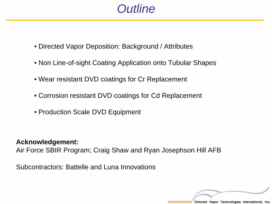
Outline
• Directed Vapor Deposition: Background / Attributes
• Non Line-of-sight Coating Application onto Tubular Shapes
• Wear resistant DVD coatings for Cr Replacement
• Corrosion resistant DVD coatings for Cd Replacement
• Production Scale DVD Equipment
Acknowledgement:Air Force SBIR Program; Craig Shaw and Ryan Josephson Hill AFB
Subcontractors: Battelle and Luna Innovations

Electron Beam – Directed Vapor Deposition*
Rationale for DVD:Conceptgas phase scattering of vapor (by collisions with background gas) enables the flux to be
collimated
*J.F. Groves and H.N.G. Wadley, Composites B, 28B, 57 (1997).
• increase depositionefficiency of EB-PVD process• increase deposition rate• non-line-of-sight coating• soft vacuum – ease of use • composition and morphology control

High pressure (0.1 – 1 Torr) deposition and plasma activation
for morphology control
Multisource evaporation (at least 4 rod) for composition control
(high speed (100kHz) beam scanning)
Nozzle axis in-linewith the source
Focused vapor high deposition efficiency
High deposition rates
Short pump down time
"Directed Vapor Deposition," J.F. Groves, G. Mattausch,
Directed Vapor Deposition
H. Morgner, D.D. Hass and H.N.G. Wadley, Surface Engineering, 16(6), 461- 464 (2000)
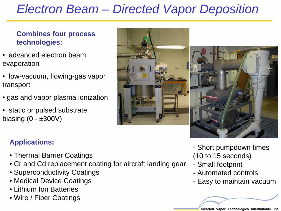
Combines four process technologies:
• gas and vapor plasma ionization
• static or pulsed substrate biasing (0 - ±300V)
• advanced electron beam evaporation
• low-vacuum, flowing-gas vapor transport
Electron Beam – Directed Vapor Deposition
Applications:
• Thermal Barrier Coatings• Cr and Cd replacement coating for aircraft landing gear• Superconductivity Coatings• Medical Device Coatings• Lithium Ion Batteries• Wire / Fiber Coatings
- Short pumpdown times(10 to 15 seconds)- Small footprint- Automated controls- Easy to maintain vacuum

Deposition Rate and Efficiency
Non Line-of-Sight Deposition
Compositional Control
Microstructural Control
• Multi-source evaporation enables precise composition control• Gas jet controls degree of source intermixing• Multilayer coatings• Combinatorial synthesis• Reactive deposition of oxides and nitrides
• Supersonic gas jet focuses vapor flux onto substrate •Materials utilization efficiencies approaching 80% •Deposition rates >80 μm/min.
• Vapor phase collisions between vapor and gas jet atoms enable NLOS deposition
• Dense and porous coatings• Plasma activation for dense layers
Electron Beam – Directed Vapor Deposition

Landing Gear Coating (NLOS)
NLOS Deposition Approach
• Use supersonic gas jet to focus vapor atoms into internal regions of components
• Scatter vapor atoms onto NLOS surfaces either by controlling the speed and density of the gas jet
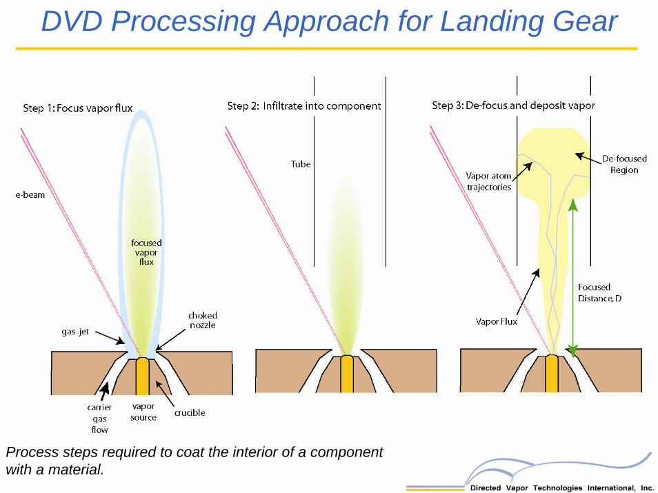
Process steps required to coat the interior of a component with a material.
DVD Processing Approach for Landing Gear
Step 1: Focus vapor flux
gas jet
focused vapor
flux
/ choked nozzle
•-------ca.,r~~ gas source crucible
flow
Step 2: Infiltrate into component Step 3: De-focus and deposit vapor
De-focused Region

Change in the location of the de-focused region of the vapor flux where NLOS deposition occurs when the gas jet pressure ratio and/or upstream pressure is increased.
Position of de-focused region dependent on:
-Carrier gas flow rate- Pressure ratio-Chamber pressure-Tube diameter-Nozzle geometry
De-focused region canreach different ID positions
to enable controlof thickness uniformity
Internal Coatings on Tubes
Pc = 0.075 Torr Pc = 0.195 Torr

0
0.2
0.4
0.6
0.8
1
1.2
0 5 10 15
Position on Tube
Rel
ativ
e C
oatin
g Th
ickn
ess
10slm
15slm
20slm
Coating Uniformity (3”diameter tubes)
TubeEntrance
TubeExit
(cm)
Tailor thickness uniformity by altering gas flow rate during deposition
Internal Coatings on Tubes

Substrate
Aluminum Coating
8.52 μm
10 slm
Dense Al coatings deposited at NLOS locations inside a tube
NLOS Coating Microstructure
Substrate Temp. ~ 200oC
20 slm
Internal Coatings on Tubes
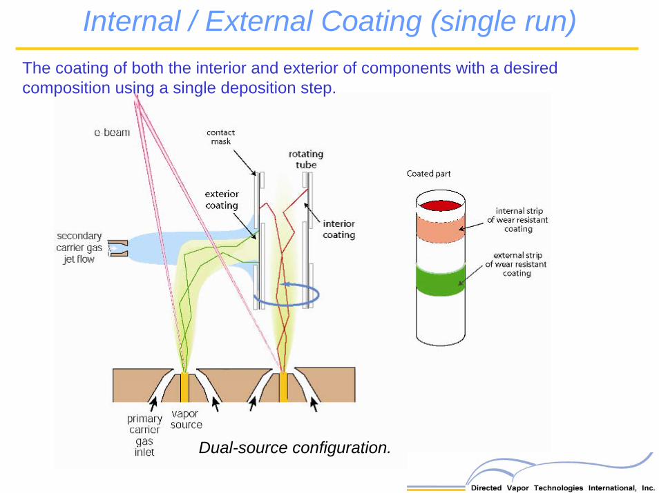
Internal / External Coating (single run)The coating of both the interior and exterior of components with a desired composition using a single deposition step.
Dual-source configuration.
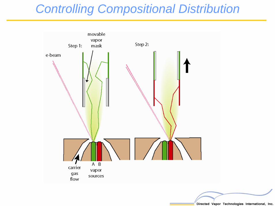
Controlling Compositional Distribution
e-beam
Step 1:
carrier gas flow
movable vapor mask
A B vapor
sources
Step 2:
t
r-::::-;::;;-,.......----__.../ =====- Directed Vapor Technologies International, Inc.
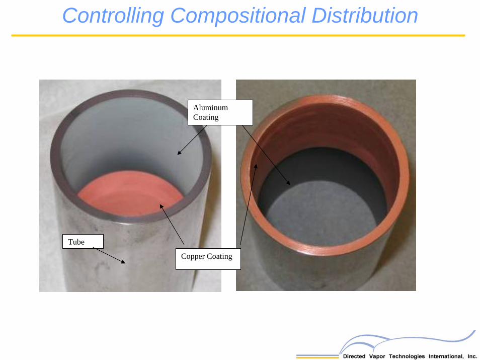
Copper Coating
Tube
Aluminum Coating
Controlling Compositional Distribution

DVD Advantages for Landing Gear Coating• Apply wear and corrosion resistant coatings onto non line-of-sight regions of components
• Short pumpdown times (10 to 15 sec); soft vacuum (0.1 to 0.5 Torr)
• Ability to apply both wear and corrosion resistant coatings with a single piece of equipment at high rate.
- Potential to apply two different coating compositions in a single deposition run
• Ability to control the thickness uniformity on parts to limit post-deposition grindingsteps
• Potential to deposit interior and exterior coatings simultaneously in a single processing step.
• Advanced compositional control enables the development of novel wear and corrosion resistant compositions
- Replace current Cr and Cd coating- Specifically designed for use in a environmentally friendly physical vapor
deposition approach.
Wear Resistant Coating Development

Wear Resistant Coatings
• Coating compositions were developed that result in nanocomposite structures consisting of nanoscaled-grains. By precisely controlling the elements in the coating and their relative volume fractions, coatings that yielded a high H/E ratio and a relatively low modulus were achieved. Such coatings are anticipated to result in excellent wear performance and good coating adhesion.
• This was achieved by creating coatings using two or more immiscible materials that can phase separate during processing resulting in nanocomposites
• Low melting point materials were used to enable good processibility (Ease of use!)
• Combinatorial study used to quickly assess potential compositions
Approach Specifically design coating composition to enable both wear performance and processability

Combinatorial Synthesis
High density / high velocity jets
lead to concentrationgradients along the
substrate
As a result individual samples containing a library of compositions can be created
Approach can be used to accelerate the
search for new coating compositions with
improved properties

Nanocomposites for Wear
Two phased ternary alloys having nano-sized grains have been developed as potential replacement of hard chrome coating on landing gear
Appearance depends on position on substrate
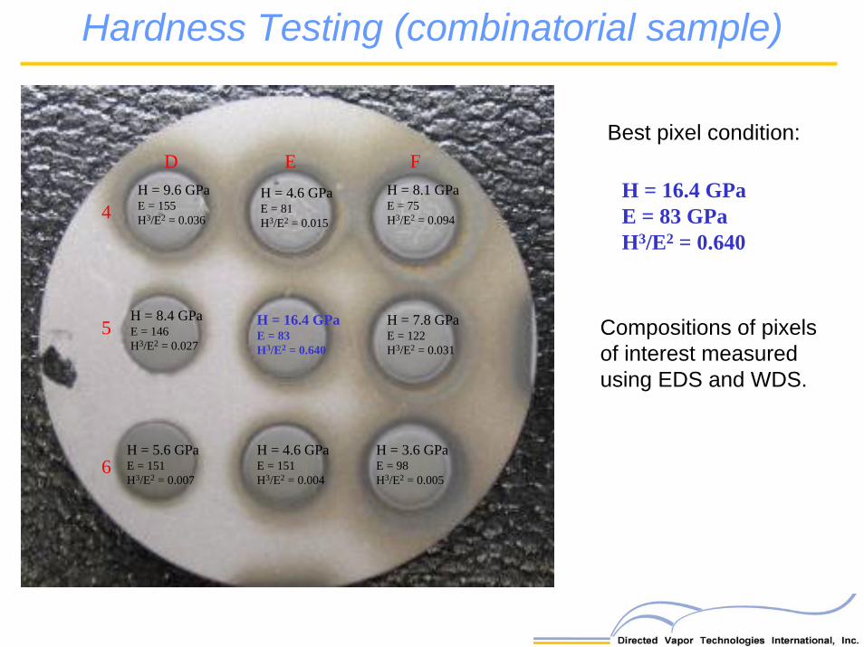
D E F
4
5
6
H = 9.6 GPaE = 155H3/E2 = 0.036
H = 4.6 GPaE = 81H3/E2 = 0.015
H = 8.1 GPaE = 75H3/E2 = 0.094
H = 16.4 GPaE = 83H3/E2 = 0.640
H = 8.4 GPaE = 146H3/E2 = 0.027
H = 7.8 GPaE = 122H3/E2 = 0.031
H = 5.6 GPaE = 151H3/E2 = 0.007
H = 4.6 GPaE = 151H3/E2 = 0.004
H = 3.6 GPaE = 98H3/E2 = 0.005
Hardness Testing (combinatorial sample)
Compositions of pixels of interest measured using EDS and WDS.
H = 16.4 GPaE = 83 GPaH3/E2 = 0.640
Best pixel condition:

DVTI Coating
300M substrate
Sample Location
Hardness (GPa)
Hardness (Vickers)
Elastic Modulus (GPa)
H3/E2
1 33.3 3087 189 1.03
2 35.2 3178 210 0.98
3 30.0 2586 171 0.92
4 35.4 3000 193 1.19
5 26.3 2319 136 0.98
Wear Coating (coupon application)
SampleArea of Wear Track
[ microns2 ]
SampleWear Rate
[ 10 –4 mm3/Nm ]
DVTI - LG031 523 ± 58 2.74
DVTI - LG029 304 ± 66 1.59
Hard Chrome 1 558 ± 218 8.16
Hardness / Modulus Testing
Pin-on-disc testing
>3X Cr >40X Cr
3 to 5x reduction in wear rate
over Cr
Hardness and Wear Testing (coupon level)
Objectives:
1) Demonstrate that the performance of DVTI-developed and deposited coatings is at least as good as that of the currently used EHC process in metal-to-metal wear.
2) Demonstrate that the directed vapor deposition (DVD) technique is viable for non-line-of-sight (NLOS) surfaces, where the hard chrome-alternative high velocity oxy-fuel (HVOF) process cannot be used.
3) Demonstrate that the coating is viable for sealing surfaces, where a surface finish of 8 to 12 micro-inches Ra may be required, either as-deposited, or after grinding, honing and/or polishing. It must also be demonstrated that abrasion of the elastomeric seal material is equivalent to, or less than that of EHC.
Battelle will test the DVD coatings with respect to metal-to-metal wear and sealing capability at a TRL 4 level
Tribological Testing (Component Level)
Tribological Testing (Component Level)
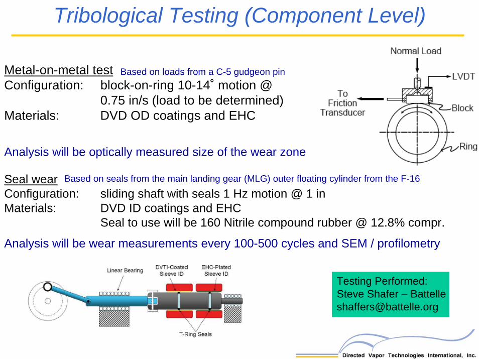
Metal-on-metal testConfiguration: block-on-ring 10-14˚ motion @
0.75 in/s (load to be determined)Materials: DVD OD coatings and EHC
Analysis will be optically measured size of the wear zone
Seal wearConfiguration: sliding shaft with seals 1 Hz motion @ 1 inMaterials: DVD ID coatings and EHC
Seal to use will be 160 Nitrile compound rubber @ 12.8% compr.
Analysis will be wear measurements every 100-500 cycles and SEM / profilometry
Testing Performed:Steve Shafer – [email protected]
Based on loads from a C-5 gudgeon pin
Based on seals from the main landing gear (MLG) outer floating cylinder from the F-16

Wear Coating on Tubes
Coated Region
Tribological Testing (Component Level)

Corrosion Resistant Coating Development

Corrosion Resistant Coating Development Development of corrosion resistant coating composition for Cadmium replacement optimized for ease of use in vapor deposition systems.
• Use combinatorial approach to develop optimized coating
Materials Selection:
• An electrochemical potential close to and below that of high strength steel (or near that of cadmium
• A relatively low melting point
• Investigating Al and Zn ternary alloys
Gives the ability to accurately:• Determine the electrochemical potential
• Determine corrosion rate
Can determine coating lifetime for a given thickness
Zero Resistance Ammetry

-1000
-900
-800
-700
-600
-500
-400
Steel
1-Cd
2-Cd
DVTI 1-1
DVTI 2-1
DVTI 2-2
DVTI 2-3
Sample
Eco
rr (m
V S
CE)
Corrosion potentials for steel substrate, Cd electroplate and DVTI coatings.
Corrosion Resistant Coating Development
DVTI coating has a lower electrochemical potential than steel and slightly higher than Cd

Mask 1.25”
Grit Blast 5”+ bottom
Coat4.75”
Not shot peened~3/4”Mask 1.25”
Grit Blast 5”+ bottom
Coat4.75”
Not shot peened~3/4”
1) Test No. 1. Neutral Salt Fog Corrosion Test (ASTM -B117-94)
2) Test No. 2. General Motors (GM) 9540P/B Cyclic Corrosion Test.
3) Test No. 3. SO2 Salt Fog Corrosion Test (ASTM G85-85)
Corrosion Testing (Component Level)
Testing in accordance with procedures and protocols referenced in Ch. 3 of the U.S. HCAT testing document
Tests to be performed by Battelle using a ATO-TECH Cyclic Corrosion Chamber
Testing by John Stropki @ Battelle presentation

Corrosion Testing (Component Level)
Three bar heating and manipulationunit for corrosion test samples

Production Scale DVD Coater
Chamber
E-beam Gun
Work platform
Sound containment
Chamber Pumps
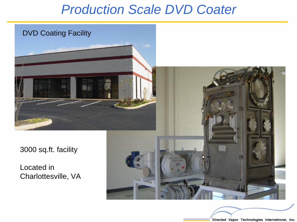
Production Scale DVD Coater DVD Coating Facility
3000 sq.ft. facility
Located in Charlottesville, VA

Questions?