depth of field imaging using phase aperture coding … system for real-time computational extended...
TRANSCRIPT

FPGA system for real-time computational extendeddepth of field imaging using phase aperture coding
Tal Remez, Or Litany, Shachar Yoseff, Harel Haim, and Alex Bronstein
Tel-Aviv UniversityElectrical Engineering Department, Tel Aviv University, Tel Aviv, Israel
Abstract. We present a proof-of-concept end-to-end system for computationalextended depth of field (EDOF) imaging. The acquisition is performed through aphase-coded aperture implemented by placing a thin wavelength-dependent op-tical mask inside the pupil of a conventional camera lens, as a result of which,each color channel is focused at a different depth. The reconstruction process re-ceives the raw Bayer image as the input, and performs blind estimation of theoutput color image in focus at an extended range of depths using a patch-wisesparse prior. We present a fast non-iterative reconstruction algorithm operatingwith constant latency in fixed-point arithmetics and achieving real-time perfor-mance in a prototype FPGA implementation. The output of the system, on simu-lated and real-life scenes, is qualitatively and quantitatively better than the resultof clear-aperture imaging followed by state-of-the-art blind deblurring.
Keywords: EDOF, sparse coding, FPGA, real-time.
1 Introduction
The increasing popularity of phone cameras combined with the affordability of high-quality CMOS sensors have transformed digital photography into an integral part ofthe way we communicate. While being the principal technology driver for miniaturecameras, the smartphone market is also one of the most challenging arenas for digi-tal imaging. The quality of a digital image is determined by the quality of the opticalsystem and the image sensor. With the increase in pixel number and density, imagingsystem resolution is now mostly bound by optical system limitations. Since form factorchallenges imposed by smart phone designs make it very difficult to improve the imagequality via standard optical solutions, many R&D activities in the field in recent yearshave shifted to the domain of computational imaging. The need to acquire high-qualityimages and videos of moving low-light scenes through a miniature lens and the fact thattraditional autofocusing mechanisms are costly, slow, and unreliable in low-light con-ditions render acute the tradeoff between the aperture size (F#) and the depth of field(DOF) of the optical system.
Imaging with limited DOF brings forth the challenge of restoration of out-of-focus(OOF) images – a notoriously ill-posed problem due to information loss in the pro-cess. There exists a wealth of literature dedicated to purely computational approachesto image deblurring and deconvolution [1,2,3,4]. The dominant models, increasinglypopular in recent years, are flavors of sparse and redundant representations [5,6], which
arX
iv:1
608.
0107
4v1
[cs
.CV
] 3
Aug
201
6
2 ECCV-16 submission ID 463
have been proved as a powerful tool for image processing, compression, and analysis.It is now well-established that small patches from a natural image can be represented asa linear combination of only a few atoms in an appropriately constructed over-complete(redundant) dictionary. This constitutes a powerful prior that has been successfully em-ployed to regularize numerous otherwise ill-posed image processing and restorationtasks [7,8].
Existing image deblurring techniques assume that the blurring kernel is known [5]or use an expectation maximization-type of approach to blindly estimate the kernelfrom the data, either parametrically when the point spread function (PSF) of the sys-tem is well-characterized and only the scene depth is unknown, or non-parametricallymaking less assumptions about the optics [1,6,2,3]. Using conventional optics, informa-tion about sharp image features is irreversibly lost, posing inherent limitations on anycomputational technique.
These limitations can be overcome by manipulating the image acquisition process.Some well-known methods produced a constant PSF kernel for all depths of field usinga wave-front coding phase mask [9,10]. Similar methods for depth-invariant PSF utilizefocal sweep [11] or use uncorrected lens as a type of spectral focal sweep [12]. Having asingle known PSF, the image can be recovered using non-blind deconvolution methods.These techniques reduce image contrast and are very sensitive to noise and thereforenot suitable for high quality image applications.
Other related techniques use an amplitude coded mask [13] or a color-dependentring mask [14] such that objects at different depth will exhibit a distinctive spatialstructure which improves the image restoration process. The main drawback of thosemethods is the fact that the light efficiency is only about 50% in [13] and 60% in [14],making them unsuitable for low light conditions.
A recent trend in the literature [15] proposes the use of wavelength-dependent phaseaperture coding, whereby one gets different responses for the red, green and blue chan-nels, resulting in the simultaneous acquisition of three perfectly registered images, eachwith a different out-of-focus characteristic. Under the assumption that sharp edges andother high-frequency features characterizing a well-focused image are present in allcolor channels, the joint analysis of the three channels acquired through a phase masklocated in pupil, allows to extend the system DOF without significant prior knowledgeabout the blurring kernel. This type of mask can be easily assembled in most conven-tional systems with minimal modification and provides a light efficiency of up to 99%using a coated glass plate.
Contributions presented in this work are threefold:
1. We present a learning-based algorithm for computational EDOF using phase aper-ture coding.
2. We demonstrate empirically the superiority of our algorithm over previous methodsin reconstruction quality at a significantly lower runtime.
3. We introduce a full end-to-end hardware system including a FPGA implementationof our algorithm.
The rest of the paper is organized as follows: Section 2 details the image forma-tion model in phase-coded aperture acquisition. Section 3 formulates the reconstruc-tion optimization problem, and Section 4 details the fast algorithm for its approximate

ECCV-16 submission ID 463 3
solution. Section 5 describes the FPGA system hosting the reconstruction process. Ex-perimental evaluation of the system on synthetic and real scenes, and its comparison toclear-aperture imaging following by standard deconvolution is presented in Section 6.A brief discussion in Section 7 concludes the paper.
2 Phase-Coded Aperture Imaging
An imaging system acquiring an out-of-focus object suffers from aberrations, in par-ticular blur, that degrade the image quality resulting in low contrast, loss of sharpnessand even loss of information. In digital systems, image blur (main OOF effect) is notobservable as long as the image size of a point source in the object plane is smaller thanthe pixel size in the detector plane. The OOF error is analytically a wave-front error, ex-pressed as a quadratic phase error in the pupil plane [16]. In case of a circular aperturewith radius R, we define the defocus parameter as
ψ =πR2
λ
(1
zo+
1
zimg− 1
f
)=πR2
λ
(1
zimg− 1
zi
)=πR2
λ
(1
zo− 1
zn
),
(1)
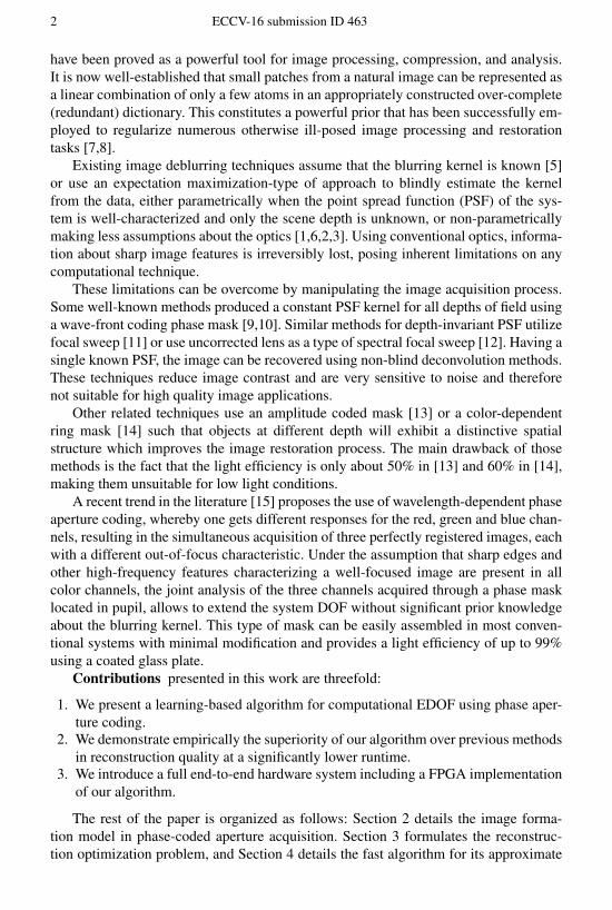
where zimg is the sensor plane location of an object in the nominal position zn, zi isthe ideal image plane for an object located at zo , and λ is the optical wavelength.The defocus parameter ψ measures the maximum phase error at the aperture edge.For ψ > 1, the image will experience contrast loss, while for ψ > 4 it will experienceinformation loss and even reversal of contrast at some frequencies, as can be observed inFigure 1(a). For a circular clear aperture, the cut-off spatial frequency due to diffractionlimit is given by fc = 2R
λzi. Increasing the aperture size R is hence a double-edged
sword: it results in higher fc and hence improved contrast and higher signal-to-noiseratio (SNR) due to the increase in the amount of collected light; however, this comesat the cost of a steeper increase in ψ as a function of the deviation of the object depthzo from the nominal depth zn, hence, lower DOF. comes at the cost of diminishing theDOF.
Radially symmetric binary optical phase masks have been proposed for overcominglimitations set by OOF imaging [17]. Milgrom et al. [18] proposed the use of a specialRGB phase mask that exhibits significantly different response in the three major colorchannels R, G and B. It has been shown that each channel provides best performancefor different depth regions, so that the three channels jointly provide an extended DOF.Based on Milgrom’s mask, a similar mask was designed in [19] specifically to furtherincrease the diversity between the color channels such that each depth region will be asunique as possible. This effect has been the key element of developing this new type ofcomputational camera. Figure 1(b) shows the diversity between the color channels fordifferent depths (ψ values) when using a clear aperture (dotted plot) and when using thephase mask from [19] (solid plot). The contrast levels are generally somewhat lowerwhen using the phase mask, for the “in focus” condition, but it exhibits higher contrast

4 ECCV-16 submission ID 463
ψ-4 -2 0 2 4 6 8
Con
trast
0
0.1
0.2
0.3
0.4
0.5
0.6
0.7
0.8
0.9
1Red (610 nm)Green (540 nm)Blue (460 nm)
(a) (b)
Fig. 1. Spatial frequency response and color channel separation (a) Optical system responseto spatial frequency for different ψ values. (b) Comparison between contrast levels for a singlespatial frequency fc/4 as a function of ψ with clear aperture (dotted) and a phase mask (solid).
at larger DOF, providing separation of the response for the three color channels, aneffect that will later be used for restoring the contrast levels to their nominal values.
Assuming approximately constant depth and, hence, the same unknown ψ for allpixels in the vicinity of a spatial location ξ in the sensor plane, the image formationmodel can be described as the following convolution
yR(ξ) = (hRψ ∗ xR)(ξ) + ηR(ξ)
yG(ξ) = (hGψ ∗ xG)(ξ) + ηG(ξ)
yB(ξ) = (hBψ ∗ xB)(ξ) + ηB(ξ),
where x∗, ∗ = R,G,B, denote the three color channels of the ideal (latent) in-focus im-age, y∗ are the corresponding channels of the OOF image formed in the sensor plane,h∗ψ are the three corresponding depth-dependent blur kernels, and η∗ denote additivesensor noise that can be fairly accurately modeled as white Gaussian at least at rea-sonable illumination intensities. In vector notation combining the three channels, theexpression simplifies to
y(ξ) = (hψ ∗ x)(ξ) + η(ξ), (2)
where x and y denote the three-channel latent in-focus and the observed OOF images,respectively.
In the majority of conventional image sensors, the acquisition of color information isdone through a color filter array (CFA), also known as Bayer filter mosaic, where everypixel captures only one of the red, green or blue channels. A demosaicing process thenrestores the raw image to a full-resolution color image. With some abuse of notation,CFA can be introduced to our image formation model as
y(ξ) = B(ξ)(hψ ∗ x)(ξ) + η′(ξ), (3)
where y denotes the raw Bayer image, and B(ξ) the location-dependent response of thearray filters, which up to cross-talk and vignetting artifacts looks like B = (1, 0, 0), (0, 1, 0),and (0, 0, 1) for the R, G, and B color channels, respectively.

ECCV-16 submission ID 463 5
3 EDOF Image Recovery Using a Sparse Prior
Sparse representation was proved to be a strong prior for both non-blind [5] and blind[1,6,2,3] image deblurring. A signal x ∈ Rn is said to admit a sparse representation (or,more accurately, approximation) in an n× k overcomplete (k > n) dictionary D if onecan find a vector z ∈ Rk with only a few non-zero coefficients, such that x ≈ Dz e.g. inthe `2-sense. The sparse representation pursuit problem can be cast as the minimizationproblem,
z = argminz‖x−Dz‖22 + µg(z), (4)
where g(z) is a sparsity-inducing prior whose relative importance is governed by theparameter µ.
While priors such as the `0 pseudonorm counting the number of non-zeros in thevector z give rise to computationally intractable optimization problems, there existefficient greedy approximation techniques including the orthogonal matching pursuit(OMP) [20,21] or convex relaxation techniques replacing the `0 pseudonorm with the`1 norm minimization [22]. The dictionary D can be constructed axiomatically basedon image transforms such as DCT or wavelet, or trained (e.g., via k-SVD [23]) usinga set of representative images. Here, we adopt the latter approach to construct a dictio-nary representing 8 × 8 patches from the image, represented as n = 192-dimensionalvectors (64 dimensions for each color channel).
Assuming (unrealistically) a known ψ, the forward model (3) described in the pre-vious section can be directly incorporated into the data fitting term, resulting in thefollowing optimization problem:
z = argminz‖y −BHψDz‖22 + µg(z), (5)
where y is a 64-dimensional vector representing the patch in the input Bayer image, Dis the 192 × k-dimensional dictionary, and z is the k-dimensional vector of represen-tation coefficients. The 192 × 192 matrix Hψ represents the action of the out-of-focusblur kernel corresponding to ψ to each of the color channels, while 64× 192 matrix Bdescribes the action of the CFA on the patch; in conventional CFA designs it is constantas long as the patches are selected from essentially same locations. The reconstructedpatch is obtained as x = Dz. Defining the blurred dictionary Dψ = HψD, the latteroptimization problem can be rewritten as
z = argminz‖y −BDψz‖22 + µg(z). (6)
Note that the pursuit is performed with respect to the blurred dictionary Dψ , whilethe patch reconstruction from the computed coefficients is performed with the cleardictionary D.
In practical applications, the depth and, hence, the out-of-focus parameter ψ in eachpatch are unknown a priori, leading to the blind setting of the above reconstructionproblem. Many studies dealt with this setting with limited success. For instance, us-ing different iterative processes, one tries to estimate the blurring kernel so that imagerestoration can be thereafter achieved. Reconstruction processes usually require high
6 ECCV-16 submission ID 463
computational complexity, which limits their use for many real-time applications. Eventhen, the assumption of a single blur kernel for the entire image is often unrealistic.
In our setup, the phase coding of the aperture contains hints about ψ through therelation between the color channels. To address the blind setting of the problem, weconstruct a concatenated blurred representation dictionary containing several fixed val-ues of ψ,
DΨ = (Dψ1, . . . ,Dψq
),
and solvingz = argmin
z‖y −BDΨz‖22 + µg(z), (7)
for z ∈ Rqk. The reconstruction is performed as before with the clear dictionary con-catenated q times, x = (D, . . . ,D)z. In all our experiments, we used q = 8 and setψ1 = 1, . . . , ψ8 = 8. While an additional prior asserting that the coefficients are local-ized in one of the sub-dictionaries can be imposed using standard structured sparsity-promoting priors such as the mixed `2,1 norm, we defer this obvious extension to futurestudy.
The pursuit process chooses elements from the dictionary that best match the inputpatch, based on the `2 distance. Using the RGB phase mask, the blurred dictionaryvaries strongly for different kernels since the response of the imaging system is verydifferent for each color. An input patch from an imaging system phase-coded aperturewill also exhibit different response for each color. The response will be unique for eachkernel and therefore the input vector will most likely associate with vectors from thedictionary Dψi
experiencing the same blurring process.Comparing our algorithm with a state-of-art algorithm with available public domain
code, provided by Krishnan et al. [2], and our implementation of [15], our processproduced superior results when applied to natural images out of the Kodak dataset [24].We also run the process on texture images (Colored Brodatz Texture database [25])and observed similar performance, meaning that the concatenated dictionary is likely todescribe well almost any natural scene.
4 Fast Image Reconstruction
As was explained in the previous section, the pursuit problem (7) can be posed as aconvex optimization problem by choosing g(z) = ‖z‖1, and solved using proximalalgorithms such as the iterative shrinkage thresholding algorithm (ISTA) or its acceler-ated version (FISTA) [26]. However, these iterative solvers typically require hundredsof iterations to converge, resulting in prohibitive complexity and unpredictable input-dependent latency, which is unacceptable in real-time applications. To overcome thislimitation, we follow the approach advocated by [27], in which a small number, T , ofISTA iterations is unrolled into a feed-forward neural network that subsequently under-goes supervised training on typical inputs, as explained in the sequel. A pseudo-codeof ISTA is given in Algorithm 1, where we denote Q = 1
LBDΨ , S = I − 1LQ
TQ,and σθ(x) = max(|x| − θ, 0)sign(x) is a two-sided shrinkage function with thresholdθ = 2µ
L applied element-wise. L denotes a scalar larger than the largest eigenvalue ofQTQ.
ECCV-16 submission ID 463 7
Input: Data x, number of iterations T , shrinkage threshold θ, matrices D, Q, and SOutput: Reconstructed image x,
auxiliary variables {zt}Tt=1,{bt}Tt=1
initialize z1 = 0 and b1 = QTxfor t = 1,2,. . . ,T do
zt+1 = σθ (bt)bt+1 = bt + S (zt+1 − zt)
endx = DzT
Algorithm 1: ISTA algorithm.
As can be easily interpreted from the ISTA algorithm, the network comprises threetypes of layers: An initialization layer (denoted as I), which finds the representationof the input signal in the dictionary; several (T − 2) recurrent middle layers (M) per-forming gradient step followed by shrinkage; and a final layer (F) which translates theresulting dictionary coefficients to the reconstructed signal. All these types of layers canbe realized from the single multi-purpose calculator stage shown in Figure 2 (right) thatis amenable for hardware implementation. To get the “I” configuration, we set bin = 0,A = −QT, c = 0 and θ = 0. The “M” configuration layer is fed by the output ofthe previous calculator, and the matrix A is set to S. The output is further fed to eitheranother “M” layer or to the “F” layer. Finally, the “F” configuration of the calculator isa reduction into multiplication by the matrix D. This is achieved by setting bin = 0,and A = D.
Supervised training of the network is done by initializing the parameters as detailedabove, and then adapting them using a stochastic gradient procedure minimizing thereconstruction error F of the entire network. We use the following empirical loss
F =1
N
N∑n=1
f(x∗n, xn), (8)
which for a large enough training set, N , approximates the expected value of f withrespect to the distribution of the ground truth signals x∗n. Here, xn denotes the outputof the network, and the loss objective f minimized during the training process is thestandard sum of squared differences,
f =1
2‖x∗n − xn‖22. (9)
Similarly to [27], the output of the network and the derivatives of the loss withrespect to the network parameters are calculated using the standard forward and backpropagation approach. Practice shows that the training process allows to reduce thenumber of layers by about two orders of magnitude while achieving a comparable re-construction quality. A detailed runtime analysis is presented in Section 6.

8 ECCV-16 submission ID 463
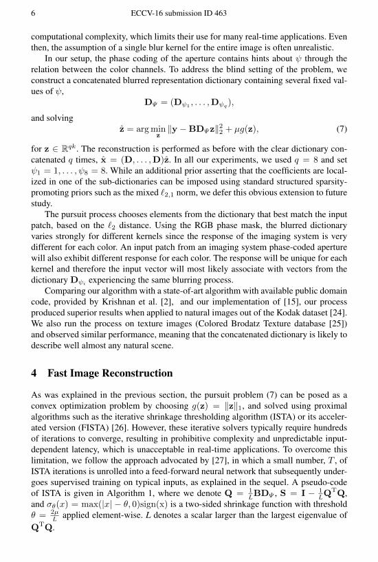
5 FPGA Image Reconstruction System
To demonstrate that the proposed image reconstruction process is efficient and is amenableto hardware implementation, we built a prototype FPGA system. An FPGA is a pro-grammable chip containing configurable logic blocks and routing resources, thereforeoffering a fair amount of flexibility previously only possible with software, along witha hardware-like computational speeds and reliability. While being distinct in many as-pects from application-specific integrated chips (ASICs), modern FPGAs are the closestapproximation of an ASIC one can get without incurring the costs of custom chip man-ufacturing.
A schematic description of our system is depicted in Figure 2 (left). We used theXilinx Kintex 7 chip on the KC705 development board chosen mainly because of theavailability of video interfaces. As the output, we used the onboard HDMI output phy,while for the input, we added an external HDMI phy board connected to the main boardthrough an FCM connector. The input frames are received by the board through theHDMI interface in raw Bayer format, 16 bits per pixel with the most significant bytespackaged as the Y channel, and the least significant byte packaged as the 4:2:2 colorchannels. The input is relayed to Write Agent 0 on the FPGA chip that buffers it inthe external dynamic memory. The content of the buffer is brought into the chip byRead Agent 0, which reorders the raster scan order into a stream of 8× 8 patches withconfigurable amount of overlap. The patches are then fed into a configurable calculatorpipeline implementing the reconstruction algorithm detailed in the previous section.The pipeline comprises three configurable stages, one of which is configured as theinitial stage (I), another as a middle stage (M), and yet another as the final stage (F),yielding the flow structure of the form I→ (T − 2)×M→ F.
The output of the calculator pipeline is produced in 4:2:2 YCbCr format comprising64 luma values at 16 bits per pixel, and additional 32+32 = 64 chroma values at 8 bitsper pixel. The luma component undergoes gamma conversion implemented as a lookuptable, reducing it to 8 bits per pixel. The patches are average-pooled (in case of overlap),reordered into raster scan order, and buffered into the dynamic memory by Write Agent1. Finally, Read Agent 1 conveys the content of the output buffer to HDMI output.
A schematic block diagram of a calculator stage is depicted in Figure 2 (right). Cal-culations are performed on vectors in fixed point arithmetics with 16 precision bits ex-cept the multiply-and-accumulate (MACC) block that uses 48 bit arithmetics internally.To keep a reasonable dynamic range, the data are scaled between various operationsby scale factors that were carefully selected to minimize precision loss on a large setof patches from a collection of natural images. Compared to its floating point counter-part, the fixed point implementation produced negligible quality degradation in all ourexperiments.
Each calculator performs element-wise soft thresholding and the multiplication ofthe input data by a matrix of size 64 × 192 (initial stage, converting the input 64-dimensional Bayer patch into a set of 192 coefficients), 192 × 192 (middle stage, per-forming operatons on the coefficients), or 192 × 128 (final stage, converting the coef-ficients into a 4:2:2 YCbCr patch with 64 luma dimensions and additional 64 chromadimensions). This is implemented by using MACC blocks of respective sizes. The pa-

ECCV-16 submission ID 463 9
rameters of each calculator stage, including threshold values and matrix coefficients,are stored in a local static memory on the FPGA chip.
Since MACC operations are fully pipelined, they require one clock cycle. The to-tal number of clock cycles it takes a single patch to pass though the chain is given by64+192× (T − 2), where T − 2 denotes the number of middle stages. There are addi-tional overheads of approximately 100 cycles per network layer. Due to high resourceutilization, we were able to use clock frequency of 125 MHz only. This results in overallthroughput of about 16 1920 × 1080 frames per second without patch overlap and a 4layer network.
Fig. 2. Schematic description of the FPGA reconstruction system. The raw Bayer image fromthe sensor at 12bit/pixel is passed, through the HDMI input interface daughter board, to theKintex 7 FPGA chip. The image is buffered in the external DRAM, from where it is fed as astream of possibly overlapping 8x8 patches to the calculator pipeline comprising of up to eightstages (see detail on the right), implementing the neural network architecture. The output patchesin 4:2:2 YCbCr format are average-pooled and buffered in raster order in the DRAM, from wherethe image is sent over to the HDMI output interface on the FPGA board. The parameters of thecalculator stages and other register values controlling the data flow are stored in the static memoryon the chip, into which they are loaded by the host application on system startup.
6 Experimental Evaluation
6.1 Synthetic images
In this experiment, we evaluated the performance of our algorithm on synthetic data oftwo types. In the first experiment, we used images from the KODAK dataset which wereblurred using a PSF simulating typical OOF blur. The same blur kernel was used for theentire image. In the second experiment, we created a synthetic scene with four differentdepths by using a different kernel in different regions of the image. In all syntheticexperiments the reconstruction neural network was trained using 2× 10⁶ patches takenfrom the KODAK training set. The network with T = 8 layers was converted to fixed-point arithmetics as described in Section 5.

10 ECCV-16 submission ID 463
Single Depth. Images taken from the KODAK dataset were used for the evaluation.Each image was convolved with a PSF corresponding to ψ = 8 and mosaiced to simu-late the input to the system. The algorithms compared were our OMP implementationof [15] with a k = 192 atom dictionary trained using k-SVD and our reconstructionneural network with a varying number of layers T . As a reference, we compared ouralgorithms to the blind deblurring algorithm from [2] following MATLAB default de-mosaicing algorithm. As the PSF varies across color channels, the algorithm was runseparately on each channel. Image reconstruction quality in terms of average PSNRand execution times are presented in Figure 3. It is evident that the highest PSNR isachieved by the neural network with T = 10; restricting to T = 8 layers performstwice as fast yielding almost the same average PSNR score. Interestingly, the neuralnetwork achieves better reconstruction quality compared to the greedy OMP algorithm[15], which we attribute to the effect of supervised training. All sparse prior-based al-gorithms outperform the blind deconvolution algorithm [2] by over 1 dB PSNR. Com-paring the execution times of the algorithms on a standard CPU shows that the OMPalgoithm is about 30 times faster than [2], while all neural network implementationsare more than 15 times faster than OMP and 500 times fatser than [2] with superiorreconstruction quality.
10−1
100
101
102
22.5
23
23.5
24
24.5
25
25.5
26
26.5
T=4 T=6
T=8 T=10
T=4 T=6
T=8 T=10
T=8
T=4
Time [sec]
PS
NR
[dB
]
Raw input for ψ=8Blind Deblurring [2]OMP [18]Floating point network (GPU)Floating point network (CPU)Fixed point network (FPGA)
Fig. 3. Comparison of average PSNR and run time on KODAK images. Presented are averagevalues over all test images in the KODAK dataset with simulated blur using ψ = 8 (magenta)reconstructed with the different algorithms. Top left corner represents high reconstruction qualityand low runtime. One can see that our algorithm (blue and cyan) achieves superior reconstructionquality in comparison to the blind deblurring algorithm of [2] (green) and to the OMP method of[15] (red). In addition, it is evident that increasing the number of layers (denoted by T above theblue and cyan points) improves the performance at an additional computational cost. Our fixedpoint FPGA implementation (cyan) offers the same reconstruction quality as its floating point(blue) counterpart executed on the CPU while being an order of magnitude faster. Remarkably,the FPGA implementation run-time is in the same range as the GPU floating point implemen-tation. All patch based algorithms were run using a patch stride of 2 pixels. Executing timeswere measured on an Intel Xeon E5-2650 2GHz CPU and a Tesla C2075 1.15GHz GPU. Ourfixed-point implementation was executed on a 100MHz Xilinx Kintex 7 FPGA.

ECCV-16 submission ID 463 11
Ground truth Blurred [2] [15] Our FPGA
Fig. 4. Synthetic image reconstruction. Columns from left to right: original scene, blurredscene (using a value of ψ = 8), blind deblurring using [2], our implementation of the OMPreconstruction of [15] and our FPGA fixed-point neural network with T = 8 layers.
In a GPU implementation, our neural network is more than 2, 000 times faster than [2]and 70 times faster than the OMP method of [15]. Furthermore, our fixed point FPGAimplementation offers the same reconstruction quality as its floating point counterpartand is an order of magnitude faster than the CPU implementation. Remarkably, theFPGA implementation run-time is in the same range as the floating point GPU imple-mentation, while running at an order of magnitude slower clock and requiring over twoorders of magnitude less power. Ground truth images and the reconstruction results bythe different algorithms are presented in Figure 4. Qualitatively, one can observe thatthe fixed-point neural network algorithm with T = 8 layers outperforms all other al-gorithms presented in the figure. Our experiments show that the output of fixed-pointnetwork with T = 4 is almost imperceavably inferior to the former case, while requiringsignificantly lower complexity.
Multiple Depths. As indicated in the previous section, for natural depth scenes onecannot assume that the image is blurred by a single blurring kernel. Our reconstructionprocess analyzes small patches rather than the entire image; therefore, the process isapplied to every region inside the image independently of the other regions, allowingour algorithm to treat the input as if it had a single blur kernel. To demonstrate the pro-cess, we simulated a “2.5D” scene with four objects each located at a different constantdistance from the camera as shown in Figure 5 (top left). The middle image in the toprow shows the simulation of the scene acquired using a conventional camera focusedon the background. As expected, other objects in the scene are increasingly blurred

12 ECCV-16 submission ID 463
with the increase of their distance from the focus point. The rightmost image in the toprow presents a simulated acquisition through a phase-coded aperture. The three bottomrows of Figure 5 present zoomed-in snippets of the ground truth compared against re-construction results using our proposed method, the blind deblurring algorithms [2] and[15] applied to the clear and to the phase-coded aperture images.
Observe that by using our method all objects were restored without noticeable arti-facts as opposed to the blind restoration of [2] applied on both aperture types. Quantita-tively, our proposed method outperforms all other methods. While the improvement interms of PSNR over the greedy OMP algorithm proposed by [15] is minor, a noticeablequalitative improvement is apparent in the zoomed-in snippets.
Ground truth Conventional imaging Imaging with phase coding
Ground truth Clear + [2] Phase + [2] Phase + [15] Phase + our17.95 dB 22.75 dB 24.78 dB 24.83 dB
Fig. 5. Synthetic Multiple Depth. The top row shows from left to right: the original syntheticimage used for simulating imaging effect on multi depth scene where each object was blurredaccording to its distance from the camera (the focus point was on the background buildings);Imaging results for conventional clear aperture imaging and imaging with a phase-coded aper-ture. The three bottom rows present from left to right zoomed-in snippets as follows: Groundtruth, blind deblurring proposed by [2] applied on the clear aperture image acquired using a con-ventional imaging system, blind deblurring of the phase-coded aperture image acquired by ouroptical system using [2], OMP [15] and our neural network. PSNR values are reported below theimages. The full sized images are available in the supplementary material.

ECCV-16 submission ID 463 13
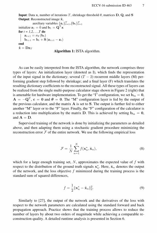
6.2 Real optical system
We built a table-top experimental system consisting of a conventional CMOS cameraand a 16mm C-mount commercial lens, into which the phase mask was inserted (Figure6,b).
(a) (b)
Fig. 6. System setup. (a) table setup of the scene presented in Figure 7; (b) 16mm lens with thephase mask (red arrow) inserted into its aperture.
A comparison between a conventional camera and our end-to-end system is pre-sented in Figure 7. The first and second columns from the left show the captured scenewith a conventional lens (clear aperture) and with a phase-coded aperture respectively,with the focus set to the background poster. The third and fourth columns show theresult of the blind deblurring algorithm from [2] applied to the clear and phase-codedaperture images, respectively. The fifth column presents the scene reconstructed from aphase-coded image using the OMP method from [15]. The rightmost column presentsthe reconstructed scene using our neural network with 4 layers implemented on anFPGA. Both clear and coded-aperture images were captured in the exact same light-ing conditions and exposure time. The entire image regions are shown in the top rowwhereas the four bottom rows contain zoomed-in snippets of the images at differentdepths. The superiority of the proposed system is evident in all cases in both qualityand run-time. For example, in the magnified fragment of the background (to which thecamera was focused), our system produces insignificant changes, while the deblurredclear and coded aperture images show significant over-sharpening artifacts visible ashalos around the buildings and cartoon like segments. Our method also outperformsthe OMP algorithm proposed by [15] which yields a noisier reconstruction. The bottomrow presents a fragment of the resolution chart in which the vanishing contrast spatialfrequency was marked with a dashed red line.
7 Conclusions
The phase-coded aperture computational EDOF imaging system presented in this workaims at solving one of the biggest challenges in today’s miniature digital cameras,namely, acquisition of images with both high spatial resolution and large depth of fieldin demanding lighting conditions. Our proposed solution can be easily incorporated toexisting imaging systems since it requires the addition of a thin mask (which can beintegrated into one of the existing optical surfaces), and a simple real-time hardware

14 ECCV-16 submission ID 463
Clear Phase Clear + [2] Phase + [2] Phase + [15] Phase + our450 [sec] 460 [sec] 140 [sec] 0.5 [sec]
Fig. 7. Full hardware pipeline experiment. From left to right: clear aperture image, phase-coded aperture image, clear aperture image after deblurring using [2], phase-coded aperture afterdeblurring using [2], phase-coded aperture after deblurring using [15] and the output of our cam-era using a fixed-point neural network with T = 4 layers. The dashed red lines in the bottomrow indicate vanishing contrast. The reconstruction time required by [2] was 450 seconds, by theOMP method from [15] 140 seconds while our FPGA only requires 0.5 seconds.
computational unit, which was demonstrated in an FPGA prototype. We showed ex-perimental evidence of the superior image quality of the proposed system compared toconventional acquisition and post-processing techniques. As we demonstrated throughextensive experiments, our system outperforms existing techniques for post processingan image taken by a standard camera. It is worthwhile noting that the FPGA system de-veloped for this project is rather flexible and, with moderate adjustments, may be usedfor implementing other image processing tasks based on sparse prior, such as denoisingor restoration from compressed samples.

ECCV-16 submission ID 463 15
References
1. Almeida, M.S.C., Almeida, L.B.: Blind and semi-blind deblurring of natural images. IEEEtransactions on image processing : a publication of the IEEE Signal Processing Society 19(1)(jan 2010) 36–52
2. Krishnan, D., Tay, T., Fergus, R.: Blind deconvolution using a normalized sparsity measure.In: Computer Vision and Pattern Recognition (CVPR), 2011 IEEE Conference on, IEEE(2011) 233–240
3. Shan, Q., Jia, J., Agarwala, A.: High-quality motion deblurring from a single image. In:ACM Transactions on Graphics (TOG). Volume 27., ACM (2008) 73
4. Starck, J.L., Pantin, E., Murtagh, F.: Deconvolution in Astronomy: a review. Publications ofthe Astronomical Society of the Pacific 114(800) (oct 2002) 1051–1069
5. Couzinie-Devy, F., Mairal, J., Bach, F., Ponce, J.: Dictionary learning for deblurring anddigital zoom. arXiv preprint arXiv:1110.0957 (2011)
6. Hu, Z., Huang, J.B., Yang, M.H.: Single image deblurring with adaptive dictionary learning.In: Image Processing (ICIP), 2010 17th IEEE International Conference on, IEEE (2010)1169–1172
7. Elad, M., Aharon, M.: Image denoising via sparse and redundant representations over learneddictionaries. Image Processing, IEEE Transactions on 15(12) (2006) 3736–3745
8. Fadili, M.J., Starck, J.L., Murtagh, F.: Inpainting and zooming using sparse representations.Computer Journal 52(1) (feb 2009) 64–79
9. Dowski, E.R., Cathey, W.T.: Extended depth of field through wave-front coding. AppliedOptics 34(11) (1995) 1859–1866
10. Cossairt, O., Zhou, C., Nayar, S.: Diffusion coded photography for extended depth of field.In: ACM Transactions on Graphics (TOG). Volume 29., ACM (2010) 31
11. Nagahara, H., Kuthirummal, S., Zhou, C., Nayar, S.K.: Flexible depth of field photography.In: Computer Vision–ECCV 2008. Springer (2008) 60–73
12. Cossairt, O., Nayar, S.: Spectral focal sweep: Extended depth of field from chromatic aber-rations. In: Computational Photography (ICCP), 2010 IEEE International Conference on,IEEE (2010) 1–8
13. Levin, A., Fergus, R., Durand, F., Freeman, W.T.: Image and depth from a conventionalcamera with a coded aperture. ACM Transactions on Graphics 26(3) (2007) 70
14. Chakrabarti, A., Zickler, T.: Depth and deblurring from a spectrally-varying depth-of-field.In: Computer Vision–ECCV 2012. Springer (2012) 648–661
15. Haim, H., Bronstein, A., Marom, E.: Multi-focus imaging using optical phase mask. In:Computational Optical Sensing and Imaging, Optical Society of America (2014) CTh2C–6
16. Goodman, J.W.: Introduction to Fourier Optics. 2nd edn. McGraw-Hill, New York (1996)17. Milgrom, B., Konforti, N., Golub, M.A., Marom, E.: Pupil coding masks for imaging poly-
chromatic scenes with high resolution and extended depth of field. Optics express 18(15)(2010) 15569–15584
18. Milgrom, B., Konforti, N., Golub, M.A., Marom, E.: Novel approach for extending thedepth of field of barcode decoders by using rgb channels of information. Optics express18(16) (2010) 17027–17039
19. Haim, H., Bronstein, A., Marom, E.: Computational multi-focus imaging combining sparsemodel with color dependent phase mask. Optics express 23(19) (sep 2015) 24547–56
20. Chen, S.S., Donoho, D.L., Saunders, M.A.: Atomic decomposition by basis pursuit. SIAMjournal on scientific computing 20(1) (1998) 33–61
21. Tropp, J.A., Gilbert, A.C.: Signal recovery from random measurements via orthogonalmatching pursuit. Information Theory, IEEE Transactions on 53(12) (2007) 4655–4666

16 ECCV-16 submission ID 463
22. Elad, M.: Sparse and Redundant Representations: From Theory to Applications in Signaland Image Processing. 1st edn. Springer Publishing Company, Incorporated (2010)
23. Aharon, M., Elad, M., Bruckstein, A.: K-svd: An algorithm for designing overcomplete dic-tionaries for sparse representation. Signal Processing, IEEE Transactions on 54(11) (2006)4311–4322
24. Franzen, R.: Kodak lossless true color image suite. see http://r0k. us/graphics/kodak (2004)25. Brodatz, P.: Textures: a photographic album for artists and designers. Dover Pubns (1966)26. Beck, A., Teboulle, M.: A fast iterative shrinkage-thresholding algorithm for linear inverse
problems. SIAM Journal on Imaging Sciences 2(1) (2009) 183–20227. Gregor, K., LeCun, Y.: Learning fast approximations of sparse coding. In: Proc. ICML.
(2010)