description of options - deif: Автоматизация ... mains mains b3.pdf · description of...
TRANSCRIPT

80
DESCRIPTION OF OPTIONS
• Description of option • Functional description • Parameter list
Document no.: 4189340473G
Gen-set Controller, GC-1FOption B3, Automatic Mains Failure (AMF)
and Automatic Transfer Switch control (ATS)

GC-1F Option B3, AMF and ATS
DEIF A/S Page 2 of 37
This description includes the following versions: GC-1F SW version 1.2x.x GC-1F/2 SW version 2.0x.x or later

GC-1F Option B3, AMF and ATS
DEIF A/S Page 3 of 37
Table of contents
1. WARNINGS AND LEGAL INFORMATION ........................................................................... 4 LEGAL INFORMATION AND RESPONSIBILITY ..................................................................................... 4 ELECTROSTATIC DISCHARGE AWARENESS ..................................................................................... 4 SAFETY ISSUES ............................................................................................................................ 4 FACTORY SETTINGS ...................................................................................................................... 4 DEFINITIONS ................................................................................................................................ 4
2. DESCRIPTION OF OPTION B3............................................................................................. 5 ANSI NUMBERS ............................................................................................................................ 5 AUTOMATIC MAINS FAILURE (AMF) ............................................................................................... 5 LOAD TAKE OVER (LTO) .............................................................................................................. 6
3. HARDWARE ........................................................................................................................... 7 TERMINALS .................................................................................................................................. 7 WIRING 3-PHASE .......................................................................................................................... 8 WIRING 1-PHASE .......................................................................................................................... 9 WIRING SPLIT-PHASE .................................................................................................................. 10 WIRING 3-PHASE 3-POSITION ATS .............................................................................................. 11 PUSH-BUTTONS AND LEDS ......................................................................................................... 12
4. FUNCTIONAL DESCRIPTIONS .......................................................................................... 13 AMF/ATS FAILURE LOGIC ........................................................................................................... 14 ATS TIMING SEQUENCES ............................................................................................................ 17 ATS CONFIGURATIONS ............................................................................................................... 24 CONFIGURATION......................................................................................................................... 28 INPUT FUNCTIONS (B3) ............................................................................................................... 28 OUTPUT FUNCTIONS (B3) ........................................................................................................... 30 ATS - SOURCE – SOURCE .......................................................................................................... 36
5. PARAMETER LIST .............................................................................................................. 37

GC-1F Option B3, AMF and ATS
DEIF A/S Page 4 of 37
1. Warnings and legal information
Legal information and responsibility DEIF takes no responsibility for installation or operation of the gen-set. If there is any doubt about how to install or operate the engine/generator controlled by the unit, the company responsible for the installation or the operation of the set must be contacted.
Electrostatic discharge awareness Sufficient care must be taken to protect the terminals against static discharges during the installation. Once the unit is installed and connected, these precautions are no longer necessary.
Safety issues Installing the unit implies work with dangerous currents and voltages. Therefore, the installation should only be carried out by authorised personnel who understand the risks involved in working with live electrical equipment.
Factory settings The unit is delivered with certain factory settings. Given the fact that these settings are based on average values, they are not necessarily the correct settings for matching the individual engine/generator. Thus precautions must be taken to check the settings before running the engine.
Definitions Throughout this document a number of notes and warnings will be presented. To ensure that these are noticed, they will be highlighted in order to separate them from the general text.
Notes
Warnings
The notes provide general information, which will be helpful for the reader to bear in mind.
The warnings indicate a potentially dangerous situation, which could result in death, personal injury or damaged equipment, if certain guidelines are not followed.
Be aware of the hazardous live currents and voltages. Do not touch any AC measurement inputs as this could lead to injury or death.
The units are not to be opened by unauthorised personnel. If opened anyway, the warranty will be lost.

GC-1F Option B3, AMF and ATS
DEIF A/S Page 5 of 37
2. Description of option B3 This document describes the functionality of AC voltage measurement and functions contained in option B3.
ANSI numbers
Function ANSI no. 3-phase AC voltage measurement, 50-480V AC, 50/60Hz - 3-phase over- and undervoltage failure 27/59 3-phase over- and underfrequency failure 81 3-phase voltage unbalance 60 3-phase – phase rotation sequence 47
Automatic Mains Failure (AMF) Option B3 is a software and hardware option, which means that the front foil will have to be changed. The basic GC-1F gen-set controller unit can be equipped with option B3. With option B3 the GC-1F will function as a real emergency power system controller. The mains (busbar) is supervised, and if a fault (voltage/frequency/unbalanced) is detected, then a disconnection signal will be sent to the mains breaker. At the same time the start sequence for the generator is initiated. When the generator voltage is within the limits, a signal will be transmitted to close the generator breaker. When the mains returns and the mains OK timer is expired, then the generator breaker will open and the mains breaker is closed.
Automatic Transfer Switch (ATS) The basic GC-1F gen-set controller unit can be equipped with option B3. With option B3, the GC-1F will be able to operate several different ATS mechanisms with AMF logic. There are two different ATS types:
• Generator – Mains • Mains Source 1 – Mains Source 2 or Normal Source – Emergency Source.
In this document, it will be called “Source – Source”
Generator – Mains This ATS type will be able to operate the mechanism of an ATS with control signals, defined by the input/output settings. The ATS will use AMF logic for the operation. The ATS controller will be able to control and protect the gen-set like in normal mains failure situations. It will also be possible just to give a start signal; “Start gen-set” to a gen-set. In this mode, the control and protection of the gen-set is done by the gen-set controller, with the GC-1F/2 ATS controller operating the ATS. Source – Source This type of ATS control will operate the mechanism of an ATS with control signals as defined by the input/output settings. The AMF handling is available between two mains or utility sources. Similar parameters as Generator – Mains are used, but with parameter names better suited to fit the Source – Source application. The GC-1F/2 ATS controller will not be able to control a gen-set directly, for example managing the start sequence with prepare and crank, but it will be able to give a start signal; “Start gen-set” signal for both sources. Priority selection of the sources will be possible by settings or done by M-Logic.

GC-1F Option B3, AMF and ATS
DEIF A/S Page 6 of 37
Load Take Over (LTO) The purpose of the LTO mode is to allow the controller to transfer the load to the gen-set regardless of the mains status. This could be used with command timer functions. There are two LTO modes, mode shift with normal LTO and LTO with AMF.
Mode shift OFF (normal LTO) If a mains failure event occurs, the controller will not automatically shift mode from LTO to AMF, thus the gen-set will not start. In this mode, the GC-1F will only start and take over the load when the unit is started in auto mode via digital input: “Auto start/stop”, regardless of the mains status. If a mains failure event occurs when a stop signal is given, the gen-set will continue to stop and open GB. The MB will remain open until the mains voltage is normal again, then it will close MB. If a mains failure event occurs while the gen-set is not running in this mode, the gen-set will not react to the mains failure. Mode shift ON (LTO with AMF mode) If a mains failure occurs when a stop gen-set signal is active, the gen-set will shift mode to AMF and run the AMF sequence. This will keep the gen-set running and GB closed until the mains voltage is normal again. When mains is normal, it will shift mode back to LTO. If a mains failure occurs while the gen-set is stopped (not running), the gen-set will react to the mains failure and start up like in a normal mains failure situation. The gen-set will stop again, when the mains has been restored.
Start/Stop of the gen-set in auto mode requires configuration of “auto start/stop” digital input.

GC-1F Option B3, AMF and ATS
DEIF A/S Page 7 of 37
3. Hardware
Terminals The AC voltage inputs are placed on terminals 28-32. Mains breaker control relay output is placed on terminals 47 and 48.
Unit rear view
AMF control 28 Mains L1 voltage
Voltage range 50-480V AC Ph-Ph value
29 Mains neutral voltage 30 Mains L2 voltage 31 Do not connect 32 Mains L3 voltage 47-48 Mains breaker control relay Function NC (normally closed). Configurable
1 2 3 4 5 6 7 8 9 10 11 12 13 14 15 16 17 18 19 20 21 22 23 24 25 26 27
28 29 30 31 32 33 34 35 36 37 38
L1 N L2 NA L3 L1 N NA L2 NA L3Mains voltage Gen Voltage
+ 0 1 2 3R21 R22 R23
com
Powersupply
Status Multi func-tional input
1 2 3 4 5 6com com InputR24 R26
Binary inputs Emergencystop
45 46 39 40 41 42 43 44
L1Gen Current
L2 L3
49505152
53545556
575859
Can L GND Can H
Can 1 J1939Option H5
B(-) GNDA(+)
modbusRS485
Option H2
Option H8/X4Can 2
Can H GND Can L
47 48

GC-1F Option B3, AMF and ATS
DEIF A/S Page 8 of 37
Wiring 3-phase
14 GB OFF feedback
46
45GB ON command
Supply
GC-1F AMF
MB ON command47
48
MB OFF feedback
Consumers
U L230 voltagesMainsNeutral29
28 U L1L2
L2
MAINS
Generator
L1N
L1N
MB
15
GB
U L133
36 U L2 Generatorvoltage34 Neutral
S2
S1
42 L2 s2
41 L2 s1
Generatorcurrent
L1 s139
L1 s240
S1
S2
L3
L3
U L332
38 U L3
S2
S1
44 L3 s2
43 L3 s1

GC-1F Option B3, AMF and ATS
DEIF A/S Page 9 of 37
Wiring 1-phase
S2
S1
N L1
U L133
34 Neutral
40 L1 s2
39 L1 s1
Generatorvoltages
currentGenerator
N L1
14 GB OFF feedback
46
45GB ON command
Supply
Generator
GC-1F AMF
MB ON command47
48
Neutral
MB OFF feedback
U L1 Mainsvoltages
MAINS
MB
GB
Consumers
28
29
15

GC-1F Option B3, AMF and ATS
DEIF A/S Page 10 of 37
14 GB OFF feedback
46
45GB ON command
Supply
GC-1F AMF
MB ON command47
48
MB OFF feedback
Consumers
U L230 voltagesMainsNeutral31
28 U L1L2
L2
MAINS
Generator
L1N
L1N
MB
15
GB
U L133
36 U L2 Generatorvoltage34 Neutral
S2
S1
42 L2 s2
41 L2 s1
Generatorcurrent
L1 s139
L1 s240
S1
S2
Wiring split-phase

GC-1F Option B3, AMF and ATS
DEIF A/S Page 11 of 37
Wiring 3-phase 3-position ATS

GC-1F Option B3, AMF and ATS
DEIF A/S Page 12 of 37
Push-buttons and LEDs The display for option B3 includes 2 extra push-buttons and 1 LED.
For general information about the display push-buttons and LEDs, please see the Installation Instructions and Reference Handbook.

GC-1F Option B3, AMF and ATS
DEIF A/S Page 13 of 37
4. Functional descriptions The following sequences will be shown in two conditions:
Mains fail timing sequence
Start engine + Open MB

GC-1F Option B3, AMF and ATS
DEIF A/S Page 14 of 37
Start engine
AMF/ATS failure logic The following describes the normal failure situations handled by the GC-1F during a mains failure/OK sequence (refer to “Mains fail timing sequence” for details).
Mains failure, open MB When a mains failure occurs, the MB is opened when either mains failure is detected (7065 Start eng. + open MB) or when GB is ready to take load (7065 Start eng.). If the MB cannot be opened, the GC-1F signals a MB open failure. The gen-set is kept running to have it ready when the MB failure has been fixed. The fail class for MB open failure (2200):
1. Warning. a. Alarm is activated. b. GB is not closed, since MB cannot be opened. c. Gen-set stays running.
2. Trip of GB. a. Alarm is activated. b. Gen-set stays running
3. Trip and stop. a. Alarm is activated. b. Gen-set is stopped including cooldown.
4. Shutdown. a. Alarm is activated. b. Gen-set is stopped without cooldown
5. Trip of MB. a. Alarm is activated. b. Gen-set stays running
6. Shutdown and manual mode. a. Alarm is activated. b. Gen-set is stopped without cooldown c. Controller changes running mode to MANUAL
tGBC
GB On
MB On
Mains failure detected
Gen start seq tFD
Gen stop seq
Mains OK
Mains OK
tFOD
tFU
tMBC
Gen running
Gen f/U OK
AMF/ATS logic will only activate in AUTO mode.

GC-1F Option B3, AMF and ATS
DEIF A/S Page 15 of 37
Mains failure, closing GB When the gen-set has been started and the MB is opened (no MB open failure), the GB must be closed. If this results in a GB close failure, the GB relay/pulse will be opened/given again and a GB close failure will be signaled. It is possible to change the fail class of the GB close failure to either “Trip and stop” or “Shutdown” to have the gen-set stopped when the GB cannot be closed. The fail class for GB close failure (2170):
1. Warning. a. Alarm is activated. b. GB is tripped c. Gen-set stays running.
2. Trip of GB. a. Alarm is activated. b. GB is tripped c. Gen-set stays running.
3. Trip and stop. a. Alarm is activated. b. GB is tripped c. Gen-set is stopped including cooldown.
4. Shutdown. a. Alarm is activated. b. GB is tripped c. Gen-set is stopped without cooldown
5. Trip of MB. a. Alarm is activated. b. GB is tripped c. MB trips (if closed) and load is dropped. d. Gen-set stays running.
6. Shutdown and manual mode. a. Alarm is activated. b. GB is tripped c. Gen-set is stopped without cooldown d. Controller changes running mode to MANUAL
Mains OK, Open GB When mains returns, the GB must be opened and MB can be closed. If GB cannot be opened, a GB open failure is signaled and the GB relay/pulse is closed/given again. The fail class for GB open failure (2160):
1. Warning. a. Alarm is activated. b. Gen-set stays running.
2. Trip of GB. a. Alarm is activated. b. Gen-set stays running.
3. Trip and stop. a. Alarm is activated. b. Gen-set is stopped including cooldown.
4. Shutdown. a. Alarm is activated. b. Gen-set is stopped without cooldown
5. Trip of MB. a. Alarm is activated. b. Gen-set stays running.
6. Shutdown and manual mode. a. Alarm is activated.

GC-1F Option B3, AMF and ATS
DEIF A/S Page 16 of 37
b. Gen-set is stopped without cooldown c. Controller changes running mode to MANUAL
Mains OK, Close MB When GB has been opened, the gen-set starts its cool-down sequence and the MB is closed. If this results in a MB close failure, a MB close failure is signaled, and the MB relay/pulse is opened/given again. Furthermore, the GB is closed again, sourcing the load. The fail class for MB close failure (2210):
1. Warning. a. Alarm is activated. b. If Gen V/Hz is OK, GB is closed. c. Gen-set stays running.
2. Trip of GB. a. Alarm is activated. b. GB trips. Load is dropped.
3. Trip and stop. a. Alarm is activated. b. GB is tripped and the gen-set is stopped including cooldown.
4. Shutdown. a. Alarm is activated. b. GB is tripped and the gen-set is stopped without cooldown
5. Trip of MB. a. Alarm is activated. b. MB trips and load is dropped. c. If Gen V/Hz is OK, GB is closed. Gen-set stays running.
6. Shutdown and manual mode. a. Alarm is activated. b. GB is tripped and the gen-set is stopped without cooldown c. Controller changes running mode to MANUAL
GC-1F Option B3, AMF and ATS
DEIF A/S Page 17 of 37
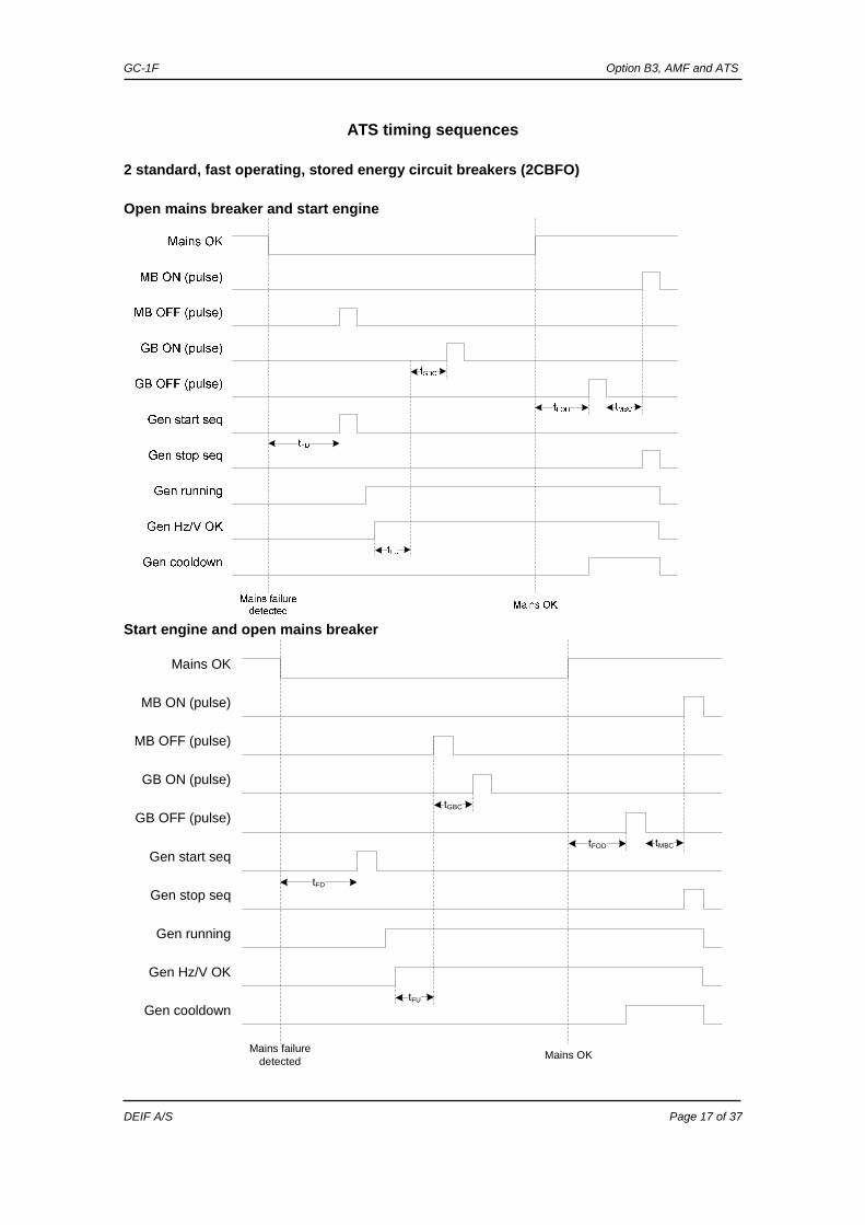
ATS timing sequences
2 standard, fast operating, stored energy circuit breakers (2CBFO) Open mains breaker and start engine
Start engine and open mains breaker
tFD
Mains OK
Gen start seq
Gen running
Gen stop seq
Gen Hz/V OK
MB ON (pulse)
Mains failure detected Mains OK
tFU
tFOD tMBC
tGBC
MB OFF (pulse)
GB ON (pulse)
GB OFF (pulse)
Gen cooldown

GC-1F Option B3, AMF and ATS
DEIF A/S Page 18 of 37
2 position electrically held, solenoid style ATS or 2 contactors electrically held, (2COEH) Open mains breaker and start engine
tFD
Mains OK
Gen start seq
Gen running
Gen stop seq
Gen Hz/V OK
GB (cont)
MB (cont)
Mains failure detected Mains OK
tFU
tFOD
tMBC
tGBC
Gen cooldown
Start engine and open mains breaker
tFD
Mains OK
Gen start seq
Gen running
Gen stop seq
Gen Hz/V OK
GB (cont)
MB (cont)
Mains failure detected Mains OK
tFU
tFOD
tMBC
tGBC
Gen running

GC-1F Option B3, AMF and ATS
DEIF A/S Page 19 of 37
2 position mechanically held solenoid style ATS or 2 contactors, mechanically held (2COMH) Open mains breaker and start engine
tFD
Mains OK
Gen start seq
Gen running
Gen stop seq
Gen Hz/V OK
MB ON (pulse)
Mains failure detected Mains OK
tFU
tFOD tMBCtGBC
GB ON (pulse)
Gen cooldown
Start engine and open mains breaker

GC-1F Option B3, AMF and ATS
DEIF A/S Page 20 of 37
3 position electrically held solenoid style ATS or contactors (3COEH) – 2 outputs Open mains breaker and start engine
Start engine and open mains breaker

GC-1F Option B3, AMF and ATS
DEIF A/S Page 21 of 37
3 position electrically held solenoid style ATS or contactors (3COEH) – 3 outputs Open mains breaker and start engine
Start engine and open mains breaker

GC-1F Option B3, AMF and ATS
DEIF A/S Page 22 of 37
3 position mechanically held solenoid style ATS or contactors (3COMH) – 2 outputs Open mains breaker and start engine
tFD
Mains OK
Gen start seq
Gen running
Gen stop seq
Gen Hz/V OK
MB ON (pulse)
Mains failure detected Mains OK
tFU
tFOD
tMBC
tGBC
GB ON (pulse)
Neutral pos ON
Gen cooldown
Start engine and open mains breaker
tFD
Mains OK
Gen start seq
Gen running
Gen stop seq
Gen Hz/V OK
MB ON (pulse)
Mains failure detected Mains OK
tFU
tFOD
tMBC
tGBC
GB ON (pulse)
Neutral pos ON
Gen cooldown

GC-1F Option B3, AMF and ATS
DEIF A/S Page 23 of 37
3 position mechanically held solenoid style ATS or contactors (3COMH) – 3 outputs Open mains breaker and start engine
tFD
Mains OK
Gen start seq
Gen running
Gen stop seq
Gen Hz/V OK
MB ON (pulse)
Mains failure detected Mains OK
tFU
tFOD
tMBC
Neutral ON (pulse)
tGBC
GB ON (pulse)
Gen cooldown
Start engine and open mains breaker
tFD
Mains OK
Gen start seq
Gen running
Gen stop seq
Gen Hz/V OK
MB ON (pulse)
Mains failure detected Mains OK
tFU
tFOD
tMBC
Neutral ON (pulse)
tGBC
GB ON (pulse)
Gen cooldown

GC-1F Option B3, AMF and ATS
DEIF A/S Page 24 of 37
ATS configurations
2 x standard fast operating stored energy circuit breakers (2CBFO) 2CBFO needs 1 trip and 1 close contact for each breaker. Often they are mechanically and/or electrically interlocked so they cannot both be closed at the same time. Thus the controller will not send a close signal to the GB until an open signal from the MB has been received (when feedback signals are assigned).
Settings Gen-Mains Source-Source Relay GB ON (pulse) CB1 ON (pulse) Relay GB OFF (pulse) CB1 OFF (pulse) Relay MB ON (pulse) CB2 ON (pulse) Relay MB OFF (pulse) CB2 OFF (pulse)
2 position electrically held solenoid style ATS (2COEH) 2COEH needs 1 continuous signal for each ATS position. When GB is closed (and MB is opened), it electrically holds the ATS in the Gen position. When MB is closed (and GB is opened), it electrically holds the ATS in the Mains position.
Settings Gen-Mains Source-Source Relay GB (cont) CB1 (cont) Relay MB (cont) CB2 (cont)
2 position mechanically held solenoid style ATS (2COMH) 2COMH operates like a 2COEH but with pulse signals instead of continuously held signals. There is no open signal, only close signals. Closing the ATS in Gen position will mechanically open mains and vice versa. The closing signals are pulses with a variable pulse length (adjustable in USW), or until a close feedback is detected.
Settings Gen-Mains Source-Source Relay GB ON (pulse) CB1 ON (pulse) Relay MB ON (pulse) CB2 ON (pulse)
GB
ON
GB
OFF
MB
ON
MB
OFF
GB
feed
back
MB
feed
back
GB
ON
GB
OFF
MB
ON
MB
OFF
GB
feed
back
MB
feed
back

GC-1F Option B3, AMF and ATS
DEIF A/S Page 25 of 37
Motorised rotary switch (MRS) A MRS is controlled by only one signal input, controlling a motor that runs to change the ATS position. The motor only runs in one direction, and therefore feedback signals are needed to tell when the ATS is in the correct position. The GB ON and the MB ON pulse outputs must be connected in parallel to operate the motor run signal. When feedback signals are detected, the pulse outputs are opened and the motor is stopped in the position.
3 position mechanically held solenoid style ATS or contactors (3COMH) 3COMH can be operated with either 2 or 3 pulse outputs. For both setups, the ATS must go through neutral when moving from either Gen to Mains or from Mains to Gen (Gen -> Neutral -> Mains, Mains -> Neutral -> Gen).
For the setup with 2 outputs, a neutral feedback must be configured as well. When the 3COMH must go from Mains to Gens, it will first send a GB ON pulse to go to neutral, and when neutral feedback is detected, a second GB ON pulse will be given to go to Gens. When the 3COMH must go from Gen to Mains, it will first send a MB ON pulse to go to neutral, and when neutral feedback is detected, a second MB ON pulse will be given to go to mains.
For a setup with 3 outputs, the neutral ON pulse will be given to move the ATS to neutral, GB ON pulse will be given to go to Gen and a MB ON pulse will be given to go to mains.
Settings Gen-Mains Source-Source Relay GB ON (pulse) CB1 ON (pulse) Relay MB ON (pulse) CB2 ON (pulse) Input GB position ON CB1 position ON Input MB position ON CB2 position ON
Settings Gen-Mains Source-Source Relay GB ON (pulse) CB1 ON (pulse) Relay MB ON (pulse) CB2 ON (pulse) Input Neutral position ON Neutral position ON
Settings Gen-Mains Source-Source Relay GB ON (pulse) CB1 ON (pulse) Relay Neutral ON (pulse) Neutral ON (pulse) Relay MB ON (pulse) CB2 ON (pulse)

GC-1F Option B3, AMF and ATS
DEIF A/S Page 26 of 37
3 position electrically held solenoid style ATS or contactors (3COEH) The 3COEH is operated like the 3COMH, but with continuous signals. Operation with either 2 or 3 outputs is supported. For both setups, the ATS must go through neutral when moving from either Gen to Mains or from Mains to Gen (Gen -> Neutral -> Mains, Mains -> Neutral -> Gen).
Settings Gen-Mains Source-Source Relay GB (cont) CB1 (cont) Relay MB (cont) CB2 (cont) Input Neutral position ON Neutral position ON
For the setup with 2 outputs, a neutral feedback must be configured as well. When the 3COEH must go from Mains to Gens, it will first open both GB and MB to go to neutral, and when neutral feedback is detected, the GB relay is closed to go to Gens. When the 3COEH must go from Gen to Mains, it will first open both MB and GB to go to neutral, and when neutral feedback is detected, the MB relay is closed to go to mains.
Settings Gen-Mains Source-Source Relay GB (cont) CB1 (cont) Relay Neutral (cont) Neutral (cont) Relay MB (cont) CB2 (cont)
w For a setup with 3 outputs, the neutral relay will be closed to move the ATS to neutral, GB relay will be closed to go to Gen and a MB relay will be closed to go to mains (only one relay closed at a time).
GB
ON
GB
OFF
MB
ON
MB
OFF
GB
feed
back
MB
feed
back
GB
ON
GB
OFF
MB
ON
MB
OFF
GB
feed
back
MB
feed
back

GC-1F Option B3, AMF and ATS
DEIF A/S Page 27 of 37
Timer explanation Timer Description tFD Mains failure delay
See 7063 and 7073 tFU Frequency/voltage OK
See 6220 tFOD Mains failure OK delay
See 7062 and 7072 tGBC GB ON delay
See 6231 tMBC MB ON delay
See 7082
ON and OFF sequences The condition(s) must be met before the operation can take place Operation Condition GB ON, direct closing Running feedback
Generator frequency/voltage OK MB open
Generator OK (ATS) input, direct closing
MB ON, direct closing Mains frequency/voltage OK GB open Mains OK (ATS)
GB OFF, direct opening Shutdown Trip GB alarms
MB OFF, direct opening Mains failure
Mains failure control (7065) set Start engine + open MB. If the generator fails to start or the generator breaker fails to close and the mains is OK, the mains “ok u” and mains “ok f” timer must expire, before the mains breaker is closed.
Mains failure control (7065) set Start engine. If the generator fails to start or the generator breaker fails to close, the mains breaker is closed.

GC-1F Option B3, AMF and ATS
DEIF A/S Page 28 of 37
Configuration
Gen-set mode
Input functions (B3)
Input function Comment MB Pos on Configurable MB Pos off Configurable Neutral Pos on Configurable Remote MB open Configurable Remote MB close Configurable Remote neutral pos Configurable LTO mode Configurable AMF mode Configurable ATS mode Configurable Generator Ok (ATS) Configurable Mains OK (ATS) Configurable Bypass to generator (ATS) Configurable Bypass to Mains (ATS) Configurable MB close inhibit Configurable
Input function description 1. MB Pos on
When this input is activated, the GC-1F sees the generator breaker as closed. If the MB on/off feedbacks are high/high simultaneously, an MB position failure is displayed.
2. MB Pos off
When this input is activated, the GC-1F sees the generator breaker as open. If the MB on/off feedback are high/high simultaneously, an MB position failure is displayed.
ATS type: Source – Source can only be selected by display, and it will only be possible when “ATS” is selected as Gen-set mode (parameter 6070).

GC-1F Option B3, AMF and ATS
DEIF A/S Page 29 of 37
3. Neutral Pos on When this input is activated, the GC-1F sees the generator and mains breaker as open. If this input is used, no GB/MB off breaker signals can be used.
4. Remote MB open
This input will open the mains breaker, but will only work in Man-mode 5. Remote MB close This input will close the mains breaker, but will only work in Man-mode 6. Remote neutral pos This input will force the ATS in neutral position, but will only work in Man-mode 7. LTO mode This input will change mode to load take over (LTO) 8. AMF mode This input will change mode to AMF 9. ATS mode This input will change mode to ATS 10. Generator Ok (ATS) This input will skip the generator AC measurement, and start the Ok timer right away. 11. Mains OK (ATS) This input will skip the Mains AC measurement, and start the Ok timer right away. 12. Bypass to generator (ATS) This input will bypass the Hz/V OK timer and close the generator breaker. 13. Bypass to Mains (ATS) This input will bypass the mains OK Hz/V timer and close the mains breaker. 14. MB close inhibit This input will make an inhibit of closing the mains breaker.

GC-1F Option B3, AMF and ATS
DEIF A/S Page 30 of 37
Output functions (B3)
Output function Factory setting MB (continues) Relay 47 Neutral (continues) MB ON (pulse) MB OFF (pulse) Neutral ON (pulse) Genset start (ATS) MB status Neutral status Mains OK Mains fail
Output function description 1. MB (continuous) MB relay contact will close continuously.
2. Neutral (continuous)
Neutral relay contact will close continuously. 3. MB ON (pulse) MB relay contact will give an ON pulse signal (Adjustable in 7084). 4. MB OFF (pulse)
MB relay contact will give an OFF pulse signal (Adjustable in 7084). 5. Neutral ON (pulse) Neutral relay contact will give an ON pulse signal (Adjustable in 2310). 6. Gen-set start (ATS)
This function is used for giving remote start/stop signal in cascade ATS applications. 7. MB status
This output contact will close when MB is closed. 8. Neutral status
This output contact will close when ATS is in neutral position. 9. Mains OK
Output contact will close when no mains failure is present or mains Ok timer is running. 10. Mains fail
Output contact will close when mains failure is present.
Relays 21/22/23 cannot be configured as MB.
Relay 47 is closed when de-energised, but works as all other relays when GC-1F is powered up.

GC-1F Option B3, AMF and ATS
DEIF A/S Page 31 of 37
The example below shows the menu for setting the mains failure low voltage:
The example below shows the menu for setting the mains failure high voltage:
The timer for both low and high voltage setpoint is set in the menu for low voltage. The same principle is used for the setting of low and high frequency.

GC-1F Option B3, AMF and ATS
DEIF A/S Page 32 of 37
The example below shows the MB close delay timer. The delay set is the time between the transmission of the GB open signal to the transmission of the MB close signal.
“MB pulse ON time” defines the MB relay out’s pulse time.
“MB pulse ON time” will be interrupted if “MB ON” feedback is present or MB OFF signal is given in manual.
GC-1F Option B3, AMF and ATS
DEIF A/S Page 33 of 37
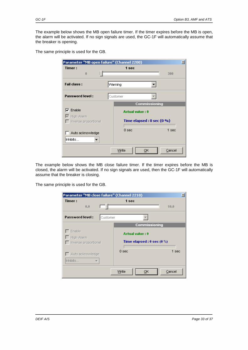
The example below shows the MB open failure timer. If the timer expires before the MB is open, the alarm will be activated. If no sign signals are used, the GC-1F will automatically assume that the breaker is opening. The same principle is used for the GB.
The example below shows the MB close failure timer. If the timer expires before the MB is closed, the alarm will be activated. If no sign signals are used, then the GC-1F will automatically assume that the breaker is closing. The same principle is used for the GB.

GC-1F Option B3, AMF and ATS
DEIF A/S Page 34 of 37
MB position failure
If “MB ON” and “MB OFF” inputs give the same feedback signals (High/High,) an MB position failure will be present. Neutral pulse ON time
“Neut. pulse ON time” will be interrupted if “Neut. ON” feedback is present or “open breaker” signal is given in manual.

GC-1F Option B3, AMF and ATS
DEIF A/S Page 35 of 37
Neutral failure
This alarm is used for 3 pos. ATS switches where a neutral is used. Auto-mode shift
“Auto-mode shift” is used for alarms with failclass: “shutdown + man-mode” and the controller running in auto-mode. When alarms are acknowledged either by display or by “auto-acknowledge” setting, the mode will automatically switch to auto-mode.
“Auto-mode shift” parameter and the alarms with “auto-acknowledge” enabled will ensure the load of a source in case of periodic failures or unstable systems causing this shutdown.

GC-1F Option B3, AMF and ATS
DEIF A/S Page 36 of 37
ATS - Source – Source This variant is normally used to switch the load between two mains sources. One of the mains is working as emergency source for the other mains. In case of mains failure on the “first priority” mains, the second priority mains will take the load.
ATS type Change of ATS type from for instance “Gen – Mains” to “Source – Source” can only be done via display, when the gen-set mode: 6070 = “Automatic Transfer Switch”. Source priority
Parameter overview The Source – Source ATS type uses the same parameters as Gen – Mains, but parameters for engine protection and control have been removed. In addition to this, the generator (Gen) and Mains (BB) parameters have changed names. The parameter numbers are kept the same, so it’s easy to navigate. Two new groups of protections; “Source 1”, “Source 2” and one new group called ATS logic. ATS logic has the same functionality and operates as the known AMF logic. “Priority 1” will always be operated as the “mains” like in normal emergency applications. “Source priority” makes it possible to choose first priority between Source 1 and Source 2.
Detailed information about standard functionality refers to “Installation Instruc-tions and Reference Handbook”.
Change of ATS type resets the unit and default parameters will be present.

GC-1F Option B3, AMF and ATS
DEIF A/S Page 37 of 37
5. Parameter list Related to this option are parameters 1620, 2160-2170, 2200-2210, 6050-6070, 6104, 7060-7082 and 7110. Please see the “Installation Instructions and Reference Handbook”, document number 4189340472.
DEIF A/S reserves the right to change any of the above.