description of the organization - mustafa cigal web viewname of the organization: ... digitizing and...
TRANSCRIPT

DESCRIPTION OF THE ORGANIZATION
NAME OF THE ORGANIZATION: TUNAOĞLU AUTOMOTIVE INDUSTRY
LOCATION OF THE ORGANIZATION: Nilüfer Organize Sanayi Bölgesi Şeftali Cadde 6.Sokak No:101 Nilüfer BURSA/TÜRKİYE
NUMBER OF ENGINEERS EMPLOYED:
Mechanical Engineer 4Plant Engineer 1Physics 1
MAIN SPHERE OF ACTIVITY:In the company pressing department, sheet metal parts in various size and shape are being stamped by 26 different hydrolic and eccentric presses from 30 tons up to 1000 tons. In order to reach higher performance in the company production, company use roll feeders and conveyor bands. The company also serve their customers with fine blanking technology using their 15 years experience in this area. The company also manufacture assemblies and sub-assemblies by using resistance welding, riveting, MIG-MAG welding machineries. The parts are coated in their own plant with Computer Controlled Aotomatic Line. The company apply asidic and alchali zinc electro-plating in their line with blue, yellow and black passivation. Using their know-how and experience, firm manufacture all kinds of cutting, forming, fine-blanking, drawing, deep drawing and progressive tools and also control aparats and prototypes. The tools/dies are designed with latest CAD/CAMplatforms and processed by up to date technology CNC milling and wire erosion machineries. The responsibility of manufacturing parts for breaking systems, that should be safe and work without defects for long years, has improved concious of quality in the firm.The company quality system proofed its capability by ISO 9002 certificated by RWTUV in June 1997. In 2001, the company reached 50 PPM considering customer rejects.The firm next target is 15 PPM.By the firm 3D CNC measuring instrument, the company have the capability of measurement, comparing CAD data and part, digitizing and CAD surface generating. The firm quality system has already been modified according to ISO/TS 16949:May-2002 and put in use. By the end of 2002,the firm quality system will be certified.The company will follow up the developments and continue to improve it.
3

BRIEF HISTORY OF THE COMPANY: Tunaoglu Automotive Inc.established in 1989. The firm is located on 3500 closed and 12000 open area in Nilüfer Industrial District of Bursa. The firm serve mainly automotive sector by stamping sheet metal parts and manufacturing tools. The company major customers are;
Bosch Braking System (Türkiye) Knorr Bremse (Germany) Oxford Teknik Malzeme (JV of Faurecia-France) Bendix (Türkiye) Bendix (USA) Hema (Licencee of ITT-Teves and AP Lockheed)
Tunaoglu makes its all efforts in order to reach full customer satisfaction without skipping
its responsibilities towards both the society and environment. Therefore, Tunaoglu invest in not only techonology but also in personnel and environment . The firm admit that total quality is heart of their organization culture.
PURPOSE AND SCOPE OF THE ENGINEERING PRACTICE
The aim of summer practice is to make the student get familiar with the organization in
which he/she is likely to take part in after graduation. Particularly ME 299 Summer Practice
for the junior students sends the to-be-mechanical engineer into the kitchen where materials
are melted, cut , formed and prepared for service.
Engineering is largely problem solving and mechanical engineering is no exception. Five
steps in problem solving are maybe defining the problem , analysing , modelling ,
synthetizing and developing a solution. Last four are entirely used - even with simplifications
– during school work but the first one simply belongs to the teachers or the authors of the
books. Factory work introduces the engineering student to the real world and the actual
problems which engineers usually encounter with. It forces him/her to define the problem ,
prepare a real-life-solution and execute it. With this property , it is rather attempt to get used
to use the practical and applied aspects of mechanical engineering in accordance with the
theoretical background acquired at school. From a point of view it can be identified as a
reinforcement and improvement of the previously completed coursework , especially ME101,
ME 201 , ME 203 and ME 223 , and a heating-up for the sophomore year courses all of which
actually define the engineering study. It is also a means to get familiar with the human
relations - from bottom to top – which is the key to manage people.Lastly , as a rule , summer
4

practise obviously clarifies the doubts which are sure to appear in mind and first of which is :
“ What does an engineer actually do?” . And maybe determines the field and the kind of
business the student will want to make further study on.
With these objectives , ME 299 concentrates on the factory as a production centre. For a
clear understanding of the fundementals of manufacturing , it leaves aside the administrative
and organizational units until another summer practise and focuses on the production units.
In this report the units in which actual manufacturing is carried on . A brief description of
these units are given and the functions are studied. Machines ,machine tools and their
functions in the factory are explained along with some of the products they manufacture.
REPORT
PRODUCTION TECHNIQUES
Chip Removal Processes: -Turning -Milling -Drilling -Planning and Shaping -Sawing
Abrasive Machining Processes: -Grinding
Metal Forming Processes: -Shearing -Press Work Joining Processes:
-Arc Welding -Resistance Welding -Oxy fuel gas welding
1.CHİP REMOVAL PROCESSES: In chip removal processes the chip is formed by a localized shear process, which takes place over very narrow edges. This process may also be called as machining. Machining process is widely used in the company in order to process materials.1.1.TURNİNG:1.1.1.TURNİNG AND RELATED OPERATIONS ON LATHE: Lathe is a machine designed for chip removal from the turning workpiece by a stationary cutting tool.
The lathe is designed primarily for turning and boring operations, and the work is mostly of cylindrical shape. However, many other operations, such as drilling, reaming, and tapping can be
5
performed on a lathe, and, by employing suitable adapters milling and grinding may be done without difficulty.
The function of the lathe is to provide suitable means for rotating the work either between centers or in a chuck or faceplate attached to the rotating spindle. A cutting tool fed either parallel or perpendicular to the axis of the work, removes material from the rotating work. The tool may also be fed at an angle relative to the axis of the work. Many kinds of machine operations besides those indicated above are performed on a lathe.
TURNING: Turning is the general name of processing a work by means of turning it at a machine and chip removal by a tool. Turning operation is usually used for machining external cylindrical and conical surfaces it is usually performed on a lathe. Forming conical surfaces is called tapering. By having a tool specific form or shape external cylindrical, conical and irregular surfaces can be turned. The shape of the resulting surface is determined by the size and the form of the tool, such kind of turning is called as form turning. In a lathe, the work is held between centers or in a chuck. In turning of the long pieces, the workpiece should be held by means of steady or follow rests. Also collets and mandrels are available work holding devices according to the shape and size of the workpiece. In turning operations, diameter is usually measured by micrometer, callipers.
FACING: When the tool is fed at 90 degrees to the axis of rotation by using a tool that is wider then the width of the cut, a flat surface is generated. The quality of this flat surface is associated with the feed, and the speed of rotation.
BORING.: Boring is the general name of internal turning. It is used to produce internal cylindrical and conical surfaces of limited length. It does not create the hole but rather improves it to the desired shape and dimensions. Existing hole is created before boring by drilling or originally cast by using cores. Boring can be done on most machines that can perform turning. And there are also machines that can perform boring by using a rotating tool and a stationary workpiece. When boring is performed on a lathe, special tools for boring are used.
DRILLING: Drilling is the general name of creating a hole on a workpiece. When drilling is performed on a lathe usually the tool for drilling is held on the tailstock quill and fed against the workpiece that is rotating at the essential speed and held in a chuck. Another way of drilling on a lathe can be performed by rotating the drill tool by holding it by the chuck and feeding the stationary workpiece, which is held at the tailstock, against the tool.
REAMING: Reaming is the general name of a finishing operation of a hole by using a special tool. Reaming on a lathe is nothing special, the reamer is held in the tailstock and fed against the rotating workpiece. The speed of turning of the workpiece shall not be too much in reaming.
PARTING: Parting is the general name of separating one part of the workpiece from the remainder by using a special cut-off tool. The thin and long tool (longer than the radius of the workpiece) is fed at 90 degrees to the rotation of the axis until the center of the work. When parting is done coolants and proper feed shall be used otherwise tool will extremely wear.
KNURLING: Knurling is the special name of forming regularly shaped roughened surfaces intentionally. While knurling can be done on other machine tools, it is usually done on a lathe.
6

Actually, knurling is not a chip removal operation but a cold forming operation by applying compressive stresses to the surface of the work.1.1.2.LATHES IN THE FACTORY:
The specified lathes are the ones that have remarkable specifications; the remaining lathes are old and non-specific lathes.
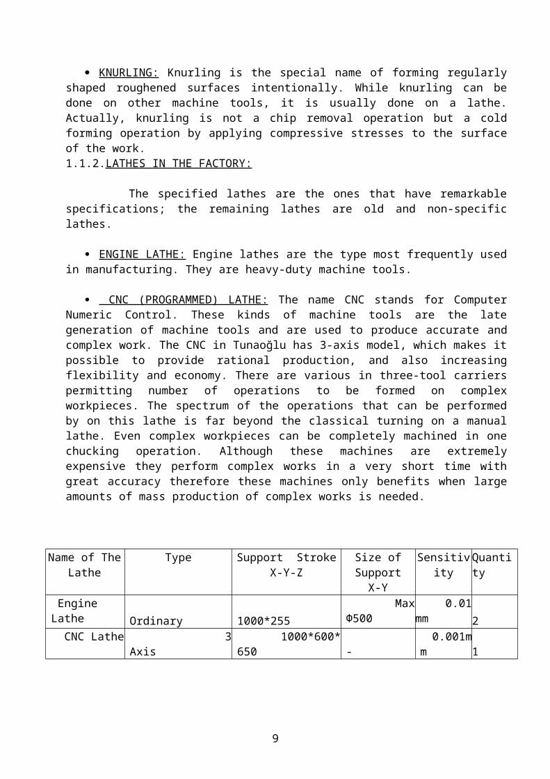
ENGINE LATHE: Engine lathes are the type most frequently used in manufacturing. They are heavy-duty machine tools.
CNC (PROGRAMMED) LATHE: The name CNC stands for Computer Numeric Control. These kinds of machine tools are the late generation of machine tools and are used to produce accurate and complex work. The CNC in Tunaoğlu has 3-axis model, which makes it possible to provide rational production, and also increasing flexibility and economy. There are various in three-tool carriers permitting number of operations to be formed on complex workpieces. The spectrum of the operations that can be performed by on this lathe is far beyond the classical turning on a manual lathe. Even complex workpieces can be completely machined in one chucking operation. Although these machines are extremely expensive they perform complex works in a very short time with great accuracy therefore these machines only benefits when large amounts of mass production of complex works is needed.
Name of The Lathe
Type Support StrokeX-Y-Z
Size of SupportX-Y
Sensitivity Quantity
Engine Lathe Ordinary 1000*255 Max Ф500 0.01mm 2 CNC Lathe 3 Axis 1000*600*650 - 0.001mm 1
1.2.MILLING:
Milling is the general name of generating a surface by using a rotating cutting tool. Metal is removed from a workpiece fed into a rotating cutter in a direction perpendicular to the axis of the cutter. Milling is well suited and widely used for mass production. In all cases a multiple-tooth cutter used so that metal removal rate is high. Unquestionably, milling, than any other machining processes, produces more flat surfaces. The cutting tool used in milling is known as a milling cutter. Equally spaced peripheral teeth will intermittently engage machine and the workpiece. In some cases the teeth may extend to both ends of the cylinder. Since milling provides rapid metal removal and also can produce a very good surface finish, it is one of the most important machining processes. It is widely used for general purpose machining in job-shops and also for tool die work. Most of the non-circular surfaces of metals that we see in daily life are produced by milling.
1.2.1.MILLING OPERATIONS: Milling operations can be classified into two main categories:
- Peripheral Milling - Face Milling.
7

PERIPHERAL MILLING: In peripheral milling, the surfaces are generated by teeth that are located in the periphery of the cutter body, and are parallel to the axis of the rotation of the cutter. Both flat and formed surfaces may be produced by this method. The cross section of the resulting surface corresponds to the contour of the cutter. Peripheral milling operations usually are performed on machines having horizontal spindles.
FACE MILLING: In face milling the generated surfaces generally is at right angles to the cutter axis and is the combined result of the action of the teeth located on both the periphery and the face of the cutter. The peripheral teeth with the face teeth providing a finishing action usually do the major portion of the cutting. Face milling is done on both horizontal and vertical-spindle machines. The choice of peripheral or face milling is dependent on the dimensions of the surface that will be worked on and the milling cutter.
1.2.2.METHODS OF GENERATING SURFACES IN MILLING: In milling, surfaces can be generated in two distinctly different methods: - Up (conventional) milling - Down (climb) milling
UP MILLING: In up milling is the traditional way of milling; the cutter rotates against the feed of the workpiece. The cutter tool tries to lift the workpiece upward where the teeth leave the work. The chip is very thin at the beginning, where the tooth first contacts the work, and increases in thickness, becoming a maximum where the tooth leaves the work. In addition, the smoothness of the generated surface depends greatly upon the sharpness of the cutting edges.
DOWN MILLING: In down milling the rotation of the cutter is at the same direction of the feed. The tool tries to push the work downward where the tooth first touches the workpiece. Maximum chip thickness is obtained close to the point at which the tooth contacts the work. The relative motion tends to pull the workpiece into the cutter so that all possibility of looseness in the table feed screw must be eliminated if down milling is to be used. The quality of the surface does not depend as greatly upon the sharpness of the cutting edges as in the case of up milling.
1.2.3.MILLING MACHINES IN THE FACTORY: The machines specified below are the Milling Machines those have special specifications. The rest are rather old and unspecified ones.
CNC MILLING MACHINE: In the factory milling processes are made on two different CNC Milling Machine. These kinds of machine tools are the late generation of machine tools and are used to produce accurate and complex work which makes it possible to provide rational production, and also increasing flexibility and economy. Properties with related to factory’s CNC Milling Machines are given above the tables.
8
1.3.DRILLING:
1.3.1.DRILLING: In manufacturing lots of holes are being formed, and drills are forming most of these holes. Consequently drilling is a very important process. Most of the drilling is done with a cutting tool having two cutting edges. Cutting takes place inside the workpiece so the only way for the chips to leave the hole that is filled with the drill. The chips leave the work from the flutes between the cutting edges. In drilling there are some difficulties, when drill comes contact with the surface it slips on the surface and flexes so the exact place cannot be drilled. So, a short drill, which is called as center drill, is used to start from the exact coordinate for drilling. Also another difficulty shows up when the long holes are drilled, chip removal becomes extremely hard as well cooling and lubricating. Also when drilling the drill can miss the axis wanted for the hole with a few degrees. Even though drilling seems to be a relative simple process, such difficulties show up during drilling.
1.3.2.THE DRILLING MACHINES IN THE FACTORY: The drilling machines which used in the factory are no more complex. They are relatively unspecified and old ones.
1.4.SHAPING AND PLANING:
1.4.1.SHAPING:
Shaping is done on a shaper, utilizing a reciprocating, single-point cutting tool that moves in a straight line across the workpiece. To produce a flat horizontal surface, the work is fed across the line of motion of the tool, between strokes. Because the tool cuts on only the forward part of the stroke, shaping is a relatively slow process. External and internal surfaces, either horizontal or inclined, can be produced readily; curved and irregular surfaces also can be made, but with much less ease or by the use of special attachments.
Name of The Milling Machine
Type Support StrokeX-Y-Z
Size StrokeX-Y
Quantity
CNC MillingMachine
3+2 Axis 2500*1200*1200 2730*930 1
CNC Miliing Machine
3 Axis 1000*600*650 -
1
Conventional Milling Machine
Digital
800*380*280 800*380*280 700*330*380
- 3
9
1.4.2.PLANING:
Planing can be used to produce horizontal, vertical, or inclined flat surfaces on workpieces that are too large to be accommodated on shapers. However, as will be pointed out, planing is much less efficient that other basic machining processes that will produce such surfaces; consequently, planing and planers have largely been replaced by planer type milling machines.
1.4.3.SHAPERS AND PLANERS IN THE FACTORY.
In the Tunaoğlu does not have any shaper and planer.Company is made some processes which is related to shaper and planer other machines (Lathe,CNC etc.)
1.5.SAWING:
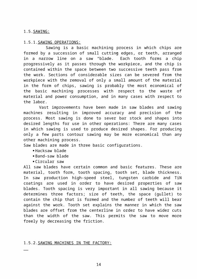
1.5.1.SAWING OPERATIONS: Sawing is a basic machining process in which chips are formed by a succession of small cutting edges, or teeth, arranged in a narrow line on a saw “blade.” Each tooth forms a chip progressively as it passes through the workpiece, and the chip is contained within the space between two successive teeth pass from the work. Sections of considerable sizes can be severed from the workpiece with the removal of only a small amount of the material in the form of chips, sawing is probably the most economical of the basic machining processes with respect to the waste of material and power consumption, and in many cases with respect to the labor. Vast improvements have been made in saw blades and sawing machines resulting in improved accuracy and precision of the process. Most sawing is done to sever bar stock and shapes into desired lengths for use in other operations: There are many cases in which sawing is used to produce desired shapes. For producing only a few parts contour sawing may be more economical than any other machining process. Saw blades are made in three basic configurations.
Hacksaw blade Band-saw blade Circular saw
All saw blades have certain common and basic features. These are material, tooth form, tooth spacing, tooth set, blade thickness. In saw production high-speed steel, tungsten carbide and TiN coatings are used in order to have desired properties of saw blades. Tooth spacing is very important in all sawing because it determines three factors; size of teeth, the space (gullet) to contain the chip that is formed and the number of teeth will bear against the work. Tooth set explains the manner in which the saw blades are offset from the centerline in order to have wider cuts than the width of the saw. This permits the saw to move more freely by decreasing the friction.
1.5.2.SAWING MACHINES IN THE FACTORY: Tunaoğlu have two types of sawing machines. These are decoupling saw and horizontal saw which are used to cutting of sheet materials.
10

2.ABRASIVE MACHINING PROCESSES:
2.1.GRINDING: Grinding is an abrasive machining process that is widely used in manufacturing to improve the surface quality and to bring the surface to exact dimensions and tolerances. In grinding, the abrasives are bonded together in the form of a wheel having closely packed grains. In grinding the chips are removed repeatedly by the sharp cutting edges of each abrasive particle. Chips are very small compared to other metal removal processes. The feeds and depth of cuts are small since the cutting speeds are very high. So a special cutting fluid is used during grinding which prevents burning of the surface and chips to fill the pores on the grinding wheel.
2.2.GRINDING MACHINES IN THE FACTORY:
SURFACE GRINDERS: Surface grinding is used primarily to grind flat surfaces. However, formed, irregular surfaces can be produced on some types of surface grinders by using a formed wheel.
There are four basic types of surface grinding machines, differing in the movement of their tables and the orientation of the grinding wheel spindles. -Horizontal spindle and reciprocating table -Vertical spindle and reciprocating table -Horizontal spindle and rotary table -Vertical spindle and rotary table
.
Type of The Grinder
Support Stroke Revolution Quantity
Surface Grinder 1000*350*250 5000rpm 1
3.METAL FORMING PROCESSES:
3.1.SHEARING: Shearing is the mechanical cutting of materials in sheet or plate form without the formation of chips or use of burning or melting. When the two cutting blades are straight, the process is called shearing. Processes, in which the shearing blades are in the form of curved edges of punches and dies, are called by other names, such as; blanking, piercing, notching, shaving and trimming. These all are basically shearing processes.
3.1.1.SHEARING PROCESSES:
SLITTING: Slitting is the shearing process used to cut rolls of sheet metal into several rolls of narrower width. Here the shearing blades are in the form of circumferential mating grooves on cylindrical rolls, the ribs on one roll mating with grooves in the other.
PIERCING AND BLANKING: In these operations the shearing blades take the form of closed curved lines on the edges of a punch and die. They are basically the same cutting action, the
difference being primarily one of the definitions. In blanking the piece punched out is the workpiece, and undesirable features should be left on the strip. In piercing, the piece punched
11

out is the scrap and the remainder of the strip becomes the desired workpiece. Piercing and blanking are usually done by some type of mechanical press. Several variations of piercing and blanking are used and have come to acquire specific names:
-LANCING: Lancing is a piercing process in which a hole is partially punched and one side bent down.
-PERFORATING: Perforating consists of piercing a large number of closely spaced holes.
-NOTCHING: Notching is essentially the same as piercing except that the edges of the sheet of metal forms a portion of the periphery of the piece that is punched out. It is used to form notches of any desired shape along the edge of a sheet.
-NIBBLING: Nibbling is a variation of notching in which a special machine makes a series of overlapping notches, each further into the sheet of metal.
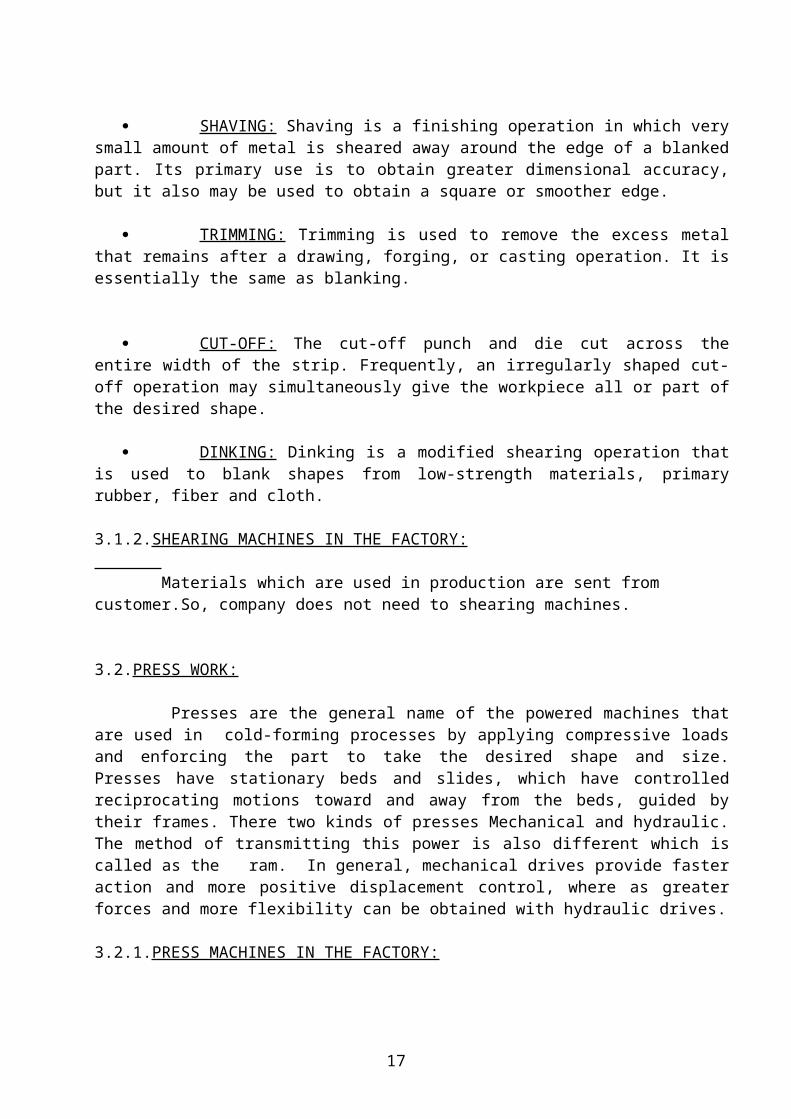
SHAVING: Shaving is a finishing operation in which very small amount of metal is sheared away around the edge of a blanked part. Its primary use is to obtain greater dimensional accuracy, but it also may be used to obtain a square or smoother edge.
TRIMMING: Trimming is used to remove the excess metal that remains after a drawing, forging, or casting operation. It is essentially the same as blanking.
CUT-OFF: The cut-off punch and die cut across the entire width of the strip. Frequently, an irregularly shaped cut-off operation may simultaneously give the workpiece all or part of the desired shape.
DINKING: Dinking is a modified shearing operation that is used to blank shapes from low-strength materials, primary rubber, fiber and cloth.
3.1.2.SHEARING MACHINES IN THE FACTORY: Materials which are used in production are sent from customer.So, company does not need to shearing machines.
3.2.PRESS WORK: Presses are the general name of the powered machines that are used in cold-forming processes by applying compressive loads and enforcing the part to take the desired shape and size. Presses have stationary beds and slides, which have controlled reciprocating motions toward and away from the beds, guided by their frames. There two kinds of presses Mechanical and hydraulic. The method of transmitting this power is also different which is called as the ram. In general, mechanical drives provide faster action and more positive displacement control, where as greater forces and more flexibility can be obtained with hydraulic drives. 3.2.1.PRESS MACHINES IN THE FACTORY: Classifications of the various drive Mechanisms of Commercial presses are: - Foot
- Mechanical
12
- Hydraulic
Foot operated presses, commonly called kick presses, are only used for very light work. Crank driven presses are the most common type because of their simplicity. They are use for most piercing and blanking operations and for simple drawing. Eccentric or cam drives are used when only a short ram stroke is required. Cam action can provide a dwell at the bottom of the stroke and is often the preferred method of actuating the blank holder in deep drawing processes. Knuckle-joint drives provide a very high mechanical advantage along with fast action. They are often used in coining, sizing and Guerin forming. Toggle mechanisms are use principally in drawing presses to actuate to blank holder.
Mechanical presses use means such as a flywheel and clutch to provide the motion and are capable of up to 60 strokes per minute.
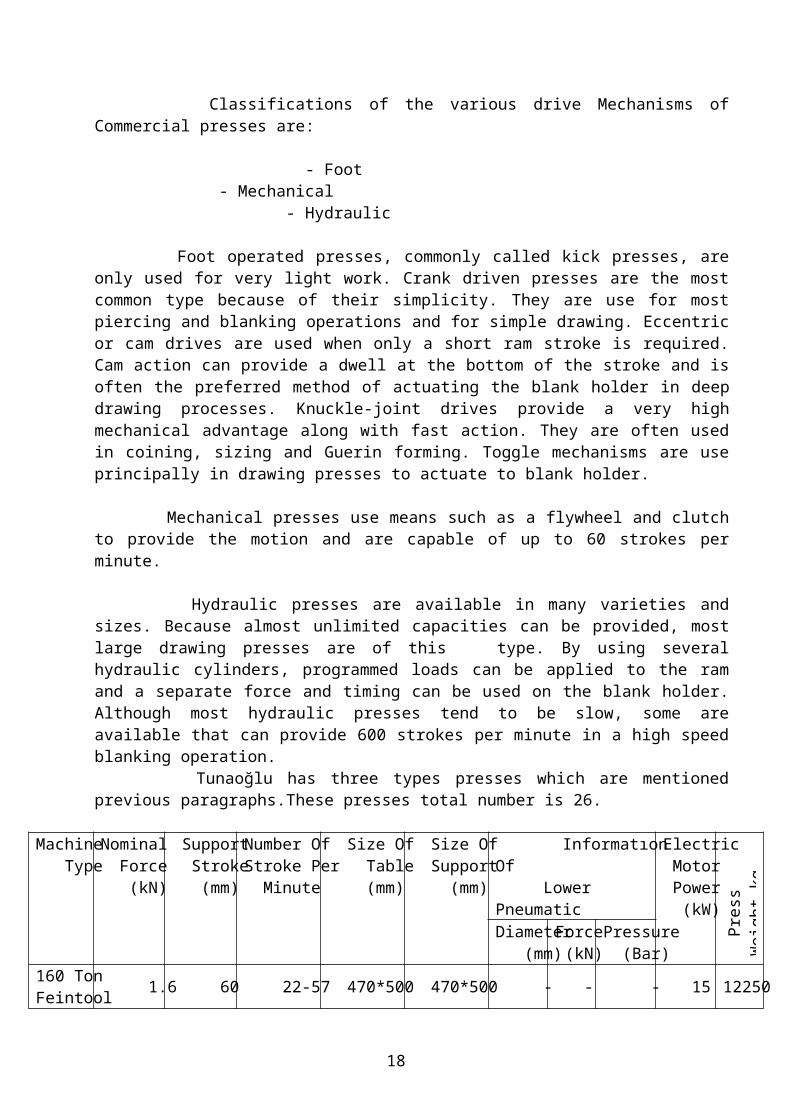
Hydraulic presses are available in many varieties and sizes. Because almost unlimited capacities can be provided, most large drawing presses are of this type. By using several hydraulic cylinders, programmed loads can be applied to the ram and a separate force and timing can be used on the blank holder. Although most hydraulic presses tend to be slow, some are available that can provide 600 strokes per minute in a high speed blanking operation. Tunaoğlu has three types presses which are mentioned previous paragraphs.These presses total number is 26.
Machine Type
Nominal Force (kN)
Support Stroke (mm)
Number OfStroke Per Minute
Size Of Table (mm)
Size Of Support (mm)
Informatıon Of Lower Pneumatic
Electric Motor Power (kW) P
ress
Wei
ght k
g
Diameter (mm)
Force (kN)
Pressure (Bar)
160 TonFeintool 1.6 60 22-57 470*500 470*500 - - - 15 12250
800 TonEccentric Smeral
8 320 35 1300*1870 1300*1680 Φ370 400 6 55 7700
630 Ton Eccentric 6.3 320 20 1250*1250 1200*1200 - - - - -
630 TonEccentric 6.3 160 30 1680*1200 2020*1200 - - - - -
400 TonEccentric Rus
4.0 250 17-25 980*1000 800*800 - - - 45 32000
400 TonEccentric Dirinler
4.0 210 30 1000*950 700*700 - - - 18 22000
400 Ton Eccentric ZTS
4.0 180 45 895*1250 560*950 Φ300 424 6 30 22000
250 TonEccentric Dirinler
2.5 80 43 850*1250 780*610 - - - 18.5 17000
160 TonEccentric Benelli
1.6 20/180 50 725*1200 560*750 Φ300 424 6 11 10942
13
160 Ton Eccentric Bulgar
1.6 20/160 50 780*1000 500*630 - - - 13 11300
160 TonEccentric Bulgar
1.6 20/160 50 780*1000 500*630 - - - 13 11300
160 TonEccentric Bulgar
1.6 20/160 50 780*1000 500*630 - - - 13 11300
120 TonEccentric Bulgar
1.2 20/130 60 1100*660 660*450 - - - 7.5 8000
100 TonEccentric Rus
1.0 50 60 560*850 310*360 - - - 14.5 6000
100 TonEccentric Bulgar
1.0 20/130 50 900*650 420*570 Φ300 424 6 11 5680
80 TonEccentric Dirinler
800 10/100 45 470*700 230*260 - - - 5.5 4550
60 TonEccentric Dirinler
600 10/100 50 660*460 230*230 - - - 4 4550
60 TonEccentric Dirinler
600 10/100 50 660*460 230*230 - - - 4 4550
60 TonEccentric Dirinler
600 10/100 50 660*460 230*230 - - - 4 2250
30 TonEccentric Dirinler
300 10/100 60 550*350 190*190 - - - 2.2 2250
30 TonEccentric Dirinler
300 10/100 60 550*350 190*190 - - - 2 2250
250 TonEccentric Bulgar
2500 40/200 45 875*1250 560*800 Φ300 424 6 30 16000
350 TonHydraulic Sarıgöz.
3.5 - - 1560*1240 1520*1320 - - - 45 24000
100 TonHydraulic Dirinler
1.0 - - 850*640 850*550 - - - 15 9000
80 TonHydraulicAdam Mak
800 - - 600*600 550*550 - - - 15 5100
160 Ton Feintool 1600 60 22-57 470*500 470*500 - - - 15 12550
14

Note: On the factory press table first 6 presses are “H” type Mechanical, second 16 presses are “C” type Mechanical, third 3 presses are “H” type Hydraulic, last one is “H” type feintool.
4. JOINING PROCESSES:
4.1.WELDING: Welding is the general name of permanently joining operation of two pieces by coalescence, the coalescence resulting from a combination of temperature, pressure and metallurgical conditions. To obtain coalescence between two metals, there must be sufficient proximity and activity between the formations of common metallic crystals. The ideal metallurgical bond requires perfectly smooth, flat or matching surfaces, clean surfaces, free from oxides, absorbed gases, grease, and other contaminants, metals with no internal impurities. Welding is one of the most used welding processes in manufacturing. There are a lot of kinds of welding process. Such as; oxy-fuel gas welding, arc welding, resistance welding etc…
4.1.1.WELDING TYPES :
ARC WELDING: The various arc-welding processes require selection or specification of the welding voltage, welding current, arc polarity (straight polarity, reversed polarity, or alternating polarity), arc length, welding speed (how fast the electrode is moved across the work piece), arc atmosphere, electrode or filler material, and flux. The filler material is generally selected to match the base metal with respect to properties and/or alloy content. -GMAW (Gas metal arc welding): The arc is maintained between an automatically fed, consumable wire electrode and the work piece. Although argon and helium, or mixtures of them, can be used as shielding gas for welding virtually any metal, they are used primarily for welding nonferrous metals. Gas metal arc welding is fast and economical because there is no frequent changing of electrodes, as with stick-type electrodes. In addition, there is no slag formed over the weld, the process often can be automated. Industrial robots may be used to perform GMAW.
RESISTANCE WELDING: In resistance welding, both heat and pressure are utilized in producing coalescence. The heat is the consequence of the electrical resistances of the workpieces and the interface between them. A certain amount of pressure is applied initially to hold the workpieces in contact, thereby controlling the electrical resistance at the interface, and is increased when proper temperature is attained to facilitate the coalescence. Because of the pressure utilized, coalescence occurs at a lower temperature than with oxy-fuel gas or arc welding. Consequently, in modern resistance welding, intentional melting of the metal need not occur.
OXY-FUEL GAS WELDING: Oxy-fuel gas welding covers a group of welding processes that utilise as the heat source a flame resulting from the burning of a fuel gas and oxygen mixed in proper proportions. The oxygen usually is supplied in relatively pure form, but may, in rare cases, come from air. Acetylene is the principal fuel gas employed in the process. The combustion of oxygen and acetylene produces a temperature of about 3482 C.
Almost all Oxy-fuel gas is fusion welding; the metals being joined are simply melted at the point where welding occurs, and no pressure is involved. Because a slight gap usually exists
15

between the pieces being joined, filler material usually must be added in the form of a wire or rod that is melted in the flame or in the pool of weld metal.
4.1.2.WELDING MACHINES IN THE FACTORY:
Tunaoğlu is used Oxy-Fuel gas welding and Arc welding machines on the welding operations.Welding is used to fit machine parts which are produced in the factory.
CASTING:
Casting is a basic forming process in which molten material (which is usually a metal) is
poured into a mold which is prepared beforehand and let it solidify there to give the desired
shape. One of the most important concepts in casting is shrinkage. Enough material should be
fed by suitable means into the mold and cracks due to shrinkage should be avoided. Otherwise
defects, which decrease the expected strength values, may occur. Casting is extremely
important as it allows the production of intricate, difficult-to-shape geometries that cannot be
manufactured by other processes, in a single step with appreciable accuracy.
OTHER MACHINES IN THE FACTORY:
Machinery Type Number Of Unit
CNC Wire Erosion 1
Precision Spark
Erosion
1
Heat Treatment Unit 1
1.1.CNC WIRE EROSION:
Support Stroke: 400*250*200
Size Of Support: 800 (+)*500
Required Electric Power: 10 kW
Wire Thickness: 0.25mm
16
Wire Material: Generaly Copper, but sometimes Brass.
Software: It works with Cammand.
Working Condition: Room temperature must be 20 Ċ .
Cooling Liquid: Water.Because it conducts electric.
It works on two axis. (X-Y)
Working Principle: Wire is catode, table is anode and product settle on table . Then arc
is created between wire and product.
Products which are material hardened with higher temperature are produced.
Machine cannot make new hole on the product.But it enlarges old holes on the
product.
SOFTWARES IN THE FACTORY:
Name Number Of Unıt
CAD/CAM
Software I-DEAS 2
CAD/CAM
Software UniGraphics 2
CAD/CAM
Software Cammand 2
CAD/CAM
Software Autocad 6
COATING IN THE FACTORY:
Also production methods company makes coating on the theirs products.In the coating
department, products are coated which colour customer wants.By coating,products resist to
oxidation and seen more beautiful.Coating operation is not made all products, this operation is
made customers want that I said first sentence.
Coating operations are programmed by PLC.Operation number and operation time are
programmed by PLC before product not to go to coated .
Coating starts with initial cleaning.Because products are coated with oil and other
substances which are not wanted, during production steps.If we want to make good coating,
17
we must do good initial cleaning.Initial cleaning operation is made by hot oil removed or
electrical oil removed.
HOT OIL REMOVED: Oil and other impurities are removed with hot water. Time is
programmed by PLC before operation.
ELECTRICAL OIL REMOVED: Product is coupled with anode, sheet metal is coupled
catode oppositely.Product is cleaned by electrical current.
CLEANED BY LIQUID: It is last process,before products g oto the zinc coating.Products are
suitable for zinc coating by this process.This process contains 3 steps.
1. Cleaned by water.
2. Cleaned By Acid: This operation is made by HCL to remove corrosion.
3. Last cleaning made by HCL.
COATING:
It is main process, which is made to prevent products from oxidation.Zinc is coated on
product surfaces slightly.Product is coupled with catode, zinc is coupled with anode
oppositely.By the movement of electrons product surface is coated with zinc.During coating
ionic bonds forms between ions.During this process the usage of electrical current is
proportional with product surface.After coating,product is cleaned.
In the nitric acid bath product is coated by cromat which is increased oxidation
resistance.After that, the desired colour is made on the product during passivation.Then,
product is cleaned as each process.Finally, product is dried.
OPERATION SEQUENCES OF SAMPLE PRODUCTS
PRODUCT NAME: SPRING BEARING
OPERATION NAME: BAND CUTTING
18

CONTROL FORM OPERATION NUMBER: 10
KOD
NO
CONTROLLED
CHARACTERISTICS
DIMENSION
(MM)
CONTROLLED
BY
CONTROL
FREQUENCY
NAME QUALITY PRODUCTION
A Chip, ondulatıon don’t
occur.
-
Eye - %100
B Sheet Thickness 0.6 +0.05
-0.05
Micrometer
1/100
1/5 Tbk 1/Tbk
C Band Wideness 54 Caliper 1/50 - 5/standard
Note: Engineering drawing is in the appendix A.
CONTROL FORM
PRODUCT NAME: SPRING BEARING
OPERATION NAME: CIRCUMFERENCE
CUUTING
OPERATION NUMBER: 20
KOD
NO
CONTROLLED
CHARACTERISTICS
DIMENSION
(MM)
CONTROLLED
BY
CONTROL
FREQUENCY
NAME QUALITY PRODUCTION
A Thinner,deformation
don’t occur.
-
Eye 2/hour 5/50
B Elongation Heightness 16.5 +0.25
-0.25
Caliper 1/100
2/hour -
Note: Engineering drawing is in the appendix A.
CONTROL FORM
PRODUCT NAME: SPRING BEARING
OPERATION NAME: 2. ELONGATION
OPERATION NUMBER: 30
KOD
CONTROLLED DIMENSION
CONTROLLED
CONTROL
19

NO CHARACTERISTICS (MM) BY FREQUENCY
NAME QUALITY PRODUCTION
A Hill elongation
heightness
Φ8 +0.2
-0.2
Height Gage
1/100
2/hour
-
B Thinner,deformation
don’t occur.
- Eye 2/hour 5/50
Note: Engineering drawing is in the appendix A.
CONTROL FORM
PRODUCT NAME: SPRING BEARING
OPERATION NAME: 3. ELONGATION
OPERATION NUMBER: 40
KOD
NO
CONTROLLED
CHARACTERISTICS
DIMENSION
(MM)
CONTROLLED
BY
CONTROL
FREQUENCY
NAME QUALITY PRODUCTION
A Heightness 4 Caliper
1/100
2/hour -
B Diameter Φ26.35 -0.2 Caliper
1/100
2/hour -
C Diameter Φ25.8 -0.2 Caliper
1/100
2/hour -
D Diameter Φ13.4 +0.2 Caliper
1/100
2/hour -
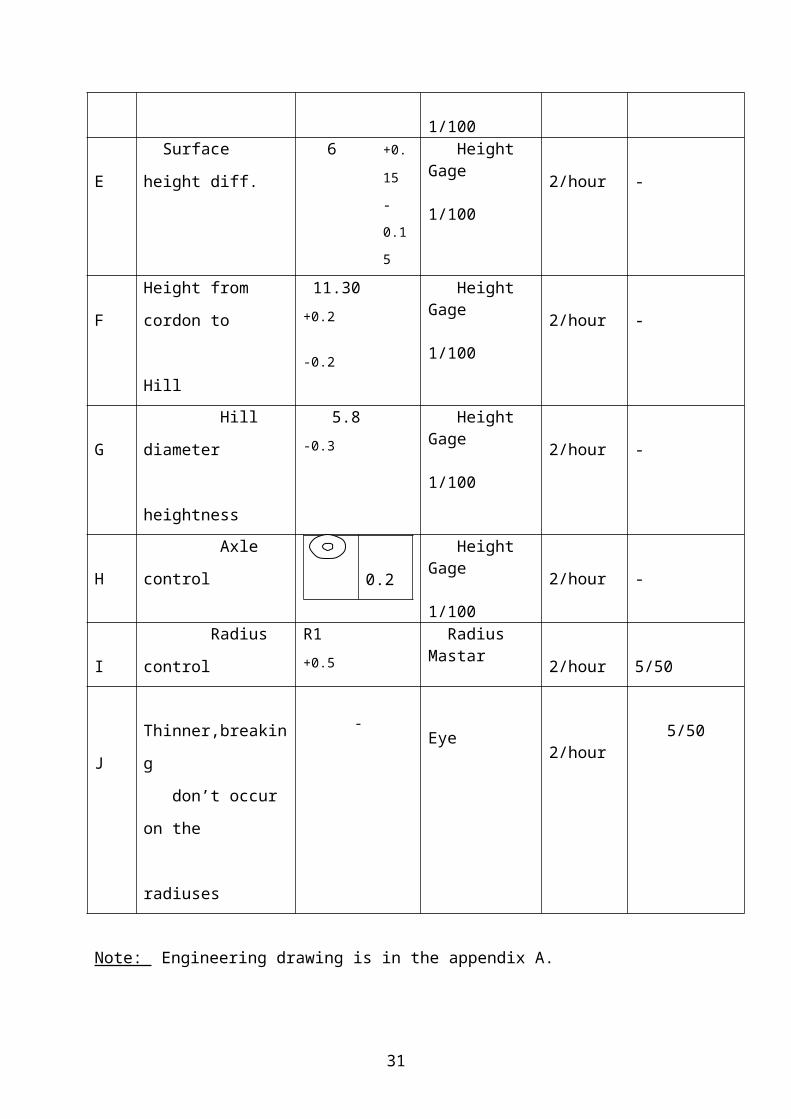
E Surface height diff. 6 +0.15
-0.15
Height Gage 1/100
2/hour -
F Height from cordon to
Hill
11.30 +0.2
-0.2
Height Gage 1/100
2/hour -
G Hill diameter
heightness
5.8 -0.3 Height Gage 1/100
2/hour -
H Axle control 0.2 Height Gage 1/100
2/hour -
I Radius control R1 +0.5 Radius Mastar 2/hour 5/50
20

J
Thinner,breaking
don’t occur on the
radiuses
- Eye
2/hour
5/50
Note: Engineering drawing is in the appendix A.
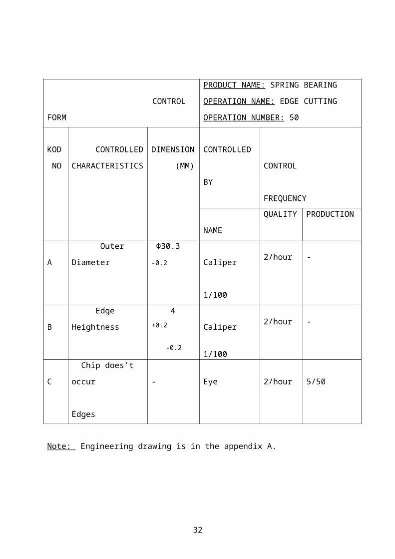
CONTROL FORM
PRODUCT NAME: SPRING BEARING
OPERATION NAME: EDGE CUTTING
OPERATION NUMBER: 50
KOD
NO
CONTROLLED
CHARACTERISTICS
DIMENSION
(MM)
CONTROLLED
BY
CONTROL
FREQUENCY
NAME QUALITY PRODUCTION
A Outer Diameter Φ30.3 -0.2
Caliper
1/100
2/hour -
B Edge Heightness 4 +0.2
-0.2
Caliper
1/100
2/hour -
C Chip does’t occur
Edges
- Eye 2/hour 5/50
Note: Engineering drawing is in the appendix A.
CONTROL FORM
PRODUCT NAME: SPRING BEARING
OPERATION NAME: UPPER DRILLING
OPERATION NUMBER: 60
KOD
NO
CONTROLLED
CHARACTERISTICS
DIMENSION
(MM)
CONTROLLED
BY
CONTROL
FREQUENCY
NAME QUALITY PRODUCTION
A Hole Diameter MİNΦ11.5 Eye 2/hour -
21

B Heightness from
cordon to hill
10.45 -0.4
Height Gage
1/100
2/hour -
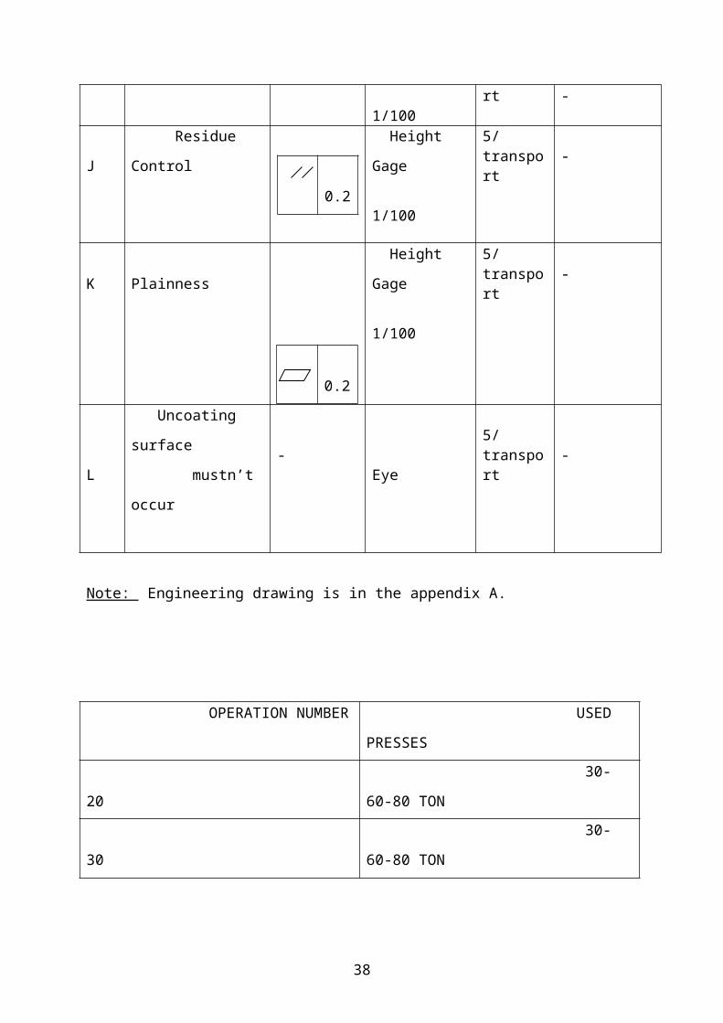
C Residue Control
0.2
Height Gage
1/100
2/hour -
D Plainness Height Gage
1/100
2/hour -
Note: Engineering drawing is in the appendix A.
CONTROL FORM
PRODUCT NAME: SPRING BEARING
OPERATION NAME: CALIBRATION
OPERATION NUMBER: 70
KOD
NO
CONTROLLED
CHARACTERISTICS
DIMENSION
(MM)
CONTROLLED
BY
CONTROL
FREQUENCY
NAME QUALITY PRODUCTION
A Edge Heightness 4 +0.2
-0.2
Caliper
1/100
2/hour -
B Hole Diameter MINΦ11.5
Caliper
1/100
2/hour -
C Outer Diameter Φ30.3 -0.2 Caliper
1/100
2/hour -
D Surface heightness
difference
6 +0.15
-0.15
Height Gage
1/100
2/hour -
E Height from cordon to
Hill
10.45 -0.4 Height Gage
1/100
2/hour -
22
0.2

F Residue Control
0.2
Height Gage
1/100
2/hour -
G Plainness Height Gage
1/100
2/hour -
H Chip doesn’t occur
Edges
- Eye 2/hour 5/50
Note: Engineering drawing is in the appendix A.
CONTROL FORM
PRODUCT NAME: SPRING BEARING
OPERATION NAME: COATING
OPERATION NUMBER: 80
KOD
NO
CONTROLLED
CHARACTERISTICS
DIMENSION
(MM)
CONTROLLED
BY
CONTROL
FREQUENCY
NAME QUALITY PRODUCTION
A Uncoating surface
mustn’t occur.
-
Eye NAP -
B Outer Diameter
Φ30.3 -0.2
Caliper 1/100
5/transport -
C Hole Diameter MIN Φ11.5 Caliper 1/100
5/transport -
Note: Engineering drawing is in the appendix A.
CONTROL FORM
PRODUCT NAME: SPRING BEARING
OPERATION NAME: FINAL CONTROL
23
0.2

OPERATION NUMBER: 90
KOD
NO
CONTROLLED
CHARACTERISTICS
DIMENSION
(MM)
CONTROLLED
BY
CONTROL
FREQUENCY
NAME QUALITY PRODUCTION
A Sheet Thickness 0.6 +0.05
-0.05
Micrometer
1/100
5/transport -
B Edge Heightness 4
Height Gage
1/100
5/transport -
C Surface heightness
difference6 +0.15
-0.15
Height Gage
1/100
5/transport -
D Height from cordon to
Hill
10.45 -0.4 Height Gage
1/100
5/transport -
E Outer Diameter
Φ30.3 -0.2
Caliper 1/100
5/transport -
F Diameter Φ26.35 -0.2 Caliper
1/100
5/transport -
G Diameter Φ25.8 -0.2 Caliper
1/100
5/transport -
H Diameter Φ13.4 +0.2 Caliper
1/100
5/transport -
I Hole Diameter MIN Φ11.5 Caliper 1/100
5/transport -
J Residue Control
0.2
Height Gage
1/100
5/transport -
K Plainness Height Gage
1/100
5/transport -
L
Uncoating surface
mustn’t occur
-
Eye 5/transport -
24
0.2

Note: Engineering drawing is in the appendix A.
OPERATION NUMBER USED PRESSES
20 30-60-80 TON
30 30-60-80 TON
40 60-80 TON
50 60-80 TON
60 60-80 TON
70 60-80 TON
CONCLUSION As declared in the introduction part of the report, the aim of the summer practice is to improve the theoretical & practical knowledge on mechanical engineering study. And the scope of the ME 299 Summer Practice is the production methods. The summer practice for junior year students depends on the analysis of production techniques and application of school knowledge in industry.
In summer practice, I think I had useful practices on production techniques and I see what is going on in the factory about production. And I think I got knowledge about application of theory in practice. I think my summer practice was corresponding with the aim of the summer practice and I worked on the scope of the summer practice.
In the summer practice I had chance to see stages of production and what is the role that Mechanical Engineers play in production. I saw that the most important role belongs to Mechanical Engineers. In every stage, planning of production, adjusting the machines, arranging the operations ad preparing the operation page that means almost everything in production, determining the machine tools, time etude of operations, jobshop investments are the duties of the office engineers. Also Mechanical Engineers have great duties in jobshop. The continuity and quality of the production is the responsibility of Mechanical Engineers in the jobshop. The use of machine tools, the quality of products, to follow the workers, to determine why the productions faulty if there is an error, are classified in the duties of jobshop engineers.
Mechanical Engineers have much duty also in assembly. Besides these Mechanical Engineers have great duties in quality control. Most of the stages of production control are carried out by Mechanical Engineers.
25

Mechanical Engineers have some duties on mechanical maintenance. The maintenance of machines, to repair when there’s an error at machines, to establish and to move the machines are the duties of Mechanical Engineers at the mechanical maintenance. Mechanical Engineers have also duties at directory, the finance and commercial departments of the company.
Also in summer practice I had chance to see the production and apply my knowledge to practice. In the factory I saw all the stages of production. It was actually educational. I saw what is going on in production. What is the production sequence? What are the operations after a half-product or a raw material came to factory? How a part is machined? How the controls are done? I found answers to such questions.
At all I see what is going on in a factory. I believe that the only practice area for a Mechanical Engineering student, is a factory. I think that I have applied my theoretical knowledge on production and drawing, to practice. Moreover I can say that I saw how engineers use their knowledge in production.
26

APPENDIX A
OPERATION NAME: BAND CUTTING
OPERATION NUMBER: 10
27

OPERATION NAME:CIRCUMRERENCE CUTTINGOPERATION NUMBER:20
28

OPERATION NAME:2. ELONGATION
OPERATION NUMBER:30
29

OPERATION NAME:3. ELONGATIONOPERATION NUMBER:40
30
OPERATION NAME:EDGE CUTTINGOPERATION NUMBER:50
31
OPERATION NAME:UPPER HOLE DRILLINGOPERATION NUMBER:60
32

OPERATION NAME:CALIBRATIONOPERATION NUMBER:70
33

OPERATION NAME:COATINGOPERATION NUMBER:80
34

OPERATION NAME:FINAL CONTROLOPERATION NUMBER:90
35

PRODUCT WHICH IS PRODUCTED ON CNCPART NAME:DRIVER
36

PRODUCT WHICH IS PRODUCED ON LATHEPART NAME:DRIVER
APPENDIX B
STRUCTURE OF ORGANIZATION
37
APPENDIX C
VIEW OF CNC CONTROL PANEL
PLANT MANAGER
QUALITY
QUALITY CONFIDENCE
QUALITY CONTROL
MECHANICALREPAIRMENT
PRES DEPT.
PRODUCTION
ENGINEERING MOULD DEPT
MATERIAL SUPPLIER
BUYING
DEPOT
PLANNING
FINANCE
PERSONEL DEPT.
PRODUCT RESPONSIBILITY
GENERAL MANAGER
38

BUTTONS FUNCTIONS WHICH IS ON THE CNC
39

40