design & communication graphics -
TRANSCRIPT
Samp. M81BC
Page 1 of 9
Coimisiún na Scrúduithe Stáit State Examinations Commission
Leaving Certificate Examination
Design & Communication Graphics Higher Level Sections B and C (180 Marks)
Sample Examination Paper 3 Hours Duration
General Instructions: • Construction lines must be shown on all solutions • Write the question number distinctly on the answer paper in Sections B and C • Work on one side of the drawing paper only • All dimensions are given in metres or millimetres • Write your Examination number in the box provided on section A and on all other sheets used
This examination is divided into three sections:
SECTION A (Core - Short Questions)
SECTION B (Core - Long Questions)
SECTION C (Applied Graphics - Long Questions)
• Four questions are presented • Answer any three on the accompanying A3 examination paper • All questions in Section A carry 20 marks
SECTION A
• Three questions are presented • Answer any two on A3 drawing paper • All questions in Section B carry 45 marks
SECTION B
• Five questions are presented • Answer any two (i.e. the options you have studied) on A3 drawing paper • All questions in Section C carry 45 marks
SECTION C

Page 2 of 9
B-1. The 3D graphic in Fig. B-1 shows two intersecting planes, ABC and ADE. The horizontal and vertical
planes of reference are also shown.
The horizontal and vertical coordinates for the intersecting planes are given below.
A = 170 --- 95 --- 20 B = 215 --- 25 --- 30 C = 150 --- 55 --- 90 D = 235 --- 20 --- 65 E = 155 --- 5 --- 45
(a) Draw the plan and elevation of the intersecting planes.
(Use a vertical orientation for the A3 sheet to maximise space) (b) Determine the line of intersection between the planes.
(c) Determine the angle of inclination of the line of intersection to the vertical plane.
(d) Determine the dihedral angle between the planes.
Scale 1:1
SECTION B - Core Answer Any Two questions from this section on A3 drawing paper
Fig. B-1
Page 3 of 9
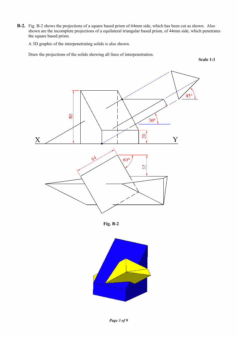
B-2. Fig. B-2 shows the projections of a square based prism of 64mm side, which has been cut as shown. Also shown are the incomplete projections of a equilateral triangular based prism, of 44mm side, which penetrates the square based prism.
A 3D graphic of the interpenetrating solids is also shown.
Draw the projections of the solids showing all lines of interpenetration. Scale 1:1
Fig. B-2
Page 4 of 9
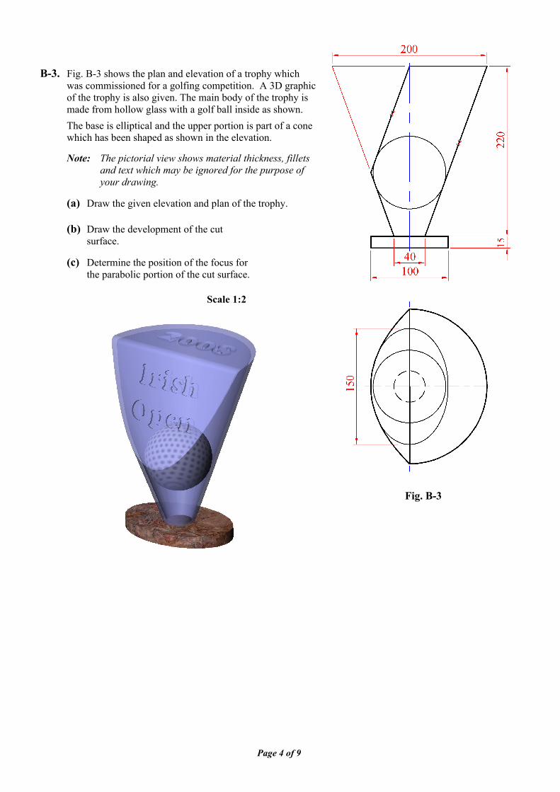
B-3. Fig. B-3 shows the plan and elevation of a trophy which
was commissioned for a golfing competition. A 3D graphic of the trophy is also given. The main body of the trophy is made from hollow glass with a golf ball inside as shown.
The base is elliptical and the upper portion is part of a cone which has been shaped as shown in the elevation.
Note: The pictorial view shows material thickness, fillets
and text which may be ignored for the purpose of your drawing.
(a) Draw the given elevation and plan of the trophy.
(b) Draw the development of the cut
surface. (c) Determine the position of the focus for
the parabolic portion of the cut surface.
Scale 1:2
Fig. B-3
Page 5 of 9
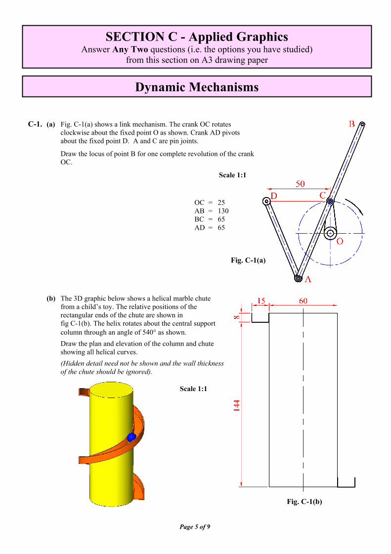
C-1. (a) Fig. C-1(a) shows a link mechanism. The crank OC rotates
clockwise about the fixed point O as shown. Crank AD pivots about the fixed point D. A and C are pin joints.
Draw the locus of point B for one complete revolution of the crank OC.
Scale 1:1
(b) The 3D graphic below shows a helical marble chute from a child’s toy. The relative positions of the rectangular ends of the chute are shown in fig C-1(b). The helix rotates about the central support column through an angle of 540° as shown.
Draw the plan and elevation of the column and chute showing all helical curves.
(Hidden detail need not be shown and the wall thickness of the chute should be ignored).
SECTION C - Applied Graphics Answer Any Two questions (i.e. the options you have studied)
from this section on A3 drawing paper
Dynamic Mechanisms
Fig. C-1(b)
Fig. C-1(a)
OC = 25 AB = 130 BC = 65 AD = 65
Scale 1:1
Page 6 of 9
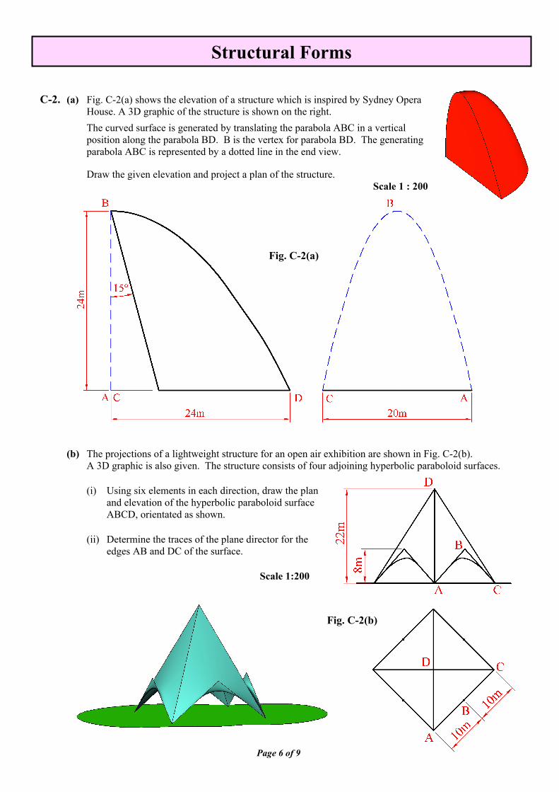
C-2. (a) Fig. C-2(a) shows the elevation of a structure which is inspired by Sydney Opera
House. A 3D graphic of the structure is shown on the right.
The curved surface is generated by translating the parabola ABC in a vertical position along the parabola BD. B is the vertex for parabola BD. The generating parabola ABC is represented by a dotted line in the end view.
Draw the given elevation and project a plan of the structure. Scale 1 : 200
(b) The projections of a lightweight structure for an open air exhibition are shown in Fig. C-2(b). A 3D graphic is also given. The structure consists of four adjoining hyperbolic paraboloid surfaces.
(i) Using six elements in each direction, draw the plan
and elevation of the hyperbolic paraboloid surface ABCD, orientated as shown.
(ii) Determine the traces of the plane director for the
edges AB and DC of the surface. Scale 1:200
Structural Forms
Fig. C-2(a)
Fig. C-2(b)
Page 7 of 9
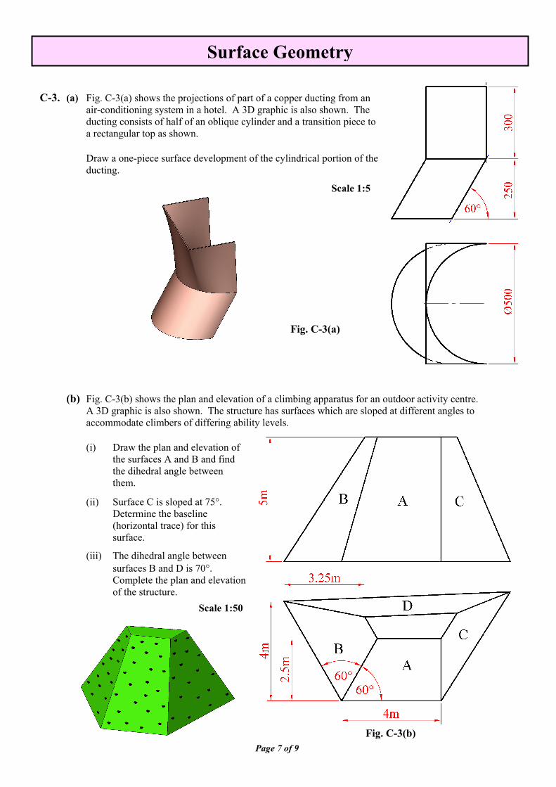
C-3. (a) Fig. C-3(a) shows the projections of part of a copper ducting from an
air-conditioning system in a hotel. A 3D graphic is also shown. The ducting consists of half of an oblique cylinder and a transition piece to a rectangular top as shown.
Draw a one-piece surface development of the cylindrical portion of the ducting.
Scale 1:5
(b) Fig. C-3(b) shows the plan and elevation of a climbing apparatus for an outdoor activity centre. A 3D graphic is also shown. The structure has surfaces which are sloped at different angles to accommodate climbers of differing ability levels.
(i) Draw the plan and elevation of
the surfaces A and B and find the dihedral angle between them.
(ii) Surface C is sloped at 75°. Determine the baseline (horizontal trace) for this surface.
(iii) The dihedral angle between surfaces B and D is 70°. Complete the plan and elevation of the structure.
Scale 1:50
Surface Geometry
Fig. C-3(a)
Fig. C-3(b)
Page 8 of 9
C-4. (a) The accompanying map, located on the back page of Section A, shows ground contours at five metre
vertical intervals.
ABC is the centreline of a proposed roadway. The section of the roadway between A and B is level at an altitude of 55m. The section from B to C has a gradient of 1 in 20 falling.
Using side slopes of 1 in 1.5 for the embankments and 1 in 1 for the cuttings, complete the earthworks necessary to accommodate the roadway.
Note: The earthworks on the southern side of the roadway have already been completed.
(b) On the map, D and E indicate the location of two points on the ground.
A vertical borehole is drilled at D and it reveals the top and bottom surfaces of a stratum of ore at distances of 35m and 60m from D respectively.
A skew borehole at E is drilled as shown and has an actual inclination of 60° to the horizontal plane. It reveals the top and bottom surfaces of the stratum at distances of 10m and 30m from E respectively. (i) Determine the dip, strike and thickness of the stratum. (ii) Determine the apparent dip of the stratum in a South-Easterly direction.
Scale 1:1000
Geologic Geometry
Page 9 of 9
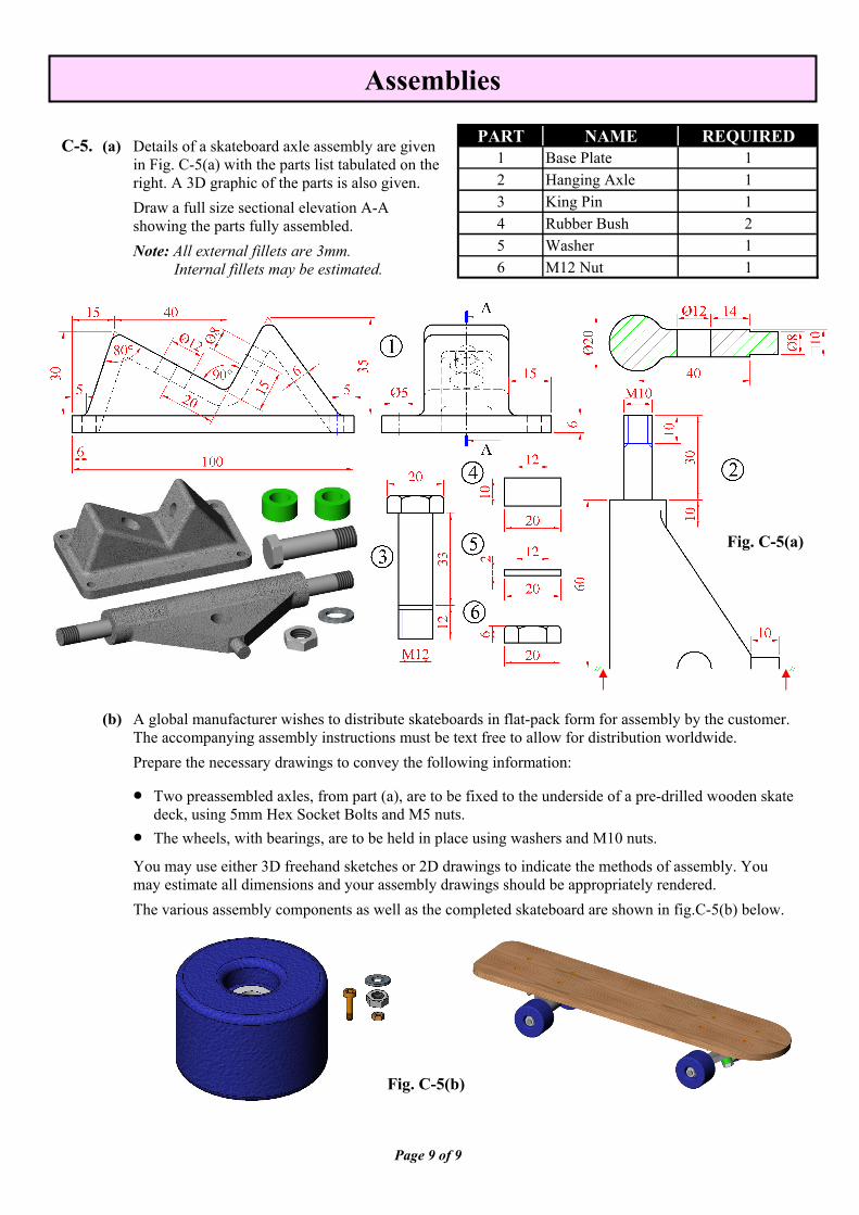
PART NAME REQUIRED1 Base Plate 12 Hanging Axle 13 King Pin 14 Rubber Bush 25 Washer 16 M12 Nut 1
C-5. (a) Details of a skateboard axle assembly are given
in Fig. C-5(a) with the parts list tabulated on the right. A 3D graphic of the parts is also given.
Draw a full size sectional elevation A-A showing the parts fully assembled.
Note: All external fillets are 3mm. Internal fillets may be estimated.
(b) A global manufacturer wishes to distribute skateboards in flat-pack form for assembly by the customer.
The accompanying assembly instructions must be text free to allow for distribution worldwide.
Prepare the necessary drawings to convey the following information:
• Two preassembled axles, from part (a), are to be fixed to the underside of a pre-drilled wooden skate deck, using 5mm Hex Socket Bolts and M5 nuts.
• The wheels, with bearings, are to be held in place using washers and M10 nuts.
You may use either 3D freehand sketches or 2D drawings to indicate the methods of assembly. You may estimate all dimensions and your assembly drawings should be appropriately rendered.
The various assembly components as well as the completed skateboard are shown in fig.C-5(b) below.
Assemblies
Fig. C-5(b)
Fig. C-5(a)

BLANK PAGE

BLANK PAGE

BLANK PAGE