design and analysis of passive phase based dsss communication system in underwater...
TRANSCRIPT
J. Basic. Appl. Sci. Res., 2(6)6052-6064, 2012
© 2012, TextRoad Publication
ISSN 2090-4304 Journal of Basic and Applied
Scientific Research www.textroad.com
*Corresponding Author : Seyed Mohsen Seyed Mousavi Department of Electrical Engineering, Mahshahr Branch, Islamic Azad University, Mahshahr, Iran. Emails: [email protected], [email protected]
Design and Analysis of Passive Phase Based DSSS Communication System in Underwater Acoustic Channels
Seyed Mohsen Seyed Mousavi1* and Morvarid Bozorgpouri2
1Department of Electrical Engineering, Mahshahr Branch, Islamic Azad University, Mahshahr, Iran
2Department of Education, Shadegan Branch, Islamic Azad University, Shadegan, Iran
ABSTRACT
The Ocean is often a complex multipath channel mostly with a sparse impulse response and researchers have been made in developing equalization algorithms to overcome this complicated feature. However, many of these proposed equalizers are highly time consuming and are not power efficient in the most applications. On the other hand direct sequence spread spectrum techniques have been utilized in both underwater acoustic communications due to low probability of intercept and resilience against inter symbol interference (ISI) caused by multipath propagation. To overcome the severe impact of ISI, we take advantage of passive phase conjugation (PPC) and properties of spread spectrum communication systems to overcome the severe multipath effect in sparse underwater acoustic channels. KEYWORDS: Spread Spectrum, Passive Phase Conjugation, Underwater Acoustic Channels,
Performance Analysis, Multipath channels.
1. INTRODUCTION
Acoustic signaling for wireless digital communications in the underwater acoustic (UWA) channels can be a very attractive alternative for radio systems. However, time-varying and long multipath spread with often harsh ambient noise conditions characterizes this channel. This time-varying multipath propagation and channel fading are the most important aspects that making acoustic communications challenging. Also, multipath spread causes severe inter-symbol interference (ISI) in UWA digital communication. Therefore, equalization [1]-[6], spatial processing including diversity combining and beam forming [7], channel coding [8]-[10], and time reversal techniques [11]-[14] are some techniques that are suitable to overcome the severe ISI in the underwater acoustic channels. Time reversal or phase conjugation was demonstrated in the early 1960s as a means of ISI removing in the severe multipath channels. Passive phase conjugation (PPC) and time reversal have been studied in some works such as [11]-[14]. In digital communications, the application of the time-reversal or phase conjugation principals consist in preceding each data frame by a probe signal that is later used as a matched filter to remove the channel multipath effect.
Usually, after equalizing the multipath acoustic channels or along with the equalization, a proper channel coding can be used to alleviate the effect of remaining ISI. For example, trellis coded modulation was used together with single carrier transmission and equalization in [8]. Convolutional codes and Reed Solomon codes have been examined in [9] for underwater acoustic communication. In conjunction with spatial multiplexing, turbo codes and space time trellis codes were used in [10] for a single-carrier underwater system with multiple transmitters. DSSS technique is a form of code division multiple access or CDMA. As in terrestrial wireless communications, this modulation scheme can accommodate multiple users if different orthogonal pseudo noise (PN) sequences are assigned to different users. Due to its inherent interference rejection, covertness and multiple access capability, DSSS technique has been utilized in underwater acoustic communication networks and reliable point to point communications [14]-[20].
To mitigate ISI and multiple access interference, in [16], the authors proposed two types of decision feedback receivers in a DS-CDMA system which performs decision feedback equalization and dispreading in a multichannel configuration. Because of using a chip resolution adaptive front end and multiple elements in different spaces in the proposed receivers, the proposed receivers have not a reasonable hardware complexity. [17] reports favorable results in the 1-2 kHz frequency band at short ranges for a single user. In order to compensate the channel impairments owing to multipath and Doppler effects, the authors in [18] utilized a
6052
Mousavi and Bozorgpouri 2012
transform-domain approximate RLS (TARLS) blind algorithm for the equalizer. In this approach, they consider applying the RLS algorithm to the orthogonally transformed input signal. In this work, the computational complexity of the TARLS algorithm was reduced considerably. In [19] and [20], by parallel data transmissions using simultaneously transmitted orthogonal signature sequences, the authors tried to increase the data rate. In [19], in order to improve the data rate of spread spectrum under water acoustic communication further, time overlapping method was introduced. Based on the saved channels (measured in lake test), performance of the proposed method in [19] was simulated. The results showed its robustness and relative higher data rate.
In this paper, a hybrid DSSS-PPC technique is considered with potential application to underwater acoustic communications. The proposed DSSS-PPC scheme exploits desirable properties of both DSSS and PPC to create a very effective communication system. Like conventional PPC and time reversal methods, the proposed DSSS-PPC scheme removes the need for explicit channel estimation and subsequent equalization; it delivers high data rate transfer while requiring only a minor modification to the conventional DSSS wireless receiver structure. The proposed DSSS receiver is based on the rake receiver which uses a few fingers and a PN sequence to collect the distributed energy of transmitted symbols in the multipath channels. Our theoretical analysis show that most of the multipath channel induced ISI can be removed by using the hybrid technique. We shall observe that with simple receiver configuration which uses few rake fingers, the proposed scheme can perform very well in the multipath UWA channels, especially in the sparse channels.
The paper is organized as follows. Section 2 introduces the system model and the description of the passive phase conjugation. Section 3 characterizes the theoretical analysis of passive phase conjugation based rake receiver of the proposed scheme. Section 4 presents some numerical results and comparisons, and finally, Section 5 summarizes our concluding remarks. 2. Passive Phase Conjugation and System Description
In this section, we first consider the passive phase conjugation procedure and then demonstrate the mathematical description of our proposed transmitter and receiver structures. 2.1 Passive Phase Conjugation
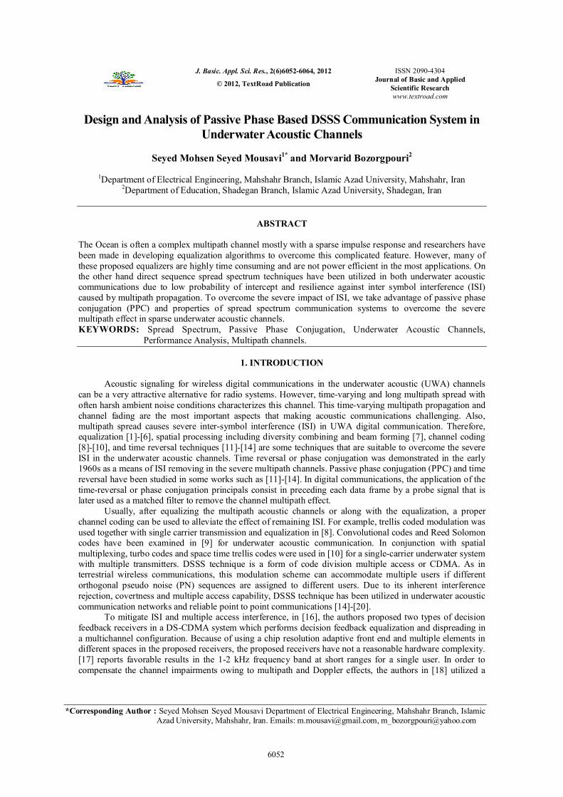
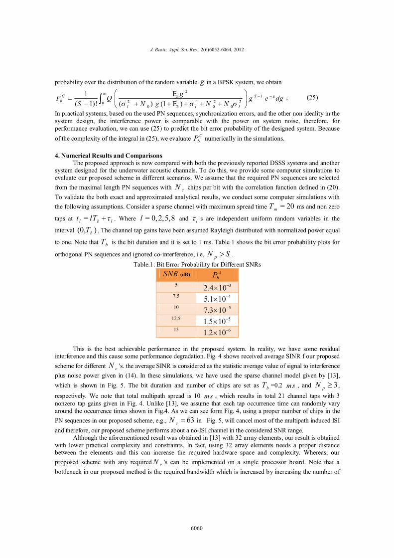
The PPC procedure shown in Fig. 1. The channel impulse response is ( )h t and its Fourier transform is ( )H . By considering this, in the frequency domain, the convolution of ( )h t and the transmitted signal
( )s t is ( ) ( ) H S . Similarly, the correlation of 1( )s t and 2 ( )s t is 1 2( ) ( ) S S , where the '*'
indicates complex conjugation. The PPC procedure begins with a source transmitting signal 1S used as a
single probe. After waiting for the multipath arrivals to clear, the source then transmits the data stream 2S . At the receiver, the received probe is cross-correlated with the received data stream. As the propagation medium changes it becomes necessary to break up the data stream and insert a new probe. The basic idea in phase conjugation is that the autocorrelation of the channel impulse response (CIR) 2| |H tends to reconcentrate
the multipath arrivals at zero time lags. The term 2| |H is the timer reversal or phase conjugation focusing operator [21]. However depending on the distribution of the multipath arrivals in ( )h t , the autocorrelation may also have temporal side-lobes that result in residual inter-symbol interference, even after focusing. Some works in the literature [13]-[14] used arrays of receivers to average down the side-lobes. If fact, the cross-correlation of the PPC procedure is done in parallel at each array element and the results are summed across the array to obtain the final communication signal suitable for demodulation. 2.2 Transmitter and Receiver Structures
In our proposed method, we avoid the cost and complexity of receiver arrays by using spread spectrum pseudo noise (PN) sequences. Because of temporal spreading, this does not yield bit rates as high as can be achieved with receiver arrays. To illustrate the main concept, consider a point to point communication scenario in an acoustic underwater channel. Assume that the communication system uses DSSS technique to combat the multipath induced inference of the channel. In the next two subsections, we describe the transmitter and receiver structures.
6053
J. Basic. Appl. Sci. Res., 2(6)6052-6064, 2012
2.2.1 Transmitter Structure The transmitter of this scenario utilizes a set of pN distinct PN sequences with cN chips per data
symbol period bT such that =b c cT N T , where cT is the chip duration. Unlike the traditional DSSS technique, the transmitter uses at least two PN sequences to spread each bit of a data frame. In other words,
each bit in a data frame of pN bits is modulated by one of the PN sequences in the given set =1{PN }N p
n n , and
this process periodically occurs for the next frames of pN bits. In fact, the interference energy that comes from the adjacent bits can be removed by multiplying the received signal with the corresponding PN sequence of the i th bit which is popular operation in the DSSS communication techniques. Simultaneously, the scattered energy is collected by this multiplication via the auto-correlation property of the corresponding PN sequence of the i th bit. According the above structure, the transmitted signal ( )x t can be expressed as
= = 0
( )
1 1( ) = ( )
b
N cP
b r j b cr j b
P t rT
x t b a g t rT jTT
E (1)
where bT , cT , cN , and bE are the bit duration, the chip duration, the number of chips in each PN
sequences, and the bit energy, respectively. ( )g t is the transmitter chip shaping pulse, which is unity during
the chip interval cT and zero otherwise. Also, rb is the r th transmitted bit and { 1} Pja denotes the j
th spreading chip corresponding to the PN signal ( )P t . Note that the number of PN signals in the transmitter
is pN and they are repeated for each frame of pN bits. 2.2.2 Rake Receiver Based Passive Phase Conjugation Structure Consider the LTI channel model with impulse response given below
1
=0( ) = ( )
L
l ll
h t h t t (2)
where lh denotes the path gain and [0, ]l mt T is the path delay associated with the l th path. mT represents the maximum delay spread of the channel. To facilitate analysis and capture the channel characteristics, the channel can be properly modeled in term of resolvable paths. Throughout the paper, we consider symbol signaling over duration bT and additionally, we assume that bT is relatively low, i.e., a high data rate signaling scenario, so that the continuous time channel response can be considered with none zero taps at = l b lt lT . Where l 's are independent uniform random variables in the interval (0, )bT . The channel tap gains have been assumed Rayleigh distributed with normalized power equal to one. Because of
high ratio of central frequency to the bandwidth, i.e., . .
cfB W
, in underwater acoustic channels, the
communication systems in the underwater applications are inherently wideband communications. On the other hand, these channels have large delay spreads, so, it is reasonable to consider that these channels can be resolvable with bT in high data rate situations. Assuming an additive white Gaussian noise (AWGN) in the channel output, the received signal can be expressed as follows
1
=0
( ) = ( ) ( ) ( )
= ( ) ( )
L
l ll
r t x t h t n t
h x t t n t (3)
where stands for the convolution. lh and ( )x t are defined in (2) and (1), respectively. ( )n t is an
6054
Mousavi and Bozorgpouri 2012
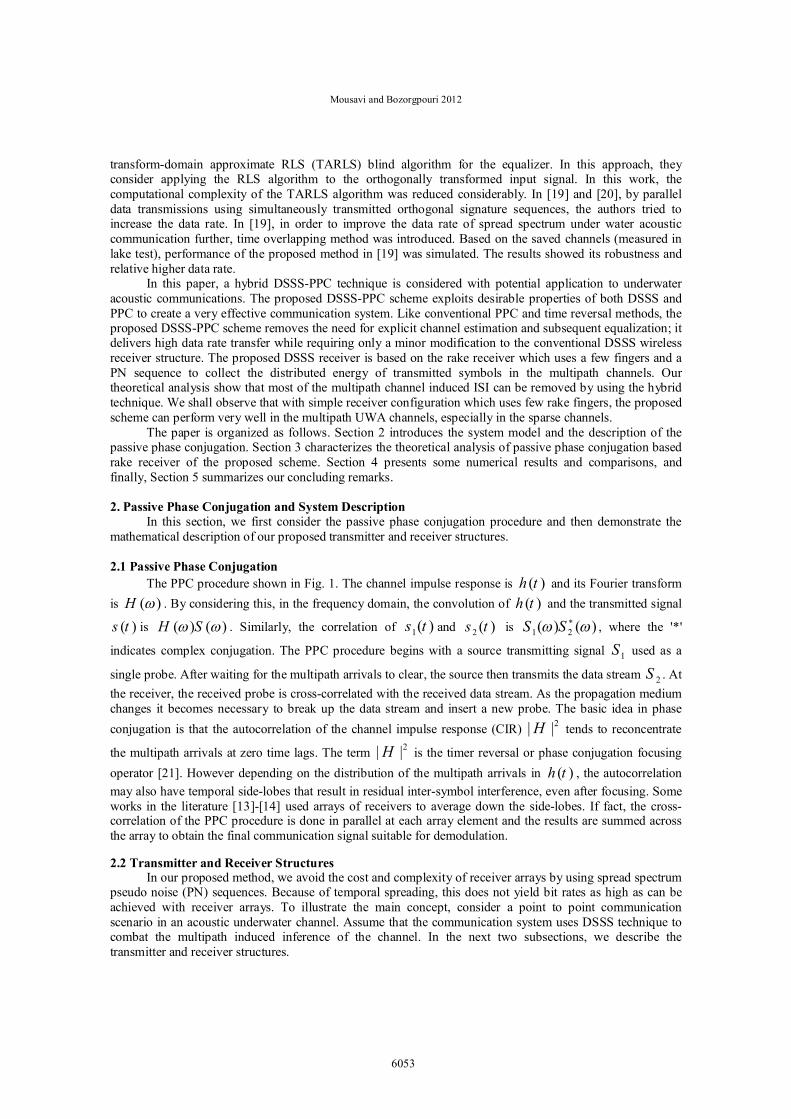
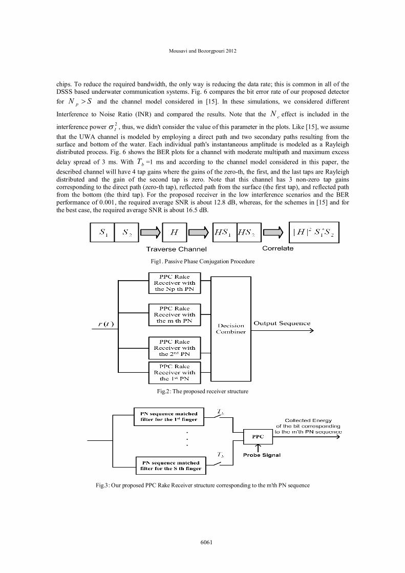
additive white Gaussian noise with zero mean and variance of 0N . The passive phased conjugation (PPC)
rake receiver structure is shown in Fig. 2. In fact, the considered structure is a combination of pN rake
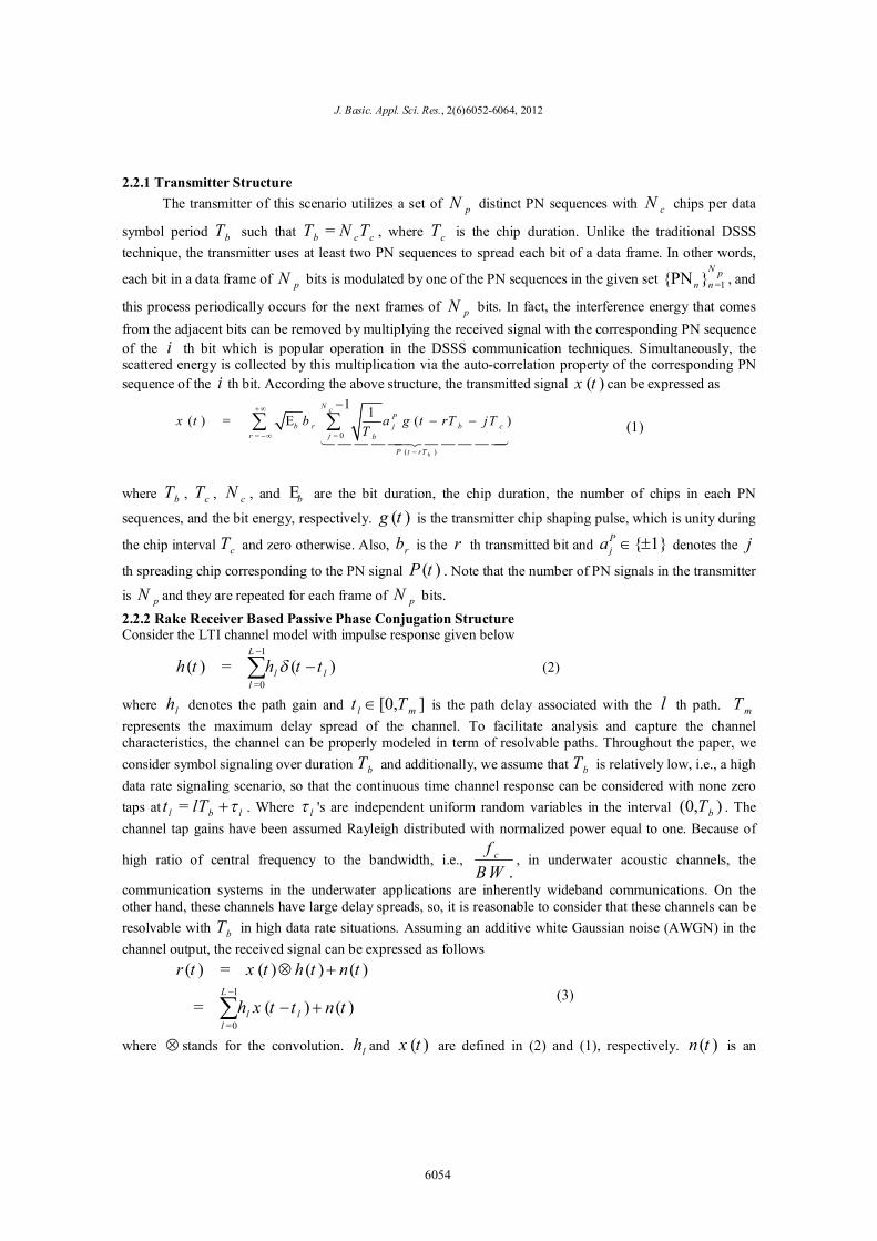
receivers based on PPC concept corresponding to pN different PN sequences. The details of each PPC Rake Receiver is shown if Fig.3. After describing the PPC Rake Receiver details, we will examine the operation of "decision combiner" block in Fig.2.
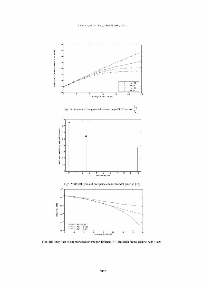
As we know, a rake receiver can make use of the energy present in multiple propagation paths. If we represent the channel as a tap delay line, at each tap, a delayed replica of the received signal is correlated with the time delayed replica of the PN signal used to spread the data symbols. Because PN codes ideally have maximum correlation at zero delay and zero correlation at non-zero delays, we will get signal from taps that correspond to the multiple propagation paths. Without loss of generality, we assume that the receiver is perfectly synchronized to the spreading sequence, the delays of the selected paths are known at the receiver but the channel coefficients are not known in the receiver. Fig. 3 shows one of the PPC Rake Receivers' structures corresponding to one of the PN sequences. We assume that only the channel gains of S paths are nonzero and, each rake receiver is equipped with S fingers to collect the spread energy. With the PPC configuration including in the Rake Receiver we expect: 1. The residual ISI or spread energy can be collected by PPC configuration in the Rake Receiver as in the time reversal or PPC focusing operator had taken place. Although most of the spread energy has been collected by the inherent feature of the Rake Receiver, in practice, with semi-orthogonal PN sequences, there is some residual interference that can be removed by PPC operation. 2. The phase conjugation (time reversal) approach avoids the explicit recovery of the channel and its subsequent equalization via algorithmic complex equalizers such as Decision Feedback Equalizers or the others. 3-The Maximum Ratio Combiner (MRC) operation that is usual in the Rake Receiver finger outputs combining is not required here, actually, this process is performed inherently in the PPC block. Now, we examine the "decision combiner" block in Fig.2. After collecting the bit energy corresponding to each PN sequences by one of the PPC based Rake Receivers in each bit interval bT , the decision combiner
block waits for mT (maximum delay spread of the acoustic channel) seconds. We assumed that mT spans
multiple bT in the considered underwater channel and the desired proposed system. Note that in the underwater channels, the maximum spread delay is sometimes tens or even hundreds of milliseconds. Thus, the assumption is reasonable. Finally, the decision combiner block aggregates the collected energy of the waiting time for each different bit and then easily takes their signs as the decided bits, then, by converting the parallel bits to serial sequences, it terminates the decision process. To formulate the receiver processes, without loss of generality, it is assumed that we are interested in the detection of the bit modulated with 1PN . Using (1), (3) and the Rake Receiver principal [1], it can be easily shown that the output signal of the each finger matched filter after sampling is:
desired dsignal ISI noise
1= , 1, 2, ...,
b k k kky h b I n k SE (3)
Where S is the number of fingers, kI is the residual interference at the output of the correlator, kn is the
AWGN with zero mean and variance of 0N . If the DSSS system uses the orthogonal PN sequences, the residual interference will be zero at the correlator output. However, in practice, some ISI remains in the correlator output, and this can be removed by the PPC operation after the finger correlator. With our proposed PPC based Rake Receiver the probe signal 1S in Fig.1 is represented by a probe sequence
1 1 2[ , ,..., ]pp p pNb b bS and 2S in Fig.1 is represented by the transmitted sequence
2 1 2[ , ,..., ]pt t tNb b bS . The elements of 1S are chosen to be real positive scalars, i.e., they do not introduce
6055
J. Basic. Appl. Sci. Res., 2(6)6052-6064, 2012
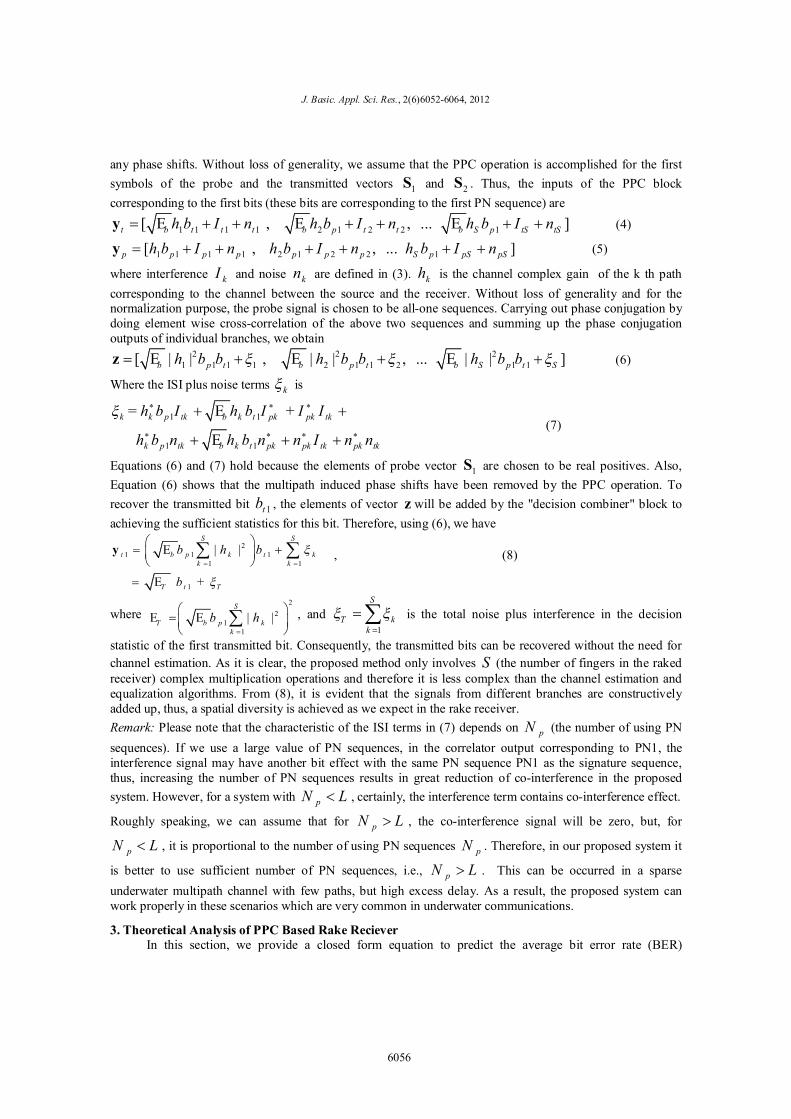
any phase shifts. Without loss of generality, we assume that the PPC operation is accomplished for the first symbols of the probe and the transmitted vectors 1S and 2S . Thus, the inputs of the PPC block corresponding to the first bits (these bits are corresponding to the first PN sequence) are
1 1 1 1 2 1 2 2 1[ , , ... ] t b t t t b p t t b S p tS tSh b I n h b I n h b I ny E E E (4)
1 1 1 1 2 1 2 2 1[ , , ... ] p p p p p p p S p pS pSh b I n h b I n h b I ny (5)
where interference kI and noise kn are defined in (3). kh is the channel complex gain of the k th path corresponding to the channel between the source and the receiver. Without loss of generality and for the normalization purpose, the probe signal is chosen to be all-one sequences. Carrying out phase conjugation by doing element wise cross-correlation of the above two sequences and summing up the phase conjugation outputs of individual branches, we obtain
2 2 21 1 1 1 2 1 1 2 1 1[ | | , | | , ... | | ] b p t b p t b S p t Sh b b h b b h b bz E E E (6)
Where the ISI plus noise terms k is
1 1
1 1
= +
k k p tk b k t pk pk tk
k p tk b k t pk pk tk pk tk
h b I h b I I I
h b n h b n n I n n
E
E (7)
Equations (6) and (7) hold because the elements of probe vector 1S are chosen to be real positives. Also, Equation (6) shows that the multipath induced phase shifts have been removed by the PPC operation. To recover the transmitted bit 1tb , the elements of vector z will be added by the "decision combiner" block to achieving the sufficient statistics for this bit. Therefore, using (6), we have
21 1 1
1 1
1
| |
+
S S
t b p k t kk k
T t T
b h b
b
y E
E
, (8)
where 2
21
1
| |
S
T b p kk
b hE E , and 1
S
T kk
is the total noise plus interference in the decision
statistic of the first transmitted bit. Consequently, the transmitted bits can be recovered without the need for channel estimation. As it is clear, the proposed method only involves S (the number of fingers in the raked receiver) complex multiplication operations and therefore it is less complex than the channel estimation and equalization algorithms. From (8), it is evident that the signals from different branches are constructively added up, thus, a spatial diversity is achieved as we expect in the rake receiver. Remark: Please note that the characteristic of the ISI terms in (7) depends on pN (the number of using PN sequences). If we use a large value of PN sequences, in the correlator output corresponding to PN1, the interference signal may have another bit effect with the same PN sequence PN1 as the signature sequence, thus, increasing the number of PN sequences results in great reduction of co-interference in the proposed system. However, for a system with pN L , certainly, the interference term contains co-interference effect.
Roughly speaking, we can assume that for pN L , the co-interference signal will be zero, but, for
pN L , it is proportional to the number of using PN sequences pN . Therefore, in our proposed system it
is better to use sufficient number of PN sequences, i.e., pN L . This can be occurred in a sparse underwater multipath channel with few paths, but high excess delay. As a result, the proposed system can work properly in these scenarios which are very common in underwater communications.
3. Theoretical Analysis of PPC Based Rake Reciever In this section, we provide a closed form equation to predict the average bit error rate (BER)
6056
Mousavi and Bozorgpouri 2012
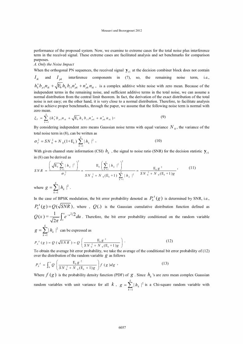
performance of the proposed system. Now, we examine to extreme cases for the total noise plus interference term in the received signal. These extreme cases are facilitated analysis and set benchmarks for comparison purposes. A. Only the Noise Impact When the orthogonal PN sequences, the received signal 1ty at the decision combiner block does not contain
tkI and pkI interference components in (7), so, the remaining noise term, i.e.,
1 1 k p tk b k t pk pk tkh b n h b n n nE , is a complex additive white noise with zero mean. Because of the
independent terms in the remaining noise, and sufficient additive terms in the total noise, we can assume a normal distribution from the central limit theorem. In fact, the derivation of the exact distribution of the total noise is not easy; on the other hand, it is very close to a normal distribution. Therefore, to facilitate analysis and to achieve proper benchmarks, through the paper, we assume that the following noise term is normal with zero mean.
1 11
( )
S
T k p tk b k t p k pk tkk
h b n h b n n nE , (9)
By considering independent zero means Gaussian noise terms with equal variance 0N , the variance of the total noise term in (8), can be written as
2 2 20 0
1
(1+ ) | |
S
T b kk
SN N hE , (10)
With given channel state information (CSI) kh , the signal to noise ratio (SNR) for the decision statistic 1ty in (8) can be derived as
2 22 2
21 1
2 22 2 0 0
0 01
| | | |
( + 1 )( + 1 ) | |
S S
b k b kk k b
ST b
b kk
h hgS N R
S N N gS N N h
E EE
EE
, (11)
where 2
1| |
S
kk
g h .
In the case of BPSK modulation, the bit error probability denoted as ( )AbP g is determined by SNR, i.e.,
( ) ( )AbP g Q SNR , where , (.)Q is the Gaussian cumulative distribution function defined as
21 /2( ) =2
u
xQ x e du . Therefore, the bit error probability conditioned on the random variable
2
1| |
S
kk
g h can be expressed as
2
20 0
( ) ( )( + 1 )
A bb
b
gP g Q S N R QS N N g
EE
. (12)
To obtain the average bit error probability, we take the average of the conditional bit error probability of (12) over the distribution of the random variable g as follows
2
200 0
( )( 1)
A b
bb
gP Q f g d gS N N g
EE
, (13)
Where ( )f g is the probability density function (PDF) of g . Since kh 's are zero mean complex Guassian
random variables with unit variance for all k , 2
1| |
S
kk
g h
is a Chi-square random variable with
6057
J. Basic. Appl. Sci. Res., 2(6)6052-6064, 2012
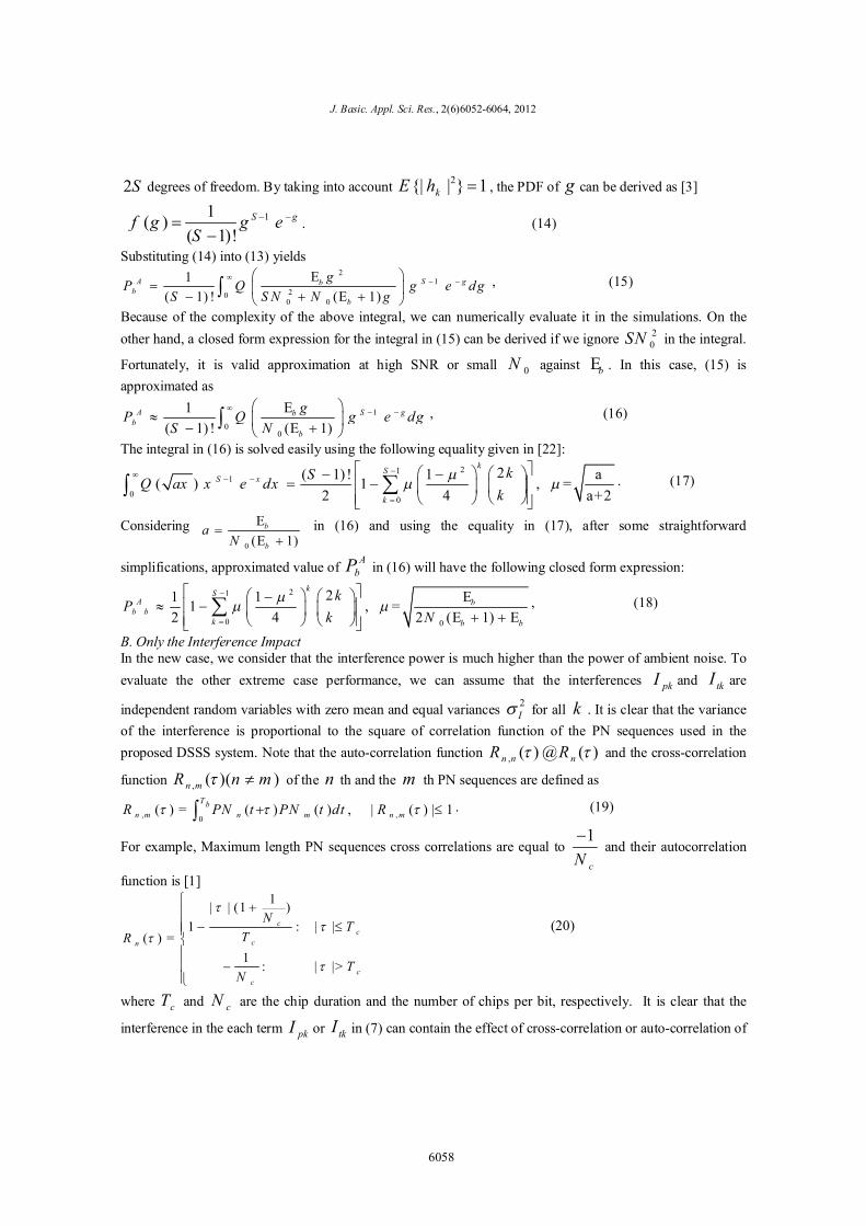
2S degrees of freedom. By taking into account 2{| | } 1kE h , the PDF of g can be derived as [3]
11 ( )
( 1)!S gf g g e
S
. (14)
Substituting (14) into (13) yields 2
120
0 0
1 ( 1) ! ( 1)
A S gbb
b
gP Q g e d gS S N N g
EE
, (15)
Because of the complexity of the above integral, we can numerically evaluate it in the simulations. On the other hand, a closed form expression for the integral in (15) can be derived if we ignore 2
0SN in the integral.
Fortunately, it is valid approximation at high SNR or small 0N against bE . In this case, (15) is approximated as
1
00
1 ( 1) ! ( 1)
A S gbb
b
gP Q g e dgS N
EE
, (16)
The integral in (16) is solved easily using the following equality given in [22]: 21
1
00
2( 1) ! 1 a( ) 1 , =2 4 a+2
kSS x
k
kSQ ax x e dxk
. (17)
Considering 0 ( 1)
b
b
aN
EE
in (16) and using the equality in (17), after some straightforward
simplifications, approximated value of AbP in (16) will have the following closed form expression:
21
0 0
21 11 , =2 4 2 ( 1)
kS
A bb b
k b b
kP
k NE
E E, (18)
B. Only the Interference Impact In the new case, we consider that the interference power is much higher than the power of ambient noise. To evaluate the other extreme case performance, we can assume that the interferences pkI and tkI are
independent random variables with zero mean and equal variances 2I for all k . It is clear that the variance
of the interference is proportional to the square of correlation function of the PN sequences used in the proposed DSSS system. Note that the auto-correlation function , ( ) ( ) n n nR R@ and the cross-correlation
function , ( )( ) n mR n m of the n th and the m th PN sequences are defined as
, ,0( ) = ( ) ( ) , | ( ) | 1
T bn m n m n mR PN t PN t dt R . (19)
For example, Maximum length PN sequences cross correlations are equal to 1
cN and their autocorrelation
function is [1] 1| | (1 )
1 : | |( ) =
1 : | |>
cc
cn
cc
N TTR
TN
(20)
where cT and cN are the chip duration and the number of chips per bit, respectively. It is clear that the
interference in the each term pkI or tkI in (7) can contain the effect of cross-correlation or auto-correlation of
6058
Mousavi and Bozorgpouri 2012
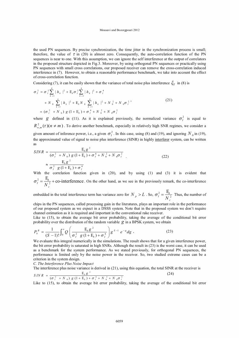
the used PN sequences. By precise synchronization, the time jitter in the synchronization process is small; therefore, the value of in (20) is almost zero. Consequently, the auto-correlation function of the PN sequences is near to one. With this assumption, we can ignore the self interference at the output of correlators in the proposed structure depicted in Fig.3. Moreover, by using orthogonal PN sequences or practically using PN sequences with small cross correlations, our proposed receiver can remove the cross-correlation induced interference in (7). However, to obtain a reasonable performance benchmark, we take into account the effect of cross-correlation function. Considering (7), it can be easily shown that the variance of total noise plus interference T in (8) is
2 2 2 2 2 4
1 1
2 2 2 20 0 0 0
1 12 4 2 2
0 0 0
| | | |
| | | |
( ) (1 )
S S
T I k b I k Ik k
S S
k b k Ik k
I b I I
h h
N h N h N N
N g N N
E
E
E
, (21)
where g defined in (11). As it is explained previously, the normalized variance 2I is equal to
2, ( )( )n mR n m . To derive another benchmark, especially in relatively high SNR regimes, we consider a
given amount of inference power, i.e., a given 2I . In this case, using (8) and (19), and ignoring 0N in (19),
the approximated value of signal to noise plus interference (SINR) in highly interferer system, can be written as
2
2 4 2 20 0 0
2
2 4
( ) (1 )
(1 )
b
I b I I
b
I b I
gS IN RN g N N
gg
EE
EE
. (22)
With the correlation function given in (20), and by using (1) and (3) it is evident that 2
2 co-interference bI
cNE
. On the other hand, as we see in the previously remark, the co-interference
embedded in the total interference term has variance zero for pN L . So, 22 b
IcN
E Thus, the number of
chips in the PN sequences, called processing gain in the literatures, plays an important role in the performance of our proposed system as we expect in a DSSS system. Note that in the proposed system we don’t require channel estimation as it is required and important in the conventional rake receiver. Like to (15), to obtain the average bit error probability, taking the average of the conditional bit error probability over the distribution of the random variable g in a BPSK system, we obtain
21
2 40
1 ( 1)! (1 )
B S gbb
I b I
gP Q g e dgS g
EE
, (23)
We evaluate this integral numerically in the simulations. The result shows that for a given interference power, the bit error probability is saturated in high SNRs. Although the result in (23) is the worst case, it can be used as a benchmark for the system performance. As we stated previously, for orthogonal PN sequences, the performance is limited only by the noise power in the receiver. So, two studied extreme cases can be a criterion in the system design. C. The Interference Plus Noise Impact The interference plus noise variance is derived in (21), using this equation, the total SINR at the receiver is
2
2 4 2 20 0 0( ) (1 )
b
I b I I
gS IN RN g N N
EE
(24)
Like to (15), to obtain the average bit error probability, taking the average of the conditional bit error
6059
J. Basic. Appl. Sci. Res., 2(6)6052-6064, 2012
probability over the distribution of the random variable g in a BPSK system, we obtain 2
12 4 2 20
0 0 0
1 ( 1)! ( ) (1 )
C S gbb
I b I I
gP Q g e dgS N g N N
EE
, (25)
In practical systems, based on the used PN sequences, synchronization errors, and the other non ideality in the system design, the interference power is comparable with the power on system noise, therefore, for performance evaluation, we can use (25) to predict the bit error probability of the designed system. Because of the complexity of the integral in (25), we evaluate C
bP numerically in the simulations. 4. Numerical Results and Comparisons
The proposed approach is now compared with both the previously reported DSSS systems and another system designed for the underwater acoustic channels. To do this, we provide some computer simulations to evaluate our proposed scheme in different scenarios. We assume that the required PN sequences are selected from the maximal length PN sequences with cN chips per bit with the correlation function defined in (20). To validate the both exact and approximated analytical results, we conduct some computer simulations with the following assumptions. Consider a sparse channel with maximum spread time = 20mT ms and non zero
taps at = l b lt lT . Where = 0,2,5,8l and l 's are independent uniform random variables in the
interval (0, )bT . The channel tap gains have been assumed Rayleigh distributed with normalized power equal
to one. Note that bT is the bit duration and it is set to 1 ms. Table 1 shows the bit error probability plots for
orthogonal PN sequences and ignored co-interference, i.e. pN S . Table.1: Bit Error Probability for Different SNRs
SNR (dB) AbP
5 32.4 10 7.5 45.1 10 10 57.3 10
12.5 51.5 10 15 61.2 10
This is the best achievable performance in the proposed system. In reality, we have some residual
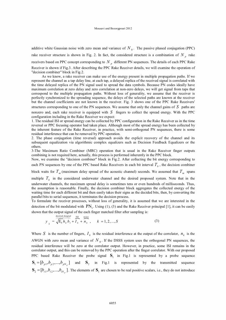
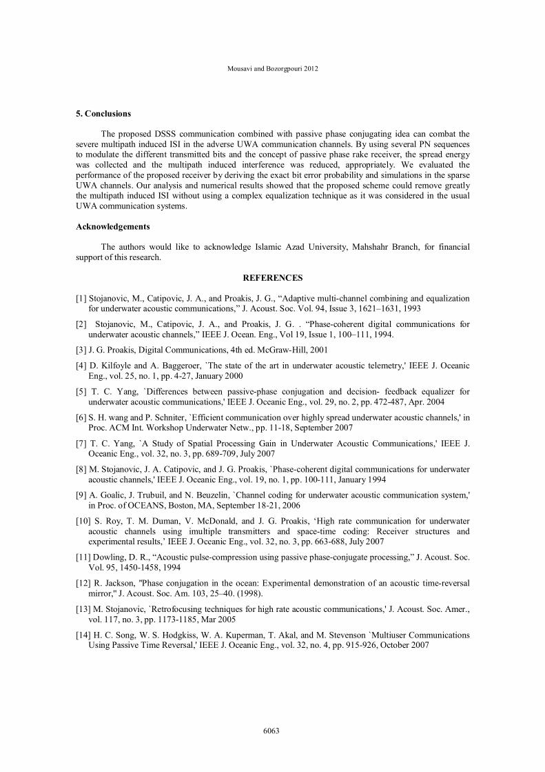
interference and this cause some performance degradation. Fig. 4 shows received average SINR f our proposed scheme for different cN 's. the average SINR is considered as the statistic average value of signal to interference plus noise power given in (14). In these simulations, we have used the sparse channel model given by [13], which is shown in Fig. 5. The bit duration and number of chips are set as bT =0.2 m s , and 3pN , respectively. We note that total multipath spread is 10 ms , which results in total 21 channel taps with 3 nonzero tap gains given in Fig. 4. Unlike [13], we assume that each tap occurrence time can randomly vary around the occurrence times shown in Fig.4. As we can see form Fig. 4, using a proper number of chips in the PN sequences in our proposed scheme, e.g., 63cN in Fig. 5, will cancel most of the multipath induced ISI and therefore, our proposed scheme performs about a no-ISI channel in the considered SNR range.
Although the aforementioned result was obtained in [13] with 32 array elements, our result is obtained with lower practical complexity and constraints. In fact, using 32 array elements needs a proper distance between the elements and this can increase the required hardware space and complexity. Whereas, our proposed scheme with any required cN 's can be implemented on a single processor board. Note that a bottleneck in our proposed method is the required bandwidth which is increased by increasing the number of
6060
Mousavi and Bozorgpouri 2012
chips. To reduce the required bandwidth, the only way is reducing the data rate; this is common in all of the DSSS based underwater communication systems. Fig. 6 compares the bit error rate of our proposed detector for pN S and the channel model considered in [15]. In these simulations, we considered different
Interference to Noise Ratio (INR) and compared the results. Note that the cN effect is included in the
interference power 2 I , thus, we didn't consider the value of this parameter in the plots. Like [15], we assume that the UWA channel is modeled by employing a direct path and two secondary paths resulting from the surface and bottom of the water. Each individual path's instantaneous amplitude is modeled as a Rayleigh distributed process. Fig. 6 shows the BER plots for a channel with moderate multipath and maximum excess delay spread of 3 ms. With bT =1 ms and according to the channel model considered in this paper, the described channel will have 4 tap gains where the gains of the zero-th, the first, and the last taps are Rayleigh distributed and the gain of the second tap is zero. Note that this channel has 3 non-zero tap gains corresponding to the direct path (zero-th tap), reflected path from the surface (the first tap), and reflected path from the bottom (the third tap). For the proposed receiver in the low interference scenarios and the BER performance of 0.001, the required average SNR is about 12.8 dB, whereas, for the schemes in [15] and for the best case, the required average SNR is about 16.5 dB.
Fig1. Passive Phase Conjugation Procedure
Fig.2: The proposed receiver structure
Fig.3: Our proposed PPC Rake Receiver structure corresponding to the m'th PN sequence
6061
J. Basic. Appl. Sci. Res., 2(6)6052-6064, 2012
-5 0 5 10 15 20 25-10
-5
0
5
10
15
20
25
30
Average SNR, Eb/No
Ave
rage
Sig
nal t
o In
terfe
renc
e +
Noi
se, S
INR
Nc=15Nc=7Nc=63Nc=31
Fig4. Performance of our proposed scheme: output SINR versus b
oNE
0 1 2 3 4 5 6 7 8 9 100
0.1
0.2
0.3
0.4
0.5
0.6
0.7
0.8
path delay, ms
path
gai
n m
agni
tude
s (n
orm
aliz
ed p
ower
)
Fig5. Multipath gains of the sparse channel model given in [13]
0 2 4 6 8 10 12 14 1610-5
10-4
10-3
10-2
10-1
100
Average SNR, dB
Bit Erro
r Rat
e (B
ER)
INR=8 dBINR= -8 dBINR= 2 dB
Fig6. Bit Error Rate of our proposed scheme for different INR: Rayleigh fading channel with 4 taps
6062
Mousavi and Bozorgpouri 2012
5. Conclusions
The proposed DSSS communication combined with passive phase conjugating idea can combat the severe multipath induced ISI in the adverse UWA communication channels. By using several PN sequences to modulate the different transmitted bits and the concept of passive phase rake receiver, the spread energy was collected and the multipath induced interference was reduced, appropriately. We evaluated the performance of the proposed receiver by deriving the exact bit error probability and simulations in the sparse UWA channels. Our analysis and numerical results showed that the proposed scheme could remove greatly the multipath induced ISI without using a complex equalization technique as it was considered in the usual UWA communication systems. Acknowledgements
The authors would like to acknowledge Islamic Azad University, Mahshahr Branch, for financial support of this research.
REFERENCES
[1] Stojanovic, M., Catipovic, J. A., and Proakis, J. G., “Adaptive multi-channel combining and equalization
for underwater acoustic communications,” J. Acoust. Soc. Vol. 94, Issue 3, 1621–1631, 1993
[2] Stojanovic, M., Catipovic, J. A., and Proakis, J. G. . “Phase-coherent digital communications for underwater acoustic channels,” IEEE J. Ocean. Eng., Vol 19, Issue 1, 100–111, 1994.
[3] J. G. Proakis, Digital Communications, 4th ed. McGraw-Hill, 2001
[4] D. Kilfoyle and A. Baggeroer, `The state of the art in underwater acoustic telemetry,' IEEE J. Oceanic Eng., vol. 25, no. 1, pp. 4-27, January 2000
[5] T. C. Yang, `Differences between passive-phase conjugation and decision- feedback equalizer for underwater acoustic communications,' IEEE J. Oceanic Eng., vol. 29, no. 2, pp. 472-487, Apr. 2004
[6] S. H. wang and P. Schniter, `Efficient communication over highly spread underwater acoustic channels,' in Proc. ACM Int. Workshop Underwater Netw., pp. 11-18, September 2007
[7] T. C. Yang, `A Study of Spatial Processing Gain in Underwater Acoustic Communications,' IEEE J. Oceanic Eng., vol. 32, no. 3, pp. 689-709, July 2007
[8] M. Stojanovic, J. A. Catipovic, and J. G. Proakis, `Phase-coherent digital communications for underwater acoustic channels,' IEEE J. Oceanic Eng., vol. 19, no. 1, pp. 100-111, January 1994
[9] A. Goalic, J. Trubuil, and N. Beuzelin, `Channel coding for underwater acoustic communication system,' in Proc. of OCEANS, Boston, MA, September 18-21, 2006
[10] S. Roy, T. M. Duman, V. McDonald, and J. G. Proakis, ‘High rate communication for underwater acoustic channels using imultiple transmitters and space-time coding: Receiver structures and experimental results,’ IEEE J. Oceanic Eng., vol. 32, no. 3, pp. 663-688, July 2007
[11] Dowling, D. R., “Acoustic pulse-compression using passive phase-conjugate processing,” J. Acoust. Soc. Vol. 95, 1450-1458, 1994
[12] R. Jackson, ''Phase conjugation in the ocean: Experimental demonstration of an acoustic time-reversal mirror,'' J. Acoust. Soc. Am. 103, 25–40. (1998).
[13] M. Stojanovic, `Retrofocusing techniques for high rate acoustic communications,' J. Acoust. Soc. Amer., vol. 117, no. 3, pp. 1173-1185, Mar 2005
[14] H. C. Song, W. S. Hodgkiss, W. A. Kuperman, T. Akal, and M. Stevenson `Multiuser Communications Using Passive Time Reversal,' IEEE J. Oceanic Eng., vol. 32, no. 4, pp. 915-926, October 2007
6063
J. Basic. Appl. Sci. Res., 2(6)6052-6064, 2012
[15] D.P. Konstantakos, C.C. Tsimenidis, A.E. Adams and B.S. Sharif, `Comparison of DS-CDMA and MC-CDMA techniques for dual-dispersive fading acoustic communication networks,' IEE Proc.-Communication, Vol. 152, No. 6, pp: 1031-1038, December 2005
[16] M.Stojanovic and L.Freitag, `Multichannel detection for wideband underwater acoustic CDMA communications,' IEEE J. Oceanic Eng., vol. 31, no. 3, pp. 685-695, July 2006
[17] G. Loubet, V. Capellano and R. Filipiak, `Underwater spread-spectrum communications,' OCEANS'97, Halifax, Canada, pp. 514-579, 6-9 October 1997
[18] Ching-Hsiang Tseng, Fu-Sheng Lu, Fu-Kuei Chen, and Shuenn-Tay Wu, ‘Compensation of Multipath Fading in Underwater Spread Spectrum Communication Systems,’ International Symposium on Underwater Technology, pp: 453-458, 15-17 Apr 1998
[19] Chengbing He, Jianguo Huang, `Underwater Acoustic Spread Spectrum Communication Based on M Family N group Parallel Transmission,' Oceans 2006-Asia Pacific, pp: 1-4, 2006
[20] Tricia Fu, Daniel Doonan, Chris Utley, and Hua Lee, `Field Testing of a Spread Spectrum Acoustic Modem with Sparse Channel Estimation,' IEEE International Conference on Acoustics, Speech and Signal Processing, (ICASSP 2008), 2008
[21] T. C. Yang, "Temporal resolutions of time-reversal and passive-phase conjugation for underwater acoustic communications", IEEE J. Ocean. Eng., vol. 28, no. 2, pp.229 - 245 , 2003
6064