design and analysis of robot manipulators · pdf filedesign and analysis of robot manipulators...
TRANSCRIPT
DESIGN AND ANALYSIS OF
ROBOT MANIPULATORS BY
INTEGRATED CAE PROCEDURES
by
Murat AKDAĞ
February, 2008
İZMİR
DESIGN AND ANALYSIS OF ROBOT MANIPULATORS BY
INTEGRATED CAE PROCEDURES
ABSTRACT
Robots are the basic components of production sector. Computer aided engineering
methods must be used effectively in the design process since the robot design has various
parameters. In this study, for industrial robots, a design process in which the integrated
engineering methods are employed, is considered and three different robots are designed
following this process. Two of the designed robots have been manufactured and are ready for
operation.
The design of the trajectory is of great importance in order to use the robots efficiently.
Great attention must be paid on trajetory design in order to reduce the end point deflections
which occur at the stoppage, especially in high speed movements. In this study, the
importance of the trajectory design is presented by experimental and numerical investigation
of strains induced on an industrial robot.
The robots have different structural stiffnesses for different positions since they are
movable machines. In this study, a new concept which presents the changes in the stiffness
for different positions of the robot within its workspace is presented. A new concept named as
“Rigidity Workspace” is investigated according to the end point static deflections and modal
behaviour of the robot. A new proposal is made for the method of positional accuracy
compansation which is performed for every industrial robot. Besides, the influence of the
joint flexibility definition on real end point deflections and modal behavior of robot systems
is investigated experimentally and numerically.
Keywords: Robot design, Computer aided engineering, The finite element method, Rigidity
workspace, Accuracy compensation.
ROBOT MANİPULATÖRLERİNİN ENTEGRE BİLGİSAYAR DESTEKLİ
MÜHENDİSLİK YÖNTEMLERİ İLE TASARIMI VE ANALİZİ
ÖZ
Robotlar, üretim sektöründeki temel bileşenlerdendir. Robot tasarımı pek çok parametreye
sahip olduğu için, bilgisayar destekli mühendislik yöntemleri tasarım sürecinde etkili bir
şekilde kullanılmadır. Bu çalışmada, endüstriyel robotlar için entegre bilgisayar destekli
mühendislik yöntemlerinin kullanıldığı bir tasarım süreci ele alınmış ve bu süreç takip
edilerek üç farklı robot tasarımı yapılmıştır. Tasarımı tamamlanan bu robotlardan ikisinin
üretimi tamamlanarak çalışır hale getirilmiştir.
Robotların verimli kullanılabilmeleri için yörünge tasarımının önemi büyüktür. Özellikle
yüksek hızlı hareketlerde durma anında ortaya çıkan titreşimlerin ve uç nokta sapmalarının
azaltılabilmesi için yörünge tasarımına dikkat edilmelidir. Bu çalışmada, yörünge tasarımının
önemi, farklı yörüngeler için endüstriyel bir robot üzerinde oluşan zorlanmaların deneysel ve
sayısal olarak incelenmesi ile ortaya konulmuştur.
Robotlar hareketli makinalar oldukları için farklı pozisyonlarda farklı yapısal direngenliğe
sahiptirler. Bu çalışmada, robotun çalışma uzayı içerisindeki farklı pozisyonları için söz
konusu direngenlik değişimlerini ortaya koyan yeni bir kavram sunulmuştur. “Direngenlik
Uzayı” olarak adlandırdığımız bu yeni kavram, robotun uç nokta statik çökmesi ve frekans
davranışına göre incelenmiştir. Bu kavram kullanılarak, üretilen her endüstriyel robot için
yapılan konumsal hassasiyet kompanzasyonu yöntemi için yeni bir öneri yapılmıştır. Ayrıca
mafsal esnekliği tanımlamasının robot sistemlerinin gerçek uç nokta sapması ve frekans
davranışının belirlenebilmesi üzerindeki etkisi deneysel ve sayısal olarak incelenmiştir.
Anahtar sözcükler: Robot tasarımı, Bilgisayar destekli mühendislik, Sonlu elemanlar
yöntemi, Direngenlik çalışma uzayı, Pozisyon hassasiyet kompanzasyonu.
1. Introduction
One of the basis study related to robot design is presented by Thomson (1984). In his
study, he investigated the requirements of the designers and users of such equipment and
attempted to evaluate current work in this field. Vukobratovic, Potkonjak, Inoue & Takano
(2002) discussed kinds of robot driving systems and described CAD systems for industrial
robots. They explained the principles of advanced robot design. Mir-Nasiri (2004) suggested
new design of robotic arm with a parallel structure, but with a functionality or geometry
similar to the serial structure of a SCARA robot. Mrozek (2003) described two approaches
towards designing interdisciplinary mechatronic systems. Clark & Lin (2007) proposed a
CAD-based integration method for analyzing and verifying the design of robotic mechanisms.
Park, Kim, Kim & Park (2007) developed new mid-sized humanoid robot hardware. They
focused on the use of an integrated application of CAD/CAM/CAE and rapid prototyping
(RP) for the rapid development of the robot’s outer body parts.
A comprehensive literature review releated to dynamic analyses of flexible robotic
manipulators is presented by Dwivedy & Eberhard (2006). The review of the published
papers is classified as modeling, control and experimental studies. In case of modeling, they
are subdivided depending on the method of analysis and number of links involved in the
analysis. In this work both link and joint flexibilities are considered. Total of 433 papers
presented between the years 1974–2005 have been reviewed in this work. Young & Pickin
(2000) conducted a trial on three modern serial linkage robots to assess and compare robot
accuracy. Laser interferometry measurement system is used for each robot and measurements
are done in a similar area of its working range. Their trial is limited only static measurements.
Karagülle & Malgaca (2004) studied the effect of flexibility on the trajectory of a planar two
link manipulator by using integrated computer-aided design/analysis (CAD/CAE) procedures.
I-DEAS program is used to create solid models and the finite element models of the parts of
the manipulator. Albu-Schaffer, Haddadin, Ott, Stemmer, Wimböck & Hirzinger (2007)
presented a new generation of torque-controlled light-weight robots developed at the Institute
of Robotics and Mechatronics of the German Aerospace Center. In their robot concept joint
torque sensing plays a central role.
2. Integrated Analysis of Robot Design
Machine manufacturers have to manufacture machine which posses convenient design for
the customer’s requirements due to increasing competition between the manufacturers in
recent years. It is not an effective solution to respond to this demand by producing several
machine models. It is important that the design of the machine is carried out so as to satisfy
the customer’s specific requirements to decrease the manufacturing cost and increase the
quality of the product. The design process must be completed rapidly in order to proceed with
the manufacturing of the machines which fulfils the customer’s requirements. Necessity for
quick design has created the flexible design concept. Flexible design can be defined as
accomplishing the whole design which fulfils all the requirements in a quick and reliable
manner. Flexible design is carried out by using integrated CAE analysis effectively.
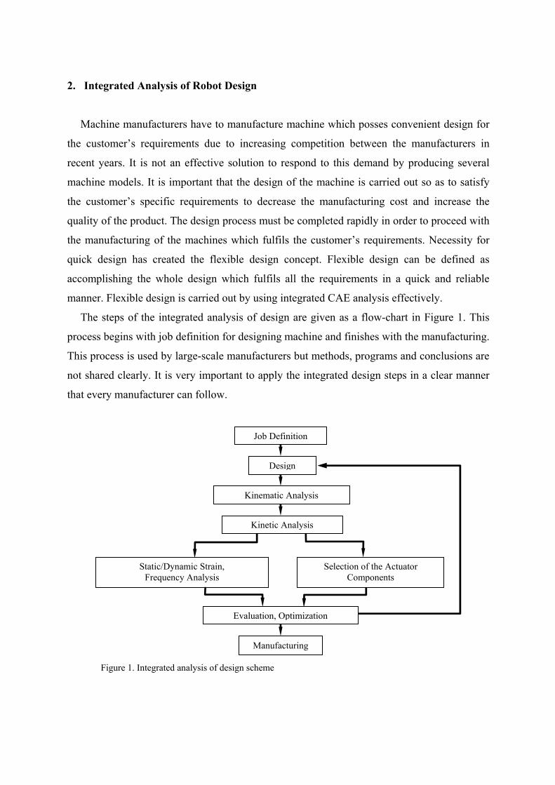
The steps of the integrated analysis of design are given as a flow-chart in Figure 1. This
process begins with job definition for designing machine and finishes with the manufacturing.
This process is used by large-scale manufacturers but methods, programs and conclusions are
not shared clearly. It is very important to apply the integrated design steps in a clear manner
that every manufacturer can follow.
Figure 1. Integrated analysis of design scheme
Job Definition
Design
Kinematic Analysis
Kinetic Analysis
Static/Dynamic Strain, Frequency Analysis
Selection of the Actuator Components
Manufacturing
Evaluation, Optimization
3. Application of Integrated Analysis of Design
3.1 Three Axis Serial Manipulator (DEU-3X2-550)
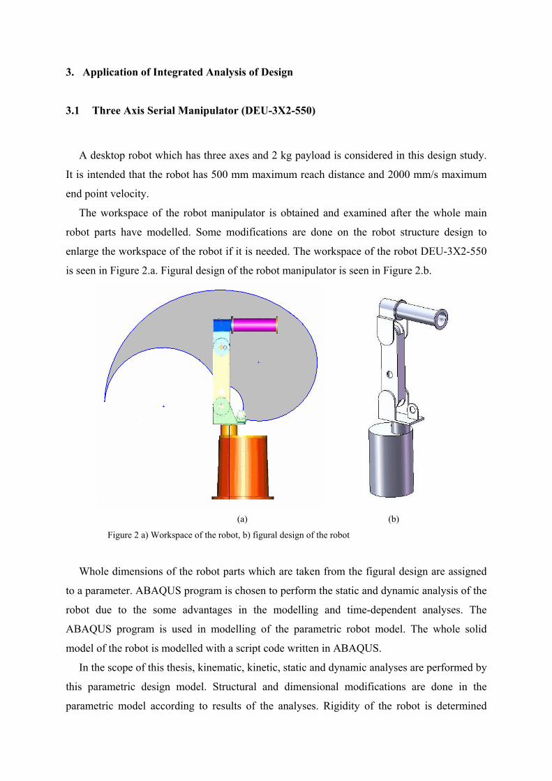
A desktop robot which has three axes and 2 kg payload is considered in this design study.
It is intended that the robot has 500 mm maximum reach distance and 2000 mm/s maximum
end point velocity.
The workspace of the robot manipulator is obtained and examined after the whole main
robot parts have modelled. Some modifications are done on the robot structure design to
enlarge the workspace of the robot if it is needed. The workspace of the robot DEU-3X2-550
is seen in Figure 2.a. Figural design of the robot manipulator is seen in Figure 2.b.
(a) (b)
Figure 2 a) Workspace of the robot, b) figural design of the robot
Whole dimensions of the robot parts which are taken from the figural design are assigned
to a parameter. ABAQUS program is chosen to perform the static and dynamic analysis of the
robot due to the some advantages in the modelling and time-dependent analyses. The
ABAQUS program is used in modelling of the parametric robot model. The whole solid
model of the robot is modelled with a script code written in ABAQUS.
In the scope of this thesis, kinematic, kinetic, static and dynamic analyses are performed by
this parametric design model. Structural and dimensional modifications are done in the
parametric model according to results of the analyses. Rigidity of the robot is determined
using the results of the maximum end point displacement and natural frequencies of the robot
at different position. Required improvements are done by altering the dimensional parameters.
In addition, this parametric model is used in the kinematic and kinetic analyses.
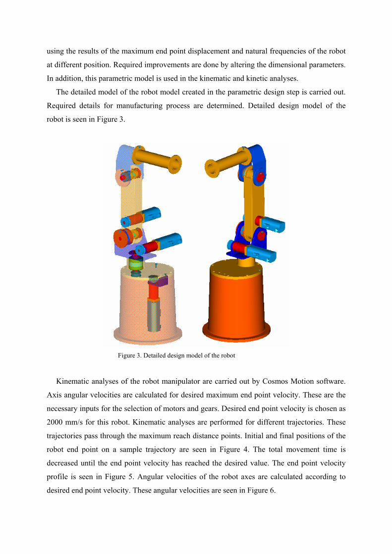
The detailed model of the robot model created in the parametric design step is carried out.
Required details for manufacturing process are determined. Detailed design model of the
robot is seen in Figure 3.
Figure 3. Detailed design model of the robot
Kinematic analyses of the robot manipulator are carried out by Cosmos Motion software.
Axis angular velocities are calculated for desired maximum end point velocity. These are the
necessary inputs for the selection of motors and gears. Desired end point velocity is chosen as
2000 mm/s for this robot. Kinematic analyses are performed for different trajectories. These
trajectories pass through the maximum reach distance points. Initial and final positions of the
robot end point on a sample trajectory are seen in Figure 4. The total movement time is
decreased until the end point velocity has reached the desired value. The end point velocity
profile is seen in Figure 5. Angular velocities of the robot axes are calculated according to
desired end point velocity. These angular velocities are seen in Figure 6.
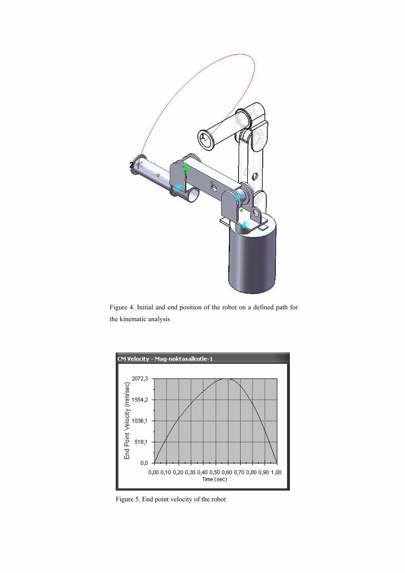
Figure 4. Initial and end position of the robot on a defined path for
the kinematic analysis
Figure 5. End point velocity of the robot
1
2
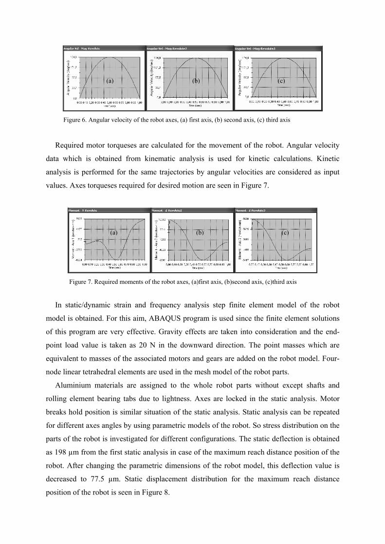
Figure 6. Angular velocity of the robot axes, (a) first axis, (b) second axis, (c) third axis
Required motor torqueses are calculated for the movement of the robot. Angular velocity
data which is obtained from kinematic analysis is used for kinetic calculations. Kinetic
analysis is performed for the same trajectories by angular velocities are considered as input
values. Axes torqueses required for desired motion are seen in Figure 7.
Figure 7. Required moments of the robot axes, (a)first axis, (b)second axis, (c)third axis
In static/dynamic strain and frequency analysis step finite element model of the robot
model is obtained. For this aim, ABAQUS program is used since the finite element solutions
of this program are very effective. Gravity effects are taken into consideration and the end-
point load value is taken as 20 N in the downward direction. The point masses which are
equivalent to masses of the associated motors and gears are added on the robot model. Four-
node linear tetrahedral elements are used in the mesh model of the robot parts.
Aluminium materials are assigned to the whole robot parts without except shafts and
rolling element bearing tabs due to lightness. Axes are locked in the static analysis. Motor
breaks hold position is similar situation of the static analysis. Static analysis can be repeated
for different axes angles by using parametric models of the robot. So stress distribution on the
parts of the robot is investigated for different configurations. The static deflection is obtained
as 198 µm from the first static analysis in case of the maximum reach distance position of the
robot. After changing the parametric dimensions of the robot model, this deflection value is
decreased to 77.5 µm. Static displacement distribution for the maximum reach distance
position of the robot is seen in Figure 8.
(a) (b) (c)
(a) (b) (c)
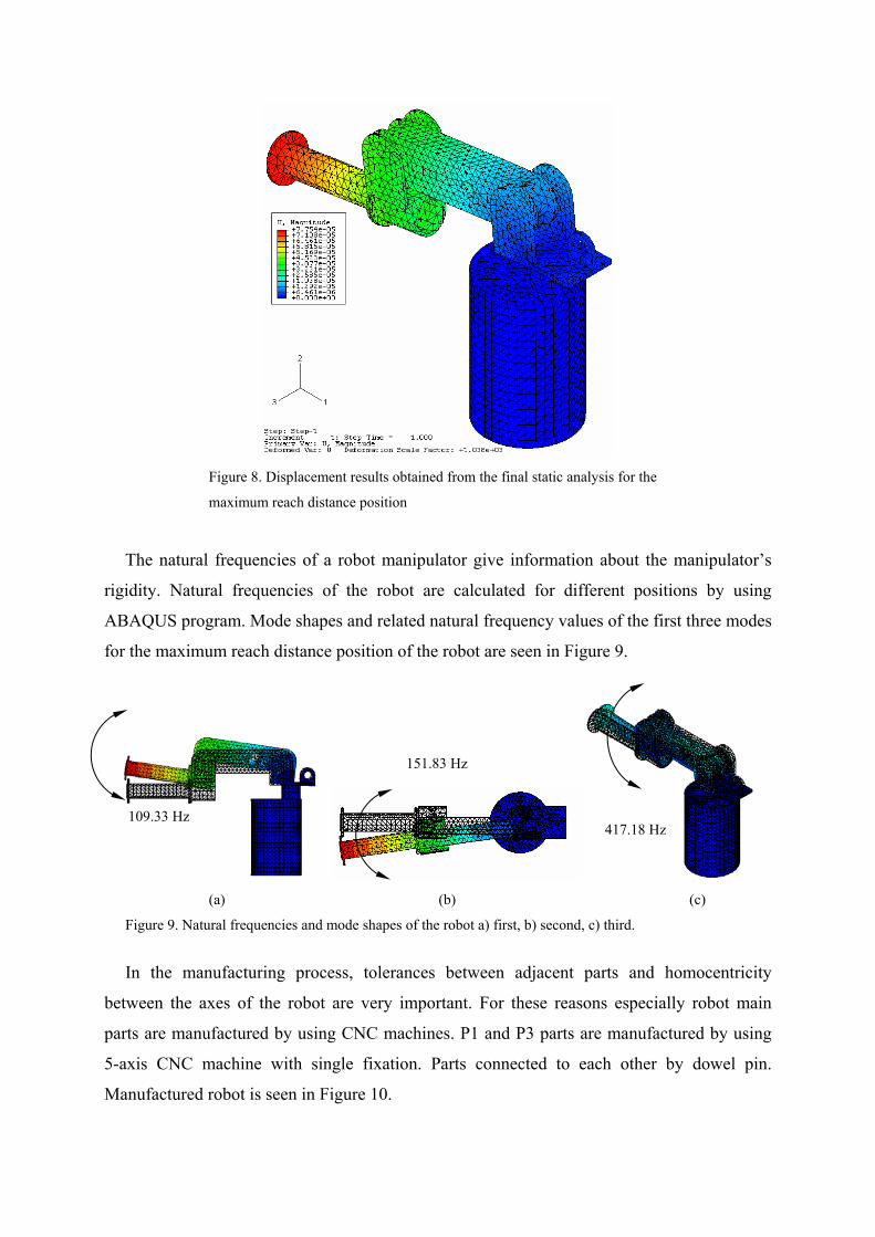
Figure 8. Displacement results obtained from the final static analysis for the
maximum reach distance position
The natural frequencies of a robot manipulator give information about the manipulator’s
rigidity. Natural frequencies of the robot are calculated for different positions by using
ABAQUS program. Mode shapes and related natural frequency values of the first three modes
for the maximum reach distance position of the robot are seen in Figure 9.
(a) (b) (c)
Figure 9. Natural frequencies and mode shapes of the robot a) first, b) second, c) third.
In the manufacturing process, tolerances between adjacent parts and homocentricity
between the axes of the robot are very important. For these reasons especially robot main
parts are manufactured by using CNC machines. P1 and P3 parts are manufactured by using
5-axis CNC machine with single fixation. Parts connected to each other by dowel pin.
Manufactured robot is seen in Figure 10.
109.33 Hz
151.83 Hz
417.18 Hz
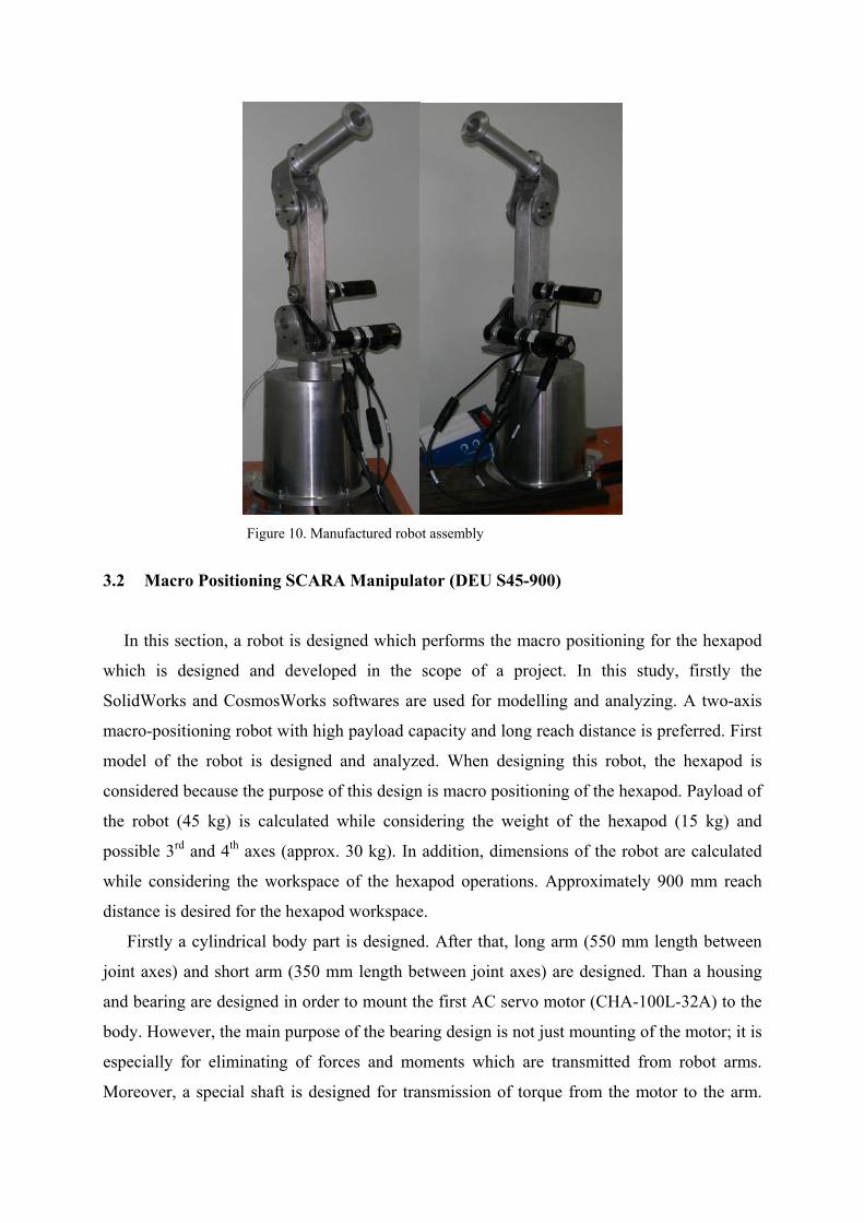
Figure 10. Manufactured robot assembly
3.2 Macro Positioning SCARA Manipulator (DEU S45-900)
In this section, a robot is designed which performs the macro positioning for the hexapod
which is designed and developed in the scope of a project. In this study, firstly the
SolidWorks and CosmosWorks softwares are used for modelling and analyzing. A two-axis
macro-positioning robot with high payload capacity and long reach distance is preferred. First
model of the robot is designed and analyzed. When designing this robot, the hexapod is
considered because the purpose of this design is macro positioning of the hexapod. Payload of
the robot (45 kg) is calculated while considering the weight of the hexapod (15 kg) and
possible 3rd and 4th axes (approx. 30 kg). In addition, dimensions of the robot are calculated
while considering the workspace of the hexapod operations. Approximately 900 mm reach
distance is desired for the hexapod workspace.
Firstly a cylindrical body part is designed. After that, long arm (550 mm length between
joint axes) and short arm (350 mm length between joint axes) are designed. Than a housing
and bearing are designed in order to mount the first AC servo motor (CHA-100L-32A) to the
body. However, the main purpose of the bearing design is not just mounting of the motor; it is
especially for eliminating of forces and moments which are transmitted from robot arms.
Moreover, a special shaft is designed for transmission of torque from the motor to the arm.
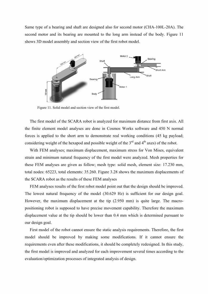
Same type of a bearing and shaft are designed also for second motor (CHA-100L-20A). The
second motor and its bearing are mounted to the long arm instead of the body. Figure 11
shows 3D model assembly and section view of the first robot model.
Figure 11. Solid model and section view of the first model.
The first model of the SCARA robot is analyzed for maximum distance from first axis. All
the finite element model analyses are done in Cosmos Works software and 450 N normal
forces is applied to the short arm to demonstrate real working conditions (45 kg payload;
considering weight of the hexapod and possible weight of the 3rd and 4th axes) of the robot.
With FEM analyses; maximum displacement, maximum stress for Von Mises, equivalent
strain and minimum natural frequency of the first model were analyzed. Mesh properties for
these FEM analyses are given as follow; mesh type: solid mesh, element size: 17.230 mm,
total nodes: 65223, total elements: 35.260. Figure 3.28 shows the maximum displacements of
the SCARA robot as the results of these FEM analyses
FEM analyses results of the first robot model point out that the design should be improved.
The lowest natural frequency of the model (30.629 Hz) is sufficient for our design goal.
However, the maximum displacement at the tip (2.950 mm) is quite large. The macro-
positioning robot is supposed to have precise movement capability. Therefore the maximum
displacement value at the tip should be lower than 0.4 mm which is determined pursuant to
our design goal.
First model of the robot cannot ensure the static analysis requirements. Therefore, the first
model should be improved by making some modifications. If it cannot ensure the
requirements even after these modifications, it should be completely redesigned. In this study,
the first model is improved and analyzed for each improvement several times according to the
evaluation/optimization processes of integrated analysis of design.
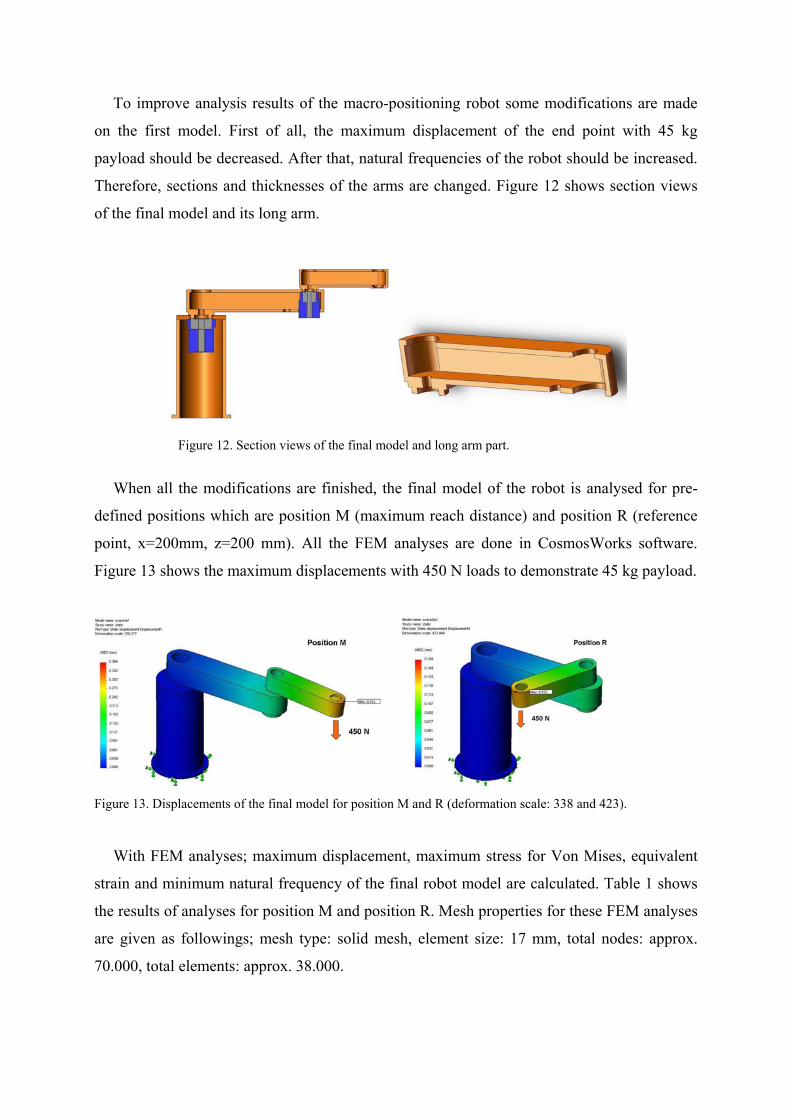
To improve analysis results of the macro-positioning robot some modifications are made
on the first model. First of all, the maximum displacement of the end point with 45 kg
payload should be decreased. After that, natural frequencies of the robot should be increased.
Therefore, sections and thicknesses of the arms are changed. Figure 12 shows section views
of the final model and its long arm.
Figure 12. Section views of the final model and long arm part.
When all the modifications are finished, the final model of the robot is analysed for pre-
defined positions which are position M (maximum reach distance) and position R (reference
point, x=200mm, z=200 mm). All the FEM analyses are done in CosmosWorks software.
Figure 13 shows the maximum displacements with 450 N loads to demonstrate 45 kg payload.
Figure 13. Displacements of the final model for position M and R (deformation scale: 338 and 423).
With FEM analyses; maximum displacement, maximum stress for Von Mises, equivalent
strain and minimum natural frequency of the final robot model are calculated. Table 1 shows
the results of analyses for position M and position R. Mesh properties for these FEM analyses
are given as followings; mesh type: solid mesh, element size: 17 mm, total nodes: approx.
70.000, total elements: approx. 38.000.
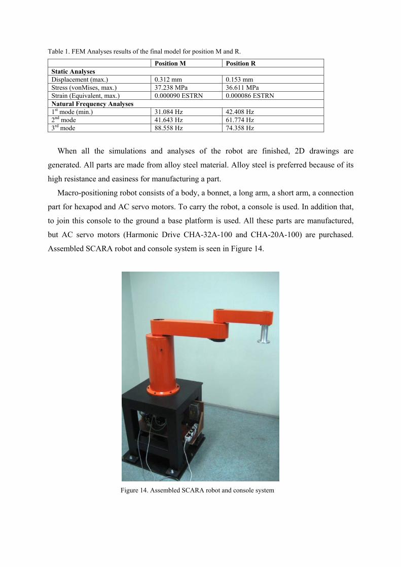
Table 1. FEM Analyses results of the final model for position M and R.
Position M Position R Static Analyses Displacement (max.) 0.312 mm 0.153 mm Stress (vonMises, max.) 37.238 MPa 36.611 MPa Strain (Equivalent, max.) 0.000090 ESTRN 0.000086 ESTRN Natural Frequency Analyses 1st mode (min.) 31.084 Hz 42.408 Hz 2nd mode 41.643 Hz 61.774 Hz 3rd mode 88.558 Hz 74.358 Hz
When all the simulations and analyses of the robot are finished, 2D drawings are
generated. All parts are made from alloy steel material. Alloy steel is preferred because of its
high resistance and easiness for manufacturing a part.
Macro-positioning robot consists of a body, a bonnet, a long arm, a short arm, a connection
part for hexapod and AC servo motors. To carry the robot, a console is used. In addition that,
to join this console to the ground a base platform is used. All these parts are manufactured,
but AC servo motors (Harmonic Drive CHA-32A-100 and CHA-20A-100) are purchased.
Assembled SCARA robot and console system is seen in Figure 14.
Figure 14. Assembled SCARA robot and console system
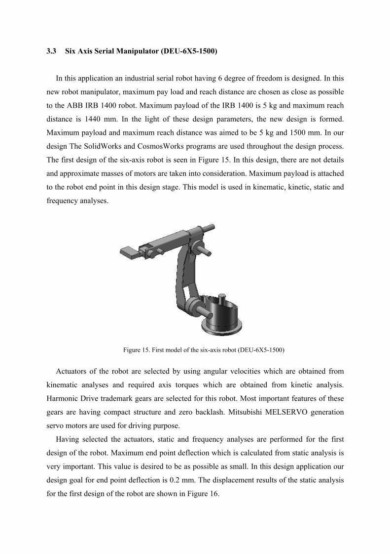
3.3 Six Axis Serial Manipulator (DEU-6X5-1500)
In this application an industrial serial robot having 6 degree of freedom is designed. In this
new robot manipulator, maximum pay load and reach distance are chosen as close as possible
to the ABB IRB 1400 robot. Maximum payload of the IRB 1400 is 5 kg and maximum reach
distance is 1440 mm. In the light of these design parameters, the new design is formed.
Maximum payload and maximum reach distance was aimed to be 5 kg and 1500 mm. In our
design The SolidWorks and CosmosWorks programs are used throughout the design process.
The first design of the six-axis robot is seen in Figure 15. In this design, there are not details
and approximate masses of motors are taken into consideration. Maximum payload is attached
to the robot end point in this design stage. This model is used in kinematic, kinetic, static and
frequency analyses.
Figure 15. First model of the six-axis robot (DEU-6X5-1500)
Actuators of the robot are selected by using angular velocities which are obtained from
kinematic analyses and required axis torques which are obtained from kinetic analysis.
Harmonic Drive trademark gears are selected for this robot. Most important features of these
gears are having compact structure and zero backlash. Mitsubishi MELSERVO generation
servo motors are used for driving purpose.
Having selected the actuators, static and frequency analyses are performed for the first
design of the robot. Maximum end point deflection which is calculated from static analysis is
very important. This value is desired to be as possible as small. In this design application our
design goal for end point deflection is 0.2 mm. The displacement results of the static analysis
for the first design of the robot are shown in Figure 16.
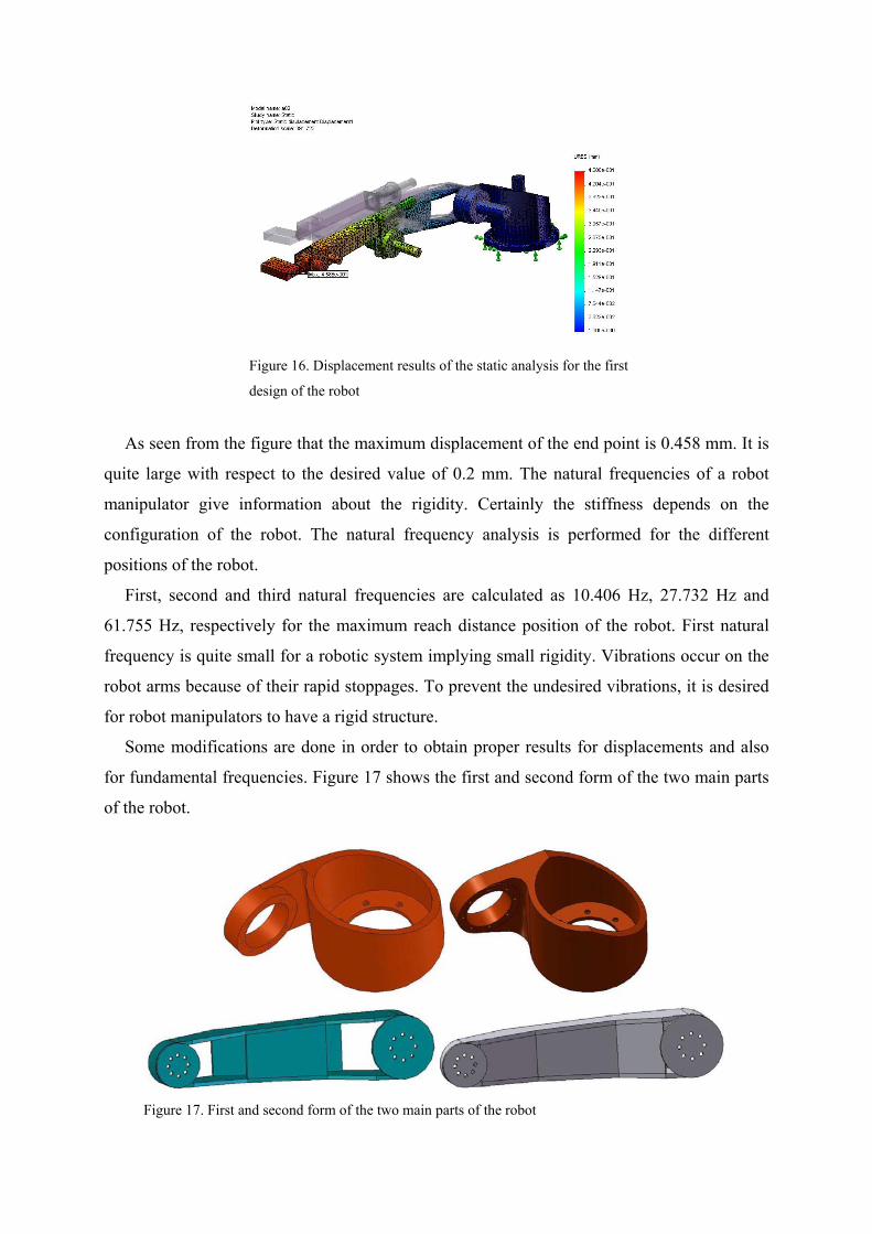
Figure 16. Displacement results of the static analysis for the first
design of the robot
As seen from the figure that the maximum displacement of the end point is 0.458 mm. It is
quite large with respect to the desired value of 0.2 mm. The natural frequencies of a robot
manipulator give information about the rigidity. Certainly the stiffness depends on the
configuration of the robot. The natural frequency analysis is performed for the different
positions of the robot.
First, second and third natural frequencies are calculated as 10.406 Hz, 27.732 Hz and
61.755 Hz, respectively for the maximum reach distance position of the robot. First natural
frequency is quite small for a robotic system implying small rigidity. Vibrations occur on the
robot arms because of their rapid stoppages. To prevent the undesired vibrations, it is desired
for robot manipulators to have a rigid structure.
Some modifications are done in order to obtain proper results for displacements and also
for fundamental frequencies. Figure 17 shows the first and second form of the two main parts
of the robot.
Figure 17. First and second form of the two main parts of the robot
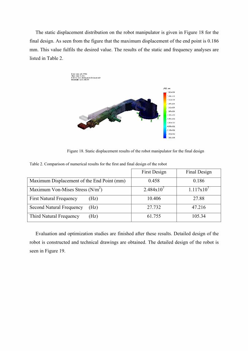
The static displacement distribution on the robot manipulator is given in Figure 18 for the
final design. As seen from the figure that the maximum displacement of the end point is 0.186
mm. This value fulfils the desired value. The results of the static and frequency analyses are
listed in Table 2.
Figure 18. Static displacement results of the robot manipulator for the final design
Table 2. Comparison of numerical results for the first and final design of the robot
First Design Final Design
Maximum Displacement of the End Point (mm) 0.458 0.186
Maximum Von-Mises Stress (N/m2) 2.484x10⁷ 1.117x10⁷
First Natural Frequency (Hz) 10.406 27.88
Second Natural Frequency (Hz) 27.732 47.216
Third Natural Frequency (Hz) 61.755 105.34
Evaluation and optimization studies are finished after these results. Detailed design of the
robot is constructed and technical drawings are obtained. The detailed design of the robot is
seen in Figure 19.
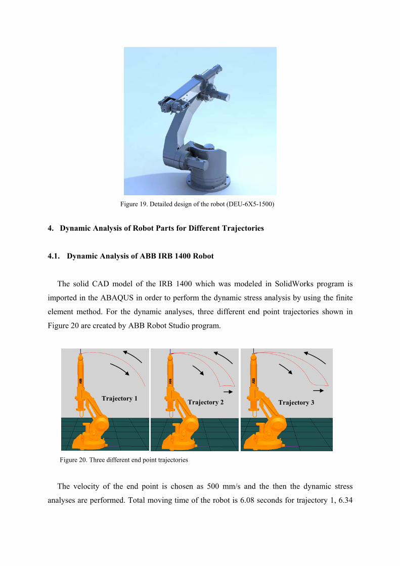
Figure 19. Detailed design of the robot (DEU-6X5-1500)
4. Dynamic Analysis of Robot Parts for Different Trajectories
4.1. Dynamic Analysis of ABB IRB 1400 Robot
The solid CAD model of the IRB 1400 which was modeled in SolidWorks program is
imported in the ABAQUS in order to perform the dynamic stress analysis by using the finite
element method. For the dynamic analyses, three different end point trajectories shown in
Figure 20 are created by ABB Robot Studio program.
Figure 20. Three different end point trajectories
The velocity of the end point is chosen as 500 mm/s and the then the dynamic stress
analyses are performed. Total moving time of the robot is 6.08 seconds for trajectory 1, 6.34
Trajectory 1 Trajectory 2 Trajectory 3
seconds for trajectory 2 and 6.08 seconds for trajectory 3. As seen from these values, first and
third trajectories have the same total moving time. In these trajectories the same job is
performed in the same time period. Maximum reach distance for this trajectory is 955 mm
while the maximum reach distance of the robot is 1440 mm. So, the defined motions are not
arduous job to perform by the robot.
Firstly, the end point velocity profiles obtained from ABB Robot Studio are used as the
end point input in ABAQUS and the joint velocities are calculated. Then these joint velocities
are used as the input for the finite element analysis. ABB Robot Studio program uses the rigid
body dynamics and elastic deformations are not considered. In the real robot system, elastic
deformations occur during the motion. The elastic deformations and respective strain and
stress values are calculated using the ABAQUS finite element package considering the joint
velocities, inertias of robot components and the payload.
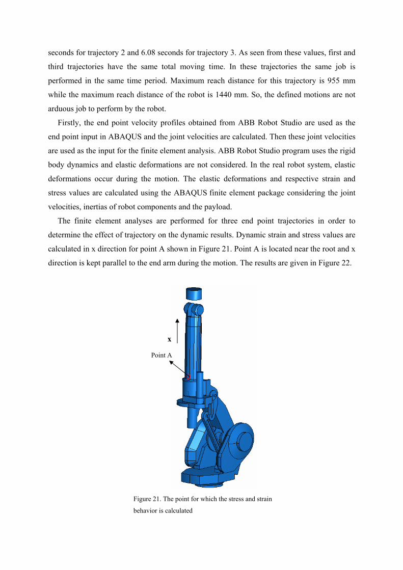
The finite element analyses are performed for three end point trajectories in order to
determine the effect of trajectory on the dynamic results. Dynamic strain and stress values are
calculated in x direction for point A shown in Figure 21. Point A is located near the root and x
direction is kept parallel to the end arm during the motion. The results are given in Figure 22.
Figure 21. The point for which the stress and strain
behavior is calculated
Point A
x
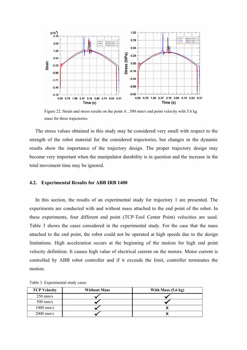
Figure 22. Strain and stress results on the point A , 500 mm/s end point velocity with 5.6 kg
mass for three trajectories
The stress values obtained in this study may be considered very small with respect to the
strength of the robot material for the considered trajectories, but changes in the dynamic
results show the importance of the trajectory design. The proper trajectory design may
become very important when the manipulator durability is in question and the increase in the
total movement time may be ignored.
4.2. Experimental Results for ABB IRB 1400
In this section, the results of an experimental study for trajectory 1 are presented. The
experiments are conducted with and without mass attached to the end point of the robot. In
these experiments, four different end point (TCP-Tool Center Point) velocities are used.
Table 3 shows the cases considered in the experimental study. For the case that the mass
attached to the end point, the robot could not be operated at high speeds due to the design
limitations. High acceleration occurs at the beginning of the motion for high end point
velocity definition. It causes high value of electrical current on the motors. Motor current is
controlled by ABB robot controller and if it exceeds the limit, controller terminates the
motion.
Table 3. Experimental study cases
TCP Velocity Without Mass With Mass (5.6 kg) 250 mm/s 500 mm/s
1000 mm/s X 2000 mm/s X
Three strain-gauges are used in order to measure the dynamic strain values on three
different parts of the robot. The positions of the strain-gauges are chosen for the locations for
which the largest strain values are expected. A data acquisition unit, National Instruments,
having sixteen input channel is used. The strain-gauges are connected to the NI SC-SG01
strain-gauge input module. The strain signals are sent to the computer through NI SC-2345
signal conditioning unit and NI PCI-6220 data acquisition card. The measurement signals are
processed by a program written in LabVIEW.
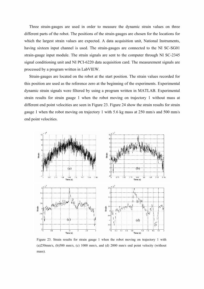
Strain-gauges are located on the robot at the start position. The strain values recorded for
this position are used as the reference zero at the beginning of the experiments. Experimental
dynamic strain signals were filtered by using a program written in MATLAB. Experimental
strain results for strain gauge 1 when the robot moving on trajectory 1 without mass at
different end point velocities are seen in Figure 23. Figure 24 show the strain results for strain
gauge 1 when the robot moving on trajectory 1 with 5.6 kg mass at 250 mm/s and 500 mm/s
end point velocities.
Figure 23. Strain results for strain gauge 1 when the robot moving on trajectory 1 with
(a)250mm/s, (b)500 mm/s, (c) 1000 mm/s, and (d) 2000 mm/s end point velocity (without
mass).
(a) (b)
(c) (d)
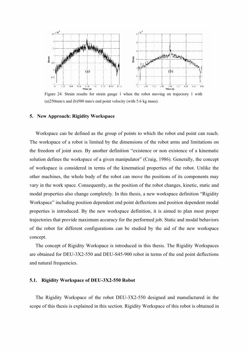
Figure 24. Strain results for strain gauge 1 when the robot moving on trajectory 1 with
(a)250mm/s and (b)500 mm/s end point velocity (with 5.6 kg mass).
5. New Approach: Rigidity Workspace
Workspace can be defined as the group of points to which the robot end point can reach.
The workspace of a robot is limited by the dimensions of the robot arms and limitations on
the freedom of joint axes. By another definition “existence or non existence of a kinematic
solution defines the workspace of a given manipulator” (Craig, 1986). Generally, the concept
of workspace is considered in terms of the kinematical properties of the robot. Unlike the
other machines, the whole body of the robot can move the positions of its components may
vary in the work space. Consequently, as the position of the robot changes, kinetic, static and
modal properties also change completely. In this thesis, a new workspace definition “Rigidity
Workspace” including position dependent end point deflections and position dependent modal
properties is introduced. By the new workspace definition, it is aimed to plan most proper
trajectories that provide maximum accuracy for the performed job. Static and modal behaviors
of the robot for different configurations can be studied by the aid of the new workspace
concept.
The concept of Rigidity Workspace is introduced in this thesis. The Rigidity Workspaces
are obtained for DEU-3X2-550 and DEU-S45-900 robot in terms of the end point deflections
and natural frequencies.
5.1. Rigidity Workspace of DEU-3X2-550 Robot
The Rigidity Workspace of the robot DEU-3X2-550 designed and manufactured in the
scope of this thesis is explained in this section. Rigidity Workspace of this robot is obtained in
(a) (b)
terms of the end point deflections and the natural frequencies of the robot. In the derivation of
the rigidity workspace, the ABAQUS program is used as the finite element solver.
Firstly, 220 different points are defined in the workspace of the robot by using a code
written in MATLAB. This code performs the kinematic calculations for the robot. The
coordinates and the corresponding joint angles for these points are prepared as an input file.
These points lie on x-z plane of the robot workspace. Whole workspace of the robot is
obtained by revolving the x-z plane about the first axis of the robot. For that reason, numerical
simulations are performed only the points on x-z plane and so the whole workspace of the
robot is determined. All parts of the robot are modeled parametrically by using script code
that is written in ABAQUS program and the robot assembly is created according to the joint
angles which are read from the input file. All definitions required for the FEM analysis are
done also in this script code. All details of the robot model and definitions about the solution
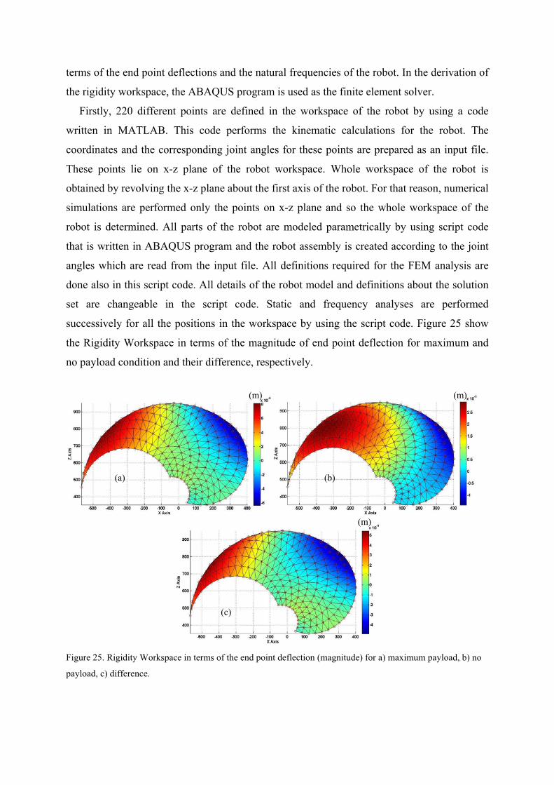
set are changeable in the script code. Static and frequency analyses are performed
successively for all the positions in the workspace by using the script code. Figure 25 show
the Rigidity Workspace in terms of the magnitude of end point deflection for maximum and
no payload condition and their difference, respectively.
Figure 25. Rigidity Workspace in terms of the end point deflection (magnitude) for a) maximum payload, b) no
payload, c) difference.
(m)
(m)
(m)
(a) (b)
(c)
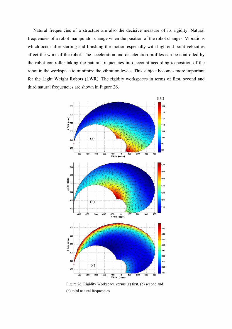
Natural frequencies of a structure are also the decisive measure of its rigidity. Natural
frequencies of a robot manipulator change when the position of the robot changes. Vibrations
which occur after starting and finishing the motion especially with high end point velocities
affect the work of the robot. The acceleration and deceleration profiles can be controlled by
the robot controller taking the natural frequencies into account according to position of the
robot in the workspace to minimize the vibration levels. This subject becomes more important
for the Light Weight Robots (LWR). The rigidity workspaces in terms of first, second and
third natural frequencies are shown in Figure 26.
Figure 26. Rigidity Workspace versus (a) first, (b) second and
(c) third natural frequencies
(Hz)
(a)
(b)
(c)
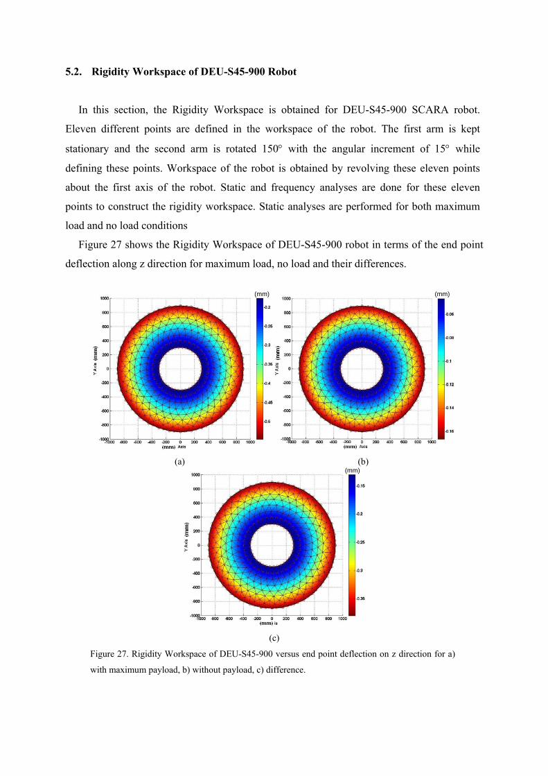
5.2. Rigidity Workspace of DEU-S45-900 Robot
In this section, the Rigidity Workspace is obtained for DEU-S45-900 SCARA robot.
Eleven different points are defined in the workspace of the robot. The first arm is kept
stationary and the second arm is rotated 150° with the angular increment of 15° while
defining these points. Workspace of the robot is obtained by revolving these eleven points
about the first axis of the robot. Static and frequency analyses are done for these eleven
points to construct the rigidity workspace. Static analyses are performed for both maximum
load and no load conditions
Figure 27 shows the Rigidity Workspace of DEU-S45-900 robot in terms of the end point
deflection along z direction for maximum load, no load and their differences.
(a) (b)
(c)
Figure 27. Rigidity Workspace of DEU-S45-900 versus end point deflection on z direction for a)
with maximum payload, b) without payload, c) difference.
(mm) (mm)
(mm)
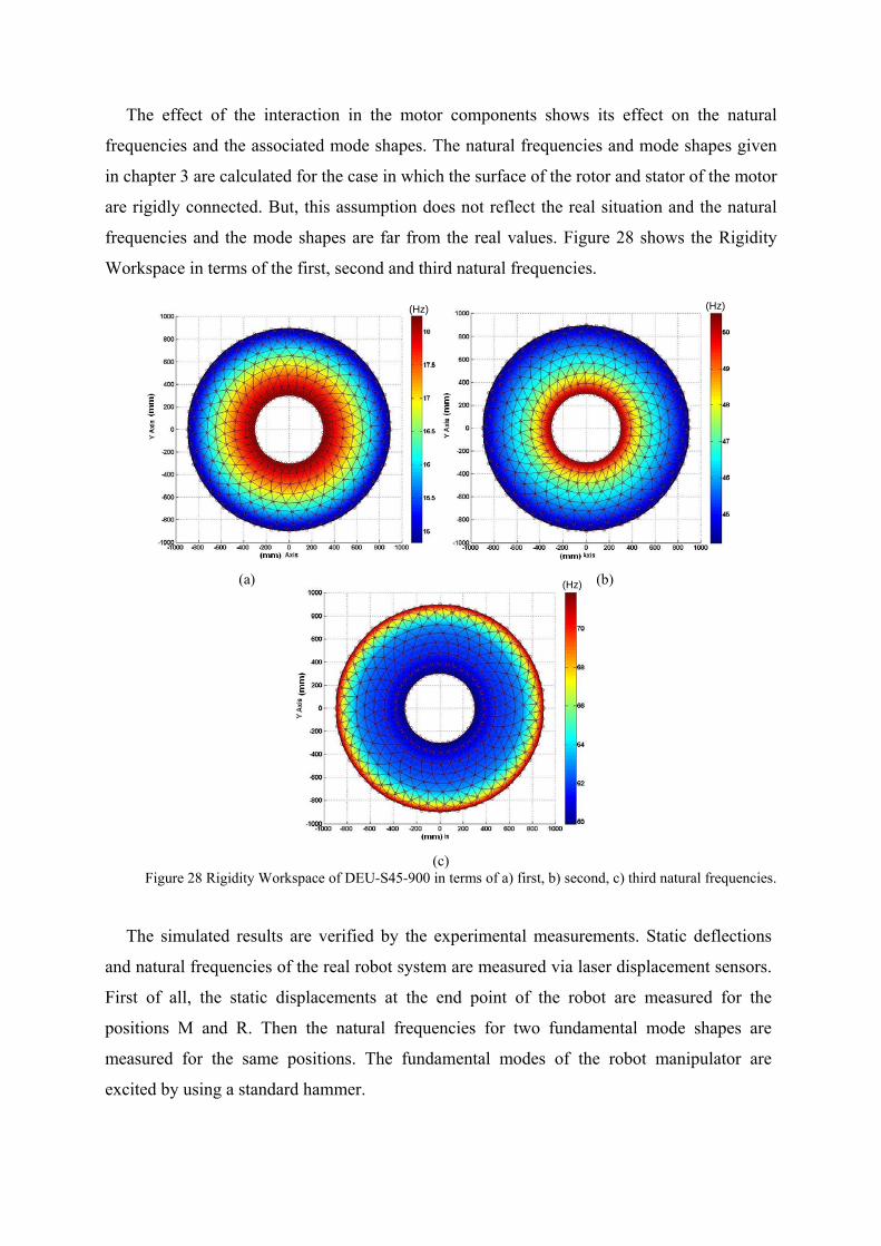
The effect of the interaction in the motor components shows its effect on the natural
frequencies and the associated mode shapes. The natural frequencies and mode shapes given
in chapter 3 are calculated for the case in which the surface of the rotor and stator of the motor
are rigidly connected. But, this assumption does not reflect the real situation and the natural
frequencies and the mode shapes are far from the real values. Figure 28 shows the Rigidity
Workspace in terms of the first, second and third natural frequencies.
(a) (b)
(c)
Figure 28 Rigidity Workspace of DEU-S45-900 in terms of a) first, b) second, c) third natural frequencies.
The simulated results are verified by the experimental measurements. Static deflections
and natural frequencies of the real robot system are measured via laser displacement sensors.
First of all, the static displacements at the end point of the robot are measured for the
positions M and R. Then the natural frequencies for two fundamental mode shapes are
measured for the same positions. The fundamental modes of the robot manipulator are
excited by using a standard hammer.
(Hz) (Hz)
(Hz)
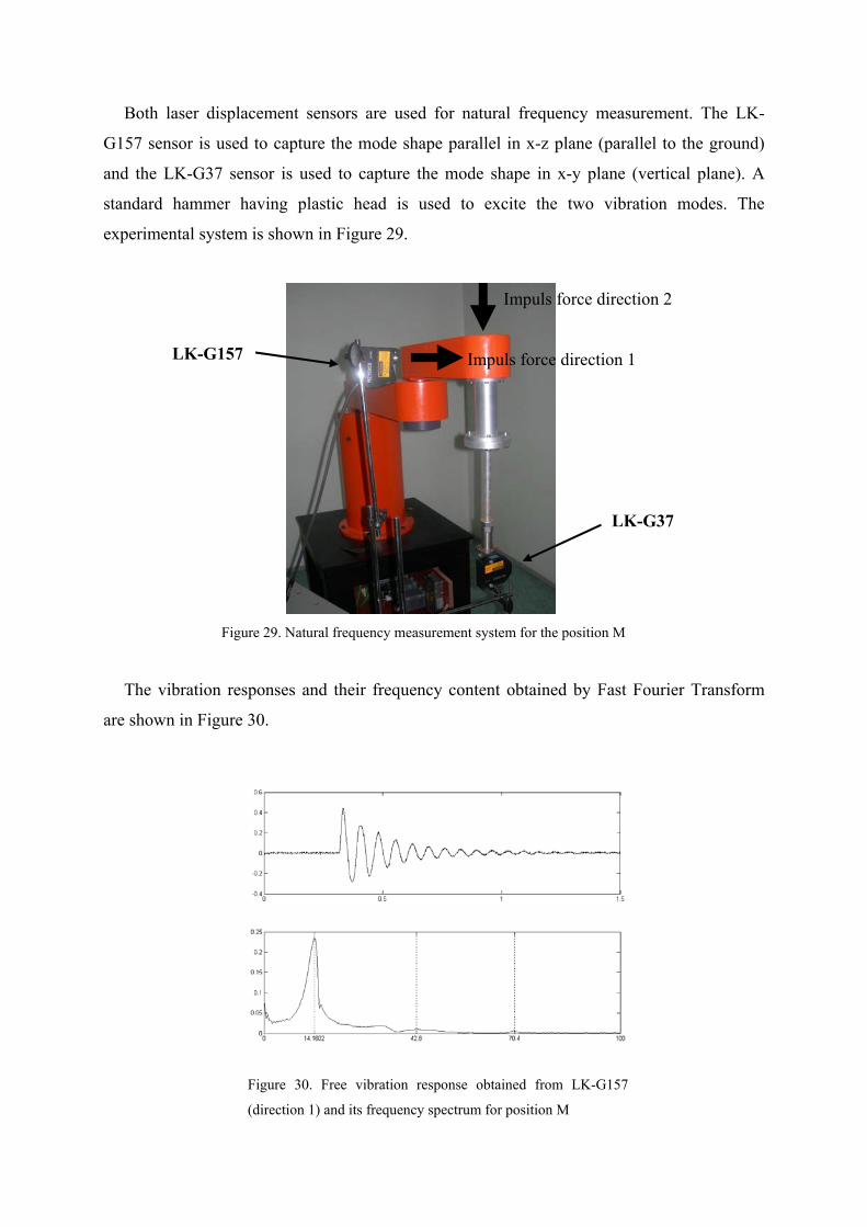
Both laser displacement sensors are used for natural frequency measurement. The LK-
G157 sensor is used to capture the mode shape parallel in x-z plane (parallel to the ground)
and the LK-G37 sensor is used to capture the mode shape in x-y plane (vertical plane). A
standard hammer having plastic head is used to excite the two vibration modes. The
experimental system is shown in Figure 29.
Figure 29. Natural frequency measurement system for the position M
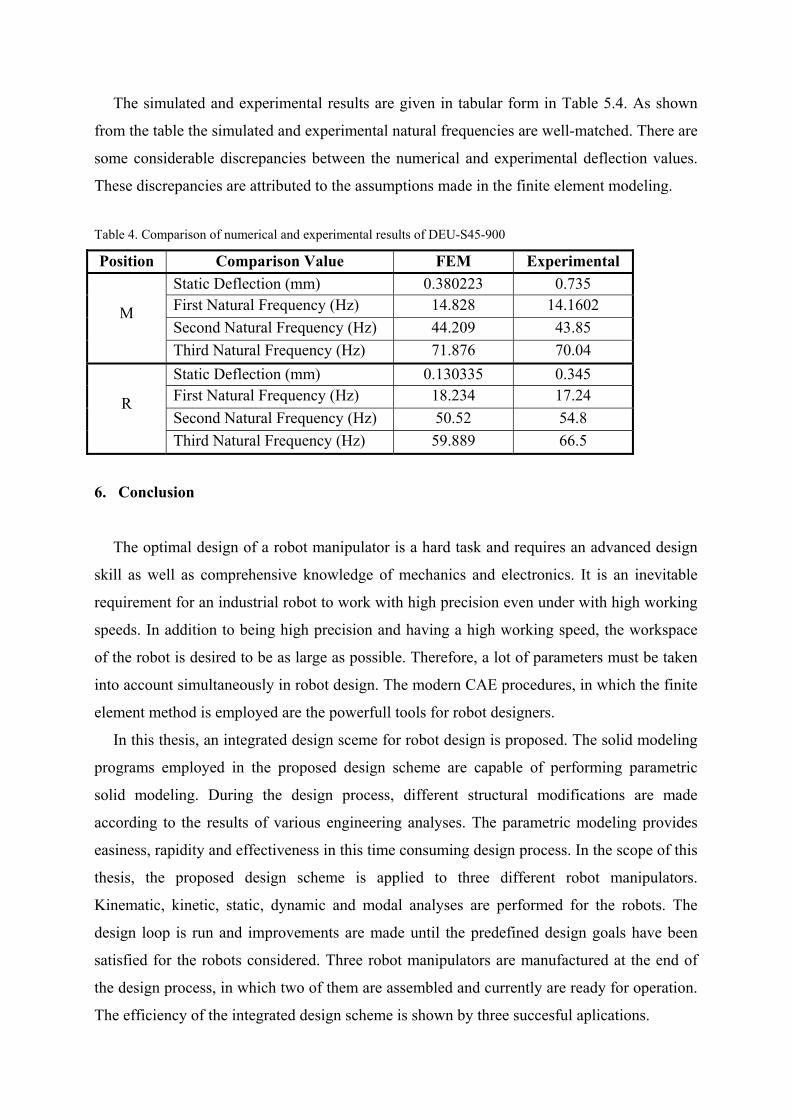
The vibration responses and their frequency content obtained by Fast Fourier Transform
are shown in Figure 30.
Figure 30. Free vibration response obtained from LK-G157
(direction 1) and its frequency spectrum for position M
LK-G157
LK-G37
Impuls force direction 2
Impuls force direction 1
The simulated and experimental results are given in tabular form in Table 5.4. As shown
from the table the simulated and experimental natural frequencies are well-matched. There are
some considerable discrepancies between the numerical and experimental deflection values.
These discrepancies are attributed to the assumptions made in the finite element modeling.
Table 4. Comparison of numerical and experimental results of DEU-S45-900
Position Comparison Value FEM Experimental Static Deflection (mm) 0.380223 0.735 First Natural Frequency (Hz) 14.828 14.1602 Second Natural Frequency (Hz) 44.209 43.85
M
Third Natural Frequency (Hz) 71.876 70.04 Static Deflection (mm) 0.130335 0.345 First Natural Frequency (Hz) 18.234 17.24 Second Natural Frequency (Hz) 50.52 54.8
R
Third Natural Frequency (Hz) 59.889 66.5
6. Conclusion
The optimal design of a robot manipulator is a hard task and requires an advanced design
skill as well as comprehensive knowledge of mechanics and electronics. It is an inevitable
requirement for an industrial robot to work with high precision even under with high working
speeds. In addition to being high precision and having a high working speed, the workspace
of the robot is desired to be as large as possible. Therefore, a lot of parameters must be taken
into account simultaneously in robot design. The modern CAE procedures, in which the finite
element method is employed are the powerfull tools for robot designers.
In this thesis, an integrated design sceme for robot design is proposed. The solid modeling
programs employed in the proposed design scheme are capable of performing parametric
solid modeling. During the design process, different structural modifications are made
according to the results of various engineering analyses. The parametric modeling provides
easiness, rapidity and effectiveness in this time consuming design process. In the scope of this
thesis, the proposed design scheme is applied to three different robot manipulators.
Kinematic, kinetic, static, dynamic and modal analyses are performed for the robots. The
design loop is run and improvements are made until the predefined design goals have been
satisfied for the robots considered. Three robot manipulators are manufactured at the end of
the design process, in which two of them are assembled and currently are ready for operation.
The efficiency of the integrated design scheme is shown by three succesful aplications.
Rapid movements of the robot manipulators are necessary to reduce the production times.
On the other hand, rapid movement means acceleration and deceleration that cause
considerable inertial forces. The importance of the trajectory selection and its effect on the
dynamic response is shown by the experimental strain measurements and numerical strain and
stress analyses performed for an industrial robot having six-degrees of freedom. The dynamic
strain and stress values for an industrial robot can be controlled via proper selection of its
trajectory.
The most important problem encountered in the offline programming of industrial robots
is their insufficient accuracies. The main parameters which affect the acccuracy are the
flexibility of the robot arms, production tolerances and the joint flexibilities. Different
compensation techniques are developed in order to overcome this accuracy problem
encountered especially for the jobs which require high precision. Today, the most preferable
method is the laser interferomety in which the end point deflections for every manufactured
robot are measured for different configurations in the workspace of the robot. A new concept
“Rigidity Workspace” which will contribute to the accuracy compensation is introduced in
this thesis. The Rigidity Workspace reflects the static end point deflections and modal
behaviors of the robot manipulator for every end point position within its kinematic
workspace. The static end point deflections and modal behaviours of the robot manipulator
for numerous points in the workspace are calculated by ABAQUS via a script code
developed in this study and the Rigidity Workspaces are illustrated by contour graphs in
terms of static deflection and the fundamental frequencies. The numerical results presented
in this study via rigidity workspace concept exhibit the structural behavior of the robot
manipulators being considered. The structural behavior of the robot manipulators can be used
to compensate the end point deflections from the real target. The numerical results are
compared with the results obtained from experimental measurements carried out on DEU-
S45-900 robot manipulator. As a result of this comparison, it is seen that the proper
definition of the joint flexibilities has great influence on the numerical results. The
manufacturers of robot equipments such as motors and bearings should supply the CAD
models of these parts with the same rigidities in order to create the accurate finite element
models for precise numerical analyses. Therefore, static and dynamic behavior of the
manipulator can be predicted through the numerical analyses. The experimental results
presented in this thesis imply that the accurate models for the robot manipulators considered
can be established by using today’s CAE tools.
References
Albu-Schaffer, A., Haddadin, S., Ott, C., Stemmer, A., Wimböck, T. & Hirzinger, G. (2007).
The DLR lightweight robot: design and control concepts for robots in human
environments. Industrial Robot, 34 (5), 376-385.
Clark, S. & Lin, Y.J. (2007). CAD tools integration for robot kinematics design assurance
with case studies on PUMA robots. Industrial Robot, 34 (3), 240-248.
Dwivedy, S.K. & Eberhard, P. (2006). Dynamic analysis of flexible manipulators, a literature
review. Mechanism and Machine Theory, 41, 749-777.
Karagülle, H. & Malgaca, L. (2004). Analysis of end point vibrations of a two-link
manipulator by integrated CAD/CAE procedures. Finite Elements in Analysis and Design,
40, 2049-2061
Mir-Nasiri, N. (2004). Design, modelling and control of four-axis parallel robotic arm for
assembly operations. Assembly Automation, 24 (4), 365-369.
Mrozek, Z. (2003). Computer aided design of mechatronic systems. International Journal of
Applied Mathematics and Computer Science, 13 (2), 255-267.
Park, K., Kim, Y.S., Kim, C.S. & Park, H.J. (2007). Integrated application of
CAD/CAM/CAE and RP for rapid development of a humanoid biped robot. Journal of
Materials Processing Technology,187-188, 609-6.13
Thomson, C. C. (1984). Robot modelling-the tools needed for optimal design and utilization.
Computer-Aided Design, 16( 6), 335-337.
Vukobratovic, M., Potkonjak, V., Inoue, K. & Takano, M. (2002). Actuators and computer-
aided design of robots. Nwokah, O.D.I.(Ed.). Mechanical systems design handbook (523-
556) CRC Press.
Young, K. & Pickin, C.G. (2000). Accuracy assessment of the modern industrial robot.
Industrial Robot, 27 (6), 427-436.