design and simulation of robot manipulators using a modular
TRANSCRIPT
19
Design and Simulation of Robot Manipulators using a Modular Hardware-in-the-loop Platform
Adrian Martin and M. Reza Emami University of Toronto Institute for Aerospace Studies
Canada
1. Introduction
The need for developing high quality systems with short and cost-effective design schedules has created an ongoing demand for efficient prototyping and testing tools (Wheelright & Clark, 1992). In many engineering applications failure of a system can have severe consequences, from loss of hardware and capital to complete mission failure, and can even result in the loss of human life (Ledin, 1999). The earliest form of prototyping, physical prototyping, began with the development of the first system, and it refers to fabricating a physical system to evaluate performance and test design alterations. There have been many advances in this field, such as the use of scaled models (Faithfull et al., 2001), but in most cases the time and cost involved in building complete physical prototypes are prohibitive. With the advent of computers a new form of prototyping, termed analytical prototyping, has become a second viable option (Ulrich & Eppinger, 2000). Computer models are generally inexpensive to develop and can be quickly modified to experiment with various aspects of the system. However, this flexibility often comes at the cost of approximations used to model complex physical phenomena, which in turn lead to inaccuracies in the model and system behaviour. A prototyping tool that has been gaining significant popularity in recent years is hardware-in-the-loop simulation, which can effectively combine the advantages of the two traditional prototyping methods. The underlying concept of hardware-in-the-loop (HIL) simulation is to use physical hardware for system components that are difficult or impossible to model and link them to a computer model that simulates the other aspects of the system. This technique has been successfully applied to development and testing in a wide range of engineering fields, including aerospace (Leitner, 1996), automotive (Hanselman, 1996), controls (Linjama et al., 2000), manufacturing (Stoeppler et al., 2005), and naval and defence (Ballard et al., 2002). This research investigates the application of HIL simulation as a tool for the design and testing of serial-link industrial manipulators, and proposes a generic and modular robotic hardware-in-the-loop simulation (RHILS) architecture. The RHILS architecture was implemented in the simulation of a standard industrial manipulator and evaluated on its ability to simulate the robot and its usefulness as a design tool. The remainder of this section briefly reviews the state-of-the-art in HIL simulation across a broad range of fields, highlighting some of the key benefits and considerations, and then summarizes the current work of other researchers in the specific field of robotic
www.intechopen.com
Robot Manipulators
348
manipulators. Section 2 presents the details of the RHILS architecture and an analysis of the load emulation mechanism. The hardware setup designed to evaluate the effectiveness and viability of the RHILS architecture is outlined in section 3. This setup was used to simulate a 5-d.o.f. industrial manipulator during a real-world design scenario and the comparison between the RHILS setup and a complete physical prototype is presented in section 4. The conclusions from this research are presented in section 5, discussing the strengths and weaknesses of the RHILS platform implementation and the direction of current research.
1.1 Hardware-in-the-Loop Simulation
Hardware-in-the-loop simulations have been used successfully in a number of engineering fields, but found their first application in aerospace flight control systems (Maclay, 1997). The increasing importance of several factors has led to an increase in the use of HIL simulation as a tool for system design, testing, and training. These factors are listed in (Maclay, 1997) as: reducing development time, exhaustive testing requirements for safety critical applications, unacceptably high cost of failure, and reduced costs of the hardware necessary to run the simulation. These factors are mentioned repeatedly throughout the literature along with a number of other benefits of HIL simulation, which are demonstrated in the following paragraphs. By using physical hardware as part of a computer simulation it is possible to reduce the complexity of the simulation and incorporate factors that would otherwise be difficult or impossible to model. The effectiveness of this technique was shown by the contact dynamics HIL simulator developed by the Canadian Space Agency. This simulation was of the manipulator motion for the Special Purpose Dexterous Manipulator (SPDM) to be installed on the International Space Station. The setup linking a computer simulation of the space manipulator to a physical hydraulic robot described in (Aghili & Piedboeuf, 2002) was successful in simulating the free motion and contact dynamics of the manipulator, a task that would be impossible with a pure computer simulation. Another benefit of HIL simulation exemplified in (Aghili & Piedboeuf, 2002) is the ability to simulate a 0-g environment, desirable since many space robots are incapable of operating in 1-g conditions and so physical prototyping is impractical. The use of HIL simulation in machine tools and manufacturing systems is discussed in (Stoeppler et al., 2005). In addition to mentioning the cost, safety, and development time benefits, (Stoeppler et al., 2005) talks about how it can be used to safely and economically test new ideas and allow the concurrent design of hardware and software components. An innovative application is detailed in (Faithfull et al., 2001), where they present the success of a HIL simulation used in conjunction with scaled physical prototyping during the design of a 4x4 electric vehicle. The HIL simulation proved to be an effective design tool, and had the added benefit of improving the credibility of the results when presented to both technical and non-technical persons (Faithfull et al., 2001). Other applications of HIL simulation include embedded computing and field robotics. In embedded computing HIL simulation is used because many of the systems are safety critical and require thorough and accurate testing (Ledin, 1999). In the field of robotics the applications range from underwater vehicle testing (Lane et al., 2001), to aerospace robotic manipulators (Aghili & Piedboeuf, 2002), to multi-agent mobile robot systems (Hu, 2005). When implementing software for HIL simulations such as those described above it is often beneficial to use object-oriented or graphical modelling techniques (Kasper et al., 1997).
www.intechopen.com
Design and Simulation of Robot Manipulators using a Modular Hardware-in-the-loop Platform
349
Programming tools such as Dymola, based on Modelica®, make it easier to model complex mathematical systems by facilitating the decomposition of the system into components and allowing them to be connected using a graphical interface (Aronsson & Fritzson, 2001). This object-oriented approach has the additional benefit of translating easily to multiprocessor systems which can avoid computational limits that may otherwise prevent real-time simulations of complex systems (Kasper et al., 1997). It is obvious that HIL simulation has been successfully applied in many areas and proven a useful design tool which reduced development time and costs (Stoeppler et al., 2005; Hu, 2005), and with the ever improving performance of today’s computers it is possible to build HIL simulations without specialized and costly hardware (Stoeppler et al., 2005). However, (Ma et al., 2004) offers the caution that, as with any type of simulation, it is necessary to extensively validate the results before making use of the simulation. Based on the validation of the SPDM Task Verification Facility, (Ma et al., 2004) proposes a two-step methodology: the first step is verification at a general, higher level, while the second step is verification at a more detailed engineering level. With these considerations taken into account HIL simulation can be an extremely powerful design and testing tool.
1.2 Robotic Hardware-in-the-Loop Simulation
HIL simulation is receiving growing interest from researchers in the field of robotics, and has been applied from a number of different perspectives. These approaches include: robot-in-the-loop simulations, such as the platform used for the task verification of the SPDM at the Canadian Space Agency (Piedboeuf et al., 1999) or the use of both real and simulated mobile robots interacting with a virtual environment (Hu, 2005); controller-in-the-loop simulations, where a real control system interacts with a computer model of the robot (Cyril et al., 2000); and joint-in-the-loop simulations, which use a computer model to compute the dynamic loads seen at each joint and then emulate those loads on the real actuators (Temeltas et al., 2002). Each of these approaches applies the HIL concept slightly differently, but all have produced positive results. In the recent work (Aghili, 2006) a hardware setup similar to that which was developed for this research is described. It focuses on the simulation of a simple 2-d.o.f. planar manipulator and includes environmental controls which allow testing in space-like thermal/vacuum conditions.
2. Platform Architecture
2.1 RHILS Architecture
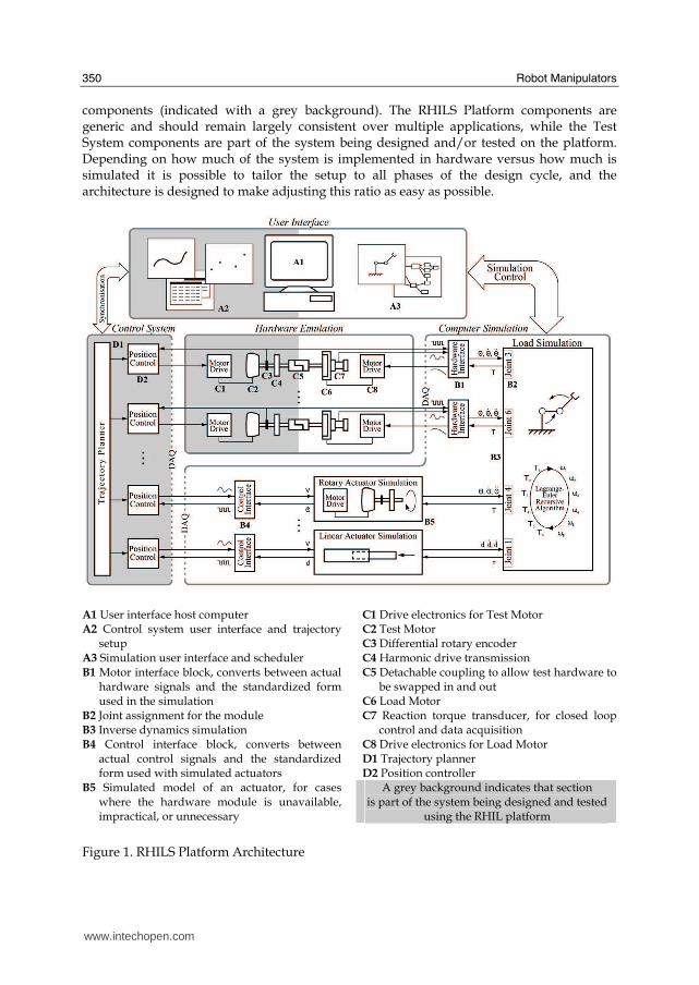
The RHILS platform architecture developed for this research allows for simultaneous design and testing of both the joint hardware and control system of a robot manipulator. The architecture is designed to be adequately generic so that it can be applied to any serial-link robot manipulator system, and focuses on modularity and extensibility in order to facilitate concurrent engineering of a wide range of manipulators. This section presents a detailed breakdown of the main blocks of the architecture. The architecture is separated into four subsystems: (a) the User Interface, (b) the Computer Simulation, (c) Hardware Emulation, and (d) the Control System, which are described below with reference to Fig. 1. These subsystems are further partitioned into two major categories: RHILS Platform components (indicated with a white background), and Test System
www.intechopen.com
Robot Manipulators
350
components (indicated with a grey background). The RHILS Platform components are generic and should remain largely consistent over multiple applications, while the Test System components are part of the system being designed and/or tested on the platform. Depending on how much of the system is implemented in hardware versus how much is simulated it is possible to tailor the setup to all phases of the design cycle, and the architecture is designed to make adjusting this ratio as easy as possible.
A1 User interface host computer A2 Control system user interface and trajectory
setup A3 Simulation user interface and scheduler B1 Motor interface block, converts between actual
hardware signals and the standardized form used in the simulation
B2 Joint assignment for the module B3 Inverse dynamics simulation B4 Control interface block, converts between
actual control signals and the standardized form used with simulated actuators
B5 Simulated model of an actuator, for cases where the hardware module is unavailable, impractical, or unnecessary
C1 Drive electronics for Test Motor C2 Test Motor
C3 Differential rotary encoder C4 Harmonic drive transmission C5 Detachable coupling to allow test hardware to
be swapped in and out C6 Load Motor C7 Reaction torque transducer, for closed loop
control and data acquisition C8 Drive electronics for Load Motor D1 Trajectory planner D2 Position controller
A grey background indicates that section is part of the system being designed and tested
using the RHIL platform
Figure 1. RHILS Platform Architecture
www.intechopen.com
Design and Simulation of Robot Manipulators using a Modular Hardware-in-the-loop Platform
351
A. User Interface Block This block contains the most overlap between the RHILS Platform and the Test System. Because it is necessary to synchronize initial conditions before starting a simulation, this block acts as an intermediary between the custom control system and the generic simulation. On the RHILS Platform side robot configurations and parameters are chosen, as well as specifying any external conditions, for example zero-gravity or end-effector payloads, that will be used during a simulation. For the Test System side any configurable control parameters are set in the control system, such as the planned trajectories and feedback loop gains. Finally, the duration of the simulation and the type of data logging to be performed are selected. B. Computer Simulation Block The Computer Simulation performs three primary roles. Its first and most obvious task, represented by the Load Simulation block, is to run the inverse dynamics computations based on the instantaneous position, velocity, and acceleration of each joint, and solve for the dynamic load applied to each joint actuator. Due to the recursive algorithm used for computing the inverse dynamics (Li & Sankar, 1992) on the dedicated kernel, it is possible to specify any reasonable number of joints in any configuration and still attain the computational efficiency necessary to run the simulation in real-time. The second task is to convert the hardware signals read in and sent out through a data acquisition board into the standardized format used by the load simulation, which is shown by the Hardware Interface blocks. These hardware interface blocks play a key role in the modularity of the architecture since they allow different hardware to be used without significant changes to the simulation. The third task of the Computer Simulation is to simulate any joints that do not have a corresponding hardware module. In some situations it may be desirable to have one or more joint actuators without a hardware component, for example when the hardware is unavailable, too costly, or simply unnecessary. Then the computer simulation must model the joint and interface directly with the control system, shown in the Actuator Simulation and Control Interface blocks. This third task makes it possible to utilize the RHILS platform at early stages of the design as well as making it more cost effective to set up tests if only one section of the manipulator is under study. C. Hardware Emulation Block The Hardware Emulation system consists of separate modules for each joint, and each module interfaces with both the Control System and the Computer Simulation. These modules are further separated into two parts: a Test Module, the joint actuator that is being designed/tested, and a Load Module, the load-emulating device that mimics the dynamic loads that would be seen in a real system. The Test Module includes not only the real actuator, but also the transmission system, position/speed sensors, and motor drive that would be used in the real manipulator, all of which can lead to significant inaccuracies in a pure computer-based simulation. The Test Module interfaces directly with the Control System, which controls the motor as if it were part of a physical robot. The Load Module is coupled to the output of the transmission system, ideally without the use of a secondary transmission that may introduce unwanted uncertainty in the load emulation mechanism. For the range required by most applications, it was found that torque motors can supply the necessary torque directly and have other desirable features including consistent torque at low speeds, low inertia, and proper heat dissipation characteristics. The Load Module is controlled through a feedback loop that follows the torque calculated by the Computer Simulation block.
www.intechopen.com
Robot Manipulators
352
This torque represents the arm dynamics that must be reflected on each joint actuator to have a genuine simulation of the real system. To emulate the dynamic torque accurately closed-loop control is needed, which requires that the torque generated by the Load Module be identified. This is done through a unique torque sensor setup described in section 3.1. D. Control System Block This block can range from running in software on a standard PC to running on dedicated custom hardware depending on the nature and requirements of the application. It is possible to use the real control system for the robot, since as far as the control system is concerned it is connected to the real actuators in a physical robot. This has significant benefits over running a simulated or modified version of the control system: in many applications intense testing of the final control system is required, which can now begin before the final hardware is complete without building expensive prototypes. On the other hand, when the control system is not the focus of the design the flexibility of this architecture allows any simple controller to be quickly implemented and used.
2.2 Load Emulation
Using a recursive inverse dynamics algorithm it is possible to efficiently calculate the torque seen by the n joints of the manipulator given the current position, velocity, and acceleration for each joint (Li & Sankar, 1992). This estimated torque, ∗
τ , must then be applied to the joint
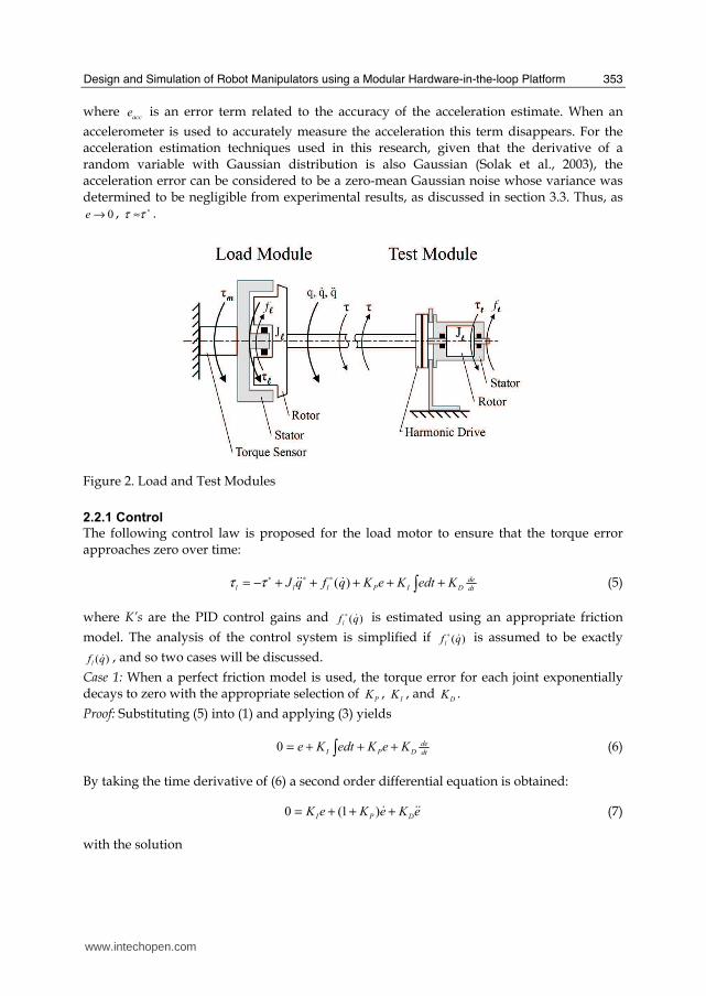
by the Load Module. The physical setup of a Load and Test Module pair is shown in Fig. 2. This load emulation setup is similar to that used in (Aghili, 2006), yet has some differences that reduce the cost and complexity of the hardware. Specifically, a reaction torque sensor is placed behind the load motor rather than a rotary torque sensor mounted on the shaft, and no velocity sensor is used. The following analysis and experimental results in later sections show that the load emulator can achieve similar performance despite the simpler hardware. In the free body diagram of the load motor shown in Fig. 2 q , q$ , and q$$ are the position,
velocity, and acceleration, respectively, l
τ is the generated torque, )(qf l $ is the friction, lJ is
the rotating moment of inertia, and τ is the torque transferred to the Test Module. With the
assumption that there is no flexibility in the shaft or coupling the dynamic equation for the load motor is given by
ττ +−= )(qfqJ lll$$$ (1)
The reaction torque sensor mounted behind the load motor measures m
τ : the torque applied
between the stator and rotor. Using (1) this can be written in two ways,
qJqf lllm$$$ +−=−= τττ )( (2)
If ∗q$$ is taken as an estimate of the current acceleration, either directly measured or
calculated by other methods such as those discussed in section 3.3, then a torque error term can be specified as
)()( qJqJe llmm$$$$ +−−+−=−=
∗∗∗ττττ (3)
or
accee +−=∗
ττ (4)
www.intechopen.com
Design and Simulation of Robot Manipulators using a Modular Hardware-in-the-loop Platform
353
where acce is an error term related to the accuracy of the acceleration estimate. When an
accelerometer is used to accurately measure the acceleration this term disappears. For the acceleration estimation techniques used in this research, given that the derivative of a random variable with Gaussian distribution is also Gaussian (Solak et al., 2003), the acceleration error can be considered to be a zero-mean Gaussian noise whose variance was determined to be negligible from experimental results, as discussed in section 3.3. Thus, as
0→e , ∗≈ττ .
Figure 2. Load and Test Modules
2.2.1 Control
The following control law is proposed for the load motor to ensure that the torque error approaches zero over time:
dt
de
DIPlllKedtKeKqfqJ +++++−= ∫∗∗∗ )( $$$ττ (5)
where K’s are the PID control gains and )(qf l $∗ is estimated using an appropriate friction
model. The analysis of the control system is simplified if )(qf l $∗ is assumed to be exactly
)(qf l $ , and so two cases will be discussed.
Case 1: When a perfect friction model is used, the torque error for each joint exponentially decays to zero with the appropriate selection of
PK ,
IK , and
DK .
Proof: Substituting (5) into (1) and applying (3) yields
dt
de
DPIKeKedtKe +++= ∫0 (6)
By taking the time derivative of (6) a second order differential equation is obtained:
eKeKeK DPI$$$ +++= )1(0 (7)
with the solution
www.intechopen.com
Robot Manipulators
354
)exp()exp( 2211 trctrce += (8)
where c’s are constants determined by the initial conditions and r’s are the roots of the equation
0)1(2=+++ DPI KrKrK . (9)
By selecting PK ,
IK , and
DK such that 0},Re{
21<rr , e is guaranteed to exponentially decay to
zero. Case 2: When friction error is considered, (6) becomes
dt
de
DPIfricKeKedtKee +++= ∫ (10)
where frice is the difference between the estimated and true friction. Similarly, (7) becomes
eKeKeKeDPIfric$$$$ +++= )1( . (11)
Since frice$ cannot be expressed as a simple function of time it is non-trivial to solve the
differential equation (11) and it is left to experimental results to show that e remains within acceptable limits.
2.2.2 Noise Rejection
In the presence of a disturbance torque, d , (6) becomes
dt
deDPIKeKedtKed +++= ∫ . (12)
As before, taking the derivative with respect to time yields
eKeKeKd DPI$$$$ +++= )1( . (13)
From here (13) can be transformed to the Laplace domain
dsKsKK
se
DPI
2)1( +++= . (14)
Considering the norm of the transfer function (14), one can obtain
dKK
eDI
2ω
ω
+≤ . (15)
From the above equation it is possible to see that IK is key in rejecting low frequency noise,
while DK determines how quickly the second order term of the denominator becomes
dominant and rejects high frequency noise. The effects of the remaining high band disturbance, i.e. jerks and vibrations, may be further reduced if the Test Module uses a flexible transmission system such as a harmonic drive.
www.intechopen.com
Design and Simulation of Robot Manipulators using a Modular Hardware-in-the-loop Platform
355
2.3 Computer Simulation
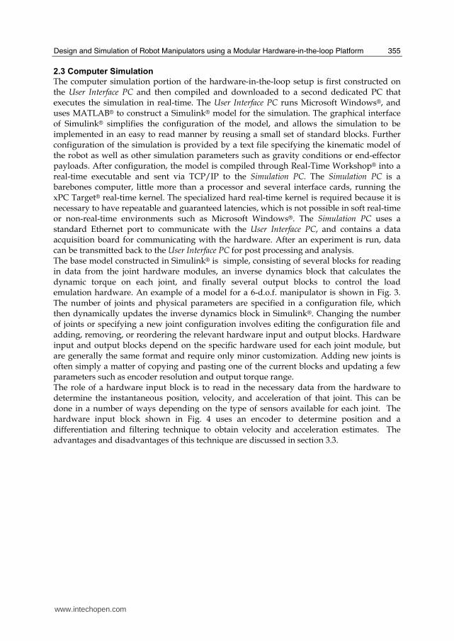
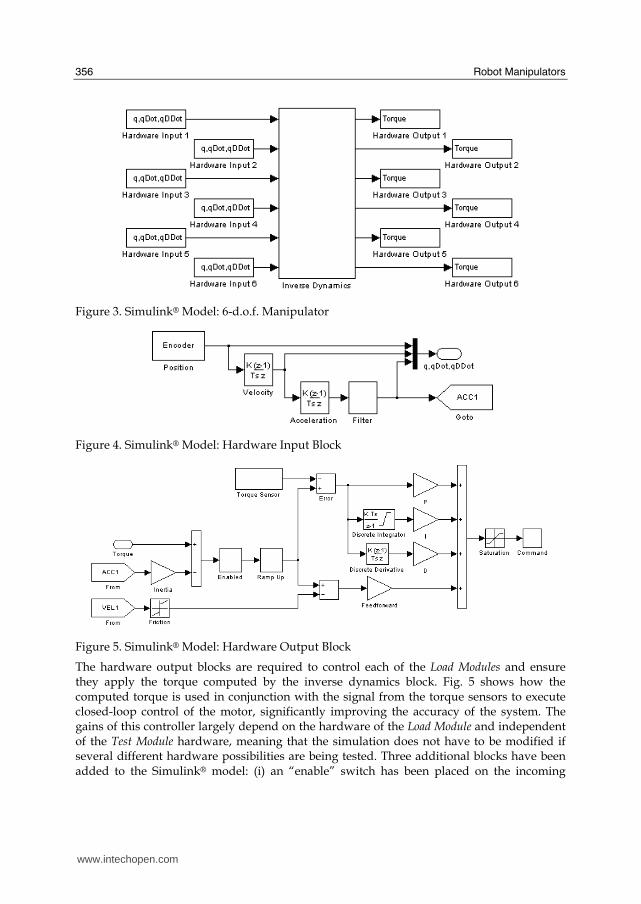
The computer simulation portion of the hardware-in-the-loop setup is first constructed on the User Interface PC and then compiled and downloaded to a second dedicated PC that executes the simulation in real-time. The User Interface PC runs Microsoft Windows®, and uses MATLAB® to construct a Simulink® model for the simulation. The graphical interface of Simulink® simplifies the configuration of the model, and allows the simulation to be implemented in an easy to read manner by reusing a small set of standard blocks. Further configuration of the simulation is provided by a text file specifying the kinematic model of the robot as well as other simulation parameters such as gravity conditions or end-effector payloads. After configuration, the model is compiled through Real-Time Workshop® into a real-time executable and sent via TCP/IP to the Simulation PC. The Simulation PC is a barebones computer, little more than a processor and several interface cards, running the xPC Target® real-time kernel. The specialized hard real-time kernel is required because it is necessary to have repeatable and guaranteed latencies, which is not possible in soft real-time or non-real-time environments such as Microsoft Windows®. The Simulation PC uses a standard Ethernet port to communicate with the User Interface PC, and contains a data acquisition board for communicating with the hardware. After an experiment is run, data can be transmitted back to the User Interface PC for post processing and analysis. The base model constructed in Simulink® is simple, consisting of several blocks for reading in data from the joint hardware modules, an inverse dynamics block that calculates the dynamic torque on each joint, and finally several output blocks to control the load emulation hardware. An example of a model for a 6-d.o.f. manipulator is shown in Fig. 3. The number of joints and physical parameters are specified in a configuration file, which then dynamically updates the inverse dynamics block in Simulink®. Changing the number of joints or specifying a new joint configuration involves editing the configuration file and adding, removing, or reordering the relevant hardware input and output blocks. Hardware input and output blocks depend on the specific hardware used for each joint module, but are generally the same format and require only minor customization. Adding new joints is often simply a matter of copying and pasting one of the current blocks and updating a few parameters such as encoder resolution and output torque range. The role of a hardware input block is to read in the necessary data from the hardware to determine the instantaneous position, velocity, and acceleration of that joint. This can be done in a number of ways depending on the type of sensors available for each joint. The hardware input block shown in Fig. 4 uses an encoder to determine position and a differentiation and filtering technique to obtain velocity and acceleration estimates. The advantages and disadvantages of this technique are discussed in section 3.3.
www.intechopen.com
Robot Manipulators
356
Figure 3. Simulink® Model: 6-d.o.f. Manipulator
Figure 4. Simulink® Model: Hardware Input Block
Figure 5. Simulink® Model: Hardware Output Block
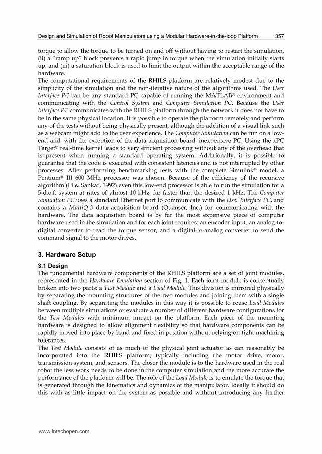
The hardware output blocks are required to control each of the Load Modules and ensure they apply the torque computed by the inverse dynamics block. Fig. 5 shows how the computed torque is used in conjunction with the signal from the torque sensors to execute closed-loop control of the motor, significantly improving the accuracy of the system. The gains of this controller largely depend on the hardware of the Load Module and independent of the Test Module hardware, meaning that the simulation does not have to be modified if several different hardware possibilities are being tested. Three additional blocks have been added to the Simulink® model: (i) an “enable” switch has been placed on the incoming
www.intechopen.com
Design and Simulation of Robot Manipulators using a Modular Hardware-in-the-loop Platform
357
torque to allow the torque to be turned on and off without having to restart the simulation, (ii) a “ramp up” block prevents a rapid jump in torque when the simulation initially starts up, and (iii) a saturation block is used to limit the output within the acceptable range of the hardware. The computational requirements of the RHILS platform are relatively modest due to the simplicity of the simulation and the non-iterative nature of the algorithms used. The User Interface PC can be any standard PC capable of running the MATLAB® environment and communicating with the Control System and Computer Simulation PC. Because the User Interface PC communicates with the RHILS platform through the network it does not have to be in the same physical location. It is possible to operate the platform remotely and perform any of the tests without being physically present, although the addition of a visual link such as a webcam might add to the user experience. The Computer Simulation can be run on a low-end and, with the exception of the data acquisition board, inexpensive PC. Using the xPC Target® real-time kernel leads to very efficient processing without any of the overhead that is present when running a standard operating system. Additionally, it is possible to guarantee that the code is executed with consistent latencies and is not interrupted by other processes. After performing benchmarking tests with the complete Simulink® model, a Pentium® III 600 MHz processor was chosen. Because of the efficiency of the recursive algorithm (Li & Sankar, 1992) even this low-end processor is able to run the simulation for a 5-d.o.f. system at rates of almost 10 kHz, far faster than the desired 1 kHz. The Computer Simulation PC uses a standard Ethernet port to communicate with the User Interface PC, and contains a MultiQ-3 data acquisition board (Quanser, Inc.) for communicating with the hardware. The data acquisition board is by far the most expensive piece of computer hardware used in the simulation and for each joint requires: an encoder input, an analog-to-digital converter to read the torque sensor, and a digital-to-analog converter to send the command signal to the motor drives.
3. Hardware Setup
3.1 Design
The fundamental hardware components of the RHILS platform are a set of joint modules, represented in the Hardware Emulation section of Fig. 1. Each joint module is conceptually broken into two parts: a Test Module and a Load Module. This division is mirrored physically by separating the mounting structures of the two modules and joining them with a single shaft coupling. By separating the modules in this way it is possible to reuse Load Modules between multiple simulations or evaluate a number of different hardware configurations for the Test Modules with minimum impact on the platform. Each piece of the mounting hardware is designed to allow alignment flexibility so that hardware components can be rapidly moved into place by hand and fixed in position without relying on tight machining tolerances. The Test Module consists of as much of the physical joint actuator as can reasonably be incorporated into the RHILS platform, typically including the motor drive, motor, transmission system, and sensors. The closer the module is to the hardware used in the real robot the less work needs to be done in the computer simulation and the more accurate the performance of the platform will be. The role of the Load Module is to emulate the torque that is generated through the kinematics and dynamics of the manipulator. Ideally it should do this with as little impact on the system as possible and without introducing any further
www.intechopen.com
Robot Manipulators
358
complexities to the computer simulation. To accomplish this, a second transmission system should be avoided and the motor must be able to supply the required torque directly. Additionally, the load emulation device should have low inertia and be able to generate sufficient torque even at low speeds. Due to these requirements most standard motors cannot be used, however, torque motors (or ring motors) are well suited for this application and have the additional benefits of low power consumption and good heat dissipation. It was noted above that a low inertia is desirable, and this is the case when simulating small or lightweight joints. However, in certain cases an inertia which is too low may in fact be a disadvantage: for a very high torque joint designed to drive heavy robots a low inertia may allow the joint to accelerate artificially quickly, before the RHILS platform has a chance to calculate and apply the correct torque in response. This has the potential to significantly reduce the effectiveness of the simulation, but can easily be corrected by adding an appropriate inertial load to the joint module to bring it within the range of the real robot. One of the key challenges for the joint emulating modules is the control of the torque applied by the Load Motor. This torque represents the arm dynamics that would be seen by each joint actuator, and requires the control of only the portion of the torque that is generated by the Load Motor rather than the coupled torque between the Load and Test Motors. Various methods of controlling this torque have been suggested in the literature with some drawbacks. For instance, in (Sandholdt et al., 1996) no feedback is used for the load emulator under the assumption that the motor torque follows the input command based on predetermined calibrations performed off-line. Since the load motor is directly coupled to the test motor with potentially significant dynamics, there is no guarantee that the load motor follows the input torque commands satisfactorily. Another approach is to use a complex control scheme that implicitly estimates the load torque based on the current measurements from both motors (Akpolat et al, 1999). The third approach is to mount a rotary torque sensor on the shaft to measure the coupled torque (Aghili, 2006), but in addition to the significant cost of a rotary torque sensor a somewhat more complex control strategy is required to effectively control each joint. The RHILS platform uses an innovative torque sensing technique that requires no complex modelling or indirect calculations. Instead of mounting a rotary torque sensor on the shaft, a reaction torque sensor is installed between the load motor case (stator) and its mounting fixture. Consequently, the measured signal is directly proportional to the load motor torque, not the coupled torque between the two motors. By decoupling the torque at the measurement stage, there is no need for approximation or estimation techniques involving actuator parameters to track the load motor torque. This also helps to make the architecture independent of the joint actuators being studied since no information about the Test Module is required to implement closed loop control of the applied torque.
3.2 Implementation
The hardware of the RHILS platform can be thought of in two parts: the load emulation modules and the test system components. The load emulation portion of the platform is largely generic and independent from the system being designed and tested, while the test system components depend on the hardware of the robot manipulator being simulated. This section details the hardware used for the Load Modules in the implementation of the platform.
www.intechopen.com
Design and Simulation of Robot Manipulators using a Modular Hardware-in-the-loop Platform
359
Two different models of torque motor were selected for use in the platform to provide a range of torque generation capability. A midsize torque motor, the PSR200 from IntelLiDrives Inc., was selected as the basic motor for the platform and used in two of the joints. The PSR200 has continuous and peak torques of 17 and 45 Nm, respectively. Since often one of the joints in a robot manipulator will undergo significantly higher torque than the other joints due to its physical configuration a single larger motor was selected. The heavier SRT-67 HC (IntelLiDrives Inc.) is capable of a continuous torque of 67 Nm and a peak torque of 185 Nm. Both types of motor are mounted onto flanges at their base and connected to the torque sensors; a second flange and shaft is mounted to the front and supported by a UCPE205-16 pillow block bearing (KML Bearing & Equipment Ltd.). The motor drives were chosen from the DR100EE series by Advanced Motion Controls Inc., and are capable of operating in current, velocity, and position mode. To measure the torque output of the load motors the RHILS platform uses TFF350-1300 reaction torque sensors with JM-2A/AD amplifier modules (Futek Inc.). Because of their extremely close proximity to the torque motors the sensors are subject to a large amount of electromagnetic interference. To counteract this problem two additional hardware components were used: AC power filters and ferrite suppression cores. The FN2070-16/07 single phase AC power filters (Schaffner Holding AG) were connected between the wall socket and the motor drive, greatly reducing the line noise and preventing the motor drives from interfering with each other. The suppression cores (Fair-Rite Products Corp.) were used in two places: first around the power lines between the torque motors and their drives, and then around the shielded cable of the torque sensors. After taking these steps the electromagnetic noise on the torque signals was greatly reduced.
3.3 Verification
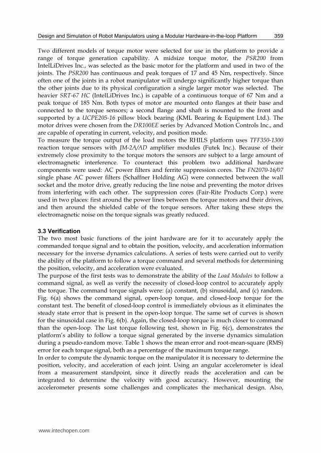
The two most basic functions of the joint hardware are for it to accurately apply the commanded torque signal and to obtain the position, velocity, and acceleration information necessary for the inverse dynamics calculations. A series of tests were carried out to verify the ability of the platform to follow a torque command and several methods for determining the position, velocity, and acceleration were evaluated. The purpose of the first tests was to demonstrate the ability of the Load Modules to follow a command signal, as well as verify the necessity of closed-loop control to accurately apply the torque. The command torque signals were: (a) constant, (b) sinusoidal, and (c) random. Fig. 6(a) shows the command signal, open-loop torque, and closed-loop torque for the constant test. The benefit of closed-loop control is immediately obvious as it eliminates the steady state error that is present in the open-loop torque. The same set of curves is shown for the sinusoidal case in Fig. 6(b). Again, the closed-loop torque is much closer to command than the open-loop. The last torque following test, shown in Fig. 6(c), demonstrates the platform’s ability to follow a torque signal generated by the inverse dynamics simulation during a pseudo-random move. Table 1 shows the mean error and root-mean-square (RMS) error for each torque signal, both as a percentage of the maximum torque range. In order to compute the dynamic torque on the manipulator it is necessary to determine the position, velocity, and acceleration of each joint. Using an angular accelerometer is ideal from a measurement standpoint, since it directly reads the acceleration and can be integrated to determine the velocity with good accuracy. However, mounting the accelerometer presents some challenges and complicates the mechanical design. Also,
www.intechopen.com
Robot Manipulators
360
purchasing accelerometers and the additional electronics for each joint would add significantly to the cost of the platform. Because of these drawbacks a differentiation technique using the position sensor was explored, although for an application in industry accelerometers may in fact be a viable option.
Command Signal Mean Error [%] RMS Error [%]
Constant (open-loop) 4.8352 4.8826
Sinusoidal (open-loop) 2.8856 3.3982
Constant 0.4769 0.5883
Sinusoidal 1.4633 1.8412
Random 1.6597 2.0128
Table 1. Torque Following Error
(a) Constant
(b) Sinusoidal
(c) Random
Figure 6. Torque Following
The issue of noise amplification during the derivative process is well known, and in order to produce a useable signal some form of filtering is required. However, the filter itself
www.intechopen.com
Design and Simulation of Robot Manipulators using a Modular Hardware-in-the-loop Platform
361
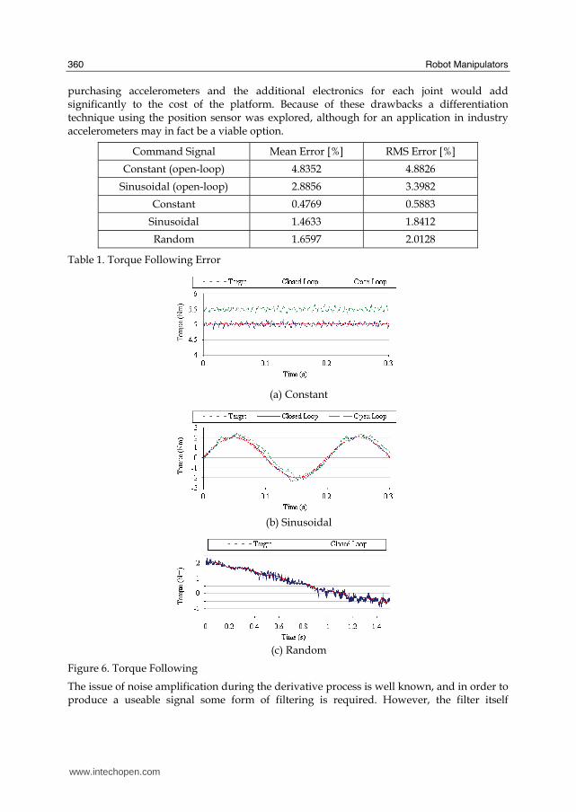
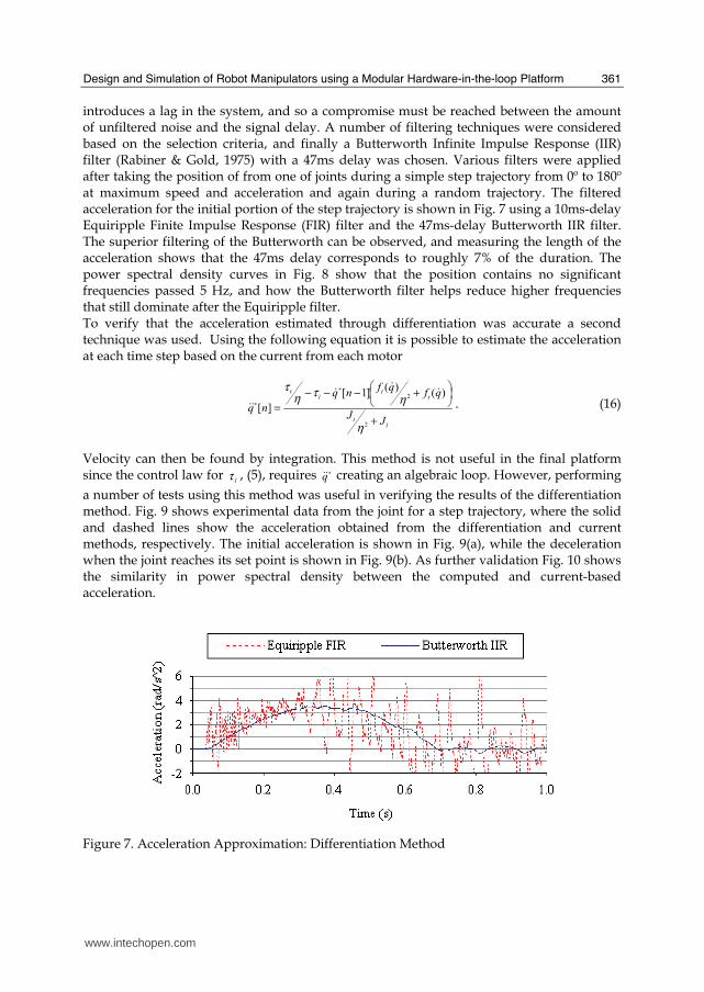
introduces a lag in the system, and so a compromise must be reached between the amount of unfiltered noise and the signal delay. A number of filtering techniques were considered based on the selection criteria, and finally a Butterworth Infinite Impulse Response (IIR) filter (Rabiner & Gold, 1975) with a 47ms delay was chosen. Various filters were applied after taking the position of from one of joints during a simple step trajectory from 0º to 180º at maximum speed and acceleration and again during a random trajectory. The filtered acceleration for the initial portion of the step trajectory is shown in Fig. 7 using a 10ms-delay Equiripple Finite Impulse Response (FIR) filter and the 47ms-delay Butterworth IIR filter. The superior filtering of the Butterworth can be observed, and measuring the length of the acceleration shows that the 47ms delay corresponds to roughly 7% of the duration. The power spectral density curves in Fig. 8 show that the position contains no significant frequencies passed 5 Hz, and how the Butterworth filter helps reduce higher frequencies that still dominate after the Equiripple filter. To verify that the acceleration estimated through differentiation was accurate a second technique was used. Using the following equation it is possible to estimate the acceleration at each time step based on the current from each motor
lt
tt
lt
JJ
qfqf
nq
nq
+
⎟⎠⎞⎜⎝
⎛+−−−
=
∗
∗
2
2 )()(
]1[
][
η
ητ
ητ $$$
$$ . (16)
Velocity can then be found by integration. This method is not useful in the final platform since the control law for
lτ , (5), requires ∗q$$ creating an algebraic loop. However, performing
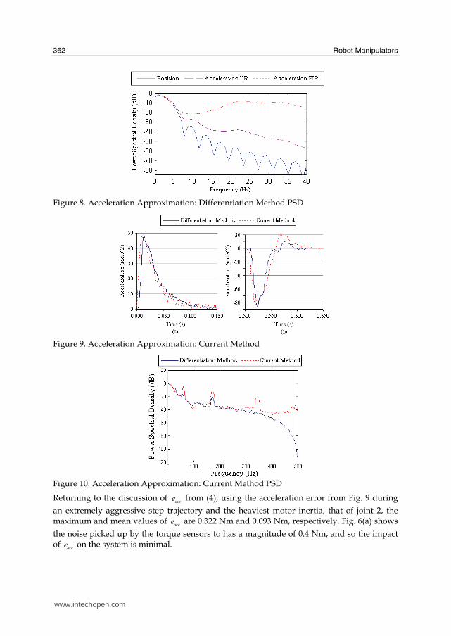
a number of tests using this method was useful in verifying the results of the differentiation method. Fig. 9 shows experimental data from the joint for a step trajectory, where the solid and dashed lines show the acceleration obtained from the differentiation and current methods, respectively. The initial acceleration is shown in Fig. 9(a), while the deceleration when the joint reaches its set point is shown in Fig. 9(b). As further validation Fig. 10 shows the similarity in power spectral density between the computed and current-based acceleration.
Figure 7. Acceleration Approximation: Differentiation Method
www.intechopen.com
Robot Manipulators
362
Figure 8. Acceleration Approximation: Differentiation Method PSD
Figure 9. Acceleration Approximation: Current Method
Figure 10. Acceleration Approximation: Current Method PSD
Returning to the discussion of acce from (4), using the acceleration error from Fig. 9 during
an extremely aggressive step trajectory and the heaviest motor inertia, that of joint 2, the maximum and mean values of
acce are 0.322 Nm and 0.093 Nm, respectively. Fig. 6(a) shows
the noise picked up by the torque sensors to has a magnitude of 0.4 Nm, and so the impact of
acce on the system is minimal.
www.intechopen.com
Design and Simulation of Robot Manipulators using a Modular Hardware-in-the-loop Platform
363
4. Case Study
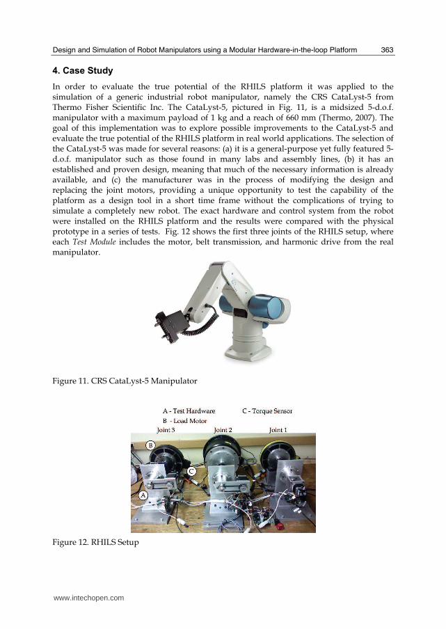
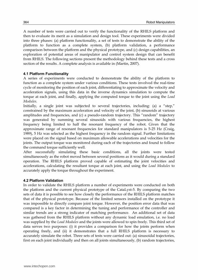
In order to evaluate the true potential of the RHILS platform it was applied to the simulation of a generic industrial robot manipulator, namely the CRS CataLyst-5 from Thermo Fisher Scientific Inc. The CataLyst-5, pictured in Fig. 11, is a midsized 5-d.o.f. manipulator with a maximum payload of 1 kg and a reach of 660 mm (Thermo, 2007). The goal of this implementation was to explore possible improvements to the CataLyst-5 and evaluate the true potential of the RHILS platform in real world applications. The selection of the CataLyst-5 was made for several reasons: (a) it is a general-purpose yet fully featured 5-d.o.f. manipulator such as those found in many labs and assembly lines, (b) it has an established and proven design, meaning that much of the necessary information is already available, and (c) the manufacturer was in the process of modifying the design and replacing the joint motors, providing a unique opportunity to test the capability of the platform as a design tool in a short time frame without the complications of trying to simulate a completely new robot. The exact hardware and control system from the robot were installed on the RHILS platform and the results were compared with the physical prototype in a series of tests. Fig. 12 shows the first three joints of the RHILS setup, where each Test Module includes the motor, belt transmission, and harmonic drive from the real manipulator.
Figure 11. CRS CataLyst-5 Manipulator
Figure 12. RHILS Setup
www.intechopen.com
Robot Manipulators
364
A number of tests were carried out to verify the functionality of the RHILS platform and then to evaluate its merit as a simulation and design tool. These experiments were divided into three phases: (a) platform functionality, a set of tests to demonstrate the ability of the platform to function as a complete system, (b) platform validation, a performance comparison between the platform and the physical prototype, and (c) design capabilities, an exploration of potential areas of manipulator and control system design that can benefit from RHILS. The following sections present the methodology behind these tests and a cross section of the results. A complete analysis is available in (Martin, 2007).
4.1 Platform Functionality
A series of experiments were conducted to demonstrate the ability of the platform to function as a complete system under various conditions. These tests involved the real-time cycle of monitoring the position of each joint, differentiating to approximate the velocity and acceleration signals, using this data in the inverse dynamics simulation to compute the torque at each joint, and finally, applying the computed torque to the joint using the Load Modules. Initially, a single joint was subjected to several trajectories, including: (a) a “step,” constrained by the maximum acceleration and velocity of the joint, (b) sinusoids at various amplitudes and frequencies, and (c) a pseudo-random trajectory. This “random” trajectory was generated by summing several sinusoids with various frequencies, the highest frequency being limited to half the resonant frequency of the robot. Given that the approximate range of resonant frequencies for standard manipulators is 5-25 Hz (Craig, 1989), 5 Hz was selected as the highest frequency in the random signal. Further limitations were placed on the signal based on maximum allowable accelerations and velocities for the joints. The output torque was monitored during each of the trajectories and found to follow the command torque sufficiently well. After successfully simulating these basic conditions, all the joints were tested simultaneously as the robot moved between several positions as it would during a standard operation. The RHILS platform proved capable of estimating the joint velocities and accelerations, calculating the resultant torque at each joint, and using the Load Modules to accurately apply the torque throughout the experiment.
4.2 Platform Validation
In order to validate the RHILS platform a number of experiments were conducted on both the platform and the current physical prototype of the CataLyst-5. By comparing the two sets of data it is possible to see how closely the performance of the RHILS platform matches that of the physical prototype. Because of the limited sensors installed on the prototype it was impossible to directly compare joint torque. However, the position error data that was compared is a key factor in determining the tuning and performance of the controller and similar trends are a strong indicator of matching performance. An additional set of data was gathered from the RHILS platform without any dynamic load emulation, i.e. no load was supplied by the Load Modules and the joints were allowed to spin freely. This third set of data serves two purposes: (i) it provides a comparison for how the joints perform when operating freely, and (ii) it demonstrates that a full RHILS platform is necessary to accurately simulate the robot. Three sets of tests were carried out: (a) sinusoidal trajectories, first on each joint individually and then on all joints simultaneously, (b) random trajectories,
www.intechopen.com
Design and Simulation of Robot Manipulators using a Modular Hardware-in-the-loop Platform
365
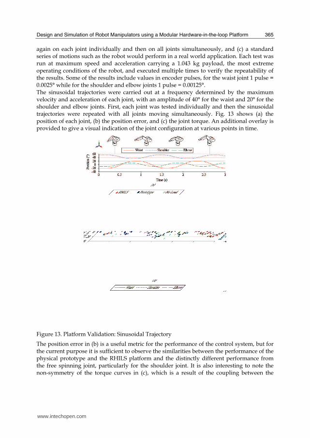
again on each joint individually and then on all joints simultaneously, and (c) a standard series of motions such as the robot would perform in a real world application. Each test was run at maximum speed and acceleration carrying a 1.043 kg payload, the most extreme operating conditions of the robot, and executed multiple times to verify the repeatability of the results. Some of the results include values in encoder pulses, for the waist joint 1 pulse = 0.0025° while for the shoulder and elbow joints 1 pulse = 0.00125°. The sinusoidal trajectories were carried out at a frequency determined by the maximum velocity and acceleration of each joint, with an amplitude of 40° for the waist and 20° for the shoulder and elbow joints. First, each joint was tested individually and then the sinusoidal trajectories were repeated with all joints moving simultaneously. Fig. 13 shows (a) the position of each joint, (b) the position error, and (c) the joint torque. An additional overlay is provided to give a visual indication of the joint configuration at various points in time.
Figure 13. Platform Validation: Sinusoidal Trajectory
The position error in (b) is a useful metric for the performance of the control system, but for the current purpose it is sufficient to observe the similarities between the performance of the physical prototype and the RHILS platform and the distinctly different performance from the free spinning joint, particularly for the shoulder joint. It is also interesting to note the non-symmetry of the torque curves in (c), which is a result of the coupling between the
www.intechopen.com
Robot Manipulators
366
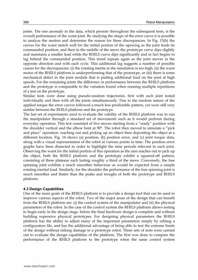
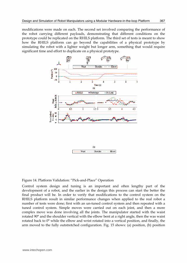
joints. The one anomaly in the data, which persists throughout the subsequent tests, is the overall performance of the waist joint. By studying the shape of the error curve it is possible to analyze the motion and determine the reason for these discrepancies. In Fig. 13(b) the curves for the waist match well for the initial portion of the upswing as the joint leads its commanded position, and then in the middle of the move the prototype curve dips slightly and maintains a smaller lead while the RHILS curve dips significantly and in fact begins to lag behind the commanded position. This trend repeats again as the joint moves in the opposite direction and with each cycle. This additional lag suggests a number of possible causes for the discrepancies: (i) the rotating inertia in the simulation is too high, (ii) the waist motor of the RHILS platform is underperforming that of the prototype, or (iii) there is some mechanical defect in the joint module that is putting additional load on the joint at high speeds. For the remaining joints the difference in performance between the RHILS platform and the prototype is comparable to the variation found when running multiple repetitions of a test on the prototype. Similar tests were done using pseudo-random trajectories, first with each joint tested individually and then with all the joints simultaneously. Due to the random nature of the applied torque the error curves followed a much less predictable pattern, yet were still very similar between the RHILS platform and the prototype. The last set of experiments used to evaluate the validity of the RHILS platform was to run the manipulator through a standard set of movements such as it would perform during everyday operation. This test consisted of five moves starting from a “ready” position with the shoulder vertical and the elbow bent at 90°. The robot then moved to simulate a “pick and place” operation: reaching out and picking up an object then depositing the object at a different location. Fig. 14 shows (a) position, (b) position error, and (c) joint torque data, along with a visual representation of the robot at various points in time. The position error graphs have been dissected in order to highlight the time periods relevant to each joint. Observing the waist for the initial portion of this operation as the arm reaches out to pick up the object, both the RHILS platform and the prototype exhibit a squared-off pattern, consisting of three plateaus each lasting roughly a third of the move. Conversely, the free spinning joint exhibits a much smoother behaviour as would be expected from a simple rotating inertial load. Similarly, for the shoulder the performance of the free spinning joint is much smoother and flatter than the peaks and troughs of both the prototype and RHILS platform.
4.3 Design Capabilities
One of the main goals of the RHILS platform is to provide a design tool that can be used to improve various aspects of the robot. Two of the major areas of the design that can benefit from the RHILS platform are: (i) the control system of the manipulator and (ii) the physical parameters of the robot. In the case of the control system the RHILS platform allows testing to begin early in the design stage, before the final hardware design is complete and without building expensive physical prototypes. For designing physical parameters the RHILS platform has the ability to adjust many of the important parameters simply by editing a configuration file, and has the additional advantage of being able to test the extreme limits of the design without risking damage to a prototype robot. Three sets of tests were carried out to evaluate the design capabilities of the platform. The first was done to compare the performance of the RHILS platform to the prototype when the same control system
www.intechopen.com
Design and Simulation of Robot Manipulators using a Modular Hardware-in-the-loop Platform
367
modifications were made on each. The second set involved comparing the performance of the robot carrying different payloads, demonstrating that different conditions on the prototype could be replicated on the RHILS platform. The third set of tests is meant to show how the RHILS platform can go beyond the capabilities of a physical prototype by simulating the robot with a lighter weight but longer arm, something that would require significant time and effort to duplicate on a physical prototype.
Figure 14. Platform Validation: “Pick-and-Place” Operation
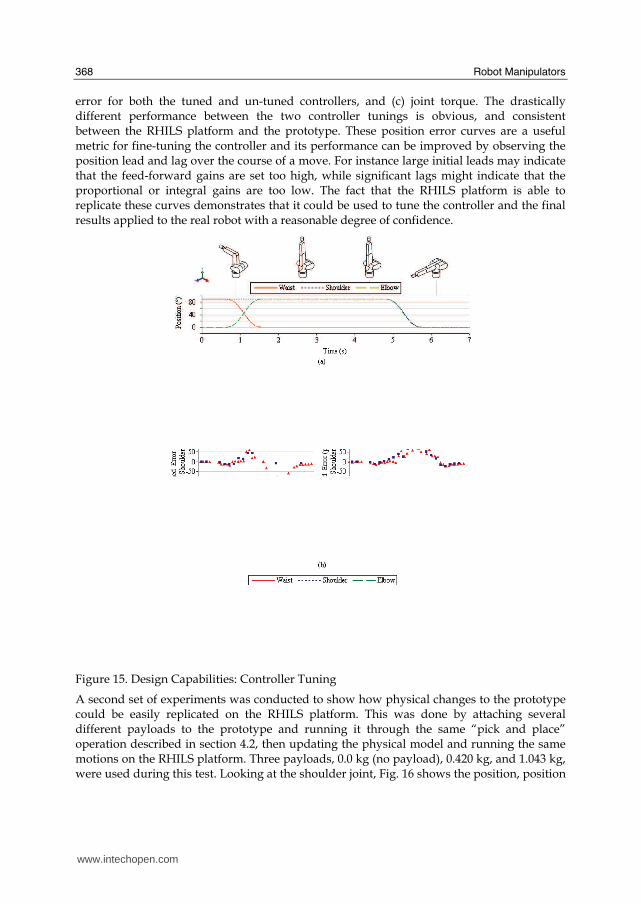
Control system design and tuning is an important and often lengthy part of the development of a robot, and the earlier in the design this process can start the better the final product will be. In order to verify that modifications to the control system on the RHILS platform result in similar performance changes when applied to the real robot a number of tests were done; first with an un-tuned control system and then repeated with a tuned control system. Simple moves were carried out on each joint, and then a more complex move was done involving all the joints. The manipulator started with the waist rotated 90° and the shoulder vertical with the elbow bent at a right angle, then the was waist rotated back to 0° while the elbow and wrist rotated into a vertical position, and finally, the arm moved to the fully outstretched configuration. Fig. 15 shows: (a) position, (b) position
www.intechopen.com
Robot Manipulators
368
error for both the tuned and un-tuned controllers, and (c) joint torque. The drastically different performance between the two controller tunings is obvious, and consistent between the RHILS platform and the prototype. These position error curves are a useful metric for fine-tuning the controller and its performance can be improved by observing the position lead and lag over the course of a move. For instance large initial leads may indicate that the feed-forward gains are set too high, while significant lags might indicate that the proportional or integral gains are too low. The fact that the RHILS platform is able to replicate these curves demonstrates that it could be used to tune the controller and the final results applied to the real robot with a reasonable degree of confidence.
Figure 15. Design Capabilities: Controller Tuning
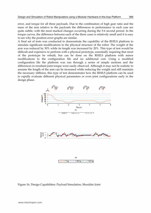
A second set of experiments was conducted to show how physical changes to the prototype could be easily replicated on the RHILS platform. This was done by attaching several different payloads to the prototype and running it through the same “pick and place” operation described in section 4.2, then updating the physical model and running the same motions on the RHILS platform. Three payloads, 0.0 kg (no payload), 0.420 kg, and 1.043 kg, were used during this test. Looking at the shoulder joint, Fig. 16 shows the position, position
www.intechopen.com
Design and Simulation of Robot Manipulators using a Modular Hardware-in-the-loop Platform
369
error, and torque for all three payloads. Due to the combination of high gear ratio and the mass of the arm relative to the payloads the differences in performance in each case are quite subtle, with the most marked changes occurring during the 5-6 second period. In the torque curves, the difference between each of the three cases is relatively small and it is easy to see why the position error graphs are similar. A final set of tests was conducted to demonstrate the capability of the RHILS platform to simulate significant modifications to the physical structure of the robot. The weight of the arm was reduced by 30% while its length was increased by 20%. This type of test would be difficult and expensive to perform with a physical prototype, essentially requiring that most of the prototype be rebuilt, but can be done on the RHILS platform with minor modifications to the configuration file and no additional cost. Using a modified configuration file the platform was run through a series of simple motions and the differences in resultant joint torque were easily observed. Although it may not be realistic to assume the length of the arm can be increased while reducing the weight and still maintain the necessary stiffness, this type of test demonstrates how the RHILS platform can be used to rapidly evaluate different physical parameters or even joint configurations early in the design phase.
Figure 16. Design Capabilities: Payload Simulation, Shoulder Joint
www.intechopen.com
Robot Manipulators
370
5. Conclusion
The RHILS architecture and suitable hardware implementation were proposed as a coherent strategy for applying HILS techniques to the simulation and design of robot manipulators. First, it was shown that the architecture was able to run on a standard computer with modest processing power, and that the hardware joint modules were able to accurately apply torque commands of various types and approximate the joint acceleration using a differentiation and filtering technique. The architecture was then applied to the simulation of a standard industrial manipulator. A series of tests were carried out to evaluate: (i) the basic functionality of the platform – its ability to simulate a 5-d.o.f. manipulator in real-time, (ii) the accuracy of the simulation – the performance of the RHILS platform relative to a physical prototype of the robot, and (iii) the design capabilities of the platform – its potential when applied to the design of both the controller and the physical structure of the manipulator. The validation of the RHILS platform was successful, and the platform exhibited similar performance characteristics to the prototype under both normal and aggressive operating conditions. The RHILS platform also demonstrated significant promise as a control system design and tuning tool. Further, it was shown that modifications to the physical design can be rapidly evaluated on the RHILS platform without the need for expensive modifications to a physical prototype. Future development of the RHILS architecture will take several directions. Improvements are being made to the current hardware in order to facilitate rapid switching of test modules in keeping with the ideal of modularity. The platform is also being used as a testbed for concurrent design strategies for reconfigurable robots using automated optimization techniques (Chhabra & Emami, 2008).
6. References
Aghili, F. & Piedboeuf, J.-C. (2002). Contact dynamics emulation for hardware-in-loop simulation of robots interacting with environment, Proceedings. ICRA '02. IEEE International Conference on Robotics and Automation, Vol. 1, pp. 523-529, 2002
Aghili, F. (2006). A Mechatronic Testbed for Revolute-Joint Prototypes of a Manipulator. IEEE Transactions on Robotics, Vol. 22, No. 6, pp. 1265-1273
Akpolat, Z. H.; Asher, G. M. & Clare, J. C. (1999). Dynamic Emulation of Mechanical Loads Using a Vector-Controlled Induction Motor-Generator Set. IEEE Transactions on Industrial Electronics, Vol. 46, No. 2, pp. 370-379
Aronsson, P. & Fritzson, P. (2001). Parallel Code Generation in MathModelica / An Object Oriented Component Based Simulation Environment, Proceedings, Parallel / High Performance Object-Oriented Scientific Computing, Workshop, POOSC01 at OOPSLA01, 2001
Ballard, B. L.; Elwell Jr., R. E.; Gettier, R. C.; Horan, F. P.; Krummenoehl, A. F. & Schepleng, D. B. (2002). Simulation Approaches for Supporting Tactical System Development. John Hopkins APL Technical Digest (Applied Physics Laboratory), Vol. 23, No. 2-3, pp. 311-324
Chhabra, R. & Emami, M. R. (2008). Concurrent Design of Robot Manipulators Using Hardware-in-the-loop Simulation, 2008 IEEE International Conference on Technologies for Practical Robot Applications (TePRA), Massachusetts, USA, November 2008
www.intechopen.com
Design and Simulation of Robot Manipulators using a Modular Hardware-in-the-loop Platform
371
Craig, J. (1989). Introduction to Robotics Mechanics and Control, 2nd Ed., Addison-Wesley Publishing Company Inc., USA, p. 323
Cyril, X.; Jaar, G. & St-Pierre, J. (2000). Advanced Space Robotics Simulation for Training and Operations, AIAA Modeling and Simulation Technologies Conference, pp. 1-6, Denver, USA, August 2000
Faithfull, P. T.; Ball, R. J. & Jones, R. P. (2001). An Investigation into the Use of Hardware-in-the-loop Simulation with a Scaled Physical Prototype as An Aid to Design. Journal of Engineering Design, Vol. 12, No. 3, pp. 231-243
Hanselman, H. (1996). Hardware-in-the-loop Simulation Testing and its Integration into a CACSD Toolset, IEEE International Symposium on Computer-Aided Control System Design, pp. 15-18, September 1996
Hu, X. (2005). Applying Robot-in-the-loop Simulation to Mobile Robot Systems, 12th International Conference on Advanced Robotics (ICAR 2005)
Kasper, R.; Koch, W. & Sczyrba, C. (1997). Object-Oriented Software Techniques in Simulation of Mechatronic Systems: Towards Distributed Hardware-in-the-Loop-Simulation using Standard Hard- and Software, Proceedings of the 15th IMACS World Congress on Scientific Computation, Modelling and Applied Mathematics, Berlin, 1997
Lane, D.; Falconer, G. J. & Randall, G. (2001). Interoperablitiy and Synchronisation of Distributed Hardware-in-the-Loop Simulation for Underwater Robot Development, Proceedings of the 2001 IEEE International Conference on Robotics & Automation, 2001
Ledin, J. (1999). Hardware-in-the-loop simulation. Embedded Systems Programming, Vol. 12, No. 2, pp. 42-53
Leitner, J. (1996). Space Technology Transition Using Hardware in the Loop Simulation, Proceedings of the 1996 Aerospace Applications Conference, Vol. 2, pp. 303-311, February 1996
Li, C.-J. & Sankar, T. S. (1992). Fast inverse dynamics computation in real-time robot control. Mechanism & Machine Theory, Vol. 27, No. 6, pp. 741-750
Linjama, M.; Virvalo, T.; Gustafsson, J., Lintula, J.; Aaltonen, V. & Kivikoski, M. (2000). Hardware-in-the-loop Environment for Servo System Controller Design, Tuning, and Testing. Microprocessors and Microsystems, Vol. 24, No. 1, pp. 13-21
Ma, O.; Wang, J.; Misra, S. & Liu, M. (2004). On the validation of SPDM task verification facility. Journal of Robotic Systems, Vol. 21, No. 5, pp. 219-235
Maclay, D. (1997). Simulation gets into the loop. IEE Review, Vol. 43, No. 3, pp. 109-112 Martin, A. (2007). Development of a Modular Hardware-in-the-Loop Simulation Platform for
Synthesis and Analysis of Robot Manipulators, M.A.Sc. Thesis Report, University of Toronto, April 2007
Piedboeuf, J.-C.; Carufel, J. de; Aghili, F. & Dupuis, E. (1999). Task Verification Facility for the Canadian Special Purpose Dexterous Manipulator, Proceedings of the 1999 IEEE International Conference on Robotics and Automation, pp. 1077–1083, USA, 1999
Rabiner, L.R. & Gold, B. (1975). Theory and Application of Digital Signal Processing, Prentice-Hall , Englewood Cliffs, NJ, p. 227
Sandholdt, P.; Ritchie, E. & Pedersen, J. K. (1996). A Dynamometer Performing Dynamical Emulation of Loads with Non-Linear Friction, IEEE International Symposium on Industrial Electronics, Vol. 2, pp. 873-878, 1996
www.intechopen.com
Robot Manipulators
372
Solak, E.; Murray-Smith, R.; Leithead, W. E.; Leith, D. J. & Rasmussen, C. E. (2003). Derivative observations in Gaussian Process Models of Dynamic Systems. Advances in Neural Information Processing Systems 15, Eds. Becker, S.; Thrun, S. & Obermayer, K., MIT Press
Stoeppler, G.; Menzel, T. & Douglas, S. (2005). Hardware-in-the-loop simulation of machine tools and manufacturing systems. Computing & Control Engineering Journal, Vol. 16, No. 1, pp. 10-15
Temeltas, H.; Gokasan, M.; Bogosyan, S. & Kilic, A. (2002). Hardware in the Loop Simulation of Robot Manipulators through Internet in Mechatronics Education, The 28th Annual Conference of the IEEE Industrial Electronics Society, Vol. 4, pp. 2617-2622, Sevilla, Spain, November 2002
Thermo Fisher Scientific Inc. (2007). CRS CataLyst-5 Robot System, Website: http://www.thermo.com/com/cda/product/detail/0,1055,21388,00.html,
February 2007 Ulrich, K. & Eppinger, S. (2000). Design and Development, 2nd Edition, McGraw-Hill Wheelright, S. & Clark, K. (1992). Revolutionizing Product Development- Quantum Leaps in
Speed, Efficiency and Quality, The Free Press, New York
www.intechopen.com
Robot ManipulatorsEdited by Marco Ceccarelli
ISBN 978-953-7619-06-0Hard cover, 546 pagesPublisher InTechPublished online 01, September, 2008Published in print edition September, 2008
InTech EuropeUniversity Campus STeP Ri Slavka Krautzeka 83/A 51000 Rijeka, Croatia Phone: +385 (51) 770 447 Fax: +385 (51) 686 166www.intechopen.com
InTech ChinaUnit 405, Office Block, Hotel Equatorial Shanghai No.65, Yan An Road (West), Shanghai, 200040, China
Phone: +86-21-62489820 Fax: +86-21-62489821
In this book we have grouped contributions in 28 chapters from several authors all around the world on theseveral aspects and challenges of research and applications of robots with the aim to show the recentadvances and problems that still need to be considered for future improvements of robot success in worldwideframes. Each chapter addresses a specific area of modeling, design, and application of robots but with an eyeto give an integrated view of what make a robot a unique modern system for many different uses and futurepotential applications. Main attention has been focused on design issues as thought challenging for improvingcapabilities and further possibilities of robots for new and old applications, as seen from today technologiesand research programs. Thus, great attention has been addressed to control aspects that are stronglyevolving also as function of the improvements in robot modeling, sensors, servo-power systems, andinformatics. But even other aspects are considered as of fundamental challenge both in design and use ofrobots with improved performance and capabilities, like for example kinematic design, dynamics, visionintegration.
How to referenceIn order to correctly reference this scholarly work, feel free to copy and paste the following:
Adrian Martin and M. Reza Emami (2008). Design and Simulation of Robot Manipulators Using a ModularHardware-in-the-loop Platform, Robot Manipulators, Marco Ceccarelli (Ed.), ISBN: 978-953-7619-06-0,InTech, Available from:http://www.intechopen.com/books/robot_manipulators/design_and_simulation_of_robot_manipulators_using_a_modular_hardware-in-the-loop_platform

© 2008 The Author(s). Licensee IntechOpen. This chapter is distributedunder the terms of the Creative Commons Attribution-NonCommercial-ShareAlike-3.0 License, which permits use, distribution and reproduction fornon-commercial purposes, provided the original is properly cited andderivative works building on this content are distributed under the samelicense.