design and control of vast dof wet sma array actuatorssmascaro/pdf/mascaro-2003-iros-wetsma.pdf ·...
TRANSCRIPT

Design and Control of Vast DOF Wet SMA Array Actuators
Stephen Mascaro, Kyu-Jin Cho, and Harry Asada d’Arbeloff Laboratory for Information Systems and Technology
Department of Mechanical Engineering Massachusetts Institute of Technology Cambridge, Massachusetts 02139 USA
e-mail: [email protected], [email protected], [email protected]
Abstract − A new concept for an actuator array is presented where a vast number of actuators are contained within a small volume and are controlled in a scalable sense. This vast degree-of-freedom system utilizes an array of Shape Memory Alloy wires embedded within a network of fluidic vessels. A Matrix Manifold and Valve (MMV) system routes fluid from hot and cold reservoirs in order to control an array of N2 SMA actuators using only 2N valves. A prototype MMV system containing a 4 by 4 array of wet SMA actuators is designed and implemented. Control strategies suitable for controlling MMV system that uses 2N valves to control N2 actuators are presented. Two different protocols are presented and evaluated. The system error increases without bound under certain input conditions, since all the actuators cannot be activated at the same time. Simulations show that system error starts to go out of bound when the individual actuator is activated 25% of the time for the 4 by 4 arrays of the actuators.
I. INTRODUCTION
A. Vast DOF Actuation using Biological Inspiration
In the human body, a vast number of actuators are distributed throughout the body. Even a tiny blood vessel, i.e. arteriole, has a built-in actuator, i.e. smooth muscle, to regulate blood flow. There are numerous local control loops, or autonomy, around the distributed actuators in the body. The number of skeletal muscles is also huge, creating a great degree of flexibility and dexterity in its bodily motion. This allows humans and other biological creatures to develop multifunctional behaviors and perform a rich variety of dexterous tasks.
The objective of this paper is to develop key enabling technologies to make a vast array of muscle actuators packed in a compact body. Specifically, we develop a scalable architecture for driving a vast array of Shape Memory Alloy (SMA) filaments. Using SMA, whose stress is a thousand times larger than a human muscle, we can build highly efficient, compact, robotic “flesh” to drive hundreds and thousands of axes of loads in addition to generating large axial torque and electricity.
B. Wet Shape Memory Alloy Actuators
NiTi SMA wires have extremely high actuation strengths of 200 MPa, which is more than 800 times higher than human muscles [1]. Their power-to-mass ratio is over 1 kW/kg, which is 100 times higher than DC motors and is comparable to conducting polymer actuators [2]. Two major drawbacks of SMA actuators are slow response and low efficiency.
The speed of response is determined mostly by the time constant associated with the cooling process. Forced air cooling using room-temperature air yields approximately 0.8~3 seconds of time constant for a SMA wire of 0.35 mm in diameter [3], while unforced air cooling provides a very slow time constant of 2~10 seconds [4]. If water is used for cooling, on the other hand, the cooling time constant is significantly reduced. Placing SMA wires in cold liquid baths has been effectively used to increase bandwidth, but significantly adds to the overall weight of the actuator [5][6]. In previous work, we developed a novel wet SMA actuator where an SMA wire was embedded within a thin compliant vessel of flowing fluid, which allows the wire to be rapidly cooled, while still maintaining a power to weight ratio of 1kW/kg [7]. In our preliminary experiments, the time constant for cooling was reduced to 0.15 sec.
The power efficiency of a standard SMA actuator is determined by the output mechanical power to the input electric power needed for phase transition. This electric activation method yields an extremely low efficiency on the order of 0.1 %. On the other hand, the efficiency is much higher when the SMA is activated directly with a high temperature fluid. Without converting electric energy to heat, which is a low efficiency process, an SMA actuator can be activated with a hot fluid. If the hot fluid pipeline and the valves are properly insulated, and the hot fluid is circulated and reserved, the resultant power efficiency may be much higher. Some researchers have already begun to explore this potential by creating fuel-powered SMA actuators, where a variety of power sources can be used to create hot water for activating
SMA strips, with theoretical efficiencies reaching 3% [8]. Hot water activation is not as fast as electric heating, but bandwidths of 0.5 Hz have been achieved [8].
In the past, arrays of SMA wires were controlled using electric current in a switch matrix arrangement [9]. However, fluidic activation of SMA actuators has only been performed on an individual basis. This paper will begin by presenting a scalable architecture for a vast DOF actuator system that utilizes networks of wet shape memory alloy actuators. This Matrix Manifold and Valve (MMV) System will route fluid from hot and cold reservoirs in order to control an array of N2 actuators using only 2N valves. A prototype system based on these principles is then designed and implemented. Control strategies suitable for controlling MMV system that uses 2N valves to control N2 actuators are presented. Two different protocols are evaluated and their performances are compared in terms of what percentage of the time each individual actuator can be commanded to move while keeping a bound on the system error.
II. DESIGN CONCEPT
A. Wet SMA Network Actuators
Fluidic heating and cooling require additional equipment for delivery and circulation of fluids. To deliver fluids to individual SMA actuators, pipes and ducts are needed with proper thermal insulation and diameter to prevent temperature drop and pressure drop. Valves are also needed to control the flow. Speed of response and other control performance are highly dependent on the dynamics of the fluid flow control system. Furthermore, we would like to use a number of actuators for this application. The fluid delivery system will be impractically complicated, heavy, and bulky, if numerous valves and pipes are needed as the number of degrees of freedom increases. The standard one-on-one architecture, in which a set of valves and pipes deliver fluids to one actuator, does not work for the large-scale systems that we are proposing.
B. Matrix Manifold and Valve (MMV) System
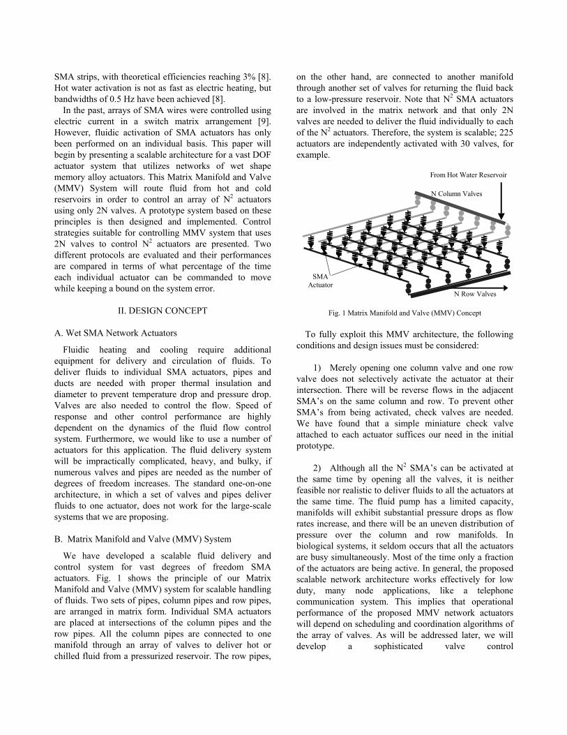
We have developed a scalable fluid delivery and control system for vast degrees of freedom SMA actuators. Fig. 1 shows the principle of our Matrix Manifold and Valve (MMV) system for scalable handling of fluids. Two sets of pipes, column pipes and row pipes, are arranged in matrix form. Individual SMA actuators are placed at intersections of the column pipes and the row pipes. All the column pipes are connected to one manifold through an array of valves to deliver hot or chilled fluid from a pressurized reservoir. The row pipes,
on the other hand, are connected to another manifold through another set of valves for returning the fluid back to a low-pressure reservoir. Note that N2 SMA actuators are involved in the matrix network and that only 2N valves are needed to deliver the fluid individually to each of the N2 actuators. Therefore, the system is scalable; 225 actuators are independently activated with 30 valves, for example.
From Hot Water Reservoir
SMA Actuator
N Column Valves
N Row Valves
Fig. 1 Matrix Manifold and Valve (MMV) Concept To fully exploit this MMV architecture, the following
conditions and design issues must be considered:
1) Merely opening one column valve and one row valve does not selectively activate the actuator at their intersection. There will be reverse flows in the adjacent SMA’s on the same column and row. To prevent other SMA’s from being activated, check valves are needed. We have found that a simple miniature check valve attached to each actuator suffices our need in the initial prototype.
2) Although all the N2 SMA’s can be activated at the same time by opening all the valves, it is neither feasible nor realistic to deliver fluids to all the actuators at the same time. The fluid pump has a limited capacity, manifolds will exhibit substantial pressure drops as flow rates increase, and there will be an uneven distribution of pressure over the column and row manifolds. In biological systems, it seldom occurs that all the actuators are busy simultaneously. Most of the time only a fraction of the actuators are being active. In general, the proposed scalable network architecture works effectively for low duty, many node applications, like a telephone communication system. This implies that operational performance of the proposed MMV network actuators will depend on scheduling and coordination algorithms of the array of valves. As will be addressed later, we will develop a sophisticated valve control

scheduler/coordinator to maximize its “channel capacity” despite the limited resources.
3) To expedite both heating and cooling operations, two fluids, hot and chilled, must be delivered to the actuator network. Switching between the two fluids requires three-way valves, with inputs from both a hot reservoir and a cold reservoir.
C. Initial Design
In the initial design, 16 SMA actuators are consolidated into a single box. Fig. 2 shows the schematic of the SMA-MMV actuator system, the “flesh” box. Totally N2 = 16 filaments of independent SMA run through 16 long vessels, called “capillaries”, which are heated up or cooled down with hot and cold fluids switched by valve actions. To drive these axes independently, two sets of N = 4 three-way valves are arranged in matrix form. The column array of three-way valves is connected to two manifolds; one is from a hot water reservoir and the other from a cold reservoir. Each three-way valve connects the set of capillaries on one row to the hot reservoir, the cold reservoir, or a dead end. Similarly the row array of three-way valves connects each set of capillaries on one column to a hot fluid accumulator, a cold fluid accumulator, or a dead end.
At one end of the flesh box each SMA filament is connected to a tendon encapsulated in a tube, which goes to an individual load. These tendons are bundled, branch out to several groups, and reach individual parts of the robotic system. Some may be used for gearshift, clutch operation, and linkage reconfiguration.
Cold Reservoir
Hot Reservoir
A
B
C
D
Pump
Pump
Col
d In
let M
anifo
ld
Cold O
utlet
Manifo
ld
Hot Outl
et Man
ifold
N three-wayinlet valves
N three-way outlet valves
1
2
3
4
Actuator A2
Actuator A3
Actuator A4
Actuator B1
Actuator C1
Actuator D1
Actuator B2
Actuator C2
Actuator D2
N2 actuatortendons
Hot
Inle
t Man
ifold
Vast Actuator Array(N2 actuators)
Wet SMA wireCapillary
Fig. 2 Flesh box: a consolidated vast wet SMA array with Matrix
Manifold and Valve control system Fig. 3 shows a picture of the initial implementation for
the vast array of wet SMA actuators using the MMV
system. In this initial implementation, the inner diameter of the capillaries is 1.6 mm, while the diameter of SMA wires ranges from 0.25 mm, producing forces up to 10 N. The stroke of each SMA wire is determined by the length of the capillary as well as by the maximum strain. For safety the strain will be limited to 4%. The capillary length of 200 mm yields 8 mm of stroke. If a greater actuation stroke is required, an entire column of SMA wires can be connected in series within the flesh box using various pulley architectures, resulting in net strokes of up to 32 mm without decreasing the force, or up to 64 mm with half the force. If larger actuation force is required, the diameter of the SMA wires can be increased to 1mm, producing actuation forces up to 150 N.
16 tendon sheaths
4 inlet valves 4 outlet
valves
16 capillaries
16 tendons
16 fluidic ports w/check valves
Fig. 3 Initial implementation of vast SMA array with MMV system
III. CONTROL
The MMV system is designed to be scalable, and share the resources. Particularly, the system has less number of valves that control the flow of hot or cold water into the pipes. This design is based on the assumption that most of the time, only a fraction of the actuators are active. In order to control this system, a scheduler that controls the switching of the valves is needed. The scheduler is designed with an objective of increasing the performance of the MMV system by allocating the resources in an intelligent method. In other words, the scheduler is to be designed such that the MMV system operates without much degradation from the system that has equal number of valves and actuators.
In this section, we present two protocols, m-Max Error Protocol (MMEP) and m-Max Delay Protocol (MMDP). Each protocol uses a measure of error or delay in order to decide the sequence that actuators are to be turned on.

A. m-Max Error Protocol(MMEP)
This protocol uses a measure of the errors of each actuator. Fig. 4 shows the block diagram of the protocol. Based on the errors of each actuator, the scheduler searches for the m actuators with the most error, and gives the control to those actuators. By turning on a valve for the ith row and a valve for the jth column, an actuator in the ith row and the jth column will be turned on.
Control 2
Control N2
Control i
Control 4
Control 3
Control 1
Select m feedback loops having largest errors
Switching Scheduler
N2 MatrixActuators
e1
e2
ei
eN2
N2 Loops m Loops Fig. 4 Block diagram of m-Max Error Protocol
Axis 1
Axis 2
Axis 3
Axis 4
Axis 5
Axis 6
Axis N2
Ignored for a long time
Fig. 5 Conceptual activation sequence for m-Max error protocol
Fig. 5 shows the sequence of activation for the MMEP.
The waveforms with dotted lines represent the desired output and the waveforms with thick solid lines represent the actual output driven by the matrix-structured valves. The actuator that requires large output accumulates error quickly, whereas actuator that requires small amount doesn’t accumulate the error, so it might be ignored for a long time. This approach is better than activating the actuators in a sequential manner, since it will treat the
important actuators first while the unimportant ones will be dealt later.
B. m-Max Delay Protocol
Time delay of the inputs can be used as a measurement for scheduling, instead of using errors. The time delay is measured by the amount of time that the input is delayed before the scheduler allocates the actuator with resources needed for an actual output. As shown in Fig. 6, time stamp is given to each input command to the actuators. Delay penalty of each actuator is evaluated. The delay penalties of the actuators that are on the same row are added up and compared to find the row that has the maximum penalty. Than the valve of the row with the maximum delay penalty is activated. The actuators at the selected row can be turned on by opening their column valves.
Time Stamp
Select m axes
having largest service delay
N2 MatrixActuators
L Axes m Axes
Switching Schedule
r1 Delay Penalty
Time Stamp
r2 Delay Penalty
Time Stamp
r3 Delay Penalty
Time Stamp
r4 Delay Penalty
Time Stamp
ri Delay Penalty
Time Stamp
rL Delay Penalty
Fig. 6 Block diagram of m-Max Delay Protocol
tHij t
Fig. 7 Evaluating Time Delay penalty
As shown in Fig. 7, the time delay is the amount of
time since the input command has been given until the time the penalty is being evaluated. Once the scheduler gives an command that allocates resource for the input, the penalty becomes zero. Delay penalty of an actuator at ith row and jth column, eij, to each input that has not yet been serviced by the scheduler is,
eHij = aHij(t-tHij)2
eLij = aLij(t-tLij)2 (1)
The command to turn on an actuator and turn off an actuator is not just a toggle, but it requires a different command. That is why penalties for high command, a command to flow hot water, and low command, a command to flow cold water, are separately evaluated. aij represents a weighting factor that is given to the penalty. Higher weighting factor can be given to the more important actuators. Total penalty of the ith row, ERi, is the sum of the penalties of the actuators at the same row as given in the following equation.
∑=
=N
j
Lij
LRi eE
1 ∑
==
N
j
Hij
HRi eE
1
From the evaluated penalties, row with the maximum penalty, K, is chosen, along with its state, high or low.
],[arg]/,[1/,
LRi
HRiNiLHi
EEMaxLHK≤≤
= (3)
The actuators on the chosen row will be turned on, by flowing hot or cold water, based on their state.
The total error, Etotal, is calculated for performance evaluation by adding up all the penalties of actuators.
∑∑==
+=N
j
Lij
Hij
N
itotal eeE
11)( (4)
N2 X Average Delay
Time
Total Delay
Time of all N2 axes
As incoming demands increase, the total delay time accumulates and
may diverge.
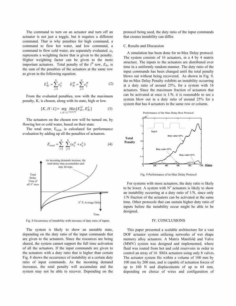
Fig. 8 Occurrence of instability with increase of duty ratio of inputs The system is likely to show an unstable state,
depending on the duty ratio of the input commands that are given to the actuators. Since the resources are being shared, the system cannot support the full time activation of all the actuators. If the input commands are given to the actuators with a duty ratio that is higher than certain Fig. 8 shows the occurrence of instability at a certain duty ratio of input commands. As the incoming demand increases, the total penalty will accumulate and the system may not be able to recover. Depending on the
protocol being used, the duty ratio of the input commands that creates instability can differ.
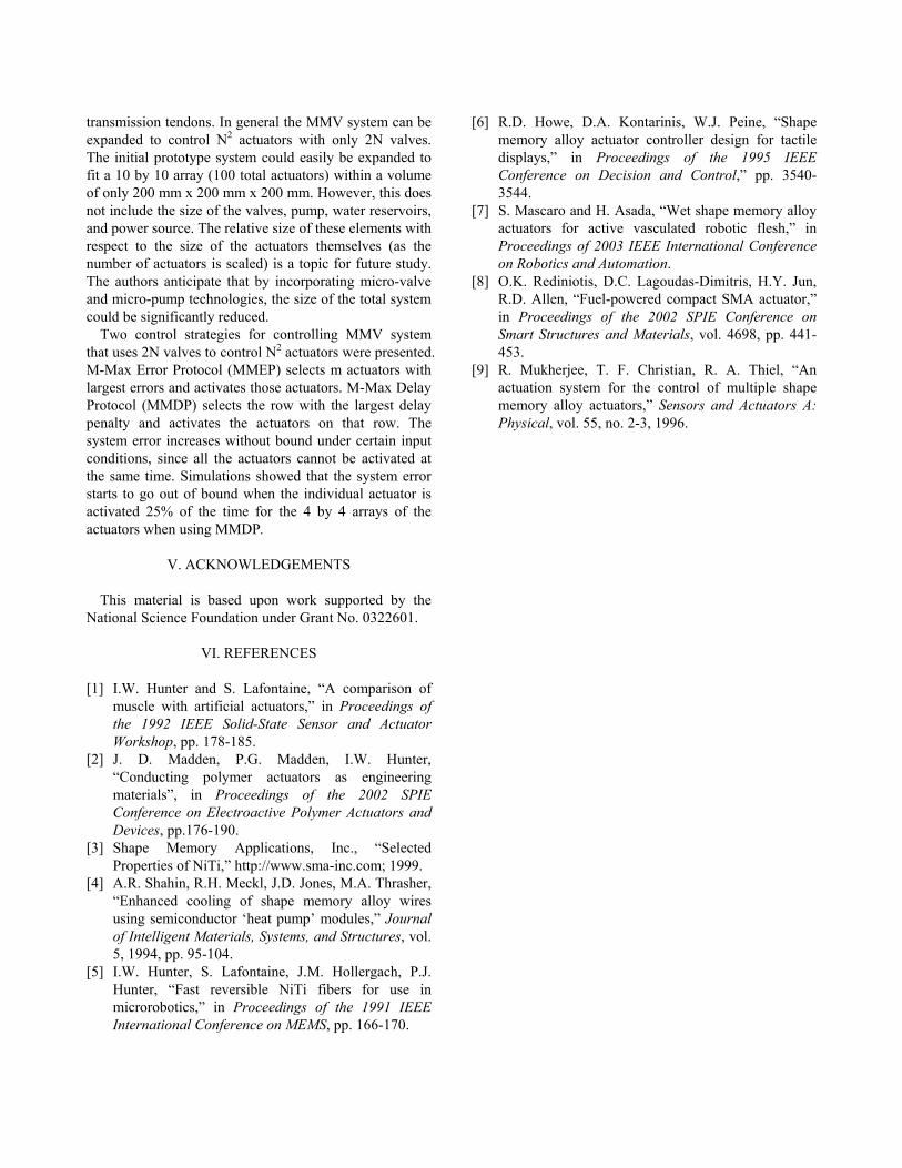
C. Results and Discussion
A simulation has been done for m-Max Delay protocol. The system consists of 16 actuators, in a 4 by 4 matrix structure. The inputs to the actuators are distributed over time in a uniformly random manner. The duty ratio of the input commands has been changed until the total penalty blows out without being recovered. As shown in Fig. 9, the m-Max Delay Penalty exhibits an instability occurring at a duty ratio of around 25%, for a system with 16 actuators. Since the maximum fraction of actuators that can be activated at once is 1/N, it is reasonable to see a system blow out in a duty ratio of around 25% for a system that has 4 actuators in the same row or column.
time
Total Penalty
Duty ratio=25%
Duty ratio=23%
Duty ratio=21%
Performance of the Max Delay Row Protocol
Input
Fig. 9 Performance of m-Max Delay Protocol
For systems with more actuators, the duty ratio is likely
to be lower. A system with N2 actuators is likely to show an instability occurring at a duty ratio of 1/N, since only 1/N fraction of the actuators can be activated at the same time. Other protocols that can sustain higher duty ratio of inputs before the instability occur might be able to be designed.
IV. CONCLUSIONS
This paper presented a scalable architecture for a vast DOF actuator system utilizing networks of wet shape memory alloy actuators. A Matrix Manifold and Valve (MMV) system was designed and implemented, where fluid was routed from hot and cold reservoirs in order to control an array of 16 SMA actuators using only 8 valves. The actuator system fits within a volume of 100 mm by 100 mm by 200 mm, and is capable of actuation forces of up to 160 N and displacements of up to 64 mm, depending on choice of wires and configuration of
(2)
transmission tendons. In general the MMV system can be expanded to control N2 actuators with only 2N valves. The initial prototype system could easily be expanded to fit a 10 by 10 array (100 total actuators) within a volume of only 200 mm x 200 mm x 200 mm. However, this does not include the size of the valves, pump, water reservoirs, and power source. The relative size of these elements with respect to the size of the actuators themselves (as the number of actuators is scaled) is a topic for future study. The authors anticipate that by incorporating micro-valve and micro-pump technologies, the size of the total system could be significantly reduced.
Two control strategies for controlling MMV system that uses 2N valves to control N2 actuators were presented. M-Max Error Protocol (MMEP) selects m actuators with largest errors and activates those actuators. M-Max Delay Protocol (MMDP) selects the row with the largest delay penalty and activates the actuators on that row. The system error increases without bound under certain input conditions, since all the actuators cannot be activated at the same time. Simulations showed that the system error starts to go out of bound when the individual actuator is activated 25% of the time for the 4 by 4 arrays of the actuators when using MMDP.
V. ACKNOWLEDGEMENTS
This material is based upon work supported by the National Science Foundation under Grant No. 0322601.
VI. REFERENCES
[1] I.W. Hunter and S. Lafontaine, “A comparison of muscle with artificial actuators,” in Proceedings of the 1992 IEEE Solid-State Sensor and Actuator Workshop, pp. 178-185.
[2] J. D. Madden, P.G. Madden, I.W. Hunter, “Conducting polymer actuators as engineering materials”, in Proceedings of the 2002 SPIE Conference on Electroactive Polymer Actuators and Devices, pp.176-190.
[3] Shape Memory Applications, Inc., “Selected Properties of NiTi,” http://www.sma-inc.com; 1999.
[4] A.R. Shahin, R.H. Meckl, J.D. Jones, M.A. Thrasher, “Enhanced cooling of shape memory alloy wires using semiconductor ‘heat pump’ modules,” Journal of Intelligent Materials, Systems, and Structures, vol. 5, 1994, pp. 95-104.
[5] I.W. Hunter, S. Lafontaine, J.M. Hollergach, P.J. Hunter, “Fast reversible NiTi fibers for use in microrobotics,” in Proceedings of the 1991 IEEE International Conference on MEMS, pp. 166-170.
[6] R.D. Howe, D.A. Kontarinis, W.J. Peine, “Shape memory alloy actuator controller design for tactile displays,” in Proceedings of the 1995 IEEE Conference on Decision and Control,” pp. 3540-3544.
[7] S. Mascaro and H. Asada, “Wet shape memory alloy actuators for active vasculated robotic flesh,” in Proceedings of 2003 IEEE International Conference on Robotics and Automation.
[8] O.K. Rediniotis, D.C. Lagoudas-Dimitris, H.Y. Jun, R.D. Allen, “Fuel-powered compact SMA actuator,” in Proceedings of the 2002 SPIE Conference on Smart Structures and Materials, vol. 4698, pp. 441-453.
[9] R. Mukherjee, T. F. Christian, R. A. Thiel, “An actuation system for the control of multiple shape memory alloy actuators,” Sensors and Actuators A: Physical, vol. 55, no. 2-3, 1996.