design and fabrication of model of tesla coil
TRANSCRIPT
Asian Journal of Electrical Sciences
ISSN: 2249-6297, Vol. 7, No. 2, 2018, pp. 96-99
© The Research Publication, www.trp.org.in
Design and Fabrication of Model of Tesla Coil
Yogesh Yashwant Pundlik1 and Gauri Yogesh Pundlik2 1Professor & Head, Department of EEE,
2Assistant Professor, Department of ECE,
Kamala Institute of Technology & Science, Singapur, Telangana, India E-Mail: [email protected]
Tesla coil is a doubly tuned resonant circuit.Actually the
TESLA COIL is the Air core transformer in which it has
two windings on the same axis. The primary winding is the
low voltage, high current winding. And the secondary is
high voltage, low current, high frequency winding. [1]A
Tesla coil transformer operates in a significantly different
fashion from a conventional (i.e., iron core) transformer. In
a conventional transformer, the windings are very tightly
coupled and voltage gain is determined by the ratio of the
numbers of turns in the windings.
This works well at normal voltages but, at high voltages, the
insulation between the two sets of windings is easily broken
down and this prevents iron cored transformers from
running at extremely high voltages without damage. Unlike
those of a conventional transformer (which may couple
97%+ of the fields between windings), a Tesla coil's
windings are "loosely" coupled, with a large air gap, and
thus the primary and secondary typically share only 10–
20% of their respective magnetic fields. Instead of a tight
coupling, the coil transfers energy (via loose coupling) from
one oscillating resonant circuit (the primary) to the other
(the secondary) over a number of RF cycles. [6] As the
primary energy transfers to the secondary, the secondary's
output voltage increases until all of the available primary
energy has been transferred to the secondary (less losses).
Even with significant spark gap losses, a well-designed
Tesla coil can transfer over 85% of the energy initially
stored in the primary capacitor to the secondary circuit. The
voltage achievable from a Tesla coil can be significantly
greater than a conventional transformer, because the
secondary winding is a long single layer solenoid widely
separated from the surroundings and therefore well
insulated.[5] [6] Also, the voltage per turn in any coil is
higher because the rate of change of magnetic flux is at high
frequencies. With the loose coupling the voltage gain is
instead proportional to the square root of the ratio of
secondary and primary inductances. Because the secondary
winding is wound to be resonant at the same frequency as
the primary, this voltage gain is also proportional to the
square root of the ratio of the primary capacitor to the stray
capacitance of the secondary. [2]
A. Principle of Working
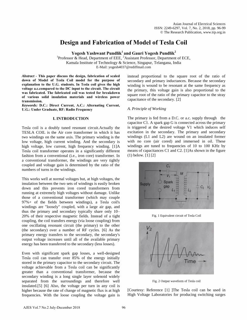
The primary is fed from a D.C. or a.c. supply through the
capacitor C1. A spark gap G is connected across the primary
is triggered at the desired voltage V1 which induces self
excitation in the secondary. The primary and secondary
windings (L1 and L2) are wound on an insulated former
with no core (air cored) and immersed in oil. These
windings are tuned to frequencies of 10 to 100 KHz by
means of capacitances C1 and C2. [1]As shown in the figure
(1) below. [1] [2]
Fig. 1 Equivalent circuit of Tesla Coil
Fig. 2 Output waveform of Tesla coil
[Courtesy: Reference [1] ]The Tesla coil can be used in
High Voltage Laboratories for producing switching surges
96AJES Vol.7 No.2 July-December 2018
I. INTRODUCTION
Abstract - This paper discuss the design, fabrication of scaled down of Model of Tesla Coil model for the purpose of explanation to the U.G. students. In Tesla coil gives the high voltage a.c.compared to the DC input to the circuit. The circuit was fabricated. The fabricated coil was tested for breakdown of various solid insulation materials and wireless power transmission. Keywords: D.C.: Direct Current, A.C.: Alternating Current, U.G.: Under Graduate, RF: Radio Frequency

for testing of electrical apparatus. The voltage build up is
slow hence, there is no damage to the insulation on account
of switching over voltages. The standard switching surge is
as shown in the figure (2) below.[Courtesy: Reference [1] ]
II. FABRICATION OF TESLA COIL
The basic requirements were: High voltage transformer, a
soldering machine, wires, varnish, Spark gap,
Toroid,Capacitors. Tesla set up primary and secondary coil
i.e. coppers coil (32 SWG) and was fixed up in a hole in a
wooden switchboard box. For fabricating a Tesla Coil the
following procedure was adopted by the authors.
Step 1: First we started making of secondary winding. For
that we have taken a PVC pipe of 2 inch diameter and the
copper wire as mentioned above was wound. The number of
turns depends on the requirement of the high voltage. We
can go with any number of turns at the secondary as per
value at output. We used 600 turns. All the turns are entirely
by hand wound. After winding an insulating layer has to be
coated with varnish. This is shown in figure (4)
Step2:The main problem is to link up flux between primary
and secondary. We need to make sure this linkage of flux,
otherwise secondary coil L2 will not respond.
Step3:The setup we created is just like an air core
transformer.
Step4:Next now we require a spark gap which is to be
coupled to primary coil L1. The RF wire used for making of
L1 is shown in figure (5). [3] [4] [5]
Step5: We get around 11.5kv output from that circuit at no
load i.e. current is zero.
All these connections can be made on the circuit with
copper wires with the help of soldering. This may take 2
hours’ time for this set up. This set up is placed in placed in
a project box which is totally covered with insulation i.e.
painted with varnish and dried in sun light.
1. The input to this circuit is 3 v dc and output is
magnified to around 1.5kv A.C at no load.
2. How the dc to A.C conversion taking place and how it
is magnifying we will that beauty later.
3. This entire circuit has to be used. Before connecting it
we need to replace the capacitors with the high voltage
capacitors.
4. We have used 3 circuits in series. Now input is
3+3+3=9v D.C
5. We have 2 switches on each circuit one is for key and
other for ignition of capacitor. So now we need to
connect the keys in series. To connect this we have to
remove the wires of each circuit. Remember we need to
mark all removed spots.
6. The first switch has to be shorted in all.
7. After that we have to connect the 2nd key of all circuits
to a common key i.e. switch and also a safety switch is
in series with this switch for more safety.
Fig. 4 Completion of Winding L2 on insulation former
Fig. 5 Radio frequency insulated wire for fabrication of primary winding
Fig. 6 Fabrication of toroid with aluminum foils.
We chose an insulation material ring which has to be fitted
on pipe. For that a ring of diameter just greater than pipe is
taken and it is entirely wound with aluminum cover. This
toroid for discharge purpose. Now it’s time to enjoy the
output. We should not forget to ground secondary but as the
secondary is at high voltage side we need to take safety
precautions.
For that the output of each capacitor from each circuit is
connected in series with other one of its points is given to
primary of tesla coil and it is placed in one of the spark gap
terminal. We used a 3-pin plug for spark gap.
97 AJES Vol.7 No.2 July-December 2018
Design and Fabrication of Model of Tesla Coil

And the other wire from capacitors is given directly to other
terminal of primary coil. And the secondary is open this
makes the completion of spark gap and connecting our coil.
Fig. 7 Input control circuit for safe operation of Tesla coil circuit
Fig. 8 Tesla Coil with L1& L2 wound surrounding the insulator former
without resistance potential divider
After the assembly of parts such as the spark gap, primary
coil, secondary coil and toroid, the fabricated scaled down
model of Tesla coil looks as shown in figure above.
II. FABRICATION OF RESISTANCE POTENTIAL DIVIDER
The potential divider can be created using resistors. 11
resistors were connected in series in which 10 resistors of
100kΩ ohm each and last resistor with 1kΩresistor.
This divider can be employed to measure high voltage
generated. Calculations were done as follows:
100k ohm * 10= 100*1000*10=1000000 ohms
1k ohm = 1000 ohms
Therefore ratio is 1000000 ohm: 1000 ohm =1000: 1
Implies if the voltage across 1k ohm resistors shown is 1V
then the total voltage output is
1*(1000/1) =1000=1kv
This Implies 1v in 1kv for each resistor is about 1kv.
The fabricated potential divider with wooden support is as
shown in figure below.
Fig. 10 Fabricated Resistance potential divider for measurement of
generated high voltage
III. RESULTS OF TESTING THE TESLA COIL
When the input D.C. was changed, the following two results
were obtained for the fabricated Tesla coil model as
1. If input D.C. is 3+3+3=9v dc then output is 11.6kV to
13.5 kV A.C under no load.
2. If input is 3+3=6v DC then the output is 5.67kV to 7.2
kV AC under no load. The output depends upon
charging of the DC battery inside.
The scaled down Tesla coil was tested for
1. With this model, we got wireless power transmission
and which is making incandescent bulb to glow 20 W
bulbs. With this it can be concluded that theminimum
power obtained by the model was 20 W.
2. Next we studied the breakdown of some solid
insulation material such asF-Class Paper, Garflex
Paper, Cotton Beeds, Transformer Insulation Paper.
After assembly of all parts, connection of ground wire and
the connection of resistance potential divider the scaled
down model is shown in the figure below.
Fig. 11 Full assembly with resistance voltage divider
98AJES Vol.7 No.2 July-December 2018
Yogesh Yashwant Pundlik and Gauri Yogesh Pundlik

IV. CONCLUSION
It can be concluded that the fabricated scaled down model
of the Tesla coil can be used as educational model for
demonstration for the U.G. students of High Voltage
Engineering subject. Apart from the model can be useful for
the demonstration of wireless transmission of electrical
power and breakdown studies of some of the solid dielectric
materials as mentioned in the previous section. Further this
can be employed for the Lightening phenomenon in
controlled fashion in educational laboratories.
REFERENCES
[1] M.S. Naidu and V.Kamaraju, High Voltage Engineering, 5th edition,
McGraw Hill Education (India) Private Limited. Second reprint 2014.
[2] A Nikola Tesla, “Tuned Lightning”,Ebook, IEEE Press, pp. 250-400. [3] RavindraArora, “High voltage and electrical insulation engineering”,
Chapter: 4, IEEE Press, pp. 227-270.
[4] Kevin Wilson, “The Tesla coil- construction and operation”, pp. 3-60. [5] R. E. Iannini, “Electronic gadgets for the evil genius: 21 build-it-
yourself projects”, pp. 137–202, TAB electronics, New York:
McGraw-Hill, 2003. [6] PrabhavManchanda, “DC TESLA COIL Construction and
Applications”,International Journal for Research in Applied Science
& Engineering Technology (IJRASET),Vol. 4, No. 7, pp. 579-584, July 2016.
99 AJES Vol.7 No.2 July-December 2018
Design and Fabrication of Model of Tesla Coil