design and implementation of a wireless kill-switch system
TRANSCRIPT

ARL-TN-0980 ● NOV 2019
Design and Implementation of a Wireless Kill-Switch System for Multi-Agent Unmanned Aerial System (UAS) Testing by Tristan Marshall and Daniel Everson Approved for public release; distribution is unlimited.
NOTICES
Disclaimers
The findings in this report are not to be construed as an official Department of the Army position unless so designated by other authorized documents. Citation of manufacturer’s or trade names does not constitute an official endorsement or approval of the use thereof. Destroy this report when it is no longer needed. Do not return it to the originator.

ARL-TN-0980 ● NOV 2019
Design and Implementation of a Wireless Kill-Switch System for Multi-Agent Unmanned Aerial System (UAS) Testing Tristan Marshall College Qualified Leaders (CQL) Army Educational Outreach Program (AEOP) Daniel Everson Weapons and Materials Research Directorate, CCDC Army Research Laboratory Approved for public release; distribution is unlimited.
ii
REPORT DOCUMENTATION PAGE Form Approved OMB No. 0704-0188
Public reporting burden for this collection of information is estimated to average 1 hour per response, including the time for reviewing instructions, searching existing data sources, gathering and maintaining the data needed, and completing and reviewing the collection information. Send comments regarding this burden estimate or any other aspect of this collection of information, including suggestions for reducing the burden, to Department of Defense, Washington Headquarters Services, Directorate for Information Operations and Reports (0704-0188), 1215 Jefferson Davis Highway, Suite 1204, Arlington, VA 22202-4302. Respondents should be aware that notwithstanding any other provision of law, no person shall be subject to any penalty for failing to comply with a collection of information if it does not display a currently valid OMB control number. PLEASE DO NOT RETURN YOUR FORM TO THE ABOVE ADDRESS.
1. REPORT DATE (DD-MM-YYYY)
November 2019 2. REPORT TYPE
Technical Note 3. DATES COVERED (From - To)
1 April–20 September 2019 4. TITLE AND SUBTITLE
Design and Implementation of a Wireless Kill-Switch System for Multi-Agent Unmanned Aerial System (UAS) Testing
5a. CONTRACT NUMBER
5b. GRANT NUMBER
5c. PROGRAM ELEMENT NUMBER
6. AUTHOR(S)
Tristan Marshall and Daniel Everson 5d. PROJECT NUMBER
5e. TASK NUMBER
5f. WORK UNIT NUMBER
7. PERFORMING ORGANIZATION NAME(S) AND ADDRESS(ES)
CCDC Army Research Laboratory ATTN: FCDD-RLW-LF Aberdeen Proving Ground, MD 21005
8. PERFORMING ORGANIZATION REPORT NUMBER
ARL-TN-0980
9. SPONSORING/MONITORING AGENCY NAME(S) AND ADDRESS(ES)
10. SPONSOR/MONITOR'S ACRONYM(S)
11. SPONSOR/MONITOR'S REPORT NUMBER(S)
12. DISTRIBUTION/AVAILABILITY STATEMENT
Approved for public release; distribution is unlimited.
13. SUPPLEMENTARY NOTES ORCID ID(s): Daniel Everson, 0000-0003-0466-1132
14. ABSTRACT
The US Army Combat Capabilities Development Command Army Research Laboratory Guidance Technologies Branch has developed a wireless kill-switch system to support the safe and secure execution of multi-agent unmanned aerial system (UAS) test events. This system allows a single operator to quickly and reliably disable one or more UASs in the event of unexpected flight behavior. The operator interfaces with the system through a ground station consisting of mechanical switches and status LEDs. A radio device in the ground station provides a wireless link to air units installed on each UAS. The air units operate independently from the UAS flight controller and are capable of disabling a UAS even in the event of a failed flight controller.
15. SUBJECT TERMS
UAS testing, multi-agent, swarming, robotics, safety
16. SECURITY CLASSIFICATION OF: 17. LIMITATION OF ABSTRACT
UU
18. NUMBER OF PAGES
53
19a. NAME OF RESPONSIBLE PERSON
Tristan Marshall a. REPORT
Unclassified b. ABSTRACT
Unclassified
c. THIS PAGE
Unclassified
19b. TELEPHONE NUMBER (Include area code)
(410) 306-0617 Standard Form 298 (Rev. 8/98)
Prescribed by ANSI Std. Z39.18
iii
Contents
List of Figures v
1. Introduction 1
2. Background 1
3. Problem Statement 2
4. Proposed Solution 2
5. Technical Design 3
5.1 Major Subcomponents 3
5.1.1 XBee Radios 4
5.1.2 Arduino Microcontroller Boards 5
5.2 Air Unit–Specific Subcomponents 6
5.2.1 Sparkfun XBee Shield 6
5.2.2 3S Lithium Polymer (LiPo) Battery and Battery Elimination Circuit (BEC) 7
5.2.3 Solid-State Relay 7
5.2.4 Dip Switch 8
5.3 Ground Station–Specific Subcomponents 8
5.3.1 Front Plate, Switches, and Indicator LEDs 8
5.3.2 Signal Routing Board 9
5.3.3 Field Box Components 9
5.4 Software Design 10
5.4.1 Ground Station 11
5.4.2 Air Unit 11
5.4.3 Wireless Data Link 11
6. Kill-Switch System Operation 12
6.1 Ground Station Setup 13
6.2 Air Unit Setup 13
6.3 Operator Interface 13
iv
6.4 Operator Actions 14
6.5 System Shutdown 15
7. System Evaluation 15
7.1 Bench Test Setup 15
7.2 Bench Test Results 15
7.3 Field Test Setup 16
7.4 Field Test Results 16
8. Lessons Learned 17
9. Future Work 18
9.1 Miniaturization 18
9.2 Radio Replacement 18
9.3 Soft Kill 18
9.4 Unit Expansion 18
9.5 Field Testing of System Functionality 19
10. References 20
Appendix A. XBee Radio Settings 22
Appendix B. Ground Station Code 26
Appendix C. Air Unit Code 32
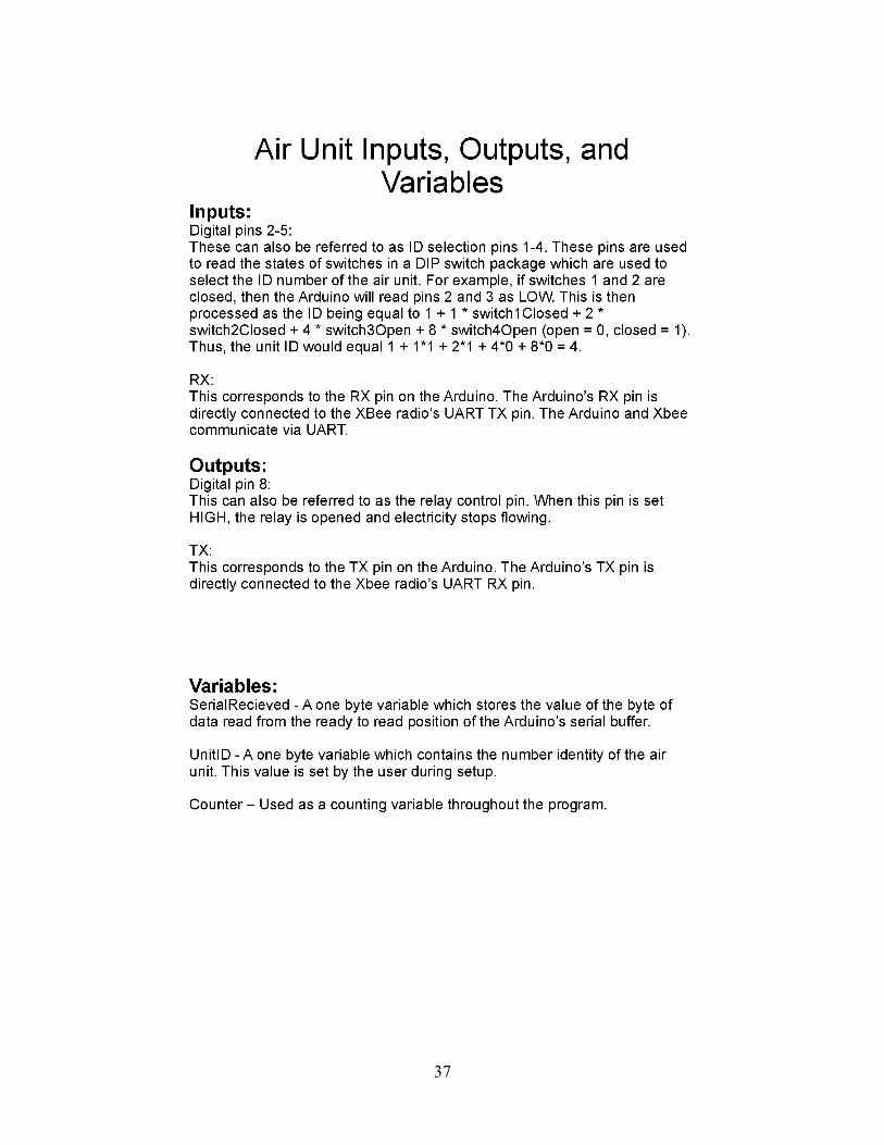
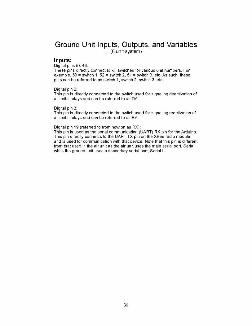
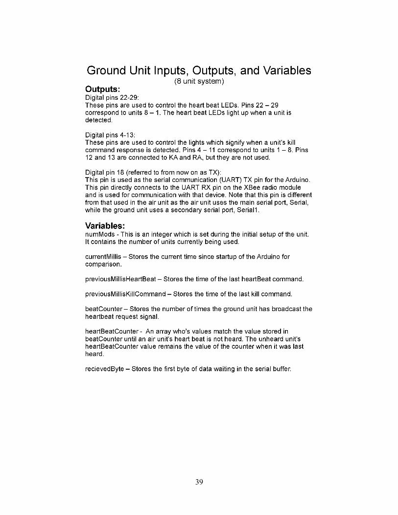
Appendix D. Unmanned Aerial System (UAS) Kill-Switch System Manual 36
List of Symbols, Abbreviations, and Acronyms 45
Distribution List 46
v
List of Figures
Fig. 1 a) Ground station subsystem. The ground station provides the user interface for controlling the kill and revive states of the air units. b) Air unit subsystem. The air unit uses a power relay to interrupt power to the UAS flight controller if a kill command is received. ...................... 3
Fig. 2 The XBee radios serve as a wireless serial data connection allowing communication between the air and ground units ................................ 4
Fig. 3 Arduino-to-Arduino communication via serial cable or XBee radio .... 5
Fig. 4 a) Arduino Uno Rev 3 used in air units and b) Arduino Mega 2560 Rev 3 utilized in ground unit ................................................................ 6
Fig. 5 The XBee Shield provides voltage division and port connections to enable communication between an XBee radio and an Arduino .......... 6
Fig. 6 The air units are powered independently of the UAS system by a battery and BEC so as to be a completely separate system .................. 7
Fig. 7 The relay provides a safe method by which the Arduino can control the power supply to the UAS flight controller ............................................ 7
Fig. 8 A dip switch is used to set the unit ID on each air unit. The dip switch configuration corresponds to unit ID 5. ................................................ 8
Fig. 9 The front plate contains the switches and LEDs that allow an operator to interface with the system and be updated on the system’s state ....... 9
Fig. 10 The signal routing board provides the Arduino Mega 2560 with connections to the XBee radio, indicator LEDs, and switches of the ground station........................................................................................ 9
Fig. 11 The Pelican case provides a weather-resistant enclosure for the ground station components.............................................................................. 10
Fig. 12 The power supply converts standard 120-V AC power to DC power for the ground unit’s systems .............................................................. 10
Fig. 13 Each box in this figure represents one of the message types used by the wireless data link................................................................................. 12
Fig. 14 a) When the kill-all switch is active, the revive-all and kill unit number switches are ignored, b) when the kill-all switch is inactive and the revive-all switch is active, the kill unit number switches are ignored, and c) when the kill-all and revive-all switches are inactive, the kill unit number switches are read............................................................. 14
1
1. Introduction
Unmanned aerial systems (UASs) are critical assets for the development of guidance and navigation technologies for the next generation of precision munitions. The US Army Combat Capabilities Development Command Army Research Lab (ARL), Guidance Technologies Branch (GTB), uses UAS to perform multiple tasks that are critical to the cost-effective and timely execution of its research effort. Technologies that enable effective guidance and navigation in a future contested battlespace will likely rely on distributed, collaborative sensing and autonomous, swarming behavior.1,2
Multi-agent and swarming concepts currently being developed by ARL GTB will require multiple simultaneously operating UASs to be effectively evaluated.3–6 As the number of aerial agents being used for a test event increases, maintaining situation awareness of the location of each UAS and taking corrective action in the event of a vehicle malfunction becomes increasingly difficult. The ability to conduct complicated multi-agent UAS testing while maintaining the safety and security of the flight operation is critical to the future success of ARL GTB’s research mission.
ARL GTB has developed a wireless kill-switch system as a hardware mitigation to the risks associated with multi-agent UAS testing. Each aerial asset is outfitted with a module capable of remotely disconnecting power to the UAS flight controller. This action immediately disables the UAS causing it to crash. While damage to the UAS and its payload is likely in this scenario, it is preferable to a UAS “fly away” that poses significant safety and security concerns. A ground station controller for the kill-switch system allows a single operator to monitor the status of the aerial assets and send kill commands to an aerial asset in the case that the malfunctioning UAS can be positively identified. If the malfunctioning UAS cannot be identified or if a multi-agent malfunction is experienced, a “kill-all” command will simultaneously disable all of the operating UAS.
2. Background
Approval for operation of UAS within active restricted airspace at Aberdeen Proving Ground is heavily scrutinized to ensure that the flight operations are conducted in a manner that is safe and secure. A primary consideration is the ability of the operation to maintain positive control of the UAS within a planned, approved operating area. A UAS malfunction that results in a vehicle leaving the planned operating area generates a safety hazard and may pose a security concern if the UAS is recovered by unauthorized personnel.

2
ARL GTB conducts UAS operations as directed by ARL Standard Operating Procedure (SOP) 385-0877, Safe Operations for Use of Laboratory Unmanned Air Vehicle (UAV).7 This procedure includes measures that mitigate the risk of a UAS exceeding the planned operating area for a given test event. SOP 385-0877 dictates that a dedicated safety observer is assigned to each airborne asset to ensure that the UAS remains within its planned operating area. A dedicated UAS operator also monitors the vehicle and is prepared to intervene in the case of a system malfunction or as directed by the flight director.
Software fail-safes are incorporated into the flight control software of UAS intended for autonomous or semiautonomous operation, but failures resulting in a UAS exceeding the planned operating area are still possible. The presence of a safety observer closely monitoring the UAS and a dedicated UAS operator who can quickly intervene in the event of a malfunction is an effective mitigation of this risk. However, multi-agent testing can generate a scenario where it is difficult for an operator to take control of a specific agent because it is difficult to identify which agent requires intervention. Even more concerning is a simultaneous failure of multiple agents, overwhelming the ability of the test team to take corrective action.
Development and evaluation of multi-agent and swarming concepts currently being researched by ARL GTB will require test events involving multiple simultaneously operating UAS. As the number of aerial agents increases, assigning a dedicated safety observer and operator for each UAS becomes impractical. It will become necessary to modify existing safe operating procedures for multi-agent testing in order to reduce the manpower required to support a test event while also maintaining the safety and security of the flight operation.
3. Problem Statement
ARL GTB will conduct multi-agent UAS experiments to evaluate emerging navigation and guidance technologies. The number of simultaneous aerial agents necessary to successfully conduct these experiments makes traditional assignment of one operator and one observer per UAS impractical. ARL GTB desires a system that will allow a single operator to quickly disable one or all of the operating UASs in the event of a vehicle malfunction or other emergency.
4. Proposed Solution
A wireless kill switch capable of terminating the flight of either an individual UAS or the entire set of UASs in a multi-agent operation will allow a single flight director to maintain positive control of the operation. This kill-switch capability consists of
3
an aerial component installed on each UAS and a single field-box ground station. Numbered toggle switches on the ground station allow an operator to disable each UAS individually in addition to a kill-all switch that allows the operator to simultaneously disable all UAS. A “revive-all” switch allows the operator to restore UASs that have been previously disabled. Two-way communication between the ground station and aerial components provides system status via “heartbeat”, “kill-confirmed”, and “revive-confirmed” messages. System status is displayed by a series of LED lights on the ground station.
5. Technical Design
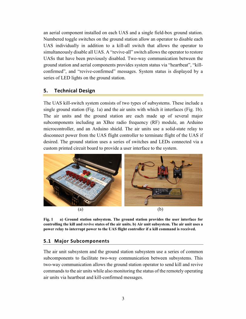
The UAS kill-switch system consists of two types of subsystems. These include a single ground station (Fig. 1a) and the air units with which it interfaces (Fig. 1b). The air units and the ground station are each made up of several major subcomponents including an XBee radio frequency (RF) module, an Arduino microcontroller, and an Arduino shield. The air units use a solid-state relay to disconnect power from the UAS flight controller to terminate flight of the UAS if desired. The ground station uses a series of switches and LEDs connected via a custom printed circuit board to provide a user interface to the system.
(a) (b)
Fig. 1 a) Ground station subsystem. The ground station provides the user interface for controlling the kill and revive states of the air units. b) Air unit subsystem. The air unit uses a power relay to interrupt power to the UAS flight controller if a kill command is received.
5.1 Major Subcomponents
The air unit subsystem and the ground station subsystem use a series of common subcomponents to facilitate two-way communication between subsystems. This two-way communication allows the ground station operator to send kill and revive commands to the air units while also monitoring the status of the remotely operating air units via heartbeat and kill-confirmed messages.

4
5.1.1 XBee Radios
The system uses XBee XBP9B-DMST-002 RevJ RF modules (Fig. 2) for wireless communication between the ground and air units. The XBee radio provides multiple design benefits including long-range RF data transmission, mesh network capabilities, user-friendly configuration, and modular hardware replacement.
Fig. 2 The XBee radios serve as a wireless serial data connection allowing communication between the air and ground units
The XBee radio is specified as capable of transmitting data over a distance of 28-km line of sight on the 915-MHz industrial, scientific, and medical frequency band.8 Long-range connectivity is a critical element of the system functionality because communication between the ground station and the air units must be maintained during large-scale multi-agent test events. The XBee radios also have the capability to behave as a mesh network, which may allow for even longer-range connectivity, although that capability is not currently implemented and is reserved for future work.
The XBee radios come with XCTU programming software9 that allows for quick and easy updating of the radio’s firmware and settings. The settings used for this implementation are provided in Appendix A. The user-friendly programming interface allows for rapid implementation of a wireless data connection between the ground station subsystem and remotely operating air units. The XBee radios also provide a modular design that allows for the quick replacement of the system’s radios in the event that maintenance or system updates are required.
5
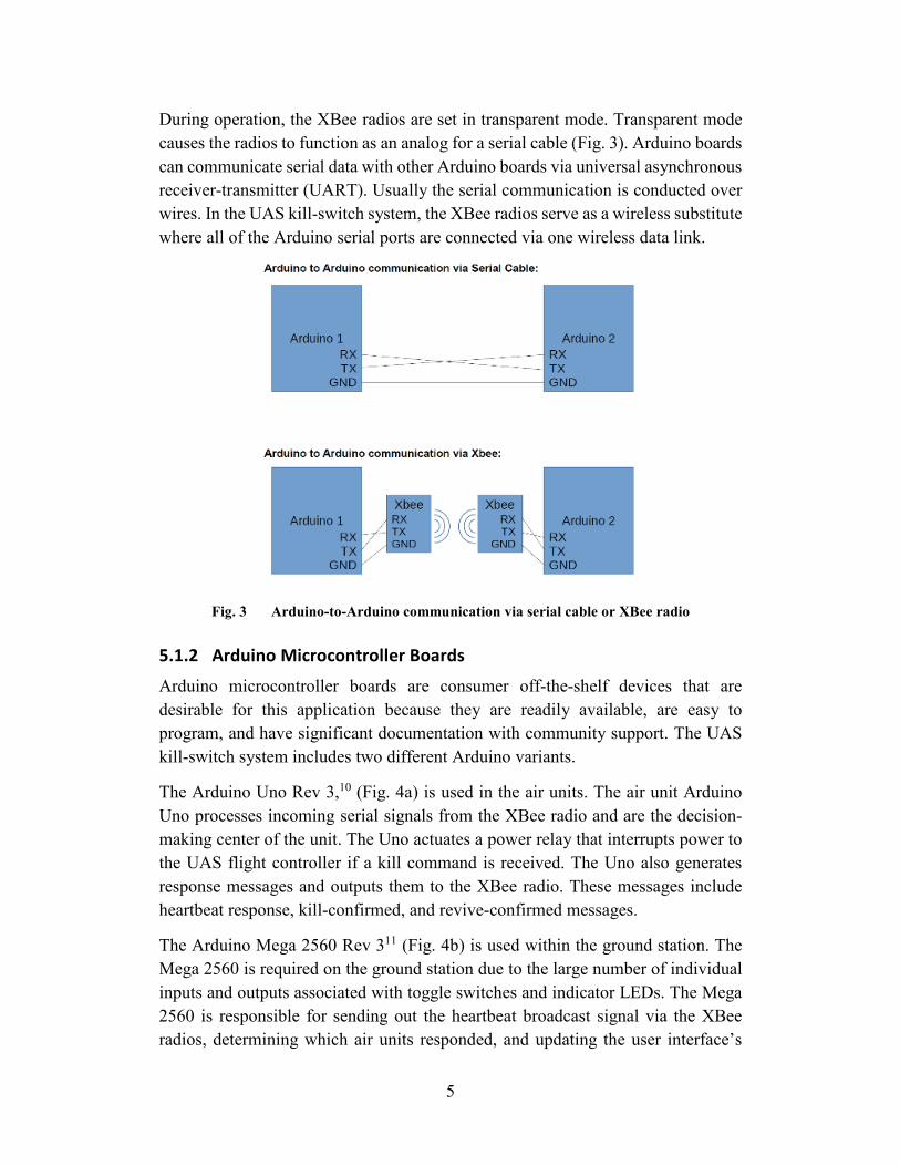
During operation, the XBee radios are set in transparent mode. Transparent mode causes the radios to function as an analog for a serial cable (Fig. 3). Arduino boards can communicate serial data with other Arduino boards via universal asynchronous receiver-transmitter (UART). Usually the serial communication is conducted over wires. In the UAS kill-switch system, the XBee radios serve as a wireless substitute where all of the Arduino serial ports are connected via one wireless data link.
Fig. 3 Arduino-to-Arduino communication via serial cable or XBee radio
5.1.2 Arduino Microcontroller Boards
Arduino microcontroller boards are consumer off-the-shelf devices that are desirable for this application because they are readily available, are easy to program, and have significant documentation with community support. The UAS kill-switch system includes two different Arduino variants.
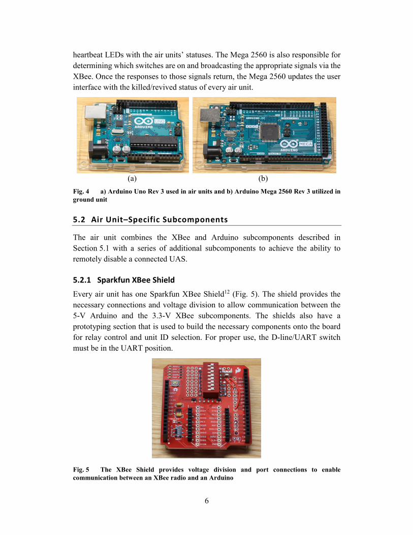
The Arduino Uno Rev 3,10 (Fig. 4a) is used in the air units. The air unit Arduino Uno processes incoming serial signals from the XBee radio and are the decision-making center of the unit. The Uno actuates a power relay that interrupts power to the UAS flight controller if a kill command is received. The Uno also generates response messages and outputs them to the XBee radio. These messages include heartbeat response, kill-confirmed, and revive-confirmed messages.
The Arduino Mega 2560 Rev 311 (Fig. 4b) is used within the ground station. The Mega 2560 is required on the ground station due to the large number of individual inputs and outputs associated with toggle switches and indicator LEDs. The Mega 2560 is responsible for sending out the heartbeat broadcast signal via the XBee radios, determining which air units responded, and updating the user interface’s
6
heartbeat LEDs with the air units’ statuses. The Mega 2560 is also responsible for determining which switches are on and broadcasting the appropriate signals via the XBee. Once the responses to those signals return, the Mega 2560 updates the user interface with the killed/revived status of every air unit.
(a) (b) Fig. 4 a) Arduino Uno Rev 3 used in air units and b) Arduino Mega 2560 Rev 3 utilized in ground unit
5.2 Air Unit–Specific Subcomponents
The air unit combines the XBee and Arduino subcomponents described in Section 5.1 with a series of additional subcomponents to achieve the ability to remotely disable a connected UAS.
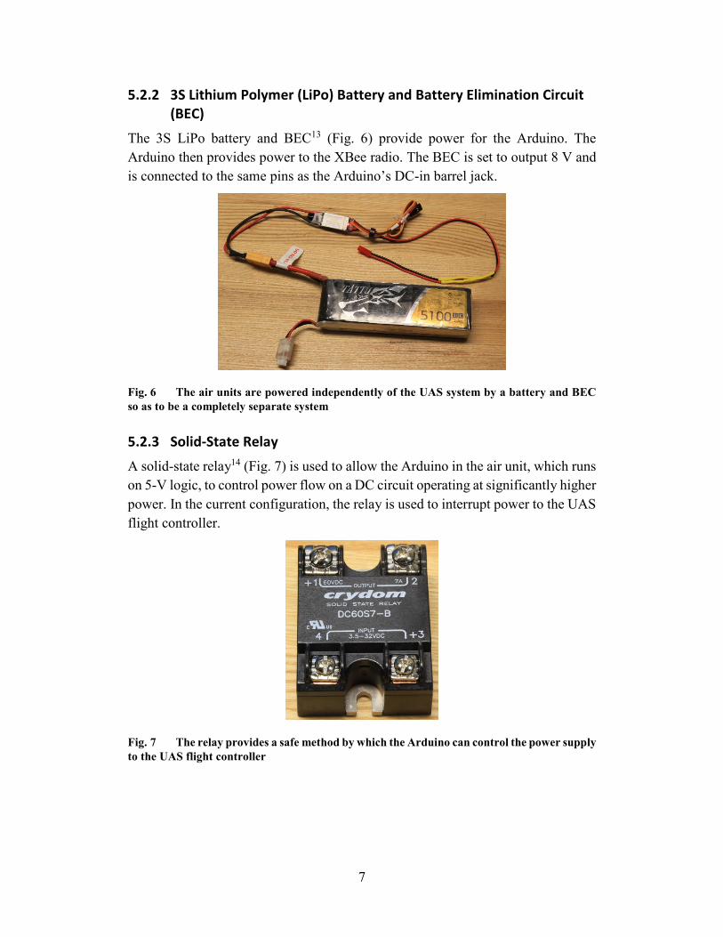
5.2.1 Sparkfun XBee Shield
Every air unit has one Sparkfun XBee Shield12 (Fig. 5). The shield provides the necessary connections and voltage division to allow communication between the 5-V Arduino and the 3.3-V XBee subcomponents. The shields also have a prototyping section that is used to build the necessary components onto the board for relay control and unit ID selection. For proper use, the D-line/UART switch must be in the UART position.
Fig. 5 The XBee Shield provides voltage division and port connections to enable communication between an XBee radio and an Arduino
7
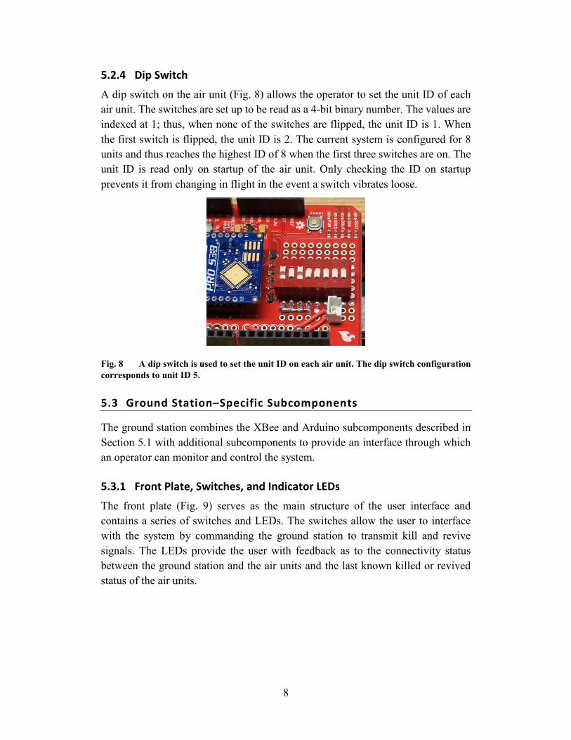
5.2.2 3S Lithium Polymer (LiPo) Battery and Battery Elimination Circuit (BEC)
The 3S LiPo battery and BEC13 (Fig. 6) provide power for the Arduino. The Arduino then provides power to the XBee radio. The BEC is set to output 8 V and is connected to the same pins as the Arduino’s DC-in barrel jack.
Fig. 6 The air units are powered independently of the UAS system by a battery and BEC so as to be a completely separate system
5.2.3 Solid-State Relay
A solid-state relay14 (Fig. 7) is used to allow the Arduino in the air unit, which runs on 5-V logic, to control power flow on a DC circuit operating at significantly higher power. In the current configuration, the relay is used to interrupt power to the UAS flight controller.
Fig. 7 The relay provides a safe method by which the Arduino can control the power supply to the UAS flight controller
8
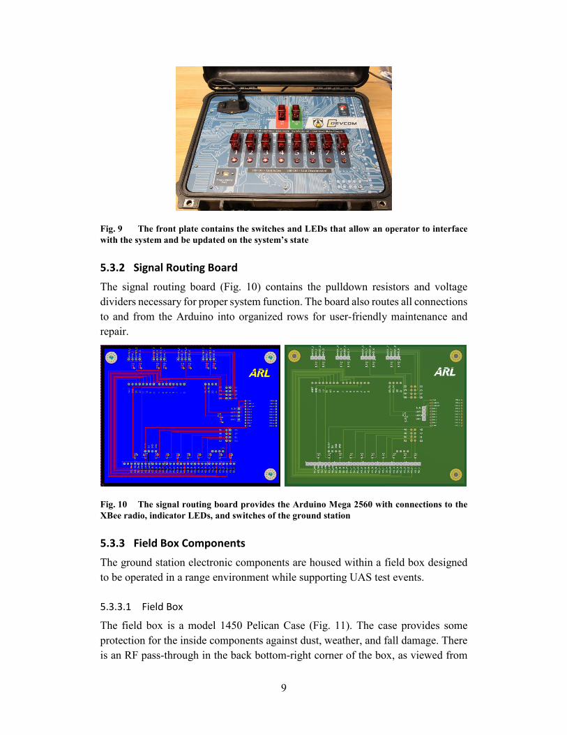
5.2.4 Dip Switch
A dip switch on the air unit (Fig. 8) allows the operator to set the unit ID of each air unit. The switches are set up to be read as a 4-bit binary number. The values are indexed at 1; thus, when none of the switches are flipped, the unit ID is 1. When the first switch is flipped, the unit ID is 2. The current system is configured for 8 units and thus reaches the highest ID of 8 when the first three switches are on. The unit ID is read only on startup of the air unit. Only checking the ID on startup prevents it from changing in flight in the event a switch vibrates loose.
Fig. 8 A dip switch is used to set the unit ID on each air unit. The dip switch configuration corresponds to unit ID 5.
5.3 Ground Station–Specific Subcomponents
The ground station combines the XBee and Arduino subcomponents described in Section 5.1 with additional subcomponents to provide an interface through which an operator can monitor and control the system.
5.3.1 Front Plate, Switches, and Indicator LEDs
The front plate (Fig. 9) serves as the main structure of the user interface and contains a series of switches and LEDs. The switches allow the user to interface with the system by commanding the ground station to transmit kill and revive signals. The LEDs provide the user with feedback as to the connectivity status between the ground station and the air units and the last known killed or revived status of the air units.
9
Fig. 9 The front plate contains the switches and LEDs that allow an operator to interface with the system and be updated on the system’s state
5.3.2 Signal Routing Board
The signal routing board (Fig. 10) contains the pulldown resistors and voltage dividers necessary for proper system function. The board also routes all connections to and from the Arduino into organized rows for user-friendly maintenance and repair.
Fig. 10 The signal routing board provides the Arduino Mega 2560 with connections to the XBee radio, indicator LEDs, and switches of the ground station
5.3.3 Field Box Components
The ground station electronic components are housed within a field box designed to be operated in a range environment while supporting UAS test events.
5.3.3.1 Field Box
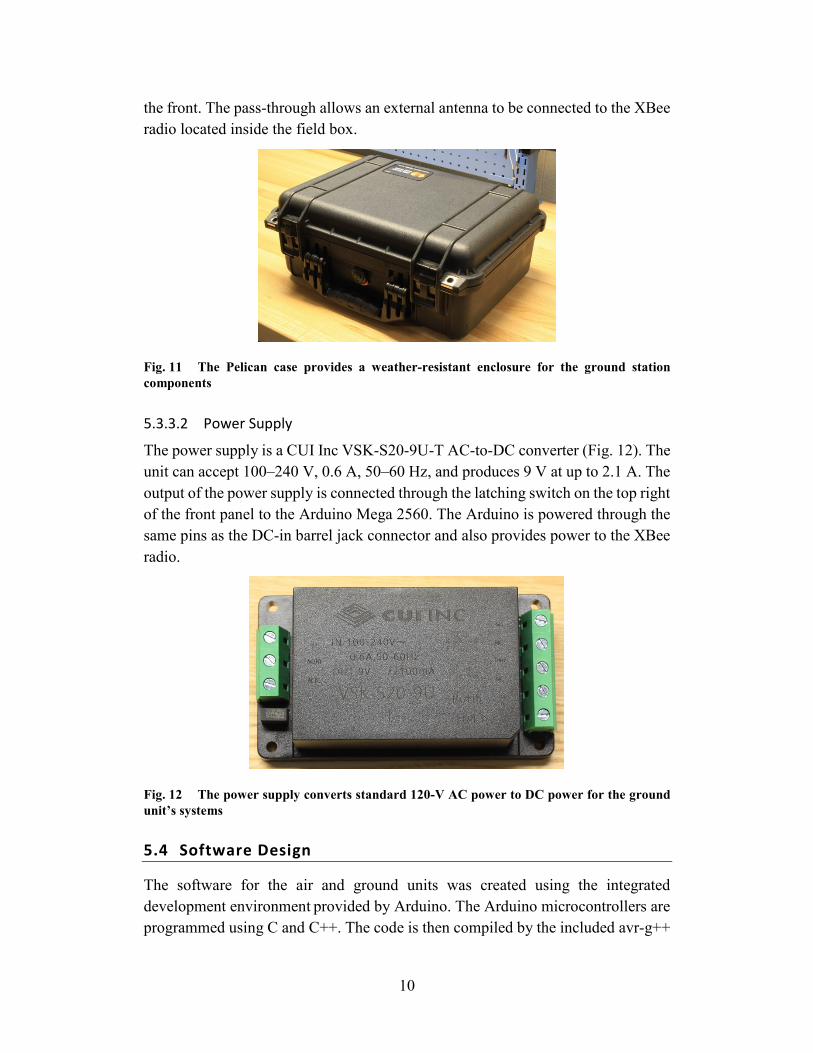
The field box is a model 1450 Pelican Case (Fig. 11). The case provides some protection for the inside components against dust, weather, and fall damage. There is an RF pass-through in the back bottom-right corner of the box, as viewed from
10
the front. The pass-through allows an external antenna to be connected to the XBee radio located inside the field box.
Fig. 11 The Pelican case provides a weather-resistant enclosure for the ground station components
5.3.3.2 Power Supply
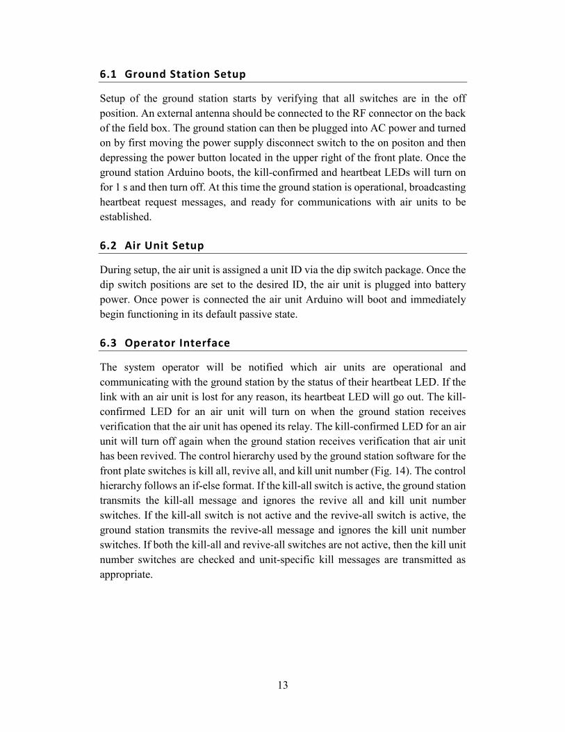
The power supply is a CUI Inc VSK-S20-9U-T AC-to-DC converter (Fig. 12). The unit can accept 100–240 V, 0.6 A, 50–60 Hz, and produces 9 V at up to 2.1 A. The output of the power supply is connected through the latching switch on the top right of the front panel to the Arduino Mega 2560. The Arduino is powered through the same pins as the DC-in barrel jack connector and also provides power to the XBee radio.
Fig. 12 The power supply converts standard 120-V AC power to DC power for the ground unit’s systems
5.4 Software Design
The software for the air and ground units was created using the integrated development environment provided by Arduino. The Arduino microcontrollers are programmed using C and C++. The code is then compiled by the included avr-g++

11
compiler and uploaded to the board. Source code for the ground station and the air units can be found in Appendixes B and C, respectively.
5.4.1 Ground Station
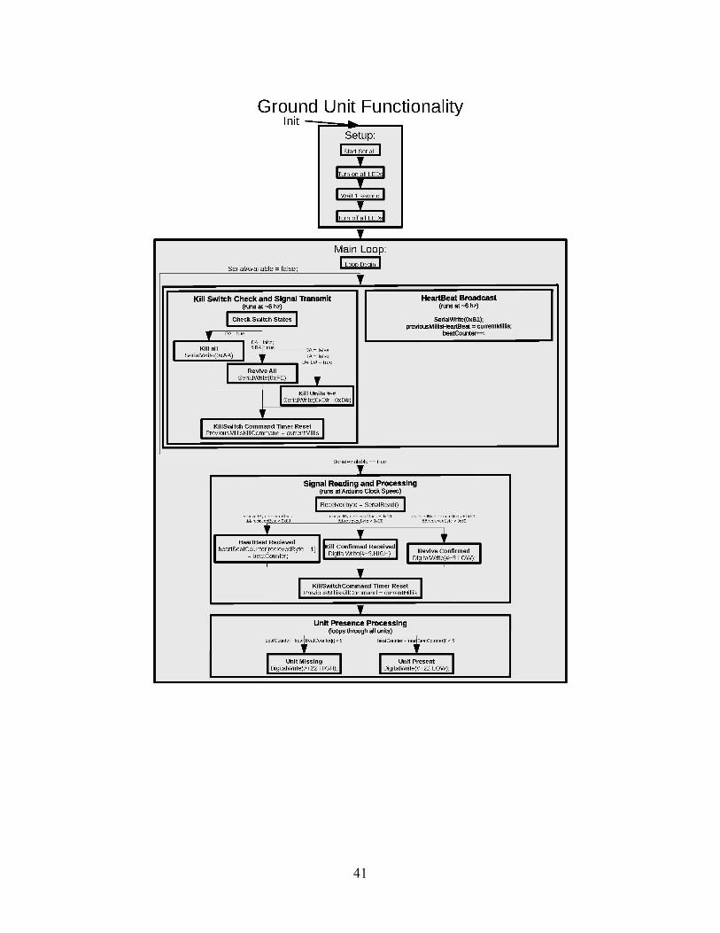
The ground station is programmed to constantly transmit a heartbeat broadcast at a rate of 6.67 Hz. Once that signal is broadcast, the ground station then reads the switches. If the kill-all switch is activated, then all other switches are ignored and the kill-all message is broadcast. If the kill-all switch is not active, then the ground station checks the revive-all switch. If the revive-all switch is active, then the revive-all message is broadcast and the kill unit number switches are ignored. If both the kill-all and revive-all switches are not active, then the ground station checks which kill unit number switches are active and broadcasts their respective kill messages. Independent of the 6.67-Hz broadcast rate, the ground station constantly listens for messages from the air units. It then determines what to do based on the message it has received. If it receives a heartbeat response from a given air unit, it saves that unit’s presence in an array. In the event that an air unit has not responded in 15 broadcast cycles, the ground station will notify the operator the communications link has been lost by turning off that unit’s heartbeat response LED until it receives a response from that unit again. If the ground station receives a kill-confirmed signal from an air unit, it will activate that unit’s kill-confirmed LED on the front panel. If the ground station receives a revive-confirmed signal from an air unit, it will deactivate that unit’s kill-confirmed LED. The full code for the ground station is provided in Appendix B.
5.4.2 Air Unit
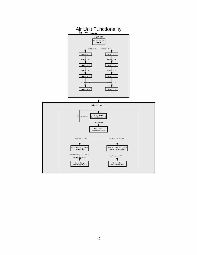
The baseline behavior of the air unit is to passively listen for messages transmitted by the ground station. The default state of the power relay on the air unit is closed. Accordingly, the air unit will not affect the UAS in the event that the air unit loses power or its communication link with the ground station. When the air unit receives a heartbeat request message, it broadcasts its heartbeat. When an air unit receives a kill-all message or its unit-specific kill message, it opens its relay interrupting power to the UAS flight controller. After opening the relay, it broadcasts a kill-confirmed message. When the air unit receives the revive-all message, it closes its relay and broadcasts the revive-confirmed message. The full code for the air unit is provided in Appendix C.
5.4.3 Wireless Data Link
The serial communication between the ground station and the air units follows a predetermined message structure (Fig. 13). Every message is a hexadecimal value

12
and is exactly 1 byte long. The first message type is the heartbeat broadcast. At a rate of 6.67 Hz, the ground station broadcasts the hex value 0xB1, which is understood by the air units to mean, “Transmit your unit ID”. The air unit ID heartbeat response message consists of a value from 0x01 to 0x08, indicating which air unit has generated the message. The next message type is the kill-all broadcast. The kill-all message consists of the value 0xAA. The air units respond to the kill message with a kill-confirmed message specific to each unit. The kill-confirmed message is the unit’s ID added to the hex value 0xC0. For example, the kill-confirmed signal for unit 3 is 0xC3. The air units also respond with the kill-confirmed message when their unit-specific kill unit number message is received. The kill unit number message is transmitted from the ground station and takes the value of the ID of the air unit to be killed added to 0xD0. Thus, the kill unit number signal for unit 3 is 0xD3. The last message type the ground station broadcasts is the revive-all message. The revive-all message consists of the value 0xFE. The air units respond to the revive-all message with a revive-confirmed message specific to each unit. The revive-confirmed message consists of the unit’s ID added to the value 0x60. Unit 3’s revive-confirmed message would take the value 0x63. The current message system supports a maximum of 15 unique unit IDs.
Fig. 13 Each box in this figure represents one of the message types used by the wireless data link
6. Kill-Switch System Operation
Operation of the kill-switch system requires that the user first set up the ground station and the air units to initiate operation. Once the system is operational, the user interfaces with the system through a series of switches and indicator lights. The user controls the operation of the system by toggling these switches to produce the desired system response.
13
6.1 Ground Station Setup
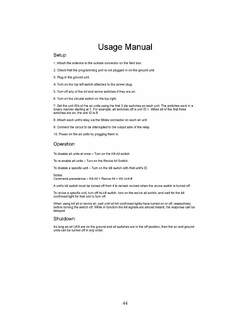
Setup of the ground station starts by verifying that all switches are in the off position. An external antenna should be connected to the RF connector on the back of the field box. The ground station can then be plugged into AC power and turned on by first moving the power supply disconnect switch to the on positon and then depressing the power button located in the upper right of the front plate. Once the ground station Arduino boots, the kill-confirmed and heartbeat LEDs will turn on for 1 s and then turn off. At this time the ground station is operational, broadcasting heartbeat request messages, and ready for communications with air units to be established.
6.2 Air Unit Setup
During setup, the air unit is assigned a unit ID via the dip switch package. Once the dip switch positions are set to the desired ID, the air unit is plugged into battery power. Once power is connected the air unit Arduino will boot and immediately begin functioning in its default passive state.
6.3 Operator Interface
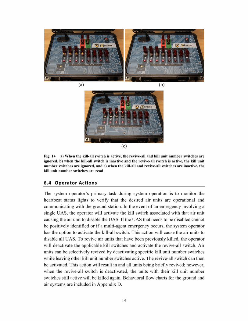
The system operator will be notified which air units are operational and communicating with the ground station by the status of their heartbeat LED. If the link with an air unit is lost for any reason, its heartbeat LED will go out. The kill-confirmed LED for an air unit will turn on when the ground station receives verification that the air unit has opened its relay. The kill-confirmed LED for an air unit will turn off again when the ground station receives verification that air unit has been revived. The control hierarchy used by the ground station software for the front plate switches is kill all, revive all, and kill unit number (Fig. 14). The control hierarchy follows an if-else format. If the kill-all switch is active, the ground station transmits the kill-all message and ignores the revive all and kill unit number switches. If the kill-all switch is not active and the revive-all switch is active, the ground station transmits the revive-all message and ignores the kill unit number switches. If both the kill-all and revive-all switches are not active, then the kill unit number switches are checked and unit-specific kill messages are transmitted as appropriate.
14
(a) (b)
(c)
Fig. 14 a) When the kill-all switch is active, the revive-all and kill unit number switches are ignored, b) when the kill-all switch is inactive and the revive-all switch is active, the kill unit number switches are ignored, and c) when the kill-all and revive-all switches are inactive, the kill unit number switches are read
6.4 Operator Actions
The system operator’s primary task during system operation is to monitor the heartbeat status lights to verify that the desired air units are operational and communicating with the ground station. In the event of an emergency involving a single UAS, the operator will activate the kill switch associated with that air unit causing the air unit to disable the UAS. If the UAS that needs to be disabled cannot be positively identified or if a multi-agent emergency occurs, the system operator has the option to activate the kill-all switch. This action will cause the air units to disable all UAS. To revive air units that have been previously killed, the operator will deactivate the applicable kill switches and activate the revive-all switch. Air units can be selectively revived by deactivating specific kill unit number switches while leaving other kill unit number switches active. The revive-all switch can then be activated. This action will result in and all units being briefly revived; however, when the revive-all switch is deactivated, the units with their kill unit number switches still active will be killed again. Behavioral flow charts for the ground and air systems are included in Appendix D.

15
6.5 System Shutdown
The system has been designed to allow for failure of system components without inadvertently disabling any UAS connected to the air units. Accordingly, powering off system components in any order will not adversely affect the system. However, it is recommended that the order of shutdown be as follows. All UAS should be landed, disarmed, and disconnected from power. The air units should then be powered off. After the air units are powered off, all switches on the ground station should be in the down position. Then the power button can be used to turn off the ground station and the power supply disconnect switch moved to the off position.
7. System Evaluation
Functionality and performance of the wireless kill-switch system was evaluated using a series of bench testing and field testing.
7.1 Bench Test Setup
The bench test included all eight air units and the ground station to verify that the system is capable of simultaneously operating all eight air units. To simplify test setup an indicator LED was installed in place of the power relay that would be used to control power to a UAS flight controller. Illumination of this LED indicates that the relay would be commanded open, disabling the UAS. The air units were also powered via USB instead of the DC-in barrel jack connectors. Otherwise, the system was configured as it would be setup for field use.
7.2 Bench Test Results
During bench testing, the kill function was found to perform exactly as required. When a kill switch was turned on, the kill occurred within a fraction of a second. No delays were created by activating multiple switches at the same time. The heartbeat function was found to work reliably as well. The heartbeat status LED for all eight air units remained illuminated unless an air unit was intentionally turned off. The kill-confirmed and revive-confirmed indications were occasionally found to delay before displaying. Review of the data transmission logs identified that the XBee radios were unable to parse all of the confirmation messages transmitted during a message cycle. While there was no delay in user interface response when fewer units were being killed, the event of killing or reviving all units simultaneously resulted in a delay in the update of the indication LEDs. This delay does not affect the kill and revive functions on the actual air units, which responded with no noticeable delay. Because only the visual status updates on the ground
16
station were delayed, this behavior is considered acceptable with respect to overall system functionality.
7.3 Field Test Setup
Two tests were conducted in an open field that is often used by ARL GTB to perform UAS experiments and is representative of a real-world operating environment. Each test used the ground station and three air units.
In the first test, two air units were connected to LED lights powered by LiPo batteries. The power relay of the air units was configured to disconnect power to the LED if a kill command was received. The third air unit was connected to a UAS as it would be for a typical flight experiment. The two LED lights were located 28 m from the ground station and the UAS was located 7 m from the ground station.
In the second test, all three air units were connected to LED lights powered by LiPo batteries. Two of the LED lights remained at static locations 28 m from the ground station. The third LED light was placed in the cab of a truck, which was used to move the air unit to greater distance from the ground station, up to a maximum distance of 664 m at the far end of the field.
7.4 Field Test Results
The objective of the first test was to verify the response of devices connected to the air units in a representative environment. To test the response of the UAS when disabled by the attached air unit, the UAS was armed and the rotors spun up while keeping the vehicle on the ground. When the applicable kill switch was activated, power was disconnected from the flight controller in a fraction of a second. However, the UAS rotors continued to spin for approximately 2.5 s after power to the flight controller had been cut because the motor speed controllers receive power independently from the UAS flight controller. This short delay in completely disabling the UAS is probably acceptable for the intended use of the wireless kill switch. Implementation of the kill switch used to ensure a safe operating environment during real-world experiments will need to consider the specific UAS response to a kill command. The LED lights responded to a kill command as turning off in a fraction of a second when the applicable kill switches where activated. This first field test corroborated the results of bench testing in terms of the reliability and speed of the kill and revive functions.
The second test evaluated the capacity of the system to maintain connectivity between the ground station and an air unit at longer ranges. The heartbeat signal was maintained over the length of the field, a distance of 664 m. Several

17
intermittent drops of the heartbeat, lasting less than a few seconds each were observed. Adjusting the external antenna on the ground station to a more optimal orientation given the location of the air unit resulted in no additional gaps in the heartbeat signal. Antenna configuration may be an important consideration to maximize the operating range of the system. Activation of the applicable kill switch on the ground station generated the expected response at the air unit within a fraction of a second. The connection range of the kill-switch system should be adequate to support multi-agent testing at the test site used. It is expected that connectivity between the ground station and an aerial UAS would be better than the ground path tested, although that is unverified. Connectivity between the ground station and aerial units out to the maximum required range should be verified prior to relying on the kill-switch system to maintain a safe operating environment.
8. Lessons Learned
The XBee radios used in this system were found to have a buffer that can only contain twenty 19-byte messages. Once 21 messages of that size are received at the same time, the radio will crash and need to be power cycled. The messaging system native to the XBee radios includes commands that are 19 bytes in length. These messages quickly lead to the buffer overload and crash when being received from multiple radios. To mitigate the risk of crashing, the radios were set to transparent mode. When in transparent mode, the radios can behave as virtual wires for serial communications between multiple devices. In the case of the UAS kill-switch system, they act as virtual wires for the Arduino microcontrollers in the ground and air units. Acting as only a messenger, the message content is determined by the Arduino programming. Thus, to reduce the risk of a crash, the messages were made to be 1 byte long. While greatly reducing the available number of messages, reducing the message size decreases traffic and the risk of an overflow related crash.
While many radios may respond to a message at the same time, the receiving radio may only receive a few of those responses, four out of eight for example. Which radio’s signals are received appears random. After a signal is sent 15 times at a rate of around 6.67 Hz it is highly likely the signal will be seen by the receiving radio at least once. It is recommended to turn off kill unit number switches after the kill-confirmed light for that unit has turned on as it will reduce the number of broadcasts at that time and improve heartbeat reliability. The effect appears to be relevant to responses more than initial transmissions. Kill-confirmed and heartbeat lights are affected while the actual kill signals are functionally unaffected.
18
9. Future Work
The current iteration of the wireless kill-switch system provides ARL GTB with a capability to enable multi-agent UAS testing for up to eight simultaneously operating UAS. Future work may improve the usability of the system and allow it to be expanded to support additional agents.
9.1 Miniaturization
The system can be miniaturized as the air unit Arduino boards can be replaced with smaller Arduino boards, such as the micro. Alternatively, a custom board could be created to house the radio and microcontroller in a more compact footprint.
9.2 Radio Replacement
Due to the difficulties mentioned in the lessons learned section, it is highly recommended that future iterations of the system should use a different radio that is designed to support more than eight units.
9.3 Soft Kill
Cutting off power to the flight controller will result in an uncontrolled crash of the UAS, also known as a hard kill. Because the UAS flight controller starts up in a disarmed state, it is impossible to recover to stable flight once a unit is killed. This method of disabling a UAS all but guarantees damage to the vehicle and its payload. Thus, it is preferable to determine a soft kill option. A soft kill occurs when the unit is no longer capable of sustained flight but is still capable of a controlled landing.
9.4 Unit Expansion
The current system is electronically configured and software programmed for eight units. In order to support a higher number of units several changes are recommended. The field box should be changed to a touch screen system powered by a small computer like a Raspberry Pi or Latte Panda. Thus, a digital interface can be scaled to support the required number of units. The design of the air units is capable of supporting up to 256 units, which is the limit of the unit ID with the current dip switch configuration. If the system is expanded beyond eight units, it is highly recommended that the radios be replaced with a new model or a different wireless radio system capable of handling additional simultaneous message traffic.
19
9.5 Field Testing of System Functionality
The system has been found to be functional on the ground; however, many system capabilities are still unverified. Further testing should be conducted to determine the capability of the system when installed on operational UAS. The maximum effective range for airborne units should be determined to aid in test planning. The specific response of any UAS outfitted with the system to a hard kill should also be determined.

20
10. References
1. Allik BL, Hamaoui M, Don M, Miller C. Kalman filter aiding MDS for projectile localization. AIAA Scitech 2019 Forum; 2019 Jan 7–11; San Diego, CA.
2. Hamaoui M. Non-iterative MDS method for collaborative network localization with sparse range and pointing measurements. IEEE Transactions on Signal Processing. 2019;67(3):568–578.
3. Lockspeiser JR, Don ML, Hamaoui M. Radio frequency ranging for swarm relative localization. Aberdeen Proving Ground (MD): Army Research Laboratory (US); 2017 Oct. Report No.: ARL-TR-8194.
4. Don ML. Dilution of precision as a geometry metric for swarm relative localization. Aberdeen Proving Ground (MD): Army Research Laboratory (US); 2017 Nov. Report No.: ARL-TR-8200.
5. Don ML. The feasibility of radio direction finding for swarm localization. Aberdeen Proving Ground (MD): Army Research Laboratory (US); 2017 Sep. Report No.: ARL-TR-8114.
6. Grabner M, Don M, Everson D. Constrained geometry relative swarm localization. Aberdeen Proving Ground (MD): CCDC Army Research Laboratory (US); Forthcoming 2019.
7. ARL SOP 385-0877. Safe operations for use of laboratory unmanned air vehicle (UAV). Aberdeen Proving Ground (MD): Army Research Laboratory (US); 2015 Apr 10.
8. XBee-PRO 900HP DigiMesh kit radio frequency (RF) module user guide, 90001496 datasheet. Hopkins (MN): Digi International; 2016 Jan [accessed 2016 Mar].
https://www.digi.com/resources/documentation/digidocs/pdfs/90001496.pdf.
9. XCTU user guide. Hopkins (MN): Digi International; 2018 June [accessed 2018 June].
https://www.digi.com/resources/documentation/digidocs/90001458-13/default.htm.
10. Arduino Uno Rev3. Code: 8058333490090. Somerville (MA): Arduino; c2019 [accessed 2019 Apr 29]. https://store.arduino.cc/usa/arduino-uno-rev3.
11. Arduino Mega 2560 Rev3. Code 7630049200067. Somerville (MA): Arduino; c2019 [accessed 2019 Apr 29]. https://store.arduino.cc/usa/mega-2560-r3.

21
12. Sparkfun XBee Shield. Mansfield (TX): Mouser Electronics; [accessed 2019 June 6]. https://www.mouser.com/ProductDetail/SparkFun/WRL-12847?qs =%2Fha2pyFaduhIWtya5xeNk8PfnGVLqhDUadWRuNFoyi56QV9SYllayA%3D%3D.
13. CC BEC 2.0 voltage regulator. Olathe (KS): Castle Creations; c2019 [accessed 2019 June 3]. http://www.castlecreations.com/en/cc-bec-2-0-010-0154-00.
14. Crydom panel-mount SSR: DC60 series. San Diego (CA): Crydom; c2016 [accessed 2019 June 6]. http://www.crydom.com/en/products/catalog/dc60-series-dc-panel-mount.pdf.

22
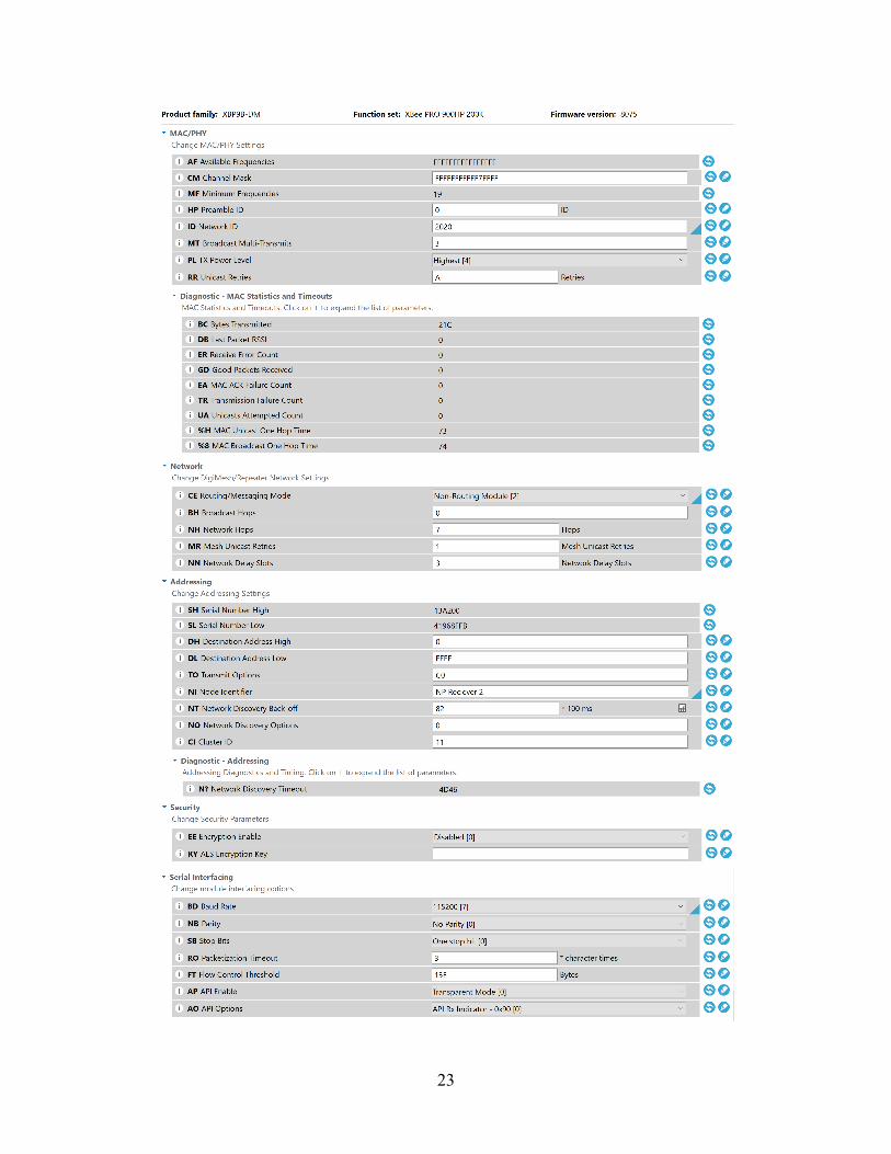
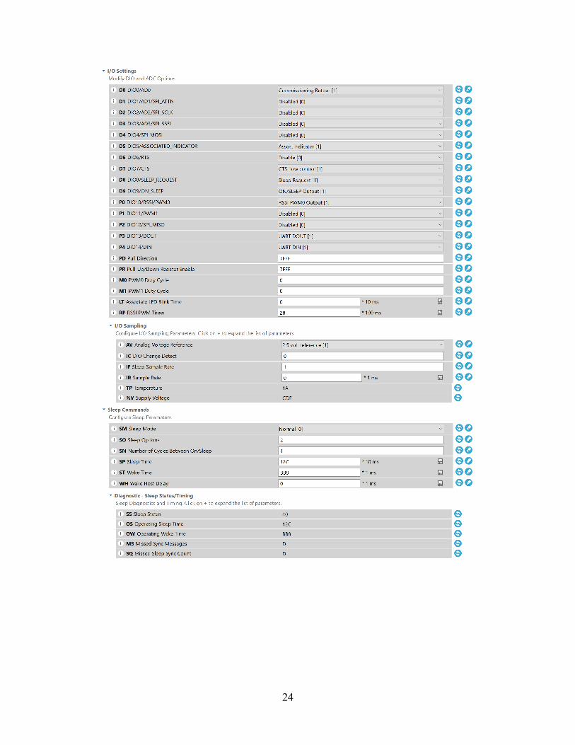
Appendix A. XBee Radio Settings
23
24

25
26
Appendix B. Ground Station Code
27
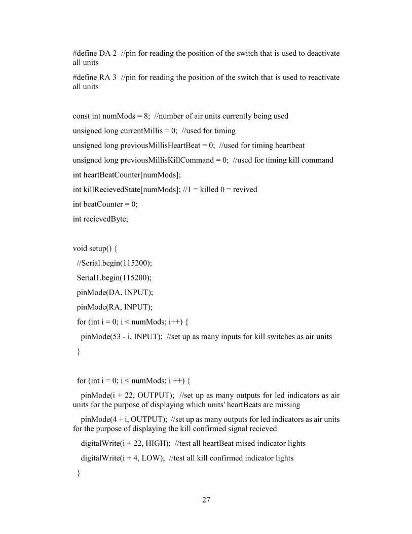
#define DA 2 //pin for reading the position of the switch that is used to deactivate all units
#define RA 3 //pin for reading the position of the switch that is used to reactivate all units
const int numMods = 8; //number of air units currently being used
unsigned long currentMillis = 0; //used for timing
unsigned long previousMillisHeartBeat = 0; //used for timing heartbeat
unsigned long previousMillisKillCommand = 0; //used for timing kill command
int heartBeatCounter[numMods];
int killRecievedState[numMods]; //1 = killed 0 = revived
int beatCounter = 0;
int recievedByte;
void setup() {
//Serial.begin(115200);
Serial1.begin(115200);
pinMode(DA, INPUT);
pinMode(RA, INPUT);
for (int i = 0; i < numMods; i++) {
pinMode(53 - i, INPUT); //set up as many inputs for kill switches as air units
}
for (int i = 0; i < numMods; i ++) {
pinMode(i + 22, OUTPUT); //set up as many outputs for led indicators as air units for the purpose of displaying which units' heartBeats are missing
pinMode(4 + i, OUTPUT); //set up as many outputs for led indicators as air units for the purpose of displaying the kill confirmed signal recieved
digitalWrite(i + 22, HIGH); //test all heartBeat mised indicator lights
digitalWrite(i + 4, LOW); //test all kill confirmed indicator lights
}
28
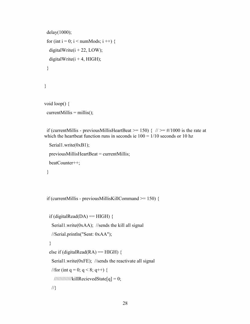
delay(1000);
for (int i = 0; i < numMods; i ++) {
digitalWrite(i + 22, LOW);
digitalWrite(i + 4, HIGH);
}
}
void loop() {
currentMillis = millis();
if (currentMillis - previousMillisHeartBeat >= 150) { // >= #/1000 is the rate at which the heartbeat function runs in seconds ie 100 = 1/10 seconds or 10 hz
Serial1.write(0xB1);
previousMillisHeartBeat = currentMillis;
beatCounter++;
}
if (currentMillis - previousMillisKillCommand >= 150) {
if (digitalRead(DA) == HIGH) {
Serial1.write(0xAA); //sends the kill all signal
//Serial.println("Sent: 0xAA");
}
else if (digitalRead(RA) == HIGH) {
Serial1.write(0xFE); //sends the reactivate all signal
//for (int q = 0; q < 8; q++) {
/////////////killRecievedState[q] = 0;
//}
29
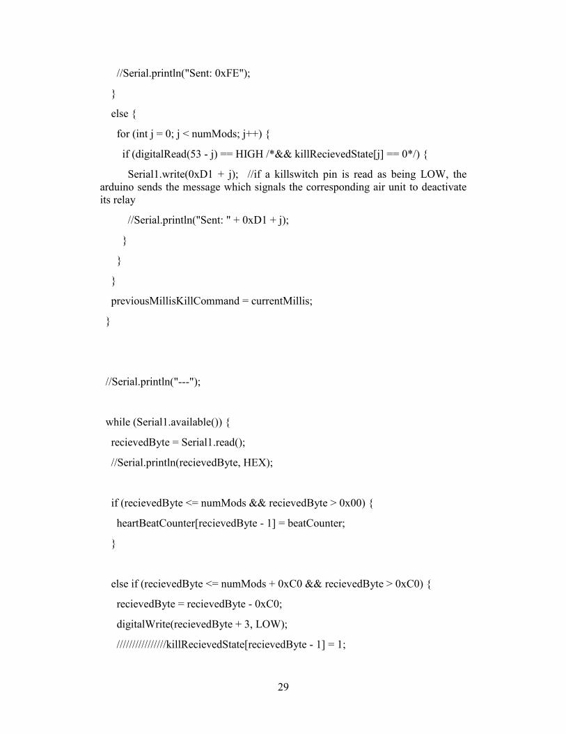
//Serial.println("Sent: 0xFE");
}
else {
for (int j = 0; j < numMods; j++) {
if (digitalRead(53 - j) == HIGH /*&& killRecievedState[j] == 0*/) {
Serial1.write(0xD1 + j); //if a killswitch pin is read as being LOW, the arduino sends the message which signals the corresponding air unit to deactivate its relay
//Serial.println("Sent: " + 0xD1 + j);
}
}
}
previousMillisKillCommand = currentMillis;
}
//Serial.println("---");
while (Serial1.available()) {
recievedByte = Serial1.read();
//Serial.println(recievedByte, HEX);
if (recievedByte <= numMods && recievedByte > 0x00) {
heartBeatCounter[recievedByte - 1] = beatCounter;
}
else if (recievedByte <= numMods + 0xC0 && recievedByte > 0xC0) {
recievedByte = recievedByte - 0xC0;
digitalWrite(recievedByte + 3, LOW);
////////////////killRecievedState[recievedByte - 1] = 1;
30
}
else if (recievedByte <= numMods + 0x60 && recievedByte > 0x60) {
recievedByte = recievedByte - 0x60;
digitalWrite(recievedByte + 3, HIGH);
}
}
if (beatCounter > 100) {
beatCounter = beatCounter - 80;
for (int i = 0; i < numMods; i++) {
heartBeatCounter[i] = heartBeatCounter[i] - 80;
if (heartBeatCounter[i] < 0) heartBeatCounter[i] = 0;
}
}
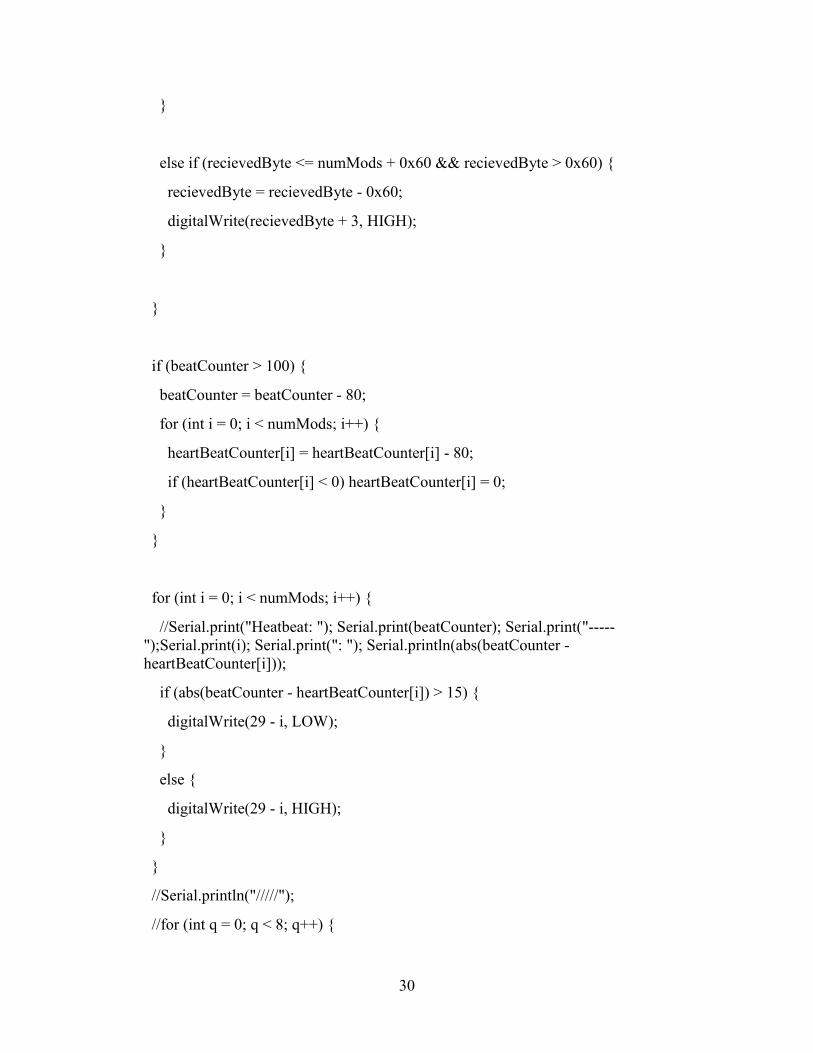
for (int i = 0; i < numMods; i++) {
//Serial.print("Heatbeat: "); Serial.print(beatCounter); Serial.print("-----");Serial.print(i); Serial.print(": "); Serial.println(abs(beatCounter - heartBeatCounter[i]));
if (abs(beatCounter - heartBeatCounter[i]) > 15) {
digitalWrite(29 - i, LOW);
}
else {
digitalWrite(29 - i, HIGH);
}
}
//Serial.println("/////");
//for (int q = 0; q < 8; q++) {

31
// Serial.println(killRecievedState[q]);
//}
//delay(15);
}
32
Appendix C. Air Unit Code
33
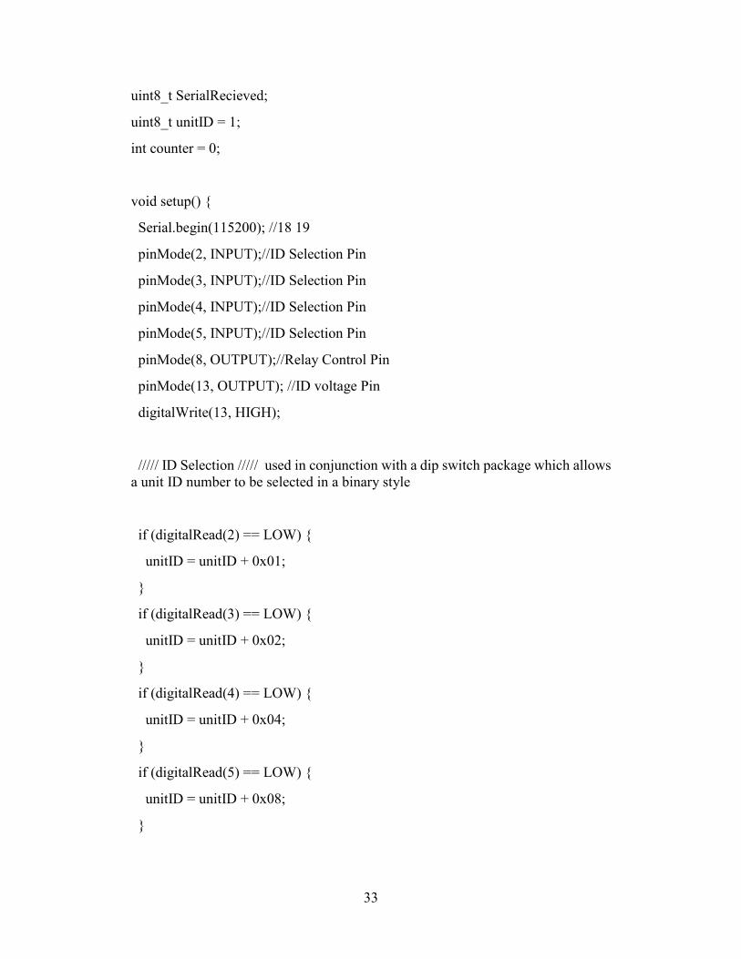
uint8_t SerialRecieved;
uint8_t unitID = 1;
int counter = 0;
void setup() {
Serial.begin(115200); //18 19
pinMode(2, INPUT);//ID Selection Pin
pinMode(3, INPUT);//ID Selection Pin
pinMode(4, INPUT);//ID Selection Pin
pinMode(5, INPUT);//ID Selection Pin
pinMode(8, OUTPUT);//Relay Control Pin
pinMode(13, OUTPUT); //ID voltage Pin
digitalWrite(13, HIGH);
///// ID Selection ///// used in conjunction with a dip switch package which allows a unit ID number to be selected in a binary style
if (digitalRead(2) == LOW) {
unitID = unitID + 0x01;
}
if (digitalRead(3) == LOW) {
unitID = unitID + 0x02;
}
if (digitalRead(4) == LOW) {
unitID = unitID + 0x04;
}
if (digitalRead(5) == LOW) {
unitID = unitID + 0x08;
}
34
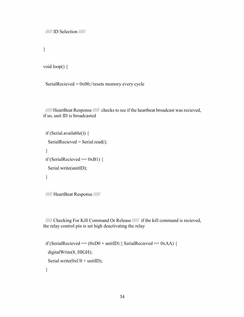
///// ID Selection /////
}
void loop() {
SerialRecieved = 0x00;//resets memory every cycle
///// HeartBeat Response ///// checks to see if the heartbeat broadcast was recieved, if so, unit ID is broadcasted
if (Serial.available()) {
SerialRecieved = Serial.read();
}
if (SerialRecieved == 0xB1) {
Serial.write(unitID);
}
///// HeartBeat Response /////
///// Checking For Kill Command Or Release ///// if the kill command is recieved, the relay control pin is set high deactivating the relay
if (SerialRecieved == (0xD0 + unitID) || SerialRecieved == 0xAA) {
digitalWrite(8, HIGH);
Serial.write(0xC0 + unitID);
}
35
if (SerialRecieved == 0xFE) {
digitalWrite(8, LOW);
Serial.write(0x60 + unitID);
}
///// Checking For Kill Command Or Release /////
}

36
Appendix D. Unmanned Aerial System (UAS) Kill-Switch System Manual
37
38
39

40
41
42

43
44
45
List of Symbols, Abbreviations, and Acronyms
AC alternating current
ARL Army Research Laboratory
BEC battery elimination circuit
CCDC US Army Combat Capabilities Development Command
DC direct current
GTB Guidance Technologies Branch
ID identification
LED light-emitting diode
LiPo lithium polymer
RF radio frequency
SOP standard operating procedure
UART universal asynchronous receiver-transmitter
UAS unmanned aerial system
46
1 DEFENSE TECHNICAL (PDF) INFORMATION CTR DTIC OCA 1 CCDC ARL (PDF) FCDD RLD CL TECH LIB 5 CCDC ARL (PDF) FCDD RLW LF T MARSHALL D EVERSON B TOPPER M ILG B ACKER